Design process of cementless femoral stem using a nonlinear three dimensional finite element...
17
RESEARCH ARTICLE Open Access Design process of cementless femoral stem using a nonlinear three dimensional finite element analysis Mohd Yusof Baharuddin 1,2 , Sh-Hussain Salleh 2* , Ahmad Hafiz Zulkifly 3 , Muhammad Hisyam Lee 4 , Alias Mohd Noor 2 , Arief Ruhullah A Harris 2 , Norazman Abdul Majid 2 and Ab Saman Abd Kader 5 Abstract Background: Minimal available information concerning hip morphology is the motivation for several researchers to study the difference between Asian and Western populations. Current use of a universal hip stem of variable size is not the best option for all femur types. This present study proposed a new design process of the cementless femoral stem using a three dimensional model which provided more information and accurate analysis compared to conventional methods. Methods: This complete design cycle began with morphological analysis, followed by femoral stem design, fit and fill analysis, and nonlinear finite element analysis (FEA). Various femur parameters for periosteal and endosteal canal diameters are measured from the osteotomy level to 150 mm below to determine the isthmus position. Results: The results showed better total fit (53.7%) and fill (76.7%) canal, with more load distributed proximally to prevent stress shielding at calcar region. The stem demonstrated lower displacement and micromotion (less than 40 μm) promoting osseointegration between the stem–bone and providing primary fixation stability. Conclusion: This new design process could be used as a preclinical assessment tool and will shorten the design cycle by identifying the major steps which must be taken while designing the femoral stem. Keywords: Morphology, Femur, Hip replacement, Cementless hip, Finite element analysis Background Total hip arthroplasty (THA) is recognized as the most successful orthopaedic surgery in the 20 th century. This fact was confirmed by the United Nation (UN) and World Health Organization (WHO) which declared the years 2000 – 2010 as the “Bone and Joint Decade” due to the rise of musculoskeletal diseases aligned with the aging popula- tion [1]. In the United States alone, the demand for THA is estimated to rise by 174% by 2030 to 572 000 procedures [2]. The high prevalence of hip arthroplasty has encouraged implant manufacturers to produce better designs with opti- mized fixation as prescribed by the orthopaedic surgeon. However, there is no universal design for hip implants which could fit and fill all femur types [3-5]. Noble et al. [3] classified the endosteal canal into three different shapes based on the canal flare index (CFI): stovepipe shape (CFI < 3.0), normal shape (3.0 < CFI < 4.7) and champagne flute shape (CFI > 4.7). In our previous study [6-9], we found that Asian medullary canals are categorized under normal and champagne flute shape. This peculiar prox- imal hip morphology of Asian’ s requires the development of an appropriate design which could prevent complica- tions due to the implant’ s geometric mismatch such as stress shielding, micromotion and loosening [8]. However, most commercial stems are designed and manufactured in Europe and North America which are tailored to their anatomical structure [6-8]. This development led to the design of a femoral stem which suits local population morphology and lessens bone loss during surgery. This newly designed stem distributes loads optimally and attains better primary fixation. Furthermore, the rapid growth of in silico methods aids in shortening the design process for implant manufacturers and researchers prior to clinical trial. Several studies have been performed regarding the cementless femoral stem using in silico and experimental methods [10-12]. Dopico – Gonzalez et al. [10] presented a robust tool for probabilistic finite element analysis of * Correspondence: [email protected] 2 Centre for Biomedical Engineering Transportation Research Alliance, Universiti Teknologi Malaysia, Skudai, Johor, Malaysia Full list of author information is available at the end of the article © 2014 Baharuddin et al.; licensee BioMed Central Ltd. This is an Open Access article distributed under the terms of the Creative Commons Attribution License (http://creativecommons.org/licenses/by/2.0), which permits unrestricted use, distribution, and reproduction in any medium, provided the original work is properly credited. The Creative Commons Public Domain Dedication waiver (http://creativecommons.org/publicdomain/zero/1.0/) applies to the data made available in this article, unless otherwise stated. Baharuddin et al. BMC Musculoskeletal Disorders 2014, 15:30 http://www.biomedcentral.com/1471-2474/15/30
Transcript of Design process of cementless femoral stem using a nonlinear three dimensional finite element...

Baharuddin et al. BMC Musculoskeletal Disorders 2014, 15:30http://www.biomedcentral.com/1471-2474/15/30
RESEARCH ARTICLE Open Access
Design process of cementless femoral stem using anonlinear three dimensional finite element analysisMohd Yusof Baharuddin1,2, Sh-Hussain Salleh2*, Ahmad Hafiz Zulkifly3, Muhammad Hisyam Lee4, Alias Mohd Noor2,Arief Ruhullah A Harris2, Norazman Abdul Majid2 and Ab Saman Abd Kader5
Abstract
Background: Minimal available information concerning hip morphology is the motivation for several researchers to studythe difference between Asian and Western populations. Current use of a universal hip stem of variable size is not the bestoption for all femur types. This present study proposed a new design process of the cementless femoral stem using athree dimensional model which provided more information and accurate analysis compared to conventional methods.
Methods: This complete design cycle began with morphological analysis, followed by femoral stem design, fit and fillanalysis, and nonlinear finite element analysis (FEA). Various femur parameters for periosteal and endosteal canal diametersare measured from the osteotomy level to 150 mm below to determine the isthmus position.
Results: The results showed better total fit (53.7%) and fill (76.7%) canal, with more load distributed proximally to preventstress shielding at calcar region. The stem demonstrated lower displacement and micromotion (less than 40 μm)promoting osseointegration between the stem–bone and providing primary fixation stability.
Conclusion: This new design process could be used as a preclinical assessment tool and will shorten the design cycle byidentifying the major steps which must be taken while designing the femoral stem.
Keywords: Morphology, Femur, Hip replacement, Cementless hip, Finite element analysis
BackgroundTotal hip arthroplasty (THA) is recognized as the mostsuccessful orthopaedic surgery in the 20th century. This factwas confirmed by the United Nation (UN) and WorldHealth Organization (WHO) which declared the years2000 – 2010 as the “Bone and Joint Decade” due to the riseof musculoskeletal diseases aligned with the aging popula-tion [1]. In the United States alone, the demand for THA isestimated to rise by 174% by 2030 to 572 000 procedures[2]. The high prevalence of hip arthroplasty has encouragedimplant manufacturers to produce better designs with opti-mized fixation as prescribed by the orthopaedic surgeon.However, there is no universal design for hip implantswhich could fit and fill all femur types [3-5]. Noble et al. [3]classified the endosteal canal into three different shapesbased on the canal flare index (CFI): stovepipe shape(CFI < 3.0), normal shape (3.0 < CFI < 4.7) and champagne
* Correspondence: [email protected] for Biomedical Engineering Transportation Research Alliance, UniversitiTeknologi Malaysia, Skudai, Johor, MalaysiaFull list of author information is available at the end of the article
© 2014 Baharuddin et al.; licensee BioMed CeCommons Attribution License (http://creativecomreproduction in any medium, provided the origin(http://creativecommons.org/publicdomain/zero/
flute shape (CFI > 4.7). In our previous study [6-9], wefound that Asian medullary canals are categorized undernormal and champagne flute shape. This peculiar prox-imal hip morphology of Asian’s requires the developmentof an appropriate design which could prevent complica-tions due to the implant’s geometric mismatch such asstress shielding, micromotion and loosening [8]. However,most commercial stems are designed and manufactured inEurope and North America which are tailored to theiranatomical structure [6-8]. This development led to thedesign of a femoral stem which suits local populationmorphology and lessens bone loss during surgery. Thisnewly designed stem distributes loads optimally andattains better primary fixation. Furthermore, the rapidgrowth of in silico methods aids in shortening the designprocess for implant manufacturers and researchers priorto clinical trial.Several studies have been performed regarding the
cementless femoral stem using in silico and experimentalmethods [10-12]. Dopico – Gonzalez et al. [10] presenteda robust tool for probabilistic finite element analysis of
ntral Ltd. This is an Open Access article distributed under the terms of the Creativemons.org/licenses/by/2.0), which permits unrestricted use, distribution, andal work is properly credited. The Creative Commons Public Domain Dedication waiver1.0/) applies to the data made available in this article, unless otherwise stated.

Baharuddin et al. BMC Musculoskeletal Disorders 2014, 15:30 Page 2 of 17http://www.biomedcentral.com/1471-2474/15/30
the cementless hip focusing on femur characteristics andimplant design geometry between Proxima short stem andIPS stem showing good agreement with the in-vitro study.In addition, Pettersen et al. [11,12] supported the excellentcorrelation between an actual human cadaver and finiteelement study while investigating the feasibility of subjectsspecific to stress shielding and micromotion using cement-less Summit stem. Ando et al. [13] also performed a finiteelement analysis to compare their stems for Japanesedysplastic hip (FMS and FMS-anatomic) with other com-mercial stems such as Omnifit, Omniflex and IDS focusingon contact stress, relative motion and load transfer priorclinical use. The results showed the load was transferredmostly in proximal region with low micromotion value,which supported the excellent success rate of this implant[14,15]. Furthermore, Rawal et al. [16] manufactured theIndian femoral stem using 3 axis CNC machine afterfinding that the equivalent von Misses stress result fromfinite element analysis was below 160 MPa to prevent theendosteal fracture. In this study, we apply a similar methodusing nonlinear three dimensional finite element analysis inthe design process of a cementless stem for Malays. Finiteelement analysis became a useful tool for researchers topredict early and medium term results [17]. Furthermore,identifying the problem and rectifying it using finite
Figure 1 Summarize steps of designing the cementless hip arthroplas
element analysis helped to significantly improve the implantduring the design process before actual clinical trials.Promising results from the analysis point towards lessdependency on in vivo experiments. We believe that finiteelement analysis using the actual femora might become auseful tool for pre-clinical testing of newly designed im-plants. The finite element could become a “safety measure”for new stems before the clinical trial. If the stem fails atthis stage, the stem would most probably fail clinically. Thisstudy aims to propose a design process of the cementlessfemoral stem which began by reverse engineering the threedimensional morphology analysis, design of optimal fit andfill femoral stem, and analysis using finite element to rectifyits disadvantages before fabrication.
MethodsThe steps and framework of a cementless femoral stemdesign are summarized in Figures 1 and 2. Generally, thefemur image of the patient is taken by standard radiographand the template given by the implant’s manufacturer wasused to determine the implant’s size. However, we proposedanother method which was more efficient than the conven-tional methods. The first step was to acquire the computedtomography (CT) dataset of the femur, followed by thereconstruction of three dimensional (3D) morphological
ty.

Figure 2 Proposed new design process framework of the cementless femoral stem.
Baharuddin et al. BMC Musculoskeletal Disorders 2014, 15:30 Page 3 of 17http://www.biomedcentral.com/1471-2474/15/30
analysis. The 3D anthropometric dataset of 60 healthy sub-jects were then used to design a cementless femoral stembefore performing a ‘virtual surgery of hip arthroplasty’using the “averaged” femora based on our previous studies[6-9]. The canal fit and fill were analyzed for the optimal im-plant, and finally the finite element model was analyzed toexamine stress distribution, displacement and micromotion.
Three dimensional (3D) morphological analysisA cross sectional study was carried out from January 2009to December 2009 following approval from the NationalMedical Research Register (NMRR) and the local hospitalethics committee. The procedure was approved by UniversitiTeknologi Malaysia Human Ethics Research Committee,and the written informed consent was filled by participantprior study. We measured the femora periosteal andendosteal canal diameters of 60 healthy femora (30 male,30 female). The average age for all subjects was 25.01 ±5.18 years. The average weight was 70.76 ± 14.38 kgfor male and 53.31 ± 13.11 kg for female. The averageheight was 170.96 ± 6.37 cm for male and 156.02 ± 6.17 cmfor female. Subjects were excluded from this study if theywere pregnant, had experienced prior femur injury or bonedisease (osteoporosis, osteoarthritis, and rheumatoidarthritis), had abnormal body mass index (BMI), woreimplants or underwent a computed tomography scan less
than 6 months from the date of consent filling. This wasverified by clinical examination and computed tomography(CT) images. The femora image was acquired using fourrow multi slices CT scanner (Somatom, Volume Zoom,Siemens) operating at 120 kV and 90 mAs. Other scanningparameters were set: 1.25 mm collimation, 3.0 mm thick-ness, 1.5 mm recon increment, 12.0 mm table feed perrotation and 512 x 512 pixel resolution. Subjects wereasked to lay down in a supine position with their feetstabilized using the specially designed wooden jig tostandardize foot position during image acquisition. Gonadshields were used and no contrast media was administered.The three dimensional (3D) femora was reconstructed
by importing the CT images into Mimics 12.1 software(Materialize, Leuvan, Belgium) as shown in Figure 3. CTimage thresholds were classified to distinguish compactbone and spongial bone after checking the profile linethrough the cross section CT gray slice. Threshold profilewas set to 662-1988 HU for compact bone and 148-661HU for spongial bone [18]. Femora mask was computedinto a 3D model and orthogonally cut into a few sectionsafter measuring 10 mm intervals from the osteotomy levelto 150 mm below lesser trochanter, T. The 3D slicedfemora were converted into stereo lithography model foraccurate measurement using commercial CAD software(SolidWorks 2009 SP2.1, Dassault System, Massachusetts,
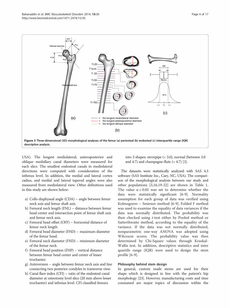
Figure 3 Three-dimensional (3D) morphological analyses of the femur (a) periosteal (b) endosteal (c) interquartile range (IQR)descriptive analysis.
Baharuddin et al. BMC Musculoskeletal Disorders 2014, 15:30 Page 4 of 17http://www.biomedcentral.com/1471-2474/15/30
USA). The longest mediolateral, anteroposterior andoblique medullary canal diameters were measured foreach slice. The smallest endosteal canals in mediolateraldirections were computed with consideration of theisthmus level. In addition, the medial and lateral cortexradius, and medial and lateral tapered angles were alsomeasured from mediolateral view. Other definitions usedin this study are shown below:
a) Collo diaphyseal angle (CDA) – angle between femurneck axis and femur shaft axis.
b) Femoral neck length (FNL) – distance between femurhead center and intersection point of femur shaft axisand femur neck axis.
c) Femoral head offset (OFF) – horizontal distance offemur neck length.
d) Femoral head diameter (FHD) – maximum diameterof the femur head.
e) Femoral neck diameter (FND) – minimum diameterof the femur neck.
f ) Femoral head position (FHP) – vertical distancebetween femur head center and center of lessertrochanter.
g) Anteversion – angle between femur neck axis and lineconnecting two posterior condyles in transverse view.
h) Canal flare index (CFI) – ratio of the endosteal canaldiameter at osteotomy level slice (20 mm above lessertrochanter) and isthmus level. CFI classified femora
into 3 shapes: stovepipe (< 3.0), normal (between 3.0and 4.7) and champagne-flute (> 4.7) [3].
The datasets were statistically analyzed with SAS 4.3software (SAS Institute Inc., Cary, NC, USA). The compari-son of the morphological analysis between our study andother populations [3,16,19-22] are shown in Table 1.The value α ≤ 0.05 was set to determine whether thedata were statistically significant [6-9]. Normalityassumption for each group of data was verified usingKolmogorov – Smirnov method [6-9]. Folded F methodwas used to examine the equality of data variances if thedata was normally distributed. The probability wasthen checked using t-test either by Pooled method orSatterthwaite method, according to the equality of thevariance. If the data was not normally distributed,nonparametric one-way ANOVA was adopted usingWilcoxon scores. The probability value was thendetermined by Chi-Square values through Kruskal-Wallis test. In addition, descriptive statistics and interquartile range (IQR) were used to design the stemprofile [6-9].
Philosophy behind stem designIn general, custom made stems are used for theirshape which is designed in line with the patient’s hipmorphology [23]. However, manufacturing costs and timeconsumed are major topics of discussion within the

Table 1 Comparison of the femur morphology with other populations
Parameters Our Study(Malay)
Mahaisavariya et al.(Thai) [19]
Rawal et al.(Indian) [16]
Bo et al.(Japan) [20]
Noble et al.(Caucasian) [3]
Massin et al.(France) [21]
Rubin et al.(Swiss) [22]
(n = 60) (n = 108) (n = 98) (n = 100) (n = 80) (n = 200) (n = 32)
Collo diaphyseal angle (o) 130.46 ± 4.02 128.04 ± 6.14 124.42 ± 5.49 137.40 ± 4.80 125.40 123.10 ± 8.2 122.90 ± 5.76
Femoral head offset (mm) 30.35 ± 4.26 - 40.23 ± 4.85 31.50 ± 5.00 - 41.00 ± 6.20 47.00 ± 7.20
Femoral neck length (mm) 45.30 ± 4.74 46.22 ± 5.14 48.40 ± 5.66 - - 49.40 ± 6.80 -
Femoral head diameter (mm) 40.81 ± 3.43 43.98 ± 3.47 45.41 ± 3.66 - 45.90 45.60 ± 4.20 43.40 ± 2.26
Femoral neck diameter (mm) 28.95 ± 3.37 - - - - - -
Femoral head position (mm) 53.14 ± 4.87 48.94 ± 4.95 52.33 ± 3.19 - - 58.70 ± 7.20 56.10 ± 8.20
Anteversion (º) 19.10 ± 8.67 11.37 ± 7.65 10.90 ± 4.22 27.00 ± 14.10 10.00 - -
Medial cortex radius (mm) 71.77 ± 30.59 - 100.00 96.70 ± 26.80 - - -
Lateral cortex radius (mm) 82.90 ± 40.81 - 80.00 96.10 ± 23.50 - - -
Medial tapered angle (º) 3.18 ± 2.53 - 4.00 3.80 ± 1.70 - - -
Lateral tapered angle (º) 16.45 ± 3.52 - 4.00 3.70 ± 1.60 - - -
AP T + 20 width (mm) 31.12 ± 3.70 - 26.26 ± 3.70 - - - -
ML T + 20 width (mm) 44.05 ± 4.59 - 36.78 ± 5.32 - 51.50 44.10 ± 6.00 43.10 ± 5.20
AP T-20 width (mm) 17.54 ± 2.93 - 15.36 ± 2.37 15.00 ± 2.30 - - -
ML T-20 width (mm) 18.45 ± 2.93 - 16.20 ± 2.71 18.00 ± 3.00 - 19.60 ± 2.90 21.00 ± 2.70
Isthmus position (mm) 112.83 ± 11.80 112.93 ± 17.96 107.80 ± 9.73 73.00 ± 18.90 116.40 - 105.70 ± 17.90
AP Isthmus width (mm) 13.12 ± 2.46 - 11.47 ± 2.11 10.40 ± 2.60 - - -
ML Isthmus width (mm) 9.73 ± 1.80 10.50 ± 1.81 9.02 ± 1.92 11.90 ± 2.60 12.00 12.40 ± 2.30 13.10 ± 2.10
Canal flare index 4.65 ± 0.83 - 4.23 ± 2.97 - - 3.60 ± 0.80 3.36 ± 0.75
Notes: Data are presented as mean ± SD.Abbreviations: AP anteroposterior, ML mediolateral, T center of lesser trochanter, ° degree.
Baharuddin et al. BMC Musculoskeletal Disorders 2014, 15:30 Page 5 of 17http://www.biomedcentral.com/1471-2474/15/30
orthopedic community. As standard, off the shelve im-plants do not cater to all types of femora, a few modifica-tions from the implant’s manufacturer have been done,especially on size and the metaphyseal region. Kaya et al.[24] reported the modification of Anatomic MedullaryLocking (AML) stem (Depuy, Warsaw, IN, USA) espe-cially at the metaphyseal, called medial modified aspects(MMA) due to narrower and shorter hips of Japanese.The AML-A was made from cobalt chromium with por-ous coating circumferentially at proximal region. Anotherquestion was whether the smaller size implant solved theproblem or was the profile used as a guideline not similarto the Asian femora. We have computed the descriptivestatistics for each parameter used in the stem design profilefrom the dataset as shown in Table 2. In addition to mean,minimum, maximum, and range values, we also reportedinter quartile range (IQR) values as a resistance statistic to-ward outliers compared to the range and standard devi-ation. The “average” morphology could be used as aguideline for the implant’s design, which better addressesthe population diversity. The assumptions made regardingsize selection and implant design were based on this“average” femur provides the actual figure of the boneitself. The best fit and fill were considered to contributeto the fixation stability of the implant. Combining the
parameters acquired from periosteal and endosteal canal,the stem design was done carefully as shown in Figure 4.The basic principles were used in the design are asfollows:
a) The implant width is in accordance with the femoraendosteal canal diameter to achieve optimal fit and fillwith the bone and promoting osseointegrationbetween implant – bone.
b) The implant length and distal size did not exceedthe position of the isthmus level or the isthmuscanal diameter.
c) The stem neck followed standard 12/14taper.
d) The optimal stem cross section geometry isaccording to the endosteal canal shape; wedgeshape at the metaphyseal region, tapered atmiddle region, and cylindrical at distal.
e) The medial and lateral curvature followed theactual femora proximal radius; lateral flares providethe “rest fit” for the implant, better physiologicalload and prevent subsidence distribution.
f ) The proximal region provides three contact pointsbetween the implant and bone for better primaryfixation stability.
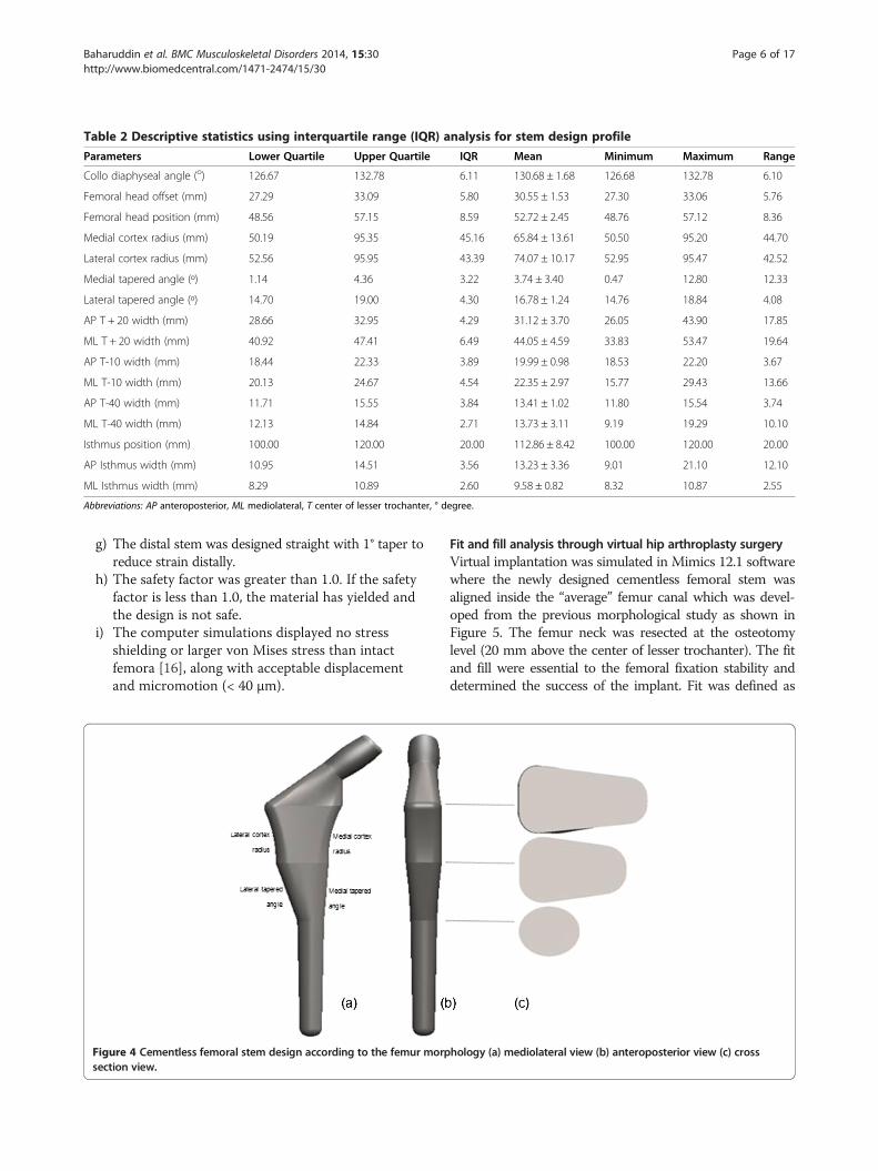
Table 2 Descriptive statistics using interquartile range (IQR) analysis for stem design profile
Parameters Lower Quartile Upper Quartile IQR Mean Minimum Maximum Range
Collo diaphyseal angle (o) 126.67 132.78 6.11 130.68 ± 1.68 126.68 132.78 6.10
Femoral head offset (mm) 27.29 33.09 5.80 30.55 ± 1.53 27.30 33.06 5.76
Femoral head position (mm) 48.56 57.15 8.59 52.72 ± 2.45 48.76 57.12 8.36
Medial cortex radius (mm) 50.19 95.35 45.16 65.84 ± 13.61 50.50 95.20 44.70
Lateral cortex radius (mm) 52.56 95.95 43.39 74.07 ± 10.17 52.95 95.47 42.52
Medial tapered angle (º) 1.14 4.36 3.22 3.74 ± 3.40 0.47 12.80 12.33
Lateral tapered angle (º) 14.70 19.00 4.30 16.78 ± 1.24 14.76 18.84 4.08
AP T + 20 width (mm) 28.66 32.95 4.29 31.12 ± 3.70 26.05 43.90 17.85
ML T + 20 width (mm) 40.92 47.41 6.49 44.05 ± 4.59 33.83 53.47 19.64
AP T-10 width (mm) 18.44 22.33 3.89 19.99 ± 0.98 18.53 22.20 3.67
ML T-10 width (mm) 20.13 24.67 4.54 22.35 ± 2.97 15.77 29.43 13.66
AP T-40 width (mm) 11.71 15.55 3.84 13.41 ± 1.02 11.80 15.54 3.74
ML T-40 width (mm) 12.13 14.84 2.71 13.73 ± 3.11 9.19 19.29 10.10
Isthmus position (mm) 100.00 120.00 20.00 112.86 ± 8.42 100.00 120.00 20.00
AP Isthmus width (mm) 10.95 14.51 3.56 13.23 ± 3.36 9.01 21.10 12.10
ML Isthmus width (mm) 8.29 10.89 2.60 9.58 ± 0.82 8.32 10.87 2.55
Abbreviations: AP anteroposterior, ML mediolateral, T center of lesser trochanter, ° degree.
Baharuddin et al. BMC Musculoskeletal Disorders 2014, 15:30 Page 6 of 17http://www.biomedcentral.com/1471-2474/15/30
g) The distal stem was designed straight with 1° taper toreduce strain distally.
h) The safety factor was greater than 1.0. If the safetyfactor is less than 1.0, the material has yielded andthe design is not safe.
i) The computer simulations displayed no stressshielding or larger von Mises stress than intactfemora [16], along with acceptable displacementand micromotion (< 40 μm).
Figure 4 Cementless femoral stem design according to the femur morpsection view.
Fit and fill analysis through virtual hip arthroplasty surgeryVirtual implantation was simulated in Mimics 12.1 softwarewhere the newly designed cementless femoral stem wasaligned inside the “average” femur canal which was devel-oped from the previous morphological study as shown inFigure 5. The femur neck was resected at the osteotomylevel (20 mm above the center of lesser trochanter). The fitand fill were essential to the femoral fixation stability anddetermined the success of the implant. Fit was defined as
hology (a) mediolateral view (b) anteroposterior view (c) cross
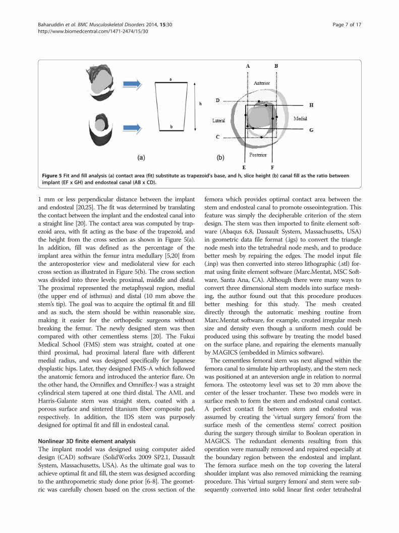
Figure 5 Fit and fill analysis (a) contact area (fit) substitute as trapezoid’s base, and h, slice height (b) canal fill as the ratio betweenimplant (EF x GH) and endosteal canal (AB x CD).
Baharuddin et al. BMC Musculoskeletal Disorders 2014, 15:30 Page 7 of 17http://www.biomedcentral.com/1471-2474/15/30
1 mm or less perpendicular distance between the implantand endosteal [20,25]. The fit was determined by translatingthe contact between the implant and the endosteal canal intoa straight line [20]. The contact area was computed by trap-ezoid area, with fit acting as the base of the trapezoid, andthe height from the cross section as shown in Figure 5(a).In addition, fill was defined as the percentage of theimplant area within the femur intra medullary [5,20] fromthe anteroposterior view and mediolateral view for eachcross section as illustrated in Figure 5(b). The cross sectionwas divided into three levels; proximal, middle and distal.The proximal represented the metaphyseal region, medial(the upper end of isthmus) and distal (10 mm above thestem’s tip). The goal was to acquire the optimal fit and filland as such, the stem should be within reasonable size,making it easier for the orthopedic surgeons withoutbreaking the femur. The newly designed stem was thencompared with other cementless stems [20]. The FukuiMedical School (FMS) stem was straight, coated at onethird proximal, had proximal lateral flare with differentmedial radius, and was designed specifically for Japanesedysplastic hips. Later, they designed FMS-A which followedthe anatomic femora and introduced the anterior flare. Onthe other hand, the Omniflex and Omniflex-J was a straightcylindrical stem tapered at one third distal. The AML andHarris-Galante stem was straight stem, coated with aporous surface and sintered titanium fiber composite pad,respectively. In addition, the IDS stem was purposelydesigned for optimal fit and fill in endosteal canal.
Nonlinear 3D finite element analysisThe implant model was designed using computer aideddesign (CAD) software (SolidWorks 2009 SP2.1, DassaultSystem, Massachusetts, USA). As the ultimate goal was toachieve optimal fit and fill, the stem was designed accordingto the anthropometric study done prior [6-8]. The geomet-ric was carefully chosen based on the cross section of the
femora which provides optimal contact area between thestem and endosteal canal to promote osseointegration. Thisfeature was simply the decipherable criterion of the stemdesign. The stem was then imported to finite element soft-ware (Abaqus 6.8, Dassault System, Massachusetts, USA)in geometric data file format (.igs) to convert the trianglenode mesh into the tetrahedral node mesh, and to producebetter mesh by repairing the edges. The model input file(.inp) was then converted into stereo lithographic (.stl) for-mat using finite element software (Marc.Mentat, MSC Soft-ware, Santa Ana, CA). Although there were many ways toconvert three dimensional stem models into surface mesh-ing, the author found out that this procedure producesbetter meshing for this study. The mesh createddirectly through the automatic meshing routine fromMarc.Mentat software, for example, created irregular meshsize and density even though a uniform mesh could beproduced using this software by treating the model basedon the surface plane, and repairing the elements manuallyby MAGICS (embedded in Mimics software).The cementless femoral stem was next aligned within the
femora canal to simulate hip arthroplasty, and the stem neckwas positioned at an anteversion angle in relation to normalfemora. The osteotomy level was set to 20 mm above thecenter of the lesser trochanter. These two models were insurface mesh to form the stem and endosteal canal contact.A perfect contact fit between stem and endosteal wasassumed by creating the ‘virtual surgery femora’ from thesurface mesh of the cementless stems’ correct positionduring the surgery through similar to Boolean operation inMAGICS. The redundant elements resulting from thisoperation were manually removed and repaired especially atthe boundary region between the endosteal and implant.The femora surface mesh on the top covering the lateralshoulder implant was also removed mimicking the reamingprocedure. This ‘virtual surgery femora’ and stem were sub-sequently converted into solid linear first order tetrahedral
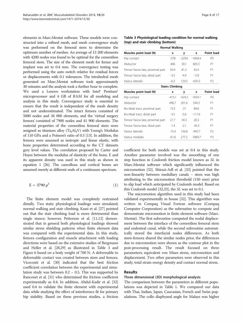
Table 3 Physiological loading condition for normal walking(top) and stair climbing (bottom)
Normal Walking
Muscles point load (N) x y z Point load
Hip contact -378 -229.6 -1604.4 P0
Abductor 406 30.1 605.5 P1
Tensor fascia lata, proximal part 50.4 81.2 92.4 P1
Tensor fascia lata, distal part -3.5 -4.9 -133 P1
Vastus lateralis -6.3 129.5 -650.3 P2
Stairs Climbing
Muscles point load (N) x y z Point load
Hip contact -415.1 -424.2 -1654.1 P0
Abductor 490.7 201.6 594.3 P1
Ilio-tibial tract, proximal part 73.5 -21 89.6 P1
Ilio-tibial tract, distal part -3.5 -5.6 -117.6 P1
Tensor fascia lata, proximal part 21.7 34.3 20.3 P1
Tensor fascia lata, distal part -1.4 -2.1 -45.5 P1
Vastus lateralis -15.4 156.8 -945.7 P2
Vastus medialis -61.6 277.2 -1869.7 P3
Baharuddin et al. BMC Musculoskeletal Disorders 2014, 15:30 Page 8 of 17http://www.biomedcentral.com/1471-2474/15/30
elements in Marc.Mentat software. These models were con-structed into a refined mesh, and mesh convergence studywas performed on the femoral stem to determine theoptimum number of meshes. An average of 13 200 elementswith 4200 nodes was found to be optimal for the cementlessfemoral stem. The size of the element mesh for femur andimplant was set to 0.4 mm. The convergence testing wasperformed using the auto switch relative for residual forcesor displacements with 0.1 tolerances. The tetrahedral meshgenerated on Marc.Mentat software took approximately30 minutes and the analysis took a further hour to complete.We used a Lenovo workstation with Intel® Pentium®microprocessor and 4 GB of RAM for all modeling andanalysis in this study. Convergence study is essential toensure that the result is independent of the mesh densityand not underestimated. The intact femora consisted of5000 nodes and 34 000 elements, and the ‘virtual surgeryfemora’ consisted of 7900 nodes and 41 900 elements. Thematerial properties of the cementless femoral stem wereassigned as titanium alloy (Ti6Al4V) with Young’s Modulusof 110 GPa and a Poisson’s ratio of 0.3 [13]. In addition, thefemora were assumed as isotropic and linear elastic, withbone properties determined according to the CT datasetsgrey level values. The correlation proposed by Carter andHayes between the modulus of elasticity of the bone, E andits apparent density was used in this study as shown inequation 1 [26]. The cancellous and cortical bones areassumed merely at different ends of a continuum spectrum.
E ¼ 3790 ρ3 ð1Þ
The finite element model was completely restraineddistally. Two static physiological loadings were simulated;normal walking and stair climbing. Kassi et al. [27] pointedout that the stair climbing load is more detrimental thansingle stance; however, Petterson et al. [11,12] demon-strated that in general both physiological loadings showedsimilar stress shielding patterns when finite element datawas compared with the experimental data. In this study,femora configuration and muscle attachment with loadingdirections were based on the extensive studies of Bergmannand Heller et al. [28,29] as illustrated in Table 3 andFigure 6 based on a body weight of 700 N. A deformable todeformable contact was created between stem and femora.Viceconti et al. [30] indicated that the best frictioncoefficient correlation between the experimental and simu-lation study was between 0.2 – 0.5. This was supported byRancourt et al. [31] who determined the friction coefficientexperimentally as 0.4. In addition, Abdul-Kadir et al. [32]used 0.4 to validate the finite element with experimentaldata while studying the effect of interference fit for primaryhip stability. Based on these previous studies, a friction
coefficient for both models was set at 0.4 in this study.Another parameter involved was the smoothing of onestep function in Coulomb friction model known as SL inMarc.Mentat software which significantly influenced themicromotion [32]. Shirazi-Adl et al. [33] pointed that thenon-linearity between medullary canals – stem was highattributing to the micromotion threshold (150 mm) priorto slip load which anticipated by Coulomb model. Based onthis Coulomb model [32,33], the SL was set to 0.1.The micromotion algorithm used in this study had been
validated experimentally in house [32]. This algorithm waswritten in Compaq Visual Fortran software (CompaqComputer Corporation) as the subroutine to compute anddemonstrate micromotion in finite element software (Marc.Mentat). The first subroutine computed the nodal displace-ment between the interface of the cementless femoral stemand endosteal canal, while the second subroutine automat-ically stored the interfacial nodes differences. As bothstem-femora shared the similar nodes prior, the differencesdue to micromotion were shown as the contour plot in thepost-processing result. The result focused on threeparameters; equivalent von Mises stress, micromotion anddisplacement. Two other parameters were observed in thisstudy; total strain energy density and contact normal stress.
ResultsThree dimensional (3D) morphological analysisThe comparison between the parameters in different popu-lations was depicted in Table 1. We compared our datawith Thai, Indian, Japan, Caucasian, French and Swiss pop-ulations. The collo diaphyseal angle for Malays was higher
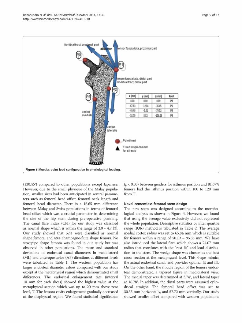
Figure 6 Muscles point load configuration in physiological loading.
Baharuddin et al. BMC Musculoskeletal Disorders 2014, 15:30 Page 9 of 17http://www.biomedcentral.com/1471-2474/15/30
(130.46º) compared to other populations except Japanese.However, due to the small physique of the Malay popula-tion, smaller sizes had been anticipated in several parame-ters such as femoral head offset, femoral neck length andfemoral head diameter. There is a 16.65 mm differencebetween Malay and Swiss populations in terms of femoralhead offset which was a crucial parameter in determiningthe size of the hip stem during pre-operative planning.The canal flare index (CFI) for our study was classifiedas normal shape which is within the range of 3.0 - 4.7 [3].Our study showed that 52% were classified as normalshape femora, and 48% champagne-flute shape femora. Nostovepipe shape femora was found in our study but wasobserved in other populations. The mean and standarddeviations of endosteal canal diameters in mediolateral(ML) and anteroposterior (AP) directions at different levelswere tabulated in Table 1. The western population haslarger endosteal diameter values compared with our studyexcept at the metaphyseal region which demonstrated smalldifferences. The endosteal enlargement rate (interval10 mm for each slices) showed the highest value at themetaphyseal section which was up to 20 mm above zerolevel, T. The femora cavity enlargement gradually decreasedat the diaphyseal region. We found statistical significance
(p < 0.05) between genders for isthmus position and 81.67%femora had the isthmus position within 100 to 120 mmfrom T.
Novel cementless femoral stem designThe new stem was designed according to the morpho-logical analysis as shown in Figure 4. However, we foundthat using the average value exclusively did not representthe whole population. Descriptive statistics by inter quartilerange (IQR) method is tabulated in Table 2. The averagemedial cortex radius was set to 65.84 mm which is suitablefor femora within a range of 50.19 – 95.35 mm. We havealso introduced the lateral flare which shows a 74.07 mmradius that correlates with the “rest fit” and load distribu-tion to the stem. The wedge shape was chosen as the bestcross section at the metaphyseal level. This shape mimicsthe actual endosteal canal, and provides optimal fit and fill.On the other hand, the middle region of the femora endos-teal demonstrated a tapered figure in mediolateral view.The medial taper was determined at 3.74°, and lateral taperat 16.78°. In addition, the distal parts were assumed cylin-drical straight. The femoral head offset was set to30.55 mm horizontally, and 52.72 mm vertically. Our studyshowed smaller offset compared with western populations
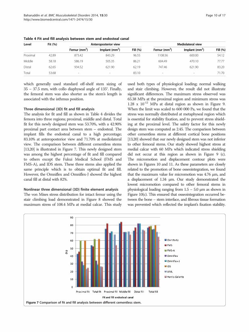
Table 4 Fit and fill analysis between stem and endosteal canal
Level Fit (%) Anteroposterior view Mediolateral view
Femur (mm2) Implant (mm2) Fill (%) Femur (mm2) Implant (mm2) Fill (%)
Proximal 42.89 873.42 843.29 96.55 1108.56 600.00 54.12
Middle 58.18 586.19 505.35 86.21 604.49 470.10 77.77
Distal 62.65 934.52 621.90 62.19 747.46 621.90 83.20
Total 53.68 - - 83.10 - - 71.70
Baharuddin et al. BMC Musculoskeletal Disorders 2014, 15:30 Page 10 of 17http://www.biomedcentral.com/1471-2474/15/30
which generally used standard off-shelf stem sizing of35 – 37.5 mm, with collo diaphyseal angle of 135°. Finally,the femoral stem was also shorter as the stem’s length isassociated with the isthmus position.
Three dimensional (3D) fit and fill analysisThe analysis for fit and fill as shown in Table 4 divides thefemora into three regions; proximal, middle and distal. Totalfit for this newly designed stem was 53.70%, with a 42.90%proximal part contact area between stem – endosteal. Theimplant fills the endosteal canal to a high percentage;83.10% at anteroposterior view and 71.70% at mediolateralview. The comparison between different cementless stems[13,20] is illustrated in Figure 7. This newly designed stemwas among the highest percentage of fit and fill comparedto others except the Fukui Medical School (FMS andFMS-A), and IDS stem. These three stems also applied thesame principle which is to obtain optimal fit and fill.However, the Omniflex and Omniflex-J showed the highestcanal fill at distal with 82%.
Nonlinear three dimensional (3D) finite element analysisThe von Mises stress distribution for intact femur using thestair climbing load demonstrated in Figure 8 showed themaximum stress of 108.4 MPa at medial calcar. This study
Figure 7 Comparison of fit and fill analysis between different cement
used both types of physiological loading; normal walkingand stair climbing. However, the result did not illustratesignificant differences. The maximum stress observed was65.38 MPa at the proximal region and minimum stress was1.28 x 10-12 MPa at distal region as shown in Figure 9.When the limit was scaled to 600 000 Pa, we found that thestress was normally distributed at metaphyseal region whichis essential for stability fixation, and to prevent stress shield-ing at the proximal level. The safety factor for this newlydesign stem was computed as 2.45. The comparison betweenother cementless stems at different cortical bone positions[13,20] showed that our newly designed stem was not inferiorto other femoral stems. Our study showed highest stress atmedial calcar with 60 MPa which indicated stress shieldingdid not occur at this region as shown in Figure 9 (c).The micromotion and displacement contour plots wereshown in Figures 10 and 11. As these parameters are closelyrelated to the promotion of bone osseointegration, we foundthat the maximum value for micromotion was 4.76 μm, anda displacement of 1.34 μm. Our study demonstrated thelowest micromotion compared to other femoral stems inphysiological loading ranging from 1.5 – 5.0 μm as shown inFigure 10(c). This ensured that osseointegration occurred be-tween the bone – stem interface, and fibrous tissue formationwas prevented which reflected the implant’s fixation stability.
less stem.
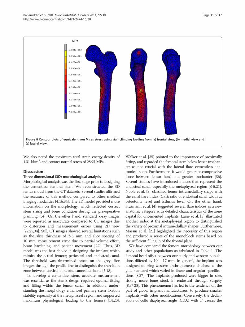
Figure 8 Contour plots of equivalent von Mises stress using stair climbing loading from (a) frontal view, (b) medial view and(c) lateral view.
Baharuddin et al. BMC Musculoskeletal Disorders 2014, 15:30 Page 11 of 17http://www.biomedcentral.com/1471-2474/15/30
We also noted the maximum total strain energy density of1.31 kJ/m3, and contact normal stress of 28.95 MPa.
DiscussionThree dimensional (3D) morphological analysisMorphological analysis was the first stage prior to designingthe cementless femoral stem. We reconstructed the 3Dfemur model from the CT datasets. Several studies affirmedthe accuracy of this method compared to other medicalimaging modalities [4,16,34]. The 3D model provided moreinformation on the morphology, which reflected correctstem sizing and bone condition during the pre-operativeplanning [34]. On the other hand, standard x-ray imageswere reported as inaccurate compared to CT images dueto distortion and measurement errors using 2D view[22,25,34]. Still, CT images showed several limitations suchas the slice thickness of 2-5 mm and slice spacing of10 mm, measurement error due to partial volume effect,beam hardening, and patient movement [22]. Thus, 3Dmodel was the best choice in designing the implant whichmimics the actual femora; periosteal and endosteal canal.The threshold was determined based on the grey sliceimages through the profile line to distinguish the transitionzone between cortical bone and cancellous bone [5,18].To develop a cementless stem, accurate measurement
was essential as the stem’s design required optimal fittingand filling within the femur canal. In addition, under-standing the morphology enhanced primary stem fixationstability especially at the metaphyseal region, and supportedmaximum physiological loading to the femora [14,20].
Walker et al. [35] pointed to the importance of proximallyfitting, and regarded the femoral stem below lesser trochan-ter as not crucial with the lateral flare cementless ana-tomical stem. Furthermore, it would generate compressiveforce between femur head and greater trochanter [36].Several studies have introduced indices that represent theendosteal canal, especially the metaphyseal region [3-5,21].Noble et al. [3] classified femur intramedullary shape withthe canal flare index (CFI); ratio of endosteal canal width atosteotomy level and isthmus level. On the other hand,Husmann et al. [4] suggested several flare indices as a newanatomic category with detailed characteristics of the zonecapital for uncemented implants. Laine et al. [5] illustratedanother index at the metaphyseal region to distinguishedthe variety of proximal intramedullary shapes. Furthermore,Massin et al. [21] highlighted the necessity of this regionand produced a series of the monoblock stems based onthe sufficient filling in of the frontal plane.We have compared the femora morphology between our
study and other populations as tabulated in Table 1. Thefemoral head offset between our study and western popula-tions differed by 10 – 17 mm. In general, the implant wasdesigned utilizing western anthropometric database as thegold standard which varied in linear and angular specifica-tions [8,37]. The implants produced were bigger in size,risking more bone stock in endosteal through surgery[8,37,38]. This phenomenon has led to the tendency on thepart of global implant manufacturers’ to produce smallerimplants with other modifications. Conversely, the declin-ation of collo diaphyseal angle (CDA) with 1° causes the
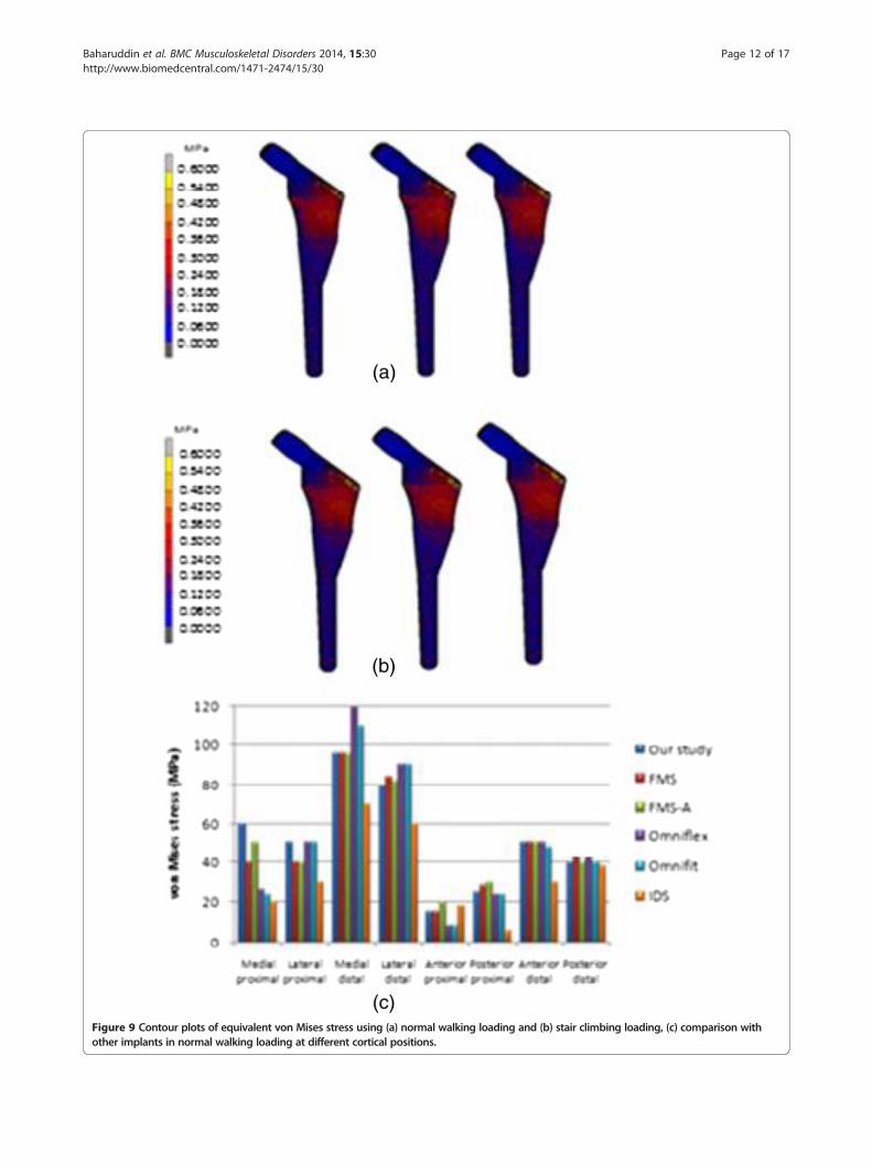
Figure 9 Contour plots of equivalent von Mises stress using (a) normal walking loading and (b) stair climbing loading, (c) comparison withother implants in normal walking loading at different cortical positions.
Baharuddin et al. BMC Musculoskeletal Disorders 2014, 15:30 Page 12 of 17http://www.biomedcentral.com/1471-2474/15/30
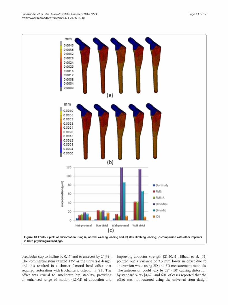
Figure 10 Contour plots of micromotion using (a) normal walking loading and (b) stair climbing loading, (c) comparison with other implantsin both physiological loadings.
Baharuddin et al. BMC Musculoskeletal Disorders 2014, 15:30 Page 13 of 17http://www.biomedcentral.com/1471-2474/15/30
acetabular cup to incline by 0.45° and to antevert by 2° [39].The commercial stem utilized 135° as the universal design,and this resulted in a shorter femoral head offset thatrequired restoration with trochanteric osteotomy [21]. Theoffset was crucial to ameliorate hip stability, providingan enhanced range of motion (ROM) of abduction and
improving abductor strength [21,40,41]. Elhadi et al. [42]pointed out a variance of 3.5 mm lower in offset due toanteversion while using 2D and 3D measurement methods.The anteversion could vary by 22° - 50° causing distortionby standard x-ray [4,42], and 60% of cases reported that theoffset was not restored using the universal stem design
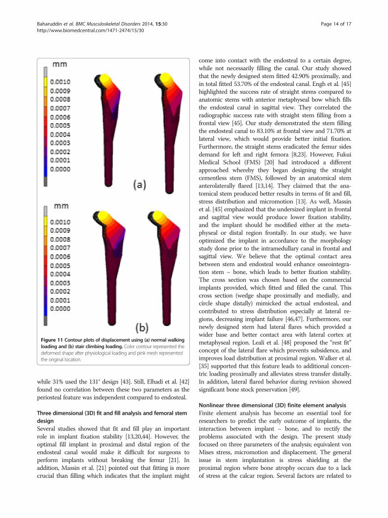
Figure 11 Contour plots of displacement using (a) normal walkingloading and (b) stair climbing loading. Color contour represented thedeformed shape after physiological loading and pink mesh representedthe original location.
Baharuddin et al. BMC Musculoskeletal Disorders 2014, 15:30 Page 14 of 17http://www.biomedcentral.com/1471-2474/15/30
while 31% used the 131° design [43]. Still, Elhadi et al. [42]found no correlation between these two parameters as theperiosteal feature was independent compared to endosteal.
Three dimensional (3D) fit and fill analysis and femoral stemdesignSeveral studies showed that fit and fill play an importantrole in implant fixation stability [13,20,44]. However, theoptimal fill implant in proximal and distal region of theendosteal canal would make it difficult for surgeons toperform implants without breaking the femur [21]. Inaddition, Massin et al. [21] pointed out that fitting is morecrucial than filling which indicates that the implant might
come into contact with the endosteal to a certain degree,while not necessarily filling the canal. Our study showedthat the newly designed stem fitted 42.90% proximally, andin total fitted 53.70% of the endosteal canal. Engh et al. [45]highlighted the success rate of straight stems compared toanatomic stems with anterior metaphyseal bow which fillsthe endosteal canal in sagittal view. They correlated theradiographic success rate with straight stem filling from afrontal view [45]. Our study demonstrated the stem fillingthe endosteal canal to 83.10% at frontal view and 71.70% atlateral view, which would provide better initial fixation.Furthermore, the straight stems eradicated the femur sidesdemand for left and right femora [8,23]. However, FukuiMedical School (FMS) [20] had introduced a differentapproached whereby they began designing the straightcementless stem (FMS), followed by an anatomical stemanterolaterally flared [13,14]. They claimed that the ana-tomical stem produced better results in terms of fit and fill,stress distribution and micromotion [13]. As well, Massinet al. [45] emphasized that the undersized implant in frontaland sagittal view would produce lower fixation stability,and the implant should be modified either at the meta-physeal or distal region frontally. In our study, we haveoptimized the implant in accordance to the morphologystudy done prior to the intramedullary canal in frontal andsagittal view. We believe that the optimal contact areabetween stem and endosteal would enhance osseointegra-tion stem – bone, which leads to better fixation stability.The cross section was chosen based on the commercialimplants provided, which fitted and filled the canal. Thiscross section (wedge shape proximally and medially, andcircle shape distally) mimicked the actual endosteal, andcontributed to stress distribution especially at lateral re-gions, decreasing implant failure [46,47]. Furthermore, ournewly designed stem had lateral flares which provided awider base and better contact area with lateral cortex atmetaphyseal region. Leali et al. [48] proposed the “rest fit”concept of the lateral flare which prevents subsidence, andimproves load distribution at proximal region. Walker et al.[35] supported that this feature leads to additional concen-tric loading proximally and alleviates stress transfer distally.In addition, lateral flared behavior during revision showedsignificant bone stock preservation [49].
Nonlinear three dimensional (3D) finite element analysisFinite element analysis has become an essential tool forresearchers to predict the early outcome of implants, theinteraction between implant – bone, and to rectify theproblems associated with the design. The present studyfocused on three parameters of the analysis; equivalent vonMises stress, micromotion and displacement. The generalissue in stem implantation is stress shielding at theproximal region where bone atrophy occurs due to a lackof stress at the calcar region. Several factors are related to
Baharuddin et al. BMC Musculoskeletal Disorders 2014, 15:30 Page 15 of 17http://www.biomedcentral.com/1471-2474/15/30
load distribution in cementless implants; stem geometry,stem – bone interface configuration, and osseointegration[13]. We looked at the stress distribution in intact femursand found the maximum stress was 108.4 MPa as shown inFigure 8. The stress is normally distributed medially andlaterally from the point load of muscle configuration, vastusmedialis and vastus lateralis, respectively. On the otherhand, the stress normally transferred at the proximal regionfor the newly designed cementless stem is shown inFigure 9. Stair climbing load distribution demonstratesmore stress at the metaphyseal region, especially atcalcar which subsequently prevents stress shielding. Inaddition, proximal osseointegration contributed to thestress distribution at stem – bone interface which preservedbone stock at this region [50]. The results also illustratedthat the stem maximum stress (65.38 MPa) did not exceedthe bone’s yield strength which was 160 MPa, [16,51] andthe intact femur. Abdul-Kadir et al. [32] reported a safetyfactor of 2 to achieve stem stability with low interference fitof 50 mm during surgery using Alloclassic stem. Inaddition, Senalp et al. [52] demonstrated a safety factorbetween 2.18 – 3.27 for four different types of stemmade by titanium alloy under static analysis. Based on theprevious study, our newly designed stem with a safetyfactor of 2.45 ensured that the implant could not fracturethe bone. The cross section geometry, which has mimickedthe endosteal canal shape and diameters, aids the stressdistributed to the implant. On the other hand, a review byKhanuja et al. [53] found that the success rate for all typesof cementless stems are similar despite the diversity ofprinciple stem designs and femur preparation methods.Additionally, they attributed the excellent survival rates tothe stem’s geometrical design rather than the choice ofmaterial and fixation surface [47,53].Stem fixation stability during physiological loading and
osseointegration between stem – bone interface are crucialfactors which influence the implant lifecycle. These twoconditions are usually correlated with micromotion anddisplacement of the stem within the femur canal. The lackof primary fixation stability would contribute to thigh painand eventual loosening of the stem due to the continuousdisturbance during osseointegration [32]. Several studiesdemonstrated a micromotion threshold of 150 μm; beyond150 μm fibrous tissue begins to form, while less than40 μm primarily stimulates bone ingrowth [32,54]. How-ever, our present study showed acceptable micromotion(4.76 μm) and displacement (1.34 μm), which promotedosseointegration at the stem – bone interface especially atthe metaphyseal region. The optimal cross section of thenewly designed cementless stem and the curvature radiusmimicking the femora morphology contributed to primaryfixation stability and low micromotion displacement.Viceconti et al. [55] pointed out through their statisticalfinite element analysis of over 1000 cases that the stem –
endosteal canal differed by up to 1 mm at arbitrary loca-tions on the interface and is prone to produce a grosslyloosened stem in 2% of patients, while for another 3 – 5%the high level of expected micromotion makes it difficult toavoid any substantial bone formation. Kawahara et al.[13,14] reported excellent FMS stem results with a 99%survival rate as they performed a morphological study ofdysplastic Japanese patients in a previous non linear 3Dfinite element clinical trial. In addition, they verifiedreduced radiolucency around the femoral stem in theGruen zone, minimal subsidence, appropriate stress shield-ing and the promise of medium term stability in theirpatients [14].
LimitationsThere are several limitations in our present study. Firstly,the anthropometric data were taken by single observerresulting in potential bias. However, based on our previousstudy on femur morphology [6-9], precautions have beentaken whereby all anthropometric data were taken threetimes and verified by an experienced orthopedic surgeon tominimize the single observer error. For finite element ana-lysis, the stem and bone were assumed to be fully bondedwithout penetration. In clinical practice, surgeons areallowed to err 50 μm on each side rather than risk thefemora fracture [32]. Furthermore, Petterson et al. [11,12]emphasized that the degree of contact pressure interferencepenetration during implant fixation is difficult to ascertaindue to several factors such as the implant’s size, femora sizeand quality, and force exerted during surgery. In this study,our newly designed stem demonstrated well distributedstress proximally, and micromotion under threshold forosseointegration (less than 40 μm). However, further stud-ies regarding biomechanical testing are required to validatethe finite element result before clinical trial. In addition,several stem designs of commercial implants were neededto demonstrate and compare the optimal performance ofour newly designed stem. Still, comparison with othercementless stems from the literature showed that our stemis not inferior to established off the shelf implants.Although dynamic loading was applied to the implant inthe actual gait cycle, we only simulated static loading in thisstudy. In addition, the “average” femora model was used forboth fit and fill analysis, and finite element analysis. This“average” femora model was developed from our previousmorphology study [6-9] and represented the local popula-tion. Other physiological factors such as age, gender andbone condition were not considered in this study.
ConclusionIn conclusion, we would like to stress the importance ofstem design based on femur morphology, especially inAsians. The cementless stem design was crucial especially atthe metaphyseal region which provided initial fixation
Baharuddin et al. BMC Musculoskeletal Disorders 2014, 15:30 Page 16 of 17http://www.biomedcentral.com/1471-2474/15/30
stability. In addition, a universal stem of variable size isnot the only option available to the peculiar morphologyof the Asian population. We hope that this new designprocess framework will shorten the design cycle, and helpresearchers to design better femoral stems by identifying themajor steps which must be taken and providing anthro-pometric datasets that could be used as guidelines. The useof accurate three dimensional models obtained frommorphological analysis and finite element analysis could beused as preclinical assessment tools to mimic the actualoptimal conditions, of stem geometry, and to rectify anyproblems prior to fabrication.
Competing interestsThe authors report no conflicts of interest in this work.
Authors’ contributionsBMY, SSH, ZAH and LMH were responsible drafting first manuscript and runningthe experiment. NAM, HARA, MNA and KASA reviewed and revised themanuscript. All of the authors participated in design study and approved thefinal version of the manuscript.
AcknowledgementsThe authors would like to thank the Centre for Biomedical EngineeringTransportation Research Alliance, Universiti Teknologi Malaysia (UTM) for providingthe research facilities. This research work has been supported by UTM’s Tier1/Flagship Research Grant (Q.J130000.2436.00G31 & Q.J130000.2436.00G32),Ministry of Science and Technology Malaysia (MOSTI), and the Ministry ofHigher Education (MOHE).
Author details1Department of Biomedical Engineering, Faculty of Engineering, University ofMalaya, Kuala Lumpur, Malaysia. 2Centre for Biomedical EngineeringTransportation Research Alliance, Universiti Teknologi Malaysia, Skudai, Johor,Malaysia. 3Department of Orthopaedic, Traumatology & Rehabilitation, Kuliyyah ofMedicine, International Islamic University Malaysia, Kuantan, Pahang, Malaysia.4Department of Mathematical Sciences, Faculty of Science, Universiti TeknologiMalaysia, Skudai, Johor, Malaysia. 5Transportation Research Alliance, UniversitiTeknologi Malaysia, Skudai, Johor, Malaysia.
Received: 7 September 2013 Accepted: 29 January 2014Published: 3 February 2014
References1. Merx H, Dreinhöfer K, Schräder P, Stürmer T, Puhl W, Günther KP, Brenner H:
International variation in hip replacement rates. Ann Rheum Dis 2003,62(3):222–226.
2. Kurtz S, Ong K, Lau E, Mowat F, Halpern M: Projections of primary and revisionhip and knee arthroplasty in the United States from 2005 to 2030. J BoneJoint Surg 2007, 89(4):780–785.
3. Noble PC, Alexander JW, Lindahl LJ, Yew DT, Granberry WM, Tullos HS:The anatomical basis of femoral component design. Clin Orthop Relat Res 1988,235:148–165.
4. Husmann O, Rubin PJ, Leyvraz PF, de Roguin B, Argenson JN: Three-dimensionalmorphology of the proximal femur. J Arthroplasty 1997, 12(4):444–450.
5. Laine HJ, Lehto MUK, Moilanen T: Diversity of proximal femoral medullarycanal. J Arthroplasty 2000, 15(1):86–92.
6. Baharuddin MY, Zulkifly AH, Lee MH, Kadir MRA, Saat A, Aziz AA: Threedimensional morphometry of the femur to design the total hip arthroplastyfor Malay population. Adv Sci Lett 2013, 19(10):2982–2987.
7. Baharuddin MY, Zulkifly AH, Lee MH, Kadir MRA, Saat A, Aziz AA: Threedimensional morphometry of proximal femoral medullary canal in Malays.Adv Sci Lett 2013, 19(12):3582–3587.
8. Baharuddin MY, Kadir MRA, Zulkifly AH, Saat A, Aziz AA, Lee MH: Morphologystudy of the proximal femur in Malay population. Int J Morphol 2011,29(4):1321–1325.
9. Baharuddin MY, Zulkifly AH, Kadir MRA, Saat A, Aziz AA, Lee MH: Morphometricstudy of the acetabular in Malay population normal hips and its clinicalapplications. J Med Sci 2011, 11(5):213–219.
10. Dopico-Gonzalez C, New AM, Browne M: Probabilistic finite element analysis ofthe uncemented hip replacement - effect of femur characteristics andimplant design geometry. J Biomech 2010, 43:512–520.
11. Pettersen SH, Wik TS, Skallerud B: Subject specific finite element analysis ofimplant stability for a cementless femoral stem. Clin Biomech 2009,24(6):480–487.
12. Pettersen SH, Wik TS, Skallerud B: Subject specific finite element analysis ofstress shielding around a cementless femoral stem. Clin Biomech 2009,24(2):196–202.
13. Ando M, Imura S, Omori H, Okumura Y, Bo A, Baba H: Nonlinear three-dimensionalfinite element analysis of newly designed cementless total hip stems.Artif Organs 1999, 23(4):339–346.
14. Kawahara H, Kokubo Y, Yayama T, Uchida K, Kobayashi S, Nakajima H, Oki H,Negoro K, Mwaka ES, Orwotho NT, Baba H: Metaphyseal loading anterolaterallyflared femoral stem in cementless total hip arthroplasty: five to eleven yearfollow up evaluation. Artif Organs 2010, 34(5):377–383.
15. Kokubo Y, Uchida K, Oki H, Negoro K, Nagamune K, Kawaguchi S, Takeno K,Yayama T, Nakajima H, Sugita D, Yoshida A, Baba H: Modified metaphyseal-loading anterolaterally flared anatomic femoral stem: five- to nine-yearprospective follow-up evaluation and results of three-dimensional finiteelement analysis. Artif Organs 2013, 37(2):175–182.
16. Rawal BR, Ribeiro R, Malhotra R, Bhatnagar N: Design and manufacturing offemoral stems for the Indian population. J Manuf Proc 2012,14(3):216–223.
17. O’Toole III, Jaramaz B, DiGioia III, Visnic CD, Reid RH: Biomechanics forpreoperative planning and surgical simulations in orthopaedics. Comp BiolMed 1995, 25(2):183–191.
18. Materialise: Mimics help manual Version 12.1. Leuven: Materialise; 2008.19. Mahaisavariya B, Sitthiseripratip K, Tongdee T, Bohez ELJ, Vander Sloten J, Oris P:
Morphological study of the proximal femur: a new method of geometricalassessment using 3-dimensional reverse engineering. Med Eng Phys 2002,24(9):617–622.
20. Bo A, Imura S, Omori H, Okumura Y, Ando M, Baba H, White P, Zarnowski A:Fit and fill analysis of a newly designed femoral stem in cementless total hiparthroplasty for patients with secondary osteoarthritis. J Orthop Sci 1997,2:301–312.
21. Massin P, Geais L, Astoin E, Simondi M, Lavaste F: The anatomic basis for theconcept of lateralized femoral stems: a frontal plane radiographic study ofthe proximal femur. J Arthroplasty 2000, 15(1):93–101.
22. Rubin PJ, Leyvraz PF, Aubaniac JM, Argenson JN, Esteve P, de Roguin B: Themorphology of the proximal femur. A three-dimensional radiographicanalysis. J Bone Joint Surg Br 1992, 74(1):28–32.
23. Götze C, Steens W, Vieth V, Poremba C, Claes L, Steinbeck J: Primary stability incementless femoral stems: custom-made versus conventional femoralprosthesis. Clin Biomech 2002, 17(4):267–273.
24. Kaya M, Nagoya S, Sasaki M, Kukita Y, Yamashita T: Primary total hip arthroplastywith Asian-type AML total hip prosthesis: follow-up for more than 10 years.J Orthop Sci 2008, 13(4):324–327.
25. Ramesh KS, Sujit K, Raj T, Amitt K, Sarvdeep D, Mandeep SD, Nagi ON, Madhu G:Proximal femoral medullary canal diameters in Indians: correlation betweenanatomic, radiographic, and computed tomographic measurements.J Orthop Surg 2010, 18:189–194.
26. Carter D, Hayes WC: The compressive behavior of bone as a two-phase porousstructure. J Bone Joint Surg 1977, 59A(7):954–962.
27. Kassi JP, Heller MO, Stoeckle U, Perka C, Duda GN: Stair climbing is more criticalthan walking in pre-clinical assessment of primary stability in cementless THAin vitro. J Biomech 2005, 38(5):1143–1154.
28. Heller MO, Bergmann G, Kassi JP, Claes L, Haas NP, Duda GN: Determination ofmuscle loading at the hip joint for use in pre-clinical testing. J Biomech 2005,38:1155–1163.
29. Bergmann G: HIP98 - Loading of the hip joint. Berlin: Free University of Berlin; 2001.30. Viceconti M, Muccini R, Bernakiewicz M, Baleani M, Cristofolini L:
Large-sliding contact elements accurately predict levels of bone-implant micromotion relevant to osseointegration. J Biomech 2000,33:1611–1618.
31. Rancourt D, Shirazi-Adl A, Drouin G, Paiement G: Friction properties of theinterface between porous-surfaced metals and tibial cancellous bone.J Biomed Mat Res 1990, 24:1503–1519.
Baharuddin et al. BMC Musculoskeletal Disorders 2014, 15:30 Page 17 of 17http://www.biomedcentral.com/1471-2474/15/30
32. Abdul-Kadir MR, Hansen U, Klabunde R, Lucas D, Amis A: Finite elementmodelling of primary hip stem stability: The effect of interference fit.J Biomech 2008, 41(3):587–594.
33. Shirazi-Adl A, Dammak M, Paiement G: Experimental determination of frictioncharacteristics at the trabecular bone/porous-coated metal interface incementless implants. J Biomed Mater Res 1993, 27:167–176.
34. Rahmati S, Abbaszadeh F, Farahmand F: An improved methodology for designof custom-made hip prostheses to be fabricated using additive manufacturingtechnologies. Rapid Prototyping J 2012, 18(5):389–400.
35. Walker PS, Culligan SG, Hua J, Muirhead-Allwood SK, Bently G: The effectof a lateral flare feature on uncemented hip stems. Hip Int 1999, 9:71–80.
36. Leali A, Fetto J: Promising mid-term results of total hip arthroplasties using anuncemented lateral-flare hip prosthesis: a clinical and radiographic study.Int Orthop 2007, 31:845–849.
37. Mishra AK, Chalise P, Singh RP, Shah RK: The proximal femur - a secondlook at rational of implant design. Nepal Med Coll J 2009,11(4):278–280.
38. Murlimanju B, Prabhu L, Pai M, Kumar B, Dhananjaya K, Prashanth K: Osteometricstudy of the upper end of femur and its clinical applications. Eur J Orthop SurgTraumatol 2012, 22(3):227–230.
39. Widmer KH, Majewski M: The impact of the CCD-angle on range of motionand cup positioning in total hip arthroplasty. Clin Biomech 2005, 20(7):723–728.
40. Fackler CD, Poss R: Dislocation in total hip arthroplasty. Clin Orthop 1980,151:169–178.
41. McGrory BJ, Morrey BE, Cahalan TD, An KN, Cabanela ME: Effect of femoral offseton range of motion and abductor muscle strength after total hiparthroplasty. J Bone Joint Surg Br 1995, 77:865–869.
42. Elhadi S, Alexandre M, Gilles P, Ernesto D: Three-dimensional hip anatomy inosteoarthritis analysis of the femoral offset. J Arthroplasty 2009, 24(6):990–997.
43. Bourne RB, Rorabeck CH: Soft tissue balancing: the hip. J Arthroplasty 2002,17:17–22.
44. Engh CA, Bobyn JD, Glassman AH: Porous-coated hip replacement: the factorsgoverning bone ingrowth, stress shielding, and clinical results. J Bone JointSurg Br 1987, 69(1):45–55.
45. Engh CA, Massin P: Cementless total hip arthroplasty using the anatomicmedullary locking stem. Clin Orthop 1989, 249:141–158.
46. Pyburn E, Goswami T: Finite element analysis of femoral components paperIII - hip joints. Mater Design 2004, 25(8):705–713.
47. Sabatini AL, Goswami T: Hip implants VII: Finite element analysis andoptimization of cross-sections. Mater Design 2008, 29(7):1438–1446.
48. Leali A, Fetto J, Insler H, Elfenbein D: The effect of a lateral flare feature onimplant stability. Int Orthop 2002, 26:166–169.
49. Walker PS, Culligan SG, Hua J, Muirhead-Allwood SK, Bentley G: Stability andbone preservation in custom designed revision hip stems. Clin Orthop 2000,373:164–173.
50. Engh CA, Bobyn JD: The influence of stem size and extent of porous coatingon femoral bone resorption after primary cementless hip arthroplasty.Clin Orthop 1988, 231:7–28.
51. Bayraktar HH, Morgan EF, Niebur GL, Morris GE, Wong EK, Keaveny TM:Comparison of the elastic and yield properties of human femoral trabecularand cortical bone tissue. J Biomech 2004, 37:27–35.
52. Senalp AZ, Kayabasi O, Kurtaran H: Static, dynamic and fatigue behavior ofnewly designed stem shapes for hip prosthesis using finite element analysis.Mater Design 2007, 28(5):1577–1583.
53. Khanuja HS, Vakil JJ, Goddard MS, Mont MA: Cementless femoral fixation intotal hip arthroplasty. J Bone Joint Surg Am 2011, 93:500–509.
54. Engh CA, Oconnor D, Jasty M, Mcgovern TF, Bobyn JD, Harris WH: Quantificationof implant micromotion, strain shielding, and bone-resorption withporous-coated anatomic medullary locking femoral prostheses. Clin OrthopRel Res 1992, 285:13–29.
55. Viceconti M, Brusi G, Pancanti A, Cristofolini L: Primary stability of an anatomicalcementless hip stem: A statistical analysis. J Biomech 2006, 39(7):1169–1179.
doi:10.1186/1471-2474-15-30Cite this article as: Baharuddin et al.: Design process of cementlessfemoral stem using a nonlinear three dimensional finite element analysis.BMC Musculoskeletal Disorders 2014 15:30.
Submit your next manuscript to BioMed Centraland take full advantage of:
• Convenient online submission
• Thorough peer review
• No space constraints or color figure charges
• Immediate publication on acceptance
• Inclusion in PubMed, CAS, Scopus and Google Scholar
• Research which is freely available for redistribution
Submit your manuscript at www.biomedcentral.com/submit