Design of Steel Structures
19
1 Design of Steel Structures Fourth stage Civil Engineering Department Mustansiriyah University Dr. Hesham A. Numan Contents • Introduction to Steel Structures. • Tension Members. • Built Up Tension Members. • Compression Members. • Built Up Compression Members. • Column base plate. • Flexural Members. • Flexural Compression Members or Beam – Columns. • Bearing Plate. • Connections. • Riveted & bolted connection. • Welded Connection. • Building Connection. • Truss Connection.
-
Upload
khangminh22 -
Category
Documents
-
view
2 -
download
0
Transcript of Design of Steel Structures

1
Design of Steel Structures
Fourth stage
Civil Engineering Department
Mustansiriyah University
Dr. Hesham A. Numan
Contents
• Introduction to Steel Structures.
• Tension Members.
• Built Up Tension Members.
• Compression Members.
• Built Up Compression Members.
• Column base plate.
• Flexural Members.
• Flexural Compression Members or Beam – Columns.
• Bearing Plate.
• Connections.
• Riveted & bolted connection.
• Welded Connection.
• Building Connection.
• Truss Connection.
2
References:
Jack C. McCormack and Stephen F.CSernak, Structural steel design, Fifth Edition,
3122.
William T. Segui, Steel design, Fifth Edition, 2013.
Abi Aghayere and Jason Vigil, Structural steel Design, 3112.
Steel Construction manual, American Institute of Steel Construction (AISC), Thirteen
Edition, 2005.
Louis F. Geschwinder, Unified Design of steel structure, 3112.
Charles G. Salmon ,Jotlon E. Johansson and Faris A.Malhas, Steel structures design and
behavior, Fifth Edition 3112.
Lecturers Dr.Jamal Saeed Abd Alamier
Lect.1
1. Introduction to Steel Structures The earliest use of iron, the chief component of steel, was for small tools, in
approximately 4000 B.C. (Murphy, 1957). This material was in the form of wrought
iron, produced by heating ore in a charcoal fire. In the latter part of the eighteenth
century and in the early nineteenth century, cast iron and wrought iron were used in
various types of bridges. Steel, an alloy of primarily iron and carbon, with fewer
impurities and less carbon than cast iron, was first used in heavy construction in the
nineteenth century. With the advent of the Bessemer converter in 1855, steel began to
displace wrought iron and cast iron in construction. In the United States, the first
structural steel railroad bridge was the Eads bridge, constructed in 1874 in St. Louis,
Missouri (Tall, 1964). In 1884, the first building with a steel frame was completed in
Chicago.
1.2 Stress-strain diagram for steel
The characteristics of steel that are of the most interest to structural engineers can
be examined by plotting the results of a tensile test. If a test specimen is subjected to an
axial load P, as shown in Figure 1(a), the stress and strain can be computed as follows:

3
Figure 1: Stress-strain diagram for steel
If the load is increased in increments from zero to the point of fracture, and stress and
strain are computed at each step, a stress–strain curve such as the one shown in Figure
1(b) can be plotted. This curve is typical of a class of steel known as ductile, or mild,
steel. The relationship between stress and strain is linear up to the proportional limit; the
material is said to follow Hooke’s law. A peak value, the upper yield point, is quickly
Fracture

4
reached after that, followed by a leveling off at the lower yield point. The stress then
remains constant, even though the strain continues to increase. At this stage of loading,
the test specimen continues to elongate as long as the load is not removed, even though
the load cannot be increased. This constant stress region is called the yield plateau, or
plastic range. At a strain of approximately 12 times the strain at yield, strain hardening
begins, and additional load (and stress) is required to cause additional elongation (and
strain). A maximum value of stress is reached, after which the specimen begins to “neck
down” as the stress decreases with increasing strain, and fracture occurs. Although the
cross section is reduced during loading (the Poisson effect), the original cross-sectional
area is used to compute all stresses. Stress computed in this way is known as
engineering stress. If the original length is used to compute the strain, it is called
engineering strain.
Steel exhibiting the behavior shown in Figure 1(b) is called ductile because of its
ability to undergo large deformations before fracturing. Ductility can be measured by the
elongation, defined as
The elastic limit of the material is a stress that lies between the proportional limit
and the upper yield point. Up to this stress, the specimen can be unloaded without
permanent deformation; the unloading will be along the linear portion of the diagram,
the same path followed during loading. This part of the stress–strain diagram is called
the elastic range. Beyond the elastic limit, unloading will be along a straight line parallel
to the initial linear part of the loading path, and there will be a permanent strain. For
example, if the load is removed at point A in Figure 1(b), the unloading will be along
line AB, resulting in the permanent strain OB.
1.3 What the difference between iron and steel
There are many differences between iron and steel. Primarily, iron is
an element while steel is an alloy comprising of iron and carbon. However,
in this alloy iron is present in a greater quantity. You can add various other metals to
steel so as to produce alloys that have different properties. For example, if
chromium is added to steel, stainless steel is the product. It is durable
and doesn’t rust easily. In the construction industry steel is used on a
large scale. This is because steel is stronger than iron and it has better

5
tension and compression properties.
So the main differences are:
Iron is an element while steel is an alloy.
Iron was known to the humans from the beginning of civilization;
however steel was discovered much later.
Steel is a derivative of iron.
1.4 Steel material types based on chemical composition
The various properties of structural steel, including strength and ductility, are
determined by its chemical composition. Steel is an alloy, its principal component being
iron. Another component of all structural steels, although in much smaller amounts, is
carbon, which contributes to strength but reduces ductility. Other components of some
grades of steel include copper, manganese, nickel, chromium, molybdenum, and silicon.
Structural steels can be grouped according to their composition as follows.
1.Plain carbon steels: mostly iron and carbon, with less than 1% carbon.
2. Low-alloy steels: iron and carbon plus other components (usually less than 5%). The
additional components are primarily for increasing strength, which is accomplished at
the expense of a reduction in ductility.
3. High-alloy or specialty steels: similar in composition to the low-alloy steels but with a
higher percentage of the components added to iron and carbon. These steels are higher
in strength than the plain carbon steels and also have some special quality, such as
resistance to corrosion.
Different grades of structural steel are identified by the designation assigned them
by the American Society for Testing and Materials (ASTM). This organization develops
standards for defining materials in terms of their composition, properties, and
performance, and it prescribes specific tests for measuring these attributes (ASTM,
2010a). One of the most commonly used structural steels is a mild steel designated as
ASTM A36, or A36 for short. It has a stress–strain curve of the type shown in Figure 1
and has the following tensile properties.
Yield stress: Fy = 36,000 psi (36 ksi)
Tensile strength: Fu = 58,000 psi to 80,000 psi (58 ksi to 80 ksi)

6
Table 1: properties of some types of steel
A36 steel is classified as a plain carbon steel, and it has the following components (other
than iron).
Carbon: 0.26% (maximum)
Phosphorous: 0.04% (maximum)
Sulfur: 0.05% (maximum)
These percentages are approximate, the exact values depending on the form of the
finished steel product. A36 is a ductile steel, with an elongation of 20% based on an
undeformed original length of 8 inches.
Steel producers who provide A36 steel must certify that it meets the ASTM standard.
The values for yield stress and tensile strength shown are minimum requirements; they
may be exceeded and usually are to a certain extent. The tensile strength is given as a
range of values because for A36 steel, this property cannot be achieved to the same
degree of precision as the yield stress.
Other commonly used structural steels are ASTM A572 Grade 50 and ASTM A992.
These two steels are very similar in both tensile properties and chemical composition,
with a maximum carbon content of 0.23%. A comparison of the tensile properties of
A36, A572 Grade 50, and A992 is given in Table 1.
1.5 Types of structural steel elements
1- STANDARD HOT ROLLED STEEL SHAPES:
They are formed from hot billet steel by passing through rolls numerous times to obtain
the shape required as shown in Figure 2.
The steel manual refer to the hot rolled steel shapes as follow:

7
Wide flange steel shape referred by WF as W 27x117
This steel shape is the most common structural steel section.
Standard steel shape referred by S as S 12x30
This has a thick web & narrow flange compared to W steel shapes.
Standard channels referred by C as C 10x30 or MC 18x58.
The second type referee to miscellaneous channels shapes which cannot be classified
with C shapes category.
Structural tee shapes refereed by WT as WT 18x58 or ST as 18x60.
In which WT is T-shape cut from W shape & ST is T-shape cut from S shape.
Angles refereed by L as L 4x4x1/2 & they are categorized as equal & non equals legs
angles.
Figure 2: Types of hot rolled steel shapes

8
2- COLD FORMED STEEL SHAPES:
They are obtained from plates & some of bars having a thickness ≤ 1/2".
This type of steel shapes is used for furniture & some of nonstructural works as cladding
of gable frames & roof trusses (purlins & side rail, etc.). Figure 3 shows some cold
rolled steel shapes.
Figure 3: Some cold rolled steel shapes.
1.6 TYPES OF STEEL STRUCTURES
1.BUILDINGS PUBLIC BUILDINGS
INDUSTRIAL BUILDINGS
RESIDENTIAL BUILDINGS
2. BRIDGES RAIL ROADS
MONO RAIL (OVERGROUND)
HIGHWYS & PEDESTRINS
3.OTHER STRUCTURES POWER TRNSMISION TOWERS
WATER SUPPLY TANKS.
SHIPS & AIR PLANES.

9
1.7 Advantages of Steel-Framed Structures
1) higneris- htrs
2) Excellent quality control
3) ygnltbitctdtiP
4) ydthitbtiP
5) yjbitdtiP
6) Speed of erection
7) ttrsiwntrsi
1.8 Disadvantages of Steel-Framed Structures
1) noggohtoe
2) cgtbter nnl aog 3) etitrjn 4) dohh hnti 5) etgnogooater
1.9 Specifications for design of steel structures
AISCM or ASDM: It is an official manual book which, include
dimensions, properties, tables & specifications of standard hot rolled steel
sections issued by (AISC).
Many available standards for properties & specifications of steel sections
may be followed in design & constructions are published by some institutes
& associations such as:
AISC: American Institute of Steel Construction.
AASHTO: American Association of State Highway & Transportation Officials.
AISI: American Iron & Steel Institute.
AREA: American Railway Engineering Association.
ASTM: American Society for Testing& Material.
NBC: National Building Code.
UBC: Uniform Building Code.
BS: British Standard.
10
DIN: Dutch International Norma.
FIP: French International
EURO: Euro Code.
1.10 AISC Steel Construction Manual
American Institute of Steel Construction (AISC), Inc. publishes the
AISC Manual of Steel Construction (Steel construction manual, or SCM),
which is currently in its 14th edition. Structural engineers use this
manual in analyzing, and designing various steel structures. Some of the
chapters of the book are as follows:
Part1-Dimensions and properties of various types of steel sections available on
the market (W, S, C, WT, HSS, etc.).
Part 2- General design considerations. Part 3- Design of flexural members.
Part 4- Design of compression members.
Part 5- Design of tension members.
Part 6- Design of members subject to combined loading. Part 7- Design consideration
for bolts.
Part 8- Design considerations for welds.
Part 9- Design of connecting elements.
Part 10- Design of simple shear connections.
Part 11- Design of flexure moment connections.
Part 12- Design of fully restrained (FR) moment connections.
Part 13- Design of bracing connections and truss connections.
Part 14- Design of beam bearing plates, column base plates, anchor rods, and column
splices.
Part 15- Design of hanger connections, bracket plates, and crane-rail connections.
Part 16- General nomenclature.

11
Part 17- Specifications and codes.
-Commentary on specifications and codes.
-Miscellaneous data and mathematical information.
1.11 Loads
The forces that act on a structure are called loads. They belong to one of two broad
categories: dead load and live load. Dead loads are those that are permanent, including
the weight of the structure itself, which is sometimes called the self-weight. In addition
to the weight of the structure, dead loads in a building include the weight of
nonstructural components such as floor coverings, partitions, and suspended ceilings
(with light fixtures, mechanical equipment, and plumbing). All of the loads mentioned
thus far are forces resulting from gravity and are referred to as gravity loads. Live loads,
which can also be gravity loads, are those that are not as permanent as dead loads. They
may or may not be acting on the structure at any given time, and the location may not be
fixed. Examples of live loads include furniture, equipment, and occupants of buildings.
In general, the magnitude of a live load is not as well defined as that of a dead load, and
it usually must be estimated. In many cases, a structural member must be investigated
for various positions of a live load so that a potential failure condition is not overlooked.
If a live load is applied slowly and is not removed and reapplied an excessive number of
times, the structure can be analyzed as if the load were static. If the load is applied
suddenly, as would be the case when the structure supports a moving crane, the effects
of impact must be accounted for. If the load is applied and removed many times over the
life of the structure, fatigue stress becomes a problem, and its effects must be accounted
for. Impact loading occurs in relatively few buildings, notably industrial buildings, and
fatigue loading is rare, with thousands of load cycles over the life of the structure
required before fatigue becomes a problem. For these reasons, all loading conditions in
this book will be treated as static, and fatigue will not be considered.
Wind exerts a pressure or suction on the exterior surfaces of a building, and because of
its transient nature, it properly belongs in the category of live loads. Because of the
relative complexity of determining wind loads, however, wind is usually considered a
separate category of loading. Because lateral loads are most detrimental to tall
structures, wind loads are usually not as important for low buildings, but uplift on light
roof systems can be critical. Although wind is present most of the time, wind loads of
12
the magnitude considered in design are infrequent and are not considered to be fatigue
loads.
Earthquake loads are another special category and need to be considered only in those
geographic locations where there is a reasonable probability of occurrence. A structural
analysis of the effects of an earthquake requires an analysis of the structure’s response to
the ground motion produced by the earthquake. Simpler methods are sometimes used in
which the effects of the earthquake are simulated by a system of horizontal loads,
similar to those resulting from wind pressure, acting at each floor level of the building.
Snow is another live load that is treated as a separate category. Adding to the uncertainty
of this load is the complication of drift, which can cause much of the load to accumulate
over a relatively small area.
Other types of live load are often treated as separate categories, such as hydrostatic
pressure and soil pressure, but the cases we have enumerated are the ones ordinarily
encountered in the design of structural steel building frames and their members.
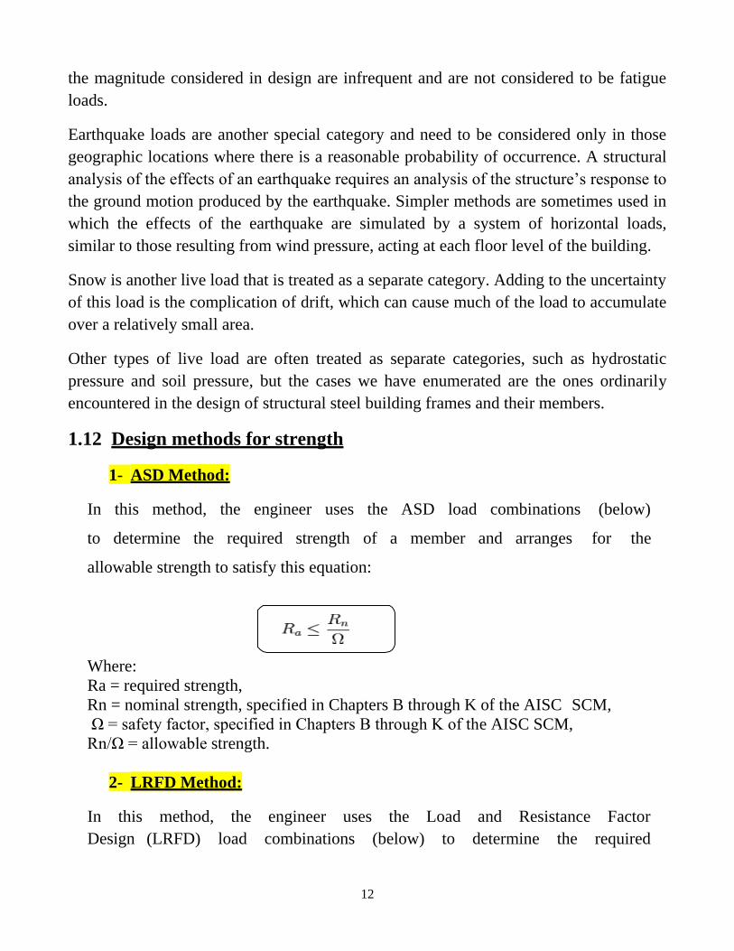
1.12 Design methods for strength
1- ASD Method:
In this method, the engineer uses the ASD load combinations (below)
to determine the required strength of a member and arranges for the
allowable strength to satisfy this equation:
Where:
Ra = required strength,
Rn = nominal strength, specified in Chapters B through K of the AISC SCM,
Ω = safety factor, specified in Chapters B through K of the AISC SCM,
Rn/Ω = allowable strength.
2- LRFD Method:
In this method, the engineer uses the Load and Resistance Factor
Design (LRFD) load combinations (below) to determine the required

13
strength of a member and arranges for the allowable strength to
satisfy this equation:
Where:
Ru = Required strength.
Rn = Nominal strength, specified in Chapters B through K of the AISC SCM.
φ = Resistance factor, specified in Chapters B through K of the AISC SCM.
φ·Rn = Design strength.
Important Note: ASD versus LRFD:
As per the AISC SCM, 14th ed., either design method is allowed by the
AISC SCM 14th edition. A common misconception about the two methods is
that ASD gives a more conservative value. In reality, ASD is more
conservative in designs with a live to dead load ratio of 3 or lower. With a
higher ratio, LRFD is more conservative.
The two design methods are related through the Ω factor of ASD and the
φ factor of LRFD. While these factors have different uses, they are
always related by the following expression:
The values of these factors vary according to the country codes.
1.13 Load combination equations
1- Allowable Stress Design (ASD):
For ASD, the required strength, Ra, is determined from the following load combinations
(according to the AISC SCM, 13 ed.):
D + F
D + H + F + L + T

14
D + H + F + (Lr or S or R)
D + H + F + 0.75(L + T) + 0.75(Lr or S or R) D + H + F ± (W or 0.7E)
D + H + F + (0.75W or 0.7E) + 0.75L + 0.75(Lr or S or R) 0.6D + W + H 0.6D ± (W or
0.7E).
2- Load and Resistance Factor Design (LRFD):
For LRFD, the required strength, Ru, is determined from the following factored load
combinations:
1.4(D + F)
1.2(D + F + T) + 1.6(L + H) + 0.5(Lr or S or R)
1.2D + 1.6(Lr or S or R) + (L or 0.8W)
1.2D + 1.0W + L + 0.5(Lr or S or R)
1.2D ± 1.0E + L + 0.2S + 0.9D + 1.6W + 1.6H
0.9D + 1.6 H ± (1.6W or 1.0E)
For the wind consideration, the ASCE allows a "position correction factor" which turns
the coefficient of wind action to 1,36:
1,2D + 1,36W +.... the same above or 0,9D - 1,36W
Where:
D = dead load,
Di = weight of Ice,
E = earthquake load,
F = load due to fluids with well-defined pressures and maximum heights,
Fa = flood load,
H = load due to lateral earth pressure, ground water pressure, or pressure of bulk
materials,
L = live load due to occupancy,

15
Lr = roof live load,
S = snow load,
R = nominal load due to initial rainwater or ice, exclusive of the ponding contribution,
T = self-straining load,
W = wind load,
Wi = wind on ice.
1.14 Properties of steel
Young's Modulus (E):
Young's Modulus or the Modulus of Elasticity is obtained by dividing the stress by the
strain present in the material. (Thomas Young, 1807). It thus represents a measure of
material stiffness. (Es) is the modulus of elasticity of steel = 29 000 ksi.
Yield strength (FY)
Yield strength represents that minimum value of guaranteed by the steel producer &
consideration of the minimum value of yield point obtained from a large number of
stress strain relation.
Table 1 / page 1-7 in AISC Manual show the strength of steel according to its type.
The strength of steel depends on its consistency of [carbon, alloys, silicon, manganese,
copper, molybdenum, nickel, phosphors, vanadium, zirconium, chromium, columbium,
etc].
Carbon & manganese are the mean element to increase the strength.
us ehtsselts elisneT)
(Fu) is the specified minimum tensile strength.
Poisson`s ratio (
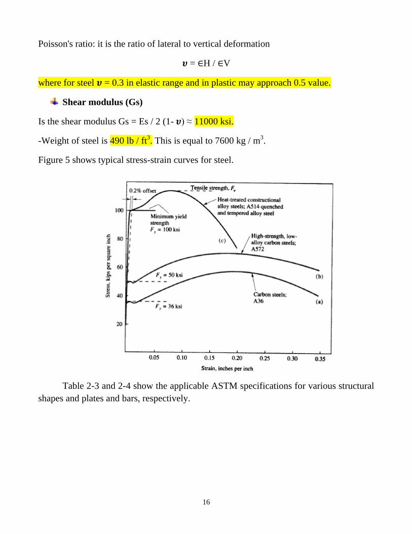
16
Poisson's ratio: it is the ratio of lateral to vertical deformation
= H / V
where for steel = 0.3 in elastic range and in plastic may approach 0.5 value.
Shear modulus (Gs)
Is the shear modulus Gs = Es / 2 (1- ) ≈ 11000 ksi.
-Weight of steel is 490 lb / ft3. This is equal to 7600 kg / m
3.
Figure 5 shows typical stress-strain curves for steel.
Table 2-3 and 2-4 show the applicable ASTM specifications for various structural
shapes and plates and bars, respectively.

17

18

19
The convert unit from SI to US
The important convert unit
1 m 3.28 ft
1 kip
4.4482216 kN
1 Ib 4.4482216 N
1Ton 2.2046 kip
1 ksi 6.895 MPa
1 psi 0.006895 MPa
1 kips.ft 1.356 kN.m
1 kip/ft2
47.881 kN/m2
1 kip/ft 14.594 kN/m
If you need the density of concrete (=150 Ib/ft3).