DESIGN OF STEEL STRUCTURES - Annamalai University
36
DESIGN OF STEEL STRUCTURES by Dr. R. Baskar, Ph.D(Struct.);FIE Professor, Dept. of Civil & Structural Engineering Annamalai University
-
Upload
khangminh22 -
Category
Documents
-
view
1 -
download
0
Transcript of DESIGN OF STEEL STRUCTURES - Annamalai University

DESIGN OF STEEL STRUCTURES
by
Dr. R. Baskar, Ph.D(Struct.);FIEProfessor,
Dept. of Civil & Structural EngineeringAnnamalai University

COMPRESSION
MEMBERS

TYPES OF COMPRESSION MEMBERS
The types of column is based on the slenderness ratio or the length to
diameter ratio of the columns.
They can be divided as follows:
(a) Short columns:
• The columns which have height less than eight times their
diameter or slenderness ration less than 32 are called short column.
• In short columns bending or buckling is negligible and hence short
columns fail by direct crushing or compressive stress.
(b) Medium columns:
• The columns which have length varying from 8 to 30 times their
diameters or the slenderness ration lying between 32 to 120 are called
intermediate or medium columns.

• In this types of columns, buckling and compressive stress are
both considered for their failures.
(c) Long columns :
• Columns having their length more than 30 times their diameter
or slenderness ratio more than 120 are called long columns.
• In such types of columns failure will occur due to
buckling or bending but direct compressive stress is very small as
compared to buckling stress.
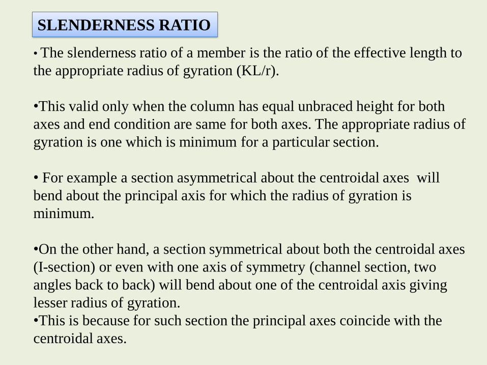
• The slenderness ratio of a member is the ratio of the effective length to
the appropriate radius of gyration (KL/r).
•This valid only when the column has equal unbraced height for both
axes and end condition are same for both axes. The appropriate radius of
gyration is one which is minimum for a particular section.
• For example a section asymmetrical about the centroidal axes will
bend about the principal axis for which the radius of gyration is
minimum.
•On the other hand, a section symmetrical about both the centroidal axes
(I-section) or even with one axis of symmetry (channel section, two
angles back to back) will bend about one of the centroidal axis giving
lesser radius of gyration.
•This is because for such section the principal axes coincide with the
centroidal axes.
SLENDERNESS RATIO
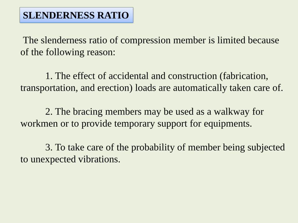
The slenderness ratio of compression member is limited because
of the following reason:
1. The effect of accidental and construction (fabrication,
transportation, and erection) loads are automatically taken care of.
2. The bracing members may be used as a walkway for
workmen or to provide temporary support for equipments.
3. To take care of the probability of member being subjected
to unexpected vibrations.
SLENDERNESS RATIO

• Design compressive stress cannot be more than fy.
•Reduction in fy due to all the above adverse factors is
difficult to quantity.
•Based on statistical test data, lower bound curves are
proposed as shown in above Figure.
•The curves a, b, c and d represent considering the
effects of cumulative degree of imperfection due to
cross-sectional layout, presence of residual, initial
curvature and eccentric loading.
CODAL PROVISIONS.

CODAL PROVISIONS
0
0.1
0.2
0.3
0.4
0.5
0.6
0.7
0.8
0.9
1
0 0.5 1 1.5 2 2.5 3
fcd
/fy
Lamda
Buckling Curves
a
b
c
d
Buckling Class a b c d
0.21 0.34 0.49 0.76
TABLE 1 IMPERFECTION FACTOR, α

The design compressive strength of a member is given
by
DESIGN STRENGTH
0
0 00.52 2
// /
y m
cd y m y m
ff f f
fcd = the design compressive stress, λ = non-dimensional effective slenderness ratio,
fcc = Euler buckling stress = 2E/(KL/r)2
= imperfection factor as in Table 1
= stress reduction factor as in Table 8
γmo = partial safety factor for material
KL/r = Effective slenderness ratio
2
2
y cc yKLf f f E
r
d e cdP A f
0.5
2 2
1
2 0.5[1 ( 0.2) ]

1.Obtain factored axial load on the column section ISHB400. The
height of the column is 3.0m and it is pin-ended.
[ fy = 250 N/mm2 ; E = 2 x10⁵ N/mm2 ; m = 1.10]
CROSS-SECTION PROPERTIES:
Z d
T
t
Y
h
3.0 m

Flange thickness = T = 12.7 mm
Overall height of ISHB400 = h = 400 mm
Clear depth between flanges = d = 400 – (12.7 x 2)
= 374.6 mm
Thickness of web = t = 10.6mm
Flange width = 2b = bf = 250 mm
Hence, half Flange Width = b = 125 mm
Self –weight = w = 0.822 kN/m
Area of cross-section = A = 10466 mm2
Radius of gyration about x = rx = 166.1 mm
Radius of gyration about y = ry = 51.6 mm

(i)Type of section:
(Table 3.1 of IS: 800)
Hence, cross-section can be classified as “COMPACT”.
(ii)Effective Sectional Area, Ae = 10,466 mm2
(Since there is no hole, (Clause 7.3.2 of IS: 800)
no reduction has been considered)
0.1250
250250,
423.356.10
6.374
5.108.97.12
125
yfwhere
t
d
T
b

(iii) Effective Length:
As, both ends are pin-jointed effective length
(Clause 7.2 and Table 7.5 of IS:800 )
KLx= KLy = 1.0 x Lx = 1.0 x Ly = 1.0 x 3.0 m = 3.0 m
(iv) Slenderness ratios:
(v) Non-dimensional Effective Slenderness ratio, :
= = =
= 0.654 (Clause 7.1.2.1 of IS: 800)
1.586.51
3000/
1.181.166
3000/
yy
xx
rKL
rKL
ccy ff Er
KLf y
22
5221021.58250 xxx

(vi) Value of from equation = 0.5[1+ ( - 0.2)+ 2]:
Where, = Imperfection Factor which depends on Buckling
Class
Now, from Table 7.2 of Chapter 7, for h/bf = 400 / 250 = 1.6 >
1.2 and also thickness of flange, T = 12.7 mm, hence for z-z axis buckling class
‘a’ and for y-y axis buckling class ‘b’ will be followed.
(Table 7.1 of IS: 800)
Hence, = 0.34 for buckling class ‘b’ will be considered.
Hence, = 0.5 x [1+0.34 x (0.654-0.2)+0.6542] = 0.791
(Table 7.1 of IS: 800)
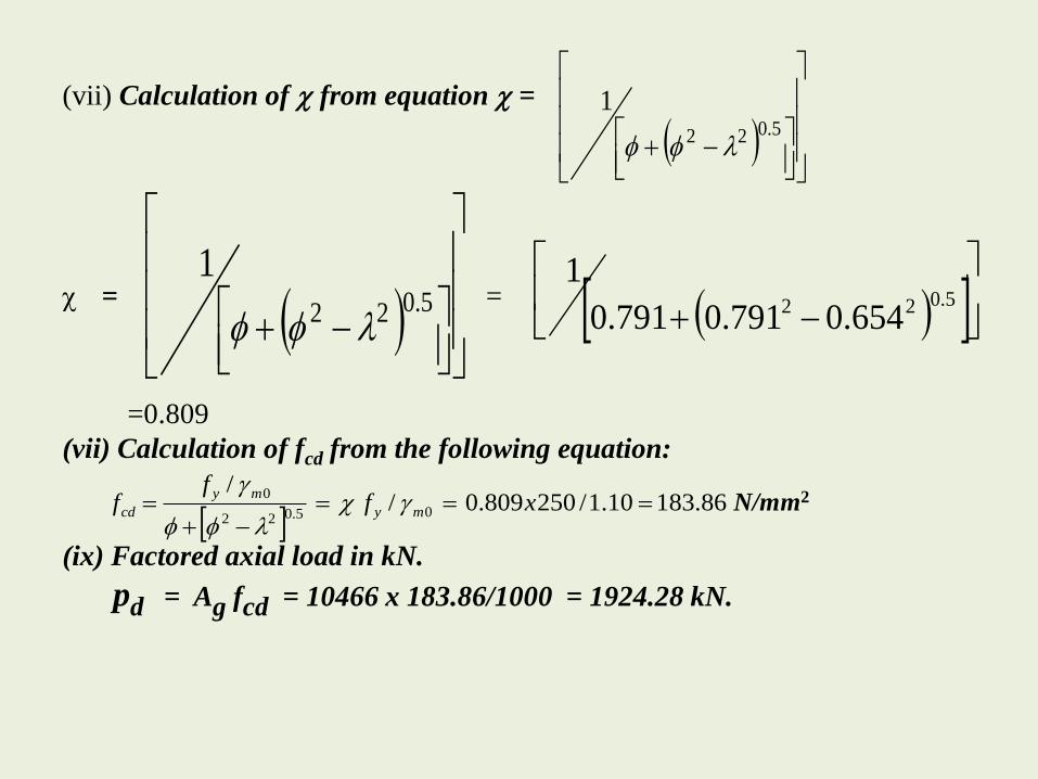
(vii) Calculation of from equation =
= =
=0.809
(vii) Calculation of fcd from the following equation:
N/mm2
(ix) Factored axial load in kN.
pd = Ag fcd = 10466 x 183.86/1000 = 1924.28 kN.
5.022
1
5.022
1
5.022 654.0791.0791.0
1
86.18310.1/250809.0/
/05.022
0
xf
ff my
my
cd

2. A double angle discontinuous strut ISA 150x75x10mm long leg back to
back is connected to either side by gusset plate of 10mm thick with 2 bolts.
The length of the strut between the intersections is 3.5m. Determine the safe
load carrying capacity of the section.
Ref. CL 7.5.2.1, P48, IS800:2007
Effective length factor is between 0.7 and 0.85
Assume k=0.85
Effective length of the member = 0.85x3500
=2975mm
From steel table ( P 45) A= 4312mm2 ; rmin= 29.0
KL/rmin = 2975/29.0 = 102.58
From Table 10/IS 800/ P 44

The given section is belonged to Buckling Class C
Therefore Design Compressive stress, from Table 9(c)/P42
fcd = 107- 2.58 x 12.4/10 = 103.8
Strength of member = (103.8x4312)/ 1000 = 447.58kN

3. Calculate the safe load of a bridge compression member of two channels
ISMC 350 @ 421.1 kg/m placed toe to toe. The effective length of member is
7m. The widths over the back of the channel are 350mm and the section is
properly connected by lacings.
A = 2(53.66) = 107.32cm 2
Izz = 2(10008) = 20016cm 4
Iyy = 2[430.6 + 53.66(17.5 − 2.44)2 ]
= 25201.7cm 4
γmin = √Imin/A
= 13.6 cm
KL/γ = 700/13.6 = 51.2 (Table 9c of code)
fcd = 183 − 1.2/10 x15 = 181.2 N/mm2
Strength of the member = 181.2 x 10732 = 1944.6kN

4. Design a simple base plate for a ISHB400 @ 0.822 kN/m column to carry a
factored load of 1800 kN.
[fcu = 40 N/mm2; fy = 250 N/mm2;m = 1.10]
Thickness of Flange for ISHB400 = T = 12.7 mm
Bearing strength of concrete = 0.4fcu = 0.4 x 40 = 16 N/mm2
Area required =1800 x 103/16 = 112500 mm2
Use plate of 450 X 300 mm (135000 mm2)
Assuming projection of 25 mm on each side, a = b = 25 mm
N/mm2
Now thickness of Slab Base, ts
300 mm
450 mm
ISHB 400
33.13300450101800 3 w
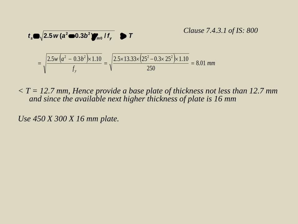
Clause 7.4.3.1 of IS: 800
< T = 12.7 mm, Hence provide a base plate of thickness not less than 12.7 mm and since the available next higher thickness of plate is 16 mm
Use 450 X 300 X 16 mm plate.
Tfbawt yms /)3.0(5.2 0
22
mm
f
baw
y
01.8250
10.1253.02533.135.210.13.05.2 2222

5. Design a laced column 10-m long to carry a factored axial load of
1100 kN.
The column is restrained in position but not in direction at both ends.
Provide single lacing system with bolted connection.
(a) Design the column with two channels back-to-back
(b) Design the column with two channels placed toe-to-toe
(c) Design the lacing system with welded connections for channels back-to-back.
Solution:
Design of column:
P = 1100 x 103 N
L = 1.0 x 10 = 10m
Assume design strength of 125MPa
Required area = 1100 x 103 / 125 =8800mm2
Select two ISMC 300 at 363 N/m. The relevant properties of ISMC 300
are

A = 4630 mm2, rzz = 118.0 mm , ryy = 26.0 mm
Cyy= 23.5mm, Izz = 6420 x 104mm4 , Iyy = 313 x 104mm4
Area available = 2 x 4630 = 9260 mm2
Built up sections will be economical, when the radius of gyration of the
y-y axis is increased in such a way that it is more or less equal to the radius of
Gyration about the z-z axis .This is achieved by spacing the sections in such a
way that rzz becomes r min .Let us first check the safety of the section and then
Workout the required spacing between the two channels.
L/rzz= 10 x 103/118.0= 84.74
The L/r of the built-up column should be taken as 1.05 x (L/rzz) =1.05 x 84.74
=88.98
For L/rzz= 88.98 and fy= 250MPa,using table 9c of the code ,
fcd= 122.53 MPa,

Load carrying capacity Aefcd = 9260 x 122.53/1000
= 1135 kN > 1100 kN.
Hence the column is safe.
(a ) Let us provide two channels back to back and connect them by lacing and
denote S as the spacing between two channels[ See fig below].
Spacing of channels:
2Izz= 2 [Iyy + A(S/2) + cyy)2
Thus, 2 x 6420 x 104 = 2 x [313 x 104 +4630
(S/2+23.5)2
=13190
S = 182.70mm
Let us keep the channels at a spacing of 183mm.
Lacing system
Using single lacing system with the inclination of

lacing bar =45 ̊ (gauge length for a 90 mm flange = 50mm)
Spacing of lacing bars, Lo = (2 x 183+ 50 +50) cot 50 ̊
= 2 x 283 x 1 = 566 mm
Lo /ryy should be < 0.7 x L/r of whole column.
21.77 < 0.7 x 88.98 =62.3
Hence safe.
Maximum shear = (2.5 /100) x 1100 x 103 = 27,500N.
Transverse shear in each panel =(V/N) = 27500/2 =13750N.
Compressive force in the lacing bar = (V/N) cosec 45 ̊
= 13750 x 1.414 = 19445 N.
Assuming 16-mm diameter bolts,
Minimum width of lacing flat (clause 7.6.2 of the code)= 3x 16,say 50mm
Minimum thickness = (1/40) (183+50+50)cosec 45 ̊ =10.01 mm
Provide 12 mm thick plate with a width of 50 mm
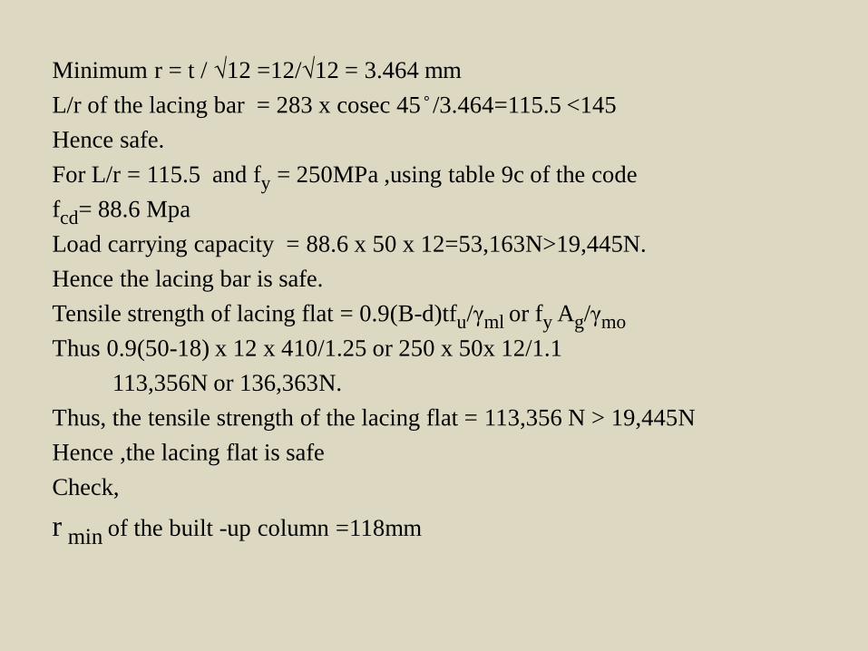
Minimum r = t / √12 =12/√12 = 3.464 mm
L/r of the lacing bar = 283 x cosec 45 ̊ /3.464=115.5 <145
Hence safe.
For L/r = 115.5 and fy = 250MPa ,using table 9c of the code
fcd= 88.6 Mpa
Load carrying capacity = 88.6 x 50 x 12=53,163N>19,445N.
Hence the lacing bar is safe.
Tensile strength of lacing flat = 0.9(B-d)tfu/γml or fy Ag/γmo
Thus 0.9(50-18) x 12 x 410/1.25 or 250 x 50x 12/1.1
113,356N or 136,363N.
Thus, the tensile strength of the lacing flat = 113,356 N > 19,445N
Hence ,the lacing flat is safe
Check,
r min of the built -up column =118mm
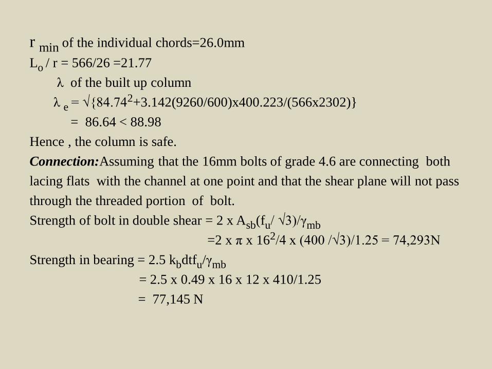
r min of the individual chords=26.0mm
Lo / r = 566/26 =21.77
λ of the built up column
λ e = √{84.742+3.142(9260/600)x400.223/(566x2302)}
= 86.64 < 88.98
Hence , the column is safe.
Connection:Assuming that the 16mm bolts of grade 4.6 are connecting both
lacing flats with the channel at one point and that the shear plane will not pass
through the threaded portion of bolt.
Strength of bolt in double shear = 2 x Asb(fu/ √3)/γmb
=2 x π x 162/4 x (400 /√3)/1.25 = 74,293N
Strength in bearing = 2.5 kbdtfu/γmb
= 2.5 x 0.49 x 16 x 12 x 410/1.25
= 77,145 N

Hence ,Strength of bolt =74,293N >19,445N
Hence one 16-mm diameter bolt of grade 4.6 is required.
Connection Assuming that the 16mm bolts of grade 4.6 are connecting both
lacing flats with the channel at one point and that the shear plane will not pass
through the threaded portion of bolt.
Strength of bolt in double shear = 2 x Asb(fu/ √3)/γmb
=2 x π x 162/4 x (400 /√3)/1.25 = 74,293N
Strength in bearing = 2.5 kbdtfu/γmb
= 2.5 x 0.49 x 16 x 12 x 410/1.25
= 77,145 N
Tie plates:
Tie plates must be provided at the ends of the laced column
Effective depth = 183 + 2 x Cyy > 2 x bf
= 183 + 2 x 23.5 =230mm > 2 x 90 = 180mm
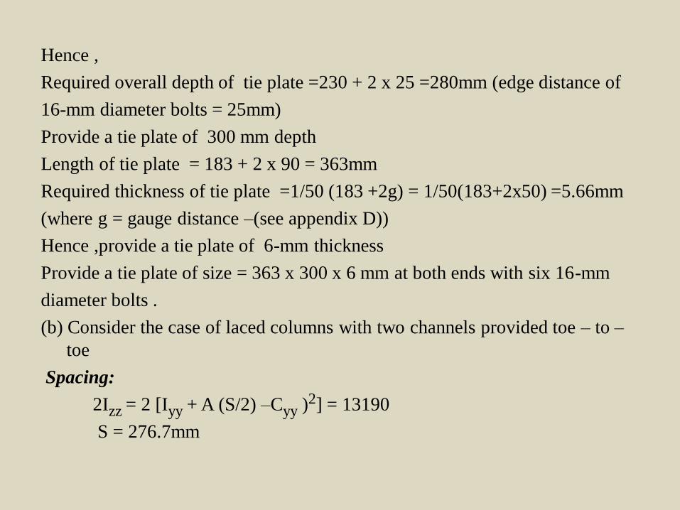
Hence ,
Required overall depth of tie plate =230 + 2 x 25 =280mm (edge distance of
16-mm diameter bolts = 25mm)
Provide a tie plate of 300 mm depth
Length of tie plate = 183 + 2 x 90 = 363mm
Required thickness of tie plate =1/50 (183 +2g) = 1/50(183+2x50) =5.66mm
(where g = gauge distance –(see appendix D))
Hence ,provide a tie plate of 6-mm thickness
Provide a tie plate of size = 363 x 300 x 6 mm at both ends with six 16-mm
diameter bolts .
(b) Consider the case of laced columns with two channels provided toe – to –
toe
Spacing:
2Izz = 2 [Iyy + A (S/2) –Cyy )2] = 13190
S = 276.7mm
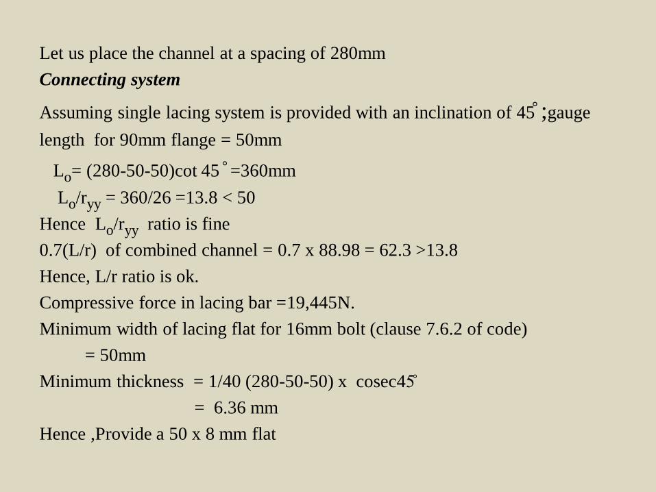
Let us place the channel at a spacing of 280mm
Connecting system
Assuming single lacing system is provided with an inclination of 45 ̊ ;gauge
length for 90mm flange = 50mm
Lo= (280-50-50)cot 45 ̊ =360mm
Lo/ryy = 360/26 =13.8 < 50
Hence Lo/ryy ratio is fine
0.7(L/r) of combined channel = 0.7 x 88.98 = 62.3 >13.8
Hence, L/r ratio is ok.
Compressive force in lacing bar =19,445N.
Minimum width of lacing flat for 16mm bolt (clause 7.6.2 of code)
= 50mm
Minimum thickness = 1/40 (280-50-50) x cosec45̊
= 6.36 mm
Hence ,Provide a 50 x 8 mm flat

Check rmin= t/√12 = 8/√12 = 2.309mm
L/r = 180 x cosec 45̊ /2.309 = 110.2 < 145
Hence, the chosen flat is safe.
For , L/r = 110.2 and fy =250 MPa ,from table 9c of the code
fcd = 94.4 N/mm2
Capacity of the lacing flat = 94.4 x 50 x 8
= 37,760 N > 19,445N.
Tensile Strength of lacing flat = 0.9(B – d)tfu/γml or fyAg/γm0
= 0.9 (50-18) x 8 x 410/1.25 or 250 x 50 x 8/1.1
= 75, 571N or 90,909N both > 19,445 N
Hence ,the lacing flat is safe .
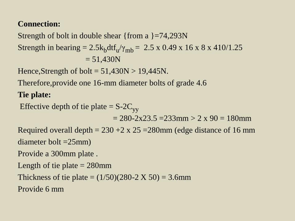
Connection:
Strength of bolt in double shear {from a }=74,293N
Strength in bearing = 2.5kbdtfu/γmb = 2.5 x 0.49 x 16 x 8 x 410/1.25
= 51,430N
Hence,Strength of bolt = 51,430N > 19,445N.
Therefore,provide one 16-mm diameter bolts of grade 4.6
Tie plate:
Effective depth of tie plate = S-2Cyy
= 280-2x23.5 =233mm > 2 x 90 = 180mm
Required overall depth = 230 +2 x 25 =280mm (edge distance of 16 mm
diameter bolt =25mm)
Provide a 300mm plate .
Length of tie plate = 280mm
Thickness of tie plate = (1/50)(280-2 X 50) = 3.6mm
Provide 6 mm

Provide a tie plate of size 280 x 300x 6 mm and use six of bolts 16-mm
diameter and grade 4.6 to connect it to the channels.The arrangement is shown
in fig (b)
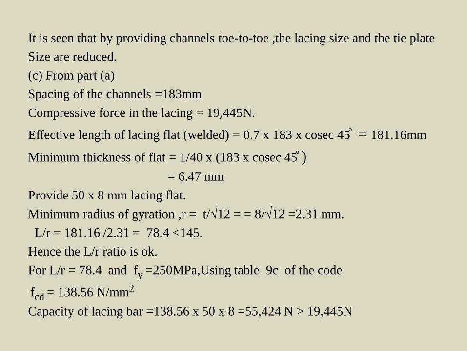
It is seen that by providing channels toe-to-toe ,the lacing size and the tie plate
Size are reduced.
(c) From part (a)
Spacing of the channels =183mm
Compressive force in the lacing = 19,445N.
Effective length of lacing flat (welded) = 0.7 x 183 x cosec 45 ̊ = 181.16mm
Minimum thickness of flat = 1/40 x (183 x cosec 45 ̊ )
= 6.47 mm
Provide 50 x 8 mm lacing flat.
Minimum radius of gyration ,r = t/√12 = = 8/√12 =2.31 mm.
L/r = 181.16 /2.31 = 78.4 <145.
Hence the L/r ratio is ok.
For L/r = 78.4 and fy =250MPa,Using table 9c of the code
fcd = 138.56 N/mm2
Capacity of lacing bar =138.56 x 50 x 8 =55,424 N > 19,445N

Hence, the lacing bar is safe.
Overlap of lacing flat = 50mm > 4 x 8 = 32 mm
Hence, the lacing flat is safe.
Connection:
Thickness of flange of ISMC 300 = 13.6mm
Minimum size of weld = 5 mm (Table 21 of code)
Strength of weld/unit length = 0.7 x 5 x 410/(√3 x 1.5)
= 552 N/mm
Required length of weld = 19,445/552 = 35.2 mm
Adding extra length for ends,the weld length to be provided
= 36 + 2(2 x 5 ) = 56mm
Provide 100mm weld length at both ends.
Tie plate:
Overall depth of plate = 183 + 2 x Cyy
=183 + 2 x 23.5
=230mm > 2 x 90mm

Let,length of tie plate =183 + 2x 50 = 283 mm
Thickness of tie plate = 1/50(183 + 2 x 50 ) = 5.66 mm
Provide a 8mm plate to accommodate a 5 mm weld.
Provide a tie plate of 283 x 240 x 8 mm size and connect it with 5 mm welds
as in fig (c).

Thank You