fire protection of bolt connection in steel structures - Theseus
39
FIRE PROTECTION OF BOLT CONNECTION IN STEEL STRUCTURES The need for fire protection in bolt connections Bachelor’s thesis Hämeenlinna University Centre, Degree Programme in Construction Engineering Spring 2021 David Dzhavadov
-
Upload
khangminh22 -
Category
Documents
-
view
3 -
download
0
Transcript of fire protection of bolt connection in steel structures - Theseus
FIRE PROTECTION OF BOLT CONNECTION IN STEEL STRUCTURES
The need for fire protection in bolt connections
Bachelor’s thesis
Hämeenlinna University Centre, Degree Programme in Construction Engineering
Spring 2021
David Dzhavadov
ABSTRACT Degree Programme in Construction Engineering Hämeenlinna University Centre Author David Dzhavadov Year 2021 Subject Fire protection of bolt connection in steel structures Supervisor(s) Zhongcheng Ma, Tomi Eloranta ABSTRACT
The purpose of this Bachelor’s thesis project is to perform a research on the need for fire protection of bolts in steel beam-to-column connections. Based on the literature study about the fire protection of steel elements, there are different cases when bolts should be protected or stay unprotected. The comparison of the results from different fire tests should be observed to make a conclusive decision about the need for fire protection of the bolts. This thesis introduces the types of fire protections for bolts, ways to calculate the temperatures of unprotected bolts and their resistances on fire according to the experiments and guidance books. The goal is to make a design tool to evaluate the need of individual fire protection for the bolts based on the temperature and the properties’ changes in case of fire. As a result, this thesis demonstrates a calculation method for the temperature rise of both unprotected and protected steel elements in the case fire. The fire protection by intumescent paint is used in the calculations. Based on the research, the formula of temperature rise in bolt assembly is summarized and used as a basis of the design tool. The excel tool developed in this thesis for bolt temperature and strength calculations is based on the example tool from commissioner of the thesis, SWECO Finland and it will be used inside the company.
Keywords Bolt connection, fire protection, intumescent coating, bolt temperature Pages 36 pages
CONTENTS
1 INTRODUCTION ........................................................................................................... 1
1.1 Basis for research ................................................................................................ 1
1.2 Future utilization ................................................................................................. 2
2 BACKGROUND AND LITERATURE REVIEW ................................................................... 3
2.1 Literature review on EN1993-1-2/2005 .............................................................. 3
2.2 Literature review on fire test results .................................................................. 5
3 TYPES OF FIRE PROTECTION FOR BOLTS ..................................................................... 7
4 CALCULATION OF UNPROTECTED BOLTS IN FIRE ...................................................... 12
4.1 Exposure factors and section factors ................................................................ 13
4.1.1 Simplified 2-D representation of the joint assembly ............................ 13
4.1.2 Complete 3-D representation of the joint assembly ............................. 16
4.2 Temperature in protected joint component other than bolts in fire ............... 22
4.3 Temperature in unprotected steel section in fire ............................................. 23
4.4 Temperature in unprotected bolts of protected joint member in fire ............. 24
4.5 Fire design resistances of bolts ......................................................................... 24
5 DESIGN TOOL IN EXCEL .............................................................................................. 25
5.1 Introduction of design tool ............................................................................... 25
5.2 Calculation flow ................................................................................................. 26
5.3 Calculation example .......................................................................................... 26
5.4 Excel tool verification ........................................................................................ 31
6 CONCLUSION ............................................................................................................. 33
REFERENCES .................................................................................................................... 35
1
1 INTRODUCTION
1.1 Basis for research
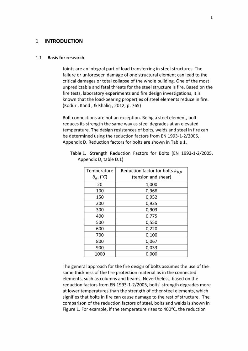
Joints are an integral part of load transferring in steel structures. The failure or unforeseen damage of one structural element can lead to the critical damages or total collapse of the whole building. One of the most unpredictable and fatal threats for the steel structure is fire. Based on the fire tests, laboratory experiments and fire design investigations, it is known that the load-bearing properties of steel elements reduce in fire. (Kodur , Kand , & Khaliq , 2012, p. 765) Bolt connections are not an exception. Being a steel element, bolt reduces its strength the same way as steel degrades at an elevated temperature. The design resistances of bolts, welds and steel in fire can be determined using the reduction factors from EN 1993-1-2/2005, Appendix D. Reduction factors for bolts are shown in Table 1.
Table 1. Strength Reduction Factors for Bolts (EN 1993-1-2/2005, Appendix D, table D.1)
Temperature 𝜃𝑎, (°C)
Reduction factor for bolts 𝑘𝑏,𝜃 (tension and shear)
20 1,000
100 0,968
150 0,952
200 0,935
300 0,903
400 0,775
500 0,550
600 0,220
700 0,100
800 0,067
900 0,033
1000 0,000
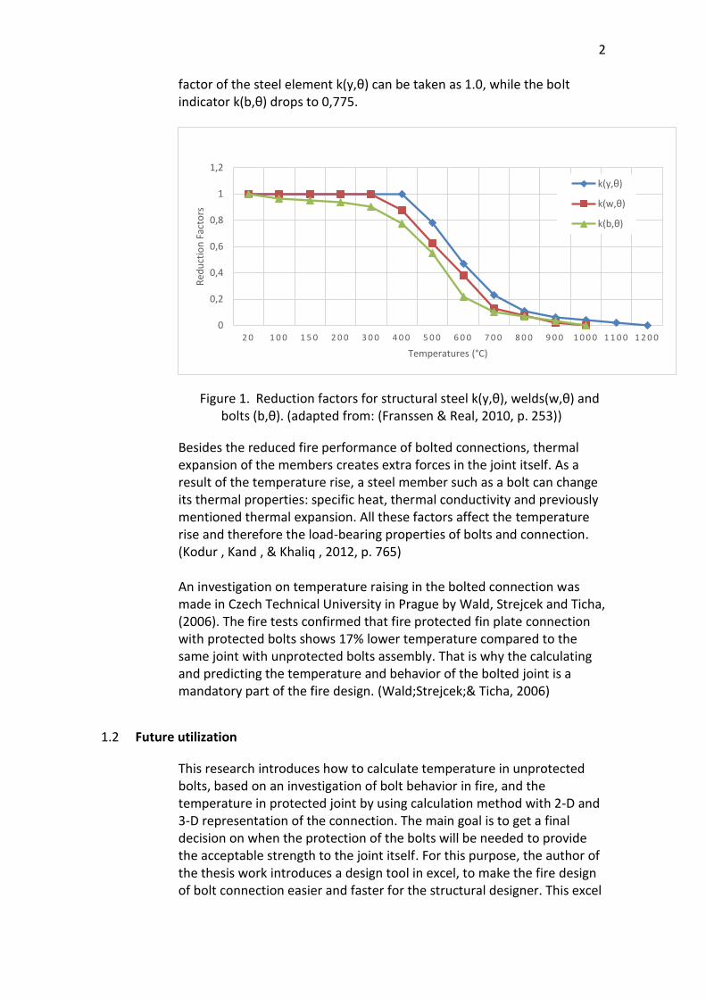
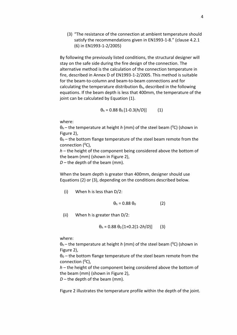
The general approach for the fire design of bolts assumes the use of the same thickness of the fire protection material as in the connected elements, such as columns and beams. Nevertheless, based on the reduction factors from EN 1993-1-2/2005, bolts’ strength degrades more at lower temperatures than the strength of other steel elements, which signifies that bolts in fire can cause damage to the rest of structure. The comparison of the reduction factors of steel, bolts and welds is shown in Figure 1. For example, if the temperature rises to 400oC, the reduction
2
factor of the steel element k(y,θ) can be taken as 1.0, while the bolt indicator k(b,θ) drops to 0,775.
Figure 1. Reduction factors for structural steel k(y,θ), welds(w,θ) and bolts (b,θ). (adapted from: (Franssen & Real, 2010, p. 253))
Besides the reduced fire performance of bolted connections, thermal expansion of the members creates extra forces in the joint itself. As a result of the temperature rise, a steel member such as a bolt can change its thermal properties: specific heat, thermal conductivity and previously mentioned thermal expansion. All these factors affect the temperature rise and therefore the load-bearing properties of bolts and connection. (Kodur , Kand , & Khaliq , 2012, p. 765) An investigation on temperature raising in the bolted connection was made in Czech Technical University in Prague by Wald, Strejcek and Ticha, (2006). The fire tests confirmed that fire protected fin plate connection with protected bolts shows 17% lower temperature compared to the same joint with unprotected bolts assembly. That is why the calculating and predicting the temperature and behavior of the bolted joint is a mandatory part of the fire design. (Wald;Strejcek;& Ticha, 2006)
1.2 Future utilization
This research introduces how to calculate temperature in unprotected bolts, based on an investigation of bolt behavior in fire, and the temperature in protected joint by using calculation method with 2-D and 3-D representation of the connection. The main goal is to get a final decision on when the protection of the bolts will be needed to provide the acceptable strength to the joint itself. For this purpose, the author of the thesis work introduces a design tool in excel, to make the fire design of bolt connection easier and faster for the structural designer. This excel
0
0,2
0,4
0,6
0,8
1
1,2
2 0 1 0 0 1 5 0 2 0 0 3 0 0 4 0 0 5 0 0 6 0 0 7 0 0 8 0 0 9 0 0 1 0 0 0 1 1 0 0 1 2 0 0
Red
uct
ion
Fac
tors
Temperatures (°C)
k(y,θ)
k(w,θ)
k(b,θ)
3
table is based on the investigations about the bolt behavior in fire and will be used inside the SWECO Finland company.
2 BACKGROUND AND LITERATURE REVIEW
This chapter summarizes some of the previous research and publications about the calculation of temperature in a joint and bolt in fire. This chapter is divided into the following sections:
• Section 2.1 describes the background research of the EN1993-1-2 from 2005 with the general assumptions for the fire design of bolted joints.
• Section 2.2 introduces and analyzes fire tests about the influence of protection paint on bolts from Wald, Strejcek, & Ticha investigation in 2006.
2.1 Literature review on EN1993-1-2/2005
The construction market in Finland offers various options for fire protection of steel structures. The most demanded type is protection paint – intumescent coating. However, based on the work experiences of construction specialists from SWECO Finland, the fire protection of bolts in steel joints has been left unattended in the design phase. The excel table presented in section 5 of this thesis is the design tool developed for the company to calculate the temperature rise of bolts under fire. However, the background research of the EN1993-1-2/2005 showed other methods to assume the sufficient fire resistance of bolt connection. The first procedure is taken from the clause 4.2.1 (6) and it represents the checklist with three points for the joint:
(1) “The thermal resistance (df/λf)c of the connection’s fire protection should be equal or greater than the minimum value of thermal resistance (df/λf)m of fire protection applied to any of the connected members.” (clause 4.2.1 (6) in EN1993-1-2/2005) It should be noted, that this condition for the joint is based on the assumptions from the British standard
Where: df – the thickness of the fire protection material. (df = 0 for unprotected members) λf – the effective thermal conductivity of the fire protection material.
(2) “The utilization of the connection should be less than the maximum value of utilization of any of the connection members.” (clause 4.2.1 (6) in EN1993-1-2/2005)
4
(3) “The resistance of the connection at ambient temperature should
satisfy the recommendations given in EN1993-1-8.” (clause 4.2.1 (6) in EN1993-1-2/2005)
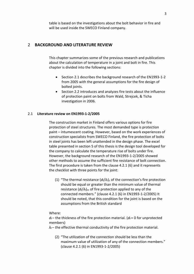
By following the previously listed conditions, the structural designer will stay on the safe side during the fire design of the connection. The alternative method is the calculation of the connection temperature in fire, described in Annex D of EN1993-1-2/2005. This method is suitable for the beam-to-column and beam-to-beam connections and for calculating the temperature distribution θh, described in the following equations. If the beam depth is less that 400mm, the temperature of the joint can be calculated by Equation (1).
θh = 0.88 θ0 [1-0.3(h/D)] (1) where: θh – the temperature at height h (mm) of the steel beam (0C) (shown in Figure 2), θ0 – the bottom flange temperature of the steel beam remote from the connection (0C), h – the height of the component being considered above the bottom of the beam (mm) (shown in Figure 2), D – the depth of the beam (mm). When the beam depth is greater than 400mm, designer should use Equations (2) or (3), depending on the conditions described below.
(i) When h is less than D/2:
θh = 0.88 θ0 (2)
(ii) When h is greater than D/2:
θh = 0.88 θ0 [1+0.2(1-2h/D)] (3)
where: θh – the temperature at height h (mm) of the steel beam (0C) (shown in Figure 2), θ0 – the bottom flange temperature of the steel beam remote from the connection (0C), h – the height of the component being considered above the bottom of the beam (mm) (shown in Figure 2), D – the depth of the beam (mm). Figure 2 illustrates the temperature profile within the depth of the joint.
5
Figure 2. Thermal gradient within the depth of a composite connection where the beam supports a concrete slab. (EN1993-1-2/2005)
2.2 Literature review on fire test results
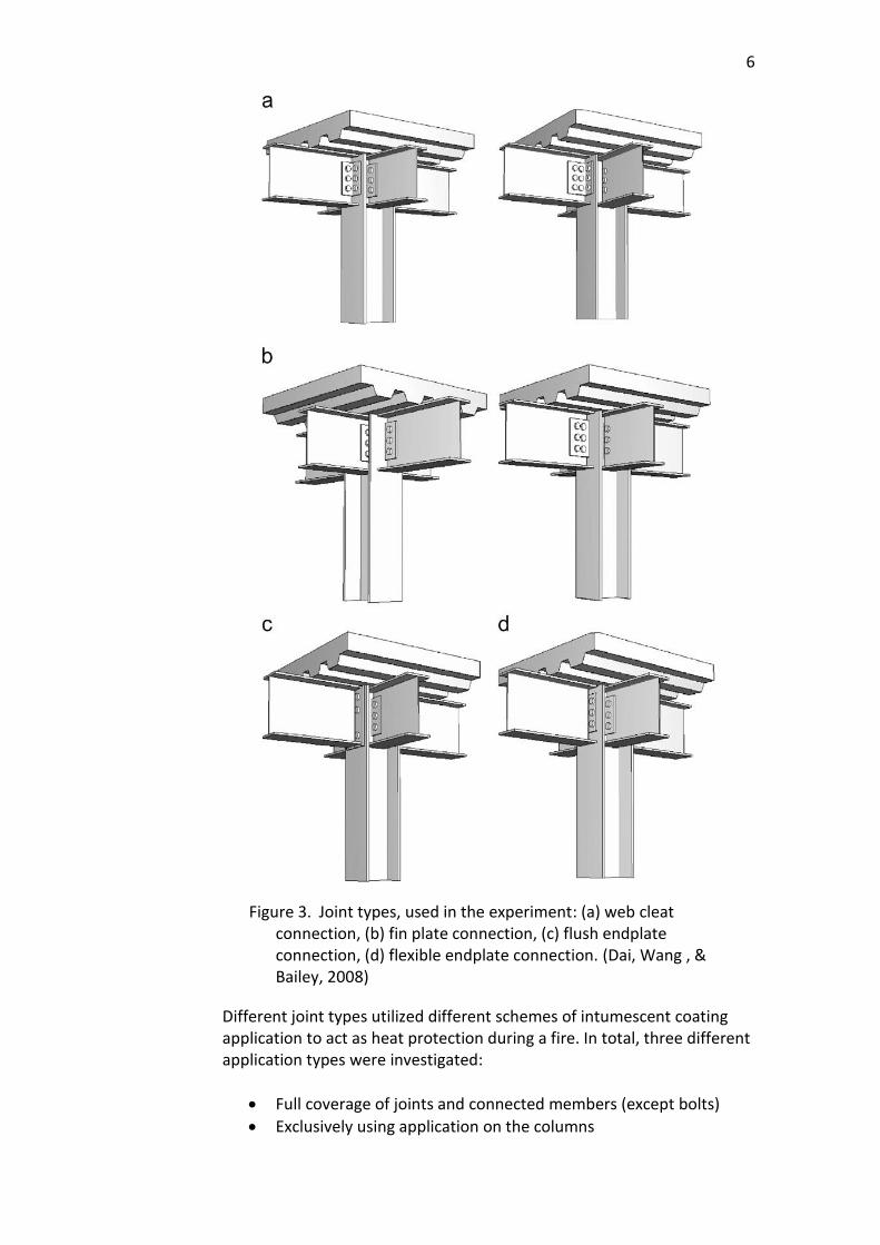
One of the literature sources reviewed for the purpose of writing this thesis was “Effects of partial fire protection on temperature developments in steel joints protected by intumescent coating” written by Dai, X., et al. (2008).
The research project in question dealt with four typical steel–concrete composite joint types and provided information of temperature distribution in them during a fire. The joint types are presented in Figure 3.
6
Figure 3. Joint types, used in the experiment: (a) web cleat connection, (b) fin plate connection, (c) flush endplate connection, (d) flexible endplate connection. (Dai, Wang , & Bailey, 2008)
Different joint types utilized different schemes of intumescent coating application to act as heat protection during a fire. In total, three different application types were investigated:
• Full coverage of joints and connected members (except bolts)
• Exclusively using application on the columns

7
• Exclusively using application on a limited area where the beams connect (with bolts).
The experimentation process fits the following description: a standard fire condition was applied to the steelwork of each of the 14 test structures in a furnace. Four structures, one for each respective joint type, were tested without a protective coating to make the ‘baseline’ clear, as well as 10 different combinations of structures plus application types. Having completed the tests, researchers concluded that in the case of full joint coverage it made little difference whether the bolts were covered or not. Either way, the performance of fully protected structure was significantly higher than that of a completely unprotected joint structure. In addition, it was discovered that 400 mm of beam protection provided the maximum level of fire protection. Lastly, the experiment showed that protecting only the column with a coating led to lower temperatures in the regions adjacent to the protected part, but due to the effect of heat conduction from other unprotected parts the temperatures were overall higher. The results of this paper are only experimental, as only unloaded structures were tested, to make the research more affordable and timely. However, the authors’ assumption is that the results will be relevant and hold true in respect to loaded specimens as well.
3 TYPES OF FIRE PROTECTION FOR BOLTS
Nowadays, construction market offers various types of fire protection for steel elements, which can prevent the steel from rapid decrease in structural reliability. An intumescent coating is the most preferred fire protection in construction due to its high-performance indicators during a fire and sufficient protection of load bearing structures to ensure safety for all occupants, even though, the application of this protective paint is a time-consuming process that can cause delays in construction planning and substantial overheads. (Dai, Wang, & Bailey, 2010, p. 19) An intumescent coating is a coating that, when exposed to fire, swells several times its original thickness, creating an insulating soot that protects the surface from fire. Its key advantages are low weight and thickness. Under normal conditions, this coating performs decorative and protective layer, furthermore, it does not affect the physical or mechanical characteristics of objects and can be used when accuracy of meeting the requirements for the weight and dimensions of structures is important. Moreover, it requires relatively low labor intensity of application and can be treated by the roller, brush or spray. Depending
8
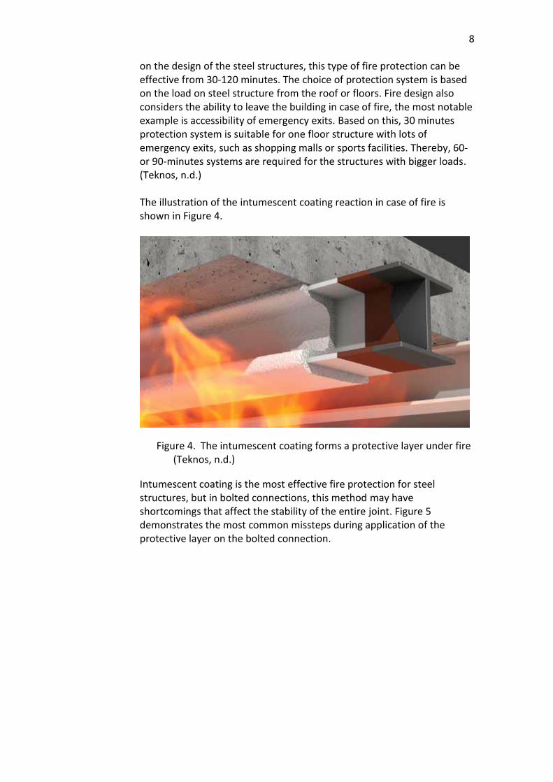
on the design of the steel structures, this type of fire protection can be effective from 30-120 minutes. The choice of protection system is based on the load on steel structure from the roof or floors. Fire design also considers the ability to leave the building in case of fire, the most notable example is accessibility of emergency exits. Based on this, 30 minutes protection system is suitable for one floor structure with lots of emergency exits, such as shopping malls or sports facilities. Thereby, 60- or 90-minutes systems are required for the structures with bigger loads. (Teknos, n.d.) The illustration of the intumescent coating reaction in case of fire is shown in Figure 4.
Figure 4. The intumescent coating forms a protective layer under fire (Teknos, n.d.)
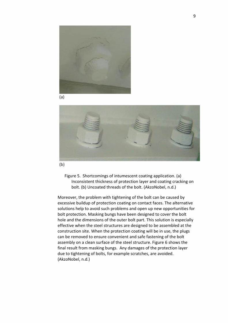
Intumescent coating is the most effective fire protection for steel structures, but in bolted connections, this method may have shortcomings that affect the stability of the entire joint. Figure 5 demonstrates the most common missteps during application of the protective layer on the bolted connection.
9
Figure 5. Shortcomings of intumescent coating application. (a) Inconsistent thickness of protection layer and coating cracking on bolt. (b) Uncoated threads of the bolt. (AkzoNobel, n.d.)
Moreover, the problem with tightening of the bolt can be caused by excessive buildup of protection coating on contact faces. The alternative solutions help to avoid such problems and open up new opportunities for bolt protection. Masking bungs have been designed to cover the bolt hole and the dimensions of the outer bolt part. This solution is especially effective when the steel structures are designed to be assembled at the construction site. When the protection coating will be in use, the plugs can be removed to ensure convenient and safe fastening of the bolt assembly on a clean surface of the steel structure. Figure 6 shows the final result from masking bungs. Any damages of the protection layer due to tightening of bolts, for example scratches, are avoided. (AkzoNobel, n.d.)

10
Figure 6. Masking bungs to avoid problem with bolt tightening (AkzoNobel, n.d.)
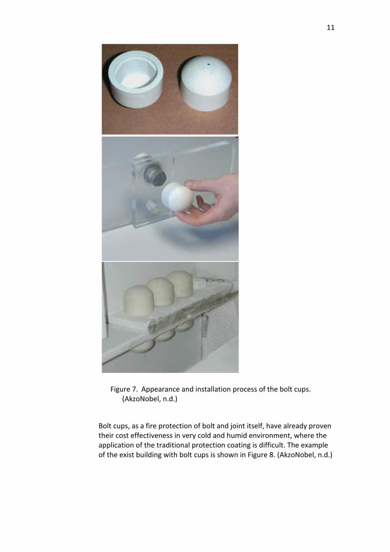
To protect the bolt itself from fire, bolt cups are installed over the bolt and connection can be considered as fully protected. Bolt cups and the installation procedure are shown in Figure 7. The bolt caps snap onto bolts and remain mechanically attached to the it even during a fire. It is suitable solution for outside and indoor steel structures. No special training for construction workers is required. (AkzoNobel, n.d.)
11
Figure 7. Appearance and installation process of the bolt cups. (AkzoNobel, n.d.)
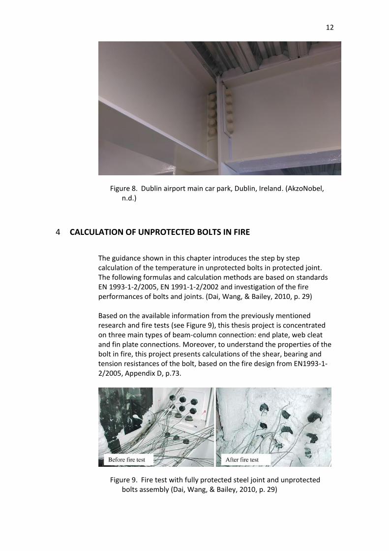
Bolt cups, as a fire protection of bolt and joint itself, have already proven their cost effectiveness in very cold and humid environment, where the application of the traditional protection coating is difficult. The example of the exist building with bolt cups is shown in Figure 8. (AkzoNobel, n.d.)
12
Figure 8. Dublin airport main car park, Dublin, Ireland. (AkzoNobel, n.d.)
4 CALCULATION OF UNPROTECTED BOLTS IN FIRE
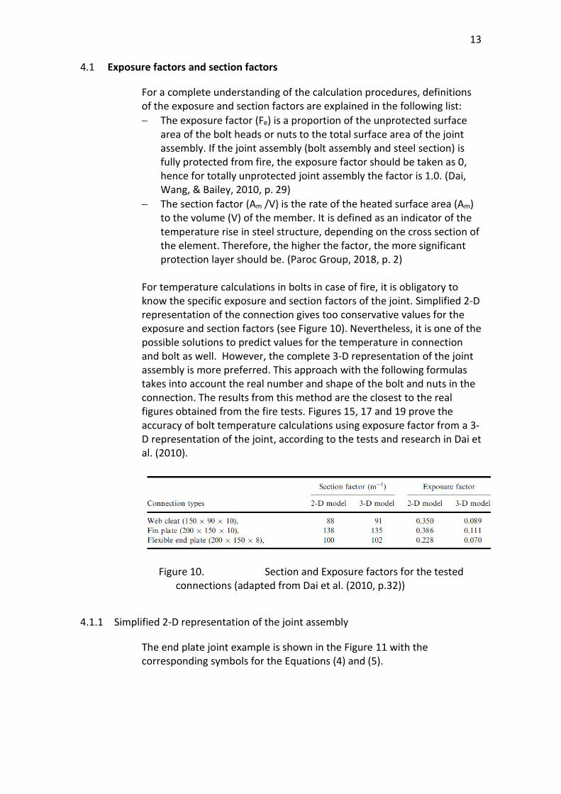
The guidance shown in this chapter introduces the step by step calculation of the temperature in unprotected bolts in protected joint. The following formulas and calculation methods are based on standards EN 1993-1-2/2005, EN 1991-1-2/2002 and investigation of the fire performances of bolts and joints. (Dai, Wang, & Bailey, 2010, p. 29) Based on the available information from the previously mentioned research and fire tests (see Figure 9), this thesis project is concentrated on three main types of beam-column connection: end plate, web cleat and fin plate connections. Moreover, to understand the properties of the bolt in fire, this project presents calculations of the shear, bearing and tension resistances of the bolt, based on the fire design from EN1993-1-2/2005, Appendix D, p.73.
Figure 9. Fire test with fully protected steel joint and unprotected bolts assembly (Dai, Wang, & Bailey, 2010, p. 29)
13
4.1 Exposure factors and section factors
For a complete understanding of the calculation procedures, definitions of the exposure and section factors are explained in the following list:
− The exposure factor (Fe) is a proportion of the unprotected surface area of the bolt heads or nuts to the total surface area of the joint assembly. If the joint assembly (bolt assembly and steel section) is fully protected from fire, the exposure factor should be taken as 0, hence for totally unprotected joint assembly the factor is 1.0. (Dai, Wang, & Bailey, 2010, p. 29)
− The section factor (Am /V) is the rate of the heated surface area (Am) to the volume (V) of the member. It is defined as an indicator of the temperature rise in steel structure, depending on the cross section of the element. Therefore, the higher the factor, the more significant protection layer should be. (Paroc Group, 2018, p. 2)
For temperature calculations in bolts in case of fire, it is obligatory to know the specific exposure and section factors of the joint. Simplified 2-D representation of the connection gives too conservative values for the exposure and section factors (see Figure 10). Nevertheless, it is one of the possible solutions to predict values for the temperature in connection and bolt as well. However, the complete 3-D representation of the joint assembly is more preferred. This approach with the following formulas takes into account the real number and shape of the bolt and nuts in the connection. The results from this method are the closest to the real figures obtained from the fire tests. Figures 15, 17 and 19 prove the accuracy of bolt temperature calculations using exposure factor from a 3-D representation of the joint, according to the tests and research in Dai et al. (2010).
Figure 10. Section and Exposure factors for the tested connections (adapted from Dai et al. (2010, p.32))
4.1.1 Simplified 2-D representation of the joint assembly
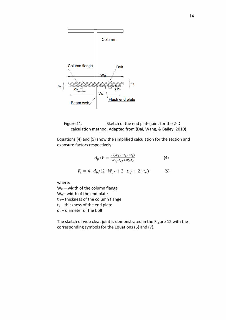
The end plate joint example is shown in the Figure 11 with the corresponding symbols for the Equations (4) and (5).
14
Figure 11. Sketch of the end plate joint for the 2-D calculation method. Adapted from (Dai, Wang, & Bailey, 2010)
Equations (4) and (5) show the simplified calculation for the section and exposure factors respectively.
𝐴𝑝/𝑉 =2∙(𝑊𝑐𝑓+𝑡𝑐𝑓+𝑡𝑒)
𝑊𝑐𝑓∙𝑡𝑐𝑓+𝑊𝑒∙𝑡𝑒 (4)
𝐹𝑒 = 4 ∙ 𝑑𝑏/(2 ∙ 𝑊𝑐𝑓 + 2 ∙ 𝑡𝑐𝑓 + 2 ∙ 𝑡𝑒) (5)
where: Wcf – width of the column flange We – width of the end plate tcf – thickness of the column flange te – thickness of the end plate db – diameter of the bolt The sketch of web cleat joint is demonstrated in the Figure 12 with the corresponding symbols for the Equations (6) and (7).
15
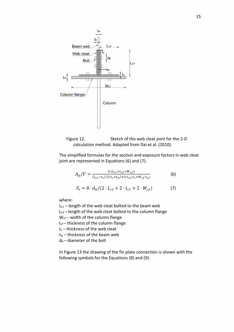
Figure 12. Sketch of the web cleat joint for the 2-D calculation method. Adapted from Dai et al. (2010).
The simplified formulas for the section and exposure factors in web cleat joint are represented in Equations (6) and (7).
𝐴𝑝/𝑉 =2∙(𝐿𝑐1+𝑡𝑐𝑓+𝑊𝑐𝑓)
(𝐿𝑐1−𝑡𝑐)∙(2∙𝑡𝑐+𝑡𝑤)+2∙𝐿𝑐2∙𝑡𝑐+𝑊𝑐𝑓∙𝑡𝑐𝑓 (6)
𝐹𝑒 = 8 ∙ 𝑑𝑏/(2 ∙ 𝐿𝑐1 + 2 ∙ 𝑡𝑐𝑓 + 2 ∙ 𝑊𝑐𝑓) (7)
where: Lc1 – length of the web cleat bolted to the beam web Lc2 – length of the web cleat bolted to the column flange Wcf – width of the column flange tcf – thickness of the column flange tc – thickness of the web cleat tw – thickness of the beam web db – diameter of the bolt In Figure 13 the drawing of the fin plate connection is shown with the following symbols for the Equations (8) and (9).
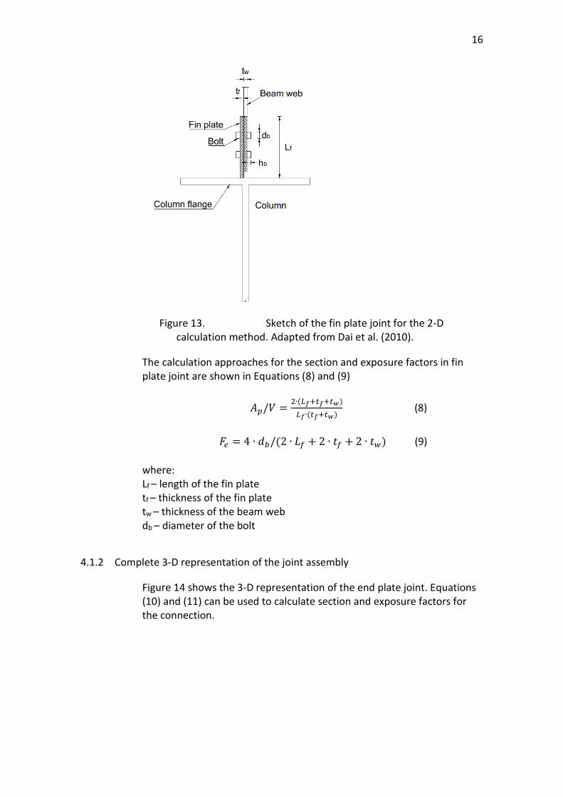
16
Figure 13. Sketch of the fin plate joint for the 2-D calculation method. Adapted from Dai et al. (2010).
The calculation approaches for the section and exposure factors in fin plate joint are shown in Equations (8) and (9)
𝐴𝑝/𝑉 =2∙(𝐿𝑓+𝑡𝑓+𝑡𝑤)
𝐿𝑓∙(𝑡𝑓+𝑡𝑤) (8)
𝐹𝑒 = 4 ∙ 𝑑𝑏/(2 ∙ 𝐿𝑓 + 2 ∙ 𝑡𝑓 + 2 ∙ 𝑡𝑤) (9)
where: Lf – length of the fin plate tf – thickness of the fin plate tw – thickness of the beam web db – diameter of the bolt
4.1.2 Complete 3-D representation of the joint assembly
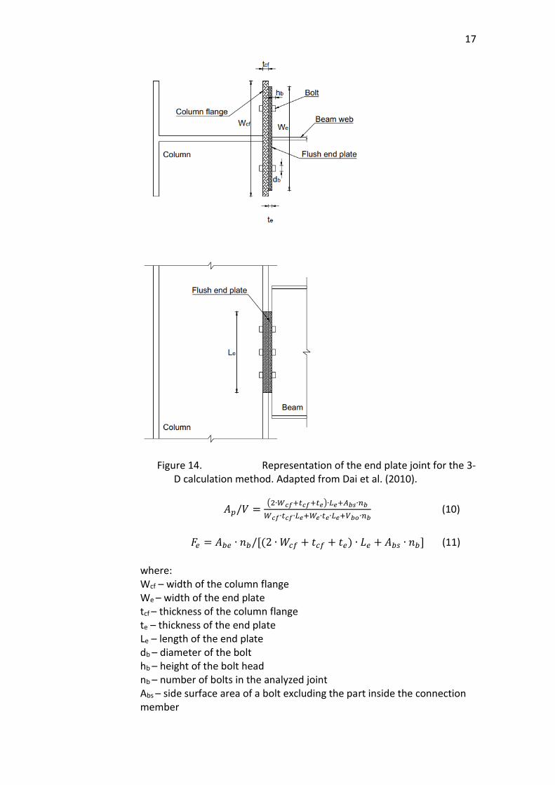
Figure 14 shows the 3-D representation of the end plate joint. Equations (10) and (11) can be used to calculate section and exposure factors for the connection.
17
Figure 14. Representation of the end plate joint for the 3-D calculation method. Adapted from Dai et al. (2010).
𝐴𝑝/𝑉 =(2∙𝑊𝑐𝑓+𝑡𝑐𝑓+𝑡𝑒)∙𝐿𝑒+𝐴𝑏𝑠∙𝑛𝑏
𝑊𝑐𝑓∙𝑡𝑐𝑓∙𝐿𝑒+𝑊𝑒∙𝑡𝑒∙𝐿𝑒+𝑉𝑏𝑜∙𝑛𝑏 (10)
𝐹𝑒 = 𝐴𝑏𝑒 ∙ 𝑛𝑏/[(2 ∙ 𝑊𝑐𝑓 + 𝑡𝑐𝑓 + 𝑡𝑒) ∙ 𝐿𝑒 + 𝐴𝑏𝑠 ∙ 𝑛𝑏] (11)
where: Wcf – width of the column flange We – width of the end plate tcf – thickness of the column flange te – thickness of the end plate Le – length of the end plate db – diameter of the bolt hb – height of the bolt head nb – number of bolts in the analyzed joint Abs – side surface area of a bolt excluding the part inside the connection member

18
𝐴𝑏𝑠 = 2 ∙ 𝜋 ∙ 𝑑𝑏 ∙ ℎ𝑏 Vbo – volume of a bolt and nut excluding the part inside connection member
𝑉𝑏𝑜 = 2 ∙ 𝜋 ∙ (𝑑𝑏
2)2 ∙ ℎ𝑏
Abe – two end surface area of a bolt
𝐴𝑏𝑒 = 2 ∙ 𝜋 ∙ (𝑑𝑏
2)2
Figure 15. Comparison of unprotected bolts temperatures based on 2-D and 3-D representations of the protected end plate connection. Adapted from Dai et al. (2010).
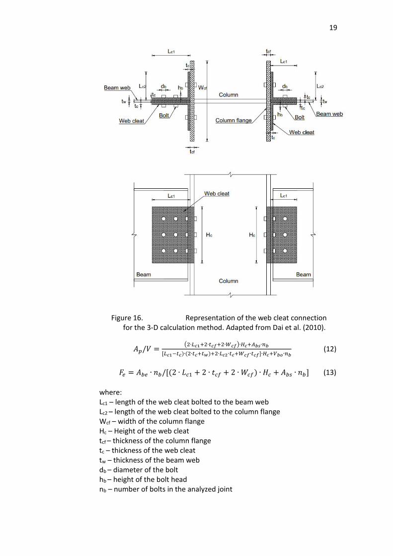
The 3-D representation of the web cleat joint is shown in Figure 16. Calculations of section and exposure factors can be done by using Equations (12) and (13).
19
Figure 16. Representation of the web cleat connection for the 3-D calculation method. Adapted from Dai et al. (2010).
𝐴𝑝/𝑉 =(2∙𝐿𝑐1+2∙𝑡𝑐𝑓+2∙𝑊𝑐𝑓)∙𝐻𝑐+𝐴𝑏𝑠∙𝑛𝑏
[𝐿𝑐1−𝑡𝑐)∙(2∙𝑡𝑐+𝑡𝑤)+2∙𝐿𝑐2∙𝑡𝑐+𝑊𝑐𝑓∙𝑡𝑐𝑓]∙𝐻𝑐+𝑉𝑏𝑜∙𝑛𝑏 (12)
𝐹𝑒 = 𝐴𝑏𝑒 ∙ 𝑛𝑏/[(2 ∙ 𝐿𝑐1 + 2 ∙ 𝑡𝑐𝑓 + 2 ∙ 𝑊𝑐𝑓) ∙ 𝐻𝑐 + 𝐴𝑏𝑠 ∙ 𝑛𝑏] (13)
where: Lc1 – length of the web cleat bolted to the beam web Lc2 – length of the web cleat bolted to the column flange Wcf – width of the column flange Hc – Height of the web cleat tcf – thickness of the column flange tc – thickness of the web cleat tw – thickness of the beam web db – diameter of the bolt hb – height of the bolt head nb – number of bolts in the analyzed joint
20
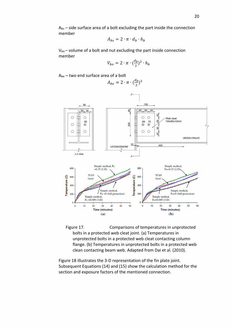
Abs – side surface area of a bolt excluding the part inside the connection member 𝐴𝑏𝑠 = 2 ∙ 𝜋 ∙ 𝑑𝑏 ∙ ℎ𝑏 Vbo – volume of a bolt and nut excluding the part inside connection member
𝑉𝑏𝑜 = 2 ∙ 𝜋 ∙ (𝑑𝑏
2)2 ∙ ℎ𝑏
Abe – two end surface area of a bolt
𝐴𝑏𝑒 = 2 ∙ 𝜋 ∙ (𝑑𝑏
2)2
Figure 17. Comparisons of temperatures in unprotected bolts in a protected web cleat joint. (a) Temperatures in unprotected bolts in a protected web cleat contacting column flange. (b) Temperatures in unprotected bolts in a protected web clean contacting beam web. Adapted from Dai et al. (2010).
Figure 18 illustrates the 3-D representation of the fin plate joint. Subsequent Equations (14) and (15) show the calculation method for the section and exposure factors of the mentioned connection.
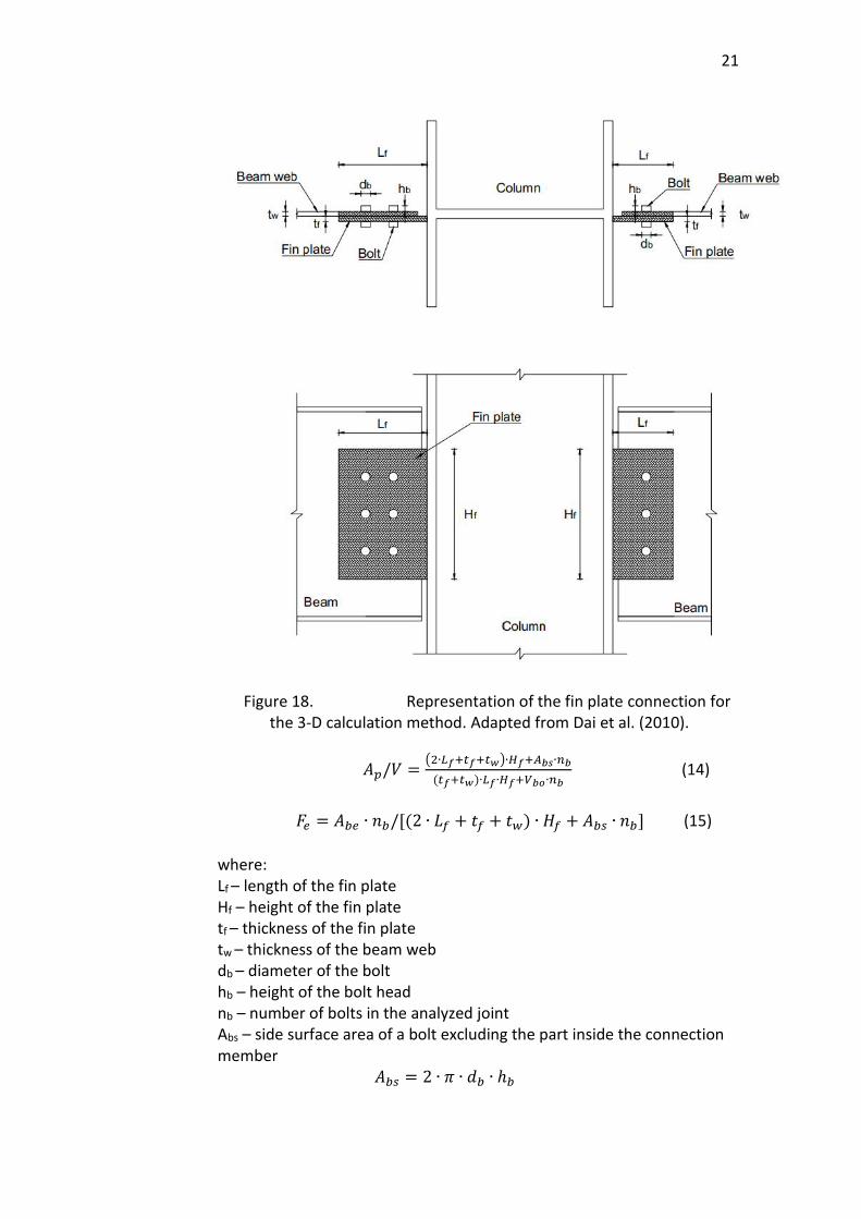
21
Figure 18. Representation of the fin plate connection for the 3-D calculation method. Adapted from Dai et al. (2010).
𝐴𝑝/𝑉 =(2∙𝐿𝑓+𝑡𝑓+𝑡𝑤)∙𝐻𝑓+𝐴𝑏𝑠∙𝑛𝑏
(𝑡𝑓+𝑡𝑤)∙𝐿𝑓∙𝐻𝑓+𝑉𝑏𝑜∙𝑛𝑏 (14)
𝐹𝑒 = 𝐴𝑏𝑒 ∙ 𝑛𝑏/[(2 ∙ 𝐿𝑓 + 𝑡𝑓 + 𝑡𝑤) ∙ 𝐻𝑓 + 𝐴𝑏𝑠 ∙ 𝑛𝑏] (15)
where: Lf – length of the fin plate Hf – height of the fin plate tf – thickness of the fin plate tw – thickness of the beam web db – diameter of the bolt hb – height of the bolt head nb – number of bolts in the analyzed joint Abs – side surface area of a bolt excluding the part inside the connection member 𝐴𝑏𝑠 = 2 ∙ 𝜋 ∙ 𝑑𝑏 ∙ ℎ𝑏
22
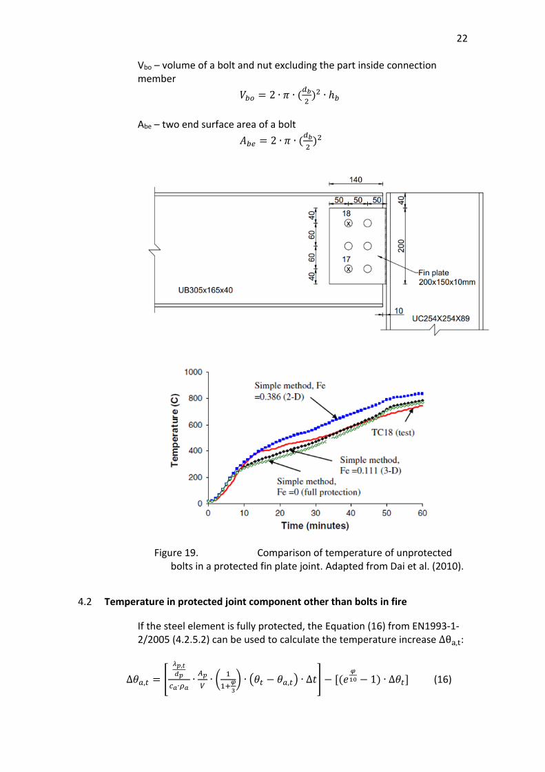
Vbo – volume of a bolt and nut excluding the part inside connection member
𝑉𝑏𝑜 = 2 ∙ 𝜋 ∙ (𝑑𝑏
2)2 ∙ ℎ𝑏
Abe – two end surface area of a bolt
𝐴𝑏𝑒 = 2 ∙ 𝜋 ∙ (𝑑𝑏
2)2
Figure 19. Comparison of temperature of unprotected bolts in a protected fin plate joint. Adapted from Dai et al. (2010).
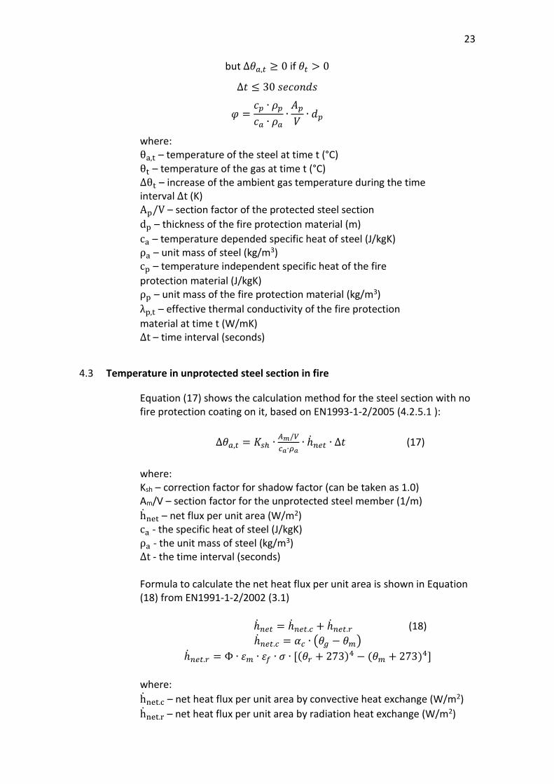
4.2 Temperature in protected joint component other than bolts in fire
If the steel element is fully protected, the Equation (16) from EN1993-1-2/2005 (4.2.5.2) can be used to calculate the temperature increase ∆θa,t:
∆𝜃𝑎,𝑡 = [
𝜆𝑝,𝑡
𝑑𝑝
𝑐𝑎∙𝜌𝑎∙
𝐴𝑝
𝑉∙ (
1
1+𝜑
3
) ∙ (𝜃𝑡 − 𝜃𝑎,𝑡) ∙ ∆𝑡] − [(𝑒𝜑
10 − 1) ∙ ∆𝜃𝑡] (16)
23
but ∆𝜃𝑎,𝑡 ≥ 0 if 𝜃𝑡 > 0
∆𝑡 ≤ 30 𝑠𝑒𝑐𝑜𝑛𝑑𝑠
𝜑 =𝑐𝑝 ∙ 𝜌𝑝
𝑐𝑎 ∙ 𝜌𝑎∙
𝐴𝑝
𝑉∙ 𝑑𝑝
where: θa,t – temperature of the steel at time t (°C) θt – temperature of the gas at time t (°C) ∆θt – increase of the ambient gas temperature during the time interval ∆t (K) Ap/V – section factor of the protected steel section
dp – thickness of the fire protection material (m)
ca – temperature depended specific heat of steel (J/kgK) ρa – unit mass of steel (kg/m3) cp – temperature independent specific heat of the fire
protection material (J/kgK) ρp – unit mass of the fire protection material (kg/m3)
λp,t – effective thermal conductivity of the fire protection
material at time t (W/mK) ∆t – time interval (seconds)
4.3 Temperature in unprotected steel section in fire
Equation (17) shows the calculation method for the steel section with no fire protection coating on it, based on EN1993-1-2/2005 (4.2.5.1 ):
∆𝜃𝑎,𝑡 = 𝐾𝑠ℎ ∙𝐴𝑚/𝑉
𝑐𝑎∙𝜌𝑎∙ ℎ𝑛𝑒𝑡 ∙ ∆𝑡 (17)
where: Ksh – correction factor for shadow factor (can be taken as 1.0) Am/V – section factor for the unprotected steel member (1/m)
hnet – net flux per unit area (W/m2) ca - the specific heat of steel (J/kgK) ρa - the unit mass of steel (kg/m3) ∆t - the time interval (seconds) Formula to calculate the net heat flux per unit area is shown in Equation (18) from EN1991-1-2/2002 (3.1)
ℎ𝑛𝑒𝑡 = ℎ𝑛𝑒𝑡.𝑐 + ℎ𝑛𝑒𝑡.𝑟 (18)
ℎ𝑛𝑒𝑡.𝑐 = 𝛼𝑐 ∙ (𝜃𝑔 − 𝜃𝑚)
ℎ𝑛𝑒𝑡.𝑟 = Φ ∙ 𝜀𝑚 ∙ 𝜀𝑓 ∙ 𝜎 ∙ [(𝜃𝑟 + 273)4 − (𝜃𝑚 + 273)4]
where:
hnet.c – net heat flux per unit area by convective heat exchange (W/m2)
hnet.r – net heat flux per unit area by radiation heat exchange (W/m2)
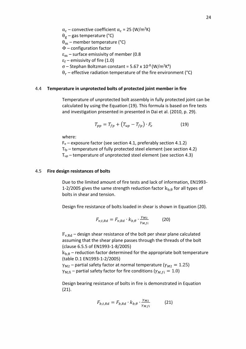
24
αc – convective coefficient αc = 25 (W/m2K) θg – gas temperature (°C)
θm – member temperature (°C) Φ – configuration factor εm – surface emissivity of member (0.8 εf – emissivity of fire (1.0) σ – Stephan Boltzman constant = 5.67 x 10⁻⁸ (W/m2K4) θr – effective radiation temperature of the fire environment (°C)
4.4 Temperature in unprotected bolts of protected joint member in fire
Temperature of unprotected bolt assembly in fully protected joint can be calculated by using the Equation (19). This formula is based on fire tests and investigation presented in presented in Dai et al. (2010, p. 29).
𝑇𝑝𝑝 = 𝑇𝑓𝑝 + (𝑇𝑢𝑝 − 𝑇𝑓𝑝) ∙ 𝐹𝑒 (19)
where: Fe – exposure factor (see section 4.1, preferably section 4.1.2) Tfp – temperature of fully protected steel element (see section 4.2) Tup – temperature of unprotected steel element (see section 4.3)
4.5 Fire design resistances of bolts
Due to the limited amount of fire tests and lack of information, EN1993-1-2/2005 gives the same strength reduction factor kb,θ for all types of bolts in shear and tension. Design fire resistance of bolts loaded in shear is shown in Equation (20).
𝐹𝑣,𝑡,𝑅𝑑 = 𝐹𝑣,𝑅𝑑 ∙ 𝑘𝑏,𝜃 ∙𝛾𝑀2
𝛾𝑀,𝑓𝑖 (20)
Fv,Rd – design shear resistance of the bolt per shear plane calculated assuming that the shear plane passes through the threads of the bolt (clause 6.5.5 of EN1993-1-8/2005) kb,θ – reduction factor determined for the appropriate bolt temperature (table D.1 EN1993-1-2/2005) γM2 – partial safety factor at normal temperature (𝛾𝑀2 = 1.25) γM,fi – partial safety factor for fire conditions (𝛾𝑀,𝑓𝑖 = 1.0)
Design bearing resistance of bolts in fire is demonstrated in Equation (21).
𝐹𝑏,𝑡,𝑅𝑑 = 𝐹𝑏,𝑅𝑑 ∙ 𝑘𝑏,𝜃 ∙𝛾𝑀2
𝛾𝑀,𝑓𝑖 (21)
25
Fb,Rd – design bearing resistance of the bolt at normal temperature
(clause 6.5.5 of EN1993-1-8/2005) Design tension resistance of a single bolt in fire is represented in Equation (22).
𝐹𝑡𝑒𝑛,𝑡,𝑅𝑑 = 𝐹𝑡,𝑅𝑑 ∙ 𝑘𝑏,𝜃 ∙𝛾𝑀2
𝛾𝑀,𝑓𝑖 (22)
Ft,Rd – design tension resistance of the bolt at normal temperature (clause 6.5.5 of EN1993-1-8/2005)
5 DESIGN TOOL IN EXCEL
One of the most efficient ways to calculate the temperature rise in the bolt connection is by using the excel tool. This thesis describes the design solution for SWECO Finland internal use. The excel table, introduced in section 5.1, is developed from earlier SWECO investigation about the temperature calculation.
5.1 Introduction of design tool
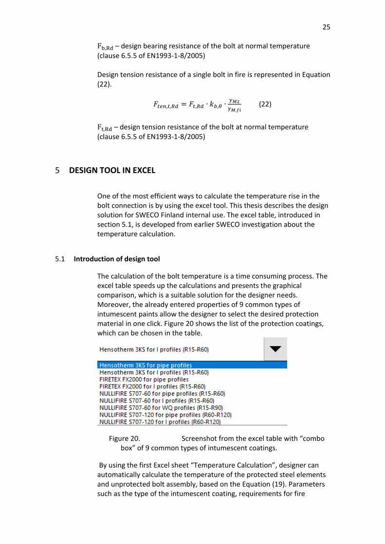
The calculation of the bolt temperature is a time consuming process. The excel table speeds up the calculations and presents the graphical comparison, which is a suitable solution for the designer needs. Moreover, the already entered properties of 9 common types of intumescent paints allow the designer to select the desired protection material in one click. Figure 20 shows the list of the protection coatings, which can be chosen in the table.
Figure 20. Screenshot from the excel table with “combo box” of 9 common types of intumescent coatings.
By using the first Excel sheet “Temperature Calculation”, designer can automatically calculate the temperature of the protected steel elements and unprotected bolt assembly, based on the Equation (19). Parameters such as the type of the intumescent coating, requirements for fire
26
resistance time (REI class), required strength of steel and bolts in per cents and dry thickness of the fire protection coating in (µm) can be chosen by the designer according to the project demands. After entering the initial data, the modified parameters are calculated automatically based on the chosen manufacturer. The cross section and exposure factors can be calculated by using the second Excel sheet “Section & Exposure Factors” by writing down the geometrical dimensions of one of the three commonly used joints with bolt assembly (see section 3.1.2) and by choosing the required bolt size. The results show the temperature difference and potential strength of the protected steel elements and unprotected bolts in case of fire. It is suitable and easy design tool for the future SWECO’s projects.
5.2 Calculation flow
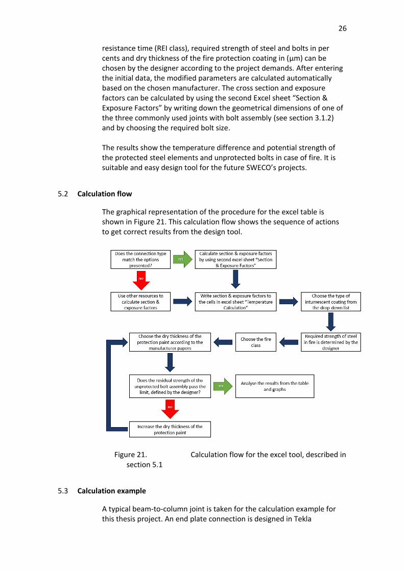
The graphical representation of the procedure for the excel table is shown in Figure 21. This calculation flow shows the sequence of actions to get correct results from the design tool.
Figure 21. Calculation flow for the excel tool, described in section 5.1
5.3 Calculation example
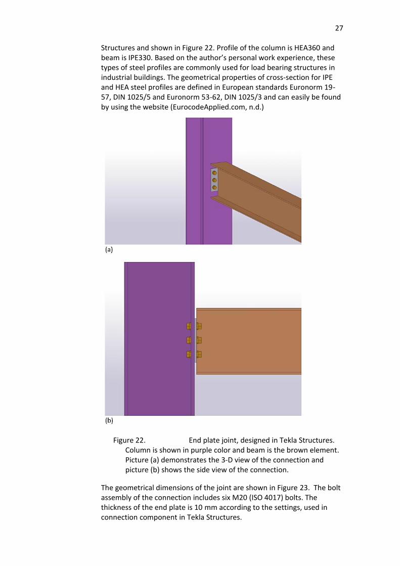
A typical beam-to-column joint is taken for the calculation example for this thesis project. An end plate connection is designed in Tekla
27
Structures and shown in Figure 22. Profile of the column is HEA360 and beam is IPE330. Based on the author’s personal work experience, these types of steel profiles are commonly used for load bearing structures in industrial buildings. The geometrical properties of cross-section for IPE and HEA steel profiles are defined in European standards Euronorm 19-57, DIN 1025/5 and Euronorm 53-62, DIN 1025/3 and can easily be found by using the website (EurocodeApplied.com, n.d.)
Figure 22. End plate joint, designed in Tekla Structures. Column is shown in purple color and beam is the brown element. Picture (a) demonstrates the 3-D view of the connection and picture (b) shows the side view of the connection.
The geometrical dimensions of the joint are shown in Figure 23. The bolt assembly of the connection includes six M20 (ISO 4017) bolts. The thickness of the end plate is 10 mm according to the settings, used in connection component in Tekla Structures.

28
Figure 23. Dimensions of the end plate joint, designed in Tekla Structures.
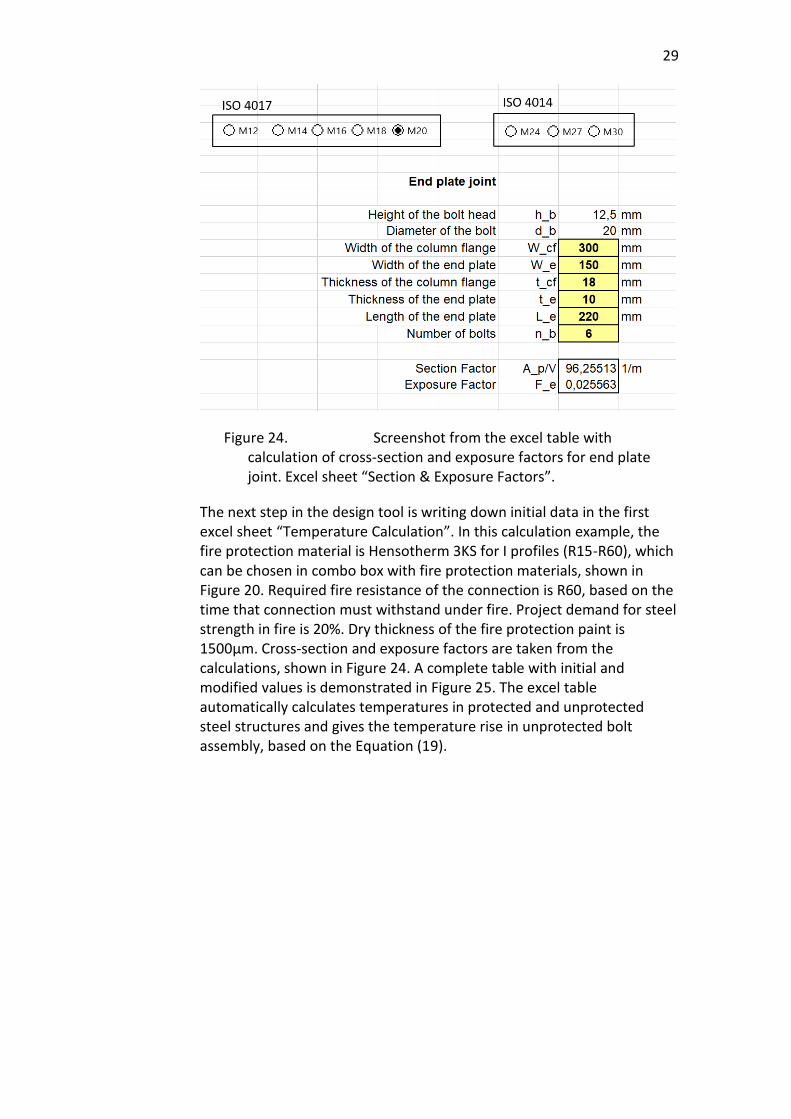
The first step in the designing tool is the calculation of cross-section and exposure factors by using the excel sheet “Section & Exposure Factors”. According to the procedure, described in thesis section 4.1, by choosing the bolt type and writing down geometrical parameters of the joint, the excel table calculates cross section and exposure factors of the preferred connection, based on formulas in section 3.1.2 of this thesis. A detailed screenshot from the design tool is shown in Figure 24.
29
Figure 24. Screenshot from the excel table with calculation of cross-section and exposure factors for end plate joint. Excel sheet “Section & Exposure Factors”.
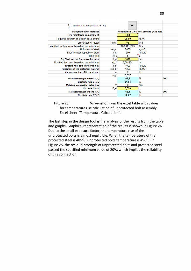
The next step in the design tool is writing down initial data in the first excel sheet “Temperature Calculation”. In this calculation example, the fire protection material is Hensotherm 3KS for I profiles (R15-R60), which can be chosen in combo box with fire protection materials, shown in Figure 20. Required fire resistance of the connection is R60, based on the time that connection must withstand under fire. Project demand for steel strength in fire is 20%. Dry thickness of the fire protection paint is 1500µm. Cross-section and exposure factors are taken from the calculations, shown in Figure 24. A complete table with initial and modified values is demonstrated in Figure 25. The excel table automatically calculates temperatures in protected and unprotected steel structures and gives the temperature rise in unprotected bolt assembly, based on the Equation (19).
30
Figure 25. Screenshot from the excel table with values for temperature rise calculation of unprotected bolt assembly. Excel sheet “Temperature Calculation”.
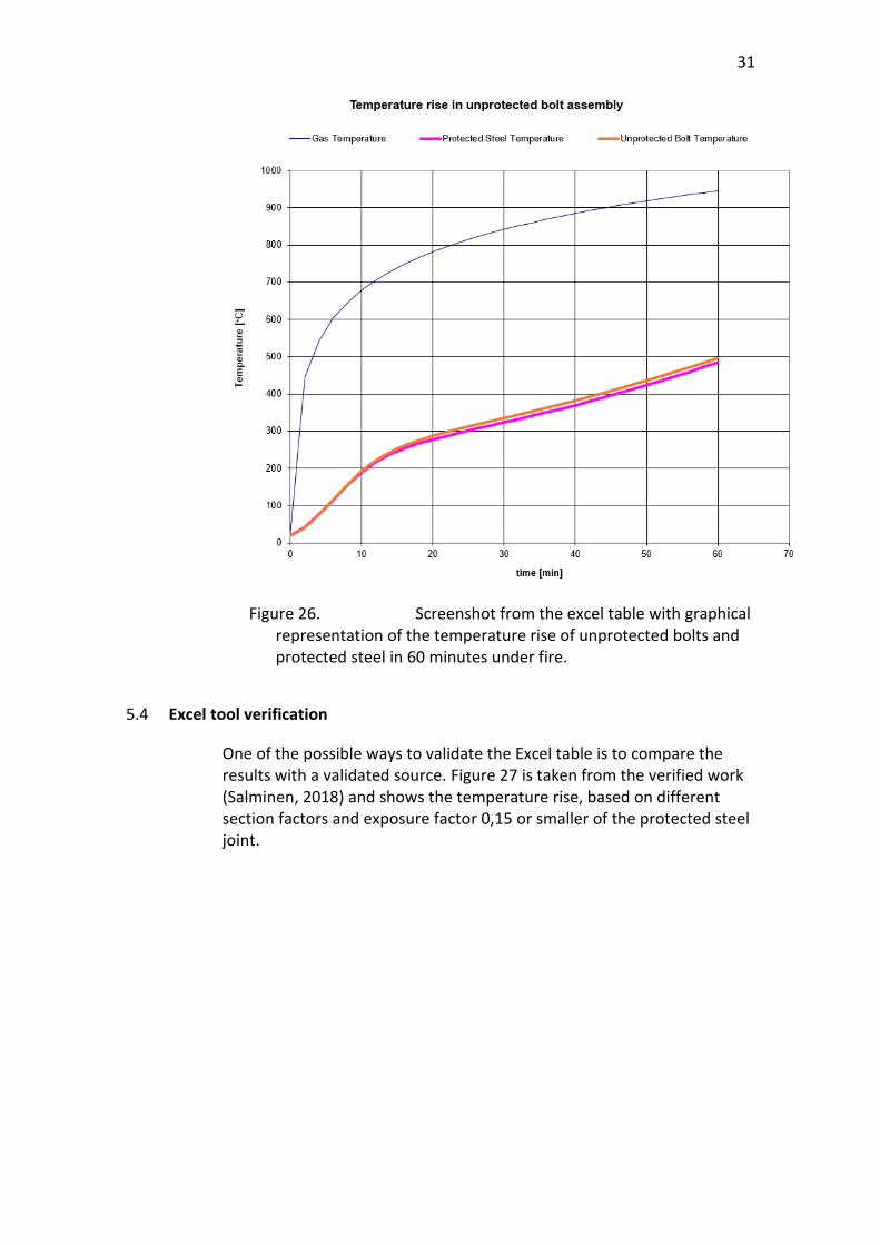
The last step in the design tool is the analysis of the results from the table and graphs. Graphical representation of the results is shown in Figure 26. Due to the small exposure factor, the temperature rise of the unprotected bolts is almost negligible. When the temperature of the protected steel is 485°C, unprotected bolts temperature is 496°C. In Figure 25, the residual strength of unprotected bolts and protected steel passed the specified minimum value of 20%, which implies the reliability of this connection.
31
Figure 26. Screenshot from the excel table with graphical representation of the temperature rise of unprotected bolts and protected steel in 60 minutes under fire.
5.4 Excel tool verification
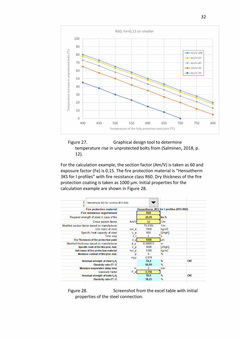
One of the possible ways to validate the Excel table is to compare the results with a validated source. Figure 27 is taken from the verified work (Salminen, 2018) and shows the temperature rise, based on different section factors and exposure factor 0,15 or smaller of the protected steel joint.
32
Figure 27. Graphical design tool to determine temperature rise in unprotected bolts from (Salminen, 2018, p. 12).
For the calculation example, the section factor (Am/V) is taken as 60 and exposure factor (Fe) is 0,15. The fire protection material is “Hensotherm 3KS for I profiles” with fire resistance class R60. Dry thickness of the fire protection coating is taken as 1000 µm. Initial properties for the calculation example are shown in Figure 28.
Figure 28. Screenshot from the excel table with initial properties of the steel connection.
R60, Fe=0,15 or smaller
Temperature of the fully protected steel joint (⁰C)
Tem
per
atu
re in
crea
se in
un
pro
tect
ed b
olt
s (⁰
C)
33
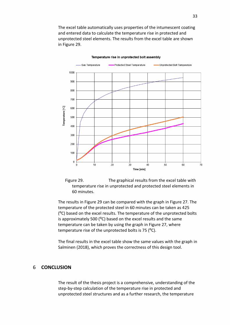
The excel table automatically uses properties of the intumescent coating and entered data to calculate the temperature rise in protected and unprotected steel elements. The results from the excel table are shown in Figure 29.
Figure 29. The graphical results from the excel table with temperature rise in unprotected and protected steel elements in 60 minutes.
The results in Figure 29 can be compared with the graph in Figure 27. The temperature of the protected steel in 60 minutes can be taken as 425 (⁰C) based on the excel results. The temperature of the unprotected bolts is approximately 500 (⁰C) based on the excel results and the same temperature can be taken by using the graph in Figure 27, where temperature rise of the unprotected bolts is 75 (⁰C). The final results in the excel table show the same values with the graph in Salminen (2018), which proves the correctness of this design tool.
6 CONCLUSION
The result of the thesis project is a comprehensive, understanding of the step-by-step calculation of the temperature rise in protected and unprotected steel structures and as a further research, the temperature

34
in bolt assembly. Moreover, more in-depth research about fire protection of bolted joints offered an alternative solution to intumescent coating. Bolt cups could be an effective and cheap choice in the Finnish construction market that is already used in some countries of western Europe. Conducting temperature calculations is a very time-consuming process that can lead to a large money loss for a company. Relying on the previous argument and a high probability of human mistake, this thesis project offers a designing tool. The excel table is a fast and accurate solution that will facilitate the calculation procedure of the temperature rise in bolted joints and show the bolts’ strength in fire for deciding on a separate protection for the bolts. Despite the fact that cross section and exposure factors are based on three main and commonly used steel connections (the end plate joint, web cleat joint and fin plate joint), the table can be used for other types of connections with cross section and exposure factors from different resources.
35
REFERENCES
AkzoNobel. (n.d.). The Performance and Protection of Bolted Connections in Fire.
Retrieved date from 12.03.2021. Retrieved from http://www.typhoonproducts.com/media/1047/15-10-15-protection-of-bolted-connections-ccr.pdf
Dai, X., Wang , Y., & Bailey, C. (2008). Effects of partial fire protection on temperature
developments in steel joints protected by intumescent coating. Fire Safety Journal, 376-386.
Dai, X., Wang, Y., & Bailey, C. (2010). A Simple Method to Predict Temperatures in Steel
Joints with Partial Intumescent Coating Fire Protection. Fire Technology, 19-35. EN 1991-1-2 (2002). Eurocode 1: Actions on structures. Part 1-2: General actions. Actions on structures exposed to fire EN 1993-1-2 (2005). Eurocode 3: Design of steel structures. Part 1-2: General rules - Structural fire design EN 1993-1-8 (2005). Eurocode 3: Design of steel structures. Part 1-8: Design of joints EurocodeApplied.com. (n.d.). Table of design properties for flanged steel profiles (IPE,
HEA, HEB, HEM). Retrieved date from 12.03.2021. Retrieved from https://eurocodeapplied.com/design/en1993/ipe-hea-heb-hem-design-properties
Franssen, J.-M., & Real, P. V. (2010). Fire Design of Steel Structures. ECCS - European
Convention for Construction Steelwork. Kodur , V., Kand , S., & Khaliq , W. (2012). Effect of Temperature on Thermal and
Mechanical Properties of Steel Bolts. Journal of materials in civil engineering, 765-774.
Paroc Group. (2018). Fire protection guide 1/steel. Salminen, M. (2018). Ruuvien palosuojaus lyhyt kirjallisuustarkastelu. Helsinki:
Teräsrakenneyhdistys ry. Teknos. (n.d.). Fire Protection. Coating Solutions for Steel. Retrieved date from
12.03.2021. Retrieved from https://www.teknos.com/globalassets/teknos.com/industrial-coatings/downloads/brochures/metal-wet-paint-brochures/teknos-fire-protection---coating-solutions-for-steel.pdf

36
Wald, F., Strejcek, M., & Ticha, A. (2006). On bolted connection with intumescent coatings.