Repairing and Maintenance of Pump Set [Diesel Engine and ...
Upload
khangminh22Category
view
0download
0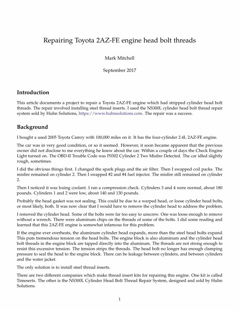
Repairing Toyota 2AZ-FE engine head bolt threads
Mark Mitchell
September 2017
Introduction
This article documents a project to repair a Toyota 2AZ-FE engine which had stripped cylinder head boltthreads. The repair involved installing steel thread inserts. I used the NS300L cylinder head bolt thread repairsystem sold by Huhn Solutions, https://www.huhnsolutions.com. The repair was a success.
Background
I bought a used 2005 Toyota Camry with 100,000 miles on it. It has the four-cylinder 2.4L 2AZ-FE engine.
The car was in very good condition, or so it seemed. However, it soon became apparent that the previousowner did not disclose to me everything he knew about the car. Within a couple of days the Check EngineLight turned on. The OBD-II Trouble Code was P0302 Cylinder 2 Two Misfire Detected. The car idled slightlyrough, sometimes.
I did the obvious things first. I changed the spark plugs and the air filter. Then I swapped coil packs. Themisfire remained on cylinder 2. Then I swapped #2 and #4 fuel injector. The misfire still remained on cylinder2.
Then I noticed it was losing coolant. I ran a compression check. Cylinders 3 and 4 were normal, about 180pounds. Cylinders 1 and 2 were low, about 140 and 130 pounds.
Probably the head gasket was not sealing. This could be due to a warped head, or loose cylinder head bolts,or most likely, both. It was now clear that I would have to remove the cylinder head to address the problem.
I removed the cylinder head. Some of the bolts were far too easy to unscrew. One was loose enough to removewithout a wrench. There were aluminum chips on the threads of some of the bolts. I did some reading andlearned that this 2AZ-FE engine is somewhat infamous for this problem.
If the engine ever overheats, the aluminum cylinder head expands, more than the steel head bolts expand.This puts tremendous tension on the head bolts. The engine block is also aluminum and the cylinder headbolt threads in the engine block are tapped directly into the aluminum. The threads are not strong enough toresist this excessive tension. The tension strips the threads. The head bolt no longer has enough clampingpressure to seal the head to the engine block. There can be leakage between cylinders, and between cylindersand the water jacket.
The only solution is to install steel thread inserts.
There are two different companies which make thread insert kits for repairing this engine. One kit is calledTimeserts. The other is the NS300L Cylinder Head Bolt Thread Repair System, designed and sold by HuhnSolutions.
1

After doing some reading, I decided the NS300L is what I would use. Visit https://www.huhnsolutions.comto read about it.
Installing the thread inserts involves drilling out the existing head bolt holes in the cylinder block to a largersize, then tapping the drilled holes to accept the steel insert, and threading the insert into the hole, using somethread locker glue to ensure it will not turn when the head bolts are installed.
The NS300L M11x1.5 Head Bolt Thread Repair Kit
This kit contains a set of steel thread inserts, the proper sized drill and tap, and a precision machined jig fordrilling and tapping the holes.
The kit includes:
Eleven steel thread inserts. (One extra, the engine needs 10). The insert has M11x1.5 threads on the inside,and 5/8" x 11 threads on the outside.
Figure 1: Steel thread insert
A 17/32" drill, and two 5/8" x 11 taps (one plug, one bottoming).
The alignment jig for drilling and tapping the holes.
Also included is a T-shaped wrench for screwing the inserts into the tapped holes, a ruler for measuring thedepth of the installed insert, some drilling and tapping fluid, and thread locker.
2

Figure 2: The steel thread insert is 1 3/4" long
Figure 3: A 17/32" drill, and two 5/8" x 11 taps (one plug, one bottoming)
3

Figure 4: The alignment jig for drilling and tapping the holes.
4

Figure 5: The complete kit
5

Tools and materials needed
In addition to the Huhn Solutions NS300L cylinder head bolt thread repair system, you also will need:
• A set of metric sockets and ratchets and wrenches.
• A 1/2" drive torque wrench.
• A special 10mm x 12-point "Double-Hex" socket to fit the cylinder head bolts. Toyota calls it a bi-hexagonsocket. It’s not a socket in the literal sense, it’s the inverse of a socket.
Figure 6: The head bolt head
You probably won’t find one on the shelf of your local auto parts store. Snap-on makes one. OTC alsomakes one. The one I used is the CTA Tools 9292 10mm Head Bolt Wrench (Toyota). It cost about $15.
Don’t be tempted to use a hexagon-shaped tool. Don’t be tempted to use a tri-square tool. The tri-squarelooks very similar, also having 12 points, but it is not the same. The angles on the points on the tri-squareare 90 degrees, whereas on the bi-hexagon they are 120 degrees.
Buy the proper tool. Using the incorrect tool will risk tearing up the socket on the cylinder head bolts.Really, buy the proper tool.
• A variable-speed electric drill with a 1/2" chuck.
• A shop vacuum. Drilling and tapping the head bolt holes produces a large quantity of aluminum chips.You should vacuum these chips away from your open engine, rather than just blowing them all over theengine compartment and shop floor.
• Packaging tape, for covering up the cylinders and water jacket and oil passages in the block whiledrilling and tapping, to keep aluminum chips from falling into the inside of the engine.
• An air compressor, and a wand with about a 6" tip on it, for cleaning out the bolt holes.
6

Figure 7: The correct double-hexagon socket driver
Figure 8: CTA Tools 9292 10mm Head Bolt Wrench (Toyota)
7

Figure 9: The shape of a double-hex driver
Figure 10: The shape of a triple-square driver. Don’t try to use this.
8
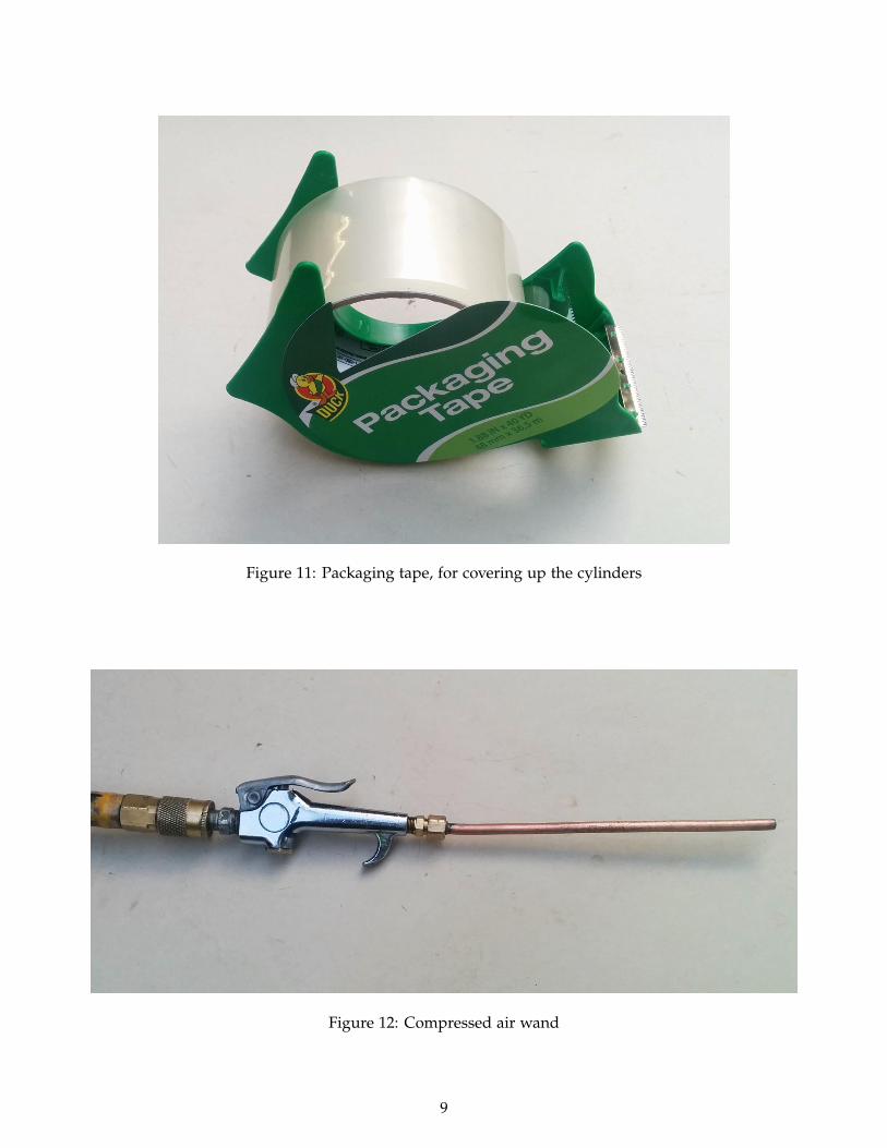
Figure 11: Packaging tape, for covering up the cylinders
Figure 12: Compressed air wand
9

• A gallon of mineral spirits, for cleaning parts and bolt holes.
• A cylinder head gasket set.
• A set of new cylinder head bolts and washers. Huhn Solutions recommends using genuine Toyota bolts,instead of Felpro or others. I can confirm this advice is sound. They cost twice as much as Felpro bolts($100 for ten Toyota bolts, vs. about $50 for ten Felpro bolts), but just spend the money.
Figure 13: Toyota head bolts
10

Removing the cylinder head
You can find some Toyota service manuals for the 2AZ-FE engine on the internet, if you search well.
You do have to remove the timing chain cover before you can remove the cylinder head. To do this, you alsohave to remove the water pump, alternator, belt tensioner, and power steering pump, and crankshaft pulley.To remove these, you have to jack up the car and remove the front passenger side tire, and the plastic splashguard. Place a jackstand to support the car, as you will be in this situation for a while.
To remove the belt tensioner you have to loosen the engine mount and jack up the engine a bit, to get a bolt toclear the fender well.
You also have to remove the oil pan in order to remove the timing chain cover.
The crankshaft pulley is held on by one RH-thread bolt, which is torqued to about 80 ft/lbs. Removing (orinstalling) that bolt requires some way to hold the crankshaft to keep it from turning. There is a special servicetool made for this. Unfortunately, it is difficult to find where I live, either for sale or for rent/borrow.
As you remove the cylinder head, be careful not to remove the steel buckets on top of the valve stems, or letthem fall out by turning the cylinder head upside down. Each bucket is a different thickness, specific to thevalve it is on top of. The cam-valve clearance is adjusted by using different thicknesses of buckets. If you takethem out and mix them up, it is a lot of work to sort out which ones go where and put them back on thecorrect valves.
Take your cylinder head to your friendly local machine shop to have it surfaced and checked for cracks andleaks. Make sure they install new valve stem seals.
Drilling the bolt holes
The instructions included with the NS300L kit explain clearly how to do the drilling, tapping, and insertinstallation. These instructions are very good, and I strongly suggest you read them multiple times, in orderto not miss anything.
You need to make sure none of the pistons are at top dead center, because the tops are not flat and parts ofthem would stick up above the cylinder block surface, and prevent the drill guide block from sitting true onthe surface.
Use the packaging tape to cover all the open parts of the cylinder block, to prevent aluminum chips fromfalling down inside the engine oil galleries and water jacket. Also cover the timing chain area.
Attach the jig block to the bare block surface, rather than on top of packaging tape. Then put tape over theadjacent areas, running up the side of the jig block a bit.
Use one of your new head bolts to attach the jig block, since the old bolts may have stretched threads.
After firmly bolting the jig block to the cylinder block, before you start drilling, make a visual inspection thatit is in fact aligned properly with the hole.
Use a variable-speed drill motor, and drill with a slow speed. I would drill about one inch, then remove thedrill to clean the chips. So it took about four of these drill-clean cycles to drill to full depth.
Place the nozzle of your shop vac close to the hole to suck up the chips as you pull the drill out. Afterremoving the drill, use your compressed air wand in the hole to blow remaining chips out, with your shopvac still vacuuming. Place a rag around the hole as a fence to try to keep the chips from flying all over.
11

Figure 14: Jig block attached to head
12

Figure 15: Jig block visual check before drilling
Tapping the bolt holes
Again, the instructions with the NS300L kit explain clearly how to do this.
I found that my tap wrench was too long. The handles would hit against the inner fender wells or other itemsin the engine compartment as the tapping progressed. I had a 1/2" drive T-handle to which I attached an11mm socket.
This 11mm socket fits the square drive on the top of the taps closely enough to work well, and the length ofthe handle was short enough to not interfere with other items in the engine compartment.
Tap as far as you can go with the jig block in place.
Then remove the jig block to tap the rest of the way.
The instructions say that the top of the insert should be 1 1/2" from the top of the engine block on my engine(2006 and older 2AZ-FE).
The insert is 1 3/4" long, so the depth of the tapped threads must be 3 1/4", or a bit more. The tap itself is 313/16" long.
So, to tap the threads to a depth of 3 1/4", only about 1/4" of tap will remain above the cylinder block surface.
After tapping, screw in an insert to see if the tapped threads are deep enough. I put a piece of tape on theinsert wrench to indicate the depth.
Then screw in a new head bolt to make sure it will go in far enough. I measured the distance through thecylinder head bolt hole to be about 2 1/8". Add to that the thickness of the head bolt washers which is about1/8". So the head bolt needs to be able to screw in far enough so the distance from the cylinder block surfaceand the bottom surface of the bolt head is less than 2 1/4" by a comfortable margin. Measure your owncylinder head and washers to be sure.
13

Figure 16: T-handle tap wrench
Figure 17: Tap with jig block
14

Figure 18: This is as far as you can go with jig block in place
15
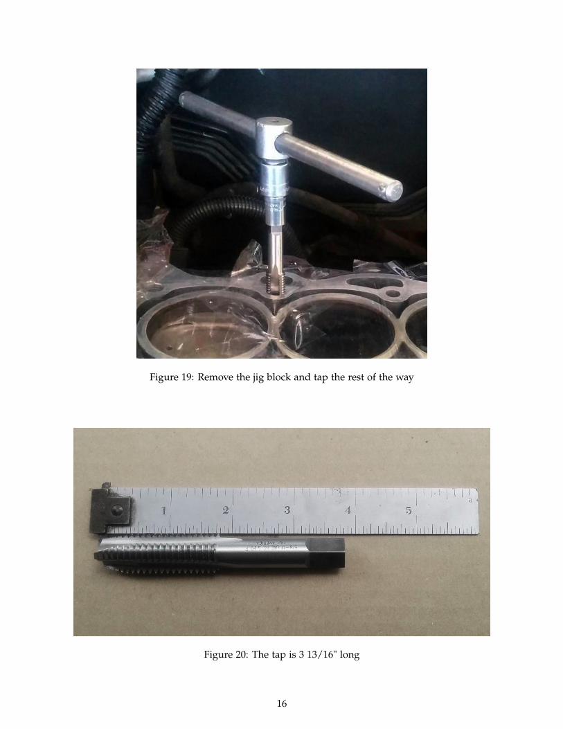
Figure 19: Remove the jig block and tap the rest of the way
Figure 20: The tap is 3 13/16" long
16

Figure 21: After tapping to a depth of 3 1/4", only about 1/4" of tap remains above the cylinder block surface
Figure 22: Insert wrench with tape to mark depth
17

Figure 23: Check the head bolt will screw in far enough
18
Once you have all the holes drilled and tapped and checked for depth, you can install the inserts with threadlocker. Read carefully the instructions:
Add a couple drops of Threadlock to the newly threaded hole approximately 1⁄2" to 3⁄4" from thedeck surface.
Add thread lock to the outside diameter of the insert.
Put the engine back together
Let the installed inserts sit overnight to allow the thread locker to cure before installing the cylinder head.
When you put the cylinder head on, double check that the block surface, the head surface, and the headgasket are all perfectly clean and there are no aluminum chips or other trash on any of them.
Follow the instructions provided with the NS300L kit regarding how to torque the head bolts.
After setting the cam timing, you might double check your work by manually rotating the engine through twocomplete revolutions to make sure the pistons do not hit the valves.
Don’t forget to put engine oil and coolant before starting the engine!
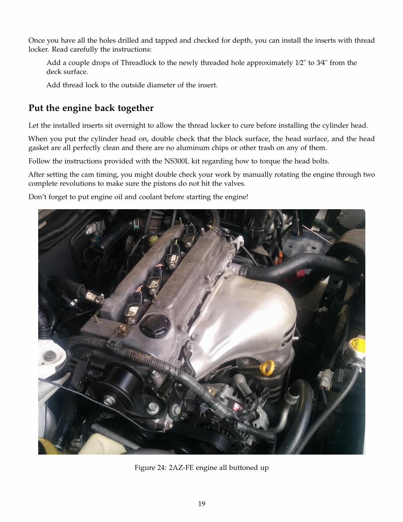
Figure 24: 2AZ-FE engine all buttoned up
19

Conclusion
This Camry 2AZ-FE engine runs great now. Since the repair the car has been driven about 2,000 miles. TheNS300L kit is very well thought out and designed, and I am very satisfied with how the repair turned out. Ialso had occasion to call Huhn Solutions with a couple of questions, and Mr. Huhn was extremely helpfuland gracious.
3 years later... The Camry now has been driven 22,000 miles since the repair, and has been running great eversince I finished this job.
20
Copyright © 2022 FDOKUMEN


![Panaeolus cinctulus [Bolt.] Saccardo et Panaeolus ... - DUMAS](https://static.fdokumen.com/doc/165x107/631dbceb3969c5af13078f6d/panaeolus-cinctulus-bolt-saccardo-et-panaeolus-dumas.jpg)