Steel Bridge Design Handbook - ROSA P
96
Steel Bridge Design Handbook November 2012 U.S. Department of Transportation Federal Highway Administration Bracing System Design Publication No. FHWA-IF-12-052 - Vol. 13
-
Upload
khangminh22 -
Category
Documents
-
view
1 -
download
0
Transcript of Steel Bridge Design Handbook - ROSA P

Steel Bridge Design Handbook
November 2012
U.S. Department of Transportation
Federal Highway Administration
Bracing System DesignPublication No. FHWA-IF-12-052 - Vol. 13
Notice
This document is disseminated under the sponsorship of the U.S. Department of Transportation in the interest of information exchange. The U.S. Government assumes no liability for use of the information contained in this document. This report does not constitute a standard, specification, or regulation.
Quality Assurance Statement
The Federal Highway Administration provides high-quality information to serve Government, industry, and the public in a manner that promotes public understanding. Standards and policies are used to ensure and maximize the quality, objectivity, utility, and integrity of its information. FHWA periodically reviews quality issues and adjusts its programs and processes to ensure continuous quality improvement.

Steel Bridge Design Handbook:
Bracing System Design
Publication No. FHWA-IF-12-052 - Vol. 13
November 2012


Technical Report Documentation Page
1. Report No. FHWA-IF-12-052 - Vol. 13
2. Government Accession No.
3. Recipient’s Catalog No.
4. Title and Subtitle
Steel Bridge Design Handbook: Bracing System Design 5. Report Date
November 2012 6. Performing Organization Code
7. Author(s) Todd Helwig, Ph.D. and Joseph Yura, Ph.D. (University of Texas at Austin)
8. Performing Organization Report No.
9. Performing Organization Name and Address
HDR Engineering, Inc. 11 Stanwix Street Suite 800 Pittsburgh, PA 15222
10. Work Unit No.
11. Contract or Grant No.
12. Sponsoring Agency Name and Address
Office of Bridge Technology Federal Highway Administration 1200 New Jersey Avenue, SE Washington, D.C. 20590
13. Type of Report and Period Covered
Technical Report March 2011 – November 2012
14. Sponsoring Agency Code
15. Supplementary Notes
16. Abstract
This module discusses the design of bracing systems for the superstructures of straight and curved girder systems. I-girder and box shaped members are covered. Bracing for other types of bridges, such as truss, arch or towers is not specifically addressed; however much of the information included in this module may be applicable. Bracing systems serve a number of important roles in both straight and horizontally curved bridges. The braces provide stability to the primary girders as well as improving the lateral or torsional stiffness and strength of the bridge system both during construction and in service. Depending on the geometry of the bridge, braces may be designated as either primary or secondary members. The engineer needs to recognize the importance of the bracing systems and bracing member design for appropriates construction and in-service stages. This module provides an overview of the design requirements of the braces so that engineers can properly size the members to ensure adequate strength and stiffness. The module provides: a) an overview of bracing utilized for I-girders is covered, b) a discussion of the bracing systems for tub girders, c) design requirements for the members and connections of bracing systems.
17. Key Words
Steel Bridge, Bracing, Bracing System, Bracing Design, I-girder, Tub-girder, Curved Girder, Top Flange Lateral Bracing, Lean-on Bracing
18. Distribution Statement
No restrictions. This document is available to the public through the National Technical Information Service, Springfield, VA 22161.
19. Security Classif. (of this report)
Unclassified 20. Security Classif. (of this page)
Unclassified 21. No of Pages
22. Price
Form DOT F 1700.7 (8-72) Reproduction of completed pages authorized

1
Steel Bridge Design Handbook:
Bracing System Design
Table of Contents FOREWORD .................................................................................................................................. 6
1.0 INTRODUCTION ................................................................................................................. 8
1.1 Torsional Behavior of Open and Closed Girders ............................................................. 8
1.2 Lateral Torsional Buckling ............................................................................................ 12
1.3 Categories of Bracing .................................................................................................... 12
2.0 BRACING OF I-GIRDERS ................................................................................................. 14
2.1 General Requirements .................................................................................................... 15
2.1.1 Cross Frame Spacing and Proportions .................................................................. 15
2.1.2 Top and Bottom Flange Lateral Systems .............................................................. 17
2.2 Cross-Frame Forces in Horizontally Curved Girders .................................................... 18
2.3 Stability Bracing of I-Girders ........................................................................................ 19
2.3.1 Torsional Bracing Design Requirements, T ........................................................ 22
2.3.2 Stiffness of Cross Frame and Diaphragm Systems b .......................................... 23
2.3.3 Web Distortional Stiffness, sec ............................................................................ 25
2.3.4 In-Plane Stiffness of Girders, g ........................................................................... 27
2.3.5 Connection Stiffness, conn .................................................................................... 28
2.4 Effects of Support Skew ................................................................................................ 29
2.5 Lean-On or Staggered Bracing ...................................................................................... 33
2.6 System Buckling of Interconnected Girders .................................................................. 38
2.7 Lateral Bracing Systems ................................................................................................ 41
2.8 Continuous Bracing ....................................................................................................... 44
3.0 BRACING OF TUB GIRDER SYSTEMS.......................................................................... 45
3.1 Top Flange Lateral Truss ............................................................................................... 46
3.1.1 Top Lateral Brace Forces ...................................................................................... 47
2
3.1.2 Selecting the Top Lateral Layout .......................................................................... 51
3.1.3 Determining the Brace Forces .............................................................................. 52
3.1.3.1 Torsion ................................................................................................ 53
3.1.3.2 Sloping Webs ...................................................................................... 54
3.1.3.3 Vertical Bending ................................................................................. 55
3.1.4 Top Flange Truss Details ...................................................................................... 57
3.1.5 Controlling Global Lateral Buckling .................................................................... 58
3.2 Intermediate Internal Cross Frames ............................................................................... 61
3.2.1 Tub Girder Distortion ........................................................................................... 62
3.2.2 Internal Cross Frame Details ................................................................................ 65
3.3 End Diaphragms............................................................................................................. 65
3.3.1 Diaphragm Strength Design Requirements .......................................................... 67
3.3.2 Diaphragm Stiffness Design Requirements .......................................................... 68
3.4 Intermediate External Cross Frames .............................................................................. 70
3.4.1 Analysis Approaches for Intermediate External Diaphragms .............................. 71
3.4.2 Spacing of Intermediate External K-frames ......................................................... 72
3.4.3 Forces in Intermediate External K-frames ............................................................ 72
4.0 BRACING MEMBER DESIGN AND CONNECTION DETAILS ................................... 75
4.1 Design of Tees and Angles ............................................................................................ 75
4.1.1 Tension Members.................................................................................................. 75
4.1.2 Compression Members ......................................................................................... 75
4.1.2.1 Single angles ....................................................................................... 75
4.1.2.2 Tees and Double Angles ..................................................................... 77
4.2 Fatigue Design of Cross-frame Members ...................................................................... 79
4.3 Welded and Bolted Connection Details ......................................................................... 79
5.0 SIMPLIFIED GEOMETRIC PROPERTIES FOR TUB GIRDERS ................................... 84
5.1 Shear Center, ey, for Open and Quasi-Closed Sections [59].......................................... 84
5.2 Monosymmetry Coefficient, x –Open section only [60] .............................................. 85
5.3 Warping Moment of Inertia, Cw -- Open section only [60] ............................................ 85
6.0 REFERENCES .................................................................................................................... 86

3
List of Figures
Figure 1 Warping Stiffness is Related to the Bending Stiffness of the Plate Elements................. 9
Figure 2 Shear Flow in Tub Girder Due to Saint-Venant Torsion .............................................. 11
Figure 3 Categories of Bracing .................................................................................................... 13
Figure 4 Collapse of a Bridge over the Tennessee River due to Insufficient Bracing ................. 14
Figure 5 Web Distortion .............................................................................................................. 21
Figure 6 Restraining Forces ......................................................................................................... 21
Figure 7 Bending Stresses in Singly Symmetric Section............................................................. 23
Figure 8 Diaphragm Stiffness, b ................................................................................................. 24
Figure 9 Stiffness Formulas for Twin Girder Cross Frames [20] ................................................ 25
Figure 10 Web Stiffener Geometry.............................................................................................. 26
Figure 11 Cross frame and Diaphragm Geometry ....................................................................... 26
Figure 12 Beam Load from Braces .............................................................................................. 28
Figure 13 Plan View of Bridge with Skewed Supports ............................................................... 29
Figure 14 Brace Orientations for Bridges with Skewed Supports ............................................... 30
Figure 15 Bent Plate Connection Detail Frequently Used in Bridges with Skewed Supports .... 32
Figure 16 Half-Pipe Web Stiffener .............................................................................................. 32
Figure 17 Summation of P Concept for Sideway Frame Stability ............................................ 33
Figure 18 Beams Linked Together at Compression Flange......................................................... 33
Figure 19 Graph of P Concept for Beams ................................................................................. 34
Figure 20 Lean on Cross Frame Bracing ..................................................................................... 35
Figure 21 Plan View of Bridge with Lean-On Cross Frame Bracing .......................................... 35
Figure 22 Lean on Bracing Layout in Bridge with Large Numbers of Girders ........................... 36
Figure 23 Stiffness and Strength Requirements for Lean-On Cross Frames ............................... 37
Figure 24 Staggered Cross Frame Layout ................................................................................... 38
Figure 25 System Buckling of a Twin Girder Widening, where the system has buckled out of
plane nearly 10 inches during deck placement ............................................................................. 39
Figure 26 Comparison of Individual Buckling Mode and System Buckling Mode .................... 40
Figure 27 Plan View of Typical Lateral (Relative) Bracing System ........................................... 42
Figure 28 Effective Length in X-type cross frames ..................................................................... 42
4
Figure 29 X-Framing Equilibrium ............................................................................................... 43
Figure 30 Twin Tub Girder System ............................................................................................. 45
Figure 31 Types of Bracing Systems for Tub Girders ................................................................. 45
Figure 32 Geometric Layout and Equivalent Plate Thickness of Top Lateral Systems [38] ...... 46
Figure 33 Top Lateral Truss Forces for Various Tub Girder Bracing Systems ........................... 50
Figure 34 Deformations of different box girder bracing systems ................................................ 51
Figure 35 Diagonal Lateral Brace Forces Due to Torsion in a Tub Girder ................................. 53
Figure 36 Strut Forces from Torsion ........................................................................................... 54
Figure 37 Strut Forces from Top Flange Loads ........................................................................... 54
Figure 38 Tub Girder Vertical Bending Stresses ......................................................................... 55
Figure 39 Bending Induced Truss Forces .................................................................................... 57
Figure 40 Strut eccentricity in a tub girder cross section ............................................................. 58
Figure 41 Effect of teq on global buckling on a tub girder section using a X-type lateral bracing
system ........................................................................................................................................... 60
Figure 42 Effect of Partial End Panel Bracing on Girder Buckling Stress .................................. 61
Figure 43 Internal Intermediate Cross-Frame Layouts for Tub Girders ...................................... 62
Figure 44 Sources of Torsion in a Tub Girder ............................................................................. 62
Figure 45 Pure Torsional and Distortional Components in a Tub Girder.................................... 63
Figure 46 Sign Convention for eccentricity ................................................................................. 63
Figure 47 Approximate Distortional Forces in Intermediate Cross Frames in a Tub Girder ...... 64
Figure 48 Typical End Diaphragm Geometry ............................................................................. 66
Figure 49 Non-continuous flanges illustrated by a 3D FEM of the end diaphragm of a twin box
girder model .................................................................................................................................. 66
Figure 50 Girder end torsional demand that acts on diaphragms and the resulting shears .......... 67
Figure 51 Idealized Rectangular Diaphragm Plate ...................................................................... 68
Figure 52 Girder and Diaphragm Deformations .......................................................................... 69
Figure 53 Relative Deformation between Adjacent Girders ........................................................ 70
Figure 54 K-frame Geometry ....................................................................................................... 73
Figure 55 External K-Frame Forces ............................................................................................ 73
Figure 56 Typical Test End Connection ...................................................................................... 76
Figure 57 Eccentrically loaded WT section ................................................................................. 77

5
Figure 58 Improper orientation and sizing of WT section used for top flange lateral bracing
member ......................................................................................................................................... 80
Figure 59 Strut offset below diagonal .......................................................................................... 81
Figure 60 Large gusset plates used so working lines of bracing members intersect ................... 82
Figure 61 Shim plates can significantly increase the eccentricity of WT sections leading to
excessive bending ......................................................................................................................... 82
Figure 62 Partial depth end diaphragm. ....................................................................................... 83
Figure 63 Calculation of Shear Center for Open and Quasi-Closed Sections ............................. 84

6
FOREWORD
It took an act of Congress to provide funding for the development of this comprehensive handbook in steel bridge design. This handbook covers a full range of topics and design examples to provide bridge engineers with the information needed to make knowledgeable decisions regarding the selection, design, fabrication, and construction of steel bridges. The handbook is based on the Fifth Edition, including the 2010 Interims, of the AASHTO LRFD Bridge Design Specifications. The hard work of the National Steel Bridge Alliance (NSBA) and prime consultant, HDR Engineering and their sub-consultants in producing this handbook is gratefully acknowledged. This is the culmination of seven years of effort beginning in 2005. The new Steel Bridge Design Handbook is divided into several modules and design examples as follows:
Bridge Steels and Their Properties Bridge Fabrication Steel Bridge Shop Drawings Structural Behavior Selecting the Right Bridge Type Stringer Bridges Loads and Combinations Structural Analysis Redundancy Limit States Design for Constructibility Design for Fatigue Bracing System Design Splice Design Bearings Substructure Design Deck Design Load Rating Corrosion Protection of Bridges Design Example: Three-span Continuous Straight I-Girder Bridge Design Example: Two-span Continuous Straight I-Girder Bridge Design Example: Two-span Continuous Straight Wide-Flange Beam Bridge Design Example: Three-span Continuous Straight Tub-Girder Bridge Design Example: Three-span Continuous Curved I-Girder Beam Bridge Design Example: Three-span Continuous Curved Tub-Girder Bridge
These modules and design examples are published separately for ease of use, and available for free download at the NSBA and FHWA websites: http://www.steelbridges.org, and http://www.fhwa.dot.gov/bridge, respectively.
7
The contributions and constructive review comments during the preparation of the handbook from many engineering processionals are very much appreciated. The readers are encouraged to submit ideas and suggestions for enhancements of future edition of the handbook to Myint Lwin at the following address: Federal Highway Administration, 1200 New Jersey Avenue, S.E., Washington, DC 20590.
M. Myint Lwin, Director Office of Bridge Technology

8
1.0 INTRODUCTION
Bracing systems serve a number of important roles in both straight and horizontally curved bridges. The braces provide stability to the primary girders as well as improving the lateral or torsional stiffness and strength of the bridge system both during construction and in service. Depending on the geometry of the bridge, braces may be designated as either primary or secondary members. In the AASHTO LRFD Specifications [1], the member designation as primary or secondary is typically assigned based upon whether the member has a design force obtained from a structural analysis. For example, a first-order analysis on a straight bridge during construction will often result in no forces in the cross frames and the braces are often designated as a secondary member. In many situations, the removal of the brace can result in a partial or complete collapse of the structure due to instabilities that can develop as a result of the larger unbraced length. In cases such as this, the engineer needs to recognize the importance of the brace and design the members accordingly. This module provides an overview of the design requirements of the braces so that engineers can properly size the members to ensure adequate strength and stiffness. In general, this module discusses the design of bracing systems for the superstructures of straight and curved girder systems. I-girder and box shaped members are covered throughout this module. Bracing for other types of bridges, such as truss, arch or towers is not specifically addressed; however much of the information included in the module may be applicable. The module has been divided into five primary sections. Following this introduction, an overview of bracing utilized for I-girders is covered. A discussion of the bracing systems for tub girders is then provided. The next section of the module outlines the design requirements for the members and connections of bracing systems. The final section contains simplified solutions for the calculation of geometric properties for tub girders. Regardless of whether the bracing systems are utilized in straight or horizontally curved girders, a clear understanding of the torsional behavior of both I-shaped and tub girder sections is important. The need for torsional stiffness in horizontally curved girders is relatively obvious since the girders are subjected to large torques due to the geometry of the bridge. However, understanding the necessity of adequate torsional stiffness in straight girders is also important since lateral-torsional buckling often controls the design of the girders during construction. In many sections, such as tub girders, the presence of bracing dramatically impacts the torsional stiffness of the section. Lateral instability of flexural members always involves torsion of the cross section. Therefore, the remainder of this introductory section is focused on the torsional stiffness of open and closed cross sections as well as a discussion of the buckling behavior of steel bridge systems. 1.1 Torsional Behavior of Open and Closed Girders
Torsional moments are resisted by the shear stresses on the girder cross section. The torsional resistance in thin-walled structures is usually categorized as either Saint-Venant torsional stiffness or warping torsional resistance. The Saint-Venant stiffness is often referred to as uniform torsion since the stiffness does not vary along the length and is also not sensitive to the

9
support conditions of the section. St. Venant torsion results in a pure shear deformation in the plane of the plates that make up the member. The warping torsional resistance, on the other hand, is often referred to as non-uniform torsion since the stiffness is associated with the bending deformation in the plane of the individual plates. The warping stiffness of a section is related to the member’s resistance to warping deformation. Two I-shaped sections subjected to a torque at the ends are shown in plan in Figure 1 to illustrate warping deformation and also warping stiffness. Figure 1a shows that warping deformation consists of a twist of the flanges relative to each other about a vertical axis through the web. Warping deformation distorts the cross section such that it no longer is a plane section because the two flanges have distorted relative to each other. Twist about the longitudinal axis of the member in Figure 1a is prevented at one end, however the warping deformations are not restrained. Since the section is free to warp along the entire length, the flanges remain straight as they twist relative to each other and the member only possesses St. Venant torsional stiffness.
warping
deformation
a) warpingpermitted
b) warpingrestrained
Figure 1 Warping Stiffness is Related to the Bending Stiffness of the Plate Elements.
The wide flange section in Figure 1b has both twist and warping deformation prevented at one end. With warping restrained at just one location along the length, the member cannot twist without bending the flanges. Since the flanges must bend if the member twists, the section therefore has warping stiffness. The warping torsion produces longitudinal stresses in the flanges of the member. Many members do not have a physical restraint preventing warping as shown in Figure 1b, however the member still has warping stiffness if twist is prevented at a minimum of two points along the longitudinal axis. The twist restraint can come from sources such as cross frames that prevent the section from rotating about the longitudinal axis, but otherwise do not specifically restrain warping deformation of the section. Since the bending stiffness is very sensitive to the unsupported length, the warping stiffness is highly variable with the unbraced length. In general, both Saint-Venant and warping torsional stiffness are developed when thin-walled members are twisted. The torsional moment resistance, TT, of a section is a function of the uniform torsional (TUT) and warping torsional (TW) components as follows: TT = TUT + TW (1) The uniform torsional component can be expressed as follows:

10
dxdGJTUT
(2)
where G is the shear modulus, J is the torsional constant, is the rotation of the cross section, and x denotes the longitudinal axis of the member. The torsional constant of an open section is given by the following expression:
i
iitb 3
31J
(3)
where bi and ti are the respective width and thickness of the plate elements that make up the cross section of the girder. The torsional constant for single cell box or tub girders is given by
i
ii tb /A4
J2
0
(4)
where A0 is the enclosed area of the cross section of the box girder, and the variables bi and ti in the summation are the respective width and thickness of the ith plate that make up the cross section. For example, in a box or tub girder with a cross section made up of four plates, the denominator in Equation 4 is calculated by simply summing the width-to-thickness ratios of the four plate elements. A0 is typically defined by the area enclosed from the mid-thickness of the plates that make up the cross section. The warping torsional component can be expressed as follows:
3
3
W dxdT
wEC
(5)
where E is the modulus of elasticity, and Cw is the warping constant. For I-shaped sections bent in the plane of the web, the warping constant is given by the expression: CW = It ho
2 (1-) (6)
y
yc
I
I
(7)
where Iyc and Iy are the respective moments of inertia for the compression flange and the entire section about an axis through the web, and ho is the spacing between flange centroids. For a doubly symmetric section, the value of is 0.5 and Equation 6 reduces to the following expression:
4
2oy
w
hIC
(8)

11
A rigorous theory for warping torsion was established by Vlasov [2]. The warping torsional stiffness often plays an important role in the total stiffness in girders with an open cross section such as I-shaped girders. For open sections with a relatively long length, the St. Venant stiffness dominates the total stiffness, while for shorter segments the warping torsional stiffness plays a much more significant component in the total stiffness. Closed box or tub girders are usually dominated by Saint-Venant torsion due to the closed cross section and the longitudinal normal stresses due to warping torsion are usually negligible [2]. The large Saint-Venant stiffness of a box or tub girder provides a torsional stiffness that may be 100~1000 times that of a comparable I-section. The shear stress due to Saint-Venant torsion can be solved using Prandtl’s membrane analogy [2]. For example, for girders with a single cell cross-section, a uniform shear flow, q, develops along the perimeter of the box and can be determined using the Bredt’s equation:
0
T
2ATt=q
(9)
in which t is the thickness of the plate, and is the shear stress, which is essentially uniform through the thickness of the plates. The distribution of torsional shear stress is demonstrated for a tub girder in Figure 2.
q
q
q= t
Figure 2 Shear Flow in Tub Girder Due to Saint-Venant Torsion
Although the torsional warping stresses in the box or tub girder are usually negligible, significant warping stresses due to the cross-sectional distortion of tub girders may develop, as is discussed later in this module. The large torsional stiffness of box or tub sections in bridges is the result of the closed cross section once the concrete deck cures. During construction of tub girders, the steel girder is an open section and requires bracing to be designed by the engineer that will stiffen the tub girder. The bracing systems for tub girders are covered later in the module.

12
1.2 Lateral Torsional Buckling
The overall stability of the girder system can be improved by either altering the geometry of the individual girders or by providing braces to reduce the unsupported length of the girders. Providing bracing is usually the more efficient solution and there are a variety of bracing systems that are provided as is discussed later in this module. The elastic buckling solution for doubly-symmetric beams is given in the following solution derived by Timoshenko [3]:
wy
2
by
bcr CI
LEπGJEI
LπM
(10) where, Lb is the unbraced length, and the other terms are as defined above. The first term under the radical in Eq. 10 relates to the St. Venant torsional stiffness, while the second term within the radical reflects the warping stiffness of the beam. Equation 10 was derived for the case of uniform moment loading. Most design specifications make use of solutions derived for uniform moment and then use a moment gradient factor (Cb) applied to the uniform moment solution to account for the benefits of variable moment. In the derivation of the buckling expression, Timoshenko assumed that the ends of the sections were restrained from twist. Although restraint against lateral translation of the section was stated in the original derivation, the assumed support condition was never applied or required to derive the expression. Therefore, effective bracing of beams can be achieved by restraining twist of the section, which is the primary means of bracing I-shaped members in bridges with the use of cross frames or diaphragms. Twist of the section can also be restrained by preventing lateral translation of the compression flange of the section, which therefore introduces another means of bracing. Both lateral and torsional bracing requirements are discussed later in this module. Lateral torsional buckling of closed box girders is not typically a concern due to the extremely large torsional stiffness of the closed cross section. During construction of tub girders a quasi-closed section is typically created by using bracing that simulates the stiffness of a top plate. Global buckling failures of tub girder sections have occurred during construction when proper bracing was not provided [4]. 1.3 Categories of Bracing
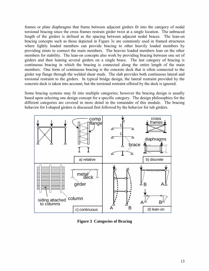
Bracing systems that are used to increase the stability of structural systems can be divided into the four categories represented in Figure 3. This section introduces the basic bracing categories, which are covered in more detail in the remainder of this module. Although the focus of this document is on bracing for the super-structure elements of steel bridges, the basic categories also apply to columns and frames, which is demonstrated in Figure 3. Diagonal bracing such as that depicted in Figure 3a fits into the category of relative bracing since the braces control the relative movement of two adjacent points at different lengths along the main members. The lateral trusses that are used to create quasi-closed tub girders and the bottom flange bracing on I-girder systems to improve the lateral stiffness fit into the category of relative bracing. Another very common type of bracing in steel bridges are nodal systems such as those depicted in Figure 3b. Nodal braces control the deformation of a single point along the length of the member. Cross
13
frames or plate diaphragms that frame between adjacent girders fit into the category of nodal torsional bracing since the cross frames restrain girder twist at a single location. The unbraced length of the girders is defined as the spacing between adjacent nodal braces. The lean-on bracing concepts such as those depicted in Figure 3c are commonly used in framed structures where lightly loaded members can provide bracing to other heavily loaded members by providing struts to connect the main members. The heavier loaded members lean on the other members for stability. The lean-on concepts also work by providing bracing between one set of girders and then leaning several girders on a single brace. The last category of bracing is continuous bracing in which the bracing is connected along the entire length of the main members. One form of continuous bracing is the concrete deck that is often connected to the girder top flange through the welded shear studs. The slab provides both continuous lateral and torsional restraint to the girders. In typical bridge design, the lateral restraint provided by the concrete deck is taken into account; but the torsional restraint offered by the deck is ignored. Some bracing systems may fit into multiple categories; however the bracing design is usually based upon selecting one design concept for a specific category. The design philosophies for the different categories are covered in more detail in the remainder of this module. The bracing behavior for I-shaped girders is discussed first followed by the behavior for tub girders.
a) relative
compflange
b) discrete
brace
crossframes
diaphragms
c) continuous d) lean-on
siding attachedto columns
metaldeck
girder
column
A B
B A
1
1
BA
Figure 3 Categories of Bracing
14
2.0 BRACING OF I-GIRDERS
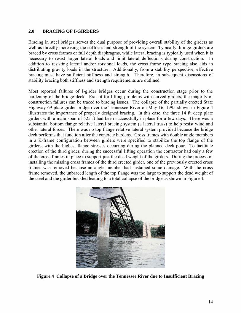
Bracing in steel bridges serves the dual purpose of providing overall stability of the girders as well as directly increasing the stiffness and strength of the system. Typically, bridge girders are braced by cross frames or full depth diaphragms, while lateral bracing is typically used when it is necessary to resist larger lateral loads and limit lateral deflections during construction. In addition to resisting lateral and/or torsional loads, the cross frame type bracing also aids in distributing gravity loads in the structure. Additionally, from a stability perspective, effective bracing must have sufficient stiffness and strength. Therefore, in subsequent discussions of stability bracing both stiffness and strength requirements are outlined. Most reported failures of I-girder bridges occur during the construction stage prior to the hardening of the bridge deck. Except for lifting problems with curved girders, the majority of construction failures can be traced to bracing issues. The collapse of the partially erected State Highway 69 plate girder bridge over the Tennessee River on May 16, 1995 shown in Figure 4 illustrates the importance of properly designed bracing. In this case, the three 14 ft. deep plate girders with a main span of 525 ft had been successfully in place for a few days. There was a substantial bottom flange relative lateral bracing system (a lateral truss) to help resist wind and other lateral forces. There was no top flange relative lateral system provided because the bridge deck performs that function after the concrete hardens. Cross frames with double angle members in a K-frame configuration between girders were specified to stabilize the top flange of the girders, with the highest flange stresses occurring during the planned deck pour. To facilitate erection of the third girder, during the successful lifting operation the contractor had only a few of the cross frames in place to support just the dead weight of the girders. During the process of installing the missing cross frames of the third erected girder, one of the previously erected cross frames was removed because an angle member had sustained some damage. With the cross frame removed, the unbraced length of the top flange was too large to support the dead weight of the steel and the girder buckled leading to a total collapse of the bridge as shown in Figure 4.
Figure 4 Collapse of a Bridge over the Tennessee River due to Insufficient Bracing

15
Bracing systems for I-girders may consist of combinations of cross frames, solid diaphragms, as well as top and/or bottom flange lateral truss systems. In this module the term cross frame will generally be used to also represent solid diaphragms since their functions are similar. For straight girders the bracing system design is typically dominated by stability and skew issues. In horizontally curved girders, the effects of torsion and lateral flange bending generally control the bracing design. This section discusses bracing on two levels: 1) Bracing needed to transfer loads within a bridge system, and 2) Bracing required to provide stability to the bridge system. In the following subsections, the design requirements and geometric arrangements for bracing systems affected by torsion, stability and skew are presented. Sections 2.1 and 2.2 provide general design requirements necessary to properly transfer the static and transient loads within a bridge system. Section 2.3 provides details for the computations associated with determining the stability requirements of a given bridge system. Also discussed within this section are the effects that support skew has on bracing systems, the use of lean-on and staggered bracing, system buckling of interconnected girders, lateral bracing systems, and continuous bracing systems. The details and equations provided in Section 2.3 can be used to determine the stability bracing forces. These equations and methods are usually sufficient for typical I-girder bridges, including straight, curved, and skewed bridges. Using these equations the stability bracing forces are additive to the bracing forces resulting from a first-order type of analysis (dead load, live load, etc.). For more complex bridges, or as alterative to using the equations discussed in Section 2.3, a large displacement analysis can be used to determine the bracing forces. In this type of analysis, the bracing forces will include the bracing forces required to transfer loads within the bridge system and the bracing forces required for stability. When a large displacement analysis is used, the effects of imperfections must be considered in order to achieve the desired analysis results. Furthermore, the equations provided in Section 2.3 will generally yield conservative bracing forces, as compared to those that result from a large displacement analysis. 2.1 General Requirements
For I-girder bridge systems the most common bracing is a discrete torsional system consisting of cross frames with a K- or X-configuration. Solid plate or channel diaphragms are also used. The braces are usually fabricated from angles or of solid diaphragms constructed with channel-type sections for ease in attachment to girder stiffeners. In addition, top or bottom lateral truss bracing (a relative brace system) may be needed as temporary bracing during construction or permanent bracing to mainly resist wind loads. The requirements given below for cross frames and lateral flange bracing are generally taken from AASHTO [1]. 2.1.1 Cross Frame Spacing and Proportions
Cross frames are necessary at all supports of straight and curved I-girder bridges to transfer lateral loads from the superstructure to the bearings, to provide no-twist boundary conditions for lateral buckling evaluation and transmit torsional overturning and uplift forces to the foundation. For straight girders, previous bridge specifications required that intermediate cross frames be spaced at no more than 25 feet. Since the first publication of the AASHTO LRFD Bridge Design

16
Specification in 1994, this requirement has been replaced with the statement that the cross-frame spacing should be determined by a rational analysis [1]. The elimination of the specified maximum spacing for straight girders is intended to result in a reduction in the number of fatigue-prone attachments. However, States may have their own requirements and preferred practices regarding cross-frame spacing that may supersede the AASHTO LRFD Bridge Design Specifications. To determine the spacing of intermediate cross-frames, at a minimum, a rational analysis should consider the following:
The need for cross frames during all stages of the assumed construction staging, as well as in the final condition.
Lateral support to bottom flange for deck overhang construction brackets. Sufficient transfer of lateral wind loads from the bottom of the girder to the deck. Stability of the bottom flange for loads producing compression in the bottom flange. Stability of the top flange for loads producing compression, especially during the
construction stage or for non-composite systems. Control of flange lateral bending effects. Distribution of vertical dead and live loads applied to the structure.
Typically, cross frames play a more active role in horizontally curved steel girder bridges compared to straight girder bridges without significant skew. Curved girders are subjected to combined bending and torsion. Without cross frames, the flanges of the I-section would have to be prohibitively large to control the flange lateral bending stresses (warping normal stresses) that are combined with the ordinary bending stresses. Cross frames allow the girders to work together as a system to resist the torsion on the curved bridge and they limit the lateral bending stresses by supplying torsional supports along the span. Therefore, cross-frame members in curved bridges are considered primary members, and should be designed for forces computed by appropriate analysis methods (see Section 2.2). In curved I-girder bridges, the cross frames should be orientated in a radial manner throughout the span, whenever possible (In curved and skewed bridges, cross frames at the supports may be placed along the skew or in a radial manner, and are often orientated in a radial manner within the span.) The spacing of the cross frames, Lb, must control lateral buckling of the compression flange and limit the magnitude of the flange lateral bending stresses. Davidson et al. [5] developed an equation for the spacing required to limit the flange lateral bending stresses to a specified percentage of the ordinary flange bending stress. However, AASHTO specifies a maximum Lb limit as shown in the following expression:
ft 300.7F
Er π0.1RLy
tb (11)
where R is the radius of curvature and rt is the radius of gyration for lateral buckling. The reasoning for these limits is given in the Behavior module (Section 5.3.7).
17
For straight girders with skewed supports, the relative displacement of the two ends of a cross frame or diaphragm system can introduce significant live load forces into stiff bracing systems, especially near supports. These displacement forces can cause fatigue issues at connections. The skew also affects the stability brace stiffness and strength requirements. Where the supports are not skewed more than 20 degrees, intermediate diaphragms are typically placed in contiguous skewed lines parallel to the skewed supports. Where the supports are skewed more than 20 degrees, cross-frames are typically placed perpendicular to the girders on contiguous or discontinuous lines. In cases where supports are skewed more than 20 degrees, it may be advantageous to place cross-frames in discontinuous lines in an effort to reduce the transverse stiffness of the bridge, particularly near interior supports. Placing the cross-frames in discontinuous lines can decrease cross frame forces, but increase flange lateral bending effects (see Sections 2.3.2 and 2.3.3). Diaphragms and cross-frames for rolled beams and plate girders should be as deep as practicable, but as a minimum should be at least 0.5 times the beam depth for rolled beams and 0.75 times the girder depth for plate girders. Cross frames should contain diagonals and top and bottom chords even if analysis shows that a chord force is zero. The flexural stiffness of a cross frame without a top or bottom chord is substantially reduced and may become ineffective as a stability brace. Several orientations are possible for a cross-frame, such as an X-shape with top and bottom chords, and K-shape where the diagonals intersect the bottom chord, or a K-shape where the diagonals intersect the top chord. Cross-frame truss assemblies are preferably field delivered as a single unit rather than individual pieces for erection efficiency as well as assisting the erector with girder alignment. Efficient cross frames are typically as deep as practical so that the diagonals of the cross frame have large enough angles to prevent the gusset-type plates at the ends of the cross frame from becoming too large. For cases requiring relatively shallow cross frames, the diagonals of X-systems may be subjected to large axial forces with large unbraced lengths. In these cases, K-frame systems should be considered. 2.1.2 Top and Bottom Flange Lateral Systems
In steel I-girder bridges, the need for lateral bracing should be investigated for all stages of construction, and the final condition. Lateral bracing may be required to resist lateral forces from wind and during construction, when the deck is not in place. When lateral bracing is required, it should be placed either in or near the plane of the flange being braced. Connecting the lateral bracing directly to the flange with a bolted connection (with or without a connection plate) is a preferred practice, as it eliminates the need for connection elements on the girder web that can be sensitive to fatigue issues. In addition, connecting directly to the flange provides a direct load path that improves the structural efficiency. To help prevent lateral movement of the structural system during construction, especially in spans greater than 250 feet, it may be desirable to consider providing either temporary or permanent flange level lateral bracing. Flange level lateral bracing may also be needed in deck replacement projects on long span bridges. In the final condition, the concrete deck can typically resist lateral wind loads and prevent significant horizontal movement of the structure. However, if the deck requires replacement and is removed, lateral deflections due to wind can be excessive in long span bridges without lateral bracing. The large lateral flexibility may make the

18
construction workers uncomfortable or can result in system instability. Essentially, a lateral bracing system will stiffen a non-composite structure significantly, as compared to one without any lateral bracing. As noted above, top flange level lateral bracing is preferred. When located in the same plane as the top flange, the bracing is near the neutral axis of the final composite structure. As such, the bracing located at the top flange will not be subjected to significant live load forces in the final condition. In general, forces during construction related to wind and dead load will govern the design of top flange level lateral bracing. If top flange lateral bracing is subjected to live load forces in the finished structure, fatigue aspects of the detailing should be considered. Also, when top flange lateral bracing is connected directly to the top flange, the deck formwork needs to be detailed to avoid interference with the bracing members. For straight simply-supported girders, a top lateral may be more advantageous than intermediate cross frames, especially for aesthetic purposes. Bottom lateral bracing can provide a similar function as top lateral bracing, but the lateral trusses can experience large forces induced by vertical bending of the I-girders, similar to those reported in tub girders by Fan and Helwig [7]. These live load forces that result from the vertical bending need to be considered by the designer. In I-girder bridges, bottom lateral bracing creates a pseudo-closed section formed by the I-girders connected with bracing and the concrete deck. In curved bridges where torsion is always present, the lateral truss will contribute significantly to the torsional stiffness of the bridge system. In addition to significant bottom flange level bracing forces caused by the torsion and pseudo-box effects, cross-frame forces will also be larger as the cross-frames act to retain the shape of the pseudo-box section. 2.2 Cross-Frame Forces in Horizontally Curved Girders
Cross frames are primary members in horizontally curved I-girder bridges. The cross-frame forces from bending and torsion in all phases of construction and loading can be determined directly from a first-order structural analysis of the bridge system. (Here, first-order structural analysis refers to a typical design analysis for static and transient loads.) Guidelines for proper modeling of the cross frames in 3D-FEA or grid analyses are described in the Structural Analysis module of this handbook and in the AASHTO/NSBA [8]. The availability of computer programs to determine the forces during erection and staged deck pours is improving [9]. Stability brace forces can be determined using equations and methods discussed in Section 2.3. Alternatively, brace forces can be determined by a large displacement analysis on straight and curved girders, provided the effects of imperfections are considered. The necessity of including the imperfections in the analysis is generally dependent on the degree of horizontal curvature. If a first order analysis is used, stability brace force requirements (discussed later in this section) should be added to the forces resulting from the first-order structural analysis of the curved system. For straight and mildly-curved girders (radius approximately greater than 1200 feet), stability forces will typically dominate. Initial imperfections are not important for girders with significant curvature. Cross-frame forces can be determined directly from 3D analysis methods, and somewhat directly from 2D analysis methods. Cross-frame forces can also be determined by the approximate V-

19
load method mentioned in the Structural Analysis module. The development of the V-load method is documented by Peollet [10]. The lateral flange bending curvature effects are approximated by applying equal and opposite lateral loads, q = M/Rho, to each flange of an equivalent length straight girder where R is the radius of curvature of the bridge. M is the girder moment due to gravity loading and also vertical V- loads that are equivalent to the overturning torsional moment in the curved system. The cross frames provide lateral support to each flange with equal and opposite reactive forces qLb, where Lb is the spacing of the cross frames. The distribution of the cross-frame end moments and shears across a transverse section of the bridge is determined by equilibrium considerations only. The distribution of cross-frame end moments and shears have been conveniently summarized by Liu and Magliola [11] for systems ranging from 2-girder to 8-girder bridges. Design examples applying the V-load method are available [10, 12]. The V-load method cannot be used if there is a flange lateral truss system present, as the lateral truss resists the lateral flange bending effects and thus the V-load method will yield inaccurate results. [13]. Other potential cross-frame forces from stability requirements, wind, overhang brackets and other lateral loads should be added algebraically to the cross-frame forces determined via the various analysis methods. In relatively flexible systems, second order effects can be significant. For example, curved I-girders with flange to depth ratios (bf/D) near the AASHTO limit of 1/6 [1] will be relatively flexible and are likely to experience significant second order effects, particularly during erection when the full bracing is not yet installed. Research on curved girders by Stith et al. [14] found that proportioning girders with bf/D ratios of approximately 1/4 or greater significantly reduces second order deformations. In these cases, cross frame forces due to horizontal curvature often can be predicted from a first-order structural analysis of the curved system with sufficient accuracy. These forces can be determined directly using commercial structural analysis programs or by using the approximate V-load method. 2.3 Stability Bracing of I-Girders For bridges with straight I-shaped girders, some type of bracing systems will most likely be necessary to control lateral buckling of the compression flange(s) during construction. For short or single spans where live load stresses dominate the design, consideration should be given to use a section that can support the deck pour without bracing. While the bridge girders may be heavier than a design with cross frames or other bracing systems, the final cost may be less (minimum weight is not minimum cost.) Short straight bridges without diaphragms or cross frames will also have less inspection and maintenance costs. Furthermore, it should be noted that the inflection point should not be considered as a brace point, in accordance with Article C6.10.8.2.3 of the AASHTO LRFD Specifications [15]. This section provides a discussion of design recommendations for torsional and lateral bracing, related to the required stiffness of the various bracing components. While engineers historically have not typically performed these calculations, they are provided so that engineers can ensure that the stiffness provided by the cross-frame and connection details are sufficient. The details and equations provided this section and subsections can be used to determine the stability bracing forces. Using these equations the stability bracing forces are additive to the bracing forces resulting from a first-order type of analysis (dead load, live load, etc.). For more complex
20
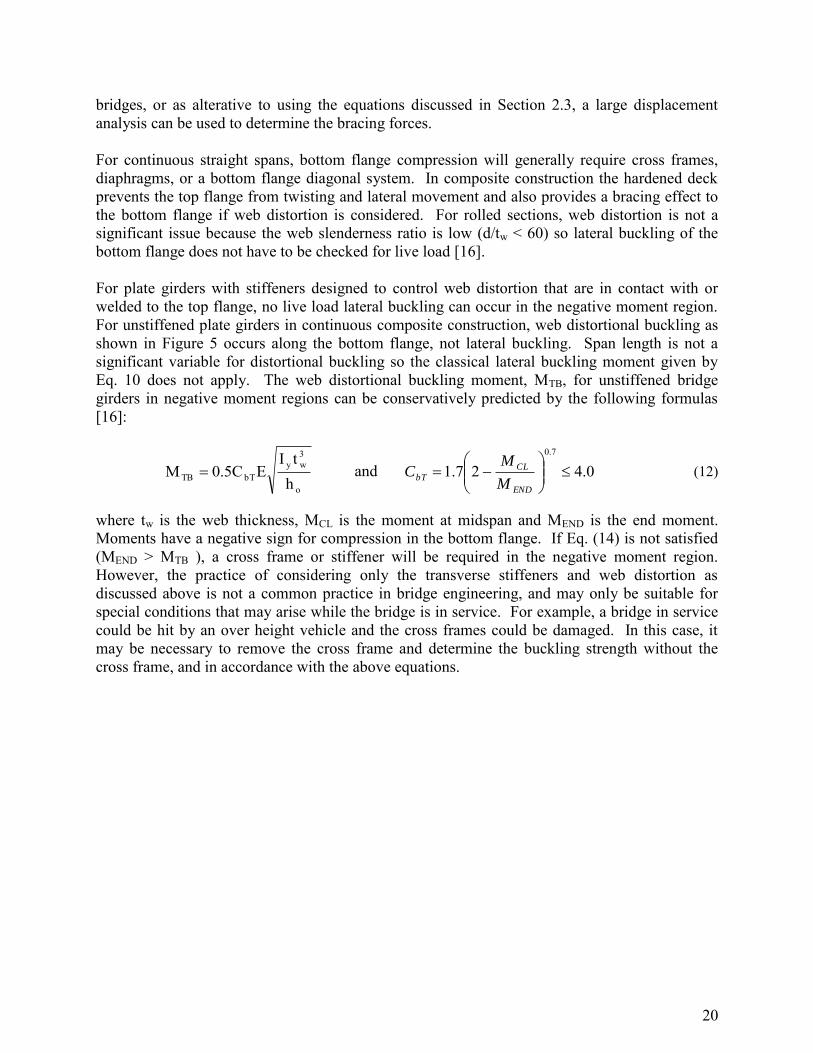
bridges, or as alterative to using the equations discussed in Section 2.3, a large displacement analysis can be used to determine the bracing forces. For continuous straight spans, bottom flange compression will generally require cross frames, diaphragms, or a bottom flange diagonal system. In composite construction the hardened deck prevents the top flange from twisting and lateral movement and also provides a bracing effect to the bottom flange if web distortion is considered. For rolled sections, web distortion is not a significant issue because the web slenderness ratio is low (d/tw < 60) so lateral buckling of the bottom flange does not have to be checked for live load [16]. For plate girders with stiffeners designed to control web distortion that are in contact with or welded to the top flange, no live load lateral buckling can occur in the negative moment region. For unstiffened plate girders in continuous composite construction, web distortional buckling as shown in Figure 5 occurs along the bottom flange, not lateral buckling. Span length is not a significant variable for distortional buckling so the classical lateral buckling moment given by Eq. 10 does not apply. The web distortional buckling moment, MTB, for unstiffened bridge girders in negative moment regions can be conservatively predicted by the following formulas [16]:
o
3wy
bTTB htI
E0.5CM and 0.427.17.0
END
CL
bTM
MC (12)
where tw is the web thickness, MCL is the moment at midspan and MEND is the end moment. Moments have a negative sign for compression in the bottom flange. If Eq. (14) is not satisfied (MEND > MTB ), a cross frame or stiffener will be required in the negative moment region. However, the practice of considering only the transverse stiffeners and web distortion as discussed above is not a common practice in bridge engineering, and may only be suitable for special conditions that may arise while the bridge is in service. For example, a bridge in service could be hit by an over height vehicle and the cross frames could be damaged. In this case, it may be necessary to remove the cross frame and determine the buckling strength without the cross frame, and in accordance with the above equations.

21
Figure 5 Web Distortion
Figure 6 Restraining Forces
Stability bracing of beams is provided by lateral (L), torsional (T) and warping (W) restraints as shown in Figure 6. Any one of these restraints alone can increase stability of the compression flange. Relative, nodal and lean-on systems as described earlier provide lateral and/or torsional restraint to single girders. Warping restraint is present only in continuous bracing systems. Lateral and warping restraints control the lateral movement of the flange to which they are attached. Lateral bracing must be connected to both flanges near inflection points. When warping restraints such as pipe stiffeners are used, the stiffener must be connected to the top and bottom flanges. On the other hand torsional braces (diaphragms or cross frames) prevent twist of the cross section at the brace location so they do not need to be attached to the compression flange to be effective [17]. Permanent metal deck forms (PMDF) that act as shear diaphragms and are attached directly to the top flange of a girder can also improve the lateral stability. Such systems provide mainly warping restraint to the top flange rather than lateral or torsional restraint. Stiffness and strength design recommendations for PMDF-braced beams are given elsewhere [18]. The diaphragm strength requirement, which is limited by the fastener capacity, generally controls the design. Top or bottom flange lateral bracing in I-girder bridges is relative or lean-on; torsional bracing is nodal, continuous or lean-on. If two adjacent beams are interconnected by a properly designed cross frame or diaphragm at midspan, that point can be considered a torsionally-braced point when evaluating the beam buckling strength. Since the beams can move laterally at midspan, the

22
effectiveness of such a torsional bracing system is sometimes questioned. As long as the two flanges move laterally the same amount, there will be no twist. If twist is prevented, the beam can be treated as braced at that point. Tests and theory confirm this approach [19, 20]. A general discussion of beam lateral and torsional bracing and the development of the design recommendations with design examples for bridge girders are presented elsewhere [17]. The design recommendations for torsional and lateral bracing given in Sections 2.3.1 and 2.3.5 have been adopted by the AISC Specification. The Commentary on the AISC Specification should be consulted for discussion on implementing the stability bracing requirements. The provisions are limited to doubly- and singly-symmetric members loaded in the plane of the web. Beam loads are assumed to be applied at the top flange, which is typical in bridges. Stability braces must have sufficient stiffness and strength to be effective. 2.3.1 Torsional Bracing Design Requirements, T
The most common form of bracing in steel bridge systems are cross frames or diaphragms that restrain the twist of the girders and are thereby typically classified as torsional braces. Concrete bridge decks in composite systems also provide torsional resistance to the girders. As noted earlier, effective stability bracing must possess sufficient stiffness and strength. The strength and stiffness requirements for torsional bracing from the AISC Specification [15]:
Stiffness: 2
242
bbeff
fTT
CIEn
LM.
n
Lββ
(13)
Strength: obbeff
fb
bbrbrhCIEn
MLL.hFM 2
20050
(14)
where = 0.75, Mf is the maximum moment within the span, Ieff = Iyc + (t/c) Iyt, t and c are as defined in Figure 7, L is the span length, Lb is the unbraced length, n is the number of span braces, ho is the distance between flange centroids and Cbb is the moment modification factor for the full bracing condition. For a singly-symmetric section Iyc and Iyt are the out-of-plane moments of inertia of the compression and tension flanges, respectively. If the cross section is doubly symmetric, Ieff becomes Iy. All torsional bracing (nodal and continuous) use the same basic design formulas. T and T are defined as the torsional stiffnesses of the nodal and continuous bracing systems, respectively. Mbr is the moment to be resisted by the nodal torsional brace (for continuous bracing Lb/ n=1). For cross frames the moment is converted to chord forces, Fbr, by dividing by hb, the distance between the chords. When the values of the variables in the two unbraced segments adjacent to a nodal brace are different, the brace can be designed for the average of values of the strength and stiffness determined for both segments. It is conservative to use Cbb = 1.0.

23
Figure 7 Bending Stresses in Singly Symmetric Section
In the development of the design recommendations outlined in this section, Yura et al. [20] extended the work of Taylor and Ojalvo [21] and showed that a torsional brace is equally effective if it is attached near the tension flange or the compression flange. A moment diagram with compression in both flanges (reverse curvature) does not significantly alter the torsional brace requirements. On the other hand, the stiffness of a torsional brace system T is greatly affected by web cross-section distortion at the brace point, as illustrated in Figure 5, and by the in-plane stiffness of the girders and is given by:
gbT
1111sec
(15) where b is the attached brace stiffness, sec is the distortional web stiffness and g is the in-plane girder system stiffness (see Section 2.3.4). The effective T is always less than the smallest of b, sec and g. Brace member sizes that satisfy the torsional brace stiffness and strength criteria are usually small but connection details must be carefully considered to control distortion.
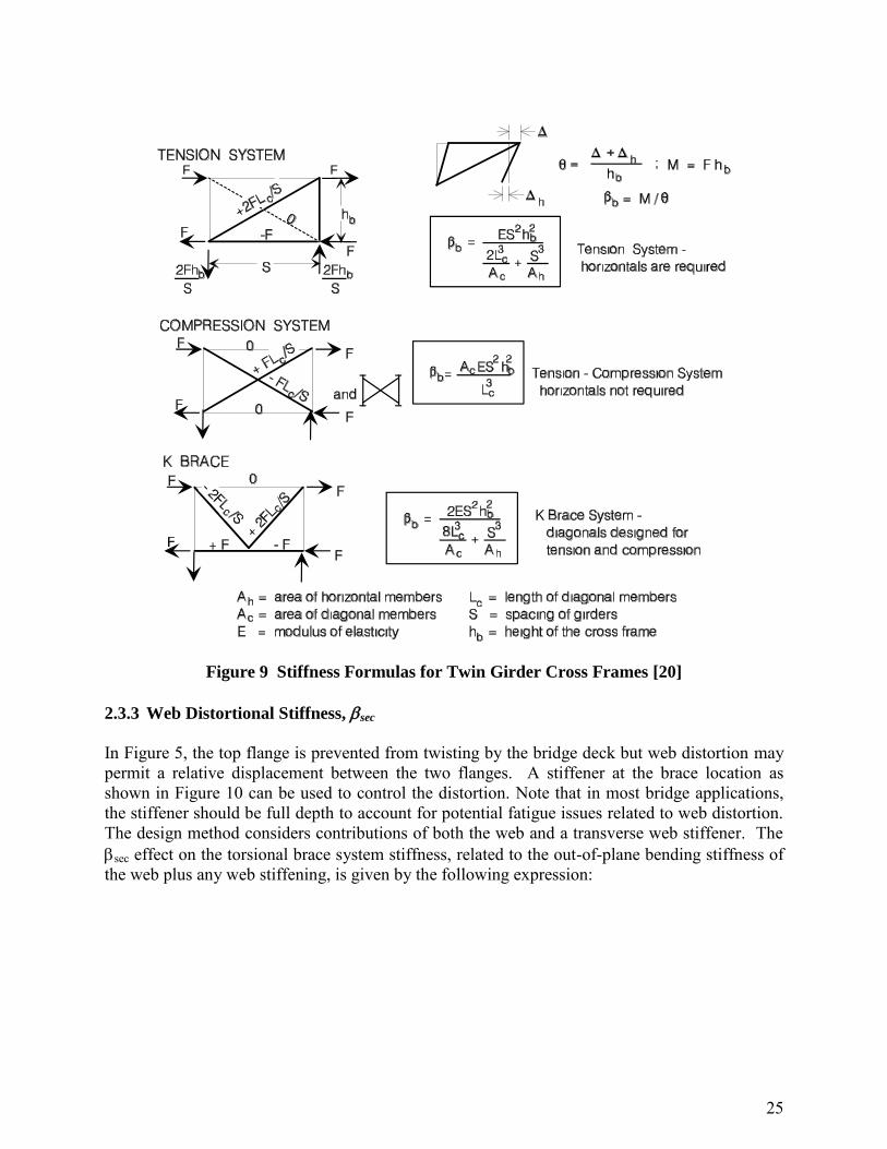
2.3.2 Stiffness of Cross Frame and Diaphragm Systems b
The b of some common torsional brace systems are given in Figure 8 and Figure 9. The choice between the two diaphragm cases shown in Figure 8 depends on the deck details. If the distance between the flanges of adjacent girders is maintained constant by the attachment of decking in addition to the diaphragm, then all the girders must sway in the same direction and the diaphragm stiffness is 6EIb/S. On the other hand, if adjacent flanges can separate as shown for the through girders, then the diaphragm stiffness will be 2EIb/S. For regions of the girders with the top flange in compression, placing a diaphragm above midheight will typically cause the two compression flanges to displace laterally in the same direction bending the diaphragm in reverse curvature and resulting in stiffness of 6EIb/S. Values of the torsional bracing stiffness shown in Figure 9 assume that the connection between the girder and the brace can support a bracing moment Mbr. Elastic truss analyses were used to derive the stiffness of the cross frame systems shown in Figure 9. If the diagonals of an X-system are designed for tension only, then horizontal members are required in the system. Although the top chord of the K-brace system has zero force, a top strut is still

24
recommended to link the top girder flanges together (to ensure the development of the stiffness 6EIb/S).
Mbr
brM
I b
b
Sb
2 E I
S
b
b
6 E I
Through GirdersDiaphragms or Decks
S
Figure 8 Diaphragm Stiffness, b
25
FF;
=
+
=
+
=
Figure 9 Stiffness Formulas for Twin Girder Cross Frames [20]
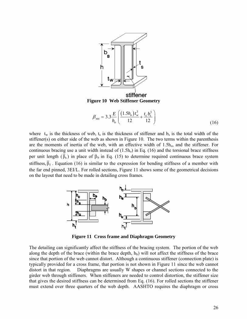
2.3.3 Web Distortional Stiffness, sec
In Figure 5, the top flange is prevented from twisting by the bridge deck but web distortion may permit a relative displacement between the two flanges. A stiffener at the brace location as shown in Figure 10 can be used to control the distortion. Note that in most bridge applications, the stiffener should be full depth to account for potential fatigue issues related to web distortion. The design method considers contributions of both the web and a transverse web stiffener. The sec effect on the torsional brace system stiffness, related to the out-of-plane bending stiffness of the web plus any web stiffening, is given by the following expression:
26
F
i
g
u
r
e
(
I
)
.
S
t
i
f
f
Figure 10 Web Stiffener Geometry
3 3
sec1.5
3.312 12
o w s s
o
h tE t b
h
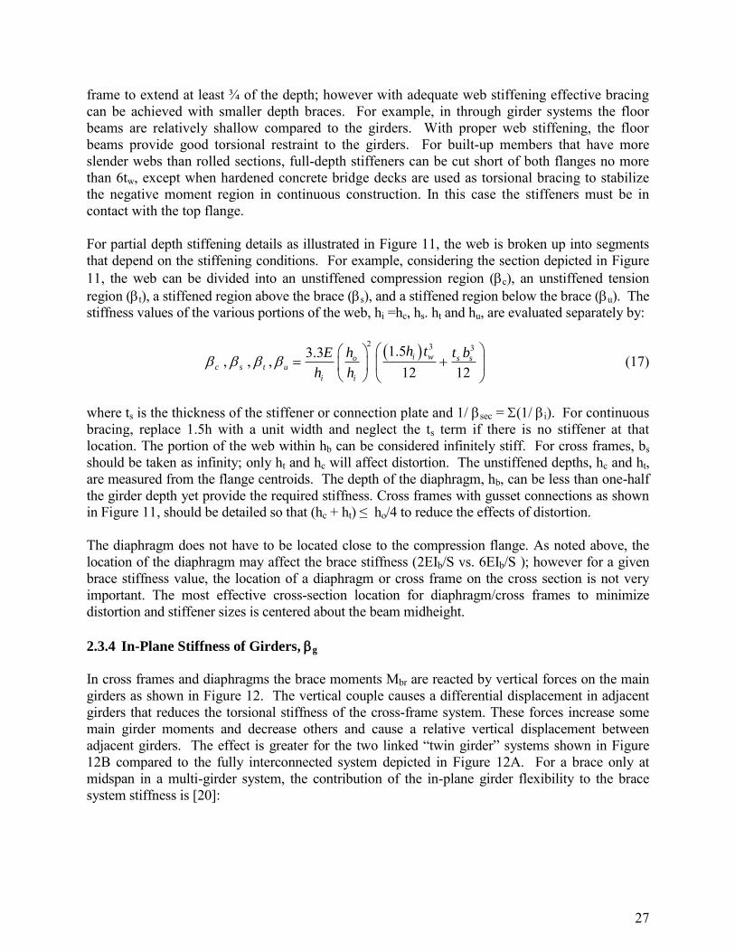
(16) where tw is the thickness of web, ts is the thickness of stiffener and bs is the total width of the stiffener(s) on either side of the web as shown in Figure 10. The two terms within the parenthesis are the moments of inertia of the web, with an effective width of 1.5ho, and the stiffener. For continuous bracing use a unit width instead of (1.5ho) in Eq. (16) and the torsional brace stiffness per unit length ( bβ ) in place of b in Eq. (15) to determine required continuous brace system stiffness, Tβ . Equation (16) is similar to the expression for bending stiffness of a member with the far end pinned, 3EI/L. For rolled sections, Figure 11 shows some of the geometrical decisions on the layout that need to be made in detailing cross frames.
Figure 11 Cross frame and Diaphragm Geometry
The detailing can significantly affect the stiffness of the bracing system. The portion of the web along the depth of the brace (within the brace depth, hb) will not affect the stiffness of the brace since that portion of the web cannot distort. Although a continuous stiffener (connection plate) is typically provided for a cross frame, that portion is not shown in Figure 11 since the web cannot distort in that region. Diaphragms are usually W shapes or channel sections connected to the girder web through stiffeners. When stiffeners are needed to control distortion, the stiffener size that gives the desired stiffness can be determined from Eq. (16). For rolled sections the stiffener must extend over three quarters of the web depth. AASHTO requires the diaphragm or cross
27
frame to extend at least ¾ of the depth; however with adequate web stiffening effective bracing can be achieved with smaller depth braces. For example, in through girder systems the floor beams are relatively shallow compared to the girders. With proper web stiffening, the floor beams provide good torsional restraint to the girders. For built-up members that have more slender webs than rolled sections, full-depth stiffeners can be cut short of both flanges no more than 6tw, except when hardened concrete bridge decks are used as torsional bracing to stabilize the negative moment region in continuous construction. In this case the stiffeners must be in contact with the top flange. For partial depth stiffening details as illustrated in Figure 11, the web is broken up into segments that depend on the stiffening conditions. For example, considering the section depicted in Figure 11, the web can be divided into an unstiffened compression region (c), an unstiffened tension region (t), a stiffened region above the brace (s), and a stiffened region below the brace (u). The stiffness values of the various portions of the web, hi =hc, hs. ht and hu, are evaluated separately by:
2 3 31.53.3, , ,
12 12i wo s s
c s t u
i i
h tE h t b
h h
(17)
where ts is the thickness of the stiffener or connection plate and 1/ sec = (1/ i). For continuous bracing, replace 1.5h with a unit width and neglect the ts term if there is no stiffener at that location. The portion of the web within hb can be considered infinitely stiff. For cross frames, bs should be taken as infinity; only ht and hc will affect distortion. The unstiffened depths, hc and ht, are measured from the flange centroids. The depth of the diaphragm, hb, can be less than one-half the girder depth yet provide the required stiffness. Cross frames with gusset connections as shown in Figure 11, should be detailed so that (hc + ht) ≤ ho/4 to reduce the effects of distortion. The diaphragm does not have to be located close to the compression flange. As noted above, the location of the diaphragm may affect the brace stiffness (2EIb/S vs. 6EIb/S ); however for a given brace stiffness value, the location of a diaphragm or cross frame on the cross section is not very important. The most effective cross-section location for diaphragm/cross frames to minimize distortion and stiffener sizes is centered about the beam midheight.
2.3.4 In-Plane Stiffness of Girders, g
In cross frames and diaphragms the brace moments Mbr are reacted by vertical forces on the main girders as shown in Figure 12. The vertical couple causes a differential displacement in adjacent girders that reduces the torsional stiffness of the cross-frame system. These forces increase some main girder moments and decrease others and cause a relative vertical displacement between adjacent girders. The effect is greater for the two linked “twin girder” systems shown in Figure 12B compared to the fully interconnected system depicted in Figure 12A. For a brace only at midspan in a multi-girder system, the contribution of the in-plane girder flexibility to the brace system stiffness is [20]:

28
3
22)1(24L
EIS
n
nx
g
g
g
(18)
where Ix is the strong axis moment of inertia of one girder, ng is the number of girders connected by the cross frames, and L is the span length. As the number of girders increase, the effect of girder stiffness will be less significant. For example, in a two-girder system the term 24(ng-1)2/ng is 12 while for a six-girder system the factor becomes 100. Helwig et al. [22] showed that for twin girders the strong axis stiffness factor g is significant and Eq. (18) can be used even when there is more than one brace along the span. If g dominates the torsional brace stiffness in Eq. (15), then a system mode of buckling that is discussed later in this section is possible.
brM
brM
2 brM
SS
Beam Load
Brace Load
2 brM
S
brM4
3S
2 brM
S
Figure 12 Beam Load from Braces
2.3.5 Connection Stiffness, conn
The diaphragm and cross-frame stiffnesses given in Figure 8 and Figure 9 assume that the attachment connections are not flexible. Clip angles welded only along the toe and tee stubs with bolted flanges will flex when tension is applied to the outstanding leg or tee stem. This flexibility, conn, will reduce the system stiffness. If partially restrained connections are used, the flexibility of the two connections should also be included in determining the system stiffness by adding the term, 2/conn, to the right side of Eq. (15). Field studies [23] have reported a reduction of 40-70% in the stiffness of the non-permanent external cross frames between tub girders due to tee stub flange flexibility. The brace force design requirements are directly proportional to the magnitude of the initial out-of-straightness of the girders [24]. The brace force design requirements above are based on an out-of-straightness of 0.002L. If oversize holes are used in the bracing details, the brace forces will be increased if slip occurs in the connection. This can be considered in design by adjusting the
29
magnitude of the lateral and torsional brace force requirements by the modification factor, (1 + oversize/( Lb/500)). 2.4 Effects of Support Skew
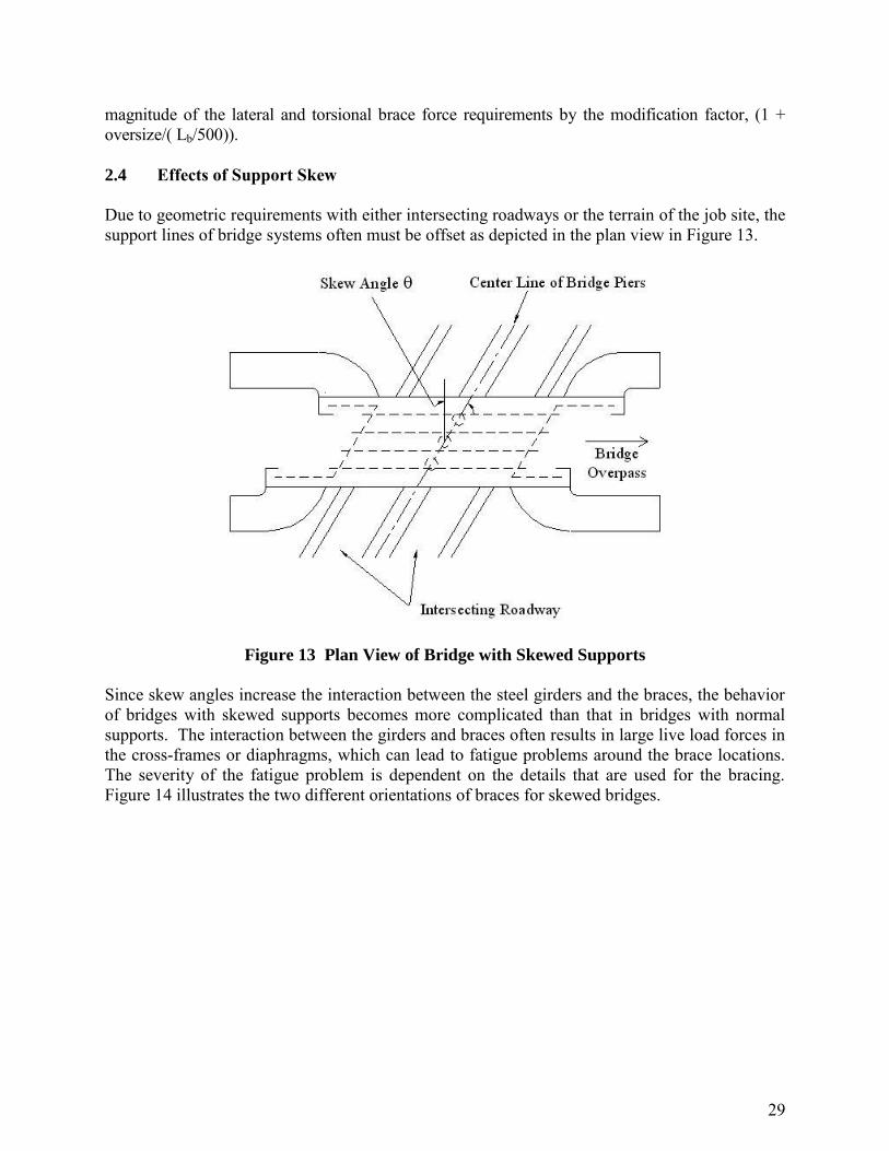
Due to geometric requirements with either intersecting roadways or the terrain of the job site, the support lines of bridge systems often must be offset as depicted in the plan view in Figure 13.
Figure 13 Plan View of Bridge with Skewed Supports
Since skew angles increase the interaction between the steel girders and the braces, the behavior of bridges with skewed supports becomes more complicated than that in bridges with normal supports. The interaction between the girders and braces often results in large live load forces in the cross-frames or diaphragms, which can lead to fatigue problems around the brace locations. The severity of the fatigue problem is dependent on the details that are used for the bracing. Figure 14 illustrates the two different orientations of braces for skewed bridges.

30
Figure 14 Brace Orientations for Bridges with Skewed Supports
If the skew angle is less than 20 degrees, AASHTO [1] allows the bracing to be parallel to the skew angle. For skew angles greater than 20 degrees, AASHTO requires the bracing to be perpendicular to the longitudinal axis of the girder. For braces parallel to the supporting abutments, points A and B at the ends of the brace will have similar vertical displacements during truck live load. However, when braces are normal to the girder lines, the two ends of the braces will have different vertical displacements during truck loading. This differential vertical displacement can result in large brace forces, which can lead to fatigue problems. Alternative bracing layouts to help minimize live load induced forces are to use either lean-on bracing or a staggered cross frame layout as discussed in the next section. When the cross frames are oriented perpendicular to the longitudinal axis of the girders as shown in Figure 12(b), the provisions outlined in the previous sections for the stability stiffness and strength requirements are directly applicable with no correction required for the skew angle. The braces will develop additional forces due to differential displacement from the skew angle. For skew angles larger than approximately 45 degrees, the forces induced due to the differential displacement will be of similar magnitude or even larger than stability induced forces. During construction of the concrete bridge deck, these forces can be predicted with reasonable accuracy from a first-order analysis on a relatively simple computer model of the steel girders and bracing system. The forces from such an analysis are additive to the stability forces predicted from Eqn. (12) and Figure 9. When the cross frames are oriented parallel to the skew angle as depicted in Figure 12(a), the skew angle has an impact on both the stability stiffness and strength requirements of the bracing. Wang and Helwig [25] present expressions for the stiffness and strength requirements of braces in bridges with skewed supports. The required stiffness of the braces is given in the following expression:

31
2cos
bbSkew (19)
where, b Skew is the stiffness requirement of the skewed brace, b is the required stiffness that results from Eq. 13, and is the skew angle. Once the required skewed brace stiffness is determined, the stiffness equations given in Figure 9 can be used to size the diagonals and struts of the cross frame. Although s in the stiffness equations is typically thought of as the girder spacing, for a skewed brace the value of s should be taken equal to the length of the cross frame in the skewed orientation (equal to girder spacing/cos). The strength requirement of the skewed brace is given in the following expression:
cosbr
Skewbr
MM (20)
where Mbr Skew is the brace moment applied to the skewed brace and Mbr is the required brace moment from Eq. (14). If the cross frame is properly sized for the stiffness and strength requirements considering the skewed geometry, there is no technical reason why a cross frame cannot be oriented parallel to the skew for angles larger than 20 degrees. The engineer needs to recognize that the stiffness of the cross frame is affected by the skew as a function of the above equations and also that the parallel brace can becomes relatively long for larger skew angles. If the longer geometry is considered in the equations the brace will have the proper stiffness and strength. However, one problematic area with cross frames parallel to the skew angle can be the connection details that are used between the brace and the girders. Many fabricators may use a bent plate to make the connection between the brace and the connection plate (web stiffener). Such a detail allows the fabricator to utilize a connection plate that is perpendicular the web plate; however the bent plate connection can dramatically reduce the effectiveness of the brace due to the flexibility introduced by the eccentric connection. One solution to eliminating the bent plate is orienting the connection plate parallel to the skew angle; however such a detail can be complicated for larger skew angles. In addition, fatigue tests on the angled stiffeners showed a much lower life compared to perpendicular stiffeners [26]. Although for larger skew angles, the intermediate cross lines will typically be oriented perpendicular to the longitudinal axis of the girders, at the supports the cross frames are usually parallel to the skew angle. In these instances, the bent plate detail is typically used as shown in Figure 15 for a bridge with nearly a 60 degree support skew.

32
Figure 15 Bent Plate Connection Detail Frequently Used in Bridges with Skewed Supports
Although currently not a standard practice, an alternative to the bent plate detail in skewed bridges, Quadrato et al. [26] proposed the detail depicted in Figure 16 which shows a plan view of an I-shaped girder with a half-pipe stiffener. The round pipe allows a perpendicular connection between the skewed support cross frame and stiffener for any skew angle. The split pipe stiffener serves as both the bearing stiffener and connection plate. The pipe stiffener increases the warping resistance of the girder and thus improves the buckling resistance of the girder. Further information regarding the increase in warping resistance can be found in Quadrato et al. [26]. Additionally, with regard to fatigue behavior, analytical and experimental research has shown that the pipe stiffener weld detail to the girder flanges is no worse than a typical plate stiffener welded to the girder flanges [27]. However, the Engineer needs to be aware that currently, the pipe material may not be approved for use in bridges, and may require special approval from the Owner.
Half-Pipe Stiffener
Cross Frame
Figure 16 Half-Pipe Web Stiffener
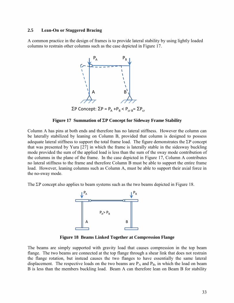
33
2.5 Lean-On or Staggered Bracing
A common practice in the design of frames is to provide lateral stability by using lightly loaded columns to restrain other columns such as the case depicted in Figure 17.
Figure 17 Summation of P Concept for Sideway Frame Stability
Column A has pins at both ends and therefore has no lateral stiffness. However the column can be laterally stabilized by leaning on Column B, provided that column is designed to possess adequate lateral stiffness to support the total frame load. The figure demonstrates the P concept that was presented by Yura [27] in which the frame is laterally stable in the sidesway buckling mode provided the sum of the applied load is less than the sum of the sway mode contribution of the columns in the plane of the frame. In the case depicted in Figure 17, Column A contributes no lateral stiffness to the frame and therefore Column B must be able to support the entire frame load. However, leaning columns such as Column A, must be able to support their axial force in the no-sway mode. The P concept also applies to beam systems such as the two beams depicted in Figure 18.
Figure 18 Beams Linked Together at Compression Flange
The beams are simply supported with gravity load that causes compression in the top beam flange. The two beams are connected at the top flange through a shear link that does not restrain the flange rotation, but instead causes the two flanges to have essentially the same lateral displacement. The respective loads on the two beams are PA and PB, in which the load on beam B is less than the members buckling load. Beam A can therefore lean on Beam B for stability
A B
PA PB
SP Concept: SP = PA +PB < Pcr B= SPcr
A B
PA PB
PA> PB

34
and the P concept, would simply require that the sum of the two applied loads are less than the sum of the two beams buckling loads. The spacing between the shear links must be close enough that beam A cannot buckle between the links. The P concept for beams is demonstrated numerically from the graph shown in Figure 19 [20].
TOTA
L LO
AD
P (
kip
s)
0
1
2
3Buckling Load
0.5P 0.5P P
W12x14 Span =24 ft.Initial Deflection = 0.16 in.
LATERAL DEFLECTION (in.)0 1 2 3 4 5
Figure 19 Graph of P Concept for Beams
The graph shows results from a three dimensional finite element analysis, for two beams linked together at the top flange. The buckling load is indicated by the horizontal line in the graph that that was determined from a critical load analysis (eigenvalue buckling analysis). The critical load does not reflect the impact of imperfections on the behavior. The two solid lines represent the results from a large displacement analysis on an imperfect system. The curves approach the critical load results (buckling load) at relatively large displacements. In one of the large displacement graph cases the two beams are equally loaded with 0.5P, while in the other case only one of the beams was loaded with a load of P. The graphs show that the total load both beam systems can support is approximately 2.5 kips despite extremely different load distributions. The above cases demonstrate the bracing scenario where lightly loaded beams can provide bracing to other, more heavily loaded beams. The lean-on concepts also apply to cases where beams can lean on braces such as cross frames or diaphragms. Cross frames and diaphragms represent relatively costly structural components in steel bridges from the perspective of both fabrication and erection. The braces can often be difficult to install in the bridge due to fit-up problems and also may attract significant live load forces, particularly in bridges with large support skews. Therefore, minimizing the number of cross frames on the bridge can lead to better overall bridge behavior as well as reduced maintenance costs. The typical practice in steel bridge behavior is to place cross frames between each of the girders at a uniform spacing along the length of the girders. Although this practice results in effective braces for providing overall stability to the bridge girders, the resulting system is not necessary structurally efficient. Cross

35
frames and diaphragms fit into the category of torsional braces since they resist twist of the girders. Improved structural efficiency is possible by utilizing lean-on bracing concepts in which several girders can be braced across the width of the bridge by a single cross frame. Lean-on bracing systems allow the designer to eliminate cross frames on parts of the bridge where the brace is difficult to install or where large forces in the finished bridge may result from truck traffic, thereby potentially leading to poor long term fatigue behavior. In a given bracing line, a cross frame may be selectively positioned and 3 or more girders can lean-on that brace as depicted in Figure 20. Girders that lean on the brace require top and bottom struts to control girder twist.
Full Cross-Frame
Only Top and Bottom Struts
Figure 20 Lean on Cross Frame Bracing
Helwig and Wang [29] developed recommendations for girders with skewed supports so that intermediate cross frames (between the supports) can be selectively located to minimize forces induced in the cross frames. For example, the plan view of the bridge in Figure 21 shows a possible layout that will reduce the number of cross frames and minimize the live load induced forces.
33.7
24 ft. 24 ft. 24 ft. 24 ft. 24 ft. 4'
124 ft.
A B C D E
Figure 21 Plan View of Bridge with Lean-On Cross Frame Bracing

36
In a given cross frame line, the full cross frame is located between the girders that will place the cross frame as far away from the support as possible. In cross frame lines A and B, this puts the cross frame near the top of the figure, while in lines D and E, the braces are near the bottom of the plan view. Near midpsan, at least one full line of cross frames should be provided to link the girders together and control differential displacement. In addition, the cross frame lines near the supports (lines A and E) should not frame directly into the support, but instead be offset by approximately 4 or 5 feet. Offsetting the bracing line from the skewed support reduces the forces induced in the cross frame, while still producing effective bracing. In systems with a large number of girders across the width, a contiguous line of cross frames near midspan may not be necessary. Instead the cross frames can be distributed across the width of the bridge as shown in Figure 22, which shows a plan view of a two span bridge with a 54 degree skew. The bridge was one of three bridges in Lubbock, Texas that was constructed using lean-on bracing. The circled cross frames were cross frames that were necessary to provide stability to the partially erected bridge.
54
A
A
B
B
Span 1
(180 ft.)
Span 2
(166 ft.)
Section A-A Section B-B
G1
G2
G3
G4
G5
G6
G7
G8
G9
air F.S.ground F.S.
bent bent
Figure 22 Lean on Bracing Layout in Bridge with Large Numbers of Girders
Because there are several girders restrained by a single cross frame in lean on systems, the individual cross frames need to be sized for the increased demand on the bracing. Figure 23 [29] demonstrates the distribution of forces across the bridge in a cross frame system with lean on bracing.

37
-F-2F-3F
FFFFF2F-F
A B C D
hbFs
Lean-On Cross Frame Stiffness and Strength Requirements
Define ngc as the number of girders per cross-frame.
Fd
s
Brace Strength:
Brace Stiffness:
S
FLnF
dgc
d
FnF gcs )1( b
br
hM
F
233
22
)1(
gc
cd
dgc
bb
nA
S
A
Ln
hES
Figure 23 Stiffness and Strength Requirements for Lean-On Cross Frames
The cross frame is idealized as a tension-only system. The expressions in the figure show the corresponding stiffness of the cross frame as well as the maximum forces in the struts and diagonals of the cross frame. In most situations, although the forces vary the same size struts will be used throughout. One other modification that is necessary with lean-on bracing is a reduction in the in-plane stiffness of girders. Since the bridge is not fully connected throughout, Helwig and Wang [29] recommended that the in-plane stiffness of the girders be reduced by 50% in the brace system stiffness calculation. This leads to the following expression for systems with lean-on bracing:
3
22)1(12L
EIS
n
nx
g
g
onLeang
(21)
Note that ng in the above cross section is the total number of girders across the width of the bridge and should not be confused with ngc in the lean on calculations. Another cross frame configuration that is sometimes utilized in bridges with large support skews is the staggered layout depicted in Figure 24.

38
Staggered Layout
AB
Figure 24 Staggered Cross Frame Layout
In the staggered layout, the cross frames are oriented perpendicular to the longitudinal axis of the girders; however the individual cross frames are staggered along a line parallel to the skew angle. The advantage of this layout is that the differential deflections of at the ends of the cross frame lines are relatively similar since the centers of the individual cross frames are located at approximately the same longitudinal location on the bridge. Therefore the behavior is similar to the parallel layout; however perpendicular connections can be used. The basic stiffness and strength expressions for the bracing are essentially the same as outlined for the cross frames along contiguous lines. One of the drawbacks to this layout is that because the adjacent cross frames (A and B in Figure 24) that connect to a girder are at different locations along the girder length, the connection plates on an individual girder do not line up on the opposing sides of the web. Additionally, a staggered cross-frame arrangement as shown in Figure 24 will result in flange lateral bending, as the cross-frame members apply lateral loads to the girder flanges. In cases of smaller bridges or bridges with small skews, the lateral flange bending effects will be less than those that result from longer span bridges, or bridges with larger skews. The differential deflections between the adjacent girders where the cross-frames connect play a significant role in the cross frame forces and the subsequent flange lateral bending effects. 2.6 System Buckling of Interconnected Girders
Cross frame and diaphragm systems provide bracing by restraining twist of the interconnected girders. The generally accepted belief among designers is that reducing the spacing between these braces will improve the buckling capacity of the girder systems. This belief holds true for many applications. However, there have been a number of applications in which the buckling behavior of the girder system can be relatively insensitive to the spacing or size of the braces. For example, the two-girder widening shown in Figure 25 had relatively close cross frames, however the girder experienced significant twisting during placement of the concrete deck as evidenced by the 10 inch lateral deformation of the bottom flange relative to the plumb line. The load on the twin girder system was balanced and did not have an eccentricity. The mode exhibited by the bridge widening is a buckling failure of the entire girder system as described below.

39
Figure 25 System Buckling of a Twin Girder Widening, where the system has buckled out
of plane nearly 10 inches during deck placement
The buckling mode that is typically envisioned in a properly braced girder system is depicted in Figure 26a, which shows a plan view of a twin girder system. By reducing the spacing between the braces, the engineer can reduce the size of Lb and thereby improve the buckling capacity of the girders that results from lateral-torsional buckling expressions such as Eq. (10). However in girder systems with a relatively large length to width ratio (Lg/s), the controlling mode is the buckled shape depicted in Figure 26b. In the system buckling mode, the girder system behaves as a unit and the resulting resistance is not significantly affected by the spacing or size of the braces.

40
y
(c) System cross section A-A
(b) Global system buckling , plan view
A
A
(a) Individual girder buckling, plan view Lb
Lg
x x
y
S
S
Figure 26 Comparison of Individual Buckling Mode and System Buckling Mode
Yura et al. [30] presented the following solution for doubly-symmetric girders that can be used to evaluate the buckling capacity of a girder in the system buckling mode:
xy
g
gs IIL
SEM 2
2
(22)
where: s is the girder spacing, Lg is the total length of the girder, E is the modulus of elasticity of the steel girder, and Iy, and Ix are the respective moments of inertia of a single girder about weak and strong axes. The expression estimates the capacity of one of the girders for comparison with the girder design moment. For singly-symmetric girders, Iy in Eq. 20 can be replaced with Ieff [30]:
ytyceff I
c
tII
(23)
where, Iyc and Iyt are the respective moments of inertia of the compression and tension flanges about an axis through the web, and c and t are the respective distances from the centroidal axis to the compression and tension flanges. For a doubly-symmetric section, Ieff given by Eq. (23) reduces to Iy since c = t.

41
Equation 20 provides a closed form solution that can be used to evaluate the system buckling capacity of twin girder systems. For a three girder system, replace Iyc in Eq. (23) with 3/2 Iyc, and define S in Eq. (22) as 2S, which is the distance between the two exterior girders. For four girders, replace the corresponding values of the Iyc, and S terms with 2Iyc and 3S. Equation (22) shows that for a given girder span (Lg), the system buckling mode can be improved by either increasing the stiffness of the individual girders or by increasing the girder spacing. Alternative methods of improving the buckling capacity include adding a top and bottom flange lateral truss near the ends of the girders as is discussed later in this module. 2.7 Lateral Bracing Systems
Common bracing systems that may be used in bridges consist of lateral trusses that control the relative moment of two points along the girders. Relative bracing systems generally consist of a combination of struts and diagonals as depicted in the plan view shown in Figure 27. As noted in the previous section, the lateral truss type bracing depicted in Figure 27 may be used on the bottom flanges of some I-girder systems to enhance the resistance to lateral loads from sources such as wind. As is covered in detail later in this module, these types of lateral trusses are extremely important to stiffen tub girders during construction. The struts are oriented perpendicular to the longitudinal axis, while the diagonals connect together two points at different lengths along the bridge. The spacing between the two points defines the unbraced length. As the name implies, the bracing system controls the relative movement of the two points. For example, the diagonal and two struts in Figure 27 combine to form a relative bracing system. The stiffness of the lateral bracing is a function of both the strut and the diagonal sizes and the bracing can be designed to control the movement of Point C relative to Points A and B. The actual bracing system may vary in terms of the number or orientation of the diagonals. In some cases, two diagonals may be used and the stiffness of the system is dependent on the buckling capacity of the diagonals. A “tension-only” system with two diagonals is sometimes specified such that the compression resistance of the diagonal is conservatively neglected since (depending on the type of member selected) the buckling resistance may be low. However, since the lateral truss often connects near the top or bottom flange of the girders, the designer needs to be aware of forces that can be induced in the bracing due to stresses from vertical bending of the girders. These stresses develop due to longitudinal strain compatibility between the bracing system and the girder flanges that experience compression or tensile stresses due to girder flexure. The nature of the stress induced in the lateral truss is the same state of stress in the girder where the truss is connected. For example, if the lateral truss is located at the top flange near the midspan region, gravity load stresses in the girders will induce compression in the truss. Generally, if a perpendicular cut everywhere along the unbraced length passes through the brace, then the brace system is relative.

42
Girder Flange
Girder Flange
A B
Strut
C
Figure 27 Plan View of Typical Lateral (Relative) Bracing System
Designs that utilize cross framing or X-framing such as the system depicted in Figure 28 are typically treated as tension-only systems in which only one of the diagonals is relied upon for resisting lateral forces. The diagonal in compression is conservatively neglected. Structural analysis models should account for the tension-only concept. There have been cases where engineers conducting peer reviews were unaware of the tension-only philosophy used in the original design. As a result the peer reviewer has requested costly retrofits because they claimed the designs were inadequate because of an apparent compressive force in one of the diagonals that exceeded the buckling capacity of that member. If one of the diagonals can support the entire load in tension, then the design is satisfactory.
Figure 28 Effective Length in X-type cross frames
In X-frame systems that rely on the compression strength of the diagonals and are connected at the intersection point, the out-of-plane and in-plane compressive strength can be determined using an effective length of one-half the total diagonal length as shown in Figure 28. This is contrary to the statement in C6.9.4.4 of AASHTO [1]. In the plane of the X-bracing, geometry dictates an unbraced length of L/2. Out of plane, the tension diagonal provides sufficient bracing

43
to force the compression diagonal into an S-shape at buckling as shown in the Figure 28 photo of a test on a U-shaped girder with a top lateral X-system. The bracing effect of the tension diagonal comes from three potential sources: 1) the magnitude of the force in the tension diagonal, 2) the out-of-plane flexural stiffness and 3) catenary action [31]. As shown in Figure 29, conservatively placing a hinge in the diagonal at the intersecting point, m, and displacing it a distance , equilibrium requires:
T
2L
LT2C
(24)
For most bracing geometries T is greater than or equal to C and must be zero for equilibrium. Thus, the intersection point is a braced point, even if the compression diagonal is discontinuous due to the presence of a splice. It has been shown [32, 33] both theoretically and experimentally for T > 0.6C and no compression member splice that the effective length is 0.5L. These studies neglect catenary action of the tension member, which is also effective in providing the necessary bracing force at the intersection. Based upon these contributing factors, the effective length of the compression diagonal is always half the length when the two diagonals are connected at the intersection.
No if T C
m
T
TC
C
L2
C
2T/LC
L2
T
2C/L
T
Figure 29 X-Framing Equilibrium
Winter [34] demonstrated that effective stability bracing must satisfy both stiffness and strength requirements. He demonstrated the concept with a simple rigid link model that could be used to determine the ideal stiffness requirements of the bracing as well as the impact of imperfections on the brace strength requirements. The bracing requirements for relative bracing based on Winter’s approach [34], are: Stiffness: L = 4 Mf Cd / Lbho (25) Strength: Fbr = 0.008 Mf Cd / ho (26) where = 0.75, Mf is the maximum moment within the unbraced length (Lb), ho is the distance between flange centroids and the constant Cd = 1.0 for single curvature bending and 2.0 for reverse curvature. The flange compressive force is conservatively approximated as Mf /ho.

44
These provisions are applicable for lateral bracing attached near the compression flange (except for cantilevers where top flange bracing is more effective). Braces that are adjacent to an inflection point must be attached to both flanges and the stiffness and strength requirements are greater as given by the Cd factor. It should also be noted, that in most I-girder bridges, the design of the lateral bracing members will be governed by the applied loads, and not necessarily the bracing requirements presented above. 2.8 Continuous Bracing
In a continuous bracing system with sufficient strength and stiffness, compression flange lateral buckling cannot occur because of the very close spacing of the connection points. A concrete bridge deck attached to the top flange through shear studs is an example of a continuous system. The hardened concrete bridge deck has very large in-plane shear stiffness and bending stiffness that effectively prevents top flange twist and lateral movement of the girders when attached by shear studs or flange embedment. During a deck pour, the concrete has no stiffness but the permanent metal deck forms (PMDF) do have significant stiffness and strength. In building construction it is standard practice to use the PMDF as beam bracing when the ribs are perpendicular to the beam because the PMDF is attached directly to the top flange through the field welding of the shear studs. In bridge constriction, the connection of the deck forms require leveling angles to account for flange transitions or differential camber. The leveling angles introduce flexible connections that reduce the effectiveness of the forms for bracing; however the forms still do provide some help to the girder stabilty. A report [4] on a stability failure during a deck pour indicated that PMDF increased the girder buckling capacity 50% compared to an unbraced girder, but the increase was insufficient to support the entire deck weight. Field tests [23] on a U-shaped girder with the PMDF attached directly to the flanges with powder-actuated fasteners showed good performance. Improved PMDF attachment details have been successfully implemented on short span bridges [35, 36] that eliminated all the intermediate cross frames. Currently, AASHTO does not allow the Engineer to consider the stability that can be provided by the PMDF’s, as discussed in Section 6.7.4.1 of the AASHTO LRFD Specifications.

45
3.0 BRACING OF TUB GIRDER SYSTEMS
U-shaped steel girders (tub girders) composite with a hardened concrete deck form a closed- box, torsionally strong bridge system. A typical cross section of a twin tub girder system is shown in Figure 30. Single tub girder systems are sometimes used for single-lane bridges. Prior to the development of composite action, the tub girder itself is a torsionally-weak, open steel section that must be braced to support the erection and construction loads. The three typical types of bracing systems are: interior diaphragms (ID), a top flange lateral truss (LT) and external intermediate cross frames (EC) between adjacent tub girders (see Figure 31).
Figure 30 Twin Tub Girder System
The three bracing systems used with tub girders are designed to achieve one or more of the following objectives mainly during the construction stage:
1. Control box girder distortion (ID) 2. Control lateral buckling of the individual top flanges (ID, LT) 3. Increase the torsional stiffness and strength (LT, EC) 4. Control global lateral buckling of the tub girder (LT) 5. Support sloping webs in trapezoidal cross sections (ID, LT) 6. Control warping normal stresses (ID) 7. Maintain alignment in multi-girder systems (EC)
Top lateral bracing system
External intermediate
cross- frame system
Internal diaphragm
bracing system
Figure 31 Types of Bracing Systems for Tub Girders
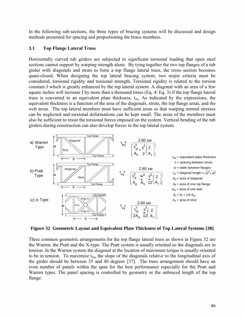
46
In the following sub-sections, the three types of bracing systems will be discussed and design methods presented for spacing and proportioning the brace members. 3.1 Top Flange Lateral Truss
Horizontally curved tub girders are subjected to significant torsional loading that open steel sections cannot support by warping strength alone. By tying together the two top flanges of a tub girder with diagonals and struts to form a top flange lateral truss, the cross section becomes quasi-closed. When designing the top lateral bracing system, two major criteria must be considered, torsional rigidity and torsional strength. Torsional rigidity is related to the torsion constant J which is greatly enhanced by the top lateral system. A diagonal with an area of a few square inches will increase J by more than a thousand times (Eq. 4/ Eq. 3) if the top flange lateral truss is converted to an equivalent plate thickness, teq. As indicated by the expressions, the equivalent thickness is a function of the area of the diagonals, struts, the top flange areas, and the web areas. The top lateral members must have sufficient areas so that warping normal stresses can be neglected and torsional deformations can be kept small. The areas of the members must also be sufficient to resist the torsional forces imposed on the system. Vertical bending of the tub girders during construction can also develop forces in the top lateral system.
=
2.60 sw t
+
t d
d
At
s
A
L 2
3
3 3 eq
+ +
=
t s d
d
A
s
A
w
A
L
2.60 sw t
2
12
3 3 3 eq
+
t d
d
A
s
A
L
2.60 sw t
2
12 2
3 3 eq
(c) X - Type
Top Flange
Strut Diag X1
Diag X2
a) Warren Type
Strut
Diagonal Top Flange
Top Flange
w
s
b) Pratt Type
Strut
Diagonal Top Flange
Top Flange
w
s
w
s Top Flange
w = width between flanges Ld = diagonal length =
teq = equivalent plate thickness
Ad = area of diagonal
s = spacing between struts
At = Af + 1/4 Aw As = area of strut
Af = area of one top flange
Aw = area of one web
2 2 w s +
Figure 32 Geometric Layout and Equivalent Plate Thickness of Top Lateral Systems [38]
Three common geometric arrangements for the top flange lateral truss as shown in Figure 32 are the Warren, the Pratt and the X-type. The Pratt system is usually oriented so the diagonals are in tension. In the Warren system the diagonal at the location of maximum torque is usually oriented to be in tension. To maximize teq, the slope of the diagonals relative to the longitudinal axis of the girder should be between 35 and 40 degrees [37]. The truss arrangement should have an even number of panels within the span for the best performance especially for the Pratt and Warren types. The panel spacing is controlled by geometry or the unbraced length of the top flange.

47
The formulations for teq given in Figure 32 were derived by Kollbrunner and Basler [38]. If teq of all three geometric arrangements are the same, the angle of twist will be the same but the forces in the top lateral systems will vary as discussed in the next sub-section. To achieve the same torsional rigidity, the X-type requires the smallest total Ad within the panel and the Pratt system the largest. If the X-system diagonals are designed for tension only, then only one diagonal should be considered effective and teq is determined using the Pratt formula. Frequently, publications incorrectly define At in the teq formulations as the area of the top flange, Af. When the top lateral truss is located below the top flanges, w is redefined as the width of the truss. AASHTO [1] suggests as a guideline that Ad ≥ 0.03w (all units in inches) in curved tub girders. This recommendation was developed by Heins [39] on the basis of limiting the warping normal stresses, fw, to less than ten percent of the maximum bending stress, fb. As teq increases, the warping normal stresses decrease. Heins [39] determined that if teq ≥ 0.05 in. for rectangular tub girders with a width-to-depth ratio, w/d ≤ 2 and a radius of curvature, R ≥ 400 ft, the ten percent limit would be satisfied. The teq value reduced to 0.03 in. for w/d =1. The teq ≥ 0.05 in. limit was converted to an Ad limit for an X-type system by ignoring the At term in the denominator of the teq expression in Figure 32 and assuming s = w (a 45˚ slope for the diagonals), which gives teq = 1.84 Ad/w. For teq ≥ 0.05 in., Ad ≥ 0.027w and is rounded to 0.03w in AASHTO [1]. This guideline is only applicable for X-type systems with two effective diagonals within the panel. Making the same Heins’ assumptions for the Pratt and Warren systems would require Ad ≥ 0.054w. Recent case and parametric studies (ac.)(ad.) on single diagonal top lateral systems using 3D-FEM have shown that the fw/ fb ratio is directly proportional to the L/R ratio for a constant teq. For bridges with L/R ≤ 0.3and 0.03≤ teq ≤ 0.05, the warping normal stresses were less than 2% of the bending stress which shows that the warping effect is small when a realistic top lateral system is in place. Wind and other lateral forces during the construction stage also can cause torsion in a tub girder because the shear center of the quasi-closed section is generally located below the bottom flange. The location of the shear center for a single tub or quasi-closed section is given in the Section 4.3. The applied torque is the resultant lateral force times its distance to the shear center. In straight tub girders with perpendicular supports, torsional loads do not dominate so a full length top lateral system may not be necessary. Lack of a top lateral system, however, makes the tub girder more susceptible to global lateral buckling as discussed later. If the supports are skewed, torsion must be considered. 3.1.1 Top Lateral Brace Forces
The forces in the members of a top lateral truss system can come from torsion, vertical bending, lateral bending, cross-section geometry, distortion and stability effects. Except for relatively straight girders, torsion effects dominate the forces in the bracing members. Figure 33 shows the forces determined from 3D-FEM analyses for a curved 180 ft simply-supported with three different top lateral truss arrangements [40]. The three different layouts consist of an X-type, a Pratt, and a Warren truss layout. The teq = 0.05 in. is the same for all three systems. The brace member sizes within each arrangement are different in order to achieve a similar teq but are constant along the span. Only gravity load (steel and concrete deck self-weight) during construction was applied and there are no distortion forces, lateral forces or stability effects

48
included in this comparison. The torsional forces in a lateral truss system are not significantly affected by the truss member sizes but the plots show that the forces in the three systems are different. In the X-system two diagonals are considered effective within each panel. For clarity the forces in the two diagonals within each panel, designated as diagonal 1 and diagonal 2, are plotted separately at the center of each panel along the span. For torsional loads only, the two diagonals should have the same magnitude of force, one in tension and the other in compression. At the left support, which is the location of maximum torque, the magnitudes of the two diagonal forces differ slightly but the disparity increases away from the supports because of in-plane bending. Although the tub girder alone is usually designed for the total bending gravity force during construction by neglecting the top lateral truss, the top flange bending strain will induce forces in the diagonals for strain compatibility. The bending forces are maximum at midspan and small near the simple supports. On the other hand torsional moments are maximum near the supports and zero at midspan so the diagonal forces at midspan are caused mainly by bending. Both diagonals within the panel have a 30 k compressive force at midspan. Note also that the maximum compressive force in a diagonal does not occur at the supports or midspan but at the fourth panel from each end. The largest compressive force is 25% higher than the maximum tension force in this example. Design approaches for X-type systems will be discussed later in this section. The diagonals in the Pratt and Warren systems show similar force distributions along the span. The diagonals of the Warren truss alternate between tension and compression in adjacent panels, whereas the Pratt system has only tension in this example. The maximum diagonal force occurs at the end panels due to torsion and is approximately twice that in the X-type system since there is only one diagonal in each panel. At midspan the Warren system has a maximum compressive force of 10 kips and the Pratt system almost zero so the bending effect in these two systems is much smaller than in the X-type arrangement. In both of these single diagonal systems, lateral movement of the two top flanges occurs in the same direction due to bending, which reduces the in-plane axial stiffness of the top lateral truss. In the Warren system the lateral displacements (0.08 in.) occur in a local two-panel zigzag pattern along the span whereas the lateral displacements of each panel in the Pratt system accumulate in the same direction with a maximum lateral displacement at midspan (0.96 in) [41] as depicted in Figure 34. These lateral displacements induce local lateral bending stresses in the two top flanges of the tub girder at each strut location in the Warren system [7]. In the Pratt system, the local top-flange lateral bending effect is concentrated only at midspan where the truss diagonals change their orientation. The strut force magnitude and distribution vary among the three systems. The struts are also usually part of the internal diaphragm system designed to control cross-section distortion and/or flange lateral buckling. No internal diaphragms were used in the span analyzed for Figure 33 in order to isolate certain types of forces in the top lateral system. In this case the strut forces can be due to torsion, bending and sloping webs. In all three systems the horizontal tension force that prevents the two flanges from spreading apart due to wet concrete load applied at the top flanges is a constant along the span and is usually quite small. The main strut forces are developed from torsion and bending. The strut forces due to torsion are zero in the X-type, are related to the algebraic sum of the transverse component of the two diagonal forces adjacent to the strut in the

49
Warren system and are equal to the transverse component of the larger diagonal force framing into ends of each strut in the Pratt system(except at midspan). In the Warren system the strut forces due to torsion alternate from tension to compression along the span and are relatively small compared to the compressive strut forces in the Pratt system. Tub girder bending causes the large tensile forces in the struts near midspan of the X-type system (30 kips), 10 kip tensile forces in the Warren system and almost zero force in the Pratt system. In the Warren system the strut forces from all three sources (sloping webs, torsion and bending) are small and fairly constant along the length compared to the large strut forces generated in the X-type and Pratt systems. The forces shown in Figure 33 do not include stability brace forces because a first order structural analysis was performed. Stability brace forces develop from the initial out-of straightness of the structural components. These forces and deformations are not included in a first order structural analysis. A top flange lateral truss system is a relative brace system that defines the unbraced length of the top flanges as the distance between panel points during the construction stage. For design the stability brace force requirements shown previously should be added to the first order analysis forces from torsion and bending. Usually the stability brace requirements will not alter the top lateral truss design because the largest stability forces occur at the location of the highest moment where the torsional forces are small. The stability brace requirements will only affect the top lateral design when the girders are relatively straight.

50
diagonal 1
diagonal 2
strut
-60
-40
-20
0
20
40
60
0 20 40 60 80 100 120 140 160 180F
orc
es (
kip
)
X - type
diagonal 1 diagonal 2
strut
-80
-60
-40
-20
0
20
40
60
80
0 20 40 60 80 100 120 140 160 180
Forc
es (
kip
)
Warren
diagonal 1
diagonal 2
strut
-60
-40
-20
0
20
40
60
80
0 20 40 60 80 100 120 140 160 180
Forc
es (
Kip
)
Distance Along Span (ft)
strut
diagonal
Pratt
Figure 33 Top Lateral Truss Forces for Various Tub Girder Bracing Systems

51
0.558
0.019
A) X-type lateral bracing system
0.613
0.956
0.604
0.083
B) Alternating-Diagonal lateral bracing system
C) Single-Diagonal lateral bracing system
Figure 34 Deformations of different box girder bracing systems
3.1.2 Selecting the Top Lateral Layout
The layout of the top lateral system is based primarily on effectively resisting the torsional forces during construction. Usually the member sizes are kept constant along the span to minimize fabrication and detailing costs so the panels with the largest torsional moment near supports controls the initial member sizes. The diagonal forces within each panel due to torsion are similar for all three lateral systems. The Pratt system with the diagonals arranged for tension will require the smallest diagonal area. The X-type diagonals, one in tension and the other in compression, and the Warren system diagonals are controlled by compression. The two X-type diagonals will have a smaller total weight than the single Warren diagonal because the force and the unbraced length of the X- diagonal is one half that in a single diagonal system due to the bracing effect of the tension diagonal. The Warren compression diagonal would be designed for the slightly lower torsional moment in the panel adjacent to the one with the highest torsion where the diagonal is in tension. On the other hand the strut forces from torsion are the highest in the Pratt truss and are zero in the X-type. The net effect based on brace system weight alone favors the Pratt tension system by approximately twenty percent over the Warren system. An X-type system over the entire span is the most costly because of the greater number of pieces and connections. The Pratt system is attractive for simple spans because it appears that the diagonals can be oriented in a tension only arrangement as shown in Figure 33 and the bending compatibility forces are negligible. However, even in a simple span, compression can develop if the pouring sequence starts at one end of the span. For example the girder in Figure 33 will develop compressive top lateral loads (maximum value of 10 kips) in the three panels near midspan when

52
half the span is loaded. Evaluation of the pouring sequence is important in Pratt systems. In continuous spans it is more difficult to ensure that tension will always control in each panel. This dilemma can be overcome by using a few X-type panels in locations where compression may develop in conjunction with the Pratt arrangement. The Warren diagonal design, which is controlled by maximum compression, offers more flexibility to handle variations in the pouring sequences that often occur in the field. Torsional rigidity, which is affected by teq, should also be evaluated when designing the top lateral bracing system. As discussed earlier, for a targeted teq the X-type arrangement requires the least bracing weight, followed by the Warren and the Pratt systems. Comparing the Warren and the Pratt system designs for the maximum loads given in Figure 34, the Pratt was 17 % lighter. The teq from the formulas in Figure 31 were 0.023 for the Pratt truss and 0.039 for the Warren truss indicating less rigidity for the Pratt system. For the Pratt truss design, a 3d-FEA analysis of the uniformly-loaded simple span gave a midspan rotation 2.3 times greater than the rotation with the Warren design. This rotation of the Pratt-system girder gave a 1.6 in. relative vertical displacement between the two top flanges of the tub girder. When torsional rigidity is a principal concern, both the Warren and X-type systems will be lighter than the Pratt arrangement with the Warren being more cost effective. The X-type top lateral truss attracts larger bending compatibility forces than the Warren or Pratt systems as shown in Figure 33 because its geometric symmetry provides greater in-plane lateral stiffness. If these girder-bending induced forces are considered in design, the member sizes may be controlled by bending, not torsion. At locations of the highest girder bending stress where the torsional moment may be small, both diagonals within the panel can have compressive loads. In this case a diagonal is not braced at the intersection point because both diagonal can bend out-of-plane. The unbraced length is the full length of the diagonal. 3.1.3 Determining the Brace Forces
The forces in the top lateral system due to torsion, girder bending and sloping webs can be determined directly if a 3D-FEA is used as illustrated in Figure 33. Field tests have shown [42] that the top flange lateral truss and external intermediate cross frames function only during the construction stage. Commercial analysis programs usually focus on the behavior of the completed bridge and may be difficult to adapt for a staged deck pour during construction. A 3D-FEM computer program for single and twin tub girder systems specifically designed for the construction phase is available [43]. The struts in the top lateral system may also function as the top chord of an intermediate cross frame used primarily to control distortion. Distortional forces are discussed with intermediate cross frames later in this module. Structural models employed by grid analyses do not directly model the top flange lateral trusses. In this section analytical methods for determining the top lateral truss forces and the top flange lateral deflection bending stresses developed mainly by Fan and Helwig [7] will be summarized. The comparison between the forces from the analytical methods and 3D-FEM is very good.

53
3.1.3.1 Torsion
An approximate torsional analysis of a quasi-closed box girder can be performed using the M/R method (see Analysis Methods or Ref. [8]) to determine the torsional moment along the span coupled with the equivalent plate method for determining the geometric properties of the cross section. The resulting torsional properties are used in the structural analysis to determine the torsional moments in the girders. Once the distribution of torsional moment, T, is known, the shear flow, q, within each panel can be determined from Eq. 9 and used to determine the forces in the top flange lateral truss. The shear flow acting on the fictitious plate is then transformed into diagonal member forces in the lateral truss as demonstrated in Figure 35. The type of force (compression or tension) is important with regard to superimposing the torsionally-induced force with the other force components that will be discussed subsequently. Although a Warren truss is shown in Figure 36b, the same expression would be used for the Pratt truss except the forces would generally be all tension provided the diagonals are oriented properly. After the diagonal forces from torsion have been established, the strut forces from torsion, Fs, are determined for the Pratt and Warren truss systems as shown in Figure 36. In the Pratt system the strut forces are equal to the transverse component of the larger diagonal force framing into the ends of each strut except where the diagonals in adjacent panels meet at one point (midspan in Figure 33). That particular strut would be in a Warren configuration. The simple expression for the strut force in the Warren truss shown in Figure 36 conservatively neglects the effect of the top flange lateral flexibility. More complex expressions that consider flange flexibility in the Warren system have been developed [44] but since the strut forces are small in typical bridges, this conservatism will not affect the design. The strut forces due to torsion are zero in the X-type. The signs of the forces (tension or compression) must be maintained so truss forces from sources can be properly superimposed.
Figure 35 Diagonal Lateral Brace Forces Due to Torsion in a Tub Girder
-F2
Fictitious Plate
q q
q=T /(2A 0 ) F1,2 = ± q1,2w/sin
w
X1,2 = ± q1,2w/(2sin
X2
X1
-X2
-X1
(a) (b) (c)
F1

54
F1
Fs = F1sin
F2
F1
Fs =(F1-F2)sin
(a) Pratt Truss (b) Warren Truss
Figure 36 Strut Forces from Torsion
3.1.3.2 Sloping Webs
The sloping webs of trapezoidal girders also induce a lateral load component on the top flange. This lateral load component causes additional top flange lateral bending stress as well as axial forces in the struts of the lateral truss. The struts are typically designed to carry the horizontal component due to the sloping webs. Historically, some past design aides [8] provided recommendations that the top and bottom flanges each support half of the horizontal web components of the applied load. Based on this assumption, the half acting on the bottom flange does not generate any top flange lateral bending stress or forces in the struts. While this assumption would be relatively accurate for the girder self-weight, the sloping web component from external loads from sources such as the fresh concrete deck must be resisted by the top flange lateral truss. This can be demonstrated by considering a free body diagram of the top flange with an externally applied distributed load of p/2 applied to each flange. Figure 37 demonstrates the transformation of the vertical load into a web shear and a horizontal component, f (force per unit length). For a truss panel length of s, the recommended design tensile force for the struts is equal to (f × s). The maximum lateral flange bending moment due to the top flange loading is (fs2)/12, assuming the top flange behaves as a continuous beam supported at the strut locations.
Figure 37 Strut Forces from Top Flange Loads
p/2 p/2
(a)
p/2 p/2
(b)
f = tan
(d)
f f f f
(c)
p/2 p/2 p/2 p/2 p/2 p/2
2 w

55
3.1.3.3 Vertical Bending
In addition to torsionally-induced forces, the top flange truss also develops forces due to vertical bending of the box girder. When the lateral truss system is attached to the top flanges of the tub girder, the longitudinal top flange deformations between panel points from bending stresses produces a compatible longitudinal deformation and corresponding force in the truss diagonals. As shown in Figure 38, the tub girder and the top lateral truss together resist the vertical bending. If the tub girder alone was designed to support the bending forces, the stress distribution through the depth of the tub girder would be represented by the dashed line. The forces in the diagonals reduce the tub bending stresses shown by the solid line. These strain- compatibility truss forces are generally undesirable since the primary purpose of the lateral truss is for torsional stiffening.
Figure 38 Tub Girder Vertical Bending Stresses
The bending compatibility forces can be significant as illustrated in Figure 34, especially for the X-type top lateral system. If the X-type redundant lateral system is not considered when proportioning the tub girder for bending, then the compatibility forces determined from an elastic analysis need not be considered in design. The diagonals can be designed for torsion alone. Within a panel the compatibility forces increase the force in one diagonal and decrease the force in the other diagonal by the same amount as shown in Fig 34. Torsion alone develops the same absolute magnitude of force in both diagonals. If the diagonals are designed only for torsion, one of the diagonals will reach its design limit first because of the added compatibility force, say 10 kips. The axial stiffness of that panel is then reduced and additional compatibility forces will also be reduced as additional load is applied to the bridge. The other diagonal in the panel has a smaller force than expected; the torsion force minus 10 kips. As additional bending and torsional forces are applied to the tub girder, the force in the highest stressed diagonal will not change (it is at its strength limit). The diagonal with the lower force will resist the torsion alone but it can support an additional torsion force equivalent to the compatibility force (10 kips). The compatibility forces do not affect the ability of a panel with two diagonals to resist the torsional moments. There may be some initial sag in both diagonals at locations of low torsion, but this does not affect structural performance of the tub girder system. Designing for compatibility forces in redundant systems is somewhat self defeating. When the brace size increases, the compatibility forces also increase. In the Warren truss and Pratt systems with a single diagonal within each panel, the bending compatibility forces must be considered because the system is not redundant. When the single
Neutral Axis
Horizontal Truss
F
– Truss Force
Girder bending stress
yt
Top flange stress, fx
top
56
diagonal in compression reaches its strength limit by forces from torsion and bending compatibility, only small additional forces can be applied.
Equations for predicting the truss forces induced due to vertical bending of the tub girder are available [7] and summarized in Figure 39. The Warren truss layout also results in a lateral load on the flanges that cause the flange stress denoted by fL bend in the figure. The formulations for the diagonal forces are related to the strut and diagonal sizes; the larger the members, the larger the forces in those members from tub girder bending. The top lateral compatibility forces will be compressive in the positive moment regions and tensile for negative moments. The expressions given in Figure 39 for the Warren system were developed for the specific case of internal cross frames positioned in every other panel, which is a spacing of 2s, where s is the spacing between the struts of the top flange truss. Bending induced forces in the top flange Warren truss are sensitive to the spacing between the internal K-frames. When internal cross frames are spaced at every panel point of the top flange truss (spacing of s), the bending induced top lateral forces are actually larger [44, 45, 46]. The 2s (every other panel point) spacing of the internal K-frames in the Warren truss system is recommended. At the truss panel points between the internal K-frames only a strut is provided. The intermediate internal cross –frame spacing does not affect the forces in the X-type system.
There are currently no direct analytical solutions for the Pratt arrangement but 3D-FEA has indicated that the diagonal and strut forces due to bending are much smaller than those in the Warren system over most of the span. However, at locations where the Pratt diagonals change their orientation (maximum bending moment locations), the two adjacent diagonals meet at one point in a Warren configuration. At these locations the bending compatibility forces are maximum and similar in both the Pratt and Warren orientations.

57
Strut Diagonal
w
S D bend bend 2 si
w = strut length L d = diagonal length = Angle between diagonal and flange
f x top = top flange bending stress in panel
D f s
K bend xTop
cos 2
D bend = diagonal force due to girder bending S bend = strut force due to girder bending
A d , A s = respective area of diagonal or strut
s d d
A w
A L
K 2 2
sin 2
s =panel length (spacing between struts)
s
S D bend bend sin
1 cos
K s f
D xTop bend
2 3 3
2 1 sin
2 sin f f s d
d t b
s A w
A L
K
b f , t f = respective width and thickness of girder flange
f s b t S L bend
f f bend 1 5 2
.
f L bend = lateral bending stress in girder top flange
X-TYPE WARREN, (Pratt)
Figure 39 Bending Induced Truss Forces
3.1.4 Top Flange Truss Details
The number of panels and the orientation of the diagonals can have a significant effect on the efficiency of the design as well as the performance of the girder system. In specifying the number of panels along the span length, the angle of the diagonals defined in Figure 39 should be kept within the range 35° < < 50°. The upper limit on this range is related to economics since larger values of will lead to more panels which results in more connections and larger fabrication costs. The lower limit on this range is related to the compression behavior of diagonals from both torsional and vertical bending. With a smaller angle of inclination, the diagonals become relatively long and therefore possess a lower buckling capacity. In general, diagonals with orientations outside of the recommended range are inefficient and should be avoided.

58
Structural T-sections are often used for the diagonals, while angles are commonly used for the struts. For practicality of the connections and safety of the construction workers, the T-sections should be oriented with the stem pointing downwards. The construction personnel often must walk on these members during erection and early stages of construction. In addition, the stem should be pointed downward to avoid clearance issues with the metal deck forms. In detailing the connections for the diagonals, care should be taken not to employ excessively thick connection plates or shims that will increase the eccentricity of the connection. The thickness of the connection plate should be approximately equal to the thickness of the WT flange. The strut for the top flange truss frequently serves as the top chord member of an internal cross frame if one is provided at the panel point. To avoid congestion at the intersection of the struts and the diagonals, some designers connect the strut to the web stiffener at an eccentricity denoted as e in Figure 40.
Strut e
Figure 40 Strut eccentricity in a tub girder cross section
This eccentricity generally has an insignificant effect on the performance of the top flange truss; however the eccentricity should be limited to a maximum value of 3 or 4 inches. In many cases, lowering the strut due to concerns about congestion between the diagonals and the struts is unnecessary because of the inclination of the diagonals and the length of the connection. In cases where the Pratt truss geometry is specified, the effects of e are more significant than for the Warren and X-type layouts because the strut forces are much higher. With an eccentric connection such as the one depicted Figure 40, forces from the diagonal in the Pratt truss would be transferred into the web/stiffener of the girder, down to the strut and across the girder, back up the web/stiffener of the girder and into the diagonal of the adjacent panel. 3.1.5 Controlling Global Lateral Buckling
Lateral buckling of an I-shaped girder is a well-documented limit state included in AASHTO. Either intermediate diaphragms or top flange lateral truss systems are used for braces to establish the unbraced length of the compression flange. Global lateral buckling of the tub girder as a whole is not as well understood and there are no AASHTO provisions for this phenomenon. There have been two total collapses from global buckling of straight tub girders during the deck pour [4]. In both cases the girders had frequently spaced internal diaphragms but no top flange lateral truss system.

59
Open-section tub-girder cross sections are susceptible to lateral buckling due to the location of the shear center (see Appendix), which is well below the bottom flange. Global buckling of tub girders is discussed by Yura and Widianto [47]. It is very unconservative (by approximately a factor of five) to use formulas developed for single web I-shaped members such as Eq. 10 for checking lateral buckling of twin web tub girders. Another unconservative approach is to assume that lateral buckling cannot occur if the tub girder is bent about its smallest principal axis. The Marcy bridge that collapsed had Iy / Ix = 1.75. A girder with a trapezoidal shape has reduced lateral buckling resistance compared to a rectangular girder. The lateral buckling capacity of tub girders can be determined from a 3D-FEM buckling analysis (a free download is available for one such program [43]) or from the classic lateral buckling formula for singly-symmetric cross sections [24-Ziemian SSRC Guide],
22 2
2 2 4y x x b w
cr
y yb
EI GJ L CM
EI IL
(27)
where x is the monosymmetric constant. Formulations for x and Cw for an open-section tub girder are given in Section 4.4. If Eq. (27) indicates that an open-section tub girder is inadequate during the construction stage, a partial or full-length top flange lateral truss system or external bracing will be required. The number of internal diaphragms does not affect global lateral buckling. The effect of installing a top lateral X-type truss system along the entire length of a uniformly-loaded, straight 170 ft simple span tub girder to improve the global buckling strength is illustrated in Figure 41. The trapezoidal cross section used in the analysis was similar to the Marcy Bridge. The area Ad of the truss diagonals was varied and a 3D-FEM buckling analysis performed. For an open section (no lateral system), the girder buckled at a top flange bending stress of 13 ksi. The addition of a top lateral system increases the buckling strength linearly as the size of the truss diagonals increases. Only a very small area for the top lateral bracing diagonals is required to increase the global buckling strength to adequate levels. For this particular girder, if the bracing area of the X-type system is larger than 0.08 in2 (teq = 0.0015 in.), then global LTB will occur at a stress higher than 50 ksi. Single diagonal bracing systems give similar results provided that the area of the diagonal is two times the area shown for the X-type system.

60
L=170 ft
0 10 20 30 40 50 60 70 80 90
100
0 0.0005 0.0010 0.0015 0.0020 0.0025 0.0030 t eq
(in)
Fcr
0 0.02 0.04 0.06 0.08 0.10 0.12 0.14 0.16
Ad of X-type System (in)2
(ksi)
Figure 41 Effect of teq on global buckling on a tub girder section using a X-type lateral
bracing system
Installing a top lateral bracing along the entire span length for a condition that occurs during construction may be expensive. A study [47] indicated that bracing of the end panels where the flange stress is low is much more effective than bracing near midspan where the stress is maximum. The effect of the end panel bracing on the global buckling strength is shown in Figure 42.

61
0 10 20 30 40 50 60 70 80
0 1 2 3 4 5 6 Number of braced panels at each end
F cr
(ksi)
0 0.05 0.1 0.15 0.2 b/L
X-type, Ad=1.05 in^2 Single-Diagonal, Ad=2.1 in^2
X - type top lateral bracing system
Single - Diagonal top lateral bracing system
6.3 18.9
b b L =170 ft
Figure 42 Effect of Partial End Panel Bracing on Girder Buckling Stress
Both the number of braced panels and the ratio of the length of the braced panels at each end, b to the length of the girder L are shown. The diagonal areas of the X-type and Single-Diagonal systems are 1.05 in2 and 2.1 in2, respectively, corresponding to the teq of 0.019 inches and 0.012 inches. To achieve Fcr higher than 50 ksi so that yielding will govern, only bracing of four panels at each end is required. Since the teq of both the X-type and the Single-Diagonal systems are about the same, the effectiveness of both systems is almost the same. A global buckling parameter study with span, number of braced panels, cross-section proportions and type of truss layout as variables and a constant teq = 0.02 in. in the braced panels indicated that Mcr is linearly proportional with the increase of b up to b/L = 0.2. Additional braced panels do not have a large impact on the global lateral-torsional buckling strength. 3.2 Intermediate Internal Cross Frames
The primary role of intermediate internal cross frames/diaphragms in tub girders is to maintain the shape of the cross section against torsional forces that tend to distort the shape of the box girder. Typical geometric arrangements, commonly called K-, X- or Z-frames, employed as intermediate cross frames cross frame are shown in Figure 43. Solid plate intermediate diaphragms are typically reserved for support regions. In the absence of a top lateral system, internal cross frames act as torsional braces to control lateral buckling of the top flanges. Torsional bracing stability requirements were presented earlier. This section outlines the design

62
requirements for internal cross frames to properly control distortion and provides recommendations on detailing practices for the internal cross frames.
K-Frame X-Frame Z-Frame Plate
Figure 43 Internal Intermediate Cross-Frame Layouts for Tub Girders
3.2.1 Tub Girder Distortion
Depending on the distribution of the applied torsional loads, the cross-section of a quasi-closed tub girder may distort from its original shape. This distortion of the cross-section can lead to significant warping stresses, which are in addition to torsional warping stresses. Warping stresses that develop as a result of distortion of the cross-section are appropriately referred to as distortional warping stresses. While torsional warping stresses in box girders may be relatively small, without proper bracing distortional warping stresses can be quite significant. Forces develop in the intermediate cross frames and other bracing members due to the distortion of the box section. Torsion in box girders is usually the result of either horizontal curvature of the girder or unbalanced gravity loading that results in an eccentricity of the load on the cross-section. Depending on the type of loading, the torque on girders can be visualized as either a horizontal or vertical couple as depicted in Figure 44.
Figure 44 Sources of Torsion in a Tub Girder
The torsional moments in curved tub girders determined from the M/R method can be visualized as a horizontal couple. In the cases of unbalanced gravity loading, the effective eccentric loading can be idealized as two couples, pure flexural load plus a torque consisting of a vertical couple.

63
Cross-sectional distortion of box girders is induced by the components of the two torsional loads that are not directly distributed in proportion to a uniform Saint-Venant shear flow on the cross-section. All practical loading cases cause some form of cross-section distortion since the load application is never distributed in proportion to the Saint-Venant shear flow. Each torsional load can be divided into pure torsional components (kips per unit length), qh,v,T, and distortional components, qh,v,D as shown in Figure 45.
Figure 45 Pure Torsional and Distortional Components in a Tub Girder
The pure torsional components are distributed around the cross section in proportion to the St. Venant shear stresses. The distortional components of the applied loads on the right side of the figure. yield zero net torque on the cross section. The horizontal and vertical torsional couples produce distortional components that are in opposite directions even though both torsional couples produce clockwise moments. Therefore, a distortional analysis requires a separation of the horizontal and vertical components and a sign convention for the eccentricity (see Figure 46).
Figure 46 Sign Convention for eccentricity
An approximate distortion analysis was developed by Fan and Helwig [48] for determining the forces, H and V, (see Figure 47) applied to intermediate cross frames. H and V are equal to the qhD and qvD distortional unit forces, respectively, given in Figure 45 multiplied by the spacing
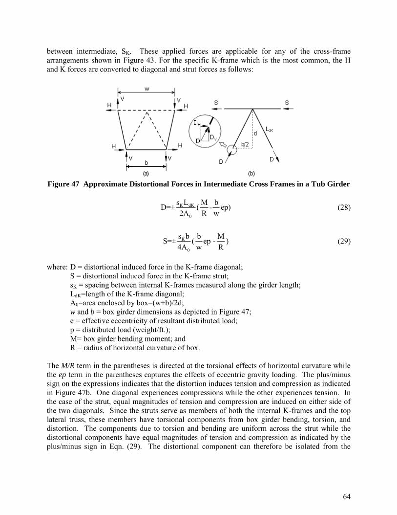
64
between intermediate, SK. These applied forces are applicable for any of the cross-frame arrangements shown in Figure 43. For the specific K-frame which is the most common, the H and K forces are converted to diagonal and strut forces as follows:
Figure 47 Approximate Distortional Forces in Intermediate Cross Frames in a Tub Girder
K dK
0
s L M bD=± ( - ep)2A R w
(28)
K
0
s b b MS=± ( ep - )4A w R
(29)
where: D = distortional induced force in the K-frame diagonal;
S = distortional induced force in the K-frame strut; sK = spacing between internal K-frames measured along the girder length; LdK=length of the K-frame diagonal; A0=area enclosed by box=(w+b)/2d; w and b = box girder dimensions as depicted in Figure 47; e = effective eccentricity of resultant distributed load; p = distributed load (weight/ft.); M= box girder bending moment; and R = radius of horizontal curvature of box.
The M/R term in the parentheses is directed at the torsional effects of horizontal curvature while the ep term in the parentheses captures the effects of eccentric gravity loading. The plus/minus sign on the expressions indicates that the distortion induces tension and compression as indicated in Figure 47b. One diagonal experiences compressions while the other experiences tension. In the case of the strut, equal magnitudes of tension and compression are induced on either side of the two diagonals. Since the struts serve as members of both the internal K-frames and the top lateral truss, these members have torsional components from box girder bending, torsion, and distortion. The components due to torsion and bending are uniform across the strut while the distortional components have equal magnitudes of tension and compression as indicated by the plus/minus sign in Eqn. (29). The distortional component can therefore be isolated from the

65
bending and torsional component by averaging the magnitudes of the strut force on either side of the two diagonals. Examples demonstrating the use of these preceding equations can be found in Fan and Helwig [48] and Helwig, et. al [49]. 3.2.2 Internal Cross Frame Details
As discussed in the subsection Vertical Bending, the spacing of the intermediate internal cross frames, should be sk = 2s, where s is the panel spacing in the top lateral system in single diagonal systems. Not only is the cost reduced by using fewer intermediate cross frames, but the forces in the top lateral system are also reduced. The panels adjacent to the cross frames only have a single top flange strut. A K-frame composed of angles is the preferred layout arrangement based mainly on its convenience when the interior of the closed box must be inspected. With an X-frame it is difficult to travel within the interior. Z-frames with only one diagonal provide less interference but the diagonal may be in compression. Since its diagonal is almost twice the length of a diagonal in a K-frame, A heavier frame will be required. The intermediate cross should also be detailed to minimize fatigue issues since live loads can cause distortion. 3.3 End Diaphragms
Diaphragms are provided at the supports of the tub girders. The diaphragms are required for torsional equilibrium of the girder system. Diaphragms resist the girder twist at the ends of the girders based primarily upon the shear stiffness of the diaphragm if the aspect ratio, Ld / hd, is less than 4 [1]. The ends of the girders are typically closed by solid plates and the diaphragm that connects the adjacent girders is may be trapezoidal in shape. The detailing requirements of the support diaphragms depend on the aspect ratio of the end diaphragms. Although the end diaphragm is typically trapezoidal in shape and is often bolted to the two adjacent girders, for establishing the detailing requirements the effective length of the diaphragm can be assumed to be measured as the spacing between the center of the bearings of two adjacent girders as shown in Figure 48. For most tub girder geometries, the practical range of spacing between the bearing centerlines and therefore the effective diaphragm length is in the range of 14 ft. < Ld < 20 ft. The lower range of the diaphragm depth so that shear stiffness dominates the behavior is 3.5 feet at the lower Ld range (14 ft.) and 5 feet at the upper Ld range (20 ft.). The end diaphragms are often deeper than these lower-bound values so shear stiffness will govern the behavior of these braces.
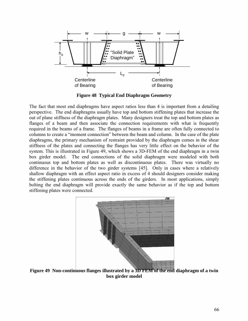
66
w w g
Centerline of Bearing
Centerline of Bearing
“ Solid Plate Diaphragm ”
h d
L d
Figure 48 Typical End Diaphragm Geometry
The fact that most end diaphragms have aspect ratios less than 4 is important from a detailing perspective. The end diaphragms usually have top and bottom stiffening plates that increase the out of plane stiffness of the diaphragm plates. Many designers treat the top and bottom plates as flanges of a beam and then associate the connection requirements with what is frequently required in the beams of a frame. The flanges of beams in a frame are often fully connected to columns to create a “moment connection” between the beam and column. In the case of the plate diaphragms, the primary mechanism of restraint provided by the diaphragm comes in the shear stiffness of the plates and connecting the flanges has very little effect on the behavior of the system. This is illustrated in Figure 49, which shows a 3D-FEM of the end diaphragm in a twin box girder model. The end connections of the solid diaphragm were modeled with both continuous top and bottom plates as well as discontinuous plates. There was virtually no difference in the behavior of the two girder systems [45]. Only in cases where a relatively shallow diaphragm with an effect aspect ratio in excess of 4 should designers consider making the stiffening plates continuous across the ends of the girders. In most applications, simply bolting the end diaphragm will provide exactly the same behavior as if the top and bottom stiffening plates were connected.
Figure 49 Non-continuous flanges illustrated by a 3D FEM of the end diaphragm of a twin
box girder model

67
3.3.1 Diaphragm Strength Design Requirements
There are two criteria that the designer should consider when proportioning the solid end diaphragms for box girder applications. The most obvious consideration is the basic shear strength of the plate diaphragm. The other consideration is related to excessive shear deformations at the ends of the beams that can result in rigid body rotations of the girders along the length. The strength limit state is relatively well-understood; however, an expression based upon stiffness criteria is also presented in the following sub-section. Figure 50 shows girder torsional demand that acts on diaphragms and the resulting shears that develop as a result of these torsional moments.
T2T1
V V
Ld
Figure 50 Girder end torsional demand that acts on diaphragms and the resulting shears
The moments T1 and T2 are the torsional moments that come as output from the results from a grid model. The girders are generally subjected to vertical gravity loading and although the net end reaction will typically be upwards, the diaphragm tends to redistribute the gravity load so that more of the gravity load shifts towards the exterior girder. Figure 50 shows the redistribution in the form of a downward shear on one girder and an upward shear on the other girder. The shear, V, represents the design shear for the end diaphragm. In terms of the girder end torques, the shear is:
d
21
LTT
V
(30)
In a curved girder Ld is the difference in the radii of the two girders. The design approach for shear is based upon a uniform shear stress through the depth of the plate. Referring to the area of the diaphragm plate as Ad = hdtd, the shear stress would be given as follows:
ddd
21
dd
21
d thLTT
ALTT
AV
(31)
Based upon a uniformly distributed load on a simply supported girder, the end torque (neglecting the presence of intermediate K-frames) is:
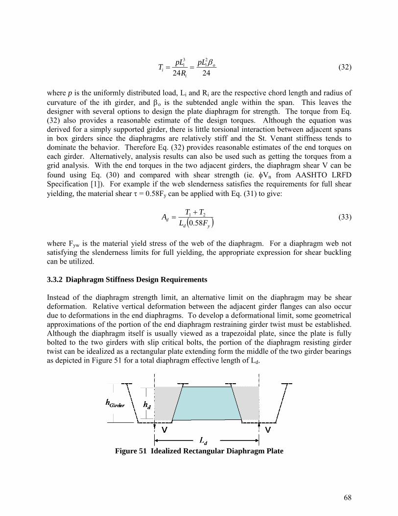
68
3 2
24 24i i o
i
i
pL pLT
R
(32)
where p is the uniformly distributed load, Li and Ri are the respective chord length and radius of curvature of the ith girder, and o is the subtended angle within the span. This leaves the designer with several options to design the plate diaphragm for strength. The torque from Eq. (32) also provides a reasonable estimate of the design torques. Although the equation was derived for a simply supported girder, there is little torsional interaction between adjacent spans in box girders since the diaphragms are relatively stiff and the St. Venant stiffness tends to dominate the behavior. Therefore Eq. (32) provides reasonable estimates of the end torques on each girder. Alternatively, analysis results can also be used such as getting the torques from a grid analysis. With the end torques in the two adjacent girders, the diaphragm shear V can be found using Eq. (30) and compared with shear strength (ie. Vn from AASHTO LRFD Specification [1]). For example if the web slenderness satisfies the requirements for full shear yielding, the material shear = 0.58Fy can be applied with Eq. (31) to give:
yd
dFL
TTA
58.021
(33)
where Fyw is the material yield stress of the web of the diaphragm. For a diaphragm web not satisfying the slenderness limits for full yielding, the appropriate expression for shear buckling can be utilized. 3.3.2 Diaphragm Stiffness Design Requirements
Instead of the diaphragm strength limit, an alternative limit on the diaphragm may be shear deformation. Relative vertical deformation between the adjacent girder flanges can also occur due to deformations in the end diaphragms. To develop a deformational limit, some geometrical approximations of the portion of the end diaphragm restraining girder twist must be established. Although the diaphragm itself is usually viewed as a trapezoidal plate, since the plate is fully bolted to the two girders with slip critical bolts, the portion of the diaphragm resisting girder twist can be idealized as a rectangular plate extending form the middle of the two girder bearings as depicted in Figure 51 for a total diaphragm effective length of Ld.
Figure 51 Idealized Rectangular Diaphragm Plate
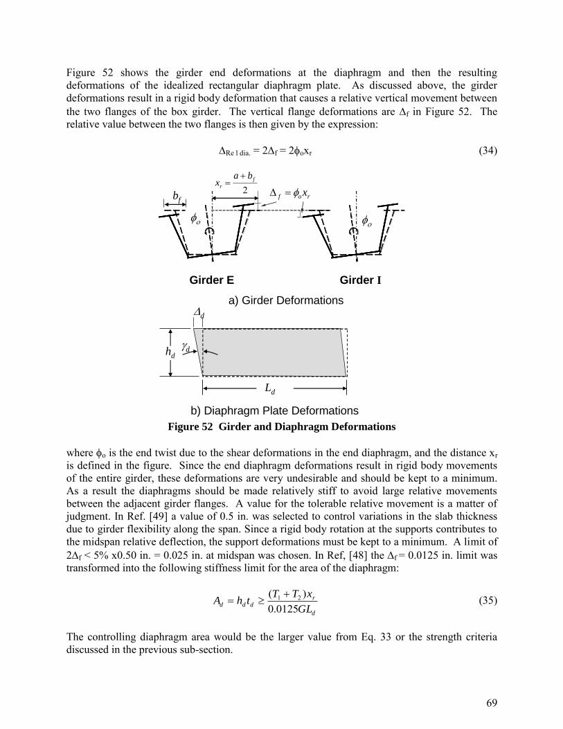
69
Figure 52 shows the girder end deformations at the diaphragm and then the resulting deformations of the idealized rectangular diaphragm plate. As discussed above, the girder deformations result in a rigid body deformation that causes a relative vertical movement between the two flanges of the box girder. The vertical flange deformations are f in Figure 52. The relative value between the two flanges is then given by the expression: Re l dia. = 2f = 2oxr (34)
Ld
Girder E
rof x
2f
r
bax
Girder I
bf
a) Girder Deformations
hd
d
d
b) Diaphragm Plate Deformations Figure 52 Girder and Diaphragm Deformations
where o is the end twist due to the shear deformations in the end diaphragm, and the distance xr is defined in the figure. Since the end diaphragm deformations result in rigid body movements of the entire girder, these deformations are very undesirable and should be kept to a minimum. As a result the diaphragms should be made relatively stiff to avoid large relative movements between the adjacent girder flanges. A value for the tolerable relative movement is a matter of judgment. In Ref. [49] a value of 0.5 in. was selected to control variations in the slab thickness due to girder flexibility along the span. Since a rigid body rotation at the supports contributes to the midspan relative deflection, the support deformations must be kept to a minimum. A limit of 2f < 5% x0.50 in. = 0.025 in. at midspan was chosen. In Ref, [48] the f = 0.0125 in. limit was transformed into the following stiffness limit for the area of the diaphragm:
d
rddd
GL
xTTthA
0125.0)( 21
(35)
The controlling diaphragm area would be the larger value from Eq. 33 or the strength criteria discussed in the previous sub-section.

70
3.4 Intermediate External Cross Frames
The primary role of the intermediate external diaphragms is to control the relative deformation between adjacent curved girders during casting of the concrete bridge deck. In cases where the external bracing is not removed after construction, the external bracing will also contribute to the load transfer between adjacent tub girders. In a twin girder system depicted at midspan in Figure 53, Girder E is the exterior girder with the longest individual span. The girders will twist independently during construction if there are no intermediate external cross frames connecting the two girders with Girder E having the larger angle of twist and vertical deflection compared to Girder I on the interior. Since the girders have some flexibility, there will be a relative vertical displacement rel between points B and C in (c) that causes a variation in the deck thickness and reinforcement cover. The dashed lines in (b) and (c) represent a straight line between the finishing machine rails at points A and D. The displacement rel must be controlled within some practical limit. Stiffer girders (larger teq) can be one approach but may be cost-prohibitive and very stiff girders pose greater problems with bolted field splices during erection. External intermediate cross frames shown in (b) can be used to improve the constructability. Studies [45, 50] have shown that only one or two cross frames near midspan are sufficient to control rel.
Girder E Girder I
a) Unloaded
b) Loaded with Cross Frame Present
c) Relative Twist Without Cross Frame
w wg
rel
Figure 53 Relative Deformation between Adjacent Girders
Cross frames should be concentrated towards the middle of the span instead of spreading the braces out equally along the bridge length. Although the deformations often don’t differ

71
substantially with the addition of several braces, the forces induced in the intermediate cross-frames will be smaller as more braces are added. However, the forces in the intermediate cross-frames from the construction loading are often relatively small except for spans with sharp curves (R< 250 ft). With skewed supports, the forces in the cross frames do become larger. Unless the support skew becomes large (greater than approximately 30 degrees), the forces can often be handled with members satisfying slenderness limits. External intermediate K-frames are primarily needed on horizontally curved girders. In straight girders, if diaphragms are provided at the supports and a top flange lateral truss is utilized, the girders are very stiff and intermediate external diaphragms can be omitted. Diaphragms would be needed if a large unbalanced load (ie. large torque) is applied or if the supports have significant skew. The problem with the large support skew is that the ends of the girders may tend to twist due to the angled diaphragm. The twist at the support results in a rotation of the girders that can result in problems with the uniformity in the slab thickness as outlined earlier. Most practical applications of straight girders do not need external bracing.
In most situations, external intermediate K-frames can be removed once the concrete deck hardens because field tests have shown that external K-frames have very little impact on live load distribution. The cross frames are most often removed due to fatigue concerns.
3.4.1 Analysis Approaches for Intermediate External Diaphragms
The treatment of the external braces in the structural analysis as well as the accuracy of the resulting forces depends heavily on the analysis method that is used. If a 3D-FEM is utilized, the braces can be modeled relatively accurately and the member forces can be obtained directly from the analysis. However, incorporating the external K-frames into a grid model poses a complicated geometrical problem. Although the internal and external K-frames are trusses made up of several members, the grid models treat these braces as a line element that spans between the centerlines of the adjacent girders. Therefore estimating the stiffness of these external braces can be difficult. In addition, the analytical estimates of the intermediate diaphragm moments from a grid model may often be of questionable accuracy. Another possible analysis approach is to designate the intermediate external K-frames solely as members to help control the constructability of the slab. With this approach, the analysis would be carried out only modeling the girders and solid diaphragms at the supports. The girders and support diaphragms would therefore be sized to support the entire load. This will often result in larger member sizes for the top flange lateral truss, when compared to an analysis that includes the external braces; however the economics of the top flange truss should not change too dramatically. The cost of the top flange truss is mainly related to fabrication costs, which are often primarily a function of the number of pieces required to fabricate. Increasing the size of a member by a few pounds per foot should not have too large of an impact on the design economics, however the behavior and safety of the design are much easier to predict with this approach. As mentioned above, a few external cross-frames concentrated near the middle of the span often provide excellent control over the relative twist between adjacent girders. In the following sections, approximate methods developed in [49] will be summarized that can be used

72
to determine the number of external cross frames needed to control constructability and to predict the member forces in the external cross frame.
3.4.2 Spacing of Intermediate External K-frames The approximate approach outlined is for determining how many intermediate cross-frames are needed. The spacing equation is based on the following assumptions: a simple- span twin curved girder symmetrical system with radial supports, no relative twist between the two supports of the span and the two girders have similar cross-section properties. The vertical and horizontal deflections at the web-top flange intersection at midspan for points B and C from vertical load applied at the top flanges of the quasi- closed sections were determined. These calculations required that the angle of twist of each girder, which is a function of the individual span lengths, be determined along with the vertical displacement of both girders. Since the cross-sectional properties of the two girders is the same, the difference between the perpendicular displacements of points B and C relative to a straight line between screed rails, rel, is mainly a function of the difference in span lengths between the two girders and the identical cross-sectional properties. The difference in span lengths is related to the spacing between the two girders, (w + g), and the subtended angle o = L/R of the bridge plan. With some minor assumptions associated with the relative location of the screed rails on typical tub girder geometries, the relationship of the span length between external cross frames and rel is
3GJEI
384EIg)w5wβ
1.2ΔL
0
relmax (36)
For design the maximum permissible deviation in slab thickness rel can be set equal to some maximum value, say 0.5 in., to determine Lmax. If Lmax is greater than the span length, no external intermediate cross frames will be required for constructability.
3.4.3 Forces in Intermediate External K-frames To develop expressions for the forces in the external diaphragm, the case of a single external K-frame located at midspan will be considered. The lengths, Li and Le, of the respective interior and exterior girders in these derivations are taken as the total arclength of the respective girders between the supports. The external diaphragm help to restrain twist and vertical deflections of the box girders at the location of the braces. The basic geometry of the external K-frame and box girder system are shown in Figure 54. The angle of the diagonal of the K-frame is represented as , while the depth of the K-frame is denoted as hK. The rotation of the two girders and the K-frame system are assumed to be the same and are represented as . The distance from the center of a girder to where the top chord of the K-frame connections is shown as LT. The distances hK and LT will be used to represent the torque exerted by the external K-frame on the girders.

73
Interior
w
w g
L T
w+g
h K
Exterior
Figure 54 K-frame Geometry
He Hi
ViVe
Exterior Interior
e
BF i
BF
DFDF
TF
a) Forces on K-Frame b) Member Forces
Figure 55 External K-Frame Forces
The K-frames exert restraining forces H and V on the girders in the respective horizontal and vertical directions. The equal and opposite forces that act on the K-frame are depicted in Figure 55a. The corresponding member forces that develop in the K-frames are depicted in Figure 55b.
2
,1,int,4K
KLLGJF
relwweextwi
D
(37)
)()()(4 ,int,
eiK
ieKDwextw
TLLh
LLLFGJF
(38)
TDB FFF cos
(39)
The variables in the above equations can be calculated as follows:
sincos TKK LhL
74
2cos111 0
0
GJ
EIK
gw
LLK ei
1
Keiei LLL
GJEI
LLKKK 2sin
)/(12
33
102
44
0, 3845
ierelw LLEI
wK
GJ
EI
EIR
wLiw 1
3845
int
4
int,
GJ
EI
EIR
wL
ext
eextw 1
3845 4
,
Comparison of the member forces with the forces from 3-D FEM show reasonable agreement [45].

75
4.0 BRACING MEMBER DESIGN AND CONNECTION DETAILS
4.1 Design of Tees and Angles
For tension and compression members, the 2010 AASHTO Specification [1] has adopted the limit state provisions from the 2010 AISC Specification [15] and added mandatory L/r limitations. Except for axial compression (=0.9), all other -factors in AASHTO [1] are larger than their counterparts in the 2010 AISC Specification [15]. Therefore, the use of the design capacities in the AISC Manual [51] for tension members and their connections is conservative. If desired, engineers can adjust AISC Manual [51] tabulated values in the ratio of the respective -factors (AASHTO/AISC). For compression members, the design strengths in the AISC Manual are directly applicable. 4.1.1 Tension Members
Single angle, double angles, and tee-sections in tension are checked for the limit states of yielding on the gross section, fracture on the net section, block shear at the end connections and limiting slenderness ratio. When evaluating the slenderness ratio, any bracing member required to enable a main member to support the applied loads should be treated as a primary member. That is, if the main member cannot support the design loads without the bracing member, then the bracing is not a secondary member. Single and double angle members are usually connected at the ends through one of the legs. The eccentricity between the end connection and the angle centroid has little structural significance and is typically ignored. Tees are mainly connected through the flange. The bracing members are connected to the main member by connection plates on the webs or directly to the flanges. The eccentricity between the connection and the member centroid has little structural significance for tension members and can be ignored. Also, the U-factor reduction in the net section fracture capacity in AASHTO Section 6.8.2.1-2 [1] was developed from test data with specimens that had eccentricities. 4.1.2 Compression Members
4.1.2.1 Single angles
The methods specified in various design codes for the design of single angle compression members loaded through one leg can be divided into two categories: column approaches and beam-column approaches. The column approach, which is the simplest for design, was given in the first edition (1971) of the ASCE Standard 10-97, Design of Latticed Steel Transmission
Towers [52]. Based on the results of many angle tests and full size tower tests, angle design was
based on axial load only with an adjusted L/rz used with the normal column formula to account for eccentricities and end restraint. The British, European, South African and Japanese steel design specifications use similar column approaches. The main variable among these different standards is the axis used to define the critical column slenderness ratio. The ASCE method uses the minimum principal radius of gyration, rz. Prior to 2005, AISC [53] specified a beam-column approach that required the eccentricity to be defined explicitly about both principal axes and also consider second-order effects. For unequal-

76
leg angles the orientation of the principal axes makes the geometry even more complex. Over the past thirty years, numerous experimental studies have shown the AISC method to be overly conservative [54]. Test loads 2-3 times greater than the AISC limit load are usually reported. The evaluation of the AISC beam-column approach is best summed up by the following statement in Ref. [55] “This [53] approach is not widely used by design engineers, since it provides a very conservative estimate of the load-carrying capacity and since it involves tedious calculations for a member that most engineers consider to be a very simple member”. In 2005 the AISC Specification [15] adopted a new design approach based on the ASCE 10-97 [55] Standard for angles loaded through one leg. The ASCE method is based mainly on tests with small (2.5 in.) equal leg angles. Tests with larger angles and unequal legs [57] showed that the capacity with the short leg connected was approximately 80% greater than tests with the long leg attached. The ASCE method predicted the same capacity for both cases since rz is constant for both arrangements. Also, tests have shown that the dominant deformation is bending about the centroidal axis parallel to the attached leg, which will always be called the x-axis, so L/rx should be the controlling slenderness ratio. This dilemma was resolved by noting that the rz/rx ratio for all equal leg angles have little variation with a narrow range of 0.61-0.65. Taking rz/rx = 0.63, the ASCE effective slenderness of KL/rz for typical tower framing details (not highly restrained) was directly converted to an equivalent KL/rx formulation [57]. A sample conversion is as follows ASCE [56]: For 0 L/rz 120, KL/rz = 60+0.5(L/rz) ≡ 0 L/rx 75, KL/rx = 60+0.8(L/rx) (40) There is an additional equation for longer members. Using rx instead of rz made the ASCE formulation reasonably accurate for both equal and unequal leg angles. Equation (a) should be applicable to typical end connections but AISC introduced additional conservatism by developing a set of similar equations that were fit to test results on angles with knife-edge end supports (zero restraint). AISC applies Eq. (a) to angles that are web members in space or box trusses. As expected, the AISC formulations are conservative compared to other national codes [54] but are still easier and more accurate than the earlier beam-column approach. AASHTO 2010 [1] adopted the new AISC method [15] for single angle compression members loaded
through one leg but only with the zero restraint condition. See AASHTO section 6.9.4.4 [1].
base plate
Figure 56 Typical Test End Connection

77
The column approach is based on angle tests with similar small end eccentricities in the plane of the outstanding leg at both ends, e.g. the connection plate thickness was similar to the angle thickness. A typical test connection detail is shown Figure 56. If filler plates are used at the connections, the increased eccentricity should be considered and Section H2 of the AISC Specification [15] used for design. A summary of stability issues for angle members is given in Ref. [58] and Chapter 11 of the SSRC Guide to Stability Design Criteria for Metal Structures [24]. 4.1.2.2 Tees and Double Angles
A tee flange is normally attached to a gusset or top flanges by welding or bolting as shown in Figure 57. The eccentrically loaded tee is subjected to a concentric load, P, and an end moment, eP, where e is the eccentricity. Unlike tension members, the effects of the eccentricity must be considered in the design of the brace because the compressive load amplifies the moments and deflections. In tension members, the bending deformations and moments along the span are reduced by the tension force. Designing tees and double angles for combined bending and axial load by directly applying all the required design checks with the AISC Specification [15] is a formidable task that is similar to the former design method for single angles described in 4.1.2.1. Unfortunately, there is no similar effective slenderness ratio method for tees or double angles. Gordon [61] has developed tables of correction factors to the concentric column capacity for all rolled WT shapes assuming a ½ in gusset thickness. The AISC approach is very conservative for singly-symmetric members as illustrated in Figure 5.6.3-7 in Chapter 6. The principle reason for the conservatism relates to combining bending and stability into one set of interaction equations. There are two general behavioral phenomena for any member subjected to axial compression and simultaneous bending in one plane: in-plane bending that includes column buckling in that plane and out-of-plane buckling that includes stem buckling, lateral torsional buckling, and flexural (column) buckling. The AISC interaction equations are accurate for in-plane bending of doubly-symmetric sections. For W-shapes, AISC permits an alternative approach of considering out-of-plane buckling separately from the in-plane interaction equations.
P
Pe
Figure 57 Eccentrically loaded WT section
For eccentrically loaded tees and double angles, separating in-plane and out-of-plane behavior greatly simplifies the design process and gives more accurate and economical designs. Also, the AISC equations treat P and M as independent variables whereas P is the only load variable in a

78
brace strut. Galambos [62] gives the following general equation for elastic lateral-torsional buckling of a singly-symmetric section loaded by P and M in the plane of symmetry with the largest flange in compression: (Pey – P)(ro
2Px – ro2P + xM) = (M – Pyo)2
(41)
where, ro
2 = yo2 + rx
2 + ry2
where Pey is the out-of-plane Euler load, Pz is the torsional buckling load, and yo is the distance beween the centroid and the shear center, x is the monosymmetry parameter as defined in Galambos [62]. Pz is typically much larger than Pey. For M=0 in Eq. (41), the flexural-torsional buckling load equations in the AISC [8] are obtained. For P=0, the beam lateral buckling solution given earlier in Eq. (10) is determined. With no moment the lateral-torsional buckling load is always smaller than the Euler load. But with moment present the flexural-torsional buckling load can increase. The moment has a positive sign if the largest flange is in compression. For the particular case of an eccentrically-loaded tee or double angle, the eccentric load causes compression in the flange so eP has a positive sign. The shear center of a tee is at the intersection of the flange and the stem. To illustrate the simplifications that follow the eccentric load will be placed at the shear center so the right side of Eq. (41) becomes zero (M=Pyo), resulting in the following expression: (Pey – Pcr)(ro
2Pz – ro2Pcr + xPcryo) = 0
(42)
The critical buckling load is either: The out-of-plane Euler buckling load Pcr = Pey
or
the pure torsional buckling load: ox
2o
2o
zcr yrrPP
There is no flexural torsional buckling so the smallest load is the normal y-axis column buckling load. The torsional buckling load is actually increased by the presense of the moment. The main point of the derivation is to illustrate that the in-plane eccentricity actually improves the out-of-plane buckling strength. Parametric FEA studies with greater eccentricities also support this statement. The out-of-plane buckling load is always flexural. In plane the amplified moment, Mcr = eP / (1 – P/Pex) should be used to determine the bending stress at the flange and at the tip of the stem. Note that the Sx listed in the AISC manual is for the stem. The section modulus at the flange tip is Ix / x(bar). Using the AISC interaction equations, the flange and the stem should be checked separately as follows:

79
Flange Check: 0.1xy
a
n IF
xM
P
P
Stem Check: 0.1xy
a
n SF
M
P
P
Where, Pn is the column capacity based on L/rx. No Q reduction factors are necessary because local stem buckling will not occur as established by FEA (the stem is always in tension). The bending stress is limited to first yield and not 1.6Fy as permitted for pure bending of a tee. Yielding of the stem does not affect the out-of-plane Euler load, but any yielding at either the stem or the flange will reduce the in-plane stiffness and increase the bending amplification factor. In summary, there are no flexural-torsional buckling equations to check and no web slenderness effects. The use of compact flanges eliminates local flange buckling. Only normal column buckling and an in-plane stress check are needed for safe designs.
4.2 Fatigue Design of Cross-frame Members
Fatigue design must be considered in the design of cross-frame members, especially in horizontally curved and/or skewed I-girder bridges, where cross-frames can transmit significant live load forces through the structure. Live load moments also produce lateral flange bending so the detailing of cross frames should include fatigue considerations. Fatigue cracks in the girders at cross-frame locations are not uncommon as noted by Zhou and Biegalski [6]. 4.3 Welded and Bolted Connection Details
The AASHTO/NSBA Collaboration publication, Guidelines for Design Details [64], shows preferred details for connecting cross frame and lateral bracing members to girders. Additionally, the NSBA publication, Practical Steel Tub Girder Design [65], provides bracing connection details in tub girders that are based on preferred detailing practices for cost-effective fabrication. In both publications, the details provided do not reflect any specific actual design conditions, but are only preferred types of details. All details require careful analysis and consideration, and the preferred details may not always be applicable. This section contains a number of pictures of details that are not recommended as standard practice details. Generally, if details such as these are used, special consideration must be given by the designer with regard to load paths and load transfer through the various structural components. Although the pictures focus on tub girders, many of the basic principles also apply to a variety of different bracing systems. A brief description of the picture is given for each detail. In Figure 58, the WT for the top flange lateral truss on the box girder had an improper orientation, and an incorrect size. The stem of the WT was oriented upwards, which increases likely interference with the metal deck forms. The stem of the WT should point downward so that the flat surface of the flange is available for the construction personnel to walk on and also so that the WT can be placed very near the top flange. Also, orientating the WT so that the
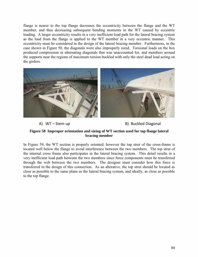
80
flange is nearer to the top flange decreases the eccentricity between the flange and the WT member, and thus decreasing subsequent bending moments in the WT caused by eccentric loading. A larger eccentricity results in a very inefficient load path for the lateral bracing system as the load from the flange is applied to the WT member in a very eccentric manner. This eccentricity must be considered in the design of the lateral bracing member. Furthermore, in the case shown in Figure 58, the diagonals were also improperly sized. Torsional loads on the box produced compression in alternating diagonals that was unaccounted for, and members around the supports near the regions of maximum torsion buckled with only the steel dead load acting on the girders.
A) WT – Stem up B) Buckled Diagonal
Figure 58 Improper orientation and sizing of WT section used for top flange lateral
bracing member
In Figure 59, the WT section is properly oriented; however the top strut of the cross-frame is located well below the flange to avoid interference between the two members. The top strut of the internal cross frame also participates in the lateral bracing system. This detail results in a very inefficient load path between the two members since force components must be transferred through the web between the two members. The designer must consider how this force is transferred in the design of this connection. As an alterative, the top strut should be located as close as possible to the same plane as the lateral bracing system, and ideally, as close as possible to the top flange.

81
Figure 59 Strut offset below diagonal
Many poor bracing details are the result when working lines of the bracing members are forced to intersect. An example of this is the top flange truss that is being fabricated in Figure 60. The picture shows that very large gusset plates were used in an attempt to have the working lines of the diagonals and the top struts .intersect. In the case shown here, the diagonals can cause a significant eccentric moment on the gusset plate connection to the top flange, that must be considered in the design of this connection. Better behavior would result if the diagonals were offset slightly and bolted directly to the underside of the flange, thereby eliminating the gusset connection plates. Although the working lines may not intersect with this detail, many stability bracing systems can be offset from the working points by as much as 10% of the unbraced length with very little impact on the structural performance. For tub girders, the designer can usually offset the working line by approximately a flange width with little effect on the performance. Connection eccentricities in the plane of the truss have very little impact on the performance of the bracing system.
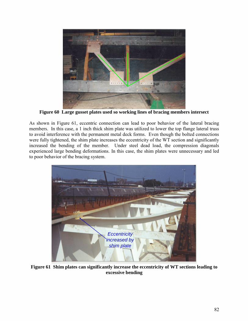
82
Figure 60 Large gusset plates used so working lines of bracing members intersect
As shown in Figure 61, eccentric connection can lead to poor behavior of the lateral bracing members. In this case, a 1 inch thick shim plate was utilized to lower the top flange lateral truss to avoid interference with the permanent metal deck forms. Even though the bolted connections were fully tightened, the shim plate increases the eccentricity of the WT section and significantly increased the bending of the member. Under steel dead load, the compression diagonals experienced large bending deformations. In this case, the shim plates were unnecessary and led to poor behavior of the bracing system.
Eccentricity
increased by
shim plate
Figure 61 Shim plates can significantly increase the eccentricity of WT sections leading to
excessive bending

83
Figure 62 shows a partial depth end diaphragm that results in a poor load path that cannot anchor the top flange lateral truss. The top flange lateral truss must be sufficiently anchored to the end of the tub girder. The partial depth end diaphragm was used to accommodate a thickened armor joint at the end of the bridge. However the thin web of the box girders may not stiff enough to anchor the very large diagonal forces in the top flange lateral truss. The torsional stiffness of the box is therefore reduced, which can lead to large deformations. In this case, the load path must be considered in the design of this lateral bracing system, or a full depth end diaphragm should be used.
Figure 62 Partial depth end diaphragm.

84
5.0 SIMPLIFIED GEOMETRIC PROPERTIES FOR TUB GIRDERS
Symbols are defined in Figure 63. 5.1 Shear Center, ey, for Open and Quasi-Closed Sections [59]
Figure 63 Calculation of Shear Center for Open and Quasi-Closed Sections
The shear center location ey is measured from the centroid of the bottom flange. A negative value indicates that the shear center is below the bottom flange. For open-section tub girders, teq= 0 and qa = -btttw.

85
5.2 Monosymmetry Coefficient, x –Open section only [60]
22 2 2 2
3 4 4 43 4
1 1212 12 41 22 1
tan sin 24 64 2cos
b b b b t t t t
x o
x w c wb b b t
wy A b y A y b y
yI t x t
w b w b y y
where At = bttt and Ab = bbtb. All geometric functions have positive values but x will be negative. 5.3 Warping Moment of Inertia, Cw -- Open section only [60]
tbcwbbaaba
w AccAccccAc
C
26612
22222
where ca = eybb, cb = eyw + dbb, cc = bt(ey – d) and Aw = dtw

86
6.0 REFERENCES
1. American Association of State Highway and Transportation Officials (AASHTO) 2010,
“AASHTO LRFD Bridge Design Specifications, 5th Ed. Washington, D. C. 2. Vlasov, V. 1961. Thin-Walled Elastic Beams, 2nd edition, National Science Foundation,
Washington D.C. 3. Timoshenko, S. and Gere, J. 1961. Theory of Elastic Stability, McGraw-Hill, New York. 4. Corr, D, McCann, D. and McDonald, B. 2009. “Lessons Learned from Marcy Bridge
Collapse”, Proc., ASCE Forensic Engineering Congress. 5. Davidson, J., Keller, M. and Yoo, C. 1996. “Cross-Frame Spacing and Parametric Effects
in Horizontally Curved I-Girder Bridges”, Journal of Structural Engineering, ASCE, Vol. 122, No. 9, pp 1089-1096.
6. Zhou, Y. and Biegalski, A. 2010. Investigation of Large Web Fractures of Welded Steel
Plate Girder Bridge”, Journal of Bridge Engineering, ASCE, Vol. 15, No. 4, pp 373-383. 7. Fan, Z. and Helwig, T. 1999. “Behavior of Steel Box Girders with Top Flange Bracing,”
Journal of Structural Engineering, ASCE, Vol. 125, No. 8, pp.829-837. 8. AASHTO/NSBA Steel Bridge Collaboration, 2011. G13.1 Guidelines for Steel Girder
Bridge Analysis, 1st Ed., Washington, D.C. 9. UT Bridge Computer Software, Ferguson Structural Engineering Laboratory, Univ. of
Texas at Austin; free download at http//fsel.engr.utexas.edu/software.
10. Peollet, W. 1987. “Computer-Aided Design of Horizontally Curved Girders by the V-Load Method”, Engineering Journal, AISC, Vol. 24, No. 1, pp 42-50.
11. Liu, D. and Magliola, R. 2010. “End Forces on Cross Frames in Horizontally Curved Steel I-Girder Bridges”, Practice Periodical on Structural Design and Construction, Vol. 15, No. 1, pp 21-26 .
12. Gaylord, E. and Gaylord, C. 1990. Structural Engineering Handbook, 3rd Ed., McGraw –Hill, New York.
13. Grubb, M. A.; 1984. “Horizontally Curved I-Girder Bridge Analysis: V-Load Method”,
Transportation Research Record, Record N982, Transportation Research Board, Washington DC, pp 26-36.
14. Stith, J., Schue, A., Farris, J., Petruzzi, B., Helwig, T., Williamson, E., Frank, K., Engelhardt, M. and Kim, J. 2010, “Guidance for Erection and Construction of Curved I-

87
Girder Bridges”, TxDOT Report 0-5574-1, Center for Transportation Research, The University of Texas at Austin, pp. 240.
15. American Institute of Steel Construction (AISC). 2010. Specification for Structural Steel Buildings, Chicago.
16. Yura, J. and Helwig, T. 2010. “Buckling of Beams with Inflection Points”, Proc., Structural Stability Research Council, Annual Stability Conference, pp.761-780.
17. Yura, J. 2001. “Fundamentals of Beam Bracing”, Engineering Journal, AISC, Vol. 38, No.1, pp.11-26.
18. Helwig, T. and Yura, J. 2008. "Shear Diaphragm Bracing of Beams II: Design Requirements", J. of Structural Engineering, ASCE, Vol. 134, No. 3, pp.357-363.
19. Flint, A. 1951. “The Stability of Beams Loaded Through Secondary Members”, Civ. Eng.
Public Works Review, Vol. 46, No. 537-8, pp.175-177, 259-260. 20. Yura, J., Phillips, B., Raju, S., and Webb, S. 1992. “Bracing of Steel Beams in Bridges,”
Research Report 1239-4F, Center for Transportation Research, Univ. of Texas at Austin, October, 80 pp.
21. Taylor, A. and Ojalvo, M., 1966, "Torsional Restraint of Lateral Buckling," J. of Structural Engineering, ASCE, Vol. 92 No. ST2, pp.115-129.
22. Helwig, T., Yura, J. and Frank, K. 1993. "Bracing Forces in Diaphragms and Cross Frames," Proc., Structural Stability Research Council Conference “Is Your Structure Suitably Braced?”, pp. 129-140.
23. Chen, B., Yura, J., Williamson, E. and Frank, K. 2003. “Top-Lateral Bracing System for Trapezoidal Steel Box-Girder Bridges”, Report 0-1898-4, Center for Transportation Research, U. of Texas at Austin, January, 116 p.
24. Ziemian, R., Ed. 2010. Stability of Angle Members, Chapter 11, Guide to Stability Design Criteria for Metal Structures, 6th Edition. J. Wiley & Sons, New York, p. 493-530.
25. Wang, L. and Helwig, T. 2008. “Stability Bracing Requirements for Steel Bridge Girders with Skewed Supports,” Journal of Bridge Engineering, ASCE, Vol. 13, No. 2, pp. 149-157.
26. Quadrato, C., Wang, W., Battistini, A., Wahr, A., Engelhardt, M., Helwig, T. and Frank, K. 2011 “Cross-Frame and Diaphragm Layout and Connection Details,” TxDOT
Report 0-5701, Center for Transportation Research, 393 p.

88
27. Wahr, A., 2010, “The Fatigue Performance of Cross Frame Connections,” Thesis, University of Texas at Austin, 228 p.
28. Yura, J. A., 1971, “The Effective Length of Columns in Unbraced Frames”, AISC Engineering Journal, pp. 37-42.
29. Helwig, T. and Wang, L. 2003, “Cross-Frame and Diaphragm Behavior for Steel Bridges with Skewed Supports”, Report 1772-1, The University of Houston, 231 p.
30. Yura, J., Helwig, T., Herman, R., and Zhou, C. 2008. “Global Lateral Buckling of I-Shaped Girder Systems”, J. of Structural Engineering, ASCE, Vol. 134, No. 9, p.1487-1494.
31. Galambos, T., Green, P., Helwig, T. and Yura, J. 2003. “Basic Design for Stability”, Lecture 4 Notes, AISC-SSRC Short Course.
32. Kitipornchai, S. and Finch, D. 1986. “Stiffness Requirements for Cross Bracing”, J. of Structural Engineering, ASCE, Vol. 112, No. 12, pp.2702-2707.
33. Picard, A. and Beaulieu, D. “Design of Diagonal Cross Bracing”, Part1: Theoretical Study, Engineering Journal, AISC, Vol. 24, No. 3, 1987,pp.122-126 and Part2: Experimental Study, Vol. 25, No. 4, 1988, pp.156-160.
34. Winter, G. (1960), “Lateral Bracing of Columns and Beams,” ASCE Transactions Vol. 125, pp. 809-825.
35. Egilmez, Ozgur O.; Helwig, Todd A.; Jetann, Charles A.; and Lowery, Richard, “Stiffness and Strength of Metal Bridge Deck Forms,” ASCE Journal of Bridge
Engineering, Vol. 12, No. 4, pp. 429-437, July/August 2007.
36. Helwig, Todd A.; Egilmez, Ozgur; and Jetann, Charles, “Lateral Bracing of Bridge Girders by Permanent Metal Deck Forms,” Research Report 4145-1, Report for Texas Department of Transportation, January 2005.
37. Klonaris, G. 2003. “Analytical and Computational Studies on the Torsional and Flexural Response of steel Trapezoidal Box-Girder Bridges”, MS Thesis, Dept. of Civil Engineering, U. of Texas at Austin, 204 pp..
38. Kollbrunner, C. and Basler, K. 1969. Torsion in Structures – An Engineering Approach, Springer-Verlag, New York..
39. Heins, C. 1978. “Box Girder design – State of the Art”, Engineering Journal, AISC, Vol. 15, No.4, pp.126-142.

89
40. Topkaya, C., Widianto and Williamson, E. 2005. “Evaluation of Top Flange Bracing Systems for Curved Box Girders”, J. of Bridge Engineering, ASCE, Vol. 10, No. 6, pp.693-703.
41. Widianto 2003. “General Behavior of a Steel Trapezoidal Box-Girder during Construction”, MS Thesis, Dept. of Civil Engineering, U. of Texas at Austin, 398 pp.
42. Helwig, T., and Fan, Z., August 2000. “Field and Computational Studies of Steel Trapezoidal Box Girder Bridges,” TxDOT Report 0-1395-3, The University of Houston, 238 p.
43. Williamson, E., Topkaya, C., Popp, D. and Yura, J. 2004. UTrAp 2.0 Analysis of Steel Box Girders during Construction, Department of Civil Engineering, Univ. of Texas at Austin.
44. Kim, K. and Yoo, C. 2006.”Interaction of Top Lateral and Internal Bracing Systems in Tub Girders”, J. of Structural Engineering, ASCE, Vol. 132, No. 10, pp.1611-1620.
45. Helwig, T., Herman, R., and Li, D. 2004. “Behavior of Trapezoidal Box Girders with Skewed Supports,” TxDOT Report 0-4148-1, The University of Houston, 198 p.
46. Kim, K. and Yoo, C. 2009.”Bending Behaviors of Quasi-Closed Trapezoidal Box Girders with X-Type Internal Cross Frames”, J. of Constructional Steel Research, Elsevier, Vol. 65, pp.1827-1835.
47. Yura, J. and Widianto 2005. “Lateral Buckling And Bracing Of Beams – A Re-Evaluation after the Marcy Bridge Collapse”, Proceedings, Structural Stability Research Council, Annual Stability Conference, pp 277-294.
48. Fan, Z. and Helwig, T. 2002. “Distortional Loads and Brace Forces in Steel Box Girders”, J. of Structural Engineering, ASCE, Vol. 128, No. 6, pp.710-718.
49. Helwig, T., Yura, J., Herman, R., Williamson, E. and Li, D. 2007, “Design Guidelines for Steel trapezoidal Box girder Systems”, Report 0-4307-1, Center for Transportation research, U. of Texas at Austin, April, 72 p.
50. Kim, K. and Yoo, C. 2006. ”Brace Forces in Steel Box Girders with Single Diagonal Lateral Bracing Systems”, J. of Structural Engineering, ASCE, Vol. 132, No. 8, pp.1212-1222.
51. American Institute of Steel Construction (AISC). 2011. Steel Construction Manual, 14th Ed., Chicago.
52. American Society of Civil Engineers (ASCE). 1971, Design of Latticed Steel Transmission Towers, Standard 10-97, Reston, VA, 88p.

90
53. American Institute of Steel Construction (AISC). 2000. Load and Resistance Factor Design Specification for Single-Angle Members, Chicago, 20 p.
54. Lutz, L. 2006. “Evaluating Single-Angle Compression Struts Using an Effective Slenderness Approach”, Engineering Journal, AISC, Vol. 43, No. 4, pp.241-246.
55. Temple M. and Sakla S. 1998a. “Single-Angle Compression Members Welded by One Leg to a Gusset Plate. I. Experimental Study”, Can. J. of Civil Engineering. Vol. 25, pp. 569-584.
56. American Society of Civil Engineers (ASCE). 2000. Design of Latticed Steel Transmission Towers, Standard 10-97, Reston, VA, 88p.
57. Mengelkoch, N. and Yura, J. 2002. “Single-Angle Compression Members Loaded Through One Leg”, Proc., Structural Stability Research Council Annual Stability Conference, pp.201-218.
58. Kennedy, J. and Madugula, M. 1982. “Buckling of Angles: State of the Art”, J. of Structural Engineering, ASCE, Vol. 108, No. 9, pp.1967-1980.
59. Terry, P. 2004. “Steel Trapezoidal Box Girder Section Properties”, MS Thesis, Dept. of Civil and Environmental Engineering, U. of Houston, Texas, 126 pp.
60. Popp, D. 2004. “UTrAp 2.0: Linerarized Buckling Analysis of Steel Trapezoidal Girders”, MS Thesis, Dept. of Civil Engineering, U. of Texas at Austin, 121 pp.
61. Gordon, M. 2010. “Tables for Eccentrically Loaded WT Shapes in Compression”, Engineering Journal, AISC, Vol. 47, No. 2, pp. 91-100.
62. Galambos, T. 2001. “Strength of Singly Symmetric I-shaped Beam-Columns”, Engineering Journal, AISC, Vol. 38, No. 2, pp. 65-77.
63. Kitipornchai, S. and Lee, H., 1986. “Inelastic Buckling of Single Angle, Tee, and Double-Angle Struts”, J. of Constructional Steel Research, vol. 6, No. 1, pp. 3-20.
64. AASHTO/NSBA Steel Bridge Collaboration, 2006, “G1.4 Guidelines for Design Details.”
65. Coletti, D., Fan. T., Gatti, W., Holt, J., and Vogel, J., 2005, “Practical Steel Tub Girder Design,” National Steel Bridge Alliance (NSBA).