Design of Plasma Generator Driven by High-frequency High ...
11
Journal of Applied Research and Technology ISSN: 1665-6423 [email protected] Centro de Ciencias Aplicadas y Desarrollo Tecnológico México Yong-Nong, C.; Chih-Ming, K. Design of Plasma Generator Driven by High-frequency High-voltage Power Supply Journal of Applied Research and Technology, vol. 11, núm. 2, abril, 2013, pp. 225-234 Centro de Ciencias Aplicadas y Desarrollo Tecnológico Distrito Federal, México Available in: http://www.redalyc.org/articulo.oa?id=47426225006 How to cite Complete issue More information about this article Journal's homepage in redalyc.org Scientific Information System Network of Scientific Journals from Latin America, the Caribbean, Spain and Portugal Non-profit academic project, developed under the open access initiative
-
Upload
khangminh22 -
Category
Documents
-
view
0 -
download
0
Transcript of Design of Plasma Generator Driven by High-frequency High ...

Journal of Applied Research and Technology
ISSN: 1665-6423
Centro de Ciencias Aplicadas y Desarrollo
Tecnológico
México
Yong-Nong, C.; Chih-Ming, K.
Design of Plasma Generator Driven by High-frequency High-voltage Power Supply
Journal of Applied Research and Technology, vol. 11, núm. 2, abril, 2013, pp. 225-234
Centro de Ciencias Aplicadas y Desarrollo Tecnológico
Distrito Federal, México
Available in: http://www.redalyc.org/articulo.oa?id=47426225006
How to cite
Complete issue
More information about this article
Journal's homepage in redalyc.org
Scientific Information System
Network of Scientific Journals from Latin America, the Caribbean, Spain and Portugal
Non-profit academic project, developed under the open access initiative
Journal of Applied Research and Technology 225
Design of Plasma Generator Driven by High-frequency High-voltage Power Supply C. Yong-Nong*, K. Chih-Ming
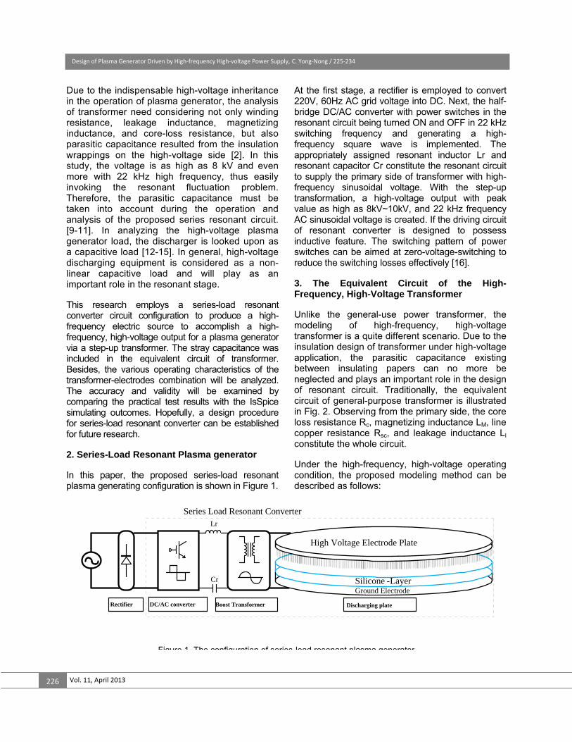
Department of Electrical Engineering, National Formosa University, No.64, Wunhua Rd., Huwei Township,Yunlin County, 63201, Taiwan * [email protected] ABSTRACT In this research, a high-frequency high-voltage power supply designed for plasma generator is presented. The power supply mainly consists of a series resonant converter with a high-frequency high-voltage boost transformer. Due to the indispensable high-voltage inheritance in the operation of plasma generator, the analysis of transformer need considering not only winding resistance, leakage inductance, magnetizing inductance, and core-loss resistance, but also parasitic capacitance resulted from the insulation wrappings on the high-voltage side. This research exhibits a simple approach to measuring equivalent circuit parameters of the high-frequency, high-voltage transformer with stray capacitance being introduced into the conventional modeling. The proposed modeling scheme provides not only a precise measurement procedure but also effective design information for series-load resonant converter. The plasma discharging plate is designed as part of the electric circuit in the series load-resonant converter and the circuit model of the plasma discharging plate is also conducted as well. Thus, the overall model of the high-voltage plasma generator is built and the designing procedures for appropriate selections of the corresponding resonant-circuit parameters can be established. Finally, a high-voltage plasma generator with 220V, 60Hz, and 1kW input, along with a 22 kHz and over 8kV output, is realized and implemented. Keywords: power supply, series resonant converter, plasma generator. 1. Introduction High-voltage plasma generating is widely used in industry applications, such as static charge remover, ozone generator for sterilizing, and plastic and metal (ex. Aluminum sheet) surface imprinting processing, and so on. Ozone generator makes use of high-voltage plasma generating to ionize the air and generate Ozone [1]. Static charge remover utilizes high-voltage plasma generating to eliminate static charges in the air. High-voltage plasma generator changes the surface feature under the high-voltage plasma generating process to increase the adhesion of the material surface or the oily ink to fortify the printing quality [2]. In general, a high-voltage plasma generator necessitates a high-voltage electric source and a pair of electrodes. To improve the plasma quality, high-frequency operation is essential for the promotion of plasma stability. A transformer is featured with easy voltage transformation and the resonant converter can definitely lower the
switching losses and reduce the EMI (Electromagnetic interference) by using voltage-switching techniques. Thus, it is extremely suitable for the design of high-voltage plasma generator [3-4]. In this study, a series load-resonant converter configuration is selected to design and realize a high-voltage plasma generator. The circuit, comprising a half-bridge inverter switching circuit in series with an inductor, capacitor, and a high-frequency, high-voltage transformer resonant combination, is connected to the discharging electrodes via the high-voltage terminal of the transformer. The transformer and discharging electrodes, therein, are looked upon as parts of the resonant circuit. Consequently, it turns out to be a prerequisite for the designing of a well-performed series load-resonant converter to analyze and model the equivalent circuits of transformer and discharging electrodes in advance. In so doing, the appropriate values of the resonant inductor and capacitor can be determined accordingly [5-8].
Design of Plasma Generator Driven by High‐frequency High‐voltage Power Supply, C. Yong‐Nong / 225‐234
Vol. 11, April 2013 226
Due to the indispensable high-voltage inheritance in the operation of plasma generator, the analysis of transformer need considering not only winding resistance, leakage inductance, magnetizing inductance, and core-loss resistance, but also parasitic capacitance resulted from the insulation wrappings on the high-voltage side [2]. In this study, the voltage is as high as 8 kV and even more with 22 kHz high frequency, thus easily invoking the resonant fluctuation problem. Therefore, the parasitic capacitance must be taken into account during the operation and analysis of the proposed series resonant circuit. [9-11]. In analyzing the high-voltage plasma generator load, the discharger is looked upon as a capacitive load [12-15]. In general, high-voltage discharging equipment is considered as a non-linear capacitive load and will play as an important role in the resonant stage. This research employs a series-load resonant converter circuit configuration to produce a high-frequency electric source to accomplish a high-frequency, high-voltage output for a plasma generator via a step-up transformer. The stray capacitance was included in the equivalent circuit of transformer. Besides, the various operating characteristics of the transformer-electrodes combination will be analyzed. The accuracy and validity will be examined by comparing the practical test results with the IsSpice simulating outcomes. Hopefully, a design procedure for series-load resonant converter can be established for future research. 2. Series-Load Resonant Plasma generator In this paper, the proposed series-load resonant plasma generating configuration is shown in Figure 1.
At the first stage, a rectifier is employed to convert 220V, 60Hz AC grid voltage into DC. Next, the half-bridge DC/AC converter with power switches in the resonant circuit being turned ON and OFF in 22 kHz switching frequency and generating a high-frequency square wave is implemented. The appropriately assigned resonant inductor Lr and resonant capacitor Cr constitute the resonant circuit to supply the primary side of transformer with high-frequency sinusoidal voltage. With the step-up transformation, a high-voltage output with peak value as high as 8kV~10kV, and 22 kHz frequency AC sinusoidal voltage is created. If the driving circuit of resonant converter is designed to possess inductive feature. The switching pattern of power switches can be aimed at zero-voltage-switching to reduce the switching losses effectively [16]. 3. The Equivalent Circuit of the High-Frequency, High-Voltage Transformer Unlike the general-use power transformer, the modeling of high-frequency, high-voltage transformer is a quite different scenario. Due to the insulation design of transformer under high-voltage application, the parasitic capacitance existing between insulating papers can no more be neglected and plays an important role in the design of resonant circuit. Traditionally, the equivalent circuit of general-purpose transformer is illustrated in Fig. 2. Observing from the primary side, the core loss resistance Rc, magnetizing inductance LM, line copper resistance Rsc, and leakage inductance Ll
constitute the whole circuit. Under the high-frequency, high-voltage operating condition, the proposed modeling method can be described as follows:
Lr
Cr
Rectifier DC/AC converter Boost Transformer Discharging plate
Series Load Resonant Converter
High Voltage Electrode Plate
Ground Electrode Silicone -Layer
Figure 1 The configuration of series load resonant plasma generator

Design of Plasma Generator Driven by High‐frequency High‐voltage Power Supply, C. Yong‐Nong / 225‐234
Journal of Applied Research and Technology 227
Figure 2. The equivalent circuit of general-purpose transformer.
3.1 Short-circuit test Because of the shortage of high-frequency sinusoidal power supply, in this paper, a high-frequency square-wave generator is built instead and employed to perform the short-circuit test of transformer. With the secondary side being short-circuited, the input voltage Vin is adjusted to achieve rated current for the primary side. When the current Isc in the primary-side reached rated value 5A, the square wave with peak value about 33.5V is measured. Simultaneously, the input power was read to be 2W. Displayed in Figure 3 are the corresponding waveforms of input voltage, input current, and input power, respectively. By utilizing Eq. 1, the line resistance Rsc can be easily calculated. In this case the Rsc is only 0.08Ω. Due to the line resistance Rsc is very small; the voltage drop can be neglected. The total input voltage can, therefore, be considered applying on the leakage inductance Ll. Based on Eq. 2 and inspecting the waveforms in Figure 3, both the rising time and falling time of current are read to be ∆t=22.7μs and current deviation is 18.06A with voltage change of 33.5V. The leakage inductance Ll can be computed to be equal to 42.1μH.
2SC
SCSC
PR
I= (1)
sc
tL V
i
(2)
3.2 Open circuit test With the secondary side being left open, the rated voltage is applied to primary side of transformer as designated as Vin Figure 2. In the meanwhile, the input current and input power can be measured. When the square waveform voltage is applied, the resulting current waveform is measured. Figure 4 demonstrates the waveforms of voltage and current simultaneously. It can be clearly observed that the resonant frequency of current is around 4.5 times that of voltage, and the peak value of current reaches even more than 6 A. This unusual phenomenon implies that there must exist unexpected resonance inside the transformer. The possible reason is that the parasitic capacitance existing between insulating paper layers leads to resonant occurrence because of the mutual energy transfer with the inherited inductance. Therefore, the conventional model of transformer shown in Figure 2 can no longer meet the practical operation of high-frequency, high-voltage transformer.
VSC:50V/div,ISC:10A/div,PSC:500W/div,:20μs/div
Figure 3. The measured waveforms
with transformer being short-circuited.
Ts
Td1
oc
1
A
2
oc
oc
v
i
p
inv
in i
oc p
VOC:200V/div,IOC:5A/div, POC:1kW/div,Time:10μs/div
Figure 4. The measured waveforms with transformer being open-circuited.
RCLM
RSC L l
N 1: N 2
iin
vin
oc
o
i
v
ideal transformer
Δ t
Δi
sc
sc
sc
v
i p
inv
in i
sc p
Design of Plasma Generator Driven by High‐frequency High‐voltage Power Supply, C. Yong‐Nong / 225‐234
Vol. 11, April 2013 228
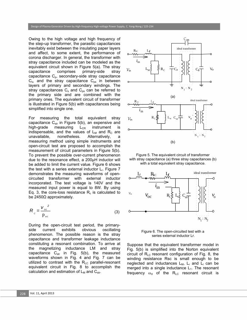
Owing to the high voltage and high frequency of the step-up transformer, the parasitic capacitances inevitably exist between the insulating paper layers and affect, to some extent, the performance of corona discharger. In general, the transformer with stray capacitance included can be modeled as the equivalent circuit shown in Figure 5(a). The stray capacitance comprises primary-side stray capacitance Cp, secondary-side stray capacitance Cs, and the stray capacitance Cps in between layers of primary and secondary windings. The stray capacitances Cs and Cps can be referred to the primary side and are combined with the primary ones. The equivalent circuit of transformer is illustrated in Figure 5(b) with capacitances being simplified into single one. For measuring the total equivalent stray capacitance Cstr in Figure 5(b), an expensive and high-grade measuring LCR instrument is indispensable, and the values of LM and RC are unavailable, nonetheless. Alternatively, a measuring method using simple instruments and open-circuit test are proposed to accomplish the measurement of circuit parameters in Figure 5(b). To prevent the possible over-current phenomenon due to the resonance effect, a 200μH inductor will be added to limit the current value. Figure 6 shows the test with a series external inductor Lr. Figure 7 demonstrates the measuring waveforms of open-circuited transformer with external inductor incorporated. The test voltage is 140V and the measured input power is equal to 8W. By using Eq. 3, the core-loss resistance Rc is calculated to be 2450Ω approximately.
oc
ocpC
2vR = (3)
During the open-circuit test period, the primary-side current exhibits obvious oscillating phenomenon. The possible reason is the stray capacitance and transformer leakage inductance constituting a resonant combination. To arrive at the magnetizing inductance LM and stray capacitance Cstr in Fig. 5(b), the measured waveforms shown in Fig. 4 and Fig. 7 can be utilized to contrast with the RLC parallel-resonant equivalent circuit in Fig. 8 to accomplish the calculation and estimation of LM and Cstr.
(a)
(b)
Figure 5. The equivalent circuit of transformer with stray capacitance (a) three stray capacitances (b)
with a total equivalent stray capacitance.
Figure 6. The open-circuited test with a series external inductor Lr.
Suppose that the equivalent transformer model in Fig. 5(b) is simplified into the Norton equivalent circuit of RLC resonant configuration of Fig. 8, the winding resistance Rsc is small enough to be neglected and inductances LM, Lr and Ll can be merged into a single inductance L1. The resonant frequency d of the RLC resonant circuit is
RCLM Cp Cs
Cps
Vo
RSC Ll
vin
iin
N 1
: N 2
ideal transformer
RC LM Cstr o'
L lRSC
v in
iin
v
N 1
: N
ideal transformer
2
RC LM Cstr o
LlRSC
voc
iinv
N 1
: N
ideal transformer
2
Lr
vin
in
in
in

Design of Plasma Generator Driven by High‐frequency High‐voltage Power Supply, C. Yong‐Nong / 225‐234
Journal of Applied Research and Technology 229
expressed as Eq. (4), L1 and L2 in Eq. (6) are the total inductance including magnetizing inductance LM without added inductor and with added inductor, respectively. The corresponding resonant frequencies are conducted to be Eq. (7) and Eq. (8), respectively. With different values of (Ll +Lr), the test results show different waveforms as displayed in Figs. 4 and 7. The natural periods Td1 and Td2 in Figs. 4 and 7 are 9.8 s and 17.8 s, respectively. The resulting resonant natural frequencies d1 and d2 of current waveforms are 641k (rad/s) and 353k (rad/s), correspondingly. By solving the Eq. (7) and Eq. (8), the stray capacitance Cstr can be expressed by Eq. (9) and the equivalent inductance L1 without current-limiting inductor is conducted as Eq. (10). The magnetizing inductance LM is, therefore, derived to be as shown in Eq. (11). Based on the above-mentioned measurements and calculations, the parameters of high-frequency and high-voltage transformer can be computed and listed in Table 1.
ocv :200V/div, oci :1A/div, ocp :200W/div, Time:10μs/div
Figure 7. The measured waveforms of the open-circuited
test with a external inductor Lr=200uH.
Figure 8. The Norton equivalent circuit
of Figure 6 for ignoring Rsc.
Table 1. The parameters of the high- frequency high-
voltage transformer.
2d
1 1= - ( )
LC 2RC (4)
1 M
1 1 1= +L L L
(5)
2 r M
1 1 1= + L (L +L ) L (6)
2d1
1 str C str
1 1= -( )L C 2R C
(7)
2d2
2 str C str
1 1= -( ) L C 2R C
(8)
r
str 2 2d1 d2
1 1-L L LC =
- (9)
) 1
2 2d1 str
C str
1L =1( +( ) C
2R C
(10)
1
1M
L LL
L L (11)
4. Equivalent circuit of plasma generating plate The plasma generating plates constitute one of the loads of resonant circuit. Consequently, it is very important to take into account the plasma generating effect in designing the resonant circuit and selecting device parameters. In this paper, the study case is based on the plasma generating electrodes used in printing industry. The modeling
ociv
in i
oc p
1
A
2
Td2
oc
voc
oc p
RCLM CstriniLl
Lr=
vS
LlLr+( ) ov
N 1
: N
ideal transformer
2
Rsc Ll Rc LM Cstr
0.08Ω 42.1μH 2.45kΩ 226.8μH 68.5nF

Design of Plasma Generator Driven by High‐frequency High‐voltage Power Supply, C. Yong‐Nong / 225‐234
Vol. 11, April 2013 230
of equivalent circuit of the plasma generator of the proposed printing machine is essential in this design. The proposed discharging brushes in Figure 9 are clung to the 50cm-radius Aluminum electrode plate. Commonly, plasma generating is looked upon as a high-voltage discharging phenomenon. Under the high-voltage discharging condition, the discharging electrode is considered as a capacitive load [12-13]. Fig. 10 indicates the equivalent circuit of series-load resonant plasma generator of Fig. 1. The plasma brushes electrode stage illustrates the equivalent circuit of the plasma generating plate, where Ceq and Req are in series and regarded as a capacitive load existing in the gap between
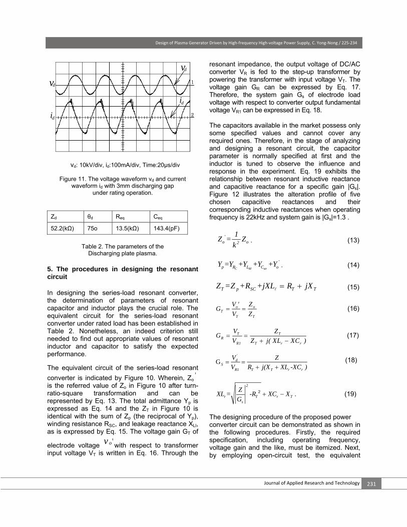
electrodes. As the discharging gap between brushes and electrode is adjusted to around 3mm, the discharging generator operates very near to the rated condition. Fig. 11 illustrates the measured results under rated condition with rated voltage being applied to the brushes discharging electrodes. It is obvious that the load voltage and load current waveforms display the phase difference θd is about 75°, while effective voltage Vd is 5.51kV and the effective current Id is 105.5mA. The equivalent impedance Zd of plasma discharger can be expressed in Eq. (12). Next, Table 2 illustrates the associated rating parameters of discharging Plate in Fig. 10.
1
2eqd eq
Zj f C
dd d
d
V= =R +
I
(12)
Figure 9. The schematic diagram of plasma generating plate.
L
ZT
V
R
Cr
Lr
R
l
MLCVT Cstr
Zp ZoZR
dv
N 1 : N
ideal transformer
2
ov 'R
id
Zd'
iT
Vdc
C1
C2
SW1
VacSW2
sc
Ceq
Req
Discharging Plate
Figure 10. The equivalent circuit of plasma generator.
Design of Plasma Generator Driven by High‐frequency High‐voltage Power Supply, C. Yong‐Nong / 225‐234
Journal of Applied Research and Technology 231
vd: 10kV/div, id:100mA/div, Time:20μs/div
Figure 11. The voltage waveform vd and current waveform id with 3mm discharging gap
under rating operation.
Table 2. The parameters of the
Discharging plate plasma. 5. The procedures in designing the resonant circuit In designing the series-load resonant converter, the determination of parameters of resonant capacitor and inductor plays the crucial role. The equivalent circuit for the series-load resonant converter under rated load has been established in Table 2. Nonetheless, an indeed criterion still needed to find out appropriate values of resonant inductor and capacitor to satisfy the expected performance. The equivalent circuit of the series-load resonant
converter is indicated by Figure 10. Wherein, Zo'
is the referred value of Zo in Figure 10 after turn-ratio-square transformation and can be represented by Eq. 13. The total admittance Yp is expressed as Eq. 14 and the ZT in Figure 10 is identical with the sum of Zp (the reciprocal of Yp), winding resistance RSC, and leakage reactance XLl, as is expressed by Eq. 15. The voltage gain GT of
electrode voltage ov 'with respect to transformer input voltage VT is written in Eq. 16. Through the
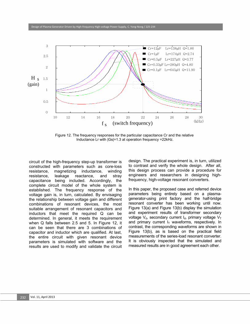
resonant impedance, the output voltage of DC/AC converter VR is fed to the step-up transformer by powering the transformer with input voltage VT. The voltage gain GR can be expressed by Eq. 17. Therefore, the system gain Gs of electrode load voltage with respect to converter output fundamental voltage VR1 can be expressed in Eq. 18. The capacitors available in the market possess only some specified values and cannot cover any required ones. Therefore, in the stage of analyzing and designing a resonant circuit, the capacitor parameter is normally specified at first and the inductor is tuned to observe the influence and response in the experiment. Eq. 19 exhibits the relationship between resonant inductive reactance and capacitive reactance for a specific gain |Gs|. Figure 12 illustrates the alteration profile of five chosen capacitive reactances and their corresponding inductive reactances when operating frequency is 22kHz and system gain is |Gs|=1.3 .
'o o2
1Z = Z
k. (13)
C M str
'p R L C oY =Y +Y +Y +Y . (14)
T p SC T TZ =Z +R +jXL R jX (15)
o oT
T T
V ' ZG
V Z (16)
T TR
R1 T r r
V ZG
V Z j( XL XC )
(17)
G'
dS
R1 T T r r
V Z
V R j(X XL -XC )
(18)
2
r T r Ts
ZXL = -R XC X
G 2 . (19)
The designing procedure of the proposed power converter circuit can be demonstrated as shown in the following procedures. Firstly, the required specification, including operating frequency, voltage gain and the like, must be itemized. Next, by employing open-circuit test, the equivalent
i d
1
2
dv
dv
i d
Zd θd Req Ceq
52.2(kΩ) 75o 13.5(kΩ) 143.4(pF)
Design of Plasma Generator Driven by High‐frequency High‐voltage Power Supply, C. Yong‐Nong / 225‐234
Vol. 11, April 2013 232
circuit of the high-frequency step-up transformer is constructed with parameters such as core-loss resistance, magnetizing inductance, winding resistance, leakage reactance, and stray capacitance being included. Accordingly, the complete circuit model of the whole system is established. The frequency response of the voltage gain is, in turn, calculated. By envisaging the relationship between voltage gain and different combinations of resonant devices, the most suitable arrangement of resonant capacitors and inductors that meet the required Q can be determined. In general, it meets the requirement when Q falls between 2.5 and 5. In Figure 12, it can be seen that there are 3 combinations of capacitor and inductor which are qualified. At last, the entire circuit with given resonant device parameters is simulated with software and the results are used to modify and validate the circuit
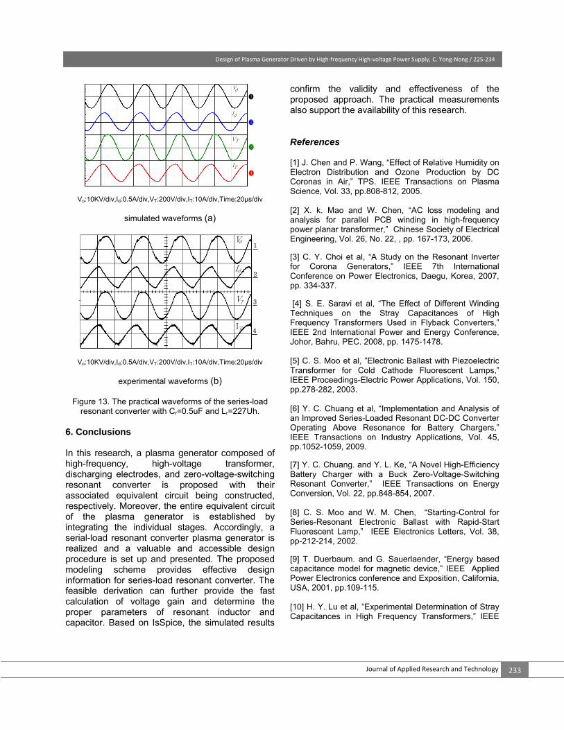
design. The practical experiment is, in turn, utilized to contrast and verify the whole design. After all, this design process can provide a procedure for engineers and researchers in designing high-frequency, high-voltage resonant converters. In this paper, the proposed case and referred device parameters being entirely based on a plasma-generator-using print factory and the half-bridge resonant converter has been working until now. Figure 13(a) and Figure 13(b) display the simulation and experiment results of transformer secondary voltage Vd, secondary current Id, primary voltage VT and primary current IT waveforms, respectively. In contrast, the corresponding waveforms are shown in Figure 13(b), as is based on the practical field measurements of the series-load resonant converter. It is obviously inspected that the simulated and measured results are in good agreement each other.
Figure 12. The frequency responses for the particular capacitance Cr and the relative Inductance Lr with |Gs|=1.3 at operation frequency =22kHz.
0
0.5
1.5
2.5
3
H
2
1
(switch frequency) 181410 12 16 20 22 24 26 28 30
Cr=12μF Lr=138μH Q=1.86
Cr=1μF Lr=174μH Q=2.74
Cr=0.5μF Lr=227μH Q=3.77
Cr=0.33μF Lr=280μH Q=4.80
Cr=0.1μF Lr=645μH Q=11.90
s(gain)
(kHz)f s
Design of Plasma Generator Driven by High‐frequency High‐voltage Power Supply, C. Yong‐Nong / 225‐234
Journal of Applied Research and Technology 233
Vo:10KV/div,Id:0.5A/div,VT:200V/div,IT:10A/div,Time:20μs/div
simulated waveforms (a)
Vo:10KV/div,Id:0.5A/div,VT:200V/div,IT:10A/div,Time:20μs/div
experimental waveforms (b)
Figure 13. The practical waveforms of the series-load resonant converter with Cr=0.5uF and Lr=227Uh.
6. Conclusions In this research, a plasma generator composed of high-frequency, high-voltage transformer, discharging electrodes, and zero-voltage-switching resonant converter is proposed with their associated equivalent circuit being constructed, respectively. Moreover, the entire equivalent circuit of the plasma generator is established by integrating the individual stages. Accordingly, a serial-load resonant converter plasma generator is realized and a valuable and accessible design procedure is set up and presented. The proposed modeling scheme provides effective design information for series-load resonant converter. The feasible derivation can further provide the fast calculation of voltage gain and determine the proper parameters of resonant inductor and capacitor. Based on IsSpice, the simulated results
confirm the validity and effectiveness of the proposed approach. The practical measurements also support the availability of this research. References [1] J. Chen and P. Wang, “Effect of Relative Humidity on Electron Distribution and Ozone Production by DC Coronas in Air,” TPS. IEEE Transactions on Plasma Science, Vol. 33, pp.808-812, 2005. [2] X. k. Mao and W. Chen, “AC loss modeling and analysis for parallel PCB winding in high-frequency power planar transformer,” Chinese Society of Electrical Engineering, Vol. 26, No. 22, , pp. 167-173, 2006. [3] C. Y. Choi et al, “A Study on the Resonant Inverter for Corona Generators,” IEEE 7th International Conference on Power Electronics, Daegu, Korea, 2007, pp. 334-337. [4] S. E. Saravi et al, “The Effect of Different Winding Techniques on the Stray Capacitances of High Frequency Transformers Used in Flyback Converters,” IEEE 2nd International Power and Energy Conference, Johor, Bahru, PEC. 2008, pp. 1475-1478. [5] C. S. Moo et al, ”Electronic Ballast with Piezoelectric Transformer for Cold Cathode Fluorescent Lamps,” IEEE Proceedings-Electric Power Applications, Vol. 150, pp.278-282, 2003. [6] Y. C. Chuang et al, “Implementation and Analysis of an Improved Series-Loaded Resonant DC-DC Converter Operating Above Resonance for Battery Chargers,” IEEE Transactions on Industry Applications, Vol. 45, pp.1052-1059, 2009. [7] Y. C. Chuang. and Y. L. Ke, “A Novel High-Efficiency Battery Charger with a Buck Zero-Voltage-Switching Resonant Converter,” IEEE Transactions on Energy Conversion, Vol. 22, pp.848-854, 2007. [8] C. S. Moo and W. M. Chen, “Starting-Control for Series-Resonant Electronic Ballast with Rapid-Start Fluorescent Lamp,” IEEE Electronics Letters, Vol. 38, pp-212-214, 2002. [9] T. Duerbaum. and G. Sauerlaender, “Energy based capacitance model for magnetic device,” IEEE Applied Power Electronics conference and Exposition, California, USA, 2001, pp.109-115. [10] H. Y. Lu et al, “Experimental Determination of Stray Capacitances in High Frequency Transformers,” IEEE
VT
IT
Vd
Id2
1
3
4
VT
IT
Vd
Id
1
3
2
4
Design of Plasma Generator Driven by High‐frequency High‐voltage Power Supply, C. Yong‐Nong / 225‐234
Vol. 11, April 2013 234
Transactions on Power Electronics, Vol. 18, pp.1105-1112, 2003. [11] H. Y. Lu and V. S. Ramsden, “Comparison of Experimental Techniques for Determination of Stray Capacitances in High Frequency Transformers,” IEEE 31st Annual Power Electronics Specialists Conference, PESC, Galway, 2000, pp. 1645-1650. [12] A. Maglaras. and F. V. Topalis, “Influence of Ground and Corona Currents on Dielectric Behavior of Small Air Gaps,” IEEE Transactions on Dielectrics and Electrical Insulation, Vol. 16, pp.32-41, 2009. [13] H. Akagi. and A. Nabae, “A Voltage-Source Inverter Using IGBT’s for a 50kHz 10kV Corona Surface Treaters,” IEEE Industry Applications Society Annul Meeting, CA, USA, 1989, pp.1164-1169. [14] H. Fujita. and H. Akagi, ”Control and Performance of a Pulse-Density-Modulated Series-Resonant Inverter for Corona Discharge Processes,” IEEE Transactions on Industry Applications, Vol. 35, pp.621-627, 1999. [15] E. S. Kilders et al, “New Application of an LLC Full Bridge Inverter Topology for Corona Generation in Plastic Industry,” IEEE Transactions on Power Electronics, California, 2001, pp.193-198. [16] Y. C. Hsieh et al, “An Interleaved Boost Converter with Zero Voltage Transition,” IEEE Transactions on Power Electronics, Vol. 24, pp.973-978, 2009.