A STUDY OF SOLAR STREET LIGHT AND OPTIMIZATION FOR SPACING IN POLES AND COST
Upload
khangminh22Category
view
2download
0
Muhd Iqbal Zakaria
Design of Low Cost and High Performance Solar Tracker for Fresnel Type Concentrated Solar Power (CSP) Collector Module Muhd Iqbal Zakaria Advisor: Zaki Iqbal Advisor: Prof. Dr.-Ing. Gerhard Kachel
WS 2011/12
Ortenaustr. 49
77656 Offenburg
Germany
Muhd Iqbal Zakaria - i -
Abstract
Author: Muhd Iqbal Zakaria Advisors: Zaki Iqbal, Prof. Dr.-Ing. Gerhard Kachel Semester: WS 2011/12 Subject: Design of Low Cost and High Performance Solar Tracker for Fresnel Type
Concentrated Solar Power (CSP) Collector Module Contents: This paper deals with the design of a solar tracker system dedicated to Fresnel
Type Concentrated Solar Power (CSP) collector module in an energy company in United Arab Emirates, Centre Suisse d’Electronique et de Microtechnique (CSEM) - UAE. The proposed solar tracker design ensures high performance regarding the conversion of solar energy into electricity by properly orienting the Fresnel mirrors in accordance with the real position of the sun. During this thesis, analysis of different available solar structures in the market has been carried out. Following from this, conceptual design has been developed for the chosen type of solar structure. The design involves several aspects such as foundations, structural designs, driving system and basics of control. The design considers variants which are involved during designing process and takes into account the analysis of the stability of the structure in terms of bending and deflection and also the calculation for the required motor for the drive system. Besides, components which are required to achieve the design tracking are identified. The operation of the tracker is based on DC motors intelligently controlled by a dedicated drive unit that moves the tracker according to the signals from control system using Solar Position Algorithm (SPA) and encoder as feedback element. Throughout the work, various suppliers have been contacted for cost estimation of the tracker and local fabricator has been interacted to discuss further fine tuning of the design.
Muhd Iqbal Zakaria - ii -
Declaration of Authorship
I certify that the work presented here is, to the best of my knowledge and belief, original
and the result of my own investigations, except as acknowledged, and has not been
submitted, either in part or whole, for a degree at this or any other University.
Muhd Iqbal Zakaria Offenburg, February 11, 2012

Muhd Iqbal Zakaria - iii -
Foreword
First of all, I would like to thank Dr. Abdul Hamid Kayal, CEO of CSEM-UAE for providing me with an opportunity to do my master thesis in this company. Working as a master thesis student in this company was absolutely a great opportunity for me to relate my studies in the practical environment. Next, I am greatly indebted to Mr. Zaki Iqbal for his constant guidance and supervision throughout my thesis with respect to giving me supports which was very helpful to me in progressing with the thesis especially when dealing with suppliers. I would also have to say that this work would not have been possible without help of Mr. Joseph, a local fabricator who was always helpful by giving advices on the design of our first prototype of solar tracker. Furthermore, I would like to express my gratitude to Prof Dr.-Ing. Gerhard Kachel, my supervisor at the university who was willing to supervise me from Germany. I would also want to thank the employees and other thesis students working together with me who were very kind, helpful and for making my stay in this company a memorable experience. Last but not least, I would like to extend my heartfelt thanks to my parents and my friends for their support throughout this thesis period. Muhd Iqbal Zakaria Offenburg, February 11, 2012
Muhd Iqbal Zakaria - iv -
Table of Contents Abstract ...................................................................................................................................... i
Declaration of Authorship ....................................................................................................... ii
Foreword .................................................................................................................................. iii
List of Figures and Illustrations ............................................................................................. vi
List of Tables .......................................................................................................................... viii
Nomenclature ........................................................................................................................... ix
List of Abbreviations ............................................................................................................... xi
1 Introduction ...................................................................................................................... 1
1.1 Problem statement ...................................................................................................... 1
1.2 Purpose of research ................................................................................................... 2
1.3 Scope of work ............................................................................................................. 2
1.4 Methodology ............................................................................................................... 3
1.5 Structure of the work .................................................................................................. 4
2 Basic information about solar power technology .......................................................... 6
2.1 Photovoltaics (PV) ..................................................................................................... 6
2.2 Concentrated Solar Power (CSP) .............................................................................. 7 2.2.1 Parabolic Troughs .................................................................................................. 8 2.2.2 Linear Fresnel Reflectors ....................................................................................... 8 2.2.3 Solar Towers .......................................................................................................... 9 2.2.4 Parabolic Dishes ..................................................................................................... 9
2.3 Solar Tracking Systems ............................................................................................ 10
3 Analysis of different available structure of solar trackers ......................................... 12
3.1 One pole ................................................................................................................... 12
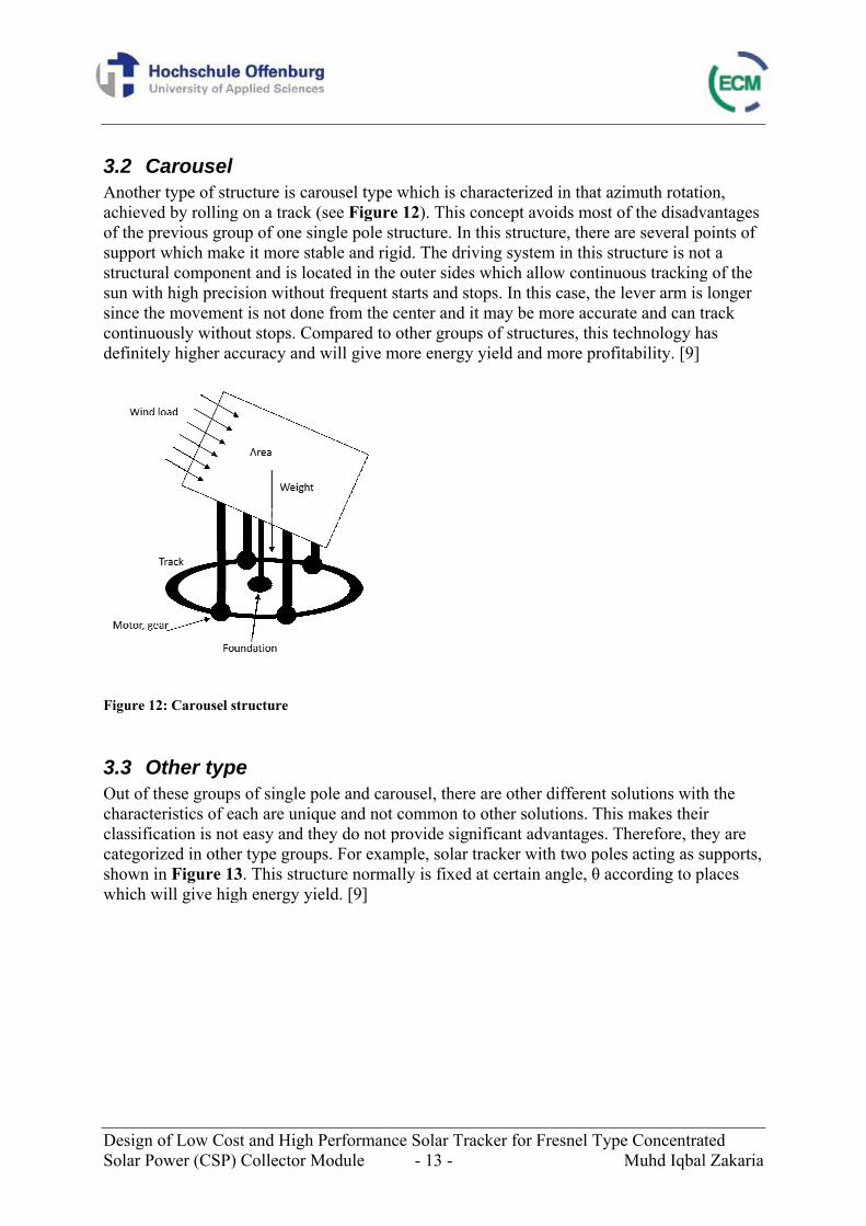
3.2 Carousel ................................................................................................................... 13
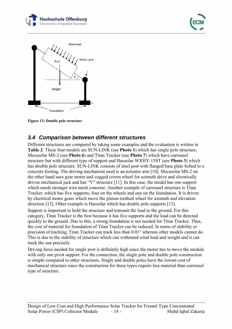
3.3 Other type ................................................................................................................. 13
3.4 Comparison between different structures ................................................................ 14
3.5 Conclusion ................................................................................................................ 17
4 Conceptual design of the solar tracker ......................................................................... 18
4.1 Clarification of scope of work .................................................................................. 20
4.2 Requirements list ...................................................................................................... 20
Muhd Iqbal Zakaria - v -
4.3 Function structures .................................................................................................. 22 4.3.1 Concept of rotation of platform ............................................................................ 24 4.3.2 Structure ............................................................................................................... 27 4.3.3 Traction system .................................................................................................... 30 4.3.4 Central bearing ..................................................................................................... 34 4.3.5 Control .................................................................................................................. 34 4.3.6 Cleaning mechanism ............................................................................................ 36
4.4 Morphological box ................................................................................................... 37
4.5 Technical evaluation of possible solutions ............................................................... 39
5 Description of the design ................................................................................................ 41
5.1 Loading specification ............................................................................................... 41 5.1.1 Thermal load ........................................................................................................ 41 5.1.2 Optical load .......................................................................................................... 42 5.1.3 Weight of structure ............................................................................................... 42
5.2 Development of platform .......................................................................................... 42
5.3 Vertical support ........................................................................................................ 44
5.4 Final design .............................................................................................................. 46
5.5 Rotation mechanism ................................................................................................. 48 5.5.1 Rotational speed ................................................................................................... 48 5.5.2 Torque .................................................................................................................. 49 5.5.3 Estimation of wind load ....................................................................................... 51 5.5.4 Calculation for motor needed ............................................................................... 51 5.5.5 Drag forces ........................................................................................................... 52
5.6 Load distribution ...................................................................................................... 53
5.7 Flow of forces ........................................................................................................... 54
5.8 Analysis of design ..................................................................................................... 56 5.8.1 Hertzian pressure between wheel and surface ...................................................... 56 5.8.2 Normal stress on plate for wheel rail system ....................................................... 57 5.8.3 Normal stress of shaft at central bearing .............................................................. 57 5.8.4 Structural beam deflection and stress ................................................................... 58
6 Identification of components for tracking system ....................................................... 71
7 Cost estimation ............................................................................................................... 74
8 Conclusion ....................................................................................................................... 76
9 Bibliography ................................................................................................................... 77
Muhd Iqbal Zakaria - vi -
List of Figures and Illustrations
Figure 1: Concept of Solar Island ............................................................................................. 1 Figure 2: Fresnel mirrors ........................................................................................................... 2 Figure 3: Trilateral work of CSP project .................................................................................... 3 Figure 4: Scope of work ............................................................................................................. 3 Figure 5: Photovoltaics (PV) Technology ................................................................................. 6 Figure 6: Parabolic Trough ....................................................................................................... 8 Figure 7: Linear Fresnel Reflectors ........................................................................................... 8 Figure 8: Solar Tower ............................................................................................................... 9 Figure 9: Parabolic Dish ............................................................................................................ 9 Figure 10: Side view of LFR system ....................................................................................... 10 Figure 11: One pole structure ................................................................................................... 12 Figure 12: Carousel structure ................................................................................................... 13 Figure 13: Double pole structure .............................................................................................. 14 Figure 14: Steps of conceptual design ..................................................................................... 19 Figure 15: Function structures for the conceptual design for the solar tracker along with possible solutions ..................................................................................................................... 23 Figure 16: Full circular concrete foundation ............................................................................ 24 Figure 17: Wheel rail system ................................................................................................... 25 Figure 18: Close view of wheel rail system ............................................................................. 26 Figure 19: Side view of one block ........................................................................................... 26 Figure 20: I-beam ..................................................................................................................... 27 Figure 21: Square hollow sections ........................................................................................... 28 Figure 22: Special manufactured profiles ................................................................................ 29 Figure 23: Rotation of wheels by electric motor ...................................................................... 30 Figure 24: Fixation of motor gear combination ....................................................................... 32 Figure 25: Pushing wheels with hydraulic actuator ................................................................. 33 Figure 26: Concepts for central bearing ................................................................................... 34 Figure 27: Pulley system for encoder at the centre .................................................................. 35 Figure 28: Sketch of cleaning mechanism ............................................................................... 36 Figure 30: s-Diagram ............................................................................................................... 40 Figure 30: Design with six wheel arrangement ........................................................................ 43 Figure 31: Design with eight wheel support arrangement ....................................................... 43 Figure 32: Design of vertical support 1 .................................................................................... 44 Figure 33: Design of vertical support 2 .................................................................................... 45
Muhd Iqbal Zakaria - vii -
Figure 34: Final design of solar tracker ................................................................................... 46 Figure 35: Final design for the variation with thermal unit on the platform ............................ 47 Figure 36: Solar azimuth tracking in Ras al Khaimah, UAE ................................................... 48 Figure 37: Placement of the motors on the heaviest part of the structure ................................ 51 Figure 38: Load distribution of solar tracker ........................................................................... 53 Figure 39: Flow forces from the receiver tube ......................................................................... 54 Figure 40: Distribution of optical loads on the beam supporting below .................................. 55 Figure 41: Flow forces from optical loads ............................................................................... 55 Figure 42: Analysis of Section I ............................................................................................... 59 Figure 43: Free body diagram for Section I ............................................................................. 60 Figure 44: Bending moment diagram for Section I .................................................................. 61 Figure 45: Analysis of Section II ............................................................................................. 62 Figure 46: Free body diagram of Section II ............................................................................. 63 Figure 47: Shear force diagram of Section II ........................................................................... 63 Figure 48: Bending moment diagram for Section II ................................................................ 64 Figure 49: Free body diagram of Section II ............................................................................. 65 Figure 50: Shear force diagram of Section II ........................................................................... 66 Figure 51: Bending moment diagram for Section II ................................................................ 66 Figure 52: Analysis of Section III ............................................................................................ 68 Figure 53: Free body diagram for Section III .......................................................................... 69 Figure 54: Bending moment diagram for Section I .................................................................. 69 Figure 55: A typical servo system ........................................................................................... 71
Muhd Iqbal Zakaria - viii -
List of Tables
Table 1: Main CSP technology families ................................................................................... 7 Table 2: Comparison between different structures of tracking system .................................... 15 Table 3: Examples of different type of structures of solar tracker ........................................... 16 Table 4: Models in series ......................................................................................................... 16 Table 5: Other examples of solar tracker in the market ........................................................... 16 Table 6: Requirements list for the solar tracker ....................................................................... 21 Table 7: Common types of gear .............................................................................................. 31 Table 8: Morphological box for the solar tracker .................................................................... 37 Table 9: Possible solutions for solar tracker ............................................................................ 38 Table 10: Point rating scale ...................................................................................................... 39 Table 11: Technical evaluation ................................................................................................ 39 Table 12: Economical evaluation ............................................................................................. 40 Table 13: Quotations for tracking system ................................................................................ 73 Table 14: Required hollow square sections .............................................................................. 74 Table 15: Cost estimation of wheel rail system ....................................................................... 75 Table 16: Cost estimation of other mechanical components .................................................... 75 Table 17: Total cost of solar tracker ......................................................................................... 75
Muhd Iqbal Zakaria - ix -
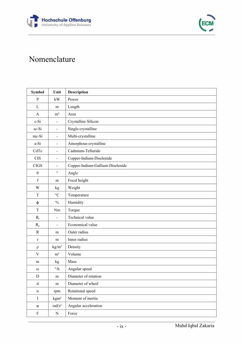
Nomenclature
Symbol Unit Description
P kW Power
L m Length
A m² Area
c-Si - Crystalline Silicon
sc-Si - Single-crystalline
mc-Si - Multi-crystalline
a-Si - Amorphous-crystalline
CdTe - Cadmium-Telluride
CIS - Copper-Indium-Diselenide
CIGS - Copper-Indium-Gallium-Diselenide
θ ° Angle
f m Focal height
W kg Weight
T °C Temperature
φ % Humidity
T Nm Torque
Rt - Technical value
Re - Economical value
R m Outer radius
r m Inner radius
ρ kg/m³ Density
V m³ Volume
m kg Mass
ω °/h Angular speed
D m Diameter of rotation
d m Diameter of wheel
n rpm Rotational speed
I kgm² Moment of inertia
α rad/s² Angular acceleration
F N Force
Muhd Iqbal Zakaria - x -
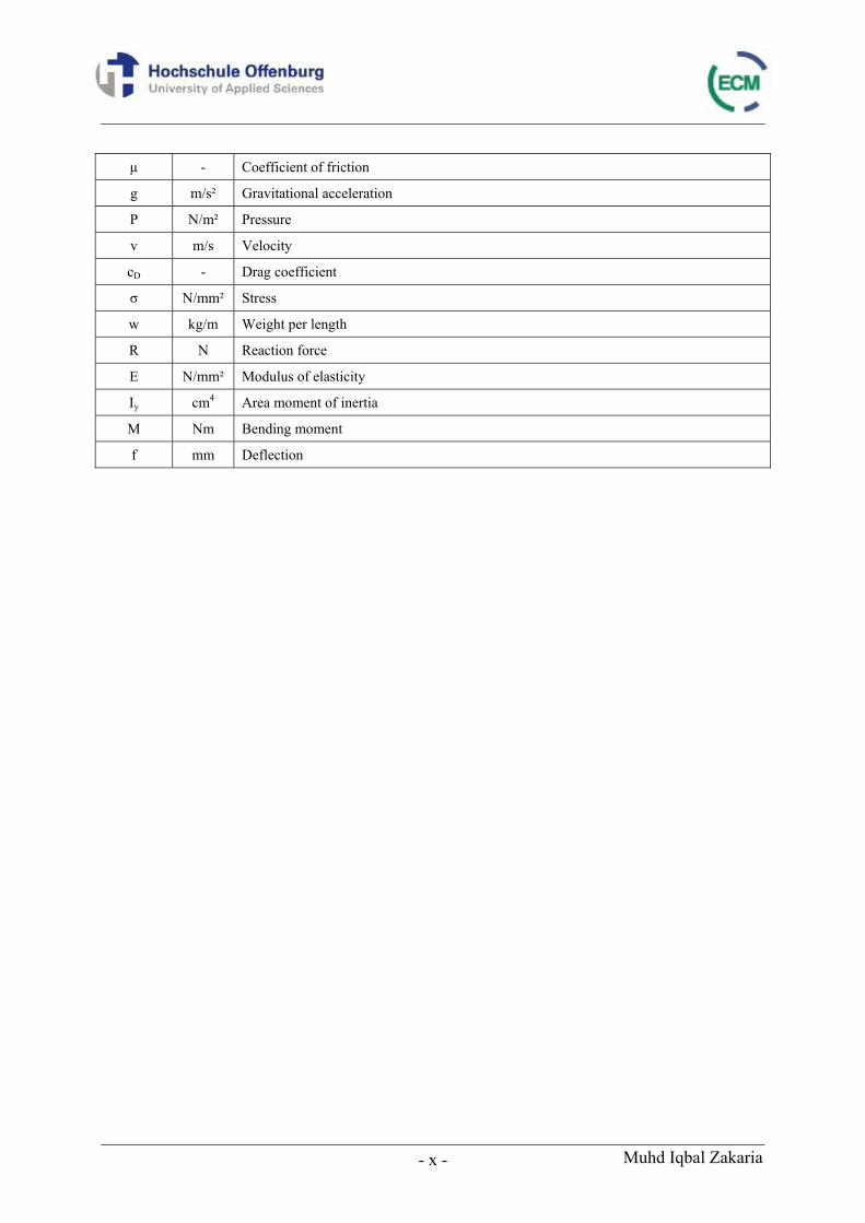
µ - Coefficient of friction
g m/s² Gravitational acceleration
P N/m² Pressure
v m/s Velocity
cD - Drag coefficient
σ N/mm² Stress
w kg/m Weight per length
R N Reaction force
E N/mm² Modulus of elasticity
Iy cm4 Area moment of inertia
M Nm Bending moment
f mm Deflection
Muhd Iqbal Zakaria - xi -
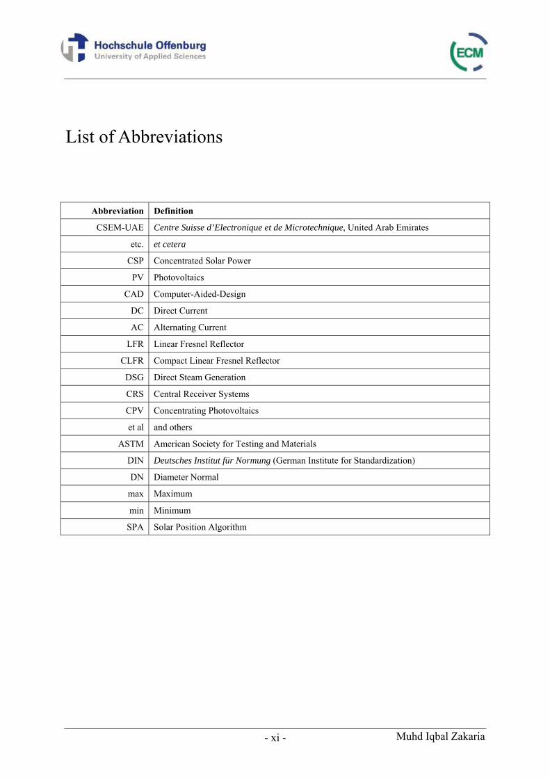
List of Abbreviations
Abbreviation Definition
CSEM-UAE Centre Suisse d’Electronique et de Microtechnique, United Arab Emirates
etc. et cetera
CSP Concentrated Solar Power
PV Photovoltaics
CAD Computer-Aided-Design
DC Direct Current
AC Alternating Current
LFR Linear Fresnel Reflector
CLFR Compact Linear Fresnel Reflector
DSG Direct Steam Generation
CRS Central Receiver Systems
CPV Concentrating Photovoltaics
et al and others
ASTM American Society for Testing and Materials
DIN Deutsches Institut für Normung (German Institute for Standardization)
DN Diameter Normal
max Maximum
min Minimum
SPA Solar Position Algorithm
Design of Low Cost and High Performance Solar Tracker for Fresnel Type Concentrated Solar Power (CSP) Collector Module - 1 - Muhd Iqbal Zakaria
1 Introduction Energy consumption is predicted to continue growing based on global scenario to maintain economic development. Thus, this will increase worldwide demand for energy and lead to a continuous rise on the price of fossil substances. Indeed, the energy demand is expected to increase faster than discovering new available fossil resources [1]. Any idea which can contribute to the energy supply and at the same time reduce our dependence on major sources of energy such as fossil fuel which is getting depleted, needs to be evaluated and tested. Sun energy can be regarded as clean and the most promising renewable energy. Since sun can exist more than billions of years, solar energy can be used permanently and is expected to become the main electricity production source by the year 2100, according to the study presented by the German Advisory Council on Global Change [2].
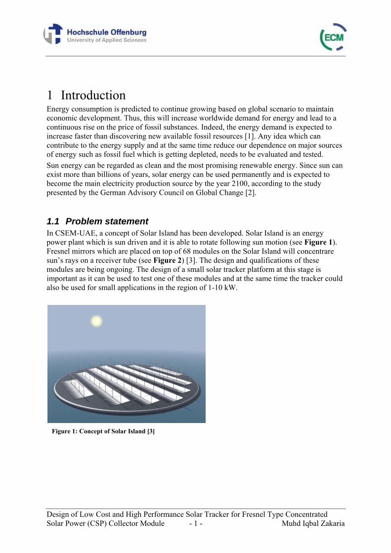
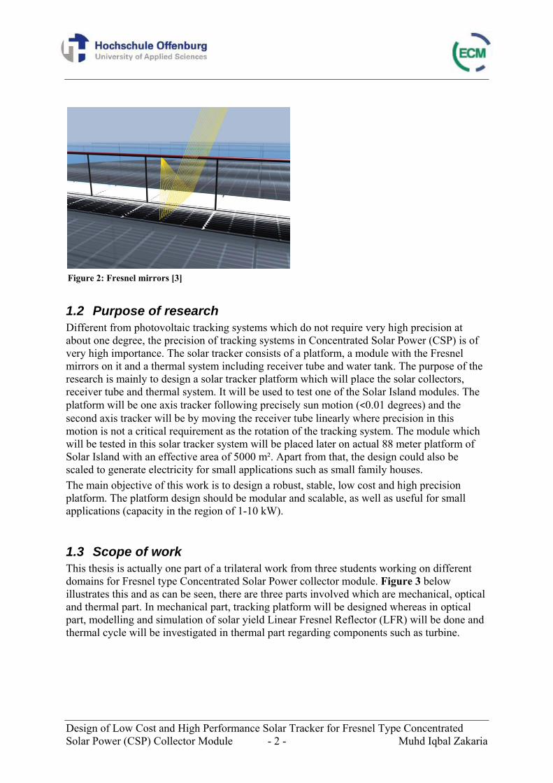
1.1 Problem statement In CSEM-UAE, a concept of Solar Island has been developed. Solar Island is an energy power plant which is sun driven and it is able to rotate following sun motion (see Figure 1). Fresnel mirrors which are placed on top of 68 modules on the Solar Island will concentrare sun’s rays on a receiver tube (see Figure 2) [3]. The design and qualifications of these modules are being ongoing. The design of a small solar tracker platform at this stage is important as it can be used to test one of these modules and at the same time the tracker could also be used for small applications in the region of 1-10 kW.
Figure 1: Concept of Solar Island [3]
Design of Low Cost and High Performance Solar Tracker for Fresnel Type Concentrated Solar Power (CSP) Collector Module - 2 - Muhd Iqbal Zakaria
1.2 Purpose of research Different from photovoltaic tracking systems which do not require very high precision at about one degree, the precision of tracking systems in Concentrated Solar Power (CSP) is of very high importance. The solar tracker consists of a platform, a module with the Fresnel mirrors on it and a thermal system including receiver tube and water tank. The purpose of the research is mainly to design a solar tracker platform which will place the solar collectors, receiver tube and thermal system. It will be used to test one of the Solar Island modules. The platform will be one axis tracker following precisely sun motion (<0.01 degrees) and the second axis tracker will be by moving the receiver tube linearly where precision in this motion is not a critical requirement as the rotation of the tracking system. The module which will be tested in this solar tracker system will be placed later on actual 88 meter platform of Solar Island with an effective area of 5000 m². Apart from that, the design could also be scaled to generate electricity for small applications such as small family houses. The main objective of this work is to design a robust, stable, low cost and high precision platform. The platform design should be modular and scalable, as well as useful for small applications (capacity in the region of 1-10 kW).
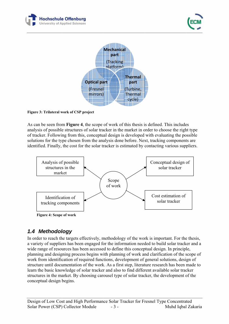
1.3 Scope of work This thesis is actually one part of a trilateral work from three students working on different domains for Fresnel type Concentrated Solar Power collector module. Figure 3 below illustrates this and as can be seen, there are three parts involved which are mechanical, optical and thermal part. In mechanical part, tracking platform will be designed whereas in optical part, modelling and simulation of solar yield Linear Fresnel Reflector (LFR) will be done and thermal cycle will be investigated in thermal part regarding components such as turbine.
Figure 2: Fresnel mirrors [3]
Design Solar Po
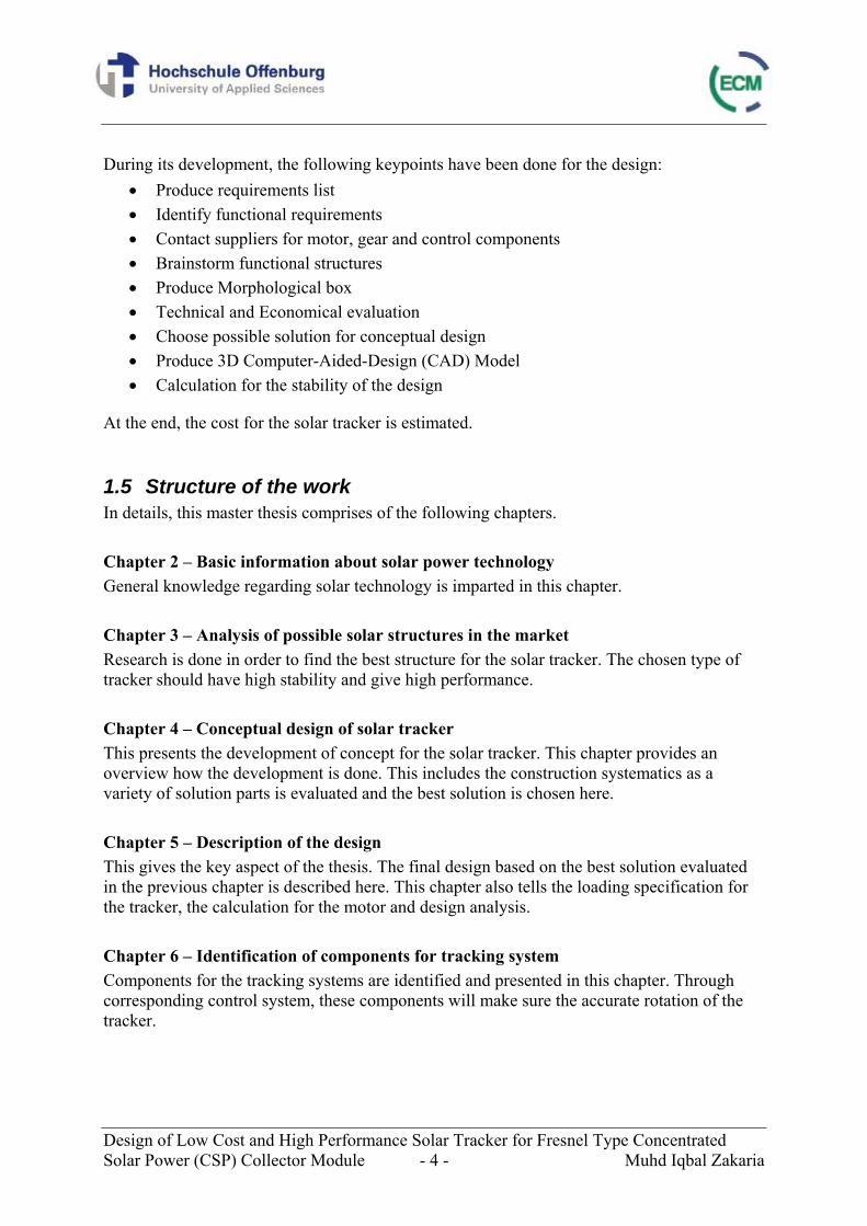
Figure 3 As can banalysisof tracksolutionidentifie
1.4 MIn ordera varietywide ranplanningwork frostructurlearn thstructurconcept
t
Fig
of Low Cosower (CSP)
: Trilateral w
be seen froms of possible
ker. Followinns for the tyed. Finally,
Methodolr to reach thy of supplienge of resoug and desigom identificre until docue basic kno
res in the matual design b
Analysis ofstructures
mark
Identificatracking com
gure 4: Scope
st and High) Collector M
work of CSP p
m Figure 4e structures ng from thi
ype chosen fthe cost for
logy he targets efers has beenurces has be
gning procescation of requmentation wledge of sarket. By chbegins.
f possible s in the ket
ation of mponents
e of work
h PerformanModule
project
, the scope of solar tra
s, conceptufrom the anar the solar tr
ffectively, mn engaged foeen accessess begins wiquired funcof the work
solar trackerhoosing caro
Optical pa
(Fresnelmirrors)
nce Solar Tr- 3 -
of work of acker in the al design isalysis done racker is est
methodologyor the informd to define ith planning
ctions, develk. As a first r and also toousel type o
Mechanicapart
(Tracking platform)
art
Scope of work
acker for Fr
this thesis imarket in o developed before. Nextimated by c
y of the wormation needthis concep
g of work anlopment of step, literat
o find differof solar trac
l
Thermal part
(Turbine, Thermal cycle)
resnel TypeM
s defined. Torder to chowith evalua
xt, tracking contacting v
rk is importded to buildptual designnd clarificatgeneral soluture researchrent availabcker, the dev
Conceptsola
Cost estsolar
e ConcentratMuhd Iqbal
This includeose the righating the pocomponent
various supp
tant. For thed solar track. In principltion of the sutions, desih has been m
ble solar tracvelopment o
tual design oar tracker
timation of r tracker
ted l Zakaria
es ht type ossible ts are pliers.
e thesis, ker and a le, scope of gn of made to cker of the
of
Design of Low Cost and High Performance Solar Tracker for Fresnel Type Concentrated Solar Power (CSP) Collector Module - 4 - Muhd Iqbal Zakaria
During its development, the following keypoints have been done for the design: • Produce requirements list • Identify functional requirements • Contact suppliers for motor, gear and control components • Brainstorm functional structures • Produce Morphological box • Technical and Economical evaluation • Choose possible solution for conceptual design • Produce 3D Computer-Aided-Design (CAD) Model • Calculation for the stability of the design
At the end, the cost for the solar tracker is estimated.
1.5 Structure of the work In details, this master thesis comprises of the following chapters. Chapter 2 – Basic information about solar power technology General knowledge regarding solar technology is imparted in this chapter. Chapter 3 – Analysis of possible solar structures in the market Research is done in order to find the best structure for the solar tracker. The chosen type of tracker should have high stability and give high performance. Chapter 4 – Conceptual design of solar tracker This presents the development of concept for the solar tracker. This chapter provides an overview how the development is done. This includes the construction systematics as a variety of solution parts is evaluated and the best solution is chosen here. Chapter 5 – Description of the design This gives the key aspect of the thesis. The final design based on the best solution evaluated in the previous chapter is described here. This chapter also tells the loading specification for the tracker, the calculation for the motor and design analysis. Chapter 6 – Identification of components for tracking system Components for the tracking systems are identified and presented in this chapter. Through corresponding control system, these components will make sure the accurate rotation of the tracker.
Design of Low Cost and High Performance Solar Tracker for Fresnel Type Concentrated Solar Power (CSP) Collector Module - 5 - Muhd Iqbal Zakaria
Chapter 7 – Cost estimation Estimation of the cost for this tracker is given in this chapter. The total cost includes the cost of the material, installation and tracking system. Chapter 8 – Summary This chapter will give summary and outlook for this thesis.
Design of Low Cost and High Performance Solar Tracker for Fresnel Type Concentrated Solar Power (CSP) Collector Module - 6 - Muhd Iqbal Zakaria
2 Basic information about solar power technology Sun energy is one of the renewable energy which has been exploited using several technologies. There are two main ways to harness solar power, either by photovoltaic (PV) technology or by concentrated solar power (CSP) technology. Solar power is produced by collecting sunlight and converting it into electricity. With photovoltaic technology, electricity is produced directly from solar radiation whereas for concentrated solar power technology, solar energy is concentrated and used to produce thermal energy which will then be converted to electricity.
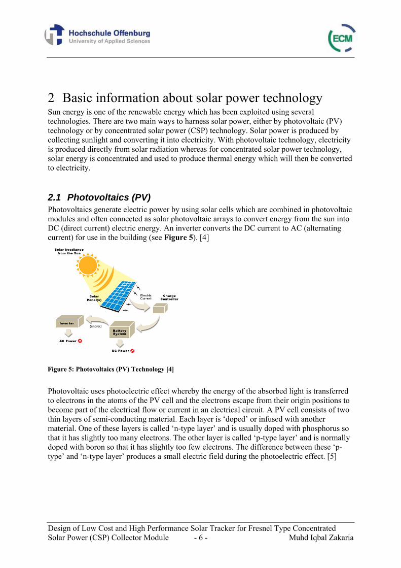
2.1 Photovoltaics (PV) Photovoltaics generate electric power by using solar cells which are combined in photovoltaic modules and often connected as solar photovoltaic arrays to convert energy from the sun into DC (direct current) electric energy. An inverter converts the DC current to AC (alternating current) for use in the building (see Figure 5). [4]
Photovoltaic uses photoelectric effect whereby the energy of the absorbed light is transferred to electrons in the atoms of the PV cell and the electrons escape from their origin positions to become part of the electrical flow or current in an electrical circuit. A PV cell consists of two thin layers of semi-conducting material. Each layer is ‘doped’ or infused with another material. One of these layers is called ‘n-type layer’ and is usually doped with phosphorus so that it has slightly too many electrons. The other layer is called ‘p-type layer’ and is normally doped with boron so that it has slightly too few electrons. The difference between these ‘p-type’ and ‘n-type layer’ produces a small electric field during the photoelectric effect. [5]
Figure 5: Photovoltaics (PV) Technology [4]
Design of Low Cost and High Performance Solar Tracker for Fresnel Type Concentrated Solar Power (CSP) Collector Module - 7 - Muhd Iqbal Zakaria
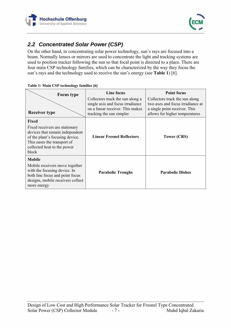
2.2 Concentrated Solar Power (CSP) On the other hand, in concentrating solar power technology, sun’s rays are focused into a beam. Normally lenses or mirrors are used to concentrate the light and tracking systems are used to position tracker following the sun so that focal point is directed to a place. There are four main CSP technology families, which can be characterized by the way they focus the sun’s rays and the technology used to receive the sun’s energy (see Table 1) [6]. Table 1: Main CSP technology families [6]
Line focus Collectors track the sun along a single axis and focus irradiance on a linear receiver. This makes tracking the sun simpler
Point focus Collectors track the sun along two axes and focus irradiance at a single point receiver. This allows for higher temperatures
Fixed Fixed receivers are stationary devices that remain independent of the plant’s focusing device. This eases the transport of collected heat to the power block
Linear Fresnel Reflectors Tower (CRS)
Mobile Mobile receivers move together with the focusing device. In both line focus and point focus designs, mobile receivers collect more energy
Parabolic Troughs Parabolic Dishes
Focus type
Receiver type
Design of Low Cost and High Performance Solar Tracker for Fresnel Type Concentrated Solar Power (CSP) Collector Module - 8 - Muhd Iqbal Zakaria
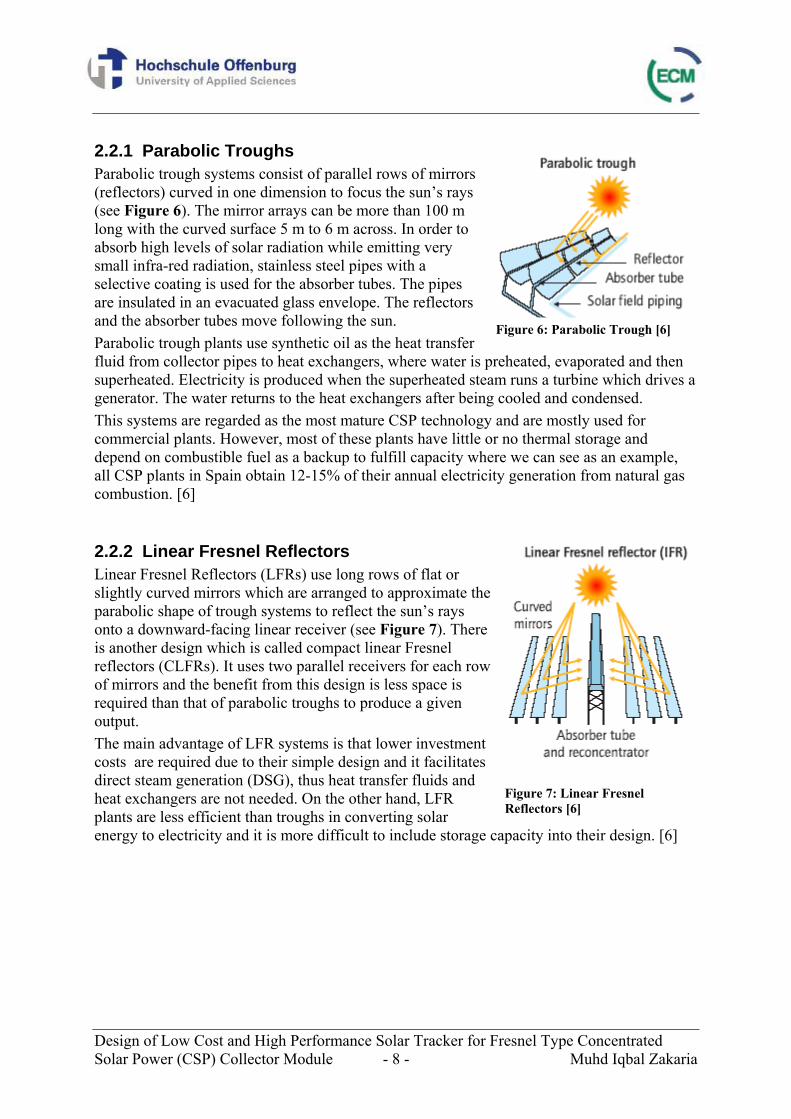
2.2.1 Parabolic Troughs Parabolic trough systems consist of parallel rows of mirrors (reflectors) curved in one dimension to focus the sun’s rays (see Figure 6). The mirror arrays can be more than 100 m long with the curved surface 5 m to 6 m across. In order to absorb high levels of solar radiation while emitting very small infra-red radiation, stainless steel pipes with a selective coating is used for the absorber tubes. The pipes are insulated in an evacuated glass envelope. The reflectors and the absorber tubes move following the sun. Parabolic trough plants use synthetic oil as the heat transfer fluid from collector pipes to heat exchangers, where water is preheated, evaporated and then superheated. Electricity is produced when the superheated steam runs a turbine which drives a generator. The water returns to the heat exchangers after being cooled and condensed. This systems are regarded as the most mature CSP technology and are mostly used for commercial plants. However, most of these plants have little or no thermal storage and depend on combustible fuel as a backup to fulfill capacity where we can see as an example, all CSP plants in Spain obtain 12-15% of their annual electricity generation from natural gas combustion. [6]
2.2.2 Linear Fresnel Reflectors Linear Fresnel Reflectors (LFRs) use long rows of flat or slightly curved mirrors which are arranged to approximate the parabolic shape of trough systems to reflect the sun’s rays onto a downward-facing linear receiver (see Figure 7). There is another design which is called compact linear Fresnel reflectors (CLFRs). It uses two parallel receivers for each row of mirrors and the benefit from this design is less space is required than that of parabolic troughs to produce a given output. The main advantage of LFR systems is that lower investment costs are required due to their simple design and it facilitates direct steam generation (DSG), thus heat transfer fluids and heat exchangers are not needed. On the other hand, LFR plants are less efficient than troughs in converting solar energy to electricity and it is more difficult to include storage capacity into their design. [6]
Figure 6: Parabolic Trough [6]
Figure 7: Linear Fresnel Reflectors [6]
Design of Low Cost and High Performance Solar Tracker for Fresnel Type Concentrated Solar Power (CSP) Collector Module - 9 - Muhd Iqbal Zakaria
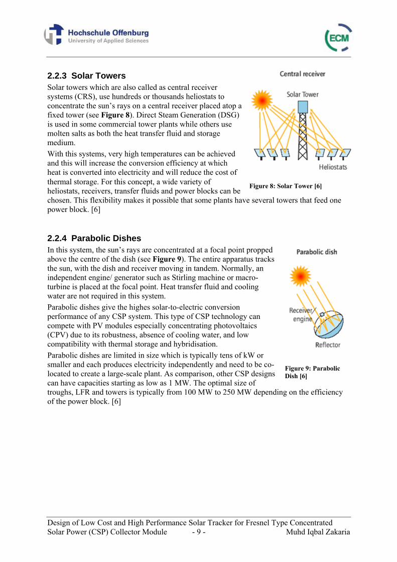
2.2.3 Solar Towers Solar towers which are also called as central receiver systems (CRS), use hundreds or thousands heliostats to concentrate the sun’s rays on a central receiver placed atop a fixed tower (see Figure 8). Direct Steam Generation (DSG) is used in some commercial tower plants while others use molten salts as both the heat transfer fluid and storage medium. With this systems, very high temperatures can be achieved and this will increase the conversion efficiency at which heat is converted into electricity and will reduce the cost of thermal storage. For this concept, a wide variety of heliostats, receivers, transfer fluids and power blocks can be chosen. This flexibility makes it possible that some plants have several towers that feed one power block. [6]
2.2.4 Parabolic Dishes In this system, the sun’s rays are concentrated at a focal point propped above the centre of the dish (see Figure 9). The entire apparatus tracks the sun, with the dish and receiver moving in tandem. Normally, an independent engine/ generator such as Stirling machine or macro-turbine is placed at the focal point. Heat transfer fluid and cooling water are not required in this system. Parabolic dishes give the highes solar-to-electric conversion performance of any CSP system. This type of CSP technology can compete with PV modules especially concentrating photovoltaics (CPV) due to its robustness, absence of cooling water, and low compatibility with thermal storage and hybridisation. Parabolic dishes are limited in size which is typically tens of kW or smaller and each produces electricity independently and need to be co-located to create a large-scale plant. As comparison, other CSP designs can have capacities starting as low as 1 MW. The optimal size of troughs, LFR and towers is typically from 100 MW to 250 MW depending on the efficiency of the power block. [6]
Figure 8: Solar Tower [6]
Figure 9: Parabolic Dish [6]
Design Solar Po
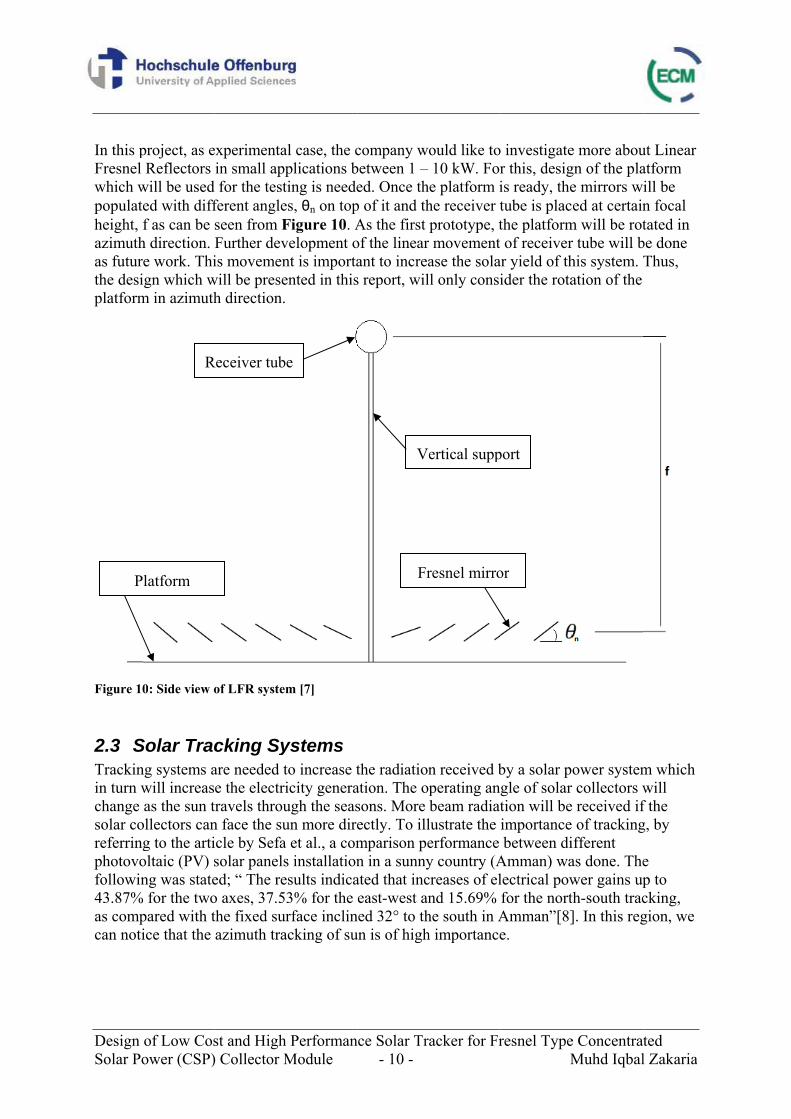
In this pFresnel which wpopulateheight, fazimuthas futurthe desiplatform
Figure 10
2.3 STrackinin turn wchange solar coreferringphotovofollowin43.87%as compcan noti
P
of Low Cosower (CSP)
project, as eReflectors
will be useded with difff as can be
h direction. e work. Thiign which wm in azimuth
0: Side view o
Solar Tracng systems awill increasas the sun t
ollectors cang to the artioltaic (PV) sng was state
% for the twopared with tice that the
R
latform
st and High) Collector M
experimentain small app
d for the testferent angleseen from FFurther devis movemen
will be preseh direction.
of LFR system
cking Syare needed te the electri
travels throun face the suicle by Sefasolar panelsed; “ The reo axes, 37.5the fixed surazimuth tra
Receiver tub
h PerformanModule
al case, the cplications bting is needees, θn on topFigure 10. Avelopment ont is importaented in this
m [7]
ystems to increase ticity generaugh the seasun more direa et al., a coms installationesults indica3% for the rface inclin
acking of su
e
nce Solar Tr- 10 -
company wobetween 1 –ed. Once th
p of it and thAs the first of the linearant to increas report, wil
the radiationation. The opsons. More ectly. To illmparison pen in a sunnyated that inceast-west an
ned 32° to thun is of high
Ve
Fr
acker for Fr
ould like to10 kW. Fore platform ihe receiver tprototype, tmovement
ase the solall only consi
n received bperating anbeam radiatlustrate the erformance y country (Acreases of elnd 15.69% he south in Ah importance
ertical supp
resnel mirro
resnel TypeM
o investigater this, desigis ready, thetube is placthe platformof receiver
ar yield of thider the rota
by a solar pgle of solar tion will beimportancebetween di
Amman) walectrical powfor the nortAmman”[8]e.
port
or
e ConcentratMuhd Iqbal
e more abougn of the plae mirrors wied at certain
m will be rotr tube will bhis system. Tation of the
ower systemr collectors we received if of trackingifferent as done. Thewer gains upth-south trac]. In this reg
ted l Zakaria
ut Linear atform ill be n focal tated in
be done Thus,
m which will f the g, by
e p to cking, gion, we
Design of Low Cost and High Performance Solar Tracker for Fresnel Type Concentrated Solar Power (CSP) Collector Module - 11 - Muhd Iqbal Zakaria
Solar tracking systems can be classified according to several criteria. A classification can be made depending on the number of rotation axes.
1) Single axis 2) Double axis
Single axis: The system can either have a horizontal or vertical axle. The horizontal type is used on tropical regions whereas the vertical type is used in high latitudes where the sun position is not very high. Double axis: The system has both horizontal and vertical axle and thus, has the ability to track the sun apparent motion. Tracking importance as depending on angles is different between PV and CSP. PV precision of tracking is less important than CSP because no focusing needed. Usually three solutions are available for PV tracking.
1) Optimum fixed angle 2) Rotating about horizontal or vertical axis 3) Double axis with no high precision (often between 1 to 5°)
On the other hand, in CSP, high precision of tracking is vital, thus double axis tracking is needed to ensure that light is concentrated on a receiver and high energy yield is obtained from the sunlight. Normally, the precision is less than 0.01°.
Design Solar Po
3 Antra
In this categoriand carotypes mnormall
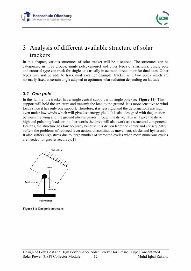
3.1 OIn this fsupport loads sineven unbetweenhigh andBesidessuffers tIt also sare need
Figure 11
of Low Cosower (CSP)
nalysisackers chapter, vaized in threousel type c
may not be ly fixed at c
One pole family, the twill hold thnce it has o
nder low winn the wing ad pulsating
s, the structuthe problemsuffers high ded for grea
1: One pole s
st and High) Collector M
s of diff
arious structee groups; scan track fo
able to tracertain angle
tracker has he structure
only one supnds which wand the grouloads or in
ure has low ms of reduce
stress due tater accurac
structure
h PerformanModule
ferent a
tures of solsingle pole,
or single axiack dual axe adapted to
a single cene and transmpport. Therewill give lesund always other wordaccuracy b
ed lever actito large num
cy. [9]
nce Solar Tr- 12 -
availabl
lar tracker , carousel ais usually inxes for exao optimum s
ntral suppormit the load efore, it is less energy yipasses thros the drive wecause it is ion, discontmber of star
acker for Fr
le struc
will be disand other tyn azimuth diample, tracksolar radiati
rt with singlto the grouness rigid andield. It is alsugh the drivwill also wodriven from
tinuous movrt-stop cycle
resnel TypeM
cture of
scussed. Thypes of struirection or fker with twion dependi
le pole (see nd. It is mord the deformso designedve. This wilork as a strum the centervement, slaces when mo
e ConcentratMuhd Iqbal
f solar
he structuresuctures. Sinfor dual axe
wo poles wng on latitu
Figure 11)re sensitive mations are d with the jull give the ductural compr and conseqcks and hys
ore numerou
ted l Zakaria
s can be ngle pole es. Other hich are
ude.
. This to wind high
unction drive ponent. quently teresis.
us cycles
Design Solar Po
3.2 CAnotherachieveof the psupport structursun withsince thcontinuodefinite
Figure 12
3.3 OOut of tcharacteclassificcategorishown iwhich w
of Low Cosower (CSP)
Carousel r type of strd by rollingrevious growhich mak
ral componeh high preci
he movemenously witholy higher ac
2: Carousel s
Other typthese groupseristics of ecation is notized in othein Figure 13will give hig
st and High) Collector M
ructure is cag on a track oup of one ske it more stent and is loision withount is not donout stops. Coccuracy and
structure
pe s of single pach are uniqt easy and th
er type group3. This strugh energy yi
h PerformanModule
arousel type(see Figureingle pole stable and rigocated in theut frequent ne from the ompared to
d will give m
pole and carque and nothey do not pps. For examcture normaield. [9]
nce Solar Tr- 13 -
e which is che 12). Thisstructure. Ingid. The drie outer sidesstarts and stcenter and other group
more energy
rousel, theret common toprovide signmple, solar ally is fixed
acker for Fr
haracterizedconcept avo
n this structuiving systems which allotops. In thisit may be mps of structuy yield and m
e are other do other solunificant advtracker with
d at certain a
resnel TypeM
d in that azioids most ofure, there arm in this struow continuos case, the le
more accuratures, this tecmore profit
different soutions. This vantages. Thh two polesangle, θ acc
e ConcentratMuhd Iqbal
muth rotatiof the disadvre several poucture is noous trackingever arm is te and can tchnology haability. [9]
lutions withmakes their
herefore, ths acting as scording to p
ted l Zakaria
on, vantages oints of
ot a g of the longer rack as
h the r ey are upports, laces
Design Solar Po
Figure 13
3.4 CDifferenTable 2Mecasostructurhas douconcretethe othedriven mwhich nTrackerby electdirectioSupportcategoryquickly the costprecisioThis is dtrack thDrivingwith onis simplmechantype of
of Low Cosower (CSP)
3: Double po
Comparisnt structures2. These fouolar MS-2 (sre but with duble pole stre footing. Ter hand usesmechanical needs strongr, which hastrical motorn [12]. Othet is importany, Titan Trato the grou
t of materialon of trackindue to the se sun precis
g force needly one pivole compared
nical structustructure.
st and High) Collector M
le structure
son betws are compa
ur models arsee Photo 6different typructure. SUNThe driving ms gear motorjack and ha
ger wire mes five suppor gears whicer example nt to hold thacker is the und. Due to l for foundang, Titan Trtability of ssely.
ded for singlt support. F
d to other sture since the
h PerformanModule
ween diffeared by takinre SUN-LIN
6) and Titan pe of supporN-LINK conmechanismr and cogge
as “V” strucsh concrete
orts; four onch move theis Haosolar
he structurebest becausthis, a stron
ation of Titaracker can trstructure wh
le post is deFor the conntructures. Sie constructio
nce Solar Tr- 14 -
ferent strng some ex
NK (see PhoTracker (se
rt and Haosnsists of ste
m used is an ed crown whcture [11]. Ine. Another en the wheelse pinion-toor which has and transm
se it has fiveng foundatioan Tracker crack less tha
hich can wit
efinitely hignection, the ingle and doon for these
acker for Fr
ructuresxamples andoto 1) whicee Photo 7)solar WXHYeel post withactuator armheel for azimn this case, xample of c
s and one onthed wheel double pol
mit the load te supports aon is not neecan be reducan 0.01° whthstand wind
gh since the single pole
ouble poles e types requi
resnel TypeM
d the evaluath has single which have
Y-15ST (seeh flanged bam [10]. Mecmuth drive the model h
carrousel strn the foundafor azimuthe supports [to the groun
and the loadeded for Titced. In termhereas otherd load and w
motor has tand doublehave the loire less mat
e ConcentratMuhd Iqbal
tion is writte pole structe carrousel e Photo 3) ase plate bocasolar MS-and electrichas one supructure is Tation. It is dh and elevat[13]. nd. For this d can be diretan Tracker
ms of stabilitr models canweight and
to move thee pole constrowest cost oterial than c
ted l Zakaria
ten in ture,
which olted to a -2 on cally pport Titan driven tion
ected r. Thus, ty or nnot do. it can
e module ruction f arrousel
Design of Low Cost and High Performance Solar Tracker for Fresnel Type Concentrated Solar Power (CSP) Collector Module - 15 - Muhd Iqbal Zakaria
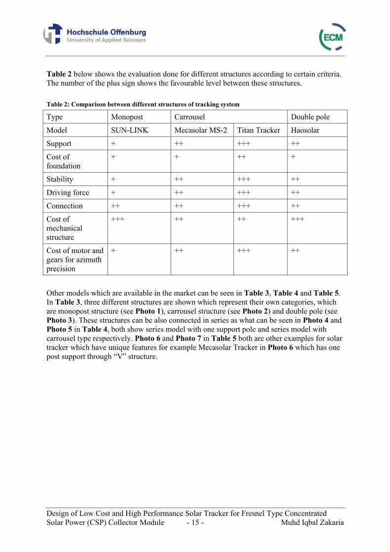
Table 2 below shows the evaluation done for different structures according to certain criteria. The number of the plus sign shows the favourable level between these structures. Table 2: Comparison between different structures of tracking system
Type Monopost Carrousel Double pole
Model SUN-LINK Mecasolar MS-2 Titan Tracker Haosolar
Support + ++ +++ ++
Cost of foundation
+ + ++ +
Stability + ++ +++ ++
Driving force + ++ +++ ++
Connection ++ ++ +++ ++
Cost of mechanical structure
+++ ++ ++ +++
Cost of motor and gears for azimuth precision
+ ++ +++ ++
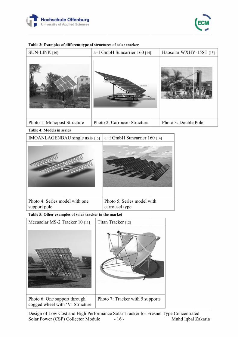
Other models which are available in the market can be seen in Table 3, Table 4 and Table 5. In Table 3, three different structures are shown which represent their own categories, which are monopost structure (see Photo 1), carrousel structure (see Photo 2) and double pole (see Photo 3). These structures can be also connected in series as what can be seen in Photo 4 and Photo 5 in Table 4, both show series model with one support pole and series model with carrousel type respectively. Photo 6 and Photo 7 in Table 5 both are other examples for solar tracker which have unique features for example Mecasolar Tracker in Photo 6 which has one post support through “V” structure.
Design Solar Po
Table 3:
SUN-LI
Photo 1Table 4:
IMOAN
Photo 4support Table 5:
Mecaso
Photo 6cogged
of Low Cosower (CSP)
Examples of
INK [10]
: MonopostModels in se
NLAGENBA
4: Series mopole Other examp
olar MS-2 T
6: One suppowheel with
st and High) Collector M
f different typ
t Structure eries
AU single a
odel with on
ples of solar t
Tracker 10 [1
ort through h ‘V’ Structu
h PerformanModule
pe of structur
a+f Gm
Photo 2
axis [15] a+
ne Phca
tracker in the
11] Titan
ure Photo
nce Solar Tr- 16 -
res of solar tr
mbH Suncarr
2: Carrousel
+f GmbH Su
hoto 5: Seriarrousel type market
n Tracker [12
o 7: Tracker
acker for Fr
racker
rier 160 [14]
l Structure
uncarrier 16
ies model wpe
2]
r with 5 sup
resnel TypeM
] Haoso
Photo
60 [14]
with
pports
e ConcentratMuhd Iqbal
olar WXHY
o 3: Double
ted l Zakaria
Y-15ST [13]
Pole
Design of Low Cost and High Performance Solar Tracker for Fresnel Type Concentrated Solar Power (CSP) Collector Module - 17 - Muhd Iqbal Zakaria
3.5 Conclusion Solar tracker structure which will theoretically give the best compromise between low cost and high precision is the carrousel structure. Tracker with more than one support is preferable for high stability as it can hold the structure better. The support will transmit the load force to the ground. In order to increase stability, the module should be placed as low as possible to lower the centre of gravity and this is also important to avoid high wind load. In our case, since the tilting of module is not necessary, the module could be placed as low as possible as long as the wheel, motor and gear can be placed beneath it. From this analysis, carrousel type is chosen for the type of solar tracker for this project which represents the potential of low cost, high precision, high stability and high wind resistance, and is developed later in a conceptual design process.
Design of Low Cost and High Performance Solar Tracker for Fresnel Type Concentrated Solar Power (CSP) Collector Module - 18 - Muhd Iqbal Zakaria
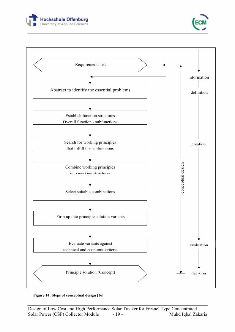
4 Conceptual design of the solar tracker Conceptual design is one part of the design process which begins with identification the problems, establishment of function structures, finding suitable working principles for the function structures and combining these into a working structure [16]. Conceptual design can be expressed briefly as a five-step process [17]: 1. Identifying a set of requirements 2. Prioritizing among these requirements 3. Developing a preliminary solutions 4. Evaluating solutions 5. Establishing final design The process of conceptual design may need backtracking and iteration since design problems are usually indefinite and have a large possible of correct answers. It involves a contingent process where the solution is subject to any possibility of unforeseen complications and changes as it develops. The first step in the design process is to define the problem. This is done by identifying a set of requirements for the product and later these requirements have to be prioritized. In the next step, one has to gather relevant information for the design of the product and its functional specifications. At this point, a survey regarding the availability of similar products in the market should be done. The design team will generate multiple solutions to fulfill the requirements of the design once the details of the design are clearly identified. The most promising alternatives are evaluated and selected for further analysis considering certain aspects such as cost and stability. This evaluation helps to identify final design that best fits the product requirements. At any point during this process, the solution might prove unworkable for any reasons that you have to go to a previous step and the problem may need to be redefined by collecting more information or generating different solutions. Figure 14 shows a more detailed step of conceptual design.
Design of Low Cost and High Performance Solar Tracker for Fresnel Type Concentrated Solar Power (CSP) Collector Module - 19 - Muhd Iqbal Zakaria
Abstract to identify the essential problems
Establish function structures Overall function - subfunctions
Search for working principles that fulfill the subfunctions
Combine working principles into working structures
Select suitable combinations
Firm up into principle solution variants
Evaluate variants against technical and economic criteria
Principle solution (Concept)
Requirements list
conc
eptu
alde
sign
information
creation
evaluation
decision
definition
Figure 14: Steps of conceptual design [16]
Design of Low Cost and High Performance Solar Tracker for Fresnel Type Concentrated Solar Power (CSP) Collector Module - 20 - Muhd Iqbal Zakaria
4.1 Clarification of scope of work The clarification of the scope of work is to gather information about the requirements that are imposed on the solution. Based on this, requirement lists can be produced according to construction systematics. During the development of the solar tracker, a new concept has to be constructed for the first prototype. The tracker should be low cost and can give high performance. In order to produce requirements list, prior basic knowledges of solar tracker are necessary.
4.2 Requirements list Basically, the requirements list includes the list of objectives and conditions of the problem to be solved in the form of demands and wishes. The demands must be met in all circumstances, where the wishes must not be completed in other hand [16]. However, if the wishes are fulfilled, then a better result will be obtained. The distinction between demands and wishes is also important at the evaluation stage, since selection depends on the fulfilment of demands, while evaluation is only performed on variants that already meet the demands. There are two types of requirements. Firstly, the inevitable fixed requirements, which is characterized by quantitative variables, if necessary, with tolerances and decsriptive details. On the other hand, the minimum requirements which must be above or below according to favorable side, such as higher efficiency, lower noise level etc are also to be formulated and reported. Changes and additions to the task, as they may arise in the course of development due to a better knowledge of the possible solutions or due to time-related shifts in the focus must always be written in the requirements list. The distinction between the requirements is important for the subsequent technical evaluation. Since the fixed requirements must be fulfilled in any case, they are eliminated for the evaluation. On the contrary, it is necessary to consider the degree of over or below the minimum requirements in the technical evaluation. For the clarity, categories in terms of key features are needed to systematically use these tools to derive the requirements list. In this case of new design of solar tracker, the requirements list is shown in the following Table 6.
Design of Low Cost and High Performance Solar Tracker for Fresnel Type Concentrated Solar Power (CSP) Collector Module - 21 - Muhd Iqbal Zakaria
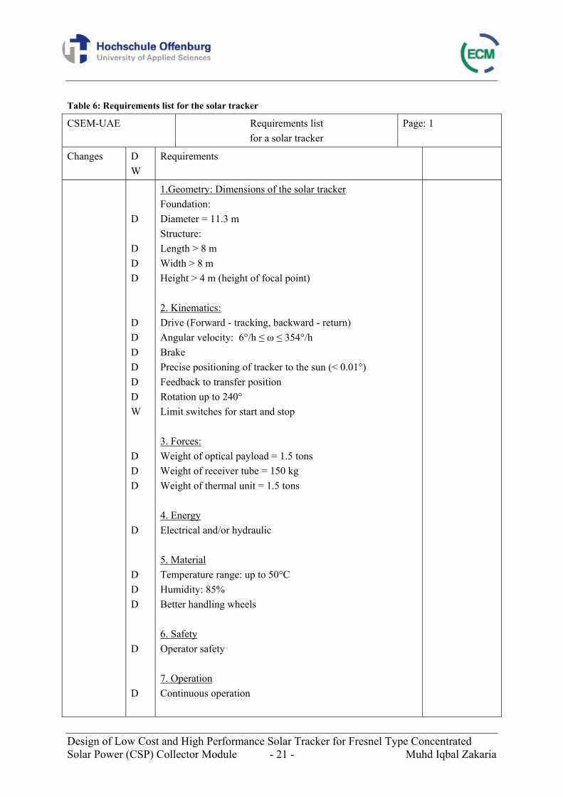
Table 6: Requirements list for the solar tracker
CSEM-UAE Requirements list for a solar tracker
Page: 1
Changes D W
Requirements
D D D D D D D D D D W D D D D D D D D D
1.Geometry: Dimensions of the solar tracker Foundation: Diameter = 11.3 m Structure: Length > 8 m Width > 8 m Height > 4 m (height of focal point) 2. Kinematics: Drive (Forward - tracking, backward - return) Angular velocity: 6°/h ≤ ω ≤ 354°/h Brake Precise positioning of tracker to the sun (< 0.01°) Feedback to transfer position Rotation up to 240° Limit switches for start and stop 3. Forces: Weight of optical payload = 1.5 tons Weight of receiver tube = 150 kg Weight of thermal unit = 1.5 tons 4. Energy Electrical and/or hydraulic 5. Material Temperature range: up to 50°C Humidity: 85% Better handling wheels 6. Safety Operator safety 7. Operation Continuous operation
Design of Low Cost and High Performance Solar Tracker for Fresnel Type Concentrated Solar Power (CSP) Collector Module - 22 - Muhd Iqbal Zakaria
D
8. Maintenance Ease of maintenance (levelling etc.)
D = demands W = wishes
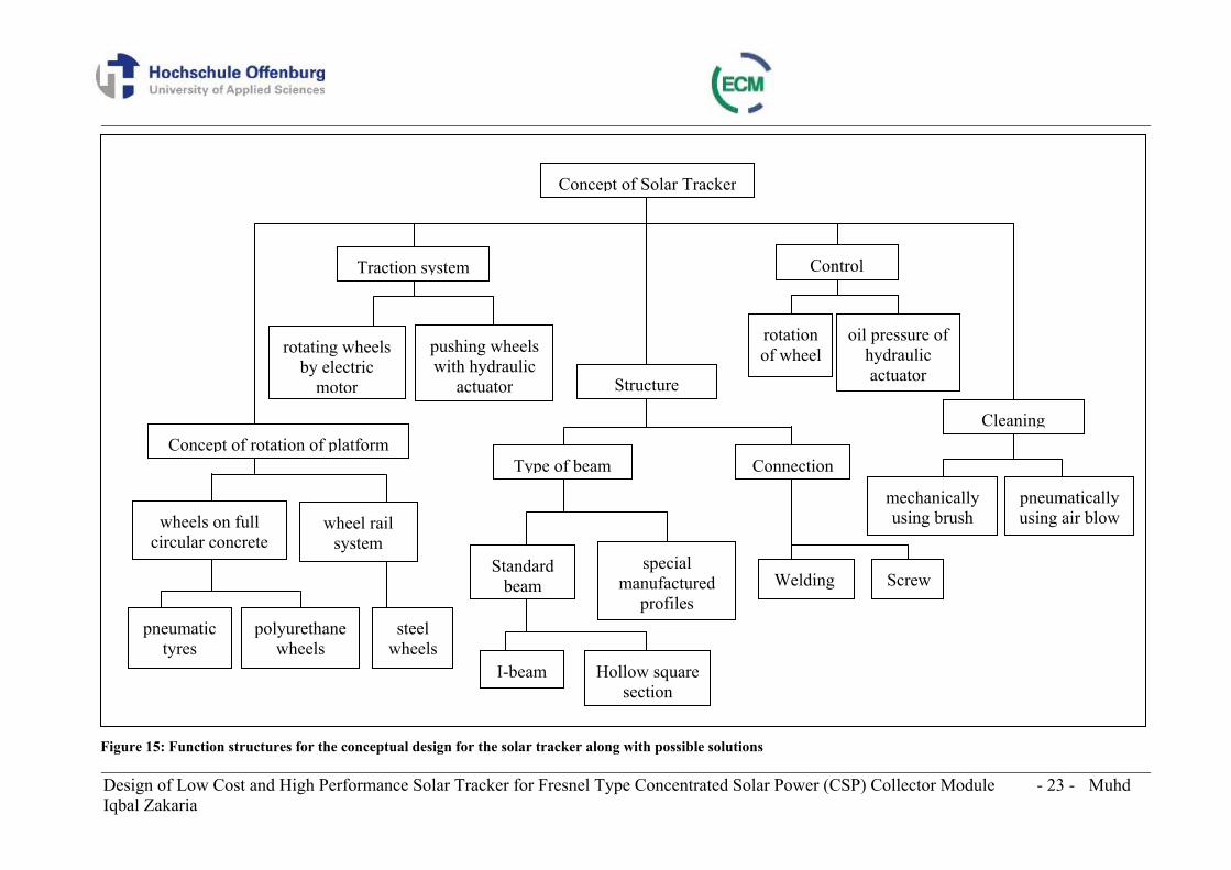
4.3 Function structures From the previous chapter, carousel type of tracker is chosen for this project. To develop new design of this concept, several steps are required. The design can be divided into several function structures such as concept of rotation, structure, traction system, control and cleaning of the tracker as can be seen from Figure 15. In accordance with the construction systematics, several solutions are developed and evaluated technically and economically. The solution with the highest technical and economical quality will be further developed for the final design.
Design of Low Cost and High Performance Solar Tracker for Fresnel Type Concentrated Solar Power (CSP) Collector Module - 23 - Muhd Iqbal Zakaria
Figure 15: Function structures for the conceptual design for the solar tracker along with possible solutions
Concept of Solar Tracker
wheel rail system
wheels on full circular concrete
rotating wheels by electric
motor
pushing wheels with hydraulic
actuator
Welding Standard
beamspecial
manufactured profiles
rotation of wheel
oil pressure of hydraulic actuator
mechanically using brush
pneumatically using air blow
Concept of rotation of platform
Traction system
Structure
Type of beam Connection
Control
Cleaning
pneumatic tyres
polyurethane wheels
steel wheels
I-beam Hollow square section
Screw
Design of Low Cost and High Performance Solar Tracker for Fresnel Type Concentrated Solar Power (CSP) Collector Module - 24 - Muhd Iqbal Zakaria
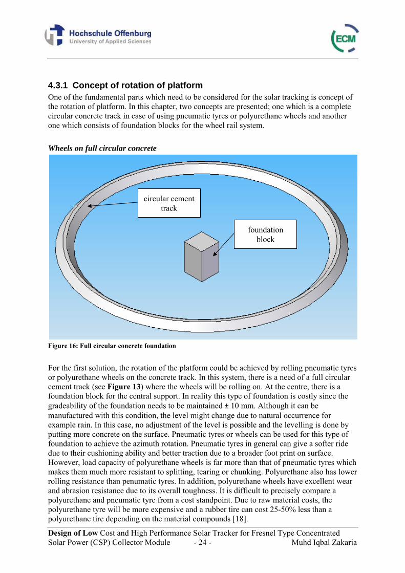
4.3.1 Concept of rotation of platform One of the fundamental parts which need to be considered for the solar tracking is concept of the rotation of platform. In this chapter, two concepts are presented; one which is a complete circular concrete track in case of using pneumatic tyres or polyurethane wheels and another one which consists of foundation blocks for the wheel rail system. Wheels on full circular concrete
Figure 16: Full circular concrete foundation For the first solution, the rotation of the platform could be achieved by rolling pneumatic tyres or polyurethane wheels on the concrete track. In this system, there is a need of a full circular cement track (see Figure 13) where the wheels will be rolling on. At the centre, there is a foundation block for the central support. In reality this type of foundation is costly since the gradeability of the foundation needs to be maintained ± 10 mm. Although it can be manufactured with this condition, the level might change due to natural occurrence for example rain. In this case, no adjustment of the level is possible and the levelling is done by putting more concrete on the surface. Pneumatic tyres or wheels can be used for this type of foundation to achieve the azimuth rotation. Pneumatic tyres in general can give a softer ride due to their cushioning ability and better traction due to a broader foot print on surface. However, load capacity of polyurethane wheels is far more than that of pneumatic tyres which makes them much more resistant to splitting, tearing or chunking. Polyurethane also has lower rolling resistance than penumatic tyres. In addition, polyurethane wheels have excellent wear and abrasion resistance due to its overall toughness. It is difficult to precisely compare a polyurethane and pneumatic tyre from a cost standpoint. Due to raw material costs, the polyurethane tyre will be more expensive and a rubber tire can cost 25-50% less than a polyurethane tire depending on the material compounds [18].
circular cement track
foundation block
Design of Low Cost and High Performance Solar Tracker for Fresnel Type Concentrated Solar Power (CSP) Collector Module - 25 - Muhd Iqbal Zakaria
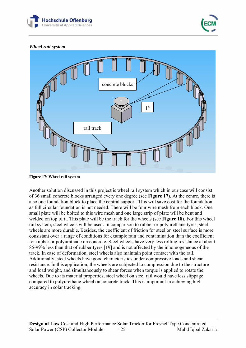
Wheel rail system
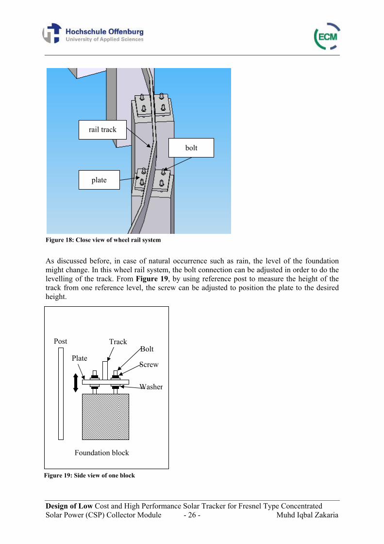
Figure 17: Wheel rail system Another solution discussed in this project is wheel rail system which in our case will consist of 36 small concrete blocks arranged every one degree (see Figure 17). At the centre, there is also one foundation block to place the central support. This will save cost for the foundation as full circular foundation is not needed. There will be four wire mesh from each block. One small plate will be bolted to this wire mesh and one large strip of plate will be bent and welded on top of it. This plate will be the track for the wheels (see Figure 18). For this wheel rail system, steel wheels will be used. In comparison to rubber or polyurethane tyres, steel wheels are more durable. Besides, the coefficient of friction for steel on steel surface is more consistant over a range of conditions for example rain and contamination than the coefficient for rubber or polyurathane on concrete. Steel wheels have very less rolling resistance at about 85-99% less than that of rubber tyres [19] and is not affected by the inhomogeneous of the track. In case of deformation, steel wheels also maintain point contact with the rail. Additionally, steel wheels have good characteristics under compressive loads and shear resistance. In this application, the wheels are subjected to compression due to the structure and load weight, and simultaneously to shear forces when torque is applied to rotate the wheels. Due to its material properties, steel wheel on steel rail would have less slippage compared to polyurethane wheel on concrete track. This is important in achieving high accuracy in solar tracking.
concrete blocks
1°
rail track
Design of Low Cost and High Performance Solar Tracker for Fresnel Type Concentrated Solar Power (CSP) Collector Module - 26 - Muhd Iqbal Zakaria
Figure 18: Close view of wheel rail system As discussed before, in case of natural occurrence such as rain, the level of the foundation might change. In this wheel rail system, the bolt connection can be adjusted in order to do the levelling of the track. From Figure 19, by using reference post to measure the height of the track from one reference level, the screw can be adjusted to position the plate to the desired height.
Post
Screw
Washer
Bolt Plate
Track
Foundation block
Figure 19: Side view of one block
rail track
plate
bolt
Design of Low Cost and High Performance Solar Tracker for Fresnel Type Concentrated Solar Power (CSP) Collector Module - 27 - Muhd Iqbal Zakaria
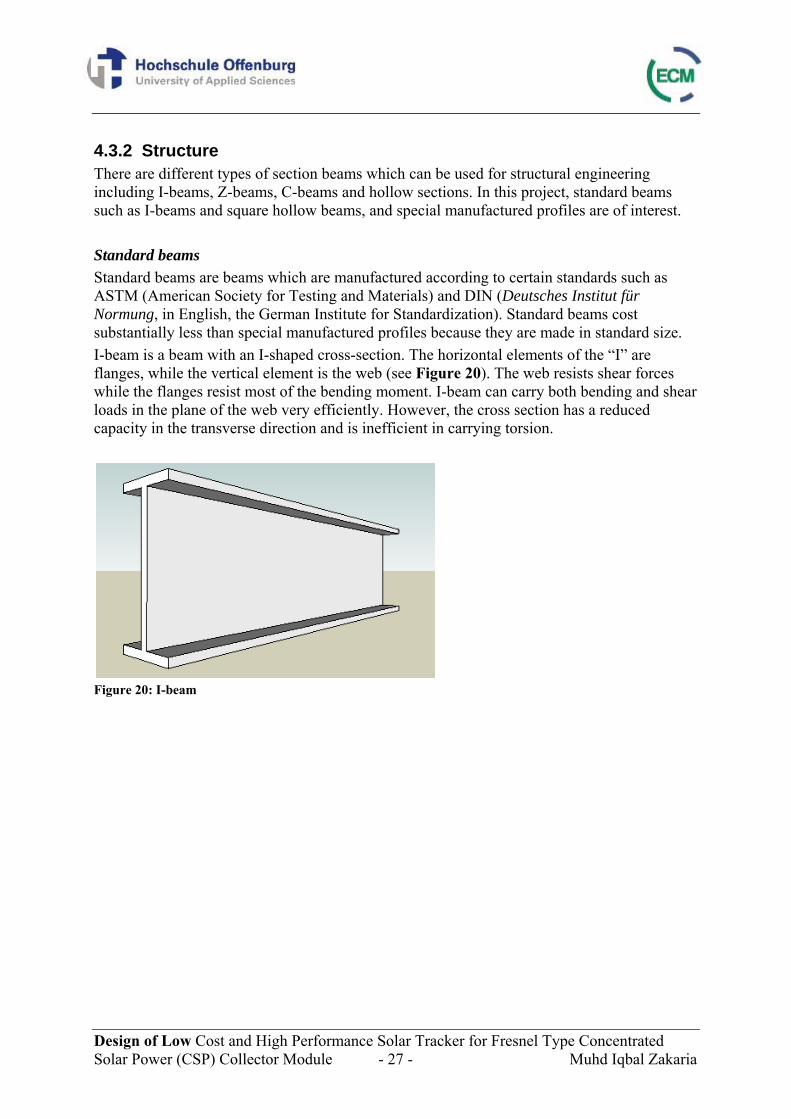
4.3.2 Structure There are different types of section beams which can be used for structural engineering including I-beams, Z-beams, C-beams and hollow sections. In this project, standard beams such as I-beams and square hollow beams, and special manufactured profiles are of interest. Standard beams Standard beams are beams which are manufactured according to certain standards such as ASTM (American Society for Testing and Materials) and DIN (Deutsches Institut für Normung, in English, the German Institute for Standardization). Standard beams cost substantially less than special manufactured profiles because they are made in standard size. I-beam is a beam with an I-shaped cross-section. The horizontal elements of the “I” are flanges, while the vertical element is the web (see Figure 20). The web resists shear forces while the flanges resist most of the bending moment. I-beam can carry both bending and shear loads in the plane of the web very efficiently. However, the cross section has a reduced capacity in the transverse direction and is inefficient in carrying torsion.
Figure 20: I-beam
Design of Low Cost and High Performance Solar Tracker for Fresnel Type Concentrated Solar Power (CSP) Collector Module - 28 - Muhd Iqbal Zakaria
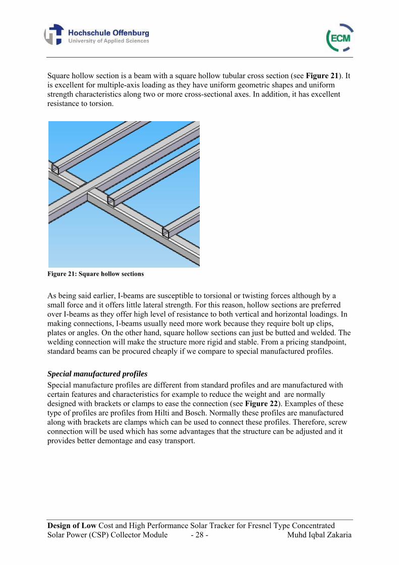
Square hollow section is a beam with a square hollow tubular cross section (see Figure 21). It is excellent for multiple-axis loading as they have uniform geometric shapes and uniform strength characteristics along two or more cross-sectional axes. In addition, it has excellent resistance to torsion.
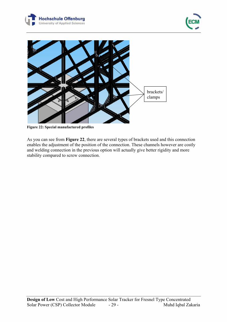
Figure 21: Square hollow sections As being said earlier, I-beams are susceptible to torsional or twisting forces although by a small force and it offers little lateral strength. For this reason, hollow sections are preferred over I-beams as they offer high level of resistance to both vertical and horizontal loadings. In making connections, I-beams usually need more work because they require bolt up clips, plates or angles. On the other hand, square hollow sections can just be butted and welded. The welding connection will make the structure more rigid and stable. From a pricing standpoint, standard beams can be procured cheaply if we compare to special manufactured profiles. Special manufactured profiles Special manufacture profiles are different from standard profiles and are manufactured with certain features and characteristics for example to reduce the weight and are normally designed with brackets or clamps to ease the connection (see Figure 22). Examples of these type of profiles are profiles from Hilti and Bosch. Normally these profiles are manufactured along with brackets are clamps which can be used to connect these profiles. Therefore, screw connection will be used which has some advantages that the structure can be adjusted and it provides better demontage and easy transport.
Design of Low Cost and High Performance Solar Tracker for Fresnel Type Concentrated Solar Power (CSP) Collector Module - 29 - Muhd Iqbal Zakaria
Figure 22: Special manufactured profiles As you can see from Figure 22, there are several types of brackets used and this connection enables the adjustment of the position of the connection. These channels however are costly and welding connection in the previous option will actually give better rigidity and more stability compared to screw connection.
brackets/ clamps
Design of Low Cost and High Performance Solar Tracker for Fresnel Type Concentrated Solar Power (CSP) Collector Module - 30 - Muhd Iqbal Zakaria
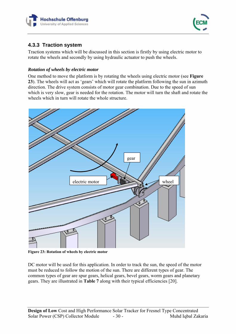
4.3.3 Traction system Traction systems which will be discussed in this section is firstly by using electric motor to rotate the wheels and secondly by using hydraulic actuator to push the wheels. Rotation of wheels by electric motor One method to move the platform is by rotating the wheels using electric motor (see Figure 23). The wheels will act as ‘gears’ which will rotate the platform following the sun in azimuth direction. The drive system consists of motor gear combination. Due to the speed of sun which is very slow, gear is needed for the rotation. The motor will turn the shaft and rotate the wheels which in turn will rotate the whole structure.
Figure 23: Rotation of wheels by electric motor DC motor will be used for this application. In order to track the sun, the speed of the motor must be reduced to follow the motion of the sun. There are different types of gear. The common types of gear are spur gears, helical gears, bevel gears, worm gears and planetary gears. They are illustrated in Table 7 along with their typical efficiencies [20].
wheel electric motor
gear
Design of Low Cost and High Performance Solar Tracker for Fresnel Type Concentrated Solar Power (CSP) Collector Module - 31 - Muhd Iqbal Zakaria
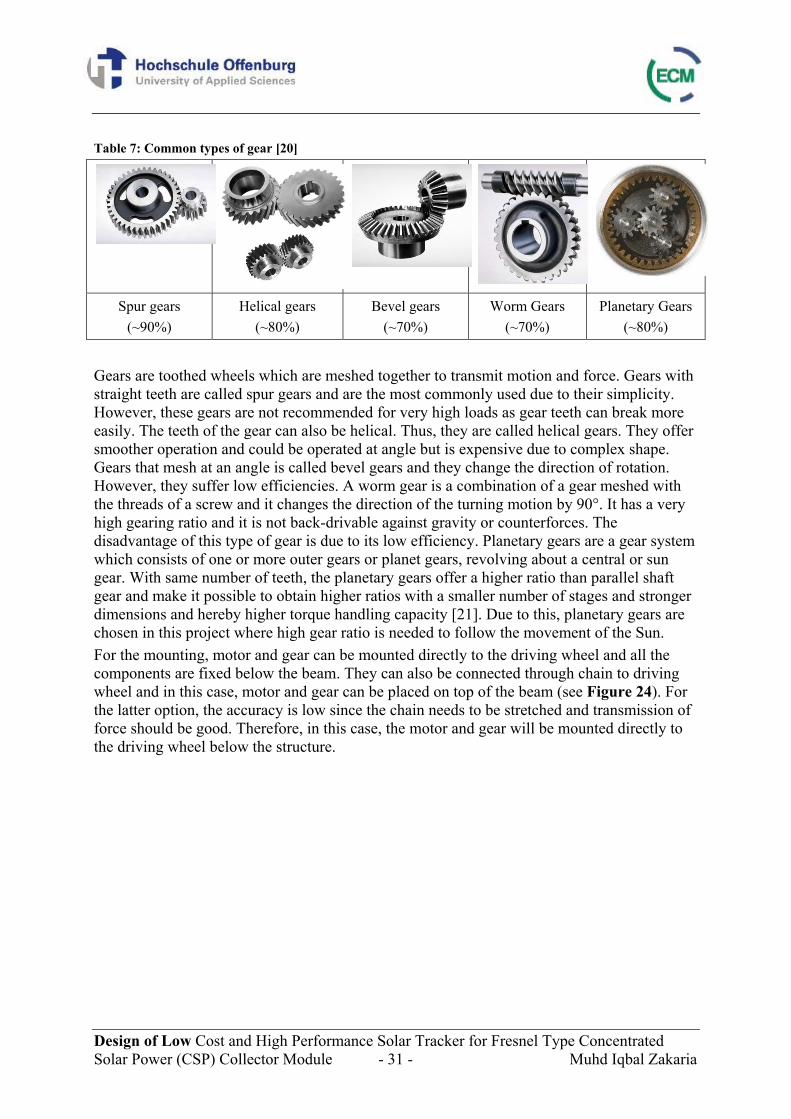
Table 7: Common types of gear [20]
Spur gears (~90%)
Helical gears (~80%)
Bevel gears (~70%)
Worm Gears (~70%)
Planetary Gears (~80%)
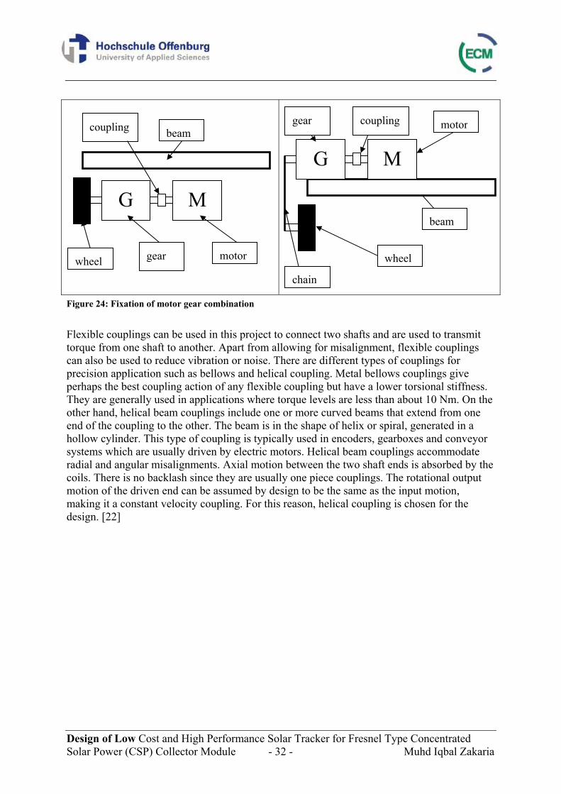
Gears are toothed wheels which are meshed together to transmit motion and force. Gears with straight teeth are called spur gears and are the most commonly used due to their simplicity. However, these gears are not recommended for very high loads as gear teeth can break more easily. The teeth of the gear can also be helical. Thus, they are called helical gears. They offer smoother operation and could be operated at angle but is expensive due to complex shape. Gears that mesh at an angle is called bevel gears and they change the direction of rotation. However, they suffer low efficiencies. A worm gear is a combination of a gear meshed with the threads of a screw and it changes the direction of the turning motion by 90°. It has a very high gearing ratio and it is not back-drivable against gravity or counterforces. The disadvantage of this type of gear is due to its low efficiency. Planetary gears are a gear system which consists of one or more outer gears or planet gears, revolving about a central or sun gear. With same number of teeth, the planetary gears offer a higher ratio than parallel shaft gear and make it possible to obtain higher ratios with a smaller number of stages and stronger dimensions and hereby higher torque handling capacity [21]. Due to this, planetary gears are chosen in this project where high gear ratio is needed to follow the movement of the Sun. For the mounting, motor and gear can be mounted directly to the driving wheel and all the components are fixed below the beam. They can also be connected through chain to driving wheel and in this case, motor and gear can be placed on top of the beam (see Figure 24). For the latter option, the accuracy is low since the chain needs to be stretched and transmission of force should be good. Therefore, in this case, the motor and gear will be mounted directly to the driving wheel below the structure.
Design of Low Cost and High Performance Solar Tracker for Fresnel Type Concentrated Solar Power (CSP) Collector Module - 32 - Muhd Iqbal Zakaria
Figure 24: Fixation of motor gear combination Flexible couplings can be used in this project to connect two shafts and are used to transmit torque from one shaft to another. Apart from allowing for misalignment, flexible couplings can also be used to reduce vibration or noise. There are different types of couplings for precision application such as bellows and helical coupling. Metal bellows couplings give perhaps the best coupling action of any flexible coupling but have a lower torsional stiffness. They are generally used in applications where torque levels are less than about 10 Nm. On the other hand, helical beam couplings include one or more curved beams that extend from one end of the coupling to the other. The beam is in the shape of helix or spiral, generated in a hollow cylinder. This type of coupling is typically used in encoders, gearboxes and conveyor systems which are usually driven by electric motors. Helical beam couplings accommodate radial and angular misalignments. Axial motion between the two shaft ends is absorbed by the coils. There is no backlash since they are usually one piece couplings. The rotational output motion of the driven end can be assumed by design to be the same as the input motion, making it a constant velocity coupling. For this reason, helical coupling is chosen for the design. [22]
M G
motorgear wheel
beam coupling
wheel
beam
motorgear
chain
coupling
M G
Design of Low Cost and High Performance Solar Tracker for Fresnel Type Concentrated Solar Power (CSP) Collector Module - 33 - Muhd Iqbal Zakaria
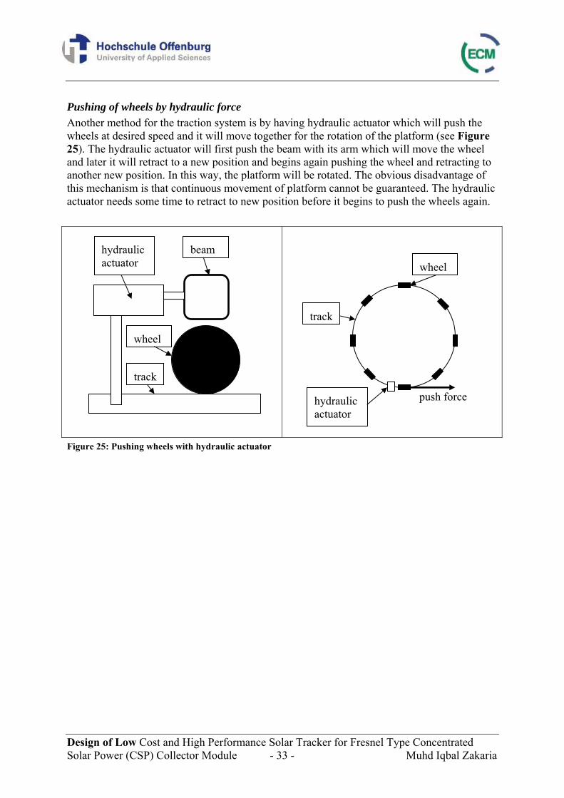
Pushing of wheels by hydraulic force Another method for the traction system is by having hydraulic actuator which will push the wheels at desired speed and it will move together for the rotation of the platform (see Figure 25). The hydraulic actuator will first push the beam with its arm which will move the wheel and later it will retract to a new position and begins again pushing the wheel and retracting to another new position. In this way, the platform will be rotated. The obvious disadvantage of this mechanism is that continuous movement of platform cannot be guaranteed. The hydraulic actuator needs some time to retract to new position before it begins to push the wheels again.
Figure 25: Pushing wheels with hydraulic actuator
hydraulic actuator
wheel
track
beam
hydraulic actuator
wheel
track
push force
Design of Low Cost and High Performance Solar Tracker for Fresnel Type Concentrated Solar Power (CSP) Collector Module - 34 - Muhd Iqbal Zakaria
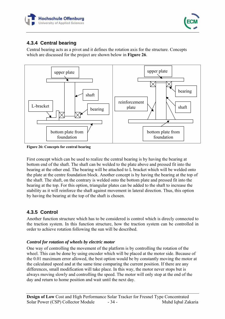
4.3.4 Central bearing Central bearing acts as a pivot and it defines the rotation axis for the structure. Concepts which are discussed for the project are shown below in Figure 26.
Figure 26: Concepts for central bearing First concept which can be used to realize the central bearing is by having the bearing at bottom end of the shaft. The shaft can be welded to the plate above and pressed fit into the bearing at the other end. The bearing will be attached to L bracket which will be welded onto the plate at the centre foundation block. Another concept is by having the bearing at the top of the shaft. The shaft, on the contrary is welded onto the bottom plate and pressed fit into the bearing at the top. For this option, triangular plates can be added to the shaft to increase the stability as it will reinforce the shaft against movement in lateral direction. Thus, this option by having the bearing at the top of the shaft is chosen.
4.3.5 Control Another function structure which has to be considered is control which is direcly connected to the traction system. In this function structure, how the traction system can be controlled in order to achieve rotation following the sun will be described. Control for rotation of wheels by electric motor One way of controlling the movement of the platform is by controlling the rotation of the wheel. This can be done by using encoder which will be placed at the motor side. Because of the 0.01 maximum error allowed, the best option would be by constantly moving the motor at the calculated speed and at the same time comparing the current position. If there are any differences, small modification will take place. In this way, the motor never stops but is always moving slowly and controlling the speed. The motor will only stop at the end of the day and return to home position and wait until the next day.
shaft
upper plate
bearing L-bracket
bottom plate from foundation
upper plate
shaft
bearing
bottom plate from foundation
reinforcement plate
Design of Low Cost and High Performance Solar Tracker for Fresnel Type Concentrated Solar Power (CSP) Collector Module - 35 - Muhd Iqbal Zakaria
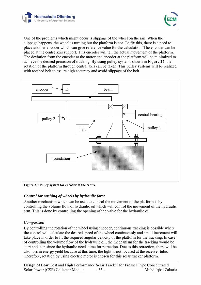
One of the problems which might occur is slippage of the wheel on the rail. When the slippage happens, the wheel is turning but the platform is not. To fix this, there is a need to place another encoder which can give reference value for the calculation. The encoder can be placed at the centre axis support. This encoder will tell the actual movement of the platform. The deviation from the encoder at the motor and encoder at the platform will be minimized to achieve the desired precision of tracking. By using pulley systems shown in Figure 27, the rotation of the platform through central axis can be taken. This pulley systems will be realized with toothed belt to assure high accuracy and avoid slippage of the belt.
Figure 27: Pulley system for encoder at the centre
Control for pushing of wheels by hydraulic force Another mechanism which can be used to control the movement of the platform is by controlling the volume flow of hydraulic oil which will control the movement of the hydraulic arm. This is done by controlling the opening of the valve for the hydraulic oil. Comparison By controlling the rotation of the wheel using encoder, continuous tracking is possible where the control will calculate the desired speed of the wheel continuously and small increment will take place in order to fit the required angular velocity of the platform for the tracking. In case of controlling the volume flow of the hydraulic oil, the mechanism for the tracking would be start and stop since the hydraulic needs time for retraction. Due to this retraction, there will be also loss in energy yield because at this time, the light is not focused at the receiver tube. Therefore, rotation by using electric motor is chosen for this solar tracker platform.
E
foundation
central bearing
beam encoder
pulley 1
pulley 2
belt
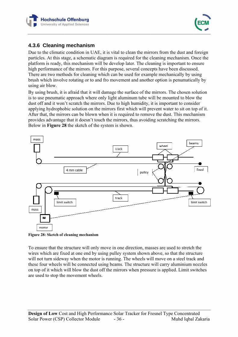
Design Solar Po
4.3.6 CDue to tparticlesplatformhigh perThere arbrush wusing aiBy usinis to usedust offapplyingAfter thprovideBelow i
Figure 28 To ensuwires wwill notthese foon top oare used
of Low Coower (CSP)
Cleaningthe climatics. At this sta
m is ready, trformance ore two meth
which involvir blow.
ng brush, it ie pneumaticf and it wong hydropho
hat, the mirrs advantagein Figure 28
8: Sketch of c
ure that the swhich are fixt turn sidewour wheels wof it which wd to stop the
st and High) Collector M
mechanc condition iage, a schemthis mechanof the mirrohods for cleve rotating o
is afraid thac approach w’t scratch thbic solutionors can be be that it doe8 the sketch
cleaning mec
structure wixed at one enay when the
will be connwill blow the movement
h PerformanModule
ism in UAE, it imatic diagranism will beors. For this aning whichor to and fro
at it will damwhere only he mirrors. Dn on the mirblown whensn’t touch th
h of the syst
hanism
ill only movnd by usinge motor is runected usinghe dust off tht wheels.
nce Solar Tr- 36 -
is vital to clam is requir
e develop latpurpose, seh can be useo movement
mage the surlight aluminDue to highrrors first wn it is requirhe mirrors, tem is show
ve in one dig pulley systunning. The
g beams. Thhe mirrors w
racker for Fr
ean the mirred for the cter. The cle
everal conceed for examt and anothe
rface of thenum tube w
h humidity, which will prred to removthus avoidi
wn.
rection, matem shown e wheels wi
he structure when pressu
resnel TypeM
rrors from thcleaning meaning is impepts have be
mple mechaner option is
mirrors. Thwill be moun
it is importarevent waterve the dust.ing scratchin
asses are useabove, so thill move on will carry aure is applie
e ConcentraMuhd Iqbal
he dust and echanism. Oportant to eeen discussenically by upenumatica
he chosen snted to blowant to consir to sit on to This mechng the mirro
ed to stretchhat the struca steel track
aluminium ned. Limit sw
ated l Zakaria
foreign Once the ensure ed.
using ally by
olution w the ider op of it. anism ors.
h the cture k and nozzles witches
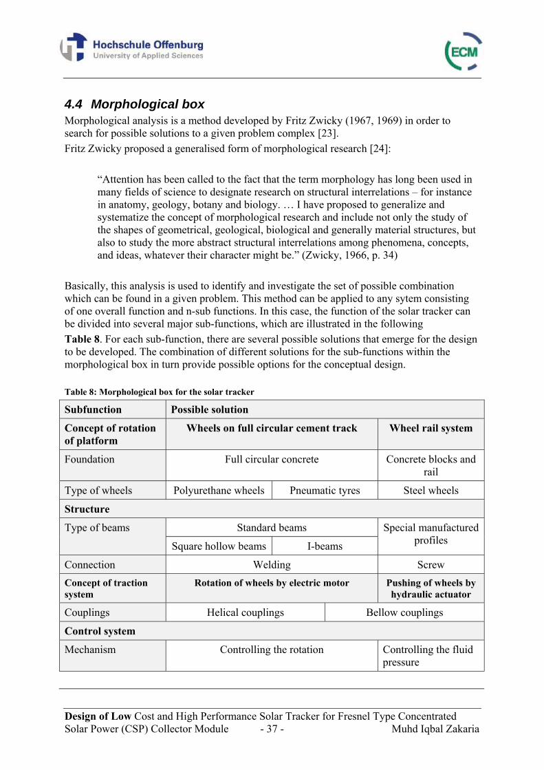
Design of Low Cost and High Performance Solar Tracker for Fresnel Type Concentrated Solar Power (CSP) Collector Module - 37 - Muhd Iqbal Zakaria
4.4 Morphological box Morphological analysis is a method developed by Fritz Zwicky (1967, 1969) in order to search for possible solutions to a given problem complex [23]. Fritz Zwicky proposed a generalised form of morphological research [24]:
“Attention has been called to the fact that the term morphology has long been used in many fields of science to designate research on structural interrelations – for instance in anatomy, geology, botany and biology. … I have proposed to generalize and systematize the concept of morphological research and include not only the study of the shapes of geometrical, geological, biological and generally material structures, but also to study the more abstract structural interrelations among phenomena, concepts, and ideas, whatever their character might be.” (Zwicky, 1966, p. 34)
Basically, this analysis is used to identify and investigate the set of possible combination which can be found in a given problem. This method can be applied to any sytem consisting of one overall function and n-sub functions. In this case, the function of the solar tracker can be divided into several major sub-functions, which are illustrated in the following Table 8. For each sub-function, there are several possible solutions that emerge for the design to be developed. The combination of different solutions for the sub-functions within the morphological box in turn provide possible options for the conceptual design. Table 8: Morphological box for the solar tracker
Subfunction Possible solution
Concept of rotation of platform
Wheels on full circular cement track Wheel rail system
Foundation Full circular concrete Concrete blocks and rail
Type of wheels Polyurethane wheels Pneumatic tyres Steel wheels
Structure
Type of beams Standard beams Special manufactured profiles Square hollow beams I-beams
Connection Welding Screw Concept of traction system
Rotation of wheels by electric motor Pushing of wheels by hydraulic actuator
Couplings Helical couplings Bellow couplings
Control system
Mechanism Controlling the rotation Controlling the fluid pressure
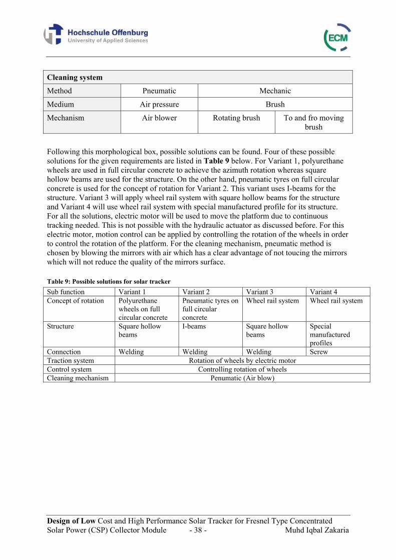
Design of Low Cost and High Performance Solar Tracker for Fresnel Type Concentrated Solar Power (CSP) Collector Module - 38 - Muhd Iqbal Zakaria
Cleaning system
Method Pneumatic Mechanic
Medium Air pressure Brush
Mechanism Air blower Rotating brush To and fro moving brush
Following this morphological box, possible solutions can be found. Four of these possible solutions for the given requirements are listed in Table 9 below. For Variant 1, polyurethane wheels are used in full circular concrete to achieve the azimuth rotation whereas square hollow beams are used for the structure. On the other hand, pneumatic tyres on full circular concrete is used for the concept of rotation for Variant 2. This variant uses I-beams for the structure. Variant 3 will apply wheel rail system with square hollow beams for the structure and Variant 4 will use wheel rail system with special manufactured profile for its structure. For all the solutions, electric motor will be used to move the platform due to continuous tracking needed. This is not possible with the hydraulic actuator as discussed before. For this electric motor, motion control can be applied by controlling the rotation of the wheels in order to control the rotation of the platform. For the cleaning mechanism, pneumatic method is chosen by blowing the mirrors with air which has a clear advantage of not toucing the mirrors which will not reduce the quality of the mirrors surface. Table 9: Possible solutions for solar tracker Sub function Variant 1 Variant 2 Variant 3 Variant 4 Concept of rotation Polyurethane
wheels on full circular concrete
Pneumatic tyres on full circular concrete
Wheel rail system Wheel rail system
Structure Square hollow beams
I-beams Square hollow beams
Special manufactured profiles
Connection Welding Welding Welding Screw Traction system Rotation of wheels by electric motor Control system Controlling rotation of wheels Cleaning mechanism Penumatic (Air blow)
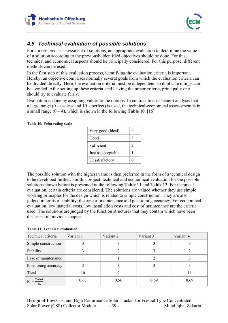
Design of Low Cost and High Performance Solar Tracker for Fresnel Type Concentrated Solar Power (CSP) Collector Module - 39 - Muhd Iqbal Zakaria
4.5 Technical evaluation of possible solutions For a more precise assessment of solutions, an appropriate evaluation to determine the value of a solution according to the previously identified objectives should be done. For this, technical and economical aspects should be principally considered. For this purpose, different methods can be used. In the first step of this evaluation process, identifying the evaluation criteria is important. Hereby, an objective comprises normally several goals from which the evaluation criteria can be divided directly. Here, the evaluation criteria must be independent, so duplicate ratings can be avoided. After setting up these criteria, and leaving the minor criteria, principally one should try to evaluate fairly. Evaluation is done by assigning values to the options. In contrast to cost-benefit analysis that a large range (0 – useless and 10 – perfect) is used, the technical-economical assesssment is in a small range (0 – 4), which is shown in the following Table 10. [16] Table 10: Point rating scale
Very good (ideal) 4
Good 3
Sufficient 2
Just as acceptable 1
Unsatisfactory 0
The possible solution with the highest value is then preferred in the form of a technical design to be developed further. For this project, technical and economical evaluation for the possible solutions shown before is presented in the following Table 11 and Table 12. For technical evaluation, certain criteria are considered. The solutions are valued whether they use simple working principles for the design which is related to simple construction. They are also judged in terms of stability, the ease of maintenance and positioning accuracy. For economical evaluation, low material costs, low installation costs and cost of maintenance are the criteria used. The solutions are judged by the function structures that they contain which have been discussed in previous chapter. Table 11: Technical evaluation
Technical criteria Variant 1 Variant 2 Variant 3 Variant 4
Simple construction 3 3 3 3
Stability 3 2 3 2
Ease of maintenance 1 1 2 3
Positioning accuracy 3 3 3 3
Total 10 9 11 11
Rt = 0.63 0.56 0.69 0.69
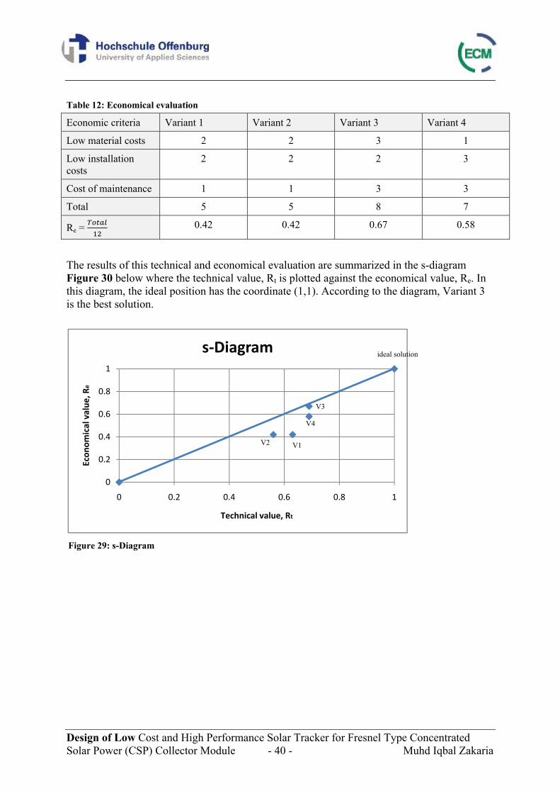
Design of Low Cost and High Performance Solar Tracker for Fresnel Type Concentrated Solar Power (CSP) Collector Module - 40 - Muhd Iqbal Zakaria
Table 12: Economical evaluation
Economic criteria Variant 1 Variant 2 Variant 3 Variant 4
Low material costs 2 2 3 1
Low installation costs
2 2 2 3
Cost of maintenance 1 1 3 3
Total 5 5 8 7
Re = 0.42 0.42 0.67 0.58
The results of this technical and economical evaluation are summarized in the s-diagram Figure 30 below where the technical value, Rt is plotted against the economical value, Re. In this diagram, the ideal position has the coordinate (1,1). According to the diagram, Variant 3 is the best solution.
0
0.2
0.4
0.6
0.8
1
0 0.2 0.4 0.6 0.8 1
Econ
omical value
, Re
Technical value, Rt
s‐Diagram ideal solution
V2 V1
V4
V3
Figure 29: s-Diagram
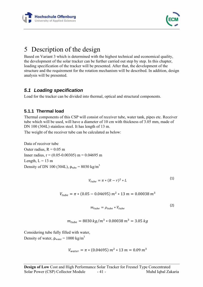
Design of Low Cost and High Performance Solar Tracker for Fresnel Type Concentrated Solar Power (CSP) Collector Module - 41 - Muhd Iqbal Zakaria
5 Description of the design Based on Variant 3 which is determined with the highest technical and economical quality, the development of the solar tracker can be further carried out step by step. In this chapter, loading specification of the tracker will be presented. After that, the development of the structure and the requirement for the rotation mechanism will be described. In addition, design analysis will be presented.
5.1 Loading specification Load for the tracker can be divided into thermal, optical and structural components.
5.1.1 Thermal load Thermal components of this CSP will consist of receiver tube, water tank, pipes etc. Receiver tube which will be used, will have a diameter of 10 cm with thickness of 3.05 mm, made of DN 100 (304L) stainless steel. It has length of 13 m. The weight of the receiver tube can be calculated as below:
Data of receiver tube Outer radius, R = 0.05 m Inner radius, r = (0.05-0.00305) m = 0.04695 m Length, L = 13 m Density of DN 100 (304L), ρtube = 8030 kg/m3
(1)
0.05 0.04695 13 0.00038
(2)
8030 ⁄ 0.00038 3.05
Considering tube fully filled with water, Density of water, ρwater = 1000 kg/m3
0.04695 13 0.09
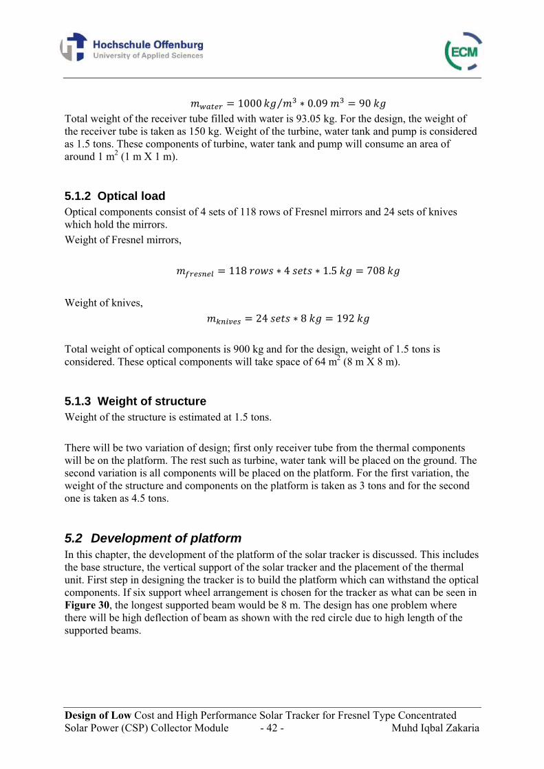
Design of Low Cost and High Performance Solar Tracker for Fresnel Type Concentrated Solar Power (CSP) Collector Module - 42 - Muhd Iqbal Zakaria
1000 ⁄ 0.09 90 Total weight of the receiver tube filled with water is 93.05 kg. For the design, the weight of the receiver tube is taken as 150 kg. Weight of the turbine, water tank and pump is considered as 1.5 tons. These components of turbine, water tank and pump will consume an area of around 1 m2 (1 m X 1 m).
5.1.2 Optical load Optical components consist of 4 sets of 118 rows of Fresnel mirrors and 24 sets of knives which hold the mirrors. Weight of Fresnel mirrors,
118 4 1.5 708
Weight of knives,
24 8 192
Total weight of optical components is 900 kg and for the design, weight of 1.5 tons is considered. These optical components will take space of 64 m2 (8 m X 8 m).
5.1.3 Weight of structure Weight of the structure is estimated at 1.5 tons. There will be two variation of design; first only receiver tube from the thermal components will be on the platform. The rest such as turbine, water tank will be placed on the ground. The second variation is all components will be placed on the platform. For the first variation, the weight of the structure and components on the platform is taken as 3 tons and for the second one is taken as 4.5 tons.
5.2 Development of platform In this chapter, the development of the platform of the solar tracker is discussed. This includes the base structure, the vertical support of the solar tracker and the placement of the thermal unit. First step in designing the tracker is to build the platform which can withstand the optical components. If six support wheel arrangement is chosen for the tracker as what can be seen in Figure 30, the longest supported beam would be 8 m. The design has one problem where there will be high deflection of beam as shown with the red circle due to high length of the supported beams.
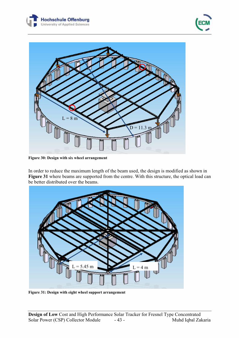
Design of Low Cost and High Performance Solar Tracker for Fresnel Type Concentrated Solar Power (CSP) Collector Module - 43 - Muhd Iqbal Zakaria
Figure 30: Design with six wheel arrangement In order to reduce the maximum length of the beam used, the design is modified as shown in Figure 31 where beams are supported from the centre. With this structure, the optical load can be better distributed over the beams.
Figure 31: Design with eight wheel support arrangement
D = 11.3 m
L = 8 m
L = 4 mL = 5.45 m
Design of Low Cost and High Performance Solar Tracker for Fresnel Type Concentrated Solar Power (CSP) Collector Module - 44 - Muhd Iqbal Zakaria
5.3 Vertical support On top of the platform, vertical support is designed to hold the receiver tube. Three vertical supports are designed and reinforcements are connected between these supports to ensure the rigidity. For the first design shown in Figure 32, however there will be pull and push forces from the profiles as what can be seen with the red arrows. This is because at that connection, there are no other profiles which will support or take the forces.
Figure 32: Design of vertical support 1
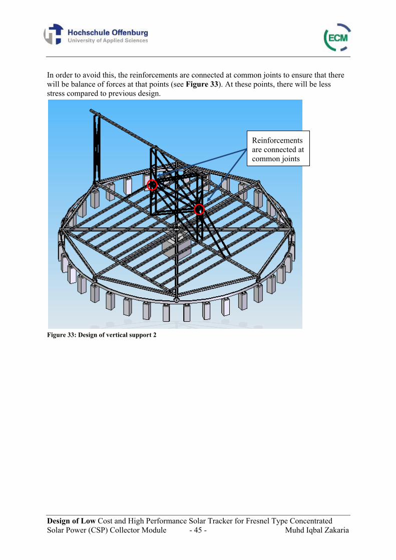
Design of Low Cost and High Performance Solar Tracker for Fresnel Type Concentrated Solar Power (CSP) Collector Module - 45 - Muhd Iqbal Zakaria
In order to avoid this, the reinforcements are connected at common joints to ensure that there will be balance of forces at that points (see Figure 33). At these points, there will be less stress compared to previous design.
Figure 33: Design of vertical support 2
Reinforcements are connected at common joints
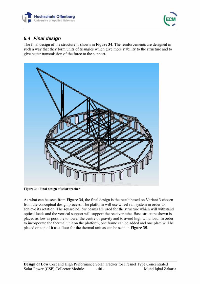
Design of Low Cost and High Performance Solar Tracker for Fresnel Type Concentrated Solar Power (CSP) Collector Module - 46 - Muhd Iqbal Zakaria
5.4 Final design The final design of the structure is shown in Figure 34. The reinforcements are designed in such a way that they form units of triangles which give more stability to the structure and to give better transmission of the force to the support.
Figure 34: Final design of solar tracker As what can be seen from Figure 34, the final design is the result based on Variant 3 chosen from the conceptual design process. The platform will use wheel rail system in order to achieve its rotation. The square hollow beams are used for the structure which will withstand optical loads and the vertical support will support the receiver tube. Base structure shown is placed as low as possible to lower the centre of gravity and to avoid high wind load. In order to incorporate the thermal unit on the platform, one frame can be added and one plate will be placed on top of it as a floor for the thermal unit as can be seen in Figure 35.
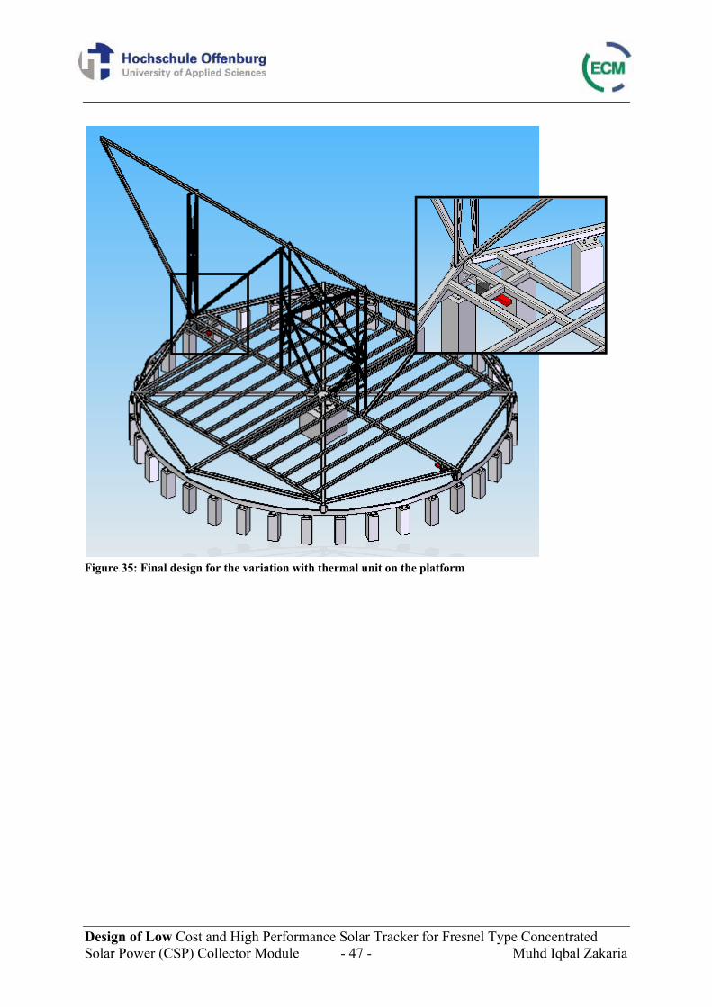
Design of Low Cost and High Performance Solar Tracker for Fresnel Type Concentrated Solar Power (CSP) Collector Module - 47 - Muhd Iqbal Zakaria
Figure 35: Final design for the variation with thermal unit on the platform
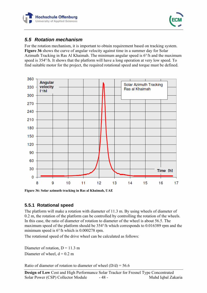
Design of Low Cost and High Performance Solar Tracker for Fresnel Type Concentrated Solar Power (CSP) Collector Module - 48 - Muhd Iqbal Zakaria
5.5 Rotation mechanism For the rotation mechanism, it is important to obtain requirement based on tracking system. Figure 36 shows the curve of angular velocity against time in a summer day for Solar Azimuth Tracking in Ras Al Khaimah. The minimum angular speed is 6°/h and the maximum speed is 354°/h. It shows that the platform will have a long operation at very low speed. To find suitable motor for the project, the required rotational speed and torque must be defined.
Figure 36: Solar azimuth tracking in Ras al Khaimah, UAE
5.5.1 Rotational speed The platform will make a rotation with diameter of 11.3 m. By using wheels of diameter of 0.2 m, the rotation of the platform can be controlled by controlling the rotation of the wheels. In this case, the ratio of diameter of rotation to diameter of the wheel is about 56.5. The maximum speed of the platform should be 354°/h which corresponds to 0.016389 rpm and the minimum speed is 6°/h which is 0.000278 rpm. The rotational speed of the drive wheel can be calculated as follows:
Diameter of rotation, D = 11.3 m Diameter of wheel, d = 0.2 m
Ratio of diameter of rotation to diameter of wheel (D/d) = 56.6
Design of Low Cost and High Performance Solar Tracker for Fresnel Type Concentrated Solar Power (CSP) Collector Module - 49 - Muhd Iqbal Zakaria
Maximum angular velocity of platform, ωmax = 354°/h = 0.0164 rpm = 0.00172 rad/s Minimum angular velocity of platform, ωmax = 6°/h = 0.000278 rpm = 2.91*10-5 rad/s The rotational speed of drive wheel, n
/ (3)
Maximum speed of drive wheel, nmax = 0.927 rpm Minimum speed of drive wheel, nmax = 0.0157 rpm
The above data shows that the speed of the drive wheel varies considerably and that it runs at extremely low speeds of between 0.0157 rpm and 0.927 rpm, therefore requiring a speed reducer with a very high gear ratio. In the case of gear reduction of 60:1, the motor speed for the max and min operation would be 55.6 rpm and 0.94 rpm respectively.
5.5.2 Torque Torque requirement for the motor will be composed of two major components; friction and accelerating the mass. Figuring the torque required for the acceleration of the platform,
(4)
Tacc = Torque needed for accelerating the mass I = Moment of inertia α = Angular acceleration
By taking the assumption of the optical load and platform as a cuboid, moment inertia can be calculated as follows: Moment of inertia for a cuboid,
112
(5)
m = Mass of system a, b = Side lengths of the cuboid
Design of Low Cost and High Performance Solar Tracker for Fresnel Type Concentrated Solar Power (CSP) Collector Module - 50 - Muhd Iqbal Zakaria
For a practical experience when moving big masses, an acceleration of 5 seconds or more can be expected. Once the platform is at the desired speed, small increments or decrements of speed will constantly take place and the solar algorithm will take care of that. Max angular acceleration is 0.000343 rad/s² and min angular acceleration is 5.82*10-6 rad/s² which correspond to max acceleration torque of 11 Nm and min acceleration torque of 0.19 Nm.
Tangential force needed for acceleration can be calculated as follows:
max / /2 (6)
Ft max acc = Tangential force for accelerating the mass T = Torque D = Diameter of rotation
11 /11.3
2 1.94
0.19 /11.3
2 0.033
It is important to estimate the friction at the wheels since it contributes to resistance to the motion. The force depends on the material of the wheel.
. . (7)
Ffriction = Frictional force μ = Coefficient of friction m = Mass g = Gravitational acceleration
Each material has its very own coefficient of friction. For example, steel would have coefficient of starting resistance of 0.02 and rolling coefficient of 0.012. Starting resistance is the friction that needs to be overcome to move a body and the rolling coefficient is the friction when it is moving. In this case, the starting resistance is 589 N and the rolling friction is 353 N. The total tangential force needed at the wheel is the sum of the force needed for the acceleration and force needed to overcome the resistance such as friction. In this case, the force required for start-up is 589 N and when in operation the maximum tangential force needed is 355 N and minimum tangential force is 353 N.
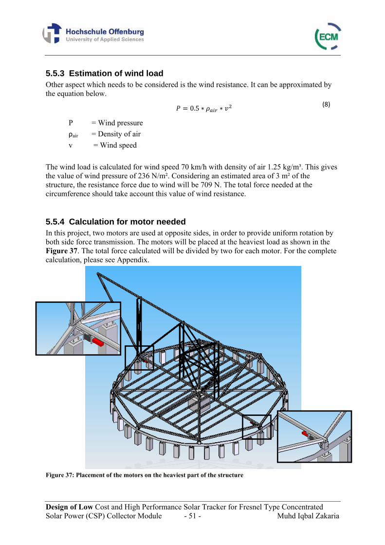
Design of Low Cost and High Performance Solar Tracker for Fresnel Type Concentrated Solar Power (CSP) Collector Module - 51 - Muhd Iqbal Zakaria
5.5.3 Estimation of wind load Other aspect which needs to be considered is the wind resistance. It can be approximated by the equation below.
0.5 (8)
P = Wind pressure ρair = Density of air v = Wind speed
The wind load is calculated for wind speed 70 km/h with density of air 1.25 kg/m³. This gives the value of wind pressure of 236 N/m². Considering an estimated area of 3 m² of the structure, the resistance force due to wind will be 709 N. The total force needed at the circumference should take account this value of wind resistance.
5.5.4 Calculation for motor needed In this project, two motors are used at opposite sides, in order to provide uniform rotation by both side force transmission. The motors will be placed at the heaviest load as shown in the Figure 37. The total force calculated will be divided by two for each motor. For the complete calculation, please see Appendix.
Figure 37: Placement of the motors on the heaviest part of the structure
Design of Low Cost and High Performance Solar Tracker for Fresnel Type Concentrated Solar Power (CSP) Collector Module - 52 - Muhd Iqbal Zakaria
5.5.5 Drag forces Drag forces which is sometimes known as air resistance refers to forces which act on an object in the direction of the relative fluid flow velocity. Drag force is very small due to the very low speed of rotation. It can be calculated using the equation below.
0.5 ² (9)
Fdrag = Drag forces ρair = Density of air v = Speed of the body cD = Drag coefficient A = Reference area
Since speed of the body is very small between 0.000165 m/s and 0.00971 m/s, the drag force can be neglected.
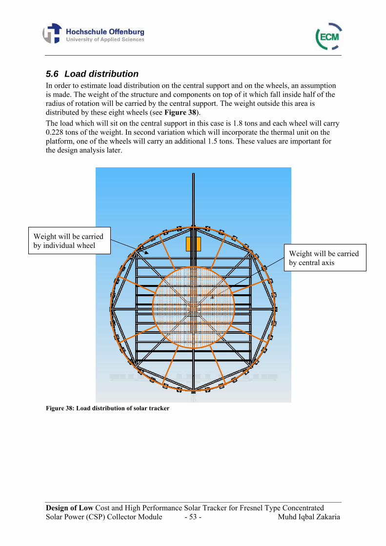
Design of Low Cost and High Performance Solar Tracker for Fresnel Type Concentrated Solar Power (CSP) Collector Module - 53 - Muhd Iqbal Zakaria
5.6 Load distribution In order to estimate load distribution on the central support and on the wheels, an assumption is made. The weight of the structure and components on top of it which fall inside half of the radius of rotation will be carried by the central support. The weight outside this area is distributed by these eight wheels (see Figure 38). The load which will sit on the central support in this case is 1.8 tons and each wheel will carry 0.228 tons of the weight. In second variation which will incorporate the thermal unit on the platform, one of the wheels will carry an additional 1.5 tons. These values are important for the design analysis later.
Figure 38: Load distribution of solar tracker
Weight will be carried by central axis
Weight will be carried by individual wheel
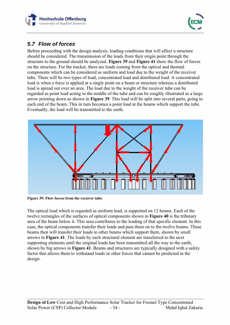
Design of Low Cost and High Performance Solar Tracker for Fresnel Type Concentrated Solar Power (CSP) Collector Module - 54 - Muhd Iqbal Zakaria
5.7 Flow of forces Before proceeding with the design analysis, loading conditions that will affect a structure should be considered. The transmission of the loads from their origin point through the structure to the ground should be analyzed. Figure 39 and Figure 41 show the flow of forces on the structure. For the tracker, there are loads coming from the optical and thermal components which can be considered as uniform and load due to the weight of the receiver tube. There will be two types of load; concentrated load and distributed load. A concentrated load is when a force is applied at a single point on a beam or structure whereas a distributed load is spread out over an area. The load due to the weight of the receiver tube can be regarded as point load acting in the middle of the tube and can be roughly illustrated as a large arrow pointing down as shown in Figure 39. This load will be split into several parts, going to each end of the beam. This in turn becomes a point load at the beams which support the tube. Eventually, the load will be transmitted to the earth.
Figure 39: Flow forces from the receiver tube The optical load which is regarded as uniform load, is supported on 12 beams. Each of the twelve rectangles of the surfaces of optical components shown in Figure 40 is the tributary area of the beam below it. This area contributes to the loading of that specific element. In this case, the optical components transfer their loads and pass them on to the twelve beams. These beams then will transfer their loads to other beams which support them, shown by small arrows in Figure 41. The loads by each structural element are transferred to the next supporting elements until the original loads has been transmitted all the way to the earth, shown by big arrows in Figure 41. Beams and structures are typically designed with a safety factor that allows them to withstand loads or other forces that cannot be predicted in the design.
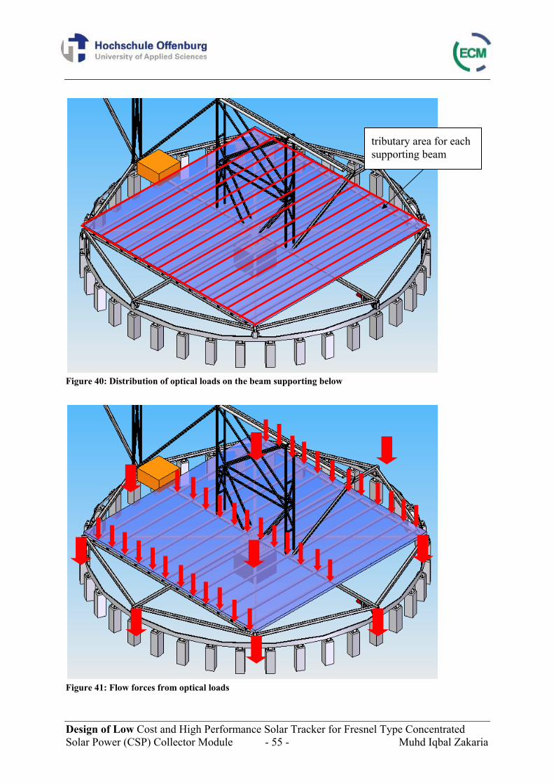
Design of Low Cost and High Performance Solar Tracker for Fresnel Type Concentrated Solar Power (CSP) Collector Module - 55 - Muhd Iqbal Zakaria
Figure 40: Distribution of optical loads on the beam supporting below
Figure 41: Flow forces from optical loads
tributary area for each supporting beam
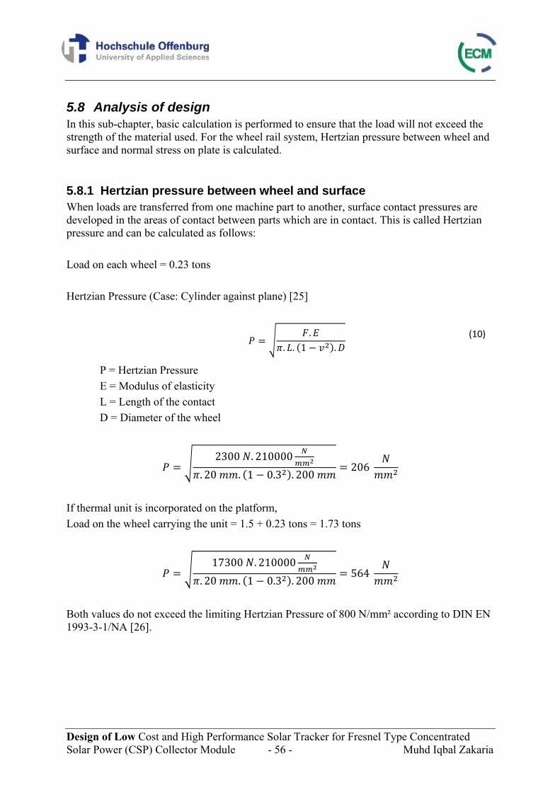
Design of Low Cost and High Performance Solar Tracker for Fresnel Type Concentrated Solar Power (CSP) Collector Module - 56 - Muhd Iqbal Zakaria
5.8 Analysis of design In this sub-chapter, basic calculation is performed to ensure that the load will not exceed the strength of the material used. For the wheel rail system, Hertzian pressure between wheel and surface and normal stress on plate is calculated.
5.8.1 Hertzian pressure between wheel and surface When loads are transferred from one machine part to another, surface contact pressures are developed in the areas of contact between parts which are in contact. This is called Hertzian pressure and can be calculated as follows: Load on each wheel = 0.23 tons Hertzian Pressure (Case: Cylinder against plane) [25]
.. . 1 .
(10)
P = Hertzian Pressure E = Modulus of elasticity L = Length of the contact D = Diameter of the wheel
2300 . 210000. 20 . 1 0.3 . 200 206
If thermal unit is incorporated on the platform, Load on the wheel carrying the unit = 1.5 + 0.23 tons = 1.73 tons
17300 . 210000. 20 . 1 0.3 . 200 564
Both values do not exceed the limiting Hertzian Pressure of 800 N/mm² according to DIN EN 1993-3-1/NA [26].
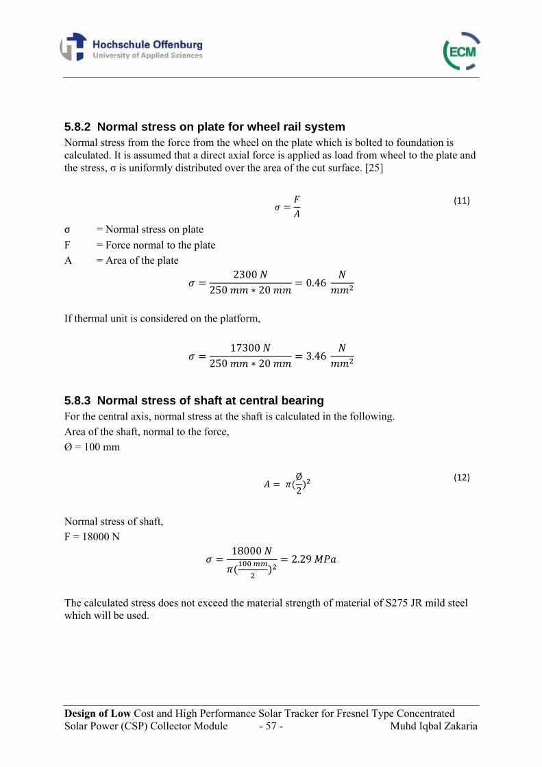
Design of Low Cost and High Performance Solar Tracker for Fresnel Type Concentrated Solar Power (CSP) Collector Module - 57 - Muhd Iqbal Zakaria
5.8.2 Normal stress on plate for wheel rail system Normal stress from the force from the wheel on the plate which is bolted to foundation is calculated. It is assumed that a direct axial force is applied as load from wheel to the plate and the stress, σ is uniformly distributed over the area of the cut surface. [25]
(11)
σ = Normal stress on plate F = Force normal to the plate A = Area of the plate
2300 250 20 0.46
If thermal unit is considered on the platform,
17300 250 20 3.46
5.8.3 Normal stress of shaft at central bearing For the central axis, normal stress at the shaft is calculated in the following. Area of the shaft, normal to the force, Ø = 100 mm
Ø2
(12)
Normal stress of shaft, F = 18000 N
18000 2.29
The calculated stress does not exceed the material strength of material of S275 JR mild steel which will be used.

Design of Low Cost and High Performance Solar Tracker for Fresnel Type Concentrated Solar Power (CSP) Collector Module - 58 - Muhd Iqbal Zakaria
5.8.4 Structural beam deflection and stress Later, critical areas of the beam sections used are identified. The stress and deflection of these sections are analyzed. Several factors which are considered for this beam calculation are material properties of the beam, load and the supports. Each material has its own ability to deform elastically which is called the modulus of elasticity and it refers to its tendency to return back to its original condition. However, at its yield point, the material will deform plastically and will stay that way even if the force is removed. Besides, cross-sectional shape of the beam is also important in beam calculation. Beams might be rectangular, round or hollow and each shape has a different moment of inertia or known as second moment of area which tells the stiffness of the beam. In most practical applications, beam software is used. However, in order to estimate the deflection and stress of these sections, assumptions are made and the calculations are presented in the following. Load, shear and moment diagrams will be shown for the critical section and they provide a graphical summary of internal beam forces. The bending analysis is done with the construction of shear and bending moment diagrams appropriate to the loading and support configuration for the section of interest. There are three sections which are regarded as critical areas.
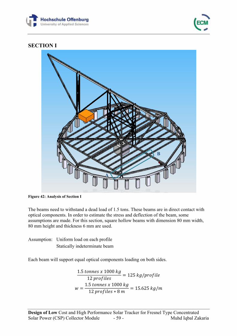
Design of Low Cost and High Performance Solar Tracker for Fresnel Type Concentrated Solar Power (CSP) Collector Module - 59 - Muhd Iqbal Zakaria
SECTION I
Figure 42: Analysis of Section I The beams need to withstand a dead load of 1.5 tons. These beams are in direct contact with optical components. In order to estimate the stress and deflection of the beam, some assumptions are made. For this section, square hollow beams with dimension 80 mm width, 80 mm height and thickness 6 mm are used. Assumption: Uniform load on each profile Statically indeterminate beam Each beam will support equal optical components loading on both sides.
1.5 1000 12 125 /
1.5 1000 12 8 15.625 /
A
B
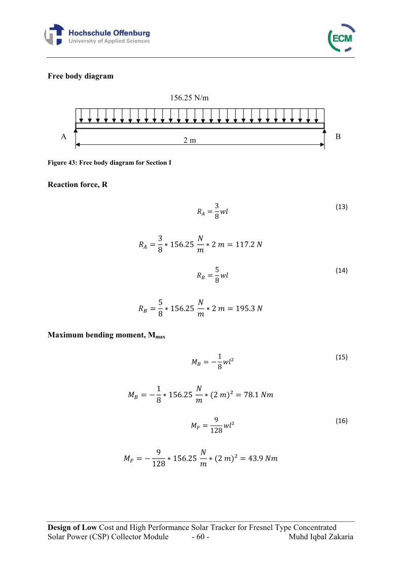
Design of Low Cost and High Performance Solar Tracker for Fresnel Type Concentrated Solar Power (CSP) Collector Module - 60 - Muhd Iqbal Zakaria
Free body diagram Figure 43: Free body diagram for Section I Reaction force, R
38
(13)
38 156.25 2 117.2
58
(14)
58 156.25 2 195.3
Maximum bending moment, Mmax
18
² (15)
18 156.25 2 ² 78.1
9
128² (16)
9
128 156.25 2 ² 43.9
A B
156.25 N/m
2 m
Design of Low Cost and High Performance Solar Tracker for Fresnel Type Concentrated Solar Power (CSP) Collector Module - 61 - Muhd Iqbal Zakaria
Bending moment diagram Figure 44: Bending moment diagram for Section I Data of beam Modulus of elasticity, E = 210 000 N/mm² Area moment of inertia, Iy = 156 cm4 Bending stress, σ The maximum bending stress is a direct function of the maximum bending moment and the member cross section, as given by the equation below.
(17)
78.1
39 10 2 10 2 /
Max deflection, fmax
185
(18)
156.25 2
185 2.1 10 156 100.04
MF = 43.9 Nm
A B +
-
MB = 78.1 Nm
X0 = 0.75 m
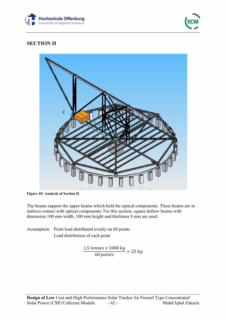
Design of Low Cost and High Performance Solar Tracker for Fresnel Type Concentrated Solar Power (CSP) Collector Module - 62 - Muhd Iqbal Zakaria
SECTION II
Figure 45: Analysis of Section II The beams support the upper beams which hold the optical components. These beams are in indirect contact with optical components. For this section, square hollow beams with dimension 100 mm width, 100 mm height and thickness 8 mm are used. Assumption: Point load distributed evenly on 60 points
Load distribution of each point
1.5 1000 60 25
C
D
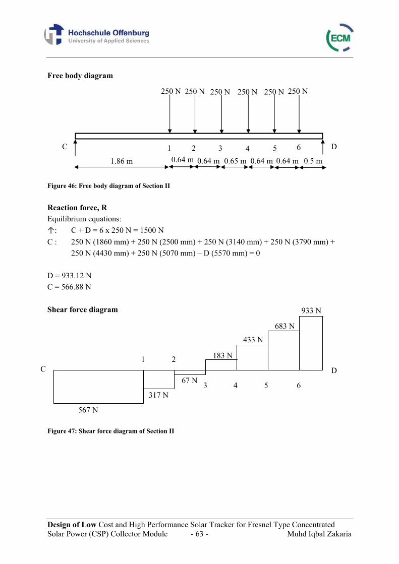
Design of Low Cost and High Performance Solar Tracker for Fresnel Type Concentrated Solar Power (CSP) Collector Module - 63 - Muhd Iqbal Zakaria
Free body diagram Figure 46: Free body diagram of Section II Reaction force, R Equilibrium equations: ↑: C + D = 6 x 250 N = 1500 N C : 250 N (1860 mm) + 250 N (2500 mm) + 250 N (3140 mm) + 250 N (3790 mm) + 250 N (4430 mm) + 250 N (5070 mm) – D (5570 mm) = 0 D = 933.12 N C = 566.88 N Shear force diagram Figure 47: Shear force diagram of Section II
C D 1 2
3 4 5 6
567 N
317 N
67 N
183 N
433 N
683 N
933 N
C D 1 2 3 4 5 6
250 N 250 N 250 N 250 N 250 N 250 N
1.86 m 0.64 m 0.64 m 0.64 m 0.65 m 0.64 m 0.5 m
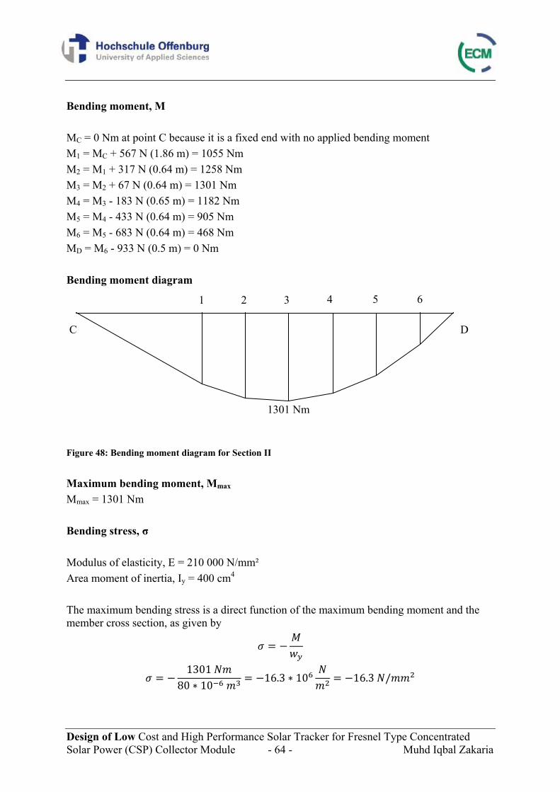
Design of Low Cost and High Performance Solar Tracker for Fresnel Type Concentrated Solar Power (CSP) Collector Module - 64 - Muhd Iqbal Zakaria
Bending moment, M MC = 0 Nm at point C because it is a fixed end with no applied bending moment M1 = MC + 567 N (1.86 m) = 1055 Nm M2 = M1 + 317 N (0.64 m) = 1258 Nm M3 = M2 + 67 N (0.64 m) = 1301 Nm M4 = M3 - 183 N (0.65 m) = 1182 Nm M5 = M4 - 433 N (0.64 m) = 905 Nm M6 = M5 - 683 N (0.64 m) = 468 Nm MD = M6 - 933 N (0.5 m) = 0 Nm Bending moment diagram Figure 48: Bending moment diagram for Section II Maximum bending moment, Mmax
Mmax = 1301 Nm Bending stress, σ Modulus of elasticity, E = 210 000 N/mm² Area moment of inertia, Iy = 400 cm4 The maximum bending stress is a direct function of the maximum bending moment and the member cross section, as given by
1301 80 10 16.3 10 16.3 /
C D
1 2 3 4 5 6
1301 Nm
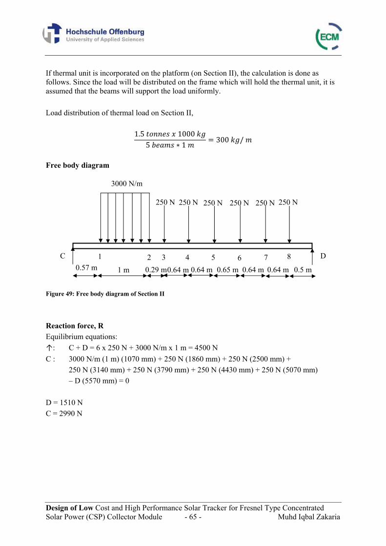
Design of Low Cost and High Performance Solar Tracker for Fresnel Type Concentrated Solar Power (CSP) Collector Module - 65 - Muhd Iqbal Zakaria
If thermal unit is incorporated on the platform (on Section II), the calculation is done as follows. Since the load will be distributed on the frame which will hold the thermal unit, it is assumed that the beams will support the load uniformly. Load distribution of thermal load on Section II,
1.5 1000 5 1 300 /
Free body diagram Figure 49: Free body diagram of Section II Reaction force, R Equilibrium equations: ↑: C + D = 6 x 250 N + 3000 N/m x 1 m = 4500 N C : 3000 N/m (1 m) (1070 mm) + 250 N (1860 mm) + 250 N (2500 mm) +
250 N (3140 mm) + 250 N (3790 mm) + 250 N (4430 mm) + 250 N (5070 mm) – D (5570 mm) = 0
D = 1510 N C = 2990 N
C D 3 4 5 6 7 8
250 N 250 N 250 N 250 N 250 N 250 N
1 m 0.64 m 0.64 m 0.64 m 0.65 m 0.64 m 0.5 m 0.29 m
1 2 0.57 m
3000 N/m
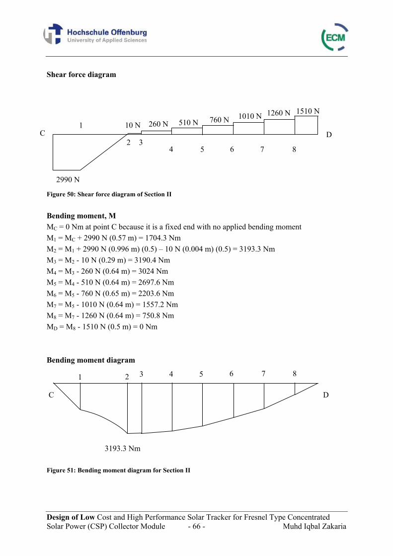
Design of Low Cost and High Performance Solar Tracker for Fresnel Type Concentrated Solar Power (CSP) Collector Module - 66 - Muhd Iqbal Zakaria
Shear force diagram Figure 50: Shear force diagram of Section II Bending moment, M MC = 0 Nm at point C because it is a fixed end with no applied bending moment M1 = MC + 2990 N (0.57 m) = 1704.3 Nm M2 = M1 + 2990 N (0.996 m) (0.5) – 10 N (0.004 m) (0.5) = 3193.3 Nm M3 = M2 - 10 N (0.29 m) = 3190.4 Nm M4 = M3 - 260 N (0.64 m) = 3024 Nm M5 = M4 - 510 N (0.64 m) = 2697.6 Nm M6 = M5 - 760 N (0.65 m) = 2203.6 Nm M7 = M5 - 1010 N (0.64 m) = 1557.2 Nm M8 = M7 - 1260 N (0.64 m) = 750.8 Nm MD = M8 - 1510 N (0.5 m) = 0 Nm Bending moment diagram Figure 51: Bending moment diagram for Section II
C D 3
4 5 6 7 8
C D
3 4 5 6 7 8
2990 N
510 N 260 N 760 N 1010 N 1260 N 1510 N
3193.3 Nm
2
1 10 N
2 1
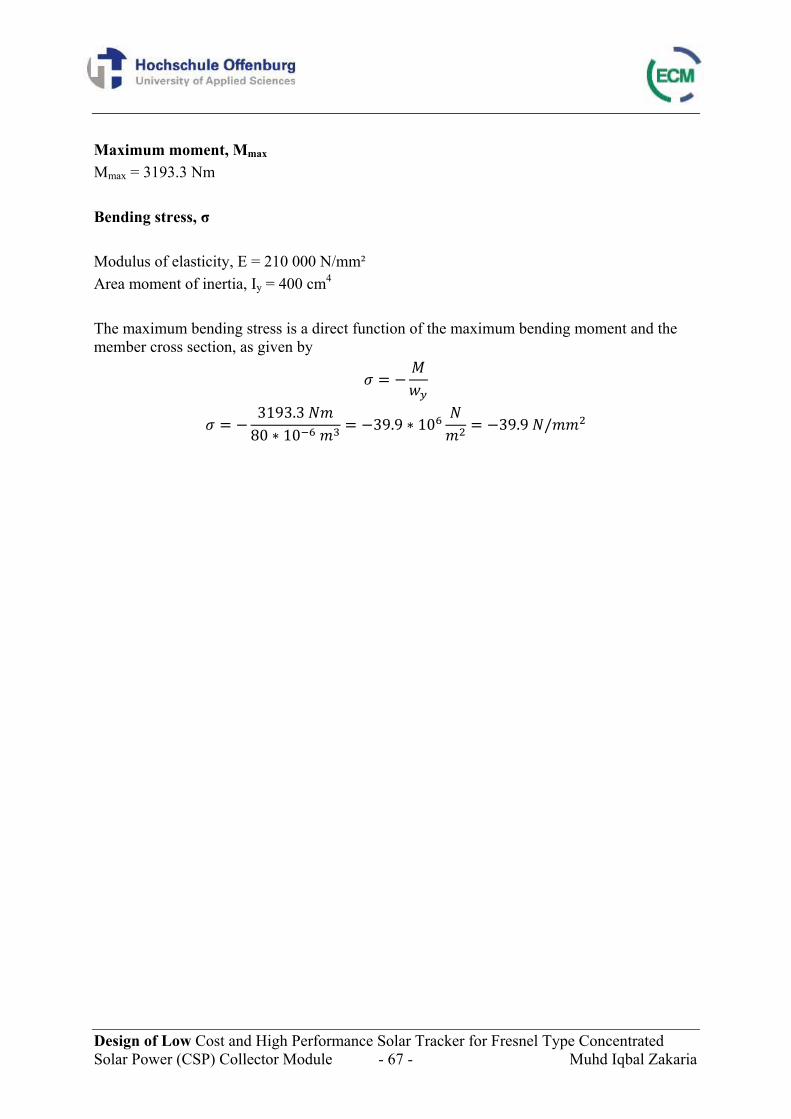
Design of Low Cost and High Performance Solar Tracker for Fresnel Type Concentrated Solar Power (CSP) Collector Module - 67 - Muhd Iqbal Zakaria
Maximum moment, Mmax
Mmax = 3193.3 Nm Bending stress, σ Modulus of elasticity, E = 210 000 N/mm² Area moment of inertia, Iy = 400 cm4 The maximum bending stress is a direct function of the maximum bending moment and the member cross section, as given by
3193.3 80 10 39.9 10 39.9 /
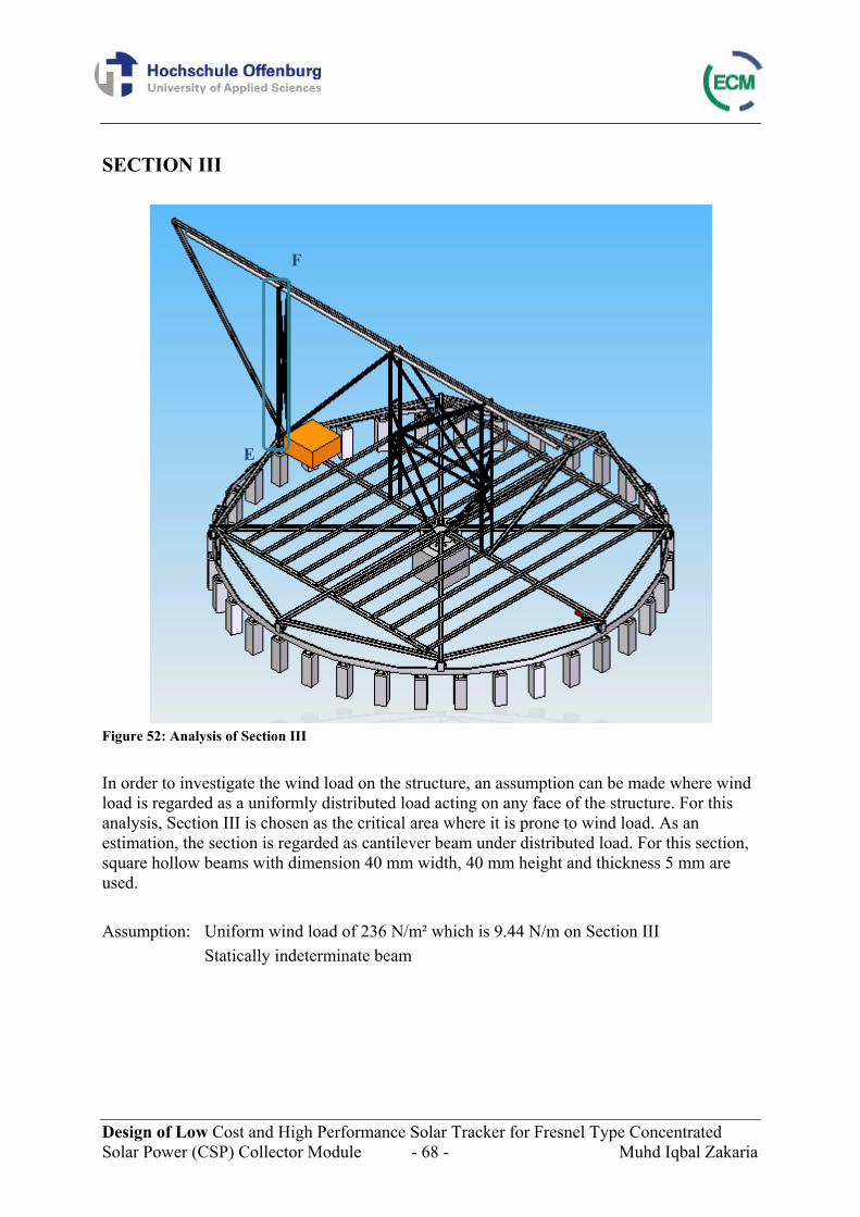
Design of Low Cost and High Performance Solar Tracker for Fresnel Type Concentrated Solar Power (CSP) Collector Module - 68 - Muhd Iqbal Zakaria
SECTION III
Figure 52: Analysis of Section III In order to investigate the wind load on the structure, an assumption can be made where wind load is regarded as a uniformly distributed load acting on any face of the structure. For this analysis, Section III is chosen as the critical area where it is prone to wind load. As an estimation, the section is regarded as cantilever beam under distributed load. For this section, square hollow beams with dimension 40 mm width, 40 mm height and thickness 5 mm are used. Assumption: Uniform wind load of 236 N/m² which is 9.44 N/m on Section III Statically indeterminate beam
F
E
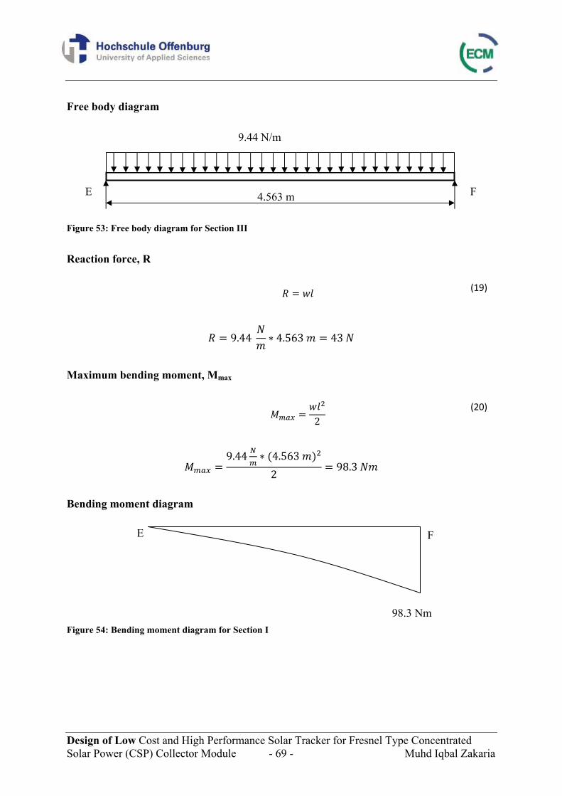
Design of Low Cost and High Performance Solar Tracker for Fresnel Type Concentrated Solar Power (CSP) Collector Module - 69 - Muhd Iqbal Zakaria
Free body diagram Figure 53: Free body diagram for Section III Reaction force, R
(19)
9.44 4.563 43
Maximum bending moment, Mmax
2
(20)
9.44 4.563 2 98.3
Bending moment diagram Figure 54: Bending moment diagram for Section I
E
E F
F
9.44 N/m
4.563 m
98.3 Nm
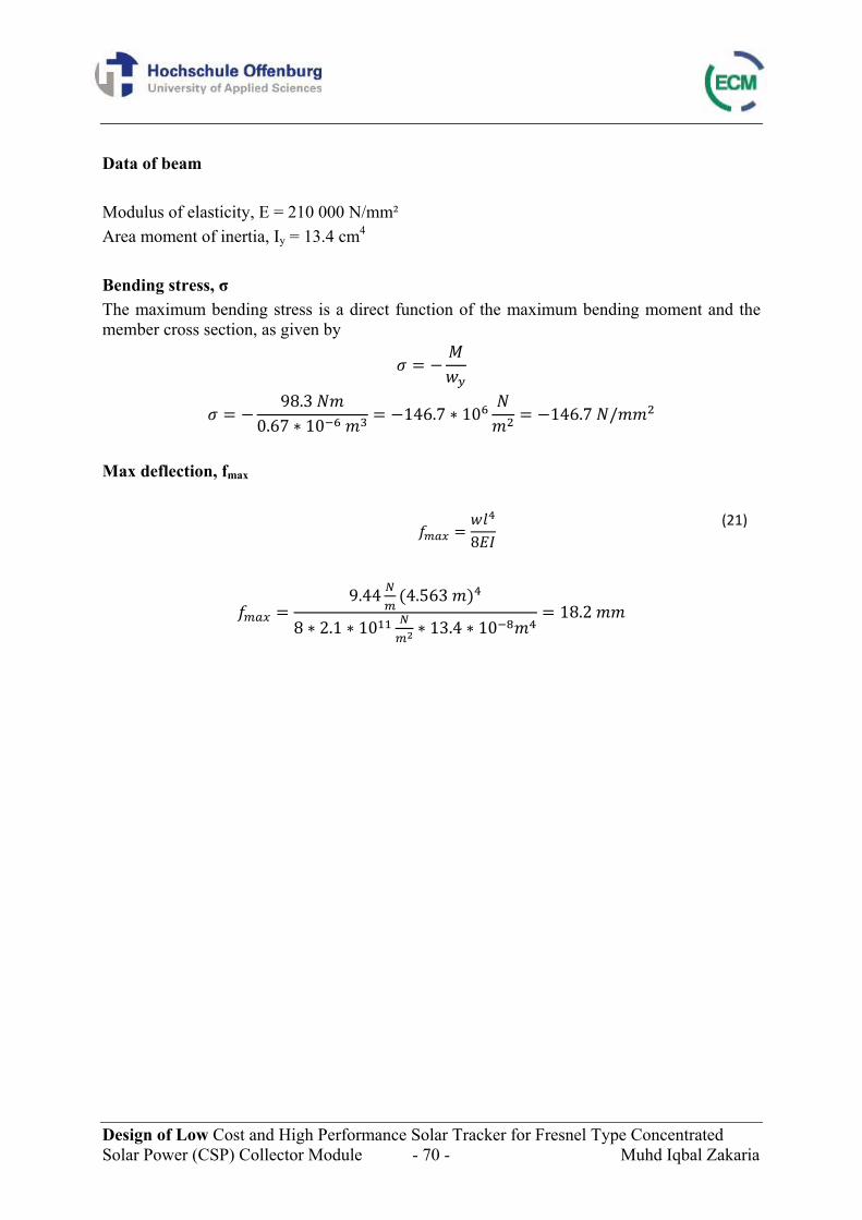
Design of Low Cost and High Performance Solar Tracker for Fresnel Type Concentrated Solar Power (CSP) Collector Module - 70 - Muhd Iqbal Zakaria
Data of beam Modulus of elasticity, E = 210 000 N/mm² Area moment of inertia, Iy = 13.4 cm4 Bending stress, σ The maximum bending stress is a direct function of the maximum bending moment and the member cross section, as given by
98.3 0.67 10 146.7 10 146.7 /
Max deflection, fmax
8
(21)
9.44 4.563
8 2.1 10 13.4 1018.2
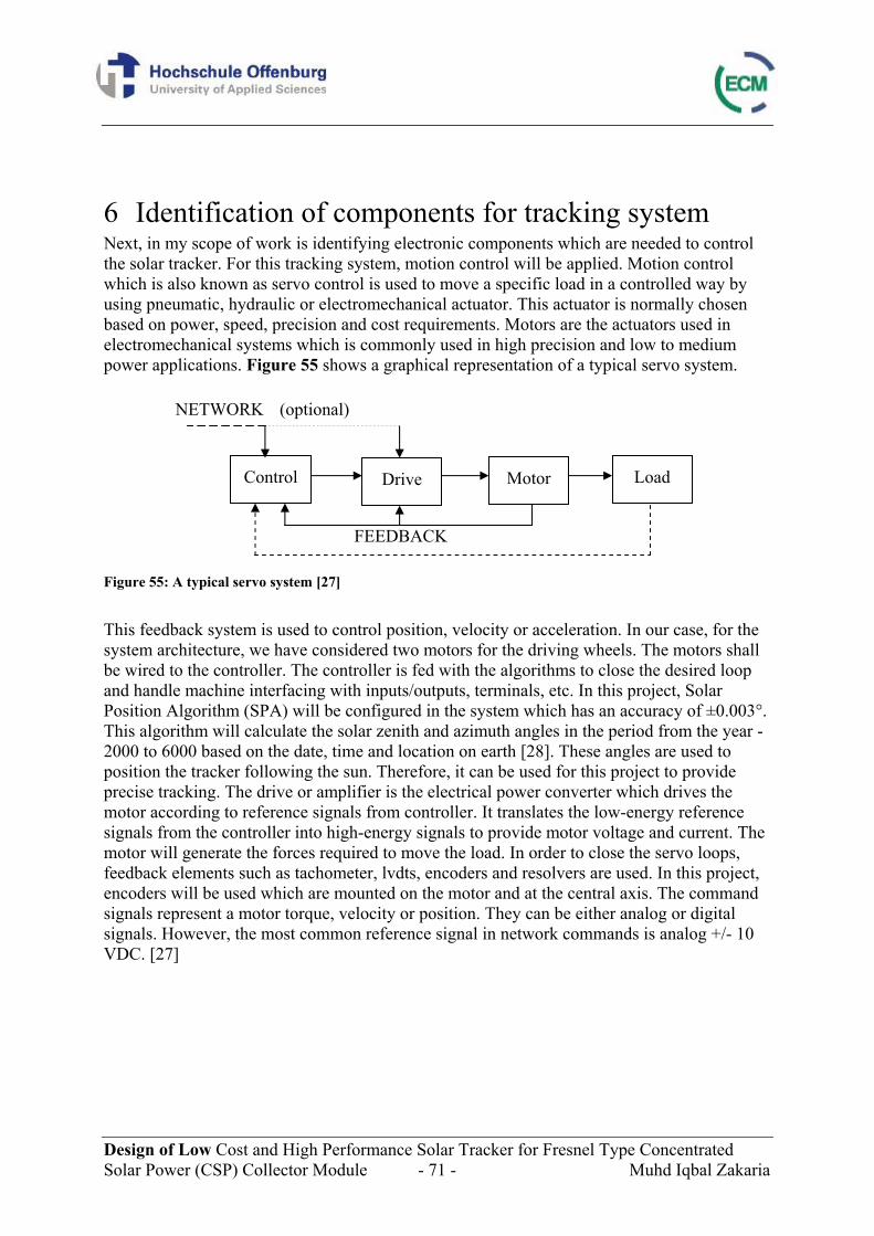
Design of Low Cost and High Performance Solar Tracker for Fresnel Type Concentrated Solar Power (CSP) Collector Module - 71 - Muhd Iqbal Zakaria
6 Identification of components for tracking system Next, in my scope of work is identifying electronic components which are needed to control the solar tracker. For this tracking system, motion control will be applied. Motion control which is also known as servo control is used to move a specific load in a controlled way by using pneumatic, hydraulic or electromechanical actuator. This actuator is normally chosen based on power, speed, precision and cost requirements. Motors are the actuators used in electromechanical systems which is commonly used in high precision and low to medium power applications. Figure 55 shows a graphical representation of a typical servo system. Figure 55: A typical servo system [27] This feedback system is used to control position, velocity or acceleration. In our case, for the system architecture, we have considered two motors for the driving wheels. The motors shall be wired to the controller. The controller is fed with the algorithms to close the desired loop and handle machine interfacing with inputs/outputs, terminals, etc. In this project, Solar Position Algorithm (SPA) will be configured in the system which has an accuracy of ±0.003°. This algorithm will calculate the solar zenith and azimuth angles in the period from the year -2000 to 6000 based on the date, time and location on earth [28]. These angles are used to position the tracker following the sun. Therefore, it can be used for this project to provide precise tracking. The drive or amplifier is the electrical power converter which drives the motor according to reference signals from controller. It translates the low-energy reference signals from the controller into high-energy signals to provide motor voltage and current. The motor will generate the forces required to move the load. In order to close the servo loops, feedback elements such as tachometer, lvdts, encoders and resolvers are used. In this project, encoders will be used which are mounted on the motor and at the central axis. The command signals represent a motor torque, velocity or position. They can be either analog or digital signals. However, the most common reference signal in network commands is analog +/- 10 VDC. [27]
Control Drive Motor Load
NETWORK (optional)
FEEDBACK
Design of Low Cost and High Performance Solar Tracker for Fresnel Type Concentrated Solar Power (CSP) Collector Module - 72 - Muhd Iqbal Zakaria
Controller The controller is the most important part of a servo system. It is used to generate the motion paths and react to changes during operation. The control system will have positional error correcting mechanism, coupled with an accurate position feedback and reference as part of the drive control. In this system, the controller sends a signal to the drive. Then, the drive provides power to the motor. As a feedback, signal from the motor is sent back to the controller and drive. Feedback from the load can also be sent to the controller. The feedback sent will be analyzed by the controller and it will update the signal to the amplifier to correct errors (see Figure 55). [27] The Solar Positon Algorithm (SPA) will calculate the actual position of the sun and the deviation of the position from the position of the platform which will be measured by the encoder will be corrected from the actuator. Motion controller for this project will have 16 digital inputs and 16 digital outputs. It has also 8 analogue inputs and 2 bipolar (±10 V) analogue outputs. For controlling the motors, one analogue output will be used for each motor. The analogue outputs will control the servo amplifiers which in turn will control the motors. The motion controller can update the control of the motor every 750 micro seconds (0.00075 s). This is called the motion control sample period and this will keep the motors running at the desire speed. With this motion controller, calculations required to get the desired speed can be fed in and it will constantly calculate the desired speed of the motor. Drive The drive or amplifier has the function to translate the low energy reference signals from the controller into high energy power signals to the motor. The command is the signal that is sent from the controller to the servo drive. Digital servo drives can be controlled over various networks including CANopen, Ethernet, EtherCAT, Ethernet Powerlink, Synqnet, USB, RS232 and so on to control the motor by connecting the amplifier to a computer. Network signals have the advantage of being able to communicate more than just the output command. including I/ O status, position information and more. Analog servo drives are controlled with +/- 10 V analog signals and PWM & Direction signals. [27] Encoder As feeback element, encoder is used. In this project, right type of encoder should be chosen. In this project, precision of 0.01 degree has to be achieved. The precision of 0.01 degree of rotation of the platform corresponds to 0.098 cm which equals to 0.56 degrees of revolution of 20 cm wheel. When using gearbox 60:1, 0.56 degrees of the wheel will equal 33.6 degree on the motor and 93.3 pulses of the encoder considering 1000 pulses encoder. In other words, for 0.01 degree of rotation, 93.3 pulses will be sent. By using 10000 pulses encoder at the centre, this will give total of 40000 pulses per revolution because there are 4 channels and it is 10000 pulses per channel. For this reference encoder, it will send one pulse every 0.009 degrees which will suit our requirement of precision.
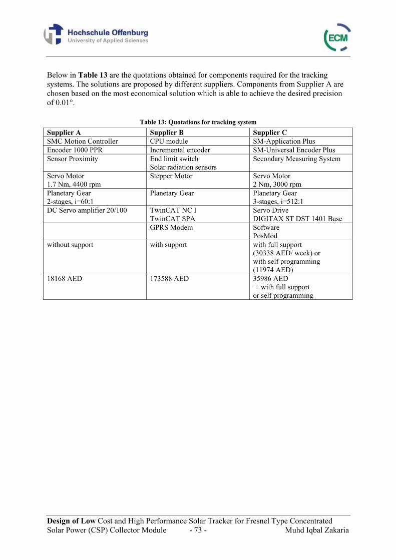
Design of Low Cost and High Performance Solar Tracker for Fresnel Type Concentrated Solar Power (CSP) Collector Module - 73 - Muhd Iqbal Zakaria
Below in Table 13 are the quotations obtained for components required for the tracking systems. The solutions are proposed by different suppliers. Components from Supplier A are chosen based on the most economical solution which is able to achieve the desired precision of 0.01°.
Table 13: Quotations for tracking system Supplier A Supplier B Supplier C SMC Motion Controller CPU module SM-Application Plus Encoder 1000 PPR Incremental encoder SM-Universal Encoder Plus Sensor Proximity End limit switch
Solar radiation sensors Secondary Measuring System
Servo Motor 1.7 Nm, 4400 rpm
Stepper Motor Servo Motor 2 Nm, 3000 rpm
Planetary Gear 2-stages, i=60:1
Planetary Gear Planetary Gear 3-stages, i=512:1
DC Servo amplifier 20/100 TwinCAT NC I TwinCAT SPA
Servo Drive DIGITAX ST DST 1401 Base
GPRS Modem Software PosMod
without support with support with full support (30338 AED/ week) or with self programming (11974 AED)
18168 AED 173588 AED 35986 AED + with full support or self programming
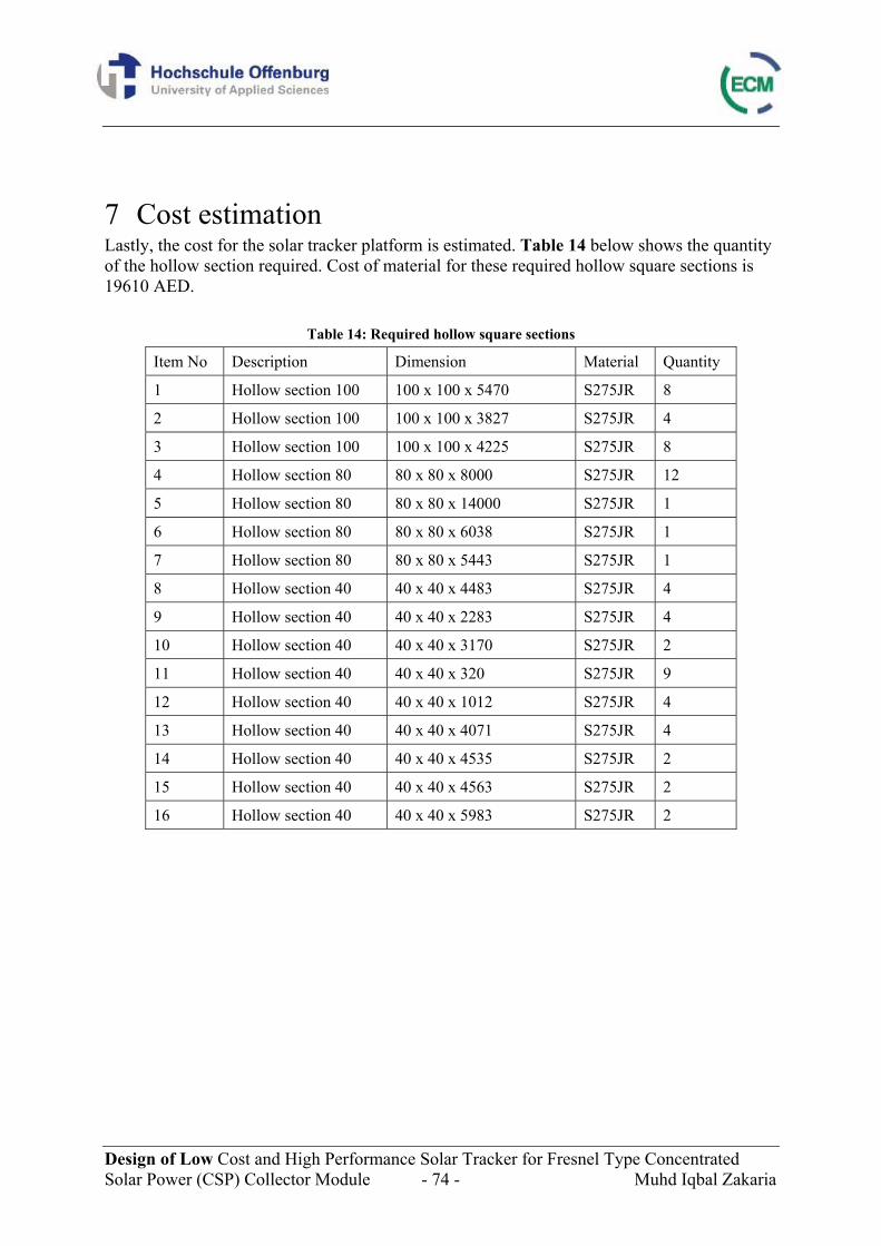
Design of Low Cost and High Performance Solar Tracker for Fresnel Type Concentrated Solar Power (CSP) Collector Module - 74 - Muhd Iqbal Zakaria
7 Cost estimation Lastly, the cost for the solar tracker platform is estimated. Table 14 below shows the quantity of the hollow section required. Cost of material for these required hollow square sections is 19610 AED.
Table 14: Required hollow square sections
Item No Description Dimension Material Quantity
1 Hollow section 100 100 x 100 x 5470 S275JR 8
2 Hollow section 100 100 x 100 x 3827 S275JR 4
3 Hollow section 100 100 x 100 x 4225 S275JR 8
4 Hollow section 80 80 x 80 x 8000 S275JR 12
5 Hollow section 80 80 x 80 x 14000 S275JR 1
6 Hollow section 80 80 x 80 x 6038 S275JR 1
7 Hollow section 80 80 x 80 x 5443 S275JR 1
8 Hollow section 40 40 x 40 x 4483 S275JR 4
9 Hollow section 40 40 x 40 x 2283 S275JR 4
10 Hollow section 40 40 x 40 x 3170 S275JR 2
11 Hollow section 40 40 x 40 x 320 S275JR 9
12 Hollow section 40 40 x 40 x 1012 S275JR 4
13 Hollow section 40 40 x 40 x 4071 S275JR 4
14 Hollow section 40 40 x 40 x 4535 S275JR 2
15 Hollow section 40 40 x 40 x 4563 S275JR 2
16 Hollow section 40 40 x 40 x 5983 S275JR 2
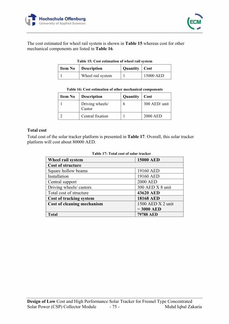
Design of Low Cost and High Performance Solar Tracker for Fresnel Type Concentrated Solar Power (CSP) Collector Module - 75 - Muhd Iqbal Zakaria
The cost estimated for wheel rail system is shown in Table 15 whereas cost for other mechanical components are listed in Table 16.
Table 15: Cost estimation of wheel rail system
Item No Description Quantity Cost
1 Wheel rail system 1 15000 AED
Table 16: Cost estimation of other mechanical components
Item No Description Quantity Cost
1 Driving wheels/ Castor
6 300 AED/ unit
2 Central fixation 1 2000 AED
Total cost Total cost of the solar tracker platform is presented in Table 17. Overall, this solar tracker platform will cost about 80000 AED.
Table 17: Total cost of solar tracker
Wheel rail system 15000 AED Cost of structure Square hollow beams 19160 AED Installation 19160 AED Central support 2000 AED Driving wheels/ castors 300 AED X 8 unit Total cost of structure 43620 AED Cost of tracking system 18168 AED Cost of cleaning mechanism 1500 AED X 2 unit
= 3000 AED Total 79788 AED
Design of Low Cost and High Performance Solar Tracker for Fresnel Type Concentrated Solar Power (CSP) Collector Module - 76 - Muhd Iqbal Zakaria
8 Conclusion Based on the discussion before, we can conclude that the proposed solution for a solar tracker platform offers several advantages. Due to the tracking system which will ensure the precision of 0.01 degree, it will give an optimum performance for the CSP system resulting from the maximation of output energy produced through an optimal positioning of the tracker. Solutions chosen from the mechanisms are done considering low cost and high performance of the solar tracker. The solutions make it possible to install small motors at the circumference which requires less force than from driving at the centre. The fact that the tracker is supported with nine supports will increase its stability and rigidity, therefore high reliability in operation under different perturbation conditions due to wind. Besides, wheel rail system solution chosen will ensure that leveling of the platform can be done easily especially after rain which might affects the level of the rail. Standard beams on the other hand offers cheaper solution compared to special manufactured profiles without neglecting the stability of the structure. Cleaning mechanism is also presented in this work as to maintain the mirrors in good conditions from dust to assure their high performance. All in all, we can affirm that the solutions proposed are effective and present interesting advantages from the point of view of practical applicability for Concentrated Solar Power structures. As has been said earlier, for this prototype, one axis tracking which is the azimuth rotation is considered. For future work, the linear movement of the receiver tube will be done. For this linear movement, certain aspects should be first considered. This includes thermal aspect for example research on optimal interval time for tracking and optimal length for the receiver tube in order to achieve desired yield. This linear movement is important to ensure that the tracker can capture more sunlight and thus it will give more energy yield.
Design of Low Cost and High Performance Solar Tracker for Fresnel Type Concentrated Solar Power (CSP) Collector Module - 77 - Muhd Iqbal Zakaria
9 Bibliography The following sources were used in the composition of this report:
[1] N. Khan, Z. Mariun, N. Saleem, N. Abas, Fossil Fuels, New Energy Sources and the Great Energy Crisis, Renewable and Sustainable Energy Rev, 2007 [2] German Advisory Council on Global Change, 2003, <http://www.wbgu.de> [3]Centre Suisse d’Electronique et de Microtechnique (CSEM) - UAE, Solar Islands [4] Solar Selections, Retrieved on 02.05.2011, <http://www.solar-selections.com/product.html> [5] Scienzagiovane, The Photovoltaic Effect, Retrieved on 02.05.2011, <http://www.scienzagiovane.unibo.it/english/solar-energy/3-photovoltaic-effect.html> [6] Cédric Philibert, Technology Roadmap: Concentrating Solar Power.International Energy Agency. [7] Ahmet Öztürk, Mathematical modelling and simulation of solar yield LFR system, WS 2011/12, University of Applied Sciences Offenburg [8] I. Sefa, M. Demirtas, I. Çolak, Application of One-Axes sun Tracking System, Energy Conversion and Management, 2009, Page 2710 [9] Juan Palo Cabanillas, Carlos Garcia, Low-cost and high performance heliostats [10] SUN-LINK Solar Tracker, Retrieved on 02.05.2011, <http://www.sunlinksolartracker.com/products.htm> [11] Meca Solar, High Tech Solar Trackers: MS-2 Tracker 10, Retrieved on 02.05.2011, <http://www.savitasol.com/resources/2axis_solares_en.pdf> [12] Titan Tracker, Retrieved on 02.05.2011, <http://www.titantracker.com/v_portal/apartados/apartado.asp?te=58> [13] Haosolar, Fixed Inclination Single-Axis Tracker, Retrieved on 02.05.2011, <http://www.haosolar.com/single-axis.aspx> [14] a+f GmbH, Suncarrier 160, Retrieved on 02.05.2011, <http://www.af.net/1706-0-Overview.html> [15] IMO Anlagenbau GmbH & Co. KG, Solar Tracker single axis, Retrieved on 02.05.2011 <http://www.imo.de/uploads/tx_ffimodlCenter/DB_Solartracker_1achsig_us.pdf> [16] G. Pahl, W. Beitz, J. Feldhusen, K.H. Grote, Engineering Design: A Systematic Approach.Third Edition, Springer-Verlag London Limited, 2007, ISBN 978-1-846283183. [17] Ö. Akın, Variants of design cognition. Design Knowing and Learning: Cognition in Design Education, Eastman, C., Newstettter, W., & McCracken, M., Eds., pp. 105 – 124, New York: Elsevier, 2001 [18] THOMBERT, Polyurethane and Rubber Tires: A Comparative Overview, Retrieved 11.05.2011, < http://www.thombert.com/white_papers/PolyurethaneRubberTires.pdf> [19] The North American Steel Interstate Coalition, Steel Wheels or Rubber Tires?, Retrieved on 11.05.2011, < http://www.steelinterstate.org/topics/steel-wheels-or-rubber-tires> [20] Society Of Robots, Robot Gears Tutorial, Retrieved on 17.05.2011 < http://www.societyofrobots.com/mechanics_gears.shtml> [21] Gayatri-Exim, Planetary Gearboxes, Retrieved on 17.05.2011 <http://www.gayatri-exim.com/planetarygearboxes_advantages.htm> [22] Slocum, Alexander H. Precison Machine Design, Society of Manufacturing Engineers, 1992, ISBN 0-13-690918-3 [23] T. Ritchey, General Morphological Analysis: A general method for non-quantified modeling, 1998
Design of Low Cost and High Performance Solar Tracker for Fresnel Type Concentrated Solar Power (CSP) Collector Module - 78 - Muhd Iqbal Zakaria
[24] F. Zwicky & A. Wilson, New Methods of Thought and Procedure: Contributions to the Symposium on Methodologies, Berlin: Springer, 1967 [25] Jack A. Collins, Henry Busby, George Staab, Mechanical Design of Machine Elements and Machines, 2003, ISBN-13 978-0-470-41303-6 [26] DIN EN 1993-3-1/NA, Bemessung und Konstruktion von Stahlbauten [27] Advanced Motion Controls, Motion Control Overview, Retrieved on 15.06.2011 < http://www.a-m-c.com/university/mco.html> [28] I. Reda, A. Andreas, Solar Position Algorithm for Solar Radiation Applications, 55 pp.; NREL Report No. TP-560-34302, 2003, Revised January 2008
Copyright © 2022 FDOKUMEN