repair and service manual - TRACKER Off Road
154
REPAIR AND SERVICE MANUAL TRACKER EViS 10002660-C Revised Dec 2019 Issued Aug 2019
-
Upload
khangminh22 -
Category
Documents
-
view
1 -
download
0
Transcript of repair and service manual - TRACKER Off Road

REPAIR AND SERVICE MANUAL
TRACKER EViS
10002660-CRevised Dec 2019Issued Aug 2019

SAFETYFor any questions about material in this manual, contact an authorized representative.
Read and understand all labels on the vehicle. Always replace any damaged or missing labels.
Steep hills allow the vehicles to move at faster speeds than speeds on a flat surface. To prevent the loss of vehicle control and possible injury, speeds must be controlled to the maximum level ground speed indicated in the GENERAL SPECIFICATIONS section. Apply the brake to control the speed.
If you operate the vehicle above the maximum specified speed, you can damage the drivetrain components. The damage caused by speeds more than the maximum specified can cause a loss of vehicle control, is abuse, and will not be covered under the warranty.
Refer to the TRANSPORTING VEHICLE section to learn how to tow or move the vehicle from one location to another location.
If the vehicle is used in a commercial environment, signs must be in position to inform of possible conditions that can be dangerous. Examples shown below.
NOTICES, CAUTIONS, WARNINGS AND DANGERSRead the NOTICES, CAUTIONS, WARNINGS and DANGERS. The person who services a vehicle needs the mechanical skill and experience to see possible hazardous conditions. Incorrect service or repairs can cause damage to the vehicle or make the vehicle dangerous to operate.
NOTICE: A NOTICE indicates and describes information not related to personal injury.
A CAUTION indicates a dangerous condition that can cause injury that is not life threatening.
A WARNING indicates a dangerous condition that can cause death or serious injury.
A DANGER indicates a dangerous condition that will cause death or serious injury.
The battery posts, terminals and all related accessories contain lead and lead compounds. Wash your hands after contacting any of these components.

REPAIR AND SERVICE MANUAL72V ELECTRIC POWERED VEHICLE
TRACKER EViS
MODEL YEAR 2020
Never modify the vehicle in any way that will alter the weight distribution of the vehicle, decrease its stability or increase the speed beyond the factory specifications. Such modifications can cause serious personal injury or death. The manufacturer prohibits and dis-claims responsibility for any such modifications or any other alteration which would adversely affect the safety of the vehicle.
The manufacturer reserves the right to incorporate engineering and design changes to products in this manual, without obligation to include these changes on units sold previously.
The information contained in this manual may be revised periodically by the manufacturer, and therefore is subject to change without notice.
THE MANUFACTURER DISCLAIMS LIABILITY FOR ERRORS IN THIS MANUAL, and SPECIFICALLY DISCLAIMS LIABILITY FOR INCIDEN-TAL AND CONSEQUENTIAL DAMAGES resulting from the use of the information and materials in this Manual.
These are the original instructions as defined by 2006/42/EC.
Dealer: 800-296-4804
Consumer: 877-394-6727
www.trackeroffroad.com
iRepair and Service Manual10002660

This vehicle has been designed and manufactured in the UnitedStates of America (USA). The Standards and Specifications listed in
the following text originate in the USA unless otherwise indicated.
The use of non-Original Equipment Manufacturer (OEM) approved parts can void the warranty.
BATTERY PROLONGED STORAGE
Batteries self-discharge over time. The rate of self-discharge varies depending on the ambient temperature, the age and condition of the batteries.
Fully charged batteries will not freeze in winter temperatures unless the temperature falls below -75°F (- 60°C).
For winter storage, the batteries must be clean, fully charged and disconnected from any source of electrical drain.
The battery charger can be left connected to the vehicle to maintain a full charge on the bat-teries, provided the charger is plugged into an active electrical source. If power to the elec-trical source is disconnected or interrupted, the battery charger will continue to check the
charge on the battery pack. This will draw power from the battery pack and eventually drain the batteries if power is not restored in a timely manner.
As with all electric vehicles, the batteries must be checked and recharged as required or at a minimum of 30 day intervals.
Check and maintain the proper fluid level in all battery cells during the storage period. Proper fluid level is required for maximum battery performance.
BATTERY DISPOSAL
Lead-acid batteries are recyclable. Return whole scrap batteries to distributor, manufacturer or lead smelter for recycling. For neutralized spills, place residue in acid-resistant containers with absor-
bent material, sand or earth and dispose of in accordance with local, state and federal regulations for acid and lead compounds. Contact local and/or state environmental officials regarding disposal
information.
Operating, servicing and maintaining a passenger vehicle or off-road vehiclecan expose you to chemicals including phthalates and lead, which are known tothe State of California to cause cancer and birth defects or other reproductiveharm. To minimize exposure, wear gloves and wash your hands frequentlywhen servicing your vehicle.For more information go to www.P65Warnings.ca.gov/passenger-vehicle.
WARNING
California Proposition 65
ii Repair and Service Manual 10002660

SAFETY INFORMATION
1
SAFETY INFORMATIONThis manual has been designed to assist the owner-operator in maintaining the vehicle in accordance with procedures developed by the manufacturer. Adherence to these procedures and fault testing tips will ensure the best possible ser-vice from the product. To reduce the chance of personal injury and/or property damage, the following instructions must be carefully observed:
GENERALMany vehicles are used for a variety of tasks beyond their original intended use; therefore it is impossible to anticipate and warn against every possible combination of circumstances that may occur. Warnings cannot replace good common sense and prudent driving practices. Common sense and prudent driving practices do more to prevent accidents and injury than warnings and instructions can provide.
The manufacturer strongly suggests anyone operating the vehicle read the entire owner’s guide provided with the pur-chase of the vehicle, paying particular attention to the CAUTIONS, WARNINGS and DANGERS within.
For any questions or concerns, contact the closest representative, or write to the address on the back cover of this pub-lication, Attention: Customer Care Department.
The manufacturer reserves the right to make design changes without obligation to make these changes on units previ-ously sold and the information contained in this manual is subject to change without notice.
The manufacturer is not liable for errors in this manual or for incidental or consequential damages that result from the use of the material in this manual.
This vehicle conforms to the current applicable standard for safety and performance requirements.
This vehicle is designed and manufactured for off-road use. It does not conform to Federal Motor Vehicle Safety Stan-dards and is not equipped for operation on public streets. Some communities may permit these types of vehicles to be operated on their streets on a limited basis and in accordance with local ordinances.
Ensure all electrical accessories are grounded directly to the battery (-) post. Never use the chassis or body as a ground connection.
Refer to GENERAL SPECIFICATIONS for vehicle seating capacity. Do not exceed number of occupants indicated.
Never modify the vehicle in any way that will alter the weight distribution of the vehicle, decrease its stability, increase the speed or extend the stopping distance beyond the fac-tory specification. Such modifications can result in serious personal injury or death.
Modifications that increase the speed and/or weight of the vehicle will extend the braking distance and may reduce the stability of the vehicle. Do not make any such modifications or changes. The manufacturer prohibits and disclaims responsibility for any such modifications or any other alteration which would adversely affect the safety of the vehicle.
Speed should be moderated by the environmental conditions, terrain and common sense.
GENERAL OPERATIONALWAYS:
• Use the vehicle in a responsible manner and maintain the vehicle in safe operating condition.
• Read and observe all warnings and operation instruction labels affixed to the vehicle.
• Follow all safety rules established in the area where the vehicle is being operated.
• Reduce speed to compensate for poor terrain or conditions.
• Apply service brake to control speed on steep grades.
• Reduce speed in damp or wet areas.
• Reduce speed and use caution when approaching sharp or blind turns.
• Reduce speed and use caution when driving over loose terrain.
• Reduce speed and use caution when driving in areas where pedestrians are present.
iiiRepair and Service Manual0002660

SAFETY INFORMATION
MAINTENANCEALWAYS:
• Replace damaged or missing warning, caution or information labels.
• Maintain the vehicle in accordance with the manufacturer’s periodic service schedule.
• Ensure that repairs are performed by trained and qualified persons.
• Follow the manufacturer’s maintenance procedures.
• Insulate any tools used within the battery area in order to prevent sparks or battery explosion.
• Check the polarity of each battery terminal and be sure to rewire the batteries correctly.
• Use specified replacement parts. Never use replacement parts of lesser quality.
• Use recommended tools.
• Determine that tools and procedures not specifically recommended by the manufacturer will not compromise the safety of personnel, nor jeopardize the safe operation of the vehicle.
• Support the vehicle using wheel chocks and safety stands. Never get under a vehicle that is supported by a jack. Lift the vehicle in accordance with the manufacturer’s instructions.
• Never attempt to maintain a vehicle in an area where exposed flame is present or persons are smoking.
• Be aware that a vehicle that is not performing as designed is a potential hazard and must not be operated.
• Test drive vehicle after repairs or maintenance in a safe area free of vehicular and pedestrian traffic.
• Keep complete records of the maintenance history of the vehicle.
VENTILATIONALWAYS:
• Charge vehicle in a well ventilated area.
• Charge in an area free of flammable liquids and items.
• Charge a vehicle in an area that is free from flame or spark. Pay particular attention to natural gas or propane gas water heaters and furnaces.
• Use a dedicated circuit for battery charger. Do not permit other appliances to be plugged into the receptacle when the charger is in operation.
• Operate charger in accordance with manufacturers recommendations or applicable electrical code.
iv Repair and Service Manual 10002660

B
TABLE OF CONTENTS
10002
SAFETY INFORMATION
GENERAL........................................................................................................................ III
GENERAL OPERATION.................................................................................................. III
MAINTENANCE............................................................................................................... IV
VENTILATION.................................................................................................................. IV
GENERAL INFORMATION AND ROUTINE MAINTENANCE
SERIAL NUMBER AND PIN PLATE LOCATION ............................................................. 1
SERVICING THE VEHICLE.............................................................................................. 1
ROUTINE MAINTENANCE............................................................................................... 2
POWERTRAIN MAINTENANCE....................................................................................... 2
BRAKES............................................................................................................................ 2
TIRES................................................................................................................................ 2
VEHICLE CLEANING AND CARE.................................................................................... 2
VEHICLE CARE PRODUCTS........................................................................................... 3
OPS, CANOPY TOP AND WINDSHIELD......................................................................... 3
TRANSPORTING VEHICLE ............................................................................................. 3
EMERGENCY ELECTRIC PARK BRAKE RELEASE....................................................... 3
TOWING A TRAILER........................................................................................................ 4
PROLONGED STORAGE................................................................................................. 4
HARDWARE ..................................................................................................................... 4
TORQUE SPECIFICATIONS............................................................................................ 5
CAPACITIES AND REPLACEMENT PARTS ................................................................... 5
SAFETY
NOTICES, CAUTIONS, WARNINGS AND DANGERS .................................................... 7
IMPORTANT SAFETY WARNING.................................................................................... 7
MODIFICATIONS TO VEHICLE ....................................................................................... 7
GENERAL MAINTENANCE.............................................................................................. 7
BEFORE SERVICING VEHICLE ...................................................................................... 7
LIFTING THE VEHICLE.................................................................................................... 8
How to Lift the Vehicle ......................................................................................... 8
Lift Front of Vehicle .............................................................................................. 9
Lift Rear of Vehicle ............................................................................................... 9
Lower Vehicle ....................................................................................................... 9
vRepair and Service Manual660
B
TABLE OF CONTENTS
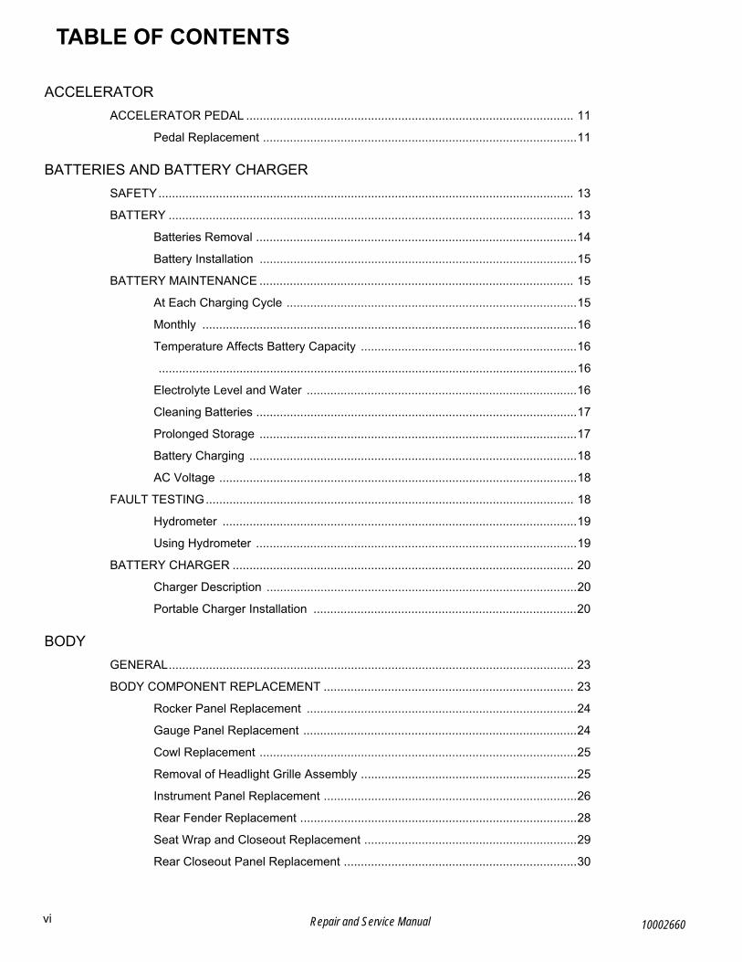
ACCELERATOR
ACCELERATOR PEDAL ................................................................................................. 11
Pedal Replacement .............................................................................................11
BATTERIES AND BATTERY CHARGER
SAFETY........................................................................................................................... 13
BATTERY ........................................................................................................................ 13
Batteries Removal ...............................................................................................14
Battery Installation ..............................................................................................15
BATTERY MAINTENANCE ............................................................................................. 15
At Each Charging Cycle ......................................................................................15
Monthly ...............................................................................................................16
Temperature Affects Battery Capacity ................................................................16
............................................................................................................................16
Electrolyte Level and Water ................................................................................16
Cleaning Batteries ...............................................................................................17
Prolonged Storage ..............................................................................................17
Battery Charging .................................................................................................18
AC Voltage ..........................................................................................................18
FAULT TESTING............................................................................................................. 18
Hydrometer .........................................................................................................19
Using Hydrometer ...............................................................................................19
BATTERY CHARGER ..................................................................................................... 20
Charger Description ............................................................................................20
Portable Charger Installation ..............................................................................20
BODY
GENERAL........................................................................................................................ 23
BODY COMPONENT REPLACEMENT .......................................................................... 23
Rocker Panel Replacement ................................................................................24
Gauge Panel Replacement .................................................................................24
Cowl Replacement ..............................................................................................25
Removal of Headlight Grille Assembly ................................................................25
Instrument Panel Replacement ...........................................................................26
Rear Fender Replacement ..................................................................................28
Seat Wrap and Closeout Replacement ...............................................................29
Rear Closeout Panel Replacement .....................................................................30
vi Repair and Service Manual 10002660

B
TABLE OF CONTENTS
10002
PAINTING ....................................................................................................................... 32
Minor Scratches ................................................................................................. 32
Larger Scratches ................................................................................................ 32
Complete Panel Repair ...................................................................................... 32
BRAKES
MAINTENANCE.............................................................................................................. 35
Daily Brake Performance Test ........................................................................... 35
Brake System Inspection ................................................................................... 35
MASTER CYLINDER ...................................................................................................... 36
Master Cylinder Replacement ............................................................................ 36
Brake Fluid ......................................................................................................... 37
REPLACEMENT OF WEAR ITEMS ............................................................................... 37
Brake Pads Replacement .................................................................................. 37
Rotor Replacement ............................................................................................ 38
BLEEDING AND FLUSHING .......................................................................................... 38
Bleeding ............................................................................................................. 38
Bleeding Sequence ............................................................................................ 39
Flushing .............................................................................................................. 39
BRAKE PEDAL REMOVAL AND INSTALLATION ......................................................... 40
ELECTRICAL
VOLTAGE TESTING FOR BATTERIES ......................................................................... 47
MAIN HARNESS............................................................................................................. 47
Power Supply ..................................................................................................... 47
Accessory Wiring ............................................................................................... 48
Faulty Wire Replacement ................................................................................... 48
Headlight Bulb Replacement (LED) ................................................................... 48
Tail light Replacement ........................................................................................ 48
ELECTRONIC SPEED CONTROL ................................................................................. 49
Speed Sensor .................................................................................................... 49
Rotary Position Sensor ...................................................................................... 49
Controller ............................................................................................................ 49
Controller Replacement ..................................................................................... 50
Solenoid Replacement ....................................................................................... 51
DC to DC Converter ........................................................................................... 51
FAULT TESTING ............................................................................................................ 52
viiRepair and Service Manual660

B
viii
TABLE OF CONTENTS
General .............................................................................................................. 52
Testing Battery Voltage ...................................................................................... 52
Continuity Check ................................................................................................ 52
Testing A Switch for Continuity .......................................................................... 52
Testing A Solenoid for Continuity ....................................................................... 53
ACCESORIES................................................................................................................. 53
Key Switch ......................................................................................................... 53
State of Charge (SOC) Meter ............................................................................. 53
Rocker Switches ................................................................................................ 54
Winch Contactor Connections ............................................................................ 55
FRONT CV SHAFT, SUSPENSION, AND STEERING
FRONT SUSPENSION ................................................................................................... 57
Front Strut Assembly Replacement ................................................................... 57
Control Arm Assembly Replacement ................................................................. 58
Lower Ball Joint Replacement ............................................................................ 58
Wheel Bearing Replacement ............................................................................. 59
Strut Replacement ............................................................................................. 60
FRONT AXLE.................................................................................................................. 61
CV Shaft Replacement ....................................................................................... 61
CV Joint Boot Replacement ............................................................................... 62
Front Differential Replacement .......................................................................... 62
STEERING...................................................................................................................... 63
Steering Wheel Replacement ............................................................................ 63
Steering Column Replacement .......................................................................... 64
Steering Rack Replacement .............................................................................. 65
Tie Rod Removal ............................................................................................... 66
Tie Rod Installation ............................................................................................ 66
MAINTENANCE.............................................................................................................. 66
Wheel Alignment ................................................................................................ 66
MOTOR
GENERAL....................................................................................................................... 69
Motor Brake Removal ........................................................................................ 69
Motor Brake Installation ..................................................................................... 69
Front Motor Removal ......................................................................................... 70
Front Motor Installation ...................................................................................... 71
Repair and Service Manual 10002660

B
TABLE OF CONTENTS
10002
Rear Motor Removal .......................................................................................... 72
Rear Motor Installation ....................................................................................... 73
MOTOR TESTS .............................................................................................................. 73
SEATING AND OPS
SEATING ........................................................................................................................ 75
Front Seat Removal and Installation .................................................................. 75
Front Seat Back and Support ............................................................................. 75
Rear Seat Removal and Installation ................................................................... 75
Seat Cushion Disassembly ................................................................................ 77
Footrest Removal and Installation ...................................................................... 77
Seat Belt Removal and Installation .................................................................... 77
Front Seat Belt Buckle Replacement ................................................................. 78
Rear Seat Belt Buckle Replacement .................................................................. 78
UPPER OPERATOR PROTECTION SYSTEM .............................................................. 80
Upper OPS Frame Removal and Installation ..................................................... 80
LOWER OPERATOR PROTECTION SYSTEM ............................................................. 81
Brush Guard Removal and Installation .............................................................. 81
OPS Lower Weldment Removal and Installation ............................................... 82
REAR AXLE AND SUSPENSION
REAR AXLE.................................................................................................................... 85
Maintenance ....................................................................................................... 85
Checking the Lubricant Level ............................................................................. 85
Rear CV Axle Removal ...................................................................................... 85
Differential Removal ........................................................................................... 86
REAR SUSPENSION...................................................................................................... 87
Strut Assembly Removal .................................................................................... 87
Strut Assembly Maintenance Items .................................................................... 88
FAULT TESTING
SUSPENSION AND STEERING..................................................................................... 91
CURTIS CONTROLLER ................................................................................................. 92
General .............................................................................................................. 92
Navigation .......................................................................................................... 92
Changing Data Value ......................................................................................... 92
Favorites ............................................................................................................ 92
ixRepair and Service Manual660
B
TABLE OF CONTENTS
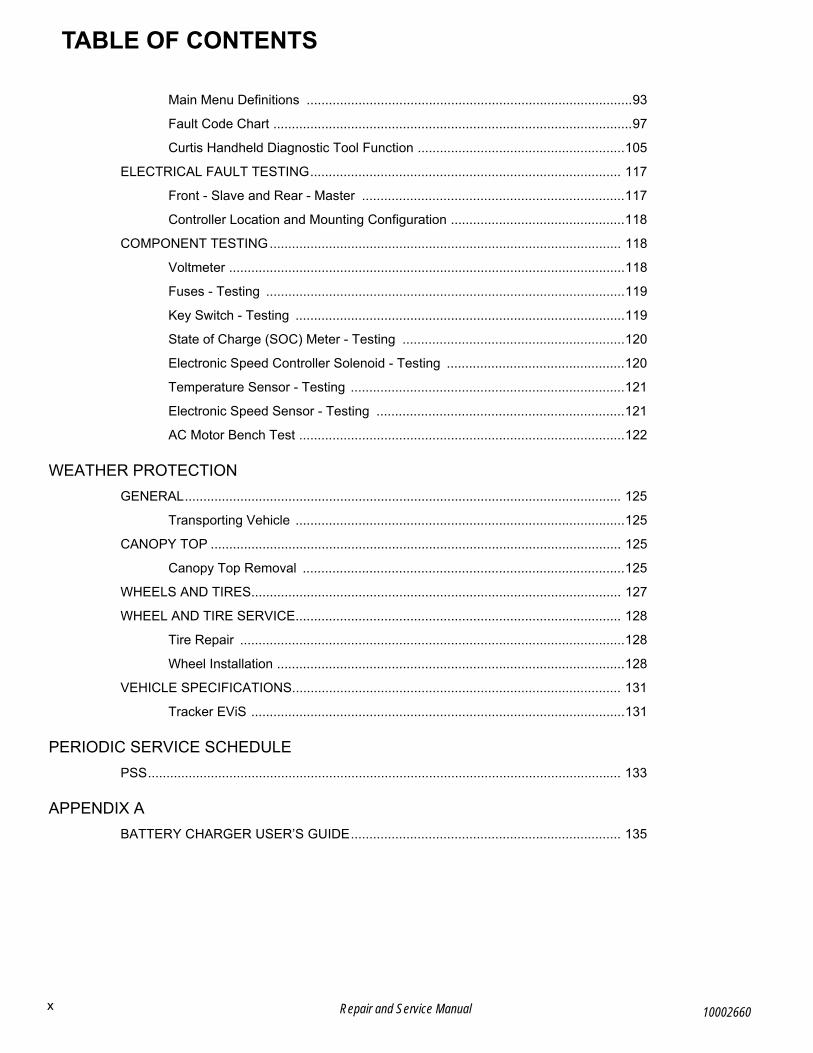
Main Menu Definitions ........................................................................................93
Fault Code Chart .................................................................................................97
Curtis Handheld Diagnostic Tool Function ........................................................105
ELECTRICAL FAULT TESTING.................................................................................... 117
Front - Slave and Rear - Master .......................................................................117
Controller Location and Mounting Configuration ...............................................118
COMPONENT TESTING............................................................................................... 118
Voltmeter ...........................................................................................................118
Fuses - Testing .................................................................................................119
Key Switch - Testing .........................................................................................119
State of Charge (SOC) Meter - Testing ............................................................120
Electronic Speed Controller Solenoid - Testing ................................................120
Temperature Sensor - Testing ..........................................................................121
Electronic Speed Sensor - Testing ...................................................................121
AC Motor Bench Test ........................................................................................122
WEATHER PROTECTION
GENERAL...................................................................................................................... 125
Transporting Vehicle .........................................................................................125
CANOPY TOP ............................................................................................................... 125
Canopy Top Removal .......................................................................................125
WHEELS AND TIRES.................................................................................................... 127
WHEEL AND TIRE SERVICE........................................................................................ 128
Tire Repair ........................................................................................................128
Wheel Installation ..............................................................................................128
VEHICLE SPECIFICATIONS......................................................................................... 131
Tracker EViS .....................................................................................................131
PERIODIC SERVICE SCHEDULE
PSS................................................................................................................................ 133
APPENDIX A
BATTERY CHARGER USER’S GUIDE......................................................................... 135
x Repair and Service Manual 10002660

xiRepair and Service Manual
Notes:
10002660

xii Repair and Service Manual
Notes:
10002660

GENERAL INFORMATION AND ROUTINE MAINTENANCERead all of SAFETY and this section before attempting any procedure. Pay particular attention to Notices, Cautions, Warnings and Dangers.
BGENERAL INFORMATION AND ROUTINE MAINTENANCE
SERIAL NUMBER AND PIN PLATE LOCATIONThe PIN plate is attached to the frame below the seat wrap panel (Ref. Fig. 3).
Two serial number labels, PART A and PART B, and a PIN label are attached to the frame below the flip seat (Ref. Fig. 2).
Design changes occur continuously. When you order ser-vice parts, the PIN number, manufacture date code, or serial number must be available.
Fig. 1 SN Label
Fig. 2 Serial Number and PIN Labels
Fig. 3 PIN Plate
SERVICING THE VEHICLETo prevent severe injury or death, resulting from improper servicing techniques, observe the following warnings:
Do not attempt any type of servicing operations before reading and understanding all notes, cau-tions, and warnings in this manual.Any service that requires adjustments to be made to the powertrain while the motor is in operation must be made with all four wheels raised.Wear eye protection when working on the vehicle. In particular, use care when working around batteries or using solvents or compressed air.To reduce the possibility of causing an electrical arc, which could cause a battery explosion, disable all electrical loads from the batteries before remov-ing any heavy gauge battery wires.To prevent the possibility of motor disintegration in the electric powertrain, never operate vehicle at full throttle for more than 4 - 5 seconds while vehicle is in a “no load” condition (all 4 wheels off of the ground).It is in the best interest of both vehicle owner and servic-ing dealer to carefully follow the procedures recom-mended in this manual. Adequate preventative maintenance, applied at regular intervals, is the best guarantee for keeping the vehicle both dependable and economical.
In any product, components will eventually fail to perform properly as the result of normal use, age, wear, or abuse.
It is impossible to anticipate all possible component fail-ures or the manner in which each component can fail.
A vehicle requiring repair indicates that the vehicle is no longer functioning as designed and should be considered potentially hazardous. Use caution when working on a vehicle. When diagnosing, removing or replacing any components that are not operating properly, consider the safety of yourself and those around you should the com-ponent move unexpectedly.
Some components are heavy, spring loaded, highly corro-sive, explosive, or can produce amperage or reach high temperatures. Carbon monoxide, battery acid and hydro-gen gas could cause serious bodily injury to the techni-cian/mechanic and bystanders if not treated with the utmost caution. Be careful not to place hands, face, feet, or body in a location that could expose them to injury should an unforeseen dangerous situation occur.
Always use the appropriate tools listed in the tool list and wear approved safety equipment.
Before a new vehicle is put into operation, the items shown in the INITIAL SERVICE CHART should be per-formed (Ref. Fig. 4).
PART CPART B
PART A
PIN Label
Serial NumberPart A
Serial NumberPart B
PIN Plate
Front of Vehicle
1Repair and Service Manual10002660

B
GENERAL INFORMATION AND ROUTINE MAINTENANCERead all of SAFETY and this section before attempting any procedure. Pay particular attention to Notices, Cautions, Warnings and Dangers.
Fig. 4 Initial Service Chart
ROUTINE MAINTENANCEThis vehicle will give years of satisfactory service, pro-vided it receives regular maintenance (See PERIODIC SERVICE SCHEDULE on page 133).
Verify appropriate lubrication locations (See Checking the Lubricant Level on page 85).
NOTICE: To prolong vehicle life, some maintenance items must be serviced more frequently on vehicles used under severe driving conditions such as extreme temperatures, extreme dust/debris condi-tions, or frequent use with maximum load.
POWERTRAIN MAINTENANCEThe powertrain is most easily accessed from the under-side of the vehicle (See LIFTING THE VEHICLE on page 8). Remove the cowl for full access to the front pow-ertrain (See Cowl Replacement on page 25). Remove the rear seat for full access to the rear powertrain (See Rear Seat Removal and Installation on page 75).
Use insulated wrenches to prevent the possibility of a dropped wrench causing a short-circuit in a battery,
which can cause an explosion and severe personal injury or death.To prevent accidental starting, disconnect the main negative battery cable before servicing.
BRAKESThis vehicle is equipped with four wheel hydraulic disc brakes. Check the fluid level at intervals specified (See PERIODIC SERVICE SCHEDULE on page 133). If fluid leaks are noticed or the brake pedal seems soft, check the fluid level immediately. If the brake pedal is soft, the brake system should be bled to remove air from the brake lines (See Bleeding on page 38).
The parking brake is an electric motor brake and is engaged any time that the vehicle comes to a complete stop. The parking brake is released when the vehicle is in F (forward) or R (reverse) and the accelerator pedal is pressed.
After the vehicle has been put into service, it is recom-mended that the brakes be checked periodically (See Daily Brake Performance Test on page 35).
To prevent severe injury or death caused from driving a vehicle with an improperly operating brake sys-
tem, the braking system must be properly main-tained. All driving brake tests must be done in a safe location with regard for the safety of all personnel.
TIRESTire condition should be inspected and inflation pressures checked periodically while tires are cool (See PERIODIC SERVICE SCHEDULE on page 133). Be sure to install the valve dust cap after checking or inflating tire.
VEHICLE CLEANING AND CARERead and understand all instruc-tions supplied by the manufacturer of the pressure washer before use.When pressure washing the exterior of the vehicle, do not use pressure in excess of 700 psi. Maintain a 12”
minimum distance from spray nozzle to painted sur-face. To reduce the possibility of cosmetic damage, do not use any abrasive or reactive solvents to clean plastic parts.
Proper techniques and cleaning materials must be used to prevent damage to the exterior of the vehicle. Using excessive water pressure can cause severe injury to operator or bystander. Excessive pressure can also cause damage to seals, plastics, seat material, body fin-ish, or the electrical system. Do not use pressure in excess of 700 psi to wash exterior of vehicle.
Clean the windshield with water and clean cloth. Minor scratches can be removed using a commercial plastic polish or Plexus® plastic cleaner. Both are available from the service parts department.
Normal cleaning of vinyl seats and plastic or rubber trim requires the use of a mild soap solution applied with a sponge or soft brush followed by and wiping with a damp cloth.
Removal of oil, tar, asphalt, shoe polish, etc. will require the use of a commercially available vinyl/rubber cleaner.
INITIAL SERVICE CHART
Item Service Operation
Battery Charger Remove from vehicle and read operat-ing instructions.
Batteries Charge. Batteries must be fully charged before initial use.
Seats Remove protective plastic covering.
Brakes Check operation; adjust if necessary.
Check hydraulic fluid level; add if nec-essary.
Tires Check air pressure; adjust if necessary.Refer to WHEELS AND TIRES section for inflation recommendations.
Vehicle Inspection Visually inspect for leaks or damage that may have occurred during ship-ment from the factory.
Inspect for loose hardware; tighten if necessary.
2 Repair Manual 10002660
GENERAL INFORMATION AND ROUTINE MAINTENANCERead all of SAFETY and this section before attempting any procedure. Pay particular attention to Notices, Cautions, Warnings and Dangers.
BThe painted surfaces of the vehicle provide attractive appearance as well as durable protection. Frequent washing with lukewarm or cold water and mild detergent is required to preserve the painted surfaces.
Occasional cleaning and waxing with non-abrasive prod-ucts designed for ‘clear coat’ automotive finishes will enhance the appearance and durability of the painted surfaces.
Corrosive materials used as fertilizers or dust control can collect on the underside of the vehicle. These materials will cause corrosion of components, unless flushed occa-sionally with plain water. Clean any areas where mud or other debris can collect. Loosen sediment packed in closed areas to ease its removal. Always use caution not to chip or otherwise damage paint.
VEHICLE CARE PRODUCTSThere are several products, available through a local dis-tributor, an authorized Branch, or the Service Parts Department, to help maintain the vehicle. Among them are:
• Touch-up paint specially formulated to match vehicle colors for use on both metal and TPE (plastic) bodies. (P/N 28140G**, 28432G** and 75831G01)
• Multi-purpose battery protectant (P/N 27619G01) formulated to form a long-term, flexible, non-tacky, dry coating that will not crack, peel or flake over a wide temperature range.
• Use windshield and plastic protectant (P/N 606314) to remove minor scratches from wind-shield.
OPS, CANOPY TOP AND WINDSHIELDThe Operator Protection System (OPS) and optional canopy top do not provide protection from roll over or falling objects.
The optional windshield does not provide protection from tree limbs or flying objects.Remove the optional windshield and store securely before transporting the vehicle on a trailer. The optional windshield is not designed to withstand highway speeds.The vehicle is equipped with an OPS (Operator Protec-tion System), and may be equipped with an optional can-opy top, and/or an optional windshield.
The OPS and optional canopy top provide some protec-tion from smaller falling objects, but will not protect against large falling objects such as trees or heavy limbs.
The optional windshield deflects oncoming wind from occupants, but will not protect against flying objects and tree limbs.
The optional canopy top and optional windshield provide some protection from the elements; however, they will not keep occupants dry in a downpour.
The optional canopy top and optional windshield are designed for weather protection only (See WEATHER PROTECTION on page 125).
TRANSPORTING VEHICLETo prevent personal injury to occu-pants of other highway vehicles, make sure the vehicle and contents are adequately secured to trailer.
Do not ride on a vehicle being transported.Remove the windshield before transporting the vehicle.Maximum speed with canopy top installed is 50 mph (80 kph).Do not tow the vehicle. It is not designed to be towed.It is recommended that the vehicle be moved by placing the entire vehicle on a trailer, flat bed truck or other suit-able transport.
If the vehicle is to be transported on a trailer at highway speeds, the windshield and canopy top must be removed (if equipped) and the seat bottoms secured. Always check that the vehicle and its contents are adequately secured before transporting the vehicle. The rated capac-ity of the trailer must be more than the weight of the vehi-cle and load (See VEHICLE SPECIFICATIONS on page 131). Engage the park brake and secure the vehicle to the trailer using ratchet tie downs.
EMERGENCY ELECTRIC PARK BRAKE RELEASEIf the park brake release switch does not deactivate the electric park brake, or if the vehicle experiences a power failure, you can release the park brake using the proce-dure below. This method is intended for emergency pro-cedures only and should only be used if necessary.
NOTICE: Leaving the key switch in the ON position while the park brake is released for long periods of time will result in a complete discharge of the bat-tery pack.
Tool List Qty.
Wheel Chocks..............................................................4
1. Chock the wheels so that the vehicle cannot roll.
2. Turn the key switch to the OFF position and remove the key.
3. Remove the seat bottom.
4. Locate the connectors labeled 1,2,3, and 4. They are zip tied to the main wiring harness between the pas-senger side battery and the row of three batteries in the middle.
5. Disconnect both sets of connectors and connect 1 to 3 and 2 to 4.
6. Insert the key and turn the key switch to the N posi-tion. This will release the park brake.
3Repair and Service Manual10002660

B
GENERAL INFORMATION AND ROUTINE MAINTENANCERead all of SAFETY and this section before attempting any procedure. Pay particular attention to Notices, Cautions, Warnings and Dangers.
7. Carefully remove the wheel chocks in the direction that the vehicle needs to be moved.
8. Turn the key switch to the OFF position after the car has been moved.
9. Disconnect both sets of connectors and connect 1 to 2 and 3 to 4. This will return the vehicle to normal operation.
Fig. 5 Motor Brake Jumper
TOWING A TRAILERThe vehicle is equipped with a 2-inch receiver. The trailer and its load must not exceed 1000 lbs (454 kg) and no more than 100 lbs (46 kg) tongue weight can be attached to the hitch. The overall capacity of the vehicle, operator, passenger, and accessories must be reduced to compen-sate for the trailer and load.
The range of motion of the trailer is limited by the ball and hitch. The trailer should not be used on rough trails or over objects such as logs, large rocks, holes, etc.
Never install baskets or extensions using the hitch receiv-ers. Such items will change the performance characteris-tics of vehicle and cause unsafe handling, possible roll over, or vehicle damage.
PROLONGED STORAGEDuring periods of storage, the batteries must be main-tained to prevent discharge.
During cold conditions, the batteries must be fully charged to prevent the possibility of freezing. A fully charged battery will not freeze in temperatures above -75° F (-60° C). Although the chemical reaction is slowed in cold temperatures, the battery must be stored fully charged, and disconnected from any circuit that could dis-charge the battery.
Clean the batteries and neutralize all deposits on the bat-tery cases to prevent self discharge.
The battery charger can remain connected to the vehicle to maintain a full charge on the batteries provided the charger is connected to an active electrical source. If power to the electrical source is disconnected or inter-rupted, the battery charger will continue to check the charge on the battery pack. This will pull power from the battery pack and eventually drain the batteries if power is not restored in a timely manner.
HARDWAREPeriodically, inspect the vehicle for loose fasteners. Use care when tightening fasteners, refer to the following table for torque values (Ref. Fig. 6).
Three classes of standard hardware, and two classes of metric hardware are used in the vehicle.
Standard:
• Grade 2 hardware is unmarked.
• Grade 5 hardware can be identified by the three marks on the hex head.
• Grade 8 hardware is identified by six marks on the head.
The class specification is marked on metric hardware.
4 Repair Manual 10002660

GENERAL INFORMATION AND ROUTINE MAINTENANCERead all of SAFETY and this section before attempting any procedure. Pay particular attention to Notices, Cautions, Warnings and Dangers.
BTORQUE SPECIFICATIONS
Fig. 6 Torque Specifications
CAPACITIES AND REPLACEMENT PARTS
Fig. 7 Capacities and Replacement Parts
CAPACITIES REPLACEMENT PARTS
Front Axle Oil 48 oz. 90 wt. Gear Oil LED Headlight Bulb P/N 619101
Rear Axle Oil 48 oz. 90 wt. Gear Oil Headlight Bulb P/N 619100
Brake Fluid DOT 4 ATC Type Fuse 10 Amp P/N 35212G07
ATC Type Fuse 15 Amp P/N 35212G01
ATC Type Fuse 20 Amp P/N 35212G02
ALL TORQUE FIGURES ARE IN FT. LBS. (Nm)
BOLT SIZE
Grade 2
1/4" 5/16" 3/8" 7/16" 1/2" 9/16" 5/8" 3/4" 7/8" 1"
Unless otherwise noted in text, tighten all hardware in accordance with this chart.This chart specifies 'lubricated' torque figures. Fasteners that are plated or lubricated when
installed are considered 'wet' and require approximately 80% of the torque required for 'dry' fasteners.
4(5)
8(11)
15(20)
24(33)
35(47)
55(75)
75(102)
130(176)
125(169)
190(258)
Grade 5
Grade 8
6(8)
13(18)
23(31)
35(47)
55(75)
80(108)
110(149)
200(271)
320(434)
480(651)
6(8)
18(24)
35(47)
55(75)
80(108)
110(149)
170(230)
280(380)
460(624)
680(922)
BOLT SIZEClass 5.8(Grade 2)
M4 M5 M6 M8 M10 M12 M141
(2)2
(3)4
(6)10
(14)20
(27)35
(47)55
(76.4)Class 8.8(Grade 5)
2(3)
4(6)
7(10)
18(24)
35(47)
61(83)
97(131)
Class 10.9(Grade 8)
3(4)
6(8)
10(14)
25(34)
49(66)
86(117)
136(184)
5.8
8.8
10.9
5Repair and Service Manual10002660
GENERAL INFORMATION AND ROUTINE MAINTENANCERead all of SAFETY and this section before attempting any procedure. Pay particular attention to Notices, Cautions, Warnings and Dangers.
Notes:
6 Repair and Service Manual 10002660
SAFETYRead all of SAFETY and this section before attempting any procedure. Pay particular attention to Notices, Cautions, Warnings and Dangers.
BSAFETY
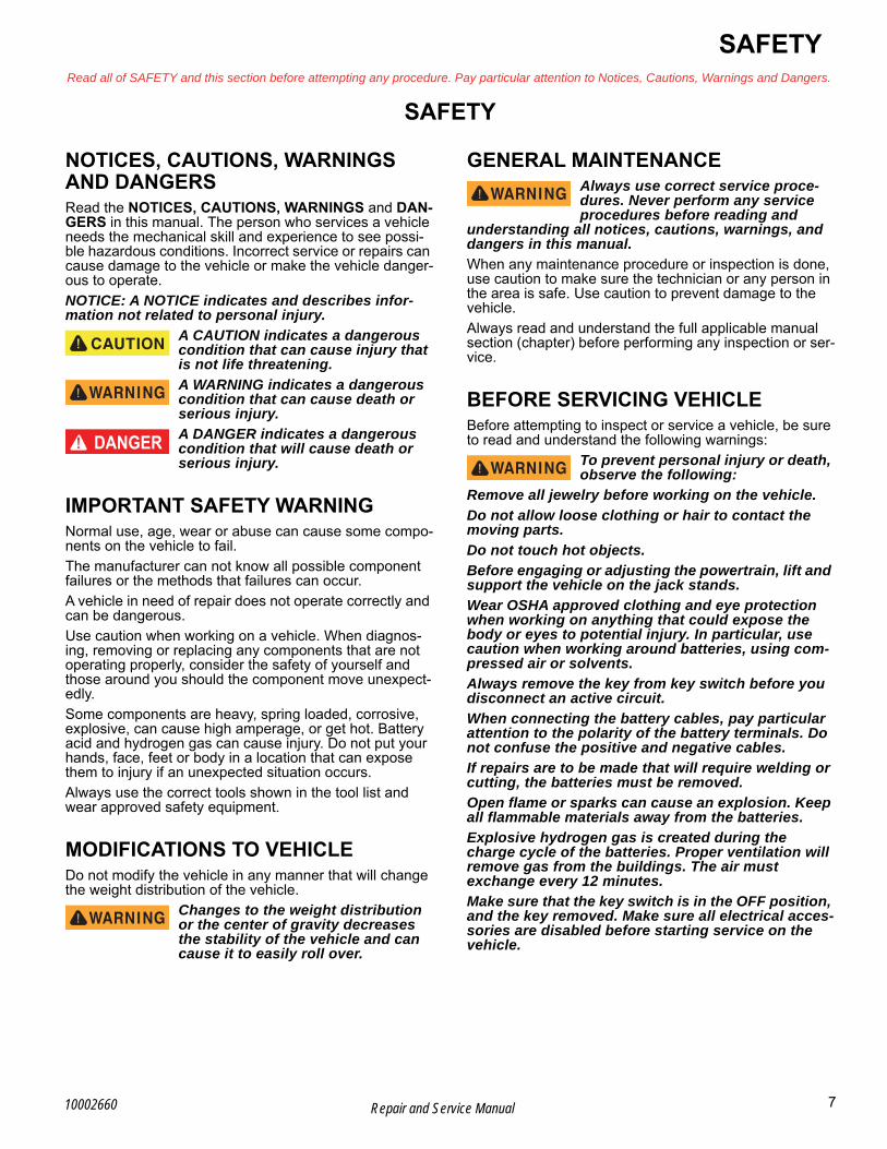
NOTICES, CAUTIONS, WARNINGS AND DANGERSRead the NOTICES, CAUTIONS, WARNINGS and DAN-GERS in this manual. The person who services a vehicle needs the mechanical skill and experience to see possi-ble hazardous conditions. Incorrect service or repairs can cause damage to the vehicle or make the vehicle danger-ous to operate.
NOTICE: A NOTICE indicates and describes infor-mation not related to personal injury.
A CAUTION indicates a dangerous condition that can cause injury that is not life threatening.
A WARNING indicates a dangerous condition that can cause death or serious injury.
A DANGER indicates a dangerous condition that will cause death or serious injury.
IMPORTANT SAFETY WARNINGNormal use, age, wear or abuse can cause some compo-nents on the vehicle to fail.
The manufacturer can not know all possible component failures or the methods that failures can occur.
A vehicle in need of repair does not operate correctly and can be dangerous.
Use caution when working on a vehicle. When diagnos-ing, removing or replacing any components that are not operating properly, consider the safety of yourself and those around you should the component move unexpect-edly.
Some components are heavy, spring loaded, corrosive, explosive, can cause high amperage, or get hot. Battery acid and hydrogen gas can cause injury. Do not put your hands, face, feet or body in a location that can expose them to injury if an unexpected situation occurs.
Always use the correct tools shown in the tool list and wear approved safety equipment.
MODIFICATIONS TO VEHICLEDo not modify the vehicle in any manner that will change the weight distribution of the vehicle.
Changes to the weight distribution or the center of gravity decreases the stability of the vehicle and can cause it to easily roll over.
GENERAL MAINTENANCEAlways use correct service proce-dures. Never perform any service procedures before reading and
understanding all notices, cautions, warnings, and dangers in this manual.
When any maintenance procedure or inspection is done, use caution to make sure the technician or any person in the area is safe. Use caution to prevent damage to the vehicle.
Always read and understand the full applicable manual section (chapter) before performing any inspection or ser-vice.
BEFORE SERVICING VEHICLEBefore attempting to inspect or service a vehicle, be sure to read and understand the following warnings:
To prevent personal injury or death, observe the following:
Remove all jewelry before working on the vehicle.
Do not allow loose clothing or hair to contact the moving parts.
Do not touch hot objects.
Before engaging or adjusting the powertrain, lift and support the vehicle on the jack stands.
Wear OSHA approved clothing and eye protection when working on anything that could expose the body or eyes to potential injury. In particular, use caution when working around batteries, using com-pressed air or solvents.
Always remove the key from key switch before you disconnect an active circuit.
When connecting the battery cables, pay particular attention to the polarity of the battery terminals. Do not confuse the positive and negative cables.
If repairs are to be made that will require welding or cutting, the batteries must be removed.
Open flame or sparks can cause an explosion. Keep all flammable materials away from the batteries.
Explosive hydrogen gas is created during the charge cycle of the batteries. Proper ventilation will remove gas from the buildings. The air must exchange every 12 minutes.
Make sure that the key switch is in the OFF position, and the key removed. Make sure all electrical acces-sories are disabled before starting service on the vehicle.
7Repair and Service Manual10002660

B
SAFETYRead all of SAFETY and this section before attempting any procedure. Pay particular attention to Notices, Cautions, Warnings and Dangers.
The batteries must be removed before any service or repairs that can cause sparks.
Never disconnect an active circuit at a battery terminal.
The batteries are heavy. Use correct safety proce-dures to lift the batteries. Always lift the battery with a commercially available battery lifting device. Make sure that not to tilt the batteries during removal or installation. An electrolyte spill can cause burns and damage.
The electrolyte in a storage battery is an acid solu-tion which can cause burns to the skin and eyes. Always use clean water to wash electrolyte from your body or eyes. Get medical assistance immedi-ately.
When servicing the vehicle, always wear eye protection. Use caution when working around batteries, or using sol-vents or compressed air.
Any electrolyte spills should be neutralized with a solution of 1/4 cup (60 ml) sodium bicarbonate (baking soda) dissolved in 1-1/2 gallons (6 liters) of water and flushed with water (See Pre-paring Acid Neutralizing Solution on page 17).
Use insulated wrenches to prevent the possibility of a dropped wrench from ‘shorting out’ a battery, which could result in an explosion and severe per-sonal injury or death.
Aerosol containers of battery terminal protectant must be used with extreme care. Insulate metal con-tainer to prevent can from contacting battery termi-nals, which could result in an explosion.
Make sure to fill the batteries to a level of 1/2 inch (13 mm) above the plates. Electrolyte more than 1/2
inch (13 mm) above the plates can cause a spill from the battery during the charge cycle. A spill of elec-trolyte can cause damage to the vehicle and storage facility.
LIFTING THE VEHICLETool List Qty.
Floor Jack ....................................................................1Jack Stands .................................................................4Wheel Chocks..............................................................4
To reduce the possibility of severe injury or death from a vehicle falling from a jack, always observe the fol-lowing warnings:
Always place chocks in front and behind the wheels not being raised.
Be sure the vehicle is on a firm and level surface.
Never get under a vehicle while it is supported by a jack.
Use jack stands and test the stability of the vehicle on the stands.
Use extreme caution. The vehicle is very unstable during the lifting process.
When lifting the vehicle, position jacks and jack stands only in the areas indicated (Ref. Fig. 1).
How to Lift the Vehicle1. Put the wheel chocks in front of each front wheel and
behind each front wheel (Ref. Fig. 2).
2. Put the jack below the rear axle-tube, next to the dif-ferential housing or below the skid plate (Ref. Fig. 1).
3. Lift the vehicle and put the jack stands below the frame where the leaf-spring bracket is attached to the frame (Ref. Fig. 1).
4. Lower the jack and test the stability of the vehicle on the two jack stands by gently rocking the vehicle.
5. Put the jack below the center of the front of the vehi-cle behind the bumper.
6. Lift the vehicle and put the jack stands below the frame where the instrument-panel support is attached to the frame.
7. Lower the jack and test the stability of the vehicle on all four jack stands by rocking the vehicle gently.
8 Repair and Service Manual 10002660

SAFETYRead all of SAFETY and this section before attempting any procedure. Pay particular attention to Notices, Cautions, Warnings and Dangers.
B
Fig. 1 Lifting the Vehicle
Fig. 2 Wheel Chocks
Lift Front of Vehicle1. Put the wheel chocks in front of each rear wheel and
behind each rear wheel (Ref. Fig. 2).
2. Place the jack under the center front of the vehicle just behind the bumper (Ref. Fig. 1).
3. Lift the vehicle with jack and position the jack stands under the frame where the instrument panel support is attached to the frame (Ref. Fig. 1).
4. Lower the jack and test the stability of the vehicle on jack stands by gently rocking the vehicle.
5. The jack can be left under the center front of the frame while the front end of the vehicle is on the jack stands.
Lift Rear of Vehicle1. Put the wheel chocks in front of each front wheel and
behind each front wheel (Ref. Fig. 2).
2. Center jack under the skid plate (Ref. Fig. 1).
3. Lift vehicle with jack and position jack stands under the frame where the leaf spring mounting bracket is welded to the frame (Ref. Fig. 1).
4. Lower the jack and test the stability of the vehicle on the two jack stands by gently rocking the vehicle.
5. The jack can be left under rear axle tube while the rear end of the vehicle is on the jack stands.
Lower VehicleLower the vehicle by reversing the lifting sequence.
9Repair and Service Manual10002660
SAFETYRead all of SAFETY and this section before attempting any procedure. Pay particular attention to Notices, Cautions, Warnings and Dangers.
Notes:
10 Repair and Service Manual 10002660

ACCELERATORRead all of SAFETY and this section before attempting any procedure. Pay particular attention to Notices, Cautions, Warnings and Dangers.
BACCELERATOR
Fig. 1 Accelerator Components
ACCELERATOR PEDALThe accelerator is a throttle by wire system with a rotary position sensor (See Rotary Position Sensor on page 47).
There are no serviceable items within the accelerator pedal assembly. The pedal assembly must be replaced as a unit if it does not operate correctly.
Pedal ReplacementTool List Qty.
Socket, 7/16” ............................................................... 1Socket, 13 mmWrench, 7/16”.............................................................. 1Wrench, 13 mmRatchet ........................................................................ 1Torque Wrench, ft.lbs .................................................. 1
1. To access the accelerator pedal (1), remove two bolts (3), washers (4) and nuts (7) that secure the cover (5) to the mounting bracket (10).
2. Disconnect the wire harness from the rotary position sensor on the pedal.
3. Remove the lock nuts (8) securing the pedal (1) to the mounting bracket.(10).
4. Remove the pedal.
5. Replace the pedal (1) and secure with new lock nuts (8).
6. Connect the wiring harness to the rotary position sensor.
7. Install the pedal cover (5) and secure it with the bolts (3), washers (4) and nuts (7).
8. Tighten the nuts (7, 8) to the torque values specified below.
Rotary Position Sensor
1
34
5
7
10
8
Item Torque Specification
7 6 - 8 ft. lbs. (8 - 11 Nm)
8 6 - 8 ft. lbs. (8 - 11 Nm)
11Repair and Service Manual10002660

ACCELERATORRead all of SAFETY and this section before attempting any procedure. Pay particular attention to Notices, Cautions, Warnings and Dangers.
Notes:
12 Repair and Service Manual 10002660

BATTERIES AND BATTERY CHARGERRead all of SAFETY and this section before attempting any procedure. Pay particular attention to Notices, Cautions, Warnings and Dangers.
BBATTERIES AND BATTERY CHARGER
SAFETYNOTICE: Always observe the following warnings when working on or near batteries.
To prevent battery explosion that could result in severe personal injury or death, keep all smoking
materials, open flame or sparks away from the bat-teries.
Hydrogen gas is formed when charging batteries. Do not charge batteries without adequate ventila-tion. A 4% concentration of hydrogen gas is explo-sive.
Be sure that the key switch is off and all electrical accessories are disabled before starting work on vehicle.
Never disconnect an active circuit at a battery termi-nal.
Batteries are heavy. Use proper lifting techniques when moving them. Always lift the battery with a com-mercially available battery lifting device. Use care not to tip batteries when removing or installing them; spilled electrolyte can cause burns and damage.
The electrolyte in a battery is an acid solution which can cause severe burns to the skin and eyes. Treat all electrolyte contact to the body and eyes with extended flushing with clear water. Contact a physi-cian immediately.
Always wear a safety shield or approved safety goggles when add-ing water or charging batteries.
Any electrolyte spills should be neutralized with a solution of 1/4 cup (60 ml) sodium bicarbonate
(baking soda) dissolved in 1-1/2 gallons (6 liters) of water and then flushed with water (Ref. Fig. 7).
Overfilling batteries can result in electrolyte being expelled from the battery during the charge cycle. Expelled electrolyte can cause damage to the vehi-cle and storage facility.
Aerosol containers of battery terminal protectant must be used with extreme caution. Insulate metal container to prevent can from contacting battery ter-minals which could result in an explosion.
Use insulated wrenches to prevent the possibility of a dropped wrench from ‘shorting out’ a battery, which could result in an explosion and severe per-sonal injury or death.
BATTERYA battery is able to produce electricity as the result of a chemical reaction. This chemical reaction releases stored chemical energy in the form of electrical energy. The chemical reaction occurs faster in warm conditions and slower in cold conditions. Temperature is important when conducting tests on a battery, and test results must be corrected to compensate for temperature differences.
As a battery ages, it still may perform adequately, but its capacity is diminished. Capacity describes the time that a battery can continue to provide its design amperes from a full charge.
A battery has a maximum life, therefore good mainte-nance is designed to maximize the available life and reduce the factors that can reduce the life of the battery.
13Repair and Service Manual10002660

B
BATTERIES AND BATTERY CHARGERRead all of SAFETY and this section before attempting any procedure. Pay particular attention to Notices, Cautions, Warnings and Dangers.
Fig. 1 Battery System
Batteries RemovalTool List Qty.
Insulated Wrench, 1/2” ................................................1Insulated Wrench, 9/16” ..............................................1Insulated Socket, 1/2”, ................................................1Insulated Socket, 9/16”................................................1Ratchet ........................................................................1Battery Carrier .............................................................1Torque Wrench, ft. lbs..................................................1
Torque Wrench, in. lbs. ................................................1Putty Knife ...................................................................1Wire Brush ...................................................................1Terminal Spreader .......................................................1
NOTICE: Hardware that is removed must always be installed in its original position unless otherwise specified. If torque values are not specified, refer to the Torque Specifications table (See TORQUE SPECIFICATIONS on page 5).
61
4
8
2
3
11
7
10
72
8
5
4
Front of Vehicle
14 Repair and Service Manual 10002660

BATTERIES AND BATTERY CHARGERRead all of SAFETY and this section before attempting any procedure. Pay particular attention to Notices, Cautions, Warnings and Dangers.
BUse insulated wrenches to prevent the possibility of a dropped wrench from ‘shorting out’ a battery, which
could result in an explosion and severe personal injury or death.
Make sure that the key switch is in the OFF position and remove the key from vehicle. Make sure all electrical accessories are deactivated.
1. Remove the negative (B-) cable.
2. Remove the positive (B+) cable.
3. Remove the nuts (6) and hold down bolts (4) from the battery hold downs (2) and battery bracket (1).
4. Remove the batteries (3) using a battery carrier (Ref. Fig. 1).
5. Remove all corrosion from terminals and hardware with a putty knife and wire brush.
6. Wash the area with a solution of sodium bicarbonate (baking soda) and water and thoroughly dry.
7. Apply corrosion resistant paint battery racks and sur-rounding area.
Battery Installation1. Place the batteries (3) in the battery racks.
2. Install the battery hold downs (2) and battery bracket (1) with hold down bolts (4).
3. Tighten the lock nuts (6) to torque specified below, tight enough to prevent movement of the battery but not tight enough to cause distortion of the battery cases.
4. Inspect all wires and terminals.
5. Clean any corrosion from the battery terminals or the wire terminals with a solution of sodium bicarbonate (baking soda) and brush.
6. Connect the battery wires as shown (Ref. Fig. 2). Be sure that all battery terminals are installed with crimp upward.
7. Tighten the battery terminal hardware to torque value specified below.
Do not overtighten the battery ter-minal clamps. This will cause a “mushroom” effect on the battery
post, preventing the terminal nut from being prop-erly tightened. Protect the battery terminals and bat-tery wire terminals with a commercially available protective coating.
Aerosol containers of battery pro-tector spray must be used with extreme care. Insulate metal con-
tainer to prevent can from contacting battery termi-nals which could result in an explosion.
After installing batteries, coat terminals with commercially available terminal protector spray.
Fig. 2 Battery Connections
BATTERY MAINTENANCETool List Qty.
Insulated Wrench, 9/16”...............................................1Battery Carrier .............................................................1Hydrometer ..................................................................1Battery Maintenance Kit P/N 25587G01......................1Battery Protective Spray ..............................................1Torque Wrench, in.lbs ..................................................1Insulated Socket, 9/16” ................................................1Terminal Spreader .......................................................1Ratchet ........................................................................1
At Each Charging CycleBefore charging the batteries, inspect the battery charger connector and vehicle receptacle housing for dirt or debris. Clean with compressed air if necessary.
Charge the batteries after each day of use.
Item Torque Specification
Lock Nut (6) 16 - 19 ft. lbs. (22 - 26 Nm)
Battery Terminal Hardware 90 - 110 in. lbs. (10 - 12 Nm)
NEG
POS
NEGPOS
NEGPOS
NEG POS
NEGPOS
NEG
POS
To Solenoid
To Controller B-
“ + “ Terminal
“ - “ Terminal
15Repair and Service Manual10002660
B
BATTERIES AND BATTERY CHARGERRead all of SAFETY and this section before attempting any procedure. Pay particular attention to Notices, Cautions, Warnings and Dangers.
Monthly• Inspect all wiring for fraying, loose terminals, corro-
sion, and worn or missing insulation.
• Check that the electrolyte level is correct and add suitable water as required.
• Clean the batteries and wire terminals.
• Tighten battery terminal nuts to 90 - 110 in. lbs. (10.2 - 12.4 Nm).
• Spray battery terminals with commercially available battery protective spray.
• Install all terminal covers.
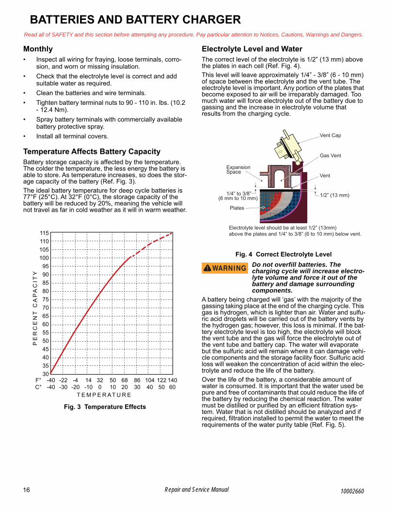
Temperature Affects Battery CapacityBattery storage capacity is affected by the temperature. The colder the temperature, the less energy the battery is able to store. As temperature increases, so does the stor-age capacity of the battery (Ref. Fig. 3).
The ideal battery temperature for deep cycle batteries is 77°F (25°C). At 32°F (0°C), the storage capacity of the battery will be reduced by 20%, meaning the vehicle will not travel as far in cold weather as it will in warm weather.
Fig. 3 Temperature Effects
Electrolyte Level and WaterThe correct level of the electrolyte is 1/2” (13 mm) above the plates in each cell (Ref. Fig. 4).
This level will leave approximately 1/4” - 3/8” (6 - 10 mm) of space between the electrolyte and the vent tube. The electrolyte level is important. Any portion of the plates that become exposed to air will be irreparably damaged. Too much water will force electrolyte out of the battery due to gassing and the increase in electrolyte volume that results from the charging cycle.
Fig. 4 Correct Electrolyte Level
Do not overfill batteries. The charging cycle will increase electro-lyte volume and force it out of the battery and damage surrounding components.
A battery being charged will ‘gas’ with the majority of the gassing taking place at the end of the charging cycle. This gas is hydrogen, which is lighter than air. Water and sulfu-ric acid droplets will be carried out of the battery vents by the hydrogen gas; however, this loss is minimal. If the bat-tery electrolyte level is too high, the electrolyte will block the vent tube and the gas will force the electrolyte out of the vent tube and battery cap. The water will evaporate but the sulfuric acid will remain where it can damage vehi-cle components and the storage facility floor. Sulfuric acid loss will weaken the concentration of acid within the elec-trolyte and reduce the life of the battery.
Over the life of the battery, a considerable amount of water is consumed. It is important that the water used be pure and free of contaminants that could reduce the life of the battery by reducing the chemical reaction. The water must be distilled or purified by an efficient filtration sys-tem. Water that is not distilled should be analyzed and if required, filtration installed to permit the water to meet the requirements of the water purity table (Ref. Fig. 5).
1151101051009590858075706560555045403530
320
14-10
-4-20
-22-30
-40-40
F°C°
5010
6820
8630
10440
12250
14060
T E M P E R AT U R E
PE
RC
EN
T C
AP
AC
ITY
Vent Cap
Gas Vent
VentExpansionSpace
Plates
1/2” (13 mm)1/4” to 3/8”(6 mm to 10 mm)
Electrolyte level should be at least 1/2” (13mm)above the plates and 1/4” to 3/8” (6 to 10 mm) below vent.
16 Repair and Service Manual 10002660

BATTERIES AND BATTERY CHARGERRead all of SAFETY and this section before attempting any procedure. Pay particular attention to Notices, Cautions, Warnings and Dangers.
B
Fig. 5 Water Purity Table
Even if the water is colorless, odorless, tasteless and suit-able for drinking, it should be analyzed to see that it does not exceed the impurity levels specified in the water purity table (Fig. 5).
Automatic watering devices such as the one included in the Battery Maintenance Kit (P/N 25587G01) can be used with an approved water source (Ref. Fig. 6). These water-ing devices are fast and accurate to use, and maintain the correct electrolyte level within the battery cells.
Fig. 6 Automatic Watering Gun
NOTICE: The watering device should only be used if the electrolyte level is less than 1/2” (13 mm) above top of plates.
Cleaning BatteriesWhen cleaning the exterior of the batteries and terminals, do not use a water hose without first spraying with a solu-tion of sodium bicarbonate (baking soda) and water to neutralize any acid deposits.
Use of a water hose without first neutralizing any acid, will transfer acid from the top of the batteries to another area of the vehicle or storage facility, where it will attack the structure or floor. After spraying down the batteries, a conductive residue will remain on the batteries which will contribute to the discharge of the batteries.
To prevent battery damage, be sure that all battery caps are tightly installed.
The correct cleaning technique is to spray the top and sides of the batteries with a solution of sodium bicarbon-ate (baking soda) and water. This solution is best applied with a garden type sprayer with a non metallic spray wand. The solution should consist of 1/4 cup (60 ml) of sodium bicarbonate (baking soda) mixed with 1-1/2 gal-lons (6 liters) of clear water (Ref. Fig. 7). In addition to the batteries, spray all metal components adjacent to the bat-teries with the sodium bicarbonate (baking soda) solution.
Fig. 7 Preparing Acid Neutralizing Solution
Leave solution on batteries for minimum of three minutes. Use a soft bristle brush or cloth to clean the tops of the batteries to remove any residue that could cause the self discharge of the battery. Rinse the entire area with low pressure clear water. All items required for complete bat-tery cleaning and watering are included in the Battery Maintenance Kit (P/N 25587G01).
Cleaning should be done once a month or more often under extreme conditions.
Prolonged StoragePrior to prolonged storage, the battery charger, controller, and all other electronic devices must be disconnected. Otherwise, they will contribute to the premature discharge of batteries.
The batteries need to be maintained to prevent discharge during periods of storage.
In high temperatures the chemical reaction is faster, while low temperatures cause the chemical reaction to slow down. A vehicle that is stored at 90° F (32° C) will lose 0.002 of specific gravity each day. If a fully charged bat-tery has a specific gravity of 1.275 and the battery is allowed to sit unused, it will become partially discharged. When it reaches 1.240 (usually less than 20 days), it should be recharged. If a battery is left in a discharged state, sulfating takes place on and within the plates. Sul-fating will cause permanent damage to the battery. To prevent damage, the battery should be recharged. A hydrometer (P/N 50900G1) can be used to determine the specific gravity, and therefore the state of charge of a bat-tery.
In cold conditions, the battery must be fully charged to prevent the possibility of freezing (Fig. 8). A fully charged battery will not freeze in temperatures above - 75° F (-60° C). Although the chemical reaction is slowed in cold tem-peratures, the battery must be stored fully charged and disconnected from any circuit that could discharge the battery.
ColorSuspendedTotal SolidsCalcium & Magnesium OxidesIronAmmoniaOrganic & Volatile MatterNitritesNitratesChloride
ClearTrace100405850
105
5
Impurity Parts PerMillion
Watering gun similar to the type included in the battery maintenance kit
Pure Water
Valve consistentlyfills to a
predeterminedlevel
ElectrolyteLevel
Single Battery Cell
1-1/2 gallons(6 liter)
Clear Water
PlasticSprayBottle
1/4 cup(60 ml)Sodium
Bicarbonate(Baking Soda)
17Repair and Service Manual10002660

B
BATTERIES AND BATTERY CHARGERRead all of SAFETY and this section before attempting any procedure. Pay particular attention to Notices, Cautions, Warnings and Dangers.
Disconnect the charger connector from the vehicle recep-tacle.
Clean the batteries, neutralize and remove all deposits from the battery case to prevent self discharge. The bat-teries should be tested or recharged at thirty day mini-mum intervals.
Fig. 8 Freezing Point of Electrolyte
Battery ChargingThe battery charger is designed to fully charge the battery set. Some automatic battery chargers contain an elec-tronic module that can not activate if the batteries are severely deep cycled. Automatic chargers will determine the correct duration of charge to the battery set and will shut off when the battery set is fully charged. Always refer to the instructions of the specific charger used.
Before charging, the following should be observed:
Do not overfill batteries. The charging cycle will increase electro-lyte volume and force it out of the battery and damage surrounding components.
• The electrolyte level in all cells must be at the recommended level and the plates covered (See Electrolyte Level and Water on page 16).
• Charging must be done in an area that is well ventilated and capable of removing the hydrogen gas that is generated by the charging process. A minimum of five air exchanges per hour is rec-ommended.
• The charging connector components must be in good condition and free from dirt or debris.
• The charger connector must be fully inserted into the vehicle receptacle.
• The charger connector and cord set must be pro-tected from damage and located in an area to prevent injury resulting from personnel running over or tripping over the cord set.
• The charger is automatically turned off during the connect/disconnect cycle, and therefore no elec-trical arc is generated at the DC plug/receptacle contacts.
NOTICE: In some portable chargers, an audible rat-tle is present in the body of the charger DC plug. This rattle is caused by an internal magnet within the charger plug. The magnet is part of the interlock system that prevents the vehicle from being driven when the charger plug is inserted in the charging receptacle.
AC VoltageBattery charger output is directly related to the input volt-age. If the vehicle routinely receives an incomplete charge in a normally adequate time period, low AC volt-age could be the problem. Consult the electrical provider.
FAULT TESTINGFault testing is done for two distinct reasons:
• A battery that performs poorly and is outside of the manufacturers specification should be identified in order to replace it under the terms of the manufac-turer’s warranty. Different manufacturers have differ-ent requirements. Consult the battery manufacturer or the manufacturer’s representative for specific requirements.
• Determine why a particular vehicle does not perform adequately. Performance problems can cause a vehicle to operate slowly or be incapable of operating for the time required.
A new battery must mature before it will develop its maxi-mum capacity. Maturing can take up to 100 charge/dis-charge cycles. After the maturing phase, as the battery ages, its capacity diminishes. The only way to determine the capacity of a battery is to perform a load test using a discharge machine following manufacturer’s recommen-dations.
A cost effective way to identify a poorly performing battery is to use a hydrometer to identify a battery in a set with a lower than normal specific gravity. Once the problematic cell or cells are identified, the suspect battery can be removed and replaced. At this point there is nothing that can be done to save the battery. The individual battery should be replaced with a good battery of the same brand, type, and approximate age.
1.1001.120 1.160 1.200 1.240 1.280
1.140 1.180 1.220 1.260 1.300
-9
-15
-21
-26
-32
-37
-43
-48
-54
-60
-65
-71
ELECTROLYTE
TEMPERATURE
SPECIFIC GRAVITY ELECTROLYTE FREEZING POINT
OC
+15
+5
-5
-15
-25
-35
-45
-55
-65
-75
-85
-95
OF
18 Repair and Service Manual 10002660

BATTERIES AND BATTERY CHARGERRead all of SAFETY and this section before attempting any procedure. Pay particular attention to Notices, Cautions, Warnings and Dangers.
BHydrometerA hydrometer (P/N 50900G1) is used to test the state of charge of a battery cell (Ref. Fig. 9). This is performed by measuring the density of the electrolyte, which is accom-plished by measuring the specific gravity of the electro-lyte. The greater the concentration of sulfuric acid, the more dense the electrolyte becomes. The higher the den-sity, the higher the state of charge.
To prevent a battery explosion that could result in severe personal injury or death. Never insert a metal
thermometer into a battery. Use a hydrometer with a built in thermometer that is designed for testing bat-teries.
Fig. 9 Hydrometer
Specific gravity is the measurement of a liquid that is compared to a baseline. The baseline is water which is assigned a base number of 1.000. The concentration of sulfuric acid to water in a new vehicle battery is 1.280 which means that the electrolyte weighs 1.280 times the weight of the same volume of water. A fully charged bat-tery will test at 1.275 - 1.280. A discharged battery will read in the 1.140 range.
NOTICE: Do not perform a hydrometer test on a bat-tery that has just been filled. The battery must go through at least one charge and discharge cycle in order to allow the water to adequately mix with the electrolyte.
The temperature of the electrolyte is important. The hydrometer reading must be corrected to 80° F (27° C). High quality hydrometers are equipped with an internal thermometer that will measure the temperature of the electrolyte and will include a conversion scale to correct the float reading. It is important to recognize that the elec-trolyte temperature is significantly different from the ambi-ent temperature if the vehicle has been operated.
The electrolyte in a battery is an acid solution which can cause severe burns to the skin and eyes.
Treat all electrolyte contact to the body and eyes with extended flushing with clear water. Contact a physician immediately.
Always wear a safety shield or approved safety goggles when using a hydrometer to test the elec-trolyte solution.
Any electrolyte spills should be neutralized with a solution of 1/4
cup (60 ml) sodium bicarbonate (baking soda) dis-solved in 1-1/2 gallons (6 liters) of water and then flushed with water (Ref. Fig. 7).
Using Hydrometer1. Draw electrolyte into the hydrometer several times to
permit the thermometer to adjust to the electrolyte temperature and note the reading. Examine the color of the electrolyte. A brown or gray color indicates a problem with the battery and indicates the battery is nearing the end of its life.
2. Draw the minimum quantity of electrolyte into the hydrometer to permit the float to float freely without contacting the top or bottom of the cylinder.
3. Hold the hydrometer in a vertical position at eye level and note the reading where the electrolyte meets the scale on the float.
4. Add or subtract four points (.004) to the reading for every 10° F (6° C) the electrolyte temperature is above or below 80° F (27° C). Adjust the reading to conform with the electrolyte temperature, e.g., if the reading indicates a specific gravity of 1.250 and the electrolyte temperature is 90° F (32° C), add four points (.004) to the 1.250 which gives a corrected reading of 1.254. Similarly if the temperature was 70° F (21° C), subtract four points (.004) from the 1.250 to give a corrected reading of 1.246 (Ref. Fig. 10).
5. Test each cell and note the readings (corrected to 80° F or 27° C). A variation of fifty points between any two cell readings (example 1.250 - 1.200) indi-cates a problem with the low reading cell(s). As a battery ages the specific gravity of the electrolyte will decrease at full charge. This is not a reason to replace the battery, providing all cells are within fifty points of each other.
Since the hydrometer test is in response to a vehicle showing a performance problem, the vehicle should be recharged and the test repeated. If the results indicate a weak cell, the battery or batteries should be removed and replaced with a good battery of the same brand, type and approximate age.
Weight
FloatBulbCylinderThermometer
Add to FloatReading
Subtractfrom FloatReading
19Repair and Service Manual10002660

B
BATTERIES AND BATTERY CHARGERRead all of SAFETY and this section before attempting any procedure. Pay particular attention to Notices, Cautions, Warnings and Dangers.
Fig. 10 Hydrometer Temperature Correction
BATTERY CHARGER
Charger DescriptionThe battery charger supplied with the vehicle is a Delta-Q Technologies QuiQ 72V charger. It is a fully automatic battery charger and is designed specifically for charging electric vehicle batteries. Use the charger on 72V battery systems only.
Instructions are printed on the charger for daily reference. A manual provided by the charger manufacturer is shipped with the charger.
For information regarding the battery charger, including charging instructions, LED display explanations, fault testing, and ordering replacement parts, refer to the char-ger manual or contact the manufacturer directly (See BATTERY CHARGER USER’S GUIDE on page 135).
Portable Charger InstallationUse charger only on 72 volt battery systems. Other usage can cause personal injury and damage.
Lead acid batteries can generate explosive hydro-gen gas during normal operation. Keep sparks, flames, and smoking materials away from batteries. Provide adequate ventilation during charging.
Never charge a frozen battery.
Study all of the battery manufacturer’s specific pre-cautions such as recommended rates of charge and removing or not removing cell caps while charging.
Risk of electric shock. Connect charger power cord to an outlet that has been properly installed and
grounded in accordance with all local codes and ordinances. A grounded outlet is required to reduce risk of electric shock – do not use ground adapters or modify the plug. Do not touch uninsulated por-tion of output connector or uninsulated battery ter-minal. Disconnect the DC supply before making or breaking the connections to the battery while charging.Do not open or disassemble the charger.Do not operate the charger if the AC supply cord is damaged or if the charger has received a sharp blow, been dropped, or otherwise damaged in any way. Refer all repair work to qualified personnel. The charger is not for use by children.Portable chargers are shipped with the vehicle. Prior to vehicle or charger operation, chargers must be removed and mounted on a platform above the ground to permit maximum air flow around and underneath the charger. For optimum performance and shortest charge times, put the charger in an area with adequate ventilation. The charger should also be installed in an area that will be rel-atively free of dirt, mud, or dust. Accumulations within the charger vents will reduce their heat dissipating qualities. The status display of the charger must be visible to the user.
160 71.1 +.032+.030
150 65.6 +.028+.026
140 60.0 +.024+.022
130 54.4 +.020+.018
120 48,9 +.016+.014
110 43.3 +.012+.010
100 37.8 +.008+.006
90 32.2 +.004+.002
80 26.7 0–.002
70 21.1 –.004–.006
60 15.6 –.008–.010
50 10 –.012–.014
40 4.4 –.016–.018
30 –1.1 –.020–.022
20 –6.7 –.024–.026
10 –12.12 –.028
EXAMPLE #1:Electrolyte TemperatureAbove 80°F (27°C)
Electrolyte temperature90° F (32° C)Hydrometer reading 1.2501.250 + .004 = 1.254corrected specific gravity
EXAMPLE #2:Electrolyte TemperatureBelow 80°F (27 °C)
Electrolyte temperature70° F (21° C)Hydrometer reading 1.2501.250 - .004 = 1.246corrected specific gravity
° F ° C
ElectrolyteTemperature
20 Repair and Service Manual 10002660

BATTERIES AND BATTERY CHARGERRead all of SAFETY and this section before attempting any procedure. Pay particular attention to Notices, Cautions, Warnings and Dangers.
B
Fig. 11 Charger Installation
The charger can remain connected to the AC outlet. To charge the vehicle, refer to the instruction labels on the charger. Insert the polarized DC plug completely into the vehicle receptacle. The charger will automatically start a few seconds after the plug is connected. The charger will automatically stop when the batteries are fully charged, and the DC plug can be removed from the vehicle.
NOTICE: Routing the DC cord through the steering wheel when charging the batteries, serves as a good reminder to store the cord out of the way when charging is complete. The DC plug can be damaged by driving over or catching the cord on the vehicle when driving away.
An ungrounded electrical device can become a physical hazard that could result in an electrical shock or electrocution.
Provide Protection From Elements
Do Not Block Louvered Airways
NEMA 15 - 5R Grounded AC Receptacle110 - 120 VAC. Dedicated 20 AMP Circuit
Locations outside the US and Canada:Reference appropriate local electrical
code and charger manufacturerrecommendations for AC power
requirements.
21Repair and Service Manual10002660

BATTERIES AND BATTERY CHARGERRead all of SAFETY and this section before attempting any procedure. Pay particular attention to Notices, Cautions, Warnings and Dangers.
Notes:
22 Repair and Service Manual 10002660
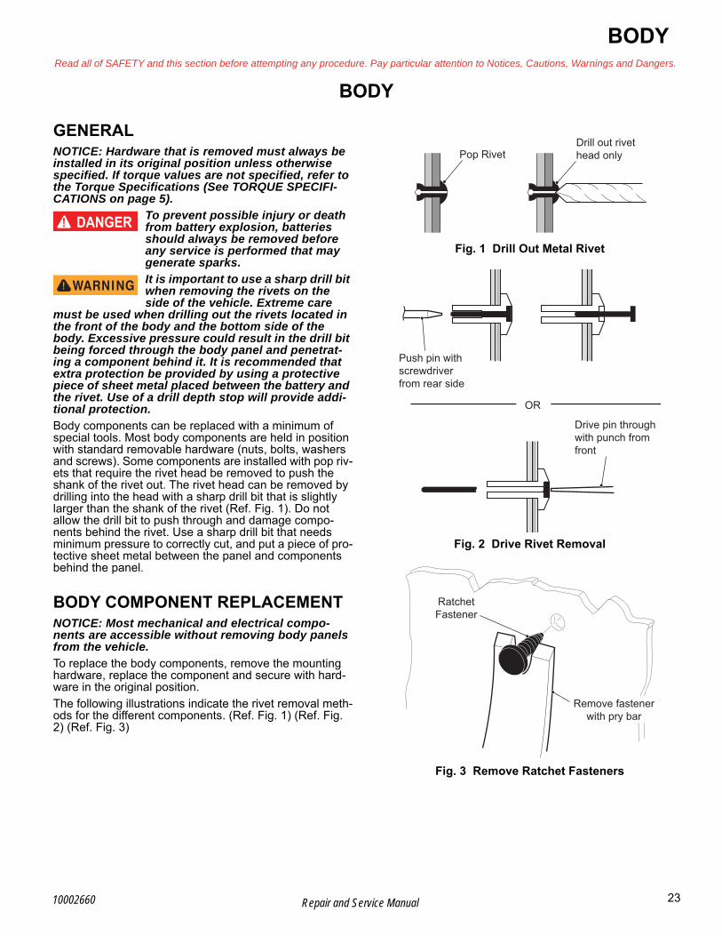
BODYRead all of SAFETY and this section before attempting any procedure. Pay particular attention to Notices, Cautions, Warnings and Dangers.
BBODY
GENERALNOTICE: Hardware that is removed must always be installed in its original position unless otherwise specified. If torque values are not specified, refer to the Torque Specifications (See TORQUE SPECIFI-CATIONS on page 5).
To prevent possible injury or death from battery explosion, batteries should always be removed before any service is performed that may generate sparks.
It is important to use a sharp drill bit when removing the rivets on the side of the vehicle. Extreme care
must be used when drilling out the rivets located in the front of the body and the bottom side of the body. Excessive pressure could result in the drill bit being forced through the body panel and penetrat-ing a component behind it. It is recommended that extra protection be provided by using a protective piece of sheet metal placed between the battery and the rivet. Use of a drill depth stop will provide addi-tional protection.
Body components can be replaced with a minimum of special tools. Most body components are held in position with standard removable hardware (nuts, bolts, washers and screws). Some components are installed with pop riv-ets that require the rivet head be removed to push the shank of the rivet out. The rivet head can be removed by drilling into the head with a sharp drill bit that is slightly larger than the shank of the rivet (Ref. Fig. 1). Do not allow the drill bit to push through and damage compo-nents behind the rivet. Use a sharp drill bit that needs minimum pressure to correctly cut, and put a piece of pro-tective sheet metal between the panel and components behind the panel.
BODY COMPONENT REPLACEMENTNOTICE: Most mechanical and electrical compo-nents are accessible without removing body panels from the vehicle.
To replace the body components, remove the mounting hardware, replace the component and secure with hard-ware in the original position.
The following illustrations indicate the rivet removal meth-ods for the different components. (Ref. Fig. 1) (Ref. Fig. 2) (Ref. Fig. 3)
Fig. 1 Drill Out Metal Rivet
Fig. 2 Drive Rivet Removal
Fig. 3 Remove Ratchet Fasteners
Pop RivetDrill out rivethead only
Push pin withscrewdriver from rear side
Drive pin through with punch fromfront
OR
RatchetFastener
Remove fastenerwith pry bar
23Repair and Service Manual10002660

B
BODYRead all of SAFETY and this section before attempting any procedure. Pay particular attention to Notices, Cautions, Warnings and Dangers.
Rocker Panel ReplacementTool List Qty.
Torx Bit, T30 ................................................................1Bit Driver......................................................................1Torque Wrench, in. lbs.................................................1
1. Remove the upper OPS from the vehicle (See Upper OPS Frame Removal and Installation on page 80).
2. Remove the lower OPS from the vehicle (See OPS Lower Weldment Removal and Installation on page 82).
3. Remove the screws (2) securing the rocker panels (1) to the chassis frame (3) (Ref. Fig. 4).
4. Remove rocker panels (1).
Fig. 4 Rocker Panel Replacement
Assemble in the reverse order of removal. Tighten the screws (2) to the torque value specified below.
Gauge Panel ReplacementTool List Qty.
Pry Bar, Small ..............................................................1Bit Driver ......................................................................1Torx Bit, T30.................................................................1
NOTICE: The gauge panel can be removed without removing the instrument panel.
To prevent personal injury, discon-nect negative (-) battery cables before servicing vehicle.
Removal:
1. Remove two screws (6) that secure the gauge panel (5) to instrument panel (10).
2. Gently pry out the top of the gauge panel (5).
3. Remove the connections from the main harness to the electrical accessories in the gauge panel.
4. Pull the bottom of the gauge panel away from and out of the instrument panel (10) (Ref. Fig. 5).
Assembly:
1. Connect the main harness to all electrical accesso-ries in the gauge panel.
2. Push the body clips (4) through the instrument panel. If the body clips (4) remained in the instrument panel (10) during the gauge panel (5) removal, push the tabs (7) into the body clips (4).
3. Install the two screws (6).
Fig. 5 Gauge Panel Replacement
Torque the screws (6) to the torque value specified below.
Item Torque Specification
2 25 - 40 in. lbs. (2.8 - 4.5 Nm)
2
1
3
Item Torque Specification
6 25 - 40 in. lbs. (2.8 - 4.5 Nm)
Front of Vehicle
4
7
6
5
10
24 Repair and Service Manual 10002660

BODYRead all of SAFETY and this section before attempting any procedure. Pay particular attention to Notices, Cautions, Warnings and Dangers.
BCowl ReplacementTool List Qty.
Drill .............................................................................. 1Drill Bit ......................................................................... 1Punch, Small ............................................................... 1Rivet Gun .................................................................... 1Pry Bar ........................................................................ 1
To prevent personal injury, discon-nect negative (-) battery cable before servicing vehicle.
1. Disconnect the wiring harness from the headlights (See Headlight Bulb Replacement (LED) on page 46).
2. Remove the gauge panel (5) (See Gauge Panel Replacement on page 24).
3. Drill out the upper rivets (12) connecting the cowl (15) to the instrument panel (10).
4. Drill out the remaining rivets (11).
5. Remove cowl assembly (15) from vehicle (Ref. Fig. 6).
Assemble in the reverse order of removal using new riv-ets.
Fig. 6 Cowl Removal
Removal of Headlight Grille AssemblyTool List Qty. 1
Socket, 10mm..............................................................1Wrench, 10mm ............................................................1Ratchet ........................................................................1Pry Bar.........................................................................1Torque Wrench, in. lbs .................................................1
1. Disconnect the wire harness (16) from the headlight bulb (17).
2. Remove the eleven nuts (18) from the rear of the headlight grille assembly (20), that secure the head-light grille assembly to the cowl (15).
3. Remove the headlight grille assembly (20) from the outside of the cowl (15). It may be necessary to pry the headlight grille assembly gently away from the cowl (Ref. Fig. 7).
Assemble in the reverse order of removal.
Tighten the nuts (18) to the torque values specified below.
11
10
1215
11
Item Torque Specification
18 17 - 25 in. lbs. (1.9 - 2.8 Nm)
25Repair and Service Manual10002660
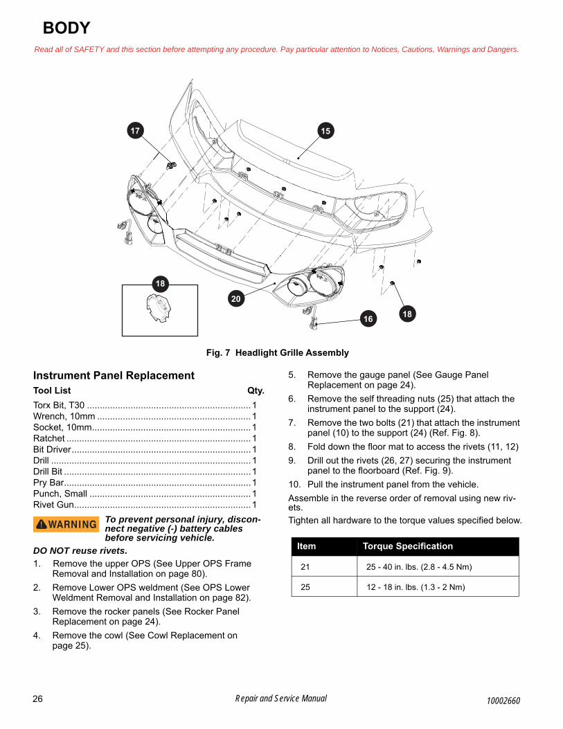
B
BODYRead all of SAFETY and this section before attempting any procedure. Pay particular attention to Notices, Cautions, Warnings and Dangers.
Fig. 7 Headlight Grille Assembly
Instrument Panel ReplacementTool List Qty.
Torx Bit, T30 ................................................................1Wrench, 10mm ............................................................1Socket, 10mm..............................................................1Ratchet ........................................................................1Bit Driver......................................................................1Drill ..............................................................................1Drill Bit .........................................................................1Pry Bar.........................................................................1Punch, Small ...............................................................1Rivet Gun.....................................................................1
To prevent personal injury, discon-nect negative (-) battery cables before servicing vehicle.
DO NOT reuse rivets.
1. Remove the upper OPS (See Upper OPS Frame Removal and Installation on page 80).
2. Remove Lower OPS weldment (See OPS Lower Weldment Removal and Installation on page 82).
3. Remove the rocker panels (See Rocker Panel Replacement on page 24).
4. Remove the cowl (See Cowl Replacement on page 25).
5. Remove the gauge panel (See Gauge Panel Replacement on page 24).
6. Remove the self threading nuts (25) that attach the instrument panel to the support (24).
7. Remove the two bolts (21) that attach the instrument panel (10) to the support (24) (Ref. Fig. 8).
8. Fold down the floor mat to access the rivets (11, 12)
9. Drill out the rivets (26, 27) securing the instrument panel to the floorboard (Ref. Fig. 9).
10. Pull the instrument panel from the vehicle.
Assemble in the reverse order of removal using new riv-ets.
Tighten all hardware to the torque values specified below.
18
20
17
16 18
15
Item Torque Specification
21 25 - 40 in. lbs. (2.8 - 4.5 Nm)
25 12 - 18 in. lbs. (1.3 - 2 Nm)
26 Repair and Service Manual 10002660

BODYRead all of SAFETY and this section before attempting any procedure. Pay particular attention to Notices, Cautions, Warnings and Dangers.
B
Fig. 8 Instrument Panel (Rear)
22
25
23
21
10
24
24
Front of Vehicle
27Repair and Service Manual10002660
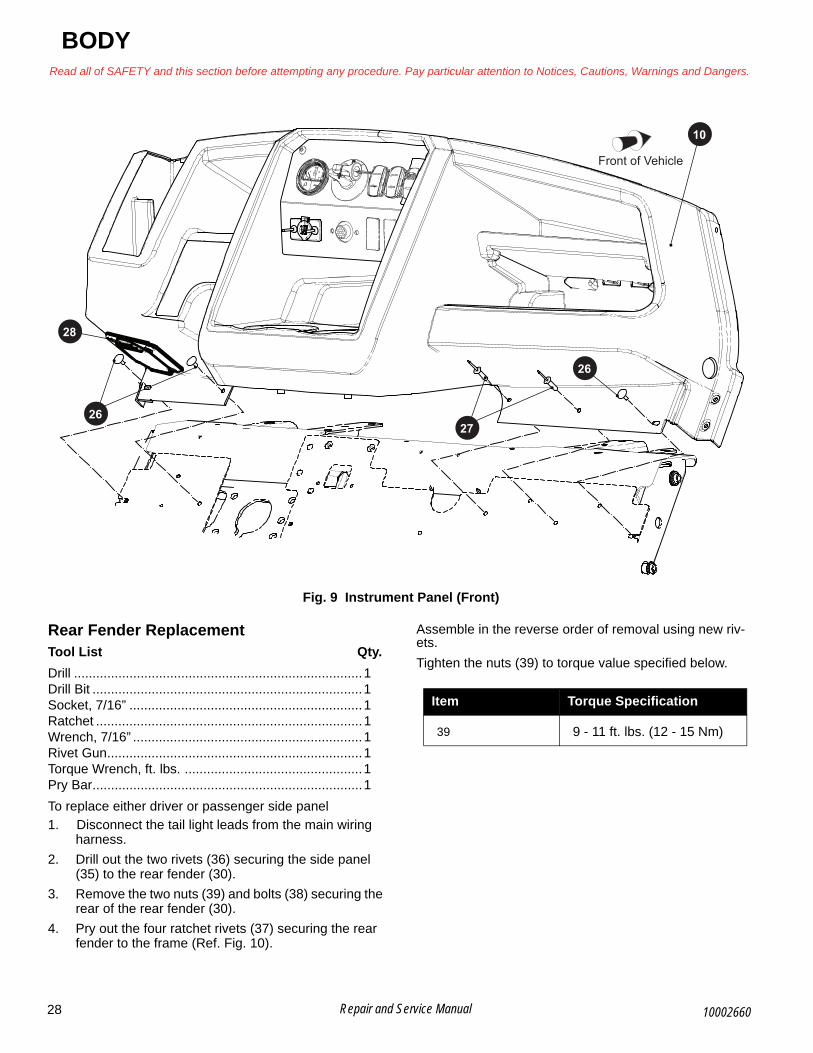
B
BODYRead all of SAFETY and this section before attempting any procedure. Pay particular attention to Notices, Cautions, Warnings and Dangers.
Fig. 9 Instrument Panel (Front)
Rear Fender ReplacementTool List Qty.
Drill ..............................................................................1Drill Bit .........................................................................1Socket, 7/16” ...............................................................1Ratchet ........................................................................1Wrench, 7/16” ..............................................................1Rivet Gun.....................................................................1Torque Wrench, ft. lbs. ................................................1Pry Bar.........................................................................1
To replace either driver or passenger side panel
1. Disconnect the tail light leads from the main wiring harness.
2. Drill out the two rivets (36) securing the side panel (35) to the rear fender (30).
3. Remove the two nuts (39) and bolts (38) securing the rear of the rear fender (30).
4. Pry out the four ratchet rivets (37) securing the rear fender to the frame (Ref. Fig. 10).
Assemble in the reverse order of removal using new riv-ets.
Tighten the nuts (39) to torque value specified below.
2627
10
26
28
Front of Vehicle
Item Torque Specification
39 9 - 11 ft. lbs. (12 - 15 Nm)
28 Repair and Service Manual 10002660

BODYRead all of SAFETY and this section before attempting any procedure. Pay particular attention to Notices, Cautions, Warnings and Dangers.
B
Fig. 10 Fender Replacement
Seat Wrap and Closeout ReplacementTool List Qty.
Drill .............................................................................. 1Drill Bit ......................................................................... 1Rivet Gun .................................................................... 1Screwdriver, Phillips .................................................... 1
1. Drill out the rivets (49) securing the seat wrap (40, 45) to the floor (41) and frame (Ref. Fig. 11). Retain the hinge plates (47) for reuse during installation.
2. Remove the 6 screws (42) connecting the front of the seat wrap (40) to the sides (45).
3. Pull the front portion (40) of the seat wrap out of the vehicle.
4. Remove the screws (46) connecting the seat wrap to the frame from the inside of the side portions of the seat wrap.
5. Pull the side portions (45) of the seat wrap out of the vehicle.
6. If a closeout (48) needs to be replaced, remove the two screws (44) attaching the closeout to the seat wrap sides (Ref. Fig. 12).
Assemble in the reverse order of removal using new riv-ets.
Fig. 11 Seat Wrap Replacement
35
36
30
38
39
Front of Vehicle37
42
45
4940
49
4648
47
41Front of Vehicle
49
49
29Repair and Service Manual10002660

B
BODYRead all of SAFETY and this section before attempting any procedure. Pay particular attention to Notices, Cautions, Warnings and Dangers.
Fig. 12 Seat Wrap Closeout
Rear Closeout Panel ReplacementTool List Qty.
Ratchet ........................................................................1Wrench, 7/16” ..............................................................1Wrench, 9/16” ..............................................................1Torque Wrench, ft. lbs. ................................................1Socket, 7/16” ...............................................................1Socket, 9/16” ...............................................................1Torque Wench, ft. lbs...................................................1
1. Remove the bolts (53), lock washers (52), washers (54) and nuts (51) securing rear closeout panel (50) to chassis frame (Ref. Fig. 13).
2. Remove the rear closeout panel (50).
Assemble in the reverse order of removal. Tighten the bolts (53) to torque value specified below.
Fig. 13 Closeout Panel
Item Torque Specification
53 21 - 25 ft. lbs. (28 - 34 Nm)
48
44
Front of Vehicle
50
5354
52
51
Front of Vehicle
30 Repair and Service Manual 10002660

B
BODYRead all of SAFETY and this section before attempting any procedure. Pay particular attention to Notices, Cautions, Warnings and Dangers.
31Repair and Service Manual10002660
Winch Assembly
Fig. 14 Winch Assembly
Front of Vehicle
Yellow wire
Cable bundle continues towards vehicle rear
Winch
Fairlead Plow Assembly
Torque to 45 - 55 Nm (33.2 - 40.6 ft lbs)
Insert and bend cotter pin after inserting hook retention pin
Pull winch wire rope through opening in brush guard and fairlead before installing hook kit.
Red wire
Torque to 3 - 4.5 Nm (2.2 - 3.3 ft. lbs)
Brushguard and winch plate shown for reference only
Plate Bracket

B
BODYRead all of SAFETY and this section before attempting any procedure. Pay particular attention to Notices, Cautions, Warnings and Dangers.
PAINTINGFollow the paint manufacturer’s recommendations for specific painting procedures and information.
All painting must be done in an area with adequate ventilation to safely disperse harmful vapors.
Wear eye protection and respirator, following manu-facturer’s instructions to protect from over spray and airborne mist.
Provide protection from over spray to vehicle and surrounding area.
Minor ScratchesTo repair minor scratches, the manufacturer of the Durashield™ body panels recommends the following steps be taken:
1. Thoroughly clean the surface to be repaired with alcohol, and allow to dry.
2. Use a brush to apply a minimum of two coats of touch up paint to damaged area. Allow 30 - 45 min-utes between coats; increase to 45 - 60 minutes in higher humidity. The painted area should be slightly above the surface of the part.
3. Use 400 grit “wet” sand paper to blend the painted area level with the surface of the part being repaired.
4. Use a polishing compound (3M Finesse or automo-tive grade) to renew the gloss and to further blend and transition the newly painted surface.
5. Clean with alcohol, and allow to dry.
6. (Optional but recommended) Apply a clear coat to renew and protect the depth of the finish.
7. Wax or polish with a Carnauba base product avail-able at any automotive parts distributor. Do not wax flat finishes.
Larger ScratchesTo repair large scratches, the manufacturer of the Durashield™ body panels recommends the following steps be taken:
1. Thoroughly clean the surface to be repaired with alcohol, and allow to dry.
2. Apply tape to area surrounding damaged area to prevent over spray of paint.
3. Shake the aerosol touch up paint a minimum of one minute to mix thoroughly and achieve the best color match.
4. Apply paint in light even overlapping strokes. Multiple coats can be applied to provide adequate coverage and finish.
5. Allow paint to dry overnight.
6. Use 400 grit “wet” sand paper to blend the painted area level with the surface of the part being repaired.
7. Use a polishing compound (3M Finesse or automo-tive grade) to renew the gloss and to further blend and transition the newly painted surface.
8. Clean with alcohol, and allow to dry.
9. (Optional but recommended) Apply a clear coat to renew and protect the depth of finish.
10. Wax or polish with a Carnauba base product avail-able at any automotive parts distributor. Do not wax flat finishes.
Complete Panel RepairIn situations where large panels or areas must be painted, touch up paint is not recommended. In such cases, pro-fessional painting or panel replacement is necessary. Body panel replacement is sometimes more cost effective than painting. If the decision to paint is chosen, it can be accomplished by any body panel repair shop with experi-ence in painting thermoplastic elastomer (TPE) panels. TPE is a common material in modern automobile body panels. All body panel repair shops should be familiar with the materials and processes required.
The finish will include an application of a primer coat, a base color coat, and a clear coat.
Most paint manufacturers can perform a computer paint match to assure accurate color matching.
32 Repair and Service Manual 10002660

BODYRead all of SAFETY and this section before attempting any procedure. Pay particular attention to Notices, Cautions, Warnings and Dangers.
Notes:
33 Repair and Service Manual 10002660

BODYRead all of SAFETY and this section before attempting any procedure. Pay particular attention to Notices, Cautions, Warnings and Dangers.
Notes:
34 Repair and Service Manual 10002660

BRAKESRead all of SAFETY and this section before attempting any procedure. Pay particular attention to Notices, Cautions, Warnings and Dangers.
B BRAKES
Fig. 1 Hydraulic Brake Line
MAINTENANCE
Daily Brake Performance TestNOTICE: To ensure correct braking performance, all periodic maintenance, inspections, and procedures must be performed as indicated in the Periodic Ser-vice Schedule (See PERIODIC SERVICE SCHEDULE on page 133). A Daily Brake Performance Test must be performed and the entire brake system serviced in accordance with the Periodic Service Schedule (See Daily Brake Performance Test on page 35).
The brake system must be bled whenever any part of the brake system has been replaced.
Press the brake pedal. The pedal should have some ini-tial free play and then become resistant. This indicates proper performance.
If the brake pedal has a soft feel or loses resistance, per-
form a brake system inspection, (See Brake System Inspection on page 35)
Brake System InspectionBrake failure usually occurs as either a gradual decrease in braking effect from the disc pads wearing away, a loss of braking at one wheel, or a sudden and complete failure with no brakes working except the electric parking brake. If the brakes at one wheel become ineffective while the brakes at the other wheel functions properly, remove the entire brake assembly and inspect the brake for signs of a leaking or inoperative wheel cylinder assembly.
NOTICE: Do not allow brake fluid to contact the brake pads. If the brake pads become wet with hydraulic fluid, wipe the brake pads and rotor until they are dry.
A
Front of Vehicle
7
Front of Vehicle
Calliper
Banjo Bolt
Crush Washer
RearBrake Line
MasterCylinderFront
Brake Line
A
AA
B
B
35Repair and Service Manual10002660

B
BRAKESRead all of SAFETY and this section before attempting any procedure. Pay particular attention to Notices, Cautions, Warnings and Dangers.
Complete brake failure usually indicates a loss of hydrau-lic fluid pressure.
If the brake pedal has a soft feel:
1. Bleed the brakes to remove air from the brake sys-tem. (See BLEEDING AND FLUSHING on page 38)
A brake pedal that loses resistance indicates a leak in the hydraulic system:
1. Check brake fluid level.
2. If the fluid is low, inspect the system for leaks.
i. Check for leaks by applying pressure to the pedal gradually and steadily.
ii. If pedal sinks very slowly to the floor, the sys-tem has a leak along the brake lines or at the hydraulic cylinder. If no external leaks are apparent, the problem is likely inside the master cylinder
3. If leaks are found, repair the leaks in the brake sys-tem.
4. If the master cylinder is found to be leaking, replace it.
5. Bleed the brakes to remove air from the brake sys-tem.
Do not allow brake fluid to contact painted surfaces. Wipe off immedi-ately if contact is made.
MASTER CYLINDERThe master cylinder is mounted to the frame, behind the driver side front wheel (Ref. Fig. 1). The master cylinder will eventually require replacement due to deterioration of the cylinder seals (cups). Fluid will leak past the cups and show as an external leak. A common symptom is a soft brake pedal, meaning that it goes all the way to the floor. The rubber parts wear or deteriorate with use, age, or fluid contamination. Corrosion or deposits formed in the cylinder bore that are due to moisture or dirt in the hydraulic system may cause wear of the cylinder bore or related parts. Do not try to remove corrosion or deposits with a cylinder hone. If corrosion or deposits are detected on the master cylinder, replace it with a new one and flush the system (See Flushing on page 39).
Master Cylinder ReplacementTool List Qty.
Insulated Wrench, 9/16” ..............................................1Container .....................................................................1Needle Nose Pliers......................................................1Wrench, 9/16” ..............................................................2Wrench, 1/2” ................................................................1Wrench, 14mm ............................................................1Socket, 9/16” ...............................................................1Socket, 1/2” .................................................................1Socket, 14mm..............................................................1Torque Wrench, ft. lbs..................................................1
DO NOT reuse crush washers.
When replacing the master cylin-der, it is likely that brake fluid will leak from the master cylinder. Do
not allow brake fluid to contact the painted body components of the vehicle. Clean off immediately if contact is made.
1. Switch the key switch into the OFF position, and remove the key.
2. Clean the area around the master cylinder (1) to pre-vent dirt and grease from contaminating the hydrau-lic system (Ref. Fig. 2).
3. Remove the banjo bolts (9) and washers (10).
4. Disconnect the front brake line (7) and the rear brake line (11) from the master cylinder (1) (Ref. Fig. 2). Provide a container for the released brake fluid.
5. Remove the cotter pin (3) and clevis pin (4).
6. Remove two hex head bolts (2) and nuts (5).
7. Remove the master cylinder from the vehicle.
Assemble in the reverse order of removal using new crush washers. Tighten all hardware to the torque values specified below.
.
Fig. 2 Master Cylinder
To prevent contaminated brake fluid causing a brake failure, never use any excess fluid or return to the original container. Dispose of brake fluid properly.
Item Torque Specification
9 20 - 24 ft lbs. (27- 32 Nm)
5 13 - 17 ft. lbs. (18 - 23 Nm)
5
4
3
2
9
2
11 1
9
10
BrakePedal
7
10
36 Repair and Service Manual 10002660

BRAKESRead all of SAFETY and this section before attempting any procedure. Pay particular attention to Notices, Cautions, Warnings and Dangers.
BFill the master cylinder with DOT 4 brake fluid and bleed the brake system. (See BLEEDING AND FLUSHING on page 38)
After bleeding the brake system, check for leaks along all lines and at the master cylinder.
Brake FluidNOTICE: Hydraulic brake systems must be com-pletely flushed if the fluid becomes contaminated. To flush, bleed the entire system until all brake fluid has been replaced with new DOT 4 standard auto-motive brake fluid.
Keep the fluid in the master cylinder (1) at the correct fluid level. The master cylinder is mounted to the frame behind the driver side front wheel (Ref. Fig. 1). To prevent con-tamination when checking fluid, clean the fill cap before removing it. Check reservoir fluid level as indicated in the Periodic Service Schedule (See PERIODIC SERVICE SCHEDULE on page 133). When required, add clean brake fluid to maintain fluid level 1/4” (6 mm) from top of reservoir. Use new DOT 4 standard automotive brake fluid.
Total brake fluid capacity for the complete hydraulic brake system is 13 fl. oz.
REPLACEMENT OF WEAR ITEMS
Brake Pads ReplacementTool List Qty.
Allen Socket, 3/8” ........................................................ 1Ratchet ....................................................................... 1Channel Lock Pliers .................................................... 1Torque Wrench, ft. lbs. ................................................ 1Torque Wrench, in. lbs................................................. 1Socket, 1/2” ................................................................. 1Socket, 13mm ............................................................ 1Wrench, 1/2”................................................................ 1Wrench, 13mm............................................................ 1
NOTICE: The front and rear brake pads must be replaced as a full set.
Replace the brake pads as a full set on both wheels. To remove the brake pads, lift and support the vehicle (See LIFTING THE VEHICLE on page 8).
1. Remove the wheel (See WHEEL AND TIRE SER-VICE on page 128).
2. Remove the banjo bolts and crush washers securing the brake lines to the caliper.
3. Loosen the 2 socket head slider pins (15), but do not remove them.
4. Remove the two hex head screws (14) securing the caliper (13) to the mounting bracket (18) (Ref. Fig. 3).
Fig. 3 Brake Caliper
5. Swing the caliper (13) free from the rotor.
6. Remove both anti-rattle springs (17).
7. Use channel lock pliers to compress the side with the O-ring.
8. Remove the brake pads (16) one at a time.
9. Compress the caliper piston. When the piston is compressed, it will stay in position until the brake pedal is pressed.
10. Compress the side with the O-ring and hold while installing the new pads (16). When both pads are installed, release pressure on the side with the O-ring.
11. Separate the brake pads (16) and put the caliper (13) over the rotor.
12. Install the two socket head slider pins (15) finger tight.
13. Install the two hex head bolts (14) to attach the cali-per (13) to the mounting bracket (18).
14. Reconnect the brake line using new crush washers.
15. Tighten all hardware to torque values specified below.
16. Replace the wheel and tighten the lug nuts (See Wheel Installation on page 128).
17. Bleed the brake system. (See BLEEDING AND FLUSHING on page 38)
Item Torque Specification
14 205 - 215 in. lbs. (23 - 25 Nm)
15 25 - 35 ft. lbs. (34 - 47 Nm)
Brake Line Banjo Bolt 17 - 20 ft. lbs (23 - 27 Nm)
14
1513
16 17
13
18Front of Vehicle
37Repair and Service Manual10002660

B
BRAKESRead all of SAFETY and this section before attempting any procedure. Pay particular attention to Notices, Cautions, Warnings and Dangers.
Rotor ReplacementNOTICE: Do not turn the rotor (disc brake hub) to remove grooves or high spots.
If the rotor (disc hub) has deep grooves or gouges, it must be replaced. If the pad contact area has worn the rotor to a thickness of 0.120" or less, the rotor must be replaced.
1. Remove the brake calipers (See Brake Pads Replacement on page 37).
2. Remove the cotter pin (31) and castellated nut (32).
3. Pull the hub assembly (2) away from the axle (35)and strut assembly (30).
4. Remove the four bolts (37) securing the rotor (45) to the hub assembly (2) (Ref. Fig. 4).
Assemble in the reverse order of removal. Tighten all hardware in a cross pattern to the torque values specified below.
Fig. 4 Rotor
BLEEDING AND FLUSHINGTool List Qty.
Shop Towels.............................................................A/RHose ........................................................................A/RClean Container, Glass................................................1Brake Fluid, DOT 4 ..................................................A/RWrench, 1/4” Box End..................................................1Crowfoot Wrench, 1/4” .................................................1Torque Wrench, in. lbs. ................................................1Socket, 1/4”..................................................................1
BleedingThe brake hydraulic system must be free of air to function properly.
The brake pedal and master cylinder acts as a hydraulic pump to remove air and brake fluid from the system.
Bleed the hydraulic system at all wheels if:
• The primary brake line was disconnected from the flexible brake hose.
• Air was introduced into the system due to low fluid level in master cylinder reservoir.
If a line or hose was disconnected at any fitting located between the master cylinder and calipers, all wheel cali-pers served by the disconnected line or hose must be bled.
Item Torque Specification
32 205 - 215 in. lbs. (23 - 25 Nm)
37 28 - 32 ft. lbs. (38 - 43 Nm)
31
32
3530
37
40
38 Repair and Service Manual 10002660
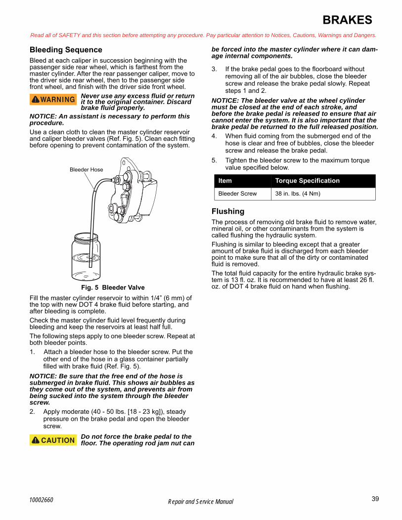
BRAKESRead all of SAFETY and this section before attempting any procedure. Pay particular attention to Notices, Cautions, Warnings and Dangers.
BBleeding SequenceBleed at each caliper in succession beginning with the passenger side rear wheel, which is farthest from the master cylinder. After the rear passenger caliper, move to the driver side rear wheel, then to the passenger side front wheel, and finish with the driver side front wheel.
Never use any excess fluid or return it to the original container. Discard brake fluid properly.
NOTICE: An assistant is necessary to perform this procedure.
Use a clean cloth to clean the master cylinder reservoir and caliper bleeder valves (Ref. Fig. 5). Clean each fitting before opening to prevent contamination of the system.
Fig. 5 Bleeder Valve
Fill the master cylinder reservoir to within 1/4” (6 mm) of the top with new DOT 4 brake fluid before starting, and after bleeding is complete.
Check the master cylinder fluid level frequently during bleeding and keep the reservoirs at least half full.
The following steps apply to one bleeder screw. Repeat at both bleeder points.
1. Attach a bleeder hose to the bleeder screw. Put the other end of the hose in a glass container partially filled with brake fluid (Ref. Fig. 5).
NOTICE: Be sure that the free end of the hose is submerged in brake fluid. This shows air bubbles as they come out of the system, and prevents air from being sucked into the system through the bleeder screw.
2. Apply moderate (40 - 50 lbs. [18 - 23 kg]), steady pressure on the brake pedal and open the bleeder screw.
Do not force the brake pedal to the floor. The operating rod jam nut can
be forced into the master cylinder where it can dam-age internal components.
3. If the brake pedal goes to the floorboard without removing all of the air bubbles, close the bleeder screw and release the brake pedal slowly. Repeat steps 1 and 2.
NOTICE: The bleeder valve at the wheel cylinder must be closed at the end of each stroke, and before the brake pedal is released to ensure that air cannot enter the system. It is also important that the brake pedal be returned to the full released position.
4. When fluid coming from the submerged end of the hose is clear and free of bubbles, close the bleeder screw and release the brake pedal.
5. Tighten the bleeder screw to the maximum torque value specified below.
FlushingThe process of removing old brake fluid to remove water, mineral oil, or other contaminants from the system is called flushing the hydraulic system.
Flushing is similar to bleeding except that a greater amount of brake fluid is discharged from each bleeder point to make sure that all of the dirty or contaminated fluid is removed.
The total fluid capacity for the entire hydraulic brake sys-tem is 13 fl. oz. It is recommended to have at least 26 fl. oz. of DOT 4 brake fluid on hand when flushing.
Bleeder Hose
Item Torque Specification
Bleeder Screw 38 in. lbs. (4 Nm)
39Repair and Service Manual10002660
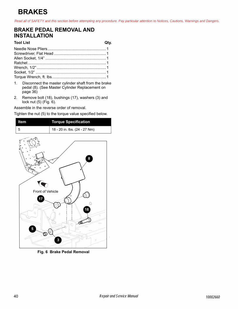
B
BRAKESRead all of SAFETY and this section before attempting any procedure. Pay particular attention to Notices, Cautions, Warnings and Dangers.
BRAKE PEDAL REMOVAL AND INSTALLATIONTool List Qty.
Needle Nose Pliers......................................................1Screwdriver, Flat Head ................................................1Allen Socket, 1/4” ........................................................1Ratchet ........................................................................1Wrench, 1/2” ................................................................1Socket, 1/2” .................................................................1Torque Wrench, ft. lbs..................................................1
1. Disconnect the master cylinder shaft from the brake pedal (8). (See Master Cylinder Replacement on page 36)
2. Remove bolt (18), bushings (17), washers (3) and lock nut (5) (Fig. 6).
Assemble in the reverse order of removal.
Tighten the nut (5) to the torque value specified below.
Fig. 6 Brake Pedal Removal
Item Torque Specification
5 18 - 20 in. lbs. (24 - 27 Nm)
17
3
18
8
Front of Vehicle
5
40 Repair and Service Manual 10002660

41Repair and Service Manual
Notes:Read all of SAFETY and this section before attempting any procedure. Pay particular attention to Notices, Cautions, Warnings and Dangers.
BRAKES
10002660

42 Repair and Service Manual
BRAKESRead all of SAFETY and this section before attempting any procedure. Pay particular attention to Notices, Cautions, Warnings and Dangers.
Notes:
10002660

ELECTRICALRead all of SAFETY and this section before attempting any procedure. Pay particular attention to Notices, Cautions, Warnings and Dangers.
BELECTRICAL
Fig. 1 Main Harness Routing
Front of Vehicle
Main Harness to Headlight
Main Harness to Contactor
Main Harness to Key Switch and Accesories
Main Harness to Taillight
Main Harness to Controllers
43Repair and Service Manual10002660
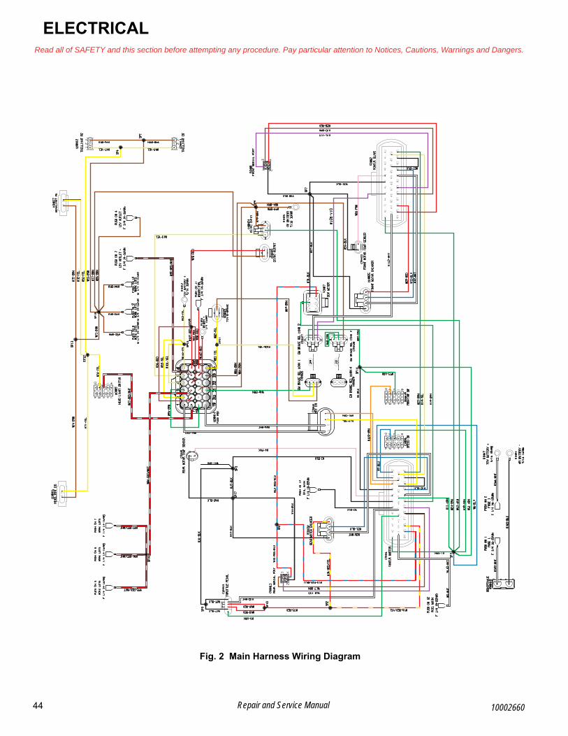
B
ELECTRICALRead all of SAFETY and this section before attempting any procedure. Pay particular attention to Notices, Cautions, Warnings and Dangers.
Fig. 2 Main Harness Wiring Diagram
44 Repair and Service Manual 10002660
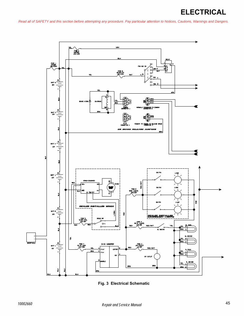
ELECTRICALRead all of SAFETY and this section before attempting any procedure. Pay particular attention to Notices, Cautions, Warnings and Dangers.
B
Fig. 3 Electrical Schematic
45Repair and Service Manual10002660

B
ELECTRICALRead all of SAFETY and this section before attempting any procedure. Pay particular attention to Notices, Cautions, Warnings and Dangers.
Fig. 4 Electrical Schematic (continued)
46 Repair and Service Manual 10002660

ELECTRICALRead all of SAFETY and this section before attempting any procedure. Pay particular attention to Notices, Cautions, Warnings and Dangers.
BVOLTAGE TESTING FOR BATTERIES
Hydrogen gas formed during bat-tery charging is explosive.Avoid any electrical spark or open flame near battery.
NOTICE: If the temperature of the battery or the ambient temperature is below 60° F (15.55° C), the capacity of the battery will be reduced, and it will require more time to charge.
Voltage on a cold battery increases faster, therefore reducing the charging rate.
Fully charge new batteries or batteries that have been in storage before testing or installing in vehicle.
Do not over charge battery.
Use a Digital Volt Ohm Meter (DVOM) to check the bat-tery.
Attach the negative (-) lead of the DVOM to the ground terminal of the battery. Attach the positive (+) lead to the positive battery terminal. The voltage reading obtained should be 12 volts or above. If the reading is below 12 volts, the battery needs to be charged or replaced.
MAIN HARNESS
Power SupplyTool List Qty.
DVOM.......................................................................... 1
1. Check for loose or bare wires.
2. Check for loose wires at each terminal connection and for worn insulation or bare wires touching the frame.
Bare wires can cause a short-cir-cuit.
NOTICE: If any DVOM readings indicate a faulty wire, check the condition of the terminals and wire junction. A faulty wire must be replaced. (See Faulty Wire Replacement on page 48)
3. Check the condition of the 72V batteries set.
a. Check for adequate battery volts (nominal 12 VDC) by setting the DVOM to 30 VDC range and place the red probe (+) on the battery post with the white (WHT) wire attached.
b. Place the black probe (-) on the battery post with the black (BLK) wire attached.
c. A reading of 11 VDC or greater indicates ade-quate battery condition.
d. No reading indicates:
• a poor connection between the probes and the battery terminals or
• a faulty DVOM
e. A voltage reading below 11 volts indicates poor battery condition and the vehicle should be recharged before proceeding with the test.
Fig. 5 72V Battery Set Connections
NOTICE: Due to the resistance of the wires involved within the harness, voltage readings can be slightly lower than battery voltage. A reading of 1 volt below battery voltage is acceptable.
4. Check the power wire.
a. Attach the black probe (-) to the battery post with the black wire attached.
b. Attach the red probe (+) to the power (white) wire terminal at the fuse block.
c. A reading of battery voltage indicates that the power wire is in good condition.
NOTICE: The power wire supplies power to the entire fuse block.
5. Check the fuse (Ref. Fig. 6).
a. Place the red probe (+) to each wire terminal on the fuse block.
b. A reading of battery voltage indicates that the fuse is in good condition.
c. No reading indicates a faulty fuse; replace with a good fuse of the same amperage rating.
NEG
POS
NEGPOS
NEGPOS
NEG POS
NEGPOS
NEGPOS
To Solenoid
ToController B-
Disconnect BL- cable
47Repair and Service Manual10002660

B
ELECTRICALRead all of SAFETY and this section before attempting any procedure. Pay particular attention to Notices, Cautions, Warnings and Dangers.
The use of an incorrect fuse rating can damage electrical components.
Fig. 6 Fuse Block
Accessory WiringAfter determining that there is power to the fuse panel, and the fuse is good, check the circuit using the proce-dures previously used to check the power supply (See Power Supply on page 47).
Use the wiring diagram to check for correct wiring and wire routing (Ref. Fig. 2). If there is power at the fuse end of the wire, there is power at the other end of the wire at the switch or electrical accessory, and there is continuity at the ground connection; then the circuit is complete. Electricity must flow from the fuse panel through the full length of the circuit to the ground connection. Correct any interruption of electricity flow, by repairing or replacing the wire or the switch or accessory.
Faulty Wire ReplacementReplace a faulty wire with one of the same gauge and color. Connect between the correct components, and secure to the harness bundle with a wire tie. Cut the faulty wire back close to the harness and wrap the ends with vinyl electrical tape.
Headlight Bulb Replacement (LED)The headlight contains an LED light board rather than a light bulb. If the LEDs burn out, then the entire light assembly must be replaced (See Removal of Headlight Grille Assembly on page 25).
Tail light ReplacementTool List Qty.
Drill...............................................................................1Drill Bit .........................................................................1Rivet Gun.....................................................................1
1. Drill out the rivets (8).
2. Disconnect the wiring harness from the tail light assembly (9).
3. Install the new tail light assembly.
4. Install new rivets (Ref. Fig. 7).
Headlight bulbs, tail light assemblies, and fuses are avail-able from a local distributor, an authorized branch or the service department.
Fig. 7 Tail Light Replacement
Front of Vehicle
9 8
48 Repair and Service Manual 10002660

ELECTRICALRead all of SAFETY and this section before attempting any procedure. Pay particular attention to Notices, Cautions, Warnings and Dangers.
BELECTRONIC SPEED CONTROL
Speed SensorThe speed sensor uses a sealed sensor to read the impulses of a ring magnet that is attached to the armature shaft of the motor speed sensor (Ref. Fig. 8). Magnetic pulses change to electrical signals, which the controller uses to determine the motor speed.
Test the speed sensor and replace if necessary (See FAULT TESTING on page 52).
Fig. 8 Speed Sensor
Rotary Position SensorThe rotary position sensor determines the speed of the vehicle. The rotary position sensor is connected through the main harness to the electronic speed control system. With no pressure applied on the accelerator pedal, the rotary position sensor remains in the neutral position. When the pedal is pressed, the amount of deflection in the rotary sensor is transferred to the electronic speed control system. The speed control system controls the speed of the motor that transmits power to the electric powertrain module in the vehicle.
ControllerThe controller is a solid state unit that activates a sole-noid, and controls the function of the vehicle by respond-ing to inputs from the rotary position sensor, motor speed sensor and many other units. The controller is located under the flip seat at the rear of the vehicle (Ref. Fig. 9).
Fig. 9 Controllers
The main wire harness, rotary position sensor, and speed sensor are connected to the controller with a 24-pin plug. The rotary position sensor is connected to the controller with a 2-pin plug on the main wire harness. The speed sensor is connected to the controller with a 3-pin plug on the main wire harness.
The controller is connected to the batteries and creates a regulated power supply for the rotary position sensor. When the pedal is pressed, the amount of deflection in the rotary sensor changes the voltage which is fed back to the controller. The controller senses the change in volt-age and supplies the appropriate power to the motor.
The rotary position sensor unit and the controller are both solid state units that contain no serviceable parts. The testing procedures test the basic functionality of the power and control wiring systems. Once the functionality of the wiring has been confirmed, the remaining tests are used to identify which of the components (controller or rotary position sensor) must be replaced.
Speed SensorControllers
49Repair and Service Manual10002660

B
ELECTRICALRead all of SAFETY and this section before attempting any procedure. Pay particular attention to Notices, Cautions, Warnings and Dangers.
Controller ReplacementTool List Qty.
Socket, 7/16.................................................................1Socket, 13mm..............................................................1Ratchet ........................................................................1Extension, 6" ...............................................................1Wrench, 7/16” ..............................................................1Wrench, 13mm ............................................................1Insulated Wrench, 9/16” ..............................................1Torque Wrench, ft. lbs. ................................................1
To prevent electrical shock, the neg-ative (B-) wire must be removed before discharging the controller.
Use a large screwdriver to cause a short-circuit in the positive (B+) and negative (B-) terminals of the controller. Be sure to hold screwdriver by the insu-lated handle.NOTICE: Record the location of the wiring on the controller before disconnecting it.
NOTICE: Always test the motors for a shorted condi-tion before installing a new converter. An electrical motor short may be the cause of the controller fail-ure and will damage the new controller (See AC Motor Bench Test on page 122).
1. Use an insulated wrench to remove the negative (B-) wire from the battery.
2. Remove the bolts (21) and flat washers (22)(Ref. Fig. 10).
3. Remove the connectors from the controller (24) (Ref. Fig. 10).
4. Disconnect the cables connecting the controller to the motor.
5. Remove bolts (23) and lock nuts (25)(Ref. Fig. 10).
6. Remove the controller (24) from the controller bracket(Ref. Fig. 10).
7. Mount new controller (24) and connect wiring(Ref. Fig. 10).
8. Tighten the hardware to the torque values specified below.
9. Connect the negative (B-) battery cable.
Fig. 10 Controller Removal
Item Torque Specification
21 80 - 90 in. lbs. (9 - 10.1 Nm)
25 92 - 100 in. lbs. (10.3 - 11.2 Nm)
BLUE (W)
Front of Vehicle
CONTROLLER with REAR MOTOR CONNECTIONS
YELLOW (V)GREEN (U)
GREEN (U)
Connect ControlHarness to Controllerby Connecting the ShortLead Controller Connectorto Passenger Side ControllerRear MotorGrease Connection
Connect ControlHarness to Controllerby Connecting the LongLead Controller Connectorto Driver Side Controller for Front MotorGrease Connection
BLUE (W)
YELLOW (V)
GREEN (U)
YELLOW (V)
BLUE (W)BLACK (B-)
RED (B+)
Front of Vehicle
RED (B+)
23
22 21
25
24
50 Repair and Service Manual 10002660
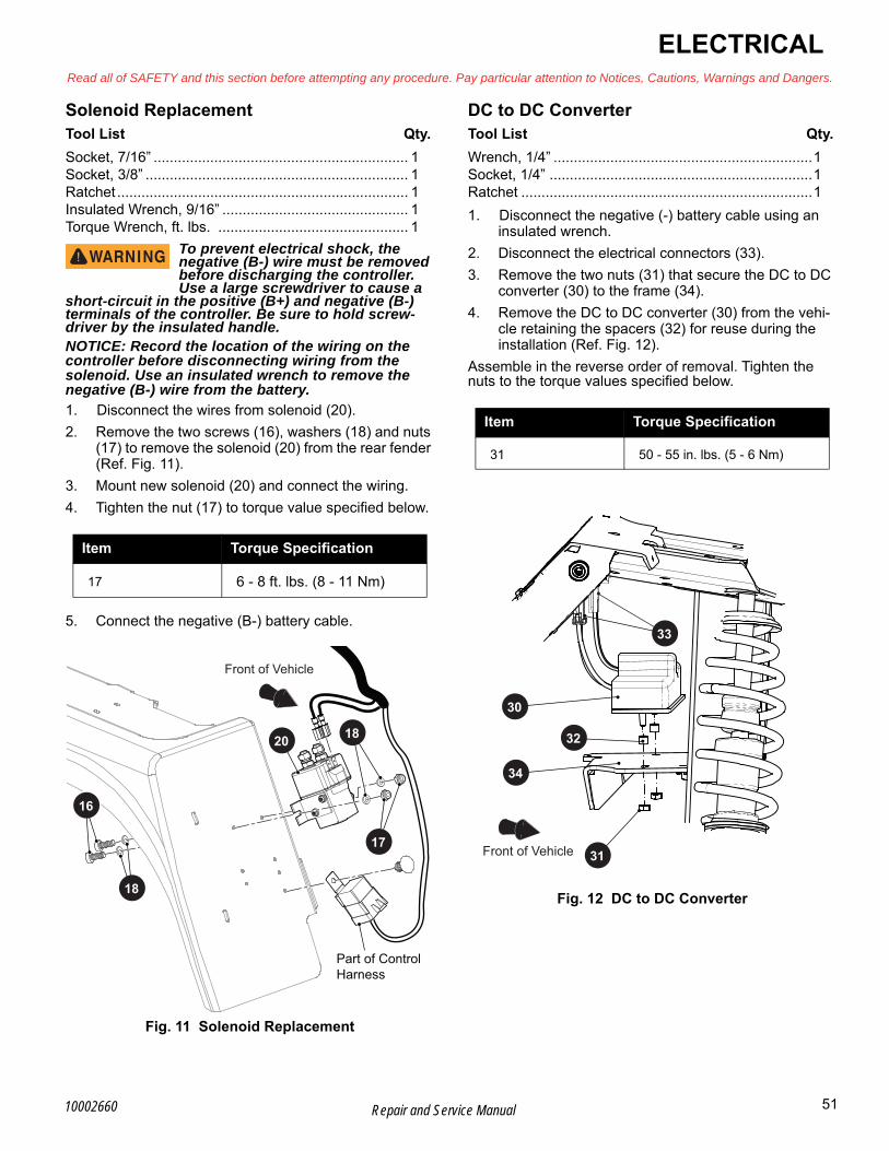
ELECTRICALRead all of SAFETY and this section before attempting any procedure. Pay particular attention to Notices, Cautions, Warnings and Dangers.
BSolenoid ReplacementTool List Qty.
Socket, 7/16” ............................................................... 1Socket, 3/8” ................................................................. 1Ratchet ........................................................................ 1Insulated Wrench, 9/16” .............................................. 1Torque Wrench, ft. lbs. ............................................... 1
To prevent electrical shock, the negative (B-) wire must be removed before discharging the controller. Use a large screwdriver to cause a
short-circuit in the positive (B+) and negative (B-) terminals of the controller. Be sure to hold screw-driver by the insulated handle.NOTICE: Record the location of the wiring on the controller before disconnecting wiring from the solenoid. Use an insulated wrench to remove the negative (B-) wire from the battery.
1. Disconnect the wires from solenoid (20).
2. Remove the two screws (16), washers (18) and nuts (17) to remove the solenoid (20) from the rear fender (Ref. Fig. 11).
3. Mount new solenoid (20) and connect the wiring.
4. Tighten the nut (17) to torque value specified below.
5. Connect the negative (B-) battery cable.
Fig. 11 Solenoid Replacement
DC to DC ConverterTool List Qty.
Wrench, 1/4” ................................................................1Socket, 1/4” .................................................................1Ratchet ........................................................................1
1. Disconnect the negative (-) battery cable using an insulated wrench.
2. Disconnect the electrical connectors (33).
3. Remove the two nuts (31) that secure the DC to DC converter (30) to the frame (34).
4. Remove the DC to DC converter (30) from the vehi-cle retaining the spacers (32) for reuse during the installation (Ref. Fig. 12).
Assemble in the reverse order of removal. Tighten the nuts to the torque values specified below.
Fig. 12 DC to DC Converter
Item Torque Specification
17 6 - 8 ft. lbs. (8 - 11 Nm)
Front of Vehicle
20 18
16
18
Part of Control Harness
17
Item Torque Specification
31 50 - 55 in. lbs. (5 - 6 Nm)
31
32
30
33
Front of Vehicle
34
51Repair and Service Manual10002660

B
ELECTRICALRead all of SAFETY and this section before attempting any procedure. Pay particular attention to Notices, Cautions, Warnings and Dangers.
FAULT TESTING
GeneralKnowledge of use of wiring diagrams and a Digital Volt Ohm Meter (DVOM) is necessary to effectively determine fault within the circuits that include the electrical accesso-ries, lighting, and gauges.
The wiring diagram shows the path followed by a voltage or signal from its origination point to its destination. Each wire is indicated by color.
Knowledge of simple logic fault testing will reduce the number of steps required to isolate the problem.
Example 1: If the vehicle does not start and none of the lights operate or burn dimly, test the battery before trying to determine fault within the lighting circuit.
Example 2: If a problem occurs in the lighting circuit that causes only one of the headlights to fail, it is not neces-sary to check the battery wiring or the fuse since voltage is present. Check the headlight that is not operating. If power is found at the connector and the ground wiring is satisfactory, it is a burned out bulb or a poor contact between the connectors and the headlight.
If power is not present but the other headlight functions, a wiring problem is indicated between the two headlights.
In some cases where battery voltage is expected, the easiest way to test the circuit is to set the DVOM to DC volts and put the negative (-) probe on the negative bat-tery terminal. Move the positive (+) probe to each wire ter-minal starting at the battery and moving out to the device that is not working. Check both sides of all switches and fuses.
When no battery voltage is found, the problem is between the point where no voltage is detected, and the last place that voltage was detected. In circuits where no voltage is expected, the same procedure can be used except that the DVOM is set to continuity. Place the negative (-) probe on a wire terminal at the beginning of the circuit and move toward the device that is not working with the positive (+) probe. When continuity is no longer indicated, a failed conductor or device is indicated.
Testing Battery VoltageDetermine the condition of the battery set before proceed-ing with any electrical testing.
An open voltage test is not helpful since a battery that has deteriorated to the point of requiring replacement can still show eight volts or higher in an open voltage test.
If there is any doubt as to the adequacy of the battery set, charge the batteries and perform a load test using a dis-charge machine following manufacturer’s instructions. If batteries are satisfactory, recharge battery set.
With the adequacy of the batteries confirmed, use a DVOM connected directly to the battery terminal posts to determine the open voltage of the set.
In the following tests, this voltage level will be used as a reference.
Some loss due to resistance of wires and connectors can
be shown by readings that could be up to one volt less than battery reference voltage (BRV).
No reading indicates an “open” condition and the battery wires should be checked for a broken or disconnected wire or component.
Continuity CheckTo prevent possible injury or death caused by a battery explosion, dis-connect the electrical power. Use an
insulated wrench to remove the negative (B-) wire from the battery.Before removing the negative (B-) wire at the battery, switch the key switch to the OFF position, then remove the key from the switch. Always use insulated wrenches when working on batteries.
To check for continuity, set the DVOM to the KΩ setting and select ‘Continuity’. The meter will give an audible sig-nal when it detects continuity. If the meter does not have a continuity setting, set it to KΩ, the meter will indicate “0” when it detects continuity.
Testing A Switch for ContinuityPut one probe on one contact of the switch. Put the sec-ond probe on the second terminal of the switch (Ref. Fig. 13).
Actuating a normally open (NO) switch causes the DVOM to show “0”, or gives an audible indication when the switch is operated. A normally closed (NC) switch causes the meter to show “0”, or gives an audible indication when the probes are attached, without activating switch. The audible indicator will stop and the meter display will show a value greater than “0” when the switch is activated.
The change in display or audible indicator shows that the switch is functioning.
Fig. 13 Continuity Check of Switch
Press toActivateSwitch
BEEP
BEEP
52 Repair and Service Manual 10002660

ELECTRICALRead all of SAFETY and this section before attempting any procedure. Pay particular attention to Notices, Cautions, Warnings and Dangers.
BTesting A Solenoid for ContinuityPut one probe on one of the large terminals and the other probe on the second large terminal (Ref. Fig. 14).
If the meter shows “0” or gives an audible indication, the solenoid terminals are “welded” closed and the solenoid must be replaced.
If the continuity test shows that contacts are not “welded” and the wiring to the solenoid coil is good, the coil has failed and the solenoid must be replaced.
Fig. 14 Continuity Check of Solenoid
ACCESORIES
Key SwitchTool List Qty.
Screwdriver, Flathead.................................................. 1Bit Driver...................................................................... 1Torx Bit, T30 ................................................................ 1Pliers, Needle Nose..................................................... 1
1. Set the key switch to the OFF position and remove the key.
2. Disconnect the negative (-) battery cable using an insulated wrench.
3. Remove the gauge panel (See Gauge Panel Replacement on page 24).
4. Disconnect the main wiring harness from the key switch.
5. Squeeze the tabs on the back side of the key switch (41) and push it through the front of the gauge panel (40) (Ref. Fig. 15).
Assemble in the reverse order of removal. Confirm proper orientation using the alignment pegs.
Fig. 15 Key Switch
State of Charge (SOC) MeterTool List Qty.
Screwdriver, Flathead ..................................................1Bit Driver ......................................................................1Torx Bit, T30.................................................................1Pliers, Needle Nose .....................................................1
1. Disconnect the negative (-) battery cable.
2. Remove the gauge panel (See Gauge Panel Replacement on page 24).
3. Disconnect the main wiring harness from the SOC meter.
4. Squeeze the tabs on the back of the SOC meter (42) and push it through the front of the gauge panel (40) (Ref. Fig. 16).
Assemble in the reverse order of removal. The SOC meter will only go into the gauge panel in the correct ori-entation.
Fig. 16 SOC Meter
BEEP
BEEP
40
41
40
42
53Repair and Service Manual10002660

B
ELECTRICALRead all of SAFETY and this section before attempting any procedure. Pay particular attention to Notices, Cautions, Warnings and Dangers.
Rocker SwitchesTool List Qty.
Screwdriver, Flathead..................................................1Bit Driver......................................................................1Torx Bit, T30 ................................................................1Pliers, Needle Nose.....................................................1
1. Disconnect the negative battery cable using an insu-lated wrench.
2. Remove the gauge panel (See Gauge Panel Replacement on page 24)
3. Disconnect the main wiring harness from the rocker switch.
4. Squeeze the tabs on the top and bottom of the back-side of the rocker switch (43) and push it through the front of the gauge panel (40) (Ref. Fig. 17).
Assemble in the reverse order of removal. Confirm proper orientation of the switch prior to seating it completely in the gauge panel.
Fig. 17 Rocker Switch12V Outlet
NOTICE: It is not necessary to remove the gauge panel to replace the 12V outlet.
Tool List Qty.
Drill ..............................................................................1Drill Bit .........................................................................1Rivet Gun
1. Drill out the two rivets securing the 12V outlet (45) to the gauge panel (40).
2. Gently pull the 12V outlet (45) through the front of the gauge panel (40) until the push on connectors are accessible.
3. Disconnect the push on connectors.
4. Connect the push on connectors to the new 12V out-let.
5. Install the 12V outlet into the gauge panel using new rivets (Ref. Fig. 18).
Fig. 18 12V Outlet
43
40
45
44
40
54 Repair and Service Manual 10002660

B
ELECTRICALRead all of SAFETY and this section before attempting any procedure. Pay particular attention to Notices, Cautions, Warnings and Dangers.
55Repair and Service Manual10002660
Winch Contactor Connections
Fig. 19 Winch Contactor Connections
Black cableBlue wire
Grey wire ring terminal from the winch harness to be left spare.(Recommend wrapping in elec tape And securing with cable tie. Removing prior to taping also acceptable.)
Connect red and black contactor cables to + and - driver side battery using nuts.
Red cable
Yellow wire
Connect red wire ring term from main harnessto red dot contactor stud.
Slide boots over cables prior to installation, slide boots over studs after installation, Torque to 3 - 4.5 Nm (26.6 - 39.8 in lbs)
Connect black wire Push-on terminalfrom winch harness to black dot tab on contactor.
Connect green wire Push-on terminalfrom winch harness to green dot tab on contactor.

56 Repair and Service Manual
ELECTRICALRead all of SAFETY and this section before attempting any procedure. Pay particular attention to Notices, Cautions, Warnings and Dangers.
Notes:
10002660

FRONT CV SHAFT, SUSPENSION, AND STEERINGRead all of SAFETY and this section before attempting any procedure. Pay particular attention to Notices, Cautions, Warnings and Dangers.
BFRONT CV SHAFT, SUSPENSION, AND STEERING
FRONT SUSPENSIONNOTICE: Hardware that is removed must always be installed in its original position unless otherwise specified. If torque values are not specified, refer to the Torque Specifications table (See TORQUE SPECIFICATIONS on page 5).
To reduce the possibility of per-sonal injury, follow the lifting proce-dure in the SAFETY section of this
manual (See LIFTING THE VEHICLE on page 8). Place wheel chocks in front and behind the rear wheels. Check the stability of the vehicle on the jack stands before starting any repair procedure. Never work on a vehicle that is supported by a jack alone.
Routine maintenance of the front suspension and steer-ing consists of:
• periodic inspections for loose, worn or damaged components
• alignment checks
See Lubrication Chart and Periodic Service Schedule for recommended intervals (See PERIODIC SERVICE SCHEDULE on page 133). Use only recommended lubri-cants.
Routine examination of the tires will provide indications if an alignment is required.
The hub is a sealed assembly and does not require lubri-cation.
The control arms contain lube free bushings.
The tie rod ends are sealed and do not require lubrica-tion.
The steering unit is sealed and does not require lubrica-tion.
Front Strut Assembly ReplacementTool List Qty.
Wheel Chocks ............................................................. 4Floor Jack.................................................................... 1Jack Stands................................................................. 4Plastic Faced Hammer ................................................ 1Wrench, 17mm............................................................ 1Wrench, 19mm............................................................ 1Impact Wrench ............................................................ 1Impact Socket, 24mm.................................................. 1Torque Wrench, ft. lbs ................................................. 1Socket, 17mm ............................................................. 1Socket, 19mm ............................................................. 1Ratchet ........................................................................ 1
Inspect the strut cartridge for leaks at the seal. Replace if leakage is found.
1. Lift and support the vehicle (See LIFTING THE VEHICLE on page 8).
2. Remove the front wheel (See WHEEL AND TIRE SERVICE on page 128).
3. Remove the brake calipers from the rotor (See Brake Pads Replacement on page 37).
4. Remove the cotter pin (8) and castellated nut (12) at the end of the steering rack assembly (11) (Ref. Fig. 1).
5. Remove the cotter pin (24), castellated nut (25), and flat washer (26) from the axle (27).
6. Remove the cotter pin (10) and nut (9) from the bot-tom of the front strut assembly (1) at the control arm assembly (21).
7. Tap downward on the control arm assembly with a plastic hammer to separate it from the ball joint.
8. Remove the front axle (27) from the front strut assembly.
9. Remove the nut (2), washers (3, 4), and strut bush-ing (5) that secures the top of the strut assembly (1) to the vehicle frame.
10. Remove the strut assembly from the vehicle.
Assemble in the reverse order of removal.
Tighten hardware to torque values specified below.
Item Torque Specification
12 45 - 55 ft. lbs. (61 - 74 Nm)
9 12 - 14 ft. lbs. (16 - 19 Nm)
2, 6 14 - 16 ft. lbs. (19 - 22 Nm)
57Repair and Service Manual10002660
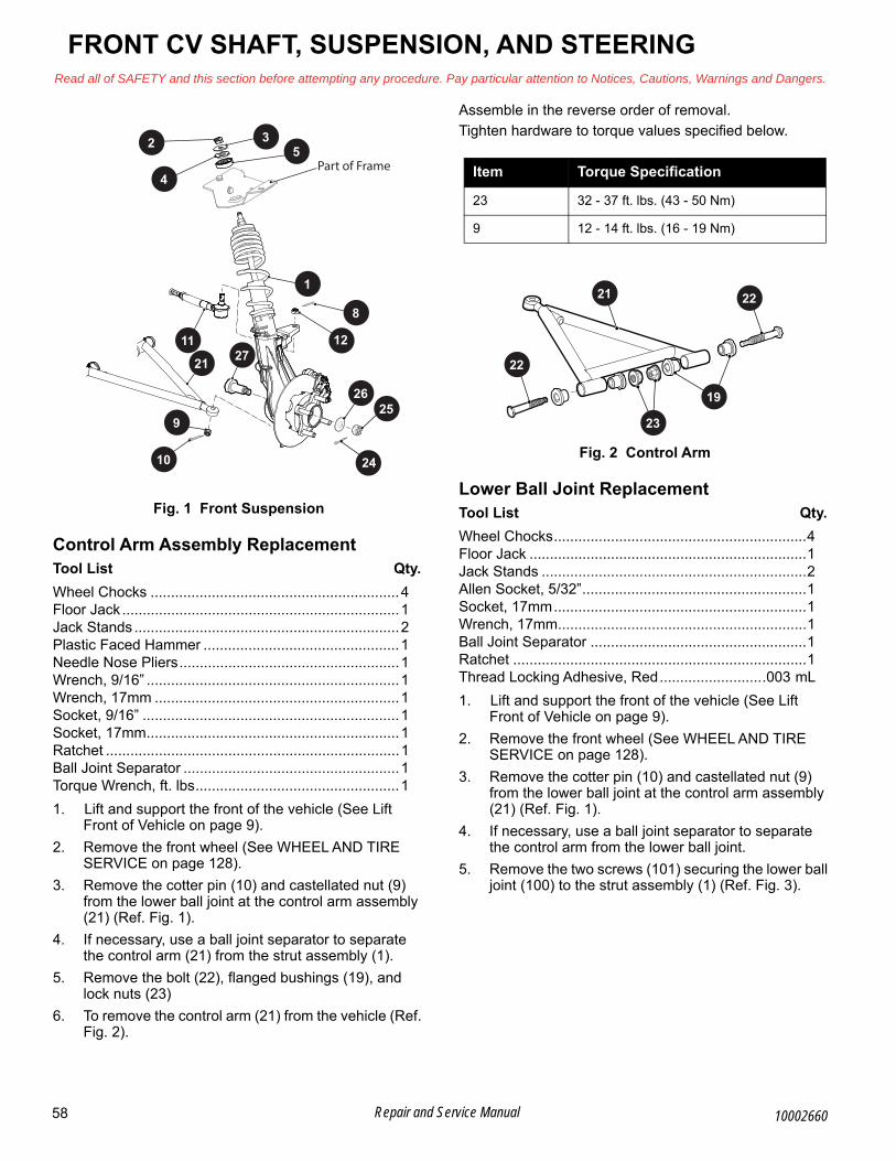
B
FRONT CV SHAFT, SUSPENSION, AND STEERINGRead all of SAFETY and this section before attempting any procedure. Pay particular attention to Notices, Cautions, Warnings and Dangers.
Fig. 1 Front Suspension
Control Arm Assembly ReplacementTool List Qty.
Wheel Chocks .............................................................4Floor Jack ....................................................................1Jack Stands .................................................................2Plastic Faced Hammer ................................................1Needle Nose Pliers......................................................1Wrench, 9/16” ..............................................................1Wrench, 17mm ............................................................1Socket, 9/16” ...............................................................1Socket, 17mm..............................................................1Ratchet ........................................................................1Ball Joint Separator .....................................................1Torque Wrench, ft. lbs..................................................1
1. Lift and support the front of the vehicle (See Lift Front of Vehicle on page 9).
2. Remove the front wheel (See WHEEL AND TIRE SERVICE on page 128).
3. Remove the cotter pin (10) and castellated nut (9) from the lower ball joint at the control arm assembly (21) (Ref. Fig. 1).
4. If necessary, use a ball joint separator to separate the control arm (21) from the strut assembly (1).
5. Remove the bolt (22), flanged bushings (19), and lock nuts (23)
6. To remove the control arm (21) from the vehicle (Ref. Fig. 2).
Assemble in the reverse order of removal.
Tighten hardware to torque values specified below.
Fig. 2 Control Arm
Lower Ball Joint ReplacementTool List Qty.
Wheel Chocks..............................................................4Floor Jack ....................................................................1Jack Stands .................................................................2Allen Socket, 5/32”.......................................................1Socket, 17mm..............................................................1Wrench, 17mm.............................................................1Ball Joint Separator .....................................................1Ratchet ........................................................................1Thread Locking Adhesive, Red..........................003 mL
1. Lift and support the front of the vehicle (See Lift Front of Vehicle on page 9).
2. Remove the front wheel (See WHEEL AND TIRE SERVICE on page 128).
3. Remove the cotter pin (10) and castellated nut (9) from the lower ball joint at the control arm assembly (21) (Ref. Fig. 1).
4. If necessary, use a ball joint separator to separate the control arm from the lower ball joint.
5. Remove the two screws (101) securing the lower ball joint (100) to the strut assembly (1) (Ref. Fig. 3).
11
21 27
8
9
10
2625
24
2
4
35
1
Part of Frame
12
Item Torque Specification
23 32 - 37 ft. lbs. (43 - 50 Nm)
9 12 - 14 ft. lbs. (16 - 19 Nm)
21 22
19
23
22
58 Repair and Service Manual 10002660
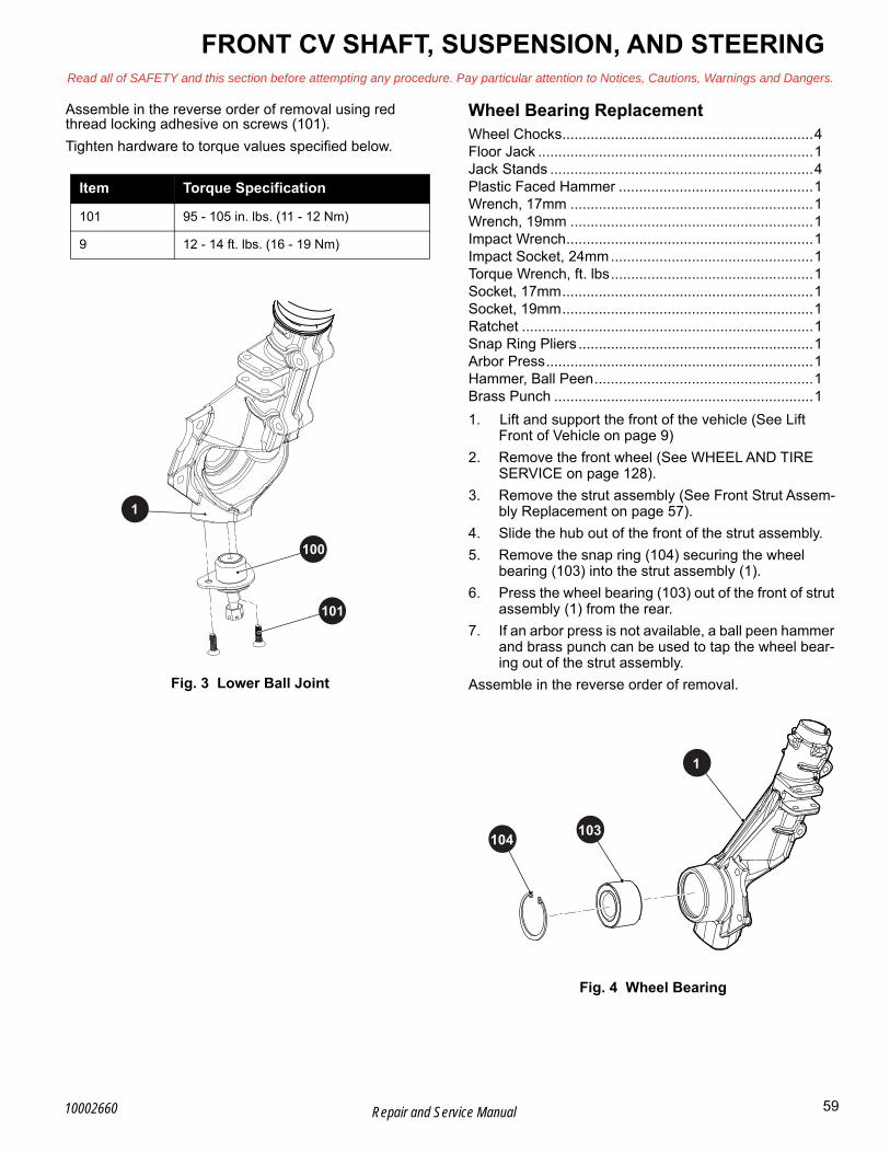
FRONT CV SHAFT, SUSPENSION, AND STEERINGRead all of SAFETY and this section before attempting any procedure. Pay particular attention to Notices, Cautions, Warnings and Dangers.
BAssemble in the reverse order of removal using red thread locking adhesive on screws (101).
Tighten hardware to torque values specified below.
Fig. 3 Lower Ball Joint
Wheel Bearing ReplacementWheel Chocks..............................................................4Floor Jack ....................................................................1Jack Stands .................................................................4Plastic Faced Hammer ................................................1Wrench, 17mm ............................................................1Wrench, 19mm ............................................................1Impact Wrench.............................................................1Impact Socket, 24mm..................................................1Torque Wrench, ft. lbs..................................................1Socket, 17mm..............................................................1Socket, 19mm..............................................................1Ratchet ........................................................................1Snap Ring Pliers ..........................................................1Arbor Press..................................................................1Hammer, Ball Peen......................................................1Brass Punch ................................................................1
1. Lift and support the front of the vehicle (See Lift Front of Vehicle on page 9)
2. Remove the front wheel (See WHEEL AND TIRE SERVICE on page 128).
3. Remove the strut assembly (See Front Strut Assem-bly Replacement on page 57).
4. Slide the hub out of the front of the strut assembly.
5. Remove the snap ring (104) securing the wheel bearing (103) into the strut assembly (1).
6. Press the wheel bearing (103) out of the front of strut assembly (1) from the rear.
7. If an arbor press is not available, a ball peen hammer and brass punch can be used to tap the wheel bear-ing out of the strut assembly.
Assemble in the reverse order of removal.
Fig. 4 Wheel Bearing
Item Torque Specification
101 95 - 105 in. lbs. (11 - 12 Nm)
9 12 - 14 ft. lbs. (16 - 19 Nm)
100
101
1
1
103104
59Repair and Service Manual10002660

B
FRONT CV SHAFT, SUSPENSION, AND STEERINGRead all of SAFETY and this section before attempting any procedure. Pay particular attention to Notices, Cautions, Warnings and Dangers.
Strut ReplacementTool List Qty.
Wheel Chocks .............................................................4Floor Jack ....................................................................1Jack Stands .................................................................4Plastic Faced Hammer ................................................1Wrench, 17mm ............................................................1Wrench, 19mm ............................................................1Wrench, 13mm ............................................................1Wrench, 9mm ..............................................................1Impact Wrench ............................................................1Impact Socket, 24mm..................................................1Torque Wrench, ft. lbs..................................................1Socket, 17mm..............................................................1Socket, 19mm..............................................................1Socket, 13mm..............................................................1Coil Spring Compressor ..............................................1Ratchet ........................................................................1
Use extreme caution when working with compressed coil springs.
Do not compress the spring any more than is necessary to relieve the tension against the spring cap.
1. Lift the front of the vehicle (See Lift Front of Vehicle on page 9).
2. Remove the front wheel (See WHEEL AND TIRE SERVICE on page 128)
3. Remove the strut assembly (See Front Strut Assem-bly Replacement on page 57).
4. Compress the coil spring (115) just enough to relieve the tension between the coil spring cap (112) and the coil spring base (114).
5. Remove the spring retaining nut (111) and coil spring cap (112).
6. Slowly release the tension from the coil spring com-pressor and remove the spring (115).
7. Remove the bump stop (113) from the strut (110) to reuse during reassembly. If the bump stop is cracked or otherwise damage, replace it with a new one.
8. Remove the two nuts (117), washers (118), and bolts (116) securing the strut to the strut assembly (1).
9. Remove the strut (110) from the strut assembly (1), retaining the coils spring base washers (114) for reuse (Ref. Fig. 5).
Assembly in the reverse order of removal using new lock nuts.
Torque all hardware to the torque values specified below.
Fig. 5 Strut Replacement
Item Torque Specification
111 14 - 16 ft. lbs. (19 - 22 Nm)
117 20 - 25 ft. lbs. (27 - 34 Nm)
1
110
112
117
116
118
114
111
113
115
60 Repair and Service Manual 10002660

FRONT CV SHAFT, SUSPENSION, AND STEERINGRead all of SAFETY and this section before attempting any procedure. Pay particular attention to Notices, Cautions, Warnings and Dangers.
BFRONT AXLE
CV Shaft ReplacementTool List Qty.
Wheel Chocks ............................................................. 4Floor Jack.................................................................... 1Jack Stands................................................................. 2Impact Wrench ............................................................ 1Impact Socket, 24mm.................................................. 1Plastic Faced Hammer ................................................ 1Socket, 17mm ............................................................. 1Wrench, 17mm............................................................ 1Torque Wrench, ft. lbs ................................................. 1Pry Bar ........................................................................ 1Ratchet ........................................................................ 1
Inspect the front axle (shaft) for contamination, specifically for torn CV boots around the axle. Replace
the front axle if any contamination is found.
1. Lift and support the vehicle (See LIFTING THE VEHICLE on page 8).
2. Remove the front wheel (See WHEEL AND TIRE SERVICE on page 128).
3. Remove the cotter pin (8) and nut (12) at the end of the steering rack assembly (11) (Ref. Fig. 1).
4. Remove the cotter pin (24), castle nut (25), and flat washer (26) from the end of the front axle (27) (Ref. Fig. 1).
5. Remove the cotter pin (10) and nut (9) from the lower ball joint.(Ref. Fig. 1).
6. Tap downward on the control arm assembly (21) with a plastic faced hammer, below the strut assembly (1) to separate the control arm assembly from the strut assembly (1) If necessary, use a ball joint separator.
7. Remove the outer end of the front axle (27) from the front strut assembly (1) (Ref. Fig. 6).
8. Pry from the back side of the CV joint housing between the differential and the CV axle, being care-ful not to damage the seal on the differential, to remove the axle.(27).
Assemble in the reverse order of removal.
Tighten hardware to torque values specified below.
NOTICE: When the axle is replaced, the front wheels must be aligned. (See Wheel Alignment on page 66)
Fig. 6 CV Axle Removal
Item Torque Specification
12 45 - 55 ft. lbs. (61 - 74 Nm)
25 100 - 110 ft. lbs. (136 - 149 Nm)
9 12 - 14 ft. lbs. (16 - 19 Nm)
24
25
1
27
Front of Vehicle
21
61Repair and Service Manual10002660
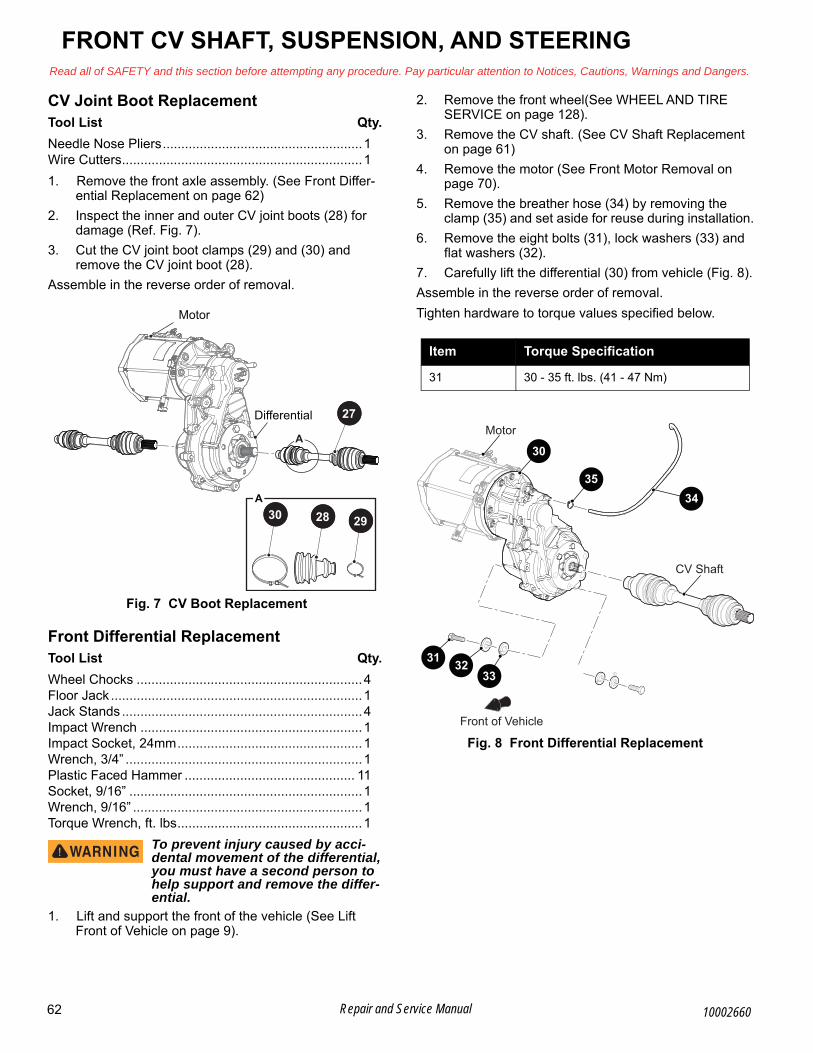
B
FRONT CV SHAFT, SUSPENSION, AND STEERINGRead all of SAFETY and this section before attempting any procedure. Pay particular attention to Notices, Cautions, Warnings and Dangers.
CV Joint Boot ReplacementTool List Qty.
Needle Nose Pliers......................................................1Wire Cutters.................................................................1
1. Remove the front axle assembly. (See Front Differ-ential Replacement on page 62)
2. Inspect the inner and outer CV joint boots (28) for damage (Ref. Fig. 7).
3. Cut the CV joint boot clamps (29) and (30) and remove the CV joint boot (28).
Assemble in the reverse order of removal.
Fig. 7 CV Boot Replacement
Front Differential ReplacementTool List Qty.
Wheel Chocks .............................................................4Floor Jack ....................................................................1Jack Stands .................................................................4Impact Wrench ............................................................1Impact Socket, 24mm..................................................1Wrench, 3/4” ................................................................1Plastic Faced Hammer .............................................. 11Socket, 9/16” ...............................................................1Wrench, 9/16” ..............................................................1Torque Wrench, ft. lbs..................................................1
To prevent injury caused by acci-dental movement of the differential, you must have a second person to help support and remove the differ-ential.
1. Lift and support the front of the vehicle (See Lift Front of Vehicle on page 9).
2. Remove the front wheel(See WHEEL AND TIRE SERVICE on page 128).
3. Remove the CV shaft. (See CV Shaft Replacement on page 61)
4. Remove the motor (See Front Motor Removal on page 70).
5. Remove the breather hose (34) by removing the clamp (35) and set aside for reuse during installation.
6. Remove the eight bolts (31), lock washers (33) and flat washers (32).
7. Carefully lift the differential (30) from vehicle (Fig. 8).
Assemble in the reverse order of removal.
Tighten hardware to torque values specified below.
Fig. 8 Front Differential Replacement
A
A
Motor
Differential 27
28 2930
Item Torque Specification
31 30 - 35 ft. lbs. (41 - 47 Nm)
1
34
Front of Vehicle
Motor
CV Shaft
30
31 3233
35
62 Repair and Service Manual 10002660

FRONT CV SHAFT, SUSPENSION, AND STEERINGRead all of SAFETY and this section before attempting any procedure. Pay particular attention to Notices, Cautions, Warnings and Dangers.
BSTEERING
Steering Wheel ReplacementTool List Qty.
Screwdriver, Flat Head................................................ 1Socket, 24mm ............................................................. 1Ratchet ........................................................................ 1Plastic Faced Hammer ................................................ 1Ball Peen Hammer ...................................................... 1Torque Wrench, ft. lbs ................................................. 1
NOTICE: Align wheels straight ahead to maintain correct orientation when replacing steering wheel.
1. Insert a flat screwdriver under the edge of the steer-ing wheel cover (37) and pry it from the steering wheel (39) (Ref. Fig. 9).
Fig. 9 Steering Wheel Cover Removal
2. Loosen the lock nut (38) two to three turns (Ref. Fig. 9) until it is slightly above the end of the steering shaft. DO NOT completely remove the nut at this time.
3. From below the steering wheel, put a plastic faced hammer against the lock nut as shown (Ref. Fig. 10).
4. Pull upward on the plastic faced hammer and strike hammer sharply with a ball peen hammer.
Do not hit the steering wheel lock nut or the end of the steering shaft directly with the ball peen hammer.
Fig. 10 Remove Steering Wheel
5. When the steering wheel (39) is loose, remove the lock nut (38) and the steering wheel (39).
6. Before installing the steering wheel (39), lightly cover the splines of the steering shaft with a commercially available anti-seize compound.
7. Align the front wheels in the straight ahead position.
8. Align the steering wheel (39) on the steering shaft, then slide onto shaft.
Tighten the lock nut (38) to the torque value specified below.
9. Align the pins on the steering wheel cover (37) with the holes in the steering wheel (Ref. Fig. 9).
10. Press the cover until it snaps into place.
37
39
38
Alignment Pins
Item Torque Specification
38 20 - 25 ft. lbs. (27 - 34 Nm)
63Repair and Service Manual10002660

B
FRONT CV SHAFT, SUSPENSION, AND STEERINGRead all of SAFETY and this section before attempting any procedure. Pay particular attention to Notices, Cautions, Warnings and Dangers.
Steering Column ReplacementTool List Qty.
Socket, 15mm..............................................................1Socket, 24mm..............................................................1Ratchet ........................................................................1Wrench, 15mm ............................................................1Torque Wrench, ft. lbs..................................................1
1. Remove the steering wheel. (See Steering Wheel Replacement on page 63)
2. Remove the four bolts (41) and lock nuts (42) that secure the steering column (40) to the frame.
3. Remove the yoke bolts (44), lock washers, and nuts (46) to release the steering yoke (43) from the steer-ing column (40) and steering rack (45) (Ref. Fig. 11).
Assemble in the reverse order of removal.
Tighten hardware to torques values specified below.
Fig. 11 Steering Column
Item Torque Specification
42 25 - 35 ft. lbs. (34 - 47 Nm)
38 20- 25 ft. lbs. (27 - 34 Nm)
44 25 - 30 ft. lbs. (34 - 41 Nm)
37
38
39
41
40
42
44
43
45
64 Repair and Service Manual 10002660

FRONT CV SHAFT, SUSPENSION, AND STEERINGRead all of SAFETY and this section before attempting any procedure. Pay particular attention to Notices, Cautions, Warnings and Dangers.
BSteering Rack ReplacementTool List Qty.
Wrench, 15mm............................................................ 1Needle Nose Pliers...................................................... 1Ball Joint Separator ..................................................... 1Plastic Faced Hammer ................................................ 1Screwdriver, Flathead.................................................. 1Allen Socket, 8mm ...................................................... 1Socket, 15mm ............................................................. 1Socket, 17mm ............................................................. 1Ratchet ........................................................................ 1Torque Wrench, ft. lbs. ............................................... 1Floor Jack.................................................................... 1Wheel Chocks ............................................................. 2Jack Stands................................................................. 2
1. Raise the front of the vehicle (See Lift Front of Vehi-cle on page 9).
2. Remove the front wheels (See WHEEL AND TIRE SERVICE on page 128).
3. Remove the steering column from the steering rack (45). (See Steering Column Replacement on page 64)
4. Remove the cotter pin (8) and nut (12) from the front strut assembly (1.) (Ref. Fig. 1).
5. Remove the three bolts (49) and nuts (48) attaching the steering rack assembly to the frame (Ref. Fig. 12).
Assemble in the reverse order of removal.
Tighten nuts to the torque value specified below. Fig. 12 Steering Rack Removal
Item Torque Specification
48 34 - 37 ft. lbs. (46 - 50 Nm)
49
48
65Repair and Service Manual10002660

B
FRONT CV SHAFT, SUSPENSION, AND STEERINGRead all of SAFETY and this section before attempting any procedure. Pay particular attention to Notices, Cautions, Warnings and Dangers.
Tie Rod RemovalTool List Qty.
Floor Jack ....................................................................1Wheel Chocks .............................................................2Jack Stands .................................................................2Wrench, 17mm ............................................................1Socket, 17mm..............................................................1Ratchet ........................................................................1
When replacing the tie rod (50), the steering rack (45) must be removed from the steering assembly to adjust the rack/ball joint length correctly. (Ref. Fig. 13)
1. Lift the front of the vehicle (See Lift Front of Vehicle on page 9)
2. Remove the front wheels (See WHEEL AND TIRE SERVICE on page 128).
3. Loosen the jam nut (52).
4. Remove the tie rod assembly (50) from the steering rack (45).
Tie Rod InstallationTool List Qty.
Wrench, 17mm ............................................................1Torque Wrench, ft. lbs..................................................1Crowfoot Wrench, 17mm.............................................1Thread Lock Primer .....................................................1Thread Locking Adhesive, Red....................................1
1. Clean the threads.
2. Apply thread locking primer and red thread locking adhesive to the rack ball end, before attaching to the steering rack (45).
3. Install an inner tie rod end (53) on each outer tie rod end (51).
4. Set the jam nuts (52) 5/8” (16 mm) distance onto the threaded portion of the steering rack (45).
5. Install the tie rod assemblies (50) onto the threaded portion of the steering rack (45) until they reach the jam nuts (52).
6. The tie rod orientation must be as shown (Ref. Fig. 13).
7. Tighten all hardware to torque values specified below.
Fig. 13 Tie Rod Installation
MAINTENANCEAll steering and suspension components are lube free.
Routine examination of the tires provide indications that an alignment is required.
NOTICE: Some maintenance items must be serviced more frequently on vehicles used under severe driv-ing conditions.
Wheel AlignmentMeasuring Tape ...........................................................1Wrench, 17mm.............................................................2Torque Wrench, ft. lbs ..................................................1
1. Center the steering unit by pushing the vehicle for-ward 10 feet.
2. Allow the unit to center itself, or rotate the steering wheel to the left until the stop is contacted.
3. Rotate the wheel to the right while counting the num-ber of rotations required to contact the right hand stop.
4. Divide the number of rotations by two. This will indi-cate the number of steering wheel rotations to achieve center.
5. Measure the center tread distance at the front of the tires. Measure as close to parallel with the front lower frame of the vehicle as possible (Ref. Fig. 14).
6. Put the measuring tape just under the frame rails and measure the center tread distance on the rear of the front tires.
• The correct measurement is 1/8” to 1/4” toe in.
7. To adjust the wheel alignment, loosen the tie rod jam nut (52), while holding the hex form on the outer tie rod end (51) (Ref. Fig. 13).
If tie rods or ends have been replaced; adjust both rod spacers the same distance prior to installing on the vehi-cle.
8. Count the threads on each end of the tie rod to make sure that each side was adjusted equally.
9. Tighten the jam nut (52) to the torque value specified below.
Item Torque Specification
52 36 - 40 ft. lbs. (48 - 54 Nm)
50 (including 51 and 53) 20 - 25 ft. lbs. (27 - 34 Nm)
5/8” (16 mm)
4552 53 51
50
66 Repair and Service Manual 10002660

FRONT CV SHAFT, SUSPENSION, AND STEERINGRead all of SAFETY and this section before attempting any procedure. Pay particular attention to Notices, Cautions, Warnings and Dangers.
BCounting threads or measuring thread distance are two methods to equalize tie rod length.
Drive the vehicle to confirm that the steering wheel is cor-rectly centered. If not, remove the steering wheel and rotate it to the correct position.
Fig. 14 Wheel Alignment Front of Front Tires
Fig. 15 Wheel Alignment Rear of Front Tires
Item Torque Specification
52 36 - 40 ft. lbs. (48 - 54 Nm)
67Repair and Service Manual10002660

68 Repair and Service Manual
FRONT CV SHAFT, SUSPENSION, AND STEERINGRead all of SAFETY and this section before attempting any procedure. Pay particular attention to Notices, Cautions, Warnings and Dangers.
Notes:
10002660
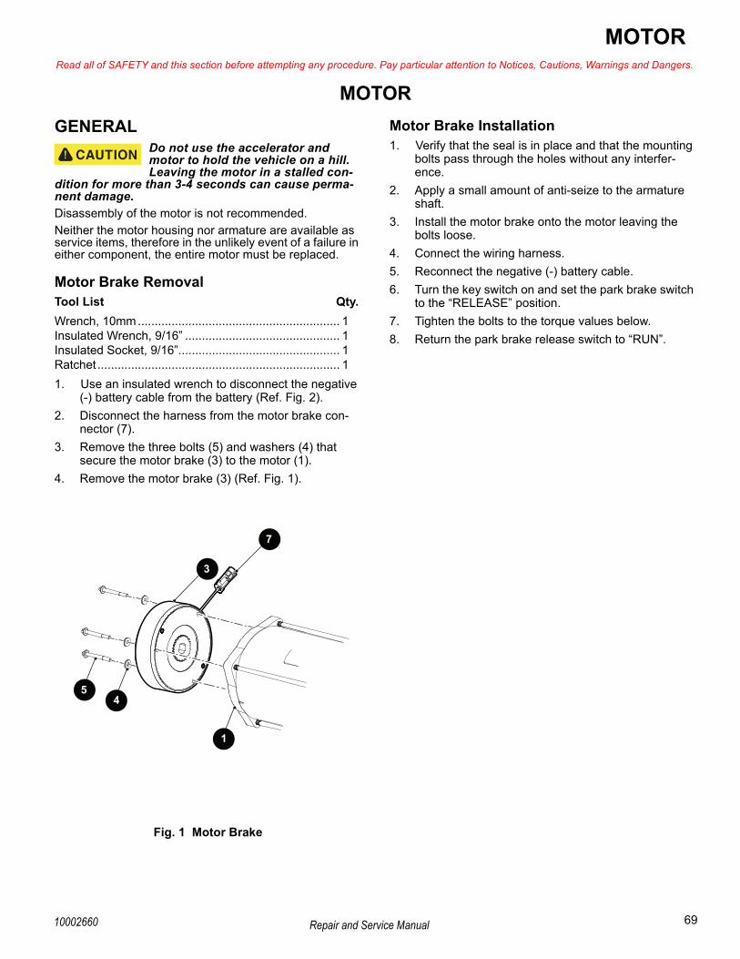
MOTORRead all of SAFETY and this section before attempting any procedure. Pay particular attention to Notices, Cautions, Warnings and Dangers.
BMOTOR
GENERALDo not use the accelerator and motor to hold the vehicle on a hill. Leaving the motor in a stalled con-
dition for more than 3-4 seconds can cause perma-nent damage.
Disassembly of the motor is not recommended.
Neither the motor housing nor armature are available as service items, therefore in the unlikely event of a failure in either component, the entire motor must be replaced.
Motor Brake RemovalTool List Qty.
Wrench, 10mm............................................................ 1Insulated Wrench, 9/16” .............................................. 1Insulated Socket, 9/16”................................................ 1Ratchet ........................................................................ 1
1. Use an insulated wrench to disconnect the negative (-) battery cable from the battery (Ref. Fig. 2).
2. Disconnect the harness from the motor brake con-nector (7).
3. Remove the three bolts (5) and washers (4) that secure the motor brake (3) to the motor (1).
4. Remove the motor brake (3) (Ref. Fig. 1).
Fig. 1 Motor Brake
Motor Brake Installation1. Verify that the seal is in place and that the mounting
bolts pass through the holes without any interfer-ence.
2. Apply a small amount of anti-seize to the armature shaft.
3. Install the motor brake onto the motor leaving the bolts loose.
4. Connect the wiring harness.
5. Reconnect the negative (-) battery cable.
6. Turn the key switch on and set the park brake switch to the “RELEASE” position.
7. Tighten the bolts to the torque values below.
8. Return the park brake release switch to “RUN”.
3
54
1
7
69Repair and Service Manual10002660

B
MOTORRead all of SAFETY and this section before attempting any procedure. Pay particular attention to Notices, Cautions, Warnings and Dangers.
Front Motor RemovalDisconnect the negative (-) battery cable with an insulated wrench before removing wires from the
motor. A short-circuit of the motor wires can cause an explosion.
Tool List Qty.
Wrench, 10mm ............................................................1Insulated Wrench, 9/16” ..............................................1Chalk or Paint Pen.......................................................1Socket, 10mm..............................................................1Ratchet ........................................................................1Scraper ........................................................................1Torque Wrench, in. lbs.................................................1
1. Use an insulated wrench to disconnect the negative (-) battery cable from the battery (Ref. Fig. 2).
2. Mark both the axle and motor housings to help with realignment during assembly of the motor to rear axle (Ref. Fig. 3).
Fig. 2 Disconnect Battery Cable
Fig. 3 Mark Axle and Motor
Do not damage the splines when removing and installing the motor to the rear axle housing.
3. Disconnect the motor wires from terminals U, V, and W (12) (Ref. Fig. 4) (Ref. Fig. 5).
4. Remove the connectors at the speed sensor (8), temperature sensor (9), and motor brake (7) (Ref. Fig. 4).
5. Remove the six bolts (11) that secure the motor (1) to the axle housing (10).
6. Carefully slide the motor straight out from the axle splines.
7. Remove the bolts (5), washers (4) and motor brake (3) from the motor (1).
8. Clean the motor coupler with compressed air and use a scraper to remove any rust deposits.
NEG
POS
NEGPOS
NEGPOS
NEG POS
NEGPOS
NEGPOS
To Solenoid
To Controller B-
BL- cable to bedisconnected
70 Repair and Service Manual 10002660

MOTORRead all of SAFETY and this section before attempting any procedure. Pay particular attention to Notices, Cautions, Warnings and Dangers.
B
Fig. 4 Front Motor Components
Front Motor InstallationAssemble in the reverse order of removal.
1. Apply a small quantity of molybdenum grease or a generous amount of silver grade anti-seize grease to the female part of the spline.
2. Carefully align the motor spline with the input shaft of the axle. Align the orientation marks and install the mounting hardware.
3. Place the differential gasket (6), in the groove pro-vided in the differential (10). Finger tighten the bolts (11) in a ‘cross sequence’ (Ref. Fig. 4), then tighten to 25 in. lbs. (2.82 Nm) increments of torque using the same ‘cross sequence’ pattern.
4. Reconnect the temperature sensor (9), speed sensor (8), and motor brake (7) wiring harnesses.
5. Reconnect the U, V, and W terminals (12) (Ref. Fig. 4) (Ref. Fig. 5).
Fig. 5 Motor Wiring
Tighten the hardware to the torque values specified below.
Disconnect the negative (-) battery cable with an insulated wrench before removing wires from the motor. A short-circuit of the motor wires can cause an explosion.
1 6
34
'CROSS SEQUENCE'
52
1
Clean the motor coupler with compressed air.
8
10
12
6
9
11
3
54
7
Item Torque Specification
5, 9 72 - 78 in. lbs. (8 - 9 Nm)
12 5 - 7 in. lbs. (.6 - .8 Nm)
MotorTerminal
WireMarker From
W
U
V
W
U
V
Controller "U"
Controller "V"
Controller "W"
MOTOR WIRING
71Repair and Service Manual10002660
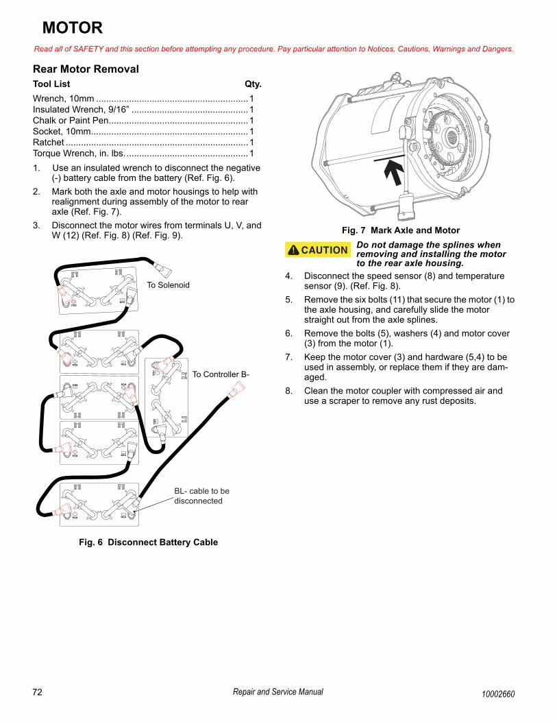
B
MOTORRead all of SAFETY and this section before attempting any procedure. Pay particular attention to Notices, Cautions, Warnings and Dangers.
Rear Motor RemovalTool List Qty.
Wrench, 10mm ............................................................1Insulated Wrench, 9/16” ..............................................1Chalk or Paint Pen.......................................................1Socket, 10mm..............................................................1Ratchet ........................................................................1Torque Wrench, in. lbs.................................................1
1. Use an insulated wrench to disconnect the negative (-) battery cable from the battery (Ref. Fig. 6).
2. Mark both the axle and motor housings to help with realignment during assembly of the motor to rear axle (Ref. Fig. 7).
3. Disconnect the motor wires from terminals U, V, and W (12) (Ref. Fig. 8) (Ref. Fig. 9).
Fig. 6 Disconnect Battery Cable
Fig. 7 Mark Axle and Motor
Do not damage the splines when removing and installing the motor to the rear axle housing.
4. Disconnect the speed sensor (8) and temperature sensor (9). (Ref. Fig. 8).
5. Remove the six bolts (11) that secure the motor (1) to the axle housing, and carefully slide the motor straight out from the axle splines.
6. Remove the bolts (5), washers (4) and motor cover (3) from the motor (1).
7. Keep the motor cover (3) and hardware (5,4) to be used in assembly, or replace them if they are dam-aged.
8. Clean the motor coupler with compressed air and use a scraper to remove any rust deposits.
NEG
POS
NEGPOS
NEGPOS
NEG POS
NEGPOS
NEGPOS
To Solenoid
To Controller B-
BL- cable to bedisconnected
72 Repair and Service Manual 10002660

MOTORRead all of SAFETY and this section before attempting any procedure. Pay particular attention to Notices, Cautions, Warnings and Dangers.
B
Fig. 8 Rear Motor Components
Rear Motor InstallationAssemble in the reverse order of removal.
1. Apply a small quantity of molybdenum grease or a generous amount of silver grade anti-seize grease to the female part of the spline.
2. Carefully align the motor spline with the input shaft of the axle. Align the orientation marks and install the mounting hardware.
3. Place the differential gasket (6), in the groove pro-vided in the differential (10). Finger tighten the bolts (11) in a ‘cross sequence’ (Ref. Fig. 8), then tighten to 25 in. lbs. (2.82 Nm) increments of torque using the same ‘cross sequence’ pattern.
4. Reconnect the temperature sensor (9) and speed sensor (8) wiring harnesses.
5. Reconnect the U, V, and W terminals (12) (Ref. Fig. 8) (Ref. Fig. 9).
Tighten the hardware to the torque values specified below.
Fig. 9 Motor Wiring
MOTOR TESTSThe armature and motor housing are not available as individual parts. The Curtis handheld can show specific motor faults (See FAULT TESTING on page 91). The motor can also be tested using a DVOM (See AC Motor Bench Test on page 122). Additionally, when a test of the power wiring system indicates that the system is operat-ing correctly and the vehicle either does not run or runs poorly, the motor is the only remaining component and should be replaced.
1
11
912
Clean the motor coupler with compressed air.
1 6
34
'CROSS SEQUENCE'
52
8
10
6
Item Torque Specification
5, 9 72 - 78 in. lbs. (8 - 9 Nm)
12 5 - 7 in. lbs. (.6 - .8 Nm)
MotorTerminal
WireMarker From
W
U
V
W
U
V
Controller "U"
Controller "V"
Controller "W"
MOTOR WIRING
73Repair and Service Manual10002660

MOTORRead all of SAFETY and this section before attempting any procedure. Pay particular attention to Notices, Cautions, Warnings and Dangers.
Notes:
74 Repair and Service Manual 10002660

SEATING AND OPSRead all of SAFETY and this section before attempting any procedure. Pay particular attention to Notices, Cautions, Warnings and Dangers.
BSEATING AND OPS
SEATINGNOTICE: Complete seat removal and replacement is not necessary in some of the repair procedures. Remove and replace the seat bottom or seat back assembly only if necessary.
Front Seat Removal and InstallationFront Seat Bottom
Lift and tilt the seat bottom toward the front of the vehicle, and remove the seat bottom.
To install the seat bottom, insert the seat tabs in the slots in the seat frame, and lower the seat bottom in position.
Front Seat Back and SupportTool List Qty.
Ratchet ........................................................................ 1Socket, 7/16 ................................................................ 1Socket, 9/16 ................................................................ 1Wrench, 9/16 ............................................................... 1
1. To remove front seat back (9), remove four screws (11) and lock washers (12) securing the seat back to the lower OPS (Ref. Fig. 1).
2. Remove the four lock nuts (8), washers (7), and bolts (6), from the seat back support (5) (or lower OPS).
Assemble in the reverse order of removal.
Tighten the bolts (11) to the torque values specified below.
Fig. 1 Front Seat Back Removal
Rear Seat Removal and InstallationTool List Qty.
Socket, 7/16”................................................................1Socket, 9/16”................................................................1Ratchet ........................................................................1Wrench, 7/16” ..............................................................1Wrench, 9/16” ..............................................................1Torque Wrench, ft. lbs..................................................1Torque Wrench, in. lbs. ................................................1
1. Remove the two bolts (15) and lock nuts (16) secur-ing the armrest (14) to the seat frame (Ref. Fig. 2).
2. Remove the bolts (36) and lock nuts (16) securing the armrest (14) to the footrest (24).
3. Remove the armrests (14) from the rear seat (Ref. Fig. 2).
Fig. 2 Arm Rest Removal
Item Torque Specification
11 13 - 16 ft. lbs. (18 - 22 Nm)
8 30 - 33 ft. lbs. (40 - 45 Nm)
9
11
12
LowerOPS
6
7 8
5
Front of Vehicle
1415
16
Front of Vehicle
36 24
75Repair and Service Manual10002660

B
SEATING AND OPSRead all of SAFETY and this section before attempting any procedure. Pay particular attention to Notices, Cautions, Warnings and Dangers.
4. Remove the bolts (33) and lock washers (34) fasten-ing the seat back (32) to the seat back bracket (28).
5. Remove the lock nuts (31), flat washers (30), and bolts (29) to remove the seat back brackets.
6. Remove the deck board fillers (40) (Ref. Fig. 3).
Fig. 3 Flip Seat Back Removal
7. Remove the lower seat belt support from the frame (See Rear Seat Belt Buckle Removal on page 79).
8. Remove the four lock nuts (35), flat washers (20), and bolts (19) to remove the seat bottom (18) (Ref. Fig. 4).
Fig. 4 Seat Bottom Removal
9. Remove the bolts (42), flat washers (43), and lock nuts (44) that secure the seat frame (41) to the main frame of the vehicle (Ref. Fig. 5).
Fig. 5 Seat Frame
10. Remove bolts (21), flat washers (22), and lock nuts (23) that secure the crossmember to the vehicle frame.) (Ref. Fig. 4).
Assemble in the reverse order of removal.
Tighten hardware to torque values specified below.
3228
33
29
30
34
30
31
4040
Front of Vehicle
19
18
20
35
212223
37
Front of Vehicle
Item Torque Specification
16, 31, 23, 44 21 - 25 ft. lbs. (28 - 34Nm)
33 44 - 55 in. lbs. (5 - 6 Nm)
35 9 - 11 ft. lbs (12 - 15 Nm)
4241
43
44
Front of Vehicle
76 Repair and Service Manual 10002660

SEATING AND OPSRead all of SAFETY and this section before attempting any procedure. Pay particular attention to Notices, Cautions, Warnings and Dangers.
BSeat Cushion DisassemblyTool List Qty.
Screwdriver, Flat Head................................................ 1Staple Gun .................................................................. 1Staples .................................................................... A/R
1. Remove the seat back from the vehicle (See Front Seat Removal and Installation on page 75).
2. Remove the back cover (5).
3. Remove the staples (40).
4. Separate the seat back base(6) and seat cushion (7) (Ref. Fig. 6).
To assemble the seat cushion, attach it to the seat back base with new staples and attach the seat back cover.
Fig. 6 Seat Cushion
Footrest Removal and InstallationNOTICE: It is not necessary to completely remove the arm rest to remove the footrest.
Tool List Qty.
Socket, 9/16” ............................................................... 1Socket, 7/16” ............................................................... 1Socket, 5/8 .................................................................. 1Ratchet ........................................................................ 1Wrench, 7/16”.............................................................. 1Wrench, 9/16”.............................................................. 1Wrench, 5/8”................................................................ 1Torque Wrench, ft. lbs. ................................................ 1
1. Remove the rear closeout panel (4) (See Rear Closeout Panel Replacement on page 30)
2. Remove the bolts (36) and lock nuts that secure the footrest (24) to the armrest (Ref. Fig. 7).
3. Remove the center lock nuts (28) and bolts (29).
4. Remove the bolts (25), flat washers (26), and lock nuts (27) to remove the footrest (24) from the vehicle (Ref. Fig. 7).
Assemble in the reverse order of removal.
Tighten hardware to torque values specified below.
Fig. 7 Foot Rest
Seat Belt Removal and InstallationTool List Qty.
Socket, 5/8“..................................................................1Ratchet ........................................................................1Wrench, 5/8” ................................................................1Torque Wrench, in. lbs. ................................................1
1. Remove the bolts (46) and nuts (47) that secure the seat belt pillar loops (48) on both sides of the vehicle.
2. Remove the bolts (50) and nuts (51) to remove the seat belt retractors (49).
3. Remove the seat belt anchors (52) by removing the bolts (53) and nuts (54) (Ref. Fig. 8).
Assemble in the reverse order of removal.
Tighten the nuts to the torque values specified below.
6
5
740
Item Torque Specification
27 62 - 68 ft. lbs. (84 - 92 Nm)
Item Torque Specification
47, 54 21 - 25 ft. lbs. (28 - 34 Nm)
51 45 - 55 in. lbs. (5 - 6 Nm)
27
26
29
4
242825
51
36
Front of Vehicle
77Repair and Service Manual10002660

B
SEATING AND OPSRead all of SAFETY and this section before attempting any procedure. Pay particular attention to Notices, Cautions, Warnings and Dangers.
Fig. 8 Seat Belt Assembly
Front Seat Belt Buckle ReplacementTool List Qty.
Socket, 5/8” .................................................................1Ratchet ........................................................................1Wrench, 5/8” ................................................................1Torque Wrench, ft. lbs..................................................1
Remove the bolts (67), washers (69), and lock nuts (66) that secure the front seat belt buckle (70) to the OPS frame (Ref. Fig. 9).
Assemble in the reverse order of removal.
Tighten the nuts to the torque values specified below.
Fig. 9 Front Seat Belt Buckle Removal
Rear Seat Belt Buckle ReplacementTool List Qty.
Socket, 5/8”..................................................................1Ratchet ........................................................................1Wrench, 5/8” ................................................................1Torque Wrench, ft lbs. ..................................................1
1. Remove bolts (74) and lock nuts (75) from the rear seat belt bracket (76) to remove the rear seat buckle (73) (Ref. Fig. 10).
2. To remove the rear seat belt bracket (76), remove the bolts (77), washers (78), and nuts (79) that secure the bracket to the frame (Ref. Fig. 10).
Assemble in the reverse order of removal.
Tighten the nuts to the torque values specified below.
Item Torque Specification
66 45 - 55 ft. lbs. (61 - 75 Nm)
50
51
53 54
4947
46
52
48
Front of Vehicle
Item Torque Specification
75 45 - 55 ft. lbs (61 - 75 Nm)
79 21 - 25 ft. lbs. (28 - 34 Nm)
66
69
70
67
78 Repair and Service Manual 10002660
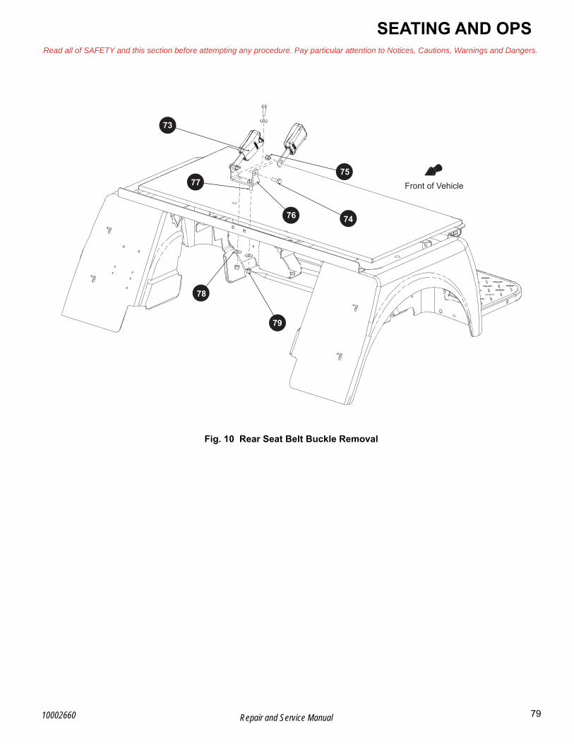
SEATING AND OPSRead all of SAFETY and this section before attempting any procedure. Pay particular attention to Notices, Cautions, Warnings and Dangers.
B
Fig. 10 Rear Seat Belt Buckle Removal
74
73
77
78
79
76
Front of Vehicle75
79Repair and Service Manual10002660

B
SEATING AND OPSRead all of SAFETY and this section before attempting any procedure. Pay particular attention to Notices, Cautions, Warnings and Dangers.
UPPER OPERATOR PROTECTION SYSTEM
Upper OPS Frame Removal and InstallationTool List Qty.
Ratchet ........................................................................1Allen Socket, 8mm” .....................................................1Torque Wrench, ft. lbs..................................................1
1. Remove front and rear seat belts. (See Seat Belt Removal and Installation on page 77)
The following steps involve lifting heavy and awkward objects. Two people are recommended.
Use a personal back support brace and proper lift-ing technique to prevent personal injury.
2. Loosen, but do not remove, the four bolts (84) fas-tening the forward (85) and the rear (86) sections of the upper OPS together.
3. Remove eight bolts (81) and lock nuts (82) that attach the upper OPS frame to the lower OPS frame.
4. Lift the upper OPS off of the vehicle.
5. If necessary, the forward (85) and rear (86) sections can be separated by removing the four bolts (94) and nuts (87) connecting them.
Assemble in the reverse order of removal.
Tighten the nuts to the torque values specified below.
Fig. 11 Upper OPS Removal
Item Torque Specification
81, 84 37 - 41 ft. lbs. (50 - 56 Nm)
81
82
87
84
86
85
Front of Vehicle
80 Repair and Service Manual 10002660

SEATING AND OPSRead all of SAFETY and this section before attempting any procedure. Pay particular attention to Notices, Cautions, Warnings and Dangers.
BLOWER OPERATOR PROTECTION SYSTEM
Brush Guard Removal and InstallationTool List Qty.
Socket, 1/2” ................................................................. 1Socket, 15mm ............................................................. 1Ratchet ........................................................................ 1Wrench, 1/2”................................................................ 1Wrench, 15mm............................................................ 1Torque Wrench, ft. lbs. ................................................ 1
1. Remove the bolts (101) and lock nuts (103) from the brush guard (100) (Ref. Fig. 12).
2. Remove the bolts (104) and lock nuts (105) to remove the brush guard (100) from the vehicle.
Assemble in the reverse order of removal.
Tighten the nuts to the torque values specified below.
Fig. 12 Brush Guard Removal
Item Torque Specification
103, 105 30 - 33 ft. lbs. (41 - 45 Nm)
101
103
105
104
100
96
110Front of Vehicle
81Repair and Service Manual10002660

B
SEATING AND OPSRead all of SAFETY and this section before attempting any procedure. Pay particular attention to Notices, Cautions, Warnings and Dangers.
OPS Lower Weldment Removal and Installa-tionNOTICE: Assistance may be required to remove the lower OPS weldment.
Tool List Qty.
Ratchet ........................................................................1Socket, 10mm..............................................................1Socket, 15mm..............................................................1Wrench, 10mm ............................................................1Wrench, 15mm ............................................................1Wrench, 1/2””...............................................................1Torque Wrench, ft. lbs..................................................1Torque Wrench, in. lbs.................................................1
1. Remove upper OPS frame from the lower OPS. (See Upper OPS Frame Removal and Installation on page 80)
2. Remove the back rest on the front seat. (See Front Seat Removal and Installation on page 75)
3. Remove the brush guard. (See Brush Guard Removal and Installation on page 81)
4. Remove the seat belts. (See Seat Belt Removal and Installation on page 77)
5. Remove the front seat belt buckle. (See Front Seat Belt Buckle Replacement on page 78)
6. Loosen, but do not remove, the bolt (111) that secures the upper portion of the lower OPS weld-ment (110) (Ref. Fig. 13).
Fig. 13 Lower OPS Weldment (Upper Fastening)
7. Remove the top bolt (124) from the restraint panel (129).
8. Remove the two lock nuts (125), bolts (121), restraint panel (129), and bracket (128).
9. Remove the lock nuts (126) and bolts (122).
10. Remove the lock nuts (127) and bolts (123) securing the rear of the lower OPS weldment (110) (Ref. Fig. 14).
11. Have an assistant to support the front of the lower OPS weldment.
12. Lift the rear of the lower OPS weldment (110) and slide it toward the rear of the vehicle to release the front bracket (115) from the bolt (111) (Ref. Fig. 13) (Ref. Fig. 14).
110
111
112
113
114
115
Front of Vehicle
82 Repair and Service Manual 10002660

SEATING AND OPSRead all of SAFETY and this section before attempting any procedure. Pay particular attention to Notices, Cautions, Warnings and Dangers.
B
Fig. 14 Lower OPS Weldment
Assemble in the reverse order of removal.
Tighten hardware to torques values specified below.
110
121
122
123
124
126
125
128
129
127
128
Front of Vehicle
115
Item Torque Specification
124, 126 6 - 7 ft. lbs. (8 - 10 Nm)
111 15 - 19 ft. lbs. (20 - 25 Nm)
125 19 - 22 ft. lbs. (25 - 30 Nm)
127 30 - 33 ft. lbs. (40 - 45 Nm)
83Repair and Service Manual10002660

SEATING AND OPSRead all of SAFETY and this section before attempting any procedure. Pay particular attention to Notices, Cautions, Warnings and Dangers.
Notes:
84 Repair and Service Manual 10002660
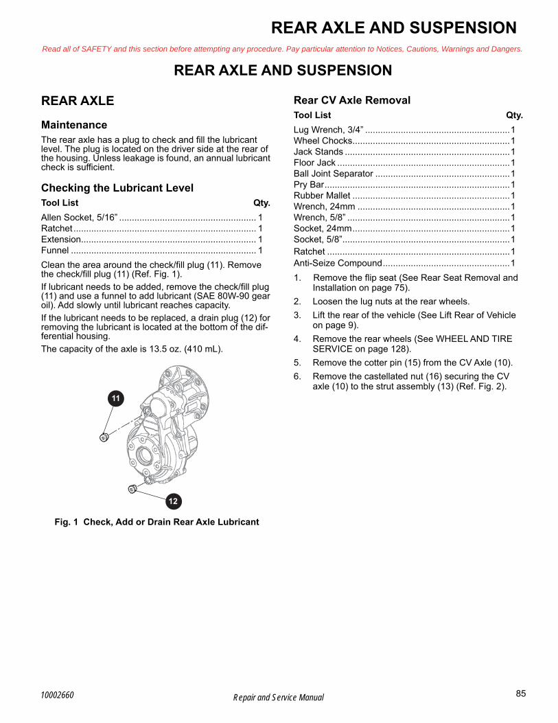
REAR AXLE AND SUSPENSIONRead all of SAFETY and this section before attempting any procedure. Pay particular attention to Notices, Cautions, Warnings and Dangers.
BREAR AXLE AND SUSPENSION
REAR AXLE
MaintenanceThe rear axle has a plug to check and fill the lubricant level. The plug is located on the driver side at the rear of the housing. Unless leakage is found, an annual lubricant check is sufficient.
Checking the Lubricant LevelTool List Qty.
Allen Socket, 5/16” ...................................................... 1Ratchet ........................................................................ 1Extension..................................................................... 1Funnel ......................................................................... 1
Clean the area around the check/fill plug (11). Remove the check/fill plug (11) (Ref. Fig. 1).
If lubricant needs to be added, remove the check/fill plug (11) and use a funnel to add lubricant (SAE 80W-90 gear oil). Add slowly until lubricant reaches capacity.
If the lubricant needs to be replaced, a drain plug (12) for removing the lubricant is located at the bottom of the dif-ferential housing.
The capacity of the axle is 13.5 oz. (410 mL).
Fig. 1 Check, Add or Drain Rear Axle Lubricant
Rear CV Axle RemovalTool List Qty.
Lug Wrench, 3/4” .........................................................1Wheel Chocks..............................................................1Jack Stands .................................................................1Floor Jack ....................................................................1Ball Joint Separator .....................................................1Pry Bar.........................................................................1Rubber Mallet ..............................................................1Wrench, 24mm ............................................................1Wrench, 5/8” ................................................................1Socket, 24mm..............................................................1Socket, 5/8”..................................................................1Ratchet ........................................................................1Anti-Seize Compound..................................................1
1. Remove the flip seat (See Rear Seat Removal and Installation on page 75).
2. Loosen the lug nuts at the rear wheels.
3. Lift the rear of the vehicle (See Lift Rear of Vehicle on page 9).
4. Remove the rear wheels (See WHEEL AND TIRE SERVICE on page 128).
5. Remove the cotter pin (15) from the CV Axle (10).
6. Remove the castellated nut (16) securing the CV axle (10) to the strut assembly (13) (Ref. Fig. 2).
11
12
85Repair and Service Manual10002660

B
REAR AXLE AND SUSPENSIONRead all of SAFETY and this section before attempting any procedure. Pay particular attention to Notices, Cautions, Warnings and Dangers.
Fig. 2 CV Axle Attachment
7. Remove the cotter pin (22) and castellated nut (23) attaching the lower ball joint to the control arm (20) (Ref. Fig. 3).
8. Loosen, but do not completely remove, the lock nut (24) connecting the outer tie rod end (21) to the strut assembly (13).
9. Free the outer tie rod end (21) by tapping upward using a rubber mallet.
10. Remove the lock nut (24)from the outer tie rod end (21).
11. Remove the cotter pin (22) and castellated nut (23) securing the control arm (20) to the lower ball joint (25).
12. Separate the lower ball joint (25) from the lower con-trol arm (20) using a ball joint separator (Ref. Fig. 3).
13. Remove the axle (10) from the strut assembly (13) by pulling the strut assembly outward (Ref. Fig. 2).
14. Remove the CV Axle from the differential using a pry bar.
Fig. 3 Control Arm and Tie Rod End Attachment
Assemble in the reverse order of removal using new lock nuts and cotter pins.
Apply commercially available anti-seize compound to the axle end prior to installation.
Tighten all hardware to the torque values specified below. Continue tightening castellated nuts until the cotter pin can be installed.
Differential RemovalTool List Qty.
Wrench, 9/16” ..............................................................1Socket, 9/16”................................................................1Ratchet ........................................................................1Lifting Device ...............................................................1Torque Wrench, ft, lbs. .................................................1Thread Locking Compound, Red.................................1
1. Remove the flip seat (See Rear Seat Removal and Installation on page 75).
2. Remove both CV Axles (See Rear CV Axle Removal on page 85).
Front of Vehicle13
15
16
10
Item Torque Specification
25 12 - 14 ft. lbs. (16 - 19 Nm)
24 45 - 55 ft. lbs. (61 - 74 Nm)
16 100 - 110 ft. lbs. (136 - 149 Nm)
Front of Vehicle21
20
23
22
25
13
25
86 Repair and Service Manual 10002660

REAR AXLE AND SUSPENSIONRead all of SAFETY and this section before attempting any procedure. Pay particular attention to Notices, Cautions, Warnings and Dangers.
B3. Remove the clamp (11) and breather hose (2) and
retain them for reuse during installation.
4. Remove the four bolts (3) and washers (4) securing the rear tie rod bracket (5) to the differential.
5. Remove the rear tie rod bracket (5) from the vehicle leaving the tie rods attached to the frame.
6. Remove the six bolts (9) and washers (7) that secure the differential (1) to the frame (8) (Ref. Fig. 4).
7. Lift the differential from the vehicle using a lifting device.
Fig. 4 IS Differential Mounting
NOTICE: Always refer to the thread locking com-pound packaging and allow the recommended cure time before entering the vehicle back into service.
Assemble in the reverse order of removal using red thread locking compound.
Tighten the mounting bolts to the torque values specified below.
REAR SUSPENSIONNOTICE: Hardware that is removed must always be installed in its original position unless otherwise specified. If torque values are not specified, refer to the Torque Specifications table (See TORQUE SPECIFICATIONS on page 5).
Strut Assembly RemovalTool List Qty.
Wrench, 19mm ............................................................1Socket, 19mm..............................................................1Socket, 19mm, Deep Well ...........................................1Ratchet ........................................................................1Torque Wrench, Ft. Lbs. ..............................................1Floor Jack ....................................................................1Wheel Chocks..............................................................2Jack Stands .................................................................2
1. Remove the flip seat (See Rear Seat Removal and Installation on page 75).
2. Lift the rear of the vehicle (See Lift Rear of Vehicle on page 9).
3. Remove the CV axle (See Rear CV Axle Removal on page 85).
4. Remove the lock nut (27), washers (28), and bushing (29) from the strut tower.
5. Remove the strut assembly (13) from the vehi-cle.Remove the lower strut bushing (24). Replace the busing (24) during reassembly if it is cracked or otherwise damaged,
Item Torque Specification
9 30 - 35 ft. lbs. (41 - 47 Nm)
Front of Vehicle
4
5
1
11
793
8
2
87Repair and Service Manual10002660
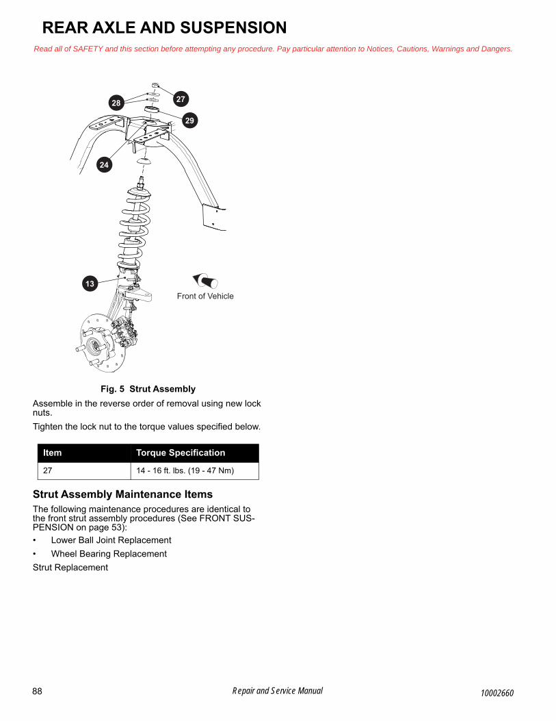
B
REAR AXLE AND SUSPENSIONRead all of SAFETY and this section before attempting any procedure. Pay particular attention to Notices, Cautions, Warnings and Dangers.
Fig. 5 Strut Assembly
Assemble in the reverse order of removal using new lock nuts.
Tighten the lock nut to the torque values specified below.
Strut Assembly Maintenance ItemsThe following maintenance procedures are identical to the front strut assembly procedures (See FRONT SUS- PENSION on page 53):
• Lower Ball Joint Replacement
• Wheel Bearing Replacement
Strut Replacement
Item Torque Specification
27 14 - 16 ft. lbs. (19 - 47 Nm)
Front of Vehicle
27
29
28
13
24
88 Repair and Service Manual 10002660

Read all of SAFETY and this section before attempting any procedure. Pay particular attention to Notices, Cautions, Warnings and Dangers.
REAR AXLE AND SUSPENSION
Notes:
89Repair and Service Manual10002660

REAR AXLE AND SUSPENSIONRead all of SAFETY and this section before attempting any procedure. Pay particular attention to Notices, Cautions, Warnings and Dangers.
Notes:
90 Repair and Service Manual 10002660

FAULT TESTINGRead all of SAFETY and this section before attempting any procedure. Pay particular attention to Notices, Cautions, Warnings and Dangers.
BFAULT TESTING
SUSPENSION AND STEERING
Fig. 1 Suspension and Steering Fault Diagnosis
Condition Possible Cause Correction
UNEVEN TIRE WEARIncorrect tire pressure Inflate to recommended pressure
Improper alignment (Incorrect toe in) Align front tires
STIFF STEERING
Water has entered steering box and can freeze in cold conditions
Remove steering column, pinion and bearing and remove water before adding grease; Inspect gasket for good seal
Excessive grease in steering box has moved into steering rack bellows
Raise the vehicle and observe the rackbellows while moving the steering from lock to lock
Any distortion of the bellows can indicate an excess of grease has accumulated in the bellows
Remove the bellows and remove excess grease
Insufficient lubricant in king pins, tie rod ends, idler bushing, rack tensioner or steering box
Add one shot of lubricant to each grease fitting and operate steering from lock to lock. Do not over grease
If steering does not return to acceptable condition, proceed to next step
Bent rack
Remove rack and place on flat surface with rack teeth up; If a 0.015” (0.381 mm) feeler gauge will pass under the rack, the rack must be replaced
PLAY IN STEERING
Steering wheel looseInspect splines - replace steering wheel if required; Tighten steering wheel nut
Steering components worn Replace
Loose wheel bearings Adjust or replace
VIBRATION
Steering components worn Replace
Loose wheel bearings Adjust or replace
Out of round tires, wheels, or brake drums
Inspect and replace if out of round
STEERING PULLS TO ONE SIDE
Incorrect tire pressure Inflate to recommended pressure
Dragging wheel brakes Service brake system
Suspension component failure Repair
Alignment incorrect Align
91Repair and Service Manual10002660
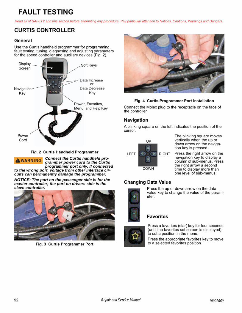
B
FAULT TESTINGRead all of SAFETY and this section before attempting any procedure. Pay particular attention to Notices, Cautions, Warnings and Dangers.
CURTIS CONTROLLER
GeneralUse the Curtis handheld programmer for programming, fault testing, tuning, diagnosing and adjusting parameters for the speed controller and auxiliary devices (Fig. 2).
Fig. 2 Curtis Handheld Programmer
Connect the Curtis handheld pro-grammer power cord to the Curtis programmer port only. If connected
to the wrong port, voltage from other interface cir-cuits can permanently damage the programmer.
NOTICE: The port on the passenger side is for the master controller; the port on drivers side is the slave controller.
Fig. 3 Curtis Programmer Port
Fig. 4 Curtis Programmer Port Installation
Connect the Molex plug to the receptacle on the face of the controller.
NavigationA blinking square on the left indicates the position of the cursor.
The blinking square moves vertically when the up or down arrow on the naviga-tion key is pressed.
Press the right arrow on the navigation key to display a column of sub-menus. Press the right arrow a second time to display more than one level of sub-menus.
Changing Data ValuePress the up or down arrow on the data value key to change the value of the param-eter.
Favorites
Press a favorites (star) key for four seconds (until the favorites set screen is displayed), to set a position in the menu.
Press the appropriate favorites key to move to a selected favorites position.
DisplayScreen
Data Increase
Soft Keys
or Data Decrease Key
Power, Favorites,Menu, and Help Key
PowerCord
NavigationKey
UP
DOWN
RIGHTLEFT
92 Repair and Service Manual 10002660

FAULT TESTINGRead all of SAFETY and this section before attempting any procedure. Pay particular attention to Notices, Cautions, Warnings and Dangers.
BMain Menu Definitions• PARAMETERS - Shows vehicle profile setting and
adjustability.
• MONITOR - Shows vehicle real-time diagnostics.
• DIAGNOSTICS - Shows active and past faults.
NOTICE: The programmer does not request confir-mation before deleting fault code history. Pressing “DELETE ALL” will permanently remove any histori-cal codes.
• PROGRAMMING - Shows parameter setting uploads and downloads.
• SYSTEM INFO- Shows controller information.
• HHP SETTINGS- Shows handheld information and adjustment.
Menu Submenu 1 Submenu 2 Submenu 3 Data Range Default value
Parameters Reset Controller 0 - 1 0
Monitor
Solenoid Coil On - Off On
Rear Node Select On - Off On
Solenoid PWM 0-100 0%
Rear Controller
Run/Tow Switch On - Off
Key Switch or Charger On - Off Off
Economy Mode Switch On - Off Off
Forward Switch On - Off Off
Reverse Switch On - Off Off
Throttles Raw Primary Throttle 0.00 - 5.00 0.73V
Mapped Primary Throttle 0 -1 00 0.00%
Raw Redundant Throttle 0.00 - 5.00 0.37V
Mapped Redundant Throttle 0 - 100 0%
Inputs
Throttle Command 0 - 100 0%
Mapped Throttle 0 - 100 0%
Throttle Pot 0.00 - 5.50 0.73V
Pot2 Raw 0.00 - 5.50 0.37V
Interlock On - Off Off
Analog 2 0.00 - 10.00 1.24V
Outputs
5 Volts 0.00 - 6.25 4.94V
12 Volts 0.00 - 12.00 12.42V
Ext Supply Current 0 - 200 63mA
Pot Low 0.00 - 6.25 0.20V
Battery
BDI 0 - 100 75%
Capacitor Voltage 0.0 - 105.0 3.1V
Key Switch Voltage 0.0 - 105.0 77.0V
Motor
Motor RPM -12000 -12000 0 RPM
Temperature -100 - 300 29 oC Motor Speed A -12000 - 12000 0 RPM Motor Speed B -12000 - 12000 0 RPM
Fig. 5 CURTIS Handheld Controller Main/Sub-menus
93Repair and Service Manual10002660

B
FAULT TESTINGRead all of SAFETY and this section before attempting any procedure. Pay particular attention to Notices, Cautions, Warnings and Dangers.
Monitor (con-tinued)
Controller
Current (RMS) 0.0 - 1000.0 ≈1A Modulation Depth 0.0 - 100 0.00% Frequency -300.0 - 300.0 0.0Hz Temperature -100 - 300 25ºC Regen On - Off On
Cutbacks Motor Temp
Cutback 0 - 100 100%
Controller Temp Cutback
0 - 100 100%
Under voltage Cutback
0 - 100 0%
Over voltage
Cutback 0 - 100 100%
Vehicle
Vehicle Speed -3276.8 - 3276.7
0
Vehicle Odometer 0.0-10000000.0 Varies
Braking Distance 0.0 - 1000000.0
0
Distance Since Stop 0.0 - 1000000.0
Diagnostics Present Errors Display active faults. Fault History Display non - active faults
Functions Settings
Get Settings From
Controller OK - Abort
Write Settings To
Controller OK - Abort
Reset All Settings Yes-No
Menu Submenu 1 Submenu 2 Submenu 3 Data Range Default value
Fig. 5 CURTIS Handheld Controller Main/Sub-menus (Continued)
94 Repair and Service Manual 10002660
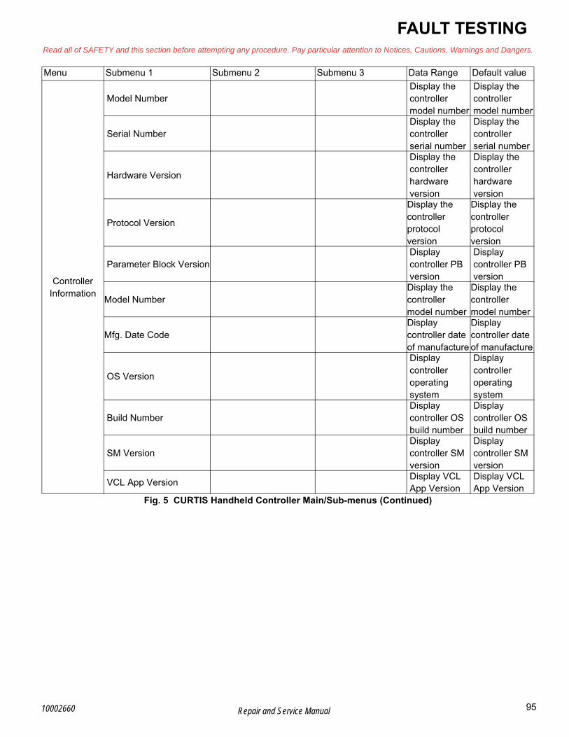
FAULT TESTINGRead all of SAFETY and this section before attempting any procedure. Pay particular attention to Notices, Cautions, Warnings and Dangers.
B
Controller Information
Model Number Display the controller model number
Display the controller model number
Serial Number Display the controller serial number
Display the controller serial number
Hardware Version
Display the controller hardware version
Display the controller hardware version
Protocol Version
Display the controller protocol version
Display the controller protocol version
Parameter Block Version Display controller PB version
Display controller PB version
Model NumberDisplay the controller model number
Display the controller model number
Mfg. Date CodeDisplay controller date of manufacture
Display controller date of manufacture
OS Version
Display controller operating system
Display controller operating system
Build Number Display controller OS build number
Display controller OS build number
SM Version Display controller SM version
Display controller SM version
VCL App VersionDisplay VCL App Version
Display VCL App Version
Menu Submenu 1 Submenu 2 Submenu 3 Data Range Default value
Fig. 5 CURTIS Handheld Controller Main/Sub-menus (Continued)
95Repair and Service Manual10002660

B
FAULT TESTINGRead all of SAFETY and this section before attempting any procedure. Pay particular attention to Notices, Cautions, Warnings and Dangers.
HHP Settings
ProgramLCD Contract -300 0Language English EnglishSet Security Code Set user lock code
FaultsFault History
Display fault history of HANDHELD
Clear Fault History Yes/NoInformation OEM Info Display OEM information
*Reconfigured Display reconfigure status
Model Number Display handheld model number
Serial Number Display handheld serial number
Manufacturing Date Display handheld manufacture date
Software Version Display handheld software version
Hardware Version Display handheld hardware version
MC-Protocol Version Display MC-Protocol versionES-Protocol Version Display ES-Protocol versionS-Protocol Version Display S-Protocol versionDevice Type Display device type
Menu Submenu 1 Submenu 2 Submenu 3 Data Range Default value
Fig. 5 CURTIS Handheld Controller Main/Sub-menus (Continued)
96 Repair and Service Manual 10002660
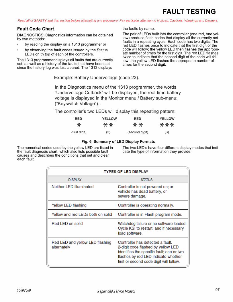
FAULT TESTINGRead all of SAFETY and this section before attempting any procedure. Pay particular attention to Notices, Cautions, Warnings and Dangers.
BFault Code ChartDIAGNOSTICS: Diagnostics information can be obtained by two methods:
• by reading the display on a 1313 programmer or
• by observing the fault codes issued by the Status LEDs on th top of each of the controllers.
The 1313 programmer displays all faults that are currently set, as well as a history of the faults that have been set since the history log was last cleared. The 1313 displays
the faults by name.
The pair of LEDs built into the controller (one red, one yel-low) produce flash codes that display all the currently set faults in a repeating cycle. Each code has two digits. The red LED flashes once to indicate that the first digit of the code will follow; the yellow LED then flashes the appropri-ate number of times for the first digit. The red LED flashes twice to indicate that the second digit of the code will fol-low; the yellow LED flashes the appropriate number of times for the second digit.
Fig. 6 Summary of LED Display Formats
The numerical codes used by the yellow LED are listed in the fault diagnosis chart, which also lists possible fault causes and describes the conditions that set and clear each fault.
The two LED’s have four different display modes that indi-cate the type of information they provide.
Example: Battery Undervoltage (code 23).
The controller’s two LEDs will display this repeating pattern:RED
(first digit) (2) (second digit) (3)
REDYELLOW YELLOW
In the Diagnostics menu of the 1313 programmer, the words “Undervoltage Cutback” will be displayed; the real-time batteryvoltage is displayed in the Monitor menu / Battery sub-menu:(”Keyswitch Voltage”).
* ** ** ***
97Repair and Service Manual10002660

B
FAULT TESTINGRead all of SAFETY and this section before attempting any procedure. Pay particular attention to Notices, Cautions, Warnings and Dangers.
LED Code
1313 Display
Explanation Controller Response
Recover When Possible Cause
1-2 Controller
Over current
Phase Current exceeded current
limits
Vehicle Disabled
KSI Cycled
1.External short of phase U,V or W 2.Check wiring 3.Motor parameters are mis-tuned 4.Defective controller 5.Speed encoder noise problems
1-3Current
Sensor Fault
Controller current
sensors have invalid
offset reading
Vehicle
DisabledKSI Cycled
1.Short to car frame from phase U,V or W.
2.Controller defective
1-4Precharge
Failed
Capacitor bank failed to charge at
KSI voltage
Vehicle Disabled
Cycle interlock
1.See handheld monitor menu - battery: capacitor voltage
2.External load on capacitor bank preventing capacitor charge
3.Check wiring 4.Check brake sensor if other faults are
found
1-5Controller
Sever Undertemp
Heat sink temperature below -
40ºC
Vehicle Disabled
Raise controller temp to above -40*C and cycle KSI or interlock
1.Controller is operating in an extreme environment
2.See monitor menu - controller: temperature
1-6Controller Sever Over
temp
Heat sink temperature above
+95ºC
Vehicle Disabled
Reduce heat sink temperature below 95*C and cycle KSI or interlock
1.Controller is operating in an extreme environment
2.See monitor menu - controller: temperature
3.Excessive load on vehicle 4.Improper mounting of controller
1-7Severe Under
voltageCapacitor voltage
dropped below limit
Reduced Drive torque and
speed
Condition clears
1.Battery menu parameters are mis adjusted 2.Non-controller system drain on batteries 3.Battery resistance too high 4.Battery disconnected while driving 5.See monitor menu - Battery: capacitor
voltage 6.Blown B+ fuse or main contactor did not
close
Fig. 7 Fault Code Chart
98 Repair and Service Manual 10002660

FAULT TESTINGRead all of SAFETY and this section before attempting any procedure. Pay particular attention to Notices, Cautions, Warnings and Dangers.
B1-8
Severe Overvoltage
Capacitor bank voltage exceeded
limit
Vehicle Disabled
Condition clears and KSI cycled
1.See monitor menu-Battery: capacitor voltage
2. Battery menu parameters are mis-adjusted 3. Battery resistance too high for given regen
current 4. Battery disconnected while regen braking
2-2Controller Over temp Cutback
Heat sink temp exceeded 85*C
Reduced drive and brake
torque
Condition clears
1.See monitor menu-Controller: temperature 2.Controller is performance-limited at this
temperature 3.Controller is operating in an extreme
environment 4.Excessive load on vehicle
2-3Under voltage
Cutback
Capacitor bank voltage dropped
below limit
Reduced Drive torque and
speed
Condition clears
1.Normal operation. Fault shows that batteries need recharging
2.Battery parameters are mis-adjusted 3.Non-controller system drain 4.Battery resistance to high 5.Battery disconnected while driving 6.See Monitor menu-Battery: capacitor
voltage 7.Blown B+ fuse or main contactor did not
close
2-4Overvoltage
Cutback
Capacitor bank voltage exceeded Overvoltage limit
Reduced brake torque
Condition clears
1.Normal operation. Fault shows that the regen braking currents elevated the battery voltage during regen braking. Controller is performance limited at this voltage
2. Battery parameters are mis-adjusted 3. Battery resistance too high for given regen
current 4.Battery disconnected while regen braking 5.See Monitor menu - Battery: ca (capacitor
voltage)
2-5 +5V supply
Failure
+ 5 V supply (pin 26) outside the +5V
+ or - 10% range
None: Check VCL
Condition clears
1.External load impedance on the + 5 V supply is too low
2.See Monitor menu-Outputs: 5 volts and ext supply current
2-6Digital Out
Over current
Digital output 6 (pin 19) current
exceeded 15mA
None: Check VCL
Fix the over current cause and use the VCL function set dig out to turn driver on
again
1.External load impedance on Digital Output 6 (pin 19) is too low
LED Code
1313 Display
Explanation Controller Response
Recover When Possible Cause
Fig. 7 Fault Code Chart (Continued)
99Repair and Service Manual10002660

B
FAULT TESTINGRead all of SAFETY and this section before attempting any procedure. Pay particular attention to Notices, Cautions, Warnings and Dangers.
2-7Digital Out 7 Over current
Digital output 7 (pin 20) current
exceeded 15mA
None: Check VCL
Fix the over current cause and use the VCL function set dig Out() to turn driver
on again
1.External load impedance on Digital Output 7 (pin 20) is too low
2-8Motor Temp Hot Cutback
Motor temp is at or above Hot
parameter setting
Reduced Drive torque and
speed
Condition clears
1.Motor temperature is at or above the programmed temperature Hot stetting, and the requested current is being cut back
2.Motor temperature control menu parameters are mis-tuned
3.See Monitor menu-Motor: temperature and - Inputs: analog 2
4.Reduce load on motor
2-9Motor Temp Sensor Fault
Motor thermistor input (pin8) is at voltage rail (0 or
10v)
Reduced speed, Motor temp cutback
disabled
Condition clears
1.Motor thermistor is not connected 2.Check sensor
3-1
Coil 1 Driver Open or
Short - also can be Main
Open or Short
Driver 1 (pin6) is either open or
shorted. This fault can only be set
when main enable =off
Shutdown driver 1
Correct condition and cycle driver
1.Open or short on driver load 2.Dirty connector pins 3.Bad crimps or faulty wiring
3-2Coil 2 Driver
Open or Short
Driver 2 (pin5) is either open or
shorted. This fault can only be set
when main enable =off
Shutdown driver 2
Correct condition and cycle driver
1.Open or short on driver load 2.Dirty connector pins 3.Bad crimps or faulty wiring
3-3Coil 3 Driver
Open or Short
Driver 3 (pin4) is either open or
shorted. This fault can only be set
when main enable =off
Shutdown driver 3
Correct condition and cycle driver
1.Open or short on driver load 2.Dirty connector pins 3.Bad crimps or faulty wiring
3-4Coil 4 Driver
Open or Short
Driver 4 (pin3) is either open or
shorted. This fault can only be set
when main enable =off
Shutdown driver 4
Correct condition and cycle driver
1.Open or short on driver load 2.Dirty connector pins 3.Bad crimps or faulty wiring
LED Code
1313 Display
Explanation Controller Response
Recover When Possible Cause
Fig. 7 Fault Code Chart (Continued)
100 Repair and Service Manual 10002660
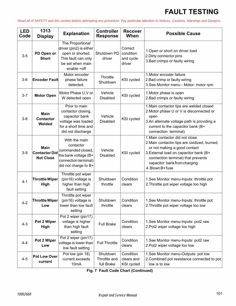
FAULT TESTINGRead all of SAFETY and this section before attempting any procedure. Pay particular attention to Notices, Cautions, Warnings and Dangers.
B3-5
PD Open or Short
The Proportional driver (pin2) is either
open or shorted. This fault can only be set when main
enable =off
Shutdown PD driver
Correct condition and cycle driver
1.Open or short on driver load 2.Dirty connector pins 3.Bad crimps or faulty wiring
3-6 Encoder FaultMotor encoder phase failure
detected.
Throttle Shutdown
KSI cycled 1.Motor encoder failure 2.Bad crimp or faulty wiring 3.See Monitor menu - Motor: motor rpm
3-7 Motor OpenMotor Phase U,V or
W detected openVehicle
DisabledKSI cycled
1.Motor phase is open 2.Bad crimps or faulty wiring
3-8Main
Contactor Welded
Prior to main contactor closing,
capacitor bank voltage was loaded for a short time and did not discharge
Vehicle Disabled
KSI cycled
1.Main contactor tips are welded closed 2.Motor phase U or V is disconnected or
open 3.An alternate voltage path is providing a
current to the capacitor bank (B+ connection terminal)
3-9Main
Contactor Did Not Close
With the main contactor
commanded closed, the bank voltage (B+ connection terminal) did not charge to B+
Vehicle Disabled
KSI cycled
1.Main contactor did not close 2.Main contactor tips are oxidized, burned,
or not making a good contact 3.External load on capacitor bank (B+
connection terminal) that prevents capacitor bank from charging
4. Blown B+ fuse
4-1Throttle Wiper
High
Throttle pot wiper (pin16) voltage is higher than high
fault setting
Shutdown throttle
Condition clears
1.See Monitor menu-Inputs: throttle pot 2.Throttle pot wiper voltage too high
4-2Throttle Wiper
Low
Throttle pot wiper (pin16) voltage is
lower than low fault setting
Shutdown throttle
Condition clears
1.See Monitor menu-Inputs: throttle pot 2.Throttle pot wiper voltage too low
4-3Pot 2 Wiper
High
Pot 2 wiper (pin17) voltage is higher than high fault
setting
Full BrakeCondition clears
1.See Monitor menu-Inputs: pot2 raw 2.Pot2 wiper voltage too high
4-4Pot 2 Wiper
Low
Pot 2 wiper (pin17) voltage is lower than
low fault settingFull Throttle
Condition clears
1.See Monitor menu-Inputs: pot2 raw 2.Pot2 wiper voltage too low
4-5Pot Low Over
current
Pot low (pin 18) current exceeds
10mA
Shutdown Throttle and
full Brake
Condition clears and KSI cycled
1.See Monitor menu-Outputs: pot low 2.Combined pot resistance connected to pot
low is to low
LED Code
1313 Display
Explanation Controller Response
Recover When Possible Cause
Fig. 7 Fault Code Chart (Continued)
101Repair and Service Manual10002660

B
FAULT TESTINGRead all of SAFETY and this section before attempting any procedure. Pay particular attention to Notices, Cautions, Warnings and Dangers.
4-6EEPROM Failure
Controller operating system tried to write
to EEPROM memory and failed
Vehicle Disabled
Download correct software (OS) and matching parameter default settings into the controller and c
1.Failure to write to EEPROM memory. This can be caused by EEPROM memory writes initiated by VCL, by the CAN bus, by adjusting parameters with the programmer, or by loading new software into controller
4-7HPD/
Sequencing Fault
HPD sequencing fault caused
incorrect sequence of KSI, interlock,
direction and throttle input
Shutdown Throttle
Reapply inputs in correct sequence
1.KSI, interlock, direction and throttle inputs applied in incorrect sequence
2.Faulty wiring, crimps, or switches at KSI, interlock, direction, or throttle inputs.
3.See Monitor menu-Inputs
4-8Emer Rev
HPD
At the conclusion of Emergency
Reverse, the fault was set because
various inputs were not returned to
neutral
Shutdown Throttle
If EMR_interlock=On, clear the interlock, throttle and
direction inputs. If
EMR_Interlock=Off, clear the throttle
and direction inputs.
1.Emergency Reverse operation has concluded, but the throttle, forward and reverse inputs, and interlock have not been returned to neutral
4-9Parameter
Change Fault
Adjustment of a parameter setting
that requires cycling of KSI
Vehicle Disabled
KSI cycled 1.This is a safety fault caused by a change in
certain parameter settings so that the vehicle will not operate until KSI id cycled
5-2Traction Throttle
Mismatch
Throttle input/output mismatched
Throttle Shutdown
Condition Clears
1.See Monitor menu-Inputs: Throttle 2.Check throttle return
5-3Throttle Input Out of Range
Throttle input out of range
Throttle Shutdown
Condition Clears
1.See Monitor menu-Inputs: Throttle 2.Check throttle return 3.Check for water intrusion of throttle wiper
5-4Park Brake
Set
Park brake engaged when traction pedal
was activated
Throttle Shutdown
Condition cleared
1.Park brake was engaged when throttle was activated
2.Release park brake and operate unit 3.Check park brake switch
LED Code
1313 Display
Explanation Controller Response
Recover When Possible Cause
Fig. 7 Fault Code Chart (Continued)
102 Repair and Service Manual 10002660

FAULT TESTINGRead all of SAFETY and this section before attempting any procedure. Pay particular attention to Notices, Cautions, Warnings and Dangers.
B5-5
HPD/SRO Fault
High pedal disable/static return to off
Vehicle Disabled
Condition cleared. Correct start sequence applied
1.Verify correct start sequence. Unit must be in neutral prior to key on
5-6Solenoid Coil Open/Short
Driver does not turn OFF
Vehicle Disabled
KSI cycled
1.Open or short on driver load 2.Dirty connector pins 3.Bad crimps or faulty wiring 4.When found in history, does not
necessarily indicate a problem
6-8VCL Run
Time ErrorRuntime VCL code
error conditionVehicle
Disabled
KSI cycled or install new software to match parameters
1.VCL code encountered a runtime VCL error
2.See Monitor menu -Controller: VCL error module
6-9External
Supply out of Range
The external 5v and 12V supply is out of
range.
None: Check VCL
External supply current within range
1.External load on the 5V and 12V supplies draws either too much or too little current
2.Fault checking menu parameters Ext supply max and Ext. supply min are mis tuned
3.See Monitor menu-Outputs: ext supply current
7-1 OS GeneralInternal controller
fault detectedVehicle
DisabledKSI Cycled
1.Internal controller fault detected 2.Cycle KSI
7-2 PDO Timeout
Time between CAN PDO messages
received exceeded the PDO timeout
period
Shutdown Interlock. Set
CAN NMT state to pre-operational
Cycle KSI or Cycle F&R
1.Time out period exceeded because of no inputs from throttle or controls
2.Cycle KSI and or F&R switch
7-3 Stall DetectedNo Motor encoder
movement detectedVehicle
DisabledCycle KSI
1.Stalled motor 2.Motor encoder failure 3.Bad crimps or faulty wiring 4.Problems with power supply for the motor
encoder 5.See Monitor menu-Motor: motor rpm
7-4
Fault on Other
Traction Controller
Fault found on slave controller
Depends on fault
KSI cycled 1.Check slave controller faults with handheld
via direct connection to slave controller
7-5Dual Severe
FaultSevere fault found on slave controller
Vehicle Disabled
KSI cycled 1.Check slave controller faults with handheld
via direct connection to slave controller
LED Code
1313 Display
Explanation Controller Response
Recover When Possible Cause
Fig. 7 Fault Code Chart (Continued)
103Repair and Service Manual10002660
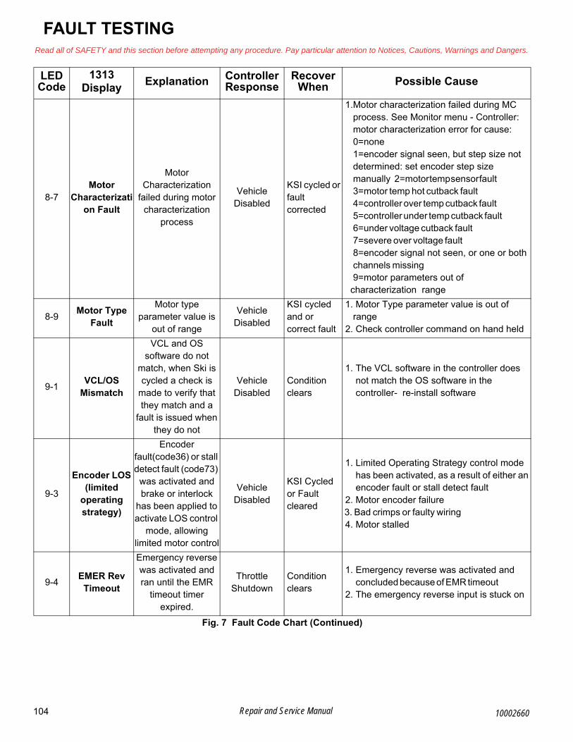
B
FAULT TESTINGRead all of SAFETY and this section before attempting any procedure. Pay particular attention to Notices, Cautions, Warnings and Dangers.
8-7Motor
Characterization Fault
Motor Characterization
failed during motor characterization
process
Vehicle Disabled
KSI cycled or fault corrected
1.Motor characterization failed during MC process. See Monitor menu - Controller: motor characterization error for cause:0=none
1=encoder signal seen, but step size not determined: set encoder step size manually 2=motor temp sensor fault 3=motor temp hot cutback fault 4=controller over temp cutback fault 5=controller under temp cutback fault 6=under voltage cutback fault 7=severe over voltage fault 8=encoder signal not seen, or one or both channels missing
9=motor parameters out of characterization range
8-9Motor Type
Fault
Motor type parameter value is
out of range
Vehicle Disabled
KSI cycled and or correct fault
1. Motor Type parameter value is out of range
2. Check controller command on hand held
9-1VCL/OS
Mismatch
VCL and OS software do not
match, when Ski is cycled a check is
made to verify that they match and a
fault is issued when they do not
Vehicle Disabled
Condition clears
1. The VCL software in the controller does not match the OS software in the controller- re-install software
9-3
Encoder LOS (limited
operating strategy)
Encoder fault(code36) or stall detect fault (code73)
was activated and brake or interlock
has been applied to activate LOS control
mode, allowing limited motor control
Vehicle Disabled
KSI Cycled or Fault cleared
1. Limited Operating Strategy control mode has been activated, as a result of either an encoder fault or stall detect fault
2. Motor encoder failure 3. Bad crimps or faulty wiring 4. Motor stalled
9-4EMER Rev
Timeout
Emergency reverse was activated and ran until the EMR
timeout timer expired.
Throttle Shutdown
Condition clears
1. Emergency reverse was activated and concluded because of EMR timeout
2. The emergency reverse input is stuck on
LED Code
1313 Display
Explanation Controller Response
Recover When Possible Cause
Fig. 7 Fault Code Chart (Continued)
104 Repair and Service Manual 10002660

FAULT TESTINGRead all of SAFETY and this section before attempting any procedure. Pay particular attention to Notices, Cautions, Warnings and Dangers.
B
Curtis Handheld Diagnostic Tool Function
9-8Illegal Model
Number
Model Number variable, cycles a check is made to confirm a legal
model number is found, a fault is
issued if not
Vehicle Disabled
Appropriate software downloaded
1. Model number variable is illegal for controller type
2. Software and hardware do not match 3. Defective controller
9-9Dual motor Parameter Mismatch
Mismatch of front and rear motors
Vehicle Disabled
Condition clears
1. Check Wires and connections 2. Check for mechanical bind 3. Check for high mechanical load 4. Verify motor encoder 5. Check faults on handheld for both
controllers
LED Code
1313 Display
Explanation Controller Response
Recover When Possible Cause
Fig. 7 Fault Code Chart (Continued)
The first screen shown is the menu options list.
The “System Info” menu indicates detailed viewing of the controller informa-tion, such as model number, serial number, hardware version, protocol ver-sion, parameter block version, mfg date code, OS version, build number, SM version, and VCL application version.
Fig. 8 Handheld Tool Function
105Repair and Service Manual10002660

B
FAULT TESTINGRead all of SAFETY and this section before attempting any procedure. Pay particular attention to Notices, Cautions, Warnings and Dangers.
The “Parameters” menu selection does not have a controller program option. The default parameter is 0.
“Reset Controller” is the view of the reset controller function. Normal values are 0 or 1.
The “Monitor” menu selection shows controller functions, inputs, and outputs.
“Solenoid Coil” indicates power to the main solenoid.
“Rear Node Select” shows the rear controller command. It indicates on or off.
Fig. 8 Handheld Tool Function (Continued)
106 Repair and Service Manual 10002660

FAULT TESTINGRead all of SAFETY and this section before attempting any procedure. Pay particular attention to Notices, Cautions, Warnings and Dangers.
B“Solenoid PWM” shows the % of solenoid command. It shows 100% when the controller is on.
“Rear Controller” allows access to a sub menu to see rear controller inputs. The front controller is a SLAVE controller, and is controlled by the rear con-troller.
The rear controller sub-menu shows the run/tow switch input, key switch input, economy or max range – max speed switch input, forward input and reverse input.
Each sub menu screen of the inputs allow for viewing larger text.
“Run/Tow Switch”
“Key or Charger Switch”
“Economy Mode Switch”
“Forward Switch”
Fig. 8 Handheld Tool Function (Continued)
107Repair and Service Manual10002660

B
FAULT TESTINGRead all of SAFETY and this section before attempting any procedure. Pay particular attention to Notices, Cautions, Warnings and Dangers.
“Reverse Switch”
“Throttles” is the only sub-menu below the “Rear Controller” sub-menu. This selection indicates throttle voltage range and % of throttle travel.
“Raw Primary Throttle”
“Mapped Primary Throttle”
“Raw Redundant Throttle”
Fig. 8 Handheld Tool Function (Continued)
108 Repair and Service Manual 10002660
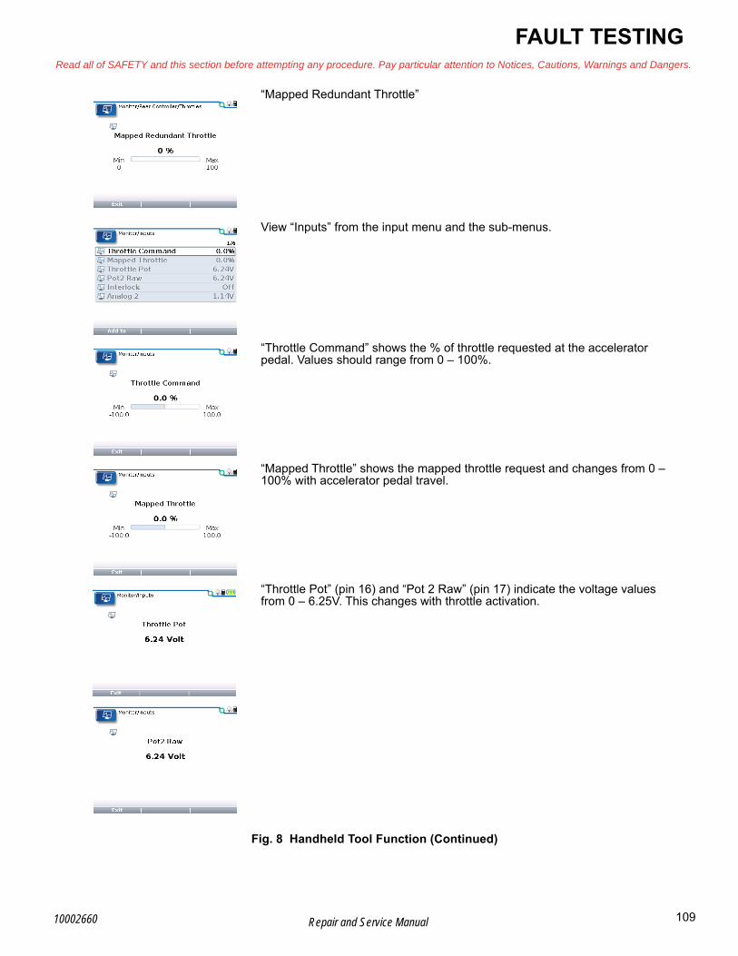
FAULT TESTINGRead all of SAFETY and this section before attempting any procedure. Pay particular attention to Notices, Cautions, Warnings and Dangers.
B“Mapped Redundant Throttle”
View “Inputs” from the input menu and the sub-menus.
“Throttle Command” shows the % of throttle requested at the accelerator pedal. Values should range from 0 – 100%.
“Mapped Throttle” shows the mapped throttle request and changes from 0 – 100% with accelerator pedal travel.
“Throttle Pot” (pin 16) and “Pot 2 Raw” (pin 17) indicate the voltage values from 0 – 6.25V. This changes with throttle activation.
Fig. 8 Handheld Tool Function (Continued)
109Repair and Service Manual10002660
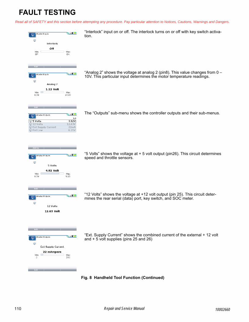
B
FAULT TESTINGRead all of SAFETY and this section before attempting any procedure. Pay particular attention to Notices, Cautions, Warnings and Dangers.
“Interlock” input on or off. The interlock turns on or off with key switch activa-tion.
“Analog 2” shows the voltage at analog 2 (pin8). This value changes from 0 – 10V. This particular input determines the motor temperature readings.
The “Outputs” sub-menu shows the controller outputs and their sub-menus.
“5 Volts” shows the voltage at + 5 volt output (pin26). This circuit determines speed and throttle sensors.
“12 Volts” shows the voltage at +12 volt output (pin 25). This circuit deter-mines the rear serial (data) port, key switch, and SOC meter.
“Ext. Supply Current” shows the combined current of the external + 12 volt and + 5 volt supplies (pins 25 and 26)
Fig. 8 Handheld Tool Function (Continued)
110 Repair and Service Manual 10002660

FAULT TESTINGRead all of SAFETY and this section before attempting any procedure. Pay particular attention to Notices, Cautions, Warnings and Dangers.
B“Pot Low” shows the voltage at pot low. This value ranges between 0 – 6.25V.
The “Battery” sub-menu indicates state of charge (BDI), capacitor voltage, and KSI voltage.
“BDI” (battery discharge indicator) indicates the state of charge percentage.
“Capacitor Voltage” is the voltage of a controller’s internal capacitor bank at the B+ terminal.
“Keyswitch Voltage” is the voltage at KSI (pin1).
The “Motor” sub-menu indicates motor conditions and component inputs.
Fig. 8 Handheld Tool Function (Continued)
111Repair and Service Manual10002660

B
FAULT TESTINGRead all of SAFETY and this section before attempting any procedure. Pay particular attention to Notices, Cautions, Warnings and Dangers.
“Motor RPM” equals speed in revolutions per minute.
“Temperature” is measured in Celsius.
“Motorspeed A” shows the motor encoder phase A speed in revolutions per minute.
Use to verify that phase A of the encoder is operating
correctly.
Motor speed A should equal Motor speed B in a properly operating power train.
“MotorSpeed B” shows the motor encoder phase B speed in revolutions per minute.
Use to verify that phase B of the encoder is operating
correctly.
Motor speed B should equal Motor speed A in a properly operating power train.
The controller operation can be seen in the “Controller” sub-menu.
“Current (RMS)” shows the RMS current of the controller, taking in all three phases into account (amp draw).
Fig. 8 Handheld Tool Function (Continued)
112 Repair and Service Manual 10002660
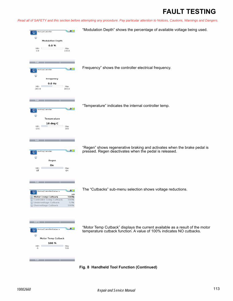
FAULT TESTINGRead all of SAFETY and this section before attempting any procedure. Pay particular attention to Notices, Cautions, Warnings and Dangers.
B“Modulation Depth” shows the percentage of available voltage being used.
Frequency” shows the controller electrical frequency.
“Temperature” indicates the internal controller temp.
“Regen” shows regenerative braking and activates when the brake pedal is pressed. Regen deactivates when the pedal is released.
The “Cutbacks” sub-menu selection shows voltage reductions.
“Motor Temp Cutback” displays the current available as a result of the motor temperature cutback function. A value of 100% indicates NO cutbacks.
Fig. 8 Handheld Tool Function (Continued)
113Repair and Service Manual10002660

B
FAULT TESTINGRead all of SAFETY and this section before attempting any procedure. Pay particular attention to Notices, Cautions, Warnings and Dangers.
“Controller Temp Cutback” shows the current available as a result of the con-troller temperature cutback function. A value of 100% indicates no cutback in current.
“Overvoltage Cutback” or “Undervoltage Cutback” indicates the current avail-able as a result of the condition. A value of 100% indicates no cutback in cur-rent.
The “Vehicle” sub-menu selection shows vehicle drive operations.
“Vehicle Speed” indicates vehicle speed in units of MPH. For accurate speed estimates, the speed to RPM parameters must be set correctly.
“Vehicle Odometer” indicates vehicle distance traveled in units of miles. For accurate distance measurements, the speed to RPM parameters must be set correctly.
Fig. 8 Handheld Tool Function (Continued)
114 Repair and Service Manual 10002660
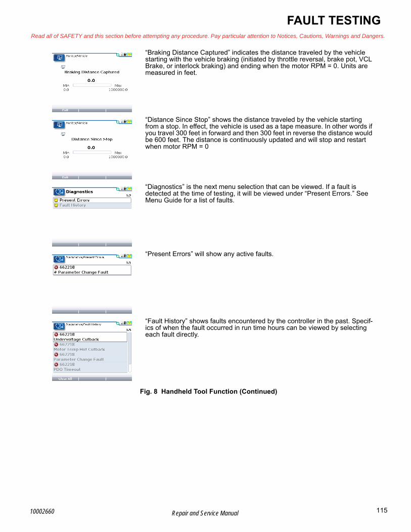
FAULT TESTINGRead all of SAFETY and this section before attempting any procedure. Pay particular attention to Notices, Cautions, Warnings and Dangers.
B“Braking Distance Captured” indicates the distance traveled by the vehicle starting with the vehicle braking (initiated by throttle reversal, brake pot, VCL Brake, or interlock braking) and ending when the motor RPM = 0. Units are measured in feet.
“Distance Since Stop” shows the distance traveled by the vehicle starting from a stop. In effect, the vehicle is used as a tape measure. In other words if you travel 300 feet in forward and then 300 feet in reverse the distance would be 600 feet. The distance is continuously updated and will stop and restart when motor RPM = 0
“Diagnostics” is the next menu selection that can be viewed. If a fault is detected at the time of testing, it will be viewed under “Present Errors.” See Menu Guide for a list of faults.
“Present Errors” will show any active faults.
“Fault History” shows faults encountered by the controller in the past. Specif-ics of when the fault occurred in run time hours can be viewed by selecting each fault directly.
Fig. 8 Handheld Tool Function (Continued)
115Repair and Service Manual10002660

B
FAULT TESTINGRead all of SAFETY and this section before attempting any procedure. Pay particular attention to Notices, Cautions, Warnings and Dangers.
The “Programming” menu allows the technician to upload settings from one controller (Save .cpf File) and then to download the same settings to another controller (Restore .cpf File). This is referred to as Cloning.
The cloning function is not allowed by Non-OEM handhelds.
The “HHP Settings” menu indicates user defined settings for the handheld, LCD screen settings, language settings as well as a user defined security code.
Fig. 8 Handheld Tool Function (Continued)
116 Repair and Service Manual 10002660

FAULT TESTINGRead all of SAFETY and this section before attempting any procedure. Pay particular attention to Notices, Cautions, Warnings and Dangers.
BELECTRICAL FAULT TESTING
Front - Slave and Rear - Master
Fig. 9 Front - Slave and Rear - Master
FRONT - SLAVE
Black Black CAN
YellowCAN
GreenCAN
BlackCAN
Blue
WhiteVioletBrown
Red
Red
Green+72V
+12V 0-5V 0-5V0-5V
0-5V
GND Analog
+5V
Pink
1 2 3 4 5 6 7 8 9 10 11 1213
24 25 26 27 28 29 30 31 32 33 34 35
14 15 16 17 18 19 20 21 22 23
Violet0V or 72V
REAR - MASTER
Green BlackWhite
Black AnalogBlack CAN
BlueBlue
YellowCAN
GreenCAN
BlackCAN
Orange
Yellow
Blue
White
GreenGreenAnalog
VioletBrown
Red/Yellow
Red/Blue
White
Dark Green+72V
+72V
+12V
0-5V
0-5V GND DVR0-5V
0-5V0-5V
0-5V+72V
+72V
+72V
+72V
+72V
+12VGND
+5V
Pink
Green
1 2 3 4 5 6 7 8 9 10 11 1213
24 25 26 27 28 29 30 31 32 33 34 35
14 15 16 17 18 19 20 21 22 23
?VOrange
117Repair and Service Manual10002660
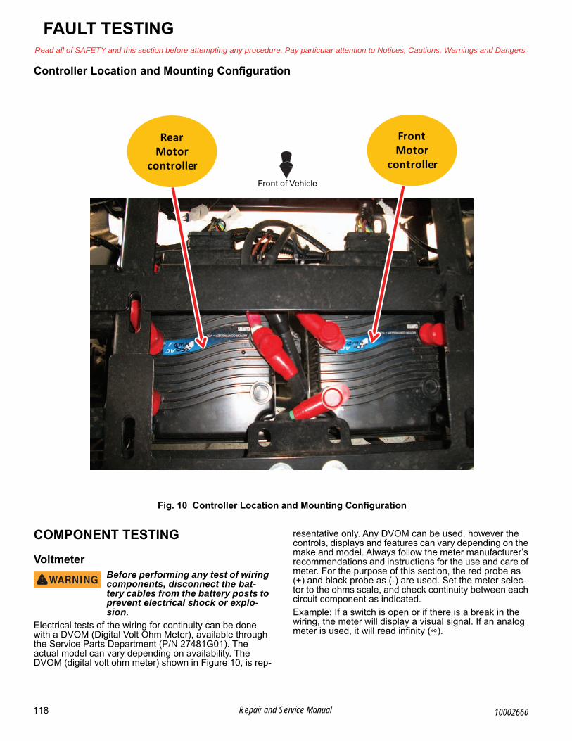
B
FAULT TESTINGRead all of SAFETY and this section before attempting any procedure. Pay particular attention to Notices, Cautions, Warnings and Dangers.
Controller Location and Mounting Configuration
Fig. 10 Controller Location and Mounting Configuration
COMPONENT TESTING
VoltmeterBefore performing any test of wiring components, disconnect the bat-tery cables from the battery posts to prevent electrical shock or explo-sion.
Electrical tests of the wiring for continuity can be done with a DVOM (Digital Volt Ohm Meter), available through the Service Parts Department (P/N 27481G01). The actual model can vary depending on availability. The DVOM (digital volt ohm meter) shown in Figure 10, is rep-
resentative only. Any DVOM can be used, however the controls, displays and features can vary depending on the make and model. Always follow the meter manufacturer’s recommendations and instructions for the use and care of meter. For the purpose of this section, the red probe as (+) and black probe as (-) are used. Set the meter selec-tor to the ohms scale, and check continuity between each circuit component as indicated.
Example: If a switch is open or if there is a break in the wiring, the meter will display a visual signal. If an analog meter is used, it will read infinity (∞).
Rear Motor
controller
Front Motor
controllerFront of Vehicle
118 Repair and Service Manual 10002660
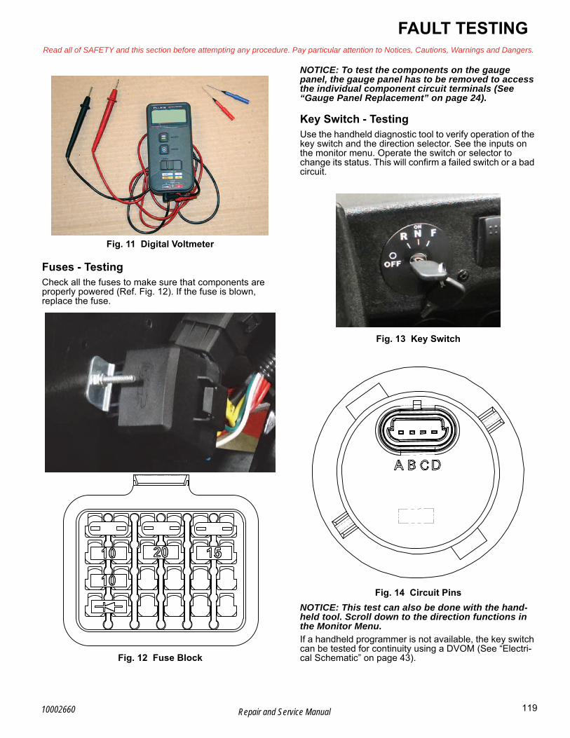
FAULT TESTINGRead all of SAFETY and this section before attempting any procedure. Pay particular attention to Notices, Cautions, Warnings and Dangers.
B
Fig. 11 Digital Voltmeter
Fuses - TestingCheck all the fuses to make sure that components are properly powered (Ref. Fig. 12). If the fuse is blown, replace the fuse.
Fig. 12 Fuse Block
NOTICE: To test the components on the gauge panel, the gauge panel has to be removed to access the individual component circuit terminals (See “Gauge Panel Replacement” on page 24).
Key Switch - TestingUse the handheld diagnostic tool to verify operation of the key switch and the direction selector. See the inputs on the monitor menu. Operate the switch or selector to change its status. This will confirm a failed switch or a bad circuit.
Fig. 13 Key Switch
Fig. 14 Circuit Pins
NOTICE: This test can also be done with the hand-held tool. Scroll down to the direction functions in the Monitor Menu.
If a handheld programmer is not available, the key switch can be tested for continuity using a DVOM (See “Electri-cal Schematic” on page 43).
119Repair and Service Manual10002660

B
FAULT TESTINGRead all of SAFETY and this section before attempting any procedure. Pay particular attention to Notices, Cautions, Warnings and Dangers.
State of Charge (SOC) Meter - TestingPut the positive (+) meter probe on the F terminal (red w/ blue wire) and the negative probe of DVOM on the A ter-minal (black wire) of the SOC meter (Fig. 15). Voltage should be 8-20V. If not; check the batteries and harness.
The B terminal (green wire) is a .4 – 4.5V circuit that will range with state of charge.
Fig. 15 SOC Meter
Electronic Speed Controller Solenoid - Test-ingTo check the electronic speed controller solenoid for energy; follow the steps below:
1. Put the positive meter probe on the white wire pri-mary circuit terminal. Put the negative meter probe on the black / orange primary circuit terminal. 72V should be indicated on the meter with the key on and the direction selector in gear.
2. Put the negative meter probe on controller B or the negative 72V battery terminal. Put the positive probe on the secondary circuit battery side terminal. 72V should be indicated. If not, check battery voltage and wiring.
NOTICE: The solenoid testing can also be done with the handheld tool. Scroll down to the Monitor Menu. Check inputs and outputs for change in status. Check for contactor related faults in the faults menu.
Fig. 16 Solenoid
A B C
DEF
120 Repair and Service Manual 10002660

FAULT TESTINGRead all of SAFETY and this section before attempting any procedure. Pay particular attention to Notices, Cautions, Warnings and Dangers.
BTemperature Sensor - TestingNOTICE: If the temperature sensor is faulty, the entire motor assembly must be replaced (See “Front Motor Removal” on page 70) (See “Rear Motor Removal” on page 72).
1. If possible, allow the vehicle to cool to room tem-perature.
2. Unplug the temperature sensor harness at the motor (Ref. 2.)
3. Use the DVOM set on OHMS (Ω) and test the resis-tance between the two pins on the motor side.
Fig. 17 Temperature Sensor
4. A reading showing at or below the minimum value indicates a bad sensor.
5. A reading showing at or above the thermal cutoff temperature indicates either a faulty sensor or a severely overheating motor (Ref. Fig. 18) (Ref. Fig. 19).
Fig. 18 KTY Temperature Sensor (male pins on the connector)
Fig. 19 PT1000 Temperature Sensor (female pins on the connector)
Electronic Speed Sensor - Testing1. Use the DVOM probes to check the motor speed
sensor while the connector is plugged in. With the key on and the direction selector in gear; put the pos-itive meter probe in the red wire connection. Put the negative meter probe in the black wire connection. 5V should be indicated. If not, check the wiring and the signal from the controller. Replace the speed sensor if these are good.
2. Put the negative meter probe in the black wire con-nection. Put the positive meter probe in the green wire connection. A 0 – 5V flash signal should be indi-cated when the motor armature is rotated slowly. If not, check the sensor magnet in the motor, then replace the speed sensor.
Minimum Value ≈359 Ω (-40° C)
Room Temperature ≈603 Ω (25° C)
Beginning of Thermal Cutback ≈1297 Ω (145° C)
Thermal Cutoff Temperature ≈1407 Ω (160° C)
TEMPERATURESENSOR
Minimum Value ≈843 Ω (-40° C)
Room Temperature ≈962 Ω (25° C)
Beginning of Thermal Cutback ≈1555 Ω (145° C)
Thermal Cutoff Temperature ≈1610 Ω (160° C)
Speed Sensor
121Repair and Service Manual10002660

B
FAULT TESTINGRead all of SAFETY and this section before attempting any procedure. Pay particular attention to Notices, Cautions, Warnings and Dangers.
Fig. 20 Speed Sensor
Back probe pins are needed to perform electrical tests via wire harness connectors.
AC Motor Bench TestSet a standard digital volt/ohm meter to the diode test position. Make sure the audible alarm can be heard.
1. Place one meter probe on the U-terminal and the other probe on the W-terminal. Full continuity should be observed (Ref. Fig. 21).
Fig. 21 U and W terminal
2. Now place one meter probe on the V-terminal and the other probe on the W-terminal. Full continuity should be observed (Ref. Fig. 22).
Fig. 22 V and W terminal
3. Then place one meter probe on the U-terminal and the other probe on the V-terminal. Full continuity should be observed (Ref. Fig. 23).
Fig. 23 U and V terminal
NOTICE: If continuity is not observed between ter-minals; an open motor field condition may exist. Disassemble the motor to visually confirm.
4. Place one meter probe on any of the three motor ter-minals. The other meter probe should be placed on the motor case. No continuity should be observed (Ref. Fig. 24).
122 Repair and Service Manual 10002660

FAULT TESTINGRead all of SAFETY and this section before attempting any procedure. Pay particular attention to Notices, Cautions, Warnings and Dangers.
BNOTICE: If continuity is observed between the case and terminals; a field to motor case short exists.
Fig. 24 Terminal and Motor case
123Repair and Service Manual10002660

FAULT TESTINGRead all of SAFETY and this section before attempting any procedure. Pay particular attention to Notices, Cautions, Warnings and Dangers.
Notes:
124 Repair and Service Manual 10002660

WEATHER PROTECTIONRead all of SAFETY and this section before attempting any procedure. Pay particular attention to Notices, Cautions, Warnings and Dangers.
BWEATHER PROTECTION
GENERALThe canopy top does not provide protection from roll over or falling objects.
The windshield does not provide protection from tree limbs or flying objects.
The canopy top and windshield are for weather protection only.
Clean with water and a clean cloth. Remove minor scratches with a commercial plastic polish or Plexus plas-tic cleaner, available from the service parts department.
Transporting VehicleTo prevent personal injury to occu-pants of other highway vehicles, be sure that the vehicle and contents
are secured to trailer.
Do not ride on a vehicle being transported.
Remove the windshield before transporting.
Maximum speed with the canopy top installed is 24 mph (39 kph).
If the vehicle is being transported on a trailer at highway speeds, remove the windshield and canopy top and secure the seat bottoms. Always check that the vehicle and contents are secured before transporting the vehicle. The rated capacity of the trailer must be more than the weight of the vehicle (See VEHICLE SPECIFICATIONS on page 131).
CANOPY TOP
Canopy Top RemovalTool List Qty.
Allen Socket, 4mm.......................................................1Ratchet ........................................................................1
Remove the screws (2) and washers (3) from the clamps (4) to release the canopy top (1) from the upper OPS (5) (Ref. Fig. 1).
Assemble in the reverse order of removal.
Fig. 1 Canopy Top
A 1
Front of Vehicle
A
2
4 35
5
125Repair and Service Manual10002660

WEATHER PROTECTIONRead all of SAFETY and this section before attempting any procedure. Pay particular attention to Notices, Cautions, Warnings and Dangers.
Notes:
126 Repair and Service Manual 10002660

WHEELS AND TIRESRead all of SAFETY and this section before attempting any procedure. Pay particular attention to Notices, Cautions, Warnings and Dangers.
BWHEELS AND TIRES
Fig. 1 Wheels and Tires
Tire Style May Vary
1
2
3
4
CROSS SEQUENCE
Valve stem should alwaysbe to outside of the wheel.
Always replace the dust cap.
Front of Vehicle
Lug Nut
Dust Cap
127Repair and Service Manual10002660

B
WHEELS AND TIRESRead all of SAFETY and this section before attempting any procedure. Pay particular attention to Notices, Cautions, Warnings and Dangers.
WHEEL AND TIRE SERVICETool List Qty.
Lug Wrench, 3/4”..........................................................1Impact Wrench.............................................................1Impact Socket, 3/4” ......................................................1Torque Wrench, ft. lbs. .................................................1
To prevent injury caused by a bro-ken socket, use only sockets made for impact wrench use. Never use a conventional socket.
When the tires are cool, inspect the condition and inflation pressures per the Periodic Service Schedule. Always install the valve dust cap after checking or inflating. When removing wheels with an impact wrench, use only impact sockets. Regular sockets are not designed for impact pressures exerted by power tools.
A tire explosion can cause severe injury or death. Never exceed infla-tion pressure rating on tire side wall.
To prevent a tire explosion, pressurize the tire with a small amount of air applied intermittently to seat beads. Never exceed the tire manufacturers recom-mendation when seating a bead. Protect face and eyes from escaping air when removing the valve core.
Use caution when inflating tires. Due to the low vol-ume of the small tires, over inflation can occur in seconds. Over inflation could cause the tire to sepa-rate from the wheel or the tire to explode, either of which could cause personal injury.
Tire inflation depends on the type of tires installed, but under no condition should inflation pressure be higher than recommended on the tire sidewall. Standard and optional tires should be inflated to the pressure desig-nated on the tire sidewall. All four tires should have the same pressure for optimum handling characteristics. Do not over inflate. Due to the low volume of the small tires, over inflation can occur in seconds. Install the valve dust cap after checking or inflating.
Tire RepairThe vehicle is fitted with low-pressure tubeless tires mounted on one piece rims.
The most cost effective way to repair a flat tire with a puncture in the tread portion of the tire is to use a tire plug.
NOTICE: Tire plug tools and plugs are available at most automotive parts stores and do not require the tire be removed from the wheel.
If the tire is flat, lift the vehicle and remove the wheel.
1. Lift the vehicle according to the lifting procedure (See LIFTING THE VEHICLE on page 8).
2. Put the tire in water to find the leak, and mark with chalk.
3. Insert the tire plug in accordance with manufacturers specifications.
If the tire is being removed or mounted, the tire-changing machine manufacturers recommendations must be fol-lowed to minimize the possibility of personal injury.
To prevent injury, be sure the mounting/demounting machine is anchored to the floor. Wear OSHA
approved safety equipment when mounting/ demounting tires.
Follow all instructions and safety warnings provided by the mounting/demounting machine manufacturer.
Wheel InstallationDo not tighten lug nuts to more than 75 ft. lbs. (102 Nm) torque.
NOTICE: Use the ‘cross sequence’ pattern when installing lug nuts to ensure even seating of the wheel against the hub.
1. With the valve stem to the outside, mount the wheel onto the hub with lug nuts.
2. Position the wheel on the hub.
3. Finger tighten the lug nuts in a ‘cross sequence’ pat-tern (Ref. Fig. 1).
4. Lower the vehicle onto the ground.
5. Continue to tighten the lug nuts to the torque value specified below, in 20 ft. lbs. (27 Nm) increments, fol-lowing the same ‘cross sequence’ pattern.
Item Torque Specification
Lug Nut 65 - 75 ft. lbs. (88 - 102 Nm)
128 Repair and Service Manual 10002660

Read all of SAFETY and this section before attempting any procedure. Pay particular attention to Notices, Cautions, Warnings and Dangers.
WHEELS AND TIRES
Notes:
129Repair and Service Manual10002660

WHEELS AND TIRESRead all of SAFETY and this section before attempting any procedure. Pay particular attention to Notices, Cautions, Warnings and Dangers.
Notes:
130 Repair and Service Manual 10002660

VEHICLE SPECIFICATIONSRead all of SAFETY and this section before attempting any procedure. Pay particular attention to Notices, Cautions, Warnings and Dangers.
BVEHICLE SPECIFICATIONS
Tracker EViS
Item Specification
Overall Length 112 in (2824 cm)
Overall Width 52 in (132 cm)
Overall Height 76 in (193 cm)
Wheelbase 70 in (178 cm)
Ground Clearance at Frame 16.5 in (41 cm)
Ground Clearance at Differential 9.5 in (24 cm)
Power Source 72 Volts DC
Motor Type 72 Volt AC
Horsepower (kW) 38 hp (28.3 kW) Peak
Electrical System 72 Volt
Battery Quantity and Type Six 12V Deep Cycle
Key or Pedal Start Pedal Start
Battery Charger 72 VDC DPI, 120 VAC 60 Hz
Speed Controller 300 Amp AC Controller
Drive Train Motor Shaft Direct Drive
Trans-axle Differential w/ Hardened Helical Gears
Gear Selection Dash mounted Forward-Neutral-Reverse
Speed Selection Dash Mounted Speed/Range Switch
Rear Axle Ratio 12.49:1
Front Axle Ratio 12.49:1
Seating Capacity 4 People
Curb Weight 1780 lb. (808 kg)
Vehicle Load Capacity 940 lb (426 kg)
Gross Front Axle Rating 749 lb (340 kg)
Gross Rear Axle Rating 1912 lb (868 kg)
Outside Clearance Circle 24.5 ft. (7.5 m)
Speed - Low (Level Ground) 16 mph (25.7 kph)
Speed - High (Level Ground) 24.5 mph (39.4 kph)
Speed - Reverse (Level Ground) 10 mph (16.1 kph)
Towing Capacity 1000 lb 454(kg)
Steering Self-compensating rack and pinion
Front Suspension Coil springs with MacPherson Struts
Rear Suspension Coil springs with MacPherson Struts
Service Brake 4-wheel Hydraulic Disc Brakes and Induction Motor
Parking Brake Speed Based Electronic Motor Brake
Front Tires Carlisle Trail Pro 25 x 8 - 12
Rear Tires Carlisle Trail Pro 25 x 10 - 12
Frame Welded steel with E-Shield ecoat plus DuraShield™ powder coat
Body and Finish Injection molded TPO
131Repair and Service Manual10002660

VEHICLE SPECIFICATIONSRead all of SAFETY and this section before attempting any procedure. Pay particular attention to Notices, Cautions, Warnings and Dangers.
Notes:
132 Repair and Service Manual 10002660

B
PERIODIC SERVICE SCHEDULERead all of SAFETY and this section before attempting any procedure. Pay particular attention to Notices, Cautions, Warnings and Dangers.
133Repair and Service Manual10002660
PERIODIC SERVICE SCHEDULE
PSS
C - CHECK C&A - CHECK & ADJUST CL - CLEAN R - REPLACE
REMARKS
Bef
ore
eac
h u
se D
AIL
Y
DA
ILY
WE
EK
LY
20 h
rs
MO
NT
HLY
50 h
rs
QU
AR
TE
RLY
125
hrs
SE
MI-
AN
NU
AL
250
- 3
00
hrs
AN
NU
AL
5 Y
EA
RS
Tires - Check pressure and inspect condition of tires & rims. C C C C C C
Hardware - Check for loose or missing. C C C C C C
Overall Vehicle Condition C C C C C C
Battery Pack - Check state of charge, condition, loose terminals, corrosion, hold down & hardware.
C C CL CL CL CL
Brake Pedal - Check for smooth operation C C C C C C
Accelerator - Check for smooth operation. C C C C C C
Charger / Receptacle - Inspect charger connector and receptacle. C C C C C C
Brakes - Conduct brake performance test; adjust if required. C&A C&A C&A C&A
Wiring - Inspect for loose connections, broken or missing insulation. C C C C
Steering Assembly - Check for excess play, loose or missing hardware. C C C C
Tie Rods - Check for excess play, bent rods, loose or missing hardware. C C C C
Front Axle - Check for damage to axle, loose or missing hardware. C C C
Rear Axle - Noise, loose or missing hardware. C C C C
Front and Rear Differential- Check for leaks, drain & replace fluid. C C C C R
Rear Suspension - Inspect for strut oil leakage, worn bushings, excessive play in hubs, loose or missing hardware.
C C C
Front Suspension - Inspect for strut oil leakage, excessive play in hubs or kingpins, worn bushings, loose or missing hardware.
C C C
Front Wheel Alignment - Inspect for unusual tire wear. C&A C&A C&A
Steering Assembly - Inspect bellows and pinion seal for damage and leakage. C C
Rack End Ball Joint - Check for noise and loose or missing hardware. C C
NOTE: Some maintenance items must be serviced more frequently on vehicles used under severe driving conditions.

134 Repair and Service Manual
PERIODIC SERVICE SCHEDULERead all of SAFETY and this section before attempting any procedure. Pay particular attention to Notices, Cautions, Warnings and Dangers.
Notes:
10002660

APPENDIX ARead all of SAFETY and this section before attempting any procedure. Pay particular attention to Notices, Cautions, Warnings and Dangers.
135Repair and Service Manual10002660
APPENDIX A
BATTERY CHARGER USER’S GUIDE

136
B
Repair and Service Manual
APPENDIX ARead all of SAFETY and this section before attempting any procedure. Pay particular attention to Notices, Cautions, Warnings and Dangers.
10002660
WarningUse charger only with an algorithm selected that is appropriate to the specific battery type. Other usage may cause personal injury and damage. Lead acid batteries may generate explosive hydrogen gas during normal operation. Keep sparks, flames, and smoking materials away from batteries. Provide adequate ventilation during charging. Never charge a frozen battery. Study all battery manufacturers’ specific precautions (e.g. maximum charge rates and if cell caps should be removed while charging).
Risk of electric shock. Connect charger power cord to an outlet that has been properly installed and grounded in accordance with all local codes and ordinances. A grounded outlet is required to reduce risk of electric shock – do not use ground adapters or modify plug. Do not touch uninsulated portions of output connector or uninsulated battery terminals. Disconnect the AC supply before making or breaking the connections to the battery. Do not open or disassemble charger. Do not operate this charger if the AC supply cord is damaged or if the charger has received a sharp blow, been dropped, or is damaged in any way – refer all repair work to the manufacturer, or qualified personnel. This charger is not intended for use by persons (including children) with reduced physical, sensory or mental capabilities, or lack of experience and knowledge on electrical systems and battery charging, unless they have been given supervision or instruction concerning use of the charger by a person responsible for their safety. Children should be supervised to ensure that they do not play with the charger.
Danger
Utiliser le chargeur seulement avec un algorithme approprié au type spécifique de batterie. D´autres types de batteries pourraient éclater et causer des blessures ou dommages. Les batteries peuvent produire des gaz explosifs en service normal. Ne jamais fumer près de la batterie et éviter toute étincelle ou flamme nue à proximité des batteries. Fournissez une ventilation adéquate du chargement. Ne jamais charger une batterie gelée. Prendre connaissance des mesures de précaution spécifiées par le fabricant de la batterie, p. ex., vérifier s´il faut enlever les bouchons des cellules lors du chargement, et les taux de chargement.
Attention
Risque de décharge électrique. Ne pas toucher les parties non isolées du connecteur de sortie ou les bornes non isolées de la batterie. Toujours connecter le chargeur à une prise de courant mise à la terre. Déconnectez la source AC avant de faire ou défaire les connections à la batterie en chargement. Ne pas utiliser le chargeur si le cordon d’alimentation AC est endommagé ou si le chargeur est abîmé suite à une chute ou autre indicent. Ne pas ouvrir ni désassembler le chargeur – référer toute réparation aux personnes qualifiées. Cet appareil n’est pas destiné à un usage par des personnes (dont les enfants) avec des facultés motrices, sensorielles ou mentales réduites, ou ayant une expérience et des connaissances insuffisantes, à moins qu’elles sont sous la supervision ou reçoivent les instructions sur l’utilisation de l’appareil d’un répondant garant de leur sécurité. Les enfants devraient être surveillés afin qu’il ne jouent en aucun temps avec l’appareil.
Danger
This manual contains important safety and operating instructions for Delta-Q QuiQ 1500 chargers. Please read this information in its entirety before using your QuiQ Charger. For technical support, please visit delta-q.com/support or contact the manufacturer of your vehicle or machine, as their versions of this charger may require special instructions.
QuiQ TM 1500 Industrial Battery Charger Product Manual
1
Operating InstructionsThe charger may become hot during charging. Use hand protection to safely handle the charger during charging.Extension cords must be 3-wire cord no longer than 30m (100’) at 10 AWG or 7.5m (25’) at 16 AWG per UL guidelines.Only connect one QuiQ Charger to a single 120VAC 15A circuit, or the circuit may become overloaded.The charger will conduct a self-test after being powered on, visible by flashing all of its LEDs in sequence.
Fault Indicator (Red Light)Charger error. Refer to troubleshooting information below.
If solid: AC voltage is above 185 volts.If flashing: AC voltage is between 105 volts and 185 volts.If off: AC voltage is below 105 volts.
AC Indicator
Bulk Charge IndicatorIf solid: Bulk charge phase complete (80% charged); in absorption phase.If flashing: Displays charge profile number if no battery is connected.
Charge Completion Indicator (Green Ligh t)If solid: Charging complete and maintenance mode is active.If flashing: Absorption phase complete, in finishing phase.
If solid: Displays scale of output during bulk phase.If flashing: Output has been reduced due to high internal charger temperature. Displays charge profiles 1-6 for 11 seconds if no battery is connected.
Ammeter
Charger 10-LED Display

APPENDIX ARead all of SAFETY and this section before attempting any procedure. Pay particular attention to Notices, Cautions, Warnings and Dangers.
137Repair and Service Manual10002660
Delta-Q QuiQ 1500 Charger Manual
Troubleshooting InstructionsIf a fault occurs, count the number of red flashes between pauses and refer to the table below.
Flashes Cause Solution
Battery high voltageCheck battery size and condition. This fault will clear automatically once the condition has been corrected.
Battery low voltageCheck battery size and condition. This fault will clear automatically once the condition has been corrected.
Charge timeout caused by battery pack not reaching required voltage; or charger output reduced due to high temperatures.
Check connections, that battery type matches selected charge profile and operate the charger at a lower ambient temperature. Reset the charger by interrupting AC power for 15+ seconds.
Battery could not be trickle charged up to minimum voltage.
Check for shorted or damaged cells. Reset the char-ger by interrupting AC power for 15+ seconds.
Charger shutdown due to high internal temperature.
Ensure sufficient cooling airflow. Reset the charger by interrupting AC power for 15+ seconds.
Internal charger fault Reset the charger by interrupting AC power for 15+ seconds. Return to service depot if fault persists.
2www.delta-q.com
Note: This is a Class A product complying with United States Federal Communications Commission, Code of Federal Regulations; 47CFR part 15. In a domestic environment this product may cause radio interference, in which case the user may be required to take adequate measures.
WARNING: Charger connectors must be mated to connectors from the same manufacturer. Failure to do so may void warranty and cause a hazardous condition or equipment damage.
Maintenance Instructions1. Do not expose charger to high pressure water spray when cleaning vehicle.
2. The enclosure of the charger meets IP66, making it dust-tight and protected against powerful water jets. The AC connection is rated to IP20, which is not protected against water. Protect the AC connection if used in wet or dusty environments.
3. If the detachable input power supply cord set is damaged, replace with a cord that is appropriate for your region:This charger is provided with a cord set for connection to outlets operating at nominal 120 Volts (or 240 Volts as appropriate). If the input plug does not fit the power outlet, contact Delta-Q Technologies for the proper cord set terminating in an attachment plug of the proper configuration for the power outlet.‘North America: UL or CSA listed / approved detachable cord, 3 conductor, 16AWG minimum and rated SJT; terminated in a grounding type IEC 60320 C14 plug rated 250V, 13A minimumFor all other regions: Safety approved detachable cord, 3 conductor, 1.5mm² minimum, rated appropriately for industrial use. The cord set must be terminated on one end with a grounding type input connector appropriate for use in the country of destination and, on the other end, an output grounding type IEC 60320 C14 plug.
LED Color IndicationGreen If solid: Charging complete and maintenance mode is active.
If flashing:Short: <80% Charge.Long: >80% Charge.When battery is not connected: Charge Profile (Algorithm Number) is displayed when first connected to AC, then will show “Battery low voltage” error
Amber If flashing: Reduced power mode due to high internal charger temperature.
Red If flashing: Charging error. Reset charger power and refer to Troubleshooting Instructions below.
Optional Remote Single -LED Display

138
B
Repair and Service Manual
APPENDIX ARead all of SAFETY and this section before attempting any procedure. Pay particular attention to Notices, Cautions, Warnings and Dangers.
10002660
Selecting A Charge ProfileDelta-Q’s QuiQ 1500 Charger can store up to 10 charging profiles, also called charge algorithms. This section shows how to identify the default profile and select a new profile using the “tap method.”
QuiQ chargers are reprogrammable using the QuiQ Programmer supplied by Delta-Q to its OEM partners. Pre-2006 QuiQ chargers with serial number prefix DQCP allow pre-loaded profiles to be selected, but cannot be reprogrammed with new profiles.
Figure 2: Remove positive lead from positive terminal on the battery pack.
Figure 3: Reconnect AC power to the charger.
Figure 1: Disconnect AC power.
Figure 4: Charger LED indicator self-test. Figure 7: Touch the positive lead to the positive battery terminal for 3 seconds.
Identify the default profile
1. Required supplies include an insulated wrench, eye protection and gloves.
2. Disconnect the AC power source from the charger, either from the wall outlet, or from the IEC320 connector on the charger.
3. Use your insulated wrench to remove the positive lead from the positive terminal on the battery pack.
4. Reconnect AC power.
5. Charger will conduct a self-test of its LED indicators.
6a. For 11 seconds after the self-test, the charger will display its default charge profile. Profiles #1-6 will display on the ammeter, as well as on the bulk charge indicator.
6b. Charge profiles #7 and above will display on the bulk charge indicator. If the charge profile number has two digits, it will be displayed by one or more flashes, a pause, then one or more flashes (e.g. #13 = )
Select a new profile
7. Disconnect AC power (see Figure 1).
8. Reconnect AC power (see Figure 3).
9. Touch the positive lead to the positive terminal for three seconds (+/- 0.5 seconds), then remove the lead. You will see the next profile displayed on the charger’s display. Repeat this step until you reach the desired charge profile.
10. When the charger displays the desired charge profile, apply the positive lead to the positive battery terminal for 10 seconds. When the charge profile is locked, you will hear a click from the charger. See Figure 7 for how to apply the positive lead to the positive terminal.
11. Disconnect AC power, wait for the LED indicator display to turn off, then reconnect AC power. (See Figure 3)
12. Check the LED display to ensure that the desired charge profile is selected.
13. Disconnect the charger from AC power and wait for the LED indicator display to turn off. (See Figure 1)
14. Reconnect the positive lead to the positive battery terminal.
Figure 8: Reattach the positive lead to the positive terminal after disconnecting AC power.
Figure 5: Charge profile #1 on the ammeter.
Figure 6: Bulk charge indicator displays charge profiles 7 and above.
Delta- Q QuiQ 1500 Charger Manual
3Visit www.youtube.com/deltaqtechnologies for instructional videos.

NOTICE: Read the following warnings before operating vehicle:
When the vehicle is without an operator, engage the parking brake, turn the key switch to the
OFF position, and remove the key from the switch.
Operate the vehicle only as fast as the terrain and safety conditions allow. Consider the terrain and traffic conditions. Consider environmental conditions that change the terrain and your ability to control the vehicle.
Do not drive fast downhill. Sudden stops or change of direction can cause a loss of control. Use the brake to control the speed of the vehicle when you drive down a slope.
All travel must be straight up or down hills. Use cautions if you must drive across a slope.
Stay in designated areas and avoid steep slopes. When the vehicle is parked, engage the parking brake.
Always keep feet, legs, hands and arms inside vehicle.
Do not drive on rough terrain.
Before driving in reverse, make sure the area behind the vehicle is clear.
Make sure the direction selector is in the correct position before pressing the accelerator pedal.
Decrease speed before and during turns.
Always completely stop the vehicle before moving the direction selector.
See GENERAL SPECIFICATIONS for the vehicle load and seat capacity (See VEHICLE SPECIFICATIONS on page 131).
NOTICE: Read the following information and warnings before operating vehicle:
In any product, components will eventually fail to per-form properly as the result of normal use, age, wear or abuse.
The manufacturer can not know all possible component failures or the methods that failures can occur.
A vehicle in need of repair does not operate correctly and can be dangerous.
Be careful when you service the vehicle. Be aware of your safety and the safety of other people in the area.
Some components are heavy, spring loaded, corrosive, explosive, can cause high amperage or get hot. Battery acid and hydrogen gas can cause injury. Do not put your hands, face, feet or body in a location that can expose them to injury if an unexpected situation occurs.
Always use the correct tools shown in the tool list and wear safety equipment.
Remove all jewelry before you service the vehicle.
Do not allow loose clothing or hair to contact the moving parts.
Do not touch hot objects.
The drive wheels must be lifted and supported on jack stands before servicing the powertrain when the motor is in operation.
When servicing the vehicle, always wear eye protection. Be careful when working around batteries or using solvents or compressed air.
Use wrenches with insulation to decrease the risk of a short-circuit if a wrench falls across the battery terminals. A battery short-circuit can cause an explosion.
To prevent the risk of battery explosion, keep all flammable materials, open flames or sparks away from the batteries.

Dealer: 800-296-4804Consumer: 877-394-6772
www.trackeroffroad.com
Copyrighted Material
This manual may not be reproduced in whole or in part without the express permission ofthe manufacturer.