Design of Anti-Vehicle Theft System using GSM and GPS with ...
11
Asian Journal of Engineering and Technology (ISSN: 2321 – 2462) Volume 05 – Issue 04, August 2017 Asian Online Journals (www.ajouronline.com ) 82 Design of Anti-Vehicle Theft System using GSM and GPS with Image Acquisition Samuel Farayola Kolawole * and Alexander Zakari Department of Electrical/Electronic Engineering, Nigerian Defence Academy Kaduna, Nigeria * Corresponding author’s email: kolabimbo [AT] hotmail.com ________________________________________________________________________________________________ ABSTRACT--- This paper presents‘An Anti-Vehicle Theft System using GSM and GPS with Image Acquisition’. The aim is to design a system that can acquire the image of an unauthorized person and transmit it to a remote location. In order to achieve such a system, the major components used include a GSM modem with integrated GPS, a camera and a microcontroller (ATmega2560). The system makes use of a secret button for authentication of the driver. The secret button is connected and programmed in such a way that when the engine is started, a five minutes window is given to the driver to authenticate by pressing the secret button. If the driver does so, the security of the system is changed to tracking mode (implying that the vehicle coordinate is continually sent to an E-mail address) every fifty (50) minutes as the driver drives the vehicle. In a situation whereby the driver forgets to authenticate within five minutes, the system will shut down the engine but all the driver has to do is to authenticate by pressing the secret button and then switch on his engine. Assuming the vehicle is actually stolen (knowing that the thief is not aware of the security system because everything is hidden), the time window will elapse without authentication. At this point the system enters the alarm mode, implying the vehicle has been stolen. The camera then snaps the thief, the GPS picks the coordinate while the GSM modem transmit such data to the owner’s E-mail address which can be accessed from a smartphone. With this data at hand, the thief can be declared wanted and arrested later. The vehicle cannot be restarted until the secret button is pressed. A prototype of the security system was developed and it was seen that when the security button is not pressed after starting the engine, the vehicle is immobilized. The engine could not be started until the security button was pressed. The owner of the vehicle then received an E-mail containing the image of the unauthorized person and the co-ordinate of the vehicle, implying that his vehicle has been stolen. Keywords--- GPS, GSM, ATMEGA Microcontroler, Camera _________________________________________________________________________________________________ 1. INTRODUCTION The Nigerian Police have consistently maintained that they are doing their best to check car theft and all crime in the Federal Capital Territory (FCT). It was reported that in December 2014, the police recovered 17 stolen cars in the FCT. They, no doubt, are working, but their efforts have not been good enough. Many of those who have fallen victim to car thieves reported the theft to the police immediately, but sadly, not many of those reports were met with positive results.[1] In time past in United States of America the rate at which vehicles were stolen was very high but statistics show that there is a decline .By the end of December 2015, Interpol Stolen Motor Vehicle (SMV) database had a total of 7,411,706 reported stolen motor vehicles shared by 126 countries. Just about 123,000 stolen vehicles where identified worldwide during the year.2014 Theft Statistics in the United Statesaccording to t he FBI’s Uniform Crime Reports shows that a motor vehicle was stolen in the United States every 46 seconds. The odds of a vehicle being stolen were one (1) in three hundred and seventy one (371) in 2013. The odds are highest in urban areas.U.S. motor vehicle thefts fell 1.5 percent from 2013 to 2014, according to the FBI’s Uniform Crime Reports. In 2014, 689,527 motor vehicles were reported stolen.[2] This decline is partly due to the fact that several tracking and Anti-vehicle theft control systems have been developed. These Anti-vehicle theft control systems come in various varieties such as immobilizing the vehicle when stolen, tracking the vehicle by continuously transmitting its location via SMS, locking the thief in the vehicle etc. However, these systems do not incorporate a way of identifying the thief.Therefore, there is a need for a system that can effectively track the stolen vehicle and identify the thief. When criminals are being tracked and arrested, it makes it thought- provoking for the thief to decide to steal a vehicle knowing that his identity is not hidden and he would be arrested anytime soon.This is to help reduce the statistics further down.This is the basis of this paper.This design is aimed at
-
Upload
khangminh22 -
Category
Documents
-
view
0 -
download
0
Transcript of Design of Anti-Vehicle Theft System using GSM and GPS with ...

Asian Journal of Engineering and Technology (ISSN: 2321 – 2462) Volume 05 – Issue 04, August 2017
Asian Online Journals (www.ajouronline.com) 82
Design of Anti-Vehicle Theft System using GSM and GPS with
Image Acquisition
Samuel Farayola Kolawole* and Alexander Zakari
Department of Electrical/Electronic Engineering, Nigerian Defence Academy
Kaduna, Nigeria
*Corresponding author’s email: kolabimbo [AT] hotmail.com
________________________________________________________________________________________________
ABSTRACT--- This paper presents‘An Anti-Vehicle Theft System using GSM and GPS with Image Acquisition’. The
aim is to design a system that can acquire the image of an unauthorized person and transmit it to a remote location.
In order to achieve such a system, the major components used include a GSM modem with integrated GPS, a camera
and a microcontroller (ATmega2560). The system makes use of a secret button for authentication of the driver. The
secret button is connected and programmed in such a way that when the engine is started, a five minutes window is
given to the driver to authenticate by pressing the secret button. If the driver does so, the security of the system is
changed to tracking mode (implying that the vehicle coordinate is continually sent to an E-mail address) every fifty
(50) minutes as the driver drives the vehicle. In a situation whereby the driver forgets to authenticate within five
minutes, the system will shut down the engine but all the driver has to do is to authenticate by pressing the secret
button and then switch on his engine. Assuming the vehicle is actually stolen (knowing that the thief is not aware of
the security system because everything is hidden), the time window will elapse without authentication. At this point the
system enters the alarm mode, implying the vehicle has been stolen. The camera then snaps the thief, the GPS picks
the coordinate while the GSM modem transmit such data to the owner’s E-mail address which can be accessed from a
smartphone. With this data at hand, the thief can be declared wanted and arrested later. The vehicle cannot be
restarted until the secret button is pressed. A prototype of the security system was developed and it was seen that when
the security button is not pressed after starting the engine, the vehicle is immobilized. The engine could not be started
until the security button was pressed. The owner of the vehicle then received an E-mail containing the image of the
unauthorized person and the co-ordinate of the vehicle, implying that his vehicle has been stolen.
Keywords--- GPS, GSM, ATMEGA Microcontroler, Camera
_________________________________________________________________________________________________
1. INTRODUCTION
The Nigerian Police have consistently maintained that they are doing their best to check car theft and all crime in the
Federal Capital Territory (FCT). It was reported that in December 2014, the police recovered 17 stolen cars in the FCT.
They, no doubt, are working, but their efforts have not been good enough. Many of those who have fallen victim to car
thieves reported the theft to the police immediately, but sadly, not many of those reports were met with positive
results.[1]
In time past in United States of America the rate at which vehicles were stolen was very high but statistics show that
there is a decline .By the end of December 2015, Interpol Stolen Motor Vehicle (SMV) database had a total of 7,411,706
reported stolen motor vehicles shared by 126 countries. Just about 123,000 stolen vehicles where identified worldwide
during the year.2014 Theft Statistics in the United Statesaccording to the FBI’s Uniform Crime Reports shows that a
motor vehicle was stolen in the United States every 46 seconds. The odds of a vehicle being stolen were one (1) in three
hundred and seventy one (371) in 2013. The odds are highest in urban areas.U.S. motor vehicle thefts fell 1.5 percent
from 2013 to 2014, according to the FBI’s Uniform Crime Reports. In 2014, 689,527 motor vehicles were reported
stolen.[2]
This decline is partly due to the fact that several tracking and Anti-vehicle theft control systems have been developed.
These Anti-vehicle theft control systems come in various varieties such as immobilizing the vehicle when stolen,
tracking the vehicle by continuously transmitting its location via SMS, locking the thief in the vehicle etc. However,
these systems do not incorporate a way of identifying the thief.Therefore, there is a need for a system that can effectively
track the stolen vehicle and identify the thief. When criminals are being tracked and arrested, it makes it thought-
provoking for the thief to decide to steal a vehicle knowing that his identity is not hidden and he would be arrested
anytime soon.This is to help reduce the statistics further down.This is the basis of this paper.This design is aimed at
Asian Journal of Engineering and Technology (ISSN: 2321 – 2462) Volume 05 – Issue 04, August 2017
Asian Online Journals (www.ajouronline.com) 83
realizing a system that can snap the thief and then send the picture to the owner of the vehicle. Even if the thief gets
away, his identity has already been known and he could be tracked and arrested even in the future. Countries that have a
good database of their citizens can quickly do a face search to get the thief’s full identity and he could be declared
wanted.Fig. 1 shows the design block of An anti-vehicle theft control system.
When the vehicle is started, the security system is powered from the vehicles battery. A time window of five minutes
(just enough to allow the thief go some distance but not too far in order to ease recovery) is given for the driver to press a
secret button. When this button is pressed at the start of the engine, the alarm mode is disabled but the coordinates of the
vehicle would still be transmitted at intervals of fifty (50) minutes (to give a level of security in case the vehicle was
snatched while the engine was on) to a registered phone number via SMS or E-mail.If the secret button is not pressed
after five (5) minutes, the vehicle is considered stolen and immediately enters security bridge (alarm) mode. At this point,
the camera (which is also hidden in the vehicle at an angle that can capture the face area of the driver) captures the driver.
Simultaneously, the GPS module picks the coordinate (location) of the vehicle. The image and coordinate are stored in
the microcontroller memory before being transmitted to a remote location.
The microcontroller is programmed to send the image captured and the coordinate acquired to a remote location (using
E-mail or to a server) where it can be retrieved. Fig 1 depicts the block diagram of an anti-vehicle theft control system.
\
Fig 1 Block diagram of an anti-vehicle theft control system
A brief explanation of the function of each block in Fig 1:
The power supply block
The power supply block powers the whole system. Three voltage levels for the system which comprises the
microcontroller, GPS module, GSM modem, immobilizer and the camerawould be designed. The microcontroller and
camera are separate and use 5.0V each. The GSM and GPS modules are combined on one board (called MG2639 shield)
hence they use the same voltage level which is 3.8V. The immobilizer (which consists basically a relay) operates at 12V,
hence the three voltage levels are 3.8V, 5.0V and 12V.
The secret button
The secret button is a switch hidden in the vehicle. This is the authentication button that shows it is the owner of the
vehicle that is driving if it is pressed. It is connected to the microcontroller in such a way that when pressed, its output
goes high; hence stopping the microcontroller from going into alarm mode (the mode that indicates the vehicle has been
stolen).
Vehicle
immobilizer
Secret
button
CAMERA
MICROCONTROLLER
(Arduino, ATmega2560)
GPS
MODULE
GSM
MODULE
POWER SUPPLY

Asian Journal of Engineering and Technology (ISSN: 2321 – 2462) Volume 05 – Issue 04, August 2017
Asian Online Journals (www.ajouronline.com) 84
The microcontroller
The microcontroller coordinates the interaction between the GSM, GPS, Camera, secret button and control to the
ignition/engine (immobilizer). It is programmed in such a way as to meet the aim of the paper. It also provides the
memory needed for the codes and image storage before transmission to a remote location. The microcontroller to be used
shall have enough memory to hold the codes and image acquired by the camera.
The GPS module
The GPS module shall be used to pick the coordinates of the vehicle. The command to do so shall come from the
microcontroller by means of the program written.
The Camera
The camera shall be used to acquire the image of the ‘thief’. It is to be hidden on the dashboard with a clear line of sight
in order to be able to capture the ‘driver-thief’. The image captured shall be stored in the microcontroller for onward
transmission. Since microcontrollers generally come with low memory, a very low resolution camera shall be used in
order to reduce the memory requirement.
The GSM module
The GSM module is to be used to transmit the coordinate acquired by the GPS module. Similarly, the image acquired by
the camera shall be sent to the remote location using the GSM module. This implies that the GSM module to be used
shall have GPRS (General Packet Radio Service) or 3G network capability.
2. METHODOLOGY
Thebasic idea for this project is such that when the vehicle is started, a time window of about five minutes is given for
the user to authenticate (by pressing a secret button) that he is the owner of the vehicle. If there is no authentication after
five minutes, an alarm mode is triggered (meaning that the vehicle has been stolen), then the camera will snap the thief
and send his picture to the owners E-mail address or a server while the GPS will pick the coordinate of the vehicle and
send it to the owner’s number via SMS or E-mail. The switching off of the engine, snapping of the thief and picking of
the coordinates are done almost simultaneously. In summary;
i. There shall be a time window of five (5) minutes for the driver to authenticate by pressing a secret (hidden) button
in the car. If the secret button is not pressed within five minutes, the vehicle is considered stolen.
ii. A signal should then be sent to the camera snap the thief and save it on the microcontroller memory temporarily.
The microcontroller then sends the image via Multimedia Messaging Service (MMS) to the owner (which is his
registered phone number on the system) or a server via the Global System of Mobile (GSM) telecommunication
module using GPRS.
iii. The Global Positioning System (GPS) module should also pick the co-ordinate of the vehicle and store it on the
microcontroller; hence the microcontroller should send it to the owner’s number (which is registered on the system)
via Short Message Service (SMS) using the GSM module.
iv. The microcontroller should then send a signal to a relay (vehicle immobilizer) which shuts down the engine of the
vehicle. The vehicle should not restart until the secret button is pressed.
This shall be achieved by interfacing the GSM module, GPS module, camera, secret button and immobilizer devices to
the microcontroller (an arduino). They shall all be programmed in ‘C++’ language in order for them to interact
effectively with the microcontroller for proper functionality.
3. REVIEW OF SIMILAR WORKS
Vehicle tracking has become necessary in this modern age due to the fact that several vehicles have been stolen and are
still being stolen. The owners of these vehicles often find it very challenging to locate and recover their vehicles. But
with the advent of vehicle tracking technologies, it has become quite easier to locate these vehicles. It is not just enough
to recover the stolen vehicle but there is a need to ensure that the identity of the thief is also captured by a camera so that
he can be arrested and penalized. This act will serve as a deterrent to many vehicle thieves. Some of the anti-vehicle theft
control systems that have been designed include;
[3] presents a GPS–GSM Based Tracking System.. The system uses the global positioning system to determine the
precise location of an object, person or other asset to which it is attached and using GSM modem this information could

Asian Journal of Engineering and Technology (ISSN: 2321 – 2462) Volume 05 – Issue 04, August 2017
Asian Online Journals (www.ajouronline.com) 85
then be transmitted to a remote user. It provides tele-monitoring system for inter-cities transportation vehicles such as
taxis and buses. This system contains single-board embedded system that is equipped with GPS and GSM modems along
with ARM processor that is installed in the vehicle. During object motion, its location can be reported by SMS message.
This system finds its application in real time traffic surveillance. The result achieved by this project isthe fact that
positional data (in terms of latitude and longitude) of objects carrying the system can easily be retrieved. Also a stolen
vehicle could be immobilised remotely by sending an SMS to the SIM number in the GSM module. However this is not
without limitations. There is no way the thief can be identified so that he could be arrested after he had stolen the vehicle.
In [4], a GSM and GPS based vehicle location and tracking system using AT89S52 microcontroller was developed. In
[5]a GPS-GSM based tracking system with Google map based monitoring’ a tracking system that could give information
about the location and route travelled by a vehicle was designed
In [6], ‘Real Time Vehicle Locking and Tracking System using GSM and GPS Technology- was developed. The paper
deals with the design and development of an anti- theft control system for an automobile, which is used to
prevent/control the theft of a vehicle. The developed system made use of an embedded system based on GSM
technology. The system is installed in a vehicle. When the vehicle is stolen, an SMS is sent as ‘data’ to the GSM number.
The GSM forwards this message to the microcontroller. The microcontroller verifies whether the received message is
from user or not (the mobile number is already fed in the microcontroller). At the same time the GPS receiver
continuously calculates its location where it is on the earth with the help of satellite signals from the space and sends this
information to microcontroller in the form of longitude and latitude. After seeking this information microcontroller sends
this to the user via GSM. When the location is detected then user sends this message as ‘lock’ to lock the engine of the
vehicle. This message is forwarded to microcontroller through GSM. Then the microcontroller locks the vehicle engine
with the help of relay by applying breaks.. When the user finds the vehicle, he sends the message ‘unlock’ to the GSM.
Then the microcontroller unlocks the engine of the vehicle. The locking and unlocking of the engine is indicated by the
switching of the LED. The limitations of this work include; firstly, if the thief is able to vandalize the windscreen etc., he
could get away without his identity known. Secondly, the owner is the determinant that the vehicle has been stolen and as
such if he is not aware the thief could go far to a place where there may be no network for the ‘lock’ SMS to be received
in order to shut down the vehicle.
In [7] a Remote Vehicle Tracking and Driver Health Monitoring System Using GSM Modem and Google Maps was
developed. The GSM modem at the control centre receives the coordinates through Short Message Service (SMS) and
updates the main database. The information then is accessed through the website and the position of the vehicle is
displayed through the Google Maps application. In [8 Cloud Computing Based Vehicle Tracking Information was
developed. The system basically provided information such as fuel level and alcohol status of the driver. Thiswas
achieved by integrating GPS systems, GSM and sensors. All mentioned systems were integrated together and the
received data were transferred to a server which is maintained in cloud infrastructures.The sensors are involved to
monitor the vital parameter of the vehicles and drivers. Fuel monitor sensor is used to monitor the fuel level. That is,
where, when and how much fuel was filled into the tank, and also show remaining content of the fuel in the tank. Rather
than opting for a system that will react to the inebriated status of a particular driver, a system that will be actively
denying control of a moving vehicle was achieved using a breath alcohol sensor that sensed the fumes that form a part of
the breath in a person who is under the influence of alcohol. If the device detects any above-normal alcohol level from
the driver (i.e. the driver is drunk) the speed of the car was reduced gradually until the vehicle came to a stop.
Furthermore all details are forwarded to cloud server through GSM enabled device..
In [9],‘Design and Development of Low Cost Automotive Vehicular Communication System Based on ARM ’puts
forward the essentials of a modular, dynamic and robust architecture and defines in detail the advanced navigation, Data
acquisition and Safety features built in a single board computer. By means of this device, the emergency services will
always be able to track the affected vehicle and monitor the state of the vehicle. Thus the system can help the vehicle
occupants and report the status to the emergency services to save the occupants in critical situations. Also it gives real
time traffic information Security and accident prevention. The project used two main underlying concepts. These are
GPS (Global Positioning System) and GSM (Global System for Mobile Communication). The main application of this
system in this context is tracking the vehicle to which the GPS is connected and giving the information about its position
whenever required. This was done with the help of the GPS satellite and the GSM module attached to the vehicle which
needs to be tracked. The work was further enhanced by interfacing various sensors such as IR sensor, accelerometer,
fingerprint, temperature, ultrasonic, camera and microphone to capture more data on the vehicle such as accident
detection, dynamic acceleration, driver authentication, engine/cabin temperature etc. Though a camera is incorporated
into this work, its sole aim is to capture an overview of the vehicle but not the identity of the driver.
In [10], ‘Real Time Web based Vehicle Tracking using GPS’ was done to determine the location, ignition status, door
open/close status and transmit the information in real time to web server.
The design was broadly divided into two

Asian Journal of Engineering and Technology (ISSN: 2321 – 2462) Volume 05 – Issue 04, August 2017
Asian Online Journals (www.ajouronline.com) 86
i. The in-vehicle unit and
ii. Tracking server or monitoring station.
In [11], ‘Vehicle tracking system with GPS GSM Interface and Self-Created Map’ was carried out basically to provide
remote monitoring capabilities by the owner or company manager. The Geographical Information system (GIS) was
incorporated into the design to give exact or nearby location of vehicle on a map that was self-created. In order to get the
position on Google map, Google API was used. In [12], a GSM and GPS based system for Vehicle Tracking and
Employee Security System was proposed. It consisted of a car unit, emergency button and company unit. Car unit was
placed inside the car. When the car picked up the employee; he/she had to swap an RFID card. The micro controller then
matched the RFID card number with its database records and sends the employee’s identity, cab identity & the cab
position co-ordinates to the company unit via GSM module. Emergency button is a part of the car unit. There are three to
four emergency buttons in the car. These buttons were placed at such position so that an employee can access them easily
i.e. near the door unlocking handle. If employee found himself/herself in a problem, he/she would press the button.
Microcontroller then detects the action & sends a signal to the GSM which will coordinate with the company unit and
police. Microcontroller also sent a signal to the relay which will turn off the car ignition & stop the car.
Company unit consisted of GSM modem, RS232 cable & computer. The GSM Modem will receive the message through
GSM. This message will then be transferred to the computer through the serial port. The employee name, employee
identity and cab position coordinates (longitude and latitude) get displayed on the computer.The basic limitation of this
paper is that there is no camera to capture the driver. This implies that if a thief has the RFID card or succeeds in exiting
the driver at gun point while the engine is on, the true identity of the thief will remain unknown. The limitations of the
work include the fact that when the vehicle is stolen, the identity of the thief is not known because there is no camera to
capture his face. Secondly, if there is network failure at the point the thief steals the vehicle, the SMS sent by the owner
may not be received to shut down the vehicle and the thief may get away with the vehicle.
4. HARDWARE DESIGN
An ATmega 2560 Microcontroller was selected for the purpose of coordinating all the activities of the system. The
interrupt feature of Pin 8 of the ATmega2560 is used as an authentication button. It is connected in such a way that when
the secret button is pressed it goes high. Hence the microcontroller goes into normal tracking mode and sends coordinate
at regular intervals of about fifty (50) minutes to the owner’s phone number or server. If this button is not pressed after
five (5) minutes, the system enters alarm mode thereby snapping the driver, stopping the engine, getting the GPS
coordinates and sending the picture and coordinates to a remote location such as a mobile phone or server. An overview
of the microcontroller connections is shown in Fig. 2 & 3

Asian Journal of Engineering and Technology (ISSN: 2321 – 2462) Volume 05 – Issue 04, August 2017
Asian Online Journals (www.ajouronline.com) 87
PG5/OC0B1
PE0/RXD0/PCINT8/PDI2
PE1/TXD0/PDO3
PE2/XCK0/AIN04
PE3/OC3A/AIN15
PE4/OC3B/INT46
PE5/OC3C/INT57
PE6/T3/INT68
PE7/ICP3/CLKO/INT79
PH0/RXD212
PH1/TXD213
PH2/XCK214
PH3/OC4A15
PH4/OC4B16
PH5/OC4C17
PH6/OC2B18
PB0/SS/PCINT019
PB1/SCK/PCINT120
PB2/MOSI/PCINT221
PB3/MISO/PCINT322
PB4/OC2A/PCINT423
PB5/OC1A/PCINT524
PB6/OC1B/PCINT625
PB7/OC0A/OC1C/PCINT726
PH7/T427
PG3/TOSC228
PG4/TOSC129
RESET30
XTAL233
XTAL134
PL0/ICP435
PL1/ICP536
PL2/T537
PL3/OC5A38
PL4/OC5B39
PL5/OC5C40
PL641
PL742
PD0/SCL/INT043
PD1/SDA/INT144
PD2/RXD1/INT245
PD3/TXD1/INT346
PD4/ICP147
PD5/XCK148
PD6/T149
PD7/T050
PG0/WR51
PG1/RD52
PC0/A853
PC1/A954
PC2/A1055
PC3/A1156
PC4/A1257
PC5/A1358
PC6/A1459
PC7/A1560
PJ0/RXD3/PCINT963
PJ1/TXD3/PCINT1064
PJ2/XCK3/PCINT1165
PJ3/PCINT1266
PJ4/PCINT1367
PJ5/PCINT1468
PJ6/PCINT1569
PG2/ALE70
PA7/AD771
PA6/AD672
PA5/AD573
PA4/AD474
PA3/AD375
PA2/AD276
PA1/AD177
PA0/AD078
PJ779
PK7/ADC15/PCINT2382
PK6/ADC14/PCINT2283
PK5/ADC13/PCINT2184
PK4/ADC12/PCINT2085
PK3/ADC11/PCINT1986
PK2/ADC10/PCINT1887
PK1/ADC9/PCINT1788
PK0/ADC8/PCINT1689
PF7/ADC7/TDI90
PF6/ADC6/TDO91
PF5/ADC5/TMS92
PF4/ADC4/TCK93
PF3/ADC394
PF2/ADC295
PF1/ADC196
PF0/ADC097
AREF98
AVCC100
U1
ATMEGA2560
1
2
3
4
J3
CAMERA
1
2
3
4
J1
GSM MODEM
1
2
3
4
J2
GPS MODEM
X1CRYSTAL
C7100pF
C5
100pF
C6
100pF
R122k
D11N4001
VCC(3.8V)
VCC(3.8V)
VCC(5V)
SW1
SECRET BUTTON
Q1
BC109
RL112V
D21N4001
SW2
IGNITION
B112V
VCC(5V)
MODEM(ON/OFF)
POWER TO IGNITION CIRCUIT
INT TO WAKE MCU
Fig 2 Atmega2560 microprocessor connections
Fig. 3 MG2639 Cellular Shield
29
30
3
11
12
13
14
15
17
9
8
10
39
40
43
4
44
19
20
22
55
54
53
52
50
47
51
48
60
49
58
46
57
59
45
56
37
36
35
34
33
32
28
27
26
25
24
23
6
18
21
41
31
38
7
2
16
1
5
42
VBAT
V_GPS
VRTC
VDD IO
SYSRST
PWRKEY_N
RSSI_LED
RF_ANT
GPS_ANT
SIM_RST
SIM_CLK
SIM_DATA
VSIM
GND
GND
GND
GND
GND
GND
RXD1
TXD1
CTS1
RTS1
DCD1
DTR1
DSR1
RING
RXD2
TXD2
GPS_RXD
GPS_TXD
GPS_FIXED_LED
MG2639V3
R3
1k
D3
LED-GREEN
Q1
MMBT2222A
SW1SW-SPST
R4
4k7
R51k
R110k
CLK
RST
VCC
IO
VPP
GND
C8
33pF
C933pF
C10
1.0u
C11 100uC1233pF
D2LED-YELLOW R2
1k
VCC(3.8V)
5V
TXD2
RXD2
TXD3
RXD3
ATMEGA2560
Asian Journal of Engineering and Technology (ISSN: 2321 – 2462) Volume 05 – Issue 04, August 2017
Asian Online Journals (www.ajouronline.com) 88
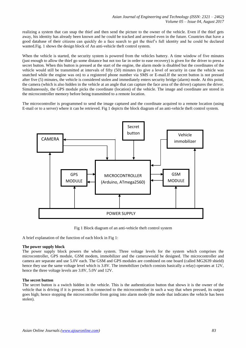
5. SOFTWARE DESIGN
The software design aspect of this research handles the programming aspect of it.. The program language used is the
Arduino assembly language which is actually a C/C++ language.
The flow chart for the ‘Vehicle Theft Control System by Using GSM and GPS Systems with thief image acquisition’ is
shown in Fig. 4
No Yes
No Yes
Yes No
Yes
No
Fig 4 Flow chart
Initialization
buttons
GPS
GPRS
CAMERA
Enter idle
state
Alarm mode
Snap picture
Stop engine
Get GPS coordinates
Send Picture and coordinates
Send GPS
Coordinates
Enter Tracking
mode
Idle state
Key
pressed?
Timeout?
Engine
started?
Tracker
timeout?
Wait

Asian Journal of Engineering and Technology (ISSN: 2321 – 2462) Volume 05 – Issue 04, August 2017
Asian Online Journals (www.ajouronline.com) 89
From the flow chart, the GPS,GSM and camera are initialized and then the system enters an idle state before the engine is
started. Upon starting the engine, a timer starts counting waiting for the secret button to be pressed. If the button is
pressed, then the alarm mode is disabled and the system enters a tracking mode where the coordinate of the vehicle is
sent every fifty (50) minutes.
If the button is not pressed within five (5) minutes, the system enters the alarm mode (indicating that the vehicle has been
stolen). The microcontroller then gives the camera the command to snap the driver, the engine to stop, the GPS to pick up
the coordinates and then send the picture and coordinate to a registered number/server where it can be retrieved.
6. RESULTS AND DISCUSSION
The results from the prototype are presented in this section.
Authentication and timing
The authentication system is done using a secret button connected to the microcontroller and programmed in such a way
that it allows a time window of five (5) minutes for it to be pressed. If this is not done within five minutes, then the
system enters security bridge mode. In Fig 5, a red LED has been used to show that the vehicle security has been bridged.
The green LED lights up when the vehicle is in normal operating mode.
Discussion
The security system can operate in one of two modes;
i. Tracking mode and
ii. Alarm mode
The discussion is based on these two modes.
Tracking mode
This mode is activated when the security button is pressed within the five (5) minutes from when the ignition is started.
This shows that the driver is the owner of the vehicle Fig 5 depicts the system in tracking mode indicated by the green
LED lighting up. In order to add some form of security to the vehicle even when the driver has authenticated, the co-
ordinate of the vehicle is continually transmitted every fifty (50) minutes. This is to allow tracking of the vehicle in case
it was snatched from the driver while the engine is still running.
Fig 5 System in tracking mode (Green LED lights up)

Asian Journal of Engineering and Technology (ISSN: 2321 – 2462) Volume 05 – Issue 04, August 2017
Asian Online Journals (www.ajouronline.com) 90
Alarm mode
The alarm mode is activated when the secret button is not pressed after five (5) minutes from when the ignition is turned
on. In this mode, there is a security breach, meaning the vehicle has been stolen. Immediately, the microcontroller then
sends a command to the camera to snap the driver (in this case the thief), the GPS modem also picks the co-ordinate of
the vehicle and both information (the image and co-ordinate) are transmitted to the owners E-mail address as shown in
fig above. The microcontroller also sends another signal to the immobilizer to immobilize the vehicle. At this point, the
red LED lights up indicating that the engine is immobilize as shown in Fig. 6.
Fig 6 System in alarm mode (Red LED lights up)
In a situation whereby the driver starts the vehicle and forgets to authenticate within the five (5) minutes, the system will
still enter the alarm mode and immobilize the vehicle. The driver only needs to press the secret button and then start the
ignition.
Thus it can be seen that it is possible to design and implement an anti-vehicle theft control system that can acquire the
image of the thief and transmit it to a remote location where it can be retrieved along with the co-ordinate of the vehicle.
Thus the aim and objectives of this project have been met.
Tracking/transmission
The tracking/transmission section consists of the GPS modem and GSM modem. The GPS modem is used to acquire the
coordinates of the vehicle while the GSM modem is used to send the image to a remote location such as an e-mail
address, phone number (via MMS) or webserver. In order to illustrate this image transmission, an application was
developed to transmit the image and coordinates to an e-mail address which can be easily accessed through a smartphone.
The vehicle plate number is also transmitted along with the coordinate and image for easier identification of the burglar
of the vehicle.( Fig. 7)

Asian Journal of Engineering and Technology (ISSN: 2321 – 2462) Volume 05 – Issue 04, August 2017
Asian Online Journals (www.ajouronline.com) 91
Fig 7 Transmitted image and coordinates
7. CONCLUSION
The main objective of this paper is to design an anti-vehicle theft security system that can acquire the image of a
supposed thief and transmit it to a remote location where it can be retrieved. It can be seen from the results obtained that
it is possible to design and implement such a system using a GSM modem, GPS modem, a camera and a microcontroller.
Although the image was sent to an email address, it can easily be accessed since most people have smartphones these
days with internet access. When a man who has stolen a vehicle with such a system in it is arrested later in the future, he
would not want to carry out such a criminal act again knowing that he could be arrested anytime. With such a system,
many vehicle thieves would think twice before indulging in such criminal act. Hence, it is expected that the rate at which
vehicles are stolen should drop further if such a system is implemented. The coordinate of the vehicle that has been
transmitted also makes it easier to locate the vehicle after it has been stolen
8. REFERENCES
1. The alarming rate of car theft in Abuja,[online].Available: www.abujafacts.ng 23 Nov 2015
2. Auto theft [online] Available www.iii.org/issue-update 16th Mar 2016
3. Abid k. and Ravi M, “GPS – GSM Based Tracking System”International Journal of Engineering Trends and
Technology,Volume3, Issue 2- 2012
4. Baburao K., et al, “GSM and GPS Based Vehicle Location And Tracking System”International Journal of
Engineering Research and Applications (IJERA) Vol. 1, Issue 3, pp.616-625
5. PankajVerma and Bhatia J.S, “Design And Development Of Gps-Gsm based Tracking System with Google map
Based Monitoring” International Journal of Computer Science, Engineering and Applications (IJCSEA) Vol.3,
No.3, June 2013
6. Pravada P. W. and Dahad S. O, “Real Time Vehicle Locking and Tracking System using GSM and GPS
Technology-An Anti-theft System” International Journal of Technology And Engineering System(IJTES):
Vol.2.No.3, Jan –March 2011
7. Madhuri U. et al., “Remote Vehicle Tracking & Driver Health Monitoring System Using GSM Modem & Google
Maps”, International Journal of Computer Science and Information Technologies, Vol. 5 (3) , pp. 2828-2832,
2014.
8. Albert A. and Ezhilarasie R., “Cloud Computing Based Vehicle Tracking Information Systems” International
Journal of Computer Science and Technology Vol. 2, Issue 1, March 2011.

Asian Journal of Engineering and Technology (ISSN: 2321 – 2462) Volume 05 – Issue 04, August 2017
Asian Online Journals (www.ajouronline.com) 92
9. Kale S. B. and Satyajit A. P., “Design and Development of Low Cost Automotive Vehicular Communication
System Based on ARM” International Journal of Engineering and Advanced Technology (IJEAT) ISSN:
Volume-3, Issue-5, June 2014
10. Muruganandham and Mukesh P.R., “Real Time Web based Vehicle Tracking using GPS” World Academy of
Science, Engineering and Technology pp.91-99, 2010
11. Modi N. D., “Vehicle tracking system with GPS GSM Interface and Self-Created Map” International Journal of
Application or Innovation in Engineering & Management (IJAIEM) Volume 3, Issue 4, April 2014
12. Pethakar S.S. et al., “GPS and GSM based Vehicle Tracing and Employee Security System” International Journal
of Computer Applications (0975 – 8887) Volume 62– No.6, January 2013