Arduino Based Tracking System Using GPS and GSM
10
The Second Myanmar National Conference on Earth Sciences (MNCES, 2018) 1089 November 29-30, 2018, Hinthada University, Hinthada, Myanmar 1 Demonstrator, Department of Physics, Pathein University. 2 Professor, Head of Department of Physics, Pathein University. 3 Professor (Rted), Head of Department of Physics, Kyaukse University. Arduino Based Tracking System Using GPS and GSM Khin Sandar Lin 1 , Nyi Nyi Yin 2 and Ohn Than 3 Abstract A tracking system is the combination of the Global Positioning System (GPS) and the Global System Mobile communication (GSM) technologies via the microcontroller. It is used to detect the GPS location of vehicles or any objects which are attached with tracking device. GPS is a satellite-based navigation technology which provides the accurate location and information. Data from the numerous satellites is received by GPS receiver in the National Marine Electronics Association (NMEA) protocol form. The NMEA code consists of a combination of information. Arduino is linked to the GPS and the GSM module in the serial connection. The GPS receiver sends data to Arduino. Then, Arduino instructs GSM module to send the location data to the GSM enable device in short message form. The conditions of process of GPS and GSM are display on the LCD as well as on serial monitor. Keywords: GPS, GSM, NMEA Introduction In this research, Arduino Uno training board, GPS receiver and GSM SIM 900A module are used as major hardware and basic C programming language is used for hardware description language to build small digital circuit. First, the sketch is written in arduino Integrated Development Environment (IDE) and the sketch is uploaded into the arduino programmable microcontroller board. After that GPS receiver tracks the satellite data and send the Arduino Uno. And then, Arduino send its data to the GSM module to SIM card number recommended by user. Under the circumstances, one can know the location where vehicles or moving objects have arrived as the short message form in the specified android mobile phone. The Global Positioning System (GPS) is a satellite based navigation system that sends data from satellites orbiting Earth to GPS receivers on the ground that can use that data to determine position and the current time anywhere on Earth. GPS module is used to determine position, time and speed. GPS satellites rotate all around the earth two times in a day. It revolves around in a very accurate course and sends out indication and the information to the earth. The receivers of GPS get all the information and apply triangulation to discover the accurate location of the user. The time difference formulates how far the receiver is away from the satellites of the GPS. It measures the exact distance with few more satellites and the receivers determine the position of the user and displays it on the map of the electronic appliance. By using four or more satellites, the receivers can determine the three dimensional position of the user which consists of altitude, latitude and longitude. After determining the position of user, the GPS unit calculates other information such as speed, bearing, track, distance, destination, sunrise, sunset time. GPS systems are extremely versatile and can be found in almost any industry sector. They can be used to map forests, helps farmers harvest their fields, and navigate airplanes on the ground or in the air. GPS system are used in military application and by emergency crews to locate people in need of assistance. These days doctors, scientists, farmers, soldiers, pilots, hikers, delivery, driver, sailors, fishermen,
-
Upload
khangminh22 -
Category
Documents
-
view
0 -
download
0
Transcript of Arduino Based Tracking System Using GPS and GSM

The Second Myanmar National Conference on Earth Sciences (MNCES, 2018) 1089
November 29-30, 2018, Hinthada University, Hinthada, Myanmar
1 Demonstrator, Department of Physics, Pathein University. 2 Professor, Head of Department of Physics, Pathein University. 3 Professor (Rted), Head of Department of Physics, Kyaukse University.
Arduino Based Tracking System Using GPS and GSM
Khin Sandar Lin1, Nyi Nyi Yin
2 and Ohn Than
3
Abstract
A tracking system is the combination of the Global Positioning System (GPS)
and the Global System Mobile communication (GSM) technologies via the
microcontroller. It is used to detect the GPS location of vehicles or any objects
which are attached with tracking device. GPS is a satellite-based navigation
technology which provides the accurate location and information. Data from
the numerous satellites is received by GPS receiver in the National Marine
Electronics Association (NMEA) protocol form. The NMEA code consists of
a combination of information. Arduino is linked to the GPS and the GSM
module in the serial connection. The GPS receiver sends data to Arduino.
Then, Arduino instructs GSM module to send the location data to the GSM
enable device in short message form. The conditions of process of GPS and
GSM are display on the LCD as well as on serial monitor.
Keywords: GPS, GSM, NMEA
Introduction
In this research, Arduino Uno training board, GPS receiver and GSM SIM 900A
module are used as major hardware and basic C programming language is used for hardware
description language to build small digital circuit. First, the sketch is written in arduino
Integrated Development Environment (IDE) and the sketch is uploaded into the arduino
programmable microcontroller board. After that GPS receiver tracks the satellite data and
send the Arduino Uno. And then, Arduino send its data to the GSM module to SIM card
number recommended by user. Under the circumstances, one can know the location where
vehicles or moving objects have arrived as the short message form in the specified android
mobile phone.
The Global Positioning System (GPS) is a satellite based navigation system that sends
data from satellites orbiting Earth to GPS receivers on the ground that can use that data to
determine position and the current time anywhere on Earth. GPS module is used to determine
position, time and speed. GPS satellites rotate all around the earth two times in a day. It
revolves around in a very accurate course and sends out indication and the information to the
earth. The receivers of GPS get all the information and apply triangulation to discover the
accurate location of the user. The time difference formulates how far the receiver is away
from the satellites of the GPS. It measures the exact distance with few more satellites and the
receivers determine the position of the user and displays it on the map of the electronic
appliance. By using four or more satellites, the receivers can determine the three dimensional
position of the user which consists of altitude, latitude and longitude. After determining the
position of user, the GPS unit calculates other information such as speed, bearing, track,
distance, destination, sunrise, sunset time. GPS systems are extremely versatile and can be
found in almost any industry sector. They can be used to map forests, helps farmers harvest
their fields, and navigate airplanes on the ground or in the air. GPS system are used in
military application and by emergency crews to locate people in need of assistance. These
days doctors, scientists, farmers, soldiers, pilots, hikers, delivery, driver, sailors, fishermen,

1090 The Second Myanmar National Conference on Earth Sciences (MNCES, 2018)
November 29-30, 2018, Hinthada University, Hinthada, Myanmar
and people from many other walks of life are using GPS systems in ways that make more
productive, safer, and easier.
The system, although must comprise at least four satellites. Each satellite and the
receiver are equipped with stable atomic clock. The satellite clocks are synchronized with
each other and ground clocks. The work of the GPS receiver is to receive signals from the
network of satellites to compute of time and position. GPS module sends the data related to
tracking position in real time, and it sends so many data in NMEA format. NMEA format
consists several sentences, and starts from $GPGGA and contains the coordinates, time and
other useful information. This GPGGA is referred to Global Positioning System Fix Data. In
this research, we study the concept of the GSM modules that is used a variation of time
division multiple access (TDMA) and is the most widely used of the three digital wireless
telephony technologies (TDMA), GSM and CDMA. GSM is the most widely used cell phone
technology and is used internationally in the context of GSM phones and GSM network.
GSM network providers put customer information on a removable SIM card.
Hardware and Software Requirements
In this study, Arduino is based tracking system using GPS and GSM modules.
Tracking of vehicle is a process in which one can track the vehicle location in form of
latitude and longitude (GPS coordinates). GPS Coordinates are the value of a location. This
vehicle tracking system can also be used for Accident Detection Alert System, Soldier
Tracking System. GPS is a navigation technology which is used of satellites. The use of GPS
receiver is to find latitude and longitude of its location. The data obtained from GPS receiver
is processed by the microcontroller to extract its latitude and longitude values. It gives the
precise information about a location. A GPS system consists of group of satellites and well
developed tools such as receiver.
GPS Module
GPS module consists of U-blox NEO 6M module and GPS antenna as shown in figure
(1). The NEO-6 module series is a family of stand-alone GPS receivers featuring the high
performance u-blox 6 positioning engine. These flexible and cost effective receivers offer
numerous connectivity options in a miniature 16 x 12.2 x 2.4 mm package. Their compact
architecture and power and memory options make NEO-6 modules ideal for battery operated
mobile devices with very strict cost and space constraints.
It can be interfaced with UART,USB,SPI and DDC. NEO-6 modules include one
configurable UART interface for serial communication. NEO-6 modules provide a USB
version 2.0 FS (Full Speed, 12Mbit/s) interface as an alternative to the UART. The pull-up
resistor on USB_DP is integrated to signal a full-speed device to the host. The VDDUSB pin
supplies the USB interface. u-blox provides a Microsoft® certified USB driver for Windows
XP, Windows Vista and Windows 7 operating systems.
The SPI interface allows for the connection of external devices with a serial interface,
e.g. serial flash to save configuration and Assist Now Offline A-GPS data or to interface to a
host CPU. The interface can be operated in master or slave mode. In master mode, one chip
select signal is available to select external slaves. In slave mode a single chip select signal
enables communication with the host. Its maximum bandwidth is 100kbit/s. The I2C
compatible Display Data Channel (DDC) interface can be used either to access external
devices with a serial interface EEPROM or to interface with a host CPU. It is capable of
master and slave operation. The DDC interface is I2C Standard Mode compliant. For timing
parameters consult the I2C standard. The DDC Interface supports serial communication with

The Second Myanmar National Conference on Earth Sciences (MNCES, 2018) 1091
November 29-30, 2018, Hinthada University, Hinthada, Myanmar
u-blox wireless modules. Its maximum bandwidth is 100kbit/s. NEO-6 modules are designed
for use with passive and active antennas.
Figure (1). GPS module and GPS antenna
The minimum gain and maximum gain are 15dB and 50dB respectively and
maximum noise figure is 1.5dB.
GPS receivers use a constellation of satellites and ground stations to compute position
and time almost anywhere on earth. At any given time, there are at least 24 active satellites
orbiting over 12,000 miles above earth. The positions of the satellites are constructed in a
way that the sky above your location will always contain at most 12 satellites. The primary
purpose of the 12 visible satellites is to transmit information back to earth over radio
frequency (ranging from 1.1 to 1.5 GHz). With this information and some math, a ground
based receiver or GPS module can calculate its position and time.
The data sent down to earth from each satellite contains a few different pieces of
information that allows GPS receiver to accurately calculate its position and time. An
important piece of equipment on each GPS satellite is an extremely accurate atomic clock.
The time on the atomic clock is sent down to earth along with the satellite’s orbital position
and arrival times at different points in the sky. In other words, the GPS module receives a
timestamp from each of the visible satellites, along with data on where in the sky each one is
located (among other pieces of data). From this information, the GPS receiver now knows the
distance to each satellite in view. If the GPS receiver’s antenna can see at least 4 satellites, it
can accurately calculate its position and time. This is also called a lock or a fix.
GPS Format
Tiny GPS is a small GPS library for Arduino providing basic NMEA. GPS modules
typically put out a series of standard strings of information, under something called the
National Marine Electronics Association (NMEA) protocol. The tutorial code at the bottom
of this page demonstrates how to decode and display the most common string, called
$GPRMC. While one can write software to serially request other strings from the GPS
module, the following strings are automatically transmitted when the "/RAW" pin is pulled
low.
$GPGGA: Global Positioning System Fix Data
$GPGSV: GPS satellites in view
$GPGSA: GPS DOP and active satellites
$GPRMC: Recommended minimum specific GPS/Transit data

1092 The Second Myanmar National Conference on Earth Sciences (MNCES, 2018)
November 29-30, 2018, Hinthada University, Hinthada, Myanmar
Each of these sentences contains a wealth of data. For example, here are a few
instances of the $GPRMC string, aka the "Recommended minimum specific GPS/Transit
data" string:
eg., 1. $GPRMC,081836,A,3751.65,S,14507.36,E,000.0,360.0,130998,011.3,E*62
eg., 2. $GPRMC,225446,A,4916.45,N,12311.12,W,000.5,054.7,191194,020.3,E*68
225446 Time of fix 22:54:46 UTC
A Navigation receiver warning A = Valid position, V = Warning
4916.45,N Latitude 49 deg. 16.45 min. North
12311.12,W Longitude 123 deg. 11.12 min. West
000.5 Speed over ground, Knots
054.7 Course Made Good, degrees true
191194 UTC Date of fix, 19 November 1994
020.3,E Magnetic variation, 20.3 deg. East
*68 mandatory checksum
eg3. $GPRMC,220516,A,5133.82,N,00042.24,W,173.8,231.8,130694,004.2,W*70
1 2 3 4 5 6 7 8 9 10 11 12
1 220516 Time Stamp
2 A validity - A-ok, V-invalid
3 5133.82 current Latitude
4 N North/South
5 00042.24 current Longitude
6 W East/West
7 173.8 Speed in knots
8 231.8 True course
9 130694 Date Stamp
10 004.2 Variation
11 W East/West
12 *70 checksum
eg4. for NMEA 0183 version 3.00 active the Mode indicator field is added
$GPRMC,hhmmss.ss,A,llll.ll,a,yyyyy.yy,a,x.x,x.x,ddmmyy,x.x,a,m*hh
Field #
1 = UTC time of fix
2 = Data status (A=Valid position, V=navigation receiver warning)
3 = Latitude of fix
4 = N or S of longitude
5 = Longitude of fix

The Second Myanmar National Conference on Earth Sciences (MNCES, 2018) 1093
November 29-30, 2018, Hinthada University, Hinthada, Myanmar
6 = E or W of longitude
7 = Speed over ground in knots
8 = Track made good in degrees True
9 = UTC date of fix
10 = Magnetic variation degrees (Easterly var. subtracts from true course)
11 = E or W of magnetic variation
12 = Mode indicator, (A=Autonomous, D=Differential, E=Estimated, N= Data not valid)
13 = Checksum
SIM 900 GSM Breakout
GSM/GPRS Modem-RS232 is built with Dual Band GSM/GPRS engine- SIM900A,
works on frequencies 900/ 1800 MHz. The Modem is coming with RS232 interface, which
allows to connect PC as well as microcontroller with RS232 Chip (MAX232). The baud rate
is configurable from 9600-115200 through AT command. The GSM/GPRS Modem is having
internal TCP/IP stack to enable you to connect with internet via GPRS. It is suitable for SMS,
Voice as well as DATA transfer application in M2M interface. The onboard Regulated Power
supply allows you to connect wide range unregulated power supply. Using this modem, one
can make audio calls, SMS, Read SMS, attend the incoming calls and internet through simple
AT commands.
1. Quad-Band 850/ 900/ 1800/ 1900 MHz
2. GPRS multi-slot class 10/8
3. GPRS mobile station class B
4. Compliant to GSM phase 2/2+Class 4 (2 W @850/ 900 MHz)
5. Class 1 (1 W @ 1800/1900MHz)
6. Control via AT commands (GSM 07.07, 07.05 and SIMCOM enhanced AT Commands)
7. Low power consumption: 1.5mA(sleep mode)
8. Operation temperature: -40°C to +85 °C
Unlike mobile phones, a GSM modem doesn’t have a keypad and display to interact
with. It just accepts certain commands through a serial interface and acknowledges for those.
These commands are called as AT commands. There are a list of AT commands to instruct
the modem to perform its functions. Every command starts with "AT". That’s why these are
called as AT commands. AT stands for “attention”. When a ten digit mobile number is
provided, the program instructs the modem to send the text message using a sequence of AT
commands.

1094 The Second Myanmar National Conference on Earth Sciences (MNCES, 2018)
November 29-30, 2018, Hinthada University, Hinthada, Myanmar
Figure (2). Schematic circuit diagram of SIM
900 GSM breakout
Figure (3). Photograph of SIM 900 GSM
breakout
Experimental Setup and Sketch
Experimental Setup
There are three main parts. Firstly, the GPS shield is connected easy to Arduino Uno.
GPS Rx (receive) is connected to the Arduino Uno Tx (transmit) and GPS Tx (transmit) is
connected to the Arduino Uno Rx (receive). This is because the Uno (Tx) D11 transmits to
the GPS (Rx) and conversely the Uno (Rx) D12 receives from the GPS (Tx) . GSM Rx
(receive) is connected to the Arduino Uno Tx (transmit) and GSM Tx (transmit) is connected
to the Arduino Uno Rx (receive). This is because the Uno (Tx) D1 transmits to the GPS (Rx)
and conversely the Uno (Rx) D0 receives from the GPS (Tx) shown in figure (4) and figure
(5). The Rs, R/W, DB4, DB5, DB6 and DB7 of LCD are connected to D7, D6, D5, D4, D3
and D2 of Arduino as shown in figure (5). Figure (6) shows the experimental circuit
connection of GPS tracking system. The block diagram of Program (sketch) of the GPS and
GSM module is illustrated in figure (7).
Figure (4). GPS tracker drawn with Proteus
software
Figure (5). GPS tracker circuit in Proteus
window
The Second Myanmar National Conference on Earth Sciences (MNCES, 2018) 1095
November 29-30, 2018, Hinthada University, Hinthada, Myanmar
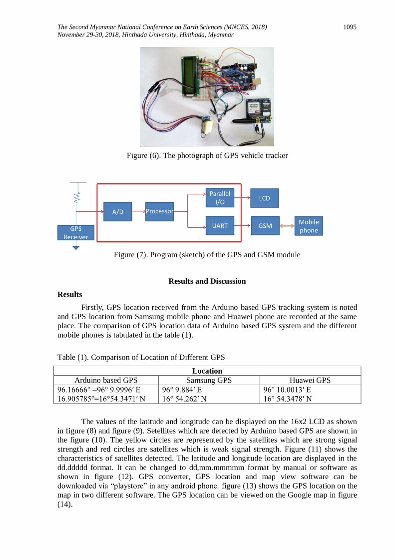
Figure (6). The photograph of GPS vehicle tracker
Figure (7). Program (sketch) of the GPS and GSM module
Results and Discussion
Results
Firstly, GPS location received from the Arduino based GPS tracking system is noted
and GPS location from Samsung mobile phone and Huawei phone are recorded at the same
place. The comparison of GPS location data of Arduino based GPS system and the different
mobile phones is tabulated in the table (1).
Table (1). Comparison of Location of Different GPS
Location
Arduino based GPS Samsung GPS Huawei GPS
96.16666° =96° 9.9996′ E
16.905785°=16°54.3471′ N
96° 9.884′ E
16° 54.262′ N
96° 10.0013′ E
16° 54.3478′ N
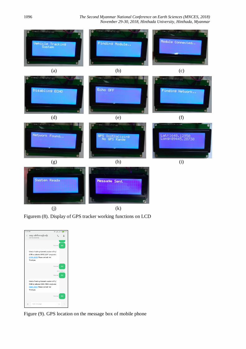
The values of the latitude and longitude can be displayed on the 16x2 LCD as shown
in figure (8) and figure (9). Setellites which are detected by Arduino based GPS are shown in
the figure (10). The yellow circles are represented by the satellites which are strong signal
strength and red circles are satellites which is weak signal strength. Figure (11) shows the
characteristics of satellites detected. The latitude and longitude location are displayed in the
dd.ddddd format. It can be changed to dd,mm.mmmmm format by manual or software as
shown in figure (12). GPS converter, GPS location and map view software can be
downloaded via “playstore” in any android phone. figure (13) shows the GPS location on the
map in two different software. The GPS location can be viewed on the Google map in figure
(14).
1096 The Second Myanmar National Conference on Earth Sciences (MNCES, 2018)
November 29-30, 2018, Hinthada University, Hinthada, Myanmar
(a) (b) (c)
(d) (e) (f)
(g) (h) (i)
(j) (k)
Figurem (8). Display of GPS tracker working functions on LCD
Figure (9). GPS location on the message box of mobile phone

The Second Myanmar National Conference on Earth Sciences (MNCES, 2018) 1097
November 29-30, 2018, Hinthada University, Hinthada, Myanmar
Figure (10). Satellite List
Above the Location
Figure (11). SNR level of
satellite above the location
Figure (12). Lat/long
converter software
Figure (13). GPS location on different google map software Figure (14). GPS location on
the Google street
map view
Conclusion
With this setup it can be able to acquire lat / long coordinates outdoors with a clear
view of the sky in 23s to 32s with an average of 28s. Indoors on the bottom floor of a 2 story
house a location is received in 61s to 140s with an average of 101s from time of power up to
time of first GPS lat / long coordinate acquisition.
The commercial GPS is not in accurate precision as much as military GPS. To be
accurate data, number of GPS satellites must be at least four or above . With this circuit the
longer time it is given the more accurate the reading. Typically it found the first reading
within a hundred feet and given more time it would get down to a few feet accuracy. It's
based on U-blox NEO 7M GPS module, and the footprints are compatible with
Arduino/MEGA boards. The regular GPS pins (RX, TX) can be connected to any digital pins

1098 The Second Myanmar National Conference on Earth Sciences (MNCES, 2018)
November 29-30, 2018, Hinthada University, Hinthada, Myanmar
of Arduino. This GPS shield is suitable for Personal positioning, Automotive navigation and
Marine navigation with Arduino or Arduino compatible boards.
Transmitter pin and receiver pin of GSM module is connected to receiver pin(Rx) D0
and transmitter pin (Tx)D1 of Arduino uno board respectively. The problem with the circuit
connection is that, while programming Arduino uses serial ports to load program from the
Arduino IDE. If these pins are used in wiring, the program will not be loaded successfully to
Arduino. So it needs to disconnect wiring in Rx and Tx each time that the program burns to
arduino. Once the program is loaded successfully, these pins are reconnect and have the
system working well.
Acknowledgements
Special thanks are extended to Board of Editors, Myanmar National conference on the Earth Science,
Hinthada University, for giving me the opportunity to submit the research article and invaluable suggestions.We
would like to express my thanks to Dr. Si Si Hla Bu, Rector, Pathein University for her permission.
References
Banzi M., (2009). “Getting Started with Arduino” U.S.A.
Boxall J., (2013). “Arduino Workshop”, No Starch Press, San Fransisco.
Göransson A., (2013). “Android™ Open Accessory Programming with Arduino” ,John Wiley , New York.
Monk S., (2010). “Arduino™ + Android™ Projects for the Evil Genius” Tab, New York.
Monk S., (2010). “30 arduino projects for the evil geneius” Mc Graw-Hill Education, New York, Chicago, San
Francisco, Athens, London, Madrid, Mexioco city, Milan, New Delhi, Singapore.
Purdun J., (2012). “Beginning C for Arduino” Apress, New York.
Trimble, (2007). “GPS. The First Global Navigation Satellite system” Navigation Limited 935 Stewart Drive Sunnyvale, New York.