Voice Based Guidance and Location Indications System for the Blind using GSM, GPS and Optical Device...
11
Sama Santhosh Reddy et al, International Journal of Computer Science and Mobile Computing, Vol.3 Issue.9, September- 2014, pg. 822-832 © 2014, IJCSMC All Rights Reserved 822 Available Online at www.ijcsmc.com International Journal of Computer Science and Mobile Computing A Monthly Journal of Computer Science and Information Technology ISSN 2320–088X IJCSMC, Vol. 3, Issue. 9, September 2014, pg.822 – 832 RESEARCH ARTICLE Voice Based Guidance and Location Indications System for the Blind using GSM, GPS and Optical Device Indicator Sama Santhosh Reddy 1 , Mrs. G. Sathyaprabha 2 , Mr. P.V. Vara Prasad Rao 3 ¹M.Tech (ES&VLSI), SLC’s Institute of Technology, JNTU, Hyderabad, India ²Assistant Professor (ECE), SLC’s Institute of Technology, JNTU, Hyderabad, India ³Head of the Department (Digital Systems Computer Electronics), SLC’s Institute of Technology, JNTU, Hyderabad, India 1 [email protected] Abstract— An active optical pathfinder using a LED and a photodiode is implemented as an electronic travel aid to improve the mobility of persons who are blind. The protected path is optimized by using radiometric calculations. Protection zones for typical configurations of obstacles are studied: an opening, a side panel, a front panel, and a post. The results in real configurations such as parked cars, trees, and dustbins are presented too. Finally, we explain how the device can be used in real life by visually impaired people, in conjunction with the typical white stick. Keywords— Blind people, electronic travel aid (ETA), infrared (IR) detection I. INTRODUCTION Walking safely and confidently without any human assistance in urban or unknown environments is a difficult task for blind people. Visually impaired people generally use either the typical white cane or the guide dog to travel independently [1]. Although the white stick gives a warning about 1 m before the obstacle, for a normal walking speed of 1.2 m/s, the time to react is very short (only 1 s). The stick scans the floor and consequently cannot detect certain obstacles (rears of trucks, low branches, etc.). Safety and confidence could be increased using devices that give a signal to find the direction of an obstacle-free path in unfamiliar or changing environments. Electronic travel aids (ETAs) are devices that give off a warning by auditory or/and tactile signals when an obstacle is in the way and allow the user to avoid it [1], [2]. Several devices have been developed to improve the mobility of blind people [3], [4]: talking GPS [5], devices for landmark identification (near-infrared (IR) light or radio frequencies) [6], [7], ultrasonic obstacle detectors (K sonar [8], Ultracane [9], Miniguide [10], Palmsonar [11], Ultra-Body-Guard [12], and iSonic cane [13]), and optical devices (the laser long cane [14]). In indoor or outdoor crowded environments, ultrasonic devices are limited due to multiple reflections [4]. These devices cannot find openings that are wide enough for a human being to go through, with anticipation of a few meters (4–6 m). On the other hand, laser devices collect information about very narrow openings that are not large enough to be free paths. Therefore, they detect a lot of useless information (details of fences, of branches, of walls, etc.).
Transcript of Voice Based Guidance and Location Indications System for the Blind using GSM, GPS and Optical Device...

Sama Santhosh Reddy et al, International Journal of Computer Science and Mobile Computing, Vol.3 Issue.9, September- 2014, pg. 822-832
© 2014, IJCSMC All Rights Reserved 822
Available Online at www.ijcsmc.com
International Journal of Computer Science and Mobile Computing
A Monthly Journal of Computer Science and Information Technology
ISSN 2320–088X
IJCSMC, Vol. 3, Issue. 9, September 2014, pg.822 – 832
RESEARCH ARTICLE
Voice Based Guidance and Location Indications
System for the Blind using GSM, GPS and
Optical Device Indicator
Sama Santhosh Reddy
1, Mrs. G. Sathyaprabha
2, Mr. P.V. Vara Prasad Rao
3
¹M.Tech (ES&VLSI), SLC’s Institute of Technology, JNTU, Hyderabad, India
²Assistant Professor (ECE), SLC’s Institute of Technology, JNTU, Hyderabad, India
³Head of the Department (Digital Systems Computer Electronics), SLC’s Institute of Technology, JNTU, Hyderabad, India 1 [email protected]
Abstract— An active optical pathfinder using a LED and a photodiode is implemented as an electronic travel aid to improve
the mobility of persons who are blind. The protected path is optimized by using radiometric calculations. Protection zones for
typical configurations of obstacles are studied: an opening, a side panel, a front panel, and a post. The results in real
configurations such as parked cars, trees, and dustbins are presented too. Finally, we explain how the device can be used in
real life by visually impaired people, in conjunction with the typical white stick.
Keywords— Blind people, electronic travel aid (ETA), infrared (IR) detection
I. INTRODUCTION
Walking safely and confidently without any human assistance in urban or unknown environments is a difficult task for blind
people. Visually impaired people generally use either the typical white cane or the guide dog to travel independently [1].
Although the white stick gives a warning about 1 m before the obstacle, for a normal walking speed of 1.2 m/s, the time to react
is very short (only 1 s). The stick scans the floor and consequently cannot detect certain obstacles (rears of trucks, low branches,
etc.). Safety and confidence could be increased using devices that give a signal to find the direction of an obstacle-free path in
unfamiliar or changing environments. Electronic travel aids (ETAs) are devices that give off a warning by auditory or/and
tactile signals when an obstacle is in the way and allow the user to avoid it [1], [2].
Several devices have been developed to improve the mobility of blind people [3], [4]: talking GPS [5], devices for landmark
identification (near-infrared (IR) light or radio frequencies) [6], [7], ultrasonic obstacle detectors (K sonar [8], Ultracane [9],
Miniguide [10], Palmsonar [11], Ultra-Body-Guard [12], and iSonic cane [13]), and optical devices (the laser long cane [14]).
In indoor or outdoor crowded environments, ultrasonic devices are limited due to multiple reflections [4]. These devices cannot
find openings that are wide enough for a human being to go through, with anticipation of a few meters (4–6 m). On the other
hand, laser devices collect information about very narrow openings that are not large enough to be free paths. Therefore, they
detect a lot of useless information (details of fences, of branches, of walls, etc.).

Sama Santhosh Reddy et al, International Journal of Computer Science and Mobile Computing, Vol.3 Issue.9, September- 2014, pg. 822-832
© 2014, IJCSMC All Rights Reserved 823
Ideally, the detected path should be shoulder width, vertical from ground level to the level of the user’s head, and up to a
few meters ahead of the user, as shown in Fig 1. Our approach is to develop an active IR device to improve the rate of relevant
detection in indoor and outdoor crowded environments. Our purpose is to detect shoulder-width openings that are a long
distance away (4–6 m), without detecting openings that are too narrow (less than 0.5 m wide). The IR devices that we have been
developing are the Tom Pouce and the Minitact. The aim of these devices is to protect users from obstacles that are at knee to
head level. The device can be fastened to the cane or held by the user. It gives a vibrating warning when an obstacle is ahead of
the white cane or of the hand. In outdoor situations, the Tom Pouce I (first generation) is fixed to the white cane at hand level.
The cane and the device are continuously swept sideways. In this way, the unevenness of the ground is detected by the tip of the
cane. High and horizontal obstacles are detected by the device. The permanent right and left scan of the device allows the user
to perceive the direction of the various paths that are available, owing to a lack of vibrations.
According to user experiences, the largest range (4mfor Tom Pouce I) has been reported to be the most comfortable for
stressfree walking. However, with this range, blind users generally claim that it is difficult to perceive narrow but still human-
sized paths with 4-m anticipation. If the ETA does not detect a free path with such anticipation, the only way to go through is to
assume that there is a path and to reduce the range of the ETA to keep looking for the freeway. For example, a 2-m range gives
a shorter and narrower protection area. The benefits of the device are then highly reduced, because they may not be the free
path. For the Tom Pouce I, it was not possible to give more than 4-m anticipation because the beam would detect the floor as
being too wide.
In the literature, ETAs are characterized by their detection ranges [2], [3], [8]–[14], but neither the width of the detection area
nor the effective abilities and limits to detect paths are detailed. The divergence of the emitted beam is far from being
satisfactory information to answer this question whatever technology is used. The purpose of this paper is to present a method to
improve and approximate the ―ideal‖ protection area, which is to have a narrower (such as shoulder width) and longer zone
(Fig. 1). This method makes it possible to calibrate and control the dimensions of the protection area of the IR devices.
Theoretical and experimental photometric results are presented and discussed. A practical device used by blind people in
everyday life will finally be described, and current real-life obstacle configurations will be presented.
II. PRINCIPLE OF THE INFRARED DETECTOR
The device includes a near-IR LED and a photodiode (Fig. 2). The LED emits a train of pulses. These pulses strike the
obstacle, and the retro diffused light is detected by the photodiode. The light detected is processed to determine whether there is
a path or not.
The sensitive surface of the photodiode is placed next to the LED and perpendicularly to the axis of the LED beam. Both
components are optically insulated and separated by 15 mm to prevent the emitted light from getting directly into the
photodiode.
The LED emits pulses managed by a control unit. The control unit increases the amplitude of the pulse step by step. When the
signal-to-noise ratio of the photodiode is high enough to detect the presence of the obstacle (detection threshold), the emission is
interrupted. The last amplitude of emitted light gives a value. When this value is lower than a constant (arbitrarily fixed, which

Sama Santhosh Reddy et al, International Journal of Computer Science and Mobile Computing, Vol.3 Issue.9, September- 2014, pg. 822-832
© 2014, IJCSMC All Rights Reserved 824
we will call ―range constant‖), a vibration is sent to the user, which means that there is an obstacle. A lack of vibration means a
free path, and the higher the constant, the larger the free path. The choice of the constant determines the range of the device
(protection length). The constant and, therefore, the range will be adjustable by the user. In this system, the range depends on
the albedos of the obstacles. In practice, this system gives efficient protection to blind people except in the case of specific
obstacles, which we will describe in Section V-C.
III. RADIOMETRIC CONSIDERATION
To study how the protection area depends on the parameters of the LED and those of the obstacles, we calculate the
irradiance on the detector to draw the theoretical protection area for planar obstacles.
Let I(θ) be the intensity distribution of a LED; the light that is retrodiffused by the target is detected by the photodiode of
surface dA. The target is a planar surface that is in front of the sensor and is supposed to be a Lambertian surface of albedo ρ.
Using a geometrical optics model [15], [16], the irradiance E on the detector is calculated.
The parameters of the setup are defined in Fig. 3. The LED is placed at origin O of the coordinates and emits a beam in
direction (Oz), and the retrodiffused light is detected by a photodiode of area dA located close to the LED (15 mm). Let P be a
plane situated at distance D from the sensor, D = OH, and θp be the angle between OH and the axis of the LED (Oz). M is the
intersection point of the LED axis (Oz) with P, l = OM, N(x, y, z) is a current point on P, da is the elementary surface around
is the unitary vector perpendicular to P in N, and θa = (ˆn, _r). The
equation of plane P is According to the experimental setup, the
LED and the photodiode are separated by 15 mm (on the x-axis). This distance is negligible compared with the distance of the
obstacle (l _ 15 mm). Therefore, to facilitate calculation, we consider that the LED and the photodiode are located in the same
place. The irradiance on dA of the light retrodiffused by the Lambertian plane P is given by
The details of the calculus procedure are included in the Appendix.
IV. EXPERIMENTAL MEASUREMENTS AND SIMULATIONS
Equation (2) is the theoretical result for planar obstacles. For verification of these results, the shapes of the obstacles were
taken into account, owing to the integration limits. A function of intensity distribution was established by the radiation pattern
given by the LED manufacturer. This equation is neither a Lorentzian nor a Gaussian function: It is in between. A Pearson VII
function was used because it showed the best fit to the LED emission curve. Moreover, a Pearson VII function can easily be
modified by adapting its m parameter (3), from a Gaussian to a Lorentzian shape, and can fit all kinds of LEDs. The Pearson VII
function [17], [18] is
I0 is the offset, w is the full-width at half-maximum of the curve, Ac is the amplitude, Γ is the Euler Gamma function
and m is the shape parameter (m = 1 is a Lorentzian curve, and m
= ∞ is a Gaussian curve). A diaphragm placed in front of the LED generates some apodization that limits the angular emission f
the LED. An apodization function was introduced in (3). The apodization function is a rectangular function that sets the values
of intensity to zero for angles greater than θL and does not change them for angles lower than θL.
The m values measured for the commercial LED currently vary between 0.7 and 300. The right m is chosen among the
commercial available LEDs. The other adjustments are controlled by the electronics, standard optics, and apertures: Intensity Ac
is controlled by the injection current in the LED, maximal angle emission θL of the LED is controlled by a diaphragm fixed to
the output aperture of the device, and emission angle w at full-width at half-maximum intensity is controlled by the focal length
of the optic associated to the LED.
Sama Santhosh Reddy et al, International Journal of Computer Science and Mobile Computing, Vol.3 Issue.9, September- 2014, pg. 822-832
© 2014, IJCSMC All Rights Reserved 825
The parameters of the source that were used for the theoretical calculations and experimental configurations were as follows:
w = 0.10 rad, Ac = 0.74 W/sr, I0 = 0.02 W/sr, m = 1.39, and θL = 18◦ (changes on these values will be specified). The threshold
of the detector (Eth) was set to 2.5 × 10⁻⁴ W/m2. LED pulses are interrupted once the detection threshold E = Eth is reached.
The LED pulses are driven by a control unit, and the forward voltage is variable; its maximum value is 3 V. The central
wavelength of the LED is 950 nm, and the divergence of the emitted beam is 6◦. The current of the pulse varies according to
the forward voltage between 20 mA and 1 A. To make a reproducible setup to draw the protection zone, two 1 m × 2 m panels
covered with a white mat paper were constructed. This paper is a Lambertian surface of 0.99 albedo. Basic configurations were
reproduced: a lateral obstacle and a frontal obstacle, an opening, and an oblique plane.
A. Case of a Lateral Panel
The ETA was placed 1 m above the ground. A 1 m × 2 m panel was moved perpendicularly to the optical axis (Oz) of the
beam. The position of the edge of the panel was noted (x0, z0) when the device started to vibrate (Fig. 4). The limits of
integration for the theoretical case (2) were as follows: [x0, x0 + 1 m] for x and [−1 m, 1 m] for y, z0 was fixed, and x0 was
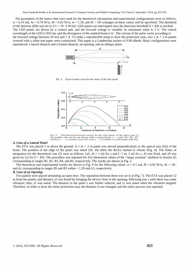
given by (2) for E = Eth. The procedure was repeated for five theoretical values of the ―range constant‖ (defined in Section II)
corresponding to ranges R1, R2, R3, R4, and R5, respectively. The results are shown in Fig. 5.
The theoretical and experimental results are shown in Fig. 6 for the following values: w = 0.1 rad, I0 = 0.02 W/sr, θL = 18◦,
and Ac corresponding to ranges R5 and R3 withm = 1.39 and 4.5, respectively
B. Case of an Opening
Two panels were placed simulating an open door. The separation between them was set to d (Fig. 7). The ETA was placed 12
m from the panels, and distance z2 was found by bringing the device close to the opening, following axis z until there was some
vibration; then, z2 was noted. The distance to the panel z was further reduced, and z1 was noted when the vibration stopped.
Therefore, in order to draw the entire protection area, the distance d was changed, and the entire process was repeated.

Sama Santhosh Reddy et al, International Journal of Computer Science and Mobile Computing, Vol.3 Issue.9, September- 2014, pg. 822-832
© 2014, IJCSMC All Rights Reserved 826
The theoretical case was calculated by integrating (2) in two parts: the left side and the right side of the panel. The calculations
were made for five values of emission power, and their experimental correspondences were measured. The theoretical results
are shown in Fig. 8. Fig. 9 shows the theoretical and experimental results for w = 0.1 rad, I0 = 0.02 W/sr, θL = 18◦, and the
value of Ac corresponding to R3 with m = 1.39 and m = 4.5.
C. Albedo and Panel Size Dependence
The ability of the device to detect a panel ahead of the user depends on the size, the reflectivity, the incidence angle, and the
emission power of the LED. Equation (2) was used to calculate the detection distance (using R1) of a 2-m-high panel as a
function of its width and albedo (Fig. 10). Thus, a 1-m-wide panel with a 0.99 albedo was detected 8 m away, but it would be
detected 3 m away if its albedo was 0.1. According to Fig. 10, when the width of the panel is known, the detection distance can
be predicted. The detection distance as a function of the color of a panel has been measured. A 1 m × 1 m panel made of 160
g/m2 colored paper was used. The results are shown in Fig. 11.

Sama Santhosh Reddy et al, International Journal of Computer Science and Mobile Computing, Vol.3 Issue.9, September- 2014, pg. 822-832
© 2014, IJCSMC All Rights Reserved 827
D. Oblique Panel
Fig. 12 shows that the detection distance of the panel varies according to the incidence angle θp of the panel (Fig. 4) with the
axis of the device and with the range.
E. Real Obstacles
To highlight the protection zone for real obstacles, typical everyday-life situations were analyzed for indoor conditions, i.e., a
narrow path and an open door, and for outdoor conditions, i.e., a sidewall with and without garbage and cars from different side
views. The measurement process was the following: The user had been walking in a given direction sweeping the device, and at
the very moment that he noticed a change in the directions indicated by the device giving vibrations, he stopped and the
directions with and without vibrations were measured.

Sama Santhosh Reddy et al, International Journal of Computer Science and Mobile Computing, Vol.3 Issue.9, September- 2014, pg. 822-832
© 2014, IJCSMC All Rights Reserved 828
F. Indoor Situation
These situations involved a person walking along a corridor with a 4-m range (R4). In Fig. 13(a), we suppose that the path
without vibration is wide enough to consider a lateral tilted wall on one side and a lateral panel on the other side. If the path had
been narrower, we would have chosen the model of an opening. For the lateral wall on the right side, the direction of the
beginning of the vibration makes a 76◦ angle with the wall. For a 4-m range, the curve in Fig. 13(a) indicates a 75-cm distance
to the wall for a white wall (albedo = 1), a value that agrees with the experiment. Regarding the 50◦ tilted cardboard box pile
(albedo measured is 0.92 at 950 nm) on the left, we consider it as a side panel of albedo of 0.92 cos2(50◦) = 0.4, taking the tilt
into consideration. The half-width of the beam is 1.5 cm, which is in agreement with a vibration limit very
G. Outdoor Situation
The most common outdoor situation is walking on a sidewalk, where cars and garbage bins are found. First, situations of a
wall with and without a garbage bin were analysed [Fig. 14(a)]; then, those of a car from two side views were analyzed.
The presence of a garbage bin gives an 8◦ difference in the angular perception of the lateral wall. In practice, this is sufficient to
be clearly perceived by users [Fig. 14(b)]. For cars in the front view [Fig. 15(a)], the color of the car is not very important, as
long as the hood of the car is a tilted plane; the main contribution to the signal is the number plate, which is a standard object.
At the very moment that the car is detected, the direction indicated by a lack of vibration gives a straight-line obstacle-free path.
For a car from a side view [Fig. 15(b)], the first path indicated is still in the direction of the wing of the car. Therefore, the user
will deviate and deviate again when he is closer to the car. The avoidance trajectory drawn by the user will be a curve whose
curvature is in the direction of the car.
V. DISCUSSION
The adjustment of the shape of the protection area, the limits of the device, the real situations, and the consequences for the
mobility of blind people are discussed.

Sama Santhosh Reddy et al, International Journal of Computer Science and Mobile Computing, Vol.3 Issue.9, September- 2014, pg. 822-832
© 2014, IJCSMC All Rights Reserved 829
A. Parameter Dependence
The main parameters that determine the shape of the protection zone of the device are the intensity distribution of the source
(3): full-width of the beam at half-maximum w, amplitude of emission Ac, shape parameter m, and apodization angle (given by
the mechanical aperture ahead the LED limiting the angular width of the beam).
The variation of these parameters allows the detection zone to be controlled. Parameter w permits the width of the protection
zone to be controlled, without much influence on the length [Fig. 16(a)]. Amplitude Ac increases length and width at the same
time [Fig. 16(b)]. The apodization angle controls the width of the protection zone at short distances and does not change its
length [Fig. 16(c)], and the shape parameter m modifies the width of the protection zone [Fig. 16(d)]. The five theoretical ranges
shown in Figs. 6 and 9 are representations of the relative distances for finding the obstacles with different amplitudes Ac of
emission.
B. Influence of External Parameters
The shape of the protection zone is modified by external parameters; the light that strikes the surface can be absorbed,
transmitted, and reflected. The surface analyzed is considered as a Lambertian plane in our statements, but in real
configurations, some parts of many objects are reflective, and others are diffusive, retroreflective, etc. The light spot on the
target has a given width, generally greater than the details of the obstacles. Therefore, it can be represented by an average
albedo. Sunlight is another external parameter that introduces additional noises as it contains the same wavelength as the LED.
The sensitivity of the photodiode is then decreased on sunny days. To solve this problem, a phototransistor has been
incorporated to measure the diurnal light. The amplitude of the emitted pulse of the LED and the threshold have to be increased
to keep the same signal-to-noise ratio. A calibration table has been saved in the control unit memory. The table is read according
to the signal of the phototransistor to keep the same characteristics of detection whatever the ambient light may be.
C. Low Albedos and Retroreflective Surfaces
Fig. 10 shows the variation of the range according to the albedo. The consequence of a reduction by ten of the albedo is a
reduction of three in the distance of anticipation. In current situations, the color of the obstacle does not have a lot of influence
on the detection distance except for very dark obstacles (Fig. 11). A small change in the anticipation distance does not affect
walking fluidity. However, a thin shiny black vertical rod is a specific case, and anticipation can be too short. The white cane
may come into contact with the post before warning is given off by the detector.
Another specific case is retroreflective surfaces such as vehicle number plates and road signs. Such panels can be detected
with 20-m anticipation, whereas a Lambertian surface would be detected 7 m away. In practice, these surfaces make it possible
to detect and anticipate vehicles from a long distance. Table I shows real anticipation distances with a range of 6 m.
D. Real Situations
In spite of the simple situations used for the theoretical model, it allows typical real situations to be interpreted. The most
important situation when the device is not efficient is sidewalks with thin dark posts. The problem can be solved owing to an
additional triangulating laser telemeter, without losing the benefit of the IR sensor, i.e., finding a shoulder width path from a
distance exceeding 4 m without perceiving the small details that do not help walking.
E. Mobility Aspects
Blind people detect obstacles by sweeping their white sticks and by making contact with obstacles. In the worst case scenario,
they get hurt, particularly by objects which are located in a high position, such as rears of trucks, branches, advertising boards,
etc. These obstacles are a source of stress for blind people when they are walking. The IR device is attached to the white stick
with its emission axis placed horizontally. As the user sweeps the white stick to detect obstacles, the system scans in every
direction that is taken by the stick; hence, the horizontal protection zone is enlarged (Fig. 17). Making a sweep of
(with the standard length of the cane fitted to the height of he user, corresponds to the width of the feet), the tip of the
stick protects the user from the hazard of holes. Thus, the user’s body is protected by the IR detector, which anticipates the
obstacles.
The horizontal detector placed on the cane at about 1 m high does not give a protection area large enough to protect the head
(Fig. 9). To solve this problem, we have added a second range R3 detector, tilted vertically by 30◦ to protect the head. Using the

Sama Santhosh Reddy et al, International Journal of Computer Science and Mobile Computing, Vol.3 Issue.9, September- 2014, pg. 822-832
© 2014, IJCSMC All Rights Reserved 830
device requires a training process. The technique to anticipate a side panel, i.e., sweeping the white stick, is quite different from
the technique to detect an opening. For a side panel, the device gives off a vibration on one side of the path, and the user must
change directions until the vibration remains turned off during the whole sweep of the stick. To find an opening, the user has to
perceive a lack of vibration between two side vibrations. When the blind user is walking along a path where there are no
vibrations, in ranges R1–R4 (down to 4 m), his/her shoulders are protected even if the perceived path is very narrow (Fig. 8).
The relative ranges used in the current device Tom Pouce II and Minitact are, finally, 6, 4, and 2 m. These ranges are chosen by
the user according to his/her speed and the density of obstacles along the path.
We have tested two commercially available ultrasonic devices: the Palmsonar and the Miniguide. The test was performed to
detect an open door with a width of 0.83 m. The measurement showed us that the Miniguide and the Palmsonar do not detect the
difference between an open door and a wall for ranges longer than 0.9 and 1.8 m, respectively. However, the Minitact can detect
an opened door with a 6-m range.

Sama Santhosh Reddy et al, International Journal of Computer Science and Mobile Computing, Vol.3 Issue.9, September- 2014, pg. 822-832
© 2014, IJCSMC All Rights Reserved 831
CONCLUSION
Typical obstacles (walls, openings, and vertical rods) have been used to draw the protection zone of the IR device. The ability
of the IR sensor to find a path wide enough for a person to go through has been demonstrated. Theoretical and radiometric
calculations based on optical geometry have been made to improve the design and performance of the system.
The importance of intensity distribution to determine the protection zone has been highlighted. The technical compromises used
in our new generation of IR devices have been presented. The data of the LED given in Section IV are those of the final
parameters for the devices. The newest versions of the Tom Pouce II [Fig. 18(b)] and Minitact [Fig. 18(a)] devices [19] have
been improved owing to the calculations presented in this paper; the Minitact only has a horizontal beam, it is smaller than the
Tom Pouce II, and it is generally used inside. The Tom Pouce II has a second beam for the height, it is fixed to the cane, and it
is used more outside (Fig. 17). These devices will progressively replace the Tom Pouce I, including a population of around 600
visually impaired people.
Very thin obstacles such as shiny dark posts are difficult to detect with enough anticipation (only 1.5 m). To solve this
problem, a triangulation laser telemeter can be added. The triangulation laser telemeter can detect a shiny dark post up to
8 m away, and it is a good complement to the IR device. Since 1998, we have developed laser telemeters that are attached to the
white stick, and the devices have helped blind people to anticipate obstacles [20]–[22].
In the near future, we are going to propose a device including the laser telemeter and various IR detectors: The laser detects
small parts with low albedos, and the IR detector finds obstacle-free paths that are wide enough for a person to go through.

Sama Santhosh Reddy et al, International Journal of Computer Science and Mobile Computing, Vol.3 Issue.9, September- 2014, pg. 822-832
© 2014, IJCSMC All Rights Reserved 832
REFERENCES
[1] B. Blash, W. Wiener, and R. Welsh, Foundations of Orientation and Mobility, 2nd ed. New York: AFB Press, 1997.
[2] U. Roentgen, G. Gelderblom, M. Soede, and L. de Witte, ―The impact of electronic mobility devices for persons who are
visually impaired: A systematic review of effects and effectiveness,‖ J. Vis. Impairment Blindness, vol. 103, no. 11, pp. 743–
753, 2009.
[3] U. Roentgen, G. Gelderblom, M. Soede, and L. de Witte, ―Inventory of electronic mobility aids for persons with visual
impairments: A literature review,‖ J. Vis. Impairment Blindness, vol. 102, no. 11, pp. 702–724, 2008.
[4] N. A. Giudice and G. E. Legge, .
[5] R. Kowalik and S. Kwasniewski, ―Navigator—A talking GPS receiver for the blind,‖ in Computers Helping People with
Special Needs, K. Miesenberger, J. Klaus, W. Zagler, and D. Burger, Eds. Heidelberg, Germany: Springer Berlin, 2004, ser.
Lecture Notes in Computer Science, p. 626.
[6] M. E. Peck, ―RFID tags guide the blind,‖ IEEE Spectrum, New York, Tech. Rep., Jan. 2008.
[7] M. Saaid, I. Ismail, and M. Noor, ―Radio frequency identification walking stick (RFIWS): A device for the blind,‖ in Proc.
5th Int. CSPA, Mar. 2009, pp. 250–253.
[8] Bay advanced technologies The Bat K-Sonar. [Online]. Available: http://www.batforblind.co.nz/
[9] Gismag Ultracane Uses Ultrasonic Echoes to Offer Spatial Awareness to the Vision-Impaired. [Online]. Available:
http://www.gizmag.com/ go/3827/
[10] G. R. Co. The Miniguide Ultrasonic Mobility Aid. [Online]. Available: http://www.gdp-research.com.au/minig_1.htm
[11] Takes Corporation, Owner’s Manual: Palmsonar ps231-72009. [Online]. Available: http://www.palmsonar.com/231-
7/prod.htm
[12] RTB The Ultra Body Guard. [Online]. Available: http://www.rtb-bl.de/ RTB/ultra-body-guard-2/?lang=en
[13] PRIMPO ISONIC: State of the Art Electronic White Cane. [Online]. Available:
http://www.primpo.com/eng/products/isonic.html
[14] VISTAC. [Online]. Available: http://www.vistac.de/
[15] W. L. Wolfe, Introduction to Radiometry. Bellingham, WA: SPIE Publ., 1998.
[16] J. L. Meyzonnette and T. Lépine, Bases de Radiomètrie Optique, 2nd ed. Toulouse, France: Cépaduès, 2001.
[17] K. Pearson, ―Mathematical contributions to the theory of evolution, xix: Second supplement to a memoir on skew
variation,‖ Philos. Trans. Roy. Soc. Lond. (A), no. 216, pp. 429–457, 1916.
[18] I. Takashi, ―New measures of sharpness for symmetric powder diffraction peak profiles,‖ J. Appl. Crystallogr., vol. 41, no.
2, pp. 393–401, 2008.
[19] H. H. et aides techniques Alarme D’Obstacle Tom Pouce Light. [Online]. Available: http://www.handicat.com/at-num-
20714.html
[20] R. Farcy, B. Denise, and R. Damaschini, ―Triangulating laser profilometer as navigational aid for the blind: Optical
aspects,‖ App. Opt., vol. 35, no. 7, pp. 1161–1166, Mar. 1996.
[21] R. Farcy and R. Damaschini, ―Triangulating laser profilometer as a threedimensional space perception system for the
blind,‖ Appl. Opt., vol. 36, no. 31, pp. 8227–8232, Nov. 1997.
[22] L. A. C. C. Instrumental. [Online]. Available: http://www.lac.upsud. fr/teletact/index-teletact.htm