Anti Theft Vehicle System Using Arduino - International ...
11
International Journal of Modern Agriculture ISSN: 2305-7246 Volume 10 Issue 2, 2021 Website: http://www.modern-journals.com/ 3606 Anti Theft Vehicle System Using Arduino Anil Kumar V 1 ,Kakarla Vinod 2 ,Goutham k 3 Dhanya R 4 ,Karanam Swethapriya 5 1,2,3,4,5 School of Electronics and Communication Engineering ,Reva University India Abstract:- In our daily life we all are most dependent on the vehicle to travel to any place due to that the productivity of the vehicles have increased at the same time the theft of the vehicles have been also increased.Due to that it had become a severe problem for the owners to protect their vehicle,to overcome the problem the technology in real time also need to be developed, an Anti theft vehicle system is developed which is both user friendly and cost effective, this system uses the Arduino which acts as controller and the ignition of the vehicle is turned of with the help of the Arduino the owner uses his own mobile to send the instruction to Arduino throughthe GSM module and he receives the location of the vehicle with the help of GPS module in the form of string i.e. the latitude and longitude values of the exact location of the vehicle 1. Introduction: According to the vehicle theft census,the theft of the vehicle has been increased in India. Due to that the technology to avoid theft of the vehicle should be developed. Arduino based real time vehicle theft system has been developed to prevent the theft of the vehicle. The vehicle owner uses subscriber identity module (SIM) inserted within his mobilephone to send message to GSM modem and GPS modem which is part of the vehicle theft prevention system that is inserted inside the vehicle. The main purpose of this project is to prevent vehicle theft. This functionality is achieved by detecting vehicle status in theft mode and by sending an SMS which is generated automatically. This SMS is then sent to the owner of the vehicle. The owner can then send back the SMS in order to disable the ignition of the vehicle. Thus in this way crimes can be reduced to a great extent as vehicles today are being stolen in large number. Hence, vehicles today require high security which can be achieved with the help of this application. How the system works is when a person tries to steal the vehicle, the microcontroller is interrupted and the command is sent to the GSM modem to send SMS. On the receipt of the message, the owner sends back the SMS to the GSM modem. This is done in order to stop the engine. This GSM modem is interfaced to the Arduino. This Arduino on the receipt of the message uses a mechanism that helps to stop the engine. Motor is being used in this project in order to indicate vehicle ON/OFF state. In this project we are using a GPS system that helps to find out the exact position of the vehicle with the help of its latitude and longitude which then can be sent to the owner of the vehicle via SMS. This data can be then entered by the owner on Google map to find out the exact location of the vehicle. 2.Literature review:
-
Upload
khangminh22 -
Category
Documents
-
view
1 -
download
0
Transcript of Anti Theft Vehicle System Using Arduino - International ...

International Journal of Modern Agriculture ISSN: 2305-7246 Volume 10 Issue 2, 2021
Website: http://www.modern-journals.com/ 3606
Anti Theft Vehicle System Using Arduino
Anil Kumar V 1 ,Kakarla Vinod
2 ,Goutham k
3
Dhanya R 4,Karanam Swethapriya
5
1,2,3,4,5School of Electronics and Communication Engineering ,Reva University India
Abstract:-
In our daily life we all are most dependent on the vehicle to travel to any place due
to that the productivity of the vehicles have increased at the same time the theft of the
vehicles have been also increased.Due to that it had become a severe problem for the owners
to protect their vehicle,to overcome the problem the technology in real time also need to be
developed, an Anti theft vehicle system is developed which is both user friendly and cost
effective, this system uses the Arduino which acts as controller and the ignition of the vehicle
is turned of with the help of the Arduino the owner uses his own mobile to send the
instruction to Arduino throughthe GSM module and he receives the location of the vehicle
with the help of GPS module in the form of string i.e. the latitude and longitude values of the
exact location of the vehicle
1. Introduction:
According to the vehicle theft census,the theft of the vehicle has been increased in India. Due
to that the technology to avoid theft of the vehicle should be developed. Arduino based real
time vehicle theft system has been developed to prevent the theft of the vehicle. The vehicle
owner uses subscriber identity module (SIM) inserted within his mobilephone to send
message to GSM modem and GPS modem which is part of the vehicle theft prevention
system that is inserted inside the vehicle.
The main purpose of this project is to prevent vehicle theft. This functionality is achieved by
detecting vehicle status in theft mode and by sending an SMS which is generated
automatically. This SMS is then sent to the owner of the vehicle. The owner can then send
back the SMS in order to disable the ignition of the vehicle. Thus in this way crimes can be
reduced to a great extent as vehicles today are being stolen in large number. Hence, vehicles
today require high security which can be achieved with the help of this application. How the
system works is when a person tries to steal the vehicle, the microcontroller is interrupted and
the command is sent to the GSM modem to send SMS. On the receipt of the message, the
owner sends back the SMS to the GSM modem. This is done in order to stop the engine. This
GSM modem is interfaced to the Arduino. This Arduino on the receipt of the message uses a
mechanism that helps to stop the engine. Motor is being used in this project in order to
indicate vehicle ON/OFF state. In this project we are using a GPS system that helps to find
out the exact position of the vehicle with the help of its latitude and longitude which then can
be sent to the owner of the vehicle via SMS. This data can be then entered by the owner on
Google map to find out the exact location of the vehicle.
2.Literature review:

International Journal of Modern Agriculture ISSN: 2305-7246 Volume 10 Issue 2, 2021
Website: http://www.modern-journals.com/ 3607
GPS modem is used only to trace the location of the vehicle i.e. latitude and longitude values
of the exact location of the vehicle but we cannot control the vehicle ,where as GSM modem
is used oly for controlling of the vehicle but we cannot trace the location of the vehicle. some
researchers uses both GSM and GPS modem to trace location and to control the vehicle.
[1]M. Uday Kumar Naidu and Dr .K. Prahlad Rao both together develop an theft detection
and control system of a vehicle using GSM .which is used to turn off the Ignition of the
vehicle by switching off the spark plug and fuel supply of the vehicle with the help of the
relay switch.[2] Kaushik et developed an anti Burgular vehicle system , in his system the
Thumb impression of authorized person is used to start the vehicle , the authorized person
thumb impression is stored in the database of the system , the vehicle starts only if the thumb
impression matches which is already present in the database , if anyone tries to access the
vehicle the fuel tank of the vehicle will be emptied through the relay Bolt fitted to the
Tank.[3] S Pethakar uses GSM and GPS and RFID security system for the vehicles, this
system is designed in such a way that the owner must use the RFID card in which the
identification numbers are already preloaded in the database of the system . if the number
does not matches then the location of the vehicle is sent to the owner automatically with the
help of GSM and GPS .after that the owner send back to the system such that the doors of the
vehicle is looked .[3] Nagraja et al used GSM system ,microcontroller ,and relay switch for
the ignition system ,if the theft is detected then the microcontroller sends the message to the
owner through GSM ,if the owner reply’s back then the switch is activated and the ignition of
vehicle is turned off.
3.Hardware Description
3.1Arduino Uno
Arduino is an open-source electronics platform based on easy-to-use hardware and
software. Arduino has been used in thousands of different projects and applications. The
Arduino software is easy-to-use for beginners yet flexible enough for advanced
users.Arduino also simplifies the process of working with microcontrollers
Fig1: Arduino Uno R3
The Arduino Uno R3 is a microcontroller board based on a removable, dual-inline-package
ATmega328 AVR microcontroller. It has 20 digital input/output pins . Programs can be
loaded on to it from the easy-to-use Arduino computer program. The Arduino has an

International Journal of Modern Agriculture ISSN: 2305-7246 Volume 10 Issue 2, 2021
Website: http://www.modern-journals.com/ 3608
extensive support community, which makes it a very easy way to get started working with
embedded electronics. The R3 is the third, and latest, revision of the Arduino Uno.
T consists of power pins of 5V—3.3V,power doesn’t drawn more than the few milli amps ,it
also consists TX and RX pins which are used for sending and receiving data serially,it also
consists of 6 analoginput pins,these used to measure continuous voltages anywhere from 0-
5V, the above information of the Arduino Uno r3 is tabulated below.Specifications are as
follows:
Microcontroller : Atmega328
Operating Voltage:- 5V
Digital I/O Pins :- 14(6 Provide PWM output)
Analog Pins :- 6
Flash memory 32 Kb 0f which 0.5kb is used for boot loader
SRAM :- 2Kb
Clock Speed :- 16MHZ
EEPROM:-1 KB
3.2 Atmega 328P
Fig2: Atmega328P microcontroller
Atmega328P is high performance, low power controller from Microchip. Atmega328P is an
8-bit microcontroller based on AVR RISC architecture. It is the most popular of all
controllers as it is used in ARDUINO boards.
Table1: Atmega328P Microcontroller Features
Microcontroller ATmega328P
Operating Voltage 5V
Input Voltage (recommended) 7-12V
Input Voltage (limit) 6-20V
Digital I/O Pins 14 (of which 6 provide PWM output)
PWM Digital I/O Pins 6
Analog Input Pins 6
DC Current per I/O Pin 20 mA
DC Current for 3.3V Pin 50 mA

International Journal of Modern Agriculture ISSN: 2305-7246 Volume 10 Issue 2, 2021
Website: http://www.modern-journals.com/ 3609
3.3 GSM MODULE 900
Fig3: GSM Module 900
GSM (Global System for Mobile communications) is the technology that underpins most of
the world's mobile phone networks. The GSM platform is a hugely successful wireless
technology and an unprecedented story of global achievement and cooperation. GSM has
become the world's fastest growing communications technology of all time and the leading
global mobile standard, spanning 218 countries. GSM is an open, digital cellular technology
used for transmitting mobile voice and data services. GSM operates in the 900MHz and
1.8GHz bands GSM supports data transfer speeds of up to 9.6 kbps, allowing the
transmission of basic data services such as SMS
3.4 GPS Module
Fig4 : GPS Module
GPS (Global Positioning System) technology is used to find the location of any object or
vehicle to monitor a child continuously using satellite signals. Three satellite signals are
Flash Memory 32 KB (ATmega328P)
of which 0.5 KB used by bootloader
SRAM 2 KB (ATmega328P)
EEPROM 1 KB (ATmega328P)
Clock Speed 16 MHz
Length 68.6 mm
Width 53.4 mm
Weight 25 g

International Journal of Modern Agriculture ISSN: 2305-7246 Volume 10 Issue 2, 2021
Website: http://www.modern-journals.com/ 3610
necessary to locate the receiver in 3D space and fourth satellite is used for time
Accuracy.GPS will give the information of parameters like longitude, latitude and attitude.
With the help of these parameters one can easily locate the position of any object. In this GPS
technology, the communication takes place between GPS transceiver and GPS satellite.
3.5 Liquid Crystal Display (LCD):
Liquid crystal display type of display used in digital watches and many portable computers.
Fig5: Liquid crystal display
LCD displays utilize two sheets of polarizing material with a liquid crystal solution between
them. An electric current passed through the liquid causes the crystals to align so that light
cannot pass through them. Each crystal, therefore, is like a shutter, either allowing light to
pass through or blocking the light.
The liquid crystals can be manipulated through an applied electric voltage so that light is
allowed to pass or is blocked.By carefully controlling where and what wavelength (color) of
light is allowed to pass, the LCD monitor is able to display images. A back light provides
LCD monitor’s brightness.
Other advances have allowed LCD’s to greatly reduce liquid crystal cell response times.
Response time is basically the amount of time it takes for a pixel to ―change colors‖. In
reality response time is the amount of time it takes a liquid crystal cell to go from being
active to inactiveHere the LCD is used at both the Transmitter as well as the receiver
side.The input which we give to the microcontroller is displayed on the LCD of the
transmitter side and the message sent is received at the receiver side which displays at the
receiver end of the LCD and the corresponding operation is performed
They make complicated equipment easier to operate. LCDs come in many shapes and sizes
but the most common is the 16 character x 4 line display with no backlight. It requires only
11 connections – eight bits for data (which can be reduced to four if necessary) and three
control lines (we have only used two here). It runs off a 5V DC supply and only needs about

International Journal of Modern Agriculture ISSN: 2305-7246 Volume 10 Issue 2, 2021
Website: http://www.modern-journals.com/ 3611
1mA of current.The display contrast can be varied by changing the voltage into pin 3 of the
display,
Table2: Pin description of LCD:
3.6 DC Motor.
Fig6: DC Motor
DC motors are configured in many types and sizes, including brush less, servo, and
gear motor types. A motor consists of a rotor and a permanent magnetic field stator. The
magnetic field is maintained using either permanent magnets or electromagnetic windings.
DC motors are most commonly used in variable speed and torque.
Motion and controls cover a wide range of components that in some way are used to
generate and/or control motion. Areas within this category include bearings and bushings,
clutches and brakes, controls and drives, drive components, encoders and resolves,
Integrated motion control, limit switches, linear actuators, linear and rotary motion
components, linear position sensing, motors (both AC and DC motors), orientation
position sensing, pneumatics and pneumatic components, positioning stages, slides and
guides, power transmission (mechanical), seals, slip rings, solenoids, springs.
Motors are the devices that provide the actual speed and torque in a drive system. This
family includes AC motor types (single and multiphase motors, universal, servo motors,
International Journal of Modern Agriculture ISSN: 2305-7246 Volume 10 Issue 2, 2021
Website: http://www.modern-journals.com/ 3612
induction, synchronous, and gear motor) and DC motors (brush less, servo motor, and gear
motor) as well as linear, stepper and air motors, and motor contactors and starters.
In any electric motor, operation is based on simple electromagnetism. A current-
carrying conductor generates a magnetic field; when this is then placed in an external
magnetic field, it will experience a force proportional to the current in the conductor, and
to the strength of the external magnetic field. As you are well aware of from playing with
magnets as a kid, opposite (North and South) polarities attract, while like polarities (North
and North, South and South) repel. The internal configuration of a DC motor is designed
to harness the magnetic interaction between a current-carrying conductor and an external
magnetic field to generate rotational motion.
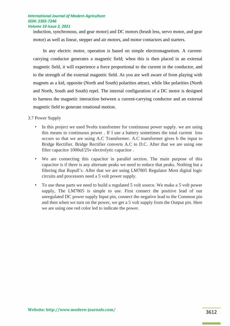
3.7 Power Supply
• In this project we used 9volts transformer for continuous power supply. we are using
this means to continuous power . If I use a battery sometimes the total current loss
occurs so that we are using A.C Transformer. A.C transformer gives b the input to
Bridge Rectifier. Bridge Rectifier converts A.C to D.C. After that we are using one
filter capacitor 1000uf/25v electrolytic capacitor .
• We are connecting this capacitor in parallel section. The main purpose of this
capacitor is if there is any alternate peaks we need to reduce that peaks. Nothing but a
filtering that Repull’s. After that we are using LM7805 Regulator Most digital logic
circuits and processors need a 5 volt power supply.
• To use these parts we need to build a regulated 5 volt source. We make a 5 volt power
supply, The LM7805 is simple to use. First connect the positive lead of our
unregulated DC power supply Input pin, connect the negative lead to the Common pin
and then when we turn on the power, we get a 5 volt supply from the Output pin. Here
we are using one red color led to indicate the power.
International Journal of Modern Agriculture ISSN: 2305-7246 Volume 10 Issue 2, 2021
Website: http://www.modern-journals.com/ 3613
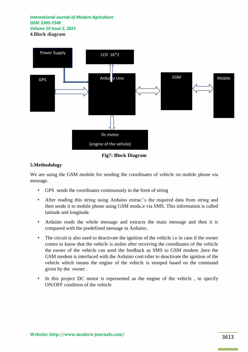
4.Block diagram
Fig7: Block Diagram
5.Methodology
We are using the GSM module for sending the coordinates of vehicle on mobile phone via
message.
• GPS sends the coordinates continuously in the form of string
• After reading this string using Arduino extract’s the required data from string and
then sends it to mobile phone using GSM module via SMS. This information is called
latitude and longitude.
• Arduino reads the whole message and extracts the main message and then it is
compared with the predefined message in Arduino.
• The circuit is also used to deactivate the ignition of the vehicle i.e in case if the owner
comes to know that the vehicle is stolen after receiving the coordinates of the vehicle
the owner of the vehicle can send the feedback as SMS to GSM modem ,here the
GSM modem is interfaced with the Arduino controller to deactivate the ignition of the
vehicle which means the engine of the vehicle is stooped based on the command
given by the owner .
• In this project DC motor is represented as the engine of the vehicle , to specify
ON/OFF condition of the vehicle
Dc motor
(engine of the vehicle)
Arduino Uno GSM Mobile
LCD 16*2
GPS
Power Supply

International Journal of Modern Agriculture ISSN: 2305-7246 Volume 10 Issue 2, 2021
Website: http://www.modern-journals.com/ 3614
5.1Circuit diagram
Fig8: Circuit Diagram for Safety system
The anti theft system which is built should be placed in the vehicle to test its function , when
ever anyone turns on the key the owner gets the message of the vehicle location if the owner
starts the vehicle he can ignore the message if in case someone starts the vehicle without
knowing for the owner then he can send the message from his mobile through GSM module
to the Arduino to get the location of the vehicle and he receives the location of the vehicle
from the GPS in the form of the string,he receives the latitude and longitude values of the
exact location of the vehicle after that the owner can send the message as STOP to the
system through gsm which in turn receives that message by Arduino and executes the
command and turns of the Ignition of the vehicle after the command gets executed the owner
again recives the location of the vehicle ,so that the owner can track the location of the
vehicle were ever the car is stopped once the car is stopped no one can start the vehicle until
the owner passes the command from his own mobile to the system.
In real time the ignition of the vehicle is turned of but in this project we are using the dc
motor which we can control it by turning ON and OFF with the help of Arduino, we can
observe the latitude and longitude values of the particular location of the vehicle in the
crystal LCD display
5.2 Basic Arduino code definitions:
setup( ): A function present in every Arduino sketch. Run once before the loop( ) function.
Often used to set pinmode to input or output. The setup( ) function looks like:
void setup( ){
//code goes here

International Journal of Modern Agriculture ISSN: 2305-7246 Volume 10 Issue 2, 2021
Website: http://www.modern-journals.com/ 3615
}
loop( ): A function present in every single Arduino sketch. This code happens over and
over again. The loop( ) is where (almost) everything happens. The one exception to this is
setup( ) and variable declaration. ModKit uses another type of loop called ―forever( )‖
which executes over Serial. The loop( ) function looks like:
void loop( ) {
//code goes here
}
input: A pin mode that intakes information.
output: A pin mode that sends information.
HIGH: Electrical signal present (5V for Uno). Also ON or True in Boolean logic.
LOW: No electrical signal present (0V). Also OFF or False in Boolean logic.
DigitalRead: Get a HIGH or LOW reading from a pin already declared as an input.
DigitalWrite: Assign a HIGH or LOW value to a pin already declared as an output.
AnalogRead: Get a value between or including 0 (LOW) and 1023 (HIGH). This allows
you to get readings from Analog sensors or interfaces that have more than two states.
AnalogWrite: Assign a value between or including 0 (LOW) and 255 (HIGH). This allows
you to set output to a PWM value instead of just HIGH or LOW.
PWM: Stands for Pulse-Width Modulation, a method of emulating an Analog signal
through a digital pin. A value between or including 0 and 255. Used with AnalogWrite.
Table3: Arduino Uno pin type definitions
Reset 3v3 5v Gnd Vin Analog In RX/TX Digital PWM(~) AREF
Resets
Arduino
sketch
on
board
3.3
volts
in and
out
5
volts
in
and
out
Ground Voltage
in for
sources
over 7V
(9V -
12V)
Analog
inputs, can
also be
used as
Digital
Serial
comm.
Receive
and
Transmit
Input or
output,
HIGH or
LOW
Digital
pins with
output
option of
PWM
External
reference
voltage
used for
analog
5.3 Commands Used
vechsto
p: Used to make vehicle engine OFF.
Vechtr
ack: Used to make track the location of vehicle.

International Journal of Modern Agriculture ISSN: 2305-7246 Volume 10 Issue 2, 2021
Website: http://www.modern-journals.com/ 3616
Engine
on: Used to make vehicle engine ON.
6.Results
If anyone steals the vehicle we can trace the location of the vehicle and we can turn of the
ignition of the vehicle and we can find vehicle where ever it is present with respect to its
location
Fig9: Vehicle tracking and making Engine OFF Fig10: Vehicle tracking and
keeping Engine ON
7.References
[1]M. Uday Kumar Naidu, Dr K Prahlada Rao ,―Theft Detection and Controlling System of a
vehicle using GSM‖, Journal of Engineerng Technologies and Innovation Research (JETIR),
Vol. 4, Issue 10 ,pp.366-370,October 2017
[2] N. Kaushik, M. Veralkar, Pranab. P, k. Nandkarny, ―Anti-theft vehicle security system‖,
International journal for scientific research and development, vol. 1, no.12, pp. 2845-2848,
March 2014.
[3] S. S. Pethakar, S. D. Suryavanshi, N. Srivastava, ―RFID, GPS and GSM based vehicle
tracing and employee security system‖, International Journal of Advanced Research in
Computer Science and Electronics Engineering, vol. 1, no. 10, pp. 91-96, Dec. 2012.
[4] PERFORMANCE STUDIES ON BLACK COTTON SOIL USING LIME AND FLY
ASH, Mr. Vataka Mohana Rao, Mr. Imran Khan P, International Journal Of Advance
Research In Science And Engineering http://www.ijarse.com IJARSE, Volume No. 10, Issue
No. 02, February 2021, ISSN-2319-8354(E).
[5] B. G. Nagaraja, Mahesh. M, R. Rayappa, C. M. Patil, ―Design and development of a GSM
based vehicle theft control system‖, presented at the International Conference on Advanced
Computer Control, Singapore, January 2009.
[6] M. A. Khedher, ―Hybrid GPS-GSM localization of automobile tracking system‖,
International journal of computer science and technology, Vol. 3, no. 6, pp. 75-85, December
2011.