
Design of an efficient load balancing algorithm using the symmetric balanced incomplete block design
10
Design of an efficient load balancing algorithm using the symmetric balanced incomplete block design Manjusri Basu a , Satya Bagchi b,⇑ , Debabrata Kumar Ghosh a a Department of Mathematics, University of Kalyani, Kalyani, WB 741235, India b Department of Mathematics, National Institute of Technology, Durgapur, Burdwan, WB 713209, India article info Article history: Received 15 January 2012 Received in revised form 8 December 2013 Accepted 13 March 2014 Available online xxxx Keywords: Balanced incomplete block design Communication complexity abstract Maintaining load balance, in a distributed network is a complex task. It was previously assumed that the communication complexity would be Oðu 2 Þ for any number of nodes u which was later modified as Oðu 3 2Þ where the number of nodes u ¼ k 2 þ k þ 1 and k is prime. In this paper, we modify the communication complexity Oðu 5 4Þ where the number of nodes u ¼ðk 2 þ k þ 1Þ 2 and k is prime. Thereby we show that by increasing the round of message interchange by 2 n , the communication complexity is Oðu 1þ 1 2 n Þ. Also by increas- ing infinitely the round of message interchange, the communication complexity can be made OðuÞ. Ó 2014 Elsevier Inc. All rights reserved. 1. Introduction In a distributed network, there are some heavy-loaded nodes, light loaded nodes and some nodes which are equally loaded, better known as idle nodes. It is desirable to increase utilization of the nodes while at the same time to reduce the time required for response. Through the load balancing scheme in a distributed network, we can determine whether a task is to be executed locally or processed via remote node since it can be processed either centrally or in a distributed manner. The distributed manner strongly adopted in a way that every node has information of all other nodes. It is also rec- ommended that the information are the latest in order to avoid inconsistency in the system. However, the exercise may not be cost effective; on the other hand, continuance with the existing system may pose the problem of over loading for a num- ber of nodes in the system. For example, the ARPANET routing algorithm is a distributed adaptive algorithm using estimated delay as the performance criterion and a version of the backward-search algorithm [3]. In the existing system, a delay vector and a successor node vector are maintained by each node. After a certain period of time, the delay vectors are interchanged among the neighbouring nodes, and a node updates both its vectors on the basis of the incoming delay vectors [8]. In order to decrease communication overhead for obtaining workload information from all nodes in the network, mes- sages must be exchanged between adjacent nodes and then load balancing process be performed periodically by using these local messages. So each processor balances the workload with its neighbours so that the whole system will be balanced after a number of iterations. On hypercube network, Cube Walking Algorithm (CWA) is used load balance. Oðu 2 Þ communication complexity is required where u is the number of nodes. The Flooding scheme is applied for reducing communication cost. However, the overlap of workload information occurs [6,7]. Based on Symmetric Broadcast Networks communication patterns between nodes are constructed. It also needs Oðu 2 Þ communication complexity for collecting workload information from all the nodes and a communication path is Oðlog 2 uÞ [1,2]. http://dx.doi.org/10.1016/j.ins.2014.03.049 0020-0255/Ó 2014 Elsevier Inc. All rights reserved. ⇑ Corresponding author. Tel.: +91 9434788190; fax: +91 3432547375. E-mail addresses: [email protected] (M. Basu), [email protected] (S. Bagchi), [email protected] (D.K. Ghosh). Information Sciences xxx (2014) xxx–xxx Contents lists available at ScienceDirect Information Sciences journal homepage: www.elsevier.com/locate/ins Please cite this article in press as: M. Basu et al., Design of an efficient load balancing algorithm using the symmetric balanced incomplete block design, Inform. Sci. (2014), http://dx.doi.org/10.1016/j.ins.2014.03.049
Transcript of Design of an efficient load balancing algorithm using the symmetric balanced incomplete block design
Information Sciences xxx (2014) xxx–xxx
Contents lists available at ScienceDirect
Information Sciences
journal homepage: www.elsevier .com/locate / ins
Design of an efficient load balancing algorithm usingthe symmetric balanced incomplete block design
http://dx.doi.org/10.1016/j.ins.2014.03.0490020-0255/� 2014 Elsevier Inc. All rights reserved.
⇑ Corresponding author. Tel.: +91 9434788190; fax: +91 3432547375.E-mail addresses: [email protected] (M. Basu), [email protected] (S. Bagchi), [email protected] (D.K. Ghosh).
Please cite this article in press as: M. Basu et al., Design of an efficient load balancing algorithm using the symmetric balanced incoblock design, Inform. Sci. (2014), http://dx.doi.org/10.1016/j.ins.2014.03.049
Manjusri Basu a, Satya Bagchi b,⇑, Debabrata Kumar Ghosh a
a Department of Mathematics, University of Kalyani, Kalyani, WB 741235, Indiab Department of Mathematics, National Institute of Technology, Durgapur, Burdwan, WB 713209, India
a r t i c l e i n f o a b s t r a c t
Article history:Received 15 January 2012Received in revised form 8 December 2013Accepted 13 March 2014Available online xxxx
Keywords:Balanced incomplete block designCommunication complexity
Maintaining load balance, in a distributed network is a complex task. It was previouslyassumed that the communication complexity would be Oðu2Þ for any number of nodes uwhich was later modified as Oðu3
2Þ where the number of nodes u ¼ k2 þ kþ 1 and k isprime. In this paper, we modify the communication complexity Oðu5
4Þ where the numberof nodes u ¼ ðk2 þ kþ 1Þ
2and k is prime. Thereby we show that by increasing the round
of message interchange by 2n, the communication complexity is Oðu1þ 12n Þ. Also by increas-
ing infinitely the round of message interchange, the communication complexity can bemade OðuÞ.
� 2014 Elsevier Inc. All rights reserved.
1. Introduction
In a distributed network, there are some heavy-loaded nodes, light loaded nodes and some nodes which are equallyloaded, better known as idle nodes. It is desirable to increase utilization of the nodes while at the same time to reducethe time required for response. Through the load balancing scheme in a distributed network, we can determine whethera task is to be executed locally or processed via remote node since it can be processed either centrally or in a distributedmanner. The distributed manner strongly adopted in a way that every node has information of all other nodes. It is also rec-ommended that the information are the latest in order to avoid inconsistency in the system. However, the exercise may notbe cost effective; on the other hand, continuance with the existing system may pose the problem of over loading for a num-ber of nodes in the system. For example, the ARPANET routing algorithm is a distributed adaptive algorithm using estimateddelay as the performance criterion and a version of the backward-search algorithm [3]. In the existing system, a delay vectorand a successor node vector are maintained by each node. After a certain period of time, the delay vectors are interchangedamong the neighbouring nodes, and a node updates both its vectors on the basis of the incoming delay vectors [8].
In order to decrease communication overhead for obtaining workload information from all nodes in the network, mes-sages must be exchanged between adjacent nodes and then load balancing process be performed periodically by using theselocal messages. So each processor balances the workload with its neighbours so that the whole system will be balanced aftera number of iterations. On hypercube network, Cube Walking Algorithm (CWA) is used load balance. Oðu2Þ communicationcomplexity is required where u is the number of nodes. The Flooding scheme is applied for reducing communication cost.However, the overlap of workload information occurs [6,7]. Based on Symmetric Broadcast Networks communicationpatterns between nodes are constructed. It also needs Oðu2Þ communication complexity for collecting workload informationfrom all the nodes and a communication path is Oðlog2uÞ [1,2].
mplete
2 M. Basu et al. / Information Sciences xxx (2014) xxx–xxx
Lee et al. [4] designed the network topology consisting of u nodes and uk links since each node linked to 2k nodes, whereu ¼ k2 þ kþ 1 and k is prime. In this network, each node receives informations from k adjacent nodes and then sends theseinformations to other k adjacent nodes periodically. So, each node receives workload information for k2 þ k ¼ u� 1 with tworound of message interchange. This algorithm needs Oðu3
2Þ communication complexity. Later, this algorithm is revised fordistributed networks and is analysed in terms of efficiency of load balancing.
In this paper, we design the network topology consisting u ¼ v2 nodes, where v ¼ k2 þ kþ 1 and k is prime. We considerthe set of nodes U ¼ fu00;u01; . . . ;u0v�1;u10; u11; . . . ;u1v�1; . . . ; uv�10;uv�11; . . . ;uv�1v�1g where u ¼ jUj. There are two steps inthis network. In first step, we construct v groups taking v nodes in each group. Each node of v groups receives informationsfrom k adjacent nodes and then send these informations to other k adjacent nodes. In second step, taking one and only onenode from each constructed group in the first step, we construct another v groups. Then the same process of the first step befollowed. So, each node receives workload information from ðu� 1Þ nodes with four round of message interchange period-
ically. This algorithm needs only Oðu � ðu12Þ
12Þ communication complexity. Thereby, by increasing the round of message inter-
change we have OðuÞ communication complexity.
2. D : ðv;k; kÞ-configuration
Let V ¼ f0;1;2; . . . ;v � 1g be a set of v elements and B ¼ fB0;B1;B2; . . . ;Bb�1g be a set of b blocks, where Bi is a subset of Vand jBij ¼ k; 0 6 i 6 b� 1. A finite incidence structure D ¼ fV ;Bg is said to be balanced incomplete block design if satisfyingfollowing conditions:
1. B is a collection of b-subsets of V.2. Each element of V appears exactly r blocks.3. Every two elements of V appears simultaneously in exactly k blocks.4. k < jV j ¼ v .
It is also known as ðb;v ; r; k; kÞ-configuration [4,5]. When k ¼ r and b ¼ v , then it is called a ðv; k; kÞ-configuration, i.e.symmetric balanced incomplete block design and if k ¼ 1, then the ðv ; k;1Þ-configuration is said to be Steiner symmetric bal-anced incomplete block design.
3. Generation of Di : ðv;kþ 1;1Þ-configurations, 0 <i <� 1
In this article, we present an algorithm to generate incidence structures Di ¼ fVi;Big satisfying the conditions forDi : ðv ; kþ 1;1Þ-configurations for v ¼ k2 þ kþ 1 and k is prime. These Di : ðv ; kþ 1;1Þ-configurations are employed for con-structing network topology below:
3.1. Design of an Algorithm Ii to construct Di : ðv; kþ 1; 1Þ-configurations
In Di : ðv ; kþ 1;1Þ-configurations, Vi ¼ fui0;ui1; . . . ;uiv�1g be a set of v elements. In order to construct Di : ðv ; kþ 1;1Þ-con-figurations for each i; ðkþ 1Þ sectors are designed. The first sector is composed of ðkþ 1Þ blocks and the remaining k sectorsconsist of k blocks. Each block in the first sector contains the element ui0 and the remaining elements of the first block, thesecond block, . . ., the ðkþ 1Þth block of the first sector are ðui1;ui2; . . . ;uikÞ; ðuikþ1;uikþ2; . . . ;uikþkÞ; . . . ; ðuik2þ1;uik2þ2; . . . ;uik2þkÞrespectively. In the remaining k sectors, each block in the jth sector contains the element uij�1 and the remaining k elementsare chosen from ðuikþ1;uikþ2; . . . ;uik2þkÞ. The incidence structure Xi generates the first sector and the incidence structure Yi
generates the remaining k sectors according to the Algorithm Ii.
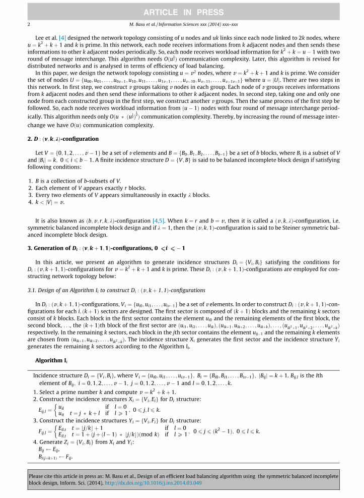
Algorithm Ii
Incidence structure Di ¼ fVi;Big, where Vi ¼ fui0;ui1; . . . ;uiv�1g; Bi ¼ fBi0;Bi1; . . . ; Biv�1g; jBijj ¼ kþ 1. Bij;l is the lthelement of Bij; i ¼ 0;1;2; . . . ;v � 1; j ¼ 0;1;2; . . . ;v � 1 and l ¼ 0;1;2; . . . ; k.
1. Select a prime number k and compute v ¼ k2 þ kþ 1.2. Construct the incidence structures Xi ¼ fVi; Eig for Di structure:
Eij;l ¼uil if l ¼ 0uit t ¼ j � kþ l if l P 1
�; 0 6 j; l 6 k.
3. Construct the incidence structures Yi ¼ fVi; Fig for Di structure:
Fij;l ¼Eil;t t ¼ bj=kc þ 1 if l ¼ 0Eil;t t ¼ 1þ ðjþ ðl� 1Þ � bj=kcÞðmod kÞ if l P 1
�; 0 6 j 6 ðk2 � 1Þ; 0 6 l 6 k.
4. Generate Zi ¼ fVi; Big from Xi and Yi:Bij Eij,Biðjþkþ1Þ Fij.
Please cite this article in press as: M. Basu et al., Design of an efficient load balancing algorithm using the symmetric balanced incompleteblock design, Inform. Sci. (2014), http://dx.doi.org/10.1016/j.ins.2014.03.049

M. Basu et al. / Information Sciences xxx (2014) xxx–xxx 3
This structure satisfies the conditions of Di : ðv; kþ 1;1Þ-configuration.
Definition 3.1. On incidence structure Yi, sector Sil is defined as the lth family of k blocks, Fij 2 Sil; l ¼ bj=kc; 0 6 j 6 k2 � 1.
Therefore Yi contains k sectors.
Example. If we consider k ¼ 3, then b0=kc ¼ b1=kc ¼ b2=kc ¼ 0, so Si0 ¼ fFi0; Fi1; Fi2g. Again b3=kc ¼ b4=kc ¼ b5=kc ¼ 1, soSi1 ¼ fFi3; Fi4; Fi5g and b6=kc ¼ b7=kc ¼ b8=kc ¼ 2, so Si2 ¼ fFi6; Fi7; Fi8g. Hence there are k ¼ 3 sectors in Yi. Table 1 illustratesthat how Zi ¼ fVi; Big generates for Vi ¼ fui0;ui1; . . . ; ui12g.
Lemma 3.1. For two elements Fij1 ;l1 and Fij2 ;l2 ; Fij1 ;l1 – Fij2 ;l2 , if l1 – l2.
Proof. From Algorithm Ii-2, if 0 6 j 6 k; 0 < l 6 k then Fij;l ¼ uiðj�kþlÞ. This means if l > 0 then all the elements are distinct.And also in Algorithm Ii-3, an element of Eij is placed on the jth element of a certain block of Yi if Fij;l ¼ Eil;t ; t – 0. h
Lemma 3.2. For a sector consisting of k blocks, the first element of each block has the same value and the other k2 elements areequal to Vi � Ei0.
Proof. In the case that Fij;0 ¼ Ei0;b jkcþ1, the first element of k blocks on a sector has the same value. According to Algorithm Ii-3,
Fij;l ¼ Eil;t ; t ¼ 1þ ðjþ ðl� 1Þ � b jkcÞ (mod k). Since k is a prime number, each element except the first element of each block is
distinct and these distinct k2 elements are equal to Vi � Ei0. h
Lemma 3.3. Each element of Vi appears in exactly kþ 1 times in Zi.
Proof. From Algorithm Ii-2, Eij;0 ¼ ui0. Since 0 6 j 6 k;0 appears kþ 1 times. The other v � 1 elements, Vi � fui0g, appearexactly once on Xi. According to Algorithm Ii-3, each element of Ei0;l; 1 6 l 6 k appears k times in a sector of Yi and the restk2 elements appear once in every sector of Yi (Lemma 3.2). Therefore, each element appears kþ 1 times in Zi. h
Lemma 3.4. Any pair of elements of Vi appears in exactly once in Zi.
Proof. The first element of Vi makes a pair with all the other elements and this pair appears once by designing rule of inci-dence structure of Algorithm Ii-2. Each element of Ei0;l; 1 6 l 6 k makes a pair with Vi � Ei0 elements. The rest k2 elements arenow considered. For an arbitrary pair Fia;l1 ¼ Fia;l2 ; l1; l2 P 1, in order to make the same pair on other block Fib, the two ele-ments should be on the same block. According to Lemma 3.3, if l1 ¼ l2, then they are located on Fib. However, this case doesnot occur since l1 – l2. Therefore, any pair of elements of Vi appears in exactly once in Zi. h
Table 1A set of blocks on Zi generated from Algorithm Ii.
Xi Yi Zi
Ei0 ¼ fui0;ui1;ui2;ui3g Fi0 ¼ fui1;ui4;ui7;ui10g Bi0 ¼ fui0;ui1;ui2;ui3gEi1 ¼ fui0;ui4;ui5;ui6g Fi1 ¼ fui1;ui5;ui8;ui11g Bi1 ¼ fui0;ui4;ui5;ui6gEi2 ¼ fui0;ui7;ui8;ui9g Fi2 ¼ fui1;ui6;ui9;ui12g Bi2 ¼ fui0;ui7;ui8;ui9gEi3 ¼ fui0;ui10 ;ui11;ui12g Fi3 ¼ fui2;ui4;ui8;ui12g Bi3 ¼ fui0;ui10 ;ui11;ui12g
Fi4 ¼ fui2;ui5;ui9;ui10g Bi4 ¼ fui1;ui4;ui7;ui10gFi5 ¼ fui2;ui6;ui7;ui11g ) Bi5 ¼ fui1;ui5;ui8;ui11gFi6 ¼ fui3;ui4;ui9;ui11g Bi6 ¼ fui1;ui6;ui9;ui12gFi7 ¼ fui3;ui5;ui7;ui12g Bi7 ¼ fui2;ui4;ui8;ui12gFi8 ¼ fui3;ui6;ui8;ui10g Bi8 ¼ fui2;ui5;ui9;ui10g
Bi9 ¼ fui2;ui6;ui7;ui11gBi10 ¼ fui3;ui4;ui9;ui11gBi11 ¼ fui3;ui5;ui7;ui12gBi12 ¼ fui3;ui6;ui8;ui10g
Please cite this article in press as: M. Basu et al., Design of an efficient load balancing algorithm using the symmetric balanced incompleteblock design, Inform. Sci. (2014), http://dx.doi.org/10.1016/j.ins.2014.03.049

4 M. Basu et al. / Information Sciences xxx (2014) xxx–xxx
Theorem 3.1. Zi designed by Algorithm Ii satisfies the conditions of Di : ðv ; kþ 1;1Þ-configuration.
Proof. From Algorithm Ii-4, it is clear that jBij ¼ v . By Lemma 3.3 and Lemma 3.4, Zi satisfies the conditions of the symmetricbalanced incomplete block design. h
3.2. Design of algorithm for network configurations
In order to construct a network topology which has minimum link cost and traffic overhead, we consider Di : ðv ; kþ 1;1Þ-configuration. An incidence structure Zi ¼ fVi;Big satisfies the conditions for a Di : ðv; kþ 1;1Þ-configuration and Mi is abinary incidence matrix of Zi. Then this matrix Mi can be transformed to an adjacency matrix of a graph Gi ¼ fVi; Eig. Basedon this idea, network topology is designed as follows:
Algorithm IIi
1. Create an incidence structure Zi ¼ fVi;Big by Algorithm Ii.2. Generate Li ¼ fVi;Hig from Zi by exchanging blocks so that each block Hij includes the element uij.
Hi0 Bi0
for (j ¼ 1; j 6 k; j ¼ jþ 1)Hiððjþ1Þ�kÞ Bij
for (j ¼ kþ 1; j < v ; j ¼ jþ 1){Bij;dj=ke�1 ¼ uis (say)if ðsðmod kÞÞ ¼ 0ÞHidj=ke�1 Bij
else{if ((j mod k) = 0)t ¼ j� kþ 1
else t ¼ b jkc � kþ b j
2kcHiðtþjðmod kÞÞ Bij
}}.
3. Create adjacency matrices Mi ¼ ðapqÞ of the order v for graph Gi from Li, where Gi is a network topology containing vnodes.
Please ciblock de
apq ¼1 if p – q and uiq 2 Hpq;
0 otherwise:
�
The adjacency matrices Mi is same for all i;0 6 i 6 v � 1.
3.3. Graphical representation of the Algorithm IIi
The graph Gi is created from Di : ðv ; kþ 1;1Þ-configuration, where Gi has v nodes. Each block Hij is composed of kþ 1nodes including uij. Each node obtains 2k links from Step 3 of Algorithm IIi. So Gi becomes a 2k-regular graph. Therefore thereare 2k � v
2 ¼ vk links in Gi. Given Zi ¼ fVi;Big obtained from Algorithm Ii. Table 2 displays how Li generates for k ¼ 3. Fig. 1 isthe network obtained from Li.
It is clear from Algorithm IIi-2 and IIi-3 that the jth row of the adjacency matrix Mi obtained from Algorithm IIi containselement uij.
3.4. Design of load balancing algorithm on distributed networks
Let us construct two sets Sij and Rij consisting of adjacent k nodes, where Sij is a set of nodes to send workload informationto node uij at time T4t , and Rij is a set of nodes to send workload information to node uij at time T4tþ1 such that
Sij ¼ fuiljuil 2 Hij � fuijgg andRij ¼ fuiljuij 2 Hil; 0 6 l 6 v � 1 and j – lg:
te this article in press as: M. Basu et al., Design of an efficient load balancing algorithm using the symmetric balanced incompletesign, Inform. Sci. (2014), http://dx.doi.org/10.1016/j.ins.2014.03.049
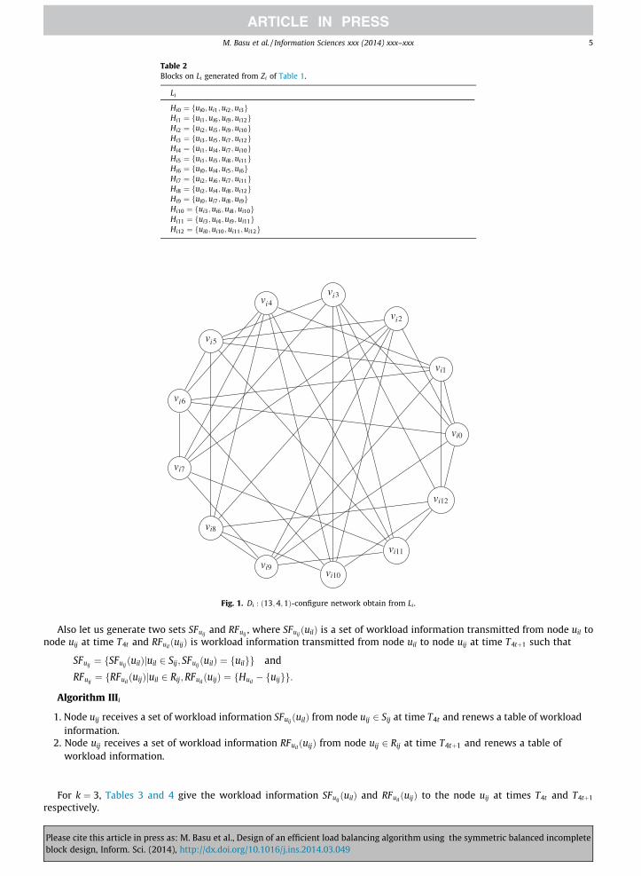
Fig. 1. Di : ð13;4;1Þ-configure network obtain from Li .
Table 2Blocks on Li generated from Zi of Table 1.
Li
Hi0 ¼ fui0;ui1;ui2;ui3gHi1 ¼ fui1;ui6;ui9;ui12gHi2 ¼ fui2;ui5;ui9;ui10gHi3 ¼ fui3;ui5;ui7;ui12gHi4 ¼ fui1;ui4;ui7;ui10gHi5 ¼ fui1;ui5;ui8;ui11gHi6 ¼ fui0;ui4;ui5;ui6gHi7 ¼ fui2;ui6;ui7;ui11gHi8 ¼ fui2;ui4;ui8;ui12gHi9 ¼ fui0;ui7;ui8;ui9gHi10 ¼ fui3;ui6;ui8;ui10gHi11 ¼ fui3;ui4;ui9;ui11gHi12 ¼ fui0;ui10;ui11;ui12g
M. Basu et al. / Information Sciences xxx (2014) xxx–xxx 5
Also let us generate two sets SFuijand RFuij
, where SFuijðuilÞ is a set of workload information transmitted from node uil to
node uij at time T4t and RFuilðuijÞ is workload information transmitted from node uil to node uij at time T4tþ1 such that
Pleaseblock
SFuij¼ fSFuij
ðuilÞjuil 2 Sij; SFuijðuilÞ ¼ fuilgg and
RFuij¼ fRFuil
ðuijÞjuil 2 Rij;RFuilðuijÞ ¼ fHuil
� fuijgg:
Algorithm IIIi
1. Node uij receives a set of workload information SFuij ðuilÞ from node uij 2 Sij at time T4t and renews a table of workloadinformation.
2. Node uij receives a set of workload information RFuil ðuijÞ from node uij 2 Rij at time T4tþ1 and renews a table ofworkload information.
For k ¼ 3, Tables 3 and 4 give the workload information SFuijðuilÞ and RFuil
ðuijÞ to the node uij at times T4t and T4tþ1
respectively.
cite this article in press as: M. Basu et al., Design of an efficient load balancing algorithm using the symmetric balanced incompletedesign, Inform. Sci. (2014), http://dx.doi.org/10.1016/j.ins.2014.03.049
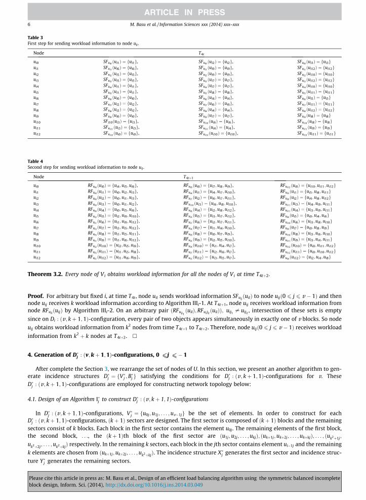
Table 3First step for sending workload information to node uij .
Node T4t
ui0 SFui0 ðui1Þ ¼ fui1g, SFui0 ðui2Þ ¼ fui2g, SFui0 ðui3Þ ¼ fui3gui1 SFui1 ðui6Þ ¼ fui6g, SFui1 ðui9Þ ¼ fui9g, SFui1 ðui12Þ ¼ fui12gui2 SFui2 ðui5Þ ¼ fui5g, SFui2 ðui9Þ ¼ fui9g, SFui2 ðui10Þ ¼ fui10gui3 SFui3 ðui5Þ ¼ fui5g, SFui3 ðui7Þ ¼ fui7g, SFui3 ðui12Þ ¼ fui12gui4 SFui4 ðui1Þ ¼ fui1g, SFui4 ðui7Þ ¼ fui7g, SFui4 ðui10Þ ¼ fui10gui5 SFui5 ðui1Þ ¼ fui1g, SFui5 ðui8Þ ¼ fui8g, SFui5 ðui11Þ ¼ fui11gui6 SFui6 ðui0Þ ¼ fui0g, SFui6 ðui4Þ ¼ fui4g, SFui6 ðui5Þ ¼ fui5gui7 SFui7 ðui2Þ ¼ fui2g, SFui7 ðui6Þ ¼ fui6g, SFui7 ðui11Þ ¼ fui11gui8 SFui8 ðui2Þ ¼ fui2g, SFui8 ðui4Þ ¼ fui4g, SFui8 ðui12Þ ¼ fui12gui9 SFui9 ðui0Þ ¼ fui0g, SFui9 ðui7Þ ¼ fui7g, SFui9 ðui8Þ ¼ fui8gui10 SFi10ðui3Þ ¼ fui3g, SFui10 ðui6Þ ¼ fui6g, SFui10 ðui8Þ ¼ fui8gui11 SFui11 ðui3Þ ¼ fui3g, SFui11 ðui4Þ ¼ fui4g, SFui11 ðui9Þ ¼ fui9gui12 SFui12 ðui0Þ ¼ fui0g, SFui12 ðui10Þ ¼ fui10g, SFui12 ðui11Þ ¼ fui11g
Table 4Second step for sending workload information to node uij .
Node T4tþ1
ui0 RFui6 ðui0Þ ¼ fui4;ui5;ui6g, RFui9 ðui0Þ ¼ fui7;ui8;ui9g, RFui12 ðui0Þ ¼ fui10;ui11;ui12gui1 RFui0 ðui1Þ ¼ fui0;ui2;ui3g, RFui4 ðui1Þ ¼ fui4;ui7;ui10g, RFui5 ðui1Þ ¼ fui5;ui8;ui11gui2 RFui0 ðui2Þ ¼ fui0;ui1;ui3g, RFui7 ðui2Þ ¼ fui6;ui7;ui11g, RFui8 ðui2Þ ¼ fui4;ui8;ui12gui3 RFui0 ðui3Þ ¼ fui0;ui1;ui2g, RFui10 ðui3Þ ¼ fui6;ui8;ui10g, RFui11 ðui3Þ ¼ fui4;ui9;ui11gui4 RFui6 ðui4Þ ¼ fui0;ui5;ui6g, RFui8 ðui4Þ ¼ fui2;ui8;ui12g, RFui11 ðui4Þ ¼ fui3;ui9;ui11gui5 RFui2 ðui5Þ ¼ fui2;ui9;ui10g, RFui3 ðui5Þ ¼ fui3;ui7;ui12g, RFui6 ðui5Þ ¼ fui0;ui4;ui6gui6 RFui1 ðui6Þ ¼ fui1;ui9;ui12g, RFui7 ðui6Þ ¼ fui2;ui7;ui11g, RFui10 ðui6Þ ¼ fui3;ui8;ui10gui7 RFui3 ðui7Þ ¼ fui3;ui5;ui12g, RFui4 ðui7Þ ¼ fui1;ui4;ui10g, RFui9 ðui7Þ ¼ fui0;ui8;ui9gui8 RFui5 ðui8Þ ¼ fui1;ui5;ui11g, RFui9 ðui8Þ ¼ fui0;ui7;ui9g, RFui10 ðui8Þ ¼ fui3;ui6;ui10gui9 RFui1 ðui9Þ ¼ fui1;ui6;ui12g, RFui2 ðui9Þ ¼ fui2;ui5;ui10g, RFui11 ðui9Þ ¼ fui3;ui4;ui11gui10 RFui2 ðui10Þ ¼ fui2;ui5;ui9g, RFui4 ðui10Þ ¼ fui1;ui4;ui7g, RFui12 ðui10Þ ¼ fui0;ui11;ui12gui11 RFui5 ðui11Þ ¼ fui1;ui5;ui8g, RFui7 ðui11Þ ¼ fui2;ui6;ui7g, RFui12 ðui11Þ ¼ fui0;ui10;ui12gui12 RFui1 ðui12Þ ¼ fui1;ui6;ui9g, RFui3 ðui12Þ ¼ fui3;ui5;ui7g, RFui8 ðui12Þ ¼ fui2;ui4;ui8g
6 M. Basu et al. / Information Sciences xxx (2014) xxx–xxx
Theorem 3.2. Every node of Vi obtains workload information for all the nodes of Vi at time T4tþ2.
Proof. For arbitrary but fixed i, at time T4t , node uil sends workload information SFuijðuilÞ to node uijð0 6 j 6 v � 1Þ and then
node uij receives k workload information according to Algorithm IIIi-1. At T4tþ1, node uij receives workload information fromnode RFuil
ðuijÞ by Algorithm IIIi-2. On an arbitrary pair ðRFuij1ðuilÞ;RFuij2 ðuilÞÞ; uij1 – uij2 , intersection of these sets is empty
since on Di : ðv ; kþ 1;1Þ-configuration, every pair of two objects appears simultaneously in exactly one of v blocks. So node
uij obtains workload information from k2 nodes from time T4tþ1 to T4tþ2. Therefore, node uijð0 6 j 6 v � 1Þ receives workload
information from k2 þ k nodes at T4tþ2. h
4. Generation of D�j : ðv;kþ 1;1Þ-configurations, 0 <j <� 1
After complete the Section 3, we rearrange the set of nodes of U. In this section, we present an another algorithm to gen-erate incidence structures D�j ¼ fV
�j ;B
�j g satisfying the conditions for D�j : ðv ; kþ 1;1Þ-configurations for v. These
D�j : ðv; kþ 1;1Þ-configurations are employed for constructing network topology below:
4.1. Design of an Algorithm I�j to construct D�j : ðv; kþ 1; 1Þ-configurations
In D�j : ðv ; kþ 1;1Þ-configurations, V�j ¼ fu0j;u1j; . . . ;uv�1jg be the set of elements. In order to construct for eachD�j : ðv; kþ 1;1Þ-configurations, ðkþ 1Þ sectors are designed. The first sector is composed of ðkþ 1Þ blocks and the remainingsectors consist of k blocks. Each block in the first sector contains the element u0j. The remaining elements of the first block,the second block, . . ., the ðkþ 1Þth block of the first sector are ðu1j;u2j; . . . ;ukjÞ; ðukþ1j;ukþ2j; . . . ;ukþkjÞ; . . . ; ðuk2þ1j;
uk2þ2j; . . . ;uk2þkjÞ respectively. In the remaining k sectors, each block in the jth sector contains element ui�1j and the remaining
k elements are chosen from ðukþ1j;ukþ2j; . . . ;uk2þkjÞ. The incidence structure X�j generates the first sector and incidence struc-
ture Y�j generates the remaining sectors.
Please cite this article in press as: M. Basu et al., Design of an efficient load balancing algorithm using the symmetric balanced incompleteblock design, Inform. Sci. (2014), http://dx.doi.org/10.1016/j.ins.2014.03.049

M. Basu et al. / Information Sciences xxx (2014) xxx–xxx 7
Algorithm I�j
Incidence structure D�j ¼ fV�j ; B
�j g, where
V�j ¼ fu0j; u1j; . . . ;uv�1jg; B�j ¼ fB�0j;B
�1j; . . . ; B�v�1jg; jB
�ijj ¼ kþ 1; i ¼ 0;1;2; . . . ;v � 1; B�ij;l is the lth element of B�ij.
1. Select the same prime number k as in Algorithm Ii and compute v ¼ k2 þ kþ 1.2. Construct two incidence structures X�j ¼ fV
�j ; E�j g for D�j structure:
E�ij;l ¼ulj if l ¼ 0utj t ¼ i � kþ l if l P 1
�; 0 6 i; l 6 k.
3. Construct two incidence structures Y�j ¼ fV�j ; F�j g for D�j structure:
F�ij;l ¼E�lj;t t ¼ bi=kc þ 1 if l ¼ 0E�lj;t t ¼ 1þ ðiþ ðl� 1Þ � bi=kcÞðmod kÞ if l P 1
�; 0 6 i 6 ðk2 � 1Þ;0 6 l 6 k.
4. Generate Z�j ¼ fV�j ;B
�j g from X�j and Y�j .
B�ij E�ij,B�ðiþkþ1Þj F�ij.
Table 5 illustrates that how to generate Z�j ¼ fV�j ;B
�j g for V�j ¼ fu0j;u1j; . . . ;u12jg; k ¼ 3.
Theorem 4.1. Z�j designed by Algorithm I�j satisfies the conditions of a D�j : ðv; kþ 1;1Þ-configuration.
The proof is similar as Theorem 3.1.
4.2. Design of Algorithm II�j for network configurations
We consider D�j : ðv ; kþ 1;1Þ-configuration. An incidence structure Z�j ¼ fV�j ;B
�j g satisfies D�j : ðv ; kþ 1;1Þ-configurations
and M�j is a binary incidence matrix of Z�j . Then this matrix M�
j can be transformed to an adjacency matrix of a graphG�j ¼ fV
�j ; E
�j g. Network topology can be designed as follows:
Algorithm II�j
1. Create an incidence structure Z�j ¼ fV�j ;B
�j g by Algorithm I�j .
2. Generate L�j ¼ fV�j ;H
�j g from Z�j by exchanging blocks so that each block H�ij includes the element uij.
H�0j B�0j
for (i = 1; i 6 k; i = i + 1)H�ððiþ1Þ�kÞj B�ijfor (i = k + 1; i < v; i = i + 1){B�ij;di=ke�1 ¼ usj (say)
if ðs mod kÞÞ ¼ 0ÞH�ðdi=ke�1Þj B�ijelse{if ðði mod kÞ ¼ 0Þt ¼ i� kþ 1else t ¼ b i
kc � kþ b i2kc
H�ðtþiðmod kÞÞj B�ij}}.
3. Create adjacency matrices M�j ¼ ða�pqÞ for graph G�j from L�j , where G�j is a network topology containing v nodes.
Please ciblock de
a�pq ¼1 if p – q and upj 2 H�pq
0 otherwise:
�
The adjacency matrix M�j is same for all j; 0 6 j 6 v � 1.
4.3. Graphical representation of the Algorithm II�j
The graph G�j is created from D�j : ðv ; kþ 1;1Þ-configuration, where G�j has v nodes. Each block H�ij is composed of kþ 1 ele-ments including uij. Each node obtains 2k links from Step 3 of Algorithm II�j . Table 6 illustrates that how to generate L�j fork ¼ 3. Fig. 2 is the graphical representation of Table 6.
te this article in press as: M. Basu et al., Design of an efficient load balancing algorithm using the symmetric balanced incompletesign, Inform. Sci. (2014), http://dx.doi.org/10.1016/j.ins.2014.03.049
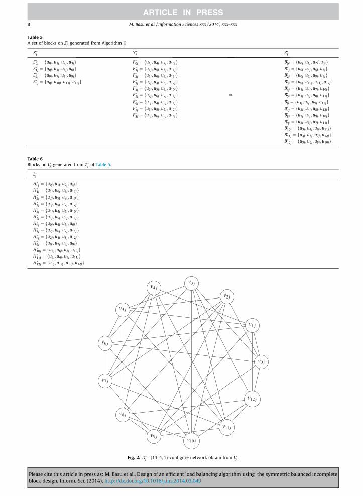
Table 6Blocks on L�j generated from Z�j of Table 5.
L�j
H�0j ¼ fu0j;u1j;u2j ;u3jgH�1j ¼ fu1j;u6j;u9j;u12jgH�2j ¼ fu2j;u5j;u9j;u10jgH�3j ¼ fu3j;u5j;u7j;u12jgH�4j ¼ fu1j;u4j;u7j;u10jgH�5j ¼ fu1j;u5j;u8j;u11jgH�6j ¼ fu0j;u4j;u5j;u6jgH�7j ¼ fu2j;u6j;u7j;u11jgH�8j ¼ fu2j;u4j;u8j;u12jgH�9j ¼ fu0j;u7j;u8j;u9jgH�10j ¼ fu3j;u6j;u8j ;u10jgH�11j ¼ fu3j;u4j;u9j;u11jgH�12j ¼ fu0j;u10j ;u11j;u12jg
Table 5A set of blocks on Z�j generated from Algorithm I�j .
X�j Y�j Z�j
E�0j ¼ fu0j ;u1j ;u2j;u3jg F�0j ¼ fu1j ;u4j;u7j;u10jg B�0j ¼ fu0j;u1j ;u2j;u3jgE�1j ¼ fu0j ;u4j ;u5j ;u6jg F�1j ¼ fu1j ;u5j ;u8j;u11jg B�1j ¼ fu0j;u4j;u5j ;u6jgE�2j ¼ fu0j ;u7j ;u8j ;u9jg F�2j ¼ fu1j ;u6j ;u9j;u12jg B�2j ¼ fu0j;u7j;u8j ;u9jgE�3j ¼ fu0j ;u10j;u11j;u12jg F�3j ¼ fu2j ;u4j ;u8j;u12jg B�3j ¼ fu0j;u10j ;u11j;u12jg
F�4j ¼ fu2j ;u5j ;u9j;u10jg B�4j ¼ fu1j;u4j;u7j;u10jgF�5j ¼ fu2j ;u6j ;u7j;u11jg ) B�5j ¼ fu1j;u5j;u8j;u11jgF�6j ¼ fu3j ;u4j ;u9j;u11jg B�6 ¼ fu1j ;u6j ;u9j ;u12jgF�7j ¼ fu3j ;u5j ;u7j;u12jg B�7j ¼ fu2j;u4j;u8j;u12jgF�8j ¼ fu3j ;u6j ;u8j;u10jg B�8j ¼ fu2j;u5j;u9j;u10jg
B�9j ¼ fu2j;u6j;u7j;u11jgB�10j ¼ fu3j;u4j ;u9j ;u11jgB�11j ¼ fu3j;u5j;u7j ;u12jgB�12j ¼ fu3j;u6j;u8j ;u10jg
Fig. 2. D�j : ð13;4;1Þ-configure network obtain from L�j .
8 M. Basu et al. / Information Sciences xxx (2014) xxx–xxx
Please cite this article in press as: M. Basu et al., Design of an efficient load balancing algorithm using the symmetric balanced incompleteblock design, Inform. Sci. (2014), http://dx.doi.org/10.1016/j.ins.2014.03.049
M. Basu et al. / Information Sciences xxx (2014) xxx–xxx 9
4.4. Design of load balancing algorithm on distributed networks for uij; 0 6 i 6 v � 1
Let us construct two sets S�ij and R�ij consisting of adjacent k nodes, where S�ij is a set of nodes to send workload informationto node uij at time T4tþ2, and R�ij is a set of nodes to send workload information to node uij at time T4tþ3 such that
Pleaseblock
S�ij ¼ fuljjulj 2 H�ij � fuijgg and
R�ij ¼ fuljjuij 2 H�lj; 0 6 l 6 v � 1 and i – lg:
Also let us generate two sets SF�uijand RF�uij
, where SF�uijðuljÞ is a set of workload information transmitted from node ulj to
node uij at time T4tþ2 and RF�uljðuijÞ is workload information transmitted from node ulj to node uij at time T4tþ3 such that
SF�uij¼ fSF�uij
ðuljÞjulj 2 S�ij; SF�uijðuljÞ ¼ fuljgg and
RF�uij¼ fRF�ulj
ðuijÞjulj 2 R�ij;RF�uljðuijÞ ¼ fHulj
� fuijgg:
An efficient load balancing algorithm is now constructed on D�j : ðv ; kþ 1;1Þ-configured networks generated by AlgorithmII�j .
Algorithm III�j
1. Node uij receives a set of workload information SF�uijðuljÞ from node uij 2 S�ij at time T4tþ2 and renews a table of
workload information.2. Node uij receives a set of workload information RF�ulj
ðuijÞ from node uij 2 R�ij at time T4tþ3 and renews a table of
workload information.
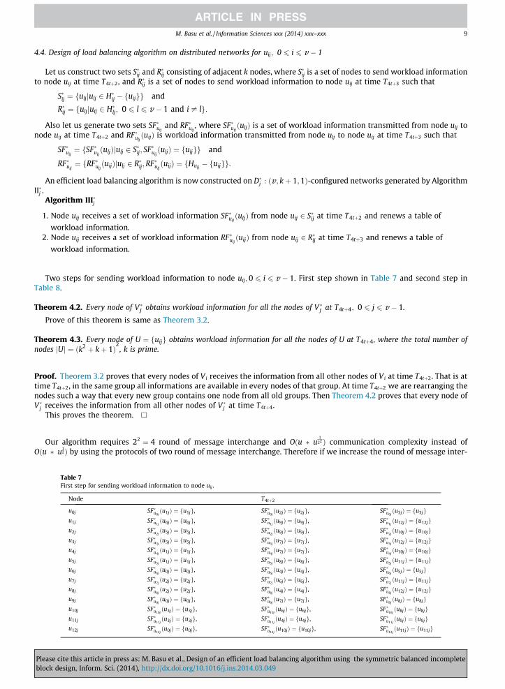
Two steps for sending workload information to node uij;0 6 i 6 v � 1. First step shown in Table 7 and second step inTable 8.
Theorem 4.2. Every node of V�j obtains workload information for all the nodes of V�j at T4tþ4; 0 6 j 6 v � 1.
Prove of this theorem is same as Theorem 3.2.
Theorem 4.3. Every node of U ¼ fuijg obtains workload information for all the nodes of U at T4tþ4, where the total number ofnodes jUj ¼ ðk2 þ kþ 1Þ
2, k is prime.
Proof. Theorem 3.2 proves that every nodes of Vi receives the information from all other nodes of Vi at time T4tþ2. That is attime T4tþ2, in the same group all informations are available in every nodes of that group. At time T4tþ2 we are rearranging thenodes such a way that every new group contains one node from all old groups. Then Theorem 4.2 proves that every node ofV�j receives the information from all other nodes of V�j at time T4tþ4.
This proves the theorem. h
Our algorithm requires 22 ¼ 4 round of message interchange and Oðu � u1
22 Þ communication complexity instead ofOðu � u
12Þ by using the protocols of two round of message interchange. Therefore if we increase the round of message inter-
Table 7First step for sending workload information to node uij .
Node T4tþ2
u0j SF�u0jðu1jÞ ¼ fu1jg, SF�u0j
ðu2jÞ ¼ fu2jg, SF�u0jðu3jÞ ¼ fu3jg
u1j SF�u1jðu6jÞ ¼ fu6jg, SF�u1j
ðu9jÞ ¼ fu9jg, SF�u1jðu12jÞ ¼ fu12jg
u2j SF�u2jðu5jÞ ¼ fu5jg, SF�u2j
ðu9jÞ ¼ fu9jg, SF�u2jðu10jÞ ¼ fu10jg
u3j SF�u3jðu5jÞ ¼ fu5jg, SF�u3j
ðu7jÞ ¼ fu7jg, SF�u3jðu12jÞ ¼ fu12jg
u4j SF�u4jðu1jÞ ¼ fu1jg, SF�u4j
ðu7jÞ ¼ fu7jg, SF�u4jðu10jÞ ¼ fu10jg
u5j SF�u5jðu1jÞ ¼ fu1jg, SF�u5j
ðu8jÞ ¼ fu8jg, SF�u5jðu11jÞ ¼ fu11jg
u6j SF�u6jðu0jÞ ¼ fu0jg, SF�u6j
ðu4jÞ ¼ fu4jg, SF�u6jðu5jÞ ¼ fu5jg
u7j SF�u7jðu2jÞ ¼ fu2jg, SF�u7j
ðu6jÞ ¼ fu6jg, SF�u7jðu11jÞ ¼ fu11jg
u8j SF�u8jðu2jÞ ¼ fu2jg, SF�u8j
ðu4jÞ ¼ fu4jg, SF�u8jðu12jÞ ¼ fu12jg
u9j SF�u9jðu0jÞ ¼ fu0jg, SF�u9j
ðu7jÞ ¼ fu7jg, SF�u9jðu8jÞ ¼ fu8jg
u10j SF�u10jðu3jÞ ¼ fu3jg, SF�u10j
ðu6jÞ ¼ fu6jg, SF�u10jðu8jÞ ¼ fu8jg
u11j SF�u11jðu3jÞ ¼ fu3jg, SF�u11j
ðu4jÞ ¼ fu4jg, SF�u11jðu9jÞ ¼ fu9jg
u12j SF�u12jðu0jÞ ¼ fu0jg, SF�u12j
ðu10jÞ ¼ fu10jg, SF�u12jðu11jÞ ¼ fu11jg
cite this article in press as: M. Basu et al., Design of an efficient load balancing algorithm using the symmetric balanced incompletedesign, Inform. Sci. (2014), http://dx.doi.org/10.1016/j.ins.2014.03.049

Table 8Second step for sending workload information to node uij .
Node T4tþ3
u0j RF�u6jðu0jÞ ¼ fu4j ;u5j;u6jg, RF�u9j
ðu0jÞ ¼ fu7j;u8j;u9jg, RF�u12jðu0jÞ ¼ fu10j ;u11j;u12jg
u1j RF�u0jðu1jÞ ¼ fu0j;u2j;u3jg, RF�u4j
ðu1jÞ ¼ fu4j;u7j;u10jg, RF�u5jðu1jÞ ¼ fu5j ;u8j ;u11jg
u2j RF�u0jðu2jÞ ¼ fu0j;u1j;u3jg, RF�u7j
ðu2jÞ ¼ fu6j;u7j;u11jg, RF�u8jðu2jÞ ¼ fu4j ;u8j ;u12jg
u3j RF�u0jðu3jÞ ¼ fu0j;u1j;u2jg, RF�u10j
ðu3jÞ ¼ fu6j;u8j;u10jg, RF�u11jðu3jÞ ¼ fu4j;u9j;u11jg
u4j RF�u6jðu4jÞ ¼ fu0j ;u5j;u6jg, RF�u8j
ðu4jÞ ¼ fu2j;u8j;u12jg, RF�u11jðu4jÞ ¼ fu3j;u9j;u11jg
u5j RF�u2jðu5jÞ ¼ fu2j ;u9j ;u10jg, RF�u3j
ðu5jÞ ¼ fu3j;u7j;u12jg, RF�u6jðu5jÞ ¼ fu0j ;u4j;u6jg
u6j RF�u1jðu6jÞ ¼ fu1j ;u9j ;u12jg, RF�u7j
ðu6jÞ ¼ fu2j;u7j;u11jg, RF�u10jðu6jÞ ¼ fu3j ;u8j ;u10jg
u7j RF�u3jðu7jÞ ¼ fu3j ;u5j ;u12jg, RF�u4j
ðu7jÞ ¼ fu1j;u4j;u10jg, RF�u9jðu7jÞ ¼ fu0j ;u8j;u9jg
u8j RF�u5jðu8jÞ ¼ fu1j ;u5j ;u11jg, RF�u9j
ðu8jÞ ¼ fu0j;u7j;u9jg, RF�u10jðu8jÞ ¼ fu3j ;u6j ;u10jg
u9j RF�u1jðu9jÞ ¼ fu1j ;u6j ;u12jg, RF�u2j
ðu9jÞ ¼ fu2j;u5j;u10jg, RF�u11jðu9jÞ ¼ fu3j;u4j;u11jg
u10j RF�u2jðu10jÞ ¼ fu2j;u5j;u9jg, RF�u4j
ðu10jÞ ¼ fu1j;u4j;u7jg, RF�u12jðu10jÞ ¼ fu0j ;u11j;u12jg
u11j RF�u5jðu11jÞ ¼ fu1j ;u5j;u8jg, RF�u7j
ðu11jÞ ¼ fu2j;u6j;u7jg, RF�u12jðu11jÞ ¼ fu0j ;u10j;u12jg
u12j RF�u1jðu12jÞ ¼ fu1j ;u6j;u9jg, RF�u3j
ðu12jÞ ¼ fu3j;u5j;u7jg, RF�u8jðu12jÞ ¼ fu2j ;u4j;u8jg
10 M. Basu et al. / Information Sciences xxx (2014) xxx–xxx
change by 2n, then the communication complexity is Oðu � u1
2n Þ. Thus by increasing the number of nodes, we have thefollowing:
Every node of U ¼ fui1 i2 ;...;i2n�1 g obtains work load information for all the nodes of U at time T2ntþ2n , where the total numberof nodes jUj ¼ ðk2 þ kþ 1Þ
2n�1
; 0 6 i1; i2; . . . ; i2n�1 6 k2 þ k, where k is prime. Hence we arrive at an important result that byincreasing round of message interchange infinitely, we can make OðuÞ communication complexity.
5. Conclusion
Researches have shown that distributed load balancing schemes can reduce task turnaround time substantially by per-forming tasks at lightly loaded nodes in the network. However, maintaining workload information on all the nodes is nec-essary for such scheme, while it may incur large communication overhead. In order to increase utilization and to reduceresponse time of the system, we present an efficient load balancing algorithm on u ¼ ðk2 þ kþ 1Þ
2nodes by employing
the symmetric balanced incomplete block design. To accomplish this, each node should receive workload information fromall the nodes without redundancy and each link should have the same amount of traffic for transferring workload informa-tion. Our algorithm requires four rounds of message interchange and Oðu5
4Þ communication complexity, as opposed to Oðu32Þ
communication complexity requiring two round of message interchange. Later, this algorithm is extended by increasing infi-nitely the round of message interchange and shows that the communication complexity is OðuÞ.
Acknowledgements
The authors would like to thank the anonymous reviewers for their valuable comments and suggestions to improve thequality of the paper.
References
[1] S. Das, D. Harvey, R. Biswas, Parallel processing of adaptive meshes with load balancing, IEEE Trans. Parall. Distrib. Syst. 12 (2001) 1269–1280.[2] S. Das, D. Harvey, R. Biswas, Adaptive load-balancing algorithms using symmetric broadcast networks, J. Parall. Distrib. Comput. 62 (2002) 1042–1068.[3] L. Ford, D. Fulkerson, Flow in Network, Princeton University Press, Princeton, NJ, 1962.[4] O. Lee, S. Yoo, B. Park, I. Chung, The design and analysis of an efficient load balancing algorithm employing the symmetric balanced incomplete block
design, Inf. Sci. 176 (2006) 2148–2160.[5] C.L. Liu, Introduction to Combinatorial Mathematics, McGraw-Hill, NY, 1968. pp. 359–383.[6] K. Nam, J. Seo, Synchronous load balancing in hypercube multicomputers with faulty nodes, J. Parall. Distrib. Comput. 58 (1999) 26–43.[7] H. Rim, J. Jang, S. Kim, Method for maximal utilization of idle links for fast load balancing, J. Korea Inf. Sci. Soc. 28 (2001) 632–641.[8] M. Wu, On runtime parallel scheduling for processor load balancing, IEEE Trans. Parall. Distrib. Syst. 8 (1997) 173–185.
Please cite this article in press as: M. Basu et al., Design of an efficient load balancing algorithm using the symmetric balanced incompleteblock design, Inform. Sci. (2014), http://dx.doi.org/10.1016/j.ins.2014.03.049