Evaluation of buckling-restrained braced frame seismic performance considering reserve strength
Upload
washingtonCategory
view
3download
0
Journal of Constructional Steel Research 67 (2011) 1760–1772
Contents lists available at ScienceDirect
Journal of Constructional Steel Research
A balanced design procedure for special concentrically braced frame connections
Charles W. Roeder ⁎, Eric J. Lumpkin, Dawn E. LehmanDepartment of Civil and Environmental Engineering, University of Washington, Seattle, WA 98195-2700, United States
⁎ Corresponding author at: 233B More Hall, Universi98195-2700, United States. Tel.: +1 206 543 6199; fax:
E-mail address: [email protected] (C.W. Ro
0143-974X/$ – see front matter © 2011 Elsevier Ltd. Adoi:10.1016/j.jcsr.2011.04.016
a b s t r a c t
a r t i c l e i n f oArticle history:Received 13 December 2010Accepted 26 April 2011Available online 14 June 2011
Keywords:Seismic designBraced framesGusset plate connectionsSpecial concentrically braced framesDuctilityInelastic behavior
Concentrically braced frames (CBFs) are stiff, strong structures that are suitable for resisting large lateralloads. Special CBFs (SCBF) are used for seismic design and are designed and detailed to sustain relatively largeinelastic deformations without significant deterioration in resistance. Current AISC Seismic Design Provisionsaim to ensure the brace sustains the required inelastic action, but recent research showed that current SCBFdesign requirements lead to variable seismic performance, unintended failure modes, and limiteddeformation capacity. To improve the seismic response of SCBFs, a balanced design procedure was proposed.The premise of the design methodology is to balance the primary yield mechanism, brace buckling andyielding, with other, complementary ductile yielding mechanisms, such as gusset plate yielding. This balanceprocess maximizes ductile yielding in the frame thereby maximizing the drift capacity of the frame. Further,the undesirable failure modes are balanced with the yield mechanisms and the preferred failure mode, bracefracture, to ensure that the frame fails in the desired manner. To achieve the objectives of the designmethodology namely maximum drift capacity, and adherence to a desired yield and failure hierarchy, rationalresistance checks and appropriate balance factors (β factors) are used to balance each yield mechanism andfailure mode. These factors were developed, validated, and refined using the measured results from anextensive test program. An SCBF connection design example to illustrate the application of the balanceddesign method and to demonstrate differences from the current AISC design method is presented in anappendix.
ty of Washington, Seattle, WA+1 206 543 1543.eder).
ll rights reserved.
© 2011 Elsevier Ltd. All rights reserved.
Introduction
Concentrically braced frames (CBFs) are stiff, strong structures,which are suitable for resisting wind and seismic loading. CBF typicallyare composed of diagonal bracingmembers connected to thebeams andcolumns with gusset plate connection. The bracing may be placed in anumber of different configurations and geometries. CBF members areinitially designed assuming truss action, i.e. the members only carryaxial load.
Special concentrically braced frames (SCBF) are employed in highseismic regions and use a ResponseModification Factor, R, to reduce theseismic design force. During large, infrequent earthquakes, SCBFs mustsustain cyclic, inelastic tensile yielding and compressive bucklingdeformation of the brace without significant deterioration of stiffnessand resistance for earthquakes exceeding the reduced design force.Brace buckling and tensile yield are theprimary yieldmechanismsof thesystem,whichpermit the frame to sustain the inelastic deformation andenergy dissipation demands needed to provide collapse-preventionperformance.
Although the brace is the primary member in the SCBF system, theconnections play an important role. Gusset plate connections typically
connect the brace to the other framing members, as shown in Fig. 1,because they are easier to construct and design than fully restrainedbrace-end connections. Design of gusset plate connections to achievethe design objectives requires significant effort [1], and recent researchhas shown that they may not lead to the intended response.Experimental investigations into modified design methods havedemonstrated small changes can improve the seismic performance ofthe system [2]. These improvements can be implemented in practiceusing a balanced-design procedure (BDP). Balanced design has beenproposed asamethod to control the sequenceof yieldingand to increaseinelastic deformation capacity in past seismic research (e.g., [3]), but ithas not been widely used in practice because of the complexity anduncertainty in achieving the required component balancing in practice.In part, this uncertainty stems from the limited experimental dataavailable to verify the design method and associated expressions. Here,this limitation is overcomeusing a large data set on braced frame systemthat simulates modern construction. The resulting BDP is robust andavailable for immediate used by practitioners.
This paper develops, presents, and justifies a simple BDP for SCBFgusset plate connections. The BDP identifies all possible yield mecha-nisms and failuresmodes associatedwith the SCBF system, and balancestheir resistances to optimize the seismic performance of the system [4].The BDP adapts currently accepted design expressions and uses balancefactors (β factors) for each yield mechanism and failure mode to assurethat (1) the primary yield mechanism occurs and is followed by

Fig. 1. AISC gusset plate design; a) geometry, tension, buckling and net section checks; b) welds, free edge buckling, and weld checks; and c) geometry of tapered gusset.
1761C.W. Roeder et al. / Journal of Constructional Steel Research 67 (2011) 1760–1772
secondary yield mechanisms, and (2) undesirable failure modes areprevented. Tomaximize inelastic action anddeformation capacity of thesystem, the BDP requires: (1) accurate models for predicting theresistance associated with each yield mechanism and failure mode, and(2) balance factors (β factors) to assure the proper separation of theprimary and secondary yieldmechanisms, to delay all failuremodes andto suppress unacceptable failure modes. To achieve this, a review ofcurrent SCBF seismic design requirements is provided, and recentresearch that provides the basis for the proposed BDP is summarized.The results of this experimental research are then used to develop andevaluate design expressions andβ factors for relevant yieldmechanismsand failure modes. Finally, a design example using the proposed BDP isprovided in the appendix.
Current design method
The premise of the current design method, as specified in the AISCSeismic Design Provisions [1] is to establish the force demands on thesystem and to use the LRFD AISC design provisions [5] to size the braceand framing members. In this selection, the designer must:
• Satisfy local and global slenderness limits for the brace and othermembers.
• Ensure that the tensile brace sustains nomore than 70% of the lateralforce demand.
• Design beams in frames with V-bracing and inverted V-bracing tosustain the vertical unbalanced load that results after brace bucklingoccurs.
• Design columns and column splices to resist the minimum of theamplified seismic load and an amplifiedmaximum force equal to theproduct of 1.1Ry and the maximum force the adjacent braces cantransfer to the column.
• Establish the plastic capacity of the brace in tension, Put=RyFyAg,and compression, Puc=1.1RyFcrAg to complete the connectiondesign. In the expression, Ag is the gross cross-sectional area of
Table 1Limit states and corresponding resistance expressions for AISC and balanced design approa
Limit state AISC design
Resistance (φRn)
Whitmore yielding ϕFyBwtpBrace net section fracture ϕU(RtbFubAnb+FupAgp)Brace to gusset weld ϕ(0.6)FEXXNwLc(.707)w2
Brace to gusset base metal ϕ(0.6)FuNsLctfBlock shear ϕ{(0.6FuAnv+UbsFuAnt)≤(0.6FyAgv+UbsFuAnt)}Whitmore fracture ϕFuBwtpGusset plate buckling ϕBwtpFcrInterface welds ϕ(0.6)FEXX[1+0.5(sinγ)1.5]2 Lw(.707)w1≥UFM
the brace, Ry is the ratio of the expected yield strength to theminimum specified yield strength, Fy, and Fcr is the critical stressassociated with brace buckling.
The gusset plate connecting the beam, column, and brace must bedesigned such that its resistance exceeds Put and Puc. Numerousdesign checks are needed to achieve this, and Table 1 provides theequations currently used in this evaluation. A cursory review of thegusset plate design checks follows:
1. The net section resistance of the brace is evaluated adjacent to thegusset-to-brace connection and reinforcement is added if it cannotachieve Put.
2. The length of the brace-to-gusset interface is sized to suppressblock shear for Put.
3. The AISC Uniform Force Method (UFM) may be used to selectgusset plate dimensions (dimensions a and b of Fig. 1a) and toestablish the force or stress demands on the bolts or welds neededtomaintain equilibriumwith Put of the brace [5]. The welds or boltsare then sized to sustain the computed demand.
4. The connection must be designed to either develop a fullyrestrained brace connection or allowance must be made for braceend rotation during buckling. This end rotation capacity iscurrently achieved with 2tp linear clearance, as shown in Fig. 1.
5. The thickness of the gusset plate must be sufficient to develop bothPut and Puc. The tensile gusset plate resistance is determined usingthe Whitmore width and specified strength of the plate [6]. Thecompressive resistance is determined using the Thornton methodwhich uses an average effective length of the gusset based upon thecentroidal length and the lengths at two ends of Whitmore width,as shown in Fig. 1a [7]. The effective length coefficient, K, iscommonly taken as 0.65 for corner gussets and 1.2 to 1.4 formidspan gussets. Edge buckling may also be evaluated.
The design process is rational, however recent research hasdemonstrated several shortcomings that have resulted in construction
ches.
Balanced design
ϕ Resistance (βRn) β
0.90 βRyFyBwtp 1.00.75 βU(RtbFubAnb+FupAgp) 0.950.75 Same as AISC 0.750.75 Same as AISC 0.750.75 β{(0.6FuAnv+UbsFuAnt)} 0.850.75 βFuBwtp 0.850.90 βBwtpFcr 0.900.75 2(1.5)β(0.6)FEXX(.707)w1≥RyFytp 0.75

1762 C.W. Roeder et al. / Journal of Constructional Steel Research 67 (2011) 1760–1772
challenges and reduced drift capacity. A new approach for gusset platedesign is needed to remedy these deficiencies.
Experimental studies
An extensive body of research has been performed on gusset plateconnections [8–15]. These connection tests are useful in establishingand validating basic models for predicting their resistance, but theyare not good indicators of SCBF seismic performance because they donot simulate the interaction of all of the braced frame components. Inparticular, these connection tests neglect the effect of brace bucklingdeformation demands on the connection (see Fig. 2a), the significantinelastic deformation demands on the beams and columns caused byframe action of the SCBF system (see Fig. 2b), and the inelasticdeformation of the gusset caused by frame action. These differencesare significant, because these effects are needed to capture the fullseismic demands on the gusset plate connection and to accuratelyreflect the ductility and inelastic performance of the system.
Experiments that include these effects simulate one or more baysof an SCBF frame [2,16–23]. A recent research program experimentallyevaluated 28 full-scale, single-bay single-story SCBFs with membersizes typical of those used in the bottom story of a 3- or 4-storybuilding (see Fig. 3a) [2,18–20,23]. In addition, six 2- and 3-story full-scale SCBF frames (see Fig. 3b) were tested at the National Center forEarthquake Engineering (NCREE) Laboratory in Taiwan to evaluate
a) Brace Buckling Demands on Gusset
b) Local Yielding of Beams and Columns
Fig. 2. Inelastic deformation demands on SCBF systems.
multi-story bracing systems [21,22]. These experiments evaluated arange of gusset plate connection design parameters including:
• The current AISC design procedures.• The range of different failure modes possible of SCBFs with gussetplate connections.
• The impact of different brace cross sections, configurations, andorientations.
• Different connections (e.g., bolted and welded) between the gussetplate and framing members.
• Differences in the 2tp linear clearance and alternate clearancemodels to achieve brace end rotation.
• The gusset plate thickness and resulting relative strength andstiffness of the brace, gusset and framing members.
• The impact of gusset plate shape by testing both tapered andrectangular gusset plates.
These tests realistically simulated the demands on and theperformance of these connections, and the results were used todevelop the proposed BDP [2]. The specimens were subjected to acyclic inelastic deformation history based on the ATC-24 testingprotocol [24], although a few tests employed a near-fault inspiredcyclic deformation history. Table 2 summarizes the general testresults. The drift range provided in this table is the total drift rangeincluding positive and negative deflections prior to achieving theinitial failure mode. The drift ranges shown for multi-story frames inthis table are average drift ranges over the height of the structure.Specimens with HSS in the identifier had rectangular HSS braces, andthose with WF had wide flange braces. Test results presented in [2]include the first eleven tests and some are reproduced here in brevityfor completion; the reader is referred to that paper for additionalinformation. When needed results from other tests are summarizedherein. More detailed information about all of the tests can be found inthe original reports (Specimens HSS1–HSS5 [18]; Specimens HSS6–HSS12 [19]; Specimens HSS13–HSS19 [20]; Specimens HSS20–HSS28[23]; Specimens TCBF1 [21]; Specimens TCBF2 1–3 [22]).
The research findings have broad implications on the currentseismic design methodology and mechanisms to improve it. Fig. 4uses the force–drift response curves from specimens that have testedwith a wide range of connection properties to illustrate the diversityin system performance observed in this research. Specifically,differences in the measured response result from different controllingyield mechanisms and failure modes. A few key observations areprovided.
• The current design methodology does not meet the performanceexpectations. Specimens HSS-1 and HSS-12 both were designed tomeet current AISC specifications [1], where Specimen HSS-1 usedfillet welds at the gusset plate-beam and gusset plate-columninterfaces and Specimen HSS-12 used a complete joint penetration(CJP). The interface welds in Specimen HSS-1 failed prior to bracetearing, as shown in Fig. 4a. Although Specimen HSS-12 achievedthe desired failure mode (brace fracture), the drift was less than1.5% in tension and far less than specimens design tomeet all or partof the BDP (see Fig. 4b). Specimen HSS-11, which had a large beamand gusset plate and met current SCBF design methods, failed atsmaller inelastic deformation because the excessive strength andstiffness of the gusset (encouraged by the current design philoso-phy) limited the system drift capacity (see Fig. 4e). Specimen HSS11greatly exceeded the BDP strength design requirements. However,the BDP is intended to avoid excess overstrength, and hence thisconnection meets the requirements of AISC but does not meet BDPrequirements.
• The 2tp linear clearance often results in relatively large, thick gussetplates. Observations from nonlinear analyses and experimentsshowed that a more compact gusset plate can achieve the braceend rotation demands and reduce construction challenges. Using

W12
x106
W12
x106
W21x68
W21x68
W24x94
200 mm Composite Slab
200 mm Composite Slab
200 mm Composite SlabAcuatorsN
6.00 m
2.93
m3.
19 m
3.19
m
a) Single Story Test b) Multi-Story Test
Fig. 3. Typical test specimens.
1763C.W. Roeder et al. / Journal of Constructional Steel Research 67 (2011) 1760–1772
those results as a basis, an alternative elliptical clearance methodwas developed for corner gusset plates, as indicated in Fig. 5 [2].Specimens HSS-2 through HSS-8 evaluated variations in theelliptical clearance distance. Based on those results, a clearance of8tp was selected. Specimen HSS-5 employed this 8tp ellipticalclearance model and balanced the brace tensile capacity with the
Table 2Test summary.
Specimen brace type Specimen description
HSS-1 AISC design — fillet welds by UFM.HSS-2 HSS1 w/fillet weld sized to cap. of plateHSS-3 BDP — fillet weld sized to capacity of plateHSS-4 BDP — fillet weld sized to capacity of plateHSS-5 BDP — fillet weld sized to capacity of plateHSS-6 BDP — HSS5 except fillet welds reinforcedHSS-7 BDP — fillet weld sized to capacity of plateHSS-8 BDP — fillet weld sized to capacity of plateHSS-9 BDP — CJP weldHSS-10 BDP — tapered gusset–fillet welds to plate cap.HSS-11 Heavy beam — fillet welds to plate capacityHSS-12 AISC design — CJP weldHSS-13 BDP — CJP weldHSS-14 No net section reinf — fillet welds to pl. cap.HSS-15 BDP — min. block shear–fillet welds to pl. cap.HSS-17 BDP — tapered gusset–fillet welds to plate cap.HSS-18 BDP — bolted shear pl.–fillet welds to plate cap.HSS-20 BDP — bolted end plateHSS-21 BDP — bolted end plateHSS-22 BDP — tapered gusset — unwelded beam flangesWF-23 BDP — W6x25 wide flange braceHSS-24 BDP-3/8″ gusset, 6 tp ellipticalHSS-25 Heavy beam — no net section reinf. — CJP weldHSS-26 Heavy beam — no net section reinf. — near faultHSS-27 No net section reinforcement — near faultHSS-28 BDP — tapered gussetTCBF1-HSS BDP — two storyTCBF1-WF BDP — two storyTCBF1-T BDP — two story — tapered gussetTCBF2-HSS BDP — three storyTCBF2-WF BDP — three storyTCBF2-IP BDP — three story — in plane buckling
capacity of the gusset plate to permit gusset yielding following braceyielding. Comparison of Fig. 4a and c shows that this revisionsignificantly improves connection inelastic deformation capacityand performance. A 6tp vertical clearance zone, as shown in Fig. 6,was developed for gusset plates used at the midspan of the beamand was evaluated in Tests TCBF2-1 and TCBF2-2.
Gusset and clearance Failure mode Drift range%
13 mm–2tp linear Weld fracture 2.813 mm–6tp ellipse Brace fracture 4.013 mm–6tp ellipse Brace fracture 5.013 mm–9.4tp ellipse Brace fracture 4.810 mm–8tp ellipse Brace fracture 5.510 mm–8tp ellipse Brace fracture 4.822 mm–6tp ellipse Brace fracture 4.010 mm–3tp ellipse Brace fracture 4.613 mm–6tp ellipse Brace fracture 3.713 mm–7tp ellipse Brace fracture 4.522 mm–6tp ellipse Brace fracture 2.613 mm–2tp linear Brace fracture 3.513 mm–7tp ellipse Brace fracture 4.110 mm–8tp ellipse Brace fracture 3.910 mm–6tp ellipse Brace fracture 4.110 mm–9tp ellipse Brace fracture 4.910 mm–8tp ellipse Brace fracture 4.210 mm–7tp ellipse Brace fracture 4.010 mm–7tp ellipse Bolt fracture 4.210 mm–8tp ellipse Gusset tearing 4.010 mm–8tp ellipse Weld fracture 5.610 mm–8tp ellipse Brace fracture 4.422 mm–6tp ellipse Brace fracture 3.322 mm–6tp ellipse Net section 1.710 mm–8tp ellipse Net section 2.519 mm–2tp linear Brace fracture 4.710 mm–8tp ellipse Brace fracture 4.3 Avg.10 mm–8tp ellipse Brace fracture 6.2 Avg.20 mm–2tp linear Brace fracture 5.6 Avg.10 mm–varies Brace fracture 3.8 Avg.10 mm–varies Brace fracture 4.9 Avg.20 mm–2tp linear Brace fracture. 3.5 Avg.
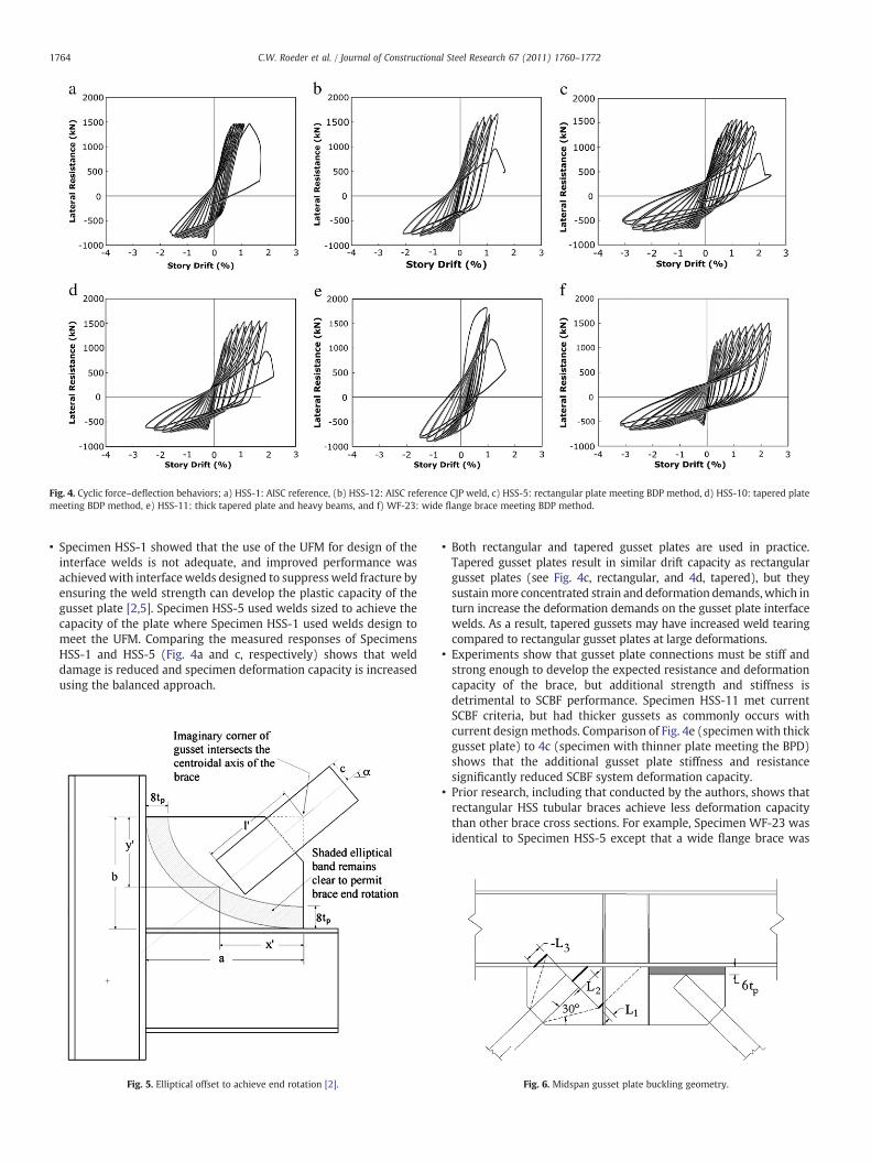
Fig. 4. Cyclic force–deflection behaviors; a) HSS-1: AISC reference, (b) HSS-12: AISC reference CJP weld, c) HSS-5: rectangular plate meeting BDP method, d) HSS-10: tapered platemeeting BDP method, e) HSS-11: thick tapered plate and heavy beams, and f) WF-23: wide flange brace meeting BDP method.
1764 C.W. Roeder et al. / Journal of Constructional Steel Research 67 (2011) 1760–1772
• Specimen HSS-1 showed that the use of the UFM for design of theinterface welds is not adequate, and improved performance wasachievedwith interfacewelds designed to suppress weld fracture byensuring the weld strength can develop the plastic capacity of thegusset plate [2,5]. Specimen HSS-5 used welds sized to achieve thecapacity of the plate where Specimen HSS-1 used welds design tomeet the UFM. Comparing the measured responses of SpecimensHSS-1 and HSS-5 (Fig. 4a and c, respectively) shows that welddamage is reduced and specimen deformation capacity is increasedusing the balanced approach.
Fig. 5. Elliptical offset to achieve end rotation [2].
• Both rectangular and tapered gusset plates are used in practice.Tapered gusset plates result in similar drift capacity as rectangulargusset plates (see Fig. 4c, rectangular, and 4d, tapered), but theysustainmore concentrated strain and deformation demands,which inturn increase the deformation demands on the gusset plate interfacewelds. As a result, tapered gussets may have increased weld tearingcompared to rectangular gusset plates at large deformations.
• Experiments show that gusset plate connections must be stiff andstrong enough to develop the expected resistance and deformationcapacity of the brace, but additional strength and stiffness isdetrimental to SCBF performance. Specimen HSS-11 met currentSCBF criteria, but had thicker gussets as commonly occurs withcurrent designmethods. Comparison of Fig. 4e (specimenwith thickgusset plate) to 4c (specimen with thinner plate meeting the BPD)shows that the additional gusset plate stiffness and resistancesignificantly reduced SCBF system deformation capacity.
• Prior research, including that conducted by the authors, shows thatrectangular HSS tubular braces achieve less deformation capacitythan other brace cross sections. For example, Specimen WF-23 wasidentical to Specimen HSS-5 except that a wide flange brace was
Fig. 6. Midspan gusset plate buckling geometry.

1765C.W. Roeder et al. / Journal of Constructional Steel Research 67 (2011) 1760–1772
used; in both cases the specimens met the BDP. Comparison ofFig. 4c and f shows that the specimen with the wide flange braceprovided greater deformation capacity.
These results show that the proposed BDP improved the ductilityand increased the inelastic deformation capacity of SCBF connections,while significantly delaying the undesirable failure modes.
Balanced design procedure (BDP)
The proposed BDP seeks to maximize yielding in and thereforedeformation of the systemwhile suppressing undesirable failure modes[4]. The BDP has similarities and differences with current designmethods. Table 1 provides an overview of the relevant resistanceexpressions for both the proposed BDP and the current AISC procedure.As evident in the table, the sameyieldmechanisms and failuremodes areused for both design procedures. Although there are other similarities,there are important, fundamental differences in the proposed BDPmethod. With both methods, the brace is sized using reduced seismicloads. Both use the expected plastic strength of the brace (Put and Puc) toquantify the demand on the gusset plate connections. Slenderness limitsand geometric requirements for all members are retained from thecurrent AISC Provisions [1]. The most important differences in the twomethods are that 1) the current procedure uses resistance factors todesign and detail the gusset platewhere the balance designmethod usesbalance factors to balance the yield mechanisms and failure modes tomaximize the drift capacity of the system, and 2) the balance factors arebased upon the inelastic deformation provided by themechanismratherthan predicted strength. In addition, there are differences in some of theresistance expressions, as shown in Table 1.
The BDP has the objective of developing a connection designmethodology to balance yielding of the brace and the gusset plate andmaximize system ductility. This is accomplished by balancing theresistances associated with the yield mechanisms, as illustrated inEq. (1):
Put orPucð Þ≤ βyield1RyRyield;1 ≤ βyield2RyRyield;2 ≤ βyield iRyRyield;i: ð1Þ
Eq. (2) is the failure mode balance procedure:
Ryieldmean = RyRyield b· βfail;1Rfail;1 b· βfail;2Rfail;2 and βyield b βfail: ð2Þ
In these equations, Ry is the ratio of the expected yield stress to thespecified yield stress and Ryield and Rfail are the nominal resistancevalues of the yield mechanism and failure mode in question,respectively. The hierarchy of yielding and prevention of undesirablefailure modes is achieved through the use of balance factors called beta(β) factors as shown within these expressions. These β factors appearsimilar to the resistance factors, φ, used in AISC LRFD design [5], but βfactors are based on achieving ductility and inelastic deformationcapacity rather than simply designing to achieve a specified strengthunder statistically extreme loads [4]. The failure mode resistanceexpressions do not include the material overstrength factors, Ry,because doing so would increase the likelihood of critical failuremodes and reduce the safety of the connection.
Each yield mechanism and failure mode has its own β factor,which was established using measured values from specimens thatachieved the target ductility and inelastic performance correspondingto the specified yield mechanism or failure mode. The subscripts 1, 2,3, etc. reflect the preferred sequence of yielding hierarchy andsuppressing of specific failure modes within the system. The β factorsare less than or equal to 1, and they are smaller for less desirable yieldmechanisms and failure modes. For example, the preferred yieldmechanism of gusset plate yielding has a βyield value of 1.0 whereundesirable failure modes have βfail values that are smaller than 1.0,because the consequence of these failures are more severe.
The results from the experimental research programswere used toestablish the β factors. Two sets of β factors (βdesign and βactual) werecomputed from the test results. Design β factors, βdesign, were basedon the nominal material properties, while actual β factors, βactual,were based upon actual material properties measured in coupon testsas illustrated in Eqs. (3) and (4).
βdesign = βd =PnomRnom
=Put orPuc½ �nom
Rnomð3Þ
βactual = βa =PactualRactual
=Put orPuc½ �actual
Ractual: ð4Þ
The βdesign values are appropriate for development of the BDP,because the design process is based upon nominalmaterial properties.However, βactual is considered, because differences between βactual
and βdesign illustrate the reserve capacity in the proposed procedure.The β factors were selected to maximize the inelastic deformationcapacity from the SCBF system, where the deformation capacity isdefined based upon the total drift range prior to initial failure obtainedfrom the test specimens. It is logical that the β factors will often belarger than the ϕ factors employed in LRFD design [5], because theseismic loads for the gusset plate are based upon Put and Puc, whichare much larger than the factored seismic design loads used formember design. The procedures and data used to establish theselection of β factors are provided in subsequent text.
Determination of balance factors
The predicted nominal yield and failure resistances, Ryield and Rfail,and associated β factors for welded connections are provided in Table 1.Their derivation is presented in this section. Although the resistanceequations for bolted connections are not explicitly described, the samedesign principles apply. Several experiments have been completed onbolted connections, and their performance was variable but sometimesquite good. However, the experimental data for bolted connections arelimited and therefore actual beta values were not derived.
Primary yield mechanism
The primary yield mechanism(s) for SCBF systems are tensileyielding and compressive buckling of the brace. The values of Put andPuc are the expected tensile andbuckling yield resistances, and thereforethey serve as the mean yield resistance, Ryield mean, in Eqs. (1),(2) and(3). The general dimensions of the gusset plate (dimensions a and b ofFig. 5) are selected to be the minimum required to accommodate thegeometry of the brace, the connection length of the brace to the gussetplate, and the elliptical clearance, rather than those recommended byUFM and other design provisions for AISC [1].
Secondary yield mechanism: gusset plate yielding
Controlled tensile yielding of the gusset plate is the preferredsecondary yield mechanism. The Whitmore width, Bw, is used toestimate the maximum nominal stress in these connections [6]. Themethod assumes a 30-degree angle relative to the length of theconnection as shown in Fig. 1. Fig. 7 shows the deformation capacityachieved in past experiments as a function of the gusset plate yielding βfactor (relative to the tensile capacity of the brace). Thisfigure comparesthe empirically derived beta factors to the measured maximumdeformation in order to derive all of the β factors. It should be notedthat each specimen has multiple variables, and this variability results inan increase in the scatter in the test results. However, the tests areexpensive, and there are insufficient test data to permit isolation of thevariables and therefore all available data were used in this evaluation.

Fig. 7. Design β factors for Whitmore yielding.Fig. 9. Design β factors for brace net section fracture.
1766 C.W. Roeder et al. / Journal of Constructional Steel Research 67 (2011) 1760–1772
Fig. 7 shows that the inelastic deformation capacity increases asthe β factor for gusset plate yielding approaches 1.0. This is consistentwith recent research results showing that yielding of the gussetfollowing brace yielding maximizes the drift capacity of the system[2]. Those results show that excess strength and stiffness of the gussetreduces the inelastic deformation capacity of the system [2].
Theβdesign values in Fig. 7 range from0.38 to 1.1. Data points that areenveloped in a square exhibited yielding over more than 50% of thesurface area of the gusset plate; on average these systems achievedgreater deformation capacities than the others. The figure also shows atrend where smaller β factor reduces the drift range. One specimen(HSS-15) had βdesign values that exceeded 1.0, but still achieved a framedrift range of approximately 4.1%without sustaining connection failure.This occurs because thinner gusset plates reduce the connectionstiffness and strain accumulations at the center of the brace, whichreduces the potential for brace fracture [2]. To encourage Whitmoreyielding of the gusset plate connection after brace yielding, a β factor of1.0 is recommended.
Brace net-section failure mode
The reducednet areaof the brace at the gusset plate jointmay lead tonet section fracture and is an issue in seismic design [25]. RectangularHSS tubes are commonly used as braces, and Fig. 8 illustrates the netsection adjacent to the brace-to-gusset interface, typical net sectionreinforcement and geometry for establishing the net effective area. TheAISC Specification [5] employs a resistance factor,ϕ, of 0.75using theneteffective area, Ae, where
Ae = UAn ð5Þ
which uses the correction factor U to account for non-uniform tensilestress due to shear lag, and
U = 1− xLc
ð6Þ
XC.G.
Agp
GussetAnb
Lc
Net Section ReinforcementA
ANet Section Fracture
Considered at Section A-A
Fig. 8. Net section evaluation for rectangular HSS brace.
where the variables are shown in the figure. This AISC proceduretypically requires significant net section reinforcement if applied toSCBF bracing.
Fig. 9 shows that only three (3) specimens had net-section damage(two sustained net section fracture); 10 specimens did not sustain netsection fracture although they did not have net-section reinforcementwith β factors greater than 1.0. Net-section fracture is preceded bylimited yield deformation. Further, the figure shows that larger βfactors increased system deformation capacity if net-section fractureis avoided. Nevertheless, net-section fracture is sudden and results incomplete loss of brace resistance and therefore must be avoided. Thetests suggest that net section fracture is more likely to occur when thebrace is subjected to cycles that results in large tensile strains and verysmall compressive strains which reflects the demand history thatmight be expected with near fault seismic events [23]. The datademonstrate that the recommended β factor of 0.95 is conservative tomitigate brace net-section fracture.
While the AISC LRFD ϕ factor is 0.75, a user note exceptionprovided in the AISC Seismic Provisions permits the use of theexpected tensile strength (RtFu) when evaluating the net sectionresistance. This exception is based on engineering judgment ratherthan experimental results. The Rt for ASTM A500 HSS tubes is 1.3, andso this exception implies an equivalent β value of 1.3 0.75 or 0.975.This research generally supports this practice.
Brace-to-gusset interface failure modes
Welds joining the brace to the gusset plate require consideration oftwo basic failure modes. The welds (or heat affected zone) joining thebrace to the gussetmay fracture or block shear failuremayoccur. For theproposed BDP, the AISC expressions for evaluating the resistance of theweld and base metal were adopted, as shown in Table 1. Although thisfailure mode was not observed in any test, the consequences of weldfailure are severe and over-strength of the welds had no adverse effecton SCBF performance. Therefore, the β factor for failure of the weld inthe basemetal and the fillermetal is 0.75, identical to the ϕ factors usedin AISC [1].
Block-shear failure may occur if the combined shear and tensilestress demand at the brace-to-gusset interface exceeds the capacityaround the perimeter of the joint. Block-shear resistance is thesummation of the capacity in tension (Ant), region adjacent to the endof the brace, and shear (Anv), as indicated by the resistance expressionprovided in Table 1. Design for block shear frequently controls theconnection design with the BDP, because the procedure encouragesthinner gusset plates. If the block-shear perimeter is shortened, theplate thickness will be controlled by block shear. Thick gusset plates

Fig. 10. Design β factors for block shear failure mode.
1767C.W. Roeder et al. / Journal of Constructional Steel Research 67 (2011) 1760–1772
may be required, and the resulting plate may be too stiff and strong toencourage yielding. Several specimens had βdesign values significantlylarger than the AISC ϕ factor, and block shear fractures or yield lines,both of which would suggest imminent problems, were not observed.Fig. 10 shows that ϕ=0.75 significantly underestimates the blockshear resistance for welded brace-to-gusset connections, and thatβactual is consistently smaller than βdesign value. As a result, a β factorof 0.85 was conservatively chosen to suppress block-shear failure, andit is expected that an even larger value may be possible for weldedjoints, however the limited test data to date does not permit thisincrease at present. Further, only a single equation considering blockshear fracture is employed, since yielding in the gusset is encouraged.Additional testing is required for bolted brace-to-gusset joints,because the boltholes may facilitate crack initiation and crack growthfor block shear failure.
Whitmore fracture failure mode
Whitmore fracture must be discouraged, because gusset platefracture causes a dramatic loss of lateral resistance. For this evaluation,the area associated the Whitmore width was again employed, and thefailuremodewas evaluatedwith respect to Put. Tensile fracture dependson the effective net section and ultimate tensile strength, Fu, of the plate,as shown in Table 1. Fig. 11 shows that increasing βd values for theWhitmore fracture failuremode led to larger drift ranges, andWhitmorefracture did not occur in any test nor were there any indications ofdistress or imminent problemswithβ factors as large as 0.9. Net-sectionfracture of the gusset was not sustained in any of the tests conducted to
Fig. 11. Design β factors for Whitmore fracture mode.
date. The resistance factor of ϕ=0.75 is used to compute tensilefracture. However for the BDP, a relatively conservative β factor of 0.85was chosen to calculate the Whitmore fracture resistance based uponthe test results. Additional experimental evaluation is warranted forbolted brace-to-gusset connections, because boltholes again impact thepotential for crack initiation in the gusset.
Gusset plate buckling
The gusset plate is checked for buckling relative to Puc of the brace.True buckling of the gusset plate, not out-of-plane bending to support theend rotation of the brace, concentrates the inelastic deformation anddamage to the connection preventing development of the inelasticcapacity of the brace. The Thorntonmethod is commonlyused to evaluategusset plate buckling [6,7]. This method uses a 30-degree angle forestablishing the area used for determination of the buckling capacity, anda average buckling length, Lavg, of the three buckling lengths (L1, L2, L3), asillustrated in Fig. 1a for a corner gussets and Fig. 6 for a midspan gussets.An effective length coefficient of 0.65 is proposed for the corner gussets.For mid-span gussets, a 6tp vertical clearance zone is employed from thetop of the brace to the beam flange, as shown in the right hand portion ofFig. 6. These clearancemodels often force the L1 or L3 length into thebeamor column web to cause a negative length as shown in Fig. 6, and thosenegative lengths are permitted to be used in calculating the averagebuckling length. TheTCBF-2experiments showed that the interior verticalstiffeners provide stability to themidspan gusset plate connectionswhilepermitting brace end rotation, and the buckling length, L1, in Fig. 6 isterminated at the vertical stiffener instead of extending it to the beamwith this midspan clearance model. However, a more conservativeeffective length coefficient of 1.5 is used for these midspan gussets,because sideway buckling is possible due to the reduced edge restraintprovided by the bottom flange of the beam. This recommendation isbased upon experimental results and nonlinear analysis [4,22,26]. Thismethodmayalsobeusedwitha single stiffener in themidspangusset, butmidspan connectionswithout vertical stiffeners are not recommended. Ineither case, once the Whitmore width and effective length of the gussetplate are established, the AISC column provisions are used to determinethe critical buckling stress (Fcr) as noted in Table 1.
The proposed BDP encourages thinner, more compact connections,which usually have shorter effective lengths relative to gusset platesdesign to meet the 2tp offset suggested in [1], and buckling is lesslikely to control their design. Significant gusset plate deformation wasnoted in all experiments, which is prescribed by both AISC and theBDP design methods, to accommodate the end rotations of thebuckling brace. Fig. 12 shows the βdesign values computed for thesetests. None of the specimens exhibited gusset plate buckling, andspecimens with larger β factors showed somewhat greater inelastic
Fig. 12. Design β factors for gusset plate buckling.

1768 C.W. Roeder et al. / Journal of Constructional Steel Research 67 (2011) 1760–1772
deformation capacity. However, the figure shows that these tests didnot place severe demands on the AISC buckling design provisions, andtherefore the balance factor, β, for gusset plate buckling is 0.9, whichis the same value as the ϕ factor for AISC LRFD compression memberdesign.
Interface welds
Experiments have demonstrated that welds joining the gusset plateto beams and columns are important to the ductility and deformationcapacity of the system [18–20]. Current AISC Seismic Provisions requirethat these welds be designed to develop the tensile force anddeformation capacities of the brace [1]. The UFM is commonly used toestablish thedemands on theweld corresponding to Put of the brace, butresearch shows that these welds are subjected to stresses anddeformations much larger than those predicted by the UFM. Further,crack initiation will occur at larger inelastic deformations [18–20]. TheUFM is an equilibrium method that was originally developed for windloading without consideration for inelastic deformation, and it wasadapted to current seismic design by designing for the expected Putrather than the factored design load. The UFM does not consider thestresses and strains caused by inelastic rotational demands due to braceend rotation and the opening and closingmoments at the beam-columnintersection and can underestimate the actual demand.
Cracking of theweld and the gusset plate adjacent to theweldsmuststill be expected after large brace bucklingdeformations and framestorydrifts [2]. Experiments show crack initiation at about 2% story driftregardless of the connectiondesign. Experiments show that these cracksshould remain stable, because demand critical weld metal is used andthis limits the rate and length of crack growth. Limited ductile tearing isnot detrimental to the performance and permits larger inelastic driftsunder these conditions. However, complete weld fracture must beprevented, and therefore the crack length must be controlled. Hence, inthe BDP, the gusset plate interface welds are designed to develop theexpected plastic capacity of the plate rather than Put of the brace. Thisdesign philosophy protects against interfaceweld fracture prior to bracefracture, while allowing for yielding and inelastic deformations of theplate. To accomplish this, a new resistance equation is proposed, asshown in Table 1. This equation employs the AISC tensile strength offillet welds but this capacity is compared to the tensile yield capacity ofthe gusset plate, rather than the tensile capacity of the brace, since thecyclic buckling of the brace induces cyclic yielding as the gusset platedeforms due to brace buckling end rotation and this demand can resultin weld cracking and failure.
Fig. 13 shows the measured inelastic deformation capacity of SCBFspecimens as a function of the βd for the interface welds. Several keyobservations can be made from this figure and observations from priorresearch [2,18–23]. Tapered gusset plates suffer greater crack damage
Fig. 13. Design β factors for interface weld failure mode.
than rectangular gusset plates. Rectangular gussets have materialoutside of the Whitmore width, which increases the weld resistanceand decreases the strain concentrated at the interface [20]. Wide flangebraces also cause greater damage to the gusset plate welds, becausewide flange braces sustain larger out-of-plane deformation demandsthan HSS tubes prior to brace fracture, and this increased deformationincreases the demands on the welds [21–23].
Fig. 13 also shows that specimens with a β value above 0.75, whichis the value of the AISC resistance factor, may sustain excessive weldtearing. Further, there is not a clear increase in ductility associatedwith larger β factors. One specimen (HSS-08) had a βd value belowthe 0.75 limit, and it experienced weld tearing that was beyondacceptable limits (weld tearingN60%). However, this specimen wasdesigned with a very tight 3tp elliptical clearance, which does notmeet the proposed BDP elliptical design clearance. The 3tp ellipticalclearance was deemed too small a clearance for the elliptical method,and thus is not recommended, because the close proximity of thebrace to the interface welds dramatically increases the demands onthe welds. Therefore, for the 8tp elliptical clearance as suggested bythe BDP, a β of 0.75 is adopted for the BDP.
Beam-column connection
The beam-column connection must also be designed. This designmust consider any diaphragm forces that are brought to the bracedframe through this connection. The authors recommend welded-webwelded-flange connections, because they provide better inelasticperformance. However, bolted-web welded-flange and shear plate(with free flanges) connections have been tested. The inelasticdeformation capacity of these connections was reduced, but thereduction was smaller than noted from other aspects of the gussetplate connection design.
Conclusions and design recommendations
A BDP for SCBF gusset plate connections is presented. The procedurepromotes ductility and inelastic deformation capacity of the SCBFsystem by balancing the resistances associated with the yieldmechanisms and the primary failure mode, while suppressing undesir-able failure modes to assure yielding from secondary mechanisms aswell as the primary yield mechanism, and while achieving the desiredfailuremode.A coordinated testingprogramhas shown that theBDPcangreatly increase the deformation capacity of an SCBF system [2]. Overall,SCBFswith rectangular gusset plates designed using the BDP showed anaverage 46% increase in drift range when compared with similarspecimens designed to meet the current SCBF specification. The benefitshown with tapered gusset plates was significant but smaller, becausetapered gusset plates have less reserve capacity and sustain greaterdamage than rectangular gussets at a given drift level.
The resistance equations and balance factors (β factors) for the BDPwere presented (see Table 1) and verified using experimental results.Values for the β factors were developed to encourage gusset plateyielding by ensuring the plate was not overdesigned but still hasadequate resistance to restrict undesirable failure modes. The values ofthe β factor and the current AISC ϕ factors are identical for gusset platebuckling and the interfacewelds. However, the design philosophies andresistance expressions are different in that the BDP sizes the weldsjoining thegusset plate to thebeamand columntodevelop theexpectedplastic capacity of theplate rather than for Put of thebrace by theUFM, asis required for the current specification. A β factor of 1.0 isrecommended for Whitmore yielding, and 0.85 is recommended forthe gusset plate fracture limit state. A factor of 0.95 is recommended fornet-section fracture of the brace, and a value of 0.85 is recommended forblock shear. These values are larger than the resistance factors currentlyused in SCBF gusset plate design, and they are recommended becausethey result in increased system ductility while preventing undesirable

1769C.W. Roeder et al. / Journal of Constructional Steel Research 67 (2011) 1760–1772
failure modes. The β factor of 0.95 for designing brace net-sectionreinforcement provides a rational basis for the 0.9 exception providedfor the ϕ factor in current AISC seismic design, and this value is alsoadopted as part of the BDP [1]. An additional yet equally important partof the design procedure is the clearancemodels for corner andmidspangusset plats. Two clearance models are proposed: 8tp elliptical and 6tpvertical clearance gusset plate clearances for corner and middle gussetplate, respectively, because they lead to thinner, more compact gussetplates, and permit increased deformation capacity from the system.These clearances delay initiation of interface weld tearing, and reducesecondary damage to the beam and column and improve construct-ability of the system. The resulting BDP will improve the deformationcapacity and predictability of the seismic performance of SCBFs.
Symbol definitionsAg and Agp Gross cross-sectional brace area of brace and reinforcing
plate, respectivelyAgv Gross area of brace in shearAnb Net area of braceBw Whitmore widthE Modulus of elasticityFcr Critical buckling stressFe Euler buckling stressFEXX Electrode strengthFu and Fy Yield and ultimate strength of steelK Effective length coefficientL Brace lengthLavg Average buckling lengthLc Brace-to-gusset connection lengthL1, L2, L3 Buckling lengths as defined in Figs. 1a and 5Ns Number of shear planesNw Number of weldsPuc and Put Maximum expected capacity of brace in compression and
tension, respectivelyRn Nominal resistanceRt and Ry Ratio of the expected to minimum specified ultimate
tensile and yield stress of steelU AISC Shear lag factorrx Radius of gyration about x-axistf Brace wall thicknesstp Gusset plate thicknessw1 Interface weld leg sizew2 Brace-to-gusset weld leg sizex ̅ Connection eccentricityφ Resistance factorβ Balance factorβa and βd Actual and design balance factors, respectively
Acknowledgments
This research was funded by the National Science Foundationunder grants CMS-0301792, Performance-Based Design of Concentri-cally Braced Frames and CMS-0619161, NEESR-SG InternationalHybrid Simulation of Tomorrow's Braced Frames. Supplementalfunding was provided by AISC. International testing, fabrication andcollaborationwere conducted at the NCREE Laboratory in TaiwanwithDr. Keh-Chyuan Tsai, Laboratory Director. Frequent advice andguidance were provided through the research Advisory Group,composed of Tom Schlafly (AISC), Tim Fraser (CANRON), WalterioLopez (Rutherford and Chekene), Larry Muir (CIVES) and RafaelSabelli (Walter P. Moore). The advice and financial support of theseindividuals and institutions are greatly appreciated.
Appendix A. Design example
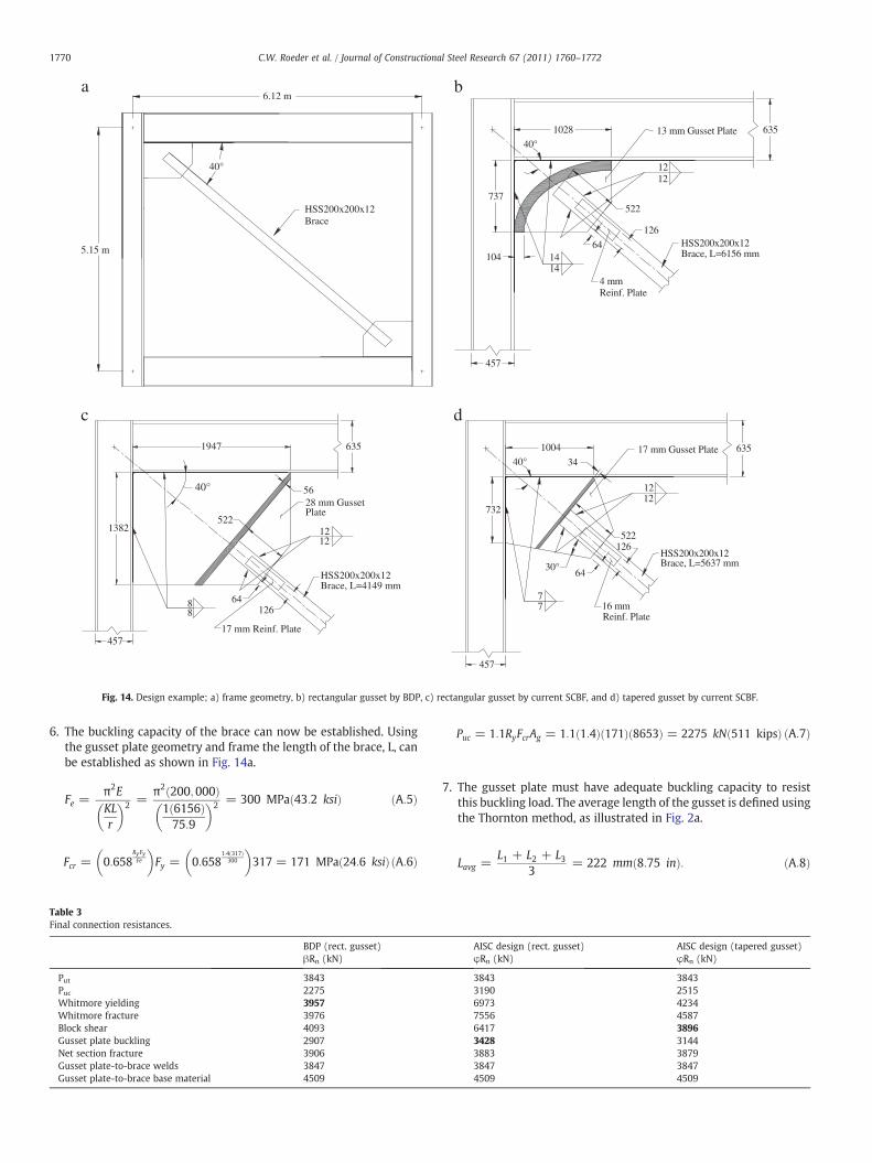
A design example is presented to illustrate the proposed BDP. Aswith current design methods, the structural members (brace, beamand column) are designed to resist factored loads. The illustrationemploys an HSS200x200x12 (HSS8x8x1/2) A500 Grade C rectangulartube for the brace. The brace is oriented at 40° to the horizontal, and itis connected to the W24x162 beam and the W14x370 column with acorner gusset plate as illustrated in Fig. 14a. The beam and columnmembers are A992 sections, and plates used in the example are A572grade 50 steel. The brace is connected to the framing elements withtwo identical corner gusset plates as shown in Fig. 14a. The finalgusset plate design for the BDP is presented in Fig. 14b. The associatedresistance values for each yield mechanism and failure mode arepresented in Table 3. The bold text in Table 3 identifies the controllingdesign criteria for that connection.
The design procedure is as follows:
1. Establish the expected yield capacity of the brace. The properties ofthe brace are Ag=8653 mm2 (13.5 in2) and rx=75.9 mm (3.04 in).The expected tensile capacity of the brace is: Put=RyFy Ag=1.4(317.2) 8653=3843 kN (864 kips).
2. Establish the brace-to-gusset connection. Here, a slotted connectionis usedwith four (4)filletwelds, as shown in Fig. 14b.With E-70filletwelds and a weld thickness equal to the thickness of the tube or12 mm, the connection length, Lc, is computed using the resistanceexpression from Table 1:
Lc =Put
β 0:6ð ÞFEXXNW :707ð Þw2
=3843
0:75 0:6ð Þ483 4ð Þ:707 12ð Þ = 522 mm 20:6 inð Þ
ðA:1Þ
3. A check of the brace base material is also made using theconnection length of 522 mm: Putb0.75 (0.6) Fu Ns Lc tf=0.75(0.6) 399.9 (4) 522 (12)=4509 kN (1013 kips), which is found tosatisfy the inequality.
4. Size the plate thickness to permit plate yielding after brace yieldingand restrict tensile rupture and block shear. The 522-mmconnection length is used to establish the Whitmore width, Bw,i.e., Bw=200+2 (522) tan30o=803 mm, The yield, tensilerupture and block shear requirements establish minimum gussetthickness, tp, follow:
tp≥Put
βRyFyAg=
38431:0 1:1ð Þ803 345ð Þ = 12:62 mm ðA:2Þ
tp≥Put
βFuBw=
38430:85 448ð Þ803 = 12:57 mm ðA:3Þ
tp ≤Put
β 0:6FuAgv + UbsFuB� �
≥ 38430:85f0:6 448ð Þ2 522ð Þ + 1 448ð Þ200Þ = 12:21 mm
ðA:4Þ
Tensile yielding controls and a 13-mm thickness is chosen.5. The 8tp elliptical clearance illustrated in Fig. 4 is used to size the
plan dimensions of the plate. This clearance can be derivedgraphically or by the approximate theoretical method derived in[2]. The gusset has a length of a=1038 mm adjacent to the beamand b=737 mm adjacent to the column.
6.12 m
5.15 m
40°
HSS200x200x12Brace
1028
737
635
457
522
126
13 mm Gusset Plate
4 mmReinf. Plate
1414
1212
64 HSS200x200x12Brace, L=6156 mm104
40°
ba
1947
1382
635
457
522
126
28 mm GussetPlate
17 mm Reinf. Plate
88
1212
64
HSS200x200x12Brace, L=4149 mm
40° 56
635
457
522126
17 mm Gusset Plate
16 mmReinf. Plate
77
1212
64
HSS200x200x12Brace, L=5637 mm
40° 34
1004
732
30°
dc
Fig. 14. Design example; a) frame geometry, b) rectangular gusset by BDP, c) rectangular gusset by current SCBF, and d) tapered gusset by current SCBF.
1770 C.W. Roeder et al. / Journal of Constructional Steel Research 67 (2011) 1760–1772
6. The buckling capacity of the brace can now be established. Usingthe gusset plate geometry and frame the length of the brace, L, canbe established as shown in Fig. 14a.
Fe =π2EKLr
� �2 =π2 200;000ð Þ1 6156ð Þ75:9
� �2 = 300 MPa 43:2 ksið Þ ðA:5Þ
Fcr = 0:658RyFyFe
� �Fy = 0:658
1:4 317ð Þ300
� �317 = 171 MPa 24:6 ksið Þ ðA:6Þ
Table 3Final connection resistances.
BDP (rect. gusset)βRn (kN)
Put 3843Puc 2275Whitmore yielding 3957Whitmore fracture 3976Block shear 4093Gusset plate buckling 2907Net section fracture 3906Gusset plate-to-brace welds 3847Gusset plate-to-brace base material 4509
Puc = 1:1RyFcrAg = 1:1 1:4ð Þ 171ð Þ 8653ð Þ = 2275 kN 511 kipsð Þ ðA:7Þ
7. The gusset plate must have adequate buckling capacity to resistthis buckling load. The average length of the gusset is defined usingthe Thornton method, as illustrated in Fig. 2a.
Lavg =L1 + L2 + L3
3= 222 mm 8:75 inð Þ: ðA:8Þ
AISC design (rect. gusset)φRn (kN)
AISC design (tapered gusset)φRn (kN)
3843 38433190 25156973 42347556 45876417 38963428 31443883 38793847 38474509 4509

1771C.W. Roeder et al. / Journal of Constructional Steel Research 67 (2011) 1760–1772
The buckling capacity of the gusset plate is compared with theplastic bucking strength of the brace. The results show that the 13-mm plate is sufficient.
KLavgr
=0:65 222ð Þ13 =
ffiffiffiffiffiffi12
p = 38:5 ðA:9Þ
Fe =π2E
KLavgr
� �2 =π2 200;000ð Þ
38:52 = 1332 MPa 191:6 ksið Þ ðA:10Þ
Puc ≤ β Bwð Þtp Fcrð Þ = 0:9 803ð Þ13 0:6583451332
� �345 = 2907kN 653kipsð Þ
ðA:11Þ
8. The next step is to design the interface welds, i.e., the welds joiningthe gusset plate to the beam and column, to develop the plasticcapacity of the gusset plate. Therefore,
w1≥RyFytp
2 1:2ð Þβ 0:6ð ÞFEXX 0:707ð Þ
=1:1 345ð Þ13
2 1:2ð Þ 0:75ð Þ 0:6ð Þ483 0:707ð Þ = 13:37 mm
ðA:12Þ
The design specifics 14-mm fillet welds on each face of the plateover the full length of the interface (Fig. 14).
9. The final step is to design the net section reinforcement at the tip ofthe slot in the HSS tube. This reinforcement will be placed as a flatplat attached to each flange as shown in Fig. 14b. The workable flatarea on the top of the brace, upon which the net sectionreinforcement is place including the dimension for the filletwelds, is approximately 146-mm wide. Therefore, a 126-mmwide plate will be used with 10 mm free on each side to place filletwelds. The slot in the brace will be cut 5 mm thicker than thegusset plate thickness for ease of erection, and the length of thereinforcement will be taken as the same length as the brace-to-gusset connection (522 mm).
Anb = 8653−2 13 + 5ð Þ12 = 8222 mm2 ðA:13Þ
Agp = 126 4ð Þ2 = 1008 mm2 ðA:14Þ
U = 1− xL= 1−67:9
522= 0:87 ðA:15Þ
Put = 3843≤ βU RtbFubAnp + FupAgp
� �
= 0:95 0:87ð Þ 1:3 400ð Þ8221 + 448 1008ð Þ½ � = 3906kN
ðA:16Þ
The condition is met, and the 4 mm×126 mm reinforcing plate isadequate for net section reinforcing.
To serve as a comparison, an AISC-designed rectangular andtapered gusset plates are also presented in Fig. 14c and d. Thecalculations for these SCBF designs are not provided but typical resultsare tabulated in Table 3. The balanced design rectangular gusset ismore compact than a comparable rectangular plate designed by theBDP. More importantly, the connection design is governed by theWhitmore yielding limit state, which encourages gusset plate yieldingand is beneficial at increasing system deformation capacity. Fig. 14cshows that the current SCBF criteria results in extremely large anduneconomical rectangular gusset plate because of the geometricconstraints imposed by the UFM and the 2tp linear clearance model.The thickness of the plate is almost twice that of the plate designed bythe BDP. Further, the welds joining the gusset to be beam and columnare sized to develop the expected tensile resistance of the brace rather
than the capacity of the gusset plate, and research has shown that thismay lead to premature weld fracture [2]. The difference in the weldsize is notable; 7 mm for the AISC-compliant design; 14-mm for theweld design to meet the BDP. Differences are also notable in the netsection reinforcement, for which the AISC-compliant net sectionreinforcement is approximately 2.5 times the thicker than the BDP.
The plan geometry of the tapered gusset plate in Fig. 14d iscomparable to the gusset in Fig. 14b, but the welds joining the gussetto the beam and column are sized to the expected tensile capacity ofthe brace rather than the plastic capacity of the gusset, and prematureweld fracture may occur. The tapered gusset is thicker and providesgreater resistance to brace end rotation. The current SCBF gussetdesigns result in shortened brace lengths and large connections inwhich the gusset plate thickness must be increased to satisfy thebuckling limit state. These factors result in stiffer and less ductileconnections [2]. It should be noted that edge buckling or edgestiffeners were not considered in these AISC or BDP designs, becauseprior research shows that the measured buckling capacity of gussetplate connections varies between 0.25 and 8 times the capacitypredicted for edge buckling [27].
References
[1] American Institute of Steel Construction (AISC). Seismic provisions for structuralsteel buildings. AISC/ANSI Standard 341-08; 2005. Chicago.
[2] Lehman DE, Roeder CW, Herman D, Johnson S, Kotulka B. Improved seismicperformance of gusset plate connections. Journal of Structural Engineering, ASCE2008;134(6):890–901.
[3] Prahuangsit D, Goel SC, Hanson RD. Axial hysteresis behavior with end restraints.Journal of the Structural Division ASCE 1978;104(6):883–96.
[4] Roeder, C.W., Lehman, D.E., and Yoo, J-H. “Improved seismic design of steel frameconnections.” International Journal of Steel Structures, Korean Society of SteelConstruction, 5(2), 141–153, Seoul.
[5] American Institute of Steel Construction (AISC). Steel Construction Manual13thEd. ; 2005. Chicago.
[6] Whitmore RE. Experimental investigation of stresses in gusset plates, a thesissubmitted in partial fulfillment of theMS degree. Knoxville, Tennessee: University.of Tennessee; 1952. MS.
[7] Thornton WA. On the analysis and design of bracing connections. Proceedings,1991 National Steel Construction Conference, AISC, Section, 26; 1991. p. 1–33.
[8] Bjorhovde, R., and Chakrabarti, S.K. Test of full size gusset plate connections,Journal of Structural Engineering, ASCE, 111(3), 667–684.
[9] Brown VLS. Stability of gusseted connections in steel structures, a dissertationsubmitted in partial fulfillment of the PhD. Department. of Civil Engineering.Delaware: Univ. of Delaware; 1998.
[10] Cheng JJR, Yam MCH, Hu SZ. Elastic buckling strength of gusset plate connections.Journal of Structural Engineering, ASCE 1994;120(2).
[11] Grondin GY, Nast TE, Cheng JJR. Strength and stability of corner gusset platesunder cyclic loading. Proceedings, Annual Technical Session and Meeting.Structural Stability Research Council; 2000.
[12] Hu SZ, Cheng JJR. Compressive behavior of gusset plate connections. StructuralEngineering Rep. No. 153. Canada: Univ. of Alberta; 1987.
[13] Rabinovitch JS, Cheng JJR. Cyclic behavior of steel gusset plate connections.Structural Engineering Rep. No. 191. Canada: University of Alberta; 1993.
[14] YamMCH. Compressive behavior and strength of steel gusset plate connections, athesis submitted in partial fulfillment of Doctor of Philosophy degree. Canada:University of Alberta; 1994.
[15] Yam MCH, Cheng JJR. Behavior and design of gusset plate connections incompression. Journal of Constructional Steel Research 2002;58(5–8):1143–59Elsevier.
[16] Tremblay R, Archambault RM-H, Filiatrault A. “Seismic response of concentricallybraced steel frames made with rectangular hollow bracing members”, ASCE.Journal of Structural Engineering 2003;129(12):1626–37.
[17] Uriz P, Mahin S. Seismic performance of concentrically braced steel framebuildings. Proceedings, 13th World Conf. on Earthquake Engineering; 2004. Paper1639.
[18] Johnson S. Improved seismic performance of special concentrically braced frames,a thesis submitted in partial fulfillment of the MS degree. Seattle: University. ofWashington; 2005.
[19] Herman D. Further improvements on and understanding of SCBF systems, a thesissubmitted in partial fulfillment of theMS degree. Seattle: University of Washington;2006.
[20] Kotulka BA. Analysis for a design guide on gusset plates used in specialconcentrically braced frames, a thesis submitted in partial fulfillment of the MSdegree. Seattle: University of Washington; 2007.
[21] Clark KA. Experimental performance of multi-story X-brace systems, a thesissubmitted in partial fulfillment of theMS degree. Seattle: University of Washington;2009.

1772 C.W. Roeder et al. / Journal of Constructional Steel Research 67 (2011) 1760–1772
[22] Lumpkin EJ. Enhanced seismic performance of multi-story special concentricallybrace frames using a balanced design procedure, a thesis submitted in partialfulfillment of the MS degree. Seattle: University of Washington; 2009.
[23] Powell JA. Evaluation of special concentrically braced frames for improved seismicperformance and constructability, a thesis submitted in partial fulfillment of theMS degree. Seattle: University of Washington; 2010.
[24] Applied Technology Council. Guidelines for Testing Steel Components, ATC-24.Redwood City CA: Applied Technology Council; 1992. 57 pp.
[25] Fell BV, Kanvinde AM, Deierlein GG, Myers AT, Fu X. Buckling and fracture ofconcentric braces under inelastic cyclic loading. Structural Steel Educational Council;2006.
[26] Roeder, C.W., Lehman, D.E., Clark, K., Powell, J., Yoo, J-H, Tsai, K-C, Lin, C-H, andWei, C-Y. Influence of gusset plate connection and braces on seismic performanceof X-braced frames, Earthquake Engineering and Structural Dynamics, Vol. 40, No. 4,pgs 355–74, Wiley.
[27] Roeder CW, Lehman DE, Yoo J-H. Performance based seismic design of bracedframe connections. Proceedings, 7th Pacific Structural Steel Conference, LongBeach, CA; March 24–27 2004.
Copyright © 2022 FDOKUMEN