Reliability Analysis of Serviceability Limit State for Braced ...
Upload
independentCategory
view
1download
0
Journal of Constructional Steel Research 72 (2012) 130–142
Contents lists available at SciVerse ScienceDirect
Journal of Constructional Steel Research
The collapse behaviour of braced steel frames exposed to fire
Ruirui Sun a,⁎, Zhaohui Huang b, Ian W. Burgess c
a Department of Civil and Structural Engineering, the University of Sheffield, Sheffield, S1 3JD, UKb School of Engineering and Design, Brunel University, Uxbridge, Middlesex, UB8 3PH, UKc Department of Civil and Structural Engineering, the University of Sheffield, Sheffield, S1 3JD, UK
⁎ Corresponding author. Tel.: +44 114 2225726; fax:E-mail address: [email protected] (R. Sun).
0143-974X/$ – see front matter © 2011 Elsevier Ltd. Aldoi:10.1016/j.jcsr.2011.11.008
a b s t r a c t
a r t i c l e i n f oArticle history:Received 25 July 2011Accepted 22 November 2011Available online 14 December 2011
Keywords:Progressive collapse mechanismSteel-framed structureBracing systemFire scenariosForce redistribution
Progressive collapsemechanisms of braced two-dimensional steel-framed structures, subjected to fire heating, areinvestigated using a robust static–dynamic procedure developed by the authors. 20 cases have been analysed toprovide a comprehensive view of the mechanisms of progressive collapse for these frames, with different bracingsystems under different fire conditions. The influences of stiffness and strength of the bracing systems are also ana-lysed. The results indicate that the pull-in of columns is one of the main factors which generate progressive col-lapse. Horizontal “hat truss” bracing systems have limited capacity to avoid pull-in of columns supporting theheated floor, although they can directly redistribute the vertical load lost by buckling columns to adjacent columns.On the other hand, vertical bracing systems have the effect, not only of increasing the lateral restraint of the frame,which reduces the pull-in of the columns, but also of effectively preventing the collapse progressing from local toglobal. Stronger vertical bracing systems can redistribute load from a buckled column to its surrounding structuralmembers. Frameswith a combinedhat and vertical bracing system can be designed to enhance the capability of theframe as much as possible to prevent progressive collapse when a heated column buckles.
© 2011 Elsevier Ltd. All rights reserved.
1. Introduction
The robustness of structures in extreme accidental or maliciousloading conditions, such as fire and explosion, is a major considerationfor building designers. Robustness is strongly related to the inherentproperties of a structure, such as redundancy, ductility and joint charac-teristics. Structural redundancy is described as the degree of static inde-terminacy of a system, and is equivalent to the number of internal andexternal constraints beyond those which are necessary to prevent thestructure from becoming a mechanism. This is not always true, becauselocal mechanisms may formwhilst the remainder of a structure is stat-ically indeterminate. Redundancy allows structures to transfer theirloads to their supports through a variety of different load paths. Whenone or more elements of the structure have failed, the forces previouslycarried by these elements can be transferred to the stiffer parts of adja-cent structure to prevent either a local or global failure [1]. The redun-dancy of the structure also controls the number of plastic hingeswhich need to form in the structure to enable structural collapse [2].The concept of structural redundancy is widely used in seismic design,because of its positive effects on structural resistance to earthquakeforces. The concept can also be applied to the design against progressivecollapse of steel and composite frames under fire conditions. Bracingsystems, most commonly used to resist wind loading, can also be effi-cient measures against the lateral loads induced in a building due to
+44 114 2225700.
l rights reserved.
seismic forces. They induce extra redundancy into framed structures,improving their capacity to prevent progressive collapse.
Several researchers have recently studied the potential of bracedframes to prevent progressive collapse. Khandelwal et al. [3] investigat-ed the progressive collapse resistance of steel frames with concentricand eccentric bracing. Jinkoo Kim et al. [4] studied the progressive col-lapse performance of braced frames with various bracing configura-tions, in the aftermath of accidental loss of a vertical element, usingstatic push-down analysis and nonlinear time-history dynamic analysis.In themain, research [5–7] on progressive collapse of framed structureshas focused on the ‘missing column’ scenario, in which the critical col-umn is removed, without specifically considering the causes or the se-quence of events leading up to this situation. However, in many casestheway a structure collapseswill depend on the exact nature of the pro-gression of intermediate events, each involving local damage, startingwith some triggering event. In a fire situation, many elements of thestructure may be heated simultaneously, so that the failure sequencemay be critically affected by the weakening which has taken place inthese parts. The main objective of this study has been to investigatethe collapse mechanisms in fire situations of steel moment-resistingframes (MRF), fitted with different bracing systems.
2. Background of Vulcan
2.1. Elements developed in the Vulcan
This study was conducted using the computer programme Vulcan,which has been developed [8–13] at the University of Sheffield for

20°C
100°C200°C
300°C400°C
500°C
600°C
700°C
800°C
Strain (%)0 0.5 1.0 1.5 2.0
F/F
y20
0.3
0.6
0.9
1.2
Fig. 1. Stress–strain curves of structural steel at elevated temperatures [14].
131R. Sun et al. / Journal of Constructional Steel Research 72 (2012) 130–142
many years. In this programme steel-framed composite buildings aremodelled as assemblies of finite beam–column, connection and lay-ered floor slab elements. The beam–columns are represented by 3-noded line elements with two Gaussian integration points alongtheir length [9]. In order to allow for different thermal distributionsacross member cross-sections, and the thermal strains and changesof material properties that accompany these temperatures, thecross-section of the beam–column element is divided into a matrixof segments; each segment can then have its own material, thermaland mechanical properties and its own temperature at any stage ofan analysis. The more complex aspects of structural behaviourunder fire conditions, such as thermal expansion and material degra-dation at elevated temperatures, are considered. The non-linearstress–strain relationship of each steel segment at any temperatureis considered. Both geometric and material nonlinearities are takeninto account. Hence, Vulcan is capable of performing inelastic buck-ling analyses of steel frames in fire.
2.2. Mechanical properties of steel at elevated temperatures
In Vulcan the models proposed in Eurocode 3 Part 1.2 [14] forstress–strain relationships, and thermal expansion of steel at elevatedtemperatures are adopted. Fig. 1 shows a set of normalised stress–strain curves for structural steel at elevated temperatures. The reduc-tion factors for proportional limit, Young's modulus and yield stress ofsteel at different temperatures are presented in Fig. 2. According to
Temperature(°C)0 300 600 900 1200
0.25
0.50
0.75
1.00
0
Reduction Factor
Yielding Strength
Young’s Modulus
Proportional Limit
Fig. 2. Reduction factors for proportional limit, Young's modulus and yield stress ofsteel at different temperatures [14].
Eurocode 3 Part 1.2 the averaged coefficient of thermal expansion ofsteel is 1.4×10⁻⁵/°C. Creep of steel may be of importance in fire con-ditions, but its effect is included implicitly in the stress–strain rela-tions provided by Eurocode 3 Part 1.2.
2.3. Formation of plastic hinges within steel frame
As mentioned above, there are two Gaussian integration pointsalong the length of each beam–column element, and so no morethan two “plastic hinges” can be formed within any beam–column el-ement. During the analysis, the plasticity of each segment within anelement is assessed at the two Gaussian integration points. A segmentis defined as having yielded when the total stress resulting frombending and axial force is greater than the yield strength of steel.Hence, gradual plastification throughout the segments within thecross-section can be simulated. A full plastic hinge is formed whenall segments within the cross-section have yielded. Hence, the influ-ence of interaction between axial force and moment on the formationof plastic hinges can be properly simulated in the analysis. It shouldbe noted that the concept of a “plastic hinge” works particularlywell for steel at ambient temperature, when elastic and yielded be-haviour is well-defined and discontinuous. At high temperatures itsstress–strain curves become highly curvilinear, and so the concept isless well-defined, with different stress levels being achieved in differ-ent segments in a more or less continuous fashion.
2.4. Static–dynamic procedure
In order to analyse structures up to complete collapse in fire, it isimportant to make sure that the simulation can be conducted untilfinal global structural failure happens. However, when using a con-ventional static procedure an analysis will often encounter a fatal sin-gularity in its stiffness matrix when one or more structural membersfail or buckle locally. In order to overcome this shortcoming, a static–dynamic procedure has been developed recently by the authors[15–17]. In this procedure, the static and dynamic analyses are usedalternatively, to cover stable and unstable states of the structurebeing analysed. The static analysis has the advantage of computation-al efficiency when the structure is stable. Once structural stability islost, however, the dynamic procedure is activated automatically, ana-lysing the motion of the structure. If stable equilibrium of the struc-ture is capable of being regained during the analysis, the staticprocedure is triggered once again. The analysis maintains this se-quence until final global failure of the structure is identified as a di-vergent motion which does not re-stabilize. This developmentextends the capability of the Vulcan software so that it is capable offollowing a sequence of structural response, from static equilibriumthrough local instabilities and global progressive collapse underambient-temperature or fire conditions.
An explicit integration method is adopted in the dynamic proce-dure. This has the benefit of avoiding convergence-checking, and istherefore less time-consuming within each time step. In this proce-dure the general equation of motion can be expressed as:
M€u þ C _u þ F uð Þ ¼ Q tð Þ ð1Þ
whereM is the mass matrix, C is the damping matrix, F(u) is the inter-nal force vector and Q(t) is the external force vector; u, _u and €u arethe displacement, velocity and acceleration vectors, respectively. Inthe explicit dynamic procedure, central difference integration isused to integrate the equations of motion explicitly over time. Byusing the kinematic conditions at the current increment i the kine-matic conditions at the next time increment (i+1) can be calculated.That is:
_uniþ1=2 ¼ _un
i−1=2 þ Δti €uni ð2Þ

Read in model
Static Analysis with Temperature Rising
Numerical Singularity?
Explicit Dynamic Analysis
Re-stabilization?
Yes
No
No
Yes
Fig. 3. Flowchart of the combined static–dynamic procedure.
Fig. 5. MRF with hat truss bracing.
132 R. Sun et al. / Journal of Constructional Steel Research 72 (2012) 130–142
uniþ1 ¼ un
i þ Δtiþ1=2 €uniþ1=2 ð3Þ
where uin and _un
i are the displacement and velocity degrees offreedom n at i-th time step, Δti is the time step and the subscript i re-fers to the increment number of the time step, and Δti+1/2=(Δti+Δti+1)/2. This particular implementation has been validated usingseveral practical cases [15–17]. The explicit dynamic procedure isdeveloped in detail in Ref. [15].
This combined static–dynamic model can be utilised to allow astructural analysis to continue beyond the temporary instabilitieswhich often cause singularities in fully static analyses. The automaticswitch between static and dynamic analysis makes Vulcan a powerfultool to investigate mechanisms of progressive collapse of structuresgenerated by the local failure of components. The criterion for trigger-ing the dynamic analysis is failure to converge of the static analysis;whilst the switch from dynamic analysis back to static analysis de-pends on the kinetic energy of the structure. If the increase of kineticenergy is relatively small compared to the internal energy, whichmeans that the velocity of movement is becoming very small, thestatic analysis will be activated. Fig. 3 shows the flowchart of the com-bined procedure.
3. Details of frames studied and fire scenarios
3.1. Frames studied
The main objective of this paper is to investigate the influence ofbracing systems on the collapse mechanisms of steel frame in fire.
5×6m
4×3.
6m
Fig. 4. The Moment-resisting frame used in studies.
Hence, taking into account both computational efficiency and struc-tural representation, the authors decided to perform the analyses onthe 2D primary MRF shown in Fig. 4. Clearly, the 2D model does notconsider the potential benefits of redistribution of forces to out-of-plane members and floor slabs. However, the main reasons for usingthe 2D model are as follows. Firstly, the planar frame studied is a rep-resentative primary frame, which is a vital part of the load-bearingand sharing mechanism. Secondly, the main concern of the study isto investigate theoretically the effectiveness of bracing systems inpreventing frame collapse, rather than in modelling realistic structur-al behaviour. Of course, high computational cost is a major concernwhen using 3D analysis for parametric studies of the kind conductedin this paper. It is well known that floor slabs can play an importantrole in enhancing the robustness of structures. For example, tensilemembrane action developed within floor slabs at high deflectionscan considerably increase the structure's load capacity. The 3Dmodel is out of the scope for this study, but the robustness of 3Dstructures, including their floor slabs, against progressive collapse infire, is currently under investigation.
In this study the connections between beams and columns are as-sumed to be rigid, and the connections between bracing membersand beam–column members are assumed to be pinned. Hence thefailure and fracture of connections were not taken into account inthe analyses. Although several idealising assumptions have beenmade the study gives an insight into the function of bracing systemsin redistributing the forces within the steel frame after the heated col-umns fail.
The frame without bracing is firstly analysed under different fireconditions, and then two basic bracing systems are installed. Theseare a “hat truss” (Fig. 5) and a vertical bracing system (Fig. 6); the be-haviour of these braced frames under different fire scenarios is alsoinvestigated. The main aims are: (1) to study the influence of eachof the different bracing systems on the collapse mechanisms of
Fig. 6. MRF with vertical bracing.

Table 1Cross-sections of beams and columns in the MRF.
Storey Column section(edge)
Column section(internal)
Beam section
Ground floor UC 203×203×60 UC 254×254×73 UB 356×171×57First floor UC 203×203×46 UC 203×203×71 UB 356×171×57Second floor UC 203×203×46 UC 203×203×71 UB 356×171×57Third floor UC 152×152×37 UC 203×203×52 UB 356×171×57
C1 C2
Fire1
C3
Fire2
B1
Axis ofsymmetry
Boundary Conditionon Symmetric line
Fig. 8. Unbraced MRF under different fire scenarios.
1000
1200
A
133R. Sun et al. / Journal of Constructional Steel Research 72 (2012) 130–142
MRF; (2) to assess the benefits of using bracing systems to preventprogressive collapse of MRF.
The MRF used was designed according to Eurocodes [18,19]. Asshown in Fig. 4 the frame has 4 storeys, with 3.6 m inter-storey heightand 5 bays with 6.0 m span. The spacing of successive frames is as-sumed to be 6.6 m. The loading conditions for a typical office buildingare assumed as: Permanent load=3.5 kN/m2; Variable load=5 kN/m2. Hence, the total line load at fire limit state is 40 kN/m. The sectionsizes of the beam and column members are listed in Table 1. Grade 43steel, with yield strength of 275 N/mm2 and Young's modulus of210 kN/mm2 at ambient temperature, is used for both beams and col-umns. The steel material properties at elevated temperatures are de-graded according to Figs. 1 and 2.
For a braced frame the bracing system should be designed to resistanticipated lateral loadings, such as wind and earthquake. In thisstudy an inverted-V bracing system is adopted. Since the main con-cern is the effect of bracing on progressive collapse of the MRF, thecross-sections of all bracing members are assumed to be identical.Rectangular hollow sections (RHS 120×80×10) are used for all brac-ing members.
3.2. Fire scenarios
The Standard Fire Curve is widely used in assessing the structuralbehaviour of isolated members in furnace tests. However, the Stan-dard Fire does not represent any realistic building fire condition; amajor defect is that it has no cooling phase. The differences in theheating rates and duration between the Standard and real fires canresult in very different structural behaviour. Parametric fire curves[20], defined as simple models of natural post-flashover compartmentfires, take into account the compartment size, fuel load density, ven-tilation conditions and the thermal properties of compartment wallsand ceilings. Hence they give more realistic estimations of real fireconditions, for defined compartments, than the Standard Fire. In thisstudy a parametric fire curve is used to simulate the fire developmentin a compartment. Fig. 7 shows the temperature–time curves for thecompartment fire and the unprotected beams and columns exposedto it. The columns are assumed to be uniformly heated across theircross-section. Considering the influence of the composite slab onthe temperature distributions within the beams, it is assumed thatthe temperature of the top flange of a heated beam is 70% of the
0
200
400
600
800
1000
0 20 40 60 80 100 120
Tem
per
atu
re(°
C)
Time(min)
Fire Temperature
Temperature of Column
Temperature of the bottom flange of beams
Fig. 7. Temperature curves for the compartment fire, unprotected beams and columns.
(common) temperature of the bottom flange and web. The fire com-partment is located in different parts of the frame in order to investi-gate whether this has an influence on the frame's behaviour. Thetemperature history shown in Fig. 7 is assumed for all fire compart-ment locations.
4. Progressive collapse resistance of Moment Resistant Frame
4.1. Behaviour of the unbraced MRF under different fire scenarios
Fig. 8 shows the two ground-floor fire scenarios (Fire 1 and Fire 2)used in this study. In order to save computing time only the half of theframe is analysed, assuming symmetry about the axis shown in thefigure. Fire 1 is a fire occurring in an edge bay and Fire 2 representsa fire in the central bay. The temperature histories of the heatedbeam and column shown in Fig. 7 are used.
4.1.1. Edge bay fire (Fire 1)Fig. 9 shows the axial forces in the columns under the influence of
Fire 1. In this case the heated columns C1 and C2 expand as their tem-perature increases. Since expansion of the columns is restrained bythe surrounding members, additional compression forces are devel-oped in these columns in the early heating stages. It can be seenthat Column C2 experiences the larger compression force, becauseof the higher restraint provided by the structure above this column.In the heating phase, the compression force in this column increases
0
200
400
600
800
0 100 200 300 400 500 600 700
Fo
rce(
KN
)
Temperature(°C)
C1 C2
C3 Average
Fig. 9. Axial forces in the columns under Fire 1.

(b) 657°C (c) 657°C(a) 495°CPlastic Hinge
Fig. 10. Failure process of MRF under Fire 1.
134 R. Sun et al. / Journal of Constructional Steel Research 72 (2012) 130–142
until its high-temperature buckling load is reached (Point A shown inFig. 9) when its temperature is 495 °C and its axial compression forcehas increased to more than 1100 kN. The compression forces in col-umns C1 and C3 reduce gradually as C2's force is increasing. However,the average force of the three columns stays constant, because thetotal externally-applied vertical load stays constant.
On heating beyond its buckling load the axial force in Column C2starts to decrease, and the forces in columns C3 and C1 both increase.When the compression force in the heated outer column C1 reachesits buckling load (at about 657 °C) it starts to buckle. Plastic hingesthen form at the ends of the beams in the adjacent bay, as shown inFig. 10(b). At this point the frame is unstable because of the formationof these plastic hinges (Fig. 10(c)). It is clear that after the buckling ofcolumns C1 and C2, the forces supported by these columns are trans-ferred to other bays only by the beams in the adjacent bay. Thesebeams act essentially as cantilevers at this stage, and plastic hingesare formed at their ends. In this case, after the heated columns havebuckled, the basic frame lacks an effective load-transfer mechanismto redistribute the load shed by buckled columns to the surroundingstructure. Hence, two bays of the frame collapse.
4.1.2. Central bay fire (Fire 2)When the fire occurs in the central bay of the frame, Fig. 11 shows
the forces in the columns C1, C2 and C3, plotted against temperature.It can be seen that the compression force in Column C3 increases dur-ing the initial heating stage, until its buckling load (Point B in the
0
200
400
600
800
1000
1200
1400
1600
0 200 400 600
Fo
rce(
KN
)
Temperature(°C)
C1 C2
C3 Average B
Fig. 11. Axial forces in the columns under Fire 2.
figure) is reached at 508 °C. Beyond this point its compression forceis reduced. This causes little change to the compression force in Col-umn C1. Most of the load-transfer is from C3 to C2. The frame staysstable until plastic hinges have formed (at 640 °C) at the ends of allbeams adjacent to Column C3 (Fig. 12(c)). At this point complete col-lapse of the frame occurs.
From the development of plastic hinges shown in Fig. 12, it is ev-ident that the failure spreads to the adjacent spans after the failure ofthe heated Column C3. Because of the large vertical displacements ofthe columns above Column C3, plastic hinges form at the ends of thebeams framing into these columns from the adjacent spans. Fig. 13shows the change of moment and axial tension force at the end ofBeam B1 as its displacement grows. The normalised ratios M/Mp andT/Ty represent the changes of moment M and tension force T causedby the vertical displacement of the top of Column C3.Mp is the plasticmoment of the beam section and Ty is the axial tensile yield strengthof the beam. In the figure the factor T/Ty is amplified 10 times in orderto show clearly the development of the axial tension force. FromFig. 13, three stages can be identified as:
(1) Stage o–a: After the buckling of Column C3, the moment at theend of the beam increases significantly to form a plastic hinge.However, the axial tension force is almost kept constant.
(2) Stage a–b: The axial tension force in the beam increases steadi-ly due to the catenary action. At the same time the moment atthe end of the beam remains almost unchanged.
(3) Beyond point b: The large axial tension force in B1 pulls inwardthe columns at the edge bay. As a result, the axial force in thebeam decreases, whilst the columns are pulled in.
It can be concluded that the load-redistribution capacity and later-al restraint provided by the frame are two important factors which af-fect the robustness of the structure against progressive collapse infire.
4.2. Behaviour of MRF with “hat truss” bracing system in fire
Prevention of the spread of failure initiated by local instability isthe key to ensuring structural resistance to progressive collapse; re-dundancy is very important for this purpose. The high redundancyprovided by additional vertical and lateral bracing systems could bea major advantage in guarding against progressive collapse. Thiscould ensure that, when localised damage occurs in any structural el-ement, re-distribution of internal forces is possible, and progressivecollapse can be prevented. It is believed that a locally heated framemay progressively fail, eventually generating an overall instability,unless it has sufficient force redistribution capability to continue car-rying its vertical loading when the original load path is compromised.

C3C2C1
B1
(b) 508°C (c) 640°C(a) 20°C
Fig. 12. Failure process of MRF under Fire 2.
135R. Sun et al. / Journal of Constructional Steel Research 72 (2012) 130–142
If the force redistribution capacity of the frame is sufficient, it mayonly collapse locally rather than lose overall stability. A “hat truss”such as that shown in Fig. 5 is clearly an effective means of distribut-ing vertical loads to columns, and the effect of this is now studied forthe two fire scenarios defined previously.
4.2.1. Edge bay fire (Fire 1)Fig. 14 shows the variation of axial forces in the columns C1 to C3
against their temperatures in the Fire 1 scenario. The cross-sections of
-1
-0.5
0
0.5
1
1.5
-100 400 900 1400
M/M
p o
r 10
*T/T
y
Displacement(mm)
Tension Force
Moment
o
b
a
Fig. 13. Change of moment and axial tension force in Beam B1.
Fig. 14. Axial forces in the columns under Fire 1 for MRF with hat truss bracing.
the bracing members used are defined as “Case 1” in Table 2. It can beseen that Column C2 buckles at about 475 °C, which is about 20 °Clower than that in the MRF without any bracing system. However,the frame collapses at a temperature of 665 °C which is slightly higherthan that of the unbraced MRF. This is because the hat truss providesstiffer restraint to the heated columns, and therefore the larger axialcompression forces within the columns were generated. However,the redistribution of force from C2 to adjacent columns is not as effec-tive as might be expected, because of failure of the bracing itself, asshown in Fig. 16(c).
Fig. 15 shows the forces in the bracing members BR1 and BR2,whose locations are shown in Fig. 16(a), as temperatures change.These bracing members are both initially in compression. As temper-ature rises the heated columns C1 and C2 expand, and the compres-sive force in BR1 increases, whilst the axial force in BR2 turnsgradually into tension. After the buckling of Column C2, the structureabove this column starts to move downwards, causing the compres-sive force in BR1 to decrease and finally to become tensile whilstthe force in BR2 changes to compression. The buckling of BR2 causes
Table 2Cross-sections of hat truss bracing members for different cases.
Case Cross sections of bracing member
1 80×120×102 100×150×103 100×200×104 (Fire 2 only) 150×250×105 Unbraced frame
Fig. 15. Axial forces in the bracing members under Fire 1 with hat truss bracing.

C1 C2 C3
BR1 BR2
(b) 625°C (c) 655°C(a) 475°C
Fig. 16. Failure process of MRF with hat truss bracing under Fire 1.
136 R. Sun et al. / Journal of Constructional Steel Research 72 (2012) 130–142
loss of the frame's load-transfer capability; Fig. 16(c) shows its col-lapse mechanism. After a heated column fails, the forces which it pre-viously carried are transferred to adjacent members by the hat truss,
Fig. 17. Displacements of the top of Column C2 against temperature for different caseswith hat truss bracing.
Fig. 18. Axial forces in Column C2 against temperature for different cases with hat trussbracing.
which works essentially as a rigid beam across top storey of the frameto distribute the vertical reaction forces and moments between theremaining axially stiff members, but this is only the case whilst its in-tegrity as a truss is maintained. When BR2 buckles, this is followed bythe formation of plastic hinges in the beams forming the chords of thetruss, and this results in collapse of the frame.
Given the apparent importance of the buckling of bracing mem-bers in the hat truss, two frames with stronger bracing membershave also been analysed. The cross sections of the bracing membersfor these cases are listed in Table 2. Fig. 17 shows the displacementsat the top of Column C2, and Fig. 18 shows the development of axialforce in Column C2, compared for the four different cases. Logically,stronger (and stiffer) bracing members increase the collapse temper-ature of the frame as a whole. However they also generate higheraxial compression force in Column C2, and this results in a reductionof its own buckling temperature, which is the initiating event in thecollapse sequence. After C2 has buckled, the redistribution given bythe stiffer bracing raises the collapse temperature of the wholeframe. The failure patterns of the frames for all the braced cases re-semble that shown in Fig. 16, which means that the collapse of theframe is induced by the failure of the hat truss as a stiff beam, sothat the main load-transfer path from columns losing strength toother columns is lost.
It may be said that the use of a central vertical axis of symmetryfor this fire case is unrealistic, because in strict terms it assumesthat there is a mirror-image fire in the edge bay to the right of thisaxis, and there can be no horizontal movement of any of the beamswhere they cross the axis of symmetry. In order to check the effectof the latter geometric constraint on the observed behaviour of theframe in an edge-bay fire, a full-frame model has also been analysedunder the effect of a single Fire 1 case in the left-hand ground floorbay. The bracing members represent Case 3 from Table 2, the stron-gest of the three cases. The failure mechanism is shown in Fig. 19,
Fig. 19. Failure mechanism of full scale frame with hat truss bracing.
-100
-80
-60
-40
-20
0
20
0 200 400 600 800
Ver
tica
l Dis
pla
cem
ent(
mm
)
Temperature(°C)
Full Frame
Symetric Frame
Fig. 20. The displacement of the top of Column C2 plotted against temperature for fullscale frame with hat truss.
Fig. 22. Axial forces in bracing members of MRF with hat truss in Fire 2.
137R. Sun et al. / Journal of Constructional Steel Research 72 (2012) 130–142
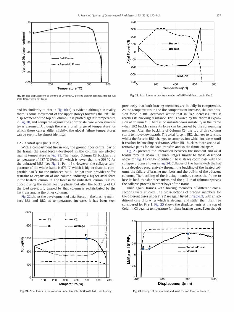
and its similarity to that in Fig. 16(c) is evident, although in realitythere is some movement of the upper storeys towards the left. Thedisplacement of the top of Column C2 is plotted against temperaturein Fig. 20, and compared against the appropriate case when symme-try is assumed. Although there is a brief range of temperature forwhich these curves differ slightly, the global failure temperaturescan be seen to be almost identical.
4.2.2. Central span fire (Fire 2)With a compartment fire in only the ground floor central bay of
the frame, the axial forces developed in the columns are plottedagainst temperature in Fig. 21. The heated Column C3 buckles at atemperature of 487 °C (Point D), which is lower than the 508 °C forthe unbraced MRF (see Fig. 11 Point B). However, the collapse tem-perature of the whole frame is 673 °C, which is higher than the com-parable 640 °C for the unbraced MRF. The hat truss provides stifferrestraint to expansion of one column, inducing a higher axial forcein the heated Column C3. The force in the unheated Column C2 is re-duced during the initial heating phase, but after the buckling of C3,the load previously carried by that column is redistributed by thehat truss among the other columns.
Fig. 22 shows the development of axial forces in the bracing mem-bers BR1 and BR2 as temperatures increase. It has been seen
Fig. 21. Axial forces in the columns under Fire 2 for MRF with hat truss bracing.
previously that both bracing members are initially in compression.As the temperatures in the fire compartment increase, the compres-sion force in BR1 decreases whilst that in BR2 increases until itreaches its buckling resistance. This is caused by the thermal expan-sion of Column C3. There is no instantaneous instability in the framewhen BR2 buckles since its force can be carried by the surroundingmembers. After the buckling of Column C3, the top of this columnstarts to move downwards. The axial force in BR2 changes to tension,whilst the force in BR1 changes to compression which increases untilit reaches its buckling resistance. When BR1 buckles there are no al-ternative paths for the load transfer, and so the frame collapses.
Fig. 23 presents the interaction between the moment and axialtensili force in Beam B1. Three stages similar to those describedabove for Fig. 13 can be identified. These stages coordinate with thecollapse process shown in Fig. 24. Collapse of the frame with the hattruss develops progressively through the buckling of the heated col-umn, the failure of bracing members and the pull-in of the adjacentcolumns. The buckling of the bracing members causes the frame tolose its load-transfer mechanism, and the pull-in of columns spreadsthe collapse process to other bays of the frame.
Once again, frames with bracing members of different cross-sections were studied. The cross-sections of bracing members forthe different cases under Fire 2 are again listed in Table. 2, with an ad-ditional case of bracing which is stronger and stiffer than the threeconsidered for Fire 1. Fig. 25 shows the displacements at the top ofColumn C3 against temperature for these bracing cases. Even though
-1
-0.5
0
0.5
1
1.5
-100 400 900 1400
M/M
p o
r 10
*F/F
y
Displacement(mm)
TensionForceMoment
o a
b
Fig. 23. Change of the moment and axial tension force in Beam B1.

(b) 487°C (c) 673°C(a) 20°C
Fig. 24. The collapse process of MRF with hat truss under Fire 2.
138 R. Sun et al. / Journal of Constructional Steel Research 72 (2012) 130–142
the stiffer restraint from the stronger bracings causes higher axialforce and lower buckling temperature for the heated columns, italso increases the overall failure temperature, because final collapseis triggered by failure of the bracing members. Fig. 26 shows theforces in the bracing members against temperature for Case 4. It canbe seen that, for Case 4, the bracing members are strong enough totransfer the load supported by the buckled column completely tothe neighbouring columns without themselves buckling or causingan overall failure, so that the frame remains stable through both theheating and cooling phases.
4.3. Behaviour of MRF with a vertical bracing system in fire
As mentioned previously, vertical bracing systems are widely usedto resist seismic loading. The role of a vertical bracing system in pre-venting progressive collapse of structures in fire conditions still needsto be studied. Moment-resisting frames with the vertical bracing sys-tem shown in Fig. 6 are now investigated. The two fire cases used pre-viously (Fire 1 and Fire 2), are used in the study. The temperatures ofthe heated beam and column described in Fig. 7 are once again used.
4.3.1. Edge bay fire (Fire 1)Fig. 27 shows the development of axial force in Columns C1, C2
and C3 under Fire 1. It can be seen that the axial force patterns withinthe columns are quite different from those in the frames analysed inprevious sections. Due to the high restraint provided by the vertical
Fig. 25. Displacements at the top of Column C3 against temperature for different caseswith hat truss bracing.
bracing members, the compression force in Column C2 increases sig-nificantly during the initial heating stage. As a direct consequence, theaxial force in Column C3 is reduced considerably. The analysis termi-nates when the heated beam descends to ground level. In theunbraced case the failure of the frame was directly initiated by thebuckling of Column C2, but in this case, although C2 buckles first itis restrained so that its top does not move freely. A local collapse isinitiated by the buckling of Column C1, which is free to continue itsvertical movement. The results indicate that the buckling tempera-ture of Column C1 is about 700 °C. From Fig. 27 it can be seen thatwhen C1 buckles, C2 has already lost most of its strength. The verticalforces previously acting on Columns C1 and C2 are transferred to Col-umn C3 through the bracing in the second bay. Fig. 28 shows the axialforces in the bracing members (BR3 and BR4) as column tempera-tures change. Clearly, the axial forces in the bracing members are ini-tially compressive. During the initial heating stage there is littlechange in the axial force of BR4. The axial force in BR3 changes fromcompression to tension, because of the thermal expansion of theheated columns, and then back to tension, because of the downwardsvertical movement of column C2. Fig. 29 shows the collapse process ofthe frame with a vertical bracing system, subject to Fire 1. Plastichinges first form in the heated columns; subsequently, because ofthe large vertical displacement at the top of C1, hinges appear at theends of the beams above the heated bay, but the failure does notspread from the affected bay to neighbouring bays. A vertical bracing
2000
1500
1000
500
0
500
1000
1500
2000
0 200 400 600 800 1000
Axi
al F
orc
e(K
N)
Temperature(°C)
Brace-1
Brace-2
Fig. 26. Axial forces in the bracing members of Case 4 under Fire 2 with hat trussbracing.

Fig. 27. Development of axial forces in the Columns C1, C2 and C3 under Fire 1 withvertical bracing.
Fig. 28. Axial forces in the bracing members against temperature with vertical bracing.
Instability
Fig. 30. Displacement at the top of Column C2 against temperature for different caseswith vertical bracing.
Fig. 31. Axial forces of the bracing member BR4 against temperature for different caseswith vertical bracing.
139R. Sun et al. / Journal of Constructional Steel Research 72 (2012) 130–142
system can effectively be seen to prevent the spread of local failurefrom bay to bay.
Frames with bracing members of different cross-sections, listed inTable.2, are studied. The failure patterns of these cases are similar tothat shown in Fig. 29. There is no sign of global collapse in these
C3C2C1
B1BR3 BR4
(b) 69(a) 527°C
Fig. 29. Collapse process of MRF with v
cases. The local collapse of the frame is initiated by the buckling ofColumn C1, and the vertical bracing system prevents the failurefrom spreading to other bays. Fig. 30 plots the deflections at the top
8°C (c) 745°C
ertical bracing system under Fire 1.

Fig. 32. Axial force in columns against temperature in MRF with vertical bracing underFire 2.
-70
-60
-50
-40
-30
-20
-10
0
10
20
0 200 400 600 800
Dis
pla
cem
ent(
mm
)
Temperature(°C)
Fig. 34. Change of deflection at the top of Column C3 with temperature.
140 R. Sun et al. / Journal of Constructional Steel Research 72 (2012) 130–142
of Column C2 against temperature for these cases. The temperature atwhich a transient instability occurs is identical for each case. This isbecause this instability is induced by the buckling of Column C1,and the restraint and loading conditions of C1 are not affected bythe presence of the bracing system. Fig. 31 presents the axial forcesin BR4, plotted against temperature for each of these cases. It is evi-dent that stiffer bracing system results in smaller deflection at thetop of Column C2 and larger forces in the bracing members.
4.3.2. Central bay fire (Fire 2)With the vertical bracing arrangement that has been defined, and
remembering the vertical axis of symmetry, the central bay is re-strained on both sides. Therefore, a central bay fire should not pro-duce dramatic overall damage to the frame. To understand this, theframe with vertical bracing is studied for Fire 2. Fig. 32 shows theaxial forces in C1, C2 and C3, plotted against temperature. It can be
Fig. 33. Axial force in bracing members against temperature in MRF with vertical brac-ing under Fire 2.
seen that the axial force in C3 develops more rapidly with rising tem-perature compared with that shown in Fig. 14 for the unbraced frame,and the buckling temperature (Point E) in this case is much lower.This is because vertical bracing provides more restraint to C3. The av-erage force stays constant during the heating and cooling phases,which means that the loads are well distributed among vertical sup-porting columns, and there is no sign of global instability.
Fig. 33 shows the development of the axial forces in BR3 and BR4with increasing temperature, and Fig. 34 shows the deflection at thetop of Column C3. In the heating phase, the compression force in-creases in BR3 whilst that in BR4 decreases as temperatures rise.This is because the thermal expansion of Column C3, which can be ob-served in Fig. 34, is overtaken by downward movement after thebuckling of C3, when forces in the bracing members start to decrease.As the deflection at the top of C3 develops, the force which it sheds isgradually transferred to surrounding members; thus the axial force
Fig. 35. Final state of the frame with vertical bracing under Fire 2.

Fig. 36. Displacement at the top of Column C3 for the frame with different bracingmembers.
Fire-1 Fire-2
(b) Fire-2(a) Fire-1
Fig. 37. Final states of frame with hat and vertical bracing for cases Fire 1 and Fire 2.
141R. Sun et al. / Journal of Constructional Steel Research 72 (2012) 130–142
in Column C2 increases. At a temperature of 832 °C, C2 bucklesand there is a sudden change of axial force in BR4, which snapsfrom tension to compression before stability is regained. There is acorresponding jump on the deflection curve, as shown in Fig. 34. Itis clear here that re-stabilization can be achieved, since the forcecan be transferred and redistributed by the other members afterlocal instability happens. Fig. 35 shows the final state of the frame.
Once again, frames with different bracing members, listed inTable. 2, are analysed to investigate the influence of the stiffnessand strength of the bracing members. Fig. 36 shows the deflectionsat the top of Column C3 plotted against temperature for these cases.It can be seen that no global collapse occurs in any of the cases, andthe frames with stronger vertical bracing members can even avoidlocal instability. Clearly, this vertical bracing can effectively preventprogressive collapse of the frame for the central bay fire.
4.4. Discussion
From the results presented, it can be seen that a bracing systemcan enhance the capacity of a steel frame to resist progressive col-lapse under fire conditions. The bracing system increases the redun-dancy of the structure, and provides alternative load-sharing pathsafter a local instability occurs. Installing a “hat truss” can increasethe load-transfer capacity after local failure, but large displacementcan eventually induce failure of bracing members and the generationof plastic hinges in beams in adjacent bays. The pull-in of columnsdue to catenary force in highly deflected beams cannot be effectivelyavoided by the use of a hat truss. It can also be seen that a verticalbracing system can effectively prevent a localised collapse spreadingto other bays. Therefore, it is proposed that a combination of thesetwo bracing systems might provide a greater variety of load-transferpaths and sufficient force redistribution capability after a local insta-bility occurs. Without performing a real parametric study, a single ex-ample of a frame with both a hat truss and a vertical bracing systemhas been analysed under both fire scenarios (Fire 1 and Fire 2). Thecross-section of the bracing members used is RHS 200×100×10.Fig. 37 shows the final state of this frame, which shows no sign ofglobal collapse or overall instability under these fire scenarios.
5. Conclusions
In this study the progressive collapse mechanisms of steel-framedstructures with different bracing systems have been investigatedusing a static–dynamic procedure developed by the authors. Thestudy has been carried out on a generic Moment Resisting Frame
with five bays and four storeys, both unbraced and with differentbracing systems, under two natural fire scenarios. The influences ofstiffness and strength of the bracing systems have also been analysed.Several conclusions can be drawn:
(1) Under Fire 1, the unbraced MRF lacks an effective load-transfermechanism to redistribute the forces shed by failed heatedmembers to the surrounding structure. Under Fire 2, the failureof the unbraced MRF can be recognised as a three-stage pro-cess, including: the beam action stage, the catenary actionstage and the column pull-in stage. The pull-in of columns isone of the main factors contributing to progressive collapseof the frame.
(2) Using hat truss bracing can increase the load-transfer capacityafter a heated column has buckled. Stronger bracing memberscan provide higher overall collapse temperatures of the frame.However, large displacements and redistributed forces caneventually induce the buckling of bracing members and yield-ing of the beams in adjacent bays. A hat truss bracing systemhas a limited capacity to avoid the pull-in of columns in theheated floor.The form of hat truss bracing used in this study, taken togetherwith the columns and beams in the upper storey of the frame,form a statically determinate trussed deep girder across the topof the frame (if the rigidity of some connections is ignored).The first bracing member which buckles under increased com-pression will therefore effectively cause a hinge in this deepgirder, which largely destroys the force-transfer mechanismthat it provides. This suggests that statically indeterminatecross-bracing, in which a tension diagonal can always compen-sate for the buckling of the compression diagonal, would be amuch more structurally efficient way of designing a hat trussto combat progressive collapse.
(3) A vertical bracing system can not only increase the lateral re-straint of the frame, reducing the pull-in effect of the columns,but can also effectively prevent the collapse developing fromlocal to global.
(4) The example frame with combined hat and vertical bracingsystems can effectively enhance the capability of the frame toprevent progressive collapse when a heated column fails.
In this study, the main concern has been to understand the pro-gressive collapse mechanisms of 2D primary steel frames, with differ-ent bracing systems and under different fire conditions. Its mainlimitations have been in ignoring the potential fracture of the connec-tions, and in not considering the redistribution capacity of compositeconcrete flooring into the third dimension. These issues are currentlyunder investigation.

142 R. Sun et al. / Journal of Constructional Steel Research 72 (2012) 130–142
Acknowledgement
The financial support of the China Scholarship Council and theUniversity of Sheffield for the first author's PhD research is gratefullyacknowledged.
References
[1] Lamont, S., ‘The Behaviour of Multi-storey Composite Steel Frame Structures inResponse to Compartment Fires’, PhD thesis, University of Edinburgh, 2001.
[2] Ghaffarzadeh H, Ghalghachi RN. Redundancy of the Steel Frames with MasonryInfill Walls. World Academy of Science, Engineering and Technology; 2009.
[3] Khandelwal K, El-Tawil S, Sadek F. Progressive collapse analysis of seismicallydesigned steel braced frames. J Construct Steel Res 2009;65(3):699–708.
[4] Kim J, Youngho Lee Y, Choi H. Progressive collapse resisting capacity of bracedframes. Struct Des Tall Spec Build 2011;20(2):257–70.
[5] Isobe D, Tsuda M. Seismic collapse analysis of reinforced concrete framed struc-tures using the finite element method. Earthquake Eng Struct Dyn 2003;32(13):2027–46.
[6] Kaewkulchai G, Williamson EB. Beam element formulation and solution proce-dure for dynamic progressive collapse analysis. Comput Struct 2004;82(7–8):639–51.
[7] Khandelwal K, El-Tawil S. Collapse behaviour of steel special moment resistingframe connections. J Struct Eng, ASCE 2007;133(5):646–55.
[8] Najjar SR, Burgess IW. A non-linear analysis for three-dimensional steel frames infire conditions. Eng Struct 1996;18(1):77–89.
[9] Huang Z, Burgess IW, Plank RJ. Three-dimensional analysis of reinforced concretebeam–column structures in fire. J Struct Eng, ASCE 2009;135(10):1201–12.
[10] Huang Z. A connection element for modelling end-plate connections in fire. J Con-struct Steel Res 2011;67:841–53.
[11] Yu C, Huang Z, Burgess IW, Plank RJ. Development and validation of 3D compositestructural elements at elevated temperatures. J Struct Eng, ASCE 2010;136(3):275–84.
[12] Huang Z. Modelling of reinforced concrete structures in fire. Proc. Institution ofCivil Engineers: Engineering and Computational Mechanics, 163. EM1; 2010.p. 43–53.
[13] Huang Z. Modelling the bond between concrete and reinforcing steel in a fire. EngStruct 2010;32(11):3660–9.
[14] EN 1993-1-2: Eurocode 3: design of steel structures, Part1–2: general rules-structural fire design. European Committee for Standardization (CEN), Brussels;2005.
[15] Sun RR, Huang Z, Burgess IW. ‘Progressive collapse analysis of steel structuresunder fire conditions,. Eng Struct 2012;34:400–13.
[16] Sun RR, Huang Z, Burgess IW. A static/dynamic procedure for collapse analysis ofstructure in fire. Proc. Fire Safety Engineering in the UK: The State of the Art; No-vember, 2010. p. 37–42. Edinburgh, UK.
[17] Sun RR, Burgess IW, Huang Z. Behaviour of frame columns in localised fires. Proc.ASFE 2011; April 2011. p. 275–80. Prague.
[18] EN 1991-1-1: Eurocode 1: actions on structures, part1-1: general actions—densities, self-weight, imposed loads for buildings. European Committee forStandardization (CEN), Brussels; 2002.
[19] EN 1993-1-1: Eurocode 3: design of steel structures, part1-1: general rules andrules for buildings. European Committee for Standardization (CEN), Brussels;2005.
[20] EN 1991-1-2: Eurocode 1: design of steel structures, part1-1: actions on struc-tures: part 1–2: general actions—actions on structures exposed to fire. EuropeanCommittee for Standardization (CEN), Brussels; 2002.
Copyright © 2022 FDOKUMEN