Evaluation of buckling-restrained braced frame seismic performance considering reserve strength
Upload
khangminh22Category
view
1download
0
Seismic Braced Frames Design Concepts and Connections
Developed by:
Rafael Sabelli, S.E.
DASSE Design Inc.
July 27, 2006 Chicago, IL
The information presented herein is based on recognized engineering principles and is for general information only. While it is believed to be accurate, this information should not be applied to any specific application without competent professional examination and verification by a licensed professional engineer. Anyone making use of this information assumes all liability arising from such use.
Copyright © 2006
By
The American Institute of Steel Construction, Inc.
All rights reserved. This document or any part thereof must not be reproduced in any form without the
written permission of the publisher.
Seismic Braced Frames
Design Concepts and Connections
Developed by:
Rafael Sabelli, S.E.
DASSE Design Inc.

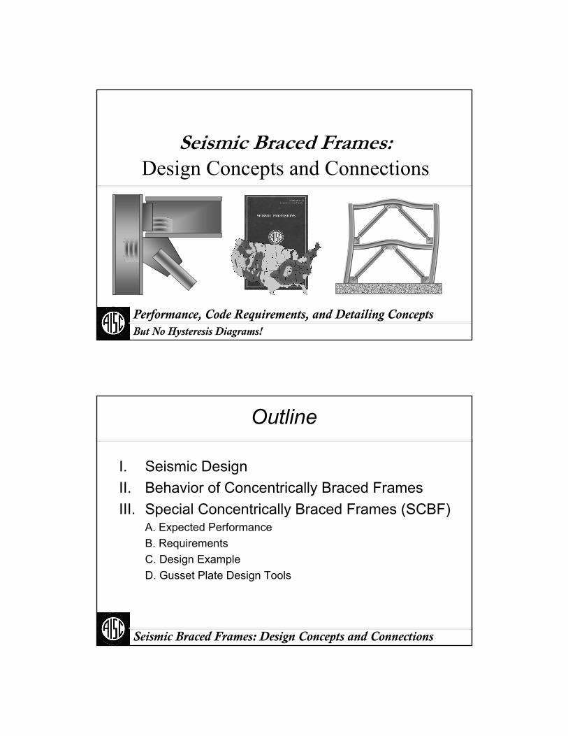
Seismic Braced Frames:Design Concepts and Connections
Performance, Code Requirements, and Detailing ConceptsBut No Hysteresis Diagrams!
Seismic Braced Frames: Design Concepts and Connections
Outline
I. Seismic DesignII. Behavior of Concentrically Braced FramesIII. Special Concentrically Braced Frames (SCBF)
A. Expected PerformanceB. RequirementsC. Design ExampleD. Gusset Plate Design Tools
Seismic Braced Frames: Design Concepts and Connections
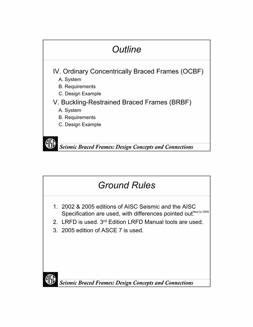
Outline
IV. Ordinary Concentrically Braced Frames (OCBF)A. SystemB. RequirementsC. Design Example
V. Buckling-Restrained Braced Frames (BRBF)A. SystemB. RequirementsC. Design Example
Seismic Braced Frames: Design Concepts and Connections
Ground Rules
1. 2002 & 2005 editions of AISC Seismic and the AISC Specification are used, with differences pointed out.
2. LRFD is used. 3rd Edition LRFD Manual tools are used.3. 2005 edition of ASCE 7 is used.
New to 2005

Part I:
Seismic Design
Seismic Braced Frames: Design Concepts and Connections
Seismic Braced Frames: Design Concepts and Connections
When are the Seismic Provisions Required?
Depends on Seismic Design CategoryDepends on Seismic Use Group
Seismic Use Group Depends on OccupancyDepends on Soil TypeDepends on Spectrum
Proximity to FaultsCapacity of FaultSoil Types A-E
Spectrum Determined from USGS MapsSite-Specific Spectrum
Soil Type FSite-Specific Spectrum

Seismic Braced Frames: Design Concepts and Connections
Seismic Design (Seismic Use Groups I&II)
Seismic Braced Frames: Design Concepts and Connections
Seismic Design (Seismic Use Group III)

Seismic Braced Frames: Design Concepts and Connections
Seismic Design
Response SpectrumBased on Maximum Credible Earthquake
Design Base ShearDepends on Building PeriodReduced by Factor “R”
R Depends on SystemReflects System DuctilityIncludes System Overstrength
Seismic Braced Frames: Design Concepts and Connections
System Ductility
What is “System Ductility”?Ability of System to Maintain Stability After Yielding/Overload of
Some ElementsAbility of Yielding/Overloaded Elements to Deform
If yielding elements fracture, system may lose stabilityAbility of Nonyielding Elements to Withstand Forces Redistributed by
YieldingWhen an element yields, other elements may receive more load
Ability of Nonyielding Elements to Withstand Deformations Caused by Yielding
System displacements increase after yielding, and deformation modes changeSo-called “nonyielding” members may have some inelastic deformation
Seismic Braced Frames: Design Concepts and Connections
System Ductility
How is System Ductility Achieved?Designate certain elements to be fuses
Ensure those elements are ductileEnsure other elements do not yield
Determine maximum forces that yielding elements can imposeMaximum forces can be much greater than design forces
Resistance factorConservative design equationsConservative design assumptionsHigher-than-specified material strengthOver-designed elements (e.g., Drift-controlled)
Check strength or ductility at expected drifts
Seismic Braced Frames: Design Concepts and Connections
System Ductility
How is System Ductility Achieved?
Seismic Braced Frames: Design Concepts and Connections
AISC Seismic
Basic AISC Seismic Design Procedure1. Calculate demands based on applicable
building code
2. Analyze
3. Size fuses (braces)
4. Size other members so fuses will govern
Seismic Braced Frames: Design Concepts and Connections
AISC Seismic
Redefines some required strengths based on size of fuse (e.g., the braces)
Gives detailing requirements to ensure ductility of fuses
Was developed based on LRFD LRFD is more consistent with ProcedureLRFD is not required (ASD equations are also included)

Seismic Braced Frames: Design Concepts and Connections
2005 AISC Seismic Provisions
Section 1: ScopeSection 2: Referenced StandardsSection 3: General Seismic Design Requirements
Defers to Applicable Building Code (ABC)Section 4: Loads, Load Combinations, Strengths
Loads and CombinationsPer ABCPer ASCE-7 2002 If No ABC
“Amplified Seismic Load” Means Combinations with ΩoEStrengths Per 2005 AISC Specification (i.e., LRFD or ASD)
Seismic Braced Frames: Design Concepts and Connections
2005 AISC Seismic Provisions
Section 5: Contract Documents, Shop and Erection2005
Drawings Identify Seismic Load Resisting System
FramesBracesChordsCollectors
Identify Protected ZoneAreas of Expected Inelastic StrainDetrimental Attachments Not Permitted
Shot-in PinsLow-Toughness Welds
Seismic Braced Frames: Design Concepts and Connections
2005 AISC Seismic Provisions
Section 6: MaterialsPermissible Materials for yielding members
Fy ≤ 50 ksiElongation ≥ 20%
Material OverstrengthExpected Yield Strength
RyFy
Corresponding Expected Ultimate Strength2005
RTFu
RT Applies only to same member as Ry
Seismic Braced Frames: Design Concepts and Connections
2005 AISC Seismic Provisions
Section 7: ConnectionsBolted Connections
PretensionedClass A Faying SurfaceNot to Share Force with Welds
Welded Connections20 ft-lbs @ -0º for the SLRS20 ft-lbs @ -20º and 40 ft-lbs @ 70º for Demand Critical Welds
Welds in CBF are not typically considered “Demand Critical”Protected Zone2005 Defined

Seismic Braced Frames: Design Concepts and Connections
Bolts
Bolts
Weld
Vertical force (and possibly the horizontal force) is shared by bolts and welds
THIS IS NOT ALLOWED!
Seismic Braced Frames: Design Concepts and Connections
Bolts
Bolted joint is not considered in the transfer of seismic forces.
This is permitted.
Seismic Braced Frames: Design Concepts and Connections
2005 AISC Seismic Provisions
Section 8: MembersWidth-Thickness LimitsColumn Requirements
StrengthSplices
Non-Frame Columns2005
Splices
Seismic Braced Frames: Design Concepts and Connections
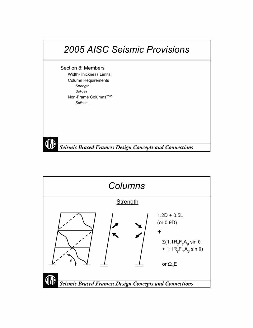
Columns
Σ(1.1RyFyAg sin θ+ 1.1RyFcrAg sin θ)
Strength
or ΩoEθ
1.2D + 0.5L (or 0.9D)
+
Seismic Braced Frames: Design Concepts and Connections
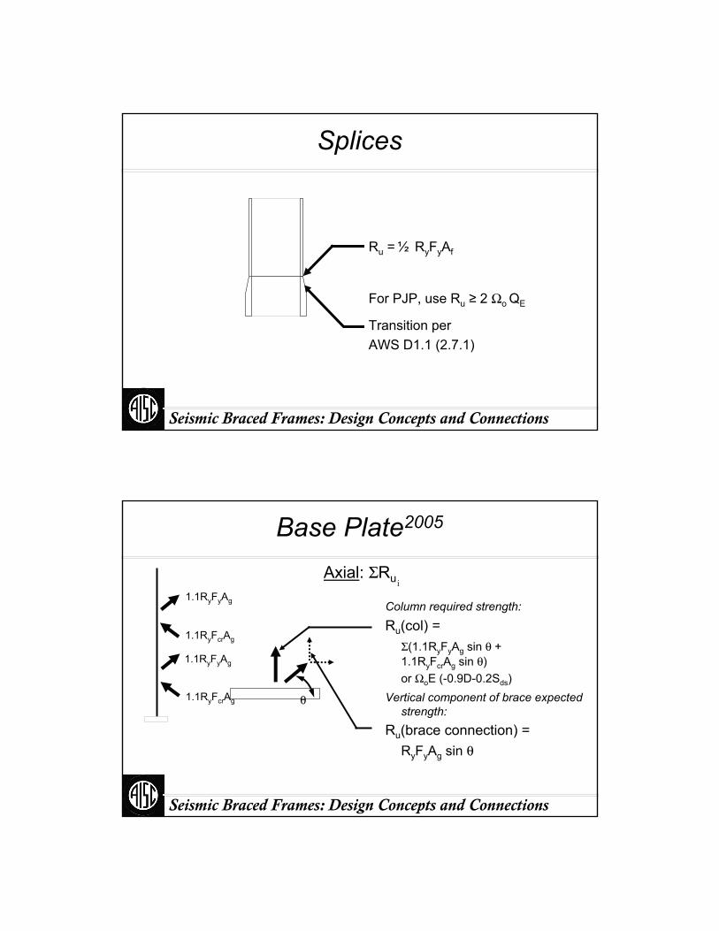
Splices
Ru = ½ RyFyAf
For PJP, use Ru ≥ 2 Ωo QE
Transition perAWS D1.1 (2.7.1)
Seismic Braced Frames: Design Concepts and Connections
Base Plate2005
Axial: ΣRui
Ru(col) = Σ(1.1RyFyAg sin θ + 1.1RyFcrAg sin θ)or ΩoE (-0.9D-0.2Sds)
Ru(brace connection) = RyFyAg sin θ
1.1RyFyAg
1.1RyFyAg
1.1RyFcrAg
1.1RyFcrAg Vertical component of brace expected strength:
Column required strength:
θ

Seismic Braced Frames: Design Concepts and Connections
Base Plate2005
Shear: ΣRu i
Ru(col)= Vu = 2 Mp / hor ΩoE (+1.2D+f1L+0.2Sds)
Ru(brace connection) = RyFyAg cos θ
Vu
Mp
Mp
VuHorizontal component of brace
expected strength:
Column required strength:
θ
Seismic Braced Frames: Design Concepts and Connections
Base Plate2005
Flexure: ΣRu
Ru(col) ≤ 1.1RyFyZ
≤ 1.2D + 0.5L + ΩoE0.9D + ΩoE
Ru(brace) ≤ 1.1RyFyZ
For fixed-end braces, add:
Seismic Braced Frames: Design Concepts and Connections
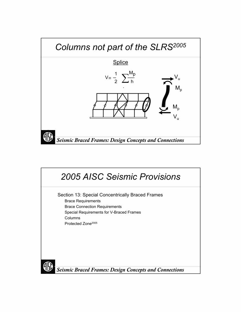
Columns not part of the SLRS2005
Splice
Vu
Mp
Vu
Mp
V12
.
Mph∑
Seismic Braced Frames: Design Concepts and Connections
2005 AISC Seismic Provisions
Section 13: Special Concentrically Braced FramesBrace RequirementsBrace Connection RequirementsSpecial Requirements for V-Braced FramesColumnsProtected Zone2005
Seismic Braced Frames: Design Concepts and Connections
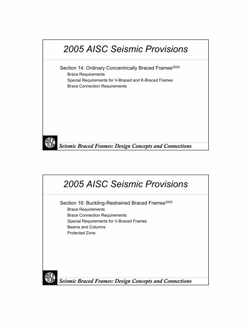
2005 AISC Seismic Provisions
Section 14: Ordinary Concentrically Braced Frames2005
Brace RequirementsSpecial Requirements for V-Braced and K-Braced Frames Brace Connection Requirements
Seismic Braced Frames: Design Concepts and Connections
2005 AISC Seismic Provisions
Section 16: Buckling-Restrained Braced Frames2005
Brace RequirementsBrace Connection RequirementsSpecial Requirements for V-Braced FramesBeams and ColumnsProtected Zone
Seismic Braced Frames: Design Concepts and Connections
2005 AISC Seismic Provisions
Appendix Q: Quality Assurance2005
Appendix R: Seismic Design Coefficients2005
Only Applicable if Building Code Does Not Define Coefficients for BRBF
Appendix T: Qualification Testing of BRBs2005
Testing Requirements for Buckling-Restrained Braces
Part II:
Concentrically Braced Frames
Seismic Braced Frames: Design Concepts and Connections

Seismic Braced Frames: Design Concepts and Connections
I. Concentrically Braced Frames
Elastic BehaviorPost-Elastic BehaviorObserved BehaviorDesign Issues
Seismic Braced Frames: Design Concepts and Connections
CBF Elastic BehaviorTruss System
Concentrically Braced Frames can be approximately modeled as vertical trusses
Seismic Braced Frames: Design Concepts and Connections
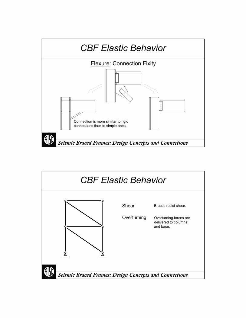
CBF Elastic BehaviorFlexure: Connection Fixity
Connection is more similar to rigid connections than to simple ones.
Seismic Braced Frames: Design Concepts and Connections
CBF Elastic Behavior
Shear
Overturning
Braces resist shear.
Overturning forces are delivered to columns and base.

Seismic Braced Frames: Design Concepts and Connections
Limit States
Members
Connections
Column Splices
Yielding or fracture can occur in:
Seismic Braced Frames: Design Concepts and Connections
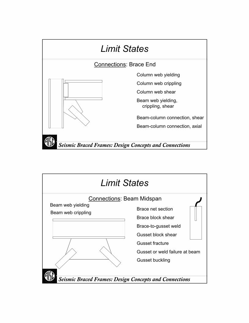
Limit StatesConnections: Brace End
Brace net section fracture
Brace block shear fracture
Brace-to-gusset weld fracture
Gusset block shear fracture
Gusset tension yield or fracture
Gusset or weld failure at column
Gusset or weld failure at beamGusset buckling

Seismic Braced Frames: Design Concepts and Connections
Limit StatesConnections: Brace End
Gusset buckling
Seismic Braced Frames: Design Concepts and Connections
Brace Fracture
Courtesy of R. Tremblay

Seismic Braced Frames: Design Concepts and Connections
Post-Elastic BehaviorUnfavorable Modes: Connection Fracture
Courtesy of C. Roeder
Seismic Braced Frames: Design Concepts and Connections
Connection Instability
Courtesy of R. Tremblay
Seismic Braced Frames: Design Concepts and Connections
Limit StatesConnections: Brace End
Column web yielding
Column web crippling
Column web shear
Beam web yielding, crippling, shear
Beam-column connection, shear
Beam-column connection, axial
Seismic Braced Frames: Design Concepts and Connections
Limit StatesConnections: Beam Midspan
Brace net section
Brace block shear
Brace-to-gusset weld
Gusset block shear
Gusset fracture
Gusset or weld failure at beam
Beam web yieldingBeam web crippling
Gusset buckling
Seismic Braced Frames: Design Concepts and Connections
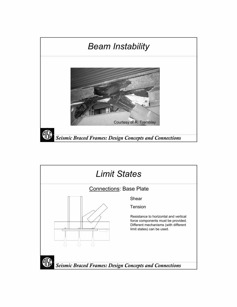
Beam Instability
Courtesy of R. Tremblay
Seismic Braced Frames: Design Concepts and Connections
Limit StatesConnections: Base Plate
Shear
Tension
Resistance to horizontal and vertical force components must be provided. Different mechanisms (with different limit states) can be used.
Seismic Braced Frames: Design Concepts and Connections
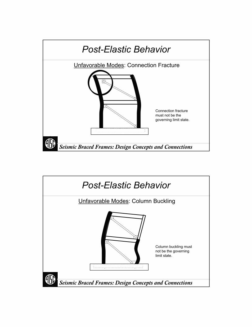
Post-Elastic BehaviorUnfavorable Modes: Connection Fracture
Connection fracture must not be the governing limit state.
Seismic Braced Frames: Design Concepts and Connections
Post-Elastic BehaviorUnfavorable Modes: Column Buckling
Column buckling must not be the governing limit state.

Seismic Braced Frames: Design Concepts and Connections
Post-Elastic BehaviorUnfavorable Modes: Column Tension Fracture
Column tension fracture must not be the governing limit state.
Seismic Braced Frames: Design Concepts and Connections
Column Fracture
Courtesy of R. Tremblay

Seismic Braced Frames: Design Concepts and Connections
Post-Elastic BehaviorUnfavorable Modes: Beam Failure
Beam failure must not be the governing limit state.
Seismic Braced Frames: Design Concepts and Connections
Post-Elastic BehaviorPreferred Modes: Brace Buckling
Brace buckling should be a governing limit state.
Seismic Braced Frames: Design Concepts and Connections
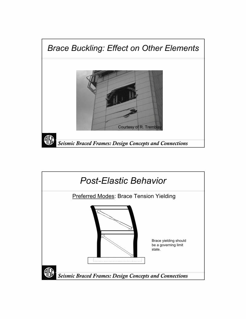
Brace Buckling: Effect on Other Elements
Courtesy of R. Tremblay
Seismic Braced Frames: Design Concepts and Connections
Post-Elastic BehaviorPreferred Modes: Brace Tension Yielding
Brace yielding should be a governing limit state.
Seismic Braced Frames: Design Concepts and Connections
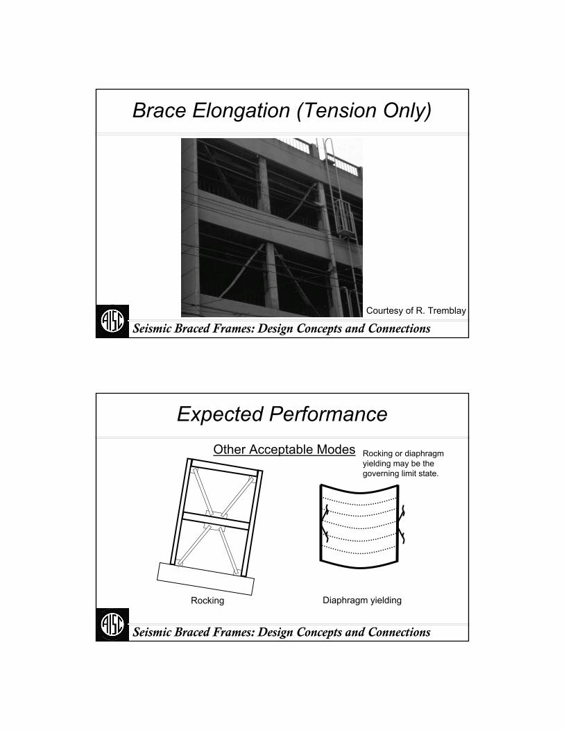
Brace Elongation (Tension Only)
Courtesy of R. Tremblay
Seismic Braced Frames: Design Concepts and Connections
Expected Performance
Diaphragm yieldingRocking
Other Acceptable Modes Rocking or diaphragm yielding may be the governing limit state.

Seismic Braced Frames: Design Concepts and Connections
System Behavior with Brace Yielding
Column Flexure
Columns must bend when braces buckle and yield.
Seismic Braced Frames: Design Concepts and Connections
Beam Flexure
System Behavior with Brace Yielding
Brace buckling and yielding induce flexural forces in beams in this configuration.

Seismic Braced Frames: Design Concepts and Connections
Frame Participation
Flexural forces are induced in rigidly-connected columns and beams due to drift.
Seismic Braced Frames: Design Concepts and Connections
Design IssuesConfiguration
Single Diagonal K-Bracing Chevron

Seismic Braced Frames: Design Concepts and Connections
Beam Forces
Configuration
Seismic Braced Frames: Design Concepts and Connections
Design IssuesConfiguration
2-Story X Zipper
Seismic Braced Frames: Design Concepts and Connections
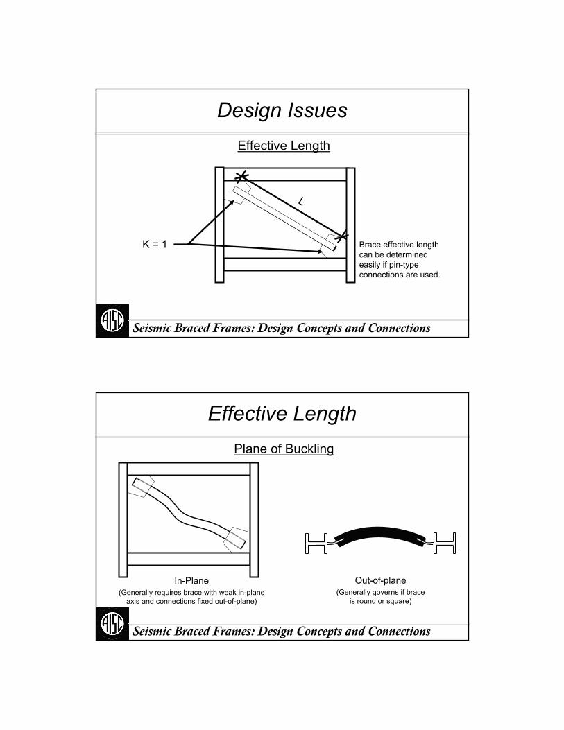
Design IssuesEffective Length
L
K = 1 Brace effective length can be determined easily if pin-type connections are used.
Seismic Braced Frames: Design Concepts and Connections
Effective LengthPlane of Buckling
Out-of-plane(Generally governs if brace
is round or square)
In-Plane(Generally requires brace with weak in-plane
axis and connections fixed out-of-plane)
Seismic Braced Frames: Design Concepts and Connections
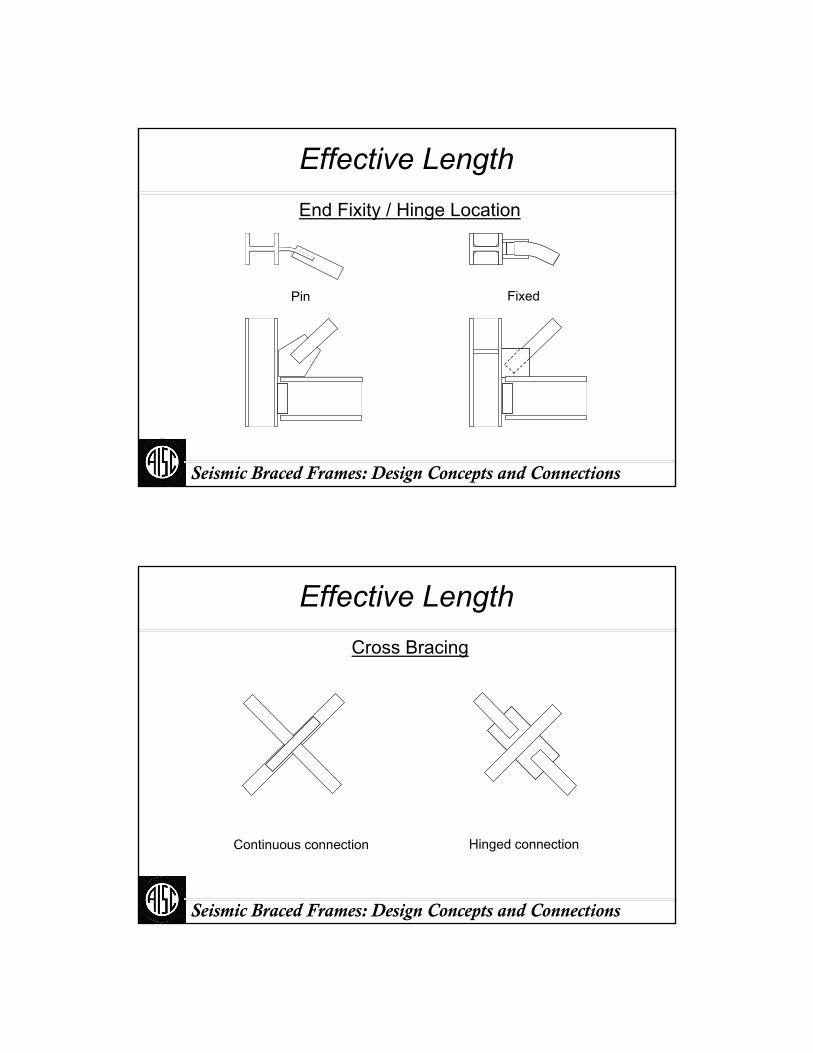
Effective LengthEnd Fixity / Hinge Location
FixedPin
Seismic Braced Frames: Design Concepts and Connections
Effective LengthCross Bracing
Hinged connectionContinuous connection

Seismic Braced Frames: Design Concepts and Connections
Effective LengthCross Bracing
(with flexural continuity at splice)
L
K = 1(out-of-plane)
Seismic Braced Frames: Design Concepts and Connections
Effective LengthCross Bracing
(with flexural continuity at splice)
Courtesy of R. Tremblay

Seismic Braced Frames: Design Concepts and Connections
Effective LengthCross Bracing(with flexural continuity at splice)
Courtesy of R. Tremblay
Seismic Braced Frames: Design Concepts and Connections
Effective LengthCross Bracing
(without flexural continuity at splice)
K = ?(out-of-plane)
L
Seismic Braced Frames: Design Concepts and Connections
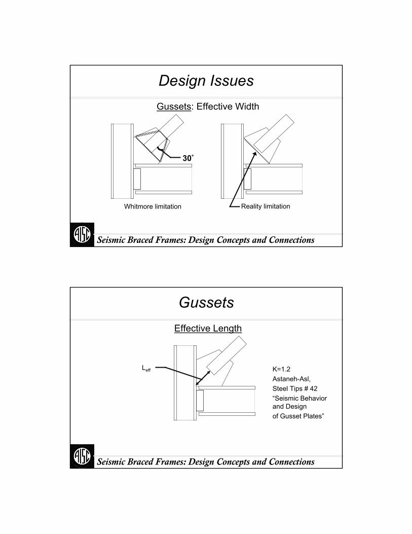
Design IssuesGussets: Effective Width
Whitmore limitation
30°
Reality limitation
Seismic Braced Frames: Design Concepts and Connections
GussetsEffective Length
Leff K=1.2Astaneh-Asl, Steel Tips # 42“Seismic Behavior and Designof Gusset Plates”

Seismic Braced Frames: Design Concepts and Connections
Connections: Compression
L2
(Astaneh, Steel Tips)
K = 1.2
L3
L1
L = Max (L)?
L = Ave (L)?
L = C (L)?L
3 Options (all reasonably reliable)
Seismic Braced Frames: Design Concepts and Connections
GussetsEdge Buckling
Le
Le
t34
EFy
⋅≤ (Astaneh-Asl, Steel Tips)
Seismic Braced Frames: Design Concepts and Connections
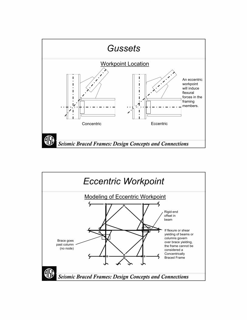
GussetsWorkpoint Location
EccentricConcentric
An eccentric workpoint will induce flexural forces in the framing members.
Seismic Braced Frames: Design Concepts and Connections
Eccentric WorkpointModeling of Eccentric Workpoint
Brace goes past column
(no node)
Rigid-end offset in beam
If flexure or shear yielding of beams or columns govern over brace yielding, the frame cannot be considered a Concentrically Braced Frame
Seismic Braced Frames: Design Concepts and Connections
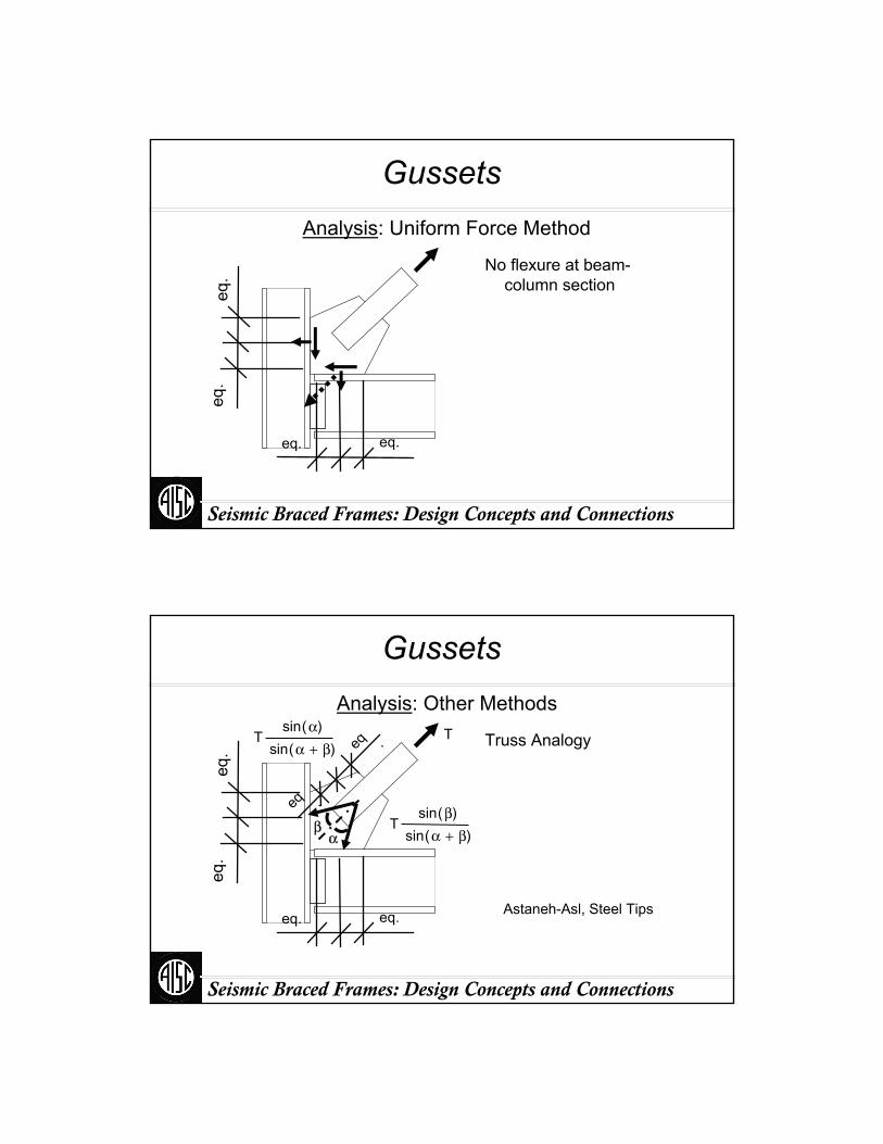
GussetsAnalysis: Uniform Force Method
No flexure at beam-column section
eq. eq.
eq.
eq.
Seismic Braced Frames: Design Concepts and Connections
GussetsAnalysis: Other Methods
Truss Analogy
αβ
T
Astaneh-Asl, Steel Tips
eq .
eq .Tsin α( )
sin α β+( )
Tsin β( )
sin α β+( )
eq. eq.
eq.
eq.
Seismic Braced Frames: Design Concepts and Connections
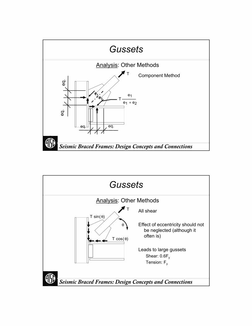
GussetsAnalysis: Other Methods
Component MethodT
e2
e1
eq. eq.
eq.
eq.
Te1
e1 e2+
Seismic Braced Frames: Design Concepts and Connections
GussetsAnalysis: Other Methods
All shear
Effect of eccentricity should not be neglected (although it often is)
Leads to large gussetsShear: 0.6Fy
Tension: Fy
T
T sin θ( )
T cos θ( )
θ
Seismic Braced Frames: Design Concepts and Connections
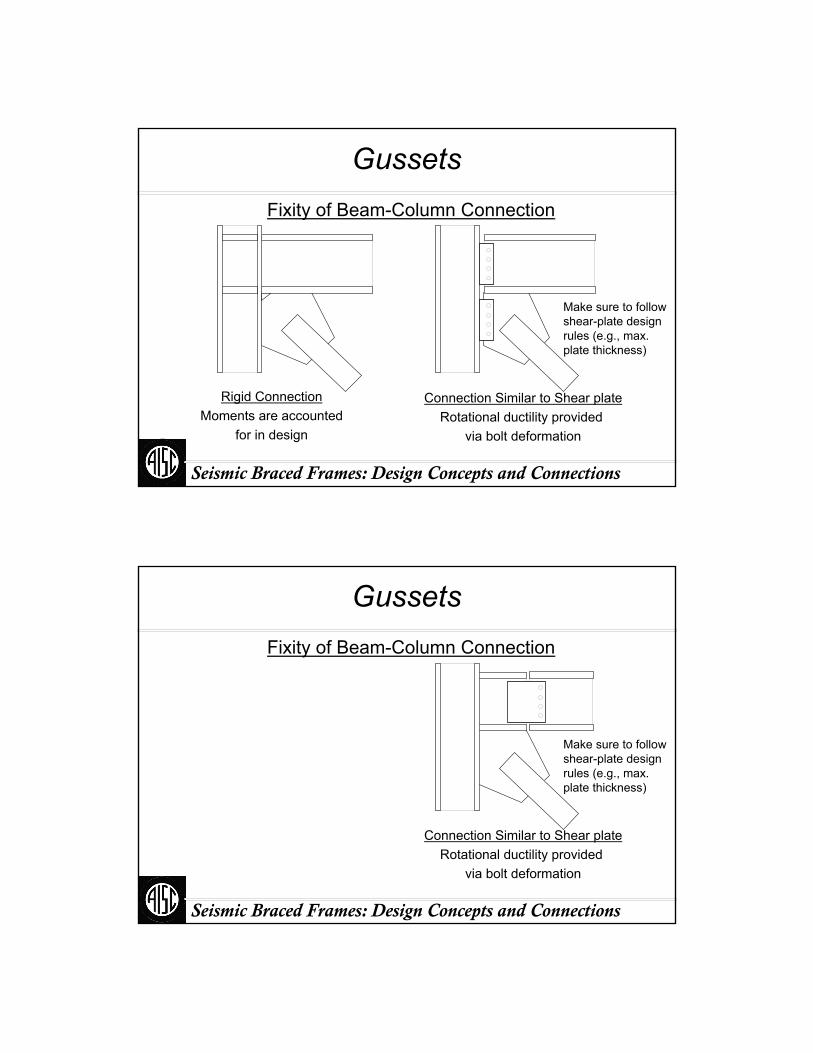
GussetsFixity of Beam-Column Connection
Rigid ConnectionMoments are accounted
for in design
Connection Similar to Shear plateRotational ductility provided
via bolt deformation
Make sure to follow shear-plate design rules (e.g., max. plate thickness)
Seismic Braced Frames: Design Concepts and Connections
GussetsFixity of Beam-Column Connection
Connection Similar to Shear plateRotational ductility provided
via bolt deformation
Make sure to follow shear-plate design rules (e.g., max. plate thickness)
Part III:
Special Concentrically Braced Frames
Seismic Braced Frames: Design Concepts and Connections
Seismic Braced Frames: Design Concepts and Connections
SCBF
Expected performance
Unfavorable modes
AISC Seismic requirements
Design example
Seismic Braced Frames: Design Concepts and Connections
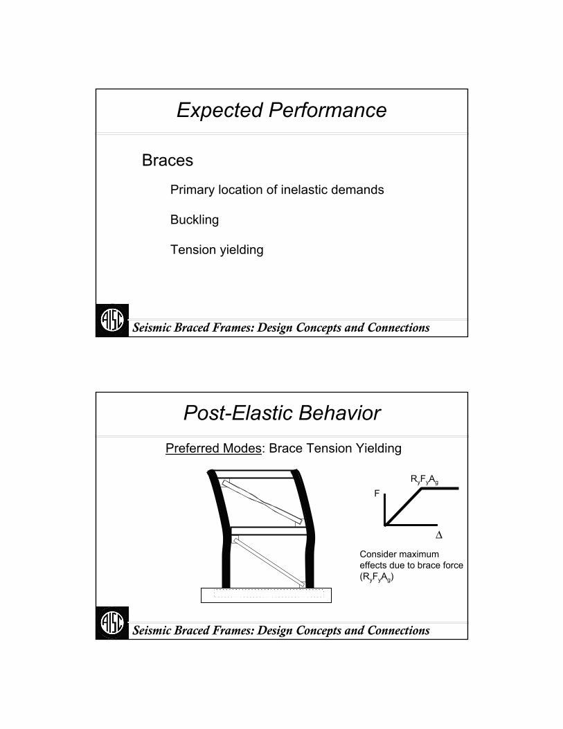
Expected Performance
Braces
Primary location of inelastic demands
Buckling
Tension yielding
Seismic Braced Frames: Design Concepts and Connections
Post-Elastic BehaviorPreferred Modes: Brace Tension Yielding
Δ
F
Consider maximum effects due to brace force (RyFyAg)
RyFyAg
Seismic Braced Frames: Design Concepts and Connections
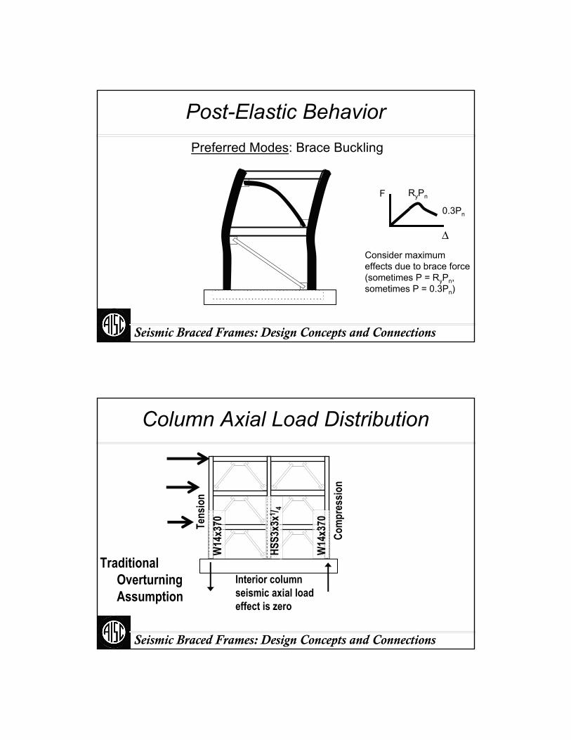
Post-Elastic BehaviorPreferred Modes: Brace Buckling
Δ
F
Consider maximum effects due to brace force (sometimes P = RyPn, sometimes P = 0.3Pn)
RyPn
0.3Pn
Seismic Braced Frames: Design Concepts and Connections
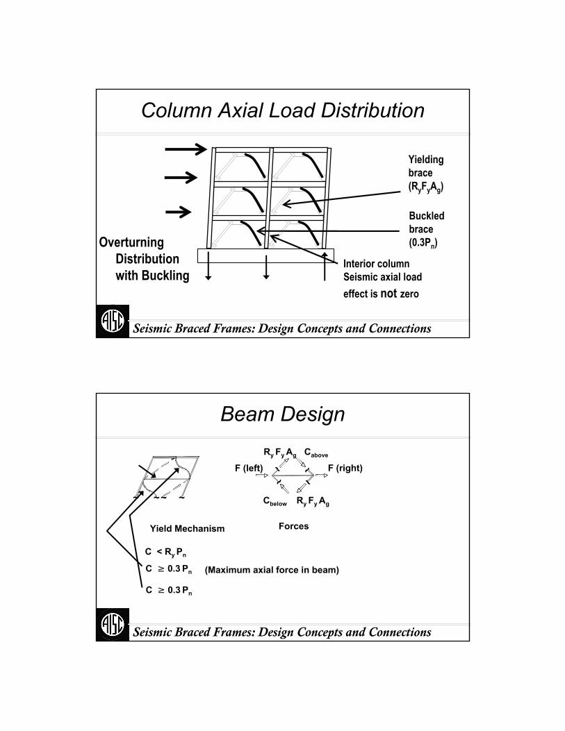
Com
pres
sion
Interior column seismic axial load effect is zero
Tens
ion
Traditional Overturning Assumption
Column Axial Load Distribution
W14
x370
W14
x370
HSS3
x3x1 / 4
Seismic Braced Frames: Design Concepts and Connections
Interior column Seismic axial load effect is not zero
Buckled brace (0.3Pn)Overturning
Distribution with Buckling
Column Axial Load Distribution
Yielding brace (RyFyAg)
Seismic Braced Frames: Design Concepts and Connections
Beam Design
C ≥ 0.3 Pn
C < Ry Pn
~~ ~~
Yield Mechanism
Cbelow Ry Fy Ag
CaboveRy Fy Ag
~ ~
~~F (left) F (right)
Forces
(Maximum axial force in beam)
C ≥ 0.3 Pn
Seismic Braced Frames: Design Concepts and Connections
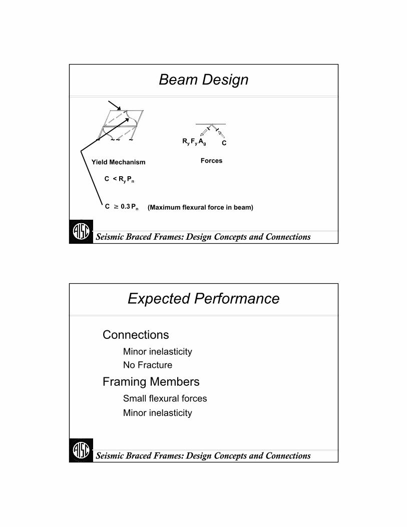
Beam Design
C < Ry Pn
~~ ~~
Yield Mechanism
C ≥ 0.3 Pn (Maximum flexural force in beam)
CRy Fy Ag
~ ~
Forces
Seismic Braced Frames: Design Concepts and Connections
Expected Performance
ConnectionsMinor inelasticityNo Fracture
Framing MembersSmall flexural forcesMinor inelasticity

Seismic Braced Frames: Design Concepts and Connections
Unfavorable Modes
Connection fracture
Column buckling
Beam failure
Seismic Braced Frames: Design Concepts and Connections
AISC Seismic
Basic AISC Seismic Design Procedure1. Calculate demands based on applicable
building code
2. Analyze
3. Size fuses (braces)
4. Size other members so fuses will govern

Seismic Braced Frames: Design Concepts and Connections
AISC Seismic
4. Size other members
Use expected brace capacity
Eliminate conservative design assumptions
Do not use φ for brace expected strength
Use expected material strength (RyFy) of brace
Consider other sources of conservatism
Seismic Braced Frames: Design Concepts and Connections
Other Sources of Conservatism
Brace effective lengthOut-of-straightness in equation of nominal
compression strengthFoundation Uplift
Size of footingParticipation of slab and grade beams-catenary action?
Other?
Seismic Braced Frames: Design Concepts and Connections
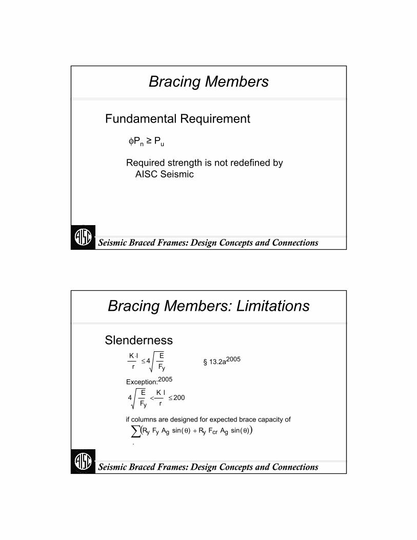
Bracing Members
Fundamental Requirement
φPn ≥ Pu
Required strength is not redefined by AISC Seismic
Seismic Braced Frames: Design Concepts and Connections
Bracing Members: Limitations
Exception:2005
if columns are designed for expected brace capacity of
Slenderness§ 13.2a2005K l⋅
r4
EFy
≤
4EFy
K lr
< 200≤
.
Ry Fy Ag sin θ( ) Ry Fcr Ag sin θ( )+( )∑
Seismic Braced Frames: Design Concepts and Connections
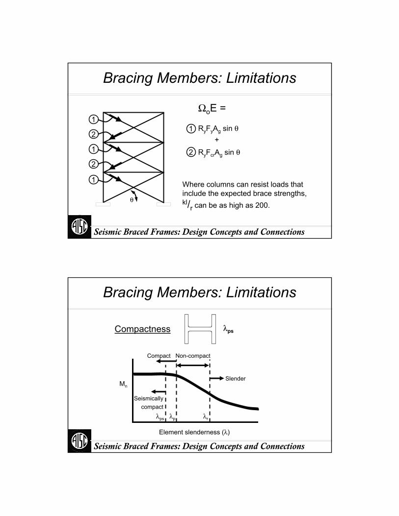
Bracing Members: Limitations
RyFyAg sin θ1
2
1
2
1
1
2 RyFcrAg sin θ+
ΩoE =
θ
Where columns can resist loads that include the expected brace strengths, kl/r can be as high as 200.
Seismic Braced Frames: Design Concepts and Connections
Bracing Members: Limitations
λpsCompactness
Slender
Non-compactCompact
Seismicallycompact
λps λp λr
Element slenderness (λ)
Mn

Seismic Braced Frames: Design Concepts and Connections
Bracing Members: Limitations
θ
Slender
Non-compact
Compact
Seismically compact
Mn
λpsCompactness
Seismic Braced Frames: Design Concepts and Connections
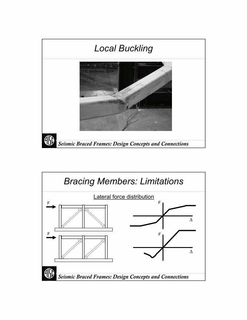
Local Buckling
Courtesy of S. MahinU.C. Berkeley, 2004
Seismic Braced Frames: Design Concepts and Connections
Local Buckling
Courtesy of S. MahinU.C. Berkeley, 2004
Seismic Braced Frames: Design Concepts and Connections
Bracing Members: LimitationsLateral force distribution
Δ
F
Δ
F
F
F
Seismic Braced Frames: Design Concepts and Connections
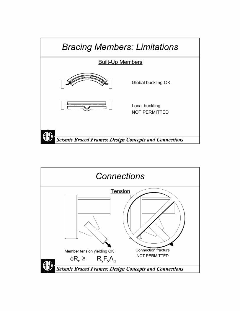
Bracing Members: LimitationsBuilt-Up Members
Global buckling OK
Local buckling NOT PERMITTED
Seismic Braced Frames: Design Concepts and Connections
Connections
Connection fractureNOT PERMITTED
Member tension yielding OK
Tension
φRn ≥ RyFyAg
Seismic Braced Frames: Design Concepts and Connections
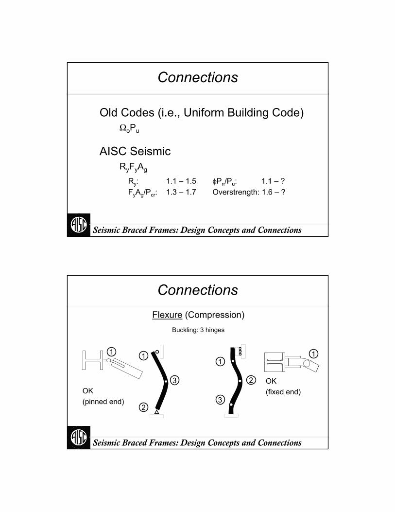
Connections
Old Codes (i.e., Uniform Building Code)ΩoPu
AISC Seismic
Ry: 1.1 – 1.5 φPn/Pu: 1.1 – ?FyAg/Pcr: 1.3 – 1.7 Overstrength: 1.6 – ?
RyFyAg
Seismic Braced Frames: Design Concepts and Connections
Connections
Buckling: 3 hinges
Flexure (Compression)
1
3
2
1
2
3
1
OK (fixed end)
1
OK(pinned end)

Seismic Braced Frames: Design Concepts and Connections
Pinned-End Gusset Hinging
Courtesy of S. MahinU.C. Berkeley, 2004
Seismic Braced Frames: Design Concepts and Connections
Fixed-End Brace Connection
Seismic Braced Frames: Design Concepts and Connections
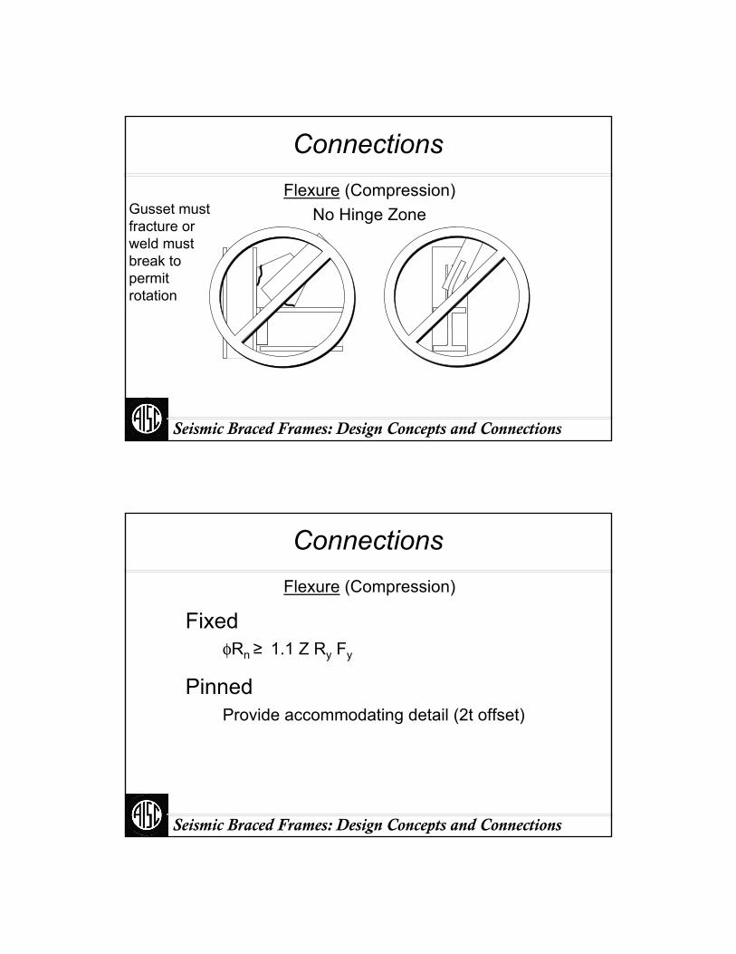
ConnectionsFlexure (Compression)
No Hinge ZoneGusset must fracture or weld must break to permit rotation
Seismic Braced Frames: Design Concepts and Connections
Connections
FixedφRn ≥ 1.1 Z Ry Fy
PinnedProvide accommodating detail (2t offset)
Flexure (Compression)

Seismic Braced Frames: Design Concepts and Connections
2t Offset
Fold line
2t
Fold line
2t
Provide accommodating detail (2t offset)Recommendation: Detail: 2t + ¾” ± ¾”
Design: 2t + 1½”
Seismic Braced Frames: Design Concepts and Connections
2t
2t Offset at Concrete Fill
Fold lineStyro-foam (1” ea. side per 6”depth)
2t
Fold line
Seismic Braced Frames: Design Concepts and Connections
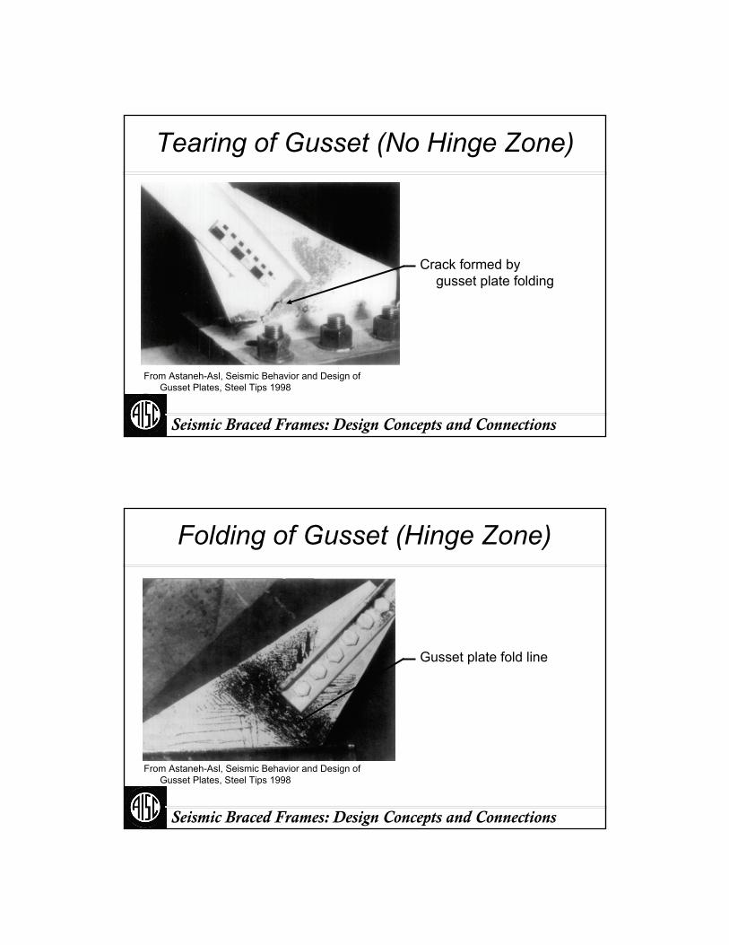
Tearing of Gusset (No Hinge Zone)
From Astaneh-Asl, Seismic Behavior and Design of Gusset Plates, Steel Tips 1998
Crack formed by gusset plate folding
Seismic Braced Frames: Design Concepts and Connections
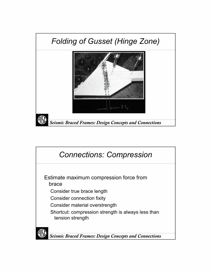
Folding of Gusset (Hinge Zone)
From Astaneh-Asl, Seismic Behavior and Design of Gusset Plates, Steel Tips 1998
Gusset plate fold line
Seismic Braced Frames: Design Concepts and Connections
Folding of Gusset (Hinge Zone)
Courtesy of R. Tremblay
Seismic Braced Frames: Design Concepts and Connections
Connections: Compression
Estimate maximum compression force from braceConsider true brace lengthConsider connection fixityConsider material overstrengthShortcut: compression strength is always less than
tension strength
Seismic Braced Frames: Design Concepts and Connections
Connections: Compression
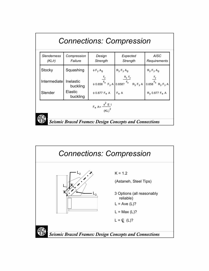
Stocky
Intermediate
Slender
CompressionFailure
Squashing
Inelastic buckling
Elastic buckling
DesignStrength
ExpectedStrength
AISCRequirements
Slenderness(KL/r)
φ Fy Ag Ry Fy Ag Ry Fy Ag
φ 0.658
Fy
Fe Fy A 0.658?
Ry Fy
Fe Ry Fy A 0.658
Fy
Fe Ry Fy A
φ 0.877 Fe A Fe A Ry 0.877 Fe A
Fe Aπ2 E I
(KL)2
Seismic Braced Frames: Design Concepts and Connections
Connections: Compression
L2
(Astaneh, Steel Tips)
K = 1.2
L3
L1
L = Max (L)?
L = Ave (L)?
L = C (L)?L
3 Options (all reasonably reliable)
Seismic Braced Frames: Design Concepts and Connections
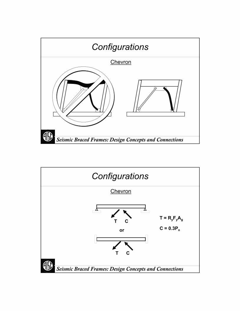
ConfigurationsChevron
Seismic Braced Frames: Design Concepts and Connections
ConfigurationsChevron
T C
or
T = RyFyAg
C = 0.3Pn
T C
Seismic Braced Frames: Design Concepts and Connections
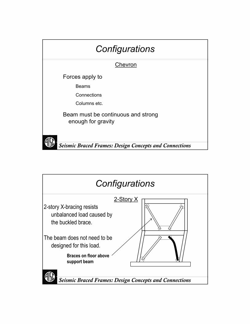
ConfigurationsChevron
Forces apply toBeams
Connections
Columns etc.
Beam must be continuous and strong enough for gravity
Seismic Braced Frames: Design Concepts and Connections
2-story X-bracing resists unbalanced load caused by the buckled brace.
The beam does not need to be designed for this load.
Braces on floor above support beam
Configurations2-Story X
Seismic Braced Frames: Design Concepts and Connections
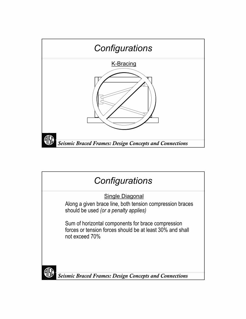
ConfigurationsK-Bracing
Seismic Braced Frames: Design Concepts and Connections
Along a given brace line, both tension compression braces should be used (or a penalty applies)
Sum of horizontal components for brace compression forces or tension forces should be at least 30% and shall not exceed 70%
ConfigurationsSingle Diagonal

Seismic Braced Frames: Design Concepts and Connections
All compression or tension systemSum of horizontal components in either
compression or tension ≥ 0.7VNo Good
V
100%V50%V
50%V
ConfigurationsSingle Diagonal
V
Seismic Braced Frames: Design Concepts and Connections
0.30V ≤ Tension ≤ 0.70.30V ≤ Compression ≤ 0.7
OK
0.30V ≤ Tension ≤ 0.70.30V ≤ Compression ≤ 0.7
OK
V
ConfigurationsX-Bracing Chevron Bracing
V50%V
50%V 25%V
25%V
25%V
25%V
Seismic Braced Frames: Design Concepts and Connections
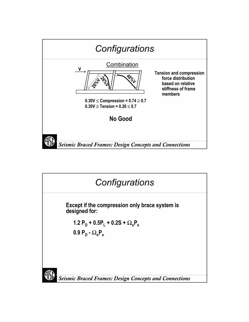
0.30V ≤ Compression = 0.74 ≥ 0.70.30V ≥ Tension = 0.26 ≤ 0.7
No Good
Tension and compression force distribution based on relative stiffness of frame members
ConfigurationsCombination
V
26%V
26%V
48%V
Seismic Braced Frames: Design Concepts and Connections
Except if the compression only brace system is designed for:
1.2 PD + 0.5PL + 0.2S + ΩoPe
0.9 PD - ΩoPe
Configurations
Seismic Braced Frames: Design Concepts and Connections
Columns
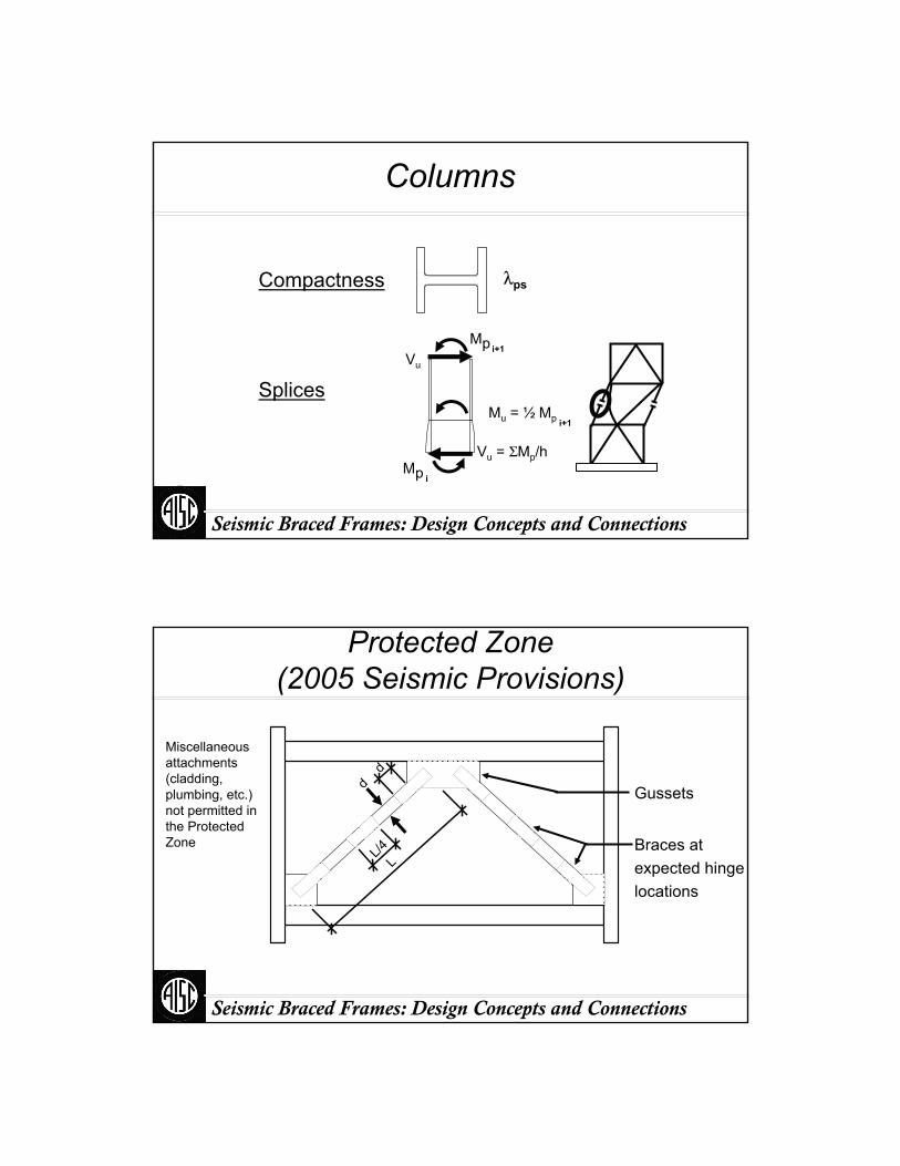
λpsCompactness
Splices
Vu = ΣMp/h
Mu = ½ Mp i+1
Mp i+1
Mp i
Vu
Seismic Braced Frames: Design Concepts and Connections
Protected Zone(2005 Seismic Provisions)
dd
LL/4
Gussets
Braces atexpected hingelocations
Miscellaneous attachments (cladding, plumbing, etc.) not permitted in the Protected Zone
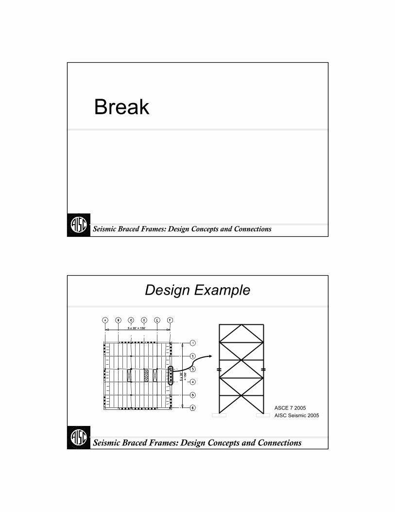
Break
Seismic Braced Frames: Design Concepts and Connections
Seismic Braced Frames: Design Concepts and Connections
Design Example
5 x 30’ = 150’
5 x
30’
= 15
0’
ASCE 7 2005AISC Seismic 2005
Seismic Braced Frames: Design Concepts and Connections
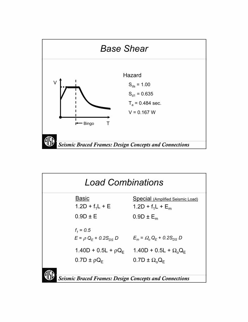
Base Shear
Bingo
HazardSds = 1.00
Sd1 = 0.635
Ta = 0.484 sec.
V = 0.167 W
T
V
Seismic Braced Frames: Design Concepts and Connections
Load Combinations
1.2D + f1L + E
0.9D ± E
1.40D + 0.5L + ρQE
0.7D ± ρQE
1.40D + 0.5L + ΩoQE
0.7D ± ΩoQE
f1 = 0.5E = ρ QE + 0.2SDS D
Basic Special (Amplified Seismic Load)
1.2D + f1L + Em
0.9D ± Em
Em = Ωo QE + 0.2SDS D
Seismic Braced Frames: Design Concepts and Connections
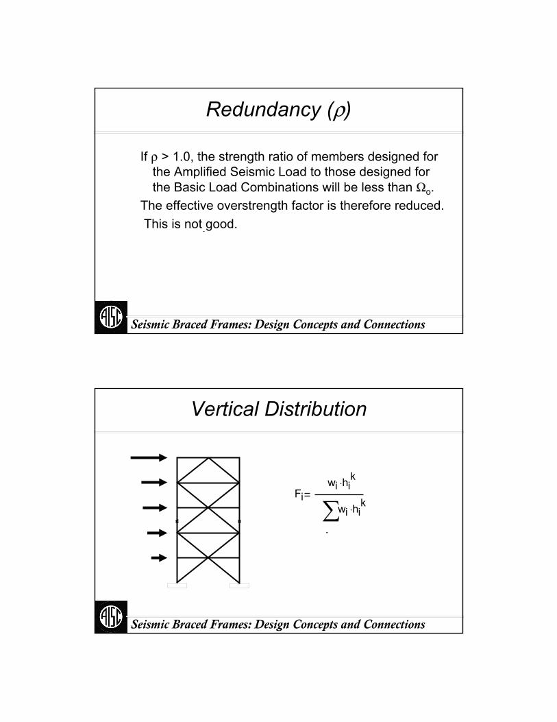
Redundancy (ρ)
Ω o effective( )Ω o
ρ
If ρ > 1.0, the strength ratio of members designed for the Amplified Seismic Load to those designed for the Basic Load Combinations will be less than Ωo.
The effective overstrength factor is therefore reduced.This is not good.
Seismic Braced Frames: Design Concepts and Connections
Vertical Distribution
Fiwi hi
k⋅
.
wi hik⋅∑

Seismic Braced Frames: Design Concepts and Connections
Horizontal Distribution
0.47 V 0.53 V0.03 V
0.03 V
5%
V
Seismic Braced Frames: Design Concepts and Connections
Redundancy per ASCE 7 2005
ρ = 1.0
Regular
Perimeter bracing
≥ 2 bays per side
Seismic Braced Frames: Design Concepts and Connections
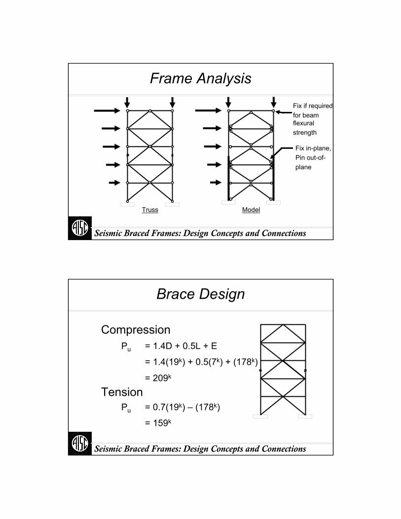
Frame Analysis
ModelTruss
Fix in-plane,Pin out-of-plane
Fix if requiredfor beam flexuralstrength
Seismic Braced Frames: Design Concepts and Connections
Brace Design
CompressionPu = 1.4D + 0.5L + E
= 1.4(19k) + 0.5(7k) + (178k)
= 209k
TensionPu = 0.7(19k) – (178k)
= 159k
Seismic Braced Frames: Design Concepts and Connections
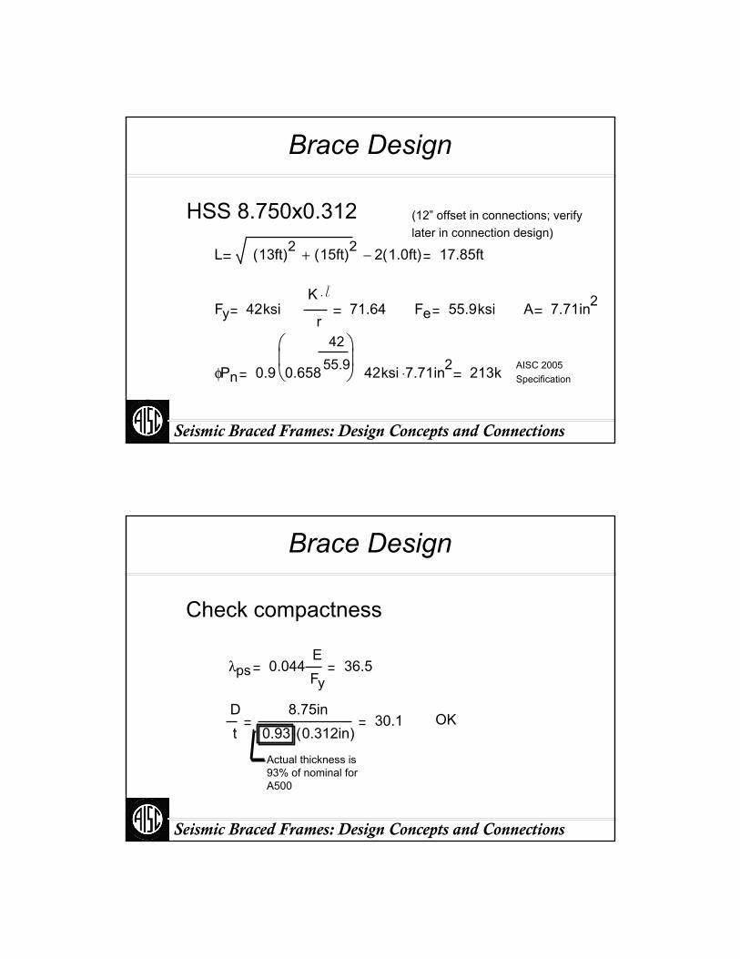
Brace Design
(12” offset in connections; verify later in connection design)
HSS 8.750x0.312
L 13ft( )2 15ft( )2+ 2 1.0ft( )− 17.85ft
Fy 42ksiK l⋅
r71.64 Fe 55.9ksi A 7.71in2
42ksi 7.71⋅ in2φPn 0.9 0.658
4255.9
⎛⎜⎝
⎞⎟⎠ 213k AISC 2005
Specification
Seismic Braced Frames: Design Concepts and Connections
Brace Design
Check compactness
λps 0.044EFy
36.5
Dt
8.75in0.93 0.312in( )⋅
30.1 OK
Actual thickness is 93% of nominal for A500
Seismic Braced Frames: Design Concepts and Connections
Required Strength in Tension
AISC Seismic Provisions 13.3.aRy Fy Ag
Other Limiting Maximum ForceConsider Variability of Force DistributionConsider Dynamics (Not only Statics)
Greater Than Previous RequirementsBrace Design ForceAmplified Seismic Load
3Rw /8 x Brace Design ForceWo x Brace Design Force
Seismic Braced Frames: Design Concepts and Connections
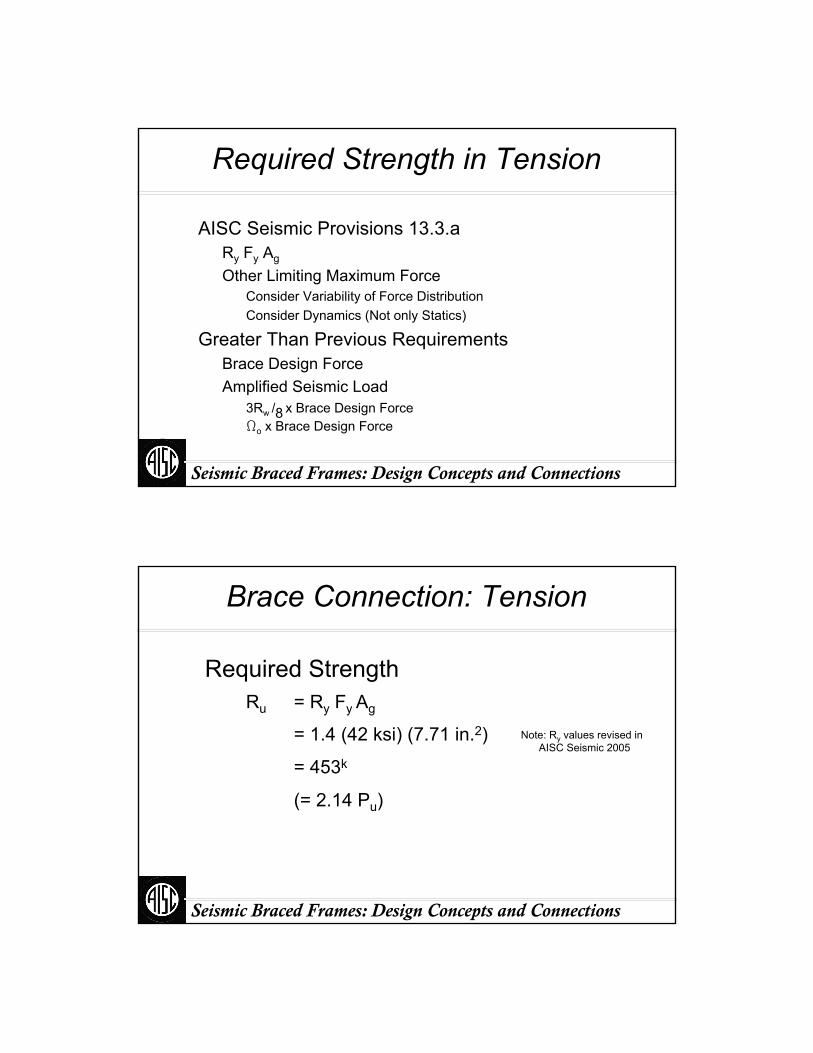
Brace Connection: Tension
Required StrengthRu = Ry Fy Ag
= 1.4 (42 ksi) (7.71 in.2)
= 453k
(= 2.14 Pu)
Note: Ry values revised in AISC Seismic 2005

Seismic Braced Frames: Design Concepts and Connections
Typical Detailing of Reduced Section at Knife Plate
Radius = 1/2 t2
Grind Smooth
HSS BraceGusset Platet1
2” max.
t2 = t1 + 1/8“
Seismic Braced Frames: Design Concepts and Connections
Demand versus Capacity
Net-Section reinforcement is always required
RyFyAg
Demand
φRTFuUAnet
Capacity
Anet
Ag= 1.3 1.1 (U = 0.9)
A500 Gr. B A53
Ry Fy
φRTFuU
≥Expected Tensile StrengthNew to 2005 AISC Seismic
Seismic Braced Frames: Design Concepts and Connections
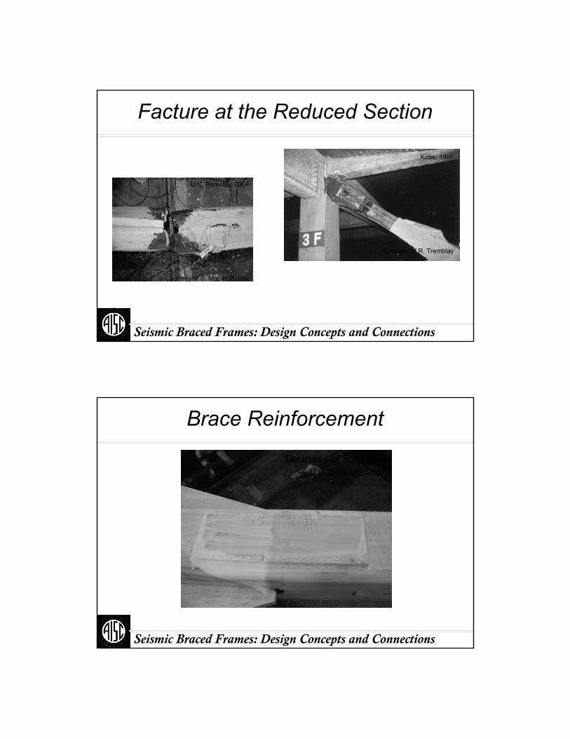
Facture at the Reduced Section
Kobe, 1995
Courtesy of R. Tremblay
U.C. Berkeley, 2004
Courtesy of S. Mahin, P. Uriz
Seismic Braced Frames: Design Concepts and Connections
Brace Reinforcement
Courtesy of S. MahinU.C. Berkeley, 2004

Seismic Braced Frames: Design Concepts and Connections
Brace Reinforcement
Courtesy of S. MahinU.C. Berkeley, 2004
Seismic Braced Frames: Design Concepts and Connections
Brace Connection: Tension
AssumptionsGusset width ~ 2 dbr (2 x 8.75” = 17.5”)
Gusset thickness (tg):
453k / (0.9 x 36 ksi x 17.5”) = 0.80”;Use ⅞”
dbr
Gusset width

Seismic Braced Frames: Design Concepts and Connections
Brace Connection: Tension
Net Section FractureAremoved = 2 [tg + ⅛”] tbr
= 2 [⅞” + ⅛”] 0.29”
= 0.58 in.2
Anet = 7.71 in.2 – 0.58 in.2 = 7.13 in.2
Seismic Braced Frames: Design Concepts and Connections
Brace Connection: Tension
Required AreaφRTFuAe ≥ RyFyAg
= 1.4 x 42 ksi x 7.71in.2 /(0.75 x 1.3 x 58 ksi)
= 8.01 in.2 ( > Ag!)
Reinforcement required
Ae ≥ RyFyAg /φRTFu
Seismic Braced Frames: Design Concepts and Connections
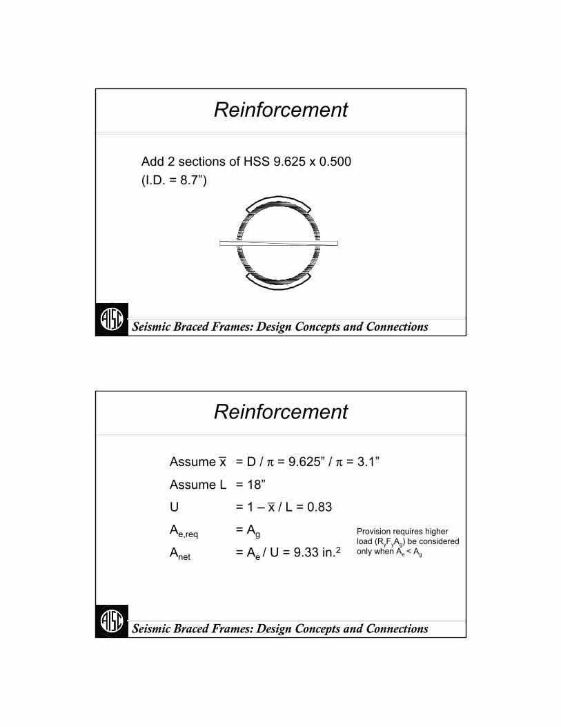
Reinforcement
Add 2 sections of HSS 9.625 x 0.500(I.D. = 8.7”)
Seismic Braced Frames: Design Concepts and Connections
Reinforcement
Assume L = 18”
Ae,req = Ag
Assume x = D / π = 9.625” / π = 3.1”_
U = 1 – x / L = 0.83_
Anet = Ae / U = 9.33 in.2Provision requires higher load (RyFyAg) be considered only when Ae < Ag

Seismic Braced Frames: Design Concepts and Connections
Reinforcement
0.93 x 0.50” = 0.465”
AreinfAnet req( ) Anet brace( )−
2 plates1.10in2
RR
9.625in2
t2
− 4.58in
Seismic Braced Frames: Design Concepts and Connections
Reinforcement
c
2 ½”
breq1.10in2
0.465in2.36in
creq 2R sin12
180o b π r
⎛⎜⎝
⎞⎟⎠
⎡⎢⎣
⎤⎥⎦
2.40in
A2.5 in2.4 in
1.10in2 1.15in2b
Seismic Braced Frames: Design Concepts and Connections
Reinforcement
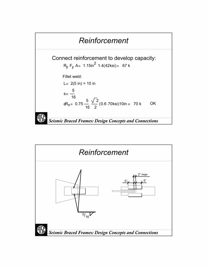
Fillet weld:
Connect reinforcement to develop capacity:Ry Fy A 1.15in2 1.4 42ksi( ) 67 k
L 2(5 in) = 10 in
s516
φRn 16 20.75
5 20.6 70⋅ ksi( )10in 70 k OK
Seismic Braced Frames: Design Concepts and Connections
Reinforcement
5/16
2” max
5”5”

Seismic Braced Frames: Design Concepts and Connections
Brace Connection: Tension
Use L = 2D = 17.5” 18”
Brace block shearφRn 4 0.75( ) t L⋅ 0.6Fu( )⋅ Ru≥
LRu
4 0.75( ) t 0.6Fu( )⋅≥ 15in
LD
Seismic Braced Frames: Design Concepts and Connections
Brace Connection: Tension
Brace-to-gusset weldL 18in
φRn 4 0.75( ) s2
2⋅ L⋅ 0.6FEXX( )⋅ Ru≥
sRu
4 0.75( )⋅2
2⋅ L⋅ 0.6 FEXX⋅( )⋅
≥516
in OK
Seismic Braced Frames: Design Concepts and Connections
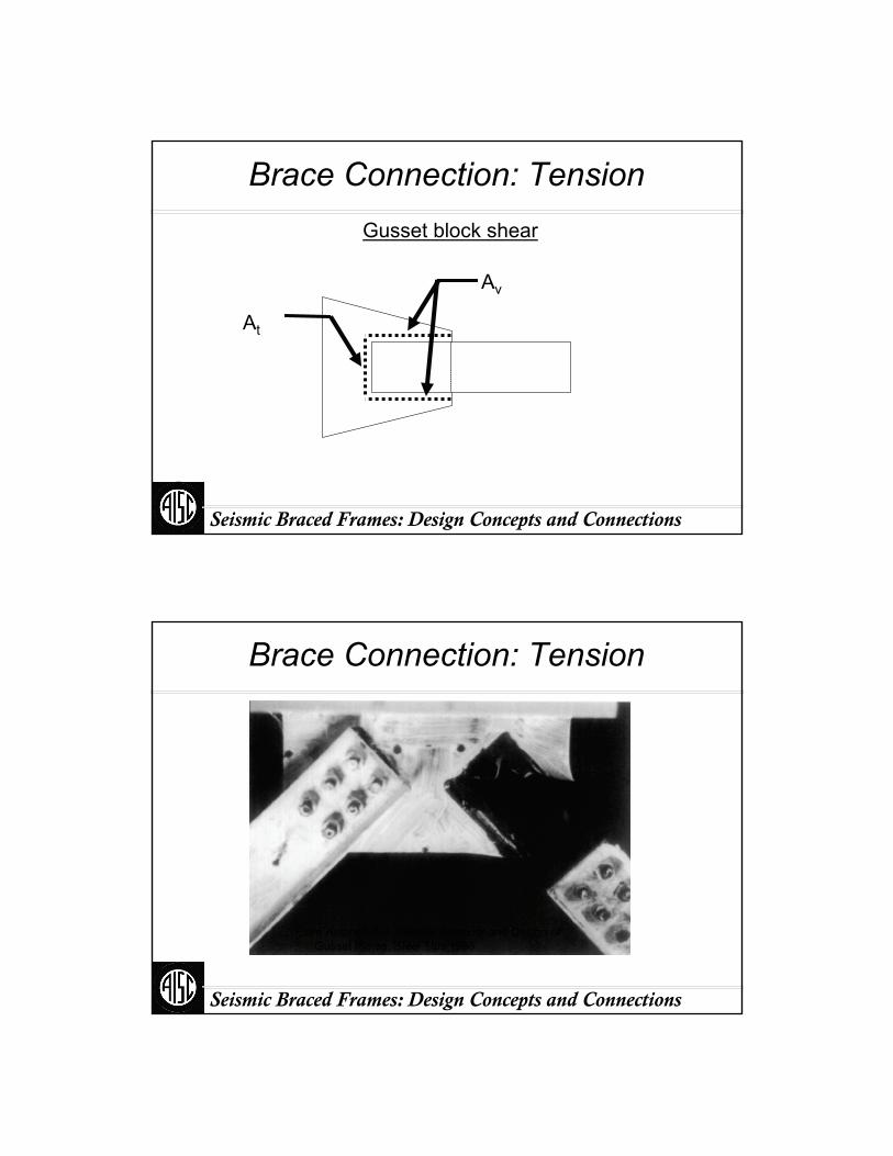
Brace Connection: TensionGusset block shear
At
Av
Seismic Braced Frames: Design Concepts and Connections
Brace Connection: Tension
From Astaneh-Asl, Seismic Behavior and Design of Gusset Plates, Steel Tips 1998
Seismic Braced Frames: Design Concepts and Connections
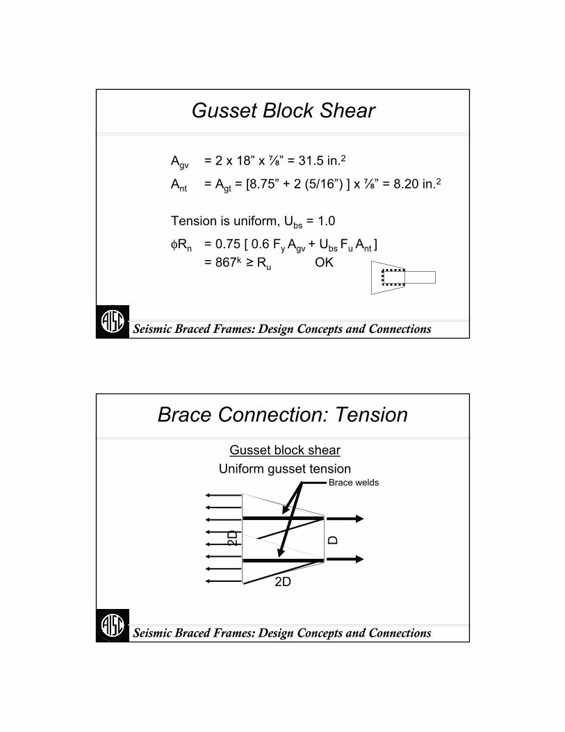
Gusset Block Shear
Ant = Agt = [8.75” + 2 (5/16”) ] x ⅞” = 8.20 in.2
φRn = 0.75 [ 0.6 Fy Agv + Ubs Fu Ant ]= 867k ≥ Ru OK
Tension is uniform, Ubs = 1.0
Agv = 2 x 18” x ⅞” = 31.5 in.2
Seismic Braced Frames: Design Concepts and Connections
Brace Connection: TensionGusset block shear
Uniform gusset tension
D2D
2D
Brace welds
Seismic Braced Frames: Design Concepts and Connections
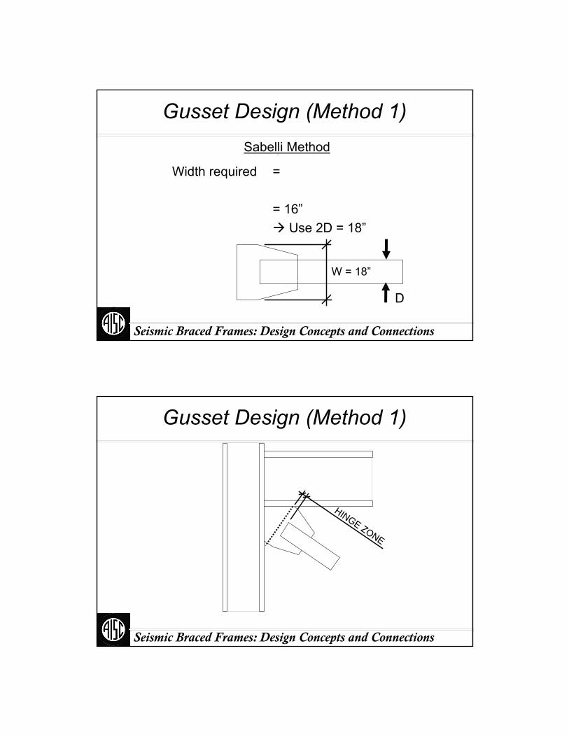
Gusset Design (Method 1)Sabelli Method
Width required =
= 16”Use 2D = 18”
W = 18”
Ru
φFy t⋅
D
Seismic Braced Frames: Design Concepts and Connections
Gusset Design (Method 1)
HINGE ZONE

Seismic Braced Frames: Design Concepts and Connections
Gusset Analysis (Method 1)
T
e c
e b
Tbeam
Tcol
Concentric Workpoint
Tbeam Tec
ec eb+⋅
Tcol Teb
ec eb+⋅
eq. eq.eq
.eq
.
Seismic Braced Frames: Design Concepts and Connections
Gusset Analysis (Method I)
T
e c
e b
Tbeam
Tcol
Modified Workpoint
ec eb
TbeamT2
TcolT2
eq. eq.
eq.
eq.

Seismic Braced Frames: Design Concepts and Connections
Gusset Design: Method IIUniform force method
θ
e b12
d b=
e c12
d c=
2α
2β
Seismic Braced Frames: Design Concepts and Connections
Uniform Force Method
Assume β 5in
Note: Assumed size must be verified by checking gusset width and combined shear & tension at gusset joints to beam & column
α β eb+( )tan θv( )
α 5in 8.95in+( )tan 49.1o( ) 9.24in
r α ec+( )2 β eb+( )2+ 21.3in
(For zero moment on welded interfaces)
Seismic Braced Frames: Design Concepts and Connections
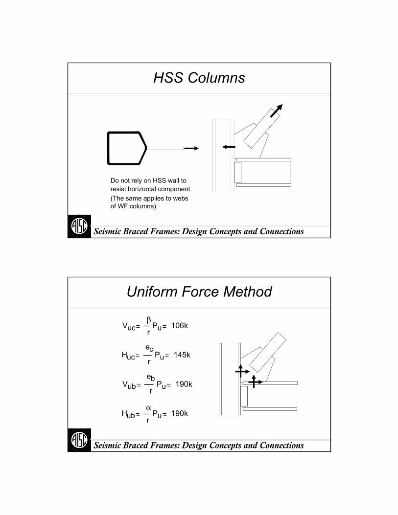
HSS Columns
Do not rely on HSS wall to resist horizontal component(The same applies to webs of WF columns)
Seismic Braced Frames: Design Concepts and Connections
Uniform Force Method
Vucβr
Pu 106k
Hucec
rPu 145k
Vubeb
rPu 190k
Hubαr
Pu 190k
Seismic Braced Frames: Design Concepts and Connections
Uniform Force Method
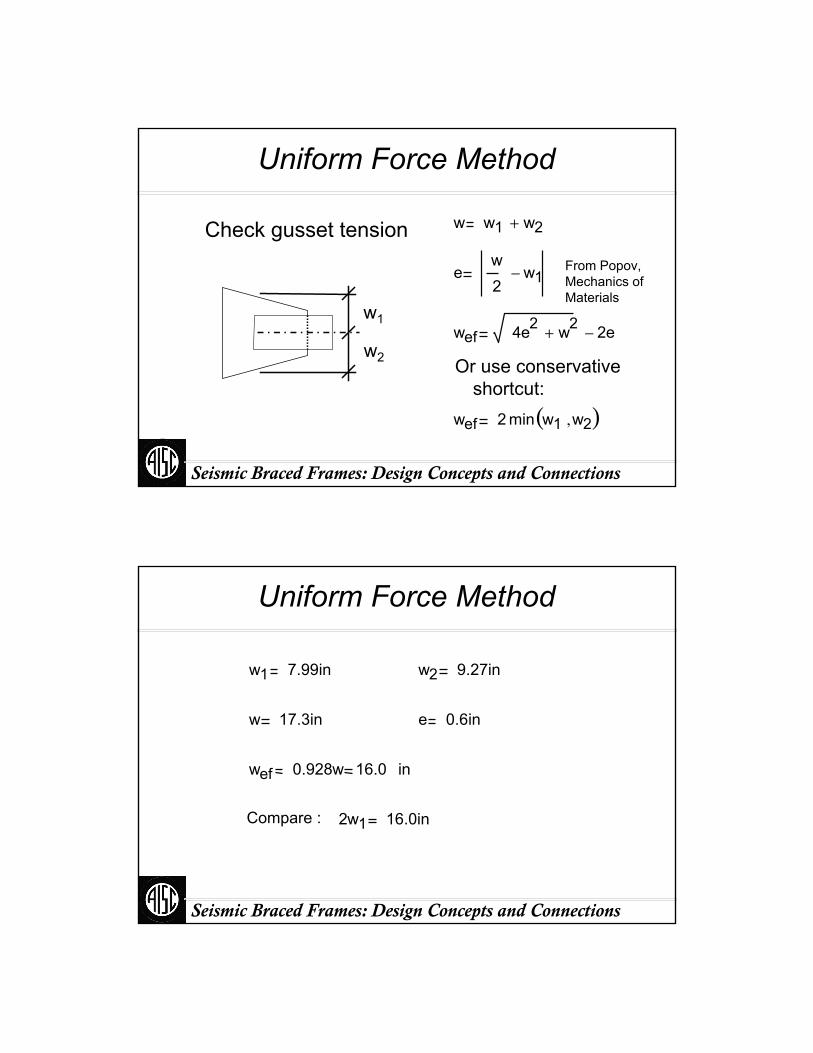
Check gusset tension
Or use conservative shortcut:
w1
w2
w w1 w2+
ew2
w1−
wef 4e2 w2+ 2e−
wef 2 min w1 w2,( )
From Popov, Mechanics of Materials
Seismic Braced Frames: Design Concepts and Connections
Uniform Force Method
w1 7.99in w2 9.27in
w 17.3in e 0.6in
wef 0.928w 16.0 in
Compare : 2w1 16.0in
Seismic Braced Frames: Design Concepts and Connections
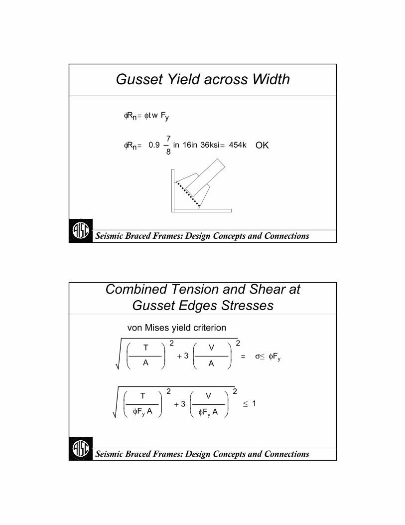
Gusset Yield across Width
φRn φt w Fy
OKφRn 0.978
in 16in 36ksi 454k
Seismic Braced Frames: Design Concepts and Connections
Combined Tension and Shear at Gusset Edges Stresses
von Mises yield criterion
σ≤ φFy
T
A
⎛⎜⎝
⎞⎟⎠
2
3V⎛
⎜⎝
⎞⎟⎠
2
+A
T
φFy A
⎛⎜⎝
⎞⎟⎠
2
3V⎛
⎜⎝
⎞⎟⎠
2
+ ≤ 1φFy A

Seismic Braced Frames: Design Concepts and Connections
Gusset Yield at Vertical Section
Huc
φ Fy t 2 β
⎛⎜⎝
⎞⎟⎠
2
3Vuc
φ Fy t 2 β
⎛⎜⎝
⎞⎟⎠
2
+ 0.83
OK
Don’t forget to deduct weld access hole for flange weld, if used.
Seismic Braced Frames: Design Concepts and Connections
Gusset Yield at Horizontal Section
Vub
φ Fy t 2 α
⎛⎜⎝
⎞⎟⎠
2
3Hub
φ Fy t 2 α
⎛⎜⎝
⎞⎟⎠
2
+ 0.74
OK
Seismic Braced Frames: Design Concepts and Connections
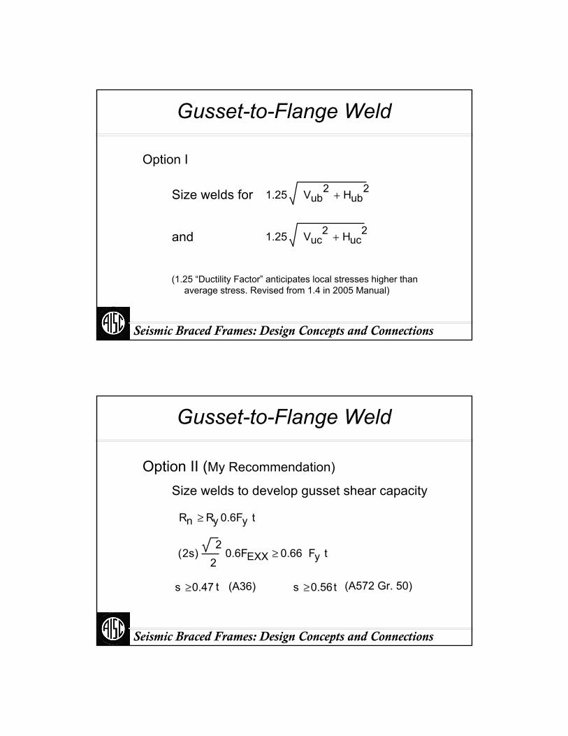
Gusset-to-Flange Weld
Size welds for
and
Option I
1.25 Vub2 Hub
2+
1.25 Vuc2 Huc
2+
(1.25 “Ductility Factor” anticipates local stresses higher than average stress. Revised from 1.4 in 2005 Manual)
Seismic Braced Frames: Design Concepts and Connections
Gusset-to-Flange Weld
Size welds to develop gusset shear capacity
Option II (My Recommendation)
Rn Ry 0.6Fy t≥
2s( )2
20.6FEXX 0.66 Fy t≥
s 0.47 t≥ (A36) s 0.56t≥ (A572 Gr. 50)
Seismic Braced Frames: Design Concepts and Connections
Gusset-to-Flange Weld
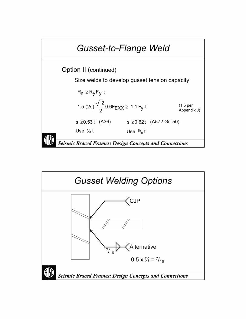
Size welds to develop gusset tension capacity
Option II (continued)
Rn RyFy t≥
2s1.5 ( )2
20.6FEXX 1.1 Fy t≥
s 0.53 t≥ (A36) s 0.62t≥ (A572 Gr. 50)
(1.5 per Appendix J)
Use ½ t Use 5/8 t
Seismic Braced Frames: Design Concepts and Connections
Gusset Welding Options
Alternative
CJP
7/16
0.5 x ⅞ = 7/16
Seismic Braced Frames: Design Concepts and Connections
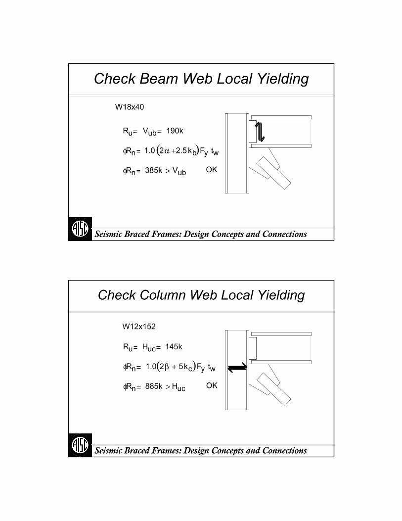
Check Beam Web Local Yielding
Ru Vub 190k
W18x40
φRn 1.0 2α 2.5kb+( )Fy tw
φRn 385k Vub> OK
Seismic Braced Frames: Design Concepts and Connections
Check Column Web Local Yielding
Ru Huc 145k
W12x152
φRn 1.0 2β 5kc+( )Fy tw
φRn 885k Huc> OK
Seismic Braced Frames: Design Concepts and Connections
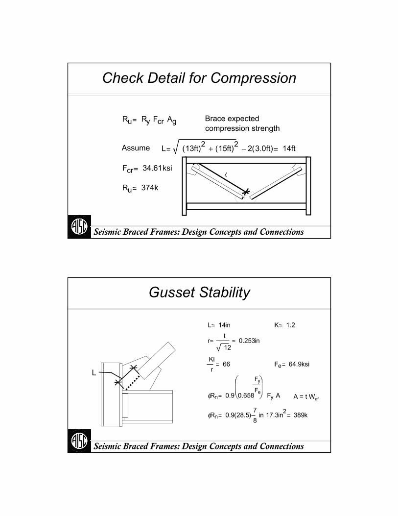
Check Detail for Compression
Ru Ry Fcr Ag Brace expectedcompression strength
Assume L 13ft( )2 15ft( )2+ 2 3.0ft( )− 14ft
Fcr 34.61ksi
Ru 374k
L
Seismic Braced Frames: Design Concepts and Connections
Gusset Stability
L
L 14in K 1.2
rt
120.253in
Klr
66 Fe 64.9ksi
φRn 0.9 0.658
Fy
Fe
⎛⎜⎜⎝
⎞⎟⎟⎠ Fy A
φRn 0.9 28.5( )78
in 17.3in2 389k
A = t Wef

Seismic Braced Frames: Design Concepts and Connections
Check Brace Length Assumption
L 14in
LL2
L2 Db/2cos(θ) = 12in
L2 + (L – Lhinge) = 24in
> 12in (for lower-bound brace strength)
< 36in (for upper-bound brace strength)
Seismic Braced Frames: Design Concepts and Connections
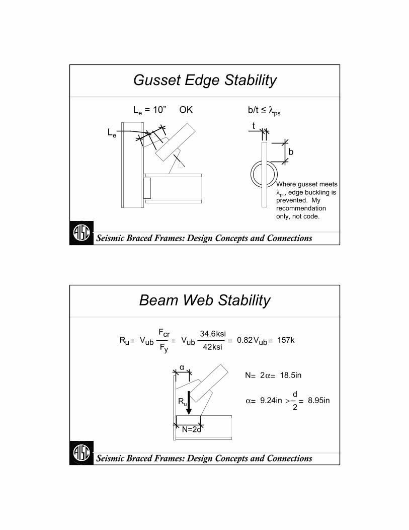
Gusset Edge Stability
Le
t34
EFy
≤ (Astaneh, Steel Tips)
Le
t21.3
Le 21.3t≤ 18.6 in
Le
Seismic Braced Frames: Design Concepts and Connections
Gusset Edge Stability
Le
Le = 10” OK
b
b/t ≤ λps
t
Where gusset meets λps, edge buckling is prevented. My recommendation only, not code.
Seismic Braced Frames: Design Concepts and Connections
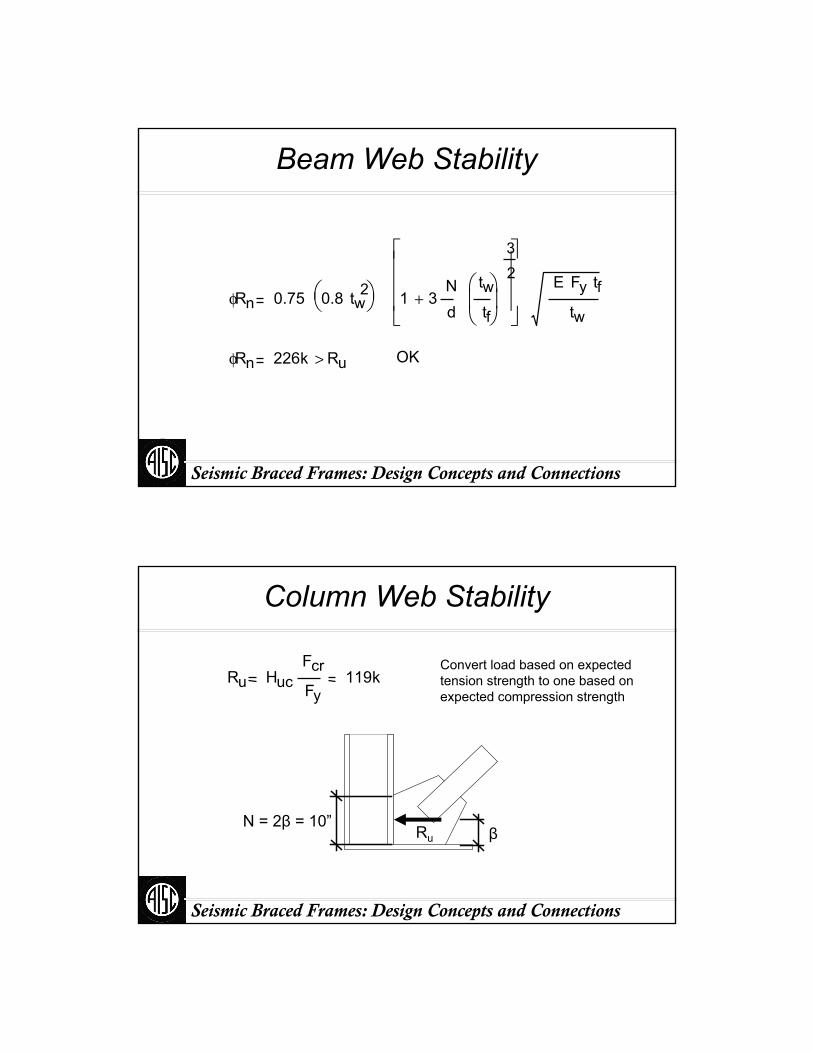
Beam Web Stability
α
N=2α
Ru
Ru VubFcr
FyVub
34.6ksi42ksi
0.82Vub 157k
N 2α 18.5in
α 9.24ind2
> 8.95in
Seismic Braced Frames: Design Concepts and Connections
Beam Web Stability
φRn 0.75 0.8 tw2⎛
⎝⎞⎠ 1 3
Nd
twtf
⎛⎜⎝
⎞⎟⎠
32
+
⎡⎢⎢⎢⎣
⎤⎥⎥⎥⎦
E Fy tftw
φRn 226k Ru> OK
Seismic Braced Frames: Design Concepts and Connections
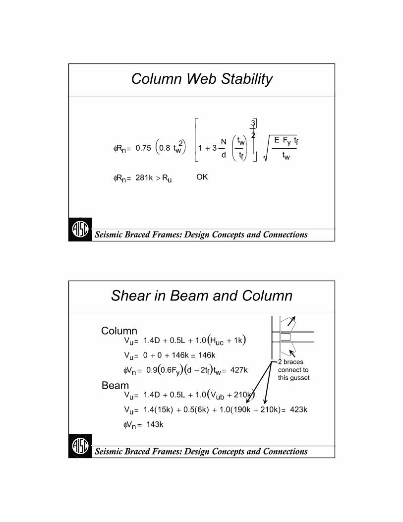
Column Web Stability
βRuN = 2β = 10”
Convert load based on expected tension strength to one based on expected compression strength
Ru HucFcrFy
119k
Seismic Braced Frames: Design Concepts and Connections
Column Web Stability
φRn 0.75 0.8 tw2⎛
⎝⎞⎠ 1 3
Nd
twtf
⎛⎜⎝
⎞⎟⎠
32
+
⎡⎢⎢⎢⎣
⎤⎥⎥⎥⎦
E Fy tftw
φRn 281k Ru> OK
Seismic Braced Frames: Design Concepts and Connections
Shear in Beam and Column
Beam
ColumnVu 1.4D 0.5L+ 1.0 Huc 1k+( )+
Vu 0 0+ 146k+ 146k
φVn 0.9 0.6Fy( ) d 2tf−( )tw 427k
Vu 1.4D 0.5L+ 1.0 Vub 210k+( )+
Vu 1.4 15k( ) 0.5 6k( )+ 1.0 190k 210k+( )+ 423k
φVn 143k
2 braces connect to this gusset
Seismic Braced Frames: Design Concepts and Connections
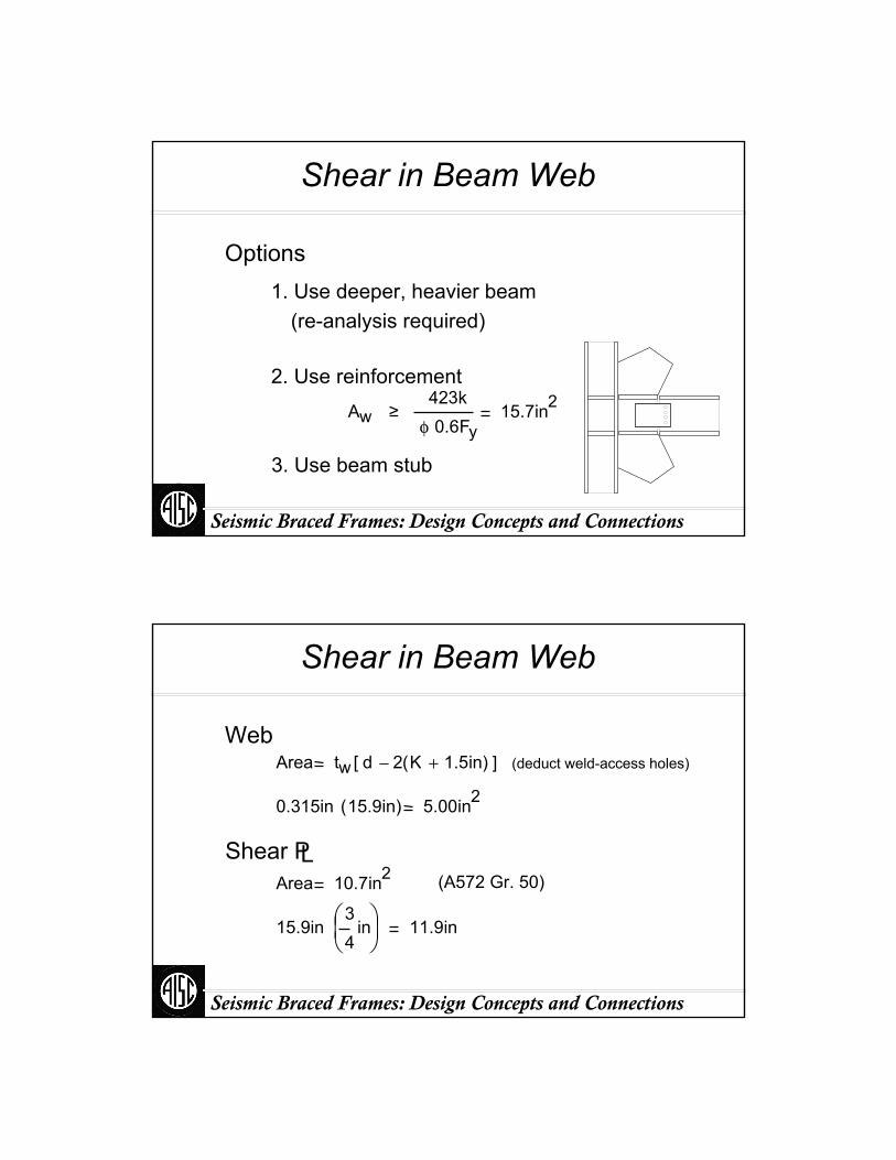
Shear in Beam Web
1. Use deeper, heavier beam (re-analysis required)
2. Use reinforcement
Options
Aw ≥423k
φ 0.6Fy15.7in2
3. Use beam stub
Seismic Braced Frames: Design Concepts and Connections
Shear in Beam Web
LShear P
WebArea tw d 2 K 1.5in+( )−[ ] (deduct weld-access holes)
0.315in 15.9in( ) 5.00in2
Area 10.7in2 (A572 Gr. 50)
15.9in34
in⎛⎜⎝
⎞⎟⎠
11.9in
Seismic Braced Frames: Design Concepts and Connections
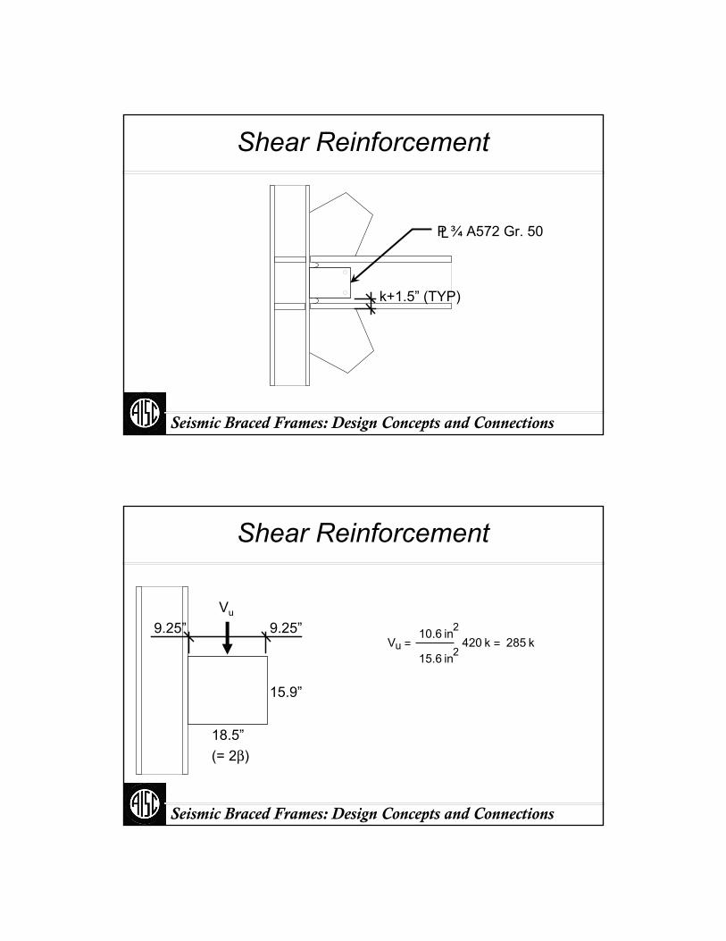
Shear Reinforcement
k+1.5” (TYP)
P ¾ A572 Gr. 50 L
Seismic Braced Frames: Design Concepts and Connections
Shear Reinforcement
15.9”
9.25”9.25”
18.5”(= 2β)
Vu
Vu10.6 in2
15.6 in2420 k 285 k

Seismic Braced Frames: Design Concepts and Connections
Shear Reinforcement
a l
ex
k lx l
l
l 15.9in K l⋅ 18.5in K 1.16in
x 0.401 (Table) a 0.181
C 5.7ex 9.25in x l⋅− 2.87in
φRn C C1⋅ D⋅ l⋅
DminPu
C C1⋅ l⋅
420k5.7 1.0( )⋅ 15.9in
4.6
USE 516
in WELD
Seismic Braced Frames: Design Concepts and Connections
Beam-to-Column Connection
(CJP web & reinforcement)
(Collector Fpx)
Vu 420k
Mu 26.5ft k Beam moment from model⋅
Pu Ωo 37.9k 75.8k
Pu Huc(i) – 0.3 Hc(i+1) 186 k
(based on postelastic mode)

Seismic Braced Frames: Design Concepts and Connections
Postelastic mode
0.3 Pn
0.3 Hc(i+1)
Ry Fy A
Huc(i)
Pu
Can be reduced somewhat by collector force (as shown in design of beam to follow)
Need not be considered in conjunction with full shear
Seismic Braced Frames: Design Concepts and Connections
Beam-to-Column Connection
Beam moment from model:26.5 ft-kip
Beam moment from connection forces:Hub (Db/2) - Vub (α)= 190 kip (9in) - 190 kip (9in)= 0 in-kip
e b12
d b=
e c12
d c=
2α
2β
Hub
Vub
This moment will be > 0 for methods other than UFM

Seismic Braced Frames: Design Concepts and Connections
Beam-to-Column Connection
CJP Flange OK (Alternatively, use a PJP or fillets)
Flange forceMu
d tf−
12
Pu+ 111 k
57.6k0.9Fy Af
0.76Pu
Pnφ
Seismic Braced Frames: Design Concepts and Connections
Beam-to-Column Connection
φRn 0.8 0.6 70⋅ ksi( ) 6.02in E
φRn 111 k≥
E 0.55in≥
916
in PJP WELD OK
Seismic Braced Frames: Design Concepts and Connections
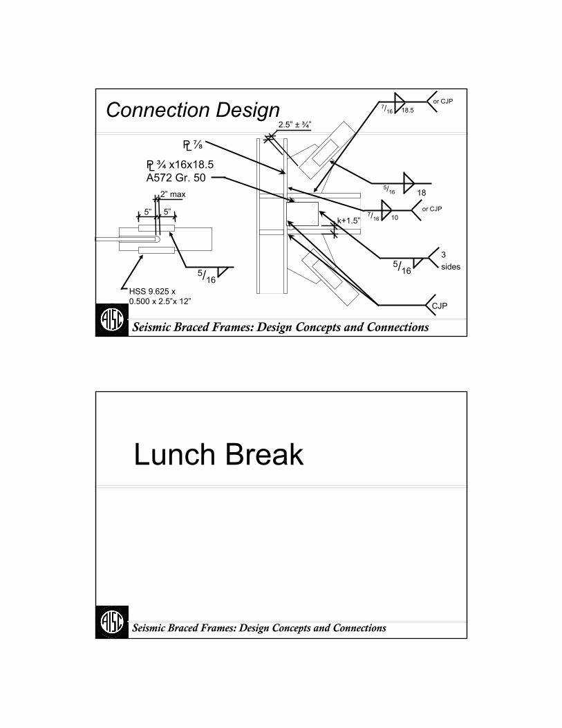
Connection Design
k+1.5”
HSS 9.625 x 0.500 x 2.5”x 12”
5/16 18
LP ⅞
CJP
2.5” ± ¾”
5/16
2” max
5”5”
5/16
3 sides
or CJP18.57/16
or CJP107/16
P ¾ x16x18.5 A572 Gr. 50 L
Lunch Break
Seismic Braced Frames: Design Concepts and Connections

Bay size Plate A36 Brace BeamL = 15 ft Material Fy = 36 (ksi) Material Material A992H = 13 ft Fu = 58 (ksi) Fy 50 (ksi)
49.1 deg. Dimensions Section W18X46Analysis Width adustment factor 1.00 Fy 42 (ksi) Stiffening
Suggested Ry 1.4 Not = 7/8 in. 3/4 in. Fu 58 (ksi) No
Slot width 1 in. 1 in. RT 1.31.25 L L 4.54
(in.) (in.) SectionGusset K = 1.2 Gusset lap with brace (min.) = 16.63 16.63
Control Horizontal = 17.00 17.00 Reinforcement (2 plates) ColumnVertical = 10.00 10.00 Material Material A992
Width and angle (beam side) = 8.29 13 deg t = 3/8 in. Fy 50 (ksi)
Precision Width and angle (col. side) = 8.29 13 deg Suggested Section W12X1520.125 (in.) b = 4.00 4.00 in. Stiffening
Welds eh = 0 (in.) A/ Ae = 0.94 NoFEXX 70 (ksi) Hinge tolerance 1 (in.) No
s Max. Useful Shoulder 1 (in.)
Brace weld 5/16 in. 7/16 in. Weld gap (hor) 0 (in.) 4.55Suggested Weld gap (vert) 0 (in.) L = 14.00 (in.)
Beam weld 7/16 in. 7/16 in. Max. Overslot 2 (in.) Fy 42 (ksi)
Column weld 7/16 in. 7/16 in. Buckling length 12.9 (in.) Ry 1.3No s 5/16 (in.) Orientation Strong
Limit States OK! Ru φRn Ru/φRn
Brace (kip) (kip)Net-section rupture J4-2 462 489 0.94Brace shear rupture J4-4 462 677 0.68Brace shear yield J4-3 462 633 0.73Brace weld J2-4 462 463 1.00
GussetGusset block shear J4-5 462 1088 0.42Tension Yield J4-3 462 470 0.98Gusset buckling J4-6 329 386 0.85
Gusset at columnYield (σvm) J4-1 244 284 0.86Tension rupture J4-2 150 381 0.39Shear rupture J4-4 104 228 0.46Column weld J2-4 244 374 0.65
Gusset at beamYield (σvm) J4-1 412 482 0.85Tension rupture J4-2 198 647 0.31Shear rupture J4-4 199 388 0.51Beam weld J2-4 194 313 0.62
ColumnWeb yielding J10-2 150 870 0.17Web crippling J10-4, 5a, 5b 107 1438 0.07
BeamWeb yielding J10-2 198 397 0.50Web crippling J10-4, 5a, 5b 141 160 0.88
Gusset edge buckling Length Limit Length/LimitAt column (Steel Tips) 9.2 in. 18.6 in. 0.49At beam (Steel Tips) 2.8 in. 18.6 in. 0.15
Beam-to-column connection forces Eccentric moment Vertical and horizontal dimensions Diagonal dimensionsHcol 150 (kip) Mecc 0 (in.-kip) Max. gusset height 23.3 in. Width 18.7 in.Vbm 198 (kip) Max gusset length 29.4 in. Length 32.2 in.M 0 (in.-kip) Area 685 in.2 Area 602 in.2
Stiffener length 0.0 in.
A500 Round Grade B
Factor to account for weld stress concentrations
Edge length measured
Edge length measured
Uniform Force Method
HSS8.625X.312
Specification Equation
Web stiffener?
to brace end
Edge stiffener?
Edge stiffener?Gusset b/t at end of
brace =
Gusset b/t at end of brace =
to brace end
Workpoint horizontal eccentricity Web stiffener?
Edge stiffener?
A572 Gr.42Vertical and horizontal dimensions
-20.00
-10.00
0.00
10.00
20.00
30.00
40.00
50.00
-20.0 -10.0 0.0 10.0 20.0 30.0 40.0 50.0
Seismic Braced Frames: Design Concepts and Connections
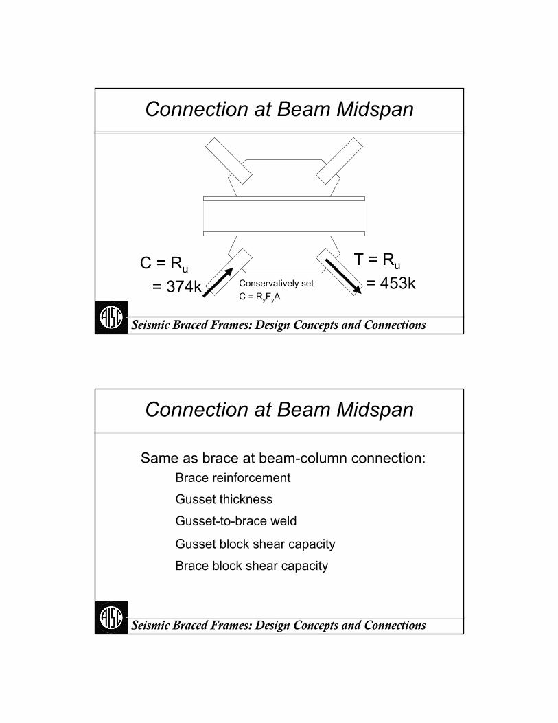
Connection at Beam Midspan
T = Ru
= 453kC = Ru
= 374k Conservatively set C = RyFyA
Seismic Braced Frames: Design Concepts and Connections
Connection at Beam Midspan
Same as brace at beam-column connection:
Gusset thickness
Brace reinforcement
Brace block shear capacity
Gusset-to-brace weld
Gusset block shear capacity
Seismic Braced Frames: Design Concepts and Connections
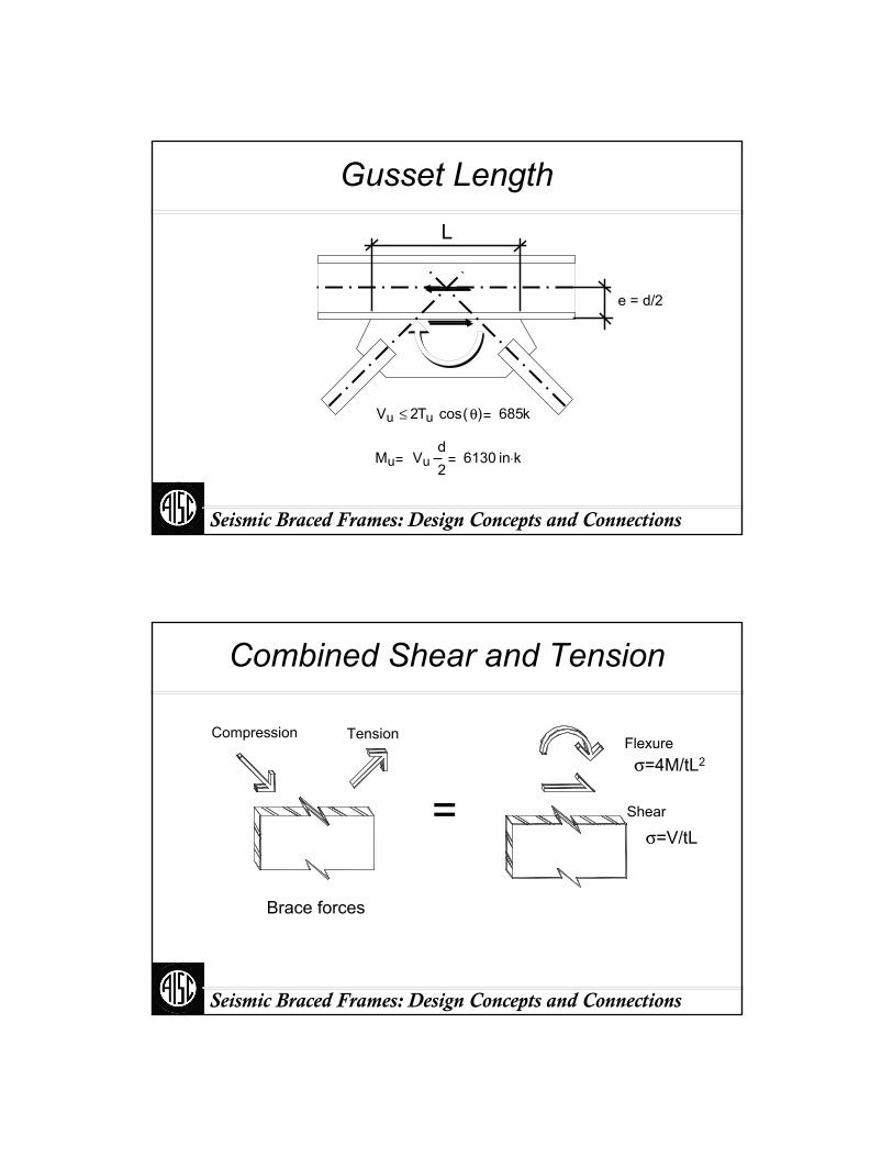
Gusset LengthL
e = d/2
Vu 2Tu cos θ( )≤ 685k
Mu Vud2
6130 in k⋅
Seismic Braced Frames: Design Concepts and Connections
Combined Shear and Tension
=
Compression
Brace forces
Tension
Shear
Flexureσ=4M/tL2
σ=V/tL
Seismic Braced Frames: Design Concepts and Connections
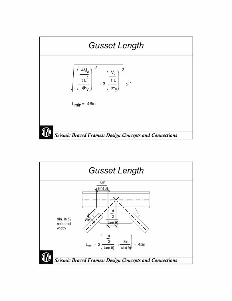
Gusset Length
4Mu
t L2
φFy
⎛⎜⎜⎜⎝
⎞⎟⎟⎟⎠
2
3
Vu
t L
φFy
⎛⎜⎜⎝
⎞⎟⎟⎠
2
+ 1≤
Lmin 46in
Seismic Braced Frames: Design Concepts and Connections
Gusset Length
8in. is ½required width
8insin θ( )
d
2
tan θ( )
Lmin 2
d
2
tan θ( )8in
sin θ( )+
⎛⎜⎜⎝
⎞⎟⎟⎠
45in
8in
Seismic Braced Frames: Design Concepts and Connections
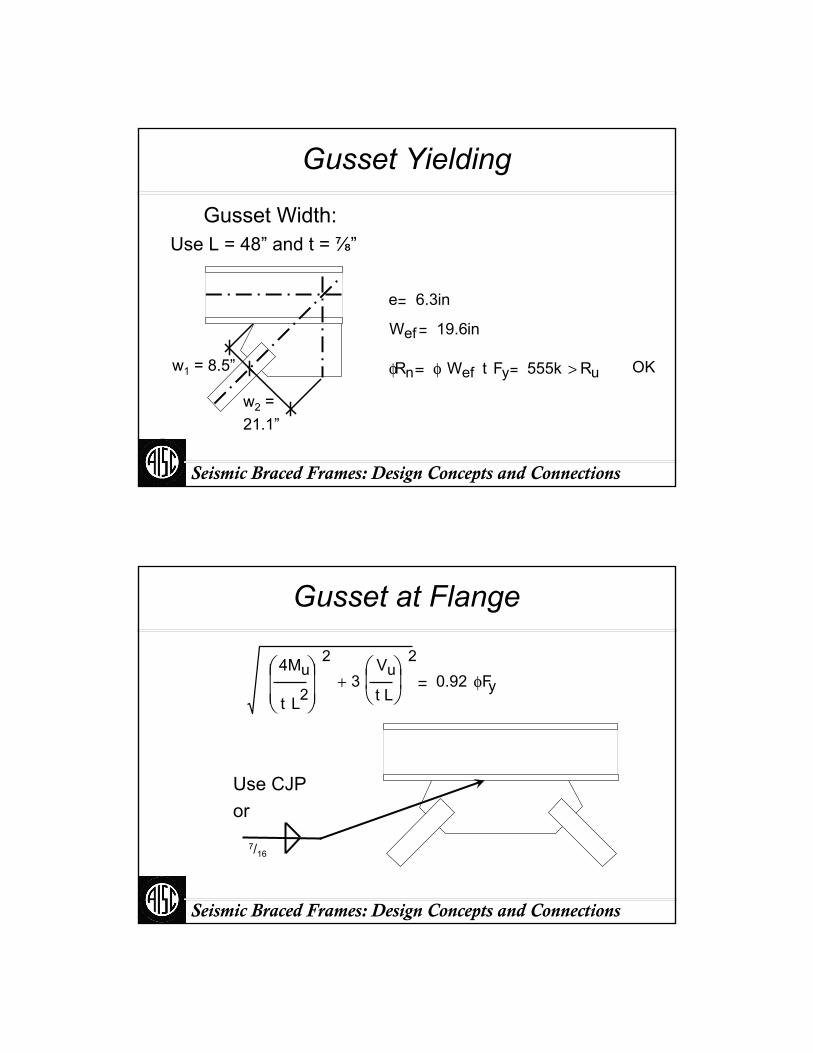
Gusset Yielding
Use L = 48” and t = ⅞”Gusset Width:
w1 = 8.5”
w2 = 21.1”
e 6.3in
Wef 19.6in
φRn φ Wef t Fy 555k Ru> OK
Seismic Braced Frames: Design Concepts and Connections
Gusset at Flange
Use CJPor
7/16
4Mu
t L2
⎛⎜⎜⎝
⎞⎟⎟⎠
2
3Vu
t L
⎛⎜⎝
⎞⎟⎠
2
+ 0.92 φFy

Seismic Braced Frames: Design Concepts and Connections
w
w/2
M
T
V
C
V
Check Combined Shear and Tension
Seismic Braced Frames: Design Concepts and Connections
Check Beam Web
Beam web cripplingw 48in
Ru CMw2
255k
Nw2
24 in
W18x40
φ Rn 0.75 0.8tw2 ⎛
⎝⎞⎠ 1 3
Nd
t wt f
⎛⎜⎝
⎞⎟⎠
3
2
+
⎡⎢⎢⎢⎣
⎤⎥⎥⎥⎦
E Fy tftw
φ Rn 265k OK
Seismic Braced Frames: Design Concepts and Connections
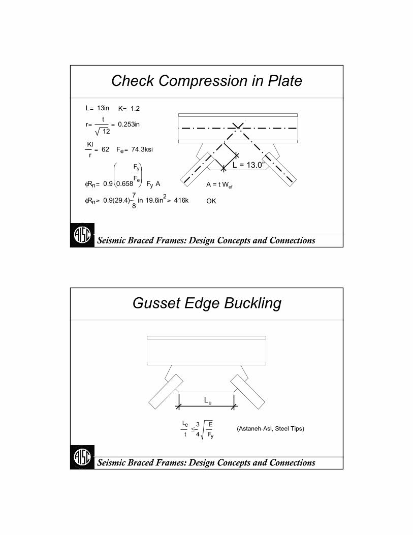
Check Compression in Plate
L = 13.0”
L 13in K 1.2
rt
120.253in
Klr
62 Fe 74.3ksi
φRn 0.9 0.658
Fy
Fe
⎛⎜⎜⎝
⎞⎟⎟⎠ Fy A
φRn 0.9 29.4( )78
in 19.6in2 416k
A = t Wef
OK
Seismic Braced Frames: Design Concepts and Connections
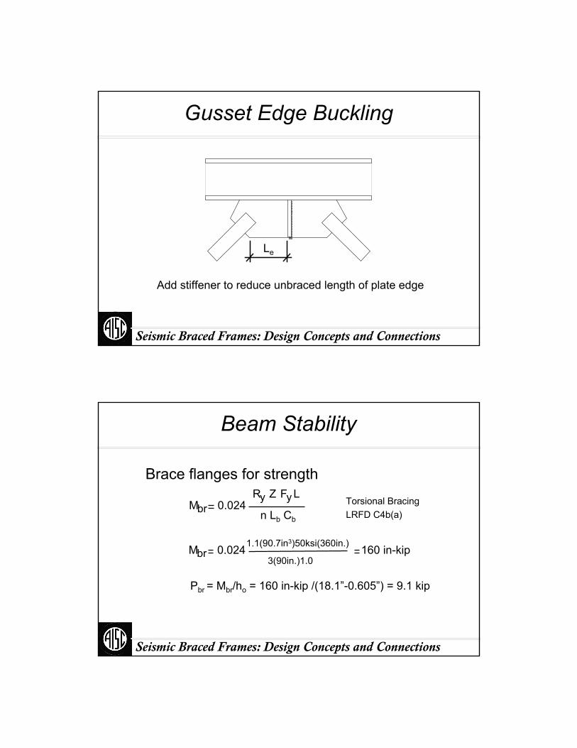
Gusset Edge Buckling
Le
Le
t34
EFy
≤ (Astaneh-Asl, Steel Tips)
Seismic Braced Frames: Design Concepts and Connections
Gusset Edge Buckling
Le
Add stiffener to reduce unbraced length of plate edge
Seismic Braced Frames: Design Concepts and Connections
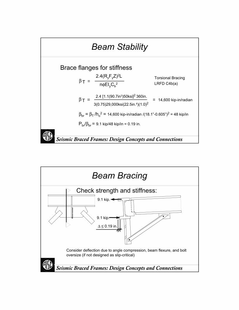
Beam Stability
Brace flanges for strength
Pbr = Mbr/ho = 160 in-kip /(18.1”-0.605”) = 9.1 kip
Mbr 0.024Ry Z F Ly
n Lb Cb
Mbr 0.0241.1(90.7in3)50ksi(360in.)
3(90in.)1.0160 in-kip
Torsional BracingLRFD C4b(a)
Seismic Braced Frames: Design Concepts and Connections
Beam Stability
Brace flanges for stiffness
βbr = βT /ho2 = 14,600 kip-in/radian /(18.1”-0.605”)2 = 48 kip/in
β T2.4(RyFyZ)2L
nφEIyCb2
β T2.4 [1.1(90.7in3)50ksi]2 360in.
3(0.75)29,000ksi(22.5in.4)(1.0)214,600 kip-in/radian
Pbr/βbr = 9.1 kip/48 kip/in = 0.19 in.
Torsional BracingLRFD C4b(a)
Seismic Braced Frames: Design Concepts and Connections
Beam BracingCheck strength and stiffness:
Δ ≤ 0.19 in.
9.1 kip.
9.1 kip.
Consider deflection due to angle compression, beam flexure, and bolt oversize (if not designed as slip-critical)

Seismic Braced Frames: Design Concepts and Connections
Beam Bracing
9/16
L3x3x¼W/ ⅞” A325 SCEACH END
Seismic Braced Frames: Design Concepts and Connections
Verify Hinge Zone
2t+¾” = 2.5” OK
2t+¾”
L=4.8
”
Seismic Braced Frames: Design Concepts and Connections
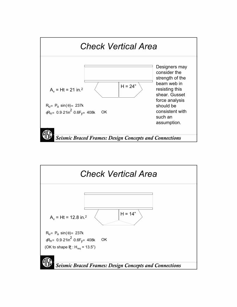
Check Vertical Area
H = 24”Av = Ht = 21 in.2
Ru Pu sin θ( ) 237k
φRn 0.9 21⋅ in2 0.6⋅ Fy 408k OK
Designers may consider the strength of the beam web in resisting this shear. Gusset force analysis should be consistent with such an assumption.
Seismic Braced Frames: Design Concepts and Connections
Check Vertical Area
(OK to shape P : Hreq = 13.5”)L
H = 14”
Ru Pu sin θ( ) 237k
φRn 0.9 21⋅ in2 0.6⋅ Fy 408k OK
Av = Ht = 12.8 in.2
Seismic Braced Frames: Design Concepts and Connections
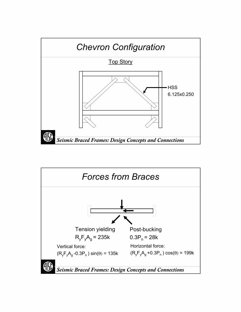
Chevron ConfigurationTop Story
HSS6.125x0.250
Seismic Braced Frames: Design Concepts and Connections
Forces from Braces
Tension yieldingRyFyAg = 235k
Post-bucking0.3Pn = 28k
Vertical force:(RyFyAg -0.3Pn ) sin(θ) = 135k
Horizontal force:(RyFyAg +0.3Pn ) cos(θ) = 199k

Seismic Braced Frames: Design Concepts and Connections
Forces from BracesBrace @ ¼ points
199k99k 99k
135k68k 68k
ME = 506 ft-k; Mu = 521 ft-k
Pu = 99k
Seismic Braced Frames: Design Concepts and Connections
Moment Magnification
B1Cm
1Pu
Pe−
Cm 1.0-0.2Pu/Pe = 0.99
Pe 3445 k B1 1.0
W24x62
Table C-C1.1
Seismic Braced Frames: Design Concepts and Connections
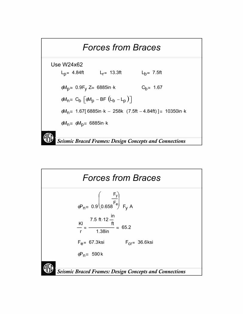
Forces from Braces
Use W24x62Lp 4.84ft Lr 13.3ft Lb 7.5ft
φMp 0.9Fy Z 6885in k⋅ Cb 1.67
φMn Cb φMp BF Lb Lp−( )−⎡⎣ ⎤⎦
φMn 1.67 6885in k⋅ 258k 7.5ft 4.84ft−( )−[ ] 10350in k⋅
φMn φMp 6885in k⋅
Seismic Braced Frames: Design Concepts and Connections
Forces from Braces
φPn 0.9 0.658
Fy
Fe
⎛⎜⎜⎝
⎞⎟⎟⎠ Fy A
Klr
7.5 ft 12⋅inft
1.38in65.2
Fe 67.3ksi Fcr 36.6ksi
φPn 590 k
Seismic Braced Frames: Design Concepts and Connections
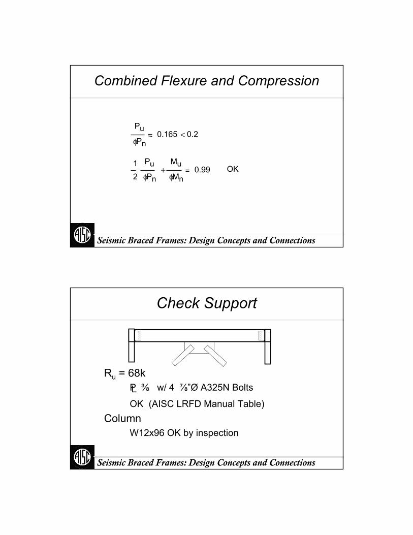
Combined Flexure and Compression
Pu
φPn0.165 0.2<
12
Pu
φPn
Mu
φMn+ 0.99 OK
Seismic Braced Frames: Design Concepts and Connections
Check Support
Ru = 68k
OK (AISC LRFD Manual Table)
P ⅜ w/ 4 ⅞”Ø A325N BoltsL
ColumnW12x96 OK by inspection
Seismic Braced Frames: Design Concepts and Connections
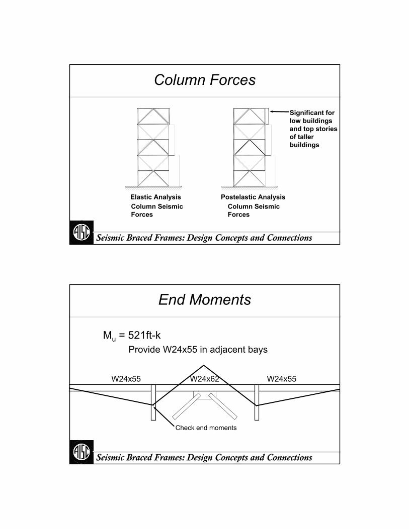
Column Forces
Elastic AnalysisColumn SeismicForces
Postelastic AnalysisColumn SeismicForces
Significant for low buildings and top stories of taller buildings
Seismic Braced Frames: Design Concepts and Connections
End Moments
Mu = 521ft-kProvide W24x55 in adjacent bays
W24x55W24x62W24x55
Check end moments
Seismic Braced Frames: Design Concepts and Connections
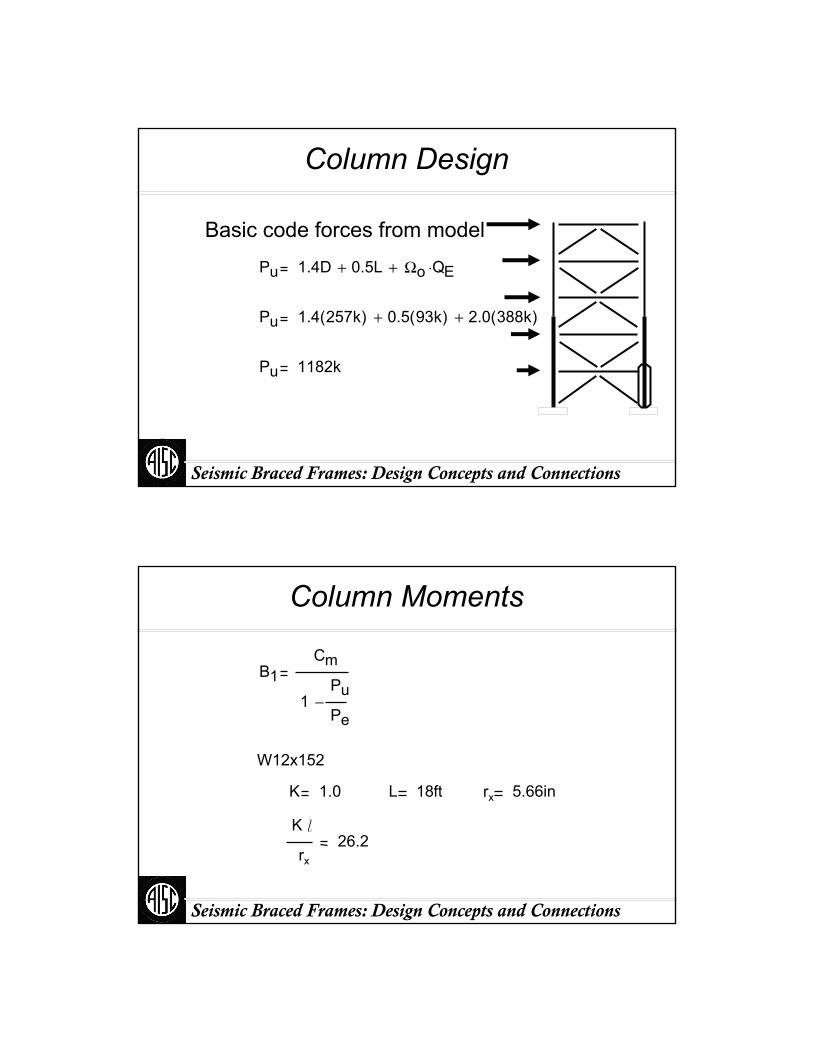
Column Design
Basic code forces from modelPu 1.4D 0.5L+ Ωo QE⋅+
Pu 1.4 257k( ) 0.5 93k( )+ 2.0 388k( )+
Pu 1182k
Seismic Braced Frames: Design Concepts and Connections
Column Moments
B1Cm
1Pu
Pe−
W12x152
K 1.0 L 18ft rx 5.66in
K l
rx
26.2
Seismic Braced Frames: Design Concepts and Connections
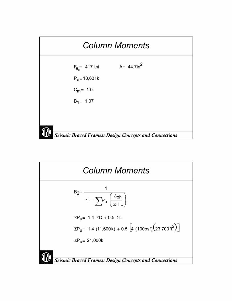
Column Moments
Fex417 ksi A 44.7in2
Pe 18,631k
Cm 1.0
B1 1.07
Seismic Braced Frames: Design Concepts and Connections
Column Moments
B21
1
.
PuΔoh
ΣH L
⎛⎜⎝
⎞⎟⎠∑−
ΣPu 1.4 ΣD 0.5 ΣL+
ΣPu 1.4 11,600k( ) 0.5 4 100psf( ) 23,700ft2( )⎡⎣ ⎤⎦+
ΣPu 21,000k
Seismic Braced Frames: Design Concepts and Connections
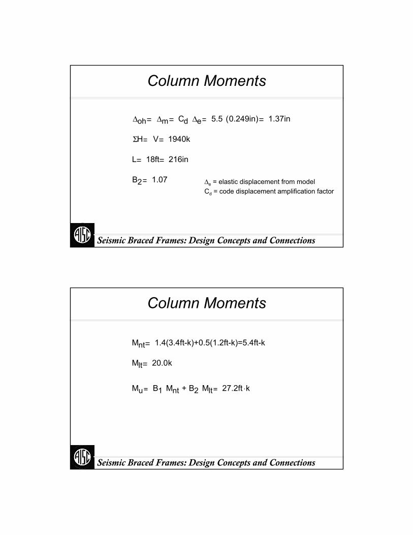
Column Moments
Δoh Δm Cd Δe 5.5 0.249in( ) 1.37in
ΣH V 1940k
L 18ft 216in
B2 1.07 Δe = elastic displacement from modelCd = code displacement amplification factor
Seismic Braced Frames: Design Concepts and Connections
Column Moments
Mnt 1.4(3.4ft-k)+0.5(1.2ft-k)=5.4ft-k
Mlt 20.0k
Mu B1 M +nt B2 Mlt 27.2ft k⋅
Seismic Braced Frames: Design Concepts and Connections
Column Moments
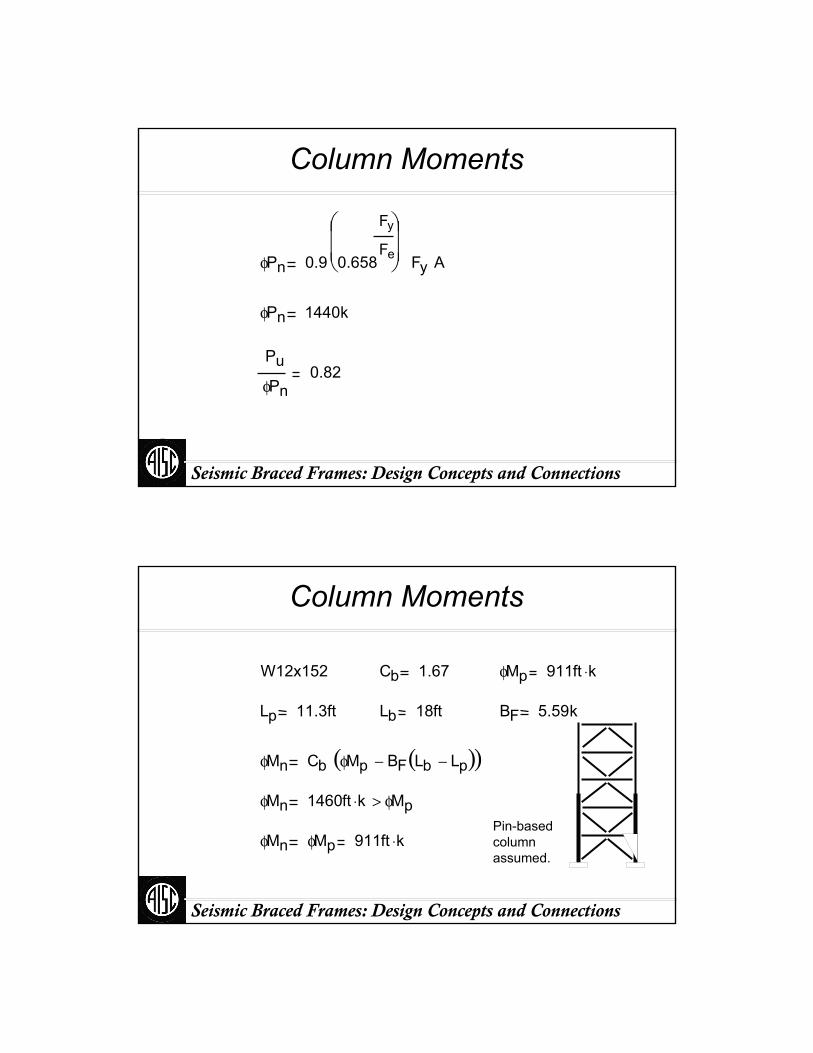
φPn 0.9 0.658
Fy
Fe
⎛⎜⎜⎝
⎞⎟⎟⎠ Fy A
φPn 1440k
Pu
φPn0.82
Seismic Braced Frames: Design Concepts and Connections
Column Moments
W12x152 Cb 1.67 φMp 911ft k⋅
Lp 11.3ft Lb 18ft BF 5.59k
φMn Cb φMp BF Lb Lp−( )−( )φMn 1460ft k⋅ φMp>
φMn φMp 911ft k⋅Pin-based column assumed.
Seismic Braced Frames: Design Concepts and Connections
Column Moments
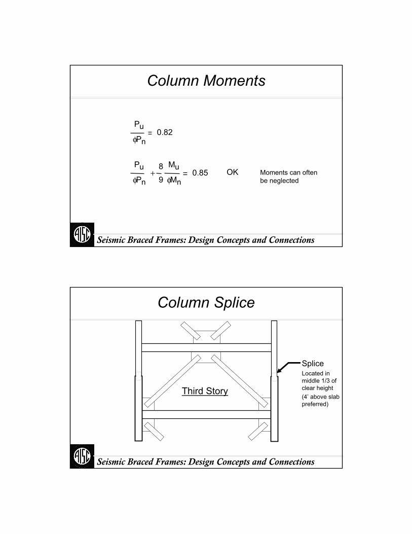
Pu
φPn0.82
Pu
φPn
89
Mu
φMn+ 0.85 OK Moments can often
be neglected
Seismic Braced Frames: Design Concepts and Connections
Column Splice
Third Story
SpliceLocated in middle 1/3 of clear height(4’ above slab preferred)

Seismic Braced Frames: Design Concepts and Connections
Column Splice
VuΣMp
Hc
Fy Z1 Z2+( )13ft 18in−
Vu50 ksi 147 in3 243 in3+( )
13ft12in
ft18in−
Vu 141k
Seismic Braced Frames: Design Concepts and Connections
Column Splice
P 9/16 x 6 ½ x 13 ESL
φRn 0.9 0.6( ) 36 ksi 612
in⎛⎜⎝
⎞⎟⎠
2916
in⎛⎜⎝
⎞⎟⎠
142k OK
Vu 141k
Seismic Braced Frames: Design Concepts and Connections
Column Splice
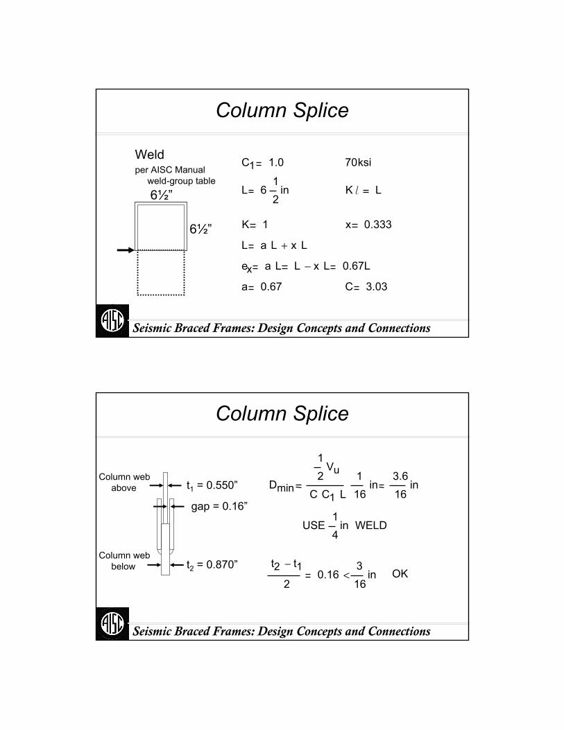
Weldper AISC Manual
weld-group table
6½”
6½”
C1 1.0 70ksi
L 612
in K l L
K 1 x 0.333
L a L x L+
ex a L L x L− 0.67L
a 0.67 C 3.03
Seismic Braced Frames: Design Concepts and Connections
Column Splice
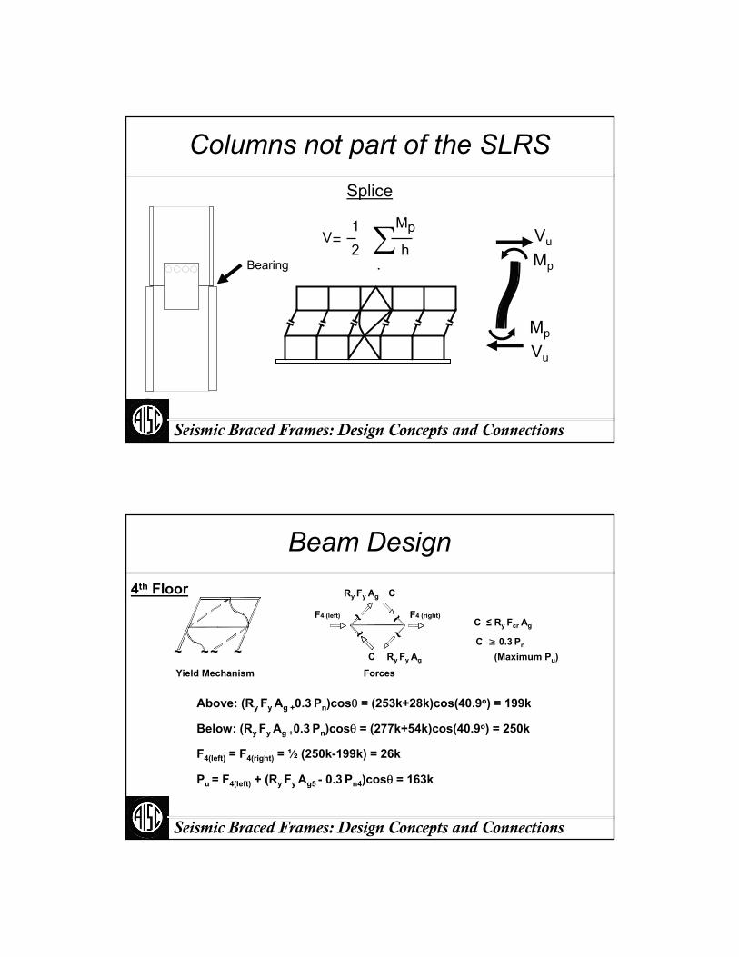
t1 = 0.550”
t2 = 0.870”
gap = 0.16”1
Dmin
12
Vu
C C L116
in3.616
in
4USE
1in WELD
t2 t1−
20.16
316
in< OK
Column web above
Column web below

Seismic Braced Frames: Design Concepts and Connections
Column Splice
Mu12
Mn12
Z Fy 3680in k⋅
Mu
d tf−311k
CJP: φRn 0.9 50ksi( ) 0.900in 12.2⋅ in 494k OK
PJP: E( )2.0Ru
0.8 0.6·70ksi( ) 12.2in≥ 1.52 in use CJP
= Ru
Seismic Braced Frames: Design Concepts and Connections
Column Splice
CJP Transition
12.5
AWS D1.12.7.1
Where
12.5
Ru
φ Rn
13
≥
Seismic Braced Frames: Design Concepts and Connections
Columns not part of the SLRSSplice
Vu
Mp
Mp
Vu
V12
.
Mph∑
Bearing
Seismic Braced Frames: Design Concepts and Connections
Beam Design
C ≥ 0.3 Pn
C ≤ Ry Fcr Ag
~~ ~~Yield Mechanism
C Ry Fy Ag
CRy Fy Ag
~ ~
~~F4 (left) F4 (right)
Forces(Maximum Pu)
Above: (Ry Fy Ag +0.3 Pn)cosθ = (253k+28k)cos(40.9o) = 199k
Below: (Ry Fy Ag +0.3 Pn)cosθ = (277k+54k)cos(40.9o) = 250k
F4(left) = F4(right) = ½ (250k-199k) = 26k
Pu = F4(left) + (Ry Fy Ag5 - 0.3 Pn4)cosθ = 163k
4th Floor

Seismic Braced Frames: Design Concepts and Connections
Beam Moments
M1.4D+0.5L = 117 ft-kip
MΩ.E = 42 ft-kip
M1.4D+0.5L+Ω.E = 159 ft-kip
Forces from model
Seismic Braced Frames: Design Concepts and Connections
Beam Moment Magnification
W18x40
Major Minor
K 1.0 K 1.0
L 30ft L 7.5ft
r 7.21in r 1.27in
K l
r49.9
K l
r70.7
Fe 57.2ksi
A 11.8 in2
Pe 675k
Fe 104ksi
A 11.8 in2
Pe 1355k(for momentmagnification)
(for compressionstrength)
Seismic Braced Frames: Design Concepts and Connections
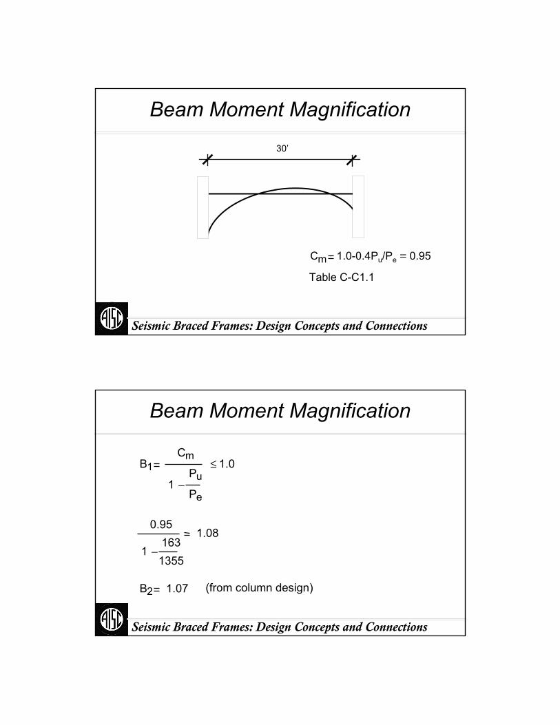
Beam Moment Magnification
30’
Cm 1.0-0.4Pu/Pe = 0.95
Table C-C1.1
Seismic Braced Frames: Design Concepts and Connections
Beam Moment Magnification
B1Cm
1Pu
Pe−
1.0≤
0.95
11631355
−1.08
B2 1.07 (from column design)
Seismic Braced Frames: Design Concepts and Connections
Beam Moments
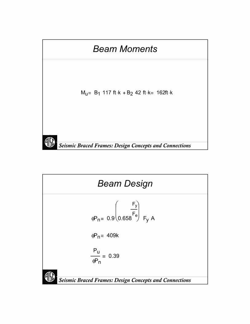
Mu B1 117 ft k⋅ B2 42 ft k⋅ 162ft k⋅+
Seismic Braced Frames: Design Concepts and Connections
Beam Design
φPn 0.9 0.658
Fy
Fe
⎛⎜⎜⎝
⎞⎟⎟⎠ Fy A
φPn 409k
Pu
φPn0.39

Seismic Braced Frames: Design Concepts and Connections
Beam Design
7.5’ 7.5’ 7.5’ 7.5’
M1 = 40 ft-kip
Mc = 60 ft-kip
Mb = 84 ft-kipMa = 120 ft-kip
M2 = Mmax. = 162 ft-kip
Cb12.5Mmax
2.5 Mmax 3 Ma+ 4 Mb+ 3 Mc+1.58
Seismic Braced Frames: Design Concepts and Connections
Beam Design
W18x40 Cb 1.58 φMp 294ft k⋅
Lp 4.49 ft Lb 7.5 ft BF 11.7 k
φMn Cb φMp BF Lb Lp−( )−( )φMn 409 ft k⋅ φMp>
φMn φMp 294 ft k⋅
Seismic Braced Frames: Design Concepts and Connections
Beam Design
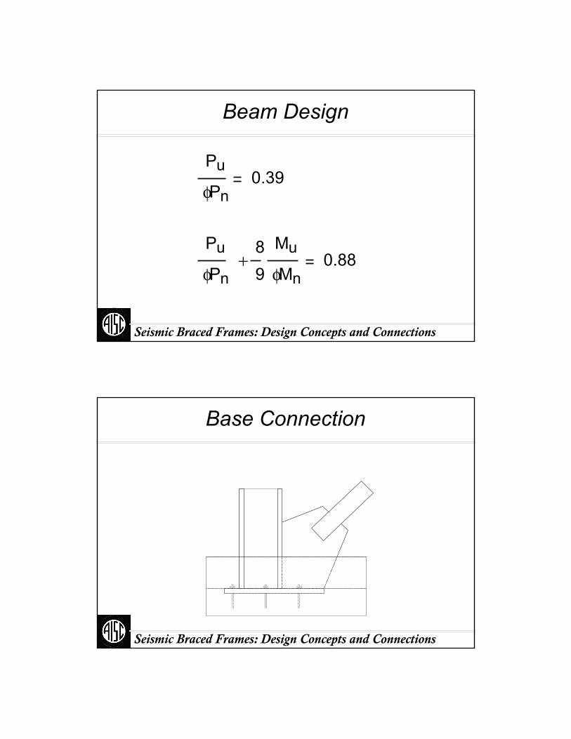
Pu
φPn0.39
Pu
φPn
89
Mu
φMn+ 0.88
Seismic Braced Frames: Design Concepts and Connections
Base Connection
Seismic Braced Frames: Design Concepts and Connections
Base Connection
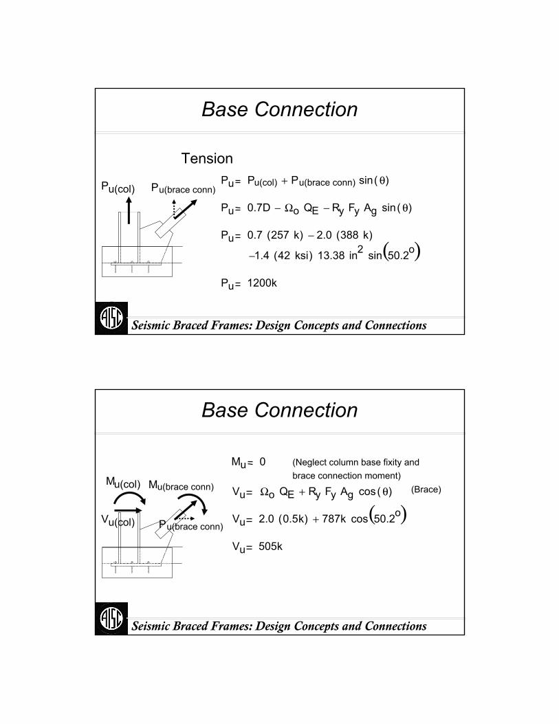
TensionPu Pu(col) Pu(brace conn) sin θ( )+
Pu 0.7D Ωo QE− Ry Fy Ag sin θ( )−
Pu 0.7 257 k( ) 2.0 388 k( )−
1.4− 42 ksi( ) 13.38 in2 sin 50.2o( )Pu 1200k
Pu(col) Pu(brace conn)
Seismic Braced Frames: Design Concepts and Connections
Base Connection
Mu 0 (Neglect column base fixity and brace connection moment)
Vu Ωo QE Ry Fy Ag cos θ( )+ (Brace)
Vu 2.0 0.5k( ) 787k cos 50.2o( )+
Vu 505k
Vu(col)
Mu(brace conn)Mu(col)
Pu(brace conn)
Seismic Braced Frames: Design Concepts and Connections
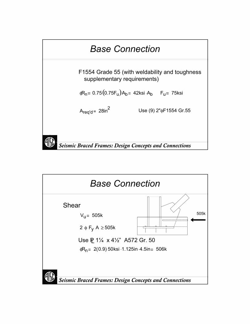
Base Connection
F1554 Grade 55 (with weldability and toughness supplementary requirements)
φRn 0.75 0.75Fu( )Ab 42ksi Ab⋅ Fu 75ksi
Areq'd 28in2 Use (9) 2"φ F1554 Gr.55
Seismic Braced Frames: Design Concepts and Connections
Base Connection
Shear
Use P 1¼ x 4½” A572 Gr. 50 L
Vu 505k
2 φ Fy A 505k≥
φRn 2 0.9( ) 50ksi 1.125⋅ in 4.5⋅ in 506k
505k
Seismic Braced Frames: Design Concepts and Connections
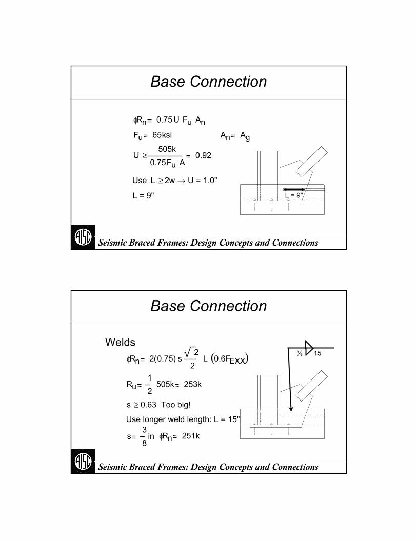
Base Connection
φRn 0.75U Fu AnFu 65ksi An Ag
U505k
0.75Fu A≥ 0.92
Use L 2w≥ → U = 1.0"
L = 9" L = 9"
Seismic Braced Frames: Design Concepts and Connections
Base Connection
WeldsφRn 2 0.75( ) s
22
L 0.6FEXX( )
Ru12
505k 253k
s 0.63 Too big!≥
Use longer weld length: L = 15"
s38
in φRn 251k
⅜ 15
Seismic Braced Frames: Design Concepts and Connections
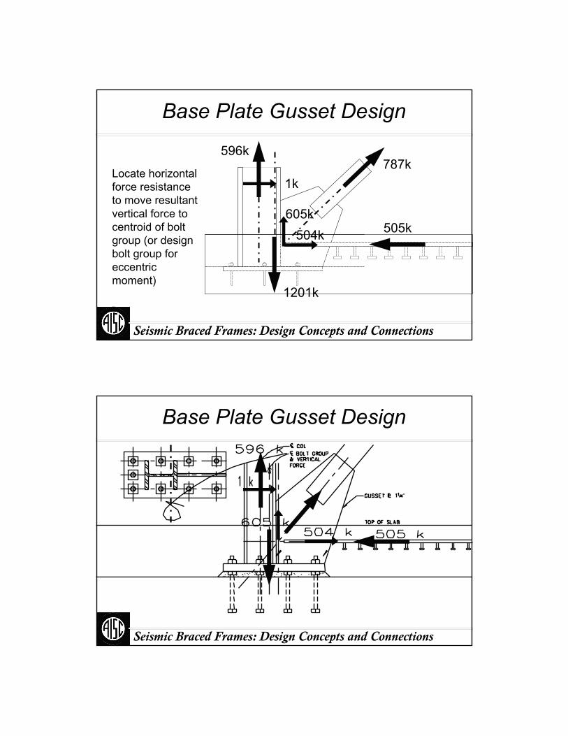
Base Plate Gusset Design
Locate horizontal force resistance to move resultant vertical force to centroid of bolt group (or design bolt group for eccentric moment)
596k
1k
605k504k 505k
1201k
787k
Seismic Braced Frames: Design Concepts and Connections
Base Plate Gusset Design
Seismic Braced Frames: Design Concepts and Connections
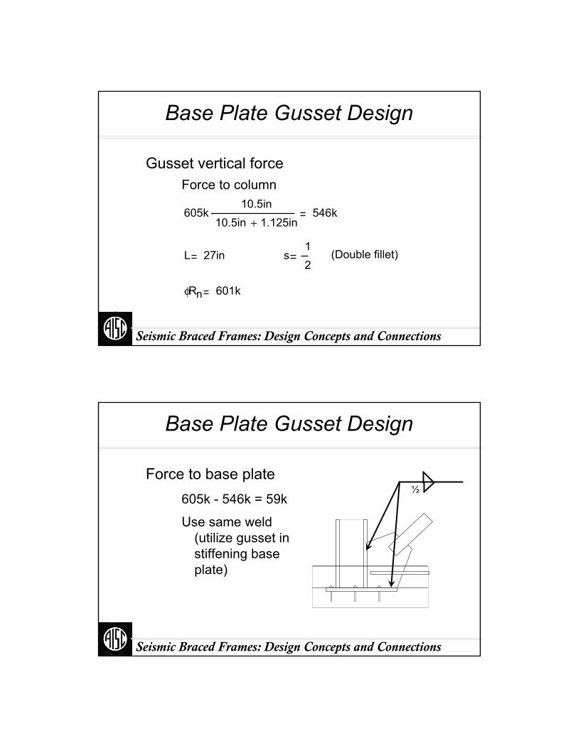
Base Plate Gusset Design
Force to columnGusset vertical force
605k10.5in
10.5in 1.125in+⋅ 546k
L 27in s12
(Double fillet)
φRn 601k
Seismic Braced Frames: Design Concepts and Connections
Base Plate Gusset Design
605k - 546k = 59k
Force to base plate
Use same weld (utilize gusset in stiffening base plate)
½
Seismic Braced Frames: Design Concepts and Connections
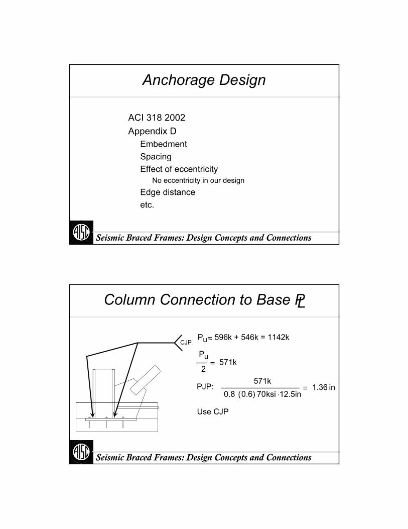
Anchorage Design
ACI 318 2002Appendix D
EmbedmentSpacingEffect of eccentricity
No eccentricity in our design
Edge distanceetc.
Seismic Braced Frames: Design Concepts and Connections
Column Connection to Base PL
Pu 596k + 546k = 1142k
Pu2
571k
PJP: 571k
0.8 0.6( ) 70ksi 12.5⋅ in1.36 in
Use CJP
CJP
Seismic Braced Frames: Design Concepts and Connections
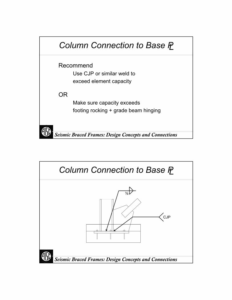
Column Connection to Base PL
RecommendUse CJP or similar weld toexceed element capacity
ORMake sure capacity exceeds footing rocking + grade beam hinging
Seismic Braced Frames: Design Concepts and Connections
Column Connection to Base PL
CJP
⅜

Seismic Braced Frames: Design Concepts and Connections
Base Plate
T
e
T39
1200k 400k
e 518
in M 2050in k⋅
φMn φ Z Fy φbt2
4 Fy
b 20in t 3.0in≥
Seismic Braced Frames: Design Concepts and Connections
Base Plate Alternatives
A grout pocket with shear lugs can resist shear
Grout
Seismic Braced Frames: Design Concepts and Connections
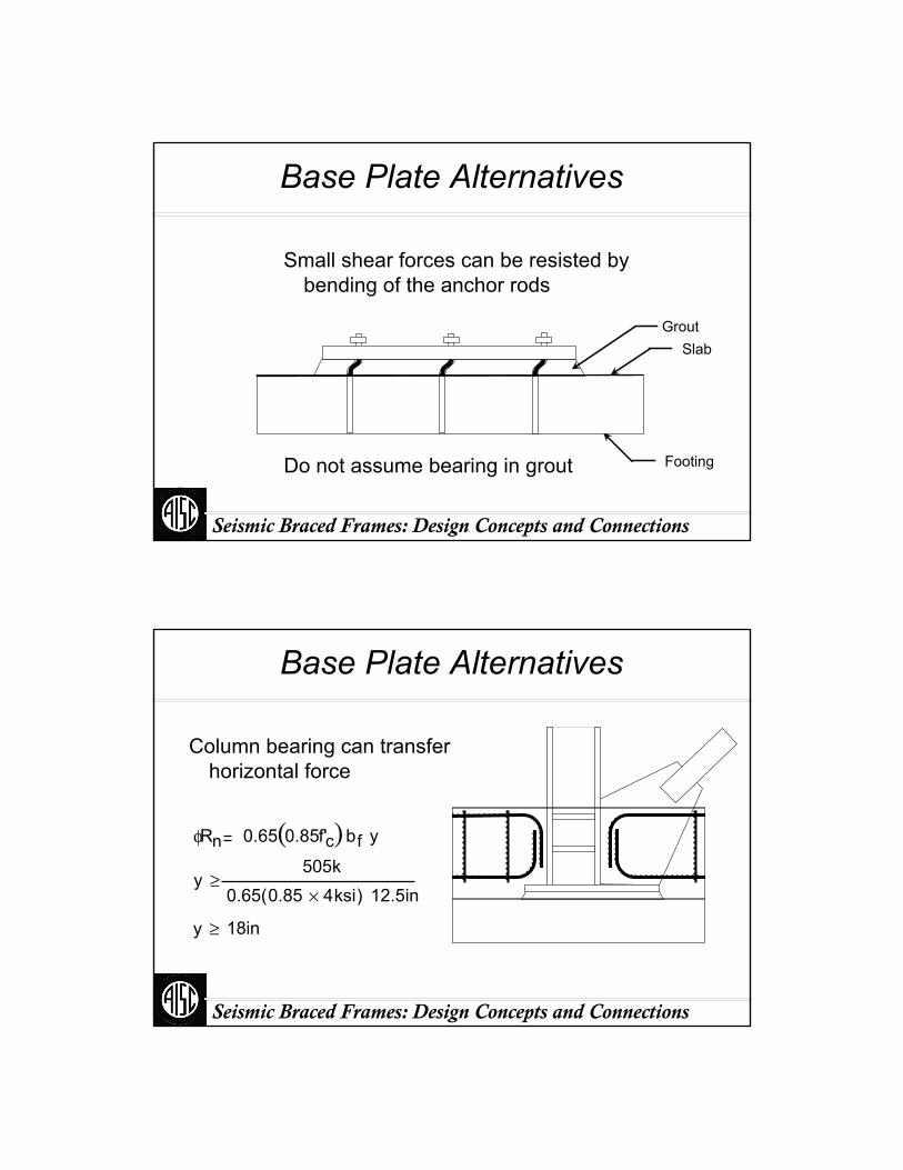
Base Plate Alternatives
Small shear forces can be resisted by bending of the anchor rods
Do not assume bearing in grout
GroutSlab
Footing
Seismic Braced Frames: Design Concepts and Connections
Base Plate Alternatives
Column bearing can transfer horizontal force
φRn 0.65 0.85f'c( )b f y
y505k
0.65 0.85 4× ksi( ) 12.5in≥
18iny ≥
Seismic Braced Frames: Design Concepts and Connections
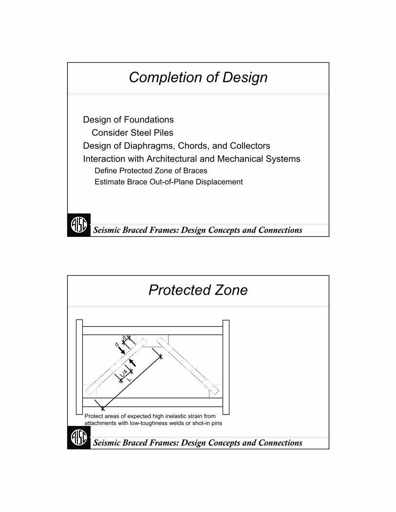
Completion of Design
Design of FoundationsConsider Steel Piles
Design of Diaphragms, Chords, and CollectorsInteraction with Architectural and Mechanical Systems
Define Protected Zone of BracesEstimate Brace Out-of-Plane Displacement
Seismic Braced Frames: Design Concepts and Connections
Protected Zone
dd
LL/4
Protect areas of expected high inelastic strain from attachments with low-toughness welds or shot-in pins

Seismic Braced Frames: Design Concepts and Connections
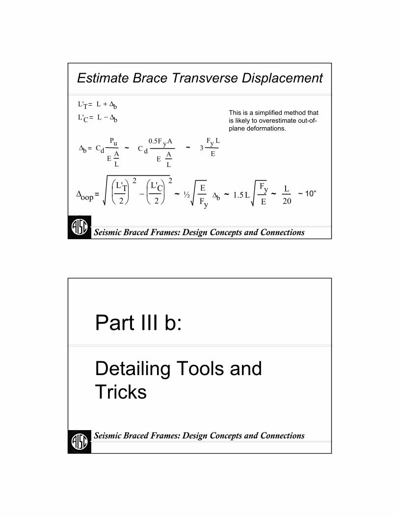
Estimate Brace Transverse Displacement
L`T
L
Δb
L'T L Δb+
Seismic Braced Frames: Design Concepts and Connections
Estimate Brace Transverse Displacement
Δoop
L`C
L
Δb
L'C L Δb−
Δoop
L'T
2
⎛⎜⎝
⎞⎟⎠
2 L'C
2
⎛⎜⎝
⎞⎟⎠
2
−
Seismic Braced Frames: Design Concepts and Connections
Estimate Brace Transverse Displacement
L'T L Δb+
L'C L Δb−
~ C d0.5 F Ay
EAL
~ 3Fy L
EΔb Cd
Pu
EAL
ΔoopL'T2
⎛⎜⎝
⎞⎟⎠
2 L'C2
⎛⎜⎝
⎞⎟⎠
2
− ~ 1.5 LFyE
~ L20
~ 10”
This is a simplified method that is likely to overestimate out-of-plane deformations.
~ ½Fy
EΔb
Part III b:
Detailing Tools and Tricks
Seismic Braced Frames: Design Concepts and Connections
Seismic Braced Frames: Design Concepts and Connections
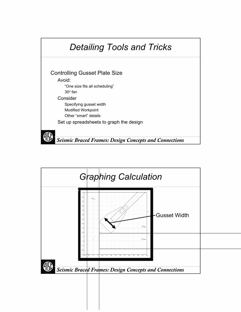
Detailing Tools and Tricks
Controlling Gusset Plate SizeAvoid:
“One size fits all scheduling”30o fan
ConsiderSpecifying gusset widthModified WorkpointOther “smart” details
Set up spreadsheets to graph the design
Seismic Braced Frames: Design Concepts and Connections
Graphing Calculationy
10 5 0 5 10 15 20 25 30 35 40 45 50 55 6015
10
5
0
5
10
15
20
25
30
35
40
45
50
55
CLBeam
TOSlab
CLCol
Gusset Width
Seismic Braced Frames: Design Concepts and Connections
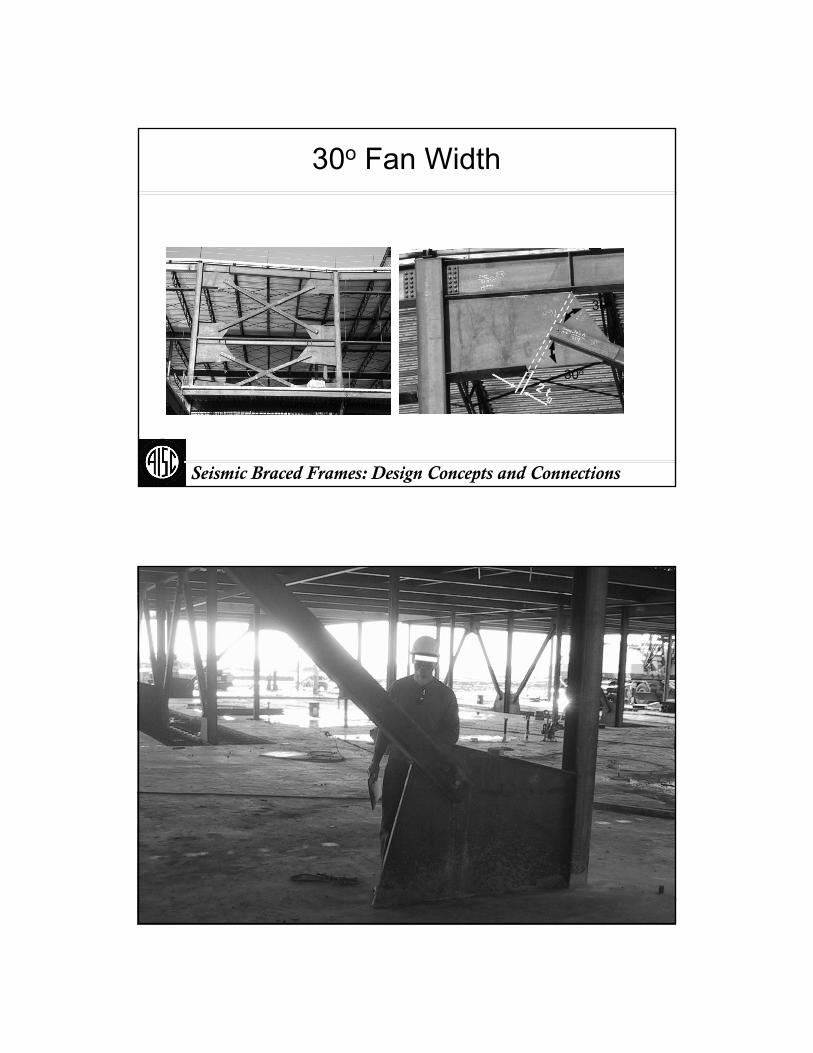
30o Fan Width
Courtesy of R. Tremblay
30o
30o
Seismic Braced Frames: Design Concepts and Connections
30o Fan Width

Seismic Braced Frames: Design Concepts and Connections
Very Big Gussets
Seismic Braced Frames: Design Concepts and Connections
Case Study: Recent SCBF Design
Recent SCBF DesignLarge Brace30o from Horizontal
Attempt 4 alternate design methods to reduce gusset size
Seismic Braced Frames: Design Concepts and Connections
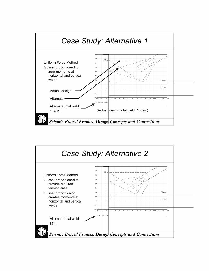
Case Study: Alternative 1
Uniform Force MethodGusset proportioned for
zero moments at horizontal and vertical welds
20 10 0 10 20 30 40 50 60 70 80 90 100 110 120 130 14020
10
0
10
20
30
40
50
60
70
80
CLBeam
TOSlab
CLCol
LV LH+ 104 in=
.
Actual design
Alternate
Alternate total weld:104 in. (Actual design total weld: 136 in.)
Seismic Braced Frames: Design Concepts and Connections
Case Study: Alternative 2
Uniform Force MethodGusset proportioned to
provide required tension area
Gusset proportioning creates moments at horizontal and vertical welds
20 10 0 10 20 30 40 50 60 70 80 90 100 110 120 130 14020
10
0
10
20
30
40
50
60
70
80
CLBeam
TOSlab
CLCol
LV LH+ 87 in= .
Alternate total weld:87 in.
Seismic Braced Frames: Design Concepts and Connections
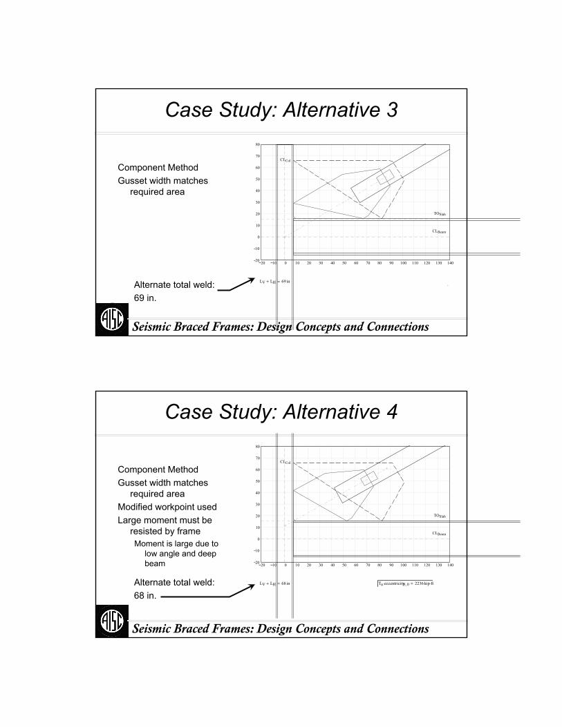
Case Study: Alternative 3
Component MethodGusset width matches
required area
20 10 0 10 20 30 40 50 60 70 80 90 100 110 120 130 14020
10
0
10
20
30
40
50
60
70
80
CLBeam
TOSlab
CLCol
LV LH+ 69 in= .Alternate total weld:69 in.
Seismic Braced Frames: Design Concepts and Connections
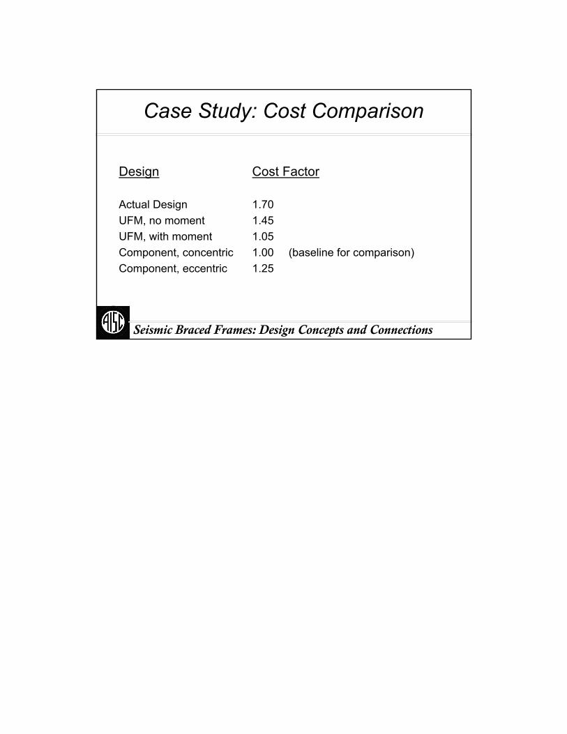
Case Study: Alternative 4
Component MethodGusset width matches
required areaModified workpoint usedLarge moment must be
resisted by frameMoment is large due to
low angle and deep beam 20 10 0 10 20 30 40 50 60 70 80 90 100 110 120 130 14020
10
0
10
20
30
40
50
60
70
80
CLBeam
TOSlab
CLCol
LV LH+ 68 in= Tu eccentricity0 0,⋅ 2236kip ft⋅=Alternate total weld:68 in.
Seismic Braced Frames: Design Concepts and Connections
Case Study: Cost Comparison
Design Cost Factor
Actual Design 1.70UFM, no moment 1.45UFM, with moment 1.05Component, concentric 1.00 (baseline for comparison)Component, eccentric 1.25
Part IV:
Ordinary Concentrically Braced Frames
Seismic Braced Frames: Design Concepts and Connections
Seismic Braced Frames: Design Concepts and Connections
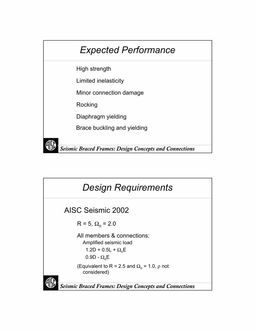
Limitations
Height Limits Separated by Seismic Design Category:
B&C D E FNL 35 35 NP (NL = Not Limited) (NP = Not Permitted)
Seismic Braced Frames: Design Concepts and Connections
Expected Performance
Limited inelasticity
Minor connection damage
Rocking
High strength
Diaphragm yielding
Brace buckling and yielding
Seismic Braced Frames: Design Concepts and Connections
Design Requirements
AISC Seismic 2002
R = 5, Ωo = 2.0
(Equivalent to R = 2.5 and Ωo = 1.0, ρ not considered)
All members & connections:Amplified seismic load1.2D + 0.5L + ΩoE0.9D - ΩoE
Seismic Braced Frames: Design Concepts and Connections
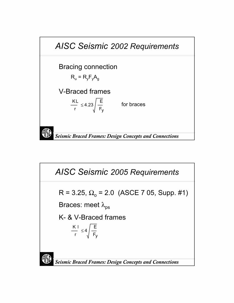
AISC Seismic 2002 Requirements
Ru = RyFyAg
for braces
Bracing connection
V-Braced framesKL r
4.23EFy
≤
Seismic Braced Frames: Design Concepts and Connections
AISC Seismic 2005 Requirements
R = 3.25, Ωo = 2.0 (ASCE 7 05, Supp. #1)
K- & V-Braced frames
Braces: meet λps
K lr
4EFy
≤

Seismic Braced Frames: Design Concepts and Connections
AISC Seismic 2005 Requirements
V-Braced Frames2005
T = RyFyAg C = 0.3Pn
BeamSimilar requirement to SCBF
Out-of-Plane BracingUnbalance Load
or T = ΩoE
Seismic Braced Frames: Design Concepts and Connections
AISC Seismic 2005 Requirements
K-Braced Frames2005
T = RyFyAg
C = 0.3Pn
Similar requirement
Note:Need for out-of-
plane bracing.K-bracing is not
recommended.(T = ΩoE is not allowed)
Seismic Braced Frames: Design Concepts and Connections
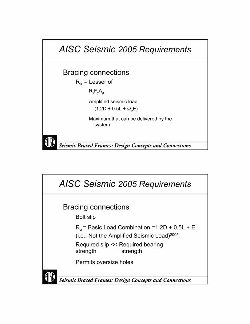
AISC Seismic 2005 Requirements
Bracing connectionsRu = Lesser of
RyFyAg
Amplified seismic load (1.2D + 0.5L + ΩoE)
Maximum that can be delivered by the system
Seismic Braced Frames: Design Concepts and Connections
AISC Seismic 2005 Requirements
Bracing connectionsBolt slip
Ru = Basic Load Combination =1.2D + 0.5L + E (i.e., Not the Amplified Seismic Load)2005
Required slip << Required bearingstrength strength
Permits oversize holes

Seismic Braced Frames: Design Concepts and Connections
Design Example
5 x 30’ = 150’
5 x
30’
= 15
0’
ASCE 7 2005AISC Seismic 2005
Seismic Braced Frames: Design Concepts and Connections
Base Shear
Bingo
HazardSds = 1.0
Sd1 =0.635
Ta = 0.18 sec.
V = 0.308 W
T
V

Seismic Braced Frames: Design Concepts and Connections
Load Combinations
1.2D + f1L + E
0.9D ± E
1.40D + 0.5L + ρQE
0.7D ± ρQE
1.40D + 0.5L + ΩoQE
0.7D ± ΩoQE
f1 = 0.5E = ρ QE + 0.2SDS D
Basic Special (Amplified Seismic Load)
1.2D + f1L + Em
0.9D ± Em
Em = Ωo QE + 0.2SDS D
Seismic Braced Frames: Design Concepts and Connections
Vertical Distribution
Fiwi hi
k⋅
.
wi hik⋅∑
Seismic Braced Frames: Design Concepts and Connections
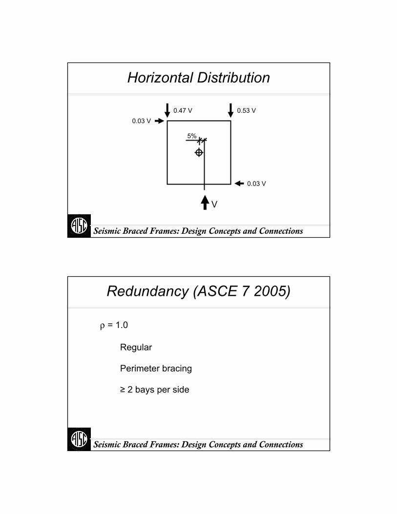
Horizontal Distribution
0.47 V 0.53 V0.03 V
0.03 V
5%
V
Seismic Braced Frames: Design Concepts and Connections
Redundancy (ASCE 7 2005)
ρ = 1.0
Regular
Perimeter bracing
≥ 2 bays per side
Seismic Braced Frames: Design Concepts and Connections
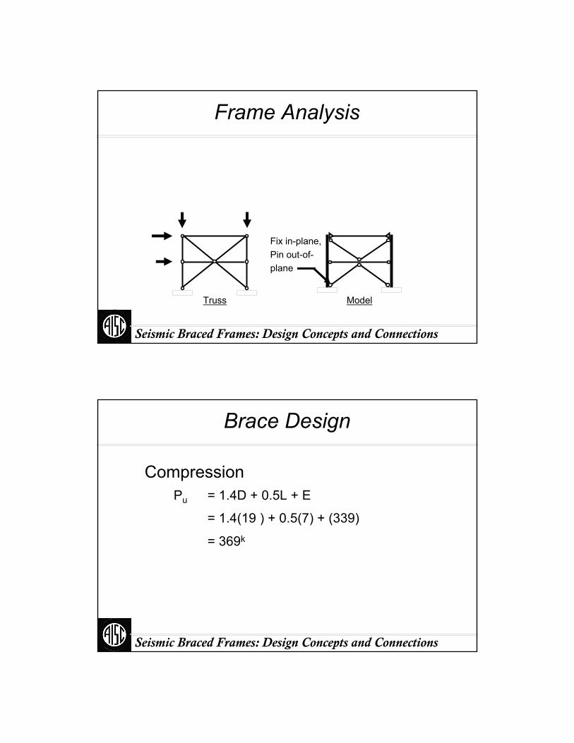
Frame Analysis
ModelTruss
Fix in-plane,Pin out-of-plane
Seismic Braced Frames: Design Concepts and Connections
Brace Design
CompressionPu = 1.4D + 0.5L + E
= 1.4(19 ) + 0.5(7) + (339)
= 369k
Seismic Braced Frames: Design Concepts and Connections
Brace Design
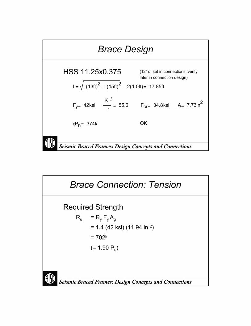
(12” offset in connections; verify later in connection design)
HSS 11.25x0.375
L 13ft( )2 15ft( )2+ 2 1.0ft( )− 17.85ft
Fy 42ksiK l
r55.6 Fcr 34.8ksi A 7.73in2
φPn 374k OK
Seismic Braced Frames: Design Concepts and Connections
Brace Connection: Tension
Required StrengthRu = Ry Fy Ag
= 1.4 (42 ksi) (11.94 in.2)
= 702k
(= 1.90 Pu)

Seismic Braced Frames: Design Concepts and Connections
Brace Connection: Tension
Amplified seismic loadRu = 1.4D + 0.5L + ΩoE
= 1.4(16.5k) + 0.5(5.2k) + 2.0(339 k)
= 692k
(= 0.99Ry Fy Ag = 1.87 Pu)
Might as well use Ry Fy Ag
Seismic Braced Frames: Design Concepts and Connections
Brace Connection: Tension
AssumptionsGusset width ~ 2 dbr (2 x 11.25” = 22.5”)
Gusset thickness (tg):
702k / (0.9 x 36 ksi x 22.5”) = 0.96”;Use 1” A36 PL
dbr
Gusset width

Seismic Braced Frames: Design Concepts and Connections
Brace Connection: Tension
Net Section FractureAremoved = 2 [tg + ⅛”] tbr
= 2 [1” + ⅛”] 0.35”
= 0.79 in.2
Anet = 11.94 in.2 – 0.79 in.2 = 11.12 in.2
Seismic Braced Frames: Design Concepts and Connections
Brace Connection: Tension
Required AreaφRTFuAe ≥ Ru
= 702k / (0.75 x 1.3 x 58 ksi)= 12.4 in.2 ( > Ag)
• Reinforcement required• Or use the Amplified Seismic Load and
a larger brace
Ae ≥ Ru / φRTFu
Note: if the Amplified Seismic Load is used for Ru, RTcannot be used for Rn
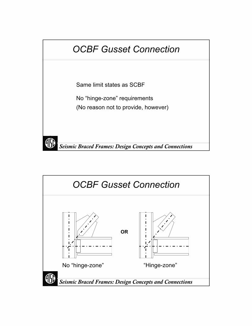
Seismic Braced Frames: Design Concepts and Connections
OCBF Gusset Connection
Same limit states as SCBF
No “hinge-zone” requirements(No reason not to provide, however)
Seismic Braced Frames: Design Concepts and Connections
OCBF Gusset Connection
OR
No “hinge-zone” “Hinge-zone”
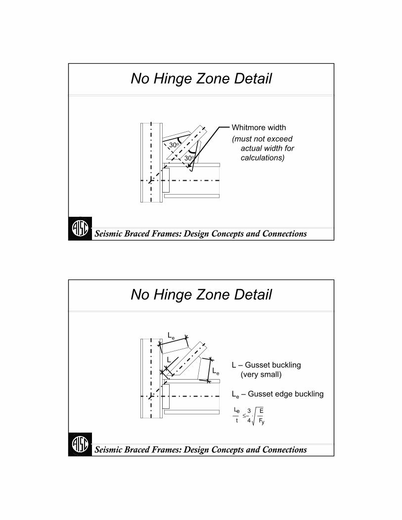
Seismic Braced Frames: Design Concepts and Connections
No Hinge Zone Detail
30o
Whitmore width(must not exceed
actual width for calculations)30o
Seismic Braced Frames: Design Concepts and Connections
No Hinge Zone Detail
L – Gusset buckling (very small)
Le – Gusset edge buckling
Le
L
Le
Le
t34
EFy
⋅≤
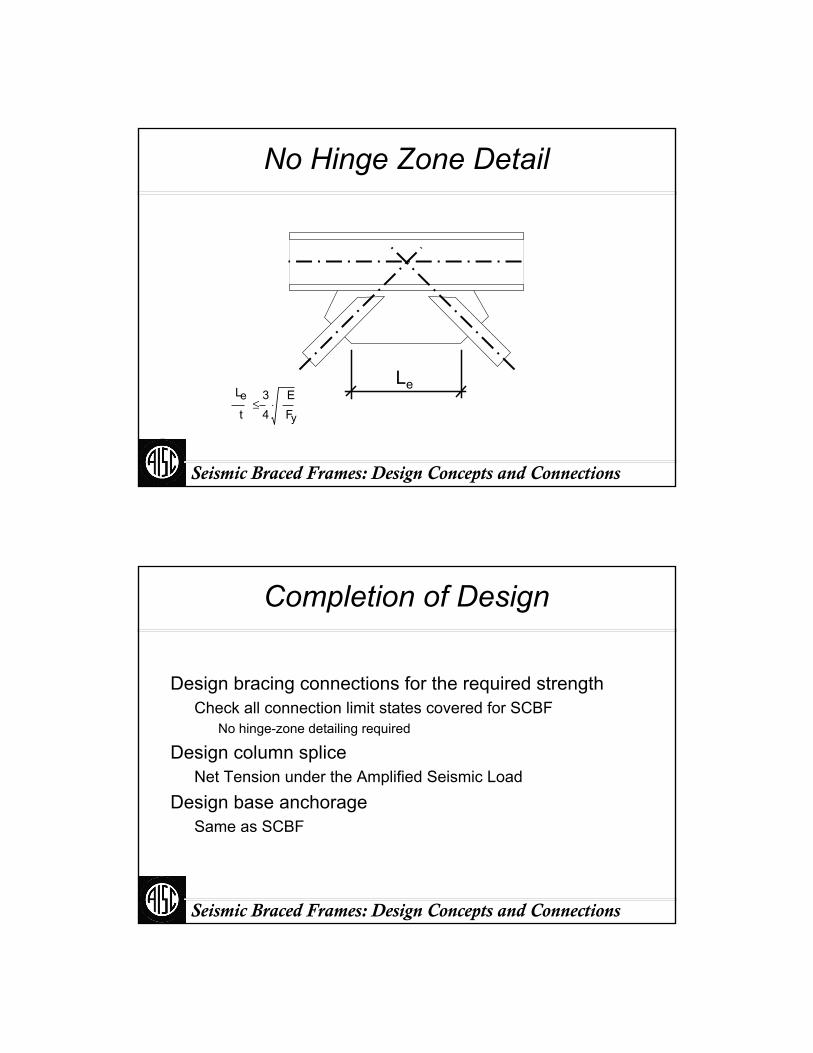
Seismic Braced Frames: Design Concepts and Connections
No Hinge Zone Detail
LeLe
t34
EFy
⋅≤
Seismic Braced Frames: Design Concepts and Connections
Completion of Design
Design bracing connections for the required strengthCheck all connection limit states covered for SCBF
No hinge-zone detailing required
Design column spliceNet Tension under the Amplified Seismic Load
Design base anchorageSame as SCBF
Part V:
Buckling-Restrained Braced Frames
Seismic Braced Frames: Design Concepts and Connections
Seismic Braced Frames: Design Concepts and Connections
Buckling Restrained Braced Frames
Introduction to BRBF SystemBuckling Restrained BracesBuckling Restrained Braced Frame SystemAdvantages of Buckling-Restrained Braced Frames
AISC Seismic RequirementsDesignTesting
Design Example

Seismic Braced Frames: Design Concepts and Connections
What is a Buckling-restrained Brace? Two Definitions
De-Coupled Stress and Buckling(Mechanics Definition)
Balanced Hysteresis(Performance Definition)
Stress resisted by steel coreBuckling resisted by sleeve
Seismic Braced Frames: Design Concepts and Connections
BRB Definitions Explained: Conventional Bracing
Brace behavior is asymmetric with respect to tension and compression and is subject to strength and stiffness degradation
Pcr
Ry Ag Fy
Compression
Tension
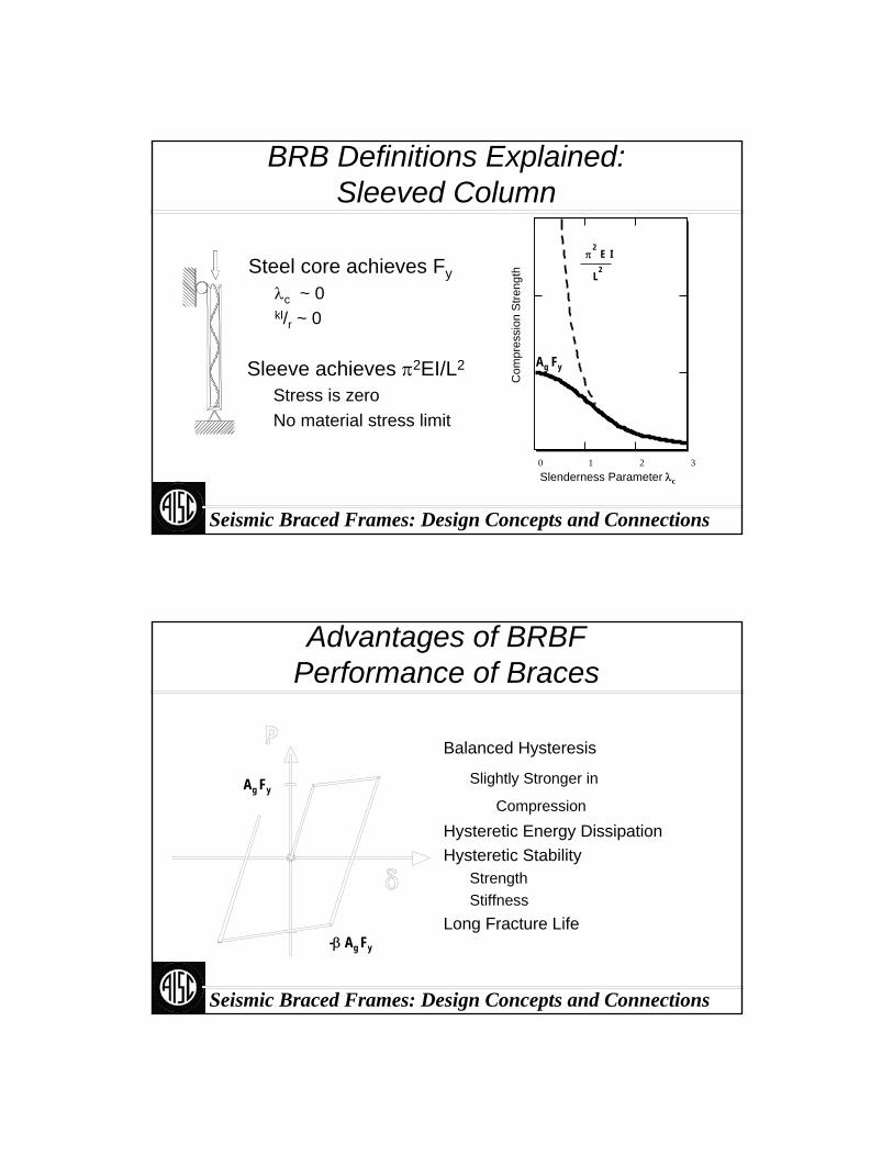
Seismic Braced Frames: Design Concepts and Connections
0 31 2
Com
pres
sion
Stre
ngth
Slenderness Parameter λc
BRB Definitions Explained: Sleeved Column
Sleeve achieves π2EI/L2
Stress is zeroNo material stress limit
Ag Fy
π2
E I
L2Steel core achieves Fy
λc ~ 0kl/r ~ 0
Seismic Braced Frames: Design Concepts and Connections
Advantages of BRBFPerformance of Braces
Balanced Hysteresis
Slightly Stronger in
Compression
Hysteretic Energy DissipationHysteretic Stability
StrengthStiffness
Long Fracture Life
Ag Fy
-β Ag Fy
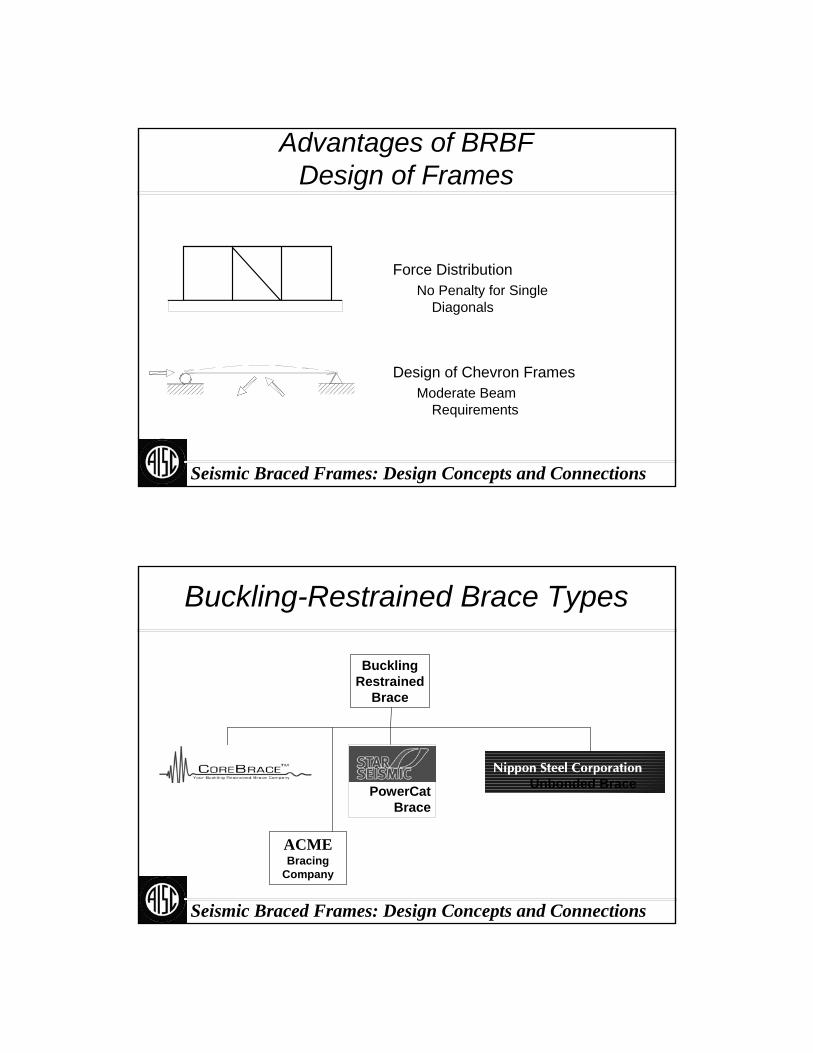
Seismic Braced Frames: Design Concepts and Connections
Advantages of BRBF Design of Frames
Force DistributionNo Penalty for Single
Diagonals
Design of Chevron FramesModerate Beam
Requirements
Seismic Braced Frames: Design Concepts and Connections
BucklingRestrained
Brace
Unbonded Brace
Buckling-Restrained Brace Types
PowerCatBrace
ACMEBracing
Company
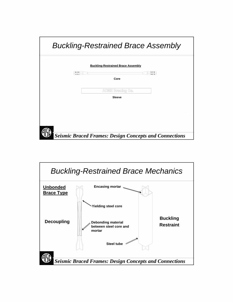
Seismic Braced Frames: Design Concepts and Connections
Buckling-Restrained Brace Assembly
Core
Buckling-Restrained Brace Assembly
Sleeve
Seismic Braced Frames: Design Concepts and Connections
Buckling-Restrained Brace Mechanics
Unbonded Brace Type
DecouplingBucklingRestraint
Encasing mortar
Yielding steel core
Steel tube
Debonding material between steel core and mortar
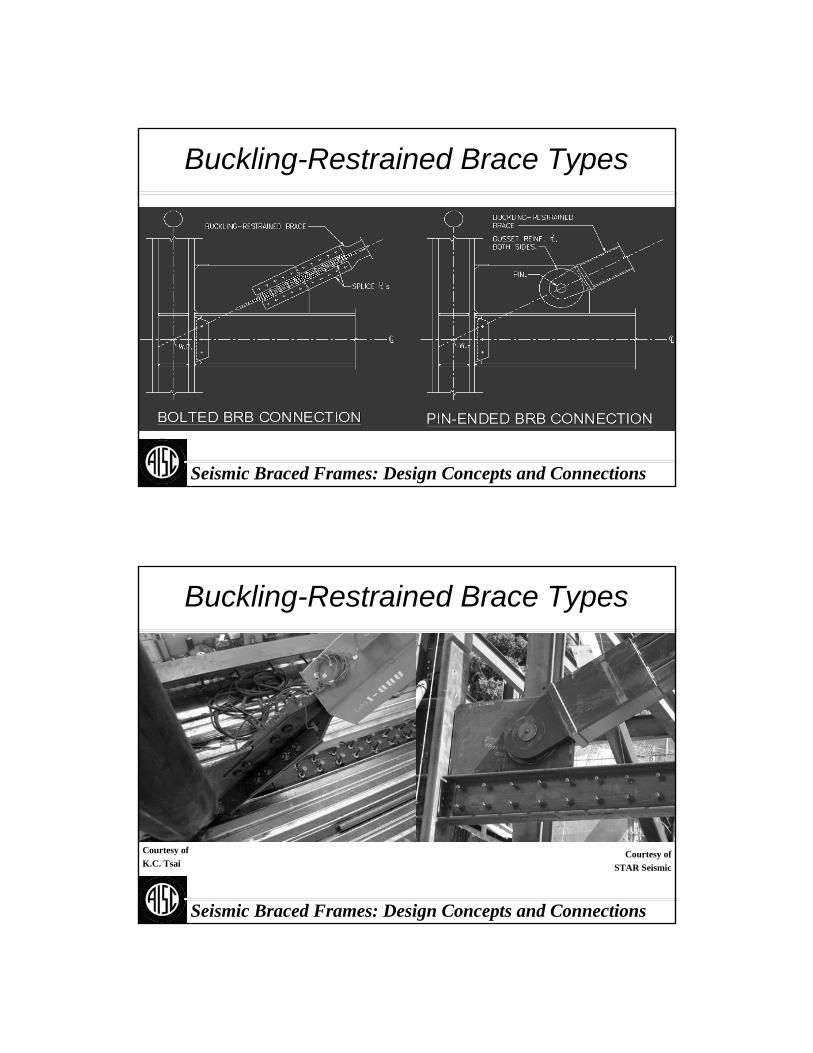
Seismic Braced Frames: Design Concepts and Connections
Buckling-Restrained Brace Types
Seismic Braced Frames: Design Concepts and Connections
Buckling-Restrained Brace Types
Courtesy ofK.C. Tsai
Courtesy ofSTAR Seismic
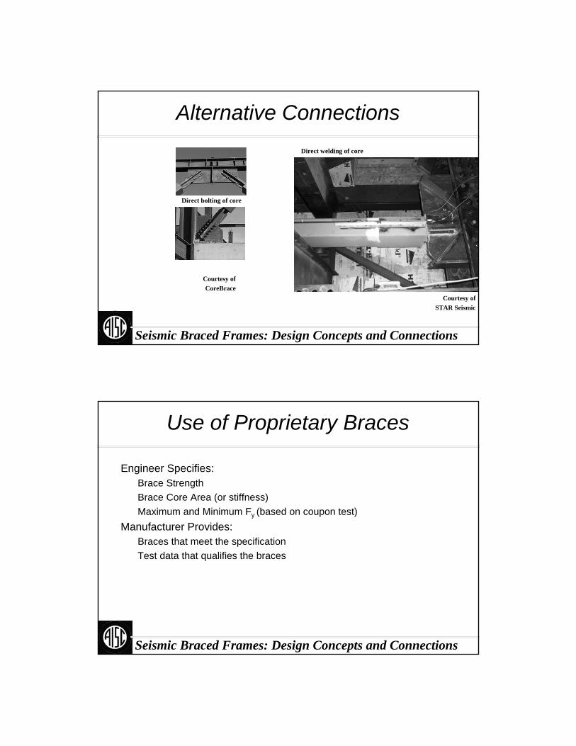
Seismic Braced Frames: Design Concepts and Connections
Alternative Connections
Courtesy ofSTAR Seismic
Courtesy ofCoreBrace
Direct bolting of core
Direct welding of core
Seismic Braced Frames: Design Concepts and Connections
Use of Proprietary Braces
Engineer Specifies:Brace StrengthBrace Core Area (or stiffness)Maximum and Minimum Fy (based on coupon test)
Manufacturer Provides:Braces that meet the specificationTest data that qualifies the braces

Seismic Braced Frames: Design Concepts and Connections
Design Procedure
Base ShearUsing Applicable Building
Code (ABC)Using R from Appendix R
Force-Based DesignTruss analysis to determine
required strength of bracesElastic analysis with assumed
brace stiffness
Seismic Braced Frames: Design Concepts and Connections
Brace Stiffness
Non-Yielding
Zone
Non-Yielding
Zone
Kbr = P/Δ
Δ ~ PLy/AyE
Ly = 0.5-0.8 L(depending on brace type and configuration)
Kbr = 1.3-2.0 AyE /L
FlexibilityL y
E A sc.L L y
E A nonyielding.
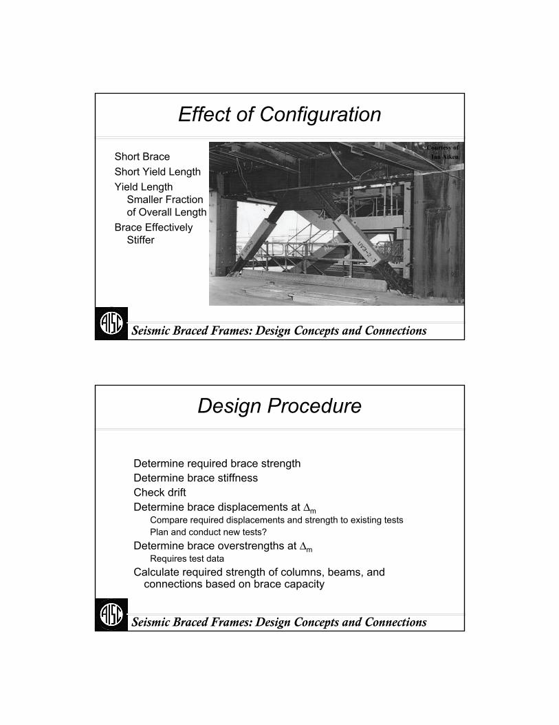
Seismic Braced Frames: Design Concepts and Connections
Effect of ConfigurationCourtesy of
Ian AikenShort BraceShort Yield LengthYield Length
Smaller Fraction of Overall Length
Brace Effectively Stiffer
Seismic Braced Frames: Design Concepts and Connections
Design Procedure
Determine required brace strengthDetermine brace stiffnessCheck drift Determine brace displacements at Δm
Compare required displacements and strength to existing testsPlan and conduct new tests?
Determine brace overstrengths at ΔmRequires test data
Calculate required strength of columns, beams, and connections based on brace capacity

Seismic Braced Frames: Design Concepts and Connections
Brace Capacity
Adjusted for Various Factorsω Strain-Hardeningβ Compression OverstrengthRy Material Overstrength
If Fy is used as core yield strength Fysc, Ry is taken from Section 6.If core yield strength Fysc is taken from material coupon test, Ry = 1.0.
Seismic Braced Frames: Design Concepts and Connections
Design Procedure
Option I: Project-Specific TestingDetermine required number of
testsDifferent strengths to be testedTest bracesDetermine system design
factorsAlternative: assume system
design factors prior to testing
Option II: Specification of Tested BracesConsult manufacturers about
brace strengths required and assumed stiffness
Specify required brace strength and minimum core area
Obtain system design factors from manufacturer’s test data
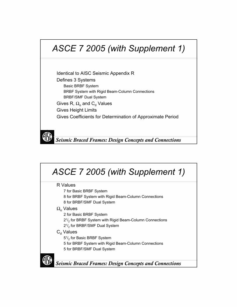
Seismic Braced Frames: Design Concepts and Connections
ASCE 7 2005 (with Supplement 1)
Identical to AISC Seismic Appendix RDefines 3 Systems
Basic BRBF SystemBRBF System with Rigid Beam-Column ConnectionsBRBF/SMF Dual System
Gives R, Ωo and Cd ValuesGives Height LimitsGives Coefficients for Determination of Approximate Period
Seismic Braced Frames: Design Concepts and Connections
R Values7 for Basic BRBF System8 for BRBF System with Rigid Beam-Column Connections8 for BRBF/SMF Dual System
Ωo Values2 for Basic BRBF System21/2 for BRBF System with Rigid Beam-Column Connections 21/2 for BRBF/SMF Dual System
Cd Values51/2 for Basic BRBF System5 for BRBF System with Rigid Beam-Column Connections 5 for BRBF/SMF Dual System
ASCE 7 2005 (with Supplement 1)
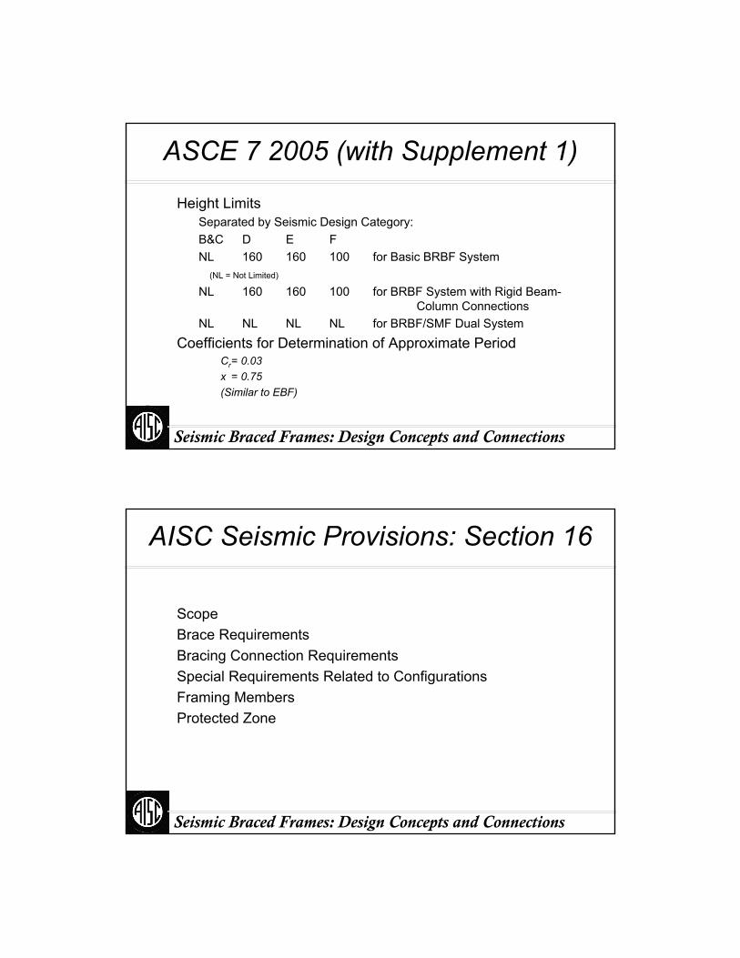
Seismic Braced Frames: Design Concepts and Connections
Height Limits Separated by Seismic Design Category:B&C D E FNL 160 160 100 for Basic BRBF System
(NL = Not Limited)
NL 160 160 100 for BRBF System with Rigid Beam-Column Connections
NL NL NL NL for BRBF/SMF Dual System
Coefficients for Determination of Approximate PeriodCr= 0.03x = 0.75(Similar to EBF)
ASCE 7 2005 (with Supplement 1)
Seismic Braced Frames: Design Concepts and Connections
AISC Seismic Provisions: Section 16
ScopeBrace RequirementsBracing Connection RequirementsSpecial Requirements Related to ConfigurationsFraming MembersProtected Zone

Seismic Braced Frames: Design Concepts and Connections
Brace RequirementsConstruction
Steel CoreBuckling-Restraining System
CoreResists 100% of Axial Force from Building-Code ForcesStrength
φPysc = 0.9 Fysc Asc
(Fysc = Specified Minimum or Measured Fy)Must Be Notch ToughNo Splices Permitted
AISC Seismic Provisions: Section 16
Seismic Braced Frames: Design Concepts and Connections
Brace RequirementsBuckling-Restraining Mechanism
CasingBeams, Columns, GussetsRestrain Core at Drifts up to 2.0 Δm.
TestingTesting per Appendix T Two Types Required to Qualify Use of Brace Designs
AxialSubassemblage with Rotations
Test Can Qualify as Both Types (Subassemblage Test Always is also Brace Test)
AISC Seismic Provisions: Section 16

Seismic Braced Frames: Design Concepts and Connections
Possible Subassemblages
Eccentric Loading of Brace
Loading of Braced FrameLoading of Brace and Column
Loading of Brace with Constant Imposed Rotation
Seismic Braced Frames: Design Concepts and Connections
TestingTesting Used to Establish Brace Expected Strength
Adjusted Brace StrengthsCompressionC’ = βωRyPysc
TensionT’ = ωRyPysc
Ry = 1.0 If Fy Is Based on Coupon TestsFactors
Factors Taken from Test Results within 2.0 Δm.Compression Strength Adjustment Factor β = Cmax/Tmax
Strain-Hardening Adjustment Factor ω = Tmax/FyA
AISC Seismic Provisions: Section 16
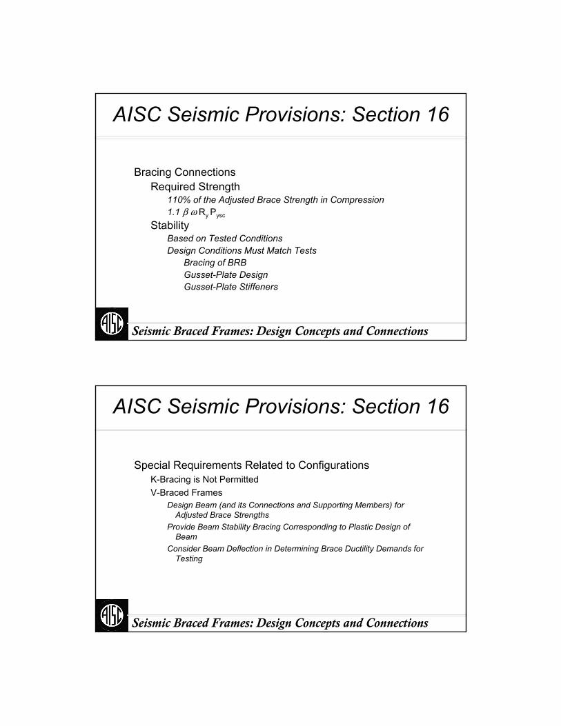
Seismic Braced Frames: Design Concepts and Connections
Bracing ConnectionsRequired Strength
110% of the Adjusted Brace Strength in Compression1.1 β ω Ry Pysc
StabilityBased on Tested ConditionsDesign Conditions Must Match Tests
Bracing of BRB Gusset-Plate DesignGusset-Plate Stiffeners
AISC Seismic Provisions: Section 16
Seismic Braced Frames: Design Concepts and Connections
Special Requirements Related to ConfigurationsK-Bracing is Not Permitted V-Braced Frames
Design Beam (and its Connections and Supporting Members) for Adjusted Brace Strengths
Provide Beam Stability Bracing Corresponding to Plastic Design of Beam
Consider Beam Deflection in Determining Brace Ductility Demands for Testing
AISC Seismic Provisions: Section 16
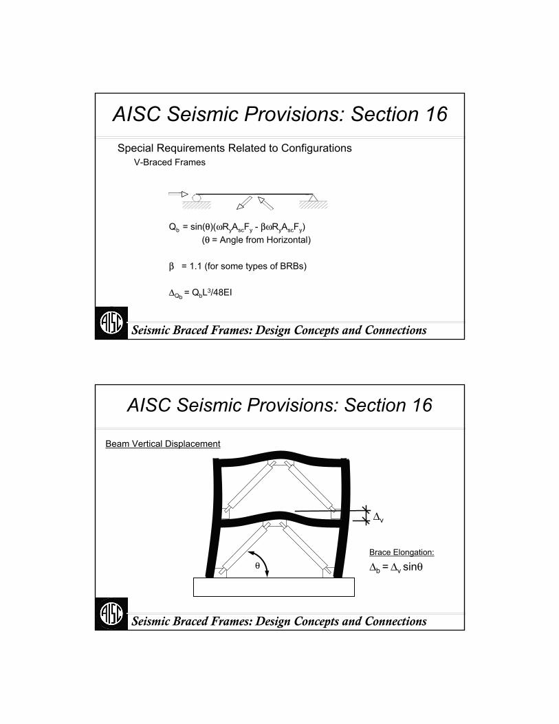
Seismic Braced Frames: Design Concepts and Connections
Qb = sin(θ)(ωRyAscFy - βωRyAscFy)(θ = Angle from Horizontal)
β = 1.1 (for some types of BRBs)
ΔQb = QbL3/48EI
Special Requirements Related to ConfigurationsV-Braced Frames
AISC Seismic Provisions: Section 16
Seismic Braced Frames: Design Concepts and Connections
AISC Seismic Provisions: Section 16
Δv
Brace Elongation:
Δb = Δv sinθ
Beam Vertical Displacement
θ

Seismic Braced Frames: Design Concepts and Connections
Beams and ColumnsUse Seismically Compact ShapesDesign for Adjusted Brace StrengthsColumn Splices
Shear from Mp at top and bottom of column 50% of φMp of Smaller Section
Protected ZoneSteel CoreGussets
AISC Seismic Provisions: Section 16
Vu
Mp
Mp
Vu
βωRyAscFy
ωRyAscFy
βωRyAscFy
ωRyAscFy
Seismic Braced Frames: Design Concepts and Connections
Beams and ColumnsUse Seismically Compact ShapesDesign for Adjusted Brace StrengthsColumn Splices
Shear from Mp at top and bottom of column 50% of φMp of Smaller Section
Protected ZoneSteel CoreGussets
AISC Seismic Provisions: Section 16
βωRyAscFy ωRyAscFy
βωRyAscFyωRyAscFy

Seismic Braced Frames: Design Concepts and Connections
Verify Adequate PerformanceStabilityDuctilityAchieve Full Tension StrengthNo Excessive Compression Overstrength
Establish Design Coefficientsβ = Cmax / Tmax
ω = Tmax / FyA
AISC Seismic Provisions: Appendix T
Seismic Braced Frames: Design Concepts and Connections
Types of Testing
Project-SpecificSuite of Tests Designed to Satisfy Appendix T Requirements
From Other SourcesPublic Domain
Published StudiesSufficient Number and Range to Satisfy Appendix T RequirementsSufficiently Documented to Satisfy Appendix T Requirements
Brace ManufacturerExisting Test DataSufficient Number and Range to Satisfy Appendix T RequirementsSufficiently Documented to Satisfy Appendix T Requirements
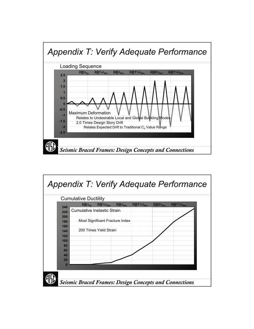
Seismic Braced Frames: Design Concepts and Connections
-2.5-2
-1.5
-1-0.5
00.5
1
1.52
2.5
Loading Sequence2@Δby 2@½Δbm 2@Δbm 2@1½Δbm 2@2Δbm 2@1½Δbm
Appendix T: Verify Adequate Performance
Maximum DeformationRelates to Undesirable Local and Global Buckling Modes2.0 Times Design Story Drift
Relates Expected Drift to Traditional Cd Value Range
Seismic Braced Frames: Design Concepts and Connections
Cumulative Ductility2@Δby 2@½Δbm 2@Δbm 2@1½Δbm 2@2Δbm 2@1½Δbm
020406080
100120140160180200220240
Cumulative Inelastic Strain
Most Significant Fracture Index
200 Times Yield Strain
Appendix T: Verify Adequate Performance

Seismic Braced Frames: Design Concepts and Connections
Acceptance CriteriaPositive Incremental StiffnessNo Fracture or InstabilityPmax ≥ Pysc ( = A Fy )Pmax ≤ 1.3 Tmax
Appendix T: Verify Adequate Performance
Seismic Braced Frames: Design Concepts and Connections
Design Example
5 x 30’ = 150’
5 x
30’
= 15
0’
Note: 2 braced frames
per side (vs. 3 for SCBF)
ASCE 7 2005AISC Seismic 2005
R = 8

Seismic Braced Frames: Design Concepts and Connections
Base Shear
Bingo
HazardSds = 1.00
Sd1 = 0.635
Ta = 0.726 sec.
V = 0.109 W
T
V
Seismic Braced Frames: Design Concepts and Connections
Load Combinations
1.2D + f1L + E
0.9D ± E
1.40D + 0.5L + ρQE
0.7D ± ρQE
1.40D + 0.5L + ΩoQE
0.7D ± ΩoQE
f1 = 0.5E = ρ QE + 0.2SDS D
Basic Special (Amplified Seismic Load)
1.2D + f1L + Em
0.9D ± Em
Em = Ωo QE + 0.2SDS D
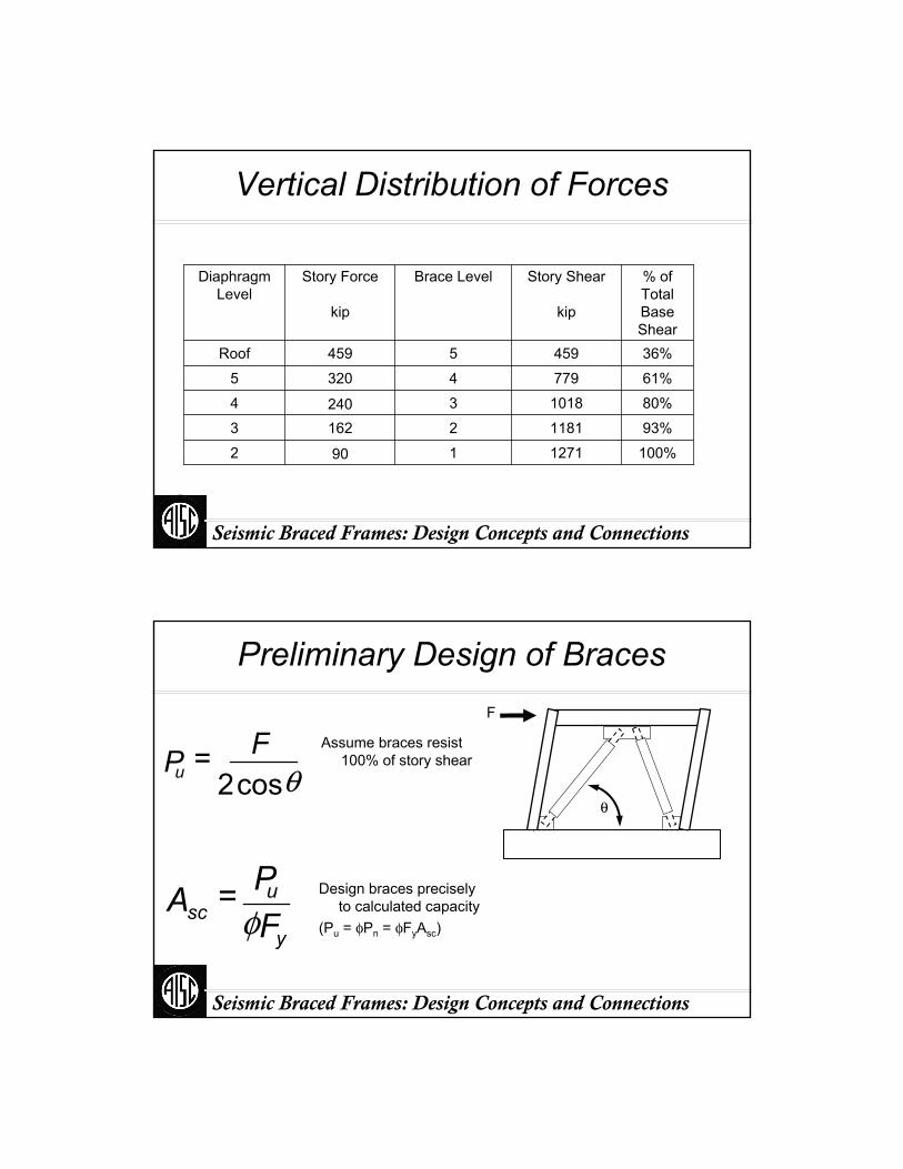
Seismic Braced Frames: Design Concepts and Connections
Vertical Distribution of Forces
100%12711902
93%118121623
80%101832404
61%77943205
36%4595459Roof
% ofTotalBaseShear
Story Shear
kip
Brace LevelStory Force
kip
DiaphragmLevel
Seismic Braced Frames: Design Concepts and Connections
Preliminary Design of Braces
y
usc F
PA φ=
θcos2 FPu =
Assume braces resist 100% of story shear
Design braces precisely to calculated capacity
(Pu = φPn = φFyAsc)
F
θ

Seismic Braced Frames: Design Concepts and Connections
Preliminary Design of Braces
7.63260.950.21
6.00205.340.92
5.18177.140.93
3.96135.440.94
2.3379.840.95
in.2kipdeg.
Core Area Asc
Brace Force Pu
Brace Angle θ
Brace Level
Seismic Braced Frames: Design Concepts and Connections
Consult Brace Manufacturer
Does the manufacturer’s suite of tests cover the brace forces and deformations in the design?
What are the appropriate brace overstrength factors to be used in the design of beams and columns?
What are the appropriate stiffness values for braces to be used in the analytical model?

Seismic Braced Frames: Design Concepts and Connections
Test Extrapolation
From designer’s perspective:Axial:
50% Prototype Strength ≤ Specimen Strength ≤ 150% Prototype StrengthSubassemblage:
Specimen Strength≥ Prototype Strength
Manufacturer’s perspective:Axial:
67% Specimen Strength ≤ Prototype Strength ≤ 200% Specimen Strength Subassemblage:
Prototype Strength ≤ Specimen Strength
Seismic Braced Frames: Design Concepts and Connections
Required Tests
391—130260.91
308—103205.32
266—89177.13
203—68135.44
120—4079.85
kipkip
Applicable Test Range
Brace Force Pu
Brace Level
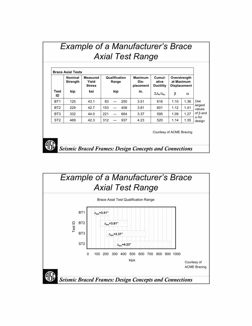
Seismic Braced Frames: Design Concepts and Connections
Example of a Manufacturer’s Brace Axial Test Range
1.351.145204.23937—31242.3469ST2
1.271.095953.37664—22144.0332BT3
1.411.126013.81458—15342.7229BT2
1.361.106163.51250—8343.1125BT1
ωβΣΔb/Δbyin.kipksikip
Overstrength at Maximum
Displacement
Cumul-ative
Ductility
Maximum Dis-
placement
Qualification Range
Measured Yield
Stress
Nominal Strength
Test ID
Brace Axial Tests
Courtesy of ACME Bracing
Use largest values of β and ω for design
Seismic Braced Frames: Design Concepts and Connections
Brace Axial Test Qualification Range
0 100 200 300 400 500 600 700 800 900 1000
BT1
BT2
BT3
ST2
Test
ID
kips
Example of a Manufacturer’s Brace Axial Test Range
Courtesy of ACME Bracing
Δbm=3.51”
Δbm=3.81”
Δbm=3.37”
Δbm=4.23”
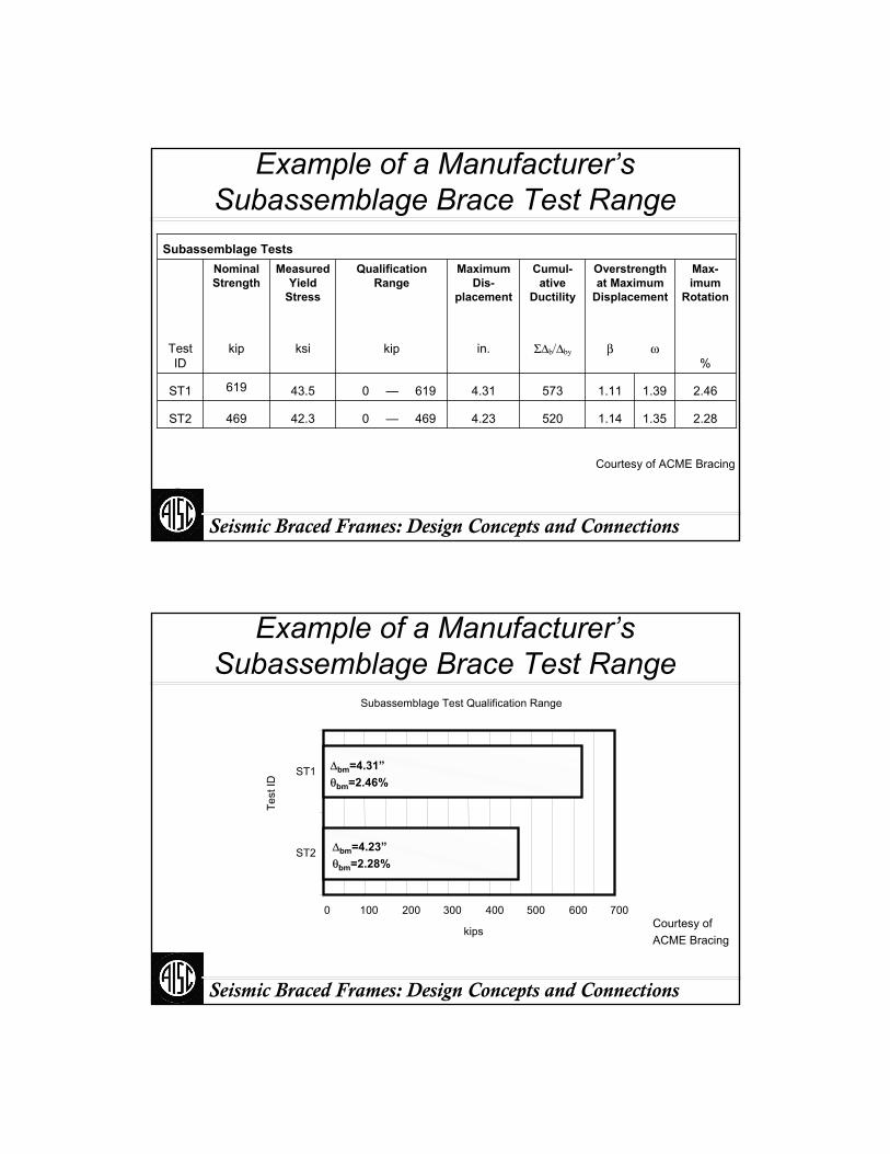
Seismic Braced Frames: Design Concepts and Connections
Example of a Manufacturer’s Subassemblage Brace Test Range
2.281.351.145204.23469—042.3469ST2
2.461.391.115734.31619—043.5619ST1
%ωβΣΔb/Δbyin.kipksikip
Max-imum
Rotation
Overstrength at Maximum
Displacement
Cumul-ative
Ductility
Maximum Dis-
placement
Qualification Range
Measured Yield
Stress
Nominal Strength
Test ID
Subassemblage Tests
Courtesy of ACME Bracing
Seismic Braced Frames: Design Concepts and Connections
Example of a Manufacturer’s Subassemblage Brace Test Range
Courtesy of ACME Bracing
Subassemblage Test Qualification Range
0 100 200 300 400 500 600 700
ST1
ST2
Test
ID
kips
Δbm=4.31”θbm=2.46%
Δbm=4.23”θbm=2.28%
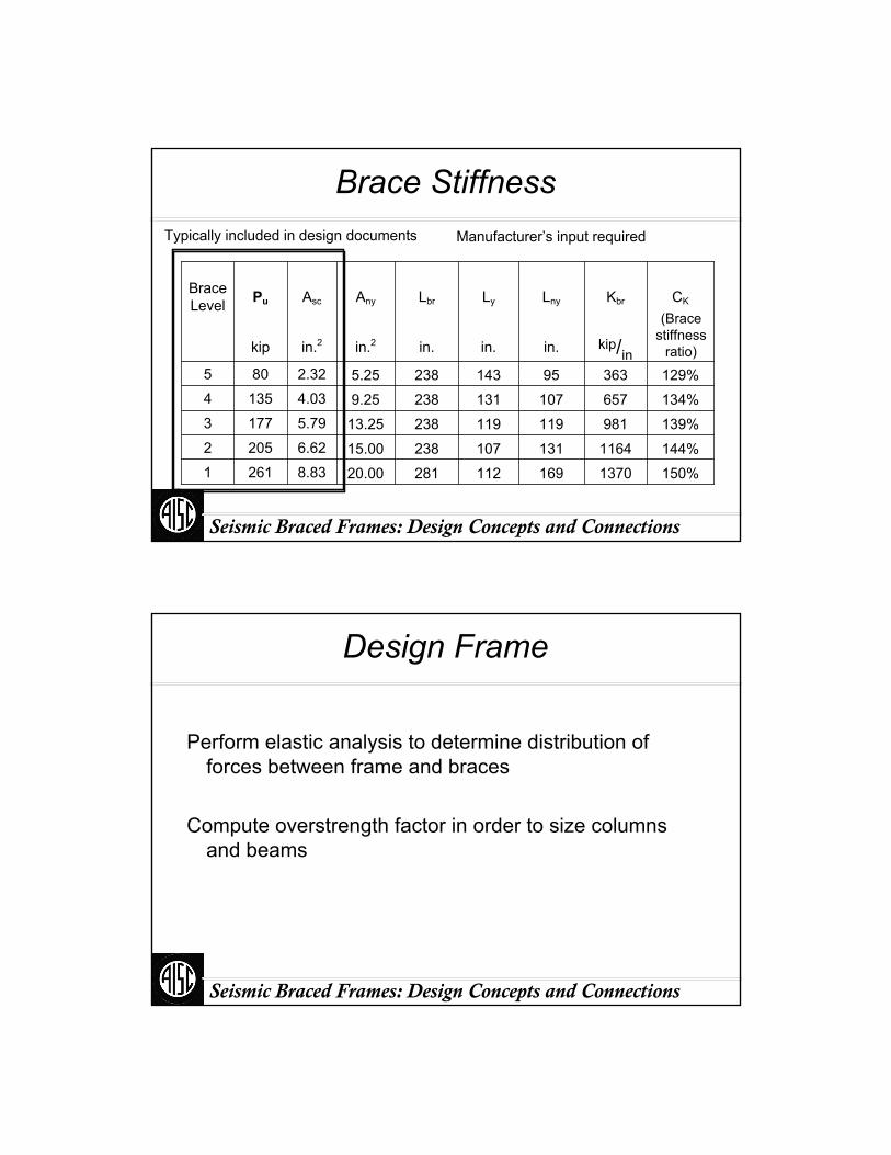
Seismic Braced Frames: Design Concepts and Connections
Brace Stiffness
150%1370169 112 28120.008.832611144%1164131 107 23815.006.622052139%981119 119 23813.255.791773134%657107 131 2389.254.031354129%36395 143 2385.252.32805
kip/inin.in.in.in.2in.2kip
CKKbrLnyLyLbrAnyAscPuBrace Level
Manufacturer’s input requiredTypically included in design documents
(Brace stiffness
ratio)
Seismic Braced Frames: Design Concepts and Connections
Design Frame
Perform elastic analysis to determine distribution of forces between frame and braces
Compute overstrength factor in order to size columns and beams
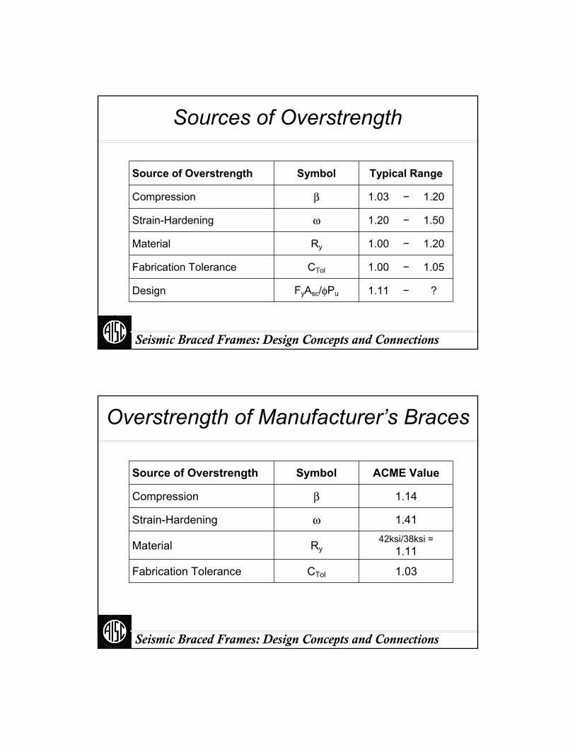
Seismic Braced Frames: Design Concepts and Connections
Sources of Overstrength
?−1.11FyAsc/φPuDesign
1.05−1.00CTolFabrication Tolerance
1.20−1.00RyMaterial
1.50−1.20ωStrain-Hardening
1.20−1.03βCompression
Typical RangeSymbolSource of Overstrength
Seismic Braced Frames: Design Concepts and Connections
Overstrength of Manufacturer’s Braces
1.03CTolFabrication Tolerance
42ksi/38ksi =1.11RyMaterial
1.41ωStrain-Hardening
1.14βCompression
ACME ValueSymbolSource of Overstrength
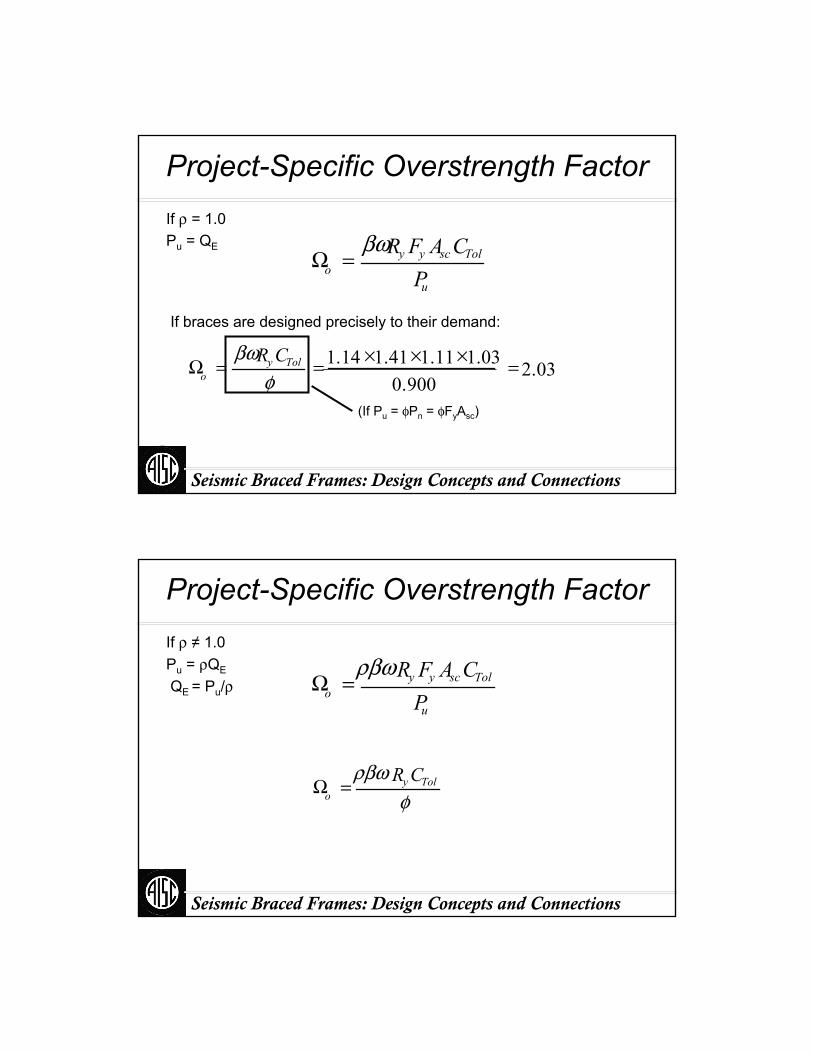
Seismic Braced Frames: Design Concepts and Connections
Project-Specific Overstrength Factor
u
Tolscyyo P
CAFRβω=Ω
If braces are designed precisely to their demand:
(If Pu = φPn = φFyAsc)
03.2900.0
03.111.141.114.1 =×××==Ωφ
βω Tolyo
CR
If ρ = 1.0Pu = QE
Seismic Braced Frames: Design Concepts and Connections
Project-Specific Overstrength Factor
u
Tolscyyo P
CAFRρβω=Ω
=Ωφ
ρβω Tolyo
CR
If ρ ≠ 1.0Pu = ρQE
QE = Pu/ρ
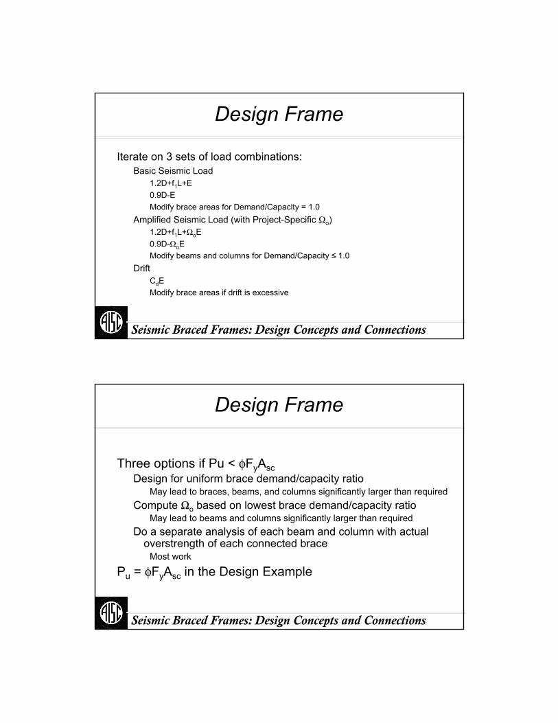
Seismic Braced Frames: Design Concepts and Connections
Design Frame
Iterate on 3 sets of load combinations:Basic Seismic Load
1.2D+f1L+E0.9D-E Modify brace areas for Demand/Capacity = 1.0
Amplified Seismic Load (with Project-Specific Ωo)1.2D+f1L+ΩoE0.9D-ΩoEModify beams and columns for Demand/Capacity ≤ 1.0
DriftCdEModify brace areas if drift is excessive
Seismic Braced Frames: Design Concepts and Connections
Design Frame
Three options if Pu < φFyAscDesign for uniform brace demand/capacity ratio
May lead to braces, beams, and columns significantly larger than requiredCompute Ωo based on lowest brace demand/capacity ratio
May lead to beams and columns significantly larger than requiredDo a separate analysis of each beam and column with actual
overstrength of each connected braceMost work
Pu = φFyAsc in the Design Example

Seismic Braced Frames: Design Concepts and Connections
Beam Design
Fhor = (βωRyFyAscCTol + ωRyFyAscCTol)cosθ = (β + 1) ωRyFyAscCTolcosθ
Fver = (βωRyFyAscCTol - ωRyFyAscCTol)sinθ = (β - 1) ωRyFyAscCTolsinθ
ωRyFyAscCTol βωRyFyAscCTol
Compute unbalance forces on beamsApply forces to beams in model
Seismic Braced Frames: Design Concepts and Connections
Vertical Unbalance Forces
162504655317.6350.21
03343664176.0040.92
74293163605.1840.93
05222412753.9640.94
13Roof131421622.3340.95
kipkipkipkipin.2deg.
ωRyFyAscCTolβωRyFyAscCTolAscθ
Net Vertical Force
Diaphragm Level
Vertical Force
Adjusted Tension Strength
Adjusted Compression
Strength
Core Area
Brace Angle
Brace Level
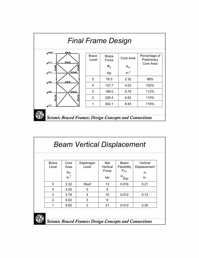
Seismic Braced Frames: Design Concepts and Connections
116%
110%
112%
102%
99%
Percentage of Preliminary Core Area
8.83
6.62
5.79
4.03
2.32
in.2Asc
Core Area
302.11
226.42
198.03
137.74
79.35
kip
Pu
Brace Force
BraceLevel
Final Frame Design
Seismic Braced Frames: Design Concepts and Connections
Beam Vertical Displacement
0.260.0122128.831036.622
0.120.0121045.793054.034
0.210.01613Roof2.325
in.in/kipkipin.2ΔvAsc
Vertical Displacement
Beam Flexibility
Fbm
Net Vertical Force
Diaphragm Level
Core Area
Brace Level

Seismic Braced Frames: Design Concepts and Connections
Beam Vertical Displacement
Δv
Brace Elongation:
Δb = Δv sinθθ
Seismic Braced Frames: Design Concepts and Connections
Brace Axial Deformation
)cos(θmbm Δ=Δ
byscy
udbm AF
PC Δ=Δ
Brace Elongation:
Based on calculated drift
Based on 2% drift (required for qualifying tests)
(If Pu = φPn = φFyAsc)
bydC Δ= φ
bedbm C Δ=Δ

Seismic Braced Frames: Design Concepts and Connections
Brace Deformations
1.59%2.21 0.22 21611.65%1.95 0.19 15621.71%2.02 0.20 15631.78%2.10 0.21 15641.85%2.18 0.22 1565
in.in.in.2Δm/H
2ΔbmΔbeH
Rotation Angle
Maximum Deformation
Elastic Deformation
Story Height
Brace Level
Based on Calculated Forces
Seismic Braced Frames: Design Concepts and Connections
Brace Deformations
2.77 2.00%21612.36 2.00%15622.36 2.00%15632.362.00%15642.36 2.00%1565in.in.
2ΔbmH
Maximum Deformation
Rotation AngleStory HeightBrace LevelBased on 2% Drift

Seismic Braced Frames: Design Concepts and Connections
Brace Deformations
BT2, BT3ST1, ST22.960.200.261BT1, BT2ST1, ST22.530.170.262BT1, BT2ST1, ST22.440.080.123
BT1ST1, ST22.440.080.124BT1ST1, ST22.490.140.215
in.in.in.ΔbΔv
Applicable Brace Tests
Applicable Subassemblage
Tests
Total Deformation
Brace Deformation
Vertical Displacement
Brace Level
From Beam Displacement
Seismic Braced Frames: Design Concepts and Connections
613
460
402
280
161
Required Connection
Strength1.1βωRyFyAscCTol
kip
8.83
6.62
5.79
4.03
2.32
in.2Asc
Core Area
302.11
226.42
198.03
137.74
79.35
kip
Pu
Brace Force
BraceLevel
Final Frame Design

Seismic Braced Frames: Design Concepts and Connections
Completion of Design
Design bracing connections for the required strengthCheck all connection limit states covered for SCBF
No hinge-zone detailing
Design column spliceSame as SCBF
Design base anchorageSame as SCBF
Specify Protected Zone
Part VI
Wrap up
Seismic Braced Frames: Design Concepts and Connections
Seismic Braced Frames: Design Concepts and Connections
Understand the likely yield mechanism(s) of your structure.
Design and detail yielding members for ductility.Design non-yielding members for the largest forces
that the yielding mechanism can deliver.
Remember
Seismic Braced Frames: Design Concepts and Connections
Acknowledgements
Professor Stephen MahinProfessor Hassan Astaneh-AslPatxi Uriz
University of California at Berkeley
Professor Charles RoederUniversity of Washington
Ian AikenSeismic Isolation Engineering
Professor Robert TremblayÉcole Polytechnique, Montreal
Professor K.C. TsaiNational Center for Research on Earthquake Engineering
Tom SabolEngelkirk and Sabol
Walterio LópezRutherford&Chekene
Images have been contributed by:
Thank You
Seismic Braced Frames: Design Concepts and Connections
Suggested Design References:
ACI (2002), Building Code Requirements for Structural Concrete, ACI 318-02, American Concrete Institute, Farmington Hills, MI.
AISC (2001), Load and Resistance Factor Design Manual of Steel Construction, 3rd Ed., American Institute of Steel Construction, Inc., Chicago.
AISC (2006), SCBF Gusset-Plate Design Aid: SCBF Gusset.xls, Steel Tools, www.AISC.org (in development).
AISC (2006), Seismic Design Manual, American Institute of Steel Construction, Inc., Chicago (in press).
AISC (2002), Seismic Provisions for Structural Steel Buildings, American Institute of Steel Construction, Inc., Chicago.
AISC (2005), Seismic Provisions for Structural Steel Buildings, American Institute of Steel Construction, Inc., Chicago (in press).
AISC (2005), Specification for Structural Steel Buildings, ANSI/AISC 360-05, American Institute of Steel Construction, Inc., Chicago, IL.
ASCE (2005), ASCE 7-05, Minimum Design Loads for Buildings and Other Structures (with Supplement Number One), American Society of Civil Engineers, Reston.
Astaneh-Asl, A., (1998). Seismic Behavior and Design of Gusset Plates for Braced Frames, Steel Tips, Structural Steel Education Council, Moraga, California.
Astaneh-Asl, A., Cochran, M., and Sabelli, R. (2006). Notes on Seismic Detailing of Gusset Plates, Steel Tips, Structural Steel Education Council, Moraga, California (in press).
Bruneau, M., Uang, C.M., and Whittaker, A., (1998). Ductile Design of Steel Structures, McGraw-Hill.
López, W. and Sabelli, R., (2004). Seismic Design of Buckling-Restrained Braced Frames, Steel Tips, Structural Steel Education Council, Moraga, California.
Sabelli, R., (2003). “Concentrically Braced Frames,” 2000 IBC Structural/Seismic Design Manual Volume 3, Steel and Concrete Building Design Examples, ICC, Whittier, California.
Sabelli, R., (2006). “Concentrically Braced Frames,” 2006 IBC Structural/Seismic Design Manual Volume 3, Steel and Concrete Building Design Examples, ICC, Whittier, California (in press).
Tamboli, A., (1999). Handbook of Structural Steel Connection Design and Details, McGraw-Hill.
Tremblay, R., (2001). “Seismic Behavior and Design of Concentrically Braced Steel Frames”, Engineering Journal, AISC, Third Quarter.
Uang, C.M. and Nakashima, M. (2003). “Steel Buckling-Restrained Frames,” Earthquake Engineering: Recent Advances and Applications, Chapter 16, Y. Bozorgnia and V.V. Bertero, eds., CRC Press, Boca Raton, FL.


American Institute of Steel Construction, Inc. One East Wacker Drive, Suite 700Chicago, IL 60601-1802
312.670.2400 www.aisc.org
There's always a solution in steel.
Copyright © 2022 FDOKUMEN