Design and simulation of low side lobe micro-strip array ...
20
Journal of Engg. Research Online First Article 1 Design and simulation of low side lobe micro-strip array antenna at multiple frequencies DOI:10.36909/jer.11731 Junaid Jamshid*, Kamlesh Narwani* , **, Aftab Ul Nabi* , ***, Saifullah Adnan*, Mushtaq Ahmed* *Faculty of Sciences and Technology, ILMA University, Karachi, Pakistan. **School of Electronic Information & Communication, Huazhong University of Technology, China. ***School of Electronics & Information Engineering, South China University of Technology, China. *Email: [email protected]; Corresponding Author. ABSTRACT In this paper, we present a simple design of a feed network for the antenna to achieve a lower side lobe level. Side Lobe Levels (SLL) are critical issues in the detection of an object. Higher side lobe levels can increase the false detection of objects in an autonomous vehicle system. The array is designed and simulated for four different frequencies, one at a time to make it a scalable design. The chosen frequencies are 10 GHz, 15 GHz, 20 GHz, and 24 GHz. The feed network design consists of eight patch elements with an equal power divider and CST studio software is used for simulations. From simulation results, it can be observed that VSWR is equal to 1.26, 1.16, 1.62, and 1.05 at respective frequencies. So, the radiation efficiency can be achieved as - 1.14 dB, -0.92 dB, -0.46 dB, -0.41 dB. The results substantiate that proposed design can reduce the SLL more than -24.5 dB in the elevation plane and also it is greater than 14.4 dB at all the
-
Upload
khangminh22 -
Category
Documents
-
view
3 -
download
0
Transcript of Design and simulation of low side lobe micro-strip array ...
Journal of Engg. Research Online First Article
1
Design and simulation of low side lobe micro-strip array antenna at multiple
frequencies
DOI:10.36909/jer.11731
Junaid Jamshid*, Kamlesh Narwani*,**, Aftab Ul Nabi*
,***, Saifullah Adnan*, Mushtaq
Ahmed*
*Faculty of Sciences and Technology, ILMA University, Karachi, Pakistan.
**School of Electronic Information & Communication, Huazhong University of Technology,
China.
***School of Electronics & Information Engineering, South China University of Technology,
China.
*Email: [email protected]; Corresponding Author.
ABSTRACT
In this paper, we present a simple design of a feed network for the antenna to achieve a lower side
lobe level. Side Lobe Levels (SLL) are critical issues in the detection of an object. Higher side
lobe levels can increase the false detection of objects in an autonomous vehicle system. The array
is designed and simulated for four different frequencies, one at a time to make it a scalable
design. The chosen frequencies are 10 GHz, 15 GHz, 20 GHz, and 24 GHz. The feed network
design consists of eight patch elements with an equal power divider and CST studio software is
used for simulations. From simulation results, it can be observed that VSWR is equal to 1.26,
1.16, 1.62, and 1.05 at respective frequencies. So, the radiation efficiency can be achieved as -
1.14 dB, -0.92 dB, -0.46 dB, -0.41 dB. The results substantiate that proposed design can reduce
the SLL more than -24.5 dB in the elevation plane and also it is greater than 14.4 dB at all the
Journal of Engg. Research Online First Article
2
aforementioned frequencies.
Keywords: high gain; low side lobe; VSWR; CST; SLL.
INTRODUCTION
The facile fabrication, low profile, weight, and low-cost PCB manufacturing have made micro-
strip patch antennas extremely significant antenna type of meeting many applications in the field
of radar systems, aircraft, automotive applications, and others (Karimi & Maddahali, 2018). In
autonomous vehicle (AV), the sensing module uses various sensor information (Radar, Lidar, and
camera information), to indicate the obstacles on the path relevant to the driving scenario. Radar
systems work in wideband frequencies from 300 MHz to 100GHz. The higher frequency in any
radar system can be affected more by weather conditions such as rain or clouds. However, the
higher the transmitted frequency, the better is the accuracy of the radar system (Rabbani &
Ghafouri-Shiraz, 2017). In fact the most important thing is the matching the impedances of
micro-strip patches which has been improved by using different unique matching networks
(Anandkumar & Sangeetha, 2020; Rajeswari & Anbalagan, 2020; Sohail et al., 2018).
A large wideband array, containing twelve radiating elements with double-layer substrate
integrated waveguide is presented in (Wang et al., 2018). Different kinds of power divider with
unequal T-junction have been reviewed in (Ahn & Tentzeris, 2019; J. Ji et al., 2020; Quan et al.,
2021) Taylor distribution is used for reducing the side lobe level, and achieve side lobe level of
23.9 dB in the E-plane and 20.5 dB in the H-plane at the center frequency. In (Liu et al., 2015),
an array is presented to enhance the gain for millimeter-wave applications; the array evaluates the
substrate height for gain enhancement. The paper shows that a long feeding line can increase the
loss, and thick substrate degrades the antenna gain. On the other hand, a relatively thin substrate
can enhance the gain, but narrower bandwidth and higher side lobe levels are also introduced in
Journal of Engg. Research Online First Article
3
the array antenna. (Oborzhytskyy & Prudyus, 2016) states that side lobe level ratios are essential
to reduce false indications of objects in radars, and autonomous applications. So much research is
being carried out on minimizing the side lobe levels. Many researchers such as (Gasztold, 2014)
have proposed different solutions to eliminate the problems caused by SLL. Power divider feed
networks have been mostly used for minimizing the side lobes levels. Various types of power
dividers proposed with unequal and equal T-junction feed networks have been designed and
reviewed in (Park et al., 2016).
In this paper, a patch array antenna is created and simulated for different frequencies, patch
antenna constructed with a couple of slots near the radiating edges. After creating a patch, a
uniform power divider is created for equal power distribution in the feed network. The detailed
construction and mathematical expression are presented in the previous article (Jamshid et al.,
2017). Here we modify the array to make it scalable for different frequencies. The array is
simulated at four different frequencies, one by one, to make it a scalable design. The frequencies
of 10 GHz, 15 GHz, 20 GHz, and 24 GHz are selected for simulation. The simulation shows that
simulated VSWR we can calculate is almost equal to 1.26, 1.16, 1.62, and 1.05, and the radiation
efficiency is equal to -1.14 dB, -0.92 dB, -0.46 dB, -0.41 dB at selected frequencies. Also, the
SLL achieved is more than -24 dB.
The remainder of the paper is organized as follows: Proposed array design is elaborated in the
section 2. Section 3 demonstrates the simulation results at different scenarios of multiple
frequencies. Finally, the conclusion along with the future work is drawn in section 4.
RELATED WORK
(Smolders & Visser, 2014) present a novel method for low sidelobe and control of axial ratio of
circularly-polarized (CP) phased array antennas. A novel random sequential rotation (RSR)
Journal of Engg. Research Online First Article
4
provides the properties likely as randomly-spaced array antennas. Wider band is achieved,
without the creation of grating lobes. In contrast, antenna gain improved using a uniform
amplitude distribution. Infact the interspacing of element is much higher than λ/2 but it well-
controlled sidelobes. In the diagonal-plane the measured cross-polarization level is down below -
20db at a 20o scan angle.
(Yang et al., 2019) proposed a hybrid technique for 3D pattern synthesizing of antenna to achieve
the low side-lobe level for truncated-cone arrays. For this technique, truncated-cone conformal
phased arrays units were projected at a tangent plane of the cone. At that time, a 2 D optimization
of Chebyshev amplitude distribution was used in 2 different direction of the tangent plane. In
keeping with mind the position of the units, the amplitude of excitation current for every unit over
the conformal design is originated reversely, after that the amplitude of excitation current is
furtherly optimize by employing the genetic algorithm (GA). A study of sidelobe level of 35 dB
and 3-dimentional pattern is done by using this truncated cone with 8 by 8 units over it.
(P. Ji et al., 2020) presented an array of microstrip for 24 GHz frequency, with a single layer of
substrate of electrically thin width to provide a solution regarding cost, ehnaced impedance
bandwidth etc for automotive application. a prototype of array construct for a predefined sidelobe
level - 25 dB in E & H-plane.In contrast, the realized gain = 22.5 dBi, for centeral frequency and
although more than -21 dBi for a 1Ghz band of frequency. At the end, the resultant sidelobe in E
plane is 20 dB and 18 dB for H-plane. (Shin et al., 2013) proposed a novel array antenna design
for low sidelobe. It is having a number of 18 elements, with gap coupled antenna to acheive a low
radiation coefficient and is used for high radiation coefficient. Polarization of 450 is used to
reduce the interference. The antenna has 20.8dBi gain and sidelobe level of elevation direction is
under -20dB.
Journal of Engg. Research Online First Article
5
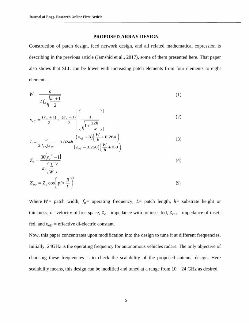
PROPOSED ARRAY DESIGN
Construction of patch design, feed network design, and all related mathematical expression is
describing in the previous article (Jamshid et al., 2017), some of them presented here. That paper
also shows that SLL can be lower with increasing patch elements from four elements to eight
elements.
0
12
2r
cW
f
(1)
w
h
rreff
121
1
2
)1(
2
)1(
(2)
0
3 0.264
0.8242
0.258 0.8
eff
effeff
W
c hL h
Wf
h
(3)
2
2
0
190
W
LZ
r
r
(4)
2
0 cos
L
RpiZZ inr (5)
Where = patch width, = operating frequency, = patch length, = substrate height or
thickness, = velocity of free space, = impedance with no inset-fed, = impedance of inset-
fed, and = effective di-electric constant.
Now, this paper concentrates upon modification into the design to tune it at different frequencies.
Initially, 24GHz is the operating frequency for autonomous vehicles radars. The only objective of
choosing these frequencies is to check the scalability of the proposed antenna design. Here
scalability means, this design can be modified and tuned at a range from 10 – 24 GHz as desired.
Journal of Engg. Research Online First Article
6
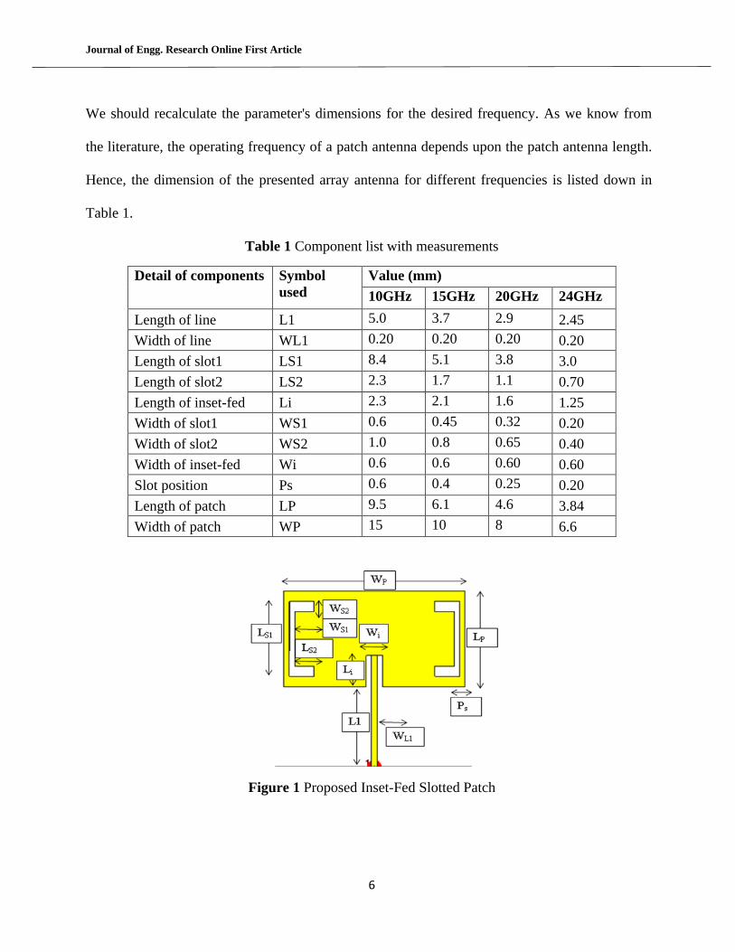
We should recalculate the parameter's dimensions for the desired frequency. As we know from
the literature, the operating frequency of a patch antenna depends upon the patch antenna length.
Hence, the dimension of the presented array antenna for different frequencies is listed down in
Table 1.
Table 1 Component list with measurements
Detail of components Symbol
used
Value (mm)
10GHz 15GHz 20GHz 24GHz
Length of line L1 5.0 3.7 2.9 2.45
Width of line WL1 0.20 0.20 0.20 0.20
Length of slot1 LS1 8.4 5.1 3.8 3.0
Length of slot2 LS2 2.3 1.7 1.1 0.70
Length of inset-fed Li 2.3 2.1 1.6 1.25
Width of slot1 WS1 0.6 0.45 0.32 0.20
Width of slot2 WS2 1.0 0.8 0.65 0.40
Width of inset-fed Wi 0.6 0.6 0.60 0.60
Slot position Ps 0.6 0.4 0.25 0.20
Length of patch LP 9.5 6.1 4.6 3.84
Width of patch WP 15 10 8 6.6
Figure 1 Proposed Inset-Fed Slotted Patch
Journal of Engg. Research Online First Article
7
Figure 1 shows the proposed patch antenna with the proper naming scheme. The length of line1 is
a quarter wavelength transformer used to match the impedances. The length of slot 1 depends
upon the patch length. It has approximately the difference of 0.80 to 0.90 from the length of the
patch. The length of slot 2 is also approximately 0.70 to 0.85 times the width of the patch. Several
iterations performed to achieve the best value, which is listed in the below table. Also, it is
confirmed from the research articles that the input impedance decreases rapidly when the inset-
fed is moved toward the center. These parametric studies have been used to derive the formula to
find the exact inset length (IL) to achieve 50-ohm input impedance for the commonly used thin
dielectric substrate.
–
(6)
The width of the inset is equally divided between the width of the inset line and the spacing form
patch. Taylor synthesis (Li et al., 2017), one of the most appropriate techniques to reduce the side
lobe level of the array. From Table 2 weighted values, we simulate the proposed antenna to verify
the reduction in side lobe levels. We observe that best-weighted values are in case 1, which lower
side lobe level more than -24.5 dB. We apply the same Taylor weight values for all frequencies in
the next section. The calculation of Taylor's weight function shown below.
1
1
__
cos,,21n
mmnAmgf
(7)
Journal of Engg. Research Online First Article
8
2
22
21
1__
2_
_
2
11
!1)!1(
!1
,,__
kA
m
mnmn
n
nAmg n
k
(8)
archA1
(9)
2
12
_2
_
2
1
nA
n (10)
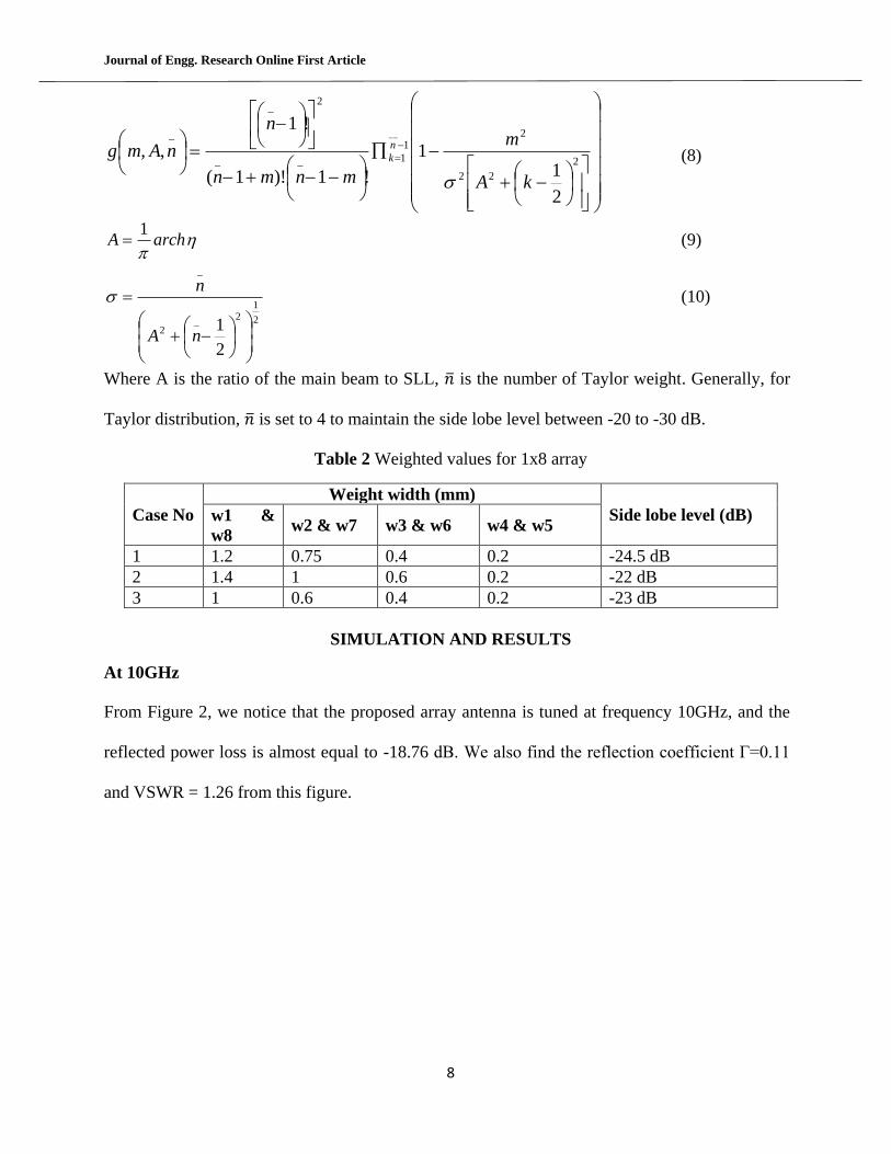
Where A is the ratio of the main beam to SLL, ̅ is the number of Taylor weight. Generally, for
Taylor distribution, ̅ is set to 4 to maintain the side lobe level between -20 to -30 dB.
Table 2 Weighted values for 1x8 array
Case No
Weight width (mm)
Side lobe level (dB) w1 &
w8 w2 & w7 w3 & w6 w4 & w5
1 1.2 0.75 0.4 0.2 -24.5 dB
2 1.4 1 0.6 0.2 -22 dB
3 1 0.6 0.4 0.2 -23 dB
SIMULATION AND RESULTS
At 10GHz
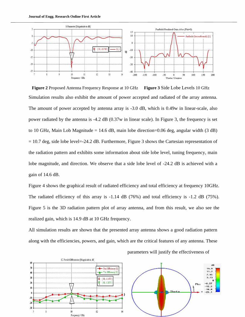
From Figure 2, we notice that the proposed array antenna is tuned at frequency 10GHz, and the
reflected power loss is almost equal to -18.76 dB. We also find the reflection coefficient Г=0.11
and VSWR = 1.26 from this figure.
Journal of Engg. Research Online First Article
9
Figure 2 Proposed Antenna Frequency Response at 10 GHz Figure 3 Side Lobe Levels 10 GHz
Simulation results also exhibit the amount of power accepted and radiated of the array antenna.
The amount of power accepted by antenna array is -3.0 dB, which is 0.49w in linear-scale, also
power radiated by the antenna is -4.2 dB (0.37w in linear scale). In Figure 3, the frequency is set
to 10 GHz, Main Lob Magnitude = 14.6 dB, main lobe direction=0.06 deg, angular width (3 dB)
= 10.7 deg, side lobe level=-24.2 dB. Furthermore, Figure 3 shows the Cartesian representation of
the radiation pattern and exhibits some information about side lobe level, tuning frequency, main
lobe magnitude, and direction. We observe that a side lobe level of -24.2 dB is achieved with a
gain of 14.6 dB.
Figure 4 shows the graphical result of radiated efficiency and total efficiency at frequency 10GHz.
The radiated efficiency of this array is -1.14 dB (76%) and total efficiency is -1.2 dB (75%).
Figure 5 is the 3D radiation pattern plot of array antenna, and from this result, we also see the
realized gain, which is 14.9 dB at 10 GHz frequency.
All simulation results are shown that the presented array antenna shows a good radiation pattern
along with the efficiencies, powers, and gain, which are the critical features of any antenna. These
parameters will justify the effectiveness of
Journal of Engg. Research Online First Article
10
antenna in practical usage. In the next section, we perform simulation at 15 GHz and check all
these parameters to verify the scalability of the design.
Figure 3 Efficiencies of Proposed Antenna Array Figure 4 Proposed Antenna Array Radiation
Pattern
At 15GHz
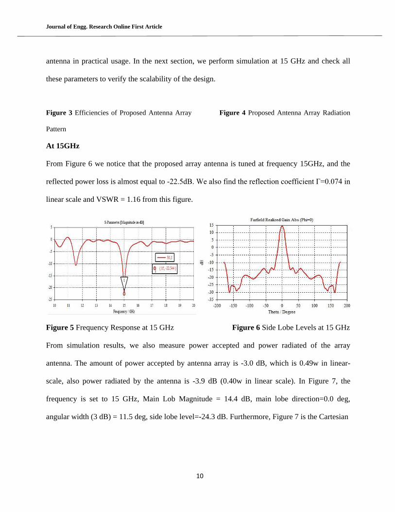
From Figure 6 we notice that the proposed array antenna is tuned at frequency 15GHz, and the
reflected power loss is almost equal to -22.5dB. We also find the reflection coefficient Г=0.074 in
linear scale and VSWR = 1.16 from this figure.
Figure 5 Frequency Response at 15 GHz Figure 6 Side Lobe Levels at 15 GHz
From simulation results, we also measure power accepted and power radiated of the array
antenna. The amount of power accepted by antenna array is -3.0 dB, which is 0.49w in linear-
scale, also power radiated by the antenna is -3.9 dB (0.40w in linear scale). In Figure 7, the
frequency is set to 15 GHz, Main Lob Magnitude = 14.4 dB, main lobe direction=0.0 deg,
angular width (3 dB) = 11.5 deg, side lobe level=-24.3 dB. Furthermore, Figure 7 is the Cartesian
Journal of Engg. Research Online First Article
11
representation of the radiation pattern and exhibits some information about side lobe level, tuning
frequency, main lobe magnitude, and direction. We observe that a side lobe level of -24.3 dB is
achieved with a gain of 14.4 dB.
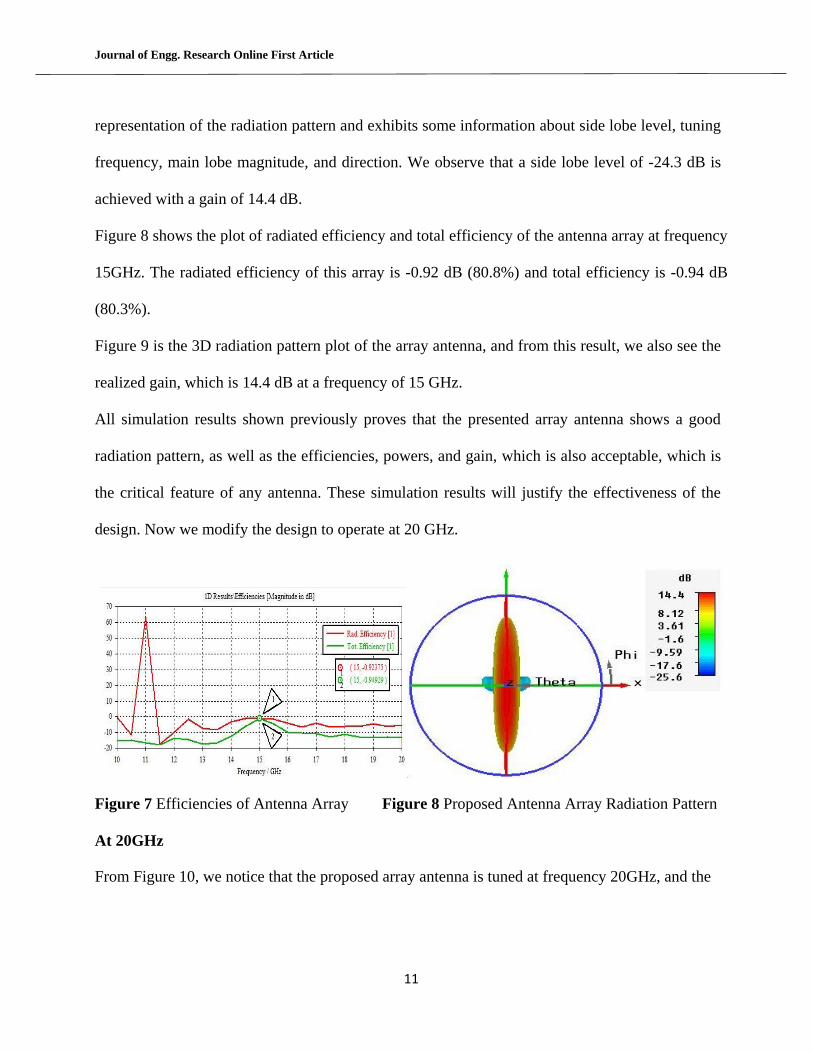
Figure 8 shows the plot of radiated efficiency and total efficiency of the antenna array at frequency
15GHz. The radiated efficiency of this array is -0.92 dB (80.8%) and total efficiency is -0.94 dB
(80.3%).
Figure 9 is the 3D radiation pattern plot of the array antenna, and from this result, we also see the
realized gain, which is 14.4 dB at a frequency of 15 GHz.
All simulation results shown previously proves that the presented array antenna shows a good
radiation pattern, as well as the efficiencies, powers, and gain, which is also acceptable, which is
the critical feature of any antenna. These simulation results will justify the effectiveness of the
design. Now we modify the design to operate at 20 GHz.
Figure 7 Efficiencies of Antenna Array Figure 8 Proposed Antenna Array Radiation Pattern
At 20GHz
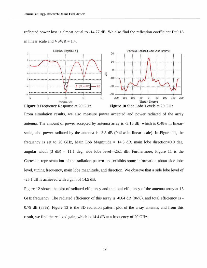
From Figure 10, we notice that the proposed array antenna is tuned at frequency 20GHz, and the
Journal of Engg. Research Online First Article
12
reflected power loss is almost equal to -14.77 dB. We also find the reflection coefficient Г=0.18
in linear scale and VSWR = 1.4.
Figure 9 Frequency Response at 20 GHz Figure 10 Side Lobe Levels at 20 GHz
From simulation results, we also measure power accepted and power radiated of the array
antenna. The amount of power accepted by antenna array is -3.16 dB, which is 0.48w in linear-
scale, also power radiated by the antenna is -3.8 dB (0.41w in linear scale). In Figure 11, the
frequency is set to 20 GHz, Main Lob Magnitude = 14.5 dB, main lobe direction=0.0 deg,
angular width (3 dB) = 11.1 deg, side lobe level=-25.1 dB. Furthermore, Figure 11 is the
Cartesian representation of the radiation pattern and exhibits some information about side lobe
level, tuning frequency, main lobe magnitude, and direction. We observe that a side lobe level of
-25.1 dB is achieved with a gain of 14.5 dB.
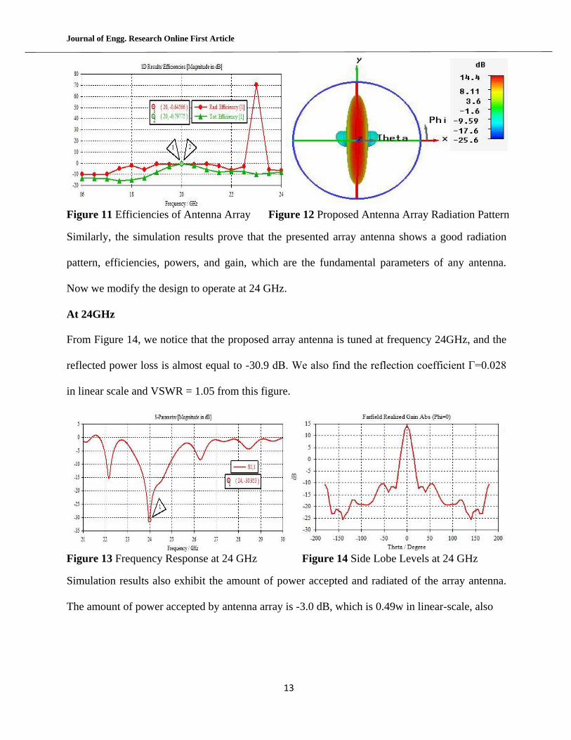
Figure 12 shows the plot of radiated efficiency and the total efficiency of the antenna array at 15
GHz frequency. The radiated efficiency of this array is -0.64 dB (86%), and total efficiency is -
0.79 dB (83%). Figure 13 is the 3D radiation pattern plot of the array antenna, and from this
result, we find the realized gain, which is 14.4 dB at a frequency of 20 GHz.
Journal of Engg. Research Online First Article
13
Figure 11 Efficiencies of Antenna Array Figure 12 Proposed Antenna Array Radiation Pattern
Similarly, the simulation results prove that the presented array antenna shows a good radiation
pattern, efficiencies, powers, and gain, which are the fundamental parameters of any antenna.
Now we modify the design to operate at 24 GHz.
At 24GHz
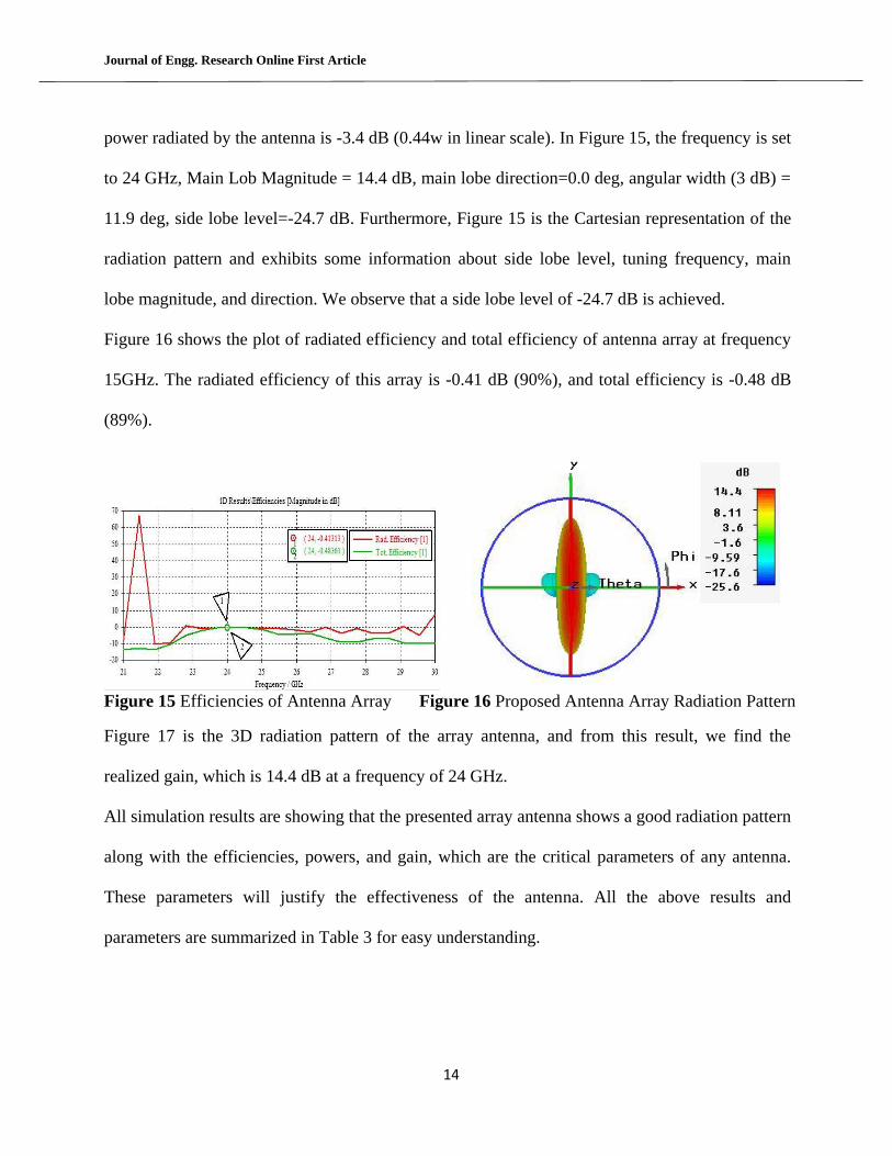
From Figure 14, we notice that the proposed array antenna is tuned at frequency 24GHz, and the
reflected power loss is almost equal to -30.9 dB. We also find the reflection coefficient Г=0.028
in linear scale and VSWR = 1.05 from this figure.
Figure 13 Frequency Response at 24 GHz Figure 14 Side Lobe Levels at 24 GHz
Simulation results also exhibit the amount of power accepted and radiated of the array antenna.
The amount of power accepted by antenna array is -3.0 dB, which is 0.49w in linear-scale, also
Journal of Engg. Research Online First Article
14
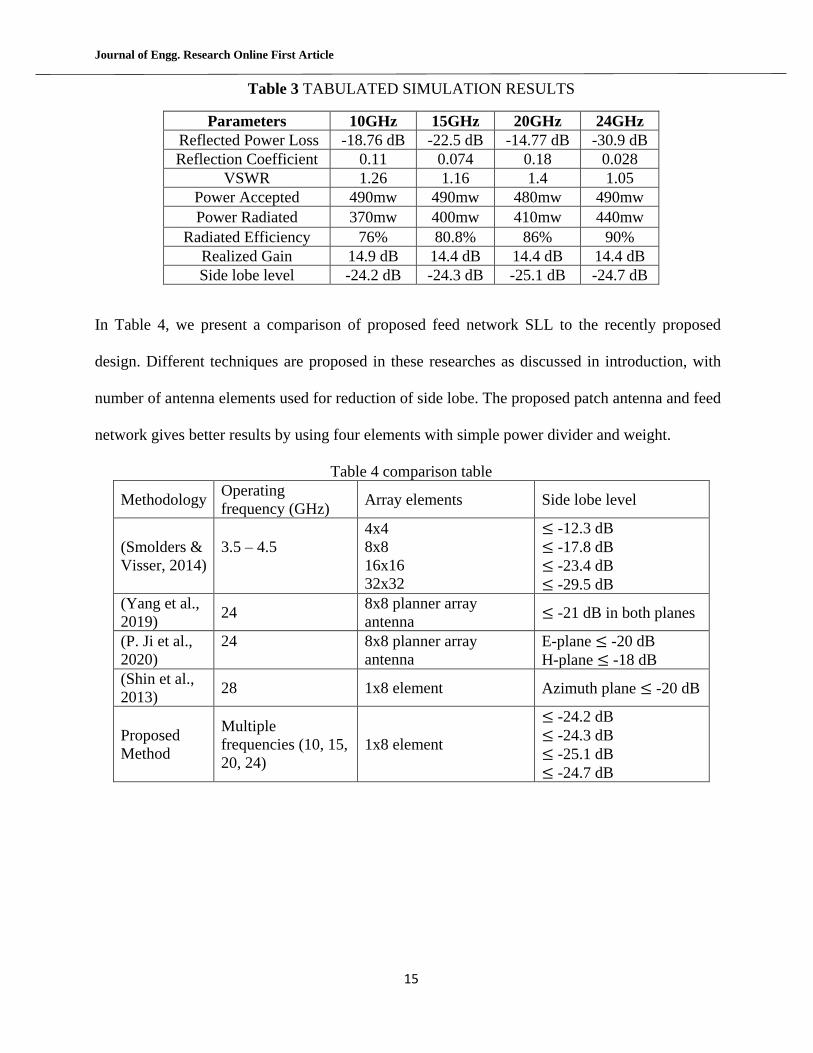
power radiated by the antenna is -3.4 dB (0.44w in linear scale). In Figure 15, the frequency is set
to 24 GHz, Main Lob Magnitude = 14.4 dB, main lobe direction=0.0 deg, angular width (3 dB) =
11.9 deg, side lobe level=-24.7 dB. Furthermore, Figure 15 is the Cartesian representation of the
radiation pattern and exhibits some information about side lobe level, tuning frequency, main
lobe magnitude, and direction. We observe that a side lobe level of -24.7 dB is achieved.
Figure 16 shows the plot of radiated efficiency and total efficiency of antenna array at frequency
15GHz. The radiated efficiency of this array is -0.41 dB (90%), and total efficiency is -0.48 dB
(89%).
Figure 15 Efficiencies of Antenna Array Figure 16 Proposed Antenna Array Radiation Pattern
Figure 17 is the 3D radiation pattern of the array antenna, and from this result, we find the
realized gain, which is 14.4 dB at a frequency of 24 GHz.
All simulation results are showing that the presented array antenna shows a good radiation pattern
along with the efficiencies, powers, and gain, which are the critical parameters of any antenna.
These parameters will justify the effectiveness of the antenna. All the above results and
parameters are summarized in Table 3 for easy understanding.
Journal of Engg. Research Online First Article
15
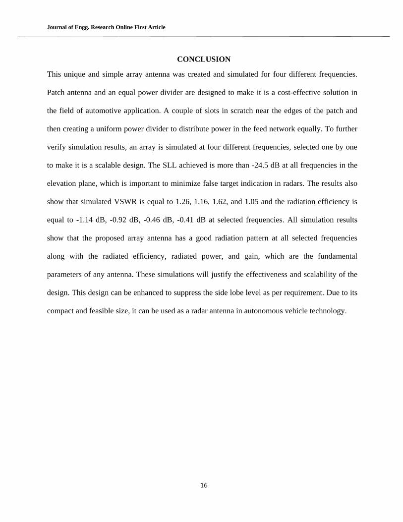
Table 3 TABULATED SIMULATION RESULTS
Parameters 10GHz 15GHz 20GHz 24GHz
Reflected Power Loss -18.76 dB -22.5 dB -14.77 dB -30.9 dB
Reflection Coefficient 0.11 0.074 0.18 0.028
VSWR 1.26 1.16 1.4 1.05
Power Accepted 490mw 490mw 480mw 490mw
Power Radiated 370mw 400mw 410mw 440mw
Radiated Efficiency 76% 80.8% 86% 90%
Realized Gain 14.9 dB 14.4 dB 14.4 dB 14.4 dB
Side lobe level -24.2 dB -24.3 dB -25.1 dB -24.7 dB
In Table 4, we present a comparison of proposed feed network SLL to the recently proposed
design. Different techniques are proposed in these researches as discussed in introduction, with
number of antenna elements used for reduction of side lobe. The proposed patch antenna and feed
network gives better results by using four elements with simple power divider and weight.
Table 4 comparison table
Methodology Operating
frequency (GHz) Array elements Side lobe level
(Smolders &
Visser, 2014)
3.5 – 4.5
4x4
8x8
16x16
32x32
-12.3 dB
-17.8 dB
-23.4 dB
-29.5 dB
(Yang et al.,
2019) 24
8x8 planner array
antenna -21 dB in both planes
(P. Ji et al.,
2020)
24
8x8 planner array
antenna
E-plane -20 dB
H-plane -18 dB
(Shin et al.,
2013) 28 1x8 element Azimuth plane -20 dB
Proposed
Method
Multiple
frequencies (10, 15,
20, 24)
1x8 element
-24.2 dB
-24.3 dB
-25.1 dB
-24.7 dB
Journal of Engg. Research Online First Article
16
CONCLUSION
This unique and simple array antenna was created and simulated for four different frequencies.
Patch antenna and an equal power divider are designed to make it is a cost-effective solution in
the field of automotive application. A couple of slots in scratch near the edges of the patch and
then creating a uniform power divider to distribute power in the feed network equally. To further
verify simulation results, an array is simulated at four different frequencies, selected one by one
to make it is a scalable design. The SLL achieved is more than -24.5 dB at all frequencies in the
elevation plane, which is important to minimize false target indication in radars. The results also
show that simulated VSWR is equal to 1.26, 1.16, 1.62, and 1.05 and the radiation efficiency is
equal to -1.14 dB, -0.92 dB, -0.46 dB, -0.41 dB at selected frequencies. All simulation results
show that the proposed array antenna has a good radiation pattern at all selected frequencies
along with the radiated efficiency, radiated power, and gain, which are the fundamental
parameters of any antenna. These simulations will justify the effectiveness and scalability of the
design. This design can be enhanced to suppress the side lobe level as per requirement. Due to its
compact and feasible size, it can be used as a radar antenna in autonomous vehicle technology.
Journal of Engg. Research Online First Article
17
REFERENCES
Ahn, H.-R., & Tentzeris, M. M. (2019). In-Phase T-Junction: Study and Application to Gysel Power
Dividers for High Power-Division Ratios Requiring No High-Impedance Transmission-Line
Section. IEEE Access, 7, 18146–18154.
Anandkumar, D., & Sangeetha, R. G. (2020). Design and analysis of aperture coupled micro strip
patch antenna for radar applications. International Journal of Intelligent Networks, 1,
141–147.
Chen, H., Zhang, T., Che, W., & Feng, W. (2014). Compact unequal Wilkinson power divider with
large power dividing ratio. 2014 9th European Microwave Integrated Circuit Conference,
608–611.
Contreras, S., & Peden, A. (2013). Graphical design method for unequal power dividers based on
phase-balanced SIW tee-junctions. International Journal of Microwave and Wireless
Technologies, 5(5), 603–610.
Gasztold, M. (2014). An antenna array with a high division ratio Wilkinson power dividers. 2014
20th International Conference on Microwaves, Radar and Wireless Communications
(MIKON), 1–5.
Jamshid, J., Abbasi, T., Khan, A. K., & Rizvi, Z. A. (2017). Uniform power distribution for low side
lobe automotive applications at 24 GHz. 2017 International Conference on Open Source
Systems Technologies (ICOSST), 42–47.
Journal of Engg. Research Online First Article
18
Ji, J., Wang, C., Wu, X., & Zhou, J. (2020). A K/Ka Dual-band Continuous Transverse Stub (CTS)
Antenna Array With Sidelobe Suppression. 2020 IEEE International Symposium on
Antennas and Propagation and North American Radio Science Meeting, 3–4.
Ji, P., Qi, Z., Huang, X., Zhao, W., Zhu, Y., & Li, X. (2020). K-Band Wideband Microstrip Antenna
Array With Sidelobe Level Reduction. 2020 International Conference on Microwave and
Millimeter Wave Technology (ICMMT), 1–3.
Karimi, P., & Maddahali, M. (2018). Wideband Slotted Array Antenna Based on Substrate
Integrated Waveguide with Circular Aperture at Ka-Band. 2018 9th International
Symposium on Telecommunications (IST), 5–10.
Li, J.-Y., Qi, Y.-X., & Zhou, S.-G. (2017). Shaped Beam Synthesis Based on Superposition Principle
and Taylor Method. IEEE Transactions on Antennas and Propagation, 65(11), 6157–6160.
Liu, Y., Wang, H., Li, K., & Gong, S. (2015). RCS Reduction of a Patch Array Antenna Based on
Microstrip Resonators. IEEE Antennas and Wireless Propagation Letters, 14, 4–7.
Oborzhytskyy, V., & Prudyus, I. (2016). The design of microwave planar power dividers and
couplers with distinct power division ratio in two different frequency bands. 2016
International Conference Radio Electronics Info Communications (UkrMiCo), 1–3.
Park, S.-J., Shin, D.-H., & Park, S.-O. (2016). Low Side-Lobe Substrate-Integrated-Waveguide
Antenna Array Using Broadband Unequal Feeding Network for Millimeter-Wave Handset
Device. IEEE Transactions on Antennas and Propagation, 64(3), 923–932.
Journal of Engg. Research Online First Article
19
Quan, Y., Yang, J., Wang, H., & Zaman, A. U. (2021). An unequal power divider based on ridge gap
waveguide with an inserted conductor plate. Microwave and Optical Technology Letters,
63(2), 443–449.
Rabbani, M. S., & Ghafouri-Shiraz, H. (2017). Evaluation of gain enhancement in large microstrip
antenna arrays for mm-wave applications. 1 (5 .)-1 (5 .).
Rajeswari, P., & Anbalagan, P. (2020). Design and deployment of android based mobile
application for performance analysis of micro strip patch antenna. Microprocessors and
Microsystems, 77, 103111.
Shin, D., Kim, K., Kim, J., & Park, S. (2013). Design of low side lobe level milimeter-wave microstrip
array antenna for automotive radar. 2013 Proceedings of the International Symposium on
Antennas Propagation, 02, 677–680.
Smolders, A. B., & Visser, H. J. (2014). Low Side-Lobe Circularly-Polarized Phased Arrays Using a
Random Sequential Rotation Technique. IEEE Transactions on Antennas and Propagation,
62(12), 6476–6481.
Sohail, A., Alimgeer, K. S., Iftikhar, A., Ijaz, B., Kim, K. W., & Mohyuddin, W. (2018). Dual notch
band UWB antenna with improved notch characteristics. Microwave and Optical
Technology Letters, 60(4), 925–930.
Wang, H., Kedze, K. E., & Park, I. (2018). Microstrip Patch Array Antenna Using a Parallel and
Series Combination Feed Network. 2018 International Symposium on Antennas and
Propagation (ISAP), 1–2.
Journal of Engg. Research Online First Article
20
Yang, H., Li, T., Xu, L., Cao, X., Gao, J., Tian, J., Yang, H., & Sun, D. (2019). A New Strategy to
Design Microstrip Antenna Array With Low Side-Lobe Level and High Gain. IEEE Access, 7,
152715–152721. https://doi.org/10.1109/ACCESS.2019.2948098