Design and performance evaluation of a dielectric flat lens for millimeter-wave applications
8
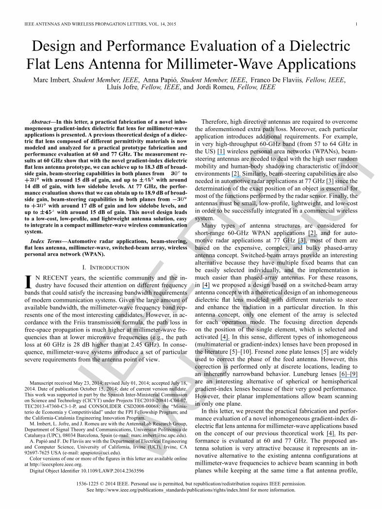
IEEE Proof Web Version IEEE ANTENNAS AND WIRELESS PROPAGATION LETTERS, VOL. 14, 2015 1 Design and Performance Evaluation of a Dielectric Flat Lens Antenna for Millimeter-Wave Applications Marc Imbert, Student Member, IEEE, Anna Papió, Student Member, IEEE, Franco De Flaviis, Fellow, IEEE, Lluís Jofre, Fellow, IEEE, and Jordi Romeu, Fellow, IEEE Abstract—In this letter, a practical fabrication of a novel inho- mogeneous gradient-index dielectric flat lens for millimeter-wave applications is presented. A previous theoretical design of a dielec- tric flat lens composed of different permittivity materials is now modeled and analyzed for a practical prototype fabrication and performance evaluation at 60 and 77 GHz. The measurement re- sults at 60 GHz show that with the novel gradient-index dielectric flat lens antenna prototype, we can achieve up to 18.3 dB of broad- side gain, beam-steering capabilities in both planes from to with around 15 dB of gain, and up to with around 14 dB of gain, with low sidelobe levels. At 77 GHz, the perfor- mance evaluation shows that we can obtain up to 18.9 dB of broad- side gain, beam-steering capabilities in both planes from to with around 17 dB of gain and low sidelobe levels, and up to with around 15 dB of gain. This novel design leads to a low-cost, low-profile, and lightweight antenna solution, easy to integrate in a compact millimeter-wave wireless communication system. Index Terms—Automotive radar applications, beam-steering, flat lens antenna, millimeter-wave, switched-beam array, wireless personal area network (WPAN). I. INTRODUCTION I N RECENT years, the scientific community and the in- dustry have focused their attention on different frequency bands that could satisfy the increasing bandwidth requirements of modern communication systems. Given the large amount of available bandwidth, the millimeter-wave frequency band rep- resents one of the most interesting candidates. However, in ac- cordance with the Friis transmission formula, the path loss in free-space propagation is much higher at millimeter-wave fre- quencies than at lower microwave frequencies (e.g., the path loss at 60 GHz is 28 dB higher than at 2.45 GHz). In conse- quence, millimeter-wave systems introduce a set of particular severe requirements from the antenna point of view. Manuscript received May 23, 2014; revised July 01, 2014; accepted July 18, 2014. Date of publication October 15, 2014; date of current version nulldate. This work was supported in part by the Spanish Inter-Ministerial Commission on Science and Technology (CICYT) under Projects TEC2010-20841-C04-02, TEC2013-47360-C3-1-P, and CONSOLIDER CSD2008-00068; the “Minis- terio de Economía y Competitividad” under the FPI Fellowship Program; and the California-Catalonia Engineering Innovation Program. M. Imbert, L. Jofre, and J. Romeu are with the AntennaLab Research Group, Department of Signal Theory and Communications, Universitat Politècnica de Catalunya (UPC), 08034 Barcelona, Spain (e-mail: [email protected]). A. Papió and F. De Flaviis are with the Department of Electrical Engineering and Computer Science, University of California, Irvine (UCI), Irvine, CA 92697-7625 USA (e-mail: [email protected]). Color versions of one or more of the figures in this letter are available online at http://ieeexplore.ieee.org. Digital Object Identifier 10.1109/LAWP.2014.2363596 Therefore, high directive antennas are required to overcome the aforementioned extra path loss. Moreover, each particular application introduces additional requirements. For example, in very high-throughput 60-GHz band (from 57 to 64 GHz in the US) [1] wireless personal area networks (WPANs), beam- steering antennas are needed to deal with the high user random mobility and human-body shadowing characteristic of indoor environments [2]. Similarly, beam-steering capabilities are also needed in automotive radar applications at 77 GHz [3] since the determination of the exact position of an object is essential for most of the functions performed by the radar sensor. Finally, the antennas must be small, low-profile, lightweight, and low-cost in order to be successfully integrated in a commercial wireless system. Many types of antenna structures are considered for short-range 60-GHz WPAN applications [2], and for auto- motive radar applications at 77 GHz [3], most of them are based on the expensive, complex, and bulky phased-array antenna concept. Switched-beam arrays provide an interesting alternative because they have multiple fixed beams that can be easily selected individually, and the implementation is much easier than phased-array antennas. For these reasons, in [4] we proposed a design based on a switched-beam array antenna concept with a theoretical design of an inhomogeneous dielectric flat lens modeled with different materials to steer and enhance the radiation in a particular direction. In this antenna concept, only one element of the array is selected for each operation mode. The focusing direction depends on the position of the single element, which is selected and activated [4]. In this sense, different types of inhomogeneous (multimaterial or gradient-index) lenses have been proposed in the literature [5]–[10]. Fresnel zone plate lenses [5] are widely used to correct the phase of the feed antenna. However, this correction is performed only at discrete locations, leading to an inherently narrowband behavior. Luneburg lenses [6]–[9] are an interesting alternative of spherical or hemispherical gradient-index lenses because of their very good performance. However, their planar implementations allow beam scanning in only one plane. In this letter, we present the practical fabrication and perfor- mance evaluation of a novel inhomogeneous gradient-index di- electric flat lens antenna for millimeter-wave applications based on the concept of our previous theoretical work [4]. Its per- formance is evaluated at 60 and 77 GHz. The proposed an- tenna solution is very attractive because it represents an in- novative alternative to the existing antenna configurations at millimeter-wave frequencies to achieve beam scanning in both planes while keeping at the same time a flat antenna profile, 1536-1225 © 2014 IEEE. Personal use is permitted, but republication/redistribution requires IEEE permission. See http://www.ieee.org/publications_standards/publications/rights/index.html for more information.
-
Upload
independent -
Category
Documents
-
view
0 -
download
0
Transcript of Design and performance evaluation of a dielectric flat lens for millimeter-wave applications
IEEE
Pro
of
Web
Ver
sion
IEEE ANTENNAS AND WIRELESS PROPAGATION LETTERS, VOL. 14, 2015 1
Design and Performance Evaluation of a DielectricFlat Lens Antenna for Millimeter-Wave ApplicationsMarc Imbert, Student Member, IEEE, Anna Papió, Student Member, IEEE, Franco De Flaviis, Fellow, IEEE,
Lluís Jofre, Fellow, IEEE, and Jordi Romeu, Fellow, IEEE
Abstract—In this letter, a practical fabrication of a novel inho-mogeneous gradient-index dielectric flat lens for millimeter-waveapplications is presented. A previous theoretical design of a dielec-tric flat lens composed of different permittivity materials is nowmodeled and analyzed for a practical prototype fabrication andperformance evaluation at 60 and 77 GHz. The measurement re-sults at 60 GHz show that with the novel gradient-index dielectricflat lens antenna prototype, we can achieve up to 18.3 dB of broad-side gain, beam-steering capabilities in both planes from to
with around 15 dB of gain, and up to with around14 dB of gain, with low sidelobe levels. At 77 GHz, the perfor-mance evaluation shows that we can obtain up to 18.9 dB of broad-side gain, beam-steering capabilities in both planes fromto with around 17 dB of gain and low sidelobe levels, andup to with around 15 dB of gain. This novel design leadsto a low-cost, low-profile, and lightweight antenna solution, easyto integrate in a compact millimeter-wave wireless communicationsystem.
Index Terms—Automotive radar applications, beam-steering,flat lens antenna, millimeter-wave, switched-beam array, wirelesspersonal area network (WPAN).
I. INTRODUCTION
I N RECENT years, the scientific community and the in-dustry have focused their attention on different frequency
bands that could satisfy the increasing bandwidth requirementsof modern communication systems. Given the large amount ofavailable bandwidth, the millimeter-wave frequency band rep-resents one of the most interesting candidates. However, in ac-cordance with the Friis transmission formula, the path loss infree-space propagation is much higher at millimeter-wave fre-quencies than at lower microwave frequencies (e.g., the pathloss at 60 GHz is 28 dB higher than at 2.45 GHz). In conse-quence, millimeter-wave systems introduce a set of particularsevere requirements from the antenna point of view.
Manuscript received May 23, 2014; revised July 01, 2014; accepted July 18,2014. Date of publication October 15, 2014; date of current version nulldate.This work was supported in part by the Spanish Inter-Ministerial Commissionon Science and Technology (CICYT) under Projects TEC2010-20841-C04-02,TEC2013-47360-C3-1-P, and CONSOLIDER CSD2008-00068; the “Minis-terio de Economía y Competitividad” under the FPI Fellowship Program; andthe California-Catalonia Engineering Innovation Program.M. Imbert, L. Jofre, and J. Romeu are with the AntennaLab Research Group,
Department of Signal Theory and Communications, Universitat Politècnica deCatalunya (UPC), 08034 Barcelona, Spain (e-mail: [email protected]).A. Papió and F. De Flaviis are with the Department of Electrical Engineering
and Computer Science, University of California, Irvine (UCI), Irvine, CA92697-7625 USA (e-mail: [email protected]).Color versions of one or more of the figures in this letter are available online
at http://ieeexplore.ieee.org.Digital Object Identifier 10.1109/LAWP.2014.2363596
Therefore, high directive antennas are required to overcomethe aforementioned extra path loss. Moreover, each particularapplication introduces additional requirements. For example,in very high-throughput 60-GHz band (from 57 to 64 GHz inthe US) [1] wireless personal area networks (WPANs), beam-steering antennas are needed to deal with the high user randommobility and human-body shadowing characteristic of indoorenvironments [2]. Similarly, beam-steering capabilities are alsoneeded in automotive radar applications at 77 GHz [3] since thedetermination of the exact position of an object is essential formost of the functions performed by the radar sensor. Finally, theantennas must be small, low-profile, lightweight, and low-costin order to be successfully integrated in a commercial wirelesssystem.Many types of antenna structures are considered for
short-range 60-GHz WPAN applications [2], and for auto-motive radar applications at 77 GHz [3], most of them arebased on the expensive, complex, and bulky phased-arrayantenna concept. Switched-beam arrays provide an interestingalternative because they have multiple fixed beams that canbe easily selected individually, and the implementation ismuch easier than phased-array antennas. For these reasons,in [4] we proposed a design based on a switched-beam arrayantenna concept with a theoretical design of an inhomogeneousdielectric flat lens modeled with different materials to steerand enhance the radiation in a particular direction. In thisantenna concept, only one element of the array is selectedfor each operation mode. The focusing direction dependson the position of the single element, which is selected andactivated [4]. In this sense, different types of inhomogeneous(multimaterial or gradient-index) lenses have been proposed inthe literature [5]–[10]. Fresnel zone plate lenses [5] are widelyused to correct the phase of the feed antenna. However, thiscorrection is performed only at discrete locations, leading toan inherently narrowband behavior. Luneburg lenses [6]–[9]are an interesting alternative of spherical or hemisphericalgradient-index lenses because of their very good performance.However, their planar implementations allow beam scanningin only one plane.In this letter, we present the practical fabrication and perfor-
mance evaluation of a novel inhomogeneous gradient-index di-electric flat lens antenna for millimeter-wave applications basedon the concept of our previous theoretical work [4]. Its per-formance is evaluated at 60 and 77 GHz. The proposed an-tenna solution is very attractive because it represents an in-novative alternative to the existing antenna configurations atmillimeter-wave frequencies to achieve beam scanning in bothplanes while keeping at the same time a flat antenna profile,
1536-1225 © 2014 IEEE. Personal use is permitted, but republication/redistribution requires IEEE permission.See http://www.ieee.org/publications_standards/publications/rights/index.html for more information.
IEEE
Pro
of
Web
Ver
sion
2 IEEE ANTENNAS AND WIRELESS PROPAGATION LETTERS, VOL. 14, 2015
Fig. 1. Dielectric flat lens antenna functioning principle.
TABLE IPERFORATED DIELECTRIC FLAT LENS CHARACTERISTIC PARAMETERS
much thinner than conventional existing shaped lenses, withbroadband operation.
II. LENS DESIGN AND SIMULATION RESULTS
The dielectric flat lens operating principle is shown in Fig. 1,and the first stage of the design procedure is described in [4].The theoretical lens design introduced in [4] consists of a set ofsix concentric rings of different permittivity ( ) materials, inorder to produce the desired phase delays required to obtain aplane wave behind the lens, when the lens is illuminated fromits central focus position. In the same way, when the feedingposition is moved along -direction (see Fig. 1), the differentpermittivity values of the lens produce a linear phase slope thatsteers the beam accordingly [4].
A. Practical Dielectric Flat Gradient-Index Lens Design
Alternative methods should be investigated because of thedifficulty of fabricating lenses through the fusion of differentpermittivity materials. For example, the relative permittivity ofa dielectric substrate material can be reduced by perforating asingle layer of substrate [5], [6]. If the diameter of holes ( ) andthe distance between holes ( ) are kept small compared to thewavelength of operation, the substrate will appear to have a uni-form effective permittivity. Therefore, we modeled, analyzed,and optimized the theoretical lens in order to design and fabri-cate a prototype from a single layer of perforated dielectric ma-terial. The final diameter of the lens was reduced to( ), with a focal length of and a thicknessof 7 mm ( ). Moreover, we optimized the design tolower the effective permittivity values required to avoid the con-siderable reflections that could occur between the radiating el-ements and the lens (due to the change of media). Then, themaximum permittivity value on the lens (center of the lens) is
, decreasing continuously and smoothly to onthe edges, creating the desired permittivity profile (see Fig. 1).Consequently, we selected a Rogers TMM6 dielectric substrate
with 7mm of thickness in order to fab-ricate the lens prototype. The different perforated dielectric flatlens characteristic parameters are summarized in Table I. Thefilling factor ( ) is the fraction of area (or volume) of substrate
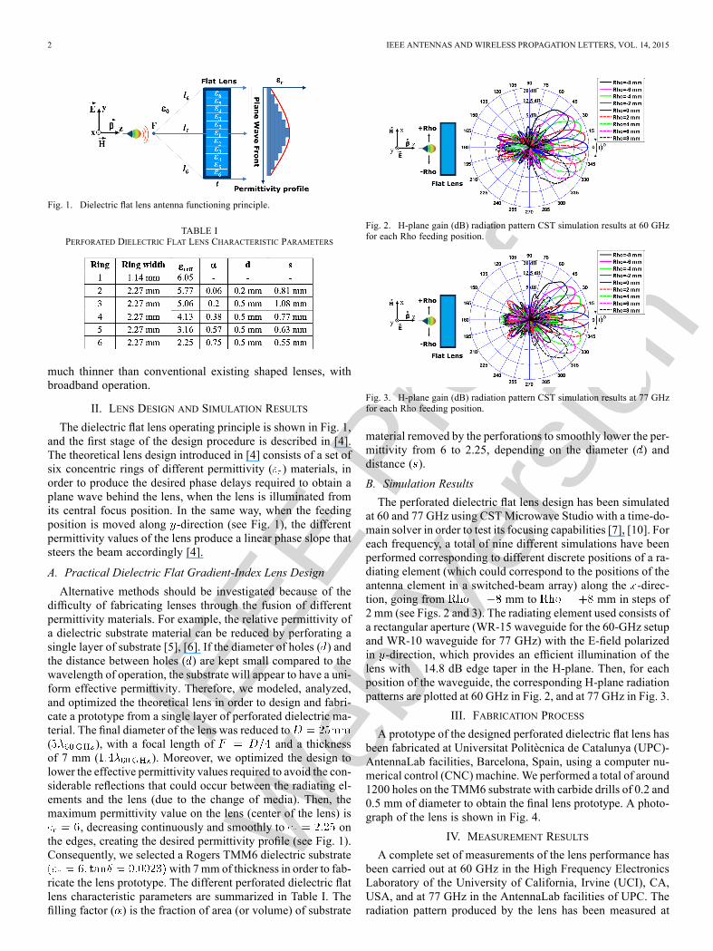
Fig. 2. H-plane gain (dB) radiation pattern CST simulation results at 60 GHzfor each Rho feeding position.
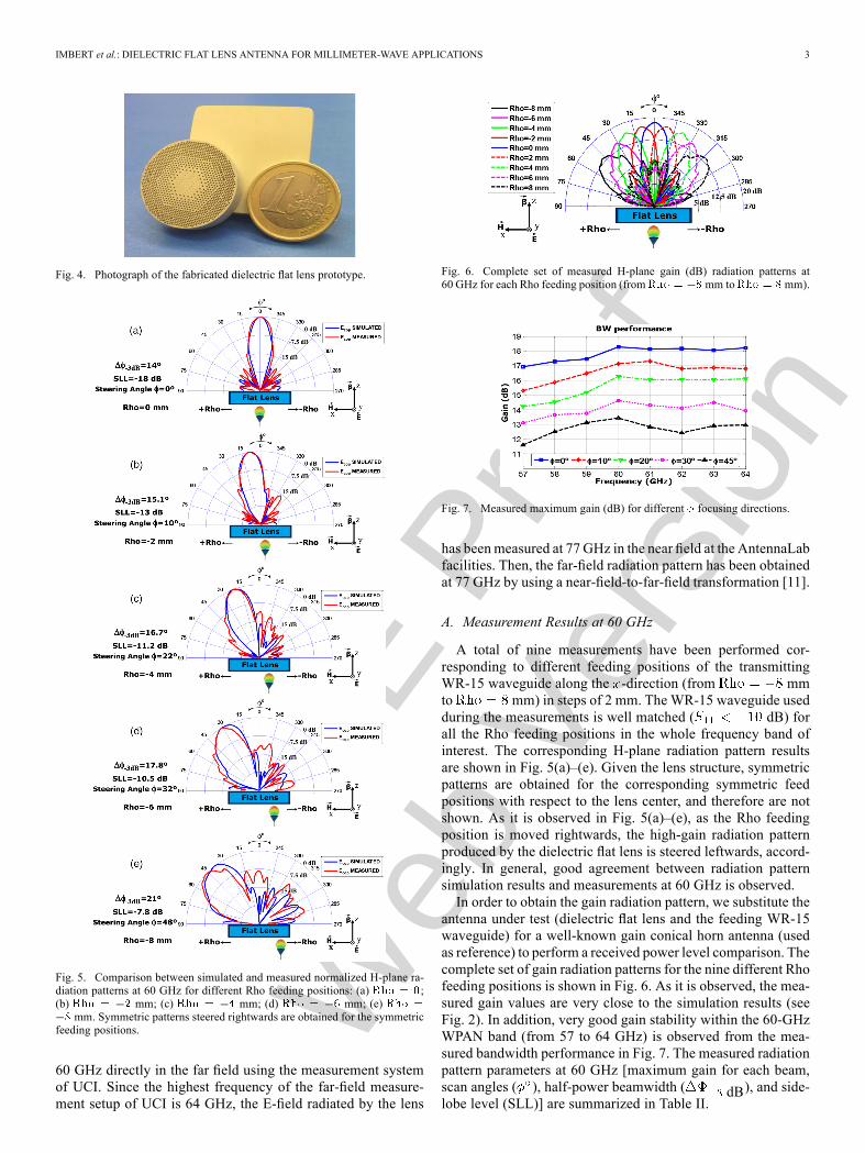
Fig. 3. H-plane gain (dB) radiation pattern CST simulation results at 77 GHzfor each Rho feeding position.
material removed by the perforations to smoothly lower the per-mittivity from 6 to 2.25, depending on the diameter ( ) anddistance ( ).
B. Simulation Results
The perforated dielectric flat lens design has been simulatedat 60 and 77 GHz using CSTMicrowave Studio with a time-do-main solver in order to test its focusing capabilities [7], [10]. Foreach frequency, a total of nine different simulations have beenperformed corresponding to different discrete positions of a ra-diating element (which could correspond to the positions of theantenna element in a switched-beam array) along the -direc-tion, going from mm to mm in steps of2 mm (see Figs. 2 and 3). The radiating element used consists ofa rectangular aperture (WR-15 waveguide for the 60-GHz setupand WR-10 waveguide for 77 GHz) with the E-field polarizedin -direction, which provides an efficient illumination of thelens with 14.8 dB edge taper in the H-plane. Then, for eachposition of the waveguide, the corresponding H-plane radiationpatterns are plotted at 60 GHz in Fig. 2, and at 77 GHz in Fig. 3.
III. FABRICATION PROCESS
A prototype of the designed perforated dielectric flat lens hasbeen fabricated at Universitat Politècnica de Catalunya (UPC)-AntennaLab facilities, Barcelona, Spain, using a computer nu-merical control (CNC) machine.We performed a total of around1200 holes on the TMM6 substrate with carbide drills of 0.2 and0.5 mm of diameter to obtain the final lens prototype. A photo-graph of the lens is shown in Fig. 4.
IV. MEASUREMENT RESULTS
A complete set of measurements of the lens performance hasbeen carried out at 60 GHz in the High Frequency ElectronicsLaboratory of the University of California, Irvine (UCI), CA,USA, and at 77 GHz in the AntennaLab facilities of UPC. Theradiation pattern produced by the lens has been measured at
IEEE
Pro
of
Web
Ver
sion
IMBERT et al.: DIELECTRIC FLAT LENS ANTENNA FOR MILLIMETER-WAVE APPLICATIONS 3
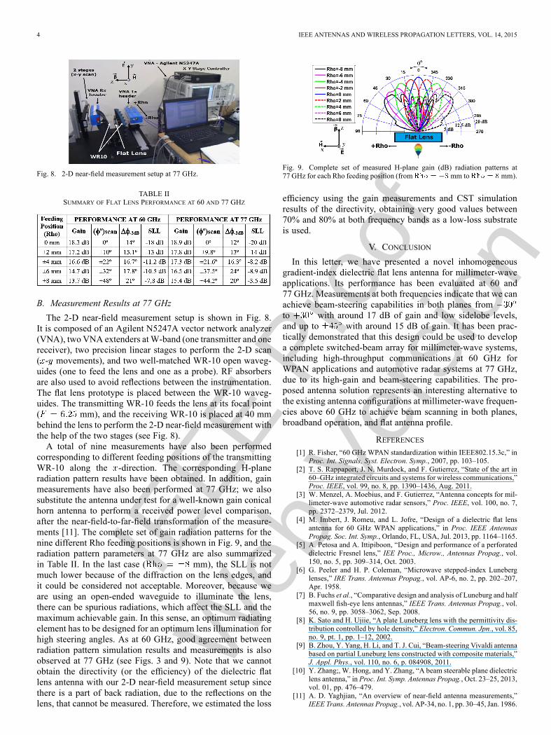
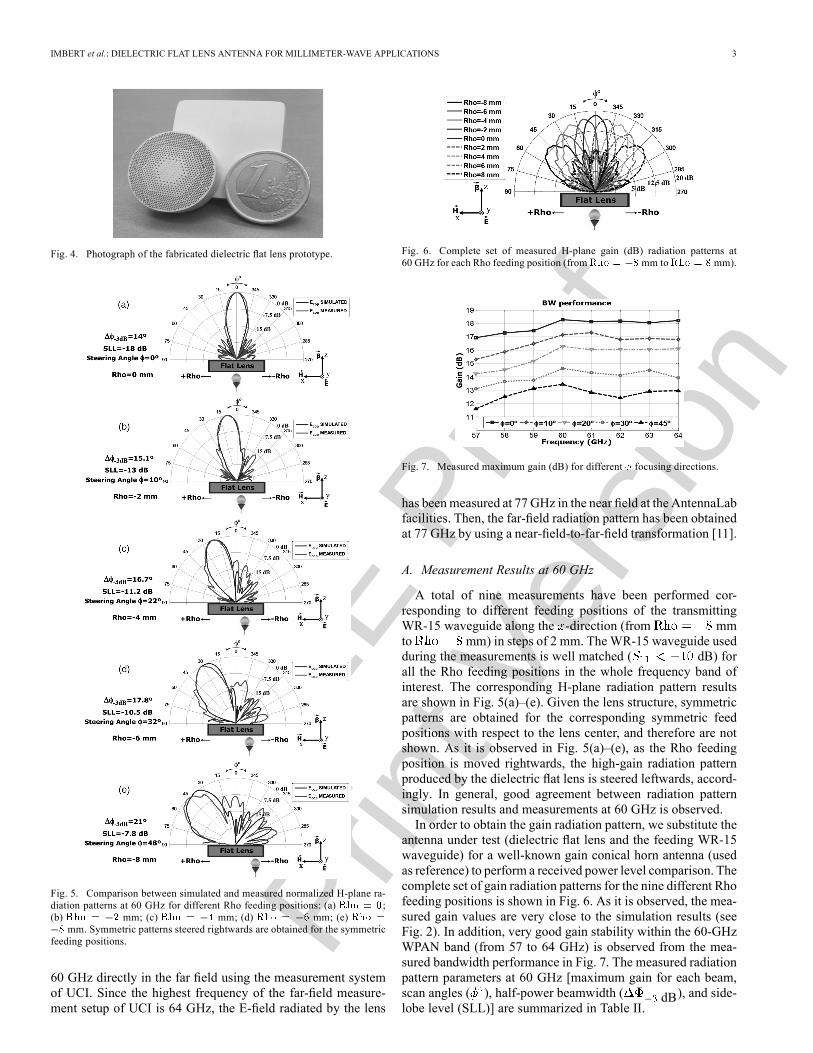
Fig. 4. Photograph of the fabricated dielectric flat lens prototype.
Fig. 5. Comparison between simulated and measured normalized H-plane ra-diation patterns at 60 GHz for different Rho feeding positions: (a) ;(b) mm; (c) mm; (d) mm; (e)
mm. Symmetric patterns steered rightwards are obtained for the symmetricfeeding positions.
60 GHz directly in the far field using the measurement systemof UCI. Since the highest frequency of the far-field measure-ment setup of UCI is 64 GHz, the E-field radiated by the lens
Fig. 6. Complete set of measured H-plane gain (dB) radiation patterns at60 GHz for each Rho feeding position (from mm to mm).
Fig. 7. Measured maximum gain (dB) for different focusing directions.
has beenmeasured at 77 GHz in the near field at the AntennaLabfacilities. Then, the far-field radiation pattern has been obtainedat 77 GHz by using a near-field-to-far-field transformation [11].
A. Measurement Results at 60 GHz
A total of nine measurements have been performed cor-responding to different feeding positions of the transmittingWR-15 waveguide along the -direction (from mmto mm) in steps of 2 mm. The WR-15 waveguide usedduring the measurements is well matched ( dB) forall the Rho feeding positions in the whole frequency band ofinterest. The corresponding H-plane radiation pattern resultsare shown in Fig. 5(a)–(e). Given the lens structure, symmetricpatterns are obtained for the corresponding symmetric feedpositions with respect to the lens center, and therefore are notshown. As it is observed in Fig. 5(a)–(e), as the Rho feedingposition is moved rightwards, the high-gain radiation patternproduced by the dielectric flat lens is steered leftwards, accord-ingly. In general, good agreement between radiation patternsimulation results and measurements at 60 GHz is observed.In order to obtain the gain radiation pattern, we substitute the
antenna under test (dielectric flat lens and the feeding WR-15waveguide) for a well-known gain conical horn antenna (usedas reference) to perform a received power level comparison. Thecomplete set of gain radiation patterns for the nine different Rhofeeding positions is shown in Fig. 6. As it is observed, the mea-sured gain values are very close to the simulation results (seeFig. 2). In addition, very good gain stability within the 60-GHzWPAN band (from 57 to 64 GHz) is observed from the mea-sured bandwidth performance in Fig. 7. The measured radiationpattern parameters at 60 GHz [maximum gain for each beam,scan angles ( ), half-power beamwidth ( dB), and side-lobe level (SLL)] are summarized in Table II.
IEEE
Pro
of
Web
Ver
sion
4 IEEE ANTENNAS AND WIRELESS PROPAGATION LETTERS, VOL. 14, 2015
Fig. 8. 2-D near-field measurement setup at 77 GHz.
TABLE IISUMMARY OF FLAT LENS PERFORMANCE AT 60 AND 77 GHZ
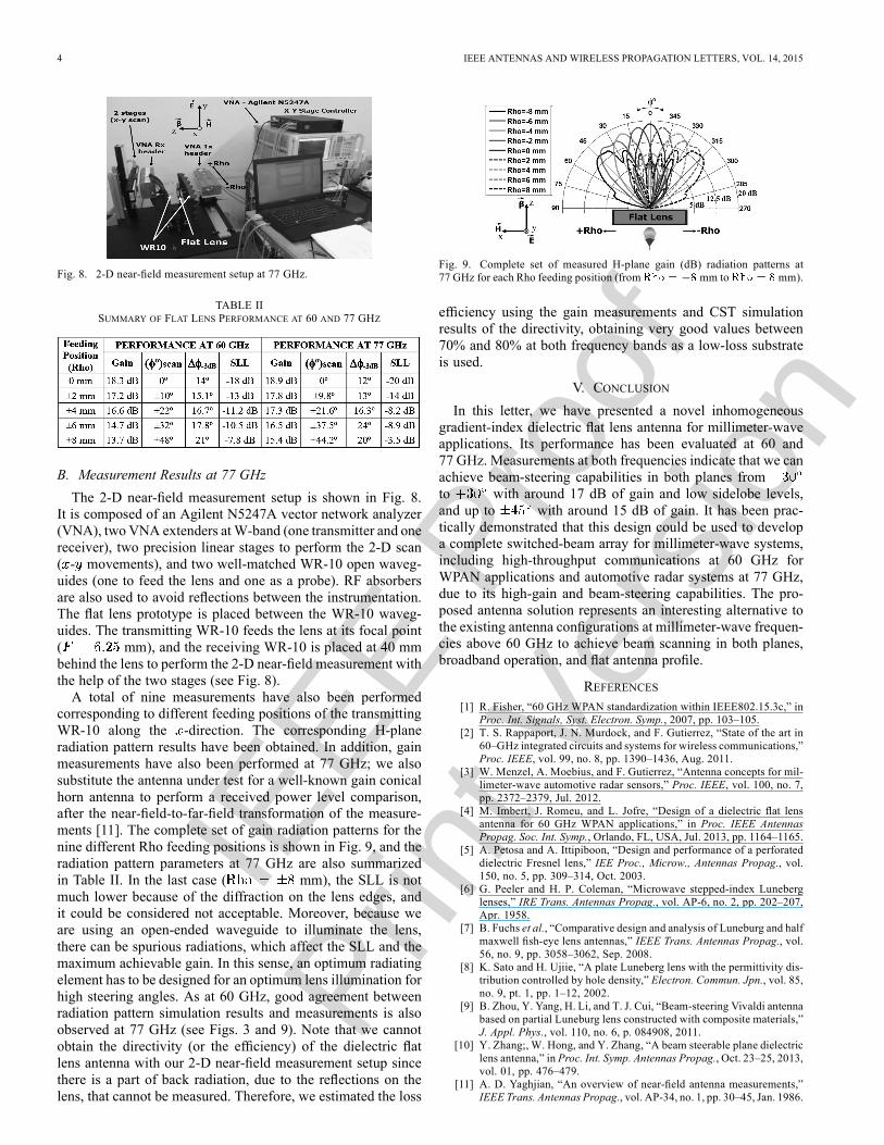
B. Measurement Results at 77 GHz
The 2-D near-field measurement setup is shown in Fig. 8.It is composed of an Agilent N5247A vector network analyzer(VNA), two VNA extenders atW-band (one transmitter and onereceiver), two precision linear stages to perform the 2-D scan( - movements), and two well-matched WR-10 open waveg-uides (one to feed the lens and one as a probe). RF absorbersare also used to avoid reflections between the instrumentation.The flat lens prototype is placed between the WR-10 waveg-uides. The transmitting WR-10 feeds the lens at its focal point( mm), and the receiving WR-10 is placed at 40 mmbehind the lens to perform the 2-D near-field measurement withthe help of the two stages (see Fig. 8).A total of nine measurements have also been performed
corresponding to different feeding positions of the transmittingWR-10 along the -direction. The corresponding H-planeradiation pattern results have been obtained. In addition, gainmeasurements have also been performed at 77 GHz; we alsosubstitute the antenna under test for a well-known gain conicalhorn antenna to perform a received power level comparison,after the near-field-to-far-field transformation of the measure-ments [11]. The complete set of gain radiation patterns for thenine different Rho feeding positions is shown in Fig. 9, and theradiation pattern parameters at 77 GHz are also summarizedin Table II. In the last case ( mm), the SLL is notmuch lower because of the diffraction on the lens edges, andit could be considered not acceptable. Moreover, because weare using an open-ended waveguide to illuminate the lens,there can be spurious radiations, which affect the SLL and themaximum achievable gain. In this sense, an optimum radiatingelement has to be designed for an optimum lens illumination forhigh steering angles. As at 60 GHz, good agreement betweenradiation pattern simulation results and measurements is alsoobserved at 77 GHz (see Figs. 3 and 9). Note that we cannotobtain the directivity (or the efficiency) of the dielectric flatlens antenna with our 2-D near-field measurement setup sincethere is a part of back radiation, due to the reflections on thelens, that cannot be measured. Therefore, we estimated the loss
Fig. 9. Complete set of measured H-plane gain (dB) radiation patterns at77 GHz for each Rho feeding position (from mm to mm).
efficiency using the gain measurements and CST simulationresults of the directivity, obtaining very good values between70% and 80% at both frequency bands as a low-loss substrateis used.
V. CONCLUSION
In this letter, we have presented a novel inhomogeneousgradient-index dielectric flat lens antenna for millimeter-waveapplications. Its performance has been evaluated at 60 and77 GHz. Measurements at both frequencies indicate that we canachieve beam-steering capabilities in both planes fromto with around 17 dB of gain and low sidelobe levels,and up to with around 15 dB of gain. It has been prac-tically demonstrated that this design could be used to developa complete switched-beam array for millimeter-wave systems,including high-throughput communications at 60 GHz forWPAN applications and automotive radar systems at 77 GHz,due to its high-gain and beam-steering capabilities. The pro-posed antenna solution represents an interesting alternative tothe existing antenna configurations at millimeter-wave frequen-cies above 60 GHz to achieve beam scanning in both planes,broadband operation, and flat antenna profile.
REFERENCES[1] R. Fisher, “60 GHz WPAN standardization within IEEE802.15.3c,” in
Proc. Int. Signals, Syst. Electron. Symp., 2007, pp. 103–105.[2] T. S. Rappaport, J. N. Murdock, and F. Gutierrez, “State of the art in
60–GHz integrated circuits and systems for wireless communications,”Proc. IEEE, vol. 99, no. 8, pp. 1390–1436, Aug. 2011.
[3] W. Menzel, A. Moebius, and F. Gutierrez, “Antenna concepts for mil-limeter-wave automotive radar sensors,” Proc. IEEE, vol. 100, no. 7,pp. 2372–2379, Jul. 2012.
[4] M. Imbert, J. Romeu, and L. Jofre, “Design of a dielectric flat lensantenna for 60 GHz WPAN applications,” in Proc. IEEE AntennasPropag. Soc. Int. Symp., Orlando, FL, USA, Jul. 2013, pp. 1164–1165.
[5] A. Petosa and A. Ittipiboon, “Design and performance of a perforateddielectric Fresnel lens,” IEE Proc., Microw., Antennas Propag., vol.150, no. 5, pp. 309–314, Oct. 2003.
[6] G. Peeler and H. P. Coleman, “Microwave stepped-index Luneberglenses,” IRE Trans. Antennas Propag., vol. AP-6, no. 2, pp. 202–207,Apr. 1958.
[7] B. Fuchs et al., “Comparative design and analysis of Luneburg and halfmaxwell fish-eye lens antennas,” IEEE Trans. Antennas Propag., vol.56, no. 9, pp. 3058–3062, Sep. 2008.
[8] K. Sato and H. Ujiie, “A plate Luneberg lens with the permittivity dis-tribution controlled by hole density,” Electron. Commun. Jpn., vol. 85,no. 9, pt. 1, pp. 1–12, 2002.
[9] B. Zhou, Y. Yang, H. Li, and T. J. Cui, “Beam-steering Vivaldi antennabased on partial Luneburg lens constructed with composite materials,”J. Appl. Phys., vol. 110, no. 6, p. 084908, 2011.
[10] Y. Zhang;, W. Hong, and Y. Zhang, “A beam steerable plane dielectriclens antenna,” in Proc. Int. Symp. Antennas Propag., Oct. 23–25, 2013,vol. 01, pp. 476–479.
[11] A. D. Yaghjian, “An overview of near-field antenna measurements,”IEEE Trans. Antennas Propag., vol. AP-34, no. 1, pp. 30–45, Jan. 1986.

IEEE
Pro
of
Prin
t Ver
sion
IEEE ANTENNAS AND WIRELESS PROPAGATION LETTERS, VOL. 14, 2015 1
Design and Performance Evaluation of a DielectricFlat Lens Antenna for Millimeter-Wave ApplicationsMarc Imbert, Student Member, IEEE, Anna Papió, Student Member, IEEE, Franco De Flaviis, Fellow, IEEE,
Lluís Jofre, Fellow, IEEE, and Jordi Romeu, Fellow, IEEE
Abstract—In this letter, a practical fabrication of a novel inho-mogeneous gradient-index dielectric flat lens for millimeter-waveapplications is presented. A previous theoretical design of a dielec-tric flat lens composed of different permittivity materials is nowmodeled and analyzed for a practical prototype fabrication andperformance evaluation at 60 and 77 GHz. The measurement re-sults at 60 GHz show that with the novel gradient-index dielectricflat lens antenna prototype, we can achieve up to 18.3 dB of broad-side gain, beam-steering capabilities in both planes from to
with around 15 dB of gain, and up to with around14 dB of gain, with low sidelobe levels. At 77 GHz, the perfor-mance evaluation shows that we can obtain up to 18.9 dB of broad-side gain, beam-steering capabilities in both planes fromto with around 17 dB of gain and low sidelobe levels, andup to with around 15 dB of gain. This novel design leadsto a low-cost, low-profile, and lightweight antenna solution, easyto integrate in a compact millimeter-wave wireless communicationsystem.
Index Terms—Automotive radar applications, beam-steering,flat lens antenna, millimeter-wave, switched-beam array, wirelesspersonal area network (WPAN).
I. INTRODUCTION
I N RECENT years, the scientific community and the in-dustry have focused their attention on different frequency
bands that could satisfy the increasing bandwidth requirementsof modern communication systems. Given the large amount ofavailable bandwidth, the millimeter-wave frequency band rep-resents one of the most interesting candidates. However, in ac-cordance with the Friis transmission formula, the path loss infree-space propagation is much higher at millimeter-wave fre-quencies than at lower microwave frequencies (e.g., the pathloss at 60 GHz is 28 dB higher than at 2.45 GHz). In conse-quence, millimeter-wave systems introduce a set of particularsevere requirements from the antenna point of view.
Manuscript received May 23, 2014; revised July 01, 2014; accepted July 18,2014. Date of publication October 15, 2014; date of current version nulldate.This work was supported in part by the Spanish Inter-Ministerial Commissionon Science and Technology (CICYT) under Projects TEC2010-20841-C04-02,TEC2013-47360-C3-1-P, and CONSOLIDER CSD2008-00068; the “Minis-terio de Economía y Competitividad” under the FPI Fellowship Program; andthe California-Catalonia Engineering Innovation Program.M. Imbert, L. Jofre, and J. Romeu are with the AntennaLab Research Group,
Department of Signal Theory and Communications, Universitat Politècnica deCatalunya (UPC), 08034 Barcelona, Spain (e-mail: [email protected]).A. Papió and F. De Flaviis are with the Department of Electrical Engineering
and Computer Science, University of California, Irvine (UCI), Irvine, CA92697-7625 USA (e-mail: [email protected]).Color versions of one or more of the figures in this letter are available online
at http://ieeexplore.ieee.org.
Digital Object Identifier 10.1109/LAWP.2014.2363596
Therefore, high directive antennas are required to overcomethe aforementioned extra path loss. Moreover, each particularapplication introduces additional requirements. For example,in very high-throughput 60-GHz band (from 57 to 64 GHz inthe US) [1] wireless personal area networks (WPANs), beam-steering antennas are needed to deal with the high user randommobility and human-body shadowing characteristic of indoorenvironments [2]. Similarly, beam-steering capabilities are alsoneeded in automotive radar applications at 77 GHz [3] since thedetermination of the exact position of an object is essential formost of the functions performed by the radar sensor. Finally, theantennas must be small, low-profile, lightweight, and low-costin order to be successfully integrated in a commercial wirelesssystem.Many types of antenna structures are considered for
short-range 60-GHz WPAN applications [2], and for auto-motive radar applications at 77 GHz [3], most of them arebased on the expensive, complex, and bulky phased-arrayantenna concept. Switched-beam arrays provide an interestingalternative because they have multiple fixed beams that canbe easily selected individually, and the implementation ismuch easier than phased-array antennas. For these reasons,in [4] we proposed a design based on a switched-beam arrayantenna concept with a theoretical design of an inhomogeneousdielectric flat lens modeled with different materials to steerand enhance the radiation in a particular direction. In thisantenna concept, only one element of the array is selectedfor each operation mode. The focusing direction dependson the position of the single element, which is selected andactivated [4]. In this sense, different types of inhomogeneous(multimaterial or gradient-index) lenses have been proposed inthe literature [5]–[10]. Fresnel zone plate lenses [5] are widelyused to correct the phase of the feed antenna. However, thiscorrection is performed only at discrete locations, leading toan inherently narrowband behavior. Luneburg lenses [6]–[9]are an interesting alternative of spherical or hemisphericalgradient-index lenses because of their very good performance.However, their planar implementations allow beam scanningin only one plane.In this letter, we present the practical fabrication and perfor-
mance evaluation of a novel inhomogeneous gradient-index di-electric flat lens antenna for millimeter-wave applications basedon the concept of our previous theoretical work [4]. Its per-formance is evaluated at 60 and 77 GHz. The proposed an-tenna solution is very attractive because it represents an in-novative alternative to the existing antenna configurations atmillimeter-wave frequencies to achieve beam scanning in bothplanes while keeping at the same time a flat antenna profile,
1536-1225 © 2014 IEEE. Personal use is permitted, but republication/redistribution requires IEEE permission.See http://www.ieee.org/publications_standards/publications/rights/index.html for more information.

IEEE
Pro
of
Prin
t Ver
sion
2 IEEE ANTENNAS AND WIRELESS PROPAGATION LETTERS, VOL. 14, 2015
Fig. 1. Dielectric flat lens antenna functioning principle.
TABLE IPERFORATED DIELECTRIC FLAT LENS CHARACTERISTIC PARAMETERS
much thinner than conventional existing shaped lenses, withbroadband operation.
II. LENS DESIGN AND SIMULATION RESULTS
The dielectric flat lens operating principle is shown in Fig. 1,and the first stage of the design procedure is described in [4].The theoretical lens design introduced in [4] consists of a set ofsix concentric rings of different permittivity ( ) materials, inorder to produce the desired phase delays required to obtain aplane wave behind the lens, when the lens is illuminated fromits central focus position. In the same way, when the feedingposition is moved along -direction (see Fig. 1), the differentpermittivity values of the lens produce a linear phase slope thatsteers the beam accordingly [4].
A. Practical Dielectric Flat Gradient-Index Lens Design
Alternative methods should be investigated because of thedifficulty of fabricating lenses through the fusion of differentpermittivity materials. For example, the relative permittivity ofa dielectric substrate material can be reduced by perforating asingle layer of substrate [5], [6]. If the diameter of holes ( ) andthe distance between holes ( ) are kept small compared to thewavelength of operation, the substrate will appear to have a uni-form effective permittivity. Therefore, we modeled, analyzed,and optimized the theoretical lens in order to design and fabri-cate a prototype from a single layer of perforated dielectric ma-terial. The final diameter of the lens was reduced to( ), with a focal length of and a thicknessof 7 mm ( ). Moreover, we optimized the design tolower the effective permittivity values required to avoid the con-siderable reflections that could occur between the radiating el-ements and the lens (due to the change of media). Then, themaximum permittivity value on the lens (center of the lens) is
, decreasing continuously and smoothly to onthe edges, creating the desired permittivity profile (see Fig. 1).Consequently, we selected a Rogers TMM6 dielectric substrate
with 7mm of thickness in order to fab-ricate the lens prototype. The different perforated dielectric flatlens characteristic parameters are summarized in Table I. Thefilling factor ( ) is the fraction of area (or volume) of substrate
Fig. 2. H-plane gain (dB) radiation pattern CST simulation results at 60 GHzfor each Rho feeding position.
Fig. 3. H-plane gain (dB) radiation pattern CST simulation results at 77 GHzfor each Rho feeding position.
material removed by the perforations to smoothly lower the per-mittivity from 6 to 2.25, depending on the diameter ( ) anddistance ( ).
B. Simulation Results
The perforated dielectric flat lens design has been simulatedat 60 and 77 GHz using CSTMicrowave Studio with a time-do-main solver in order to test its focusing capabilities [7], [10]. Foreach frequency, a total of nine different simulations have beenperformed corresponding to different discrete positions of a ra-diating element (which could correspond to the positions of theantenna element in a switched-beam array) along the -direc-tion, going from mm to mm in steps of2 mm (see Figs. 2 and 3). The radiating element used consists ofa rectangular aperture (WR-15 waveguide for the 60-GHz setupand WR-10 waveguide for 77 GHz) with the E-field polarizedin -direction, which provides an efficient illumination of thelens with 14.8 dB edge taper in the H-plane. Then, for eachposition of the waveguide, the corresponding H-plane radiationpatterns are plotted at 60 GHz in Fig. 2, and at 77 GHz in Fig. 3.
III. FABRICATION PROCESS
A prototype of the designed perforated dielectric flat lens hasbeen fabricated at Universitat Politècnica de Catalunya (UPC)-AntennaLab facilities, Barcelona, Spain, using a computer nu-merical control (CNC)machine.We performed a total of around1200 holes on the TMM6 substrate with carbide drills of 0.2 and0.5 mm of diameter to obtain the final lens prototype. A photo-graph of the lens is shown in Fig. 4.
IV. MEASUREMENT RESULTS
A complete set of measurements of the lens performance hasbeen carried out at 60 GHz in the High Frequency ElectronicsLaboratory of the University of California, Irvine (UCI), CA,USA, and at 77 GHz in the AntennaLab facilities of UPC. Theradiation pattern produced by the lens has been measured at
IEEE
Pro
of
Prin
t Ver
sion
IMBERT et al.: DIELECTRIC FLAT LENS ANTENNA FOR MILLIMETER-WAVE APPLICATIONS 3
Fig. 4. Photograph of the fabricated dielectric flat lens prototype.
Fig. 5. Comparison between simulated and measured normalized H-plane ra-diation patterns at 60 GHz for different Rho feeding positions: (a) ;(b) mm; (c) mm; (d) mm; (e)
mm. Symmetric patterns steered rightwards are obtained for the symmetricfeeding positions.
60 GHz directly in the far field using the measurement systemof UCI. Since the highest frequency of the far-field measure-ment setup of UCI is 64 GHz, the E-field radiated by the lens
Fig. 6. Complete set of measured H-plane gain (dB) radiation patterns at60 GHz for each Rho feeding position (from mm to mm).
Fig. 7. Measured maximum gain (dB) for different focusing directions.
has beenmeasured at 77 GHz in the near field at the AntennaLabfacilities. Then, the far-field radiation pattern has been obtainedat 77 GHz by using a near-field-to-far-field transformation [11].
A. Measurement Results at 60 GHz
A total of nine measurements have been performed cor-responding to different feeding positions of the transmittingWR-15 waveguide along the -direction (from mmto mm) in steps of 2 mm. TheWR-15 waveguide usedduring the measurements is well matched ( dB) forall the Rho feeding positions in the whole frequency band ofinterest. The corresponding H-plane radiation pattern resultsare shown in Fig. 5(a)–(e). Given the lens structure, symmetricpatterns are obtained for the corresponding symmetric feedpositions with respect to the lens center, and therefore are notshown. As it is observed in Fig. 5(a)–(e), as the Rho feedingposition is moved rightwards, the high-gain radiation patternproduced by the dielectric flat lens is steered leftwards, accord-ingly. In general, good agreement between radiation patternsimulation results and measurements at 60 GHz is observed.In order to obtain the gain radiation pattern, we substitute the
antenna under test (dielectric flat lens and the feeding WR-15waveguide) for a well-known gain conical horn antenna (usedas reference) to perform a received power level comparison. Thecomplete set of gain radiation patterns for the nine different Rhofeeding positions is shown in Fig. 6. As it is observed, the mea-sured gain values are very close to the simulation results (seeFig. 2). In addition, very good gain stability within the 60-GHzWPAN band (from 57 to 64 GHz) is observed from the mea-sured bandwidth performance in Fig. 7. The measured radiationpattern parameters at 60 GHz [maximum gain for each beam,scan angles ( ), half-power beamwidth ( dB), and side-lobe level (SLL)] are summarized in Table II.
IEEE
Pro
of
Prin
t Ver
sion
4 IEEE ANTENNAS AND WIRELESS PROPAGATION LETTERS, VOL. 14, 2015
Fig. 8. 2-D near-field measurement setup at 77 GHz.
TABLE IISUMMARY OF FLAT LENS PERFORMANCE AT 60 AND 77 GHZ
B. Measurement Results at 77 GHz
The 2-D near-field measurement setup is shown in Fig. 8.It is composed of an Agilent N5247A vector network analyzer(VNA), two VNA extenders atW-band (one transmitter and onereceiver), two precision linear stages to perform the 2-D scan( - movements), and two well-matched WR-10 open waveg-uides (one to feed the lens and one as a probe). RF absorbersare also used to avoid reflections between the instrumentation.The flat lens prototype is placed between the WR-10 waveg-uides. The transmitting WR-10 feeds the lens at its focal point( mm), and the receiving WR-10 is placed at 40 mmbehind the lens to perform the 2-D near-field measurement withthe help of the two stages (see Fig. 8).A total of nine measurements have also been performed
corresponding to different feeding positions of the transmittingWR-10 along the -direction. The corresponding H-planeradiation pattern results have been obtained. In addition, gainmeasurements have also been performed at 77 GHz; we alsosubstitute the antenna under test for a well-known gain conicalhorn antenna to perform a received power level comparison,after the near-field-to-far-field transformation of the measure-ments [11]. The complete set of gain radiation patterns for thenine different Rho feeding positions is shown in Fig. 9, and theradiation pattern parameters at 77 GHz are also summarizedin Table II. In the last case ( mm), the SLL is notmuch lower because of the diffraction on the lens edges, andit could be considered not acceptable. Moreover, because weare using an open-ended waveguide to illuminate the lens,there can be spurious radiations, which affect the SLL and themaximum achievable gain. In this sense, an optimum radiatingelement has to be designed for an optimum lens illumination forhigh steering angles. As at 60 GHz, good agreement betweenradiation pattern simulation results and measurements is alsoobserved at 77 GHz (see Figs. 3 and 9). Note that we cannotobtain the directivity (or the efficiency) of the dielectric flatlens antenna with our 2-D near-field measurement setup sincethere is a part of back radiation, due to the reflections on thelens, that cannot be measured. Therefore, we estimated the loss
Fig. 9. Complete set of measured H-plane gain (dB) radiation patterns at77 GHz for each Rho feeding position (from mm to mm).
efficiency using the gain measurements and CST simulationresults of the directivity, obtaining very good values between70% and 80% at both frequency bands as a low-loss substrateis used.
V. CONCLUSION
In this letter, we have presented a novel inhomogeneousgradient-index dielectric flat lens antenna for millimeter-waveapplications. Its performance has been evaluated at 60 and77 GHz. Measurements at both frequencies indicate that we canachieve beam-steering capabilities in both planes fromto with around 17 dB of gain and low sidelobe levels,and up to with around 15 dB of gain. It has been prac-tically demonstrated that this design could be used to developa complete switched-beam array for millimeter-wave systems,including high-throughput communications at 60 GHz forWPAN applications and automotive radar systems at 77 GHz,due to its high-gain and beam-steering capabilities. The pro-posed antenna solution represents an interesting alternative tothe existing antenna configurations at millimeter-wave frequen-cies above 60 GHz to achieve beam scanning in both planes,broadband operation, and flat antenna profile.
REFERENCES
[1] R. Fisher, “60 GHz WPAN standardization within IEEE802.15.3c,” inProc. Int. Signals, Syst. Electron. Symp., 2007, pp. 103–105.
[2] T. S. Rappaport, J. N. Murdock, and F. Gutierrez, “State of the art in60–GHz integrated circuits and systems for wireless communications,”Proc. IEEE, vol. 99, no. 8, pp. 1390–1436, Aug. 2011.
[3] W. Menzel, A. Moebius, and F. Gutierrez, “Antenna concepts for mil-limeter-wave automotive radar sensors,” Proc. IEEE, vol. 100, no. 7,pp. 2372–2379, Jul. 2012.
[4] M. Imbert, J. Romeu, and L. Jofre, “Design of a dielectric flat lensantenna for 60 GHz WPAN applications,” in Proc. IEEE AntennasPropag. Soc. Int. Symp., Orlando, FL, USA, Jul. 2013, pp. 1164–1165.
[5] A. Petosa and A. Ittipiboon, “Design and performance of a perforateddielectric Fresnel lens,” IEE Proc., Microw., Antennas Propag., vol.150, no. 5, pp. 309–314, Oct. 2003.
[6] G. Peeler and H. P. Coleman, “Microwave stepped-index Luneberglenses,” IRE Trans. Antennas Propag., vol. AP-6, no. 2, pp. 202–207,Apr. 1958.
[7] B. Fuchs et al., “Comparative design and analysis of Luneburg and halfmaxwell fish-eye lens antennas,” IEEE Trans. Antennas Propag., vol.56, no. 9, pp. 3058–3062, Sep. 2008.
[8] K. Sato and H. Ujiie, “A plate Luneberg lens with the permittivity dis-tribution controlled by hole density,” Electron. Commun. Jpn., vol. 85,no. 9, pt. 1, pp. 1–12, 2002.
[9] B. Zhou, Y. Yang, H. Li, and T. J. Cui, “Beam-steering Vivaldi antennabased on partial Luneburg lens constructed with composite materials,”J. Appl. Phys., vol. 110, no. 6, p. 084908, 2011.
[10] Y. Zhang;, W. Hong, and Y. Zhang, “A beam steerable plane dielectriclens antenna,” in Proc. Int. Symp. Antennas Propag., Oct. 23–25, 2013,vol. 01, pp. 476–479.
[11] A. D. Yaghjian, “An overview of near-field antenna measurements,”IEEE Trans. Antennas Propag., vol. AP-34, no. 1, pp. 30–45, Jan. 1986.