Optimization of hybrid PV/wind power system for remote telecom station
Upload
khangminh22Category
view
3download
0
HAL Id: hal-00784763https://hal-ifp.archives-ouvertes.fr/hal-00784763
Submitted on 4 Feb 2013
HAL is a multi-disciplinary open accessarchive for the deposit and dissemination of sci-entific research documents, whether they are pub-lished or not. The documents may come fromteaching and research institutions in France orabroad, or from public or private research centers.
L’archive ouverte pluridisciplinaire HAL, estdestinée au dépôt et à la diffusion de documentsscientifiques de niveau recherche, publiés ou non,émanant des établissements d’enseignement et derecherche français ou étrangers, des laboratoirespublics ou privés.
Design and Optimization of Future Hybrid and ElectricPropulsion Systems: An Advanced Tool Integrated in a
Complete Workflow to Study Electric Devices.Fabrice Le Berr, Abdenour Abdelli, D. M. Postariu, R. Benlamine
To cite this version:Fabrice Le Berr, Abdenour Abdelli, D. M. Postariu, R. Benlamine. Design and Optimization of FutureHybrid and Electric Propulsion Systems: An Advanced Tool Integrated in a Complete Workflow toStudy Electric Devices.. Oil & Gas Science and Technology - Revue d’IFP Energies nouvelles, InstitutFrançais du Pétrole (IFP), 2012, 67 (4), pp.547-562. �10.2516/ogst/2012029�. �hal-00784763�

Design and Optimization of Future Hybridand Electric Propulsion Systems:
An Advanced Tool Integrated in a CompleteWorkflow to Study Electric Devices
F. Le Berr, A. Abdelli, D.-M. Postariu and R. Benlamine
IFP Energies nouvelles, 1-4 avenue de Bois-Préau, 92852 Rueil-Malmaison Cedex - France
e-mail: [email protected] - [email protected]
Résumé — Développement et optimisation des futurs systèmes de propulsion hybride et électrique :
un outil avancé et intégré dans une chaîne complète dédiée à l'étude des composants électriques —
Le recours à l’électrification pour réduire les émissions de gaz à effet de serre dans le domaine du
transport est désormais reconnu comme une solution pertinente et d’avenir, très étudiée par
l’ensemble des acteurs du domaine. Dans cet objectif, un outil d’aide au dimensionnement et à la
caractérisation de machines électriques a été développé à IFP Energies nouvelles. Cet outil, appelé
EMTool, est basé sur les équations physiques du domaine et est intégré à un ensemble d’outils de
simulation dédiés à l’étude des groupes motopropulseurs électrifiés, comme les outils de modélisation
par éléments finis ou les outils de simulation système. Il permet d’étudier plusieurs types de
topologies de machines électriques : machines synchrones à aimants permanents à flux radial ou
axial, machines asynchrones, etc. Ce papier présente les grands principes de dimensionnement et les
principales équations intégrées à l’EMTool, les méthodes pour évaluer les performances des
machines dimensionnées ainsi que les validations effectuées sur une machine existante. Enfin, le
positionnement de l’EMTool dans la chaîne d’outils et des exemples d’applications sont exposés,
notamment en couplant l’outil à des algorithmes d’optimisation avancés ou à la modélisation par
éléments finis.
Abstract — Design and Optimization of Future Hybrid and Electric Propulsion Systems: An
Advanced Tool Integrated in a Complete Workflow to Study Electric Devices — Electrification to
reduce greenhouse effect gases in transport sector is now well-known as a relevant and future
solution studied intensively by the whole actors of the domain. To reach this objective, a tool for
design and characterization of electric machines has been developed at IFP Energies nouvelles. This
tool, called EMTool, is based on physical equations and is integrated to a complete workflow of
simulation tools, as Finite Element Models or System Simulation. This tool offers the possibility to
study several types of electric machine topologies: permanent magnet synchronous machine with
radial or axial flux, induction machines, etc. This paper presents the main principles of design and
the main equations integrated in the EMTool, the methods to evaluate electric machine performances
and the validations performed on existing machine. Finally, the position of the EMTool in the
simulation tool workflow and application examples are presented, notably by coupling the EMTool
with advanced optimization algorithms or finite element models.
Oil & Gas Science and Technology – Rev. IFP Energies nouvelles, Vol. 67 (2012), No. 4, pp. 547-562Copyright © 2012, IFP Energies nouvellesDOI: 10.2516/ogst/2012029
Electronic Intelligence in VehiclesIntelligence électronique dans les véhicules
Do s s i e r

Oil & Gas Science and Technology – Rev. IFP Energies nouvelles, Vol. 67 (2012), No. 4548
ABBREVIATIONS
CFPM Concentrating Flux Permanent Magnet
EM Electric Motor
EV Electric Vehicle
FEM Finite Element Model
GHG Greenhouse Gases
HEV Hybrid Electric Vehicle
ICE Internal Combustion Engine
IM Induction Machine
IPM Internal Permanent Magnet
MTPA Maximum Torque Per Ampere
PM Permanent Magnet
PMBL Permanent Magnet Brushless
PMBLDC DC Permanent Magnet Brushless
PMSM Permanent Magnet Synchronous Motor
INTRODUCTION
Fighting against the planet global warming, by limiting or
even reducing the emissions of greenhouse effect gases
(GHG) and notably the CO2 emissions, will certainly be one
of the major challenges of the next decades. The transport
sector is recognized as one of those major responsible of
these GHG. This sector has been in a considerable expansion
during the last fifty years, notably due to the increase of
human activity and mobility demand. In this context, it seems
to be difficult to reduce CO2 emissions, except by improving
energy efficiency of transport systems. For instance, this
objective motivates all the developments on the well known
Internal Combustion Engine (ICE) which is now becoming a
remarkable innovative and efficient system. Nevertheless, to
go further and to keep on improving global efficiency of the
global powertrain, it is time to consider a breakthrough: the
transport electrification.
By introducing new perspectives and notably a new
source of energy, electrification seems to be an interesting
alternative way to continue the progress on the powertrain
efficiency. Nevertheless, electrification introduces new chal-
lenges to face to: new degrees of freedom to optimize and
thus an increase in powertrain complexity, a new type of
energy to manage with new problems of efficiency, new
challenges in terms of reliability, security and cost as
evidence. In a context where industrial world is affected by
successive economic and financial crises, engineers have to
find cost effective solutions to keep on progress on system
efficiency improvement and one of these solutions consists in
developing and extending numerical simulation in order to
manage system complexity while limiting development cost
and duration.
The objective of this paper is to present a tool dedicated to
the study of electrification notably for the transport sector.
After a first explanation of the motivations to develop such a
design and modeling tool to help engineers to face to the new
challenges of transport electrification, this paper presents the
global methodology used in this tool dedicated to the pre-sizing
and characterization of the electric machines. A validation
case is presented by comparison with experimental results
obtained on an Electric Motor of the automotive sector. At
the end of the paper, some concrete application examples are
presented to illustrate the interesting potential of the tool to
support the specification, the optimization and the management
of the complex electrified powertrain envisaged in the transport
sector.
1 CONTEXT
1.1 The Complex Issue of Transport Electrification
It is now an acknowledge fact that human activity and
notably transport sector is one of those major responsible of
the increase of the global warming. Indeed, the transport
sector is the second-largest sector in terms of CO2 emissions,
just after the sector of generation of electricity and heat. The
transport sector represented 22% of global CO2 emissions in
2008 in the world (Fig. 1), [1]. In France for instance, the
transport sector represents more than 34% of the whole CO2
emitted by the country [2]. Taken into account this context
and to tackle the difficult challenge of global warming, the
whole transport sector is now focused one important objec-
tive: reducing CO2 emissions by improving energy efficiency.
The different transport sectors have decided to take measures
and incentives to limit or reduce the CO2 emissions. In the
automotive industry, the European Community in association
with the car manufacturers has set the objective to limit the
CO2 emissions at 130 g/km in 2012 and 95 g/km in 2020 for
light-duty vehicles with high penalties (in the order of billions
Euros) for those who would not reach their targets. In the
aeronautic sector, the Advisory Council for Aeronautics
Research (ACARE) wishes a reduction of about 50% for the
CO2 emissions of air transport before 2020 [3]. Even if it is
7%10%
22%
41%20%
Transport
Industry
Electricity and heat
Residential
Other
Figure 1
World CO2 emissions by sector in 2008.

F Le Berr et al. / Design and Optimization of Future Hybrid and Electric Propulsion Systems: An Advanced Tool Integrated in a Complete Workflow to Study Electric Devices
549
considered as the most efficient transport sector as far as
emissions in gCO2/km/ton are concerned, the maritime trans-
port sector is also concerned by these incentives and a reduc-
tion of about 40% between 1990 and 2050 is recommended
[4]. In this context, engineers are facing to a veritable techno-
logical bottleneck because future improvements of existing
powertrains will probably be not sufficient to reach these
ambitious targets. Indeed, classical propulsion powertrains
are now becoming very complex but also very efficient system.
For instance, the Internal Combustion Engines (ICE) designed
for automotive applications are combining turbochargers, high
pressure direct injection system able to perform multi-pulses
injections, devices able to change the valve lifts, etc. To keep on
improving the efficiency of such optimized systems, techno-
logical breakthroughs are indispensable and electrification
seems to be one of the most relevant and realistic approaches
to face to these difficult challenges, envisaged in automotive
[5-7], aeronautic [8, 9] and maritime transport sectors [10].
Even if electric devices are systems well known and
widespread in the industry and rail transport, the constraints
and the requirements on these kinds of systems embedded in
powertrains are very different compared to a classical
industrial application. Generally, transport propulsion systems
are operating during relative short duration, with a lot of
transient phases and on a wide range of operating conditions.
These considerations impose to review the requirements on
the electric devices to envisage an extension to the road
transport sector. Nevertheless and before dealing with the
design of electric devices and notably Electric Motors, what
kind of Electric Motors are the most suited to tackle transport
electrification?
1.2 Electric Motor Review for Transport
Electric machine includes two types of elements, namely
electric and machinery elements. They play a key role in the
development of electrical energy in modern civilization.
Nowadays electric machines can be found everywhere. In a
modern industrialized country, electric machines consume
nearly about 65% of the generated electrical energy and
cover industry, domestic appliance, aerospace, military,
automobiles, renewable energy developments, etc. [32-39].
Among the different types of Electric Motor drives, different
types are considered as viable for powertrain electrification,
namely the DC motor, the asynchronous motor (induction
motor), the synchronous motor with wound rotor, the
switched reluctance motor and the Permanent Magnet
Brushless (PMBL) motor drives. The different characteris-
tics, advantages and drawbacks of the different electric
machines are listed in Table 1.
Considering Table 1, the selection of electrical machine
topologies for traction machines has been narrowed into inte-
rior and Concentrating Flux Permanent Magnet synchronous
motors with radial flux but also synchronous permanent mag-
net axial flux machine. Permanent magnet machines are get-
ting more widespread in traction applications [48] due to
their superior power density, compactness and current avail-
ability of power electronics needed for effective control.
Despite recent increase in price of permanent magnet materi-
als, they are still cost effective. Axial flux permanent magnet
machines in particular benefit from short axial length, which
might be a considerable advantage to embed the machine
into vehicle powertrain [47]. Moreover, rotors of axial flux
machines may replace engine’s flywheel and sits in engine’s
existing flywheel housing [49]. Induction Machines (IM) are
also selected because they are recognized as a matured tech-
nology being widely accepted in traction applications [50].
DC machines have been excluded from the selection list for
well known issues associated to mechanical commutation.
Switched reluctance machines have also been considered as a
candidate for HEV application. However, they are still less
widespread and hence are not considered in this study. Same
observation can be done on the synchronous wound rotor
machine. This machine is not selected for the moment
TABLE 1
General comparison of different types of Electric Motors for traction powertrain purposes
DC motorAsynchronous Synchronous wound Synchronous permanent Synchronous permanent Switched
(induction) motor rotor machine magnet machine magnet machine reluctance machine
Field orientation Radial Radial Radial Radial Axial Radial
Torque + - - ++ ++ +
Efficiency - - +/- ++ ++ +
Max speed - +/- - +/- +/- +
Cooling - - +/- + - +
Field weakening + + + +/- +/- +/-
Reliability - + - + + +
Economic potential + ++ - - +/- +

Oil & Gas Science and Technology – Rev. IFP Energies nouvelles, Vol. 67 (2012), No. 4550
because of rotor copper losses difficult to evacuate but it
would be a relevant machine in the future because it uses
no Permanent Magnet and is thus cost attractive for future
applications.
1.3 Modelling and Simulation Contributionfor Electrification
In spite of its undeniable potential, electrification has also
one major drawback: the increasing complexity of the
propulsion system. With electrification, the latter has to
manage several energy sources (from fuel and electrical
energy storage systems) and several types of propulsion
devices (ICE, Electric Motors) to benefit from these new
degrees of freedom in the most optimal way. In this context
and taken into account that the duration and the cost of the
development of the propulsion system have always to be
reduced, numerical simulation can offer an interesting
potential to support the design, the evaluation and the
management of such complex systems [11-13]. In the case of
propulsion system electrification and particularly for the
study of electric devices, a lot of tools are nowadays
available to address different objectives.
To study one specific component, multi-dimension or
finite element simulations are considered as the most accurate
tools because they take into account the detailed geometry of
the component and use an accurate modelling of the different
phenomena occurring in the component. For Electric Motor
(EM), Finite Element Models (FEM) [14] are considered as
the reference tool to understand EM, develop and validate
more simplified models [15, 16]. Nevertheless, FEM are also
complex and CPU expensive models. They cannot be
embedded in complete simulators representative of the com-
plete system, to study component interactions.
To study complex interactions within the complete system,
zero dimension (0D) simulation is acknowledged as a helpful
and even essential tool. In the automotive world, many
studies on the new Hybrid Electrical Vehicle (HEV) or the
Electric Vehicle (EV) concepts have been the opportunity to
create complete vehicle simulators, notably to understand the
system and the component interactions [17, 18], to help to
specify the characteristics of the different components [11]
and to develop and validate control strategies [12, 13]. An
example of such a HEV simulator, design on the LMS
IMAGINE.Lab AMESim® platform [19], is presented in
Figure 2. These kinds of simulators are also developed in the
aeronautic sector [20].
ECU
Electric motor
Mission profile
& ambient data
Internal combustion engine Planetary train
Generator
Figure 2
Example of a complete HEV simulator (powersplit architecture) developed on the LMS.IMAGINE.Lab AMESim® environment.

To be widely used during the different phases of the
design of a new concept, system simulation has to reconcile
model representativeness and reduced CPU time. Most of the
time, these two objectives are not compatible and
methodology coupling FEM and analytical models for
system simulation are used [15] to take benefit of the
advantages of the different tools. In fact, tools can be
organised on a diagram illustrating the permanent
compromise between accuracy and computation duration
[21, 16]. For electrification and more specifically for Electric
Motors, this kind of diagram is illustrated in Figure 3.
2 A TOOL FOR PRE-SIZING ANDCHARACTERIZATION OF ELECTRIC MOTORS:THE EMTOOL
2.1 The Motivations
Electric machine models used in system simulation are
generally composed of the two types of models presented in
Figure 3: the look-up tables or the analytical models. Look-up
table’s models are relevant to estimate with simple simula-
tions the energy consumption of transport systems [5] or to
develop strategies for energy management [12] notably on
powertrain architecture coupling at least two power genera-
tion devices. Analytical models are more dedicated to esti-
mate in a more physical approach the behaviour of the electric
machine, by taken into account all the phenomena occurring
inside the electric machine: electro-magnetic phenomena, iron
and copper losses, thermal aspects, non-linear behaviours
such as saturation phenomena [15]. Based on more physical
modelling approaches, these types of models are relevant to
estimate more accurately the system energy consumption or to
develop more specific control strategies related to the electric
machine with some constraints from its environment. They
are also more adapted to analyse the behaviour of the electric
machine on non-reference or critical operating conditions.
To be relevant, look-up and analytical models always need
input data, for instance losses map for look-up table models
and electromagnetic parameters for analytical model. In an
early stage of the development of a new concept (where the
simulation is the only tool available to evaluate the concept),
these data are generally not available. A tool able to design
an electric machine to evaluate its losses map or their
electromagnetic parameters is thus relevant. This is the main
objective of the tool developed at IFP Energies nouvelles
(IFPEN). This tool, called “EMTool”, is presented in the
following parts of the paper.
F Le Berr et al. / Design and Optimization of Future Hybrid and Electric Propulsion Systems: An Advanced Tool Integrated in a Complete Workflow to Study Electric Devices
551
Figure 3
Model classification for Electric Motor models.
Rotation speed [tr/min]
Torq
ue [
Nm
]
1000 2000 3000 4000 5000 60000
50
100
150
200
250
300
350
Finite element models
Experimental results
Analytical models
Look-up table models
Sizing, behavior modeling,
dedicated control strategy development,
integration in a complete vehicle simulator
Sizing, study on specific
and critical operating
conditions, etc.
Understanding,
validation and model
identification
Powertrain and vehicle modeling,
energy management strategies development
Numerical
campaign
Fast computation capability
Accuracy
Model
reduction
Modeling
and hypotheses
validation
Oil & Gas Science and Technology – Rev. IFP Energies nouvelles, Vol. 67 (2012), No. 4552
Some analytical software’s dedicated to the design of
electrical machines are available on the market. The well-
known software’s are Ansoft Corporation RMxprt and
SPEED. These tools are generally dedicated to specialist of
electric machine design. The EMTool was in a first time
developed for non-specialist engineers, with few specific
skills in the design and modeling of electrical machines,
needing data to model the behavior of the electrical machine
in complex hybrid powertrain simulators. This tool is also
evaluative and new topologies can be easily added if needed.
For a Research and Development center as IFP Energies
nouvelles, such an in-house tool is very important to study
new innovative and complex electrified powertrains.
2.2 EMTool Requirements and Overview
The main objective of the EMTool is to provide the means to
design and to model an electric machine in order to be used
in system simulation at an early stage of the development of
a new concept, while data on the Electric Motor are often not
available. In order to extend the use of this tool, EMTool has
to be usable by engineers who are not specialists in electric
devices, even if the tool integrates physical models and
correlations. These two points are the main requirements
taken into account in the EMTool. Among the topologies
listed in Table 1, the EMTool integrates for the moment the
main types of Electric Motors adapted for transportation: a
cheap to produce and well known topology (AM), a robust,
widespread and very efficient motor (PMSM) with radial and
axial flux rotor topologies.
To widespread the use of such a tool, it has to be able to
design a virtual motor using a limited number of motor
specifications, which are listed in Table 2 and consist in:
maximum torque, maximum power, maximum speed and
DC-bus voltage. The expert data necessary for the process of
design and modeling are pre-defined in function of the
topology chosen for the motor and also in function of the
4 main characteristics defined for the minimal specifications.
TABLE 2
Example of minimal specs
Torque Power Max. speed Battery voltage
Motor specs 300 Nm 63 kW 5 000 RPM 650 V
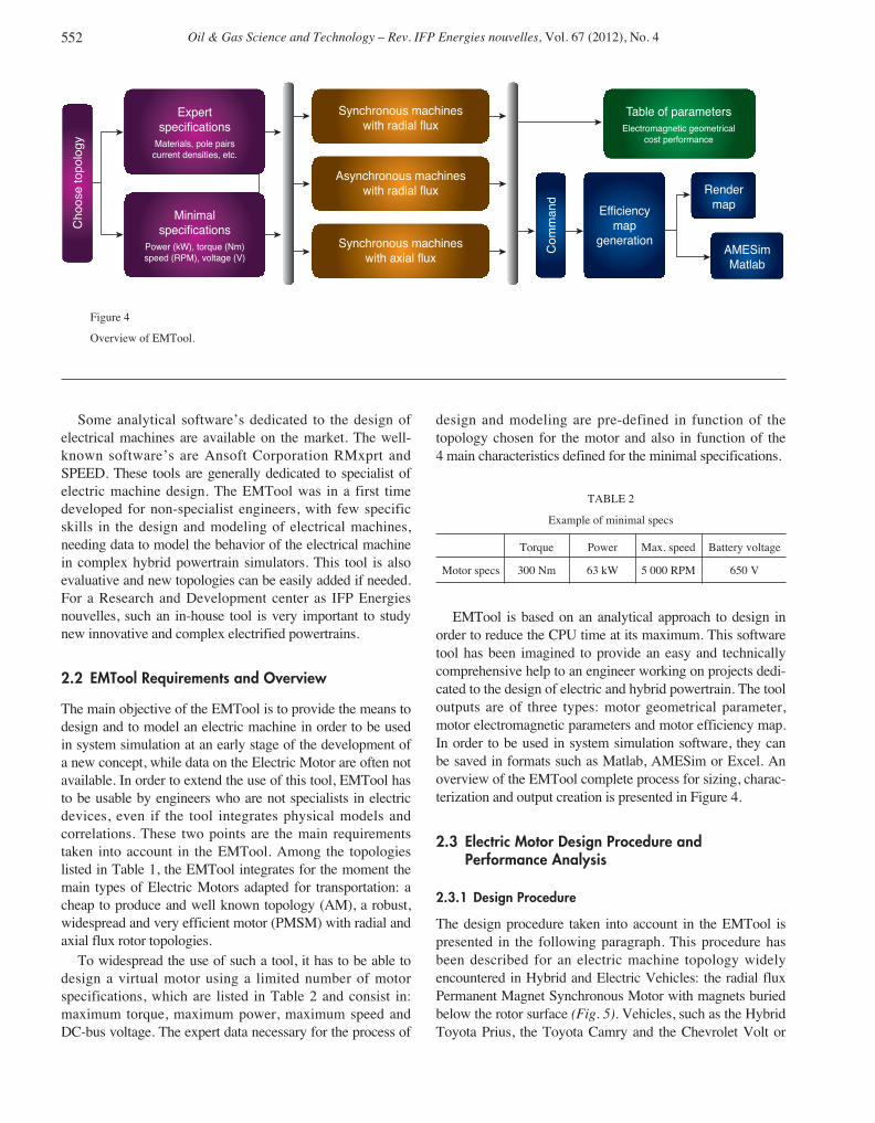
EMTool is based on an analytical approach to design in
order to reduce the CPU time at its maximum. This software
tool has been imagined to provide an easy and technically
comprehensive help to an engineer working on projects dedi-
cated to the design of electric and hybrid powertrain. The tool
outputs are of three types: motor geometrical parameter,
motor electromagnetic parameters and motor efficiency map.
In order to be used in system simulation software, they can
be saved in formats such as Matlab, AMESim or Excel. An
overview of the EMTool complete process for sizing, charac-
terization and output creation is presented in Figure 4.
2.3 Electric Motor Design Procedure andPerformance Analysis
2.3.1 Design Procedure
The design procedure taken into account in the EMTool is
presented in the following paragraph. This procedure has
been described for an electric machine topology widely
encountered in Hybrid and Electric Vehicles: the radial flux
Permanent Magnet Synchronous Motor with magnets buried
below the rotor surface (Fig. 5). Vehicles, such as the Hybrid
Toyota Prius, the Toyota Camry and the Chevrolet Volt or
Table of parameters
Electromagnetic geometrical
cost performance
Synchronous machines
with radial fluxExpert
specifications
Materials, pole pairs
current densities, etc.
Minimal
specifications
Power (kW), torque (Nm)
speed (RPM), voltage (V)
Asynchronous machines
with radial flux
Synchronous machines
with axial flux
Efficiency
map
generation
Com
mand
Choose topolo
gy
Render
map
AMESim
Matlab
Figure 4
Overview of EMTool.

F Le Berr et al. / Design and Optimization of Future Hybrid and Electric Propulsion Systems: An Advanced Tool Integrated in a Complete Workflow to Study Electric Devices
553
boats, such as the EPIC 23E speedboat are powered by this
class of motor. The sizing procedure of the other topologies
implemented in EMTool are similar for other types of radial
flux electric motors [22-25, 43], while axial flux motors’
design procedure follows a different philosophy [26-29]. The
main steps are described bellow [30, 31].
The pre-sizing part consists in computing the base speed
of the motor, which is determined thanks to the power and
the torque specified in the minimal specifications. The shape
of the motor is determined by a classical D2L sizing method-
ology. The product D2L is determined from analytical
expression of the torque. Using the ratio of the length of the
machine to the air-gap diameter (χ) which is estimated by an
empirical formula based on pole pairs number, the inner rotor
diameter and length of electric machine can be estimated
thanks to the following equations:
(1)
where Tn (Nm) represents the nominal torque, Al (A/m) the
peak linear current density, Bg (T) the peak airgap induction,
p the pole pairs and Dg (m) the air-gap diameter.
Minimum rotor volume is determined from a torque
constraint, while the actual rotor diameter is computed based
on a constraint on the maximum rotor diameter: respecting a
maximum tangential speed on the frontier of the rotor to
avoid the tearing of the rotor surface. This constraint is par-
ticularly important for surface mounted permanent magnet
D LT
Al B
pp
DD L
gn
g
g
g
2
0 5
2
2 1
4
=⋅
=⋅
=⎛
⎝⎜⎜
⎞
π
π
.ˆ . ˆ
. .χ
χ ⎠⎠⎟⎟
0 33.
motors where the magnet’s fixations are subjected to rather
high values of centrifuges force:
(2)
where σmec, υ, ρfe, Ωmax are maximal mechanical stress of the
rotor material, Poisson’s ratio, material density and motor’s
maximum speed.
The mechanical air gap g is calculated from the empirical
relation:
(3)
The Inner stator diameter sizing is based on the rotor
diameter and imposed mechanical constraints. The stator
yoke thickness is obtained as follows:
(4)
where Bmg = Bg ⋅ αi represents the average air gap induction,
τp the pole pitch, kf the axial iron percentage and Bs the stator
yoke induction.
The slot surface is determined using the following equation:
(5)
where τs is the slot pitch, Kr the slot fill factor and Jc the surface
current density.
Thus a tooth’s width wt is computed in function of the
tooth induction Bd using the flux conservation law:
(6)
The number of slots is chosen as high as possible while
respecting a mechanical constraint imposed on tooth’s
length/width ratio. Magnet sizing is based on the specified
torque and the air gap diameter and gives the magnetic flux.
Using magnet’s field Hc and induction Br, the tool computes
the appropriate magnet size that creates the necessary flux.
The dependence between the length and height of the magnets
is defined by the following equation:
(7)
where lm and hm are respectively the length and the height of
the magnet, g the air gap and Epb the width of the flux barrier.
The last part of the sizing procedure is dedicated to the
characterization of the machine and notably the computation
of the electromagnetic parameters: d-q frame inductances,
lh
p
B p Ep B D
h B g Bm
m d b g re
m r r g
=⎛
⎝⎜
⎞
⎠⎟
⋅ ⋅ + ⋅
⋅ − ⋅ ⋅
2
µ
wB
k Bt
g s
f d
=⋅
⋅
τ
ST
D L B J Ks
n s
g g c r
=⋅
⋅ ⋅ ⋅ ⋅ ⋅
42
. τ
π
hB
k By
mg p
f s
=⋅
⋅ ⋅
τ
2
g D Lg= +0 001 0 003 2. . . /
Drmec
fe
max
max
.=+⎛
⎝⎜
⎞
⎠⎟ ⋅ ⋅
⎛
⎝
⎜⎜⎜⎜
⎞
⎠
⎟⎟⎟
23
8
2
σ
υρ Ω ⎟⎟
0 5.
Permanent magnet
Air (flux barrier)
Figure 5
Rotor geometry.

Oil & Gas Science and Technology – Rev. IFP Energies nouvelles, Vol. 67 (2012), No. 4554
resistances, currents, etc. The d- and q-axis inductances
can be expressed as [42]:
(8)
(9)
where Lf is the per-phase leakage inductance.
The maximum value of permanent magnet flux linkage is
obtained with:
(10)
The current phase is calculated by:
(11)
To compute all the parameters of the electric machine, the
number of conductors in one slot Ncs has to be determined. It
should be designed in order to fulfil the operating conditions
at the base point. The electric machine must be able to pro-
vide the base torque Tm = Tb under the supply voltage Vm = Vb
at the electrical pulsation ω = ωb. By considering the electri-
cal diagram of the machine operating at the base point (Tb,
ωb) and the electromagnetic parameters calculated to one
conductor per slot, the number of conductors in one slot can
be determined.
After computing all the electromagnetic parameters relevant
to the performance analysis, the tool makes a first estimation
of the cost of the materials used to build the motor, based on
the volume and the masses of the different parts and the prices
of the different materials. This evaluation may be interesting
to differentiate two technologies as far as cost is concerned.
2.3.2 Performance Analysis
To achieve performance analysis of the designed electric
machine, three steps have been developed. The first step is to
represent the electromagnetic behaviour in the d/q axis refer-
ence frame. The second step is to develop a control strategy
allowing to establish the relevant strategy at each operating
point. And the last step is to evaluate the different losses occur-
ring in the machine. These different aspects are illustrated in
the following sections.
Equations for Electric Model
A conventional steady state d–q electrical hypothesis in a
synchronously rotating reference frame is used to model the
behaviour of the radial and axial permanent magnet synchro-
nous machines. The steady-state equations describing a rotor
flux-oriented induction machine in the synchronous frame
given by [44] have been also used.
IJ K S
Ns
s r s
cs
=
Ψmr b bs
g cs
D L k N
pB N=
⎛
⎝⎜
⎞
⎠⎟
4
πsin( ).α
L DL
g
k N
pN Lq r
b bscs f= ⋅ ⋅ ⋅
⋅⎛
⎝⎜
⎞
⎠⎟ +3
10
2
2µ . . .π
L DL
g
k N
p
Dl
d rb bs
rm
= ⋅ ⋅ ⋅⋅⎛
⎝⎜
⎞
⎠⎟
− ⋅ ⋅
31
1 82
0
2
µ . . .π
πpp g hl D N L
m
m r cs f⋅ ⋅
+ ⋅ ⋅⎛
⎝⎜
⎞
⎠⎟
⎛
⎝⎜⎜
⎞
⎠⎟⎟ +π2 2.
Control Strategy
In order to satisfy current and voltage limits in the synchronous
machines, the stator current vector must stay inside the current
limit circle and voltage limit ellipse for all operating condi-
tions as shown in Figure 6. Therefore, the control trajectories
under the vector control are set by these limits. For any oper-
ating point, in the case where the stator current vector lies
inside the current limit circle and voltage limit ellipse, the
Maximum Torque Per Ampere (MTPA) control algorithm is
applied to the machine. However, when the terminal voltage
reaches its limit value, the flux-weakening control is selected
in order to satisfy both current and voltage limits. The transition
between the MTPA and flux-weakening control is determined
by the flow chart given in Figure 7.
A4
A3
A2
Currentlimit Voltage
limit
MTPA trajectory
A1
1.00.80.60.40.20-0.2-0.4-0.6-0.8-1.0
Iqn (
A)
-1.0
-0.8
-0.6
-0.4
-0.2
0
0.2
0.4
0.6
0.8
1.0
Idn (A)
ω = ωb = 1200 tr/min
ω = 3000 tr/min
ω = 3000 tr/min
ω = 1500 tr/min
Figure 6
Control trajectories in id-iq plane.
Motor parameters, Ω and Tcontrol
Calculation of the terminal voltage
V < Vsm
Flux - weakening
control
MTPA control
No
Yes
Determination of the id, iq corresponding
MTPA control
Figure 7
Flow chart of control mode transition.

F Le Berr et al. / Design and Optimization of Future Hybrid and Electric Propulsion Systems: An Advanced Tool Integrated in a Complete Workflow to Study Electric Devices
555
In order to estimate machine efficiency values for the
various operating regions of the induction machine, the
Rotor-Flux-Oriented (RFO) control has been considered
[45]. The rotor flux reference is equal to the rated rotor flux
below base speed. For the field weakening operation, a com-
monly used method is to vary the rotor flux reference in pro-
portion to 1/ω. Usually, the d-axis reference current idsref is
decreased in order to reduce the rotor flux. And the q-axis ref-
erence current iqsref is increased according to the decrease
of the d-axis reference current to use the current rating fully.
Loss Modelling
Generally, three types of losses are generally taken into
account in an electric machine model: iron losses, copper
losses and mechanical losses. For each topology, these main
losses have been taken into account. In the radial permanent
magnet synchronous machines, the iron losses have been
calculated according to [46]. For the axial permanent magnet
synchronous machines, depending of the type of topology,
iron losses have been calculated according to [47]. In the
induction machine, iron losses have been calculated by the
formulas given by [43]. According to the selected topology,
copper losses in the stator and rotor are calculated by the
classical formula RI2. Mechanical losses are also taken into
account with classical formula (depending of rotor speed).
Efficiency Maps
Figure 8 shows efficiency maps generated by the EMTool for
electrical machines under investigation, using the electric and
loss models described in the previous sections. These models
have been associated with the control strategy presented
previously. Electric machines have been sized to meet the
0
0
0
2020
20
20
20
20
20
3030
30
30
30
30
30
404040
40
40
40
40
505050
50
50
50
50
535353
53
53
53
53
565656
56
56
56
56
595959
59
59
59
59
626262
62
62
62
62
6565
65
65
65
65
65
6868
68
68
68
68
68
717171
71
71
71
71
727272
72
72
72
72
7373
73
73
73
73
73
7474
74
74
74
74
74
757575
75
75
75
75
767676
76
76
76
76
777777
77
77
77
77
7878
78
78
78
78
78
797979
79
79
79
79
808080
80
80
80
80
8181
81
81
81
81
81
828282
82
82
82
82
8383
83
83
83
83
83
848484
84
84
84
84
858585
85
85
85
85
868686
86
86
86
86
8787
87
87
87
87
888888
88
88
88
89
89
89
89
8989
90
90
90
9090
91
91
91
91
92
92
9292
93
93
93
94
9495
0
0
0
202020
20
20
20
20
303030
30
30
30
30
404040
40
40
40
40
505050
50
50
50
50
535353
53
53
53
53
565656
56
56
56
56
595959
59
59
59
59
626262
62
62
62
62
656565
65
65
65
65
6868
68
68
68
68
68
7171
71
71
71
71
71
7272
72
72
72
72
72
737373
73
73
73
73
7474
74
74
74
74
74
757575
75
75
75
75
7676
76
76
76
76
76
7777
77
77
77
77
77
787878
78
78
78
78
797979
79
79
79
79
808080
80
80
80
80
818181
81
81
81
81
8282
82
82
82
82
82
8383
83
83
83
83
83
8484
84
84
84
84
84
8585
85
85
85
85
8686
86
86 86
86
8787
87
87
87
87
88
88
88
88
88
88
89
89
89
89
89
90
90
90
9091
9191
92
0
0
0
202020
20
20
20
20
303030
30
30
30
30
404040
40
40
40
40
505050
50
50
50
50
535353
53
53
53
53
565656
56
56
56
56
595959
59
59
59
59
626262
62
62
62
62
656565
65
65
65
65
686868
68
68
68
68
717171
71
71
71
71
727272
72
72
72
72
737373
73
73
73
73
747474
74
74
74
74
757575
75
75
75
75
767676
76
76
76
76
777777
77
77
77
77
787878
78
78
78
78
797979
79
79
79
79
808080
80
80
80
80
818181
81
81
81
81
828282
82
82
82
82
838383
83
83
83
83
848484
84
84
84
84
858585
85
85
85
85
868686
86
86
86
86
8787
87
87
87
87
87
8888
88
88
88
88
88
8989
89
89
89
89
89
9090
90
90
90
90
90
91
9191
91
91
91
92
9292
92
92
92
93
93
93
93
93
93
94
94
94
94
94
95
95
95
95
95
96
96
96
0
0
0
202020
20
20
20
20
303030
30
30
30
30
404040
40
40
40
40
505050
50
50
50
50
535353
53
53
53
53
565656
56
56
56
56
595959
59
59
59
59
626262
62
62
62
62
656565
65
65
65
65
686868
68
68
68
68
717171
71
71
71
71
727272
72
72
72
72
737373
73
73
73
73
747474
74
74
74
74
757575
75
75
75
75
767676
76
76
76
76
777777
77
77
77
77
787878
78
78
78
78
797979
79
79
79
79
808080
80
80
80
80
818181
81
81
81
81
828282
82
82
82
82
838383
83
83
83
83
848484
84
84
84
84
858585
85
85
85
85
868686
86
86
86
86
878787
87
87
87
87
888888
88
88
88
88
898989
89
89
89
89
909090
90
90
90
90
919191
91
91
91
91
9292
92
92
92
92
9393
93
93
93
93
9494
94
94
94
94
9595
95
95
95
95
96
96
9696
97
P
eak a
nd c
ontinuous torq
ue (
N.m
)
Peak a
nd c
ontinuous torq
ue (
N.m
)
Peak a
nd c
ontinuous torq
ue (
N.m
)
Peak a
nd c
ontinuous torq
ue (
N.m
)
a) b)
c) d)
0
50
100
150
200
250
300
350
400
0
50
100
150
200
250
300
350
400
Motor efficiency (%)Motor efficiency (%)
Motor efficiency (%)Motor efficiency (%)
Rotation speed (rev/min)0 1000 2000 3000 4000 5000
Rotation speed (rev/min)1000 2000 3000 4000 5000
Rotation speed (rev/min)1000 2000 3000 4000 5000
Rotation speed (rev/min)0 1000 2000 3000 4000 5000
0
50
100
150
200
250
300
350
400
0
50
100
150
200
250
300
350
400
50
55
60
65
70
75
80
85
90
95
100
50
55
60
65
70
75
80
85
90
95
100
50
55
60
65
70
75
80
85
90
95
100
50
55
60
65
70
75
80
85
90
95
100
Figure 8
Efficiency maps: a) interior permanent magnet type, b) flux-concentrating type, c) axial flux type, d) induction machine.

Oil & Gas Science and Technology – Rev. IFP Energies nouvelles, Vol. 67 (2012), No. 4556
specifications of the Prius II. The minimum specification is
as follows: maximum power is 50 kW at the base speed of
1 200 rev/min. The battery voltage is 500 V.
2.4 EMTool Outputs and Validation
The process ends by the generation of the efficiency map
using a command similar to the performance analysis. It
computes losses for every pair of torque and speed between
zero and nominal values. The map can be saved in formats
compatible with AMESim libraries (IFP-Drive library) or
Matlab’s models. The tool also generates a result file which
contains the data of the sized motor: the topology and type of
command, the geometrical parameters from the outer size to
the size of the slots, the evaluated performances (torque and
power), the electromagnetic parameters (direct and inverse
inductance) and the bill of materials.
A comparison of the performances of the motor designed
by EMTool to measurements performed on the Prius II
Electric Motor shows the relevance of the process (Fig. 9).
Efficiency maps have a mean difference of 5% and a maxi-
mum of 17% in highly saturated regimes (saturation phenom-
ena are not taken into account in EMTool for the moment).
The maximum efficiencies of the two maps are similar.
EMTool has also been validated thanks to FEM. An
example of validation procedure is given in Section 3.3.
3 EMTOOL APPLICATION
3.1 EMTool Position in the Workflow Dedicatedto Study Electric Machines
As explained in Section 1.3, system simulation and Finite
Element Models are two complementary tools to study
Absolute error (%)
Comparison with measurements:
• maximum error 17% in saturated regime,
• mean error 5%,
• similar maximum efficiencies.
Rotation speed (RPM)
Torq
ue (
N.m
)
1000 2000 3000 4000 5000 60000
50
100
150
200
250
300
350
0
2
4
6
8
10
12
14
16
18
20
Simulated motor efficiency (%)
Rotation speed (RPM)
Torq
ue (
N.m
)
1000 2000 3000 4000 5000 60000
50
100
150
200
250
300
350
70
75
80
85
90
95
100
Measured motor efficiency (%)
Rotation speed (RPM)
Torq
ue (
N.m
)
1000 2000 3000 4000 5000 60000
50
100
150
200
250
300
350
70
75
80
85
90
95
100
Figure 9
Comparison between simulated and measured efficiency map of the Prius II Electric Motor.

F Le Berr et al. / Design and Optimization of Future Hybrid and Electric Propulsion Systems: An Advanced Tool Integrated in a Complete Workflow to Study Electric Devices
557
transport electrification. EMTool becomes completely
integrated into this complete tool chain devoted to the speci-
fication, the design and the optimization of electric devices in
order to reach vehicle and customer requirements (perfor-
mances, CO2 reduction, etc.). A scheme of the complete
workflow dedicated to the study of electric devices is pre-
sented in Figure 10. As explained before, EMTool is able to
help the parameterization of models used in complete system
simulator. With its ability to generate very quickly virtual
motor characteristics and notably efficiency maps, this tool
can also be coupled with optimization algorithm to help to
the design and specification of electric devices embedded in
complete vehicle system. An example of such a procedure is
presented in Section 3.2. EMTool can also be used in a first
step to generate a motor geometry before analysing and opti-
mizing it in details on FEM software suites. An example of
such a procedure is presented in Section 3.3.
3.2 EMTool Coupling with Optimization Algorithmto Help Vehicle System Design
3.2.1 Context: The Design of an Electric Vehicle
The design of a vehicle system and notably the specification
of its powertrain is a complex procedure. In fact, the step-by-step
design of the different powertrain components is generally
difficult, due to the fact that some component characteristics
have opposed impact on a target parameter, like the energy
consumption for instance. In the case of the design of an
Electric Vehicle, the Electric Motor has to face to a double
objective: to be efficient and compact as far as mass and vol-
ume are concerned. Generally these two criteria do not
evolve in the same direction and the objective of the design is
to find the good compromise for the vehicle system.
To solve this global problem for the vehicle system,
EMTool can be coupled to global optimization algorithms. In
- Rotation speed [tr/min]
Torq
ue [
Nm
]
1000 2000 3000 4000 5000 60000
50
100
150
200
250
300
350
70
75
80
85
90
95
Vehicle and customer requirements:
performances target, objectives of CO2 reduction, component and global architecture constraints...
EMTool:
– Pre-sizing of EM
– Evaluation of global EM geometry
and electro-magnetic parameters
– Loss evaluation and global efficiency
calculation (maps for AMESim)
System simulation: Finite element models:
– Concept evaluation of electric
components integrated in
complete vehicle system
– Balance evaluation between
energy consumption,
performances and pollutants
– Specific study of dedicated
topology and concept
(sizing improvement)
– Detailed simulation of critical
operating conditions
Figure 10
Complete tool workflow dedicated to Electric Motor study.

Oil & Gas Science and Technology – Rev. IFP Energies nouvelles, Vol. 67 (2012), No. 4558
this application, the optimization of the Electric Vehicle is
carried out using a multi objective genetic algorithm. In this
optimization problem, EMTool is used to design and to
model the selected Electric Motor using the design variables
optimization. Vehicle performance constraints are imposed
on the design problem to ensure that the performance
requirements of the vehicle are met. These constraints are
defined from Table 3 to Table 6.
TABLE 3
Vehicle performances for take-off
Parameter
Loaded mass 400 kg
Slope 25%
Vehicle speed 10 km/h
TABLE 4
Vehicle performances for maximum speed
Parameter
Loaded mass 75 kg
Maximum speed at 0% slope 140 km/h
Maximum speed at 5% slope 110 km/h
TABLE 5
Vehicle performances for acceleration
Parameter
0-50 kph 3 s
0-100 kph 9 s
1 000 m with zero initial speed 33 s
TABLE 6
Vehicle range
Parameter
Loaded mass 75 kg
Total range 60 km
Driving cycle NEDC
3.2.2 Design Variables, Constraints and Objectives
The design variables considered for the Electric Vehicle
optimization and their associated bounds are shown in Table 7.
Seven variables are continuous (i.e. ksi, By, Js, A, Tb, Ωb and
Ngear) and four are discrete (i.e. p, Nspp, Nscel and Npcel). Two
conflicting objectives have to be minimising thanks to these
variables: the motor losses and the total embedded mass of
the Electric Vehicle.
When varying the design variables in their corresponding
range, six constraints have to be fulfilled to ensure the system
feasibility. The first two constraints (g1 and g2) concern the
number Ncs of copper windings per slot. This number has to
be higher than one and bounded by the slot section in relation
to the winding section. The third constraint (g3) checks that
maximum transition torque of the Electric Motor meet the
maximum torque required by the powertrain. In this study, in
order to take into account the thermal effect, we suppose that
the Electric Motor can develop a maximum torque equal to 2
times its nominal torque. The fourth constraint (g4) concerns
the maximal power of Electric Motor that has to meet the
maximal power required by the vehicle. We suppose also that
the Electric Motor is able to develop 1.5 times of its nominal
power. An additional constraint (g5) checks that the battery is
able to offer the maximal power required by the powertrain.
Finally, the last constraint (g6) ensures that the battery meet
the required vehicle range.
TABLE 7
Design variable bounds
Design variable Type Bounds
Electric Motor design variable
Diameter/length ration Continuous ksi ∈ [0.1, 10]
Induction in the stator yoke (Tesla) Continuous By ∈ [1.2, 1.9]
Current density (A.mm-2) Continuous Js ∈ [1, 60]
Linear current density (A.mm-1) Continuous A ∈ [1, 30]
Number of pole pairs Discrete p ∈ [1, 30]
Number of slots per pole per phase Discrete Nspp ∈ [1, 6]
Base torque (N.m) Continuous Tb ∈ [1, 1 000]
Base speed (rad.s-1) Continuous Ωb ∈ [1, 500]
Differential gear design variable
Gear ratio Continuous Ngear ∈ [1, 20]
Battery design variable
Number of series cells Discrete Nscel ∈ [1, 300]
Number of parallel cells Discrete Npcel ∈ [1, 5]
3.2.3 The Optimization Process
The non-dominated sorting genetic algorithm (NSGA-II) is
applied for the optimization of the Electric Vehicle [40]. The
NSGA-II is coupled with EMTool, a battery sizing model
and a vehicle model. For each candidate solution investigated
by the multi objective genetic algorithm, objectives and con-
straints are evaluated considering the standard automotive
cycle (NEDC) and the vehicle performance constraints. Five
independent runs are performed to take into account the
stochastic nature of the NSGA-II. The population size and
the number of non-dominated individuals in the archive are

F Le Berr et al. / Design and Optimization of Future Hybrid and Electric Propulsion Systems: An Advanced Tool Integrated in a Complete Workflow to Study Electric Devices
559
set to 100. The number of generations is set also to 100.
Mutation and recombination operators are similar to those
presented in [41]. They are used with a crossover probability
of 1, a mutation rate on design variables of 1/m (m is the
total number of design variables in the problem) and a
mutation probability of 5% for the X-gene parameter used
in the self-adaptive recombination scheme.
In first, the selected variables are used to design the traction
drive components of the EV which consists of gear transmis-
sion, Electric Motor, power electronics and battery storage.
The designed components are then used to evaluate the
Electric Motor losses, the total mass of the vehicle and the
vehicle constraints. Note that in this study, the Electric Motor
is represented by its minimum torque, maximum torque and
loss maps (coming from EMTool). The power electronics is
represented by an efficiency coefficient and the battery is
considered ideal with charge and discharge efficiency.
3.2.4 Final Results
The best trade-off solutions determined from the five indepen-
dent runs are displayed in Figure 11. The global Pareto-optimal
front is obtained by merging all the fronts associated with
these runs. Moreover, the values of the optimization variables
corresponding to one particular solution of the front are
detailed in Table 8. This particular solution has been chosen
after the analysis of the vehicle consumption of the solutions
presented on the Pareto front. As we can see in Figure 12, the
solutions of the Pareto front present an optimal solution in
term of vehicle consumption.
3.3 Using EMTool as Input to FEM Analysis
As showed in Figure 10, EMTool can be also be used as a
first pre-sizing step of an Electric Motor before performing a
detail analysis on FEM. Indeed, the geometry outputs pro-
vided by EMTool can be considered as the starting elements
for a finite element simulation. To illustrate this application,
the set of “minimal specifications” in Table 2 is used with
EMTool to generate a 3 pole asynchronous motor geometry
which is then analyze in the Flux2D finite element simulation
software. An example of the outputs supplied by EMtool
relevant to a finite element simulation is given in Table 9 (the
hypothesis for the stator slot shape taken into account in
EMTool is represented in Fig. 13). The electromagnetic
regions and the mesh for the asynchronous motor used in
Flux2D are presented in Figure 14 and Figure 15. Finally,
finite element simulations can be run on the nominal operating
condition used in EMTool to size the electric machine
(torque of 300 N.m at base speed). Figure 16 shows the electric
field lines and an evaluation of the output torque of the
machine versus the slip. The maximum torque predicted by the
EMTool is about 5% accurate if compared to torque evaluated
by FEM.
360 380340320300280260240220
Vehic
le w
eig
ht (k
g)
1350
1280
1340
1330
1320
1310
1290
1300
Motor losses (W)
1
360 380340320300280260240220
Consum
ption (
kW
h/k
m)
0.1350
0.1310
0.1315
0.1320
0.1325
0.1330
0.1335
0.1340
0.1345
Motor losses (W)
1
Figure 11
Pareto front of the best trade-off solutions.
Figure 12
Vehicle energy consumption of the best trade-off solutions.
TABLE 8
Details of a particular solution
Diameter/length ration 0.3
Induction in the stator yoke (Tesla) 1
Current density (A.mm-2) 60
Linear current density (A.mm-1) 12.45
Number of pole pairs 4
Number of slots per pole per phase 1
Base torque (N.m) 99
Base speed (tr.mn-1) 4 800
Gear ratio 7
Number of series cells 76
Number of parallel cells 3

Oil & Gas Science and Technology – Rev. IFP Energies nouvelles, Vol. 67 (2012), No. 4560
As a conclusion, the motor generated by EMTool can thus
be seen as a “first step” motor upon which improvements can
be brought using the FEM software. EMTool has been
designed with simplicity in mind and to be able to provide an
electric machine in a short amount of time when the user
doesn’t have detailed information on what specificities the
motor needs to have. Finally, EMTool can be used as a pre-
sizing tool before using a more advanced design methodology
based on finite element software.
CONCLUSION AND PERSPECTIVES
To keep on improving efficiency of future powertrains and
reduced CO2 pathway of transport sector, electrification is
considered as a key issue to reach these ambitious objectives.
In this context of increasing complexity of the powertrain, it is
TABLE 9
Geometry data generated by EMTool
Topology Asynchronous machine
Type of command Vector command
Minimal specifications
Power 63 kW
Torque 300 Nm
Max. speed 5 000 RPM
Battery voltage 650 V
Size
Outer diameter 34.6 cm
Axial length 15.7 cm
Total mass 83.3 kg
Rotor inertia 0.226 kg.m2
h1
h3
h2
b1
b3
b2
Stator yoke
Airgap diameterRotor
Airgap
Electromagnetic
regions
Mesh
Figure 13
Hypothesis for stator slot shape in EMTool.
Figure 14
Representation of an asynchronous motor in Flux2D.
Stator geometry
Number of pole pairs 3 -
Number of slots/pole/phase 2 -
Outer diameter 36 -
Airgap diameter 20.8 cm
Airgap width 1.38 mm
Stator yoke 26.89 mm
Teeth height 41.8 mm
Teeth width 10.4 mm
Slot height h1 41.8 mm
Slot height h2 2.5 mm
Slot height h3 4.7 mm
Slot width b1 7.8 mm
Slot width b2 3.9 mm
Slot width b3 5.8 mm

now recognized that simulation tools are indispensable to
design, optimize and manage the global system. For a few
years, IFPEN invests a lot of efforts on powertrain simulation,
notably by developing system simulation solutions, generally
build and validated thanks to multi-dimension model.
For electric devices, this typical scheme associating system
modelling and Finite Element Model has been set up. To
complete this tool workflow, a tool dedicated to the pre-sizing
and the characterization of electric machines has been designed
and linked to the different existing tools. This tool has several
objectives and notably the ability to help the parameterization
of simulation model of Electric Motor, to participate to the
complete powertrain sizing in a global approach and to
define a first geometry of electric machine based on simple
requirements.
This tool is flexible and will be improved in the next steps.
Some new electric machine topologies will be introduced to
cover a large scale of electric devices used in transport sec-
tors. A specific work will also be done to deal with specific
operating conditions faced in electric machines used in trans-
port sector, notably improvements on thermal and saturation
behaviours. Thermal modelling is very important and a future
key step in the development of the EMTool, particularly if
high current density (such as 60 A/mm2) is chosen as bounds
for the electromagnetic modelling.
REFERENCES
1 CO2 emissions from fuel combustion – Highlights, IEA Statistics,2010 edition
2 http://www.citepa.org/emissions/nationale/Ges/ges_co2.htm
3 ACARE : European Aeronautics, a vision for 2020:http://www.acare4europe.org/docs/Vision%202020.pdf
4 http://www.ccr-zkr.org/Files/wrshp120411/cp20110512fr.pdf
5 Marc N., Prada E., Sciarretta A., Anwen S., Vangraefschepe F.,Badin F., Charlet A., Higelin P. (2010) Sizing and fuel consump-tion evaluation methodology for hybrid light duty vehicles,EVS-25, Shenzhen, China, 5-9 Nov.
6 Kromer M.A., Heywood J.B. (2008) A Comparative Assessmentof Electric Propulsion Systems in the 2030 US Light-DutyVehicle Fleet, SAE Paper 2008-01-0459.
7 Karbowski D., Pagerit S., Kwon J., Rousseau A., Freiherr vonPechmann K.-F. (2009) “Fair” Comparison of PowertrainConfigurations for Plug-In Hybrid Operation Using GlobalOptimization, SAE Paper 2009-01-1334.
8 Diesel-Electric Hybrid Propulsion System for Helicopter.
9 Jänker P., Stuhlberger J., Hoffmann F., Niesl G., Kloeppel V.(2010) The Hybrid Helicopter Drive – a Step to New Horizonsof Efficiency and Flexibility, 36th European Rotorcraft Forum(ERF 2010), Paris, 7-10 Sept., Paper 124.
10 http://www.bateau-electrique.com
11 Husain I., Islam M.S. (1999) Design, Modeling and Simulationof an Electric Vehicle System, SAE Paper 1999-01-1149.
12 Sciaretta A.., Dabadie J., Albrecht A. (2008) Control-OrientedModeling of Power Split Devices in Combined Hybrid-ElectricVehicles, SAE Paper 2008-01-1313.
13 Verdonck N., Chasse A., Pognant-Gros P., Sciarretta A. (2010)Automated Model Generation for Hybrid Vehicles Optimizationand Control, Oil Gas Sci. Technol. – Rev. IFP 65, 1, 115-132.
14 Flux2D (Version 10.3) (2009) Tutorial: Brushless permanentmagnet motor. CEDRAT.
F Le Berr et al. / Design and Optimization of Future Hybrid and Electric Propulsion Systems: An Advanced Tool Integrated in a Complete Workflow to Study Electric Devices
561
Figure 15
Zoom on the mesh created for the slots and airgap in Flux2D.
Isovalues results
Quantity: equiflux weber
Slip: 27.3E-3
Pos (deg): 0
Phase (deg): 0
Line/Value
1 / -6.64294E-3
2 / -5.31414E-3
3 / -3.98534E-3
4 / -2.65654E-3
5 / -1.32775E-3
6 / 0
7 / 1.32985E-3
8 / 2.65865E-3
9 / 3.98745E-3
10 / 5.31625E-3
11 / 6.64505E-3
0.75 1.000.500.2500
300
New
ton.m
EMTool
specifications
250
200
150
100
Slip
Figure 16
Electric field repartition and representation of the torque
function of the slip computed in FEM.

Oil & Gas Science and Technology – Rev. IFP Energies nouvelles, Vol. 67 (2012), No. 4
15 Abdelli A., Le Berr F. (2011) Analytical Approach to Model aSaturated Interior Permanent Magnet Synchronous Motor for aHybrid Electric Vehicle, SAE Paper 2011-01-0347.
16 Abdelli A., Le Berr F. (2011) Global methodology to integrateinnovative models for electric motors in complete vehicle simu-lators, Oil Gas Sci. Technol. – Rev. IFP Energies nouvelles 66,5, 877-888.
17 Da Costa A., Alix G. (2011) Enhancing hybrid vehicleperformances with limited CO2 overcost thanks to an innovativestrategy, 2011 EAEC Congress, Valence, Spain.
18 Dabadie J.C., Le Berr F., Salzgeber K., Prenninger P. (2011)Evaluation of TEG Potential in Hybrid Electric Vehicle bySimulation, Vehicle Thermal Management Systems (VTMS 10),Gaydon, Warwickshire, UK, 15-19 May 2011.
19 http://www.lmsintl.com/imagine-amesim-suite
20 Smaoui H., Joubert E. (2011) Modeling and validation of a fullelectrical light aircraft propulsion system, 2011 LMS EuropeanAerospace Conference, Toulouse, France, 5-6 Oct.
21 Albrecht A., Grondin O., Le Berr F., Le Solliec G. (2007)Towards a stronger simulation support for engine controldesign: a methodological point of view, Oil Gas Sci. Technol.62, 4, 437-456.
22 Hugues A. (2005) Electric Motors and Drives, 3rd ed., Ed.Newnes.
23 Benyhaia N., Srairi K., Mimoune S.M. (2005) Commande de lamachine asynchrone par orientation du flux rotorique, Courrierdu Savoir – N°06, Juin 2005, pp. 147-150.
24 Boldea I., Nasar S.A. (2001) The induction machine handbook,1st ed., CRC express.
25 Lipo T.A. (2004) Introduction to AC machine design, 2nd ed.,University of Wisconsin-Madison.
26 Chaker N., Ben Salah I., Tounsi S., Neji R. (2009) Design ofAxial-Flux Motor for Traction Application, J. ElectromagneticAnalysis & Applications 1, 2, 73-83.
27 Lipo T.A., Huang S., Aydin M. (2000) Performance Assessmentof Axial Flux Permanent Magnet Motors for Low NoiseApplications, Final Report to Office of Naval Research, Oct.
28 Huang S., Aydin M., Lipo T.A. (2000) Comparison of (Non-slotted and Slotted) Surface Mounted PM Motors and Axial FluxMotors for Submarine Ship Drives, 3rd Naval Symposium onElectrical Machines, Philadelphia, 4-7 Dec.
29 Aydin M., Huang S., Lipo T.A. (2001) Design and 3DElectromagnetic Field Analysis of Non-slotted and SlottedTORUS Type Axial Flux Surface Mounted Permanent MagnetDisc Machines, Electrical Machines and Drives Conference,2001, IEMDC 2001, IEEE International, Boston, 17-20 June,pp. 645-651.
30 Pyrhönen J., Jokinen T., Hrabovcov´ V. (2008) Design ofRotating Electrical Machines, John Wiley & Sons Ltd.
31 Hwang C.C., Chang S.M., Pan C.T., Chang T.Y. (2002)Estimation of parameters of interior permanent magnet synchro-nous motors, J. Magn. Magn. Mater. 239, 600-603
32 Mhango L.M.C. (1989) Benefits of Nd-Fe-B Magnet inBrushless dc Motor Design for Aircraft Applications,Proceedings of IEE-ICEMD’89, pp. 76-79.
33 Richter E. (1982) The Proper Magnet Characteristics forIndustrial PM Machines, Proceedings of Motor Convention, pp564-581.
34 Mclean G.W. (1979) Brushless d.c. Drives using Claw-TypeStator and Disc Rotor, IEE Proc. 126, 7, 683-689.
35 Binns K.J., Barnard W.R., Jabbar M.A. (1978) HybridPermanent-Magnet Synchronous Motors, IEE Proc. 125, 3,203-208. doi: 10.1049/piee.1978.0053.
36 Evans P.D., Eastham J.F. (1980) Disc-Geometry HomopolarSynchronous Machine, IEE Proc. B Electr. Power Appl. UK127, 5, 299-307. doi: 10.1049/ip-b:19800039.
37 Amaratunga G., Mclaren P. (1987) Permanent MagnetGenerators for Aerospace Applications: Optimization of Powerto Weight Ratio, Proceedings of IEE-ICEM’87, pp. 335-339.
38 Spooner E., Chalmers B.J., El-missiry M.M., Kitzmann I. (1990)The Design of an Axial-flux Slotless Torodial-stator Permanentmagnet Machine for Starter/Alternator Applications, Proceedingsof 25th Universities Power Engineering Conference, Aberdeen,12-14 September, pp. 171-174.
39 Spooner E., Chalmers B.J. (1992) TORUS: A Slotless, Toroidal-Stator, Permanent-Magnet Generator, IEE Proc. B Electr. PowerAppl. UK 139, 6, 497-506.
40 Deb K. (2002). Multi-Objective Optimization using EvolutionaryAlgorithms, John Wiley & Sons, Inc., ISBN 0470743611, NewJersey, USA.
41 Sareni B., Regnier J., Roboam X. (2004) Recombination andself-adaptation in multiobjective genetic algorithms, Lecturenotes in Computer Science 2936, 115-126.
42 Lee S.T. (2009) Development and Analysis of InteriorPermanent Magnet Synchronous Motor with Field ExcitationStructure, PhD Dissertation, Dept. Elec. Eng., Univ. Tennessee,Knoxville.
43 Boldea I., Nasar S.A. (2002) The Induction Machine Handbook,CRC Press, Boca Raton.
44 Novotny D.W., Lorenz R.D. (1985) Introduction to FieldOrientation and High performance AC Drives, in Tubrial CourseRet., IEEE-IAS Annual Meeting Cord. Rec., Totonto, Canada,3-7 Oct., Section 1 and 6.
45 Kerkman R., Rowan T., Leggate D. (1992) Indirect field-ori-ented control of an induction motor in the field-weakeningregion, IEEE Trans. Ind. Appl. 28, 4, 850-857.
46 Roshen W. (2007) Iron Loss Model for permanent – Magnetsynchronous Motors, IEEE Trans. Magn. 43, 8.
47 Gieras J.F., Wang R.J., Kamper M.J. (2008) Axial FluxPermanent Magnet Brushless Machines, Springer Verlag.
48 Bianchi N. et al. (2001) High Performance PM SynchronousMotor Drive for an Electrical Scooter, IEEE Trans. Ind. Appl.37, 5, 1347-1355.
49 Brown N.L. (2008) STEAM – A Smart Electrical Machine forIntegrated Engine Application, Electromagnetics in PowerSystems Applications, UK Magnetics Society, Wantage, Ox.,18 June.
50 Brauer M. et al. ELFA – Innovative series hybrid drives forsignle unit and articulated city buses, www.siemens.com/elfa.
Final manuscript received in May 2012Published online in July 2012
562
Copyright © 2012 IFP Energies nouvelles
Permission to make digital or hard copies of part or all of this work for personal or classroom use is granted without fee provided that copies are not madeor distributed for profit or commercial advantage and that copies bear this notice and the full citation on the first page. Copyrights for components of thiswork owned by others than IFP Energies nouvelles must be honored. Abstracting with credit is permitted. To copy otherwise, to republish, to post onservers, or to redistribute to lists, requires prior specific permission and/or a fee: Request permission from Information Mission, IFP Energies nouvelles,fax. +33 1 47 52 70 96, or [email protected].
Copyright © 2022 FDOKUMEN