Deposition and high temperature corrosion in a 10 MW straw fired boiler
14
Ž . Fuel Processing Technology 54 1998 95–108 Deposition and high temperature corrosion in a 10 MW straw fired boiler Hanne Philbert Michelsen a, ) , Flemming Frandsen a , Kim Dam-Johansen a , Ole Hede Larsen b a Department of Chemical Engineering, Technical UniÕersity of Denmark, Lyngby, Denmark b Fælleskemikerne, Elsam, 666 , Denmark Abstract Deposition and corrosion measurements were conducted at a 10 MW wheat straw fired stoker boiler used for combined power and heat production. The plant experiences major problems with deposits on the heat transfer surfaces, and test probes have shown enhanced corrosion due to selective corrosion for metal temperatures above 5208C. Deposition measurements carried out at a position equal to the secondary superheater showed deposits rich in potassium and chlorine and to a lesser extent in silicon, calcium, and sulfur. Potassium and chlorine make up 40–80 wt.% of the deposits. Mechanisms of deposit formation and selective corrosion are discussed based on the results of the practical measurements. Published by Elsevier Science B.V. Keywords: Deposition; Corrosion; Wheat straw 1. Introduction In recent years, much attention has been drawn toward the burning of biomass for power production. First of all a fairly large surplus of, e.g., wheat straw exists in certain parts of Denmark and the use of this for energy production could solve a waste problem and at the same time substitute coal. Secondly, the Danish Government has decided a Ž . 20% reduction of the carbon dioxide CO emissions before year 2005 with reference 2 to 1988. Biomass is considered CO neutral, which means that during growth it 2 accumulates the same amount of CO by photosynthesis as is released during combus- 2 tion. In 1993, the Danish power producers were enjoined to burn 1,200,000 metric tons of straw and 200,000 metric tons of wood chips every year beyond the year 2000. As a ) Corresponding author. 0378-3820r98r$19.00 Published by Elsevier Science B.V. Ž . PII S0378-3820 97 00062-3
Transcript of Deposition and high temperature corrosion in a 10 MW straw fired boiler
Ž .Fuel Processing Technology 54 1998 95–108
Deposition and high temperature corrosion in a 10MW straw fired boiler
Hanne Philbert Michelsen a,), Flemming Frandsen a,Kim Dam-Johansen a, Ole Hede Larsen b
a Department of Chemical Engineering, Technical UniÕersity of Denmark, Lyngby, Denmarkb Fælleskemikerne, Elsam,666, Denmark
Abstract
Deposition and corrosion measurements were conducted at a 10 MW wheat straw fired stokerboiler used for combined power and heat production. The plant experiences major problems withdeposits on the heat transfer surfaces, and test probes have shown enhanced corrosion due toselective corrosion for metal temperatures above 5208C. Deposition measurements carried out at aposition equal to the secondary superheater showed deposits rich in potassium and chlorine and toa lesser extent in silicon, calcium, and sulfur. Potassium and chlorine make up 40–80 wt.% of thedeposits. Mechanisms of deposit formation and selective corrosion are discussed based on theresults of the practical measurements. Published by Elsevier Science B.V.
Keywords: Deposition; Corrosion; Wheat straw
1. Introduction
In recent years, much attention has been drawn toward the burning of biomass forpower production. First of all a fairly large surplus of, e.g., wheat straw exists in certainparts of Denmark and the use of this for energy production could solve a waste problemand at the same time substitute coal. Secondly, the Danish Government has decided a
Ž .20% reduction of the carbon dioxide CO emissions before year 2005 with reference2
to 1988. Biomass is considered CO neutral, which means that during growth it2
accumulates the same amount of CO by photosynthesis as is released during combus-2
tion. In 1993, the Danish power producers were enjoined to burn 1,200,000 metric tonsof straw and 200,000 metric tons of wood chips every year beyond the year 2000. As a
) Corresponding author.
0378-3820r98r$19.00 Published by Elsevier Science B.V.Ž .PII S0378-3820 97 00062-3

( )H.P. Michelsen et al.rFuel Processing Technology 54 1998 95–10896
result, feasible ways of burning biomass for heat and power production have been aw xmajor question, e.g., small scale furnaces and co-combustion with coal 1 . The use of
straw for heat production in small scale furnaces and on individual farms has beenpracticed for a number of years. Generating power from biomass, however, is a fairlynew task. Biomass fired boilers have generally been experiencing great problems with
w xslagging and fouling 2 , and the steam temperature is traditionally kept below 4508C inorder to limit the corrosion damage of the superheater tubes. Especially, straw firedboilers have been experiencing problems due to the inorganic metal constituents such asalkali metals and chlorine present in the straw.
A demand to raise the temperature of the superheated steam to improve the electricalefficiency and to make the plants more economically feasible has been an area ofdiscussion especially with regards to corrosion of the superheater tubes. In order to
Ždetermine the effect on corrosion from raising the steam temperature Elsam the.Jutland–Funen Electricity Consortium performed corrosion studies on an existing 10.7
Ž .MW wheat straw fired boiler Rudkøbing KVV . Only negligible corrosion of theexisting superheater tubes, having a steam temperature of 4508C, has been observed, butcorrosion probe measurements showed that severe corrosion takes place at test probes
w xwith metal temperatures above 5208C 3 . The metal test elements were found to sufferfrom severe selective corrosion, where chlorine attack the chromium and iron in the steelleaving a nickel enriched skeleton behind. The corrosion of superheater tubes is closelyrelated to the composition of deposited material, and especially the presence of
Ž .potassium chloride KCl in the deposit is expected to play a major role in themechanism of selective chlorine corrosion.
This paper presents the results of deposit measurements carried out in connection tothe above-mentioned corrosion studies. The aim of the deposit measurements was tocharacterize and determine the appearance, structure, and chemical composition of thedeposits associated with the superheater corrosion. Two metal temperatures were usedfor the deposit measurements: 4608C was used to simulate the metal temperature of theexisting superheater tubes, and 5508C was used for simulation of the elevated steamtemperatures in potential future superheater tubes. Deposition probe exposure times of 2,4, and 14–16 h were used to determine eventual changes in deposit composition withtime. Samples of deposits collected from the corrosion probes were analyzed to giveinformation about the chemical composition of deposits with long exposure times.
2. The Rudkøbing thermal power plant
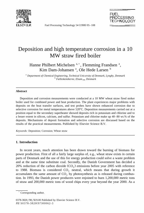
The measurements were carried out at Rudkøbing KVV, Denmark, which is a 10.7MW stoker fired unit producing 2.3 MW electricity and 7 MW heat. The unit is 100%fired with wheat straw, and at full load this equals about 3 metric tons of straw per hour.A schematic drawing of Rudkøbing KVV is shown in Fig. 1. The first pass consists ofthe boiler. The primary combustion takes place on a stationary grate followed by avibrating grate. From this grate the ash drops to the hopper and is removed to a closedcontainer by a water filled slag remover. The evaporated tubes are placed in the twogrates and at the walls of the furnace. The primary superheater is located in the third
( )H.P. Michelsen et al.rFuel Processing Technology 54 1998 95–108 97
Fig. 1. The schematic drawing of the Rudkøbing thermal power plant.
pass and has an outgoing steam temperature of 4358C. The secondary superheater islocated closest to the furnace in the second pass and has an exit steam temperature of4508C and reaches a final pressure of 61 bars. After the first superheater the gas passesthrough the economizer, the air preheater and finally the fly ash particles are removed inan electrostatic precipitator. The boiler is kept at a constant air-excess number of 1.35that equals an oxygen concentration of approximately 6 vol.% in the stack.
The measurement location is placed in the upper part of the boiler just before thesecondary superheater in the second pass. The gas temperature at this point was725–7508C while the measurements took place.
Deposit measurements were conducted using an air cooled deposition probe insertedjust before the secondary superheater in the convective pass, the same position as theabove-mentioned corrosion studies. The probe is made of stainless steel, has an outerdiameter of 38 mm and it is possible to change the metal test element at the end of theprobe. A constant temperature was maintained by a regulator. Two thermocouplesplaced just before and after the test element measure the temperature.
3. Bulk analysis of fuel, fly ash and bottom ash
Samples of fly ash and bottom ash were collected and analyzed in order to determinethe pathways and behavior of the inorganic constituents in the boiler. The compositionof the wheat straw burned in the experimental period is shown in Table 1.
The analyses of three fly ash samples and one bottom ash sample are shown in Table2. As mentioned above, the bottom ash drops into a water-filled slag remover and thesample of the bottom ash is found as a slurry of ash in water. A part of the water solublefraction of the bottom ash might thus be dissolved in the water and hence no longer be
( )H.P. Michelsen et al.rFuel Processing Technology 54 1998 95–10898
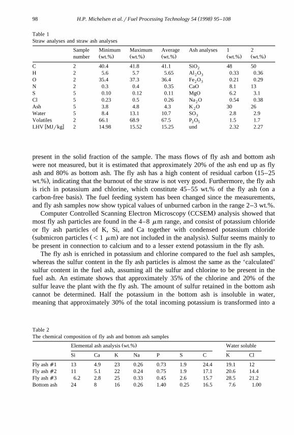
Table 1Straw analyses and straw ash analyses
Sample Minimum Maximum Average Ash analyses 1 2Ž . Ž . Ž . Ž . Ž .number wt.% wt.% wt.% wt.% wt.%
C 2 40.4 41.8 41.1 SiO 48 502
H 2 5.6 5.7 5.65 Al O 0.33 0.362 3
O 2 35.4 37.3 36.4 Fe O 0.21 0.292 3
N 2 0.3 0.4 0.35 CaO 8.1 13S 5 0.10 0.12 0.11 MgO 6.2 3.1Cl 5 0.23 0.5 0.26 Na O 0.54 0.382
Ash 5 3.8 4.8 4.3 K O 30 262
Water 5 8.4 13.1 10.7 SO 2.8 2.93
Volatiles 2 66.1 68.9 67.5 P O 1.5 1.72 5w xLHV MJrkg 2 14.98 15.52 15.25 und 2.32 2.27
present in the solid fraction of the sample. The mass flows of fly ash and bottom ashwere not measured, but it is estimated that approximately 20% of the ash end up as fly
Žash and 80% as bottom ash. The fly ash has a high content of residual carbon 15–25.wt.% , indicating that the burnout of the straw is not very good. Furthermore, the fly ash
Žis rich in potassium and chlorine, which constitute 45–55 wt.% of the fly ash on a.carbon-free basis . The fuel feeding system has been changed since the measurements,
and fly ash samples now show typical values of unburned carbon in the range 2–3 wt.%.Ž .Computer Controlled Scanning Electron Microscopy CCSEM analysis showed that
most fly ash particles are found in the 4–8 mm range, and consist of potassium chlorideor fly ash particles of K, Si, and Ca together with condensed potassium chlorideŽ Ž . .submicron particles -1 mm are not included in the analysis . Sulfur seems mainly tobe present in connection to calcium and to a lesser extend potassium in the fly ash.
The fly ash is enriched in potassium and chlorine compared to the fuel ash samples,whereas the sulfur content in the fly ash particles is almost the same as the ‘calculated’sulfur content in the fuel ash, assuming all the sulfur and chlorine to be present in thefuel ash. An estimate shows that approximately 35% of the chlorine and 20% of thesulfur leave the plant with the fly ash. The amount of sulfur retained in the bottom ashcannot be determined. Half the potassium in the bottom ash is insoluble in water,meaning that approximately 30% of the total incoming potassium is transformed into a
Table 2The chemical composition of fly ash and bottom ash samples
Ž .Elemental ash analysis wt.% Water soluble
Si Ca K Na P S C K Cl
Fly ash a1 13 4.9 23 0.26 0.73 1.9 24.4 19.1 12Fly ash a2 11 5.1 22 0.24 0.75 1.9 17.1 20.6 14.4Fly ash a3 6.2 2.8 25 0.33 0.45 2.6 15.7 28.5 21.2Bottom ash 24 8 16 0.26 1.40 0.25 16.5 7.6 1.00
( )H.P. Michelsen et al.rFuel Processing Technology 54 1998 95–108 99
nonwater soluble form during combustion, presumably silicates. All the potassium in thefly ash is water soluble.
4. Deposition probe measurements
The deposits formed were light grey mostly on the upstream side of the probe. Thedeposit on the back of the test element was a white powder and easy to brush off. Thethicker deposit on the front of the test element was darker and more dense. There was nodirect sign of molten phases in the deposits. The hard deposit seemed to be stronglybonded to the metal oxide layer than the metal oxide layer was bonded to the metalitself.
The deposits were quite hard to remove from the metal surface, and some metal scalewas scraped off when the deposit was removed from the test elements. Therefore, the
Ž .results of the elemental ash composition are given on an iron free basis Table 3 toavoid the influence of the metal contamination. This is reasonable because the content ofiron in straw is very low and normally iron does not play any role in fouling deposits.The deposits are rich in potassium and chlorine and to a lesser extent in silicon, calcium,and sulfur. The deposits formed on both the deposition and the corrosion probes had avery high content of potassium chloride, and the sum of chlorine and potassium make up40–80 wt.%. No significant difference in the chemical composition of the depositsformed on the 4608C and 5508C probes was observed. Furthermore, no trend in thecomposition of potassium chlorine, sulfur, and silicon in the deposits as a function of theexposure time was found. One deposit sample taken from an uncooled probe showed acomposition quite different from the other deposits, e.g., the chlorine content is only 1.5wt.%. This deposit consists mainly of Si, K, and Ca, and only about 30% of thepotassium is water soluble. This indicates that only little potassium chloride is con-densed on uncooled surfaces at the measurement location, and that the deposits mainlyconsist of fly ash particles with a lot of potassium silicate.
The chemical composition of the deposits is similar to the ones of the fly ash particlescollected in the electrostatic precipitator, but the deposits do not only consist of fly ash
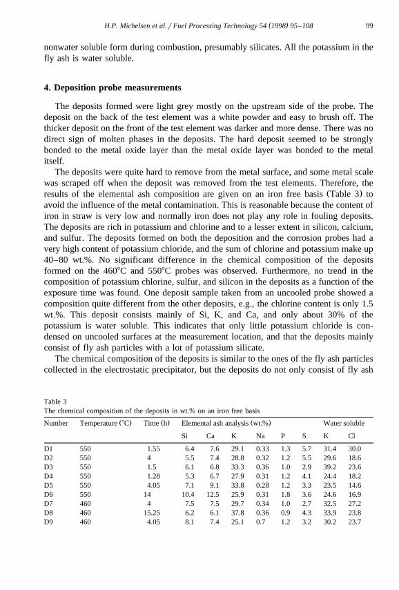
Table 3The chemical composition of the deposits in wt.% on an iron free basis
Ž . Ž . Ž .Number Temperature 8C Time h Elemental ash analysis wt.% Water soluble
Si Ca K Na P S K Cl
D1 550 1.55 6.4 7.6 29.1 0.33 1.3 5.7 31.4 30.0D2 550 4 5.5 7.4 28.8 0.32 1.2 5.5 29.6 18.6D3 550 1.5 6.1 6.8 33.3 0.36 1.0 2.9 39.2 23.6D4 550 1.28 5.3 6.7 27.9 0.31 1.2 4.1 24.4 18.2D5 550 4.05 7.1 9.1 33.8 0.28 1.2 3.3 23.5 14.6D6 550 14 10.4 12.5 25.9 0.31 1.8 3.6 24.6 16.9D7 460 4 7.5 7.5 29.7 0.34 1.0 2.7 32.5 27.2D8 460 15.25 6.2 6.1 37.8 0.36 0.9 4.3 33.9 23.8D9 460 4.05 8.1 7.4 25.1 0.7 1.2 3.2 30.2 23.7
( )H.P. Michelsen et al.rFuel Processing Technology 54 1998 95–108100
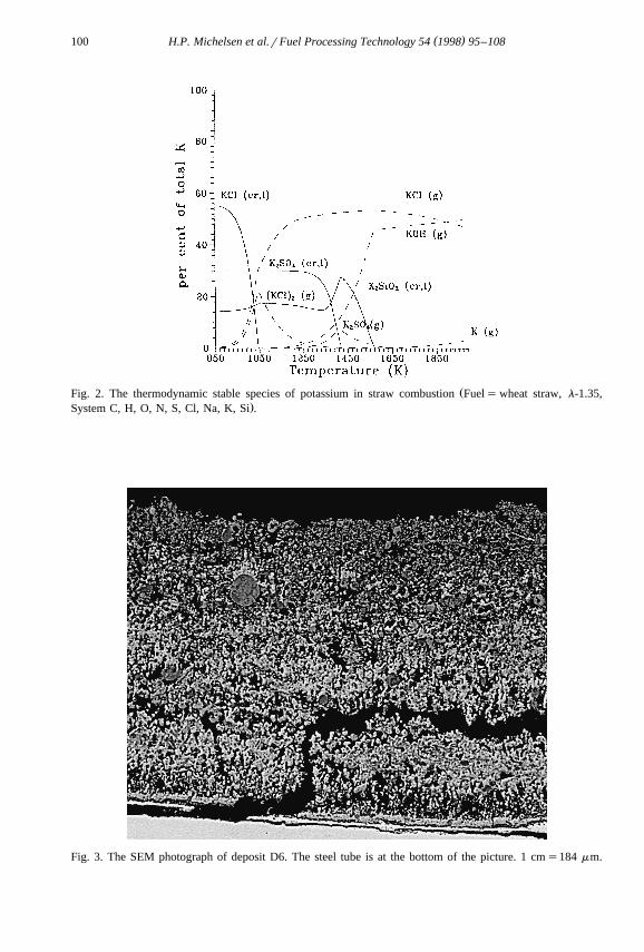
ŽFig. 2. The thermodynamic stable species of potassium in straw combustion Fuels wheat straw, l-1.35,.System C, H, O, N, S, Cl, Na, K, Si .
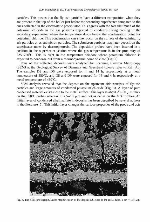
Fig. 3. The SEM photograph of deposit D6. The steel tube is at the bottom of the picture. 1 cms184 mm.
( )H.P. Michelsen et al.rFuel Processing Technology 54 1998 95–108 101
particles. This means that the fly ash particles have a different composition when theyare present in the top of the boiler just before the secondary superheater compared to theones collected in the electrostatic precipitator. This agrees with the fact that much of thepotassium chloride in the gas phase is expected to condense during cooling in thesecondary superheater where the temperature drops below the condensation point forpotassium chloride. This condensation can either occur on the surface of the existing flyash particles or as submicron particles. The submicron particles may later deposit on thesuperheater tubes by thermophoresis. The deposition probes have been inserted in aposition in the superheater section where the gas temperature is in the proximity of725–7508C. This is right in the temperature window where potassium chlorine is
Ž .expected to condense out from a thermodynamic point of view Fig. 2 .Four of the collected deposits were analyzed by Scanning Electron Microscopy
Ž . Ž w x.SEM at the Geological Survey of Denmark and Greenland please refer to Ref. 4 .The samples D2 and D6 were exposed for 4 and 14 h, respectively at a metaltemperature of 5508C, and D8 and D9 were exposed for 15 and 4 h, respectively at ametal temperature of 4608C.
SEM analysis revealed that the deposit on the upstream side consists of fly ashŽ .particles and large amounts of condensed potassium chloride Fig. 3 . A layer of pure
condensed material exists close to the metal surface. This layer is about 20–30 mm thickon the 5508C probes whereas it is 5–10 mm and not as dense on the 468C probes. Aninitial layer of condensed alkali sulfate in deposits has been described by several authors
w xin the literature 5 . This initial layer changes the surface properties of the probe and acts
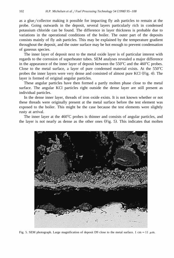
Fig. 4. The SEM photograph. Large magnification of the deposit D6 close to the metal tube. 1 cms184 mm.
( )H.P. Michelsen et al.rFuel Processing Technology 54 1998 95–108102
as a gluercollector making it possible for impacting fly ash particles to remain at theprobe. Going outwards in the deposit, several layers particularly rich in condensedpotassium chloride can be found. The difference in layer thickness is probable due tovariations in the operational conditions of the boiler. The outer part of the depositsconsists mainly of fly ash particles. This may be explained by the temperature gradientthroughout the deposit, and the outer surface may be hot enough to prevent condensationof gaseous species.
The inner layer of deposit next to the metal oxide layer is of particular interest withregards to the corrosion of superheater tubes. SEM analyses revealed a major differencein the appearance of the inner layer of deposit between the 5508C and the 4608C probes.Close to the metal surface, a layer of pure condensed material exists. At the 5508C
Ž .probes the inner layers were very dense and consisted of almost pure KCl Fig. 4 . Thelayer is formed of original angular particles.
These angular particles have then formed a partly molten phase close to the metalsurface. The angular KCl particles right outside the dense layer are still present asindividual particles.
In the dense inner layer, threads of iron oxide exists. It is not known whether or notthese threads were originally present at the metal surface before the test element wasexposed to the boiler. This might be the case because the test elements were slightlyrusty at arrival.
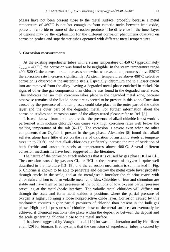
The inner layer at the 4608C probes is thinner and consists of angular particles, andŽ .the layer is not nearly as dense as the other ones Fig. 5 . This indicates that molten
Fig. 5. SEM photograph. Large magnification of deposit D9 close to the metal surface. 1 cms11 mm.
( )H.P. Michelsen et al.rFuel Processing Technology 54 1998 95–108 103
phases have not been present close to the metal surface, probably because a metaltemperature of 4608C is not hot enough to form eutectic melts between iron oxide,potassium chloride or some of the corrosion products. The difference in the inner layerof deposit may be the explanation for the different corrosion phenomena observed oncorrosion probes and superheater tubes operated with different metal temperatures.
5. Corrosion measurements
ŽAt the existing superheater tubes with a steam temperature of 4508C approximately.T s4808C the corrosion was found to be negligible. In the steam temperature rangemetal
490–5208C, the corrosion rate increases somewhat whereas at temperatures above 5208Cthe corrosion rate increases significantly. At steam temperatures above 4908C selectivecorrosion is observed at the austenitic steels. Especially, chromium and to a lesser extentiron are removed from the alloy leaving a degraded metal phase enriched in nickel. Nosigns of other flue gas components than chlorine was found in the degraded metal zone.This indicates that no melt corrosion takes place in the degraded metal zone, becauseotherwise remains of the liquid phase are expected to be present in this zone. Corrosioncaused by the presence of molten phases could take place in the outer part of the oxidelayer and the outer part of the degraded metal. For further information about the
w xcorrosion studies and corrosion rates of the alloys tested please refer to Ref. 3 .ŽIt is well known from the literature that the presence of alkali chloride most work is
.performed with sodium chloride can cause very high corrosion rates well below thew xmelting temperature of the salt 6–12 . The corrosion is severe even when no other
w xcomponents than O rair is present in the gas phase. Alexander 8 found that alkali2
sulfates alone have little effect on the rate of oxidation of austenitic steels at tempera-tures up to 7008C, and that alkali chlorides significantly increase the rate of oxidation ofboth ferritic and austenitic steels at temperatures above 4008C. Several differentcorrosion mechanisms have been suggested in the literature.
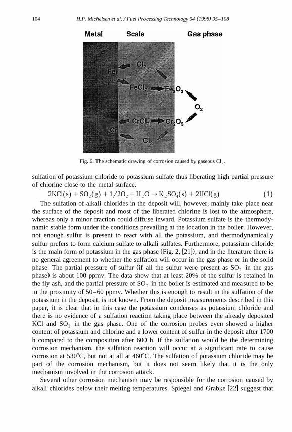
The nature of the corrosion attack indicates that it is caused by gas phase HCl or Cl .2
The corrosion caused by gaseous Cl or HCl in the presence of oxygen is quite well2w xdescribed in the literature 13–18 , and the corrosion mechanism is summarized in Fig.
6. Chlorine is known to be able to penetrate and destroy the metal oxide layer probablythrough cracks in the scale, and at the metalrscale interface the chlorine reacts withchromium and iron to form volatile metal chlorides. Chlorides of iron and chromium arestable and have high partial pressures at the conditions of low oxygen partial pressureprevailing at the metalrscale interface. The volatile metal chlorides will diffuse outthrough the scale and form metal oxides at positions where the partial pressure ofoxygen is higher, forming a loose nonprotective oxide layer. Corrosion caused by thismechanism requires higher partial pressures of chlorine than present in the bulk gasphase. High partial pressures of chlorine close to the metal surface can eventually beachieved if chemical reactions take place within the deposit or between the deposit andthe scale generating chlorine close to the metal surface.
w xIt has been suggested by Vaugham et al. 19 for waste incineration and by Henriksenw xet al. 20 for biomass fired systems that the corrosion of superheater tubes is caused by
( )H.P. Michelsen et al.rFuel Processing Technology 54 1998 95–108104
Fig. 6. The schematic drawing of corrosion caused by gaseous Cl .2
sulfation of potassium chloride to potassium sulfate thus liberating high partial pressureof chlorine close to the metal surface.
2KCl s qSO g q1r2O qH O™K SO s q2HCl g 1Ž . Ž . Ž . Ž . Ž .2 2 2 2 4
The sulfation of alkali chlorides in the deposit will, however, mainly take place nearthe surface of the deposit and most of the liberated chlorine is lost to the atmosphere,whereas only a minor fraction could diffuse inward. Potassium sulfate is the thermody-namic stable form under the conditions prevailing at the location in the boiler. However,not enough sulfur is present to react with all the potassium, and thermodynamicallysulfur prefers to form calcium sulfate to alkali sulfates. Furthermore, potassium chloride
Ž w x.is the main form of potassium in the gas phase Fig. 2, 21 , and in the literature there isno general agreement to whether the sulfation will occur in the gas phase or in the solid
Žphase. The partial pressure of sulfur if all the sulfur were present as SO in the gas2.phase is about 100 ppmv. The data show that at least 20% of the sulfur is retained in
the fly ash, and the partial pressure of SO in the boiler is estimated and measured to be2
in the proximity of 50–60 ppmv. Whether this is enough to result in the sulfation of thepotassium in the deposit, is not known. From the deposit measurements described in thispaper, it is clear that in this case the potassium condenses as potassium chloride andthere is no evidence of a sulfation reaction taking place between the already depositedKCl and SO in the gas phase. One of the corrosion probes even showed a higher2
content of potassium and chlorine and a lower content of sulfur in the deposit after 1700h compared to the composition after 600 h. If the sulfation would be the determiningcorrosion mechanism, the sulfation reaction will occur at a significant rate to causecorrosion at 5308C, but not at all at 4608C. The sulfation of potassium chloride may bepart of the corrosion mechanism, but it does not seem likely that it is the onlymechanism involved in the corrosion attack.
Several other corrosion mechanism may be responsible for the corrosion caused byw xalkali chlorides below their melting temperatures. Spiegel and Grabke 22 suggest that
( )H.P. Michelsen et al.rFuel Processing Technology 54 1998 95–108 105
chlorine is liberated close to the metal surface by sodium chloride reacting with thew xmetal oxide layer to form Na CrO and Na Fe O . Fujikawa and Maruyama 9 and2 4 2 3 4
w xHiramatsu et al. 10 propose that NaCl reacts with chromium carbide, preferably, foundw x w xat the grain boundaries to form Na CrO and Cl . Shinata et al. 12 , Shinata 23 , and2 4 2
w xShinata and Nishi 24 have studied the effect of NaCl on chromium, Cr–Ni alloys, andstainless steels. They suggest a mechanism where NaCl reacts with chromium oxide toform Na CrO in the initiation process followed by the formation of an eutectic melt2 4
between NaCl and Na CrO . The oxidation reaction is carried out in the melt, and it is2 4
considered difficult to form a protective scale in such a melt. The eutectic temperature inthe system NaCl and Na CrO is 5778C.2 4
No differences in the chemical composition or appearance except from the initiallayer between the two metal temperatures were observed. This indicates a shift inphysical behavior of the deposit at the interface between deposit and metal between4608C and 5508C, e.g., the formation of a liquid phase at the scalerdeposit interface.The eutectic point in the system KCl and K CrO is 6508C and can therefore not be2 4
responsible for the formation of a liquid melt at the low temperatures of the probes.However, KCl form low temperature eutectics with FeCl and CrCl which have2 2
eutectic points of 340–3938C and 462–4758C, respectively. KCl forms eutectics withw xFeCl as low as 202–2208C 25 .3
From the nature of the corrosion attack it is reasonable to assume, that chlorine attackthe iron and chromium in the steel to form volatile metal chlorides. The mechanism bywhich Cl or HCl is generated close to the metal surface is not so clear. Whereas the2
corrosion attack is further accelerated by the presence of a liquid phase seems plausiblebut it cannot fully be confirmed from these measurements. In order to determine theprecise mechanism of corrosion, lab scale corrosion studies are planned.
The type of corrosion and the much lower temperatures where corrosion occurs inbiomass fired boilers make the corrosion problems much different from coal firedboilers where the corrosion mechanism usually is governed by the presence of molten
w xalkali sulfates and is characterized by a bell shaped corrosion curve 26–30 . Preventionof corrosion in coal fired boilers can usually be accomplished by using a higher alloyedsteel typically with a higher content of chromium. In biomass fired boilers the corrosionis caused by chlorine, and the chlorine tend to selectively remove the chromium and to alesser extent the iron out of the steel. Adding more chromium to the alloy therefore
w xtends to have no positive effect on corrosion. Fujikawa and Maruyama 9 even find thatchromium tends to accelerate corrosion at temperatures below the melting point ofsodium chloride.
6. Summary and conclusion
Large amounts of deposits are formed in the convective pass of the boiler. Thecorrosion of superheater tubes is closely related to the deposits. Straw has a high contentof potassium and chlorine which plays a major role in the deposition process.
Ž .The fly ash has a high content of unburned carbon 15–20 wt.% . Furthermore, thefly ash is enriched in potassium and chlorine. Approximately 35% of the total chlorine
( )H.P. Michelsen et al.rFuel Processing Technology 54 1998 95–108106
Ž .leaves the plant in a condensed form KCl and not as a gaseous compound in the fluegas. Approximately 20% of the total sulfur is captured by the fly ash.
Deposits collected by probes inserted at the top of the furnace just before thesecondary superheater section were light grey with the most deposit formed on theupstream side of the probe. The deposits were rich in potassium and chlorine and to alesser extent in silicon, calcium, and sulfur. Potassium and chlorine make up 40–80wt.% of the deposits. SEM analysis of deposit samples revealed that the deposit on theupstream side consists of fly ash particles and condensed potassium chloride. At the5508C probes the inner layer was very dense and consisted of almost pure KCl. Thestructure and the density of the layer indicate that molten phases have been present inthe dense layer next to the metal oxide layer. At the 4608C probes the inner layer wasthinner and consisted of individual angular particles and was not as dense as on the5508C probes. The difference in the inner layer of the deposit and hereby molten phasesmay play the determining role in the corrosion of superheater tubes.
At the existing superheater tubes with a steam temperature of 4508C the corrosionwas found to be negligible. Corrosion probe studies revealed that the corrosion rateincreased moderately in the steam temperature interval 490–5208C and markedly attemperatures above 5208C. Selective corrosion is observed at steam temperatures above4908C where chromium and to a lesser extent iron are removed from the alloy leaving adegraded metal phase enriched in nickel. The corrosion is caused by gaseous chlorinespecies formed in the deposit or at the interface between the deposit and scale, e.g., bysulfation of KCl, formation of K CrO , or by reaction between chromium carbide and2 4
potassium chloride. Whether the corrosion attack is further accelerated by the presenceof a liquid phase seems plausible, but cannot fully be concluded from these measure-ments.
Corrosion of superheater tubes caused by the presence of alkali chlorides in biomassdeposits on the superheater tubes can cause accelerated corrosion well below the meltingpoint of potassium chloride. The potential corrosion problems associated with generatingpower from biomass may be a serious issue in considering the future biomass firedpower plants. Either the temperature of the steam has to be kept low or ways to preventpotassium chloride to be present in the deposits have to be found.
Acknowledgements
ŽThis work was carried out as a part of the CHEC Combustion and Harmful Emission.Control research programme. The CHEC programme is financially supported by
ELSAM, ELKRAFT, The Danish Technical Research Council, the Danish EnergyResearch Program, and the Nordic Energy Research Programme. Henning Sørensen,Geological Survey of Denmark and Greenland, is greatly acknowledged for performingthe SEM analyses.
References
w x1 P.F.B. Hansen, K.A. Andersen, K. Wieck-Hansen, O. Overgaard, I. Rasmussen, Co-firing Coal and Strawin a 150 MWe Utility Boiler: In-situ measurements, This conference proceedings, 1996.
( )H.P. Michelsen et al.rFuel Processing Technology 54 1998 95–108 107
w x2 T.R. Miles, T.R. Miles Jr., L.L. Baxter, R.W. Bryers, B.M. Jenkins, L.L. Oden, Alkali deposits found inbiomass power plants. A Preliminary Investigation of Their Extent and Nature, National RenewableEnergy Laboratory, 1617 Cole Boulevard, Golden, CO, 1994.
w x3 O.H. Larsen, N. Henriksen, S. Inselmann, R. Blum, The Influence of Boiler Design and ProcessConditions on Fouling and Corrosion in Straw and CoalrStraw-Fired Ultra Supercritical Power Plants,Submitted to the 9th European Bioenergy Conference, Copenhagen, Denmark, 1996.
w x4 H.S. Sørensen, K. Laursen, A Study of Inorganic Constituents in Biomass and Ashes: Analysis byComputer Controlled SEM, This conference proceedings, 1996.
w x Ž .5 S.A. Benson, M.L. Jones, J.N. Harb, Ash formation and deposition, in: L.D. Smoot Ed. , Fundamentalsof Coal Combustion for Clean and Efficient Use, Elsevier, 1993.
w x6 H.T. Shirley, Effects of sulphate–chloride mixtures in fuel–ash corrosion of steels and high-nickel alloys,J. Iron Steel Inst., February, 1956.
w x Ž .7 D.H. Lucas, The work of C.E.R.L. in combustion and related fields, J. Inst. Fuel 36 1963 206.w x8 P.A. Alexander, Laboratory studies of the effects of sulphates and chlorides on the oxidation of
Ž .superheater alloys, in: R. Johnson, D.J. Littler Eds. , The Mechanism of Corrosion by Fuel Impurities,Butterworths, 1963.
w x9 H. Fujikawa, N. Maruyama, Corrosion behavior of austenitic stainless steels in high chloride-containingŽ .environment, Mater. Sci. Eng. A120 1989 301.
w x10 N. Hiramatsu, Y. Uematsu, T. Tanaka, M. Kinugasa, Effects of alloying elements on NaCl-induced hotŽ .corrosion of stainless steels, Mater. Sci. Eng. A120 1989 319.
w x Ž .11 P. Hancock, Vanadic and chloride attack of superalloys, Mater. Sci. Technol. 3 1987 536.w x12 Y. Shinata, F. Takahashi, K. Hashiura, NaCl-induced hot corrosion of stainless steels, Mater. Sci. Eng. 87
Ž .1987 399.w x Ž .13 P.L. Daniel, R.A. Rapp, Halogen corrosion of metals, in: M.G. Fontana, R.W. Staehle Eds. , Advances
in Corrosion Science and Technology, Vol. 5, Plenum, 1976.w x14 A.S. Kim, M.J. McNallan, Mixed oxidation of iron–chromium alloys in gases containing oxygen and
Ž .chlorine at 900 to 1200 K, Corrosion 46 1990 746.w x15 S.Y. Lee, M.J. McNallan, Formation of condensed chlorides during mixed oxidation–chlorination of iron
Ž .at 1000 K, Corrosion 47 1991 868.w x16 V.A.C. Haanappel, N.W.J. Haanappel, T. Fransen, H.D. van Corbach, P.J. Gellings, Corrosion kinetics of
Ž .low- and high-alloy steels in chlorine-containing gas atmospheres, Corrosion 48 1992 812.w x Ž .17 H. Chu, P.K. Datta, J.S. Gray, K.N. Strafford, Corrosion mechanism of Fe Ni 25CrAlX type alloys in a
Ž .bioxidant environment at elevated temperatures, Corrosion Sci. 35 1993 1091.w x18 H.J. Grabke, E. Reese, M. Spiegel, The effect of chlorides, hydrogen chloride, and sulfur dioxide in the
Ž .oxidation of steels below deposits, Corrosion Sci. 37 1995 1023.w x19 D.A. Vaugham, H.H. Krause, W.D. Boyd, Chloride corrosion and its inhibition in refuse firing,
Proceedings of the International Conference on Ash Deposits and Corrosion From Impurities inCombustion Gases, Henniker, NH, June 26–July 1, 1977.
w x20 N. Henriksen, O.H. Larsen, R. Blum, S. Inselman, High-temperature corrosion when co-firing coal andstraw in pulverized coal boilers and circulating fluidized bed boilers, VGB Conference, Corrosion andCorrosion Protection in Power Plants, Essen, November 29–30, 1995.
w x21 D.C. Dayton, R.J. French, T.A. Milne, Direct observations of alkali vapor release during biomasscombustion and gasification: 1. Application of molecular beamrmass spectrometry to switchgrass
Ž .combustion, Energy Fuels 9 1995 855.w x22 M. Spiegel, H.J. Grabke, High temperature corrosion of low and high alloy steels in simulated waste
Ž .incineration atmospheres, in: R.W. Bryers Ed. , Incinerating Municipal and Industrial Waste. FiresideProblems and Prospects for Improvement, Hemisphere Publishing, 1991.
w x23 Y. Shinata, Accelerated oxidation rate of chromium induced by sodium chloride, Oxidation Metals 27Ž .1987 315.
w x Ž .24 Y. Shinata, Y. Nishi, NaCl-induced accelerated oxidation of chromium, Oxidation Metals 26 1986 201.w x25 G.J. Janz, C.B. Allen, J.R. Downey Jr., R.P.T. Tamkins, Eutectic Data; Safety, Hazard, Corrosion,
Melting Points, Compositions and Bibliography, Molten Salts Data Center, Rensselaer PolytechnicInstitute, Troy, NY, 1976.

( )H.P. Michelsen et al.rFuel Processing Technology 54 1998 95–108108
w x26 W.T. Reid, External Corrosion and Deposits—Boilers and Gas Turbines, Elsevier, New York, 1971.w x27 A.J.B. Cutler, E. Raask, External corrosion in coal-fired boilers: assessment from laboratory data,
Ž .Corrosion Sci. 21 1981 789.w x Ž .28 R.A. Rapp, Chemistry and electrochemistry of the hot corrosion of metals, Corrosion 42 1986 568.w x29 P. Kofstad, High Temperature Corrosion, Elsevier, New York, 1988.w x Ž .30 J.N. Harb, E.E. Smith, Fireside corrosion in PC-fired boilers, Prog. Energy Combust. Sci. 16 1990 169.