Demonstration designs for the remediation of space debris from the International Space Station
24
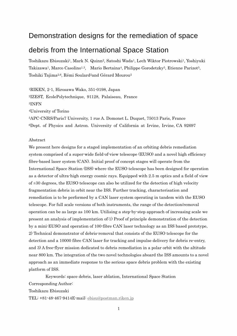
1 Demonstration designs for the remediation of space debris from the International Space Station Toshikazu Ebisuzaki 1 , Mark N. Quinn 2 , Satoshi Wada 1 , Lech Wiktor Piotrowski 1 , Yoshiyuki Takizawa 1 , Marco Casolino 1,3 , Mario Bertaina 4 , Philippe Gorodetzky 5 , Etienne Parizot 5 , Toshiki Tajima 2,6 , Rémi Soulard 2 and Gérard Mourou 2 1 RIKEN, 2-1, Hirosawa Wako, 351-0198, Japan 2 IZEST, EcolePolytechnique, 91128, Palaiseau, France 3 INFN 4 University of Torino 5 APC-CNRS/Paris7 University, 1 rue A. Domonet L. Duquet, 75013 Paris, France 6 Dept. of Physics and Astron. University of California at Irvine, Irvine, CA 92697 Abstract We present here designs for a staged implementation of an orbiting debris remediation system comprised of a super-wide field-of-view telescope (EUSO) and a novel high efficiency fibre-based laser system (CAN). Initial proof of concept stages will operate from the International Space Station (ISS) where the EUSO telescope has been designed for operation as a detector of ultra-high energy cosmic rays. Equipped with 2.5 m optics and a field of view of ±30 degrees, the EUSO telescope can also be utilized for the detection of high velocity fragmentation debris in orbit near the ISS. Further tracking, characterisation and remediation is to be performed by a CAN laser system operating in tandem with the EUSO telescope. For full scale versions of both instruments, the range of the detection/removal operation can be as large as 100 km. Utilising a step-by-step approach of increasing scale we present an analysis of implementation of:1) Proof of principle demonstration of the detection by a mini-EUSO and operation of 100-fibre CAN laser technology as an ISS based prototype, 2) Technical demonstrator of debris-removal that consists of the EUSO telescope for the detection and a 10000 fibre CAN laser for tracking and impulse delivery for debris re-entry, and 3) A free-flyer mission dedicated to debris remediation in a polar orbit with the altitude near 800 km. The integration of the two novel technologies aboard the ISS amounts to a novel approach as an immediate response to the serious space debris problem with the existing platform of ISS. Keywords: space debris, laser ablation, International Space Station Corresponding Author: Toshikazu Ebisuzaki TEL: +81-48-467-9414E-mail: [email protected]
-
Upload
independent -
Category
Documents
-
view
2 -
download
0
Transcript of Demonstration designs for the remediation of space debris from the International Space Station
1
Demonstration designs for the remediation of space
debris from the International Space Station
Toshikazu Ebisuzaki1, Mark N. Quinn2, Satoshi Wada1, Lech Wiktor Piotrowski1, Yoshiyuki
Takizawa1, Marco Casolino1,3, Mario Bertaina4, Philippe Gorodetzky5, Etienne Parizot5,
Toshiki Tajima2,6, Rémi Soulard2and Gérard Mourou2
1RIKEN, 2-1, Hirosawa Wako, 351-0198, Japan
2IZEST, EcolePolytechnique, 91128, Palaiseau, France
3INFN
4University of Torino
5APC-CNRS/Paris7 University, 1 rue A. Domonet L. Duquet, 75013 Paris, France
6Dept. of Physics and Astron. University of California at Irvine, Irvine, CA 92697
Abstract
We present here designs for a staged implementation of an orbiting debris remediation
system comprised of a super-wide field-of-view telescope (EUSO) and a novel high efficiency
fibre-based laser system (CAN). Initial proof of concept stages will operate from the
International Space Station (ISS) where the EUSO telescope has been designed for operation
as a detector of ultra-high energy cosmic rays. Equipped with 2.5 m optics and a field of view
of ±30 degrees, the EUSO telescope can also be utilized for the detection of high velocity
fragmentation debris in orbit near the ISS. Further tracking, characterisation and
remediation is to be performed by a CAN laser system operating in tandem with the EUSO
telescope. For full scale versions of both instruments, the range of the detection/removal
operation can be as large as 100 km. Utilising a step-by-step approach of increasing scale we
present an analysis of implementation of:1) Proof of principle demonstration of the detection
by a mini-EUSO and operation of 100-fibre CAN laser technology as an ISS based prototype,
2) Technical demonstrator of debris-removal that consists of the EUSO telescope for the
detection and a 10000 fibre CAN laser for tracking and impulse delivery for debris re-entry,
and 3) A free-flyer mission dedicated to debris remediation in a polar orbit with the altitude
near 800 km. The integration of the two novel technologies aboard the ISS amounts to a novel
approach as an immediate response to the serious space debris problem with the existing
platform of ISS.
Keywords: space debris, laser ablation, International Space Station
Corresponding Author:
Toshikazu Ebisuzaki
TEL: +81-48-467-9414E-mail: [email protected]
2
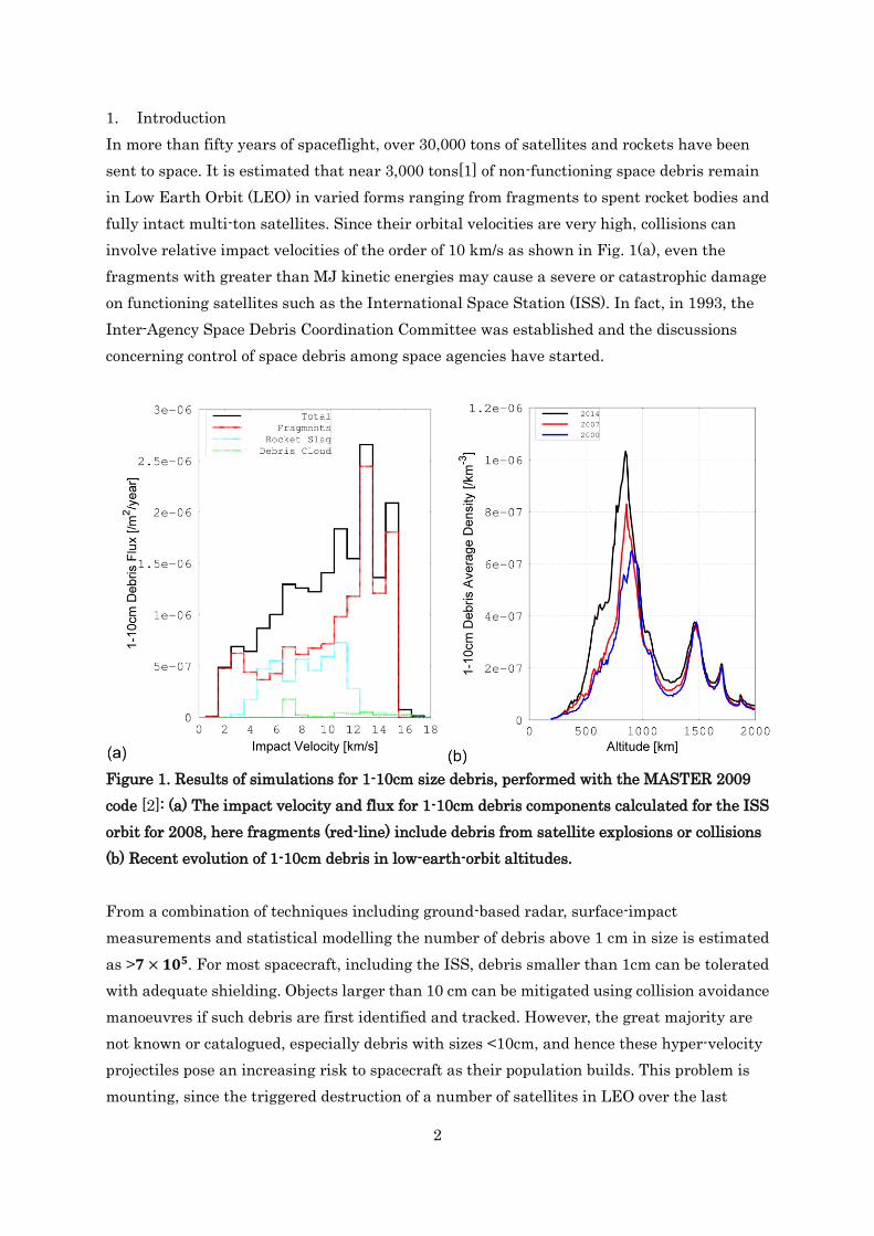
1. Introduction
In more than fifty years of spaceflight, over 30,000 tons of satellites and rockets have been
sent to space. It is estimated that near 3,000 tons[1] of non-functioning space debris remain
in Low Earth Orbit (LEO) in varied forms ranging from fragments to spent rocket bodies and
fully intact multi-ton satellites. Since their orbital velocities are very high, collisions can
involve relative impact velocities of the order of 10 km/s as shown in Fig. 1(a), even the
fragments with greater than MJ kinetic energies may cause a severe or catastrophic damage
on functioning satellites such as the International Space Station (ISS). In fact, in 1993, the
Inter-Agency Space Debris Coordination Committee was established and the discussions
concerning control of space debris among space agencies have started.
Figure 1. Results of simulations for 1-10cm size debris, performed with the MASTER 2009
code [2]: (a) The impact velocity and flux for 1-10cm debris components calculated for the ISS
orbit for 2008, here fragments (red-line) include debris from satellite explosions or collisions
(b) Recent evolution of 1-10cm debris in low-earth-orbit altitudes.
From a combination of techniques including ground-based radar, surface-impact
measurements and statistical modelling the number of debris above 1 cm in size is estimated
as >𝟕 × 𝟏𝟎𝟓. For most spacecraft, including the ISS, debris smaller than 1cm can be tolerated
with adequate shielding. Objects larger than 10 cm can be mitigated using collision avoidance
manoeuvres if such debris are first identified and tracked. However, the great majority are
not known or catalogued, especially debris with sizes <10cm, and hence these hyper-velocity
projectiles pose an increasing risk to spacecraft as their population builds. This problem is
mounting, since the triggered destruction of a number of satellites in LEO over the last
3
decade including Iridium 33, Cosmos 2251 and Fengyun-1C. Such large objects are the main
source of new debris when hit by the much more numerous smaller fragments in LEO. The
small cm-size debris are thus the main threat for impacting the functioning and derelict
payloads. The evolution of this population is shown in Fig. 1(b). Much of the increase after
2000 is attributed to the breakup of the aforementioned satellites with significant increases
seen for the sun-synchronous polar orbit near 800 km altitude.
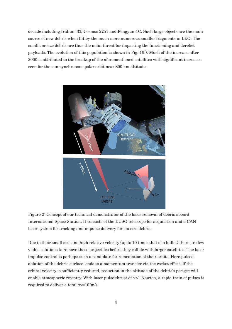
Figure 2: Concept of our technical demonstrator of the laser removal of debris aboard
International Space Station. It consists of the EUSO telescope for acquisition and a CAN
laser system for tracking and impulse delivery for cm size debris.
Due to their small size and high relative velocity (up to 10 times that of a bullet) there are few
viable solutions to remove these projectiles before they collide with larger satellites. The laser
impulse control is perhaps such a candidate for remediation of their orbits. Here pulsed
ablation of the debris surface leads to a momentum transfer via the rocket effect. If the
orbital velocity is sufficiently reduced, reduction in the altitude of the debris’s perigee will
enable atmospheric re-entry. With laser pulse thrust of <<1 Newton, a rapid train of pulses is
required to deliver a total Δv≈102m/s.
4
Since the late 1980’s a number of designs for delivering laser pulses to debris have been
proposed operating either from ground-based or space-based. For the latter case, this began
with Metzger et al. [3] who proposed a nuclear-powered debris-sweeper with a 10 kJ, 1 Hz
krypton fluoride laser (λ of 248 nm). Recently, Phipps [4] proposed a solar-powered
space-based system L’ADROIT to be launched consisting of a super-wide-field debris detector
with a powerful Nd-Yag laser system with pulse energy of ~38 J or more. Schall [5] was the
first to propose to use the ISS as platform for testing debris sweeping technology.
Here in this present paper, we propose to implement a staged approach to evaluating such
space based concepts utilizing a large wide-field of view detector in tandem with a short
pulsed laser beginning with prototypes on-board the ISS as depicted in Fig. 2. At the ISS
altitude near 400km the combined remediation technology can be tested and improved prior
to a future design and deployment of freely orbiting systems at higher altitudes such as near
800km where the debris population in LEO peaks.
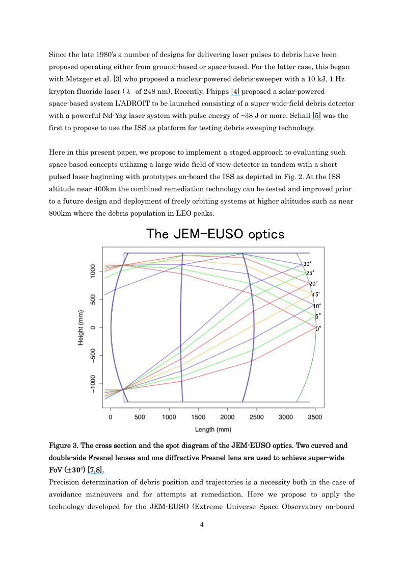
Figure 3. The cross section and the spot diagram of the JEM-EUSO optics. Two curved and
double-side Fresnel lenses and one diffractive Fresnel lens are used to achieve super-wide
FoV (±𝟑𝟎°) [7,8].
Precision determination of debris position and trajectories is a necessity both in the case of
avoidance maneuvers and for attempts at remediation. Here we propose to apply the
technology developed for the JEM-EUSO (Extreme Universe Space Observatory on-board
5
Japanese Experiment Module, hereafter EUSO telescope) designed for the ISS. The
JEM-EUSO mission is to detect UV light emitted from the extensive air-showers produced by
the ultra-high energy cosmic rays entering the atmosphere at night [7,8]. This detector has
a super wide-field of view (FoV) as large as ±30 degrees with three double-side Fresnel
lenses and a short time resolution down to a few μs with highly pixelized photo-multipliers.
During daylight operation, this same detector can provide a unique technology for the
detection and position determination of the non-catalogued debris from orbit. Pulsed laser
technology has rapidly advanced in the last two decades and it allows us now to consider a
space-borne pulsed-laser system. In fact, Soulard et al. [9] proposed to use a space-based
laser system applying their Coherent Amplifying Network (CAN) fibre-based technology. A
CAN laser is comprised of an array of fibres, each producing a laser beam of ~1 mJ, which is
phase combined into a beam of total energy of a 1-100 J. Excellent electrical efficiency
approaching 30% and a repetition rate higher than 10 kHz are possible which is an ideal
solution method for tracking, and impulse delivery to the high velocity debris. Both of these
instruments, EUSO and CAN, have been designed for applications in independent physics
experiments which are on-going in their development.
This paper is organized as follows. In section 2, we describe the method of the detection,
tracking, and laser impulse control of small debris. In section 3, a proof-of-principle prototype
is described utilizing the mini-EUSO telescope which will be installed on the ISS together
with a scaled down CAN laser. In section 4, we present a full scale system designed to test
impulse delivery to small space debris from the ISS. In section 5, we mention a free-flyer
mission, dedicated to debris remediation in a polar orbit with the altitude near800 km and
evaluation of its performance.
2. Space-based debris remediation
The operation of the space-borne debris remediation system is divided into three stages:1)
passive detection with a super-wide FOV camera, 2) active tracking by a narrow FOV
6
telescope and 3) velocity modification by laser ablation.
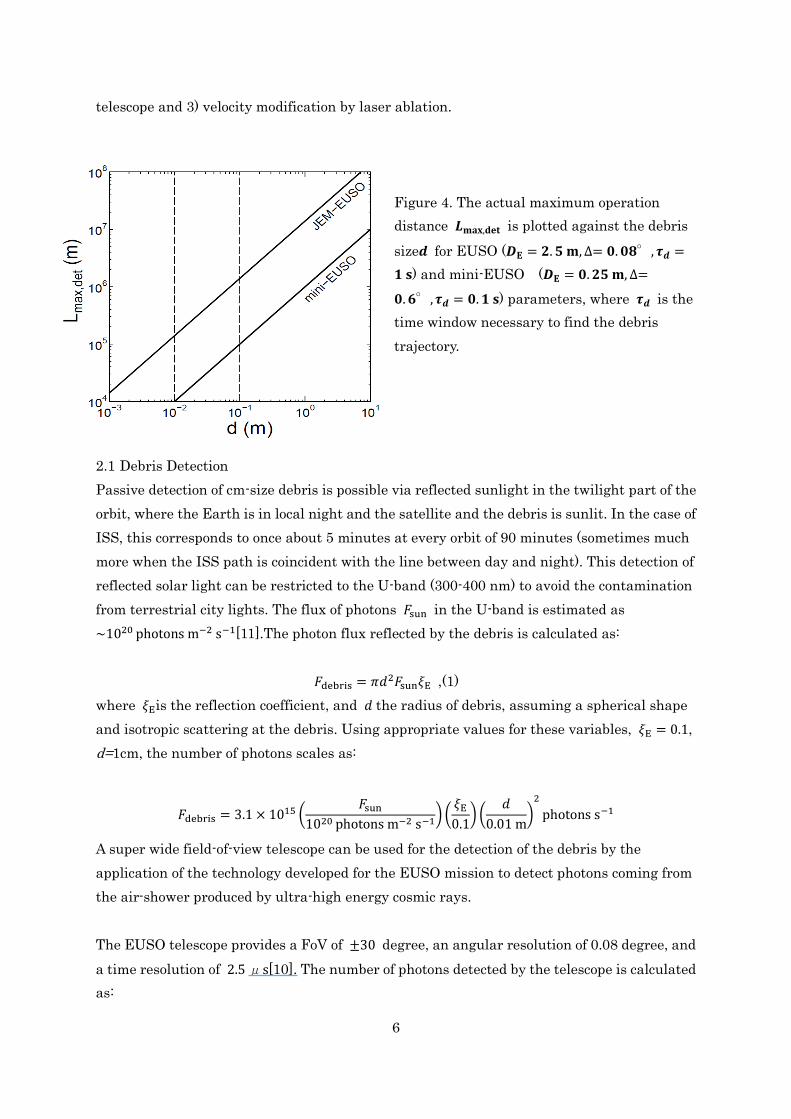
Figure 4. The actual maximum operation
distance 𝑳𝐦𝐚𝐱,𝐝𝐞𝐭 is plotted against the debris
size𝒅 for EUSO (𝑫𝐄 = 𝟐. 𝟓 𝐦, ∆= 𝟎. 𝟎𝟖°, 𝝉𝒅 =
𝟏 𝐬) and mini-EUSO (𝑫𝐄 = 𝟎. 𝟐𝟓 𝐦, ∆=
𝟎. 𝟔°, 𝝉𝒅 = 𝟎. 𝟏 𝐬) parameters, where 𝝉𝒅 is the
time window necessary to find the debris
trajectory.
2.1 Debris Detection
Passive detection of cm-size debris is possible via reflected sunlight in the twilight part of the
orbit, where the Earth is in local night and the satellite and the debris is sunlit. In the case of
ISS, this corresponds to once about 5 minutes at every orbit of 90 minutes (sometimes much
more when the ISS path is coincident with the line between day and night). This detection of
reflected solar light can be restricted to the U-band (300-400 nm) to avoid the contamination
from terrestrial city lights. The flux of photons 𝐹sun in the U-band is estimated as
~1020 photons m−2 s−1[11].The photon flux reflected by the debris is calculated as:
𝐹debris = 𝜋𝑑2𝐹sun𝜉E ,(1)
where 𝜉Eis the reflection coefficient, and 𝑑 the radius of debris, assuming a spherical shape
and isotropic scattering at the debris. Using appropriate values for these variables, 𝜉E = 0.1,
d=1cm, the number of photons scales as:
𝐹debris = 3.1 × 10¹⁵ (𝐹sun
1020 photons m−2 s−1) (
𝜉E
0.1) (
𝑑
0.01 m)
2
photons s−1
A super wide field-of-view telescope can be used for the detection of the debris by the
application of the technology developed for the EUSO mission to detect photons coming from
the air-shower produced by ultra-high energy cosmic rays.
The EUSO telescope provides a FoV of ±30 degree, an angular resolution of 0.08 degree, and
a time resolution of 2.5 μs[10]. The number of photons detected by the telescope is calculated
as:
7
𝑛debris =𝜁𝐷E
2𝐹debris
16𝐿2 , (2)
Where 𝐿 is the distance to the debris, 𝐷E is the diameter of the optics of the EUSO telescope,
and 𝜁 is the collection efficiency of the telescope. A linear track trigger algorithm can be
employed for detection of small high velocity debris objects. This algorithm tracks the
movement of the debris over a predefined time window to distinguish the unique pattern of
the track of debris from the background [9]
We set the detection criteria of debris as:
SNR =𝑛debris√𝜏d
√𝐵≥ 10, (3)
where, 𝜏d is the integratioin time along the track in the Linear Track Trigger algorithm, and
𝐵 is the number of background photon flux per pixel [9]:
𝐵 = 4.4 × 10⁵ (Δ
0.08deg)
2
(𝜁
0.1) (
𝐷E
2.5 m)
2photons s−1 pixel−1, (4)
where the angular resolution of the EUSO telescope isΔ = 0.08 degrees. Substituting typical
numbers for parameters in equations 3 and 4, the minimum detectable debris size by EUSO
telescope at 100 km is (Fig 3):
𝑑min
= 7.4 × 10⁻³ (𝐹sun
1020 photons m−2 s−1)
−1
2
(𝜉E
0.1)
−1
2
(𝜁
0.1)
−1
4
(Δ
0.08deg)
1
2
(𝐷E
2.5 m)
−1
2
(𝐿
100 km) (
𝜏𝑑
1 s)
−1
4 m
,(5)
or equivalently the maximum detection distance, 𝐿max,det for debris size scales as :
𝐿max,det = 1.4 × 10⁵ (𝐹sun
1020 photons m−2 s−1)
1
2(
𝜉E
0.1)
1
2(
𝜁
0.1)
1
4(
Δ
0.08deg)
−1
2
(𝐷E
2.5 m)
1
2(
𝜏𝑑
1 s)
1
4(
𝑑
0.01 m)m (6)
We have to note that 𝜏d must be considerably shorter than the encounter time, which is
about 10 seconds for the typical case of 𝐿 = 100 kmand 𝑣 = 10 km s−1. The angular velocity of
the debris is also obtained as well. Based on this information, the debris tracking system is
evoked, as discussed in the next subsection.
2.2 Debris Tracking
The path of the debris has been defined by EUSO with an accuracy of 0.08°linked to the
pixel size. Now, we must track the debris within this 0.08°cone, with an accuracy of the
debris size. We call that active debris tracking, which is proposed employing a combined
pulsed laser and telescope with a FoV consistent with the determination accuracy of the
debris detection, which is about the angular resolution of the detection telescope. Thus a
8
series of laser pulses is sent to the debris object where the beam angle is expanded by the
telescope to the accuracy of the position determination, described above. The number of laser
photons reflected by the debris from 𝑁 pulses and detected by the telescope can be estimated
as:
𝑛𝑙𝑎𝑠𝑒𝑟 = (𝑁𝐸p
ℎ𝑐/𝜆) (
𝜋𝑑2
(𝜋𝜃𝐿
2)2
)𝜉T𝜁𝜋(𝐷/2)2
2𝜋𝐿2 =
3.9 × 10⁴ (𝜉T
0.1) (
𝜁
0.1) (
𝑁
104) (𝐸p
10 J) (
𝑑
0.01 m)
2(
𝐷T
1.5 m)
2(
𝐿
100 𝑘m)
−4(
𝜆
0.35 𝜇m) (
Δ
0.08degree)
−2
photons, (7)
where 𝐸p is the energy of a laser pulse, 𝜉T the collection efficiency of the tracking telescope,
and 𝐷T is the diameter of the tracking optics. The diffraction limited image and the arrival
time of the signal enable the three dimensional position of the debris (two position angles and
the distance) to be determined.
2.3 Laser ablation of debris
When an intense laser beam is focused on a small area of the debris, its material is ejected as
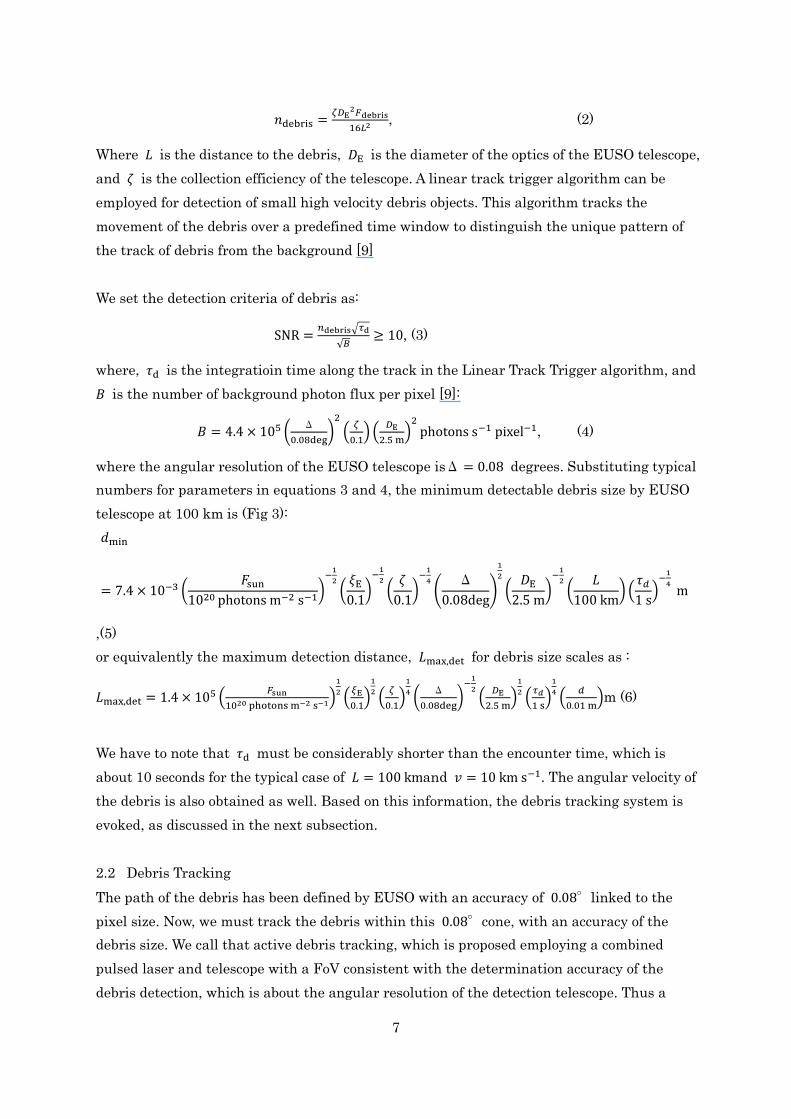
ablation plasma, if the laser intensity is higher than the ablation threshold. Figure 5 shows
the concept of the laser ablation propulsion. For a given energy deposit 𝐸, the resultant
reaction impact 𝐸/𝑣𝑎 is much larger than that of radiation pressure 𝐸/𝑐 of the laser beam,
since the velocity 𝑣𝑎of ablated material is much slower than the light velocity 𝑐.
Figure 5: Concept of the propulsion by laser ablation. Ablated material is ejected as ablation
plasma by the velocity of 𝒗𝒂.
9
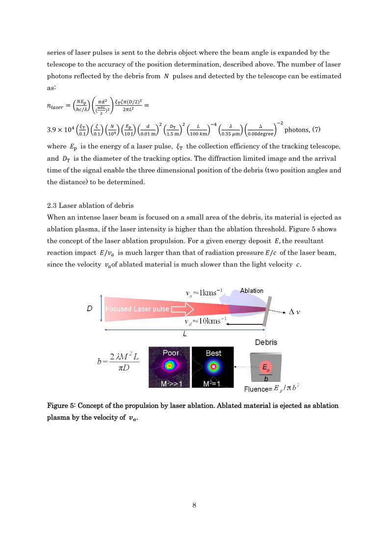
Figure 6. The concept of the removal of debris by laser ablation. Reducing the speed of
debris by∆𝐯via laser-ablation impulses
Space debris, smaller than10 cm, can be sufficiently decelerated by laser impulses resulting
in its re-entry to the Earth’s atmosphere, as shown in Fig. 6. Here the debris of mass 𝑚 is
transferred to a lower orbit via a deceleration of Δ𝑣. The total laser energy required can be
estimated as, 𝐸𝐿 ≈ 𝑚𝐶mΔ𝑣 where 𝐶m is the efficiency of coupling to debris. For a given
laser pulse duration and debris material, the optimal 𝐶𝑚 requires a specific fluence to be
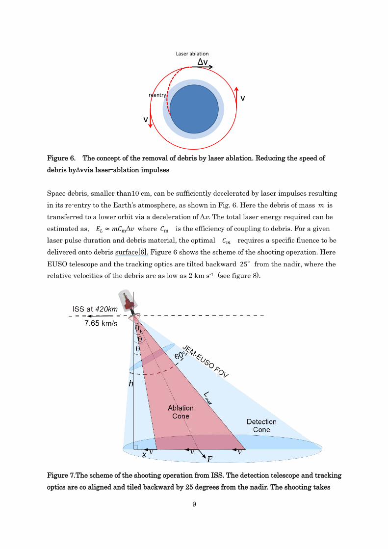
delivered onto debris surface[6]. Figure 6 shows the scheme of the shooting operation. Here
EUSO telescope and the tracking optics are tilted backward 25°from the nadir, where the
relative velocities of the debris are as low as 2 km s-1 (see figure 8).
Figure 7.The scheme of the shooting operation from ISS. The detection telescope and tracking
optics are co aligned and tiled backward by 25 degrees from the nadir. The shooting takes
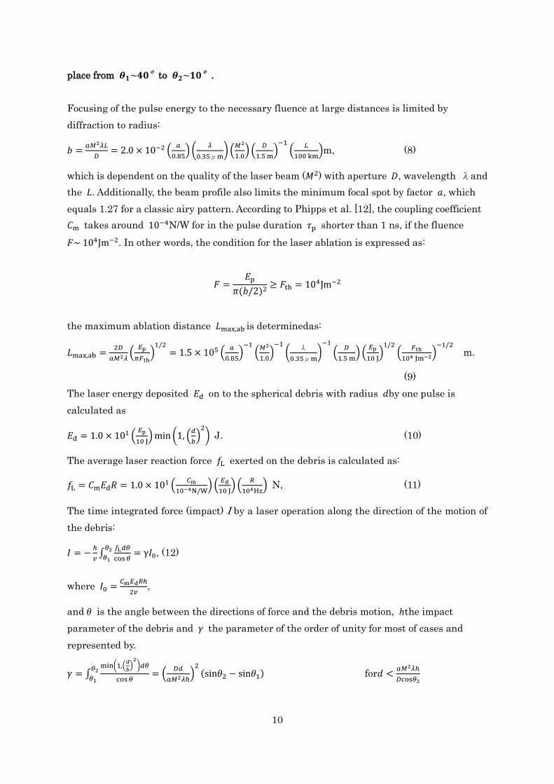
10
place from 𝜽𝟏~𝟒𝟎°to 𝜽𝟐~𝟏𝟎°.
Focusing of the pulse energy to the necessary fluence at large distances is limited by
diffraction to radius:
𝑏 =𝑎𝑀2𝜆𝐿
𝐷= 2.0 × 10⁻² (
𝑎
0.85) (
𝜆
0.35μm) (
𝑀2
1.0) (
𝐷
1.5 m)
−1(
𝐿
100 km)m, (8)
which is dependent on the quality of the laser beam (𝑀2) with aperture 𝐷, wavelength λand
the 𝐿. Additionally, the beam profile also limits the minimum focal spot by factor 𝑎, which
equals 1.27 for a classic airy pattern. According to Phipps et al. [12], the coupling coefficient
𝐶m takes around 10−4N/W for in the pulse duration 𝜏p shorter than 1 ns, if the fluence
𝐹~ 104Jm−2. In other words, the condition for the laser ablation is expressed as:
𝐹 =𝐸p
𝜋(𝑏/2)2≥ 𝐹th = 104Jm−2
the maximum ablation distance 𝐿max,ab is determinedas:
𝐿max,ab =2𝐷
𝑎𝑀2𝜆(
𝐸p
𝜋𝐹th)
1/2= 1.5 × 10⁵ (
𝑎
0.85)
−1(
𝑀2
1.0)
−1
(λ
0.35μm)
−1
(𝐷
1.5 m) (
𝐸p
10 J)
1/2(
𝐹th
104 Jm−2)−1/2
m.
(9)
The laser energy deposited 𝐸d on to the spherical debris with radius 𝑑by one pulse is
calculated as
𝐸d = 1.0 × 101 (𝐸p
10 J) min (1, (
𝑑
𝑏)
2) J. (10)
The average laser reaction force 𝑓L exerted on the debris is calculated as:
𝑓L = 𝐶m𝐸d𝑅 = 1.0 × 101 (𝐶m
10−4N/W) (
𝐸d
10 J) (
𝑅
104Hz) N, (11)
The time integrated force (impact) I by a laser operation along the direction of the motion of
the debris:
𝐼 = −ℎ
𝑣∫
𝑓L𝑑𝜃
cos 𝜃
𝜃2
𝜃1= γ𝐼0, (12)
where 𝐼0 =𝐶m𝐸d𝑅ℎ
2𝑣,
and 𝜃 is the angle between the directions of force and the debris motion, ℎthe impact
parameter of the debris and 𝛾 the parameter of the order of unity for most of cases and
represented by.
𝛾 = ∫min(1,(
𝑑
𝑏)
2)𝑑𝜃
cos 𝜃= (
𝐷𝑑
𝑎𝑀2𝜆ℎ)
2(sin𝜃2 − sin𝜃1)
𝜃2
𝜃1 for𝑑 <
𝑎𝑀2𝜆ℎ
𝐷cos𝜃2
11
= ln1+sin𝜃0
1−sin𝜃0− ln
1+sin𝜃2
1−sin𝜃2+ (
𝐷𝑑
𝑎𝑀2𝜆ℎ)
2(sin𝜃1 − sin𝜃0) for
𝑎𝑀2𝜆ℎ
𝐷cos𝜃2< 𝑑 <
𝑎𝑀2𝜆ℎ
𝐷cos𝜃1
= ln1+sin𝜃1
1−sin𝜃1− ln
1+sin𝜃2
1−sin𝜃2 for 𝑑 >
𝑎𝑀2𝜆ℎ
𝐷cos𝜃1, (13)
where the orbit of a debris is assumed by a horizontal straight line, 𝜃0 = Cos−1 (𝑎𝑀2𝜆ℎ
𝐷d) and
𝜃1and 𝜃2the angles thatthe shooting starts and ends, respectively. The velocity change ∆𝑣 by
an impact𝐼:
∆𝑣
= 3. 0
× 101 (𝛾
1.0) (
𝐶m
10−4NW−1) (
𝐸p
10 J) (
𝑅
104 Hz) (
ℎ
100 km) (
𝑣
2km s−1)
−1
(𝜌
2 × 10³kg m−3)
−1
(𝑑
0.1 m)
−3
m s−1, (14)
for the case of debris in the LEO. The reduction ∆𝑟 in the orbital radius of debris by an
instantaneous change in the orbital velocity is given by [5]:
∆𝑟 = 1.0 × 10² (∆𝑣
30 m s−1)km
= 1.0 × 10² (𝛾
1.0) (
𝐶m
10−4N/W) (
𝐸p
10 J) (
𝑅
104 Hz) (
ℎ
100 km) (
𝑣
2km s−1)−1
(𝜌
2×10³kg m−3)−1
(𝑑
0.1 m)
−3
km. (15)
The minimum operation distance 𝐿min is determined by the maximum speed of the tracking
system, which is likely to be less than 10 degrees−1, so that:
𝐿min = 1.1 × 101 (𝑣
2km s−1) (𝜔
10 degrees−1)−1
km, (16)
where 𝜔 is the angular velocity of the debris. The cross section 𝐴sh of the shooting area is
estimated as:
𝐴sh~ℎ2 tan 𝜑1 = 𝐿max2 cos2 𝜃1tan 𝜑1 = 1.6 × 10⁹ (
𝐿max
100 km)
2m2 (17)
For 𝜃1 = 40°,𝜑1 = 15°, and 𝐿max = min (𝐿max,ab + 𝐿max,det).
Is should be noted that these calculations do not consider the effects of debris spin or its
orientation with respect to the laser pulse direction [6]. However, with high repetition laser
pulses, i.e. > kHz, it can be possible to rapidly probe the orientation and angular velocity of
the debris without modifying its trajectory. Ablation should thus be carried out only once such
debris characteristics are known to ensure impulse delivery is optimised for remediation.
3 The CAN laser system
In choosing a laser system for active tracking and de-orbiting of small debris, there are a
number of design factors which should be considered for operation on-board the ISS.
12
Primarily the limited provision of solar power necessitates a laser system with high electrical
efficiency. Likewise, with very high relative velocities >10 km/s between laser source and
debris, interaction times are short (<10s), and hence a fast response and good average power
are demanded. Heat dissipation, compactness and robustness are also key factors for
operation in space. Many of these factors are absent with traditional gas or crystal-based
laser technology which are limited by poor wall-plug efficiency < 0.1% and poor heat
dissipation restricting the repetition to a few pulses per second and hence providing very low
average power (~10W). However, with the rapid development of fibre-based diode-pumped
laser science, embodied by the CAN concept, these design factors can be realized.
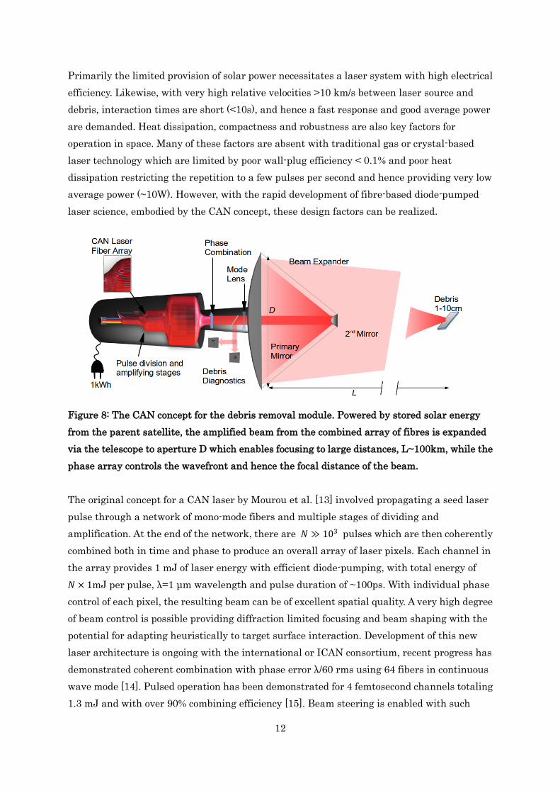
Figure 8: The CAN concept for the debris removal module. Powered by stored solar energy
from the parent satellite, the amplified beam from the combined array of fibres is expanded
via the telescope to aperture D which enables focusing to large distances, L~100km, while the
phase array controls the wavefront and hence the focal distance of the beam.
The original concept for a CAN laser by Mourou et al. [13] involved propagating a seed laser
pulse through a network of mono-mode fibers and multiple stages of dividing and
amplification. At the end of the network, there are 𝑁 ≫ 103 pulses which are then coherently
combined both in time and phase to produce an overall array of laser pixels. Each channel in
the array provides 1 mJ of laser energy with efficient diode-pumping, with total energy of
𝑁 × 1mJ per pulse, λ=1 μm wavelength and pulse duration of ~100ps. With individual phase
control of each pixel, the resulting beam can be of excellent spatial quality. A very high degree
of beam control is possible providing diffraction limited focusing and beam shaping with the
potential for adapting heuristically to target surface interaction. Development of this new
laser architecture is ongoing with the international or ICAN consortium, recent progress has
demonstrated coherent combination with phase error λ/60 rms using 64 fibers in continuous
wave mode [14]. Pulsed operation has been demonstrated for 4 femtosecond channels totaling
1.3 mJ and with over 90% combining efficiency [15]. Beam steering is enabled with such
13
phase ccontrol and is limited to the beam separation (d ) as λ/d ≈1mrad, although much larger
values have been measured by Bourderionnet et al. using a translatable lens array [16].
Scalability is inherent in this network approach, with arrays of 1000 and 10000 fibers
planned for prototype demonstrations.
By virtue of their intrinsic geometry, the surface area of optical fibres enable more effective
dissipation of heat than traditional media providing access to kHz repetition rates in
pulsed-mode. Similarly, the orders of magnitude improvement in electrical efficiency of diode
pumping over traditional lasing-media is well known ( >30% ) as is their high average power
( >10 kW). Transport within single mode fibres provides increased robustness of the system
which is critical for stability of optical systems in orbit.
A conceptual design for the CAN debris interaction module is shown in Fig. 8. Here, stored
solar energy from the ISS provides the power required for the multi-channel fibre laser. In
order to deliver pulses over ~100 km, the beam would be expanded to meter scales via
multiple optics such as a simple telescope design. Here primary and secondary mirrors
provide mechanical motion to steer and focus the beam with coarse precision over a FoV of 10
degrees. With the inclusion of beam expanding optics we expect that phase control enables
precision steering of 0.05 mrad with a precision of 0.01 μrad. Similarly, focusing is finely
controlled from a broad beam to a diffraction limited spot on the target when sufficient
fluence is required to induce ablation and recoil impulses. Since phase adjustment can occur
at rates of ~103 Hz, debris surface condition scan be evaluated with trains of pulses and to
tailor the beam profile for an optimal interaction. Such a heuristic approach could rapidly
scan and optimize the coupling in terms of recoil thrust or reflectivity with debris of distinct
orientation, rotation and surface type.
As reported in Soulard et al. [9], a configuration of 104 fibres results in a pulse energy of 10 J,
an ablation range with best focus of 20-60 km for 𝐷𝑇 = 1.5 m beam aperture. We can
evaluate the performance of this system if it is employed in a nadir configuration on-board
the ISS with the EUSO instrument. If operating at high rep-rate (10 kHz) the laser could
deliver very high average powers ~100 kW. Since rates of debris of <<1/hr are expected, a MJ
of laser energy for debris ablation could be stored as 0.3kWh which, including efficiency
losses, would be ~1 kWh equivalent to 8kg of Li-ion batteries, assuming a power density of
130 Wh/kg.
A key challenge is the rapid beam pointing required when engaging debris, since the angular
velocity of a debris is as high as 0.1 radian per second for the typical case of 10 km s-1 relative
velocity and 100 km distance. Such a high speed requires special consideration in the
14
mechanical design of the expanding optics. If necessary, we can only engage debris with the
relative velocity less than 10 km s-1, and may remove them in further encounters with more
favourable conditions.
4 Proof of principle and prototype systems on-board the ISS
In using the combined technology for the EUSO and CAN systems we propose a development
in two steps on-board the ISS before realising a remediation system:
1. Scaled down proof of principle design operating from the ISS
2. Technical demonstrator capable of testing debris remediation operating from the ISS
3. Free orbiting system to remove most of LEO debris near 800km
A summary of the specification of these systems is shown in Table 1. Further details are
discussed in the following section.
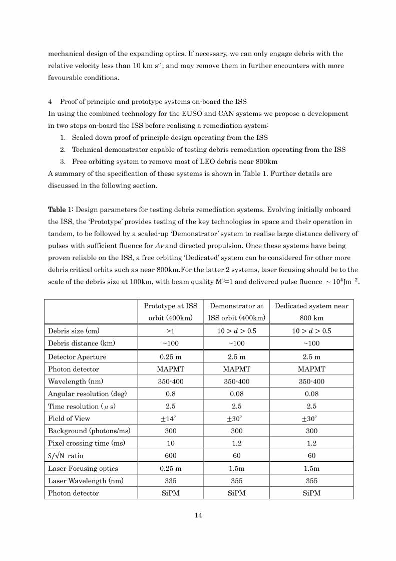
Table 1: Design parameters for testing debris remediation systems. Evolving initially onboard
the ISS, the ‘Prototype’ provides testing of the key technologies in space and their operation in
tandem, to be followed by a scaled-up ‘Demonstrator’ system to realise large distance delivery of
pulses with sufficient fluence for Δv and directed propulsion. Once these systems have being
proven reliable on the ISS, a free orbiting ‘Dedicated’ system can be considered for other more
debris critical orbits such as near 800km.For the latter 2 systems, laser focusing should be to the
scale of the debris size at 100km, with beam quality M2=1 and delivered pulse fluence ~ 104Jm−2.
Prototype at ISS
orbit (400km)
Demonstrator at
ISS orbit (400km)
Dedicated system near
800 km
Debris size (cm) >1 10 > 𝑑 > 0.5 10 > 𝑑 > 0.5
Debris distance (km) ~100 ~100 ~100
Detector Aperture 0.25 m 2.5 m 2.5 m
Photon detector MAPMT MAPMT MAPMT
Wavelength (nm) 350-400 350-400 350-400
Angular resolution (deg) 0.8 0.08 0.08
Time resolution (μs) 2.5 2.5 2.5
Field of View ±14° ±30° ±30°
Background (photons/ms) 300 300 300
Pixel crossing time (ms) 10 1.2 1.2
S/√N ratio 600 60 60
Laser Focusing optics 0.25 m 1.5m 1.5m
Laser Wavelength (nm) 335 355 355
Photon detector SiPM SiPM SiPM
15
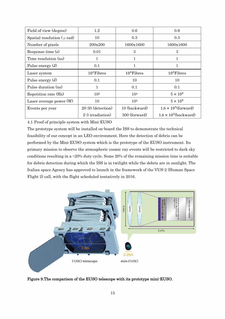
Field of view (degree) 1.2 0.6 0.6
Spatial resolution (μrad) 10 0.3 0.3
Number of pixels 200x200 1600x1600 1600x1600
Response time (s) 0.01 3 3
Time resolution (ns) 1 1 1
Pulse energy (J) 0.1 1 1
Laser system 102Fibres 104Fibres 104Fibres
Pulse energy (J) 0.1 10 10
Pulse duration (ns) 1 0.1 0.1
Repetition rate (Hz) 102 104 5 × 10⁴
Laser average power (W) 10 105 5 × 10⁵
Events per year 20-30 (detection)
2-3 irradiation)
10 (backward)
300 (forward)
1.6 × 10⁵(forward)
1.6 × 10³(backward)
4.1 Proof of principle system with Mini-EUSO
The prototype system will be installed on-board the ISS to demonstrate the technical
feasibility of our concept in an LEO environment. Here the detection of debris can be
performed by the Mini-EUSO system which is the prototype of the EUSO instrument. Its
primary mission to observe the atmospheric cosmic ray events will be restricted to dark sky
conditions resulting in a ≈20% duty cycle. Some 20% of the remaining mission time is suitable
for debris detection during which the ISS is in twilight while the debris are in sunlight. The
Italian space Agency has approved to launch in the framework of the VUS-2 (Human Space
Flight 2) call, with the flight scheduled tentatively in 2016.
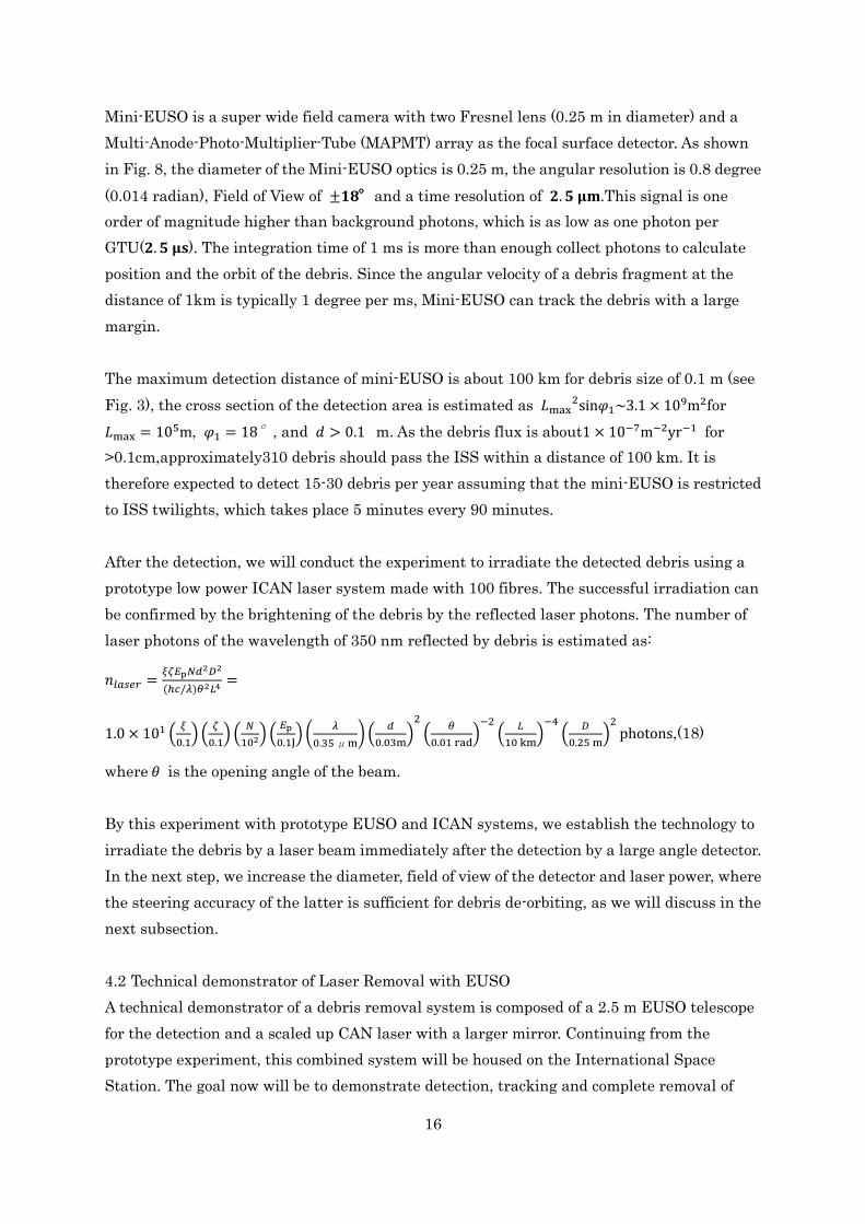
Figure 9.The comparison of the EUSO telescope with its prototype mini-EUSO.
16
Mini-EUSO is a super wide field camera with two Fresnel lens (0.25 m in diameter) and a
Multi-Anode-Photo-Multiplier-Tube (MAPMT) array as the focal surface detector. As shown
in Fig. 8, the diameter of the Mini-EUSO optics is 0.25 m, the angular resolution is 0.8 degree
(0.014 radian), Field of View of ±𝟏𝟖°and a time resolution of 𝟐. 𝟓 𝛍𝐦.This signal is one
order of magnitude higher than background photons, which is as low as one photon per
GTU(𝟐. 𝟓 𝛍𝐬). The integration time of 1 ms is more than enough collect photons to calculate
position and the orbit of the debris. Since the angular velocity of a debris fragment at the
distance of 1km is typically 1 degree per ms, Mini-EUSO can track the debris with a large
margin.
The maximum detection distance of mini-EUSO is about 100 km for debris size of 0.1 m (see
Fig. 3), the cross section of the detection area is estimated as 𝐿max2sin𝜑1~3.1 × 10⁹m2for
𝐿max = 105m, 𝜑1 = 18°, and 𝑑 > 0.1 m. As the debris flux is about1 × 10−7m−2yr−1 for
>0.1cm,approximately310 debris should pass the ISS within a distance of 100 km. It is
therefore expected to detect 15-30 debris per year assuming that the mini-EUSO is restricted
to ISS twilights, which takes place 5 minutes every 90 minutes.
After the detection, we will conduct the experiment to irradiate the detected debris using a
prototype low power ICAN laser system made with 100 fibres. The successful irradiation can
be confirmed by the brightening of the debris by the reflected laser photons. The number of
laser photons of the wavelength of 350 nm reflected by debris is estimated as:
𝑛𝑙𝑎𝑠𝑒𝑟 =𝜉𝜁𝐸p𝑁𝑑2𝐷2
(ℎ𝑐/𝜆)𝜃2𝐿4 =
1.0 × 101 (𝜉
0.1) (
𝜁
0.1) (
𝑁
102) (𝐸p
0.1J) (
𝜆
0.35 μm) (
𝑑
0.03m)
2
(𝜃
0.01 rad)
−2(
𝐿
10 km)
−4(
𝐷
0.25 m)
2photons,(18)
where 𝜃 is the opening angle of the beam.
By this experiment with prototype EUSO and ICAN systems, we establish the technology to
irradiate the debris by a laser beam immediately after the detection by a large angle detector.
In the next step, we increase the diameter, field of view of the detector and laser power, where
the steering accuracy of the latter is sufficient for debris de-orbiting, as we will discuss in the
next subsection.
4.2 Technical demonstrator of Laser Removal with EUSO
A technical demonstrator of a debris removal system is composed of a 2.5 m EUSO telescope
for the detection and a scaled up CAN laser with a larger mirror. Continuing from the
prototype experiment, this combined system will be housed on the International Space
Station. The goal now will be to demonstrate detection, tracking and complete removal of
17
5mm-10cm debris fragments from this orbit.
The EUSO optics consists of two curved double-sided Fresnel lenses with a diffractive Fresnel
lens in between for chromatic aberration reduction. The combination of three Fresnel lenses
achieves a full angle FoV of 60 degrees. As with its prototype, mini-EUSO, the EUSO
telescope has been designed for cosmic ray observation on-board the ISS[7,8]. This module
can operate in the nadir direction (planned for the first two years) or in a tilted configuration
up to an angle of 30° relative to nadir (for the rest of its mission) during the night. In terms of
debris detection, it can be operated during the period of astronomical twilight or day time.
Twilight operation is the best opportunity to detect debris since the sun still illuminates the
objects in the ISS orbit in contrast to the dark background, where the sunlight cannot
illuminate. The EUSO telescope can also detect debris in day time if it is directed above the
horizon where the background photons flux is expected to be much lower than the surface of
the Earth. The operation of the EUSO mission must be carefully redesigned to include the
debris removal operation to compromise different tasks.
The CAN laser module will include a 1.5 m Cassegrain telescope. This will entail a dual
function: as a beam expander to enable longer focal distances and as a collector of reflected
photons which will be imaged to provide diagnostic data on the debris. The detector here will
comprise silicon photomultiplier (SiPM) technology with 4800x4800 pixels of 1 mmsize with a
time resolution of 1 ns. The number of background photons in 1 ns is negligible compared
with the number of signal photons reflected by the laser as estimated in equation 24. As for
the laser system, a 10000 fibre system will be capable of producing an average power of 100
kW (Table 1), as described in Soulard et al. [9].
18
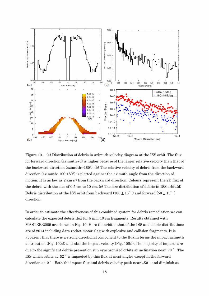
Figure 10. (a) Distribution of debris in azimuth-velocity diagram at the ISS orbit. The flux
for forward direction (azimuth~0) is higher because of the larger relative velocity than that of
the backward direction (azimuth~180°). (b) The relative velocity of debris from the backward
direction (azimuth~100-180°) is plotted against the azimuth angle from the direction of
motion. It is as low as 2 km s-1 from the backward direction. Colours represent the 2D flux of
the debris with the size of 0.5 cm to 10 cm. (c) The size distribution of debris in ISS orbit.(d)
Debris distribution at the ISS orbit from backward (180 ± 15°) and forward (50 ± 15°)
direction.
In order to estimate the effectiveness of this combined system for debris remediation we can
calculate the expected debris flux for 5 mm-10 cm fragments. Results obtained with
MASTER-2009 are shown in Fig. 10. Here the orbit is that of the ISS and debris distributions
are of 2014 including data rocket motor slag with explosive and collision fragments. It is
apparent that there is a strong directional component to the flux in terms the impact azimuth
distribution (Fig. 10(a)) and also the impact velocity (Fig, 10(b)). The majority of impacts are
due to the significant debris present on sun-synchronised orbits at inclination near 90°. The
ISS which orbits at 52°is impacted by this flux at most angles except in the forward
direction at 0°. Both the impact flux and debris velocity peak near ±50°and diminish at
19
large angles towards the backward directions.
We can consider the two types of operational modes, those are backward and forward modes.
As can be seen in figure 10(b), the velocities of the debris relative to ISS are as low as, or less
than 2 km s-1 in the backward direction (180°± 15). In this case, there are less demands for
rapid tracking and beam steering, and thus complete removal of all the debris in the range is
possible by an operation with one encounter (equation 15 and figure 9). On the other hand,
just a dozen operations are expected in one year (Table 1), since the flux from backward is as
low as 10-7 m-2 yr-1.
The situation is different in the case near the forward direction (50°± 15°for example). The
relative velocity from the forward direction is higher (~10 km s-1) so that the complete
removal of the debris smaller than 6cm is possible (equation 15 and figure 9). Here, the flux
from the forward direction is also increased to 2 × 10⁻⁶ m−2yr−1 and more than 200 debris
will be detected and treated. Compared to the total flux distribution, Fig. 10(c), with the
directional components, Fig. 10(d), it is clear that the relative forward direction debris is the
dominating component by almost 2 orders of magnitude.
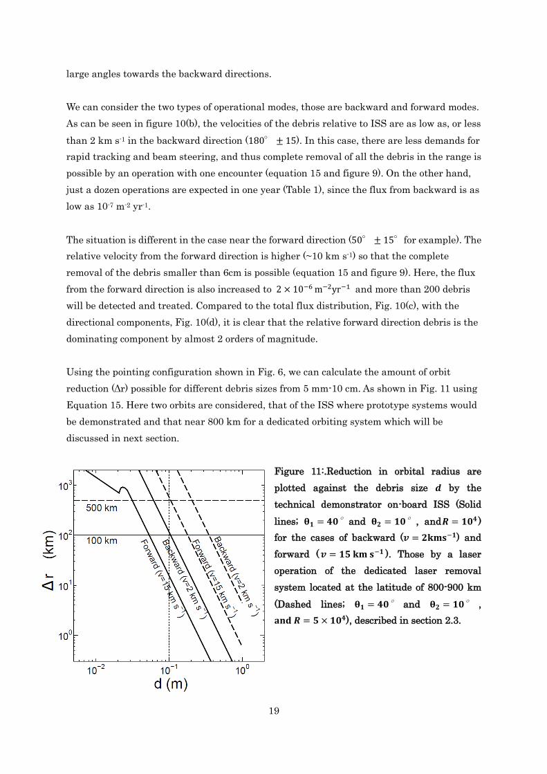
Using the pointing configuration shown in Fig. 6, we can calculate the amount of orbit
reduction (Δr) possible for different debris sizes from 5 mm-10 cm. As shown in Fig. 11 using
Equation 15. Here two orbits are considered, that of the ISS where prototype systems would
be demonstrated and that near 800 km for a dedicated orbiting system which will be
discussed in next section.
Figure 11:.Reduction in orbital radius are
plotted against the debris size 𝒅 by the
technical demonstrator on-board ISS (Solid
lines; 𝛉𝟏 = 𝟒𝟎°and 𝛉𝟐 = 𝟏𝟎°, and𝑹 = 𝟏𝟎𝟒 )
for the cases of backward (𝒗 = 𝟐𝐤𝐦𝐬−𝟏) and
forward ( 𝒗 = 𝟏𝟓 𝐤𝐦 𝐬−𝟏 ). Those by a laser
operation of the dedicated laser removal
system located at the latitude of 800-900 km
(Dashed lines; 𝛉𝟏 = 𝟒𝟎° and 𝛉𝟐 = 𝟏𝟎° ,
𝐚𝐧𝐝 𝑹 = 𝟓 × 𝟏𝟎𝟒), described in section 2.3.
20
4.3 Free orbiting system
If such a remediation solution from the environs of the ISS is successfully demonstrated, one
should think of a mission fully dedicated to the debris removal at critical orbits near 800 km
altitude where there are many more satellites and indeed greater abundance of debris (flux
x10) as shown in Fig. 1(b). The strategy of the removal operation must be carefully built-up
based on the debris distribution in the potion-velocity phase space. Such a system would be
the ultimate goal after the proof of concept demonstration on the ISS.
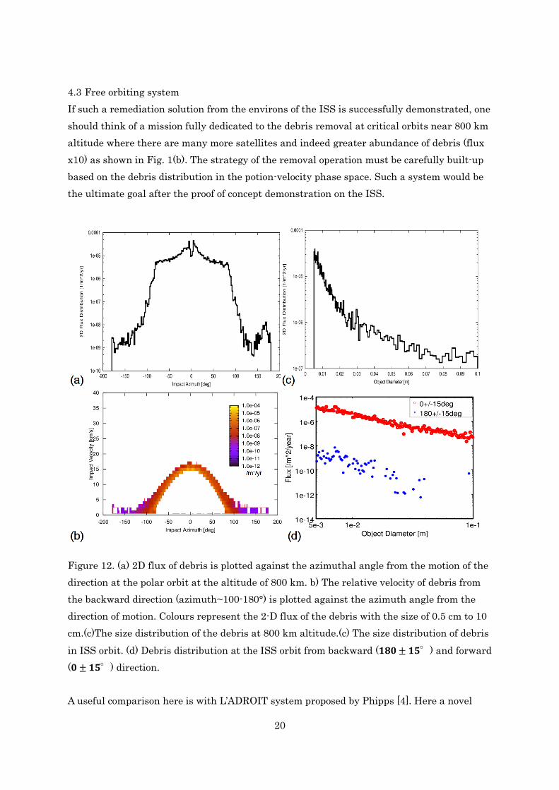
Figure 12. (a) 2D flux of debris is plotted against the azimuthal angle from the motion of the
direction at the polar orbit at the altitude of 800 km. b) The relative velocity of debris from
the backward direction (azimuth~100-180°) is plotted against the azimuth angle from the
direction of motion. Colours represent the 2-D flux of the debris with the size of 0.5 cm to 10
cm.(c)The size distribution of the debris at 800 km altitude.(c) The size distribution of debris
in ISS orbit. (d) Debris distribution at the ISS orbit from backward (𝟏𝟖𝟎 ± 𝟏𝟓°) and forward
(𝟎 ± 𝟏𝟓°) direction.
A useful comparison here is with L’ADROIT system proposed by Phipps [4]. Here a novel
21
double mirror catadioptic system, developed by Köse and Perline [17], is implemented to
provide the super-wide angle (±30°) passive detector. Active tracking and impulse control is
provided by a 1,5m Cassegrain system coupled to a powerful laser system producing 100 ps
pulses of UV energy (>188 J) at <20 Hz repetition. Phipps also specifies an elliptical polar
orbit ranging from 560 km perigee to 960 km apogee.
Analysis of this orbit for 5mm-10cm debris is shown in Fig. 12. The total flux here is
9 × 10⁻³m−1yr
−1which is a factor of 10 greater than for the ISS orbit. Impact angle is peaked
in the forward direction (Fig. 12(a)) and therefore impulse interaction with these debris will
involve relative velocities of 15 km s−1 as shown in Fig. 12(b). This forward flux is increased
by an order of magnitude compared to the ISS orbit while the backwards direction is
relatively unchanged as shown in Fig. 12(d).
Operating a free orbiting system to remediate this debris, we propose a functionally similar
system to that of Phipps but much more feasible from the technical point of view. As
summarized in table 1, our system consists of an EUSO telescope with a diameter of 2.5 m for
debris detection and an 1.5 m Casegrain optics connecting to highly parallel (> 104) CAN
laser system for debris manoeuvre. Both of them have certain technical basis ready to use in
ground. Only thing that we have to do is the increase in repetition rate up to five times than
the technical demonstrator on-board ISS. It has an ability to reduce altitudes of the most of
debris less than 0.1m by 500 km by one encounter with the relative velocity of 2-17 km s-1 at
the altitude near 800 km (figure 12). If we adopt a larger tilt angle of EUSO and
tracking/shooting optics towards almost 90°, the performance in orbital reduction could
increase still, because of a smaller angle between the debris velocity and reaction force by
laser ablation.
Since the debris flux is as high as ~10-4 m-2 yr-1 (figure 11) and the cross section of the
operation area is 1.6 × 10⁹m2 (equation 17), the system can operate against 1.0 × 10⁵ debris
per year (one per five minutes): the dedicated system is oriented above the horizon to be
functional in whole the daytime. Since the polar orbit crosses all the possible orbits at the
same altitude, the sweep-up time for a target zone of thicknessΔh = 70 km around the
system is estimated by [13]:
𝜏sw =4𝜋𝑟2Δℎ
𝑣𝛺𝐴𝑠ℎ
= 2.0 × 10⁶ (𝑟
7200 km)
2(Δℎ
70 km) (
𝑣
17 km s−1)−1
(𝛺
0.82 str)
−1(
𝐴sh
1.6×10⁹m2)−1
s, (19)
The system may start from the orbit of an altitude of 1000 km and gradually reduce its orbit
22
in the rate of 10 km per month. After 50 months (~4 years), it reaches 500 km removing most
of the cm size debris between from 1000 km to 500 km.
5 Discussions and Conclusions
Increasing numbers of debris at higher orbits are elevating the risk of future collisions to
both functional and derelict satellites. Remediation of cm-size debris which poses the main
threat would require directed impulse control to promote atmospheric re-entry. Development
of an orbiting debris sweeper, such as that described in recent articles, should be presided by
a staged implementation of the novel technologies. We believe that the ISS can provide such
an environment enabling scaling and rigorous testing of individual subsystems such as power,
detection and laser impulse delivery.
Utilization of the EUSO telescope on-board the ISS can be accomplished without significant
changes to the existing design as a proof of principle wide angle detector of debris. Original
configured for nadir operation with provision to tilt astern to the direction of the motion by
≳ 25∘, this system would provide passive detection of cm scale debris at ranges > 100km,
from the ISS orbit. Measured population data for such small debris would greatly compliment
the computation models used to predict risks to orbital payloads. No major obstacles are
foreseen in implementing a debris detection mode to the operation of this orbiting air-shower
telescope. In orbit, a robust, electrically efficient laser system such as that built on the CAN
architecture would be required. Attributes of stability and good beam quality would enable
precise taking and impulse delivery from distances > 100 km
Laser impulse control can be also be used to modify the rotation rate of large debris objects
such as derelict satellites or spent rockets. Prior to their capture by dedicated removal
spacecraft it is necessary to stop their rotation. The moment of impact necessary to stop the
rotation is in the order of 102 N s m for the case of a typical satellite with the mass of 1000 kg
the size of 1 m, and angular velocity of 0.1 Hz. It takes only several minutes to give this
amount of impulse using a 1kW laser system. Also the precise orbital injection of a satellite
can be done remotely with 10kW-class space laser system without additional propellant in
the satellite. It may give us a significant freedom for the operation of the orbital bodies.
In conclusion, we have proposed a staged approach to the development of a space based
system for the remediation of orbital debris fragments 5mm-10cm in size. Beginning with
demonstration missions on the International Space Station incorporating the EUSO module
as a detector, we have shown that there are sufficient debris numbers to validate
proof-of-principle operation of both tracking and remediation capability with the efficient
fibre-based CAN laser system. This would lay the ground-work for a freely orbiting system to
23
carry our remediation at higher altitudes where debris risks are increasing for highly
populated polar orbits where >104 debris fragments would be removed per year.
Acknowledgement
This work was partially supported by JSPS KAKENHI Numbers 23340081,24244042, and
RIKEN Strategic Research Programs for R&D in Japan, the CEA, l’Ecole Polytechnique and
Thales in France.
References
[1] Liou, J.-C., &Krisko, P., N UPDATE ON THE EFFECTIVENESS OF POSTMISSION
DISPOSAL IN LEO. 64th International Astronautical Congress, Beijing, China,
(IAC-13-A6.4.2), 2013
[2] Flegel, S. et al., MASTER2009 Final Report, Institute of Aerospace Systems, June, 2011
[3] Metzger, J. D., et al., 1989 J. Propulsion & Power 5 pp. 582-90
[4] Phipps, C.R. 2014, L’ADROIT – A spaceborne ultraviolet laser system for space debris
clearing, ActaAstronautica, 104, 243-255.
[5] Schall, W. O. (1998). Laser requirements for the removal of space debris from orbit. Proc.
SPIE, 3574, 426-436.
[6] Liedahl, D. A.; Rubenchik, A.; Libby, S. B.; et al., 2013, Pulsed laser interactions with
space debris: Target shape effects, ADVANCES IN SPACE RESEARCH, 52, 5, 895-915
DOI: 10.1016/j.asr.2013.05.019
[7] Takahashi, Y. et al. 2008, TheJEM-EUSO Mission, New J. of Phys., 11, 065009.
[8] M. Casolino, J. H. Adams, M. E. Bertaina, et al. Detecting ultra-high energy cosmic rays
from space with unprecedented acceptance: objectives and design of the JEM-EUSO mission,
Astrophysics and Space Sciences Transactions 2011, 7, 477.
[9] Soulard, R. et al. 2014, A novel laser architecture for space debris removal, Acta
Astronautica, 105. 192-200.
[10] Adams Jr., J.H., 2013, An evaluation of the exposure in nadir observation of the
JEM-EUSO mission, Astroparticle Physics, 44, 76-90.
[11] Allen, C.W. 1973, Astrophysical Quantities, Third Edition, University of London, Athlone
Press.
[12] Phipps, C. et al. 2006, Laser impulse coupling at 130fs, Applied Surface Science, 252,
4838-4844.
[13] Mourou G. et al. 2013, The future is fibre accelerators, Nature Photonics, 7, 258-261.
[14] Bourderionnet, J., C. Bellanger, J. Primot, A. Brignon, "Collective coherent phase combining of
64 fibers", Opt. Express.19, 18, (2011).
24
[15] Klenke A, Breitkopf S, Kienel M. 530 W, 1.3 mJ, four-channel coherently combined
femtosecond fiber chirped-pulse amplification system. Opt Lett 2013; 38: 2283–
2285.
[16] Bourderionnet, J., et al. "Continuous laser beam steering with micro-optical arrays:
experimental results." SPIE Europe Security and Defence. International Society for Optics and
Photonics, 2008.
[17] Köse, E. and Perline, R.K., "Double-mirror catadioptric sensors with ultrawide field of
view and no distortion," Appl. Opt. 53, 528-536 (2014)