POSS-Polyimide Nanocomposite Films: Simulated Hypervelocity Space Debris and Atomic Oxygen Effects
18
http://hip.sagepub.com High Performance Polymers DOI: 10.1177/0954008308089710 2008; 20; 475 High Performance Polymers R. Verker, E. Grossman, I. Gouzman and N. Eliaz Atomic Oxygen Effects POSS-Polyimide Nanocomposite Films: Simulated Hypervelocity Space Debris and http://hip.sagepub.com/cgi/content/abstract/20/4-5/475 The online version of this article can be found at: Published by: http://www.sagepublications.com can be found at: High Performance Polymers Additional services and information for http://hip.sagepub.com/cgi/alerts Email Alerts: http://hip.sagepub.com/subscriptions Subscriptions: http://www.sagepub.com/journalsReprints.nav Reprints: http://www.sagepub.co.uk/journalsPermissions.nav Permissions: http://hip.sagepub.com/cgi/content/refs/20/4-5/475 Citations at Soreq NRC Library on October 22, 2008 http://hip.sagepub.com Downloaded from
Transcript of POSS-Polyimide Nanocomposite Films: Simulated Hypervelocity Space Debris and Atomic Oxygen Effects

http://hip.sagepub.com
High Performance Polymers
DOI: 10.1177/0954008308089710 2008; 20; 475 High Performance Polymers
R. Verker, E. Grossman, I. Gouzman and N. Eliaz Atomic Oxygen Effects
POSS-Polyimide Nanocomposite Films: Simulated Hypervelocity Space Debris and
http://hip.sagepub.com/cgi/content/abstract/20/4-5/475 The online version of this article can be found at:
Published by:
http://www.sagepublications.com
can be found at:High Performance Polymers Additional services and information for
http://hip.sagepub.com/cgi/alerts Email Alerts:
http://hip.sagepub.com/subscriptions Subscriptions:
http://www.sagepub.com/journalsReprints.navReprints:
http://www.sagepub.co.uk/journalsPermissions.navPermissions:
http://hip.sagepub.com/cgi/content/refs/20/4-5/475 Citations
at Soreq NRC Library on October 22, 2008 http://hip.sagepub.comDownloaded from

POSS-Polyimide Nanocomposite Films: SimulatedHypervelocity Space Debris and Atomic OxygenEffects
R. VERKER1
E. GROSSMANI. GOUZMANSpace Environment Group, Soreq NRC, Yavne 81800, Israel
N. ELIAZSchool of Mechanical Engineering, Tel-Aviv University, Ramat Aviv, Tel-Aviv 69978, Israel
(Received 20 December 2006� accepted 3 January 2008)
Abstract: The combined effect of hypervelocity space debris impact and atomic oxygen (AO) attack onthe degradation of reinforced polyhedral oligomeric silsesquioxanes (POSS)-polyimide films was studied.A laser-driven flyer (LDF) system was used to accelerate aluminum flyers to impact velocities of up to3 km s�1. The impacted films were exposed to an RF-plasma source, which was used to simulate theeffect of AO in the low Earth orbit. Scanning electron microscopy (SEM) was used to characterize thefracture morphology. The extent of damage in POSS-polyimide impacted films was found to be muchsmaller compared to POSS-free films, insinuating on a toughening mechanism developed due to POSSincorporation. When exposed to air RF-plasma, the impacted POSS-free film revealed a synergistic effectassociated with a large increase in the erosion rate while impacted POSS-containing samples showedimproved erosion resistance. The increased erosion rate of the impacted POSS-free film is explained byformation of residual stresses that affect the oxidation mainly by increasing the diffusivity of oxygen.
Keywords: POSS, polyimide, atomic oxygen, space debris
1. INTRODUCTION
Most satellites today are being launched into low Earth orbit (LEO) altitudes, from 200to 1000 km. Natural or man-made LEO space environment possesses many obstacles to asuccessful spacecraft mission. The degrading environment for polymers includes atomicoxygen (AO), ultraviolet (UV) radiation, ionizing radiation, ultrahigh vacuum (UHV),thermal cycles, micrometeoroids and orbital debris. Due to separate, combined or syner-
High Performance Polymers, 20: 475–491, 2008 DOI:10.1177/0954008308089710
��2008 SAGE Publications
Figure 1 appears in color online: http://hip.sagepub.com
at Soreq NRC Library on October 22, 2008 http://hip.sagepub.comDownloaded from

476 R. VERKER ET AL.
gistic interactions with these space hazards, polymers in particular suffer a relatively rapiderosion, structure modification and surface roughening. This might lead to irreversibledegradation of optical, thermal, electrical and mechanical properties [1,2].
Micrometeoroids originate naturally from planetary or asteroidal collisions and come-tary ejecta [3]. Hypervelocity debris at LEO altitudes are man-made constituents, origi-nating from large objects such as spent satellites and rockets, consisting mostly of smallobjects such as aluminum oxide fuel particles, paint chips and fragmentation objects fromcollisions of these bodies in orbit [3,4]. Typical velocities of debris particles range from afew kilometers per second up to 16 km s�1, making these hypervelocity particles a threatto spacecraft [5,6]. Debris traveling at ultrahigh velocities generates temperatures of ap-proximately 4700�C and pressures of several megabar upon colliding with a surface [7].
Accumulation of impacts over the large surface area of solar panels has led, in somecases, to degradation in efficiency [8]. In the case of composites, if a complete penetrationoccurs, it can lead to further breakdown of the composite during subsequent exposure toAO or vacuum UV (VUV). Debris impacts into polymer films occur quite often since theyare used extensively onboard spacecraft, mainly as thermal blankets [6]. Thermal controlmaterials on the Long Duration Exposure Facility (LDEF) have demonstrated significantsynergistic effects of orbital debris with other space environmental hazards. These syn-ergistic effects further expand the damaged area caused by direct impacts. For example,the top surface of a metalized Mylar sample aboard the LDEF was completely eroded,exposing the interior surfaces to VUV radiation, AO and thermal cycling [6].
Kapton surfaces coated with SiO2 have been shown to exhibit AO erosion yields lessthan one percent of the erosion yield of unprotected Kapton. Although the SiO2 coatingitself is resistant to AO, inherent and hypervelocity debris-induced defects in the coatingwill permit AO attack of the underlying polymer and undercut the coating [9].
A promising approach toward the production of LEO survivable polymers is to incor-porate Polyhedral Oligomeric Silsesquioxanes (POSS) into the polymeric chains [10–13].Previous work showed that POSS-containing polyimides have significantly lower erosionyields than Kapton, since AO irradiation results in formation of SiO2 passivation layerwhich protects the underlying polymer from further AO attack [10]. It was also shownthat POSS-polyimides gained weight during AO exposure and healed microcracks thatwere present [11]. However, the effect of AO erosion on POSS-polyimide surfaces al-ready impacted by hypervelocity debris has not yet been studied.
In this work, the effect of hypervelocity impacts combined with ground simulatedAO exposure on the fracture of nano-reinforced POSS-polyimide films was studied. Tri-SilanolPhenyl-POSS was incorporated into the polyimide network by weak cross-linking,forming an interpenetrating network, making the POSS-polyimide blend oxidation-resistant [14,15].
at Soreq NRC Library on October 22, 2008 http://hip.sagepub.comDownloaded from
HYPERVELOCITY SPACE DEBRIS AND ATOMIC OXYGEN EFFECTS 477
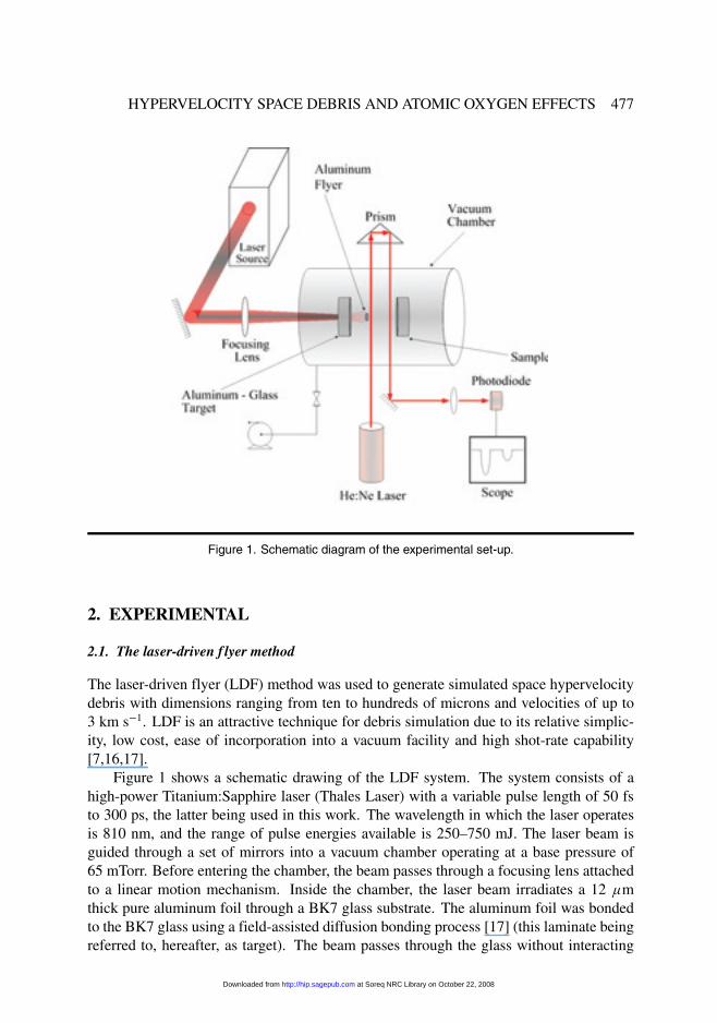
Figure 1. Schematic diagram of the experimental set-up.
2. EXPERIMENTAL
2.1. The laser-driven f lyer method
The laser-driven flyer (LDF) method was used to generate simulated space hypervelocitydebris with dimensions ranging from ten to hundreds of microns and velocities of up to3 km s�1. LDF is an attractive technique for debris simulation due to its relative simplic-ity, low cost, ease of incorporation into a vacuum facility and high shot-rate capability[7,16,17].
Figure 1 shows a schematic drawing of the LDF system. The system consists of ahigh-power Titanium:Sapphire laser (Thales Laser) with a variable pulse length of 50 fsto 300 ps, the latter being used in this work. The wavelength in which the laser operatesis 810 nm, and the range of pulse energies available is 250–750 mJ. The laser beam isguided through a set of mirrors into a vacuum chamber operating at a base pressure of65 mTorr. Before entering the chamber, the beam passes through a focusing lens attachedto a linear motion mechanism. Inside the chamber, the laser beam irradiates a 12 �mthick pure aluminum foil through a BK7 glass substrate. The aluminum foil was bondedto the BK7 glass using a field-assisted diffusion bonding process [17] (this laminate beingreferred to, hereafter, as target). The beam passes through the glass without interacting
at Soreq NRC Library on October 22, 2008 http://hip.sagepub.comDownloaded from

478 R. VERKER ET AL.
with it, until it hits the aluminum/glass interface. At the interface, a high-temperature andhigh-pressure plasma is formed, which then expands perpendicularly to the foil.
The theory of plasma expansion, which is responsible for the production of theultrahigh-velocity flyers, is described in detail elsewhere [18]. Briefly, the expandingplasma induces a shock wave in the target, moving faster than the speed of sound towardthe free (rear) surface. When the shock wave reaches the free surface, the latter is accel-erated and the former is reflected as a rarefaction wave. The rarefaction wave, moving inan opposite direction, causes deceleration of the free surface. The two rarefaction waves(i.e. the tail of the initial pressure wave and the wave reflected from the free surface),running in opposite directions, generate tension in the material. When the tension (i.e.negative pressure) exceeds the material spall strength, a spall forms in a plane parallel tothe rear surface. A pressure gradient between the plasma high pressure on one side of thespall and the vacuum low pressure on the other side of the spall causes the spalled layeracceleration, resulting in an aluminum layer 1 mm in diameter flying away at the ultra-high velocity of up to about 3 km s�1. The accelerated aluminum layer is composed ofsmall flyers, the largest being of the order of 30–50 �m in size, moving at about the sameultrahigh velocity. The smaller flyers, which are on the nanometer scale, are slower andexhibit a much wider velocity distribution. The aluminum flyers are accelerated towardsa polymer sample placed at a distance 12 mm from the target.
2.2. Flyer velocity measurements
The flyer velocity is a function of the laser beam spot size and pulse energy. Figure 1also shows the set-up used to measure the flyer velocity in situ. A continuous He:Ne laserbeam is set orthogonal to the flyer’s trajectory and, using a prism, the beam crosses theflyer’s path twice. The two parallel beams were set at a distance of 13 mm from eachother. A photodiode attached to an oscilloscope receives the continuous laser signal. Asthe flyer crosses and blocks the continuous laser path, velocity can be calculated from thetwo peaks detected by the oscilloscope.
2.3. RF plasma AO ground simulation system
A conventional RF plasma reactor (15 W, 13.56 MHz, Model PDC-3XG from Harrick),operating at 500 mTorr of air, was used to simulate the effect of AO in the low Earthorbit [19]. Samples were positioned on a specially designed sample holder, which al-lows simultaneous exposure of up to six different samples. The samples were positioned100 mm downstream from the reactor in the afterglow region, where they were exposedto a mixture of atomic and molecular oxygen, excited species and VUV radiation. Nev-ertheless, the contribution of ions, VUV and excited species is reduced compared to theRF plasma reactor environment [20]. Although LEO AO is hyperthermal, the RF plasmaenvironment with thermal AO is considered to be a useful tool for materials evaluation.The space equivalent AO flux at the sample position was 4 � 1014 O-atoms cm�2 s�1.Atomic oxygen equivalent fluence measurements were conducted based on 25 �m thick
at Soreq NRC Library on October 22, 2008 http://hip.sagepub.comDownloaded from

HYPERVELOCITY SPACE DEBRIS AND ATOMIC OXYGEN EFFECTS 479
Kapton-HN film (DuPont, Inc.) mass loss, assuming an erosion yield of 3� 10�24 cm3 perO-atoms [21]. The erosion yield was determined gravimetrically, using an analytical bal-ance (Model UM3 from Mettler) with an accuracy of �1 �g.
2.4. Materials and characterization techniques
The materials studied in this work were blends of oxydianiline – pyromellitic dianhydryde(ODA-PMDA) polyimide (Pyre-M.L. RC-5019 by Industrial Summit Technology, Co.)and TriSilanolPhenyl-POSS (Hybrid Plastics, Inc.). Samples were produced in the formof thin films (25–30 �m thick), with different POSS contents of 0, 5, 10 and 15 wt %.POSS-polyimide films were produced at a bench-scale process by casting and curing apre-mixed solution of polyamic acid and POSS in N-methyl-Pyrrolidone solvent [22].The curing of the pre-mixed solution is based on a process developed by DuPont, Inc.After casting the pre-mixed solution on a Si wafer, the samples were heated to 200�Cin moist air at a ramp rate of 4�C min�1 and held for a period of 30 min. In a secondtemperature cycle, the samples were heated to 350�C in the presence of pure nitrogen at aramp rate of 2�C min�1 and held for a period of 60 min. In order to avoid residual stresses,the final stage was slow cooling at a rate of 2�C min�1 down to room temperature [23]. Atroom temperature, the POSS-polyimide films were peeled-off the Si wafer. In addition,a commercial 25 �m thick Kapton-HN film (DuPont, Inc.) was studied. Kapton-HN isalso used in this work as a reference material for the 0 wt % POSS-polyimide and forevaluating the AO equivalent fluence.
The morphology of fractured surfaces resulting from the debris impacts at ultrahighvelocities was studied using an Environmental SEM (ESEM, model Quanta 200 fromFEI). This microscope allows characterization of non-conductive samples without theneed for a conductive coating.
XPS spectra were obtained using non-monochromatized Al K� radiation (1486.6 eV)and a hemispherical CLAM 2 (VG Microtech) analyzer. The binding energy scale wascalibrated with the use of an Ag(3d5�2) line at 368.3 eV as a reference.
3. RESULTS AND DISCUSSION
3.1. RF-plasma erosion tests
In order to understand the contribution of the TriSilanolPhenyl-POSS to the oxidationresistance of the polyimide, an RF-plasma erosion test was performed. The four dif-ferent POSS-containing samples and a Kapton-HN sample were exposed simultaneouslyto the plasma afterglow, the exposed area being 0.5 cm2 per sample. The erosion yieldwas determined gravimetrically by weighing the samples on an analytical balance (ModelUM3 from Mettler). The samples were weighted periodically, and the AO equivalentfluence was determined using the Kapton-HN reference sample. The erosions of thePOSS-polyimide and Kapton-HN samples are plotted in figure 2 as a function of the AO
at Soreq NRC Library on October 22, 2008 http://hip.sagepub.comDownloaded from

480 R. VERKER ET AL.
Figure 2. Mass loss measurements for 0, 5, 10 and 15 wt.% POSS-polyimide and for Kapton-HNsamples.
equivalent fluence. The erosion of all five samples appeared to increase linearly with thefluence. According to these measurements, the higher the POSS content of a sample, thesmaller the erosion rate.
The 0 and 5 wt.% POSS-polyimide samples reveal similar erosion rates and low AOerosion resistance. Better AO erosion resistance is observed when the POSS content isincreased to 10 and 15 wt.%. The 15 wt.% POSS-polyimide sample reached an erosionrate of 68% of the erosion rate of Kapton-HN. It appears that 5 wt.% is not sufficientto generate any significant erosion resistance towards AO attack. On the other hand,the 10 wt.% POSS generates almost the same erosion resistance as that produced by the15 wt.% POSS-containing sample.
3.2. Ultrahigh-velocity impacts on POSS-polyimide f ilms
The effect of POSS content on the extent of damage of impacted samples is demonstratedin figure 3. The fractures were created using flyer velocities of 1.8–2.8 km s�1. All ESEMimages were taken from the flyer exit side.
To evaluate and compare the impact damage, one should consider the film thicknessand the flyer impact velocity. The effect of film thickness and flyer velocity on the amountof damage to Kapton-HN films (i.e. 0 wt.% POSS) due to ultrahigh-velocity impacts wasdiscussed in detail elsewhere [24]. In general, as the film becomes thicker, its abilityto absorb energy and slow the flyers increases. Consequently, the strain rate associatedwith the impact process is reduced, and the fractured surface tends to shift from brittle to
at Soreq NRC Library on October 22, 2008 http://hip.sagepub.comDownloaded from

HYPERVELOCITY SPACE DEBRIS AND ATOMIC OXYGEN EFFECTS 481
Figure 3. ESEM images of (a) 0 wt.%� (b) 5 wt.%� (c) 10 wt.% and (d) 15 wt.% 16–30 �m thickPOSS-polyimide films, impacted by flyers at velocities of 1.8–2.8 km s�1.
ductile. The impact on Kapton-HN films introduces high temperatures �T � Tg� at thecentral impact region, and lower temperatures �T � Tg� at remote regions. Consequently,the central impact region is characterized by ductile-like fractures, whereas the remoteradial crack regions are characterized by a brittle-like fracture. Considering the abovevariables, a comparison of the ultrahigh-velocity impacts on the 0 wt.% POSS film tothat on 10 and 15 wt.% POSS films reveals that adding POSS to the polyimide reducesthe extent of damage created by the impact. The perforated area of the 10 and 15 wt.%samples, due to shearing and bending of the film, is about third of the perforated areaof the 0 wt.% sample. Addition of POSS contributes significantly to the polyimide filmhardness, as demonstrated by residual impression nanoindentation measurements [25].The addition of POSS also improves other mechanical properties such as Young’s modulusand tensile strength [22]. It appears that POSS-containing films exhibit better ultrahigh-velocity impact toughness compared to the 0% POSS-containing film. The ability of
at Soreq NRC Library on October 22, 2008 http://hip.sagepub.comDownloaded from

482 R. VERKER ET AL.
Figure 4. ESEM images of 0 and 15 wt.% POSS-polyimide films impacted by flyers at velocities of (a)2.4 and (c) 2.2 km s�1, subsequently exposed to AO equivalent fluence of 2�6 � 1020 O-atom cm�2
(images (b) and (d), respectively).
POSS to improve the ultrahigh-velocity impact toughness of polyimide films is discussedfurther below.
3.3. Synergistic effect of ultrahigh-velocity impacts and RF-plasma exposure
Figure 4 demonstrates the synergistic effect of ultrahigh-velocity impacts and RF-plasmaerosion on 0 and 15 wt.% POSS samples. The fractures of the 0 wt.% POSS samples werecreated using flyers with a velocity of 2.4 km s�1. Similarly, the fractures of the 15 wt.%POSS samples were created using flyers with a velocity of 2.2 km s�1.
After being impacted by the ultrahigh-velocity flyers, the samples were exposed toAO equivalent fluence of 2�6�1020 O-atom cm�2. All ESEM images were taken from the
at Soreq NRC Library on October 22, 2008 http://hip.sagepub.comDownloaded from
HYPERVELOCITY SPACE DEBRIS AND ATOMIC OXYGEN EFFECTS 483
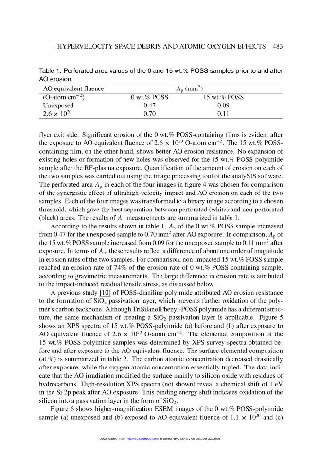
Table 1. Perforated area values of the 0 and 15 wt.% POSS samples prior to and afterAO erosion.
AO equivalent fluence Ap (mm2)(O-atom cm�2) 0 wt.% POSS 15 wt.% POSSUnexposed 0.47 0.092�6� 1020 0.70 0.11
flyer exit side. Significant erosion of the 0 wt.% POSS-containing films is evident afterthe exposure to AO equivalent fluence of 2�6 � 1020 O-atom cm�2. The 15 wt.% POSS-containing film, on the other hand, shows better AO erosion resistance. No expansion ofexisting holes or formation of new holes was observed for the 15 wt.% POSS-polyimidesample after the RF-plasma exposure. Quantification of the amount of erosion on each ofthe two samples was carried out using the image processing tool of the analySIS software.The perforated area Ap in each of the four images in figure 4 was chosen for comparisonof the synergistic effect of ultrahigh-velocity impact and AO erosion on each of the twosamples. Each of the four images was transformed to a binary image according to a chosenthreshold, which gave the best separation between perforated (white) and non-perforated(black) areas. The results of Ap measurements are summarized in table 1.
According to the results shown in table 1, Ap of the 0 wt.% POSS sample increasedfrom 0.47 for the unexposed sample to 0.70 mm2 after AO exposure. In comparison, Ap ofthe 15 wt.% POSS sample increased from 0.09 for the unexposed sample to 0.11 mm2 afterexposure. In terms of Ap, these results reflect a difference of about one order of magnitudein erosion rates of the two samples. For comparison, non-impacted 15 wt.% POSS samplereached an erosion rate of 74% of the erosion rate of 0 wt.% POSS-containing sample,according to gravimetric measurements. The large difference in erosion rate is attributedto the impact-induced residual tensile stress, as discussed below.
A previous study [10] of POSS-dianiline polyimide attributed AO erosion resistanceto the formation of SiO2 passivation layer, which prevents further oxidation of the poly-mer’s carbon backbone. Although TriSilanolPhenyl-POSS polyimide has a different struc-ture, the same mechanism of creating a SiO2 passivation layer is applicable. Figure 5shows an XPS spectra of 15 wt.% POSS-polyimide (a) before and (b) after exposure toAO equivalent fluence of 2�6 � 1020 O-atom cm�2. The elemental composition of the15 wt.% POSS polyimide samples was determined by XPS survey spectra obtained be-fore and after exposure to the AO equivalent fluence. The surface elemental composition(at.%) is summarized in table 2. The carbon atomic concentration decreased drasticallyafter exposure, while the oxygen atomic concentration essentially tripled. The data indi-cate that the AO irradiation modified the surface mainly to silicon oxide with residues ofhydrocarbons. High-resolution XPS spectra (not shown) reveal a chemical shift of 1 eVin the Si 2p peak after AO exposure. This binding energy shift indicates oxidation of thesilicon into a passivation layer in the form of SiO2.
Figure 6 shows higher-magnification ESEM images of the 0 wt.% POSS-polyimidesample (a) unexposed and (b) exposed to AO equivalent fluence of 1.1 � 1020 and (c)
at Soreq NRC Library on October 22, 2008 http://hip.sagepub.comDownloaded from

484 R. VERKER ET AL.
Figure 5. XPS survey spectra of 15 wt.% POSS-polyimide films (a) before and (b) after exposure toAO equivalent fluence of 2�6� 1020 O-atom cm�2.
Table 2. Elemental composition (at.%) determined from XPS data for 15 wt.% POSS-polyimide samples prior to and after exposure to AO.
Unexposed Exposed to AOO 1s 21.5 61.5C 1s 72.3 11.0Si 2p 1.7 27.0N 1s 4.5 0.5
2�6�1020 O-atom cm�2. One can observe the formation of new holes, which are the char-acteristic outcome feature of the accelerated erosion rate of the 0 wt.% POSS-polyimidesample. After ultrahigh-velocity impact, the 0 wt.% POSS-polyimide film can be charac-terized by through-holes, as evident on the image upper part, and by some dents (that maybe the result of residual stresses within the polymer) along the lower edge of the crack(figure 6a). After exposure of the sample to an AO equivalent fluence of 1.1 � 1020 O-atom cm�2, three main effects are evident (figure 6b): (i) expansion of existing through-holes� (ii) development of new holes at the dented sites� and (iii) formation of a rough
at Soreq NRC Library on October 22, 2008 http://hip.sagepub.comDownloaded from

HYPERVELOCITY SPACE DEBRIS AND ATOMIC OXYGEN EFFECTS 485
Figure 6. Zoom-in ESEM images of the 0 wt.% POSS-polyimide film impacted by flyers (a) at avelocity of 2.4 km s�1 and (b) subsequently exposed to AO equivalent fluence of 1�1 � 1020 and (c)2�6� 1020 O-atom cm�2.
surface (at the image left-hand side). On the other hand, the surface on the upper right-hand side appears undamaged, as in the unexposed state.
Further exposure of the sample to an equivalent fluence of 2�6�1020 O-atom cm�2 re-sulted in formation of a larger number of new holes, while older holes coalesce (figure 6c).Also evident on figure 6c is that the region mostly susceptible to erosion is the area nextto the center of the impact hole where the film is bent, and not near the crack.
A model is proposed to explain the extensive erosion and formation of new macro-holes in the impacted 0 wt.% POSS-containing film due to UV and AO exposure in theRF-plasma afterglow. The new macro-holes formation is a result of a multi-step pro-cess [26].
at Soreq NRC Library on October 22, 2008 http://hip.sagepub.comDownloaded from

486 R. VERKER ET AL.
(i) The establishment of a field of residual tensile stresses within the polymer due to theultrahigh-velocity impacts, and temporary local increase in the average temperatureto values that may exceed the glass transition temperature [24].
(ii) An increase in the polymer’s local free volume (i.e. the volume that is not occupiedby the polymer chains), in regions of higher residual tensile stresses and/or a higheraverage temperature [27].
(iii) Increased molecular and atomic oxygen diffusion into the polymer due to resid-ual tensile stresses, which reduce the local chemical potential. It is well knownthat diffusion processes can be motivated by gradients of stress, temperature and/orelectrical potential. A hydrostatic tensile stress decreases the chemical potential ofan interstitial solute. This is true whether the stress is externally applied or is resid-ual. Since the gradient of chemical potential is the fundamental driving force fordiffusion, the flux of solute is defined as
J � � Bc
NA
�
c�c � �D�c � DcVsol
kT� � h� (1)
where B is the mechanical mobility, c concentration, � chemical potential, D diffu-sion coefficient, Vsol atomic volume of the solute atom in the material, k Boltzmannconstant, NA Avogadros numbes, T temperature, and h hydrostatic component ofthe elastic stress field [28–30]. The situation is even more complex in the case of thePOSS-polyimide samples studied here. Not only does the ultrahigh-velocity impactestablish a field of residual tensile stresses, the local free volume is also increased(for the amorphous phase, as long as the stress is not high enough to induce orderingof the polymer chains and crystallization). It is agreed that the polymer fractionalfree volume has a major effect on the diffusivity and permeability of molecularoxygen and AO [27]. Furthermore, oxygen diffusion, which is the rate-limiting stepin many photo-oxidative reactions [31, 32], can be affected by other factors suchas polymer crystallinity, cross-linking and morphology. The latter is a parameterthat has an important influence on the rate of polymer photochemical degradation.Micro-cracks, initially developed on the surface at stressed regions, facilitate thediffusion of oxygen into the bulk [31].
(iv) A local increase in the AO-induced erosion rate. In general, AO reaction with poly-mers is a thermally activated, two-step process. In the first step, AO and molecularoxygen diffuse into the polymer. In the present study, VUV radiation from the RFplasma interacts with the diffused molecular oxygen to form AO. In the second step,the AO, either diffused oxygen atoms or VUV dissociated oxygen molecules, reactmore readily with reactive sites. The formation of reactive sites in the underneathlayers of the polymer are a result of VUV radiation, which initiates a destruction ofthe aromatic polyimide groups [33–35]. The reaction’s volatile products (i.e. H2O,CO and CO2) then diffuse towards the film surface and desorb. One of the effectsof the stress is to decrease the efficiency of recombination of photochemically gen-
at Soreq NRC Library on October 22, 2008 http://hip.sagepub.comDownloaded from

HYPERVELOCITY SPACE DEBRIS AND ATOMIC OXYGEN EFFECTS 487
Figure 7. Zoom-in ESEM images of the 15 wt.% POSS-polyimide film impacted by flyers at (a) a ve-locity of 2.2 km s�1 and (b) subsequently exposed to AO equivalent fluence of 2�6�1020 O-atom cm�2.
erated radical pairs, by increasing the separation between them. Consequently, theprobability of radical trapping and radical-dependent reactions is increased. Thisleads to an increased rate of degradation, which first takes place on the polymer’ssurface thus affecting its morphology, followed by bulk etching [31].
(v) The formation of new macro-holes, which replicate the distribution of residual ten-sile stresses.
It is believed that different regions in the 0 wt.% POSS-polyimide sample were sus-tained to different amounts of residual tensile stresses.
The expansion of existing through-holes (figure 6b) due to AO erosion is obvious. Thedevelopment of new holes at the dented sites is attributed to two facts. (i) The dented sitesare thinner compared to other regions in the film. This alone can promote the formationof new through-holes because a smaller amount of AO equivalent fluence is required forperforation. (ii) The formation of these dented sites is attributed to residual tensile stresses,which make them susceptible to AO erosion (as previously discussed). The formation ofa rough surface at the image left-hand side is also attributed to residual tensile stressesat this region, which promoted faster degradation reactions, affecting its morphology andmaking it rougher. Increase in AO equivalent fluence (figure 6c) leads to the formation ofnew holes via the mechanisms mentioned above, as well as expansion of older holes untilthey coalesce.
Figure 7 shows ESEM images of impacted 15 wt.% POSS-polyimide sample (a) un-exposed and (b) exposed to 2�6�1020 O-atom cm�2 AO equivalent fluence. The exposureto the RF-plasma environment resulted in erosion of the 15 wt.% POSS-polyimide filmsurface and made it rougher. The roughness is equivalent all over the film surface, sug-gesting that no residual stress exists beneath the surface.
at Soreq NRC Library on October 22, 2008 http://hip.sagepub.comDownloaded from

488 R. VERKER ET AL.
Figure 8. ESEM images of 25 �m thick Kapton-HN film, impacted by 2.9 km s�1 flyers. (a) Radialcracking that forms a star-like pattern is evident. (b) 0 wt.% POSS sample impacted by 2.4 km s�1
flyers and subsequently exposed to 2�6� 1020 O-atom cm�2 AO equivalent fluence. New holes wereformed, also in a radial star-like pattern.
The unexposed fractured surface morphology (fractography), which is of ductile type(figure 7a), can be characterized as porous with elongated thin features emanating fromthe fractured surfaces. A fluence of 2�6 � 1020 O-atom cm�2 (figure 7b) eroded most ofthe elongated thin features and around the through-hole (located at the image lower part).This is attributed to the roughness of the fracture surface, which facilitates diffusion ofAO into the bulk, thus resulting in a higher local erosion rate. Nevertheless, even in thehigh-magnification ESEM images, no formation of new holes is evident for the 15 wt.%POSS-polyimide sample. Since the model suggests that new holes are most likely to beformed in sites where residual tensile stresses exist, it appears – considering this parameterand the roughness issue mentioned above – that no residual stresses were introduced inthe case of 15 wt.% POSS-polyimide sample.
Further support for the model, which explains new holes formation by AO erosionin residual tensile stressed regions, is shown in figure 8. Figure 8a shows a 25 �m thickKapton-HN film, impacted by a 2.9 km s�1 flyer [24]. The impacted Kapton-HN is char-acterized by radial cracking around a central impact zone, forming a star-like pattern.Figure 8b shows the 2.4 km s�1 impacted 0 wt.% POSS-polyimide sample after exposureto 2�6� 1020 O-atom cm�2 AO equivalent fluence. Erosion is most apparent from the ex-pansion of holes formed by the ultrahigh-velocity impact and formation of a large numberof new holes. These new holes tend to be formed in a radial star-like pattern around thesample’s central impact zone. The kinetic energy that the Kapton-HN sample experiencedwas high enough for long radial cracks to develop, as a secondary process, after piecesof Kapton-HN were sheared-off from the central impact zone. On the other hand, the ki-netic energy that the 0 wt.% POSS-polyimide sample experienced was not as high, henceshorter cracks were formed. However, the formation of the new holes (along with holes
at Soreq NRC Library on October 22, 2008 http://hip.sagepub.comDownloaded from

HYPERVELOCITY SPACE DEBRIS AND ATOMIC OXYGEN EFFECTS 489
created directly by the ultrahigh-velocity impacts) in a radial star-like pattern around thesample’s central impact zone supports the residual tensile stress model. It appears that aresidual tensile stress field developed within the polymer film in radial directions, as isthe case of the Kapton-HN sample (figure 8a). When exposed to AO equivalent fluencethese residual stresses, which already caused a local increase in the polymer free volume,initiated the process of local high-rate degradation. This has been facilitated by diffusionof oxygen into the bulk of the polymer, leading to the formation of the star-like pattern.Under further RF-plasma erosion, these holes grew and, eventually, coalesced as shownin figure 6c.
4. CONCLUSIONS
Ultrahigh-velocity impact and simulated AO exposure effects on POSS-polyimide filmswere studied. Addition of 15 wt.% POSS to the polyimide increased the AO erosiondurability due to formation of SiO2 passivation layer. The results of ultrahigh-velocityimpacts into the POSS-polyimide films insinuate on improved ultrahigh-velocity impacttoughness of POSS-containing films, compared to pure polyimide films. A synergisticerosion effect was observed under AO exposure of the previously hypervelocity impactedfilms. Due to this effect, an impacted pure polyimide film (0 wt.% POSS) eroded oneorder of magnitude faster than impacted 15 wt.% POSS-containing film. The acceleratederosion of the 0 wt.% POSS sample is characterized mainly by the formation of AO-induced new holes. These holes tend to be formed in a radial star-like pattern around thesample’s central impact zone. A model explaining this phenomenon is suggested based onresidual tensile stresses, which are also established in a star-like pattern, as a result of theultrahigh-velocity impact. These residual stresses generate a local increase in the polymerfree volume, which facilitates oxygen diffusion into the bulk of the polymer, thus initiatingthe process of local high-rate degradation. Due to this mechanism, the AO-induced newholes replicate the star-like pattern. The low erosion rate of the impacted 15 wt.% POSS-containing film is therefore attributed to both mechanical (i.e. negligible residual tensilestresses) and chemical (i.e. formation of an oxide passivation layer) mechanisms.
Acknowledgements: This work was supported in part by the Israeli Space Agency. The authors are grateful to J.Lichtenhan from Hybrid Plastics and A. Laikhtman and G. Lempert from Soreq NRC for useful discussions. Theauthors are also grateful to M. Freankel, S. Maman, S. David and D. Shkolnik (Soreq NRC) for their technicalsupport.
NOTE
1. Author to whom correspondence should be addressed: e-mail: [email protected]
at Soreq NRC Library on October 22, 2008 http://hip.sagepub.comDownloaded from

490 R. VERKER ET AL.
REFERENCES
[1] Grossman, E., Gouzman, I., Viel-Inguimbert, I. and Diguirard, M. (2003). Modification of a 5-eV atomic-oxygen laser detonation source. J. Spacecraft and Rockets, 40: 110.
[2] Houdayer, A., Cerny, G., Klemberg-Sapieha, J. E., Czeremuszkin, G. and Wertheimer, M. R. (1997). MeVproton irradiations and atomic oxygen exposure of spacecraft materials with SiO2 protective coatings.Nucl. Instrum. Methods Phys. Res. B, 131: 335.
[3] Tennyson, R. C. and Shortliffe, G., (1997). MOD impact damage on composite materials in space In Proc.7th Inter. Symp. Mater. in Space Env. ESA Publication, ESTEC Noordwijk, The Netherlands.
[4] Hastings, D. and Garrett, H. (1996). Spacecraft-Environment Interactions. Cambridge University Press,Cambridge, UK, p.45.
[5] Miao, J. and Stark, J. P. W. (2001). Direct simulation of meteoroids and space debris flux on LDEFspacecraft surfaces. Planetary and Space Sci., 49: 927.
[6] Silverman, E. M. (1995). Space Environmental Effects on Spacecraft – LEO Material Selection Guide,NASA Contractor Report No. 4661. Langley Research Center, p. 1–4.
[7] Stein, C., Roybal, R. and Tlomak, P. (2000). The production of contamination on spacecraft surfaces byhypervelocity debris impacts. In Proc. 8th Inter. Symp. Mater. in Space Env. CNES Publication, Toulouse,France.
[8] Medina, D. F., Wright, L. and Campbell, M. (2001). Parametric investigation of solar panel hypervelocityimpact damage. Adv. Space Res., 28: 1347.
[9] Rutledgs, S. K. and Olle, R. M. (1993). Space station freedom solar array blanket coverlay atomic oxygendurability testing results. In Proc. 38th Inter. Symp. SAMPE Symposium. Anheim, California, USA.
[10] Brunsvold, A. L., Minton, T. K., Gouzman, I., Grossman, E. and Gonzales, R. (2004). An investiga-tion of the resistance of polyhedral oligomeric silsesquioxane polyimide to atomic-oxygen attack. HighPerformance Polymers, 16: 303.
[11] Gilman, J. W., Schlitzer, D. S. and Lichtenhan, J. D. (1996). Low earth orbit resistant siloxane copolymers.J. Applied Polymer Sience, 60: 591.
[12] Gonzales, R. I. (2002). Synthesis and In-Situ Atomic Oxygen Erosion Studies of Space Survivable HybridOrganic/Inorganic Polyhedral Oligomeric Silsesquioxane Polymers. Ph.D. Thesis, University of Florida,USA.
[13] Philips, S. H., Haddad, T. S. and Tomczak, S. J. (2004). Developments in nanoscience: polyhedraloligomeric silsesquioxane (POSS)-polymers. Current Opinion in Solid State and Materials Science, 8: 21.
[14] Lichtenhan, J. (2006). Private Communication.[15] Fu, B. X. (2005). Private Communication.[16] Tighe, A., Gabriel, S. and Van Eesbeek, M. (2000). Ground based simulation of orbital debris using laser
driven flyer plates. In Proc. 8th Inter. Symp. Mater in Space Env. CNES Publication, Toulouse, France.[17] Roybal, R., Tlomak, P., Stein, C. and Stokes, H. (1999). Simulated space debris impact experiments on
toughened laminated thin solar cell cover glass. Inter. J. Impact Eng., 23: 811.[18] Eliezer, S. (2002). The Interaction of High-Power Lasers with Plasmas. Institute of Physics, Bristol, UK.[19] Gouzman, I., Grossman, E., Lempert, G., Noter, Y., Lifshitz, Y., Viel-Inguimbert, V. and Dinguirard, M.
(2004). Atomic-oxygen durability of a silicone paint: comparison between two simulation methods. J.Spacecraft and Rockets, 41: 350.
[20] Intrater, R., Lempert, G., Gouzman, I., Grossman, E., Cohen, Y., Rein, D. M., Khakfin, R. L. and Hoffman,A. (2004). Simulated low Earth orbit environment interaction with different types of polyethylene. HighPerformance Polymers, 16: 249.
[21] ASTM E-2089-00. (2002). Standard practices for ground laboratory atomic oxygen interaction evaluationof materials for space applications. In: Annual book of ASTM standards, vol. 15.03. West Conshohocken,PA, USA: ASTM International, p. 752.
[22] Hybrid Plastics, Inc., Technical bulletin, http://www.hybridplastics.com/pdf/POSS-Kapton%20PI%20Spec.pdf.
[23] Du-Pont. Inc. (1993). Technical Bulletin, PYRALIN R� Polyimide Coating PI 2545 PI 2540 ProductInformation.
at Soreq NRC Library on October 22, 2008 http://hip.sagepub.comDownloaded from

HYPERVELOCITY SPACE DEBRIS AND ATOMIC OXYGEN EFFECTS 491
[24] Verker, R., Eliaz, N., Gouzman, I., Eliezer, S., Fraenkel, M., Maman, S., Beckmann, F., Pranzas, K. andGrossman, E. (2004). The effect of simulated hypervelocity space debris on polymers. Acta Materialia,52: 5539.
[25] Verker, R., Grossman, E., Gouzman, I., Laikhtman, A., Katz, S., Freankel, M., Maman, S., Lempert, G.and Eliaz, N. (2006). Mechanical and morphological behavior of POSS-polyimide films under hyperve-locity impacts and atomic oxygen exposure. Soreq NRC Report No. 3689.
[26] Verker, R., Grossman, E., Gouzman, I. and Eliaz, N. (2007). Residual Stress Effect on Degradation ofPolyimide under Simulated Hypervelocity Space Debris and Atomic Oxygen. Polymer, 48: 19.
[27] Klopffer, M. H. and Flaconnèche, B. (2001). Transport properties of gases in polymers: bibliographicreview. Oil & Gas Science and Technology – Rev. IFP, 56: 223.
[28] Larche, F. C. and Cahn, W. J. (1982). The Effect of Self-Stress on Diffusion in Solids. Acta Metall., 30:1835.
[29] Oriani, R. A. (1969). Hydrogen in metals. In Proc. of the conference on fundamental aspects of stresscorrosion cracking, National Association of Corrosion Engineers, Houston, Texas.
[30] Eliaz, N. and Banks-Sills, L. (2008). Chemical potential, diffusion and stress – common confusions innomenclature and units. Corrosion Reviews, 26(2–3): 87–103.
[31] Tyler, D. R. (2004). Mechanistic aspects of the effects of stress on the rates of photochemical degradationreactions in polymers. Journal of Macromolecular Science, 44: 351.
[32] O’Donnell, J. B. and White, J. R. (1994). Photo-oxidation of polystyrene under load. Journal of MaterialsScience, 29: 3955.
[33] Whitaker, A. F. and Jang, B. Z. (1993). The mass loss mechanism of polymers in a radio frequency inducedatomic oxygen environment. Journal of Applied Polymer Science, 48: 1341.
[34] Klein, R. and Scheer, M. D. (1968). Mechanism of O(3P) Addition to Condensed Films. II. Propene,1-Butene, and Their Mixtures. The Journal of Physical Chemistry, 72: 616.
[35] Grossman, E., Gouzman, I., Lempert, G., Noter, Y. and Lifshitz, Y. (2004). Assessment of Atomic Oxygenflux in LEO ground simulation facilities. Journal of Spacecraft and Rockets 41: 356.
at Soreq NRC Library on October 22, 2008 http://hip.sagepub.comDownloaded from