Een nieuwe commentaar op de documenten van het Tweede Vaticaans Concilie: deel 1
Upload
khangminh22Category
view
4download
0
1
Joule Thief
DC-DC converters
LED drivers
Knipperlicht schakelingen
deel 2Energie besparing, verlichting, zaklantaarn, groeilamp, zonnecellen, tweede leven voor
uitgeputte batterijen, Step-Up - Boost drivers, licht in het donker, tuinverlichting,
LED’s, Astabiele Multivibratoren, Energy Harvesting etc.

2
Joule Thief uit het Pools
https://web.archive.org/web/20171030234220/http://flagiusz.republika.pl/joulethief/sim.html
START VAN VERTAALDE INTERNETPAGINA
Joule Thief - simulations of different
versions of the layout
This part of the website devoted to the analy-
sis of the Joule Thief system and its nume-
rous variants is intended for more advanced
people who want not only to understand how
they work, but also to find out the answer to a
number of naturally arising questions:
• Which layout is better?
• Which of them will have the highest
efficiency, and which will we be able to
obtain the highest current efficiency?
• How to choose the optimal values of
the elements?
These are very good questions that can be
answered by performing a series of time-con-
suming trials and tests on a "live" circuit.
Such systems can also be subjected to com-
puter simulation, which will tell us which way
to go to achieve the intended goal.
There are many electronic circuit simulators.
Not all of them cope well with oscillatory sys-
tems, as well as with the difficult problems of
couplings on inductive elements - and such
are the problems in the systems analyzed
here.
One of the best in terms of simulation accu-
racy and generally available is the Spice pro-
gram, known for many years.
I use the LTspice IV version available on the
website of a market-leading electronics ma-
nufacturer, Linear Technology.
LT SPICE TV LINKhttps://web.archive.org/web/20171102173425/
http://www.linear.com/designtools/software#LTspice
LINEAR TECH LINK (Analog Devices)https://web.archive.org/web/20171031183812/
http://www.linear.com/
NIEUWE LINKShttps://www.analog.com/en/design-center/
design-tools-and-calculators.html
https://www.analog.com/en/design-center/
design-tools-and-calculators/ltspice-simulator.html
https://www.analog.com/en/index.html
This program includes everything you need.
We have a schematic editor (in the past we
had to describe connection graphs in a text
file), we have an analyzer (the main part of the
Spice engine), we have waveform visualizati-
ons, we also have a very rich collection of li-
braries of electronic components and circuits
- so we have everything we need.
To make the simulation conditions as close to
reality as possible, in all cases I used the real
resistance of the supply voltage Rs = 1Ω
The values of the elements have been selec-
ted so that for all systems with a supply vol-
tage of 1.5 V, the current flowing through the
LED was about 20 mA.
“ So let's go ! “

3
Joule Thief - basic layout
Schematic diagram
The first to be simulated was the basic ver-
sion of the system, consisting of the minimum
number of elements and the simplest trans-
former with the same number of turns in both
windings.
Waveform diagrams: system start and stable
operation.
The control of the LED diode, as shown in the
attached diagram, is pulse-driven.
LED current average value:
~ 20mA (peak ~ 120mA)
- efficiency: ~ 63%
- for R1 = 5k6
Waveform diagrams: system start and stable
operation
Vin [V]
0.6 0.7 0.8 0.9 1.0 1.1 1.2 1.3 1.4 1.5 2.0 2.5 3.0
ILED [mA]
- 1.8 3.5 5.4 7.4 10 12 15 18 20 36 63 48
Eff. [%]
- 42 50 55 58 59 62 62 63 63 63 67 55
Maximum achievable LED cur-
rent at Vin = 1.5V:
~ 50 mA (peak ~ 600 mA)
- efficiency: ~ 76%
- for R1 = 250 Ohm.
Download data files for simula-
tion, version 4:
http://flagiusz.republika.pl/joulethief/
JT_basic.asc

4
Fast Joule Thief - fast version (by Flagiusz)
A capacitor C1 has been added to speed up
the switching of the transis-
tor.
Thanks to it, the dynamic im-
pedance in the transistor's
base control circuit was sig-
nificantly reduced, as a result
of which the transistor swit-
ching caused by the current
induced in L1 changing with
time was accelerated.
The faster switching transistor (from clogging
to saturation and back) works less in the li-
near range, which results in lower losses and
higher efficiency.
Here, too, the LED diode is impulse-
controlled, and thanks to the faster
switching of the transistor, the effi-
ciency of the entire system has signifi-
cantly increased.
LED current average value:
~ 21mA (peak ~ 150mA)
- efficiency: ~ 92.8%
- for R1 = 5k6
Vin [V]0.6 0.7 0.8 0.9 1.0 1.1 1.2 1.3 1.4 1.5 2.0 2.5 3.0
ILED [mA]0.5 1.7 3.3 5.2 7.3 10 12 15 18 21 39 58 86
Eff. [%]
76 86 87 89 90 91 92 92 93 93 94 97 96

5
Maximum achievable LED current at Vin =
1.5V:
~ 50mA (peak ~ 600mA)
- efficiency: ~ 81.8%
- for R1 = 250
Download data files for simulation.
_________________________________________
Supercharged Joule Thief (by A. Watson)
Schematic diagram
Another interesting modification of the basic
JT system is the Supercharged Joule Thief
(SJT) developed by A. Watson.
LINKS in this text:
RustyBolt.info/wordpress
https://web.archive.org/web/20160820054134/
http://rustybolt.info/wordpress/?p=221
The branch that controls the base current of
the transistor Q1 has changed, and it is no
longer powered directly from the positive
pole, but via the D diode from the point be-
hind the L2 coil.
This connection introduces a strong
positive feedback which helps to turn
on the transistor as quickly as possi-
ble, causing it to immediately go from
clogged to saturated.
The entire cycle works as follows:
when the transistor is turned off, the current
flowing in the branch from + V1 through L2,
D and R1 charges C1.
when the voltage on the capacitor exceeds
the value of approx. 0.7V required for the po-
larization of the B-E junction of the Q1 trans-
istor, the current that opens the Q1 transistor
begins to flow through L1.
As a result, the second branch is crea-
ted: + V1, L2, Q1 (c-> e) through
which the current increases with time
this current, flowing through L2, indu-
ces the electromotive force in the
magnetically coupled L1, in such a
way that it maintains the current flo-
wing through the base of Q1, com-
pensating for the falling voltage on the
discharging C1.
When the current flowing through L2 is not
able to increase further (reaching the maxi-
mum current efficiency of the power source,
reaching the maximum current for Q1 or satu-
ration of the L2 / L1 core), the interaction ge-
nerating the electromotive force in L1, which
supported Q1 in the fully open state (satura-
tion ).
The transistor, devoid of polarization current,
begins to close.
The energy stored in the core begins to be re-
leased, as a result of which the coil L1 begins

6
to generate current towards the collector and
the anode of diode D2 and diode D1 (LED)
Disimilarly, the L1 winding tries to "suck" the
current from the base of Q1, causing it to turn
off immediately
The transistor's B-E junction becomes re-
verse biased and the current through L1 is
unable to flow
The only outlet for the energy stored in the
core is the current flow through the L1 branch
Until then, the D1 (LED) diode was not con-
ducting - it was not lit because the voltage on
it was too low (supply voltage 1.5 V < Vf for
the LED - for blue and white Vf it is about
2.8-3.2 V )
L1 striving to return the stored energy causes
an immediate increase in the potential of the
point at the interface of the collector Q1 and
the anodes D and D1 (LED), causing a
voltage there that allows the LED to start
conducting (> Vf)
So the current begins to flow through:
the power source, L1, which gives off
the stored energy, and the diode D1
(LED) causing it to glow.
At this time also the capacitance C1
from + V1 is charged through L2, D2 and
R1, on which the voltage increases
As long as the energy stored in the core
is returned, L1 blocks the base polarity
of the transistor keeping it plugged
When the stored energy is exhausted,
the current produced by L2 disappears,
and the force that keeps the base of the
transistor blocked by L1 also disappears
Because the newly charged capacitor
C1 has sufficient voltage to polarize the BE
junction of the transistor, and the braking
force generated by L1 has just disappeared,
the current begins to flow, which opens the
Q1 transistor again and the whole fun starts
from the beginning, which can be seen in de-
tail on the waveforms below.
The optimal selection of the values of the ele-
ments enables very fast switching of the
transistor and full core charging runs to the
maximum value supported by the transistor
(Ic). Pictures below.
Why did I devote so much to this particular
description?
Well, because although the SJT actually
works much better than the standard Joule
Thief, I have never managed to get better re-
sults on it than on the much simpler, well-op-

7
timized, high-speed version I use.
The numerous tests and measurements per-
formed by me, both on the physically built cir-
cuit and on the simulations carried out, did
not confirm the superiority of this system over
the fast version, and in terms of the maximum
output current also in my DC versions.
On the contrary, due to the additional series
diode D2 in the base current control circuit
Q1, the minimum voltage required for the
start has increased adversely.
The fast version does not have such a defect
- it starts from a very low supply voltage
slightly exceeding the base bias voltage
( about 0.6 V ).
Also in terms of SJT efficiency, it does not ex-
ceed the alternative solution proposed by me,
although in both cases this efficiency is actu-
ally very high and difficult to achieve by other
JT systems.
This slight decrease in efficiency in SJT is
caused by the diode D2, through which the
base current of the transistor actually flows
and these additional losses are caused on it.
I corresponded with Watson on this matter,
discussing the advantages and disadvanta-
ges of this solution for a long time and con-
vincing him that the JT fast version I use is
simpler, cheaper and slightly better (more ef-
fective).
The originator showed the superiority of his
solution by comparing it to the classic solu-
tion.
If he had decided to leave the upper
C2 pin on tap T1 just BEFORE SW1
switch, and not behind - only in "his"
branch, he would certainly notice
that the solution he invented does
not work any better.
I am absolutely far from accusing anyone of
bad intentions, especially since what he pre-
sents on his blog undoubtedly confirms that
he knows his stuff. I fully respect his know-
ledge and appreciate his creativity - otherwise
I wouldn't be spending so much time on this
layout.
In electronics, it is sometimes such that even
a small innocent suggestion, slight differences
in the values of the elements or the method of
measurement, may cause divergent results
and, consequently, a wrong impression. I
hope it was the same this time.
If you think otherwise - please contact me.
LED current average value:
~ 20.3 mA (peak ~ 135.2 mA)
- efficiency: ~ 92.1%
- I (in): ~ 60.2 mA (peak ~ 135.3 mA)
- for R1 = 2k2 Ohm.
Vin [V]0.6 0.7 0.8 0.9 1.0 1.1 1.2
1.3 1.4 1.5 2.0 2.5 3.0
ILED [mA]- - - - 6.4 9.1 11
14 17 20 41 76 125
Eff. [%]1.4 2.3 3.7 1.4 88 90 90
91 91 92 93 94 94
Maximum achievable LED current at Vin =
1.5V:
~ 54.9 mA (peak ~ 348.7mA)
- efficiency: ~ 75.6%

8
- I (in): ~ 346.5 mA (peak ~ 437.1 mA)
- for R1 = 40 Ohm.
Download data files for simulation.
_________________________________________
DC version - without stabilization
Schematic diagram
Contrary to the previous two versions, a recti-
fier (Shottky diode) and a filter (C2) are used
here. Waveform diagrams: system start and
stable operation
Thanks to this, the LED diode is not powered
by impulse, but by a much more favorable di-
rect current.
Additional elements through which the cur-
rent flows (diode D2) introduce slight losses,
so that the efficiency of the system is slightly
lower than in the previous version.
LED current average value:
~ 20 mA (peak ~ 21 mA)
- efficiency: ~ 86%
- for R1 = 6k4 Ohm.

9
Vin [V]0.6 0.7 0.8 0.9 1.0 1.1 1.2 1.3 1.4 1.5 2.0 2.5 3.0
ILED [mA]0.2 1.4 2.8 4.7 6.8 8.7 11 14 17 20 40 66 96
Eff. [%]
27 78 81 82 83 83 84 85 86 86 88 89 90
Maximum achievable LED current at Vin =
1.5V:
~ 72.5 mA (peak ~ 80 mA)
- efficiency: ~ 67.8%
- for R1 = 100 Ohm
- I (in): ~ 414 mA (peak ~ 711 mA)
Download data files for simulation.
_________________________________________
DC version - without stabilization # 2
(by Flagiusz)
Schematic diagram
It is the same as the previous one, with the
difference that the voltage of the circuit con-
trolling the base of the transistor does not
come directly from the power supply, but
from the output voltage.

10
Waveform diagrams: system start and stable
operation
The Q1 transistor control circuit, which con-
sists of R1, L1 and C1, operates at a constant
voltage determined by Vf (D1) regardless of
the value of the supply V1.
As a result, the stability of the system has
been increased at lower input voltages and a
better current efficiency was obtained in this
range at the cost of a slightly inferior effi-
ciency.
LED current average value:
~ 20.5 mA (peak ~ 20.6 mA)
- efficiency: ~ 85.6%
- I (in): ~ 55.7 mA (peak ~ 127.5 mA)
- for R1 = 12k Ohm.
Vin [V]0.6 0.7 0.8 0.9 1.0 1.1 1.2
1.3 1.4 1.5 2.0 2.5 3.0
ILED [mA] - 4.5 5.9 7.4 9.1 11 13
15 18 20 37 57 76
Eff. [%]- 76 78 80 81 82 83
84 85 86 88 89 90

11
Characteristics of the output current and ef-
ficiency in the function of supply voltage,
comparison of both versions of the system
Maximum achievable LED current at Vin =
1.5V:
~ 73.7mA (peak ~ 81.4mA)
- efficiency: ~ 65.1%
- for R1 = 100
- I (in): ~ 435 mA (peak ~ 706 mA)
Download data files for simulation.
_______________________________________
JT with current stabilization
LED current average value:
~ 19.6 mA (peak ~ 20.0 mA)
- efficiency: ~ 67.4%
- I (in): ~ 79.7 mA (peak ~ 399.1 mA)
- for R1 = 510 Ohm.
Vin [V]0.6 0.7 0.8 0.9 1.0 1.1 1.2 1.3 1.4 1.5 2.0
2.5 3.0
ILED [mA]
4.0 8.3 11 14 16 17 18 19 20 20 20 21 21
Eff. [%]43 67 67 67 67 67 68 68 68 68 67 66 64
Download data files for simulation.

12
JT with current stabilization # 2
(by Flagiusz)
Waveform diagrams: system start and stable
operation
Vin [V]0.6 0.7 0.8 0.9 1.0 1.1 1.2
1.3 1.4 1.5 2.0 2.5 3.0
ILED [mA]19 20 20 21 21 21
21 21 21 21 22 23
24
Eff. [%]41 47 50 53 55 56
58 58 59 60 61 62
66

13
Characteristics of the output current and efficiency
in the function of supply voltage, comparison of
both versions of the system.
Download data files for simulation.
_________________________________________
Compare all versions of Joule Thief
Collective summary of the output current
characteristics and efficiency in the func-
tion of supply voltage
It is very important that the simulations at-
tached here and the diagrams derived from
them were carried out for specific input cri-
teria, namely for the comparison of the
systems, the values of the elements were
adopted, which for the supply voltage equal to
1.5V gave the LED current as close as pos-
sible to 20 mA at the maximum possible
efficiency.
The fact that the attached diagrams may
show that at different supply voltages
some solutions may achieve higher current
(e.g. SJT), does not mean that other sys-
tems are not able to obtain the same high
or even higher current. They are able, but
for a different value of the elements.
Therefore, to each of the above systems I
added the maximum values of the output
current (LED) achieved during the simula-
tion, giving the corresponding values of the
elements.

14
Flashing version
Schematic diagram
Waveform diagrams: system start and
stable operation
Download data files for simulation.

15
Step-up converter + 5V
Schematic diagram
Waveform diagrams: system start and sta-
ble operation under low and high load
The values of the elements were selected
to obtain a voltage stabilization value of
5.0 V.
Vin [V]
0.6 0.7 0.8 0.9 1.0 1.1 1.2
1.3 1.4 1.5 2.0 2.5 3.0 3.5
4.0 4.5
Iout= 1 mA
Vout [V]
0.5 0.6 2.6 3.0 3.5 4.9 4.9
4.9 4.9 4.9 5.0 5.0 5.0 5.0
5.1 5.2
Eff. [%]
- - 0.9 1.0 9.7 9.7 9.7
9.7 9.7 9.7 9.9 10.2 12.5
12.9 15.1 12.7
Iout= 10 mA
Vout [V]
0.4 0.5 2.6 3.0 3.5 4.9 4.9
4.9 4.9 4.9 4.9 5.0 5.0 5.0
5.1 5.2
Eff. [%]
- - 9.7 10 42 47
47 47 47 47 48 51 54
54 55 61.7

16
Iout= 50 mA
Vout [V]
0.4 0.5 2.4 2.8 3.1 3.5 3.9
4.3 4.5 4.6 4.9 4.9 5.0 5.0
5.0 5.1
Eff. [%] - - 47 48 49 49
51 57 65 69 74 77 79
81 82 83
Iout= 100 mA
Vout [V]
0.4 0.5 1.8 2.1 2.4 2.6 2.9
3.2 3.5 3.8 4.5 4.8 4.9 5.0
5.0 5.0
Eff. [%]
- - 61 61 62 62 62
62 62 63 76 80 83 84
84 85
Schematic diagram
Download data files for simulation.
_________________________________________
Following page Joule Thief from Watson.

17

18
http://rustybolt.info/wordpress/?p=221
With original GIF
links and reactions
RUSTY
2011-12-04 Joule Thief Conventional
& Supercharged
Joule Thief SMPS DC-DC
LED
Meters and Test Equipment
on December 4th, 2011 by admin - No Com-
ments
Clarification:
People have asked if the three windings ex-
plained in the schematic are in series or pa-
rallel. The three are in parallel, in other words,
solder three of them together on each end.
But make sure you use an ohmmeter to find
and separate the other (4th or feedback) win-
ding from the three.
In Jan, 2009 I designed a circuit that removed
the Schottky and capacitor from between the
collector and LED and instead used it (or a re-
gular 1N4148 diode) only to rectify and filter
the coil output only for the transistor base
bias. My reasoning was that the losses in the
diode would be reduced – much less current
through the diode – and more power would
then go to the LED. I found out that when I
used a 560 pF to 1000 pF capacitor for the fil-
ter cap, the circuit was much more efficient
than when the capacitor was larger. I called
this a Supercharged Joule Thief.
In October 2011 I added a switch to a JT to
allow switching between conventional Joule
Thief and Supercharged. I used a luxmeter to
measure the actual light output of the LED.
There was no measuring of the current
through the LED, so there was no question of
if or how the ammeter or voltmeter might in-
fluence the reading because of the pulses
from the JT.
As I show in the schematic, the performance
difference is significant between the two
types. My Supercharged Joule Thief has
much less power consumption for almost the
same amount of light. In other words, it is
much more efficient, greener and wastes less
energy than a conventional JT.
The switch allows me to switch between the
conventional Joule Thief and the Superchar-
ged Joule Thief. Since the LED and most of
the rest of the circuit is the same for both
measurements, there is no difference in the
measurements caused by a difference in the
circuit or the LED’s light output. This “apples
to apples” comparison is important: it nar-
rows down the efficiency difference to the
changed components and only the changed
components.
I used a 1 ohm resistor in series with the LED
to measure the LED current. I assumed the
voltage across the LED was 3.3 volts. When I
calculated the SJT efficiency, I sometimes
came up with a figure above 90 percent, but
typically it was in the high 80s. This compa-
red to 40 to 60 percent for a conventional JT.
I have corresponded with others and some

19
have insisted that using this resistor in series
with the LED to measure the LED current is
not accurate. The problem seems to be with
the way that the digital voltmeter measures
the rectified pulses. I decided that the way to
end this controversy is to measure the LED
light output. I bought an inexpensive luxme-
ter for about $40 (USD). I glued the LED to a
hole in the end of a small cardboard box
which holds the LED a fixed distance from the
luxmeter sensor, and blocks all ambient light.
The LED is a white 10mm that can handle a
watt for a short period – long enough to make
a lux measurement.
My Supercharged JT was published on my
late, great watsonseblog since 2009. I some-
times wonder if anyone considered adopting
it to replace the conventional JT. It is well
worth the very few changes and parts needed
and almost no difference in cost.
If my SJT is compared to a conventional JT
with a Schottky diode and filter capacitor on
the output, I can’t see how the Schottky/filter
capacitor JT could come close to the effi-
ciency of the SJT, because of the losses in
the voltage drop across the Schottky diode.
Previously in my blog I measured the effi-
ciency of a conventional JT and my SJT. I
used the supply voltage times the supply cur-
rent to get input power. I measured the vol-
tage across a 1 ohm current sense resistor in
series with the LED. I multiplied this current
times 3.3V for the LED forward voltage to get
the output power. Then I divided the output
power by the input power to get the effi-
ciency.
I have to go by my memory (my blog is now
gone). I was getting around 50% to 55% effi-
ciency for a conventional JT, and my SJT was
getting 80% to 90% efficiency. The diffe-
rence was very significant. But some, inclu-
ding myself, doubted the measurements, so
that’s why I bought the luxmeter – I could
make a comparison of the actual light output.
And as I showed above, this agrees with the
earlier efficiency measurements I made.
Back to experimenting…
Tags:
conventional joule thief
https://rustybolt.info/wordpress/?tag=
conventional-joule-thief
light output
https://rustybolt.info/wordpress/?tag=light-output
luxmeter
https://rustybolt.info/wordpress/?tag=luxmeter
supercharged joule thiefhttps://rustybolt.info/wordpress/?tag=
supercharged-joule-thief
Share on Facebook Share on Twitter Share on
Reddit Share on LinkedIn
https://rustybolt.info/wordpress/?p=221
________________________________________
2020-12-15 False Advertising For
Sterilizing UV LED Lights
https://rustybolt.info/wordpress/?p=14728
December 15th, 2020
From my comment to al-Ghaili post
https://www.facebook.com/ScienceNaturePage/
videos/223929302517497/?app=fbl
https://www.sciencedirect.com/science/article/pii/
S1011134420304942?via%3Dihub

20
Highlights
• Corona virus HCoV-43 was found sensitive
to UV-LED irradiation.
• Sensitivity was wavelength dependent with
267 nm ~ 279 nm > 286 nm > 297 nm.
• Similar wavelength sensitivity was found for
other viruses.
• UV-LEDs could probably be used in the fight
against SARS-CoV-2 and COVID19.
The flaw is that the UV must be UV-C light
about 265 to 285 nm wavelength. This wave-
length is not emitted by almost all UV LEDs.
The plastic lenses in cheap LEDs do not allow
UV-C to pass through. The LED window must
be glass that passes UV-C.
If you want to find out if your UV LED puts out
UV-C, do the green banana test. Search for
green banana uv test on YouTube. Big Clive
has a video on how it’s done.
If your UV light uses LEDs it is very doubtful
that it will put out UV-C. Don’t be fooled by
false advertising for LED lights that will steri-
lize! They don’t!
________________________________________
Fabrikanten van LED gerelateerde
producten in China
Product aantallen per plaats
Yangzhou 21,964
Shenzhen 13,879
Guangzhou 3,966
Zhongshan 2,978
Yantai 1,987
Ningbo 1,656
Foshan 1,326
Jinhua 1,250
Nanjing 1,213
Zhengzhou 1,005
_________________________________________
In China gemaakt:
LED, verlichting en aansturing en onderdelenhttps://www.made-in-
china.com/productdirectory.do?word=
led+component&file=&subaction=hunt&style=
b&mode=and&code=0&comProvince=
nolimit&order=0&isOpenCorrection=1
________________________________________
Giving batteries a second life
Battery university
Cadex C7400ER Battery analyzer
RigidArm for ceelular batteries.
https://batteryuniversity.com/learn/article/
giving_batteries_a_second_life
21
Small batteries
https://batteryuniversity.com/learn/article/
primary_
batteries
9 V
AAA
AA
C
D
batterijen
Coulomb counting measurement
https://batteryuniversity.com/index.php/learn/article/
how_to_measure_state_of_charge
_______________________________________
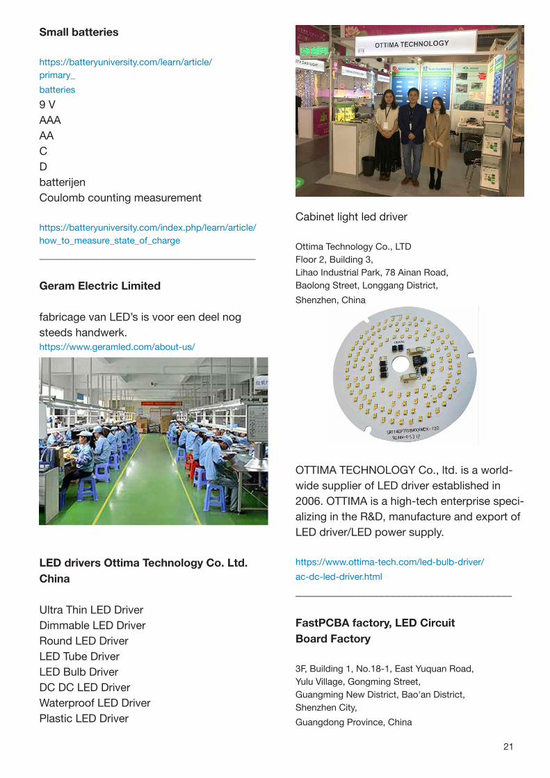
Geram Electric Limited
fabricage van LED’s is voor een deel nog
steeds handwerk.https://www.geramled.com/about-us/
LED drivers Ottima Technology Co. Ltd.
China
Ultra Thin LED Driver
Dimmable LED Driver
Round LED Driver
LED Tube Driver
LED Bulb Driver
DC DC LED Driver
Waterproof LED Driver
Plastic LED Driver
Cabinet light led driver
Ottima Technology Co., LTD
Floor 2, Building 3,
Lihao Industrial Park, 78 Ainan Road,
Baolong Street, Longgang District,
Shenzhen, China
OTTIMA TECHNOLOGY Co., ltd. is a world-
wide supplier of LED driver established in
2006. OTTIMA is a high-tech enterprise speci-
alizing in the R&D, manufacture and export of
LED driver/LED power supply.
https://www.ottima-tech.com/led-bulb-driver/
ac-dc-led-driver.html
_______________________________________
FastPCBA factory, LED Circuit
Board Factory
3F, Building 1, No.18-1, East Yuquan Road,
Yulu Village, Gongming Street,
Guangming New District, Bao'an District,
Shenzhen City,
Guangdong Province, China

22
Onderdelen spoeltjes
http://m.cnfastpcb.com/
________________________________________
Led circuit board
When electrons and holes recombine, they
can radiate visible light, and thus can be used
to make light-emitting diodes.
Used as an indicator light in circuits and in-
struments, or as a text or digital display. The
gallium arsenide diode emits red light, the
gallium phosphide...
http://m.cnfastpcb.com/pcb-assembly/lighting-led/
led-circuit-board.html
________________________________________
Witte strip waterproef
AST Lighting
Xiamen Sales Office
Shenzhen Factory
Shi Yan Town,
Bao’an District,
ShenZhen City,
Guangdong, China
https://www.astlighting.com/product/
smd3014-140led-m
Interessante PDF: 2019 AST Lighting LED
Strip catalog.pdf
https://drive.google.com/file/d/15XiTbhK_
MW7S6k9gcXFrTTOfMtNC_62E/view
________________________________________
LED Tuinverlichting
met zonnecel
Ningbo Addlux Electric Co., Ltd.
China
https://nbaddlux.en.made-in-
china.com/product/TCIEhwFgnVWa/China-20W-
Ce-UL-Saso-IP65-Intelligent-Remote-Control-5054-
LED-Solar-Flood-Light-Made-in-China-for-Outdoor-
Garden-Street-Park-Lighting-From-Best-Distributor-
Factory.html
Grow lamp 50 Watt
https://nbaddlux.en.made-in-
china.com/product/jspQKZbYyCck/China-50W-
Sunlike-Full-Spectrum-LED-Grow-Lamp.html
________________________________________
In China gemaakt:
Printed Circuit Boards
PDF als download aangeboden
https://kmc2010.en.made-in-china.com/
Product-Catalogs/
________________________________________
Specificaties van LED’s
Spanning, stroom, sperspanning,
vermogen etc.
De rode LED’s hebben een lagere voor-
waartse spanning, gevolgd door oranje, geel,
groen, puur groen, ultra blauw en ultra wit.
Zie de link op de volgende pagina.

23
https://lightkeyled.en.made-in-
china.com/product/mSFEnirTFJYI/China-Through-
Hole-Lamp-LED-with-Various-Emitting-Color.html
________________________________________
Ultra Violet LED’s
Lang niet alle UV LED’s kunnen worden ge-
bruikt voor het onschadelijk maken van bv.
Corona. Er moet aan specifieke spectrale
eisen worden voldaan samen met de licht-
sterkte.
https://lightkeyled.en.made-in-china.com/product-
group/pqInvywAXrYM/UV-LED-catalog-1.html
________________________________________
Electronics Component Pack with Resis-
tors LEDs Switch Potentiometer
Eén van de vele voorbeelden van onderdelen
kits voor een bijzonder lage prijs
$ 5,- - $ 5,85 per set.
https://xuanyao.en.made-in-
china.com/product/uwXmCqKvyTWB/China-
Electronics-Component-Pack-with-Resistors-
LEDs-Switch-Potentiometer.html
________________________________________
Joule Thief bij Facebook
https://www.facebook.com/pg/blockingoscillator/
posts/
________________________________________
One-Volt LED
blz. 804 Everyday Practical Electronics
november 1999.
https://worldradiohistory.com/UK/Everyday-
Electronics/90s/EPE-1999-11.pdf
Cover practical Electronics tijdschrift
In deel 1 genoemde verwijzing.
________________________________________
LED’s
Twee verschillende LED’s onder een loep.
Linksboven de standaard LED met links de
plus aansluiting met gebogen draadje naar
het halfgeleider materiaal in het kookpannetje.
De kom fungeert als reflector en container
halfgeleider materiaal voor het uitgestraalde
licht.
Rechtsonder een LED met een ingebouwde
geïntegreerde schakeling, die drie zones aan-
stuurt met verschillende LED’s met verschil-
lende kleuren. Deze worden afwisselend na
een bepaalde tijd geactiveerd.
De prijs van dergelijke geavanceerde LED’s is
nauwelijks hoger dan de ‘normale’ LED’s.

24
Een LED groeilamp op bijna-lege batterijen
laten werken
Rolf Blijleven
Transistoren:
BC550
2N1711
met LDR voor automatisch licht in het donker
https://rolfblijleven.blogspot.com/2013/04/led-groei-
lamp-op-bijna-lege-batterijen.html
________________________________________
Groeilampje door Rolf Blijlevenhttps://rolfblijleven.blogspot.com/2015/08/groeilamp-
jes-worden-rocket-science.html
_______________________________________
Large-area Flexible Organic Photodiodes
Can Compete With Silicon Devices
https://rh.gatech.edu/news/641041/large-area-
flexible-organic-photodiodes-can-compete-silicon-
devices
_________________________________________
Light-emitting diode Wikipedia
https://en.wikipedia.org/wiki/Light-emitting_diode
_________________________________________
LED onder de microscoop
By Unconventional2 - Own work, CC BY-SA
4.0,
https://commons.wikimedia.org/w/index.php?
curid=58175752
________________________________________
Grafieken kleuren spectrum LED
By Tijl Schepens, CC BY-SA 4.0,https://commons.wikimedia.org/w/index.php?curid=69
091874
________________________________________
Allerlei soorten LED’s
By Afrank99 - Own work, CC BY-SA 2.0,https://commons.wikimedia.org/w/index.php?
curid=248198
________________________________________
LED onder de microsocoop
By Volkan Yuksel - Own work, CC BY-SA 4.0,https://commons.wikimedia.org/w/index.php?
curid=37002613
________________________________________
Drie kleuren LED van dichtbij
By Sven Killig - Self-photographed, CC BY-
SA 3.0 de,https://commons.wikimedia.org/w/index.php?
curid=15320589
________________________________________
Grow rode LED kleur
By NASA Marshall Space Flight Center
https://commons.wikimedia.org/w/index.php?
curid=39544881
________________________________________
Desinfectie
Speciale UV-C LED van Osram
https://www.ledinside.com/node/view/31774

25
LED INSIDE
LED NIEUWS
https://www.ledinside.com/
_______________________________________
UV leds
LG Innotek Introduces UV LEDs with World-
class Power Performance
https://www.ledinside.com/products/2014/10/lg_
innotek_introduces_uv_leds_with_world_class_
power_performance
________________________________________
RGB LED met drie kleuren
Waarom kunnen er geen weerstanden worden
gebruikt om een bepaalde kleur te bereiken?
Het probleem zit hem erin dat elke kleur LED
een andere voorwaartse spanning (kan) heb-
ben.
Rood heeft de laagste spanning, dan blauw
en dan groen. De heldere witte of blauwe
hebben meestal de hoogste voorwaartse
spanning.
_______________________________________
Hoe kunnen we LED dimmen?
Dat gebeurt meestal door PWM of te wel re-
geling van de pulsbreedte.
Maar het kan ook door het knijpen van de
stroom middels een stroombron.
https://www.circuitbread.com/tutorials/how-to-
dim-an-led
________________________________________
How to choose LED driver IC?
https://www.ledinside.com/knowledge/2009/12/led_
driver_ic_2010a
________________________________________
Osram
LED Engin
Advanced LED emitters, optics and light engi-
nes for a wide range of lighting applications.
https://www.osram.us/ledengin/
________________________________________
Osram
LuxiTune
Tunable White Light Enginehttps://www.osram.us/ledengin/products/
luxitune/index.jsp

26
What’s inside an LED Bulb?
‘Normale’ LED lampen van binnen bekeken
We took apart two LED lightbulbs, a CREE
LED bulb from 2014 and a Philips bulb from
2018, and compared their build quality, the
electronics, and their overall design. It was
fascinating to see the differences in approa-
ches they took and the challenges they faced
with rectifying the incoming power and also
keeping temperatures reasonable so the elec-
tronics don't fry.
https://www.circuitbread.com/tutorials/whats-
inside-an-led-bulb
________________________________________
Voorwaartse spanning LED
****https://www.circuitbread.com/ee-faq/the-forward-vol-
tages-of-different-leds
________________________________________
LED met multimeter testen
https://www.circuitbread.com/ee-faq/how-to-test-leds-
with-digital-multimeters-dmms
________________________________________
Hoe de juiste weerstand berekenen
https://www.circuitbread.com/ee-faq/how-do-i-
choose-the-correct-resistor-for-my-led
________________________________________
Hoe werkt een LED ?
https://www.circuitbread.com/tutorials/how-does-
an-led-work
****
In het grote oppervlak zit een soort spiegel
lens, waar het PN halfgeleider materiaal is op-
geplakt.
De N-regio onderaan, daarboven aan de op-
pervlak het P-regio gebied, waar het uiteinde-
lijke licht vandaan komt. De p-regio is op de +
van de spanningsbron aangesloten.
________________________________________
Why can't I share a resistor on the com-
mon anode or cathode of my RGB LED?
https://www.circuitbread.com/tutorials/why-cant-i-
share-a-resistor-on-the-common-anode-or-cathode-
of-my-rgb-led
________________________________________
How RGB LEDs work and
how to control color?
2 soorten:
common anode +
common cathode -
https://www.circuitbread.com/tutorials/how-rgb-leds-
work-and-how-to-control-color
________________________________________
Kies de juiste weerstand voor de LED
https://www.circuitbread.com/tutorials/selecting-a-re-
sistor-for-an-led-6-easy-steps
________________________________________

27
Hoe kun je met een kleine beurs LED lam-
pen in India gaan maken ?
benodigd:
LED McPCB
Bulb Body
Heat Sinks
B22 Cap
Diffuser
HPF IC Driver
Packing Box
Warranty Card
https://www.differentwaysformoney.com/how-to-start-
led-bulb-making-business-in-india/
________________________________________
Hoe worden LED’s gemaakt?
Hear from our experts on Everything LED
Lighting
https://sitlersledsupplies.com/how-are-leds-made/
________________________________________
LED’s magazine
What is an LED?
Main LED materials
The main semiconductor materials used to
manufacture LEDs are:
Indium gallium nitride (InGaN): blue, green
and ultraviolet high-brightness LEDs
Aluminum gallium indium phosphide (Al-
GaInP): yellow, orange and red high-
brightness LEDs
Aluminum gallium arsenide (AlGaAs): red and
infrared LEDs
Gallium phosphide (GaP): yellow and green
LEDs
https://www.ledsmagazine.com/leds-ssl-design/
materials/article/16701292/what-is-an-led
________________________________________
Geschiedenis van LED
https://www.circuitbread.com/tutorials/the-history-of-
leds
________________________________________
What is a Light-Emitting Diode?
https://sitlersledsupplies.com/light-emitting-diode/
________________________________________
UV
Signify launches residential UV-C table top
lamp in Asia and Middle East
The company agrees to supply UV-C ceiling
units to Leipzig's soccer team. As the virus-
fighting technology picks up, and as horticul-
ture shines, the overall future remains
uncertain in the pandemic as Q3 comparable
sales fall.
With this UV-C tabletop lamp, Signify's tag
line could be “try this at home.” From a safety
perspective, some people would say don't try
this at home. (Photo credit: Image courtesy of
Signify.)
The company agrees to supply UV-C ceiling
units to Leipzig's soccer team.

28
https://www.ledsmagazine.com/lighting-health-
wellbeing/article/14186058/signify-launches-
residential-uvc-table-top-lamp-in-asia-and-
middle-east
________________________________________
LED’s and OLED’s
Small lights with big potential: light emitting
diodes & organic light emitting diodes
***
History of LED:
1961 eerste LED
1962 Nick Holonyak
1963 eerste commerciële LED de SNX-110.
1972 George Craford
1993 Shuji Nakamura
https://edisontechcenter.org/LED.html
PDF TheFirstPracticalLED
met veel referenties
________________________________________
What is a diode?
How can a diode produce Light?
https://electronics.howstuffworks.com/led.htm
________________________________________
LED
https://whatis.techtarget.com/search/query?q=LED
________________________________________
Blinking LED
5 mm Blinking LED red
3 mm Blinking LED red
https://www.circuitspecialists.com/l56bhd.html?
otaid=gpl&gclid=CPSDktq9rNQCFQWSaQodVlwCiA
________________________________________
Follow up on Candle Flicker LED’s
***
Reverse engineering the controller chip
https://cpldcpu.wordpress.com/2014/03/01/
follow-up-on-candle-flicker-leds/
Azoneberg candleflicker
**https://siliconpr0n.org/archive/doku.php?
id=azonenberg:unknown:candleflicker_led
High resolution chip maps
https://siliconpr0n.org/archive/doku.php
Why use Dokuwiki and not Mediawiki?
ACLs are required for certain projects that
can't yet be made public.
Dokuwiki supports this much better than Me-
diawiki which is either fully closed or fully
open

29
Lijst met IC chip afbeeldingen
per fabrikant
https://siliconpr0n.org/map/
________________________________________
A couple of “Candle Flicker" LEDs have
been reverse engineered, as described here.
The device consists of two chips, the actual
LED and a fairly simple controller.
Lately, some solar powered garden lights
have come on the market that have multicolor
LEDs and controllers that change color and
brightness in a long term pattern. Those have
some simple microprocessor built in to the
LED housing.
Link Tim’s blog:https://cpldcpu.wordpress.com/2014/03/01/
follow-up-on-candle-flicker-leds/
________________________________________
Hacking a Candlelight flicker LED
****
Deze kunnen ook nog andere LED’s aanstu-
ren
https://cpldcpu.wordpress.com/2013/12/08/
hacking-a-candleflicker-led/
Reverse engineering a REAL candle
***
https://cpldcpu.wordpress.com/2016/01/05/
reverse-engineering-a-real-candle/
________________________________________
LED’s, Displays & Lamps
https://www.circuitspecialists.com/semiconductor-
devices-lamps---displays
________________________________________
Flameless LED Candle Power Boost
experimenter’s corner
http://www.discovercircuits.com/dc-
mag/Issue_nov10/pg-4.htm
________________________________________
LED’s, 555, PWM, Flasher and Light Cha-
sers
https://forum.allaboutcircuits.com/ubs/leds-555s-
pwm-flashers-and-light-chasers-index.378/
________________________________________
Light Emitting diodes
https://learn.sparkfun.com/tutorials/light-
emitting-diodes-leds/all
________________________________________
Fabrikant in China
Assortiment blinking LED’s
https://ledz.com/?p=led.blinking
met datasheets
https://ledz.com/
PDF leveringsoverzicht
https://ledz.com/E-Catalogue1.pdf
________________________________________

30
LED BRONNEN
Angelle, Amber. "Will LED Light Bulbs Best
Your CFLs and Incandescents?"
Aug. 2010. Jan. 6, 2020.
http://www.popularmechanics.com/science/environ-
ment/will-led-light-bulbs-best-cfls-and-incandescents
________________________________________
EarthEasy. "LED Light Bulbs: Comparison
Charts."
Jan. 7, 2020.https://learn.eartheasy.com/guides/led-light-bulbs-
comparison-charts/
________________________________________
LEDs Magazine. "Fact or Fiction:
LEDs don't Produce Heat."
May 10, 2005. Jan. 9, 2020.
The energy consumed by a 100-watt GLS in-
candescent bulb produces around 12% heat,
83% IR and only 5% visible light.
In contrast, a typical LED might produce15%
visible light and 85% heat.
https://www.ledsmagazine.com/leds-ssl-design/ther-
mal/article/16696536/fact-or-fiction-leds-dont-pro-
duce-heat
________________________________________
Morrison, Geoffrey. "LED Local Dimming
Explained." CNET.
March 26, 2017. Jan. 8, 2020.https://www.cnet.com/news/led-local-dimming-explai-
ned/
________________________________________
Scheer, Roddy and Moss, Doug. "The Dark
Side of LED Lightbulbs." Scientific Ameri-
can. Sept. 15, 2012. Jan. 7, 2020
https://www.scientificamerican.com/article/led-
lightbulb-concerns/
Study from the journal Environmental Science
and Technology.
________________________________________
Electronics LED Tutorials
Infrared RGB LED controller - Microcontroller
Basics
How to Blink an LED - Microcontroller Basics
How does an LED work?
Why can't I share a resistor on the common
anode or cathode of my RGB LED?
The History of LEDs
What's inside an LED bulb?
Your LED Questions Answered!
How to Dim an LED
Your LED Questions Answered!
How RGB LEDs work and how to control
color
Selecting a resistor for an LED
Why Are LED's Better? (Comparing different
types of light bulbs)
https://www.circuitbread.com/tutorials/tags/leds
LEDs and Forward Voltage
Voorwaartse spanningen LED’s:
ultraviolet 3,1 - 4,4 V
Violet 2,8 - 4,0 V
Blauw 2,5 - 3,7 V
Groen 1,9 - 4,0 V
Geel 2,1 - 2,2 V
Oranje/goud 2,0 - 2,1 V
Rood 1,6 - 2,0 V
infrarood > 1,9 V
________________________________________

31
De langste draad /
aansluiting is vrijwel
altijd de + (anode)
De voorwaartse
stroom loopt van +
naar min door de
geleidende diode.
De kortste draad /
aansluiting is met de
grotere reflecte-
rende deel verbon-
den.
De kathode of te wel
het streepje in de
symbool tekening.
Anvil (aanbeeld)
houder
Het reflecterende
deel met daarin
het halfgeleider
materiaal (P-N)Gebogen draad
van de + naar de
bovenzijde van
de p-laag (met
photons).
Vervolg zie deel 3
Copyright © 2022 FDOKUMEN


![2-[5-Methyl-2-(propan-2-yl)phenoxy]- N ′-{2-[5-methyl-2-(propan-2-yl)phenoxy]acetyl}acetohydrazide](https://static.fdokumen.com/doc/165x107/6344862303a48733920aed56/2-5-methyl-2-propan-2-ylphenoxy-n-2-5-methyl-2-propan-2-ylphenoxyacetylacetohydrazide.jpg)