
Database Design Using Entity-Relationship Diagrams
362
www.allitebooks.com
-
Upload
khangminh22 -
Category
Documents
-
view
0 -
download
0
Transcript of Database Design Using Entity-Relationship Diagrams

ISBN: 978-1-4398-6176-9
9 781439 861769
90000
Information Technology / Database
Essential to database design, entity-relationship (ER) diagrams are known for their usefulness in mapping out clear database designs. They are also well-known for being difficult to master. With Database Design Using Entity-Relationship Diagrams, Second Edition, database designers, developers, and students preparing to enter the field can quickly learn the ins and outs of ER diagramming.
Building on the success of the bestselling first edition, this accessible text includes a new chapter on the relational model and functional dependencies. It also includes expanded chapters on Enhanced Entity Relationship (EER) diagrams and reverse mapping. It uses cutting-edge case studies and examples to help readers master database development basics and defines ER and EER diagramming in terms of requirements (end user requests) and specifications (designer feedback to those requests).
• Describes a step-by-step approach for producing an ER diagram and developing a relational database from it
• Contains exercises, examples, case studies, bibliographies, and summaries in each chapter
• Details the rules for mapping ER diagrams to relational databases• Explains how to reverse engineer a relational database back to an
entity-relationship model• Includes grammar for the ER diagrams that can be presented back
to the user
The updated exercises and chapter summaries provide the real-world understanding needed to develop ER and EER diagrams, map them to relational databases, and test the resulting relational database. Complete with a wealth of additional exercises and examples throughout, this edition should be a basic component of any database course. Its comprehensive nature and easy-to-navigate structure make it a resource that students and professionals will turn to throughout their careers.
Database Design Using Entity-Relationship Diagrams
Seco
nd
Editio
nBagui
Earp
www.auerbach-publications.com
K12857
www.crcpress.com
K12857 cvr mech.indd 1 8/9/11 8:53 AM
www.allitebooks.com

Database Design Using Entity-Relationship
Diagrams
Second Edition
www.allitebooks.com

Database Design Using Entity-Relationship
Diagrams
Second Edition
Sikha Bagui and Richard Earp
www.allitebooks.com

CRC PressTaylor & Francis Group6000 Broken Sound Parkway NW, Suite 300Boca Raton, FL 33487-2742
© 2012 by Taylor & Francis Group, LLCCRC Press is an imprint of Taylor & Francis Group, an Informa business
No claim to original U.S. Government worksVersion Date: 20110510
International Standard Book Number-13: 978-1-4398-6177-6 (eBook - PDF)
This book contains information obtained from authentic and highly regarded sources. Reasonable efforts have been made to publish reliable data and information, but the author and publisher cannot assume responsibility for the validity of all materials or the consequences of their use. The authors and publishers have attempted to trace the copyright holders of all material reproduced in this publication and apologize to copyright holders if permission to publish in this form has not been obtained. If any copyright material has not been acknowledged please write and let us know so we may rectify in any future reprint.
Except as permitted under U.S. Copyright Law, no part of this book may be reprinted, reproduced, transmit-ted, or utilized in any form by any electronic, mechanical, or other means, now known or hereafter invented, including photocopying, microfilming, and recording, or in any information storage or retrieval system, without written permission from the publishers.
For permission to photocopy or use material electronically from this work, please access www.copyright.com (http://www.copyright.com/) or contact the Copyright Clearance Center, Inc. (CCC), 222 Rosewood Drive, Danvers, MA 01923, 978-750-8400. CCC is a not-for-profit organization that provides licenses and registration for a variety of users. For organizations that have been granted a photocopy license by the CCC, a separate system of payment has been arranged.
Trademark Notice: Product or corporate names may be trademarks or registered trademarks, and are used only for identification and explanation without intent to infringe.
Visit the Taylor & Francis Web site athttp://www.taylorandfrancis.com
and the CRC Press Web site athttp://www.crcpress.com
www.allitebooks.com

Dedicated to my late father-in-law, Paresh C. Bagui; late
mother-in-law, Khodan B. Bagui; father, Santosh Saha;
mother, Ranu Saha, and husband, Subhash Bagui
S.B.
Dedicated to my wife, Brenda, and my children,
Beryl, Rich, Gen, and Mary Jo
R.E.
www.allitebooks.com
vii
Contents
Preface...................................................................................................xixAcknowledgments............................................................................. xxiiiIntroduction......................................................................................... xxv
Chapter 1 Data,.Databases,.and.the.Software.Engineering.Process................................................................................. 1
1.1. Introduction.....................................................................11.2. Data...................................................................................11.3. Building.a.Database........................................................21.4. What.is.the.Software.Engineering.Process?................31.5. Entity.Relationship.Diagrams.and.the.Software.
Engineering.Life.Cycle...................................................61.5.1. Phase.1:.Get.the.Requirements.for.the.
Database............................................................71.5.2. Phase.2:.Specify.the.Database........................71.5.3. Phase.3:.Design.the.Database.........................8
1.6. Chapter.Summary...........................................................8Chapter.1.Exercises......................................................................8Bibliography..................................................................................9
Chapter 2 Data.and.Data.Models...................................................... 11
2.1. Introduction...................................................................112.2. Files,.Records,.and.Data.Items....................................112.3. Moving.from.3.×.5.Cards.to.Computers....................142.4. Database.Models.......................................................... 20
2.4.1. The.Hierarchical.Model............................... 202.4.1.1. The.Hierarchical.Model.with.
a.Linked.List....................................252.4.1.2. Relationship.Terminology.............272.4.1.3. Drawbacks.of.the.
Hierarchical.Model....................... 282.5. The.Network.Model......................................................29
www.allitebooks.com

viii • Contents
2.6. The.Relational.Model....................................................322.7. Chapter.Summary.........................................................33Bibliography................................................................................33
Chapter 3 The.Relational.Model.and.Functional.Dependencies..... 35
3.1. Introduction...................................................................353.2. Fundamental.Relational.Database..............................353.3. Relational.Database.and.Sets.......................................383.4. Functional.Dependency...............................................393.5. Non-1NF.to.1NF........................................................... 403.6. The.Second.Normal.Form........................................... 43
3.6.1. Anomalies.......................................................473.6.2. Non-2NF.to.2NF........................................... 48
3.7. The.Third.Normal.Form...............................................503.8. The.Equijoin.Operation............................................... 543.9. Some.Functional.Dependency.Rules......................... 563.10. The.Boyce.Codd.Normal.Form...................................633.11. Chapter.Summary.........................................................65Chapter.3.Exercises....................................................................65Bibliography............................................................................... 66
Chapter 4 The.Basic.ER.Diagram:.A.Data.Modeling.Schema......... 67
4.1. Introduction...................................................................674.2. What.Is.a.Data.Modeling.Schema?.............................67
4.2.1. So,.What.Is.an.Entity.Relationship.Diagram?........................................................ 68
4.3. Defining.a.Database—.Some.Definitions:.Entity,.Relationship,.Attribute.....................................694.3.1. A.Beginning.Methodology...........................704.3.2. ER.Design.Methodology...............................71
4.4. A.First.“Entity-Only”.ER.Diagram:.An.Entity.with.Attributes...............................................................72
4.5. More.about.Attributes..................................................744.5.1. The.Simple.or.Atomic.Attribute..................754.5.2. The.Composite.Attribute..............................764.5.3. The.Multivalued.Attribute............................774.5.4. The.Derived.Attribute...................................784.5.5. Keys..................................................................78
www.allitebooks.com

Contents • ix
4.6. English.Description.of.the.Entity...............................834.6.1. The.Method....................................................83
4.6.1.1. The.Entity........................................834.6.1.2. The.Attributes.................................834.6.1.3. The.Keys.......................................... 84
4.6.2. ER.Design.Methodology.............................. 844.6.3. Examples........................................................ 84
4.6.3.1. Figure 4.3.Example....................... 844.6.3.2. Figure 4.4.Example........................854.6.3.3. Figure 4.5a.Example..................... 864.6.3.4. Figure 4.6.Example........................874.6.3.5. Figure 4.7.Example....................... 88
4.7. Mapping.the.Entity.Diagram.to.a.Relational.Database.........................................................................89
4.8. Chapter.Summary.........................................................94Chapter.4.Exercises....................................................................94Bibliography................................................................................95Case.Study.................................................................................. 96
Chapter 5 Beyond.the.First.Entity.Diagram................................... 101
5.1. Introduction.................................................................1015.2. Examining.an.Entity:.Changing.an.Attribute.
to.Be.an.Entity.............................................................1025.3. Defining.a.Relationship.for.Our.New.Entity...........103
5.3.1. ER.Design.Methodology.............................1045.4. A.Preliminary.Grammar.for.the.ER.Diagrams......105
5.4.1. The.Relationship..........................................1055.5. Defining.a.Second.Entity...........................................1055.6. Does.a.Relationship.Exist?.........................................1115.7. Attribute.or.Relationship?..........................................111
5.7.1. ER.Design.Methodology.............................1125.8. Chapter.Summary.......................................................113Chapter.5.Exercises..................................................................113Bibliography..............................................................................114Case.Study.................................................................................114
Chapter 6 Extending.Relationships/Structural.Constraints......... 123
6.1. Introduction................................................................ 1236.2. The.Cardinality.Ratio.of.a.Relationship.................. 123
www.allitebooks.com

x • Contents
6.2.1. One.to.One.(1:1).......................................... 1246.2.2. Many.to.One.(M:1)......................................1256.2.3. One.to.Many.(1:M)......................................1256.2.4. Many.to.Many.(M:N)..................................125
6.3. Participation:.Full/Partial......................................... 1286.4. English.Descriptions...................................................1306.5. Tighter.English............................................................131
6.5.1. Pattern.1—x:y::k:1........................................1326.5.2. Pattern.2—x:y::k:1........................................1336.5.3. Pattern.3—x:y::k:M......................................1336.5.4. Pattern.4—x:y::k:M..................................... 1346.5.5. Summary.of.the.Patterns.and.
Relationships................................................1356.5.5.1. Pattern.1........................................1356.5.5.2. Pattern.1........................................1356.5.5.3. Pattern.2........................................1366.5.5.4. Pattern.2........................................1366.5.5.5. Pattern.3........................................1386.5.5.6. Pattern.3........................................1386.5.5.7. Pattern.4........................................1386.5.5.8. Pattern.4........................................140
6.5.6. ER.Design.Methodology.............................1416.6. Some.Examples.of.Other.Relationships...................141
6.6.1. An.Example.of.the.One-to-Many.Relationship.(1:M).......................................1416.6.1.1. Pattern.4—1:M,.from.the.1.
Side,.Partial.Participation...........1436.6.1.2. Pattern.2—M(Partial):1,.
from.M.Side,.Optional.Participation................................143
6.6.2. An.Example.of.the.Many-to-One.Relationship.(M:1).......................................1446.6.2.1. Pattern.1—M:1,.from.the.M.
Side,.Full.Participation................1446.6.2.2. Pattern.3—1:M,.from.the.1.
Side,.Full.Participation................1456.6.3. An.Example.of.the.Many-to-Many.
Relationship.(M:N)......................................145
Contents • xi
6.6.3.1. Pattern.3—M:N,.from.the.M.Side,.Full.Participation................146
6.6.3.2. Pattern.4—M:N,.from.the.M.Side,.Partial.Participation...........146
6.7. One.Final.Example......................................................1476.7.1. ER.Design.Methodology.............................148
6.7.1.1. The.Entity......................................1496.7.1.2. The.Entity......................................150
6.7.2. Pattern.1—M:1,.from.the.M.Side,.Full.Participation.................................................152
6.7.3. Pattern.3—1:M,.from.the.1.Side,.Full.Participation.................................................152
6.8. Mapping.Relationships.to.a.Relational.Database.......................................................................1536.8.1. Mapping.Binary.M:N.Relationships.........1536.8.2. Mapping.Binary.1:1.Relationships............1556.8.3. Mapping.Binary.1:N.Relationships...........160
6.9. Chapter.Summary.......................................................161Chapter.6.Exercises..................................................................162Bibliography..............................................................................165Case.Study.................................................................................165
Chapter 7 The.Weak.Entity.............................................................. 171
7.1. Introduction.................................................................1717.2. Strong.and.Weak.Entities...........................................1717.3. Weak.Entities.and.Structural.Constraints..............1767.4. Weak.Entities.and.the.Identifying.Owner...............176
7.4.1. Another.Example.of.a.Weak.Entity.and.the.Identifying.Owner.........................178
7.5. Weak.Entities.Connected.to.Other.Weak.Entities..........................................................................179
7.6. Revisiting.the.Methodology......................................1807.7. Weak.Entity.Grammar...............................................181
7.7.1. The.Keys........................................................1817.8. Mapping.Weak.Entities.to.a.Relational.
Database.......................................................................1827.9. Chapter.Summary.......................................................184

xii • Contents
Chapter.7.Exercises..................................................................185Bibliography..............................................................................185Case.Study.................................................................................186
Chapter 8 Further.Extensions.for.ER.Diagrams.with.Binary.Relationships................................................................... 193
8.1. Introduction.................................................................1938.2. Attributes.of.Relationships........................................194
8.2.1. The.Attributes...............................................1958.3. Relationships.Developing.into.Entities:.The.
M:N.Relationship.Revisited.......................................1968.3.1. The.Entity......................................................198
8.3.1.1. The.Attributes...............................1988.3.1.2. The.Keys.........................................198
8.4. More.Entities.and.Relationships...............................1988.4.1. More.than.Two.Entities..............................199
8.4.1.1. Pattern.4—x:y::1:M,.from.the.1.Side,.Partial.Participation........199
8.4.1.2. Pattern.1—x:y::M:1,.from.the.M.Side,.Full.Participation.......... 200
8.4.2. Adding.More.Attributes.that.Evolve.into.Entities...................................................201
8.5. More.Evolution.of.the.Database............................... 2038.6. Attributes.that.Evolve.into.Entities.......................... 2058.7. Recursive.Relationships............................................. 208
8.7.1. Recursive.Relationships.and.Structural.Constraints................................2108.7.1.1. One-to-One.Recursive.
Relationship.(Partial.Participation.on.Both.Sides).......210
8.7.1.2. One-to-Many.Recursive.Relationship.(Partial.Participation.on.Both.Sides).......211
8.7.1.3. Many-to-Many.Recursive.Relationship.(Partial.on.Both.Sides)..............................................211
8.8. Multiple.Relationships................................................213
Contents • xiii
8.9. The.Derived.or.Redundant.Relationship.................2168.10. Optional:.An.Alternative.ER.Notation.
for.Specifying.Structural.Constraints.on.Relationships.............................................................. 218
8.11. Review.of.the.Methodology.......................................2218.11.1. ER.Design.Methodology.............................2218.11.2. The.Entity..................................................... 222
8.11.2.1. The.Attributes.............................. 2228.11.2.2. The.Keys........................................ 222
8.12. Mapping.Rules.for.Recursive.Relationships........... 2238.13. Chapter.Summary...................................................... 224Chapter.8.Exercises................................................................. 225Bibliography............................................................................. 226Case.Study................................................................................ 226
Chapter 9 Ternary.and.Higher-Order.ER.Diagrams...................... 229
9.1. Introduction................................................................ 2299.2. Binary.or.Ternary.Relationship?.............................. 2309.3. Structural.Constraints.for.Ternary.Relationships..... 233
9.3.1. Many.to.Many.to.Many.(M:M:M)............2339.4. An.Example.of.an.n-ary.Relationship......................2359.5. n-ary.Relationships.Do.Not.Preclude.Binary.
Relationships............................................................... 2369.6. Methodology.and.Grammar.for.the.n-ary.
Relationship.................................................................2379.6.1. A.More.Exact.Grammar............................ 238
9.6.1.1. Pattern.3—M:N,.from.the.M.Side,.Full.Participation................239
9.6.1.2. Pattern.3—k:M,.from.the.k.Side,.Full.Participation.(k.=.1.or.M)..............................................239
9.6.1.3. Pattern.5.(n-ary)—x:y:z::a:b:c,.from.the.a.Side,.Full/Partial.Participation.................................239
9.6.2. Grammar.in.a.Partial.Participation,.Ternary.Relationship.with.an.M:1:M.Relationship................................................. 240

xiv • Contents
9.7. Ternary.Relationships.from.Relationship-Relationship.Situations...................... 242
9.8. n-ary.Relationships.that.May.Be.Resolved.into.Binary.Relationships.................................................. 244
9.9. Mapping.n-ary.Relationships.to.a.Relational.Database...................................................................... 247
9.10. Review.of.the.Methodology...................................... 2499.10.1. ER.Design.Methodology............................ 249
9.11. Chapter.Summary...................................................... 250Chapter.9.Exercises................................................................. 250Bibliography..............................................................................251
Chapter 10 The.Enhanced.Entity.Relationship.(EER).Model......... 253
10.1. Introduction.................................................................25310.2. What.Is.a.Generalization.or.Specialization?...........25310.3. Variants.........................................................................25510.4. Examples.of.Generalizations.or.Specializations.... 25610.5. Methodology.and.Grammar.for.
Generalization/Specialization.Relationships......... 26210.6. Mapping.Rules.for.Generalizations.
and.Specializations..................................................... 26410.6.1. Mapping.Rule.15......................................... 26510.6.2. Mapping.Rule.16......................................... 26710.6.3. Mapping.Rule.17......................................... 26810.6.4. Mapping.Rule.18......................................... 269
10.7. Subclasses.of.Subclasses.............................................27010.7.1. Mapping.Rule.19..........................................273
10.8. Categories.or.Union.Types.........................................27410.8.1. Participation.Ratios.in.Categories.or.
Union.Types..................................................27610.8.2. Mapping.Categories.or.Union.Types.
When.Superclasses.Have.the.Same.Primary.Keys................................................278
10.8.3. Mapping.Categories.or.Union.Types.When.Superclasses.Have.Different.Primary.Keys................................................279

Contents • xv
10.9. Final.ER.Design.Methodology................................. 28010.9.1. ER.Design.Methodology............................ 280
10.10. Chapter.Summary.......................................................281Chapter.10.Exercises............................................................... 282Bibliography............................................................................. 282Case.Study................................................................................ 283
Chapter 11 Relational.Mapping.and.Reverse.Engineering.ER/EER.Diagrams........................................................... 287
11.1. Introduction................................................................ 28711.2. Steps.Used.to.Map.ER/EER.Diagrams.to.
Relational.Databases.................................................. 28711.3. Reverse.Engineering...................................................293
11.3.1. Reverse.Engineering.Rule.1..Develop.Strong.Entities............................................. 294
11.3.2. Reverse.Engineering.Rule.2..Look.for.1:1.and.1:N.(1:x).Relationships...................295
11.3.3. Reverse.Engineering.Rule.2a..Check.for.Attributes.of.the.1:x.Relationship....... 297
11.3.4. Reverse.Engineering.Rule.3..Look.for.Weak.Entities.and.Multivalued.Attributes....................................................298
11.3.5. Reverse.Engineering.Rule.3a..Checking.for.Weak.Entities...................... 298
11.3.6. Reverse.Engineering.Rule.3b..Checking.for.Multivalued.Attributes....... 300
11.3.7. Reverse.Engineering.Rule.4..Check.for.M:N.and n-ary.Relationships.................... 302
11.3.8. Reverse.Engineering.Rule.4a..Check.for.the.Binary.Case..................................... 302
11.3.9. Reverse.Engineering.Rule.4b..Check.for.the.n-ary.Case....................................... 303
11.3.10. Reverse.Engineering.Rule.5..Check.for.Generalization/Specialization.Relationships............................................... 303

xvi • Contents
11.3.11. Reverse.Engineering.Rule.5a..Check.for.Generalization/Specialization.Relationships.with.Disjoint.or.Overlap.Relationships.with.Total.or.Partial.Participation.Constraints.......................... 304
11.3.12. Reverse.Engineering.Rule.5b..Check.for.Disjoint.Generalization/Specialization.Relationships.with.Single-Predicate-Defined.Attributes........ 306
11.3.13. Reverse.Engineering.Rule.5c..Check.for.Overlap.Generalization/Specialization.Relationship.with.More.than.One.Flag.............................................. 306
11.3.14. Reverse.Engineering.Rule.6..Check.for.Shared.Subclasses................................. 306
11.3.15. Reverse.Engineering.Rule.7..Check.for.Categories.or.Union.Types.................. 307
11.4. Chapter.Summary...................................................... 307Chapter.11.Exercises............................................................... 308Bibliography............................................................................. 309
Chapter 12 A.Brief.Overview.of.the.Barker/Oracle-Like.Model......311
12.1. Introduction.................................................................31112.2. A.First.“Entity-Only”.ER.Diagram:.An.Entity.
with.Attributes.............................................................31212.3. Attributes.in.the.Barker/Oracle-Like.Model...........313
12.3.1. Optional.versus.Mandatory.Attributes....31312.4. Relationships.in.the.Barker/Oracle-Like.Model.....31412.5. Structural.Constraints.in.the.
Barker/Oracle-Like.Model.........................................31512.6. Dealing.with.the.Concept.of.the.Weak.Entity.
in.the.Barker/Oracle-Like.Model..............................31812.7. Dealing.with.the.Concept.of.Multivalued.
Attributes.in.the.Barker/Oracle-Like.Model...........31912.8. Treatment.of.Foreign.Keys.........................................32112.9. Recursive.Relationships.in.the.
Barker/Oracle-Like.Model.........................................322
Contents • xvii
12.10. Mapping.M:N.Relationships......................................32312.11. Chapter.Summary.......................................................323Chapter.12.Exercises............................................................... 326Bibliography............................................................................. 326
Glossary................................................................................................ 327


xix
Preface
Data. modeling. and. database. design. have. undergone. significant. evolu-tion. in.recent.years..Today,. the.relational.data.model.and. the.relational.database.system.dominate.business.applications..The.relational.model.has.allowed.the.database.designer.to.focus.on.the.logical.and.physical.char-acteristics.of.a.database.separately..In.this.book,.we.concentrate.on.tech-niques.for.database.design.with.a.very.strong.bias.for.relational.database.systems,.using.the.ER.(entity.relationship).approach.for.conceptual.mod-eling.(solely.a.logical.implementation).
INTENDED AUDIENCE
This.book.is.intended.to.be.used.for.data.modeling.by.database.practition-ers.and.students..It.is.also.intended.to.be.used.as.a.supplemental.text.in.database.courses,.systems.analysis.and.design.courses,.and.other.courses.that.design.and.implement.databases..Many.present-day.database.and.sys-tems.analysis.and.design.books.limit.their.coverage.of.data.modeling..This.book.not.only.increases.the.exposure.to.data.modeling.concepts,.but.also.presents.a.step-by-step.approach.to.designing.an.ER.diagram.and.devel-oping.a.relational.database.from.it.
BOOK HIGHLIGHTS
This.book.focuses.on.presenting.(a).an.ER design methodology.for.develop-ing.an.ER.diagram;.(b).a.grammar.for.the.ER.diagrams.that.can.be.pre-sented.back.to.the.user;.and.(c).mapping rules.to.map.the.ER.diagram.to.a.relational.database..The.steps.for.the.ER.design.methodology,.the.gram-mar.for.the.ER.diagrams,.as.well.as.the.mapping.rules.are.developed.and.presented.in.a.systematic.step-by-step.manner.throughout.the.book..Also,.several.examples.of.“sample.data”.have.been.included.with.relational.data-base.mappings.to.give.a.“realistic”.feeling.
www.allitebooks.com

xx • Preface
This.book.is.divided.into.12.chapters..The.first.three.chapters.are.back-ground.material..The.first.chapter.introduces.the.concept.of.data,.the.data-base,.and.software.engineering..Chapter.2.presents.the.different.database.models.. Chapter. 3. introduces. the. relational. model. and. discusses. func-tional.dependencies.used.to.generate.third.normal.form.databases.
From. Chapter. 4,. we. start. presenting. the. concept. of. ER. diagrams..Chapter 4. introduces. the.concept.of. the.entity,.attributes,. relationships,.and.the.“one-entity”.ER.diagram..Steps.1,.2,.and.3.of.the.ER.design.meth-odology.are.developed.in.this.chapter..The.one-entity.grammar.and.map-ping.rules.for.the.one-entity.diagram.are.presented.
Chapter. 5. extends. the. one-entity. diagram. to. include. a. second. entity..The. concept. of. testing. attributes. for. entities. is. discussed,. and. relation-ships.between.the.entities.are.developed..Steps.3a,.3b,.4,.5,.and.6.of.the.ER.Design.Methodology.are.developed,.and.grammar. for. the.ER.diagrams.developed.up.to.this.point.is.presented.
Chapter. 6. discusses. structural. constraints. in. relationships.. Several.examples.are.given.of.1:1,.1:M,.and.N:M.relationships..Step.6.of. the.ER.design.methodology.is.revised,.and.step.7.is.developed..A.grammar.for.the.structural.constraints.and.the.mapping.rules.is.also.presented.
Chapter.7.develops.the.concept.of.the.weak.entity..This.chapter.revisits.and.revises.steps.3.and.4.of.the.ER.design.methodology.to.include.the.weak.entity..Again,.a.grammar.and.the.mapping.rules.for.the.weak.entity.are.presented.
Chapter.8.discusses.and.extends.different.aspects.of.binary.relationships.in.ER.diagrams..This.chapter.revises.step.5.to.include.the.concept.of.more.than.one.relationship.and.revises.step.6b.to.include.derived.and.redun-dant.relationships..The.concept.of.the.recursive.relationship.is.introduced.in. this.chapter..The.grammar.and.mapping.rules. for.recursive.relation-ships.are.presented.
Chapter. 9. discusses. ternary. and. other. “higher-order”. relationships..Step.6.of.the.ER.design.methodology.is.again.revised.to.include.ternary.and.other.higher-order.relationships..Several.examples.are.given,.and.the.grammar.and.mapping.rules.are.developed.and.presented.
Chapter.10.discusses.enhanced.entity.relationships.(EERs):.generaliza-tions.and.specializations,.shared.subclasses,.and.categories.or.union.types..Once.again,.step.6.of.the.ER.design.methodology.is.modified.to.include.generalizations.and.specializations,.and.the.grammar.and.mapping.rules.for.mapping.the.EER.are.presented.
Chapter.11.gives.a.summary.of.the.mapping.rules.and.reverse.engineer-ing.from.a.relational.database.to.an.ER.diagram.
Preface • xxi
Chapters.4–11.present.ER.and.EER.diagrams.using.a.Chen-like.model..In.Chapter.12,.we.discuss.the.Barker/Oracle-like.models,.highlighting.the.main. similarities.and.differences.between. the.Chen-like.model.and. the.Barker/Oracle-like.model.
In.every.chapter,.we.present.several.examples..“Checkpoint”.sections.within.the.chapters.and.end-of-chapter.exercises.are.presented.in.every.chapter.to.be.worked.out.by.the.students.to.obtain.a.better.understand-ing.of. the.material.within. the. respective. sections.and.chapters..At. the.end. of. Chapters. 4–10,. there. is. a. running. case. study,. with. the. solution.(that.is,.the.ER/EER.diagram.and.the.relational.database.with.some.sam-ple.data).

xxiii
Acknowledgments
Our.special. thanks.are.due.to.our.editors,.John.Wyzalek,.Amy.Blalock,.and.Judith.Simon.at.CRC.Press.
We.would.also.like.to.thank.President.Judy.Bense,.Provost.Chula.King,.and. Dean. Jane. Halonen. for. their. inspiration,. encouragement,. support,.and.true.leadership.quality.
Our.sincere.thanks.also.go.to.Dr..Leo.Ter.Haar,.chair,.Computer.Science.Department,.for.his.advice,.guidance,.and.support.and.for.encouraging.us. to. complete. this. book,. and. Dr.. Norman. Wilde. and. Dr.. Ed. Rodgers.for.their.continuing.support.and.encouragement.throughout.past.years..And,.last.but.not.least,.we.would.like.to.thank.our.fellow.faculty.mem-bers,.Diana.Walker.and.Michelle.Lockhart.for.their.continuous.support.and.encouragement.


xxv
Introduction
This.book.was.written.to.aid.students.in.database.classes.and.to.help.data-base.practitioners.in.understanding.how.to.arrive.at.a.definite,.clear.database.design.using.an.entity.relationship.(ER).diagram..In.designing.a.database.with.an.ER.diagram,.we.recognize.that.this.is.but.one.way.to.arrive.at.the.objective:.the.database..There.are.other.design.methodologies.that.also.pro-duce.databases,.but.an.ER.diagram.is.the.most.common..The.ER.diagram.is.a.subset.of.what.are.called.“semantic.models.”.As.we.go.through.this.material,.we.occasionally.point.out.where.other.models.differ.from.the.ER.model.
The.ER.model.is.one.of.the.best-known.tools.for.logical.database.design..Within.the.database.community,. it. is.considered.a.natural.and.easy-to-understand. way. of. conceptualizing. the. structure. of. a. database.. Claims.that.have.been.made. for. it. include. the. following:. It. is. simple.and.easily.understood. by. nonspecialists,. it. is. easily. conceptualized,. the. basic. con-structs. (entities.and.relationships).are.highly. intuitive.and. thus.provide.a.natural.way.of.representing.a.user’s.information.requirements,.and.it.is.a.model.that.describes.a.world.in.terms.of.entities.and.attributes.that.is.most.suitable.for.computer-naïve.end.users..In.contrast,.many.educators.have.reported.that.students. in.database.courses.have.difficulty.grasping.the.concepts.of. the.ER.approach,.particularly. in.applying. them.to.real-world.problems.
We.took. the.approach.of. starting.with.an.entity.and. then.developing.from.it.an.“inside-out.strategy”.(as.mentioned. in.Elmasri.and.Navathe,.2007).. Software. engineering. involves. eliciting. from. a. (perhaps). “naïve”.user.what.the.user.would.like.to.have.stored.in.an.information.system..The.process.we.present.follows.the.software.engineering.paradigm.of.require-ments/specifications,.with.the.ER.diagram.being.the.core.of.the.specifica-tion..Designing.a.software.solution.depends.on.correct.elicitation..In.most.software.engineering.paradigms,. the.process.starts.with.a.requirements.elicitation.followed.by.a.specification.and.then.a.feedback.loop..In.plain.English,.the.idea.is.(a).“tell.me.what.you.want”.(requirements),.then.(b).“this. is. what. I. think. you. want”. (specification).. This. process. of. require-ments/specification. may. (and. probably. should). be. iterative. so. that. the.user.understands.what.he.or.she.will.get.from.the.system.and.the.analyst.understands.what.the.user.wants.

xxvi • Introduction
A.methodology.for.producing.an.ER.diagram.is.presented..The.process.leads.to.an.ER.diagram.that.is.then.translated.into.plain.(but.meant.to.be.precise).English.that.a.user.can.understand..The.iterative.mechanism.then.takes.over.to.arrive.at.a.specification.(a.revised.ER.diagram.and.English).that.both.the.user.and.analyst.understand..The.mapping.of. the.ER.dia-gram. into. a. relational. database. is. presented;. mapping. to. other. logical.database.models.is.not.covered..We.feel.that.the.relational.database.is.the.most.appropriate.to.demonstrate.mappings.as.it.is.the.most.used.contem-porary. database. model.. Actually,. the. idea. behind. the. ER. diagram. is. to.produce.a.high-level.database.model.that.has.no.particular.logical.model.(relational,.hierarchical,.object.oriented,.or.network).implied.
We.have.a.strong.bias.toward.the.relational.model..The.“goodness”.of.the.final.relational.model.is.testable.via.the.ideas.of.normal.forms..The.good-ness.of.the.relational.model.produced.by.a.mapping.from.an.ER.diagram.theoretically.should.be.guaranteed.by.the.mapping.process..If.a.diagram.is.“good.enough,”.then.the.mapping.to.a.“good”.relational.model.should.happen.almost.automatically..In.practice,.the.scenario.will.be.to.produce.as.good.an.ER.diagram.as.possible,.map.it.to.a.relational.model,.and.then.shift. the. discussion. to. discussion. of. “Is. this. a. good. relational. model. or.not?”.by.using.the.theory.of.normal.forms.and.other.associated.criteria.of.“relational.goodness.”
The.approach.we.take.to.database.design.is.intuitive.and.informal..We.do.not.deal.with.precise.definitions.of.set.relations..We.use.the.intuitive.“one/many”.for.cardinality.and.“may/must”.for.participation.constraints..The.intent.is.to.provide.a.mechanism.to.produce.an.ER.diagram.that.can.be.presented.to.a.user.in.English.and.to.polish.the.diagram.into.a.specifi-cation.that.can.then.be.mapped.into.a.database..We.then.suggest.testing.the.produced.database.by.the.theory.of.normal.forms.and.other.criteria.(i.e.,.referential.integrity.constraints)..We.also.suggest.a.reverse-mapping.paradigm.for.mapping.a.relational.database.back.to.an.ER.diagram.for.the.purpose.of.documentation.
THE ER MODELS WE CHOSE
We.begin.our.venture. into.ER.diagrams.with.a.“Chen-like”.model,.and.most.of.this.book.is.written.using.the.Chen-like.model..Why.did.we.choose.this.model?.Chen.(1976).introduced.the.idea.of.the.ER.diagrams.(Elmasri.

Introduction • xxvii
and.Navathe.2007),.and.most.database.texts.use.some.variant.of.the.Chen.model..Chen.and.others.have.improved.the.ER.process.over.the.years,.and.while.there.is.no.standard.ER.diagram.model,.the.Chen-like.model.and.variants.thereof.are.common,.particularly.in.comprehensive.database.texts..In.the.last.chapter,.we.briefly.introduce.the.“Barker/Oracle-like”.model..As.with.the.Chen.model,.we.do.not.follow.the.Barker.or.Oracle.models.pre-cisely.and.hence.use.the.term.Barker/Oracle-like.models.in.this.text.
There.are.also.other.reasons.for.choosing.the.Chen-like.model.over.the.other.models..With.the.Chen-like.model,.one.need.not.consider.how.the.database.will.be.implemented..The.Barker-like.model.is.more.intimately.tied.to.the.relational.database.paradigm..Oracle.Corporation.uses.an.ER.diagram.that.is.closer.to.the.Barker.model..Also,.in.the.Barker-like.and.Oracle-like.ER.diagram.there.is.no.accommodation.for.some.of.the.fea-tures.we.present.in.the.Chen-like.model..For.example,.multivalued.attri-butes,.many-to-many.relationships,.and.weak.entities.are.not.part.of.the.Barker-.or.Oracle-like.design.process.
The.process.of.database.design.follows.the.software.engineering.par-adigm,.and.during.the.requirements.and.specifications.phase,.sketches.of.ER.diagrams.are.made.and.remade..It.is.not.at.all.unusual.to.arrive.at.a.design.and.then.revise.it..In.developing.ER.models,.one.needs.to.realize.that.the.Chen.model.is.developed.to.be.independent.of.imple-mentation..The.Chen-like.model.is.used.almost.exclusively.by.univer-sities. in. database. instruction.. The. mapping. rules. of. the. Chen. model.to. a. relational. database. are. relatively. straightforward,. but. the. model.itself. does. not. represent. any. particular. logical. model.. Although. the.Barker/Oracle-like. model. is. popular,. it. is. implementation. dependent.on.knowledge.of.the.relational.database..The.Barker/Oracle-like.model.maps.directly.to.a.relational.database;.there.are.no.real.mapping.rules.for.that.model.
BIBLIOGRAPHY
Chen,. P.. P.. 1976.. The. entity. relationship. model-toward. a. unified. view. of. data,. ACM Transactions on Database Systems,.1(1).
Elmasri,.R.,.and.Navathe,.S..B..2007..Fundamentals of Database Systems,.5th.ed..Addison.Wesley,.Reading,.MA.

1
1Data, Databases, and the Software Engineering Process
1.1 INTRODUCTION
In. this. chapter,. we. introduce. some. concepts. and. ideas. that. are. funda-mental. to.our.presentation.of. the.design.of.a.database..We.define.data,.describe.the.notion.of.a.database,.and.explore.a.process.of.how.to.design.a.database.
1.2 DATA
Data,. as. we. use. the. term,. are. facts. about. something. or. someone.. For.example,. a. person. has. a. name,. an. address,. and. a. gender.. Some. data.(facts). about. a. specific. person. might. be. “Mary. Smith,”. “123. 4th. St.,”.“female.”.If.we.had.a.list.of.several.people’s.names,.addresses,.and.gen-ders,.we.would.have.a.set.of.facts.about.several.people..A.database.is.a.collection.of.related.data..For.this.“set.of.facts.about.several.people”.to.be.a.database,.we.would.expect.that.the.people.in.the.database.had.some-thing. in.common—that. they.were.“related”. in.some.way..Here.related.does.not. imply.a.familial.relationship,.but.rather.something.more. like.“people.who.play.golf,”.“people.who.have.dogs,”.or.“people.I.interviewed.on.the.street.today.”.In.a.“database.of.people,”.one.expects.the.people.to.have.some.common.characteristic.that.ties.them.together..A.“set.of.facts.about.some.people”.is.not.a.database.until.the.common.characteristic.is.also.defined..To.put.it.another.way:.Why.are.these.people’s.names.and.addresses.being.kept.in.one.list?
www.allitebooks.com

2 • Database Design Using Entity-Relationship Diagrams
CHECKPOINT 1.1. 1.. A.tree.is.classified.as.a.“large.oak.tree.about.100.years.old.”.What.are.
three.facts.about.this.tree?. 2.. Another. tree. has. the. following. characteristics:. pine,. small,. 15. years.
old..If.I.write.about.the.two.trees.and.their.facts.on.a.piece.of.paper,.what.do.I.have?
. 3.. Why.is.the.piece.of.paper.not.a.database.of.trees?
1.3 BUILDING A DATABASE
How.do.we.construct.a.database?.Suppose.you.were.asked.to.put.together.a.database.of.items.one.keeps.in.a.pantry..How.would.you.go.about.doing.this?.You.might.grab.a.piece.of.paper.and.begin.listing.items.that.you.see..When.you.are.done,.you.would.have.a.database.of.items.in.the.pantry..Simple.enough,.but.is.it.a.good.database.or.a.poor.one?.Was.your.approach.to.database.con-struction.a.good.methodology.or.not-so-good.methodology?.The.answer.to.these.questions.would.depend.on.why.you.constructed.the.list—who.will.use.the.list.and.for.what..If.you.are.more.methodical,.you.might.first.ask.yourself.how.best.to.construct.this.database.before.you.grab.the.paper.and.begin.a.list.of.items..A.bit.of.prethinking.might.save.time.in.the.long.run.because.you.might.think.about.how.the.list.was.to.be.used.and.by.whom.
When.dealing.with.software.and.computer-related.activity.like.databases,.we.have.a.science.of.“how.to”.called.software.engineering.(SE)..SE.is.a.process.of.specifying.systems.and.writing.software..To.design.a.good.database,.we.will.use.ideas.from.SE..By.being.aware.of.SE.and.respecting.its.known.systematic.approach,.we.can.see.why.we.handle.database.design.the.way.we.do..In.this.chapter,.we.present.a.brief.outline.of.SE..After.this.brief.background/overview.of.SE.in.this.chapter,.we.explore.database.models,.in.particular.the.relational.database.model,.in.subsequent.chapters..While.there.are.many.kinds.of.data-base.models,.most.of.the.databases.in.use.today.are.relational..Our.focus.in.this.book. is. to.put. forward.a.methodology.based.on.SE.to.design.a.sound.relational.database.(as.opposed.to.other.database.models).
CHECKPOINT 1.2You.have.a.set.of.books.on.bookshelves.in.your.house..Your.mother.asks.you.to.create.a.list.of.all.the.books.she.has.
. 1.. Who.is.going.to.use.this.list?
. 2.. When.the.list.is.completed,.is.it.a.database?
. 3.. What.questions.should.be.asked.before.you.begin?
. 4.. What. is. the. question-and-answer. procedure. in. question. 3. going. to.accomplish?

Data, Databases, and the Software Engineering Process • 3
1.4 WHAT IS THE SOFTWARE ENGINEERING PROCESS?
The.term.software engineering.refers.to.a.process.of.specifying,.designing,.writing,.delivering,.maintaining,. and.finally. retiring. software..Software.engineers.often.refer.to.the.“life.cycle”.of.software;.software.has.a.begin-ning.and.an.ending..There.are.many.excellent.references.on.the.topic.of.SE. (Schach,.2011)..Some.authors.use. the. term. software engineering. syn-onymously.with.“systems.analysis.and.design,”.but.the.underlying.point.is. that.any. information.system.requires. some.process. to.develop. it. cor-rectly..SE.spans.a.wide.range.of.information.system.tasks..The.task.we.are.primarily.interested.in.here.is.that.of.specifying.and.designing.a.database..“Specifying.a.database”.means.that.we.will.decide.on.and.document.what.the.database.is.supposed.to.contain.and.how.we.will.go.about.the.overall.task.itself.
A.basic.idea.in.SE.is.to.build.software.correctly,.a.series.of.steps.or.phases.is.required.to.progress.through.a.life.cycle..These.steps.ensure.that.a.pro-cess. of. thinking. precedes. action—thinking. through. “what. is. needed”.precedes.“what.software.is.written.”.Further,.the.“thinking.before.action”.necessitates.that.all.parties.involved.in.software.development.understand.and.communicate.with.one.another..One.common.version.of.presenting.the.thinking.before.acting.scenario.is.referred.to.as.a.“waterfall”.model.(Schach,.2011);.the.software.development.process.is.supposed.to.flow.in.a.directional.way.without.retracing.
Generally,. the. first. step. in. the. SE. process. involves. formally. specify-ing.what.is.to.be.done..We.actually.break.this.first.step.down.into.two.steps:.requirement.elucidation.and.actually.writing.of.the.specification.document..The.waterfall.model.implies.that.once.the.specification.of.the.software.is.written.and.accepted.by.a.user,.it.is.not.changed,.but.rather.it.is.used.as.a.basis.for.design..One.may.liken.the.overall.SE.exercise.to.building. a. house.. The. specification. is. the. phase. of. “what. you. want. in.your.house.”.Once.agreed.on,.the.next.step.is.to.design.the.house.to.the.specification..As.the.house.is.designed.and.the.blueprint.is.drawn,.it.is.not.acceptable. to. revisit. the. specification.except. for.minor.alterations..There.has.to.be.a.“meeting.of.the.minds”.at.the.end.of.the.specification.phase.to.move.along.with.the.design.(the.blueprint).of.the.house.to.be.constructed..So.it.is.with.software.and.database.development..Software.production.is.a.life-cycle.process—software.(a.database).is.created,.used,.and.eventually.retired.
4 • Database Design Using Entity-Relationship Diagrams
The.“players”.in.the.software.development.life.cycle.may.be.placed.into.two.camps,.often.referred.to.as.the.user.and.the.analyst..Software.is.designed.by.the.analyst.for.the.user.according.to.the.user’s.specification..In.our.pre-sentation,.we.will.think.of.ourselves.as.the.analyst.trying.to.enunciate.what.the.users.think.they.want..Recall.the.example.in.this.chapter.in.which.your.mother.asked.you. to.draw.up.a. list.of. items. in.a.home. library..Here,. the.mother.is.the.user;.the.person.drawing.up.the.list.of.objects.is.the.analyst.
There.is.no.general.agreement.among.software.engineers.regarding.the.exact.number.of.steps.or.phases. in.the.waterfall-type.software.develop-ment.model..Models.vary.depending.on.the.interest.of.the.SE-researcher.in.one.part.or.another.in.the.process..A.very.brief.description.of.the.soft-ware.process.goes.like.this.(software.in.the.following.may.be.taken.to.mean.a.database):
Step 1 (or Phase 1): Requirements..Find.out.what.the.user.wants/needs..The.“finding-out.procedure”.is.often.called.“elucidation.”
Step 2: Specification.. Write. out. the. user. wants/needs. as. precisely. as.possible..In.this.step,.the.user.and.analyst.document.not.only.what.is.desired.but.also.how.much.it.will.cost.and.how.long.it.will.take..A.credo.of.SE.is.to.generate.software.on.time.and.on.budget.
Step 2a: Feed back the specification to the user..A.formal.review.of.the.specification.document.is.performed.to.see.if.the.analyst.(you).has.it.right.
Step 2b: Redo the specification as necessary and return to step 2a.until.the.analyst.and.the.user.both.understand.one.another.and.agree.to.move.on.
Step 3: Design—software is designed to meet the specification from step 2. As. in. house. building,. now. that. the. analyst. knows. what. is.required,. the. plan. for. the. software. is. formalized—the. blueprint. is.drawn.up.
Step 3a: Software design is independently checked against the speci-fication..If.it.is.necessary,.the.design.is.repaired.or.redone.until.the.analyst.has.clearly.met.the.specification..Note.the.sense.of.agreement.in.step.2.and.the.use.of.step.2.as.a.basis.for.further.action..When.step.3.begins,.going.back.up.the.waterfall.is.difficult;.it.is.supposed.to.be.that.way..Perhaps.minor.specification.details.might.be.revisited,.but.the.idea.is.to.move.on.once.each.step.is.finished..Once.step.3a.is.com-pleted,.both.the.user.and.the.analyst.know.what.is.to.be.done..In.the.building-a-house.analogy,.the.blueprint.is.now.drawn.up.
Data, Databases, and the Software Engineering Process • 5
. . One.final.point.here:.In.the.specification,.a.budget.and.timeline.are.proposed.by.the.analyst.and.accepted.by.the.user..In.the.design,.this.budgetary.part.of.the.overall.design.is.sometimes.refined..All.SE.takes.money.and.time.and.not.only.is.it.vital.to.correctly.produce.a.given.product,.but.also.the.ancillary.items.of.time.and.money.must.be.clear.to.all.parties.
Step 4: Development..Software.is.written;.a.database.is.created.Step 4a:. In the development phase,. software,. as. written,. is. checked.
against.the.design.until.the.analyst.has.clearly.met.the.design..Note.that.the.specification.in.step.2.is.long.past,.and.only.minor.modifica-tions.of.the.design.would.be.tolerated.here..The.point.of.step.4.is.to.build.the.software.according.to.the.design.(the.blueprint,.if.you.will).from.step.3..In.our.case,.the.database.is.actually.created.and.popu-lated.in.this.phase.
Step 5: Implementation..Software.is.turned.over.to.the.user.to.be.used.in.the.application.
Step 5a: User tests the software.and.accepts. it.or.rejects. it.until. it. is.written.correctly.(that.is,.until.it.meets.the.specification.and.design)..In.our.case,.the.database.is.queried,.data.are.added.or.deleted,.and.the.user.uses.what.was.created..A.person.may.think.that.this.is.the.end.of.the.software.life.cycle,.but.there.are.two.more.important.steps.
Step 6: Maintenance..Maintenance.is.performed.on.the.software.until.it. is. retired.. No. matter. how. well. specified,. designed,. and. written,.some.parts.of.the.software.may.fail..Some.parts.may.need.to.be.mod-ified.over.time.to.suit.the.user..Times.change;.demands.and.needs.change..Maintenance.is.a.very.time-consuming.and.expensive.part.of.the.software.process—particularly.if.the.SE.process.has.not.been.done.well..Maintenance. involves.correcting.hidden.software. faults.as.well.as.enhancing.the.functionality.of.the.software.
. . In.databases,.new.data.are.often.required;.some.old.data.may.no.longer. be. needed.. Hardware. changes.. Operating. systems. change..The. database. engine. itself,. which. is. software,. is. often. upgraded—new.versions.are.imposed.on.the.market..The.data.in.the.database.must.conform.to.change,.and.a.system.of.changing.the.data.in.the.database.has.to.be.in.place.
Step 7: Retirement..Eventually,.whatever.software.is.written.becomes.outdated..Database.engines,.computers,.and.technology. in.general.are.all.evolving..Think.of.the.old.software.package.you.used.on.some.old. personal. computer.. It. does. not. work. any. longer. because. the.
6 • Database Design Using Entity-Relationship Diagrams
operating. system.has.been.updated,. the.computer. is.obsolete,. and.the.old. software.has. to.be. retired..Basically,. the.SE.process.has. to.start. all. over. with. new. specifications.. The. same. is. true. with. data-bases.and.designed.systems..At.times,.the.most.cost-effective.thing.to.do.is.to.start.anew.
CHECKPOINT 1.3. 1.. In.what.phase.is.the.database.actually.created?. 2.. Which.person.tests.the.database?. 3.. Where.does.the.user.say.what.is.wanted.in.the.database?
1.5 ENTITY RELATIONSHIP DIAGRAMS AND THE SOFTWARE ENGINEERING LIFE CYCLE
This.text.concentrates.on.steps.1.through.3.of.the.software.life.cycle.for.data-bases..A.database.is.a.collection.of.related.data..The.concept.of.related data.means.that.a.database.stores.information.about.one.enterprise:.a.business,.an.organization,.a.grouping.of.related.people.or.processes..For.example,.a.database. might. contain. data. about. Acme. Plumbing. and. involve. custom-ers.and.service.calls..A.different.database.might.be.about.the.members.and.activities.of.the.Over.55.Club.in.town..It.would.be.inappropriate.to.have.data.about.the.Over.55.Club.and.Acme.Plumbing.in.the.same.database.because.the.two.organizations.are.not.related..Again,.a.database. is.a.collection.of.related.data..To.keep.a.database.about.each.of.the.above.entities.is.fine,.but.not.in.the.same.database.
Database.systems.are.often.modeled.using.an.entity.relationship.(ER).diagram.as.the.blueprint.from.which.the.actual.data.are.stored;.the.blue-print.is.the.output.of.the.design.phase..The.ER.diagram.is.an.analyst’s.tool.to.diagram.the.data.to.be.stored.in.a.database.system..Phase.1,.the.require-ments.phase,.can.be.quite.frustrating.as.the.analyst.has.to.elicit.needs.and.wants.from.the.user..The.user.may.or.may.not.be.computer.sophisticated.and.may.or.may.not.know.the.capabilities.of.a.software.system..The.ana-lyst.often.has.a.difficult.time.deciphering.a.user’s.needs.and.wants.to.create.a.specification.that.(a).makes.sense.to.both.parties.(user.and.analyst).and.(b).allows.the.analyst.to.do.design.efficiently.
In.the.real.world,.the.user.and.the.analyst.may.each.be.committees.of.professionals,.but.the.idea.is.that.users.(or.user.groups).must.convey.their.ideas.to.an.analyst.(or.team.of.analysts)—users.have.to.express.what.they.

Data, Databases, and the Software Engineering Process • 7
want.and.what.they.think.they.need;.analysts.have.to.elicit.these.desires,.document.them,.and.create.a.plan.to.realize.the.user’s.desires.
User.descriptions.may.seem.vague.and.unstructured..Typically,.users.are.successful.at.a.business..They.know.the.business;.they.understand.the.business.model..The.computer.person. is. typically. ignorant.of. the.business. but. understands. the. computer. end. of. the. problem.. To. the.computer-oriented.person,. the.user’s.description.of. the.business. is.as.new. to. the. analyst. as. the. computer. jargon. is. to. the. user.. We. present.a. methodology. that. is. designed. to. make. the. analyst’s. language. pre-cise. enough. so. that. the. user. is. comfortable. with. the. to-be-designed.database.and.still.provide.the.analyst.with.a.tool.that.can.be.mapped.directly.into.a.database.
In.brief,.we.next.review.the.early.steps.in.the.SE.life.cycle.as.it.applies.to.database.design.
1.5.1 Phase 1: Get the Requirements for the Database
In.phase.1,.we. listen.and.ask.questions.about.what. facts. (data). the.user.wants.to.organize.into.a.database.retrieval.system..This.step.often.involves.letting.users.describe.how.they.intend.to.use.the.data..You,.the.analyst,.will.eventually.provide.a.process.for.loading.data.into.and.retrieving.data.from.a.database..There.is.often.a.“learning.curve”.necessary.for.the.analyst.as.the.user.explains.the.system.he.or.she.knows.so.well.to.a.person.who.may.be.uninformed.of.their.specific.business.
1.5.2 Phase 2: Specify the Database
Phase. 2. involves. grammatical. descriptions. and. diagrams. of. what. the.analyst. thinks. the.user.wants..Database.design. is.usually. accomplished.with.an.ER.diagram.that.functions.as.the.blueprint.for.the.to-be-designed.database..Since.most.users.are.unfamiliar.with.the.notion.of.an.ER.dia-gram,.our.methodology.will.supplement.the.ER.diagram.with.grammati-cal.descriptions.of.what.the.database.is.supposed.to.contain.and.how.the.parts.of.the.database.relate.to.one.another..The.technical.description.of.a.database.can.be.dry.and.uninteresting.to.a.user;.however,.when.the.ana-lysts.put.what.they.think.they.heard.into.English.statements,.the.users.and.the.analysts.have.a.better.meeting.of.the.minds..For.example,.if.the.analyst.makes.statements. like,. “All.employees.must.generate. invoices,”. the.user.may.then.affirm,.deny,.or.modify.the.declaration.to.fit.what.is.actually.the.

8 • Database Design Using Entity-Relationship Diagrams
case..To.continue.the.example,.it.makes.a.big.difference.in.the.database.if.“all.employees.must.generate.invoices”.versus.“some.employees.may.gener-ate.invoices.”
1.5.3 Phase 3: Design the Database
Once.the.database.has.been.diagrammed.and.agreed.to,.the.ER.diagram.becomes.the.finalized.blueprint.for.construction.of.the.database.in.phase.3..Moving.from.the.ER.diagram.to.the.actual.database.is.akin.to.asking.a.builder.of.houses.to.take.a.blueprint.and.commence.construction.
As.we.have.seen,.there.are.more.steps.in.the.SE.process,.but.also.as.stated,.this.book.is.about.design.and.hence.the.remaining.steps.of.the.waterfall.model.are.not.emphasized.
CHECKPOINT 1.4. 1.. Briefly. describe. the. major. steps. of. the. SE. life. cycle. as. it. applies. to.
databases.. 2.. Who. are. the. two. main. players. in. the. software. development. life.
cycle?. 3.. Why. is. written. communication. between. the. parties. in. the. design.
process.important?
1.6 CHAPTER SUMMARY
This.chapter.serves.as.a.background.chapter..The.chapter.briefly.describes.data,.databases,.and.the.SE.process..The.SE.process.is.presented.as.it.applies.to.ER.diagrams—the.database.design.blueprint.
CHAPTER 1 EXERCISES
Fred. Jones. operates. a. golf. shop.. He. has. golf. equipment. and. custom-ers,.and.his.primary.business. is. selling.retail. to.customers..Fred.has.so.many.customers.that.he.wants.to.keep.track.of.them.on.a.computer..He.approaches.Sally.Smith,.who.is.knowledgeable.about.computers,.and.asks.her.what.to.do.

Data, Databases, and the Software Engineering Process • 9
. 1.. In.our.context,.Fred.is.a.__________;.Sally.is.a.______________.
. 2..When. Fred. explains. to. Sally. what. he. wants,. Sally. begins. writing.what?
. 3..When.Fred.says,.“Sally,.this.specification.is.all.wrong,”.what.happens.next?
. 4..If. Fred. says,. “Sally,. this. specification. is. acceptable,”. what. happens.next?
. 5..If,.during.the.design,.Sally.finds.out.that.Fred.forgot.to.tell.her.about.something.he.wants,.what.is.Sally.to.do?
. 6..How.does.Sally.get.Fred’s.specifications.in.the.first.place?
. 7..Step.3a.says:.“Software.design.is.independently.checked.against.the.specification.”.What.does.this.mean?
BIBLIOGRAPHY
Schach,. S.. R.. 2011.. Object-Oriented and Classical Software Engineering.. New. York:.McGraw-Hill.

11
2Data and Data Models
2.1 INTRODUCTION
In.this.chapter,.we.introduce.more.concepts.that.are.essential.to.our.pre-sentation.of.the.design.of.a.database..We.defined.a.database.as.a.collection.of.related.facts.(related.data)..In.this.chapter,.we.explore.database.models.and.introduce.the.relational.database.model..While.there.are.many.kinds.of.database.models,.most.of.the.databases.in.use.today.are.relational;.our.focus.in.this.book.is.to.design.a.good.relational.database..In.the.next.chap-ter,.we.introduce.the.concept.of.functional.dependencies.to.define.what.is.a.good.(and.a.not-so-good).relational.database..The.purpose.of.this.chapter.is.mostly.historical;.it.engenders.an.appreciation.for.the.simplicity.and.power.of.the.relational.model.
2.2 FILES, RECORDS, AND DATA ITEMS
Data.has.to.be.stored.in.some.fashion.in.a.file.to.be.useful..Suppose.there.were. no. computers—think. back. to. a. time. when. files. were. paper. docu-ments.. A. business. kept. track. of. its. customers. and. products.. A. doctor’s.office.kept.track.of.patients..A.sports.team.kept.statistics.on.its.players..In.all.of.these.cases,.data.was.recorded.on.paper..The.files.with.data.in.them.could.be.referred.to.as.a.“database.”.A.database.is.most.simply.a.repository.of.data.about.some.specific.entity..A.customer.file.might.be.as.plain.and.minimal.as.a.list.of.people.that.did.business.with.a.merchant..There.are.two.aspects.to.filing:.storage.and.retrieval..Some.method.of.storing.data.that.will.facilitate.retrieval.is.most.desirable.
Suppose. we. have. a. file. of. customer. records.. The. whole. file. might. be.called. the. customer. file,. whereas. the. individual. customer’s. information.
www.allitebooks.com

12 • Database Design Using Entity-Relationship Diagrams
is. kept. in. a. customer. record.. Files. consist. of. records.. More. than. likely,.more. information. than.a. list.of. just.customer’s.names.would.be. stored..Most.likely,.at.the.very.least.a.customer’s.name,.address,.and.phone.num-ber.would.constitute.a.customer.record..Each.of.these.components.of.the.record.is.called.a.data.item.or.field..The.customer.file.contains.customer.records.that.consist.of.fields.of.data.
Here.is.an.example.of.some.data.(you.can.imagine.each.line.as.a.3.×.5.card,.with.the.three.cards.making.up.a.file):
CUSTOMER FileRecord 1: Jones, J 123 4th St Mobile, ALRecord 2: Smith, S 452 Main St Pensacola, FLRecord 3: Harris, H 92 Adams Lane Elberta, AL
This.file.contains.three.records..There.is.one.record.for.each.customer..The. records. each. consist. of. four. fields:. record. number,. name,. address,.city..As.more.customers.are.added,. they.also.are.assigned.a.3.×.5.card,.and.these.records.are.placed.in.the.file..Several.interesting.questions.and.observations.arise:
. 1..The.merchant.who.keeps.this.file.may.well.want.to.add.information.in.the.future..Suppose.that.the.merchant.wanted.to.add.a.telephone.number..Would. the.merchant.add.a.number. to.all.3.×.5.cards,.or.would. the. adding. be. done. “as. necessary”?. If. it. were. done. as. nec-essary,. then. some. customers. would. have. telephone. numbers,. and.some.would.not..If.a.customer.had.no.phone.number,.then.the.phone.number.for.that.customer.would.be.“null”.(unknown).
. 2..How.will.the.file.be.organized?.Imagine.not.three.customers,.but.300.or.3,000..Would.the.3.×.5.cards.be.put.in.alphabetical.order?.Perhaps,.but.what.happens.if.you.get.another.J..Jones.or.S..Smith?.The.field.on.which.the.file.is.organized.is.called.a.key..Perhaps.the.file.should.be.organized.by.telephone.number,.which.might.not.have.a.duplicate.value?
. 3..Suppose. the. file. were. organized. by. telephone. number.. What. if. the.telephone.number.for.some.customer.was.not.recorded?.If.there.were.no. telephone. number,. the. common. terminology. is. that. we. say. the.telephone.field.for.that.record.is.null..It.would.make.no.sense.to.have.the. file. organized. by. telephone. number. if. some. values. were. null..Clearly,. the.key.of.a.file. cannot.be.null..Also,. if. telephone.number.were.the.key,.then.the.person.finding.a.record.in.the.file.would.have.to.know.the.phone.number.to.find.the.appropriate.record.efficiently.

Data and Data Models • 13
. 4..The.format.of.the.file.given.is
CUSTOMER(record_number, name, address, city)
The.format.of.the.file.dictates.the.order.of.the.fields.in.any.record..In.this.record,. record_number. is.first,. followed.by. a.name,. and. so. on.. The. file.design. could. have. the. fields. in. some. other. order,. but. once. defined,. the.order.of.the.fields.stays.constant.
If.a.telephone.number.field.were.added,.then.the.file.format.could.be
CUSTOMER (record_number, name, address, city, telephone)
This.shorthand.format.notation.is.referred.to.as.the.file design..If.the.file.were.set.up.to.find.data.by.name.and.name.were.the.key,.then.the.name.would.be.underlined,.as.follows:
CUSTOMER (record_number, name, address, city, telephone)
. 5..You. might. ask,. “Why. not. use. the. record. number. to. organize. the.file?”.On.one.hand,.it.is.unique.(which.is.desirable.for.a.key),.but.on.the.other.hand,.you.would.have.to.know.the.record.number.to.find.a.customer..The.example. is.organized.by.record.number;.however,.imagine.300.or.more.customers..You.want.to.find.Smith’s.address—you.would.have.to.know.the.record.number..It.makes.more.sense.to.organize.this.file.of.3.×.5.cards.by.name..Taking.some.of.these.points.into.consideration,.here.is.an.enhanced.version.of.the.customer.file.in.which.each.line.represents.a.3.×.5.card:
CUSTOMER FileRecord 1: Adams, A 77 A St Pensacola
FL555-5847
Record 2: Charles, X
365 Broad St
Mobile AL 555-8214
Record 3: Harris, H
92 Adams Lane
Elberta, AL
555-1234
Record 4: Jones, A 22 Pine Forest
Pensacola FL
null
Record 5: Jones, J 123 4th St
Mobile, AL 555-9978
Record 6: Morris, M 932 Dracena Way
Gulf Breeze FL
555-1111
Record 7: Smith, S 452 Main St
Pensacola, FL
555-0003

14 • Database Design Using Entity-Relationship Diagrams
CHECKPOINT 2.1. 1.. What.does.it.mean.to.say.a.field.has.unique.values?. 2.. Why.is.it.desirable.to.have.a.key.be.unique?. 3.. Why.does.a.file.have.to.be.organized.by.a.key.field?. 4.. What.does.null.mean?. 5.. Consider.this.customer.file:
Record 1: 77 A St Adams, A Pensacola FL
555-5847
Record 2: Charles, X
365 Broad St
555-8214 Mobile AL
Record 3: 555-1234 Harris, H 92 Adams Lane
Elberta, AL
What.is.wrong.here?
2.3 MOVING FROM 3 × 5 CARDS TO COMPUTERS
Let.us.return.to.our.example.of.a.merchant.who.kept.his.customer.file.on.3.×.5.cards..As. time.passed,. the.customer.base.grew.and. the.merchant.probably. desired. to. keep. more. information. about. customers.. From. a.data-processing.standpoint,.we.would.say.that.the.techniques.for.storing.and.retrieval.led.to.enhanced.forms.or.cards,.more.fields,.and.perhaps.bet-ter.ways.to.store.and.find.individual.records..Were.customer.records.kept.in.alphabetical.order?.Were. they. stored.by. telephone.number.or. record.number.(which.might.be.a.customer.number)?.What.happened.if.a.new.field. was. required. that. was. not. on. existing. forms. or. cards?. Such. was. a.data-processing.dilemma.of.the.past.
When.computers.began.to.be.used.for.businesses,.data.was.stored.on.magnetic.media..The.magnetic.media.were.mostly.disks.and.tapes..The.way.data.was.stored.and.retrieved.on.a.computer.started.out.like.the.3.×.5.cards,.but.the.data.was.virtual;.it.did.not.physically.exist.where.you.could.touch.it.or.see.it.without.some.kind.of.software.to.load.and.find.records. and. some. kind. of. display. device. to. see. what. the. “3. ×. 5. card”.had.on.it..The.most.common.way.data.was.fed.into.a.computer.was.via.punched.cards..Punched.card.systems.for.handling.data.were.in.use.as.early.as.the.1930s;.sorters.were.capable.of.scanning.and.arranging.a.pile.of.cards..Using.punched.cards.to.input.data.into.computers.did.not.blos-som.until.the.1960s..The.output.or.“display.device”.was.typically.a.line.printer.
Data and Data Models • 15
As.data.was.placed.on.a.computer,.and.software.could.be.developed.to.handle.the.data,.filing.techniques.evolved..In.the.very.early.days.of.data-bases,.the.files.kept.on.computers.basically.replicated.the.3.×.5.cards..There.were.many.problems.with.computers.and.databases. in. the.“early.days.”.(Generally,.early days.in.terms.of.computers.and.databases.means.roughly.early.to.mid-1960s.).Some.problems.involved.input.(how.the.data.got.into.the.computer),.output.(how.the.data.was.to.be.displayed),.and.file.mainte-nance.(for.example,.how.the.data.was.to.be.stored.and.kept.up.to.date;.how.records.were.to.be.added.and.deleted;.how.fields.were.to.be.added,.deleted,.or.changed)..A.person.using.a.computer.for.keeping.track.of.data.could.buy.a.computer.and.hire.programmers,.operators,.and.data.entry.person-nel.. In. the. early. days,. computers. were. expensive. and. large.. Most. small.businesses.did.not.have.the.resources.to.obtain.a.computer,.much.less.hire.people.whose.jobs.were.solely.“on.the.computer.”.Early.attempts.at.filing.data.and.retrieving.them.were.the.purview.of.large.businesses.and.large.organizations..One.thing.was.clear:.Many.more.virtual.customer.records.than.the.300.or.so.we.envisioned.were.possible.
In.the.early.days,.imagine.that.some.company.had.a.computer,.and.the.departments.within.the.company.wanted.to.keep.files.on.the.computer..Suppose.further.that.the.company.made.some.product.and.had.several.departments. (e.g.,. sales,. accounting,. production).. Now,. suppose. that.each. department. wanted. to. keep. data. about. customers.. Each. depart-ment. had. a. different. view. of. customers.. The. sales. department. wanted.to.know.the.name,.address,.telephone.number,.and.some.data.related.to.the.propensity.to.buy.the.product..The.accounting.department.wanted.to.know.roughly.the.same.information,.but.wanted.to.keep.track.of.bill-ing.and.payments..Production.also.wanted.some.of.the.same.informa-tion,.but.wanted.to.know.what.the.customer.wanted.in.the.product.and.how.many.they.should.make..Each.department.wanted.about.the.same.thing,.but.each.approached.the.problem.in.a.different.way..What.actu-ally. happened. in. the. early. days. was. that. each. department. shared. the.expensive.computer.but.hired.its.own.programming.staff.to.keep.“their.database.”.While.the.sense.of.sharing.the.expensive.computer.was.there,.the.sense.of. sharing.data.was.not..The. idea.of.a.“software.package”. to.store. and. retrieve. data. was. not. there. either.. Programmers. used. com-puter. languages. like. COBOL,. RPG,. ALGOL,. PL/1,. and. FORTRAN. to.store.and.retrieve.data..Each.department.created.its.own.records.and.its.own.storage.and.retrieval.methods,.kept.its.own.programs,.and.had.its.own.data.entry.groups.
16 • Database Design Using Entity-Relationship Diagrams
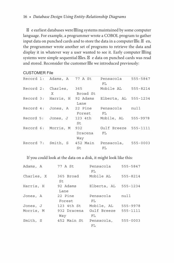
The.earliest.databases.were.filing.systems.maintained.by.some.computer.language..For.example,.a.programmer.wrote.a.COBOL.program.to.gather.input.data.on.punched.cards.and.to.store.the.data.in.a.computer.file..Then,.the.programmer.wrote.another.set.of.programs.to.retrieve.the.data.and.display.it. in.whatever.way.a.user.wanted.to.see.it..Early.computer.filing.systems.were.simple.sequential.files..The.data.on.punched.cards.was.read.and.stored..Reconsider.the.customer.file.we.introduced.previously:
CUSTOMER FileRecord 1: Adams, A 77 A St Pensacola
FL555-5847
Record 2: Charles, X
365 Broad St
Mobile AL 555-8214
Record 3: Harris, H 92 Adams Lane
Elberta, AL 555-1234
Record 4: Jones, A 22 Pine Forest
Pensacola FL
null
Record 5: Jones, J 123 4th St
Mobile, AL 555-9978
Record 6: Morris, M 932 Dracena Way
Gulf Breeze FL
555-1111
Record 7: Smith, S 452 Main St
Pensacola, FL
555-0003
If.you.could.look.at.the.data.on.a.disk,.it.might.look.like.this:
Adams, A 77 A St Pensacola FL
555-5847
Charles, X 365 Broad St
Mobile AL 555-8214
Harris, H 92 Adams Lane
Elberta, AL 555-1234
Jones, A 22 Pine Forest
Pensacola FL
null
Jones, J 123 4th St Mobile, AL 555-9978Morris, M 932 Dracena
WayGulf Breeze FL
555-1111
Smith, S 452 Main St Pensacola, FL
555-0003

Data and Data Models • 17
The.records.as.addressed.by.COBOL.had.a.structure.like.this:
01.CUSTOMER05.NAME CHARACTER(20)05.ADDRESS CHARACTER(20)05.CITY-STATE CHARACTER(25)05.PHONE CHARACTER(7)
The.file.was.referred.to.as.a.“sequential.file.”.If.a.person.wanted.to.see.a.listing.of.data.by.address.rather.than.name,.the.file.had.to.be.sorted.and.the.data.redisplayed..If.data.was.added.to.the.file,.it.had.to.be.put.in.its.proper.place.according.to.the.sequential.key,.which.in.this.example.is.the.name.field.
Two.other.principal.filing.systems.evolved.in.the.1960s:.indexed.and.the.direct.access.filing.systems..Indexed.systems.were.based.on.the.maintenance.of.indexes.for.records.rather.than.a.strict.sequential.ordering.of.the.records.themselves..Look.again.at.the.customer.example.in.a.different.light:
CUSTOMER FileRecord 1: Adams, A 77 A St. Pensacola
FL555-5847
Record 2: Charles, X 365 Broad St
Mobile AL 555-8214
...
In. this. case,. suppose. that. Record. 1. were. not. a. numerical. record. but.rather. a. disk. address.. Then,. suppose. there. was. an. index. to. the. records.themselves.that.consisted.of.names.and.disk.addresses.like.this:
Name Disk addressAdams, A 1Charles, X 2Harris, H 3and so forth.
Now,.suppose.you.added.a.customer.called.Baker,.B..In.a.sequential.fil-ing. system,. you. would. have. to. put. Baker. between. Adams. and. Charles,.but.in.an.indexed.system,.you.could.put.Baker.anywhere.on.the.disk.and.simply.change.the.index.to.find.Baker:
18 • Database Design Using Entity-Relationship Diagrams
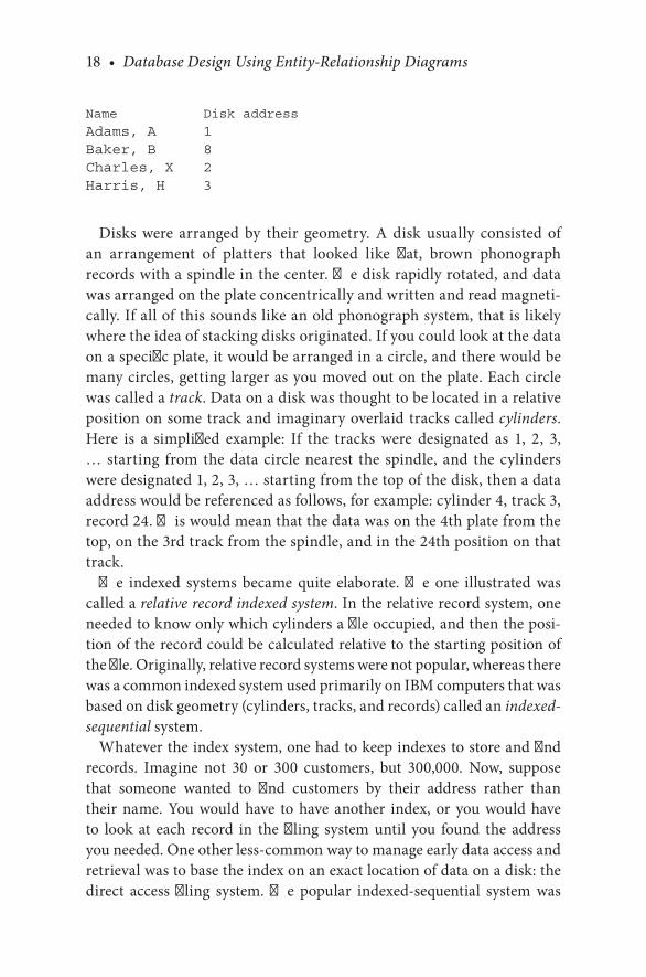
Name Disk addressAdams, A 1Baker, B 8Charles, X 2Harris, H 3
Disks. were. arranged. by. their. geometry.. A. disk. usually. consisted. of.an. arrangement. of. platters. that. looked. like. flat,. brown. phonograph.records.with.a.spindle.in.the.center..The.disk.rapidly.rotated,.and.data.was.arranged.on.the.plate.concentrically.and.written.and.read.magneti-cally..If.all.of.this.sounds.like.an.old.phonograph.system,.that.is.likely.where.the.idea.of.stacking.disks.originated..If.you.could.look.at.the.data.on.a.specific.plate,.it.would.be.arranged.in.a.circle,.and.there.would.be.many.circles,.getting.larger.as.you.moved.out.on.the.plate..Each.circle.was.called.a.track..Data.on.a.disk.was.thought.to.be.located.in.a.relative.position.on.some.track.and.imaginary.overlaid.tracks.called.cylinders..Here. is. a. simplified. example:. If. the. tracks. were. designated. as. 1,. 2,. 3,.….starting. from. the.data. circle.nearest. the. spindle,. and. the. cylinders.were.designated.1,.2,.3,.….starting.from.the.top.of.the.disk,.then.a.data.address.would.be.referenced.as.follows,.for.example:.cylinder.4,.track.3,.record.24..This.would.mean.that.the.data.was.on.the.4th.plate.from.the.top,.on.the.3rd.track.from.the.spindle,.and.in.the.24th.position.on.that.track.
The. indexed. systems. became. quite. elaborate.. The. one. illustrated. was.called.a.relative record indexed system..In.the.relative.record.system,.one.needed.to.know.only.which.cylinders.a.file.occupied,.and.then.the.posi-tion.of.the.record.could.be.calculated.relative.to.the.starting.position.of.the.file..Originally,.relative.record.systems.were.not.popular,.whereas.there.was.a.common.indexed.system.used.primarily.on.IBM.computers.that.was.based.on.disk.geometry.(cylinders,.tracks,.and.records).called.an.indexed-sequential.system.
Whatever.the.index.system,.one.had.to.keep.indexes.to.store.and.find.records.. Imagine. not. 30. or. 300. customers,. but. 300,000.. Now,. suppose.that. someone. wanted. to. find. customers. by. their. address. rather. than.their. name.. You. would. have. to. have. another. index,. or. you. would. have.to. look. at. each. record. in. the. filing. system. until. you. found. the. address.you.needed..One.other.less-common.way.to.manage.early.data.access.and.retrieval.was.to.base.the.index.on.an.exact.location.of.data.on.a.disk:.the.direct. access. filing. system.. The. popular. indexed-sequential. system. was.
Data and Data Models • 19
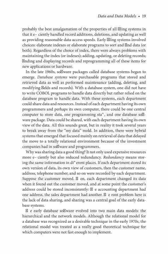
probably.the.best.amalgamation.of.the.properties.of.all.filing.systems.in.that.it.efficiently.handled.record.additions,.deletions,.and.updating.as.well.as.providing.reasonable.data.access.speeds..Early.filing.systems.involved.choices:.elaborate.indexes.or.elaborate.programs.to.sort.and.find.data.(or.both)..Regardless.of.the.choice.of.index,.there.were.always.problems.with.maintaining.the.index.(or.indexes);.adding,.updating,.or.deleting.records;.finding.and.displaying.records.and.reprogramming.all.of.these.items.for.new.applications.or.hardware.
In. the. late.1960s,. software.packages.called.database.systems.began. to.emerge.. Database systems. were. purchasable. programs. that. stored. and.retrieved.data.as.well. as.performed.maintenance. (adding,.deleting,. and.modifying.fields.and.records)..With.a.database.system,.one.did.not.have.to.write.COBOL.programs.to.handle.data.directly.but.rather.relied.on.the.database.program.to.handle.data..With.these.systems,.each.department.could.share.data.and.resources..Instead.of.each.department.having.its.own.programmers.and.perhaps.its.own.computer,.there.could.be.one.central.computer. to. store. data,. one. programming. staff,. and. one. database. soft-ware.package..Data.could.be.shared,.with.each.department.having.its.own.view.of.the.data..All.this.sounds.great,.but.in.reality.it.took.several.years.to.break.away. from.the.“my.data”.mold.. In.addition,. there.were.hybrid.systems.that.emerged.that.focused.mainly.on.retrieval.of.data.that.delayed.the. move. to. a. totally. relational. environment. because. of. the. investment.companies.had.in.software.and.programmers.
Why.was.sharing.data.a.good.thing?.It.not.only.used.expensive.resources.more. efficiently. but. also. reduced. redundancy.. Redundancy. means. stor-ing.the.same.information.in.different.places..If.each.department.stored.its.own.version.of.data,.its.own.view.of.customers,.then.the.customer.name,.address,.telephone.number,.and.so.on.were.recorded.by.each.department..Suppose. the. customer. moved.. Then,. each. department. changed. its. data.when.it.found.out.the.customer.moved,.and.at.some.point.the.customer’s.address. could.be. stored. inconsistently:.The.accounting.department.had.one.address,.the.sales.department.had.another..The.root.problem.here.is.the.lack.of.data.sharing,.and.sharing.was.a.central.goal.of.the.early.data-base.systems.
The. early. database. software. evolved. into. two. main. data. models:. the.hierarchical.and.the.network.models..Although.the.relational.model.for.a.database.was.recognized.as.a.desirable.technique.in.the.early.1970s,.the.relational. model. was. treated. as. a. really. good. theoretical. technique. for.which.computers.were.not.fast.enough.to.implement.

20 • Database Design Using Entity-Relationship Diagrams
The. database. models. (hierarchical,. network,. and. relational). were. logical models—ways.of.logically.perceiving.the.arrangement.of.data.in.a.file.struc-ture..One.perceived.how.the.data.was.to.be.logically.stored,.and.the.database.physically.implemented.the.logical.model..As.we.shall.see,.there.is.a.close.rela-tionship.between.the.logical.and.physical.implementations.of.the.hierarchical.and.network.models..Since.there.were.no.practical.relational.implementations.on.other.than.what.was.then.supercomputers.at.research.centers,.the.world.of.commercial.databases.in.the.1970s.involved.choosing.between.the.hierarchi-cal.and.network.models..The.next.sections.give.a. little. insight. into.each.of.these.three.main.models.and.an.introduction.to.the.relational.model.
CHECKPOINT 2.2. 1.. What.is.a.sequential.file?. 2.. What.is.COBOL?. 3.. Why.is.ordering.important.in.a.sequential.filing.system?. 4.. What.is.a.database.program?. 5.. In.the.early.days,.how.was.data.put.into.a.file?
2.4 DATABASE MODELS
We.now.take.a.look.back.at.database.models.as.they.were.before.the.rela-tional.database.was.practical..The.look.back.shows.why.the.“old.systems”.are.considered.obsolete.and.why.the.relational.model.is.the.de.facto.stan-dard.in.databases.today..The.old.systems.were.classified.as.two.main.types:.hierarchical.and.network..These.two.models.defined.a.database.before.the.1980s..Although.they.might.be.considered.“old.fashioned,”.there.are.sys-tems.still.in.use.today.that.depend.on.these.models.
2.4.1 The Hierarchical Model
In. hierarchical. database. models,. all. data. are. arranged. in. a. top-down.fashion.in.which.some.records.have.one.or.more.“dependent”.or.“child”.records,.and.each.child.record.is.tied.to.one.and.only.one.“parent.”.The.parent-child.relationship.is.not.meant.to.infer.a.human.familial.relation-ship..The.terms.parent.and.child.are.historical.and.are.meant.to.conjure.up.a.picture.of.one.type.of.data.as.dependent.on.another..As.is.illustrated.here,.the.child.will.be.sports.played.by.a.parent-person..Another.termi-nology.for.the.parent-child.relationship.is.owner.and.objects owned,.but.parent-child.is.more.common.
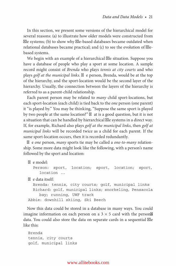
Data and Data Models • 21
In.this.section,.we.present.some.versions.of.the.hierarchical.model.for.several.reasons:.(a).to.illustrate.how.older.models.were.constructed.from.file.systems;.(b).to.show.why.file-based.databases.became.outdated.when.relational.databases.became.practical;.and.(c).to.see.the.evolution.of.file-based.systems.
We.begin.with.an.example.of.a.hierarchical.file.situation..Suppose.you.have. a. database. of. people. who. play. a. sport. at. some. location.. A. sample.record.might.consist.of.Brenda.who.plays. tennis at city courts. and.who.plays.golf at the municipal links..The.person,.Brenda,.would.be.at.the.top.of.the.hierarchy,.and.the.sport-location.would.be.the.second.layer.of.the.hierarchy..Usually,.the.connection.between.the.layers.of.the.hierarchy.is.referred.to.as.a.parent-child.relationship.
Each.parent.person.may.be.related. to.many. child.sport-locations,.but.each.sport-location.(each.child).is.tied.back.to.the.one.person.(one.parent).it.“is.played.by.”.You.may.be.thinking,.“Suppose.the.same.sport.is.played.by.two.people.at.the.same.location?”.That.is.a.good.question,.but.it.is.not.a.situation.that.can.be.handled.by.hierarchical.file.systems.in.a.direct.way..If,.for.example,.Richard.also.plays.golf at the municipal links,.then.golf at municipal links.will.be. recorded. twice.as.a.child. for.each.parent.. If. the.same.sport-location.occurs,.then.it.is.recorded.redundantly.
The.one.person,.many.sports.tie.may.be.called.a.one-to-many.relation-ship..Some.more.data.might.look.like.the.following,.with.a.person’s.name.followed.by.the.sport.and.location:
The.model:Person: sport, location; sport, location; sport,
location ...
The.data.itself:Brenda: tennis, city courts; golf, municipal linksRichard: golf, municipal links; snorkeling, Pensacola
bay; running, UWF trackAbbie: downhill skiing, Ski Beech
Now.this.data.could.be.stored.in.a.database.in.many.ways..You.could.imagine. information. on. each. person. on. a. 3. ×. 5. card. with. the. person,s.data..You.could.also.store.the.data.on.separate.cards.in.a.sequential.file.like.this:
Brendatennis, city courtsgolf, municipal links
www.allitebooks.com
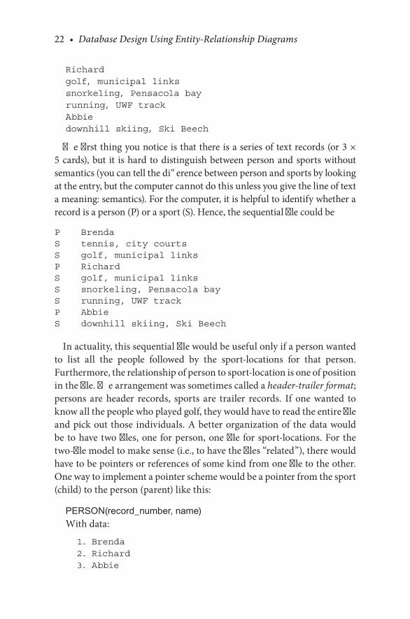
22 • Database Design Using Entity-Relationship Diagrams
Richardgolf, municipal linkssnorkeling, Pensacola bayrunning, UWF trackAbbiedownhill skiing, Ski Beech
The.first.thing.you.notice.is.that.there.is.a.series.of.text.records.(or.3.×.5.cards),.but. it. is.hard. to.distinguish.between.person.and.sports.without.semantics.(you.can.tell.the.difference.between.person.and.sports.by.looking.at.the.entry,.but.the.computer.cannot.do.this.unless.you.give.the.line.of.text.a.meaning:.semantics)..For.the.computer,.it.is.helpful.to.identify.whether.a.record.is.a.person.(P).or.a.sport.(S)..Hence,.the.sequential.file.could.be
P BrendaS tennis, city courtsS golf, municipal linksP RichardS golf, municipal linksS snorkeling, Pensacola bayS running, UWF trackP AbbieS downhill skiing, Ski Beech
In.actuality,.this.sequential.file.would.be.useful.only.if.a.person.wanted.to. list. all. the. people. followed. by. the. sport-locations. for. that. person..Furthermore,.the.relationship.of.person.to.sport-location.is.one.of.position.in.the.file..The.arrangement.was.sometimes.called.a.header-trailer format;.persons. are. header. records,. sports. are. trailer. records.. If. one. wanted. to.know.all.the.people.who.played.golf,.they.would.have.to.read.the.entire.file.and.pick.out.those. individuals..A.better.organization.of. the.data.would.be.to.have.two.files,.one.for.person,.one.file. for.sport-locations..For. the.two-file.model.to.make.sense.(i.e.,.to.have.the.files.“related”),.there.would.have.to.be.pointers.or.references.of.some.kind.from.one.file.to.the.other..One.way.to.implement.a.pointer.scheme.would.be.a.pointer.from.the.sport.(child).to.the.person.(parent).like.this:
PERSON(record_number, name)With.data:
1. Brenda 2. Richard 3. Abbie

Data and Data Models • 23
SPORTS(sport, location, reference to person)With.data:tennis, city courts, 1golf, municipal links,1golf, municipal links, 2snorkeling, Pensacola bay, 2running, UWF track, 2downhill skiing, Ski Beech, 3
A.diagram.of.this.relationship.is.shown.in.Figure 2.1.The.actual.location.of.the.records.on.a.disk.could.be.arbitrary..The.sense.
of.the.data.is.not.lost.if.the.locations.are.disk.addresses.and.if.you.imagine.that.there.are.thousands.of.persons.and.sports:
PERSON(record address, name)With.data:A45C. BrendaC333. AbbieB259. Richard
SPORTS(sport, location, reference to person)With.data:golf, municipal links, B259running, UWF track, B259downhill skiing, Ski Beech, C333snorkeling, Pensacola bay, B259tennis, city courts, A45Cgolf, municipal links, A45C
This.system.has.a.parent-child.link..Here,.we.assume.that.the.primary.key.of.the.person.file.is.the.record_number..The.“reference.to.person”.in.the.sports.file.refers.to.the.primary.key.of.the.person.file.and.is.called.a.
Person (Parent record)
Sport Sport Sport(Child Records)
FIGURE 2.1A.hierarchy.of.persons.and.sports.with.parent.pointers.

24 • Database Design Using Entity-Relationship Diagrams
foreign key.(FK).because.it.is.a.primary.key.of.another.file..The.FK.refer-ences.a.primary.key,.hence.completing. the.essential. relationship.of.one.file.to.the.other..If.there.were.no.relationship,.then.you.would.have.two.independent.files.with.no.connection—the.system.would.make.no.sense.
While. we. have. established. the. relationship. of. child. to. parent. in. the.discussion,.the.database.has.some.drawbacks..To.answer.a.question.like,.“Who.plays.golf.at.municipal.links?”.you.start.looking.at.the.Sports.file,.look.for.“golf.at.municipal.links,”.and.see.what.parent.records.there.are..If.your.question.were,.“What.sports.does.Richard.play?”.you.would.first.find.Richard.in.the.Person.file,.then.look.through.the.Sports.file.to.find.links.back.to.Richard.
If.you.were.actually. implementing.this.model,.you.could.enhance.the.system.a.bit..An.improvement.to.this.model.would.be.to.reference.each.sport.from.within.each.parent.record.(let.us.go.back.to.simple.numbers.for.this):
PERSON(record address, name, (sport address))With.data:
1. Brenda, (101, 102) 2. Richard (103, 104, 105) 3. Abbie (106)
SPORTS(sport, location, reference to person)With.data:101, tennis, city courts, 1102, golf, municipal links, 1103, golf, municipal links, 2104, snorkeling, Pensacola bay, 2105, running, UWF track, 2106, downhill skiing, Ski Beech, 3
Figure 2.2.depicts.the.relationship.between.parent.and.child.records.in.both.directions..When.viewed.from.the.parent,.this.link.is.called.a.multi-ple-child.pointer.(MCP)..When.viewed.from.the.child.the.link.is.called.a.parent.pointer.
In.this.model,.the.relationship.between.parent.and.child.records.is.done.two.ways..The.“reference.to.person”.in.the.Sports.file.is.a.link.(the.FK).from.child.to.parent..The.reference.to.multiple.children.in.the.parent.records.is.called.an.MCP.scheme..While.it.is.true.that.the.MCP.is.redundant.to.the.relationship,.it.does.two.practical.things:.(a).It.allows.questions.to.be.asked.
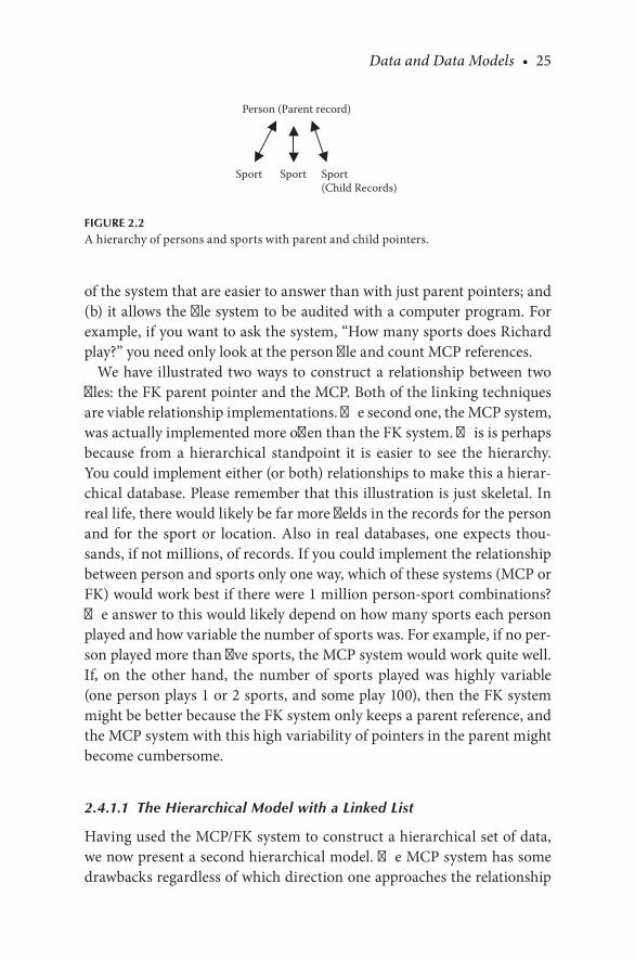
Data and Data Models • 25
of.the.system.that.are.easier.to.answer.than.with.just.parent.pointers;.and.(b).it.allows.the.file.system.to.be.audited.with.a.computer.program..For.example,.if.you.want.to.ask.the.system,.“How.many.sports.does.Richard.play?”.you.need.only.look.at.the.person.file.and.count.MCP.references.
We.have. illustrated.two.ways.to.construct.a.relationship.between.two.files:.the.FK.parent.pointer.and.the.MCP..Both.of.the.linking.techniques.are.viable.relationship.implementations..The.second.one,.the.MCP.system,.was.actually.implemented.more.often.than.the.FK.system..This.is.perhaps.because. from. a. hierarchical. standpoint. it. is. easier. to. see. the. hierarchy..You.could.implement.either.(or.both).relationships.to.make.this.a.hierar-chical.database..Please.remember.that.this.illustration.is.just.skeletal..In.real.life,.there.would.likely.be.far.more.fields.in.the.records.for.the.person.and. for. the. sport.or. location.. Also. in. real.databases,.one.expects. thou-sands,.if.not.millions,.of.records..If.you.could.implement.the.relationship.between.person.and.sports.only.one.way,.which.of.these.systems.(MCP.or.FK).would.work.best.if.there.were.1.million.person-sport.combinations?.The.answer.to.this.would.likely.depend.on.how.many.sports.each.person.played.and.how.variable.the.number.of.sports.was..For.example,.if.no.per-son.played.more.than.five.sports,.the.MCP.system.would.work.quite.well..If,. on. the. other. hand,. the. number. of. sports. played. was. highly. variable.(one.person.plays.1.or.2.sports,.and.some.play.100),.then.the.FK.system.might.be.better.because.the.FK.system.only.keeps.a.parent.reference,.and.the.MCP.system.with.this.high.variability.of.pointers.in.the.parent.might.become.cumbersome.
2.4.1.1 The Hierarchical Model with a Linked List
Having.used.the.MCP/FK.system.to.construct.a.hierarchical.set.of.data,.we.now.present.a.second.hierarchical.model..The.MCP.system.has.some.drawbacks.regardless.of.which.direction.one.approaches.the.relationship.
Person (Parent record)
Sport Sport Sport(Child Records)
FIGURE 2.2A.hierarchy.of.persons.and.sports.with.parent.and.child.pointers.

26 • Database Design Using Entity-Relationship Diagrams
(as.MCP,.FK,.or.both)..For.example,.suppose.you.implemented.the.system.with.the.child.pointers.in.the.parent.record.(MCP),.and.there.were.more.child.records.than.were.planned..Suppose.the.system.was.not.person.and.sports,.but.students.at.a.school.and.absences..The.student.would.be.the.parent,. and. the. absence. records. would. be. the. child.. Now,. suppose. you.designed. this. system.with.an.MCP.relationship. so. that. a. student. could.have.up.to.20.absences..What.happens.when.the.student.is.absent.for.the.21st.time?.One.of.two.things.has.to.happen:.(a).The.MCP.system.would.have.to.be.modified.to.include.some.kind.of.overflow;.or.(b).some.other.hierarchical.system.would.have. to.be.used..We.could,.of.course,. imple-ment.this.as.an.FK.system.and.ignore.the.MCP.part.entirely..Or,.we.could.implement.a.different.system,.and.that.is.what.we.illustrate.now.
The.following.file.system.uses.a.“linked.list”.or.“chain”.system.to.imple-ment.the.relationship.between.parent.and.child..This.system.is.similar.to.both.of.the.schemes.discussed..With.the.same.data,.the.records.would.set.up.like.this:
Parent (link to 1st child)
and.within.the.child.records:
Child (link to next child)
Here.is.the.data.from.above.with.this.type.of.arrangement:
PERSON(record address, name, first sport)With.data:1. Brenda (101)2. Richard (103)3. Abbie (106)
SPORTS(sport, location, link to next sport for that person)With.data:101, tennis, city courts, 102102, golf, municipal links, 999103, golf, municipal links, 104104, snorkeling, Pensacola bay, 105105, running, UWF track, 999106, downhill skiing, Ski Beech, 999
Here,.999.means.“no.next.link.”Figure 2.3. illustrates.a. linked. list.parent-to-child.pointing.scheme.. In.
this.system,.we.have.a.link.from.parent.to.child.that.we.did.not.have.with.the.FK.system.alone..Furthermore,.the.records.in.both.the.parent.and.the.
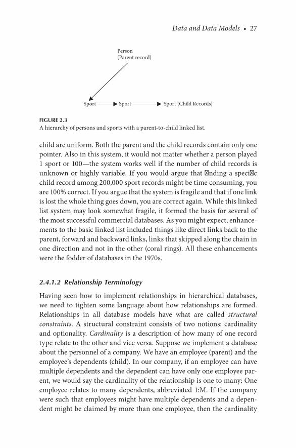
Data and Data Models • 27
child.are.uniform..Both.the.parent.and.the.child.records.contain.only.one.pointer..Also.in.this.system,.it.would.not.matter.whether.a.person.played.1.sport.or.100—the.system.works.well. if. the.number.of.child.records.is.unknown. or. highly. variable.. If. you. would. argue. that. finding. a. specific.child.record.among.200,000.sport.records.might.be.time.consuming,.you.are.100%.correct..If.you.argue.that.the.system.is.fragile.and.that.if.one.link.is.lost.the.whole.thing.goes.down,.you.are.correct.again..While.this.linked.list.system.may.look.somewhat.fragile,.it.formed.the.basis.for.several.of.the.most.successful.commercial.databases..As.you.might.expect,.enhance-ments.to.the.basic.linked.list.included.things.like.direct.links.back.to.the.parent,.forward.and.backward.links,.links.that.skipped.along.the.chain.in.one.direction.and.not.in.the.other.(coral.rings)..All.these.enhancements.were.the.fodder.of.databases.in.the.1970s.
2.4.1.2 Relationship Terminology
Having. seen. how. to. implement. relationships. in. hierarchical. databases,.we. need. to. tighten. some. language. about. how. relationships. are. formed..Relationships. in. all. database. models. have. what. are. called. structural constraints.. A. structural. constraint. consists. of. two. notions:. cardinality.and.optionality..Cardinality. is.a.description.of.how.many.of.one.record.type.relate.to.the.other.and.vice.versa..Suppose.we.implement.a.database.about.the.personnel.of.a.company..We.have.an.employee.(parent).and.the.employee’s.dependents.(child)..In.our.company,.if.an.employee.can.have.multiple.dependents.and.the.dependent.can.have.only.one.employee.par-ent,.we.would.say.the.cardinality.of.the.relationship.is.one.to.many:.One.employee. relates. to. many. dependents,. abbreviated. 1:M.. If. the. company.were.such.that.employees.might.have.multiple.dependents.and.a.depen-dent.might.be.claimed.by.more.than.one.employee,.then.the.cardinality.
Person(Parent record)
Sport Sport Sport (Child Records)
FIGURE 2.3A.hierarchy.of.persons.and.sports.with.a.parent-to-child.linked.list.

28 • Database Design Using Entity-Relationship Diagrams
would. be. many. to. many:. Many. employees. relate. to. many. dependents,.abbreviated.M:N.(as.in.M.of.one.side.relates.to.N.on.the.other.side,.and.M.and.N.are.generally.not.equal).
Optionality refers.to.whether.one.record.may.or.must.have.a.correspond-ing.record.in.the.other.file..If.the.employee.may.or.may.not.have.depen-dents,.then.the.optionality.of.the.employee-to-dependent.relationship.is.optional.or.partial..If.the.dependents.must.be.“related.to”.employee(s).(and.every.employee.must.have.dependents),.then.the.optionality.of.dependent.to.employee.is.mandatory.or.full.
Further,.relationships.are.always.stated.in.both.directions.in.a.database.description..We.would.say
Employees may have zero or more dependents,
and
Dependents must be associated with one and only one employee.
Note. the. employee-to-dependent,. one-to-many. cardinality. and. the.optional/mandatory. nature. of. the. relationship.. We. return. to. this. lan-guage,.but.it.is.easy.to.see.that.the.way.a.database.is.designed.depends.on.the.description.of.it..If.the.description.is.clear.and.unambiguous,.then.the.likely.outcome.of.database.design.is.far.more.predictable.
2.4.1.3 Drawbacks of the Hierarchical Model
All.relationships.between.records.in.a.hierarchical.model.have.a.cardinal-ity.of.one.to.many.or.one.to.one,.but.never.many.to.one.or.many.to.many..So,.for.a.hierarchical.model.of.employee.and.dependent,.we.can.only.have.the.employee-to-dependent.relationship.as.one.to.many.or.one.to.one;.an.employee.may.have.zero.or.more.dependents..In.the.hierarchical.model,.you.could.not.have.dependents.with.multiple.parent-employees.(unless.we.introduce.redundant.recording.of.dependents).
As.we. illustrated,. the.original.way.hierarchical.databases.were. imple-mented.involved.choosing.some.way.of.physically.“connecting”.the.par-ent.and.the.child.records..Imagine.you.have.looked.up.information.on.an.employee.in.an.employee.filing.cabinet.and.you.want.to.find.the.dependent.records.for.that.employee.in.a.dependent.filing.cabinet..One.way.to.imple-ment.the.employee-dependent.relationship.would.be.to.have.an.employee.record.point.to.a.dependent.record.and.have.that.dependent.record.point.to. the. next. dependent. (a. linked. list. of. child. records).. For. example,. you.find.employee.Jones..In.Jones’s.record.there.is.a.notation.that.Jones’s.first.

Data and Data Models • 29
dependent.is.found.in.the.dependent.filing.cabinet,.file.drawer.2,.record.17..The.“file.drawer.2,.record.17”.is.called.a.pointer.and.is.the.connection.or. relationship. between. the. employee. and. the. dependent.. Now,. to. take.this.example.further,.suppose.the.record.of.the.dependent.in.file.drawer.2,.record.17,.points.to.the.next.dependent.in.file.drawer.3,.record.38,.then.that.dependent.points.to.the.next.dependent.in.file.drawer.1,.record.82.
As.we.pointed.out.in.the.person-sports.model,.the.linked.list.approach.to.connecting.parent.and.child.records.has.advantages.and.disadvantages..For.example,.some.advantages.would.be.that.each.employee.has.to.main-tain.only.one.pointer,.and. that. the. size.of. the. linked. list.of.dependents.is. theoretically. unbounded.. Drawbacks. would. include. the. fragility. of.the. system. in. that. if.one.dependent.record. is.destroyed,. then. the.chain.is.broken..Further,.if.you.wanted.information.about.only.one.of.the.child.records,.you.might.have.to.look.through.many.records.before.you.found.the.one.you.were.looking.for.
There. are,. of. course,. several. other. ways. of. implementing. the. parent-child.link..The.point.here.is.that.some.system.has.to.be.chosen.to.be.imple-mented.in.the.underlying.database.software..Once.the.linking.system.is.chosen,.it.is.fixed.by.the.software.implementation;.the.way.the.link.is.done.has.to.be.used.to.link.all.child.records.to.parents.regardless.of.how.inef-ficient.it.might.be.for.one.situation.
There.are.three.major.drawbacks.to.the.hierarchical.model:
. 1..Not.all.situations.fall.into.the.one-to-many,.parent-child.format.
. 2..The.choice.of.the.way.in.which.the.files.are.linked.has.an.impact.on.performance.both.positively.and.negatively.
. 3..The. linking. of. parents. and. child. records. is. done. physically.. If. the.dependent.file.were.reorganized,.then.all.pointers.would.have.to.be.reset.
2.5 THE NETWORK MODEL
Each.of.the.methods.presented.for.the.hierarchical.database.has.advan-tages.and.disadvantages..Since.the.network.model.allows.M:N.relation-ships,.we.want.to.implement.a.system.of.pointers.for.multiple.parents.for.each.child.record..How.would.this.be.handled?.You.would.most. likely.have.to.have.multiple.child-forward.links.with.either.a.linked.list.or.an.MCP.system.in.the.parent,.parent.pointers.in.the.child.records.(perhaps.
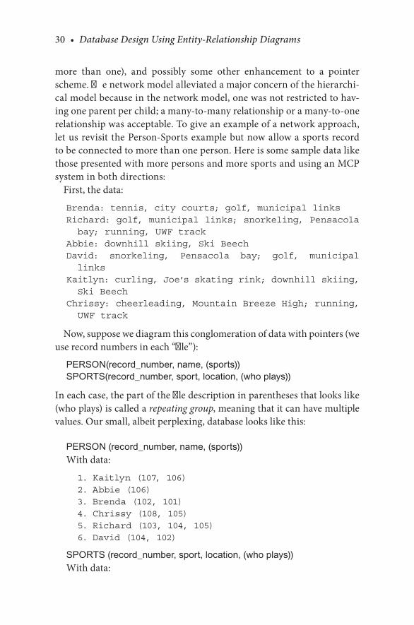
30 • Database Design Using Entity-Relationship Diagrams
more. than. one),. and. possibly. some. other. enhancement. to. a. pointer.scheme..The.network.model.alleviated.a.major.concern.of.the.hierarchi-cal.model.because.in.the.network.model,.one.was.not.restricted.to.hav-ing.one.parent.per.child;.a.many-to-many.relationship.or.a.many-to-one.relationship.was.acceptable..To.give.an.example.of.a.network.approach,.let.us.revisit. the.Person-Sports.example.but.now.allow.a.sports.record.to.be.connected.to.more.than.one.person..Here.is.some.sample.data.like.those.presented.with.more.persons.and.more.sports.and.using.an.MCP.system.in.both.directions:
First,.the.data:
Brenda: tennis, city courts; golf, municipal linksRichard: golf, municipal links; snorkeling, Pensacola bay; running, UWF track
Abbie: downhill skiing, Ski BeechDavid: snorkeling, Pensacola bay; golf, municipal links
Kaitlyn: curling, Joe’s skating rink; downhill skiing, Ski Beech
Chrissy: cheerleading, Mountain Breeze High; running, UWF track
Now,.suppose.we.diagram.this.conglomeration.of.data.with.pointers.(we.use.record.numbers.in.each.“file”):
PERSON(record_number, name, (sports))SPORTS(record_number, sport, location, (who plays))
In.each.case,.the.part.of.the.file.description.in.parentheses.that.looks.like.(who.plays).is.called.a.repeating group,.meaning.that.it.can.have.multiple.values..Our.small,.albeit.perplexing,.database.looks.like.this:
PERSON (record_number, name, (sports))With.data:
1. Kaitlyn (107, 106)2. Abbie (106)3. Brenda (102, 101)4. Chrissy (108, 105)5. Richard (103, 104, 105)6. David (104, 102)
SPORTS (record_number, sport, location, (who plays))With.data:

Data and Data Models • 31
101 tennis, city courts (3)102 golf, municipal links (3, 6)103 golf, municipal links (5)104 snorkeling, Pensacola bay (5, 6)105 running, UWF track (4, 5)106 downhill skiing, Ski Beech (2, 1)107 curling, Joe’s skating rink (1)108 cheerleading, Mountain Breeze High (4)
The.network.with.pointers.in.both.directions.is.illustrated.in.Figure 2.4.The.complexity.of. the.network.database. is. exponentially.greater. than.
that.of.the.hierarchical.one..The.database.just.illustrated.could.have.been.implemented.as.a.series.of.linked.child/parents.or.some.other.combina-tion.of.links.and.pointers..The.second.and.third.drawbacks.of.hierarchical.databases.spill.over.to.network.databases..If.one.were.to.design.a.file-based.database.system.from.scratch,.one.would.have.to.choose.some.method.of.physically.connecting.or.linking.records..This.choice.of.record.connection.then.locks.us.into.the.same.problem.as.before:.a.hardware-implemented.connection.that.has.an.impact.on.performance.both.positively.and.nega-tively..Further,.as. the.database.becomes.more.complicated,. the.paths.of.connections.and.the.maintenance.problems.become.exponentially.more.difficult.to.manage.
As.a.project,.you.could.create.the.Person-Sports.database.with.a.few.more.records.than.given.in.the.example.using.linked.lists..At.first,.you.might.think.this.to.be.a.daunting.exercise,.but.one.of.the.most.popular.database.systems.in.the.1970s.used.a.variant.of.this.system..The.parent.and.child.records.were.all.linked.with.linked.lists.going.in.two.directions—forward.and.backward..The.forward/backward.idea.was.to.speed.up.finding.child.records.such.that.one.could.search.for.children.by.going.either.way..An.enhancement.of.this.system.would.be.to.use.forward-pointing.linked.lists.with. a. backward-pointing. chain. of. links,. but. with. the. backward. chain.
PersonA PersonB
SportW SportX SportY SportZ
FIGURE 2.4A.network.of.persons.and.sports.with.MCP.and.parent.pointers.
www.allitebooks.com

32 • Database Design Using Entity-Relationship Diagrams
skipping.every.n.records,.where.the.optimal.n.turns.out.to.be.the.square.root.of.the.number.of.entries.in.the.chain.
2.6 THE RELATIONAL MODEL
Codd.(1970).introduced.the.relational.model.to.describe.a.database.that.did.not.suffer.the.drawbacks.of.the.hierarchical.and.network.models.(i.e.,.physical.links.and.hardware-bound.restrictions)..Codd’s.premise.was.that.if.we.ignore.the.way.data.files.are.connected.and.arrange.our.data.into.sim-ple.two-dimensional,.unordered.tables,.then.we.can.develop.a.calculus.for.queries.(questions.posed.to.the.database),.and.we.can.focus.on.the.data.as.data,.not.as.a.physical.realization.of.a.logical.model..Codd’s.idea.was.truly.logical.in.that.one.was.no.longer.concerned.with.how.data.was.physically.stored..Rather,.data.sets.were.simply.unordered,.two-dimensional.tables.of.data..To.arrive.at.a.workable.way.of.deciding.which.pieces.of.data.went.into.which.table,.Codd.proposed.“normal.forms.”.To.understand.normal.forms,.we.must.first.introduce.the.notion.of.functional dependencies..After.we.understand.functional.dependences,.normal.forms.follow.
As. a. historical. note,. when. Codd. introduced. his. relational. model,. it.was.deemed.by.most.people.as.“theoretical.only.”.At.the.time,.a.typical.mainframe.computer.might.have.64K.of. internal.memory,. and.a.good.set.of.hard.disks.might.have.as.much.as.several.megabytes.of.storage..To.top.that.off,. the.computer. typically. took.up.a. large.room.that.required.separate. air. handling,. special. architectural. features. like. raised. floors,.and. enhanced. power. grids.. Remember. that. all. the. “computing. power”.was.shared.by.everyone.who.had.to.have.computing..In.a.company,.users.might. include. accounting,. purchasing,. personnel,. finance,. and. so. on..For.even.one.of.those.units.to.be.able.to.run.the.relational.model.in.the.early.1970s.would.have.required.vast.dedicated.resources..As.computers.became.more.ubiquitous,.less.expensive,.smaller,.and.so.on,.the.amount.of.memory.available.both.internally.and.externally.became.cheaper.and.had.far.greater.capacity..The.relational.model.“grew.up”.with.the.evolu-tion.of.computers.in.the.1980s..We.expand.the.notion.of.relational.data-base.in.the.next.chapter.
Data and Data Models • 33
CHECKPOINT 2.3. 1.. What.are.the.three.main.data.models.we.have.discussed?. 2.. Which.data.model.is.mostly.used.today?.Why?. 3.. What.are.some.of.the.disadvantages.of.the.hierarchical.data.model?. 4.. What.are.some.of.the.disadvantages.of.the.network.data.model?. 5.. How.are.all.relationships.(mainly.the.cardinalities).described.in.the.hier-
archical.data.model?.How.can.these.be.a.disadvantage.of.the.hierarchical.data.model?
. 6.. How.are.all.relationships.(mainly.the.cardinalities).described.in.the.network.data.model?.Would.you.treat.these.as.advantages.or.disad-vantages.of.the.network.data.model?
. 7.. What.are.structural.constraints?
. 8.. Why.was.Codd’s.promise.of.the.relational.model.better?
2.7 CHAPTER SUMMARY
In.this.chapter,.we.covered.concepts.that.are.essential.to.the.understanding.and.design.of.a.database..We.also.covered.data.models.from.a.historical.perspective—the.hierarchical.and.network.models.and.then.introduction.of.the.relational.model..This.chapter.should.serve.more.as.background.to.the.material.for.the.rest.of.the.book.
BIBLIOGRAPHY
Codd, E..F. 1970..A.relational.model.of.data.for.large.shared.data.banks..Communications of the ACM, 13(6):.377–387.

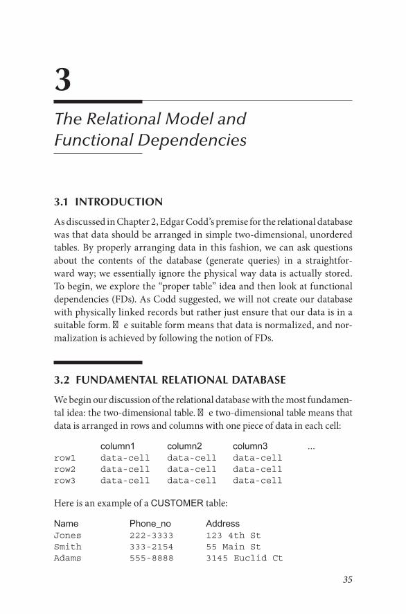
35
3The Relational Model and Functional Dependencies
3.1 INTRODUCTION
As.discussed.in.Chapter.2,.Edgar.Codd’s.premise.for.the.relational.database.was.that.data.should.be.arranged.in.simple.two-dimensional,.unordered.tables..By.properly.arranging.data. in.this. fashion,.we.can.ask.questions.about. the. contents. of. the. database. (generate. queries). in. a. straightfor-ward.way;.we.essentially.ignore.the.physical.way.data.is.actually.stored..To.begin,.we.explore.the.“proper.table”.idea.and.then.look.at.functional.dependencies.(FDs)..As.Codd.suggested,.we.will.not.create.our.database.with.physically.linked.records.but.rather.just.ensure.that.our.data.is.in.a.suitable.form..The.suitable.form.means.that.data.is.normalized,.and.nor-malization.is.achieved.by.following.the.notion.of.FDs.
3.2 FUNDAMENTAL RELATIONAL DATABASE
We.begin.our.discussion.of.the.relational.database.with.the.most.fundamen-tal.idea:.the.two-dimensional.table..The.two-dimensional.table.means.that.data.is.arranged.in.rows.and.columns.with.one.piece.of.data.in.each.cell:
column1 column2 column3 ...row1 data-cell data-cell data-cellrow2 data-cell data-cell data-cellrow3 data-cell data-cell data-cell
Here.is.an.example.of.a.CUSTOMER.table:
Name Phone_no AddressJones 222-3333 123 4th StSmith 333-2154 55 Main StAdams 555-8888 3145 Euclid Ct

36 • Database Design Using Entity-Relationship Diagrams
The.columns.are.given.titles:.Name, Phone_no, Address.The.rows.are.horizontal.arrangements.of.data.cells.under.each.column..
Row.1.containsJones 222-3333 123 4th St
Often,.when.discussing.a.row.in.a.table,.it.is.denoted.like.this:<Jones, 222-3333, 123 4th St>
The.data.cells.contain.facts,. for.example,.you.have.a.customer.named.Smith,.Smith’s.address. is.55.Main.Street,.and.so.on..In.the.two-dimen-sional. table,. each. column. of. data. contains. the. same. kind. of. data—the.same.data.type.with.the.same.semantics.(same.meaning)..The.following.is.a.two-dimensional.arrangement .but.it.violates.the.sense.of.“each.column.contains.the.same.kind.of.data”:
Name Phone_no AddressJones 222-3333 123 4th St55 Main St Smith 333-2154Adams 3145 Euclid Ct 555-8888
All.the.same.data.is.there,.but.it.is.jumbled.around,.and.the.column.head-ings.make.no.sense..In.an.arrangement.like.this,.we.would.say.the.data.was.“inconsistent.”
In.relational.databases,.the.data.cell.is.supposed.to.be.atomic..The.char-acteristic.of.atomicity.means.that.the.cell.contains.one.fact.and.only.one.fact..If.Adams.had.two.phone.numbers.and.if. they.were.entered.on.the.same.row,.it.would.not.be.a.valid.table.of.data.for.a.relational.database..You.would.have.to.design.the.tables.some.other.way.
Name Phone_no AddressJones 222-3333 123 4th StSmith 333-2154 55 Main StAdams 555-8888, 555-8889 3145 Euclid Ct
The.Phone_no.for.Adams.is.nonatomic..The.data.cell.that.contains.the.two.phone.numbers.is.said.to.contain.a.repeating group..If.a.two-dimensional.arrangement.of.data.cells.contains.only.atomic.data,.it.is.said.to.be.a.table..This.data.arrangement.with.a.nonatomic.cell.is.not.a.table,.unlike.the.pre-vious.example.with.all.atomic.cells..In.Codd’s.terminology.of.database,.if.you.have.a.table.(i.e.,.a.two-dimensional.arrangement.of.atomic.data),.then.your.data.is.in.the.first.normal.form.(1NF).
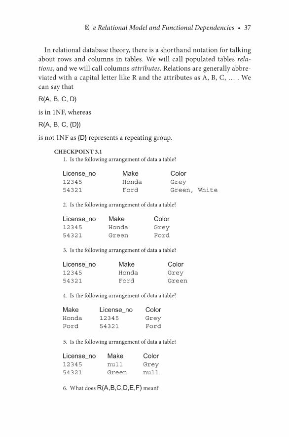
The Relational Model and Functional Dependencies • 37
In.relational.database.theory,.there.is.a.shorthand.notation.for.talking.about. rows. and. columns. in. tables.. We. will. call. populated. tables. rela-tions,.and.we.will.call.columns.attributes..Relations.are.generally.abbre-viated.with.a.capital.letter.like.R.and.the.attributes.as.A,.B,.C,.…...We.can.say.that
R(A, B, C, D)
is.in.1NF,.whereas
R(A, B, C, {D})
is.not.1NF.as.{D}.represents.a.repeating.group.
CHECKPOINT 3.1. 1.. Is.the.following.arrangement.of.data.a.table?
License_no Make Color12345 Honda Grey54321 Ford Green, White
. 2.. Is.the.following.arrangement.of.data.a.table?
License_no Make Color12345 Honda Grey54321 Green Ford
. 3.. Is.the.following.arrangement.of.data.a.table?
License_no Make Color12345 Honda Grey54321 Ford Green
. 4.. Is.the.following.arrangement.of.data.a.table?
Make License_no ColorHonda 12345 GreyFord 54321 Ford
5.. Is.the.following.arrangement.of.data.a.table?
License_no Make Color12345 null Grey54321 Green null
6.. What.does.R(A,B,C,D,E,F).mean?

38 • Database Design Using Entity-Relationship Diagrams
3.3 RELATIONAL DATABASE AND SETS
In.mathematics,.we.define.sets.as.an.unordered.collection.of.unique.objects..Codd.viewed.and.defined.a. relational.database. such. that. (a).all.data.was.atomic.in.two-dimensional.tables,.and.(b).all.tables.contained.sets.of.rows..The.notion.of.“sets.of.rows”.is.a.powerful.one.in.that.it.implies.two.things:.(a).there.are.no.duplicate.rows,.and.(b).there.is.no.order.among.the.rows.(rows.are.not.presumed.to.be.sorted.in.any.way)..Mathematical.sets.do.not.have.sorted.order.and.do.not.contain.duplicates..If.I.had.a.set.of.apparel,.it.might.contain.shoes,.socks,.shirt,.pants,.and.hats..The.same.set.could.be.written.as.(pants,.shirt,.socks,.hats,.shoes)..The.order.of.the.items.in.the.set.is.not.defined..An.item.either.is.in.the.set.or.not.in.the.set..As.far.as.the.set.is.concerned,.the.set.(pants,.shirt,.socks,.hat,.pants,.shirt,.shoes,.socks,.hats).is.the.same.as.before..The.duplication.of.items.makes.no.sense.in.sets.
When.we.look.at.some.rows.of.data.in.a.relational.database,.we.think.of.the.tables.(the.relation).as.sets.of.rows..Consider.the.following.table:
Name JobRich CarpenterBeryl DentistMary Jo Programmer
Setwise,.here.is.the.same.table:
Name JobBeryl DentistMary Jo ProgrammerRich Carpenter
The.order.of.the.rows.is.unimportant..If.we.had.a.duplicate.row.like.this
Name JobRich CarpenterBeryl DentistMary Jo ProgrammerRich Carpenter
we.would.not.have.a.valid.relational.table..Since.a.relational.database.is.a.“set.of.rows,”.the.extra.row.is.unnecessary.for.the.extraction.of.information.in.the.database..Also,.from.a.practical.standpoint.the.duplicate.row.would.violate.the.sense.of.being.able.to.identify.one.and.only.one.row.from.a.primary.key.

The Relational Model and Functional Dependencies • 39
As.with.sets,.we.may.ask.a.question.like,.“Is.<Lindsey, Cook>.in.the.database?”.In.this.case,.Lindsey.is.not.there..The.point.is.that.the.particu-lar.row.is.either.there.or.not—it.is.in.the.set.of.rows.or.it.is.not.
3.4 FUNCTIONAL DEPENDENCY
A.functional.dependency.(FD).is.a.relationship.of.one.attribute.in.a.relation.to.another.(according.to.the.old.terminology,.one.“field”.in.a.“record”.has.a.relationship.to.another.“field”)..In.a.database,.we.often.have.the.case.for.which.one.attribute.defines.the.other..For.example,.we.can.say.that.Social.Security.Number.(SSN).defines.or.identifies.a.name..What.does.this.mean?.It.means.that.if.I.have.a.database.with.SSNs.and.names,.and.if.I.know.someone’s.SSN,.then.I.can.find.the.person’s.name..Further,.since.we.used.the.word.defines,.we.are.saying.that.for.every.SSN.we.will.have.one.and.only.one.name..We.will.say.that.we.have.classified.name.as.functionally dependent.on.SSN.
The.idea.of.a.FD.is.to.define.one.field.as.an.anchor.from.which.one.can.always.find.a.single.value.for.another.field..If.this.sounds.familiar,.it.is—.this.is.the.idea.of.a.primary.key.we.discussed.previously..The.main.idea.in.FDs.is.to.find.primary.keys.such.that.all.data.in.a.record.depends.on.the.primary.key.alone.
In.a.database,.the.designer.makes.choices.defining.data.with.FDs..Recall.that. it. is. the. designer’s. responsibility. to. elicit. FD. information. from. the.user..The.user.tells.us.that.a.project.has.one.location.or.multiple.locations..The.user.tells.us.that.a.person.can.have.one.and.only.one.phone.number.or.not..Also,.working.backward.from.data,.one.cannot.examine.a.database.and.“prove”.that.some.attribute.is.functionally.dependent.on.another..The.sense.of.FD.is.one.of.definition,.and.it.goes.with.the.table.design.just.like.the.definition.of.column.order.and.data.type.
As.another.example,.suppose.that.a.company.assigned.each.employee.a.unique.employee.number..Just.consider.the.employee.number.and.name.for.a.moment..Each.employee.has.one.employee.number.and.one.name..Names.might.be.the.same.for.two.different.employees,.but.for.two.employees.their.employee.numbers.would.always.be.different.and.unique.because.the.com-pany.defined.them.that.way..It.would.be.inconsistent.in.the.database.if.there.were.two.occurrences.of.the.same.employee.number.with.different.names.
We.write.an.FD.with.an.arrow.like.this:
SSN à Name

40 • Database Design Using Entity-Relationship Diagrams
or
EmpNo à NameThe.expression.EmpNo à Name.is.read.“Empno.defines.Name”.or.“Empno.implies.Name.”
CHECKPOINT 3.2. 1.. In. the. following. table,. does. all. the. data. conform. to. EmpNo à
Name?
Empno Name123 Beryl456 Mary Jo
. 2.. Does.the.fact.that.the.data.conforms.to.the.proposed.FD.prove.that.the.FD.is.in.fact.true?
. 3.. In. the. following. table,. does. all. the. data. conform. to. EmpNo à Name?
Empno Name123 Beryl456 Mary Jo, Mary, MJ
. 4.. In.the.following.database,.does.all.the.data.conform.to.EmpNo à Name?
<123, Beryl><MJ, 456>
. 5.. In.the.following.database,.does.EmpNo à Name?
Empno Name123 Beryl456 Mary Jo
3.5 NON-1NF TO 1NF
Let.us.consider.this.arrangement.of.data:
CUSTOMERCustomer_no Name Phone_no Address101 Jones 222-3333 123 4th St102 Smith 333-2154 55 Main St107 Adams 555-8888, 555-8889 3145 Euclid Ct
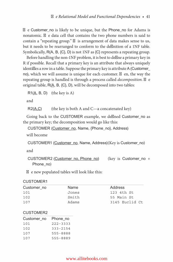
The Relational Model and Functional Dependencies • 41
The.Customer_no. is. likely. to.be.unique,.but. the.Phone_no. for.Adams. is.nonatomic..The.data.cell. that.contains. the. two.phone.numbers. is. said. to.contain.a.“repeating.group.”.This.arrangement.of.data.makes.sense.to.us,.but.it.needs.to.be.rearranged.to.conform.to.the.definition.of.a.1NF.table..Symbolically,.R(A, B, {C}, D).is.not.1NF.as.{C}.represents.a.repeating.group.
Before.handling.the.non-1NF.problem,.it.is.best.to.define.a.primary.key.in.R.if.possible..Recall.that.a.primary.key.is.an.attribute.that.always.uniquely.identifies.a.row.in.a.table..Suppose.the.primary.key.is.attribute.A (Customer_no),.which.we.will.assume.is.unique.for.each.customer..Then,.the.way.the.repeating.group.is.handled.is.through.a.process.called.decomposition..The.original.table,.R(A, B, {C}, D),.will.be.decomposed.into.two.tables:
R1(A, B, D). (the.key.is.A)
and
R2(A,C). (the.key.is.both.A.and.C—a.concatenated.key)
Going.back. to. the.CUSTOMER. example,.we.defined.Customer_no. as.the.primary.key;.the.decomposition.would.go.like.this:
CUSTOMER (Customer_no, Name, {Phone_no}, Address)will.become
CUSTOMER1 (Customer_no, Name, Address).(Key.is.Customer_no)
and
CUSTOMER2 (Customer_no, Phone_no) (key. is. Customer_no. +.Phone_no)
The.new.populated.tables.will.look.like.this:
CUSTOMER1Customer_no Name Address101 Jones 123 4th St102 Smith 55 Main St107 Adams 3145 Euclid Ct
CUSTOMER2Customer_no Phone_no101 222-3333102 333-2154107 555-8888107 555-8889
www.allitebooks.com

42 • Database Design Using Entity-Relationship Diagrams
All.data. is.now.atomic. in.both. tables—both. tables.are. in.1NF..The.pri-mary.key.of. the.first. table,.Customer_no. in.CUSTOMER1,. is.referenced.in.the.second.table..Customer_no.in.CUSTOMER2.is.called.a.foreign.key.as.it.references.a.primary.key.in.another.table..In.CUSTOMER1,.the.key.is.Customer_no,.which. is.unique.and.hence.serves. to. identify.a. row.. In.CUSTOMER2,. there. is.no.one.attribute.that. identifies.a.row;.hence,.the.entire.row.is.considered.a.primary.key.
Let.us.consider.another.example..Suppose.there.were.no.customer.num-ber,.no.obvious.key..Suppose.the.original.data.looked.like.this:
CUSTOMERName Phone_no AddressJones 222-3333 123 4th StSmith 333-2154 55 Main StAdams 555-8888, 555-8889 3145 Euclid Ct
Neither.Name.nor.Address.would.be.considered.a.reliable.row.identi-fier;.now,.we.have.no.obvious.key,.and.we.have.a.repeating.group..What.do.we.do?.We.take.the.repeating.group.values.and.combine.them.with.all.the.other.attributes.and.call.the.whole.row.a.key..Is.this.the.best.key.you.can.choose?.Perhaps;.ways. to.determine.the.worth.of.all.attributes.concate-nated.together.as.a.key.are.determined.further.in.this.chapter.as.we.define.the.other.normal.forms..Here,.we.have.taken.a.non-1NF.arrangement.of.data.and.made.it.1NF..Further,.this.technique.always.works.because.you.end. up. with. atomic. data. in. a. two-dimensional. table. (1NF).. Here. is. the.decomposition.in.which.we.have.no.obvious.primary.key:
CUSTOMER (Name, {Phone_no}, Address)
Name Phone_no AddressJones 222-3333 123 4th StSmith 333-2154 55 Main StAdams 555-8888, 555-8889 3145 Euclid Ct
is.made.into.one.table.like.this.with.Name.and.Phone_no.as.the.key:CUSTOMER (Name, Phone_no, Address)
Name Phone_no AddressJones 222-3333 123 4th StSmith 333-2154 55 Main StAdams 555-8888 3145 Euclid CtAdams 555-8889 3145 Euclid Ct

The Relational Model and Functional Dependencies • 43
In.this.transformed.table,.we.now.have.1NF,.unique.rows,.and.a.primary.key.. We. can. proceed. to. see. whether. we. are. in. the. other. normal. forms..Notice.in.the.case.of.CUSTOMER.with.Customer_no.just.given,.it.could.be.resolved.to.1NF.like.this:
CUSTOMER (Customer_no, Name, Phone_no, Address, City)
Customer_no
Name Phone_no Address City
101 Jones 222-3333 123 4th St Pensacola102 Smith 333-2154 55 Main St Alpharetta107 Adams 555-8888 3145 Euclid Ct Two Egg107 Adams 555-8889 3145 Euclid Ct Two Egg
But,.since.we.have.a.primary.key.in.Customer_no,.this.decomposition.is.a.bit. severe..As.we. take.up.other.normal. forms,. this.problem.will.be.resolved.
CHECKPOINT 3.3. 1.. What.would.you.suppose.is.the.key.of.this.table?
Color Make YearRed Honda 2005Green Ford 2007Blue Ford 2005Red Buick 2008
. 2.. Put.this.arrangement.of.data.into.1NF:
Name HomePhone CellPhoneJones 111-1111,222-2222 333-3333Smith 444-4444 555-5555,666-6666Adams 777-7777,888-8888 112-1212,113-1313
3.6 THE SECOND NORMAL FORM
The. second. normal. form. (2NF). can. only. be. addressed. when. we. have. a.table.and.data.is.in.the.first.normal.form.(1NF)..If.you.look.at.a.table.for.the.first.time,.you.must.first.decide.whether.it.is.in.fact.a.table.(i.e.,.in.1NF).and,.beyond.the.data.in.the.table,.ask.what.the.design.is..Consider.the.fol-lowing.arrangement.of.data:

44 • Database Design Using Entity-Relationship Diagrams
License_no Make Color12345 Honda Grey54321 Green Ford
The.data.looks.like.it.is.in.the.1NF,.so.we.must.ask,.“What.is.the.table.design?”.The.small.amount.of.data.shown.seems.to.contain.atomic.data.and.no.duplicate.rows..But,.what.is.not.stated.are.the.intended.FDs..The.appropriate.question.is,.“Are.Make.and.Color.functionally.dependent.on.License_no?”.Semantically,.they.appear.to.be,.but.whoever.produced.this.table.of.data.should.also.furnish.an.accompanying.table.design.
Now,.let.us.consider.this.table.of.data.with.no.FD.defined.as.yet:
EMPLOYEEEmpNo Name101 Kaitlyn102 Brenda103 Beryl104 Fred105 Fred
Does.it.appear.to.be.a.valid.table?.Yes,.it.is.consistent..and.it.contains.atomic. data. and. no. duplicate. rows.. Now,. suppose. we. define. the. data.like.this:.The.table.name.is.EMPLOYEE..EMPLOYEE.has.two.attributes,.EmpNo.and.Name..The.data.types.of.the.attributes.are.as.follows:
EMPLOYEE [Empno NUMERIC(3), Name VARCHAR(20)]
VARCHAR.is.a.very.common.database.type.meaning.variable.number.of.characters,.and.the.VARCHAR(20).means.that.data.will.be.from.zero.to.20.characters..So.far,.so.good,.but.is.anything.missing?.We.have.stated.nothing.about.FDs..If.no.FDs.are.defined.with.the.table,.the.only.ones.we.may.assume.are.reflexive:
Empno à Empno,Name à Name,
and
Empno, Name à Empno, Name
These. reflexive.FDs.are.always. true;. they.exist. for. the. sense.of.math-ematical.completeness..If.you.put.these.FDs.in.words,.they.would.say,.“If.I.know.a.person’s.name,.I.can.tell.you.their.name.”.Also.note.that.combina-tions.of.attributes.can.be.FDs..The.expression.Empno, Name à Empno,

The Relational Model and Functional Dependencies • 45
Name.means.that.if.I.know.an.Empno.and.Name.combination,.I.can.tell.you.the.Empno.and.Name.(a.reflexive.FD).
As.we.look.at.the.table,.it.appears.that.we.have.the.FD,.Empno à Name,.but.unless.it.is.explicitly.defined.as.such,.we.can.only.say,.“It.appears.that.…..”.Wait!.There.are.two.people.named.Fred..Is.this.a.problem.with.FDs?.Not.at.all..You.expect.that.Name.will.not.be.unique,.and.it.is.common-place.for.two.people.to.have.the.same.first.name..However,.no.two.people.have. the. same.EmpNo,. and. for.each.EmpNo,. there. is.one.and.only.one.name.value.
A.proper.definition.for.this.table.would.be
EMPLOYEE (Empno NUMERIC(3), Name VARCHAR(20))
given
Empno à Name
The.underline.under.Empno. indicates. that.Empno. is. the.primary.key.in.this.table..If.a.primary.key.is.defined,.it.is.always.on.the.left-hand.side.(LHS).of.an.FD..Primary.keys.imply.FDs..Primary.keys.are.defined..The.primary. key. does. not. have. to. be. the. first. column. in. the. table,. but. it. is.conventional.to.put.it.there..FDs.do.not.necessarily.define.primary.keys,.but.as.we.shall.see,.a.command.of.the.FD.calculus.will.lead.us.to.conclude.what.may.be.a.primary.key.and.what.may.not.
Let.us.look.at.another.example..Suppose.you.are.given.this.relation.with.Empno.defined.as.the.primary.key:
EMPLOYEE1 (Empno NUMERIC(3), Job VARCHAR(20), Name VARCHAR(20))
What. does. this. tell. us?. The. table. definition. tells. us. that. the. first. col-umn.will.be.Empno,.the.second.column.is.Job,.and.the.third.column.is.Name..It.says.all.the.Empnos will.be.numbers.up.to.3.digits.long..Job.and.Name.will.be.character.strings.of.up.to.20.characters.each..The.underline.under.Empno. tells.us. that.Empno. is.a.primary.key;.hence,. two.FDs.are.defined,.Empno à Job.and.Empno à Name..The.FDs.say.that.if.you.know.the.Empno,.you.can.find.the.Job.and.the.Name.for.that.Empno;.Job.and.Name.are.functionally.defined.by.Empno..Here.is.some.sample.data:
EmpNo Job Name101 President Kaitlyn104 Programmer Fred103 Designer Beryl

46 • Database Design Using Entity-Relationship Diagrams
Every.time.we.find.Empno.=.104,.we.find.the.name.Fred..Every.time.we.find.Empno.103,.we.know.that.the.job.of.103.is.Designer.
Let.us.now.consider.another.example..Consider.this.table:
TAXI (Cab_no NUMERIC(4), DateDriven(DATE), Driver VARCHAR(20))
FDs.are.forthcoming.Here.is.some.sample.data:
Cab_no DateDriven Driver101 2/4/2010 Rich102 2/4/2010 Gen103 2/5/2010 John102 2/5/2010 Steph
While.we.cannot.define.FDs.by.looking.at.the.data,.we.can.eliminate.them.. Can. we. say. that. Cab_no à Driver?. Clearly,. we. cannot. because.Cab_no.102.has. two.different.drivers;.we.have. two.rows.with.data. that.contradicts.the.FD,.Cab_no à Driver:.<102,Gen>, <102, Steph>..Can.we.say.that.DateDriven à Driver?.Again,.the.answer.is.no.because.we.can.find. information. to. the. contrary. (see. 2/4/2010).. How. about. DateDriven à Cab_no?. No.. According. to. this. table,. it. takes. both. the. Cab_no. and.the.DateDriven. to.define.a.Driver..Given. this.data,.we.can.ask. the. table.designer.whether.the.combination.of.Cab_no.and.DateDriven.will. form.the.FD,.Cab_no,.DateDriven à Driver?.Assuming.this.is.the.intention,.the.complete.definition.of.the.table.would.be
TAXI (Cab_no NUMERIC(4), DateDriven (DATE), Driver VARCHAR(20))
given.the.FD
Cab_no, DateDriven à Driver
The. Cab_no. and. DateDriven. attributes. are. both. underlined.. It. is. the.combination. of. these. two. attributes. that. defines. a. primary. key. for. this.relation..When.we.have.two.or.more.attributes.as.a.key,.we.say.the.key.is.concatenated..Concatenated.means.“put.together.”
Now.suppose.we.expand.our.TAXI.table.a.little.and.include.information.about.the.Cab.itself—the.color.of.the.cab..Let.us.propose.this.design
TAXI(Cab_no NUMERIC(4), DateDriven (DATE), Driver VARCHAR(20), Color VARCHAR(20))
with.FD
Cab_no, DateDriven à Driver, Color

The Relational Model and Functional Dependencies • 47
Suppose.the.data.now.looks.like.this:
Cab_no DateDriven Driver Color101 2/4/2010 Rich Yellow102 2/4/2010 Gen Green103 2/5/2010 John Yellow102 2/5/2010 Steph Green
Now.this.table.seems.to.be.okay,.but.there.is.a.hidden.problem.with.it.. The. design. says. Cab_no, DateDriven. is. the. primary. key.. It. is. true.with.this.little.bit.of.data—if.we.know.the.combination.of.Cab_no and DateDriven,.we.can.identify.the.Driver.and.the.Color.of.the.cab..If.I.know.(102,.2/4/2010),.then.I.can.find.the.driver.(Gen).and.the.color.of.the.cab.(Green)..You.may.detect.a.problem.here,.but.let.us.keep.going.and.see.if.you.see.it..To.illustrate.the.problem,.suppose.Cab_no.102.is.painted.red..You.can.change.the.data.in.the.table.to.reflect.this,.but.notice.what.you.have.to.do:
Cab_no DateDriven Driver Color101 2/4/2010 Rich Yellow102 2/4/2010 Gen Red103 2/5/2010 John Yellow102 2/5/2010 Steph Red
You.had.to.make.two.changes..Imagine.this. table. is. thousands.of.rows,.and.you.change.the.color.of.a.cab..You.have.to.change.each.row.to.reflect.the. new. cab. color. for. that. cab.. The. color. of. the. cab. is. recorded. redun-dantly..When.such.redundancy.appears,.it.is.a.symptom.of.a.design.prob-lem..Here,.we.say.that.the.table.is.not.in.the.2NF.
3.6.1 Anomalies
The. update. we. just. proposed. is. called. an. update anomaly. because. the.change.of.cab.color.is.not.a.simple.update.to.the.table,.but.rather.it.requires.multiple.updates.due.to.the.redundancy..There.are.other.problems.with.this.table.of.data—other.anomalies..Anomalies.come.in.three.forms:.update,.insert,.and.delete..An.example.of.an.insert.anomaly.in.the.preceding.ill-designed.table.would.be.as.follows:.Suppose.you.wanted.to.insert.cab.and.color.data.into.the.table.without.identifying.a.driver.or.a.date.driven..You.cannot.do.this.because.you.would.have.to.include.a.row.like.this:.<105, null, null, Blue>..This.is.an.invalid.row.because.you.cannot.have.part.

48 • Database Design Using Entity-Relationship Diagrams
of.the.primary.key.as.null..In.a.relational.database,.there.is.a.defined.rule.called.the.entity integrity constraint.that.applies.to.all.relations.and.pro-hibits.any.part.of.a.primary.key.from.being.null..This.makes.sense.because.if.a.primary.key.or.any.part.of.it.is.null,.it.means.that.you.do.not.in.fact.need.to.know.the.primary.key.to.identify.a.row,.and.hence.your.definition.of.a.primary.key.is.contradictory.
An.example.of.a.delete.anomaly.would.be.the.following:.Suppose.you.wanted.to.delete.a.cab.from.the.database..Suppose.Cab_no.102.was.wrecked.and.taken.out.of.the.fleet..You.cannot.delete.Cab_no.102.in.the.table.without.deleting.all.the.rows.where.Cab_no.102.appears,.and.this.deletion.would.also. delete. the. other. information,. such. as.<102,2/5/2010,Steph,Red>.where. we. know. that. Steph. drove. on. 2/5/2010.. A. delete. anomaly. causes.data.to.be.deleted.beyond.that.which.was.intended.
3.6.2 Non-2NF to 2NF
In.terms.of.FDs,.the.problem.in.our.non-2NF.table.is.that.the.Color.of.cab.depends.on.the.Cab_no.and.not.the.DateDriven..The.correct.FDs.in.this.table.are.as.follows:
Cab_no, DateDriven à DriverCab_no à Color
You.need.only.the.Cab_no.to.identify.the.color..Since.you.have.a.concat-enated.key.and.you.have.an.attribute.in.the.table.that.is.dependent.on.only.part.of.the.key,.this.is.said.to.be.a.partial.dependency..Tables.with.partial.dependencies. are. said. to. be. not in the second normal form.. The. second.normal.form.(2NF).table.has.a.primary.key.with.no.partial.dependencies..For.a.table.to.not.be.in.the.2NF,.there.has.to.be.a.concatenated.key.with.some.attribute.not.dependent.on.the.whole.key.
In.this.non-2NF.Cab.situation,.the.symbolic.discussion.of.the.problem.would.be.like.this:
We. have. a. relation,. R(A,B,C,D),. with. the. FDs. AB à C and A à D..Hence,. the. relation. is. not. in. the. 2NF. because. you. have. a. partial.dependency,.A à D,.when.AB.is.the.key.of.the.relation;.attribute.D.depends.on.part.of.the.key.AB,.not.the.whole.key.
What.are.you.supposed.to.do.with.tables.that.are.not.in.2NF?.The.answer.is.decomposition..The.non-2NF.table.is.decomposed.into.two.tables;.each.table.contains.data.dependent.only.on.the.primary.key.(the.whole.key.and.

The Relational Model and Functional Dependencies • 49
nothing.but.the.key)..Symbolically,.R(A,B,C,D).with.FDs.AB à C.and.A à D. (non-2NF). will. be. decomposed. into. two. relations,. R1(A,B,C). and.R2(A,D),.both.of.which.are.in.2NF.because.all.nonkey.attributes.depend.only.on.the.primary.key..Going.back.to.the.Cab.problem,.the.original.table.will.be.decomposed.into.two.tables:
TAXI (Cab_no NUMERIC(4), DateDriven(DATE), Driver VARCHAR(20), Color VARCHAR(20))
with.FDs
Cab_no, DateDriven à Driver, Cab_no à Color
becomes.…
TAXI_1 (Cab_no NUMERIC(4), DateDriven(DATE), Driver VARCHAR(20))
with.FD
Cab_no, DateDriven à Driver
with.sample.data
Cab_no DateDriven Driver101 2/4/2010 Rich102 2/4/2010 Gen103 2/5/2010 John102 2/5/2010 Steph
and
Cab (Cab_no NUMERIC(4), Color VARCHAR(20))
with.FD
Cab_no à Color
With.sample.data
CABCab_no Color101 Yellow102 Green103 Yellow
We.give.the.new.TAXI.table.a.slightly.different.name.(TAXI_1).to.distin-guish.it.from.the.original..Reconsider.the.update.we.proposed..With.the.decomposed. tables,. suppose.Cab_no.102.got.painted. red..The.only. row.

50 • Database Design Using Entity-Relationship Diagrams
that.changed.in.this.new.decomposed.table.is.the.second.row.in.the.CAB.table,.which.would.now.look.like.this:
CABCab_no Color101 Yellow102 Red103 Yellow
There.is.one.change,.one.row.updated..With.the.tables.in.their.decom-posed.2NF.form,.there.is.no.redundancy,.and.all.data.depends.on.the.pri-mary.key.of.each.table:
TAXI_1(Cab_no NUMERIC(4), DateDriven (DATE), Driver VARCHAR(20))
with.FD:Cab_no, DateDriven à Driver
AndCAB (Cab_no NUMERIC(4), Color VARCHAR(20))
with.FD:Cab_no à Color
Observe.also.that.the.other.anomalies.are.gone.when.the.tables.are.decom-posed..You.can.insert.a.cab.and.color.into.the.CAB.table.without.disturbing.TAXI_1..The.Cab.does.not.need.a.Driver.or.DateDriven.to.be.added.to.the.data-base..You.can.delete.a.Cab-Color.combination.with.losing.the.information.about.the.Driver.or.DataDriven..You.will.delete.only.the.color.of.the.cab.
CHECKPOINT 3.4. 1.. Given.AB à CDE,.is.R(A,B,C,D,E).in.2NF?. 2.. Given.B à ACDE,.is.R(A,B,C,D,E).in.2NF?. 3.. Given.AB à CD.and.B à E,.is.R(A,B,C,D,E).in.2NF?. 4.. If.a.table.is.in.the.1NF.and.you.have.no.concatenated.key,.you.do.not.
have.to.worry.about.2NF.problems.(True/False)?
3.7 THE THIRD NORMAL FORM
Let.us.now.consider.another.example.of.a.table.with.a.defined.key:
EMPLOYEE (Empno NUMERIC(3), Name VARCHAR(20), SkillID NUMERIC(3), SkillDesc VARCHAR(20))

The Relational Model and Functional Dependencies • 51
with.FD
Empno à Name, SkillID, SkillDesc
Or,.in.shorthand
R(A,B,C,D)
with.FD
A à BCD
Here.is.some.sample.data:
EMPLOYEEEmpno Name SkillID SkillDesc101 Adams Prog Programmer102 Baker Brick Bricklayer103 Charles PR Public Relations107 Davis Prog Programmer
Is.this.table.in.1NF.and.2NF?.Yes,.it.is..It.contains.all.atomic.attributes,.and.there.are.no.concatenated.keys.and.hence.no.chance.of.partial.depen-dencies.. Yet,. there. is. still. a. problem. here.. Can. you. see. it?. For. SkillID. =.Prog,.we.have.a.SkillDesc.=.Programmer..Again,.we.have.redundancy.in.the.database.
As.we.illustrated,.redundancy.is.a.“red.flag”—it.suggests.a.design.prob-lem..We.have.a.primary.key.in.Empno;.knowing.that,.the.Empno.allows.us.to.identify.a.row..Since.Empno.is.the.primary.key,.it.identifies.all.the.con-tents.of.the.row;.hence,.we.can.legally.say.that.Empno à Name, SkillID, SkillDesc..The.problem.is.that.SkillDesc.is.better.defined.by.SkillID.than.by.Empno;.because.of.this,.we.can.deduce.that.SkillDesc. is.functionally.dependent.on.SkillID.more.so.than.Empno..We.have.a.transitive.depen-dency.of.Empno à SkillID.and.SkillID à SkillDesc..This.transitive.depen-dency. causes. redundancy,. which. provokes. anomalies. (update,. insert,.and.delete)..What.would.be.an.update.anomaly.in.the.EMPLOYEE.table?.Suppose.we.wanted.to.change.the.description.SkillDesc.of.SkillID.=.Prog.to.SkillDesc.=.Programmer/analyst?.There.would.be.two.row.changes.in.this.small.table.of.only.four.rows..An.insert.anomaly.arises.when.we.try.to.insert.new.data.in.the.table..Suppose.we.wanted.to.put.the.fact.that.we.have.a.SkillID.=.Cart.and.SkillDesc.=.Cartographer.in.the.table..We.would.have.to.do.the.following:

52 • Database Design Using Entity-Relationship Diagrams
EMPLOYEEEmpno Name SkillID SkillDesc101 Adams Prog Programmer102 Baker Brick Bricklayer103 Charles PR Public Relations107 Davis Prog Programmernull null Cart Cartographer
But,. this. will. not. work. because. we. violated. the. entity. integrity. rule..A.delete.anomaly.would.occur. if.we.deleted.a.row.and. lost.more. infor-mation. than. we. planned.. Suppose. we. decided. to. delete. the. employee.Charles..Charles.has.the.SkillID.of.PR,.and.you.not.only.lose.the.row.with.Charles,.but.also.lose.the.fact.that.SkillID.=.PR.means.SkillDesc.=.Public Relations.
Now,. let. us. return. to. the. original. EMPLOYEE. table. and. resolve. the.problem:
EMPLOYEE (Empno NUMERIC(3), Name VARCHAR(20), SkillID NUMERIC(3), SkillDesc VARCHAR(20))
with.FD
Empno à Name, SkillID, SkillDescor
R(A,B,C,D)
with.FD
A à BCD
The.problem.is.that.the.SkillDesc. is.functionally.dependent.on.SkillID.and.not.Empno..The.corrected.FDs.should.be
Empno à Name, SkillID
and
SkillID à SkillDesc
or
R(A,B,C,D)
with.FDs:
A à BC, C à D
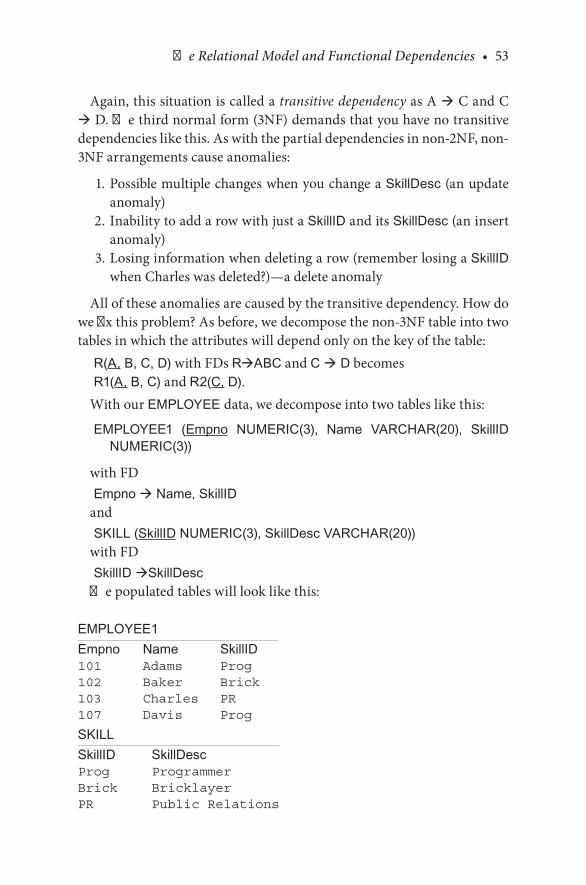
The Relational Model and Functional Dependencies • 53
Again,.this.situation.is.called.a.transitive dependency.as.A.à.C.and.C.à.D..The.third.normal.form.(3NF).demands.that.you.have.no.transitive.dependencies.like.this..As.with.the.partial.dependencies.in.non-2NF,.non-3NF.arrangements.cause.anomalies:
. 1..Possible.multiple.changes.when.you.change.a.SkillDesc.(an.update.anomaly)
. 2..Inability.to.add.a.row.with.just.a.SkillID.and.its.SkillDesc.(an.insert.anomaly)
. 3..Losing.information.when.deleting.a.row.(remember.losing.a.SkillID.when.Charles.was.deleted?)—a.delete.anomaly
All.of.these.anomalies.are.caused.by.the.transitive.dependency..How.do.we.fix.this.problem?.As.before,.we.decompose.the.non-3NF.table.into.two.tables.in.which.the.attributes.will.depend.only.on.the.key.of.the.table:
R(A, B, C, D).with.FDs.RàABC.and.C à D.becomesR1(A, B, C).and.R2(C, D).
With.our.EMPLOYEE data,.we.decompose.into.two.tables.like.this:
EMPLOYEE1 (Empno NUMERIC(3), Name VARCHAR(20), SkillID NUMERIC(3))
with.FDEmpno à Name, SkillID
andSKILL (SkillID NUMERIC(3), SkillDesc VARCHAR(20))
with.FDSkillID àSkillDesc
The.populated.tables.will.look.like.this:
EMPLOYEE1Empno Name SkillID101 Adams Prog102 Baker Brick103 Charles PR107 Davis Prog
SKILLSkillID SkillDescProg ProgrammerBrick BricklayerPR Public Relations

54 • Database Design Using Entity-Relationship Diagrams
These.two.tables.represent.a.database.in.3NF..The.redundancy.is.now.gone..If.you.want.to.change.a.SkillDesc,.you.make.one.change..If.you.want.to.delete.an.employee,.you.do.not.lose.the.SkillID-SkillDesc,.and.if.you.want.to.insert.a.new.SkillID.with.no.employee.yet.defined,.you.can.do.so..The.anomalies.are.gone.
CHECKPOINT 3.5. 1.. Consider.this.table:
EMPLOYEE (Emp_no, Name, Project_no, Project_location)with.FDs
Emp_no à Emp_no, Name, Project_no
and
Project_no à Project_locationIs.this.table.in.1NF,.2NF,.3NF?.Decompose.the.table.if.necessary.
. 2.. Consider.this.table:
R(A, B, C, D, E, F)with.FDs
AB à CD, D à E, E à FIs.this.table.in.1NF,.2NF,.3NF?.Decompose.the.table.if.necessary.
3.8 THE EQUIJOIN OPERATION
In.a.relational.database,.we.often.decompose.tables.to.move.to.the.3NF..Managers.and.users.will.complain.that.“My.table.of.data.has.been.spread.all.over. the.place,”.or.“The.normalization.process. removed.my.primary.information. table.”. While. tables. are. decomposed,. they. can. be. recon-structed.easily.with.the.equijoin.operation.of.relational.calculus,.which.is.realized.in.SQL.(Structured.Query.Language),.the.de.facto.query.language.of.the.relational.database..A.discussion.of.relational.calculus.and.SQL.are.beyond.the.scope.of.this.chapter,.and.many.excellent.references.to.the.query.language.exist.(Bagui.and.Earp,.2009,.2011;.Earp.and.Bagui,.2008)..The.point.here.is.that.while.a.normalized.table.may.have.been.decomposed,.the.

The Relational Model and Functional Dependencies • 55
original.table.can.be.re-formed.from.the.decomposed.ones..Let.us.give.an.example..Suppose.we.have.a.table.like.this.from.the.previous.section:
EMPLOYEE (Emp_no, Name, Project_no, Project_location)
with.FDs
Emp_no à Emp_no, Name, Project_no, Project_location
and
Project_no à Project_location
We. recognize. the. transitive. dependency. and. decompose. EMPLOYEE.into.these.two.tables:
EMPLOYEE1 (Emp_no, Name, Project_no)PROJECT (Project_no, Project_location)
The.EMPLOYEE table.can.be.reconstructed.by.joining.EMPLOYEE1.and.PROJECT.by.the.common.attribute,.Project_no..Project_no.is.the.primary.key.of.PROJECT.and.is.a.foreign.key.referencing.EMPLOYEE1..If.R(A, B, C).is.decomposed.into.S(A, B).and.T(B, C),.the.equijoin.oper-ation.can.reconstruct.R.combining.rows.of.S.and.T.where.the.values.of.common.attribute.B.are.equal..If.R.=.EMPLOYEE,.S.=.EMPLOYEE1,.T = PROJECT,. and.B = Project_no,. the. equijoin. would. proceed. like.this:
EMPLOYEE (Emp_no, Name, Project_no, Project_location)with.data
<101, Adams, P1, Pensacola><102, Baker, P1, Pensacola><103, Charles, P2, Mobile><104, Davis, P2, Mobile>
decomposes.to
EMPLOYEE1 (Emp_no, Name, Project_no)
with.data
<101, Adams, P1><102, Baker, P1><103, Charles, P2><104, Davis, P2>
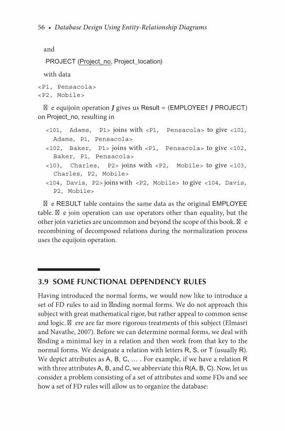
56 • Database Design Using Entity-Relationship Diagrams
and
PROJECT (Project_no, Project_location)
with.data
<P1, Pensacola><P2, Mobile>
The.equijoin.operation J.gives.us.Result.=.(EMPLOYEE1 J.PROJECT).on.Project_no, resulting.in
<101, Adams, P1>. joins. with. <P1, Pensacola>. to. give.<101, Adams, P1, Pensacola>
<102, Baker, P1>. joins. with.<P1, Pensacola>. to. give.<102, Baker, P1, Pensacola>
<103, Charles, P2>. joins. with. <P2, Mobile>. to. give. <103, Charles, P2, Mobile>
<104, Davis, P2>.joins.with <P2, Mobile> to.give <104, Davis, P2, Mobile>
The.RESULT.table.contains.the.same.data.as.the.original.EMPLOYEE.table..The. join.operation.can.use.operators.other. than.equality,.but. the.other.join.varieties.are.uncommon.and.beyond.the.scope.of.this.book..The.recombining.of.decomposed.relations.during.the.normalization.process.uses.the.equijoin.operation.
3.9 SOME FUNCTIONAL DEPENDENCY RULES
Having.introduced.the.normal.forms,.we.would.now.like.to.introduce.a.set.of.FD.rules.to.aid.in.finding.normal.forms..We.do.not.approach.this.subject.with.great.mathematical.rigor,.but.rather.appeal.to.common.sense.and.logic..There.are.far.more.rigorous.treatments.of.this.subject.(Elmasri.and.Navathe,.2007)..Before.we.can.determine.normal.forms,.we.deal.with.finding.a.minimal.key.in.a.relation.and.then.work.from.that.key.to.the.normal.forms..We.designate.a.relation.with.letters.R,.S,.or.T.(usually.R)..We.depict.attributes.as.A, B, C,.…...For.example,.if.we.have.a.relation.R.with.three.attributes.A, B,.and.C,.we.abbreviate.this.R(A, B, C)..Now,.let.us.consider.a.problem.consisting.of.a.set.of.attributes.and.some.FDs.and.see.how.a.set.of.FD.rules.will.allow.us.to.organize.the.database:
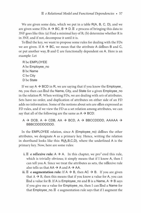
The Relational Model and Functional Dependencies • 57
We.are.given.some.data,.which.we.put.in.a.table.R(A, B, C, D),.and.we.are.given.some.FDs: A à BC, B à D..The.process.of.bringing.this.data.to.3NF.goes.like.this:.(a).Find.a.minimal.key.of.R;.(b).determine.whether.R.is.in.3NF,.and.if.not,.decompose.it.until.it.is.
To.find.the.key,.we.want.to.propose.some.rules.for.dealing.with.the.FDs.we.are.given..If.A à BC,.we.mean.that.the.attribute.A defines.B.and.C,.or.put.another.way,.B.and.C.are.functionally.dependent.on.A..Here.is.an.example:.Let
R.be.EMPLOYEEA.be.Employee_noB.be.NameC.be.CityD.be.State
If.we.say.A à BCD.in.R,.we.are.saying.that.if.you.know.the.Employee_no,.you.then.can.find.the.Name,.City,.and.State.for.a.given.Employee_no.in.the.relation.R..When.writing.FDs,.we.are.dealing.with.sets.of.attributes..Sets.have.no.order,.and.duplication.of.attributes.on.either.side.of.an.FD.adds.no.information..Some.of.the.notions.about.sets.are.often.expressed.as.FD.rules,.and.if.we.view.the.FD.as.a.set.relation.among.attributes,.we.can.say.that.all.of.the.following.are.the.same.as.A à BCD:
A à DCB, A à CDB, AA à BCD, A à BBCCDDDD, AAAAA à BBBCDDDDDDDD.
In. the. EMPLOYEE. relation,. since. A. (Employee_no). defines. the. other.attributes,.we.designate.A. as.a.primary.key..Hence,.writing. the.relation.in.shorthand. looks. like. this:.R(A,B,C,D),.where. the.underlined.A. is. the.primary.key..Now,.here.are.some.rules:
. i..The reflexive rule: A à A. In.this.chapter,.we.proffered.this.rule,.which.is.trivially.obvious;.it.simply.means.that.if.I.know.A,.then.I.can.tell.you.A..Since.we.treat.the.attributes.as.sets,.the.reflexive.rule.also.tells.us.that.AA à A.and.A à AA.
ii. The augmentation rule: If A à B, then AC à B. If.you.are.given.that.A.à.B,.then.this.means.that.if.you.know.a.value.for.A,.you.can.find.a.value.for.B..If.A.is.Employee_no.and.B.is.a.Name,.A à B.says.if.you.give.me.a.value.for.Employee_no,.then.I.can.find.a.Name.for.that.Employee_no..The.augmentation.rule.says.that.if.I.augment.the.
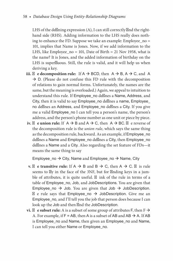
58 • Database Design Using Entity-Relationship Diagrams
LHS.of.the.defining.expression.(A),.I.can.still.correctly.find.the.right-hand.side.(RHS)..Adding.information.to.the.LHS.really.does.noth-ing.to.enhance.the.FD..Suppose.we.take.an.example:.Employee_no.=.101,.implies.that.Name.is.Jones..Now,.if.we.add.information.to.the.LHS,.like.Employee_no.=.101,.Date.of.Birth.=.21.Nov.1958,.what.is.the.name?.It.is.Jones,.and.the.added.information.of.birthday.on.the.LHS.is.superfluous..Still,.the.rule.is.valid,.and.it.will.help.us.when.deriving.a.key.
iii. The decomposition rule: If.A à BCD,.then A à B, A à C,.and A à D.. (Please. do. not. confuse. this. FD. rule. with. the. decomposition.of.relations.to.gain.normal.forms..Unfortunately,.the.names.are.the.same,.but.the.meaning.is.overloaded.).Again,.we.appeal.to.intuition.to.understand.this.rule..If.Employee_no.defines.a.Name,.Address,.and.City,.then.it.is.valid.to.say.Employee_no.defines.a.name,.Employee_no.defines.an.Address,.and.Employee_no.defines.a.City..If.you.give.me.a.valid.Employee_no.I.can.tell.you.a.person’s.name,.the.person’s.address,.and.the.person’s.phone.number.as.one.unit.or.piece.by.piece.
iv. The union rule:.If A à B and A à C, then A à BC..The.reverse.of.the.decomposition.rule.is.the.union rule,.which.says.the.same.thing.as.the.decomposition.rule,.backward..As.an.example,.if.Employee_no.defines.a.Name.and.Employee_no.defines.a.City,.then.Employee_no.defines.a.Name.and.a.City..Also.regarding.the.set.feature.of.FDs—it.means.the.same.thing.to.say
Employee_no à City, Name.and.Employee_no à Name, City
v. The transitive rule:. If.A à B. and.B à C,. then.A à C..This. rule.seems. to.fly. in. the. face.of. the.3NF,.but. for.finding.keys. in.a. jum-ble. of. attributes,. it. is. quite. useful.. Think. of. the. rule. in. terms. of. a.table.of.Employee_no, Job,.and.JobDescriptions..You.are.given.that.Employee_no à Job.. You. are. given. that. Job à JobDescription..The. rule. says. that. Employee_no à JobDescription.. Give. me. an.Employee_no,.and.I’ll.tell.you.the.job.that.person.does.because.I.can.look.up.the.Job.and.then.find.the.JobDescription.
vi. The subset rule: A.is.a.subset.of.some.group.of.attributes.F,.then.F.à.A..For.example,.if.F = AB,.then.A.is.a.subset.of.AB.and.AB à A..If.AB.is.Employee_no.and.Name,.then.given.an.Employee_no.and.Name,.I.can.tell.you.either.Name.or.Employee_no.

The Relational Model and Functional Dependencies • 59
Example 3.1
Let.us.consider. the. following.problem:.We.are.given.some.data. in.a.table:.R(A, B, C, D, E).and.we.are.given.some.FDs:.A à BC, B à D, AC à E. What.we.want.to.find.is.one.set.of.attributes.that.defines.all.the.others,.a.key.to.this.relation,.R..After.we.find.the.key,.we.will.work.on.normal.forms.
Step 1..Find.an.LHS.(of.an.FD).that.is.a.minimal.key.for.R..You.can.always.start.with.the.reflexive.property.and.use.all.the.attributes.on.the.LHS..ABCDE à ABCDE..ABCDE.is.a.key,.but.what.we.want.to.find.is.some.subset.of.all.attributes.that.will.define.the.others—a.minimal.key.(if.it.exists)..A.good.way.to.find.a.minimal.LHS.is.to.first.look.for.an.FD.that.has.a.concatenated.LHS.(if.there.is.one)..If.there.is.no.concatenated.key,. then.choose.an.attribute. that.defines.as.many.other.attributes.as.possible..Admittedly,.this.is.a.subjective.choice,.but.if.you.choose.incor-rectly,. you. only. need. to. try. again. with. a. different. or. enhanced. LHS..After.choosing.some.LHS,.we. look.at. the.FD.rules.and.see. if.we.can.define.the.other.attributes.from.our.chosen.LHS..In.this.case,.we.have.AC à E..We.will.see.if.we.can.show.that.AC à ABCDE.and.hence.let.AC.be.a.minimal.key.of.the.original.R..Notice.that.we.start.with.the.largest.concatenated.LHS.because.we.will.need.at.least.AC.to.define.whatever.is.functionally.dependent.on.it.
Step 2..Use.the.rules.to.find.as.many.RHS.attributes.as.possible.with.the.chosen.LHS..Since.AC à E,.we.know.by.the.reflexive.rule.that.AC à AC,.and.then.by.the.union.rule,.we.combine.these.two:
Union.rule: AC à E (given),.AC à AC (reflexive),.then.AC à ACE.
Use. the.other.given.FDs. to.find.other.attributes. that.depend.on. the.chosen.LHS.from.step.1.
We.have.established.that.AC à ACE..We.were.given.that.A à BC.
Subset.rule:.AC à ACE.(derived.previously),.then.AC à A.Transitive.rule:.AC à A, A à BC.(given),.then.AC à BC.Union.rule:.AC à ACE, AC à BC,.then.AC à ACEBC,.and.since.
we.are.dealing.with.sets.of.attributes,.AC à ABCE.
Step 3..Repeat.step.2.as.necessary.to.get.all.attributes.on.the.RHS.from.the.chosen.LHS.if.you.can.
We.have.all.attributes.on. the.RHS.except.D..The.other.FD.we.are.given.is.B à D.
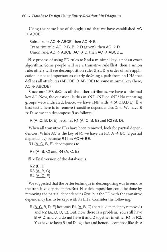
60 • Database Design Using Entity-Relationship Diagrams
Using.the.same.line.of. thought.and.that.we.have.established.AC à ABCE:
Subset.rule:.AC à ABCE,.then.AC à B.Transitive.rule:.AC à B, B à D.(given),.then.AC à D.Union.rule:.AC à ABCE, AC à D,.then.AC à ABCDE.
The.process.of.using.FD.rules.to.find.a.minimal.key.is.not.an.exact.algorithm.. Some. people. will. see. a. transitive. rule. first,. then. a. union.rule;.others.will.see.decomposition.rules.first..The.order.of.rule.appli-cation.is.not.as.important.as.clearly.defining.a.path.from.an.LHS.that.defines.all.attributes.(ABCDE à ABCDE).to.some.minimal.key.(here,.AC à ABCDE).
Since.our.LHS.defines.all. the.other.attributes,.we.have.a.minimal.key AC..Now,.the.question:.Is.this.in.1NF,.2NF,.or.3NF?.No.repeating.groups.were.indicated;.hence,.we.have.1NF.with.R (A,C,B,D,E)..The.best.tactic.here.is.to.remove.transitive.dependencies.first..We.have.B à D,.so.we.can.decompose.R.as.follows:
R (A, C, B, D, E).becomes.R1 (A, C, B, E).and.R2 (B, D).
When.all.transitive.FDs.have.been.removed,.look.for.partial.depen-dencies..While.AC.is.the.key.of.R,.we.have.an.FD:.A à BC.(a.partial.dependency).because.R1.has.AC à BE.
R1 (A, C, B, E).decomposes.to
R3 (A, B, C).and.R4 (A, C, E)
The.final.version.of.the.database.is
R2 (B, D)R3 (A, B, C)R4 (A, C, E)
We.suggested.that.the.better.technique.in.decomposing.was.to.remove.the.transitive.dependencies.first..The.decomposition.could.be.done.by.removing.the.partial.dependencies.first,.but.the.FD.with.the.transitive.dependency.has.to.be.kept.with.its.LHS..Consider.the.following:
R (A, C, B, D, E).becomes.R1 (A, B, C).(partial.dependency.removed).and.R2 (A, C, D, E)..But,.now.there.is.a.problem..You.still.have.B à D,.and.you.do.not.have.B.and.D.together.in.either.R1.or.R2..You.have.to.keep.B.and.D.together.and.hence.decompose.like.this:
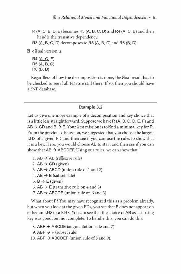
The Relational Model and Functional Dependencies • 61
R (A, C, B, D, E).becomes.R3 (A, B, C, D).and.R4 (A, C, E).and.then.handle.the.transitive.dependency.
R3 (A, B, C, D).decomposes.to.R5 (A, B, C).and.R6 (B, D).
The.final.version.is
R4 (A, C, E)R5 (A, B, C)R6 (B, D)
Regardless.of.how.the.decomposition.is.done,.the.final.result.has.to.be.checked.to.see.if.all.FDs.are.still.there..If.so,.then.you.should.have.a.3NF.database.
Example 3.2
Let.us.give.one.more.example.of.a.decomposition.and.key.choice.that.is.a.little.less.straightforward..Suppose.we.have.R (A, B, C, D, E, F).and.AB à CD.and.B à E..Your.first.mission.is.to.find.a.minimal.key.for.R..From.the.previous.discussion,.we.suggested.that.you.choose.the.largest.LHS.of.a.given.FD.and.then.see.if.you.can.use.the.rules.to.show.that.it.is.a.key..Here,.you.would.choose.AB.to.start.and.then.see.if.you.can.show.that.AB à ABCDEF..Using.our.rules,.we.can.show.that
. 1..AB à AB.(reflexive.rule)
. 2..AB à CD.(given)
. 3..AB à ABCD.(union.rule.of.1.and.2)
. 4..AB à B.(subset.rule)
. 5..B à E.(given)
. 6..AB à E.(transitive.rule.on.4.and.5)
. 7..AB à ABCDE.(union.rule.on.6.and.3)
What.about.F?.You.may.have.recognized.this.as.a.problem.already,.but.when.you.look.at.the.given.FDs,.you.see.that.F.does.not.appear.on.either.an.LHS.or.a.RHS..You.can.see.that.the.choice.of.AB.as.a.starting.key.was.good,.but.not.complete..To.handle.this,.you.can.do.this:
. 8..ABF à ABCDE.(augmentation.rule.and.7)
. 9..ABF à F.(subset.rule)
. 10..ABF à ABCDEF.(union.rule.of.8.and.9).

62 • Database Design Using Entity-Relationship Diagrams
This.last.discussion.and.example.suggest.two.things:.(a).our.basic.algo-rithm.of.“start.with.the.largest.concatenated.key.as.the.LHS”.is.good,.but.the.augmentation.rule.allows.us.to.include.attributes.on.the.LHS.as.necessary.to.get.to.a.minimal.key;.and.(b).you.can.derive.new.FD.rules..Our.use.of.the.rules.in.steps.8,.9,.and.10.suggest.we.can.proffer.this.rule:
vii. The double augmentation rule:.You.are.given.or.have.derived.AB à C,.then.ABD à CD..You.can.add.an.attribute.to.both.the.LHS.and.the.RHS.at.the.same.time.as.we.did.to.go.from.step.7.to.step.10.
There.are.many. theories.and.algorithms.about.how.to.decompose.and. how. to. choose. minimal. keys.. For. example,. to. find. a. minimal.key,. there. are. proposed. algorithms. that. start. with. all attributes à all attributes.and.then.remove.attributes.from.the.LHS—a.top-down.approach..In.terms.of.decomposition,.it.seems.easier.to.attack.transi-tive.dependencies.first..We.have.presented.what.we.feel.is.a.practical.workable.approach.to.going.from.a.jumbled.set.of.attributes.to.3NF..Here.is.the.summary.of.the.approach.we.illustrated:
Find the minimal key (MK):MK1..Lump.all.attributes.into.one.relation.R.and.choose.the.larg-
est.LHS.FD.as.the.minimal.key.K.MK2..Use.FD.rules.to.find.out.whether.K.can.in.fact.define.all.
the.attributes.in.R.MK3.. If.K.cannot.define.all. the.attributes,. then.augment.K.with.
another. “well-chosen”. attribute. and. return. to. step. MK2. with.K. now. K′. (K. plus. some. other. attribute).. With. practice,. the.well-chosen.attribute.will.be.some.attribute.from.the.original.set.that.defines.whatever.other.attributes.are.missing.in.step.MK2.
Decompose (D):D1..Remove.all.transitive.dependencies.to.a.separate.relation.D2..Remove.all.partial.dependencies.to.a.separate.relation.
Check.to.see.if.the.final.product.still.retains.all.given.FDs.
CHECKPOINT 3.6For.each.of.the.following,.find.a.minimal.key.and.decompose.as.necessary.to.reach.the.3NF..Show.decomposed.relations.with.keys.
. 1.. R(A, B, C, D, E, F) and A à BCDEF
. 2.. R(A,B,C,D).and.AB à CD, C à D
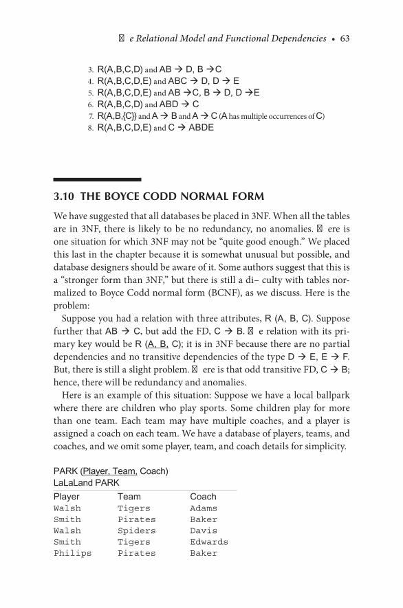
The Relational Model and Functional Dependencies • 63
. 3.. R(A,B,C,D).and.AB à D, B àC
. 4.. R(A,B,C,D,E).and.ABC à D, D à E
. 5.. R(A,B,C,D,E).and.AB àC, B à D, D àE
. 6.. R(A,B,C,D).and.ABD à C
. 7.. R(A,B,{C}).and.A à B.and.A à.C.(A.has.multiple.occurrences.of.C)
. 8.. R(A,B,C,D,E).and.C à ABDE
3.10 THE BOYCE CODD NORMAL FORM
We.have.suggested.that.all.databases.be.placed.in.3NF..When.all.the.tables.are. in. 3NF,. there. is. likely. to. be. no. redundancy,. no. anomalies.. There. is.one.situation.for.which.3NF.may.not.be.“quite.good.enough.”.We.placed.this.last.in.the.chapter.because.it.is.somewhat.unusual.but.possible,.and.database.designers.should.be.aware.of.it..Some.authors.suggest.that.this.is.a.“stronger.form.than.3NF,”.but.there.is.still.a.difficulty.with.tables.nor-malized.to.Boyce.Codd.normal.form.(BCNF),.as.we.discuss..Here.is.the.problem:
Suppose.you.had.a.relation.with.three.attributes,.R (A, B, C)..Suppose.further.that.AB à C,.but.add.the.FD,.C à B..The.relation.with.its.pri-mary.key.would.be.R (A, B, C);.it.is.in.3NF.because.there.are.no.partial.dependencies.and.no.transitive.dependencies.of.the.type.D à E, E à F..But,.there.is.still.a.slight.problem..There.is.that.odd.transitive.FD,.C à B;.hence,.there.will.be.redundancy.and.anomalies.
Here.is.an.example.of.this.situation:.Suppose.we.have.a.local.ballpark.where. there. are. children. who. play. sports.. Some. children. play. for. more.than. one. team.. Each. team. may. have. multiple. coaches,. and. a. player. is.assigned.a.coach.on.each.team..We.have.a.database.of.players,.teams,.and.coaches,.and.we.omit.some.player,.team,.and.coach.details.for.simplicity.
PARK (Player, Team, Coach)LaLaLand PARKPlayer Team CoachWalsh Tigers AdamsSmith Pirates BakerWalsh Spiders DavisSmith Tigers EdwardsPhilips Pirates Baker

64 • Database Design Using Entity-Relationship Diagrams
Player, Team à Coach..Note.that.Player.does.not.à Team,.Team.does.not.à Coach.(look.at.the.data.to.disprove.these.FDs)..On.the.other.hand,.Coach à Team..While.this.data.is.in.3NF,.you.have.redundancy.because.Coach à Team.
The.normalization.to.BCNF,.which.denies.any.transitive.dependency,.would.work.like.this:
R (A, B, C), with.FDs AB à C, C à B.can.be.normalized.into.R1 (C, B).and.R2(A, C)..The.problem.is.that.one.of.the.FDs.has.vanished.(AB à C),.but.so.have.the.anomalies..The.ballpark.example.normalized.to.BCNF.looks.like.this:
PC (Player, Coach) CT (Coach, Team)LaLaLand PARKPlayer Coach Coach TeamWalsh Adams Adams TigersSmith Baker Baker PiratesWalsh Davis Davis SpidersSmith Edwards Edwards TigersPhilips Baker
In.the.PC.table,.both.attributes.are.a.concatenated.key.(Player, Coach à Player, Coach)..Since.there.can.be.no.partial.or.transitive.dependencies,.PC.is.in.3NF.and.BCNF..CT.is.also.in.3NF.and.BCNF.(Coach à Team)..The.decomposition.problem.is.that.we.lost.the.FD:.Player, Team à Coach..The.original.table.can.be.reconstructed.with.an.equijoin.operation.by.joining.PC.and.CT on.Coach,.but.the.BCNF.version.allows.updates.with.no.redun-dancy,.whereas.the.original.PARK.table.does.not..Consider.adding.a.coach.to.the.original.PARK.table;.it.can.only.be.done.if.a.player.is.assigned,.or.else.there.would.be.a.null.in.the.key..In.the.BCNF.version,.a.coach.can.be.added.to.CT.with.no.player.assigned..The.other.anomalies.will.be.left.as.exercises.
BCNF.is.a.little.more.complicated.than.the.1NF,.2NF,.and.3NF..In.the.first.three.normal.forms,.there.is.no.issue.regarding.whether.the.decom-position.is.a.“good.idea.”.All.databases.should.be.reduced.to.at.least.3NF..BCNF.presents.a.quandary..What.is.more.annoying.to.the.person.using.the.database?.Is.the.loss.of.an.FD.worse.than.some.anomalies?.In.a.non-BCNF.situation,. if. the.occurrence.of.anomaly-producing.redundancy. is.low,.then.it.may.well.be.better.just.to.leave.the.tables.as.is—in.3NF.but.not.BCNF..If.the.redundancy.is.pervasive,.then.normalization.to.BCNF.may.be.in.order..One.option.that.is.never.acceptable.is.to.keep.both.versions.because.that.is.total.redundancy.
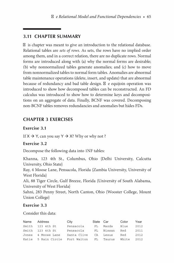
The Relational Model and Functional Dependencies • 65
3.11 CHAPTER SUMMARY
This.chapter.was.meant.to.give.an.introduction.to.the.relational.database..Relational. tables.are.sets of rows..As.sets,. the.rows.have.no.implied.order.among.them,.and.in.a.correct.relation,.there.are.no.duplicate.rows..Normal.forms.are. introduced.along.with.(a).why.the.normal. forms.are.desirable;.(b). why. nonnormalized. tables. generate. anomalies;. and. (c). how. to. move.from.nonnormalized.tables.to.normal.form.tables..Anomalies.are.abnormal.table.maintenance.operations.(delete,.insert,.and.update).that.are.abnormal.because.of. redundancy.and.bad. table.design..The.equijoin.operation.was.introduced.to.show.how.decomposed.tables.can.be.reconstructed..An.FD.calculus.was. introduced. to.show.how.to.determine.keys.and.decomposi-tions. on. an. aggregate. of. data.. Finally,. BCNF. was. covered.. Decomposing.non-BCNF.tables.removes.redundancies.and.anomalies.but.hides.FDs.
CHAPTER 3 EXERCISES
Exercise 3.1
If.X à Y,.can.you.say.Y à X?.Why.or.why.not.?
Exercise 3.2
Decompose.the.following.data.into.1NF.tables:
Khanna,. 123. 4th. St.,. Columbus,. Ohio. {Delhi. University,. Calcutta.University,.Ohio.State}Ray,.4.Moose.Lane,.Pensacola,.Florida.{Zambia.University,.University.of.West.Florida}Ali,.88.Tiger.Circle,.Gulf.Breeze,.Florida.{University.of.South.Alabama,.University.of.West.Florida}Sahni,.283.Penny.Street,.North.Canton,.Ohio.{Wooster.College,.Mount.Union.College}
Exercise 3.3
Consider.this.data:
Name Address City State Car Color YearSmith 123 4th St Pensacola FL Mazda Blue 2012Smith 123 4th St Pensacola FL Nissan Red 2011Jones 4 Moose Lane Santa Clive CA Lexus Red 2012Katie 5 Rain Circle Fort Walton FL Taurus White 2012

66 • Database Design Using Entity-Relationship Diagrams
and.the.following.FDs:Name à Address, City, State, Car, Color, Year and Car à Color, Year
Decompose.as.necessary.to.achieve.3NF.
BIBLIOGRAPHY
Armstrong,.W..1974..Dependency.structures.of.data.base.relationships..Proceedings of the IFIP Congress, Stockholm,.Sweden,.August.5–10,.1974.
Bagui,.S.,.and.Earp,.R..2009..SQL.Essentials in Access. Deer.Park,.NY:.Linus.Bagui,.S.,.and.Earp,.R..2011..Essential of SQL Using SQL Server 2008..Jones.and.Bartlett.Chen,. P.. P.. 1976.. The. entity. relationship. model—toward. a. unified. view. of. data.. ACM
Transactions on Database Systems,.1(1),.9–36.Codd,. E.. 1970.. A. relational. model. for. large. shared. data. banks.. Communications. of. the.
ACM,.13(6),.377–387.Codd,.E..1972..Further Normalization of the Data Base Relational Model..Republished.in.
Randall.J..Rustin.(ed.),.Database Systems:.Courant Computer Science Symposia Series.6,.Prentice-Hall,.1972.
Codd,. E.. 1974.. Recent. investigations. in. relational. database. system.. Proceedings of the IFIP Congress, Stockholm,.Sweden,.August.5–10,.1974.
Date,.C..2003..An Introduction to Database Systems..Reading,.MA:.Addison-Wesley.Earp,. R.,. and. Bagui,. S.. 2008.. Practical Guide to Using SQL in Oracle. Plano,. Texas:.
Wordware.Elmasri,. R.,. and. Navathe,. S.. B.. 2007.. Fundamentals of Database Systems. Reading,. MA:.
Addison-Wesley.Maier,. D.. 1983.. The Theory of Relational Databases.. New. York,. NY.. Computer. Science.
Press.Norman,.R..J..1996..Object-Oriented Systems Analysis and Design. Upper.Saddle.River,.NJ:.
Prentice.Hall.Schach,. S.. R.. 2011.. Object-Oriented and. Classical Software Engineering.. New. York:.
McGraw-Hill.

67
4The Basic ER DiagramA Data Modeling Schema
4.1 INTRODUCTION
This.chapter.begins.by.describing.a.data.modeling.approach.and.then.intro-duces.entity.relationship.(ER).diagrams..The.concepts.of.entities,.attributes,.relationships,.and.keys.are.introduced..The.first.three.steps.in.an.ER.design.methodology.are.developed..Step.1.begins.by.building.a.one-entity.diagram..Step.2.concentrates.on.using.structured.English.to.describe.a.database..Step.3,. the. last.section. in.this.chapter,.discusses.mapping.the.ER.diagram.to.a.relational.database..These.concepts—the.diagram,.structured.English,.and.mapping—evolve.together.as.the.book.progresses..At.the.end.of.the.chap-ter,.we.also.begin.a.running.case.study,.which.is.continued.in.the.following.chapters.
4.2 WHAT IS A DATA MODELING SCHEMA?
A.data modeling schema.is.a.method.that.allows.us.to.model.or.illustrate.a.database..This.is.often.in.the.form.of.a.graphic.diagram,.but.other.means.of.communication.are.also.desirable;.people.who.are.not.in.the.computer.field.may.or.may.not.understand.diagrams.and.graphics..The.ER.diagram.is.a.graphic.tool.that.facilitates.data.modeling..ER.diagrams.are.a.subset.of.“semantic.models”.in.database.parlance..Semantic.models.refer.to.models.that. intend. to. elicit. meaning. from. data.. ER. diagrams. are. not. the. only.semantic.modeling.tools,.but.are.common.and.popular.
68 • Database Design Using Entity-Relationship Diagrams
When.we.begin. to.discuss. the.contents.of.a.database,. the.data.model.helps.us.to.decide.which.piece.of.data.goes.with.which.other.piece(s).of.data.on.a.conceptual. level..An.early.concept.concerning.the.database. is.to. recognize. that. there. are. levels. of. abstraction. we. can. use. in. discuss-ing.databases..For.example,. if.we.were. to.discuss. the.filing.of. “names,”.we.could.discuss.(a).abstractly,.that.is,.“We.will.file.names.of.people.we.know”;.or.(b).concretely,.that.is,.“We.will.file.first,.middle,.and.last.names.(20.characters.each).of.people.we.know,.so.that.we.can.retrieve.the.names.in.alphabetical.order.by.last.name,.and.we.will.put.this.data.in.a.spread-sheet.format.in.package.x.”
If.a.person.is.designing.a.database,.the.first.step.is.to.abstract,.then.refine.the. abstraction.. The. longer. one. stays. away. from. the. concrete. details. of.logical.models.(relational,.hierarchical,.network).and.physical.realizations.(fields.[how.many.characters,.the.data.type,.….].and.files.[relative,.spread-sheet,. …. ]),. the. easier. it. is. to. change. the. model. and. to. decide. how. the.data.will.eventually.be.physically.realized.(stored)..When.we.use.the.term.field.or.file,.we.will.be.referring.to.physical.data.as.opposed.to.conceptual.data.
Mapping.is.the.process.of.choosing.a.logical.model.and.then.moving.to.a.physical.database.file.system.from.a.conceptual.model.(the.ER.diagram)..A.physical.file.loaded.with.data.is.necessary.to.actually.obtain.data.from.a.database..Mapping.is.the.bridge.between.the.design.concept.and.physical.reality..In.this.book,.we.concentrate.on.the.relational.database.model.due.to.its.ubiquitousness.in.the.contemporary.database.models.
4.2.1 So, What Is an Entity Relationship Diagram?
The.ER diagram is.a.semantic.data.modeling.tool.used.to.accomplish.the.goal. of. abstractly. describing. or. portraying. data.. Abstractly. described.data. is. called. a. conceptual. model.. Our. conceptual. model. will. lead. us.to.a.“schema.”.A.schema.implies.a.permanent,.fixed description.of.the.structure.of. the.data..Therefore,.when.we.agree. that.we.have.captured.the. correct. depiction. of. reality. within. our. conceptual. model,. our. ER.diagram,.we.can.call.it.a.schema.
An.ER.diagram.could.also.be.used.to.document.an.existing.database.by.reverse.engineering.it,.but.in.introducing.the.subject,.we.focus.on.the.idea.of.using.an.ER.diagram.to.model.a.to-be-created.database,.and.we.deal.with.reverse.engineering.in.further.discussion.
The Basic ER Diagram • 69
4.3 DEFINING A DATABASE— SOME DEFINITIONS: ENTITY, RELATIONSHIP, ATTRIBUTE
As.the.name.implies,.an.entity.relationship.diagram.models.data.as.enti-ties.and.relationships..An.entity.is.a.thing.about.which.we.store.data.(e.g.,.a.person,.a.bank.account,.a.building)..In.the.original.presentation,.Chen.(1976).described.an.entity.as.a.“thing.which.can.be.distinctly.identified.”.So.an.entity.may.be.a.person,.place,.object,.event,.or.concept.about.which.we.wish.to.store.data..A.relationship.is.a.connection.between.entities..An.attribute.is.the.category.of.data.that.describes.an.entity.or.relationship.
An.entity.represents.a.type.or.class.of.something.and.should.be.named.accordingly..The.following.are.some.examples.of.entities:
•. Examples.of.a.person.entity.would.be.EMPLOYEE, VET,.or.STUDENT.•. Examples.of.a.place.entity.would.be.STATE or.COUNTRY.•. Examples. of. an. object. entity. would. be. BUILDING,. AUTO,. or
PRODUCT.•. An. example. of. an. event. entity. would. be. SALES, RETURNS, or
REGISTRATION.•. An. example. of. a. concept. entity. would. be ACCOUNT. or
DEPARTMENT.
The.name.of.an.entity.should.be.generic..The.name.should.be.able. to.accommodate.changes.“over. time.”.For.example,. if.we.were.modeling.a.business. and. the. business. made. donuts,. we. might. consider. creating. an.entity.called.DONUT..But,.how.long.will.it.be.before.this.business.evolves.into.making.more.generic.pastry?.If.it.is.anticipated.that.the.business.will.involve.pastry.of.all.kinds. rather. than. just.donuts,.perhaps. it.would.be.better.to.create.an.entity.called.PASTRY—it.may.be.more.applicable.over.time..In.this.case,.an.entity.“business”.is.too.generic.because.you.want.to.record.data.about.donuts.or.pastry—components.of.the.business.
In.older.data-processing.circles,.we.would.have.referred.to.an.entity.as.a.“record,”.but.the.term.record. is. too.physical.and.too.confining;.record.gives.us.a.mental.picture.of.a.physical.thing,.and.to.work.at.the.conceptual.level,.we.want.to.avoid.device-oriented.terms..In.a.database.context,.it.is.unusual.to.store.information.about.one.entity,.so.we.think.of.storing.col-lections.of.data.about.entities;.such.collections.are.called.entity sets..Entity.sets.correspond.to.the.older.concept.of.“files,”.but.a.file.usually.connotes.a.

70 • Database Design Using Entity-Relationship Diagrams
physical.thing,.and.hence.we.abstract.the.concept.of.the.file.(entity.set).as.well.as.the.concept.of.a.record.(entity)..As.an.example,.suppose.we.have.a.company.that.has.customers..You.would.imagine.that.the.company.had.a.customer.entity.set.with.individual.customer.entities.in.it.
An.entity.may.be.very.broad.(e.g.,.a.person),.or.it.may.be.narrowed.by.the.application.for.which.data.is.being.prepared.(like.a.student.or.a.customer)..“Broad”.entities,.which.cover.a.whole.class.of.objects,.are.sometimes.called.generalizations.(e.g.,.person),.and.“narrower”.entities.are.sometimes.called.specializations.(e.g.,.student)..In.further.diagrams.(in.this.book),.we.revisit.generalizations. and. specializations,. but. for. now,. we. concern. ourselves.with.an.application.level.at.which.there.are.no.subgroups.(specializations).or.supergroups.(generalizations).of.entities.
When.we.speak.of.capturing.data.about.a.particular.entity,.we.refer.to.this.as.an.instance..An.entity.instance.is.a.single.occurrence.of.an.entity..For.example,.if.we.create.an.entity.called.TOOL,.and.if.we.choose.to.record.data.about.a.screwdriver,.then.the.screwdriver.“record”.is.an.instance.of.TOOL..Each.instance.of.an.entity.must.be.uniquely.identifiable.so.that.each.instance.is.separate.and.distinctly.identifiable.from.all.other.instances.of.that.type.of.entity..In.a.customer.entity.set,.you.might.imagine.that.the.company. would. assign. a. unique. customer. number,. for. example.. This.unique.identifier.is.called.a.key.
A.relationship. is. a. link.or.association.between.entities..Relationships.are.usually.denoted.by.verb.phrases..We.begin.by.expanding.the.notion.of.an.entity.(in.this.chapter.and.the.next),.and.then.we.come.back.to.the.notion.of.a.relationship.(in.Chapter.6).once.we.have.established.the.con-cept.of.an.entity.
An.attribute.is.a.property.or.characteristic.of.an.entity..For.example,.an.entity,.AUTOMOBILE,.has.attributes.type, color, vehicle_id, and.so.on.
4.3.1 A Beginning Methodology
Database. modeling. begins. with. a. description. of. “what. is. to. be. stored.”.Such.a.description.may.come.from.anyone;.we.will.call.the.describer.the.“user.”.For.example,.Ms..Smith.of.Acme.Parts.Company.comes.to.you.ask-ing.that.you.design.a.database.of.parts.for.her.company..Ms..Smith.is.the.user..You.are.the.database.designer..What.Ms..Smith.tells.you.about.the.parts.will.be.the.database.description.
As.a.starting.point.in.dealing.with.a.to-be-created.database,.we.identify.a.cen-tral,.“primary”.entity—a.category.about.which.we.will.store.data..For.example,.

The Basic ER Diagram • 71
if.we.wanted.to.create.a.database.about.students.and.their.environment,.then.one.entity.would.be.STUDENT.(our.characterization.of.an.entity.will.always.be. in.the.singular)..Having.chosen.one.first.primary.entity,.STUDENT,.we.then.search.for.information.to.be.recorded.about.our.STUDENT.(attributes)..This. methodology. of. selecting. one. primary. entity. from. a. data. description.is.our.first.step.in.drawing.an.ER.diagram.and.hence.the.beginning.of.the.requirements.phase.of.software.engineering.for.our.database.
Once.the.primary.entity.has.been.chosen,.we.then.ask.what.information.we.want. to. record.about.our.entity.. In.our.STUDENT. example,.we.add.some.details.about.the.STUDENT—details.that.will.qualify,.identify,.clas-sify,.or.express.the.state.of.the.entity.(in.this.case,.the.STUDENT.entity)..These.details.or.contents.of.entities.are.called.attributes.* Some.example.attributes. of. STUDENT. would. be. the. student’s. name,. student. number,.major,.address,.and.so.on—information.about.the.student..Keep.in.mind.that.in.this.process.of.selecting.attributes,.the.user.should.be.able.to.tell.you.what.data.he.or.she.wishes.to.keep.
4.3.2 ER Design Methodology
Step 1. Select one primary entity from the database requirements descrip-tion and show attributes to be recorded for that entity.
Requirements definition. is. the. first. phase. of. software. engineering. in.which.the.systems.analyst.tries.to.find.out.what.a.user.wants..In.the.case.of.a.database,.an.information-oriented.system,.the.user.will.want.to.store.data..Now.that.we.have.chosen.a.primary.entity.and.some.attributes,.our.task.will.be.to.(a).draw.a.diagram.of.our.first.impression.entity.(our.pri-mary.entity),. (b).translate.the.diagram.into.English,.and.(c).present.the.English.(and.the.diagram).back.to.the.user.to.see.if.we.have.it.right.and.then.progress.from.there.
Step.c.is.called.feedback.in.software.engineering..The.process.of.refining.via.feedback.is.a.normal.process.in.the.requirements/specification.phases..The.feedback.loop.is.essential.in.arriving.at.the.reality.of.what.one.wants.to.depict.from.both.the.user.and.analyst.viewpoints..First,.we.show.how.to.draw.the.entity,.and.then.we.present.guidelines.on.converting.our.dia-gram.into.English.
*. C..J..Date.(1995),.An Introduction to Database Systems,.6th.edition,.preferred.the.word.“property”.to.“attribute”.because.it.is.more.generic.and.because.attribute.is.used.in.other.contexts..We.use.attribute.because.we.believe.it.to.be.more.commonly.used.
72 • Database Design Using Entity-Relationship Diagrams
CHECKPOINT 4.1
. 1.. Of.the.following.items,.determine.which.could.be.an.entity.and.state.why:.automobile,.college.class,.student,.name.of.student,.book.title,.number.of.dependents.
. 2.. Why.are.entities.not.called.files.or.records?
. 3.. What.are.entity.sets?
. 4.. Why.do.we.need.entity.relationship.diagrams?
. 5.. What.are.attributes?.List.attributes.of.the.entities.you.found.in.ques-tion.1?
. 6.. What.is.a.relationship?
4.4 A FIRST “ENTITY-ONLY” ER DIAGRAM: AN ENTITY WITH ATTRIBUTES
To.recap.our.example,.we.have.chosen.an.example.with.a.primary.entity.from.a. student. information. database:. the. student.. Again,. note. that. “a. student”.is.something.that.we.want.to.store.information.about.(the.definition.of.an.entity)..In.this.chapter,.we.do.not.concern.ourselves.with.any.other.entities.
Let. us. think. about. some. attributes. of. the. entity. STUDENT.. That. is,.what.are.some.attributes.a.student.might.have?.A.student.has.a.name,.an.address,.and.an.educational.connection..We.call.the.educational.connec-tion.a.school..We.have.picked.three.attributes.for.the.entity.STUDENT,.and.we.have.also.chosen.a.generic.label.for.each:.name,.address,.school.
We.begin.our.first.venture.into.ER.diagrams.with.a.“Chen-like”.model..Chen.(1976).introduced.the.idea.of.the.ER.diagrams..Chen.and.others.have.improved.the.ER.process.over.the.years,.and.while.there.is.no.standard.ER.diagram. model,. the. Chen-like. model. and. variants. thereof. are. common..After.the.Chen-like.model,.we.introduce.other.models..We.briefly.discuss.the.Barker/Oracle-like.model.in.Chapter.12..Chen-like.models.have.the.advan-tage.that.one.need.not.know.the.underlying.logical.model.to.understand.the.design..Barker.models.and.some.other.models.require.a.full.understanding.of.the.relational.model,.and.the.diagrams.are.affected.by.relational.concepts.
To.begin,.in.the.Chen-like.model,.we.will.do.as.Chen.originally.did.and.put. the.entities. in.boxes.and.show.attributes.nearby..One.way. to.depict.attributes.is.to.put.them.in.circles.or.ovals.appended.to.the.boxes.(refer.to.Figure 4.1a.and.Figure 4.1b)..Figure 4.1c.is.an.alternative.style.of.depicting.attributes.. The. alternative. attribute. style. (Figure 4.1c). is. not. as. descrip-tive.but.is.more.compact.and.may.be.used.if.Chen-like.diagrams.become.cluttered.

The Basic ER Diagram • 73
There. are. several. ways. of. depicting. attributes.. We. have. illustrated. the.model.of.an.“attribute.in.an.oval”.(Chen-like.model).because.it.is.common.and.useful..Refer.to.Figures 4.2a,.4.2b,.and.4.2c.for.some.alternate.models.for.attributes..There.are.benefits.to.alternate.forms.for.depicting.attributes..The.standard.form.of.the.Chen-like.model.with.ovals.and.boxes.is.good.for.conceptualizing;.it.is.easily.changed.and.very.clear.regarding.which.attri-bute.goes.where..The.concise.forms.(Figure 4.1c.and.other.variants.shown.in.Figures 4.2a,.4.2b,.and.4.2c).are.easily.created.from.the.standard.form.and.are.sometimes.more.useful.for.documentation.when.space.is.a.concern.
Entity
attribute
attribute
attribute
(a)
Student
name address
school
(b)
nameschooladdress
Student
�e compactform of theER diagram
(c)
FIGURE 4.1(a).Chen-like.model:.entity.with.attributes.. (b).Student.entity.with. three.attributes.. (c).Alternative.ER.model.

74 • Database Design Using Entity-Relationship Diagrams
Figures 4.1b.and.4.1c.show.an.ER.diagram.with.one.entity,.STUDENT,.and.three.attributes:.name,.address, and school..If.more.attributes.were.added.to.our.conceptual.model,.such.as.phone.and.major,.they.would.be.appended.to.the.entity.(STUDENT.is.the.only.entity.we.have.so.far),.as.can.be.seen.in.Figure 4.3.
4.5 MORE ABOUT ATTRIBUTES
Attributes. are. characteristics. of. entities. that. provide. descriptive. detail.about.the.entities..There.are.several.different.kinds.of.attributes:.simple.or.atomic,.composite,.multivalued,.and.derived..The.properties.of.an.attribute.
schooladdress
majorphonename
Student
(a)
schooladdressmajorphonename
Student
(b)
Student
school address major phone name
(c)
FIGURE 4.2(a).Second.alternative.model.for.ER.diagram..(b).Third.alternative.model.for.ER.diagram..(c).Fourth.alternative.model.for.ER.diagram.
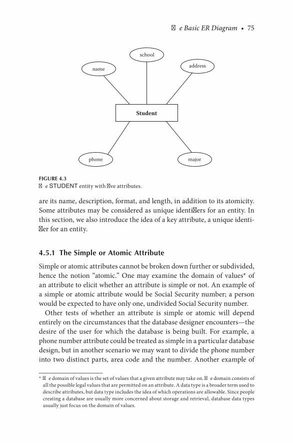
The Basic ER Diagram • 75
are.its.name,.description,.format,.and.length,.in.addition.to.its.atomicity..Some.attributes.may.be.considered.as.unique.identifiers.for.an.entity..In.this.section,.we.also.introduce.the.idea.of.a.key.attribute,.a.unique.identi-fier.for.an.entity.
4.5.1 The Simple or Atomic Attribute
Simple.or.atomic.attributes.cannot.be.broken.down.further.or.subdivided,.hence. the.notion.“atomic.”.One.may.examine. the.domain.of.values*.of.an.attribute.to.elicit.whether.an.attribute.is.simple.or.not..An.example.of.a.simple.or.atomic.attribute.would.be.Social.Security.number;.a.person.would.be.expected.to.have.only.one,.undivided.Social.Security.number.
Other. tests. of. whether. an. attribute. is. simple. or. atomic. will. depend.entirely.on.the.circumstances.that.the.database.designer.encounters—the.desire. of. the. user. for. which. the. database. is. being. built.. For. example,. a.phone.number.attribute.could.be.treated.as.simple.in.a.particular.database.design,.but.in.another.scenario.we.may.want.to.divide.the.phone.number.into. two.distinct.parts,.area.code.and. the.number..Another.example.of.
*. The.domain.of.values.is.the.set.of.values.that.a.given.attribute.may.take.on..The.domain.consists.of.all.the.possible.legal.values.that.are.permitted.on.an.attribute..A.data.type.is.a.broader.term.used.to.describe.attributes,.but.data.type.includes.the.idea.of.which.operations.are.allowable..Since.people.creating.a.database.are.usually.more.concerned.about.storage.and.retrieval,.database.data.types.usually.just.focus.on.the.domain.of.values.
Student
school
address
phone major
name
FIGURE 4.3The.STUDENT.entity.with.five.attributes.

76 • Database Design Using Entity-Relationship Diagrams
when.the.use.of.the.attribute.in.the.database.will.determine.if.the.attribute.is.simple.or.atomic.is.a.birthdate.attribute..If.we.are.setting.up.a.database.for.a.veterinary.hospital,.it.may.make.sense.to.break.a.birthdate.field.up.into.month,.day,.and.year.since.it.will.make.a.difference.in.treatment.if.a.young.animal.is.5.days.old.versus.if.it.is.5.months.or.5.years.old..Hence,.in.this.case.birthdate.would.be.a.composite.attribute..For.a RACE HORSE.database,.however,. it.may.not.be.necessary. to.break.up.a.birthdate.field.into.month/day/year.since.all.horses.are.dated.only.by.the.year.in.which.they.are.born..In.this.case,.birthdate,.consisting.of.only.the.year,.would.be.atomic.
If.an.attribute.is.nonatomic,.it.needs.to.be.depicted.as.such.on.the.ER.dia-gram..The.following.sections.deal.with.these.more.complicated,.nonatomic.attribute.ideas:.the.composite.attribute.and.the.multivalued.attribute.
4.5.2 The Composite Attribute
A.composite attribute,.sometimes.called.a.group attribute,.is.an.attribute.that.is.formed.by.combining.or.aggregating.related.attributes..The.names.chosen.for.composite.attributes.should.be.descriptive.and.general..The.con-cept.of.name.is.adequate.for.a.general.description,.but.it.may.be.desirable.to.be.more.specific.about.the.parts.of.this.attribute..Most.data-processing.applications.divide.the.name.into.component.parts..Name,.then,.is.called.a.composite attribute.or.an.aggregate.because.it.is.usually.composed.of.a.first name,.a.last name,.and.a.middle initial—subattributes,.if.you.will..The.way.that.composite.attributes.are.shown.in.ER.diagrams.in.the.Chen-like.model.is.illustrated.in.Figure 4.4..The.subattributes,.like.first name,.middle name, and.last name,.are.called.simple,.atomic,.or.elementary.attributes..The. word.aggregate. is.used. in.a.different. sense. in. some. database. query.languages,. and. to. avoid. confusion,. we. do. not. call. composite. attributes.aggregates;.we.use.the.word.composite.
The.test.of.whether.an.attribute.will.be.composite.(or.not).will.depend.entirely.on.the.circumstances.that.the.database.designer.encounters—the.desire.of. the.user.requesting. the.database.be.built..For.example,. in.one.database.it.may.not.be.important.to.know.exactly.which.city,.state,.or.zip.code.a.person.comes.from,.so.an.address.attribute.in.that.database.may.not.be.broken.up.into.its.component.parts;.it.may.just.be.called.address..In.another.database,.it.may.be.important.to.know.which.city.and.state.a.person.is.from,.so.in.this.second.database.we.would.have.to.break.up.the.

The Basic ER Diagram • 77
address.attribute.into.street.address,.city,.state,.and.zip.code,.making.the.address.attribute.a.composite.attribute.
4.5.3 The Multivalued Attribute
Another.type.of.nonsimple.attribute.that.has.to.be.managed.is.called.a.multivalued attribute..The.multivalued.attribute,.as.the.name.implies,.may.take.on.more.than.one.value.for.a.given.occurrence.of.an.entity..For.example,.the.attribute.school.could.easily.be.multivalued.if.a.per-son.attends.(or.has.attended,.depending.on.the.context.of.the.database).more.than.one.school..As.a.counter.example,.most.people.go.by.only.one.name;.hence,. the.grouping.name. is.not.multivalued..The.multivalued.attribute. called.school. is. depicted. in. Figure 4.5. (Chen-like. model). as.a.double.oval,.which.illustrates.the.situation.for.which.a.database.will.
Student
name school address
firstname
middleinitial
lastname
“name” is a composite attribute – itis composed of “first name,” “middleinitial,” and “last name.”
FIGURE 4.4STUDENT.entity.with.a.composite.attribute:.name.

78 • Database Design Using Entity-Relationship Diagrams
store.data.about.students.who.may.have.attended.more.than.one.school..Although.we.have.chosen.to.illustrate.school.as.a.multivalued.attribute,.we.do.not.mean.to.imply.that.this.will.always.be.the.case.in.all.data-bases.. In. fact,. the.attribute.school.may.well.be. single.valued. in. some.databases..The.idea.of.school.may.mean.the.current.(or.just.previous).school.as.opposed.to.all.schools.attended..If.the.subjects.about.whom.we. are. storing. data. can. attend. only. one. school. at. a. time. (and. that. is.what.we.want.to.depict),.then.the.attribute.school.may.well.be.a.single-valued.attribute.
Again,.the.test.of.single.versus.multivalued.will.depend.entirely.on.the.circumstances. that. the. database. designer. encounters—the. desire. of. the.user.of.the.to-be-built.database..It.is.recommended.that.if.the.sense.of.the.database.is.that.the.attribute.school.means.“current.school,”.then.the.attri-bute.should.be.called.“current.school”.and.illustrated.as.a.single-valued.attribute.. We. show. a. multivalued. attribute. in. Figure 4.5.. This. diagram.implies.that.multiple.schools.may.be.recorded.for.each.student.
4.5.4 The Derived Attribute
Derived.attributes.are.attributes.that.the.user.may.envision.but.may.not.be.recorded.per.se..These.derived.attributes.may.be.calculated.from.other.data.in.the.database..An.example.of.a.derived.attribute.would.be.an.age,.which.could.be. calculated.once.a. student’s.birth.date. is. entered.. In. the.Chen-like.model,.a.derived.attribute.is.shown.in.a.dashed.oval.(as.shown.in.Figure 4.5b).
4.5.5 Keys
A. database. is. used. to. store. data. for. retrieval.. An. attribute. that. may. be.used.to.find.a.particular.entity.occurrence.is.called.a.key..As.we.model.our.database.with.the.ER.models,.we.may.find.that.some.attributes.naturally.seem.to.be.keys..If.an.attribute.may.be.thought.of.as.a.unique.identifier.for.an.entity,.it.is.called.a.candidate key..When.a.candidate.key.is.chosen.to.be.the.unique.identifier,.it.becomes.the.primary key.for.the.entity.
As.an.example.of.keys,.suppose.we.add.an.attribute.called.student_num-ber.to.our STUDENT entity.example..We.might.well.consider.a.student_number.to.be.a.unique.identifier.for.the.entity—a.candidate.key.because.of.uniqueness..Name.is.often.unique,.but.not.necessarily.so..Members.of.the.same.class.often.share.last.names..Address.may.or.may.not.be.a.unique.

The Basic ER Diagram • 79
identifier.and.hence.is.not.a.likely.candidate.key..Siblings.who.take.classes.together. could. easily. have. the. same. address.. The. point. is. that. schools.often.choose.to.assign.a.unique.student.number.to.each.student.to.be.able.to.find.student.records—the.idea.of.a.key.is.to.provide.a.unique.way.to.find.an.entity.instance.(a.particular.record).
Some.schools.also.choose.to.record.a.Social Security number (SSN).as.an.attribute..A.SSN.is.also.unique.and.hence.a.candidate.key.along.with.student_number.. If. both.SSN. and.student_number. were. recorded,. then.the.designer.would.have.to.choose.which.candidate.key.would.be.the.pri-mary.key..In.our.case,.we.choose.not.to.record.a.SSN..The.STUDENT.entity.with.the.unique.identifier.student_number,.added.as.a.key,.is.depicted.in.Figure 4.6.
Student
name school
firstname
middleinitial
lastname
“school” is a multi-valuedattribute – the multi-valuedattribute is depicted usingdouble concentric circles orovals.
address
FIGURE 4.5(a).STUDENT.entity.with.a.multivalued.attribute.

80 • Database Design Using Entity-Relationship Diagrams
In. the. Chen-like. ER. model,. attributes,. which. are. unique. identifiers.(candidate.keys),.are.usually.underlined.(as.shown.in.Figure 4.6)..A.unique.identifier.may.be.an.attribute.or.a.combination.of.attributes..It.is.not.nec-essary.to.choose.which.candidate.key.will.be.the.primary.key.at.this.point,.but.one.could.do.so..When.there.is.only.one.candidate.key,.we.will.gener-ally.speak.of. it.as. the.primary.key.simply.because. it. is.obvious.that. the.primary.key.is.a.candidate.key..In.Figure 4.6,.we.also.depict.the.short.form.of.the.ER.diagram.(at.the.bottom.of.the.figure).with.composite.attributes.and.multivalued.attributes.as.well.as.primary.keys..The.composite.attri-butes.are.listed.with.its.component.parts,.and.the.multivalued.attributes.are.enclosed.in.parentheses.in.the.abbreviated.form.
Finally,.while.on.the.subject.of.keys,.we.will.have.situations.in.the.ER.diagram.(in.the.Chen-like.model).for.which.no.key.is.obvious.or.intended..Entities.that.have.at.least.one.identified.key.are.called.strong.entities..In.Chen’s.(1976).original.article,.strong.entities.were.called.regular entities..Some.entities.will.be.discovered.that.depend.on.other.entities.for.their.being.
Student
name school
firstname
middleinitial
lastname
addressbirthdateage
Derivedattribute
FIGURE 4.5(b).STUDENT.entity.with.a.derived.attribute:.age.

The Basic ER Diagram • 81
(and. hence. their. identification).. Chen. called. those. entities. that. rely. on.other.entities.for.their.existence.weak.entities.
We.often.are.able.to.recognize.these.weak.entities.because.they.may.not.have.candidate.keys,.although.the.actual.meaning.of.a.weak.entity.is.“one.that.depends.on.another.for.existence.”.As.Chen.did,.we.follow.the.Chen-like.ER.notation.and.call.such.entities.weak entities—weak.because.they.will.have.to.depend.on.some.other.entity.to.furnish.a.unique.identifier.to.give.the.entity.a.reason.to.be.recorded.
Although. a. weak. entity. may. have. a. candidate. key,. it. would. not. be. a.strong.entity..We.depict.weak.entities.in.the.Chen-like.ER.diagrams.with.double.boxes.(see.Figure 4.7)..For.now,.we.concentrate.on.those.entities.
or, the short form …
name [first, middle initial, last]student number(school)address
Student
namestudentnumber
firstname
middleinitial
lastname
“student_ number” is a uniqueidentifier for “Student” andhence is underlined to show itsprimary key significance
addressschool
Student
FIGURE 4.6STUDENT.entity.with.a.primary.key.or.unique.identifier.attribute.

82 • Database Design Using Entity-Relationship Diagrams
that.have.keys,. the.strong.entities,.and.we.will. reconsider.situations. for.which.no.key.is.obvious,.the.weak.entities,.later.
CHECKPOINT 4.2
. 1.. Describe.the.basic.types.of.data.representation.schemas.used.in.ER.modeling.
. 2.. What.notation.is.used.to.diagrammatically.show.an.entity. in.the.Chen-like.ER.model?
. 3.. How. do. we. diagrammatically. show. attributes. in. the. Chen-like. ER.model?
. 4.. How.do.we.show.composite.attributes.in.the.Chen-like.ER.model?
. 5.. Draw.an.entity.representation.for.the.entity.“building,”.with.the.fol-lowing.attributes:.building.name,.occupancy,.and.whether.or.not. it.has.an.elevator.(yes/no).
Automobile
vehicle id
make
body_style
color yearStrong entity
Automobile
make
body_style
color year
Weak entity
FIGURE 4.7A.strong.and.a.weak.AUTOMOBILE.entity.

The Basic ER Diagram • 83
. 6.. Embellish. the. building. entity. to. include. the. building. superinten-dent’s.name.(first,.middle,.and.last)..Does.this.have.to.be.a.composite.attribute?.Why.or.why.not?
. 7.. Embellish.the.building.entity.to.include.the.address.of.the.building,.which.will.be.the.primary.key.
. 8.. Again,.embellish.the.building.entity.to.include.names.(and.only.the.names).of.the.janitorial.staff.
. 9.. Add.a.multivalued.attribute.to.the.building.entity.
. 10.. How.many.attributes.can.an.entity.have?
4.6 ENGLISH DESCRIPTION OF THE ENTITY
Now.that.we.have.an.entity.with.attributes,.we.want.to.prepare.the.first.feed-back.to.the.user:.the.English.description..Users.will.not.likely.want.to.study.the.entity.diagram,.but.they.might.want.to.hear.what.you,.the.analyst,.think.you.heard..For.an.English.description,.we.use.a.“structured”.English.gram-mar.and.substitute.the.appropriate.information.from.the.entity.diagram.
4.6.1 The Method
The. template. for. the. structured. English. for. single. entities. is. as. follows:.Let.Entity.be.the.name.of.the.entity.and.att(j).be.the.attributes..The.order.of. the.attributes. is.not. important,. so. j.=.1,.2,.…. is.assigned.arbitrarily..Suppose.that.there.are.n.attributes.so.far..The.generalized.English.equiva-lent.of.our.diagram.is.presented.next.
4.6.1.1 The Entity
This database records data about Entity. For each Entity in the data-base, we record att(1), att(2), att(3), … att(n).
4.6.1.2 The Attributes
For.atomic.attributes,.att(j):
For each Entity, there always will be one and only one att(j). The value for att(j) will not be subdivided.
For.composite.attributes,.att(j):
For each Entity, we will record att(j), which is composed of x, y, z, … (x, y, z) are the component parts of att(j).

84 • Database Design Using Entity-Relationship Diagrams
For.multivalued.attributes,.att(j):
For each Entity, we will record att(j)’s. There may be more than one att(j) recorded for each Entity.
For.derived.attributes,.att(j):
For each Entity, there may exist att(j)’s, which will be derived from the database.
4.6.1.3 The Keys
For.the.key(s):(a).more.than.one.candidate.key.(strong.entity):
For each Entity, we will have the following candidate keys: att(j), att(k), ….(where.j,.k.are.candidate.key.attributes).
(b).one.candidate.key.(strong.entity):
For each Entity, we will have the following primary key: att(j).
(c).no.candidate.keys.(weak.entity):
For each Entity, we do not assume that any attribute will be unique enough to identify individual entities without the accompanying reference to Entity1 (i.e., some other entity), the owner Entity.*
(d).no.candidate.keys.(intersecting.entity):.This.is.discussed.next.
4.6.2 ER Design Methodology
Step 2. Use structured English for entities, attributes, and keys to describe the database that has been elicited.Step 3. Show some sample data.
Sample.data.also.helps.describe.the.database.as.it.is.perceived.
4.6.3 Examples
We.now.revisit.each.of.our.figures.and.add.an.English.description.to.each.
4.6.3.1 Figure 4.3 Example
First,.reconsider.Figure 4.3..There.are.no.multivalued.or.composite.attri-butes.. Entity. =. STUDENT,. att(1). =. name, att(2). =. school,. and. so. on. (j.
*. The.details.of.the.weak.entity/strong.entity.relationship.will.become.clearer.as.we.introduce.rela-tionships.in.Chapter.5.

The Basic ER Diagram • 85
assigned.arbitrarily)..The.English.“translation”.of.the.entity.diagram.using.the.templates.is.discussed.next.
4.6.3.1.1 The Entity
This.database.records.data.about.STUDENTs..For.each.STUDENT in.the.data-base,.we.record.a.name,.a.school,.an.address,.a.phone number,.and.a.major.
4.6.3.1.2 The Attributes
For.each.STUDENT,. there.will.be.one.and.only.one.name..The.value.for.name.will.not.be.subdivided.(note.that.in.Figure 4.3.we.did.not.divide.name).
For.each.STUDENT,.there.will.be.one.and.only.one.major..The.value.for.major.will.not.be.subdivided.
For.each.STUDENT,.there.will.be.one.and.only.one.address..The.value.for.address.will.not.be.subdivided.
For.each.STUDENT,.there.will.be.one.and.only.one.school..The.value.for.school.will.not.be.subdivided.
For.each.STUDENT,.there.will.be.one.and.only.one.phone..The.value.for.phone will.not.be.subdivided.
4.6.3.1.3 The Keys
For.each.STUDENT,.we.do.not.assume. that. any.attribute.will.be.unique.enough.to. identify. individual.entities.. (Remember. that.we.are.describing.Figure 4.3.)
4.6.3.1.4 Sample Data
In.addition.to.these.descriptions,.some.sample.data.is.often.helpful.in.showing.the.user.what.you.have.proposed..Sample.data.for.Figure 4.3.are.as.follows:
STUDENTname major address school phone numberSmith Cosc 123 4th St St. Helens 222-2222Jones Acct 222 2nd St PS 123 333-3333Saha Eng 284 3rd St Canton 345-3546Kapoor Math 20 Living Cr High 435-4534
4.6.3.2 Figure 4.4 Example
Now,.consider.Figure 4.4..This.figure.has.a.composite.attribute,.name..The.English.translation.of.this.entity.diagram.would.be.as.given.next.

86 • Database Design Using Entity-Relationship Diagrams
4.6.3.2.1 The Entity
This.database.records.data.about.STUDENTs..For.each.STUDENT in.the.database,.we.record.a.name,.a.school,.and.an.address.
4.6.3.2.2 The Attributes
For.each.STUDENT,.there.will.be.one.and.only.one.name..The.value.for.name.will.be.subdivided.into.first name,.last name,.and.middle initial.
For.each.STUDENT,.there.will.be.one.and.only.one.address..The.value.for.address.will.not.be.subdivided.
For.each.STUDENT, there.will.be.one.and.only.one.school..The.value.of.the.school.will.not.be.subdivided.
4.6.3.2.3 The Keys
For.each.STUDENT,.we.do.not.assume.that.any.attribute.will.be.unique.enough.to.identify.individual.entities.
4.6.3.2.4 Sample Data
STUDENTname.first name.last name.mi school addressRichard Earp W U. Alabama 222 2nd StBoris Backer Heidleburg 333 DreistrasseHelga Hogan H U. Hoover 88 Half Moon AveArpan Bagui K Northern
School33 Bloom Ave
Hema Malini South Bend 100 Livingstone
4.6.3.3 Figure 4.5a Example
Next.consider.Figure 4.5a..This.figure.has.a.composite.as.well.as.a.multival-ued.attribute..The.English.translation.of.this.entity.diagram.is.given.next.
4.6.3.3.1 The Entity
For. the. entity,. this. database. records. data. about. STUDENTs.. For. each.STUDENT in.the.database,.we.record.a.name,.schools,.and.an.address.
4.6.3.3.2 The Attributes
For.each.STUDENT,.there.will.be.one.and.only.one.name..The.value.for.name.will.be.subdivided.into.first name,.last name,.and.middle initial.
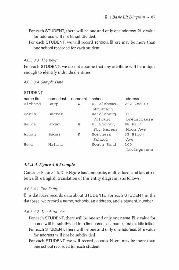
The Basic ER Diagram • 87
For.each.STUDENT,.there.will.be.one.and.only.one.address..The.value.for.address.will.not.be.subdivided.
For.each.STUDENT,.we.will.record.schools. There.may.be.more.than.one.school.recorded.for.each.student.
4.6.3.3.3 The Keys
For.each.STUDENT,.we.do.not.assume.that.any.attribute.will.be.unique.enough.to.identify.individual.entities.
4.6.3.3.4 Sample Data
STUDENTname.first name.last name.mi school addressRichard Earp W U. Alabama,
Mountain222 2nd St
Boris Backer Heidleburg, Volcano
333 Dreistrasse
Helga Hogan H U. Hoover, St. Helens
88 Half Moon Ave
Arpan Bagui K Northern School
33 Bloom Ave
Hema Malini South Bend 100 Livingstone
4.6.3.4 Figure 4.6 Example
Consider.Figure 4.6..This.figure.has.composite,.multivalued,.and.key.attri-butes..The.English.translation.of.this.entity.diagram.is.as.follows.
4.6.3.4.1 The Entity
This.database.records.data.about.STUDENTs..For.each.STUDENT in.the.database,.we.record.a name, schools, an.address,.and.a student_number.
4.6.3.4.2 The Attributes
For.each.STUDENT,.there.will.be.one.and.only.one.name..The.value.for.name.will.be.subdivided.into.first name,.last name,.and.middle initial.
For.each.STUDENT,.there.will.be.one.and.only.one.address..The.value.for.address.will.not.be.subdivided.
For.each.STUDENT,.we.will.record.schools. There.may.be.more.than.one.school.recorded.for.each.student.

88 • Database Design Using Entity-Relationship Diagrams
4.6.3.4.3 The Keys
For.each.STUDENT,.there.is.an.attribute—student_number—that.will.be.unique.enough.to.identify.individual.entities.
4.6.3.5 Figure 4.7 Example
Finally,. consider. Figure 4.7. (top. figure).. This. figure. shows. a. strong.entity..We.combine.the.grammar.a.little.to.keep.the.methodology.from.being.overly.repetitive..The.English.translation.of.this.entity.diagram.follows.
4.6.3.5.1 The Entity
This.database.records.data.about.AUTOMOBILEs..For.each.AUTOMOBILE.in.the.database,.we.record.a make, body_style, year, color, and vehicle_id.
4.6.3.5.2 The Attributes
Each.AUTOMOBILE.will.have.one.and.only.one.make, body_style, year, color,.and.vehicle_id..None.of.these.attributes.will.be.subdivided.
4.6.3.5.3 The Keys
For.each.AUTOMOBILE,.the.attribute,.vehicle_id, will.be.unique.enough.to.identify.individual.entities.
The. bottom. of. Figure 4.7. shows. a. weak. entity.. The. only. difference.between.the.strong.and.weak.entity.description.involves.the.key.phrase,.which.may.not.exist.in.the.weak.entity.
Before.leaving.this.introductory.chapter.on.ER.diagrams,.we.show.the.other.major.component.of.ER.diagrams..Figure 4.8.shows.a.relationship.between.two.entities,.an.AUTOMOBILE.and.a.STUDENT..The.concept.of.relationships. is. discussed. elaborately. in. Chapter. 6.. A. relationship. adds.action.to.the.diagram..For.example,.the.relationship.in.Figure 4.8.might.be.that.STUDENTs.drive.AUTOMOBILEs.
Our.ER.design.methodology.has.evolved.to.the.following.so.far:
Step 1. Select one primary entity from the database requirements description and show attributes to be recorded for that entity. Label keys if appropriate.Step 2. Use structured English for entities, attributes, and keys to describe the database that has been elicited.Step 3. Show some sample data.

The Basic ER Diagram • 89
4.7 MAPPING THE ENTITY DIAGRAM TO A RELATIONAL DATABASE
Having.illustrated.the.idea.of.the.entity.and.the.attribute,.we.now.turn.to.a. semiphysical. realization.of. the.concepts..We.say. semiphysical.because.we.are.really.not.concerned.with.the.actual.physical.file.that.is.stored.in.memory;.rather,.we.are.concerned.with.placing.data.into.relational.tables.that.we.will.visualize.as.a.physical.organization.of.data..Basically,.a.rela-tional.database. is. a.database.of. two-dimensional. tables. called. relations..The.tables.are.composed.of.rows.and.columns..The.rows.are.often.called.
A Relationship
Automobile
makebody style
color year
vehicle id
Student
student number
school address
name
firstname
middleinitial
lastname
SA
FIGURE 4.8An.ER.diagram.of.a.STUDENT-AUTOMOBILE.database.
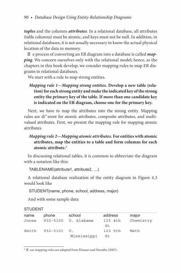
90 • Database Design Using Entity-Relationship Diagrams
tuples.and.the.columns.attributes. In.a.relational.database,.all.attributes.(table.columns).must.be.atomic,.and.keys.must.not.be.null..In.addition,.in.relational.databases,.it.is.not.usually.necessary.to.know.the.actual.physical.location.of.the.data.in.memory.
The.process.of.converting.an.ER.diagram.into.a.database.is.called.map-ping..We.concern.ourselves.only.with.the.relational.model;.hence,.as.the.chapters.in.this.book.develop,.we.consider.mapping.rules.to.map.ER.dia-grams.to.relational.databases.
We.start.with.a.rule.to.map.strong.entities.
Mapping rule 1—Mapping strong entities. Develop a new table (rela-tion) for each strong entity and make the indicated key of the strong entity the primary key of the table. If more than one candidate key is indicated on the ER diagram, choose one for the primary key.
Next,. we. have. to. map. the. attributes. into. the. strong. entity.. Mapping.rules.are.different. for.atomic.attributes,. composite.attributes,. and.multi-valued.attributes..First,.we.present.the.mapping.rule.for.mapping.atomic.attributes.
Mapping rule 2—Mapping atomic attributes. For entities with atomic attributes, map the entities to a table and form columns for each atomic attribute.*
In.discussing.relational.tables,.it.is.common.to.abbreviate.the.diagram.with.a.notation.like.this:
TABLENAME(attribute1, attribute2, ....)
A. relational. database. realization. of. the. entity. diagram. in. Figure 4.3.would.look.like
STUDENT(name, phone, school, address, major)
And.with.some.sample.data:
STUDENTname phone school address majorJones 932-5100 U. Alabama 123 4th
StChemistry
Smith 932-5101 U. Mississippi
123 5th St
Math
*. These.mapping.rules.are.adapted.from.Elmasri.and.Navathe.(2007).
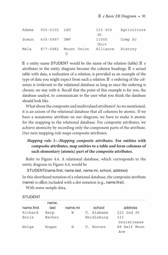
The Basic ER Diagram • 91
Adams 932-5102 LSU 123 6th St
Agriculture
Sumon 435-0997 UWF 11000 Univ
Comp Sc
Mala 877-0982 Mount Union U
Alliance History
The.entity.name.STUDENT.would.be.the.name.of.the.relation.(table)..The.attributes. in. the.entity.diagram.become. the.column.headings..The.actual.table.with.data,.a.realization.of.a.relation,.is.provided.as.an.example.of.the.type.of.data.you.might.expect.from.such.a.relation..The.ordering.of.the.col-umns.is.irrelevant.to.the.relational.database.as.long.as.once.the.ordering.is.chosen,.we.stay.with.it..Recall.that.the.point.of.this.example.is.for.you,.the.database.analyst,.to.communicate.to.the.user.what.you.think.the.database.should.look.like.
What.about.the.composite.and.multivalued.attributes?.As.we.mentioned,.it.is.an.axiom.of.the.relational.database.that.all.columns.be.atomic..If.we.have.a.nonatomic.attribute.on.our.diagram,.we.have. to.make. it. atomic.for.the.mapping.to.the.relational.database..For.composite.attributes,.we.achieve.atomicity.by.recording.only.the.component.parts.of.the.attribute..Our.next.mapping.rule.maps.composite.attributes.
Mapping rule 3—Mapping composite attributes. For entities with composite attributes, map entities to a table and form columns of each elementary (atomic) part of the composite attributes.
Refer. to. Figure 4.4.. A. relational. database,. which. corresponds. to. the.entity.diagram.in.Figure 4.4,.would.be
STUDENT(name.first, name.last, name.mi, school, address)In.this.shorthand.notation.of.a.relational.database,.the.composite.attribute.(name).is.often.included.with.a.dot.notation.(e.g.,.name.first).
With.some.sample.data,
STUDENT
name.firstname.
last name.mi school addressRichard Earp W U. Alabama 222 2nd StBoris Backer Heidleburg 333
DreistrasseHelga Hogan H U. Hoover 88 Half Moon
Ave

92 • Database Design Using Entity-Relationship Diagrams
Arpan Bagui K Cambridge 33 Bloom AveHema Malini Fashion U 100
Livingstone
A. multivalued. attribute. is. depicted. in. Figure 4.5a.. In. this. entity. dia-gram,. the.STUDENT. entity.has.a.composite.name. attribute.and.a.mul-tivalued.school.attribute..This.means.that.a.student.may.have.more.than.one.school.recorded.for.his.or.her.row..Data,.which.would.be.represented.by.this.diagram,.might.look.like.this:
STUDENTname.first name.last name.mi address schoolRichard Earp W 222 2nd St U. Alabama,
St Helens, Mountain, Volcano
Boris Backer 333 Dreistrasse
Heidleburg, Manatee U. UCF, UWF
Helga Hogan H 88 Half Moon Ave
U. Hoover, Mount Union U, Manatee U
Arpan Bagui K 33 Bloom Ave Cambridge, USF, Harvard
Hema Malini 100 Livingstone
Fashion U, Milan U
Note. that. this. is. not. considered. a. relational. table. because. the. school.attribute.is.not.atomic..To.be.a.relational.table,.every.attribute.has.to.be.atomic..To.map.this.multivalued.attribute.atomically,.we.follow.the. fol-lowing.mapping.rule:
Mapping rule 4—Mapping multivalued attributes. Form a separate table for the multivalued attribute. Record a row for each value of the multivalued attribute together with the key from the original table. The key of the new table will be the concatenation of the multivalued attribute plus the key of the owner entity. Remove the multivalued attribute from the original table.

The Basic ER Diagram • 93
As.per.mapping.rule.4,.we.require.a.key.to.map.multivalued.attributes;.hence,. we. use. Figure 4.6. to. correctly. map. the. multivalued. attribute..Figure 4.6.would.be.mapped.into.the.following.two.relations:
STUDENT(student_number, name.first, name.last, name.mi, address)
and
STUDENT_SCHOOL(student_number, school)
Some.sample.data.would.be
STUDENTstudent_number name.first name.last name.mi address111-11-2222 Richard Earp W 222 2nd St222-11-2222 Boris Backer 333
Dreistrasse234-45-4567 Helga Hogan H 88 Half Moon
Ave888-77-9990 Arpan Bagui K 33 Bloom Ave123-45-4321 Hema Malini 100
Livingstone
STUDENT_SCHOOLstudent_number school111-11-2222 U. Alabama111-11-2222 St. Helens111-11-2222 Mountain111-11-2222 Volcano222-11-2222 Heidleburg222-11-2222 Manatee U222-11-2222 UCF222-11-2222 UWF234-45-4567 U. Hoover234-45-4567 Mount Union U234-45-4567 Manatee U888-77-9990 Cambridge888-77-9990 USF888-77-9990 Harvard123-45-4321 Fashion U123-45-4321 Milan U
In.relational.databases,.every.row.of.a.table.contains.atomic.attributes,.and.every.row.is.unique..Therefore,.a.candidate.key.in.any.table.is.always.all.

94 • Database Design Using Entity-Relationship Diagrams
of.the.attributes..Usually,.a.subset.of.“all.of.the.attributes”.can.be.found.to.be.a.key,.but.since.no.two.rows.are.ever.the.same,.it.is.always.true.that.one.candidate.key.is.the.collection.of.all.attributes.
CHECKPOINT 4.3
. 1.. How.do.you.map.multivalued.attributes?
. 2.. How.do.you.map.composite.attributes?
. 3.. What.is.a.unique.identifier?.Is.it.a.candidate.key?.Is.it.“the”.primary.key?.Discuss.
4.8 CHAPTER SUMMARY
The.main.focus.in.this.chapter.was.on.developing.the.concept.of.the.entity.and.developing.a.one-entity.diagram.using.the.Chen-like.model..The.con-cept.of.attributes.was.also.discussed,.and.the.last.section.focused.on.how.a.one-entity.diagram.could.be.mapped.to.a.relational.database..The.gram-mar.for.a.one-entity.diagram.and.its.attributes.was.also.developed..This.grammar.is.further.developed.in.the.following.chapters..The.next.chap-ter.discusses.developing.a.second.entity.and.the.relationship.between.this.second.entity.and.the.primary.entity.
CHAPTER 4 EXERCISES
Note: The user should clarify the assumptions made when reporting the work.
Exercise 4.1
You.want.to.create.a.database.about.businesses..Each.business.will.have.a.name,.address,. the.business phone number,. the.owner’s phone num-ber,.and.the.first names.of.the.employees.who.work.at.the.business..Draw.the. ER. diagram. using. the. Chen-like. model. and. then. write. the. English.description. for. your. diagrams.. Compare. the. English. to. your. diagrams.and.state.any.assumptions.you.made.when.drawing.the.diagrams..Map.your.diagrams.to.a.relational.database.
Which.attributes.would.you.consider.composite.attributes. in.this.data-base?.Which.attributes.would.you.consider.multivalued.attributes. in. this.database?. Could. there. be. any. derived. attributes?. What. would. be. good.keys?

The Basic ER Diagram • 95
Exercise 4.2
You.want.to.create.a.database.about.the.books.on.your.shelf..Each.book.has. authors. (assume. that. only. the. last name. is. needed),. title, publisher, courses used. in.(course.number.only)..Draw.the.ER.diagram.using.the.Chen-like. model,. and. then. write. the. English. description. for. your. dia-grams..Compare.the.English.to.your.diagrams.and.state.any.assumptions.you.made.when.drawing.the.diagrams.
Which.attributes.would.you.consider.composite.attributes.in.this.data-base?.Which.attributes.would.you.consider.multivalued.attributes.in.this.database?. Could. there. be. any. derived. attributes?. What. would. be. good.keys?.Map.your.diagram.to.a.relational.database.
BIBLIOGRAPHY
Batini,.C.,.Ceri,.S.,.and.Navathe,.S..B..1992..Conceptual Database Design..Redwood.City,.CA:.Benjamin.Cummings.
Chen,. P.. P.. 1976.. The. entity. relationship. model—toward. a. unified. view. of. data.. ACM Transactions on Database Systems,.1(1):9–37.
Chen,. P.. P.. 1977.. The. entity-relationship. model:. a. basis. for. the. enterprise. view. of. data..Proceedings IFIPS NCC,.46:76–84.
Codd,.E..1990..Relational Model for Data Management—Version 2..Reading,.MA:.Addison-Wesley.
Date,.C..J..1995..An Introduction to Database Systems,.6th.ed.,.Reading,.MA:.Addison-Wesley.Date,.C..J..2003..An Introduction to Database Systems..Reading,.MA:.Addison-Wesley.Earp,.R.,.and.Bagui,.S..2000..Building.an.entity.relationship.diagram:.a.software.engineering.
approach..Database Management Journal,.22–10–41:1–16.Elmasri,. R.,. and. Navathe,. S.. B.. 2007.. Fundamentals of Database Systems.. Reading,. MA:.
Addison-Wesley.Jeffry,. A.,. Hoffer,. V.,. and. Heikki,. T.. 2011.. Modern Database Management.. Upper. Saddle.
River,.NJ:.Prentice.Hall.Navathe,. S.,. and. Cheng,. A.. 1983.. A. methodology. for. database. schema. mapping. from.
extended. entity. relationship. models. into. the. hierarchical. model.. In. The Entity-Relationship Approach to Software Engineering,.G..C..Davis.et.al..(editors)..Amsterdam:.Elsevier,.North-Holland,.223–248.
Scheuermann,.P.,.Scheffner,.G.,.and.Weber,.H..1980..Abstraction.capabilities.and.invariant.properties.modeling.within.the.entity-relationship.approach..In.Entity-Relationship Approach to System Analysis and Design,. P.. Chen. (editor).. Amsterdam:. Elsevier,.North-Holland,.pp..121–140.
Teorey,. T.. J.,. Yang,. D.,. and. Fry,. J.. P.. 1986.. A. logical. design. methodology. for. relational.databases. using. the. extended. entity-relationship. model.. ACM Computing Surveys,.18(2):197–222.
Valacich,.J..S.,.George,.J..F.,.and.Hoffer,.J..A..2009..Essentials of Systems Analysis and Design..Upper.Saddle.River,.NJ:.Prentice.Hall.
96 • Database Design Using Entity-Relationship Diagrams
CASE STUDY
West Florida Mall
A.new.mall,.West.Florida.Mall,.just.had.its.grand.opening.3.weeks.ago.in.Pensacola,.Florida..This.new.mall.is.attracting.a.lot.of.customers.and.stores..West.Florida.Mall,.which.is.part.of.a.series.of.malls.owned.by.a.parent.com-pany,.now.needs.a.database.to.keep.track.of.the.management.of.the.mall.in.terms.of.all.its.stores.as.well.as.the.owners.and.workers.of.the.stores..Before.we.build.a.database.for.this.system.of.malls,.the.first.step.will.be.to.design.an.ER.diagram.for.the.mall.owner..We.gathered.the.following.initial.user.speci-fications.about.the.mall,.with.which.we.can.start.creating.the.ER.diagram:
. 1..We.need.to.record.information.about.the.mall.and.each.store.in.the.mall..We.need.to.record.the.mall’s.name.and.address..A.mall,.at.any.point.in.time,.must.contain.one.or.more.stores.
. 2..For.each.Store.we.will.need.to.keep.the.following.information:.Store.number.(which.will.be.unique),. the.name.of. the.Store,. location.of.store. (Room. number),. departments,. the. owner. of. the. store,. and.manager.of. the. store..Each.store.may.have.more. than.one.depart-ment,. and. each. department. is. managed. by. a. manager.. Each. store.will.have.only.one.store.manager..Each.store.is.owned.by.only.one.owner..Each.store.is.located.in.one.and.only.one.mall.
. 3..A. Store. manager. can. manage. only. one. store.. We. have. to. record.information.on.the.store.manager:.the.name,.social.security.number,.which.store.he.or.she.is.working.for,.and.salary.
. 4..The.store.owner.is.a.person..We.have.to.record.information.about.the.store.owner.like.name,.address,.and.office.phone.number..A.store.owner.has.to.own.at.least.one.store.and.may.own.more.than.one.store.
DEVELOPING THE CASE STUDYAs.per.step.1.in.designing.the.ER.diagram,.we.have.to.select.our.primary.entity.and.then.the.attributes.for.our.primary.entity.(step.1.is.shown.next):
Step 1. Select one primary entity from the database requirements description and show attributes to be recorded for that entity.
We.will.choose.MALL.as.our.primary.entity.Our.next.step.is.to.translate.the.diagram.into.English:
Step 2. Use structured English for entities, attributes, and keys to describe the database that has been elicited.

The Basic ER Diagram • 97
The Entity
This.database.records.data.about.a.MALL.For. each. MALL. in. the. database,. we. record. a. name,. an. address,. and.
store_names.
The Attributes for MALL
For. each.MALL,. there. will. be. one. and. only. one.name.. The. value. for.name.will.not.be.subdivided.
For.each.MALL,.there.will.be.one.and.only.one.address..The.value.for.address.will.not.be.subdivided.
For. each. MALL, record. store_names. There. may. be. more. than. one.store_name recorded.for.each.MALL..The.value.of.each.store_name.will.not.be.subdivided.
The Keys
For.each.MALL,.we.assume.that.the.mall.name,.name,.will.be.unique.The.MALL.entity.is.shown.in.Figure 4.9.So. far,. for. this. case. study,. we. selected. one. primary. entity,. MALL,.
showed. its. known. attributes,. and. used. structured. English. to. describe.the.entity.and.its.attributes..Next,.we.map.this.entity.diagram.to.a.rela-tional.database.
Mapping the Entity to a Relational Database
MALL.is.a.strong.entity,.so.we.use.mapping.rule.1,.which.states
Develop a new table (relation) for each strong entity and make the indicated key of the strong entity the primary key of the table. If more than one candidate key is indicated on the ER diagram, choose one for the primary key.
Mall
name store_namesaddress
FIGURE 4.9The.MALL.attribute.

98 • Database Design Using Entity-Relationship Diagrams
We.develop.a.new.relation.for.the.entity,.MALL.(as.shown.in.Figure 4.9),.and. name. will. be. our. primary. key.. Data. that. would. be. represented. by.Figure 4.9.might.look.like.this:
MALLname address store_nameWest Florida Mall N Davis Hwy,
Pensacola, FLPenneys, Sears, Dollar Store, Rex
Cordova Mall 9th Avenue, Pensacola, FL
Dillards, Parisian, Circuit City
Navy Mall Navy Blvd, Pensacola, FL
Belks, Wards, Pearl Vision
BelAir Mall 10th Avenue, Mobile, AL
Dillards, Sears, Penney’s
We.can.see.that.MALL.has.a.multivalued.attribute,.store_name..This.does.not.make.the.table.a.relational.table.because.store_name.is.not.atomic;.it.is.multivalued..For.multivalued.attributes,.the.mapping.rule.is
Form a separate table for the multivalued attribute. Record a row for each value of the multivalued attributes together with the key from the original table. The key of the new table will be the con-catenation of the multivalued attribute plus the key of the owner entity. Remove the multivalued attribute from the original table.
Using.this.mapping.rule,.the.data.would.be.mapped.to.two.relations:MALL-STORE
name store_name
MALL
name address

The Basic ER Diagram • 99
and.data.would.look.like
MALLname addressWest Florida Mall N Davis Hwy, Pensacola, FLCordova Mall 9th Avenue, Pensacola, FLNavy Mall Navy Blvd, Pensacola, FLBelAir Mall 10th Avenue, Mobile, AL
And.the.relation.with.the.multivalued.attribute:
MALL-STOREname store_nameWest Florida Mall Penny’sWest Florida Mall SearsWest Florida Mall Dollar StoreWest Florida Mall RexCordova Mall DillardsCordova Mall ParisianCordova Mall Circuit CityNavy Mall BelksNavy Mall WardsNavy Mall Pearl VisionBelAir Mall DillardsBelAir Mall SearsBelAir Mall Penney’s
This.case.study.is.continued.at.the.end.of.the.next.chapter.

101
5Beyond the First Entity Diagram
5.1 INTRODUCTION
Now. that. we. have. devised. a. method. for. drawing,. interpreting,. and.refining.one.primary.entity,.we.need.to.move.to.databases.that.are.more.complex..To.progress. from.here,.we.continue.with.our.primary.entity.and. look. for.other. information. that.would.be.associated.with. (related.to).that.entity.
The.first.technique.employed.in.this.chapter.is.methodical:.We.test.our.primary.entity.to.see.whether.our.“attributes”.ought.to.be.entities.them-selves..We.then. look. for.other.pieces.of. information. in.our.description,.add.them.to.(a).an.existing.entity.and.examine. the.existing.entity.rela-tionship.(ER).diagram.or.(b).create.a.new.entity.directly..After.creating.the.new.entities,.we.look.to.see.what.kind.of.relationships.exist.between.the.two.entities..This.chapter.develops.steps.3.through.5.of.the.ER.design.methodology.presented.in.this.book..Step.3.examines.the.attributes.of.the.primary.entity,.step.4.discusses.what.to.do.if.another.entity.is.needed,.and.step.5.discusses.developing.the.relationship.between.the.two.entities.
Although.the.concept.of.relationships.is.introduced.in.this.chapter,.we.do.not.include.any.new.mapping.rules.in.this.chapter.since.mapping.rules.can.be.better.understood.after.the.development.of.structural.constraints.on.relationships,.which.is.discussed.in.Chapter.6..At.the.end.of.this.chap-ter,.we.continue.with.the.case.study.that.was.started.in.Chapter.4.

102 • Database Design Using Entity-Relationship Diagrams
5.2 EXAMINING AN ENTITY: CHANGING AN ATTRIBUTE TO BE AN ENTITY
Consider.Figure 5.1..In.this.figure,.we.have.a.student.with.the.following.attributes:.name.(a.composite.attribute),.student_number.(an.atomic.attri-bute. and. key),. school. (a. multivalued. attribute),. and. address. (an. atomic.attribute).. Suppose. that. during. our. first. session. with. the. user,. we. show.the.diagram,.the.English,.and.the.sample.data,.and.the.user.says,.“Wait.a.minute..I.want.to.record.all.schools.that.a.student.attended,.and.I.want.to.record.not.only.the.name.of.the.school,.but.also.the.location.(city.and.state).and.school.type.(community.college,.university,.high.school,.etc.).”
What.the.user.just.told.us.was.that.the.attribute.school.should.really.be.an.entity..Remember.that.the.definition.of.an.entity.was.something.about.which.we.wanted. to.record. information..Our.original. thought.was. that.we.were.recording.schools.attended,.but.now.we.are.told.that.we.want.to.record.information.about.the.schools..The.first.indicator.that.an.attribute.should.be.considered.an.entity.is.that.we.need.to.store.information.about.the.attribute..What.we.do.then.is.to.migrate.from.Figure 5.1.to.Figure 5.2..In.Figure 5.2,.SCHOOL.is.now.an.entity.by.itself,.so.we.have.two.separate.entities,.SCHOOL.and.STUDENT..We.assume.school_name.to.be.unique.and.choose.the.school_name.as.the.key.for.the.entity.SCHOOL.
The.next.step.would.be.to.define.a.relationship.between.the.two.entities.
Student
student number
school address
name
firstname
middleinitial
lastname
FIGURE 5.1STUDENT.entity.with.a.multivalued.attribute.
Beyond the First Entity Diagram • 103
5.3 DEFINING A RELATIONSHIP FOR OUR NEW ENTITY
Databases.are.designed.to.store.related.data..For.example,.it.would.ordi-narily.make.no.sense.to.record.data.about.students.and.foreign.curren-cies.or.about.airline.flights.and.employees.at.a. tennis.ball. factory. listed.in. the. same.database..These.concepts.are.not. related.. In.a.database,.we.should. be. creating. a. collection. of. related. data.. Following. our. method,.we. clearly. have. a. situation. for. which. an. attribute. was. part. of. an. entity.(school.was.considered.“part.of”.student),.but.now.school.has.become.an.entity.by.itself..What.we.have.to.do.now.is.relate.the.SCHOOL.entity.to.the.STUDENT.entity.
In.Figure 5.2,.we.have.two.entities,.but.they.appear.as.though.they.are.independent.. To. make. the. SCHOOL. entity. and. the. STUDENT. entity.function.as.a.database,.we.have. to.add.something:. the.relationship. that.the.entity.SCHOOL.has.to.the.entity.STUDENT.
A.relationship.in.an.ER.diagram.is.a.connection.between.two.or.more.entities.or.between.one.entity.and. itself..The. latter.kind.of.relationship,.between.one.entity.and.itself,.is.known.as.a.recursive relationship,.which.we.discuss. in.Chapter.8..A.relationship name. is.usually.a.verb or.verb phrase.that.denotes.the.connection.between.entities..Once.we.have.under-stood.how.the.relationship.is.denoted,.we.have.a.“tool”.to.draw.a.database.description.in.the.form.of.an.ER.diagram.
In.the.Chen-like.model,.a.relationship.is.depicted.by.a.diamond.on.the.line.that.joins.the.two.entities.together,.as.shown.in.Figure 5.3.
In.Figure 5.3,. the. relationship. is.depicted.as.attend..The. sense.of. the.relationship.is.that.of.a.verb.connecting.two.nouns.(entities)..All.relation-ships.are.two-way..As.we.will.see,.it.is.necessary.to.state.all.relationships.from. both. directions.. For. example,. in. the. Chen-like. model. we. would.informally. say,. “A STUDENT. attended. a. SCHOOL”. or. “STUDENTS.attend.SCHOOLS.”
The.degree.of.a.relationship.refers.to.the.number.of.entities.that.partici-pate.in.the.relationship..In.Figure 5.3,.two.entities.are.participating.in.the.relationship.attend, so.this.is.called.a.binary.relationship.
We.now.have.a.tool.to.draw.a.database.description.in.the.form.of.ER.diagrams..In.ER.diagrams,.we.record.information.about.x.and.y.(x.and.y.are.entities).and.then.express.the.relationship.of.x.to.y.
Our.growing.and.amended.methodology.is.discussed.next.

104 • Database Design Using Entity-Relationship Diagrams
5.3.1 ER Design Methodology
Step 1. Select one primary entity from the database requirements description and show the attributes to be recorded for that entity. Label keys if appropriate and show some sample data.
Step 2. Use structured English for entities, attributes, and keys, to describe the database that has been elicited.
Step 3. Examine attributes in the primary entity (possibly with user assistance) to find out if information about one of the attributes is to be recorded.
School
type_of_school
school_name
location
city
state
Student
student numbername
firstname
middleinitial
lastname
address
FIGURE 5.2Two.ER.diagrams:.one.of.STUDENT.and.one.of.SCHOOL.

Beyond the First Entity Diagram • 105
Step 3a. If information about an attribute is needed, then make the attribute an entity, and then
Step 3b. Define the relationship back to the original entity.Step 4. Show some sample data.
5.4 A PRELIMINARY GRAMMAR FOR ER DIAGRAMS
In.Chapter.4,.we.outlined.a.grammar.to.describe.an.entity..Now.that.we.have.added.a.relationship.to.our.diagram,.we.need.to.embellish.our.English.description.of.the.proposed.database..We.also.want.to.show.the.user.some.sample.data.to.solidify.the.understanding.of.the.path.we.are.taking..We.want.to.add.the.following.to.our.list.of.grammatical.expressions:
For.each.relationship,.we.add.the.following.comment.(in.loose.English.[for.now]):
A(n) Entity1 Relationship Entity2 (active voice) and a(n) Entity2 Relationship Entity1 (passive voice).
A.discussion.of.this.follows.
5.4.1 The Relationship
A. STUDENT attends a. SCHOOL, and. a SCHOOL is attended by. a STUDENT.
The.user.may.be.the.ultimate.judge.of.the.appropriateness.of.the.expression.we.use,.but.we.will.add.to.this.grammar.soon..The.user.may.prefer.a.dif-ferent.tense.for.the.verb.and.may.choose.a.verb.that.he.or.she.thinks.more.appropriately.assesses.the.situation..For.example,.the.user.may.choose.to.portray.the.relationship.as.“STUDENTs.will matriculate.at.SCHOOLs.”.As.an.exercise,.you.will.be.asked.to.provide.a.complete.description.of.the.ER.diagram.in.Figure 5.3,.with.all.entities,.attributes,.keys,.and.relationships.
5.5 DEFINING A SECOND ENTITY
Having.examined.the.original.primary.entity.for.“suspicious”.attributes,.we.may.now.begin.to.add.more.data..Let.us.presume.the.user.wants. to.add.information.about.automobiles.that.students.own.or.drive..Ignoring.
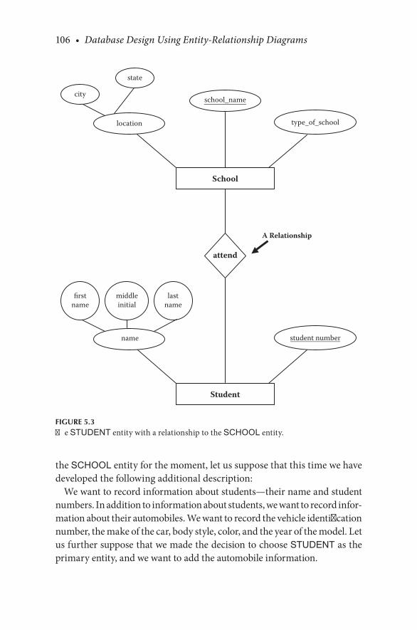
106 • Database Design Using Entity-Relationship Diagrams
the.SCHOOL.entity.for.the.moment,.let.us.suppose.that.this.time.we.have.developed.the.following.additional.description:
We.want.to.record.information.about.students—their.name.and.student.numbers..In.addition.to.information.about.students,.we.want.to.record.infor-mation.about.their.automobiles..We.want.to.record.the.vehicle.identification.number,.the.make.of.the.car,.body.style,.color,.and.the.year.of.the.model. Let.us.further.suppose.that.we.made.the.decision.to.choose.STUDENT.as.the.primary.entity,.and.we.want.to.add.the.automobile.information.
School
type_of_school
school_name
location
city
state
Student
student numbername
firstname
middleinitial
lastname
A Relationship
attend
FIGURE 5.3The.STUDENT.entity.with.a.relationship.to.the.SCHOOL.entity.

Beyond the First Entity Diagram • 107
The.automobile.is.clearly.an.entity.in.that.it.is.something.about.which.we.want. to.record. information.. If.we.add.the.automobile. into.the.data-base,.we.could.have.included.it.in.step.1.of.our.methodology.by.adding.an.attribute.called.automobile,.only.later.to.perform.step.3.of.the.meth-odology.and.migrate.automobile.and.school.to.the.status.of.entities..The.depiction.of.automobile.as.an.attribute.of.the.STUDENT.entity.is.shown.in.Figure 5.4.(in.the.Chen-like.model)..(We.ignore.the.SCHOOL.entity.for.the.moment.)
If.we.added.the.automobile attribute to.the.STUDENT entity.and.then.recognized.that.automobile.should.have.been.an.entity,.we.would.then.cre-ate.the.AUTOMOBILE.entity.and.add.the.relationship.to.the.model..(Note.that.Figure 5.4.would.actually.be.sufficient.if.the.user.did.not.want.to.store.information.about.the.automobiles.themselves.)
Of.course,.we.could.have.recognized.that.the.attribute.automobile.was.going.to.be.an.entity.all.along.and.simply.recorded.it.as.such.in.our.dia-gram. in. the. first. place.. By. recognizing. AUTOMOBILE. as. an. entity,. we.would.draw.the.two.entities.STUDENT.and.AUTOMOBILE.and.then.look.for. a. relationship. between. the. two.. Either. way,. we. would. end. up. with.Figure 5.5,. with. two. entities,. STUDENT. and. AUTOMOBILE,. and. some.relationship.between.the.two.
Student
student number
automobile
name
firstname
middleinitial
lastname
FIGURE 5.4A.STUDENT.entity.with.an.attribute.called.automobile.
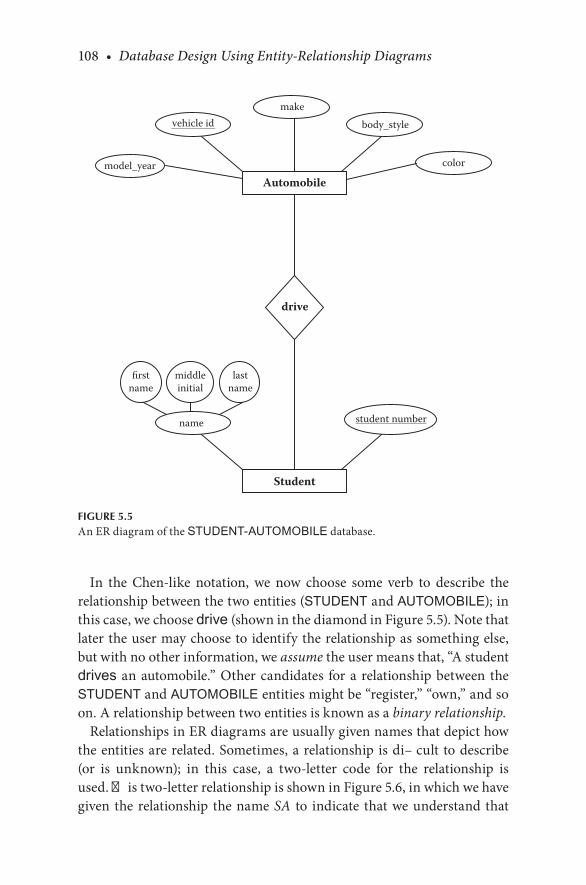
108 • Database Design Using Entity-Relationship Diagrams
In. the. Chen-like. notation,. we. now. choose. some. verb. to. describe. the.relationship.between.the.two.entities.(STUDENT.and.AUTOMOBILE);.in.this.case,.we.choose.drive (shown.in.the.diamond.in.Figure 5.5)..Note.that.later.the.user.may.choose.to.identify.the.relationship.as.something.else,.but.with.no.other.information,.we.assume.the.user.means.that,.“A.student.drives. an.automobile.”.Other.candidates. for.a. relationship.between. the.STUDENT and.AUTOMOBILE.entities.might.be.“register,”.“own,”.and.so.on..A.relationship.between.two.entities.is.known.as.a.binary relationship.
Relationships.in.ER.diagrams.are.usually.given.names.that.depict.how.the.entities.are.related..Sometimes,.a.relationship. is.difficult. to.describe.(or. is. unknown);. in. this. case,. a. two-letter. code. for. the. relationship. is.used..This.two-letter.relationship.is.shown.in.Figure 5.6,.in.which.we.have.given. the.relationship. the.name.SA. to. indicate. that.we.understand. that.
Automobile
makebody_style
model_year color
vehicle id
Student
student numbername
firstname
middleinitial
lastname
drive
FIGURE 5.5An.ER.diagram.of.the.STUDENT-AUTOMOBILE.database.

Beyond the First Entity Diagram • 109
a.relationship.exists,.but.we.are.not.clear.on.exactly.what.to.call.it.(SA.=.STUDENT- AUTOMOBILE)..Of.course,.if.we.were.confident.of.“drive”.as.the.relationship,.we.would.use.drive.
The. English. description. of. the. entities. and. relationships. implies. that.entities.are.nouns.(N).and.relationships.are.verbs.(V)..Using.the.drive.rela-tionship.(as.shown.in.Figure 5.6),.Students.(N).drive.(V).automobiles.(N)..If.the.“unknown”.relationship.is.really.unknown,.we.might.say.“Students.(N).are.related.to.(V).automobiles.(N)”.or.“A.student.(N).is.related.to.(V).an.automobile.(N).”.In.the.next.chapter,.we.develop.this.English.descrip-tion.as.well.as.the.relationship.part.of.the.diagram.more.fully.
Automobile
makebody_style
model_year color
vehicle id
Student
student numbername
firstname
middleinitial
lastname
school address
A Relationship
SA
FIGURE 5.6An.ER.diagram.of.the.STUDENT-AUTOMOBILE.database.with.an.“unknown,”.“yet-to-be-determined”.relationship.
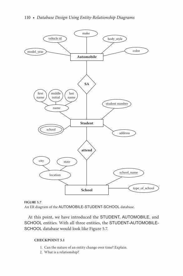
110 • Database Design Using Entity-Relationship Diagrams
At.this.point,.we.have. introduced.the.STUDENT,.AUTOMOBILE,.and.SCHOOL.entities..With.all.three.entities,.the.STUDENT-AUTOMOBILE-SCHOOL.database.would.look.like.Figure 5.7.
CHECKPOINT 5.1
. 1.. Can.the.nature.of.an.entity.change.over.time?.Explain.
. 2.. What.is.a.relationship?
Automobile
makebody_style
model_year color
vehicle id
Student
student numbername
firstname
middleinitial
lastname
schooladdress
SA
School
attend
type_of_school
locationschool_name
city state
FIGURE 5.7An.ER.diagram.of.the.AUTOMOBILE-STUDENT-SCHOOL.database.
Beyond the First Entity Diagram • 111
. 3.. What.are.the.differences.between.an.entity.and.a.relationship?
. 4.. When.would.it.be.preferable.to.consider.an.attribute.an.entity?.Why.or.why.not?
. 5.. Does.it.make.sense.to.have.an.entity.with.one.attribute?
5.6 DOES A RELATIONSHIP EXIST?
Some.situations.may.unfold.for.which.a.relationship.might.be.unclear..For.example,.consider.this.user.description.of.a.desired.database:
Create.a.database.for.CUSTOMERS.and.SUPPLIERS..CUSTOMERS.will. have. a. name, address, phone number,. and. customer number..SUPPLIERS.will.have.a.supplier number, name,.and.address.
In. this. database,. we. clearly. have. two. entities:. CUSTOMER. and.SUPPLIER. We.want.to.store.information.about.customers.(their.name,.address,.…).and.suppliers.(supplier.number,.name,.…)..But,.what. is.the.connection.between.the.two?
What.we.have.here.is.an.incomplete,.vague.user.description.from.which.to.design.our.database..The.connection.for.the.company.that.wants.the.database.is.that.they.have.both.customers.and.suppliers;.however,.what.they.may.not.realize.is.that.the.relationship.from.CUSTOMER.to.SUPPLIER.is.via.a.COMPANY.or.a.VENDOR,.and.not.a.direct.relationship..So,.what.we.have.so.far.in.this.description.is.two.different.parts.of.a.company.data-base—one.for.customers.and.one.for.suppliers..If.we.later.have.some.other.entity.like.“inventory”.or.“vendor,”.which.is.related.to.customers.and.to.suppliers,. there.may.be. linking.entities.and.relationships..For.now.with.just.two.unrelated.ideas.(customer.and.supplier),.there.is.no.apparent.rela-tionship,.so.the.thing.to.do.would.be.to.leave.any.relationship.off.the.over-all.diagram.until.more.information.is.elicited.from.the.user..It.may.even.be.that.two.unrelated.databases.need.to.be.developed.
5.7 ATTRIBUTE OR RELATIONSHIP?
Sometimes,. it. may. be. unclear. whether. something. is. an. attribute. or. a.relationship.. Both. attributes. and. relationships. express. something.about. an. entity.. The. attributes. of. an. entity. express. qualities. in. terms.
112 • Database Design Using Entity-Relationship Diagrams
of.properties.or.characteristics..Relationships.express.associations.with.other.entities.
Suppose.we.are.constructing.a.library.database..Suppose.further.that.we.create.another.primary.entity,.BOOK,.which.has.an.attribute.borrower_name. In.some.cases,.an.attribute.construct.is.likely.to.be.inappropriate.for.expressing.an.optional.association.that.really.ought.to.be.a.relationship.between.two.entities..As.a.side.issue,.BORROWER.would.require.the.use.of.a.null.value.for.those.BOOK entities.that.were.not.on.loan..In.reality,.only.a.fraction.of.the.books.in.a.library.is.on.loan.at.any.given.time..Thus,.the. “borrower”. attribute. would. be. null. for. some. of. the. BOOK. entities..This.recurrence.of.many.nulls.might.indicate.that.the.attribute,.borrower_name, could. be. an. attribute. of. an. entity.. If. a.BORROWER entity. were.created.and.the.association.between.the.entities.BOOK.and.BORROWER.was.explicitly.stated.as.a.relationship,.the.database.designer.would.likely.be. closer. to. putting. attributes. and. entities. in. their. correct. places.. It. is.important. to.understand. the.distinction.between. the. types.of. informa-tion.that.can.be.expressed.as.attributes.and.those.that.should.be.treated.as.relationships.and.entities.
CHECKPOINT 5.2
. 1.. Are.relationships.between.two.entities.permanent,.or.can.the.nature.of.this.relationship.change.over.time?
. 2.. Are.attributes.of.an.entity.permanent?
. 3.. Does.there.always.exist.a.relationship.between.two.entities?
. 4.. What.is.a.binary.relationship?
Our.ER.elicitation.and.design.methodology.is.described.next.
5.7.1 ER Design Methodology
Step 1. Select one primary entity from the database requirements description and show attributes to be recorded for that entity. Label keys if appropriate and show some sample data.
Step 2. Use structured English for entities, attributes, and keys to describe the database that has been elicited.
Step 3. Examine attributes in the primary entity (possibly with user assistance) to find out if information about one of the attributes is to be recorded.
Step 3a. If information about an attribute is needed, then make the attribute an entity, and then
Step 3b. Define the relationship back to the original entity.

Beyond the First Entity Diagram • 113
Step 4. If another entity is appropriate, draw the second entity with its attributes. Repeat step 2 to see if this entity should be further split into more entities.
Step 5. Connect entities with relationships if relationships exist.Step 6. Show some sample data.
5.8 CHAPTER SUMMARY
Entities,.attributes,.and.relationships.were.defined.in.Chapter.4..However,.in.real.life,.while.trying.to.design.databases,.it.is.often.difficult.to.deter-mine. whether. something. should. be. an. attribute,. entity,. or. relationship..This.chapter.discussed.ways.(techniques).to.determine.whether.something.should.be.an.entity,.attribute,.or.relationship.
This.chapter.also.introduced.the.concept.of.binary.relationships..Real-life.databases.will.have.more.than.one.entity,.so.this.chapter.developed.the.ER.diagram.from.a.one-entity.diagram.to.a. two-entity.diagram.and.showed.how. to. determine. and. depict. binary. relationships. between. the. two. enti-ties.using.the.Chen-like.model..Since.the.concept.of.relationships.was.only.introduced.and.structural.constraints.of.relationships.have.not.yet.been.dis-cussed.(Chapter.6),.we.have.not.included.mapping.rules.in.this.chapter.
CHAPTER 5 EXERCISES
Exercise 5.1
Draw.an.ER.diagram.(using. the.Chen-like.model). for.an.entity.called.HOTEL.and.include.no.fewer.than.five.attributes. for. the.entity..Of. the.five.attributes,.include.at.least.one.composite.attribute.and.one.multival-ued.attribute.
Exercise 5.2
Suppose. that.we.reconsider.our.STUDENT. example,.and.the.only.attri-butes.of. student.are.student number. and.name..Let.us. suppose. that.we.have. another. entity. called. HIGH SCHOOL. that. is. going. to. be. the. high.school.from.which.the.student.graduated..For.the.HIGH SCHOOL.entity,.we.will.record.the.high.school.name.and.the.location.(meaning.city.and.state)..Draw. the.ER.diagram.using. the.concise. form.(as. in.Figure 4.1c)..

114 • Database Design Using Entity-Relationship Diagrams
What.would.you.name.the.relationship.here?.Write.out.the.grammar.for.the.relationship.between.the.two.entities.
Exercise 5.3
Suppose. that. a. college. had. one. dormitory. with. many. rooms.. The.DORMITORY. entity,. which. is. actually. a. “dormitory. room”. entity. since.there.is.only.one.dorm,.has.the.attributes.room number.and.single/double.(meaning.that.there.are.private.rooms.and.double.rooms)..Let.us.suppose.that.the.STUDENT.entity.in.this.case.contains.the.attributes.student num-ber, student name,.and.home telephone number..Draw.the.ER.diagram.in.the. Chen-like. model. linking. the. two. entities.. Name. your. relationships..Write.the.grammar.for.the.relationship.between.the.two.entities.
Exercise 5.4
If.we.have.two.entities,.a.PLANE.and.a.PILOT,.and.describe.the.relation-ship.between.the.two.entities.as
“A PILOT flies a PLANE.”What.should.the.relationship.read.from.the.side.of.the.other.entity?
Exercise 5.5
Complete.the.methodology.by.adding.sample.data.to.Figures 5.3,.5.5,.and.Exercises.5.1,.5.2,.5.3,.and.5.4.
BIBLIOGRAPHY
Elmasri,. R.,. and. Navathe,. S.. B,. 2007.. Fundamentals of Database Systems.. Reading,. MA:.Addison-Wesley.
Hoffer,. J.,.Ramesh,.V.,. and.Topi,.H..2011..Modern Database Management..Upper.Saddle.River,.NJ:.Prentice.Hall.
CASE STUDY
West Florida Mall (continued)
In.Chapter.4,.we.chose.our.primary.entity,.MALL,. and.used. structured.English.to.describe.it,.its.attributes,.and.keys,.and.then.we.mapped.MALL.to. a. relational. database. (with. some. sample. data).. In. this. chapter,. we.

Beyond the First Entity Diagram • 115
continue.to.develop.this.case.study.by.looking.at.steps.3,.4,.and.5.of.the.ER.design.methodology.
Step.3.says:
Step 3. Examine attributes in the primary entity (with user assis-tance) to find out if information about one of the attributes is to be recorded.
On.reexamining.the.attributes.of.the.primary.entity.MALL,. it.appears.that.we.need.to.store.information.about.the.attribute.store. So,.we.look.at.step.3a,.which.says
Step 3a. If information about an attribute is needed, then make the attribute an entity, and then proceed to step 3b.
So,.turning.the.attribute.store.into.an.entity,.we.have.the.following.(repeat-ing.Step.2):
The Entity
This.database.records.data.about.a.STORE.
For.each.STORE.in.the.database,.we.record.a.store.name.(sname),.a.store.number.(snum),.a.store.location.(sloc),.and.departments.(dept).
The Attributes for STORE
For.each.STORE,.there.will.be.one.and.only.one.sname (store.name)..The.value.for.sname will.not.be.subdivided.
For.each.STORE,.there.will.be.one.and.only.one snum (store.number)..The.value.for.snum.will.be.unique.and.will.not.be.subdivided.
For.each.STORE,.we.will.record.a sloc (store.location)..There.will.be.one.sloc.recorded.for.each.STORE..The.value.for.sloc.will.not.be.subdivided.
For.each.STORE,.we.will.record.dept.(departments)..There.will.be.more.than.one.dept.recorded.for.each.STORE..The.value.for.dept.will.not.be.subdivided.
The Keys
For.each.STORE,.we.will.assume.that.the.snum.will.be.unique.Note:.Once.STORE.is.made.into.an.entity,.the.attribute.store.is.removed.
from.the.entity.MALL,.as.shown.in.Figure 5.8.

116 • Database Design Using Entity-Relationship Diagrams
Having.defined.STORE,.we.now.need.to.follow.step.3b,.which.says
Step 3b. Define the relationship back to the original entity.
There.is.a.relationship,.located_in,.between.STORE.and.MALL. This.is.shown.in.Figure 5.8.
Next,.step.4.says
Step 4. If another entity is appropriate, draw the second entity with its attributes. Repeat step 2 to see if this entity should be further split into more entities.
We.select.another.entity,.STORE_MANAGER.Now,.repeating.step.2.for.STORE_MANAGER:
The Entity
This.database.records.data.about.a.STORE_MANAGER.
For.each.STORE_MANAGER.in.the.database,.we.record.a.store.man-ager.name.(sm_name),.store.manager.Social.Security.number.(sm_ssn),.and.store.manager.salary.(sm_salary).
Mall
located_in
Store
sname snumsloc
name
address
dept
FIGURE 5.8ER.diagram.of.the.mall.database.so.far.

Beyond the First Entity Diagram • 117
The Attributes for STORE_MANAGER
For.each.STORE_MANAGER,. there.will.be.one.and.only.one.sm_name.(store.manager.name)..The.value.for.sm_name.will.not.be.subdivided.
For.each.STORE_MANAGER,.there.will.be.one.and.only.one.sm_ssn.(store.manager.Social.Security.number)..The.value.for.sm_ssn.will.be.unique.and.will.not.be.subdivided.
For.each.STORE_MANAGER,.we.will.record.a.sm_salary.(store.manager.salary)..There.will.be.one.and.only.one.sm_salary recorded.for.each.STORE_MANAGER..The.value.for.sm_salary will.not.be.subdivided.
The Keys
For. each.STORE_MANAGER,. we. will. assume. that. the.sm_ssn. will.be.unique.
Having.defined.STORE_MANAGER,.we.now.follow.step.5,.which.saysStep 5. Connect entities with relationships if relationships exist.
There. is. a. relationship,. manages,. between. STORE. and. STORE_MANAGER..This.is.shown.in.Figure 5.9.
Mall
located_in
Store
sname snumsloc
name
address
dept
Store Managermanages
sm_ssn sm_salary sm_name
FIGURE 5.9An.ER.diagram.of.West.Florida.Mall.database.developing.

118 • Database Design Using Entity-Relationship Diagrams
Then,.we.select.our.next.primary.entity,.OWNER.Now,.repeating.step.2.for.OWNER:
The Entity
This.database.records.data.about.a.OWNER.
For.each.OWNER in.the.database,.we.record.a.store.owner.name.(so_name),. store. owner. Social. Security. number. (so_ssn), store. owner.office.phone.(so_off_phone),.and.store.owner.address.(so_address).
The Attributes for OWNER
For.each.OWNER,.there.will.be.one.and.only.one.so_name.(store.owner.name)..The.value.for.so_name.will.not.be.subdivided.
For.each.OWNER,.there.will.be.one.and.only.one.so_ssn (store.owner.Social.Security.number)..The.value. for.so_ssn.will.be.unique.and.will.not.be.subdivided.
For.each.OWNER,.there.will.be.one.and.only.one.so_off_phone (store.owner.office.phone)..The.value.for.so_off_phone.will.be.unique.and.will.not.be.subdivided.
For.each.OWNER,.we.will.record.a.so_address (store.owner.address)..There. will. be. one. and. only. one. so_address. recorded. for. each.OWNER..The.value.for.so_address.will.not.be.subdivided.
The Keys
For.each.OWNER,.we.will.assume.that.the.so_ssn.will.be.unique.Having.defined.OWNER,.we.now.follow.step.5,.which.says:
Step 5. Connect entities with relationships if relationships exist.
There. is. a. relationship,. owns,. between. STORE. and. OWNER.. This. is.shown.in.Figure 5.10.
MAPPING TO A RELATIONAL DATABASE
Having.described.the.entities,.attributes,.and.keys,.the.next.step.would.be.to.map.to.a.relational.database..We.will.also.show.some.data.for.the.entities.
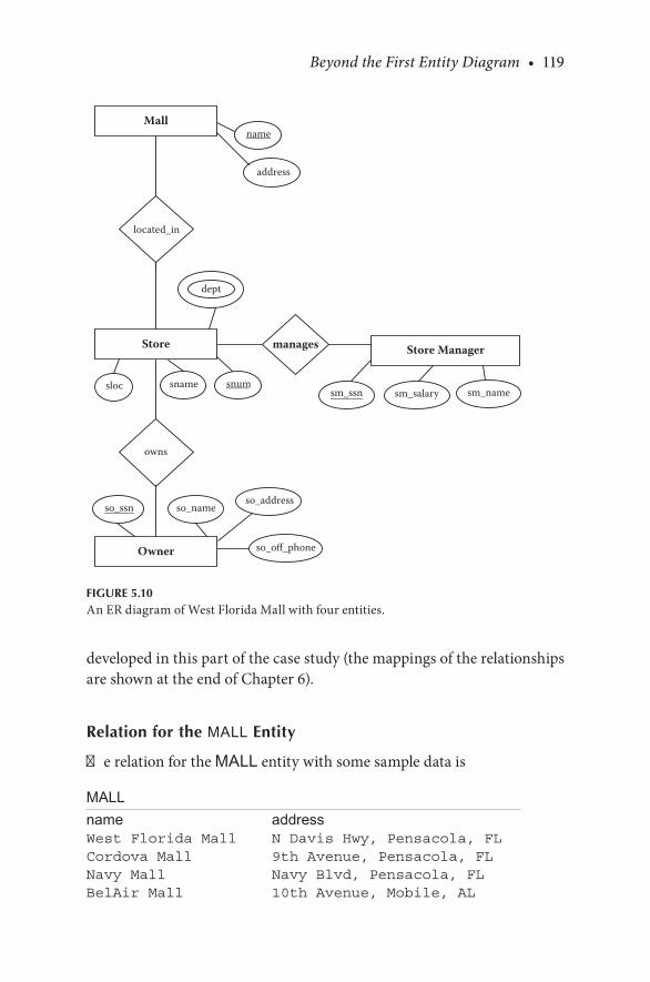
Beyond the First Entity Diagram • 119
developed.in.this.part.of.the.case.study.(the.mappings.of.the.relationships.are.shown.at.the.end.of.Chapter.6).
Relation for the MALL Entity
The.relation.for.the.MALL.entity.with.some.sample.data.is
MALLname addressWest Florida Mall N Davis Hwy, Pensacola, FLCordova Mall 9th Avenue, Pensacola, FLNavy Mall Navy Blvd, Pensacola, FLBelAir Mall 10th Avenue, Mobile, AL
Mall
located_in
Store
owns
Owner
sname snumsloc
name
address
dept
Store Managermanages
sm_ssn sm_salary sm_name
so_off_phone
so_addressso_nameso_ssn
FIGURE 5.10An.ER.diagram.of.West.Florida.Mall.with.four.entities.

120 • Database Design Using Entity-Relationship Diagrams
Note.that.we.do.not.need.the.MALL-Store.mapping.that.was.presented.in.Chapter.4.since.Store.has.changed.from.a.multivalued.attribute.to.an.entity.
Relation for the STORE entity
The.entity.STORE.has.a.multivalued.attribute.depts,.so.we.again.have.to.use.mapping.rule.4.to.map.this.entity..First,.we.will.show.the.relation.with.the.multivalued.attribute.excised,.and.then.we.will.show.the.relation.with.the.multivalued.attribute.
Relation with the Multivalued Attribute Excised (with some sample data)
STOREsloc sname snumRm 101 Penneys 1Rm 102 Sears 2Rm 109 Dollar Store 3Rm 110 Rex 4
Relation with the Multivalued Attribute (with some sample data)Relation for the STORE MANAGER Entity (using Mapping Rule 1 and Mapping Rule 2) with some sample data
STORE-deptsnum depts1 Tall men’s clothing1 Women’s clothing1 Children’s clothing1 Men’s clothing...2 Men’s clothing2 Women’s clothing2 Children’s clothing...

Beyond the First Entity Diagram • 121
STORE MANAGERsm_ssn sm_name sm_salary234-987-0988 Saha 45,900456-098-0987 Becker 43,989928-982-9882 Ford 44,000283-972-0927 Raja 38,988
Relation for the OWNER Entity (using Mapping Rule 1 and Mapping Rule 2) with some sample data
OWNERso_ssn so_name so_off_phone so_address879-987-0987 Earp (850)474-2093 1195 Gulf
Breeze Pkwy, Pensacola, FL
826-098-0877 Sardar (850)474-9873 109 Navy Blvd, Pensacola, FL
928-088-7654 Bagui (850)474-9382 89 Highland Heights, Tampa, FL
982-876-8766 Bush (850)474-9283 987 Middle Tree, Mobile, AL
So. far,. our. relational. database. has. developed. into. (without. the. data).(note.that.the.primary.keys.are.underlined.)MALL
name address
STORE
sloc sname snum
STORE-dept
snum depts

122 • Database Design Using Entity-Relationship Diagrams
OWNER
so _ ssn so _ name so _ off _ phone so _ address
STORE MANAGER
sm _ ssn sm _ name sm _ salary
This.case.study.is.continued.at.the.end.of.the.next.chapter.

123
6Extending Relationships/Structural Constraints
6.1 INTRODUCTION
In.Chapters.4.and.5,.we.introduced.some.components.of.entity.relation-ship. (ER). diagrams:. entities,. attributes,. and. relationships.. It. is. really.insufficient. for. requirement. elicitation. to. define. relationships. without.also. defining. what. are. called. structural constraints.. Structural. con-straints.are.information.about.how.two.(or.more).entities.are.related.to.one. another.. There. are. two. types. of. structural. constraints:. cardinality.and.participation.
In. this. chapter,. in. addition. to. the. structural. constraints. of. relation-ships,.we.want.to.introduce.a.grammar.to.describe.what.we.have.drawn..The. grammar. will. help. with. the. requirement. elicitation. process. as. we.will.specify.a.template.for.the.English.that.can.be.imposed.on.a.diagram,.which. will. in. turn. make. us. say. exactly. what. the. diagram. means.. This.chapter.develops.steps.6.and.7.of.the.ER.design.methodology..Step.6.states.the.nature.of.a.relationship.in.English,.and.step.7.discusses.presenting.the.database.(designed.so.far).to.the.user.
Mapping.rules.for.relationships.are.also.developed.and.discussed.with.examples.and.sample.data..At.the.end.of.the.chapter,.we.continue.the.run-ning.case.study.that.we.began.in.Chapter.4.and.continued.in.Chapter.5.
6.2 THE CARDINALITY RATIO OF A RELATIONSHIP
Cardinality. is.a. rough.measure.of. the.number.of.entities. (one.or.more).that.will.be.related.to.another.entity.(or.entities)..For.example,.there.are.four. ways. in. which. the. entities. AUTOMOBILE. and. STUDENT. can. be.

124 • Database Design Using Entity-Relationship Diagrams
“numerically. involved”. in. a. relationship:. one. to. one. (1:1),. many. to. one.(M:1),.one.to.many.(1:M),.and.many.to.many.(M:N)..The.most.common.relationships.are.1:M.and.M:N.
6.2.1 One to One (1:1)
In.the.one-to-one.(1:1).type.of.relationship,.one.entity.is.associated.with.one.other.entity.and.vice.versa..For.example,.if.in.our.drive.relationship.(Figure 6.1),.we.stated.that.one.automobile.is.driven.by.one.student,.and.one.student.drives.one.automobile,.then.the.student/automobile.relation-ship.would.be.one.to.one,.symbolically:
STUDENT:AUTOMOBILE::1:1
Diagramatically. we. can. represent. a. 1:1. relationship. as. shown. in.Figure 6.1a.(Batani,.Ceri,.and.Navathe,.1992).
Student Automobile
o o o o o o
o o o o o o
. .
Student Automobile
o o o o o o
o o o o o o
. (a). (b).
Student Automobile
o o o o o o
o o o o o o
. .
Student Automobile
o o o o o o
o o o o o o
. (c). (d).
FIGURE 6.1(a). One-to-one. relationship. STUDENT:AUTOMOBILE::1:1.. (b). Many-to-one. rela-tionship. STUDENT:AUTOMOBILE::M:1.. (c). One-to-many. relationship. STUDENT: AUTOMOBILE::1:M..(d).Many-to-many.relationship.STUDENT:AUTOMOBILE::M:N.

Extending Relationships/Structural Constraints • 125
6.2.2 Many to One (M:1)
If.the.SA.(STUDENT:AUTOMOBILE).relationship.(shown.in.Figure 5.6).were.many.to.one,.we.would.be.saying.that.many.students.are.associated.with. one. automobile,. and. one. automobile. is. associated. with. many. stu-dents;.that.is,
STUDENT:AUTOMOBILE::M:1
We.have.intentionally.used.the.verb.phrase.“is.associated.with”.in.place.of.drive.here.because.the.statement.“many.students.drive.one.automobile”.may.be.taken.in.a.variety.of.ways..Also,.using.a.specific.verb.for.a.relation-ship.is.not.always.best.when.the.diagram.is.first.drawn.unless.the.analyst.is.absolutely.sure.that.the.verb.correctly.describes.the.user’s.intention..We.could.have.also.used.the.verb.phrase.“is.related.to”.instead.of.“is.associ-ated.with”.if.we.wanted.to.be.uncommitted.about.the.exact.verb.to.use.
We.will. tighten. the. language.used. to.describe.relationships,.but.what.does.a.STUDENT:AUTOMOBILE::M:1.relationship.imply?.It.would.repre-sent.a.situation.in.which.perhaps.a.family.owned.one.car,.and.that.car.was.driven.by.multiple.people.in.the.family.
Diagrammatically,. we. can. represent. an. M:1. relationship. as. shown. in.Figure 6.1b.(Batani,.Ceri,.Navathe,.1992).
6.2.3 One to Many (1:M)
A. one-to-many. SA. (STUDENT:AUTOMOBILE). relationship. (shown. in.Figure 5.6).would. imply.that.one.student. is.associated.with.many.auto-mobiles,.and.an.automobile.is.associated.with.one.student..Clearly,.if.we.define.a.relationship.as.1:M.(or.M:1),.then.we.need.to.be.very.clear.about.which.entity.is.1.and.which.is.M..Here,
STUDENT:AUTOMOBILE::1:M
Diagrammatically,. we. can. represent. a. 1:M. relationship. as. shown. in.Figure 6.1c.(Batani,.Ceri,.Navathe,.1992).
6.2.4 Many to Many (M:N)
In.many-to-many.relationships,.many.occurrences.of.one.entity.are.associ-ated.with.many.occurrences.of.the.other.entity..Many.to.many.is.depicted.
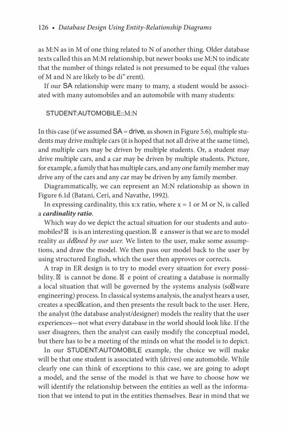
126 • Database Design Using Entity-Relationship Diagrams
as.M:N.as.in.M.of.one.thing.related.to.N.of.another.thing..Older.database.texts.called.this.an.M:M.relationship,.but.newer.books.use.M:N.to.indicate.that.the.number.of.things.related.is.not.presumed.to.be.equal.(the.values.of.M.and.N.are.likely.to.be.different).
If.our.SA.relationship.were.many.to.many,.a.student.would.be.associ-ated.with.many.automobiles.and.an.automobile.with.many.students:
STUDENT:AUTOMOBILE::M:N
In.this.case.(if.we.assumed.SA.=.drive, as.shown.in.Figure 5.6),.multiple.stu-dents.may.drive.multiple.cars.(it.is.hoped.that.not.all.drive.at.the.same.time),.and.multiple.cars.may.be.driven.by.multiple.students..Or,.a.student.may.drive.multiple.cars,.and.a.car.may.be.driven.by.multiple.students..Picture,.for.example,.a.family.that.has.multiple.cars,.and.any.one.family.member.may.drive.any.of.the.cars.and.any.car.may.be.driven.by.any.family.member.
Diagrammatically,.we.can.represent.an.M:N.relationship.as.shown.in.Figure 6.1d.(Batani,.Ceri,.and.Navathe,.1992).
In.expressing.cardinality,.this.x:x.ratio,.where.x.=.1.or.M.or.N,.is.called.a.cardinality ratio.
Which.way.do.we.depict.the.actual.situation.for.our.students.and.auto-mobiles?.This.is.an.interesting.question..The.answer.is.that.we.are.to.model.reality as defined by our user..We.listen.to.the.user,.make.some.assump-tions,.and.draw.the.model..We.then.pass.our.model.back.to.the.user.by.using.structured.English,.which.the.user.then.approves.or.corrects.
A.trap.in.ER.design.is.to.try.to.model.every.situation.for.every.possi-bility..This.cannot.be.done..The.point.of.creating.a.database.is.normally.a. local.situation.that.will.be.governed.by.the.systems.analysis.(software.engineering).process..In.classical.systems.analysis,.the.analyst.hears.a.user,.creates.a.specification,.and.then.presents.the.result.back.to.the.user..Here,.the.analyst.(the.database.analyst/designer).models.the.reality.that.the.user.experiences—not.what.every.database.in.the.world.should.look.like..If.the.user.disagrees,.then.the.analyst.can.easily.modify.the.conceptual.model,.but.there.has.to.be.a.meeting.of.the.minds.on.what.the.model.is.to.depict.
In. our. STUDENT:AUTOMOBILE. example,. the. choice. we. will. make.will.be.that.one.student.is.associated.with.(drives).one.automobile..While.clearly. one. can. think. of. exceptions. to. this. case,. we. are. going. to. adopt.a. model,. and. the. sense. of. the. model. is. that. we. have. to. choose. how. we.will.identify.the.relationship.between.the.entities.as.well.as.the.informa-tion.that.we.intend.to.put.in.the.entities.themselves..Bear.in.mind.that.we.

Extending Relationships/Structural Constraints • 127
are.dealing.with.a.conceptual.model.that.could.change.depending.on.the.reality.of.the.situation;.however,.we.have.to.choose.some.sort.of.model.to.begin,.and.the.one.we.are.choosing.is.a.one-to-one.relationship.between.students.and.automobiles.
In.the.Chen-like.model,.we.will.depict.the.one-to-oneness.of.this.rela-tionship.by.adding.the.cardinality.numbers.to.the.lines.on.the.ER.diagram.that.connect.the.relationships.and.the.entities.(see.Figure 6.2).
1
1
Automobile
make
body_style
color year
vehicle id
Student
student number
school address
name
firstname
middleinitial
lastname
drive
Cardinality ratioof 1:1
FIGURE 6.2An. ER. diagram. of. a. STUDENT-AUTOMOBILE. database. with. a. relationship. named.drive and.cardinality.ratios.

128 • Database Design Using Entity-Relationship Diagrams
In.Figure 6.2,.we.put.a.“1”.on.the.line.between.the.entity.box.for.the.STUDENT.and.the.diamond.box.for.the.relationship,.and.we.put.another.“1”.on.the.line.between.the.diamond.relationship.and.the.entity.box.for.the.AUTOMOBILE..These.1s.loosely.mean.that.a.student.is.related.to.one.automobile,.and.an.automobile.is.related.to.one.student..We.must.be.quite.careful.in.saying.exactly.what.this.relationship.means..It.does.not.mean.that.one.student.owns.one.automobile.or.a.student.pays.insurance.for.an.automobile..In.our.model,.we.mean.that.a.student.will.drive.at.most.one.automobile.on.a.college.campus..Further,.we.are.saying.that.an.automo-bile.will.be.driven.by.one.and.only.one.student..Since.we.are.clarifying.(refining).the.database,.we.try.to.settle.on.the.name.of.the.relationship.to. include. the.concept. that.we.are.modeling—driving—by.naming. the.relationship.drive..Again,.see.Figure 6.2.for.the.renamed.model.with.1:1.cardinality.
6.3 PARTICIPATION: FULL/PARTIAL
It.is.likely.that.on.any.campus.not.all.students.will.drive.an.automobile..For.our.model,.we.could.assume.that.normally.all.of.the.automobiles.on.the.campus.are.associated.with.a.student..(We.are.for.the.moment.exclud-ing. faculty. and. staff. driving. by. only. modeling. the. student/automobile.relationship.)
To.show.that.every.automobile.is.driven.by.a.student,.but.not.every.student.drives.an.automobile,.we.enhance.our.Chen-like.models.of.ER.diagrams. by. putting. a. double. line. between. the. relationship. diamond.and. the. AUTOMOBILE. entity. to. indicate. that. every. automobile. is.driven. by. a. student.. Put. another. way,. every. automobile. in. the. data-base. participates. in. the. relationship.. From. the. student. side,. we. leave.the.line.between.the.STUDENT.entity.and.the.relationship.as.a.single.line.to.indicate.that.not every.student.drives.an.automobile..Some.stu-dents.will.not.participate.in.the.drive.relationship.because.they.do.not.drive.a.car.on.campus..The.single/double.lines.are.called.participation constraints (also.known.as.optionality.constraints).and.are.depicted.in.Figure 6.3.
The.double.line.indicates.full.participation..Some.designers.prefer.to.call.this.participation.mandatory..The.point.is.that.if.part.of.a.relationship.is.mandatory.or.full,.you.cannot.have.a.null.value.(a.missing.value).for.that.

Extending Relationships/Structural Constraints • 129
attribute.in.relationships..In.our.case,.if.an.automobile.is.in.the.database,.it.has.to.be.related.to.some.student.
The.single.line,.partial.participation,.is.also.called.optional..The.sense.of.partial,.optional.participation.is.that.there.could.be.students.who.do.not.have.a.relationship.to.an.automobile.
1
1
Automobile
make
body_style
color year
vehicle id
Student
student number
school address
name
firstname
middleinitial
lastname
drive
Full participation
Partial participation
Both structural constraints (cardinality ratio andparticipation) are shown
FIGURE 6.3An.ER.diagram.of.the.STUDENT-AUTOMOBILE.database.with.the.relationship.named.drive,.cardinality.ratios,.and.participation.

130 • Database Design Using Entity-Relationship Diagrams
CHECKPOINT 6.1
. 1.. What.are.structural.constraints?
. 2.. What.kind.of.information.does.the.cardinality.ratio.give.us?
. 3.. In.how.many.different.ways.can.two.entities.be.involved.in.a.cardi-nality.relationship?.Give.examples.
. 4.. What.kind.of.information.does.the.participation.constraint.give.us?
. 5.. Is.it.always.necessary.to.have.cardinality.ratios.as.well.as.participa-tion.constraints.in.the.same.ER.diagram?.Why?.Explain.
6.4 ENGLISH DESCRIPTIONS
We.would.now.like.to.tighten.the.English.grammar.that.describes.how.a.relationship.affects.entities.using.our.structural.constraints.and.to.adopt.a.standard.way.of.stating.the.relationship..The.standard.language.should.appear.on.the.model,.or.at.least.with.it..Further,.using.a.standard.language.approach.to.describe.the.ER.diagrams.allows.us.not.only.to.close.the.loop.with.the.user.in.the.systems.analysis.process,.but.also.to.facilitate.feedback.and.“nail.down”.the.exact.meaning.of.the.relationship.
In.the.Chen-like.model,.the.double.lines.define.full.participation.as.in,.“Automobiles. fully. participate. in. the.drive. relationship.”. Better. yet,. the.double.lines.invite.us.to.state.the.relationship.as
Automobiles must be driven by one (and only one) student.
The.must.part.comes.from.the.full.(mandatory).participation.and.the.one.part.from.the.cardinality.
The.grammar.for.describing.the.partial.or.optional.relationship.for.the.STUDENT entity to.the.AUTOMOBILE entity,.would.be
Students may drive one and only one automobile.
The. may. comes. from. the. single. line. leaving. the. STUDENT. entity. box.and.the.one and only one.part.comes. from.the.cardinality..The.point. is.that. when. expressing. the. sense. of. the. ER. diagrams,. one. uses. the. lan-guage.that.conveys.what.the.relationship.really.means.(i.e.,.a.student.may.drive.one.automobile,.and.an.automobile.must.be.driven.by.one.and.only.one. student).. A. graphic. on. how. to. read. an. ER. diagram. is. presented. in.Figure 6.4.

Extending Relationships/Structural Constraints • 131
6.5 TIGHTER ENGLISH
We.strongly.recommend.that.an.English.sentence.accompany.each.dia-gram.to.reinforce.the.meaning.of.the.figure.(refer.to.Figure 6.4)..English.is.often.an.ambiguous.language..The.statement.that
Automobiles must be driven by one and only one student.
Automobiles1
must be driven by
one and only one
1 student
Students1
1
may drive
one and only one
automobile
Automobile
drive
Student
�e “must” showing fullparticipation
Automobile
drive
StudentParticipationis partial.
FIGURE 6.4The.STUDENT-AUTOMOBILE.database:.translating.the.diagram.into.English.

132 • Database Design Using Entity-Relationship Diagrams
actually.means
Automobiles, which are in the database, must be driven by one and only one student.
The.relationship.should.not.be.stated.loosely,.as.in
A student drives an automobile.
This.could.be.vaguely.interpreted.Another.way.to.put.this.is
Every automobile must be driven by one and only one student. Students may drive one and only one automobile.
To.relieve.ambiguity.in.the.statement.of.the.relationship,.we.will.take.the.English.statement.from.the.relationship.as.we.have.illustrated.and.define. four. pattern. possibilities. for. expressing. our. relationship.. All.binary. relationships. must. be. stated. in. two. ways. from. both. sides.. As.you.will.see,.we.try.to.stick.to.the.exact.pattern.match.in.the.following.examples,. but. common. sense. and. reasonable. grammar. should. pre-vail.when.the.pattern.does.not.quite.fit..There.is.nothing.wrong.with.restating. the.precise. language. to.make. it.clearer,.but.you.have. to.say.the.same.thing.
6.5.1 Pattern 1—x:y::k:1
From the k side, full participation (k = 1 or M):. The. x’s,. which. are.recorded.in.the.database,.must.be.related.to.one.and.only.one.y..No.x.is.related.to.more.than.one.y.
Example 6.1 Student:Advisor::M:1, Full Participation
Students must be advised by one advisor.
or,
Students, which are recorded in the database, must be advised by one and only one advisor. No student is advised by more than one advisor.

Extending Relationships/Structural Constraints • 133
The.phrase.“which.are.recorded.in.the.database”.has.proven.to.be.helpful.because.some.database.designers.tend.to.generalize.beyond.the.problem.at.hand..For.example,.one.could.reasonably.argue.that.there.might.be.a.case.where.thus-and-so.are.true/not.true,.but.the.point.is,.“Will.that.case.ever.be.encountered.in.this.particular.database?”.The.negative.statement.is.often.helpful.to.solidify.the.meaning.of.the.relationship.
6.5.2 Pattern 2—x:y::k:1
From the k side, partial participation (k = 1 or M): x,.but.not.necessarily.all.x.(which.are.recorded.in.the.database).may.be.related.to.one.and.only.one.y..Some.x’s.are.not.related.to.a.y..The.x’s.may.not.be.related.to.more.than.one.y.
Example 6.2 Student:Fraternity::M:1
Some students join a fraternity.which.becomes
Students, but not necessarily all students (which are recorded in the database), may join a fraternity. Some students may not join a fraternity. Students may not join more than one fraternity.
6.5.3 Pattern 3—x:y::k:M
From the k side, full participation (k = 1 or M): The x’s,.which.are.recorded.in.the.database,.must.be.related.to.many.(one.or.more).y’s..Sometimes,.it.is.helpful.to.include.a.phrase.like:.“No.x.is.related.to.a.non-y”.or.“Non-x.are.not.related.to.a.y.”.The.negative.will.depend.on.the.sense.of.the.statement.
Example 6.3 Automobile:Student::M:N
Automobiles are driven by (registered to) many students.
which.means
Automobiles, which are recorded in our database, must be driven by many (one or more) students.

134 • Database Design Using Entity-Relationship Diagrams
There.are.several.ideas.implied.here..First,.we.are.only.talking.about.vehi-cles.registered.at.this.school..Second,.in.this.database,.only.student.cars.are.registered.in.this.database..Third,.if.an.automobile.from.this.database.is. driven,. it. has. to. be. registered. and. driven. by. a. student. (at. least. one)..Fourth,. the.“one.or.more”.comes.from.the.cardinality.constraint..Fifth,.there.is.a.strong.temptation.to.say.something.about.the.y,.the.M.side.back.to.the.x,.but.this.should.be.avoided.as.this.is.covered.elsewhere.in.another.pattern.and.because.we.discourage.inferring.other.relationships.from.the.one.covered..For.example,.one.might.try.to.say.here.that.all.students.drive.cars.or.all.students.are.related.to.a.vehicle.….neither.statement.is.true.
6.5.4 Pattern 4—x:y::k:M
From the k side, partial participation (k = 1 or M): x,.but.not.necessarily.all.x.(which.are.recorded.in.the.database),.may.be.related.to.many.(zero.or.more).y’s..Some.x.may.not.be.related.to.a.y.
Example 6.4 Course:Book::k:M
Some courses may require (use) many books.
which.restated.becomes
Courses, but not necessarily all courses (which are recorded in the database), may use many (zero or more) textbooks. Some courses may not require textbooks.
Note.that.due.to.partial.participation.(the.single.lines),.the.phrase.“zero.or.more”.is.used.for.cardinality..If.a.relationship.is.modeled.with.the.patterns.we.have.used.and.then.the.English.sounds. incorrect,. it.may.be.that.the.wrong.model.has.been.chosen..Generally,.the.grammatical.expression.will.be.most.useful.in.(a).restating.the.designed.database.to.a.“naïve.user”.and.(b). checking. the. meaning. on. the. designed. database. among. the. design-ers..The.complete.version.of. the.English.may.eventually.prove. tiresome.to.a.database.designer,.but.one.should.never.lose.track.of.the.fact.that.a.statement.like.“x.are.related.to.one.y”.can.be.interpreted.in.several.ways.unless.it.is.nailed.down.with.constraints.stated.in.an.unambiguous.way..Furthermore,.a.negation.statement.may.be.useful.to.elicit.requirement.def-initions,.although.at.times.the.negation.is.so.cumbersome.it.may.be.omit-ted..What.we.are.saying.is.to.add.the.negative.or.other.noncontradictory.

Extending Relationships/Structural Constraints • 135
grammar. if. it. makes. sense. and. helps. with. requirement. elicitation.. The.danger.in.adding.sentences.is.that.we.may.end.up.with.contradictory.or.confusing.remarks.
6.5.5 Summary of the Patterns and Relationships
6.5.5.1 Pattern 1
The.relationship.is
x:y::1(full):1
and.is.diagramatically.shown.by.Figure 6.5.
6.5.5.2 Pattern 1
The.relationship.is
x:y::M(full):1
and.is.diagramatically.shown.by.Figure 6.6.
1
1
Entity1
Relation-ship
Entity2
FIGURE 6.5Chen.model.of.1(full):1.relationship:.pattern.1.
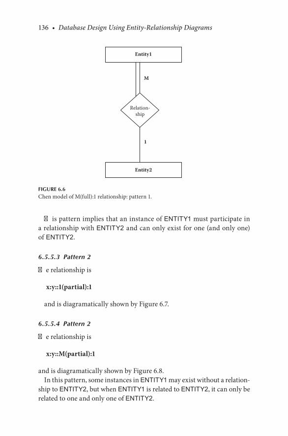
136 • Database Design Using Entity-Relationship Diagrams
This.pattern.implies.that.an.instance.of.ENTITY1.must.participate.in.a.relationship.with.ENTITY2 and.can.only.exist.for.one.(and.only.one).of ENTITY2.
6.5.5.3 Pattern 2
The.relationship.is
x:y::1(partial):1
and.is.diagramatically.shown.by.Figure 6.7.
6.5.5.4 Pattern 2
The.relationship.is
x:y::M(partial):1
and.is.diagramatically.shown.by.Figure 6.8.In.this.pattern,.some.instances.in.ENTITY1.may.exist.without.a.relation-
ship.to.ENTITY2,.but.when.ENTITY1.is.related.to.ENTITY2,.it.can.only.be.related.to.one.and.only.one.of.ENTITY2.
M
1
Entity1
Relation-ship
Entity2
FIGURE 6.6Chen.model.of.M(full):1.relationship:.pattern.1.
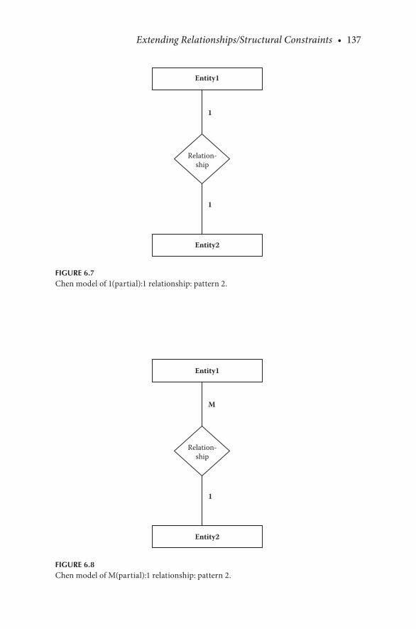
Extending Relationships/Structural Constraints • 137
1
1
Entity1
Relation-ship
Entity2
FIGURE 6.7Chen.model.of.1(partial):1.relationship:.pattern.2.
M
1
Entity1
Relation-ship
Entity2
FIGURE 6.8Chen.model.of.M(partial):1.relationship:.pattern.2.

138 • Database Design Using Entity-Relationship Diagrams
6.5.5.5 Pattern 3
The.relationship.is
x:y::1(full):M
and.is.diagramatically.shown.by.Figure 6.9.
6.5.5.6 Pattern 3
The.relationship.is
x:y::M(full):N
and.is.diagramatically.shown.by.Figure 6.10.This.pattern.implies.that.an.instance.of.ENTITY1.must.participate.in.a.
relationship.with.ENTITY2.and.can.exist.for.more.than.one.of.ENTITY2.
6.5.5.7 Pattern 4
The.relationship.is
x:y::1(partial):M
and.is.diagramatically.shown.by.Figure 6.11.
1
M
Entity1
Relation-ship
Entity2
FIGURE 6.9Chen.model.of.1(full):M.relationship:.pattern.3.
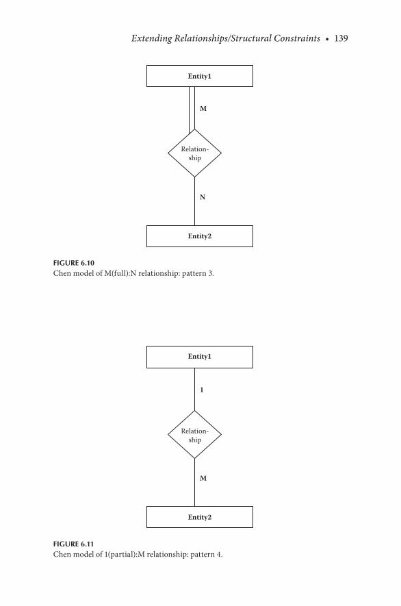
Extending Relationships/Structural Constraints • 139
M
N
Entity1
Relation-ship
Entity2
FIGURE 6.10Chen.model.of.M(full):N.relationship:.pattern.3.
1
M
Entity1
Relation-ship
Entity2
FIGURE 6.11Chen.model.of.1(partial):M.relationship:.pattern.4.

140 • Database Design Using Entity-Relationship Diagrams
6.5.5.8 Pattern 4
The.relationship.is
x:y::M(partial):N
and.is.diagramatically.shown.by.Figure 6.12.In. this.pattern,. some. instances. in.ENTITY1.may.exist.without.a. rela-
tionship.to.ENTITY2,.but.when.ENTITY1.is.related.to.ENTITY2,.it.can.be.related.to.more.than.one.of.ENTITY2.
CHECKPOINT 6.2
. 1.. Sketch.an.ER.diagram.that.shows.the.participation.ratios.(full/par-tial).and.cardinalities.for.the.following:
. a.. Students.must.be.advised.by.one.advisor,.and.an.advisor.can.advise.many.students.
. b.. Students,.but.not.necessarily.all.students,.may.join.a.fraternity..Some.students.may.not. join.a.fraternity..Students.may.not. join.more.than.one.fraternity..A.fraternity.may.have.many.students.(in.its.membership).
Our. refined. methodology. may. now. be. restated. with. the. relationship.information.added.
M
N
Entity1
Relation-ship
Entity2
FIGURE 6.12Chen.model.of.M(partial):N.relationship:.pattern.4.

Extending Relationships/Structural Constraints • 141
6.5.6 ER Design Methodology
Step 1. Select one primary entity from the database requirements description and show attributes to be recorded for that entity. Label keys, if appropriate, and show some sample data.
Step 2. Use structured English for entities, attributes, and keys to describe the database that has been elicited.
Step 3. Examine attributes in the primary entity (possibly with user assistance) to find out if information about one of the attributes is to be recorded.
Step 3a. If information about an attribute is needed, then make the attribute an entity, and then
Step 3b. Define the relationship back to the original entity.Step 4. If another entity is appropriate, draw the second entity with its
attributes. Repeat step 2 to see if this entity should be further split into more entities.
Step 5. Connect entities with relationships if relationships exist.Step 6. State the exact nature of the relationships in structured English
from all sides; for example, if a relationship is A:B::1:M, then there is a relationship from A(1) to B(M) and from B(M) back to A(1).
Step 7. Present the “as designed” database to the user complete with the English for entities, attributes, keys, and relationships. Refine the diagram as necessary.
Step 8. Show some sample data.
6.6 SOME EXAMPLES OF OTHER RELATIONSHIPS
In. this. section,. we. consider. three. other. examples. of. relationships—two.1:M.relationships.and.an.M:N.relationship—in.more.detail.to.practice.and.further.clarify.the.process.we.have.presented..As.stated,.the.1:M.and.M:N.relationships.are.common.in.a.database.
6.6.1 An Example of the One-to-Many Relationship (1:M)
Relationships. that. are. 1:M. or. M:1. are. really. relative. views. of. the. same.problem..When.specifying.1:M.or.M:1,.we.need.to.be.especially.careful.to.specify.which.entity.is.1.and.which.is.M..The.designation.is.really.which.view.is.more.natural.for.the.database.designer..As.an.example.of.a.1-to-M.

142 • Database Design Using Entity-Relationship Diagrams
relationship,. consider. dorm. rooms. and. students.. One. dorm. room. may.have.many.students.living.in.it,.and.many.students.can.live.in.one.dorm.room.. So,. the. relationship. between. dorm. room. and. students. would. be.considered.a.one-to-many.(1:M::DORM:STUDENT).situation.and.would.be. depicted. as. in. Figure 6.13. (without. attributes).. We. will. let. the. term.DORM.mean.dorm.room.
In.Figure 6.13. (the.Chen-like.model),. the.name. that.we.chose. for. the.DORM-STUDENT.relationship.was.occupy.
Note.that.not.all.dorms.have.students.living.in.them;.hence,.the.partici-pation.of.dorms.in.the.relationship.is.partial..Informally,
Dorms may be occupied by many students.
Furthermore,.all.students.may.not.live.in.dorms,.so.the.relationship.of.STUDENT.to.DORM.is.also.partial:
Students may occupy a dorm room.
Now,.let.us.restate.the.relationships.in.the.short.and.long.English.forms.The. first. statement,. “Dorms. may. be. occupied. by. many. students,”. fits.
pattern 4,.x:y::1(partial):M.
1
M
Dorm
Student
occupy
Dorms may beoccupied bystudents.
Many studentsmay occupy adorm.
FIGURE 6.13An.ER.diagram.(without.attributes).of.a.1:M.relationship.

Extending Relationships/Structural Constraints • 143
6.6.1.1 Pattern 4—1:M, from the 1 Side, Partial Participation
“Some.x.are.related.to.many.y.”
Therefore,.the.more.precise.statement.is
x,.but.not.necessarily.all.x,.(which.are.recorded.in.the.database).may.be.related.to.many.(zero.or.more).y’s..Some.x.are.not.related.to.a.y.…
or
Dorms, but not necessarily all dorms, (which are recorded in the database) may be occupied by many (zero or more) students.
For.the.inverse.relation:
Students may occupy a dorm room.
This.fits.pattern 2,.M(partial):1.
6.6.1.2 Pattern 2—M(Partial):1, from M Side, Optional Participation
“Some.x.are.related.to.one.y.”
Therefore,.the.long.“translation”.of.the.statement.is
x,.but.not.necessarily.all.x.(which.are.recorded.in.the.database),.may.be.related.to.one.and.only.one.y..Some.x.may.not.be.related.to.y..(No.x.is.related.to.more.than.one.y.).[…].indicates.optional.clarification.
This.x.and.y.notation.resolves.into.x.=.students,.y.=.dorms,.and.hence
Students, but not necessarily all students (which are recorded in the data-base), may occupy one and only one dorm. Some students may not occupy a dorm room. No student occupies more than one dorm.
Or,.stated.another.way:
A student may occupy a (one and only one) dorm and a dorm may be occu-pied by many students.

144 • Database Design Using Entity-Relationship Diagrams
6.6.2 An Example of the Many-to-One Relationship (M:1)
For.another.database,.let.us.assume.that.a.school.that.we.are.modeling.has.student.parking.lots..Let.us.further.assume.that.every.student.is.assigned.to.park.his.or.her.car.in.some.(one).specific.parking.lot..We.then.have.an.entity.called.PARKING_LOT.that.will.have.parking.locations.described.by.some.descriptive.notation.such.as.East.Lot.7,.North.Lot.28,.and.so.on..In.this.case,.if.we.viewed.many.automobiles.as.assigned.to.one.parking.lot.and.a.parking.lot.as.containing.many.automobiles,.we.could.depict.this.relationship.as.a.many-to-one,.M:1::AUTOMOBILE:PARKING_LOT..This.diagram.is.shown.in.Figure 6.14.(again.without.attributes).
We.have.depicted.participation.of. the. relationship.between.automobile.and.parking.lot.as.full.in.both.instances—meaning.that.all.automobiles.have.one.parking.lot,.and.all.parking.lots.are.assigned.to.students’.automobiles.
The.grammatical.expressions.of.this.relationship.are.discussed.next.
6.6.2.1 Pattern 1—M:1, from the M Side, Full Participation
The.x,.which.are.recorded.in.the.database,.must.be.related.to.one.and.only.one.y..No.x.are.related.to.more.than.one.y.
M
1
Automobile
Parking_Lot
park
Automobilesmust park in oneparking lot
Parking lotsmust park manyautomobiles
FIGURE 6.14An.ER.diagram.(without.attributes).of.an.M:1.relationship.

Extending Relationships/Structural Constraints • 145
x.=.automobile,.y.=.parking.lot,.relationship.=.park
Automobiles, which are recorded in the database, must be parked in one and only one parking lot. No automobiles may be parked in more than one park-ing lot. An automobile must park in only one parking lot.
The.inverse.is.discussed.next.
6.6.2.2 Pattern 3—1:M, from the 1 Side, Full Participation
The.x,.which.are.recorded.in.the.database,.must.be.related.to.many.(one.or.more).y’s..(“No.x.is.related.to.a.non-y”.or.“Non-x.are.not.related.to.a.y.”.[The.negative.will.depend.on.the.sense.of.the.statement].)
Parking lots, which are recorded in the database, must park many (one or more) automobiles.
The.negative.in.this.case.seems.misleading,.so.we.will.omit.it..The.point.is.that.recorded.parking.lots.must.have.students.parking.there.
Or,.stated.another.way:
An automobile must be parked in a (one and only one) parking lot, and a parking lot must have at least one automobile parked in it (and can have many automobiles parked in it).
6.6.3 An Example of the Many-to-Many Relationship (M:N)
The.classic.example.of.the.M:N.relationship.we.will.study.here.is.students.taking. courses.. At. the. outset,. we. know. that. students. take. (enroll. in).many.courses,. and. that.any.course. is.populated.by.many. students..The.basic.diagram.for.the.STUDENT-COURSE.relationship.is.that.shown.in.Figure 6.15.
We.have.chosen.the.word.enroll.to.depict.the.relationship..The.partici-pation.of.students.in.enroll.is.depicted.as.full.(mandatory);.course.enroll-ment. is. depicted. as. partial.. This. choice. was. arbitrary. as. both. could. be.full.or.partial,.depending.on.user.needs.and.desires..Look.carefully.at.the.exact.grammatical.expressions.and.note.the.impact.of.choosing.full.in.one.case.and.partial.in.the.other.
The.grammatical.expressions.of.this.relationship.are.discussed.next.
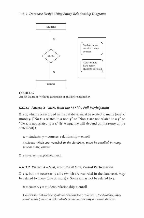
146 • Database Design Using Entity-Relationship Diagrams
6.6.3.1 Pattern 3—M:N, from the M Side, Full Participation
The.x,.which.are.recorded.in.the.database,.must.be.related.to.many.(one.or.more).y..(“No.x.is.related.to.a.non-y”.or.“Non-x.are.not.related.to.a.y”.or.“No.x.is.not.related.to.a.y.”.[The.negative.will.depend.on.the.sense.of.the.statement].)
x.=.students,.y.=.courses,.relationship.=.enroll
Students, which are recorded in the database, must be enrolled in many (one or more) courses.
The.inverse.is.explained.next.
6.6.3.2 Pattern 4—N:M, from the N Side, Partial Participation
The.x,.but.not.necessarily.all.x.(which.are.recorded.in.the.database),.may.be.related.to.many.(one.or.more).y..Some.x.may.not.be.related.to.y.
x.=.course,.y.=.student,.relationship.=.enroll
Courses, but not necessarily all courses (which are recorded in the database), may enroll many (one or more) students. Some courses may not enroll students.
M
N
Student
Course
enroll
Students mustenroll in manycourses
Courses mayhave manystudents enrolled
FIGURE 6.15An.ER.diagram.(without.attributes).of.an.M:N.relationship.

Extending Relationships/Structural Constraints • 147
Or,.stated.another.way:
A student must enroll in one or more courses, and a course may have one or more students enrolled in it.
This.“course.partiality”. likely.reflects.courses. that.are. in. the.database.but.are.not.currently.enrolling.students..It.could.mean.potential.courses.or. courses. that. are. no. longer. offered.. Of. course,. if. the. course. is. in. the.database.only. if. students.are.enrolled,. then. the.participation.constraint.becomes.full,.and.the.sense.of.the.entity.relationship.changes.
Also,. this. database. tells. us. that. while. we. can. have. courses. without.students,. we. only. store. information. about. active. students.. Obviously,.we.could.make.the.student.connection.partial.and.hence.store.all.stu-dents—even. inactive. ones.. We. chose. to. represent. the. relationships. in.this.manner.to.make.the.point.that.the.participation.constraint.is.sup-posed.to.depict.reality—the.reality.of.what.the.user.might.want.to.store.data.about.
Note.that.all. the.examples. in.this.chapter.deal.with.only.two.entities,.that.is,.they.are.binary.relationships..The.example.in.the.following.section.is.also.another.example.of.a.binary.relationship.
CHECKPOINT 6.3
. 1.. Give.an.example.of.a.1(full):1.relationship?.Does.such.a.relationship.always.have.to.be.mandatory?.Explain.with.examples.
. 2.. Give.an.example.of.a.1(partial):1.relationship?.Does.such.a.relation-ship.always.have.to.be.optional?.Explain.with.examples.
. 3.. Give.an.example.of.a.M(full):N.relationship?.Would.such.a.relation-ship.always.be.optional.or.mandatory?.Explain.with.examples.
. 4.. Give.an.example.of.a.M(partial):N.relationship?.Would.such.a.rela-tionship.always.be.optional.or.mandatory?.Explain.with.examples.
6.7 ONE FINAL EXAMPLE
As.a.final. example. to. conclude. the. chapter,.we.present.one.more.prob-lem.and.then.our.methodology.*.Consider.a.model.for.a.simplified.airport.where. PASSENGERS. and. FLIGHTS are. to. be. recorded.. Suppose. that.
*. .Modeled.after.Elmasri.and.Navathe.(2007).

148 • Database Design Using Entity-Relationship Diagrams
the.attributes.of.PASSENGER.are.name, luggage_pieces,.and.frequent_flier_no.. Suppose. the. attributes. for. FLIGHT. are. flight_no,. destination,.arrive_time, and.depart_time..Draw.the.ER.diagram.
Note:.We.are.leaving.out.many.attributes.that.we.could.consider..Assume.that.this.is.all.of.the.information.that.we.choose.to.record.
The.solution.is.given.next.
6.7.1 ER Design Methodology
Step 1. Select one primary entity from the database requirements description and show attributes to be recorded for that entity. Label keys if appropriate and show some sample data.
Suppose.we.choose.PASSENGER.as.our.primary.entity..PASSENGER.has. the. following. attributes:. frequent_ flier_no, name [first, middle, last], luggage_pieces.
We. draw. this. much. of. the. diagram,. choosing. frequent_flier_no. as. a.key.and.noting.the.composite.attribute.name..This.diagram.is.shown.in.Figure 6.16.
Step 2. Use structured English for entities, attributes, and keys, to describe the database which has been elicited.
Passenger
luggage_pieces
frequent_flier_no
name
first middle last
FIGURE 6.16The.PASSENGER.entity.diagram.

Extending Relationships/Structural Constraints • 149
6.7.1.1 The Entity
This.database.records.data.about.PASSENGERS..For.each.passenger,.we.record.frequent_flier_no, name [first, middle, last], pieces_of_luggage.
6.7.1.1.1 The Attributes
For.atomic.attributes,.att(j):
For.each PASSENGER,.there.will.be.one.and.only.one.frequent_flier_no..The.value.for.frequent_flier_no.will.not.be.subdivided.
For.each.PASSENGER,.there.will.be.one.and.only.one.recording.of.lug-gage_pieces. The.value.for.luggage_pieces.will.not.be.subdivided.
For.composite.attributes,.att(j):
For.each.PASSENGER,.we.will.record.their.name,.which.is.composed.of.first, middle,. and. last. First, middle,. and. last. are. the.component.parts.of.name.
6.7.1.1.2 The Keys
For. each. PASSENGER,. we. will. have. the. following. primary. key:.frequent_flier_no.
Note. that. we. have. chosen. frequent_flier_no. as. a. primary. key. for.PASSENGER..If.this.were.not.true,.some.other.means.of.unique.identifi-cation.would.be.necessary..Here,.this.is.all.the.information.we.are.given.
Step 3. Examine attributes in the primary entity (possibly with user assistance) to find out if information about one of the attributes is to be recorded.
No.further.information.is.suggested.
Step 4. If another entity is appropriate, draw the second entity with its attributes. Repeat step 2 to see if this entity should be further split into more entities.
The.other.entity.in.this.problem.is.FLIGHT,.with.attributes.flight_no, des-tination, depart_time, arrive_ time.
Again,.we.use.structured.English.as.in.the.following.

150 • Database Design Using Entity-Relationship Diagrams
6.7.1.2 The Entity
This. database. records. data. about. Flights.. For. each FLIGHT,. we. record flight_no, destination, depart_time,.and.arrive_time.
6.7.1.2.1 The Attributes
For.atomic.attributes,.att(j):
For.each.FLIGHT,.there.will.be.one.and.only.one.flight_no. The.value.for.flight_no will.not.be.subdivided.
For.each.FLIGHT,.there.will.be.one.and.only.one.recording.of.destina-tion..The.value.for.destination.will.not.be.subdivided.
For.each.FLIGHT,.there.will.be.one.and.only.one.recording.of.depart_time..The.value.for.depart_time.will.not.be.subdivided.
For.each.FLIGHT,.there.will.be.one.and.only.one.recording.of.arrive_time..The.value.for.arrive_time.will.not.be.subdivided.
6.7.1.2.2 The Keys
For.the.key(s):.One.candidate.key.(strong.entity):
For.each.FLIGHT,.we.will.have.the.following.primary.key:.flight_no.
We.are.assuming.flight_no.is.unique.
Step 5. Connect entities with relationships if relationships exist.
What.relationship.is.there.between.flights.and.passengers?All.passengers.will.fly.on.one.flight..All.flights.will.have.multiple.pas-
sengers.. The. diagram. for. this. problem. is. illustrated. in. Figure 6.17. and.Figure 6.18.
Note. that.we.have.again.made.a.choice:.We.will.depict.one.flight.per.passenger.in.this.database..The.specifications.do.not.tell.us.whether.this.should.be.1.or.M,.so.we.chose.1..We.also.chose.full.participation.on.both.sides..It.would.seem.illogical.to.record.data.about.passengers.who.did.not.fly.on.a.flight.and.flights.for.which.there.were.no.passengers..But.again,.if.the.database.called.for.storing.information.about.potential.passengers.who.might.not.book.a.specific.flight.or.flights.that.did.not.involve.passen-gers,.then.we.would.have.to.change.the.conceptual.design..Figure 6.17.is.good.for.displaying.just.the.entities.and.the.attributes..Figure 6.18.uses.the.

Extending Relationships/Structural Constraints • 151
concise.form.of.describing.attributes.and.includes.some.of.the.preceding.steps.and.some.sample.data..For.conceptualizing,.Figure 6.17.may.be.used.and.later.converted.into.Figure 6.18.style.for.documentation..Either.figure.requires.an.accompaniment.of.structured.English.(step.6).
As.designers,.we.make.a.choice.and.then.present.our.choice.to.the.user..If.the.user.decided.to.store.information.about.all.flights.and.all.passengers.over.some.period.of.time,.that.would.be.a.different.database.(an.M:N.rela-tionship.and.perhaps.partial.participations.for.nonpassenger.flights.and.nonflying.passengers)..The.point.is.that.this.is.eventually.a.user’s.choice,.
M
1
destination
Passenger
frequentflier_no
luggage_piecesname
Flight
arrive_time
depart_time
flight_no
fly
firstmiddle last
Passengers mustfly on 1 flight
Flights must flymany passengers
FIGURE 6.17ER.diagram.for.PASSENGER-FLIGHT.database.
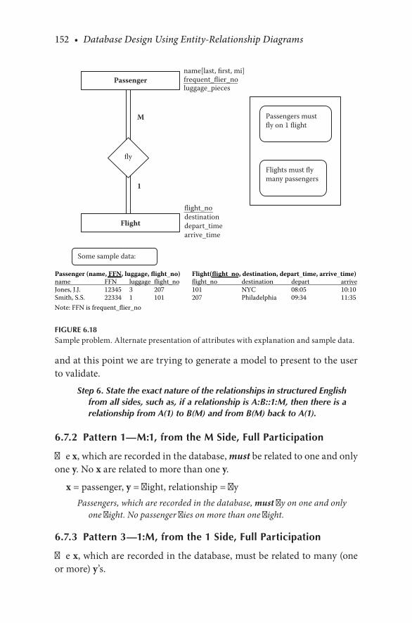
152 • Database Design Using Entity-Relationship Diagrams
and.at.this.point.we.are.trying.to.generate.a.model.to.present.to.the.user.to.validate.
Step 6. State the exact nature of the relationships in structured English from all sides, such as, if a relationship is A:B::1:M, then there is a relationship from A(1) to B(M) and from B(M) back to A(1).
6.7.2 Pattern 1—M:1, from the M Side, Full Participation
The.x,.which.are.recorded.in.the.database,.must.be.related.to.one.and.only.one.y..No.x.are.related.to.more.than.one.y.
x.=.passenger,.y.=.flight,.relationship.=.flyPassengers, which are recorded in the database, must fly on one and only
one flight. No passenger flies on more than one flight.
6.7.3 Pattern 3—1:M, from the 1 Side, Full Participation
The.x,.which.are.recorded.in.the.database,.must.be.related.to.many.(one.or.more).y’s.
name[last, first, mi]frequent_flier_noluggage_pieces
M
1
flight_nodestinationdepart_timearrive_time
Passenger
Flight
fly
Flights must flymany passengers
Some sample data:
Passengers mustfly on 1 flight
Passenger (name, FFN, luggage, flight_no) Flight(flight_no, destination, depart_time, arrive_time) name FFN luggage flight_no flight_no destination depart arriveJones, J.J. 12345 3 207 101 NYC 08:05 10:10Smith, S.S. 22334 1 101 207 Philadelphia 09:34 11:35Note: FFN is frequent_flier_no
FIGURE 6.18Sample.problem..Alternate.presentation.of.attributes.with.explanation.and.sample.data.

Extending Relationships/Structural Constraints • 153
x.=.flight,.y.=.passenger,.relationship.=.fly
Flights, which are recorded in the database, must fly many (one or more) passengers.
Or,.stated.another.way:
A passenger must fly on a flight, and a flight must have at least one (and can have many) passengers on it.
Attribute.descriptions.follow.previous.patterns.and.are.left.to.the.exercises.
Step 7. Present the “as designed” database to the user complete with the English for entities, attributes, keys, and relationships. Refine the diagram as necessary.
Step 8. Show some sample data.
See.Figure 6.18.
6.8 MAPPING RELATIONSHIPS TO A RELATIONAL DATABASE
In.this.section,.we.continue.with.the.mapping.rules.that.we.began.at.the.end.of.Chapter.4..In.Chapter.4,.we.learned.how.to.map.entities,.entities.with.composite.attributes,.and.entities.with.multivalued.attributes..In.this.chapter,.having.covered.structural.constraints.of.relationships,.we. learn.how.to.map.relationships.
6.8.1 Mapping Binary M:N Relationships
For.mapping.binary.M:N.relationships,.we.present.mapping.rule.5.
Mapping rule 5—Mapping binary M:N relationships. For each M:N relationship, create a new table (relation) with the primary keys of each of the two entities (owner entities) that are being related in the M:N relationship. The primary key of this new table will be the concatenated keys of the owner entities. Include any attributes that the M:N relationship may have in this new table.

154 • Database Design Using Entity-Relationship Diagrams
For.example,.refer.to.Figure 6.15..If.the.STUDENT and COURSE tables.have.the.following.data:
STUDENTname.
first name.last name.mi student_number addressRichard Earp W 589 222 2nd StBoris Backer 909 333 DreistrasseHelga Hogan H 384 88 Half Moon AveArpan Bagui K 876 33 Bloom AveHema Malini 505 100 Livingstone
COURSEcname c_number credit_hrsDatabase COP4710 4Visual Basic CGS3464 3Elements of Stats STA3023 3Indian History HIST2022 4
Before.performing.mapping.rule.5,.one.must.first.ensure.that.the.pri-mary. keys. of. the. entities. involved. have. been. established.. If. c_number and student_number are.the.primary.keys.of COURSE and STUDENT, respectively,.then.to.map.the.M:N.relationship,.we.create.a.relation.called.ENROLL.as.follows:
ENROLLc_number student_numberCOP4710 589CGS3464 589CGS3464 909STA3023 589HIST2022 384STA3023 505STA3023 876HIST2022 876HIST2022 505
Both.c_number and student_number together.are.the.primary.key.of.the.relation,.ENROLL.

Extending Relationships/Structural Constraints • 155
The.relational.mapping.for.Figure 6.15.would.be.as.follows:
STUDENT(name.first, name.last, name.mi, student_number, address)COURSE(cname, c_number, credit_hrs)ENROLL(c_number, student_number)
What.often.happens.in.M:N.relationships.is.that.data.arises.that.fits.bet-ter.with. the. relationship. than.with.either.entity..Relationship.attributes.are.covered.in.Chapter.8,.but.should.a.relationship.attribute.arise,.it.will.be.mapped.with.the.primary.keys.
6.8.2 Mapping Binary 1:1 Relationships
To.map.binary.1:1.relationships,.include.the.primary.key.of.EntityA.into.EntityB.as.the.foreign.key..The.question.is,.which.is.EntityA.and.which.is.EntityB?.This.question.is.answered.in.the.mapping.rules.presented.in.this.section.
Mapping rule 6—Mapping binary 1:1 relationships when one side of the relationship has full participation and the other has partial par-ticipation. When one of the sides of the relationship has full par-ticipation and the other has partial participation, then store the primary key of the side with the partial participation constraint on the side with the full participation constraint as a foreign key. Include any attributes on the relationship on the same side to which the key was added.. (We.cover.attributes.of.relationships. in.Chapter.8.and.then.embellish.the.mapping.rules.accordingly.)
For.example,.refer.to.Figure 6.3..It.says:
An automobile, recorded in the database, must be driven by one and only one student.
And
A student may drive one and only one automobile.
Here,.the.full.participation.is.on.the.AUTOMOBILE.side.since.“An.auto-mobile.‘must’.be.driven.by.a.student.”
So,.we. take. the.primary.key. from.the.partial.participation.constraint.side. STUDENT. and. include. it. in. the. AUTOMOBILE. table.. The. primary.key. of. STUDENT. is. student_number,. so. this. will. be. included. in. the.

156 • Database Design Using Entity-Relationship Diagrams
AUTOMOBILE.relation.as.the.foreign.key..A.relational.database.realiza-tion.of.the.ER.diagram.in.Figure 6.3.will.look.like
AUTOMOBILE(vehicle_id, make, body_style, color, year, student_number)
STUDENT(name.first, name.last, name.mi, student_number, address)
And.with.some.data,.it.would.look.like.this:
AUTOMOBILEvehicle_id make body_style color year student_numberA39583 Ford Compact Blue 1999 589B83974 Chevy Compact Red 1989 909E98722 Mazda Van Green 2002 876F77665 Ford Compact White 1998 384
STUDENTname.first name.last name.mi student_number addressRichard Earp W 589 222 2nd StBoris Backer 909 333 DreistrasseHelga Hogan H 384 88 Half Moon AveArpan Bagui K 876 33 Bloom AveHema Malini 505 100 Livingstone
Since.STUDENT.has.a.multivalued.attribute.school,.we.need.to.map.the.multivalued. attribute. to. its. own. table. (as. per. mapping. rule. 4,. mapping.multivalued.attributes):
Name-Schoolstudent_number school589 St. Helens589 Mountain589 Volcano909 Manatee U909 Everglades High384 PCA384 Pensacola High876 UWF505 Cuttington505 UT

Extending Relationships/Structural Constraints • 157
In.this.case,.if.the.relationship.had.any.attributes,.they.would.be.included.in.the.AUTOMOBILE relation.since.that.is.where.the.key.went.
Mapping rule 7—Mapping binary 1:1 relationships when both sides have partial participation constraints.
When. both. sides. have. partial. participation. constraints. in. binary. 1:1.relationships,.the.relationships.can.be.mapped.in.one.of.two.ways..For.the.first.option:
Mapping rule 7A. Select either one of the relations to store the key of the other.(and.live.with.some.null.values).
Again,.refer.to.Figure 6.2..The.participation.constraints.are.partial.from.both.sides.(and. let.us.assume.for. the. time.being.that. there. is.no.school.attribute)..Then,.Figure 6.2.would.read:
An automobile may be driven by one and only one student.
And
A student may drive one and only one automobile.
A.relational.realization.could.be.the.following:.Take.the.vehicle_id (pri-mary.key.of.AUTOMOBILE).and.store.it.in STUDENT.as.follows:
AUTOMOBILE(vehicle_id, make, body_style, color, year)STUDENT(name.first, name.last, name.mi, student_number,
address, vehicle_id)
And.with.some.sample.data:
AUTOMOBILEvehicle_id make body_style color yearA39583 Ford Compact Blue 1999B83974 Chevy Compact Red 1989E98722 Mazda Van Green 2002F77665 Ford Compact White 1998G99999 Chevy Van Grey 1989
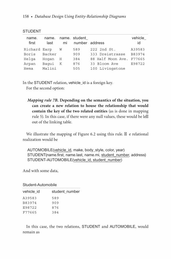
158 • Database Design Using Entity-Relationship Diagrams
STUDENTname.
firstname.
lastname.
mistudent_number address
vehicle_id
Richard Earp W 589 222 2nd St. A39583Boris Backer 909 333 Dreistrasse B83974Helga Hogan H 384 88 Half Moon Ave. F77665Arpan Bagui K 876 33 Bloom Ave E98722Hema Malini 505 100 Livingstone
In.the.STUDENT.relation,.vehicle_id.is.a.foreign.key.For.the.second.option:
Mapping rule 7B. Depending on the semantics of the situation, you can create a new relation to house the relationship that would contain the key of the two related entities.(as.is.done.in.mapping.rule 5)..In.this.case,.if.there.were.any.null.values,.these.would.be.left.out.of.the.linking.table.
We.illustrate.the.mapping.of.Figure 6.2.using.this.rule..The.relational.realization.would.be
AUTOMOBILE(vehicle_id, make, body_style, color, year)STUDENT(name.first, name.last, name.mi, student_number, address)STUDENT-AUTOMOBILE(vehicle_id, student_number)
And.with.some.data,
Student-Automobilevehicle_id student_numberA39583 589B83974 909E98722 876F77665 384
In. this. case,. the. two. relations,. STUDENT. and. AUTOMOBILE,. would.remain.as

Extending Relationships/Structural Constraints • 159
STUDENTname.first name.last name.mi student_number addressRichard Earp W 589 222 2nd StBoris Backer 909 333 DreistrasseHelga Hogan H 384 88 Half Moon AveArpan Bagui K 876 33 Bloom AveHema Malini 505 100 Livingstone
AUTOMOBILEvehicle_id make body_style color yearA39583 Ford Compact Blue 1999B83974 Chevy Compact Red 1989E98722 Mazda Van Green 2002F77665 Ford Compact White 1998G99999 Chevy Van Grey 1989
Mapping rule 8—Mapping binary 1:1 relationships when both sides have full participation constraints. Use the semantics of the rela-tionship to select which of the relations should contain the key of the other. If this choice is unclear, then use mapping rule 7B.
Now,.assuming.full.participation.on.both.sides.of.Figure 6.2,. the.two.tables.STUDENT.and.AUTOMOBILE could.be
STUDENT(name.first, name.last, name.mi, student_number, address)AUTOMOBILE(vehicle_id, make, body_style, color, year,
student_number)
And.with.some.sample.data,
STUDENTname.first name.last name.mi student_number addressRichard Earp W 589 222 2nd StBoris Backer 909 333 DreistrasseHelga Hogan H 384 88 Half Moon AveArpan Bagui K 876 33 Bloom AveHema Malini 505 100 Livingstone
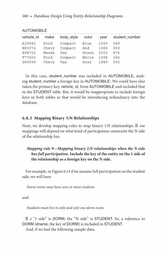
160 • Database Design Using Entity-Relationship Diagrams
AUTOMOBILEvehicle_id make body_style color year student_numberA39583 Ford Compact Blue 1999 589B83974 Chevy Compact Red 1989 909E98722 Mazda Van Green 2002 876F77665 Ford Compact White 1998 384G99999 Chevy Van Grey 1989 505
In. this. case,. student_number. was. included. in. AUTOMOBILE,. mak-ing.student_number.a.foreign.key.in.AUTOMOBILE. We.could.have.also.taken.the.primary.key,.vehicle_id,.from.AUTOMOBILE and.included.that.in.the.STUDENT table..But,.it.would.be.inappropriate.to.include.foreign.keys. in. both. tables. as. that. would. be. introducing. redundancy. into. the.database.
6.8.3 Mapping Binary 1:N Relationships
Next,.we.develop.mapping.rules.to.map.binary.1:N.relationships..These.mappings.will.depend.on.what.kind.of.participation.constraint.the.N.side.of.the.relationship.has.
Mapping rule 9—Mapping binary 1:N relationships when the N side has full participation. Include the key of the entity on the 1 side of the relationship as a foreign key on the N side.
For.example,.in.Figure 6.13.if.we.assume.full.participation.on.the.student.side,.we.will.have
Dorm rooms may have zero or more students.
and
Students must live in only and only one dorm room.
The. “1. side”. is. DORM;. the. “N. side”. is. STUDENT.. So,. a. reference. to.DORM.(dname,.the.key.of.DORM).is.included.in.STUDENT.
And,.if.we.had.the.following.sample.data,
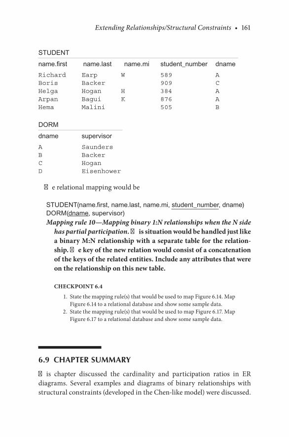
Extending Relationships/Structural Constraints • 161
STUDENTname.first name.last name.mi student_number dnameRichard Earp W 589 ABoris Backer 909 CHelga Hogan H 384 AArpan Bagui K 876 AHema Malini 505 B
DORMdname supervisorA SaundersB BackerC HoganD Eisenhower
The.relational.mapping.would.be
STUDENT(name.first, name.last, name.mi, student_number, dname)DORM(dname, supervisor)Mapping rule 10—Mapping binary 1:N relationships when the N side
has partial participation. This situation would be handled just like a binary M:N relationship with a separate table for the relation-ship. The key of the new relation would consist of a concatenation of the keys of the related entities. Include any attributes that were on the relationship on this new table.
CHECKPOINT 6.4
. 1.. State.the.mapping.rule(s).that.would.be.used.to.map.Figure 6.14..Map.Figure 6.14.to.a.relational.database.and.show.some.sample.data.
. 2.. State.the.mapping.rule(s).that.would.be.used.to.map.Figure 6.17..Map.Figure 6.17.to.a.relational.database.and.show.some.sample.data.
6.9 CHAPTER SUMMARY
This. chapter. discussed. the. cardinality. and. participation. ratios. in. ER.diagrams.. Several. examples. and. diagrams. of. binary. relationships. with.structural.constraints.(developed.in.the.Chen-like.model).were.discussed..

162 • Database Design Using Entity-Relationship Diagrams
Tighter. English. grammar. was. presented. for. each. of. the. diagrams,. and.steps.7.and.8.of.the.ER.design.methodology.were.defined..The.final.section.of. the. chapter.discussed.mapping. relationships.. As. our. model.becomes.more. complex,. we. will. revisit. the. mapping. rules. to. accommodate. this.complexity.in.further.chapters.
CHAPTER 6 EXERCISES
Exercise 6.1
Let.us.suppose.that.we.reconsider.our.student.example.in.Exercise.5.2.in.which.the.only.attributes.of.student.are.student.number.and.name..Let.us.suppose.that.we.have.another.entity.called.“high.school,”.which.is.going.to.be.the.high.school.from.which.the.student.graduated..For.the.high.school.entity,.we.will.record.the.high.school.name.and.the.location.(meaning.city.and.state)..Draw.the.ER.diagram.using.the.Chen-like.model..Follow.the.methodology.and.include.all.English.descriptions.of.your.diagrams..Map.the.ER.diagram.to.a.relational.database.
Exercise 6.2
Suppose. that. a. college. had. one. dormitory. with. many. rooms.. The. dor-mitory. entity,. which. is. actually. a. “dormitory. room”. entity. since. there.is. only. one. dorm,. has. the. attributes. room. number. and. single/double.(meaning. that. there. are. private. rooms. and. double. rooms).. Let. us. sup-pose.that. the.student.entity. in.this.case.contains. the.attributes.student.number,.student.name,.and.home.telephone.number..Draw.the.ER.dia-gram.using.the.Chen-like.model..Follow.the.methodology.and.include.all.English.descriptions.of.your.diagram..Map.the.ER.diagram.to.a.relational.database.
Exercise 6.3
Consider. a. student. database. with. students. and. campus. organizations..Students. will. have. the. attributes. of. student. number. and. student. name..Organizations.will.have.the.attributes.organization.name.and.organization.
Extending Relationships/Structural Constraints • 163
type..Draw.the.ER.diagram.using.the.Chen-like.model..Follow.the.meth-odology.and.include.all.English.descriptions.of.your.diagram..Map.the.ER.diagram.to.a.relational.database.and.include.some.sample.data.
Exercise 6.4
Consider.a.student.and.advisor.database..Students.have.a.student.num-ber.and.student.name..Advisors.have.names,.office.numbers,.and.advise.in.some.major..The.major. that. the.advisor.advises. in. is.designated.by.a.major. code. (e.g.,. Chemistry,. CHEM;. Biology,. BIOL;. Computer. Science,.COMPSC;.…)..Draw.the.ER.diagram.using.the.Chen-like.model..Follow.the. methodology. and. include. all. English. descriptions. of. your. diagram..Map. the. ER. diagram. to. a. relational. database. and. include. some. sample.data.
Exercise 6.5
You.want.to.record.the.following.data.in.a.database:.restaurant.name.and.location,.employee.names.and.IDs,.capacity.of.restaurant.(smoking.and.nonsmoking),.hours.of.operation.(assume.same.hours.every.day),.employee.salaries.and.titles..An.employee.can.work.for.only.one.restaurant..Draw.the.ER.diagram.using.the.Chen-like.model..Follow.the.methodology.and.include.all.English.descriptions.of.your.diagram..Map.the.ER.diagram.to.a.relational.database.and.include.some.sample.data.
Exercise 6.6
Record.the.following.data.in.a.database:.business.name,.owner,.location(s),.telephone. numbers,. delivery. truck. number,. truck. capacity,. usual. route.description.(e.g.,.North,.West,.Central,.Lake,.…)..Draw.the.ER.diagram.using. the. Chen-like. model.. Follow. the. methodology. and. include. all.English.descriptions.of.your.diagram.
Exercise 6.7
Refer.to.Figure 6.19..What.are.the.English.language.statements.you.can.make.about.the.figure?

164 • Database Design Using Entity-Relationship Diagrams
Exercise 6.8
Refer.to.Figure 6.18..Complete.the.diagram.by.adding.a.precise.English.description.of.each.attribute..Map.Figure 6.18.to.a.relational.database.
Exercise 6.9
What.is.the.cardinality.of.the.following:
. a..Each.student.must.own.a.car.and.can.own.only.one.car..A.car.may.be.owned.by.only.one.student.
1
M
address
Agency
address year_business_openedagency name
Property
owner_name
asking_price
list
FIGURE 6.19Exercise.7.

Extending Relationships/Structural Constraints • 165
. b..Each.student.may.drive.a.car.and.can.drive.more. than.one.car..A.car. can. be. driven. by. one. student. and. can. only. be. driven. by. one.student.
. c..Each.student.may.rent.many.cars.and.cars.may.be.rented.by.many.students.
Which.of. these.cardinality. rules.are.optional?.Which.rules.are.manda-tory?.Show.these.relationships.diagrammatically.
BIBLIOGRAPHY
Batani,.C.,.Ceri,.S.,.and.Navathe,.S..B..1992..Conceptual Database Design. Redwood.City,.CA:.Benjamin.Cummings.
Earp,.R.,. and.Bagui,.S..2001..Extending. relationships. in. the.entity. relationship.diagram..Data Base Management Journal,.22–10–42:1–14.
Elmasri,. R.,. and. Navathe,. S.. B.. 2007.. Fundamentals of Database Systems.. Reading,. MA:.Addison-Wesley.
Kroenke,.D..M..2010..Database Processing..Upper.Saddle.River,.NJ:.Prentice.Hall.McFadden,. F.. R.,. and. Hoffer,. J.. A.. 2007.. Modern Database Management. Upper. Saddle.
River,.NJ:.Pearson.Education.Ramakrishnan,. R.,. and. Gehrke,. J.. 2003.. Database Management Systems.. New. York:.
McGraw.Hill.
CASE STUDY
West Florida Mall (continued)
In.the.last.couple.of.chapters,.we.selected.our.primary.entities.(as.per.the.specifications.from.the.user.so.far).and.defined.the.relationships.between.the.primary.entities..In.this.chapter,.we.proceed.with.the.ER.diagram.for.this.case.study.by.looking.at.steps.6.and.7.of.the.ER.design.methodology,.and.we.map.the.ER.diagram.to.a.relational.database.(with.some.sample.data).as.we.proceed.
Step.6.develops.the.structural.constraints.of.binary.relationships.by.stating
Step 6. State the exact nature of the relationships in structured English from all sides, for example, when a relationship is A:B::1:M, there is a relationship from A(1) to B(M) and from B(M) back to A(1).
Refer.to.Figure 6.20.

166 • Database Design Using Entity-Relationship Diagrams
First,.for.the.relationship.located_in:
From.MALL.to.STORE,.this.fits.pattern.3,.1(full):N:A mall must have at least one store and can have many stores.
Or,Malls, which are recorded in the database, must have many (one or more) stores located in them.
From.STORE.to.MALL, this.fits.pattern.1,.M(full):1:Many stores (one or more) must be in one mall.
Or,Stores, which are recorded in the database, must be in one mall.
1
N
1 1
N
1
Mall
located_in
Store Store Manager
owns
Owner
manages
FIGURE 6.20ER.diagram.of.West.Florida.Mall.with.four.entities.and.structural.constraints.

Extending Relationships/Structural Constraints • 167
The.MALL.entity.is.mapped.as.mapped.in.Chapter.5:
MALLname addressWest Florida Mall N Davis Hwy, Pensacola, FLCordova Mall 9th Avenue, Pensacola, FLNavy Mall Navy Blvd, Pensacola, FLBelAir Mall 10th Avenue, Mobile, AL
Next,.we.have.to.map.the.relationship.between.the.MALL.entity.and.the.STORE.entity..This.is.a.binary.1:N.relationship;.hence,.we.use.mapping.rule.9,.which.states:
Include the key of the entity on the 1 side of the relationship to the N side as a foreign key.
So,.the.key.from.the.1.side,.the.MALL.side,.will.be.included.in.the.N.side,.STORE.side,.as.the.foreign.key..We.show.this.next.with.some.sample.data:
STOREsloc sname snum mall_nameRm 101 Penneys 1 West Florida MallRm 102 Sears 2 West Florida MallRm 109 Dollar Store 3 West Florida MallRm 110 Rex 4 West Florida Mall
Due.to.the.multivalued.attribute.depts.in.STORE,.we.will.keep.the.rela-tion.with.the.multivalued.attribute.(as.developed.in.Chapter.5)..It.is.shown.next.with.some.sample.data:
STORE-deptsnum depts1 Tall men’s clothing1 Women’s clothing1 Children’s clothing1 Men’s clothing...

168 • Database Design Using Entity-Relationship Diagrams
Then,.for.the.relationship.owns:
From.OWNER.to.STORE,.this.fits.pattern.3,.1(full):M:Owners, which are recorded in the database, must own one or more stores.
Or,One owner must own at least one store and may own many stores.
From.STORE.to.OWNER,.this.fits.pattern.1,.M(full):1:Stores, which are recorded in the database, must have one and only one owner.
Or,Many stores can have one owner.
For.the.relationship.owns, from.OWNER.to.STORE,.a.1:N relationship:
Again,. using. mapping. rule. 9,. we. will. take. the. key. from. the. 1. side,.so_ssn,.and.include.this.as.the.foreign.key.in.the.N.side,.STORE. STORE,.with.some.sample.data,.is.now:
STOREsloc sname snum mall_name so_ssnRm 101 Penneys 1 West Florida Mall 879-987-0987Rm 102 Sears 2 West Florida Mall 928-088-7654Rm 109 Dollar Store 3 West Florida Mall 826-098-0877Rm 110 Rex 4 West Florida Mall 982-876-8766
And,.the.relation.for.the.OWNER.entity.remains.as.developed.in.Chapter.5..With.some.sample.data,.it.is:
OWNERso_ssn so_name so_off_phone so_address879-987-0987 Earp (850)474-2093 1195 Gulf Breeze
Pkwy, Pensacola, FL826-098-0877 Sardar (850)474-9873 109 Navy Blvd,
Pensacola, FL928-088-7654 Bagui (850)474-9382 89 Highland
Heights, Tampa, FL982-876-8766 Bush (850)474-9283 987 Middle Tree,
Mobile, AL
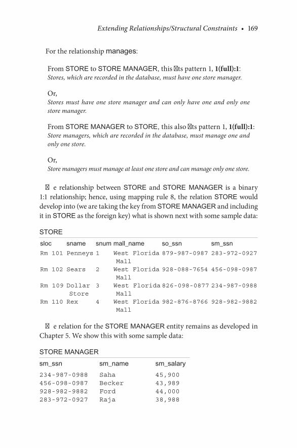
Extending Relationships/Structural Constraints • 169
For.the.relationship.manages:
From.STORE.to.STORE MANAGER,.this.fits.pattern.1,.1(full):1:Stores, which are recorded in the database, must have one store manager.
Or,Stores must have one store manager and can only have one and only one store manager.
From.STORE MANAGER to.STORE, this.also.fits.pattern.1,.1(full):1:Store managers, which are recorded in the database, must manage one and only one store.
Or,Store managers must manage at least one store and can manage only one store.
The. relationship. between. STORE. and. STORE MANAGER. is. a. binary.1:1.relationship;.hence,.using.mapping.rule.8,. the.relation.STORE.would.develop.into.(we.are.taking.the.key.from.STORE MANAGER.and.including.it.in.STORE.as.the.foreign.key).what.is.shown.next.with.some.sample.data:
STOREsloc sname snum mall_name so_ssn sm_ssnRm 101 Penneys 1 West Florida
Mall879-987-0987 283-972-0927
Rm 102 Sears 2 West Florida Mall
928-088-7654 456-098-0987
Rm 109 Dollar Store
3 West Florida Mall
826-098-0877 234-987-0988
Rm 110 Rex 4 West Florida Mall
982-876-8766 928-982-9882
The.relation.for.the.STORE MANAGER.entity.remains.as.developed.in.Chapter.5..We.show.this.with.some.sample.data:
STORE MANAGERsm_ssn sm_name sm_salary234-987-0988 Saha 45,900456-098-0987 Becker 43,989928-982-9882 Ford 44,000283-972-0927 Raja 38,988
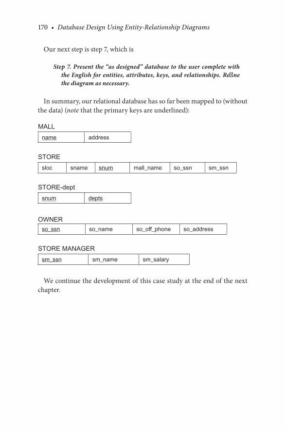
170 • Database Design Using Entity-Relationship Diagrams
Our.next.step.is.step.7,.which.is
Step 7. Present the “as designed” database to the user complete with the English for entities, attributes, keys, and relationships. Refine the diagram as necessary.
In.summary,.our.relational.database.has.so.far.been.mapped.to.(without.the.data).(note that.the.primary.keys.are.underlined):
MALLname address
STOREsloc sname snum mall_name so_ssn sm_ssn
STORE-deptsnum depts
OWNERso_ssn so_name so_off_phone so_address
STORE MANAGERsm_ssn sm_name sm_salary
We.continue.the.development.of.this.case.study.at.the.end.of.the.next.chapter.

171
7The Weak Entity
7.1 INTRODUCTION
Chapters.4.and.5.introduced.the.concepts.of.the.entity,.the.attribute,.and.the.relationship..Chapter.6.dealt.with.structural.constraints,.that.is,.how.two.entities.are.related.to.one.another..In.this.chapter,.we.discuss.the.con-cept. of. the. “weak”. entity,. which. is. used. in. the. Chen-like. model.. Weak.entities.may.not.have.a.key.attribute.of.their.own.as.they.are.dependent.on.a.strong.or.regular.entity.for.their.existence..Strong.entities.always.have.a.primary.key..The.weak.entity.has.some.restrictions.on.its.use.and.gener-ates.some.interesting.diagrams..This.chapter.revisits.and.redefines.steps.3.and.4.of.the.entity.relationship.(ER).design.methodology.to.include.the.concept. of. the. weak. entity.. Grammar. and. mapping. rules. for. the. weak.entity.are.also.developed.
7.2 STRONG AND WEAK ENTITIES
As.we.mentioned. in.Chapter.4,. there.are. situations. for.which.finding.a.key. for. an. entity. is. difficult.. So. far,. we. have. concentrated. on. examples.with.strong.(regular).entities—entities.with.easily.identifiable.keys..Strong.entities.almost.always.have.a.unique.identifier.that. is.a.subset.of.all. the.attributes;.however,.a.unique.identifier.may.be.an.attribute.or.a.group.of.attributes..For.example,.a.student.number,.an.automobile.vehicle.identifi-cation.number.(VIN),.a.driver’s.license.number,.and.so.on.may.be.unique.identifiers.of.strong.entities.
A.weak.entity.is.one.that.clearly.will.be.an.entity.but.will.depend.on.another. entity. for. its. existence.. As. we. mentioned,. a. weak. entity. will.not.necessarily.have.a.unique. identifier..A.classic.example.of. this.kind.

172 • Database Design Using Entity-Relationship Diagrams
of. entity. is. a. DEPENDENT. as. related. to. an. EMPLOYEE entity.. If. one.were.constructing.a.database.about.employees.and.their.dependents,.an.instance.of.a.dependent.would.depend.entirely.on.some.instance.of.an.employee.or.else.the.dependent.would.not.be.kept.in.the.database..The.EMPLOYEE entity.is.called.the.owner.entity.or.identifying.entity.for.the.weak.entity.DEPENDENT.
How. can. a. weak. entity. come. about. in. our. diagrams?. In. the. creation.of.a.database,.we.might.have.a.dependent.name.shown.as.a.multivalued.attribute.as.in.Figure 7.1..An.example.of.data.for.a.diagram.like.Figure 7.1.would.be.as.follows:
EMPLOYEEfname minit lname emp ID dependentsJohn J Jones 0001 John, Jr; Fred; SallySam S Smith 0004 Brenda; RichardAdam A Adams 0007 John; Quincy; MaudeSantosh C Saha 0009 Ranu; Pradeep; Mala
Suppose.that.in.our.conversations.with.the.user,.we.discover.that.more.information.is.supposed.to.be.gathered.about.the.dependents.themselves..
Employee
name dependents
fname minit lname
employee id
FIGURE 7.1EMPLOYEE entity.showing.dependents.as.a.multivalued.attribute.

The Weak Entity • 173
Following.our.methodology,.this.is.an.acknowledgment.that.the.depen-dents.should.be.entities—that.is,.they.fit.the.criteria.for.“entity,”.which.is.that.we.would.be.recording.information.about.“something”.(the.depen-dent).. Hence,. we. would. be. describing. an. entity. called. DEPENDENT.. If.we. make. DEPENDENT. an. entity,. we. would. embellish. the. diagram. in.Figure 7.1.to.that.of.Figure 7.2.
Figure 7.2.poses.a.problem:.The.DEPENDENT. entity. is.dependent.on.the.EMPLOYEE.for.its.being..Also,.it.has.no.clear.unique.identifier..This.
Employee
employee id
name
Dependent
birth_date
insurance
dname
ED
First pass at creating an ERdiagram for Employee-Dependent
Problem:What identifies a uniquedependent?
fname lnameminit
FIGURE 7.2The.EMPLOYEE-DEPENDENT.ER.diagram,.first.pass.
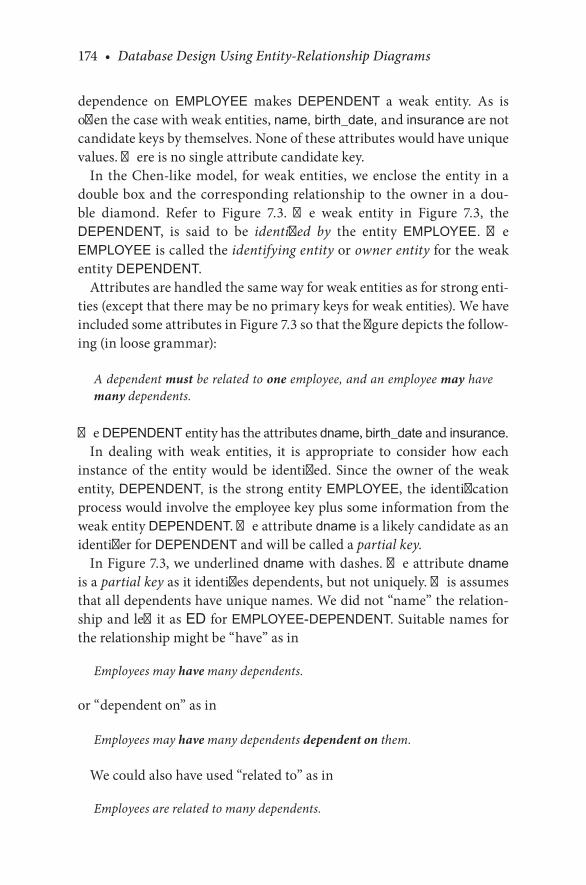
174 • Database Design Using Entity-Relationship Diagrams
dependence. on. EMPLOYEE. makes. DEPENDENT a. weak. entity.. As. is.often.the.case.with.weak.entities,.name, birth_date, and.insurance.are.not.candidate.keys.by.themselves..None.of.these.attributes.would.have.unique.values..There.is.no.single.attribute.candidate.key.
In. the.Chen-like.model,. for.weak.entities,.we.enclose. the.entity. in.a.double.box.and.the.corresponding.relationship.to.the.owner.in.a.dou-ble. diamond.. Refer. to. Figure 7.3.. The. weak. entity. in. Figure 7.3,. the.DEPENDENT,. is. said. to. be. identified by. the. entity. EMPLOYEE.. The.EMPLOYEE.is.called.the.identifying entity.or.owner entity.for.the.weak.entity.DEPENDENT.
Attributes.are.handled.the.same.way.for.weak.entities.as.for.strong.enti-ties.(except.that.there.may.be.no.primary.keys.for.weak.entities)..We.have.included.some.attributes.in.Figure 7.3.so.that.the.figure.depicts.the.follow-ing.(in.loose.grammar):
A dependent must be related to one employee, and an employee may have many dependents.
The.DEPENDENT.entity.has.the.attributes.dname,.birth_date.and.insurance.In. dealing. with. weak. entities,. it. is. appropriate. to. consider. how. each.
instance.of. the. entity.would.be. identified..Since. the.owner.of. the.weak.entity,.DEPENDENT,. is. the.strong.entity.EMPLOYEE,. the.identification.process.would.involve.the.employee.key.plus.some.information.from.the.weak.entity DEPENDENT..The.attribute.dname.is.a.likely.candidate.as.an.identifier.for.DEPENDENT.and.will.be.called.a.partial.key.
In.Figure 7.3,.we.underlined.dname with.dashes..The.attribute.dname.is.a.partial key.as.it.identifies.dependents,.but.not.uniquely..This.assumes.that.all.dependents.have.unique.names..We.did.not.“name”.the.relation-ship.and.left.it.as.ED. for.EMPLOYEE-DEPENDENT..Suitable.names.for.the.relationship.might.be.“have”.as.in
Employees may have many dependents.
or.“dependent.on”.as.in
Employees may have many dependents dependent on them.
We.could.also.have.used.“related.to”.as.in
Employees are related to many dependents.
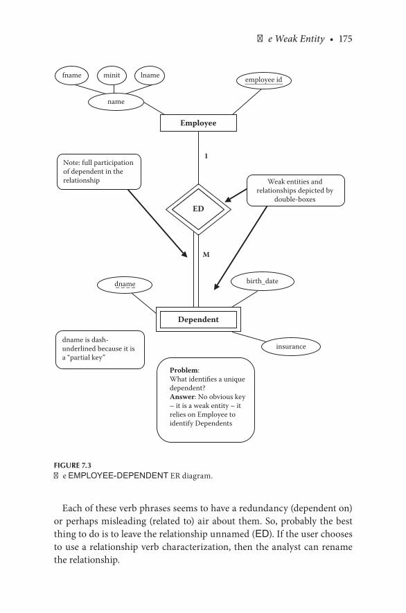
The Weak Entity • 175
Each.of.these.verb.phrases.seems.to.have.a.redundancy.(dependent.on).or.perhaps.misleading.(related.to).air.about.them..So,.probably.the.best.thing.to.do.is.to.leave.the.relationship.unnamed.(ED)..If.the.user.chooses.to.use.a.relationship.verb.characterization,.then.the.analyst.can.rename.the.relationship.
Employee
employee id
name
Dependent
birth_date
insurance
dname
M
1
ED
dname is dash-underlined because it isa “partial key”
fname lnameminit
Weak entities andrelationships depicted by
double-boxes
Note: full participationof dependent in therelationship
Problem:What identifies a uniquedependent?Answer: No obvious key– it is a weak entity – itrelies on Employee toidentify Dependents
FIGURE 7.3The.EMPLOYEE-DEPENDENT.ER.diagram.

176 • Database Design Using Entity-Relationship Diagrams
7.3 WEAK ENTITIES AND STRUCTURAL CONSTRAINTS
Weak.entities.always.have.full.or.mandatory.participation.from.the.weak.side.toward.the.owner..If.the.weak.entity.did.not.have.total.participation,.then.we.would.have.a.data.item.in.the.database.that.was.not.uniquely.iden-tified.and.was.not.tied.to.a.strong.entity..In.our.EMPLOYEE-DEPENDENT.example,.this.would.be.like.keeping.track.of.a.dependent.not.related.in.any.way.to.an.employee..The.cardinality.of.the.relationship.between.the.weak.and.strong.entity.will.usually.be.1:M,.but.not.necessarily.so.
7.4 WEAK ENTITIES AND THE IDENTIFYING OWNER
There.are.situations.for.which.a.weak.entity.may.be.connected.to.an.owner.entity.while.other.relationships.exist.apart.from.the.“owner”.relationship..For. example,. consider. Figure 7.4.. In. this. figure,. we. show. two. relation-ships—owns. and.drives—connecting. the. two.entities.EMPLOYEE. and.AUTOMOBILE.. Here,. the. AUTOMOBILE. entity. is. considered. a. weak.entity;. that. is,. if. there. is.no.employee,. then.there.will.be.no.automobile.(the.automobile.has.to.have.an.employee.to.exist.in.the.database)..Further,.the.automobile.is.identified.by.the.owner;.note.the.double.diamond.on.the.owns.relationship.and.the.full.participation.of.the.AUTOMOBILE entity.in.the.owns relationship.
In. Figure 7.4,. we. also. have. a. drives. relationship.. The. automobile. is.driven.by.employees.other.than.the.owner..All.automobiles.are.driven.by.some.employee;.hence,.the.participation.is.full..But,.the.driver-employee.may.not.necessarily.be.the.actual.owner..To.identify.AUTOMOBILE,.we.are.saying.that.we.need.the.owns.relationship,.but.other.nonowner.driv-ers.may.exist.
According.to.Figure 7.4,.one.employee.may.own.many.automobiles..To.answer.the.question.of.which.automobiles.an.employee.owns,.in.addition.to.the.employee’s.ID,.we.need.to.know.the.make,.model,.and.color.of.the.automobiles..The.make, model, and color.of.the.AUTOMOBILE.entity.are.partial.keys.(dotted.underlined.in.Figure 7.4).
One.final.point.about.the.AUTOMOBILE-EMPLOYEE.situation:.It.could.be.that.the.vin.of.the.AUTOMOBILE.could.be.recorded..Vins.are.unique;.hence,.the.weak.entity.AUTOMOBILE.could.have.a.primary.key..In.this.

The Weak Entity • 177
case,.although.AUTOMOBILE.would.have.a.primary.key,.it.would.still.be.weak.because.it.would.not.be.in.the.database.without.the.owner.or.driver.employee.. Having. a. primary. key. does. not. necessarily. make. an. entity.“strong.”
CHECKPOINT 7.1. 1.. How.would.you.identify.a.strong.entity?. 2.. How.would.you.identify.a.weak.entity?. 3.. What.kind.of.a.relationship.line.(single.or.double).would.be.leading.
up.to.the.weak.entity.in.a.Chen-like.diagram?. 4.. What. kind. of. relationship. does. a. weak. entity. have. in. a. Chen-like.
model?. 5.. What.is.a.partial.key?
Employee
employee id
name
Automobile
make
M
1
owns
N
M
drives
fname lnameminit
color
model
Note: full participationof Automobile in theowner relationship
�e owner of the weakentity is double boxed.�e other relationshipexists, but it does notdenote ownership.
FIGURE 7.4A.weak.entity.with.two.relationships.

178 • Database Design Using Entity-Relationship Diagrams
7.4.1 Another Example of a Weak Entity and the Identifying Owner
As.another.example.of.a.weak.entity.in.an.ER.diagram.and.the.identify-ing.owner,.consider.Figure 7.5..In.Figure 7.5,.we.have.two.strong.entities:.PERSON. and.VET..There. is.one.weak.entity,.PET..Figure 7.5. illustrates.that.the.PERSON.owns the.PET,.but.the.VET treats.the.PET..In.the.dia-gram,.PERSON.is.the.identifying.or.controlling.entity.for.PET;.hence,.the.relationship.owns.has.a.double.diamond. to.PERSON..Here,.owns is. a.weak.relationship..PET.is.a.weak.entity.in.relation.to.PERSON.
The.relationship.treats.does.not.have.a.double.diamond.because.VET.is.not.the.owner.of.PET..Here,.treats is.not.a.weak.relationship,.and.PET.is.not.a.weak.entity.in.relation.to.VET.
1
M
N
M
treats
Vet
Person
SSNname
name
Vet ID
owns
animal-type
Pet
name
FIGURE 7.5The.PERSON-PET-VET ER.diagram.

The Weak Entity • 179
7.5 WEAK ENTITIES CONNECTED TO OTHER WEAK ENTITIES
We.would.like.to.make.a.final.point.regarding.weak.entities..Just.because.an.entity.is.weak.does.not.preclude.it.from.being.an.owner.of.another.weak.entity..For.example,.consider.Figure 7.6..In.this.figure,.the.EMPLOYEE-DEPENDENT. relationship.has.been.enhanced. to. include.hobbies.of. the.dependents..(Never.mind.why.one.would.want.to.keep.this.information,.but.let.us.suppose.that.they.do.anyway.)
DEPENDENT.is.a.weak.entity..The.entity.HOBBY.is.also.weak..Hobbies.might.be.identified.by.their.type.(stamp.collecting,.baseball,.tying.knots,.
dname
type
1
M
1
M
Hobby
ED
DH
birth_date
Dependent insurance
years_involved
Employee
employee id
name
fname lnameminit
FIGURE 7.6The.EMPLOYEE-DEPENDENT-HOBBY.ER.diagram.

180 • Database Design Using Entity-Relationship Diagrams
observing. trains,.etc.)..The.type.attribute.of.HOBBY. is.a.partial.key. for.HOBBY.
The.entity.DEPENDENT. is.the.owner.of.the.weak.entity.HOBBY,.and.the.entity.EMPLOYEE.is.the.owner.of.the.weak.entity.DEPENDENT.
The.reason.that.this.situation.is.brought.up.here.is.to.show.that.it.can.exist..In.further.discussion,.when.we.map.this.situation,.we.treat.this.spe-cial.situation.carefully.
CHECKPOINT 7.2. 1.. Can.a.weak.entity.be.dependent.on.another.weak.entity?. 2.. Can.a.weak.entity.have.a.relationship.that.is.not.“weak”.with.the.identi-
fying.entity?. 3.. Can. a. weak. entity. be. related. to. more. than. one. entity. (strong. or.
weak)?
7.6 REVISITING THE METHODOLOGY
The.inclusion.of.a.weak.entity.in.an.ER.diagram.causes.us.to.revisit.our.methodology.and.make.some.adjustments..We.might.discover.the.weak.entity.in.one.of.two.places:.one.would.be.as.we.illustrated.with.the.evolu-tion. of. the. multivalued. attribute,. the. “dependent”;. this. would. occur. in.steps.3a.and.3b:
Step 3. Examine attributes in the primary entity (possibly with user assistance) to find out if information about one of the attributes is to be recorded.
Step 3a. If information about an attribute is needed, then make the attribute an entity, and then
Step 3b. Define the relationship back to the original entity.
So,.we.add
Step 3c. If the new entity depends entirely on another entity for its existence, then draw the entity as weak (double boxed) and show the connection to the identifying entity as a double diamond. The participation of the weak entity in the relationship is full. Dash underline the partial key identifier(s) in the weak entity.

The Weak Entity • 181
The.second.place.that.a.weak.entity.might.appear.would.be.as.part.of.step.4.when.new.entities.are.considered:
Step 4. If another entity is appropriate, draw the second entity with its attributes. Repeat step 2 to see if any attributes should be further split into more entities.
So,.we.add
Step 4a. If the additional entity or entities do not have candidate keys, then draw them as weak entities (as explained in step 3c) and show the connection to an identifying entity. The participation of the weak entity in the relationship is full or mandatory. Dash underline the partial key identifier(s) in the weak entity.
Again,.note.that.a.weak.entity.cannot.exist.without.an.identifying.entity,.so.if.the.weak.entity.is.“discovered”.independent.of.an.identifying.entity,.the.relationship.connection.should.be.made.immediately.
7.7 WEAK ENTITY GRAMMAR
Previously,.we.covered.some.grammar.associated.with.weak.entities,.but.now.we.want.to.revise.and.enhance.the.idea.when.we.have.no.primary.key.for.the.weak.entity..It.is.possible.for.a.weak.entity.to.have.a.primary.key;.therefore,.it.might.appear.in.item.(b),.so.we.add.part.(c).to.the.grammar.for.the.keys,.given.next.
7.7.1 The Keys
For the key(s):
. (a). More.than.one.candidate.key.(strong.entity):.One.key.is.chosen.as.the.primary.key.….(covered.previously).
. (b). One.candidate.key.(strong.or.weak.entity):.The.primary.key.is. the.candidate.key..For.each.weak.entity,.it.is.assumed.that.no.weak.entity.will.be.recorded.without.a.corresponding.owner.(strong).entity.

182 • Database Design Using Entity-Relationship Diagrams
For each weak entity that has a primary key, we also must record the primary key of the owner entity.
. (c). No.candidate.keys (weak.entity):
For each (weak) entity, we do not assume that any attribute will be unique enough to identify individual entities.
In.this.case,.the.DEPENDENT.entity.would.be.depicted.as
For.each DEPENDENT entity, we.do.not.assume.that.any.attribute.will.be.unique.enough to.identify.individual.entities.
We.now.enhance.this.description.to.include.the.identifying.entity:
Since. the weak entity does. not. have. a. candidate. key,. each weak entity will.be.identified.by.key(s).belonging.to.its strong entity. For.each. DEPENDENT,. entities. will. be. identified. by. the. concatena-tion.of. its.partial.key.and.the.owner.primary.key:. (DEPENDENT.DNAME+EMPLOYEE.EMPLOYEE_ID).
In. this. case,. the. DEPENDENT. entity. is. identified. by. the. EMPLOYEE.entity,.and.this.second.statement.becomes:
Since. the DEPENDENT. entity. does. not. have. a. candidate. key,. each DEPENDENT. entity. will. be. identified by. key(s). belonging. to. the.EMPLOYEE.entity plus.dname.in.the.DEPENDENT.entity.
7.8 MAPPING WEAK ENTITIES TO A RELATIONAL DATABASE
In.this.section,.we.develop.the.mapping.rules.for.mapping.weak.entities.to.a.relational.database.
Mapping Rule 11—Mapping weak entities. Develop a new table (rela-tion) for each weak entity. As is the case with the strong entity, include any atomic attributes from the weak entity in the table. If there is a composite attribute, include only the atomic parts of

The Weak Entity • 183
the composite attribute and be sure to qualify the atomic parts in order not to lose information. To relate the weak entity to its owner, include the primary key of the owner entity in the weak relation. The primary key of the weak relation will be the par-tial key of the weak entity concatenated to the primary key of the owner entity.
If a weak entity owns other weak entities, then the weak entity that is connected to the strong entity must be mapped first. The key of the weak owner entity has to be defined before the “weaker” entity (the one furthest from the strong entity) can be mapped.
For. example,. refer. to. Figure 7.3.. The. EMPLOYEE. relation. and.DEPENDENT.relation.would.be.mapped.as
EMPLOYEE(fname, minit, lname, employee_id)DEPENDENT(employee_id, dname, insurance, birth_date)
And.with.data:
EMPLOYEEfname lname minit employee_idRichard Earp W 589Boris Backer 909Helga Hogan H 384Arpan Bagui K 876Hema Malini 505
DEPENDENTdname birth_date insurance employee_idBeryl 1/1/94 Vista 589Kaityln 2/25/07 Vista 909David 3/4/05 BlueCross 589Fred 3/7/08 BlueCross 589Chloe 5/6/08 SE 384
Here,.employee_id is. the.primary.key.of.EMPLOYEE..The.employee_id from. the. owner. relation. EMPLOYEE. is. included. in. the. weak. relation.DEPENDENT..The employee_id now.becomes.part.of.the.primary.key.of.DEPENDENT. Since.dname.is.the.partial.key.of.the.DEPENDENT.relation,.
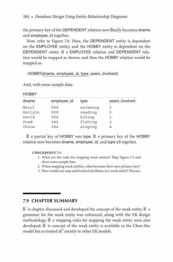
184 • Database Design Using Entity-Relationship Diagrams
the.primary.key.of.the.DEPENDENT.relation.now.finally.becomes.dname and employee_id together.
Now,. refer. to. Figure 7.6.. Here,. the. DEPENDENT. entity. is. dependent.on. the. EMPLOYEE entity,. and. the. HOBBY. entity. is. dependent. on. the.DEPENDENT. entity.. The. EMPLOYEE. relation. and. DEPENDENT. rela-tion.would.be.mapped.as.shown,.and.then.the.HOBBY.relation.would.be.mapped.as
HOBBY(dname, employee_id, type, years_involved)
And,.with.some.sample.data:
HOBBYdname employee_id type years_involvedBeryl 589 swimming 3Kaityln 909 reading 5David 589 hiking 1Fred 589 fishing 2Chloe 384 singing 4
The.partial.key.of.HOBBY.was. type. The.primary.key.of. the.HOBBY.relation.now.becomes.dname, employee_id, and type all.together.
CHECKPOINT 7.3. 1.. What.are. the. rules. for.mapping.weak.entities?.Map.Figure 7.5.and.
show.some.sample.data.. 2.. When.mapping.weak.entities,.what.becomes.their.new.primary.key?. 3.. How.would.you.map.multivalued.attributes.in.a.weak.entity?.Discuss.
7.9 CHAPTER SUMMARY
This.chapter.discussed.and.developed.the.concept.of.the.weak.entity..The.grammar. for. the. weak. entity. was. enhanced,. along. with. the. ER. design.methodology..The.mapping.rules.for.mapping.the.weak.entity.were.also.developed..This.concept.of. the.weak.entity. is.available. in. the.Chen-like.model.but.is.treated.differently.in.other.ER.models.

The Weak Entity • 185
CHAPTER 7 EXERCISES
Exercise 7.1
Construct.an.ER.diagram.(in.the.Chen-like.model).for.a.database.that.is.to.contain.employee.name,.employee.number,.employee.address,.skill(s)..An.employee.may.have.more.than.one.skill..Then,.enhance.the.diagram.to.include.level.of.skill,.date.skill.certified.(if.certified),.date.began.using.the.skill..Are.there.any.weak.entities.in.this.database?.Map.this.ER.diagram.to.a.relational.database.
Exercise 7.2
Construct.an.ER.diagram.(in.the.Chen-like.model).for.sports.and.play-ers..Attributes.of.sport.are.sport.name,.type.of.sport,.timed.or.untimed..Attributes.of.players.are.name,.person.ID,.date.of.birth..Players.may.play.multiple. sports..Which.entity/entities.would.you.consider.weak?.Write.out. the.grammar. for. the.ER.diagram..Map. this.ER.diagram. to.a. rela-tional.database.
Exercise 7.3
How.are.weak.entities.generally.identified?
Exercise 7.4
What.mapping.rules.would.be.used.to.map.Figure 7.4?.Map.Figure 7.4.to.a.relational.database.and.show.some.sample.data.
BIBLIOGRAPHY
Chen,. P.. P.. 1976.. The. entity. relationship. model—toward. a. unified. view. of. data.. ACM Transactions on Database Systems,.1(1).
Connolly,. E.,. and. Begg,. C.. 2009.. Database Systems, a Practical Approach to Design, Implementation, and Management..Reading,.MA:.Addison-Wesley.
Elmasri,. R.,. and. Navathe,. S.. B.. 2007.. Fundamentals of Database Systems.. Reading,. MA:.Addison-Wesley.
Ramakrishnan,. R.,. and. Gehrke,. J.. 2003.. Database Management Systems.. New. York:.McGraw.Hill.

186 • Database Design Using Entity-Relationship Diagrams
CASE STUDY
West Florida Mall (continued)
In. the. previous. chapters,. we. selected. our. primary. entities,. defined. the.attributes.and.relationships.for.this.case.study,.and.mapped.it. to.a.rela-tional.database.(with.some.sample.data)..In.Chapter.6,.we.also.determined.the. structural. constraints.of. the. relationships.and.adjusted. some.of. the.mappings.accordingly..Then,.on.reviewing.step.7,.which.says
Step 7. Present the “as designed” database to the user complete with the English for entities, attributes, keys, and relationships. Refine the diagram as necessary.
Suppose.we.obtained.some.additional.input.from.the.user:A.store.must.have.one.or.more.departments..A.department.will.not.exist.
without.a.store..For.each.department.we.will.store.the.department.name,.department.number,.and.department.manager..Each.department.has.at.least.one.employee.working.for.it.
We. have. to. record. information. about. the. employees. in. the. store.. For.each. employee. in. a. store,. we. will. have. to. keep. an. employee’s. name,.Social.Security.number,.and.the.department.where.the.employee.works..Employees.must.work.in.one.and.only.one.department.
In. Chapter. 5,. we. determined. that. departments. was. a. multivalued.attribute.of.STORE. (that. is,.one.store.had.many.departments)..But,.on.reviewing. these. additional. (given. here). specifications,. we. can. now. see.that.DEPARTMENT. needs. to. be. an. entity. on. its. own. since. we. have. to.record. information. about. a. DEPARTMENT.. Also,. we. can. see. that. we.have. to. record. information. about. another. new. entity,.EMPLOYEE.. So,.these. current. specifications. add. two. new. entities,. DEPARTMENT. and.EMPLOYEE.
CASE STUDY
First,.we.select.an.entity,.DEPARTMENT.Now,.repeating.step.2.for.DEPARTMENT:

The Weak Entity • 187
The Entity
This.database.records.data.about.a.DEPARTMENT.
For.each.DEPARTMENT.in.the.database,.we.record.a.department.name.(dname) and.department.number (dnum).
The Attributes for DEPARTMENT
For.each.DEPARTMENT. there.will.be.one.and.only.one.dname..The.value.for.dname.will.not.be.subdivided.
For. each. DEPARTMENT,. there. will. be. one. and. only. one. dnum.. The.value.for.dnum.will.not.be.subdivided.
The Keys
For.each.DEPARTMENT,.we.do.not.assume.that.any.attribute.will.be.unique.enough.to.identify.individual.entities.without.the.accompa-nying.reference.to.STORE,.the.owner.entity.
Note. that. the. language. leads. you. to. think. of. DEPARTMENT. as. a.weak.entity.
Next,.we.select.our.next.entity,.EMPLOYEE.Now,.repeating.step.2.for.EMPLOYEE:
The Entity
This.database.records.data.about.an.EMPLOYEE.
For. each. EMPLOYEE in. the. database,. we. record. an. employee. name.(ename).and.employee.Social.Security.number (essn).
The Attributes for EMPLOYEE
For.each.EMPLOYEE, there.will.be.one.and.only.one.ename..The.value.for.ename.will.not.be.subdivided.
For.each.EMPLOYEE,.there.will.be.one.and.only.one.essn..The.value.for.essn.will.not.be.subdivided.

188 • Database Design Using Entity-Relationship Diagrams
The Keys
For. each. EMPLOYEE,. we. will. assume. that. the. essn. will. be. unique.(so EMPLOYEE.will.be.a.strong.entity).
These.entities.have.been.added.to.the.diagram.in.Figure 7.7.Using. step. 6. to. determine. the. structural. constraints. of. relationships,.
we.get:
First,.for.the.relationship, dept_of:From.STORE.to DEPARTMENT,.this.fits.pattern.3,.1(full):N:
Stores, which are recorded in the database, must have many (one or more) departments.
From.DEPARTMENT.to.STORE, this.fits.pattern.1,.M(full):1:
Many departments (one or more) must be in one store.
1
N
N
N
N
1
1
1
1
N
Store
dept_ofowns
located_in
Department
Mall
Owner
Store Manager
Employee
manages
works_for
FIGURE 7.7ER.diagram.of.West.Florida.Mall.developed.so.far.
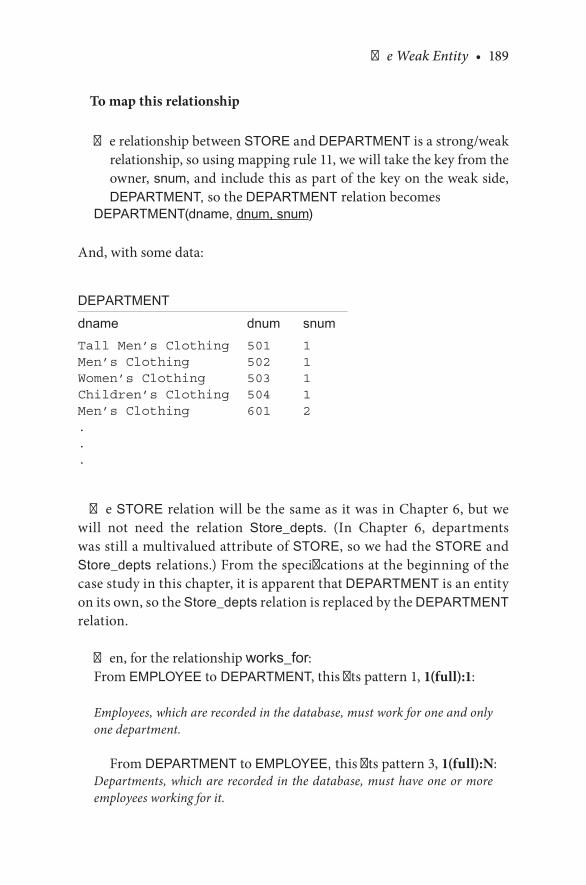
The Weak Entity • 189
To map this relationship
The.relationship.between.STORE.and.DEPARTMENT.is.a.strong/weak.relationship,.so.using.mapping.rule.11,.we.will.take.the.key.from.the.owner,.snum,.and.include.this.as.part.of.the.key.on.the.weak.side,.DEPARTMENT, so.the.DEPARTMENT relation.becomes
DEPARTMENT(dname, dnum, snum)
And,.with.some.data:
DEPARTMENTdname dnum snumTall Men’s Clothing 501 1Men’s Clothing 502 1Women’s Clothing 503 1Children’s Clothing 504 1Men’s Clothing 601 2...
The.STORE.relation.will.be.the.same.as.it.was.in.Chapter.6,.but.we.will. not. need. the. relation. Store_depts.. (In. Chapter. 6,. departments.was.still.a.multivalued.attribute.of.STORE,.so.we.had.the.STORE.and.Store_depts relations.).From.the.specifications.at.the.beginning.of.the.case.study.in.this.chapter,.it.is.apparent.that.DEPARTMENT.is.an.entity.on.its.own,.so.the.Store_depts.relation.is.replaced.by.the.DEPARTMENT.relation.
Then,.for.the.relationship works_for:From.EMPLOYEE.to DEPARTMENT,.this.fits.pattern.1,.1(full):1:
Employees, which are recorded in the database, must work for one and only one department.
From.DEPARTMENT.to.EMPLOYEE, this.fits.pattern.3,.1(full):N:Departments, which are recorded in the database, must have one or more employees working for it.

190 • Database Design Using Entity-Relationship Diagrams
To map this relationship:
From.EMPLOYEE.to DEPARTMENT,.the.relationship.is.1:1,.and.since.both.sides.have.full.participation,.using.mapping.rule.8.we.may.select.which. side. may. store. the. key. of. the. other.. But,. since. the. relation-ship.between.DEPARTMENT.and.EMPLOYEE.is.a.binary.1(full):N.relationship,.using.mapping.rule.9,.we.will.take.the.key.from.the.1.side.(DEPARTMENT.side),.dnum.and.snum,.and.include.this.concat-enated.key.as.the.foreign.key.in.the.N.side.(EMPLOYEE.side),.so.the.relation.EMPLOYEE.becomes
EMPLOYEE(ename, essn, dnum, snum)
And,.with.some.sample.data:
EMPLOYEEename essn dnum snumKaitlyn 987-754-9865 501 1Fred 276-263-9182 502 1Katie 982-928-2726 503 1Seema 837-937-9373 501 1Raju 988-876-3434 601 2...
In.summary,.our.relational.database.has.so.far.been.mapped.to.(without.the.data)
MALLname address
STOREsloc sname snum mall_name so_owner sm_ssn
OWNERso_ssn so_name so_off_phone so_address
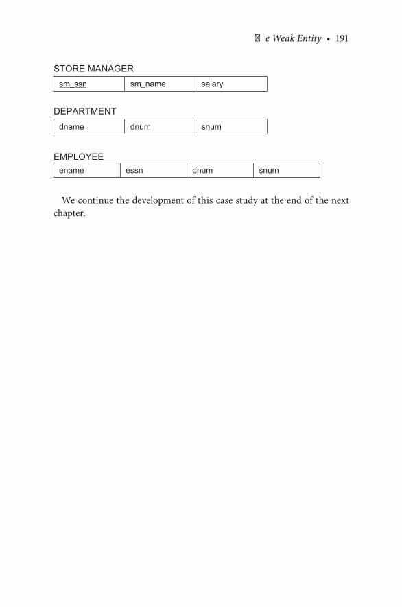
The Weak Entity • 191
STORE MANAGERsm_ssn sm_name salary
DEPARTMENTdname dnum snum
EMPLOYEEename essn dnum snum
We.continue.the.development.of.this.case.study.at.the.end.of.the.next.chapter.

193
8Further Extensions for ER Diagrams with Binary Relationships
8.1 INTRODUCTION
Having.developed.the.basic.entity.relationship.(ER).model.in.Chapters.4.through.7,.this.chapter.deals.with.some.extensions.to.the.basic.model..In.this.chapter,.we.introduce.a.new.concept—attributes.of.relationships;.we.present.several.examples..We.then.revisit.step.6.of.the.ER.design.method-ology.to.include.attributes.of.relationships..Next,.the.chapter.looks.at.how.more.entities.and.relationships.are.added.to.the.ER.model.and.how.attri-butes.and.relationships.evolve.into.entities,.all.the.while.refining.our.ER.design.methodology..Relationships.may.develop.into.entities,.creating.an.intersection.entity..The.grammar.and.structured.English.for.the.intersec-tion.entity.are.also.presented..Then,.this.chapter.introduces.the.concept.of.recursive.relationships.
Also,.in.previous.chapters.we.mostly.looked.at.cases.in.which.two.enti-ties. had. a. (one). relationship. between. them.. In. this. chapter,. we. present.additional.scenarios.of.how.two.entities.can.have.more.than.one.relation-ship.between.them..Step.5.of.the.ER.design.methodology.is.also.redefined.to.include.more.than.one.relationship.between.two.entities..This.chapter.discusses.derived.and.redundant.relationships,.and.the.ER.design.meth-odology.is.again.refined;.step.6b.is.included.to.deal.with.these.structures..Finally,.in.this.chapter.we.include.an.optional.section.that.looks.at.an.alter-native.ER.notation.for.specifying.structural.constraints.on.relationships.

194 • Database Design Using Entity-Relationship Diagrams
8.2 ATTRIBUTES OF RELATIONSHIPS
In.Chapter.6,.we.considered.the.M:N.relationship.STUDENT-COURSE..The.STUDENT-COURSE.relationship.is.M:N.because.students.take.many.courses.and.courses.are. taken.by.many.students..Now,.consider.adding.the.attribute.grade.to.the.ER.diagram..If.we.tried.to.put.grade.with.the.STUDENT.entity,.we.would.have.a.multivalued.attribute.that.had.to.some-how.be.related.to.the.COURSE.entity.to.make.sense..Similarly,.if.we.tried.to.put.the.grade.attribute.with.the.COURSE entity,.the.COURSE.entity.would. have. to. be. related. to. the. STUDENT entity.. The. correct. place. for.the. grade. attribute. in. the. diagram. would. be. on. the. relationship. enroll.because.grade.requires.both.a.STUDENT.and.a.COURSE to.make.sense..See.Figure 8.1.for.the.placement.of.the.grade attribute.in.an.M:N,.full:full.participation.model.
A.few.other.attributes.have.been.added.to.Figure 8.1.to.show.the.rela-tive.position.of.the.attributes..Again,.since.grade.is.necessarily.identified.by.both.STUDENT.and.COURSE,. it.cannot.reside.with.either.entity.by.itself..An.attribute.like.grade.is.called.a.relationship attribute.or.intersec-tion attribute.
An. intersection.attribute.may.arise.first.as.a.multivalued.attribute.on.some. entity. during. the. design. process. only. later. to. be. questioned;. that.is,.“Why.is.this.attribute.here.when.it.requires.another.entity.to.identify.it?”.When.it.is.recognized.that.the.attribute.has.to.be.identified.by.more.than.one.entity,.the.attribute.is.moved.to.the.relationship.between.the.two.(or more).entities.that.identify.it.
Relationship.attributes.may.occur.with.an.ER.diagram.containing.any.cardinality,. but. one. will. most. often. find. relationship. attributes. in. the.binary,.M:N.situation..We.now.need.to.revisit.our.methodology.to.add.a.guideline.for.the.attributes.of.a.relationship:
Step 6. State the exact nature of the relationships in structured English from all sides, for example, if a relationship is A:B::1:M, then there is a relationship from A to B, 1 to Many, and from B back to A, Many to 1.
And,.we.add:
Step 6a. Examine the list of attributes and determine whether any of them need to be identified by two (or more) entities. If so, place the attribute on the appropriate relationship that joins the two entities.
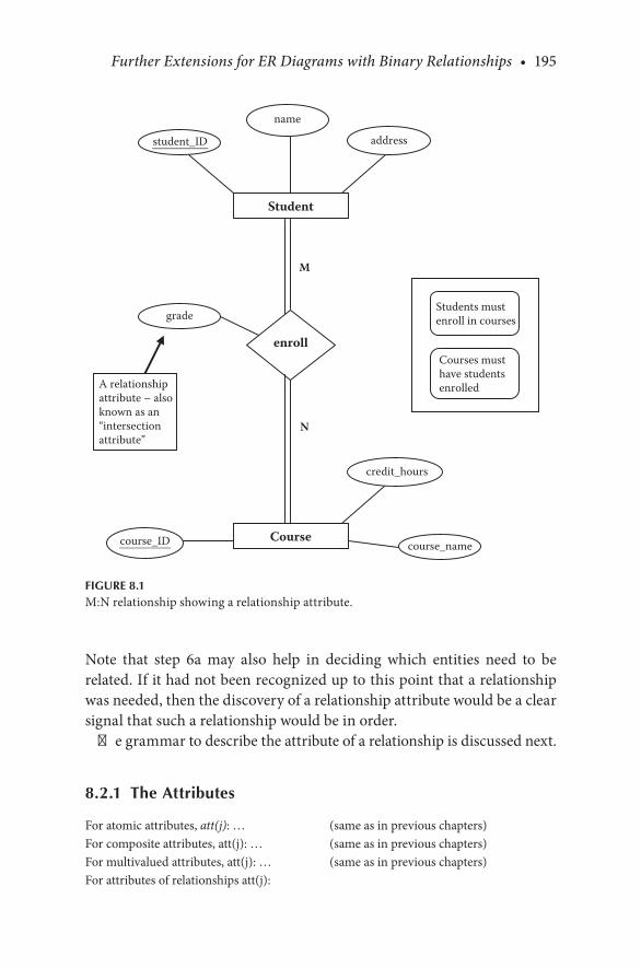
Further Extensions for ER Diagrams with Binary Relationships • 195
Note. that. step. 6a. may. also. help. in. deciding. which. entities. need. to. be.related..If.it.had.not.been.recognized.up.to.this.point.that.a.relationship.was.needed,.then.the.discovery.of.a.relationship.attribute.would.be.a.clear.signal.that.such.a.relationship.would.be.in.order.
The.grammar.to.describe.the.attribute.of.a.relationship.is.discussed.next.
8.2.1 The Attributes
For.atomic.attributes,.att(j):.… (same.as.in.previous.chapters)For.composite.attributes,.att(j):.… (same.as.in.previous.chapters)For.multivalued.attributes,.att(j):.… (same.as.in.previous.chapters)For.attributes.of.relationships.att(j):
M
N
course_ID
Student
name
addressstudent_ID
Course
credit_hours
course_name
grade
enroll
Students mustenroll in courses
Courses musthave studentsenrolledA relationship
attribute – alsoknown as an“intersectionattribute”
FIGURE 8.1M:N.relationship.showing.a.relationship.attribute.
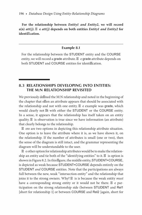
196 • Database Design Using Entity-Relationship Diagrams
For the relationship between Entity1 and Entity2, we will record a(n) att(j). The att(j) depends on both entities Entity1 and Entity2 for identification.
Example 8.1
For.the.relationship.between.the STUDENT entity.and.the COURSE entity, we.will.record.a grade attribute..The grade attribute.depends.on.both.STUDENT and COURSE entities for.identification.
8.3 RELATIONSHIPS DEVELOPING INTO ENTITIES: THE M:N RELATIONSHIP REVISITED
We.previously.defined.the.M:N.relationship.and.noted.in.the.beginning.of.the.chapter.that.often.an.attribute.appears.that.should.be.associated.with.the.relationship.and.not.with.one.entity..The.example.was.grade,.which.would. clearly. not. fit. with. either. the.STUDENT or the.COURSE. entity..In. a. sense,. it. appears. that. the. relationship. has. itself. taken. on. an. entity.quality..This.observation.is.true.since.we.have.information.(an.attribute).that.clearly.belongs.to.the.relationship.
There.are.two.options.in.depicting.this.relationship.attribute.situation..One.option. is. to. leave. the.attribute.where. it. is,.as.we.have.shown.it,.on.the. relationship.. If. the. number. of. attributes. is. small. (one. or. two),. then.the.sense.of.the.diagram.is.still.intact,.and.the.grammar.representing.the.diagram.will.be.understandable.to.the.user.
The.other.option.for.relationship.attributes.would.be.to.make.the.relation-ship.an.entity.and.tie.both.of.the.“identifying.entities”.to.it..This.option.is.shown.in.Figure 8.2..In.this.figure,.the.middle.entity,.STUDENT+COURSE,.is.depicted.as.weak.because.STUDENT+COURSE.depends.entirely.on.the.STUDENT and COURSE entities. Note.that.the.participations.are.always.full.between.the.new,.weak.“intersection.entity”.and.the.relationship.that.joins.it.to.the.strong.owners..Why?.This.is.because.the.weak.entity.must.have. a. corresponding. strong. entity. or. it. would. not. be. there.. The. par-ticipation.on. the. strong.relationship. side. (between.STUDENT. and.Rel1.[short.for.relationship.1].or.between.COURSE.and.Rel2 [again,.short.for.

Further Extensions for ER Diagrams with Binary Relationships • 197
relationship.2]).can.be.partial.or.full.depending.on.whether.it.was.partial.or.full.originally..What.would.a.partial.COURSE-Rel 2.connection.mean?.It.would.indicate.that.classes.existed.in.the.database.that.were.not.offered.and.hence.had.no.students.in.them.
Now.that.we.have.a.STUDENT+COURSE.entity.(an.intersecting.entity),.our.grammatical.description.of.this. intersecting.entity.would.be.as.dis-cussed.next.
1
M
M
1
Course
Student
address
student_ID
credit_hours
course_ID
Rel 1
name
Rel 2
Student + Course
grade
course_name
Possibly partial
Possibly partial
Always full
Always full
FIGURE 8.2M:N.relationship.that.has.been.replaced.with.by.1:M.relationships.

198 • Database Design Using Entity-Relationship Diagrams
8.3.1 The Entity
This. database. records. data. about. STUDENT-COURSE. combinations:.STUDENT+COURSE. For.each.STUDENT+COURSE.in.the.database,.we.record.a.grade.
8.3.1.1 The Attributes
For.each.STUDENT+COURSE combination,.there.will.be.one.and.only.one.grade..The.value.for.grade.will.not.be.subdivided.
8.3.1.2 The Keys
(d).Intersecting.entity:.The.key.of.the.intersection.entity.will.consist.of.the.concatenation.of.the.foreign.keys.of.the.owner.entities.
In. the.STUDENT-COURSE. example,. the. intersection.entity.will.con-tain.a.student_ID.and.a.course_ID—both.foreign.keys;.hence,.the.key.of.this.entity.will.be.student_ID+course_ID.(the.plus.sign.here.means.con-catenation)..Both.attributes.are.necessary.to.identify.a.unique.row.in.the.database.
The.last.statement.is.very.close.(and.for.a.user,.it.is.hoped.indistinguish-able). from.the.key.statements. found. in. the.“attribute.on.a.relationship”.grammar.given:
For.the.relationship.between STUDENT and COURSE, we.will.record.a grade..The.grade depends.on.both.entities STUDENT and COURSE for.identification.
8.4 MORE ENTITIES AND RELATIONSHIPS
In. the. handling. of. a. database,. we. have. to. model. the. information. pre-sented..We.will. likely.have. situations. that.call. for.more. than. two.enti-ties.and.more.than.one.binary.relationship..Again,.a.binary.relationship.is.a.relationship.between.two.entities..(In.Chapter.9,.we.look.at.ternary.
Further Extensions for ER Diagrams with Binary Relationships • 199
and.higher.relationship.combinations.).This.section.deals.with.situations.for.which.the.information.about.the.database.indicates.that.we.have.to.expand.our.diagrams.with.more.entities,.but.all.the.connections.will.be.binary.
8.4.1 More than Two Entities
Let.us.again.reconsider.the.STUDENT-COURSE.ER.diagram.(Figure 8.1)..If. this.database.were.oriented. toward.a.college,. the.courses.would.have.instructors,.and.the.instructors.would.be.related.to.the.courses..We.may.add. INSTRUCTOR. to.our.database.per.our.methodology.steps.4.and.5,.which.say:
Step 4. If another entity is appropriate, draw the second entity with its attributes. Repeat step 2 to see if this entity should be further split into more entities.
Step 5. Connect entities with relationships (one or more) if relation-ships exist.
If.we.added.instructors.to.Figure 8.1,.we.arrive.at.Figure 8.3.(attributes.other.than.the.primary.keys.are.intentionally.left.off.to.unclutter.the.dia-gram)..The.relationship.between. INSTRUCTOR. and.COURSE. is. teach;.instructors.teach.many.courses,.a.course.is.taught.by.an.instructor.(loosely.speaking)..The.participation.would.be.determined.by.the.situation,.but.we.will.choose.one.for.our.example..Stated.more.precisely,.we.would.say.it.in.the.way.that.follows.
8.4.1.1 Pattern 4—x:y::1:M, from the 1 Side, Partial Participation
Short: An instructor may teach many courses.
which.actually.means
Long: An instructor, but not necessarily all instructors (which are recorded in the database), may teach many (one or more) courses. Some instruc-tors may not teach courses.

200 • Database Design Using Entity-Relationship Diagrams
8.4.1.2 Pattern 1—x:y::M:1, from the M Side, Full Participation
Short: Courses must be taught by instructors.
which.actually.means:
Long: Courses, which are recorded in the database, must be taught by one and only one instructor. No course is taught by more than one instructor.
M
N
M
1
teach
Course
Instructor
enroll
Student
student_ID
instructor_ID
course_number
FIGURE 8.3An.ER.diagram.(with.only.primary.keys).showing.a.STUDENT/COURSE/INSTRUCTOR.database.
Further Extensions for ER Diagrams with Binary Relationships • 201
In.this.diagram.(Figure 8.3),.the.INSTRUCTOR.entity.is.related.to.the.COURSE.entity..There.could.be.a.relationship.between.the.INSTRUCTOR.and.STUDENT entities,.but.the.relationships.in.Figure 8.3.are.assumed.to.be.the.only.ones.that.exist..One.could.argue.that.the.other.possible.rela-tionships.are.advisor, mentor, counselor, coach,.….,.but.remember.that.we.are.modeling.only.what.exists.and.not.what.might.be..We.assume.that.the.diagram.represents.the. information.given.and.only.the. information.given.
8.4.2 Adding More Attributes that Evolve into Entities
Now,.consider.adding.“building”.to.each.of.the.entities..Students.live.in.buildings.(dorms),.courses.are.taught.in.buildings.(classrooms.and.labs),.and.instructors.have.offices.in.buildings..“Building”.may.be.added.as.an.attribute.of.each.of.the.three.entities.and.not.considered.as.an.entity.unto.itself.. Why. is. it. not. an. entity?. At. this. stage,. we. have. not. expressed. the.desire.to.record.information.about.buildings..If.buildings.(dorm.rooms,.classrooms,.office.rooms).were.considered.as.attribute.items.for.appropri-ate.entities,.then.we.would.have.the.ER.diagram.as.in.Figure 8.4.
Now. that. we. have. added. buildings. to. our. database. (Figure 8.4),. sup-pose.we.evolve.yet.again.to.where.we.now.decide.that.we.want.to.record.more.information.about.buildings,.or.put.another.way,.we.want.to.make.BUILDING. an. entity.. We. would. then. have. to. connect. other. entities. to.BUILDING. with. appropriate. relationships.. Such. a. design. is. depicted. in.Figure 8.5. (only. key. attributes. are. shown).. Whether. we. begin. with. the.idea.of.BUILDING.as.an.entity.or.evolve.to.it.by.starting.with.STUDENTS, COURSES,.and.INSTRUCTORS,.we.need.to.constantly.ask.the.question,.“Is. this. item.in.the.ER.diagram.one.that.we.want. to.record. information.about.or.not?.Should.this.be.an.entity?”.In.Figure 8.5,.we.have.depicted.BUILDING. as. an.entity.with.only.key.attributes.. In. the.evolution.of.our.database,.we.will.add.attributes.to.entities.once.the.frame-like.diagram.is.clear..For.an.embellished.ER.diagram.with.more.attributes.and.cardinali-ties,.see.Figure 8.6.
CHECKPOINT 8.1. 1.. In. Figure 8.6,. why. is.BUILDING. an. entity. and. not. an. attribute. of.
another.entity?. 2.. Why. is. the. room_number. attribute. attached. to. the. lives in
relationship.rather.than.the.STUDENT.entity?

202 • Database Design Using Entity-Relationship Diagrams
. 3.. What.will.make.you.decide.whether.an.attribute.should.be.connected.to. ENTITYA. or. ENTITYB. or. on. the. relationship. connecting.ENTITYA and.ENTITYB?
. 4.. Why.are.all.the.lines.leaving.BUILDING.(on.Figure 8.6).single.lines.(partial.participation)?
. 5.. According.Figure 8.6,.does.a.student.have.to.enroll.in.a.course?
. 6.. According.to.Figure 8.6,.how.many.courses.can.an.instructor.teach?
. 7.. According.to.Figure 8.6,.does.an.instructor.have.to.teach.a.course?
M
N
M
1
teach
Course
classroomnumber
Instructor
enroll
Student
student_ID
instructor_ID
sectionnumber
dorm roomnumber
bldg_number
FIGURE 8.4An.ER.diagram.(with.only.primary.keys).showing.a.STUDENT/COURSE/INSTRUCTOR.database.with.building.attributes.

Further Extensions for ER Diagrams with Binary Relationships • 203
. 8.. According. to. Figure 8.6,. does. a. course. have. to. be. taught. by. an.instructor?
. 9.. According. to. Figure 8.6,. a. course. can. be. taught. by. how. many.instructors?
8.5 MORE EVOLUTION OF THE DATABASE
Let.us.reconsider.the.ER.diagram.in.Figure 8.6..As.the.diagram.is.ana-lyzed,.the.user.may.ask:.“Why.is.a.room_number.attribute.not.included.in.the.class.relationship?”.Why.is.there.not.an.office number.for.the.office.
M
N
M
1
teach
Course
Instructor
enroll
Student
instructor_ID
section_number
office
Livesin
classBuilding
bldg number
student_ID
FIGURE 8.5ER.diagram.(with.only.primary.keys).showing.a.STUDENT/COURSE/INSTRUCTOR/BUILDING.database.
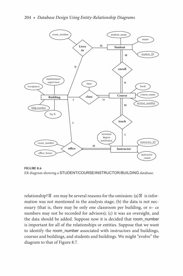
204 • Database Design Using Entity-Relationship Diagrams
relationship?.There.may.be.several.reasons.for.the.omission:.(a).This.infor-mation.was.not.mentioned.in.the.analysis.stage;.(b).the.data.is.not.nec-essary. (that. is,. there. may. be. only. one. classroom. per. building,. or. office.numbers.may.not.be.recorded.for.advisors);. (c). it.was.an.oversight,.and.the.data.should.be.added..Suppose.now.it. is.decided.that. room_number.is.important.for.all.of.the.relationships.or.entities..Suppose.that.we.want.to. identify. the. room_number. associated.with. instructors.and.buildings,.courses.and.buildings,.and.students.and.buildings..We.might.“evolve”.the.diagram.to.that.of.Figure 8.7.
M
M
N
N
1 M
M
1
1
M
teach
Course
Instructor
enroll
Student
major
instructor_ID
room_number
maintenancesupervisor
terminaldegree
institution
student_name
book
course_name
section_number
instructor_name
office
Livesin
classBuilding
bldg number
Sq. ft.
occupancytime
room_number
office_hours
student_ID
FIGURE 8.6ER.diagram.showing.a.STUDENT/COURSE/INSTRUCTOR/BUILDING.database.

Further Extensions for ER Diagrams with Binary Relationships • 205
In.Figure 8.7,.we.have.room.number.as.a.relationship.attribute..In.this.case,.we.have.also.added.information.attached.to.BUILDING:.bldg_num-ber,.occupancy,.maintenance supervisor,.and.sq. ft.
8.6 ATTRIBUTES THAT EVOLVE INTO ENTITIES
In.this.section,.we.illustrate.one.more.time.the.idea.that.we.have.to.model.“what. is”. and. not. necessarily. “what. might. be.”. Also,. we. again. see. how.an.attribute.might.become.an.entity..Suppose.in.the.design.process,.you.
M
M
N
N
1 M
M
1
1
M
teach
Course
Instructor
enroll
Student
major
instructor_ID
room_number
maintenancesupervisor
terminaldegree
institution
student_name
book
course_name
section_number
instructor_name
office
livesin
classBuilding
bldg number
room_numberSq. ft.
occupancytime
room_number
office_hours
student_ID
FIGURE 8.7ER. diagram. showing. a. STUDENT/COURSE/INSTRUCTOR/BUILDING. database.with.room_number.added.to.the.relationships.where.needed.
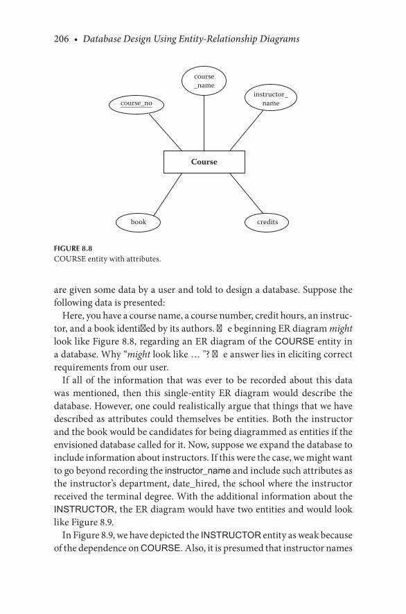
206 • Database Design Using Entity-Relationship Diagrams
are.given.some.data.by.a.user.and.told.to.design.a.database..Suppose.the.following.data.is.presented:
Here,.you.have.a.course.name,.a.course.number,.credit.hours,.an.instruc-tor,.and.a.book.identified.by.its.authors..The.beginning.ER.diagram.might.look.like.Figure 8.8,.regarding.an.ER.diagram.of.the.COURSE.entity.in.a.database..Why.“might.look.like.…."?.The.answer.lies.in.eliciting.correct.requirements.from.our.user.
If. all. of. the. information. that.was. ever. to.be. recorded.about. this.data.was. mentioned,. then. this. single-entity. ER. diagram. would. describe. the.database..However,.one.could.realistically.argue.that.things.that.we.have.described.as.attributes.could.themselves.be.entities..Both.the. instructor.and.the.book.would.be.candidates.for.being.diagrammed.as.entities.if.the.envisioned.database.called.for.it..Now,.suppose.we.expand.the.database.to.include.information.about.instructors..If.this.were.the.case,.we.might.want.to.go.beyond.recording.the.instructor_name.and.include.such.attributes.as.the.instructor’s.department,.date_hired,.the.school.where.the.instructor.received.the.terminal.degree..With.the.additional.information.about.the.INSTRUCTOR,.the.ER.diagram.would.have.two.entities.and.would.look.like.Figure 8.9.
In.Figure 8.9,.we.have.depicted.the.INSTRUCTOR.entity.as.weak.because.of.the.dependence.on.COURSE. Also,.it.is presumed.that.instructor.names.
Course
course_name
instructor_name
book credits
course_no
FIGURE 8.8COURSE.entity.with.attributes.
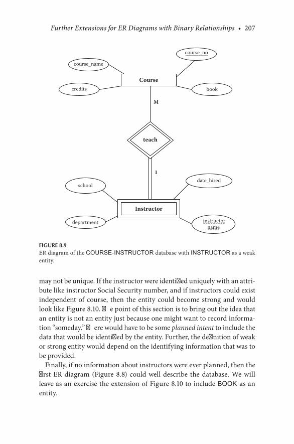
Further Extensions for ER Diagrams with Binary Relationships • 207
may.not.be.unique..If.the.instructor.were.identified.uniquely.with.an.attri-bute.like.instructor.Social.Security.number,.and.if.instructors.could.exist.independent.of. course,. then. the.entity. could.become.strong.and.would.look.like.Figure 8.10..The.point.of.this.section.is.to.bring.out.the.idea.that.an.entity.is.not.an.entity.just.because.one.might.want.to.record.informa-tion.“someday.”.There.would.have.to.be.some.planned intent.to.include.the.data.that.would.be.identified.by.the.entity..Further,.the.definition.of.weak.or.strong.entity.would.depend.on.the.identifying.information.that.was.to.be.provided.
Finally,.if.no.information.about.instructors.were.ever.planned,.then.the.first.ER.diagram.(Figure 8.8). could.well.describe. the.database..We.will.leave.as.an.exercise.the.extension.of.Figure 8.10.to.include.BOOK as.an.entity.
M
1
Course
course_no
course_name
Instructor
date_hired
instructorname
school
teach
credits book
department
FIGURE 8.9ER.diagram.of.the.COURSE-INSTRUCTOR.database.with.INSTRUCTOR.as.a.weak.entity.
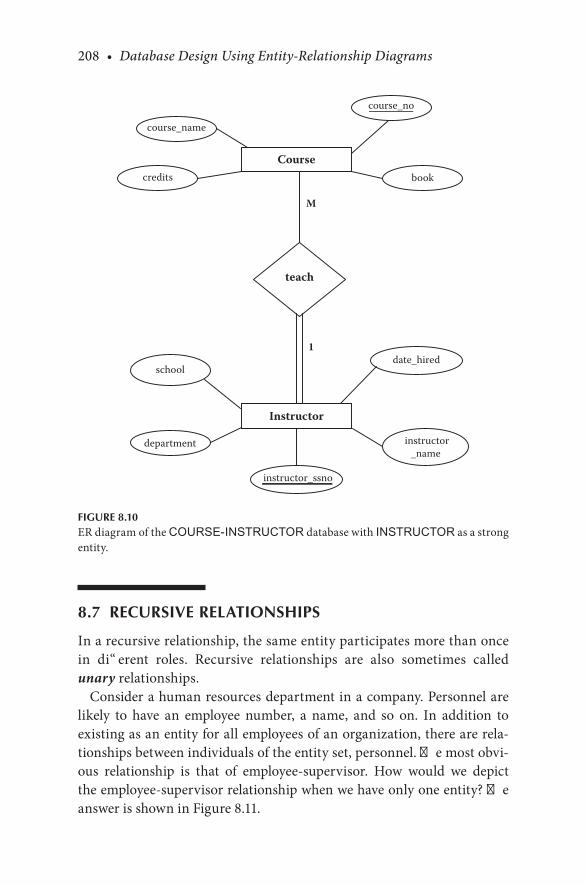
208 • Database Design Using Entity-Relationship Diagrams
8.7 RECURSIVE RELATIONSHIPS
In.a.recursive.relationship,.the.same.entity.participates.more.than.once.in. different. roles.. Recursive. relationships. are. also. sometimes. called.unary.relationships.
Consider.a.human.resources.department.in.a.company..Personnel.are.likely. to. have. an. employee. number,. a. name,. and. so. on.. In. addition. to.existing.as.an.entity.for.all.employees.of.an.organization,.there.are.rela-tionships.between.individuals.of.the.entity.set,.personnel..The.most.obvi-ous. relationship. is. that. of. employee-supervisor.. How. would. we. depict.the.employee-supervisor.relationship.when.we.have.only.one.entity?.The.answer.is.shown.in.Figure 8.11.
M
1
Course
course_no
course_name
Instructor
date_hired
instructor_ssno
instructor_name
school
teach
credits book
department
FIGURE 8.10ER.diagram.of.the.COURSE-INSTRUCTOR.database.with.INSTRUCTOR.as.a.strong.entity.
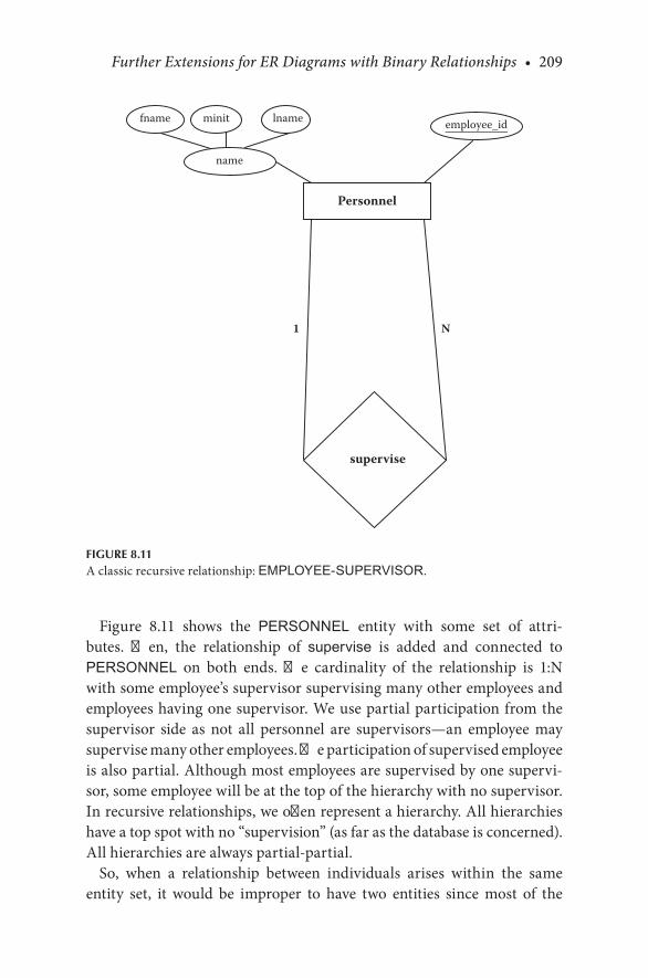
Further Extensions for ER Diagrams with Binary Relationships • 209
Figure 8.11. shows. the. PERSONNEL entity. with. some. set. of. attri-butes.. Then,. the. relationship. of. supervise. is. added. and. connected. to.PERSONNEL. on. both. ends.. The. cardinality. of. the. relationship. is. 1:N.with.some.employee’s.supervisor.supervising.many.other.employees.and.employees.having.one.supervisor..We.use.partial.participation.from.the.supervisor. side. as. not. all. personnel. are. supervisors—an. employee. may.supervise.many.other.employees..The.participation.of.supervised.employee.is.also.partial..Although.most.employees.are.supervised.by.one.supervi-sor,.some.employee.will.be.at.the.top.of.the.hierarchy.with.no.supervisor..In.recursive.relationships,.we.often.represent.a.hierarchy..All.hierarchies.have.a.top.spot.with.no.“supervision”.(as.far.as.the.database.is.concerned)..All.hierarchies.are.always.partial-partial.
So,. when. a. relationship. between. individuals. arises. within. the. same.entity. set,. it. would. be. improper. to. have. two. entities. since. most. of. the.
1 N
Personnel
employee_id
name
fname lnameminit
supervise
FIGURE 8.11A.classic.recursive.relationship:.EMPLOYEE-SUPERVISOR.
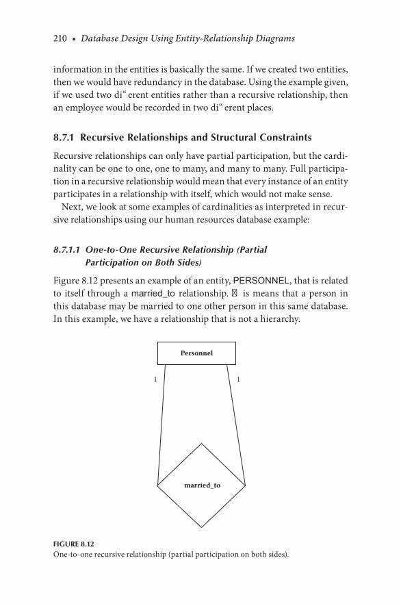
210 • Database Design Using Entity-Relationship Diagrams
information.in.the.entities.is.basically.the.same..If.we.created.two.entities,.then.we.would.have.redundancy.in.the.database..Using.the.example.given,.if.we.used.two.different.entities.rather.than.a.recursive.relationship,.then.an.employee.would.be.recorded.in.two.different.places.
8.7.1 Recursive Relationships and Structural Constraints
Recursive.relationships.can.only.have.partial.participation,.but.the.cardi-nality.can.be.one.to.one,.one.to.many,.and.many.to.many..Full.participa-tion.in.a.recursive.relationship.would.mean.that.every.instance.of.an.entity.participates.in.a.relationship.with.itself,.which.would.not.make.sense.
Next,.we.look.at.some.examples.of.cardinalities.as.interpreted.in.recur-sive.relationships.using.our.human.resources.database.example:
8.7.1.1 One-to-One Recursive Relationship (Partial Participation on Both Sides)
Figure 8.12.presents.an.example.of.an.entity,.PERSONNEL,.that.is.related.to. itself. through.a.married_to relationship..This.means. that.a.person. in.this.database.may.be.married.to one.other.person.in.this.same.database..In.this.example,.we.have.a.relationship.that.is.not.a.hierarchy.
11
Personnel
married_to
FIGURE 8.12One-to-one.recursive.relationship.(partial.participation.on.both.sides).
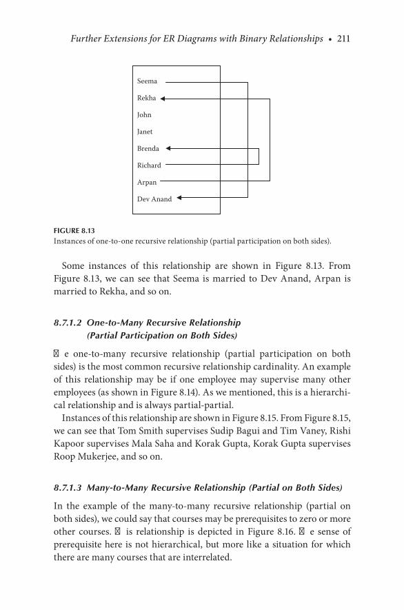
Further Extensions for ER Diagrams with Binary Relationships • 211
Some. instances. of. this. relationship. are. shown. in. Figure 8.13.. From.Figure 8.13,.we.can. see. that.Seema. is.married. to.Dev.Anand,.Arpan. is.married.to.Rekha,.and.so.on.
8.7.1.2 One-to-Many Recursive Relationship (Partial Participation on Both Sides)
The. one-to-many. recursive. relationship. (partial. participation. on. both.sides).is.the.most.common.recursive.relationship.cardinality..An.example.of. this. relationship. may. be. if. one. employee. may. supervise. many. other.employees.(as.shown.in.Figure 8.14)..As.we.mentioned,.this.is.a.hierarchi-cal.relationship.and.is.always.partial-partial.
Instances.of.this.relationship.are.shown.in.Figure 8.15..From.Figure 8.15,.we.can.see.that.Tom.Smith.supervises.Sudip.Bagui.and.Tim.Vaney,.Rishi.Kapoor.supervises.Mala.Saha.and.Korak.Gupta,.Korak.Gupta.supervises.Roop.Mukerjee,.and.so.on.
8.7.1.3 Many-to-Many Recursive Relationship (Partial on Both Sides)
In. the. example. of. the. many-to-many. recursive. relationship. (partial. on.both.sides),.we.could.say.that.courses.may.be.prerequisites.to.zero.or.more.other. courses.. This. relationship. is. depicted. in. Figure 8.16.. The. sense. of.prerequisite.here. is.not.hierarchical,.but.more. like.a.situation.for.which.there.are.many.courses.that.are.interrelated.
Seema
Rekha
John
Janet
Brenda
Richard
Arpan
Dev Anand
FIGURE 8.13Instances.of.one-to-one.recursive.relationship.(partial.participation.on.both.sides).
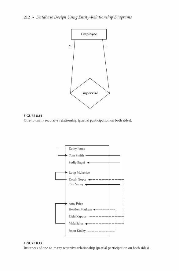
212 • Database Design Using Entity-Relationship Diagrams
1M
Employee
supervise
FIGURE 8.14One-to-many.recursive.relationship.(partial.participation.on.both.sides).
Kathy Jones
Tom Smith
Sudip Bagui
Roop Mukerjee
Korak GuptaTim Vaney
Amy Price
Heather Markam
Rishi Kapoor
Mala Saha
Jason Kinley
FIGURE 8.15Instances.of.one-to-many.recursive.relationship.(partial.participation.on.both.sides).

Further Extensions for ER Diagrams with Binary Relationships • 213
8.8 MULTIPLE RELATIONSHIPS
So.far,.we.have.mostly.discussed.two.entities.with.one.relationship..This.sec-tion.discusses.how.two.entities.can.have.more.than.one.binary.relationship.
Consider.a.diagram. that.has. two.entities:.STUDENT. and.FACULTY..Suppose. we. have. no. other. entities. in. the. database.. Suppose. further.that. the.STUDENT.entity.has. the. following.attributes:.name, student_no, birthdate,. and.high_school. from.which. the. student.graduated..The.FACULTY.entity.could.have.the.following.attributes:.name, ssno (Social.Security. number), department, office_number.. In. developing. the. dia-gram,. we. find. two. distinct. verbs. to. describe. the. connection. between.STUDENT.and.FACULTY..STUDENTs.are. instructed by.FACULTY,.and.FACULTY.advise.STUDENTs.. There. are. two. distinct. relationships. that.we.need.to.add.to.our.diagram:. instruct.and.advise..Each.distinct.rela-tionship.is.given.its.own.“diamond.”.The.ER.diagram.for.this.is.shown.in.Figure 8.17a.
In.this.diagram,.all.relationships.are.arbitrarily.shown.as.partial;.that.is,.there.will.be.some.faculty.who.do.not.advise.students,.and.some.students.who.are.not.instructed.by.faculty..In.constructing.ER.diagrams,.one.has.to.include.however.many.distinct.relationships.exist..It.would.be.incorrect.
MN
Course
pre-requisite
FIGURE 8.16Many-to-many.recursive.relationship.(partial.participation.on.both.sides).

214 • Database Design Using Entity-Relationship Diagrams
to.try.to.make.a.relationship.do.“double.duty”.and.stand.for.two.different.relationship.ideas.
In.this.example,.an.embellishment.might.include.intersection.data.for.the. instruct relationship. (a.grade. in.a.course,. for.example).. Intersection.data. for. the. advise relationship. could. be date_assigned, last_meeting,.and.so.on,.as.shown.in.Figure 8.17b.
The. placing. of. relationships. in. the. ER. diagram. is. covered. in. our. ER.design.methodology.in.step.5,.which.we.redefine.here:
N N
M 1
Faculty
Student
student no
name
ssnoname
instruct
fname lnameminit
department
advise
birthdatehigh_school
office_number
minitlnamefname
(a)
FIGURE 8.17(a).ER.diagram.with.two.entities.and.two.relationships..
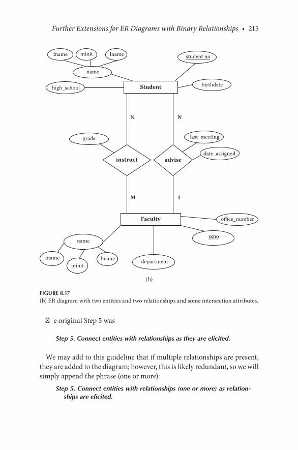
Further Extensions for ER Diagrams with Binary Relationships • 215
The.original.Step.5.was
Step 5. Connect entities with relationships as they are elicited.
We.may.add.to.this.guideline.that.if.multiple.relationships.are.present,.they.are.added.to.the.diagram;.however,.this.is.likely.redundant,.so.we.will.simply.append.the.phrase.(one.or.more):
Step 5. Connect entities with relationships (one or more) as relation-ships are elicited.
N N
M 1
Faculty
Student
student no
name
ssnoname
instruct
fname lnameminit
department
advise
birthdatehigh_school
grade
date_assigned
last_meeting
office_number
minitlnamefname
(b)
FIGURE 8.17(b).ER.diagram.with.two.entities.and.two.relationships.and.some.intersection.attributes.
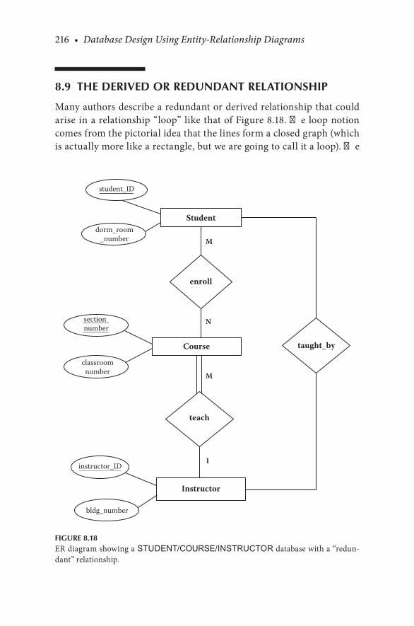
216 • Database Design Using Entity-Relationship Diagrams
8.9 THE DERIVED OR REDUNDANT RELATIONSHIP
Many.authors.describe.a.redundant.or.derived.relationship.that.could.arise.in.a.relationship.“loop”.like.that.of.Figure 8.18..The.loop.notion.comes.from.the.pictorial.idea.that.the.lines.form.a.closed.graph.(which.is.actually.more.like.a.rectangle,.but.we.are.going.to.call.it.a.loop)..The.
M
N
M
1
teach
taught_byCourse
classroomnumber
Instructor
enroll
Student
student_ID
instructor_ID
sectionnumber
dorm_room_number
bldg_number
FIGURE 8.18ER.diagram.showing.a.STUDENT/COURSE/INSTRUCTOR.database.with.a.“redun-dant”.relationship.

Further Extensions for ER Diagrams with Binary Relationships • 217
idea.of.redundancy.is.that.since.students.take.courses.and.each.course.is. taught. by. an. instructor,. you. do. not. need. a. taught_by. relationship.because. you. can. get. that. information. without. the. extra. relationship..If. such. a. relationship. exists,. then. it. should. be. excised,. but. there. are.caveats.
First,.one.has.to.be.sure.that.the.redundant.relationship.is.truly.redun-dant..If.the.added.relation.were.advised_by.instead.of.taught_by,.then.the.relationship.should.stay.because.it.has.a.completely.different.sense.than.taught_by.
Second,.if.the.relationship.loop.is.present.it.may.mean.that.only.one.of. the.two.redundant.relationships.should.be.kept,.and.the.semantics.should.point. to.which.one.. In.Figure 8.18,. the. INSTRUCTOR. is.more.likely.related.to.a.COURSE.than.to.a.STUDENT..So,.the.better.choice.of. which. relationship. to. keep. would. be. the. original. one,. teach.. It. is.conceivable.that.a.designer.might.have.included.the.taught_by.relation-ship.first,.only. later.to. include.the. teach. relationship..Then,.by.exam-ining.the.diagram.for.loops,.one.could.deduce.that.the. taught_by.was.redundant.
Third,.one.or.both.of.the.relationships.may.have.an.intersection.attri-bute. that.would.suggest.which.relationship.(or.both).should.be.kept.. In.Figure 8.19,.we.included.the.time.attribute,.which.was.put.with.the.teach.relationship.as.an.instructor.teaches.a.course.at.a.particular.time.
The.idea.of.derived.or.redundant.relationships.causes.us.to.suggest.one.more.step.in.our.methodology:
Step 6b. Examine the diagram for loops that might indicate redundant relationships. If a relationship is truly redundant, excise the redun-dant relationship.
CHECKPOINT 8.2. 1.. What.is.a.recursive.relationship?. 2.. What.would.you.look.for.if.you.are.trying.to.see.if.a.relationship.is.
recursive?. 3.. What. kinds. of. structural. constraints. can. recursive. relationships.
have?. 4.. Can.recursive.relationships.have.full.participation?.Why.or.why.not?. 5.. How.is.the.recursive.relationship.denoted.diagrammatically.in.the.
Chen-like.ER.model?. 6.. Can.the.same.two.entities.have.more.than.one.relationship?. 7.. How.would.you.determine.if.a.relationship.is.redundant?
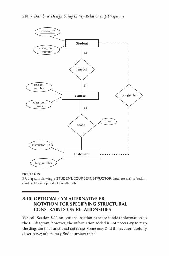
218 • Database Design Using Entity-Relationship Diagrams
8.10 OPTIONAL: AN ALTERNATIVE ER NOTATION FOR SPECIFYING STRUCTURAL CONSTRAINTS ON RELATIONSHIPS
We.call.Section.8.10.an.optional. section.because. it.adds. information. to.the.ER.diagram;.however,.the.information.added.is.not.necessary.to.map.the.diagram.to.a.functional.database..Some.may.find.this.section.usefully.descriptive;.others.may.find.it.unwarranted.
M
N
M
1
teach
taught_byCourse
classroomnumber
Instructor
enroll
Student
student_ID
instructor_ID
sectionnumber
dorm_room_number
bldg_number
time
FIGURE 8.19ER.diagram.showing.a.STUDENT/COURSE/INSTRUCTOR.database.with.a.“redun-dant”.relationship.and.a.time.attribute.

Further Extensions for ER Diagrams with Binary Relationships • 219
So. far,. we. have. discussed. cardinality. ratios. in. terms. of. their. upper.bounds.(the.maximum.cardinality),.shown.by.the.M.or.N.in.the.ER.dia-grams.(shown.in.this.and.previous.chapters)..You.will.recall.(from.Chapter.6).that.cardinality.is.a.rough.measure.of.the.number.of.entity.instances.in.one.entity.set.that.can.be.related.to.instances.in.another.entity.set.
In. this. section,. we. describe. an. alternative. ER. notation. for. specifying.structural.constraints.on.relationships..This.notation.will.associate.a.pair.of.numbers.(min, max).with.each.structural.constraint.of.a.relationship..This.min.and.max.may.provide.more.information.about.the.entities.and.how.they.are.related.
The.min.is.the.minimum.number.of.instances.in.one.entity.set.that.can.be.related.to.an.instance.of.another.entity..The.min.can.be.between.zero.and. the. maximum.. If. the. min. is. zero,. it. implies. that. every. instance. of.an.entity.does.not.have.to.participate.in.the.relationship..If.min.is.zero.it.implies.partial.participation..If.the.min.is.greater.than.zero,.it.implies.full.participation..We.now.present.an.ER.diagram.with.(min, max).ratios.
First,.let.us.start.with.the.recursive.relationship.shown.in.Figure 8.20.The.(min, max).of.(0,.1).means.that.each.person. in.the.PERSONNEL.
entity.may.or.may.not.be.married.(shown.by.the.zero.for.the.min).and.can.only.be.married.to.at.most.one.other.person.(shown.by.the.max).
(0, 1) (0, 1)
Personnel
married_to
FIGURE 8.20Recursive.relationship.with.(min, max).ratios.

220 • Database Design Using Entity-Relationship Diagrams
Next,. look.at.Figure 8.21..From.this.figure,.we.can.say.that.a.student.may.not.be.advised.by.any.faculty.member.and.may.be.advised.by.up.to.two.faculty.members.(shown.by.the.minimum.of.zero.and.maximum.of.two)..A. faculty.member.may.advise.between.0.and.30. students..A. fac-ulty. member. may. instruct. between. 0. and. 40. students.. And,. a. student.must.be.instructed.by.one.faculty.member.and.can.be.instructed.by.up.to.two.faculty.members.in.this.database..With.the.min/max.notation,.it.is.optional.(albeit.redundant).to.keep.the.single-/double-line.participation.constraint..Since.the.single-/double-line.notation.is.so.common,.we.sug-gest.keeping.it.
(1, 2) (0, 2)
(0, 40) (0, 30)
Faculty
Student
student_no
name
ssnoname
instruct
fname lnameminit
department
advise
birthdatehigh_school
office_number
minitlnamefname
FIGURE 8.21ER.diagram.showing.an.alternative.ER.notation.for.specifying.structural.constraints.
Further Extensions for ER Diagrams with Binary Relationships • 221
CHECKPOINT 8.3 (OPTIONAL). 1.. What.lower.bound.of.cardinality.does.full.participation.imply?. 2.. What.does.a.min/max.ratio.of.(1,.1).between.two.entities.imply?. 3.. What.kind.of.participation.ratio.(full.participation.or.partial.partici-
pation).does.a.min/max.ratio.of.(0,.1).imply?
8.11 REVIEW OF THE METHODOLOGY
To.review,.our.methodology.for.designing.ER.diagrams.has.now.evolved.to:
8.11.1 ER Design Methodology
Step 1. Select one primary entity from the database requirements description and show attributes to be recorded for that entity. Label keys if appropriate and show some sample data.
Step 2. Use structured English for entities, attributes, and keys to describe the database that has been elicited.
Step 3. Examine attributes in the existing (primary) entities (possibly with user assistance) to find out if information about one of the entities is to be recorded.
(We. change. “primary”. to. “existing”. because. we. redo. step. 3. as. we. add.new.entities.)
Step 3a. If information about an attribute is needed, then make the attribute an entity, and then
Step 3b. Define the relationship back to the original entity.Step 4. If another entity is appropriate, draw the second entity with
its attributes. Repeat steps 2 and 3 to see if this entity should be further split into more entities.
Step 5. Connect entities with relationships (one or more) if relation-ships exist.
Step 6. State the exact nature of the relationships in structured English from all sides, for example, if a relationship is A:B::1:M, then there is a relationship from A(1) to B(M) and from B(M) back to A(1).
Step 6a. Examine the list of attributes and determine whether any of them need to be identified by two (or more) entities. If so, place the attribute on an appropriate relationship that joins the two entities.
222 • Database Design Using Entity-Relationship Diagrams
Step 6b. Examine the diagram for loops that might indicate redundant relationships. If a relationship is truly redundant, excise the redun-dant relationship.
Step 7. Show some sample data.Step 8. Present the “as designed” database to the user complete with
the English for entities, attributes, keys, and relationships. Refine the diagram as necessary.
The.grammar.to.describe.our.entities,.attributes,.and.keys.has.evolved.as.discussed.next.
8.11.2 The Entity
This.database.records.data.about.ENTITY. For.each ENTITY in.the.data-base,.we.record att(1), att(2), att(3), … att(n).
8.11.2.1 The Attributes
For.atomic.attributes,.att(j):For.each.ENTITY, there.will.be.one.and.only.one att(j)..The.value.for
att(j) will.not.be.subdivided.For.composite.attributes,.att(j):
For.each.ENTITY,.we.will.record att(j), which.is.composed.of x, y, z, … . (x, y, z) are.the component.parts.of att(j).
For.multivalued.attributes,.att(j):For.each.ENTITY, we.will. record att(j)’s. There.may.be.more. than.
one att(j) recorded.for.each.ENTITY.For.attributes.of.relationships,.att(j):For.the.relationship.between ENTITY1 and ENTITY2, we.will.record.a(n)
att(j). The att(j) depends.on.both.entities.ENTITY1 and ENTITY2 for.identification.
8.11.2.2 The Keys
For.the.key(s):. (a). More.than.one.candidate.key.(strong.entity):
For. each. ENTITY, we. will. have. the. following. candidate. keys: att(j), att(k), ….(where.j,.k.are.candidate.key.attributes).
. (b). One.candidate.key.(strong.entity):For.each ENTITY, we.will.have.the.following.primary.key: att(j)
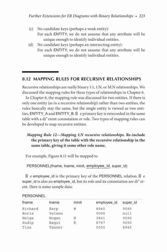
Further Extensions for ER Diagrams with Binary Relationships • 223
. (c). No.candidate.keys.(perhaps.a.weak.entity):For. each ENTITY, we. do. not. assume. that. any. attribute. will. be.
unique.enough.to.identify individual.entities.. (d). No.candidate.keys.(perhaps.an.intersecting.entity):
For. each ENTITY, we. do. not. assume. that. any. attribute. will. be.unique.enough.to.identify individual.entities.
8.12 MAPPING RULES FOR RECURSIVE RELATIONSHIPS
Recursive.relationships.are.really.binary.1:1,.1:N,.or.M:N.relationships..We.discussed.the.mapping.rules.for.these.types.of.relationships.in.Chapter.6.
In.Chapter.6,.the.mapping.rule.was.discussed.for.two.entities..If.there.is.only.one.entity.(as.in.a.recursive.relationship).rather.than.two.entities,.the.rules.basically.stay.the.same,.but.the.single.entity.is.viewed.as.two.enti-ties,.ENTITY_A.and.ENTITY_B..The.primary.key.is.rerecorded.in.the.same.table.with.a.different.connotation.or.role..Two.types.of.mapping.rules.can.be.developed.to.map.recursive.entities.
Mapping Rule 12—Mapping 1:N recursive relationships. Re-include the primary key of the table with the recursive relationship in the same table, giving it some other role name.
For.example,.Figure 8.11.will.be.mapped.to
PERSONNEL(fname, lname, minit, employee_id, super_id)
The.employee_id.is.the.primary.key.of.the.PERSONNEL.relation..The.super_id.is.also.an.employee_id,.but.its.role.and.its.connotation.are.differ-ent..Here.is.some.sample.data:
PERSONNELfname lname minit employee_id super_idRichard Earp W 8945 9090Boris Yelsen 9090 nullHelga Hogan H 3841 9090Sudip Bagui K 8767 9090Tina Tanner 5050 8945

224 • Database Design Using Entity-Relationship Diagrams
Mapping Rule 13—Mapping M:N recursive relationships. Create a separate table for the relationship (as in mapping rule 5).
As.an.example,.assume.that.Figure 8.11.was.an.M:N.relationship..Then.Figure 8.11.would.map. to. the.above.relation.(PERSONNEL).and.a.new.linking.relationship-entity:
PERSONNEL_SUPERVISOR(employee_id, super_id)
And.with.some.sample.data:
PERSONNEL_SUPERVISORemployee_id super_id8945 90909090 null3841 90908767 90905050 8945
CHECKPOINT 8.4. 1.. Map. the. recursive. relationship. shown. in.Figure 8.14. to.a. relational.
database.and.show.some.sample.data.. 2.. If. Figure 8.14. was. an. M:N. relationship,. how. would. you. map. this.
recursive. relationship. to. a. relational. database?. Show. the. mapping.with.some.sample.data.
8.13 CHAPTER SUMMARY
This.chapter.looked.at.different.aspects.of.binary.relationships.in.ER.dia-grams.and.refined.several.steps.in.the.ER.design.methodology..The.refining.of.the.ER.design.methodology.means.a.continuous.assessment.and.reas-sessment.of.the.ER.diagram.that.is.drawn.after.discussion.with.the.users..The. idea. that. relationships. could. have. attributes,. how. attributes. evolve.into.entities,.recursive.relationships,.and.derived.and.redundant.relation-ships.was.discussed.with.examples.and.diagrams..The.ER.design.meth-odology.steps.were.refined.to.include.all.of.this.information.into.the.new.and.evolving.methodology..Toward.the.end.of.the.chapter,.an.alternative.

Further Extensions for ER Diagrams with Binary Relationships • 225
ER.notation.for.specifying.structural.constraints.on.relationships.was.pre-sented..On.completing.this.chapter,.the.reader.or.database.creator.should.be.able.to.efficiently.design.a.database.with.binary.relationships..The.next.chapter.deals.with.ternary.and.other.higher-order.relationships.
CHAPTER 8 EXERCISES
In.each.of.the.exercises.that.follow,.the.admonition.to.“construct.an.ER.diagram”.implies.not.only.the.diagram.but.also.the.structured.grammati-cal.description.of.the.diagram.
Exercise 8.1
Define. and. state. in. precise. terms. the. cardinality. and. participation. in.Figure 8.6,. the. student/course/instructor/building.database..Discuss. the.structural.constraints.of.Figure 8.6..What.are.the.participations,.what.are.the.cardinalities,.and.under.which.circumstances.would.the.ones.depicted.be.correct.or.incorrect?
Exercise 8.2
Consider.the.following.data.and.construct.an.ER.diagram;.use.structured.grammar.to.rationalize.your.constraints..The.following.are.the.data:.horse.name,.race,.owner,.odds.at.post,.post.position,.date.of.race,.order.of.finish,.year.to.date.earnings,.owner.name.and.address.
Exercise 8.3
In.the.chapter,.we.described.a.database.that.had.two.entities,.COURSE.and.INSTRUCTOR.(refer.to.Figure 8.10)..Book.was.left.as.an.attribute.of.COURSE..Extend.the.database.to.include.BOOK.as.an.entity..Attributes.of.BOOK.might.include.book title, author, price, edition, publisher.
Exercise 8.4
Refer.to.Figure 8.7..Change.Figure 8.7.to.include.the.following.informa-tion:. One. building. can. have. a. maximum. of. 99. students. living. in. it.. A.student.has.to.enroll.in.at.least.one.class.and.can.enroll.in.a.maximum.of.
226 • Database Design Using Entity-Relationship Diagrams
five.classes..A.class.has.to.enroll.at.least.5.students.and.can.enroll.a.maxi-mum.of.35.students..An.instructor.may.or.may.not.teach.a.class.and.can.teach.up.to.three.classes..A.course.has.to.have.one.instructor.teaching.it,.and.only.one.instructor.can.teach.a.particular.course..An.instructor.may.or.may.not.have.an.office.and.can.have.up.to.two.offices..A.building.may.or.may.not.have.an.office.and.can.have.up.to.15.offices..A.course.has.to.be.offered.in.one.classroom.and.can.only.be.offered.in.one.classroom.
BIBLIOGRAPHY
Earp,.R.,.and.Bagui,.S..2000..Binary.relationships.in.entity.relationships.in.entity.relation-ship.(ER).diagrams..Data Base Management Journal, 22:10–43.
Elmasri,. R.,. and. Navathe,. S.. B.. 2007.. Fundamentals of Database Systems.. Reading,. MA:.Addison-Wesley.
Sanders,.L..1995..Data Modeling..Danvers,.MA:.Boyd.&.Fraser.Teorey,.T..J.,.Nadeau,.T.,.and.Lightstone,.S..S..2005..Database Modeling and Design: Logical
Design..Morgan.Kaufman,.San.Francisco,.CA.
CASE STUDY
West Florida Mall (continued)
So.far.in.our.case.study,.we.have.developed.the.major.entities.and.relation-ships.and.mapped.these.to.a.relational.database.(with.some.sample.data)..Then,.on.reviewing.step.7,.which.says
Step 7. Present the “as designed” database to the user complete with the English for entities, attributes, keys, and relationships. Refine the diagram as necessary.
Suppose.we.got.some.additional.input.from.the.user:
An. employee. can. also. be. a. department. manager,. and. a. department.manager. can. manage. at. most. one. department.. We. have. to. store.information.on.the.department.manager:.the.name,.Social.Security.number,.which.store.he.or.she.is.working.for,.which.department.he.or.she.is.working.for..A.department.manager.supervises.at.least.one.employee.and.may.manage.several.employees.

Further Extensions for ER Diagrams with Binary Relationships • 227
On.reviewing.these.additional.specifications,.we.can.see.that.we.have.a.recursive.relationship.developing.since.an.employee.can.be.a.department.manager.supervising.other.employees.
So,. using. mapping. rule. 12,. we. will. reinclude. the. primary. key. of. the.EMPLOYEE.entity.in.itself,.giving.us.the.following.EMPLOYEE.relation:
EMPLOYEE(ename, essn, dnum, snum, dm_ssn)
And,.with.some.sample.data:
EMPLOYEEename essn dnum snum dm_ssnKaitlyn 987-754-9865 501 1 276-263-9182Fred 276-263-9182 502 1 nullKatie 982-928-2726 503 1 987-754-9865Seema 837-937-9373 501 1 276-263-9182...
This.recursive.relationship.is.also.shown.in.Figure 8.22.So,.in.summary.our.relational.database.has.now.developed.to.(without.
the.data)
MALLname address
STOREsloc sname snum mall_name so_ssn sm_ssn
OWNERso_ssn so_name so_off_phone so_address
STORE MANAGERsm_ssn sm_name salary

228 • Database Design Using Entity-Relationship Diagrams
DEPARTMENTdname dnum snum
EMPLOYEEename essn snum dm_ssn dnum
We.continue.the.development.of.this.case.study.at.the.end.of.the.next.chapter.
1
N
N
N
N
1
1
1
1
N
Store
dept_of
owns
located_in
Department
Mall
Owner
Store Manager
Employee
manages
works_for
N 1
manages
FIGURE 8.22ER.diagram.of.West.Florida.Mall.developed.so.far.
229
9Ternary and Higher-Order ER Diagrams
9.1 INTRODUCTION
All.relationships.that.we.have.dealt.with.so.far.in.previous.chapters.have.been.binary.relationships..Although.binary.relationships.seem.natural.to.most.of.us,.in.reality.it.is.sometimes.necessary.to.connect.three.or.more.entities..If.a.relationship.connects.three.entities,. it. is.called.a.ternary.or.3-ary. relationship.. If. a. relationship. connects. more. than. three. entities.(n.entities),.it.is.called.an.n-ary.relationship,.where.n.equals.the.number.of.entities.that.participate.in.the.relationship..The.n-ary.relationships.(n.≥.3).are.also.referred.to.as.higher-order.relationships.
In. this. chapter,. we. consider. relationships. that. connect. three. or. more.entities.. First. we. look. at. ternary. (3-ary). relationships.. Ternary. relation-ships.arise. for. three.main. reasons:. (a). if.we.have. intersection.attributes.that.require.three.different.entities.to.identify.the.attribute;.(b).if.we.have.a.relationship.of.a.relationship;.and.(c).by.reverse.engineering..Since.we.dis-cuss.reverse.engineering.in.Chapter.11,.we.do.not.discuss.the.development.of.ternary.relationships.from.reverse.engineering.in.this.chapter.
In.this.chapter,.we.first.discuss.how.intersection.attributes.create.ternary.relationships,.and.then.we.look.at.structural.constraints..Next,.we.discuss.how. ternary. and. other. n-ary. relationships. do. not. preclude. binary. rela-tionships.with.the.same.entities.and.how.some.ternary.diagrams.may.be.resolved. into.binary.relationships..The.development.of. ternary.relation-ships.from.relationships.of.relationships.is.also.introduced..Step.6.of.the.entity.relationship.(ER).design.methodology.is.redefined.in.this.chapter.to.include.ternary.and.other.higher-order.relationships.

230 • Database Design Using Entity-Relationship Diagrams
9.2 BINARY OR TERNARY RELATIONSHIP?
Ternary.relationships.are.required.when.binary.relationships.are.not.suf-ficient.to.accurately.describe.the.semantics.of.an.association.among.three.entities..In.this.section,.we.explain.the.difference.between.a.binary.and.a.ternary.relationship.with.the.help.of.an.example.and.show.how.an.inter-section.attribute.necessitates.a.ternary.relationship.
Where. binary. relationships. exist. between. entities,. these. relationships.have. structural. constraints. (cardinality. and. participation).. Further,. we.found.that.attributes.of.relationships.were.also.possible..In.particular,.we.found.that.the.M:N.relationship.often.spawned.an.attribute.that.we.called.an.intersection.attribute.(recall.the.STUDENT/CLASS.M:N.relationship.and.the.intersection.attribute.grade.as.shown.in.Figure 8.1)..In.the.binary.relationship.case,.we.made.the.point.that.an.attribute.like.grade.would.infer.that.an.M:N.binary.relationship.must.exist..Whether.one.determined.the.M:N.relationship.first.or.found.the.“orphaned”.attribute.first—the.end.result.would.be.an.M:N.relationship.with.an.intersection.attribute.
Cases. exist. in. database. design. when. a. relationship. between. more.than.two.entities.is.needed..The.usual.case.would.be.to.find.one.of.these.orphaned.attributes.that.necessitated.the.n-ary.relationship..Consider.this.example:
You. have. a. database. for. a. company. that. contains. the. entities.PRODUCT,. SUPPLIER,. and. CUSTOMER.. The. usual. relationships.might. be. PRODUCT/SUPPLIER;. the. company. buys. products. from. a.supplier—a. normal,. binary. relationship.. The. intersection. attribute. for.PRODUCT/SUPPLIER. is.wholesale_price. (as. shown. in.Figure 9.1a)..Now,.consider.the.CUSTOMER.entity.and.that.the.customer.buys.prod-ucts..If.all.customers.buy.products.irrespective.of.supplier,.then.you.have.a.simple,.binary.relationship.between.CUSTOMER.and.PRODUCT..For.the.CUSTOMER/PRODUCT. relationship,. the. intersection. attribute. is.retail_price.(as.shown.in.Figure 9.1b).
Some.sample.data.for.Figure 9.1a.would.be:
productID supplierID wholesale_priceBeans Acme Bean Co 1.49Beans Baker Bean Co 1.57Carrots Joe’s Carrots 0.89
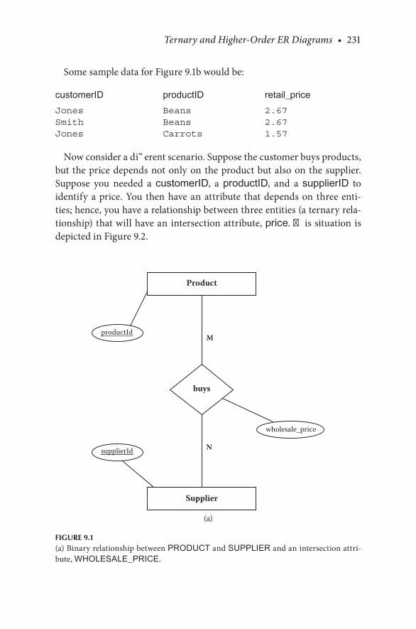
Ternary and Higher-Order ER Diagrams • 231
Some.sample.data.for.Figure 9.1b.would.be:
customerID productID retail_priceJones Beans 2.67Smith Beans 2.67Jones Carrots 1.57
Now.consider.a.different.scenario..Suppose.the.customer.buys.products,.but. the.price.depends.not.only.on.the.product.but.also.on.the.supplier..Suppose. you. needed. a. customerID,. a. productID,. and. a. supplierID. to.identify.a.price..You. then.have.an.attribute. that.depends.on. three.enti-ties;.hence,.you.have.a.relationship.between.three.entities.(a.ternary.rela-tionship).that.will.have.an.intersection.attribute,.price..This.situation.is.depicted.in.Figure 9.2.
M
N
Product
Supplier
buys
wholesale_price
productId
supplierId
(a)
FIGURE 9.1(a).Binary.relationship.between.PRODUCT.and.SUPPLIER.and.an.intersection.attri-bute,.WHOLESALE_PRICE..

232 • Database Design Using Entity-Relationship Diagrams
M
N
Product
Customer
buys
retail_price
productId
customerId
(b)
FIGURE 9.1(b).Binary.relationship.between.PRODUCT.and.CUSTOMER.and.an.intersection.attri-bute,.RETAIL_PRICE.
M1 M2
M3
Product buy Supplier
productID
price supplierID
CustomercustomerID
FIGURE 9.2ER.diagram.(with.only.primary.keys).showing.a.three-way.relationship.
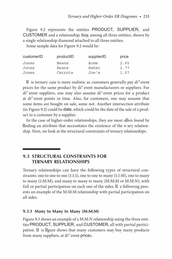
Ternary and Higher-Order ER Diagrams • 233
Figure 9.2. represents. the. entities. PRODUCT, SUPPLIER, and.CUSTOMER and.a.relationship,.buy,.among.all.three.entities,.shown.by.a.single.relationship.diamond.attached.to.all.three.entities.
Some.sample.data.for.Figure 9.2.would.be:
customerID productID supplierID priceJones Beans Acme 2.65Jones Beans Baker 2.77Jones Carrots Joe’s 1.57
This.ternary.case.is.more.realistic.as.customers.generally.pay.different.prices.for.the.same.product.by.different.manufacturers.or.suppliers..For.different. suppliers,. one. may. also. assume. different. prices. for. a. product.at. different. points. in. time.. Also,. for. customers,. one. may. assume. that.some.items.are.bought.on.sale,.some.not..Another.intersection.attribute.(in Figure 9.2).could.be.date,.which.could.be.the.date.of.the.sale.of.a.prod-uct.to.a.customer.by.a.supplier.
In.the.case.of.higher-order.relationships,.they.are.most.often.found.by.finding.an.attribute.that.necessitates.the.existence.of.the.n-ary.relation-ship..Next,.we.look.at.the.structural.constraints.of.ternary.relationships.
9.3 STRUCTURAL CONSTRAINTS FOR TERNARY RELATIONSHIPS
Ternary. relationships. can. have. the. following. types. of. structural. con-straints:.one.to.one.to.one.(1:1:1),.one.to.one.to.many.(1:1:M),.one.to.many.to.many.(1:M:M),.and.many.to.many.to.many.(M:M:M.or.M:M:N),.with.full.or.partial.participation.on.each.one.of.the.sides..The.following.pres-ents.an.example.of.the.M:M:M.relationship.with.partial.participation.on.all.sides.
9.3.1 Many to Many to Many (M:M:M)
Figure 9.3.shows.an.example.of.a.M:M:N.relationship.using.the.three.enti-ties.PRODUCT, SUPPLIER, and.CUSTOMER,.all.with.partial.partici-pation. This.figure.shows.that.many.customers.may.buy.many.products.from.many.suppliers,.at.different.prices.
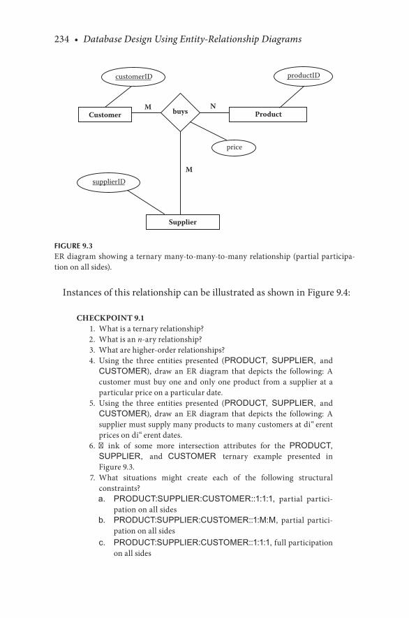
234 • Database Design Using Entity-Relationship Diagrams
Instances.of.this.relationship.can.be.illustrated.as.shown.in.Figure 9.4:
CHECKPOINT 9.1. 1.. What.is.a.ternary.relationship?. 2.. What.is.an.n-ary.relationship?. 3.. What.are.higher-order.relationships?. 4.. Using. the. three. entities. presented. (PRODUCT, SUPPLIER, and.
CUSTOMER),. draw. an. ER. diagram. that. depicts. the. following:. A.customer. must. buy. one. and. only. one. product. from. a. supplier. at. a.particular.price.on.a.particular.date.
. 5.. Using. the. three. entities. presented. (PRODUCT, SUPPLIER, and.CUSTOMER),. draw. an. ER. diagram. that. depicts. the. following:. A.supplier.must.supply.many.products.to.many.customers.at.different.prices.on.different.dates.
. 6.. Think. of. some. more. intersection. attributes. for. the. PRODUCT, SUPPLIER, and. CUSTOMER ternary. example. presented. in.Figure.9.3.
. 7.. What. situations. might. create. each. of. the. following. structural.constraints?
a. PRODUCT:SUPPLIER:CUSTOMER::1:1:1,. partial. partici-pation.on.all.sides
b. PRODUCT:SUPPLIER:CUSTOMER::1:M:M,. partial. partici-pation.on.all.sides
c. PRODUCT:SUPPLIER:CUSTOMER::1:1:1,.full.participation.on.all.sides
M N
M
Customer buys Product
productID
price
supplierID
Supplier
customerID
FIGURE 9.3ER.diagram.showing.a. ternary.many-to-many-to-many.relationship.(partial.participa-tion.on.all.sides).
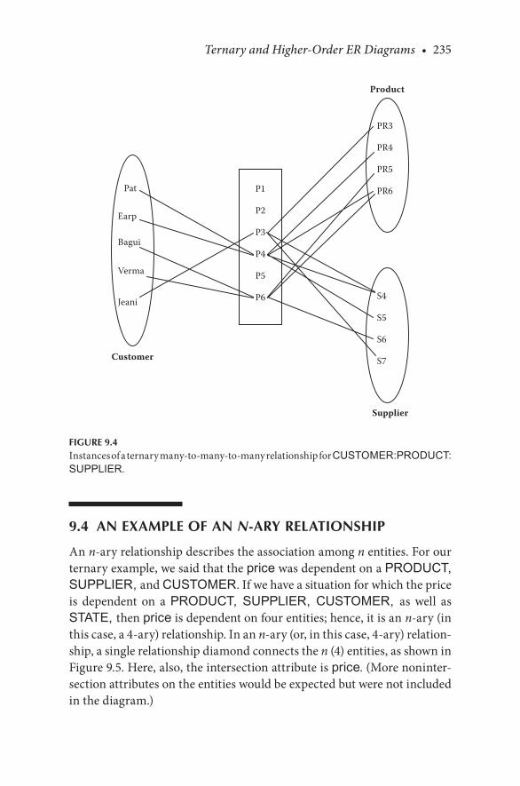
Ternary and Higher-Order ER Diagrams • 235
9.4 AN EXAMPLE OF AN N-ARY RELATIONSHIP
An.n-ary.relationship.describes.the.association.among.n.entities..For.our.ternary.example,.we.said.that.the.price.was.dependent.on.a.PRODUCT, SUPPLIER, and.CUSTOMER..If.we.have.a.situation.for.which.the.price.is. dependent. on. a. PRODUCT, SUPPLIER, CUSTOMER, as. well. as.STATE, then.price.is.dependent.on.four.entities;.hence,.it.is.an.n-ary.(in.this.case,.a.4-ary).relationship..In.an.n-ary.(or,.in.this.case,.4-ary).relation-ship,.a.single.relationship.diamond.connects.the.n.(4).entities,.as.shown.in.Figure 9.5..Here,.also,.the.intersection.attribute.is.price..(More.noninter-section.attributes.on.the.entities.would.be.expected.but.were.not.included.in.the.diagram.)
Product
Customer
Supplier
Pat
Earp
Bagui
Verma
Jeani
PR3
PR4
PR5
PR6
S4
S5
S6
S7
P1
P2
P3
P4
P5
P6
FIGURE 9.4Instances.of.a.ternary.many-to-many-to-many.relationship.for.CUSTOMER:PRODUCT: SUPPLIER.
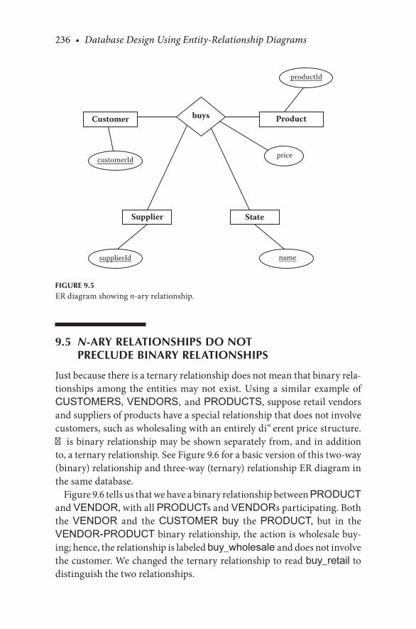
236 • Database Design Using Entity-Relationship Diagrams
9.5 N-ARY RELATIONSHIPS DO NOT PRECLUDE BINARY RELATIONSHIPS
Just.because.there.is.a.ternary.relationship.does.not.mean.that.binary.rela-tionships. among. the. entities. may. not. exist.. Using. a. similar. example. of.CUSTOMERS, VENDORS, and PRODUCTS,.suppose.retail.vendors.and.suppliers.of.products.have.a.special.relationship.that.does.not.involve.customers,.such.as.wholesaling.with.an.entirely.different.price.structure..This.binary.relationship.may.be.shown.separately.from,.and.in.addition.to,.a.ternary.relationship..See.Figure 9.6.for.a.basic.version.of.this.two-way.(binary).relationship.and.three-way.(ternary).relationship.ER.diagram.in.the.same.database.
Figure 9.6.tells.us.that.we.have.a.binary.relationship.between.PRODUCT.and.VENDOR,.with.all.PRODUCTs.and.VENDORs.participating..Both.the. VENDOR. and. the. CUSTOMER. buy. the. PRODUCT,. but. in. the.VENDOR-PRODUCT.binary.relationship,.the.action.is.wholesale.buy-ing;.hence,.the.relationship.is.labeled.buy_wholesale and.does.not.involve.the.customer..We.changed.the.ternary.relationship.to.read.buy_retail.to.distinguish.the.two.relationships.
Customer buys Product
StateSupplier
pricecustomerId
productId
supplierId name
FIGURE 9.5ER.diagram.showing.n-ary.relationship.

Ternary and Higher-Order ER Diagrams • 237
9.6 METHODOLOGY AND GRAMMAR FOR THE N-ARY RELATIONSHIP
We.need.to.revisit.step.6.in.the.ER.design.methodology.to.cover.the.pos-sibility.of.the.n-ary.relationship..The.old.version.was:
Step 6. State the exact nature of the relationships in structured English from all sides, for example, if a relationship is A:B::1:M, then there is a relationship from A to B, 1 to Many, and from B back to A, Many to 1.
We.add.the.following.sentence.to.step.6:
For ternary and higher-order (n-ary) relationships, state the rela-tionship in structured English, being careful to mention all enti-ties for the n-ary relationship. State the structural constraints as they exist.
M N
M1 M2
M3
Product buy_retail Vendor
productID
retail_price vendorID
Customer
buy_wholesale
wholesale_price
date
customerID
FIGURE 9.6ER.diagram.(with.only.primary.keys).showing.a.three-way.and.a.two-way.relationship.

238 • Database Design Using Entity-Relationship Diagrams
The.grammar.for.the.n-ary.relationship.must.involve.all.of.the.entities.linked.to.it..Therefore,.a.suitable.informal.sentence.would.go.something.like.this:
ENTITY1 Relationship (from/to/by) ENTITY2 (and) (from/to/by) ENTITY3. It.is.understood.that.attribute.will.necessitate.naming.all.n.entities.to.identify.it.
Here,.if.we.choose.some.combination.for.Entity1,.….Entityn,.this.process.resolves.into
Entity1:CUSTOMERRelationship:.buyRelationship.attribute:.retail_price
Entity2:.PRODUCTEntity3:.VENDORCUSTOMERS buy PRODUCTS from VENDORS. It.is.understood.
that retail_price will necessitate. referencing. all. three. entities. to.identify.it.
With. a. binary. relationship,. we. have. to. state. two. relationships.. One.would.think.that.with.ternary.relationships,.we.would.be.bound.to.state.three..Since.the.relationship.attribute.has.already.been.stated,.let.us.look.at.the.other.possibilities:
Suppose
Entity1:.PRODUCTEntity2:.CUSTOMEREntity3:.VENDORPRODUCTS are bought by CUSTOMERS from VENDORS.
In.the.informal.version.of.the.statement.from.the.diagram,.little.infor-mation.is.gained.by.repetition..It.is.suggested.that.other.combinations.be.tried;.however,. in. the. informal. statement,. it. seems. likely. that.one.state-ment,.inferred.from.the.semantics.of.the.situation,.would.suffice.to.infor-mally.declare.the.nature.of.the.relationship.
9.6.1 A More Exact Grammar
A.more.exact.grammar.for.the.n-ary.relationship.would.be.an.extension.of.that.developed.for.the.binary.relationship..Unlike.the.informal.case,.in.
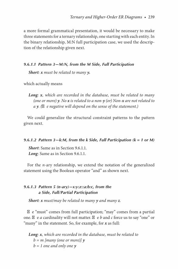
Ternary and Higher-Order ER Diagrams • 239
a.more.formal.grammatical.presentation,.it.would.be.necessary.to.make.three.statements.for.a.ternary.relationship,.one.starting.with.each.entity..In.the.binary.relationship,.M:N.full.participation.case,.we.used.the.descrip-tion.of.the.relationship.given.next.
9.6.1.1 Pattern 3—M:N, from the M Side, Full Participation
Short: x must be related to many y.
which.actually.means
Long: x, which are recorded in the database, must be related to many (one or more) y. No x is related to a non-y (or) Non-x are not related to a y. (The negative will depend on the sense of the statement.)
We. could. generalize. the. structural. constraint. patterns. to. the. pattern.given.next.
9.6.1.2 Pattern 3—k:M, from the k Side, Full Participation (k = 1 or M)
Short:.Same.as.in.Section.9.6.1.1.Long:.Same.as.in.Section.9.6.1.1.
For. the. n-ary. relationship,. we. extend. the. notation. of. the. generalized.statement.using.the.Boolean.operator.“and”.as.shown.next.
9.6.1.3 Pattern 5 (n-ary)—x:y:z::a:b:c, from the a Side, Full/Partial Participation
Short: x must/may be related to many y and many z.
The.“must”.comes.from.full.participation;.“may”.comes.from.a.partial.one..The.a.cardinality.will.not.matter..The.b.and.c.force.us.to.say.“one”.or.“many”.in.the.statement..So,.for.example,.for.x.as.full:
Long: x, which are recorded in the database, must be related tob = m [many (one or more)] yb = 1 one and only one y

240 • Database Design Using Entity-Relationship Diagrams
and (or other appropriate linking word [from, by, to, …])c = m [many (one or more)] zc = 1 one and only one z
No x is related to more than one z.No x is related to more than one y.
Example 9.1
For. CUSTOMERS:PRODUCTS:VENDORS::M1:M2:M3,. full. par-ticipation.all.around:
Short:. CUSTOMERS. must buy many. PRODUCTS. from many.VENDORS.
Long:. CUSTOMERS, which are recorded in the database, must buy many (one or more).PRODUCTS.from many (one or more).VENDORS.
Other.grammatical.expressions.are.derived.similarly.
Products, which are recorded in the database, must be bought by many (one or more) customers from many (one or more) vendors.Vendors, which are recorded in the database, must sell many (one or more) products to many (one or more) customers.
A negative could be: No customer (in this database) buys products from nonvendors.
As.with.the.binary.cases,.the.negative.statements.would.be.optional,.if.they.make.sense.
9.6.2 Grammar in a Partial Participation, Ternary Relationship with an M:1:M Relationship
Let.us.consider.Figure 9.7..In.this.figure,.we.are.trying.to.represent.a.data-base.about.a.graduation.ceremony.that.has.some.students.and.some.faculty.attending..Roughly,.we.are.trying.to.say.that.some.STUDENTS attend.a.given.GRADUATION.with.some.FACULTY;.some.FACULTY.attend.a.GRADUATION.with.some.STUDENTS,.and.all.GRADUATIONs.are.attended. by. some. STUDENTS. and. some. FACULTY.. The. intersection.attribute.is.derived_attendance.

Ternary and Higher-Order ER Diagrams • 241
Here,.we.have.partial.participation.on.the.M.cardinality.relationships.and.a.1-relationship.with.full.participation..Using.the.grammar.presented,.we.have.this.outcome:
STUDENT:GRADUATION:FACULTY::M:1:MShort: Students may attend one graduation with many faculty.Long: Students, which are recorded in the database, may attend (b = 1)
one and only one graduationwith
(c = m) [many (one or more)] faculty.No student attends more than one graduation [with many faculty].
We.put.the.[with.many.faculty].in.square.brackets.because.it.is.not.really.needed.to.make.sense.of.the.diagram.Similarly:
Faculty, which are recorded in the database, may attend one graduation with many students. Some faculty do not attend graduation [with many students].Graduations must be attended by some students and some faculty. No grad-uation takes place without some students and some faculty.
M 1
M
GraduationattendStudent
stu_SSNdate location
Faculty
fac_SSN
timespeakerderived_
attendance
FIGURE 9.7ER.diagram.(with.only.primary.keys).showing.three-way.relationship.with.partial.par-ticipations.and.a.1-relationship.
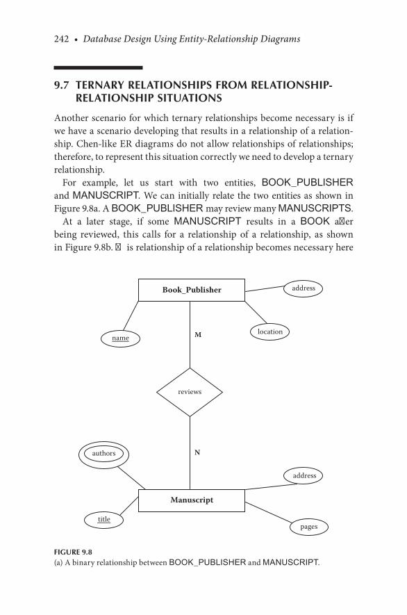
242 • Database Design Using Entity-Relationship Diagrams
9.7 TERNARY RELATIONSHIPS FROM RELATIONSHIP-RELATIONSHIP SITUATIONS
Another.scenario.for.which.ternary.relationships.become.necessary.is.if.we.have.a.scenario.developing.that.results.in.a.relationship.of.a.relation-ship..Chen-like.ER.diagrams.do.not.allow.relationships.of.relationships;.therefore,.to.represent.this.situation.correctly.we.need.to.develop.a.ternary.relationship.
For. example,. let. us. start. with. two. entities,. BOOK_PUBLISHER.and.MANUSCRIPT..We.can. initially.relate. the. two.entities.as. shown. in.Figure 9.8a..A.BOOK_PUBLISHER may.review.many.MANUSCRIPTS.
At. a. later. stage,. if. some. MANUSCRIPT. results. in. a. BOOK. after.being. reviewed,. this. calls. for. a. relationship. of. a. relationship,. as. shown.in.Figure 9.8b..This.relationship.of.a.relationship.becomes.necessary.here.
M
N
Book_Publisher
Manuscript
reviews
name
authors
location
address
title
address
pages
FIGURE 9.8(a).A.binary.relationship.between.BOOK_PUBLISHER.and.MANUSCRIPT..

Ternary and Higher-Order ER Diagrams • 243
because.the.BOOK_PUBLISHER, reviews,.and MANUSCRIPT.taken.together.results-in a.BOOK,.as.shown.in.Figure 9.8c.
In.Figure 9.8c,.the.BOOK_PUBLISHER,.the.reviews.relationship,.and MANUSCRIPT.taken.together.are.like.creating.a.higher-level.aggregate.class.composed.of.BOOK_PUBLISHER, review,.and MANUSCRIPT..This.aggregate.class.(of.the.two.entities.and.a.relationship).then.needs.to.be.related.to.BOOK,.as.shown.in.Figure 9.8c.
To.represent.this.situation.correctly.in.the.ER.model.schema.presented.in. this. book,. since. we. cannot. show. a. relationship. of. a. relationship. to.represent. this. situation,. we. need. to. create. a. weak. entity. REVIEW. and.relate.it.to.BOOK_PUBLISHER, MANUSCRIPT,.and.BOOK as.shown.in. Figure 9.8d.. The. relationship. BMR. connects. BOOK_PUBLISHER, MANUSCRIPT,. and. REVIEW.. This. review. may. result. in. a. BOOK.(as shown.in.Figure 9.8d).
In. Figure 9.8d,. we. give. priority. to. the. weak.REVIEW. entity. because.without.a.review,.there.is.no.book;.the.manuscript.and.the.publisher.must.both.contribute.to.the.review..If.we.tried.to.connect.the.book.to.the.manu-script.without.the.publisher,.we.would.not.depict.the.real.situation.
Book_Publisher
Manuscript
reviews results-in
Book
FIGURE 9.8(b).A.relationship.of.a.relationship.

244 • Database Design Using Entity-Relationship Diagrams
9.8 N-ARY RELATIONSHIPS THAT MAY BE RESOLVED INTO BINARY RELATIONSHIPS
Just.because.three.entities.are.related.does.not.necessarily.imply.a.ternary.relationship..In.this.section,.we.show.how.some.ternary.relationships.can.be.resolved.into.binary.relationships,.and.then.we.give.another.example.of.how.a.ternary.relationship.cannot.be.resolved.into.binary.relationships.(a real.ternary.relationship).
Just.as. the.binary.M:N.relationship.may.be.decomposed. into. two.1:M.relationships,.so.may.many.n-ary.relationships.be.decomposed..First,.note.the. decomposition. of. the. M:N. into. two. 1:M. relationships. in. Figure 9.9..The.idea.is.to.make.the.relationship.an.entity.and.hence.form.two.simpler.binary.relationships.
Next,. let.us. look.again.at.Figure 9.7.. If.we.decompose.Figure 9.7. into.three. binary. relationships,. we. have. Figure 9.10.. In. Figure 9.10,. the.
Book_Publisher
Manuscript
reviews results-in
Book
FIGURE 9.8(c).A.relationship.of.a.relationship.with.a.higher.level.aggregate.class.composed.of.BOOK-PUBLISHER,.REVIEWS.and.MANUSCRIPT.

Ternary and Higher-Order ER Diagrams • 245
new. entity. ATTENDANCE. is. weak. and. depends. on. the. three. entities.FACULTY,.STUDENT.and.GRADUATION.for.its.existence..The.sense.of.ATTENDANCE.would.be.a.roll.of.attendees.for.a.GRADUATION.cer-emony.event.
There.are.situations,.however,.for.which.a.relationship.inherently.asso-ciates.more.than.two.entities..Let.us.take.Figure 9.2.as.an.example..Here,.if.we.had.another.attribute.like.an.order.that.a.customer.places.to.a.sup-plier.for.a.product,.this.attribute.would.require.all.three.entities—CUS-TOMER, PRODUCT, and SUPPLIER—at. the. same. time.. An. order.would.specify.that.a.supplier.would.supply.some.quantity.of.a.product.to.a.customer..This.relationship.cannot.adequately.be.captured.by.binary.rela-tionships..With.binary.relationships,.we.could.only.say. that.a.customer.placed.an.order.for.a.product,.or.a.supplier.received.an.order.for.a.product..
Book_Publisher BMR Manuscript
Review
results_in
Book
working_title
ISBN
final_title
name location
address
FIGURE 9.8(d).A.relationship.of.a.relationship.resolved.into.a.ternary.relationship.
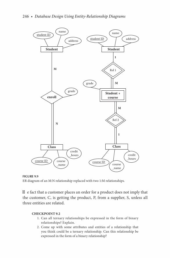
246 • Database Design Using Entity-Relationship Diagrams
The.fact.that.a.customer.places.an.order.for.a.product.does.not.imply.that.the.customer,.C,. is.getting. the.product,.P,. from.a. supplier,.S,.unless.all.three.entities.are.related.
CHECKPOINT 9.2. 1.. Can.all. ternary. relationships.be.expressed. in. the. form.of.binary.
relationships?.Explain.. 2.. Come. up. with. some. attributes. and. entities. of. a. relationship. that.
you. think.could.be.a. ternary. relationship..Can. this. relationship.be.expressed.in.the.form.of.a.binary.relationship?
1
M
M
M
N
1
Student
enroll
Class
name
address
grade
credit_hours
course ID course_name
student IDstudent ID name
address
Rel 1
Student
Student +course
Class
Rel 2
course IDcourse_name
credit_hours
grade
FIGURE 9.9ER.diagram.of.an.M:N.relationship.replaced.with.two.1:M.relationships.
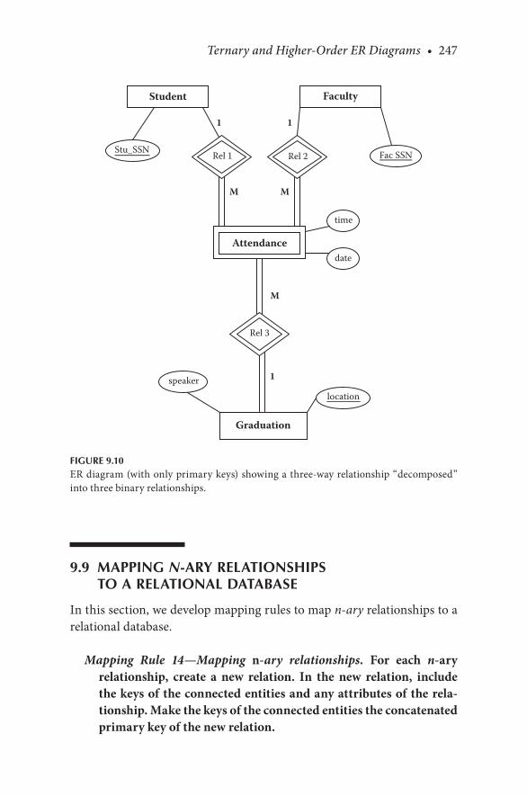
Ternary and Higher-Order ER Diagrams • 247
9.9 MAPPING N-ARY RELATIONSHIPS TO A RELATIONAL DATABASE
In.this.section,.we.develop.mapping.rules.to.map.n-ary relationships.to.a.relational.database.
Mapping Rule 14—Mapping n-ary relationships. For each n-ary relationship, create a new relation. In the new relation, include the keys of the connected entities and any attributes of the rela-tionship. Make the keys of the connected entities the concatenated primary key of the new relation.
1 1
M M
M
1
Graduation
Rel 3
Student Faculty
Rel 1 Rel 2Stu_SSN Fac SSN
Attendance
time
date
locationspeaker
FIGURE 9.10ER.diagram.(with.only.primary.keys).showing.a.three-way.relationship.“decomposed”.into.three.binary.relationships.

248 • Database Design Using Entity-Relationship Diagrams
For.example,.refer.to.Figure 9.2;.you.have.a.ternary.relationship.called.buy. relating. PRODUCT, SUPPLIER,. and. CUSTOMER.. There. is. an.intersection.attribute,.price..The.mapped.relations.would.be:
BUY(price, productID, supplierID, customerID)PRODUCT(productID, …)SUPPLIER(supplierID, …)CUSTOMER(customerID, …)
And,.some.sample.data.would.be:
BUYprice productID supplierID customerID$87.10 TAG1 F1 PENS$83.98 TAG2 G25 MOB$95.25 TAG3 G20 DEL$99.10 TAG4 F4 GULF
PRODUCTproductID …
TAG1TAG2TAG3…
SUPPLIERsupplierID …F1G25G20…
CUSTOMERcustomerID …PENSMOBDEL…

Ternary and Higher-Order ER Diagrams • 249
CHECKPOINT 9.3. 1.. Could. Figure 9.5. be. described. in. the. form. of. binary. relationships?.
Discuss.. 2.. What.mapping.rules.would.you.follow.to.map.Figure 9.5?. 3.. Map.Figure 9.5.to.a.relational.database.and.show.some.sample.data.
9.10 REVIEW OF THE METHODOLOGY
Our.ER.design.methodology.has.now.finally.evolved.to.the.presentation.that.follows.
9.10.1 ER Design Methodology
Step 1. Select one primary entity from the database requirements description and show the attributes to be recorded for that entity. Label keys if appropriate and show some sample data.
Step 2. Use structured English for entities, attributes, and keys to describe the database that has been elicited.
Step 3. Examine attributes in the existing entities (possibly with user assistance) to find out if information about one of the entities is to be recorded.
(We. change. primary. to. existing. because. we. redo. step. 3. as. we. add. new.entities.)
Step 3a. If information about an attribute is needed, then make the attribute an entity, and then
Step 3b. Define the relationship back to the original entity.Step 4. If another entity is appropriate, draw the second entity with
its attributes. Repeat steps 2 and 3 to see if this entity should be further split into more entities.
Step 5. Connect entities with relationships (one or more) if relation-ships exist.
Step 6. State the exact nature of the relationships in structured English from all sides, for example, if a relationship is A:B::1:M, then there is a relationship from A(1) to B(M) and from B(M) back to A(1).
For ternary and higher-order (n-ary) relationships, state the relation-ship in structured English being careful to mention all entities for the n-ary relationship. State the structural constraints as they exist.
Step 6a. Examine the list of attributes and determine whether any of them need to be identified by two (or more) entities. If so, place the attribute on an appropriate relationship that joins the two entities.

250 • Database Design Using Entity-Relationship Diagrams
Step 6b. Examine the diagram for loops that might indicate redundant relationships. If a relationship is truly redundant, excise the redun-dant relationship.
Step 7. Show some sample data.Step 8. Present the “as designed” database to the user complete with
the English for entities, attributes, keys, and relationships. Refine the diagram as necessary.
9.11 CHAPTER SUMMARY
Binary.relationships.are.the.most.commonly.occurring.kind.of.relation-ships.. Some. ER. diagram. notations. do. not. have. expressions. for. ternary.or. other. higher-order. relationships;. that. is,. everything. is. expressed. in.terms.of.a.binary.relationship..In.this.chapter,.we.showed.how.the.need.for.ternary.relationships.comes.about. from.unique.situations..For.example,.intersection.attributes.arise.that.need.all.three.entities.taken.together.for.their.identification..Ternary.relationships.can.also.be.developed.through.reverse.engineering,.and.this.is.discussed.in.Chapter.11..Also.in.this.chap-ter,.we.discussed. the.structural.constraints.of. ternary.relationships.and.their.grammar.in.detail.and.showed.how.some.ternary.or.n-ary.relation-ships.may.be.resolved.into.binary.relationships..The.final.section.of.this.chapter.discussed.mapping.rules.for.n-ary.relationships.
CHAPTER 9 EXERCISES
Exercise 9.1
In.Chapter.8,.we.described.a.database. that.had. two.entities,.COURSE.and.INSTRUCTOR. “Book”.was.left.as.an.attribute.of.COURSE..Extend.the.database.to.include.book.as.an.entity..Attributes.of.book.might.include.book.title,.author,.price,.edition,.and.publisher..Explore.the.relationships.that.might.exist.here:.use.“in”.or.“by,”.“write,”.“teach,”.and.so.on..Draw.an.ER.diagram.with.at.least.two.relationships,.one.of.them.ternary..What.would.be.some.attributes.of.the.relationships?

Ternary and Higher-Order ER Diagrams • 251
Exercise 9.2
Construct. an.ER.diagram. for.a.broker,. a. security,. and.a.buyer.. Include.in. the.diagram.the.price.of. the. security,. the.commission.paid,. the.bro-ker. name. and. address,. the. buyer. name. and. address,. and. the. security.exchange,.symbol,.and.price..Include.in.the.diagram.the.number.of.shares.of.the.security.held.by.a.buyer.(you.may.choose.to.include.this.by.broker.or.not).
Exercise 9.3
Using. three. entities—INSTRUCTOR, CLASS, and.ROOM—draw. an.ER. diagram. that. depicts. the. following:. Each. CLASS in. a. ROOM. has.one. INSTRUCTOR,. but. each. INSTRUCTOR. in. a. room. may. have.many.CLASSes,.and.each.INSTRUCTOR.of.a.CLASS may.be.in.many.ROOMs.
BIBLIOGRAPHY
Elmasri,.R.,.and.Navathe,.S..B..2007..Fundamentals of Database Systems,.5th.ed..Reading,.MA:.Addison-Wesley.
Teorey,.T..J.,.Nadeau,.T.,.and.Lightstone,.S..S..2005..Database Modeling and Design: Logical Design. San.Francisco,.CA:.Morgan.Kaufman.
Teorey,. T.. J.,. Yang,. D.,. and. Fry,. J.. P.. 1986.. A. logical. design. methodology. for. relational.databases. using. the. extended. entity-relationship. model.. ACM Computing Surveys,.18(2):197–222.


253
10The Enhanced Entity Relationship (EER) Model
10.1 INTRODUCTION
In. the.first. several. chapters.of. this.book,.we.presented. the.entity. rela-tionship.(ER).diagram.as.a.conceptual.database.tool..The.approach.we.took.in.developing.an.ER.diagram.was.to.assume.that.we.were.to.model.reality.for.a.user..Although.we.worked.on.the.basics.of.the.ER.diagram,.there.are.situations.for.which.the.basic.model.fails.to.completely.describe.the. reality. of. the. data. to. be. stored.. With. the. increase. in. the. types. of.database.applications,.the.basic.concepts.of.ER.modeling.(as.originally.developed.by.Chen).were.not.sufficient.to.represent.the.requirements.of.more.complex.applications.like.generalizations.and.specializations.(class.hierarchies)..An.ER.model.that.supports.these.additional.semantic.con-cepts. is. called. the. enhanced entity relationship. (EER). model. (Elmasri.and.Navathe,.2007)..In.this.chapter,.we.discuss.generalizations.and.spe-cializations.in.the.EER.model.and.develop.a.methodology.and.grammar.for.this.extension..We.also.discuss.shared.subclasses.and.categories.or.union.types..We.present.a.methodology.to.map.the.EER.diagram.to.a.relational.database.
10.2 WHAT IS A GENERALIZATION OR SPECIALIZATION?
The.EER.model. includes.all. the.concepts.of. the.original.ER.model.and.additional. concepts. of. generalizations/specializations. (class. hierar-chies).. Generalizations. and. specializations. are. associated. with. the. idea.of. superclasses,. subclasses,. and. attribute. inheritance.. As. an. example. of.

254 • Database Design Using Entity-Relationship Diagrams
a.class.hierarchy,.suppose.we.have.this.entity.for.a.store.that.sells.sports.equipment:
CUSTOMER(customer_number, name, address)
Now,.suppose.the.database.evolves.to.a.situation.for.which.we.want.to.keep.information.that.is.pertinent.to.specific.sports.for.some.customers:
GOLF(customer_number, handicap, preferred_clubmake)BASEBALL(customer_number, position, preferred_batsize)
The.GOLF.and.BASEBALL.entities.are.subclasses.(specializations).within.the.CUSTOMER.(a.generalization)..This.example.illustrates.a.hierarchy.in.which.CUSTOMER.is.at.the.top.of.the.class.hierarchy.and.the.specific.sports.are.subclasses.
In.an.object-oriented.setting,.we.might.designate.the.entities.like.this:
CUSTOMER(customer_number, name, address)CUSTOMER.GOLF(handicap, preferred_clubmake)CUSTOMER.BASEBALL(position, preferred_batsize)
The.inference.in.object-oriented.programming.is.that.GOLF.is.a.subclass.of.CUSTOMER..Although.not.specifically.stated,.CUSTOMER.GOLF.inherits.all.the.attributes.of.CUSTOMER.plus.has.attributes.pertinent.to.GOLF..The.example.is.one.of.specialization—the.thinking.process.started.with.a.class,.CUSTOMER,.and.then.specialized.to.specific.sports.
The.idea.of.classes.in.a.database.infers.the.ability.to.describe.subclasses.and.superclasses.with.inheritance.features.
As.an.example.of.a.generalization,.suppose.we.have.a.STUDENT.entity that.contains.information.about.students..But,.suppose.we.wanted.to.store.information.about.all.the.people.at.an.institution—not.only.students,.but.also.staff.and.faculty..We.might.think.of.a.superclass.called.PERSON that.contains.a.subclass.for.STUDENT,.another.subclass.for.STAFF,.and.yet.another.subclass.for.FACULTY..Clearly,.information.about.each.of.these.subclasses.of.PERSON contains.information.pertinent.to.that.subclass..Yet,.the.PERSON superclass entity.would.contain.information.common.to.all.of.these.subclasses..PERSON may.contain.a.name,.address,.and.phone number,. and. when. the. STAFF subclass. was. defined,. it. would.inherit. those. attributes. of. the. superclass. and. define. more. attributes.

The Enhanced Entity Relationship (EER) Model • 255
pertinent. to.STAFF..The.superclass. in.a.database. is.called.a.generaliza-tion,.and.the.subclasses.(STUDENT,.STAFF,.and.FACULTY).are.called.specializations.
The.concept.of.classes.includes.the.use.of.simple.attributes,.as.we.have.seen..In.object-oriented.programming,.the.concept.of.a.class.also.includes.actions.that.a.class.may.perform..As.with.data.typing,.databases.tend.to.focus.more.on.attributes.than.procedural.action.
10.3 VARIANTS
One.way.programmers.in.the.past.solved.the.problem.of.specializations.was.to.create.variants..Variants.are.record.pieces.that.vary.according.to.other.parts.of.the.record..To.illustrate.variants.and.their.use.in.ER.dia-grams,.consider.this.problem:.Suppose.we.have.an.entity.that.has.values.that.vary.according.to.“the.situation.”.For.example,.suppose.we.are.mod-eling. student-athletes,. and. each. athlete. plays. some. sport.. We. would,. of.course,.record.information.about.the.student.or.athlete—a.name,.a.unique.identifier.like.a.student.number,.and.perhaps.some.other.information..But.then,.we.would.like.to.record.some.information.about.the.sport.that.the.student-athlete.may.play..Let.us.suppose.that.we.have.an.ATHLETE table.with.this.type.of.data:
ATHLETEstudent student_no other sport infoBaker 123456789 … tennis 220, state rank 14Adams 123456788 … football tackle, neck braceJones 123455676 … golf handicap 3
The.info.attribute.has.different.values.for.different.sports..These.different.values.are.called.variants..While.the.introduction.of.variants.in.records.seems.to.solve.a.problem.of.representing.data,.it.causes.database.problems.with.storage.and.retrieval..In.a.database,.one.expects.that.all.the.informa-tion.in.a.column.of.a.table.is.consistent..Student.numbers.might.contain.nine.digits;.hence,.all.values.in.the.student.number.column.would.contain.a.nine-digit.number..With.variants,.this.is.not.the.case..The.ATHLETE table.contains.inconsistent.columnar.information.in.the.info.column..This.variant.problem.in.a.database.has.been.solved. in.various.ways.over. the.years.

256 • Database Design Using Entity-Relationship Diagrams
A.solution.to.the.problem.of.variants.in.records.and.varying.attributes.in.entities.in.the.ER.diagram.is.to.excise.the.variant.and.reference.it.back.to.the.primary.key.of.the.“parent”.information.piece..We.attack.the.prob-lem.in.this.way.
In.ER.diagrams,.we.recognize.that.we.are.actually.storing.information.about. two. different,. but. related,. things:. a. generalization. called. athletes,.who. have. a. name,. ID,. and. so. on,. and. specializations,. which. are. sports.(tennis,.football,.golf,.etc.),.each.with.its.own.different.attributes..Since.we.are.storing.information.about.two.things,.why.not.create.an.entity.called.SPORTS. and. then. relate. the.ATHLETE to. the.SPORTS. entity?. One.SPORTS.entity.would.not.work.because.the.SPORTS.entity.would.be.too.general;.we.would.want.to.store.different.information.about.different,.specific.sports..Furthermore,.we.want.to.store.information.about.a.sport.as.it.pertains.to.each.individual.student-athlete.
Why.then.would.we.not.create.a.series.of.weak.entities—one.for.each.sport—that.depends.on.the.ATHLETE?.The.answer.is.that.we.could.do.this,.but.there.is.a.better.way.to.look.at.this.problem,.which,.as.it.turns.out,.will.result. in.the.same.database.as.using.a.weak.entity/relationship.but.gives.us.an.alternative.way.to.present.the.ER.information.with.more.expressive.diagrams.that.include.the.concept.of.inheritance.
10.4 EXAMPLES OF GENERALIZATIONS OR SPECIALIZATIONS
Generalizations. and. specializations. are. categorizations. of. entities. for.which.the.specialization.entity.may.result.from.generalizations.contain-ing.variants..These.variants.are.most.easily.handled.by.removing.the.vari-ant.from.the.generalization.and.treating.it.as.a.subclass.entity.and.leaving.the.original,.“fixed.part”.of.the.entity.as.a.superclass.or.parent.type..If.we.referred.to.the.superclass.as.a.parent class,.then.we.would.call.the.variant.parts.the.subclasses,.the.child classes.
Pursuing.the.parent-child.superclass/subclass.idea.a.bit.further,.we.can.imagine.the.child.class.inheriting.the.characteristics.of.the.parent.class..Inheritance.in.this.context.means.that.the.child.class.will.have.defined.in.it.whatever.attributes.are.defined.in.the.parent.class..In.a.relational.data-base,.the.tying.of.the.child.to.the.parent.(hence.placing.parent.and.child.

The Enhanced Entity Relationship (EER) Model • 257
information. together). is. done. using. table. combination. operators. called.joins..In.our.sports.example,.we.would.consider.the.ATHLETE as.a.parent.class.and.SPORTS.as.a.child.class.so.that.when.we.define.information.about.a.sport,. it. is.done.in.the.context.of.maintaining.the.possibility.of.inheriting.information.from.the.parent,.ATHLETE,.via.a.join.operation.
If.we.were.designing. the.database. for. student-athletes,. and.we. recog-nized.that.we.would.want.to.record.a.name,.a.personal.identifier.(ssno), address,.and.so.on,.we.could.be.starting.with.the.generalization.(or.par-ent.or.superclass)..Then,.we.decide.to.record.a.player.in.a.sport.and.some.information.about.the.sport.itself..The.player-sport.is.said.to.be.a.special-ization.of.the.ATHLETE.class..This.design.approach.may.be.characterized.as.top down.
If.we.had.been.designing.the.database.and.we.started.with.sports,.we.might.have.had.a.TENNIS.entity,.a.FOOTBALL.entity,.and.so.on.for.each.athlete,.only.to.recognize.that. these.entities.may.be.generalized.into.an ATHLETE.entity.(a.superclass).with.individual.sports.as.subclass.entities;.this.design.approach.might.be.characterized.as.bottom up..A.generaliza-tion.relationship.specifies.that.several.types.of.entities.with.certain.com-mon.attributes.can.be.generalized.into.a.higher-level.entity.class,.a.generic.or.superclass.entity.
Either.way.(bottom.up.or.top.down),.we.end.up.with.one.entity.being.a.superclass.(a.parent).and.the.other.being.a.subclass.(a.child).of.the.parent..Whether.one.needs.to.specialize.or.generalize.in.design.depends.on.where.one.recognizes.the.problem.
To.illustrate.how.we.might.handle.this.generalization-specialization,.par-ent-child.class.situation,.suppose.we.have.defined.our.entity,.ATHLETE,.like.this:
Entity:.ATHLETEAttributes:.name, ssno, address, gender, weight, height.
The.ER.diagram.for.this.entity.is.simple.and.straightforward..Then,.in.the.course.of.database.design,.we.decide.to.add.information.about.sports.that.athletes.play..We.might.attempt.to.draw.a.diagram.like.Figure 10.1.with.a.variant.sports flag.
What.is.wrong.with.Figure 10.1?.The.problem.is.that.we.have.attributes.that. have. attributes. that. have. attributes.. Sports. flag. is. not. a. composite.attribute—it. does. not. have. component. parts.. So,. instead. of. creating.

258 • Database Design Using Entity-Relationship Diagrams
attributes.with.attributes,.we.will.create.entities.for.each.specific.sport.and.then.relate.these.entities.back.to.the.ATHLETE.
Now,.refer.to.Figure 10.2..Here,.we.created.weak.entities.for.each.sport.rather. than. use. attributes. of. attributes.. We. have. to. make. the. sports.weak.entities.because.they.have.no.primary.key.per.se—they.depend.on.ATHLETE..This.diagram.still.does.not.tell.the.whole.story.because.sports.are.not.just.weak.entities,.but.rather.they.are.in.a.sense.“choices.”.If.the.sports.were.simply.weak.entities,.then.you.would.expect.that.all.superclass.entities.were.related.to.each.subclass..This.is.not.really.the.case..Plus,.we.want.to.honor.the.concept.of.inheritance.
The.process.of.specialization.is.intended.as.a.process.by.which.the.sub-class.inherits.all.the.properties.of.the.superclass..In.EER.terminology,.the.ATHLETE.entity.is.called.a.superclass,.and.the.sports.entities.are.called.subclasses..The.attributes.like.handicap.may.be.termed.specific attributes.as.they.are.specific.to.the.particular.subclass.
Athlete
name ssno gender
heightweight
Sports Flag
Tennis Golf Football
state_ranking
handicap position
FIGURE 10.1The.ATHLETE.with.an.attempt.to.add.a.variant.attribute.
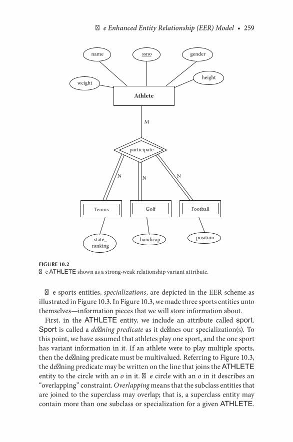
The Enhanced Entity Relationship (EER) Model • 259
The.sports.entities,.specializations,.are.depicted.in.the.EER.scheme.as.illustrated.in.Figure 10.3..In.Figure 10.3,.we.made.three.sports.entities.unto.themselves—information.pieces.that.we.will.store.information.about.
First,. in. the. ATHLETE. entity,. we. include. an. attribute. called. sport..Sport. is.called.a.defining predicate.as.it.defines.our.specialization(s)..To.this.point,.we.have.assumed.that.athletes.play.one.sport,.and.the.one.sport.has.variant. information. in. it.. If.an.athlete.were. to.play.multiple. sports,.then.the.defining.predicate.must.be.multivalued..Referring.to.Figure 10.3,.the.defining.predicate.may.be.written.on.the.line.that.joins.the.ATHLETE.entity.to.the.circle.with.an.o.in.it..The.circle.with.an.o.in.it.describes.an.“overlapping” constraint..Overlapping.means.that.the.subclass.entities.that.are.joined.to.the.superclass.may.overlap;.that.is,.a.superclass.entity.may.contain.more.than.one.subclass.or.specialization.for.a.given.ATHLETE..
M
N NN
Athlete
name ssno gender
heightweight
participate
Tennis Golf Football
handicap positionstate_ranking
FIGURE 10.2The.ATHLETE.shown.as.a.strong-weak.relationship.variant.attribute.

260 • Database Design Using Entity-Relationship Diagrams
The. overlap. (o). in. Figure 10.3. means. that. an. athlete. may. participate. in.more.than.one.sport.
If. there. were. a. d. in. the. circle. (in. place. of. the. o). in. Figure 10.3,. then.the.entities.would.not.overlap:.They.would.be.disjoint..A.d.would. indi-cate.that.athletes.would.participate.in.only.one.sport;.that.is,.the.athletes.would.play.only.golf,.only.tennis,.or.only.football.(but.not.any.of.the.two.together)..If.this.were.the.case,.then.the.small.o.would.be.replaced.by.a.d,.and.Sport,.the.defining.predicate,.would.be.single.valued..As.a.final.note.on. this. diagram,. the. participation. of. the. superclass. in. the. subclasses. is.optional..There.is.a.single.line.joining.the.o/d.designation.that.means.that.an.athlete.may.participate.in.a.sport—some.athletes.(or.potential.athletes).do.not.participate.in.a.sport.or.sports.
An.example.of.a.disjoint.constraint.is.shown.in.Figure 10.4..According.to. Figure 10.4,. all. the. furniture. in. the. database. is. a. chair,. a. desk,. or. a.table..In.this.case,.there.is.no.sense.of.overlapping.subclasses..There.is.a.
Athlete
weightssno
gender
state_ranking
handicap position
o
Tennis Golf Football
Overlapconstraint
sport
name
height
multi-valued attribute isneeded for overlappingconstraint. If theconstraint is disjoint, themulti-valued attributebecomes single valued
FIGURE 10.3ATHLETE.with.superclass/subclass.overlap.relationship.

The Enhanced Entity Relationship (EER) Model • 261
full. participation. designation. from. the.FURNITURE. entity. to. the. o/d.circle.. Each. piece. of. furniture. must. participate. in. a. subclass.. Contrast.this.to.the.partial.participation.in.the.ATHLETE.example..The.disjoint.constraint.specifies.that.if.the.subclasses.of.a.generalization.are.disjoint,.then. an. entity. may. be. a. member. of. only. one. of. the. subclasses. or. spe-cializations..Further,.the.defining.predicate.for.disjoint.subclasses.will.be.single.valued.
In.Figure 10.4,.the.name.of.the.specialization.is.the.name.of.the.entity.itself..If.this.is.not.the.case,.then.the.defining.predicate.may.be.repeated.in.the.diagram.for.clarity.
Figure 10.3.shows.a.subclass.symbol.(⊂).between.the.predicate-defined.entities. and. the. disjoint/overlapping. (o/d). constraint. circle.. “Tennis,”.“Golf,”.and.“Football”.belong to.the.defining.predicate.“Sport.”.The.entities.
furniture ID
Type
“Table” “Desk” “Chair”
Furniture
employee_number office_no
furniture_type
size drawers chair_type
d
Table Desk Chair
Definingpredicate
Value ofdefiningpredicate
A disjointconstraint
color
FIGURE 10.4An.office.database.with.specialization.entities,.full.participation,.and.disjoint.relationship.

262 • Database Design Using Entity-Relationship Diagrams
TENNIS,.GOLF,.and.FOOTBALL.are.subclasses.of.ATHLETE..The.sub-class.symbol.on.each.line.that.connects.a.subclass.to.the.circle.indicates.the.direction.of.the.superclass/subclass.or.parent-child,.inheritance.rela-tionship.. In. Figure 10.3,. the. subclass. TENNIS,. GOLF,. or. FOOTBALL.(the.specializations).would.inherit.from.the.parent,.ATHLETE.
CHECKPOINT 10.1. 1.. What.is.a.specialization?.Give.an.example.of.a.specialization.. 2.. What.is.a.generalization?.Give.an.example.of.a.generalization.. 3.. What.is.a.disjoint.constraint?.What.symbol.shows.the.disjoint.con-
straint.in.EER.diagrams?. 4.. What.is.an.overlapping.constraint?.What.symbol.shows.the.overlap-
ping.constraint.in.EER.diagrams?. 5.. What.does.the.subclass.symbol.signify?. 6.. Why. would. you. create. a. generalization/specialization. relationship.
rather.than.creating.a.“weak.entity”?. 7.. How. does. “inheritance”. play. into. the. superclass/subclass. relation-
ship?.Discuss.. 8.. What. is. the. difference. between. a. generalization. entity. and. regular.
entity.as.described.in.the.previous.chapters?
10.5 METHODOLOGY AND GRAMMAR FOR GENERALIZATION/SPECIALIZATION RELATIONSHIPS
We.need.to.revisit.step.6.in.the.ER.design.methodology.to.include.general-ization/specialization.relationships..The.previous.version.of.step.6.was:
Step 6. State the exact nature of the relationships in structured English from all sides, for example, if a relationship is A:B::1:M, then there is a relationship from A to B, 1 to Many, and from B back to A, Many to 1.
For ternary and higher-order (n-ary) relationships, state the relation-ship in structured English, being careful to mention all entities for the n-ary relationship. State the structural constraints as they exist.
We.add.the.following.sentence.to.step.6:
For specialization/generalization relationships, state the relationship in structured English, being careful to mention all entities (subclasses or specializations). State the structural constraints as they exist.

The Enhanced Entity Relationship (EER) Model • 263
The.grammar.that.we.propose.for.specialization/generalization.relation-ships.is.similar.to.that.we.used.in.weak.relationships..We.add.to.the.grammar.to.include.the.participation.and.the.overlapping/disjoint.(o/d).constraints:
The.grammatical.description.for.weak.entities.was
For.each weak entity,.we.do.not.assume.that.any.attribute.will.be.unique.enough.to.identify individual.entities..Since.the weak entity does.not.have.a.candidate.key,.each weak entity will be identified.by.key(s).belonging.to.the strong entity.
In.the.case.of.the.subclasses.of.ATHLETE,.a.first.attempt.to.describe.the.subclass.identified.by.a.superclass.becomes
For.each sport,.we.do.not.assume.that.any.sport.attribute.will.be.unique.enough.to.identify individual.sport entities..Since.sport.does.not.have.a. candidate. key,. each sport will. be identified. by. inheriting. key(s).belonging.to ATHLETE.
So,.a.more.complete.EER.diagram.grammatical.pattern.would.say
For. each specialization, we. do. not. assume. that. any. attribute. will. be.unique.enough.to identify.individual.entities..Since.the specialization does.not.have.a.candidate.key,.each specialization will.be.identified.by.key(s).inherited.from the.generalization..Further, specializations overlap [or are disjoint]. [Explain.the.overlapping/disjoint.situation.].The. individual specialization is identified. by. a. defining. predicate, attribute name, which.will.be.contained.in generalization..If.the.spe-cializations.overlap,.the.defining.predicate.will.be.multivalued.
For.Figure 10.3,.the.pattern.becomes
For.each.sport,.we.do.not.assume.that.any.attribute.will.be.unique.enough.to.identify individual.entities..Since.the sport does.not.have.a.candidate.key,.each.sport will.be identified.by.key(s).inherited.from ATHLETE. Further,.the sports.overlap..Athletes.may.play more.than.one.sport..The.individual.sport is. identified.by.a.defining.predicate.attribute, sport, which.will.be.contained.in ATHLETE..Since.a.person.may.play.more.than.one.sport,.the.defining.predicate.is.a.multivalued.attribute..The.sports.we.will.record.are.GOLF,.TENNIS,.and.FOOTBALL.
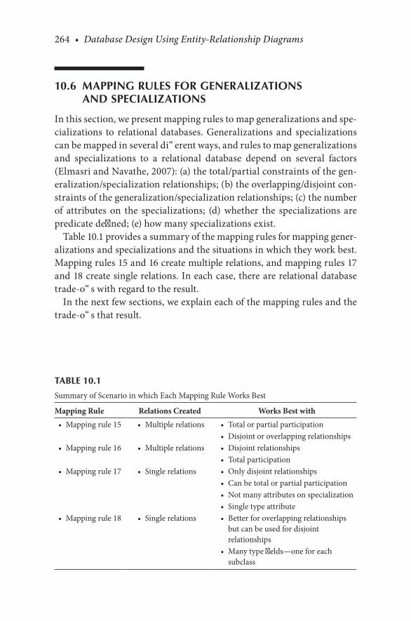
264 • Database Design Using Entity-Relationship Diagrams
10.6 MAPPING RULES FOR GENERALIZATIONS AND SPECIALIZATIONS
In.this.section,.we.present.mapping.rules.to.map.generalizations.and.spe-cializations. to. relational.databases..Generalizations.and. specializations.can.be.mapped.in.several.different.ways,.and.rules.to.map.generalizations.and. specializations. to. a. relational. database. depend. on. several. factors.(Elmasri.and.Navathe,.2007):.(a).the.total/partial.constraints.of.the.gen-eralization/specialization.relationships;.(b).the.overlapping/disjoint.con-straints.of.the.generalization/specialization.relationships;.(c).the.number.of. attributes. on. the. specializations;. (d). whether. the. specializations. are.predicate.defined;.(e).how.many.specializations.exist.
Table 10.1.provides.a.summary.of.the.mapping.rules.for.mapping.gener-alizations.and.specializations.and.the.situations.in.which.they.work.best..Mapping.rules.15.and.16.create.multiple.relations,.and.mapping.rules.17.and.18.create.single.relations..In.each.case,.there.are.relational.database.trade-offs.with.regard.to.the.result.
In.the.next.few.sections,.we.explain.each.of.the.mapping.rules.and.the.trade-offs.that.result.
TABLE 10.1
Summary.of.Scenario.in.which.Each.Mapping.Rule.Works.Best
Mapping Rule Relations Created Works Best with•. Mapping.rule.15 •. Multiple.relations. •. Total.or.partial.participation
•. Disjoint.or.overlapping.relationships•. Mapping.rule.16 •. Multiple.relations. •. Disjoint.relationships
•. Total.participation•. Mapping.rule.17 •. Single.relations. •. Only.disjoint.relationships
•. Can.be.total.or.partial.participation•. Not.many.attributes.on.specialization•. Single.type.attribute
•. Mapping.rule.18 •. Single.relations. •. Better.for.overlapping.relationships.but.can.be.used.for.disjoint.relationships
•. Many.type.fields—one.for.each.subclass

The Enhanced Entity Relationship (EER) Model • 265
10.6.1 Mapping Rule 15
As.per.Table 10.1,.mapping.rule.15.works.well.for.either.disjoint.or.over-lapping. scenarios.. This. rule. would. also. work. well. if. the. specializations.have.many.attributes.
Mapping Rule 15—Mapping generalizations and specializations with disjoint or overlapping subclasses and with total or partial par-ticipation constraints (with few or many attributes on the special-izations). For each generalization/specialization entity situation, create one relation (table) for the generalization entity (if you have not done so already per the prior steps) and create one relation (table) for each specialization. Add the attributes for each entity to their respective relations. Include the primary key of the gener-alization entity in the specialization relations. The primary key of the specialization relations will be the same as the primary key of the generalization relation.
So,.using.mapping.rule.15,.we.create.a.separate.relation.for.the.general-ization. (superclass). as. well. as. for. each. of. the. specializations. (subclasses)..Refer.to.Figure 10.3..The.generalization/specialization.relationship.between.ATHLETE and TENNIS, GOLF,.and FOOTBALL.would.be.mapped.as.follows:
ATHLETE(ssno, weight, name, gender, height, (sport))TENNIS(ssno, state_ranking)GOLF(ssno, handicap)FOOTBALL(ssno, position)
Since. ATHLETE. in. Figure 10.3. contains. a. multivalued. attribute,.ATHLETE.now.becomes
ATHLETE1(ssno, weight, name, gender, height)
and
ATHLETE-SPORT (ssno, sport)
The.key.of.the.generalization.entity.ssno.is.added.to.the.specialization.entities.TENNIS,.GOLF,.and.FOOTBALL.as.the.primary.key..And,.since.
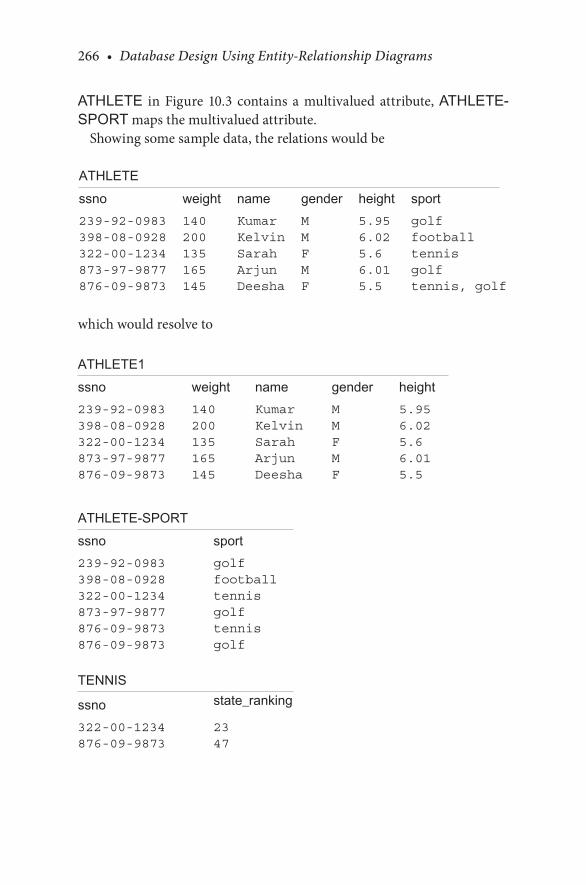
266 • Database Design Using Entity-Relationship Diagrams
ATHLETE. in. Figure 10.3. contains. a. multivalued. attribute,.ATHLETE-SPORT.maps.the.multivalued.attribute.
Showing.some.sample.data,.the.relations.would.be
ATHLETEssno weight name gender height sport239-92-0983 140 Kumar M 5.95 golf398-08-0928 200 Kelvin M 6.02 football322-00-1234 135 Sarah F 5.6 tennis873-97-9877 165 Arjun M 6.01 golf876-09-9873 145 Deesha F 5.5 tennis, golf
which.would.resolve.to
ATHLETE1ssno weight name gender height239-92-0983 140 Kumar M 5.95398-08-0928 200 Kelvin M 6.02322-00-1234 135 Sarah F 5.6873-97-9877 165 Arjun M 6.01876-09-9873 145 Deesha F 5.5
ATHLETE-SPORTssno sport239-92-0983 golf398-08-0928 football322-00-1234 tennis873-97-9877 golf876-09-9873 tennis876-09-9873 golf
TENNIS
ssno state_ranking
322-00-1234 23876-09-9873 47
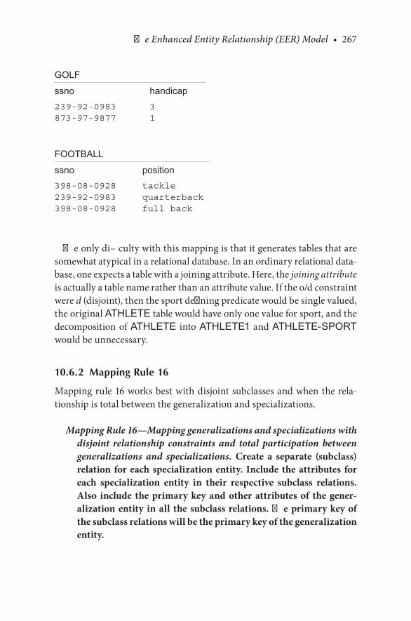
The Enhanced Entity Relationship (EER) Model • 267
GOLFssno handicap239-92-0983 3873-97-9877 1
FOOTBALLssno position398-08-0928 tackle239-92-0983 quarterback398-08-0928 full back
The.only.difficulty.with.this.mapping.is.that.it.generates.tables.that.are.somewhat.atypical.in.a.relational.database..In.an.ordinary.relational.data-base,.one.expects.a.table.with.a.joining.attribute..Here,.the.joining attribute.is.actually.a.table.name.rather.than.an.attribute.value..If.the.o/d.constraint.were.d.(disjoint),.then.the.sport.defining.predicate.would.be.single.valued,.the.original.ATHLETE.table.would.have.only.one.value.for.sport,.and.the.decomposition.of.ATHLETE. into.ATHLETE1.and.ATHLETE-SPORT.would.be.unnecessary.
10.6.2 Mapping Rule 16
Mapping.rule.16.works.best.with.disjoint.subclasses.and.when.the.rela-tionship.is.total.between.the.generalization.and.specializations.
Mapping Rule 16—Mapping generalizations and specializations with disjoint relationship constraints and total participation between generalizations and specializations. Create a separate (subclass) relation for each specialization entity. Include the attributes for each specialization entity in their respective subclass relations. Also include the primary key and other attributes of the gener-alization entity in all the subclass relations. The primary key of the subclass relations will be the primary key of the generalization entity.

268 • Database Design Using Entity-Relationship Diagrams
To.illustrate.this.rule,.we.map.Figure 10.4.as.follows:
TABLE(furniture_id, office_no, employee_number, furniture_type, size)
DESK(furniture_id, office_no, employee_number, furniture_type, drawers)
CHAIR(furniture_id, office_no, employee_number, furniture_type, color, chair_type)
Using.this.mapping.rule.16,.we.create.separate.relations.for.each.sub-class,.but.we.do.not.have.a.separate.relation.for.the.superclass.entity..This.rule.works.best.with.the.disjoint.relationship.scenario.in.which.the.num-ber.of.subclasses.is.very.small.and.fixed..If.this.rule.were.used.in.the.over-lap.relationship.scenario,.it.would.create.redundancy.in.the.database.since.all.the.attributes.from.the.generalization.entity.would.be.rerecorded.sev-eral.times.over..In.the.tables.presented,.we.included.the.attribute.furniture.type,.which.is.redundant.to.the.name.of.the.table.itself..This.was.done.to.mirror.the.diagram.and.should.be.excised.to.produce.the.following:
TABLE(furniture_id, office_no, employee_number, size)DESK(furniture_id, office_no, employee_number, drawers)CHAIR(furniture_id, office_no, employee_number, color,
chair_type)
Also,.this.is.a.good.rule.to.use.if.the.subclasses.have.too.many.attributes.
10.6.3 Mapping Rule 17
Although.mapping.rule.17.will.work.for.both.total.and.partial.participa-tion,.it.will.work.only.for.disjoint.relationships.and.(a).if.the.specializations.do.not.have.many.attributes. and. (b). if. the. specializations.are.predicate.defined..Using.this.mapping.rule,.if.the.specializations.have.many.attri-butes,. then.this.mapping.will.create.many.null.values..And,. if.mapping.rule.17.were.used.with.overlapping.relationships,. redundancy.would.be.created.in.the.database.
Mapping Rule 17—Mapping generalizations and specializations with disjoint relationships, total or partial participation constraints, and predicate defined with single type attributes. Create a single
The Enhanced Entity Relationship (EER) Model • 269
relation that includes the attributes of the generalization (super-class) as well as the attributes of the specializations (subclasses) in one relation. The primary key of the relation will be the primary key of the generalization (superclass).
In.Figure 10.4,.if.we.assume.that.furniture_type.is.the.defining.predi-cate,. for.example,.a.condition.of.membership. is. specified.on. furniture_type.as.follows:.furniture_type = “Table”,.then.this.is.a.defining.predicate.of.this.specialization..In.the.EER.diagram,.the.predicate-defined.subclass.is.shown.by.writing.the.predicate.condition.next.to.the.arc.that.connects.the.subclass.to.the.relationship.constraint.circle..Also,.the.defining.pred-icate. name. is. placed. on. the. arc. from. the. superclass. to. the. relationship.constraint.circle..So,.we.would.map.Figure 10.4.as.per.mapping.rule.17.as.follows:
FURNITURE(furniture_id, office_no, employee_number, furniture_type, size, drawers, color, chair_type)
This. mapping. rule. will. generate. nulls. for. the. nonparticipating. attri-butes.. For. example,. chairs. do. not. have. drawers;. hence,. if. the. furniture.type.is.“chair,”.there.will.be.a.null.for.the.drawers.attribute..Nulls.are.gen-erally.undesirable..There.is.a.trade-off.in.the.relational.database.here.in.that.on.one.hand.nulls.may.be.tolerated.to.reduce.the.number.of.tables,.but. the. purist. approach. would. dictate. that. each. furniture. type. have. its.own.table.per.mapping.rule.15.or.16..Also,.while.this.table.configuration.looks.plausible,.it.is.not.in.the.third.normal.form.(3NF).and.hence.repre-sents.another.database.trade-off.
10.6.4 Mapping Rule 18
Mapping.rule.18.will.work.for.overlapping.relationships.but.can.also.be.used.for.disjoint.relationships..This.mapping.rule.again.uses.the.predicate.or.flag.for.each.specialization.and.assumes.that.such.predicates.or.flags.are.unique.to.the.specialization..This.rule.would.be.used.if.there.were.numer-ous.overlaps.within.each.generalization.
Mapping Rule 18—Mapping overlapping relationships and gen-eralizations/specializations with more than one flag. Create a single relation that includes the attributes of the generalization
270 • Database Design Using Entity-Relationship Diagrams
(superclass) and the attributes of the specializations (subclasses) and the subclass flag. The primary key of the relation is the pri-mary key of the superclass.
With. disjoint. relationships,. mapping. rule. 18. would. create. many. null.values.when.the.entity.is.not.a.member.of.a.particular.specialization.(sub-class)..Hence,.this.rule.works.best.if.there.are.many.overlaps..This.rule.is.also.not.recommended. if. the.subclasses.have.many.attributes.since. this.will.also.cause.many.null.values.when.these.subclasses.are.not.be.used.
So,.mapping.Figure 10.3.as.per.mapping.rule.18.and.using.flag.predi-cates,.we.would.have
ATHLETE(ssno, weight, name, gender, height, sport, tflag, state_ranking, gflag, handicap, fflag, position)
Again,.the.problem.with.this.arrangement.is.that.the.resulting.table.is.not. in. 3NF.. There. are. clearly. transitive. functional. dependencies. in. the.table.with.tflag → state_ranking.and.gflag → handicap.and.so.forth..A.normalization.of.this.table.would.also.generate.the.result.as.per.mapping.rule.15.
CHECKPOINT 10.2. 1.. How.are.the.mapping.rules.for.generalizations/specializations.differ-
ent.from.the.mapping.rules.for.weak.entities?. 2.. Would.it.be.wise.to.map.Figure 10.3.using.mapping.rule.17?.Why.or.
why.not?. 3.. Which.mapping.rules.are.good.to.use.if.there.are.too.many.attributes.
on.the.subclasses?. 4.. Which. mapping. rule. or. rules. will. not. work. well. for. overlapping.
subclasses?. 5.. When.would.you.create.an.overlapping.relationship?. 6.. When.would.you.create.a.disjoint.relationship?. 7.. Does.mapping.rule.15.create.relations.in.3NF?.Discuss.. 8.. Does.mapping.rule.16.create.relations.in.3NF?.Discuss.
10.7 SUBCLASSES OF SUBCLASSES
So.far.in.this.chapter,.we.have.presented.scenarios.of.one.generalization.class,. that. is,. only. one. superclass.. This. superclass. has. had. one. or. more.subclasses..The.subclasses.could.have.one.or.more.attributes..It.is.possible.

The Enhanced Entity Relationship (EER) Model • 271
for.subclasses.to.have.subclasses.and.for.there.to.be.more.than.one.set.of.subclasses..Here,.we.give.examples.of.a.specialization.hierarchy,.a.special-ization.lattice,.and.shared.subclass.parents.
Subclasses.of.subclasses.are.shown.in.Figure 10.5..In.Figure 10.5,.the.subclasses.HOBBY.and.PROFESSIONAL.are.“part.of”.or.“subclasses”.of. FOOTBALL. HOBBY. and. PROFESSIONAL. would. inherit. attri-butes.from.FOOTBALL,.which.would.inherit.attributes.from.ATHLETE..(To.simplify.the.EER.diagram,.attributes.of.the.subclasses.in.the.football.tree.are.omitted.).So,.of.the.athletes,.some.athletes.play.football,.and.of.those. who. play. football,. some. play. football. as. a. hobby,. and. some. are.professionals..Every.instance.of.HOBBY.will.inherit.from.the.subclass.FOOTBALL;. likewise,. every. instance. of. PROFESSIONAL. will. also.inherit.from.FOOTBALL..In.this.case,.every.subclass.is.inheriting.from.only.one.other.subclass..When.a.subclass.inherits.from.only.one.subclass,.
Athlete
weightssno
gender
state_ranking
handicap ProfessionalHobby
d
Tennis Golf Football
sport
name
height
FIGURE 10.5Specialization.hierarchy.
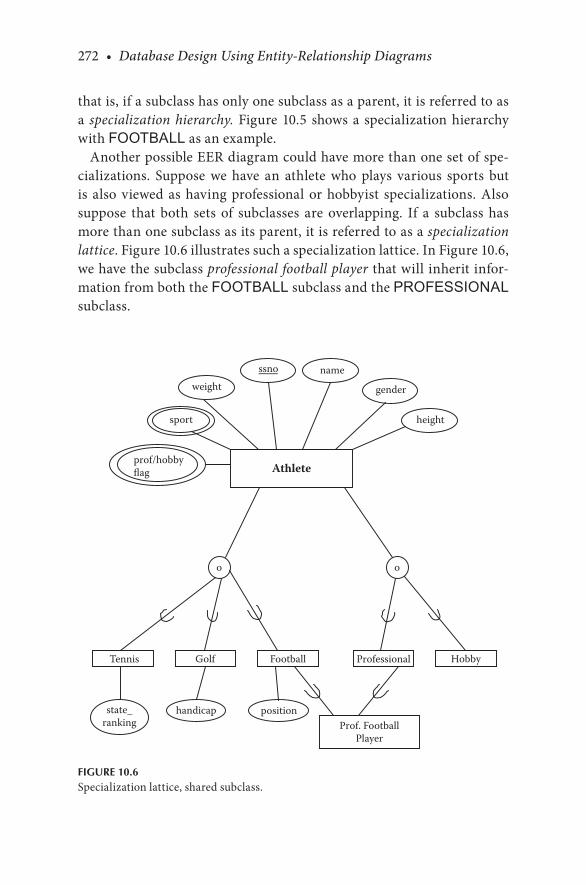
272 • Database Design Using Entity-Relationship Diagrams
that.is,.if.a.subclass.has.only.one.subclass.as.a.parent,.it.is.referred.to.as.a. specialization hierarchy..Figure 10.5. shows.a. specialization.hierarchy.with.FOOTBALL.as.an.example.
Another.possible.EER.diagram.could.have.more.than.one.set.of.spe-cializations.. Suppose. we. have. an. athlete. who. plays. various. sports. but.is. also.viewed.as.having.professional.or.hobbyist. specializations..Also.suppose. that. both. sets. of. subclasses. are. overlapping.. If. a. subclass. has.more.than.one.subclass.as.its.parent,.it.is.referred.to.as.a.specialization lattice..Figure 10.6.illustrates.such.a.specialization.lattice..In.Figure 10.6,.we.have.the.subclass.professional football player.that.will.inherit.infor-mation.from.both.the.FOOTBALL.subclass.and.the.PROFESSIONAL.subclass.
Athlete
weightssno
gender
state_ranking
handicap position
o
Tennis Golf Football
o
Professional
Prof. FootballPlayer
Hobby
sport
prof/hobbyflag
name
height
FIGURE 10.6Specialization.lattice,.shared.subclass.

The Enhanced Entity Relationship (EER) Model • 273
A. shared subclass. is. a. subclass. that. has. more. than. one. subclass. for.its. parents.. PROFESSIONAL FOOTBALL PLAYER is. a. subclass. of.FOOTBALL.as.well.as.PROFESSIONAL and.hence.inherits.from.mul-tiple.subclasses..Every.instance.of.a.shared.subclass.inherits.all.the.attri-butes.of.all.its.superclasses.
10.7.1 Mapping Rule 19
We.present.mapping.rule.19.to.map.shared.subclasses.
Mapping Rule 19—Mapping shared subclasses. In general, the same criteria that are used to determine which rule would be best for mapping generalizations and specializations can be applied to mapping shared subclasses. However, the rule that generates the best database is usually mapping rule 15.
As.an.example.of.applying.mapping.rule.15,.consider.the.mapping.of.Figure 10.6:
ATHLETE(ssno, weight, name, gender, height, (sport),(prof/hobby flag))
TENNIS(ssno, state_ranking)GOLF(ssno, handicap)FOOTBALL(ssno, position)PROFESSIONAL(ssno, agent,…HOBBY(ssno, title, budget,…PROFESSIONAL_FOOTBALL_PLAYER (ssno, team,…)
Here,.we.used.mapping.rule.15.to.map.Figure 10.6..In.other.cases,.it.could.be.appropriate.to.use.one.of.the.other.mapping.rules,.16–18..An.important.thing.to.note.is.that,.since.a.shared.subclass.ultimately.has.only.one.super-class,.the.subclasses.maintain.the.same.key.attribute..Also.in.this.mapping.there. are. multivalued. attributes,. which. necessitates. normalization. for. a.relational.database..To.normalize.these.tables,.there.would.have.to.be.two.more.tables.to.deal.with.the.multivalued.predicates:
ATHLETE(ssno, weight, name, gender, height, (sport),(prof/hobby flag))

274 • Database Design Using Entity-Relationship Diagrams
becomes
ATHLETE1(ssno, weight, name, gender, height)ATHLETE_SPORT(ssno,.sport)ATHLETE_PROAM(ssno,.prof/hobby flag)
10.8 CATEGORIES OR UNION TYPES
Thus.far.in.this.chapter,.we.presented.examples.with.one.superclass.and.several. subclasses..Suppose. the.design.of. the.database. results. in. several.superclasses,. and. a. subclass. inherits. from. the. superclasses.. Each. super-class.is.an.entity.unto.itself..When.a.subclass.has.more.than.one.superclass.from.which. it.may. inherit,. it. is.referred.to.as.a.category.or.union. type..Note. that. this. is.different. from.the.previous.section. in. that.here.we.are.
Student
u
ssn
Faculty
name addressnameaddressssn
Player
dept
team namesport
UnionType
FIGURE 10.7(a).A.category.or.union.type.with.same.primary.keys.(partial.participation).

The Enhanced Entity Relationship (EER) Model • 275
discussing.inheriting.from.more.than.one.superclass.as.opposed.to.more.than.one.subclass.
Whereas.a.shared.subclass.always.has.only.one.superclass.in.its.hierarchy,.a.category.or.union.type.can.have.more.than.one.superclass..A.category.or.union.type.will. inherit.information.from.any.one.of.the.superclasses;.hence,.the.term.union.is.used.to.describe.the.combination.of.information.from. whichever. superclasses. are. the. parents.. Symbolically,. we. show. the.union. type.with.a.u. in. the.circle.connecting. the.subclasses. to. its. super-classes,.as.shown.in.Figure 10.7a..Usually,.the.superclasses.will.have.dif-ferent.keys.since.they.are.different.entities,.but.there.may.also.be.scenarios.for. which. a. category. or. union. type. could. inherit. from. two. superclasses.that.have.the.same.type.key..For.example,. if.we.have.a.superclass.called.STUDENT,.another.superclass.called.FACULTY,.and.a.subclass.(category.or.union.type).PLAYER,.as.shown.in.Figure 10.7a,.the.PLAYER.category.can.be.a.subset.of.the.union.of.the.superclasses,.STUDENT.and.FACULTY,.and.inherit.the.same.key,.ssn.
Student
u
ssn
Faculty
name addressnameaddressssn
Player
dept
team namesport
FIGURE 10.7(b).A.category.or.union.type.with.the.same.primary.keys.(full.or.total.participation)..

276 • Database Design Using Entity-Relationship Diagrams
Figure 10.7a.says:
A.player.may.be.a.student.or.faculty member.
A.category.or.union.type.inherits.all.the.attributes.of.the.class.or.classes.to.which.it.belongs..So,.if.a.player.belongs.to.the.STUDENT.class.(super-class),. it. inherits. all. the. attributes. of. the. student. entity. type,. and. if. it.belongs.to.the.FACULTY.class.(superclass),.it.inherits.all.the.attributes.of.the.faculty.entity.type.
As.another.example.of.a.union.in.an.ER.diagram,.consider.Figure 10.8a..Here,.we.have.a.bill.payer,.but.the.payer.may.come.from.several.superclasses..PAYOR. could. inherit.data. from.PATIENT,.PRIMARY_INSURANCE,.or.OTHER_RESPONSIBLE_PARTY.
10.8.1 Participation Ratios in Categories or Union Types
Categories. or. union. types. can. also. have. participation. constraints..Reconsider. Figure 10.7a.. The. category. or. union. type. PLAYER. has.
Student
u
ssn
Faculty
name addressnameaddressssn
Player
dept
namesport
FIGURE 10.7(c).Full.participation.between.FACULTY.and.PLAYER.
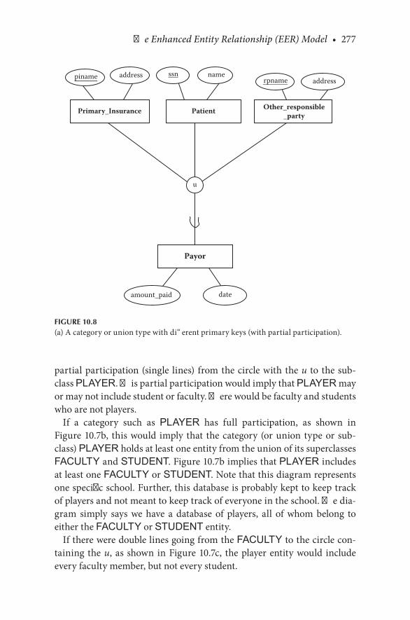
The Enhanced Entity Relationship (EER) Model • 277
partial.participation.(single. lines).from.the.circle.with.the.u. to.the.sub-class.PLAYER..This.partial.participation.would.imply.that.PLAYER.may.or.may.not.include.student.or.faculty..There.would.be.faculty.and.students.who.are.not.players.
If. a. category. such. as. PLAYER. has. full. participation,. as. shown. in.Figure 10.7b,. this.would. imply. that. the.category.(or.union.type.or.sub-class).PLAYER.holds.at.least.one.entity.from.the.union.of.its.superclasses.FACULTY.and.STUDENT..Figure 10.7b.implies.that.PLAYER.includes.at.least.one.FACULTY.or.STUDENT..Note.that.this.diagram.represents.one.specific.school..Further,.this.database.is.probably.kept.to.keep.track.of.players.and.not.meant.to.keep.track.of.everyone.in.the.school..The.dia-gram. simply. says. we. have. a. database. of. players,. all. of. whom. belong. to.either.the.FACULTY.or.STUDENT.entity.
If.there.were.double.lines.going.from.the.FACULTY.to.the.circle.con-taining.the.u,.as.shown.in.Figure 10.7c,. the.player.entity.would. include.every.faculty.member,.but.not.every.student.
amount_paid date
Primary_Insurance
u
ssn
Patient Other_responsible_party
rpname addressnameaddresspiname
Payor
FIGURE 10.8(a).A.category.or.union.type.with.different.primary.keys.(with.partial.participation).
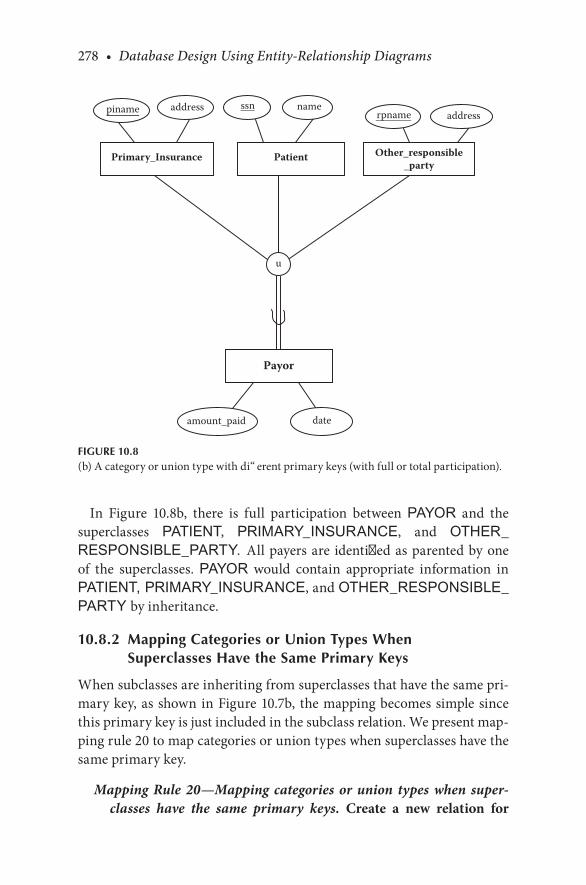
278 • Database Design Using Entity-Relationship Diagrams
In. Figure 10.8b,. there. is. full. participation. between. PAYOR. and. the.superclasses. PATIENT,. PRIMARY_INSURANCE,. and. OTHER_RESPONSIBLE_PARTY. All.payers.are. identified.as.parented.by.one.of. the. superclasses.. PAYOR. would. contain. appropriate. information. in.PATIENT, PRIMARY_INSURANCE,.and.OTHER_RESPONSIBLE_PARTY by.inheritance.
10.8.2 Mapping Categories or Union Types When Superclasses Have the Same Primary Keys
When.subclasses.are.inheriting.from.superclasses.that.have.the.same.pri-mary.key,.as.shown.in.Figure 10.7b,. the.mapping.becomes.simple.since.this.primary.key.is.just.included.in.the.subclass.relation..We.present.map-ping.rule.20.to.map.categories.or.union.types.when.superclasses.have.the.same.primary.key.
Mapping Rule 20—Mapping categories or union types when super-classes have the same primary keys. Create a new relation for
amount_paid date
Primary_Insurance
u
ssn
Patient Other_responsible_party
rpname addressnameaddresspiname
Payor
FIGURE 10.8(b).A.category.or.union.type.with.different.primary.keys.(with.full.or.total.participation).
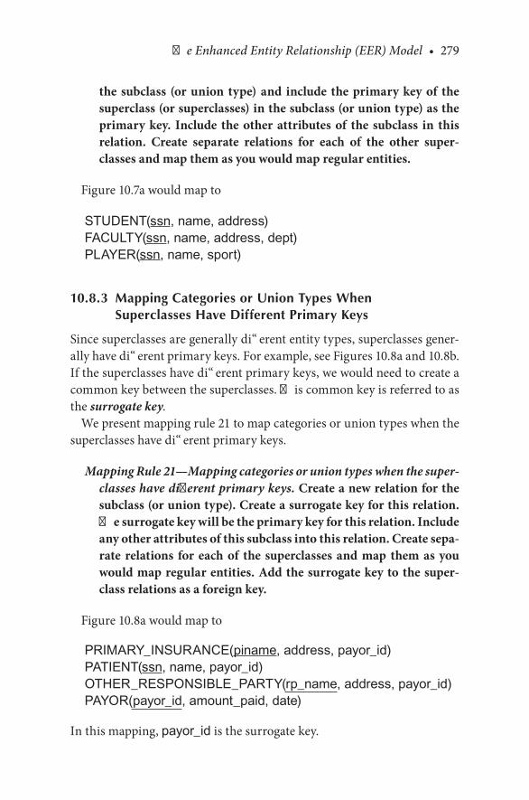
The Enhanced Entity Relationship (EER) Model • 279
the subclass (or union type) and include the primary key of the superclass (or superclasses) in the subclass (or union type) as the primary key. Include the other attributes of the subclass in this relation. Create separate relations for each of the other super-classes and map them as you would map regular entities.
Figure 10.7a.would.map.to
STUDENT(ssn, name, address)FACULTY(ssn, name, address, dept)PLAYER(ssn, name, sport)
10.8.3 Mapping Categories or Union Types When Superclasses Have Different Primary Keys
Since.superclasses.are.generally.different.entity.types,.superclasses.gener-ally.have.different.primary.keys..For.example,.see.Figures 10.8a.and.10.8b..If.the.superclasses.have.different.primary.keys,.we.would.need.to.create.a.common.key.between.the.superclasses..This.common.key.is.referred.to.as.the.surrogate key.
We.present.mapping.rule.21.to.map.categories.or.union.types.when.the.superclasses.have.different.primary.keys.
Mapping Rule 21—Mapping categories or union types when the super-classes have different primary keys. Create a new relation for the subclass (or union type). Create a surrogate key for this relation. The surrogate key will be the primary key for this relation. Include any other attributes of this subclass into this relation. Create sepa-rate relations for each of the superclasses and map them as you would map regular entities. Add the surrogate key to the super-class relations as a foreign key.
Figure 10.8a.would.map.to
PRIMARY_INSURANCE(piname, address, payor_id)PATIENT(ssn, name, payor_id)OTHER_RESPONSIBLE_PARTY(rp_name, address, payor_id)PAYOR(payor_id, amount_paid, date)
In.this.mapping,.payor_id.is.the.surrogate.key.

280 • Database Design Using Entity-Relationship Diagrams
CHECKPOINT 10.3. 1.. Figure 10.7a.says,.“A.player.may.be.a.student.or.a.faculty.”.We.show.
this.as.a.union..Could.we.have.shown.this.as.a.disjoint.relationship?.Discuss.
. 2.. What.is.the.difference.between.a.disjoint.relationship.and.a.union?
. 3.. How.would.you.map.a.category.or.union.type.with.the.same.keys.on.the.superclasses?
. 4.. How.would.you.map.a.category.or.union.type.with.different.keys.on.the.superclasses?
. 5.. When.would.you.create.a.generalization/specialization.relationship,.and.when.would.you.create.a.category.or.union.type?.Explain.with.examples.
. 6.. A.shared.subclass.inherits.attributes.from._________________?
. 7.. A.category.or.union.type.inherits.attributes.from._____________?
. 8.. What. is. the. difference. between. a. shared. subclass. and. category. or.union.type?
10.9 FINAL ER DESIGN METHODOLOGY
So,.our.final.ER.design.methodology.has.finally.evolved.to.the.presenta-tion.discussed.next.
10.9.1 ER Design Methodology
Step 1. Select one, primary entity from the database requirements description and show attributes to be recorded for that entity. Label keys if appropriate and show some sample data.
Step 2. Use structured English for entities, attributes, and keys to describe the database that has been elicited.
Step 3. Examine attributes in the existing entities (possibly with user assistance) to find out if information about one of the entities is to be recorded.
(We. change. primary. to. existing. because. we. redo. step. 3. as. we. add. new.entities.)
Step 3a. If information about an attribute is needed, then make the attribute an entity, and then
Step 3b. Define the relationship back to the original entity.

The Enhanced Entity Relationship (EER) Model • 281
Step 4. If another entity is appropriate, draw the second entity with its attributes. Repeat steps 2 and 3 to see if this entity should be further split into more entities.
Step 5. Connect entities with relationships (one or more) if relation-ships exist.
Step 6. State the exact nature of the relationships in structured English from all sides, for example, if a relationship is A:B::1:M, then there is a relationship from A(1) to B(M) and from B(M) back to A(1).For ternary and higher-order (n-ary) relationships, state the rela-
tionship in structured English, being careful to mention all enti-ties for the n-ary relationship. State the structural constraints as they exist.
For specialization/generalization relationships, state the relation-ship in structured English, being careful to mention all entities (subclasses or specializations). State the structural constraints as they exist.
Step 6a. Examine the list of attributes and determine whether any of them need to be identified by two (or more) entities. If so, place the attribute on an appropriate relationship that joins the two entities.
Step 6b. Examine the diagram for loops that might indicate redundant relationships. If a relationship is truly redundant, excise the redun-dant relationship.
Step 7. Show some sample data.Step 8. Present the “as designed” database to the user complete with
the English for entities, attributes, keys, and relationships. Refine the diagram as necessary.
10.10 CHAPTER SUMMARY
In. this. chapter,. we. have. described. the. concepts. of. generalizations. and.specializations,.overlapping.and.disjoint.relationships,.shared.subclasses.and. categories. or. union. types.. This. chapter. approached. EER. diagrams.as. discussed. by. Elmasri. and. Navathe. (2007). and. Connolly,. Begg,. and.Strachan.(1998)..Some.authors.(e.g.,.Sanders,.1995).use.a.close.variation.of.this.model.and.call.the.specialization/generalization.relationship.an.“IsA”.relationship.
This.chapter.also.concluded.the.development.of.the.EER.design.meth-odology.and.mapping.EER.diagrams.into.a.relational.database.

282 • Database Design Using Entity-Relationship Diagrams
CHAPTER 10 EXERCISES
Exercise 10.1
Draw.an.ER.diagram. for.a. library. for.an.entity. called. library holdings..Include.as.attributes.the.call.number,.name.of.book,.author(s),. location.in.library..Add.a.defining.predicate.of.holding type.and.draw.in.the.dis-joint,.partial.specializations.of.journals.and.reference.books,.with.jour-nals.having.the.attribute.renewal date.and.reference.books.the.attribute.checkout constraints.. Map. this. to. a. relational. database. and. show. some.sample.data.
Exercise 10.2
Draw.an.ER.diagram.for.computers.at.a.school..Each.computer.is.identi-fied. by. an. ID. number,. make,. model,. date. acquired,. and. location.. Each.computer.is.categorized.as.a.student.computer.or.a.staff.computer..If.it.is.a.student.computer,.an.attribute.is.hours available..If.it.is.a.staff.computer,.an.attribute. is.responsible party. (owner,. if.you.will)..Map. this. to.a. rela-tional.database.and.show.some.sample.data.
Exercise 10.3
Present.an.EER.diagram.that.has.a.union.type,.a.disjoint.relationship,.and.an.overlapping.relationship..Also.include.shared.subclasses.with.different.keys..Include.primary.keys.and.a.minimal.set.of.attributes.and.finally.map.this.to.a.relational.database..Write.out.the.structured.English.to.explain.your.diagram.
BIBLIOGRAPHY
Connolly,.T.,.Begg,.C.,.and.Strachan,.A..1998..Database Systems, a Practical Approach to Design, Implementation, and Management..Harlow,.UK:.Addison-Wesley.
Elmasri,.R.,.and.Navathe,.S..B..2007..Fundamentals of Database Systems,.5th.ed..Reading,.MA:.Addison-Wesley.
Sanders,.L..Data Modeling..1995..Danvers,.MA:.Boyd.and.Fraser.Teorey,.T..J.,.Nadeau,.T.,.and.Lightstone,.S..S..2005..Database Modeling and Design: Logical
Design..San.Francisco,.CA:.Morgan.Kaufman.
The Enhanced Entity Relationship (EER) Model • 283
CASE STUDY
West Florida Mall (continued)
So.far.in.our.case.study,.we.have.developed.the.major.entities.and.relation-ships.and.mapped.these.to.a.relational.database.(with.some.sample.data)..Then,.on.reviewing.step.7,.which.says
Step 7. Present the “as designed” database to the user complete with the English for entities, attributes, keys, and relationships. Refine the diagram as necessary.
Suppose.we.obtained.some.additional.input.from.the.user:
A. PERSON. may. be. an. owner,. employee,. or. manager.. For. each.PERSON,. we. will. record. the. name,. Social. Security. number,.address,.and.phone.number.
On.reviewing.these.additional.specifications,.we.came.up.with.one.new.entity,.PERSON.
Now,. repeating. step. 2. for. PERSON,. we. obtain. the. information. as.described.next.
The Entity
This.database.records.data.about.a PERSON.
For.each.PERSON.in.the.database,.we.record.a.person’s.name.(pname), person’s.Social.Security.number.(pssn), person’s.phone (pphone), and.person’s.address (padd).
The Attributes for PERSON
For.each.PERSON,.there.will.be.one.and.only.one.pname.(person’s.name)..The.value.for.pname.will.not.be.subdivided.
For. each PERSON,. there. will. be. one. and. only. one. pssn. (person’s.Social.Security.number)..The.value.for.pssn.will.not.be.subdivided.

284 • Database Design Using Entity-Relationship Diagrams
For.each.PERSON,.there.will.be.one.and.only.one.pphone.(person’s.phone)..The.value.for.pphone.will.not.be.subdivided.
For. each PERSON,. there. will. be. one. and. only. one. padd. (person’s.address)..The.value.for.padd.will.not.be.subdivided.
The Keys
For.each.PERSON,.we.will.assume.that.the.pssn.will.be.unique.
These.entities.have.been.added.to.the.diagram.in.Figure 10.9.
Person
d
1
N
N
N
N
1
1
1
1
N
Store
dept_of
owns
located_in
Department
Mall
Owner
Store Manager
Employee
manages
works_for
N 1
manages
FIGURE 10.9Final.ER.diagram.of.West.Florida.Mall.

The Enhanced Entity Relationship (EER) Model • 285
Using.step.6.to.determine.the.structural.constraints.of.relationships,.we.obtain.the.following:
As. shown. in. Figure 10.9,. there. is. a. disjoint. relationship. between.PERSON and.STORE_ MANAGER, OWNER,.and EMPLOYEE. This. means. that. a. person. may. be. an. owner,. store. manager,. or. an.employee.(a.disjoint.generalization/specialization.relationship).
To.map.this.relationship.we.would.normally.have:
MALLname address
STOREsloc sname snum mall_name so_ssn sm_ssn
OWNERso_ssn so_off_phone pssn
DEPARTMENTdname dnum snum
EMPLOYEEessn dnum snum dm_ssn pssn
PERSONpssn pname padd pphone
Store-Managersm ssn pssn ...
But. since.PERSON has. the. fields. of. Social. Security. number. (pssn),.name.(pname),.address.(padd),.and.phone.number.(pphone),.and.since.a.person.may.be.an.owner,.store.manager,.or.an.employee.(a.disjoint).gen-eralization/specialization.relationship,.notice.that.we.removed.some.of.the.attributes.from.the.original.entities..For.example,.in.the.EMPLOYEE.entity,.we.no.longer.need.to.keep.the.ename.field.since.this.can.be.obtained.from.PERSON.as.long.as.we.have.the.ssno.of.the.employee..Also,.since.pssn.is.actually.the.same.field.as.essn.in.EMPLOYEE,.so_ssn.in.OWNER,.and.sm_ssn.in.STORE_MANAGER,.we.do.not.need.to.include.pssn.in.EMPLOYEE, OWNER,.or.STORE_MANAGER.again.
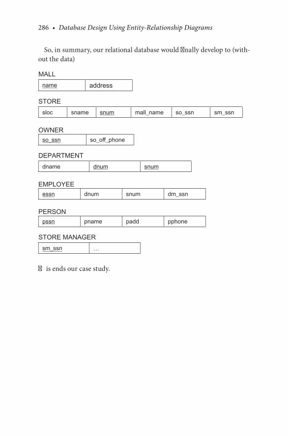
286 • Database Design Using Entity-Relationship Diagrams
So,.in.summary,.our.relational.database.would.finally.develop.to.(with-out.the.data)
MALLname address
STOREsloc sname snum mall_name so_ssn sm_ssn
OWNERso_ssn so_off_phone
DEPARTMENTdname dnum snum
EMPLOYEEessn dnum snum dm_ssn
PERSONpssn pname padd pphone
STORE MANAGERsm_ssn …
This.ends.our.case.study.

287
11Relational Mapping and Reverse Engineering ER/EER Diagrams
11.1 INTRODUCTION
Throughout.this.book,.we.have.developed.rules.for.mapping.entity.rela-tionship.(ER).and.enhanced.entity.relationship.(EER).diagrams.to.a.rela-tional. database.. In. this. chapter,. we. present. a. summary. of. the. mapping.rules. and. then. discuss. reverse. engineering—starting. with. the. database.and.working.backward.to.an.ER/EER.diagram..We.often.find.that.data-bases.exist.without.an.ER/EER.diagram.to.accompany.them..The.ER/EER.diagram.is.documentation;.just.as.computer.programs.require.documen-tation,.so.do.databases..Therefore,.we.have.included.a.section.on.reverse.engineering..As.we.did.previously,. for. reverse.engineering.we.present.a.series.of.steps.to.develop.an.ER/EER.diagram.from.tables.and.data.
11.2 STEPS USED TO MAP ER/EER DIAGRAMS TO RELATIONAL DATABASES
In.this.section,.we.present.a.summary.of.the.steps.that.we.have.developed.to.map.an.ER/EER.diagram.to.a.relational.database..In.following.these.steps,.the.resulting.relational.tables.should.be.close.to.the.third.normal.form.(3NF)..It.must.be.pointed.out.that.these.rules.do.not.preclude.the.usual.exercise.of.checking.the.resulting.database.to.be.absolutely.sure.it.is.normalized..If.data-bases.are.not.normalized,.redundancy.will.likely.be.present..As.much.as.pos-sible,.the.steps.should.be.followed.in.the.order.presented.to.promote.correct.mapping.to.result.in.tables.as.close.to.3NF.as.possible..Here.are.the.steps:
Step 1: Map all the strong entities in the ER diagram.
288 • Database Design Using Entity-Relationship Diagrams
We.start.with.mapping.rule.1.to.map.strong.entities:
Mapping Rule 1—Mapping strong entities. Develop a new table (rela-tion) for each strong entity and make the indicated key of the strong entity the primary key of the table. If more than one candidate key is indicated on the ER diagram, choose one for the primary key.
Next,.we.have.to.check.the.mapping.of.the.attributes.in.the.strong.entity..Since. the. mapping. rules. are. different. for. atomic. attributes,. composite.attributes,. and. multivalued. attributes,. we. present. each. of. the. mapping.rules.separately..First.is.the.mapping.rule.for.mapping.atomic.attributes:
Mapping Rule 2—Mapping atomic attributes. For entities with atomic attributes, map the entities to a table and form columns for each atomic attribute.
In.a.relational.database,.all.columns.have.to.be.atomic..If.we.have.nona-tomic.attributes.on.our.diagram,.we.have.to.make.them.atomic.for.map-ping.to.the.relational.database.
For. composite. attributes,. we. achieve. atomicity. by. recording. only. the.component.parts.of.the.attribute..Our.next.mapping.rule.concerns.com-posite.attributes:
Mapping Rule 3—Mapping composite attributes. For entities with composite attributes, map entities to a table and form columns of each elementary (atomic) part of the composite attribute.
The.mapping.rule.for.multivalued.attributes.is
Mapping Rule 4—Mapping multivalued attributes. Form a separate table for the multivalued attribute. Record a row for each value of the multivalued attribute together with the key from the original table. The key of the new table will be the concatenation of the multivalued attribute plus the key of the owner entity. Remove the multivalued attribute from the original table.
At.the.end.of.this.step,.all.the.strong.entities.should.be.mapped.
Step 2. Map all the weak entities in the ER diagram.For.weak.entities,.we.use.mapping.rule.11.
Mapping Rule 11—Mapping weak entities. Develop a new table (rela-tion) for each weak entity. As is the case with the strong entity, include any atomic attributes from the weak entity in the table.

Relational Mapping and Reverse Engineering ER/EER Diagrams • 289
If there is a composite attribute, include only the atomic parts of the composite attribute and be sure to qualify the atomic parts in order not to lose information. To relate the weak entity to its owner, include the primary key of the owner entity in the weak entity table. The primary key of the weak entity table will be the partial key in the weak entity concatenated to the primary key of the owner entity.
If the weak entity owns other weak entities, then the weak entity that is connected to the strong entity must be mapped first. The key of the weak owner entity has to be defined before the “weaker” entity (the one furthest from the strong entity) can be mapped.
After.the.strong.entities.are.mapped.(as.per.step.1),.it.is.important.that.the.weak.entities.are.mapped.next.since.the.key.of.the.weak.entity.is.the.key.of.the.strong.(owner).entity.plus.the.partial.key.of.the.weak.entity.
Once.all. the. strong.entities. and.weak.entities.have.been.mapped,. the.next.step.is.to.map.the.relationships.
Step 3. Map the relationships.
The.relationships.can.be.mapped.in.any.order..It.is.most.convenient.to.begin.by.mapping.binary.M:N.relationships..At.this.point,.we.should.have.tables.for.all.the.strong.and.weak.entities..The.next.section.involves.adding.attributes.to.these.tables.or.creating.new.tables.to.house.relationships.
Mapping Rule 5—Mapping M:N relationships. For each M:N relation-ship, create a new table (relation) with the primary keys of each of the two entities (owner entities) that are being related in the M:N relationship. The primary key of this new table will be the concat-enated keys of the owner entities. Include any attributes that the M:N relationship may have in this new table.
Next,.we.will.map.the.binary.1:1.relationships..Mapping.1:M.or.1:1.rela-tionships.depends.on.participation.constraints. Most.of.the.rules.that.fol-low.involve.either.(a).adding.an.attribute.(a.foreign.key).to.a.table.created.by.a.previous.mapping.rule.or.(b).adding.a.new.table.in.a.process.similar.to.mapping.M:N.relationships.
Mapping Rule 6—Mapping binary 1:1 relationships when one side of the relationship has full participation and the other has par-tial participation. When one of the sides of the relationship has full participation and the other has partial participation, then store the primary key of the side with the partial participation
290 • Database Design Using Entity-Relationship Diagrams
constraint on the side with the full participation constraint; this attribute is a foreign key (it is not underlined). Include any attributes on the relationship in the same table to which the key was added.
Mapping Rule 7—Mapping binary 1:1 relationships when both sides have partial participation constraints.
When. both. sides. have. partial. participation. constraints. in. binary. 1:1.relationships,.the.relationships.can.be.mapped.in.one.of.two.ways:
Option 1:Mapping Rule 7A. Select either one of the tables to store the key of the
other as a foreign key.
This.choice.depends.on.semantics..Perhaps.a.safer.choice.for.mapping.this.type.of.relationship.is.rule.7B:
Option 2:Mapping Rule 7B. Depending on semantics, you can create a new
table to house the relationship that would contain the key of the two related entities.
Mapping Rule 8—Mapping binary 1:1 relationships when both sides have full participation constraints. Use the semantics of the rela-tionship to select which of the tables should contain the key of the other. If this choice is unclear, then use mapping rule 7B: create a separate table to house the relationship.
Now.that. the.M:N.relationships.and.binary.1:1.relationships.have.been.mapped,.the.next.step.will.be.to.map.the.common.binary.1:N.relationships.
Mapping Rule 9—Mapping binary 1:N relationships when the N side has full participation. Include the key of the entity on the 1 side of the relationship as a foreign key on the N side.
Mapping Rule 10—Mapping binary 1:N relationships when the N side has partial participation. This situation would be handled just like a binary M:N relationship with a separate table for the rela-tionship. The key of the new table would consist of a concatenation of the keys of the related entities. Include any attributes that were on the relationship on this new table.
Partial.participation.is.a.problem.because.it.leads.to.null.values..If.we.put.the.key.from.the.1.side.into.the.N-side.table.and.if.the.participation.

Relational Mapping and Reverse Engineering ER/EER Diagrams • 291
is.partial.(not.every.row.on.the.N.side.has.a.relationship.to.the.1.side),.then.there.will.be.nulls.in.the.database.when.it.is.populated..Therefore,.it. is.better. to.create.a.separate. table. for. the.1:N.relationship.and.hence.avoid.nulls.
Finally,.on.the.subject.of.1:N.relationships,.we.should.look.at.Figure 8.2,.where.an.M:N.relationship.was.converted.into.two.1:N.relationships..Note.that.the.result.of.converting.the.M:N.into.two.1:N.relationships.will.result.in.the.same.set.of.tables.from.1:N.mappings.
Our.next.step.would.be.to.map.recursive.relationships.
Mapping Rule 12—Mapping 1:N recursive relationships. Reinclude the primary key of the table with the recursive relationship in the same table, giving it some other role name.
Mapping Rule 13—Mapping M:N recursive relationships. Create a separate table for the relationship (as in mapping rule 5).
We.will.use.mapping.rule.14.to.map.n-ary.relationships.
Mapping Rule 14—Mapping n-ary relationships. For each n-ary rela-tionship, create a new table. In the new table, include the keys of the connected entities and any attributes of the relationship. Make the keys of the connected entities the concatenated primary key of the new table.
Next,.we.map.the.EER.diagram.
Step 4. Mapping generalizations/specializations.
Mapping Rule 15—Mapping generalizations and specializations with disjoint or overlapping subclasses and with total or partial par-ticipation constraints (with few or many attributes on the special-izations). For each generalization/specialization entity situation, create one table for the generalization entity (if you have not done so already per the previous steps) and create one table for each specialization. Add the attributes for each specialization to their respective tables (relations). Include the primary key of the gen-eralization entity in the specialization tables. The primary key of the specialization tables will be the same primary key as the gen-eralization table.
Mapping Rule 16—Mapping generalizations and specializations with disjoint relationship constraints and total participation between generalizations and specializations. Create a separate
292 • Database Design Using Entity-Relationship Diagrams
(subclass) table for each specialization entity. Include the attri-butes for each specialization entity in their respective subclass tables. Also include the primary key and other attributes of the generalization entity in all the subclass tables. The primary key of the subclass tables will be the primary key of the generaliza-tion entity.
Mapping Rule 17—Mapping generalizations and specializations with disjoint relationships, total or partial participation constraints, and predicate defined with single type attributes. Create a single table that includes the attributes of the generalization (superclass) as well as the attributes of the specializations (subclasses). The pri-mary key of the table will be the primary key of the generalization (superclass).
Mapping Rule 18—Mapping overlapping relationships and general-izations/specializations with more than one flag. Create a single table that includes the attributes of the generalization (superclass) and the attributes of the specializations or subclasses (including the subclass flags). The primary key of the table is the primary key of the superclass.
Mapping Rule 19—Mapping shared subclasses. The same criteria that are used to determine which rule would be best for mapping gen-eralizations and specializations can be applied to mapping shared subclasses. That is, any of the mapping rules 15–18 can be used to map a shared subclass.
Mapping Rule 20—Mapping categories or union types when super-classes have same primary keys. Create a new table for the subclass (or union type) and include the primary key of the superclass (or superclasses) in the subclass (or union type) as the primary key. Include the other attributes (if any) of the subclass in this table. Create separate tables for each of the other superclasses and map them as you would map regular entities.
Mapping Rule 21—Mapping categories or union types when the superclasses have different primary keys. Create a new table for the subclass (or union type). Create a surrogate key for this table. This will be the primary key for this table. Include any other attri-butes (if any) of this subclass in this table. Create separate tables for each of the superclasses and map them as you would map regu-lar entities. Include the surrogate key in the superclass tables as a foreign key.

Relational Mapping and Reverse Engineering ER/EER Diagrams • 293
CHECKPOINT 11.1
. 1.. What.is.the.first.mapping.rule?
. 2.. Why. is. it. good. to.first.map.strong.entities.and. then.map. the.weak.entities?
. 3.. What.would.you.map.after.you.map.the.weak.entities?
. 4.. How.would.you.map.weak.entities.of.weak.entities?
. 5.. While. mapping. a. binary. 1:N. relationship. when. the. N. side. has. full.participation,.why.do.we.include.the.key.of.the.1.side.of.the.table.in.the.N.side.of.the.table?.What.would.be.wrong.if.we.included.the.key.of.the.N.side.of.the.table.in.the.1.side.of.the.table?
. 6.. Why.would.it.be.reasonable.to.map.a.1:N.binary.relationship.that.has.partial.participation.on.the.N.side.like.an.M:N.relationship?
If.the.rules.are.followed,.the.resulting.relational.database.should.be.at.or.close.to.3NF..The.next.phase.of.mapping.is.“checking.your.work”.by.reviewing.the.table.to.ensure.that.you.are.at.least.in.3NF.(refer.to.Chapter.3)..In.brief,.checking.for.3NF.consists.of.the.following.steps:
1. 1NF—Check. that. there. are. no. nonatomic. attributes. in. any. table..Nonatomic.attributes.were.dealt.with.in.mapping.rule.3.for.compos-ite.attributes.and.mapping.rule.4.for.multivalued.attributes.
2. 2NF—Check.that.all.attributes.in.all.tables.depend.on.the.full.primary.key..Ask.yourself,.“Will.I.always.get.the.same.value.for.attribute.Y.when.I.have.value.X.when.X.is.the.primary.key?”.X.in.this.case.could.be.a.concatenated.key,.and.you.would.be.looking.for.partial.dependencies.
3. 3NF—Check.for.situations.for.which.an.attribute.is.in.a.table.but.that.attribute.is.better.defined.by.some.attribute.that.is.not.the.primary.key..Recall.that.if.the.primary.key.in.a.table.is.X.and.X.→.YZW,.then.if.Z.→.W.is.clearer.than.X.→.W,.you.likely.have.a.transitive.depen-dency.and.you.would.need.to.normalize.
11.3 REVERSE ENGINEERING
Having.developed.a.methodology.to.develop.ER/EER.diagrams.and.map.them.to.a.relational.database,.we.now.turn.our.attention.to.the.reverse.engineering.problem—the.issue.of.taking.a.relational.database.and.devising.an.ER/EER.diagram..Often,. in.real-world.situations,.we.find.ourselves.with.a.database.and.have.no.diagram.to.show.how.it.was.developed..There.are.several.reasons.why.a.reverse.engineered.diagram.(RED).paradigm.is.useful.

294 • Database Design Using Entity-Relationship Diagrams
The.Reverse.Engineered.Diagram.provides.us.with.a.grammatical.and.diagrammatic.description.of.the.database..Often,.people.use.databases.but.do.not.understand.them.because.there.is.no.“big.picture.”.By.reverse.engi-neering.from.the.data.and.tables.to.the.diagram,.we.can.more.easily.express.the.meaning.of.the.database.in.words..By.having.the.ER/EER.diagram.of.the.relational.database.and.the.grammatical.expression.of.the.diagram,.we.can.embellish.the.database.and.maintain.meaning..The.ER.diagram.can.also.aid.greatly.in.the.development.of.queries.on.the.database.
While. the.expression.reverse engineering.might. imply. that.we. reverse.the.steps.to.create.a.diagram,.we.have.found.it.easier.to.repeat.the.steps.from.the.top.(more.or.less).to.discover.which.diagram.would.have.been.used.to.create.the.relational.database..The.process.of.reverse.engineering.is.most.easily.approached.by.finding.strong.entities.and.then.filling.in.the.other.parts.of.the.database..There.is.one.caveat.here.in.that.the.steps.pre-sented.assume.that.the.database.is.in.3NF..If.it.is.not.in.3NF,.then.reverse.engineering.may.aid.in.discovering.why.redundancy.exists.in.the.database.and.hence.suggest.some.changes.
With.ER.diagrams.and.the.elucidation.process,.we.proposed.drawing.the.diagram,.adding.English.descriptions,.and.presenting.the.result.to.the. user.. Here,. after. this. process. of. reverse. engineering. is. completed,.it. is.expected.that.the.resulting.diagram.would.be.accompanied.by.an.English. version. and. presented. to. the. users. as. well.. The. sense. of. this.reverse.engineering.process.is.much.like.the.original.elucidation.in.that.one.proceeds.and.checks.with.users.to.be.sure.the.analysts.have.it.cor-rect..The.rules.are.provided.as.a.guideline.to.move.from.no.ER.diagram.to.a.more.complete,.documented.database..The.following.rules.are.not.to.be.considered.rigid.but.rather.a.starting.point.toward.“negotiating”.a.documented.database..It.is.likely.that.the.ER.diagram.will.evolve,.the.database.may.change,.and.the.users.will.govern.the.final.product..For.example,.superclasses.and.subclasses.can.be.mapped.in.several.ways..It.may.be.discovered.that.another.mapping.may.have.been.better.than.the.existing.one..With.no.original.ER.diagram,.many.scenarios.are.possible.once.the.big.picture.is.presented.
We.suggest.the.following.rules.to.affect.reverse.engineering.(Figure 11.1):
11.3.1 Reverse Engineering Rule 1. Develop Strong Entities
For.tables.with.a.one-attribute.key,.draw.a.strong.entity.R.for.that.table.and.include.all.the.attributes.of.that.table.in.the.entity.R.on.the.ER.diagram.
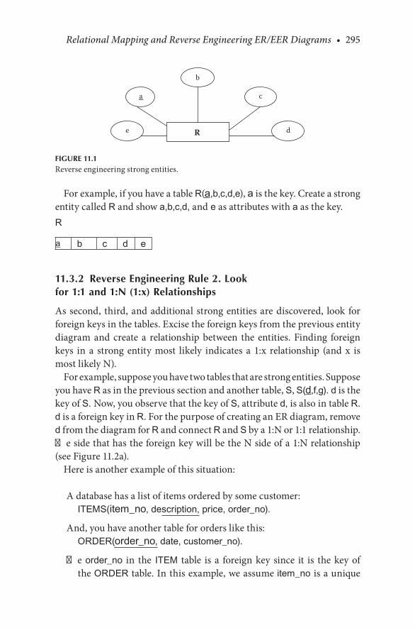
Relational Mapping and Reverse Engineering ER/EER Diagrams • 295
For.example,.if.you.have.a.table.R(a,b,c,d,e),.a.is.the.key..Create.a.strong.entity.called.R.and.show.a,b,c,d,.and e.as.attributes.with.a.as.the.key.R
a b c d e
11.3.2 Reverse Engineering Rule 2. Look for 1:1 and 1:N (1:x) Relationships
As.second,. third,.and.additional. strong.entities.are.discovered,. look. for.foreign.keys.in.the.tables..Excise.the.foreign.keys.from.the.previous.entity.diagram. and. create. a. relationship. between. the. entities.. Finding. foreign.keys. in. a. strong. entity. most. likely. indicates. a. 1:x. relationship. (and. x. is.most.likely.N).
For.example,.suppose.you.have.two.tables.that.are.strong.entities..Suppose.you.have.R.as.in.the.previous.section.and.another.table,.S,.S(d,f,g). d.is.the.key.of.S. Now,.you.observe.that.the.key.of.S,.attribute.d,.is.also.in.table.R..d.is.a.foreign.key.in.R..For.the.purpose.of.creating.an.ER.diagram,.remove.d.from.the.diagram.for.R.and.connect.R.and.S.by.a.1:N.or.1:1.relationship..The.side.that.has.the.foreign.key.will.be.the.N.side.of.a.1:N.relationship.(see.Figure 11.2a).
Here.is.another.example.of.this.situation:
A.database.has.a.list.of.items.ordered.by.some.customer:ITEMS(item_no, description, price, order_no).
And,.you.have.another.table.for.orders.like.this:ORDER(order_no, date, customer_no).
The.order_no. in. the ITEM. table. is.a. foreign.key. since. it. is. the.key.of.the.ORDER.table..In.this.example,.we.assume. item_no. is.a.unique.
R
a
b
c
de
FIGURE 11.1Reverse.engineering.strong.entities.
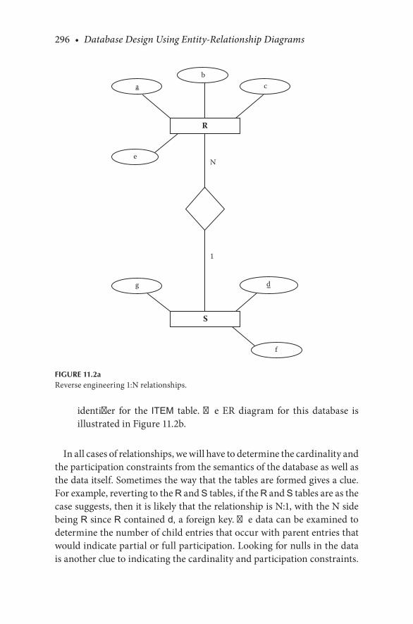
296 • Database Design Using Entity-Relationship Diagrams
identifier. for. the. ITEM. table.. The. ER. diagram. for. this. database. is.illustrated.in.Figure 11.2b.
In.all.cases.of.relationships,.we.will.have.to.determine.the.cardinality.and.the.participation.constraints.from.the.semantics.of.the.database.as.well.as.the.data.itself..Sometimes.the.way.that.the.tables.are.formed.gives.a.clue..For.example,.reverting.to.the.R.and.S.tables,.if.the.R.and.S.tables.are.as.the.case.suggests,.then.it.is.likely.that.the.relationship.is.N:1,.with.the.N.side.being.R.since.R.contained.d,.a.foreign.key..The.data.can.be.examined.to.determine.the.number.of.child.entries.that.occur.with.parent.entries.that.would.indicate.partial.or.full.participation..Looking.for.nulls.in.the.data.is.another.clue.to.indicating.the.cardinality.and.participation.constraints..
N
1
R
bc
e
a
S
d
f
g
FIGURE 11.2aReverse.engineering.1:N.relationships.

Relational Mapping and Reverse Engineering ER/EER Diagrams • 297
We. must. use. the. word. indicate. because. only. the. true. (albeit. unknown).semantics.and.the.data.itself.would.“prove”.the.full/partial.participation.
11.3.3 Reverse Engineering Rule 2a. Check for Attributes of the 1:x Relationship
In.the.ER.diagram,.if.a.foreign.key.is.excised.from.an.entity.R.because.it.is.the.key.of.S,.you.have.to.check.to.see.whether.any.of.the.remaining.attri-butes.in.R.should.stay.with.the.entity.R,.should.be.placed.on.a.relationship.RS,.or.should.be.placed.with.S..Since.step.2.is.reverse.mapping.a.1:x.rela-tionship,. it.may.be. that.an.attribute. from.the.1:x. relationship. itself.was.placed.with.the.foreign.key.when.the.original.ER.diagram.was.mapped,.or.it.may.be.that.an.attribute.was.on.the.relationship.itself.
1
N
Order
datecustomer_noorder_no
Item
descriptionitem_no
price
FIGURE 11.2bAnother.example.of.reverse.engineering.1:N.relationships.

298 • Database Design Using Entity-Relationship Diagrams
You.have.to.judge.where.a.remaining.attribute.is.more.likely.to.belong..If.it.is.likely.that.the.attribute.was.defined.by.the.key.of.an.entity,.put.the.attribute.with.the.entity.containing.the.key..If.the.attribute.requires.both.keys.for.its.identity,.the.attribute.should.be.placed.on.the.relationship.RS.
Example 11.2
In.the.case.discussed,.we.removed.d.from.R.in.the.ER.diagram.because.d. was. the. key. of. S.. Suppose. after. we. create. S,. we. determine. that. e.only.makes.sense.if.we.define.it.in.terms.of.both.a.and.d,.the.keys.of.R.and.S..This.would.imply.that.e was.an.intersection.attribute.on.the.relationship.between.R.and.S.and.hence.would.be.depicted.as.such,.as.shown.in.Figure.11.3a.
Reconsider.the.ORDER.database.example..If,.in.our.ORDER.data-base.example,.the.items_ordered.were.uniquely.identified.by.item_no,.but. the. situation. was. that. items. were. ordered. repeatedly,. then. the.date.attribute.would.have.to.be.identified.by.both.the.item_no.and.the.order_no..In.this.case,.Figure.11.2b.would.become.Figure 11.3b.
This.concludes.the.reverse.mapping.of.obviously.strong.tables..We.now.look.for.weak.tables.and.multivalued.attributes.
11.3.4 Reverse Engineering Rule 3. Look for Weak Entities and Multivalued Attributes
Examine.the.tables.for.any.concatenated.keys.to.see.whether.they.contain.any.of.the.keys.of.the.strong.entities..If.they.do,.this.could.indicate.a.weak.entity,.a.multivalued.attribute,.or.a.table.resulting.from.M:N.or.higher-order.relationship..Which.of.these.it.is.may.depend.on.nonkey.attributes.
11.3.5 Reverse Engineering Rule 3a. Checking for Weak Entities
If.there.is.a.table.in.which.there.are.attributes.other.than.the.concatenated.key.(which.consists.of.a.foreign.key.from.a.strong.entity.and.another.attri-bute—the.partial.key),.then.you.probably.have.a.weak.entity.
For.example,.if.you.have.a.table
SKILL(emp_no, skill_type, date_certified)
The.concatenated.key.is.emp_no and.skill_type..Here,.emp_no.is.a.for-eign.key,.and.skill_type.is.not;.hence,.skill_type.would.likely.be.a.partial.

Relational Mapping and Reverse Engineering ER/EER Diagrams • 299
key.of.a.weak.entity..Why.a.weak.entity?.This.is.because.there.is.another.attribute,. date_certified,. which. means. that. we. are. storing. information.about.skills.for.that.employee..Here,.skill_type.is.not.a.unique.identifier.for.the.information.presented.
Place.the.weak.entity.on.the.ER.diagram.along.with.a.relationship.to.its.owner.entity.(Figure 11.4)..The.relationship.is.likely.to.be.1:N::strong.(owner):weak(dependent)::partial:full..Examine.the.attributes.in.the.weak.entity.to.determine.whether.they.would.have.come.from.the.weak.entity.or.the.relationship.between.the.weak.entity.and.its.owner..Here,.SKILL.is.the.weak.entity,.skill_type.is.the.partial.key,.and.date_certified.is.an.attri-bute.of.the.weak.entity.SKILL.
N
1
R
bc
e
a
S
d
f
g
FIGURE 11.3aReverse.engineering.a.relationship.attribute.

300 • Database Design Using Entity-Relationship Diagrams
11.3.6 Reverse Engineering Rule 3b. Checking for Multivalued Attributes
If.there.are.(a).no.other.attributes.other.than.a.concatenated.key.in.a.table;.(b).part.of.the.key.is.a.foreign.key.from.a.strong.entity;.and.(c).the.other.attribute.is.not.a.foreign.key,.then.it.is.likely.that.this.a.multivalued.attri-bute.situation..The.multivalued.attribute.would.have.been.connected.to.the.strong.entity.referenced.by.the.foreign.key..Place.the.multivalued.attribute.on.the.entity.to.which.it.belongs.as.a.multivalued.attribute.(Figure 11.5).
For.example,.if.we.have.the.table
INSTRUCTOR (ssno, degree)
1
N
Order
date
customer_noorder_no
Item
descriptionitem_no
price
FIGURE 11.3bReverse.engineering.1:N.relationships.with.relationship.attributes.

Relational Mapping and Reverse Engineering ER/EER Diagrams • 301
Here,.we.have.a.concatenated.key.and.no.other.attributes..Since.ssno.is.likely.the.key.of.another.entity,.(say).PERSON.and.since.degree.is.not.a.likely.key,.then.degree.must.be.a.multivalued.attribute..Why.not.a.weak.entity?.If.it.were.a.weak.entity,.there.would.probably.be.more.attributes—for.example,.we.would.be.recording.information.about.the.degrees.for.that.person,.but.we.are.not.doing.so.in.this.case.
1
N
Employee
emp_no
Skill
date_certified
skill_type
FIGURE 11.4Reverse.engineering.weak.entities.
Instructor degree
FIGURE 11.5Reverse.engineering.multivalued.attributes.
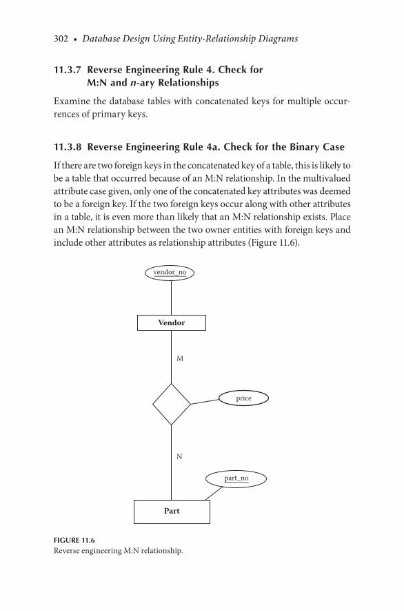
302 • Database Design Using Entity-Relationship Diagrams
11.3.7 Reverse Engineering Rule 4. Check for M:N and n-ary Relationships
Examine.the.database.tables.with.concatenated.keys.for.multiple.occur-rences.of.primary.keys.
11.3.8 Reverse Engineering Rule 4a. Check for the Binary Case
If.there.are.two.foreign.keys.in.the.concatenated.key.of.a.table,.this.is.likely.to.be.a.table.that.occurred.because.of.an.M:N.relationship..In.the.multivalued.attribute.case.given,.only.one.of.the.concatenated.key.attributes.was.deemed.to.be.a.foreign.key..If.the.two.foreign.keys.occur.along.with.other.attributes.in.a.table,.it.is.even.more.than.likely.that.an.M:N.relationship.exists..Place.an.M:N.relationship.between.the.two.owner.entities.with.foreign.keys.and.include.other.attributes.as.relationship.attributes.(Figure 11.6).
M
N
Part
Vendor
vendor_no
part_no
price
FIGURE 11.6Reverse.engineering.M:N.relationship.
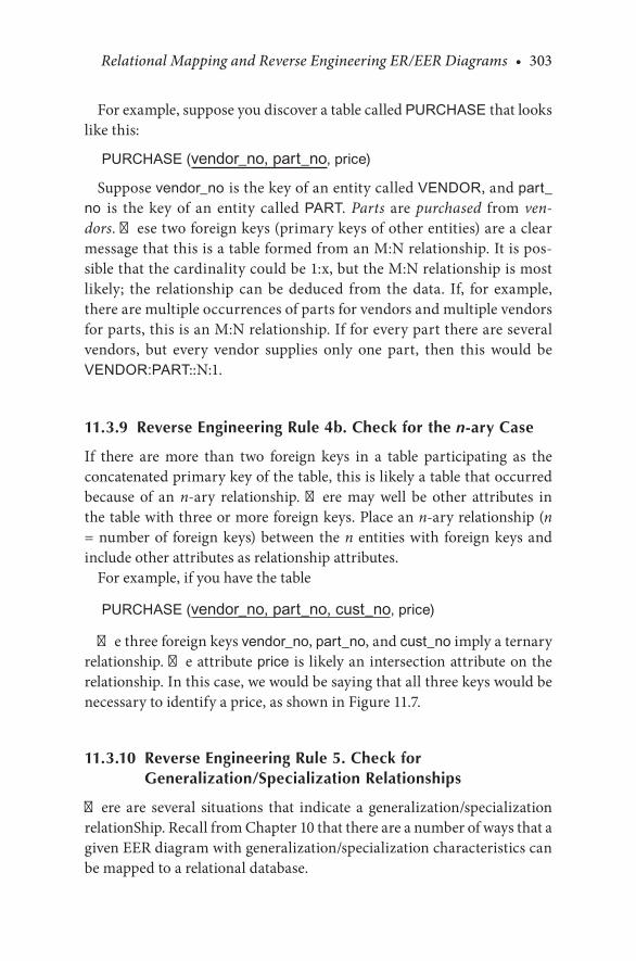
Relational Mapping and Reverse Engineering ER/EER Diagrams • 303
For.example,.suppose.you.discover.a.table.called.PURCHASE that.looks.like.this:
PURCHASE (vendor_no, part_no, price)
Suppose.vendor_no is.the.key.of.an.entity.called.VENDOR,.and.part_no is. the. key. of. an. entity. called.PART.. Parts. are. purchased. from. ven-dors..These.two.foreign.keys.(primary.keys.of.other.entities).are.a.clear.message.that.this.is.a.table.formed.from.an.M:N.relationship..It.is.pos-sible.that.the.cardinality.could.be.1:x,.but.the.M:N.relationship.is.most.likely;. the. relationship. can. be. deduced. from. the. data.. If,. for. example,.there.are.multiple.occurrences.of.parts.for.vendors.and.multiple.vendors.for.parts,.this.is.an.M:N.relationship..If.for.every.part.there.are.several.vendors,. but. every. vendor. supplies. only. one. part,. then. this. would. be.VENDOR:PART::N:1.
11.3.9 Reverse Engineering Rule 4b. Check for the n-ary Case
If. there. are. more. than. two. foreign. keys. in. a. table. participating. as. the.concatenated.primary.key.of.the.table,.this.is.likely.a.table.that.occurred.because. of. an. n-ary. relationship.. There. may. well. be. other. attributes. in.the.table.with.three.or.more.foreign.keys..Place.an.n-ary.relationship.(n.=.number.of. foreign.keys).between.the.n. entities.with. foreign.keys.and.include.other.attributes.as.relationship.attributes.
For.example,.if.you.have.the.table
PURCHASE (vendor_no, part_no, cust_no, price)
The.three.foreign.keys.vendor_no,.part_no,.and.cust_no.imply.a.ternary.relationship..The.attribute.price. is. likely.an.intersection.attribute.on.the.relationship..In.this.case,.we.would.be.saying.that.all.three.keys.would.be.necessary.to.identify.a.price,.as.shown.in.Figure 11.7.
11.3.10 Reverse Engineering Rule 5. Check for Generalization/Specialization Relationships
There. are. several. situations. that. indicate. a. generalization/specialization.relationShip..Recall.from.Chapter.10.that.there.are.a.number.of.ways.that.a.given.EER.diagram.with.generalization/specialization.characteristics.can.be.mapped.to.a.relational.database.
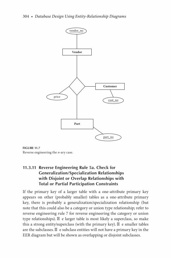
304 • Database Design Using Entity-Relationship Diagrams
11.3.11 Reverse Engineering Rule 5a. Check for Generalization/Specialization Relationships with Disjoint or Overlap Relationships with Total or Partial Participation Constraints
If. the. primary. key. of. a. larger. table. with. a. one-attribute. primary. key.appears. on. other. (probably. smaller). tables. as. a. one-attribute. primary.key,. there. is. probably. a. generalization/specialization. relationship. (but.note.that.this.could.also.be.a.category.or.union.type.relationship;.refer.to.reverse.engineering.rule.7.for.reverse.engineering.the.category.or.union.type.relationships)..The. larger. table. is.most. likely.a. superclass,. so.make.this.a.strong.entity/superclass.(with.the.primary.key)..The.smaller.tables.are.the.subclasses..The.subclass.entities.will.not.have.a.primary.key.in.the.EER.diagram.but.will.be.shown.as.overlapping.or.disjoint.subclasses.
Part
Vendor
Customer
vendor_no
part_no
cust_noprice
FIGURE 11.7Reverse.engineering.the.n-ary.case.

Relational Mapping and Reverse Engineering ER/EER Diagrams • 305
For.example,.if.we.had.the.following.set.of.tables.in.a.database:
M (m, a, b, c, f)N (m, d, n)O (m, o)P (m, p, e)
we.can.see.that.m.is.the.primary.key.in.all.the.tables..Since.M.is.the.larger.table,. it. is. probably. the. superclass. and. N,. O,. P. are. subclasses. that. will.inherit.from.M..This.set.of.tables.would.map.to.Figure 11.8.
Next,.we.should.try.to.determine.if.the.subclasses.are.disjoint.or.over-lapping..We.do.this.by.looking.at.the.data..If.the.primary.key.appears.on.one.subclass.table.at.a.time,.that.is,.if.a.record.or.object.appears.to.be.in.only.one.table.at.a.time,.then.this.is.probably.a.disjoint.relationship,.so.we.would.place.a.d.in.the.circle.joining.the.superclass.entity.to.the.subclasses.entities..If.the.primary.key.appears.on.more.than.one.subclass.table.at.a.time,.that.is,.if.a.record.or.object.appears.to.be.in.more.than.one.subclass.table.simultaneously,.then.this.is.probably.an.overlapping.subclass.situa-tion,.so.we.would.place.an.o.on.the.circle.joining.the.superclass.entity.to.
M
cm
b
d o p
d
N O P
f
a
en
FIGURE 11.8Reverse.engineering.a.generalization/specialization.relationship.

306 • Database Design Using Entity-Relationship Diagrams
the.subclass.entities..If.the.subclasses.overlap,.then.a.multivalued.attribute.will.be.necessary.in.the.superclass.entity.
To.try.to.determine.if.the.relationship.is.total.or.partial,.we.again.need.the.help.of.some.actual.data..If.every.primary.key.(or.object.or.record).in.the.superclass.table.appears.on.at.least.one.of.the.subclass.tables,.this.is.probably.a.total.participation.subclass/superclass.relationship..But,.if.every.primary.key.(or.object.or.record).in.the.superclass.table.does.not.appear.on.at.least.one.of.the.subclass.tables,.this.is.likely.a.partial.participation.relationship.
11.3.12 Reverse Engineering Rule 5b. Check for Disjoint Generalization/Specialization Relationships with Single-Predicate-Defined Attributes
If.there.is.a.single.large.table.that.appears.to.have.predicate-defined.attri-butes. and. values. or. nulls. corresponding. to. the. predicate-defined. attri-butes,.this.is.probably.a.disjoint.generalization/specialization.relationship.with.a.predicate-defined.attribute.on.the.superclass..The.superclass.entity.will.have.the.primary.key.and.the.attributes.that.are.not.predicate.defined..The.subclasses.will.contain.the.attributes.corresponding.to.the.predicate-defined.attributes.
11.3.13 Reverse Engineering Rule 5c. Check for Overlap Generalization/Specialization Relationship with More than One Flag
In.the.case.of.the.overlap.generalization/specialization.relationship.with.more.than.one.flag,.flags.are.defining.predicates..If.there.is.a.single.large.table. that.appears. to.have.more. than.one.flag.and. several.values.corre-sponding. to. the. flags,. it. is. probably. an. overlapping. generalization/spe-cialization.relationship..The.superclass.entity.will.be.the.large.table.with.the.primary.key.and.the.attributes. that.do.not.correspond.to.flags..The.subclass.entities.will.be.composed.of.the.attributes.that.correspond.to.the.respective.flags.
11.3.14 Reverse Engineering Rule 6. Check for Shared Subclasses
To.determine.whether.there.are.shared.subclass.entities,.we.need.to.follow.reverse.engineering.rules.5a–5c,.and.we.need.data.to.help.us.determine.if.the.subclasses.are.actually.shared..If.from.the.data.we.observe.that.the.attributes.have.been.inherited.from.more.than.one.subclass,. this.would.

Relational Mapping and Reverse Engineering ER/EER Diagrams • 307
suggest. that. this. is. a. shared. subclass. entity.. The. shared. subclass. entity.would.have.one.primary.key—inherited.from.its.subclasses.
11.3.15 Reverse Engineering Rule 7. Check for Categories or Union Types
If.the.primary.key.of.a.table.appears.on.other.tables.as.a.primary.key,.there.could.be.a.category.or.union.type.of.relationship.in.which.the.superclass.entities.have.the.same.primary.key.(but.this.could.also.be.a.generaliza-tion/specialization.relationship;. see. reverse.engineering.rule.5a).. In. this.case,.it.might.be.difficult.to.decipher.which.are.the.superclasses.in.the.cat-egory.or.union.types..We.might.need.the.data.to.help.us.see.which.tables.are.inheriting.from.which.tables;.this.will.help.us.determine.which.are.the.superclasses.and.which.are.the.subclasses.
If. the.primary.key.of.a. table.appears.on.other. tables.as.a. foreign.key,.there.could.be.a.category.or.union.type.of.relationship.in.which.the.super-classes.have.different.primary.keys;.hence,. a. surrogate.key.was.created,.which.was.included.in.the.other.superclass.tables.as.the.foreign.key..In.this.case,.the.superclasses.would.be.the.tables.that.contain.the.surrogate.key.as.the.foreign.key.(these.superclasses.would.have.their.own.primary.keys),.and.the.table.that.contains.the.surrogate.key.as.the.primary.key.would.be.the.category.or.union.type.
CHECKPOINT 11.2
. 1.. What. hints. would. you. look. for. to. determine. if. a. relationship. is.ternary?
. 2.. What. hints. would. you. look. for. when. you. are. trying. to. determine.whether.tables.have.weak.entities.and.multivalued.attributes.included.in.them?
. 3.. What.hints.would.you.look.for.to.determine.if.there.is.a.generaliza-tion/specialization.relationship?
. 4.. What.hints.would.help.you.determine.if.a.shared.subclass.exists?
. 5.. What.hints.would.help.you.determine.if.a.category.or.union.type.of.relationship.exists?
11.4 CHAPTER SUMMARY
In. this. chapter,. we. presented. a. summary. of. the. mapping. rules. (rules.used. to. map. ER. and. EER. diagrams. to. relational. databases). that. we.developed.throughout.the.book.and.then.discussed.and.developed.a.set.
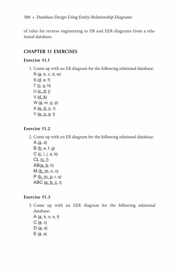
308 • Database Design Using Entity-Relationship Diagrams
of. rules. for. reverse.engineering. to.ER.and.EER.diagrams. from.a.rela-tional.database.
CHAPTER 11 EXERCISES
Exercise 11.1
. 1..Come.up.with.an.ER.diagram.for.the.following.relational.database:R (a, b, c, d, w)S (d, e, f)T (c, g, h)U (c, d, j)V (d, k)W (a, m, o, p)X (a, d, c, r)Y (a, o, s, t)
Exercise 11.2
. 2..Come.up.with.an.ER.diagram.for.the.following.relational.database:A (a, d)B (b, e, f, g)C (c, i, j, a, b)CL (c, l)AB(a, b, h)M (b, m, o, n)P (b, m, p, r, q)ABC (a, b, c, t)
Exercise 11.3
. 3..Come. up. with. an. EER. diagram. for. the. following. relational.database:A (a, b, o, s, t)C (a, c)D (a, d)E (a, e)

Relational Mapping and Reverse Engineering ER/EER Diagrams • 309
Exercise 11.4
. 4..Come.up.with.an.EER.diagram.for.the.following.database:A (a, d, e, f, n)B (b, g, h, n)C (c, i, j, n)D (n)
BIBLIOGRAPHY
Elmasri,.R.,.and.Navathe,.S..B..2007..Fundamentals of Database Systems,.5th.ed..Redwood.City,.CA:.Benjamin.Cummings.


311
12A Brief Overview of the Barker/Oracle-Like Model
12.1 INTRODUCTION
There.are.many.variations.of.entity.relationship.ER.diagrams..One.such.model.was. introduced.by.Richard.Barker.(1990)..The.Barker.model.was.adopted.and.modified.slightly.by.the.Oracle.Corporation..In.this.chapter,.we.introduce.the.conventions.used.in.the.Barker/Oracle-like.model.as.it.applies.to.our.ER.Design.Methodology..We.depict.major.concepts.of.the.ER.diagrams.of.both.Barker.and.Oracle..Our.combined.Barker/Oracle-like.model.is.not.meant.as.a.primer.on.the.“pure.model”.of.either.party,.but.the.transition.to.the.ER.diagram.of.Barker.or.Oracle.will.be.minor.
Why.are.we.interested.in.the.Barker/Oracle-like.model,.and.why.present.it.here?.First,.the.Barker/Oracle-like.model.is.common;.it.is.used.often.in.Oracle.literature..The.pedantic.problem.with.the.Barker/Oracle-like.model.is.that.one.needs.to.understand.relational.database.theory.fully.to.under-stand.why.the.Barker/Oracle-like.model.is.done.the.way.it. is..We.present.the.Barker/Oracle-like.model.here.because.the.way.it.unfolds.is.a.bit.differ-ent.from.the.Chen-like.model..The.Chen-like.model.focuses.on.modeling.data,.whereas.the.Barker/Oracle-like.model.adapts.the.data.to.the.relational.database.concurrently.with.the.design..Therefore,.the.ER.design.method-ology. for. the. Barker/Oracle-like. model. will. develop. differently. from. the.Chen-like.model..Further,.the.Barker/Oracle-like.model.will.not.have.some.of.the.conventions.used.in.the.Chen-like.model..For.example,.the.Barker/Oracle-like.model.does.not.directly.use.the.concept.of.composite.attributes,.multivalued.attributes,.or.weak.entities,.but.rather.handles.these.concepts.immediately. in. light.of.the.relational.model..Since.the.Barker/Oracle-like.model.is.so.close.to.the.relational.model.at.the.beginning,.the.mapping.rules.are.trivial—the.mapping.takes.place.in.the.diagram.itself.
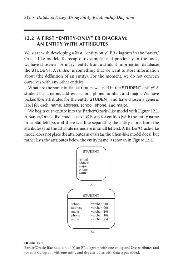
312 • Database Design Using Entity-Relationship Diagrams
12.2 A FIRST “ENTITY-ONLY” ER DIAGRAM: AN ENTITY WITH ATTRIBUTES
We.start.with.developing.a.first,.“entity-only”.ER.diagram.in.the.Barker/Oracle-like. model.. To. recap. our. example. used. previously. in. the. book,.we.have.chosen.a.“primary”.entity.from.a.student.information.database:.the.STUDENT..A.student.is.something.that.we.want.to.store.information.about. (the.definition.of.an.entity)..For. the.moment,.we.do.not.concern.ourselves.with.any.other.entities.
What.are.the.some.initial.attributes.we.used.in.the.STUDENT.entity?.A.student.has.a.name,.address,.school,.phone.number,.and.major..We.have.picked.five.attributes.for.the.entity.STUDENT.and.have.chosen.a.generic.label.for.each:.name, address, school, phone, and major.
We.begin.our.venture.into.the.Barker/Oracle-like.model.with.Figure 12.1..A.Barker/Oracle-like.model.uses.soft.boxes.for.entities.(with.the.entity.name.in.capital. letters),.and.there. is.a. line.separating.the.entity.name.from.the.attributes.(and.the.attribute.names.are.in.small.letters)..A.Barker/Oracle-like.model.does.not.place.the.attributes.in.ovals.(as.the.Chen-like.model.does),.but.rather.lists.the.attributes.below.the.entity.name,.as.shown.in.Figure 12.1.
STUDENT
schooladdressmajorphonename
(a)
STUDENT
school varchar (20)address varchar (20)major varchar (10)phone varchar (10)name varchar (25)
(b)
FIGURE 12.1Barker/Oracle-like.notation.of.(a).an.ER.diagram.with.one.entity.and.five.attributes.and.(b).an.ER.diagram.with.one.entity.and.five.attributes.with.data.types.added.
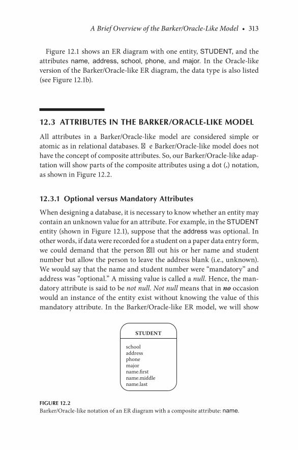
A Brief Overview of the Barker/Oracle-Like Model • 313
Figure 12.1.shows.an.ER.diagram.with.one.entity,.STUDENT,.and.the.attributes. name, address, school,. phone,. and. major.. In. the. Oracle-like.version.of.the.Barker/Oracle-like.ER.diagram,.the.data.type.is.also.listed.(see.Figure 12.1b).
12.3 ATTRIBUTES IN THE BARKER/ORACLE-LIKE MODEL
All. attributes. in. a. Barker/Oracle-like. model. are. considered. simple. or.atomic.as.in.relational.databases..The.Barker/Oracle-like.model.does.not.have.the.concept.of.composite.attributes..So,.our.Barker/Oracle-like.adap-tation.will.show.parts.of.the.composite.attributes.using.a.dot.(.).notation,.as.shown.in.Figure 12.2.
12.3.1 Optional versus Mandatory Attributes
When.designing.a.database,.it.is.necessary.to.know.whether.an.entity.may.contain.an.unknown.value.for.an.attribute..For.example,.in.the.STUDENT.entity.(shown.in.Figure 12.1),.suppose.that.the.address.was.optional..In.other.words,.if.data.were.recorded.for.a.student.on.a.paper.data.entry.form,.we. could. demand. that. the. person. fill. out. his. or. her. name. and. student.number.but.allow.the.person.to.leave.the.address.blank.(i.e.,.unknown)..We.would.say.that.the.name.and.student.number.were.“mandatory”.and.address.was.“optional.”.A.missing.value.is.called.a.null..Hence,.the.man-datory.attribute.is.said.to.be.not null..Not null.means.that.in.no.occasion.would.an. instance.of. the.entity.exist.without.knowing.the.value.of. this.mandatory.attribute.. In. the.Barker/Oracle-like.ER.model,.we.will. show.
STUDENT
schooladdressphonemajorname.firstname.middlename.last
FIGURE 12.2Barker/Oracle-like.notation.of.an.ER.diagram.with.a.composite.attribute:.name.
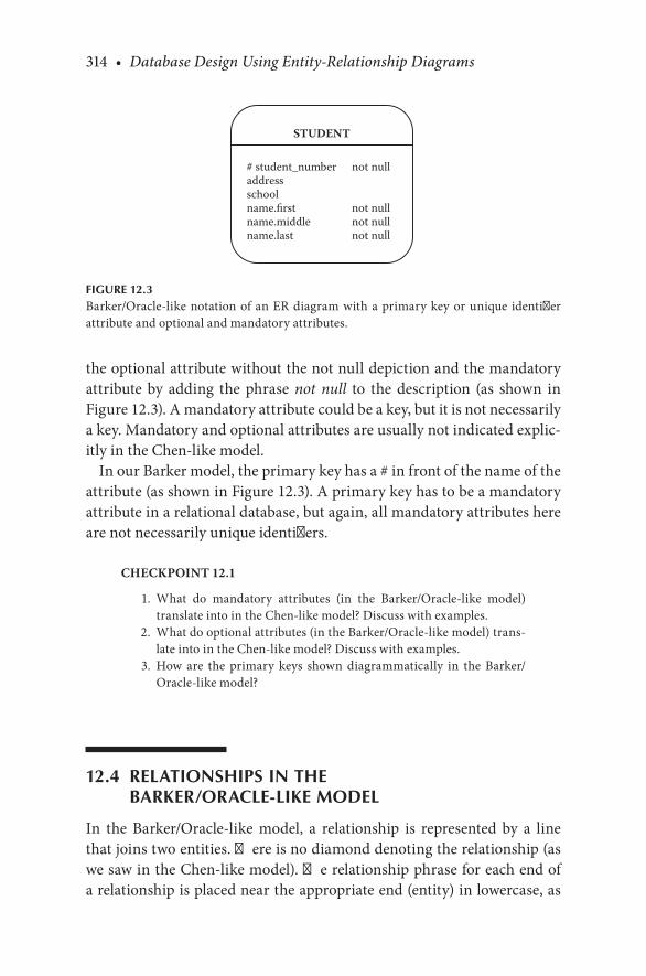
314 • Database Design Using Entity-Relationship Diagrams
the.optional.attribute.without.the.not.null.depiction.and.the.mandatory.attribute. by. adding. the. phrase. not null. to. the. description. (as. shown. in.Figure 12.3)..A.mandatory.attribute.could.be.a.key,.but.it.is.not.necessarily.a.key..Mandatory.and.optional.attributes.are.usually.not.indicated.explic-itly.in.the.Chen-like.model.
In.our.Barker.model,.the.primary.key.has.a.#.in.front.of.the.name.of.the.attribute.(as.shown.in.Figure 12.3)..A.primary.key.has.to.be.a.mandatory.attribute.in.a.relational.database,.but.again,.all.mandatory.attributes.here.are.not.necessarily.unique.identifiers.
CHECKPOINT 12.1
. 1.. What. do. mandatory. attributes. (in. the. Barker/Oracle-like. model).translate.into.in.the.Chen-like.model?.Discuss.with.examples.
. 2.. What.do.optional.attributes.(in.the.Barker/Oracle-like.model).trans-late.into.in.the.Chen-like.model?.Discuss.with.examples.
. 3.. How. are. the. primary. keys. shown. diagrammatically. in. the. Barker/Oracle-like.model?
12.4 RELATIONSHIPS IN THE BARKER/ORACLE-LIKE MODEL
In. the. Barker/Oracle-like. model,. a. relationship. is. represented. by. a. line.that.joins.two.entities..There.is.no.diamond.denoting.the.relationship.(as.we.saw.in.the.Chen-like.model)..The.relationship.phrase.for.each.end.of.a.relationship.is.placed.near.the.appropriate.end.(entity).in.lowercase,.as.
STUDENT
# student_number not nulladdressschoolname.first not nullname.middle not nullname.last not null
FIGURE 12.3Barker/Oracle-like.notation.of.an.ER.diagram.with.a.primary.key.or.unique. identifier.attribute.and.optional.and.mandatory.attributes.

A Brief Overview of the Barker/Oracle-Like Model • 315
shown. in. Figure 12.4.. In. this. model,. from. the. STUDENT entity. to. the SCHOOL entity.we.would.say.(informally),
Students attended schools
And,.from.the.other.direction,.from.the.SCHOOL.entity.to.the.STUDENT entity,.we.would.say,
Schools are attended by students.
12.5 STRUCTURAL CONSTRAINTS IN THE BARKER/ORACLE-LIKE MODEL
In.the.Barker/Oracle-like.notation,.the.cardinality.of.1.is.shown.by.a.single.line.leading.to.the.entity..In.Figure 12.5,.a.single.line.joins.the.two.entities,.so. this. is. a.1:1. relationship.between. the.STUDENT. and.AUTOMOBILE..This.means.that.one.student.may.be.related.to.one.and.only.one.automo-bile,.and.one.automobile.can.be.related.to.one.and.only.one.student.
are attended by
attended
SCHOOL
location.citylocation.state type of schoolschool_name
STUDENT
# student numbername.firstname.middlename.last
FIGURE 12.4Barker/Oracle-like.notation.of.the.STUDENT.entity.with.a.relationship.to.the.SCHOOL.entity.

316 • Database Design Using Entity-Relationship Diagrams
The.dashed.line.leading.to.an.entity.signifies.optional.(partial).partici-pation.of.an.entity.in.a.relationship..In.Figure 12.5,.the.STUDENT entity.is.participating.optionally.in.the.relationship,.but.the.AUTOMOBILE.entity.is.not.participating.optionally.(the.latter.relationship.is.mandatory).
An.enhanced.grammar.from.the.STUDENT entity.to.the.AUTOMOBILE.entity.would.be
A student may drive one and only one automobile
And,.from.the.AUTOMOBILE entity.to.the.STUDENT entity.it.would.be
An automobile must be driven by one and only one student.
A. continuous. (solid). line. coming. from. the. AUTOMOBILE entity. (as.shown. in. Figure 12.5). signifies. mandatory. (full). participation. of. that.entity.in.a.relationship..A.dashed.line.coming.from.the.STUDENT entity.(as.shown.in.Figure 12.5).signifies.optional.(partial).participation..Again,.according.to.Figure 12.6,.students.must.occupy.dorms,.but.a.dorm.may.have.students.
must be driven by
can drive
AUTOMOBILE
model year# vehicle id not nullmakebody stylecolor
STUDENT
# student number not nullname.first not nullname.middle not nullname.last not nulladdress
Cardinalityratio of 1:1
FIGURE 12.5A.1:1.relationship.in.the.Barker/Oracle-like.notation.

A Brief Overview of the Barker/Oracle-Like Model • 317
A.cardinality.of.M.(many).is.shown.by.a.“crow’s-foot”.structure.leading.to.the.respective.entity..Figure 12.6.is.an.example.of.a.1:M.relationship.between.DORM.and STUDENT..The.exact.grammar.for.Figure 12.6.would.be
A dorm may be occupied by zero or more students
and
A student must occupy one and only one dorm.
CHECKPOINT 12.2
. 1.. How. is. the. optional. relationship. shown. diagrammatically. in. the.Barker/Oracle-like.model?
. 2.. How.is.the.many.relationship.shown.diagrammatically.in.the.Barker/Oracle-like.model?
. 3.. Show.the.following.using.the.Barker/Oracle-like.notation:
. a.. A.movie.theater.must.show.many.movies,.and.movies.must.be.shown.in.a.movie.theater.
. b.. A. movie. theater. may. show. many. movies,. and. movies. may. be.shown.in.a.movie.theater.
is occupied by
occupies
DORM
STUDENT
many
one
FIGURE 12.6A.1:M.relationship.in.the.Barker/Oracle-like.notation.
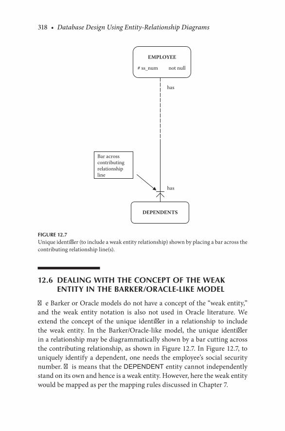
318 • Database Design Using Entity-Relationship Diagrams
12.6 DEALING WITH THE CONCEPT OF THE WEAK ENTITY IN THE BARKER/ORACLE-LIKE MODEL
The.Barker.or.Oracle.models.do.not.have.a.concept.of.the.“weak.entity,”.and. the. weak. entity. notation. is. also. not. used. in. Oracle. literature.. We.extend. the. concept. of. the. unique. identifier. in. a. relationship. to. include.the. weak. entity.. In. the. Barker/Oracle-like. model,. the. unique. identifier.in.a.relationship.may.be.diagrammatically.shown.by.a.bar.cutting.across.the.contributing.relationship,.as.shown.in.Figure 12.7..In.Figure 12.7,.to.uniquely. identify.a.dependent,.one.needs. the.employee’s. social. security.number..This.means.that.the.DEPENDENT.entity.cannot.independently.stand.on.its.own.and.hence.is.a.weak.entity..However,.here.the.weak.entity.would.be.mapped.as.per.the.mapping.rules.discussed.in.Chapter.7.
has
has
EMPLOYEE
# ss_num not null
DEPENDENTS
Bar acrosscontributingrelationshipline
FIGURE 12.7Unique.identifier.(to.include.a.weak.entity.relationship).shown.by.placing.a.bar.across.the.contributing.relationship.line(s).

A Brief Overview of the Barker/Oracle-Like Model • 319
12.7 DEALING WITH THE CONCEPT OF MULTIVALUED ATTRIBUTES IN THE BARKER/ORACLE-LIKE MODEL
The.Barker.or.Oracle.models.do.not.have.the.concept.of.the.“multivalued”.attribute..Multivalued.attributes.can.be. shown.as. in.Figure 12.8,.which.shows.that.a.student.may.have.attended.many.schools.
In. the. Barker/Oracle-like. model,. the. foreign. key. is. shown. in. the.appropriate.entity,.whereas.in.the.Chen-like.model,.foreign.keys.are.not.
attended
was attended by
Note: “*” shows a foreign key
STUDENT
#sname not nulladdress
SCHOOL
*#sname not nullschool not null
FIGURE 12.8The.multivalued.attribute.and.the.foreign.key.

320 • Database Design Using Entity-Relationship Diagrams
“discovered”.until.the.database.is.mapped..We.signal.a.foreign.key.with.an.asterisk.(*).in.front.of.the.attribute.(see.Figure 12.8)..An.instance.of.this.database.shown.in.Figure 12.8.is
STUDENTsname addressSumona Gupta 111 Mirabelle Circle, Pensacola, FLTom Bundy 198 Palace Drive, Mobile, ALTony Jones 329 Becker Place, Mongotomery, ALSita Pal 987 Twin Lane, North Canton, OHNeetu Singh 109 Bombay Blvd, Calicut, CA
SCHOOLsname schoolSumona Gupta Ferry Pass ElementarySumona Gupta PCASumona Gupta Pensacola HighTom Bundy Mobile Middle SchoolTom Bundy St. JohnsTony Jones Montgomery ElementaryTony Jones Montgomery MiddleTony Jones Montgomery HighSita Pal Tagore Primary SchoolSita Pal Nehru Secondary School
As. you. can. see,. the. multivalued. attribute. is. mapped. to. tables. as. it. is.depicted.in.the.Barker/Oracle-like.notation..In.the.Chen-like.model,.the.multivalued.attribute.is.kept.in.the.diagram.and.then.mapped.using.the.mapping.rules.(see.mapping.rule.4).
CHECKPOINT 12.3
. 1.. Does.the.Barker-like.model.or.the.Oracle-like.model.have.the.concept.of.the.weak.entity?.Discuss.
. 2.. Show.the.following.using.the.Barker/Oracle-like.notation:.For.a.stu-dent,.we.are.trying.to.store.the.student’s.name,.address,.phone,.books.(that.is,.books.that.the.student.borrows.from.the.library)..Map.this.to.a.relational.database.and.show.some.sample.data.
. 3.. Does.the.Barker/Oracle-like.notation.have.the.concept.of.the.multi-valued.attribute?.Discuss.
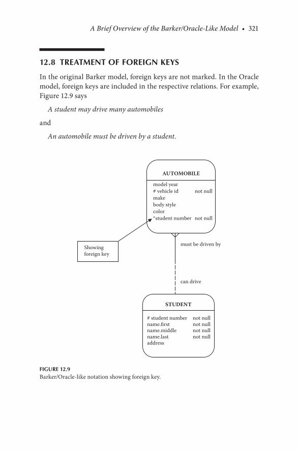
A Brief Overview of the Barker/Oracle-Like Model • 321
12.8 TREATMENT OF FOREIGN KEYS
In.the.original.Barker.model,.foreign.keys.are.not.marked..In.the.Oracle.model,.foreign.keys.are.included.in.the.respective.relations..For.example,.Figure 12.9.says
A student may drive many automobiles
and
An automobile must be driven by a student.
must be driven by
can drive
AUTOMOBILE
model year# vehicle id not nullmakebody stylecolor* student number not null
STUDENT
# student number not nullname.first not nullname.middle not nullname.last not nulladdress
Showingforeign key
FIGURE 12.9Barker/Oracle-like.notation.showing.foreign.key.

322 • Database Design Using Entity-Relationship Diagrams
The.primary.key.from.the.STUDENT.relation.(the.1.side),.student num-ber,.is.included.in.the.AUTOMOBILE.relation.(the.N.side)..In.our.Barker/Oracle-like.model,.we.precede.the.foreign.key.with.an.asterisk.(as.shown.in.Figure 12.9).
12.9 RECURSIVE RELATIONSHIPS IN THE BARKER/ORACLE-LIKE MODEL
Recursive. relationships. in. the. Barker/Oracle-like. model. are. drawn. as.shown.in.Figure 12.10..Again,.the.dotted.line.in.the.relationship.shows.an.optional.relationship,.the.solid.line.would.show.a.mandatory.relationship,.and. a. “crow’s-foot”. would. show. a. many. relationship.. The. relationships.are.named.as.shown..Figure 12.10.shows.that.an.employee.may.supervise.other. employees,. and. an. employee. may. be. supervised. by. one. and. only.one.supervisor..Note.the.foreign.key.super_ssn. in.the.EMPLOYEE.rela-tion.itself.
supervises
is supervised by
EMPLOYEE
# ssn not nulladdressmajorphonename*super_ssn
Recursiverelationship
FIGURE 12.10Barker/Oracle-like.notation.recursive.relationship.

A Brief Overview of the Barker/Oracle-Like Model • 323
12.10 MAPPING M:N RELATIONSHIPS
Finally,.we.discuss.one.important.aspect.that.is.treated.differently.in.the.Barker/Oracle-like.model:.an.M:N.relationship..In.the.Barker/Oracle-like.model,.all.M:N.relationships.are.resolved.into.two.1:M.relationships.with.an.intersection.entity.in.the.middle..In.the.Chen-like.model,.the.M:N.may.be.presented.as.two.1:M.relationships.
Figure 12.11.is.an.example.of.an.M:N.relationship.in.the.Chen-like.format..In.the.Barker/Oracle-like.model.this.would.be.shown.as.in.Figure 12.12.
CHECKPOINT 12.4
. 1.. How. are. recursive. relationships. shown. in. the. Barker/Oracle-like.model?
. 2.. Why. is. it.difficult. to. show.M:N.relationships. in. the.Barker/Oracle-like.model?
. 3.. How.are.the.foreign.keys.treated.in.the.Barker/Oracle-like.model?
. 4.. How. are. recursive. relationships. shown. in. the. Barker/Oracle-like.model?
12.11 CHAPTER SUMMARY
This. chapter.briefly.discussed. some. of. the. main. features. of. the. Barker/Oracle-like. model.. The. one-entity. diagram,. with. attributes,. was. pre-sented..The.idea.of.optional.versus.mandatory.attributes.was.discussed..Relationships. and. structural. constraints. were. briefly. discussed. in. the.context.of.the.Barker/Oracle-like.model,.and.although.the.Barker/Oracle-like.notation.does.not.use.the.concept.of.the.weak.entity.and.multivalued.attributes,.we.showed.how.these.concepts.can.be.shown.diagrammatically.in. the. Barker/Oracle-like. notation.. An. example. of. the. depiction. of. the.recursive. relationship. in. the. Barker/Oracle. model. is. illustrated.. Finally,.the.chapter.showed.how.to.map.an.M:N.relationship.into.two.1:M.rela-tionships..Mapping.rules.were.also.discussed.in.the.context.of.the.Barker/Oracle-like.notation.

324 • Database Design Using Entity-Relationship Diagrams
M
N
course_ID
Student
name
addressstudent_ID
Course
credit_hours
course_name
grade
enroll
Students mustenroll in courses
Courses musthave studentsenrolled A relationship
attribute – alsoknown as an“intersectionattribute”
FIGURE 12.11An.ER.diagram.of.an.M:N.relationship.in.the.Chen-like.model.

A Brief Overview of the Barker/Oracle-Like Model • 325
enroll in
enroll students
are enrolled in courses
enroll students
STUDENT
#student_id not nullname address
ENROLL
grade*#student_id not null*#course_id not null
COURSE
# course_id not nullcredit_hourscourse_name
FIGURE 12.12Barker/Oracle-like.notation.of.an.M:N.relationship.broken.into.two.1:M.relationships.

326 • Database Design Using Entity-Relationship Diagrams
CHAPTER 12 EXERCISES
Exercise 12.1
. 1..Redraw.Figure 8.17a.using.the.Barker/Oracle.notation..Map.this.to.a.relational.database.and.show.some.sample.data.
Exercise 12.1
. 2..Redraw.Figure 8.7.using.the.Barker/Oracle.notation..Map.this.to.a.relational.database.and.show.some.sample.data.
BIBLIOGRAPHY
Barker,.R..1990..Case*Method, Entity Relationship Modeling..Reading,.MA:.Addison.Wesley.Hay,.D..C..1996..Data Model Patterns..New.York:.Dorset.House.Rodgers,. Ulka.. 1991.. ORACLE: A Database Developer’s Guide.. Englewood. Cliffs,. NJ:.
Prentice-Hall.Siau,.K..2004..Advanced Topics in Database Research. Hershey,.PA:.Idea.Group.

327
Glossary
A
Attribute:. Property.used.to.describe.an.entity.or.relationship.
B
Binary relationship:. Relationship.between.two.entities.
C
Candidate key:. An.attribute.or.set.of.attributes.that.uniquely.identifies.individual.occurrences.of.an.entity.type.
Cardinality ratio:. Describes.the.number.of.one.entity.that.is.related.to.another.entity.
Category:. When. a. subclass. has. more. than. one. superclass. that. it. may.inherit.from;.also.referred.to.as.union.type.
Composite attribute:. An. attribute. composed. of. multiple. components,.each.with.an.independent.existence.
D
Database:. A.shared.collection.of.logically.associated.or.related.data.Degree of a relationship:. The. number. of. participating. entities. in. a.
relationship.Derived attribute:. An. attribute. that. gets. a. value. calculated. or. derived.
from.the.database.

328 • Glossary
E
Entity:. “Something”.in.the.real.world.that.is.of.importance.to.a.user.and.that. needs. to. be. represented. in. a. database. so. that. information.about. the. entity. may. be. recorded.. An. entity. may. have. physical.existence.(such.as.a.student.or.building).or.it.may.have.conceptual.existence.(such.as.a.course).
Entity set:. A.collection.of.all.entities.of.a.particular.entity.type.Entity type:. A.set.of.entities.of.the.same.type.
F
First normal form (1NF):. The.domain.of.all. attributes. in.a. table.must.include.only.atomic.(simple,.indivisible).values,.and.the.value.of.any.attribute.in.a.tuple.(or.row).must.be.single-valued.from.the.domain.of.that.attribute.
Foreign key:. An.attribute.that.is.a.primary.key.of.another.relation.(table)..A.foreign.key. is.how.relationships.are. implemented. in.relational.databases.
Full participation:. All.of.one.entity.set.participates.in.a.relationship.Functional dependency:. A.relationship.between.two.attributes.in.a.rela-
tion..Attribute.Y.is.functionally.dependent.on.attribute.X.if.attri-bute.X.identifies.attribute.Y..For.every.unique.value.of.X,.the.same.value.of.Y.will.always.be.found.
G
Generalization:. The.process.of.minimizing.the.differences.between.enti-ties.by.identifying.their.common.features.and.removing.the.com-mon.features.into.a.superclass.entity.
H
Hierarchical model:. All.data.are.arranged.in.a.top-down.fashion.
Glossary • 329
I
Identifying owner:. The. strong. entity. on. which. a. weak. entity. is.dependent.
Identifying relationship:. A.weak.relationship.
K
Key:. An.attribute.or.data.item.that.uniquely.identifies.a.record.instance.or.tuple.in.a.relation.
M
Mandatory relationship:. Same.as.full.participation;.all.of.one.entity.set.participates.in.a.relationship.
Many to many:. Many.tuples.(rows).of.one.relation.can.be.related.to.many.tuples.(rows).in.another.relation.
Many to one:. Many. tuples. (rows).of.one.relation.can.be. related. to.one.tuple.(row).in.another.relation.
Mapping:. The. process. of. choosing. a. logical. model. and. then. moving. to.a.physical.database.file.system.from.a.conceptual.model.(the.ER.diagram).
Multivalued attribute:. An.attribute.that.may.have.multiple.values.for.a.single.entity.
O
One to many:. A.relationship.in.which.one.tuple.(or.row).of.one.relation.can.be.related.to.more.than.one.tuple.(row).in.another.relation.
One to one:. A.relationship.in.which.one.tuple.(or.row).of.one.relation.can.be.related.to.only.one.tuple.(row).in.another.relation.
Optional participation:. A.constraint.that.specifies.whether.the.existence.of.an.entity.depends.on. its.being.related.to.another.entity.via.a.relationship.type.

330 • Glossary
P
Partial key:. The.unique.key.in.a.dependent.entity.Partial participation:. Part. of. one. entity. set. participates. in. a.
relationship.Participation constraints (also known as optionality):. Determines.
whether.all.or.some.of.an.entity.occurrence.is.related.to.another.entity.
Primary key:. A.unique.identifier.for.a.row.in.a.table.in.a.relational.data-base;.a.selected.candidate.key.of.an.entity.
R
Recursive relationship:. Relationship.among.entities.in.the.same.class.Regular entity:. See.Entity.Relation:. A.table.containing.single-value.entries.and.no.duplicate.rows..
The.meaning.of. the.columns. is. the. same. in.every. row,.and. the.order.of.the.rows.and.columns.is.immaterial..Often,.a.relation.is.defined.as.a.populated.table.
Relationship:. An.association.between.entities.Reverse engineering:. The. process. of. going. from. relational. tables. to. a.
logical.model.(or.ER.diagram).
S
Second normal form:. A.relation.that.is.in.first.normal.form.and.in.which.each.nonkey.attribute.is.fully.functionally.dependent.on.the.pri-mary.key.
Shared subclass:. A. subclass. that. has. more. than. one. subclass. for. its.parents.
Simple attribute:. Attribute.composed.of.a.single.value.Specialization:. The. process. of. maximizing. the. differences. between.
members.of.a.superclass.entity.by.identifying.their.distinguishing.characteristics.
Specialization hierarchy:. A.subclass.inherits.from.only.one.subclass.
Glossary • 331
Specialization lattice:. A. subclass. has. more. than. one. subclass. as. its.parent.
Strong entity:. An.entity.that. is.not.dependent.on.another.entity.for.its.existence.
Structural constraints:. Indicate. how. many. of. one. type. of. a. record. is.related.to.another.and.whether.the.record.must.have.such.a.rela-tionship..The.cardinality.ratio.and.participation.constraints.taken.together.form.the.structural.constraints.
Subclass:. An.entity.type.that.has.a.distinct.role.and.is.also.a.member.of.a.superclass.
Superclass:. An. entity. type. that. includes. distinct. subclasses. that. are.required.to.be.represented.in.a.data.model.
T
Table:. Same.as.relation;.a.tabular.view.of.data.that.may.be.used.to.hold.one.or.more.columns.of.data;.an.implementation.of.an.entity.
Third normal form:. A. relation. that. is. in. second. normal. form. and. in.which.no.nonkey.attribute.is.functionally.dependent.on.another.nonkey.attribute.(that.is,.there.are.no.transitive.dependencies.in.the.relation).
U
Union type:. A.subclass.has.more.than.one.superclass.it.may.inherit.from;.also.referred.to.as.a.category.
Unique identifier:. Any. combination. of. attributes. or. relationships. that.serves.to.uniquely.identify.an.occurrence.of.an.entity.
W
Waterfall model:. A.series.of.steps.that.software.undergoes,.from.concept.exploration.through.final.retirement.
Weak entity:. An. entity. that. is. dependent. on. some. other. entity. for. its.existence.


ISBN: 978-1-4398-6176-9
9 781439 861769
90000
Information Technology / Database
Essential to database design, entity-relationship (ER) diagrams are known for their usefulness in mapping out clear database designs. They are also well-known for being difficult to master. With Database Design Using Entity-Relationship Diagrams, Second Edition, database designers, developers, and students preparing to enter the field can quickly learn the ins and outs of ER diagramming.
Building on the success of the bestselling first edition, this accessible text includes a new chapter on the relational model and functional dependencies. It also includes expanded chapters on Enhanced Entity Relationship (EER) diagrams and reverse mapping. It uses cutting-edge case studies and examples to help readers master database development basics and defines ER and EER diagramming in terms of requirements (end user requests) and specifications (designer feedback to those requests).
• Describes a step-by-step approach for producing an ER diagram and developing a relational database from it
• Contains exercises, examples, case studies, bibliographies, and summaries in each chapter
• Details the rules for mapping ER diagrams to relational databases• Explains how to reverse engineer a relational database back to an
entity-relationship model• Includes grammar for the ER diagrams that can be presented back
to the user
The updated exercises and chapter summaries provide the real-world understanding needed to develop ER and EER diagrams, map them to relational databases, and test the resulting relational database. Complete with a wealth of additional exercises and examples throughout, this edition should be a basic component of any database course. Its comprehensive nature and easy-to-navigate structure make it a resource that students and professionals will turn to throughout their careers.
Database Design Using Entity-Relationship Diagrams
Seco
nd
Editio
nBagui
Earp
www.auerbach-publications.com
K12857
www.crcpress.com
K12857 cvr mech.indd 1 8/9/11 8:53 AM