Group Q- Automatic Ball Launching Entity
53
Washington University in St. Louis Washington University in St. Louis Washington University Open Scholarship Washington University Open Scholarship Mechanical Engineering Design Project Class Mechanical Engineering & Materials Science Fall 12-9-2017 Group Q- Automatic Ball Launching Entity Group Q- Automatic Ball Launching Entity Zachary White Washington University in St. Louis Tim Grote Washington University in St. Louis Joshua Norlin Washington University in St. Louis Follow this and additional works at: https://openscholarship.wustl.edu/mems411 Part of the Mechanical Engineering Commons Recommended Citation Recommended Citation White, Zachary; Grote, Tim; and Norlin, Joshua, "Group Q- Automatic Ball Launching Entity" (2017). Mechanical Engineering Design Project Class. 77. https://openscholarship.wustl.edu/mems411/77 This Final Report is brought to you for free and open access by the Mechanical Engineering & Materials Science at Washington University Open Scholarship. It has been accepted for inclusion in Mechanical Engineering Design Project Class by an authorized administrator of Washington University Open Scholarship. For more information, please contact [email protected].
-
Upload
khangminh22 -
Category
Documents
-
view
1 -
download
0
Transcript of Group Q- Automatic Ball Launching Entity

Washington University in St. Louis Washington University in St. Louis
Washington University Open Scholarship Washington University Open Scholarship
Mechanical Engineering Design Project Class Mechanical Engineering & Materials Science
Fall 12-9-2017
Group Q- Automatic Ball Launching Entity Group Q- Automatic Ball Launching Entity
Zachary White Washington University in St. Louis
Tim Grote Washington University in St. Louis
Joshua Norlin Washington University in St. Louis
Follow this and additional works at: https://openscholarship.wustl.edu/mems411
Part of the Mechanical Engineering Commons
Recommended Citation Recommended Citation White, Zachary; Grote, Tim; and Norlin, Joshua, "Group Q- Automatic Ball Launching Entity" (2017). Mechanical Engineering Design Project Class. 77. https://openscholarship.wustl.edu/mems411/77
This Final Report is brought to you for free and open access by the Mechanical Engineering & Materials Science at Washington University Open Scholarship. It has been accepted for inclusion in Mechanical Engineering Design Project Class by an authorized administrator of Washington University Open Scholarship. For more information, please contact [email protected].

Executive Summary
The goal of the project is to create a machine that can track and aim at a target and deliver a tennis ball at
a safe speed. The machine can be calibrated to ensure accurate aim. The application of the product is for
entertainment and sports training, with calibration being able to be used to make easy shots for fun, and
difficult shot for training. The device uses a two-axis rotation, allowing it to aim up/down and
left/right. The device uses a microprocessor to calculate aim based on position of target and knowledge
about the strength of the firing mechanism.
MEMS 411: Senior Design Project
Automatic Ball Launching Entity (ABLE)
Zachary White
Tim Grote
Joshua Norlin

Project Name Introduction and Background Information
Page 1 of 51
TABLE OF CONTENTS
List of Figures ........................................................................................................................................... 4
List of Tables ............................................................................................................................................ 5
1 Introduction and Background Information............................................................................................ 6
1.1 Initial Project Description ............................................................................................................. 6
1.2 Existing Products .......................................................................................................................... 6
1.3 Relevant Patents ............................................................................................................................ 7
1.4 Codes & Standards ........................................................................................................................ 8
1.5 Project Scope ................................................................................................................................ 8
1.6 Project Planning ............................................................................................................................ 9
1.7 Realistic Constraints ..................................................................................................................... 9
1.7.1 Functional ............................................................................................................................. 9
1.7.2 Safety .................................................................................................................................. 10
1.7.3 Quality ................................................................................................................................. 10
1.7.4 Manufacturing ..................................................................................................................... 10
1.7.5 Timing ................................................................................................................................. 10
1.7.6 Economic ............................................................................................................................ 10
1.7.7 Ergonomic ........................................................................................................................... 10
1.7.8 Ecological ........................................................................................................................... 10
1.7.9 Aesthetic ............................................................................................................................. 10
1.7.10 Life Cycle ............................................................................................................................ 10
1.7.11 Legal ................................................................................................................................... 10
1.8 Revised Project Description ........................................................................................................ 11
2 Customer Needs & Product Specifications ......................................................................................... 11
2.1 Customer Interviews ................................................................................................................... 11
2.2 Interpreted Customer Needs........................................................................................................ 13
2.3 Target Specifications................................................................................................................... 13
3 Concept Generation ............................................................................................................................ 14
3.1 Functional Decomposition .......................................................................................................... 14
3.2 Morphological Chart ................................................................................................................... 15
3.3 Concept #1 – “Wheely-Dealy Air” ............................................................................................. 16
3.4 Concept #2 – “Telescope Launcher” .......................................................................................... 17
3.5 Concept #3 – “Table Ballista” .................................................................................................... 18

Project Name Introduction and Background Information
Page 2 of 51
3.6 Concept #4 – “Bow-pod” ............................................................................................................ 19
3.7 Concept #5 – “Axle Tube” .......................................................................................................... 20
3.8 Concept #6 – “Table X-Bow” ..................................................................................................... 20
4 Concept Selection ............................................................................................................................... 21
4.1 Concept Scoring Matrix .............................................................................................................. 21
4.2 Explanation of Winning Concept Scores .................................................................................... 21
4.3 Explanation of Second-Place Concept Scores ............................................................................ 22
4.4 Explanation of Third-Place Concept Scores ............................................................................... 22
4.5 Summary of Evaluation Results .................................................................................................. 22
5 Embodiment & Fabrication plan ......................................................................................................... 23
5.1 Isometric Drawing with Bill of Materials ................................................................................... 23
5.2 Exploded View ............................................................................................................................ 24
5.3 Additional Views ........................................................................................................................ 25
6 Engineering Analysis .......................................................................................................................... 28
6.1 Engineering Analysis Results ..................................................................................................... 28
6.1.1 Motivation ........................................................................................................................... 28
6.1.2 Summary Statement of the Analysis ................................................................................... 28
6.1.3 Methodology ....................................................................................................................... 28
6.1.4 Results ................................................................................................................................. 29
6.1.5 Significance ......................................................................................................................... 31
6.2 Product Risk Assessment ............................................................................................................ 33
6.2.1 Risk Identification ............................................................................................................... 33
6.2.2 Risk Heat Map .................................................................................................................... 35
6.2.3 Risk Prioritization ............................................................................................................... 35
7 Design Documentation ........................................................................................................................ 36
7.1 Performance Goals ...................................................................................................................... 36
7.2 Working Prototype Demonstration ............................................................................................. 36
7.2.1 Performance Evaluation ...................................................................................................... 36
7.2.2 Working Prototype – Video Link ........................................................................................ 36
7.2.3 Working Prototype – Additional Photos ............................................................................. 37
8 Discussion ........................................................................................................................................... 38
8.1 Design for Manufacturing – Part Redesign for Injection Molding ............................................. 38
8.1.1 Draft Analysis Results ........................................................................................................ 38

Project Name Introduction and Background Information
Page 3 of 51
8.1.2 Explanation of Design Changes .......................................................................................... 39
8.2 Design for Usability – Effect of Impairments on Usability ........................................................ 39
8.2.1 Vision .................................................................................................................................. 39
8.2.2 Hearing ................................................................................................................................ 39
8.2.3 Physical ............................................................................................................................... 39
8.2.4 Language ............................................................................................................................. 39
8.2 Overall Experience ...................................................................................................................... 39
8.2.1 Does your final project result align with the initial project description? ............................ 39
8.2.2 Was the project more or less difficult than you had expected? ........................................... 39
8.2.3 In what ways do you wish your final prototype would have performed better? ................. 40
8.2.4 Was your group missing any critical information when you evaluated concepts? ............. 40
8.2.5 Were there additional engineering analyses that could have helped guide your design? ... 40
8.2.6 How did you identify your most relevant codes and standards and how they influence
revision of the design? ........................................................................................................................ 40
8.2.7 What ethical considerations (from the Engineering Ethics and Design for Environment
seminar) are relevant to your device? How could these considerations be addressed? ...................... 40
8.2.8 On which part(s) of the design process should your group have spent more time? Which
parts required less time? ...................................................................................................................... 40
8.2.9 Was there a task on your Gantt chart that was much harder than expected? Were there any
that were much easier? ........................................................................................................................ 40
8.2.10 Was there a component of your prototype that was significantly easier or harder to
make/assemble than you expected? .................................................................................................... 41
8.2.11 If your budget were increased to 10x its original amount, would your approach have
changed? If so, in what specific ways? ............................................................................................... 41
8.2.12 If you were able to take the course again with the same project and group, what would you
have done differently the second time around? ................................................................................... 41
8.2.13 Were your team member’s skills complementary? ............................................................. 41
8.2.14 Was any needed skill missing from the group? .................................................................. 41
8.2.15 Has the project enhanced your design skills? ..................................................................... 41
8.2.16 Would you now feel more comfortable accepting a design project assignment at a job?... 41
8.2.17 Are there projects you would attempt now that you would not have attempted before? .... 41
9 Appendix A - Parts List ...................................................................................................................... 42
10 Appendix B - CAD Models ............................................................................................................ 43
11 Annotated Bibliography .................................................................................................................. 51

Project Name Introduction and Background Information
Page 4 of 51
LIST OF FIGURES
Figure 1: Function Tree for ABLE ............................................................................................................. 14
Figure 2: Design Concept 1 ........................................................................................................................ 16
Figure 3: Design Concept 2 ........................................................................................................................ 17
Figure 4: Design Concept 3 ........................................................................................................................ 18
Figure 5: Design Concept 4 ........................................................................................................................ 19
Figure 6: Design Concept 5 ........................................................................................................................ 20
Figure 7: Design Concept 6 ........................................................................................................................ 20
Figure 8 Isometric Drawing of Axle Tube Assembly ................................................................................. 23
Figure 9: Exploded View of ABLE ............................................................................................................ 24
Figure 10: Front View ................................................................................................................................. 25
Figure 11: Side View .................................................................................................................................. 26
Figure 12: Back Isometric View ................................................................................................................. 27
Figure 13: Graphic of the Motion Analysis Feature of SolidWorks ........................................................... 28
Figure 14: Settings Used for SolidWorks Motion Analysis ........................................................................ 29
Figure 15: Graph of Motor Toque vs Time for the Rotating Base .............................................................. 29
Figure 16: Graph of Motor Torque vs Time for Barrel ............................................................................... 30
Figure 17: Mass Properties Analysis with SolidWorks .............................................................................. 30
Figure 18: Spring Response to Applied Force ............................................................................................ 31
Figure 19: Design Before Analysis ............................................................................................................. 32
Figure 20: Design After Analysis ............................................................................................................... 32
Figure 21: Risk Heat Map for ABLE .......................................................................................................... 35
Figure 22: First Additional View of Finished Device ................................................................................. 37
Figure 23: Second Additional View of Finished Device ............................................................................ 37
Figure 24: Shaft Expander Before Draft ..................................................................................................... 38
Figure 25: Shaft Expander After Draft ....................................................................................................... 38
Figure 26: CAD Model for Table ............................................................................................................... 43
Figure 27: CAD Model for Axle Holder (Motor Side) ............................................................................... 44
Figure 28: CAD Model for Axle Holder ..................................................................................................... 45
Figure 29: CAD Model for Barrel Mount ................................................................................................... 46
Figure 30: CAD Model for Rotating Base .................................................................................................. 47
Figure 31: CAD Model for Shaft Expander ................................................................................................ 48
Figure 32: CAD Model for Axle ................................................................................................................. 49
Figure 33: CAD Model for Reloading Rod ................................................................................................ 50

Project Name Introduction and Background Information
Page 5 of 51
LIST OF TABLES
Table 1: Gantt Chart for ABLE..................................................................................................................... 9
Table 2: Customer Interviews for ABLE .................................................................................................... 11
Table 3: Interpreted Customer Needs for ABLE ........................................................................................ 13
Table 4: Target Product Specifications for ABLE ...................................................................................... 13
Table 5: Morphological Chart forABLE ..................................................................................................... 15
Table 6: Analytic Hierarchy Process .......................................................................................................... 21
Table 7: Weighted Scoring Matrix for 6 design Concepts .......................................................................... 21
Table 8: Parts List for ABLE ...................................................................................................................... 42

Project Name Introduction and Background Information
Page 6 of 51
1 INTRODUCTION AND BACKGROUND INFORMATION
1.1 INITIAL PROJECT DESCRIPTION
The project goal is to create a machine that can track a moving person and deliver some payload
(e.g. ball) in a safe and accurate way at moderate range. This product has two main applications. The first
application is as an entertainment product, allowing an individual to play with a ball alone. The second
application is for sports training. Athletes could use the machine to practice catches. Additionally, the
device can be configured to intentionally “miss” a target for more difficult catches. The machine will be
stationary, firing from a fixed location.
1.2 EXISTING PRODUCTS
NERF Football launcher (https://www.youtube.com/watch?v=nh-nLIFMTPQ)
This project uses a large mounted air cannon that can rotate in two axes (up/down and left/right
aiming) to launch a NERF football at a target. Instead of tracking a target, it seems to predict where the
target will be using switches to determine the speed of the runner. This product has both auto-aiming and
ball launching capabilities, but no target tracking.
Target Tracking Tripod (https://www.amazon.com/SoloShot-SOLOSHOT-Automatic-Tracking-
Tripod/dp/B009NIX3ZY/ref=cm_cr_arp_d_product_top?ie=UTF8)
This product automatically launches balls placed inside. It is made so dogs can use it to play fetch
by themselves. It has proximity sensors so it doesn’t fire if the dog is too close. However, it has no aiming
feature, it simply launches a ball whenever it is safe to do so at a fixed location. This product has ball
launching capabilities, but no target tracking or auto-aiming.
Ring Security Spotlight Cam (wired) https://ring.com/spotlight-cam-
wired?gclid=CjwKCAjwos7NBRAWEiwAypNCe7sn7YexL6eNxLc_yFO1pvJgaS5VFcp453V07MILvT
5fk9iord35UxoCnuwQAvD_BwE&gclsrc=aw.ds
This security camera uses motion sensors to detect when someone or something has entered a pre-
set security zone. It then tracks any intruders within its field of view and alerts the user in real time. The
user can then hear audio, speak to any intruders, and issue an alarm to scare intruders away. This product
was included due to its ability to track targets within its field of view even though it doesn’t launch any
projectiles.
PetSafe Automatic Ball Launcher http://store.petsafe.net/automatic-ball-launcher
The PetSafe Automatic Ball Launcher has multiple distance and angle settings which allows for
tennis sized balls to be fired between eight to thirty feet, at various angles. This product can only change
distance and angle settings with direct input from the user. It has built in safety settings to prevent it from
shooting people or pets, via motion sensors. It can fire without user input and will shut off by itself after
fifteen minutes. This product was included because of its ability to fire automatically and detect when it is
safe to fire.
Skyprodigy 130 computerized telescope https://www.celestron.com/products/skyprodigy-130-
computerized-telescope

Project Name Introduction and Background Information
Page 7 of 51
The Skyprodigy 130 can automatically adjust itself automatically locate a pre-selected Celestial
object if it is already in its database. This is done by changing the angle of elevation, which corresponds
to altitude, and azimuthal angle, rotate clockwise or counterclockwise, without human input besides
inputting which celestial body. This product was chosen as it can automatically adjust itself after being set
up. Furthermore it aligns itself after using its internal camera to observe the night’s sky and determine
where the telescope is from its database.
iFetch Interactive Ball Launcher https://www.amazon.com/iFetch-Interactive-Ball-Launcher-
Dogs/dp/B00PG3LWDK
The iFetch Interactive Ball Launcher is a device primarily oriented on playing with a dog. The angle
and launch direction are preset and cannot be adjusted. This device is built for safely playing in a public
place.
BallReady Auto Food Dispenser and Ball Launcher https://www.indiegogo.com/projects/ballready-
auto-food-dispenser-ball-launcher-dog#/
The BallReady Auto Food Dispenser and Ball Launcher is a device oriented on playing with and
feeding a dog. The angle and launch direction are preset and cannot be adjusted. This device is built for
safely playing in a home.
1.3 RELEVANT PATENTS
Patent No: US 6563636 B1
The patent covers an intelligent motor control system that allows for precise control of the
telescope’s position and angle of elevation. The overall control system includes; two intelligent motor
portions for changing the angle of elevation or azimuthal angle, a processor for receiving commands
calculates the amount of movement needed about each axis, and a processor for telling the motors how
much to move and correcting if it overshoots or undershoots. The telescope also limits its azimuthal
rotation so that it doesn’t damage any power cords that are attached to it. See figures below.
Patent No: US 7661221 B2
The mounting device as described by this patent allows a camera or another device to be mounted
to a weapon. The mount contains a side partition that attaches the support partition to the weapon or scope
and a support partition that can support multiple mounting configurations. See figures below.
Video camera capable of automatic target tracking (US5631697A)
This patent is for a camera with built in targeting abilities that allow it to select a target to track
from predefined specifications. Once the target is selected, it processes the image in such a way to ensure
the target is tracked, even when other objects are in the field of view. It does this by limiting the field of
view it uses for tracking, while maintain the field of view of the whole camera, as is shown in the (quite
frankly, hilarious) pictures.
Auto-alignment tracking telescope mount (US6369942B1)

Project Name Introduction and Background Information
Page 8 of 51
Device is a telescope mount that can automatically track astronomical objects using information
about the data, time, and geographical position of the mount, in addition to a manual calibration. Like the
ball launcher, it has two axes for movement to allow it to aim.
Remote Digital Firing System US6860206B1
This patent covers the use of a remote firing system involving the use of a portable command
console and a series of circuits.
Remote Digital Firing System US20080121097A1
This patent covers an apparatus that can be placed on a platform to hold and trigger a
mechanically triggered weapon with a single remote electrical pulse.
1.4 CODES & STANDARDS
We plan to apply include mechanical and electrical toy safety standards (AS/NZS 62115:2011) and
standards for kinetic energy for toys (CNS Z 8016-34).
1.5 PROJECT SCOPE
The scope of our project is limited to the following: tracking a single moving target, firing a ball at said
target, and for the launcher to do all of this without any human input. What is out of the project scope
would include: having various firing types, being able to override the targeting so that you could aim the
launcher, or firing multiple types of projectiles.

Project Name Introduction and Background Information
Page 9 of 51
1.6 PROJECT PLANNING
Table 1: Gantt Chart for ABLE
1.7 REALISTIC CONSTRAINTS
ABLE primarily is constrained by functional, safety, and economic constraints for the purposes of this
project. In transitioning to a commercial product, quality, manufacturing, and ergonomic constraints
would become more important. On the whole, the constraints of the project have led the project to adopt a
more simplistic design, to minimize the amount of work required to meet the constraints.
1.7.1 Functional
ABLE has many functional constraints. ABLE has to have at least two axis of motion in order to track a
target in 3D space, and requires a set amount of force in order to have good accuracy. Furthermore, it
requires informational input on the targets location and computational ability to calculate the best method
of aiming to launch the ball to the target. Additionally, it needs to be robust enough to withstand the
forces from launching and the accelerations from aiming without breaking.

Project Name Introduction and Background Information
Page 10 of 51
1.7.2 Safety
The primary safety concerns are centered on firing the ball. Primarily, the ball needs to be fired in a way
to minimize potential injury, which constrains how the system is controlled and potential firing
mechanisms. The reloading mechanism must also be safe to use. Furthermore, the device must be safe to
transport and set up, not introducing undue hazards into the equations.
1.7.3 Quality
The device must comply with standards of electrical safety, and must exhibit and reasonable degree of
consistency in aim and operation. Furthermore, it must be built to a standard that it does not break upon
reasonable use.
1.7.4 Manufacturing
There were a few production constraints for the wooden components of ABLE due to unavailability of
tools. Furthermore, there were constraints for the availability of electrical components (The solenoid in
particular) that influenced design.
1.7.5 Timing
Time constraints limited the complexity of some of the parts and designs, and caused changes to the parts
to make manufacturing and assembly faster. Furthermore, manufacturing and assembly was constrained
by part delivery time.
1.7.6 Economic
There were initially very strict economic constraints that limited the complexity of the design and the
amount of parts. However, this constraint was somewhat removed later in the project. The other primary
economic constraint was the resource cost of machine time, where finding time and availability on
machines and appropriate tools influenced the design process.
1.7.7 Ergonomic
The primary ergonomic constraint was centered on the reloading mechanism. The mechanism needed to
be easy to use, and could not require undue amounts of force. Furthermore, the use of the system must be
easy to understand for the user.
1.7.8 Ecological
There are no strong ecological constraints for this design beyond the use of sustainable materials.
1.7.9 Aesthetic
The device should look like it can launch and aim, should feel nice to use.
1.7.10 Life Cycle
The device should minimize the amount of unrecyclable parts, must be able to operate outside, and must
be able to withstand basic wear and tear.
1.7.11 Legal
The device must follow all applicable regulations, and be safe to use in a public environment without
excessive danger. Furthermore, the device must not infringe on existing copyrights and other intellectual
properties.

Project Name Customer Needs & Product Specifications
Page 11 of 51
1.8 REVISED PROJECT DESCRIPTION
The goal of the project is to create a machine that can track and aim at a target and deliver a tennis
ball at a safe speed. The machine can be calibrated to ensure accurate aim. The application of the product
is for entertainment and sports training, with calibration being able to be used to make easy shots for fun,
and difficult shot for training. The device uses a two-axis rotation, allowing it to aim up/down and
left/right. The device uses a microprocessor to calculate aim based on position of target and knowledge
about the strength of the firing mechanism.
2 CUSTOMER NEEDS & PRODUCT SPECIFICATIONS
2.1 CUSTOMER INTERVIEWS
Table 2: Customer Interviews for ABLE
Customer Data: Customer: Zachary White
Automatic Ball Launching Entity (ABLE)
Address: 735 Westgate Apt. 3N
Date: 9/15/2017
Question Customer Statement Interpreted Need Importance
Likes I like that the product is able to
track me
I like that the product only targets
me
ABLE is able to track a
target
ABLE does fires only at
user
5
5
Dislikes Only able to fire in one way ABLE has multiple firing
modes
1
Needs Able to be used on a variety of
surfaces
Needs to not hit too hard
It needs to be able to fire
accurately
ABLE works on any
surface
ABLE is safe to use
ABLE fires at target
accurately
3
5
5
How would you see
yourself using this
device
To help with hand/eye
coordination
Use it by myself
ABLE can be operated
alone
3
When/where would
you use this product
Use it outside when it isn’t
raining
Use in summer/fall/spring
ABLE withstands
outside conditions
without deterioration
ABLE withstands
outside conditions
without deterioration
4
4
4

Project Name Customer Needs & Product Specifications
Page 12 of 51
Use mostly in afternoon, maybe
evening
ABLE operates normally
throughout the day
Wants (cool additional
features)
It would be cool if it could shoot
various types of balls
Lightweight, portable
Doesn’t take more than one
person to set up
ABLE fires multiple
types of projectiles
ABLE is easy to
transport
ABLE can be operated
alone
1
3
3
Customer Data: Customer: Brian White
Automatic Ball Launching Entity (ABLE)
Address: 21400 Van K Drive
Date: 9/16/2017
Question Customer Statement Interpreted Need Importance
Likes I like that the tracking system is
self-calibrating.
Like the ability to have an
internal power source.
Likes that it is portable.
ABLE is easy to use
ABLE is easy to use
ABLE is easy to
transport
5
5
3
Dislikes Dislikes it is having a fixed
muzzle velocity.
Dislikes the lack of user input.
Dislikes that it can only use one
type of ball/ projectile.
ABLE adjusts to user
input
ABLE adjusts to user
input
ABLE fires multiple
types of projectiles
2
2
1
Needs Be accurate, but not necessarily
the same every time.
Able to fire several types of
objects.
It is reliable and easy to use.
ABLE fires at target
accurately
ABLE fires multiple
types of projectiles
ABLE is easy to use
5
1
5
How would you see
yourself using this
device
Use it to play with a dog.
Use it in the backyard to help son
play catch.
ABLE is safe to use
ABLE is safe to use
5
5
When/where would
you use this product
Would be able to be used outside.
Use on sunny or non-rainy days.
ABLE withstands
outside conditions
without deterioration
4
Project Name Customer Needs & Product Specifications
Page 13 of 51
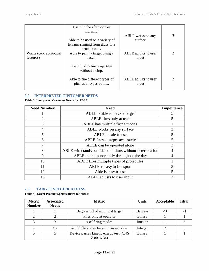
Use it in the afternoon or
morning.
Able to be used on a variety of
terrains ranging from grass to a
tennis court.
ABLE works on any
surface
3
Wants (cool additional
features)
Able to paint a target using a
laser.
Use it just to fire projectiles
without a chip.
Able to fire different types of
pitches or types of hits.
ABLE adjusts to user
input
ABLE adjusts to user
input
2
2
2.2 INTERPRETED CUSTOMER NEEDS
Table 3: Interpreted Customer Needs for ABLE
Need Number Need Importance
1 ABLE is able to track a target 5
2 ABLE fires only at user 5
3 ABLE has multiple firing modes 1
4 ABLE works on any surface 3
5 ABLE is safe to use 5
6 ABLE fires at target accurately 5
7 ABLE can be operated alone 3
8 ABLE withstands outside conditions without deterioration 4
9 ABLE operates normally throughout the day 4
10 ABLE fires multiple types of projectiles 1
11 ABLE is easy to transport 3
12 Able is easy to use 5
13 ABLE adjusts to user input 2
2.3 TARGET SPECIFICATIONS
Table 4: Target Product Specifications for ABLE
Metric
Number
Associated
Needs
Metric Units Acceptable Ideal
1 1 Degrees off of aiming at target Degrees <3 <1
2 2 Fires only at operator Binary 1 1
3 3 # of firing modes Integer 1 3
4 4,7 # of different surfaces it can work on Integer 2 5
5 5 Device passes kinetic energy test (CNS
Z 8016-34)
Binary 1 1

Project Name Concept Generation
Page 14 of 51
6 6 Range of positions around target that
are hit
Meters <3 <1
7 7,11 Mass Kg <60 <30
8 7,11 Volume m^3 <2 <0.5
9 8,9 Time spent outside without breaking Hours >12 >24
10 10 Number of different projectiles that
work with device
Integer 1 >3
11 12 Time a novice needs to spend with the
device to understand use
Minutes <60 <10
12 13 Number of parameters that can be
adjusted
Integer >3 0
13 5 Device complies with
AS/NZS 62115:2011
Binary 1 1
3 CONCEPT GENERATION
3.1 FUNCTIONAL DECOMPOSITION
Figure 1: Function Tree for ABLE

Project Name Concept Generation
Page 15 of 51
3.2 MORPHOLOGICAL CHART
Table 5: Morphological Chart forABLE
Track position of
target
Control actions
Turn firing
mechanism left/right
Turn firing
mechanism up/down
Impart kinetic
energy to projectile
Reload mechanism

Project Name Concept Generation
Page 16 of 51
Interface with
ground
Provide energy to
controller and
moving parts
3.3 CONCEPT #1 – “WHEELY-DEALY AIR”
Figure 2: Design Concept 1
Air turret that fires at a tracked target via GPS and uses a computer to control motors. Uses a belt
system and a piston to control vertical and horizontal adjustments. Sits on a wheeled platform.
Powered by cable.

Project Name Concept Generation
Page 17 of 51
3.4 CONCEPT #2 – “TELESCOPE LAUNCHER”
Figure 3: Design Concept 2
Auto-aiming compression spring turret that fires at a target tracked using a wireless arm band.
Uses a microprocessor to control motors. Uses a gear box and rotational motors to control
vertical and horizontal adjustments. Sits on a tripod. Powered by battery.

Project Name Concept Generation
Page 18 of 51
3.5 CONCEPT #3 – “TABLE BALLISTA”
Figure 4: Design Concept 3
Torsional-spring turret that fires at a target tracked via object-tracking cameras. Uses a
microprocessor to control motors. Uses a rear-mounted piston and gearbox to control vertical and
horizontal adjustments. Sits on a stable table. Powered by cable.

Project Name Concept Generation
Page 19 of 51
3.6 CONCEPT #4 – “BOW-POD”
Figure 5: Design Concept 4
Tension-spring turret that fires at a tracked target via GPS. Uses a cell phone to send commands
to motors. Uses two rotational motors to control vertical and horizontal adjustments. Sits on a
tripod. Powered by cable.

Project Name Concept Generation
Page 20 of 51
3.7 CONCEPT #5 – “AXLE TUBE”
Figure 6: Design Concept 5
Compression spring turret that fires at a tracked target via Armband and uses a microprocessor to
control motors. Uses an axle and gear box to control vertical and horizontal adjustments. Sits on
a table with folding legs. Powered by a battery.
3.8 CONCEPT #6 – “TABLE X-BOW”
Figure 7: Design Concept 6
Tension spring turret that fires at a tracked target via Armband and uses a microprocessor to
control motors. Uses a rear-mounted piston and a rotational motor to control vertical and
horizontal adjustments. Sits on a stable table. Powered by battery.

Project Name Concept Selection
Page 21 of 51
4 CONCEPT SELECTION
4.1 CONCEPT SCORING MATRIX
Table 6: Analytic Hierarchy Process
Table 7: Weighted Scoring Matrix for 6 design Concepts
4.2 EXPLANATION OF WINNING CONCEPT SCORES
Axle tube was generally an all-around better design than the others, outperforming in key categories. It is
designed to be robust, yet simple, meaning the cost of components is lower, and it’s easier to make and

Project Name Concept Selection
Page 22 of 51
assemble the parts. Furthermore, the enclosed nature of the launcher makes it inherently safer to use. In
terms of vertical angular resolution, it gives the most accuracy by supporting the axle at both ends,
allowing the motor to easily control the angle of the barrel, allowing for a large degree of rotational
motion at a high accuracy. This is compared to the piston/four-bar designs of the table ballista and table,
which have a smaller overall range of motion that is hard to get exactly.
4.3 EXPLANATION OF SECOND-PLACE CONCEPT SCORES
Telescope launcher did almost as well as axle tube, but fell below because of a few criteria. To start, it
performed the same in terms of mechanical safety, distance resolution, and ease of reloading as it used the
same firing mechanism as Axle Tube. However, by the nature of the lighter design, the requirements for
manufacturing and assembly were greater, and it was significantly less robust. However, because of the
lightweight design, the cost and weight were both reduced. In the end, the increased robustness and ease
of manufacturing outweighed the reduced cost and weight, although not by a large margin.
4.4 EXPLANATION OF THIRD-PLACE CONCEPT SCORES
Table ballista barely eked out the table X-bow for third place. It owes this success to the removal of the
reload assistance motor. While having the motor would be nice, the comparative value of ease of
reloading to cost was significantly lower. Other than that difference, there was very little difference
between it and the reference. It lost out to the two compression spring designs due to its lower safety and
reduced vertical angular resolution. Additionally, the design was more complex than the Axle Tube,
leading to harder assembly and manufacturing.
4.5 SUMMARY OF EVALUATION RESULTS
Safety was the most important feature, followed by robustness, tracking accuracy, and cost. The winning
design was Axle Tube, followed by Telescope Launcher, Table Ballista, Table X-Bow, Bow-Pod, and
Wheely Dealy Air Mobiley. The two last place designs did significantly worse than the other four.

Project Name Embodiment & Fabrication plan
Page 23 of 51
5 EMBODIMENT & FABRICATION PLAN
5.1 ISOMETRIC DRAWING WITH BILL OF MATERIALS
Figure 8 Isometric Drawing of Axle Tube Assembly

Project Name Embodiment & Fabrication plan
Page 24 of 51
5.2 EXPLODED VIEW
Figure 9: Exploded View of ABLE

Project Name Embodiment & Fabrication plan
Page 25 of 51
5.3 ADDITIONAL VIEWS
Figure 10: Front View

Project Name Embodiment & Fabrication plan
Page 26 of 51
Figure 11: Side View

Project Name Embodiment & Fabrication plan
Page 27 of 51
Figure 12: Back Isometric View

Project Name Engineering Analysis
Page 28 of 51
6 ENGINEERING ANALYSIS
6.1 ENGINEERING ANALYSIS RESULTS
6.1.1 Motivation
There are three primary forms of analysis for this project. Primarily, an analysis of the torques required to
rotate the platform and the barrel will ensure that the motors can provide enough force to move our device
the speeds needed to meet the performance goals. This will also influence the design to minimize the
torques required to ensure smooth operation. Additionally, it will provide insight into the factors of safety
of the connections, primarily the connection between the shaft expander and the rotating base.
Additionally, the CAD model will be used to get a rough estimate of the weight of the device. This
information will help the design meet the weight performance goal. Finally, the spring constant for the
chosen compression spring needs to be measured for the tracking system to know where to aim.
6.1.2 Summary Statement of the Analysis
The torque required to accelerate an object is given by the equation
𝜏 = 𝐼𝛼
In order to determine the torque requirements for the motor, an acceleration profile must be determined.
SolidWorks has a built-in feature for this, allowing us to determine a reasonable bound for the torque. It
does this by calculating the moment of inertia of the part and the angular acceleration of the motor while
maintaining the assembly mates of the part.
Figure 13: Graphic of the Motion Analysis Feature of SolidWorks
6.1.3 Methodology
Toque: Toque analysis is done using the CAD model and the SolidWorks motion study. The parts in
SolidWorks are modeled with their material properties, meaning the program can calculate the amount of

Project Name Engineering Analysis
Page 29 of 51
torque required to rotate parts at a certain speed. For this measurement, the performance goal of a moving
target was used as a reference for the speed of rotation, including a factor of safety to make sure the
device can rotate fast enough. For the measurement, we used an average rotational speed of 3.75 RPM.
Furthermore, the device was tested in the worst-case scenario, with the barrel horizontal, which
maximizes the moment of inertia.
Figure 14: Settings Used for SolidWorks Motion Analysis
Mass: SolidWorks provides a built-in calculator for the overall mass.
Spring: This analysis is done by hand using a set of known masses. The force exerted by a mass on the
spring was plotted against the displacement cause by the force. The slope of that line using a line of best
fit is the spring constant.
6.1.4 Results
For the device rotating at an average speed of 3.75 RPM (rotating 112.5 degrees over 5 seconds), the
maximum torque for the rotating base was 0.15 lbf per inch.
Figure 15: Graph of Motor Toque vs Time for the Rotating Base
For the vertical component of the aiming, rotating 50 degrees over 5 seconds, the maximum torque was
0.02 lbf per inch.
0.00 0.50 1.00 1.50 2.00 2.50 3.00 3.50 4.00 4.50 5.00
Time (sec)
-0.15
-0.07
-0.00
0.07
0.15
Mot
or
Torq
ue6
(poun
d_f
orc
e-in
ch)

Project Name Engineering Analysis
Page 30 of 51
Figure 16: Graph of Motor Torque vs Time for Barrel
The mass of the whole device, excluding electronic components, is 18.70 pounds according to the
SolidWorks analysis.
Figure 17: Mass Properties Analysis with SolidWorks
From our trendline we got that the spring constant was 119.96 Newtons per meter with a pre-load
of -.1371 Newtons. We then converted this from Newtons per meter to pounds force per inch and got a
spring constant of 0.685 lbf/in. This constant may not be accurate, as it was measured in tension instead
of compression.
0.00 0.50 1.00 1.50 2.00 2.50 3.00 3.50 4.00 4.50 5.00
Time (sec)
-0.02
-0.01
0.00
0.01
0.02
Mot
or
Torq
ue1
(poun
d_f
orc
e-inc
h)

Project Name Engineering Analysis
Page 31 of 51
Figure 18: Spring Response to Applied Force
6.1.5 Significance
Both the torques were well beneath the torque output of their respective motors, meaning that the design
can progress using the same configuration, and no special care needs to be taken to reduce the moments
of inertia. This also gives us a large factor of safety for the weights that were not included in this analysis
with the electronics. Furthermore, the design is well under the weight requirements. The measured value
for the spring constant is lower than optimal, meaning it will be insufficient to launch our ball any
significant distance. Overall, the analysis supported our design decisions, at least in terms of structure. A
few changes were made from non-numerical analysis in order to increase the safety of the design against
potential failure modes, including a redesign shaft expander to withstand more torque, and a redesign
barrel mount to distribute the load across the barrel.

Project Name Engineering Analysis
Page 32 of 51
Figure 19: Design Before Analysis
Figure 20: Design After Analysis

Project Name Engineering Analysis
Page 33 of 51
6.2 PRODUCT RISK ASSESSMENT
6.2.1 Risk Identification
6.2.1.1 Tracking
Description: A tracking error could cause the device to aim and fire at a bystander, or to miss the intended
target.
Impact: 2. Although being hit by a rogue ball may cause injury, the chance of it being severe is low due to
the nature of the ball.
Likelihood: 3. Due to time and knowledge constraints, the tracking system will have limitations and flaws
that will cause tracking issues. However, the chances of injury occurring from any individual error is
decently low.
6.2.1.2 Kinetic Energy
Description: The spring transfers an unsafe level of energy to the ball, causing it to move faster than is
safe.
Impact: 3. Using the full force of the spring could cause moderate injuries if it is not controlled.
Likelihood: 1. This risk is well managed with our design, as the compression of the spring is set by the
firing mechanism, meaning it can be controlled in normal circumstances. However, the user could still
manually compress the spring more.
6.2.1.3 Firing Angle
Description: If the firing angle is too low or too high, it will be unsafe to catch the ball due to the speed
and trajectory they are moving.
Impact: 2. Despite the unsafe firing method, the maximum energy in the ball would still be limited by the
compression of the spring, meaning severity of injury would be moderately low.
Likelihood: 2. Although programming will attempt to stop this from happening, lack of sensors will limit
the devices knowledge of its vertical position.
6.2.1.4 Rotation
Description: Excessive base rotation will cause the wiring the tangle and break, leading to equipment
failure and potential injury to the user.
Impact: 4. This mode of failure would damage the device in such a way that it would be non-functional.
Likelihood: 2. With no good way for the device to sense its absolute position (just relative position to the
target), it has no safeguards preventing it from rotating past certain points. However, the user can account
for this with their positioning.
6.2.1.5 Motor Torque
Description: The torque from the motors can exert toque that can damage the user if the device is
improperly handled, such as sticking an arm through the axle holding arms or in the barrel.

Project Name Engineering Analysis
Page 34 of 51
Impact: 5. The device does not care about obstructions to its motion, and will do its best to move despite
them. If that obstruction happens to be a limb, it would try to turn until either it, or the limb, was broken.
Likelihood: 1. This risk requires gross misuse of the device to manifest.
6.2.1.6 Splinters/cuts
Description: Many parts of the device are manufactured using wood, meaning splinters are a risk when
handling the device. Although the largest offenders have been sanded down, the risk remains for the user
to get small splinters when setting up or operating the device.
Impact: 1. The sections with the largest risk of giving splinters have been taken care of, meaning the
remaining splinters would be small nearly insignificant.
Likelihood: 2. Despite the best efforts, some splinters will remain.
6.2.1.7 Failure
Description: Failure of one or more parts, causing the device to break apart. The most likely parts to fail
are the shaft expander and the PVC endcap.
Impact: 5. Either of these failure modes would cause a sudden release of energy, and would damage the
device to the point of needing significant repair.
Likelihood: 2. Time constraints and material constraints limit the fortification of the design against
failure. When removing the bearing from the motor holder only superficial damage occurred.

Project Name Engineering Analysis
Page 35 of 51
6.2.2 Risk Heat Map
Figure 21: Risk Heat Map for ABLE
6.2.3 Risk Prioritization
The most important risks for the design process are failure and rotation. Both of these risks would cause
irreversible damage to the device and potentially the user. The risks from failure were mitigated by
designing parts to be thicker than needed to minimize the chance that the stresses cause them to fail.
Future prototypes could use stronger materials to increase this factor of safety. For the rotation and firing
angle issues, sensors that give an absolute position would ensure that the device could be programmed to
never pass certain thresholds. For the current iteration, these risks are mitigated through close monitoring
and calibration. Although the motor torque issues is high impact, there is very little that can be done
without additional components that can detect when the device is blocked, meaning the primary design
for the current iteration to mitigate the issue is in ensuring the user has proper knowledge of how to
operate the device. Instruction would also minimize the kinetic energy risk. A future prototype would also
benefit from an improved tracking scheme to minimize the risk of wrongful aiming and misfires. The
least important risk by far is the risk of splinters. This could be fixed by using a safe covering material
over the wood, or by wearing gloves during setup and transport.
Tracking
Kinetic Energy
Firing Angle Rotation
Motor Torque
Splinters/Cuts Failure
0
1
2
3
4
5
0 1 2 3 4 5
LIK
ELIH
OO
D
IMPACT
Risk Assessment Heat Map
Insignificant Catastrophic
Low
Hig
h

Project Name Design Documentation
Page 36 of 51
7 DESIGN DOCUMENTATION
7.1 PERFORMANCE GOALS
1. ABLE must fire ball at least 20 yards.
2. ABLE must fire on average within a 1-yard circle around target running at 4 mph at 15 yards away
over 5 shots.
3. ABLE must be able to be reloaded within 20 seconds, from having a ball in hand to ball launch.
4. ABLE must land ball +/- 1 yard on average of 5 shots when a static target is 15 yards away.
5. ABLE (including table) must weigh less than 30 lbs.
7.2 WORKING PROTOTYPE DEMONSTRATION
7.2.1 Performance Evaluation
Our device was able to fully reach two goals, and partially reach all of the others. The device was able to
meet the weight and reload speed requirements fully with no issue. However, it was unable to fire a full
20 yards, instead having a range of around 6 yards. This could be improved with a redesign of the
launching mechanism, replacing the PVC barrel with a mechanism more suited for holding the surgical
tubing. Additionally, the device was able to fire consistently at its maximum range within a much tighter
range than 1 yard. While tracking was successfully implemented, the device was not able to fire and track
safely at the same time, meaning it was not able to meet the second performance evaluation very well at
all.
7.2.2 Working Prototype – Video Link
https://youtu.be/NLtWWr0Za5U

Project Name Design Documentation
Page 37 of 51
7.2.3 Working Prototype – Additional Photos
Figure 22: First Additional View of Finished Device
Figure 23: Second Additional View of Finished Device

Project Name Discussion
Page 38 of 51
8 DISCUSSION
8.1 DESIGN FOR MANUFACTURING – PART REDESIGN FOR INJECTION MOLDING
8.1.1 Draft Analysis Results
Figure 24: Shaft Expander Before Draft
Figure 25: Shaft Expander After Draft

Project Name Discussion
Page 39 of 51
8.1.2 Explanation of Design Changes
Adding draft to the outside portions of the design represented a minimal change, as neither of those sides
interfaced with other parts. However, the draft of the internal hole was more difficult. The primary issue
was that the dimensions of the hole are dependent on the shaft of the stepper motor. Thus, the shaft was
added making sure that the dimensions of the hole are the same at the bottom of the part (where it
interfaces with the shaft of the motor). This has a positive benefit, however, of allowing the shaft
expander to attach via a force fit rather than needed a set screw.
8.2 DESIGN FOR USABILITY – EFFECT OF IMPAIRMENTS ON USABILITY
8.2.1 Vision
The device would be almost entirely unusable for a blind individual, due to the person needing to see the
ball in order to catch it. For a color blind individual, there is no issue using the device, as color is not an
important factor in the design, and each shape is highly distinguishable. Furthermore, there is only a
single projectile being launched, which should be easily seen by color blind individuals.
8.2.2 Hearing
Use of the device is entirely unaffected by a hearing impairment, as it does not rely on sound cues, and
catching the projectile does not require sound.
8.2.3 Physical
Physical impairments will limit the ability of an individual to reload the device. This can be minimized by
reducing the amount of force required to pull back the reloading rod, either by using as light as possible of
a rod or by automating the reload mechanism with a motor. Furthermore, physical impairments may
affect how an individual catches a ball, meaning the ball may need to be launched shorter distances so it
does not move as fast or impart as much force.
8.2.4 Language
A language impairment will make it harder to understand how to use the device and how to set it up. This
can be dealt with by including instructions in different languages, or by including pictorial instructions to
the user.
8.2 OVERALL EXPERIENCE
8.2.1 Does your final project result align with the initial project description?
The final prototype aligns moderately well with the initial project description. It is able to track a
target and fire a ball a modest distance, but still requires human input to fire, and can’t achieve the desired
ranges. Additionally, it lacks vertical aiming needed for properly calibrated distance firing. Nevertheless,
it remains a good proof-of-concept towards fully meeting the project description.
8.2.2 Was the project more or less difficult than you had expected?
The project ended up being more difficult than expected particularly in terms of time spent on the
project. This ended up being mainly due to unforeseen issues when it came to assembly and manufacture
of the project, centered around a lack of engineering knowledge of attachments between moving parts..

Project Name Discussion
Page 40 of 51
8.2.3 In what ways do you wish your final prototype would have performed better?
Having more effective means of transferring the energy of the motors to the rotation of parts
would have improved the project significantly, making the tracking system work better and would have
reduced concerns with wiring.
8.2.4 Was your group missing any critical information when you evaluated concepts?
The main issue with the evaluation of concepts was an overestimate of the ability of a simple
spring to provide enough energy to the ball to launch it forward without causing structural issues
elsewhere in the design. With that issue in mind, a different design would have likely won.
8.2.5 Were there additional engineering analyses that could have helped guide your design?
For the most part, additional engineering analysis would not have influenced our design all too
much. The primary area where it could have accelerated our design process was looking more in depth as
to the forces required to launch the ball using different mechanisms, and working to maximize a person’s
ability to supply that force.
8.2.6 How did you identify your most relevant codes and standards and how they influence revision of
the design?
The primary concern with our device was safety. Thus, we looked up standards regarding safety
for electrical toys and kinetic energy toys. Fundamentally, we were unable to reasonably include these
standards in their normal form in our project, because the kinetic energy considerations from the standard
would be insufficient to meaningfully launch a ball. Furthermore, the standards for electrical safety were
not the focus of the project, as for the initial prototype, getting the device to function was the priority.
8.2.7 What ethical considerations (from the Engineering Ethics and Design for Environment seminar)
are relevant to your device? How could these considerations be addressed?
The primary ethical concern for our device is in the waste caused by manufacturing and disposal.
These issues are addressed by ensuring that it minimizes the use of non-sustainable materials, and
contains many recyclable components.
8.2.8 On which part(s) of the design process should your group have spent more time? Which parts
required less time?
Once the issues surrounding getting the vertical rotation set up started to surface, it should have
been deemphasized and given less time. This way, more time could have been given to the programming
and firing mechanism, both of which needed significantly more time than they were given.
8.2.9 Was there a task on your Gantt chart that was much harder than expected? Were there any that
were much easier?
Manufacturing of parts was much harder than expected as we had conflicts with some of the
machine shop times. Furthermore, due to some scheduling issues and difficulty getting two people in for
manufacturing/assembly made much of the early construction of the design more time consuming than
expected and when it came to anything involving the heavier tools delayed it unless another group was
present.

Project Name Discussion
Page 41 of 51
8.2.10 Was there a component of your prototype that was significantly easier or harder to
make/assemble than you expected?
Getting the firing mechanism to fully function was much significantly harder than we thought due
to a variety of reasons. The biggest reason is that we had to go through multiple iterations with the
launching mechanism, as our plan to use a spring didn’t end up working due to issues with it strength and
stability. Furthermore, there were several issues attaching the firing mechanism to the axis, and it took
several iterations to get a method that worked well.
8.2.11 If your budget were increased to 10x its original amount, would your approach have changed? If
so, in what specific ways?
The main change that would be made with a larger budget would be a more accurate tracking
method that provided a good sense of distance and position. Furthermore, more power motors and proper
wiring supplies would improve the ability of the device to act on the new position information. Finally,
inclusion of some form of mechanical assistance on the reloading mechanism would allow the device to
launch further by storing more energy without placing an undue burden on the user.
8.2.12 If you were able to take the course again with the same project and group, what would you have
done differently the second time around?
One thing that we would have done differently is to use the earlier time more effectively and
work on manufacturing during other assignments, as well as making sure everyone was on the same page
in terms of expectations for the project. Additionally, we would put more work into ideas for the firing
mechanism, as that was one of the most frustrating aspects of the project. Finally, we would scale back
the expectations of the project to be more reasonable for the limited amount of time we had.
8.2.13 Were your team member’s skills complementary?
For the most part, team members were able to work well together and specialized at different
things. However, there was an amount of codependence that negatively influenced the group, with some
members unable to fully contribute without the help of others.
8.2.14 Was any needed skill missing from the group?
The main issue of the project was a lack of time and materials as opposed to a lack of skill. For
example, a team member possessed the skill to improve tracking programming and wiring, but lacked the
time to do so as they helped with the construction aspects.
8.2.15 Has the project enhanced your design skills?
The project has improved the design skills of the team, primarily in their ability to work around
roadblocks in the design process, as well as teaching them more about how to feasibly connect different
members together and transfer motion.
8.2.16 Would you now feel more comfortable accepting a design project assignment at a job?
Yes.
8.2.17 Are there projects you would attempt now that you would not have attempted before?
While the project did improve the skills of the team members, it did not change their drive to
attempt difficult assignments.

Project Name Appendix A - Parts List
Page 42 of 51
9 APPENDIX A - PARTS LIST Table 8: Parts List for ABLE

Project Name Appendix B - CAD Models
Page 43 of 51
10 APPENDIX B - CAD MODELS
Figure 26: CAD Model for Table
Project Name Appendix B - CAD Models
Page 44 of 51
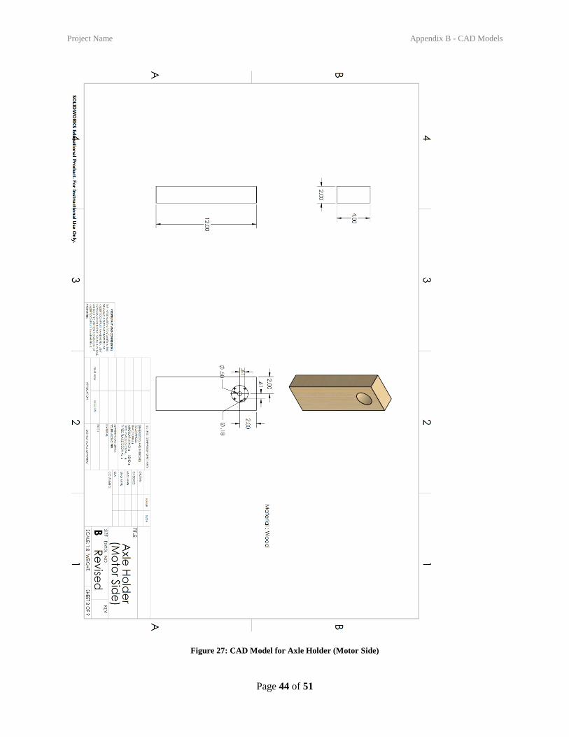
Figure 27: CAD Model for Axle Holder (Motor Side)
Project Name Appendix B - CAD Models
Page 45 of 51
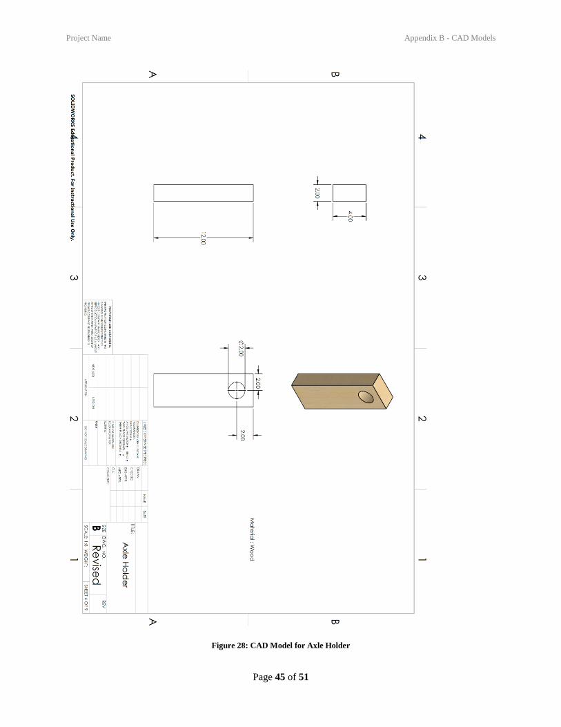
Figure 28: CAD Model for Axle Holder

Project Name Appendix B - CAD Models
Page 46 of 51
Figure 29: CAD Model for Barrel Mount

Project Name Appendix B - CAD Models
Page 47 of 51
Figure 30: CAD Model for Rotating Base

Project Name Appendix B - CAD Models
Page 48 of 51
Figure 31: CAD Model for Shaft Expander

Project Name Appendix B - CAD Models
Page 49 of 51
Figure 32: CAD Model for Axle

Project Name Appendix B - CAD Models
Page 50 of 51
Figure 33: CAD Model for Reloading Rod

Project Name Annotated Bibliography
Page 51 of 51
11 ANNOTATED BIBLIOGRAPHY