
Mobility Management Entity Configuration - Cisco
30
Mobility Management Entity Configuration This chapter provides configuration information for the Mobility Management Entity (MME). Because each wireless network is unique, the system is designed with a variety of parameters allowing it to perform in various wireless network environments. In this chapter, only the minimum set of parameters are provided to make the system operational. Optional configuration commands specific to the MME product are located in the Command Line Interface Reference. At least one packet processing card must be made active prior to service configuration. Information and instructions for configuring a packet processing card to be active can be found in the System Settings chapter of the System Administration Guide. Important Before you plan or modify your MME's configuration, we recommend that you review Appendix A: Engineering Rules for the engineering rules and configuration limits hardcoded into the system. Important While configuring any base-service or enhanced feature, it is highly recommended to avoid conflicting or blocked IP addresses and port numbers when binding or assigning these to your configuration. In association with some service steering or access control features, the use of inappropriate port numbers may result in communication loss. Refer to the respective feature configuration document carefully before assigning any port number or IP address for communication with internal or external networks. Caution Information about all commands in this chapter can be found in the Command Line Interface Reference. Important • Configuring the System as a Standalone MME (base configuration), page 2 • Configuring Optional Features on the MME, page 12 MME Administration Guide, StarOS Release 21.1 1
-
Upload
khangminh22 -
Category
Documents
-
view
2 -
download
0
Transcript of Mobility Management Entity Configuration - Cisco

Mobility Management Entity Configuration
This chapter provides configuration information for the Mobility Management Entity (MME).
Because each wireless network is unique, the system is designed with a variety of parameters allowing it toperform in various wireless network environments. In this chapter, only the minimum set of parameters areprovided to make the system operational. Optional configuration commands specific to the MME productare located in the Command Line Interface Reference.
At least one packet processing card must be made active prior to service configuration. Information andinstructions for configuring a packet processing card to be active can be found in the System Settingschapter of the System Administration Guide.
Important
Before you plan or modify your MME's configuration, we recommend that you review Appendix A:Engineering Rules for the engineering rules and configuration limits hardcoded into the system.
Important
While configuring any base-service or enhanced feature, it is highly recommended to avoid conflictingor blocked IP addresses and port numbers when binding or assigning these to your configuration. Inassociation with some service steering or access control features, the use of inappropriate port numbersmay result in communication loss. Refer to the respective feature configuration document carefully beforeassigning any port number or IP address for communication with internal or external networks.
Caution
Information about all commands in this chapter can be found in the Command Line Interface Reference.Important
• Configuring the System as a Standalone MME (base configuration), page 2
• Configuring Optional Features on the MME, page 12
MME Administration Guide, StarOS Release 21.1 1

Configuring the System as a Standalone MME (baseconfiguration)
This section provides a high-level series of steps and associated configuration file examples for configuringthe system to perform as an MME in a test environment. This section also includes suggestions about thetypes of information that are needed to be able to configure the MME, as well as information about how theMME works based on some of the possible configurations.
The configurations in this section assume the following:
• A single context (other than the Local context) for all interfaces and services
• Static S-GW/P-GW selection (MME Policy configuration)
Information RequiredThe following sections describe the minimum amount of information required to configure and make theMME operational on the network. Tomake the process more efficient, it is recommended that this informationbe available prior to configuring the system.
There are additional configuration parameters that are not described in this section. These parameters dealmostly with fine-tuning the operation of the S-GW in the network. Information on these parameters can befound in the appropriate sections of the Command Line Interface Reference.
Required MME Context Configuration InformationThe following table lists the information that is required to configure the MME context.
Table 1: Required Information for MME Context Configuration
DescriptionRequired Information
An identification string from 1 to 79 characters (alpha and/or numeric) bywhich the MME context is recognized by the system.
MME context name
S1-MME Interface Configuration (To/from eNodeB)
An identification string between 1 and 79 characters (alpha and/or numeric)by which the interface is recognized by the system.
Multiple names are needed if multiple interfaces will be configured.
Interface name
IPv4 or IPv6 address assigned to the S1-MME interface. This address will beused for binding the SCTP (local bind address(es)) to communicate with theeNodeBs using S1-AP.
Multiple addresses and subnets are needed if multiple interfaces will beconfigured.
IP address and subnet
MME Administration Guide, StarOS Release 21.12
Mobility Management Entity ConfigurationConfiguring the System as a Standalone MME (base configuration)

DescriptionRequired Information
The physical port to which the interface will be bound. Ports are identified bythe chassis slot number where the line card resides followed by the number ofthe physical connector on the card. For example, port 17/1 identifies connectornumber 1 on the card in slot 17.
A single physical port can facilitate multiple interfaces.
Physical port number
S11 Interface Configuration (To/from S-GW)
An identification string between 1 and 79 characters (alpha and/or numeric)by which the interface is recognized by the system.
Multiple names are needed if multiple interfaces will be configured.
Interface name
IPv4 address assigned to the S11 interface.
Multiple addresses and subnets are needed if multiple interfaces will beconfigured.
IP address and subnet
The physical port to which the interface will be bound. Ports are identified bythe chassis slot number where the line card resides followed by the number ofthe physical connector on the card. For example, port 17/1 identifies connectornumber 1 on the card in slot 17.
A single physical port can facilitate multiple interfaces.
Physical port number
S6a Interface Configuration (To/from HSS)
An identification string between 1 and 79 characters (alpha and/or numeric)by which the interface is recognized by the system.
Multiple names are needed if multiple interfaces will be configured.
Interface name
IPv4 or IPv6 addresses assigned to the S6a interface.
Multiple addresses and subnets are needed if multiple interfaces will beconfigured.
IP address and subnet
The physical port to which the interface will be bound. Ports are identified bythe chassis slot number where the line card resides followed by the number ofthe physical connector on the card. For example, port 17/1 identifies connectornumber 1 on the card in slot 17.
A single physical port can facilitate multiple interfaces.
Physical port number
S6a Diameter Endpoint Configuration
An identification string from 1 to 63 characters (alpha and/or numeric) bywhich the S6a Diameter endpoint configuration is recognized by the system.
End point name
MME Administration Guide, StarOS Release 21.1 3
Mobility Management Entity ConfigurationInformation Required

DescriptionRequired Information
An identification string between 1 through 127 characters.
The realm is the Diameter identity. The originator's realm is present in allDiameter messages and is typically the company or service name.
Origin realm name
An identification string from 1 to 255 characters (alpha and/or numeric) bywhich the S6a origin host is recognized by the system.
Origin host name
The IP address of the S6a interface.Origin host address
The S6a endpoint name described above.Peer name
The S6a origin realm name described above.Peer realm name
The IP address and port number of the HSS.Peer address and portnumber
The S6a endpoint name described above.Route-entry peer
S13 Interface Configuration (To/from EIR)
An identification string between 1 and 79 characters (alpha and/or numeric)by which the interface is recognized by the system.
Multiple names are needed if multiple interfaces will be configured.
Interface name
IPv4 or IPv6 addresses assigned to the S13 interface.
Multiple addresses and subnets are needed if multiple interfaces will beconfigured.
IP address and subnet
The physical port to which the interface will be bound. Ports are identified bythe chassis slot number where the line card resides followed by the number ofthe physical connector on the card. For example, port 17/1 identifies connectornumber 1 on the card in slot 17.
A single physical port can facilitate multiple interfaces.
Physical port number
S13 Diameter Endpoint Configuration
An identification string from 1 to 63 characters (alpha and/or numeric) bywhich the S13 Diameter endpoint configuration is recognized by the system.
End point name
An identification string between 1 through 127 characters.
The realm is the Diameter identity. The originator's realm is present in allDiameter messages and is typically the company or service name.
Origin realm name
An identification string from 1 to 255 characters (alpha and/or numeric) bywhich the S13 origin host is recognized by the system.
Origin host name
MME Administration Guide, StarOS Release 21.14
Mobility Management Entity ConfigurationInformation Required

DescriptionRequired Information
The IP address of the S13 interface.Origin host address
The S13 endpoint name described above.Peer name
The S13 origin realm name described above.Peer realm name
The IP address and port number of the EIR.Peer address and portnumber
The S13 endpoint name described above.Route-entry peer
MME Service Configuration
An identification string from 1 to 63 characters (alpha and/or numeric) bywhich the MME service can be identified on the system. It is configured in theContext configuration mode.
Multiple names are needed if multiple MME services will be configured.
MME service name
The identifier of Public LandMobile Network (PLMN) of whichMME belongsto. PLMN identifier is consisting of MCC and MNC.
PLMN identifier
The identifier of MME node. The MME Id is consisting of MME group andMME code.
MME identifier
An identification string from 1 to 64 characters (alpha and/or numeric) bywhich the TAI management database service can be associated with the MMEservice.
This is required for static S-GW selection. Refer to the Required MME PolicyConfiguration Information section below.
TAI management databasename
IPv4 or IPv6 address of a PDN Gateway (P-GW). This is required for staticS-GW/P-GW selection.
P-GW IP address
eGTP Service Configuration
An identification string from 1 to 63 characters (alpha and/or numeric) bywhich the eGTP service can be associated with MME system.
Multiple names are needed if multiple eGTP services will be used.
eGTP service name
Identifies the type of interface to which the eGTP service is bound. Thisinterface type is "interface-mme".
Interface type
The IPv4 address of the S11 interface.GTP-C binding IP address
HSS Peer Service Configuration
MME Administration Guide, StarOS Release 21.1 5
Mobility Management Entity ConfigurationInformation Required

DescriptionRequired Information
An identification string from 1 to 63 characters (alpha and/or numeric) bywhich the HSS peer service is recognized by the system.
Multiple names are needed if multiple HSS peer services will be used.
HSS peer service name
The name for a pre-configured Diameter endpoint, configured on system toassociate with this MME service to access an HSS and an EIR. This is the S6aDiameter endpoint name.
Diameter HSS peer
Required MME Policy Configuration InformationThe following table lists the information that is required to configure the MME Policy on an MME.
Table 2: Required Information for MME Policy Configuration
DescriptionRequired Information
An identification string from 1 to 64 characters (alpha and/or numeric) bywhich the TAI management database is recognized by the system.
Tracking Area Identifier (TAI)management database name
An identification string from 1 to 64 characters (alpha and/or numeric) bywhich the TAI management object is recognized by the system.
Tracking Area Identifier (TAI)management object name
TheMobile Country Code,Mobile Network Code, and TrackingArea Codefor the S-GW this management object represents.
MCC, MNC, and TAC
The IPv4 or IPv6 address of the S-GW this management object represents.S-GW IP address
How This Configuration WorksThe following figure and supporting text describe how this configuration with a single context is used by thesystem to process a subscriber call originating from the GTP LTE network.
MME Administration Guide, StarOS Release 21.16
Mobility Management Entity ConfigurationHow This Configuration Works
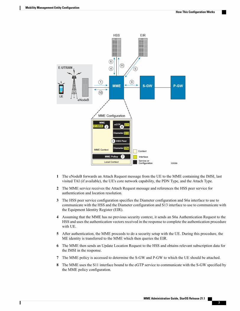
1 The eNodeB forwards an Attach Request message from the UE to the MME containing the IMSI, lastvisited TAI (if available), the UE's core network capability, the PDN Type, and the Attach Type.
2 The MME service receives the Attach Request message and references the HSS peer service forauthentication and location resolution.
3 The HSS peer service configuration specifies the Diameter configuration and S6a interface to use tocommunicate with the HSS and the Diameter configuration and S13 interface to use to communicate withthe Equipment Identity Register (EIR).
4 Assuming that the MME has no previous security context, it sends an S6a Authentication Request to theHSS and uses the authentication vectors received in the response to complete the authentication procedurewith UE.
5 After authentication, the MME proceeds to do a security setup with the UE. During this procedure, theME identity is transferred to the MME which then queries the EIR.
6 The MME then sends an Update Location Request to the HSS and obtains relevant subscription data forthe IMSI in the response.
7 The MME policy is accessed to determine the S-GW and P-GW to which the UE should be attached.
8 The MME uses the S11 interface bound to the eGTP service to communicate with the S-GW specified bythe MME policy configuration.
MME Administration Guide, StarOS Release 21.1 7
Mobility Management Entity ConfigurationHow This Configuration Works

9 The MME then sends a Create Session Request to S-GW which is also forwarded to the specified P-GW(assuming GTP-S5/S8) P-GW establishes the S5/S8 GTPU bearers and then responds with aCreate-Session-response which is forwarded to the MME by the S-GW. The S-GW includes the relevantS1-U bearer information.
10 The MME then sends a NAS Attach Accept embedded in the S1 Init Ctxt Setup request to the eNodeB.The Attach Accept contains the IP address allocated to the PDN and the temporary identifier (GUTI)assigned to the UE. The MME waits for positive acknowledgment from both the eNodeB (Init Ctxt Setupresponse) and UE (Attach Complete). The Init Ctxt Setup Response contains the S1-U bearer endpointinformation. The MME then uses the S11 Modify Bearer Request to update the eNodeB endpoints withthe S-GW. The receipt of the S11 Modify Bearer Response completes the end-to-end bearer setup.
11 The MME then uses the S6a Notify Request to update the HSS with the APN and P-GW identity.
MME ConfigurationTo configure the system to perform as a standalone eGTP S-GW, review the following graphic and subsequentsteps.
Step 1 Set system configuration parameters such as activating PSCs by applying the example configurations found in the SystemAdministration Guide.
Step 2 Create the MME context, service, and all interfaces, and bind the S1-MME interface to an IP address by applying theexample configuration in the section.
Step 3 Create the eGTP service and associate it with the S11 interface by applying the example configuration in the section.Step 4 Create the HSS peer service and associate it with the S6a interface and S13 interface by applying the example configuration
in the section.Step 5 Save your configuration to flash memory, an external memory device, and/or a network location using the Exec mode
command save configuration. For additional information on how to verify and save configuration files, refer to theSystem Administration Guide and the Command Line Interface Reference.
MME Administration Guide, StarOS Release 21.18
Mobility Management Entity ConfigurationMME Configuration
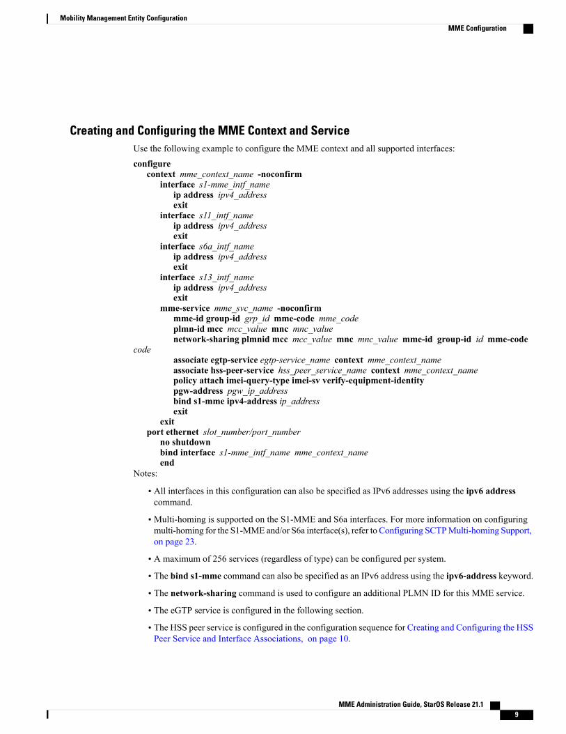
Creating and Configuring the MME Context and ServiceUse the following example to configure the MME context and all supported interfaces:
configurecontext mme_context_name -noconfirm
interface s1-mme_intf_nameip address ipv4_addressexit
interface s11_intf_nameip address ipv4_addressexit
interface s6a_intf_nameip address ipv4_addressexit
interface s13_intf_nameip address ipv4_addressexit
mme-service mme_svc_name -noconfirmmme-id group-id grp_id mme-code mme_codeplmn-id mcc mcc_value mnc mnc_valuenetwork-sharing plmnid mcc mcc_value mnc mnc_value mme-id group-id id mme-code
codeassociate egtp-service egtp-service_name context mme_context_nameassociate hss-peer-service hss_peer_service_name context mme_context_namepolicy attach imei-query-type imei-sv verify-equipment-identitypgw-address pgw_ip_addressbind s1-mme ipv4-address ip_addressexit
exitport ethernet slot_number/port_number
no shutdownbind interface s1-mme_intf_name mme_context_nameend
Notes:
• All interfaces in this configuration can also be specified as IPv6 addresses using the ipv6 addresscommand.
• Multi-homing is supported on the S1-MME and S6a interfaces. For more information on configuringmulti-homing for the S1-MME and/or S6a interface(s), refer to Configuring SCTPMulti-homing Support,on page 23.
• A maximum of 256 services (regardless of type) can be configured per system.
• The bind s1-mme command can also be specified as an IPv6 address using the ipv6-address keyword.
• The network-sharing command is used to configure an additional PLMN ID for this MME service.
• The eGTP service is configured in the following section.
• The HSS peer service is configured in the configuration sequence for Creating and Configuring the HSSPeer Service and Interface Associations, on page 10.
MME Administration Guide, StarOS Release 21.1 9
Mobility Management Entity ConfigurationMME Configuration

• In the above example, the mobile equipment identity (IMEI) is checked during the attach procedure.This is configured in the policy attach command. Another option is to check IMEI during the trackingarea update (TAU). This can be accomplished instead of, or, in addition to, the EIR query during theattach procedure. To check during the TAU, use the policy tau command.
• The pgw-address command is used to statically configure P-GW discovery.
Creating and Configuring the eGTP Service and Interface AssociationUse the following example to create an eGTP service and associate it with the S11 interface.
configurecontext mme_context_name
egtp-service egtp_service_nameinterface-type interface-mmegtpc bind ipv4-address s11_infc_ip_addressexit
exitport ethernet slot_number/port_number
no shutdownbind interface s11_interface_name mme_context_nameend
Notes:
• The gtpc bind command can be specified as an IPv6 address using the ipv6-address keyword. Theinterface specified for S11 communication must also be the same IPv6 address.
Creating and Configuring the HSS Peer Service and Interface AssociationsUse the following example to create and configure the HSS peer service:
configurecontext mme_context_name
hss-peer-service hss_peer_service_namediameter hss-endpoint hss_endpoint_name eir-endpoint eir-endpoint_nameexit
exitdiameter endpoint hss-endpoint_name
origin realm realm_nameorigin host name address S6a_interface_addresspeer peer_name realm realm_name address hss_ip_addressroute-entry realm realm_name peer peer_nameexit
diameter endpoint eir-endpoint_nameorigin realm realm_nameorigin host name address S13_interface_addresspeer peer_name realm realm_name address eir_ip_addressroute-entry realm realm_name peer peer_nameexit
port ethernet slot_number/port_numberno shutdownbind interface s6a_interface_name mme_context_nameexit
port ethernet slot_number/port_number
MME Administration Guide, StarOS Release 21.110
Mobility Management Entity ConfigurationMME Configuration
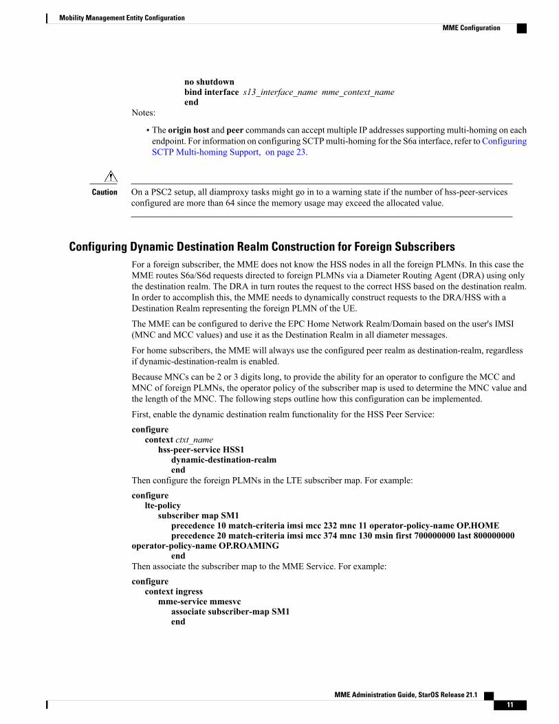
no shutdownbind interface s13_interface_name mme_context_nameend
Notes:
• The origin host and peer commands can accept multiple IP addresses supporting multi-homing on eachendpoint. For information on configuring SCTPmulti-homing for the S6a interface, refer to ConfiguringSCTP Multi-homing Support, on page 23.
On a PSC2 setup, all diamproxy tasks might go in to a warning state if the number of hss-peer-servicesconfigured are more than 64 since the memory usage may exceed the allocated value.
Caution
Configuring Dynamic Destination Realm Construction for Foreign SubscribersFor a foreign subscriber, the MME does not know the HSS nodes in all the foreign PLMNs. In this case theMME routes S6a/S6d requests directed to foreign PLMNs via a Diameter Routing Agent (DRA) using onlythe destination realm. The DRA in turn routes the request to the correct HSS based on the destination realm.In order to accomplish this, the MME needs to dynamically construct requests to the DRA/HSS with aDestination Realm representing the foreign PLMN of the UE.
The MME can be configured to derive the EPC Home Network Realm/Domain based on the user's IMSI(MNC and MCC values) and use it as the Destination Realm in all diameter messages.
For home subscribers, the MME will always use the configured peer realm as destination-realm, regardlessif dynamic-destination-realm is enabled.
Because MNCs can be 2 or 3 digits long, to provide the ability for an operator to configure the MCC andMNC of foreign PLMNs, the operator policy of the subscriber map is used to determine the MNC value andthe length of the MNC. The following steps outline how this configuration can be implemented.
First, enable the dynamic destination realm functionality for the HSS Peer Service:
configurecontext ctxt_name
hss-peer-service HSS1dynamic-destination-realmend
Then configure the foreign PLMNs in the LTE subscriber map. For example:
configurelte-policy
subscriber map SM1precedence 10 match-criteria imsi mcc 232 mnc 11 operator-policy-name OP.HOMEprecedence 20 match-criteria imsi mcc 374 mnc 130 msin first 700000000 last 800000000
operator-policy-name OP.ROAMINGend
Then associate the subscriber map to the MME Service. For example:
configurecontext ingress
mme-service mmesvcassociate subscriber-map SM1end
MME Administration Guide, StarOS Release 21.1 11
Mobility Management Entity ConfigurationMME Configuration

A static route entry must also be added in the diameter endpoint configuration for each foreign realm. Forexample:
configurecontext ingress
diameter endpoint s6a1peer HSS1 realm HSS-Realm1 address ip-address sctproute-entry realm epc.mnc045.mcc123.3gppnetwork.org peer HSS1end
With this sample configuration, an MNC of length 2 and value of 11 is matched with first operator policy(OP.HOME), and an MNC length of 3 and value of 130 is matched with the second operator policy(OP.ROAMING). With this configuration, the MME will find the MNC based on the operator policy for theforeign subscriber.
If there is no matching entry present in the operator policy, the MME will use the global static table to decidethe MNC length and pass that information to Diameter layer to construct the dynamic realm. The followinglist of MCCs are all considered as 3 digit MNCs. All other MCCs are considered 2 digit MNCs.
405354334302
708356338310
722358342311
732360344312
365346316
376348
The show hss-peer-service service name command displays this configuration in the Destination Realmfield, either Configured Peer Realm (default), or Dynamic Realm.Request Auth-vectors : 1Notify Request Message : EnableDestination Realm : Dynamic Realm
Configuring Optional Features on the MMEThe configuration examples in this section are optional and provided to cover the most common uses of theMME in a live network. The intent of these examples is to provide a base configuration for testing.
Configuring Differentiation Between HeNB-GW and eNodeBsThe MME can be configured to distinguish the Home eNodeB Gateway (HeNB-GW) from other eNodeBs.This is required to support S1 handovers to Home eNodeBs connected via a HeNB-GW.
As per 3GPP TS 36.300, section 4.6.2, the TAI used in a HeNB-GW should not be reused in another HeNB-GW.The global eNodeB id of the HeNB-GW can now be configured within the lte-policy configuration mode.
In case of S1-based handovers to Home eNodeBs served by a HeNB-GW, the lookup at MME for the targeteNodeB based on global ENB id will fail, as MME is aware of only the HeNB-GW. In those cases additionallookup needs to be done based on TAI to find the HeNB-GW serving the Home eNodeB.
MME Administration Guide, StarOS Release 21.112
Mobility Management Entity ConfigurationConfiguring Optional Features on the MME

This feature allows operators to configure the global eNodeB ids of HeNB-GWs in the MME service. TheMME uses this information to perform HeNB-GW related functions.
The following steps create an HeNB-GW management database, configures a single Global eNodeB ID andTAI within the management database, and associates the HeNB-GW management database with the MMEservice:
configurelte-policy
mme henbgw mgmt-db db_namehenbgw-global-enbid mcc mcc_valuemnc mnc_value enbid enbid_valueend
configurecontext ctxt_name
mme-service svc_nameassociate henbgw-mgmt-db db_nameend
Notes:
• A maximum of 8 HeNB-GWs can be configured within the HeNB-GW management database.
• The show lte-policy henbgw-mgmt-db name db_name command displays configuration informationabout the specified HeNB-GW management database.
• The showmme-service enodeb-association full command displayswhether the eNodeB is anHeNB-GWby including "(HeNB-GW)" in the output of the eNodeB Type field.
Configuring Dual Address BearersThis example configures support for IPv4/v6 PDNs.
Use the following configuration example to enable support on the MME for dual-address bearers:
configurecontext mme_context_name -noconfirm
mme-service mme_svc_namepolicy network dual-addressing-supportend
Configuring Dynamic Peer SelectionThe configuration in this section replaces static configurations on theMME for the following peer components:MME, P-GW, S-GW, SGSN.
Use the following example to configure dynamic P-GW, S-GW, and peer MME selection through a DNSinterface:
configurecontext mme_context_name -noconfirm
interface dns_intf_nameip address ipv4_addressexit
ip domain-lookupip name-servers dns_ip_addressdns-client name
MME Administration Guide, StarOS Release 21.1 13
Mobility Management Entity ConfigurationConfiguring Dual Address Bearers

bind address dns_intf_ip_addressexit
mme-service mme_svc_namedns pgwdns sgwdns peer-mmedns peer-sgsnend
Notes:
• For the dns pgw, dns sgw, dns peer-mme, and dns peer-sgsn commands, the DNS client service mustexist in the same context as theMME service. If the DNS client resides in a different context, the contextcommand and ctx_name variable must be added to the command(s).
• If you have associated a tai-mgmt-db with a call-control-profile, and DNS is to be used for S-GWlookups, the DNS configuration must be configured within the same call-control-profile using thedns-sgw command present within the call-control-profile configuration mode.
Configuring Emergency Session SupportThe configuration example in this section enables emergency bearer session support on the MME.
Use the following configuration example to enable emergency bearer services on the MME:
configurelte-policy
lte-emergency-profile profile_nameambr max-ul bitrate max-dl bitrateapn apn_name pdn-type typepgw ip-address address protocol type weight valueqos qci qci arp arp_value preemption-capability capability vulnerability typeue-validation-level typeexit
mme-service mme_svc_nameassociate lte-emergency-profile profile_nameend
Notes:
• A maximum of four LTE emergency profiles can be configured on the system.
• In the apn command, the valid PDN types are: ipv4, ipv4v6, and ipv6.
• In the pgw command, the valid protocol types are: both, gtp, and pmip. A maximum of four P-GW IPaddresses can be configured per profile. An FQDN can also be configured in place of the IP addressesbut only one P-GW FQDN can be configured per profile.
• In the qos command, the valid preemption capabilities are:may and shall not. The valid vulnerabilitytypes are: not-preemptable and preemptable.
• The ue-validation-level types are: auth-only, full, imsi, and none.
• To configure the MME to ignore the IMEI validation of the equipment during the attach procedure inemergency cases, use the following command in themme-service configuration mode:policy attach imei-query-type imei | imei-sv | none verify-equipment-identity verify-emergency
MME Administration Guide, StarOS Release 21.114
Mobility Management Entity ConfigurationConfiguring Emergency Session Support
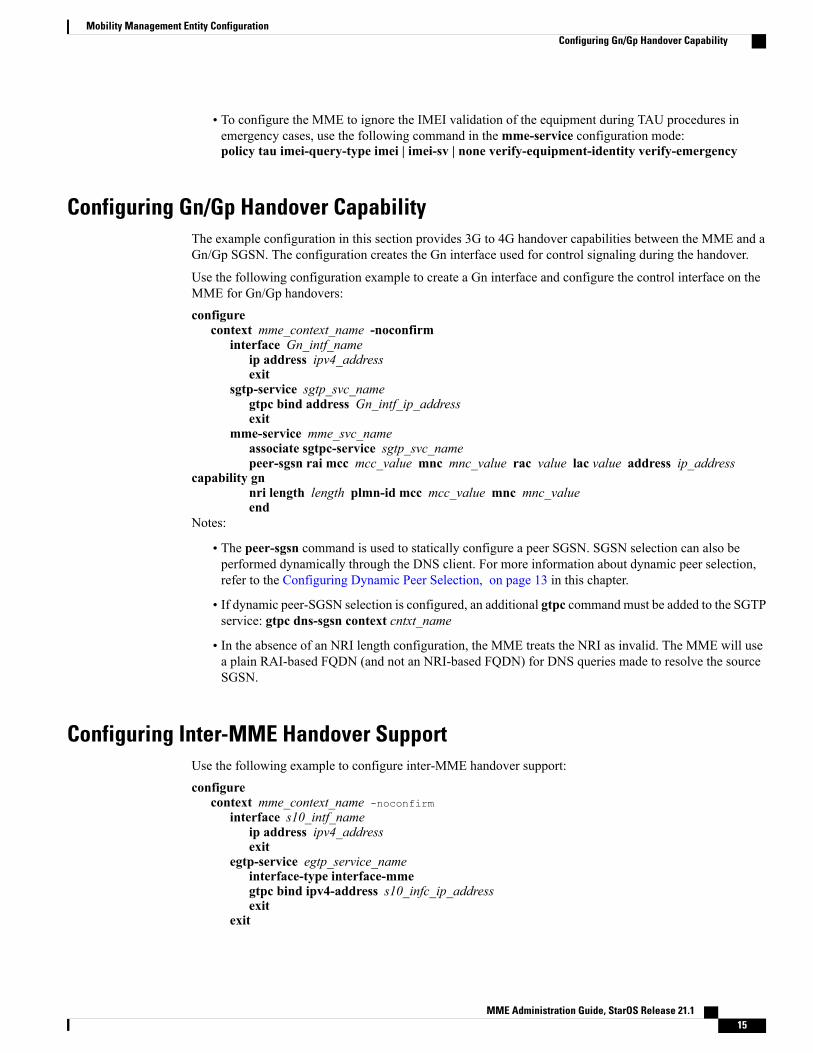
• To configure the MME to ignore the IMEI validation of the equipment during TAU procedures inemergency cases, use the following command in themme-service configuration mode:policy tau imei-query-type imei | imei-sv | none verify-equipment-identity verify-emergency
Configuring Gn/Gp Handover CapabilityThe example configuration in this section provides 3G to 4G handover capabilities between the MME and aGn/Gp SGSN. The configuration creates the Gn interface used for control signaling during the handover.
Use the following configuration example to create a Gn interface and configure the control interface on theMME for Gn/Gp handovers:
configurecontext mme_context_name -noconfirm
interface Gn_intf_nameip address ipv4_addressexit
sgtp-service sgtp_svc_namegtpc bind address Gn_intf_ip_addressexit
mme-service mme_svc_nameassociate sgtpc-service sgtp_svc_namepeer-sgsn rai mcc mcc_value mnc mnc_value rac value lac value address ip_address
capability gnnri length length plmn-id mcc mcc_value mnc mnc_valueend
Notes:
• The peer-sgsn command is used to statically configure a peer SGSN. SGSN selection can also beperformed dynamically through the DNS client. For more information about dynamic peer selection,refer to the Configuring Dynamic Peer Selection, on page 13 in this chapter.
• If dynamic peer-SGSN selection is configured, an additional gtpc command must be added to the SGTPservice: gtpc dns-sgsn context cntxt_name
• In the absence of an NRI length configuration, the MME treats the NRI as invalid. The MME will usea plain RAI-based FQDN (and not an NRI-based FQDN) for DNS queries made to resolve the sourceSGSN.
Configuring Inter-MME Handover SupportUse the following example to configure inter-MME handover support:
configurecontext mme_context_name -noconfirm
interface s10_intf_nameip address ipv4_addressexit
egtp-service egtp_service_nameinterface-type interface-mmegtpc bind ipv4-address s10_infc_ip_addressexit
exit
MME Administration Guide, StarOS Release 21.1 15
Mobility Management Entity ConfigurationConfiguring Gn/Gp Handover Capability

mme-service mme_svc_namepeer-mme gummei mcc number mnc number group-id id mme-code code address
ipv4_addressexit
exitport ethernet slot_number/port_number
no shutdownbind interface s10_interface_name mme_context_nameend
Notes:
• The S10 IP address can also be specified as an IPv6 address. To support this, the ip address commandcan be changed to the ipv6 address command.
• The peer-mme command can also be configured to acquire a peer MME through the use of a TAI matchas shown in this command example:peer-mme tai-match priority value mcc number mnc number tac any address ipv4_address
• The peer-mme command is used to statically configure a peer MME. MME selection can also beperformed dynamically through the DNS client. For more information about dynamic peer selection,refer to the Configuring Dynamic Peer Selection, on page 13 in this chapter.
• The peer MME IP address can also be specified as an IPv6 address.
Configuring X.509 Certificate-based Peer AuthenticationThe configuration example in this section enables X.509 certificate-based peer authentication, which can beused as the authentication method for IP Security on the MME.
Use of the IP Security feature requires that a valid license key be installed. Contact your local Sales orSupport representative for information on how to obtain a license.
Important
The following configuration example enables X.509 certificate-based peer authentication on the MME.
In Global Configuration Mode, specify the name of the X.509 certificate and CA certificate, as follows:
configurecertificate name cert_name pem url cert_pem_url private-key pprivate-keyem url private_key_urlca-certificate name ca_cert_name pem url ca_cert_urlend
Notes:
• The certificate name and ca-certificate list ca-cert-name commands specify the X.509 certificate andCA certificate to be used.
• The PEM-formatted data for the certificate and CA certificate can be specified, or the information canbe read from a file via a specified URL as shown in this example.
When creating the crypto template for IPSec in the Context Configuration Mode, bind the X.509 certificateand CA certificate to the crypto template and enable X.509 certificate-based peer authentication for the localand remote nodes, as follows:
configurecontext mme_context_name
MME Administration Guide, StarOS Release 21.116
Mobility Management Entity ConfigurationConfiguring X.509 Certificate-based Peer Authentication
crypto template crypto_template_name ikev2-dynamiccertificate name cert_nameca-certificate list ca-cert-name ca_cert_nameauthentication local certificateauthentication remote certificateend
Notes:
• Amaximum of sixteen certificates and sixteen CA certificates are supported per system. One certificateis supported per service, and a maximum of four CA certificates can be bound to one crypto template.
• The certificate name and ca-certificate list ca-cert-name commands bind the certificate and CAcertificate to the crypto template.
• The authentication local certificate and authentication remote certificate commands enable X.509certificate-based peer authentication for the local and remote nodes.
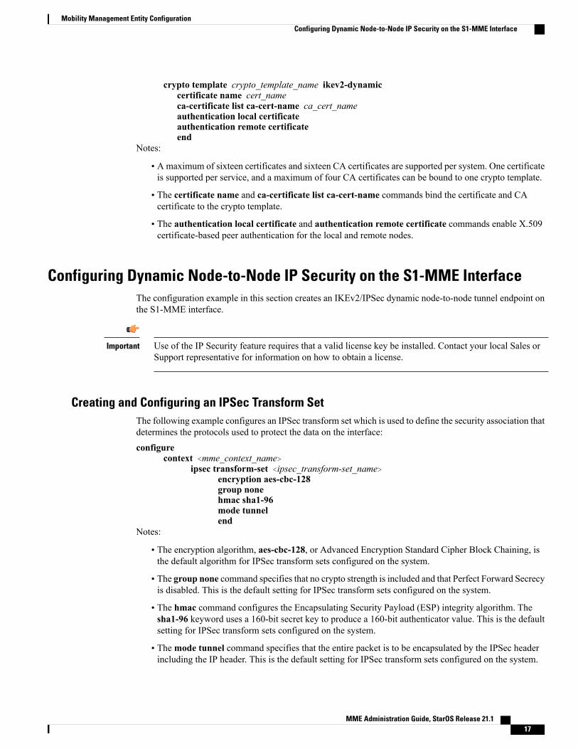
Configuring Dynamic Node-to-Node IP Security on the S1-MME InterfaceThe configuration example in this section creates an IKEv2/IPSec dynamic node-to-node tunnel endpoint onthe S1-MME interface.
Use of the IP Security feature requires that a valid license key be installed. Contact your local Sales orSupport representative for information on how to obtain a license.
Important
Creating and Configuring an IPSec Transform SetThe following example configures an IPSec transform set which is used to define the security association thatdetermines the protocols used to protect the data on the interface:
configurecontext <mme_context_name>
ipsec transform-set <ipsec_transform-set_name>encryption aes-cbc-128group nonehmac sha1-96mode tunnelend
Notes:
• The encryption algorithm, aes-cbc-128, or Advanced Encryption Standard Cipher Block Chaining, isthe default algorithm for IPSec transform sets configured on the system.
• The group none command specifies that no crypto strength is included and that Perfect Forward Secrecyis disabled. This is the default setting for IPSec transform sets configured on the system.
• The hmac command configures the Encapsulating Security Payload (ESP) integrity algorithm. Thesha1-96 keyword uses a 160-bit secret key to produce a 160-bit authenticator value. This is the defaultsetting for IPSec transform sets configured on the system.
• Themode tunnel command specifies that the entire packet is to be encapsulated by the IPSec headerincluding the IP header. This is the default setting for IPSec transform sets configured on the system.
MME Administration Guide, StarOS Release 21.1 17
Mobility Management Entity ConfigurationConfiguring Dynamic Node-to-Node IP Security on the S1-MME Interface
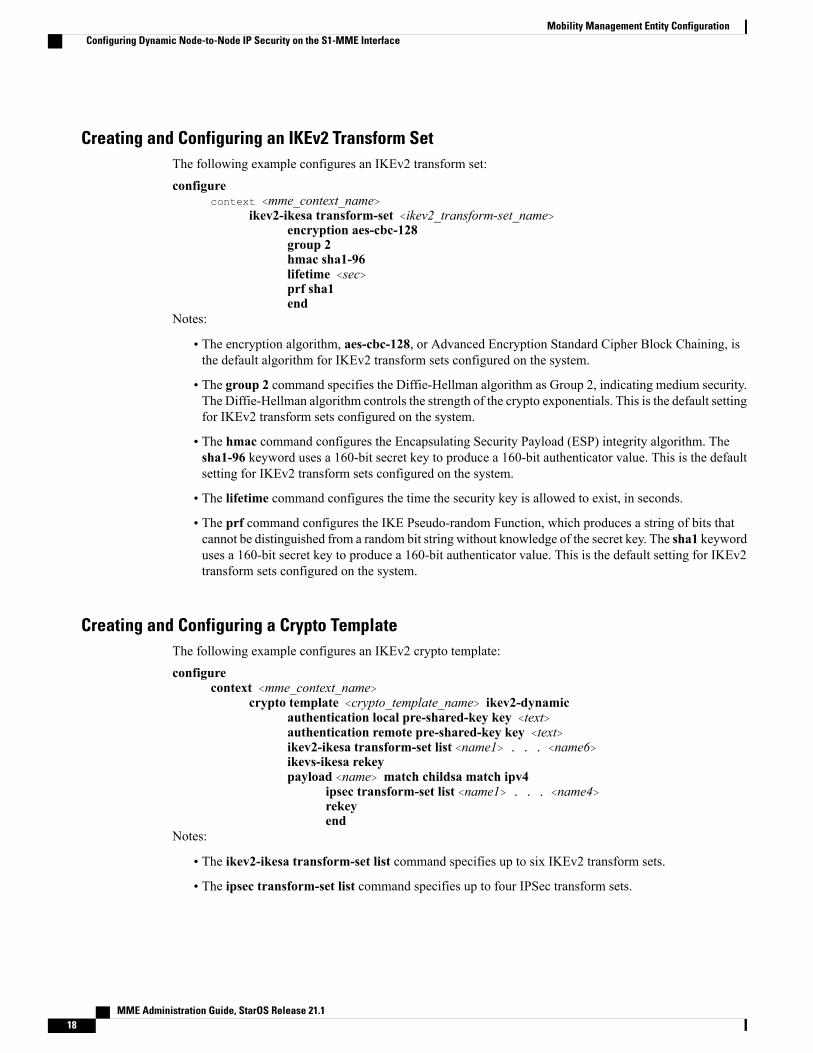
Creating and Configuring an IKEv2 Transform SetThe following example configures an IKEv2 transform set:
configurecontext <mme_context_name>
ikev2-ikesa transform-set <ikev2_transform-set_name>encryption aes-cbc-128group 2hmac sha1-96lifetime <sec>prf sha1end
Notes:
• The encryption algorithm, aes-cbc-128, or Advanced Encryption Standard Cipher Block Chaining, isthe default algorithm for IKEv2 transform sets configured on the system.
• The group 2 command specifies the Diffie-Hellman algorithm as Group 2, indicating medium security.The Diffie-Hellman algorithm controls the strength of the crypto exponentials. This is the default settingfor IKEv2 transform sets configured on the system.
• The hmac command configures the Encapsulating Security Payload (ESP) integrity algorithm. Thesha1-96 keyword uses a 160-bit secret key to produce a 160-bit authenticator value. This is the defaultsetting for IKEv2 transform sets configured on the system.
• The lifetime command configures the time the security key is allowed to exist, in seconds.
• The prf command configures the IKE Pseudo-random Function, which produces a string of bits thatcannot be distinguished from a random bit string without knowledge of the secret key. The sha1 keyworduses a 160-bit secret key to produce a 160-bit authenticator value. This is the default setting for IKEv2transform sets configured on the system.
Creating and Configuring a Crypto TemplateThe following example configures an IKEv2 crypto template:
configurecontext <mme_context_name>
crypto template <crypto_template_name> ikev2-dynamicauthentication local pre-shared-key key <text>authentication remote pre-shared-key key <text>ikev2-ikesa transform-set list <name1> . . . <name6>ikevs-ikesa rekeypayload <name> match childsa match ipv4
ipsec transform-set list <name1> . . . <name4>rekeyend
Notes:
• The ikev2-ikesa transform-set list command specifies up to six IKEv2 transform sets.
• The ipsec transform-set list command specifies up to four IPSec transform sets.
MME Administration Guide, StarOS Release 21.118
Mobility Management Entity ConfigurationConfiguring Dynamic Node-to-Node IP Security on the S1-MME Interface

Binding the S1-MME IP Address to the Crypto TemplateThe following example configures the binding of the S1-MME interface to the crypto template:
configurecontext <mme_context_name>
mme-service <mme_svc_name>bind s1-mme ipv4-address <address> ipv4-address <address> crypto-template
<enodeb_crypto_template>end
Notes:
• The bind command in the MME service configuration can also be specified as an IPv6 address usingthe ipv6-address command.
• This example shows the bind command using multi-homed addresses. The multi-homing feature alsosupports the use of IPv6 addresses.
Configuring ACL-based Node-to-Node IP Security on the S1-MME InterfaceThe configuration example in this section creates an IKEv2/IPSec ACL-based node-to-node tunnel endpointon the S1-MME interface.
Use of the IP Security feature requires that a valid license key be installed. Contact your local Sales orSupport representative for information on how to obtain a license.
Important
Creating and Configuring a Crypto Access Control ListThe following example configures a crypto ACL (Access Control List), which defines the matching criteriaused for routing subscriber data packets over an IPSec tunnel:
configurecontext <mme_context_name>
ip access-list <acl_name>permit tcp host <source_host_address> host <dest_host_address>end
Notes:
• The permit command in this example routes IPv4 traffic from the server with the specified source hostIPv4 address to the server with the specified destination host IPv4 address.
Creating and Configuring an IPSec Transform SetThe following example configures an IPSec transform set which is used to define the security association thatdetermines the protocols used to protect the data on the interface:
configurecontext <mme_context_name>
ipsec transform-set <ipsec_transform-set_name>
MME Administration Guide, StarOS Release 21.1 19
Mobility Management Entity ConfigurationConfiguring ACL-based Node-to-Node IP Security on the S1-MME Interface

encryption aes-cbc-128group nonehmac sha1-96mode tunnelend
Notes:
• The encryption algorithm, aes-cbc-128, or Advanced Encryption Standard Cipher Block Chaining, isthe default algorithm for IPSec transform sets configured on the system.
• The group none command specifies that no crypto strength is included and that Perfect Forward Secrecyis disabled. This is the default setting for IPSec transform sets configured on the system.
• The hmac command configures the Encapsulating Security Payload (ESP) integrity algorithm. Thesha1-96 keyword uses a 160-bit secret key to produce a 160-bit authenticator value. This is the defaultsetting for IPSec transform sets configured on the system.
• Themode tunnel command specifies that the entire packet is to be encapsulated by the IPSec headerincluding the IP header. This is the default setting for IPSec transform sets configured on the system.
Creating and Configuring an IKEv2 Transform SetThe following example configures an IKEv2 transform set:
configurecontext <mme_context_name>
ikev2-ikesa transform-set <ikev2_transform-set_name>encryption aes-cbc-128group 2hmac sha1-96lifetime <sec>prf sha1end
Notes:
• The encryption algorithm, aes-cbc-128, or Advanced Encryption Standard Cipher Block Chaining, isthe default algorithm for IKEv2 transform sets configured on the system.
• The group 2 command specifies the Diffie-Hellman algorithm as Group 2, indicating medium security.The Diffie-Hellman algorithm controls the strength of the crypto exponentials. This is the default settingfor IKEv2 transform sets configured on the system.
• The hmac command configures the Encapsulating Security Payload (ESP) integrity algorithm. Thesha1-96 keyword uses a 160-bit secret key to produce a 160-bit authenticator value. This is the defaultsetting for IKEv2 transform sets configured on the system.
• The lifetime command configures the time the security key is allowed to exist, in seconds.
• The prf command configures the IKE Pseudo-random Function which produces a string of bits thatcannot be distinguished from a random bit string without knowledge of the secret key. The sha1 keyworduses a 160-bit secret key to produce a 160-bit authenticator value. This is the default setting for IKEv2transform sets configured on the system.
MME Administration Guide, StarOS Release 21.120
Mobility Management Entity ConfigurationConfiguring ACL-based Node-to-Node IP Security on the S1-MME Interface

Creating and Configuring a Crypto MapThe following example configures an IKEv2 crypto map:
configurecontext <mme_context_name>
crypto map <crypto_map_name> ikev2-ipv4match address <acl_name>peer <ipv4_address>authentication local pre-shared-key key <text>authentication remote pre-shared-key key <text>ikev2-ikesa transform-set list <name1> . . . <name6>payload <name> match ipv4
lifetime <seconds>ipsec transform-set list <name1> . . . <name4>exit
exitinterface <s1-mme_intf_name>
ip address <ipv4_address>crypto-map <crypto_map_name>exit
exitport ethernet <slot_number/port_number>
no shutdownbind interface <s1-mme_intf_name> <mme_context_name>end
Notes:
• The type of crypto map used in this example is IKEv2-IPv4 for IPv4 addressing. An IKEv2-IPv6 cryptomap can also be used for IPv6 addressing.
• The ipsec transform-set list command specifies up to four IPSec transform sets.
Configuring Mobility Restriction SupportMobility or handover restriction is performed by handover restriction lists configured on the MME. Theselists restrict inter-RAT, 3G location area, and/or 4G tracking area handovers based on the configuration inthe Handover Restriction List Configuration Mode.
Mobility restriction support is only available through the operator policy configuration. For moreinformation on operator policy, refer to the Operator Policy chapter in this guide.
Important
Configuring Inter-RAT Handover Restrictions on the MMEInter-RAT handover restriction configurations on theMME restrict subscribers from participating in handoversto defined radio access network types.
Use the following example to configure this feature:
configurelte-policy
MME Administration Guide, StarOS Release 21.1 21
Mobility Management Entity ConfigurationConfiguring Mobility Restriction Support
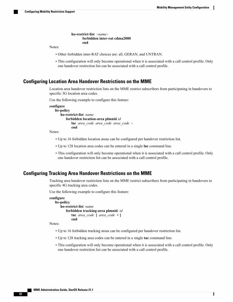
ho-restrict-list <name>forbidden inter-rat cdma2000end
Notes:
• Other forbidden inter-RAT choices are: all, GERAN, and UNTRAN.
• This configuration will only become operational when it is associated with a call control profile. Onlyone handover restriction list can be associated with a call control profile.
Configuring Location Area Handover Restrictions on the MMELocation area handover restriction lists on the MME restrict subscribers from participating in handovers tospecific 3G location area codes.
Use the following example to configure this feature:
configurelte-policy
ho-restrict-list nameforbidden location-area plmnid id
lac area_code area_code area_code +end
Notes:
• Up to 16 forbidden location areas can be configured per handover restriction list.
• Up to 128 location area codes can be entered in a single lac command line.
• This configuration will only become operational when it is associated with a call control profile. Onlyone handover restriction list can be associated with a call control profile.
Configuring Tracking Area Handover Restrictions on the MMETracking area handover restriction lists on the MME restrict subscribers from participating in handovers tospecific 4G tracking area codes.
Use the following example to configure this feature:
configurelte-policy
ho-restrict-list nameforbidden tracking-area plmnid id
tac area_code [ area_code + ]end
Notes:
• Up to 16 forbidden tracking areas can be configured per handover restriction list.
• Up to 128 tracking area codes can be entered in a single tac command line.
• This configuration will only become operational when it is associated with a call control profile. Onlyone handover restriction list can be associated with a call control profile.
MME Administration Guide, StarOS Release 21.122
Mobility Management Entity ConfigurationConfiguring Mobility Restriction Support

Configuring S4-SGSN Handover CapabilityThis configuration example configures an S3 interface supporting inter-RAT handovers between the MMEand an S4-SGSN.
Use the following example to configure this feature:
configurecontext mme_context_name -noconfirm
interface s3_interface_nameip address ipv4_addressexit
mme-service mme_svc_namepeer-sgsn rai mcc mcc_value mnc mnc_value rac value lac value address ip_address
capability s3nri length length plmn-id mcc mcc_value mnc mnc_valueexit
exitport ethernet slot_number/port_number
no shutdownbind interface s3_interface_name mme_context_nameend
Notes:
• The S3 IP address can also be specified as an IPv6 address. To support this, the ip address commandcan be changed to the ipv6 address command.
• The peer-sgsn command is used to statically configure a peer SGSN. SGSN selection can also beperformed dynamically through the DNS client. For more information about dynamic peer selection,refer to the Configuring Dynamic Peer Selection, on page 13 section in this chapter.
• In the absence of an NRI length configuration, the MME treats the NRI as invalid. The MME will usea plain RAI-based FQDN (and not an NRI-based FQDN) for DNS queries made to resolve the sourceSGSN.
Configuring SCTP Multi-homing SupportSCTPmulti-homing can be configured on the S1-MME interface (to/from eNodeB), the S6a interface (to/fromHLR/HSS), and the SGs interface (to/from the MSC/VLR).
Configuring SCTP Multi-homing on the S1-MME InterfaceUp to two IPv4 or IPv6 addresses for the S1-MME interface can be entered to allow for SCTP multi-homing.
The configuration example in this section is intended as a replacement for the S1-MME interface configurationlocated in the section for Creating and Configuring the MME Context and Service, on page 9. Use thefollowing example to configure S1-MME multi-homing between the MME and the eNodeB:
configurecontext mme_context_name -noconfirm
interface s1-mme_intf_nameip address ipv4_addressip address secondary_ipv4_address
MME Administration Guide, StarOS Release 21.1 23
Mobility Management Entity ConfigurationConfiguring S4-SGSN Handover Capability

exitmme-service mme_svc_name
bind s1-mme ipv4-address ipv4_address ipv4-address secondary_ipv4_addressexit
exitport ethernet slot_number/port_number
no shutdownbind interface s1-mme_intf_name mme_context_nameend
Notes:
• The S1-MME IP addresses can also be specified as IPv6 addresses using the ipv6 address keyword.
• The IP addresses in the bind s1-mme ipv4-address command can also be specified as IPv6 addressesusing the ipv6-address keyword.
Configuring SCTP Multi-homing on the S6a InterfaceUp to four IPv4 or IPv6 addresses for the S6a interface can be configured to allow for SCTP multi-homing.
The configuration example in this section is intended as a replacement for the S6a interface configurationlocated in Creating and Configuring the MME Context and Service, on page 9 section and the Diameterconfiguration for the S6a interface located in Creating and Configuring the HSS Peer Service and InterfaceAssociations, on page 10 . Use the following example to configure S6a multi-homing between the MMEand the HLR/HSS:
configurecontext mme_context_name
interface s6a_intf_nameip address s6a_intf_primary_ip_addr ip_maskip address s6a_intf_secondary_ip_addr2 ip_mask secondaryip address s6a_intf_secondary_ip_addr3 ip_mask secondaryexit
exitdiameter endpoint hss-endpoint_name
origin realm realm_nameorigin host name address s6a_intf_primary_ip_addr port number address
s6a_intf_secondary_ip_addr2 port number address s6a_intf_secondary_ip_addr3 port numberpeer peer_name realm realm_name address hss_ip_addr1 port number address hss_ip_addr2
port number sctproute-entry realm realm_name peer peer_nameexit
port ethernet slot_number/port_numberno shutdownbind interface s6a_intf_name mme_context_nameexit
Notes:
• The S6a IP addresses can also be specified as IPv6 addresses using the ipv6 address keyword.
Configuring S6a SCTP and Application Timers for Multi-homingIn the event of a path failure, the SCTP multi-homing feature requires time to activate the alternate path.Timers associated with the SCTP heartbeat and the application in this instance, a Diameter watchdog request,
MME Administration Guide, StarOS Release 21.124
Mobility Management Entity ConfigurationConfiguring SCTP Multi-homing Support
must be tuned properly to ensure that the application does not timeout before the redundant SCTP path canbe activated. The required calculation is based on the two paths configured between the MME and the HSS,the maximum retransmission configuration for the SCTP paths, and the SCTP heartbeat timeout configuration.The configuration of the timers must be identical on both peers.
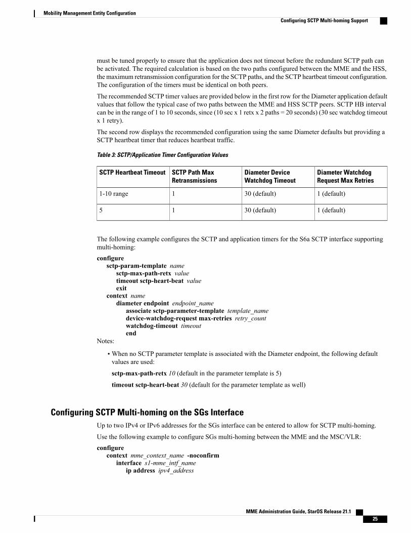
The recommended SCTP timer values are provided below in the first row for the Diameter application defaultvalues that follow the typical case of two paths between the MME and HSS SCTP peers. SCTP HB intervalcan be in the range of 1 to 10 seconds, since (10 sec x 1 retx x 2 paths = 20 seconds) (30 sec watchdog timeoutx 1 retry).
The second row displays the recommended configuration using the same Diameter defaults but providing aSCTP heartbeat timer that reduces heartbeat traffic.
Table 3: SCTP/Application Timer Configuration Values
Diameter WatchdogRequest Max Retries
Diameter DeviceWatchdog Timeout
SCTP Path MaxRetransmissions
SCTP Heartbeat Timeout
1 (default)30 (default)11-10 range
1 (default)30 (default)15
The following example configures the SCTP and application timers for the S6a SCTP interface supportingmulti-homing:
configuresctp-param-template name
sctp-max-path-retx valuetimeout sctp-heart-beat valueexit
context namediameter endpoint endpoint_name
associate sctp-parameter-template template_namedevice-watchdog-request max-retries retry_countwatchdog-timeout timeoutend
Notes:
•When no SCTP parameter template is associated with the Diameter endpoint, the following defaultvalues are used:
sctp-max-path-retx 10 (default in the parameter template is 5)
timeout sctp-heart-beat 30 (default for the parameter template as well)
Configuring SCTP Multi-homing on the SGs InterfaceUp to two IPv4 or IPv6 addresses for the SGs interface can be entered to allow for SCTP multi-homing.
Use the following example to configure SGs multi-homing between the MME and the MSC/VLR:
configurecontext mme_context_name -noconfirm
interface s1-mme_intf_nameip address ipv4_address
MME Administration Guide, StarOS Release 21.1 25
Mobility Management Entity ConfigurationConfiguring SCTP Multi-homing Support

ip address secondary_ipv4_addressexit
sgs-service mme_svc_namebind ipv4-address ipv4_address ipv4-address secondary_ipv4_addressexit
exitport ethernet slot_number/port_number
no shutdownbind interface sgs_intf_name mme_context_nameend
Notes:
• The SGs IP addresses can also be specified as IPv6 addresses using the ipv6 address keyword.
• The IP addresses in the bind ipv4-address command can also be specified as IPv6 addresses using theipv6-address keyword.
SCTP Parameters for MMEThe details on the configurable values for SCTP parameters are provided in the table given below:
GranularityMaximum valueMinimum valueParameter
10ms5s10msRTO.min
10ms120s500msRTO.max
10msRTO.maxRTO.minRTO.initial
-1/81/8RTO.alpha
-1/41/4RTO.beta
1s120s5sValid.Cookie.Life
1s300s1sHB.interval
10ms500ms0msSACK period
151SACK frequency
1 byte65535 bytes508 bytesMTU size
The details on the default values for SCTP parameters are provided in the table given below:
Default valueParameter
5RTO Alpha
10RTO Beta
MME Administration Guide, StarOS Release 21.126
Mobility Management Entity ConfigurationConfiguring SCTP Multi-homing Support
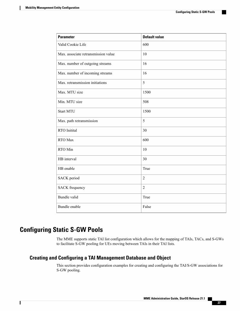
Default valueParameter
600Valid Cookie Life
10Max. associate retransmission value
16Max. number of outgoing streams
16Max. number of incoming streams
5Max. retransmission initiations
1500Max. MTU size
508Min. MTU size
1500Start MTU
5Max. path retransmission
30RTO Initital
600RTO Max
10RTO Min
30HB interval
TrueHB enable
2SACK period
2SACK frequency
TrueBundle valid
FalseBundle enable
Configuring Static S-GW PoolsThe MME supports static TAI list configuration which allows for the mapping of TAIs, TACs, and S-GWsto facilitate S-GW pooling for UEs moving between TAIs in their TAI lists.
Creating and Configuring a TAI Management Database and ObjectThis section provides configuration examples for creating and configuring the TAI/S-GW associations forS-GW pooling.
MME Administration Guide, StarOS Release 21.1 27
Mobility Management Entity ConfigurationConfiguring Static S-GW Pools

Use the following example to configure this feature on the MME:
configurelte-policy
tai-mgmt-db db_nametai-mgmt-obj object_nametai mcc number mnc number tac valuesgw-address ipv4_address s5-s8-protocol gtp weight numberend
Notes:
• Up to four databases can be configured on the system.
• Up to 500 management objects can be configured per database.
• Up to 16 TAIs can be configured per management object.
• Up to 16 TACs can be configured per TAI.
• The sgw-address variable can also be specified as an IPv6 address.
• Up to 32 S-GW IP addresses can be configured per management object.
•Weights for IPv4 addresses are ignored if IPv6 addresses are present meaning only IPv6 addresses areload-balanced if present.
• The s5-s8-protocol can also be specified as pmip or both (GTP and PMIP).
Associating a TAI Management Database with an MME ServiceIn order for an MME service to use a statically configured S-GW pool, it must be associated with the TAIManagement Database.
Use the following example to configure the TAI Management Database-to-MME service association:
configurecontext mme_context_name
mme-service mme_svc_nameassociate tai-mgmt-db database_nameend
Notes:
• Only one TAI Management Database can be configured per MME service.
• This association can also be performed in the Call Control Profile Configuration Mode supportingOperator Policy. If both associations are configured, the Operator Policy association is preferred by thesystem.
Associating a TAI Management Database with a Call Control ProfileMME service can access a statically configured S-GW pool through an Operator Policy instance, specificallythrough the Call Control Profile.
Use the following example to configure the TAI Management Database-to-MME service association:
configurecall-control-profile name
MME Administration Guide, StarOS Release 21.128
Mobility Management Entity ConfigurationConfiguring Static S-GW Pools

associate tai-mgmt-db database_nameend
Notes:
• Only one TAI Management Database can be configured per Call Control Profile.
• This association can also be performed in the MME Service Configuration Mode. If both associationsare configured, the Operator Policy association is preferred by the system.
• If the tai-mgmt-db is associated with a call-control-profile, and DNS is to be used for S-GW lookups,the DNS configuration must be configured within the same call-control-profile using the dns-sgwcommand within the call-control-profile configuration mode.
Configuring UMTS to LTE ID MappingUMTS networks are configured with LACs allocated from the reserved space of 32K to 64K. In LTE networks,this space is typically reserved for MME group IDs. To overcome this issue during inter-RAT handovers, theMME can be configured with mappings between LACs and MME group IDs.
Use the following configuration example to map PLMN IDs to MME group IDs:
configurelte-policy
network-global-mme-id-mgmt-dbplmn mcc mcc_value mnc mnc_value mme-group-id-range first id last idexit
exitcontext mme_service_context
mme-service service_nameassociate network-global-mme-id-mgmt-dbend
Notes:
• Up to 32 mappings can be configured on the system.
• Overlapping ranges can be identified in the output of the show configuration errors command.
Configuring User Location Information Reporting SupportThis feature allows the MME to query and receive UE location reports from an eNodeB.
User Location Information Reporting is a licensed feature and requires the purchase of the ULI Reportingfeature license to enable it.
Note
Use the following example to configure User Location Information (ULI) reporting support on the MME:
configurecontext mme_context_name
mme-service mme_svc_namelocation-reportingend
MME Administration Guide, StarOS Release 21.1 29
Mobility Management Entity ConfigurationConfiguring UMTS to LTE ID Mapping

MME Administration Guide, StarOS Release 21.130
Mobility Management Entity ConfigurationConfiguring User Location Information Reporting Support