CLI Book 3: Cisco ASA Series VPN CLI Configuration Guide, 9.4
Upload
khangminh22Category
view
2download
0
CLI Book 2: Cisco ASA Series Firewall CLI Configuration Guide, 9.12Americas HeadquartersCisco Systems, Inc.170 West Tasman DriveSan Jose, CA 95134-1706USAhttp://www.cisco.comTel: 408 526-4000
800 553-NETS (6387)Fax: 408 527-0883

THE SPECIFICATIONS AND INFORMATION REGARDING THE PRODUCTS IN THIS MANUAL ARE SUBJECT TO CHANGE WITHOUT NOTICE. ALL STATEMENTS,INFORMATION, AND RECOMMENDATIONS IN THIS MANUAL ARE BELIEVED TO BE ACCURATE BUT ARE PRESENTED WITHOUT WARRANTY OF ANY KIND,EXPRESS OR IMPLIED. USERS MUST TAKE FULL RESPONSIBILITY FOR THEIR APPLICATION OF ANY PRODUCTS.
THE SOFTWARE LICENSE AND LIMITED WARRANTY FOR THE ACCOMPANYING PRODUCT ARE SET FORTH IN THE INFORMATION PACKET THAT SHIPPED WITHTHE PRODUCT AND ARE INCORPORATED HEREIN BY THIS REFERENCE. IF YOU ARE UNABLE TO LOCATE THE SOFTWARE LICENSE OR LIMITED WARRANTY,CONTACT YOUR CISCO REPRESENTATIVE FOR A COPY.
The Cisco implementation of TCP header compression is an adaptation of a program developed by the University of California, Berkeley (UCB) as part of UCB's public domain version ofthe UNIX operating system. All rights reserved. Copyright © 1981, Regents of the University of California.
NOTWITHSTANDING ANY OTHERWARRANTY HEREIN, ALL DOCUMENT FILES AND SOFTWARE OF THESE SUPPLIERS ARE PROVIDED “AS IS" WITH ALL FAULTS.CISCO AND THE ABOVE-NAMED SUPPLIERS DISCLAIM ALL WARRANTIES, EXPRESSED OR IMPLIED, INCLUDING, WITHOUT LIMITATION, THOSE OFMERCHANTABILITY, FITNESS FOR A PARTICULAR PURPOSE AND NONINFRINGEMENT OR ARISING FROM A COURSE OF DEALING, USAGE, OR TRADE PRACTICE.
IN NO EVENT SHALL CISCO OR ITS SUPPLIERS BE LIABLE FOR ANY INDIRECT, SPECIAL, CONSEQUENTIAL, OR INCIDENTAL DAMAGES, INCLUDING, WITHOUTLIMITATION, LOST PROFITS OR LOSS OR DAMAGE TO DATA ARISING OUT OF THE USE OR INABILITY TO USE THIS MANUAL, EVEN IF CISCO OR ITS SUPPLIERSHAVE BEEN ADVISED OF THE POSSIBILITY OF SUCH DAMAGES.
Any Internet Protocol (IP) addresses and phone numbers used in this document are not intended to be actual addresses and phone numbers. Any examples, command display output, networktopology diagrams, and other figures included in the document are shown for illustrative purposes only. Any use of actual IP addresses or phone numbers in illustrative content is unintentionaland coincidental.
All printed copies and duplicate soft copies of this document are considered uncontrolled. See the current online version for the latest version.
Cisco has more than 200 offices worldwide. Addresses and phone numbers are listed on the Cisco website at www.cisco.com/go/offices.
Cisco and the Cisco logo are trademarks or registered trademarks of Cisco and/or its affiliates in the U.S. and other countries. To view a list of Cisco trademarks, go to this URL:https://www.cisco.com/c/en/us/about/legal/trademarks.html. Third-party trademarks mentioned are the property of their respective owners. The use of the word partner does not imply apartnership relationship between Cisco and any other company. (1721R)
© 2021 Cisco Systems, Inc. All rights reserved.

C O N T E N T S
About This Guide xixP R E F A C E
Document Objectives xix
Related Documentation xix
Document Conventions xix
Communications, Services, and Additional Information xxi
Introduction to Cisco ASA Firewall Services 1C H A P T E R 1
How to Implement Firewall Services 1
Basic Access Control 2
Application Filtering 2
URL Filtering 3
Threat Protection 3
Firewall Services for Virtual Environments 4
Network Address Translation 4
Application Inspection 5
Use Case: Expose a Server to the Public 5
Access Control 7P A R T I
Objects for Access Control 9C H A P T E R 2
Guidelines for Objects 9
Configure Objects 10
Configure Network Objects and Groups 10
Configure a Network Object 10
Configure a Network Object Group 11
Configure Service Objects and Service Groups 12
CLI Book 2: Cisco ASA Series Firewall CLI Configuration Guide, 9.12iii

Configure a Service Object 12
Configure a Service Group 13
Configure Local User Groups 15
Configure Security Group Object Groups 16
Configure Time Ranges 17
Monitoring Objects 18
History for Objects 19
Access Control Lists 21C H A P T E R 3
About ACLs 21
ACL Types 21
ACL Names 23
Access Control Entry Order 23
Permit/Deny vs. Match/Do Not Match 23
Access Control Implicit Deny 23
IP Addresses Used for Extended ACLs When You Use NAT 24
Time-Based ACEs 25
Licensing for Access Control Lists 25
Guidelines for ACLs 25
Configure ACLs 26
Basic ACL Configuration and Management Options 26
Configure Extended ACLs 28
Add an Extended ACE for IP Address or Fully-Qualified Domain Name-Based Matching 28
Add an Extended ACE for Port-Based Matching 29
Add an Extended ACE for ICMP-Based Matching 30
Add an Extended ACE for User-Based Matching (Identity Firewall) 31
Add an Extended ACE for Security Group-Based Matching (Cisco TrustSec) 32
Examples for Extended ACLs 33
Example of Converting Addresses to Objects for Extended ACLs 34
Configure Standard ACLs 34
Configure Webtype ACLs 35
Add a Webtype ACE for URL Matching 35
Add a Webtype ACE for IP Address Matching 36
Examples for Webtype ACLs 37
CLI Book 2: Cisco ASA Series Firewall CLI Configuration Guide, 9.12iv
Contents
Configure EtherType ACLs 38
Examples for EtherType ACLs 40
Edit ACLs in an Isolated Configuration Session 40
Monitoring ACLs 42
History for ACLs 42
Access Rules 45C H A P T E R 4
Controlling Network Access 45
General Information About Rules 46
Interface Access Rules and Global Access Rules 46
Inbound and Outbound Rules 46
Rule Order 47
Implicit Permits 47
Implicit Deny 48
NAT and Access Rules 48
Same Security Level Interfaces and Access Rules 48
Extended Access Rules 49
Extended Access Rules for Returning Traffic 49
Allowing Broadcast and Multicast Traffic 49
Management Access Rules 50
EtherType Rules 50
Supported EtherTypes and Other Traffic 50
EtherType Rules for Returning Traffic 50
Allowing MPLS 51
Licensing for Access Rules 51
Guidelines for Access Control 51
Configure Access Control 52
Configure an Access Group 52
Configure ICMP Access Rules 53
Monitoring Access Rules 55
Evaluating Syslog Messages for Access Rules 55
Configuration Examples for Permitting or Denying Network Access 56
History for Access Rules 57
CLI Book 2: Cisco ASA Series Firewall CLI Configuration Guide, 9.12v
Contents

Identity Firewall 61C H A P T E R 5
About the Identity Firewall 61
Architecture for Identity Firewall Deployments 62
Features of the Identity Firewall 63
Deployment Scenarios 65
Guidelines for the Identity Firewall 67
Prerequisites for the Identity Firewall 69
Configure the Identity Firewall 70
Configure the Active Directory Domain 70
Configure Active Directory Agents 73
Configure Identity Options 74
Configure Identity-Based Security Policy 78
Collect User Statistics 79
Examples for the Identity Firewall 80
AAA Rule and Access Rule Example 1 80
AAA Rule and Access Rule Example 2 80
VPN Filter Examples 81
Applying Interface Access Rules to VPN Traffic Example 81
Applying VPN Filters with User Specifications Example 81
Monitoring the Identity Firewall 82
History for the Identity Firewall 83
ASA and Cisco TrustSec 85C H A P T E R 6
About Cisco TrustSec 85
About SGT and SXP Support in Cisco TrustSec 86
Roles in the Cisco TrustSec Feature 86
Security Group Policy Enforcement 87
How the ASA Enforces Security Group-Based Policies 88
Effects of Changes to Security Groups on the ISE 89
Speaker and Listener Roles on the ASA 90
Register the ASA with the ISE 91
Create a Security Group on the ISE 92
Generate the PAC File 92
CLI Book 2: Cisco ASA Series Firewall CLI Configuration Guide, 9.12vi
Contents

Guidelines for Cisco TrustSec 92
Configure the ASA to Integrate with Cisco Trustsec 95
Configure the AAA Server for Cisco TrustSec Integration 96
Import a PAC File 98
Configure the Security Exchange Protocol 99
Add an SXP Connection Peer 102
Refresh Environment Data 103
Configure the Security Policy 103
Configure Layer 2 Security Group Tagging Imposition 105
Usage Scenarios 105
Configure a Security Group Tag on an Interface 107
Configure IP-SGT Bindings Manually 108
Troubleshooting Tips 108
Example for Cisco TrustSec 109
AnyConnect VPN Support for Cisco TrustSec 110
Add an SGT to Remote Access VPN Group Policies and Local Users 110
Monitoring Cisco TrustSec 111
History for Cisco TrustSec 112
ASA FirePOWER Module 115C H A P T E R 7
About the ASA FirePOWER Module 115
How the ASA FirePOWER Module Works with the ASA 115
ASA FirePOWER Inline Mode 116
ASA FirePOWER Inline Tap Monitor-Only Mode 117
ASA FirePOWER Passive Monitor-Only Traffic Forwarding Mode 117
ASA FirePOWER Management 118
Compatibility with ASA Features 118
What to Do if the ASA FirePOWER Module Cannot Filter URLs 118
Licensing Requirements for the ASA FirePOWER Module 119
Guidelines for ASA FirePOWER 119
Defaults for ASA FirePOWER 121
Perform Initial ASA FirePOWER Setup 121
Deploy the ASA FirePOWER Module in Your Network 121
Routed Mode 121
CLI Book 2: Cisco ASA Series Firewall CLI Configuration Guide, 9.12vii
Contents

Transparent Mode 124
Register the ASA FirePOWER Module with a Management Center 126
Access the ASA FirePOWER CLI 126
Configure ASA FirePOWER Basic Settings 127
Configure the ASA FirePOWER Module for ASDM Management 128
Configure the ASA FirePOWER Module 130
Configure the Security Policy on the ASA FirePOWER Module 130
Redirect Traffic to the ASA FirePOWER Module 130
Configure Inline or Inline Tap Monitor-Only Modes 130
Configure Passive Traffic Forwarding 132
Enable Captive Portal for Active Authentication 133
Managing the ASA FirePOWER Module 134
Install or Reimage the Module 134
Install or Reimage the Software Module 134
Reimage the 5585-X ASA FirePOWER Hardware Module 137
Reset the Password 139
Reload or Reset the Module 140
Shut Down the Module 140
Uninstall a Software Module Image 141
Session to the Software Module From the ASA 141
Upgrade the System Software 142
Monitoring the ASA FirePOWER Module 142
Showing Module Status 142
Showing Module Statistics 144
Monitoring Module Connections 144
Examples for the ASA FirePOWER Module 145
History for the ASA FirePOWER Module 146
Cisco Umbrella 149C H A P T E R 8
About Cisco Umbrella Connector 149
Cisco Umbrella Enterprise Security Policy 149
Cisco Umbrella Registration 150
Licensing Requirements for Cisco Umbrella Connector 150
Guidelines and Limitations for Cisco Umbrella 150
CLI Book 2: Cisco ASA Series Firewall CLI Configuration Guide, 9.12viii
Contents

Configure Cisco Umbrella Connector 152
Install the CA Certificate from the Cisco Umbrella Registration Server 153
Configure the Umbrella Connector Global Settings 155
Enable Umbrella in the DNS Inspection Policy Map 157
Verify the Umbrella Registration 158
Examples for the Umbrella Connector 159
Example: Enabling Umbrella on the Global DNS Inspection Policy 159
Example: Enabling Umbrella on an Interface with a Custom Inspection Policy 160
Command Page 162
Monitoring the Umbrella Connector 162
Monitoring the Umbrella Service Policy Statistics 162
Monitoring Umbrella Syslog Messages 164
History for Cisco Umbrella Connector 165
Firewall Services for Virtual Environments 167P A R T I I
Attribute-Based Access Control 169C H A P T E R 9
Guidelines for Attribute-Based Network Objects 169
Configure Attribute-Based Access Control 170
Configure Attributes for vCenter Virtual Machines 170
Configure a VM Attribute Agent 172
Configure Attribute-Based Network Objects 174
Configure Access Control Using Attribute-Based Network Objects 175
Monitoring Attribute-Based Network Objects 177
History for Attribute-Based Access Control 178
Network Address Translation 179P A R T I I I
Network Address Translation (NAT) 181C H A P T E R 1 0
Why Use NAT? 181
NAT Basics 182
NAT Terminology 182
NAT Types 182
Network Object NAT and Twice NAT 183
CLI Book 2: Cisco ASA Series Firewall CLI Configuration Guide, 9.12ix
Contents

Network Object NAT 183
Twice NAT 183
Comparing Network Object NAT and Twice NAT 184
NAT Rule Order 184
NAT Interfaces 186
Guidelines for NAT 187
Firewall Mode Guidelines for NAT 187
IPv6 NAT Guidelines 187
IPv6 NAT Best Practices 187
Additional Guidelines for NAT 188
Network Object NAT Guidelines for Mapped Address Objects 190
Twice NAT Guidelines for Real and Mapped Address Objects 191
Twice NAT Guidelines for Service Objects for Real and Mapped Ports 192
Dynamic NAT 193
About Dynamic NAT 193
Dynamic NAT Disadvantages and Advantages 194
Configure Dynamic Network Object NAT 194
Configure Dynamic Twice NAT 197
Dynamic PAT 199
About Dynamic PAT 200
Dynamic PAT Disadvantages and Advantages 200
PAT Pool Object Guidelines 201
Configure Dynamic Network Object PAT 202
Configure Dynamic Twice PAT 204
Configure PAT with Port Block Allocation 207
Configure Per-Session PAT or Multi-Session PAT 209
Static NAT 211
About Static NAT 211
Static NAT with Port Translation 212
One-to-Many Static NAT 213
Other Mapping Scenarios (Not Recommended) 214
Configure Static Network Object NAT or Static NAT-with-Port-Translation 215
Configure Static Twice NAT or Static NAT-with-Port-Translation 218
Identity NAT 221
CLI Book 2: Cisco ASA Series Firewall CLI Configuration Guide, 9.12x
Contents

Configure Identity Network Object NAT 221
Configure Identity Twice NAT 223
Monitoring NAT 225
History for NAT 225
NAT Examples and Reference 231C H A P T E R 1 1
Examples for Network Object NAT 231
Providing Access to an Inside Web Server (Static NAT) 231
NAT for Inside Hosts (Dynamic NAT) and NAT for an Outside Web Server (Static NAT) 232
Inside Load Balancer with Multiple Mapped Addresses (Static NAT, One-to-Many) 234
Single Address for FTP, HTTP, and SMTP (Static NAT-with-Port-Translation) 235
Examples for Twice NAT 236
Different Translation Depending on the Destination (Dynamic Twice PAT) 236
Different Translation Depending on the Destination Address and Port (Dynamic PAT) 238
NAT in Routed and Transparent Mode 240
NAT in Routed Mode 240
NAT in Transparent Mode or Within a Bridge Group 240
Routing NAT Packets 242
Mapped Addresses and Routing 242
Addresses on the Same Network as the Mapped Interface 242
Addresses on a Unique Network 242
The Same Address as the Real Address (Identity NAT) 243
Transparent Mode Routing Requirements for Remote Networks 244
Determining the Egress Interface 244
NAT for VPN 245
NAT and Remote Access VPN 245
NAT and Site-to-Site VPN 247
NAT and VPN Management Access 250
Troubleshooting NAT and VPN 251
Translating IPv6 Networks 251
NAT64/46: Translating IPv6 Addresses to IPv4 252
NAT64/46 Example: Inside IPv6 Network with Outside IPv4 Internet 252
NAT64/46 Example: Inside IPv6 Network with Outside IPv4 Internet and DNS Translation 253
NAT66: Translating IPv6 Addresses to Different IPv6 Addresses 255
CLI Book 2: Cisco ASA Series Firewall CLI Configuration Guide, 9.12xi
Contents

NAT66 Example, Static Translation between Networks 255
NAT66 Example, Simple IPv6 Interface PAT 256
Rewriting DNS Queries and Responses Using NAT 257
DNS Reply Modification, DNS Server on Outside 257
DNS Reply Modification, DNS Server, Host, and Server on Separate Networks 259
DNS Reply Modification, DNS Server on Host Network 259
DNS64 Reply Modification 260
PTR Modification, DNS Server on Host Network 262
Service Policies and Application Inspection 263P A R T I V
Service Policy 265C H A P T E R 1 2
About Service Policies 265
The Components of a Service Policy 265
Features Configured with Service Policies 267
Feature Directionality 268
Feature Matching Within a Service Policy 269
Order in Which Multiple Feature Actions are Applied 269
Incompatibility of Certain Feature Actions 270
Feature Matching for Multiple Service Policies 271
Guidelines for Service Policies 271
Defaults for Service Policies 273
Default Service Policy Configuration 273
Default Class Maps (Traffic Classes) 274
Configure Service Policies 275
Identify Traffic (Layer 3/4 Class Maps) 276
Create a Layer 3/4 Class Map for Through Traffic 276
Create a Layer 3/4 Class Map for Management Traffic 279
Define Actions (Layer 3/4 Policy Map) 280
Apply Actions to an Interface (Service Policy) 281
Monitoring Service Policies 282
Examples for Service Policies (Modular Policy Framework) 282
Applying Inspection and QoS Policing to HTTP Traffic 282
Applying Inspection to HTTP Traffic Globally 283
CLI Book 2: Cisco ASA Series Firewall CLI Configuration Guide, 9.12xii
Contents

Applying Inspection and Connection Limits to HTTP Traffic to Specific Servers 284
Applying Inspection to HTTP Traffic with NAT 285
History for Service Policies 285
Getting Started with Application Layer Protocol Inspection 287C H A P T E R 1 3
Application Layer Protocol Inspection 287
When to Use Application Protocol Inspection 287
Inspection Policy Maps 288
Replacing an In-Use Inspection Policy Map 288
How Multiple Traffic Classes are Handled 288
Guidelines for Application Inspection 289
Defaults for Application Inspection 291
Default Inspections and NAT Limitations 291
Default Inspection Policy Maps 295
Configure Application Layer Protocol Inspection 295
Choosing the Right Traffic Class for Inspection 301
Configure Regular Expressions 302
Create a Regular Expression 302
Create a Regular Expression Class Map 305
Monitoring Inspection Policies 305
History for Application Inspection 307
Inspection of Basic Internet Protocols 309C H A P T E R 1 4
DCERPC Inspection 309
DCERPC Overview 310
Configure a DCERPC Inspection Policy Map 310
DNS Inspection 312
Defaults for DNS Inspection 312
Configure DNS Inspection Policy Map 313
FTP Inspection 317
FTP Inspection Overview 317
Strict FTP 318
Configure an FTP Inspection Policy Map 319
HTTP Inspection 321
CLI Book 2: Cisco ASA Series Firewall CLI Configuration Guide, 9.12xiii
Contents

HTTP Inspection Overview 322
Configure an HTTP Inspection Policy Map 322
ICMP Inspection 326
ICMP Error Inspection 326
ILS Inspection 327
Instant Messaging Inspection 327
IP Options Inspection 330
Defaults for IP Options Inspection 330
Configure an IP Options Inspection Policy Map 331
IPsec Pass Through Inspection 332
IPsec Pass Through Inspection Overview 332
Configure an IPsec Pass Through Inspection Policy Map 333
IPv6 Inspection 334
Defaults for IPv6 Inspection 334
Configure an IPv6 Inspection Policy Map 334
NetBIOS Inspection 336
PPTP Inspection 337
RSH Inspection 337
SMTP and Extended SMTP Inspection 337
SMTP and ESMTP Inspection Overview 338
Defaults for ESMTP Inspection 338
Configure an ESMTP Inspection Policy Map 339
SNMP Inspection 342
SQL*Net Inspection 343
Sun RPC Inspection 343
Sun RPC Inspection Overview 343
Manage Sun RPC Services 343
TFTP Inspection 344
XDMCP Inspection 345
VXLAN Inspection 345
History for Basic Internet Protocol Inspection 346
Inspection for Voice and Video Protocols 349C H A P T E R 1 5
CTIQBE Inspection 349
CLI Book 2: Cisco ASA Series Firewall CLI Configuration Guide, 9.12xiv
Contents

Limitations for CTIQBE Inspection 349
H.323 Inspection 350
H.323 Inspection Overview 350
How H.323 Works 350
H.239 Support in H.245 Messages 351
Limitations for H.323 Inspection 352
Configure H.323 Inspection Policy Map 352
MGCP Inspection 355
MGCP Inspection Overview 355
Configure an MGCP Inspection Policy Map 356
RTSP Inspection 358
RTSP Inspection Overview 358
RealPlayer Configuration Requirements 358
Limitations for RSTP Inspection 358
Configure RTSP Inspection Policy Map 359
SIP Inspection 361
SIP Inspection Overview 361
Limitations for SIP Inspection 362
Default SIP Inspection 363
Configure SIP Inspection Policy Map 363
Skinny (SCCP) Inspection 366
SCCP Inspection Overview 366
Supporting Cisco IP Phones 367
Limitations for SCCP Inspection 367
Default SCCP Inspection 367
Configure a Skinny (SCCP) Inspection Policy Map 368
STUN Inspection 369
History for Voice and Video Protocol Inspection 370
Inspection for Mobile Networks 373C H A P T E R 1 6
Mobile Network Inspection Overview 373
GTP Inspection Overview 373
GTP Inspection Limitations 374
Stream Control Transmission Protocol (SCTP) Inspection and Access Control 374
CLI Book 2: Cisco ASA Series Firewall CLI Configuration Guide, 9.12xv
Contents

SCTP Stateful Inspection 375
SCTP Access Control 375
SCTP NAT 375
SCTP Application Layer Inspection 376
SCTP Limitations 376
Diameter Inspection 377
M3UA Inspection 377
M3UA Protocol Conformance 378
M3UA Inspection Limitations 378
RADIUS Accounting Inspection Overview 379
Licensing for Mobile Network Protocol Inspection 379
Defaults for GTP Inspection 380
Configure Mobile Network Inspection 380
Configure a GTP Inspection Policy Map 381
Configure an SCTP Inspection Policy Map 385
Configure a Diameter Inspection Policy Map 386
Create a Custom Diameter Attribute-Value Pair (AVP) 390
Inspecting Encrypted Diameter Sessions 391
Configure Server Trust Relationship with Diameter Clients 393
Configure Full TLS Proxy with Static Client Certificate for Diameter Inspection 394
Configure Full TLS Proxy with Local Dynamic Certificates for Diameter Inspection 397
Configure TLS Proxy with TLS Offload for Diameter Inspection 400
Configure an M3UA Inspection Policy Map 402
Configure the Mobile Network Inspection Service Policy 405
Configure RADIUS Accounting Inspection 407
Configure a RADIUS Accounting Inspection Policy Map 407
Configure the RADIUS Accounting Inspection Service Policy 409
Monitoring Mobile Network Inspection 410
Monitoring GTP Inspection 410
Monitoring SCTP 411
Monitoring Diameter 412
Monitoring M3UA 413
History for Mobile Network Inspection 414
CLI Book 2: Cisco ASA Series Firewall CLI Configuration Guide, 9.12xvi
Contents

Connection Management and Threat Detection 417P A R T V
Connection Settings 419C H A P T E R 1 7
What Are Connection Settings? 419
Configure Connection Settings 420
Configure Global Timeouts 421
Protect Servers from a SYN Flood DoS Attack (TCP Intercept) 423
Customize Abnormal TCP Packet Handling (TCP Maps, TCP Normalizer) 425
Bypass TCP State Checks for Asynchronous Routing (TCP State Bypass) 429
The Asynchronous Routing Problem 429
Guidelines and Limitations for TCP State Bypass 430
Configure TCP State Bypass 431
Disable TCP Sequence Randomization 432
Offload Large Flows 434
Flow Offload Limitations 434
Configure Flow Offload 435
Configure Connection Settings for Specific Traffic Classes (All Services) 437
Monitoring Connections 442
History for Connection Settings 442
Quality of Service 447C H A P T E R 1 8
About QoS 447
Supported QoS Features 447
What is a Token Bucket? 448
Policing 448
Priority Queuing 448
How QoS Features Interact 449
DSCP (DiffServ) Preservation 449
Guidelines for QoS 449
Configure QoS 450
Determine the Queue and TX Ring Limits for a Priority Queue 450
Queue Limit Worksheet 450
TX Ring Limit Worksheet 451
CLI Book 2: Cisco ASA Series Firewall CLI Configuration Guide, 9.12xvii
Contents

Configure the Priority Queue for an Interface 451
Configure a Service Rule for Priority Queuing and Policing 453
Monitor QoS 455
QoS Police Statistics 455
QoS Priority Statistics 456
QoS Priority Queue Statistics 456
Configuration Examples for Priority Queuing and Policing 457
Class Map Examples for VPN Traffic 457
Priority and Policing Example 458
History for QoS 459
Threat Detection 461C H A P T E R 1 9
Detecting Threats 461
Basic Threat Detection Statistics 462
Advanced Threat Detection Statistics 462
Scanning Threat Detection 463
Guidelines for Threat Detection 463
Defaults for Threat Detection 464
Configure Threat Detection 465
Configure Basic Threat Detection Statistics 465
Configure Advanced Threat Detection Statistics 466
Configure Scanning Threat Detection 467
Monitoring Threat Detection 468
Monitoring Basic Threat Detection Statistics 468
Monitoring Advanced Threat Detection Statistics 469
Evaluating Host Threat Detection Statistics 471
Monitoring Shunned Hosts, Attackers, and Targets 473
Examples for Threat Detection 474
History for Threat Detection 475
CLI Book 2: Cisco ASA Series Firewall CLI Configuration Guide, 9.12xviii
Contents

About This Guide
The following topics explain how to use this guide.
• Document Objectives, on page xix• Related Documentation, on page xix• Document Conventions, on page xix• Communications, Services, and Additional Information, on page xxi
Document ObjectivesThe purpose of this guide is to help you configure the firewall features for the Cisco ASA series using thecommand-line interface. This guide does not cover every feature, but describes only the most commonconfiguration scenarios.
You can also configure and monitor the ASA by using the Adaptive Security Device Manager (ASDM), aweb-based GUI application. ASDM includes configuration wizards to guide you through some commonconfiguration scenarios, and online help for less common scenarios.
Throughout this guide, the term “ASA” applies generically to supported models, unless specified otherwise.
Related DocumentationFormore information, seeNavigating the Cisco ASA Series Documentation at http://www.cisco.com/go/asadocs.
Document ConventionsThis document adheres to the following text, display, and alert conventions.
Text Conventions
IndicationConvention
Commands, keywords, button labels, field names, and user-entered text appearin boldface. For menu-based commands, the full path to the command is shown.
boldface
CLI Book 2: Cisco ASA Series Firewall CLI Configuration Guide, 9.12xix

IndicationConvention
Variables, for which you supply values, are presented in an italic typeface.
Italic type is also used for document titles, and for general emphasis.
italic
Terminal sessions and information that the system displays appear inmonospacetype.
monospace
Required alternative keywords are grouped in braces and separated by verticalbars.
{x | y | z}
Elements in square brackets are optional.[ ]
Optional alternative keywords are grouped in square brackets and separated byvertical bars.
[x | y | z]
Default responses to system prompts are also in square brackets.[ ]
Non-printing characters such as passwords are in angle brackets.< >
An exclamation point (!) or a number sign (#) at the beginning of a line of codeindicates a comment line.
!, #
Reader Alerts
This document uses the following for reader alerts:
Means reader take note. Notes contain helpful suggestions or references to material not covered in the manual.Note
Means the following information will help you solve a problem.Tip
Means reader be careful. In this situation, you might do something that could result in equipment damage orloss of data.
Caution
Means the described action saves time.You can save time by performing the action described in the paragraph.Timesaver
Means reader be warned. In this situation, you might perform an action that could result in bodilyinjury.
Warning
CLI Book 2: Cisco ASA Series Firewall CLI Configuration Guide, 9.12xx
About This GuideAbout This Guide

Communications, Services, and Additional Information• To receive timely, relevant information from Cisco, sign up at Cisco Profile Manager.
• To get the business impact you’re looking for with the technologies that matter, visit Cisco Services.
• To submit a service request, visit Cisco Support.
• To discover and browse secure, validated enterprise-class apps, products, solutions and services, visitCisco Marketplace.
• To obtain general networking, training, and certification titles, visit Cisco Press.
• To find warranty information for a specific product or product family, access Cisco Warranty Finder.
Cisco Bug Search Tool
Cisco Bug Search Tool (BST) is a web-based tool that acts as a gateway to the Cisco bug tracking systemthat maintains a comprehensive list of defects and vulnerabilities in Cisco products and software. BST providesyou with detailed defect information about your products and software.
CLI Book 2: Cisco ASA Series Firewall CLI Configuration Guide, 9.12xxi
About This GuideCommunications, Services, and Additional Information

CLI Book 2: Cisco ASA Series Firewall CLI Configuration Guide, 9.12xxii
About This GuideCommunications, Services, and Additional Information

C H A P T E R 1Introduction to Cisco ASA Firewall Services
Firewall services are those ASA features that are focused on controlling access to the network, includingservices that block traffic and services that enable traffic flow between internal and external networks. Theseservices include those that protect the network against threats, such as Denial of Service (DoS) and otherattacks.
The following topics provide an overview of firewall services.
• How to Implement Firewall Services, on page 1• Basic Access Control, on page 2• Application Filtering, on page 2• URL Filtering, on page 3• Threat Protection, on page 3• Firewall Services for Virtual Environments, on page 4• Network Address Translation, on page 4• Application Inspection, on page 5• Use Case: Expose a Server to the Public, on page 5
How to Implement Firewall ServicesThe following procedure provides a general sequence for implementing firewall services. However, each stepis optional, needed only if you want to provide the service to your network.
Before you begin
Configure the ASA according to the general operations configuration guide, including at minimum basicsettings, interface configuration, routing, and management access.
Procedure
Step 1 Implement access control for the network. See Basic Access Control, on page 2.Step 2 Implement application filtering. See Application Filtering, on page 2.Step 3 Implement URL filtering. See URL Filtering, on page 3.Step 4 Implement threat protection. See Threat Protection, on page 3.
CLI Book 2: Cisco ASA Series Firewall CLI Configuration Guide, 9.121

Step 5 Implement firewall services that are tailored to virtual environments. See Firewall Services for VirtualEnvironments, on page 4.
Step 6 Implement Network Address Translation (NAT). See Network Address Translation, on page 4.Step 7 Implement application inspection if the default settings are insufficient for your network. See Application
Inspection, on page 5.
Basic Access ControlAccess rules, applied per interface or globally, are your first line of defense. You can drop, upon entry, specifictypes of traffic, or traffic from (or to) specific hosts or networks. By default, the ASA allows traffic to flowfreely from an inside network (higher security level) to an outside network (lower security level).
You can apply an access rule to limit traffic from inside to outside, or allow traffic from outside to inside.
Basic access rules control traffic using a “5-tuple” of source address and port, destination address and port,and protocol. See Access Rules, on page 45 and Access Control Lists, on page 21.
You can augment your rules by making them identity aware. This lets you configure rules based on useridentity or group membership. To implement identity control, do any combination of the following:
• Install Cisco Context Directory Agent (CDA), also known as AD agent, on a separate server to collectuser and group information already defined in your Active Directory (AD) server. Then, configure theASA to get this information, and add user or group criteria to your access rules. See Identity Firewall,on page 61.
• Install Cisco Identity Services Engine (ISE) on a separate server to implement Cisco Trustsec. You canthen add security group criteria to your access rules. See ASA and Cisco TrustSec, on page 85.
• Install the ASA FirePOWER module on the ASA and implement identity policies in the module. Theidentity-aware access policies in ASA FirePOWER would apply to any traffic that you redirect to themodule. See ASA FirePOWER Module, on page 115.
Application FilteringThe wide-spread use of web-based applications means that a lot of traffic runs over the HTTP or HTTPSprotocols. With traditional 5-tuple access rules, you either allow or disallow all HTTP/HTTPS traffic. Youmight require more granular control of web traffic.
You can install a module on the ASA to provide application filtering to selectively allow HTTP or other trafficbased on the application being used. Thus, you do not have to make a blanket permit for HTTP. You can lookinside the traffic and prevent applications that are unacceptable for your network (for example, inappropriatefile sharing). When you add a module for application filtering, do not configure HTTP inspection on the ASA.
To implement application filtering, install the ASA FirePOWER module on the ASA and use applicationfiltering criteria in your ASA FirePOWER access rules. These policies apply to any traffic that you redirectto the module. See ASA FirePOWER Module, on page 115.
CLI Book 2: Cisco ASA Series Firewall CLI Configuration Guide, 9.122
Introduction to Cisco ASA Firewall ServicesBasic Access Control

URL FilteringURL filtering denies or allows traffic based on the URL of the destination site.
The purpose of URL filtering is primarily to completely block or allow access to a web site. Although youcan target individual pages, you typically specify a host name (such as www.example.com) or a URL category,which defines a list of host names that provide a particular type of service (such as Gambling).
When trying to decide whether to use URL filtering or application filtering for HTTP/HTTPS traffic, considerwhether your intention is to create a policy that applies to all traffic directed at a web site. If your intentionis to treat all such traffic the same way (denying it or allowing it), use URL filtering. If your intention is toselectively block or allow traffic to the site, use application filtering.
To implement URL filtering, do one of the following:
• Install the ASA FirePOWERmodule on the ASA and use URL filtering criteria in your ASA FirePOWERaccess rules. These policies apply to any traffic that you redirect to the module. See ASA FirePOWERModule, on page 115.
• Subscribe to the Cisco Umbrella service, where you configure the Enterprise Security policy to blockmalicious sites based on the fully-qualified domain name (FQDN). For FQDNs that are consideredsuspicious, you can redirect user connections to the Cisco Umbrella intelligent proxy, which performsURL filtering. The Umbrella service works by handling users' DNS lookup requests, returning the IPaddress for a block page or the IP address of the intelligent proxy. The service returns the real IP addressfor an FQDN for allowed domains. See Cisco Umbrella, on page 149.
Threat ProtectionYou can implement a number of measures to protect against scanning, denial of service (DoS), and otherattacks. A number of ASA features help protect against attacks by applying connection limits and droppingabnormal TCP packets. Some features are automatic, others are configurable but have defaults appropriate inmost cases, while others are completely optional and you must configure them if you want them.
Following are the threat protection services available with the ASA.
• IP packet fragmentation protection—The ASA performs full reassembly of all ICMP error messages andvirtual reassembly of the remaining IP fragments that are routed through the ASA, and drops fragmentsthat fail the security check. No configuration is necessary.
• Connection limits, TCP normalization, and other connection-related features—Configureconnection-related services such as TCP and UDP connection limits and timeouts, TCP sequence numberrandomization, TCP normalization, and TCP state bypass. TCP normalization is designed to drop packetsthat do not appear normal. See Connection Settings, on page 419.
For example, you can limit TCP and UDP connections and embryonic connections (a connection requestthat has not finished the necessary handshake between source and destination). Limiting the number ofconnections and embryonic connections protects you from a DoS attack. The ASA uses the embryoniclimit to trigger TCP Intercept, which protects inside systems from a DoS attack perpetrated by floodingan interface with TCP SYN packets.
• Threat detection—Implement threat detection on the ASA to collect statistics to help identify attacks.Basic threat detection is enabled by default, but you can implement advanced statistics and scanning
CLI Book 2: Cisco ASA Series Firewall CLI Configuration Guide, 9.123
Introduction to Cisco ASA Firewall ServicesURL Filtering

threat detection. You can shun hosts that are identified as a scanning threat. See Threat Detection, onpage 461.
• Next-Generation IPS—Install the ASA FirePOWERmodule on the ASA and implement Next GenerationIPS intrusion rules in your ASA FirePOWER. These policies would apply to any traffic that you redirectto ASA FirePOWER. See ASA FirePOWER Module, on page 115.
Firewall Services for Virtual EnvironmentsVirtual environments deploy servers as virtual machines, for example, in VMware ESXi. The firewalls in avirtual environment can be traditional hardware devices, or they can also be virtual machine firewalls, suchas the ASAv.
Traditional and next-generation firewall services apply to virtual environments in the same way that theyapply to environments that do not use virtual machine servers. However, virtual environments can provideadditional challenges, because it is easy to create and tear down servers.
Additionally, traffic between servers within the data center might require as much protection as traffic betweenthe data center and external users. For example, if an attacker gains control of a server within the data center,that could open up attacks on other servers in the data center.
Firewall services for virtual environments add capabilities to apply firewall protection specifically to virtualmachines. Following are the firewall services available for virtual environments:
• Attribute-based access control—You can configure network objects to match traffic based on attributes,and use those objects in access control rules. This lets you decouple firewall rules from network topology.For example, you can allow all hosts with the Engineering attribute to access hosts with the Lab Serverattribute. You could then add/remove hosts with these attributes and the firewall policy would be appliedautomatically without the need for updating access rules. For more information, see Attribute-BasedAccess Control, on page 169.
Network Address TranslationOne of the main functions of Network Address Translation (NAT) is to enable private IP networks to connectto the Internet. NAT replaces a private IP address with a public IP address, translating the private addressesin the internal private network into legal, routable addresses that can be used on the public Internet. In thisway, NAT conserves public addresses because you can advertise at a minimum only one public address forthe entire network to the outside world.
Other functions of NAT include:
• Security—Keeping internal IP addresses hidden discourages direct attacks.
• IP routing solutions—Overlapping IP addresses are not a problem when you use NAT.
• Flexibility—You can change internal IP addressing schemes without affecting the public addressesavailable externally; for example, for a server accessible to the Internet, you can maintain a fixed IPaddress for Internet use, but internally, you can change the server address.
• Translating between IPv4 and IPv6 (Routed mode only)—If you want to connect an IPv6 network to anIPv4 network, NAT lets you translate between the two types of addresses.
CLI Book 2: Cisco ASA Series Firewall CLI Configuration Guide, 9.124
Introduction to Cisco ASA Firewall ServicesFirewall Services for Virtual Environments

NAT is not required. If you do not configure NAT for a given set of traffic, that traffic will not be translated,but will have all of the security policies applied as normal.
See:
• Network Address Translation (NAT), on page 181
• NAT Examples and Reference, on page 231
Application InspectionApplication inspection engines are required for services that embed IP addressing information in the user datapacket or that open secondary channels on dynamically assigned ports. These protocols require the ASA todo a deep packet inspection, to open the required pinholes and to apply network address translation (NAT).
The default ASA policy already applies inspection globally for many popular protocols, such as DNS, FTP,SIP, ESMTP, TFTP, and others. The default inspections might be all you require for your network.
However, you might need to enable inspection for other protocols, or fine-tune an inspection.Many inspectionsinclude detailed options that let you control packets based on their contents. If you know a protocol well, youcan apply fine-grained control on that traffic.
You use service policies to configure application inspection. You can configure a global service policy, orapply a service policy to each interface, or both.
See:
• Service Policy, on page 265
• Getting Started with Application Layer Protocol Inspection, on page 287
• Inspection of Basic Internet Protocols, on page 309
• Inspection for Voice and Video Protocols, on page 349
• Inspection for Mobile Networks, on page 373.
Use Case: Expose a Server to the PublicYou can make certain application services on a server available to the public. For example, you could exposea web server, so that users can connect to the web pages but not make any other connections to the server.
To expose a server to the public, you typically need to create access rules that allow the connection and NATrules to translate between the server’s internal IP address and an external address that the public can use. Inaddition, you can use port address translation (PAT) to map an internal port to an external port, if you do notwant the externally exposed service to use the same port as the internal server. For example, if the internalweb server is not running on TCP/80, you can map it to TCP/80 to make connections easier for external users.
The following example makes a web server on the inside private network available for public access.
CLI Book 2: Cisco ASA Series Firewall CLI Configuration Guide, 9.125
Introduction to Cisco ASA Firewall ServicesApplication Inspection

Figure 1: Static NAT for an Inside Web Server
Procedure
Step 1 Create a network object for the internal web server.
hostname(config)# object network myWebServhostname(config-network-object)# host 10.1.2.27
Step 2 Configure static NAT for the object:
hostname(config-network-object)# nat (inside,outside) static 209.165.201.10
Step 3 Add an access rule to the access group attached to the outside interface to permit web access to the server.
hostname(config)# access-list outside_access_in line 1 extendedpermit tcp any4 object myWebServ eq http
Step 4 If you do not already have an access group on the outside interface, apply it using the access-group command:
hostname(config)# access-group outside_access_in in interface outside
CLI Book 2: Cisco ASA Series Firewall CLI Configuration Guide, 9.126
Introduction to Cisco ASA Firewall ServicesUse Case: Expose a Server to the Public

P A R T IAccess Control
• Objects for Access Control, on page 9• Access Control Lists, on page 21• Access Rules, on page 45• Identity Firewall, on page 61• ASA and Cisco TrustSec, on page 85• ASA FirePOWER Module, on page 115• Cisco Umbrella, on page 149


C H A P T E R 2Objects for Access Control
Objects are reusable components for use in your configuration. You can define and use them in Cisco ASAconfigurations in the place of inline IP addresses, services, names, and so on. Objects make it easy to maintainyour configurations because you can modify an object in one place and have it be reflected in all other placesthat are referencing it. Without objects you would have to modify the parameters for every feature whenrequired, instead of just once. For example, if a network object defines an IP address and subnet mask, andyou want to change the address, you only need to change it in the object definition, not in every feature thatrefers to that IP address.
• Guidelines for Objects, on page 9• Configure Objects, on page 10• Monitoring Objects, on page 18• History for Objects, on page 19
Guidelines for ObjectsIPv6 Guidelines
Supports IPv6 with the following restrictions:
• You can mix IPv4 and IPv6 entries in a network object group, but you cannot use a mixed object groupfor NAT.
Additional Guidelines and Limitations
• Objects must have unique names, because objects and object groups share the same name space. Whileyou might want to create a network object group named “Engineering” and a service object group named“Engineering,” you need to add an identifier (or “tag”) to the end of at least one object group name tomake it unique. For example, you can use the names “Engineering_admins” and “Engineering_hosts”to make the object group names unique and to aid in identification.
• Object names are limited to 64 characters, including letters, numbers, and these characters:.!@#$%^&()-_{}. Object names are case-sensitive.
• You cannot remove an object or make an object empty if it is used in a command, unless you enableforward referencing (the forward-reference enable command).
CLI Book 2: Cisco ASA Series Firewall CLI Configuration Guide, 9.129

Configure ObjectsThe following sections describe how to configure objects that are primarily used on access control.
Configure Network Objects and GroupsNetwork objects and groups identify IP addresses or host names. Use these objects in access control lists tosimplify your rules.
Configure a Network ObjectA network object can contain a host, a network IP address, a range of IP addresses, or a fully qualified domainname (FQDN).
You can also enable NAT rules on the object (excepting FQDN objects). For more information aboutconfiguring object NAT, see Network Address Translation (NAT), on page 181.
Procedure
Step 1 Create or edit a network object using the object name: object network object_name
Example:
hostname(config)# object network email-server
Step 2 Add an address to the object using one of the following commands. Use the no form of the command toremove the object.
• host {IPv4_address | IPv6_address}—The IPv4 or IPv6 address of a single host. For example, 10.1.1.1or 2001:DB8::0DB8:800:200C:417A.
• subnet {IPv4_address IPv4_mask | IPv6_address/IPv6_prefix}—The address of a network. For IPv4subnets, include the mask after a space, for example, 10.0.0.0 255.0.0.0. For IPv6, include the addressand prefix as a single unit (no spaces), such as 2001:DB8:0:CD30::/60.
• range start_address end_address—A range of addresses. You can specify IPv4 or IPv6 ranges. Do notinclude masks or prefixes.
• fqdn [v4 | v6] fully_qualified_domain_name—A fully-qualified domain name, that is, the name of ahost, such as www.example.com. Specify v4 to limit the address to IPv4, and v6 for IPv6. If you do notspecify an address type, IPv4 is assumed.
Example:
hostname(config-network-object)# host 10.2.2.2
Step 3 (Optional) Add a description: description string
CLI Book 2: Cisco ASA Series Firewall CLI Configuration Guide, 9.1210
Access ControlConfigure Objects

Configure a Network Object GroupNetwork object groups can contain multiple network objects as well as inline networks or hosts. Networkobject groups can include a mix of both IPv4 and IPv6 addresses.
However, you cannot use a mixed IPv4 and IPv6 object group for NAT, or object groups that include FQDNobjects.
Procedure
Step 1 Create or edit a network object group using the object name: object-group network group_name
Example:
hostname(config)# object-group network admin
Step 2 Add objects and addresses to the network object group using one or more of the following commands. Usethe no form of the command to remove an object.
• network-object host {IPv4_address | IPv6_address}—The IPv4 or IPv6 address of a single host. Forexample, 10.1.1.1 or 2001:DB8::0DB8:800:200C:417A.
• network-object {IPv4_address IPv4_mask | IPv6_address/IPv6_prefix}—The address of a network orhost. For IPv4 subnets, include the mask after a space, for example, 10.0.0.0 255.0.0.0. For IPv6, includethe address and prefix as a single unit (no spaces), such as 2001:DB8:0:CD30::/60.
• network-object object object_name—The name of an existing network object.
• group-object object_group_name—The name of an existing network object group.
Example:
hostname(config-network-object-group)# network-object 10.1.1.0 255.255.255.0hostname(config-network-object-group)# network-object 2001:db8:0:cd30::/60hostname(config-network-object-group)# network-object host 10.1.1.1hostname(config-network-object-group)# network-object host 2001:DB8::0DB8:800:200C:417Ahostname(config-network-object-group)# network-object object existing-object-1hostname(config-network-object-group)# group-object existing-network-object-group
Step 3 (Optional) Add a description: description string
Examples
To create a network group that includes the IP addresses of three administrators, enter the followingcommands:
hostname (config)# object-group network adminshostname (config-protocol)# description Administrator Addresseshostname (config-protocol)# network-object host 10.2.2.4hostname (config-protocol)# network-object host 10.2.2.78hostname (config-protocol)# network-object host 10.2.2.34
CLI Book 2: Cisco ASA Series Firewall CLI Configuration Guide, 9.1211
Access ControlConfigure a Network Object Group

Create network object groups for privileged users from various departments by entering the followingcommands:
hostname (config)# object-group network enghostname (config-network)# network-object host 10.1.1.5hostname (config-network)# network-object host 10.1.1.9hostname (config-network)# network-object host 10.1.1.89
hostname (config)# object-group network hrhostname (config-network)# network-object host 10.1.2.8hostname (config-network)# network-object host 10.1.2.12
hostname (config)# object-group network financehostname (config-network)# network-object host 10.1.4.89hostname (config-network)# network-object host 10.1.4.100
You then nest all three groups together as follows:
hostname (config)# object-group network adminhostname (config-network)# group-object enghostname (config-network)# group-object hrhostname (config-network)# group-object finance
Configure Service Objects and Service GroupsService objects and groups identify protocols and ports. Use these objects in access control lists to simplifyyour rules.
Configure a Service ObjectA service object can contain a single protocol specification.
Procedure
Step 1 Create or edit a service object using the object name: object service object_name
Example:
hostname(config)# object service web
Step 2 Add a service to the object using one of the following commands. Use the no form of the command to removean object.
• service protocol—The name or number (0-255) of an IP protocol. Specify ip to apply to all protocols.
• service {icmp | icmp6} [icmp-type [icmp_code]]—For ICMP or ICMP version 6 messages. You canoptionally specify the ICMP type by name or number (0-255) to limit the object to that message type. Ifyou specify a type, you can optionally specify an ICMP code for that type (1-255). If you do not specifythe code, then all codes are used.
CLI Book 2: Cisco ASA Series Firewall CLI Configuration Guide, 9.1212
Access ControlConfigure Service Objects and Service Groups

• service {tcp | udp | sctp} [source operator port] [destination operator port]—For TCP, UDP or SCTP.You can optionally specify ports for the source, destination, or both. You can specify the port by nameor number. The operator can be one of the following:
• lt—less than.
• gt—greater than.
• eq—equal to.
• neq—not equal to.
• range—an inclusive range of values. When you use this operator, specify two port numbers, forexample, range 100 200.
Example:
hostname(config-service-object)# service tcp destination eq http
Step 3 (Optional) Add a description: description string
Configure a Service GroupA service object group includes a mix of protocols, if desired, including optional source and destination portsfor protocols that use them, and ICMP type and code.
Before you begin
You can model all services using the generic service object group, which is explained here. However, youcan still configure the types of service group objects that were available prior to ASA 8.3(1). These legacyobjects include TCP/UDP/TCP-UDP port groups, protocol groups, and ICMP groups. The contents of thesegroups are equivalent to the associated configuration in the generic service object group, with the exceptionof ICMP groups, which do not support ICMP6 or ICMP codes. If you still want to use these legacy objects,for detailed instructions, see the object-service command description in the command reference on Cisco.com.
Procedure
Step 1 Create or edit a service object group using the object name: object-group service object_name
Example:
hostname(config)# object-group service general-services
Step 2 Add objects and services to the service object group using one or more of the following commands. Use theno form of the command to remove an object.
• service-object protocol—The name or number (0-255) of an IP protocol. Specify ip to apply to allprotocols.
• service-object {icmp | icmp6} [icmp-type [icmp_code]]—For ICMP or ICMP version 6 messages. Youcan optionally specify the ICMP type by name or number (0-255) to limit the object to that message
CLI Book 2: Cisco ASA Series Firewall CLI Configuration Guide, 9.1213
Access ControlConfigure a Service Group

type. If you specify a type, you can optionally specify an ICMP code for that type (1-255). If you do notspecify the code, then all codes are used.
• service-object {tcp | udp | tcp-udp | sctp} [source operator port] [destination operator port]—ForTCP, UDP, or both, or for SCTP. You can optionally specify ports for the source, destination, or both.You can specify the port by name or number. The operator can be one of the following:
• lt—less than.
• gt—greater than.
• eq—equal to.
• neq—not equal to.
• range—an inclusive range of values. When you use this operator, specify two port numbers, forexample, range 100 200.
• service-object object object_name—The name of an existing service object.
• group-object object_group_name—The name of an existing service object group.
Example:
hostname(config-service-object-group)# service-object ipsechostname(config-service-object-group)# service-object tcp destination eq domainhostname(config-service-object-group)# service-object icmp echohostname(config-service-object-group)# service-object object my-servicehostname(config-service-object-group)# group-object Engineering_groups
Step 3 (Optional) Add a description: description string
Examples
The following example shows how to add both TCP and UDP services to a service object group:
hostname(config)# object-group service CommonAppshostname(config-service-object-group)# service-object tcp destination eq ftphostname(config-service-object-group)# service-object tcp-udp destination eq wwwhostname(config-service-object-group)# service-object tcp destination eq h323hostname(config-service-object-group)# service-object tcp destination eq httpshostname(config-service-object-group)# service-object udp destination eq ntp
The following example shows how to add multiple service objects to a service object group:
hostname(config)# object service SSHhostname(config-service-object)# service tcp destination eq sshhostname(config)# object service EIGRPhostname(config-service-object)# service eigrphostname(config)# object service HTTPShostname(config-service-object)# service tcp source range 1 1024 destination eq httpshostname(config)# object-group service Group1hostname(config-service-object-group)# service-object object SSHhostname(config-service-object-group)# service-object object EIGRP
CLI Book 2: Cisco ASA Series Firewall CLI Configuration Guide, 9.1214
Access ControlConfigure a Service Group

hostname(config-service-object-group)# service-object object HTTPS
Configure Local User GroupsYou can create local user groups for use in features that support the identity firewall by including the groupin an extended ACL, which in turn can be used in an access rule, for example.
The ASA sends an LDAP query to the Active Directory server for user groups globally defined in the ActiveDirectory domain controller. The ASA imports these groups for identity-based rules. However, the ASAmighthave localized network resources that are not defined globally that require local user groups with localizedsecurity policies. Local user groups can contain nested groups and user groups that are imported from ActiveDirectory. The ASA consolidates local and Active Directory groups.
A user can belong to local user groups and user groups imported from Active Directory.
Because you can use usernames and user group names directly in an ACL, you need to configure local usergroups only if:
• You want to create a group of users defined in the LOCAL database.
• You want to create a group of users or user groups that are not captured in a single user group definedon the AD server.
Procedure
Step 1 Create or edit a user object group using the object name: object-group user group_name
Example:
hostname(config)# object-group user admins
Step 2 Add users and groups to the user object group using one or more of the following commands. Use the no formof the command to remove an object.
• user [domain_NETBIOS_name\]username—A username. If there is a space in the domain name orusername, you must enclose the domain name and user name in quotation marks. The domain name canbe LOCAL (for users defined in the local database) or an Active Directory (AD) domain name as specifiedin the user-identity domain domain_NetBIOS_name aaa-server aaa_server_group_tag command.When adding users defined in an AD domain, the user_name must be the Active DirectorysAMAccountName, which is unique, instead of the common name (cn), which might not be unique. Ifyou do not specify a domain name, the default is used, which is either LOCAL or the one defined on theuser-identity default-domain command.
• user-group [domain_NETBIOS_name\\]username—Auser group. If there is a space in the domain nameor group name, you must enclose the domain name and group name in quotation marks. Note the double\\ that separates the domain and group names.
• group-object object_group_name—The name of an existing user object group.
Example:
CLI Book 2: Cisco ASA Series Firewall CLI Configuration Guide, 9.1215
Access ControlConfigure Local User Groups

hostname(config-user-object-group)# user EXAMPLE\adminhostname(config-user-object-group)# user-group EXAMPLE\\managershostname(config-user-object-group)# group-object local-admins
Step 3 (Optional) Add a description: description string
Configure Security Group Object GroupsYou can create security group object groups for use in features that support Cisco TrustSec by including thegroup in an extended ACL, which in turn can be used in an access rule, for example.
When integrated with Cisco TrustSec, the ASA downloads security group information from the ISE. The ISEacts as an identity repository, by providing Cisco TrustSec tag-to-user identity mapping and Cisco TrustSectag-to-server resource mapping. You provision and manage security group ACLs centrally on the ISE.
However, the ASA might have localized network resources that are not defined globally that require localsecurity groups with localized security policies. Local security groups can contain nested security groups thatare downloaded from the ISE. The ASA consolidates local and central security groups.
To create local security groups on the ASA, you create a local security object group. A local security objectgroup can contain one or more nested security object groups or Security IDs or security group names. Youcan also create a new Security ID or security group name that does not exist on the ASA.
You can use the security object groups you create on the ASA to control access to network resources. Youcan use the security object group as part of an access group or service policy.
If you create a group with tags or names that are not known to the ASA, any rules that use the group will beinactive until the tags or names are resolved with ISE.
Tip
Procedure
Step 1 Create or edit a security group object group using the object name: object-group security group_name
Example:
hostname(config)# object-group security mktg-sg
Step 2 Add objects to the service group object group using one or more of the following commands. Use the no formof the command to remove an object.
• security-group {tag sgt_number | name sg_name}—A security group tag (SGT) or name. A tag is anumber from 1 to 65533 and is assigned to a device through IEEE 802.1X authentication, webauthentication, or MAC authentication bypass (MAB) by the ISE. Security group names are created onthe ISE and provide user-friendly names for security groups. The security group table maps SGTs tosecurity group names. Consult your ISE configuration for the valid tags and names.
• group-object object_group_name—The name of an existing security group object group.
CLI Book 2: Cisco ASA Series Firewall CLI Configuration Guide, 9.1216
Access ControlConfigure Security Group Object Groups

Example:
hostname(config-security-object-group)# security-group tag 1hostname(config-security-object-group)# security-group name mgkthostname(config-security-object-group)# group-object local-sg
Step 3 (Optional) Add a description: description string
Configure Time RangesA time range object defines a specific time consisting of a start time, an end time, and optional recurringentries. You use these objects on ACL rules to provide time-based access to certain features or assets. Forexample, you could create an access rule that allows access to a particular server during working hours only.
You can include multiple periodic entries in a time range object. If a time range has both absolute and periodicvalues specified, then the periodic values are evaluated only after the absolute start time is reached, and theyare not further evaluated after the absolute end time is reached.
Note
Creating a time range does not restrict access to the device. This procedure defines the time range only. Youmust then use the object in an access control rule.
Procedure
Step 1 Create the time range: time-range name
Step 2 (Optional.) Add a start or end time (or both) to the time range.
absolute [start time date] [end time date]
If you do not specify a start time, the default start time is now.
The time is in the 24-hour format hh:mm. For example, 8:00 is 8:00 a.m. and 20:00 is 8:00 p.m.
The date is in the format day month year; for example, 1 January 2014.
Step 3 (Optional.) Add recurring time periods.
periodic days-of-the-week time to [days-of-the-week] time
You can specify the following values for days-of-the-week. Note that you can specify a second day of theweek only if you specify a single day for the first argument.
• Monday, Tuesday, Wednesday, Thursday, Friday, Saturday, or Sunday. You can specify more thanone of these, separated by spaces, for the first days-of-the-week argument.
• daily
• weekdays
• weekend
The time is in the 24-hour format hh:mm. For example, 8:00 is 8:00 a.m. and 20:00 is 8:00 p.m.
CLI Book 2: Cisco ASA Series Firewall CLI Configuration Guide, 9.1217
Access ControlConfigure Time Ranges

You can repeat this command to configure more than one recurring period.
Examples
The following is an example of an absolute time range beginning at 8:00 a.m. on January 1, 2006.Because no end time and date are specified, the time range is in effect indefinitely.
hostname(config)# time-range for2006hostname(config-time-range)# absolute start 8:00 1 january 2006
The following is an example of a weekly periodic time range from 8:00 a.m. to 6:00 p.m on weekdays:
hostname(config)# time-range workinghourshostname(config-time-range)# periodic weekdays 8:00 to 18:00
The following example establishes an end date for the time range, and sets a weekday period from8 a.m. to 5 p.m., plus different hours after 5 for Monday, Wednesday, Friday compared to Tuesday,Thursday.
asa4(config)# time-range contract-A-accessasa4(config-time-range)# absolute end 12:00 1 September 2025asa4(config-time-range)# periodic weekdays 08:00 to 17:00asa4(config-time-range)# periodic Monday Wednesday Friday 18:00 to 20:00asa4(config-time-range)# periodic Tuesday Thursday 17:30 to 18:30
Monitoring ObjectsTo monitor objects and groups, enter the following commands:
• show access-list
Displays the access list entries. Entries that include objects are also expanded out into individual entriesbased on the object contents.
• show running-config object [id object_id]
Displays all current objects. Use the id keyword to view a single object by name.
• show running-config object object_type
Displays the current objects by their type, network or service.
• show running-config object-group [id group_id]
Displays all current object groups. Use the id keyword to view a single object group by name.
• show running-config object-group grp_type
Displays the current object groups by their group type.
CLI Book 2: Cisco ASA Series Firewall CLI Configuration Guide, 9.1218
Access ControlMonitoring Objects

History for Objects
Description
Platform
ReleasesFeature Name
Object groups simplify ACL creation and maintenance.
We introduced or modified the following commands: object-groupprotocol, object-group network, object-group service, object-groupicmp_type.
7.0(1)Object groups
Regular expressions and policy maps were introduced to be used underinspection policy maps. The following commands were introduced:class-map type regex, regex, match regex.
7.2(1)Regular expressions and policy maps
Object support was introduced.
We introduced or modified the following commands: object-network,object-service, object-group network, object-group service, networkobject, access-list extended, access-list webtype, access-list remark.
8.3(1)Objects
User object groups for identity firewall were introduced.
We introduced the following commands: object-network user, user.
8.4(2)User Object Groups for IdentityFirewall
Security group object groups for Cisco TrustSec were introduced.
We introduced the following commands: object-network security,security.
8.4(2)Security GroupObject Groups for CiscoTrustSec
Previously, network object groups could only contain all IPv4 addressesor all IPv6 addresses. Now network object groups can support a mixof both IPv4 and IPv6 addresses.
You cannot use a mixed object group for NAT.Note
We modified the following commands: object-group network.
9.0(1)Mixed IPv4 and IPv6 network objectgroups
ICMP traffic can now be permitted/denied based on ICMP code.
We introduced or modified the following commands: access-listextended, service-object, service.
9.0(1)Extended ACL and object enhancementto filter ICMP traffic by ICMP code
You can now create service objects and groups that specific SCTPports.
We modified the following commands: service-object, service.
9.5(2)Service object support for StreamControl Transmission Protocol (SCTP)
CLI Book 2: Cisco ASA Series Firewall CLI Configuration Guide, 9.1219
Access ControlHistory for Objects

CLI Book 2: Cisco ASA Series Firewall CLI Configuration Guide, 9.1220
Access ControlHistory for Objects

C H A P T E R 3Access Control Lists
Access control lists (ACLs) are used by many different features. When applied to interfaces or globally asaccess rules, they permit or deny traffic that flows through the appliance. For other features, the ACL selectsthe traffic to which the feature will apply, performing a matching service rather than a control service.
The following sections explain the basics of ACLs and how to configure and monitor them. Access rules,ACLs applied globally or to interfaces, are explained in more detail in Access Rules, on page 45.
• About ACLs, on page 21• Licensing for Access Control Lists, on page 25• Guidelines for ACLs, on page 25• Configure ACLs, on page 26• Edit ACLs in an Isolated Configuration Session, on page 40• Monitoring ACLs, on page 42• History for ACLs, on page 42
About ACLsAccess control lists (ACLs) identify traffic flows by one or more characteristics, including source and destinationIP address, IP protocol, ports, EtherType, and other parameters, depending on the type of ACL. ACLs areused in a variety of features. ACLs are made up of one or more access control entries (ACEs).
ACL TypesThe ASA uses the following types of ACLs:
• Extended ACLs—Extended ACLs are the main type that you will use. These ACLs are used for accessrules to permit and deny traffic through the device, and for traffic matching by many features, includingservice policies, AAA rules, WCCP, Botnet Traffic Filter, and VPN group and DAP policies. SeeConfigure Extended ACLs, on page 28.
• EtherType ACLs—EtherType ACLs apply to non-IP layer-2 traffic on bridge group member interfacesonly. You can use these rules to permit or drop traffic based on the EtherType value in the layer-2 packet.With EtherType ACLs, you can control the flow of non-IP traffic across the device. See ConfigureEtherType ACLs, on page 38.
• Webtype ACLs—Webtype ACLs are used for filtering clientless SSL VPN traffic. These ACLs can denyaccess based on URLs or destination addresses. See Configure Webtype ACLs, on page 35.
CLI Book 2: Cisco ASA Series Firewall CLI Configuration Guide, 9.1221

• Standard ACLs—Standard ACLs identify traffic by destination address only. There are few features thatuse them: route maps and VPN filters. Because VPN filters also allow extended access lists, limit standardACL use to route maps. See Configure Standard ACLs, on page 34.
The following table lists some common uses for ACLs and the type to use.
Table 1: ACL Types and Common Uses
DescriptionACL TypeACL Use
The ASA does not allow any traffic from a lower securityinterface to a higher security interface unless it is explicitlypermitted by an extended ACL. In routed mode, you must usean ACL to permit traffic between a bridge group memberinterface and an interface outside same the bridge group.
To access the ASA interface for managementaccess, you do not also need an ACL allowing thehost IP address. You only need to configuremanagement access according to the generaloperations configuration guide.
Note
ExtendedControl network access for IP traffic (routedand transparent mode)
AAA rules use ACLs to identify traffic.ExtendedIdentify traffic for AAA rules
You can configure the RADIUS server to download a dynamicACL to be applied to the user, or the server can send the nameof an ACL that you already configured on the ASA.
Extended, downloadedfrom aAAA server peruser
Augment network access control for IP trafficfor a given user
Group policies for remote access and site to site VPNs usestandard or extended ACLs for filtering. Remote access VPNsalso use extended ACLs for client firewall configurations anddynamic access policies.
Extended
Standard
VPN access and filtering
ACLs can be used to identify traffic in a class map, which isused for features that support Modular Policy Framework.Features that supportModular Policy Framework include TCPand general connection settings, and inspection.
ExtendedIdentify traffic in a traffic class map forModular Policy Framework
You can configure an ACL that controls traffic based on itsEtherType for any interface that is a member of a bridge group.
EtherTypeFor bridge group member interfaces, controlnetwork access for non-IP traffic
Various routing protocols use standard ACLs for route filteringand redistribution (through route maps) for IPv4 addresses,and extended ACLs for IPv6.
Standard
Extended
Identify route filtering and redistribution
You can configure a webtype ACL to filter URLs anddestinations.
WebtypeFiltering for clientless SSL VPN
CLI Book 2: Cisco ASA Series Firewall CLI Configuration Guide, 9.1222
Access ControlACL Types

ACL NamesEach ACL has a name or numeric ID, such as outside_in, OUTSIDE_IN, or 101. Limit the names to 241characters or fewer.Consider using all uppercase letters to make it easier to find the name when viewing arunning configuration.
Develop a naming convention that will help you identify the intended purpose of the ACL. For example,ASDM uses the convention interface-name_purpose_direction, such as “outside_access_in”, for an ACLapplied to the “outside” interface in the inbound direction.
Traditionally, ACL IDs were numbers. Standard ACLs were in the range 1-99 or 1300-1999. Extended ACLswere in the range 100-199 or 2000-2699. The ASA does not enforce these ranges, but if you want to usenumbers, you might want to stick to these conventions to maintain consistency with routers running IOSSoftware.
Access Control Entry OrderAn ACL is made up of one or more ACEs. Unless you explicitly insert an ACE at a given line, each ACEthat you enter for a given ACL name is appended to the end of the ACL.
The order of ACEs is important. When the ASA decides whether to forward or drop a packet, the ASA teststhe packet against each ACE in the order in which the entries are listed. After a match is found, no more ACEsare checked.
Thus, if you place a more specific rule after a more general rule, the more specific rule might never be hit.For example, if you want to permit network 10.1.1.0/24, but drop traffic from host 10.1.1.15 on that subnet,the ACE that denies 10.1.1.15 must come before the one that permits 10.1.1.0/24. If the permit 10.1.1.0/24ACE comes first, 10.1.1.15 will be allowed, and the deny ACE will never be matched.
In an extended ACL, use the line number parameter on the access-list command to insert rules at the rightlocation. Use the show access-list name command to view the ACL entries and their line numbers to helpdetermine the right number to use. For other types of ACL, you must rebuild the ACL (or better, use ASDM)to change the order of ACEs.
Permit/Deny vs. Match/Do Not MatchAccess control entries either “permit” or “deny” traffic that matches the rule. When you apply an ACL to afeature that determines whether traffic is allowed through the ASA or is dropped, such as global and interfaceaccess rules, “permit” and “deny” mean what they say.
For other features, such as service policy rules, “permit” and “deny” actually mean “match” or “do not match.”In these cases, the ACL is selecting the traffic that should receive the services of that feature, such as applicationinspection or redirection to a service module. “Denied” traffic is simply traffic that does not match the ACL,and thus will not receive the service.
Access Control Implicit DenyACLs that are used for through-the-box access rules have an implicit deny statement at the end. Thus, fortraffic controlling ACLs such as those applied to interfaces, if you do not explicitly permit a type of traffic,that traffic is dropped. For example, if you want to allow all users to access a network through the ASA exceptfor one or more particular addresses, then you need to deny those particular addresses and then permit allothers.
CLI Book 2: Cisco ASA Series Firewall CLI Configuration Guide, 9.1223
Access ControlACL Names

For management (control plane) ACLs, which control to-the-box traffic, there is no implicit deny at the endof a set of management rules for an interface. Instead, any connection that does not match a managementaccess rule is then evaluated by regular access control rules.
For ACLs used to select traffic for a service, you must explicitly “permit” the traffic; any traffic not “permitted”will not be matched for the service; “denied” traffic bypasses the service.
For EtherType ACLs, the implicit deny at the end of the ACL does not affect IP traffic or ARPs; for example,if you allow EtherType 8037, the implicit deny at the end of the ACL does not now block any IP traffic thatyou previously allowed with an extended ACL (or implicitly allowed from a high security interface to a lowsecurity interface). However, if you explicitly deny all traffic with an EtherType ACE, then IP and ARP trafficis denied; only physical protocol traffic, such as auto-negotiation, is still allowed.
IP Addresses Used for Extended ACLs When You Use NATWhen you use NAT or PAT, you are translating addresses or ports, typically mapping between internal andexternal addresses. If you need to create an extended ACL that applies to addresses or ports that have beentranslated, you need to determine whether to use the real (untranslated) addresses or ports or the mapped ones.The requirement differs by feature.
Using the real address and port means that if the NAT configuration changes, you do not need to change theACLs.
Features That Use Real IP Addresses
The following commands and features use real IP addresses in the ACLs, even if the address as seen on aninterface is the mapped address:
• Access Rules (extended ACLs referenced by the access-group command)
• Service Policy Rules (Modular Policy Framework match access-list command)
• Botnet Traffic Filter traffic classification (dynamic-filter enable classify-list command)
• AAA Rules (aaa ... match commands)
• WCCP (wccp redirect-list group-list command)
For example, if you configure NAT for an inside server, 10.1.1.5, so that it has a publicly routable IP addresson the outside, 209.165.201.5, then the access rule to allow the outside traffic to access the inside server needsto reference the server’s real IP address (10.1.1.5), and not the mapped address (209.165.201.5).
hostname(config)# object network server1hostname(config-network-object)# host 10.1.1.5hostname(config-network-object)# nat (inside,outside) static 209.165.201.5
hostname(config)# access-list OUTSIDE extended permit tcp any host 10.1.1.5 eq wwwhostname(config)# access-group OUTSIDE in interface outside
Features That Use Mapped IP Addresses
The following features use ACLs, but these ACLs use the mapped values as seen on an interface:
• IPsec ACLs
• capture command ACLs
CLI Book 2: Cisco ASA Series Firewall CLI Configuration Guide, 9.1224
Access ControlIP Addresses Used for Extended ACLs When You Use NAT

• Per-user ACLs
• Routing protocol ACLs
• All other feature ACLs.
Time-Based ACEsYou can apply time range objects to extended and webtype ACEs so that the rules are active for specific timeperiods only. These types of rules let you differentiate between activity that is acceptable at certain times ofthe day but that is unacceptable at other times. For example, you could provide additional restrictions duringworking hours, and relax them after work hours or at lunch. Conversely, you could essentially shut yournetwork down during non-work hours.
You cannot create time-based rules that have the exact same protocol, source, destination, and service criteriaof a rule that does not include a time range object. The non-time-based rule always overrides the duplicatetime-based rule, as they are redundant.
Users could experience a delay of approximately 80 to 100 seconds after the specified end time for the ACLto become inactive. For example, if the specified end time is 3:50, because the end time is inclusive, thecommand is picked up anywhere between 3:51:00 and 3:51:59. After the command is picked up, the ASAfinishes any currently running task and then services the command to deactivate the ACL.
Note
Licensing for Access Control ListsAccess control lists do not require a special license.
However, to use sctp as the protocol in an entry, you must have a Carrier license.
Guidelines for ACLsFirewall Mode
• Extended and standard ACLs are supported in routed and transparent firewall modes.
• Webtype ACLs are supported in routed mode only.
• EtherType ACLs are supported for bridge groupmember interfaces only, in routed and transparent modes.
Failover and Clustering
Configuration sessions are not synchronized across failover or clustered units. When you commit the changesin a session, they are made in all failover and cluster units as normal.
IPv6
• Extended and webtype ACLs allow a mix of IPv4 and IPv6 addresses.
CLI Book 2: Cisco ASA Series Firewall CLI Configuration Guide, 9.1225
Access ControlTime-Based ACEs

• Standard ACLs do not allow IPv6 addresses.
• EtherType ACLs do not contain IP addresses.
Additional Guidelines
• When you specify a network mask, the method is different from the Cisco IOS software access-listcommand. The ASA uses a network mask (for example, 255.255.255.0 for a Class C mask). The CiscoIOS mask uses wildcard bits (for example, 0.0.0.255).
• Normally, you cannot reference an object or object group that does not exist in an ACL or object group,or delete one that is currently referenced. You also cannot reference an ACL that does not exist in anaccess-group command (to apply access rules). However, you can change this default behavior so thatyou can “forward reference” objects or ACLs before you create them. Until you create the objects orACLs, any rules or access groups that reference them are ignored. To enable forward referencing, usethe forward-reference enable command.
• (Extended ACL only) The following features use ACLs, but cannot accept an ACL with identity firewall(specifying user or group names), FQDN (fully-qualified domain names), or Cisco TrustSec values:
• VPN crypto map command
• VPN group-policy command, except for vpn-filter
• WCCP
• DAP
Configure ACLsThe following sections explain how to configure the various types of ACL, Read the section on ACL basicsto get the big picture, then the sections on specific types of ACL for the details.
Basic ACL Configuration and Management OptionsAn ACL is made up of one or more access control entries (ACEs) with the same ACL ID or name. To createa new ACL, you simply create an ACE with a new ACL name, and it becomes the first rule in the new ACL.
Working with an ACL, you can do the following things:
Examine the ACL contents and determine line numbers and hit counts
Use the show access-list name command to view the contents of the ACL. Each row is an ACE, andincludes the line number, which you will need to know if you want to insert new entries into an extendedACL. The information also includes a hit count for each ACE, which is how many times the rule wasmatched by traffic. For example:
hostname# show access-list outside_access_inaccess-list outside_access_in; 3 elements; name hash: 0x6892a938access-list outside_access_in line 1 extended permit ip 10.2.2.0 255.255.255.0 any(hitcnt=0) 0xcc48b55caccess-list outside_access_in line 2 extended permit ip host2001:DB8::0DB8:800:200C:417A any (hitcnt=0) 0x79797f94
CLI Book 2: Cisco ASA Series Firewall CLI Configuration Guide, 9.1226
Access ControlConfigure ACLs

access-list outside_access_in line 3 extended permit ip user-groupLOCAL\\usergroup any any (hitcnt=0) 0xb0f5b1e1
Add an ACE
The command for adding an ACE is access-list name [line line-num] type parameters. The line numberargument works for extended ACLs only. If you include the line number, the ACE is inserted at thatlocation in the ACL, and the ACE that was at that location is moved down, along with the remainder ofthe ACEs (that is, inserting an ACE at a line number does not replace the old ACE at that line). If youdo not include a line number, the ACE is added to the end of the ACL. The parameters available differbased on the ACL type; see the specific topics on each ACL type for details.
Add comments to an ACL (all types except webtype)
Use the access-list name [line line-num] remark text command to add remarks into an ACL to helpexplain the purpose of an ACE. Best practice is to insert the remark before the ACE; if you view theconfiguration in ASDM, remarks will be associated with the ACE that follows the remarks. You canenter multiple remarks before an ACE to include an expanded comment. Each remark is limited to 100characters. You can include leading spaces to help set off the remarks. If you do not include a line number,the remark is added to the end of the ACL. For example, you could add remarks before adding eachACE:
hostname(config)# access-list OUT remark - this is the inside admin addresshostname(config)# access-list OUT extended permit ip host 209.168.200.3 anyhostname(config)# access-list OUT remark - this is the hr admin addresshostname(config)# access-list OUT extended permit ip host 209.168.200.4 any
Edit or move an ACE or remark
You cannot edit or move an ACE or remark. Instead, you must create a new ACE or remark with thedesired values at the right location (using the line number), then delete the old ACE or remark. Becauseyou can insert ACEs in extended ACLs only, you need to rebuild standard, webtype, or EtherType ACLsif you need to edit or move ACEs. It is far easier to reorganize a long ACL using ASDM.
Delete an ACE or remark
Use the no access-list parameters command to remove an ACE or remark. Use the show access-listcommand to view the parameter string that you must enter: the string must exactly match an ACE orremark to delete it, with the exception of the line line-num argument, which is optional on the no access-listcommand.
Delete an entire ACL, including remarks
Use the clear configure access-list name command. USE CAUTION! The command does not ask youfor confirmation. If you do not include a name, every access list on the ASA is removed.
Rename an ACL
Use the access-list name rename new_name command.
Apply the ACL to a policy
Creating an ACL in and of itself does nothing to traffic. Youmust apply the ACL to a policy. For example,you can use the access-group command to apply an extended ACL to an interface, thus denying orpermitting traffic that goes through the interface.
CLI Book 2: Cisco ASA Series Firewall CLI Configuration Guide, 9.1227
Access ControlBasic ACL Configuration and Management Options

Configure Extended ACLsAn extended ACL is composed of all ACEs with the same ACL ID or name. Extended ACLs are the mostcomplex and feature-rich type of ACL, and you can use them for many features. The most noteworthy use ofextended ACLs is as access groups applied globally or to interfaces, which determine the traffic that will bedenied or permitted to flow through the box. But extended ACLs are also used to determine the traffic towhich other services will be provided.
Because extended ACLs are complex, the following sections focus on creating ACEs to provide specific typesof traffic matching. The first sections, on basic address-based ACEs and on TCP/UDP ACEs, build thefoundation for the remaining sections.
Add an Extended ACE for IP Address or Fully-Qualified Domain Name-Based MatchingThe basic extended ACE matches traffic based on source and destination addresses, including IPv4 and IPv6addresses and fully-qualified domain names (FQDN), such as www.example.com. In fact, every type ofextended ACE must include some specification for source and destination address, so this topic explains theminimum extended ACE.
Tip If you want to match traffic based on FQDN, you must create a network object for each FQDN.Tip
To add an ACE for IP address or FQDN matching, use the following command:
access-list access_list_name [line line_number] extended {deny | permit} protocol_argumentsource_address_argument dest_address_argument [log [[level] [interval secs] | disable | default]] [time-rangetime_range_name] [inactive]
Example:
hostname(config)# access-list ACL_IN extended permit ip any anyhostname(config)# access-list ACL_IN extended permit object service-obj-http any any
The options are:
• access_list_name—The name of the new or existing ACL.
• Line number—The line line_number option specifies the line number at which insert the ACE; otherwise,the ACE is added to the end of the ACL.
• Permit or Deny—The deny keyword denies or exempts a packet if the conditions are matched. Thepermit keyword permits or includes a packet if the conditions are matched.
• Protocol—The protocol_argument specifies the IP protocol:
• name or number—Specifies the protocol name or number. Specify ip to apply to all protocols.
• object-group protocol_grp_id—Specifies a protocol object group created using the object-groupprotocol command.
• object service_obj_id—Specifies a service object created using the object service command. Theobject can include port or ICMP type and code specifications if desired.
• object-group service_grp_id—Specifies a service object group created using the object-groupservice command.
CLI Book 2: Cisco ASA Series Firewall CLI Configuration Guide, 9.1228
Access ControlConfigure Extended ACLs
• Source Address, Destination Address—The source_address_argument specifies the IP address or FQDNfrom which the packet is being sent, and the dest_address_argument specifies the IP address or FQDNto which the packet is being sent:
• host ip_address—Specifies an IPv4 host address.
• ip_address mask—Specifies an IPv4 network address and subnet mask, such as 10.100.10.0255.255.255.0.
• ipv6-address/prefix-length—Specifies an IPv6 host or network address and prefix.
• any, any4, and any6—any specifies both IPv4 and IPv6 traffic; any4 specifies IPv4 traffic only;and any6 specifies IPv6 traffic only.
• interface interface_name—Specifies the name of an ASA interface. Use the interface name ratherthan IP address to match traffic based on which interface is the source or destination of the traffic.
• object nw_obj_id—Specifies a network object created using the object network command.
• object-group nw_grp_id—Specifies a network object group created using the object-group networkcommand.
• Logging—log arguments set logging options when an ACE matches a connection for network access(an ACL applied with the access-group command). If you enter the log option without any arguments,you enable syslog message 106100 at the default level (6) and for the default interval (300 seconds). Logoptions are:
• level—A severity level between 0 and 7. The default is 6 (informational). If you change this levelfor an active ACE, the new level applies to new connections; existing connections continue to belogged at the previous level.
• interval secs—The time interval in seconds between syslog messages, from 1 to 600. The defaultis 300. This value is also used as the timeout value for deleting an inactive flow from the cache usedto collect drop statistics.
• disable—Disables all ACE logging.
• default—Enables logging to message 106023 for denied packets. This setting is the same as notincluding the log option.
• Time Range—The time-range time_range_name option specifies a time range object, which determinesthe times of day and days of the week in which the ACE is active. If you do not include a time range,the ACE is always active.
• Activation—Use the inactive option to disable the ACE without deleting it. To reenable it, enter theentire ACE without the inactive keyword.
Add an Extended ACE for Port-Based MatchingIf you specify service objects in an ACE, the service objects can include protocols with port specifications,such as TCP/80. Alternatively, you can specify the ports directly in the ACE. With port-based matching, youcan target certain types of traffic for port-based protocols rather than all traffic for the protocol.
The port-based extended ACE is just the basic address-matching ACEwhere the protocol is tcp, udp, or sctp.To add port specifications, use the following command:
CLI Book 2: Cisco ASA Series Firewall CLI Configuration Guide, 9.1229
Access ControlAdd an Extended ACE for Port-Based Matching

access-list access_list_name [line line_number] extended {deny | permit} {tcp | udp | sctp}source_address_argument [port_argument] dest_address_argument [port_argument] [log [[level] [intervalsecs] | disable | default] [time-range time-range-name] [inactive]
Example:
hostname(config)# access-list ACL_IN extended deny tcp any host 209.165.201.29 eq www
The port_argument option specifies the source or destination port. If you do not specify ports, all ports arematched. Available arguments include:
• operator port—The port can be the integer or name of a port. The operator can be one of the following:
• lt—less than
• gt—greater than
• eq—equal to
• neq—not equal to
• range—an inclusive range of values. When you use this operator, specify two port numbers, forexample, range 100 200.
DNS, Discard, Echo, Ident, NTP, RPC, SUNRPC, and Talk each require onedefinition for TCP and one for UDP. TACACS+ requires one definition for port49 on TCP.
Note
• object-group service_grp_id—Specifies a service object group created using the object-group service{tcp | udp | tcp-udp} command. Note that these object types are no longer recommended.
You cannot specify the recommended generic service objects, where the protocol and port are definedwithin the object, as the port argument. You specify these objects as part of the protocol argument, asexplained in Add an Extended ACE for IP Address or Fully-Qualified Domain Name-Based Matching,on page 28.
For an explanation of the other keywords, and how to use service objects to specify protocols and ports, seeAdd an Extended ACE for IP Address or Fully-Qualified Domain Name-Based Matching, on page 28.
Add an Extended ACE for ICMP-Based MatchingIf you specify service objects in an ACE, the service objects can include the ICMP/ICMP6 protocols ICMPtype and code specifications. Alternatively, you can specify the ICMP type and code directly in the ACE. Forexample, you can target ICMP Echo Request traffic (pings).
The ICMP extended ACE is just the basic address-matching ACE where the protocol is icmp or icmp6.Because these protocols have type and code values, you can add type and code specifications to the ACE.
To add an ACE for IP address or FQDN matching, where the protocol is ICMP or ICMP6, use the followingcommand:
CLI Book 2: Cisco ASA Series Firewall CLI Configuration Guide, 9.1230
Access ControlAdd an Extended ACE for ICMP-Based Matching

access-list access_list_name [line line_number] extended {deny | permit} {icmp | icmp6}source_address_argument dest_address_argument [icmp_argument] [log [[level] [interval secs] | disable |default]] [time-range time_range_name] [inactive]
Example:
hostname(config)# access-list abc extended permit icmp any any object-group obj_icmp_1hostname(config)# access-list abc extended permit icmp any any echo
The icmp_argument option specifies the ICMP type and code.
• icmp_type [icmp_code]—Specifies the ICMP type by name or number, and the optional ICMP code forthat type. If you do not specify the code, then all codes are used.
• object-group icmp_grp_id—Specifies an object group for ICMP/ICMP6 created using the (deprecated)object-group icmp-type command.
You cannot specify the recommended generic service objects, where the protocol and type are definedwithin the object, as the ICMP argument. You specify these objects as part of the protocol argument, asexplained in Add an Extended ACE for IP Address or Fully-Qualified Domain Name-Based Matching,on page 28.
For an explanation of the other keywords, see Add an Extended ACE for IP Address or Fully-Qualified DomainName-Based Matching, on page 28.
Add an Extended ACE for User-Based Matching (Identity Firewall)The user-based extended ACE is just the basic address-matching ACE where you include username or usergroup to the source matching criteria. By creating rules based on user identity, you can avoid tying rules tostatic host or network addresses. For example, if you define a rule for user1, and the identity firewall featuremaps that user to a host assigned 10.100.10.3 one day, but 192.168.1.5 the next day, the user-based rule stillapplies.
Because you must still supply source and destination addresses, broaden the source address to include thelikely addresses that will be assigned to the user (normally through DHCP). For example, user “LOCAL\user1any” will match the LOCAL\user1 user nomatter what address is assigned, whereas “LOCAL\user1 10.100.1.0255.255.255.0” matches the user only if the address is on the 10.100.1.0/24 network.
By using group names, you can define rules based on entire classes of users, such as students, teachers,managers, engineers, and so forth.
To add an ACE for user or group matching, use the following command:
access-list access_list_name [line line_number] extended {deny | permit} protocol_argument [user_argument]source_address_argument [port_argument] dest_address_argument [port_argument] [log [[level] [intervalsecs] | disable | default]] [time-range time_range_name] [inactive]
Example:
hostname(config)# access-list v1 extended permit ip user LOCAL\idfwany 10.0.0.0 255.255.255.0
The user_argument option specifies the user or group for which to match traffic in addition to the sourceaddress. Available arguments include the following:
CLI Book 2: Cisco ASA Series Firewall CLI Configuration Guide, 9.1231
Access ControlAdd an Extended ACE for User-Based Matching (Identity Firewall)

• object-group-user user_obj_grp_id—Specifies a user object group created using the object-group usercommand.
• user {[domain_nickname\]name | any | none}—Specifies a username. Specify any to match all userswith user credentials, or none to match addresses that are not mapped to usernames. These options areespecially useful for combining access-group and aaa authentication match policies.
• user-group [domain_nickname\\]user_group_name—Specifies a user group name. Note the double \\separating the domain and group name.
For an explanation of the other keywords, see Add an Extended ACE for IP Address or Fully-Qualified DomainName-Based Matching, on page 28.
You can include both user and Cisco Trustsec security groups in a given ACE.Tip
Add an Extended ACE for Security Group-Based Matching (Cisco TrustSec)The security group (Cisco TrustSec) extended ACE is just the basic address-matching ACEwhere you includesecurity groups or tags to the source or destination matching criteria. By creating rules based on securitygroups, you can avoid tying rules to static host or network addresses. Because you must still supply sourceand destination addresses, broaden the addresses to include the likely addresses that will be assigned to users(normally through DHCP).
Before adding this type of ACE, configure Cisco TrustSec.Tip
To add an ACE for security group matching, use the following command:
access-list access_list_name [line line_number] extended {deny | permit} protocol_argument[security_group_argument] source_address_argument [port_argument] [security_group_argument]dest_address_argument [port_argument] [log [[level] [interval secs] | disable | default]] [inactive | time-rangetime_range_name]
Example:
hostname(config)# access-list INSIDE_IN extended permit ipsecurity-group name my-group any any
The security_group_argument option specifies the security group for which to match traffic in addition to thesource or destination address. Available arguments include the following:
• object-group-security security_obj_grp_id—Specifies a security object group created using theobject-group security command.
• security-group {name security_grp_id | tag security_grp_tag}—Specifies a security group name ortag.
For an explanation of the other keywords, see Add an Extended ACE for IP Address or Fully-Qualified DomainName-Based Matching, on page 28.
CLI Book 2: Cisco ASA Series Firewall CLI Configuration Guide, 9.1232
Access ControlAdd an Extended ACE for Security Group-Based Matching (Cisco TrustSec)

You can include both user and Cisco Trustsec security groups in a given ACE.Tip
Examples for Extended ACLsThe following ACL allows all hosts (on the interface to which you apply the ACL) to go through the ASA:
hostname(config)# access-list ACL_IN extended permit ip any any
The following ACL prevents hosts on 192.168.1.0/24 from accessing the 209.165.201.0/27 network forTCP-based traffic. All other addresses are permitted.
hostname(config)# access-list ACL_IN extended deny tcp 192.168.1.0 255.255.255.0209.165.201.0 255.255.255.224hostname(config)# access-list ACL_IN extended permit ip any any
If you want to restrict access to selected hosts only, then enter a limited permit ACE. By default, all othertraffic is denied unless explicitly permitted.
hostname(config)# access-list ACL_IN extended permit ip 192.168.1.0 255.255.255.0209.165.201.0 255.255.255.224
The following ACL restricts all hosts (on the interface to which you apply the ACL) from accessing a websiteat address 209.165.201.29. All other traffic is allowed.
hostname(config)# access-list ACL_IN extended deny tcp any host 209.165.201.29 eq wwwhostname(config)# access-list ACL_IN extended permit ip any any
The following ACL that uses object groups restricts several hosts on the inside network from accessing severalweb servers. All other traffic is allowed.
hostname(config-network)# access-list ACL_IN extended deny tcp object-group deniedobject-group web eq wwwhostname(config)# access-list ACL_IN extended permit ip any anyhostname(config)# access-group ACL_IN in interface inside
The following example temporarily disables an ACL that permits traffic from one group of network objects(A) to another group of network objects (B):
hostname(config)# access-list 104 permit ip host object-group A object-group B inactive
To implement a time-based ACE, use the time-range command to define specific times of the day and week.Then use the access-list extended command to bind the time range to an ACE. The following example bindsan ACE in the “Sales” ACL to a time range named “New_York_Minute.”
hostname(config)# access-list Sales line 1 extended deny tcp host 209.165.200.225 host209.165.201.1 time-range New_York_Minute
The following example shows a mixed IPv4/IPv6 ACL:
CLI Book 2: Cisco ASA Series Firewall CLI Configuration Guide, 9.1233
Access ControlExamples for Extended ACLs

hostname(config)# access-list demoacl extended permit ip 2001:DB8:1::/64 10.2.2.0255.255.255.0hostname(config)# access-list demoacl extended permit ip 2001:DB8:1::/64 2001:DB8:2::/64hostname(config)# access-list demoacl extended permit ip host 10.3.3.3 host 10.4.4.4
Example of Converting Addresses to Objects for Extended ACLsThe following normal ACL that does not use object groups restricts several hosts on the inside network fromaccessing several web servers. All other traffic is allowed.
hostname(config)# access-list ACL_IN extended deny tcp host 10.1.1.4 host 209.165.201.29eq wwwhostname(config)# access-list ACL_IN extended deny tcp host 10.1.1.78 host 209.165.201.29eq wwwhostname(config)# access-list ACL_IN extended deny tcp host 10.1.1.89 host 209.165.201.29eq wwwhostname(config)# access-list ACL_IN extended deny tcp host 10.1.1.4 host 209.165.201.16eq wwwhostname(config)# access-list ACL_IN extended deny tcp host 10.1.1.78 host 209.165.201.16eq wwwhostname(config)# access-list ACL_IN extended deny tcp host 10.1.1.89 host 209.165.201.16eq wwwhostname(config)# access-list ACL_IN extended deny tcp host 10.1.1.4 host 209.165.201.78eq wwwhostname(config)# access-list ACL_IN extended deny tcp host 10.1.1.78 host 209.165.201.78eq wwwhostname(config)# access-list ACL_IN extended deny tcp host 10.1.1.89 host 209.165.201.78eq wwwhostname(config)# access-list ACL_IN extended permit ip any anyhostname(config)# access-group ACL_IN in interface inside
If you make two network object groups, one for the inside hosts, and one for the web servers, then theconfiguration can be simplified and can be easily modified to add more hosts:
hostname(config)# object-group network deniedhostname(config-network)# network-object host 10.1.1.4hostname(config-network)# network-object host 10.1.1.78hostname(config-network)# network-object host 10.1.1.89
hostname(config-network)# object-group network webhostname(config-network)# network-object host 209.165.201.29hostname(config-network)# network-object host 209.165.201.16hostname(config-network)# network-object host 209.165.201.78
hostname(config)# access-list ACL_IN extended deny tcp object-group denied object-groupweb eq wwwhostname(config)# access-list ACL_IN extended permit ip any anyhostname(config)# access-group ACL_IN in interface inside
Configure Standard ACLsA standard ACL is composed of all ACEs with the same ACL ID or name. Standard ACLs are used for alimited number of features, such as route maps or VPN filters. A standard ACL uses IPv4 addresses only, anddefines destination addresses only.
To add a standard access list entry, use the following command:
CLI Book 2: Cisco ASA Series Firewall CLI Configuration Guide, 9.1234
Access ControlExample of Converting Addresses to Objects for Extended ACLs

access-list access_list_name standard {deny | permit} {any4 | host ip_address | ip_address mask}
Example:
hostname(config)# access-list OSPF standard permit 192.168.1.0 255.255.255.0
The options are:
• Name—The access_list_name argument specifies the name of number of an ACL. Traditional numbersfor standard ACLs are 1-99 or 1300-1999, but you can use any name or number. You create a new ACLif the ACL does not already exist, otherwise, you are adding the entry to the end of the ACL.
• Permit or Deny—The deny keyword denies or exempts a packet if the conditions are matched. Thepermit keyword permits or includes a packet if the conditions are matched.
• Destination Address—The any4 keyword matches all IPv4 addresses. The host ip_address argumentmatches a host IPv4 address. The ip_address ip_mask argument matches an IPv4 subnet, for example,10.1.1.0 255.255.255.0.
Configure Webtype ACLsWebtype ACLs are used for filtering clientless SSLVPN traffic, constraining user access to specific networks,subnets, hosts, and Web servers. If you do not define a filter, all connections are allowed. A webtype ACL iscomposed of all ACEs with the same ACL ID or name.
With webtype ACLs, you can match traffic based on URLs or destination addresses. A single ACE cannotmix these specifications. The following sections explain each type of ACE.
Add a Webtype ACE for URL MatchingTo match traffic based on the URL the user is trying to access, use the following command;
access-list access_list_name webtype {deny | permit} url {url_string | any} [log [[level] [interval secs] |disable | default]] [time_range time_range_name] [inactive]
Example:
hostname(config)# access-list acl_company webtype deny url http://*.example.com
The options are:
• access_list_name—The name of the new or existing ACL. If the ACL already exists, you are adding theACE to the end of the ACL.
• Permit or Deny—The deny keyword denies or exempts a packet if the conditions are matched. Thepermit keyword permits or includes a packet if the conditions are matched.
• URL—The url keyword specifies the URL to match. Use url any to match all URL-based traffic.Otherwise, enter a URL string, which can include wildcards. Following are some tips and limitations onspecifying URLs:
• Specify any to match all URLs.
• ‘Permit url any' will allow all the URLs that have the format protocol://server-ip/path and will blocktraffic that does not match this pattern, such as port-forwarding. There should be an ACE to allow
CLI Book 2: Cisco ASA Series Firewall CLI Configuration Guide, 9.1235
Access ControlConfigure Webtype ACLs

connections to the required port (port 1494 in the case of Citrix) so that an implicit deny does notoccur.
• Smart tunnel and ica plug-ins are not affected by an ACL with ‘permit url any’ because they matchsmart-tunnel:// and ica:// types only.
• You can use these protocols: cifs://, citrix://, citrixs://, ftp://, http://, https://, imap4://, nfs://, pop3://,smart-tunnel://, and smtp://. You can also use wildcards in the protocol; for example, htt* matcheshttp and https, and an asterisk * matches all protocols. For example, *://*.example.com matchesany type URL-based traffic to the example.com network.
• If you specify a smart-tunnel:// URL, you can include the server name only. The URL cannot containa path. For example, smart-tunnel://www.example.com is acceptable, butsmart-tunnel://www.example.com/index.html is not.
• An asterisk * matches none or any number of characters. To match any http URL, enter http://*/*.
• A question mark ? matches any one character exactly.
• Square brackets [] are range operators, matching any character in the range. For example, to matchboth http://www.cisco.com:80/ and http://www.cisco.com:81/, enter http://www.cisco.com:8[01]/.
• Logging—log arguments set logging options when an ACE matches a packet. If you enter the log optionwithout any arguments, you enable syslog message 106102 at the default level (6) and for the defaultinterval (300 seconds). Log options are:
• level—A severity level between 0 and 7. The default is 6.
• interval secs—The time interval in seconds between syslog messages, from 1 to 600. The defaultis 300.
• disable—Disables all ACL logging.
• default—Enables logging to message 106103. This setting is the same as not including the logoption.
• Time Range—The time-range time_range_name option specifies a time range object, which determinesthe times of day and days of the week in which the ACE is active. If you do not include a time range,the ACE is always active.
• Activation—Use the inactive option to disable the ACE without deleting it. To reenable it, enter theentire ACE without the inactive keyword.
Add a Webtype ACE for IP Address MatchingYou can match traffic based on the destination address the user is trying to access. The webtype ACL caninclude a mix of IPv4 and IPv6 addresses in addition to URL specifications.
To add a webtype ACE for IP address matching, use the following command:
access-list access_list_name webtype {deny | permit} tcp dest_address_argument [operator port] [log[[level] [interval secs] | disable | default]] [time_range time_range_name]] [inactive]]
Example:
hostname(config)# access-list acl_company webtype permit tcp any
CLI Book 2: Cisco ASA Series Firewall CLI Configuration Guide, 9.1236
Access ControlAdd a Webtype ACE for IP Address Matching

For an explanation of keywords not explained here, see Add a Webtype ACE for URL Matching, on page35. Keywords and arguments specific to this type of ACE include the following:
• tcp—The TCP protocol. Webtype ACLs match TCP traffic only.
• Destination Address—The dest_address_argument specifies the IP address to which the packet is beingsent:
• host ip_address—Specifies an IPv4 host address.
• dest_ip_address mask—Specifies an IPv4 network address and subnet mask, such as 10.100.10.0255.255.255.0.
• ipv6-address/prefix-length—Specifies an IPv6 host or network address and prefix.
• any, any4, and any6—any specifies both IPv4 and IPv6 traffic; any4 specifies IPv4 traffic only;and any6 specifies IPv6 traffic only.
• operator port—The destination port. If you do not specify ports, all ports are matched. The port can bethe integer or name of a TCP port. The operator can be one of the following:
• lt—less than
• gt—greater than
• eq—equal to
• neq—not equal to
• range—an inclusive range of values. When you use this operator, specify two port numbers, forexample, range 100 200.
Examples for Webtype ACLsThe following example shows how to deny access to a specific company URL:
hostname(config)# access-list acl_company webtype deny url http://*.example.com
The following example shows how to deny access to a specific web page:
hostname(config)# access-list acl_file webtype deny url https://www.example.com/dir/file.html
The following example shows how to deny HTTP access to any URL on a specific server through port 8080:
hostname(config)# access-list acl_company webtype deny url http://my-server:8080/*
The following examples show how to use wildcards in webtype ACLs.
• The following example matches URLs such as http://www.example.com/layouts/1033:
access-list VPN-Group webtype permit url http://www.example.com/*
• The following example matches URLs such as http://www.example.com/ and http://www.example.net/:
CLI Book 2: Cisco ASA Series Firewall CLI Configuration Guide, 9.1237
Access ControlExamples for Webtype ACLs

access-list test webtype permit url http://www.example.*
• The following example matches URLs such as http://www.example.com and ftp://wwz.example.com:
access-list test webtype permit url *://ww?.e*co*/
• The following example matches URLs such as http://www.cisco.com:80 and https://www.cisco.com:81:
access-list test webtype permit url *://ww?.c*co*:8[01]/
The range operator “[]” in the preceding example specifies that either character 0 or 1 can occur at thatlocation.
• The following example matches URLs such as http://www.example.com and http://www.example.net:
access-list test webtype permit url http://www.[a-z]xample?*/
The range operator “[]” in the preceding example specifies that any character in the range from a to zcan occur.
• The following example matches http or https URLs that include “cgi” somewhere in the file name orpath.
access-list test webtype permit url htt*://*/*cgi?*
To match any http URL, you must enter http://*/* instead of http://*.Note
The following example shows how to enforce a webtype ACL to disable access to specific CIFS shares.
In this scenario we have a root folder named “shares” that contains two sub-folders named “Marketing_Reports”and “Sales_Reports.” We want to specifically deny access to the “shares/Marketing_Reports” folder.
access-list CIFS_Avoid webtype deny url cifs://172.16.10.40/shares/Marketing_Reports.
However, due to the implicit “deny all” at the end of the ACL, the above ACL makes all of the sub-foldersinaccessible (“shares/Sales_Reports” and “shares/Marketing_Reports”), including the root folder (“shares”).
To fix the problem, add a new ACL to allow access to the root folder and the remaining sub-folders:
access-list CIFS_Allow webtype permit url cifs://172.16.10.40/shares*
Configure EtherType ACLsEtherType ACLs apply to non-IP layer-2 traffic on bridge group member interfaces. You can use these rulesto permit or drop traffic based on the EtherType value in the layer-2 packet. With EtherType ACLs, you can
CLI Book 2: Cisco ASA Series Firewall CLI Configuration Guide, 9.1238
Access ControlConfigure EtherType ACLs

control the flow of non-IP traffic across the bridge group. Note that 802.3-formatted frames are not handledby the ACL because they use a length field as opposed to a type field.
To add an EtherType ACE, use the following command:
access-list access_list_name ethertype {deny | permit} {any | bpdu | dsap {hex_address | bpdu | ipx | isis| raw-ipx} | eii-ipx | ipx | isis | mpls-multicast | mpls-unicast | hex_number}
Example:
hostname(config)# access-list ETHER ethertype deny mpls-multicast
The options are:
• access_list_name—The name of the new or existing ACL. If the ACL already exists, you are adding theACE to the end of the ACL.
• Permit or Deny—The deny keyword denies a packet if the conditions are matched. The permit keywordpermits a packet if the conditions are matched.
• Traffic Matching Criteria—You can match traffic using the following options:
• any—Matches all layer 2 traffic.
• bpdu—bridge protocol data units (dsap 0x42), which are allowed by default. This keyword isconverted to dsap bpdu.
• dsap {hex_address | bpdu | ipx | isis | raw-ipx}—The IEEE 802.2 Logical Link Control (LLC)packet's Destination Service Access Point address. Include the address you want to permit or denyin hexadecimal, from 0x01 to 0xff. You can also use the following keywords to create rules forcommon values:
• bpdu for 0x42, bridge protocol data units.
• ipx for 0xe0, Internet Packet Exchange (IPX) 802.2 LLC.
• isis for 0xfe, Intermediate System to Intermediate System (IS-IS).
• raw-ipx for 0xff, raw IPX 802.3 format.
• eii-ipx—Ethernet II IPX format, EtherType 0x8137.
• ipx—Internet Packet Exchange (IPX). This keyword is a shortcut for configuring three separaterules, for dsap ipx, dsap raw-ipx, and eii-ipx.
• isis—Intermediate System to Intermediate System (IS-IS). This keyword is converted to dsap isis.
• mpls-multicast—MPLS multicast.
• mpls-unicast—MPLS unicast.
• hex_number—Any EtherType that can be identified by a 16-bit hexadecimal number 0x600 to0xffff. See RFC 1700, “Assigned Numbers,” at http://www.ietf.org/rfc/rfc1700.txt for a list ofEtherTypes.
CLI Book 2: Cisco ASA Series Firewall CLI Configuration Guide, 9.1239
Access ControlConfigure EtherType ACLs

Examples for EtherType ACLsThe following examples shows how to configure EtherType ACLs, including how to apply them to an interface.
For example, the following sample ACL allows common EtherTypes originating on the inside interface:
hostname(config)# access-list ETHER ethertype permit ipxINFO: ethertype ipx is saved to config as ethertype eii-ipxINFO: ethertype ipx is saved to config as ethertype dsap ipxINFO: ethertype ipx is saved to config as ethertype dsap raw-ipxhostname(config)# access-list ETHER ethertype permit mpls-unicasthostname(config)# access-group ETHER in interface inside
The following example allows some EtherTypes through the ASA, but it denies all others:
hostname(config)# access-list ETHER ethertype permit 0x1234hostname(config)# access-list ETHER ethertype permit mpls-unicasthostname(config)# access-group ETHER in interface insidehostname(config)# access-group ETHER in interface outside
The following example denies traffic with EtherType 0x1256 but allows all others on both interfaces:
hostname(config)# access-list nonIP ethertype deny 1256hostname(config)# access-list nonIP ethertype permit anyhostname(config)# access-group nonIP in interface insidehostname(config)# access-group nonIP in interface outside
Edit ACLs in an Isolated Configuration SessionWhen you edit an ACL used for access rules or any other purpose, the change is immediately implementedand impacts traffic. With access rules, you can enable the transactional commit model to ensure that new rulesbecome active only after rule compilation is complete, but the compilation happens after each ACE you edit.
If you want to further isolate the impact of editing ACLs, you can make your changes in a “configurationsession,” which is an isolated mode that allows you to edit several ACEs and objects before explicitlycommitting your changes. Thus, you can ensure that all of your intended changes are complete before youchange device behavior.
Before you begin
• You can edit ACLs that are referenced by an access-group command, but you cannot edit ACLs that arereferenced by any other command. You can also edit unreferenced ACLs or create new ones.
• You can create or edit objects and object groups, but if you create one in a session, you cannot edit it inthe same session. If the object is not defined as desired, you must commit your changes and then edit theobject, or discard the entire session and start over.
• When you edit an ACL that is referenced by an access-group command (access rules), the transactionalcommit model is used when you commit the session. Thus, the ACL is completely compiled before thenew ACL replaces the old version.
• If you enable forward referencing of ACL and object names (the forward-reference enable command),you can delete an ACL that is referenced by an access-group command (access rules), and then recreate
CLI Book 2: Cisco ASA Series Firewall CLI Configuration Guide, 9.1240
Access ControlExamples for EtherType ACLs

the ACL. When you commit changes, the new version of the ACL will be used after compilation iscomplete. You can also create rules that refer to objects that do not exist, or delete objects that are in useby access rules. However, you will get a commit error if you delete an object used by other rules, suchas NAT.
Procedure
Step 1 Start the session.
hostname#configure session session_namehostname(config-s)#
If the session_name already exists, you open that session. Otherwise, you are creating a new session.
Use the show configuration session command to view the existing sessions. You can have at most 3 sessionsactive at a time. If you need to delete an old unused session, use the clear configuration session session_namecommand.
If you cannot open an existing session because someone else is editing it, you can clear the flag that indicatesthe session is being edited. Do this only if you are certain the session is not actually being edited. Use theclear session session_name access command to reset the flag.
Step 2 (Uncommitted sessions only.) Make your changes. You can use the following basic commands with any oftheir parameters:
• access-list
• object
• object-group
Step 3 Decidewhat to dowith the session. The commands available depend onwhether you have previously committedthe session. Possible commands are:
• exit—To simply exit the session without committing or discarding changes, so that you can return later.
• commit [noconfirm [revert-save | config-save]]—(Uncommitted sessions only.) To commit yourchanges. You are asked if you want to save the session. You can save the revert session (revert-save),which lets you undo your changes using the revert command, or the configuration session (config-save),which includes all of the changes made in the session (allowing you to commit the same changes againif you would like to). If you save the revert or configuration session, the changes are committed, but thesession remains active. You can open the session and revert or recommit the changes. You can avoid theprompt by including the noconfirm option and optionally, the desired save option.
• abort—(Uncommitted sessions only.) To abandon your changes and delete the session. If you want tokeep the session, exit the session and use the clear session session_name configuration command, whichempties the session without deleting it.
• revert—(Committed sessions only.) To undo your changes, returning the configuration back to what itwas before you committed the session, and delete the session.
CLI Book 2: Cisco ASA Series Firewall CLI Configuration Guide, 9.1241
Access ControlEdit ACLs in an Isolated Configuration Session

• show configuration session [session_name]—To show the changes made in the session.
Monitoring ACLsTo monitor ACLs, enter one of the following commands:
• show access-list [name]—Displays the access lists, including the line number for each ACE and hitcounts. Include an ACL name or you will see all access lists.
• show running-config access-list [name]—Displays the current running access-list configuration. Includean ACL name or you will see all access lists.
History for ACLsDescriptionReleasesFeature Name
ACLs are used to control network access or to specify traffic for manyfeatures to act upon. An extended access control list is used forthrough-the-box access control and several other features. StandardACLs are used in route maps and VPN filters. Webtype ACLs are usedin clientless SSL VPN filtering. EtherType ACLs control non-IP layer2 traffic.
We introduced the following commands: access-list extended,access-list standard, access-list webtype, access-list ethertype.
7.0(1)Extended, standard, webtype ACLs
When using NAT or PAT, mapped addresses and ports are no longerused in an ACL for several features. Youmust use the real, untranslatedaddresses and ports for these features. Using the real address and portmeans that if the NAT configuration changes, you do not need to changethe ACLs.
8.3(1)Real IP addresses in extended ACLs
You can now use identity firewall users and groups for the source anddestination. You can use an identity firewall ACL with access rules,AAA rules, and for VPN authentication.
We modified the following commands: access-list extended.
8.4(2)Support for Identity Firewall inextended ACLs
In transparent firewall mode, the ASA can now control IS-IS trafficusing an EtherType ACL.
We modified the following command: access-list ethertype {permit| deny} isis.
8.4(5), 9.1(2)EtherType ACL support for IS-IS traffic
You can now use Cisco TrustSec security groups for the source anddestination. You can use an identity firewall ACL with access rules.
We modified the following commands: access-list extended.
9.0(1)Support for Cisco TrustSec in extendedACLs
CLI Book 2: Cisco ASA Series Firewall CLI Configuration Guide, 9.1242
Access ControlMonitoring ACLs

DescriptionReleasesFeature Name
Extended and webtype ACLs now support IPv4 and IPv6 addresses.You can even specify a mix of IPv4 and IPv6 addresses for the sourceand destination. The any keyword was changed to represent IPv4 andIPv6 traffic. The any4 and any6 keywords were added to representIPv4-only and IPv6-only traffic, respectively. The IPv6-specific ACLsare deprecated. Existing IPv6 ACLs are migrated to extended ACLs.See the release notes for more information about migration.
Wemodified the following commands: access-list extended, access-listwebtype.
We removed the following commands: ipv6 access-list, ipv6 access-listwebtype, ipv6-vpn-filter.
9.0(1)Unified extended and webtype ACLsfor IPv4 and IPv6
ICMP traffic can now be permitted/denied based on ICMP code.
We introduced or modified the following commands: access-listextended , service-object, service.
9.0(1)Extended ACL and object enhancementto filter ICMP traffic by ICMP code
You can now edit ACLs and objects in an isolated configuration session.You can also forward reference objects and ACLs, that is, configurerules and access groups for objects or ACLs that do not yet exist.
We introduced the clear configuration session, clear session,configure session, forward-reference, and show configurationsession commands.
9.3(2)Configuration session for editing ACLsand objects.
Forward referencing of objects andACLs in access rules.
You can now create ACL rules using the sctp protocol, including portspecifications.
We modified the following command: access-list extended .
9.5(2)ACL support for Stream ControlTransmission Protocol (SCTP)
You can now write Ethertype access control rules for the IEEE 802.2Logical Link Control packet's Destination Service Access Point address.Because of this addition, the bpdu keyword no longer matches theintended traffic. Rewrite bpdu rules for dsap 0x42.
We modified the following commands: access-list ethertype
9.6(2)Ethertype rule support for the IEEE802.2 Logical Link Control packet'sDestination Service Access Pointaddress.
You can now create Ethertype ACLs and apply them to bridge groupmember interfaces in routed mode. You can also apply extended accessrules to the Bridge Virtual Interface (BVI) in addition to the memberinterfaces.
We modified the following commands: access-group, access-listethertype .
9.7(1)Support in routed mode for Ethertyperules on bridge groupmember interfacesand extended access rules on BridgeGroup Virtual Interfaces (BVI).
CLI Book 2: Cisco ASA Series Firewall CLI Configuration Guide, 9.1243
Access ControlHistory for ACLs

DescriptionReleasesFeature Name
EtherType access control lists now support Ethernet II IPX (EII IPX).In addition, new keywords are added to the DSAP keyword to supportcommon DSAP values: BPDU (0x42), IPX (0xE0), Raw IPX (0xFF),and ISIS (0xFE). Consequently, existing EtherType access controlentries that use the BPDU or ISIS keywords will be convertedautomatically to use the DSAP specification, and rules for IPX will beconverted to 3 rules (DSAP IPX, DSAP Raw IPX, and EII IPX). Inaddition, packet capture that uses IPX as an EtherType value has beendeprecated, because IPX corresponds to 3 separate EtherTypes.
We modified the following commands: access-list ethertype addedthe new keywords eii-ipx and dsap {bpdu | ipx | isis | raw-ipx};capture ethernet-type no longer supports the ipx keyword.
9.9(1)EtherType access control list changes.
CLI Book 2: Cisco ASA Series Firewall CLI Configuration Guide, 9.1244
Access ControlHistory for ACLs

C H A P T E R 4Access Rules
This chapter describes how to control network access through or to the ASA using access rules. You useaccess rules to control network access in both routed and transparent firewall modes. In transparent mode,you can use both access rules (for Layer 3 traffic) and EtherType rules (for Layer 2 traffic).
To access the ASA interface for management access, you do not also need an access rule allowing the hostIP address. You only need to configure management access according to the general operations configurationguide.
Note
• Controlling Network Access, on page 45• Licensing for Access Rules, on page 51• Guidelines for Access Control, on page 51• Configure Access Control, on page 52• Monitoring Access Rules, on page 55• Configuration Examples for Permitting or Denying Network Access, on page 56• History for Access Rules, on page 57
Controlling Network AccessAccess rules determine which traffic is allowed through the ASA. There are several different layers of rulesthat work together to implement your access control policy:
• Extended access rules (Layer 3+ traffic) assigned to interfaces—You can apply separate rule sets (ACLs)in the inbound and outbound directions. An extended access rule permits or denies traffic based on thesource and destination traffic criteria.
• Extended access rules (Layer 3+ traffic) assigned to Bridge Virtual Interfaces (BVI; routed mode)—Ifyou name a BVI, you can apply separate rule sets in the inbound and outbound direction, and you canalso apply rule sets to the bridge group member interfaces. When both the BVI and member interfacehave access rules, the order of processing depends on direction. Inbound, the member access rules areevaluated first, then the BVI access rules. Outbound, the BVI rules are considered first, then the memberinterface rules.
• Extended access rules assigned globally—You can create a single global rule set, which serves as yourdefault access control. The global rules are applied after interface rules.
CLI Book 2: Cisco ASA Series Firewall CLI Configuration Guide, 9.1245

• Management access rules (Layer 3+ traffic)—You can apply a single rule set to cover traffic directed atan interface, which would typically be management traffic. In the CLI, these are “control plane” accessgroups. For ICMP traffic directed at the device, you can alternatively configure ICMP rules.
• EtherType rules (Layer 2 traffic) assigned to interfaces (bridge group member interfaces only)—Youcan apply separate rule sets in the inbound and outbound directions. EtherType rules control networkaccess for non-IP traffic. An EtherType rule permits or denies traffic based on the EtherType. You canalso apply extended access rules to bridge group member interfaces to control Layer 3+ traffic.
General Information About RulesThe following topics provide general information about access rules and EtherType rules.
Interface Access Rules and Global Access RulesYou can apply an access rule to a specific interface, or you can apply an access rule globally to all interfaces.You can configure global access rules in conjunction with interface access rules, in which case, the specificinbound interface access rules are always processed before the general global access rules. Global access rulesapply only to inbound traffic.
Inbound and Outbound RulesYou can configure access rules based on the direction of traffic:
• Inbound—Inbound access rules apply to traffic as it enters an interface. Global and management accessrules are always inbound.
• Outbound—Outbound rules apply to traffic as it exits an interface.
“Inbound” and “outbound” refer to the application of an ACL on an interface, either to traffic entering theASA on an interface or traffic exiting the ASA on an interface. These terms do not refer to the movement oftraffic from a lower security interface to a higher security interface, commonly known as inbound, or from ahigher to lower interface, commonly known as outbound.
Note
An outbound ACL is useful, for example, if you want to allow only certain hosts on the inside networks toaccess a web server on the outside network. Rather than creating multiple inbound ACLs to restrict access,you can create a single outbound ACL that allows only the specified hosts. (See the following figure.) Theoutbound ACL prevents any other hosts from reaching the outside network.
CLI Book 2: Cisco ASA Series Firewall CLI Configuration Guide, 9.1246
Access ControlGeneral Information About Rules

Figure 2: Outbound ACL
See the following commands for this example:
hostname(config)# access-list OUTSIDE extended permit tcp host 10.1.1.14 host 209.165.200.225eq wwwhostname(config)# access-list OUTSIDE extended permit tcp host 10.1.2.67 host 209.165.200.225eq wwwhostname(config)# access-list OUTSIDE extended permit tcp host 10.1.3.34 host 209.165.200.225eq wwwhostname(config)# access-group OUTSIDE out interface outside
Rule OrderThe order of rules is important. When the ASA decides whether to forward or drop a packet, the ASA teststhe packet against each rule in the order in which the rules are listed in the applied ACL. After a match isfound, no more rules are checked. For example, if you create an access rule at the beginning that explicitlypermits all traffic for an interface, no further rules are ever checked.
Implicit PermitsUnicast IPv4 and IPv6 traffic from a higher security interface to a lower security interface is allowed throughby default. This includes traffic between standard routed interfaces and Bridge Virtual Interfaces (BVI) inrouted mode.
For bridge group member interfaces, this implicit permit from a higher to a lower security interface appliesto interfaces within the same bridge group only. There are no implicit permits between a bridge group memberinterface and a routed interface or a member of a different bridge group.
CLI Book 2: Cisco ASA Series Firewall CLI Configuration Guide, 9.1247
Access ControlRule Order

Bridge group member interfaces (routed or transparent mode) also allow the following by default:
• ARPs in both directions. (You can control ARP traffic using ARP inspection, but you cannot control itby access rule.)
• BPDUs in both directions. (You can control these using Ethertype rules.)
For other traffic, you need to use either an extended access rule (IPv4 and IPv6) or an EtherType rule (non-IP).
Implicit DenyACLs have an implicit deny at the end of the list, so unless you explicitly permit it, traffic cannot pass. Forexample, if you want to allow all users to access a network through the ASA except for particular addresses,then you need to deny the particular addresses and then permit all others.
For management (control plane) ACLs, which control to-the-box traffic, there is no implicit deny at the endof a set of management rules for an interface. Instead, any connection that does not match a managementaccess rule is then evaluated by regular access control rules.
For EtherType ACLs, the implicit deny at the end of the ACL does not affect IP traffic or ARPs; for example,if you allow EtherType 8037, the implicit deny at the end of the ACL does not now block any IP traffic thatyou previously allowed with an extended ACL (or implicitly allowed from a high security interface to a lowsecurity interface). However, if you explicitly deny all traffic with an EtherType rule, then IP and ARP trafficis denied; only physical protocol traffic, such as auto-negotiation, is still allowed.
If you configure a global access rule, then the implicit deny comes after the global rule is processed. See thefollowing order of operations:
1. Interface access rule.
2. For bridge group member interfaces, the Bridge Virtual Interface (BVI) access rule.
3. Global access rule.
4. Implicit deny.
NAT and Access RulesAccess rules always use the real IP addresses when determining an access rule match, even if you configureNAT. For example, if you configure NAT for an inside server, 10.1.1.5, so that it has a publicly routable IPaddress on the outside, 209.165.201.5, then the access rule to allow the outside traffic to access the insideserver needs to reference the server’s real IP address (10.1.1.5), and not the mapped address (209.165.201.5).
Same Security Level Interfaces and Access RulesEach interface has a security level, and security level checking is performed before access rules are considered.Thus, even if you allow a connection in an access rule, it can be blocked due to same-security-level checkingat the interface level. You might want to ensure that your configuration allows same-security-level connectionsso that your access rules are always considered for permit/deny decisions.
• Connections between the same security level ingress and egress interfaces are subject to thesame-security-traffic inter-interface check.
To allow these connections, enter the same-security-traffic permit inter-interface command.
CLI Book 2: Cisco ASA Series Firewall CLI Configuration Guide, 9.1248
Access ControlImplicit Deny

To allow these connections, choose Configuration > Device Setup > Interface Settings > Interfaces,then select the Enable traffic between two or more interfaces which are configured with the samesecurity levels option.
• Connections with the same ingress and egress interfaces are subject to the same-security-trafficintra-interface check.
To allow these connections, enter the same-security-traffic permit intra-interface command.
To allow these connections, choose Configuration > Device Setup > Interface Settings > Interfaces,then select the Enable traffic between two or more hosts connected to the same interface option.
Extended Access RulesThis section describes information about extended access rules.
Extended Access Rules for Returning TrafficFor TCP, UDP, and SCTP connections for both routed and transparent mode, you do not need an access ruleto allow returning traffic because the ASA allows all returning traffic for established, bidirectional connections.
For connectionless protocols such as ICMP, however, the ASA establishes unidirectional sessions, so youeither need access rules to allow ICMP in both directions (by applying ACLs to the source and destinationinterfaces), or you need to enable the ICMP inspection engine. The ICMP inspection engine treats ICMPsessions as bidirectional connections. For example, to control ping, specify echo-reply (0) (ASA to host) orecho (8) (host to ASA).
Allowing Broadcast and Multicast TrafficIn routed firewall mode, broadcast and multicast traffic is blocked even if you allow it in an access rule,including unsupported dynamic routing protocols and DHCP. You must configure the dynamic routingprotocols or DHCP relay to allow this traffic.
For interfaces that are members of the same bridge group in transparent or routed firewall mode, you canallow any IP traffic through using access rules.
Because these special types of traffic are connectionless, you need to apply an access rule to both the inboundand outbound interfaces, so returning traffic is allowed through.
Note
The following table lists common traffic types that you can allow using access rules between interfaces thatare members of the same bridge group.
Table 2: Special Traffic for Access Rules between Members of the Same Bridge Group
NotesProtocol or PortTraffic Type
If you enable the DHCP server, then the ASA doesnot pass DHCP packets.
UDP ports 67 and 68DHCP
—Protocol 88EIGRP
—Protocol 89OSPF
CLI Book 2: Cisco ASA Series Firewall CLI Configuration Guide, 9.1249
Access ControlExtended Access Rules

NotesProtocol or PortTraffic Type
Multicast streams are always destined to a Class Daddress (224.0.0.0 to 239.x.x.x).
The UDP ports vary depending onthe application.
Multicast streams
—UDP port 520RIP (v1 or v2)
Management Access RulesYou can configure access rules that control management traffic destined to the ASA. Access control rules forto-the-box management traffic (defined by such commands as http, ssh, or telnet) have higher precedencethan a management access rule applied with the control-plane option. Therefore, such permittedmanagementtraffic will be allowed to come in even if explicitly denied by the to-the-box ACL.
Unlike regular access rules, there is no implicit deny at the end of a set of management rules for an interface.Instead, any connection that does not match a management access rule is then evaluated by regular accesscontrol rules.
Alternatively, you can use ICMP rules to control ICMP traffic to the device. Use regular extended accessrules to control ICMP traffic through the device.
EtherType RulesThis section describes EtherType rules.
Supported EtherTypes and Other TrafficAn EtherType rule controls the following:
• EtherType identified by a 16-bit hexadecimal number, including common types IPX and MPLS unicastor multicast.
• Ethernet V2 frames.
• BPDUs, which are permitted by default. BPDUs are SNAP-encapsulated, and the ASA is designed tospecifically handle BPDUs.
• Trunk port (Cisco proprietary) BPDUs. Trunk BPDUs have VLAN information inside the payload, sothe ASA modifies the payload with the outgoing VLAN if you allow BPDUs.
• Intermediate System to Intermediate System (IS-IS).
• The IEEE 802.2 Logical Link Control packet. You can control access based on the Destination ServiceAccess Point address.
The following types of traffic are not supported:
• 802.3-formatted frames—These frames are not handled by the rule because they use a length field asopposed to a type field.
EtherType Rules for Returning TrafficBecause EtherTypes are connectionless, you need to apply the rule to both interfaces if you want traffic topass in both directions.
CLI Book 2: Cisco ASA Series Firewall CLI Configuration Guide, 9.1250
Access ControlManagement Access Rules

Allowing MPLSIf you allow MPLS, ensure that Label Distribution Protocol and Tag Distribution Protocol TCP connectionsare established through the ASA by configuring bothMPLS routers connected to the ASA to use the IP addresson the ASA interface as the router-id for LDP or TDP sessions. (LDP and TDP allowMPLS routers to negotiatethe labels (addresses) used to forward packets.)
On Cisco IOS routers, enter the appropriate command for your protocol, LDP or TDP. The interface is theinterface connected to the ASA.
mpls ldp router-id interface force
Or
tag-switching tdp router-id interface force
Licensing for Access RulesAccess control rules do not require a special license.
However, to use sctp as the protocol in a rule, you must have a Carrier license.
Guidelines for Access ControlIPv6 Guidelines
Supports IPv6. The source and destination addresses can include any mix of IPv4 and IPv6 addresses.
Per-User ACL Guidelines
• The per-user ACL uses the value in the timeout uauth command, but it can be overridden by the AAAper-user session timeout value.
• If traffic is denied because of a per-user ACL, syslog message 109025 is logged. If traffic is permitted,no syslog message is generated. The log option in the per-user ACL has no effect.
Additional Guidelines and Limitations
• Over time, your list of access rules can grow to include many obsolete rules. Eventually, the ACLs forthe access groups can become so large that they impact overall system performance. If you find that thesystem is having issues sending syslogmessages, communicating for failover synchronization, establishingand maintaining SSH/HTTPS management access connections, and so forth, you might need to pruneyour access rules. In general, you should actively maintain your rule lists to remove obsolete rules, rulesthat are never hit, FQDN objects that can no longer be resolved, and so forth. Also consider implementingobject group search.
• You can reduce the memory required to search access rules by enabling object group search, but this isat the expense rule of lookup performance and increased CPU utilization. When enabled, object groupsearch does not expand network or service objects, but instead searches access rules for matches basedon those group definitions. You can set this option using the object-group-search access-controlcommand.
CLI Book 2: Cisco ASA Series Firewall CLI Configuration Guide, 9.1251
Access ControlAllowing MPLS

You can use the object-group-search threshold command to enable a threshold to help preventperformance degradation. When operating with a threshold, for each connection, both the source anddestination IP addresses are matched against network objects. If the number of objects matched by thesource address times the number matched by the destination address exceeds 10,000, the connection isdropped. Configure your rules to prevent an excessive number of matches.
Object group search works with network and service objects only. It does notwork with security group or user objects. Do not enable this feature if the ACLsinclude security groups. The result can be inactive ACLs or other unexpectedbehavior.
Note
• You can improve system performance and reliability by using the transactional commit model for accessgroups. See the basic settings chapter in the general operations configuration guide for more information.Use the asp rule-engine transactional-commit access-group command.
• In ASDM, rule descriptions are based on the access list remarks that come before the rule in the ACL;for new rules you create in ASDM, any descriptions are also configured as remarks before the relatedrule. However, the packet tracer in ASDMmatches the remark that is configured after the matching rulein the CLI.
• Normally, you cannot reference an object or object group that does not exist in an ACL or object group,or delete one that is currently referenced. You also cannot reference an ACL that does not exist in anaccess-group command (to apply access rules). However, you can change this default behavior so thatyou can “forward reference” objects or ACLs before you create them. Until you create the objects orACLs, any rules or access groups that reference them are ignored. To enable forward referencing, usethe forward-reference enable command.
Configure Access ControlThe following topics explain how to configure access control.
Configure an Access GroupBefore you can create an access group, create the ACL.
To bind an ACL to an interface or to apply it globally, use the following command:
access-group access_list { {in | out} interface interface_name [per-user-override | control-plane] | global}
For an interface-specific access group:
• Specify the extended or EtherType ACL name. You can configure one access-group command per ACLtype per interface per direction, and one control plane ACL. The control plane ACLmust be an extendedACL. Ethertype ACLs are allowed on bridge group member interfaces only. For bridge groups in routedmode, you can specify extended ACLs for each direction on both the Bridge Virtual Interface (BVI) andeach bridge group member interface.
• The in keyword applies the ACL to inbound traffic. The out keyword applies the ACL to the outboundtraffic.
CLI Book 2: Cisco ASA Series Firewall CLI Configuration Guide, 9.1252
Access ControlConfigure Access Control

• Specify the interface name.
• The per-user-override keyword (for inbound extended ACLs only) allows dynamic user ACLs that aredownloaded for user authorization to override the ACL assigned to the interface. For example, if theinterface ACL denies all traffic from 10.0.0.0, but the dynamic ACL permits all traffic from 10.0.0.0,then the dynamic ACL overrides the interface ACL for that user.
By default, VPN remote access traffic is not matched against interface ACLs. However, if you use theno sysopt connection permit-vpn command to turn off this bypass, the behavior depends on whetherthere is a vpn-filter applied in the group policy and whether you set the per-user-override option:
• No per-user-override, no vpn-filter—Traffic is matched against the interface ACL.
• No per-user-override, vpn-filter—Traffic is matched first against the interface ACL, then againstthe VPN filter.
• per-user-override, vpn-filter—Traffic is matched against the VPN filter only.
• The control-plane keyword specifies if the extended ACL is for to-the-box traffic.
Unlike regular access rules, there is no implicit deny at the end of a set of management (control plane)rules for an interface. Instead, any connection that does not match a management access rule is thenevaluated by regular access control rules.
For a global access group, specify the global keyword to apply the extended ACL to the inbound directionof all interfaces.
Example
The following example shows how to use the access-group command:
hostname(config)# access-list outside_access permit tcp any host 209.165.201.3 eq 80hostname(config)# access-group outside_access in interface outside
The access-list command lets any host access the host address using port 80. The access-groupcommand specifies that the access-list command applies to traffic entering the outside interface.
Configure ICMP Access RulesBy default, you can send ICMP packets to any interface using either IPv4 or IPv6, with these exceptions:
• The ASA does not respond to ICMP echo requests directed to a broadcast address.
• The ASA only responds to ICMP traffic sent to the interface that traffic comes in on; you cannot sendICMP traffic through an interface to a far interface.
To protect the device from attacks, you can use ICMP rules to limit ICMP access to interfaces to particularhosts, networks, or ICMP types. ICMP rules function like access rules, where the rules are ordered, and thefirst rule that matches a packet defines the action.
If you configure any ICMP rule for an interface, an implicit deny ICMP rule is added to the end of the ICMPrule list, changing the default behavior. Thus, if you want to simply deny a few message types, you mustinclude a permit any rule at the end of the ICMP rule list to allow the remaining message types.
CLI Book 2: Cisco ASA Series Firewall CLI Configuration Guide, 9.1253
Access ControlConfigure ICMP Access Rules
We recommend that you always grant permission for the ICMP unreachable message type (type 3). DenyingICMP unreachable messages disables ICMP path MTU discovery, which can halt IPsec and PPTP traffic.Additionally ICMP packets in IPv6 are used in the IPv6 neighbor discovery process.
Procedure
Step 1 Create rules for ICMP traffic.
icmp {permit | deny} {host ip_address | ip_address mask | any} [icmp_type] interface_name
If you do not specify an icmp_type, the rule applies to all types. You can enter the number or the name. Tocontrol ping, specify echo-reply (0) (ASA-to-host) or echo (8) (host-to-ASA).
For the address, you can apply the rule to any address, to a single host, or to a network (ip_address mask).
Step 2 Create rules for ICMPv6 (IPv6) traffic.
ipv6 icmp {permit | deny} {host ipv6_address | ipv6-network/prefix-length | any} [icmp_type] interface_name
If you do not specify an icmp_type, the rule applies to all types.
For the address, you can apply the rule to any address, to a single host, or to a network(ipv6-network/prefix-length).
Step 3 (Optional.) Set rate limits on ICMP Unreachable messages so that the ASA will appear on trace route output.
icmp unreachable rate-limit rate burst-size size
The rate limit can be 1-100, with 1 being the default. The burst size is meaningless, but must be 1-10.
Example:
Increasing the rate limit, along with enabling the set connection decrement-ttl command in a service policy,is required to allow a traceroute through the ASA that shows the ASA as one of the hops. For example, thefollowing policy increases the rate limit and decrements the time-to-live (TTL) value for all traffic throughthe ASA.
icmp unreachable rate-limit 50 burst-size 1class-map global-classmatch any
policy-map global_policyclass global-classset connection decrement-ttl
Examples
The following example shows how to allow all hosts except the one at 10.1.1.15 to use ICMP to theinside interface:
hostname(config)# icmp deny host 10.1.1.15 insidehostname(config)# icmp permit any inside
CLI Book 2: Cisco ASA Series Firewall CLI Configuration Guide, 9.1254
Access ControlConfigure ICMP Access Rules

The following example shows how to allow the host at 10.1.1.15 to use only ping to the insideinterface:
hostname(config)# icmp permit host 10.1.1.15 inside
The following example shows how to deny all ping requests and permit all packet-too-big messages(to support path MTU discovery) at the outside interface:
hostname(config)# ipv6 icmp deny any echo-reply outsidehostname(config)# ipv6 icmp permit any packet-too-big outside
The following example shows how to permit host 2000:0:0:4::2 or hosts on prefix 2001::/64 to pingthe outside interface:
hostname(config)# ipv6 icmp permit host 2000:0:0:4::2 echo-reply outsidehostname(config)# ipv6 icmp permit 2001::/64 echo-reply outsidehostname(config)# ipv6 icmp permit any packet-too-big outside
Monitoring Access RulesTo monitor network access, enter the following commands:
• clear access-list id counters
Clear the hit counts for the access list.
• show access-list [name]
Displays the access lists, including the line number for each ACE and hit counts. Include an ACL nameor you will see all access lists.
• show running-config access-group
Displays the current ACL bound to the interfaces.
Evaluating Syslog Messages for Access RulesUse a syslog event viewer, such as the one in ASDM, to view messages related to access rules.
If you use default logging, you see syslog message 106023 for explicitly denied flows only. Traffic thatmatches the “implicit deny” entry that ends the rule list is not logged.
If the ASA is attacked, the number of syslog messages for denied packets can be very large. We recommendthat you instead enable logging using syslog message 106100, which provides statistics for each rule (includingpermit rules) and enables you to limit the number of syslog messages produced. Alternatively, you can disableall logging for a given rule.
When you enable logging for message 106100, if a packet matches an ACE, the ASA creates a flow entry totrack the number of packets received within a specific interval. The ASA generates a syslog message at thefirst hit and at the end of each interval, identifying the total number of hits during the interval and the timestamp for the last hit. At the end of each interval, the ASA resets the hit count to 0. If no packets match the
CLI Book 2: Cisco ASA Series Firewall CLI Configuration Guide, 9.1255
Access ControlMonitoring Access Rules

ACE during an interval, the ASA deletes the flow entry. When you configure logging for a rule, you cancontrol the interval and even the severity level of the log message, per rule.
A flow is defined by the source and destination IP addresses, protocols, and ports. Because the source portmight differ for a new connection between the same two hosts, you might not see the same flow incrementbecause a new flow was created for the connection.
Permitted packets that belong to established connections do not need to be checked against ACLs; only theinitial packet is logged and included in the hit count. For connectionless protocols, such as ICMP, all packetsare logged, even if they are permitted, and all denied packets are logged.
See the syslog messages guide for detailed information about these messages.
When you enable logging for message 106100, if a packet matches an ACE, the ASA creates a flow entry totrack the number of packets received within a specific interval. The ASA has a maximum of 32 K loggingflows for ACEs. A large number of flows can exist concurrently at any point of time. To prevent unlimitedconsumption of memory and CPU resources, the ASA places a limit on the number of concurrent deny flows;the limit is placed on deny flows only (not on permit flows) because they can indicate an attack. When thelimit is reached, the ASA does not create a new deny flow for logging until the existing flows expire, andissues message 106101. You can control the frequency of this message using the access-list alert-intervalsecs command, and the maximum number of deny flows cached using the access-list deny-flow-max numbercommand.
Tip
Configuration Examples for Permitting or Denying NetworkAccess
Following are some typical configuration examples for permitting or denying network access.
Extended ACL Examples
The following example adds a network object for inside server 1, performs static NAT for the server, andenables access from the outside for inside server 1.
hostname(config)# object network inside-server1hostname(config)# host 10.1.1.1hostname(config)# nat (inside,outside) static 209.165.201.12
hostname(config)# access-list outside_access extended permit tcp any object inside-server1eq wwwhostname(config)# access-group outside_access in interface outside
The following example allows all hosts to communicate between the inside and hr networks but only specifichosts to access the outside network:
hostname(config)# access-list ANY extended permit ip any anyhostname(config)# access-list OUT extended permit ip host 209.168.200.3 anyhostname(config)# access-list OUT extended permit ip host 209.168.200.4 any
hostname(config)# access-group ANY in interface insidehostname(config)# access-group ANY in interface hr
CLI Book 2: Cisco ASA Series Firewall CLI Configuration Guide, 9.1256
Access ControlConfiguration Examples for Permitting or Denying Network Access

hostname(config)# access-group OUT out interface outside
The following example uses object groups to permit specific traffic on the inside interface:
!hostname (config)# object-group service myacloghostname (config-service)# service-object tcp source range 2000 3000hostname (config-service)# service-object tcp source range 3000 3010 destinatio$hostname (config-service)# service-object ipsechostname (config-service)# service-object udp destination range 1002 1006hostname (config-service)# service-object icmp echo
hostname(config)# access-list outsideacl extended permit object-group myaclog interfaceinside any
EtherType Examples
For example, the following sample ACL allows common EtherTypes originating on the inside interface:
hostname(config)# access-list ETHER ethertype permit ipxINFO: ethertype ipx is saved to config as ethertype eii-ipxINFO: ethertype ipx is saved to config as ethertype dsap ipxINFO: ethertype ipx is saved to config as ethertype dsap raw-ipxhostname(config)# access-list ETHER ethertype permit mpls-unicasthostname(config)# access-group ETHER in interface inside
The following example allows some EtherTypes through the ASA, but it denies all others:
hostname(config)# access-list ETHER ethertype permit 0x1234hostname(config)# access-list ETHER ethertype permit mpls-unicasthostname(config)# access-group ETHER in interface insidehostname(config)# access-group ETHER in interface outside
The following example denies traffic with EtherType 0x1256 but allows all others on both interfaces:
hostname(config)# access-list nonIP ethertype deny 1256hostname(config)# access-list nonIP ethertype permit anyhostname(config)# access-group nonIP in interface insidehostname(config)# access-group nonIP in interface outside
History for Access RulesDescriptionPlatform ReleasesFeature Name
Controlling network access through the ASA using ACLs.
We introduced the following command: access-group.
7.0(1)Interface access rules
Global access rules were introduced.
We modified the following command: access-group.
8.3(1)Global access rules
CLI Book 2: Cisco ASA Series Firewall CLI Configuration Guide, 9.1257
Access ControlHistory for Access Rules

DescriptionPlatform ReleasesFeature Name
You can now use identity firewall users and groups for the source anddestination. You can use an identity firewall ACL with access rules,AAA rules, and for VPN authentication.
We modified the following commands: access-list extended.
8.4(2)Support for Identity Firewall
In transparent firewall mode, the ASA can now pass IS-IS traffic usingan EtherType ACL.
We modified the following command: access-list ethertype {permit| deny} isis.
8.4(5), 9.1(2)EtherType ACL support for IS-IS traffic
You can now use TrustSec security groups for the source anddestination. You can use an identity firewall ACL with access rules.
We modified the following commands: access-list extended.
9.0(1)Support for TrustSec
ACLs now support IPv4 and IPv6 addresses. You can even specify amix of IPv4 and IPv6 addresses for the source and destination. Theany keyword was changed to represent IPv4 and IPv6 traffic. The any4and any6 keywords were added to represent IPv4-only and IPv6-onlytraffic, respectively. The IPv6-specific ACLs are deprecated. ExistingIPv6 ACLs are migrated to extended ACLs. See the release notes formore information about migration.
Wemodified the following commands: access-list extended, access-listwebtype.
We removed the following commands: ipv6 access-list, ipv6 access-listwebtype, ipv6-vpn-filter
9.0(1)Unified ACL for IPv4 and IPv6
ICMP traffic can now be permitted/denied based on ICMP code.
We introduced or modified the following commands: access-listextended , service-object, service.
9.0(1)Extended ACL and object enhancementto filter ICMP traffic by ICMP code
When enabled, a rule update is applied after the rule compilation iscompleted; without affecting the rule matching performance.
We introduced the following commands: asp rule-enginetransactional-commit, show running-config asp rule-enginetransactional-commit, clear configure asp rule-enginetransactional-commit.
9.1(5)Transactional CommitModel onAccessGroup Rule Engine
You can now edit ACLs and objects in an isolated configuration session.You can also forward reference objects and ACLs, that is, configurerules and access groups for objects or ACLs that do not yet exist.
We introduced the clear config-session, clear session, configuresession, forward-reference, and show config-session commands.
9.3(2)Configuration session for editing ACLsand objects.
Forward referencing of objects andACLs in access rules.
You can now create access rules using the sctp protocol, includingport specifications.
We modified the following command: access-list extended .
9.5(2)Access rule support for Stream ControlTransmission Protocol (SCTP)
CLI Book 2: Cisco ASA Series Firewall CLI Configuration Guide, 9.1258
Access ControlHistory for Access Rules
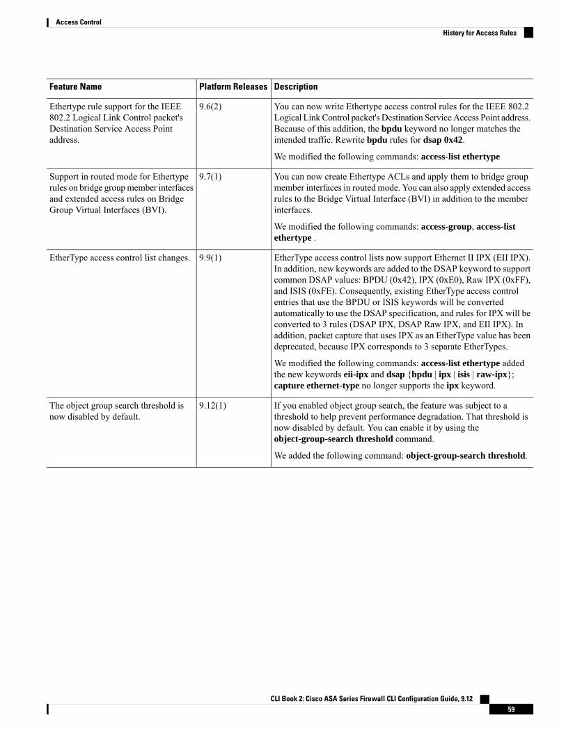
DescriptionPlatform ReleasesFeature Name
You can now write Ethertype access control rules for the IEEE 802.2Logical Link Control packet's Destination Service Access Point address.Because of this addition, the bpdu keyword no longer matches theintended traffic. Rewrite bpdu rules for dsap 0x42.
We modified the following commands: access-list ethertype
9.6(2)Ethertype rule support for the IEEE802.2 Logical Link Control packet'sDestination Service Access Pointaddress.
You can now create Ethertype ACLs and apply them to bridge groupmember interfaces in routed mode. You can also apply extended accessrules to the Bridge Virtual Interface (BVI) in addition to the memberinterfaces.
We modified the following commands: access-group, access-listethertype .
9.7(1)Support in routed mode for Ethertyperules on bridge groupmember interfacesand extended access rules on BridgeGroup Virtual Interfaces (BVI).
EtherType access control lists now support Ethernet II IPX (EII IPX).In addition, new keywords are added to the DSAP keyword to supportcommon DSAP values: BPDU (0x42), IPX (0xE0), Raw IPX (0xFF),and ISIS (0xFE). Consequently, existing EtherType access controlentries that use the BPDU or ISIS keywords will be convertedautomatically to use the DSAP specification, and rules for IPX will beconverted to 3 rules (DSAP IPX, DSAP Raw IPX, and EII IPX). Inaddition, packet capture that uses IPX as an EtherType value has beendeprecated, because IPX corresponds to 3 separate EtherTypes.
We modified the following commands: access-list ethertype addedthe new keywords eii-ipx and dsap {bpdu | ipx | isis | raw-ipx};capture ethernet-type no longer supports the ipx keyword.
9.9(1)EtherType access control list changes.
If you enabled object group search, the feature was subject to athreshold to help prevent performance degradation. That threshold isnow disabled by default. You can enable it by using theobject-group-search threshold command.
We added the following command: object-group-search threshold.
9.12(1)The object group search threshold isnow disabled by default.
CLI Book 2: Cisco ASA Series Firewall CLI Configuration Guide, 9.1259
Access ControlHistory for Access Rules

CLI Book 2: Cisco ASA Series Firewall CLI Configuration Guide, 9.1260
Access ControlHistory for Access Rules

C H A P T E R 5Identity Firewall
This chapter describes how to configure the ASA for the Identity Firewall.
• About the Identity Firewall, on page 61• Guidelines for the Identity Firewall, on page 67• Prerequisites for the Identity Firewall, on page 69• Configure the Identity Firewall, on page 70• Collect User Statistics, on page 79• Examples for the Identity Firewall, on page 80• Monitoring the Identity Firewall, on page 82• History for the Identity Firewall, on page 83
About the Identity FirewallIn an enterprise, users often need access to one or more server resources. Typically, a firewall is not aware ofthe users’ identities and, therefore, cannot apply security policies based on identity. To configure per-useraccess policies, you must configure a user authentication proxy, which requires user interaction (ausername/password query).
The Identity Firewall in the ASA provides more granular access control based on users’ identities. You canconfigure access rules and security policies based on user names and user group names rather than throughsource IP addresses. The ASA applies the security policies based on an association of IP addresses toWindowsActive Directory login information and reports events based on the mapped usernames instead of network IPaddresses.
The Identity Firewall integrates with Microsoft Active Directory in conjunction with an external ActiveDirectory (AD) Agent that provides the actual identity mapping. The ASA uses Windows Active Directoryas the source to retrieve the current user identity information for specific IP addresses and allows transparentauthentication for Active Directory users.
Identity-based firewall services enhance the existing access control and security policymechanisms by allowingusers or groups to be specified in place of source IP addresses. Identity-based security policies can be interleavedwithout restriction between traditional IP address-based rules.
The key benefits of the Identity Firewall include:
• Decoupling network topology from security policies
• Simplifying the creation of security policies
CLI Book 2: Cisco ASA Series Firewall CLI Configuration Guide, 9.1261

• Providing the ability to easily identify user activities on network resources
• Simplifying user activity monitoring
Architecture for Identity Firewall DeploymentsThe Identity Firewall integrates withWindowActive Directory in conjunction with an external Active Directory(AD) Agent that provides the actual identity mapping.
The identity firewall consists of three components:
• ASA
• Microsoft Active Directory
Although Active Directory is part of the Identity Firewall on the ASA, Active Directory administratorsmanage it. The reliability and accuracy of the data depends on data in Active Directory.
Supported versions include Windows Server 2003, Windows Server 2008, and Windows Server 2008R2 servers.
• Active Directory (AD) Agent
The ADAgent runs on aWindows server. SupportedWindows servers includeWindows 2003,Windows2008, and Windows 2008 R2.
Windows 2003 R2 is not supported for the AD Agent server.Note
The following figure show the components of the Identity Firewall. The succeeding table describes the rolesof these components and how they communicate with one another.
Figure 3: Identity Firewall Components
CLI Book 2: Cisco ASA Series Firewall CLI Configuration Guide, 9.1262
Access ControlArchitecture for Identity Firewall Deployments

Client <-> ASA: Theclient logs into thenetwork throughMicrosoft ActiveDirectory. The AD Serverauthenticates users andgenerates user loginsecurity logs.
Alternatively, the clientcan log into the networkthrough a cut-throughproxy or VPN.
4On the ASA:Administrators configurelocal user groups andIdentity Firewall policies.
1
ASA <-> Client: Basedon the policies configuredon the ASA, it grants ordenies access to the client.
If configured, the ASAprobes the NetBIOS of theclient to pass inactive andno-response users.
5ASA <-> AD Server: TheASA sends an LDAPquery for the ActiveDirectory groupsconfigured on the ADServer.
The ASA consolidateslocal andActiveDirectorygroups and applies accessrules and Modular PolicyFramework securitypolicies based on useridentity.
2
AD Agent <-> ADServer: The AD Agentmaintains a cache of userID and IP address mappedentries. and notifies theASA of changes.
The AD Agent sends logsto a syslog server.
6ASA <-> AD Agent:Depending on the IdentityFirewall configuration, theASA downloads theIP-user database or sendsa RADIUS request to theAD Agent that asks forthe user’s IP address.
The ASA forwards thenew mapped entries thathave been learned fromweb authentication andVPN sessions to the ADAgent.
3
Features of the Identity FirewallThe Identity Firewall includes the following key features.
CLI Book 2: Cisco ASA Series Firewall CLI Configuration Guide, 9.1263
Access ControlFeatures of the Identity Firewall

Flexibility
• The ASA can retrieve user identity and IP address mapping from the AD Agent by querying the ADAgent for each new IP address or by maintaining a local copy of the entire user identity and IP addressdatabase.
• Supports host group, subnet, or IP address for the destination of a user identity policy.
• Supports a fully qualified domain name (FQDN) for the source and destination of a user identity policy.
• Supports the combination of 5-tuple policies with ID-based policies. The identity-based feature worksin tandem with the existing 5-tuple solution.
• Supports use with application inspection policies.
• Retrieves user identity information from remote access VPN, AnyConnect VPN, L2TP VPN andcut-through proxy. All retrieved users are populated to all ASAs that are connected to the AD Agent.
Scalability
• Each AD Agent supports 100 ASAs. Multiple ASAs are able to communicate with a single AD Agentto provide scalability in larger network deployments.
• Supports 30 Active Directory servers provided the IP address is unique among all domains.
• Each user identity in a domain can have up to 8 IP addresses.
• Supports up to 64,000 user identity-IP address mapped entries in active policies for the ASA 5500 Seriesmodels. This limit controls the maximum number of users who have policies applied. The total numberof users are the aggregate of all users configured in all different contexts.
• Supports up to 512 user groups in active ASA policies.
• A single access rule can contain one or more user groups or users.
• Supports multiple domains.
Availability
• The ASA retrieves group information from the Active Directory and falls back to web authentication forIP addresses when the AD Agent cannot map a source IP address to a user identity.
• The AD Agent continues to function when any of the Active Directory servers or the ASA are notresponding.
• Supports configuring a primary AD Agent and a secondary AD Agent on the ASA. If the primary ADAgent stops responding, the ASA can switch to the secondary AD Agent.
• If the AD Agent is unavailable, the ASA can fall back to existing identity sources such as cut-throughproxy and VPN authentication.
• The AD Agent runs a watchdog process that automatically restarts its services when they are down.
• Allows a distributed IP address/user mapping database for use among ASAs.
CLI Book 2: Cisco ASA Series Firewall CLI Configuration Guide, 9.1264
Access ControlFeatures of the Identity Firewall

Deployment ScenariosYou can deploy the components of the Identity Firewall in the followingways, depending on your environmentalrequirements.
The following figure shows how you can deploy the components of the Identity Firewall to allow forredundancy. Scenario 1 shows a simple installation without component redundancy. Scenario 2 also shows asimple installation without redundancy. However, in this deployment scenario, the Active Directory serverand AD Agent are co-located on the same Windows server.
Figure 4: Deployment Scenario without Redundancy
The following figure shows how you can deploy the Identity Firewall components to support redundancy.Scenario 1 shows a deployment with multiple Active Directory servers and a single AD Agent installed on aseparateWindows server. Scenario 2 shows a deployment with multiple Active Directory servers and multipleAD Agents installed on separate Windows servers.
Figure 5: Deployment Scenario with Redundant Components
The following figure shows how all Identity Firewall components—Active Directory server, the AD Agent,and the clients—are installed and communicate on the LAN.
CLI Book 2: Cisco ASA Series Firewall CLI Configuration Guide, 9.1265
Access ControlDeployment Scenarios

Figure 6: LAN -based Deployment
The following figure shows a WAN-based deployment to support a remote site. The Active Directory serverand the AD Agent are installed on the main site LAN. The clients are located at a remote site and connect tothe Identity Firewall components over a WAN.
Figure 7: WAN-based Deployment
The following figure also shows a WAN-based deployment to support a remote site. The Active Directoryserver is installed on the main site LAN. However, the AD Agent is installed and accessed by the clients atthe remote site. The remote clients connect to the Active Directory servers at the main site over a WAN.
CLI Book 2: Cisco ASA Series Firewall CLI Configuration Guide, 9.1266
Access ControlDeployment Scenarios

Figure 8: WAN-based Deployment with Remote AD Agent
The following figure shows an expanded remote site installation. An AD Agent and Active Directory serversare installed at the remote site. The clients access these components locally when logging into network resourceslocated at the main site. The remote Active Directory server must synchronize its data with the central ActiveDirectory servers located at the main site.
Figure 9: WAN-based Deployment with Remote AD Agent and AD Servers
Guidelines for the Identity FirewallThis section describes the guidelines and limitations that you should check before configuring the IdentityFirewall.
Failover
• The Identity Firewall supports user identity-IP address mapping and AD Agent status replication fromactive to standby when Stateful Failover is enabled. However, only user identity-IP address mapping,AD Agent status, and domain status are replicated. User and user group records are not replicated to thestandby ASA.
• When failover is configured, the standby ASA must also be configured to connect to the AD Agentdirectly to retrieve user groups. The standby ASA does not send NetBIOS packets to clients even whenthe NetBIOS probing options are configured for the Identity Firewall.
CLI Book 2: Cisco ASA Series Firewall CLI Configuration Guide, 9.1267
Access ControlGuidelines for the Identity Firewall

• When a client is determined to be inactive by the active ASA, the information is propagated to the standbyASA. User statistics are not propagated to the standby ASA.
• When you have failover configured, you must configure the AD Agent to communicate with both theactive and standby ASAs. See the Installation and Setup Guide for the Active Directory Agent for thesteps to configure the ASA on the AD Agent server.
IPv6
• The AD Agent supports endpoints with IPv6 addresses. It can receive IPv6 addresses in log events,maintain them in its cache, and send them through RADIUS messages. The AAA server must use anIPv4 address.
• NetBIOS over IPv6 is not supported.
Additional Guidelines
• A full URL as a destination address is not supported.
• For NetBIOS probing to function, the network between the ASA, AD Agent, and clients must supportUDP-encapsulated NetBIOS traffic.
• MAC address checking by the Identity Firewall does not work when intervening routers are present.Users logged into clients that are behind the same router have the same MAC addresses. With thisimplementation, all the packets from the same router are able to pass the check, because the ASA isunable to ascertain the actual MAC addresses behind the router.
• Although you can use user specifications in VPN filter ACLs, the user-based rules are interpreteduni-directionally rather than bi-directionally, which is how VPN filter usually works. That is, you canfilter based on user-initiated traffic, but the filter does not apply for going from the destination back tothe user. For example, you could include a rule that allows a specific user to ping a server, but that rulewill not allow the server to ping the user.
• The following ASA features do not support using the identity-based object and FQDN in an extendedACL:
• Crypto maps
• WCCP
• NAT
• Group policy (except for VPN filters)
• DAP
• You can use the user-identity update active-user-database command to actively initiate a user-IPaddress download from the AD agent.
By design, if a previous download session has finished, the ASA does not allow you to issue this commandagain.
As a result, if the user-IP database is very large, the previous download session is not finished yet, andyou issue another user-identity update active-user-database command, the following error messageappears:
CLI Book 2: Cisco ASA Series Firewall CLI Configuration Guide, 9.1268
Access ControlGuidelines for the Identity Firewall

“ERROR: one update active-user-database is already in progress.”
You need to wait until the previous session is completely finished, then you can issue another user-identityupdate active-user-database command.
Another example of this behavior occurs because of packet loss from the AD Agent to the ASA.
When you issue a user-identity update active-user-database command, the ASA requests the totalnumber of user-IP mapped entries to be downloaded. Then the AD Agent initiates a UDP connection tothe ASA and sends the change of authorization request packet.
If for some reason the packet is lost, there is no way for the ASA to discern this. As a result, the ASAholds the session for 4-5 minutes, during which time this error message continues to appear if you haveissued the user-identity update active-user-database command.
• When you use the Cisco Context Directory Agent (CDA) in conjunction with the ASA or Cisco IronportWeb Security Appliance (WSA), make sure that you open the following ports:
• Authentication port for UDP—1645
• Accounting port for UDP—1646
• Listening port for UDP—3799
The listening port is used to send change of authorization requests from the CDA to the ASA or tothe WSA.
• If the user-identity action domain-controller-down domain_name disable user-identity-rule commandis configured and the specified domain is down, or if the user-identity action ad-agent-down disableuser-identity-rule command is configured and the AD Agent is down, all the logged-in users have thedisabled status.
• For domain names, the following characters are not valid: \/:*?"<>|.
• For usernames, the following characters are not valid: \/[]:;=,+*?"<>|@.
• For user group names, the following characters are not valid: \/[]:;=,+*?"<>|.
• How you configure the Identity Firewall to retrieve user information from the AD Agent affects theamount of memory used by the feature. You specify whether the ASA uses on-demand retrieval or fulldownload retrieval. Choosing on-demand retrieval has the benefit of using less memory, because onlyusers of received packets are queried and stored.
Prerequisites for the Identity FirewallThis section lists the prerequisites for configuring the Identity Firewall.
AD Agent
• The AD Agent must be installed on a Windows server that is accessible to the ASA. Additionally, youmust configure the ADAgent to obtain information from the Active Directory servers and to communicatewith the ASA.
• Supported Windows servers include Windows 2003, Windows 2008, and Windows 2008 R2.
CLI Book 2: Cisco ASA Series Firewall CLI Configuration Guide, 9.1269
Access ControlPrerequisites for the Identity Firewall

Windows 2003 R2 is not supported for the AD Agent server.Note
• For the steps to install and configure the AD Agent, see the Installation and Setup Guide for the ActiveDirectory Agent.
• Before configuring the AD Agent in the ASA, obtain the secret key value that the AD Agent and theASA use to communicate. This value must match on both the AD Agent and the ASA.
Microsoft Active Directory
• Microsoft Active Directorymust be installed on aWindows server and accessible by the ASA. Supportedversions include Windows 2003, 2008, and 2008 R2 servers.
• Before configuring the Active Directory server on the ASA, create a user account in Active Directoryfor the ASA.
• Additionally, the ASA sends encrypted log-in information to the Active Directory server by using SSLenabled over LDAP. SSL must be enabled on the Active Directory server. See the documentation forMicrosoft Active Directory for how to enable SSL for Active Directory.
Before running the AD Agent Installer, you must install the patches listed in the README First for the CiscoActive Directory Agent on eachMicrosoft Active Directory server that the ADAgent monitors. These patchesare required even when the AD Agent is installed directly on the domain controller server.
Note
Configure the Identity FirewallTo configure the Identity Firewall, perform the following tasks:
Procedure
Step 1 Configure the Active Directory domain in the ASA.Step 2 Configure the AD Agent in ASA.Step 3 Configure Identity Options.Step 4 Configure Identity-based Security Policy. After the AD domain and AD Agent are configured, you can create
identity-based object groups and ACLs for use in many features.
Configure the Active Directory DomainActive Directory domain configuration on the ASA is required for the ASA to download Active Directorygroups and accept user identities from specific domains when receiving IP-user mapping from the AD Agent.
CLI Book 2: Cisco ASA Series Firewall CLI Configuration Guide, 9.1270
Access ControlConfigure the Identity Firewall

Before you begin
• Active Directory server IP address
• Distinguished Name for LDAP base DN
• Distinguished Name and password for the Active Directory user that the Identity Firewall uses to connectto the Active Directory domain controller
To configure the Active Directory domain, perform the following steps:
Procedure
Step 1 Create the AAA server group and configure AAA server parameters for the Active Directory server.
aaa-server server-tag protocol ldap
Example:ciscoasa(config)# aaa-server adserver protocol ldap
Step 2 Configure the AAA server as part of a AAA server group and the AAA server parameters that are host-specificfor the Active Directory server.
aaa-server server-tag [(interface-name)] host{server-ip | name} [key] [timeoutseconds]
Example:ciscoasa(config-aaa-server-group)# aaa-server adserver (mgmt) host 172.168.224.6
Step 3 Specifies the location in the LDAP hierarchy where the server should begin searching when it receives anauthorization request.
ldap-base-dn string
Example:ciscoasa(config-aaa-server-host)# ldap-base-dn DC=SAMPLE,DC=com
Specifying the ldap-base-dn command is optional. If you do not specify this command, the ASA retrievesthe defaultNamingContext from the Active Directory and uses it as the base DN.
Step 4 Specify the extent of the search in the LDAP hierarchy that the server should make when it receives anauthorization request.
ldap-scope subtree
Example:ciscoasa(config-aaa-server-host)# ldap-scope subtree
Step 5 Specify the login password for the LDAP server.
ldap-login-password string
Example:ciscoasa(config-aaa-server-host)# ldap-login-password obscurepassword
CLI Book 2: Cisco ASA Series Firewall CLI Configuration Guide, 9.1271
Access ControlConfigure the Active Directory Domain

Step 6 Specify the name of the directory object that the system should bind this as.
ldap-login-dn string
Example:ciscoasa(config-aaa-server-host)# ldap-login-dn SAMPLE\user1
The ASA identifies itself for authenticated binding by attaching a Login DN field to the user authenticationrequest. The Login DN field describes the authentication characteristics of the ASA.
The string argument is a case-sensitive string of up to 128 characters that specifies the name of the directoryobject in the LDAP hierarchy. Spaces are not permitted in the string, but other special characters are allowed.
You can specify the traditional or simplified format.
The typical ldap-login-dn command format includes: CN=username,OU=Employees,OU=SampleUsers,DC=sample,DC=com.
Step 7 Configure the LDAP server model for the Microsoft Active Directory server.
server-type microsoft
Example:ciscoasa(config-aaa-server-host)# server-type microsoft
Step 8 Specify the location of the Active Directory groups configuration in the Active Directory domain controller.
ldap-group-base-dn string
Example:ciscoasa(config-aaa-server-host)# ldap-group-base-dn OU=Sample Groups,DC=SAMPLE,DC=com
If not specified, the value in the ldap-group-base-dn command is used. Specifying this command is optional.
Step 9 Allow the ASA to access the Active Directory domain controller over SSL.
ldap-over-ssl enable
Example:ciscoasa(config-aaa-server-host)# ldap-over-ssl enable
To support LDAP over SSL, Active Directory server needs to be configured to have this support.
By default, the Active Directory does not have SSL configured. If SSL is not configured in the Active Directory,you do not need to configure it on the ASA for the Identity Firewall.
Step 10 Specify the server port.
server-port port-number
Example:ciscoasa(config-aaa-server-host)# server-port 389
ciscoasa(config-aaa-server-host)# server-port 636
By default, if the ldap-over-ssl command is not enabled, the default server port is 389; if the ldap-over-sslcommand is enabled, the default server port is 636.
CLI Book 2: Cisco ASA Series Firewall CLI Configuration Guide, 9.1272
Access ControlConfigure the Active Directory Domain

Step 11 Set the amount of time before LDAP queries time out.
group-search-timeout seconds
Example:ciscoasa(config-aaa-server-host)# group-search-timeout 300
Configure Active Directory AgentsConfigure the primary and secondary AD Agents for the AD Agent Server Group. When the ASA detectsthat the primary AD Agent is not responding and a secondary agent is specified, the ASA switches to thesecondary AD Agent. The Active Directory server for the AD agent uses RADIUS as the communicationprotocol; therefore, you should specify a key attribute for the shared secret between the ASA and AD Agent.
Before you begin
• AD agent IP address
• Shared secret between the ASA and AD agent
To configure the AD Agents, perform the following steps:
Procedure
Step 1 Create the AAA server group and configure AAA server parameters for the AD Agent.
aaa-server server-tag protocol radius
Example:ciscoasa(config)# aaa-server adagent protocol radius
Step 2 Enable the AD Agent mode.
ad-agent-mode
Example:ciscoasa(config)# ad-agent-mode
Step 3 Configure the AAA server as part of a AAA server group and the AAA server parameters that are host-specificfor the AD Agent.
aaa-server server-tag [(interface-name)] host {server-ip | name} [key] [timeoutseconds]
Example:ciscoasa(config-aaa-server-group)# aaa-server adagent (inside) host 192.168.1.101
Step 4 Specify the server secret value used to authenticate the ASA to the AD Agent server.
key key
CLI Book 2: Cisco ASA Series Firewall CLI Configuration Guide, 9.1273
Access ControlConfigure Active Directory Agents

Example:ciscoasa(config-aaa-server-host)# key mysecret
Step 5 Define the server group of the AD Agent.
user-identity ad-agent aaa-server aaa_server_group_tag
Example:ciscoasa(config-aaa-server-hostkey# user-identity ad-agent aaa-server adagent
The first server defined in the aaa_server_group_tag argument is the primary ADAgent and the second serverdefined is the secondary AD Agent. The Identity Firewall supports defining only two AD Agent hosts.
When the ASA detects that the primary AD Agent is down and a secondary agent is specified, it switches tothe secondary AD Agent. The AAA server for the AD agent uses RADIUS as the communication protocol,and should specify a key attribute for the shared secret between the ASA and AD Agent.
Step 6 Test the communication between the ASA and the AD Agent server.
test aaa-server ad-agent
Example:ciscoasa(config-aaa-server-host)# test aaa-server ad-agent
Configure Identity OptionsTo configure the Identity Options for the Identity Firewall, perform the following steps:
Procedure
Step 1 Enable the Identity Firewall feature. By default, the Identity Firewall feature is disabled.
user-identity enable
Example:ciscoasa(config)# user-identity enable
Step 2 Specify the default domain for the Identity Firewall.
user-identity default-domain domain_NetBIOS_name
Example:ciscoasa(config)# user-identity default-domain SAMPLE
For the domain_NetBIOS_name argument, enter a name of up to 32 characters that consists of [a-z], [A-Z],[0-9], [!@#$%^&()-_=+[]{};,. ] except '.' and ' ' at the first character. If the domain name includes a space,enclose the entire name in quotation marks. The domain name is not case sensitive.
CLI Book 2: Cisco ASA Series Firewall CLI Configuration Guide, 9.1274
Access ControlConfigure Identity Options

The default domain is used for all users and user groups when a domain has not been explicitly configuredfor those users or groups. When a default domain is not specified, the default domain for users and groups isLOCAL. For multiple context modes, you can set a default domain name for each context, as well as withinthe system execution space.
The default domain name that you specify must match the NetBIOS domain name configured onthe Active Directory domain controller. If the domain name does not match, the ADAgent incorrectlyassociates the user identity-IP address mapped entries with the domain name that you enter whenconfiguring the ASA. To view the NetBIOS domain name, open the Active Directory user eventsecurity log in any text editor.
The Identity Firewall uses the LOCAL domain for all locally defined user groups or locally definedusers. Users logging in through a web portal (cut-through proxy) are designated as belonging to theActive Directory domain with which they authenticated. Users logging in through a VPN aredesignated as belonging to the LOCAL domain unless the VPN is authenticated by LDAP with theActive Directory. In this case, the Identity Firewall can associate the users with their Active Directorydomain.
Note
Step 3 Associate the LDAP parameters defined for the AAA server for importing user group queries with the domainname.
user-identity domain domain_nickname aaa-server aaa_server_group_tag
Example:ciscoasa(config)# user-identity domain SAMPLE aaa-server ds
For the domain_nickname argument, enter a name of up to 32 characters consisting of [a-z], [A-Z], [0-9],[!@#$%^&()-_=+[]{};,. ] except '.' and ' ' at the first character. If the domain name includes a space, you mustenclose that space character in quotation marks. The domain name is not case sensitive.
Step 4 Enable NetBIOS probing.
user-identity logout-probe netbios local-system probe-time minutes minutes retry-interval secondsseconds retry-count times user-not-needed [user-not-needed | match-any | exact-match]
Example:ciscoasa(config)# user-identity logout-probe netbioslocal-system probe-time minutes 10 retry-interval seconds 10retry-count 2 user-not-needed
Enabling this option configures how often the ASA probes the user client IP address to determine whetherthe client is still active. By default, NetBIOS probing is disabled. To minimize the NetBIOS packets, the ASAonly sends a NetBIOS probe to a client when the user has been idle for more than the specified number ofminutes.
• Exact match-—The username of the user assigned to the IP address must be the only one in the NetBIOSresponse. Otherwise, the user identity of that IP address is considered invalid.
• User-not-needed—As long as the ASA received a NetBIOS response from the client, the user identityis considered valid.
The Identity Firewall only performs NetBIOS probing for those users identities that are in the active state andexist in at least one security policy. The ASA does not perform NetBIOS probing for clients where the userslogged in through cut-through proxy or by using a VPN.
CLI Book 2: Cisco ASA Series Firewall CLI Configuration Guide, 9.1275
Access ControlConfigure Identity Options

Step 5 Specify the amount of time before a user is considered idle, meaning the ASA has not received traffic fromthe user's IP address for the specified amount of time.
user-identity inactive-user-timer minutes minutes
Example:ciscoasa(config)# user-identity inactive-user-timer minutes 120
When the timer expires, the user's IP address is marked as inactive and removed from the local cached useridentity-IP address mapping database, and the ASA no longer notifies the AD Agent about that IP address.Existing traffic is still allowed to pass. When this command is specified, the ASA runs an inactive timer evenwhen the NetBIOS Logout Probe is configured.
By default, the idle timeout is set to 60 minutes. This option does not apply to VPN or cut-through proxyusers.
Step 6 Specify the amount of time before the ASA queries the Active Directory server for user group information.
user-identity poll-import-user-group-timer hours hours
Example:ciscoasa(config)# user-identity poll-import-user-group-timer hours1
If a user is added to or deleted from an Active Directory group, the ASA received the updated user group afterthe import group timer ran. By default, the poll-import user-group-timer hours value is 8 hours.
To immediately update user group information, enter the user-identity update import-user command.
Step 7 Specify the action when a client does not respond to a NetBIOS probe.
user-identity action netbios-response-fail remove-user-ip
Example:ciscoasa(config)# user-identity action netbios-response-fail remove-user-ip
For example, the network connection might be blocked to that client or the client is not active.
When this command is configured, the ASA removes the user identity-IP address mapping for that client.
By default, this command is disabled.
Step 8 Specify the action when the domain is down, because the Active Directory domain controller is not responding.
user-identity action domain-controller-down domain_nickname disable-user-identity-rule
Example:ciscoasa(config)# user-identity action domain-controller-down SAMPLEdisable-user-identity-rule
When the domain is down and the disable-user-identity-rule keyword is configured, the ASA disables theuser identity-IP address mapping for that domain. Additionally, the status of all user IP addresses in thatdomain are marked as disabled in the output displayed by the show user-identity user command.
By default, this command is disabled.
Step 9 Enable user-not-found tracking. By default, this command is disabled.
user-identity user-not-found enable
CLI Book 2: Cisco ASA Series Firewall CLI Configuration Guide, 9.1276
Access ControlConfigure Identity Options

Example:ciscoasa(config)# user-identity user-not-found enable
Only the last 1024 IP addresses are tracked.
Step 10 Specify the action when the AD Agent is not responding.
user-identity action ad-agent-down disable-user-identity-rule
Example:ciscoasa(config)# user-identity action ad-agent-down disable-user-identity-rule
When the AD Agent is down and this command is configured, the ASA disables the user identity rulesassociated with the users in that domain. Additionally, the status of all user IP addresses in that domain ismarked as disabled in the output displayed by the show user-identity user command.
By default, this command is disabled.
Step 11 Specify the action when a user's MAC address is found to be inconsistent with the ASA IP address currentlymapped to that MAC address.
user-identity actionmac-address-mismatch remove-user-ip
Example:ciscoasa(config)# user-identity actionmac-address-mismatch remove-user-ip
When this command is configured, the ASA removes the user identity-IP address mapping for that client.
By default, the ASA uses the remove-user-ip keyword when this command is specified.
Step 12 Define how the ASA retrieves the user identity-IP address mapping information from the AD Agent.user-identity ad-agent active-user-database {on-demand | full-download}
Example:ciscoasa(config)# user-identity ad-agent active-user-database full-download
By default, the ASA uses the full-download option.
• Full-download—Specifies that the ASA send a request to the AD Agent to download the entire IP-usermapping table when the ASA starts and then to receive incremental IP-user mapping information whenusers log in and log out. Full downloads are event driven, meaning that when there are subsequent requeststo download the database, just the updates to the user identity-IP address mapping database are sent.
• On-demand—Specifies that the ASA retrieve the user mapping information of an IP address from theAD Agent when the ASA receives a packet that requires a new connection, and the user of its source IPaddress is not in the user-identity database.
When the ASA registers a change request with the AD Agent, the AD Agent sends a new event to the ASA.
Step 13 Define the hello timer between the ASA and the AD Agent.
user-identity ad-agent hello-timer seconds seconds retry-times number
Example:ciscoasa(config)# user-identity ad-agent hello-timer seconds 20 retry-times 3
CLI Book 2: Cisco ASA Series Firewall CLI Configuration Guide, 9.1277
Access ControlConfigure Identity Options

The hello timer between the ASA and the ADAgent defines how frequently the ASA exchanges hello packets.The ASA uses the hello packet to obtain ASA replication status (in-sync or out-of-sync) and domain status(up or down). If the ASA does not receive a response from the AD Agent, it resends a hello packet after thespecified interval.
By default, the hello timer is set to 30 seconds and 5 retries.
Step 14 Enable the ASA to keep track of the last event time stamp that it receives for each identifier and to discardany message if the event time stamp is at least 5 minutes older than the ASA’s clock, or if its time stamp isearlier than the last event’s time stamp.
user-identity ad-agent event-timestamp-check
Example:ciscoasa(config)# user-identity ad-agent event-timestamp-check
For a newly booted ASA that does not have knowledge of the last event time stamp, the ASA compares theevent time stamp with its own clock. If the event is at least 5 minutes older, the ASA does not accept themessage.
We recommend that you configure the ASA, Active Directory, and Active Directory agent to synchronizetheir clocks among themselves using NTP.
Step 15 Define the server group of the AD Agent.
user-identity ad-agent aaa-server aaa_server_group_tag
Example:ciscoasa(config)# user-identity ad-agent aaa-server ad-agent
For the aaa_server_group_tag argument, enter the value defined by the aaa-server command.
Configure Identity-Based Security PolicyYou can incorporate identity-based policy in many ASA features. Any feature that uses extended ACLs (otherthan those listed as unsupported in the Guidelines section) can take advantage of an identity firewall. You cannow add user identity arguments to extended ACLs, as well as network-based parameters.
Features that can use identity include the following:
• Access rules—An access rule permits or denies traffic on an interface using network information. Withan identity firewall, you can control access based on user identity.
• AAA rules—An authentication rule (also known as cut-through proxy) controls network access basedon the user. Because this function is very similar to an access rule plus an identity firewall, AAA rulescan now be used as a backup method of authentication if a user’s AD login expires. For example, forany user without a valid login, you can trigger a AAA rule. To ensure that the AAA rule is only triggeredfor users that do not have valid logins, you can specify special usernames in the extended ACL used forthe access rule and for the AAA rule: None (users without a valid login) and Any (users with a validlogin). In the access rule, configure your policy as usual for users and groups, but then include a AAArule that permits all None users; you must permit these users so they can later trigger a AAA rule. Then,configure a AAA rule that denies Any users (these users are not subject to the AAA rule, and werehandled already by the access rule), but permits all None users. For example:
CLI Book 2: Cisco ASA Series Firewall CLI Configuration Guide, 9.1278
Access ControlConfigure Identity-Based Security Policy

access-list 100 ex permit ip user CISCO\xyz any anyaccess-list 100 ex deny ip user CISCO\abc any anyaccess-list 100 ex permit ip user NONE any anyaccess-list 100 ex deny any anyaccess-group 100 in interface inside
access-list 200 ex deny ip user ANY any anyaccess-list 200 ex permit user NONE any anyaaa authenticate match 200 inside user-identity
For more information, see the legacy feature guide.
• VPN filter—Although a VPN does not support identity firewall ACLs in general, you can configure theASA to enforce identity-based access rules on VPN traffic. By default, VPN traffic is not subject toaccess rules. You can force VPN clients to abide by access rules that use an identity firewall ACL (withthe no sysopt connection permit-vpn command). You can also use an identity firewall ACL with theVPN filter feature; a VPN filter accomplishes a similar effect by allowing access rules in general.
Collect User StatisticsTo activate the collection of user statistics by the Modular Policy Framework and match lookup actions forthe Identify Firewall, perform the following steps:
Procedure
Activate the collection of user statistics by the Modular Policy Framework and matches lookup actions forthe Identify Firewall.
user-statistics [accounting | scanning]
Example:ciscoasa(config)# class-map c-identity-example-1ciscoasa(config-cmap)# match access-list identity-example-1ciscoasa(config-cmap)# exitciscoasa(config)# policy-mapp-identity-example-1ciscoasa(config-pmap)# class c-identity-example-1ciscoasa(config-pmap)# user-statistics accountingciscoasa(config-pmap)# exitciscoasa(config)# service-policy p-identity-example-1 interface outside
The accounting keyword specifies that the ASA collect the sent packet count, sent drop count, and receivedpacket count. The scanning keyword specifies that the ASA collect only the sent drop count.
When you configure a policy map to collect user statistics, the ASA collects detailed statistics for selectedusers. When you specify the user-statistics command without the accounting or scanning keywords, theASA collects both accounting and scanning statistics.
CLI Book 2: Cisco ASA Series Firewall CLI Configuration Guide, 9.1279
Access ControlCollect User Statistics

Examples for the Identity FirewallThis section provides examples for the Identity Firewall.
AAA Rule and Access Rule Example 1This example shows a typical cut-through proxy configuration to allow a user to log in through the ASA. Inthis example, the following conditions apply:
• The ASA IP address is 172.1.1.118.
• The Active Directory domain controller has the IP address 71.1.2.93.
• The end-user client has the IP address 172.1.1.118 and uses HTTPS to log in through a web portal.
• The user is authenticated by the Active Directory domain controller via LDAP.
• The ASA uses the inside interface to connect to the Active Directory domain controller on the corporatenetwork.
ciscoasa(config)# access-list AUTH extended permit tcp any 172.1.1.118 255.255.255.255 eqhttpciscoasa(config)# access-list AUTH extended permit tcp any 172.1.1.118 255.255.255.255 eqhttpsciscoasa(config)# aaa-server LDAP protocol ldapciscoasa(config-aaa-server-group)# aaa-server LDAP (inside) host 171.1.2.93ciscoasa(config-aaa-server-host)# ldap-base-dn DC=cisco,DC=comciscoasa(config-aaa-server-host)# ldap-group-base-dn DC=cisco,DC=comciscoasa(config-aaa-server-host)# ldap-scope subtreeciscoasa(config-aaa-server-host)# ldap-login-dncn=kao,OU=Employees,OU=CiscoUsers,DC=cisco,DC=comciscoasa(config-aaa-server-host)# ldap-login-password *****ciscoasa(config-aaa-server-host)# ldap-over-ssl enableciscoasa(config-aaa-server-host)# server-type microsoftciscoasa(config-aaa-server-host)# aaa authentication match AUTH inside LDAPciscoasa(config)#ciscoasa(config)# http server enableciscoasa(config)# http 0.0.0.0 0.0.0.0 insideciscoasa(config)#ciscoasa(config)# auth-prompt prompt Enter Your Authenticationciscoasa(config)# auth-prompt accept You are Goodciscoasa(config)# auth-prompt reject Goodbye
AAA Rule and Access Rule Example 2In this example, the following guidelines apply:
• In access-list commands, permit user NONE rules should be written before entering the access-list 100ex deny any any command to allow unauthenticated incoming users to trigger AAA cut-through proxy.
• In the auth access-list command, permit user NONE rules guarantee only unauthenticated triggercut-through proxy. Ideally, they should be the last lines.
ciscoasa(config)# access-list listenerAuth extended permit tcp any any
CLI Book 2: Cisco ASA Series Firewall CLI Configuration Guide, 9.1280
Access ControlExamples for the Identity Firewall

ciscoasa(config)# aaa authentication match listenerAuth inside ldapciscoasa(config)# aaa authentication listener http inside port 8888ciscoasa(config)# access-list 100 ex permit ip user SAMPLE\user1 any anyciscoasa(config)# access-list 100 ex deny ip user SAMPLE\user2 any anyciscoasa(config)# access-list 100 ex permit ip user NONE any anyciscoasa(config)# access-list 100 ex deny any anyciscoasa(config)# access-group 100 in interface insideciscoasa(config)# aaa authenticate match 200 inside user-identity
VPN Filter ExamplesThe ASA reports users logging in through VPN authentication or a web portal (cut-through proxy) to the ADAgent, which distributes the user information to all registered ASA devices. Specifically, the IP-user mappingof authenticated users is forwarded to all ASA contexts that include the input interface where HTTP/HTTPSpackets are received and authenticated. The ASA designates users logging in through a VPN as belongingthe LOCAL domain.
There are two different ways to apply identity firewall rules to VPN users:
• Ensure that interface access rules, which can include identity firewall rules, are applied to VPN users.
• Bypass interface access rules, but apply a VPN filter to VPN traffic. VPN filters can include identityfirewall rules.
The following topics provide examples.
Applying Interface Access Rules to VPN Traffic ExampleBy default, the sysopt connection permit-vpn command is enabled and VPN traffic is exempted from anaccess list check. To apply interface-based ACL rules for VPN traffic, you need to disable VPN traffic accesslist bypass.
In this example, if the user logs in from the outside interface, the identity firewall rules control which networkresources are accessible. All VPN users are to be stored under the LOCAL domain. Therefore, it is onlymeaningful to apply the rules for LOCAL users or object groups that include LOCAL users.
! Apply VPN-Filter with bypassing access-list check disabledno sysopt connection permit-vpnaccess-list v1 extended deny ip user LOCAL\idfw any 10.0.0.0 255.255.255.0access-list v1 extended permit ip user LOCAL\idfw any 20.0.0.0 255.255.255.0access-group v1 in interface outside
Applying VPN Filters with User Specifications ExampleBy default, the sysopt connection permit-vpn command is enabled and VPN traffic is exempted from anaccess list check. You can use a VPN filter to apply the identity firewall rules to the VPN traffic. You candefine a VPN filter with identity firewall rules in the username and group policy.
In the example, when user idfw logs in, the user can access network resources in the 10.0.00/24 subnet.However, when user user1 logs in, access to network resources in 10.0.00/24 subnet is denied. Note that allVPN users are stored under the LOCAL domain. Therefore, it is only meaningful to apply the rules for LOCALusers or object groups that include LOCAL users.
CLI Book 2: Cisco ASA Series Firewall CLI Configuration Guide, 9.1281
Access ControlVPN Filter Examples

Although you can use user specifications in VPN filter ACLs, the user-based rules are interpreteduni-directionally rather than bi-directionally, which is how VPN filter usually works. That is, you can filterbased on user-initiated traffic, but the filter does not apply for going from the destination back to the user.For example, you could include a rule that allows a specific user to ping a server, but that rule will not allowthe server to ping the user.
Note
! Apply VPN-Filter with bypassing access-list check enabledsysopt connection permit-vpnaccess-list v1 extended permit ip user LOCAL\idfw any 10.0.0.0 255.255.255.0access-list v2 extended deny ip user LOCAL\user1 any 10.0.0.0 255.255.255.0username user1 password QkBIIYVi6IFLEsYv encrypted privilege 0username user1 attributes
vpn-group-policy group1 vpn-filter value v2username idfw password eEm2dmjMaopcGozT encryptedusername idfw attributes
vpn-group-policy testgroup vpn-filter value v1sysopt connection permit-vpnaccess-list v1 extended permit ip user LOCAL\idfw any 10.0.0.0 255.255.255.0access-list v1 extended deny ip user LOCAL\user1 any 10.0.0.0 255.255.255.0group-policy group1 internalgroup-policy group1 attributes
vpn-filter value v1vpn-tunnel-protocol ikev1 l2tp-ipsec ssl-client ssl-clientless
Monitoring the Identity FirewallSee the following commands for monitoring the Identity Firewall status:
• show user-identity ad-agent
This command shows the status of the AD Agent and the domains.
• show user-identity ad-agent statistics
This command shows the statistics for the AD Agent.
• show user-identity memory
This command shows the memory usage of various modules in the Identity Firewall.
• show user-identity user all list
This command shows information about all users contained in the IP-user mapping database used by theIdentity Firewall.
• show user-identity user active user domainuser-name\list detail
This command shows additional information about an active user.
• show user-identity group
This command shows the list of user groups configured for the Identity Firewall.
CLI Book 2: Cisco ASA Series Firewall CLI Configuration Guide, 9.1282
Access ControlMonitoring the Identity Firewall

History for the Identity FirewallTable 3: History for the Identity Firewall
DescriptionReleasesFeature Name
The Identity Firewall feature wasintroduced.
We introduced or modified the followingcommands: user-identity enable,user-identity default-domain,user-identity domain, user-identitylogout-probe, user-identityinactive-user-timer, user-identitypoll-import-user-group-timer,user-identity action netbios-response-fail,user-identity user-not-found,user-identity action ad-agent-down,user-identity actionmac-address-mismatch, user-identityaction domain-controller-down,user-identity ad-agentactive-user-database, user-identityad-agent hello-timer, user-identityad-agent aaa-server, user-identity updateimport-user, dns domain-lookup, dnspoll-timer, dns expire-entry-timer,object-group user, show user-identity,show dns, clear configure user-identity,clear dns, debug user-identity.
8.4(2)Identity Firewall
CLI Book 2: Cisco ASA Series Firewall CLI Configuration Guide, 9.1283
Access ControlHistory for the Identity Firewall

CLI Book 2: Cisco ASA Series Firewall CLI Configuration Guide, 9.1284
Access ControlHistory for the Identity Firewall

C H A P T E R 6ASA and Cisco TrustSec
This chapter describes how to implement Cisco TrustSec for the ASA.
• About Cisco TrustSec, on page 85• Guidelines for Cisco TrustSec, on page 92• Configure the ASA to Integrate with Cisco Trustsec, on page 95• Example for Cisco TrustSec, on page 109• AnyConnect VPN Support for Cisco TrustSec, on page 110• Monitoring Cisco TrustSec, on page 111• History for Cisco TrustSec, on page 112
About Cisco TrustSecTraditionally, security features such as firewalls performed access control based on predefined IP addresses,subnets, and protocols. However, with enterprises transitioning to borderless networks, both the technologyused to connect people and organizations and the security requirements for protecting data and networks haveevolved significantly. Endpoints are becoming increasingly nomadic and users often employ a variety ofendpoints (for example, laptop versus desktop, smart phone, or tablet), which means that a combination ofuser attributes plus endpoint attributes provide the key characteristics (in addition to existing 6-tuple basedrules), that enforcement devices such as switches and routers with firewall features or dedicated firewalls canreliably use for making access control decisions.
As a result, the availability and propagation of endpoint attributes or client identity attributes have becomeincreasingly important requirements to enable security across the customers’ networks, at the access,distribution, and core layers of the network, and in the data center.
Cisco TrustSec provides access control that builds upon an existing identity-aware infrastructure to ensuredata confidentiality between network devices and integrate security access services on one platform. In theCisco TrustSec feature, enforcement devices use a combination of user attributes and endpoint attributes tomake role-based and identity-based access control decisions. The availability and propagation of this informationenables security across networks at the access, distribution, and core layers of the network.
Implementing Cisco TrustSec into your environment has the following advantages:
• Provides a growing mobile and complex workforce with appropriate and more secure access from anydevice
• Lowers security risks by providing comprehensive visibility of who and what is connecting to the wiredor wireless network
CLI Book 2: Cisco ASA Series Firewall CLI Configuration Guide, 9.1285

• Offers exceptional control over activity of network users accessing physical or cloud-based IT resources
• Reduces total cost of ownership through centralized, highly secure access policymanagement and scalableenforcement mechanisms
• For more information, see the following URLs:
DescriptionReference
Describes the Cisco TrustSec system and architecturefor the enterprise.
http://www.cisco.com/c/en/us/solutions/enterprise-networks/trustsec/index.html
Provides instructions for deploying the Cisco TrustSecsolution in the enterprise, including links tocomponent design guides.
http://www.cisco.com/c/en/us/solutions/enterprise/design-zone-security/landing_DesignZone_TrustSec.html
Provides an overview of the Cisco TrustSec solutionwhen used with the ASA, switches, wireless LAN(WLAN) controllers, and routers.
http://www.cisco.com/c/en/us/solutions/collateral/enterprise-networks/trustsec/solution_overview_c22-591771.pdf
Provides the Cisco TrustSec Platform SupportMatrix,which lists the Cisco products that support the CiscoTrustSec solution.
http://www.cisco.com/c/en/us/solutions/enterprise-networks/trustsec/trustsec_matrix.html
About SGT and SXP Support in Cisco TrustSecIn the Cisco TrustSec feature, security group access transforms a topology-aware network into a role-basednetwork, which enables end-to-end policies enforced on the basis of role-based access control (RBAC). Deviceand user credentials acquired during authentication are used to classify packets by security groups. Everypacket entering the Cisco TrustSec cloud is tagged with a security group tag (SGT). The tagging helps trustedintermediaries identify the source identity of the packet and enforce security policies along the data path. AnSGT can indicate a privilege level across the domain when the SGT is used to define a security group ACL.
An SGT is assigned to a device through IEEE 802.1X authentication, web authentication, orMAC authenticationbypass (MAB), which occurs with a RADIUS vendor-specific attribute. An SGT can be assigned staticallyto a particular IP address or to a switch interface. An SGT is passed along dynamically to a switch or accesspoint after successful authentication.
The Security-group eXchange Protocol (SXP) is a protocol developed for Cisco TrustSec to propagate theIP-to-SGT mapping database across network devices that do not have SGT-capable hardware support tohardware that supports SGTs and security group ACLs. SXP, a control plane protocol, passes IP-SGTmappingfrom authentication points (such as legacy access layer switches) to upstream devices in the network.
The SXP connections are point-to-point and use TCP as the underlying transport protocol. SXP uses TCPport 64999 to initiate a connection. Additionally, an SXP connection is uniquely identified by the source anddestination IP addresses.
Roles in the Cisco TrustSec FeatureTo provide identity and policy-based access enforcement, the Cisco TrustSec feature includes the followingroles:
CLI Book 2: Cisco ASA Series Firewall CLI Configuration Guide, 9.1286
Access ControlAbout SGT and SXP Support in Cisco TrustSec

• Access Requester (AR)—Access requesters are endpoint devices that request access to protected resourcesin the network. They are primary subjects of the architecture and their access privilege depends on theirIdentity credentials.
Access requesters include endpoint devices such PCs, laptops, mobile phones, printers, cameras, andMACsec-capable IP phones.
• Policy Decision Point (PDP)—A policy decision point is responsible for making access control decisions.The PDP provides features such as 802.1x,MAB, and web authentication. The PDP supports authorizationand enforcement through VLAN, DACL, and security group access (SGACL/SXP/SGT).
In the Cisco TrustSec feature, the Cisco Identity Services Engine (ISE) acts as the PDP. The Cisco ISEprovides identity and access control policy functionality.
• Policy Information Point (PIP)—A policy information point is a source that provides external information(for example, reputation, location, and LDAP attributes) to policy decision points.
Policy information points include devices such as Session Directory, Sensor IPS, and CommunicationManager.
• Policy Administration Point (PAP)—A policy administration point defines and inserts policies into theauthorization system. The PAP acts as an identity repository by providing Cisco TrustSec tag-to-useridentity mapping and Cisco TrustSec tag-to-server resource mapping.
In the Cisco TrustSec feature, the Cisco Secure Access Control System (a policy server with integrated802.1x and SGT support) acts as the PAP.
• Policy Enforcement Point (PEP)—A policy enforcement point is the entity that carries out the decisions(policy rules and actions) made by the PDP for each AR. PEP devices learn identity information throughthe primary communication path that exists across networks. PEP devices learn the identity attributes ofeach AR from many sources, such as endpoint agents, authorization servers, peer enforcement devices,and network flows. In turn, PEP devices use SXP to propagate IP-SGT mapping to mutually trusted peerdevices across the network.
Policy enforcement points include network devices such as Catalyst switches, routers, firewalls(specifically the ASA), servers, VPN devices, and SAN devices.
The Cisco ASA serves the PEP role in the identity architecture. Using SXP, the ASA learns identity informationdirectly from authentication points and uses it to enforce identity-based policies.
Security Group Policy EnforcementSecurity policy enforcement is based on security group name. An endpoint device attempts to access a resourcein the data center. Compared to traditional IP-based policies configured on firewalls, identity-based policiesare configured based on user and device identities. For example, mktg-contractor is allowed to accessmktg-servers; mktg-corp-users are allowed to access mktg-server and corp-servers.
The benefits of this type of deployment include the following:
• User group and resource are defined and enforced using single object (SGT) simplified policymanagement.
• User identity and resource identity are retained throughout the Cisco TrustSec-capable switchinfrastructure.
The following figure shows a deployment for security group name-based policy enforcement.
CLI Book 2: Cisco ASA Series Firewall CLI Configuration Guide, 9.1287
Access ControlSecurity Group Policy Enforcement

Figure 10: Security Group Name-Based Policy Enforcement Deployment
Implementing Cisco TrustSec allows you to configure security policies that support server segmentation andincludes the following features:
• A pool of servers can be assigned an SGT for simplified policy management.
• The SGT information is retained within the infrastructure of Cisco TrustSec-capable switches.
• The ASA can use the IP-SGT mapping for policy enforcement across the Cisco TrustSec domain.
• Deployment simplification is possible because 802.1x authorization for servers is mandatory.
How the ASA Enforces Security Group-Based Policies
User-based security policies and security-group based policies can coexist on the ASA. Any combination ofnetwork, user-based, and security-group based attributes can be configured in a security policy.
Note
To configure the ASA to function with Cisco TrustSec, you must import a Protected Access Credential (PAC)file from the ISE.
Importing the PAC file to the ASA establishes a secure communication channel with the ISE. After the channelis established, the ASA initiates a PAC secure RADIUS transaction with the ISE and downloads Cisco TrustSecenvironment data (that is, the security group table). The security group table maps SGTs to security groupnames. Security group names are created on the ISE and provide user-friendly names for security groups.
The first time that the ASA downloads the security group table, it walks through all entries in the table andresolves all the security group names included in security policies that have been configured on it; then theASA activates those security policies locally. If the ASA cannot resolve a security group name, it generatesa syslog message for the unknown security group name.
The following figure shows how a security policy is enforced in Cisco TrustSec.
CLI Book 2: Cisco ASA Series Firewall CLI Configuration Guide, 9.1288
Access ControlHow the ASA Enforces Security Group-Based Policies

Figure 11: Security Policy Enforcement
1. An endpoint device connects to an access layer device directly or via remote access and authenticateswith Cisco TrustSec.
2. The access layer device authenticates the endpoint device with the ISE by using authentication methodssuch as 802.1X or web authentication. The endpoint device passes role and group membership informationto classify the device into the appropriate security group.
3. The access layer device uses SXP to propagate the IP-SGT mapping to the upstream devices.
4. The ASA receives the packet and looks up the SGTs for the source and destination IP addresses using theIP-SGT mapping passed by SXP.
If the mapping is new, the ASA records it in its local IP-SGT Manager database. The IP-SGT Managerdatabase, which runs in the control plane, tracks IP-SGT mapping for each IPv4 or IPv6 address. Thedatabase records the source from which the mapping was learned. The peer IP address of the SXPconnection is used as the source of the mapping. Multiple sources can exist for each IP-SGT mappedentry.
If the ASA is configured as a Speaker, the ASA transmits all IP-SGT mapping entries to its SXP peers.
5. If a security policy is configured on the ASA with that SGT or security group name, the ASA enforcesthe policy. (You can create security policies on the ASA that include SGTs or security group names. Toenforce policies based on security group names, the ASA needs the security group table to map securitygroup names to SGTs.)
If the ASA cannot find a security group name in the security group table and it is included in a securitypolicy, the ASA considers the security group name to be unknown and generates a syslog message. Afterthe ASA refreshes the security group table from the ISE and learns the security group name, the ASAgenerates a syslog message indicating that the security group name is known.
Effects of Changes to Security Groups on the ISEThe ASA periodically refreshes the security group table by downloading an updated table from the ISE.Security groups can change on the ISE between downloads. These changes are not reflected on the ASA untilit refreshes the security group table.
CLI Book 2: Cisco ASA Series Firewall CLI Configuration Guide, 9.1289
Access ControlEffects of Changes to Security Groups on the ISE

We recommend that you schedule policy configuration changes on the ISE during a maintenance window,then manually refresh the security group table on the ASA to make sure the security group changes have beenincorporated.
Tip
Handling policy configuration changes in this way maximizes the chances of security group name resolutionand immediate activation of security policies.
The security group table is automatically refreshed when the environment data timer expires. You can alsotrigger a security group table refresh on demand.
If a security group changes on the ISE, the following events occur when the ASA refreshes the security grouptable:
• Only security group policies that have been configured using security group names need to be resolvedwith the security group table. Policies that include security group tags are always active.
• When the security group table is available for the first time, all policies with security group names arewalked through, security group names are resolved, and policies are activated. All policies with tags arewalked through, and syslogs are generated for unknown tags.
• If the security group table has expired, policies continue to be enforced according to the most recentlydownloaded security group table until you clear it, or a new table becomes available.
• When a resolved security group name becomes unknown on the ASA, it deactivates the security policy;however, the security policy persists in the ASA running configuration.
• If an existing security group is deleted on the PAP, a previously known security group tag can becomeunknown, but no change in policy status occurs on the ASA. A previously known security group namecan become unresolved, and the policy is then inactivated. If the security group name is reused, the policyis recompiled using the new tag.
• If a new security group is added on the PAP, a previously unknown security group tag can become known,a syslog message is generated, but no change in policy status occurs. A previously unknown securitygroup name can become resolved, and associated policies are then activated.
• If a tag has been renamed on the PAP, policies that were configured using tags display the new name,and no change in policy status occurs. Policies that were configured with security group names arerecompiled using the new tag value.
Speaker and Listener Roles on the ASATheASA supports SXP to send and receive IP-SGTmapping entries to and from other network devices. UsingSXP allows security devices and firewalls to learn identity information from access switches without the needfor hardware upgrades or changes. SXP can also be used to pass IP-SGT mapping entries from upstreamdevices (such as data center devices) back to downstream devices. The ASA can receive information fromboth upstream and downstream directions.
When configuring an SXP connection on the ASA to an SXP peer, you must designate the ASA as a Speakeror a Listener for that connection so that it can exchange Identity information:
• Speaker mode—Configures the ASA so that it can forward all active IP-SGT mapping entries collectedon the ASA to upstream devices for policy enforcement.
CLI Book 2: Cisco ASA Series Firewall CLI Configuration Guide, 9.1290
Access ControlSpeaker and Listener Roles on the ASA

• Listener mode—Configures the ASA so that it can receive IP-SGT mapping entries from downstreamdevices (SGT-capable switches) and use that information to create policy definitions.
If one end of an SXP connection is configured as a Speaker, then the other end must be configured as aListener, and vice versa. If both devices on each end of an SXP connection are configured with the same role(either both as Speakers or both as Listeners), the SXP connection fails and the ASA generates a syslogmessage.
Multiple SXP connections can learn IP-SGT mapping entries that have been downloaded from the IP-SGTmapping database. After an SXP connection to an SXP peer is established on the ASA, the Listener downloadsthe entire IP-SGT mapping database from the Speaker. All changes that occur after this are sent only when anew device appears on the network. As a result, the rate of SXP information flow is proportional to the rateat which end hosts authenticate to the network.
IP-SGT mapping entries that have been learned through SXP connections are maintained in the SXP IP-SGTmapping database. The samemapping entries may be learned through different SXP connections. Themappingdatabase maintains one copy for each mapping entry learned. Multiple mapping entries of the same IP-SGTmapping value are identified by the peer IP address of the connection from which the mapping was learned.SXP requests that the IP-SGT Manager add a mapping entry when a new mapping is learned the first timeand remove a mapping entry when the last copy in the SXP database is removed.
Whenever an SXP connection is configured as a Speaker, SXP requests that the IP-SGTManager forward allthe mapping entries collected on the device to the peer. When a new mapping is learned locally, the IP-SGTManager requests that SXP forward it through connections that are configured as Speakers.
Configuring the ASA to be both a Speaker and a Listener for an SXP connection can cause SXP looping,which means that SXP data can be received by an SXP peer that originally transmitted it.
Register the ASA with the ISEThe ASA must be configured as a recognized Cisco TrustSec network device in the ISE before the ASA cansuccessfully import a PAC file. To register the ASA with the ISE, perform the following steps:
Procedure
Step 1 Log into the ISE.Step 2 Choose Administration > Network Devices > Network Devices.Step 3 Click Add.Step 4 Enter the IP address of the ASA.Step 5 When the ISE is being used for user authentication, enter a shared secret in the Authentication Settings area.
When you configure the AAA sever on the ASA, provide the shared secret that you create here on the ISE.The AAA server on the ASA uses this shared secret to communicate with the ISE.
Step 6 Specify a device name, device ID, password, and a download interval for the ASA. See the ISE documentationfor how to perform these tasks.
CLI Book 2: Cisco ASA Series Firewall CLI Configuration Guide, 9.1291
Access ControlRegister the ASA with the ISE

Create a Security Group on the ISEWhen configuring the ASA to communicate with the ISE, you specify a AAA server. When configuring theAAA server on the ASA, you must specify a server group. The security group must be configured to use theRADIUS protocol. To create a security group on the ISE, perform the following steps:
Procedure
Step 1 Log into the ISE.Step 2 Choose Policy > Policy Elements > Results > Security Group Access > Security Group.Step 3 Add a security group for the ASA. (Security groups are global and not ASA specific.)
The ISE creates an entry under Security Groups with a tag.
Step 4 In the Security Group Access area, configure device ID credentials and a password for the ASA.
Generate the PAC FileTo generate the PAC file, perform the following steps.
The PAC file includes a shared key that allows the ASA and ISE to secure the RADIUS transactions thatoccur between them. For this reason, make sure that you store it securely on the ASA.
Note
Procedure
Step 1 Log into the ISE.Step 2 Choose Administration > Network Resources > Network Devices.Step 3 From the list of devices, choose the ASA.Step 4 Under the Security Group Access (SGA), click Generate PAC.Step 5 To encrypt the PAC file, enter a password.
The password (or encryption key) that you enter to encrypt the PAC file is independent of the password thatwas configured on the ISE as part of the device credentials.
The ISE generates the PAC file. The ASA can import the PAC file from flash or from a remote server viaTFTP, FTP, HTTP, HTTPS, or SMB. (The PAC file does not have to reside on the ASA flash before you canimport it.)
Guidelines for Cisco TrustSecThis section includes the guidelines and limitations that you should review before configuring Cisco TrustSec.
CLI Book 2: Cisco ASA Series Firewall CLI Configuration Guide, 9.1292
Access ControlCreate a Security Group on the ISE

Failover
• You can configure security group-based policies on the ASA in both the Active/Active and Active/Standbyconfigurations.
• When the ASA is part of a failover configuration, you must import the PAC file to the primary ASAdevice. You must also refresh the environment data on the primary device.
• The ASA can communicate with the ISE configured for high availability (HA).
• You can configure multiple ISE servers on the ASA and if the first server is unreachable, it continues tothe next server, and so on. However, if the server list is downloaded as part of the Cisco TrustSecenvironment data, it is ignored.
• If the PAC file downloaded from the ISE expires on the ASA and it cannot download an updated securitygroup table, the ASA continues to enforce security policies based on the last downloaded security grouptable until the ASA downloads an updated table.
Clustering
• When the ASA is part of a clustering configuration, you must import the PAC file to the control unit.
• When the ASA is part of a clustering configuration, you must refresh the environment data on the controlunit.
IPv6
The ASA supports SXP for IPv6 and IPv6-capable network devices. The AAA server must use an IPv4address.
Layer 2 SGT Imposition
• Supported only on physical interfaces, subinterfaces, EtherChannel interfaces, and redundant interfaces.
• Not supported on logical interfaces or virtual interfaces, such as a BVI.
• Does not support link encryption using SAP negotiation and MACsec.
• Not supported on failover links.
• Not supported on cluster control links.
• The ASA does not reclassify existing flows if the SGT is changed. Any policy decisions that were madebased on the previous SGT remain in force for the life of the flow. However, the ASA can immediatelyreflect SGT changes on egress packets, even if the packets belong to a flow whose classification wasbased on a previous SGT.
• The hardware architecture of the ASA 5585-X is designed to load balance regular packets in an optimalway, but this is not the case for inline tagged packets with Layer 2 Security Group Tagging Imposition.Significant performance degradation on the ASA 5585-X may occur when it processes incoming inlinetagged packets. This issue does not occur with inline tagged packets on other ASA platforms, as well aswith untagged packets on the ASA 5585-X. One workaround is to offload access policies so that minimalinline tagged packets go to the ASA 5585-X, which allows the switches to handle tagged policyenforcement. Another workaround is to use SXP so that the ASA 5585-X can map the IP address to thesecurity group tag without the need to receive tagged packets.
CLI Book 2: Cisco ASA Series Firewall CLI Configuration Guide, 9.1293
Access ControlGuidelines for Cisco TrustSec

• The ASASM does not support Layer 2 Security Group Tagging Imposition.
Additional Guidelines
• The ASA supports SXPVersion 3. The ASA negotiates SXP versions with different SXP-capable networkdevices.
• You can configure the ASA to refresh the security group table when the SXP reconcile timer expires andyou can download the security group table on demand. When the security group table on the ASA isupdated from the ISE, changes are reflected in the appropriate security policies.
• Cisco TrustSec supports the Smart Call Home feature in single context and multi-context mode, but notin the system context.
• The ASA can only be configured to interoperate in a single Cisco TrustSec domain.
• The ASA does not support static configuration of SGT-name mapping on the device.
• NAT is not supported in SXP messages.
• SXP conveys IP-SGT mapping to enforcement points in the network. If an access layer switch belongsto a different NAT domain than the enforcing point, the IP-SGT map that it uploads is invalid, and anIP-SGT mapping database lookup on the enforcement device does not yield valid results. As a result,the ASA cannot apply security group-aware security policy on the enforcement device.
• You can configure a default password for the ASA to use for SXP connections, or you can choose notto use a password; however, connection-specific passwords are not supported for SXP peers. Theconfigured default SXP password should be consistent across the deployment network. If you configurea connection-specific password, connections may fail and a warning message appears. If you configurethe connection with the default password, but it is not configured, the result is the same as when youhave configured the connection with no password.
• The ASA can be configured as an SXP Speaker or Listener, or both. However, SXP connection loopscan form when a device has bidirectional connections to a peer or is part of a unidirectionally connectedchain of devices. (The ASA can learn IP-SGT mapping for resources from the access layer in the datacenter. The ASA might need to propagate these tags to downstream devices.) SXP connection loops cancause unexpected behavior of SXP message transport. In cases where the ASA is configured to be aSpeaker and Listener, an SXP connection loop can occur, causing SXP data to be received by the peerthat originally transmitted it.
• When changing the ASA local IP address, you must ensure that all SXP peers have updated their peerlist. In addition, if SXP peers changes its IP addresses, you must ensure those changes are reflected onthe ASA.
• Automatic PAC file provisioning is not supported. The ASA administrator must request the PAC filefrom the ISE administrative interface and import it into the ASA.
• PAC files have expiration dates. You must import the updated PAC file before the current PAC fileexpires; otherwise, the ASA cannot retrieve environment data updates. If the PAC file downloaded fromthe ISE expires on the ASA and it cannot download an updated security group table, the ASA continuesto enforce security policies based on the last downloaded security group table until the ASA downloadsan updated table.
• When a security group changes on the ISE (for example, it is renamed or deleted), the ASA does notchange the status of any ASA security policies that contain an SGT or security group name associated
CLI Book 2: Cisco ASA Series Firewall CLI Configuration Guide, 9.1294
Access ControlGuidelines for Cisco TrustSec

with the changed security group; however, the ASA generates a syslog message to indicate that thosesecurity policies changed.
• The multi-cast types are not supported in ISE 1.0.
• An SXP connection stays in the initializing state among two SXP peers interconnected by the ASA; asshown in the following example:
(SXP peer A) - - - - (ASA) - - - (SXP peer B)
Therefore, when configuring the ASA to integrate with Cisco TrustSec, you must enable the no-NAT,no-SEQ-RAND, andMD5-AUTHENTICATIONTCP options on the ASA to configure SXP connections.Create a TCP state bypass policy for traffic destined to SXP port TCP 64999 among the SXP peers. Thenapply the policy on the appropriate interfaces.
For example, the following set of commands shows how to configure the ASA for a TCP state bypasspolicy:
access-list SXP-MD5-ACL extended permit tcp host peerA host peerB eq 64999access-list SXP-MD5-ACL extended permit tcp host peerB host peerA eq 64999
tcp-map SXP-MD5-OPTION-ALLOWtcp-options range 19 19 allow
class-map SXP-MD5-CLASSMAPmatch access-list SXP-MD5-ACL
policy-map type inspect dns preset_dns_mapparametersmessage-length maximum 512
policy-map global_policyclass SXP-MD5-CLASSMAPset connection random-sequence-number disableset connection advanced-options SXP-MD5-OPTION-ALLOWset connection advanced-options tcp-state-bypass
service-policy global_policy global
Configure the ASA to Integrate with Cisco TrustsecTo configure the ASA to integrate with Cisco TrustSec, perform the following tasks.
Before you begin
Before configuring the ASA to integrate with Cisco TrustSec, you must complete the following tasks in ISE:
• Register the ASA with the ISE, on page 91
• Create a Security Group on the ISE, on page 92
• Generate the PAC File, on page 92
CLI Book 2: Cisco ASA Series Firewall CLI Configuration Guide, 9.1295
Access ControlConfigure the ASA to Integrate with Cisco Trustsec

Procedure
Step 1 Configure the AAA Server for Cisco TrustSec Integration, on page 96Step 2 Import a PAC File, on page 98Step 3 Configure the Security Exchange Protocol, on page 99
This task enables and sets the default values for SXP.
Step 4 Add an SXP Connection Peer, on page 102Step 5 Refresh Environment Data, on page 103
Do this as needed.
Step 6 Configure the Security Policy, on page 103Step 7 Configure Layer 2 Security Group Tagging Imposition, on page 105
Configure the AAA Server for Cisco TrustSec IntegrationThis section describes how to integrate the AAA server for Cisco TrustSec. To configure the AAA servergroup to communicate with the ISE on the ASA, perform the following steps.
Before you begin
• The referenced server group must be configured to use the RADIUS protocol. If you add a non-RADIUSserver group to the ASA, the configuration fails.
• If the ISE is also used for user authentication, obtain the shared secret that was entered on the ISE whenyou registered the ASA with the ISE. Contact your ISE administrator to obtain this information.
Procedure
Step 1 Create the AAA server group and configure the AAA server parameters for the ASA to communicate withthe ISE server.
aaa-server server-tag protocol radius
Example:
ciscoasa(config)# aaa-server ISEserver protocol radius
The server-tag argument specifies the server group name.
Step 2 Exit from the aaa server group configuration mode.exit
Example:
ciscoasa(config-aaa-server-group)# exit
CLI Book 2: Cisco ASA Series Firewall CLI Configuration Guide, 9.1296
Access ControlConfigure the AAA Server for Cisco TrustSec Integration

Step 3 Configure a AAA server as part of a AAA server group and set host-specific connection data.
ciscoasa(config)# aaa-server server-tag(interface-name) host server-ip
Example:
ciscoasa(config)# aaa-server ISEserver (inside) host 192.0.2.1
The interface-name argument specifies the network interface where the ISE server resides. The parenthesesare required in this parameter. The server-tag argument is the name of the AAA server group. The server-ipargument specifies the IP address of the ISE server.
Step 4 Specify the server secret value used to authenticate the ASA with the ISE server.key key
Example:
ciscoasa(config-aaa-server-host)# key myexclusivekey
The key argument is an alphanumeric keyword up to 127 characters long.
If the ISE is also used for user authentication, enter the shared secret that was entered on the ISE when youregistered the ASA with the ISE.
Step 5 Exit from the aaa server host configuration mode.exit
Example:
ciscoasa(config-aaa-server-host)# exit
Step 6 Identify the AAA server group that is used by Cisco TrustSec for environment data retrieval.cts server-group AAA-server-group-name
Example:
ciscoasa(config)# cts server-group ISEserver
The AAA-server-group-name argument is the name of the AAA server group that you specified in Step 1 inthe server-tag argument.
You may configure only one instance of the server group on the ASA for Cisco TrustSec.Note
The following example shows how to configure the ASA to communicate with the ISE server for CiscoTrustSec integration:
ciscoasa(config)#aaa-server ISEserver protocol radiusciscoasa(config-aaa-server-group)# exitciscoasa(config)# aaa-server ISEserver (inside) host 192.0.2.1ciscoasa(config-aaa-server-host)# key myexclusivemumblekeyciscoasa(config-aaa-server-host)# exit
CLI Book 2: Cisco ASA Series Firewall CLI Configuration Guide, 9.1297
Access ControlConfigure the AAA Server for Cisco TrustSec Integration

ciscoasa(config)# cts server-group ISEserver
Import a PAC FileThis section describes how to import a PAC file.
Before you begin
• The ASA must be configured as a recognized Cisco TrustSec network device in the ISE before the ASAcan generate a PAC file.
• Obtain the password used to encrypt the PAC file when generating it on the ISE. The ASA requires thispassword to import and decrypt the PAC file.
• The ASA requires access to the PAC file generated by the ISE. The ASA can import the PAC file fromflash or from a remote server via TFTP, FTP, HTTP, HTTPS, or SMB. (The PAC file does not need toreside on the ASA flash before you can import it.)
• The server group has been configured for the ASA.
To import a PAC file, perform the following steps:
Procedure
Import a Cisco TrustSec PAC file.
cts import-pac filepath password value
Example:
ciscoasa(config)# cts import-pac disk0:/xyz.pac password IDFW-pac99
The value argument specifies the password used to encrypt the PAC file. The password is independent of thepassword that was configured on the ISE as part of the device credentials. The filepath argument is enteredas one of the following options:
Single Mode
• disk0: Path and filename on disk0
• disk1: Path and filename on disk1
• flash: Path and filename on flash
• ftp: Path and filename on FTP
• http: Path and filename on HTTP
• https: Path and filename on HTTPS
• smb: Path and filename on SMB
• tftp: Path and filename on TFTP
CLI Book 2: Cisco ASA Series Firewall CLI Configuration Guide, 9.1298
Access ControlImport a PAC File
Multi-mode
• http: Path and filename on HTTP
• https: Path and filename on HTTPS
• smb: Path and filename on SMB
• tftp: Path and filename on TFTP
The following example shows how to import a PAC file into the ASA:
ciscoasa(config)# cts import pac disk0:/pac123.pac password hidemePAC file successfully imported
The following example shows how to use the terminal to import a PAC file into the ASA:
ciscoasa(config)# cts import-pac terminal password A9875Za551Enter the PAC file data in ASCII hex formatEnd with the word "quit" on a line by itself.ciscoasa(exec_pac_hex)# 01002904050000010000000000000000ciscoasa(exec_pac_hex)# 00000000000000001111111111111111ciscoasa(exec_pac_hex)# 11111111111111112222222222222222ciscoasa(exec_pac_hex)# 222222222222222276d7d64b6be4804bciscoasa(exec_pac_hex)# 0b4fdca3aeee11950ecd0e47c34157e5ciscoasa(exec_pac_hex)# 25f4964ed75835cde0adb7e198e0bcdbciscoasa(exec_pac_hex)# 6aa8e363b0e4f9b4ac241be9ab576d0bciscoasa(exec_pac_hex)# a1fcd34e5dd05dbe1312cbfea072fdb9ciscoasa(exec_pac_hex)# ee356fb61fe987d2d8f0ac3ef0467627ciscoasa(exec_pac_hex)# 7f8b137da2b840e16da520468b039baeciscoasa(exec_pac_hex)# 36a4d844acc85cdefd7cb2cc58787590ciscoasa(exec_pac_hex)# ef123882a69b6c37bdbc9320e403024fciscoasa(exec_pac_hex)# 354d42f404ec2d67ef3606575014584bciscoasa(exec_pac_hex)# 2796e65ccd6e6c8d14d92448a8b24f6eciscoasa(exec_pac_hex)# 47015a21f4f66cf6129d352bdfd4520fciscoasa(exec_pac_hex)# 3f0c6f340a80715df4498956efe15decciscoasa(exec_pac_hex)# c08bb9a58cb6cb83ac91a3c40ce61de0ciscoasa(exec_pac_hex)# 284b743e52fd68e848685e2d78c33633ciscoasa(exec_pac_hex)# f2b4c5824138fc7bac9d9b83ac58ff9fciscoasa(exec_pac_hex)# 1dbc84c416322f1f3c5951cf2132994aciscoasa(exec_pac_hex)# a7cf20409df1d0d6621eba2b3af83252ciscoasa(exec_pac_hex)# 70d0130650122bdb13a83b2dae55533aciscoasa(exec_pac_hex)# 4a394f21b441e164ciscoasa(exec_pac_hex)# quitPAC Imported Successfullyciscoasa(config)#
Configure the Security Exchange ProtocolYou need to enable and configure the Security Exchange Protocol (SXP) to use Cisco Trustsec.
Before you begin
At least one interface must be in the UP/UP state. If you enable SXP with all interfaces down, the ASA doesnot display a message indicating that SXP is not working or it could not be enabled. If you check the
CLI Book 2: Cisco ASA Series Firewall CLI Configuration Guide, 9.1299
Access ControlConfigure the Security Exchange Protocol

configuration by entering the show running-config command, the command output displays the followingmessage:
“WARNING: SXP configuration in process, please wait for a few moments and try again.”
Procedure
Step 1 Enable SXP on the ASA. By default, SXP is disabled.
cts sxp enable
Example:
ciscoasa(config)# cts sxp enable
Step 2 (Optional; not recommended.) Configure the default source IP address for SXP connections.
cts sxp default source-ip ipaddress
Example:
ciscoasa(config)# cts sxp default source-ip 192.168.1.100
The ipaddress argument is an IPv4 or IPv6 address.
When you configure a default source IP address for SXP connections, you must specify the same address asthe ASA outbound interface. If the source IP address does not match the address of the outbound interface,SXP connections fail.
When a source IP address for an SXP connection is not configured, the ASA performs a route/ARP lookupto determine the outbound interface for the SXP connection. We recommend that you do not configure adefault source IP address for SXP connections and allow the ASA to perform a route/ARP lookup to determinethe source IP address for an SXP connection.
Step 3 (Optional.) Configure the default password for TCP MD5 authentication with SXP peers. By default, SXPconnections do not have a password.
cts sxp default password [0 | 8] password
Example:
ciscoasa(config)# cts sxp default password 8 IDFW-TrustSec-99
Configure a default password if and only if you configure the SXP connection peers to use the default password.
The length of the password depends on the decryption level, which defaults to 0 if you do not specify it:
• 0—Unencrypted cleartext. The password can be up to 80 characters.
• 8—Encrypted text. The password can be up to 162 characters.
Step 4 (Optional.) Specify the time interval between ASA attempts to set up new SXP connections between SXPpeers.
CLI Book 2: Cisco ASA Series Firewall CLI Configuration Guide, 9.12100
Access ControlConfigure the Security Exchange Protocol

cts sxp retry period timervalue
Example:
ciscoasa(config)# cts sxp retry period 60
The ASA continues to make connection attempts until a successful connection is made, waiting the retryinterval before trying again after a failed attempt. You can specify a retry period from 0 to 64000 seconds.The default is 120 seconds. If you specify 0 seconds, the ASA does not try to connect to SXP peers.
We recommend that you configure the retry timer to a different value from its SXP peer devices.
Step 5 (Optional.) Specify the value of the reconciliation timer.
cts sxp reconciliation period timervalue
Example:
ciscoasa(config)# cts sxp reconciliation period 60
After an SXP peer terminates its SXP connection, the ASA starts a hold down timer. If an SXP peer connectswhile the hold down timer is running, the ASA starts the reconciliation timer; then, the ASA updates the SXPmapping database to learn the latest mappings.
When the reconciliation timer expires, the ASA scans the SXP mapping database to identify stale mappingentries (which were learned in a previous connection session). The ASAmarks these connections as obsolete.When the reconciliation timer expires, the ASA removes the obsolete entries from the SXPmapping database.
You can specify a reconciliation period from 1 to 64000 seconds. The default is 120 seconds.
Step 6 (Optional.) Configure the delete-hold-down timer for the IP-SGT mappings learned from a peer after an SXPpeer terminates its SXP connection.
cts sxp delete-hold-down period timervalue
The timer value specifies the number of seconds, 120-64000, that IP-SGTmappings learned from a torn-downSXP connection are held before being deleted.
Example:
ciscoasa(config)# cts sxp delete-hold-down period 240
Each SXP connection is associated with a delete hold down timer. This timer is triggered when an SXPconnection on the listener side is torn down. The IP-SGT mappings learned from this SXP connection are notdeleted immediately. Instead, they are held until the delete hold down timer expires. The mappings are deletedupon the expiry of this timer.
Step 7 (Optional.) Configure the depth of IPv4 subnet expansion when acting as a speaker to peers that use SXPv2or lower.
cts sxp mapping network-map maximum_hosts
If a peer uses SXPv2 or lower, the peer cannot understand SGT to subnet bindings. The ASA can expand theIPv4 subnet bindings to individual host bindings (IPv6 bindings are not expanded). This command specifiesthe maximum number of host bindings that can be generated from a subnet binding.
CLI Book 2: Cisco ASA Series Firewall CLI Configuration Guide, 9.12101
Access ControlConfigure the Security Exchange Protocol

You can specify the maximum number to be from 0 to 65535. The default is 0, which means that subnetbindings are not expanded to host bindings.
Add an SXP Connection PeerTo add an SXP connection peer, perform the following steps:
Procedure
Set up an SXP connection to an SXP peer.
cts sxp connection peer peer_ip_address [source source_ip_address] password {default | none} [mode{local | peer}] {speaker | listener}
Example:
ciscoasa(config)# cts sxp connection peer 192.168.1.100 password default mode peer speaker
SXP connections are set per IP address; a single device pair can service multiple SXP connections.
The peer_ip_address argument is the IPv4 or IPv6 address of the SXP peer. The peer IP address must bereachable from the ASA outgoing interface.
The source_ip_address argument is the local IPv4 or IPv6 address of the SXP connection. The source IPaddress must be the same as the ASA outbound interface or the connection fails.
We recommend that you do not configure a source IP address for an SXP connection and allow the ASA toperform a route/ARP lookup to determine the source IP address for the SXP connection.
Indicate whether or not to use the authentication key for the SXP connection:
• default—Use the default password configured for SXP connections.
• none—Do not use a password for the SXP connection.
Indicate the mode of the SXP connection:
• local—Use the local SXP device.
• peer—Use the peer SXP device.
Indicate whether the ASA functions as a Speaker or Listener for the SXP connection.
• speaker— The ASA can forward IP-SGT mapping to upstream devices.
• listener—The ASA can receive IP-SGT mapping from downstream devices.
The following example shows how to configure SXP peers on the ASA:
ciscoasa(config)# cts sxp connection peer 192.168.1.100 password defaultmode peer speakerciscoasa(config)# cts sxp connection peer 192.168.1.101 password default
CLI Book 2: Cisco ASA Series Firewall CLI Configuration Guide, 9.12102
Access ControlAdd an SXP Connection Peer

mode peer speaker
Refresh Environment DataThe ASA downloads environment data from the ISE, which includes the Security Group Tag (SGT) nametable. The ASA automatically refreshes its environment data that is obtained from the ISE when you completethe following tasks on the ASA:
• Configure a AAA server to communicate with the ISE.
• Import a PAC file from the ISE.
• Identify the AAA server group that the ASA will use to retrieve Cisco TrustSec environment data.
Normally, you do not need to manually refresh the environment data from the ISE; however, security groupscan change on the ISE. These changes are not reflected on the ASA until you refresh the data in the ASAsecurity group table, so refresh the data on the ASA to make sure that any security group changes made onthe ISE are reflected on the ASA.
We recommend that you schedule policy configuration changes on the ISE and the manual data refresh onthe ASA during a maintenance window. Handling policy configuration changes in this way maximizes thechances of security group names getting resolved and security policies becoming active immediately on theASA.
Note
To refresh the environment data, perform the following steps:
Procedure
Refresh the environment data from the ISE and reset the reconcile timer to the configured default value.
cts refresh environment-data
Example:
ciscoasa(config)# cts refresh environment-data
Configure the Security PolicyYou can incorporate Cisco TrustSec policy in many ASA features. Any feature that uses extended ACLs(unless listed in this chapter as unsupported) can take advantage of Cisco TrustSec. You can add securitygroup arguments to extended ACLs, as well as traditional network-based parameters.
• To configure an extended ACL, see Add an Extended ACE for Security Group-Based Matching (CiscoTrustSec), on page 32.
CLI Book 2: Cisco ASA Series Firewall CLI Configuration Guide, 9.12103
Access ControlRefresh Environment Data

• To configure security group object groups that can be used in the ACL, see Configure Security GroupObject Groups, on page 16.
For example, an access rule permits or denies traffic on an interface using network information. With CiscoTrustSec, you can control access based on security group. For example, you could create an access rule forsample_securitygroup1 10.0.0.0 255.0.0.0, meaning the security group could have any IP address on subnet10.0.0.0/8.
You can configure security policies based on combinations of security group names (servers, users, unmanageddevices, and so on), user-based attributes, and traditional IP-address-based objects (IP address, Active Directoryobject, and FQDN). Security group membership can extend beyond roles to include device and locationattributes and is independent of user group membership.
The following example shows how to create an ACL that uses a locally defined security object group:
object-group security objgrp-it-adminsecurity-group name it-admin-sg-namesecurity-group tag 1
object-group security objgrp-hr-adminsecurity-group name hr-admin-sg-name // single sg_namegroup-object it-admin // locally defined object-group as nested object
object-group security objgrp-hr-serverssecurity-group name hr-servers-sg-nameobject-group security objgrp-hr-networksecurity-group tag 2access-list hr-acl permit ip object-group-security objgrp-hr-admin anyobject-group-security objgrp-hr-servers
The ACL configured in the previous example can be activated by configuring an access group or the ModularPolicy Framework.
Additional examples:
!match src hr-admin-sg-name from any network to dst host 172.23.59.53access-list idw-acl permit ip security-group name hr-admin-sg-name any host 172.23.59.53
!match src hr-admin-sg-name from host 10.1.1.1 to dst anyaccess-list idfw-acl permit ip security-group name hr-admin-sg-name host 10.1.1.1 any
!match src tag 22 from any network to dst hr-servers-sg-name any networkaccess-list idfw-acl permit ip security-group tag 22 any security-groupname hr-servers-sg-name any
!match src user mary from any host to dst hr-servers-sg-name any networkaccess-list idfw-acl permit ip user CSCO\mary any security-groupname hr-servers-sg-name any
!match src objgrp-hr-admin from any network to dst objgrp-hr-servers any networkaccess-list idfw-acl permit ip object-group-security objgrp-hr-admin anyobject-group-security objgrp-hr-servers any
!match src user Jack from objgrp-hr-network and ip subnet 10.1.1.0/24! to dst objgrp-hr-servers any networkaccess-list idfw-acl permit ip user CSCO\Jack object-group-securityobjgrp-hr-network 10.1.1.0 255.255.255.0 object-group-security objgrp-hr-servers any
!match src user Tom from security-group mktg any google.comobject network net-googlefqdn google.comaccess-list sgacl permit ip sec name mktg any object net-google
CLI Book 2: Cisco ASA Series Firewall CLI Configuration Guide, 9.12104
Access ControlConfigure the Security Policy

! If user Tom or object_group security objgrp-hr-admin needs to be matched,! multiple ACEs can be defined as follows:access-list idfw-acl2 permit ip user CSCO\Tom 10.1.1.0 255.255.255.0
object-group-security objgrp-hr-servers anyaccess-list idfw-acl2 permit ip object-group-security objgrp-hr-admin
10.1.1.0 255.255.255.0 object-group-security objgrp-hr-servers any
Configure Layer 2 Security Group Tagging ImpositionCisco TrustSec identifies and authenticates each network user and resource and assigns a 16-bit number calleda Security Group Tag (SGT). This identifier is in turn propagated between network hops, which allows anyintermediary devices such as ASAs, switches, and routers to enforce polices based on this identity tag.
SGT plus Ethernet Tagging, also called Layer 2 SGT Imposition, enables the ASA to send and receive securitygroup tags on Ethernet interfaces using Cisco proprietary Ethernet framing (EtherType 0x8909), which allowsthe insertion of source security group tags into plain-text Ethernet frames. The ASA inserts security grouptags on the outgoing packet and processes security group tags on the incoming packet, based on a manualper-interface configuration. This feature allows inline hop-by-hop propagation of endpoint identity acrossnetwork devices and provides seamless Layer 2 SGT Imposition between each hop.
The following figure shows a typical example of Layer 2 SGT Imposition.
Figure 12: Layer 2 SGT Imposition
Usage ScenariosThe following table describes the expected behavior for ingress traffic when configuring this feature.
CLI Book 2: Cisco ASA Series Firewall CLI Configuration Guide, 9.12105
Access ControlConfigure Layer 2 Security Group Tagging Imposition

Table 4: Ingress Traffic
Untagged Packet ReceivedTagged Packet ReceivedInterface Configuration
SGT value is from the IP-SGT Manager.Packet is dropped.No command is issued.
SGT value is from the IP-SGT Manager.SGT value is from the IP-SGT Manager.The cts manual command is issued.
SGT value is from the policy static sgtsgt_number command.
SGT value is from the policy static sgtsgt_number command.
The cts manual command and the policystatic sgt sgt_number command are bothissued.
SGT value is from the policy static sgtsgt_number command.
SGT value is from the inline SGT in thepacket.
The cts manual command and the policystatic sgt sgt_number trusted commandare both issued.
If there is no matched IP-SGT mapping from the IP-SGT Manager, then a reserved SGT value of “0x0” for“Unknown” is used.
Note
The following table describes the expected behavior for egress traffic when configuring this feature.
Table 5: Egress Traffic
Tagged or Untagged Packet SentInterface Configuration
UntaggedNo command is issued.
TaggedThe cts manual command is issued.
TaggedThe cts manual command and the propagate sgtcommand are both issued.
UntaggedThe cts manual command and the no propagate sgtcommand are both issued.
The following table describes the expected behavior for to-the-box and from-the-box traffic when configuringthis feature.
Table 6: To-the-box and From-the-box Traffic
Tagged or Untagged Packet ReceivedInterface Configuration
Packet is dropped.No command is issued on the ingress interface forto-the-box traffic.
Packet is accepted, but there is no policy enforcementor SGT propagation.
The cts manual command is issued on the ingressinterface for to-the-box traffic.
CLI Book 2: Cisco ASA Series Firewall CLI Configuration Guide, 9.12106
Access ControlUsage Scenarios

Tagged or Untagged Packet ReceivedInterface Configuration
Untagged packet is sent, but there is no policyenforcement. The SGT number is from the IP-SGTManager.
The cts manual command is not issued or the ctsmanual command and no propagate sgt commandare both issued on the egress interface forfrom-the-box traffic.
Tagged packet is sent. The SGT number is from theIP-SGT Manager.
The cts manual command is issued or the cts manualcommand and the propagate sgt command are bothissued on the egress interface for from-the-box traffic.
If there is no matched IP-SGT mapping from the IP-SGT Manager, then a reserved SGT value of “0x0” for“Unknown” is used.
Note
Configure a Security Group Tag on an InterfaceTo configure a security group tag on an interface, perform the following steps:
Procedure
Step 1 Specify an interface and enter interface configuration mode.
interface id
Example:
ciscoasa(config)# interface gigabitethernet 0/0
Step 2 Enable Layer 2 SGT Imposition and enter cts manual interface configuration mode.cts manual
Example:
ciscoasa(config-if)# cts manual
Step 3 Enable propagation of a security group tag on an interface. Propagation is enabled by default.propagate sgt
Example:
ciscoasa(config-if-cts-manual)# propagate sgt
Step 4 Apply a policy to a manually configured CTS link.
policy static sgt sgt_number [trusted]
Example:
CLI Book 2: Cisco ASA Series Firewall CLI Configuration Guide, 9.12107
Access ControlConfigure a Security Group Tag on an Interface

ciscoasa(config-if-cts-manual)# policy static sgt 50 trusted
The static keyword specifies an SGT policy to incoming traffic on the link.
The sgt sgt_number keyword-argument pair specifies the SGT number to apply to incoming traffic from thepeer. Valid values are from 2-65519.
The trusted keyword indicates that ingress traffic on the interface with the SGT specified in the commandshould not have its SGT overwritten. Untrusted is the default.
The following example enables an interface for Layer 2 SGT imposition and defines whether or not theinterface is trusted:
ciscoasa(config)# interface gi0/0ciscoasa(config-if)# cts manualciscoasa(config-if-cts-manual)# propagate sgtciscoasa(config-if-cts-manual)# policy static sgt 50 trusted
Configure IP-SGT Bindings ManuallyTo configure IP-SGT bindings manually, perform the following steps:
Procedure
Configure IP-SGT bindings manually.
cts role-based sgt-map {IPv4_addr[/mask] | IPv6_addr[/prefix]} sgt sgt_value
Example:
ciscoasa(config)# cts role-based sgt-map 10.2.1.2 sgt 50
You can specify an IPv4 or IPv6 host address. You can also specify network addresses by including a subnetmask or prefix value (for IPv6), such as 10.100.10.0/24. The sgt_value is the SGT number, from 2 to 65519.
Troubleshooting TipsUse the packet-tracer command to determine why a particular session was allowed or denied, which SGTvalue is being used (from the SGT in the packet, from the IP-SGT manager, or from the policy static sgtcommand configured on the interface), and which security group-based security policies were applied.
The following example displays output from the packet-tracer command to show security group tagmappingto an IP address:
ciscoasa# packet-tracer input inside tcp inline-tag 100security-group name alpha 30 security-group tag 31 300Mapping security-group 30:alpha to IP address 10.1.1.2.Mapping security-group 31:bravo to IP address 192.168.1.2.
CLI Book 2: Cisco ASA Series Firewall CLI Configuration Guide, 9.12108
Access ControlConfigure IP-SGT Bindings Manually

Phase: 1Type: ROUTE-LOOKUPSubtype: inputResult: ALLOWConfig:Additional Information:in 192.168.1.0 255.255.255.0 outside....----------------More---------------------
Use the capture capture-name type inline-tag tag command to capture only the Cisco CMDpackets (EtherType0x8909) with or without a specific SGT value.
The following example displays output from the show capture command for a specified SGT value:
ciscoasa# show capture my-inside-capture1: 11:34:42.931012 INLINE-TAG 36 10.0.101.22 > 10.0.101.100: icmp: echo request2: 11:34:42.931470 INLINE-TAG 48 10.0.101.100 > 10.0.101.22: icmp: echo reply3: 11:34:43.932553 INLINE-TAG 36 10.0.101.22 > 10.0.101.100: icmp: echo request4: 11.34.43.933164 INLINE-TAG 48 10.0.101.100 > 10.0.101.22: icmp: echo reply
Example for Cisco TrustSecThe following example shows how to configure the ASA to use Cisco TrustSec:
// Import an encrypted CTS PAC filects import-pac asa.pac password Cisco// Configure ISE for environment data downloadaaa-server cts-server-list protocol radiusaaa-server cts-server-list host 10.1.1.100 cisco123cts server-group cts-server-list// Configure SXP peerscts sxp enablects sxp connection peer 192.168.1.100 password default mode peer speaker//Configure security-group based policiesobject-group security objgrp-it-adminsecurity-group name it-admin-sg-namesecurity-group tag 1
object-group security objgrp-hr-adminsecurity-group name hr-admin-sg-namegroup-object it-adminobject-group security objgrp-hr-serverssecurity-group name hr-servers-sg-nameaccess-list hr-acl permit ip object-group-security objgrp-hr-admin anyobject-group-security objgrp-hr-servers//Configure security group tagging plus Ethernet tagging
interface gi0/1cts manualpropagate sgtpolicy static sgt 100 trustedcts role-based sgt-map 10.1.1.100 sgt 50
CLI Book 2: Cisco ASA Series Firewall CLI Configuration Guide, 9.12109
Access ControlExample for Cisco TrustSec

AnyConnect VPN Support for Cisco TrustSecASA supports security group tagging of VPN sessions. You can assign a Security Group Tag (SGT) to a VPNsession using an external AAA server, or by configuring a security group tag for a local user or for a VPNgroup policy. This tag can then be propagated through the Cisco TrustSec system over Layer 2 Ethernet.Security group tags are useful on group policies and for local users when the AAA server cannot provide anSGT.
Following is the typical process for assigning an SGT to a VPN user:
1. A user connects to a remote access VPN that uses a AAA server group containing ISE servers.
2. The ASA requests AAA information from ISE, which might include an SGT. The ASA also assigns anIP address for the user’s tunneled traffic.
3. The ASA uses AAA information to authenticate the user and creates a tunnel.
4. The ASA uses the SGT from AAA information and the assigned IP address to add an SGT in the Layer2 header.
5. Packets that include the SGT are passed to the next peer device in the Cisco TrustSec network.
If there is no SGT in the attributes from the AAA server to assign to a VPN user, then the ASA uses the SGTin the group policy. If there is no SGT in the group policy, then tag 0x0 is assigned.
You can also use ISE for policy enforcement using ISE Change of Authorization (CoA). For information onhow to configure policy enforcement, see the VPN configuration guide.
Note
Add an SGT to Remote Access VPN Group Policies and Local UsersTo configure an SGT attribute on remote access VPN group policies, or on the VPN policy for a user definedin the LOCAL user database, perform the following steps.
There is no default SGT for group policies or local users.
Procedure
Step 1 To configure an SGT on a remote access VPN group policy:a) Enter group-policy configuration mode:
group-policy name
Example:
ciscoasa(config)# group policy Grpolicy1
b) Configure the SGT for the group policy.
security-group-tag {none | value sgt}
CLI Book 2: Cisco ASA Series Firewall CLI Configuration Guide, 9.12110
Access ControlAnyConnect VPN Support for Cisco TrustSec

If you set a tag using value, the tag can be from 2 to 65519. Specify none to set no SGT.
Example:
ciscoasa(config-group-policy# security-group-tag value 101
Step 2 To configure an SGT on for a user in the LOCAL database:a) If necessary, create the user.
username name {nopassword | password password [encrypted]} [privilege priv_level]}
Example:
ciscoasa(config)# username newuser password changeme encrypted privilege 15
b) Enter username configuration mode.
username name attributes
Example:
asa3(config)# username newuser attributesasa3(config-username)#
c) Configure the SGT for the user.
security-group-tag {none | value sgt}
If you set a tag using value, the tag can be from 2 to 65519. Specify none to set no SGT.
Example:
ciscoasa(config-username)# security-group-tag value 101
Monitoring Cisco TrustSecSee the following commands for monitoring Cisco TrustSec:
• show running-config cts
• show running-config [all] cts role-based [sgt-map]
This command shows the user-defined IP-SGT binding table entries.
• show cts sxp connections
This command shows the SXP connections on the ASA for a particular user context when multiplecontext mode is used.
• show conn security-group
Shows data for all SXP connections.
CLI Book 2: Cisco ASA Series Firewall CLI Configuration Guide, 9.12111
Access ControlMonitoring Cisco TrustSec

• show cts environment-data
Shows the Cisco TrustSec environment information contained in the security group table on the ASA.
• show cts sgt-map
Shows the IP address-security group table manager entries in the control path.
• show asp table cts sgt-map
This command shows the IP address-security group table mapping entries from the IP address-securitygroup table mapping database maintained in the datapath.
• show cts pac
Shows information about the PAC file imported into the ASA from the ISE and includes a warningmessage when the PAC file has expired or is within 30 days of expiration.
History for Cisco TrustSecTable 7: History for Cisco TrustSec
DescriptionPlatformReleasesFeature Name
Cisco TrustSec provides access control that builds on an existingidentity-aware infrastructure to ensure data confidentiality between networkdevices and integrate security access services on one platform. In the CiscoTrustSec feature, enforcement devices use a combination of user attributesand endpoint attributes to make role-based and identity-based accesscontrol decisions.
In this release, the ASA integrates with Cisco TrustSec to provide securitygroup-based policy enforcement. Access policies within the Cisco TrustSecdomain are topology-independent, based on the roles of source anddestination devices rather than on network IP addresses.
The ASA can use Cisco TrustSec for other types of security group-basedpolicies, such as application inspection; for example, you can configurea class map that includes an access policy based on a security group.
We introduced or modified the following commands: access-list extended,cts sxp enable, cts server-group, cts sxp default, cts sxp retry period,cts sxp reconciliation period, cts sxp connection peer, cts import-pac,cts refresh environment-data, object-group security, security-group,show running-config cts, show running-config object-group, clearconfigure cts, clear configure object-group, show cts pac, show ctsenvironment-data, show cts environment-data sg-table, show cts sxpconnections, show object-group, show configure security-group, clearcts environment-data, debug cts, and packet-tracer.
9.0(1)Cisco TrustSec
CLI Book 2: Cisco ASA Series Firewall CLI Configuration Guide, 9.12112
Access ControlHistory for Cisco TrustSec

DescriptionPlatformReleasesFeature Name
You can now use security group tagging combined with Ethernet taggingto enforce policies. SGT plus Ethernet Tagging, also called Layer 2 SGTImposition, enables the ASA to send and receive security group tags onEthernet interfaces using Cisco proprietary Ethernet framing (EtherType0x8909), which allows the insertion of source security group tags intoplain-text Ethernet frames.
We introduced or modified the following commands: cts manual, policystatic sgt, propagate sgt, cts role-based sgt-map, show cts sgt-map,packet-tracer, capture, show capture, show asp drop, show asp tableclassify, show running-config all, clear configure all, andwrite memory.
9.3(1)Layer 2 Security Group TagImposition
Cisco Trustsec on ASA now implements SXPv3, which enablesSGT-to-subnet bindings, which are more efficient than host bindings.
We introduced or modified the following commands: cts sxp mappingnetwork-map, cts role-based sgt-map, show cts sgt-map, show cts sxpsgt-map, show asp table cts sgt-map.
9.6(1)Cisco Trustsec support for SecurityExchange Protocol (SXP) version 3.
The default SXP connection hold down timer is 120 seconds. You cannow configure this timer, between 120 to 64000 seconds.
New/Modified commands: cts sxp delete-hold-down period, show ctssxp connection brief, show cts sxp connections
9.8(3)Trustsec SXP connectionconfigurable delete hold down timer
CLI Book 2: Cisco ASA Series Firewall CLI Configuration Guide, 9.12113
Access ControlHistory for Cisco TrustSec

CLI Book 2: Cisco ASA Series Firewall CLI Configuration Guide, 9.12114
Access ControlHistory for Cisco TrustSec
C H A P T E R 7ASA FirePOWER Module
The following topics describe how to configure the ASA FirePOWER module that runs on the ASA.
• About the ASA FirePOWER Module, on page 115• Licensing Requirements for the ASA FirePOWER Module, on page 119• Guidelines for ASA FirePOWER, on page 119• Defaults for ASA FirePOWER, on page 121• Perform Initial ASA FirePOWER Setup, on page 121• Configure the ASA FirePOWER Module, on page 130• Managing the ASA FirePOWER Module, on page 134• Monitoring the ASA FirePOWER Module, on page 142• Examples for the ASA FirePOWER Module, on page 145• History for the ASA FirePOWER Module, on page 146
About the ASA FirePOWER ModuleThe ASA FirePOWERmodule supplies next-generation firewall services, including Next-Generation IntrusionPrevention System (NGIPS), Application Visibility and Control (AVC), URL filtering, and AdvancedMalwareProtection (AMP).
The ASA FirePOWER module runs a separate application from the ASA. The module can be a hardwaremodule (on the ASA 5585-X only) or a software module (all other models).
How the ASA FirePOWER Module Works with the ASAYou can configure your ASA FirePOWER module using one of the following deployment models:
• Inline mode—In an inline deployment, the actual traffic is sent to the ASA FirePOWER module, andthe module’s policy affects what happens to the traffic. After dropping undesired traffic and taking anyother actions applied by policy, the traffic is returned to the ASA for further processing and ultimatetransmission.
• Inline tap monitor-only mode (ASA inline)—In an inline tap monitor-only deployment, a copy of thetraffic is sent to the ASA FirePOWER module, but it is not returned to the ASA. Inline tap mode letsyou see what the ASA FirePOWERmodule would have done to traffic, and lets you evaluate the contentof the traffic, without impacting the network. However, in this mode, the ASA does apply its policies tothe traffic, so traffic can be dropped due to access rules, TCP normalization, and so forth.
CLI Book 2: Cisco ASA Series Firewall CLI Configuration Guide, 9.12115

• Passive monitor-only (traffic forwarding) mode—If you want to prevent any possibility of the ASA withFirePOWER Services device impacting traffic, you can configure a traffic-forwarding interface andconnect it to a SPAN port on a switch. In this mode, traffic is sent directly to the ASA FirePOWERmodule without ASA processing. The traffic is dropped, and nothing is returned from the module, nordoes the ASA send the traffic out any interface. You must operate the ASA in single context transparentmode to configure traffic forwarding.
Be sure to configure consistent policies on the ASA and the ASA FirePOWER. Both policies should reflectthe inline or monitor-only mode of the traffic.
The following sections explain these modes in more detail.
ASA FirePOWER Inline ModeIn inline mode, traffic goes through the firewall checks before being forwarded to the ASA FirePOWERmodule. When you identify traffic for ASA FirePOWER inspection on the ASA, traffic flows through theASA and the module as follows:
1. Traffic enters the ASA.
2. Incoming VPN traffic is decrypted.
3. Firewall policies are applied.
4. Traffic is sent to the ASA FirePOWER module.
5. The ASA FirePOWER module applies its security policy to the traffic, and takes appropriate actions.
6. Valid traffic is sent back to the ASA; the ASA FirePOWER module might block some traffic accordingto its security policy, and that traffic is not passed on.
7. Outgoing VPN traffic is encrypted.
8. Traffic exits the ASA.
The following figure shows the traffic flow when using the ASA FirePOWER module in inline mode. In thisexample, the module blocks traffic that is not allowed for a certain application. All other traffic is forwardedthrough the ASA.
Figure 13: ASA FirePOWER Module Traffic Flow in the ASA
CLI Book 2: Cisco ASA Series Firewall CLI Configuration Guide, 9.12116
Access ControlASA FirePOWER Inline Mode

If you have a connection between hosts on two ASA interfaces, and the ASA FirePOWER service policy isonly configured for one of the interfaces, then all traffic between these hosts is sent to the ASA FirePOWERmodule, including traffic originating on the non-ASA FirePOWER interface (because the feature isbidirectional).
Note
ASA FirePOWER Inline Tap Monitor-Only ModeThis mode sends a duplicate stream of traffic to the ASA FirePOWER module for monitoring purposes only.The module applies the security policy to the traffic and lets you know what it would have done if it wereoperating in inline mode; for example, traffic might be marked “would have dropped” in events. You can usethis information for traffic analysis and to help you decide if inline mode is desirable.
You cannot configure both inline tap monitor-only mode and normal inline mode at the same time on theASA. Only one type of service policy rule is allowed. In multiple context mode, you cannot configure inlinetap monitor-only mode for some contexts, and regular inline mode for others.
Note
The following figure shows the traffic flow when operating in inline tap mode.
Figure 14: ASA FirePOWER Inline Tap Monitor-Only Mode
ASA FirePOWER Passive Monitor-Only Traffic Forwarding ModeIf you want to operate the ASA FirePOWERmodule as a pure Intrusion Detection System (IDS), where thereis no impact on the traffic at all, you can configure a traffic forwarding interface. A traffic forwarding interfacesends all received traffic directly to the ASA FirePOWER module without any ASA processing.
The module applies the security policy to the traffic and lets you know what it would have done if it wereoperating in inline mode; for example, traffic might be marked “would have dropped” in events. You can usethis information for traffic analysis and to help you decide if inline mode is desirable.
Traffic in this setup is never forwarded: neither the module nor the ASA sends the traffic on to its ultimatedestination. You must operate the ASA in single context and transparent modes to use this configuration.
The following figure shows an interface configured for traffic-forwarding. That interface is connected to aswitch SPAN port so the ASA FirePOWER module can inspect all of the network traffic. Another interfacesends traffic normally through the firewall.
CLI Book 2: Cisco ASA Series Firewall CLI Configuration Guide, 9.12117
Access ControlASA FirePOWER Inline Tap Monitor-Only Mode

Figure 15: ASA FirePOWER Passive Monitor-Only, Traffic-Forwarding Mode
ASA FirePOWER ManagementThe module has a basic command line interface (CLI) for initial configuration and troubleshooting only. Youconfigure the security policy on the ASA FirePOWER module using one of the following methods:
• Firepower/FireSIGHTManagement Center—Can be hosted on a separateManagement Center applianceor as a virtual appliance. The Management Center application is called Firepower beginning in version6.0. Previous versions are called FireSIGHT.
• ASDM (check for compatibility with your model/version)—You can manage both the ASA and themodule using the on-box ASDM.
Compatibility with ASA FeaturesThe ASA includes many advanced application inspection features, including HTTP inspection. However, theASA FirePOWER module provides more advanced HTTP inspection than the ASA provides, as well asadditional features for other applications, including monitoring and controlling application usage.
You must follow these configuration restrictions on the ASA:
• Do not configure ASA inspection on HTTP traffic that you send to the ASA FirePOWER module.
• Do not enable the Mobile User Security (MUS) server; it is not compatible with the ASA FirePOWERmodule.
Other application inspections on the ASA are compatible with the ASA FirePOWER module, including thedefault inspections.
What to Do if the ASA FirePOWER Module Cannot Filter URLsThe ASA FirePOWER module obtains its URL filtering data from the managing Firepower ManagementCenter, over HTTP. The module cannot perform URL filtering if it cannot download this database.
If there is a device between the ASAFirePOWERmodule and FirepowerManagement Center that is performingASA HTTP inspection, the inspections can block the ASA FirePOWER module's HTTP GET requests to the
CLI Book 2: Cisco ASA Series Firewall CLI Configuration Guide, 9.12118
Access ControlASA FirePOWER Management

Firepower Management Center. This problem also occurs if you configure HTTP inspection on the ASA thathosts the ASA FirePOWER module (which is a misconfiguration).
To resolve the issues, do any of the following that apply to your situation:
• If you configured HTTP inspection on the ASA that hosts the ASA FirePOWER module, remove theHTTP inspection configuration. ASAFirePOWER inspection andASAHTTP inspection are incompatible.
• If there is an intervening device doing ASAHTTP inspection, remove the drop protocol violations actionfrom the HTTP inspection policy map:
policy-map type inspect http http_inspection_policyparameters
no protocol-violation action drop-connection
Licensing Requirements for the ASA FirePOWER ModuleCertain areas of ASA FirePOWER module functionality may require additional licenses.
For an ASA FirePOWER module managed by a Firepower/FireSIGHT Management Center, enable licenseson the module using the Management Center. See the licensing chapter of the FireSIGHT System User Guide5.4,Firepower Management Center Configuration Guide 6.0, or the online help on the FireSIGHTManagementCenter for more information.
For the ASAFirePOWERmodulemanaged usingASDM, enable licenses on themodule using the FirePOWERmodule configuration in ASDM. See the licensing chapter of the ASA FirePOWER Module User Guide 5.4,ASA FirePOWER Services Local Management Configuration Guide 6.0, or the online help for the module inASDM for more information.
The ASA itself does not require any additional licenses.
Guidelines for ASA FirePOWERFailover Guidelines
Does not support failover directly; when the ASA fails over, any existing ASA FirePOWER flows aretransferred to the newASA. The ASA FirePOWERmodule in the newASA begins inspecting the traffic fromthat point forward; old inspection states are not transferred.
You are responsible for maintaining consistent policies on theASAFirePOWERmodules in the high-availabilityASA pair to ensure consistent failover behavior.
Create the failover pair before you configure the ASA FirePOWER modules. If the modules are alreadyconfigured on both devices, clear the interface configuration on the standby device before creating thehigh-availability pair. From the CLI on the standby device, enter the clear configure interface command.
Note
CLI Book 2: Cisco ASA Series Firewall CLI Configuration Guide, 9.12119
Access ControlLicensing Requirements for the ASA FirePOWER Module

ASA Clustering Guidelines
Does not support clustering directly, but you can use these modules in a cluster. You are responsible formaintaining consistent policies on the ASA FirePOWER modules in the cluster.
Create the cluster before you configure the ASA FirePOWERmodules. If the modules are already configuredon the data units, clear the interface configuration on the devices before adding them to the cluster. From theCLI, enter the clear configure interface command.
Note
Model Guidelines
• For ASA model software and hardware compatibility with the ASA FirePOWER module, see the CiscoASA Compatibility.
• For the ASA 5515-X through ASA 5555-X, you must install a Cisco solid state drive (SSD). For moreinformation, see the ASA 5500-X hardware guide. (The SSD is standard on the 5508-X, and 5516-X.)
• You cannot change the software type installed on the ASA 5585-X hardware module. If you purchasean ASA FirePOWER module, you cannot later install other software on it.
• The interfaces on the ASA 5585-X ASA FirePOWER hardware module drop traffic for up to 30 secondsduring a module reboot, including reboots that occur during a software upgrade.
ASDM Guidelines for Managing ASA FirePOWER
• The ASA, ASDM, and ASA FirePOWER versions supported for ASDM management differ by model.For supported combinations, see Cisco ASA Compatibility.
• If you enable command authorization on the ASA that hosts the module, you must log in with a username that has privilege level 15 to see the ASA FirePOWER home, configuration, and monitoringpages. Read-only or monitor-only access to ASA FirePOWER pages other than the status page is notsupported.
• If you are using Java 7 update 51 up to Java 8, you need to configure identity certificates for both theASA and the ASA FirePOWER module. See Install an Identity Certificate for ASDM.
• You can never use both ASDM and Firepower Management Center, you must choose one or the other.
Additional Guidelines and Limitations
• See Compatibility with ASA Features, on page 118.
• You cannot configure both normal inline mode and inline tap monitor-only mode at the same time onthe ASA. Only one type of service policy rule is allowed. In multiple context mode, you cannot configureinline tap monitor-only mode for some contexts, and regular inline mode for others.
• If you configure NetFlow on the ASA and include the flow-export delay flow-create command, evenif your ASA FirePOWER access control policy blocks the connection with reset, the connection willremain on the ASA until the connection timeout is reached. If you cannot tolerate this behavior, you needto remove the command from the NetFlow configuration.
CLI Book 2: Cisco ASA Series Firewall CLI Configuration Guide, 9.12120
Access ControlGuidelines for ASA FirePOWER

• If the module is stuck in recover/init mode, you cannot reload the ASA gracefully. Instead, use the reloadquick command, so the ASA does not wait for the module to shut down gracefully prior to the systemreload. If quick reload does not work, you will have to force-crash the ASA to reload it.
• On the ASA 5500-X series, particularly the smaller models, you can see very intermittent latency,30-60ms, on .02% of the traffic. If you have applications that cannot tolerate this small latency, ensurethat you configure your redirection service policy so that these latency-sensitive applications are notredirected to the ASA FirePOWER module.
Defaults for ASA FirePOWERThe following table lists the default settings for the ASA FirePOWER module.
Table 8: ASA FirePOWER Default Network Parameters
DefaultParameters
System software image: 192.168.45.45/24
Boot image: 192.168.8.8/24
Management IP address
System software image: none
Boot image: 192.168.8.1/24
Gateway
adminSSH or session Username
System software image:
• Release 6.0 and following: Admin123
• Releases prior to 6.0: Sourcefire
Boot image: Admin123
Password
Perform Initial ASA FirePOWER SetupDeploy the ASA FirePOWER module in your network, and then choose your management method.
Deploy the ASA FirePOWER Module in Your NetworkSee the section for your firewall mode and ASA model to determine how to connect the ASA FirePOWERmodule management interface to your network.
Routed Mode
ASA 5585-X (Hardware Module) in Routed Mode
The ASA FirePOWER module includes separate management interfaces from the ASA.
CLI Book 2: Cisco ASA Series Firewall CLI Configuration Guide, 9.12121
Access ControlDefaults for ASA FirePOWER

All management traffic to and from the ASA FirePOWER module must enter and exit the Management 1/0or 1/1 interface. The ASA FirePOWER module also needs Internet access. Because the Management 1/xinterface is not an ASA data interface, traffic cannot pass through the ASA over the backplane; therefore youneed to physically cable the management interface to an ASA interface. See the following typical cablingsetup to allow ASA FirePOWER access to the Internet through the ASA management interface (or you coulduse a data interface). Other options are possible, depending on how you want to connect your network; forexample, you can make the Management 1/0 interface outside facing; or you can route between it and adifferent ASA interface if you have an inside router.
ASA 5508-X through ASA 5555-X (Software Module) in Routed Mode
These models run the ASA FirePOWER module as a software module, and the ASA FirePOWER moduleshares the Management 0/0 or Management 1/1 interface (depending on your model) with the ASA.
All management traffic to and from the ASA FirePOWER module must enter and exit the Managementinterface. The ASA FirePOWERmodule also needs Internet access. Management traffic cannot pass throughthe ASA over the backplane; therefore you need to physically cable the management interface to an ASAinterface to reach the Internet.
If you do not configure a name and IP address in the ASA configuration for Management, then the interfacebelongs exclusively to the module. In this case, the Management interface is not a regular ASA interface, andyou can:
1. Configure the ASA FirePOWER IP address to be on the same network as a regular ASA data interface.
2. Specify the data interface as the ASA FirePOWER gateway.
3. Directly connect the Management interface to the data interface (using a Layer2 switch).
See the following typical cabling setup to allow ASA FirePOWER access to the Internet through the ASAinside interface.
CLI Book 2: Cisco ASA Series Firewall CLI Configuration Guide, 9.12122
Access ControlASA 5508-X through ASA 5555-X (Software Module) in Routed Mode

For the ASA 5508-X, and 5516-X, the default configuration enables the above network deployment; the onlychange you need to make is to set the module IP address to be on the same network as the ASA inside interfaceand to configure the module gateway IP address.
For other models, you must remove the ASA-configured name and IP address for Management 0/0 or 1/1,and then configure the other interfaces as indicated above.
You can avoid using an external switch if you have extra interfaces that you can assign to an inside bridgegroup to configure a “soft switch”. Be sure to set all bridge group interfaces to the same security level, allowsame security communication, and configure NAT for each bridge group member. See the ASA interfacesconfiguration guide chapter for more information.
Note
If you want to deploy a separate router on the inside network, then you can route between management andinside. In this case, you canmanage both the ASA and ASA FirePOWERmodule on theManagement interfacewith the appropriate configuration changes, including configuring the ASA name and IP address for theManagement interface (on the same network as the ASA FirePOWER module address).
Note
CLI Book 2: Cisco ASA Series Firewall CLI Configuration Guide, 9.12123
Access ControlASA 5508-X through ASA 5555-X (Software Module) in Routed Mode

Transparent Mode
ASA 5585-X (Hardware Module) in Transparent Mode
The ASA FirePOWER module includes separate management interfaces from the ASA.
All management traffic to and from the ASA FirePOWER module must enter and exit the Management 1/0or 1/1 interface. The ASA FirePOWER module also needs Internet access. Because this interface is not anASA data interface, traffic cannot pass through the ASA over the backplane; therefore you need to physicallycable the management interface to an ASA interface. See the following typical cabling setup to allow ASAFirePOWER access to the Internet through the ASA inside interface.
If you do not use an inside router, you can manage the ASA over the inside interface (using the BVI IP address)and not use the Management 0/0 interface:
CLI Book 2: Cisco ASA Series Firewall CLI Configuration Guide, 9.12124
Access ControlTransparent Mode

You can avoid using an external switch if you have extra interfaces that you can assign to the inside bridgegroup to configure a “soft switch”. Be sure to set all bridge group interfaces to the same security level, allowsame security communication, and configure NAT for each bridge group member. See the ASA interfacesconfiguration guide chapter for more information.
Note
ASA 5508-X through ASA 5555-X, ISA 3000 (Software Module) in Transparent Mode
These models run the ASA FirePOWER module as a software module, and the ASA FirePOWER moduleshares the Management 0/0 or Management 1/1 interface (depending on your model) with the ASA.
All management traffic to and from the ASA FirePOWER module must enter and exit the Managementinterface. The ASA FirePOWER module also needs Internet access.
The following figure shows the recommended network deployment for the ASA 5500-X or ISA 3000 withthe ASA FirePOWER module:
If you do not use an inside router, you can manage the ASA over the inside interface (using the BVI IP address)and not use the Management interface for ASA management:
CLI Book 2: Cisco ASA Series Firewall CLI Configuration Guide, 9.12125
Access ControlASA 5508-X through ASA 5555-X, ISA 3000 (Software Module) in Transparent Mode

You can avoid using an external switch if you have extra interfaces that you can assign to the inside bridgegroup to configure a “soft switch”. Be sure to set all bridge group interfaces to the same security level, allowsame security communication, and configure NAT for each bridge group member. See the ASA interfacesconfiguration guide chapter for more information.
Note
Register the ASA FirePOWER Module with a Management CenterTo register the module with a Firepower/FireSIGHT Management Center, you must access the ASAFirePOWER module CLI. The first time you access the CLI, you are prompted for basic configurationparameters. You must also add the module to the Management Center.
Notes:
• If you want to use ASDM tomanage themodule, skip this section and see Configure the ASA FirePOWERModule for ASDM Management, on page 128.
• If you need to move the module’s management from one management center to another, first removethe device from the management center’s inventory. Then, use the configure manager add commandto point to the newmanagement center. You can then complete the registration from the newmanagementcenter. This process ensures a clean hand-over.
Access the ASA FirePOWER CLITo access the ASA FirePOWER CLI, you can use one of the following methods.
Procedure
Step 1 Console Port:
• ASA 5585-X—This model includes a dedicated console port for the ASA FirePOWERmodule. Use thesupplied DB-9 to RJ-45 serial cable and/or your own USB serial adapter.
• All other models—Connect to the ASA console port using the supplied DB-9 to RJ-45 serial cable and/oryour own USB serial adapter. The ASA 5508-X/5516-X also has a mini-USB console port. See thehardware guide for instructions on using the USB console port.
At the ASA CLI, session to the ASA FirePOWER module:
session sfr
See also Session to the Software Module From the ASA, on page 141.
Step 2 SSH:
You can connect to the module default IP address (see Defaults for ASA FirePOWER, on page 121) or youcan use the following ASA command to change the management IP address, and then connect using SSH:
session {1 | sfr} do setup host ip ip_address/mask,gateway_ip
Use 1 for a hardware module, sfr for a software module.
CLI Book 2: Cisco ASA Series Firewall CLI Configuration Guide, 9.12126
Access ControlRegister the ASA FirePOWER Module with a Management Center
Configure ASA FirePOWER Basic SettingsThe first time you access the ASA FirePOWER module CLI, you are prompted for basic configurationparameters. You must also add the module to the Firepower/FireSIGHT Management Center if you are notusing ASDM.
Before you begin
Access the module CLI according to Access the ASA FirePOWER CLI, on page 126.
Procedure
Step 1 At the ASA FirePOWER CLI, log in with the username admin.
If this is the first time you are logging in, use the default password. See Defaults for ASA FirePOWER, onpage 121.
Step 2 Complete the system configuration as prompted.
Use the following network settings for the ASAFirePOWERmodule for the recommended network deployment(Deploy the ASA FirePOWER Module in Your Network, on page 121):
• Management interface: 192.168.1.2
• Management subnet mask: 255.255.255.0
• Gateway IP: 192.168.1.1
Example:
System initialization in progress. Please stand by.You must change the password for 'admin' to continue.Enter new password: <new password>Confirm new password: <repeat password>You must configure the network to continue.You must configure at least one of IPv4 or IPv6.Do you want to configure IPv4? (y/n) [y]: yDo you want to configure IPv6? (y/n) [n]:Configure IPv4 via DHCP or manually? (dhcp/manual) [manual]:Enter an IPv4 address for the management interface [192.168.45.45]: 10.86.118.3Enter an IPv4 netmask for the management interface [255.255.255.0]: 255.255.252.0Enter the IPv4 default gateway for the management interface []: 10.86.116.1Enter a fully qualified hostname for this system [Sourcefire3D]: asasfr.example.comEnter a comma-separated list of DNS servers or 'none' []: 10.100.10.15,10.120.10.14Enter a comma-separated list of search domains or 'none' [example.net]: example.comIf your networking information has changed, you will need to reconnect.For HTTP Proxy configuration, run 'configure network http-proxy'(Wait for the system to reconfigure itself.)
This sensor must be managed by a Defense Center. A unique alphanumericregistration key is always required. In most cases, to register a sensorto a Defense Center, you must provide the hostname or the IP address alongwith the registration key.'configure manager add [hostname | ip address ] [registration key ]'
However, if the sensor and the Defense Center are separated by a NAT device,you must enter a unique NAT ID, along with the unique registration key.
CLI Book 2: Cisco ASA Series Firewall CLI Configuration Guide, 9.12127
Access ControlConfigure ASA FirePOWER Basic Settings

'configure manager add DONTRESOLVE [registration key ] [ NAT ID ]'
Later, using the web interface on the Defense Center, you must use the sameregistration key and, if necessary, the same NAT ID when you add thissensor to the Defense Center.
Step 3 Register the ASA FirePOWER module to a Management Center:
> configure manager add {hostname | IPv4_address | IPv6_address | DONTRESOLVE} reg_key [nat_id]
where:
• {hostname | IPv4_address | IPv6_address | DONTRESOLVE} specifies either the fully qualified hostname or IP address of the Management Center. If the Management Center is not directly addressable,use DONTRESOLVE.
• reg_key is the unique alphanumeric registration key required to register a ASA FirePOWER module tothe Management Center.
• nat_id is an optional alphanumeric string used during the registration process between the ManagementCenter and the ASA FirePOWER module. It is required if the hostname is set to DONTRESOLVE.
Step 4 Close the console connection. For the software module, enter:
> exit
Configure the ASA FirePOWER Module for ASDM ManagementNot supported for all version/model combinations; check for compatibilitywith your model and version.
ASDM can change the ASA FirePOWER module IP address over the ASA backplane, but all furthermanagement requires network access between the ASDM interface and the Management interface, where themodule is reachable.
To use ASDM to manage the module, launch ASDM and run the Startup Wizard.
Procedure
Step 1 On the computer connected to the ASA, launch a web browser.Step 2 In the Address field, enter the following URL: https://192.168.1.1/admin. The Cisco ASDM web page
appears.Step 3 Click one of the available options: Install ASDM Launcher, Run ASDM, or Run Startup Wizard.Step 4 Follow the onscreen instructions to launch ASDM according to the option you chose. The Cisco ASDM-IDM
Launcher appears.
If you click Install ASDM Launcher, in some cases you need to install an identity certificate for theASA and a separate certificate for the ASA FirePOWER module according to Install an IdentityCertificate for ASDM.
Note
Step 5 Leave the username and password fields empty, and click OK. The main ASDM window appears.
CLI Book 2: Cisco ASA Series Firewall CLI Configuration Guide, 9.12128
Access ControlConfigure the ASA FirePOWER Module for ASDM Management

Step 6 If you are prompted to provide the IP address of the installed ASA Firepower module, cancel out of the dialogbox. You must first set the module IP address to the correct IP address using the Startup Wizard.
Step 7 Choose Wizards > Startup Wizard.Step 8 Configure additional ASA settings as desired, or skip screens until you reach the ASA Firepower Basic
Configuration screen.
Set the following values to work with the default configuration:
• IP Address—192.168.1.2
• Subnet Mask—255.255.255.0
• Gateway—192.168.1.1
Step 9 Click I accept the agreement, and click Next or Finish to complete the wizard.
CLI Book 2: Cisco ASA Series Firewall CLI Configuration Guide, 9.12129
Access ControlConfigure the ASA FirePOWER Module for ASDM Management

Step 10 Quit ASDM, and then relaunch. You should see ASA Firepower tabs on the Home page.
Configure the ASA FirePOWER ModuleConfigure the security policy in the ASA FirePOWER module, and then configure the ASA to send traffic tothe module.
Configure the Security Policy on the ASA FirePOWER ModuleThe security policy controls the services provided by the module, such as Next Generation IPS filtering andapplication filtering. You configure the security policy on the ASA FirePOWER module using one of thefollowing methods.
FireSIGHT Management Center
Use a web browser to open https://DC_address, where DC_address is the DNS name or IP address of themanager you defined in Configure ASA FirePOWER Basic Settings, on page 127. For example,https://dc.example.com.
Alternatively, in ASDM, choose Home > ASA FirePOWER Status and click the link at the bottom of thedashboard.
For more information about ASA FirePOWER configuration, see the Management Center online help,FireSIGHT System User Guide 5.4, or Firepower Management Center Configuration Guide 6.0 (available athttp://www.cisco.com/c/en/us/support/security/defense-center/products-installation-and-configuration-guides-list.html).
ASDM
In ASDM, choose Configuration > ASA FirePOWER Configuration.
For more information about ASA FirePOWER configuration, see the module's online help in ASDM, ASAFirePOWER Module User Guide 5.4, or ASA FirePOWER Services Local Management Configuration Guide6.0 (available at http://www.cisco.com/c/en/us/support/security/asa-firepower-services/products-installation-and-configuration-guides-list.html.
Redirect Traffic to the ASA FirePOWER ModuleFor inline and inline tap (monitor-only) modes, you configure a service policy to redirect traffic to the module.If you want passive monitor-only mode, you configure a traffic redirection interface, which bypasses ASApolicies.
The following topics explain how to configure these modes.
Configure Inline or Inline Tap Monitor-Only ModesRedirect traffic to the ASA FirePOWER module by creating a service policy that identifies specific trafficthat you want to send. In this mode, ASA policies, such as access rules, are applied to the traffic before it isredirected to the module.
CLI Book 2: Cisco ASA Series Firewall CLI Configuration Guide, 9.12130
Access ControlConfigure the ASA FirePOWER Module

Before you begin
• Be sure to configure consistent policies on the ASA and the ASA FirePOWER module. Both policiesshould reflect the inline or inline tap mode of the traffic.
• In multiple context mode, perform this procedure within each security context.
Procedure
Step 1 Create an L3/L4 class map to identify the traffic that you want to send to the module.
class-map namematch parameter
Example:
hostname(config)# class-map firepower_class_maphostname(config-cmap)# match access-list firepower
If you want to send multiple traffic classes to the module, you can create multiple class maps for use in theservice policy. For information on matching statements, see Identify Traffic (Layer 3/4 Class Maps), on page276.
Step 2 Add or edit a policy map that sets the actions to take with the class map traffic: policy-map name
Example:
hostname(config)# policy-map global_policy
In the default configuration, the global_policy policy map is assigned globally to all interfaces. If you wantto edit the global_policy, enter global_policy as the policy name.
Step 3 Identify the class map you created at the start of this procedure: class name
Example:
hostname(config-pmap)# class firepower_class_map
Step 4 Send the traffic to the ASA FirePOWER module.
sfr {fail-close | fail-open} [monitor-only]
Where:
• The fail-close keyword sets the ASA to block all traffic if the ASA FirePOWER module is unavailable.
• The fail-open keyword sets the ASA to allow all traffic through, uninspected, if the module is unavailable.
• Specify monitor-only to send a read-only copy of traffic to the module, i.e. inline tap mode. If you donot include the keyword, the traffic is sent in inline mode. See ASA FirePOWER Inline TapMonitor-OnlyMode, on page 117 for more information.
Example:
CLI Book 2: Cisco ASA Series Firewall CLI Configuration Guide, 9.12131
Access ControlConfigure Inline or Inline Tap Monitor-Only Modes

hostname(config-pmap-c)# sfr fail-close
Step 5 If you created multiple class maps for ASA FirePOWER traffic, you can specify another class for the policyand apply the sfr redirect action.
See Feature Matching Within a Service Policy, on page 269 for detailed information about how the order ofclasses matters within a policy map. Traffic cannot match more than one class map for the same action type.
Step 6 If you are editing an existing service policy (such as the default global policy called global_policy), you aredone. Otherwise, activate the policy map on one or more interfaces.
service-policy policymap_name {global | interface interface_name}
Example:
hostname(config)# service-policy global_policy global
The global keyword applies the policy map to all interfaces, and interface applies the policy to one interface.Only one global policy is allowed. You can override the global policy on an interface by applying a servicepolicy to that interface. You can only apply one policy map to each interface.
Configure Passive Traffic ForwardingIf you want to operate the module in passive monitor-only mode, where the module gets a copy of the trafficand neither it nor the ASA can affect the network, configure a traffic forwarding interface and connect theinterface to a SPAN port on a switch. For more details, see ASA FirePOWER Passive Monitor-Only TrafficForwarding Mode, on page 117.
The following guidelines explain the requirements for this deployment mode:
• The ASA must be in single-context and transparent mode.
• You can configure up to 4 interfaces as traffic-forwarding interfaces. Other ASA interfaces can be usedas normal.
• Traffic-forwarding interfaces must be physical interfaces, not VLANs or BVIs. The physical interfacealso cannot have any VLANs associated with it.
• Traffic-forwarding interfaces cannot be used for ASA traffic; you cannot name them or configure themfor ASA features, including failover or management-only.
• You cannot configure both a traffic-forwarding interface and a service policy for ASA FirePOWERtraffic.
Procedure
Step 1 Enter interface configuration mode for the physical interface you want to use for traffic-forwarding.
interface physical_interface
Example:
CLI Book 2: Cisco ASA Series Firewall CLI Configuration Guide, 9.12132
Access ControlConfigure Passive Traffic Forwarding

hostname(config)# interface gigabitethernet 0/5
Step 2 Remove any name configured for the interface. If this interface was used in any ASA configuration, thatconfiguration is removed. You cannot configure traffic-forwarding on a named interface.
no nameif
Step 3 Enable traffic-forwarding.
traffic-forward sfr monitor-only
You can ignore any warnings about traffic forwarding being for demonstration purposes only. Thisis a supported production mode.
Note
Step 4 Enable the interface.
no shutdown
Repeat for any additional interfaces.
Example
The following example makes GigabitEthernet 0/5 a traffic-forwarding interface:
interface gigabitethernet 0/5no nameiftraffic-forward sfr monitor-onlyno shutdown
Enable Captive Portal for Active AuthenticationASA FirePOWER includes identity policies that allow you to collect user identification information. Bycollecting user identity information, you can tailor access control rules to specific users and user groups,selectively allowing and disallowing access based on the user. You can also analyze traffic based on useridentity.
For HTTP/HTTPS connections, you can define identity rules that collect user identification through activeauthentication. If you want to implement active authentication identity rules, you must enable captive portalon the ASA to act as the authentication proxy port. When a connection matches an identity rule that requestsactive authentication, the ASA FirePOWERmodule redirects the authentication request to the ASA interfaceIP address/captive portal. The default port is 885, which you can change.
If you do not enable captive portal for the authentication proxy, only passive authentication is available.
Before you begin
• This feature is available in routed mode only for ASA FirePOWER 6.0+ only.
• In multiple context mode, perform this procedure within each security context.
CLI Book 2: Cisco ASA Series Firewall CLI Configuration Guide, 9.12133
Access ControlEnable Captive Portal for Active Authentication

Procedure
Step 1 Enable captive portal.
captive-portal {global | interface name} [port number]
Where:
• global enables captive portal globally on all interfaces.
• interface name enables captive portal on the specified interface only. You can enter the commandmultipletimes to enable it on more than one interface. You can use this approach if you are redirecting traffic foronly a subset of interfaces to the ASA FirePOWER module.
• port number optionally specifies the authentication port. If you do not include the keyword, port 885 isused. If you do include the keyword, the port number must be 1025 or higher.
Example:
For example, to enable captive portal globally on port 885, enter the following:
ciscoasa(config)# captive-portal globalciscoasa(config)#
Step 2 In the ASA FirePOWER identity policy, ensure that the active authentication settings specify the same portyou configured for captive portal, and configure the other required settings to enable active authentication.
Managing the ASA FirePOWER ModuleThis section includes procedures that help you manage the module.
Install or Reimage the ModuleThis section describes how to install or reimage a software or hardware module.
Install or Reimage the Software ModuleIf you purchase the ASA with the ASA FirePOWER module, the module software and required solid statedrives (SSDs) come pre-installed and ready to configure. If you want to add the ASA FirePOWER softwaremodule to an existing ASA, or need to replace the SSD, you need to install the ASA FirePOWER boot software,partition the SSD, and install the system software according to this procedure.
Reimaging the module is the same procedure, except you should first uninstall the ASA FirePOWERmodule.You would reimage a system if you replace an SSD.
For information on how to physically install the SSD, see the ASA hardware guide.
Before you begin
• The free space on flash (disk0) should be at least 3GB plus the size of the boot software.
• In multiple context mode, perform this procedure in the system execution space.
CLI Book 2: Cisco ASA Series Firewall CLI Configuration Guide, 9.12134
Access ControlManaging the ASA FirePOWER Module

• You must shut down any other software module that you might be running; the ASA can run a singlesoftware module at a time. You must do this from the ASA CLI.
• When reimaging the ASA FirePOWER module, use the sw-module module shutdown and uninstallcommands to remove the old image. For example:
sw-module module sfr shutdownsw-module module sfr uninstallreload
• If you have an active service policy redirecting traffic to an IPS or CX module, you must remove thatpolicy. For example, if the policy is a global one, you could use no service-policy ips_policy global. Ifthe service policy includes other rules you want to maintain, simply remove the redirection commandfrom the relevant policy map, or the entire traffic class if redirection is the only action for the class. Youcan remove the policies using CLI or ASDM.
• If you have an active service policy redirecting traffic to another module, you must remove that policy.For example, if the policy is a global one, you could use no service-policy module_policy global.
• Obtain both the ASA FirePOWER Boot Image and System Software packages from Cisco.com.
Procedure
Step 1 Download the boot image to the ASA. Do not transfer the system software; it is downloaded later to the SSD.You have the following options:
• ASDM—First, download the boot image to your workstation, or place it on an FTP, TFTP, HTTP,HTTPS, SMB, or SCP server. Then, in ASDM, choose Tools > File Management, and then choose theappropriate File Transfer command, either Between Local PC and Flash or Between Remote Serverand Flash. Transfer the boot software to disk0 on the ASA.
• ASA CLI—First, place the boot image on a TFTP, FTP, HTTP, or HTTPS server, then use the copycommand to download it to flash. The following example uses TFTP.
ciscoasa# copy tftp://10.1.1.89/asasfr-5500x-boot-5.4.1-58.imgdisk0:/asasfr-5500x-boot-5.4.1-58.img
Step 2 Download the ASA FirePOWER system software from Cisco.com to an HTTP, HTTPS, or FTP serveraccessible from the ASA FirePOWER management interface. Do not download it to disk0 on the ASA.
Step 3 Set the ASA FirePOWER module boot image location in ASA disk0 by entering the following command:
sw-module module sfr recover configure image disk0: file_path
Example:
hostname# sw-module module sfr recover configure image disk0:asasfr-5500x-boot-5.4.1-58.img
If you see a message like “ERROR: Another service (cxsc) is running, only one service is allowed to run atany time,” it means that you already have a different software module configured. You must shut it down andremove it to install a new module as described in the prerequisites section above.
CLI Book 2: Cisco ASA Series Firewall CLI Configuration Guide, 9.12135
Access ControlInstall or Reimage the Software Module

Step 4 Load the ASA FirePOWER boot image:
sw-module module sfr recover boot
Step 5 Wait approximately 5-15 minutes for the ASA FirePOWER module to boot up, and then open a consolesession to the now-running ASA FirePOWER boot image. You might need to press enter after opening thesession to get to the login prompt. The default username is admin and the default password is Admin123.
hostname# session sfr consoleOpening console session with module sfr.Connected to module sfr. Escape character sequence is 'CTRL-^X'.
Cisco ASA SFR Boot Image 5.3.1asasfr login: adminPassword: Admin123
If the module boot has not completed, the session command will fail with a message about not being able toconnect over ttyS1. Wait and try again.
Step 6 Configure the system so that you can install the system software package:
asasfr-boot> setup
Example:
asasfr-boot> setup
Welcome to SFR Setup[hit Ctrl-C to abort]
Default values are inside []
You are prompted for the following. Note that the management address and gateway, and DNS information,are the key settings to configure.
• Host name—Up to 65 alphanumeric characters, no spaces. Hyphens are allowed.
• Network address—You can set static IPv4 or IPv6 addresses, or use DHCP (for IPv4) or IPv6 statelessautoconfiguration.
• DNS information—You must identify at least one DNS server, and you can also set the domain nameand search domain.
• NTP information—You can enable NTP and configure the NTP servers, for setting system time.
Step 7 Install the System Software image:
asasfr-boot> system install [noconfirm] url
Include the noconfirm option if you do not want to respond to confirmation messages. Use an HTTP, HTTPS,or FTP URL; if a username and password are required, you will be prompted to supply them.
When installation is complete, the system reboots. The time required for application component installationand for the ASA FirePOWER services to start differs substantially: high-end platforms can take 10 or moreminutes, but low-end platforms can take 60-80 minutes or longer. (The show module sfr output should showall processes as Up.)
For example:
CLI Book 2: Cisco ASA Series Firewall CLI Configuration Guide, 9.12136
Access ControlInstall or Reimage the Software Module

asasfr-boot> system install http://upgrades.example.com/packages/asasfr-sys-5.4.1-58.pkgVerifyingDownloadingExtractingPackage Detail
Description: Cisco ASA-FirePOWER 5.4.1-58 System InstallRequires reboot: Yes
Do you want to continue with upgrade? [y]: yWarning: Please do not interrupt the process or turn off the system.Doing so might leave system in unusable state.
UpgradingStarting upgrade process ...Populating new system image
Reboot is required to complete the upgrade. Press 'Enter' to reboot the system.(press Enter)Broadcast message from root (ttyS1) (Mon Feb 17 19:28:38 2014):
The system is going down for reboot NOW!Console session with module sfr terminated.
Step 8 Open a session to the ASA FirePOWERmodule. You will see a different login prompt because you are logginginto the fully functional module.
ciscoasa# session sfr console
Example:
ciscoasa# session sfr consoleOpening console session with module sfr.Connected to module sfr. Escape character sequence is 'CTRL-^X'.
Sourcefire ASA5555 v5.4.1 (build 58)Sourcefire3D login:
Step 9 See Configure ASA FirePOWER Basic Settings, on page 127 to complete the setup.
Reimage the 5585-X ASA FirePOWER Hardware ModuleIf you need to reimage the ASA FirePOWER hardware module in an ASA 5585-X for any reason, you needto install both the Boot Image and a System Software package, in that order. You must install both packagesto have a functioning system. Under normal circumstances, you do not need to reimage the system to installupgrade packages.
To install the boot image, you need to TFTP boot the image from the Management-0 port on the ASAFirePOWER SSP by logging into the module’s Console port. Because the Management-0 port is on an SSPin the first slot, it is also known as Management1/0, but ROMMON recognizes it as Management-0 orManagement0/1.
The interfaces on the ASA 5585-X ASA FirePOWER hardware module drop traffic for up to 30 secondsduring a module reboot, including reboots that occur during a module reimage.
Note
CLI Book 2: Cisco ASA Series Firewall CLI Configuration Guide, 9.12137
Access ControlReimage the 5585-X ASA FirePOWER Hardware Module

Before you begin
To accomplish a TFTP boot, you must:
• Place the Boot Image and a System Software package on a TFTP server that can be accessed throughthe Management1/0 interface on the ASA FirePOWER module.
• Connect Management1/0 to the network. You must use this interface to TFTP boot the Boot Image.
Procedure
Step 1 Connect to the module console port.Step 2 Reload the system:
system reboot
Step 3 When prompted, break out of the boot by pressing Esc. If you see grub start to boot the system, you havewaited too long.
This will place you at the ROMMON prompt.
Step 4 At the ROMMON prompt, enter:
set
Configure the following parameters:
• ADDRESS—The management IP address of the module.
• SERVER—The IP address of the TFTP server.
• GATEWAY—The gateway address to the TFTP server. If the TFTP server is directly attached toManagement1/0, use the IP address of the TFTP server. If the TFTP server and management address areon the same subnet, do not configure the gateway or TFTP boot will fail.
• IMAGE—The Boot Image path and image name on the TFTP server. For example, if you place the fileon the TFTP server in /tftpboot/images/filename.img, the IMAGE value is images/filename.img.
Example:
ADDRESS=10.5.190.199SERVER=10.5.11.170GATEWAY=10.5.1.1IMAGE=asasfrboot-5.4.1-58.img
Step 5 Save the settings:
sync
Step 6 Initiate the download and boot process:
tftp
You will see ! marks to indicate progress. When the boot completes after several minutes, you will see a loginprompt.
Step 7 Log in as admin, with the password Admin123.
CLI Book 2: Cisco ASA Series Firewall CLI Configuration Guide, 9.12138
Access ControlReimage the 5585-X ASA FirePOWER Hardware Module

Step 8 Configure the system so that you can install the system software package:
setup
You are prompted for the following. Note that the management address and gateway, and DNS information,are the key settings to configure.
• Host name—Up to 65 alphanumeric characters, no spaces. Hyphens are allowed.
• Network address—You can set static IPv4 or IPv6 addresses, or use DHCP (for IPv4) or IPv6 statelessautoconfiguration.
• DNS information—You must identify at least one DNS server, and you can also set the domain nameand search domain.
• NTP information—You can enable NTP and configure the NTP servers, for setting system time.
Step 9 Install the System Software image:
system install [noconfirm] url
Example:
asasfr-boot> system install http://upgrades.example.com/packages/asasfr-sys-5.4.1-58.pkg
Include the noconfirm option if you do not want to respond to confirmation messages.
When installation is complete, the system reboots. Allow 10 or more minutes for application componentinstallation and for the ASA FirePOWER services to start.
Step 10 When the boot completes, log in as admin with the defautl password. See Defaults for ASA FirePOWER, onpage 121.
Step 11 See Configure ASA FirePOWER Basic Settings, on page 127 to complete the setup.
Reset the PasswordIf you forget the password for the admin user, another user with CLI Configuration permissions can log inand change the password.
If there are no other users with the required permissions, you can reset the admin password from the ASA.The default password differs based on software release; see Defaults for ASA FirePOWER, on page 121.
Before you begin
• In multiple context mode, perform this procedure in the system execution space.
• The password-reset option on the ASA hw-module and sw-module commands does not work with ASAFirePOWER.
Procedure
Reset the module password for the user admin to the default:
CLI Book 2: Cisco ASA Series Firewall CLI Configuration Guide, 9.12139
Access ControlReset the Password

session {1 | sfr} do password-reset
Use 1 for a hardware module, sfr for a software module.
Reload or Reset the ModuleYou can reload, or to reset and then reload, the module from the ASA.
Before you begin
In multiple context mode, perform this procedure in the system execution space.
Procedure
Enter one of the following commands:
• Hardware module (ASA 5585-X):
hw-module module 1 {reload | reset}
The interfaces on the ASA 5585-X ASA FirePOWER hardware module drop traffic for up to30 seconds during a module reboot, including reboots that occur during a software upgrade.
Note
• Software module (all other models):
sw-module module sfr {reload | reset}
Shut Down the ModuleShutting down themodule software prepares the module to be safely powered off without losing configurationdata.
Before you begin
• In multiple context mode, perform this procedure in the system execution space.
• If you reload the ASA, the module is not automatically shut down, so we recommend shutting down themodule before reloading the ASA.
Procedure
Enter one of the following commands:
• Hardware module (ASA 5585-X):
hw-module module 1 shutdown
CLI Book 2: Cisco ASA Series Firewall CLI Configuration Guide, 9.12140
Access ControlReload or Reset the Module

• Software module (all other models):
sw-module module sfr shutdown
Uninstall a Software Module ImageYou can uninstall a software module image and its associated configuration.
Before you begin
In multiple context mode, perform this procedure in the system execution space.
Procedure
Step 1 Uninstall the software module image and associated configuration.
sw-module module sfr uninstall
Example:
ciscoasa# sw-module module sfr uninstall
Module sfr will be uninstalled. This will completely remove the disk imageassociated with the sw-module including any configuration that existed within it.
Uninstall module sfr? [confirm]
Step 2 Reload the ASA.
reload
You must reload the ASA before you can install a new module.
Session to the Software Module From the ASAUse the ASA FirePOWER CLI to configure basic network settings and to troubleshoot the module.
To access the ASA FirePOWER software module CLI from the ASA, you can session from the ASA. (Youcannot session to a hardware module running on a 5585-X.)
You can either session to the module (using Telnet) or create a virtual console session. A console sessionmight be useful if the control plane is down and you cannot establish a Telnet session. In multiple contextmode, session from the system execution space.
In either a Telnet or a Console session, you are prompted for a username and password. You can log in withany username configured on the ASA FirePOWER. Initially, the admin username is the only one configured(and it is always available). The initial default password differs based on the type of image (full image or bootimage) and software release; see Defaults for ASA FirePOWER, on page 121.
• Telnet session:
CLI Book 2: Cisco ASA Series Firewall CLI Configuration Guide, 9.12141
Access ControlUninstall a Software Module Image

session sfr
When in the ASA FirePOWER CLI, to exit back to the ASA CLI, enter any command that would logyou out of the module, such as logout or exit, or press Ctrl-Shift-6, x.
• Console session:
session sfr console
The only way out of a console session is to press Ctrl-Shift-6, x. Logging out of the module leaves youat the module login prompt.
Do not use the session sfr console command in conjunction with a terminal server where Ctrl-Shift-6, x isthe escape sequence to return to the terminal server prompt. Ctrl-Shift-6, x is also the sequence to escape theASA FirePOWER console and return to the ASA prompt. Therefore, if you try to exit the ASA FirePOWERconsole in this situation, you instead exit all the way to the terminal server prompt. If you reconnect theterminal server to the ASA, the ASA FirePOWER console session is still active; you can never exit to theASA prompt. Youmust use a direct serial connection to return the console to the ASA prompt. Use the sessionsfr command instead of the console command when facing this situation.
Note
Upgrade the System SoftwareBefore applying an upgrade, ensure that the ASA is running the minimum required release for the new version;you might need to upgrade the ASA prior to upgrading the module. For more information about applyingupgrades, see the Management Center online help, FireSIGHT System User Guide 5.4, or FirepowerManagement Center Configuration Guide 6.0.
For ASDM management, you can apply upgrades to the system software and components usingConfiguration > ASA FirePOWER Configuration > Updates. Click Help on the Updates page for moreinformation.
Monitoring the ASA FirePOWER ModuleThe following topics provide guidance on monitoring the module. For ASA FirePOWER-related syslogmessages, see the syslog messages guide. ASA FirePOWER syslog messages start with message number434001.
Showing Module StatusTo check the status of a module, enter one of the following commands:
• show module [1 | sfr] [details]
Shows the status of modules. Include the 1 (for hardware modules) or sfr (for software modules) keywordto see status specific to the ASA FirePOWER module. Include the details keyword to get additionalinformation, including the address of the device that manages the module.
• show module sfr recover
Displays the location of the boot image used when installing the module.
CLI Book 2: Cisco ASA Series Firewall CLI Configuration Guide, 9.12142
Access ControlUpgrade the System Software

The following is sample output from the show module command for anASA 5585-Xwith anASAFirePOWERhardware module installed:
hostname# show moduleMod Card Type Model Serial No.---- -------------------------------------------- ------------------ -----------
0 ASA 5585-X Security Services Processor-10 wi ASA5585-SSP-10 JAF1507AMKE1 ASA 5585-X FirePOWER Security Services Proce ASA5585-SSP-SFR10 JAF1510BLSA
Mod MAC Address Range Hw Version Fw Version Sw Version---- --------------------------------- ------------ ------------ ---------------
0 5475.d05b.1100 to 5475.d05b.110b 1.0 2.0(7)0 100.10(0)81 5475.d05b.2450 to 5475.d05b.245b 1.0 2.0(13)0 5.3.1-44
Mod SSM Application Name Status SSM Application Version---- ------------------------------ ---------------- --------------------------
1 FirePOWER Up 5.3.1-44
Mod Status Data Plane Status Compatibility---- ------------------ --------------------- -------------
0 Up Sys Not Applicable1 Up Up
The following example shows the details for a software module. Note that DC Addr indicates the address ofthe Management Center that manages this device.
hostname# show module sfr detailsGetting details from the Service Module, please wait...
Card Type: FirePOWER Services Software ModuleModel: ASA5555Hardware version: N/ASerial Number: FCH1714J6HPFirmware version: N/ASoftware version: 5.3.1-100MAC Address Range: bc16.6520.1dcb to bc16.6520.1dcbApp. name: ASA FirePOWERApp. Status: UpApp. Status Desc: Normal OperationApp. version: 5.3.1-100Data Plane Status: UpStatus: UpDC addr: 10.89.133.202Mgmt IP addr: 10.86.118.7Mgmt Network mask: 255.255.252.0Mgmt Gateway: 10.86.116.1Mgmt web ports: 443Mgmt TLS enabled: true
The following example shows the location of the ASA FirePOWER boot image that was used with thesw-module module sfr recover command when installing the module.
hostname# show module sfr recoverModule sfr recover parameters...Boot Recovery Image: NoImage File Path: disk0:/asasfr-5500x-boot-5.4.1-58.img
CLI Book 2: Cisco ASA Series Firewall CLI Configuration Guide, 9.12143
Access ControlShowing Module Status

Showing Module StatisticsUse the show service-policy sfr command to display statistics and status for each service policy that includesthe sfr command. Use clear service-policy to clear the counters.
The following example shows the ASA FirePOWER service policy and the current statistics as well as themodule status. In monitor-only mode, the input counters remain at zero.
ciscoasa# show service-policy sfr
Global policy:Service-policy: global_policyClass-map: my-sfr-classSFR: card status Up, mode fail-closepacket input 2626422041, packet output 2626877967, drop 0, reset-drop 0, proxied 0
Monitoring Module ConnectionsTo show connections through the ASA FirePOWER module, enter one of the following commands:
• show asp table classify domain sfr
Shows the NP rules created to send traffic to the ASA FirePOWER module.
• show asp drop
Shows dropped packets. The drop types are explained below.
• show conn
Shows if a connection is being forwarded to a module by displaying the ‘X - inspected by service module’flag.
The show asp drop command can include the following drop reasons related to the ASA FirePOWERmodule.
Frame Drops:
• sfr-bad-tlv-received—This occurs when ASA receives a packet from FirePOWER without a Policy IDTLV. This TLV must be present in non-control packets if it does not have the Standby/Active bit set inthe actions field.
• sfr-request—The frame was requested to be dropped by FirePOWER due a policy on FirePOWERwhereby FirePOWERwould set the actions to Deny Source, Deny Destination, or Deny Pkt. If the frameshould not have been dropped, review the policies on the module that are denying the flow.
• sfr-fail-close—The packet is dropped because the card is not up and the policy configured was ‘fail-close’(rather than ‘fail-open’ which allows packets through even if the card was down). Check card status andattempt to restart services or reboot it.
• sfr-fail—The FirePOWER configuration was removed for an existing flow andwe are not able to processit through FirePOWER it will be dropped. This should be very unlikely.
• sfr-malformed-packet—The packet from FirePOWER contains an invalid header. For instance, the headerlength may not be correct.
CLI Book 2: Cisco ASA Series Firewall CLI Configuration Guide, 9.12144
Access ControlShowing Module Statistics

• sfr-ha-request—This counter is incremented when the security appliance receives a FirePOWER HArequest packet, but could not process it and the packet is dropped.
• sfr-invalid-encap—This counter is incremented when the security appliance receives a FirePOWERpacket with invalid message header, and the packet is dropped.
• sfr-bad-handle-received—ReceivedBad flow handle in a packet from FirePOWERModule, thus droppingflow. This counter is incremented, flow and packet are dropped on ASA as the handle for FirePOWERflow has changed in flow duration.
• sfr-rx-monitor-only—This counter is incremented when the security appliance receives a FirePOWERpacket when in monitor-only mode, and the packet is dropped.
Flow Drops:
• sfr-request—The FirePOWER requested to terminate the flow. The actions bit 0 is set.
• reset-by-sfr—The FirePOWER requested to terminate and reset the flow. The actions bit 1 is set.
• sfr-fail-close—The flowwas terminated because the card is down and the configured policy was 'fail-close'.
Example
The following is sample output from the show asp table classify domain sfr command. Note that if youconfigure redirection globally, only the input table will show data, and the output table will be empty. If youconfigure redirection by interface, both tables should contain data.
ciscoasa# show asp table classify domain sfr
Input Tablein id=0x2aaae04034f0, priority=71, domain=sfr, deny=false
hits=0, user_data=0x2aaadfdedf40, cs_id=0x0, use_real_addr, flags=0x0, protocol=0src ip/id=0.0.0.0, mask=0.0.0.0, port=0, tag=anydst ip/id=0.0.0.0, mask=0.0.0.0, port=0, tag=any, dscp=0x0input_ifc=management, output_ifc=any
Output Table:
L2 - Output Table:
L2 - Input Table:
Last clearing of hits counters: Never
Examples for the ASA FirePOWER ModuleThe following example diverts all HTTP traffic to the ASA FirePOWERmodule, and blocks all HTTP trafficif the module fails for any reason:
hostname(config)# access-list ASASFR permit tcp any any eq 80hostname(config)# class-map my-sfr-classhostname(config-cmap)# match access-list ASASFRhostname(config-cmap)# policy-map my-sfr-policyhostname(config-pmap)# class my-sfr-classhostname(config-pmap-c)# sfr fail-close
CLI Book 2: Cisco ASA Series Firewall CLI Configuration Guide, 9.12145
Access ControlExamples for the ASA FirePOWER Module

hostname(config-pmap-c)# service-policy my-sfr-policy global
The following example diverts all IP traffic destined for the 10.1.1.0 network and the 10.2.1.0 network to theASA FirePOWER module, and allows all traffic through if the module fails for any reason.
hostname(config)# access-list my-sfr-acl permit ip any 10.1.1.0 255.255.255.0hostname(config)# access-list my-sfr-acl2 permit ip any 10.2.1.0 255.255.255.0hostname(config)# class-map my-sfr-classhostname(config-cmap)# match access-list my-sfr-aclhostname(config)# class-map my-sfr-class2hostname(config-cmap)# match access-list my-sfr-acl2hostname(config-cmap)# policy-map my-sfr-policyhostname(config-pmap)# class my-sfr-classhostname(config-pmap-c)# sfr fail-openhostname(config-pmap)# class my-sfr-class2hostname(config-pmap-c)# sfr fail-openhostname(config-pmap-c)# service-policy my-sfr-policy interface outside
History for the ASA FirePOWER Module
DescriptionPlatformReleasesFeature
TheASAFirePOWERmodule supplies next-generation firewallservices, including Next-Generation IPS (NGIPS), ApplicationVisibility and Control (AVC), URL filtering, and AdvancedMalware Protection (AMP).You can use the module in singleor multiple context mode, and in routed or transparent mode.
We introduced or modified the following commands: captureinterface asa_dataplane, debug sfr, hw-module module 1reload, hw-module module 1 reset, hw-module module 1shutdown, session do setup host ip, session do get-config,session do password-reset, session sfr, sfr, show asp tableclassify domain sfr, show capture, show conn, show modulesfr, show service-policy, sw-module sfr.
ASA 9.2(2.4)
ASAFirePOWER5.3.1
ASA 5585-X (all models) support for thematching ASA FirePOWER SSP hardwaremodule.
ASA 5512-X through ASA 5555-X support forthe ASA FirePOWER software module.
You can run the ASA FirePOWER softwaremodule on the ASA5506-X. You can manage the module using FireSIGHTManagement Center, or you can use ASDM.
ASA 9.3(2)
ASDM 7.3(3)
ASAFirePOWER5.4.1
ASA 5506-X support for the ASA FirePOWERsoftware module, including support forconfiguring the module in ASDM
You can now configure a traffic forwarding interface to sendtraffic to the module instead of using a service policy. In thismode, neither the module nor the ASA affects the traffic.
We fully supported the following command: traffic-forwardsfr monitor-only. You can configure this in CLI only.
ASA 9.3(2)
ASAFirePOWER5.4.1
ASA FirePOWER passive monitor-only modeusing traffic redirection interfaces
CLI Book 2: Cisco ASA Series Firewall CLI Configuration Guide, 9.12146
Access ControlHistory for the ASA FirePOWER Module

DescriptionPlatformReleasesFeature
You can manage the module using ASDM instead of usingFireSIGHT Management Center.
No new screens or commands were added.
ASA 9.4(1)
ASDM 7.4(1)
ASAFirePOWER5.4.1
Support formanaging themodule throughASDMfor the 5506H-X, 5506W-X, 5508-X, and5516-X.
You can manage the module using ASDM instead of usingFirepower Management Center (formerly FireSIGHTManagement Center).
No new screens or commands were added.
ASA 9.5.(1.5)
ASDM7.5(1.112)
ASAFirePOWER 6.0
Support formanaging themodule throughASDMfor the 5512-X through 5585-X.
The captive portal feature is required to enable activeauthentication using identity policies starting with ASAFirePOWER 6.0.
We introduced or modified the following commands:captive-portal, clear configure captive-portal, showrunning-config captive-portal.
ASA 9.5.(2)
ASAFirePOWER 6.0
Captive portal for active authentication on ASAFirePOWER 6.0.
TheASA 5506-X series and 5512-X no longer support the ASAFirePOWER module in 9.10(1) and later due to memoryconstraints. You must remain on 9.9(x) or lower to continueusing this module. Other module types are still supported. Ifyou upgrade to 9.10(1), the ASA configuration to send trafficto the FirePOWER module will be erased; make sure to backup your configuration before you upgrade. The FirePOWERimage and its configuration remains intact on the SSD. If youwant to downgrade, you can copy the ASA configuration fromthe backup to restore functionality.
9.10(1)No support in 9.10(1) for the ASA FirePOWERmodule on the ASA 5506-X series and the ASA5512-X
CLI Book 2: Cisco ASA Series Firewall CLI Configuration Guide, 9.12147
Access ControlHistory for the ASA FirePOWER Module

CLI Book 2: Cisco ASA Series Firewall CLI Configuration Guide, 9.12148
Access ControlHistory for the ASA FirePOWER Module

C H A P T E R 8Cisco Umbrella
You can configure the device to redirect DNS requests to Cisco Umbrella, so that your FQDN policy definedin Cisco Umbrella can be applied to user connections. The following topics explain how to configure theUmbrella Connector to integrate the device with Cisco Umbrella.
• About Cisco Umbrella Connector, on page 149• Licensing Requirements for Cisco Umbrella Connector, on page 150• Guidelines and Limitations for Cisco Umbrella, on page 150• Configure Cisco Umbrella Connector, on page 152• Examples for the Umbrella Connector, on page 159• Monitoring the Umbrella Connector , on page 162• History for Cisco Umbrella Connector, on page 165
About Cisco Umbrella ConnectorIf you use Cisco Umbrella, you can configure the Cisco Umbrella Connector to redirect DNS queries to CiscoUmbrella. This allows Cisco Umbrella to identify requests to black- or grey-list domain names and apply yourDNS-based security policy.
The Umbrella Connector is part of the system’s DNS inspection. If your existing DNS inspection policy mapdecides to block or drop a request based on your DNS inspection settings, the request is not forwarded toCisco Umbrella. Thus, you have two lines of protection: your local DNS inspection policy and your CiscoUmbrella cloud-based policy.
When redirecting DNS lookup requests to Cisco Umbrella, the Umbrella Connector adds an EDNS (Extensionmechanisms for DNS) record. An EDNS record includes the device identifier information, organization ID,and client IP address. Your cloud-based policy can use those criteria to control access in addition to thereputation of the FQDN. You can also elect to encrypt the DNS request using DNSCrypt to ensure the privacyof usernames and internal IP addresses.
Cisco Umbrella Enterprise Security PolicyIn your cloud-based Cisco Umbrella Enterprise Security policy, you can control access based on the reputationof the fully-qualified domain name (FQDN) in the DNS lookup request. Your Enterprise Security policy canenforce one of the following actions:
• Allow—If you have no block rules for an FQDN, and Cisco Umbrella determines that it belongs to anon-malicious site, then the site’s actual IP address is returned. This is normal DNS lookup behavior.
CLI Book 2: Cisco ASA Series Firewall CLI Configuration Guide, 9.12149

• Proxy—If you have no block rules for an FQDN, and Cisco Umbrella determines that it belongs to asuspicious site, then the DNS reply returns the IP address of the Umbrella intelligent proxy. The proxycan then inspect the HTTP connection and apply URL filtering. You must ensure that intelligent proxyis enabled from the Cisco Umbrella dashboard (Security Setting > Enable Intelligent Proxy).
• Block—If you explicitly block an FQDN, or Cisco Umbrella determines that it belongs to a malicioussite, then the DNS reply returns the IP address of the Umbrella cloud landing page for blocked connections.
Cisco Umbrella RegistrationWhen you configure the Umbrella Connector on a device, it registers with Cisco Umbrella in the cloud. Theregistration process assigns a single device ID, which identifies one of the following:
• One standalone device in single context mode.
• One high availability pair in single context mode.
• One cluster in single context mode.
• One security context in a multiple-context standalone device.
• One security context of a high availability pair
• One security context of a cluster.
Once registered, the device details will appear on the Cisco Umbrella dashboard. You can then change whichpolicy is attached to a device. During registration, either the policy you specify in the configuration is used,or the default policy is assigned. You can assign the same Umbrella policy to multiple devices. If you specifythe policy, the device ID you receive differs from what you would get if you did not specify a policy.
Licensing Requirements for Cisco Umbrella ConnectorTo use the Cisco Umbrella Connector, you must have a 3DES license. If you are using Smart Licensing, youraccount must be enabled for export-controlled functionality.
The Cisco Umbrella portal has separate licensing requirements.
Guidelines and Limitations for Cisco UmbrellaContext Mode
• In multiple-context mode, you configure the Umbrella Connector in each context. Each context has aseparate device ID, and is represented as a separate device in the Cisco Umbrella Connector dashboard.The device name is the hostname configured in the context, plus the hardware model, plus the contextname. For example, CiscoASA-ASA5515-Context1.
Failover
• The active unit in the high availability pair registers the pair as a single unit with Cisco Umbrella. Bothpeers use the same device ID, which is formed from their serial numbers:
CLI Book 2: Cisco ASA Series Firewall CLI Configuration Guide, 9.12150
Access ControlCisco Umbrella Registration

primary-serial-number_secondary-serial-number. For multiple context mode, each pair of securitycontexts is considered a single unit. You must configure high availability, and the units must havesuccessfully formed a high-availability group (even if the standby device is currently in a failed state),before enabling Cisco Umbrella, or the registration will fail.
Cluster
• The cluster control unit registers the cluster as a single unit with Cisco Umbrella. All peers use the samedevice ID. For multiple context mode, a security context in the cluster is considered a single unit acrossall peers.
Additional Guidelines
• Redirection to Cisco Umbrella is done for DNS requests in through traffic only. DNS requests that thesystem itself initiates are never redirected to Cisco Umbrella. For example, FQDN-based access controlrules are never resolved based on Umbrella policy, nor are any FQDNs that are used in other commandsor configuration settings.
• The Cisco Umbrella Connector works on any DNS request in through traffic. However, the block andproxy actions are effective only if the DNS response is then used for HTTP/HTTPS connections, becausethe IP address returned is for a web site. Any blocked or proxied addresses for non-HTTP/HTTPSconnections will either fail or complete in a misleading fashion. For example, pinging a blocked FQDNwould result in pinging the server that hosts the Cisco Umbrella cloud block page.
Cisco Umbrella does try to intelligently identify FQDNs that might benon-HTTP/HTTPS, and does not return the IP address to the intelligent proxyfor those FQDNs for proxied domain names.
Note
• The system sends DNS/UDP traffic only to Cisco Umbrella. If you enable DNS/TCP inspection, thesystem does not send any DNS/TCP requests to Cisco Umbrella. However, DNS/TCP requests do notincrement the Umbrella bypass counter.
• If you enable DNScrypt for Umbrella inspection, the system uses UDP/443 for the encrypted session.You must include UDP/443 along with UDP/53 in the class map that applies DNS inspection for CiscoUmbrella for DNScrypt to work correctly. Both UDP/443 and UDP/53 are included in the defaultinspection class for DNS, but if you create a custom class, ensure that you define an ACL that includesboth ports for the match class.
• DNScrypt uses IPv4 only for the certificate update handshake. However, DNSscrypt does encrypt bothIPv4 and IPv6 traffic.
• Cisco Umbrella and ASA FirePOWER processing are not compatible for a given connection. If you wantto use both services, you must exclude UDP/53 and UDP/443 from ASA FirePOWER processing. Forexample, if you are currently redirecting all traffic to the ASA FirePOWER module, you must updatethe class to use an access list match. The access list should start by denying any connections to theUmbrella servers on destination ports UDP/53 and UDP/443, then permit any source to any destination.The ACL and match statements would be similar to the following:
access-list sfr extended deny udp any host 208.67.220.220 eq domainaccess-list sfr extended deny udp any host 208.67.220.220 eq 443access-list sfr extended permit ip any any
CLI Book 2: Cisco ASA Series Firewall CLI Configuration Guide, 9.12151
Access ControlGuidelines and Limitations for Cisco Umbrella

class-map sfrmatch access-list sfrpolicy-map global_policyclass sfrsfr fail-open
• There must be an IPv4 route to the Internet that can reach api.opendns.com (registration uses IPv4 only).You also must have routes to the following DNS resolvers, and your access rules must allow DNS trafficto these hosts. These routes can go through either the data interfaces or the management interface; anyvalid route will work for both registration and DNS resolution. The default servers that the system usesare indicated; you can use the other servers by configuring the resolver in the Umbrella global settings.
• 208.67.220.220 (system default for IPv4)
• 208.67.222.222
• 2620:119:53::53 (system default for IPv6)
• 2620:119:35::35
• The system does not support the Umbrella FamilyShield service. If you configure the FamilyShieldresolvers, you might get unexpected results.
• When evaluating whether to fail open, the system considers whether the Umbrella resolver is down, orif an intervening device drops the DNS request or response based on how long it has waited for theresponse after sending out the request. Other factors, such as no route to the Umbrella resolver, are notconsidered.
• To unregister a device, first delete the Umbrella configuration, then delete the device from the CiscoUmbrella dashboard.
• Any web requests that use IP addresses instead of FQDN will bypass Cisco Umbrella. In addition, if aroaming client obtains DNS resolution from a different WAN connection than the one that goes throughan Umbrella-enabled device, connections that use those resolutions bypass Cisco Umbrella.
• If a user has an HTTP proxy, then the proxy might be doing DNS resolution, and the resolutions will notgo through Cisco Umbrella.
• NAT DNS46 and DNS64 are not supported. You cannot translate DNS requests between IPv4 and IPv6addressing.
• The EDNS record will include both the IPv4 and IPv6 host addresses.
• If the client uses DNS over HTTPS, then the cloud security service will not inspect DNS andHTTP/HTTPStraffic.
Configure Cisco Umbrella ConnectorYou can configure the device to interact with Cisco Umbrella in the cloud. The system redirects DNS lookuprequests to Cisco Umbrella, which then applies your cloud-based Enterprise Security fully-qualified domainname (FQDN) policy. For malicious or suspicious traffic, users can be blocked from a site, or redirected toan intelligent proxy that can perform URL filtering based on your cloud-based policy.
The following procedure explains the end-to-end process for configuring the Cisco Umbrella Connector.
CLI Book 2: Cisco ASA Series Firewall CLI Configuration Guide, 9.12152
Access ControlConfigure Cisco Umbrella Connector

Before you begin
In multiple-context mode, perform this procedure in each security context that should use Cisco Umbrella.
Procedure
Step 1 Establish an account on Cisco Umbrella, https://umbrella.cisco.com.Step 2 Install the CA Certificate from the Cisco Umbrella Registration Server, on page 153.
The device registration uses HTTPS, which requires that you install the root certificate.
Step 3 If it is not already enabled, configure DNS servers and enable DNS lookup on the interfaces.
You can use your own servers, or configure the Cisco Umbrella servers. DNS inspection automatically redirectsto the Cisco Umbrella resolvers even if you configure different servers.
• 208.67.220.220
• 208.67.222.222
• 2620:119:53::53
• 2620:119:35::35
Example:
ciscoasa(config)# dns domain-lookup outsideciscoasa(config)# dns domain-lookup insideciscoasa(config)# dns name-server 208.67.220.220
Step 4 Configure the Umbrella Connector Global Settings, on page 155.Step 5 Enable Umbrella in the DNS Inspection Policy Map, on page 157.Step 6 Verify the Umbrella Registration, on page 158.
Install the CA Certificate from the Cisco Umbrella Registration ServerYou must import the root certificate to establish the HTTPS connection with the Cisco Umbrella registrationserver. The system uses the HTTPS connection when registering the device.
Following is the PEM certificate that you must import.
-----BEGIN CERTIFICATE-----MIIElDCCA3ygAwIBAgIQAf2j627KdciIQ4tyS8+8kTANBgkqhkiG9w0BAQsFADBhMQswCQYDVQQGEwJVUzEVMBMGA1UEChMMRGlnaUNlcnQgSW5jMRkwFwYDVQQLExB3d3cuZGlnaWNlcnQuY29tMSAwHgYDVQQDExdEaWdpQ2VydCBHbG9iYWwgUm9vdCBDQTAeFw0xMzAzMDgxMjAwMDBaFw0yMzAzMDgxMjAwMDBaME0xCzAJBgNVBAYTAlVTMRUwEwYDVQQKEwxEaWdpQ2VydCBJbmMxJzAlBgNVBAMTHkRpZ2lDZXJ0IFNIQTIgU2VjdXJlIFNlcnZlciBDQTCCASIwDQYJKoZIhvcNAQEBBQADggEPADCCAQoCggEBANyuWJBNwcQwFZA1W248ghX1LFy949v/cUP6ZCWA1O4Yok3wZtAKc24RmDYXZK83nf36QYSvx6+M/hpzTc8zl5CilodTgyu5pnVILR1WN3vaMTIa16yrBvSqXUu3R0bdKpPDkC55gIDvEwRqFDu1m5K+wgdlTvza/P96rtxcflUxDOg5B6TXvi/TC2rSsd9f/ld0Uzs1gN2ujkSYs58O09rg1/RrKatEp0tYhG2SS4HD2nOLEpdIkARFdRrdNzGXkujNVA075ME/OV4uuPNcfhCOhkEAjUVmR7ChZc6gqikJTvOX6+guqw9ypzAO+sf0
CLI Book 2: Cisco ASA Series Firewall CLI Configuration Guide, 9.12153
Access ControlInstall the CA Certificate from the Cisco Umbrella Registration Server

/RR3w6RbKFfCs/mC/bdFWJsCAwEAAaOCAVowggFWMBIGA1UdEwEB/wQIMAYBAf8CAQAwDgYDVR0PAQH/BAQDAgGGMDQGCCsGAQUFBwEBBCgwJjAkBggrBgEFBQcwAYYYaHR0cDovL29jc3AuZGlnaWNlcnQuY29tMHsGA1UdHwR0MHIwN6A1oDOGMWh0dHA6Ly9jcmwzLmRpZ2ljZXJ0LmNvbS9EaWdpQ2VydEdsb2JhbFJvb3RDQS5jcmwwN6A1oDOGMWh0dHA6Ly9jcmw0LmRpZ2ljZXJ0LmNvbS9EaWdpQ2VydEdsb2JhbFJvb3RDQS5jcmwwPQYDVR0gBDYwNDAyBgRVHSAAMCowKAYIKwYBBQUHAgEWHGh0dHBzOi8vd3d3LmRpZ2ljZXJ0LmNvbS9DUFMwHQYDVR0OBBYEFA+AYRyCMWHVLyjnjUY4tCzhxtniMB8GA1UdIwQYMBaAFAPeUDVW0Uy7ZvCj4hsbw5eyPdFVMA0GCSqGSIb3DQEBCwUAA4IBAQAjPt9L0jFCpbZ+QlwaRMxp0Wi0XUvgBCFsS+JtzLHgl4+mUwnNqipl5TlPHoOlblyYoiQm5vuh7ZPHLgLGTUq/sELfeNqzqPlt/yGFUzZgTHbO7Djc1lGA8MXW5dRNJ2Srm8c+cftIl7gzbckTB+6WohsYFfZcTEDts8Ls/3HB40f/1LkAtDdC2iDJ6m6K7hQGrn2iWZiIqBtvLfTyyRRfJs8sjX7tN8Cp1Tm5gr8ZDOo0rwAhaPitc+LJMto4JQtV05od8GiG7S5BNO98pVAdvzr508EIDObtHopYJeS4d60tbvVS3bR0j6tJLp07kzQoH3jOlOrHvdPJbRzeXDLz-----END CERTIFICATE-----
Procedure
Step 1 Create a trustpoint for the Cisco Umbrella registration server.
crypto ca trustpoint name
You can use any name you want for the trustpoint (up to 128 characters), such as ctx1 or umbrella_server.
Example:
ciscoasa(config)# crypto ca trustpoint ctx1ciscoasa(config-ca-trustpoint)#
Step 2 Indicate that you want to manually enroll by pasting the certificate.
enrollment terminal
Example:
ciscoasa(config-ca-trustpoint)# enrollment terminalciscoasa(config-ca-trustpoint)#
Step 3 Import the certificate.
crypto ca authenticate name
Enter the name of the trustpoint you created for this certificate. Follow the prompts and paste the base-64encoded certificate. Do not include the BEGIN CERTIFICATE and END CERTIFICATE lines.
ciscoasa(config-ca-trustpoint)# crypto ca authenticate ctx1Enter the base 64 encoded CA certificate.End with the word "quit" on a line by itselfMIIElDCCA3ygAwIBAgIQAf2j627KdciIQ4tyS8+8kTANBgkqhkiG9w0BAQsFADBhMQswCQYDVQQGEwJVUzEVMBMGA1UEChMMRGlnaUNlcnQgSW5jMRkwFwYDVQQLExB3d3cuZGlnaWNlcnQuY29tMSAwHgYDVQQDExdEaWdpQ2VydCBHbG9iYWwgUm9vdCBDQTAeFw0xMzAzMDgxMjAwMDBaFw0yMzAzMDgxMjAwMDBaME0xCzAJBgNVBAYTAlVTMRUwEwYDVQQKEwxEaWdpQ2VydCBJbmMxJzAlBgNVBAMTHkRpZ2lDZXJ0IFNIQTIgU2VjdXJlIFNlcnZlciBDQTCCASIwDQYJKoZIhvcNAQEBBQADggEPADCCAQoCggEBANyuWJBNwcQwFZA1W248ghX1LFy949v/cUP6ZCWA1O4Yok3wZtAKc24RmDYXZK83nf36QYSvx6+M/hpzTc8zl5CilodTgyu5pnVILR1WN3vaMTIa16yrBvSqXUu3R0bdKpPDkC55gIDvEwRqFDu1m5K+wgdlTvza/P96rtxcflUxDOg5B6TXvi/TC2rSsd9f
CLI Book 2: Cisco ASA Series Firewall CLI Configuration Guide, 9.12154
Access ControlInstall the CA Certificate from the Cisco Umbrella Registration Server

/ld0Uzs1gN2ujkSYs58O09rg1/RrKatEp0tYhG2SS4HD2nOLEpdIkARFdRrdNzGXkujNVA075ME/OV4uuPNcfhCOhkEAjUVmR7ChZc6gqikJTvOX6+guqw9ypzAO+sf0/RR3w6RbKFfCs/mC/bdFWJsCAwEAAaOCAVowggFWMBIGA1UdEwEB/wQIMAYBAf8CAQAwDgYDVR0PAQH/BAQDAgGGMDQGCCsGAQUFBwEBBCgwJjAkBggrBgEFBQcwAYYYaHR0cDovL29jc3AuZGlnaWNlcnQuY29tMHsGA1UdHwR0MHIwN6A1oDOGMWh0dHA6Ly9jcmwzLmRpZ2ljZXJ0LmNvbS9EaWdpQ2VydEdsb2JhbFJvb3RDQS5jcmwwN6A1oDOGMWh0dHA6Ly9jcmw0LmRpZ2ljZXJ0LmNvbS9EaWdpQ2VydEdsb2JhbFJvb3RDQS5jcmwwPQYDVR0gBDYwNDAyBgRVHSAAMCowKAYIKwYBBQUHAgEWHGh0dHBzOi8vd3d3LmRpZ2ljZXJ0LmNvbS9DUFMwHQYDVR0OBBYEFA+AYRyCMWHVLyjnjUY4tCzhxtniMB8GA1UdIwQYMBaAFAPeUDVW0Uy7ZvCj4hsbw5eyPdFVMA0GCSqGSIb3DQEBCwUAA4IBAQAjPt9L0jFCpbZ+QlwaRMxp0Wi0XUvgBCFsS+JtzLHgl4+mUwnNqipl5TlPHoOlblyYoiQm5vuh7ZPHLgLGTUq/sELfeNqzqPlt/yGFUzZgTHbO7Djc1lGA8MXW5dRNJ2Srm8c+cftIl7gzbckTB+6WohsYFfZcTEDts8Ls/3HB40f/1LkAtDdC2iDJ6m6K7hQGrn2iWZiIqBtvLfTyyRRfJs8sjX7tN8Cp1Tm5gr8ZDOo0rwAhaPitc+LJMto4JQtV05od8GiG7S5BNO98pVAdvzr508EIDObtHopYJeS4d60tbvVS3bR0j6tJLp07kzQoH3jOlOrHvdPJbRzeXDLzquit
INFO: Certificate has the following attributes:Fingerprint: 345eff15 b7a49add 451b65a7 f4bdc6aeDo you accept this certificate? [yes/no]: yes
Trustpoint 'ctx1' is a subordinate CA and holds a non self-signed certificate.
Trustpoint CA certificate accepted.
% Certificate successfully importedciscoasa(config)#
Configure the Umbrella Connector Global SettingsThe Umbrella global settings primarily define the API token that is needed to register the device with CiscoUmbrella. The global settings are not sufficient to enable Umbrella. You must also enable Umbrella in yourDNS inspection policy map, as described in Enable Umbrella in the DNS Inspection Policy Map, on page157.
Before you begin
• Log into the Cisco Umbrella Network Devices Dashboard (https://login.umbrella.com/) and obtain alegacy network device API token for your organization. A token will be a hexadecimal string, for example,AABBA59A0BDE1485C912AFE. Generate a Legacy Network Devices API key from the Umbrelladashboard.
• Install the certificate for the Cisco Umbrella registration server.
Procedure
Step 1 Enter Umbrella configuration mode.
umbrella-global
Example:
CLI Book 2: Cisco ASA Series Firewall CLI Configuration Guide, 9.12155
Access ControlConfigure the Umbrella Connector Global Settings

ciscoasa(config)# umbrella-globalciscoasa(config-umbrella)#
Step 2 Configure the API token needed to register with Cisco Umbrella.
token api_token
Example:
ciscoasa(config)# umbrella-globalciscoasa(config-umbrella)# token AABBA59A0BDE1485C912AFEPlease make sure all the Umbrella Connector prerequisites are satisfied:1. DNS server is configured to resolve api.opendns.com2. Route to api.opendns.com is configured3. Root certificate of Umbrella registration is installed4. Unit has a 3DES license
Step 3 (Optional.) If you intend to enable DNScrypt in the DNS inspection policy map, you can optionally configurethe DNScrypt provider public key for certificate verification. If you do not configure the key, the defaultcurrently distributed public key is used for validation.
public-key hex_key
The key is a 32-byte hexadecimal value. Enter the hex value in ASCII with a colon separator for every 2 bytes.The key is 79 bytes long. Obtain this key from Cisco Umbrella.
The default key is:B735:1140:206F:225D:3E2B:D822:D7FD:691E:A1C3:3CC8:D666:8D0C:BE04:BFAB:CA43:FB79
To revert to using the default public key, enter no public-key. You can either omit the key you configured,or include it on the no version of the command.
Example:
ciscoasa(config-umbrella)# public-keyB735:1140:206F:225D:3E2B:D822:D7FD:691E:A1C3:3CC8:D666:8D0C:BE04:BFAB:CA43:FB79
Step 4 (Optional.) Configure the idle timeout after which a connection from a client to the Umbrella server will beremoved if there is no response from the server.
timeout edns hh:mm:ss
The timeout is in hours:minutes:seconds format, and can be from 0:0:0 to 1193:0:0. The default is 0:02:00 (2minutes).
Example:
ciscoasa(config-umbrella)# timeout edns 00:01:00
Step 5 (Optional.) Configure the local domain names for which Umbrella should be bypassed.
You can identify local domains for which DNS requests should bypass Cisco Umbrella and instead go directlyto the configured DNS servers. For example, you can have your internal DNS server resolve all names forthe organization's domain name on the assumption that all internal connections are allowed.
CLI Book 2: Cisco ASA Series Firewall CLI Configuration Guide, 9.12156
Access ControlConfigure the Umbrella Connector Global Settings

You can enter your local domain name directly. Optionally, you can create the regular expressions that definethe name, then create a regular expression class map and specify it on the following command:
local-domain-bypass {regular_expression | regex class regex_classmap}
Example:
ciscoasa(config)# umbrella-globalciscoasa(config-umbrella)# local-domain-bypass example.com
Step 6 (Optional.) Configure the addresses of the non-default Cisco Umbrella DNS servers, which resolve DNSrequests, that you want to use.
resolver {ipv4 | ipv6} ip_address
You can enter the command separately to define the IPv4 and IPv6 addresses of non-default Umbrella resolvers.
Example:
ciscoasa(config-umbrella)# resolver ipv4 208.67.222.222ciscoasa(config-umbrella)# resolver ipv6 2620:119:35::35
Enable Umbrella in the DNS Inspection Policy MapConfiguring the global Umbrella settings is not enough to register the device and enable DNS lookup redirection.You must add Umbrella as part of your active DNS inspection.
You can enable Umbrella globally by adding it to the preset_dns_map DNS inspection policy map.
However, if you have customized DNS inspection and applied different inspection policy maps to differenttraffic classes, you must enable Umbrella on each class where you want the service.
The following procedure explains how to implement Umbrella globally. If you have customized DNS policymaps, please see Configure DNS Inspection Policy Map, on page 313.
Procedure
Step 1 Edit the preset_dns_map inspection policy map and enter parameter configuration mode.
ciscoasa(config)# policy-map type inspect dns preset_dns_mapciscoasa(config-pmap)# parametersciscoasa(config-pmap-p)#
Step 2 Enable Umbrella and optionally specify the name of the Cisco Umbrella policy to apply to the device.
umbrella [tag umbrella_policy] [fail-open]
The tag is the name of a policy as defined in Cisco Umbrella. During registration, Cisco Umbrella will assignthe policy to the device (if the policy name exists). If you do not specify a policy, the default policy is applied.
Include the fail-open keyword if you want DNS resolution to work if the Umbrella DNS server is unavailable.When failing open, if the Cisco Umbrella DNS server is unavailable, Umbrella disables itself on this policy
CLI Book 2: Cisco ASA Series Firewall CLI Configuration Guide, 9.12157
Access ControlEnable Umbrella in the DNS Inspection Policy Map

map and allows DNS requests to go to the other DNS servers configured on the system, if any. When theUmbrella DNS servers are available again, the policy map resumes using them. If you do not include thisoption, DNS requests continue to go to the unreachable Umbrella resolver, so they will not get a response.
Example:
ciscoasa(config-pmap-p)# umbrella fail-open
Step 3 (Optional.) Enable DNScrypt to encrypt connections between the device and Cisco Umbrella.
dnscrypt
Enabling DNScrypt starts the key-exchange thread with the Umbrella resolver. The key-exchange threadperforms the handshake with the resolver every hour and updates the device with a new secret key. BecauseDNScrypt uses UDP/443, you must ensure that the class map used for DNS inspection includes that port.Note that the default inspection class already includes UDP/443 for DNS inspection.
Example:
ciscoasa(config-pmap-p)# dnscrypt
Example
ciscoasa(config)# policy-map type inspect dns preset_dns_mapciscoasa(config-pmap)# parametersciscoasa(config-pmap-p)# umbrella fail-openciscoasa(config-pmap-p)# dnscrypt
Verify the Umbrella RegistrationAfter you configure the global Umbrella settings and enable Umbrella in DNS inspection, the device shouldcontact Cisco Umbrella and register. You can check for successful registration by checking whether CiscoUmbrella provided a device ID.
First, check the service policy statistics, and look for the Umbrella Registration line. This should indicate thepolicy applied by Cisco Umbrella (the tag), the HTTP status of the connection (401 indicates that the APItoken was incorrect, and 409 indicates that the device already exists in Cisco Umbrella), and the device ID.
Note that the Umbrella Resolver lines should not indicate that the resolvers are unresponsive. If they are,verify that you opened DNS communication to these IP addresses in your access control policy. This mightbe a temporary situation, or it might indicate a routing problem.
asa(config)# show service-policy inspect dnsInterface inside:Service-policy: global_policyClass-map: inspection_defaultInspect: dns preset_dns_map, packet 0, lock fail 0, drop 0, reset-drop 0, 5-min-pkt-rate
0 pkts/sec, v6-fail-close 0 sctp-drop-override 0message-length maximum client auto, drop 0message-length maximum 512, drop 0
CLI Book 2: Cisco ASA Series Firewall CLI Configuration Guide, 9.12158
Access ControlVerify the Umbrella Registration

dns-guard, count 0protocol-enforcement, drop 0nat-rewrite, count 0umbrella registration: mode: fail-open tag: default, status: 200 success, device-id:
010a13b8fbdfc9aaUmbrella ipv4 resolver: 208.67.220.220Umbrella ipv6 resolver: 2620:119:53::53
Umbrella: bypass 0, req inject 0 - sent 0, res recv 0 - inject 0 local-domain-bypass10
DNScrypt egress: rcvd 402, encrypt 402, bypass 0, inject 402DNScrypt ingress: rcvd 804, decrypt 402, bypass 402, inject 402DNScrypt: Certificate Update: completion 10, failure 1
You can also verify the running configuration (filter on policy-map). The umbrella command in the policymap updates to show the device ID. You cannot directly configure the device ID when you enable thiscommand. The following example edits the output to show the relevant information.
ciscoasa(config)# show running-config policy-map!policy-map type inspect dns preset_dns_mapparametersmessage-length maximum client automessage-length maximum 512dnscryptumbrella device-id 010a3e5760fdd6d3no tcp-inspection
policy-map global_policyclass inspection_defaultinspect dns preset_dns_map
Examples for the Umbrella ConnectorThe following topics provide examples of configuring the Umbrella Connector.
Example: Enabling Umbrella on the Global DNS Inspection PolicyThe following example shows how to enable Umbrella globally. The configuration enables DNScrypt usingthe default public key. It assigns the default Cisco Umbrella Enterprise Security policy.
ciscoasa(config)# crypto ca trustpoint ctx1ciscoasa(config-ca-trustpoint)# enrollment terminalciscoasa(config-ca-trustpoint)# crypto ca authenticate ctx1Enter the base 64 encoded CA certificate.End with the word "quit" on a line by itselfMIIElDCCA3ygAwIBAgIQAf2j627KdciIQ4tyS8+8kTANBgkqhkiG9w0BAQsFADBhMQswCQYDVQQGEwJVUzEVMBMGA1UEChMMRGlnaUNlcnQgSW5jMRkwFwYDVQQLExB3d3cuZGlnaWNlcnQuY29tMSAwHgYDVQQDExdEaWdpQ2VydCBHbG9iYWwgUm9vdCBDQTAeFw0xMzAzMDgxMjAwMDBaFw0yMzAzMDgxMjAwMDBaME0xCzAJBgNVBAYTAlVTMRUwEwYDVQQKEwxEaWdpQ2VydCBJbmMxJzAlBgNVBAMTHkRpZ2lDZXJ0IFNIQTIgU2VjdXJlIFNlcnZlciBDQTCCASIwDQYJKoZIhvcNAQEBBQADggEPADCCAQoCggEBANyuWJBNwcQwFZA1W248ghX1LFy949v/cUP6ZCWA1O4Yok3wZtAKc24RmDYXZK83nf36QYSvx6+M/hpzTc8zl5CilodTgyu5pnVILR1WN3vaMTIa16yrBvSqXUu3R0bdKpPDkC55gIDvEwRqFDu1m5K+wgdlTvza/P96rtxcflUxDOg5B6TXvi/TC2rSsd9f/ld0Uzs1gN2ujkSYs58O09rg1/RrKatEp0tYhG2SS4HD2nOLEpdIkARFdRrdNzGXkujNVA075ME/OV4uuPNcfhCOhkEAjUVmR7ChZc6gqikJTvOX6+guqw9ypzAO+sf0
CLI Book 2: Cisco ASA Series Firewall CLI Configuration Guide, 9.12159
Access ControlExamples for the Umbrella Connector

/RR3w6RbKFfCs/mC/bdFWJsCAwEAAaOCAVowggFWMBIGA1UdEwEB/wQIMAYBAf8CAQAwDgYDVR0PAQH/BAQDAgGGMDQGCCsGAQUFBwEBBCgwJjAkBggrBgEFBQcwAYYYaHR0cDovL29jc3AuZGlnaWNlcnQuY29tMHsGA1UdHwR0MHIwN6A1oDOGMWh0dHA6Ly9jcmwzLmRpZ2ljZXJ0LmNvbS9EaWdpQ2VydEdsb2JhbFJvb3RDQS5jcmwwN6A1oDOGMWh0dHA6Ly9jcmw0LmRpZ2ljZXJ0LmNvbS9EaWdpQ2VydEdsb2JhbFJvb3RDQS5jcmwwPQYDVR0gBDYwNDAyBgRVHSAAMCowKAYIKwYBBQUHAgEWHGh0dHBzOi8vd3d3LmRpZ2ljZXJ0LmNvbS9DUFMwHQYDVR0OBBYEFA+AYRyCMWHVLyjnjUY4tCzhxtniMB8GA1UdIwQYMBaAFAPeUDVW0Uy7ZvCj4hsbw5eyPdFVMA0GCSqGSIb3DQEBCwUAA4IBAQAjPt9L0jFCpbZ+QlwaRMxp0Wi0XUvgBCFsS+JtzLHgl4+mUwnNqipl5TlPHoOlblyYoiQm5vuh7ZPHLgLGTUq/sELfeNqzqPlt/yGFUzZgTHbO7Djc1lGA8MXW5dRNJ2Srm8c+cftIl7gzbckTB+6WohsYFfZcTEDts8Ls/3HB40f/1LkAtDdC2iDJ6m6K7hQGrn2iWZiIqBtvLfTyyRRfJs8sjX7tN8Cp1Tm5gr8ZDOo0rwAhaPitc+LJMto4JQtV05od8GiG7S5BNO98pVAdvzr508EIDObtHopYJeS4d60tbvVS3bR0j6tJLp07kzQoH3jOlOrHvdPJbRzeXDLzquit
INFO: Certificate has the following attributes:Fingerprint: 345eff15 b7a49add 451b65a7 f4bdc6aeDo you accept this certificate? [yes/no]: yes
Trustpoint 'ctx1' is a subordinate CA and holds a non self-signed certificate.
Trustpoint CA certificate accepted.
% Certificate successfully importedciscoasa(config)#
ciscoasa(config)# dns domain-lookup outsideciscoasa(config)# dns domain-lookup insideciscoasa(config)# dns name-server 208.67.220.220
ciscoasa(config)# umbrella-globalciscoasa(config-umbrella)# token AABBA59A0BDE1485C912AFEPlease make sure all the Umbrella Connector prerequisites are satisfied:1. DNS server is configured to resolve api.opendns.com2. Route to api.opendns.com is configured3. Root certificate of Umbrella registration is installed4. Unit has a 3DES license
ciscoasa(config)# policy-map type inspect dns preset_dns_mapciscoasa(config-pmap)# parametersciscoasa(config-pmap-p)# umbrellaciscoasa(config-pmap-p)# dnscrypt
Example: Enabling Umbrella on an Interface with a Custom Inspection PolicyThe following example shows how to enable Umbrella for a specific traffic class. Umbrella is enabled on theinside interface only for DNS/UDP traffic. Because we are enabling DNScrypt, UDP/443 must be includedin the traffic class. An Enterprise Security policy named mypolicy (defined in Cisco Umbrella) is applied.
ciscoasa(config)# crypto ca trustpoint ctx1ciscoasa(config-ca-trustpoint)# enrollment terminalciscoasa(config-ca-trustpoint)# crypto ca authenticate ctx1Enter the base 64 encoded CA certificate.End with the word "quit" on a line by itselfMIIElDCCA3ygAwIBAgIQAf2j627KdciIQ4tyS8+8kTANBgkqhkiG9w0BAQsFADBhMQswCQYDVQQGEwJVUzEVMBMGA1UEChMMRGlnaUNlcnQgSW5jMRkwFwYDVQQLExB3d3cuZGlnaWNlcnQuY29tMSAwHgYDVQQDExdEaWdpQ2VydCBHbG9iYWwgUm9vdCBDQTAeFw0xMzAzMDgxMjAwMDBaFw0yMzAzMDgxMjAwMDBaME0xCzAJBgNVBAYTAlVT
CLI Book 2: Cisco ASA Series Firewall CLI Configuration Guide, 9.12160
Access ControlExample: Enabling Umbrella on an Interface with a Custom Inspection Policy
MRUwEwYDVQQKEwxEaWdpQ2VydCBJbmMxJzAlBgNVBAMTHkRpZ2lDZXJ0IFNIQTIgU2VjdXJlIFNlcnZlciBDQTCCASIwDQYJKoZIhvcNAQEBBQADggEPADCCAQoCggEBANyuWJBNwcQwFZA1W248ghX1LFy949v/cUP6ZCWA1O4Yok3wZtAKc24RmDYXZK83nf36QYSvx6+M/hpzTc8zl5CilodTgyu5pnVILR1WN3vaMTIa16yrBvSqXUu3R0bdKpPDkC55gIDvEwRqFDu1m5K+wgdlTvza/P96rtxcflUxDOg5B6TXvi/TC2rSsd9f/ld0Uzs1gN2ujkSYs58O09rg1/RrKatEp0tYhG2SS4HD2nOLEpdIkARFdRrdNzGXkujNVA075ME/OV4uuPNcfhCOhkEAjUVmR7ChZc6gqikJTvOX6+guqw9ypzAO+sf0/RR3w6RbKFfCs/mC/bdFWJsCAwEAAaOCAVowggFWMBIGA1UdEwEB/wQIMAYBAf8CAQAwDgYDVR0PAQH/BAQDAgGGMDQGCCsGAQUFBwEBBCgwJjAkBggrBgEFBQcwAYYYaHR0cDovL29jc3AuZGlnaWNlcnQuY29tMHsGA1UdHwR0MHIwN6A1oDOGMWh0dHA6Ly9jcmwzLmRpZ2ljZXJ0LmNvbS9EaWdpQ2VydEdsb2JhbFJvb3RDQS5jcmwwN6A1oDOGMWh0dHA6Ly9jcmw0LmRpZ2ljZXJ0LmNvbS9EaWdpQ2VydEdsb2JhbFJvb3RDQS5jcmwwPQYDVR0gBDYwNDAyBgRVHSAAMCowKAYIKwYBBQUHAgEWHGh0dHBzOi8vd3d3LmRpZ2ljZXJ0LmNvbS9DUFMwHQYDVR0OBBYEFA+AYRyCMWHVLyjnjUY4tCzhxtniMB8GA1UdIwQYMBaAFAPeUDVW0Uy7ZvCj4hsbw5eyPdFVMA0GCSqGSIb3DQEBCwUAA4IBAQAjPt9L0jFCpbZ+QlwaRMxp0Wi0XUvgBCFsS+JtzLHgl4+mUwnNqipl5TlPHoOlblyYoiQm5vuh7ZPHLgLGTUq/sELfeNqzqPlt/yGFUzZgTHbO7Djc1lGA8MXW5dRNJ2Srm8c+cftIl7gzbckTB+6WohsYFfZcTEDts8Ls/3HB40f/1LkAtDdC2iDJ6m6K7hQGrn2iWZiIqBtvLfTyyRRfJs8sjX7tN8Cp1Tm5gr8ZDOo0rwAhaPitc+LJMto4JQtV05od8GiG7S5BNO98pVAdvzr508EIDObtHopYJeS4d60tbvVS3bR0j6tJLp07kzQoH3jOlOrHvdPJbRzeXDLzquit
INFO: Certificate has the following attributes:Fingerprint: 345eff15 b7a49add 451b65a7 f4bdc6aeDo you accept this certificate? [yes/no]: yes
Trustpoint 'ctx1' is a subordinate CA and holds a non self-signed certificate.
Trustpoint CA certificate accepted.
% Certificate successfully importedciscoasa(config)#
ciscoasa(config)# dns domain-lookup outsideciscoasa(config)# dns domain-lookup insideciscoasa(config)# dns name-server 208.67.220.220
ciscoasa(config)# umbrella-globalciscoasa(config-umbrella)# token AABBA59A0BDE1485C912AFE
ciscoasa(config)# policy-map type inspect dns umbrella-policyciscoasa(config-pmap)# parametersciscoasa(config-pmap-p)# umbrella tag mypolicyciscoasa(config-pmap-p)# dnscrypt
ciscoasa(config)# object-group service umbrella-service-objectciscoasa(config-service-object-group)# service-object udp destination eq domainciscoasa(config-service-object-group)# service-object udp destination eq 443
ciscoasa(config)# access-list umbrella-acl extended permitobject-group umbrella-service-object any any
ciscoasa(config)# class-map dns-umbrellaciscoasa(config-cmap)# match access-list umbrella-acl
ciscoasa(config)# policy-map inside-policyciscoasa(config-pmap)# class dns-umbrellaciscoasa(config-pmap-c)# inspect dns umbrella-policy
ciscoasa(config)# service-policy inside-policy interface inside
CLI Book 2: Cisco ASA Series Firewall CLI Configuration Guide, 9.12161
Access ControlExample: Enabling Umbrella on an Interface with a Custom Inspection Policy

Command Page
Syntax Description
Command DefaultCommand ModesCommand History ModificationRelease
Usage GuidelinesTask ID OperationTask
ID
Example
Monitoring the Umbrella ConnectorThe following topics explain how to monitor the Umbrella Connector.
Monitoring the Umbrella Service Policy StatisticsYou can view both summarized and detailed statistics for DNS inspection with Umbrella enabled.
show service-policy inspect dns [detail]
Without the detail keyword, you see all the basic DNS inspection counters plus Umbrella configurationinformation. The status field provides the HTTP status code for the system’s attempt to register with CiscoUmbrella.
The Resolver lines indicate which Umbrella servers are being used. These lines will say whether the serveris unresponsive, or if the system is currently probing the server to determine if it has become available. Ifthe mode is fail-open, the system allows DNS requests to go to other DNS servers (if configured); otherwise,DNS requests will not get a response so long as the Umbrella servers are unreponsive.
asa(config)# show service-policy inspect dnsInterface inside:Service-policy: global_policyClass-map: inspection_defaultInspect: dns preset_dns_map, packet 0, lock fail 0, drop 0, reset-drop 0, 5-min-pkt-rate
0 pkts/sec, v6-fail-close 0 sctp-drop-override 0message-length maximum client auto, drop 0message-length maximum 512, drop 0dns-guard, count 0protocol-enforcement, drop 0nat-rewrite, count 0umbrella registration: mode: fail-open tag: default, status: 200 success, device-id:
010a13b8fbdfc9aaUmbrella ipv4 resolver: 208.67.220.220Umbrella ipv6 resolver: 2620:119:53::53
Umbrella: bypass 0, req inject 0 - sent 0, res recv 0 - inject 0 local-domain-bypass10
CLI Book 2: Cisco ASA Series Firewall CLI Configuration Guide, 9.12162
Access ControlCommand Page

DNScrypt egress: rcvd 402, encrypt 402, bypass 0, inject 402DNScrypt ingress: rcvd 804, decrypt 402, bypass 402, inject 402DNScrypt: Certificate Update: completion 10, failure 1
The detailed output shows DNScrypt statistics and the keys used.
asa(config)# show service-policy inspect dns detailGlobal policy:Service-policy: global_policyClass-map: inspection_defaultClass-map: dnscrypt30000Inspect: dns dns_umbrella, packet 12, lock fail 0, drop 0, reset-drop 0,
5-min-pkt-rate 0 pkts/sec, v6-fail-close 0 sctp-drop-override 0message-length maximum client auto, drop 0message-length maximum 1500, drop 0dns-guard, count 3protocol-enforcement, drop 0nat-rewrite, count 0Umbrella registration: mode: fail-open tag: default, status: 200 SUCCESS, device-id:
010af97abf89abc3, retry 0Umbrella ipv4 resolver: 208.67.220.220Umbrella ipv6 resolver: 2620:119:53::53
Umbrella: bypass 0, req inject 6 - sent 6, res recv 6 - inject 6 local-domain-bypass10
Umbrella app-id fail, count 0Umbrella flow alloc fail, count 0Umbrella block alloc fail, count 0Umbrella client flow expired, count 0Umbrella server flow expired, count 0Umbrella request drop, count 0Umbrella response drop, count 0
DNScrypt egress: rcvd 6, encrypt 6, bypass 0, inject 6DNScrypt ingress: rcvd 18, decrypt 6, bypass 12, inject 6DNScrypt length error, count 0DNScrypt add padding error, count 0DNScrypt encryption error, count 0DNScrypt magic_mismatch error, count 0DNScrypt disabled, count 0DNScrypt flow error, count 0DNScrypt nonce error, count 0
DNScrypt: Certificate Update: completion 1, failure 1DNScrypt Receive internal drop count 0DNScrypt Receive on wrong channel drop count 0DNScrypt Receive cannot queue drop count 0DNScrypt No memory to create channel count 0DNScrypt Send no output interface count 1DNScrypt Send open channel failed count 0DNScrypt Send no handle count 0DNScrypt Send dupb failure count 0DNScrypt Create cert update no memory count 0DNScrypt Store cert no memory count 0DNScrypt Certificate invalid length count 0DNScrypt Certificate invalid magic count 0DNScrypt Certificate invalid major version count 0DNScrypt Certificate invalid minor version count 0DNScrypt Certificate invalid signature count 0Last Successful: 01:42:29 UTC May 2 2018, Last Failed: NoneMagic DNSC, Major Version 0x0001, Minor Version 0x0000,Query Magic 0x714e7a696d657555, Serial Number 1517943461,Start Time 1517943461 (18:57:41 UTC Feb 6 2018)End Time 1549479461 (18:57:41 UTC Feb 6 2019)Server Public Key
240B:11B7:AD02:FAC0:6285:1E88:6EAA:44E7:AE5B:AD2F:921F:9577:514D:E226:D552:6836
CLI Book 2: Cisco ASA Series Firewall CLI Configuration Guide, 9.12163
Access ControlMonitoring the Umbrella Service Policy Statistics

Client Secret Key Hash48DD:E6D3:C058:D063:1098:C6B4:BA6F:D8A7:F0F8:0754:40B0:AFB3:CB31:2B22:A7A4:9CEE
Client Public key6CB9:FA4B:4273:E10A:8A67:BA66:76A3:BFF5:2FB9:5004:CD3B:B3F2:86C1:A7EC:A0B6:1A58
NM key Hash9182:9F42:6C01:003C:9939:7741:1734:D199:22DF:511E:E8C9:206B:D0A3:8181:CE57:8020
Monitoring Umbrella Syslog MessagesYou can monitor the following Umbrella-related syslog messages:
• %ASA-3-339001: DNSCRYPT certificate update failed for number tries.
Check that there is a route to the Umbrella server and that the egress interface is up and functioningcorrectly. Also check that the public key configured for DNScrypt is correct. You might need to obtaina new key from Cisco Umbrella.
• %ASA-3-339002: Umbrella device registration failed with error code error_code.
The error codes have the following meanings:
• 400—There is a problem with the request format or content. The token is probably too short orcorrupted. Verify that the token matches the one on the Umbrella Dashboard.
• 401—The API token is not authorized. Try reconfiguring the token. If you refreshed the token onthe Umbrella Dashboard, then you must ensure that you use the new token.
• 409—The device ID conflicts with another organization. Please check with the UmbrellaAdministrator to see what the issue might be.
• 500—There is an internal server error. Check with the Umbrella Administrator to see what the issuemight be.
• %ASA-6-339003: Umbrella device registration was successful.
• %ASA-3-339004: Umbrella device registration failed due to missing token.
You must obtain an API token from Cisco Umbrella and configure it in the global Umbrella settings.
• %ASA-3-339005: Umbrella device registration failed after number retries.
Check the syslog 339002 messages to identify the errors that you need to fix.
• %ASA-3-339006: Umbrella resolver IP_address is reachable, resuming Umbrella redirect.
This message indicates that the system is functioning normally again. No action is needed.
• %ASA-3-339007: Umbrella resolver IP_address is unresponsive and fail-close mode used, starting probeto resolver.
Because you are using fail-close mode, users will not get responses to their DNS requests until theUmbrella DNS server comes back online. If the problem persists, verify that there is a route from thesystem to the Umbrella servers, and that you allow DNS traffic to the servers in your access controlpolicy.
CLI Book 2: Cisco ASA Series Firewall CLI Configuration Guide, 9.12164
Access ControlMonitoring Umbrella Syslog Messages

History for Cisco Umbrella ConnectorDescriptionPlatform ReleasesFeature Name
You can configure the device to redirect DNS requests to CiscoUmbrella, so that your Enterprise Security policy defined in CiscoUmbrella can be applied to user connections. You can allow or blockconnections based on FQDN, or for suspicious FQDNs, you can redirectthe user to the Cisco Umbrella intelligent proxy, which can performURL filtering. TheUmbrella configuration is part of the DNS inspectionpolicy.
We added or modified the following commands: umbrella,umbrella-global, token, public-key, timeout edns, dnscrypt, showservice-policy inspect dns detail.
9.10(1)Cisco Umbrella support.
You can now identify local domain names that should bypass CiscoUmbrella. DNS requests for these domains go directly to the DNSservers without Umbrella processing. You can also identify whichUmbrella servers to use for resolving DNS requests. Finally, you candefine the Umbrella inspection policy to fail open, so that DNS requestsare not blocked if the Umbrella server is unavailable.
We added or changed the following commands: local-domain-bypass,resolver, umbrella fail-open.
9.12(1)Cisco Umbrella Enhancements.
CLI Book 2: Cisco ASA Series Firewall CLI Configuration Guide, 9.12165
Access ControlHistory for Cisco Umbrella Connector

CLI Book 2: Cisco ASA Series Firewall CLI Configuration Guide, 9.12166
Access ControlHistory for Cisco Umbrella Connector

P A R T IIFirewall Services for Virtual Environments
• Attribute-Based Access Control, on page 169


C H A P T E R 9Attribute-Based Access Control
Attributes are customized network objects for use in your configuration. You can define and use them in CiscoASA configurations to filter traffic associated with one or more virtual machines in an VMware ESXienvironment managed by VMware vCenter. Attributes allow you to define access control lists (ACLs) toassign policies to traffic from groups of virtual machines sharing one or more attributes. You assign attributesto virtual machines within the ESXi environment and configure an attribute agent, which connects to vCenteror a single ESXi host using HTTPS. The agent then requests and retrieves one or more bindings which correlatespecific attributes to the primary IP address of a virtual machine.
Attribute-based access control is supported on all hardware platforms, and on all ASAv platforms running onESXi, KVM, or HyperV hypervisors. Attributes can only be retrieved from virtual machines running on anESXi hypervisor.
• Guidelines for Attribute-Based Network Objects, on page 169• Configure Attribute-Based Access Control, on page 170• Monitoring Attribute-Based Network Objects , on page 177• History for Attribute-Based Access Control, on page 178
Guidelines for Attribute-Based Network ObjectsIPv6 Guidelines
• IPv6 addresses not supported by vCenter for host credentials.
• IPv6 is supported for virtual machine bindings where the primary IP address of the virtual machine isan IPv6 address.
Additional Guidelines and Limitations
• Multi-context mode is not supported. Attribute-based network objects are supported for single-modecontext only.
• Attribute-based network objects support binding to the virtual machine's primary address only. Bindingto multiple vNICs on a single virtual machine is not supported.
• Attribute-based network objects may only be configured for objects used for access groups. Networkobjects for other features (NAT, etc.) are not supported.
CLI Book 2: Cisco ASA Series Firewall CLI Configuration Guide, 9.12169

• Virtual machines must be running VMware Tools in order to report primary IP addresses to vCenter.The ASA is not notified of attribute changes unless vCenter knows the IP address of the virtual machine.This is a vCenter restriction.
• Attribute-based network objects are not supported in the Amazon Web Services (AWS) or MicrosoftAzure public cloud environments.
Configure Attribute-Based Access ControlThe following procedure provides a general sequence for implementing attribute-based access control onmanaged virtual machines in a VMware ESXi environment.
Procedure
Step 1 Assign custom attribute types and values to your managed virtual machines. See Configure Attributes forvCenter Virtual Machines, on page 170.
Step 2 Configure an attribute agent to connect to your vCenter Server or ESXi host. See Configure a VM AttributeAgent, on page 172.
Step 3 Configure attribute-based network objects needed for your deployment scheme. See Configure Attribute-BasedNetwork Objects, on page 174.
Step 4 Configure the access control lists and rules. See Configure Access Control Using Attribute-Based NetworkObjects, on page 175 .
Configure Attributes for vCenter Virtual MachinesYou assign custom attribute types and values to virtual machines, and associate these attributes to networkobjects. You can then use these attribute-based network objects to apply ACLs to a set of virtual machineswith common user-defined characteristics. For example, you could isolate developer build machines fromtest machines, or group virtual machines by project and/or location. For the ASA to monitor virtual machinesusing attributes, you need to make the attributes available to vCenter from the managed virtual machines. Youdo this by inserting a formatted text file into the Notes field, which is found on the Summary page of virtualmachines in vCenter.
You can see the Notes field in the following figure.
CLI Book 2: Cisco ASA Series Firewall CLI Configuration Guide, 9.12170
Firewall Services for Virtual EnvironmentsConfigure Attribute-Based Access Control

Figure 16: Summary Tab of a Virtual Machine in vCenter
To specify custom attributes, you copy a properly formatted XML file into the Notes field for the virtualmachine. The format of the file is:
<CustomAttributes><Attribute type='attribute-type' value='attribute-value'/>...</CustomAttributes>
A single virtual machine may have multiple attributes defined by repeating the second line above. Note thateach line must identify a unique attribute type. If the same attribute type is defined with multiple attributevalues, each binding update for that attribute type will overwrite the previous one.
For string attribute values, the value associated with the object definition must be an exact match to the valuereported to vCenter by the virtual machine. For example, an attribute value Build Machine does not matchthe annotation value build machine on the virtual machine. A binding would not be added to the host-map forthis attribute.
You can define multiple unique attribute types in a single file.
Procedure
Step 1 Select the virtual machine from your vCenter inventory.Step 2 Click the Summary tab for the virtual machine.Step 3 In the Notes field, click the Edit link.
CLI Book 2: Cisco ASA Series Firewall CLI Configuration Guide, 9.12171
Firewall Services for Virtual EnvironmentsConfigure Attributes for vCenter Virtual Machines

Step 4 Paste the custom attributes text file into the Edit Notes box. The text file should follow the XML templateformat:
Example:<CustomAttributes><Attribute type='attribute-type' value='attribute-value'/>...</CustomAttributes>
Step 5 Click OK.
Example
The following example shows a properly formatted XML text file that defines custom attributes for'role' and 'project' that you can apply to virtual machines:<CustomAttributes><Attribute type='role' value='Developer'/><Attribute type='project' value='Alpha'/></CustomAttributes>
Configure a VM Attribute AgentYou configure a VM attribute agent to communicate with vCenter or a single ESXi host. When you assignattributes to virtual machines within the VMware environment, the attribute agent sends a message to vCenterindicating which attributes have been configured, and vCenter responds with a binding update for every virtualmachine where a matching attribute type is configured.
The VM attribute agent and vCenter exchange binding updates as follows:
• If the agent issues a request containing a new attribute type, vCenter responds with a binding update forevery virtual machine where the attribute type is configured. After that point, vCenter only issues a newbinding when an attribute value is added or changed.
• If a monitored attribute changes for one or more virtual machines, a binding update message is received.Each binding message is identified by the IP address of the virtual machine reporting the attribute value.
• If multiple attributes are being monitored by a single agent, a single binding update contains the currentvalue of all monitored attributes for each virtual machine.
• If a specific attribute being monitored by the agent is not configured on a virtual machine, the bindingwill contain an empty attribute value for that virtual machine.
• If a virtual machine has not been configured with any monitored attributes, vCenter does not send abinding update.
Each attribute agent communicates with exactly one vCenter or ESXi host. A single ASA may have multipleattribute agents defined, each communicating with a different vCenter, or one or more communicating withthe same vCenter.
CLI Book 2: Cisco ASA Series Firewall CLI Configuration Guide, 9.12172
Firewall Services for Virtual EnvironmentsConfigure a VM Attribute Agent

Procedure
Step 1 Create the VM attribute agent to communicates with vCenter: attribute source-group agent-name typeagent-type
Example:
hostname(config)# attribute source-group VMAgent type esxi
The agent-name argument specifies the VM attribute agent name. The type argument is the type of attributeagent.
Currently ESXi is the only supported agent type.Note
Step 2 Configure your vCenter host credentials: host ip-address username ESXi-username password ESXi-password
Example:
hostname(config-attr)# host 10.122.202.217 user admin password Cisco123
Step 3 Configure keepalive settings for vCenter communication: keepalive retry-interval interval retry-count count
Example:
hostname(config-attr)# keepalive retry-timer 10 retry-count 3
The default keepalive timer values are 3 retries at 30-second intervals.
Step 4 Examine the VM attribute agent configuration: show attribute source-group agent-name
Example:
hostname(config-attr)# sh attribute source-group VMAgent
Attribute agent VMAgentAgent type: ESXiAgent state: InactiveConnection state: ConnectedHost Address: 10.122.202.217Retry interval: 30 secondsRetry count: 3
The Agent State remains inactive until you configure a network object and specify attributes to associate withthe object.
Step 5 Exit from the attribute configuration mode: exit
Example:
hostname(config-attr)# exit
CLI Book 2: Cisco ASA Series Firewall CLI Configuration Guide, 9.12173
Firewall Services for Virtual EnvironmentsConfigure a VM Attribute Agent
Configure Attribute-Based Network ObjectsAttribute-based network objects filter traffic according to attributes associated with one or more virtualmachines in a VMware ESXi environment. You can define access control lists (ACLs) to assign policies totraffic from groups of virtual machines sharing one or more attributes.
For example, you can configure access rules that permit machines with an engineering attribute to accessmachines with a eng_lab attribute. A network admininstrator can add or remove engineering machines andlab servers while the security policy managed by the security administrator continues to work automaticallywithout manual updates to the access rules.
Procedure
Step 1 Enable object group search: object-group-search access-control
Example:
hostname(config)# object-group-search access-control
You must enable object-group-search to configure attribute-based network objects.
Step 2 Create or edit an attribute-based network object using the object name: object network object-id
Example:
hostname(config)# object network dev
Step 3 Specify an agent, attribute type, and attribute value to associate with the object: attribute agent-nameattribute-type attribute-value
Example:
hostname(config-network-object)# attribute VMAgent custom.role Developer
The agent-name specifies the VM attribute agent; see Configure a VM Attribute Agent. If you configure anattribute-based network object to use an attribute agent which has not been configured, a placeholder agentis automatically created with no credentials and default keepalive values. This agent remains in the "Nocredentials available" state until host credentials are supplied using the host subcommand
Together, the attribute-type and attribute-value pair define a unique attribute. The attribute-type is an arbitrarystring and must include the custom. prefix. If you define the same attribute type more than once with multipleattribute values, the last value defined overwrites the previous one.
Examples
The following example creates the attribute-based network object dev for a development group, witha role of 'Developer'. The VM attribute agent communicates with vCenter and returns all of the virtualmachine bindings that match the attribute custom.role:
CLI Book 2: Cisco ASA Series Firewall CLI Configuration Guide, 9.12174
Firewall Services for Virtual EnvironmentsConfigure Attribute-Based Network Objects

hostname(config)# object network devhostname(config-network-object)# attribute VMAgent custom.role Developer
The following example creates the attribute-based network object test for a test group, with a roleof 'Automation'. The VM attribute agent communicates with vCenter and returns all of the virtualmachine bindings that match the attribute custom.role. Note that this is the same list of virtualmachines as the previous example:
hostname(config)# object network testhostname(config-network-object)# attribute VMAgent custom.role Automation
The following example creates the attribute-based network object project for a project group, witha role of 'Alpha'. The VM attribute agent communicates with vCenter and returns all of the virtualmachine bindings that match the attribute custom.project. Note that some machines overlap morethan one attribute:
hostname(config)# object network projecthostname(config-network-object)# attribute VMAgent custom.project Alpha
The following example shows a VM attribute agent in active status with pending attribute requests:
hostname(config-attr)# show attribute source-group VMAgent
Attribute agent VMAgentAgent type: ESXiAgent state: ActiveConnection state: ConnectedHost Address: 10.122.202.217Retry interval: 30 secondsRetry count: 3Attribute requests pending:
'custom.project''custom.role'
Configure Access Control Using Attribute-Based Network ObjectsYou can use attribute-based network objects when you define access control lists (ACLs) to traffic fromgroups of virtual machines sharing one or more attributes. Access lists are made up of one or more accesscontrol entries (ACEs). An ACE is a single entry in an access list that specifies a permit or deny rule (toforward or drop the packet). Typically a permit or deny rule is applied to a protocol, to a source and destinationIP address or network, and, optionally, to the source and destination ports.
When you use attribute-based network objects, you can replace source and/or destination IP addresses withthese objects. As virtual machines are deployed, moved, or retired, attributes can be updated on the virtualmachines while the assigned access control policies can remain in effect without configuration changes.
For complete information on all of the available options for ACLs, see Configure ACLs, on page 26.
CLI Book 2: Cisco ASA Series Firewall CLI Configuration Guide, 9.12175
Firewall Services for Virtual EnvironmentsConfigure Access Control Using Attribute-Based Network Objects

Procedure
Step 1 Create and configure an extended ACL entry (ACE) using attribute-based network objects: access-listaccess_list_name extended {deny | permit} protocol_argument object source_object_name objectdest_object_name
Example:
hostname(config)# access-list lab-access extended permit ip object dev object test
Repeat as needed for your policies.Note
The options are:
• access_list_name—The name of the new or existing ACL.
• Permit or Deny—The deny keyword denies or exempts a packet if the conditions are matched. Thepermit keyword permits or includes a packet if the conditions are matched.
• Protocol—The protocol_argument specifies the IP protocol:
• name or number—Specifies the protocol name or number. Specify ip to apply to all protocols.
• object-group protocol_grp_id—Specifies a protocol object group created using the object-groupprotocol command.
• Source Object—object specifies an attribute-based network object created using the object networkcommand. The source_object_name specifies the object from which the packet is being sent.
• Destination Object—object specifies an attribute-based network object created using the object networkcommand. The dest_object_name specifies the object to which the packet is being sent.
Step 2 Bind the ACL to an interface or apply it globally: access-group access_list_name {in interface interface_name| global}
Example:
hostname(config)# access-group lab-access in interface inside
For an interface-specific access group:
• Specify the extended ACL name. You can configure one access-group command per ACL type perinterface.
• The in keyword applies the ACL to inbound traffic.
• Specify the interface name.
For a global access group, specify the global keyword to apply the extended ACL to the inbound directionof all interfaces.
CLI Book 2: Cisco ASA Series Firewall CLI Configuration Guide, 9.12176
Firewall Services for Virtual EnvironmentsConfigure Access Control Using Attribute-Based Network Objects

Example
The following example shows how to apply an attribute-based extended ACL globally:
hostname(config)# access-list lab-access extended permit ip object dev object testhostname(config)# access-group lab-access globalhostname(config)# show access-listaccess-list cached ACL log flows: total 0, denied 0 (deny-flow-max 4096)
alert-interval 300access-list lab-access; 1 elements; name hash: 0x62b4790baccess-list lab-access line 1 extended permit ip object dev object test (hitcnt=0) 0x64a1be76
access-list lab-access line 1 extended permit ip object dev(2) object test(3) (hitcnt=0)0x64a1be76
Monitoring Attribute-Based Network ObjectsTo monitor attribute-based network objects, enter the following commands:
• show attribute host-map
Displays attribute bindings for a given attribute's agent, type, and value.
• show attribute object-map
Displays the object-to-attribute bindings.
• show attribute source-group
Displays the configured VM attribute agents.
Examples
The following example shows a map of the host-to-attribute bindings:
hostname# show attribute host-map /allIP Address-Attribute Bindings Information
Source/Attribute Value=======================================================================VMAgent.custom.project 'Alpha'
10.15.28.3410.15.28.3210.15.28.3110.15.28.33
VMAgent.custom.role 'Automation'10.15.27.13310.15.27.13510.15.27.134
VMAgent.custom.role 'Developer'10.15.28.3410.15.28.1210.15.28.31
CLI Book 2: Cisco ASA Series Firewall CLI Configuration Guide, 9.12177
Firewall Services for Virtual EnvironmentsMonitoring Attribute-Based Network Objects

10.15.28.13
The following example shows the object-to-attribute bindings:
hostname# show attribute object-map /allNetwork Object-Attribute Bindings Information
ObjectSource/Attribute Value
=======================================================================dev
VMAgent.custom.role 'Developer'test
VMAgent.custom.role 'Automation'project
VMAgent.custom.project 'Alpha'
The following example shows the attribute agent configuration:
hostname# show attribute source-groupAttribute agent VMAgentAgent type: ESXiAgent state: ActiveConnection state: ConnectedHost Address: 10.122.202.217Retry interval: 30 secondsRetry count: 3Attributes being monitored:
'custom.role' (2)
History for Attribute-Based Access ControlDescriptionPlatform ReleasesFeature Name
You can now control network access using virtual machine attributesin addition to traditional network charateristics such as IP addresses,protocols, and ports. The virtual machines must be in a VMware ESXienvironment.
We introduced the following commands:
object network attribute
attribute agent-name attribute-type attribute-value
attribute source-group agent-name type agent-type
host ip-address username ESXi-username password ESXi-password
keepalive retry-interval interval retry-count count
9.7.(1)Support for Attribute-Based NetworkObjects
You can no longer use VM-attribute based network objects on thefollowing platforms: ASA 5506-X (all models), 5508-X, 5512-X,5516-X.
9.10(1)Remove support for VM attribute-basednetwork objects from ASA 5506-X (allmodels), 5508-X, 5512-X, 5516-X.
CLI Book 2: Cisco ASA Series Firewall CLI Configuration Guide, 9.12178
Firewall Services for Virtual EnvironmentsHistory for Attribute-Based Access Control

P A R T IIINetwork Address Translation
• Network Address Translation (NAT), on page 181• NAT Examples and Reference, on page 231


C H A P T E R 10Network Address Translation (NAT)
The following topics explain Network Address Translation (NAT) and how to configure it.
• Why Use NAT?, on page 181• NAT Basics, on page 182• Guidelines for NAT, on page 187• Dynamic NAT, on page 193• Dynamic PAT, on page 199• Static NAT, on page 211• Identity NAT, on page 221• Monitoring NAT, on page 225• History for NAT, on page 225
Why Use NAT?Each computer and device within an IP network is assigned a unique IP address that identifies the host. Becauseof a shortage of public IPv4 addresses, most of these IP addresses are private, not routable anywhere outsideof the private company network. RFC 1918 defines the private IP addresses you can use internally that shouldnot be advertised:
• 10.0.0.0 through 10.255.255.255
• 172.16.0.0 through 172.31.255.255
• 192.168.0.0 through 192.168.255.255
One of the main functions of NAT is to enable private IP networks to connect to the Internet. NAT replacesa private IP address with a public IP address, translating the private addresses in the internal private networkinto legal, routable addresses that can be used on the public Internet. In this way, NAT conserves publicaddresses because it can be configured to advertise at a minimum only one public address for the entire networkto the outside world.
Other functions of NAT include:
• Security—Keeping internal IP addresses hidden discourages direct attacks.
• IP routing solutions—Overlapping IP addresses are not a problem when you use NAT.
CLI Book 2: Cisco ASA Series Firewall CLI Configuration Guide, 9.12181

• Flexibility—You can change internal IP addressing schemes without affecting the public addressesavailable externally; for example, for a server accessible to the Internet, you can maintain a fixed IPaddress for Internet use, but internally, you can change the server address.
• Translating between IPv4 and IPv6 (Routed mode only) —If you want to connect an IPv6 network toan IPv4 network, NAT lets you translate between the two types of addresses.
NAT is not required. If you do not configure NAT for a given set of traffic, that traffic will not be translated,but will have all of the security policies applied as normal.
Note
NAT BasicsThe following topics explain some of the basics of NAT.
NAT TerminologyThis document uses the following terminology:
• Real address/host/network/interface—The real address is the address that is defined on the host, beforeit is translated. In a typical NAT scenario where you want to translate the inside network when it accessesthe outside, the inside network would be the “real” network. Note that you can translate any networkconnected to the device, not just an inside network. Therefore if you configure NAT to translate outsideaddresses, “real” can refer to the outside network when it accesses the inside network.
• Mapped address/host/network/interface—The mapped address is the address that the real address istranslated to. In a typical NAT scenario where you want to translate the inside network when it accessesthe outside, the outside network would be the “mapped” network.
During address translation, IP addresses configured for the device interfaces arenot translated.
Note
• Bidirectional initiation—Static NAT allows connections to be initiated bidirectionally, meaning both tothe host and from the host.
• Source and destination NAT—For any given packet, both the source and destination IP addresses arecompared to the NAT rules, and one or both can be translated/untranslated. For static NAT, the rule isbidirectional, so be aware that “source” and “destination” are used in commands and descriptionsthroughout this guide even though a given connection might originate at the “destination” address.
NAT TypesYou can implement NAT using the following methods:
CLI Book 2: Cisco ASA Series Firewall CLI Configuration Guide, 9.12182
Network Address TranslationNAT Basics

• Dynamic NAT—A group of real IP addresses are mapped to a (usually smaller) group of mapped IPaddresses, on a first come, first served basis. Only the real host can initiate traffic. See Dynamic NAT,on page 193.
• Dynamic Port Address Translation (PAT)—A group of real IP addresses are mapped to a single IP addressusing a unique source port of that IP address. See Dynamic PAT, on page 199.
• Static NAT—A consistent mapping between a real and mapped IP address. Allows bidirectional trafficinitiation. See Static NAT, on page 211.
• Identity NAT—A real address is statically translated to itself, essentially bypassing NAT. You mightwant to configure NAT this way when you want to translate a large group of addresses, but then wantto exempt a smaller subset of addresses. See Identity NAT, on page 221.
Network Object NAT and Twice NATYou can implement address translation in two ways: network object NAT and twice NAT.
We recommend using network object NAT unless you need the extra features that twice NAT provides. It iseasier to configure network object NAT, and it might be more reliable for applications such as Voice over IP(VoIP). (For VoIP, you might see a failure in the translation of indirect addresses that do not belong to eitherof the objects used in the rule.)
Network Object NATAll NAT rules that are configured as a parameter of a network object are considered to be network object NATrules. This is a quick and easy way to configure NAT for a network object. You cannot create these rules fora group object, however.
After you configure the network object, you can then identify the mapped address for that object, either as aninline address or as another network object or network object group.
When a packet enters an interface, both the source and destination IP addresses are checked against the networkobject NAT rules. The source and destination address in the packet can be translated by separate rules ifseparate matches are made. These rules are not tied to each other; different combinations of rules can be useddepending on the traffic.
Because the rules are never paired, you cannot specify that sourceA/destinationA should have a differenttranslation than sourceA/destinationB. Use twice NAT for that kind of functionality, where you can identifythe source and destination address in a single rule.
Twice NATTwice NAT lets you identify both the source and destination address in a single rule. Specifying both thesource and destination addresses lets you specify that sourceA/destinationA can have a different translationthan sourceA/destinationB.
CLI Book 2: Cisco ASA Series Firewall CLI Configuration Guide, 9.12183
Network Address TranslationNetwork Object NAT and Twice NAT

For static NAT, the rule is bidirectional, so be aware that “source” and “destination” are used in commandsand descriptions throughout this guide even though a given connection might originate at the “destination”address. For example, if you configure static NATwith port address translation, and specify the source addressas a Telnet server, and you want all traffic going to that Telnet server to have the port translated from 2323to 23, then you must specify the source ports to be translated (real: 23, mapped: 2323). You specify the sourceports because you specified the Telnet server address as the source address.
Note
The destination address is optional. If you specify the destination address, you can either map it to itself(identity NAT), or you can map it to a different address. The destination mapping is always a static mapping.
Comparing Network Object NAT and Twice NATThe main differences between these two NAT types are:
• How you define the real address.
• Network object NAT—You define NAT as a parameter for a network object. A network objectnames an IP host, range, or subnet so you can then use the object in the NAT configuration insteadof the actual IP addresses. The network object IP address serves as the real address. This methodlets you easily add NAT to network objects that might already be used in other parts of yourconfiguration.
• Twice NAT—You identify a network object or network object group for both the real and mappedaddresses. In this case, NAT is not a parameter of the network object; the network object or groupis a parameter of the NAT configuration. The ability to use a network object group for the realaddress means that twice NAT is more scalable.
• How source and destination NAT is implemented.
• Network Object NAT— Each rule can apply to either the source or destination of a packet. So tworules might be used, one for the source IP address, and one for the destination IP address. Thesetwo rules cannot be tied together to enforce a specific translation for a source/destination combination.
• Twice NAT—A single rule translates both the source and destination. A packet matches one ruleonly, and further rules are not checked. Even if you do not configure the optional destination address,a matching packet still matches one twice NAT rule only. The source and destination are tiedtogether, so you can enforce different translations depending on the source/destination combination.For example, sourceA/destinationA can have a different translation than sourceA/destinationB.
• Order of NAT Rules.
• Network Object NAT—Automatically ordered in the NAT table.
• Twice NAT—Manually ordered in the NAT table (before or after network object NAT rules).
NAT Rule OrderNetwork Object NAT and twice NAT rules are stored in a single table that is divided into three sections.Section 1 rules are applied first, then section 2, and finally section 3, until a match is found. For example, if
CLI Book 2: Cisco ASA Series Firewall CLI Configuration Guide, 9.12184
Network Address TranslationComparing Network Object NAT and Twice NAT

a match is found in section 1, sections 2 and 3 are not evaluated. The following table shows the order of ruleswithin each section.
Table 9: NAT Rule Table
Order of Rules within the SectionRule TypeTable Section
Applied on a first match basis, in the order they appear in theconfiguration. Because the first match is applied, you must ensurethat specific rules come before more general rules, or the specificrules might not be applied as desired. By default, twice NAT rulesare added to section 1.
By "specific rules first," we mean:
• Static rules should come before dynamic rules.
• Rules that include destination translation should come beforerules with source translation only.
If you cannot eliminate overlapping rules, where more than onerule might apply based on the source or destination address, beespecially careful to follow these recommendations.
Twice NATSection 1
If a match in section 1 is not found, section 2 rules are applied inthe following order:
1. Static rules.
2. Dynamic rules.
Within each rule type, the following ordering guidelines areused:
1. Quantity of real IP addresses—From smallest to largest. Forexample, an object with one address will be assessed beforean object with 10 addresses.
2. For quantities that are the same, then the IP address numberis used, from lowest to highest. For example, 10.1.1.0 isassessed before 11.1.1.0.
3. If the same IP address is used, then the name of the networkobject is used, in alphabetical order. For example, abracadabrais assessed before catwoman.
Network Object NATSection 2
If a match is still not found, section 3 rules are applied on a firstmatch basis, in the order they appear in the configuration. Thissection should contain your most general rules. You must alsoensure that any specific rules in this section come before generalrules that would otherwise apply.
Twice NATSection 3
For section 2 rules, for example, you have the following IP addresses defined within network objects:
• 192.168.1.0/24 (static)
CLI Book 2: Cisco ASA Series Firewall CLI Configuration Guide, 9.12185
Network Address TranslationNAT Rule Order

• 192.168.1.0/24 (dynamic)
• 10.1.1.0/24 (static)
• 192.168.1.1/32 (static)
• 172.16.1.0/24 (dynamic) (object def)
• 172.16.1.0/24 (dynamic) (object abc)
The resultant ordering would be:
• 192.168.1.1/32 (static)
• 10.1.1.0/24 (static)
• 192.168.1.0/24 (static)
• 172.16.1.0/24 (dynamic) (object abc)
• 172.16.1.0/24 (dynamic) (object def)
• 192.168.1.0/24 (dynamic)
NAT InterfacesExcept for bridge group member interfaces, you can configure a NAT rule to apply to any interface (in otherwords, all interfaces), or you can identify specific real and mapped interfaces. You can also specify anyinterface for the real address, and a specific interface for the mapped address, or vice versa.
For example, you might want to specify any interface for the real address and specify the outside interfacefor the mapped address if you use the same private addresses on multiple interfaces, and you want to translatethem all to the same global pool when accessing the outside.
Figure 17: Specifying Any Interface
However, the concept of “any” interface does not apply to bridge group member interfaces. When you specify“any” interface, all bridge groupmember interfaces are excluded. Thus, to apply NAT to bridge groupmembers,you must specify the member interface. This could result in many similar rules where only one interface isdifferent. You cannot configure NAT for the Bridge Virtual Interface (BVI) itself, you can configure NATfor member interfaces only.
CLI Book 2: Cisco ASA Series Firewall CLI Configuration Guide, 9.12186
Network Address TranslationNAT Interfaces

Guidelines for NATThe following topics provide detailed guidelines for implementing NAT.
Firewall Mode Guidelines for NATNAT is supported in routed and transparent firewall mode.
However, configuring NAT on bridge group member interfaces (interfaces that are part of a Bridge GroupVirtual Interface, or BVI) has the following restrictions:
• When configuring NAT for the members of a bridge group, you specify the member interface. Youcannot configure NAT for the bridge group interface (BVI) itself.
• When doing NAT between bridge group member interfaces, you must specify the real and mappedaddresses. You cannot specify “any” as the interface.
• You cannot configure interface PAT when the mapped address is a bridge group member interface,because there is no IP address attached to the interface.
• You cannot translate between IPv4 and IPv6 networks (NAT64/46) when the source and destinationinterfaces are members of the same bridge group. Static NAT/PAT 44/66, dynamic NAT44/66, anddynamic PAT44 are the only allowed methods; dynamic PAT66 is not supported. However, you can doNAT64/46 between members of different bridge groups, or between a bridge group member (source)and standard routed interface (destination).
IPv6 NAT GuidelinesNAT supports IPv6 with the following guidelines and restrictions.
• For standard routed mode interfaces, you can also translate between IPv4 and IPv6.
• You cannot translate between IPv4 and IPv6 for interfaces that are members of the same bridge group.You can translate between two IPv6 or two IPv4 networks only. This restriction does not apply whenthe interfaces are members of different bridge groups, or between a bridge group member and a standardrouted interface.
• You cannot use dynamic PAT for IPv6 (NAT66) when translating between interfaces in the same bridgegroup. This restriction does not apply when the interfaces are members of different bridge groups, orbetween a bridge group member and a standard routed interface.
• For static NAT, you can specify an IPv6 subnet up to /64. Larger subnets are not supported.
• When using FTP with NAT46, when an IPv4 FTP client connects to an IPv6 FTP server, the client mustuse either the extended passivemode (EPSV) or extended port mode (EPRT); PASV and PORT commandsare not supported with IPv6.
IPv6 NAT Best PracticesYou can use NAT to translate between IPv6 networks, and also to translate between IPv4 and IPv6 networks(routed mode only). We recommend the following best practices:
CLI Book 2: Cisco ASA Series Firewall CLI Configuration Guide, 9.12187
Network Address TranslationGuidelines for NAT

• NAT66 (IPv6-to-IPv6)—We recommend using static NAT. Although you can use dynamic NAT orPAT, IPv6 addresses are in such large supply, you do not have to use dynamic NAT. If you do not wantto allow returning traffic, you can make the static NAT rule unidirectional (twice NAT only).
• NAT46 (IPv4-to-IPv6)—We recommend using static NAT. Because the IPv6 address space is so muchlarger than the IPv4 address space, you can easily accommodate a static translation. If you do not wantto allow returning traffic, you can make the static NAT rule unidirectional (twice NAT only). Whentranslating to an IPv6 subnet (/96 or lower), the resulting mapped address is by default an IPv4-embeddedIPv6 address, where the 32-bits of the IPv4 address is embedded after the IPv6 prefix. For example, ifthe IPv6 prefix is a /96 prefix, then the IPv4 address is appended in the last 32-bits of the address. Forexample, if youmap 192.168.1.0/24 to 201b::0/96, then 192.168.1.4 will bemapped to 201b::0.192.168.1.4(shown with mixed notation). If the prefix is smaller, such as /64, then the IPv4 address is appended afterthe prefix, and a suffix of 0s is appended after the IPv4 address. You can also optionally translate theaddresses net-to-net, where the first IPv4 address maps to the first IPv6 address, the second to the second,and so on.
• NAT64 (IPv6-to-IPv4)—You may not have enough IPv4 addresses to accommodate the number of IPv6addresses. We recommend using a dynamic PAT pool to provide a large number of IPv4 translations.
Additional Guidelines for NAT• For interfaces that are members of a bridge group, you write NAT rules for the member interfaces. Youcannot write NAT rules for the Bridge Virtual Interface (BVI) itself.
• You cannot write NAT rules for a Virtual Tunnel Interface (VTI), which are used in site-to-site VPN.Writing rules for the VTI's source interface will not apply NAT to the VPN tunnel. To write NAT rulesthat will apply to VPN traffic tunneled on a VTI, you must use "any" as the interface; you cannot explicitlyspecify interface names.
• (Network Object NAT only.) You can only define a single NAT rule for a given object; if you want toconfigure multiple NAT rules for an object, you need to create multiple objects with different names thatspecify the same IP address. For example, object network obj-10.10.10.1-01, object networkobj-10.10.10.1-02, and so on.
• If a VPN is defined on an interface, inbound ESP traffic on the interface is not subject to the NAT rules.The system allows the ESP traffic for established VPN tunnels only, dropping traffic not associated withan existing tunnel. This restriction applies to ESP and UDP ports 500 and 4500.
• If you define a site-to-site VPN on a device that is behind a device that is applying dynamic PAT, so thatUDP ports 500 and 4500 are not the ones actually used, you must initiate the connection from the devicethat is behind the PAT device. The responder cannot initiate the security association (SA) because it doesnot know the correct port numbers.
• If you change the NAT configuration, and you do not want to wait for existing translations to time outbefore the new NAT configuration is used, you can clear the translation table using the clear xlatecommand in the device CLI. However, clearing the translation table disconnects all current connectionsthat use translations.
If you create a new NAT rule that should apply to an existing connection (such as a VPN tunnel), youneed to use clear conn to end the connection. Then, the attempt to re-establish the connection should hitthe NAT rule and the connection should be NAT'ed correctly.
CLI Book 2: Cisco ASA Series Firewall CLI Configuration Guide, 9.12188
Network Address TranslationAdditional Guidelines for NAT

If you remove a dynamic NAT or PAT rule, and then add a new rule with mappedaddresses that overlap the addresses in the removed rule, then the new rule willnot be used until all connections associated with the removed rule time out or arecleared using the clear xlate or clear conn commands. This safeguard ensuresthat the same address is not assigned to multiple hosts.
Note
• When translating SCTP traffic, use static network object NAT only. Dynamic NAT/PAT is not allowed.Although you can configure static twice NAT, this is not recommended because the topology of thedestination part of the SCTP association is unknown.
• Objects and object groups used in NAT cannot be undefined; they must include IP addresses.
• You cannot use an object group with both IPv4 and IPv6 addresses; the object group must include onlyone type of address.
• (Twice NAT only.) When using any as the source address in a NAT rule, the definition of “any” traffic(IPv4 vs. IPv6) depends on the rule. Before the ASA performs NAT on a packet, the packet must beIPv6-to-IPv6 or IPv4-to-IPv4; with this prerequisite, the ASA can determine the value of any in a NATrule. For example, if you configure a rule from “any” to an IPv6 server, and that server was mapped froman IPv4 address, then any means “any IPv6 traffic.” If you configure a rule from “any” to “any,” andyou map the source to the interface IPv4 address, then anymeans “any IPv4 traffic” because the mappedinterface address implies that the destination is also IPv4.
• You can use the same mapped object or group in multiple NAT rules.
• The mapped IP address pool cannot include:
• The mapped interface IP address. If you specify “any” interface for the rule, then all interface IPaddresses are disallowed. For interface PAT (routed mode only), specify the interface name insteadof the interface address.
• The failover interface IP address.
• (Transparent mode.) The management IP address.
• (Dynamic NAT.) The standby interface IP address when VPN is enabled.
• Existing VPN pool addresses.
• Avoid using overlapping addresses in static and dynamic NAT policies. For example, with overlappingaddresses, a PPTP connection can fail to get established if the secondary connection for PPTP hits thestatic instead of dynamic xlate.
• You cannot use overlapping addresses in the source address of a NAT rule and a remote access VPNaddress pool.
• For application inspection limitations with NAT or PAT, see Default Inspections and NAT Limitations,on page 291.
• The default behavior for identity NAT has proxy ARP enabled, matching other static NAT rules. Youcan disable proxy ARP if desired. See Routing NAT Packets, on page 242 for more information.
• If you enable the arp permit-nonconnected command, the system does not respond to ARP requests ifthe mapped address is not part of any connected subnet and you also do not specify the mapped interface
CLI Book 2: Cisco ASA Series Firewall CLI Configuration Guide, 9.12189
Network Address TranslationAdditional Guidelines for NAT

in the NAT rule (that is, you specify "any" interface). To resolve this problem, specify the mappedinterface.
• If you specify a destination interface in a rule, then that interface is used as the egress interface ratherthan looking up the route in the routing table. However, for identity NAT, you have the option to use aroute lookup instead.
• If you use PAT on Sun RPC traffic, which is used to connect to NFS servers, be aware that the NFSserver might reject connections if the PAT'ed port is above 1024. The default configuration of NFSservers is to reject connections from ports higher than 1024. The error is typically "Permission Denied."Mapping ports above 1024 might happen if you use the "flat range" option to use the higher port numbersif a port in the lower range is not available, especially if you do not select the option to include the lowerrange in the flat range.Mapping ports above 1024 might happen if you use the "flat range" option to usethe higher port numbers if a port in the lower range is not available, especially if you do not select theoption to include the lower range in the flat range. You can avoid this problem by changing the NFSserver configuration to allow all port numbers.
• NAT applies to through traffic only. Traffic generated by the system is not subject to NAT.
• You can improve system performance and reliability by using the transactional commit model for NAT.See the basic settings chapter in the general operations configuration guide for more information. Usethe asp rule-engine transactional-commit nat command.
• Do not name a network object or group pat-pool, using any combination of upper- or lower-case letters.
• The unidirectional option is mainly useful for testing purposes and might not work with all protocols.For example, SIP requires protocol inspection to translate SIP headers using NAT, but this will not occurif you make the translation unidirectional.
• You cannot use NAT on the internal payload of Protocol Independent Multicast (PIM) registers.
Network Object NAT Guidelines for Mapped Address ObjectsFor dynamic NAT, you must use an object or group for the mapped addresses. For the other NAT types, youcan use an object or group, or you have the option of using inline addresses. Network object groups areparticularly useful for creating a mapped address pool with discontinuous IP address ranges or multiple hostsor subnets. Use the object network and object-group network commands to create the objects.
Consider the following guidelines when creating objects for mapped addresses.
• A network object group can contain objects or inline addresses of either IPv4 or IPv6 addresses. Thegroup cannot contain both IPv4 and IPv6 addresses; it must contain one type only.
• See Additional Guidelines for NAT, on page 188 for information about disallowed mapped IP addresses.
• Do not name a network object or group pat-pool, using any combination of upper- or lower-case letters.
• Dynamic NAT:
• You cannot use an inline address; you must configure a network object or group.
• The object or group cannot contain a subnet; the object must define a range; the group can includehosts and ranges.
• If a mapped network object contains both ranges and host IP addresses, then the ranges are used fordynamic NAT, and then the host IP addresses are used as a PAT fallback.
CLI Book 2: Cisco ASA Series Firewall CLI Configuration Guide, 9.12190
Network Address TranslationNetwork Object NAT Guidelines for Mapped Address Objects

• Dynamic PAT (Hide):
• Instead of using an object, you can optionally configure an inline host address or specify the interfaceaddress.
• If you use an object, the object or group cannot contain a subnet. The object must define a host, orfor a PAT pool, a range. The group (for a PAT pool) can include hosts and ranges.
• Static NAT or Static NAT with port translation:
• Instead of using an object, you can configure an inline address or specify the interface address (forstatic NAT-with-port-translation).
• If you use an object, the object or group can contain a host, range, or subnet.
• Identity NAT
• Instead of using an object, you can configure an inline address.
• If you use an object, the object must match the real addresses you want to translate.
Twice NAT Guidelines for Real and Mapped Address ObjectsFor each NAT rule, configure up to four network objects or groups for:
• Source real address
• Source mapped address
• Destination real address
• Destination mapped address
Objects are required unless you specify the any keyword inline to represent all traffic, or for some types ofNAT, the interface keyword to represent the interface address. Network object groups are particularly usefulfor creating a mapped address pool with discontinuous IP address ranges or multiple hosts or subnets. Usethe object network and object-group network commands to create the objects.
Consider the following guidelines when creating objects for twice NAT.
• A network object group can contain objects or inline addresses of either IPv4 or IPv6 addresses. Thegroup cannot contain both IPv4 and IPv6 addresses; it must contain one type only.
• See Additional Guidelines for NAT, on page 188 for information about disallowed mapped IP addresses.
• Do not name a network object or group pat-pool, using any combination of upper- or lower-case letters.
• Source Dynamic NAT:
• You typically configure a larger group of real addresses to be mapped to a smaller group.
• The mapped object or group cannot contain a subnet; the object must define a range; the group caninclude hosts and ranges.
• If a mapped network object contains both ranges and host IP addresses, then the ranges are used fordynamic NAT, and the host IP addresses are used as a PAT fallback.
CLI Book 2: Cisco ASA Series Firewall CLI Configuration Guide, 9.12191
Network Address TranslationTwice NAT Guidelines for Real and Mapped Address Objects

• Source Dynamic PAT (Hide):
• If you use an object, the object or group cannot contain a subnet. The object must define a host, orfor a PAT pool, a range. The group (for a PAT pool) can include hosts and ranges.
• Source Static NAT or Static NAT with port translation:
• The mapped object or group can contain a host, range, or subnet.
• The static mapping is typically one-to-one, so the real addresses have the same quantity as themapped addresses. You can, however, have different quantities if desired.
• Source Identity NAT
• The real and mapped objects must match. You can use the same object for both, or you can createseparate objects that contain the same IP addresses.
• Destination Static NAT or Static NAT with port translation (the destination translation is always static):
• Although the main feature of twice NAT is the inclusion of the destination IP address, the destinationaddress is optional. If you do specify the destination address, you can configure static translationfor that address or just use identity NAT for it. You might want to configure twice NAT without adestination address to take advantage of some of the other qualities of twice NAT, including theuse of network object groups for real addresses, or manually ordering of rules. For more information,see Comparing Network Object NAT and Twice NAT, on page 184.
• For identity NAT, the real and mapped objects must match. You can use the same object for both,or you can create separate objects that contain the same IP addresses.
• The static mapping is typically one-to-one, so the real addresses have the same quantity as themapped addresses. You can, however, have different quantities if desired.
• For static interface NAT with port translation (routed mode only), you can specify the interfacekeyword instead of a network object/group for the mapped address.
Twice NAT Guidelines for Service Objects for Real and Mapped PortsYou can optionally configure service objects for:
• Source real port (Static only) or Destination real port
• Source mapped port (Static only) or Destination mapped port
Use the object service command to create the objects.
Consider the following guidelines when creating objects for twice NAT.
• NAT supports TCP, UDP, and SCTP only. When translating a port, be sure the protocols in the real andmapped service objects are identical (for example, both TCP). Although you can configure static twiceNAT rules with SCTP port specifications, this is not recommended, because the topology of the destinationpart of the SCTP association is unknown. Use static object NAT instead for SCTP.
• The “not equal” (neq) operator is not supported.
• For identity port translation, you can use the same service object for both the real and mapped ports.
CLI Book 2: Cisco ASA Series Firewall CLI Configuration Guide, 9.12192
Network Address TranslationTwice NAT Guidelines for Service Objects for Real and Mapped Ports

• Source Dynamic NAT—Source Dynamic NAT does not support port translation.
• Source Dynamic PAT (Hide)—Source Dynamic PAT does not support port translation.
• Source Static NAT, Static NAT with port translation, or Identity NAT—A service object can containboth a source and destination port; however, you should specify either the source or the destination portfor both service objects. You should only specify both the source and destination ports if your applicationuses a fixed source port (such as some DNS servers); but fixed source ports are rare. For example, if youwant to translate the port for the source host, then configure the source service.
• Destination Static NAT or Static NAT with port translation (the destination translation is alwaysstatic)—For non-static source NAT, you can only perform port translation on the destination. A serviceobject can contain both a source and destination port, but only the destination port is used in this case.If you specify the source port, it will be ignored.
Dynamic NATThe following topics explain dynamic NAT and how to configure it.
About Dynamic NATDynamic NAT translates a group of real addresses to a pool of mapped addresses that are routable on thedestination network. The mapped pool typically includes fewer addresses than the real group. When a hostyou want to translate accesses the destination network, NAT assigns the host an IP address from the mappedpool. The translation is created only when the real host initiates the connection. The translation is in placeonly for the duration of the connection, and a given user does not keep the same IP address after the translationtimes out. Users on the destination network, therefore, cannot initiate a reliable connection to a host that usesdynamic NAT, even if the connection is allowed by an access rule.
For the duration of the translation, a remote host can initiate a connection to the translated host if an accessrule allows it. Because the address is unpredictable, a connection to the host is unlikely. Nevertheless, in thiscase you can rely on the security of the access rule.
Note
The following figure shows a typical dynamic NAT scenario. Only real hosts can create a NAT session, andresponding traffic is allowed back.
Figure 18: Dynamic NAT
The following figure shows a remote host attempting to initiate a connection to a mapped address. This addressis not currently in the translation table; therefore, the packet is dropped.
CLI Book 2: Cisco ASA Series Firewall CLI Configuration Guide, 9.12193
Network Address TranslationDynamic NAT

Figure 19: Remote Host Attempts to Initiate a Connection to a Mapped Address
Dynamic NAT Disadvantages and AdvantagesDynamic NAT has these disadvantages:
• If the mapped pool has fewer addresses than the real group, you could run out of addresses if the amountof traffic is more than expected.
Use PAT or a PAT fall-back method if this event occurs often because PAT provides over 64,000translations using ports of a single address.
• You have to use a large number of routable addresses in the mapped pool, and routable addresses maynot be available in large quantities.
The advantage of dynamic NAT is that some protocols cannot use PAT. PAT does not work with the following:
• IP protocols that do not have a port to overload, such as GRE version 0.
• Some multimedia applications that have a data stream on one port, the control path on another port, andare not open standard.
See Default Inspections and NAT Limitations, on page 291 for more information about NAT and PAT support.
Configure Dynamic Network Object NATThis section describes how to configure network object NAT for dynamic NAT.
CLI Book 2: Cisco ASA Series Firewall CLI Configuration Guide, 9.12194
Network Address TranslationDynamic NAT Disadvantages and Advantages

Procedure
Step 1 Create a host or range network object (object network command), or a network object group (object-groupnetwork command), for the mapped addresses.
• The object or group cannot contain a subnet; the object must define a range; the group can include hostsand ranges.
• If a mapped network object contains both ranges and host IP addresses, then the ranges are used fordynamic NAT, and then the host IP addresses are used as a PAT fallback.
Step 2 Create or edit the network object for which you want to configure NAT: object network obj_name
Example:
hostname(config)# object network my-host-obj1
Step 3 (Skip when editing an object that has the right address.) Define the real IPv4 or IPv6 addresses that you wantto translate.
• host {IPv4_address | IPv6_address}—The IPv4 or IPv6 address of a single host. For example, 10.1.1.1or 2001:DB8::0DB8:800:200C:417A.
• subnet {IPv4_address IPv4_mask | IPv6_address/IPv6_prefix}—The address of a network. For IPv4subnets, include the mask after a space, for example, 10.0.0.0 255.0.0.0. For IPv6, include the addressand prefix as a single unit (no spaces), such as 2001:DB8:0:CD30::/60.
• range start_address end_address—A range of addresses. You can specify IPv4 or IPv6 ranges. Do notinclude masks or prefixes.
Example:
hostname(config-network-object)# host 10.2.2.2
Step 4 Configure dynamic NAT for the object IP addresses. You can only define a single NAT rule for a givenobject.
nat [(real_ifc,mapped_ifc)] dynamic mapped_obj [interface [ipv6]] [dns]
Where:
• Interfaces—(Required for bridge group member interfaces.) Specify the real (real_ifc) and mapped(mapped_ifc) interfaces. Be sure to include the parentheses. In routed mode, if you do not specify thereal and mapped interfaces, all interfaces are used. You can also specify the keyword any for one or bothof the interfaces, for example (any,outside), but any does not apply to bridge group member interfaces.
• Mapped IP address—Specify the network object or network object group that includes the mapped IPaddresses.
• Interface PAT fallback—(Optional) The interface keyword enables interface PAT fallback. After themapped IP addresses are used up, then the IP address of the mapped interface is used. If you specifyipv6, then the IPv6 address of the interface is used. For this option, you must configure a specific interfacefor themapped_ifc. (You cannot specify interfacewhen the mapped interface is a bridge groupmember.)
CLI Book 2: Cisco ASA Series Firewall CLI Configuration Guide, 9.12195
Network Address TranslationConfigure Dynamic Network Object NAT

• DNS—(Optional) The dns keyword translates DNS replies. Be sure DNS inspection is enabled (it isenabled by default). See Rewriting DNS Queries and Responses Using NAT, on page 257 for moreinformation.
Example:
hostname(config-network-object)# nat (inside,outside) dynamic MAPPED_IPS interface
Examples
The following example configures dynamic NAT that hides the 192.168.2.0 network behind a rangeof outside addresses 10.2.2.1 through 10.2.2.10:
hostname(config)# object network my-range-objhostname(config-network-object)# range 10.2.2.1 10.2.2.10hostname(config)# object network my-inside-nethostname(config-network-object)# subnet 192.168.2.0 255.255.255.0hostname(config-network-object)# nat (inside,outside) dynamic my-range-obj
The following example configures dynamic NATwith dynamic PAT backup. Hosts on inside network10.76.11.0 are mapped first to the nat-range1 pool (10.10.10.10-10.10.10.20). After all addresses inthe nat-range1 pool are allocated, dynamic PAT is performed using the pat-ip1 address (10.10.10.21).In the unlikely event that the PAT translations are also used up, dynamic PAT is performed usingthe outside interface address.
hostname(config)# object network nat-range1hostname(config-network-object)# range 10.10.10.10 10.10.10.20
hostname(config-network-object)# object network pat-ip1hostname(config-network-object)# host 10.10.10.21
hostname(config-network-object)# object-group network nat-pat-grphostname(config-network-object)# network-object object nat-range1hostname(config-network-object)# network-object object pat-ip1
hostname(config-network-object)# object network my_net_obj5hostname(config-network-object)# subnet 10.76.11.0 255.255.255.0hostname(config-network-object)# nat (inside,outside) dynamic nat-pat-grp interface
The following example configures dynamic NAT with dynamic PAT backup to translate IPv6 hoststo IPv4. Hosts on inside network 2001:DB8::/96 are mapped first to the IPv4_NAT_RANGE pool(209.165.201.1 to 209.165.201.30). After all addresses in the IPv4_NAT_RANGE pool are allocated,dynamic PAT is performed using the IPv4_PAT address (209.165.201.31). In the event that the PATtranslations are also used up, dynamic PAT is performed using the outside interface address.
hostname(config)# object network IPv4_NAT_RANGEhostname(config-network-object)# range 209.165.201.1 209.165.201.30
hostname(config-network-object)# object network IPv4_PAThostname(config-network-object)# host 209.165.201.31
hostname(config-network-object)# object-group network IPv4_GROUP
CLI Book 2: Cisco ASA Series Firewall CLI Configuration Guide, 9.12196
Network Address TranslationConfigure Dynamic Network Object NAT

hostname(config-network-object)# network-object object IPv4_NAT_RANGEhostname(config-network-object)# network-object object IPv4_PAT
hostname(config-network-object)# object network my_net_obj5hostname(config-network-object)# subnet 2001:DB8::/96hostname(config-network-object)# nat (inside,outside) dynamic IPv4_GROUP interface
Configure Dynamic Twice NATThis section describes how to configure twice NAT for dynamic NAT.
Procedure
Step 1 Create host or range network objects (object network command), or network object groups (object-groupnetwork command), for the source real addresses, the source mapped addresses, the destination real addresses,and the destination mapped addresses.
• If you want to translate all source traffic, you can skip adding an object for the source real addresses,and instead specify the any keyword in the nat command.
• If you want to configure destination static interface NAT with port translation only, you can skip addingan object for the destination mapped addresses, and instead specify the interface keyword in the natcommand.
If you do create objects, consider the following guidelines:
• You typically configure a larger group of real addresses to be mapped to a smaller group.
• The object or group cannot contain a subnet; the object must define a range; the group can include hostsand ranges.
• If a mapped network object contains both ranges and host IP addresses, then the ranges are used fordynamic NAT, and then the host IP addresses are used as a PAT fallback.
Step 2 (Optional.) Create service objects for the destination real ports and the destination mapped ports.
For dynamic NAT, you can only perform port translation on the destination. A service object can contain botha source and destination port, but only the destination port is used in this case. If you specify the source port,it will be ignored.
Step 3 Configure dynamic NAT.
nat [(real_ifc,mapped_ifc)] [line | {after-auto [line]}] source dynamic {real_obj | any} {mapped_obj[interface [ipv6]]} [destination static {mapped_obj | interface [ipv6]} real_obj] [servicemapped_dest_svc_obj real_dest_svc_obj] [dns] [unidirectional] [inactive] [description desc]
Where:
• Interfaces—(Required for bridge group member interfaces.) Specify the real (real_ifc) and mapped(mapped_ifc) interfaces. Be sure to include the parentheses. In routed mode, if you do not specify thereal and mapped interfaces, all interfaces are used. You can also specify the keyword any for one or bothof the interfaces, for example (any,outside), but any does not apply to bridge group member interfaces.
CLI Book 2: Cisco ASA Series Firewall CLI Configuration Guide, 9.12197
Network Address TranslationConfigure Dynamic Twice NAT

• Section and Line—(Optional.) By default, the NAT rule is added to the end of section 1 of the NAT table(see NAT Rule Order, on page 184). If you want to add the rule into section 3 instead (after the networkobject NAT rules), then use the after-auto keyword. You can insert a rule anywhere in the applicablesection using the line argument.
• Source addresses:
• Real—Specify a network object, group, or the any keyword.
• Mapped—Specify a different network object or group. You can optionally configure the followingfallback method:
• Interface PAT fallback—(Optional.) The interface keyword enables interface PAT fallback.After the mapped IP addresses are used up, then the IP address of the mapped interface is used.If you specify ipv6, then the IPv6 address of the interface is used. For this option, you mustconfigure a specific interface for the mapped_ifc. (You cannot specify interface when themapped interface is a bridge group member).
• Destination addresses (Optional):
• Mapped—Specify a network object or group, or for static interface NAT with port translation only,specify the interface keyword. If you specify ipv6, then the IPv6 address of the interface is used.If you specify interface, be sure to also configure the service keyword. For this option, you mustconfigure a specific interface for the real_ifc. See Static NAT with Port Translation, on page 212for more information.
• Real—Specify a network object or group. For identity NAT, simply use the same object or groupfor both the real and mapped addresses.
• Destination port—(Optional.) Specify the service keyword along with the mapped and real serviceobjects. For identity port translation, simply use the same service object for both the real and mappedports.
• DNS—(Optional; for a source-only rule.) The dns keyword translates DNS replies. Be sure DNS inspectionis enabled (it is enabled by default). You cannot configure the dns keyword if you configure a destinationaddress. See Rewriting DNS Queries and Responses Using NAT, on page 257 for more information.
• Unidirectional—(Optional.) Specify unidirectional so the destination addresses cannot initiate trafficto the source addresses.
• Inactive—(Optional.) To make this rule inactive without having to remove the command, use the inactivekeyword. To reactivate it, reenter the whole command without the inactive keyword.
• Description—(Optional.) Provide a description up to 200 characters using the description keyword.
Example:
hostname(config)# nat (inside,outside) source dynamic MyInsNet NAT_POOLdestination static Server1_mapped Server1 service MAPPED_SVC REAL_SVC
CLI Book 2: Cisco ASA Series Firewall CLI Configuration Guide, 9.12198
Network Address TranslationConfigure Dynamic Twice NAT

Examples
The following example configures dynamic NAT for inside network 10.1.1.0/24 when accessingservers on the 209.165.201.1/27 network as well as servers on the 203.0.113.0/24 network:
hostname(config)# object network INSIDE_NWhostname(config-network-object)# subnet 10.1.1.0 255.255.255.0
hostname(config)# object network MAPPED_1hostname(config-network-object)# range 209.165.200.225 209.165.200.254
hostname(config)# object network MAPPED_2hostname(config-network-object)# range 209.165.202.129 209.165.200.158
hostname(config)# object network SERVERS_1hostname(config-network-object)# subnet 209.165.201.0 255.255.255.224
hostname(config)# object network SERVERS_2hostname(config-network-object)# subnet 203.0.113.0 255.255.255.0
hostname(config)# nat (inside,outside) source dynamic INSIDE_NW MAPPED_1destination static SERVERS_1 SERVERS_1hostname(config)# nat (inside,outside) source dynamic INSIDE_NW MAPPED_2destination static SERVERS_2 SERVERS_2
The following example configures dynamic NAT for an IPv6 inside network 2001:DB8:AAAA::/96when accessing servers on the IPv4 209.165.201.1/27 network as well as servers on the 203.0.113.0/24network:
hostname(config)# object network INSIDE_NWhostname(config-network-object)# subnet 2001:DB8:AAAA::/96
hostname(config)# object network MAPPED_1hostname(config-network-object)# range 209.165.200.225 209.165.200.254
hostname(config)# object network MAPPED_2hostname(config-network-object)# range 209.165.202.129 209.165.200.158
hostname(config)# object network SERVERS_1hostname(config-network-object)# subnet 209.165.201.0 255.255.255.224
hostname(config)# object network SERVERS_2hostname(config-network-object)# subnet 203.0.113.0 255.255.255.0
hostname(config)# nat (inside,outside) source dynamic INSIDE_NW MAPPED_1destination static SERVERS_1 SERVERS_1hostname(config)# nat (inside,outside) source dynamic INSIDE_NW MAPPED_2destination static SERVERS_2 SERVERS_2
Dynamic PATThe following topics describe dynamic PAT.
CLI Book 2: Cisco ASA Series Firewall CLI Configuration Guide, 9.12199
Network Address TranslationDynamic PAT

About Dynamic PATDynamic PAT translates multiple real addresses to a single mapped IP address by translating the real addressand source port to the mapped address and a unique port.
Each connection requires a separate translation session because the source port differs for each connection.For example, 10.1.1.1:1025 requires a separate translation from 10.1.1.1:1026.
The following figure shows a typical dynamic PAT scenario. Only real hosts can create a NAT session, andresponding traffic is allowed back. The mapped address is the same for each translation, but the port isdynamically assigned.
Figure 20: Dynamic PAT
For the duration of the translation, a remote host on the destination network can initiate a connection to thetranslated host if an access rule allows it. Because the port address (both real and mapped) is unpredictable,a connection to the host is unlikely. Nevertheless, in this case you can rely on the security of the access rule.
After the connection expires, the port translation also expires. For multi-session PAT, the PAT timeout isused, 30 seconds by default. For per-session PAT, the xlate is immediately removed.
We recommend that you use different PAT pools for each interface. If you use the same pool for multipleinterfaces, especially if you use it for "any" interface, the pool can be quickly exhausted, with no ports availablefor new translations.
Note
Dynamic PAT Disadvantages and AdvantagesDynamic PAT lets you use a single mapped address, thus conserving routable addresses. You can even usethe ASA interface IP address as the PAT address.
You cannot use dynamic PAT for IPv6 (NAT66) when translating between interfaces in the same bridgegroup. This restriction does not apply when the interfaces are members of different bridge groups, or betweena bridge group member and a standard routed interface.
Dynamic PAT does not work with some multimedia applications that have a data stream that is different fromthe control path. See Default Inspections and NAT Limitations, on page 291 for more information about NATand PAT support.
Dynamic PAT might also create a large number of connections appearing to come from a single IP address,and servers might interpret the traffic as a DoS attack. You can configure a PAT pool of addresses and use around-robin assignment of PAT addresses to mitigate this situation.
CLI Book 2: Cisco ASA Series Firewall CLI Configuration Guide, 9.12200
Network Address TranslationAbout Dynamic PAT

PAT Pool Object GuidelinesWhen creating network objects for a PAT pool, follow these guidelines.
For a PAT pool
• If available, the real source port number is used for the mapped port. However, if the real port is notavailable, by default the mapped ports are chosen from the same range of ports as the real port number:0 to 511, 512 to 1023, and 1024 to 65535. Therefore, ports below 1024 have only a small PAT pool thatcan be used. If you have a lot of traffic that uses the lower port ranges, you can specify a flat range ofports to be used instead of the three unequal-sized tiers: either 1024 to 65535, or 1 to 65535.
• If you enable block allocation for a PAT pool, port blocks are allocated in the 1024-65535 range only.Thus, if an application requires a low port number (1-1023), it might not work. For example, an applicationrequesting port 22 (SSH) will get a mapped port within the range of 1024-65535 and within the blockallocated to the host.
• If you use the same PAT pool object in two separate rules, then be sure to specify the same options foreach rule. For example, if one rule specifies extended PAT, then the other rule must also specify extendedPAT.
For extended PAT for a PAT pool
• Many application inspections do not support extended PAT. See Default Inspections and NATLimitations,on page 291 for a complete list of unsupported inspections.
• If you enable extended PAT for a dynamic PAT rule, then you cannot also use an address in the PATpool as the PAT address in a separate static NAT with port translation rule. For example, if the PAT poolincludes 10.1.1.1, then you cannot create a static NAT-with-port-translation rule using 10.1.1.1 as thePAT address.
• If you use a PAT pool and specify an interface for fallback, you cannot specify extended PAT.
• For VoIP deployments that use ICE or TURN, do not use extended PAT. ICE and TURN rely on thePAT binding to be the same for all destinations.
For round robin for a PAT pool
• If a host has an existing connection, then subsequent connections from that host will use the same PATIP address if ports are available. However, this “stickiness” does not survive a failover. If the device failsover, then subsequent connections from a host might not use the initial IP address.
• IP address “stickiness” is also impacted if you mix PAT pool/round robin rules with interface PAT ruleson the same interface. For any given interface, choose either a PAT pool or interface PAT; do not createcompeting PAT rules.
• Round robin, especially when combined with extended PAT, can consume a large amount of memory.Because NAT pools are created for every mapped protocol/IP address/port range, round robin results ina large number of concurrent NAT pools, which use memory. Extended PAT results in an even largernumber of concurrent NAT pools.
CLI Book 2: Cisco ASA Series Firewall CLI Configuration Guide, 9.12201
Network Address TranslationPAT Pool Object Guidelines

Configure Dynamic Network Object PATThis section describes how to configure network object NAT for dynamic PAT.
Procedure
Step 1 (Optional.) Create a host or range network object (object network command), or a network object group(object-group network command), for the mapped addresses.
• Instead of using an object, you can optionally configure an inline host address or specify the interfaceaddress.
• If you use an object, the object or group cannot contain a subnet; the object must define a host, or for aPAT pool, a range; the group (for a PAT pool) can include hosts and ranges.
Step 2 Create or edit the network object for which you want to configure NAT: object network obj_name
Example:
hostname(config)# object network my-host-obj1
Step 3 (Skip when editing an object that has the right address.) Define the real IPv4 or IPv6 addresses that you wantto translate.
• host {IPv4_address | IPv6_address}—The IPv4 or IPv6 address of a single host. For example, 10.1.1.1or 2001:DB8::0DB8:800:200C:417A.
• subnet {IPv4_address IPv4_mask | IPv6_address/IPv6_prefix}—The address of a network. For IPv4subnets, include the mask after a space, for example, 10.0.0.0 255.0.0.0. For IPv6, include the addressand prefix as a single unit (no spaces), such as 2001:DB8:0:CD30::/60.
• range start_address end_address—A range of addresses. You can specify IPv4 or IPv6 ranges. Do notinclude masks or prefixes.
Example:
hostname(config-network-object)# range 10.1.1.1 10.1.1.90
Step 4 Configure dynamic PAT for the object IP addresses. You can only define a single NAT rule for a givenobject.
nat [(real_ifc,mapped_ifc)] dynamic {mapped_inline_host_ip | mapped_obj | pat-pool mapped-obj[round-robin] [extended] [flat [include-reserve]] [block-allocation] | interface [ipv6]} [interface [ipv6]]
Where:
• Interfaces—(Required for bridge group member interfaces.) Specify the real (real_ifc) and mapped(mapped_ifc) interfaces. Be sure to include the parentheses. In routed mode, if you do not specify thereal and mapped interfaces, all interfaces are used. You can also specify the keyword any for one or bothof the interfaces, for example (any,outside), but any does not apply to bridge group member interfaces.
• Mapped IP address—You can specify the mapped IP address as:
• mapped_inline_host_ip—An inline host address.
CLI Book 2: Cisco ASA Series Firewall CLI Configuration Guide, 9.12202
Network Address TranslationConfigure Dynamic Network Object PAT

• mapped_obj—A network object that is defined as a host address.
• pat-pool mapped-obj—A network object or group that contains multiple addresses.
• interface [ipv6]—The IP address of the mapped interface is used as the mapped address. If youspecify ipv6, then the IPv6 address of the interface is used. For this option, you must configure aspecific interface for the mapped_ifc. (You cannot specify interface when the mapped interface isa bridge group member.) You must use this keyword when you want to use the interface IP address;you cannot enter it inline or as an object.
• For a PAT pool, you can specify one or more of the following options:
• round-robin—Enables round-robin address allocation for a PAT pool. Without round robin, bydefault all ports for a PAT address will be allocated before the next PAT address is used. Theround-robin method assigns an address/port from each PAT address in the pool before returning touse the first address again, and then the second address, and so on.
• extended—Enables extended PAT. Extended PAT uses 65535 ports per service, as opposed to perIP address, by including the destination address and port in the translation information. Normally,the destination port and address are not considered when creating PAT translations, so you arelimited to 65535 ports per PAT address. For example, with extended PAT, you can create a translationof 10.1.1.1:1027 when going to 192.168.1.7:23 as well as a translation of 10.1.1.1:1027 when goingto 192.168.1.7:80.
• flat [include-reserve]—(Flat range) Enables use of the entire 1024 to 65535 port range whenallocating ports. When choosing the mapped port number for a translation, the ASA uses the realsource port number if it is available. However, without this option, if the real port is not available,by default the mapped ports are chosen from the same range of ports as the real port number: 1 to511, 512 to 1023, and 1024 to 65535. To avoid running out of ports at the low ranges, configurethis setting. To use the entire range of 1 to 65535, also specify the include-reserve keyword.
• block-allocation—Enables port block allocation. For carrier-grade or large-scale PAT, you canallocate a block of ports for each host, rather than have NAT allocate one port translation at a time.If you allocate a block of ports, subsequent connections from the host use new randomly-selectedports within the block. If necessary, additional blocks are allocated if the host has active connectionsfor all ports in the original block. Port blocks are allocated in the 1024-65535 range only. Port blockallocation is compatible with round-robin, but you cannot use the extended or flat [include-reserve]options. You also cannot use interface PAT fallback.
• Interface PAT fallback—(Optional.) The interface [ipv6] keyword enables interface PAT fallback whenentered after a primary PAT address. After the primary PAT addresses are used up, then the IP addressof the mapped interface is used. If you specify ipv6, then the IPv6 address of the interface is used. Forthis option, you must configure a specific interface for the mapped_ifc. (You cannot specify interfacewhen the mapped interface is a bridge group member.)
Example:
hostname(config-network-object)# nat (any,outside) dynamic interface
CLI Book 2: Cisco ASA Series Firewall CLI Configuration Guide, 9.12203
Network Address TranslationConfigure Dynamic Network Object PAT

Examples
The following example configures dynamic PAT that hides the 192.168.2.0 network behind address10.2.2.2:
hostname(config)# object network my-inside-nethostname(config-network-object)# subnet 192.168.2.0 255.255.255.0hostname(config-network-object)# nat (inside,outside) dynamic 10.2.2.2
The following example configures dynamic PAT that hides the 192.168.2.0 network behind theoutside interface address:
hostname(config)# object network my-inside-nethostname(config-network-object)# subnet 192.168.2.0 255.255.255.0hostname(config-network-object)# nat (inside,outside) dynamic interface
The following example configures dynamic PATwith a PAT pool to translate the inside IPv6 networkto an outside IPv4 network:
hostname(config)# object network IPv4_POOLhostname(config-network-object)# range 203.0.113.1 203.0.113.254hostname(config)# object network IPv6_INSIDEhostname(config-network-object)# subnet 2001:DB8::/96hostname(config-network-object)# nat (inside,outside) dynamic pat-pool IPv4_POOL
Configure Dynamic Twice PATThis section describes how to configure twice NAT for dynamic PAT.
Procedure
Step 1 Create host or range network objects (object network command), or network object groups (object-groupnetwork command), for the source real addresses, the source mapped addresses, the destination real addresses,and the destination mapped addresses.
• If you want to translate all source traffic, you can skip adding an object for the source real addresses,and instead specify the any keyword in the nat command.
• If you want to use the interface address as the mapped address, you can skip adding an object for thesource mapped addresses, and instead specify the interface keyword in the nat command.
• If you want to configure destination static interface NAT with port translation only, you can skip addingan object for the destination mapped addresses, and instead specify the interface keyword in the natcommand.
If you use an object, the object or group cannot contain a subnet. The object must define a host, or for a PATpool, a range. The group (for a PAT pool) can include hosts and ranges.
Step 2 (Optional.) Create service objects for the destination real ports and the destination mapped ports.
CLI Book 2: Cisco ASA Series Firewall CLI Configuration Guide, 9.12204
Network Address TranslationConfigure Dynamic Twice PAT

For dynamic NAT, you can only perform port translation on the destination. A service object can contain botha source and destination port, but only the destination port is used in this case. If you specify the source port,it will be ignored.
Step 3 Configure dynamic PAT.
nat [(real_ifc,mapped_ifc)] [line | after-auto [line]] source dynamic {real-obj | any} {mapped_obj [interface[ipv6]] | pat-pool mapped-obj [round-robin] [extended] [flat [include-reserve]] [block-allocation] [interface[ipv6]] | interface [ipv6]} [destination static {mapped_obj | interface [ipv6]} real_obj] [servicemapped_dest_svc_obj real_dest_svc_obj] [unidirectional] [inactive] [description description]
Where:
• Interfaces—(Required for bridge group member interfaces.) Specify the real (real_ifc) and mapped(mapped_ifc) interfaces. Be sure to include the parentheses. In routed mode, if you do not specify thereal and mapped interfaces, all interfaces are used. You can also specify the keyword any for one or bothof the interfaces, for example (any,outside), but any does not apply to bridge group member interfaces..
• Section and Line—(Optional.) By default, the NAT rule is added to the end of section 1 of the NAT table(see NAT Rule Order, on page 184). If you want to add the rule into section 3 instead (after the networkobject NAT rules), then use the after-auto keyword. You can insert a rule anywhere in the applicablesection using the line argument.
• Source addresses:
• Real—A network object, group, or the any keyword. Use the any keyword if you want to translateall traffic from the real interface to the mapped interface.
• Mapped—Configure one of the following:
• Network object—A network object that contains a host address.
• pat-pool mapped-obj—A network object or group that contains multiple addresses.
• interface [ipv6]—(Routed mode only.) The IP address of the mapped interface is used as themapped address (interface PAT). If you specify ipv6, then the IPv6 address of the interface isused. For this option, you must configure a specific interface for the mapped_ifc. (You cannotspecify interface when the mapped interface is a bridge group member.) If you specify thiskeyword with a PAT pool or network object, you are enabling interface PAT fallback. Afterthe PAT IP addresses are used up, then the IP address of the mapped interface is used.
For a PAT pool, you can specify one or more of the following options:
• round-robin—Enables round-robin address allocation for a PAT pool. Without round robin,by default all ports for a PAT address will be allocated before the next PAT address is used.The round-robin method assigns an address/port from each PAT address in the pool beforereturning to use the first address again, and then the second address, and so on.
• extended—Enables extended PAT. Extended PAT uses 65535 ports per service, as opposedto per IP address, by including the destination address and port in the translation information.Normally, the destination port and address are not considered when creating PAT translations,so you are limited to 65535 ports per PAT address. For example, with extended PAT, you cancreate a translation of 10.1.1.1:1027 when going to 192.168.1.7:23 as well as a translation of10.1.1.1:1027 when going to 192.168.1.7:80.
• flat [include-reserve]—(Flat range) Enables use of the entire 1024 to 65535 port range whenallocating ports. When choosing the mapped port number for a translation, the ASA uses the
CLI Book 2: Cisco ASA Series Firewall CLI Configuration Guide, 9.12205
Network Address TranslationConfigure Dynamic Twice PAT
real source port number if it is available. However, without this option, if the real port is notavailable, by default the mapped ports are chosen from the same range of ports as the real portnumber: 1 to 511, 512 to 1023, and 1024 to 65535. To avoid running out of ports at the lowranges, configure this setting. To use the entire range of 1 to 65535, also specify theinclude-reserve keyword.
• block-allocation—Enables port block allocation. For carrier-grade or large-scale PAT, youcan allocate a block of ports for each host, rather than have NAT allocate one port translationat a time. If you allocate a block of ports, subsequent connections from the host use newrandomly-selected ports within the block. If necessary, additional blocks are allocated if thehost has active connections for all ports in the original block. Port blocks are allocated in the1024-65535 range only. Port block allocation is compatible with round-robin, but you cannotuse the extended or flat [include-reserve] options. You also cannot use interface PAT fallback.
• Destination addresses (Optional):
• Mapped—Specify a network object or group, or for static interface NAT with port translation only(non-bridge group member interfaces only), specify the interface keyword. If you specify ipv6,then the IPv6 address of the interface is used. If you specify interface, be sure to also configure theservice keyword. For this option, you must configure a specific interface for the real_ifc. See StaticNAT with Port Translation, on page 212 for more information.
• Real—Specify a network object or group. For identity NAT, simply use the same object or groupfor both the real and mapped addresses.
• Destination port—(Optional.) Specify the service keyword along with the mapped and real serviceobjects. For identity port translation, simply use the same service object for both the real and mappedports.
• Unidirectional—(Optional.) Specify unidirectional so the destination addresses cannot initiate trafficto the source addresses.
• Inactive—(Optional.) To make this rule inactive without having to remove the command, use the inactivekeyword. To reactivate it, reenter the whole command without the inactive keyword.
• Description—(Optional.) Provide a description up to 200 characters using the description keyword.
Example:
hostname(config)# nat (inside,outside) source dynamic MyInsNet interfacedestination static Server1 Server1description Interface PAT for inside addresses when going to server 1
Examples
The following example configures interface PAT for inside network 192.168.1.0/24 when accessingoutside Telnet server 209.165.201.23, and Dynamic PAT using a PAT pool when accessing anyserver on the 203.0.113.0/24 network.
hostname(config)# object network INSIDE_NW
CLI Book 2: Cisco ASA Series Firewall CLI Configuration Guide, 9.12206
Network Address TranslationConfigure Dynamic Twice PAT

hostname(config-network-object)# subnet 192.168.1.0 255.255.255.0
hostname(config)# object network PAT_POOLhostname(config-network-object)# range 209.165.200.225 209.165.200.254
hostname(config)# object network TELNET_SVRhostname(config-network-object)# host 209.165.201.23
hostname(config)# object service TELNEThostname(config-service-object)# service tcp destination eq 23
hostname(config)# object network SERVERShostname(config-network-object)# subnet 203.0.113.0 255.255.255.0
hostname(config)# nat (inside,outside) source dynamic INSIDE_NW interfacedestination static TELNET_SVR TELNET_SVR service TELNET TELNEThostname(config)# nat (inside,outside) source dynamic INSIDE_NW pat-pool PAT_POOLdestination static SERVERS SERVERS
The following example configures interface PAT for inside network 192.168.1.0/24 when accessingoutside IPv6 Telnet server 2001:DB8::23, and Dynamic PAT using a PAT pool when accessing anyserver on the 2001:DB8:AAAA::/96 network.
hostname(config)# object network INSIDE_NWhostname(config-network-object)# subnet 192.168.1.0 255.255.255.0
hostname(config)# object network PAT_POOLhostname(config-network-object)# range 2001:DB8:AAAA::1 2001:DB8:AAAA::200
hostname(config)# object network TELNET_SVRhostname(config-network-object)# host 2001:DB8::23
hostname(config)# object service TELNEThostname(config-service-object)# service tcp destination eq 23
hostname(config)# object network SERVERShostname(config-network-object)# subnet 2001:DB8:AAAA::/96
hostname(config)# nat (inside,outside) source dynamic INSIDE_NW interface ipv6destination static TELNET_SVR TELNET_SVR service TELNET TELNEThostname(config)# nat (inside,outside) source dynamic INSIDE_NW pat-pool PAT_POOLdestination static SERVERS SERVERS
Configure PAT with Port Block AllocationFor carrier-grade or large-scale PAT, you can allocate a block of ports for each host, rather than have NATallocate one port translation at a time (see RFC 6888). If you allocate a block of ports, subsequent connectionsfrom the host use new randomly-selected ports within the block. If necessary, additional blocks are allocatedif the host has active connections for all ports in the original block. Blocks are freed when the last xlate thatuses a port in the block is removed.
The main reason for allocating port blocks is reduced logging. The port block allocation is logged, connectionsare logged, but xlates created within the port block are not logged. On the other hand, this makes log analysismore difficult.
Port blocks are allocated in the 1024-65535 range only. Thus, if an application requires a low port number(1-1023), it might not work. For example, an application requesting port 22 (SSH) will get a mapped port
CLI Book 2: Cisco ASA Series Firewall CLI Configuration Guide, 9.12207
Network Address TranslationConfigure PAT with Port Block Allocation

within the range of 1024-65535 and within the block allocated to the host. You can create a separate NATrule that does not use block allocation for applications that use low port numbers; for twice NAT, ensure therule comes before the block allocation rule.
Before you begin
Usage notes for NAT rules:
• You can include the round-robin keyword, but you cannot include extended, flat, include-reserve, orinterface (for interface PAT fallback). Other source/destination address and port information is alsoallowed.
• As with all NAT changes, if you replace an existing rule, you must clear xlates related to the replacedrule to have the new rule take effect. You can clear them explicitly or simply wait for them to time out.When operating in a cluster, you must clear xlates globally across the cluster.
• For a given PAT pool, you must specify (or not specify) block allocation for all rules that use the pool.You cannot allocate blocks in one rule and not in another. PAT pools that overlap also cannot mix blockallocation settings. You also cannot overlap static NAT with port translation rules with the pool.
Procedure
Step 1 (Optional.) Configure the block allocation size, which is the number of ports in each block.
xlate block-allocation size value
The range is 32-4096. The default is 512. Use the “no” form to return to the default.
If you do not use the default, ensure that the size you choose divides evenly into 64,512 (the number of portsin the 1024-65535 range). Otherwise, there will be ports that cannot be used. For example, if you specify 100,there will be 12 unused ports.
Step 2 (Optional.) Configure the maximum blocks that can be allocated per host.
xlate block-allocation maximum-per-host number
The limit is per protocol, so a limit of 4 means at most 4 UDP blocks, 4 TCP blocks, and 4 ICMP blocks perhost. The range is 1-8, the default is 4. Use the “no” form to return to the default.
Step 3 (Optional.) Enable interim syslog generation.
xlate block-allocation pba-interim-logging seconds
By default, the system generates syslog messages during port block creation and deletion. If you enable interimlogging, the system generates the followingmessage at the interval you specify. Themessages report all activeport blocks allocated at that time, including the protocol (ICMP, TCP, UDP) and source and destinationinterface and IP address, and the port block. You can specify an interval from 21600-604800 seconds (6 hoursto 7 days).
%ASA-6-305017: Pba-interim-logging: Active protocol block of ports for translation fromreal_interface:real_host_ip to mapped_interface:mapped_ip_address/start_port_num-end_port_num
Example:
ciscoasa(config)# xlate block-allocation pba-interim-logging 21600
CLI Book 2: Cisco ASA Series Firewall CLI Configuration Guide, 9.12208
Network Address TranslationConfigure PAT with Port Block Allocation

Step 4 Add NAT rules that use PAT pool block allocation.
• Object PAT.
nat [(real_ifc,mapped_ifc)] dynamic pat-pool mapped-obj block-allocation
Example:
object network mapped-pat-poolrange 10.100.10.1 10.100.10.2
object network src_hosthost 10.111.10.15
object network src_hostnat (inside,outside) dynamic
pat-pool mapped-pat-pool block-allocation
• Twice PAT.
nat [(real_ifc,mapped_ifc)] [line | after-auto [line]] source dynamic real_obj pat-poolmapped-objblock-allocation
Example:
object network mapped-pat-poolrange 10.100.10.1 10.100.10.2
object network src_networksubnet 10.100.10.0 255.255.255.0
nat (inside,outside) 1 source dynamic src_networkpat-pool mapped-pat-pool block-allocation
Configure Per-Session PAT or Multi-Session PATBy default, all TCP PAT traffic and all UDP DNS traffic uses per-session PAT. To use multi-session PATfor traffic, you can configure per-session PAT rules: a permit rule uses per-session PAT, and a deny rule usesmulti-session PAT.
Per-session PAT improves the scalability of PAT and, for clustering, allows each member unit to own PATconnections; multi-session PAT connections have to be forwarded to and owned by the control unit. At theend of a per-session PAT session, the ASA sends a reset and immediately removes the xlate. This reset causesthe end node to immediately release the connection, avoiding the TIME_WAIT state. Multi-session PAT, onthe other hand, uses the PAT timeout, by default 30 seconds.
For “hit-and-run” traffic, such as HTTP or HTTPS, per-session PAT can dramatically increase the connectionrate supported by one address. Without per-session PAT, the maximum connection rate for one address foran IP protocol is approximately 2000 per second. With per-session PAT, the connection rate for one addressfor an IP protocol is 65535/average-lifetime.
For traffic that can benefit from multi-session PAT, such as H.323, SIP, or Skinny, you can disable per-sessionPAT by creating a per-session deny rule. However, if you also want to use per-session PAT for the UDP portsused by these protocols, you must create the permit rules for them.
CLI Book 2: Cisco ASA Series Firewall CLI Configuration Guide, 9.12209
Network Address TranslationConfigure Per-Session PAT or Multi-Session PAT
Before you begin
By default, the following rules are installed:
xlate per-session permit tcp any4 any4xlate per-session permit tcp any4 any6xlate per-session permit tcp any6 any4xlate per-session permit tcp any6 any6xlate per-session permit udp any4 any4 eq domainxlate per-session permit udp any4 any6 eq domainxlate per-session permit udp any6 any4 eq domainxlate per-session permit udp any6 any6 eq domain
You cannot remove these rules, and they always exist after any manually-created rules. Because rules areevaluated in order, you can override the default rules. For example, to completely negate these rules, youcould add the following:
xlate per-session deny tcp any4 any4xlate per-session deny tcp any4 any6xlate per-session deny tcp any6 any4xlate per-session deny tcp any6 any6xlate per-session deny udp any4 any4 eq domainxlate per-session deny udp any4 any6 eq domainxlate per-session deny udp any6 any4 eq domainxlate per-session deny udp any6 any6 eq domain
Procedure
Create a permit or deny per-session PAT rule. This rule is placed above the default rules, but below any othermanually-created rules. Be sure to create your rules in the order you want them applied.
xlate per-session {permit | deny} {tcp | udp} source_ip [operator src_port] destination_ip [operatordest_port]
For the source and destination IP addresses, you can configure the following:
• host ip_address—Specifies an IPv4 or IPv6 host address.
• ip_address mask—Specifies an IPv4 network address and subnet mask.
• ipv6-address/prefix-length—Specifies an IPv6 network address and prefix.
• any4 and any6—any4 specifies only IPv4 traffic; and any6 specifies any6 traffic.
The operatormatches the port numbers used by the source or destination. The default is all ports. The permittedoperators are:
• lt—less than
• gt—greater than
• eq—equal to
• neq—not equal to
CLI Book 2: Cisco ASA Series Firewall CLI Configuration Guide, 9.12210
Network Address TranslationConfigure Per-Session PAT or Multi-Session PAT

• range—an inclusive range of values.When you use this operator, specify two port numbers, for example,range 100 200.
Example
The following example creates a deny rule for H.323 traffic, so that it uses multi-session PAT:
hostname(config)# xlate per-session deny tcp any4 209.165.201.7 eq 1720hostname(config)# xlate per-session deny udp any4 209.165.201.7 range 1718 1719
The following example enables the distribution of SIP across the members of a cluster by permittingper-session PAT for the SIP UDP port. Per-session PAT is the default for SIP TCP ports, so you donot need a rule for TCP unless you altered the default rules.
hostname(config)# xlate per-session permit udp any4 any4 eq sip
Static NATThe following topics explain static NAT and how to implement it.
About Static NATStatic NAT creates a fixed translation of a real address to a mapped address. Because the mapped address isthe same for each consecutive connection, static NAT allows bidirectional connection initiation, both to andfrom the host (if an access rule exists that allows it). With dynamic NAT and PAT, on the other hand, eachhost uses a different address or port for each subsequent translation, so bidirectional initiation is not supported.
The following figure shows a typical static NAT scenario. The translation is always active so both real andremote hosts can initiate connections.
Figure 21: Static NAT
You can disable bidirectionality if desired.Note
CLI Book 2: Cisco ASA Series Firewall CLI Configuration Guide, 9.12211
Network Address TranslationStatic NAT

Static NAT with Port TranslationStatic NAT with port translation lets you specify a real and mapped protocol and port.
When you specify the port with static NAT, you can choose to map the port and/or the IP address to the samevalue or to a different value.
The following figure shows a typical static NAT with port translation scenario showing both a port that ismapped to itself and a port that is mapped to a different value; the IP address is mapped to a different valuein both cases. The translation is always active so both translated and remote hosts can initiate connections.
Figure 22: Typical Static NAT with Port Translation Scenario
Static NAT-with-port-translation rules limit access to the destination IP address for the specified port only.If you try to access the destination IP address on a different port not covered by a NAT rule, then the connectionis blocked. In addition, for twice NAT, traffic that does not match the source IP address of the NAT rule willbe dropped if it matches the destination IP address, regardless of the destination port. Therefore, you mustadd additional rules for all other traffic allowed to the destination IP address. For example, you can configurea static NAT rule for the IP address, without port specification, and place it after the port translation rule.
For applications that require application inspection for secondary channels (for example, FTP and VoIP),NAT automatically translates the secondary ports.
Note
Following are some other uses of static NAT with port translation.
Static NAT with Identity Port Translation
You can simplify external access to internal resources. For example, if you have three separate serversthat provide services on different ports (such as FTP, HTTP, and SMTP), you can give external users asingle IP address to access those services. You can then configure static NATwith identity port translationto map the single external IP address to the correct IP addresses of the real servers based on the port theyare trying to access. You do not need to change the port, because the servers are using the standard ones(21, 80, and 25 respectively). For details on how to configure this example, see Single Address for FTP,HTTP, and SMTP (Static NAT-with-Port-Translation), on page 235.
Static NAT with Port Translation for Non-Standard Ports
You can also use static NAT with port translation to translate a well-known port to a non-standard portor vice versa. For example, if inside web servers use port 8080, you can allow outside users to connectto port 80, and then undo translation to the original port 8080. Similarly, to provide extra security, youcan tell web users to connect to non-standard port 6785, and then undo translation to port 80.
CLI Book 2: Cisco ASA Series Firewall CLI Configuration Guide, 9.12212
Network Address TranslationStatic NAT with Port Translation

Static Interface NAT with Port Translation
You can configure static NAT tomap a real address to an interface address/port combination. For example,if you want to redirect Telnet access for the device's outside interface to an inside host, then you can mapthe inside host IP address/port 23 to the outside interface address/port 23.
One-to-Many Static NATTypically, you configure static NAT with a one-to-one mapping. However, in some cases, you might want toconfigure a single real address to several mapped addresses (one-to-many). When you configure one-to-manystatic NAT, when the real host initiates traffic, it always uses the first mapped address. However, for trafficinitiated to the host, you can initiate traffic to any of the mapped addresses, and they will be untranslated tothe single real address.
The following figure shows a typical one-to-many static NAT scenario. Because initiation by the real hostalways uses the first mapped address, the translation of real host IP/first mapped IP is technically the onlybidirectional translation.
Figure 23: One-to-Many Static NAT
For example, you have a load balancer at 10.1.2.27. Depending on the URL requested, it redirects traffic tothe correct web server. For details on how to configure this example, see Inside Load Balancer with MultipleMapped Addresses (Static NAT, One-to-Many), on page 234.
CLI Book 2: Cisco ASA Series Firewall CLI Configuration Guide, 9.12213
Network Address TranslationOne-to-Many Static NAT

Figure 24: One-to-Many Static NAT Example
Other Mapping Scenarios (Not Recommended)NAT has the flexibility to allow any kind of static mapping scenario: one-to-one, one-to-many, but alsofew-to-many, many-to-few, andmany-to-onemappings.We recommend using only one-to-one or one-to-manymappings. These other mapping options might result in unintended consequences.
Functionally, few-to-many is the same as one-to-many; but because the configuration is more complicatedand the actual mappings may not be obvious at a glance, we recommend creating a one-to-many configurationfor each real address that requires it. For example, for a few-to-many scenario, the few real addresses aremapped to the many mapped addresses in order (A to 1, B to 2, C to 3). When all real addresses are mapped,the next mapped address is mapped to the first real address, and so on until all mapped addresses are mapped(A to 4, B to 5, C to 6). This results in multiple mapped addresses for each real address. Just like a one-to-manyconfiguration, only the first mappings are bidirectional; subsequent mappings allow traffic to be initiated tothe real host, but all traffic from the real host uses only the first mapped address for the source.
The following figure shows a typical few-to-many static NAT scenario.
CLI Book 2: Cisco ASA Series Firewall CLI Configuration Guide, 9.12214
Network Address TranslationOther Mapping Scenarios (Not Recommended)

Figure 25: Few-to-Many Static NAT
For a many-to-few or many-to-one configuration, where you have more real addresses than mapped addresses,you run out of mapped addresses before you run out of real addresses. Only the mappings between the lowestreal IP addresses and the mapped pool result in bidirectional initiation. The remaining higher real addressescan initiate traffic, but traffic cannot be initiated to them (returning traffic for a connection is directed to thecorrect real address because of the unique 5-tuple (source IP, destination IP, source port, destination port,protocol) for the connection).
Many-to-few or many-to-one NAT is not PAT. If two real hosts use the same source port number and go tothe same outside server and the same TCP destination port, and both hosts are translated to the same IP address,then both connections will be reset because of an address conflict (the 5-tuple is not unique).
Note
The following figure shows a typical many-to-few static NAT scenario.
Figure 26: Many-to-Few Static NAT
Instead of using a static rule this way, we suggest that you create a one-to-one rule for the traffic that needsbidirectional initiation, and then create a dynamic rule for the rest of your addresses.
Configure Static Network Object NAT or Static NAT-with-Port-TranslationThis section describes how to configure a static NAT rule using network object NAT.
Procedure
Step 1 (Optional.) Create a network object (object network command), or a network object group (object-groupnetwork command), for the mapped addresses.
CLI Book 2: Cisco ASA Series Firewall CLI Configuration Guide, 9.12215
Network Address TranslationConfigure Static Network Object NAT or Static NAT-with-Port-Translation

• Instead of using an object, you can configure an inline address or specify the interface address (for staticNAT-with-port-translation).
• If you use an object, the object or group can contain a host, range, or subnet.
Step 2 Create or edit the network object for which you want to configure NAT: object network obj_name
Example:
hostname(config)# object network my-host-obj1
Step 3 (Skip when editing an object that has the right address.) Define the real IPv4 or IPv6 addresses that you wantto translate.
• host {IPv4_address | IPv6_address}—The IPv4 or IPv6 address of a single host. For example, 10.1.1.1or 2001:DB8::0DB8:800:200C:417A.
• subnet {IPv4_address IPv4_mask | IPv6_address/IPv6_prefix}—The address of a network. For IPv4subnets, include the mask after a space, for example, 10.0.0.0 255.0.0.0. For IPv6, include the addressand prefix as a single unit (no spaces), such as 2001:DB8:0:CD30::/60.
• range start_address end_address—A range of addresses. You can specify IPv4 or IPv6 ranges. Do notinclude masks or prefixes.
Example:
hostname(config-network-object)# subnet 10.2.1.0 255.255.255.0
Step 4 Configure static NAT for the object IP addresses. You can only define a single NAT rule for a given object.
nat [(real_ifc,mapped_ifc)] static {mapped_inline_host_ip | mapped_obj | interface [ipv6]} [net-to-net][dns | service {tcp | udp | sctp} real_port mapped_port] [no-proxy-arp]
Where:
• Interfaces—(Required for bridge group member interfaces.) Specify the real (real_ifc) and mapped(mapped_ifc) interfaces. Be sure to include the parentheses. In routed mode, if you do not specify thereal and mapped interfaces, all interfaces are used. You can also specify the keyword any for one or bothof the interfaces, for example (any,outside), but any does not apply to bridge group member interfaces..
• Mapped IP address—You can specify the mapped IP address as one of the following. Typically, youconfigure the same number of mapped addresses as real addresses for a one-to-one mapping. You can,however, have a mismatched number of addresses. See Static NAT, on page 211.
• mapped_inline_host_ip—An inline host IP address. This provides a one-to-one mapping for hostobjects. For subnet objects, the same netmask is used for the inline host address, and you getone-to-one translations for addresses in the mapped inline host’s subnet. For range objects, themapped address includes the same number of hosts that are in the range object, starting with themapped host address. For example, if the real address is defined as a range from 10.1.1.1 through10.1.1.6, and you specify 172.20.1.1 as the mapped address, then the mapped range will include172.20.1.1 through 172.20.1.6. For NAT46 or NAT66 translations, this can be an IPv6 networkaddress.
• mapped_obj—An existing network object or group. To do a one-to-one mapping for a range of IPaddresses, select an object that contains a range with the same number of addresses.
CLI Book 2: Cisco ASA Series Firewall CLI Configuration Guide, 9.12216
Network Address TranslationConfigure Static Network Object NAT or Static NAT-with-Port-Translation

• interface—(Static NAT-with-port-translation only.) The IP address of the mapped interface is usedas the mapped address. If you specify ipv6, then the IPv6 address of the interface is used. For thisoption, you must configure a specific interface for the mapped_ifc. (You cannot specify interfacewhen the mapped interface is a bridge group member.) You must use this keyword when you wantto use the interface IP address; you cannot enter it inline or as an object. Be sure to also configurethe service keyword.
• Net-to-net—(Optional.) For NAT 46, specify net-to-net to translate the first IPv4 address to the firstIPv6 address, the second to the second, and so on. Without this option, the IPv4-embedded method isused. For a one-to-one translation, you must use this keyword.
• DNS—(Optional.) The dns keyword translates DNS replies. Be sure DNS inspection is enabled (it isenabled by default). See Rewriting DNS Queries and Responses Using NAT, on page 257 for moreinformation.
• Port translation—(Static NAT-with-port-translation only.) Specify service with the desired protocolkeyword and the real and mapped ports. You can enter either a port number or a well-known port name(such as http).
• No Proxy ARP—(Optional.) Specify no-proxy-arp to disable proxy ARP for incoming packets to themapped IP addresses. For information on the conditions which might require the disabling of proxy ARP,see Mapped Addresses and Routing, on page 242.
Example:
hostname(config-network-object)#nat (inside,outside) static MAPPED_IPS service tcp 80 8080
Examples
The following example configures static NAT for the real host 10.1.1.1 on the inside to 10.2.2.2 onthe outside with DNS rewrite enabled.
hostname(config)# object network my-host-obj1hostname(config-network-object)# host 10.1.1.1hostname(config-network-object)# nat (inside,outside) static 10.2.2.2 dns
The following example configures static NAT for the real host 10.1.1.1 on the inside to 10.2.2.2 onthe outside using a mapped object.
hostname(config)# object network my-mapped-objhostname(config-network-object)# host 10.2.2.2
hostname(config-network-object)# object network my-host-obj1hostname(config-network-object)# host 10.1.1.1hostname(config-network-object)# nat (inside,outside) static my-mapped-obj
The following example configures static NAT-with-port-translation for 10.1.1.1 at TCP port 21 tothe outside interface at port 2121.
CLI Book 2: Cisco ASA Series Firewall CLI Configuration Guide, 9.12217
Network Address TranslationConfigure Static Network Object NAT or Static NAT-with-Port-Translation

hostname(config)# object network my-ftp-serverhostname(config-network-object)# host 10.1.1.1hostname(config-network-object)# nat (inside,outside) static interface service tcp 21 2121
The following example maps an inside IPv4 network to an outside IPv6 network.
hostname(config)# object network inside_v4_v6hostname(config-network-object)# subnet 10.1.1.0 255.255.255.0hostname(config-network-object)# nat (inside,outside) static 2001:DB8::/96
The following example maps an inside IPv6 network to an outside IPv6 network.
hostname(config)# object network inside_v6hostname(config-network-object)# subnet 2001:DB8:AAAA::/96hostname(config-network-object)# nat (inside,outside) static 2001:DB8:BBBB::/96
Configure Static Twice NAT or Static NAT-with-Port-TranslationThis section describes how to configure a static NAT rule using twice NAT.
Procedure
Step 1 Create host or range network objects (object network command), or network object groups (object-groupnetwork command), for the source real addresses, the source mapped addresses, the destination real addresses,and the destination mapped addresses.
• If you want to configure source static interface NAT with port translation only, you can skip adding anobject for the source mapped addresses, and instead specify the interface keyword in the nat command.
• If you want to configure destination static interface NAT with port translation only, you can skip addingan object for the destination mapped addresses, and instead specify the interface keyword in the natcommand.
If you do create objects, consider the following guidelines:
• The mapped object or group can contain a host, range, or subnet.
• The static mapping is typically one-to-one, so the real addresses have the same quantity as the mappedaddresses. You can, however, have different quantities if desired. For more information, see Static NAT,on page 211.
Step 2 (Optional.) Create service objects for the:
• Source or Destination real ports
• Source or Destination mapped ports
A service object can contain both a source and destination port; however, you should specify either the sourceor the destination port for both service objects. You should only specify both the source and destination ports
CLI Book 2: Cisco ASA Series Firewall CLI Configuration Guide, 9.12218
Network Address TranslationConfigure Static Twice NAT or Static NAT-with-Port-Translation

if your application uses a fixed source port (such as some DNS servers); but fixed source ports are rare. Forexample, if you want to translate the port for the source host, then configure the source service.
Step 3 Configure static NAT.
nat [(real_ifc,mapped_ifc)] [line | {after-object [line]}] source static real_ob [mapped_obj | interface [ipv6]][destination static {mapped_obj | interface [ipv6]} real_obj] [service real_src_mapped_dest_svc_objmapped_src_real_dest_svc_obj] [net-to-net] [dns] [unidirectional | no-proxy-arp] [inactive] [descriptiondesc]
Where:
• Interfaces—(Required for bridge group member interfaces.) Specify the real (real_ifc) and mapped(mapped_ifc) interfaces. Be sure to include the parentheses. In routed mode, if you do not specify thereal and mapped interfaces, all interfaces are used. You can also specify the keyword any for one or bothof the interfaces, for example (any,outside), but any does not apply to bridge group member interfaces.
• Section and Line—(Optional.) By default, the NAT rule is added to the end of section 1 of the NAT table(see NAT Rule Order, on page 184). If you want to add the rule into section 3 instead (after the networkobject NAT rules), then use the after-auto keyword. You can insert a rule anywhere in the applicablesection using the line argument.
• Source addresses:
• Real—Specify a network object or group. Do not use the any keyword, which would be used foridentity NAT.
• Mapped—Specify a different network object or group. For static interface NATwith port translationonly, you can specify the interface keyword. If you specify ipv6, then the IPv6 address of theinterface is used. If you specify interface, be sure to also configure the service keyword (in thiscase, the service objects should include only the source port). For this option, you must configurea specific interface for the mapped_ifc. (You cannot specify interface when the mapped interfaceis a bridge groupmember.) See Static NATwith Port Translation, on page 212 for more information.
• Destination addresses (Optional):
• Mapped—Specify a network object or group, or for static interface NAT with port translation only,specify the interface keyword. If you specify ipv6, then the IPv6 address of the interface is used.If you specify interface, be sure to also configure the service keyword (in this case, the serviceobjects should include only the destination port). For this option, you must configure a specificinterface for the real_ifc. (You cannot specify interface when the mapped interface is a bridgegroup member.)
• Real—Specify a network object or group. For identity NAT, simply use the same object or groupfor both the real and mapped addresses.
• Ports—(Optional.) Specify the service keyword along with the real and mapped service objects. Forsource port translation, the objects must specify the source service. The order of the service objects inthe command for source port translation is service real_obj mapped_obj. For destination port translation,the objects must specify the destination service. The order of the service objects for destination porttranslation is service mapped_obj real_obj. In the rare case where you specify both the source anddestination ports in the object, the first service object contains the real source port/mapped destinationport; the second service object contains the mapped source port/real destination port. For identity porttranslation, simply use the same service object for both the real andmapped ports (source and/or destinationports, depending on your configuration).
CLI Book 2: Cisco ASA Series Firewall CLI Configuration Guide, 9.12219
Network Address TranslationConfigure Static Twice NAT or Static NAT-with-Port-Translation

• Net-to-net—(Optional.) For NAT 46, specify net-to-net to translate the first IPv4 address to the firstIPv6 address, the second to the second, and so on. Without this option, the IPv4-embedded method isused. For a one-to-one translation, you must use this keyword.
• DNS—(Optional; for a source-only rule.) The dns keyword translates DNS replies. Be sure DNS inspectionis enabled (it is enabled by default). You cannot configure the dns keyword if you configure a destinationaddress. See Rewriting DNS Queries and Responses Using NAT, on page 257 for more information.
• Unidirectional—(Optional.) Specify unidirectional so the destination addresses cannot initiate trafficto the source addresses.
• No Proxy ARP—(Optional.) Specify no-proxy-arp to disable proxy ARP for incoming packets to themapped IP addresses. See Mapped Addresses and Routing, on page 242 for more information.
• Inactive—(Optional.) To make this rule inactive without having to remove the command, use the inactivekeyword. To reactivate it, reenter the whole command without the inactive keyword.
• Description—(Optional.) Provide a description up to 200 characters using the description keyword.
Example:
hostname(config)# nat (inside,dmz) source static MyInsNet MyInsNet_mappeddestination static Server1 Server1 service REAL_SRC_SVC MAPPED_SRC_SVC
Examples
The following example shows the use of static interface NAT with port translation. Hosts on theoutside access an FTP server on the inside by connecting to the outside interface IP address withdestination port 65000 through 65004. The traffic is untranslated to the internal FTP server at192.168.10.100:6500 through 65004. Note that you specify the source port range in the service object(and not the destination port) because you want to translate the source address and port as identifiedin the command; the destination port is “any.” Because static NAT is bidirectional, “source” and“destination” refers primarily to the command keywords; the actual source and destination addressand port in a packet depends on which host sent the packet. In this example, connections are originatedfrom outside to inside, so the “source” address and port of the FTP server is actually the destinationaddress and port in the originating packet.
hostname(config)# object service FTP_PASV_PORT_RANGEhostname(config-service-object)# service tcp source range 65000 65004
hostname(config)# object network HOST_FTP_SERVERhostname(config-network-object)# host 192.168.10.100
hostname(config)# nat (inside,outside) source static HOST_FTP_SERVER interfaceservice FTP_PASV_PORT_RANGE FTP_PASV_PORT_RANGE
The following example shows a static translation of one IPv6 network to another IPv6 when accessingan IPv6 network, and the dynamic PAT translation to an IPv4 PAT pool when accessing the IPv4network:
hostname(config)# object network INSIDE_NW
CLI Book 2: Cisco ASA Series Firewall CLI Configuration Guide, 9.12220
Network Address TranslationConfigure Static Twice NAT or Static NAT-with-Port-Translation

hostname(config-network-object)# subnet 2001:DB8:AAAA::/96
hostname(config)# object network MAPPED_IPv6_NWhostname(config-network-object)# subnet 2001:DB8:BBBB::/96
hostname(config)# object network OUTSIDE_IPv6_NWhostname(config-network-object)# subnet 2001:DB8:CCCC::/96
hostname(config)# object network OUTSIDE_IPv4_NWhostname(config-network-object)# subnet 10.1.1.0 255.255.255.0
hostname(config)# object network MAPPED_IPv4_POOLhostname(config-network-object)# range 10.1.2.1 10.1.2.254
hostname(config)# nat (inside,outside) source static INSIDE_NW MAPPED_IPv6_NWdestination static OUTSIDE_IPv6_NW OUTSIDE_IPv6_NWhostname(config)# nat (inside,outside) source dynamic INSIDE_NW pat-pool MAPPED_IPv4_POOLdestination static OUTSIDE_IPv4_NW OUTSIDE_IPv4_NW
Identity NATYou might have a NAT configuration in which you need to translate an IP address to itself. For example, ifyou create a broad rule that applies NAT to every network, but want to exclude one network from NAT, youcan create a static NAT rule to translate an address to itself. Identity NAT is necessary for remote access VPN,where you need to exempt the client traffic from NAT.
The following figure shows a typical identity NAT scenario.
Figure 27: Identity NAT
The following topics explain how to configure identity NAT.
Configure Identity Network Object NATThis section describes how to configure an identity NAT rule using network object NAT.
Procedure
Step 1 (Optional.) Create a network object (object network command), or a network object group (object-groupnetwork command), for the mapped addresses.
• Instead of using an object, you can configure an inline address.
CLI Book 2: Cisco ASA Series Firewall CLI Configuration Guide, 9.12221
Network Address TranslationIdentity NAT

• If you use an object, the object must match the real addresses you want to translate.
Step 2 Create or edit the network object for which you want to configure NAT: object network obj_name
The object must be a different one than what you use for the mapped addresses, even though the contentsmust be the same in each object.
Example:
hostname(config)# object network my-host-obj1
Step 3 (Skip when editing an object that has the right address.) Define the real IPv4 or IPv6 addresses that you wantto translate.
• host {IPv4_address | IPv6_address}—The IPv4 or IPv6 address of a single host. For example, 10.1.1.1or 2001:DB8::0DB8:800:200C:417A.
• subnet {IPv4_address IPv4_mask | IPv6_address/IPv6_prefix}—The address of a network. For IPv4subnets, include the mask after a space, for example, 10.0.0.0 255.0.0.0. For IPv6, include the addressand prefix as a single unit (no spaces), such as 2001:DB8:0:CD30::/60.
• range start_address end_address—A range of addresses. You can specify IPv4 or IPv6 ranges. Do notinclude masks or prefixes.
Example:
hostname(config-network-object)# subnet 10.2.1.0 255.255.255.0
Step 4 Configure identity NAT for the object IP addresses. You can only define a single NAT rule for a given object.
nat [(real_ifc,mapped_ifc)] static {mapped_inline_host_ip | mapped_obj} [no-proxy-arp] [route-lookup]
Where:
• Interfaces—(Required for bridge group member interfaces.) Specify the real (real_ifc) and mapped(mapped_ifc) interfaces. Be sure to include the parentheses. In routed mode, if you do not specify thereal and mapped interfaces, all interfaces are used. You can also specify the keyword any for one or bothof the interfaces, for example (any,outside), but any does not apply to bridge group member interfaces.
• Mapped IP addresses—Be sure to configure the same IP address for both the mapped and real address.Use one of the following:
• mapped_inline_host_ip—An inline host IP address. For host objects, specify the same address. Forrange objects, specify the first address in the real range (the same number of addresses in the rangewill be used). For subnet objects, specify any address within the real subnet (all addresses in thesubnet will be used).
• mapped_obj—A network object or group that includes the same addresses as the real object.
• No Proxy ARP—(Optional.) Specify no-proxy-arp to disable proxy ARP for incoming packets to themapped IP addresses. For information on the conditions which might require the disabling of proxy ARP,see Mapped Addresses and Routing, on page 242.
CLI Book 2: Cisco ASA Series Firewall CLI Configuration Guide, 9.12222
Network Address TranslationConfigure Identity Network Object NAT

• Route lookup—(Routed mode only; interfaces specified.) Specify route-lookup to determine the egressinterface using a route lookup instead of using the interface specified in the NAT command. SeeDetermining the Egress Interface, on page 244 for more information.
Example:
hostname(config-network-object)# nat (inside,outside) static MAPPED_IPS
Example
The following example maps a host address to itself using an inline mapped address:
hostname(config)# object network my-host-obj1hostname(config-network-object)# host 10.1.1.1hostname(config-network-object)# nat (inside,outside) static 10.1.1.1
The following example maps a host address to itself using a network object:
hostname(config)# object network my-host-obj1-identityhostname(config-network-object)# host 10.1.1.1
hostname(config-network-object)# object network my-host-obj1hostname(config-network-object)# host 10.1.1.1hostname(config-network-object)# nat (inside,outside) static my-host-obj1-identity
Configure Identity Twice NATThis section describes how to configure an identity NAT rule using twice NAT.
Procedure
Step 1 Create host or range network objects (object network command), or network object groups (object-groupnetwork command), for the source real addresses (you will typically use the same object for the source mappedaddresses), the destination real addresses, and the destination mapped addresses.
• If you want to perform identity NAT for all addresses, you can skip creating an object for the source realaddresses and instead use the keywords any any in the nat command.
• If you want to configure destination static interface NAT with port translation only, you can skip addingan object for the destination mapped addresses, and instead specify the interface keyword in the natcommand.
If you do create objects, consider the following guidelines:
• The mapped object or group can contain a host, range, or subnet.
• The real and mapped source objects must match. You can use the same object for both, or you can createseparate objects that contain the same IP addresses.
CLI Book 2: Cisco ASA Series Firewall CLI Configuration Guide, 9.12223
Network Address TranslationConfigure Identity Twice NAT

Step 2 (Optional.) Create service objects for the:
• Source or Destination real ports
• Source or Destination mapped ports
A service object can contain both a source and destination port; however, you should specify either the sourceor the destination port for both service objects. You should only specify both the source and destination portsif your application uses a fixed source port (such as some DNS servers); but fixed source ports are rare. Forexample, if you want to translate the port for the source host, then configure the source service.
Step 3 Configure identity NAT.
nat [(real_ifc,mapped_ifc)] [line | {after-object [line]}] source static {nw_obj nw_obj | any any} [destinationstatic {mapped_obj | interface [ipv6]} real_obj] [service real_src_mapped_dest_svc_objmapped_src_real_dest_svc_obj] [no-proxy-arp] [route-lookup] [inactive] [description desc]
Where:
• Interfaces—(Required for bridge group member interfaces.) Specify the real (real_ifc) and mapped(mapped_ifc) interfaces. Be sure to include the parentheses. In routed mode, if you do not specify thereal and mapped interfaces, all interfaces are used. You can also specify the keyword any for one or bothof the interfaces, for example (any,outside), but any does not apply to bridge group member interfaces.
• Section and Line—(Optional.) By default, the NAT rule is added to the end of section 1 of the NAT table(see NAT Rule Order, on page 184). If you want to add the rule into section 3 instead (after the networkobject NAT rules), then use the after-auto keyword. You can insert a rule anywhere in the applicablesection using the line argument.
• Source addresses—Specify a network object, group, or the any keyword for both the real and mappedaddresses.
• Destination addresses (Optional):
• Mapped—Specify a network object or group, or for static interface NAT with port translation only,specify the interface keyword. If you specify ipv6, then the IPv6 address of the interface is used.If you specify interface, be sure to also configure the service keyword (in this case, the serviceobjects should include only the destination port). For this option, you must configure a specificinterface for the real_ifc. (You cannot specify interface when the real interface is a bridge groupmember).
• Real—Specify a network object or group. For identity NAT, simply use the same object or groupfor both the real and mapped addresses.
• Ports—(Optional.) Specify the service keyword along with the real and mapped service objects. Forsource port translation, the objects must specify the source service. The order of the service objects inthe command for source port translation is service real_obj mapped_obj. For destination port translation,the objects must specify the destination service. The order of the service objects for destination porttranslation is service mapped_obj real_obj. In the rare case where you specify both the source anddestination ports in the object, the first service object contains the real source port/mapped destinationport; the second service object contains the mapped source port/real destination port. For identity porttranslation, simply use the same service object for both the real andmapped ports (source and/or destinationports, depending on your configuration).
• No Proxy ARP—(Optional.) Specify no-proxy-arp to disable proxy ARP for incoming packets to themapped IP addresses. See Mapped Addresses and Routing, on page 242 for more information.
CLI Book 2: Cisco ASA Series Firewall CLI Configuration Guide, 9.12224
Network Address TranslationConfigure Identity Twice NAT

• Route lookup—(Optional; routed mode only; interfaces specified.) Specify route-lookup to determinethe egress interface using a route lookup instead of using the interface specified in the NAT command.See Determining the Egress Interface, on page 244 for more information.
• Inactive—(Optional.) To make this rule inactive without having to remove the command, use the inactivekeyword. To reactivate it, reenter the whole command without the inactive keyword.
• Description—Optional.) Provide a description up to 200 characters using the description keyword.
Example:
hostname(config)# nat (inside,outside) source static MyInsNet MyInsNetdestination static Server1 Server1
Monitoring NATTo monitor NAT, use the following commands:
• show nat
Shows NAT statistics, including hits for each NAT rule.
• show nat pool
Shows NAT pool statistics, including the addresses and ports allocated, and how many times they wereallocated.
• show running-config nat
Shows the NAT configuration. You cannot see object NAT rules using show running-config object.When you use show running-config without modifiers, objects that include NAT rules are shown twice,first with the basic address configuration, then later in the configuration, the object with the NAT rule.The complete object, with the address and NAT rule, is not shown as a unit.
• show xlate
Shows current NAT session information.
History for NAT
DescriptionPlatformReleasesFeature Name
Configures NAT for a network object IP address(es).
We introduced or modified the following commands: nat(object network configuration mode), show nat, show xlate,show nat pool.
8.3(1)Network Object NAT
CLI Book 2: Cisco ASA Series Firewall CLI Configuration Guide, 9.12225
Network Address TranslationMonitoring NAT

DescriptionPlatformReleasesFeature Name
Twice NAT lets you identify both the source and destinationaddress in a single rule.
Wemodified or introduced the following commands: nat, shownat, show xlate, show nat pool.
8.3(1)Twice NAT
In earlier releases for identity NAT, proxy ARP was disabled,and a route lookup was always used to determine the egressinterface. You could not configure these settings. In 8.4(2) andlater, the default behavior for identity NAT was changed tomatch the behavior of other static NAT configurations: proxyARP is enabled, and the NAT configuration determines theegress interface (if specified) by default. You can leave thesesettings as is, or you can enable or disable them discretely.Note that you can now also disable proxy ARP for regular staticNAT.
For pre-8.3 configurations, the migration of NAT exempt rules(the nat 0 access-list command) to 8.4(2) and later nowincludes the following keywords to disable proxy ARP and touse a route lookup: no-proxy-arp and route-lookup. Theunidirectional keyword that was used for migrating to 8.3(2)and 8.4(1) is no longer used for migration. When upgrading to8.4(2) from 8.3(1), 8.3(2), and 8.4(1), all identity NATconfigurations will now include the no-proxy-arp androute-lookup keywords, to maintain existing functionality.The unidirectional keyword is removed.
We modified the following command: nat static[no-proxy-arp] [route-lookup].
8.4(2)/8.5(1)Identity NAT configurable proxy ARP and routelookup
You can now specify a pool of PAT addresses instead of asingle address. You can also optionally enable round-robinassignment of PAT addresses instead of first using all ports ona PAT address before using the next address in the pool. Thesefeatures help prevent a large number of connections from asingle PAT address from appearing to be part of a DoS attackand makes configuration of large numbers of PAT addresseseasy.
Wemodifed the following commands: nat dynamic [pat-poolmapped_object [round-robin]] and nat source dynamic[pat-pool mapped_object [round-robin]].
8.4(2)/8.5(1)PAT pool and round robin address assignment
When using a PAT pool with round robin allocation, if a hosthas an existing connection, then subsequent connections fromthat host will use the same PAT IP address if ports are available.
We did not modify any commands.
This feature is not available in 8.5(1) or 8.6(1).
8.4(3)Round robin PAT pool allocation uses the sameIP address for existing hosts
CLI Book 2: Cisco ASA Series Firewall CLI Configuration Guide, 9.12226
Network Address TranslationHistory for NAT

DescriptionPlatformReleasesFeature Name
If available, the real source port number is used for the mappedport. However, if the real port is not available, by default themapped ports are chosen from the same range of ports as thereal port number: 0 to 511, 512 to 1023, and 1024 to 65535.Therefore, ports below 1024 have only a small PAT pool.
If you have a lot of traffic that uses the lower port ranges, whenusing a PAT pool, you can now specify a flat range of ports tobe used instead of the three unequal-sized tiers: either 1024 to65535, or 1 to 65535.
Wemodifed the following commands: nat dynamic [pat-poolmapped_object [flat [include-reserve]]] and nat sourcedynamic [pat-pool mapped_object [flat [include-reserve]]].
This feature is not available in 8.5(1) or 8.6(1).
8.4(3)Flat range of PAT ports for a PAT pool
Each PAT IP address allows up to 65535 ports. If 65535 portsdo not provide enough translations, you can now enableextended PAT for a PAT pool. Extended PAT uses 65535 portsper service, as opposed to per IP address, by including thedestination address and port in the translation information.
We modifed the following command: nat dynamic [pat-poolmapped_object [extended]] and nat source dynamic [pat-poolmapped_object [extended]].
This feature is not available in 8.5(1) or 8.6(1).
8.4(3)Extended PAT for a PAT pool
CLI Book 2: Cisco ASA Series Firewall CLI Configuration Guide, 9.12227
Network Address TranslationHistory for NAT

DescriptionPlatformReleasesFeature Name
In rare situations, you might want to use a VPN peer’s real IPaddress on the inside network instead of an assigned local IPaddress. Normally with VPN, the peer is given an assignedlocal IP address to access the inside network. However, youmight want to translate the local IP address back to the peer’sreal public IP address if, for example, your inside servers andnetwork security is based on the peer’s real IP address.
You can enable this feature on one interface per tunnel group.Object NAT rules are dynamically added and deleted when theVPN session is established or disconnected. You can view therules using the show nat command.
Because of routing issues, we do not recommend using thisfeature unless you know you need it; contact Cisco TAC toconfirm feature compatibility with your network. See thefollowing limitations:
• Only supports Cisco IPsec and AnyConnect Client.
• Return traffic to the public IP addresses must be routedback to the ASA so the NAT policy and VPN policy canbe applied.
• Does not support load-balancing (because of routingissues).
• Does not support roaming (public IP changing).
We introduced the following command:nat-assigned-to-public-ip interface (tunnel-groupgeneral-attributes configuration mode).
8.4(3)Automatic NAT rules to translate a VPN peer’slocal IP address back to the peer’s real IP address
NAT now supports IPv6 traffic, as well as translating betweenIPv4 and IPv6. Translating between IPv4 and IPv6 is notsupported in transparent mode.
We modified the following commands: nat (global and objectnetwork configurationmodes), show nat, show nat pool, showxlate.
9.0(1)NAT support for IPv6
NAT now supports translation of the DNS PTR record forreverse DNS lookups when using IPv4 NAT, IPv6 NAT, andNAT64 with DNS inspection enabled for the NAT rule.
9.0(1)NAT support for reverse DNS lookups
CLI Book 2: Cisco ASA Series Firewall CLI Configuration Guide, 9.12228
Network Address TranslationHistory for NAT
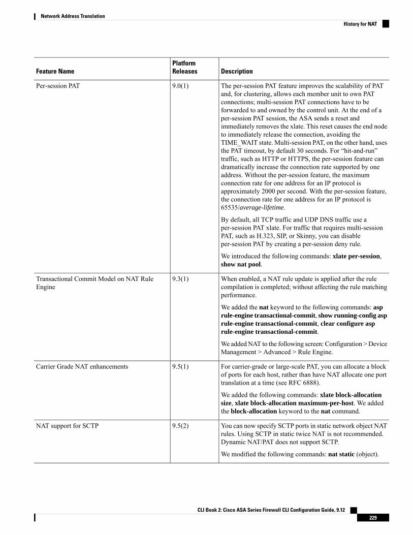
DescriptionPlatformReleasesFeature Name
The per-session PAT feature improves the scalability of PATand, for clustering, allows each member unit to own PATconnections; multi-session PAT connections have to beforwarded to and owned by the control unit. At the end of aper-session PAT session, the ASA sends a reset andimmediately removes the xlate. This reset causes the end nodeto immediately release the connection, avoiding theTIME_WAIT state. Multi-session PAT, on the other hand, usesthe PAT timeout, by default 30 seconds. For “hit-and-run”traffic, such as HTTP or HTTPS, the per-session feature candramatically increase the connection rate supported by oneaddress. Without the per-session feature, the maximumconnection rate for one address for an IP protocol isapproximately 2000 per second. With the per-session feature,the connection rate for one address for an IP protocol is65535/average-lifetime.
By default, all TCP traffic and UDP DNS traffic use aper-session PAT xlate. For traffic that requires multi-sessionPAT, such as H.323, SIP, or Skinny, you can disableper-session PAT by creating a per-session deny rule.
We introduced the following commands: xlate per-session,show nat pool.
9.0(1)Per-session PAT
When enabled, a NAT rule update is applied after the rulecompilation is completed; without affecting the rule matchingperformance.
We added the nat keyword to the following commands: asprule-engine transactional-commit, show running-config asprule-engine transactional-commit, clear configure asprule-engine transactional-commit.
We addedNAT to the following screen: Configuration >DeviceManagement > Advanced > Rule Engine.
9.3(1)Transactional Commit Model on NAT RuleEngine
For carrier-grade or large-scale PAT, you can allocate a blockof ports for each host, rather than have NAT allocate one porttranslation at a time (see RFC 6888).
We added the following commands: xlate block-allocationsize, xlate block-allocation maximum-per-host. We addedthe block-allocation keyword to the nat command.
9.5(1)Carrier Grade NAT enhancements
You can now specify SCTP ports in static network object NATrules. Using SCTP in static twice NAT is not recommended.Dynamic NAT/PAT does not support SCTP.
We modified the following commands: nat static (object).
9.5(2)NAT support for SCTP
CLI Book 2: Cisco ASA Series Firewall CLI Configuration Guide, 9.12229
Network Address TranslationHistory for NAT

DescriptionPlatformReleasesFeature Name
When you enable port block allocation for NAT, the systemgenerates syslog messages during port block creation anddeletion. If you enable interim logging, the system generatesmessage 305017 at the interval you specify. The messagesreport all active port blocks allocated at that time, includingthe protocol (ICMP, TCP, UDP) and source and destinationinterface and IP address, and the port block.
We added the following command: xlate block-allocationpba-interim-logging seconds.
9.12(1)Interim logging for NAT port block allocation.
CLI Book 2: Cisco ASA Series Firewall CLI Configuration Guide, 9.12230
Network Address TranslationHistory for NAT

C H A P T E R 11NAT Examples and Reference
The following topics provide examples for configuring NAT, plus information on advanced configurationand troubleshooting.
• Examples for Network Object NAT, on page 231• Examples for Twice NAT, on page 236• NAT in Routed and Transparent Mode, on page 240• Routing NAT Packets, on page 242• NAT for VPN, on page 245• Translating IPv6 Networks, on page 251• Rewriting DNS Queries and Responses Using NAT, on page 257
Examples for Network Object NATFollowing are some configuration examples for network object NAT.
Providing Access to an Inside Web Server (Static NAT)The following example performs static NAT for an inside web server. The real address is on a private network,so a public address is required. Static NAT is necessary so hosts can initiate traffic to the web server at a fixedaddress.
CLI Book 2: Cisco ASA Series Firewall CLI Configuration Guide, 9.12231

Figure 28: Static NAT for an Inside Web Server
Procedure
Step 1 Create a network object for the internal web server.
hostname(config)# object network myWebServhostname(config-network-object)# host 10.1.2.27
Step 2 Configure static NAT for the object:
hostname(config-network-object)# nat (inside,outside) static 209.165.201.10
NAT for Inside Hosts (Dynamic NAT) and NAT for an Outside Web Server(Static NAT)
The following example configures dynamic NAT for inside users on a private network when they access theoutside. Also, when inside users connect to an outside web server, that web server address is translated to anaddress that appears to be on the inside network.
CLI Book 2: Cisco ASA Series Firewall CLI Configuration Guide, 9.12232
Network Address TranslationNAT for Inside Hosts (Dynamic NAT) and NAT for an Outside Web Server (Static NAT)

Figure 29: Dynamic NAT for Inside, Static NAT for Outside Web Server
Procedure
Step 1 Create a network object for the dynamic NAT pool to which you want to translate the inside addresses.
hostname(config)# object network myNatPoolhostname(config-network-object)# range 209.165.201.20 209.165.201.30
Step 2 Create a network object for the inside network.
hostname(config)# object network myInsNethostname(config-network-object)# subnet 10.1.2.0 255.255.255.0
Step 3 Enable dynamic NAT for the inside network using the dynamic NAT pool object.
hostname(config-network-object)# nat (inside,outside) dynamic myNatPool
Step 4 Create a network object for the outside web server.
hostname(config)# object network myWebServhostname(config-network-object)# host 209.165.201.12
Step 5 Configure static NAT for the web server.
CLI Book 2: Cisco ASA Series Firewall CLI Configuration Guide, 9.12233
Network Address TranslationNAT for Inside Hosts (Dynamic NAT) and NAT for an Outside Web Server (Static NAT)

hostname(config-network-object)# nat (outside,inside) static 10.1.2.20
Inside Load Balancer with Multiple Mapped Addresses (Static NAT,One-to-Many)
The following example shows an inside load balancer that is translated to multiple IP addresses. When anoutside host accesses one of the mapped IP addresses, it is untranslated to the single load balancer address.Depending on the URL requested, it redirects traffic to the correct web server.
Figure 30: Static NAT with One-to-Many for an Inside Load Balancer
Procedure
Step 1 Create a network object for the addresses to which you want to map the load balancer.
hostname(config)# object network myPublicIPshostname(config-network-object)# range 209.165.201.3 209.265.201.8
Step 2 Create a network object for the load balancer.
CLI Book 2: Cisco ASA Series Firewall CLI Configuration Guide, 9.12234
Network Address TranslationInside Load Balancer with Multiple Mapped Addresses (Static NAT, One-to-Many)

hostname(config)# object network myLBHosthostname(config-network-object)# host 10.1.2.27
Step 3 Configure static NAT for the load balancer applying the range object.
hostname(config-network-object)# nat (inside,outside) static myPublicIPs
Single Address for FTP, HTTP, and SMTP (Static NAT-with-Port-Translation)The following static NAT-with-port-translation example provides a single address for remote users to accessFTP, HTTP, and SMTP. These servers are actually different devices on the real network, but for each server,you can specify static NAT-with-port-translation rules that use the same mapped IP address, but differentports.
Figure 31: Static NAT-with-Port-Translation
Procedure
Step 1 Create a network object for the FTP server and configure static NAT with port translation, mapping the FTPport to itself.
CLI Book 2: Cisco ASA Series Firewall CLI Configuration Guide, 9.12235
Network Address TranslationSingle Address for FTP, HTTP, and SMTP (Static NAT-with-Port-Translation)

hostname(config)# object network FTP_SERVERhostname(config-network-object)# host 10.1.2.27hostname(config-network-object)# nat (inside,outside) static 209.165.201.3 service tcp ftpftp
Step 2 Create a network object for the HTTP server and configure static NAT with port translation, mapping theHTTP port to itself.
hostname(config)# object network HTTP_SERVERhostname(config-network-object)# host 10.1.2.28hostname(config-network-object)# nat (inside,outside) static 209.165.201.3 service tcp httphttp
Step 3 Create a network object for the SMTP server and configure static NAT with port translation, mapping theSMTP port to itself.
hostname(config)# object network SMTP_SERVERhostname(config-network-object)# host 10.1.2.29hostname(config-network-object)# nat (inside,outside) static 209.165.201.3 service tcp smtpsmtp
Examples for Twice NATThis section includes the following configuration examples:
Different Translation Depending on the Destination (Dynamic Twice PAT)The following figure shows a host on the 10.1.2.0/24 network accessing two different servers. When the hostaccesses the server at 209.165.201.11, the real address is translated to 209.165.202.129:port. When the hostaccesses the server at 209.165.200.225, the real address is translated to 209.165.202.130:port.
CLI Book 2: Cisco ASA Series Firewall CLI Configuration Guide, 9.12236
Network Address TranslationExamples for Twice NAT

Figure 32: Twice NAT with Different Destination Addresses
Procedure
Step 1 Add a network object for the inside network:
hostname(config)# object network myInsideNetworkhostname(config-network-object)# subnet 10.1.2.0 255.255.255.0
Step 2 Add a network object for the DMZ network 1:
hostname(config)# object network DMZnetwork1hostname(config-network-object)# subnet 209.165.201.0 255.255.255.224
Step 3 Add a network object for the PAT address:
hostname(config)# object network PATaddress1hostname(config-network-object)# host 209.165.202.129
Step 4 Configure the first twice NAT rule:
hostname(config)# nat (inside,dmz) source dynamic myInsideNetwork PATaddress1destination static DMZnetwork1 DMZnetwork1
Because you do not want to translate the destination address, you need to configure identity NAT for it byspecifying the same address for the real and mapped destination addresses.
CLI Book 2: Cisco ASA Series Firewall CLI Configuration Guide, 9.12237
Network Address TranslationDifferent Translation Depending on the Destination (Dynamic Twice PAT)

Step 5 Add a network object for the DMZ network 2:
hostname(config)# object network DMZnetwork2hostname(config-network-object)# subnet 209.165.200.224 255.255.255.224
Step 6 Add a network object for the PAT address:
hostname(config)# object network PATaddress2hostname(config-network-object)# host 209.165.202.130
Step 7 Configure the second twice NAT rule:
Example:
hostname(config)# nat (inside,dmz) source dynamic myInsideNetwork PATaddress2destination static DMZnetwork2 DMZnetwork2
Different Translation Depending on the Destination Address and Port (DynamicPAT)
The following figure shows the use of source and destination ports. The host on the 10.1.2.0/24 networkaccesses a single host for both web services and Telnet services. When the host accesses the server for Telnetservices, the real address is translated to 209.165.202.129:port. When the host accesses the same server forweb services, the real address is translated to 209.165.202.130:port.
Figure 33: Twice NAT with Different Destination Ports
CLI Book 2: Cisco ASA Series Firewall CLI Configuration Guide, 9.12238
Network Address TranslationDifferent Translation Depending on the Destination Address and Port (Dynamic PAT)

Procedure
Step 1 Add a network object for the inside network:
hostname(config)# object network myInsideNetworkhostname(config-network-object)# subnet 10.1.2.0 255.255.255.0
Step 2 Add a network object for the Telnet/Web server:
hostname(config)# object network TelnetWebServerhostname(config-network-object)# host 209.165.201.11
Step 3 Add a network object for the PAT address when using Telnet:
hostname(config)# object network PATaddress1hostname(config-network-object)# host 209.165.202.129
Step 4 Add a service object for Telnet:
hostname(config)# object service TelnetObjhostname(config-network-object)# service tcp destination eq telnet
Step 5 Configure the first twice NAT rule:
hostname(config)# nat (inside,outside) source dynamic myInsideNetwork PATaddress1destination static TelnetWebServer TelnetWebServer service TelnetObj TelnetObj
Because you do not want to translate the destination address or port, you need to configure identity NAT forthem by specifying the same address for the real and mapped destination addresses, and the same port for thereal and mapped service.
Step 6 Add a network object for the PAT address when using HTTP:
hostname(config)# object network PATaddress2hostname(config-network-object)# host 209.165.202.130
Step 7 Add a service object for HTTP:
hostname(config)# object service HTTPObjhostname(config-network-object)# service tcp destination eq http
Step 8 Configure the second twice NAT rule:
hostname(config)# nat (inside,outside) source dynamic myInsideNetwork PATaddress2destination static TelnetWebServer TelnetWebServer service HTTPObj HTTPObj
CLI Book 2: Cisco ASA Series Firewall CLI Configuration Guide, 9.12239
Network Address TranslationDifferent Translation Depending on the Destination Address and Port (Dynamic PAT)

NAT in Routed and Transparent ModeYou can configure NAT in both routed and transparent firewall mode. The following sections describe typicalusage for each firewall mode.
NAT in Routed ModeThe following figure shows a typical NAT example in routed mode, with a private network on the inside.
Figure 34: NAT Example: Routed Mode
1. When the inside host at 10.1.2.27 sends a packet to a web server, the real source address of the packet,10.1.2.27, is translated to a mapped address, 209.165.201.10.
2. When the server responds, it sends the response to the mapped address, 209.165.201.10, and the ASAreceives the packet because the ASA performs proxy ARP to claim the packet.
3. The ASA then changes the translation of the mapped address, 209.165.201.10, back to the real address,10.1.2.27, before sending it to the host.
NAT in Transparent Mode or Within a Bridge GroupUsing NAT in transparent mode eliminates the need for the upstream or downstream routers to perform NATfor their networks. It can perform a similar function within a bridge group in routed mode.
NAT in transparent mode, or in routed mode between members of the same bridge group, has the followingrequirements and limitations:
• You cannot configure interface PAT when the mapped address is a bridge group member interface,because there is no IP address attached to the interface.
CLI Book 2: Cisco ASA Series Firewall CLI Configuration Guide, 9.12240
Network Address TranslationNAT in Routed and Transparent Mode

• ARP inspection is not supported. Moreover, if for some reason a host on one side of the ASA sends anARP request to a host on the other side of the ASA, and the initiating host real address is mapped to adifferent address on the same subnet, then the real address remains visible in the ARP request.
• Translating between IPv4 and IPv6 networks is not supported. Translating between two IPv6 networks,or between two IPv4 networks is supported.
The following figure shows a typical NAT scenario in transparent mode, with the same network on the insideand outside interfaces. The transparent firewall in this scenario is performing the NAT service so that theupstream router does not have to perform NAT.
Figure 35: NAT Example: Transparent Mode
1. When the inside host at 10.1.1.75 sends a packet to a web server, the real source address of the packet,10.1.1.75, is changed to a mapped address, 209.165.201.15.
2. When the server responds, it sends the response to the mapped address, 209.165.201.15, and the ASAreceives the packet because the upstream router includes this mapped network in a static route directedto the ASA management IP address.
3. The ASA then undoes the translation of the mapped address, 209.165.201.15, back to the real address,10.1.1.1.75. Because the real address is directly-connected, the ASA sends it directly to the host.
4. For host 192.168.1.2, the same process occurs, except for returning traffic, the ASA looks up the routein its routing table and sends the packet to the downstream router at 10.1.1.3 based on the ASA staticroute for 192.168.1.0/24.
CLI Book 2: Cisco ASA Series Firewall CLI Configuration Guide, 9.12241
Network Address TranslationNAT in Transparent Mode or Within a Bridge Group

Routing NAT PacketsThe ASA needs to be the destination for any packets sent to the mapped address. The ASA also needs todetermine the egress interface for any packets it receives destined for mapped addresses. This section describeshow the ASA handles accepting and delivering packets with NAT.
Mapped Addresses and RoutingWhen you translate the real address to a mapped address, the mapped address you choose determines how toconfigure routing, if necessary, for the mapped address.
See additional guidelines about mapped IP addresses in Additional Guidelines for NAT, on page 188.
The following topics explain the mapped address types.
Addresses on the Same Network as the Mapped InterfaceIf you use addresses on the same network as the destination (mapped) interface, the ASA uses proxy ARP toanswer any ARP requests for the mapped addresses, thus intercepting traffic destined for a mapped address.This solution simplifies routing because the ASA does not have to be the gateway for any additional networks.This solution is ideal if the outside network contains an adequate number of free addresses, a considerationif you are using a 1:1 translation like dynamic NAT or static NAT. Dynamic PAT greatly extends the numberof translations you can use with a small number of addresses, so even if the available addresses on the outsidenetwork is small, this method can be used. For PAT, you can even use the IP address of the mapped interface.
If you configure the mapped interface to be any interface, and you specify a mapped address on the samenetwork as one of the mapped interfaces, then if an ARP request for that mapped address comes in on adifferent interface, then you need to manually configure an ARP entry for that network on the ingress interface,specifying its MAC address. Typically, if you specify any interface for the mapped interface, then you use aunique network for the mapped addresses, so this situation would not occur. Configure ARP using the arpcommand.
Note
Addresses on a Unique NetworkIf you need more addresses than are available on the destination (mapped) interface network, you can identifyaddresses on a different subnet. The upstream router needs a static route for the mapped addresses that pointsto the ASA.
Alternatively for routed mode, you can configure a static route on the ASA for the mapped addresses usingany IP address on the destination network as the gateway, and then redistribute the route using your routingprotocol. For example, if you use NAT for the inside network (10.1.1.0/24) and use the mapped IP address209.165.201.5, then you can configure a static route for 209.165.201.5 255.255.255.255 (host address) to the10.1.1.99 gateway that can be redistributed.
route inside 209.165.201.5 255.255.255.255 10.1.1.99
CLI Book 2: Cisco ASA Series Firewall CLI Configuration Guide, 9.12242
Network Address TranslationRouting NAT Packets

For transparent mode, if the real host is directly-connected, configure the static route on the upstream routerto point to the ASA: specify the bridge group IP address. For remote hosts in transparent mode, in the staticroute on the upstream router, you can alternatively specify the downstream router IP address.
The Same Address as the Real Address (Identity NAT)The default behavior for identity NAT has proxy ARP enabled, matching other static NAT rules. You candisable proxy ARP if desired. You can also disable proxy ARP for regular static NAT if desired, in whichcase you need to be sure to have proper routes on the upstream router.
Normally for identity NAT, proxy ARP is not required, and in some cases can cause connectivity issues. Forexample, if you configure a broad identity NAT rule for “any” IP address, then leaving proxy ARP enabledcan cause problems for hosts on the network directly connected to the mapped interface. In this case, when ahost on the mapped network wants to communicate with another host on the same network, then the addressin the ARP request matches the NAT rule (which matches “any” address). The ASA will then proxy ARP forthe address, even though the packet is not actually destined for the ASA. (Note that this problem occurs evenif you have a twice NAT rule; although the NAT rule must match both the source and destination addresses,the proxy ARP decision is made only on the “source” address). If the ASA ARP response is received beforethe actual host ARP response, then traffic will be mistakenly sent to the ASA.
Figure 36: Proxy ARP Problems with Identity NAT
In rare cases, you need proxy ARP for identity NAT; for example for virtual Telnet. When using AAA fornetwork access, a host needs to authenticate with the ASA using a service like Telnet before any other trafficcan pass. You can configure a virtual Telnet server on the ASA to provide the necessary login.When accessingthe virtual Telnet address from the outside, you must configure an identity NAT rule for the address specificallyfor the proxy ARP functionality. Due to internal processes for virtual Telnet, proxy ARP lets the ASA keeptraffic destined for the virtual Telnet address rather than send the traffic out the source interface according tothe NAT rule. (See the following figure).
CLI Book 2: Cisco ASA Series Firewall CLI Configuration Guide, 9.12243
Network Address TranslationThe Same Address as the Real Address (Identity NAT)

Figure 37: Proxy ARP and Virtual Telnet
Transparent Mode Routing Requirements for Remote NetworksWhen you use NAT in transparent mode, some types of traffic require static routes. See the general operationsconfiguration guide for more information.
Determining the Egress InterfaceWhen you use NAT and the ASA receives traffic for a mapped address, then the ASA untranslates thedestination address according to the NAT rule, and then it sends the packet on to the real address. The ASAdetermines the egress interface for the packet in the following ways:
• Bridge group interfaces in Transparent mode or RoutedMode—TheASA determines the egress interfacefor the real address by using the NAT rule; you must specify the source and destination bridge groupmember interfaces as part of the NAT rule.
• Regular interfaces in Routed mode—The ASA determines the egress interface in one of the followingways:
• You configure the interface in the NAT rule—The ASA uses the NAT rule to determine the egressinterface. However, you have the option to always use a route lookup instead. In certain scenarios,a route lookup override is required.
• You do not configure the interface in the NAT rule—The ASA uses a route lookup to determinethe egress interface.
The following figure shows the egress interface selection method in routed mode. In almost all cases, a routelookup is equivalent to the NAT rule interface, but in some configurations, the two methods might differ.
CLI Book 2: Cisco ASA Series Firewall CLI Configuration Guide, 9.12244
Network Address TranslationTransparent Mode Routing Requirements for Remote Networks

Figure 38: Routed Mode Egress Interface Selection with NAT
NAT for VPNThe following topics explain NAT usage with the various types of VPN.
NAT and Remote Access VPNThe following figure shows both an inside server (10.1.1.6) and a VPN client (209.165.201.10) accessing theInternet. Unless you configure split tunneling for the VPN client (where only specified traffic goes throughthe VPN tunnel), then Internet-bound VPN traffic must also go through the ASA.When the VPN traffic entersthe ASA, the ASA decrypts the packet; the resulting packet includes the VPN client local address (10.3.3.10)as the source. For both inside and VPN client local networks, you need a public IP address provided by NATto access the Internet. The below example uses interface PAT rules. To allow the VPN traffic to exit the sameinterface it entered, you also need to enable intra-interface communication (also known as “hairpin” networking).
CLI Book 2: Cisco ASA Series Firewall CLI Configuration Guide, 9.12245
Network Address TranslationNAT for VPN

Figure 39: Interface PAT for Internet-Bound VPN Traffic (Intra-Interface)
The following figure shows a VPN client that wants to access an inside mail server. Because the ASA expectstraffic between the inside network and any outside network to match the interface PAT rule you set up forInternet access, traffic from the VPN client (10.3.3.10) to the SMTP server (10.1.1.6) will be dropped due toa reverse path failure: traffic from 10.3.3.10 to 10.1.1.6 does not match a NAT rule, but returning traffic from10.1.1.6 to 10.3.3.10 should match the interface PAT rule for outgoing traffic. Because forward and reverseflows do not match, the ASA drops the packet when it is received. To avoid this failure, you need to exemptthe inside-to-VPN client traffic from the interface PAT rule by using an identity NAT rule between thosenetworks. Identity NAT simply translates an address to the same address.
CLI Book 2: Cisco ASA Series Firewall CLI Configuration Guide, 9.12246
Network Address TranslationNAT and Remote Access VPN

Figure 40: Identity NAT for VPN Clients
See the following sample NAT configuration for the above network:
! Enable hairpin for non-split-tunneled VPN client traffic:same-security-traffic permit intra-interface
! Identify local VPN network, & perform object interface PAT when going to Internet:object network vpn_localsubnet 10.3.3.0 255.255.255.0nat (outside,outside) dynamic interface
! Identify inside network, & perform object interface PAT when going to Internet:object network inside_nwsubnet 10.1.1.0 255.255.255.0nat (inside,outside) dynamic interface
! Use twice NAT to pass traffic between the inside network and the VPN client without! address translation (identity NAT):nat (inside,outside) source static inside_nw inside_nw destination static vpn_local vpn_local
NAT and Site-to-Site VPNThe following figure shows a site-to-site tunnel connecting the Boulder and San Jose offices. For traffic thatyou want to go to the Internet (for example from 10.1.1.6 in Boulder to www.example.com), you need a publicIP address provided by NAT to access the Internet. The below example uses interface PAT rules. However,for traffic that you want to go over the VPN tunnel (for example from 10.1.1.6 in Boulder to 10.2.2.78 in San
CLI Book 2: Cisco ASA Series Firewall CLI Configuration Guide, 9.12247
Network Address TranslationNAT and Site-to-Site VPN

Jose), you do not want to perform NAT; you need to exempt that traffic by creating an identity NAT rule.Identity NAT simply translates an address to the same address.
Figure 41: Interface PAT and Identity NAT for Site-to-Site VPN
The following figure shows a VPN client connected to Firewall1 (Boulder), with a Telnet request for a server(10.2.2.78) accessible over a site-to-site tunnel between Firewall1 and Firewall2 (San Jose). Because this isa hairpin connection, you need to enable intra-interface communication, which is also required fornon-split-tunneled Internet-bound traffic from the VPN client. You also need to configure identity NATbetween the VPN client and the Boulder & San Jose networks, just as you would between any networksconnected by VPN to exempt this traffic from outbound NAT rules.
Figure 42: VPN Client Access to Site-to-Site VPN
See the following sample NAT configuration for Firewall1 (Boulder) for the second example:
CLI Book 2: Cisco ASA Series Firewall CLI Configuration Guide, 9.12248
Network Address TranslationNAT and Site-to-Site VPN

! Enable hairpin for VPN client traffic:same-security-traffic permit intra-interface
! Identify local VPN network, & perform object interface PAT when going to Internet:object network vpn_localsubnet 10.3.3.0 255.255.255.0nat (outside,outside) dynamic interface
! Identify inside Boulder network, & perform object interface PAT when going to Internet:object network boulder_insidesubnet 10.1.1.0 255.255.255.0nat (inside,outside) dynamic interface
! Identify inside San Jose network for use in twice NAT rule:object network sanjose_insidesubnet 10.2.2.0 255.255.255.0
! Use twice NAT to pass traffic between the Boulder network and the VPN client without! address translation (identity NAT):nat (inside,outside) source static boulder_inside boulder_insidedestination static vpn_local vpn_local
! Use twice NAT to pass traffic between the Boulder network and San Jose without! address translation (identity NAT):nat (inside,outside) source static boulder_inside boulder_insidedestination static sanjose_inside sanjose_inside
! Use twice NAT to pass traffic between the VPN client and San Jose without! address translation (identity NAT):nat (outside,outside) source static vpn_local vpn_localdestination static sanjose_inside sanjose_inside
See the following sample NAT configuration for Firewall2 (San Jose):
! Identify inside San Jose network, & perform object interface PAT when going to Internet:object network sanjose_insidesubnet 10.2.2.0 255.255.255.0nat (inside,outside) dynamic interface
! Identify inside Boulder network for use in twice NAT rule:object network boulder_insidesubnet 10.1.1.0 255.255.255.0
! Identify local VPN network for use in twice NAT rule:object network vpn_localsubnet 10.3.3.0 255.255.255.0
! Use twice NAT to pass traffic between the San Jose network and Boulder without! address translation (identity NAT):nat (inside,outside) source static sanjose_inside sanjose_insidedestination static boulder_inside boulder_inside
! Use twice NAT to pass traffic between the San Jose network and the VPN client without! address translation (identity NAT):nat (inside,outside) source static sanjose_inside sanjose_insidedestination static vpn_local vpn_local
CLI Book 2: Cisco ASA Series Firewall CLI Configuration Guide, 9.12249
Network Address TranslationNAT and Site-to-Site VPN

NAT and VPN Management AccessWhen using VPN, you can allowmanagement access to an interface other than the one fromwhich you enteredthe ASA (see the management-access command). For example, if you enter the ASA from the outsideinterface, the management-access feature lets you connect to the inside interface using ASDM, SSH, Telnet,or SNMP; or you can ping the inside interface.
The following figure shows a VPN client Telnetting to the ASA inside interface. When you use amanagement-access interface, and you configure identity NAT according to NAT and Remote Access VPN,on page 245 or NAT and Site-to-Site VPN, on page 247, you must configure NATwith the route lookup option.Without route lookup, the ASA sends traffic out the interface specified in the NAT command, regardless ofwhat the routing table says; in the below example, the egress interface is the inside interface. You do not wantthe ASA to send the management traffic out to the inside network; it will never return to the inside interfaceIP address. The route lookup option lets the ASA send the traffic directly to the inside interface IP addressinstead of to the inside network. For traffic from the VPN client to a host on the inside network, the routelookup option will still result in the correct egress interface (inside), so normal traffic flow is not affected.See the Determining the Egress Interface, on page 244 for more information about the route lookup option.
Figure 43: VPN Management Access
See the following sample NAT configuration for the above network:
! Enable hairpin for non-split-tunneled VPN client traffic:same-security-traffic permit intra-interface
! Enable management access on inside ifc:management-access inside
! Identify local VPN network, & perform object interface PAT when going to Internet:
CLI Book 2: Cisco ASA Series Firewall CLI Configuration Guide, 9.12250
Network Address TranslationNAT and VPN Management Access
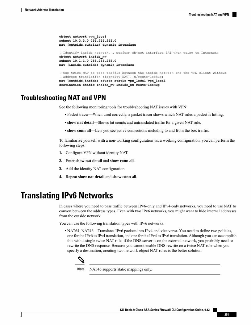
object network vpn_localsubnet 10.3.3.0 255.255.255.0nat (outside,outside) dynamic interface
! Identify inside network, & perform object interface PAT when going to Internet:object network inside_nwsubnet 10.1.1.0 255.255.255.0nat (inside,outside) dynamic interface
! Use twice NAT to pass traffic between the inside network and the VPN client without! address translation (identity NAT), w/route-lookup:nat (outside,inside) source static vpn_local vpn_localdestination static inside_nw inside_nw route-lookup
Troubleshooting NAT and VPNSee the following monitoring tools for troubleshooting NAT issues with VPN:
• Packet tracer—When used correctly, a packet tracer shows which NAT rules a packet is hitting.
• show nat detail—Shows hit counts and untranslated traffic for a given NAT rule.
• show conn all—Lets you see active connections including to and from the box traffic.
To familiarize yourself with a non-working configuration vs. a working configuration, you can perform thefollowing steps:
1. Configure VPN without identity NAT.
2. Enter show nat detail and show conn all.
3. Add the identity NAT configuration.
4. Repeat show nat detail and show conn all.
Translating IPv6 NetworksIn cases where you need to pass traffic between IPv6-only and IPv4-only networks, you need to use NAT toconvert between the address types. Even with two IPv6 networks, you might want to hide internal addressesfrom the outside network.
You can use the following translation types with IPv6 networks:
• NAT64, NAT46—Translates IPv6 packets into IPv4 and vice versa. You need to define two policies,one for the IPv6 to IPv4 translation, and one for the IPv4 to IPv6 translation. Although you can accomplishthis with a single twice NAT rule, if the DNS server is on the external network, you probably need torewrite the DNS response. Because you cannot enable DNS rewrite on a twice NAT rule when youspecify a destination, creating two network object NAT rules is the better solution.
NAT46 supports static mappings only.Note
CLI Book 2: Cisco ASA Series Firewall CLI Configuration Guide, 9.12251
Network Address TranslationTroubleshooting NAT and VPN

• NAT66—Translates IPv6 packets to a different IPv6 address.We recommend using static NAT. Althoughyou can use dynamic NAT or PAT, IPv6 addresses are in such large supply, you do not have to usedynamic NAT.
NAT64 and NAT 46 are possible on standard routed interfaces only. NAT66 is possible on both routed andbridge group member interfaces.
Note
NAT64/46: Translating IPv6 Addresses to IPv4When traffic goes from an IPv6 network to an IPv4-only network, you need to convert the IPv6 address toIPv4, and return traffic from IPv4 to IPv6. You need to define two address pools, an IPv4 address pool tobind IPv6 addresses in the IPv4 network, and an IPv6 address pool to bind IPv4 addresses in the IPv6 network.
• The IPv4 address pool for the NAT64 rule is normally small and typicallymight not have enough addressesto map one-to-one with the IPv6 client addresses. Dynamic PAT might more easily meet the possiblelarge number of IPv6 client addresses compared to dynamic or static NAT.
• The IPv6 address pool for the NAT46 rule can be equal to or larger than the number of IPv4 addressesto be mapped. This allows each IPv4 address to be mapped to a different IPv6 address. NAT46 supportsstatic mappings only, so you cannot use dynamic PAT.
You need to define two policies, one for the source IPv6 network, and one for the destination IPv4 network.Although you can accomplish this with a single twice NAT rule, if the DNS server is on the external network,you probably need to rewrite the DNS response. Because you cannot enable DNS rewrite on a twice NATrule when you specify a destination, creating two network object NAT rules is the better solution.
NAT64/46 Example: Inside IPv6 Network with Outside IPv4 InternetFollowing is a straight-forward example where you have an inside IPv6-only network, and you want to convertto IPv4 for traffic sent to the Internet. This example assumes you do not need DNS translation, so you canperform both the NAT64 and NAT46 translations in a single twice NAT rule.
CLI Book 2: Cisco ASA Series Firewall CLI Configuration Guide, 9.12252
Network Address TranslationNAT64/46: Translating IPv6 Addresses to IPv4
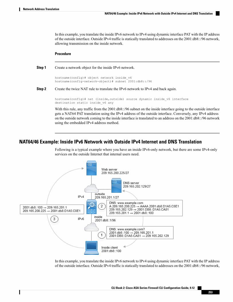
In this example, you translate the inside IPv6 network to IPv4 using dynamic interface PATwith the IP addressof the outside interface. Outside IPv4 traffic is statically translated to addresses on the 2001:db8::/96 network,allowing transmission on the inside network.
Procedure
Step 1 Create a network object for the inside IPv6 network.
hostname(config)# object network inside_v6hostname(config-network-object)# subnet 2001:db8::/96
Step 2 Create the twice NAT rule to translate the IPv6 network to IPv4 and back again.
hostname(config)# nat (inside,outside) source dynamic inside_v6 interfacedestination static inside_v6 any
With this rule, any traffic from the 2001:db8::/96 subnet on the inside interface going to the outside interfacegets a NAT64 PAT translation using the IPv4 address of the outside interface. Conversely, any IPv4 addresson the outside network coming to the inside interface is translated to an address on the 2001:db8::/96 networkusing the embedded IPv4 address method.
NAT64/46 Example: Inside IPv6 Network with Outside IPv4 Internet and DNS TranslationFollowing is a typical example where you have an inside IPv6-only network, but there are some IPv4-onlyservices on the outside Internet that internal users need.
In this example, you translate the inside IPv6 network to IPv4 using dynamic interface PATwith the IP addressof the outside interface. Outside IPv4 traffic is statically translated to addresses on the 2001:db8::/96 network,
CLI Book 2: Cisco ASA Series Firewall CLI Configuration Guide, 9.12253
Network Address TranslationNAT64/46 Example: Inside IPv6 Network with Outside IPv4 Internet and DNS Translation

allowing transmission on the inside network. You enable DNS rewrite on the NAT46 rule, so that replies fromthe external DNS server can be converted fromA (IPv4) to AAAA (IPv6) records, and the addresses convertedfrom IPv4 to IPv6.
Following is a typical sequence for a web request where a client at 2001:DB8::100 on the internal IPv6 networktries to open www.example.com.
1. The client’s computer sends a DNS request to the DNS server at 2001:DB8::D1A5:CA81. The NAT rulesmake the following translations to the source and destination in the DNS request:
• 2001:DB8::100 to a unique port on 209.165.201.1 (The NAT64 interface PAT rule.)
• 2001:DB8::D1A5:CA81 to 209.165.202.129 (The NAT46 rule. D1A5:CA81 is the IPv6 equivalentof 209.165.202.129.)
2. The DNS server responds with an A record indicating that www.example.com is at 209.165.200.225. TheNAT46 rule, with DNS rewrite enabled, converts the A record to the IPv6-equivalent AAAA record, andtranslates 209.165.200.225 to 2001:db8:D1A5:C8E1in the AAAA record. In addition, the source anddestination addresses in the DNS response are untranslated:
• 209.165.202.129 to 2001:DB8::D1A5:CA81
• 209.165.201.1 to 2001:db8::100
3. The IPv6 client now has the IP address of the web server, andmakes anHTTP request to www.example.comat 2001:db8:D1A5:C8E1. (D1A5:C8E1 is the IPv6 equivalent of 209.165.200.225.) The source anddestination of the HTTP request are translated:
• 2001:DB8::100 to a unique port on 209.156.101.54 (The NAT64 interface PAT rule.)
• 2001:db8:D1A5:C8E1 to 209.165.200.225 (The NAT46 rule.)
The following procedure explains how to configure this example.
Procedure
Step 1 Create a network object for the inside IPv6 network and add the NAT64 rule.
hostname(config)# object network inside_v6hostname(config-network-object)# subnet 2001:db8::/96hostname(config-network-object)# nat(inside,outside) dynamic interface
With this rule, any traffic from the 2001:db8::/96 subnet on the inside interface going to the outside interfacegets a NAT64 PAT translation using the IPv4 address of the outside interface.
Step 2 Create a network object for the IPv6 translated network for the outside IPv4 network and add the NAT46 rule.
hostname(config)# object network outside_v4_anyhostname(config-network-object)# subnet 0.0.0.0 0.0.0.0hostname(config-network-object)# nat(outside,inside) static 2001:db8::/96 dns
CLI Book 2: Cisco ASA Series Firewall CLI Configuration Guide, 9.12254
Network Address TranslationNAT64/46 Example: Inside IPv6 Network with Outside IPv4 Internet and DNS Translation

With this rule, any IPv4 address on the outside network coming to the inside interface is translated to anaddress on the 2001:db8::/96 network using the embedded IPv4 address method. In addition, DNS responsesare converted from A (IPv4) to AAAA (IPv6) records, and the addresses converted from IPv4 to IPv6.
NAT66: Translating IPv6 Addresses to Different IPv6 AddressesWhen going from an IPv6 network to another IPv6 network, you can translate the addresses to different IPv6addresses on the outside network. We recommend using static NAT. Although you can use dynamic NAT orPAT, IPv6 addresses are in such large supply, you do not have to use dynamic NAT.
Because you are not translating between different address types, you need a single rule for NAT66 translations.You can easily model these rules using network object NAT. However, if you do not want to allow returningtraffic, you can make the static NAT rule unidirectional using twice NAT only.
NAT66 Example, Static Translation between NetworksYou can configure a static translation between IPv6 address pools using network object NAT. The followingexample explains how to convert inside addresses on the 2001:db8:122:2091::/96 network to outside addresseson the 2001:db8:122:2999::/96 network.
Procedure
Create the network object for the inside IPv6 network and add the static NAT rule.
hostname(config)# object network inside_v6hostname(config-network-object)# subnet 2001:db8:122:2091::/96
CLI Book 2: Cisco ASA Series Firewall CLI Configuration Guide, 9.12255
Network Address TranslationNAT66: Translating IPv6 Addresses to Different IPv6 Addresses

hostname(config-network-object)# nat(inside,outside) static 2001:db8:122:2999::/96
With this rule, any traffic from the 2001:db8:122:2091::/96 subnet on the inside interface going to the outsideinterface gets a static NAT66 translation to an address on the 2001:db8:122:2999::/96 network.
NAT66 Example, Simple IPv6 Interface PATA simple approach for implementing NAT66 is to dynamically assign internal addresses to different ports onthe outside interface IPv6 address.
When you configure an interface PAT rule for NAT66, all the global addresses that are configured on thatinterface are used for PAT mapping. Link-local or site-local addresses for the interface are not used for PAT.
Procedure
Create the network object for the inside IPv6 network and add the dynamic PAT rule.
hostname(config)# object network inside_v6hostname(config-network-object)# subnet 2001:db8:122:2091::/96hostname(config-network-object)# nat(inside,outside) dynamic interface ipv6
With this rule, any traffic from the 2001:db8:122:2091::/96 subnet on the inside interface going to the outsideinterface gets a NAT66 PAT translation to one of the IPv6 global addresses configured for the outside interface.
CLI Book 2: Cisco ASA Series Firewall CLI Configuration Guide, 9.12256
Network Address TranslationNAT66 Example, Simple IPv6 Interface PAT

Rewriting DNS Queries and Responses Using NATYou might need to configure the ASA to modify DNS replies by replacing the address in the reply with anaddress that matches the NAT configuration. You can configure DNS modification when you configure eachtranslation rule. DNS modification is also known as DNS doctoring.
This feature rewrites the address in DNS queries and replies that match a NAT rule (for example, the A recordfor IPv4, the AAAA record for IPv6, or the PTR record for reverse DNS queries). For DNS replies traversingfrom amapped interface to any other interface, the record is rewritten from the mapped value to the real value.Inversely, for DNS replies traversing from any interface to a mapped interface, the record is rewritten fromthe real value to the mapped value. This feature works with NAT44,NAT 66, NAT46, and NAT64.
Following are the main circumstances when you would need to configure DNS rewrite on a NAT rule.
• The rule is NAT64 or NAT46, and the DNS server is on the outside network. You need DNS rewrite toconvert between DNS A records (for IPv4) and AAAA records (for IPv6).
• The DNS server is on the outside, clients are on the inside, and some of the fully-qualified domain namesthat the clients use resolve to other inside hosts.
• The DNS server is on the inside and responds with private IP addresses, clients are on the outside, andthe clients access fully-qualified domain names that point to servers that are hosted on the inside.
DNS Rewrite Limitations
Following are some limitations with DNS rewrite:
• DNS rewrite is not applicable for PAT because multiple PAT rules are applicable for each A or AAAArecord, and the PAT rule to use is ambiguous.
• If you configure a twice NAT rule, you cannot configure DNSmodification if you specify the destinationaddress as well as the source address. These kinds of rules can potentially have a different translationfor a single address when going to A vs. B. Therefore, the can not accurately match the IP address insidethe DNS reply to the correct twice NAT rule; the DNS reply does not contain information about whichsource/destination address combination was in the packet that prompted the DNS request.
• You must enable DNS application inspection with DNS NAT rewrite enabled for NAT rules to rewriteDNS queries and responses. By default, DNS inspection with DNS NAT rewrite enabled is globallyapplied, so you probably do not need to change the inspection configuration.
• DNS rewrite is actually done on the xlate entry, not the NAT rule. Thus, if there is no xlate for a dynamicrule, rewrite cannot be done correctly. The same problem does not occur for static NAT.
• DNS rewrite does not rewrite DNS Dynamic Update messages (opcode 5).
The following topics provide examples of DNS rewrite in NAT rules.
DNS Reply Modification, DNS Server on OutsideThe following figure shows a DNS server that is accessible from the outside interface. A server, ftp.cisco.com,is on the inside interface. You configure NAT to statically translate the ftp.cisco.com real address (10.1.3.14)to a mapped address (209.165.201.10) that is visible on the outside network.
CLI Book 2: Cisco ASA Series Firewall CLI Configuration Guide, 9.12257
Network Address TranslationRewriting DNS Queries and Responses Using NAT
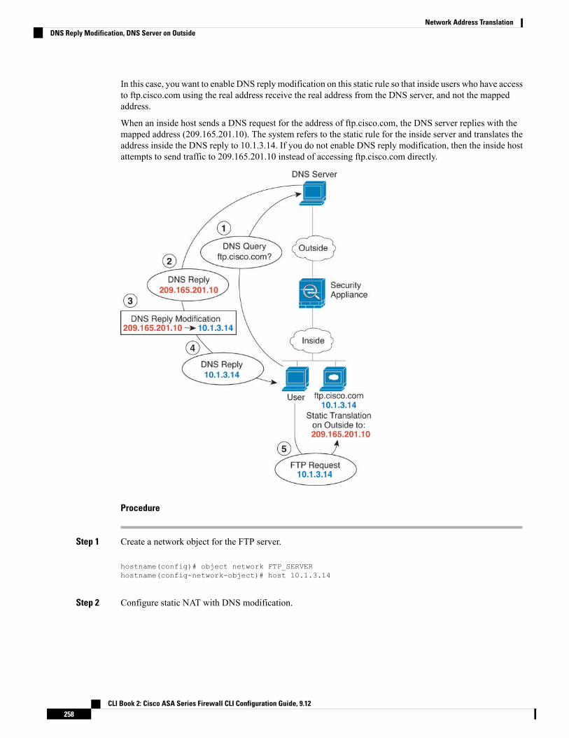
In this case, you want to enable DNS reply modification on this static rule so that inside users who have accessto ftp.cisco.com using the real address receive the real address from the DNS server, and not the mappedaddress.
When an inside host sends a DNS request for the address of ftp.cisco.com, the DNS server replies with themapped address (209.165.201.10). The system refers to the static rule for the inside server and translates theaddress inside the DNS reply to 10.1.3.14. If you do not enable DNS reply modification, then the inside hostattempts to send traffic to 209.165.201.10 instead of accessing ftp.cisco.com directly.
Procedure
Step 1 Create a network object for the FTP server.
hostname(config)# object network FTP_SERVERhostname(config-network-object)# host 10.1.3.14
Step 2 Configure static NAT with DNS modification.
CLI Book 2: Cisco ASA Series Firewall CLI Configuration Guide, 9.12258
Network Address TranslationDNS Reply Modification, DNS Server on Outside

hostname(config-network-object)# nat (inside,outside) static 209.165.201.10 dns
DNS Reply Modification, DNS Server, Host, and Server on Separate NetworksThe following figure shows a user on the inside network requesting the IP address for ftp.cisco.com, whichis on the DMZ network, from an outside DNS server. The DNS server replies with the mapped address(209.165.201.10) according to the static rule between outside and DMZ even though the user is not on theDMZ network. The ASA translates the address inside the DNS reply to 10.1.3.14.
If the user needs to access ftp.cisco.com using the real address, then no further configuration is required. Ifthere is also a static rule between the inside and DMZ, then you also need to enable DNS reply modificationon this rule. The DNS reply will then be modified two times.In this case, the ASA again translates the addressinside the DNS reply to 192.168.1.10 according to the static rule between inside and DMZ.
Figure 44: DNS Reply Modification, DNS Server, Host, and Server on Separate Networks
DNS Reply Modification, DNS Server on Host NetworkThe following figure shows an FTP server and DNS server on the outside. The system has a static translationfor the outside server. In this case, when an inside user requests the address for ftp.cisco.com from the DNSserver, the DNS server responds with the real address, 209.165.20.10. Because you want inside users to usethe mapped address for ftp.cisco.com (10.1.2.56) you need to configure DNS reply modification for the statictranslation.
CLI Book 2: Cisco ASA Series Firewall CLI Configuration Guide, 9.12259
Network Address TranslationDNS Reply Modification, DNS Server, Host, and Server on Separate Networks
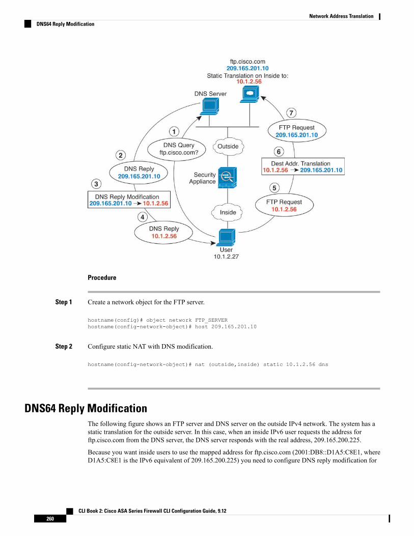
Procedure
Step 1 Create a network object for the FTP server.
hostname(config)# object network FTP_SERVERhostname(config-network-object)# host 209.165.201.10
Step 2 Configure static NAT with DNS modification.
hostname(config-network-object)# nat (outside,inside) static 10.1.2.56 dns
DNS64 Reply ModificationThe following figure shows an FTP server and DNS server on the outside IPv4 network. The system has astatic translation for the outside server. In this case, when an inside IPv6 user requests the address forftp.cisco.com from the DNS server, the DNS server responds with the real address, 209.165.200.225.
Because you want inside users to use the mapped address for ftp.cisco.com (2001:DB8::D1A5:C8E1, whereD1A5:C8E1 is the IPv6 equivalent of 209.165.200.225) you need to configure DNS reply modification for
CLI Book 2: Cisco ASA Series Firewall CLI Configuration Guide, 9.12260
Network Address TranslationDNS64 Reply Modification

the static translation. This example also includes a static NAT translation for the DNS server, and a PAT rulefor the inside IPv6 hosts.
Procedure
Step 1 Create a network object for the FTP server and configure static NAT with DNS modification. Because thisis a one-to-one translation, include the net-to-net option for NAT46.
hostname(config)# object network FTP_SERVERhostname(config-network-object)# host 209.165.200.225hostname(config-network-object)# nat (outside,inside) static 2001:DB8::D1A5:C8E1/128net-to-net dns
Step 2 Create a network object for the DNS server and configure static NAT. Include the net-to-net option forNAT46.
hostname(config)# object network DNS_SERVERhostname(config-network-object)# host 209.165.201.15hostname(config-network-object)# nat (outside,inside) static 2001:DB8::D1A5:C90F/128net-to-net
Step 3 Configure an IPv4 PAT pool for translating the inside IPv6 network.
CLI Book 2: Cisco ASA Series Firewall CLI Configuration Guide, 9.12261
Network Address TranslationDNS64 Reply Modification
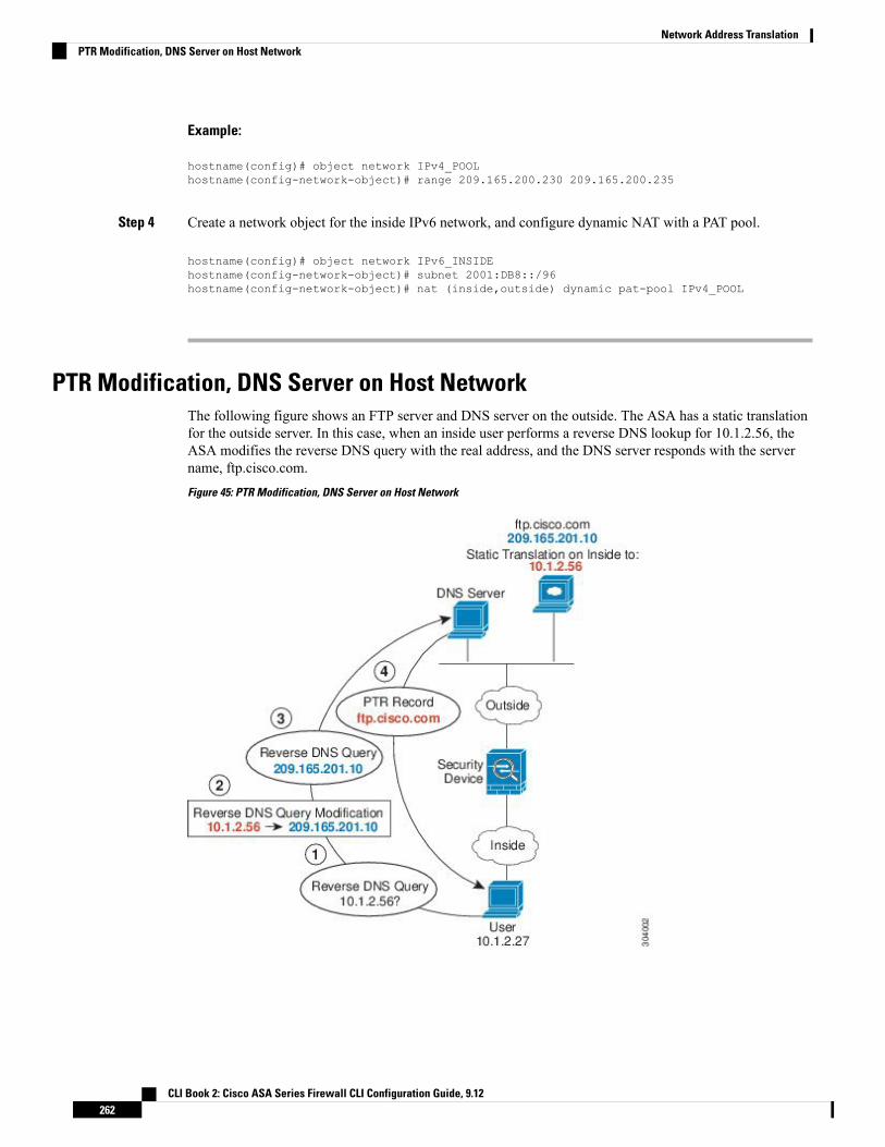
Example:
hostname(config)# object network IPv4_POOLhostname(config-network-object)# range 209.165.200.230 209.165.200.235
Step 4 Create a network object for the inside IPv6 network, and configure dynamic NAT with a PAT pool.
hostname(config)# object network IPv6_INSIDEhostname(config-network-object)# subnet 2001:DB8::/96hostname(config-network-object)# nat (inside,outside) dynamic pat-pool IPv4_POOL
PTR Modification, DNS Server on Host NetworkThe following figure shows an FTP server and DNS server on the outside. The ASA has a static translationfor the outside server. In this case, when an inside user performs a reverse DNS lookup for 10.1.2.56, theASA modifies the reverse DNS query with the real address, and the DNS server responds with the servername, ftp.cisco.com.
Figure 45: PTR Modification, DNS Server on Host Network
CLI Book 2: Cisco ASA Series Firewall CLI Configuration Guide, 9.12262
Network Address TranslationPTR Modification, DNS Server on Host Network
P A R T IVService Policies and Application Inspection
• Service Policy, on page 265• Getting Started with Application Layer Protocol Inspection, on page 287• Inspection of Basic Internet Protocols, on page 309• Inspection for Voice and Video Protocols, on page 349• Inspection for Mobile Networks, on page 373


C H A P T E R 12Service Policy
Service policies using Modular Policy Framework provide a consistent and flexible way to configure ASAfeatures. For example, you can use a service policy to create a timeout configuration that is specific to aparticular TCP application, as opposed to one that applies to all TCP applications. A service policy consistsof multiple actions or rules applied to an interface or applied globally.
• About Service Policies, on page 265• Guidelines for Service Policies, on page 271• Defaults for Service Policies, on page 273• Configure Service Policies, on page 275• Monitoring Service Policies, on page 282• Examples for Service Policies (Modular Policy Framework), on page 282• History for Service Policies, on page 285
About Service PoliciesThe following topics describe how service policies work.
The Components of a Service PolicyThe point of service policies is to apply advanced services to the traffic you are allowing. Any traffic permittedby access rules can have service policies applied, and thus receive special processing, such as being redirectedto a service module or having application inspection applied.
You can have these types of service policy:
• One global policy that gets applied to all interfaces.
• One service policy applied per interface. The policy can be a mix of classes for traffic going through thedevice and management traffic directed at the ASA interface rather than going through it,
Each service policy is composed of the following elements:
1. Service policy map, which is the ordered set of rules, and is named on the service-policy command. InASDM, the policy map is represented as a folder on the Service Policy Rules page.
2. Rules, each rule being a class command within the service policy map and the commands associated withthe class command. In ASDM, each rule is shown on a separate row, and the name of the rule is the classname.
CLI Book 2: Cisco ASA Series Firewall CLI Configuration Guide, 9.12265

The class command defines the traffic matching criteria for the rule.
The commands associated with class, such as inspect, set connection timeout, and so forth, define theservices and constraints to apply to matching traffic. Note that inspect commands can point to inspectionpolicy maps, which define actions to apply to inspected traffic. Keep in mind that inspection policy mapsare not the same as service policy maps.
The following example compares how service policies appear in the CLI with how they appear in ASDM.Note that there is not a one-to-one mapping between the figure call-outs and lines in the CLI.
The following CLI is generated by the rules shown in the figure above.
: Access lists used in class maps.: In ASDM, these map to call-out 3, from the Match to the Time fields.access-list inside_mpc line 1 extended permit tcp 10.100.10.0 255.255.255.0 any eq sipaccess-list inside_mpc_1 line 1 extended deny udp host 10.1.1.15 any eq snmpaccess-list inside_mpc_1 line 2 extended permit udp 10.1.1.0 255.255.255.0 any eq snmpaccess-list inside_mpc_2 line 1 extended permit icmp any any: SNMP map for SNMP inspection. Denies all but v3.: In ASDM, this maps to call-out 4, rule actions, for the class-inside policy.snmp-map snmp-v3onlydeny version 1deny version 2deny version 2c
: Inspection policy map to define SIP behavior.: The sip-high inspection policy map must be referred to by an inspect sip command: in the service policy map.: In ASDM, this maps to call-out 4, rule actions, for the sip-class-inside policy.policy-map type inspect sip sip-highparametersrtp-conformance enforce-payloadtypeno traffic-non-sipsoftware-version action mask loguri-non-sip action mask logstate-checking action drop-connection logmax-forwards-validation action drop logstrict-header-validation action drop log
: Class map to define traffic matching for the inside-class rule.: In ASDM, this maps to call-out 3, from the Match to the Time fields.class-map inside-classmatch access-list inside_mpc_1
: Class map to define traffic matching for the sip-class-inside rule.: In ASDM, this maps to call-out 3, from the Match to the Time fields.class-map sip-class-insidematch access-list inside_mpc
: Class map to define traffic matching for the inside-class1 rule.: In ASDM, this maps to call-out 3, from the Match to the Time fields.
CLI Book 2: Cisco ASA Series Firewall CLI Configuration Guide, 9.12266
Service Policies and Application InspectionThe Components of a Service Policy

class-map inside-class1match access-list inside_mpc_2
: Policy map that actually defines the service policy rule set named test-inside-policy.: In ASDM, this corresponds to the folder at call-out 1.policy-map test-inside-policy: First rule in test-inside-policy, named sip-class-inside. Inspects SIP traffic.: The sip-class-inside rule applies the sip-high inspection policy map to SIP inspection.: In ASDM, each rule corresponds to call-out 2.class sip-class-insideinspect sip sip-high
: Second rule, inside-class. Applies SNMP inspection using an SNMP map.class inside-classinspect snmp snmp-v3only
: Third rule, inside-class1. Applies ICMP inspection.class inside-class1inspect icmp
: Fourth rule, class-default. Applies connection settings and enables user statistics.class class-defaultset connection timeout embryonic 0:00:30 half-closed 0:10:00 idle 1:00:00
reset dcd 0:15:00 5user-statistics accounting
: The service-policy command applies the policy map rule set to the inside interface.: This command activates the policies.service-policy test-inside-policy interface inside
Features Configured with Service PoliciesThe following table lists the features you configure using service policies.
Table 10: Features Configured with Service Policies
See:For ManagementTraffic?
For ThroughTraffic?Feature
• Getting Started with Application Layer ProtocolInspection, on page 287.
• Inspection of Basic Internet Protocols, on page 309.
• Inspection for Voice and Video Protocols, on page349.
• Inspection for Mobile Networks, on page 373.
RADIUSaccounting only
All exceptRADIUSaccounting
Application inspection (multipletypes)
ASA FirePOWER Module, on page 115.NoYesASA FirePOWER (ASA SFR)
See the NetFlow implementation guide.YesYesNetFlow Secure Event Loggingfiltering
Quality of Service, on page 447.NoYesQoS input and output policing
Quality of Service, on page 447.NoYesQoS standard priority queue
Connection Settings, on page 419.YesYesTCP and UDP connection limitsand timeouts, and TCP sequencenumber randomization
Connection Settings, on page 419.NoYesTCP normalization
CLI Book 2: Cisco ASA Series Firewall CLI Configuration Guide, 9.12267
Service Policies and Application InspectionFeatures Configured with Service Policies

See:For ManagementTraffic?
For ThroughTraffic?Feature
Connection Settings, on page 419.NoYesTCP state bypass
See the user-statistics command in the commandreference.
YesYesUser statistics for Identity Firewall
Feature DirectionalityActions are applied to traffic bidirectionally or unidirectionally depending on the feature. For features thatare applied bidirectionally, all traffic that enters or exits the interface to which you apply the policy map isaffected if the traffic matches the class map for both directions.
When you use a global policy, all features are unidirectional; features that are normally bidirectional whenapplied to a single interface only apply to the ingress of each interface when applied globally. Because thepolicy is applied to all interfaces, the policy will be applied in both directions so bidirectionality in this caseis redundant.
Note
For features that are applied unidirectionally, for example QoS priority queue, only traffic that enters (or exits,depending on the feature) the interface to which you apply the policy map is affected. See the following tablefor the directionality of each feature.
Table 11: Feature Directionality
Global DirectionSingle Interface DirectionFeature
IngressBidirectionalApplication inspection (multiple types)
IngressBidirectionalASA FirePOWER (ASA SFR)
IngressN/ANetFlow Secure Event Logging filtering
IngressIngressQoS input policing
EgressEgressQoS output policing
EgressEgressQoS standard priority queue
IngressBidirectionalTCP and UDP connection limits and timeouts, andTCP sequence number randomization
IngressBidirectionalTCP normalization
IngressBidirectionalTCP state bypass
IngressBidirectionalUser statistics for Identity Firewall
CLI Book 2: Cisco ASA Series Firewall CLI Configuration Guide, 9.12268
Service Policies and Application InspectionFeature Directionality

Feature Matching Within a Service PolicyA packet matches class maps in a policy map for a given interface according to the following rules:
1. A packet can match only one class map in the policy map for each feature type.
2. When the packet matches a class map for a feature type, the ASA does not attempt to match it to anysubsequent class maps for that feature type.
3. If the packet matches a subsequent class map for a different feature type, however, then the ASA alsoapplies the actions for the subsequent class map, if supported. See Incompatibility of Certain FeatureActions, on page 270 for more information about unsupported combinations.
Application inspection includes multiple inspection types, and most are mutually exclusive. For inspectionsthat can be combined, each inspection is considered to be a separate feature.
Note
Examples of Packet Matching
For example:
• If a packet matches a class map for connection limits, and also matches a class map for an applicationinspection, then both actions are applied.
• If a packet matches a class map for HTTP inspection, but also matches another class map that includesHTTP inspection, then the second class map actions are not applied.
• If a packet matches a class map for HTTP inspection, but also matches another class map that includesFTP inspection, then the second class map actions are not applied because HTTP and FTP inspectionscannot be combined.
• If a packet matches a class map for HTTP inspection, but also matches another class map that includesIPv6 inspection, then both actions are applied because the IPv6 inspection can be combined with anyother type of inspection.
Order in Which Multiple Feature Actions are AppliedThe order in which different types of actions in a policy map are performed is independent of the order inwhich the actions appear in the policy map.
Actions are performed in the following order:
1. QoS input policing
2. TCP normalization, TCP and UDP connection limits and timeouts, TCP sequence number randomization,and TCP state bypass.
When a the ASA performs a proxy service (such as AAA) or it modifies the TCP payload (such as FTPinspection), the TCP normalizer acts in dual mode, where it is applied before and after the proxy or payloadmodifying service.
Note
CLI Book 2: Cisco ASA Series Firewall CLI Configuration Guide, 9.12269
Service Policies and Application InspectionFeature Matching Within a Service Policy

3. Application inspections that can be combined with other inspections:
a. IPv6
b. IP options
c. WAAS
4. Application inspections that cannot be combined with other inspections. See Incompatibility of CertainFeature Actions, on page 270 for more information.
5. ASA FirePOWER (ASA SFR)
6. QoS output policing
7. QoS standard priority queue
NetFlow Secure Event Logging filtering and User statistics for Identity Firewall are order-independent.Note
Incompatibility of Certain Feature ActionsSome features are not compatible with each other for the same traffic. The following list might not includeall incompatibilities; for information about compatibility of each feature, see the chapter or section for thefeature:
• You cannot configure QoS priority queuing and QoS policing for the same set of traffic.
• Most inspections should not be combined with another inspection, so the ASA only applies one inspectionif you configure multiple inspections for the same traffic. Exceptions are listed in Order inWhichMultipleFeature Actions are Applied, on page 269.
• You cannot configure traffic to be sent to multiple modules.
• HTTP inspection is not compatible with ASA FirePOWER.
The match default-inspection-traffic command, which is used in the default global policy, is a special CLIshortcut to match the default ports for all inspections. When used in a policy map, this class map ensures thatthe correct inspection is applied to each packet, based on the destination port of the traffic. For example, whenUDP traffic for port 69 reaches the ASA, then the ASA applies the TFTP inspection; when TCP traffic forport 21 arrives, then the ASA applies the FTP inspection. So in this case only, you can configure multipleinspections for the same class map. Normally, the ASA does not use the port number to determine whichinspection to apply, thus giving you the flexibility to apply inspections to non-standard ports, for example.
Note
An example of a misconfiguration is if you configure multiple inspections in the same policy map and do notuse the default-inspection-traffic shortcut. In the first example, traffic destined to port 21 is mistakenlyconfigured for both FTP and HTTP inspection. In the second example, traffic destined to port 80 is mistakenlyconfigured for both FTP and HTTP inspection. In both cases of misconfiguration examples, only the FTPinspection is applied, because FTP comes before HTTP in the order of inspections applied.
CLI Book 2: Cisco ASA Series Firewall CLI Configuration Guide, 9.12270
Service Policies and Application InspectionIncompatibility of Certain Feature Actions

Example 1: Misconfiguration for FTP packets: HTTP Inspection Also Configured
class-map ftpmatch port tcp eq 21
class-map httpmatch port tcp eq 21 [it should be 80]
policy-map testclass ftpinspect ftp
class httpinspect http
Example 2: Misconfiguration for HTTP packets: FTP Inspection Also Configured
class-map ftpmatch port tcp eq 80 [it should be 21]
class-map httpmatch port tcp eq 80
policy-map testclass ftpinspect ftp
class httpinspect http
Feature Matching for Multiple Service PoliciesFor TCP and UDP traffic (and ICMP when you enable stateful ICMP inspection), service policies operate ontraffic flows, and not just individual packets. If traffic is part of an existing connection that matches a featurein a policy on one interface, that traffic flow cannot also match the same feature in a policy on another interface;only the first policy is used.
For example, if HTTP traffic matches a policy on the inside interface to inspect HTTP traffic, and you havea separate policy on the outside interface for HTTP inspection, then that traffic is not also inspected on theegress of the outside interface. Similarly, the return traffic for that connection will not be inspected by theingress policy of the outside interface, nor by the egress policy of the inside interface.
For traffic that is not treated as a flow, for example ICMP when you do not enable stateful ICMP inspection,returning traffic can match a different policy map on the returning interface.
Guidelines for Service PoliciesInspection Guidelines
There is a separate topic that provides detailed guidelines for application inspection service policies. SeeGuidelines for Application Inspection, on page 289.
IPv6 Guidelines
Supports IPv6 for the following features:
• Application inspection for several, but not all, protocols. For details, see Guidelines for ApplicationInspection, on page 289.
CLI Book 2: Cisco ASA Series Firewall CLI Configuration Guide, 9.12271
Service Policies and Application InspectionFeature Matching for Multiple Service Policies

• ASA FirePOWER
• NetFlow Secure Event Logging filtering
• SCTP state bypass
• TCP and UDP connection limits and timeouts, TCP sequence number randomization
• TCP normalization
• TCP state bypass
• User statistics for Identity Firewall
Class Map (Traffic Class) Guidelines
The maximum number of class maps (traffic classes) of all types is 255 in single mode or per context inmultiple mode. Class maps include the following types:
• Layer 3/4 class maps (for through traffic and management traffic).
• Inspection class maps
• Regular expression class maps
• match commands used directly underneath an inspection policy map
This limit also includes default class maps of all types, limiting user-configured class maps to approximately235.
Policy Map Guidelines
See the following guidelines for using policy maps:
• You can only assign one policy map per interface. However you can create up to 64 policy maps in theconfiguration.
• You can apply the same policy map to multiple interfaces.
• You can identify up to 63 Layer 3/4 class maps in a Layer 3/4 policy map.
• For each class map, you can assign multiple actions from one or more feature types, if supported. SeeIncompatibility of Certain Feature Actions, on page 270.
Service Policy Guidelines
• Interface service policies on ingress interfaces take precedence over the global service policy for a givenfeature. For example, if you have a global policy with FTP inspection, and an interface policy with TCPnormalization, then both FTP inspection and TCP normalization are applied to the interface. However,if you have a global policy with FTP inspection, and an ingress interface policy with FTP inspection,then only the ingress interface policy FTP inspection is applied to that interface. If no ingress or globalpolicy implements a feature, then an interface service policy on the egress interface that specifies thefeature is applied.
• You can only apply one global policy. For example, you cannot create a global policy that includesfeature set 1, and a separate global policy that includes feature set 2. All features must be included in asingle policy.
CLI Book 2: Cisco ASA Series Firewall CLI Configuration Guide, 9.12272
Service Policies and Application InspectionGuidelines for Service Policies

• When you make service policy changes to the configuration, all new connections use the new servicepolicy. Existing connections continue to use the policy that was configured at the time of the connectionestablishment. Output for the show command will not include data about the old connections.
For example, if you remove a QoS service policy from an interface, then add a modified version, thenthe show service-policy command only displays QoS counters associated with new connections thatmatch the new service policy; existing connections on the old policy no longer show in the commandoutput.
To ensure that all connections use the new policy, you need to disconnect the current connections so theycan reconnect using the new policy. Use the clear conn or clear local-host commands.
Defaults for Service PoliciesThe following topics describe the default settings for service policies and the Modular Policy Framework.
Default Service Policy ConfigurationBy default, the configuration includes a policy that matches all default application inspection traffic and appliescertain inspections to the traffic on all interfaces (a global policy). Not all inspections are enabled by default.You can only apply one global policy, so if you want to alter the global policy, you need to either edit thedefault policy or disable it and apply a new one. (An interface policy overrides the global policy for a particularfeature.)
The default policy includes the following application inspections:
• DNS
• FTP
• H323 (H225)
• H323 (RAS)
• RSH
• RTSP
• ESMTP
• SQLnet
• Skinny (SCCP)
• SunRPC
• SIP
• NetBios
• TFTP
• IP Options
The default policy configuration includes the following commands:
CLI Book 2: Cisco ASA Series Firewall CLI Configuration Guide, 9.12273
Service Policies and Application InspectionDefaults for Service Policies

class-map inspection_defaultmatch default-inspection-trafficpolicy-map type inspect dns preset_dns_mapparametersmessage-length maximum client automessage-length maximum 512dns-guardprotocol-enforcementnat-rewritepolicy-map global_policyclass inspection_defaultinspect dns preset_dns_mapinspect ftpinspect h323 h225 _default_h323_mapinspect h323 ras _default_h323_mapinspect ip-options _default_ip_options_mapinspect netbiosinspect rshinspect rtspinspect skinnyinspect esmtp _default_esmtp_mapinspect sqlnetinspect sunrpcinspect tftpinspect sipservice-policy global_policy global
Default Class Maps (Traffic Classes)The configuration includes a default Layer 3/4 class map (traffic class) that the ASA uses in the default globalpolicy called default-inspection-traffic; it matches the default inspection traffic. This class, which is used inthe default global policy, is a special shortcut to match the default ports for all inspections.
When used in a policy, this class ensures that the correct inspection is applied to each packet, based on thedestination port of the traffic. For example, when UDP traffic for port 69 reaches the ASA, then the ASAapplies the TFTP inspection; when TCP traffic for port 21 arrives, then the ASA applies the FTP inspection.So in this case only, you can configure multiple inspections for the same class map. Normally, the ASA doesnot use the port number to determine which inspection to apply, thus giving you the flexibility to applyinspections to non-standard ports, for example.
class-map inspection_defaultmatch default-inspection-traffic
Another class map that exists in the default configuration is called class-default, and it matches all traffic.This class map appears at the end of all Layer 3/4 policy maps and essentially tells the ASA to not performany actions on all other traffic. You can use the class-default class if desired, rather than making your ownmatch any class map. In fact, some features are only available for class-default.
class-map class-defaultmatch any
CLI Book 2: Cisco ASA Series Firewall CLI Configuration Guide, 9.12274
Service Policies and Application InspectionDefault Class Maps (Traffic Classes)

Configure Service PoliciesTo configure service policies using the Modular Policy Framework, perform the following steps:
Procedure
Step 1 Identify the traffic on which you want to act by creating Layer 3/4 class maps, as described in Identify Traffic(Layer 3/4 Class Maps), on page 276.
For example, you might want to perform actions on all traffic that passes through the ASA; or you might onlywant to perform certain actions on traffic from 10.1.1.0/24 to any destination address.
Step 2 Optionally, perform additional actions on some inspection traffic.
If one of the actions you want to perform is application inspection, and you want to perform additional actionson some inspection traffic, then create an inspection policy map. The inspection policy map identifies thetraffic and specifies what to do with it.
For example, you might want to drop all HTTP requests with a body length greater than 1000 bytes.
You can create a self-contained inspection policy map that identifies the traffic directly withmatch commands,or you can create an inspection class map for reuse or for more complicated matching. For example, you couldmatch text within a inspected packets using a regular expression or a group of regular expressions (a regularexpression class map), and target actions based on narrower criteria. For example, you might want to drop allHTTP requests with a URL including the text “example.com.”
CLI Book 2: Cisco ASA Series Firewall CLI Configuration Guide, 9.12275
Service Policies and Application InspectionConfigure Service Policies

See Configure Application Layer Protocol Inspection, on page 295.
Step 3 Define the actions you want to perform on each Layer 3/4 class map by creating a Layer 3/4 policy map, asdescribed in Define Actions (Layer 3/4 Policy Map), on page 280.
Step 4 Determine on which interfaces you want to apply the policy map, or apply it globally, as described in ApplyActions to an Interface (Service Policy), on page 281.
Identify Traffic (Layer 3/4 Class Maps)A Layer 3/4 class map identifies Layer 3 and 4 traffic to which you want to apply actions. You can createmultiple Layer 3/4 class maps for each Layer 3/4 policy map.
Create a Layer 3/4 Class Map for Through TrafficALayer 3/4 class mapmatches traffic based on protocols, ports, IP addresses and other Layer 3 or 4 attributes.
We suggest that you only inspect traffic on ports on which you expect application traffic; if you inspect alltraffic, for example using match any, the ASA performance can be impacted.
Tip
CLI Book 2: Cisco ASA Series Firewall CLI Configuration Guide, 9.12276
Service Policies and Application InspectionIdentify Traffic (Layer 3/4 Class Maps)
Procedure
Step 1 Create a Layer 3/4 class map: class-map class_map_name
Where class_map_name is a string up to 40 characters in length.
The name “class-default” is reserved. All types of class maps use the same name space, so you cannot reusea name already used by another type of class map. The CLI enters class-map configuration mode.
Example:
hostname(config)# class-map all_udp
Step 2 (Optional) Add a description to the class map.
description string
Example:
hostname(config-cmap)# description All UDP traffic
Step 3 Match traffic using one of the following commands. Unless otherwise specified, you can include only onematch command in the class map.
• match any—Matches all traffic.
hostname(config-cmap)# match any
• match access-list access_list_name—Matches traffic specified by an extended ACL.
hostname(config-cmap)# match access-list udp
• match port {tcp | udp | sctp} {eq port_num | range port_num port_num}—Matches destination ports,either a single port or a contiguous range of ports, for the indicated protocol. For applications that usemultiple, non-contiguous ports, use the match access-list command and define an ACE to match eachport.
hostname(config-cmap)# match tcp eq 80
• match default-inspection-traffic—Matches default traffic for inspection: the default TCP and UDPports used by all applications that the ASA can inspect.
hostname(config-cmap)# match default-inspection-traffic
This command, which is used in the default global policy, is a special CLI shortcut that when used in apolicy map, ensures that the correct inspection is applied to each packet, based on the destination portof the traffic. For example, when UDP traffic for port 69 reaches the ASA, then the ASA applies theTFTP inspection; when TCP traffic for port 21 arrives, then the ASA applies the FTP inspection. So inthis case only, you can configure multiple inspections for the same class map (with the exception ofWAAS inspection, which can be configured with other inspections. See Incompatibility of Certain Feature
CLI Book 2: Cisco ASA Series Firewall CLI Configuration Guide, 9.12277
Service Policies and Application InspectionCreate a Layer 3/4 Class Map for Through Traffic

Actions, on page 270 for more information about combining actions). Normally, the ASA does not usethe port number to determine the inspection applied, thus giving you the flexibility to apply inspectionsto non-standard ports, for example.
See Default Inspections and NAT Limitations, on page 291 for a list of default ports. Not all applicationswhose ports are included in the match default-inspection-traffic command are enabled by default inthe policy map.
You can specify amatch access-list command alongwith thematch default-inspection-traffic commandto narrow the matched traffic. Because the match default-inspection-traffic command specifies theports and protocols to match, any ports and protocols in the ACL are ignored.
• match dscp value1 [value2] [...] [value8]—Matches the DSCP value in an IP header, up to eight DSCPvalues.
hostname(config-cmap)# match dscp af43 cs1 ef
• match precedence value1 [value2] [value3] [value4]—Matches up to four precedence values, representedby the TOS byte in the IP header, where the precedence values can be 0 to 7.
hostname(config-cmap)# match precedence 1 4
• match rtp starting_port range—Matches RTP traffic, where the starting_port specifies an even-numberedUDP destination port between 2000 and 65534. The range specifies the number of additional UDP portsto match above the starting_port, between 0 and 16383.
hostname(config-cmap)# match rtp 4004 100
• match tunnel-group name—Matches VPN tunnel group traffic to which you want to apply QoS.
You can also specify one other match command to refine the traffic match. You can specify any of thepreceding commands, except for thematch any,match access-list, ormatch default-inspection-trafficcommands. Or you can also enter the match flow ip destination-address command to match flows inthe tunnel group going to each IP address.
hostname(config-cmap)# match tunnel-group group1hostname(config-cmap)# match flow ip destination-address
Examples
The following is an example for the class-map command:
hostname(config)# access-list udp permit udp any anyhostname(config)# access-list tcp permit tcp any anyhostname(config)# access-list host_foo permit ip any 10.1.1.1 255.255.255.255
hostname(config)# class-map all_udphostname(config-cmap)# description "This class-map matches all UDP traffic"hostname(config-cmap)# match access-list udp
CLI Book 2: Cisco ASA Series Firewall CLI Configuration Guide, 9.12278
Service Policies and Application InspectionCreate a Layer 3/4 Class Map for Through Traffic
hostname(config-cmap)# class-map all_tcphostname(config-cmap)# description "This class-map matches all TCP traffic"hostname(config-cmap)# match access-list tcp
hostname(config-cmap)# class-map all_httphostname(config-cmap)# description "This class-map matches all HTTP traffic"hostname(config-cmap)# match port tcp eq http
hostname(config-cmap)# class-map to_serverhostname(config-cmap)# description "This class-map matches all traffic to server 10.1.1.1"hostname(config-cmap)# match access-list host_foo
Create a Layer 3/4 Class Map for Management TrafficFor management traffic to the ASA, you might want to perform actions specific to this kind of traffic. Youcan specify a management class map that can match an ACL or TCP or UDP ports. The types of actionsavailable for a management class map in the policy map are specialized for management traffic.
Procedure
Step 1 Create a management class map: class-map type management class_map_name
Where class_map_name is a string up to 40 characters in length.
The name “class-default” is reserved. All types of class maps use the same name space, so you cannot reusea name already used by another type of class map. The CLI enters class-map configuration mode.
Example:
hostname(config)# class-map management all_udp
Step 2 (Optional) Add a description to the class map.
description string
Example:
hostname(config-cmap)# description All UDP traffic
Step 3 Match traffic using one of the following commands.
• match access-list access_list_name—Matches traffic specified by an extended ACL.
hostname(config-cmap)# match access-list udp
• match port {tcp | udp | sctp} {eq port_num | range port_num port_num}—Matches destination ports,either a single port or a contiguous range of ports, for the indicated protocol. For applications that usemultiple, non-contiguous ports, use the match access-list command and define an ACE to match eachport.
CLI Book 2: Cisco ASA Series Firewall CLI Configuration Guide, 9.12279
Service Policies and Application InspectionCreate a Layer 3/4 Class Map for Management Traffic

hostname(config-cmap)# match tcp eq 80
Define Actions (Layer 3/4 Policy Map)After you configure Layer 3/4 class maps to identify traffic, use a Layer 3/4 policy map to associate actionsto those classes.
The maximum number of policy maps is 64, but you can only apply one policy map per interface.Tip
Procedure
Step 1 Add the policy map: policy-map policy_map_name
Where policy_map_name is the name of the policy map, up to 40 characters in length. All types of policymaps use the same name space, so you cannot reuse a name already used by another type of policy map. TheCLI enters policy-map configuration mode.
Example:
hostname(config)# policy-map global_policy
Step 2 Specify a previously configured Layer 3/4 class map: class class_map_name
Where the class_map_name is the name of the class map.
See Identify Traffic (Layer 3/4 Class Maps), on page 276 to add a class map.
Example:
hostname(config-pmap)# class all_http
Step 3 Specify one or more actions for this class map.
See Features Configured with Service Policies, on page 267.
If there is no match default-inspection-traffic command in a class map, then at most one inspectcommand is allowed to be configured under the class.
Note
Step 4 Repeat the process for each class map you want to include in this policy map.
Examples
The following is an example of a policy-map command for a connection policy. It limits the numberof connections allowed to the web server 10.1.1.1:
CLI Book 2: Cisco ASA Series Firewall CLI Configuration Guide, 9.12280
Service Policies and Application InspectionDefine Actions (Layer 3/4 Policy Map)

hostname(config)# access-list http-server permit tcp any host 10.1.1.1hostname(config)# class-map http-serverhostname(config-cmap)# match access-list http-server
hostname(config)# policy-map global-policyhostname(config-pmap)# description This policy map defines a policy concerningconnection to http server.hostname(config-pmap)# class http-serverhostname(config-pmap-c)# set connection conn-max 256
The following example shows how multi-match works in a policy map:
hostname(config)# class-map inspection_defaulthostname(config-cmap)# match default-inspection-traffichostname(config)# class-map http_traffichostname(config-cmap)# match port tcp eq 80
hostname(config)# policy-map outside_policyhostname(config-pmap)# class inspection_defaulthostname(config-pmap-c)# inspect http http_maphostname(config-pmap-c)# inspect siphostname(config-pmap)# class http_traffichostname(config-pmap-c)# set connection timeout idle 0:10:0
The following example shows how traffic matches the first available class map, and will not matchany subsequent class maps that specify actions in the same feature domain:
hostname(config)# class-map telnet_traffichostname(config-cmap)# match port tcp eq 23hostname(config)# class-map ftp_traffichostname(config-cmap)# match port tcp eq 21hostname(config)# class-map tcp_traffichostname(config-cmap)# match port tcp range 1 65535hostname(config)# class-map udp_traffichostname(config-cmap)# match port udp range 0 65535hostname(config)# policy-map global_policyhostname(config-pmap)# class telnet_traffichostname(config-pmap-c)# set connection timeout idle 0:0:0hostname(config-pmap-c)# set connection conn-max 100hostname(config-pmap)# class ftp_traffichostname(config-pmap-c)# set connection timeout idle 0:5:0hostname(config-pmap-c)# set connection conn-max 50hostname(config-pmap)# class tcp_traffichostname(config-pmap-c)# set connection timeout idle 2:0:0hostname(config-pmap-c)# set connection conn-max 2000
When a Telnet connection is initiated, it matches class telnet_traffic. Similarly, if an FTP connectionis initiated, it matches class ftp_traffic. For any TCP connection other than Telnet and FTP, it willmatch class tcp_traffic. Even though a Telnet or FTP connection can match class tcp_traffic, theASA does not make this match because they previously matched other classes.
Apply Actions to an Interface (Service Policy)To activate the Layer 3/4 policy map, create a service policy that applies it to one or more interfaces or thatapplies it globally to all interfaces. Use the following command:
CLI Book 2: Cisco ASA Series Firewall CLI Configuration Guide, 9.12281
Service Policies and Application InspectionApply Actions to an Interface (Service Policy)

service-policy policy_map_name {global | interface interface_name} [fail-close]
Where:
• policy_map_name is the name of the policy map.
• global creates a service policy that applies to all interfaces that do not have a specific policy.
You can only apply one global policy, so if you want to alter the global policy, you need to either editthe default policy or disable it and apply a new one. By default, the configuration includes a global policythat matches all default application inspection traffic and applies inspection to the traffic globally. Thedefault service policy includes the following command: service-policy global_policy global.
• interface interface_name creates a service policy by associating a policy map with an interface.
• fail-close generates a syslog (767001) for IPv6 traffic that is dropped by application inspections that donot support IPv6 traffic. By default, syslogs are not generated.
Examples
For example, the following command enables the inbound_policy policy map on the outside interface:
hostname(config)# service-policy inbound_policy interface outside
The following commands disable the default global policy, and enables a new one called new_global_policy.
hostname(config)# no service-policy global_policy globalhostname(config)# service-policy new_global_policy global
Monitoring Service PoliciesTo monitor service policies, enter the following command:
• show service-policy
Displays the service policy statistics.
Examples for Service Policies (Modular Policy Framework)This section includes several Modular Policy Framework examples.
Applying Inspection and QoS Policing to HTTP TrafficIn this example, any HTTP connection (TCP traffic on port 80) that enters or exits the ASA through the outsideinterface is classified for HTTP inspection. Any HTTP traffic that exits the outside interface is classified forpolicing.
CLI Book 2: Cisco ASA Series Firewall CLI Configuration Guide, 9.12282
Service Policies and Application InspectionMonitoring Service Policies

Figure 46: HTTP Inspection and QoS Policing
See the following commands for this example:
hostname(config)# class-map http_traffichostname(config-cmap)# match port tcp eq 80
hostname(config)# policy-map http_traffic_policyhostname(config-pmap)# class http_traffichostname(config-pmap-c)# inspect httphostname(config-pmap-c)# police output 250000hostname(config)# service-policy http_traffic_policy interface outside
Applying Inspection to HTTP Traffic GloballyIn this example, any HTTP connection (TCP traffic on port 80) that enters the ASA through any interface isclassified for HTTP inspection. Because the policy is a global policy, inspection occurs only as the trafficenters each interface.
Figure 47: Global HTTP Inspection
See the following commands for this example:
hostname(config)# class-map http_traffichostname(config-cmap)# match port tcp eq 80
hostname(config)# policy-map http_traffic_policyhostname(config-pmap)# class http_traffichostname(config-pmap-c)# inspect httphostname(config)# service-policy http_traffic_policy global
CLI Book 2: Cisco ASA Series Firewall CLI Configuration Guide, 9.12283
Service Policies and Application InspectionApplying Inspection to HTTP Traffic Globally

Applying Inspection and Connection Limits to HTTP Traffic to Specific ServersIn this example, any HTTP connection destined for Server A (TCP traffic on port 80) that enters the ASAthrough the outside interface is classified for HTTP inspection and maximum connection limits. Connectionsinitiated from Server A to Host A do not match the ACL in the class map, so they are not affected.
Any HTTP connection destined for Server B that enters the ASA through the inside interface is classified forHTTP inspection. Connections initiated from Server B to Host B do not match the ACL in the class map, sothey are not affected.
Figure 48: HTTP Inspection and Connection Limits to Specific Servers
See the following commands for this example:
hostname(config)# object network obj-192.168.1.2hostname(config-network-object)# host 192.168.1.2hostname(config-network-object)# nat (inside,outside) static 209.165.201.1hostname(config)# object network obj-192.168.1.0hostname(config-network-object)# subnet 192.168.1.0 255.255.255.0hostname(config-network-object)# nat (inside,outside) dynamic 209.165.201.2hostname(config)# access-list serverA extended permit tcp any host 209.165.201.1 eq 80hostname(config)# access-list ServerB extended permit tcp any host 209.165.200.227 eq 80
hostname(config)# class-map http_serverAhostname(config-cmap)# match access-list serverAhostname(config)# class-map http_serverBhostname(config-cmap)# match access-list serverB
hostname(config)# policy-map policy_serverAhostname(config-pmap)# class http_serverAhostname(config-pmap-c)# inspect httphostname(config-pmap-c)# set connection conn-max 100hostname(config)# policy-map policy_serverBhostname(config-pmap)# class http_serverBhostname(config-pmap-c)# inspect http
hostname(config)# service-policy policy_serverB interface insidehostname(config)# service-policy policy_serverA interface outside
CLI Book 2: Cisco ASA Series Firewall CLI Configuration Guide, 9.12284
Service Policies and Application InspectionApplying Inspection and Connection Limits to HTTP Traffic to Specific Servers

Applying Inspection to HTTP Traffic with NATIn this example, the Host on the inside network has two addresses: one is the real IP address 192.168.1.1, andthe other is a mapped IP address used on the outside network, 209.165.200.225. You must use the real IPaddress in the ACL in the class map. If you applied it to the outside interface, you would also use the realaddress.
Figure 49: HTTP Inspection with NAT
See the following commands for this example:
hostname(config)# object network obj-192.168.1.1hostname(config-network-object)# host 192.168.1.1hostname(config-network-object)# nat (VM1,outside) static 209.165.200.225
hostname(config)# access-list http_client extended permit tcp host 192.168.1.1 any eq 80
hostname(config)# class-map http_clienthostname(config-cmap)# match access-list http_client
hostname(config)# policy-map http_clienthostname(config-pmap)# class http_clienthostname(config-pmap-c)# inspect http
hostname(config)# service-policy http_client interface inside
History for Service PoliciesDescriptionReleasesFeature Name
Modular Policy Frameworkwas introduced.7.0(1)Modular Policy Framework
Themanagement class mapwas introducedfor use with RADIUS accounting traffic.The following commands were introduced:class-map type management, and inspectradius-accounting.
7.2(1)Management class map for use withRADIUS accounting traffic
The inspection policy map was introduced.The following command was introduced:class-map type inspect.
7.2(1)Inspection policy maps
CLI Book 2: Cisco ASA Series Firewall CLI Configuration Guide, 9.12285
Service Policies and Application InspectionApplying Inspection to HTTP Traffic with NAT
DescriptionReleasesFeature Name
Regular expressions and policy maps wereintroduced to be used under inspectionpolicy maps. The following commandswere introduced: class-map type regex,regex, match regex.
7.2(1)Regular expressions and policy maps
The match any keyword was introducedfor use with inspection policy maps: trafficcanmatch one or more criteria to match theclass map. Formerly, only match all wasavailable.
8.0(2)Match any for inspection policy maps
CLI Book 2: Cisco ASA Series Firewall CLI Configuration Guide, 9.12286
Service Policies and Application InspectionHistory for Service Policies

C H A P T E R 13Getting Started with Application Layer ProtocolInspection
The following topics describe how to configure application layer protocol inspection.
• Application Layer Protocol Inspection, on page 287• Configure Application Layer Protocol Inspection, on page 295• Configure Regular Expressions, on page 302• Monitoring Inspection Policies, on page 305• History for Application Inspection, on page 307
Application Layer Protocol InspectionInspection engines are required for services that embed IP addressing information in the user data packet orthat open secondary channels on dynamically assigned ports. These protocols require the ASA to do a deeppacket inspection instead of passing the packet through the fast path. As a result, inspection engines can affectoverall throughput. Several common inspection engines are enabled on the ASA by default, but you mightneed to enable others depending on your network.
The following topics explain application inspection in more detail.
When to Use Application Protocol InspectionWhen a user establishes a connection, the ASA checks the packet against ACLs, creates an address translation,and creates an entry for the session in the fast path, so that further packets can bypass time-consuming checks.However, the fast path relies on predictable port numbers and does not perform address translations inside apacket.
Many protocols open secondary TCP or UDP ports. The initial session on a well-known port is used to negotiatedynamically assigned port numbers.
Other applications embed an IP address in the packet that needs to match the source address that is normallytranslated when it goes through the ASA.
If you use applications like these, then you need to enable application inspection.
When you enable application inspection for a service that embeds IP addresses, the ASA translates embeddedaddresses and updates any checksum or other fields that are affected by the translation.
CLI Book 2: Cisco ASA Series Firewall CLI Configuration Guide, 9.12287

When you enable application inspection for a service that uses dynamically assigned ports, the ASAmonitorssessions to identify the dynamic port assignments, and permits data exchange on these ports for the durationof the specific session.
Inspection Policy MapsYou can configure special actions for many application inspections using an inspection policy map. Thesemaps are optional: you can enable inspection for a protocol that supports inspection policy maps withoutconfiguring a map. These maps are needed only if you want something other than the default inspectionactions.
An inspection policy map consists of one or more of the following elements. The exact options available foran inspection policy map depends on the application.
• Traffic matching criteria—You match application traffic to criteria specific to the application, such as aURL string, for which you then enable actions.
For some traffic matching criteria, you use regular expressions to match text inside a packet. Be sure tocreate and test the regular expressions before you configure the policy map, either singly or groupedtogether in a regular expression class map.
• Inspection class map—Some inspection policy maps let you use an inspection class map to includemultiple traffic matching criteria. You then identify the inspection class map in the inspection policymap and enable actions for the class as a whole. The difference between creating a class map and definingthe traffic match directly in the inspection policy map is that you can create more complex match criteriaand you can reuse class maps. However, you cannot set different actions for different matches.
• Parameters—Parameters affect the behavior of the inspection engine.
The following topics provide more details.
Replacing an In-Use Inspection Policy MapIf you have an inspection enabled with a policy map in a service policy, replacing the policy map is a two-stepprocess. First, you must remove the inspection. Then, you add it back with the new policy map name.
For example, to replace sip-map1 with sip-map2 in SIP inspection, use the following command sequence:
hostname(config)# policy-map testhostname(config-pmap)# class siphostname(config-pmap-c)# no inspect sip sip-map1hostname(config-pmap-c)# inspect sip sip-map2
How Multiple Traffic Classes are HandledYou can specify multiple inspection class maps or direct matches in the inspection policy map.
If a packet matches multiple different classes or direct matches, then the order in which the ASA applies theactions is determined by internal ASA rules, and not by the order they are added to the inspection policy map.The internal rules are determined by the application type and the logical progression of parsing a packet, andare not user-configurable. For example for HTTP traffic, parsing a Request Method field precedes parsingthe Header Host Length field; an action for the Request Method field occurs before the action for the HeaderHost Length field. For example, the following match commands can be entered in any order, but the matchrequest method get command is matched first.
CLI Book 2: Cisco ASA Series Firewall CLI Configuration Guide, 9.12288
Service Policies and Application InspectionInspection Policy Maps

match request header host length gt 100reset
match request method getlog
If an action drops a packet, then no further actions are performed in the inspection policy map. For example,if the first action is to reset the connection, then it will never match any further match criteria. If the first actionis to log the packet, then a second action, such as resetting the connection, can occur.
If a packet matches multiple match criteria that are the same, then they are matched in the order they appearin the policy map. For example, for a packet with the header length of 1001, it will match the first commandbelow, and be logged, and then will match the second command and be reset. If you reverse the order of thetwomatch commands, then the packet will be dropped and the connection reset before it can match the secondmatch command; it will never be logged.
match request header length gt 100log
match request header length gt 1000reset
A class map is determined to be the same type as another class map or direct match based on the lowest prioritymatch option in the class map (the priority is based on the internal rules). If a class map has the same type oflowest priority match option as another class map, then the class maps are matched according to the orderthey are added to the policy map. If the lowest priority match for each class map is different, then the classmap with the higher priority match option is matched first. For example, the following three class maps containtwo types of match commands: match request-cmd (higher priority) and match filename (lower priority).The ftp3 class map includes both commands, but it is ranked according to the lowest priority command,matchfilename. The ftp1 class map includes the highest priority command, so it is matched first, regardless of theorder in the policy map. The ftp3 class map is ranked as being of the same priority as the ftp2 class map,which also contains the match filename command. They are matched according to the order in the policymap: ftp3 and then ftp2.
class-map type inspect ftp match-all ftp1match request-cmd get
class-map type inspect ftp match-all ftp2match filename regex abc
class-map type inspect ftp match-all ftp3match request-cmd getmatch filename regex abc
policy-map type inspect ftp ftpclass ftp3log
class ftp2log
class ftp1log
Guidelines for Application Inspection
Failover
State information for multimedia sessions that require inspection are not passed over the state link for statefulfailover. The exceptions are GTP,M3UA, and SIP, which are replicated over the state link. Youmust configurestrict application server process (ASP) state checking in M3UA inspection to get stateful failover.
CLI Book 2: Cisco ASA Series Firewall CLI Configuration Guide, 9.12289
Service Policies and Application InspectionGuidelines for Application Inspection

Clustering
The following inspections are not supported in clustering:
• CTIQBE
• H323, H225, and RAS
• IPsec passthrough
• MGCP
• MMP
• RTSP
• SCCP (Skinny)
• WAAS
IPv6
Supports IPv6 for the following inspections:
• Diameter
• DNS over UDP
• FTP
• GTP
• HTTP
• ICMP
• IPsec pass-through
• IPv6
• M3UA
• SCCP (Skinny)
• SCTP
• SIP
• SMTP
• VXLAN
Supports NAT64 for the following inspections:
• DNS over UDP
• FTP
• HTTP
• ICMP
CLI Book 2: Cisco ASA Series Firewall CLI Configuration Guide, 9.12290
Service Policies and Application InspectionGuidelines for Application Inspection
• SCTP
Additional Guidelines
• Some inspection engines do not support PAT, NAT, outside NAT, or NAT between same securityinterfaces. For more information about NAT support, see Default Inspections and NAT Limitations, onpage 291.
• For all the application inspections, the ASA limits the number of simultaneous, active data connectionsto 200 connections. For example, if an FTP client opens multiple secondary connections, the FTPinspection engine allows only 200 active connections and the 201 connection is dropped and the adaptivesecurity appliance generates a system error message.
• Inspected protocols are subject to advanced TCP-state tracking, and the TCP state of these connectionsis not automatically replicated. While these connections are replicated to the standby unit, there is abest-effort attempt to re-establish a TCP state.
• If the system determines that a TCP connection requires inspection, the system clears all TCP optionsexcept for the MSS and selective-acknowledgment (SACK) options on the packets before inspectingthem. Other options are cleared even if you allow them in a TCP map applied to the connections.
• TCP/UDP Traffic directed to the ASA (to an interface) is inspected by default. However, ICMP trafficdirected to an interface is never inspected, even if you enable ICMP inspection. Thus, a ping (echorequest) to an interface can fail under specific circumstances, such as when the echo request comes froma source that the ASA can reach through a backup default route.
Defaults for Application InspectionThe following topics explain the default operations for application inspection.
Default Inspections and NAT LimitationsBy default, the configuration includes a policy that matches all default application inspection traffic and appliesinspection to the traffic on all interfaces (a global policy). Default application inspection traffic includes trafficto the default ports for each protocol. You can only apply one global policy, so if you want to alter the globalpolicy, for example, to apply inspection to non-standard ports, or to add inspections that are not enabled bydefault, you need to either edit the default policy or disable it and apply a new one.
The following table lists all inspections supported, the default ports used in the default class map, and theinspection engines that are on by default, shown in bold. This table also notes any NAT limitations. In thistable:
• Inspection engines that are enabled by default for the default port are in bold.
• The ASA is in compliance with the indicated standards, but it does not enforce compliance on packetsbeing inspected. For example, FTP commands are supposed to be in a particular order, but the ASA doesnot enforce the order.
CLI Book 2: Cisco ASA Series Firewall CLI Configuration Guide, 9.12291
Service Policies and Application InspectionDefaults for Application Inspection
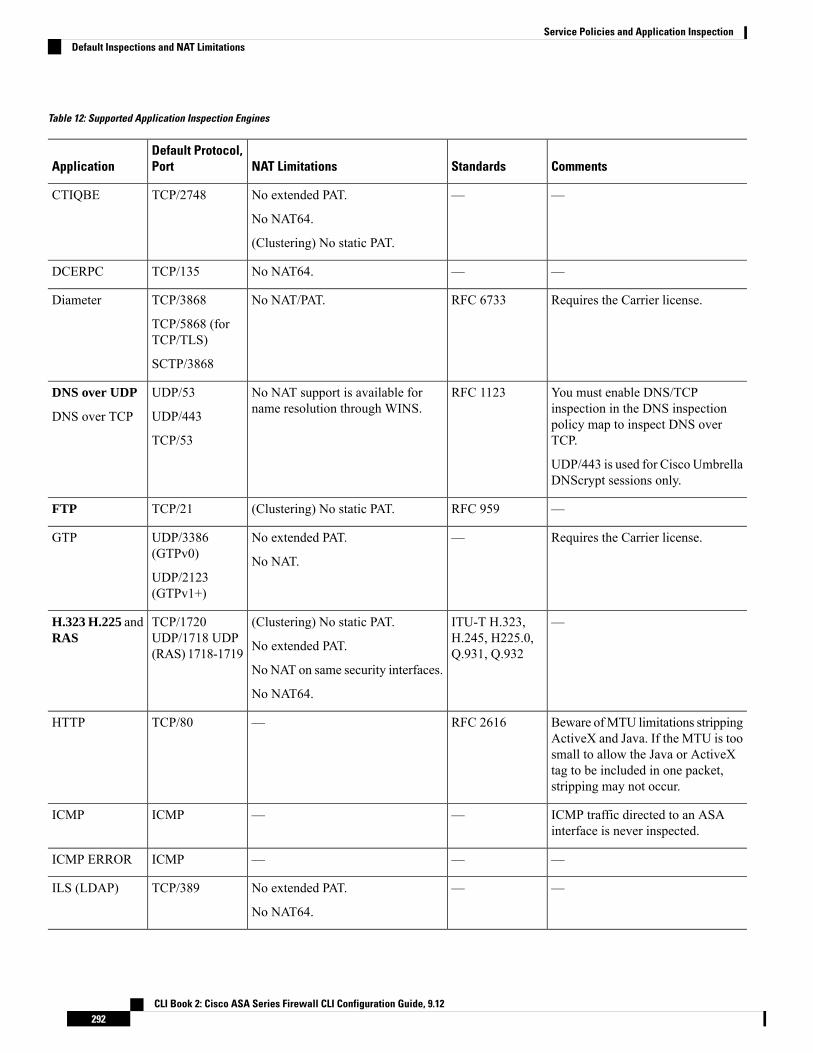
Table 12: Supported Application Inspection Engines
CommentsStandardsNAT LimitationsDefault Protocol,PortApplication
——No extended PAT.
No NAT64.
(Clustering) No static PAT.
TCP/2748CTIQBE
——No NAT64.TCP/135DCERPC
Requires the Carrier license.RFC 6733No NAT/PAT.TCP/3868
TCP/5868 (forTCP/TLS)
SCTP/3868
Diameter
You must enable DNS/TCPinspection in the DNS inspectionpolicy map to inspect DNS overTCP.
UDP/443 is used for Cisco UmbrellaDNScrypt sessions only.
RFC 1123No NAT support is available forname resolution through WINS.
UDP/53
UDP/443
TCP/53
DNS over UDP
DNS over TCP
—RFC 959(Clustering) No static PAT.TCP/21FTP
Requires the Carrier license.—No extended PAT.
No NAT.
UDP/3386(GTPv0)
UDP/2123(GTPv1+)
GTP
—ITU-T H.323,H.245, H225.0,Q.931, Q.932
(Clustering) No static PAT.
No extended PAT.
No NAT on same security interfaces.
No NAT64.
TCP/1720UDP/1718 UDP(RAS) 1718-1719
H.323 H.225 andRAS
Beware ofMTU limitations strippingActiveX and Java. If the MTU is toosmall to allow the Java or ActiveXtag to be included in one packet,stripping may not occur.
RFC 2616—TCP/80HTTP
ICMP traffic directed to an ASAinterface is never inspected.
——ICMPICMP
———ICMPICMP ERROR
——No extended PAT.
No NAT64.
TCP/389ILS (LDAP)
CLI Book 2: Cisco ASA Series Firewall CLI Configuration Guide, 9.12292
Service Policies and Application InspectionDefault Inspections and NAT Limitations
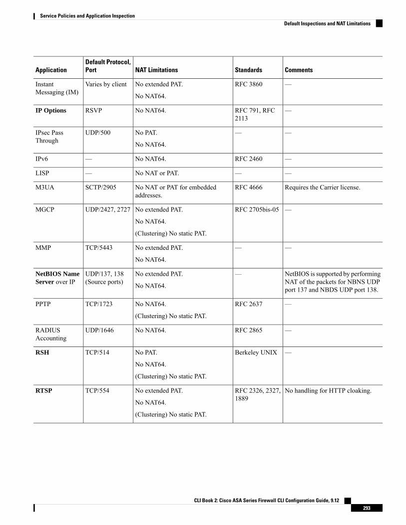
CommentsStandardsNAT LimitationsDefault Protocol,PortApplication
—RFC 3860No extended PAT.
No NAT64.
Varies by clientInstantMessaging (IM)
—RFC 791, RFC2113
No NAT64.RSVPIP Options
——No PAT.
No NAT64.
UDP/500IPsec PassThrough
—RFC 2460No NAT64.—IPv6
——No NAT or PAT.—LISP
Requires the Carrier license.RFC 4666No NAT or PAT for embeddedaddresses.
SCTP/2905M3UA
—RFC 2705bis-05No extended PAT.
No NAT64.
(Clustering) No static PAT.
UDP/2427, 2727MGCP
——No extended PAT.
No NAT64.
TCP/5443MMP
NetBIOS is supported by performingNAT of the packets for NBNS UDPport 137 and NBDS UDP port 138.
—No extended PAT.
No NAT64.
UDP/137, 138(Source ports)
NetBIOS NameServer over IP
—RFC 2637No NAT64.
(Clustering) No static PAT.
TCP/1723PPTP
—RFC 2865No NAT64.UDP/1646RADIUSAccounting
—Berkeley UNIXNo PAT.
No NAT64.
(Clustering) No static PAT.
TCP/514RSH
No handling for HTTP cloaking.RFC 2326, 2327,1889
No extended PAT.
No NAT64.
(Clustering) No static PAT.
TCP/554RTSP
CLI Book 2: Cisco ASA Series Firewall CLI Configuration Guide, 9.12293
Service Policies and Application InspectionDefault Inspections and NAT Limitations

CommentsStandardsNAT LimitationsDefault Protocol,PortApplication
Requires the Carrier license.
Although you can do static networkobject NAT on SCTP traffic (nodyamic NAT/PAT), the inspectionengine is not used for NAT.
RFC 4960—SCTPSCTP
Does not handle TFTP uploadedCisco IP Phone configurations undercertain circumstances.
RFC 2543No NAT/PAT on interfaces with thesame, or lower to higher, securitylevels.
No extended PAT.
No NAT64 or NAT46.
(Clustering) No static PAT.
TCP/5060UDP/5060
SIP
Does not handle TFTP uploadedCisco IP Phone configurations undercertain circumstances.
—NoNAT on same security interfaces.
No extended PAT.
No NAT64, NAT46, or NAT66.
(Clustering) No static PAT.
TCP/2000SKINNY(SCCP)
—RFC 821, 1123No NAT64.TCP/25SMTP andESMTP
v.2 RFC 1902-1908; v.3 RFC2570-2580.
RFC 1155, 1157,1212, 1213, 1215
No NAT or PAT.UDP/161, 162SNMP
v.1 and v.2.—No extended PAT.
No NAT64.
(Clustering) No static PAT.
TCP/1521SQL*Net
—RFC 5245, 5389(WebRTC) Static NAT/PAT44 only.
(Cisco Spark) Static NAT/PAT44and 64; and dynamic NAT/PAT.
TCP/3478UDP/3478
STUN
——No extended PAT.
No NAT64.
TCP/111
UDP/111
Sun RPC
Payload IP addresses are nottranslated.
RFC 1350No NAT64.
(Clustering) No static PAT.
UDP/69TFTP
——No extended PAT.
No NAT64.
TCP/1- 65535WAAS
CLI Book 2: Cisco ASA Series Firewall CLI Configuration Guide, 9.12294
Service Policies and Application InspectionDefault Inspections and NAT Limitations

CommentsStandardsNAT LimitationsDefault Protocol,PortApplication
——No extended PAT.
No NAT64.
(Clustering) No static PAT.
UDP/177XDMCP
Virtual Extensible Local AreaNetwork.
RFC 7348Not applicableUDP/4789VXLAN
The default policy configuration includes the following commands:
class-map inspection_defaultmatch default-inspection-trafficpolicy-map type inspect dns preset_dns_mapparametersmessage-length maximum client automessage-length maximum 512dns-guardprotocol-enforcementnat-rewritepolicy-map global_policyclass inspection_defaultinspect dns preset_dns_mapinspect ftpinspect h323 h225 _default_h323_mapinspect h323 ras _default_h323_mapinspect ip-options _default_ip_options_mapinspect netbiosinspect rshinspect rtspinspect skinnyinspect esmtp _default_esmtp_mapinspect sqlnetinspect sunrpcinspect tftpinspect sip
Default Inspection Policy MapsSome inspection types use hidden default policy maps. For example, if you enable ESMTP inspection withoutspecifying a map, _default_esmtp_map is used.
The default inspection is described in the sections that explain each inspection type. You can view thesedefault maps using the show running-config all policy-map command.
DNS inspection is the only one that uses an explicitly-configured default map, preset_dns_map.
Configure Application Layer Protocol InspectionYou configure application inspection in service policies.
CLI Book 2: Cisco ASA Series Firewall CLI Configuration Guide, 9.12295
Service Policies and Application InspectionDefault Inspection Policy Maps

Inspection is enabled by default globally on all interfaces for some applications on their standard ports andprotocols. See Default Inspections and NAT Limitations, on page 291 for more information on defaultinspections. A commonmethod for customizing the inspection configuration is to customize the default globalpolicy. You can alternatively create a new service policy as desired, for example, an interface-specific policy.
Before you begin
For some applications, you can perform special actions when you enable inspection by configuring inspectionpolicy maps. The table later in this procedure shows which protocols allow inspection policy maps, withpointers to the instructions on configuring them. If you want to configure these advanced features, create themap before configuring inspection.
Procedure
Step 1 Unless you are adding inspection to an existing class map, create an L3/L4 class map to identify the trafficfor which you want to apply the inspection.
class-map namematch parameter
Example:
hostname(config)# class-map dns_class_maphostname(config-cmap)# match access-list dns
In the default global policy, the inspection_default class map is a special class map that includes default portsfor all inspection types (match default-inspection-traffic). You can have more than one inspection on theinspection_default class only, and you might want to simply edit the existing global policy that applies theinspection defaults. If you are using this class map in either the default policy or for a new service policy, youcan skip this step. For detailed information on which class map to choose, see Choosing the Right TrafficClass for Inspection, on page 301.
For information on matching statements, see Create a Layer 3/4 Class Map for Through Traffic, on page 276.For RADIUS accounting inspection, which uses a management layer 3/4 class, see Configure RADIUSAccounting Inspection, on page 407.
Step 2 Add or edit a Layer 3/4 policy map that sets the actions to take with the class map traffic: policy-map name
Example:
hostname(config)# policy-map global_policy
In the default configuration, the global_policy policy map is assigned globally to all interfaces. If you wantto edit the global_policy, enter global_policy as the policy name.
Step 3 Identify the L3/L4 class map you are using for inspection: class name
Example:
hostname(config-pmap)# class inspection_default
CLI Book 2: Cisco ASA Series Firewall CLI Configuration Guide, 9.12296
Service Policies and Application InspectionConfigure Application Layer Protocol Inspection

To edit the default policy, or to use the special inspection_default class map in a new policy, specifyinspection_default for the name. Otherwise, you are specifying the class you created earlier in this procedure.
You can combine multiple class maps in the same policy if desired, so you can create one class map to matchcertain traffic, and another to match different traffic. However, if traffic matches a class map that contains aninspection command, and then matches another class map that also has an inspection command, only the firstmatching class is used. For example, SNMP matches the inspection_default class map. To enable SNMPinspection, enable SNMP inspection for the default class. Do not add another class that matches SNMP.
Step 4 Enable application inspection: inspect protocol
The protocol is one of the following values:
Table 13: Inspection Protocol Keywords
NotesKeywords
See CTIQBE Inspection, on page 349.ctiqbe
See DCERPC Inspection, on page 309.
If you added a DCERPC inspection policy map according to Configurea DCERPC Inspection PolicyMap, on page 310, identify the map namein this command.
dcerpc [map_name]
See Diameter Inspection, on page 377.
If you added a Diameter inspection policy map according to Configurea Diameter Inspection Policy Map, on page 386, identify the map namein this command.
tls-proxy proxy_name identifies the TLS proxy to use for this inspection.You need a TLS proxy only if you want to enable inspection of encryptedtraffic.
diameter [map_name] [tls-proxyproxy_name]
See DNS Inspection, on page 312.
If you added a DNS inspection policy map according to Configure DNSInspection Policy Map, on page 313, identify the map name in thiscommand. The default DNS inspection policy map name is“preset_dns_map.”
dynamic-filter-snoop enables dynamic filter snooping, which is usedexclusively by the Botnet Traffic Filter. Include this keyword only ifyou use Botnet Traffic Filtering. We suggest that you enable DNSsnooping only on interfaces where external DNS requests are going.Enabling DNS snooping on all UDP DNS traffic, including that goingto an internal DNS server, creates unnecessary load on the ASA.
dns [map_name][dynamic-filter-snoop]
See SMTP and Extended SMTP Inspection, on page 337.
If you added an ESMTP inspection policy map according to Configurean ESMTP Inspection Policy Map, on page 339, identify the map namein this command.
esmtp [map_name]
CLI Book 2: Cisco ASA Series Firewall CLI Configuration Guide, 9.12297
Service Policies and Application InspectionConfigure Application Layer Protocol Inspection

NotesKeywords
See FTP Inspection, on page 317.
Use the strict keyword to increase the security of protected networksby preventing web browsers from sending embedded commands in FTPrequests. See Strict FTP, on page 318 for more information.
If you added an FTP inspection policy map according to Configure anFTP Inspection Policy Map, on page 319, identify the map name in thiscommand.
ftp [strict [map_name]]
See GTP Inspection Overview, on page 373.
If you added a GTP inspection policy map according to Configure aGTP Inspection Policy Map, on page 381, identify the map name in thiscommand.
gtp [map_name]
See H.323 Inspection, on page 350.
If you added an H323 inspection policy map according to ConfigureH.323 Inspection Policy Map, on page 352, identify the map name inthis command.
h323 h225 [map_name]
See H.323 Inspection, on page 350.
If you added an H323 inspection policy map according to ConfigureH.323 Inspection Policy Map, on page 352, identify the map name inthis command.
h323 ras [map_name]
See HTTP Inspection, on page 321.
If you added an HTTP inspection policy map according to Configurean HTTP Inspection PolicyMap, on page 322, identify the map name inthis command.
http [map_name]
See ICMP Inspection, on page 326.icmp
See ICMP Error Inspection, on page 326.icmp error
See ILS Inspection, on page 327.ils
See Instant Messaging Inspection, on page 327.
If you added an Instant Messaging inspection policy map, identify themap name in this command.
im [map_name]
See IP Options Inspection, on page 330.
If you added an IP Options inspection policymap according to Configurean IP Options Inspection Policy Map, on page 331, identify the mapname in this command.
ip-options [map_name]
See IPsec Pass Through Inspection, on page 332.
If you added an IPsec Pass Through inspection policy map accordingto Configure an IPsec Pass Through Inspection Policy Map, on page333, identify the map name in this command.
ipsec-pass-thru [map_name]
CLI Book 2: Cisco ASA Series Firewall CLI Configuration Guide, 9.12298
Service Policies and Application InspectionConfigure Application Layer Protocol Inspection

NotesKeywords
See IPv6 Inspection, on page 334.
If you added an IPv6 inspection policy map according to Configure anIPv6 Inspection Policy Map, on page 334, identify the map name in thiscommand.
ipv6 [map_name]
For detailed information on configuring LISP, including inspection, seethe clustering chapter in the general configuration guide.
If you added a LISP inspection policy map, identify the map name inthis command.
lisp [map_name]
See M3UA Inspection, on page 377.
If you added an M3UA inspection policy map according to Configurean M3UA Inspection Policy Map, on page 402, identify the map namein this command.
m3ua [map_name]
See MGCP Inspection, on page 355.
If you added an MGCP inspection policy map according to Configurean MGCP Inspection Policy Map, on page 356, identify the map namein this command.
mgcp [map_name]
See NetBIOS Inspection, on page 336.
If you added a NetBIOS inspection policy map, identify the map namein this command.
netbios [map_name]
See PPTP Inspection, on page 337.pptp
See RADIUS Accounting Inspection Overview, on page 379.
The radius-accounting keyword is only available for a managementclass map. You must specify a RADIUS accounting inspection policymap; see Configure a RADIUS Accounting Inspection Policy Map, onpage 407.
radius-accounting map_name
See RSH Inspection, on page 337.rsh
See RTSP Inspection, on page 358.
If you added a RTSP inspection policy map according to ConfigureRTSP Inspection Policy Map, on page 359, identify the map name inthis command.
rtsp [map_name]
See SCTP Application Layer Inspection, on page 376.
If you added an SCTP inspection policy map according to Configure anSCTP Inspection Policy Map, on page 385, identify the map name inthis command.
sctp [map_name]
CLI Book 2: Cisco ASA Series Firewall CLI Configuration Guide, 9.12299
Service Policies and Application InspectionConfigure Application Layer Protocol Inspection
NotesKeywords
See SIP Inspection, on page 361.
If you added a SIP inspection policy map according to Configure SIPInspection Policy Map, on page 363, identify the map name in thiscommand.
tls-proxy proxy_name identifies the TLS proxy to use for this inspection.You need a TLS proxy only if you want to enable inspection of encryptedtraffic.
sip [map_name] [tls-proxyproxy_name]
See Skinny (SCCP) Inspection, on page 366.
If you added a Skinny inspection policy map according to Configure aSkinny (SCCP) Inspection Policy Map, on page 368, identify the mapname in this command.
tls-proxy proxy_name identifies the TLS proxy to use for this inspection.You need a TLS proxy only if you want to enable inspection of encryptedtraffic.
skinny [map_name] [tls-proxyproxy_name]
See SNMP Inspection, on page 342.
If you added an SNMP inspection policy map, identify the map namein this command.
snmp [map_name]
See SQL*Net Inspection, on page 343.sqlnet
See STUN Inspection, on page 369.stun
See Sun RPC Inspection, on page 343.
The default class map includes UDP port 111; if you want to enable SunRPC inspection for TCP port 111, you need to create a new class mapthat matches TCP port 111, add the class to the policy, and then applythe inspect sunrpc command to that class.
sunrpc
See TFTP Inspection, on page 344.tftp
Enables TCP option 33 parsing. Use when deploying Cisco Wide AreaApplication Services products.
waas
See XDMCP Inspection, on page 345.xdmcp
See VXLAN Inspection, on page 345.vxlan
If you are editing the default global policy (or any in-use policy) to use a different inspection policymap, you must remove the old inspection with the no inspect protocol command, and then re-addit with the new inspection policy map name.
Note
Example:
hostname(config-class)# no inspect siphostname(config-class)# inspect sip sip-map
CLI Book 2: Cisco ASA Series Firewall CLI Configuration Guide, 9.12300
Service Policies and Application InspectionConfigure Application Layer Protocol Inspection

Step 5 If you are editing an existing service policy (such as the default global policy called global_policy), you aredone. Otherwise, activate the policy map on one or more interfaces.
service-policy policymap_name {global | interface interface_name}
Example:
hostname(config)# service-policy global_policy global
The global keyword applies the policy map to all interfaces, and interface applies the policy to one interface.Only one global policy is allowed. You can override the global policy on an interface by applying a servicepolicy to that interface. You can only apply one policy map to each interface.
Choosing the Right Traffic Class for InspectionThe default Layer 3/4 class map for through traffic is called “inspection_default.” It matches traffic using aspecialmatch command,match default-inspection-traffic, to match the default protocols and ports for eachapplication protocol. This traffic class (along with match any, which is not typically used for inspection)matches both IPv4 and IPv6 traffic for inspections that support IPv6. See Guidelines for Application Inspection,on page 289 for a list of IPv6-enabled inspections.
You can specify a match access-list command along with the match default-inspection-traffic commandto narrow the matched traffic to specific IP addresses. Because thematch default-inspection-traffic commandspecifies the ports to match, any ports in the ACL are ignored.
We suggest that you only inspect traffic on ports on which you expect application traffic; if you inspect alltraffic, for example using match any, the ASA performance can be impacted.
Tip
If you want to match non-standard ports, then create a new class map for the non-standard ports. See DefaultInspections and NAT Limitations, on page 291 for the standard ports for each inspection engine. You cancombine multiple class maps in the same policy if desired, so you can create one class map to match certaintraffic, and another to match different traffic. However, if traffic matches a class map that contains an inspectioncommand, and then matches another class map that also has an inspection command, only the first matchingclass is used. For example, SNMP matches the inspection_default class. To enable SNMP inspection, enableSNMP inspection for the default class. Do not add another class that matches SNMP.
For example, to limit inspection to traffic from 10.1.1.0 to 192.168.1.0 using the default class map, enter thefollowing commands:
hostname(config)# access-list inspect extended permit ip 10.1.1.0 255.255.255.0192.168.1.0 255.255.255.0hostname(config)# class-map inspection_defaulthostname(config-cmap)# match access-list inspect
View the entire class map using the following command:
hostname(config-cmap)# show running-config class-map inspection_default!class-map inspection_defaultmatch default-inspection-traffic
CLI Book 2: Cisco ASA Series Firewall CLI Configuration Guide, 9.12301
Service Policies and Application InspectionChoosing the Right Traffic Class for Inspection

match access-list inspect!
To inspect FTP traffic on port 21 as well as 1056 (a non-standard port), create an ACL that specifies the ports,and assign it to a new class map:
hostname(config)# access-list ftp_inspect extended permit tcp any any eq 21hostname(config)# access-list ftp_inspect extended permit tcp any any eq 1056hostname(config)# class-map new_inspectionhostname(config-cmap)# match access-list ftp_inspect
Configure Regular ExpressionsRegular expressions define pattern matching for text strings. You can use these expressions in some protocolinspection maps to match packets based on strings such as URLs or the contents of particular header fields.
Create a Regular ExpressionA regular expression matches text strings either literally as an exact string, or by usingmetacharacters so thatyou can match multiple variants of a text string. You can use a regular expression to match the content ofcertain application traffic; for example, you can match a URL string inside an HTTP packet.
Before you begin
UseCtrl+V to escape all of the special characters in the CLI, such as question mark (?) or a tab. For example,type d[Ctrl+V]?g to enter d?g in the configuration.
See the regex command in the command reference for performance impact information when matching aregular expression to packets. In general, matching against long input strings, or trying to match a large numberof regular expressions, will reduce system performance.
As an optimization, the ASA searches on the deobfuscated URL. Deobfuscation compresses multiple forwardslashes (/) into a single slash. For strings that commonly use double slashes, like “http://”, be sure to searchfor “http:/” instead.
Note
The following table lists the metacharacters that have special meanings.
Table 14: Regular Expression Metacharacters
NotesDescriptionCharacter
Matches any single character. For example, d.gmatches dog, dag, dtg, and any word that containsthose characters, such as doggonnit.
Dot.
CLI Book 2: Cisco ASA Series Firewall CLI Configuration Guide, 9.12302
Service Policies and Application InspectionConfigure Regular Expressions

NotesDescriptionCharacter
A subexpression segregates characters fromsurrounding characters, so that you can use othermetacharacters on the subexpression. For example,d(o|a)g matches dog and dag, but do|ag matches doand ag. A subexpression can also be used with repeatquantifiers to differentiate the characters meant forrepetition. For example, ab(xy){3}z matchesabxyxyxyz.
Subexpression(exp)
Matches either expression it separates. For example,dog|cat matches dog or cat.
Alternation|
A quantifier that indicates that there are 0 or 1 of theprevious expression. For example, lo?se matches lseor lose.
Question mark?
A quantifier that indicates that there are 0, 1 or anynumber of the previous expression. For example, lo*sematches lse, lose, loose, and so on.
Asterisk*
A quantifier that indicates that there is at least 1 ofthe previous expression. For example, lo+se matcheslose and loose, but not lse.
Plus+
Repeat at least x times. For example, ab(xy){2,}zmatches abxyxyz, abxyxyxyz, and so on.
Minimum repeat quantifier{x} or {x,}
Matches any character in the brackets. For example,[abc] matches a, b, or c.
Character class[abc]
Matches a single character that is not contained withinthe brackets. For example, [^abc] matches anycharacter other than a, b, or c. [^A-Z] matches anysingle character that is not an uppercase letter.
Negated character class[^abc]
Matches any character in the range. [a-z]matches anylowercase letter. You can mix characters and ranges:[abcq-z] matches a, b, c, q, r, s, t, u, v, w, x, y, z, andso does [a-cq-z].
The dash (-) character is literal only if it is the last orthe first character within the brackets: [abc-] or [-abc].
Character range class[a-c]
Preserves trailing or leading spaces in the string. Forexample, “ test” preserves the leading space when itlooks for a match.
Quotation marks“”
Specifies the beginning of a line.Caret^
When used with a metacharacter, matches a literalcharacter. For example, \[ matches the left squarebracket.
Escape character\
CLI Book 2: Cisco ASA Series Firewall CLI Configuration Guide, 9.12303
Service Policies and Application InspectionCreate a Regular Expression
NotesDescriptionCharacter
When character is not a metacharacter, matches theliteral character.
Characterchar
Matches a carriage return 0x0d.Carriage return\r
Matches a new line 0x0a.Newline\n
Matches a tab 0x09.Tab\t
Matches a form feed 0x0c.Formfeed\f
Matches an ASCII character using hexadecimal(exactly two digits).
Escaped hexadecimal number\xNN
Matches an ASCII character as octal (exactly threedigits). For example, the character 040 represents aspace.
Escaped octal number\NNN
Procedure
Step 1 Test a regular expression to make sure it matches what you think it will match: test regex input_textregular_expression
Where the input_text argument is a string you want to match using the regular expression, up to 201 charactersin length. The regular_expression argument can be up to 100 characters in length.
Use Ctrl+V to escape all of the special characters in the CLI. For example, to enter a tab in the input text inthe test regex command, you must enter test regex “test[Ctrl+V Tab]” “test\t”.
If the regular expression matches the input text, you see the following message:
INFO: Regular expression match succeeded.
If the regular expression does not match the input text, you see the following message:
INFO: Regular expression match failed.
Step 2 To add a regular expression after you tested it, enter the following command: regex name regular_expression
Where the name argument can be up to 40 characters in length. The regular_expression argument can be upto 100 characters in length.
Examples
The following example creates two regular expressions for use in an inspection policy map:
CLI Book 2: Cisco ASA Series Firewall CLI Configuration Guide, 9.12304
Service Policies and Application InspectionCreate a Regular Expression
hostname(config)# regex url_example example\.comhostname(config)# regex url_example2 example2\.com
Create a Regular Expression Class MapA regular expression class map identifies one or more regular expression. It is simply a collection of regularexpression objects. You can use a regular expression class map in many cases in replace of a regular expressionobject.
Procedure
Step 1 Create the regular expression class map: class-map type regex match-any class_map_name
Where class_map_name is a string up to 40 characters in length. The name “class-default” is reserved. Alltypes of class maps use the same name space, so you cannot reuse a name already used by another type ofclass map.
Thematch-any keyword specifies that the traffic matches the class map if it matches at least one of the regularexpressions.
Step 2 (Optional) Add a description to the class map: description string
Step 3 Identify the regular expressions you want to include by entering the following command for each regularexpression: match regex regex_name
Examples
The following example creates two regular expressions, and adds them to a regular expression classmap. Traffic matches the class map if it includes the string “example.com” or “example2.com.”
hostname(config)# regex url_example example\.comhostname(config)# regex url_example2 example2\.comhostname(config)# class-map type regex match-any URLshostname(config-cmap)# match regex url_examplehostname(config-cmap)# match regex url_example2
Monitoring Inspection PoliciesTomonitor inspection service policies, enter the following commands. See the command reference on Cisco.comfor detailed syntax and examples.
• show service-policy inspect protocol
Displays statistics for inspection service policies. The protocol is the protocol from the inspect command,for example dns. However, not all inspection protocols show statistics with this command. For example:
asa# show service-policy inspect dns
CLI Book 2: Cisco ASA Series Firewall CLI Configuration Guide, 9.12305
Service Policies and Application InspectionCreate a Regular Expression Class Map

Global policy:Service-policy: global_policyClass-map: inspection_defaultInspect: dns preset_dns_map, packet 0, lock fail 0, drop 0, reset-drop 0,
5-min-pkt-rate 0 pkts/sec, v6-fail-close 0message-length maximum client auto, drop 0message-length maximum 512, drop 0dns-guard, count 0protocol-enforcement, drop 0nat-rewrite, count 0
asa#
• show conn
Shows current connections for traffic passing through the device. This command has a wide range ofkeywords so that you can get information about various protocols.
• Additional commands for specific inspected protocols:
• show ctiqbe
Displays information about the media connections allocated by the CTIQBE inspection engine
• show h225
Displays information for H.225 sessions.
• show h245
Displays information for H.245 sessions established by endpoints using slow start.
• show h323 ras
Displays connection information for H.323 RAS sessions established between a gatekeeper and itsH.323 endpoint.
• show mgcp {commands | sessions }
Displays the number of MGCP commands in the command queue or the number of existing MGCPsessions.
• show sip
Displays information for SIP sessions.
• show skinny
Displays information for Skinny (SCCP) sessions.
• show sunrpc-server active
Displays the pinholes opened for Sun RPC services.
CLI Book 2: Cisco ASA Series Firewall CLI Configuration Guide, 9.12306
Service Policies and Application InspectionMonitoring Inspection Policies

History for Application InspectionDescriptionReleasesFeature Name
The inspection policy map was introduced.The following command was introduced:class-map type inspect.
7.2(1)Inspection policy maps
Regular expressions and policy maps wereintroduced to be used under inspectionpolicy maps. The following commandswere introduced: class-map type regex,regex, match regex.
7.2(1)Regular expressions and policy maps
The match any keyword was introducedfor use with inspection policy maps: trafficcanmatch one or more criteria to match theclass map. Formerly, only match all wasavailable.
8.0(2)Match any for inspection policy maps
CLI Book 2: Cisco ASA Series Firewall CLI Configuration Guide, 9.12307
Service Policies and Application InspectionHistory for Application Inspection

CLI Book 2: Cisco ASA Series Firewall CLI Configuration Guide, 9.12308
Service Policies and Application InspectionHistory for Application Inspection

C H A P T E R 14Inspection of Basic Internet Protocols
The following topics explain application inspection for basic Internet protocols. For information on why youneed to use inspection for certain protocols, and the overall methods for applying inspection, see GettingStarted with Application Layer Protocol Inspection, on page 287.
• DCERPC Inspection, on page 309• DNS Inspection, on page 312• FTP Inspection, on page 317• HTTP Inspection, on page 321• ICMP Inspection, on page 326• ICMP Error Inspection, on page 326• ILS Inspection, on page 327• Instant Messaging Inspection, on page 327• IP Options Inspection, on page 330• IPsec Pass Through Inspection, on page 332• IPv6 Inspection, on page 334• NetBIOS Inspection, on page 336• PPTP Inspection, on page 337• RSH Inspection, on page 337• SMTP and Extended SMTP Inspection, on page 337• SNMP Inspection, on page 342• SQL*Net Inspection, on page 343• Sun RPC Inspection, on page 343• TFTP Inspection, on page 344• XDMCP Inspection, on page 345• VXLAN Inspection, on page 345• History for Basic Internet Protocol Inspection, on page 346
DCERPC InspectionDCERPC inspection is not enabled in the default inspection policy, so you must enable it if you need thisinspection. You can simply edit the default global inspection policy to add DCERPC inspection. You canalternatively create a new service policy as desired, for example, an interface-specific policy.
The following sections describe the DCERPC inspection engine.
CLI Book 2: Cisco ASA Series Firewall CLI Configuration Guide, 9.12309

DCERPC OverviewMicrosoft Remote Procedure Call (MSRPC), based on DCERPC, is a protocol widely used by Microsoftdistributed client and server applications that allows software clients to execute programs on a server remotely.
This typically involves a client querying a server called the Endpoint Mapper listening on a well known portnumber for the dynamically allocated network information of a required service. The client then sets up asecondary connection to the server instance providing the service. The security appliance allows the appropriateport number and network address and also applies NAT, if needed, for the secondary connection.
The DCERPC inspection engine inspects for native TCP communication between the EPM and client on wellknown TCP port 135. Map and lookup operations of the EPM are supported for clients. Client and server canbe located in any security zone. The embedded server IP address and Port number are received from theapplicable EPM response messages. Since a client may attempt multiple connections to the server port returnedby EPM, multiple use of pinholes are allowed, which have configurable timeouts.
DCE inspection supports the following universally unique identifiers (UUIDs) and messages:
• End point mapper (EPM) UUID. All EPM messages are supported.
• ISystemMapper UUID (non-EPM). Supported messages are:
• RemoteCreateInstance opnum4
• RemoteGetClassObject opnum3
• OxidResolver UUID (non-EPM). Supported message is:
• ServerAlive2 opnum5
• Any message that does not contain an IP address or port information because these messages do notrequire inspection.
Configure a DCERPC Inspection Policy MapTo specify additional DCERPC inspection parameters, create a DCERPC inspection policy map. You canthen apply the inspection policy map when you enable DCERPC inspection.
When defining traffic matching criteria, you can either create a class map or include the match statementsdirectly in the policy map. The difference between creating a class map and defining the traffic match directlyin the inspection policy map is that you can reuse class maps.
Procedure
Step 1 (Optional) Create a DCERPC inspection class map.
For the traffic that you identify in this class map, you specify actions to take on the traffic in the inspectionpolicy map.
If you want to perform different actions for each match command, you should identify the traffic directly inthe policy map.
a) Create the class map: class-map type inspect dcerpc [match-all | match-any] class_map_name
CLI Book 2: Cisco ASA Series Firewall CLI Configuration Guide, 9.12310
Service Policies and Application InspectionDCERPC Overview

Where class_map_name is the name of the class map. Thematch-all keyword is the default, and specifiesthat traffic must match all criteria to match the class map. The match-any keyword specifies that the trafficmatches the class map if it matches at least onematch statement. The CLI enters class-map configurationmode.
b) Specify the traffic on which you want to perform actions using the following match command. If youuse a match not command, then any traffic that does not match the criterion in the match not commandhas the action applied.
• match [not] uuid type—Matches the universally unique identifier (UUID) of the DCERPCmessage.The type can be one of the following:
• ms-rpc-epm—Matches Microsoft RPC EPM messages.
• ms-rpc-isystemactivator—Matches ISystemMapper messages.
• ms-rpc-oxidresolver—Matches OxidResolver messages.
c) Enter exit to leave class map configuration mode.
Step 2 Create a DCERPC inspection policy map: policy-map type inspect dcerpc policy_map_name
Where the policy_map_name is the name of the policy map. The CLI enters policy-map configuration mode.
Step 3 (Optional) Add a description to the policy map: description string
Step 4 To apply actions to matching traffic, perform the following steps.a) Specify the traffic on which you want to perform actions using one of the following methods:
• If you created a DCERPC class map, specify it by entering the following command: classclass_map_name
• Specify traffic directly in the policy map using one of the match commands described for DCERPCclass maps. If you use a match not command, then any traffic that does not match the criterion inthe match not command has the action applied.
b) Specify the action you want to perform on the matching traffic by entering one of the following commands:
• reset [log]—Drop the packet, close the connection, and send a TCP reset to the server or client.
• log—Send a system log message. You can use this option alone or with one of the other actions.
You can specify multiple class or match commands in the policy map.
Example:
hostname(config)# policy-map type inspect dcerpc dcerpc-maphostname(config-pmap)# match uuid ms-rpc-epmhostname(config-pmap-c)# log
Step 5 To configure parameters that affect the inspection engine, perform the following steps:a) Enter parameters configuration mode:
hostname(config-pmap)# parametershostname(config-pmap-p)#
CLI Book 2: Cisco ASA Series Firewall CLI Configuration Guide, 9.12311
Service Policies and Application InspectionConfigure a DCERPC Inspection Policy Map

b) Set one or more parameters. You can set the following options; use the no form of the command to disablethe option:
• timeout pinhole hh:mm:ss—Configures the timeout for DCERPC pinholes and override the globalsystem pinhole timeout of two minutes. The timeout can be from 00:00:01 to 119:00:00.
• endpoint-mapper [epm-service-only] [lookup-operation [timeout hh:mm:ss]]—Configures optionsfor the endpoint mapper traffic. The epm-service-only keyword enforces endpoint mapper serviceduring binding so that only its service traffic is processed. The lookup-operation keyword enablesthe lookup operation of the endpoint mapper service. You can configure the timeout for pinholesgenerated from the lookup operation. If no timeout is configured for the lookup operation, the timeoutpinhole command or the default is used.
Examples
The following example shows how to define a DCERPC inspection policy map with the timeoutconfigured for DCERPC pinholes.
hostname(config)# policy-map type inspect dcerpc dcerpc_maphostname(config-pmap)# timeout pinhole 0:10:00
hostname(config)# class-map dcerpchostname(config-cmap)# match port tcp eq 135
hostname(config)# policy-map global-policyhostname(config-pmap)# class dcerpchostname(config-pmap-c)# inspect dcerpc dcerpc-map
hostname(config)# service-policy global-policy global
What to do next
You can now configure an inspection policy to use the map. See Configure Application Layer ProtocolInspection, on page 295.
DNS InspectionDNS inspection is enabled by default. You need to configure it only if you want non-default processing. Thefollowing sections describe DNS application inspection.
Defaults for DNS InspectionDNS inspection is enabled by default, using the preset_dns_map inspection class map:
• The maximum DNS message length is 512 bytes.
• DNS over TCP inspection is disabled.
• The maximum client DNS message length is automatically set to match the Resource Record.
CLI Book 2: Cisco ASA Series Firewall CLI Configuration Guide, 9.12312
Service Policies and Application InspectionDNS Inspection

• DNS Guard is enabled, so the ASA tears down the DNS session associated with a DNS query as soonas the DNS reply is forwarded by the ASA. The ASA also monitors the message exchange to ensure thatthe ID of the DNS reply matches the ID of the DNS query.
• Translation of the DNS record based on the NAT configuration is enabled.
• Protocol enforcement is enabled, which enables DNS message format check, including domain namelength of no more than 255 characters, label length of 63 characters, compression, and looped pointercheck.
See the following default DNS inspection commands:
class-map inspection_defaultmatch default-inspection-trafficpolicy-map type inspect dns preset_dns_mapparameters
message-length maximum client automessage-length maximum 512dns-guardprotocol-enforcementnat-rewrite
policy-map global_policyclass inspection_defaultinspect dns preset_dns_map
! ...service-policy global_policy global
Configure DNS Inspection Policy MapYou can create a DNS inspection policy map to customize DNS inspection actions if the default inspectionbehavior is not sufficient for your network.
Before you begin
Some traffic matching options use regular expressions for matching purposes. If you intend to use one ofthose techniques, first create the regular expression or regular expression class map.
Procedure
Step 1 (Optional) Create a DNS inspection class map by performing the following steps.
A class map groups multiple traffic matches. You can alternatively identify match commands directly in thepolicymap. The difference between creating a class map and defining the traffic match directly in the inspectionpolicy map is that the class map lets you create more complex match criteria, and you can reuse class maps.
To specify traffic that should not match the class map, use thematch not command. For example, if thematchnot command specifies the string “example.com,” then any traffic that includes “example.com” does notmatch the class map.
For the traffic that you identify in this class map, you specify actions to take on the traffic in the inspectionpolicy map.
If you want to perform different actions for each match command, you should identify the traffic directly inthe policy map.
CLI Book 2: Cisco ASA Series Firewall CLI Configuration Guide, 9.12313
Service Policies and Application InspectionConfigure DNS Inspection Policy Map

a) Create the class map: class-map type inspect dns [match-all | match-any] class_map_name
Where class_map_name is the name of the class map. Thematch-all keyword is the default, and specifiesthat traffic must match all criteria to match the class map. The match-any keyword specifies that the trafficmatches the class map if it matches at least onematch statement. The CLI enters class-map configurationmode, where you can enter one or more match commands.
b) (Optional) Add a description to the class map: description string
Where string is the description of the class map (up to 200 characters).
c) Specify the traffic on which you want to perform actions using one of the following match commands.If you use a match not command, then any traffic that does not match the criterion in the match notcommand has the action applied.
• match [not] header-flag [eq] {f_name [f_name...] | f_value}—Matches the DNS flag. The f_nameargument is the DNS flag name, one of the following:AA (Authoritative Answer), QR (Query), RA(Recursion Available),RD (Recursion Desired),TC (Truncation). The f_value argument is the 16-bitvalue in hex starting with 0x, from 0x0 to 0xffff. The eq keyword specifies an exact match (matchall); without the eq keyword, the packet only needs to match one of the specified headers (matchany). For example, match header-flag AA QR.
• match [not] dns-type {eq {t_name | t_value} | range t_value1 t_value2}—Matches the DNS type.The t_name argument is the DNS type name, one of the following: A (IPv4 address), AXFR (fullzone transfer), CNAME (canonical name), IXFR (incremental zone transfer), NS (authoritativename server), SOA (start of a zone of authority) or TSIG (transaction signature). The t_valuearguments are arbitrary values in the DNS type field (0-65535). The range keyword specifies a range,and the eq keyword specifies an exact match. For example: match dns-type eq A.
• match [not] dns-class {eq {in | c_value} | range c_value1 c_value2}—Matches the DNS class. Theclass is either in (for Internet) or c_value, an arbitrary value from 0 to 65535 in the DNS class field.The range keyword specifies a range, and the eq keyword specifies an exact match. For example:match dns-class eq in.
• match [not] {question | resource-record {answer | authority | additional}}—Matches a DNSquestion or resource record. The question keyword specifies the question portion of a DNSmessage.The resource-record keyword specifies one of these sections of the resource record: answer, authority,or additional. For example: match resource-record answer.
• match [not] domain-name regex {regex_name | class class_name}—Matches the DNS messagedomain name list against the specified regular expression or regular expression class.
d) Enter exit to leave class map configuration mode.
Step 2 Create a DNS inspection policy map: policy-map type inspect dns policy_map_name
Where the policy_map_name is the name of the policy map. The CLI enters policy-map configuration mode.
Step 3 (Optional) Add a description to the policy map: description string
Step 4 To apply actions to matching traffic, perform the following steps.a) Specify the traffic on which you want to perform actions using one of the following methods:
• If you created a DNS class map, specify it by entering the following command: class class_map_name
CLI Book 2: Cisco ASA Series Firewall CLI Configuration Guide, 9.12314
Service Policies and Application InspectionConfigure DNS Inspection Policy Map

• Specify traffic directly in the policy map using one of thematch commands described for DNS classmaps. If you use a match not command, then any traffic that does not match the criterion in thematch not command has the action applied.
b) Specify the action you want to perform on the matching traffic by entering one of the following commands:
• drop [log]—Drop all packets that match.
• drop-connection [log]—Drop the packet and close the connection.
• mask [log]—Mask out the matching portion of the packet. This action is available for header flagmatches only.
• log—Send a system log message. You can use this option alone or with one of the other actions.
• enforce-tsig [drop] [log]—Enforce the presence of the TSIG resource record in a message. You candrop a packet without the TSIG resource record, log it, or drop and log it. You can use this optionin conjunction with the mask action for header flag matches; otherwise, this action is exclusive withthe other actions.
You can specify multiple class or match commands in the policy map. For information about the orderof class and match commands, see How Multiple Traffic Classes are Handled, on page 288.
Example:
hostname(config)# policy-map type inspect dns dns-maphostname(config-pmap)# class dns-class-maphostname(config-pmap-c)# drophostname(config-pmap-c)# match header-flag eq aahostname(config-pmap-c)# drop log
Step 5 To configure parameters that affect the inspection engine, perform the following steps:a) Enter parameters configuration mode.
hostname(config-pmap)# parametershostname(config-pmap-p)#
b) Set one or more parameters. You can set the following options; use the no form of the command to disablethe option.
• dnscrypt—Enables DNScrypt to encrypt connections between the device and Cisco Umbrella.Enabling DNScrypt starts the key-exchange thread with the Umbrella resolver. The key-exchangethread performs the handshake with the resolver every hour and updates the device with a new secretkey. Because DNScrypt uses UDP/443, you must ensure that the class map used for DNS inspectionincludes that port. Note that the default inspection class already includes UDP/443 for DNS inspection.
• dns-guard—Enables DNS Guard. The ASA tears down the DNS session associated with a DNSquery as soon as the DNS reply is forwarded by the ASA. The ASA also monitors the messageexchange to ensure that the ID of the DNS reply matches the ID of the DNS query.
• id-mismatch count number duration seconds action log—Enables logging for excessive DNS IDmismatches, where the count number duration seconds arguments specify the maximum numberof mismatch instances per second before a system message log is sent.
• id-randomization—Randomizes the DNS identifier for a DNS query.
CLI Book 2: Cisco ASA Series Firewall CLI Configuration Guide, 9.12315
Service Policies and Application InspectionConfigure DNS Inspection Policy Map

• message-length maximum {length | client {length | auto} | server {length | auto}}—Sets themaximum DNS message length, from 512 to 65535 bytes. You can also set the maximum length forclient or server messages. The auto keyword sets the maximum length to the value in the ResourceRecord.
• nat-rewrite—Translates the DNS record based on the NAT configuration.
• protocol-enforcement—Enables DNS message format check, including domain name length of nomore than 255 characters, label length of 63 characters, compression, and looped pointer check.
• tcp-inspection—Enables inspection of DNS over TCP traffic. Ensure that DNS/TCP port 53 trafficis part of the class to which you apply DNS inspection. The inspection default class includes TCP/53.
• tsig enforced action {[drop] [log]}—Requires a TSIG resource record to be present. You can dropa non-conforming packet, log the packet, or both.
• umbrella [tag umbrella_policy] [fail-open]—Enables Cisco Umbrella and optionally specifiesthe name of the Cisco Umbrella policy (tag) to apply to the device. If you do not specify a policy,the default policy is applied. For more information, see Cisco Umbrella, on page 149.
Include the fail-open keyword if you want DNS resolution to work if the Umbrella DNS server isunavailable. When failing open, if the Cisco Umbrella DNS server is unavailable, Umbrella disablesitself on this policy map and allows DNS requests to go to the other DNS servers configured on thesystem, if any. When the Umbrella DNS servers are available again, the policy map resumes usingthem. If you do not include this option, DNS requests continue to go to the unreachable Umbrellaresolver, so they will not get a response.
Example:
hostname(config-pmap)# parametershostname(config-pmap-p)# dns-guardhostname(config-pmap-p)# message-length maximum 1024hostname(config-pmap-p)# nat-rewritehostname(config-pmap-p)# protocol-enforcement
Example
The following example shows a how to use a new inspection policy map in the global defaultconfiguration:
regex domain_example “example\.com”regex domain_foo “foo\.com”
! define the domain names that the server servesclass-map type inspect regex match-any my_domains
match regex domain_examplematch regex domain_foo
! Define a DNS map for query onlyclass-map type inspect dns match-all pub_server_map
match not header-flag QRmatch questionmatch not domain-name regex class my_domains
CLI Book 2: Cisco ASA Series Firewall CLI Configuration Guide, 9.12316
Service Policies and Application InspectionConfigure DNS Inspection Policy Map
policy-map type inspect dns new_dns_mapclass pub_server_map
drop logmatch header-flag RD
mask logparameters
message-length maximum client automessage-length maximum 512dns-guardprotocol-enforcementnat-rewrite
policy-map global_policyclass inspection_defaultno inspect dns preset_dns_mapinspect dns new_dns_map
service-policy global_policy global
What to do next
You can now configure an inspection policy to use the map. See Configure Application Layer ProtocolInspection, on page 295.
FTP InspectionFTP inspection is enabled by default. You need to configure it only if you want non-default processing. Thefollowing sections describe the FTP inspection engine.
FTP Inspection OverviewThe FTP application inspection inspects the FTP sessions and performs four tasks:
• Prepares dynamic secondary data connection channels for FTP data transfer. Ports for these channels arenegotiated through PORT or PASV commands. The channels are allocated in response to a file upload,a file download, or a directory listing event.
• Tracks the FTP command-response sequence.
• Generates an audit trail.
• Audit record 303002 is generated for each file that is retrieved or uploaded.
• Audit record 201005 is generated if the secondary dynamic channel preparation failed due to memoryshortage.
• Translates the embedded IP address.
If you disable FTP inspection, outbound users can start connections only in passive mode, and all inboundFTP is disabled.
Note
CLI Book 2: Cisco ASA Series Firewall CLI Configuration Guide, 9.12317
Service Policies and Application InspectionFTP Inspection

Strict FTPStrict FTP increases the security of protected networks by preventing web browsers from sending embeddedcommands in FTP requests. To enable strict FTP, include the strict option with the inspect ftp command.
When you use strict FTP, you can optionally specify an FTP inspection policy map to specify FTP commandsthat are not permitted to pass through the ASA.
Strict FTP inspection enforces the following behavior:
• An FTP command must be acknowledged before the ASA allows a new command.
• The ASA drops connections that send embedded commands.
• The 227 and PORT commands are checked to ensure they do not appear in an error string.
Using strict FTP may cause the failure of FTP clients that are not strictly compliant with FTP RFCs.Caution
With strict FTP inspection, each FTP command and response sequence is tracked for the following anomalousactivity:
• Truncated command—Number of commas in the PORT and PASV reply command is checked to see ifit is five. If it is not five, then the PORT command is assumed to be truncated and the TCP connectionis closed.
• Incorrect command—Checks the FTP command to see if it ends with <CR><LF> characters, as requiredby the RFC. If it does not, the connection is closed.
• Size of RETR and STOR commands—These are checked against a fixed constant. If the size is greater,then an error message is logged and the connection is closed.
• Command spoofing—The PORT command should always be sent from the client. The TCP connectionis denied if a PORT command is sent from the server.
• Reply spoofing—PASV reply command (227) should always be sent from the server. The TCP connectionis denied if a PASV reply command is sent from the client. This prevents the security hole when the userexecutes “227 xxxxx a1, a2, a3, a4, p1, p2.”
• TCP stream editing—The ASA closes the connection if it detects TCP stream editing.
• Invalid port negotiation—The negotiated dynamic port value is checked to see if it is less than 1024. Asport numbers in the range from 1 to 1024 are reserved for well-known connections, if the negotiated portfalls in this range, then the TCP connection is freed.
• Command pipelining—The number of characters present after the port numbers in the PORT and PASVreply command is cross checked with a constant value of 8. If it is more than 8, then the TCP connectionis closed.
• The ASA replaces the FTP server response to the SYST command with a series of Xs to prevent theserver from revealing its system type to FTP clients. To override this default behavior, use the nomask-syst-reply command in the FTP map.
CLI Book 2: Cisco ASA Series Firewall CLI Configuration Guide, 9.12318
Service Policies and Application InspectionStrict FTP

Configure an FTP Inspection Policy MapFTP command filtering and security checks are provided using strict FTP inspection for improved securityand control. Protocol conformance includes packet length checks, delimiters and packet format checks,command terminator checks, and command validation.
Blocking FTP based on user values is also supported so that it is possible for FTP sites to post files fordownload, but restrict access to certain users. You can block FTP connections based on file type, server name,and other attributes. System message logs are generated if an FTP connection is denied after inspection.
If you want FTP inspection to allow FTP servers to reveal their system type to FTP clients, and limit theallowed FTP commands, then create and configure an FTP inspection policy map. You can then apply themap when you enable FTP inspection.
Before you begin
Some traffic matching options use regular expressions for matching purposes. If you intend to use one ofthose techniques, first create the regular expression or regular expression class map.
Procedure
Step 1 (Optional) Create an FTP inspection class map by performing the following steps.
A class map groups multiple traffic matches. You can alternatively identify match commands directly in thepolicymap. The difference between creating a class map and defining the traffic match directly in the inspectionpolicy map is that the class map lets you create more complex match criteria, and you can reuse class maps.
To specify traffic that should not match the class map, use thematch not command. For example, if thematchnot command specifies the string “example.com,” then any traffic that includes “example.com” does notmatch the class map.
For the traffic that you identify in this class map, you specify actions to take on the traffic in the inspectionpolicy map.
If you want to perform different actions for each match command, you should identify the traffic directly inthe policy map.
a) Create the class map: class-map type inspect ftp [match-all | match-any] class_map_name
Where class_map_name is the name of the class map. Thematch-all keyword is the default, and specifiesthat traffic must match all criteria to match the class map. The match-any keyword specifies that the trafficmatches the class map if it matches at least onematch statement. The CLI enters class-map configurationmode, where you can enter one or more match commands.
b) (Optional) Add a description to the class map: description string
Where string is the description of the class map (up to 200 characters).
c) Specify the traffic on which you want to perform actions using one of the following match commands.If you use a match not command, then any traffic that does not match the criterion in the match notcommand has the action applied.
• match [not] filename regex {regex_name | class class_name}—Matches the filename in the FTPtransfer against the specified regular expression or regular expression class.
CLI Book 2: Cisco ASA Series Firewall CLI Configuration Guide, 9.12319
Service Policies and Application InspectionConfigure an FTP Inspection Policy Map

• match [not] filetype regex {regex_name | class class_name}—Matches the file type in the FTPtransfer against the specified regular expression or regular expression class.
• match [not] request-command ftp_command [ ftp_command...]—Matches the FTP command, oneor more of the following:
• APPE—Append to a file.
• CDUP—Changes to the parent directory of the current working directory.
• DELE—Delete a file on the server.
• GET—Gets a file from the server.
• HELP—Provides help information.
• MKD—Makes a directory on the server.
• PUT—Sends a file to the server.
• RMD—Deletes a directory on the server.
• RNFR—Specifies the “rename-from” filename.
• RNTO—Specifies the “rename-to” filename.
• SITE—Used to specify a server-specific command. This is usually used for remoteadministration.
• STOU—Stores a file using a unique file name.
• match [not] server regex {regex_name | class class_name}—Matches the FTP server name againstthe specified regular expression or regular expression class.
• match [not] username regex {regex_name | class class_name}—Matches the FTP username againstthe specified regular expression or regular expression class.
d) Enter exit to leave class map configuration mode.
Step 2 Create an FTP inspection policy map: policy-map type inspect ftp policy_map_name
Where the policy_map_name is the name of the policy map. The CLI enters policy-map configuration mode.
Step 3 (Optional) Add a description to the policy map: description string
Step 4 To apply actions to matching traffic, perform the following steps.a) Specify the traffic on which you want to perform actions using one of the following methods:
• If you created an FTP class map, specify it by entering the following command: class class_map_name
• Specify traffic directly in the policy map using one of the match commands described for FTP classmaps. If you use a match not command, then any traffic that does not match the criterion in thematch not command has the action applied.
b) Specify the action you want to perform on the matching traffic by entering the following command:
• reset [log]—Drop the packet, close the connection, and send a TCP reset to the server or client. Addthe log keyword to send a system log message.
CLI Book 2: Cisco ASA Series Firewall CLI Configuration Guide, 9.12320
Service Policies and Application InspectionConfigure an FTP Inspection Policy Map

You can specify multiple class or match commands in the policy map. For information about the orderof class and match commands, see How Multiple Traffic Classes are Handled, on page 288.
Step 5 To configure parameters that affect the inspection engine, perform the following steps:a) Enter parameters configuration mode.
hostname(config-pmap)# parametershostname(config-pmap-p)#
b) Set one or more parameters. You can set the following options; use the no form of the command to disablethe option:
• mask-banner—Masks the greeting banner from the FTP server.
• mask-syst-reply—Masks the reply to syst command.
Example
Before submitting a username and password, all FTP users are presented with a greeting banner. Bydefault, this banner includes version information useful to hackers trying to identify weaknesses ina system. The following example shows how to mask this banner:
hostname(config)# policy-map type inspect ftp mymaphostname(config-pmap)# parametershostname(config-pmap-p)# mask-banner
hostname(config)# class-map match-all ftp-traffichostname(config-cmap)# match port tcp eq ftp
hostname(config)# policy-map ftp-policyhostname(config-pmap)# class ftp-traffichostname(config-pmap-c)# inspect ftp strict mymap
hostname(config)# service-policy ftp-policy interface inside
What to do next
You can now configure an inspection policy to use the map. See Configure Application Layer ProtocolInspection, on page 295.
HTTP InspectionIf you are not using a purpose-built module for HTTP inspection and application filtering, such as ASAFirePOWER, you can manually configure HTTP inspection on the ASA.
HTTP inspection is not enabled in the default inspection policy, so youmust enable it if you need this inspection.However, the default inspect class does include the default HTTP ports, so you can simply edit the defaultglobal inspection policy to add HTTP inspection. You can alternatively create a new service policy as desired,for example, an interface-specific policy.
CLI Book 2: Cisco ASA Series Firewall CLI Configuration Guide, 9.12321
Service Policies and Application InspectionHTTP Inspection

Do not configure HTTP inspection in both a service module and on the ASA, as the inspections are notcompatible.
Tip
The following sections describe the HTTP inspection engine.
HTTP Inspection Overview
You can install a service module that performs application and URL filtering, which includes HTTP inspection,such as ASA FirePOWER. The HTTP inspection running on the ASA is not compatible with these modules.Note that it is far easier to configure application filtering using a purpose-built module rather than trying tomanually configure it on the ASA using an HTTP inspection policy map.
Tip
Use the HTTP inspection engine to protect against specific attacks and other threats that are associated withHTTP traffic.
HTTP application inspection scans HTTP headers and body, and performs various checks on the data. Thesechecks prevent various HTTP constructs, content types, and tunneling andmessaging protocols from traversingthe security appliance.
The enhanced HTTP inspection feature, which is also known as an application firewall and is available whenyou configure an HTTP inspection policy map, can help prevent attackers from using HTTP messages forcircumventing network security policy.
HTTP application inspection can block tunneled applications and non-ASCII characters in HTTP requestsand responses, preventing malicious content from reaching the web server. Size limiting of various elementsin HTTP request and response headers, URL blocking, and HTTP server header type spoofing are alsosupported.
Enhanced HTTP inspection verifies the following for all HTTP messages:
• Conformance to RFC 2616
• Use of RFC-defined methods only.
• Compliance with the additional criteria.
Configure an HTTP Inspection Policy MapTo specify actions when a message violates a parameter, create an HTTP inspection policy map. You canthen apply the inspection policy map when you enable HTTP inspection.
Before you begin
Some traffic matching options use regular expressions for matching purposes. If you intend to use one ofthose techniques, first create the regular expression or regular expression class map.
CLI Book 2: Cisco ASA Series Firewall CLI Configuration Guide, 9.12322
Service Policies and Application InspectionHTTP Inspection Overview

Procedure
Step 1 (Optional) Create an HTTP inspection class map by performing the following steps.
A class map groups multiple traffic matches. You can alternatively identify match commands directly in thepolicymap. The difference between creating a class map and defining the traffic match directly in the inspectionpolicy map is that the class map lets you create more complex match criteria, and you can reuse class maps.
To specify traffic that should not match the class map, use thematch not command. For example, if thematchnot command specifies the string “example.com,” then any traffic that includes “example.com” does notmatch the class map.
For the traffic that you identify in this class map, you specify actions to take on the traffic in the inspectionpolicy map.
If you want to perform different actions for each match command, you should identify the traffic directly inthe policy map.
a) Create the class map: class-map type inspect http [match-all | match-any] class_map_name
Where class_map_name is the name of the class map. Thematch-all keyword is the default, and specifiesthat traffic must match all criteria to match the class map. The match-any keyword specifies that the trafficmatches the class map if it matches at least onematch statement. The CLI enters class-map configurationmode, where you can enter one or more match commands.
b) (Optional) Add a description to the class map: description string
Where string is the description of the class map (up to 200 characters).
c) Specify the traffic on which you want to perform actions using one of the following match commands.If you use a match not command, then any traffic that does not match the criterion in the match notcommand has the action applied.
• match [not] req-resp content-type mismatch—Matches traffic with a content-type field in theHTTP response that does not match the accept field in the corresponding HTTP request message.
• match [not] request args regex {regex_name | class class_name}—Matches text found in the HTTPrequest message arguments against the specified regular expression or regular expression class.
• match [not] request body {regex {regex_name | class class_name} | length gt bytes}—Matchestext found in the HTTP request message body against the specified regular expression or regularexpression class, or messages where the request body is greater than the specified length.
• match [not] request header {field | regex regex_name} regex {regex_name | classclass_name}—Matches the content of a field in the HTTP request message header against the specifiedregular expression or regular expression class. You can specify the field name explicitly or matchthe field name to a regular expression. Field names are: accept, accept-charset, accept-encoding,accept-language, allow, authorization, cache-control, connection, content-encoding, content-language,content-length, content-location, content-md5, content-range, content-type, cookie, date, expect,expires, from, host, if-match, if-modified-since, if-none-match, if-range, if-unmodified-since,last-modified, max-forwards, pragma, proxy-authorization, range, referer, te, trailer, transfer-encoding,upgrade, user-agent, via, warning.
• match [not] request header {field | regex {regex_name | class class_name}} {length gt bytes |count gt number}—Matches the length of the specified fields in the HTTP request message header,or the overall number of fields (count) in the header. You can specify the field name explicitly or
CLI Book 2: Cisco ASA Series Firewall CLI Configuration Guide, 9.12323
Service Policies and Application InspectionConfigure an HTTP Inspection Policy Map

match the field name to a regular expression or regular expression class. Field names are listed inthe previous bullet.
• match [not] request header {length gt bytes | count gt number | non-ascii}—Matches the overalllength of the HTTP request message header, or the overall number of fields (count) in the header,or headers that have non-ASCII characters.
• match [not] request method {method | regex {regex_name | class class_name}}—Matches theHTTP request method. You can specify the method explicitly or match the method to a regularexpression or regular expression class. Methods are: bcopy, bdelete, bmove, bpropfind, bproppatch,connect, copy, delete, edit, get, getattribute, getattributenames, getproperties, head, index, lock,mkcol, mkdir, move, notify, options, poll, post, propfind, proppatch, put, revadd, revlabel, revlog,revnum, save, search, setattribute, startrev, stoprev, subscribe, trace, unedit, unlock, unsubscribe.
• match [not] request uri {regex {regex_name | class class_name} | length gt bytes}—Matches textfound in the HTTP request message URI against the specified regular expression or regular expressionclass, or messages where the request URI is greater than the specified length.
• match [not] response body {active-x | java-applet | regex {regex_name | classclass_name}}—Matches text found in the HTTP response message body against the specified regularexpression or regular expression class, or comments out Java applet and Active X object tags in orderto filter them.
• match [not] response body length gt bytes—Matches HTTP response messages where the body isgreater than the specified length.
• match [not] response header {field | regex regex_name} regex {regex_name | classclass_name}—Matches the content of a field in the HTTP response message header against thespecified regular expression or regular expression class. You can specify the field name explicitlyor match the field name to a regular expression. Field names are: accept-ranges, age, allow,cache-control, connection, content-encoding, content-language, content-length, content-location,content-md5, content-range, content-type, date, etag, expires, last-modified, location, pragma,proxy-authenticate, retry-after, server, set-cookie, trailer, transfer-encoding, upgrade, vary, via,warning, www-authenticate.
• match [not] response header {field | regex {regex_name | class class_name}} {length gt bytes |count gt number}—Matches the length of the specified fields in the HTTP response message header,or the overall number of fields (count) in the header. You can specify the field name explicitly ormatch the field name to a regular expression or regular expression class. Field names are listed inthe previous bullet.
• match [not] response header {length gt bytes | count gt number | non-ascii}—Matches the overalllength of the HTTP response message header, or the overall number of fields (count) in the header,or headers that have non-ASCII characters.
• match [not] response status-line regex {regex_name | class class_name}—Matches text found inthe HTTP response message status line against the specified regular expression or regular expressionclass.
d) Enter exit to leave class map configuration mode.
Step 2 Create an HTTP inspection policy map: policy-map type inspect http policy_map_name
Where the policy_map_name is the name of the policy map. The CLI enters policy-map configuration mode.
Step 3 (Optional) Add a description to the policy map: description string
CLI Book 2: Cisco ASA Series Firewall CLI Configuration Guide, 9.12324
Service Policies and Application InspectionConfigure an HTTP Inspection Policy Map

Step 4 To apply actions to matching traffic, perform the following steps.a) Specify the traffic on which you want to perform actions using one of the following methods:
• If you created an HTTP class map, specify it by entering the following command: classclass_map_name
• Specify traffic directly in the policy map using one of the match commands described for HTTPclass maps. If you use a match not command, then any traffic that does not match the criterion inthe match not command has the action applied.
b) Specify the action you want to perform on the matching traffic by entering one of the following commands:
• drop-connection [log]—Drop the packet and close the connection.
• reset [log]—Drop the packet, close the connection, and send a TCP reset to the server or client.
• log—Send a system log message. You can use this option alone or with one of the other actions.
You can specify multiple class or match commands in the policy map. For information about the orderof class and match commands, see How Multiple Traffic Classes are Handled, on page 288.
Step 5 To configure parameters that affect the inspection engine, perform the following steps:a) Enter parameters configuration mode:
hostname(config-pmap)# parametershostname(config-pmap-p)#
b) Set one or more parameters. You can set the following options; use the no form of the command to disablethe option:
• body-match-maximum number—Sets the maximum number of characters in the body of an HTTPmessage that should be searched in a body match. The default is 200 bytes. A large number will havea significant impact on performance.
• protocol-violation action {drop-connection [log] | reset [log] | log}—Checks for HTTP protocolviolations. You must also choose the action to take for violations (drop connection, reset, or log) andwhether to enable or disable logging.
• spoof-server string—Substitutes a string for the server header field.WebVPN streams are not subjectto the spoof-server command.
Example
The following example shows how to define an HTTP inspection policy map that will allow and logany HTTP connection that attempts to access “www\.xyz.com/.*\.asp" or "www\.xyz[0-9][0-9]\.com"with methods "GET" or "PUT." All other URL/Method combinations will be silently allowed.
hostname(config)# regex url1 “www\.xyz.com/.*\.asp”hostname(config)# regex url2 “www\.xyz[0-9][0-9]\.com”hostname(config)# regex get “GET”hostname(config)# regex put “PUT”
CLI Book 2: Cisco ASA Series Firewall CLI Configuration Guide, 9.12325
Service Policies and Application InspectionConfigure an HTTP Inspection Policy Map

hostname(config)# class-map type regex match-any url_to_loghostname(config-cmap)# match regex url1hostname(config-cmap)# match regex url2hostname(config-cmap)# exit
hostname(config)# class-map type regex match-any methods_to_loghostname(config-cmap)# match regex gethostname(config-cmap)# match regex puthostname(config-cmap)# exit
hostname(config)# class-map type inspect http http_url_policyhostname(config-cmap)# match request uri regex class url_to_loghostname(config-cmap)# match request method regex class methods_to_loghostname(config-cmap)# exit
hostname(config)# policy-map type inspect http http_policyhostname(config-pmap)# class http_url_policyhostname(config-pmap-c)# log
What to do next
You can now configure an inspection policy to use the map. See Configure Application Layer ProtocolInspection, on page 295.
ICMP InspectionThe ICMP inspection engine allows ICMP traffic to have a “session” so it can be inspected like TCP andUDP traffic. Without the ICMP inspection engine, we recommend that you do not allow ICMP through theASA in an ACL.Without stateful inspection, ICMP can be used to attack your network. The ICMP inspectionengine ensures that there is only one response for each request, and that the sequence number is correct.
However, ICMP traffic directed to an ASA interface is never inspected, even if you enable ICMP inspection.Thus, a ping (echo request) to an interface can fail under specific circumstances, such as when the echo requestcomes from a source that the ASA can reach through a backup default route.
For information on enabling ICMP inspection, see Configure Application Layer Protocol Inspection, on page295.
ICMP Error InspectionWhen ICMP Error inspection is enabled, the ASA creates translation sessions for intermediate hops that sendICMP error messages, based on the NAT configuration. The ASA overwrites the packet with the translatedIP addresses.
When disabled, the ASA does not create translation sessions for intermediate nodes that generate ICMP errormessages. ICMP error messages generated by the intermediate nodes between the inside host and the ASAreach the outside host without consuming any additional NAT resource. This is undesirable when an outsidehost uses the traceroute command to trace the hops to the destination on the inside of the ASA. When theASA does not translate the intermediate hops, all the intermediate hops appear with the mapped destinationIP address.
CLI Book 2: Cisco ASA Series Firewall CLI Configuration Guide, 9.12326
Service Policies and Application InspectionICMP Inspection

For information on enabling ICMP Error inspection, see Configure Application Layer Protocol Inspection,on page 295.
ILS InspectionThe Internet Locator Service (ILS) inspection engine provides NAT support for Microsoft NetMeeting,SiteServer, and Active Directory products that use LDAP to exchange directory information with an ILSserver. You cannot use PAT with ILS inspection because only IP addresses are stored by an LDAP database.
For search responses, when the LDAP server is located outside, consider using NAT to allow internal peersto communicate locally while registered to external LDAP servers. If you do not need to use NAT, werecommend that you turn off the inspection engine to provide better performance.
Additional configuration may be necessary when the ILS server is located inside the ASA border. This wouldrequire a hole for outside clients to access the LDAP server on the specified port, typically TCP 389.
Because ILS traffic (H225 call signaling) only occurs on the secondary UDP channel, the TCP connection isdisconnected after the TCP inactivity interval. By default, this interval is 60 minutes and can be adjusted usingthe TCP timeout command. In ASDM, this is on the Configuration > Firewall > Advanced > GlobalTimeouts pane.
Note
ILS inspection has the following limitations:
• Referral requests and responses are not supported.
• Users in multiple directories are not unified.
• Single users having multiple identities in multiple directories cannot be recognized by NAT.
For information on enabling ILS inspection, see Configure Application Layer Protocol Inspection, on page295.
Instant Messaging InspectionThe Instant Messaging (IM) inspect engine lets you control the network usage of IM and stop leakage ofconfidential data, propagation of worms, and other threats to the corporate network.
IM inspection is not enabled in the default inspection policy, so you must enable it if you need this inspection.However, the default inspect class does include the default IM ports, so you can simply edit the default globalinspection policy to add IM inspection. You can alternatively create a new service policy as desired, forexample, an interface-specific policy.
If you decide to implement IM inspection, you can also configure an IM inspection policy map to specifyactions when a message violates a parameter. The following procedure explains IM inspection policy maps.
Before you begin
Some traffic matching options use regular expressions for matching purposes. If you intend to use one ofthose techniques, first create the regular expression or regular expression class map.
CLI Book 2: Cisco ASA Series Firewall CLI Configuration Guide, 9.12327
Service Policies and Application InspectionILS Inspection

Procedure
Step 1 (Optional) Create an IM inspection class map by performing the following steps.
A class map groups multiple traffic matches. You can alternatively identify match commands directly in thepolicymap. The difference between creating a class map and defining the traffic match directly in the inspectionpolicy map is that the class map lets you create more complex match criteria, and you can reuse class maps.
To specify traffic that should not match the class map, use thematch not command. For example, if thematchnot command specifies the string “example.com,” then any traffic that includes “example.com” does notmatch the class map.
For the traffic that you identify in this class map, you specify actions to take on the traffic in the inspectionpolicy map.
If you want to perform different actions for each match command, you should identify the traffic directly inthe policy map.
a) Create the class map: class-map type inspect im [match-all | match-any] class_map_name
Where the class_map_name is the name of the class map. The match-all keyword is the default, andspecifies that traffic must match all criteria to match the class map. The match-any keyword specifies thatthe traffic matches the class map if it matches at least one match statement. The CLI enters class-mapconfiguration mode, where you can enter one or more match commands.
b) (Optional) Add a description to the class map: description string
Where string is the description of the class map (up to 200 characters).
c) Specify the traffic on which you want to perform actions using one of the following match commands.If you use a match not command, then any traffic that does not match the criterion in the match notcommand has the action applied.
• match [not] protocol {im-yahoo | im-msn}—Matches a specific IM protocol, either Yahoo orMSN.
• match [not] service {chat | file-transfer | webcam | voice-chat | conference | games}—Matchesthe specific IM service.
• match [not] login-name regex {regex_name | class class_name}—Matches the source client loginname of the IM message against the specified regular expression or regular expression class.
• match [not] peer-login-name regex {regex_name | class class_name}—Matches the destinationpeer login name of the IM message against the specified regular expression or regular expressionclass.
• match [not] ip-address ip_address mask}—Matches the source IP address and mask of the IMmessage.
• match [not] peer-ip-address ip_address mask}—Matches the destination IP address and mask ofthe IM message.
• match [not] version regex {regex_name | class class_name}—Matches the version of the IMmessage against the specified regular expression or regular expression class.
• match [not] filename regex {regex_name | class class_name}—Matches the filename of the IMmessage against the specified regular expression or regular expression class. This match is notsupported for the MSN IM protocol.
CLI Book 2: Cisco ASA Series Firewall CLI Configuration Guide, 9.12328
Service Policies and Application InspectionInstant Messaging Inspection

d) Enter exit to leave class map configuration mode.
Step 2 Create an IM inspection policy map: policy-map type inspect im policy_map_name
Where the policy_map_name is the name of the policy map. The CLI enters policy-map configuration mode.
Step 3 (Optional) Add a description to the policy map: description string
Step 4 To apply actions to matching traffic, perform the following steps.a) Specify the traffic on which you want to perform actions using one of the following methods:
• If you created an IM class map, specify it by entering the following command: class class_map_name
• Specify traffic directly in the policy map using one of the match commands described for IM classmaps. If you use a match not command, then any traffic that does not match the criterion in thematch not command has the action applied.
b) Specify the action you want to perform on the matching traffic by entering the following command:
• drop-connection [log]—Drop the packet and close the connection.
• reset [log]—Drop the packet, close the connection, and send a TCP reset to the server or client.
• log—Send a system log message. You can use this option alone or with one of the other actions.
You can specify multiple class or match commands in the policy map. For information about the orderof class and match commands, see How Multiple Traffic Classes are Handled, on page 288.
Example
The following example shows how to define an IM inspection policy map.
hostname(config)# regex loginname1 “ying\@yahoo.com”hostname(config)# regex loginname2 “Kevin\@yahoo.com”hostname(config)# regex loginname3 “rahul\@yahoo.com”hostname(config)# regex loginname4 “darshant\@yahoo.com”hostname(config)# regex yahoo_version_regex “1\.0”hostname(config)# regex gif_files “.*\.gif”hostname(config)# regex exe_files “.*\.exe”
hostname(config)# class-map type regex match-any yahoo_src_login_name_regexhostname(config-cmap)# match regex loginname1hostname(config-cmap)# match regex loginname2
hostname(config)# class-map type regex match-any yahoo_dst_login_name_regexhostname(config-cmap)# match regex loginname3hostname(config-cmap)# match regex loginname4
hostname(config)# class-map type inspect im match-any yahoo_file_block_listhostname(config-cmap)# match filename regex gif_fileshostname(config-cmap)# match filename regex exe_files
hostname(config)# class-map type inspect im match-all yahoo_im_policyhostname(config-cmap)# match login-name regex class yahoo_src_login_name_regexhostname(config-cmap)# match peer-login-name regex class yahoo_dst_login_name_regex
hostname(config)# class-map type inspect im match-all yahoo_im_policy2
CLI Book 2: Cisco ASA Series Firewall CLI Configuration Guide, 9.12329
Service Policies and Application InspectionInstant Messaging Inspection

hostname(config-cmap)# match version regex yahoo_version_regex
hostname(config)# class-map im_inspect_class_maphostname(config-cmap)# match default-inspection-traffic
hostname(config)# policy-map type inspect im im_policy_allhostname(config-pmap)# class yahoo_file_block_listhostname(config-pmap-c)# match service file-transferhostname(config-pmap)# class yahoo_im_policyhostname(config-pmap-c)# drop-connectionhostname(config-pmap)# class yahoo_im_policy2hostname(config-pmap-c)# resethostname(config)# policy-map global_policy_namehostname(config-pmap)# class im_inspect_class_maphostname(config-pmap-c)# inspect im im_policy_all
What to do next
You can now configure an inspection policy to use the map. See Configure Application Layer ProtocolInspection, on page 295.
IP Options InspectionYou can configure IP Options inspection to control which IP packets are allowed based on the contents of theIP Options field in the packet header. You can drop packets that have unwanted options, clear the options(and allow the packet), or allow the packet without change.
IP options provide control functions that are required in some situations but unnecessary for most commoncommunications. In particular, IP options include provisions for time stamps, security, and special routing.Use of IP Options is optional, and the field can contain zero, one, or more options.
For a list of IP options, with references to the relevant RFCs, see the IANA page,http://www.iana.org/assignments/ip-parameters/ip-parameters.xhtml.
IP options inspection is enabled by default, but for RSVP traffic only. You need to configure it only if youwant to allow additional options than the default map allows, or if you want to apply it to other types of trafficby using a non-default inspection traffic class map.
IP options inspection does not work on fragmented packets. For example, options are not cleared fromfragments.
Note
The following sections describe IP Options inspection.
Defaults for IP Options InspectionIP Options inspection is enabled by default for RSVP traffic only, using the _default_ip_options_map inspectionpolicy map.
• The Router Alert option is allowed.
This option notifies transit routers to inspect the contents of the packet even when the packet is notdestined for that router. This inspection is valuable when implementing RSVP and similar protocols that
CLI Book 2: Cisco ASA Series Firewall CLI Configuration Guide, 9.12330
Service Policies and Application InspectionIP Options Inspection

require relatively complex processing from the routers along the packet’s delivery path. Dropping RSVPpackets containing the Router Alert option can cause problems in VoIP implementations.
• Packets that contain any other options are dropped.
Each time a packet is dropped due to inspection, syslog 106012 is issued. The message shows whichoption caused the drop. Use the show service-policy inspect ip-options command to view statistics foreach option.
Following is the policy map configuration:
policy-map type inspect ip-options _default_ip_options_mapdescription Default IP-OPTIONS policy-mapparametersrouter-alert action allow
Configure an IP Options Inspection Policy MapIf you want to perform non-default IP options inspection, create an IP options inspection policy map to specifyhow you want to handle each option type.
Procedure
Step 1 Create an IP options inspection policy map: policy-map type inspect ip-options policy_map_name
Where the policy_map_name is the name of the policy map. The CLI enters policy-map configuration mode.
Step 2 (Optional) Add a description to the policy map: description string
Step 3 Enter parameters configuration mode:
hostname(config-pmap)# parametershostname(config-pmap-p)#
Step 4 Identify the options you want to allow.
You can inspect the following options. In all cases, the allow action allows packets that contain the optionwithout modification; the clear action allows the packets but removes the option from the header.
Use the no form of the command to remove the option from the map. Any packet that contains an option thatyou do not include in the map is dropped, even if the packet contains otherwise allowed or cleared options.
For a list of IP options, with references to the relevant RFCs, see the IANA page,http://www.iana.org/assignments/ip-parameters/ip-parameters.xhtml.
• default action {allow | clear}—Sets the default action for any option not explicitly included in the map.If you do not set a default action of allow or clear, packets that contain non-allowed options are dropped
• basic-security action {allow | clear}—Allows or clears the Security (SEC) option.• commercial-security action {allow | clear}—Allows or clears the Commercial Security (CIPSO) option.• eool action {allow | clear}—Allows or clears the End of Options List option.
CLI Book 2: Cisco ASA Series Firewall CLI Configuration Guide, 9.12331
Service Policies and Application InspectionConfigure an IP Options Inspection Policy Map

• exp-flow-control action {allow | clear}—Allows or clears the Experimental Flow Control (FINN)option.
• exp-measurement action {allow | clear}—Allows or clears the Experimental Measurement (ZSU)option.
• extended-security action {allow | clear}—Allows or clears the Extended Security (E-SEC) option.• imi-traffic-descriptor action {allow | clear}—Allows or clears the IMI Traffic Descriptor (IMITD)option.
• nop action {allow | clear}—Allows or clears the No Operation option.
• quick-start action {allow | clear}—Allows or clears the Quick-Start (QS) option.• record-route action {allow | clear}—Allows or clears the Record Route (RR) option.• router-alert action {allow | clear}—Allows or clears the Router Alert (RTRALT) option.
• timestamp action {allow | clear}—Allows or clears the Time Stamp (TS) option.• {0-255} action {allow | clear}—Allows or clears the option identified by the option type number. Thenumber is the whole option type octet (copy, class, and option number), not just the option number portionof the octet. These option types might not represent real options. Non-standard options must be in theexpected type-length-value format defined in the Internet Protocol RFC 791,http://tools.ietf.org/html/rfc791.
What to do next
You can now configure an inspection policy to use the map. See Configure Application Layer ProtocolInspection, on page 295.
IPsec Pass Through InspectionIPsec Pass Through inspection is not enabled in the default inspection policy, so you must enable it if youneed this inspection. However, the default inspect class does include the default IPsec ports, so you can simplyedit the default global inspection policy to add IPsec inspection. You can alternatively create a new servicepolicy as desired, for example, an interface-specific policy.
The following sections describe the IPsec Pass Through inspection engine.
IPsec Pass Through Inspection OverviewInternet Protocol Security (IPsec) is a protocol suite for securing IP communications by authenticating andencrypting each IP packet of a data stream. IPsec also includes protocols for establishing mutual authenticationbetween agents at the beginning of the session and negotiation of cryptographic keys to be used during thesession. IPsec can be used to protect data flows between a pair of hosts (for example, computer users orservers), between a pair of security gateways (such as routers or firewalls), or between a security gateway anda host.
IPsec Pass Through application inspection provides convenient traversal of ESP (IP protocol 50) and AH (IPprotocol 51) traffic associated with an IKE UDP port 500 connection. It avoids lengthy ACL configurationto permit ESP and AH traffic and also provides security using timeout and max connections.
Configure a policy map for IPsec Pass Through to specify the restrictions for ESP or AH traffic. You can setthe per client max connections and the idle timeout.
CLI Book 2: Cisco ASA Series Firewall CLI Configuration Guide, 9.12332
Service Policies and Application InspectionIPsec Pass Through Inspection

NAT and non-NAT traffic is permitted. However, PAT is not supported.
Configure an IPsec Pass Through Inspection Policy MapAn IPsec Pass Through map lets you change the default configuration values used for IPsec Pass Throughapplication inspection. You can use an IPsec Pass Through map to permit certain flows without using an ACL.
The configuration includes a default map, _default_ipsec_passthru_map, that sets no maximum limit on ESPconnections per client, and sets the ESP idle timeout at 10 minutes. You need to configure an inspection policymap only if you want different values, or if you want to set AH values.
Procedure
Step 1 Create an IPsec Pass Through inspection policy map: policy-map type inspect ipsec-pass-thrupolicy_map_name
Where the policy_map_name is the name of the policy map. The CLI enters policy-map configuration mode.
Step 2 (Optional) Add a description to the policy map: description string
Step 3 To configure parameters that affect the inspection engine, perform the following steps:a) Enter parameters configuration mode:
hostname(config-pmap)# parametershostname(config-pmap-p)#
b) Set one or more parameters. You can set the following options; use the no form of the command to disablethe option:
• esp per-client-max number timeout time—Allows ESP tunnels and sets the maximum connectionsallowed per client and the idle timeout (in hh:mm:ss format). To allow an unlimited number ofconnections, specify 0 for the number.
• ah per-client-max number timeout time—Allows AH tunnels. The parameters have the samemeaning as for the esp command.
Example
The following example shows how to use ACLs to identify IKE traffic, define an IPsec Pass Thruparameter map, define a policy, and apply the policy to the outside interface:
hostname(config)# access-list ipsecpassthruacl permit udp any any eq 500hostname(config)# class-map ipsecpassthru-traffichostname(config-cmap)# match access-list ipsecpassthruaclhostname(config)# policy-map type inspect ipsec-pass-thru iptmaphostname(config-pmap)# parametershostname(config-pmap-p)# esp per-client-max 10 timeout 0:11:00hostname(config-pmap-p)# ah per-client-max 5 timeout 0:06:00hostname(config)# policy-map inspection_policyhostname(config-pmap)# class ipsecpassthru-traffic
CLI Book 2: Cisco ASA Series Firewall CLI Configuration Guide, 9.12333
Service Policies and Application InspectionConfigure an IPsec Pass Through Inspection Policy Map

hostname(config-pmap-c)# inspect ipsec-pass-thru iptmaphostname(config)# service-policy inspection_policy interface outside
IPv6 InspectionIPv6 inspection lets you selectively log or drop IPv6 traffic based on the extension header. In addition, IPv6inspection can check conformance to RFC 2460 for type and order of extension headers in IPv6 packets.
IPv6 inspection is not enabled in the default inspection policy, so you must enable it if you need this inspection.You can simply edit the default global inspection policy to add IPv6 inspection. You can alternatively createa new service policy as desired, for example, an interface-specific policy.
Defaults for IPv6 InspectionIf you enable IPv6 inspection and do not specify an inspection policy map, then the default IPv6 inspectionpolicy map is used, and the following actions are taken:
• Allows only known IPv6 extension headers. Non-conforming packets are dropped and logged.
• Enforces the order of IPv6 extension headers as defined in the RFC 2460 specification. Non-conformingpackets are dropped and logged.
• Drops any packet with a routing type header.
Following is the policy map configuration:
policy-map type inspect ipv6 _default_ipv6_mapdescription Default IPV6 policy-mapparametersverify-header typeverify-header ordermatch header routing-type range 0 255drop log
Configure an IPv6 Inspection Policy MapTo identify extension headers to drop or log, or to disable packet verification, create an IPv6 inspection policymap to be used by the service policy.
Procedure
Step 1 Create an IPv6 inspection policy map: policy-map type inspect ipv6 policy_map_name
Where the policy_map_name is the name of the policy map. The CLI enters policy-map configuration mode.
Step 2 (Optional) Add a description to the policy map: description string
Step 3 (Optional) Drop or log traffic based on the headers in IPv6 messages.a) Identify the traffic based on the IPv6 header: match header type
Where type is one of the following:
CLI Book 2: Cisco ASA Series Firewall CLI Configuration Guide, 9.12334
Service Policies and Application InspectionIPv6 Inspection

• ah—Matches the IPv6 Authentication extension header.
• count gt number—Specifies the maximum number of IPv6 extension headers, from 0 to 255.
• destination-option—Matches the IPv6 destination-option extension header.
• esp—Matches the IPv6 Encapsulation Security Payload (ESP) extension header.
• fragment—Matches the IPv6 fragment extension header.
• hop-by-hop—Matches the IPv6 hop-by-hop extension header.
• routing-address count gt number—Sets the maximum number of IPv6 routing header type 0addresses, greater than a number between 0 and 255.
• routing-type {eq | range} number—Matches the IPv6 routing header type, from 0 to 255. For arange, separate values by a space, for example, 30 40.
b) Specify the action to perform on matching packets. You can drop the packet and optionally log it, or justlog it. If you do not enter an action, the packet is logged.
• drop [log]—Drop all packets that match.
• log—Send a system log message. You can use this option alone or with one of the other actions.
c) Repeat the process until you identify all headers that you want to drop or log.
Step 4 Configure parameters that affect the inspection engine.a) Enter parameters configuration mode.
hostname(config-pmap)# parametershostname(config-pmap-p)#
b) Set one or more parameters. You can set the following options; use the no form of the command to disablethe option:
• verify-header type—Allows only known IPv6 extension headers.
• verify-header order—Enforces the order of IPv6 extension headers as defined in RFC 2460.
Example
The following example creates an inspection policy map that will drop and log all IPv6 packets withthe hop-by-hop, destination-option, routing-address, and routing type 0 headers. It also enforcesheader order and type.
policy-map type inspect ipv6 ipv6-pmparametersverify-header typeverify-header ordermatch header hop-by-hopdrop logmatch header destination-option
CLI Book 2: Cisco ASA Series Firewall CLI Configuration Guide, 9.12335
Service Policies and Application InspectionConfigure an IPv6 Inspection Policy Map
drop logmatch header routing-address count gt 0drop logmatch header routing-type eq 0drop log
policy-map global_policyclass class-defaultinspect ipv6 ipv6-pm
!service-policy global_policy global
What to do next
You can now configure an inspection policy to use the map. See Configure Application Layer ProtocolInspection, on page 295.
NetBIOS InspectionNetBIOS application inspection performs NAT for the embedded IP address in the NetBIOS name service(NBNS) packets and NetBIOS datagram services packets. It also enforces protocol conformance, checkingthe various count and length fields for consistency.
NetBIOS inspection is enabled by default. You can optionally create a policy map to drop or log NetBIOSprotocol violations. The following procedure explains how to configure a NetBIOS inspection policy map.
Procedure
Step 1 Create a NetBIOS inspection policy map: policy-map type inspect netbios policy_map_name
Where the policy_map_name is the name of the policy map. The CLI enters policy-map configuration mode.
Step 2 (Optional) Add a description to the policy map: description string
Step 3 Enter parameters configuration mode.
hostname(config-pmap)# parametershostname(config-pmap-p)#
Step 4 Specify the action to take for NETBIOS protocol violations: protocol-violation action {drop [log] | log}
Where the drop action drops the packet. The log action sends a system log message when this policy mapmatches traffic.
Example
hostname(config)# policy-map type inspect netbios netbios_maphostname(config-pmap)# parametershostname(config-pmap-p)# protocol-violation drop log
CLI Book 2: Cisco ASA Series Firewall CLI Configuration Guide, 9.12336
Service Policies and Application InspectionNetBIOS Inspection

hostname(config)# policy-map netbios_policyhostname(config-pmap)# class inspection_defaulthostname(config-pmap-c)# no inspect netbioshostname(config-pmap-c)# inspect netbios netbios_map
What to do next
You can now configure an inspection policy to use the map. See Configure Application Layer ProtocolInspection, on page 295.
PPTP InspectionPPTP is a protocol for tunneling PPP traffic. A PPTP session is composed of one TCP channel and usuallytwo PPTP GRE tunnels. The TCP channel is the control channel used for negotiating and managing the PPTPGRE tunnels. The GRE tunnels carry PPP sessions between the two hosts.
When enabled, PPTP application inspection inspects PPTP protocol packets and dynamically creates the GREconnections and xlates necessary to permit PPTP traffic.
Specifically, the ASA inspects the PPTP version announcements and the outgoing call request/responsesequence. Only PPTP Version 1, as defined in RFC 2637, is inspected. Further inspection on the TCP controlchannel is disabled if the version announced by either side is not Version 1. In addition, the outgoing-callrequest and reply sequence are tracked. Connections and xlates are dynamically allocated as necessary topermit subsequent secondary GRE data traffic.
The PPTP inspection engine must be enabled for PPTP traffic to be translated by PAT. Additionally, PAT isonly performed for a modified version of GRE (RFC2637) and only if it is negotiated over the PPTP TCPcontrol channel. PAT is not performed for the unmodified version of GRE (RFC 1701 and RFC 1702).
For information on enabling PPTP inspection, see Configure Application Layer Protocol Inspection, on page295.
RSH InspectionRSH inspection is enabled by default. The RSH protocol uses a TCP connection from the RSH client to theRSH server on TCP port 514. The client and server negotiate the TCP port number where the client listensfor the STDERR output stream. RSH inspection supports NAT of the negotiated port number if necessary.
For information on enabling RSH inspection, see Configure Application Layer Protocol Inspection, on page295.
SMTP and Extended SMTP InspectionESMTP inspection detects attacks, including spam, phising, malformed message attacks, and bufferoverflow/underflow attacks. It also provides support for application security and protocol conformance, whichenforces the sanity of the ESMTP messages as well as block senders/receivers, and block mail relay.
ESMTP inspection is enabled by default. You need to configure it only if you want different processing thanthat provided by the default inspection map.
CLI Book 2: Cisco ASA Series Firewall CLI Configuration Guide, 9.12337
Service Policies and Application InspectionPPTP Inspection

The following sections describe the ESMTP inspection engine.
SMTP and ESMTP Inspection OverviewExtended SMTP (ESMTP) application inspection provides improved protection against SMTP-based attacksby restricting the types of SMTP commands that can pass through the ASA and by adding monitoringcapabilities. ESMTP is an enhancement to the SMTP protocol and is similar is most respects to SMTP.
ESMTP application inspection controls and reduces the commands that the user can use as well as the messagesthat the server returns. ESMTP inspection performs three primary tasks:
• Restricts SMTP requests to seven basic SMTP commands and eight extended commands. Supportedcommands are the following:
• Extended SMTP—AUTH, EHLO, ETRN, HELP, SAML, SEND, SOML, STARTTLS, and VRFY.
• SMTP (RFC 821)—DATA, HELO, MAIL, NOOP, QUIT, RCPT, RSET.
• Monitors the SMTP command-response sequence.
• Generates an audit trail—Audit record 108002 is generated when an invalid character embedded in themail address is replaced. For more information, see RFC 821.
ESMTP inspection monitors the command and response sequence for the following anomalous signatures:
• Truncated commands.
• Incorrect command termination (not terminated with <CR><LR>).
• The MAIL and RCPT commands specify who are the sender and the receiver of the mail. Mail addressesare scanned for strange characters. The pipeline character (|) is deleted (changed to a blank space) and“<” ‚”>” are only allowed if they are used to define a mail address (“>” must be preceded by “<”).
• Unexpected transition by the SMTP server.
• For unknown or unsupported commands, the inspection engine changes all the characters in the packetto X, which are rejected by the internal server. This results in a message such as “500 Command unknown:'XXX'.” Incomplete commands are discarded
Unsupported ESMTP commands are ATRN, ONEX, VERB, CHUNKING, and private extensions..
• TCP stream editing.
• Command pipelining.
With ESMTP inspection enabled, a Telnet session used for interactive SMTP may hang if the following rulesare not observed: SMTP commands must be at least four characters in length; they must be terminated withcarriage return and line feed; and you must wait for a response before issuing the next reply.
Note
Defaults for ESMTP InspectionESMTP inspection is enabled by default, using the _default_esmtp_map inspection policy map.
CLI Book 2: Cisco ASA Series Firewall CLI Configuration Guide, 9.12338
Service Policies and Application InspectionSMTP and ESMTP Inspection Overview

• The server banner is masked. The ESMTP inspection engine changes the characters in the server SMTPbanner to asterisks except for the “2”, “0”, “0” characters. Carriage return (CR) and linefeed (LF)characters are ignored.
• Encrypted connections are allowed but not inspected.
• Special characters in sender and receiver address are not noticed, no action is taken.
• Connections with command line length greater than 512 are dropped and logged.
• Connections with more than 100 recipients are dropped and logged.
• Messages with body length greater than 998 bytes are logged.
• Connections with header line length greater than 998 are dropped and logged.
• Messages with MIME filenames greater than 255 characters are dropped and logged.
• EHLO reply parameters matching “others” are masked.
Following is the policy map configuration:
policy-map type inspect esmtp _default_esmtp_mapdescription Default ESMTP policy-mapparametersmask-bannerno mail-relayno special-characterallow-tlsmatch cmd line length gt 512drop-connection logmatch cmd RCPT count gt 100drop-connection logmatch body line length gt 998logmatch header line length gt 998drop-connection logmatch sender-address length gt 320drop-connection logmatch MIME filename length gt 255drop-connection logmatch ehlo-reply-parameter othersmask
Configure an ESMTP Inspection Policy MapTo specify actions when a message violates a parameter, create an ESMTP inspection policy map. You canthen apply the inspection policy map when you enable ESMTP inspection.
Before you begin
Some traffic matching options use regular expressions for matching purposes. If you intend to use one ofthose techniques, first create the regular expression or regular expression class map.
CLI Book 2: Cisco ASA Series Firewall CLI Configuration Guide, 9.12339
Service Policies and Application InspectionConfigure an ESMTP Inspection Policy Map

Procedure
Step 1 Create an ESMTP inspection policy map: policy-map type inspect esmtp policy_map_name
Where the policy_map_name is the name of the policy map. The CLI enters policy-map configuration mode.
Step 2 (Optional) Add a description to the policy map: description string
Step 3 To apply actions to matching traffic, perform the following steps.a) Specify the traffic on which you want to perform actions using one of the following match commands.
If you use a match not command, then any traffic that does not match the criterion in the match notcommand has the action applied.
• match [not] body {length | line length} gt bytes—Matches messages where the length or length ofa line in an ESMTP body message is greater than the specified number of bytes.
• match [not] cmd verb verb1 [verb2...]—Matches the command verb in the message. You can specifyone or more of the following commands: auth, data, ehlo, etrn, helo, help, mail, noop, quit, rcpt, rset,saml, soml, vrfy.
• match [not] cmd line length gt bytes—Matchesmessages where the length of a line in the commandverb is greater than the specified number of bytes.
• match [not] cmd rcpt count gt count—Matches messages where the number of recipients is greaterthan the specified count.
• match [not] ehlo-reply-parameter parameter [parameter2...]—Matches ESMTP EHLO replyparameters. You can specify one or more of the following parameters: 8bitmime, auth, binaryname,checkpoint, dsn, etrn, others, pipelining, size, vrfy.
• match [not] header {length | line length} gt bytes—Matches messages where the length or lengthof a line in an ESMTP header is greater than the specified number of bytes.
• match [not] header to-fields count gt count—Matches messages where the number of To fields inthe header is greater than the specified number.
• match [not] invalid-recipients count gt number—Matches messages where the number of invalidrecipients is greater than the specified count.
• match [not] mime filetype regex {regex_name | class class_name}—Matches the MIME or mediafile type against the specified regular expression or regular expression class.
• match [not] mime filename length gt bytes—Matches messages where a file name is longer thanthe specified number of bytes.
• match [not] mime encoding type [type2...]—Matches the MIME encoding type. You can specifyone or more of the following types: 7bit, 8bit, base64, binary, others, quoted-printable.
• match [not] sender-address regex {regex_name | class class_name}—Matches the sender emailaddress against the specified regular expression or regular expression class.
• match [not] sender-address length gt bytes—Matches messages where the sender address is greaterthan the specified number of bytes.
b) Specify the action you want to perform on the matching traffic by entering one of the following commands:
• drop-connection [log]—Drop the packet and close the connection.
CLI Book 2: Cisco ASA Series Firewall CLI Configuration Guide, 9.12340
Service Policies and Application InspectionConfigure an ESMTP Inspection Policy Map

• mask [log]—Mask out the matching portion of the packet. This action is available forehlo-reply-parameter and cmd verb only.
• reset [log]—Drop the packet, close the connection, and send a TCP reset to the server or client.
• log—Send a system log message. You can use this option alone or with one of the other actions.
• rate-limit message_rate—Limit the rate of messages in packets per second. This option is availablewith cmd verb only, where you can use it as the only action, or you can use it in conjunction withthe mask action.
You can specify multiple match commands in the policy map. For information about the order of matchcommands, see How Multiple Traffic Classes are Handled, on page 288.
Step 4 To configure parameters that affect the inspection engine, perform the following steps:a) Enter parameters configuration mode:
hostname(config-pmap)# parametershostname(config-pmap-p)#
b) Set one or more parameters. You can set the following options; use the no form of the command to disablethe option:
• mail-relay domain-name action {drop-connection [log] | log}—Identifies a domain name for mailrelay. You can either drop the connection and optionally log it, or log it.
• mask-banner—Masks the banner from the ESMTP server.
• special-character action {drop-connection [log] | log}—Identifies the action to take for messagesthat include the special characters pipe (|), back quote, and NUL in the sender or receiver emailaddresses. You can either drop the connection and optionally log it, or log it.
• allow-tls [action log]—Whether to allow ESMTP over TLS (encrypted connections) withoutinspection. You can optionally log encrypted connections. The default is to allow TLS sessionswithout inspection. If you specify no allow-tls, the system strips the STARTTLS indication fromthe session connection and forces a plain-text connection.
Example
The following example shows how to define an ESMTP inspection policy map.
hostname(config)# regex user1 “[email protected]”hostname(config)# regex user2 “[email protected]”hostname(config)# regex user3 “[email protected]”hostname(config)# class-map type regex senders_black_listhostname(config-cmap)# description “Regular expressions to filter out undesired senders”hostname(config-cmap)# match regex user1hostname(config-cmap)# match regex user2hostname(config-cmap)# match regex user3
hostname(config)# policy-map type inspect esmtp advanced_esmtp_maphostname(config-pmap)# match sender-address regex class senders_black_list
CLI Book 2: Cisco ASA Series Firewall CLI Configuration Guide, 9.12341
Service Policies and Application InspectionConfigure an ESMTP Inspection Policy Map

hostname(config-pmap-c)# drop-connection log
hostname(config)# policy-map outside_policyhostname(config-pmap)# class inspection_defaulthostname(config-pmap-c)# inspect esmtp advanced_esmtp_map
hostname(config)# service-policy outside_policy interface outside
What to do next
You can now configure an inspection policy to use the map. See Configure Application Layer ProtocolInspection, on page 295.
SNMP InspectionSNMP application inspection lets you restrict SNMP traffic to a specific version of SNMP. Earlier versionsof SNMP are less secure; therefore, denying certain SNMP versions may be required by your security policy.The ASA can deny SNMP versions 1, 2, 2c, or 3. You control the versions permitted by creating an SNMPmap.
SNMP inspection is not enabled in the default inspection policy, so you must enable it if you need thisinspection. You can simply edit the default global inspection policy to add SNMP inspection. You canalternatively create a new service policy as desired, for example, an interface-specific policy.
Procedure
Create an SNMP map.
Use the snmp-map map_name command to create the map and enter SNMP map configuration mode, thenthe deny version version command to identify the versions to disallow. The version can be 1, 2, 2c, or 3.
Example:
The following example denies SNMP Versions 1 and 2:
hostname(config)# snmp-map sample_maphostname(config-snmp-map)# deny version 1hostname(config-snmp-map)# deny version 2
What to do next
You can now configure an inspection policy to use the map. See Configure Application Layer ProtocolInspection, on page 295.
CLI Book 2: Cisco ASA Series Firewall CLI Configuration Guide, 9.12342
Service Policies and Application InspectionSNMP Inspection

SQL*Net InspectionSQL*Net inspection is enabled by default. The inspection engine supports SQL*Net versions 1 and 2, butonly the Transparent Network Substrate (TNS) format. Inspection does not support the Tabular Data Stream(TDS) format. SQL*Net messages are scanned for embedded addresses and ports, and NAT rewrite is appliedwhen necessary.
The default port assignment for SQL*Net is 1521. This is the value used by Oracle for SQL*Net, but thisvalue does not agree with IANA port assignments for Structured Query Language (SQL). If your applicationuses a different port, apply the SQL*Net inspection to a traffic class that includes that port.
Disable SQL*Net inspection when SQL data transfer occurs on the same port as the SQL control TCP port1521. The security appliance acts as a proxy when SQL*Net inspection is enabled and reduces the clientwindow size from 65000 to about 16000 causing data transfer issues.
Note
For information on enabling SQL*Net inspection, see Configure Application Layer Protocol Inspection, onpage 295.
Sun RPC InspectionThis section describes Sun RPC application inspection.
Sun RPC Inspection OverviewSun RPC protocol inspection is enabled by default. You simply need to manage the Sun RPC server table toidentify which services are allowed to traverse the firewall. However, pinholing for NFS is done for any servereven without the server table configuration.
Sun RPC is used by NFS and NIS. Sun RPC services can run on any port. When a client attempts to accessa Sun RPC service on a server, it must learn the port that service is running on. It does this by querying theport mapper process, usually rpcbind, on the well-known port of 111.
The client sends the Sun RPC program number of the service and the port mapper process responds with theport number of the service. The client sends its Sun RPC queries to the server, specifying the port identifiedby the port mapper process.When the server replies, the ASA intercepts this packet and opens both embryonicTCP and UDP connections on that port.
NAT or PAT of Sun RPC payload information is not supported.
Manage Sun RPC ServicesUse the Sun RPC services table to control Sun RPC traffic based on established Sun RPC sessions.
Procedure
Step 1 Configure the Sun RPC service properties.
CLI Book 2: Cisco ASA Series Firewall CLI Configuration Guide, 9.12343
Service Policies and Application InspectionSQL*Net Inspection
sunrpc-server interface_name ip_address mask service service_type protocol {tcp | udp} port[-port]timeout hh:mm:ss
Where:
• interface_name—The interface through which traffic to the server flows.
• ip_address mask—The address of the Sun RPC server.
• service service_type —The service type on the server, which is the mapping between a specific servicetype and the port number used for the service. To determine the service type (for example, 100003), usethe sunrpcinfo command at the UNIX or Linux command line on the Sun RPC server machine.
• protocol {tcp | udp}—Whether the service uses TCP or UDP.
• port[-port]—The port or range of ports used by the service. To specify a range of ports, separate thestarting and ending port numbers in the range with a hyphen (for example, 111-113).
• timeout hh:mm:ss—The idle timeout for the pinhole opened for the connection by Sun RPC inspection.
Example:
For example, to create a timeout of 30 minutes to the Sun RPC server with the IP address 192.168.100.2, enterthe following command. In this example, the Sun RPC server is on the inside interface using TCP port 111.
hostname(config)# sunrpc-server inside 192.168.100.2 255.255.255.255service 100003 protocol tcp 111 timeout 00:30:00
Step 2 (Optional.) Monitor the pinholes created for these services.
To display the pinholes open for Sun RPC services, enter the show sunrpc-server active command. Forexample:
hostname# show sunrpc-server activeLOCAL FOREIGN SERVICE TIMEOUT-----------------------------------------------1 209.165.200.5/0 192.168.100.2/2049 100003 0:30:002 209.165.200.5/0 192.168.100.2/2049 100003 0:30:003 209.165.200.5/0 192.168.100.2/647 100005 0:30:004 209.165.200.5/0 192.168.100.2/650 100005 0:30:00
The entry in the LOCAL column shows the IP address of the client or server on the inside interface, whilethe value in the FOREIGN column shows the IP address of the client or server on the outside interface.
If necessary, you can clear these services using the clear sunrpc-server active
TFTP InspectionTFTP inspection is enabled by default.
TFTP, described in RFC 1350, is a simple protocol to read and write files between a TFTP server and client.
CLI Book 2: Cisco ASA Series Firewall CLI Configuration Guide, 9.12344
Service Policies and Application InspectionTFTP Inspection

The inspection engine inspects TFTP read request (RRQ), write request (WRQ), and error notification(ERROR), and dynamically creates connections and translations, if necessary, to permit file transfer betweena TFTP client and server.
A dynamic secondary channel and a PAT translation, if necessary, are allocated on a reception of a valid read(RRQ) or write (WRQ) request. This secondary channel is subsequently used by TFTP for file transfer orerror notification.
Only the TFTP server can initiate traffic over the secondary channel, and at most one incomplete secondarychannel can exist between the TFTP client and server. An error notification from the server closes the secondarychannel.
TFTP inspection must be enabled if static PAT is used to redirect TFTP traffic.
For information on enabling TFTP inspection, see Configure Application Layer Protocol Inspection, on page295.
XDMCP InspectionXDMCP is a protocol that uses UDP port 177 to negotiate X sessions, which use TCP when established.
For successful negotiation and start of an XWindows session, the ASA must allow the TCP back connectionfrom the Xhosted computer. To permit the back connection, you can use access rules to allow the TCP ports.Alternatively, you can use the established command on the ASA. Once XDMCP negotiates the port to sendthe display, the established command is consulted to verify if this back connection should be permitted.
During the XWindows session, the manager talks to the display Xserver on the well-known port 6000 | n.Each display has a separate connection to the Xserver, as a result of the following terminal setting.
setenv DISPLAY Xserver:n
where n is the display number.
When XDMCP is used, the display is negotiated using IP addresses, which the ASA can NAT if needed.XDCMP inspection does not support PAT.
For information on enabling XDMCP inspection, see Configure Application Layer Protocol Inspection, onpage 295.
VXLAN InspectionVirtual Extensible Local Area Network (VXLAN) inspection works on VXLAN encapsulated traffic thatpasses through the ASA. It ensures that the VXLAN header format conforms to standards, dropping anymalformed packets. VXLAN inspection is not done on traffic for which the ASA acts as a VXLAN TunnelEnd Point (VTEP) or a VXLAN gateway, as those checks are done as a normal part of decapsulating VXLANpackets.
VXLAN packets are UDP, normally on port 4789. This port is part of the default-inspection-traffic class, soyou can simply add VXLAN inspection to the inspection_default service policy rule. Alternatively, you cancreate a class for it using port or ACL matching.
CLI Book 2: Cisco ASA Series Firewall CLI Configuration Guide, 9.12345
Service Policies and Application InspectionXDMCP Inspection

History for Basic Internet Protocol InspectionFeature InformationReleasesFeature Name
The ASA started supporting non-EPM DCERPC messages inrelease 8.3, supporting the ISystemMapper UUID messageRemoteCreateInstance opnum4. This change extends supportto the RemoteGetClassObject opnum3 message.
We did not modify any commands.
9.4(1)DCERPC inspection support for ISystemMapperUUID message RemoteGetClassObject opnum3.
The ASA can inspect the VXLAN header to enforce compliancewith the standard format.
We introduced the following command: inspect vxlan.
9.4(1)VXLAN packet inspection
The default for ESMTP inspection was changed to allow TLSsessions, which are not inspected. However, this default appliesto new or reimaged systems. If you upgrade a system thatincludes no allow-tls, the command is not changed.
The change in default behavior was also made in these olderversions: 8.4(7.25), 8.5(1.23), 8.6(1.16), 8.7(1.15), 9.0(4.28),9.1(6.1), 9.2(3.2) 9.3(1.2), 9.3(2.2).
9.4(1)ESMTP inspection change in default behavior forTLS sessions.
IP Options inspection now supports all possible IP options. Youcan tune the inspection to allow, clear, or drop any standard orexperimental options, including those not yet defined. You canalso set a default behavior for options not explicitly defined inan IP options inspection map.
We added the following commands: basic-security,commercial-security, default, exp-flow-control, exp-measure,extended-security, imi-traffic-description, quick-start,record-route, timestamp, and {0-255} (which indicates an IPoption type number).
9.5(1)IP Options inspection improvements.
DCERPC inspection now supports NAT for OxidResolverServerAlive2 opnum5 messages. You can also now filter onDCERPC message universally unique identifiers (UUIDs) toreset or log particular message types. There is a new DCERPCinspection class map for UUID filtering.
We introduced the following command: match [not] uuid. Wemodified the following command: class-map type inspect.
9.5(2)DCERPC inspection improvements and UUIDfiltering
You can now inspect DNS over TCP traffic (TCP/53).
We added the following command: tcp-inspection.
9.6(2)DNS over TCP inspection.
CLI Book 2: Cisco ASA Series Firewall CLI Configuration Guide, 9.12346
Service Policies and Application InspectionHistory for Basic Internet Protocol Inspection

Feature InformationReleasesFeature Name
You can configure the device to redirect DNS requests to CiscoUmbrella, so that your Enterprise Security policy defined inCisco Umbrella can be applied to user connections. You canallow or block connections based on FQDN, or for suspiciousFQDNs, you can redirect the user to the Cisco Umbrellaintelligent proxy, which can perform URL filtering. TheUmbrella configuration is part of the DNS inspection policy.
We added or modified the following commands: umbrella(global and policy-map parameters configurationmodes), token,public-key, timeout edns, dnscrypt, show service-policyinspect dns detail.
9.10(1)Cisco Umbrella support.
You can now identify local domain names that should bypassCisco Umbrella. DNS requests for these domains go directly tothe DNS servers without Umbrella processing. You can alsoidentify which Umbrella servers to use for resolving DNSrequests. Finally, you can define the Umbrella inspection policyto fail open, so that DNS requests are not blocked if theUmbrella server is unavailable.
We added or changed the following commands:local-domain-bypass, resolver, umbrella fail-open.
9.12(1)Cisco Umbrella Enhancements.
CLI Book 2: Cisco ASA Series Firewall CLI Configuration Guide, 9.12347
Service Policies and Application InspectionHistory for Basic Internet Protocol Inspection

CLI Book 2: Cisco ASA Series Firewall CLI Configuration Guide, 9.12348
Service Policies and Application InspectionHistory for Basic Internet Protocol Inspection

C H A P T E R 15Inspection for Voice and Video Protocols
The following topics explain application inspection for voice and video protocols. For basic information onwhy you need to use inspection for certain protocols, and the overall methods for applying inspection, seeGetting Started with Application Layer Protocol Inspection, on page 287.
• CTIQBE Inspection, on page 349• H.323 Inspection, on page 350• MGCP Inspection, on page 355• RTSP Inspection, on page 358• SIP Inspection, on page 361• Skinny (SCCP) Inspection, on page 366• STUN Inspection, on page 369• History for Voice and Video Protocol Inspection, on page 370
CTIQBE InspectionCTIQBE protocol inspection supports NAT, PAT, and bidirectional NAT. This enables Cisco IP SoftPhoneand other Cisco TAPI/JTAPI applications to work successfully with Cisco CallManager for call setup acrossthe ASA.
TAPI and JTAPI are used by many Cisco VoIP applications. CTIQBE is used by Cisco TSP to communicatewith Cisco CallManager.
For information on enabling CTIQBE inspection, see Configure Application Layer Protocol Inspection, onpage 295.
Limitations for CTIQBE InspectionStateful failover of CTIQBE calls is not supported.
The following summarizes special considerations when using CTIQBE application inspection in specificscenarios:
• If two Cisco IP SoftPhones are registered with different Cisco CallManagers, which are connected todifferent interfaces of the ASA, calls between these two phones fail.
• When Cisco CallManager is located on the higher security interface compared to Cisco IP SoftPhones,if NAT or outside NAT is required for the Cisco CallManager IP address, the mapping must be static as
CLI Book 2: Cisco ASA Series Firewall CLI Configuration Guide, 9.12349

Cisco IP SoftPhone requires the Cisco CallManager IP address to be specified explicitly in its Cisco TSPconfiguration on the PC.
• When using PAT or Outside PAT, if the Cisco CallManager IP address is to be translated, its TCP port2748 must be statically mapped to the same port of the PAT (interface) address for Cisco IP SoftPhoneregistrations to succeed. The CTIQBE listening port (TCP 2748) is fixed and is not user-configurableon Cisco CallManager, Cisco IP SoftPhone, or Cisco TSP.
H.323 InspectionH.323 inspection supports RAS, H.225, and H.245, and its functionality translates all embedded IP addressesand ports. It performs state tracking and filtering and can do a cascade of inspect function activation. H.323inspection supports phone number filtering, dynamic T.120 control, H.245 tunneling control, HSI groups,protocol state tracking, H.323 call duration enforcement, and audio/video control.
H.323 inspection is enabled by default. You need to configure it only if you want non-default processing.
The following sections describe the H.323 application inspection.
H.323 Inspection OverviewH.323 inspection provides support for H.323 compliant applications such as Cisco CallManager. H.323 is asuite of protocols defined by the International Telecommunication Union for multimedia conferences overLANs. The ASA supports H.323 through Version 6, including H.323 v3 feature Multiple Calls on One CallSignaling Channel.
With H.323 inspection enabled, the ASA supports multiple calls on the same call signaling channel, a featureintroduced with H.323 Version 3. This feature reduces call setup time and reduces the use of ports on theASA.
The two major functions of H.323 inspection are as follows:
• NAT the necessary embedded IPv4 addresses in the H.225 and H.245messages. Because H.323messagesare encoded in PER encoding format, the ASA uses an ASN.1 decoder to decode the H.323 messages.
• Dynamically allocate the negotiated H.245 and RTP/RTCP connections. The H.225 connection can alsobe dynamically allocated when using RAS.
How H.323 WorksThe H.323 collection of protocols collectively may use up to two TCP connection and four to eight UDPconnections. FastConnect uses only one TCP connection, and RAS uses a single UDP connection forregistration, admissions, and status.
An H.323 client can initially establish a TCP connection to an H.323 server using TCP port 1720 to requestQ.931 call setup. As part of the call setup process, the H.323 terminal supplies a port number to the client touse for an H.245 TCP connection. In environments where H.323 gatekeeper is in use, the initial packet istransmitted using UDP.
H.323 inspection monitors the Q.931 TCP connection to determine the H.245 port number. If the H.323terminals are not using FastConnect, the ASA dynamically allocates the H.245 connection based on theinspection of the H.225 messages. The H.225 connection can also be dynamically allocated when using RAS.
CLI Book 2: Cisco ASA Series Firewall CLI Configuration Guide, 9.12350
Service Policies and Application InspectionH.323 Inspection

Within each H.245 message, the H.323 endpoints exchange port numbers that are used for subsequent UDPdata streams. H.323 inspection inspects the H.245 messages to identify these ports and dynamically createsconnections for the media exchange. RTP uses the negotiated port number, while RTCP uses the next higherport number.
The H.323 control channel handles H.225 and H.245 and H.323 RAS. H.323 inspection uses the followingports.
• 1718—Gate Keeper Discovery UDP port
• 1719—RAS UDP port
• 1720—TCP Control Port
Youmust permit traffic for the well-knownH.323 port 1719 for RAS signaling. Additionally, you must permittraffic for the well-known H.323 port 1720 for the H.225 call signaling; however, the H.245 signaling portsare negotiated between the endpoints in the H.225 signaling. When an H.323 gatekeeper is used, the ASAopens an H.225 connection based on inspection of the ACF and RCF messages.
After inspecting the H.225 messages, the ASA opens the H.245 channel and then inspects traffic sent overthe H.245 channel as well. All H.245messages passing through the ASA undergo H.245 application inspection,which translates embedded IP addresses and opens the media channels negotiated in H.245 messages.
Each UDP connection with a packet going through H.323 inspection is marked as an H.323 connection andtimes out with the H.323 timeout as configured with the timeout command.
You can enable call setup between H.323 endpoints when the Gatekeeper is inside the network. The ASAincludes options to open pinholes for calls based on the RegistrationRequest/RegistrationConfirm (RRQ/RCF)messages. Because these RRQ/RCF messages are sent to and from the Gatekeeper, the calling endpoint's IPaddress is unknown and the ASA opens a pinhole through source IP address/port 0/0. By default, this optionis disabled. To enable call setup between H.323 endpoint, enter the ras-rcf-pinholes enable command duringparameter configuration mode while creating an H.323 Inspection policy map.
Note
H.239 Support in H.245 MessagesThe ASA sits between two H.323 endpoints. When the two H.323 endpoints set up a telepresentation sessionso that the endpoints can send and receive a data presentation, such as spreadsheet data, the ASA ensuresuccessful H.239 negotiation between the endpoints.
H.239 is a standard that provides the ability for H.300 series endpoints to open an additional video channelin a single call. In a call, an endpoint (such as a video phone), sends a channel for video and a channel fordata presentation. The H.239 negotiation occurs on the H.245 channel.
The ASA opens pinholes for the additional media channel and the media control channel. The endpoints useopen logical channel message (OLC) to signal a new channel creation. The message extension is part of H.245version 13.
The decoding and encoding of the telepresentation session is enabled by default. H.239 encoding and decodingis preformed by ASN.1 coder.
CLI Book 2: Cisco ASA Series Firewall CLI Configuration Guide, 9.12351
Service Policies and Application InspectionH.239 Support in H.245 Messages

Limitations for H.323 InspectionH.323 inspection is tested and supported for Cisco Unified Communications Manager (CUCM) 7.0. It is notsupported for CUCM 8.0 and higher. H.323 inspection might work with other releases and products.
The following are some of the known issues and limitations when using H.323 application inspection:
• PAT is supported except for extended PAT or per-session PAT.
• Static PAT may not properly translate IP addresses embedded in optional fields within H.323 messages.If you experience this kind of problem, do not use static PAT with H.323.
• Not supported with NAT between same-security-level interfaces.
• Not supported with NAT64.
• NAT with H.323 inspection is not compatible with NAT when done directly on the endpoints. If youperform NAT on the endpoints, disable H.323 inspection.
Configure H.323 Inspection Policy MapYou can create an H.323 inspection policy map to customize H.323 inspection actions if the default inspectionbehavior is not sufficient for your network.
Before you begin
Some traffic matching options use regular expressions for matching purposes. If you intend to use one ofthose techniques, first create the regular expression or regular expression class map.
Procedure
Step 1 (Optional) Create an H.323 inspection class map by performing the following steps.
A class map groups multiple traffic matches. You can alternatively identify match commands directly in thepolicymap. The difference between creating a class map and defining the traffic match directly in the inspectionpolicy map is that the class map lets you create more complex match criteria, and you can reuse class maps.
To specify traffic that should not match the class map, use thematch not command. For example, if thematchnot command specifies the string “example.com,” then any traffic that includes “example.com” does notmatch the class map.
For the traffic that you identify in this class map, you specify actions to take on the traffic in the inspectionpolicy map.
If you want to perform different actions for each match command, you should identify the traffic directly inthe policy map.
a) Create the class map: class-map type inspect h323 [match-all | match-any] class_map_name
Where class_map_name is the name of the class map. Thematch-all keyword is the default, and specifiesthat traffic must match all criteria to match the class map. The match-any keyword specifies that thetraffic matches the class map if it matches at least one of the criteria. The CLI enters class-map configurationmode, where you can enter one or more match commands.
b) (Optional) Add a description to the class map: description string
CLI Book 2: Cisco ASA Series Firewall CLI Configuration Guide, 9.12352
Service Policies and Application InspectionLimitations for H.323 Inspection
Where string is the description of the class map (up to 200 characters).
c) Specify the traffic on which you want to perform actions using one of the following match commands.If you use a match not command, then any traffic that does not match the criterion in the match notcommand has the action applied.
• match [not] called-party regex {regex_name | class class_name}—Matches the called party againstthe specified regular expression or regular expression class.
• match [not] calling-party regex {regex_name | class class_name}—Matches the calling partyagainst the specified regular expression or regular expression class.
• match [not] media-type {audio | data | video}—Matches the media type.
Step 2 Create an H.323 inspection policy map: policy-map type inspect h323 policy_map_name
Where the policy_map_name is the name of the policy map. The CLI enters policy-map configuration mode.
Step 3 (Optional) Add a description to the policy map: description string
Step 4 To apply actions to matching traffic, perform the following steps.
You can specify multiple class or match commands in the policy map. For information about the order ofclass and match commands, see How Multiple Traffic Classes are Handled, on page 288.
a) Specify the traffic on which you want to perform actions using one of the following methods:
• If you created an H.323 class map, specify it by entering the following command: classclass_map_name
• Specify traffic directly in the policy map using one of the match commands described for H.323class maps. If you use a match not command, then any traffic that does not match the criterion inthe match not command has the action applied.
b) Specify the action you want to perform on the matching traffic by entering one of the following commands:
• drop [log]—Drop the packet. For media type matches, you can include the log keyword to send asystem log message.
• drop-connection—Drop the packet and close the connection. This option is available for called orcalling party matching.
• reset—Drop the packet, close the connection, and send a TCP reset to the server and/or client. Thisoption is available for called or calling party matching.
Step 5 To configure parameters that affect the inspection engine, perform the following steps:a) Enter parameters configuration mode:
hostname(config-pmap)# parametershostname(config-pmap-p)#
b) Set one or more parameters. You can set the following options; use the no form of the command to disablethe option:
• ras-rcf-pinholes enable—Enables call setup between H.323 endpoints. You can enable call setupbetween H.323 endpoints when the Gatekeeper is inside the network. Use this option to open pinholes
CLI Book 2: Cisco ASA Series Firewall CLI Configuration Guide, 9.12353
Service Policies and Application InspectionConfigure H.323 Inspection Policy Map

for calls based on the RegistrationRequest/RegistrationConfirm (RRQ/RCF) messages. Becausethese RRQ/RCF messages are sent to and from the Gatekeeper, the calling endpoint's IP address isunknown and the ASA opens a pinhole through source IP address/port 0/0. By default, this optionis disabled.
• timeout users time—Sets the H.323 call duration limit (in hh:mm:ss format). To have no timeout,specify 00:00:00. Range is from 0:0:0 to 1193:0;0.
• call-party-number—Enforces sending call party number during call setup.
• h245-tunnel-block action {drop-connection | log}—Enforces H.245 tunnel blocking. Specifywhether you want to drop the connection or simply log it.
• rtp-conformance [enforce-payloadtype]—Checks RTP packets flowing on the pinholes for protocolconformance. The optional enforce-payloadtype keyword enforces the payload type to be audio orvideo based on the signaling exchange.
• state-checking {h225 | ras}—Enables state checking validation. You can enter the commandseparately to enable state checking for H.225 and RAS.
• early-message message_type—Whether to allow the specified type of H.225 messages before theH.225 SETUP message. You can allow the facility message to arrive early, in compliance withH.460.18.
If you encounter call setup issues, where connections are being closed before being completed whenusing H.323/H.225, use this command to allow earlymessages. Also, ensure that you enable inspectionfor both H.323 RAS and H.225 (they are both enabled by default).
Step 6 While still in parameter configuration mode, you can configure HSI groups.a) Define an HSI group and enter HSI group configuration mode: hsi-group id
Where id is the HSI group ID. Range is from 0 to 2147483647.
b) Add an HSI to the HSI group using the IP address: hsi ip_address
You can add a maximum of five hosts per HSI group.
c) Add an endpoint to the HSI group: endpoint ip_address if_name
Where ip_address is the endpoint to add and if_name is the interface through which the endpoint isconnected to the ASA. You can add a maximum of ten endpoints per HSI group.
Example
The following example shows how to configure phone number filtering:
hostname(config)# regex caller 1 “5551234567”hostname(config)# regex caller 2 “5552345678”hostname(config)# regex caller 3 “5553456789”
hostname(config)# class-map type inspect h323 match-all h323_traffichostname(config-pmap-c)# match called-party regex caller1hostname(config-pmap-c)# match calling-party regex caller2
CLI Book 2: Cisco ASA Series Firewall CLI Configuration Guide, 9.12354
Service Policies and Application InspectionConfigure H.323 Inspection Policy Map

hostname(config)# policy-map type inspect h323 h323_maphostname(config-pmap)# parametershostname(config-pmap-p)# class h323_traffichostname(config-pmap-c)# drop
What to do next
You can now configure an inspection policy to use the map. See Configure Application Layer ProtocolInspection, on page 295.
MGCP InspectionMGCP inspection is not enabled in the default inspection policy, so you must enable it if you need thisinspection. However, the default inspect class does include the default MGCP ports, so you can simply editthe default global inspection policy to addMGCP inspection. You can alternatively create a new service policyas desired, for example, an interface-specific policy.
The following sections describe MGCP application inspection.
MGCP Inspection OverviewMGCP is used to control media gateways from external call control elements called media gateway controllersor call agents. A media gateway is typically a network element that provides conversion between the audiosignals carried on telephone circuits and data packets carried over the Internet or over other packet networks.Using NAT and PAT with MGCP lets you support a large number of devices on an internal network with alimited set of external (global) addresses. Examples of media gateways are:
• Trunking gateways, that interface between the telephone network and a Voice over IP network. Suchgateways typically manage a large number of digital circuits.
• Residential gateways, that provide a traditional analog (RJ11) interface to a Voice over IP network.Examples of residential gateways include cable modem/cable set-top boxes, xDSL devices, broad-bandwireless devices.
• Business gateways, that provide a traditional digital PBX interface or an integrated soft PBX interfaceto a Voice over IP network.
MGCP messages are transmitted over UDP. A response is sent back to the source address (IP address andUDP port number) of the command, but the response may not arrive from the same address as the commandwas sent to. This can happen when multiple call agents are being used in a failover configuration and the callagent that received the command has passed control to a backup call agent, which then sends the response.The following figure illustrates how you can use NAT with MGCP.
CLI Book 2: Cisco ASA Series Firewall CLI Configuration Guide, 9.12355
Service Policies and Application InspectionMGCP Inspection

Figure 50: Using NAT with MGCP
MGCP endpoints are physical or virtual sources and destinations for data. Media gateways contain endpointson which the call agent can create, modify and delete connections to establish and control media sessions withother multimedia endpoints. Also, the call agent can instruct the endpoints to detect certain events and generatesignals. The endpoints automatically communicate changes in service state to the call agent.
• Gateways usually listen to UDP port 2427 to receive commands from the call agent.
• The port on which the call agent receives commands from the gateway. Call agents usually listen to UDPport 2727 to receive commands from the gateway.
MGCP inspection does not support the use of different IP addresses for MGCP signaling and RTP data. Acommon and recommended practice is to send RTP data from a resilient IP address, such as a loopback orvirtual IP address; however, the ASA requires the RTP data to come from the same address asMGCP signaling.
Note
Configure an MGCP Inspection Policy MapIf the network has multiple call agents and gateways for which the ASA has to open pinholes, create anMGCPmap. You can then apply the MGCP map when you enable MGCP inspection.
Procedure
Step 1 To create an MGCP inspection policy map: policy-map type inspect mgcp policy_map_name
Where the policy_map_name is the name of the policy map. The CLI enters policy-map configuration mode.
CLI Book 2: Cisco ASA Series Firewall CLI Configuration Guide, 9.12356
Service Policies and Application InspectionConfigure an MGCP Inspection Policy Map

Step 2 (Optional) Add a description to the policy map: description string
Step 3 Enter parameters configuration mode.
hostname(config-pmap)# parametershostname(config-pmap-p)#
Step 4 Set one or more parameters. You can set the following options; use the no form of the command to disablethe option.
• call-agent ip_address group_id—Configures the call agent groups that canmanage one or more gateways.The call agent group information is used to open connections for the call agents in the group (other thanthe one a gateway sends a command to) so that any of the call agents can send the response. Call agentswith the same group_id belong to the same group. A call agent may belong to more than one group. Thegroup_id option is a number from 0 to 4294967295. The ip_address option specifies the IP address ofthe call agent.
MGCP call agents send AUEP messages to determine if MGCP end points are present. Thisestablishes a flow through the ASA and allowsMGCP end points to register with the call agent.
Note
• gateway ip_address group_id—Identifies which group of call agents is managing a particular gateway.The IP address of the gateway is specified with the ip_address option. The group_id option is a numberfrom 0 to 4294967295 that must correspond with the group_id of the call agents that are managing thegateway. A gateway may only belong to one group.
• command-queue command_limit—Sets the maximum number of commands allowed in the MGCPcommand queue, from 1 to 2147483647. The default is 200.
Example
The following example shows how to define an MGCP map:
hostname(config)# policy-map type inspect mgcp sample_maphostname(config-pmap)# parametershostname(config-pmap-p)# call-agent 10.10.11.5 101hostname(config-pmap-p)# call-agent 10.10.11.6 101hostname(config-pmap-p)# call-agent 10.10.11.7 102hostname(config-pmap-p)# call-agent 10.10.11.8 102hostname(config-pmap-p)# gateway 10.10.10.115 101hostname(config-pmap-p)# gateway 10.10.10.116 102hostname(config-pmap-p)# gateway 10.10.10.117 102hostname(config-pmap-p)# command-queue 150
What to do next
You can now configure an inspection policy to use the map. See Configure Application Layer ProtocolInspection, on page 295.
CLI Book 2: Cisco ASA Series Firewall CLI Configuration Guide, 9.12357
Service Policies and Application InspectionConfigure an MGCP Inspection Policy Map

RTSP InspectionRTSP inspection is enabled by default. You need to configure it only if you want non-default processing. Thefollowing sections describe RTSP application inspection.
RTSP Inspection OverviewThe RTSP inspection engine lets the ASA pass RTSP packets. RTSP is used by RealAudio, RealNetworks,Apple QuickTime 4, RealPlayer, and Cisco IP/TV connections.
For Cisco IP/TV, use RTSP TCP ports 554 and 8554.Note
RTSP applications use the well-known port 554 with TCP (rarely UDP) as a control channel. The ASA onlysupports TCP, in conformity with RFC 2326. This TCP control channel is used to negotiate the data channelsthat are used to transmit audio/video traffic, depending on the transport mode that is configured on the client.
The supported RDT transports are: rtp/avp, rtp/avp/udp, x-real-rdt, x-real-rdt/udp, and x-pn-tng/udp.
The ASA parses Setup response messages with a status code of 200. If the response message is travelinginbound, the server is outside relative to the ASA and dynamic channels need to be opened for connectionscoming inbound from the server. If the response message is outbound, then the ASA does not need to opendynamic channels.
RTSP inspection does not support PAT or dual-NAT. Also, the ASA cannot recognize HTTP cloaking whereRTSP messages are hidden in the HTTP messages.
RealPlayer Configuration RequirementsWhen using RealPlayer, it is important to properly configure transport mode. For the ASA, add an access-listcommand from the server to the client or vice versa. For RealPlayer, change transport mode by clickingOptions>Preferences>Transport>RTSP Settings.
If using TCP mode on the RealPlayer, select the Use TCP to Connect to Server and Attempt to use TCPfor all content check boxes. On the ASA, there is no need to configure the inspection engine.
If using UDP mode on the RealPlayer, select the Use TCP to Connect to Server and Attempt to use UDPfor static content check boxes, and for live content not available via multicast. On the ASA, add an inspectrtsp command.
Limitations for RSTP InspectionThe following restrictions apply to the RSTP inspection.
• The ASA does not support multicast RTSP or RTSP messages over UDP.
• The ASA does not have the ability to recognize HTTP cloaking where RTSP messages are hidden in theHTTP messages.
CLI Book 2: Cisco ASA Series Firewall CLI Configuration Guide, 9.12358
Service Policies and Application InspectionRTSP Inspection

• The ASA cannot perform NAT on RTSP messages because the embedded IP addresses are contained inthe SDP files as part of HTTP or RTSP messages. Packets could be fragmented and the ASA cannotperform NAT on fragmented packets.
• With Cisco IP/TV, the number of translates the ASA performs on the SDP part of the message isproportional to the number of program listings in the Content Manager (each program listing can haveat least six embedded IP addresses).
• You can configure NAT for Apple QuickTime 4 or RealPlayer. Cisco IP/TV only works with NAT ifthe Viewer and Content Manager are on the outside network and the server is on the inside network.
Configure RTSP Inspection Policy MapYou can create an RTSP inspection policy map to customize RTSP inspection actions if the default inspectionbehavior is not sufficient for your network.
Before you begin
Some traffic matching options use regular expressions for matching purposes. If you intend to use one ofthose techniques, first create the regular expression or regular expression class map.
Procedure
Step 1 (Optional) Create an RTSP inspection class map by performing the following steps.
A class map groups multiple traffic matches. You can alternatively identify match commands directly in thepolicymap. The difference between creating a class map and defining the traffic match directly in the inspectionpolicy map is that the class map lets you create more complex match criteria, and you can reuse class maps.
To specify traffic that should not match the class map, use thematch not command. For example, if thematchnot command specifies the string “example.com,” then any traffic that includes “example.com” does notmatch the class map.
For the traffic that you identify in this class map, you specify actions to take on the traffic in the inspectionpolicy map.
If you want to perform different actions for each match command, you should identify the traffic directly inthe policy map.
a) Create the class map: class-map type inspect rtsp [match-all | match-any] class_map_name
Where class_map_name is the name of the class map. Thematch-all keyword is the default, and specifiesthat traffic must match all criteria to match the class map. The match-any keyword specifies that thetraffic matches the class map if it matches at least one of the criteria. The CLI enters class-map configurationmode, where you can enter one or more match commands.
b) (Optional) Add a description to the class map: description string
Where string is the description of the class map (up to 200 characters).
c) Specify the traffic on which you want to perform actions using one of the following match commands.If you use a match not command, then any traffic that does not match the criterion in the match notcommand has the action applied.
CLI Book 2: Cisco ASA Series Firewall CLI Configuration Guide, 9.12359
Service Policies and Application InspectionConfigure RTSP Inspection Policy Map
• match [not] request-method method—Matches anRTSP requestmethod. Themethods are: announce,describe, get_parameter, options, pause, play, record, redirect, setup, set_parameter, teardown.
• match [not] url-filter regex {regex_name | class class_name}—Matches the URL against thespecified regular expression or regular expression class.
Step 2 To create an RTSP inspection policy map: policy-map type inspect rtsp policy_map_name
Where the policy_map_name is the name of the policy map. The CLI enters policy-map configuration mode.
Step 3 (Optional) Add a description to the policy map: description string
Step 4 To apply actions to matching traffic, perform the following steps.a) Specify the traffic on which you want to perform actions using one of the following methods:
• If you created an RTSP class map, specify it by entering the following command: classclass_map_name
• Specify traffic directly in the policy map using one of the match commands described for RTSPclass maps. If you use a match not command, then any traffic that does not match the criterion inthe match not command has the action applied.
b) Specify the action you want to perform on the matching traffic by entering one of the following commands:
• drop-connection [log]—Drop the packet, close the connection, and optionally send a system logmessage. This option is available for URL matching.
• log—Send a system log message.
• rate-limit message_rate—Limit the rate of messages per second. This option is available for requestmethod matching.
You can specify multiple class or match commands in the policy map. For information about the orderof class and match commands, see How Multiple Traffic Classes are Handled, on page 288.
Step 5 To configure parameters that affect the inspection engine, perform the following steps:a) Enter parameters configuration mode:
hostname(config-pmap)# parametershostname(config-pmap-p)#
b) Set one or more parameters. You can set the following options; use the no form of the command to disablethe option:
• reserve-port-protect—Restricts the use of reserve ports during media negotiation.
• url-length-limit bytes—Sets a limit on the URL length allowed in the message, from 0 to 6000 bytes.
Example
The following example shows a how to define an RTSP inspection policy map.
CLI Book 2: Cisco ASA Series Firewall CLI Configuration Guide, 9.12360
Service Policies and Application InspectionConfigure RTSP Inspection Policy Map

hostname(config)# regex badurl1 www.url1.com/rtsp.avihostname(config)# regex badurl2 www.url2.com/rtsp.rmhostname(config)# regex badurl3 www.url3.com/rtsp.asp
hostname(config)# class-map type regex match-any badurl-listhostname(config-cmap)# match regex badurl1hostname(config-cmap)# match regex badurl2hostname(config-cmap)# match regex badurl3
hostname(config)# policy-map type inspect rtsp rtsp-filter-maphostname(config-pmap)# match url-filter regex class badurl-listhostname(config-pmap-p)# drop-connection
hostname(config)# class-map rtsp-traffic-classhostname(config-cmap)# match default-inspection-traffic
hostname(config)# policy-map rtsp-traffic-policyhostname(config-pmap)# class rtsp-traffic-classhostname(config-pmap-c)# inspect rtsp rtsp-filter-map
hostname(config)# service-policy rtsp-traffic-policy global
What to do next
You can now configure an inspection policy to use the map. See Configure Application Layer ProtocolInspection, on page 295.
SIP InspectionSIP is a widely used protocol for Internet conferencing, telephony, presence, events notification, and instantmessaging. Partially because of its text-based nature and partially because of its flexibility, SIP networks aresubject to a large number of security threats.
SIP application inspection provides address translation in message header and body, dynamic opening of portsand basic sanity checks. It also supports application security and protocol conformance, which enforce thesanity of the SIP messages, as well as detect SIP-based attacks.
SIP inspection is enabled by default. You need to configure it only if you want non-default processing, or ifyou want to identify a TLS proxy to enable encrypted traffic inspection. The following topics explain SIPinspection in more detail.
SIP Inspection OverviewSIP, as defined by the IETF, enables call handling sessions, particularly two-party audio conferences, or“calls.” SIP works with SDP for call signaling. SDP specifies the ports for the media stream. Using SIP, theASA can support any SIP VoIP gateways and VoIP proxy servers. SIP and SDP are defined in the followingRFCs:
• SIP: Session Initiation Protocol, RFC 3261
• SDP: Session Description Protocol, RFC 2327
CLI Book 2: Cisco ASA Series Firewall CLI Configuration Guide, 9.12361
Service Policies and Application InspectionSIP Inspection

To support SIP calls through the ASA, signaling messages for the media connection addresses, media ports,and embryonic connections for the media must be inspected, because while the signaling is sent over awell-known destination port (UDP/TCP 5060), the media streams are dynamically allocated. Also, SIP embedsIP addresses in the user-data portion of the IP packet. Note that the maximum length of the SIP Request URIthat the ASA supports is 255.
Instant Messaging (IM) applications also use SIP extensions (defined in RFC 3428) and SIP-specific eventnotifications (RFC 3265). After users initiate a chat session (registration/subscription), the IM applicationsuse the MESSAGE/INFO methods and 202 Accept responses when users chat with each other. For example,two users can be online at any time, but not chat for hours. Therefore, the SIP inspection engine opens pinholesthat time out according to the configured SIP timeout value. This value must be configured at least five minuteslonger than the subscription duration. The subscription duration is defined in the Contact Expires value andis typically 30 minutes.
BecauseMESSAGE/INFO requests are typically sent using a dynamically allocated port other than port 5060,they are required to go through the SIP inspection engine.
SIP inspection supports the Chat feature only. Whiteboard, File Transfer, and Application Sharing are notsupported. RTC Client 5.0 is not supported.
Note
Limitations for SIP InspectionSIP inspection is tested and supported for Cisco Unified Communications Manager (CUCM) 7.0, 8.0, 8.6,and 10.5. It is not supported for CUCM8.5, or 9.x. SIP inspection might work with other releases and products.
SIP inspection applies NAT for embedded IP addresses. However, if you configure NAT to translate bothsource and destination addresses, the external address (“from” in the SIP header for the “trying” responsemessage) is not rewritten. Thus, you should use object NAT when working with SIP traffic so that you avoidtranslating the destination address.
Do not configure NAT or PAT for interfaces with the same, or lower (source) to higher (destination), securitylevels. This configuration is not supported.
The following limitations and restrictions apply when using PAT with SIP:
• If a remote endpoint tries to register with a SIP proxy on a network protected by the ASA, the registrationfails under very specific conditions, as follows:
• PAT is configured for the remote endpoint.
• The SIP registrar server is on the outside network.
• The port is missing in the contact field in the REGISTERmessage sent by the endpoint to the proxyserver.
• If a SIP device transmits a packet in which the SDP portion has an IP address in the owner/creator field(o=) that is different than the IP address in the connection field (c=), the IP address in the o= field maynot be properly translated. This is due to a limitation in the SIP protocol, which does not provide a portvalue in the o= field. Because PAT needs a port to translate, the translation fails.
• When using PAT, any SIP header field which contains an internal IP address without a port might notbe translated and hence the internal IP address will be leaked outside. If you want to avoid this leakage,configure NAT instead of PAT.
CLI Book 2: Cisco ASA Series Firewall CLI Configuration Guide, 9.12362
Service Policies and Application InspectionLimitations for SIP Inspection

Default SIP InspectionSIP inspection is enabled by default using the default inspection map, which includes the following:
• SIP instant messaging (IM) extensions: Enabled.
• Non-SIP traffic on SIP port: Permitted.
• Hide server’s and endpoint’s IP addresses: Disabled.
• Mask software version and non-SIP URIs: Disabled.
• Ensure that the number of hops to destination is greater than 0: Enabled.
• RTP conformance: Not enforced.
• SIP conformance: Do not perform state checking and header validation.
Also note that inspection of encrypted traffic is not enabled. You must configure a TLS proxy to inspectencrypted traffic.
Configure SIP Inspection Policy MapYou can create a SIP inspection policy map to customize SIP inspection actions if the default inspectionbehavior is not sufficient for your network.
Before you begin
Some traffic matching options use regular expressions for matching purposes. If you intend to use one ofthose techniques, first create the regular expression or regular expression class map.
Procedure
Step 1 (Optional) Create a SIP inspection class map by performing the following steps.
A class map groups multiple traffic matches. You can alternatively identify match commands directly in thepolicymap. The difference between creating a class map and defining the traffic match directly in the inspectionpolicy map is that the class map lets you create more complex match criteria, and you can reuse class maps.
To specify traffic that should not match the class map, use thematch not command. For example, if thematchnot command specifies the string “example.com,” then any traffic that includes “example.com” does notmatch the class map.
For the traffic that you identify in this class map, you specify actions to take on the traffic in the inspectionpolicy map.
If you want to perform different actions for each match command, you should identify the traffic directly inthe policy map.
a) Create the class map: class-map type inspect sip [match-all | match-any] class_map_name
Where the class_map_name is the name of the class map. The match-all keyword is the default, andspecifies that traffic must match all criteria to match the class map. The match-any keyword specifies thatthe traffic matches the class map if it matches at least one match statement. The CLI enters class-mapconfiguration mode, where you can enter one or more match commands.
CLI Book 2: Cisco ASA Series Firewall CLI Configuration Guide, 9.12363
Service Policies and Application InspectionDefault SIP Inspection
b) (Optional) Add a description to the class map: description string
Where string is the description of the class map (up to 200 characters).
c) Specify the traffic on which you want to perform actions using one of the following match commands.If you use a match not command, then any traffic that does not match the criterion in the match notcommand has the action applied.
• match [not] called-party regex {regex_name | class class_name}—Matches the called party, asspecified in the To header, against the specified regular expression or regular expression class.
• match [not] calling-party regex {regex_name | class class_name}—Matches the calling party, asspecified in the From header, against the specified regular expression or regular expression class.
• match [not] content length gt bytes—Matches messages where the content length in the SIP headeris greater than the specified number of bytes, from 0 to 65536.
• match [not] content type {sdp | regex {regex_name | class class_name}—Matches the content typeas SDP or against the specified regular expression or regular expression class.
• match [not] im-subscriber regex {regex_name | class class_name}—Matches the SIP IM subscriberagainst the specified regular expression or regular expression class.
• match [not] message-path regex {regex_name | class class_name}—Matches the SIP via headeragainst the specified regular expression or regular expression class.
• match [not] request-method method—Matches a SIP request method: ack, bye, cancel, info, invite,message, notify, options, prack, refer, register, subscribe, unknown, update.
• match [not] third-party-registration regex {regex_name | class class_name}—Matches the requesterof a third-party registration against the specified regular expression or regular expression class.
• match [not] uri {sip | tel} length gt bytes—Matches a URI in the SIP headers of the selected type(SIP or TEL) that is greater than the length specified, between 0 and 65536 bytes.
d) Enter exit to leave class map configuration mode.
Step 2 Create a SIP inspection policy map: policy-map type inspect sip policy_map_name
Where the policy_map_name is the name of the policy map. The CLI enters policy-map configuration mode.
Step 3 (Optional) Add a description to the policy map: description string
Step 4 To apply actions to matching traffic, perform the following steps.a) Specify the traffic on which you want to perform actions using one of the following methods:
• If you created a SIP class map, specify it by entering the following command: class class_map_name
• Specify traffic directly in the policy map using one of the match commands described for SIP classmaps. If you use a match not command, then any traffic that does not match the criterion in thematch not command has the action applied.
b) Specify the action you want to perform on the matching traffic by entering one of the following commands:
• drop—Drop all packets that match.
• drop-connection—Drop the packet and close the connection.
• reset—Drop the packet, close the connection, and send a TCP reset to the server and/or client.
CLI Book 2: Cisco ASA Series Firewall CLI Configuration Guide, 9.12364
Service Policies and Application InspectionConfigure SIP Inspection Policy Map

• log—Send a system log message. You can use this option alone or with one of the other actions.
• rate-limit message_rate—Limits the rate of messages. Rate limiting is available for request methodmatches to “invite” and “register” only.
You can specify multiple class or match commands in the policy map. For information about the orderof class and match commands, see How Multiple Traffic Classes are Handled, on page 288.
Step 5 To configure parameters that affect the inspection engine, perform the following steps:a) Enter parameters configuration mode:
hostname(config-pmap)# parametershostname(config-pmap-p)#
b) Set one or more parameters. You can set the following options; use the no form of the command to disablethe option:
• im—Enables instant messaging.
• ip-address-privacy—Enables IP address privacy, which hides the server and endpoint IP addresses.
• max-forwards-validation action {drop | drop-connection | reset | log} [log]—Checks the valueof the Max-Forwards header, which cannot be zero before reaching the destination. You must alsochoose the action to take for non-conforming traffic (drop packet, drop connection, reset, or log) andwhether to enable or disable logging.
• rtp-conformance [enforce-payloadtype]—Checks RTP packets flowing on the pinholes for protocolconformance. The optional enforce-payloadtype keyword enforces the payload type to be audio orvideo based on the signaling exchange.
• software-version action {mask [log] | log}—Identifies the software version using the Server andUser-Agent (endpoint) header fields. You can mask the software version in the SIP messages andoptionally log it, or simply log it.
• state-checking action {drop | drop-connection | reset | log} [log]—Enables state transition checking.You must also choose the action to take for non-conforming traffic (drop packet, drop connection,reset, or log) and whether to enable or disable logging.
• strict-header-validation action {drop | drop-connection | reset | log} [log]—Enables strictverification of the header fields in the SIP messages according to RFC 3261. You must also choosethe action to take for non-conforming traffic (drop packet, drop connection, reset, or log) and whetherto enable or disable logging.
• traffic-non-sip—Allows non-SIP traffic on the well-known SIP signaling port.
• trust-verification-server ip ip_address—Identifies Trust Verification Services servers, which enableCisco Unified IP Phones to authenticate application servers during HTTPS establishment. You canenter the command up to four times to identify four servers. SIP inspection opens pinholes to eachserver for each registered phone, and the phone decides which to use. Configure the Trust VerificationServices server on the CUCM server.
• trust-verification-server port number—Identifies the Trust Verification Services port. The defaultport is 2445, so use this command only if the server uses a different port. The allowed port range is1026 to 32768.
CLI Book 2: Cisco ASA Series Firewall CLI Configuration Guide, 9.12365
Service Policies and Application InspectionConfigure SIP Inspection Policy Map

• uri-non-sip action {mask [log] | log}—Identifies the non-SIP URIs present in the Alert-Info andCall-Info header fields. You can mask the information in the SIP messages and optionally log it, orsimply log it.
Examples
The following example shows how to disable instant messaging over SIP:
hostname(config)# policy-map type inspect sip mymaphostname(config-pmap)# parametershostname(config-pmap-p)# no im
hostname(config)# policy-map global_policyhostname(config-pmap)# class inspection_defaulthostname(config-pmap-c)# inspect sip mymap
hostname(config)# service-policy global_policy global
The following example shows how to identify four Trust Verification Services servers.
hostname(config)# policy-map type inspect sip sample_sip_maphostname(config-pmap)# parametershostname(config-pmap-p)# trust-verification-server ip 10.1.1.1hostname(config-pmap-p)# trust-verification-server ip 10.1.1.2hostname(config-pmap-p)# trust-verification-server ip 10.1.1.3hostname(config-pmap-p)# trust-verification-server ip 10.1.1.4hostname(config-pmap-p)# trust-verification-server port 2445
What to do next
You can now configure an inspection policy to use the map. See Configure Application Layer ProtocolInspection, on page 295.
Skinny (SCCP) InspectionSCCP (Skinny) application inspection performs translation of embedded IP address and port numbers withinthe packet data, and dynamic opening of pinholes. It also performs additional protocol conformance checksand basic state tracking.
SCCP inspection is enabled by default. You need to configure it only if you want non-default processing, orif you want to identify a TLS proxy to enable encrypted traffic inspection.
The following sections describe SCCP application inspection.
SCCP Inspection OverviewSkinny (SCCP) is a simplified protocol used in VoIP networks. Cisco IP Phones using SCCP can coexist inan H.323 environment. When used with Cisco CallManager, the SCCP client can interoperate with H.323compliant terminals.
CLI Book 2: Cisco ASA Series Firewall CLI Configuration Guide, 9.12366
Service Policies and Application InspectionSkinny (SCCP) Inspection

The ASA supports PAT and NAT for SCCP. PAT is necessary if you have more IP phones than global IPaddresses for the IP phones to use. By supporting NAT and PAT of SCCP Signaling packets, Skinny applicationinspection ensures that all SCCP signaling and media packets can traverse the ASA.
Normal traffic between Cisco CallManager and Cisco IP Phones uses SCCP and is handled by SCCP inspectionwithout any special configuration. The ASA also supports DHCP options 150 and 66, which it accomplishesby sending the location of a TFTP server to Cisco IP Phones and other DHCP clients. Cisco IP Phones mightalso include DHCP option 3 in their requests, which sets the default route.
The ASA supports inspection of traffic from Cisco IP Phones running SCCP protocol version 22 and earlier.Note
Supporting Cisco IP PhonesIn topologies where Cisco CallManager is located on the higher security interface with respect to the CiscoIP Phones, if NAT is required for the Cisco CallManager IP address, the mapping must be static as a CiscoIP Phone requires the Cisco CallManager IP address to be specified explicitly in its configuration. A staticidentity entry allows the Cisco CallManager on the higher security interface to accept registrations from theCisco IP Phones.
Cisco IP Phones require access to a TFTP server to download the configuration information they need toconnect to the Cisco CallManager server.
When the Cisco IP Phones are on a lower security interface compared to the TFTP server, you must use anACL to connect to the protected TFTP server on UDP port 69. While you do need a static entry for the TFTPserver, this does not have to be an identity static entry. When using NAT, an identity static entry maps to thesame IP address. When using PAT, it maps to the same IP address and port.
When the Cisco IP Phones are on a higher security interface compared to the TFTP server andCisco CallManager, no ACL or static entry is required to allow the Cisco IP Phones to initiate the connection.
Limitations for SCCP InspectionSCCP inspection is tested and supported for Cisco Unified Communications Manager (CUCM) 7.0, 8.0, 8.6,and 10.5. It is not supported for CUCM 8.5, or 9.x. SCCP inspection might work with other releases andproducts.
If the address of an internal Cisco CallManager is configured for NAT or PAT to a different IP address orport, registrations for external Cisco IP Phones fail because the ASA does not support NAT or PAT for thefile content transferred over TFTP. Although the ASA supports NAT of TFTP messages and opens a pinholefor the TFTP file, the ASA cannot translate the Cisco CallManager IP address and port embedded in the CiscoIP Phone configuration files that are transferred by TFTP during phone registration.
The ASA supports stateful failover of SCCP calls except for calls that are in the middle of call setup.Note
Default SCCP InspectionSCCP inspection is enabled by default using these defaults:
CLI Book 2: Cisco ASA Series Firewall CLI Configuration Guide, 9.12367
Service Policies and Application InspectionSupporting Cisco IP Phones

• Registration: Not enforced.
• Maximum message ID: 0x181.
• Minimum prefix length: 4
• Media timeout: 00:05:00
• Signaling timeout: 01:00:00.
• RTP conformance: Not enforced.
Also note that inspection of encrypted traffic is not enabled. You must configure a TLS proxy to inspectencrypted traffic.
Configure a Skinny (SCCP) Inspection Policy MapTo specify actions when a message violates a parameter, create an SCCP inspection policy map. You can thenapply the inspection policy map when you enable SCCP inspection.
Procedure
Step 1 Create an SCCP inspection policy map: policy-map type inspect skinny policy_map_name
Where the policy_map_name is the name of the policy map. The CLI enters policy-map configuration mode.
Step 2 (Optional) Add a description to the policy map: description string
Step 3 (Optional) Drop traffic based on the station message ID field in SCCP messages.a) Identify the traffic based on the station message ID value in hexadecimal, from 0x0 to 0xffff. You can
either specify a single ID, or a range of IDs, using the match [not] message-id command. If you use amatch not command, then any traffic that does not match the criterion in the match not command hasthe action applied.
match message-id {value | range start_value end_value}
Example:
hostname(config-pmap)# match message-id 0x181hostname(config-pmap)# match message-id range 0x200 0xffff
b) Specify the action to perform on matching packets. You can drop the packet and optionally log it: drop[log]
c) Repeat the process until you identify all message IDs that you want to drop.
Step 4 Configure parameters that affect the inspection engine.a) Enter parameters configuration mode.
hostname(config-pmap)# parametershostname(config-pmap-p)#
b) Set one or more parameters. You can set the following options; use the no form of the command to disablethe option:
CLI Book 2: Cisco ASA Series Firewall CLI Configuration Guide, 9.12368
Service Policies and Application InspectionConfigure a Skinny (SCCP) Inspection Policy Map

• enforce-registration—Enforces registration before calls can be placed.
• message-ID max hex_value—Sets the maximum SCCP station message ID allowed. The messageID is in hex, and the default maximum is 0x181.
• rtp-conformance [enforce-payloadtype]—Checks RTP packets flowing on the pinholes for protocolconformance. The optional enforce-payloadtype keyword enforces the payload type to be audio orvideo based on the signaling exchange.
• sccp-prefix-len {max | min} length—Sets the maximum or minimum SCCP prefix length valueallowed. Enter the command twice to set both a minimum andmaximum value. The default minimumis 4, there is no default maximum.
• timeout {media | signaling} time—Sets the timeouts for media and signaling connections (inhh:mm:ss format). To have no timeout, specify 0 for the number. The default media timeout is 5minutes, the default signaling timeout is one hour.
Example
The following example shows how to define an SCCP inspection policy map.
hostname(config)# policy-map type inspect skinny skinny-maphostname(config-pmap)# parametershostname(config-pmap-p)# enforce-registrationhostname(config-pmap-p)# match message-id range 200 300hostname(config-pmap-p)# drop loghostname(config)# class-map inspection_defaulthostname(config-cmap)# match default-inspection-traffichostname(config)# policy-map global_policyhostname(config-pmap)# class inspection_defaulthostname(config-pmap-c)# inspect skinny skinny-maphostname(config)# service-policy global_policy global
What to do next
You can now configure an inspection policy to use the map. See Configure Application Layer ProtocolInspection, on page 295.
STUN InspectionSession Traversal Utilities for NAT (STUN), defined in RFC 5389, is used by WebRTC clients forbrowser-based real-time communications so that plug-ins are not necessary. WebRTC clients often use cloudSTUN servers to learn their public IP addresses and ports.WebRTC uses Interactive Connectivity Establishment(ICE, RFC 5245) to verify connectivity between clients. These clients typically use UDP, although they canalso use TCP or other protocols.
Because firewalls often block outgoing UDP traffic,WebRTC products such as Cisco Spark can have problemscompleting connections. STUN inspection opens pinholes for STUN endpoints, and enforces basic STUNand ICE compliance, to allow communications for clients if the connectivity check is acknowledged by bothsides. Thus, you can avoid opening new ports in your access rules to enable these applications.
CLI Book 2: Cisco ASA Series Firewall CLI Configuration Guide, 9.12369
Service Policies and Application InspectionSTUN Inspection

When you enable STUN inspection on the default inspection class, TCP/UDP port 3478 is watched for STUNtraffic. The inspection supports IPv4 addresses and TCP/UDP only.
There are some NAT limitations for STUN inspection. For WebRTC traffic, static NAT/PAT44 are supported.Cisco Spark can support additional types of NAT, because Spark does not require pinholes. You can also useNAT/PAT64, including dynamic NAT/PAT, with Cisco Spark.
STUN inspection is supported in failover and cluster modes, as pinholes are replicated. However, the transactionID is not replicated among units. In the case where a unit fails after receiving a STUN Request and anotherunit received the STUN Response, the STUN Response will be dropped.
STUN inspection uses transaction IDs to match requests and responses. If you use debug to troubleshootconnection drops, note that the system changes the format (endianness) of the IDs for the debug output, sothey do not compare directly to those you might see in a pcap.
Note
For information on enabling STUN inspection, see Configure Application Layer Protocol Inspection, on page295.
History for Voice and Video Protocol InspectionFeature InformationReleasesFeature Name
You can now inspect IPv6 traffic when using SIP, SCCP, andTLS Proxy (using SIP or SCCP).
We did not modify any commands.
9.3(1)SIP, SCCP, and TLS Proxy support for IPv6
You can now configure Trust Verification Services servers inSIP inspection. You can also use NAT66. SIP inspection hasbeen tested with CUCM 10.5.
We added the trust-verification-server parameter command.
9.3(2)SIP support for Trust Verification Services,NAT66, CUCM 10.5, and model 8831 phones.
If you havemultiple SIP signaling flows going through an ASAwith multiple cores, SIP inspection performance has beenimproved. However, you will not see improved performance ifyou are using a TLS, phone, or IME proxy.
We did not modify any commands.
9.4(1)Improved SIP inspection performance on multiplecore ASA.
You can now configure SIP inspection on the ASA cluster. Acontrol flow can be created on any unit (due to load balancing),but its child data flowsmust reside on the same unit. TLS Proxyconfiguration is not supported.
We introduced the following command: show clusterservice-policy.
9.4(1)SIP inspection support in ASA clustering
CLI Book 2: Cisco ASA Series Firewall CLI Configuration Guide, 9.12370
Service Policies and Application InspectionHistory for Voice and Video Protocol Inspection

Feature InformationReleasesFeature Name
You can no longer use Phone Proxy or UC-IME Proxy whenconfiguring SIP inspection. Use TLS Proxy to inspect encryptedtraffic.
We removed the following commands: phone-proxy, uc-ime.We removed the phone-proxy and uc-ime keywords from theinspect sip command.
9.4(1)SIP inspection support for Phone Proxy andUC-IME Proxy was removed.
You can now configure an H.323 inspection policy map to allowfor H.225 FACILITY messages to come before the H.225SETUP message, which can happen when endpoints complywith H.460.18.
We introduced the following command: early-message.
9.6(1)H.323 inspection support for the H.255 FACILITYmessage coming before theH.225 SETUPmessagefor H.460.18 compatibility.
You can now inspect STUN traffic for WebRTC applicationsincluding Cisco Spark. Inspection opens pinholes required forreturn traffic.
We added or modified the following commands: inspect stun,show asp drop, show conn detail, show service-policy inspectstun.
9.6(2)Session Traversal Utilities for NAT (STUN)inspection.
You can now use TLSv1.2 with TLS proxy for encrypted SIPor SCCP inspection with the Cisco Unified CommunicationsManager 10.5.2. The TLS proxy supports the additional TLSv1.2cipher suites added as part of the client cipher-suite command.
We modified the following commands: client cipher-suite.
9.7(1)Support for TLSv1.2 in TLS proxy and CiscoUnified Communications Manager 10.5.2.
CLI Book 2: Cisco ASA Series Firewall CLI Configuration Guide, 9.12371
Service Policies and Application InspectionHistory for Voice and Video Protocol Inspection

CLI Book 2: Cisco ASA Series Firewall CLI Configuration Guide, 9.12372
Service Policies and Application InspectionHistory for Voice and Video Protocol Inspection

C H A P T E R 16Inspection for Mobile Networks
The following topics explain application inspection for protocols used in mobile networks such as LTE. Theseinspections require the Carrier license. For information on why you need to use inspection for certain protocols,and the overall methods for applying inspection, see Getting Started with Application Layer Protocol Inspection,on page 287.
• Mobile Network Inspection Overview, on page 373• Licensing for Mobile Network Protocol Inspection, on page 379• Defaults for GTP Inspection, on page 380• Configure Mobile Network Inspection, on page 380• Monitoring Mobile Network Inspection, on page 410• History for Mobile Network Inspection, on page 414
Mobile Network Inspection OverviewThe following topics explain the inspections available for protocols used in mobile networks such as LTE.There are other services available for SCTP traffic in addition to inspection.
GTP Inspection OverviewGPRS Tunneling Protocol is used in GSM, UMTS and LTE networks for general packet radio service (GPRS)traffic. GTP provides a tunnel control andmanagement protocol to provide GPRS network access for a mobilestation by creating, modifying, and deleting tunnels. GTP also uses a tunneling mechanism for carrying userdata packets.
Service provider networks use GTP to tunnel multi-protocol packets through the GPRS backbone betweenendpoints. In GTPv0-1, GTP is used for signaling between gatewayGPRS support nodes (GGSN) and servingGPRS support nodes (SGSN). In GTPv2, the signaling is between Packet Data Network Gateways (PGW)and the Serving Gateway (SGW) as well as other endpoints. The GGSN/PGW is the interface between theGPRSwireless data network and other networks. The SGSN/SGWperformsmobility, data sessionmanagement,and data compression.
You can use the ASA to provide protection against rogue roaming partners. Place the device between thehome GGSN/PGW and visited SGSN/SGW endpoints and use GTP inspection on the traffic. GTP inspectionworks only on traffic between these endpoints. In GTPv2, this is known as the S5/S8 interface.
GTP and associated standards are defined by 3GPP (3rd Generation Partnership Project). For detailedinformation, see http://www.3gpp.org.
CLI Book 2: Cisco ASA Series Firewall CLI Configuration Guide, 9.12373

GTP Inspection LimitationsFollowing are some limitations on GTP inspection:
• GTPv2 piggybacking messages are not supported. They are always dropped.
• GTPv2 emergency UE attach is supported only if it contains IMSI (International Mobile SubscriberIdentity).
• GTP inspection does not inspect early data. That is, data sent from a PGW or SGW right after a CreateSession Request but before the Create Session Response.
• For GTPv2, inspection supports up to 3GPP 29.274 Release 10 version 13. For GTPv1, support is up torelease 10.12 of 3GPP 29.060. For GTPv0, support is up to release 8.
• GTP inspection does not support inter-SGSN handoff to the secondary PDP context. Inspection needsto do the handoff for both primary and secondary PDP contexts.
Stream Control Transmission Protocol (SCTP) Inspection and Access ControlSCTP (StreamControl Transmission Protocol) is described in RFC 4960. The protocol supports the telephonysignaling protocol SS7 over IP and is also a transport protocol for several interfaces in the 4G LTE mobilenetwork architecture.
SCTP is a transport-layer protocol operating on top of IP in the protocol stack, similar to TCP and UDP.However, SCTP creates a logical communication channel, called an association, between two end nodes overone or more source or destination IP addresses. This is called multi-homing. An association defines a set ofIP addresses on each node (source and destination) and a port on each node. Any IP address in the set can beused as either a source or a destination IP address of data packets associated to this association to formmultipleconnections.Within each connection, multiple streamsmay exist to sendmessages. A stream in SCTP representsa logical application data channel.
The following figure illustrates the relationship between an association and its streams.
Figure 51: Relationship Between SCTP Association and Streams
If you have SCTP traffic going through the ASA, you can control access based on SCTP ports, and implementapplication layer inspection to enable connections and to optionally filter on payload protocol ID to selectivelydrop, log, or rate limit applications.
CLI Book 2: Cisco ASA Series Firewall CLI Configuration Guide, 9.12374
Service Policies and Application InspectionGTP Inspection Limitations

Each node can have up to three IP addresses. Any addresses over the limit of three are ignored and not includedin the association. Pinholes for secondary IP addresses are opened automatically. You do not need to writeaccess control rules to allow them.
Note
The following sections describe the services available for SCTP traffic in more detail.
SCTP Stateful InspectionSimilar to TCP, SCTP traffic is automatically inspected at layer 4 to ensure well-structured traffic and limitedRFC 4960 enforcement. The following protocol elements are inspected and enforced:
• Chunk types, flags, and length.
• Verification tags.
• Source and destination ports, to prevent association redirect attacks.
• IP addresses.
SCTP stateful inspection accepts or rejects packets based on the association state:
• Validating the 4-way open and close sequences for initial association establishment.
• Verifying the forward progression of TSN within an association and a stream.
• Terminating an association when seeing the ABORT chunk due to heartbeat failure. SCTP endpointsmight send the ABORT chunk in response to bombing attacks.
If you decide you do not want these enforcement checks, you can configure SCTP state bypass for specifictraffic classes, as explained in Configure Connection Settings for Specific Traffic Classes (All Services), onpage 437.
SCTP Access ControlYou can create access rules for SCTP traffic. These rules are similar to TCP/UDP port-based rules, whereyou simply use sctp as the protocol, and the port numbers are SCTP ports. You can create service objects orgroups for SCTP, or specify the ports directly. See the following topics.
• Configure Service Objects and Service Groups, on page 12
• Add an Extended ACE for Port-Based Matching, on page 29
SCTP NATYou can apply static network object NAT to the addresses in SCTP association establishment messages.Although you can configure static twice NAT, this is not recommended because the topology of the destinationpart of the SCTP association is unknown. You cannot use dynamic NAT/PAT.
NAT for SCTP depends upon SCTP stateful inspection rather than SCTP application-layer inspection. Thus,you cannot NAT traffic if you configure SCTP state bypass.
CLI Book 2: Cisco ASA Series Firewall CLI Configuration Guide, 9.12375
Service Policies and Application InspectionSCTP Stateful Inspection

SCTP Application Layer InspectionYou can further refine your access rules by enabling SCTP inspection and filtering on SCTP applications.You can selectively drop, log, or rate limit SCTP traffic classes based on the payload protocol identifier(PPID).
If you decide to filter on PPID, keep the following in mind:
• PPIDs are in data chunks, and a given packet can have multiple data chunks or even a control chunk. Ifa packet includes a control chunk or multiple data chunks, the packet will not be dropped even if theassigned action is drop.
• If you use PPID filtering to drop or rate-limit packets, be aware that the transmitter will resend anydropped packets. Although a packet for a rate-limited PPID might make it through on the next attempt,a packet for a dropped PPIDwill again be dropped. Youmight want to evaluate the eventual consequenceof these repeated drops on your network.
SCTP LimitationsSCTP support includes the following limitations.
• Each node can have up to three IP addresses. Any addresses over the limit of three are ignored and notincluded in the association. Pinholes for secondary IP addresses are opened automatically. You do notneed to write access control rules to allow them.
• Unused pinholes time out in 5 minutes.
• Dual stack IPv4 and IPv6 addresses on multi-homed endpoints is not supported.
• Network object static NAT is the only supported type of NAT. Also, NAT46 and NAT64 are not supported.
• Fragmentation and reassembly of SCTP packets is done only for traffic handled by Diameter, M3UA,and SCTP PPID-based inspection.
• ASCONF chunks, which are used to dynamically add or delete IP addresses in SCTP, are not supported.
• The Hostname parameter in INIT and INIT-ACK SCTP messages, which is used to specify a hostnamewhich can then be resolved to an IP address, is not supported.
• SCTP/M3UA does not support equal-cost multipath routing (ECMP), whether configured on the ASAor elsewhere in the network. With ECMP, packets can be routed to a destination over multiple best paths.However, an SCTP/M3UA packet response to a single destination has to come back on the same interfacethat it exited. Even though the response can come from any M3UA server, it must always come back onthe same interface that it exited. The symptom for this problem is that SCTP INIT-ACK packets aredropped, which you can see in the show asp drop flow sctp-chunk-init-timeout counter:
Flow drop:SCTP INIT timed out (not receiving INIT ACK)(sctp-chunk-init-timeout)
If you encounter this problem, you can resolve it by configuring static routes to the M3UA servers, orby configuring policy-based routing to implement a network design that ensures that INIT-ACK packetsgo through the same interface as the INIT packets.
CLI Book 2: Cisco ASA Series Firewall CLI Configuration Guide, 9.12376
Service Policies and Application InspectionSCTP Application Layer Inspection

Diameter InspectionDiameter is an Authentication, Authorization, and Accounting (AAA) protocol used in next-generation mobileand fixed telecom networks such as EPS (Evolved Packet System) for LTE (Long Term Evolution) and IMS(IP Multimedia Subsystem). It replaces RADIUS and TACACS in these networks.
Diameter uses TCP and SCTP as the transport layer, and secures communications using TCP/TLS andSCTP/DTLS. It can optionally provide data object encryption as well. For detailed information on Diameter,see RFC 6733.
Diameter applications perform service management tasks such as deciding user access, service authorization,quality of service, and rate of charging. Although Diameter applications can appear on many differentcontrol-plane interfaces in the LTE architecture, the ASA inspects Diameter command codes and attribute-valuepairs (AVP) for the following interfaces only:
• S6a: Mobility Management Entity (MME) - Home Subscription Service (HSS).
• S9: PDN Gateway (PDG) - 3GPP AAA Proxy/Server.
• Rx: Policy Charging Rules Function (PCRF) - Call Session Control Function (CSCF).
Diameter inspection opens pinholes for Diameter endpoints to allow communication. The inspection supports3GPP version 12 and is RFC 6733 compliant. You can use it for TCP/TLS (by specifying a TLS proxy whenyou enable inspection) and SCTP, but not SCTP/DTLS. Use IPsec to provide security to SCTP Diametersessions.
You can optionally use a Diameter inspection policy map to filter traffic based on application ID, commandcodes, and AVP, to apply special actions such as dropping packets or connections, or logging them. You cancreate custom AVP for newly-registered Diameter applications. Filtering lets you fine-tune the traffic youallow on your network.
Diameter messages for applications that run on other interfaces will be allowed and passed through by default.However, you can configure a Diameter inspection policy map to drop these applications by application ID,although you cannot specify actions based on the command codes or AVP for these unsupported applications.
Note
M3UA InspectionMTP3 User Adaptation (M3UA) is a client/server protocol that provides a gateway to the SS7 network forIP-based applications that interface with the SS7 Message Transfer Part 3 (MTP3) layer. M3UA makes itpossible to run the SS7 User Parts (such as ISUP) over an IP network. M3UA is defined in RFC 4666.
M3UA uses SCTP as the transport layer. SCTP port 2905 is the default port.
The MTP3 layer provides networking functions such as routing and node addressing, but uses point codes toidentify nodes. The M3UA layer exchanges Originating Point Codes (OPC) and Destination Point Codes(DPC). This is similar to how IP uses IP addresses to identify nodes.
M3UA inspection provides limited protocol conformance. You can optionally implement strict applicationserver process (ASP) state checking and additional message validation for select messages. Strict ASP statechecking is required if you want stateful failover or if you want to operate within a cluster. However, strictASP state checking works in Override mode only, it does not work if you are running in Loadsharing orBroadcast mode (per RFC 4666). The inspection assumes there is one and only one ASP per endpoint.
CLI Book 2: Cisco ASA Series Firewall CLI Configuration Guide, 9.12377
Service Policies and Application InspectionDiameter Inspection

You can optionally apply access policy based on point codes or Service Indicators (SI). You can also applyrate limiting based on message class and type.
M3UA Protocol ConformanceM3UA inspection provides the following limited protocol enforcement. Inspection drops and logs packetsthat do not meet requirements.
• Common message header. Inspection validates all fields in the common header.
• Version 1 only.
• Message length must be correct.
• Message type class with a reserved value is not allowed.
• Invalid message ID within the message class is not allowed.
• Payload data message.
• Only one parameter of a given type is allowed.
• Data messages on SCTP stream 0 are not allowed.
• The Affected Point Code field must be present in the following messages or the message is dropped:Destination Available (DAVA), Destination Unavailable (DUNA), Destination State Audit (DAUD),Signaling Congestion (SCON), Destination User Part Unavailable (DUPU), Destination Restricted(DRST).
• If you enable message tag validation for the following messages, the content of certain fields are checkedand validated. Messages that fail validation are dropped.
• Destination User Part Unavailable (DUPU)—The User/Cause field must be present, and it mustcontain only valid cause and user codes.
• Error—All mandatory fields must be present and contain only allowed values. Each error messagemust contain the required fields for that error code.
• Notify—The status type and status information fields must contain allowed values only.
• If you enable strict application server process (ASP) state validation, the systemmaintains the ASP statesof M3UA sessions and allows or drops ASPmessages based on the validation result. If you do not enablestrict ASP state validation, all ASP messages are forwarded uninspected.
M3UA Inspection LimitationsFollowing are some limitations on M3UA inspection.
• NAT is not supported for IP addresses that are embedded in M3UA data.
• M3UA strict application server process (ASP) state validation depends on SCTP stateful inspection. Donot implement SCTP state bypass and M3UA strict ASP validation on the same traffic.
• Strict ASP state checking is required if you want stateful failover or if you want to operate within acluster. However, strict ASP state checking works in Override mode only, it does not work if you arerunning in Loadsharing or Broadcast mode (per RFC 4666). The inspection assumes there is one andonly one ASP per endpoint.
CLI Book 2: Cisco ASA Series Firewall CLI Configuration Guide, 9.12378
Service Policies and Application InspectionM3UA Protocol Conformance
RADIUS Accounting Inspection OverviewThe purpose of RADIUS accounting inspection is to prevent over-billing attacks on GPRS networks that useRADIUS servers. Although you do not need the Carrier license to implement RADIUS accounting inspection,it has no purpose unless you are implementing GTP inspection and you have a GPRS setup.
The over-billing attack in GPRS networks results in consumers being billed for services that they have notused. In this case, a malicious attacker sets up a connection to a server and obtains an IP address from theSGSN. When the attacker ends the call, the malicious server will still send packets to it, which gets droppedby the GGSN, but the connection from the server remains active. The IP address assigned to the maliciousattacker gets released and reassigned to a legitimate user who will then get billed for services that the attackerwill use.
RADIUS accounting inspection prevents this type of attack by ensuring the traffic seen by the GGSN islegitimate.With the RADIUS accounting feature properly configured, the ASA tears down a connection basedon matching the Framed IP attribute in the Radius Accounting Request Start message with the RadiusAccounting Request Stop message.When the Stop message is seen with the matching IP address in the FramedIP attribute, the ASA looks for all connections with the source matching the IP address.
You have the option to configure a secret pre-shared key with the RADIUS server so the ASA can validatethe message. If the shared secret is not configured, the ASA will only check that the source IP address is oneof the configured addresses allowed to send the RADIUS messages.
When using RADIUS accounting inspection with GPRS enabled, the ASA checks for the3GPP-Session-Stop-Indicator in the Accounting Request STOP messages to properly handle secondary PDPcontexts. Specifically, the ASA requires that the Accounting Request STOP messages include the3GPP-SGSN-Address attribute before it will terminate the user sessions and all associated connections. Somethird-party GGSNs might not send this attribute by default.
Note
Licensing for Mobile Network Protocol InspectionInspection of the following protocols requires the license listed in the table below.
• GTP
• SCTP.
• Diameter
• M3UA
License RequirementModel
Carrier license• ASA 5525-X
• ASA 5545-X
• ASA 5555-X
• ASA 5585-X
• ASASM
CLI Book 2: Cisco ASA Series Firewall CLI Configuration Guide, 9.12379
Service Policies and Application InspectionRADIUS Accounting Inspection Overview

License RequirementModel
Carrier license (enabled by default)ASAv (all models)
Carrier licenseASA on the Firepower 4100
Carrier licenseASA on the Firepower 9300
The Carrier license is not available on other models. You cannot inspect these protocols.All other models
Defaults for GTP InspectionGTP inspection is not enabled by default. However, if you enable it without specifying your own inspectionmap, a default map is used that provides the following processing. You need to configure a map only if youwant different values.
• Errors are not permitted.
• The maximum number of requests is 200.
• The maximum number of tunnels is 500. This is equivalent to the number of PDP contexts (endpoints).
• The GTP endpoint timeout is 30 minutes. Endpoints include GSNs (GTPv0,1) and SGW/PGW (GTPv2).
• The PDP context timeout is 30 minutes. In GTPv2, this is the bearer context timeout.
• The request timeout is 1 minute.
• The signaling timeout is 30 minutes.
• The tunneling timeout is 1 hour.
• The T3 response timeout is 20 seconds.
• Unknown message IDs are allowed. You can configure match message v1/v2 id range commands todrop and log any commands that you do not support or want to allow. Messages are considered unknownif they are either undefined or are defined in GTP releases that the system does not support.
Configure Mobile Network InspectionInspections for protocols used in mobile networks are not enabled by default. You must configure them ifyou want to support mobile networks.
Procedure
Step 1 (Optional.) Configure a GTP Inspection Policy Map, on page 381.Step 2 (Optional.) Configure an SCTP Inspection Policy Map, on page 385.Step 3 (Optional.) Configure a Diameter Inspection Policy Map, on page 386.
CLI Book 2: Cisco ASA Series Firewall CLI Configuration Guide, 9.12380
Service Policies and Application InspectionDefaults for GTP Inspection

If you want to filter on attribute-value pairs (AVP) that are not yet supported in the software, you can createcustom AVP for use in the Diameter inspection policy map. See Create a Custom Diameter Attribute-ValuePair (AVP), on page 390.
Step 4 (Optional.) If you want to inspect encrypted Diameter TCP/TLS traffic, create the required TLS proxy asdescribed in Inspecting Encrypted Diameter Sessions, on page 391
Step 5 (Optional.) Configure an M3UA Inspection Policy Map, on page 402Step 6 Configure the Mobile Network Inspection Service Policy , on page 405.Step 7 (Optional.) Configure RADIUS Accounting Inspection, on page 407.
RADIUS accounting inspection protects against over-billing attacks.
Configure a GTP Inspection Policy MapIf you want to enforce additional parameters on GTP traffic, and the default map does not meet your needs,create and configure a GTP map.
Before you begin
Some traffic matching options use regular expressions for matching purposes. If you intend to use one ofthose techniques, first create the regular expression or regular expression class map.
Procedure
Step 1 Create a GTP inspection policy map: policy-map type inspect gtp policy_map_name
Where the policy_map_name is the name of the policy map. The CLI enters policy-map configuration mode.
Step 2 (Optional) Add a description to the policy map: description string
Step 3 To apply actions to matching traffic, perform the following steps.a) Specify the traffic on which you want to perform actions using one of the following match commands.
If you use a match not command, then any traffic that does not match the criterion in the match notcommand has the action applied.
• match [not] apn regex {regex_name | class class_name}—Matches the access point name (APN)against the specified regular expression or regular expression class.
• match [not] message {v1 | v2} id {message_id | range message_id_1 message_id_2}—Matchesthe message ID, which can be 1 to 255. You can specify a single ID or a range of IDs. You mustspecify whether the message is for GTPv0/1 (v1) or GTPv2 (v2).
• match [not]message length min bytes max bytes—Matches messages where the length of the UDPpayload (GTP header plus the rest of the message) is between the minimum and maximum values,from 1 to 65536.
• match [not] msisdn regex {regex_name | class class_name}—Matches the Mobile StationInternational Subscriber DirectoryNumber (MSISDN) information element in the Create PDPContextrequest, Create session request, and Modify Bearer Response messages against the specified regularexpression or regular expression class. The regular expression can identify a specific MSISDN, or
CLI Book 2: Cisco ASA Series Firewall CLI Configuration Guide, 9.12381
Service Policies and Application InspectionConfigure a GTP Inspection Policy Map

a range of MSISDNs based on the first x number of digits. MSISDN filtering is supported for GTPv1and GTPv2 only.
• match [not] selection-mode mode_value—Matches the Selection Mode information element in theCreate PDP Context request. The selection mode specifies the origin of the Access Point Name(APN) in the message, and can be one of the following. Selection Mode filtering is supported forGTPv1 and GTPv2 only.
• 0—Verified. The APN was provided by the mobile station or network, and the subscription isverified.
• 1—Mobile Station. The APN was provided by the mobile station, and the subscription is notverified.
• 2—Network. The APN was provided by the network, and the subscription is not verified.
• 3—Reserved, not used.
• match [not] version {version_id | range version_id_1 version_id_2}—Matches the GTP version,which can be 0 to 255. You can specify a single version or a range of versions.
b) Specify the action you want to perform on the matching traffic by entering one of the following commands:
• drop [log]—Drop all packets that match. Add the log keyword to also send a system log message.
• rate-limit message_rate—Limit the rate of messages. This option is available withmessage id only.
You can specify multiple match commands in the policy map. For information about the order of matchcommands, see How Multiple Traffic Classes are Handled, on page 288.
Step 4 To configure parameters that affect the inspection engine, perform the following steps:a) Enter parameters configuration mode:
hostname(config-pmap)# parametershostname(config-pmap-p)#
b) Set one or more parameters. You can set the following options; use the no form of the command to disablethe option:
• anti-replay [window_size]—Enable anti-replay by specifying a sliding window for GTP-Umessages.The size of the sliding window is in number of messages and can be 128, 256, 512, or 1024. If youdo not specify a size, you get the default, 512. As valid messages appear, the window moves to thenew sequence numbers. Sequence numbers are in the range 0-65535, wrapping when they reach themaximum, and they are unique per PDP context. Messages are considered valid if their sequencenumbers are within the window. Anti-replay helps prevent session hijacking or DoS attacks, whichcan occur when a hacker captures GTP data packets and replays them.
• permit errors—Allows invalid GTP packets or packets that otherwise would fail parsing and bedropped.
• request-queue max_requests—Sets the maximum number of GTP requests that will be queuedwaiting for a response. The default is 200.When the limit has been reached and a new request arrives,the request that has been in the queue for the longest time is removed. The Error Indication, theVersion Not Supported and the SGSNContext Acknowledge messages are not considered as requestsand do not enter the request queue to wait for a response.
CLI Book 2: Cisco ASA Series Firewall CLI Configuration Guide, 9.12382
Service Policies and Application InspectionConfigure a GTP Inspection Policy Map

• tunnel-limit max_tunnels—Sets the maximum number of active GTP tunnels allowed. This isequivalent to the number of PDP contexts or endpoints. The default is 500. New requests will bedropped once the number of tunnels specified by this command is reached.
• timeout {endpoint | pdp-context | request | signaling | t3-response | tunnel} time—Sets the idletimeout for the specified service (in hh:mm:ss format). To have no timeout, specify 0 for the number.Enter the command separately for each timeout.
• endpoint—The maximum period of inactivity before a GTP endpoint is removed.
• pdp-context—The maximum period of inactivity before removing the PDP Context for a GTPsession. In GTPv2, this is the bearer context.
• request—The maximum period of inactivity after which a request is removed from the requestqueue. Any subsequent responses to a dropped request will also be dropped.
• signaling—The maximum period of inactivity before GTP signaling is removed.
• t3-response—The maximum wait time for a response before removing the connection.
• tunnel—The maximum period of inactivity for the GTP tunnel before it is torn down.
Step 5 While still in parameter configuration mode, configure GTP-U checking for IP packets and anti-spoofing.
gtp-u-header-check [anti-spoofing [gtpv2-dhcp-bypass | gtpv2-dhcp-drop]]
Without keywords, this command checks whether the inner payload of a GTP data packet is a valid IP packet,and drops the packet if it has a non-IP header.
If you include the anti-spoofing keyword, the system also checks whether the mobile user IP address in theIP header of the inner payload matches the IP address assigned in GTP control messages such as CreateSession Response, and drops the GTP-U message if the IP addresses do not match. This check supports IPv4,IPv6, and IPv4v6 PDN Types. If the mobile station gets its address using DHCP, the end-user IP address inGTPv2 is 0.0.0.0 (IPv4) or prefix::0 (IPv6), so in this case, the system updates the end-user IP address withthe first IP address found in the inner packets. You can change the default behavior for DHCP-obtainedaddresses using the following keywords:
• gtpv2-dhcp-bypass—Do not update the 0.0.0.0 or prefix::0 address. Instead, allow packets where theend-user IP address is 0.0.0.0 or prefix::0. This option bypasses the anti-spoofing check when DHCP isused to obtain the IP address.
• gtpv2-dhcp-drop—Do not update the 0.0.0.0 or prefix::0 address. Instead, drop all packets where theend-user IP address is 0.0.0.0 or prefix::0. This option prevents access for users that use DHCP to obtainthe IP address.
Step 6 While still in parameter configuration mode, configure IMSI prefix filtering, if desired:
mcc country_code mnc network_code
By default, GTP inspection does not check for valid Mobile Country Code (MCC)/Mobile Network Code(MNC) combinations. If you configure IMSI prefix filtering, the MCC and MNC in the IMSI of the receivedpacket is compared with the configured MCC/MNC combinations and is dropped if it does not match.
The Mobile Country Code is a non-zero, three-digit value; add zeros as a prefix for one- or two-digit values.The Mobile Network Code is a two- or three-digit value.
CLI Book 2: Cisco ASA Series Firewall CLI Configuration Guide, 9.12383
Service Policies and Application InspectionConfigure a GTP Inspection Policy Map

Add all permitted MCC and MNC combinations. By default, the ASA does not check the validity of MNCand MCC combinations, so you must verify the validity of the combinations configured. To find moreinformation about MCC and MNC codes, see the ITU E.212 recommendation, Identification Plan for LandMobile Stations.
Step 7 While still in parameter configuration mode, configure GSN or PGW pooling, if desired.
permit-response to-object-group SGSN-SGW_name from-object-group GSN-PGW_pool
When the ASA performs GTP inspection, by default the ASA drops GTP responses from GSNs or PGWsthat were not specified in the GTP request. This situation occurs when you use load-balancing among a poolof GSNs or PGWs to provide efficiency and scalability of GPRS.
To configure GSN/PGW pooling and thus support load balancing, create a network object group that specifiesthe GSN/PGW endpoints and specify this on the from-object-group parameter. Likewise, create a networkobject group for the SGSN/SGW and select it on the to-object-group parameter. If the GSN/PGW respondingbelongs to the same object group as the GSN/PGW that the GTP request was sent to and if the SGSN/SGWis in an object group that the responding GSN/PGW is permitted to send a GTP response to, the ASA permitsthe response.
The network object group can identify the endpoints by host address or by the subnet that contains them.
Example:
The following is an example of GSN/PGW pooling. An entire Class C network is defined as the GSN/PGWpool but you can identify multiple individual IP addresses, one per network-object command, instead ofidentifying whole networks. The example then modifies a GTP inspection map to permit responses from thepool to the SGSN/SgW.
hostname(config)# object-group network gsnpool32hostname(config-network)# network-object 192.168.100.0 255.255.255.0hostname(config)# object-group network sgsn32hostname(config-network)# network-object host 192.168.50.100
hostname(config)# policy-map type inspect gtp gtp-policyhostname(config-pmap)# parametershostname(config-pmap-p)# permit-response to-object-group sgsn32from-object-group gsnpool32
Example
The following example shows how to limit the number of tunnels in the network:
hostname(config)# policy-map type inspect gtp gmaphostname(config-pmap)# parametershostname(config-pmap-p)# tunnel-limit 3000
hostname(config)# policy-map global_policyhostname(config-pmap)# class inspection_defaulthostname(config-pmap-c)# inspect gtp gmap
hostname(config)# service-policy global_policy global
CLI Book 2: Cisco ASA Series Firewall CLI Configuration Guide, 9.12384
Service Policies and Application InspectionConfigure a GTP Inspection Policy Map

What to do next
You can now configure an inspection policy to use the map. See Configure the Mobile Network InspectionService Policy , on page 405.
Configure an SCTP Inspection Policy MapTo apply alternative actions to SCTP traffic based on the application-specific payload protocol identifier(PPID), such as rate limiting, create an SCTP inspection policy map to be used by the service policy.
PPIDs are in data chunks, and a given packet can have multiple data chunks or even a control chunk. If apacket includes a control chunk or multiple data chunks, the packet will not be dropped even if the assignedaction is drop. For example, if you configure an SCTP inspection policy map to drop PPID 26, and a PPID26 data chunk is combined in a packet with a Diameter PPID data chunk, that packet will not be dropped.
Note
Procedure
Step 1 Create an SCTP inspection policy map: policy-map type inspect sctp policy_map_name
Where the policy_map_name is the name of the policy map. The CLI enters policy-map configuration mode.
Step 2 (Optional) Add a description to the policy map: description string
Step 3 Drop, rate limit, or log traffic based on the PPID in SCTP data chunks.a) Identify the traffic based on the PPID.
match [not] ppid ppid_1 [ppid_2]
Where ppid_1 is the PPID number (0-4294967295) or name (see the CLI help for the available names).You can include a second (higher) PPID, ppid_2, to specify a range of PPIDs. Use match not ppid toidentify traffic that does not match the PPID or range.
You can find the current list of SCTP PPIDs athttp://www.iana.org/assignments/sctp-parameters/sctp-parameters.xhtml#sctp-parameters-25.
b) Specify the action to perform on matching packets.
• drop—Drop and log all packets that match.
• log—Send a system log message.
• rate-limit rate—Limit the rate of messages. The rate is in kilobits per second (kbps).
c) Repeat the process until you identify all PPIDs you want to selectively handle.
Example
The following example creates an inspection policy map that will drop unassigned PPIDs (unassignedat the time this example was written), rate limit PPIDs 32-40, and log the Diameter PPID. The servicepolicy applies the inspection to the inspection_default class, which matches all SCTP traffic.
CLI Book 2: Cisco ASA Series Firewall CLI Configuration Guide, 9.12385
Service Policies and Application InspectionConfigure an SCTP Inspection Policy Map

policy-map type inspect sctp sctp-pmapmatch ppid 58 4294967295dropmatch ppid 26dropmatch ppid 49dropmatch ppid 32 40rate-limit 1000match ppid diameterlog
policy-map global_policyclass inspection_defaultinspect sctp sctp-pmap
!service-policy global_policy global
What to do next
You can now configure an inspection policy to use the map. See Configure the Mobile Network InspectionService Policy , on page 405.
Configure a Diameter Inspection Policy MapYou can create a Diameter inspection policy map to filter on various Diameter protocol elements. You canthen selectively drop or log connections.
To configure Diameter message filtering, you must have a good knowledge of these protocol elements as theyare defined in RFCs and technical specifications. For example, the IETF has a list of registered applications,command codes, and attribute-value pairs athttp://www.iana.org/assignments/aaa-parameters/aaa-parameters.xhtml, although Diameter inspection doesnot support all listed items. See the 3GPP web site for their technical specifications.
Before you begin
Some traffic matching options use regular expressions for matching purposes. If you intend to use one ofthose techniques, first create the regular expression or regular expression class map.
Procedure
Step 1 (Optional) Create a Diameter inspection class map by performing the following steps.
A class map groups multiple traffic matches. You can alternatively identify match commands directly in thepolicymap. The difference between creating a class map and defining the traffic match directly in the inspectionpolicy map is that the class map lets you create more complex match criteria, and you can reuse class maps.
To specify traffic that should not match the class map, use thematch not command. For example, if thematchnot command specifies the string “example.com,” then any traffic that includes “example.com” does notmatch the class map.
For the traffic that you identify in this class map, you specify actions to take on the traffic in the inspectionpolicy map.
CLI Book 2: Cisco ASA Series Firewall CLI Configuration Guide, 9.12386
Service Policies and Application InspectionConfigure a Diameter Inspection Policy Map

If you want to perform different actions for each match command, you should identify the traffic directly inthe policy map.
a) Create the class map: class-map type inspect diameter [match-all | match-any] class_map_name
Where class_map_name is the name of the class map. Thematch-all keyword is the default, and specifiesthat traffic must match all criteria to match the class map. The match-any keyword specifies that the trafficmatches the class map if it matches at least onematch statement. The CLI enters class-map configurationmode, where you can enter one or more match commands.
b) (Optional) Add a description to the class map: description string
Where string is the description of the class map (up to 200 characters).
c) Specify the traffic on which you want to perform actions using one of the following match commands.If you use a match not command, then any traffic that does not match the criterion in the match notcommand has the action applied.
• match [not] application-id app_id [app_id_2]—Matches the application identifier, where app_idis the Diameter application name or number (0-4294967295). If there is a range ofconsecutively-numbered applications that you want to match, you can include a second ID. You candefine the range by application name or number, and it applies to all the numbers between the firstand second IDs.
These applications are registered with the IANA. Following are the core supported applications, butyou can filter on other applications. Use the CLI help for a list of application names.
• 3gpp-rx-ts29214 (16777236)
• 3gpp-s6a (16777251)
• 3gpp-s9 (16777267)
• common-message (0). This is the base Diameter protocol.
• match [not] command-code code [code_2]—Matches the command code, where code is theDiametercommand code name or number (0-4294967295). If there is a range of consecutively-numberedcommand codes that you want to match, you can include a second code. You can define the rangeby command code name or number, and it applies to all the numbers between the first and secondcodes.
For example, the following command matches the Capability Exchange Request/Answer commandcode:
match command-code cer-cea
• Match the attribute-value pair (AVP).
To match AVP by attribute only:
match [not] avp code [code_2] [vendor-id id_number]
To match an AVP based on the value of the attribute:
match [not] avp code [vendor-id id_number] value
Where:
CLI Book 2: Cisco ASA Series Firewall CLI Configuration Guide, 9.12387
Service Policies and Application InspectionConfigure a Diameter Inspection Policy Map

• code—The name or number (1-4294967295) of an attribute-value pair. For the first code, youcan specify the name of a custom AVP or one that is registered in RFCs or 3GPP technicalspecifications and is directly supported in the software. If you want to match a range of AVP,specify the second code by number only. If you want to match an AVP by its value, you cannotspecify a second code. See the CLI help for a list of AVP names.
• vendor-id id_number—(Optional.) The ID number of the vendor to also match, from0-4294967295. For example, the 3GPP vendor ID is 10415, the IETF is 0.
• value—The value portion of the AVP. You can configure this only if the data type of the AVPis supported. For example, you can specify an IP address for AVP that have the address datatype. Following are the specific syntax of the value option for the supported data types:
• Diameter Identity, Diameter URI, Octet String—Use regular expression or regularexpression class objects to match these data types.
{regex regex_name | class regex_class}
• Address—Specify the IPv4 or IPv6 address to match. For example, 10.100.10.10 or2001:DB8::0DB8:800:200C:417A.
• Time—Specify the start and end dates and time. Both are required. Time is in 24-hourformat.
date year month day time hh:mm:ss date year month day time hh:mm:ss
For example:
date 2015 feb 5 time 12:00:00 date 2015 mar 9 time 12:00:00
• Numeric—Specify a range of numbers:
range number_1 number_2
The valid number range depends on the data type:
• Integer32: -2147483647 to 2147483647
• Integer64: -9223372036854775807 to 9223372036854775807
• Unsigned32: 0 to 4294967295
• Unsigned64: 0 to 18446744073709551615
• Float32: decimal point representation with 8 digit precision
• Float64: decimal point representation with 16 digit precision
d) Enter exit to leave class map configuration mode.
Step 2 Create a Diameter inspection policy map: policy-map type inspect diameter policy_map_name
Where the policy_map_name is the name of the policy map. The CLI enters policy-map configuration mode.
Step 3 (Optional) Add a description to the policy map: description string
Step 4 To apply actions to matching traffic, perform the following steps.a) Specify the traffic on which you want to perform actions using one of the following methods:
CLI Book 2: Cisco ASA Series Firewall CLI Configuration Guide, 9.12388
Service Policies and Application InspectionConfigure a Diameter Inspection Policy Map

• If you created a Diameter class map, specify it by entering the following command: classclass_map_name
• Specify traffic directly in the policy map using one of the match commands described for Diameterclass maps.
b) Specify the action you want to perform on the matching traffic by entering one of the following commands:
• drop—Drop all packets that match.
• drop-connection—Drop the packet and close the connection.
• log—Send a system log message.
You can specify multiple class or match commands in the policy map. For information about the orderof class and match commands, see How Multiple Traffic Classes are Handled, on page 288.
Example:
hostname(config)# policy-map type inspect diameter diameter-maphostname(config-pmap)# class diameter-class-maphostname(config-pmap-c)# drophostname(config-pmap-c)# match command-code cer-ceahostname(config-pmap-c)# log
Step 5 To configure parameters that affect the inspection engine, perform the following steps:a) Enter parameters configuration mode.
hostname(config-pmap)# parametershostname(config-pmap-p)#
b) Set one or more parameters. You can set the following options; use the no form of the command to disablethe option.
• unsupported {application-id | command-code | avp} action log—Enables logging for unsupportedDiameter elements. These options specify application IDs, command codes, and AVP that are notdirectly supported by the software. The default is to allow the elements without logging them. Youcan enter the command three times to enable logging for all elements.
• strict-diameter {state | session}—Enables strict Diameter protocol conformance to RFC 6733. Bydefault, inspection ensures that Diameter frames comply with the RFC. You can add state machinevalidation or session-related message validation, or both by entering the command twice.
Example:
hostname(config-pmap)# parametershostname(config-pmap-p)# unsupported application-id action loghostname(config-pmap-p)# unsupported command-code action loghostname(config-pmap-p)# unsupported avp action loghostname(config-pmap-p)# strict-diameter statehostname(config-pmap-p)# strict-diameter session
CLI Book 2: Cisco ASA Series Firewall CLI Configuration Guide, 9.12389
Service Policies and Application InspectionConfigure a Diameter Inspection Policy Map

Example
The following example shows a how to log some applications and block a specific IP address.
class-map type inspect diameter match-any log_appmatch application-id 3gpp-s6amatch application-id 3gpp-s13
class-map type inspect diameter match-all block_ipmatch command-code cer-ceamatch avp host-ip-address 1.1.1.1
policy-map type inspect diameter diameter_mapparametersunsupported application-id log
class log_applog
class block_ipdrop-connection
policy-map global_policyclass inspection_defaultinspect diameter diameter_map
service-policy global_policy global
What to do next
You can now configure an inspection policy to use the map. See Configure the Mobile Network InspectionService Policy , on page 405.
Create a Custom Diameter Attribute-Value Pair (AVP)As new attribute-value pairs (AVP) are defined and registered, you can create custom Diameter AVP to definethem and use them in your Diameter inspection policy map. You would get the information you need to createthe AVP from the RFC or other source that defines the AVP.
Create custom AVP only if you want to use them in a Diameter inspection policy map or class map for AVPmatching.
Procedure
Create a custom Diameter AVP.
diameter avp name code value data-type type [vendor-id id_number] [description text]
Where:
• name—The name of the custom AVP you are creating, up to 32 characters. You would refer to this nameon the match avp command in a Diameter inspection policy map or class map.
• code value—The customAVP code value, from 256-4294967295. You cannot enter a code and vendor-idcombination that is already defined in the system.
CLI Book 2: Cisco ASA Series Firewall CLI Configuration Guide, 9.12390
Service Policies and Application InspectionCreate a Custom Diameter Attribute-Value Pair (AVP)

• data-type type—The data type of the AVP. You can define AVP of the following types. If the new AVPis of a different type, you cannot create a custom AVP for it.
• address—For IP addresses.
• diameter-identity—Diameter identity data.
• diameter-uri—Diameter uniform resource identifier (URI).
• float32—32-bit floating point number.
• float64—64-bit floating point number.
• int32—32-bit integer.
• int64—64-bit integer.
• octetstring—Octet string.
• time—Time value.
• uint32—32-bit unsigned integer.
• uint64—64-bit unsigned integer.
• vendor-id id_number—(Optional.) The ID number of the vendor who defined the AVP, from0-4294967295. For example, the 3GPP vendor ID is 10415, the IETF is 0.
• description text—(Optional.) A description of the AVP, up to 80 characters. Enclose the description inquotation marks if you include spaces.
Inspecting Encrypted Diameter SessionsIf a Diameter application uses encrypted data over TCP, inspection cannot see inside the packets to implementyour message filtering rules. Thus, if you create filtering rules, and you want them to also apply to encryptedTCP traffic, you must configure a TLS proxy. You also need a proxy if you want strict protocol enforcementon encrypted traffic. This configuration does not apply to SCTP/DTLS traffic.
The TLS proxy acts as a man-in-the-middle. It decrypts traffic, inspects it, then encrypts it again and sends itto the intended destination. Thus, both sides of the connection, the Diameter server and Diameter client, musttrust the ASA, and all parties must have the required certificates. You must have a good understanding ofdigital certificates to implement TLS proxy. Please read the chapter on digital certificates in the ASA generalconfiguration guide.
The following illustration shows the relationship among the Diameter client and server, and the ASA, and thecertification requirements to establish trust. In this model, a Diameter client is anMME (MobilityManagementEntity), not an end user. The CA certificate on each side of a link is the one used to sign the certificate on theother side of the link. For example, the ASA proxy TLS server CA certificate is the one used to sign theDiameter/TLS client certificate.
CLI Book 2: Cisco ASA Series Firewall CLI Configuration Guide, 9.12391
Service Policies and Application InspectionInspecting Encrypted Diameter Sessions

Figure 52: Diameter TLS Inspection
ASA proxy TLS server
• Server identity certificate
• CA certificate used to sign theDiameter TLS client's identitycertificate
2Diameter TLS client (MME)
• Client identity certificate
• CA certificate used to sign the ASATLS proxy server's identity certificate
1
Diameter TLS server (full proxy)
• Server identity certificate
• CA certificate used to sign the ASAproxy TLS client's identity certificate
4ASA proxy TLS client
• Client identity (static or LDC)certificate
• CA certificate used to sign theDiameter TLS server identitycertificate
3
——Diameter TCP server (TLS offload).5
You have the following options for configuring TLS proxy for Diameter inspection:
• Full TLS proxy—Encrypt traffic between the ASA and Diameter clients and the ASA and Diameterserver. You have the following options for establishing the trust relationship with the TLS server:
• Use a static proxy client trustpoint. The ASA presents the same certificate for every Diameter clientwhen communicating with the Diameter server. Because all clients look the same, the Diameterserver cannot provide differential services per client. On the other hand, this option is faster thanthe LDC method.
• Use local dynamic certificates (LDC). With this option, the ASA presents unique certificates perDiameter client when communicating with the Diameter server. The LDC retains all fields from thereceived client identity certificate except its public key and a new signature from the ASA. Thismethod gives the Diameter server better visibility into client traffic, which makes it possible toprovide differential services based on client certificate characteristics.
• TLS offload—Encrypt traffic between the ASA and Diameter client, but use a clear-text connectionbetween the ASA and Diameter server. This option is viable if the Diameter server is in the same datacenter as the ASA, where you are certain that the traffic between the devices will not leave the protectedarea. Using TLS offload can improve performance, because it reduces the amount of encryption processingrequired. It should be the fastest of the options. The Diameter server can apply differential services basedon client IP address only.
CLI Book 2: Cisco ASA Series Firewall CLI Configuration Guide, 9.12392
Service Policies and Application InspectionInspecting Encrypted Diameter Sessions

All three options use the same configuration for the trust relationship between the ASA and Diameter clients.
TLS proxy uses TLSv1.0 - 1.2. You can configure the TLS version and the cipher suite.Note
The following topics explain how to configure TLS proxy for Diameter inspection.
Configure Server Trust Relationship with Diameter ClientsThe ASA acts as a TLS proxy server in relation to the Diameter clients. To establish the mutual trustrelationship:
• You need to import the Certificate Authority (CA) certificate used to sign the ASA’s server certificateinto the Diameter client. This might be in the client’s CA certificate store or some other location that theclient uses. Consult the client documentation for exact details on certificate usage.
• You need to import the CA certificate used to sign the Diameter TLS client’s certificate so the ASA cantrust the client.
The following procedure explains how to import the CA certificate used to sign the Diameter client’s certificate,and import an identity certificate to use for the ASA TLS proxy server. Instead of importing an identitycertificate, you could create a self-signed certificate on the ASA.
Procedure
Step 1 Import the CA certificate that is used to sign the Diameter client’s certificate into an ASA trustpoint.
This step allows the ASA to trust the Diameter clients.
a) Create the trustpoint for the Diameter client.
In this example, enrollment terminal indicates you will paste the certificate into the CLI. The trustpointis called diameter-clients.
ciscoasa(config)# crypto ca trustpoint diameter-clientsciscoasa(ca-trustpoint)# revocation-check noneciscoasa(ca-trustpoint)# enrollment terminal
b) Add the certificate.
ciscoasa(config)# crypto ca authenticate diameter-clientsEnter the base 64 encoded CA certificate.End with a blank line or the word "quit" on a line by itselfMIIDRTCCAu+gAwIBAgIQKVcqP/KW74VP0NZzL+JbRTANBgkqhkiG9w0BAQUFADCB[certificate data omitted]/7QEM8izy0EOTSErKu7Nd76jwf5e4qttkQ==quit
INFO: Certificate has the following attributes:Fingerprint: 24b81433 409b3fd5 e5431699 8d490d34Do you accept this certificate? [yes/no]: yTrustpoint CA certificate accepted.
CLI Book 2: Cisco ASA Series Firewall CLI Configuration Guide, 9.12393
Service Policies and Application InspectionConfigure Server Trust Relationship with Diameter Clients

% Certificate successfully imported
Step 2 Import the certificate and create a trustpoint for the ASA proxy server’s identity certificate and keypair.
This step allows the Diameter clients to trust the ASA.
a) Import the certificate in pkcs12 format.
In the following example, tls-proxy-server-tp is the trustpoint name and “123” is the decryption passphrase. Use your own trustpoint name and pass phrase.
ciscoasa (config)# crypto ca import tls-proxy-server-tp pkcs12 "123"
Enter the base 64 encoded pkcs12.End with a blank line or the word "quit" on a line by itself:[PKCS12 data omitted]
quit
INFO: Import PKCS12 operation completed successfully
ciscoasa (config)#
b) Configure the trustpoint.
ciscoasa(config)# crypto ca trustpoint tls-proxy-server-tpciscoasa(ca-trustpoint)# revocation-check none
Configure Full TLS Proxy with Static Client Certificate for Diameter InspectionIf the Diameter server can accept the same certificate for all clients, you can set up a static client certificatefor the ASA to use when communicating with the Diameter server.
With this configuration, you need to establish the mutual trust relationship between the ASA and clients (asexplained in Configure Server Trust Relationship with Diameter Clients, on page 393), and the ASA andDiameter server. Following are the ASA and Diameter server trust requirements.
• You need to import the CA certificate used to sign the Diameter Server's identity certificate so the ASAcan validate the server's identity certificate during the TLS handshake.
• You need to import the client certificate, one that the Diameter server also trusts. If the Diameter serverdoes not already trust the certificate, import the CA certificate used to sign it into the server. Consult theDiameter server’s documentation for details.
Procedure
Step 1 Import the CA certificate that is used to sign the Diameter server’s certificate into an ASA trustpoint.
This step allows the ASA to trust the Diameter server.
a) Create the trustpoint for the Diameter server.
CLI Book 2: Cisco ASA Series Firewall CLI Configuration Guide, 9.12394
Service Policies and Application InspectionConfigure Full TLS Proxy with Static Client Certificate for Diameter Inspection

In this example, enrollment terminal indicates you will paste the certificate into the CLI. You could alsouse enrollment url to specify automatic enrollment (SCEP) with the CA. The trustpoint is calleddiameter-server.
ciscoasa(config)# crypto ca trustpoint diameter-serverciscoasa(ca-trustpoint)# revocation-check noneciscoasa(ca-trustpoint)# enrollment terminal
b) Add the certificate.
ciscoasa(config)# crypto ca authenticate diameter-serverEnter the base 64 encoded CA certificate.End with a blank line or the word "quit" on a line by itselfMIIDRTCCAu+gAwIBAgIQKVcqP/KW74VP0NZzL+JbRTANBgkqhkiG9w0BAQUFADCB[certificate data omitted]/7QEM8izy0EOTSErKu7Nd76jwf5e4qttkQ==quit
INFO: Certificate has the following attributes:Fingerprint: 24b81433 409b3fd5 e5431699 8d490d34Do you accept this certificate? [yes/no]: yTrustpoint CA certificate accepted.
% Certificate successfully imported
Step 2 Import the certificate and create a trustpoint for the ASA proxy client’s identity certificate and keypair.
This step allows the Diameter server to trust the ASA.
a) Import the certificate in pkcs12 format.
In the following example, tls-proxy-client-tp is the trustpoint name and “123” is the decryption passphrase. Use your own trustpoint name and pass phrase.
ciscoasa (config)# crypto ca import tls-proxy-client-tp pkcs12 "123"
Enter the base 64 encoded pkcs12.End with a blank line or the word "quit" on a line by itself:[PKCS12 data omitted]
quit
INFO: Import PKCS12 operation completed successfully
ciscoasa (config)#
b) Configure the trustpoint.
ciscoasa(config)# crypto ca trustpoint tls-proxy-client-tpciscoasa(ca-trustpoint)# revocation-check none
Step 3 Configure the TLS proxy.a) Name the TLS proxy and enter TLS proxy configuration mode.
CLI Book 2: Cisco ASA Series Firewall CLI Configuration Guide, 9.12395
Service Policies and Application InspectionConfigure Full TLS Proxy with Static Client Certificate for Diameter Inspection

tls-proxy name
b) Identify the trustpoint used when the ASA acts as the proxy server in relationship to the Diameter clients.
server trust-point trustpoint_name
For testing purposes, or if you are certain that you can trust the Diameter clients, you can skipthis step and include the no server authenticate-client command in the TLS proxy configuration.
Note
c) Identify the trustpoint used when the ASA acts as the proxy client in relationship to the Diameter server.
client trust-point name
d) (Optional.) Define the ciphers that the client can use.
client cipher-suite cipher-list
Where cipher-list can include any combination of the following:
• 3des-sha1
• aes128-sha1
• aes256-sha1
• des-sha1
• null-sha1
• rc4-sha1
Separate multiple options with spaces.
If you do not define the ciphers the TLS proxy can use, the proxy server uses the global cipher suitedefined by the ssl cipher command. By default, the global cipher level is medium, which means all ciphersare available except for NULL-SHA, DES-CBC-SHA, and RC4-MD5. Specify the client cipher-suitecommand only if you want to use a different suite than the one generally available on the ASA.
To set the minimum TLS version for all SSL client connections on the ASA, see the ssl client-versioncommand. The default is TLS v1.0.
e) (Optional.) Define the ciphers that the server can use.
server cipher-suite cipher-list
Where cipher-list can include any combination of the following:
• 3des-sha1
• aes128-sha1
• aes256-sha1
• des-sha1
• null-sha1
• rc4-sha1
Separate multiple options with spaces.
CLI Book 2: Cisco ASA Series Firewall CLI Configuration Guide, 9.12396
Service Policies and Application InspectionConfigure Full TLS Proxy with Static Client Certificate for Diameter Inspection

If you do not define the ciphers the TLS proxy can use, the proxy server uses the global cipher suitedefined by the ssl cipher command. By default, the global cipher level is medium, which means all ciphersare available except for NULL-SHA, DES-CBC-SHA, and RC4-MD5. Specify the server cipher-suitecommand only if you want to use a different suite than the one generally available on the ASA.
To set the minimum TLS version for all SSL server connections on the ASA, see the ssl server-versioncommand. The default is TLS v1.0.
Example:
ciscoasa(config)# tls-proxy diameter-tls-static-proxyciscoasa(config-tlsp)# server trust-point tls-proxy-server-tpciscoasa(config-tlsp)# client trust-point tls-proxy-client-tp
What to do next
You can now use the TLS proxy in Diameter inspection. See Configure theMobile Network Inspection ServicePolicy , on page 405.
Configure Full TLS Proxy with Local Dynamic Certificates for Diameter InspectionIf the Diameter server needs unique certificates for each client, you can configure the ASA to generate localdynamic certificates (LDC). These certificates exist for the duration of the client’s connection and are thendestroyed.
With this configuration, you need to establish the mutual trust relationship between the ASA and clients (asexplained in Configure Server Trust Relationship with Diameter Clients, on page 393), and the ASA andDiameter server. The configuration is similar to the one described in Configure Full TLS Proxy with StaticClient Certificate for Diameter Inspection, on page 394, except instead of importing a Diameter client certificate,you set up the LDC on the ASA. Following are the ASA and Diameter server trust requirements.
• You need to import the CA certificate used to sign the Diameter Server's identity certificate so the ASAcan validate the server's identity certificate during the TLS handshake.
• You need to create the LDC trustpoint. You need to export the LDC server’s CA certificate and importit into the Diameter server. The export step is explained below. Consult the Diameter server’sdocumentation for information on importing certificates.
Procedure
Step 1 Import the CA certificate that is used to sign the Diameter server’s certificate into an ASA trustpoint.
This step allows the ASA to trust the Diameter server.
a) Create the trustpoint for the Diameter server.
In this example, enrollment terminal indicates you will paste the certificate into the CLI. You could alsouse enrollment url to specify automatic enrollment (SCEP) with the CA. The trustpoint is calleddiameter-server.
ciscoasa(config)# crypto ca trustpoint diameter-server
CLI Book 2: Cisco ASA Series Firewall CLI Configuration Guide, 9.12397
Service Policies and Application InspectionConfigure Full TLS Proxy with Local Dynamic Certificates for Diameter Inspection

ciscoasa(ca-trustpoint)# revocation-check noneciscoasa(ca-trustpoint)# enrollment terminal
b) Add the certificate.
ciscoasa(config)# crypto ca authenticate diameter-serverEnter the base 64 encoded CA certificate.End with a blank line or the word "quit" on a line by itselfMIIDRTCCAu+gAwIBAgIQKVcqP/KW74VP0NZzL+JbRTANBgkqhkiG9w0BAQUFADCB[certificate data omitted]/7QEM8izy0EOTSErKu7Nd76jwf5e4qttkQ==quit
INFO: Certificate has the following attributes:Fingerprint: 24b81433 409b3fd5 e5431699 8d490d34Do you accept this certificate? [yes/no]: yTrustpoint CA certificate accepted.
% Certificate successfully imported
Step 2 Create the local CA to sign local dynamic certificates (LDC).a) Create an RSA keypair for the trustpoint.
In this example, the keypair name is ldc-signer-key.
ciscoasa(config)# crypto key generate rsa label ldc-signer-keyINFO: The name for the keys will be: ldc-signer-keyKeypair generation processciscoasa(config)#
b) Create the LDC issuer trustpoint.
In this example, the trustpoint name is ldc-server, the keypair created above is used, self-signed enrollmentis specified (enrollment self, which is required), and the common name of the ASA is included as thesubject name. Check whether the Diameter application has specific requirements for the subject name.
The proxy-ldc-issuer command defines the local CA role for the trustpoint to issue dynamic certificatesfor TLS proxy.
ciscoasa(config)# crypto ca trustpoint ldc-serverciscoasa(ca-trustpoint)# keypair ldc-signer-keyciscoasa(ca-trustpoint)# subject-name CN=asa3ciscoasa(ca-trustpoint)# enrollment selfciscoasa(ca-trustpoint)# proxy-ldc-issuerciscoasa(ca-trustpoint)# exit
c) Enroll the trustpoint.
ciscoasa(config)# crypto ca enroll ldc-server
Step 3 Configure the TLS proxy.a) Name the TLS proxy and enter TLS proxy configuration mode.
CLI Book 2: Cisco ASA Series Firewall CLI Configuration Guide, 9.12398
Service Policies and Application InspectionConfigure Full TLS Proxy with Local Dynamic Certificates for Diameter Inspection

tls-proxy name
b) Identify the trustpoint used when the ASA acts as the server in relationship to the Diameter clients.
server trust-point trustpoint_name
For testing purposes, or if you are certain that you can trust the Diameter clients, you can skipthis step and include the no server authenticate-client command in the TLS proxy configuration.
Note
c) Identify the LDC trustpoint used when the ASA issues dynamic certificates and acts as the client inrelationship to the Diameter server.
client ldc issuer name
d) Identify the LDC keypair. Specify the same key that is defined in the LDC trustpoint.
client ldc key-pair name
e) (Optional.) Define the ciphers that the client can use.
client cipher-suite cipher-list
Where cipher-list can include any combination of the following:
• 3des-sha1
• aes128-sha1
• aes256-sha1
• des-sha1
• null-sha1
• rc4-sha1
Separate multiple options with spaces.
If you do not define the ciphers the TLS proxy can use, the proxy server uses the global cipher suitedefined by the ssl cipher command. By default, the global cipher level is medium, which means all ciphersare available except for NULL-SHA, DES-CBC-SHA, and RC4-MD5. Specify the client cipher-suitecommand only if you want to use a different suite than the one generally available on the ASA.
To set the minimum TLS version for all SSL client connections on the ASA, see the ssl client-versioncommand. The default is TLS v1.0.
f) (Optional.) Define the ciphers that the server can use.
server cipher-suite cipher-list
Where cipher-list can include any combination of the following:
• 3des-sha1
• aes128-sha1
• aes256-sha1
• des-sha1
• null-sha1
CLI Book 2: Cisco ASA Series Firewall CLI Configuration Guide, 9.12399
Service Policies and Application InspectionConfigure Full TLS Proxy with Local Dynamic Certificates for Diameter Inspection

• rc4-sha1
Separate multiple options with spaces.
If you do not define the ciphers the TLS proxy can use, the proxy server uses the global cipher suitedefined by the ssl cipher command. By default, the global cipher level is medium, which means all ciphersare available except for NULL-SHA, DES-CBC-SHA, and RC4-MD5. Specify the server cipher-suitecommand only if you want to use a different suite than the one generally available on the ASA.
To set the minimum TLS version for all SSL server connections on the ASA, see the ssl server-versioncommand. The default is TLS v1.0.
Example:
ciscoasa(config)# tls-proxy diameter-tls-ldc-proxyciscoasa(config-tlsp)# server trust-point tls-proxy-server-tpciscoasa(config-tlsp)# client ldc issuer ldc-serverciscoasa(config-tlsp)# client ldc key-pair ldc-signer-key
Step 4 Export the LDC CA certificate and import it into the Diameter server.a) Export the certificate.
In the following example, the LDC trustpoint is ldc-server; specify your own LDC trustpoint name.
ciscoasa(config)# crypto ca export ldc-server identity-certificate-----BEGIN CERTIFICATE-----MIIDbDCCAlSgAwIBAgIQfWOQvGFpj7hCCB49+kS4CjANBgkqhkiG9w0BAQUFADATMREwDwYDVQQDEwhIdW5ueUJlZTAeFw0xMzA2MjUwMTE5MzJaFw00ODA2MjUwMTI5...[data omitted]...lJZ48NoI64RqfGC/KHUsOQ==-----END CERTIFICATE-----
b) Copy the certificate data and save it into a file.
You can now import it into the Diameter server. Consult the Diameter server’s documentation for theprocedure. Note that the data is in Base64 format. If your server requires binary or DER format, you willneed to use OpenSSL tools to convert formats.
What to do next
You can now use the TLS proxy in Diameter inspection. See Configure theMobile Network Inspection ServicePolicy , on page 405.
Configure TLS Proxy with TLS Offload for Diameter InspectionIf you are certain the network path between the ASA and Diameter server is secure, you can avoid theperformance cost of encrypting data between the ASA and server. With TLS offload, the TLS proxyencrypts/decrypts sessions between the Diameter client and the ASA, but uses clear text with the Diameterserver.
CLI Book 2: Cisco ASA Series Firewall CLI Configuration Guide, 9.12400
Service Policies and Application InspectionConfigure TLS Proxy with TLS Offload for Diameter Inspection
With this configuration, you need to establish the mutual trust relationship between the ASA and clients only,which simplifies the configuration. Before doing the following procedure, complete the steps in ConfigureServer Trust Relationship with Diameter Clients, on page 393.
Procedure
Step 1 Configure the TLS proxy with TLS offload.a) Name the TLS proxy and enter TLS proxy configuration mode.
tls-proxy name
b) Identify the trustpoint used when the ASA acts as the server in relationship to the Diameter clients.
server trust-point trustpoint_name
For testing purposes, or if you are certain that you can trust the Diameter clients, you can skipthis step and include the no server authenticate-client command in the TLS proxy configuration.
Note
c) (Optional.) Define the ciphers that the server can use.
server cipher-suite cipher-list
Where cipher-list can include any combination of the following:
• 3des-sha1
• aes128-sha1
• aes256-sha1
• des-sha1
• null-sha1
• rc4-sha1
Separate multiple options with spaces.
If you do not define the ciphers the TLS proxy can use, the proxy server uses the global cipher suitedefined by the ssl cipher command. By default, the global cipher level is medium, which means all ciphersare available except for NULL-SHA, DES-CBC-SHA, and RC4-MD5. Specify the server cipher-suitecommand only if you want to use a different suite than the one generally available on the ASA.
To set the minimum TLS version for all SSL server connections on the ASA, see the ssl server-versioncommand. The default is TLS v1.0.
d) Specify that communication between the ASA and the Diameter server should be in clear text. In thisrelationship, the ASA acts as a client of the Diameter server.
client clear-text
Example:
ciscoasa(config)# tls-proxy diameter-tls-offload-proxyciscoasa(config-tlsp)# server trust-point tls-proxy-server-tpciscoasa(config-tlsp)# client clear-text
CLI Book 2: Cisco ASA Series Firewall CLI Configuration Guide, 9.12401
Service Policies and Application InspectionConfigure TLS Proxy with TLS Offload for Diameter Inspection

Step 2 Because the Diameter ports differ for TCP and TLS, configure a NAT rule to translate the TCP port to theTLS port for traffic going from the Diameter server to the client.
Create an object NAT rule for each Diameter server. Each rule should:
• Perform static identity NAT for the Diameter server address. That is, the IP address in the object shouldbe the same as the translated address in the NAT rule.
• Translate the real port 3868, which is the default Diameter TCP port number, to 5868, the default DiameterTLS port number.
• The source interface should be the one that connects to the Diameter server, and the destination interfacethe one that connects to the Diameter client.
The following example translates TCP traffic on port 3868 coming to the outside interface from the 10.29.29.29Diameter server to port 5868 on the inside interface.
ciscoasa(config)# object network diameter-clientciscoasa(config-network-object)# host 10.29.29.29ciscoasa(config-network-object)# nat (outside,inside) static 10.29.29.29service tcp 3868 5868
What to do next
You can now use the TLS proxy in Diameter inspection. See Configure theMobile Network Inspection ServicePolicy , on page 405.
Configure an M3UA Inspection Policy MapUse an M3UA inspection policy map to configure access control based on point codes. You can also dropand rate limit messages by class and type.
The default point code format is ITU. If you use a different format, specify the required format in the policymap.
If you do not want to apply policy based on point code or message class, you do not need to configure anM3UA policy map. You can enable inspection without a map.
Procedure
Step 1 Create an M3UA inspection policy map: policy-map type inspect m3ua policy_map_name
Where the policy_map_name is the name of the policy map. The CLI enters policy-map configuration mode.
Step 2 (Optional) Add a description to the policy map: description string
Step 3 To apply actions to matching traffic, perform the following steps.a) Specify the traffic on which you want to perform actions using one of the following match commands.
If you use a match not command, then any traffic that does not match the criterion in the match notcommand has the action applied.
CLI Book 2: Cisco ASA Series Firewall CLI Configuration Guide, 9.12402
Service Policies and Application InspectionConfigure an M3UA Inspection Policy Map

• match [not] message class class_id [id message_id]—Matches the M3UA message class and type.The following table lists the possible values. Consult M3UA RFCs and documentation for detailedinformation about these messages.
Message ID TypeM3UA Message Class
0-10 (Management Messages)
11 (Transfer Messages)
1-62 (SS7 Signaling Network ManagementMessages)
1-63 (ASP State Maintenance Messages)
1-44 (ASP Traffic Maintenance Messages)
1-49 (Routing Key Management Messages)
• match [not] opc code—Matches the originating point code in the data message, that is, the trafficsource. Point code is in zone-region-sp format, where the possible values for each element dependon the SS7 variant:
• ITU—Point codes are 14 bit in 3-8-3 format. The value ranges are [0-7]-[0-255]-[0-7].
• ANSI—Point codes are 24 bit in 8-8-8 format. The value ranges are [0-255]-[0-255]-[0-255].
• Japan—Point codes are 16 bit in 5-4-7 format. The value ranges are [0-31]-[0-15]-[0-127].
• China—Point codes are 24 bit in 8-8-8 format. The value ranges are [0-255]-[0-255]-[0-255].
• match [not] dpc code—Matches the destination point code in the data message. Point code is inzone-region-sp format, as explained for match opc.
• match [not] service-indicator number—Matches the service indicator number, 0-15. Following arethe available service indicators. Consult M3UA RFCs and documentation for detailed informationabout these service indicators.
• 0—Signaling Network Management Messages
• 1—Signaling Network Testing and Maintenance Messages
• 2—Signaling Network Testing and Maintenance Special Messages
• 3—SCCP
• 4—Telephone User Part
• 5—ISDN User Part
• 6—Data User Part (call and circuit-related messages)
• 7—Data User Part (facility registration and cancellation messages)
• 8—Reserved for MTP Testing User Part
• 9—Broadband ISDN User Part
• 10—Satellite ISDN User Part
CLI Book 2: Cisco ASA Series Firewall CLI Configuration Guide, 9.12403
Service Policies and Application InspectionConfigure an M3UA Inspection Policy Map

• 11—Reserved
• 12—AAL type 2 Signaling
• 13—Bearer Independent Call Control
• 14—Gateway Control Protocol
• 15—Reserved
b) Specify the action you want to perform on the matching traffic by entering one of the following commands:
• drop [log]—Drop all packets that match. Optionally, send a system log message.
• rate-limit message_rate—Limit the rate of messages. This option is available with match messageclass only.
You can specify multiple match commands in the policy map. For information about the order of matchcommands, see How Multiple Traffic Classes are Handled, on page 288.
Step 4 To configure parameters that affect the inspection engine, perform the following steps:a) Enter parameters configuration mode:
hostname(config-pmap)# parametershostname(config-pmap-p)#
b) Set one or more parameters. You can set the following options; use the no form of the command to disablethe option:
• message-tag-validation {dupu | error | notify}—Ensures that the content of certain fields arechecked and validated for the specified message type. Messages that fail validation are dropped.Validation differs by message type.
• Destination User Part Unavailable (DUPU)—The User/Cause field must be present, and it mustcontain only valid cause and user codes.
• Error—All mandatory fields must be present and contain only allowed values. Each errormessage must contain the required fields for that error code.
• Notify—The status type and status information fields must contain allowed values only.
• ss7 variant {ITU | ANSI | JAPAN | CHINA}—Identifies the variant of SS7 used in your network.This option determines the valid format for point codes. After you configure the option and deployanM3UA policy, you cannot change it unless you first remove the policy. The default variant is ITU.
• strict-asp-state—Performs application server process (ASP) state validation. The system maintainsthe ASP states of M3UA sessions and allows or drops ASP messages based on the validation result.If you do not enable strict ASP state validation, all ASP messages are forwarded uninspected. StrictASP state checking is required if you want stateful failover or if you want to operate within a cluster.However, strict ASP state checking works in Override mode only, it does not work if you are runningin Loadsharing or Broadcast mode (per RFC 4666). The inspection assumes there is one and onlyone ASP per endpoint.
• timeout endpoint time—Sets the idle timeout to remove statistics for anM3UA endpoint, in hh:mm:ssformat. To have no timeout, specify 0. The default is 30 minutes (00:30:00).
CLI Book 2: Cisco ASA Series Firewall CLI Configuration Guide, 9.12404
Service Policies and Application InspectionConfigure an M3UA Inspection Policy Map

• timeout session time—Sets the idle timeout to remove an M3UA session if you enable strict ASPstate validation, in hh:mm:ss format. To have no timeout, specify 0. The default is 30 minutes(00:30:00). Disabling this timeout can prevent the system from removing stale sessions.
Example
The following is an example of an M3UA policy map and service policy.
hostname(config)# policy-map type inspect m3ua m3ua-maphostname(config-pmap)# match message class 2 id 6hostname(config-pmap-c)# drophostname(config-pmap-c)# match message class 9hostname(config-pmap-c)# drophostname(config-pmap-c)# match dpc 1-5-1hostname(config-pmap-c)# drop loghostname(config-pmap-c)# parametershostname(config-pmap-p)# ss7 variant ITUhostname(config-pmap-p)# timeout endpoint 00:45:00
hostname(config)# policy-map global_policyhostname(config-pmap)# class inspection_defaulthostname(config-pmap-c)# inspect m3ua m3ua-map
hostname(config)# service-policy global_policy global
What to do next
You can now configure an inspection policy to use the map. See Configure the Mobile Network InspectionService Policy , on page 405.
Configure the Mobile Network Inspection Service PolicyInspections for the protocols used in mobile networks are not enabled in the default inspection policy, so youmust enable them if you need these inspections. You can simply edit the default global inspection policy toadd these inspections. You can alternatively create a new service policy as desired, for example, aninterface-specific policy.
Procedure
Step 1 If necessary, create an L3/L4 class map to identify the traffic for which you want to apply the inspection.
class-map namematch parameter
Example:
hostname(config)# class-map mobile_class_map
CLI Book 2: Cisco ASA Series Firewall CLI Configuration Guide, 9.12405
Service Policies and Application InspectionConfigure the Mobile Network Inspection Service Policy

hostname(config-cmap)# match access-list mobile
In the default global policy, the inspection_default class map is a special class map that includes default portsfor all inspection types (match default-inspection-traffic). If you are using this class map in either the defaultpolicy or for a new service policy, you can skip this step.
For information on matching statements, see Create a Layer 3/4 Class Map for Through Traffic, on page 276.
Step 2 Add or edit a policy map that sets the actions to take with the class map traffic: policy-map name
Example:
hostname(config)# policy-map global_policy
In the default configuration, the global_policy policy map is assigned globally to all interfaces. If you wantto edit the global_policy, enter global_policy as the policy name.
Step 3 Identify the L3/L4 class map you are using for the inspection: class name
Example:
hostname(config-pmap)# class inspection_default
To edit the default policy, or to use the special inspection_default class map in a new policy, specifyinspection_default for the name. Otherwise, you are specifying the class you created earlier in this procedure.
Step 4 Enable the inspections.
In the following commands, the inspection policy maps are optional. If you created any of these maps tocustomize the inspection, specify their names on the appropriate command. For Diameter, you can also specifya TLS proxy to enable inspection of encrypted messages.
• inspect gtp [map_name]—To enable GTP inspection.
• inspect sctp [map_name]—To enable SCTP inspection.
• inspect diameter [map_name] [tls-proxy proxy_name]—To enable Diameter inspection.
If you specify a TLS proxy for Diameter inspection, and you apply NAT port redirection toDiameter server traffic (for example, redirect server traffic from port 5868 to 3868), configureinspection globally or on the ingress interface only. If you apply the inspection to the egressinterface, NATed Diameter traffic bypasses inspection.
Note
• inspect m3ua [map_name]—To enable M3UA inspection.
Example:
hostname(config-class)# inspect gtphostname(config-class)# inspect sctphostname(config-class)# inspect diameterhostname(config-class)# inspect m3ua
CLI Book 2: Cisco ASA Series Firewall CLI Configuration Guide, 9.12406
Service Policies and Application InspectionConfigure the Mobile Network Inspection Service Policy
If you are editing the default global policy (or any in-use policy) to use a different inspection policymap, you must remove the inspection with the no inspect version of the command, and then re-addit with the new inspection policy map name. For example, to change the policy map for GTP:
hostname(config-class)# no inspect gtphostname(config-class)# inspect gtp gtp-map
Note
Step 5 If you are editing an existing service policy (such as the default global policy called global_policy), you aredone. Otherwise, activate the policy map on one or more interfaces.
service-policy policymap_name {global | interface interface_name}
Example:
hostname(config)# service-policy global_policy global
The global keyword applies the policy map to all interfaces, and interface applies the policy to one interface.Only one global policy is allowed. You can override the global policy on an interface by applying a servicepolicy to that interface. You can only apply one policy map to each interface.
Configure RADIUS Accounting InspectionRADIUS accounting inspection is not enabled by default. You must configure it if you want RADIUSaccounting inspection.
Procedure
Step 1 Configure a RADIUS Accounting Inspection Policy Map, on page 407.Step 2 Configure the RADIUS Accounting Inspection Service Policy, on page 409.
Configure a RADIUS Accounting Inspection Policy MapYou must create a RADIUS accounting inspection policy map to configure the attributes needed for theinspection.
Procedure
Step 1 Create a RADIUS accounting inspection policy map: policy-map type inspect radius-accountingpolicy_map_name
Where the policy_map_name is the name of the policy map. The CLI enters policy-map configuration mode.
Step 2 (Optional) Add a description to the policy map: description string
Step 3 Enter parameters configuration mode.
CLI Book 2: Cisco ASA Series Firewall CLI Configuration Guide, 9.12407
Service Policies and Application InspectionConfigure RADIUS Accounting Inspection

hostname(config-pmap)# parametershostname(config-pmap-p)#
Step 4 Set one or more parameters. You can set the following options; use the no form of the command to disablethe option.
• send response—Instructs the ASA to send Accounting-Request Start and Stop messages to the senderof those messages (which are identified in the host command).
• enable gprs—Implement GPRS over-billing protection. The ASA checks for the 3GPP VSA 26-10415attribute in the Accounting-Request Stop and Disconnect messages in order to properly handle secondaryPDP contexts. If this attribute is present, then the ASA tears down all connections that have a source IPmatching the User IP address on the configured interface.
• validate-attribute number—Additional criteria to use when building a table of user accounts whenreceiving Accounting-Request Start messages. These attributes help when the ASA decides whether totear down connections.
If you do not specify additional attributes to validate, the decision is based solely on the IP address inthe Framed IP Address attribute. If you configure additional attributes, and the ASA receives a startaccounting message that includes an address that is currently being tracked, but the other attributes tovalidate are different, then all connections started using the old attributes are torn down, on the assumptionthat the IP address has been reassigned to a new user.
Values range from 1-191, and you can enter the command multiple times. For a list of attribute numbersand their descriptions, see http://www.iana.org/assignments/radius-types.
• host ip_address [key secret]—The IP address of the RADIUS server or GGSN. You can optionallyinclude a secret key so that the ASA can validate the message. Without the key, only the IP address ischecked. You can repeat this command to identify multiple RADIUS andGGSNs hosts. The ASA receivesa copy of the RADIUS accounting messages from these hosts.
• timeout users time—Sets the idle timeout for users (in hh:mm:ss format). To have no timeout, specify00:00:00. The default is one hour.
Example
policy-map type inspect radius-accounting radius-acct-pmapparameterssend responseenable gprsvalidate-attribute 31host 10.2.2.2 key 123456789host 10.1.1.1 key 12345
class-map type management radius-classmatch port udp eq radius-acct
policy-map global_policyclass radius-classinspect radius-accounting radius-acct-pmap
CLI Book 2: Cisco ASA Series Firewall CLI Configuration Guide, 9.12408
Service Policies and Application InspectionConfigure a RADIUS Accounting Inspection Policy Map

Configure the RADIUS Accounting Inspection Service PolicyRADIUS accounting inspection is not enabled in the default inspection policy, so you must enable it if youneed this inspection. Because RADIUS accounting inspection is for traffic directed to the ASA, you mustconfigure it as a management inspection rule rather than a standard rule.
Procedure
Step 1 Create an L3/L4 management class map to identify the traffic for which you want to apply the inspection, andidentify the matching traffic.
class-map type management namematch {port | access-list} parameter
Example:
hostname(config)# class-map type management radius-class-maphostname(config-cmap)# match port udp eq radius-acct
In this example, the match is for the radius-acct UDP port, which is 1646. You can specify a different port, arange of ports (match port udp range number1 number2) or use match access-list acl_name and use anACL.
Step 2 Add or edit a policy map that sets the actions to take with the class map traffic: policy-map name
Example:
hostname(config)# policy-map global_policy
In the default configuration, the global_policy policy map is assigned globally to all interfaces. If you wantto edit the global_policy, enter global_policy as the policy name.
Step 3 Identify the L3/L4 management class map you are using for RADIUS accounting inspection: class name
Example:
hostname(config-pmap)# class radius-class-map
Step 4 Configure RADIUS accounting inspection: inspect radius-accounting [radius-accounting_policy_map]
Where radius_accounting_policy_map is the RADIUS accounting inspection policy map you created inConfigure a RADIUS Accounting Inspection Policy Map, on page 407.
Example:
hostname(config-class)# no inspect radius-accountinghostname(config-class)# inspect radius-accounting radius-class-map
If you are editing an in-use policy to use a different inspection policy map, you must remove theRADIUS accounting inspection with the no inspect radius-accounting command, and then re-addit with the new inspection policy map name.
Note
CLI Book 2: Cisco ASA Series Firewall CLI Configuration Guide, 9.12409
Service Policies and Application InspectionConfigure the RADIUS Accounting Inspection Service Policy

Step 5 If you are editing an existing service policy (such as the default global policy called global_policy), you aredone. Otherwise, activate the policy map on one or more interfaces.
service-policy policymap_name {global | interface interface_name}
Example:
hostname(config)# service-policy global_policy global
The global keyword applies the policy map to all interfaces, and interface applies the policy to one interface.Only one global policy is allowed. You can override the global policy on an interface by applying a servicepolicy to that interface. You can only apply one policy map to each interface.
Monitoring Mobile Network InspectionThe following topics explain how to monitor mobile network inspection.
Monitoring GTP InspectionTo display the GTP configuration, enter the show service-policy inspect gtp command in privileged EXECmode.
Use the show service-policy inspect gtp statistics command to show the statistics for GTP inspection. Thefollowing is sample output:
firewall(config)# show service-policy inspect gtp statisticsGPRS GTP Statistics:version_not_support 0 msg_too_short 0unknown_msg 0 unexpected_sig_msg 0unexpected_data_msg 0 ie_duplicated 0mandatory_ie_missing 0 mandatory_ie_incorrect 0optional_ie_incorrect 0 ie_unknown 0ie_out_of_order 0 ie_unexpected 0total_forwarded 67 total_dropped 1signalling_msg_dropped 1 data_msg_dropped 0signalling_msg_forwarded 67 data_msg_forwarded 0total created_pdp 33 total deleted_pdp 32total created_pdpmcb 31 total deleted_pdpmcb 30total dup_sig_mcbinfo 0 total dup_data_mcbinfo 0no_new_sgw_sig_mcbinfo 0 no_new_sgw_data_mcbinfo 0pdp_non_existent 1
You can get statistics for a specific GTP endpoint by entering the IP address on the show service-policyinspect gtp statistics ip_address command.
firewall(config)# show service-policy inspect gtp statistics 10.9.9.91 in use, 1 most used, timeout 0:30:00GTP GSN Statistics for 10.9.9.9, Idle 0:00:34, restart counter 0Tunnels Active 0Tunnels Created 1Tunnels Destroyed 0Total Messages Received 1
Signalling Messages Data Messages
CLI Book 2: Cisco ASA Series Firewall CLI Configuration Guide, 9.12410
Service Policies and Application InspectionMonitoring Mobile Network Inspection

total received 1 0dropped 0 0forwarded 1 0
Use the show service-policy inspect gtp pdp-context command to display PDP context-related information.For GTPv2, this is the bearer context. For example:
ciscoasa(config)# show service-policy inspect gtp pdp-context4 in use, 5 most used
Version v1, TID 050542012151705f, MS Addr 2005:a00::250:56ff:fe96:eec,SGSN Addr 10.0.203.22, Idle 0:52:01, Timeout 3:00:00, APN ssenoauth146
Version v2, TID 0505420121517056, MS Addr 100.100.100.102,SGW Addr 10.0.203.24, Idle 0:00:05, Timeout 3:00:00, APN ssenoauth146
Version v2, TID 0505420121517057, MS Addr 100.100.100.103,SGW Addr 10.0.203.25, Idle 0:00:04, Timeout 3:00:00, APN ssenoauth146
Version v2, TID 0505420121517055, MS Addr 100.100.100.101,SGW Addr 10.0.203.23, Idle 0:00:06, Timeout 3:00:00, APN ssenoauth146
ciscoasa(config)# show service-policy inspect gtp pdp-context detail1 in use, 1 most used
Version v1, TID 050542012151705f, MS Addr 2005:a00::250:56ff:fe96:eec,SGSN Addr 10.0.203.22, Idle 0:06:14, Timeout 3:00:00, APN ssenoauth146
user_name (IMSI): 50502410121507 MS address: 2005:a00::250:56ff:fe96:eecnsapi: 5 linked nsapi: 5primary pdp: Y sgsn is Remotesgsn_addr_signal: 10.0.203.22 sgsn_addr_data: 10.0.203.22ggsn_addr_signal: 10.0.202.22 ggsn_addr_data: 10.0.202.22sgsn control teid: 0x00000001 sgsn data teid: 0x000003e8ggsn control teid: 0x000f4240 ggsn data teid: 0x001e8480signal_sequence: 18 state: Ready
...
The PDP or bearer context is identified by the tunnel ID (TID), which is a combination of the values for IMSIand NSAPI (GTPv0-1) or IMSI and EBI (GTPv2). A GTP tunnel is defined by two associated contexts indifferent GSN or SGW/PGW nodes and is identified with a Tunnel ID. A GTP tunnel is necessary to forwardpackets between an external packet data network and a mobile subscriber (MS) user.
Monitoring SCTPYou can use the following commands to monitor SCTP.
• show service-policy inspect sctp
Displays SCTP inspection statistics. The sctp-drop-override counter increments each time a PPID ismatched to a drop action, but the packet was not dropped because it contained data chunks with differentPPIDs. For example:
ciscoasa# show service-policy inspect sctpGlobal policy:Service-policy: global_policyClass-map: inspection_defaultInspect: sctp sctp, packet 153302, lock fail 0, drop 20665, reset-drop 0,
CLI Book 2: Cisco ASA Series Firewall CLI Configuration Guide, 9.12411
Service Policies and Application InspectionMonitoring SCTP

5-min-pkt-rate 0 pkts/sec, v6-fail-close 0, sctp-drop-override 4910Match ppid 30 35
rate-limit 1000 kbps, chunk 2354, dropped 10, bytes 21408, dropped-bytes 958
Match: ppid 40drop, chunk 5849
Match: ppid 55log, chunk 9546
• show sctp [detail]
Displays current SCTP cookies and associations. Add the detail keyword to see detailed informationabout SCTP associations. The detailed view also shows information about multi-homing, multiple streams,and fragment reassembly.
ciscoasa# show sctp
AssocID: 71adeb15Local: 192.168.107.12/50001 (ESTABLISHED)Remote: 192.168.108.122/2905 (ESTABLISHED)Secondary Conn List:
192.168.108.12(192.168.108.12):2905 to 192.168.107.122(192.168.107.122):50001192.168.107.122(192.168.107.122):50001 to 192.168.108.12(192.168.108.12):2905192.168.108.122(192.168.108.122):2905 to 192.168.107.122(192.168.107.122):50001192.168.107.122(192.168.107.122):50001 to 192.168.108.122(192.168.108.122):2905192.168.108.12(192.168.108.12):2905 to 192.168.107.12(192.168.107.12):50001192.168.107.12(192.168.107.12):50001 to 192.168.108.12(192.168.108.12):2905
• show conn protocol sctp
Displays information about current SCTP connections.
• show local-host [connection sctp start[-end]]
Displays information on hosts making SCTP connections through the ASA, per interface. Add theconnection sctp keyword to see only those hosts with the specified number or range of SCTP connections.
• show traffic
Displays SCTP connection and inspection statistics per interface if you enable the sysopt trafficdetailed-statistics command.
Monitoring DiameterYou can use the following commands to monitor Diameter.
• show service-policy inspect diameter
Displays Diameter inspection statistics. For example:
ciscoasa# show service-policy inspect diameterGlobal policy:Service-policy: global_policyClass-map: inspection_defaultInspect: Diameter Diameter_map, packet 0, lock fail 0, drop 0, -drop 0,
5-min-pkt-rate 0 pkts/sec, v6-fail-close 0Class-map: log_app
Log: 5849
CLI Book 2: Cisco ASA Series Firewall CLI Configuration Guide, 9.12412
Service Policies and Application InspectionMonitoring Diameter

Class-map: block_ipdrop-connection: 2
• show diameter
Displays state information for each Diameter connection. For example:
ciscoasa# show diameterTotal active diameter sessions: 5Session 3638
==========ref_count: 1 val = .; 1096298391; 2461;
Protocol : diameter Context id : 0From inside:211.1.1.10/45169 to outside:212.1.1.10/3868
...
• show conn detail
Displays connection information. Diameter connections are marked with the Q flag.
• show tls-proxy
Displays information about the TLS proxy if you use one in Diameter inspection.
Monitoring M3UAYou can use the following commands to monitor M3UA.
• show service-policy inspect m3ua drops
Displays drop statistics for M3UA inspection.
• show service-policy inspect m3ua endpoint [IP_address]
Displays statistics for M3UA endpoints. You can specify an endpoint IP address to see information fora specific endpoint. For high availability or clustered systems, the statistics are per unit, they are notsynchronized across units. For example:
ciscoasa# sh service-policy inspect m3ua endpointM3UA Endpoint Statistics for 10.0.0.100, Idle : 0:00:06 :
Forwarded Dropped Total ReceivedAll Messages 21 5 26DATA Messages 9 5 14M3UA Endpoint Statistics for 10.0.0.110, Idle : 0:00:06 :
Forwarded Dropped Total ReceivedAll Messages 21 8 29DATA Messages 9 8 17
• show service-policy inspect m3ua session
Displays information about M3UA sessions if you enable strict application server process (ASP) statevalidation. Information includes source association ID, whether the session is single or double exchange,and in clustering, whether it is a cluster owner session or a backup session. In a cluster with 3 or moreunits, you might see stale backup sessions if a unit leaves and then returns to the cluster. These stalesessions are removed when they time out, unless you disabled session timeout.
CLI Book 2: Cisco ASA Series Firewall CLI Configuration Guide, 9.12413
Service Policies and Application InspectionMonitoring M3UA

Ciscoasa# show service-policy inspect m3ua session0 in use, 0 most usedFlags: o - cluster owner session, b - cluster backup session
d - double exchange , s - single exchangeAssocID: cfc59fbe in Down state, idle:0:00:05, timeout:0:01:00, bdAssocID: dac2e123 in Active state, idle:0:00:18, timeout:0:01:00, os
• show service-policy inspect m3ua table
Displays the run-time M3UA inspection table, including classification rules.
• show conn detail
Displays connection information. M3UA connections are marked with the v flag.
History for Mobile Network InspectionFeature InformationReleasesFeature Name
GTP inspection can now handle GTPv2. In addition, GTPinspection for all versions now supports IPv6 addresses.
We changed thematch message id command tomatch message{v1 | v2} id message_id . We replaced the timeout gsncommandwith timeout endpoint.We removed the gsn keywordfrom the clear/show service-policy inspect gtp statisticscommand; now, simply enter the endpoint ID to see or clearthese statistics. The clear/show service-policy inspect gtprequest and pdpmcb commands now include a versionkeyword, so you can display information about a specific GTPversion.
9.5(1)GTPv2 inspection and improvements to GTPv0/1inspection.
You can now apply application-layer inspection to StreamControl Transmission Protocol (SCTP) traffic to apply actionsbased on payload protocol identifier (PPID).
We added or modified the following commands: clear connprotocol sctp, inspect sctp, match ppid, policy-map typeinspect sctp, show conn protocol sctp, show local-hostconnection sctp, show service-policy inspect sctp.
9.5(2)SCTP inspection
You can now apply application-layer inspection to Diametertraffic and also apply actions based on application ID, commandcode, and attribute-value pair (AVP) filtering.
We added or modified the following commands: class-maptype inspect diameter, diameter, inspect diameter, matchapplication-id,match avp,match command-code,policy-maptype inspect diameter, show conn detail, show diameter,show service-policy inspect diameter, unsupported.
9.5(2)Diameter inspection
CLI Book 2: Cisco ASA Series Firewall CLI Configuration Guide, 9.12414
Service Policies and Application InspectionHistory for Mobile Network Inspection

Feature InformationReleasesFeature Name
You can now inspect Diameter over TCP/TLS traffic, applystrict protocol conformance checking, and inspect Diameterover SCTP in cluster mode.
We added or modified the following commands: clientclear-text, inspect diameter, strict-diameter.
9.6(1)Diameter inspection improvements
SCTP stateful inspection now works in cluster mode. You canalso configure SCTP stateful inspection bypass in cluster mode.
We did not introduce or change any commands.
9.6(1)SCTP stateful inspection in cluster mode
You can now inspectM3UA traffic and also apply actions basedon point code, service indicator, and message class and type.
We added or modified the following commands: clearservice-policy inspect m3ua {drops | endpoint [IP_address]},inspect m3ua, match dpc, match opc, matchservice-indicator, policy-map type inspect m3ua, show asptable classify domain inspect-m3ua, show conn detail, showservice-policy inspect m3ua {drops | endpoint [IP_address]},ss7 variant, timeout endpoint.
9.6(2)MTP3 User Adaptation (M3UA) inspection.
The system now fully supports SCTP multi-streamingreordering, reassembly, and fragmentation, which improvesDiameter andM3UA inspection effectiveness for SCTP traffic.The system also supports SCTP multi-homing, where theendpoints have more than one IP address each. Formulti-homing, the system opens pinholes for the secondaryaddresses so that you do not need to write access rules to allowthem. SCTP endpoints must be limited to 3 IP addresses each.
We modified the output of the following command: show sctpdetail.
9.7(1)Support for SCTP multi-streaming reordering andreassembly and fragmentation. Support for SCTPmulti-homing, where the SCTP endpoints havemore than one IP address.
M3UA inspection now supports stateful failover,semi-distributed clustering, and multihoming. You can alsoconfigure strict application server process (ASP) state validationand validation for various messages. Strict ASP state validationis required for stateful failover and clustering.
We added or modified the following commands: clearservice-policy inspect m3ua session [assocID id],match portsctp, message-tag-validation, show service-policy inspectm3ua drop, show service-policy inspect m3ua endpoint, showservice-policy inspect m3ua session, show service-policyinspect m3ua table, strict-asp-state, timeout session.
9.7(1)M3UA inspection improvements.
You can now set the SSL cipher suite when the ASA acts as aTLS proxy server. Formerly, you could only set global settingsfor the ASA using the ssl cipher command.
We introduced the following command: server cipher-suite
9.8(1)Support for setting the TLS proxy server SSLcipher suite.
CLI Book 2: Cisco ASA Series Firewall CLI Configuration Guide, 9.12415
Service Policies and Application InspectionHistory for Mobile Network Inspection

Feature InformationReleasesFeature Name
You can now configure GTP inspection to drop Create PDPContext messages based on Mobile Station InternationalSubscriber Directory Number (MSISDN) or Selection Mode.You can also implement anti-replay and user spoofingprotection.
We added the following commands: anti-replay,gtp-u-header-check,match msisdn,match selection-mode.
9.10(1)GTP inspection enhancements for MSISDN andSelection Mode filtering, anti-replay, and userspoofing protection.
The system now supports GTPv1 release 10.12. Previously, thesystem supported release 6.1. The new support includesrecognition of 25 additional GTPv1 messages and 66information elements.
In addition, there is a behavior change. Now, any unknownmessage IDs are allowed. Previously, unknown messages weredropped and logged.
We did not add or change any commands.
9.12(1)GTPv1 release 10.12 support.
CLI Book 2: Cisco ASA Series Firewall CLI Configuration Guide, 9.12416
Service Policies and Application InspectionHistory for Mobile Network Inspection

P A R T VConnection Management and Threat Detection
• Connection Settings, on page 419• Quality of Service, on page 447• Threat Detection, on page 461


C H A P T E R 17Connection Settings
This chapter describes how to configure connection settings for connections that go through the ASA, or formanagement connections that go to the ASA.
• What Are Connection Settings?, on page 419• Configure Connection Settings, on page 420• Monitoring Connections, on page 442• History for Connection Settings, on page 442
What Are Connection Settings?Connection settings comprise a variety of features related to managing traffic connections, such as a TCPflow through the ASA. Some features are named components that you would configure to supply specificservices.
Connection settings include the following:
• Global timeouts for various protocols—All global timeouts have default values, so you need to changethem only if you are experiencing premature connection loss.
• Connection timeouts per traffic class—You can override the global timeouts for specific types of trafficusing service policies. All traffic class timeouts have default values, so you do not have to set them.
• Connection limits and TCP Intercept—By default, there are no limits on how many connections cango through (or to) the ASA. You can set limits on particular traffic classes using service policy rules toprotect servers from denial of service (DoS) attacks. Particularly, you can set limits on embryonicconnections (those that have not finished the TCP handshake), which protects against SYN floodingattacks. When embryonic limits are exceeded, the TCP Intercept component gets involved to proxyconnections and ensure that attacks are throttled.
• Dead Connection Detection (DCD)—If you have persistent connections that are valid but often idle,so that they get closed because they exceed idle timeout settings, you can enable Dead ConnectionDetection to identify idle but valid connections and keep them alive (by resetting their idle timers).Whenever idle times are exceeded, DCD probes both sides of the connection to see if both sides agreethe connection is valid. The show service-policy command output includes counters to show the amountof activity from DCD.
• TCP sequence randomization—Each TCP connection has two initial sequence numbers (ISN): onegenerated by the client and one generated by the server. By default, the ASA randomizes the ISN of theTCP SYN passing in both the inbound and outbound directions. Randomization prevents an attacker
CLI Book 2: Cisco ASA Series Firewall CLI Configuration Guide, 9.12419

from predicting the next ISN for a new connection and potentially hijacking the new session. You candisable randomization per traffic class if desired.
• TCP Normalization—The TCP Normalizer protects against abnormal packets. You can configure howsome types of packet abnormalities are handled by traffic class.
• TCP State Bypass—You can bypass TCP state checking if you use asymmetrical routing in your network.
• SCTP State Bypass—You can bypass StreamControl Transmission Protocol (SCTP) stateful inspectionif you do not want SCTP protocol validation.
• Flow offloading—You can identify select traffic to be offloaded to a super fast path, where the flowsare switched in the NIC itself. Offloading can help you improve performance for data-intensive applicationssuch as large file transfers.
Configure Connection SettingsConnection limits, timeouts, TCPNormalization, TCP sequence randomization, and decrementing time-to-live(TTL) have default values that are appropriate for most networks. You need to configure these connectionsettings only if you have unusual requirements, your network has specific types of configuration, or if youare experiencing unusual connection loss due to premature idle timeouts.
Other connection-related features are not enabled. You would configure these services on specific trafficclasses only, and not as a general service. These features include the following: TCP Intercept, TCP StateBypass, Dead Connection Detection (DCD), SCTP state bypass, flow offload.
The following general procedure covers the gamut of possible connection setting configurations. Pick andchoose which to implement based on your needs.
Procedure
Step 1 Configure Global Timeouts, on page 421. These settings change the default idle timeouts for various protocolsfor all traffic that passes through the device. If you are having problems with connections being reset due topremature timeouts, first try changing the global timeouts.
Step 2 Protect Servers from a SYN Flood DoS Attack (TCP Intercept), on page 423. Use this procedure to configureTCP Intercept.
Step 3 Customize Abnormal TCP Packet Handling (TCP Maps, TCP Normalizer), on page 425, if you want to alterthe default TCP Normalization behavior for specific traffic classes.
Step 4 Bypass TCP State Checks for Asynchronous Routing (TCP State Bypass), on page 429, if you have this typeof routing environment.
Step 5 Disable TCP Sequence Randomization, on page 432, if the default randomization is scrambling data for certainconnections.
Step 6 Offload Large Flows, on page 434, if you need to improve performance in a computing intensive data center.Step 7 Configure Connection Settings for Specific Traffic Classes (All Services), on page 437. This is a catch-all
procedure for connection settings. These settings can override the global defaults for specific traffic classesusing service policy rules. You also use these rules to customize TCP Normalizer, change TCP sequencerandomization, decrement time-to-live on packets, and implement other optional features.
CLI Book 2: Cisco ASA Series Firewall CLI Configuration Guide, 9.12420
Connection Management and Threat DetectionConfigure Connection Settings

Configure Global TimeoutsYou can set the global idle timeout durations for the connection and translation slots of various protocols. Ifthe slot has not been used for the idle time specified, the resource is returned to the free pool.
Changing the global timeout sets a new default timeout, which in some cases can be overridden for particulartraffic flows through service policies.
Procedure
Use the timeout command to set global timeouts.
All timeout values are in the format hh:mm:ss, with a maximum duration of 1193:0:0 in most cases. Use theno timeout command to reset all timeouts to their default values. If you want to simply reset one timer to thedefault, enter the timeout command for that setting with the default value.
Use 0 for the value to disable a timer.
You can configure the following global timeouts.
• timeout conn hh:mm:ss—The idle time after which a connection closes, between 0:5:0 and 1193:0:0.The default is 1 hour (1:0:0).
• timeout half-closed hh:mm:ss—The idle time until a TCP half-closed connection closes. A connectionis considered half-closed if both the FIN and FIN-ACK have been seen. If only the FIN has been seen,the regular conn timeout applies. The minimum is 30 seconds. The default is 10 minutes.
• timeout udp hh:mm:ss—The idle time until a UDP connection closes. This duration must be at least 1minute. The default is 2 minutes.
• timeout icmp hh:mm:ss—The idle time for ICMP, between 0:0:2 and 1193:0:0. The default is 2 seconds(0:0:2).
• timeout icmp-error hh:mm:ss—The idle time before the ASA removes an ICMP connection afterreceiving an ICMP echo-reply packet, between 0:0:0 and 0:1:0 or the timeout icmp value, whichever islower. The default is 0 (disabled). When this timeout is disabled, and you enable ICMP inspection, thenthe ASA removes the ICMP connection as soon as an echo-reply is received; thus any ICMP errors thatare generated for the (now closed) connection are dropped. This timeout delays the removal of ICMPconnections so you can receive important ICMP errors.
• timeout sunrpc hh:mm:ss—The idle time until a SunRPC slot is freed. This duration must be at least 1minute. The default is 10 minutes.
• timeout H323 hh:mm:ss—The idle time after which H.245 (TCP) and H.323 (UDP) media connectionsclose, between 0:0:0 and 1193:0:0. The default is 5 minutes (0:5:0). Because the same connection flagis set on both H.245 and H.323 media connections, the H.245 (TCP) connection shares the idle timeoutwith the H.323 (RTP and RTCP) media connection.
• timeout h225 hh:mm:ss—The idle time until an H.225 signaling connection closes. The H.225 defaulttimeout is 1 hour (1:0:0). To close a connection immediately after all calls are cleared, a value of 1 second(0:0:1) is recommended.
• timeout mgcp hh:mm:ss—The idle time after which an MGCP media connection is removed, between0:0:0 and 1193:0:0. The default is 5 minutes (0:5:0)
CLI Book 2: Cisco ASA Series Firewall CLI Configuration Guide, 9.12421
Connection Management and Threat DetectionConfigure Global Timeouts

• timeout mgcp-pat hh:mm:ss—The absolute interval after which an MGCP PAT translation is removed,between 0:0:0 and 1193:0:0. The default is 5 minutes (0:5:0). The minimum time is 30 seconds.
• timeout sctp hh:mm:ss—The idle time until a StreamControl Transmission Protocol (SCTP) connectioncloses, between 0:1:0 and 1193:0:0. The default is 2 minutes (0:2:0).
• timeout sip hh:mm:ss—The idle time until a SIP signaling port connection closes, between 0:5:0 and1193:0:0. The default is 30 minutes (0:30:0).
• timeout sip_media hh:mm:ss—The idle time until an SIP media port connection closes. This durationmust be at least 1 minute. The default is 2 minutes. The SIP media timer is used for SIP RTP/RTCP withSIP UDP media packets, instead of the UDP inactivity timeout.
• timeout sip-provisional-media hh:mm:ss—The timeout value for SIP provisional media connections,between 0:1:0 and 0:30:0. The default is 2 minutes.
• timeout sip-invite hh:mm:ss—The idle time after which pinholes for PROVISIONAL responses andmedia xlates will be closed, between 0:1:0 and 00:30:0. The default is 3 minutes (0:3:0).
• timeout sip-disconnect hh:mm:ss—The idle time after which a SIP session is deleted if the 200 OK isnot received for a CANCEL or a BYE message, between 0:0:1 and 00:10:0. The default is 2 minutes(0:2:0).
• timeout uath hh:mm:ss {absolute | inactivity}—The duration before the authentication and authorizationcache times out and the user has to reauthenticate the next connection, between 0:0:0 and 1193:0:0. Thedefault is 5 minutes (0:5:0). The default timer is absolute; you can set the timeout to occur after a periodof inactivity by entering the inactivity keyword. The uauth duration must be shorter than the xlateduration. Set to 0 to disable caching. Do not use 0 if passive FTP is used for the connection or if thevirtual http command is used for web authentication.
• timeout xlate hh:mm:ss—The idle time until a translation slot is freed. This duration must be at least 1minute. The default is 3 hours.
• timeout pat-xlate hh:mm:ss—The idle time until a PAT translation slot is freed, between 0:0:30 and0:5:0. The default is 30 seconds. You may want to increase the timeout if upstream routers reject newconnections using a freed PAT port because the previous connection might still be open on the upstreamdevice.
• timeout tcp-proxy-reassembly hh:mm:ss—The idle timeout after which buffered packets waiting forreassembly are dropped, between 0:0:10 and 1193:0:0. The default is 1 minute (0:1:0).
• timeout floating-conn hh:mm:ss—When multiple routes exist to a network with different metrics, theASA uses the one with the best metric at the time of connection creation. If a better route becomesavailable, then this timeout lets connections be closed so a connection can be reestablished to use thebetter route. The default is 0 (the connection never times out). To make it possible to use better routes,set the timeout to a value between 0:0:30 and 1193:0:0.
• timeout conn-holddown hh:mm:ss—How long the system should maintain a connection when the routeused by the connection no longer exists or is inactive. If the route does not become active within thisholddown period, the connection is freed. The purpose of the connection holddown timer is to reducethe effect of route flapping, where routes might come up and go down quickly. You can reduce theholddown timer to make route convergence happen more quickly. The default is 15 seconds, the rangeis 00:00:00 to 00:00:15.
CLI Book 2: Cisco ASA Series Firewall CLI Configuration Guide, 9.12422
Connection Management and Threat DetectionConfigure Global Timeouts

• timeout igp stale-route hh:mm:ss—How long to keep a stale route before removing it from the routerinformation base. These routes are for interior gateway protocols such as OSPF. The default is 70 seconds(00:01:10), the range is 00:00:10 to 00:01:40.
Protect Servers from a SYN Flood DoS Attack (TCP Intercept)A SYN-flooding denial of service (DoS) attack occurs when an attacker sends a series of SYN packets to ahost. These packets usually originate from spoofed IP addresses. The constant flood of SYN packets keepsthe server SYN queue full, which prevents it from servicing connection requests from legitimate users.
You can limit the number of embryonic connections to help prevent SYN flooding attacks. An embryonicconnection is a connection request that has not finished the necessary handshake between source and destination.
When the embryonic connection threshold of a connection is crossed, the ASA acts as a proxy for the serverand generates a SYN-ACK response to the client SYN request using the SYN cookie method (see Wikipediafor details on SYN cookies). When the ASA receives an ACK back from the client, it can then authenticatethat the client is real and allow the connection to the server. The component that performs the proxy is calledTCP Intercept.
The end-to-end process for protecting a server from a SYN flood attack involves setting connection limits,enabling TCP Intercept statistics, and then monitoring the results.
Before you begin
• Ensure that you set the embryonic connection limit lower than the TCP SYN backlog queue on the serverthat you want to protect. Otherwise, valid clients can no longer access the server during a SYN attack.To determine reasonable values for embryonic limits, carefully analyze the capacity of the server, thenetwork, and server usage.
• Depending on the number of CPU cores on your ASA model, the maximum concurrent and embryonicconnections can exceed the configured numbers due to the way each core manages connections. In theworst case scenario, the ASA allows up to n-1 extra connections and embryonic connections, where nis the number of cores. For example, if your model has 4 cores, if you configure 6 concurrent connectionsand 4 embryonic connections, you could have an additional 3 of each type. To determine the number ofcores for your model, enter the show cpu core command.
Procedure
Step 1 Create an L3/L4 class map to identify the servers you are protecting. Use an access-list match.
class-map namematch parameter
Example:
hostname(config)# access-list servers extended permit tcp any host 10.1.1.5 eq httphostname(config)# access-list servers extended permit tcp any host 10.1.1.6 eq httphostname(config)# class-map protected-servershostname(config-cmap)# match access-list servers
CLI Book 2: Cisco ASA Series Firewall CLI Configuration Guide, 9.12423
Connection Management and Threat DetectionProtect Servers from a SYN Flood DoS Attack (TCP Intercept)

Step 2 Add or edit a policy map that sets the actions to take with the class map traffic, and identify the class map.
policy-map nameclass name
Example:
hostname(config)# policy-map global_policyhostname(config-pmap)# class protected-servers
In the default configuration, the global_policy policy map is assigned globally to all interfaces. If you wantto edit the global_policy, enter global_policy as the policy name. For the class map, specify the class youcreated earlier in this procedure.
Step 3 Set the embryonic connection limits.
• set connection embryonic-conn-max n—The maximum number of simultaneous embryonic TCPconnections allowed, from 0 and 2000000. The default is 0, which allows unlimited connections.
• set connection per-client-embryonic-max n—Themaximum number of simultaneous embryonic TCPconnections allowed per client, from 0 and 2000000. The default is 0, which allows unlimited connections.
Example:
hostname(config-pmap-c)# set connection embryonic-conn-max 1000hostname(config-pmap-c)# set connection per-client-embryonic-max 50
Step 4 If you are editing an existing service policy (such as the default global policy called global_policy), you canskip this step. Otherwise, activate the policy map on one or more interfaces.
service-policy policymap_name {global | interface interface_name}
Example:
hostname(config)# service-policy global_policy global
The global keyword applies the policy map to all interfaces, and interface applies the policy to one interface.Only one global policy is allowed. You can override the global policy on an interface by applying a servicepolicy to that interface. You can only apply one policy map to each interface.
Step 5 Configure threat detection statistics for attacks intercepted by TCP Intercept.
threat-detection statistics tcp-intercept [rate-interval minutes] [burst-rate attacks_per_sec] [average-rateattacks_per_sec]
Where:
• rate-interval minutes sets the size of the history monitoring window, between 1 and 1440 minutes. Thedefault is 30 minutes. During this interval, the ASA samples the number of attacks 30 times.
• burst-rate attacks_per_sec sets the threshold for syslogmessage generation, between 25 and 2147483647.The default is 400 per second. When the burst rate is exceeded, syslog message 733104 is generated.
CLI Book 2: Cisco ASA Series Firewall CLI Configuration Guide, 9.12424
Connection Management and Threat DetectionProtect Servers from a SYN Flood DoS Attack (TCP Intercept)

• average-rate attacks_per_sec sets the average rate threshold for syslog message generation, between25 and 2147483647. The default is 200 per second. When the average rate is exceeded, syslog message733105 is generated.
Example:
hostname(config)# threat-detection statistics tcp-intercept
Step 6 Monitor the results with the following commands:
• show threat-detection statistics top tcp-intercept [all | detail]—View the top 10 protected serversunder attack. The all keyword shows the history data of all the traced servers. The detail keyword showshistory sampling data. The ASA samples the number of attacks 30 times during the rate interval, so forthe default 30 minute period, statistics are collected every 60 seconds.
• clear threat-detection statistics tcp-intercept—Erases TCP Intercept statistics.
Example:
hostname(config)# show threat-detection statistics top tcp-interceptTop 10 protected servers under attack (sorted by average rate)Monitoring window size: 30 mins Sampling interval: 30 secs<Rank> <Server IP:Port> <Interface> <Ave Rate> <Cur Rate> <Total> <Source IP (Last AttackTime)>----------------------------------------------------------------------------------1 10.1.1.5:80 inside 1249 9503 2249245 <various> Last: 10.0.0.3 (0 secs ago)2 10.1.1.6:80 inside 10 10 6080 10.0.0.200 (0 secs ago)
Customize Abnormal TCP Packet Handling (TCP Maps, TCP Normalizer)The TCPNormalizer identifies abnormal packets that the ASA can act on when they are detected; for example,the ASA can allow, drop, or clear the packets. TCP normalization helps protect the ASA from attacks. TCPnormalization is always enabled, but you can customize how some features behave.
The default configuration includes the following settings:
no check-retransmissionno checksum-verificationexceed-mss allowqueue-limit 0 timeout 4reserved-bits allowsyn-data allowsynack-data dropinvalid-ack dropseq-past-window droptcp-options range 6 7 cleartcp-options range 9 18 cleartcp-options range 20 255 cleartcp-options md5 allowtcp-options mss allowtcp-options selective-ack allowtcp-options timestamp allowtcp-options window-scale allowttl-evasion-protection
CLI Book 2: Cisco ASA Series Firewall CLI Configuration Guide, 9.12425
Connection Management and Threat DetectionCustomize Abnormal TCP Packet Handling (TCP Maps, TCP Normalizer)

urgent-flag clearwindow-variation allow-connection
To customize the TCP normalizer, first define the settings using a TCP map. Then, you can apply the map toselected traffic classes using service policies.
Procedure
Step 1 Create a TCPmap to specify the TCP normalization criteria that you want to look for: tcp-map tcp-map-name
Step 2 Configure the TCP map criteria by entering one or more of the following commands. The defaults are usedfor any commands you do not enter. Use the no form of a command to disable the setting.
• check-retransmission—Prevent inconsistent TCP retransmission. This command is disabled by default.
• checksum-verification—Verify the TCP checksum, dropping packets that fail verification. This commandis disabled by default.
• exceed-mss {allow | drop}—Allow or drop packets whose data length exceeds the TCP maximumsegment size. The default is to allow the packets.
• invalid-ack {allow | drop}—Allow or drop packets with an invalid ACK. The default is to drop thepacket, with the exception of WAAS connections, where they are allowed. You might see invalid ACKsin the following instances:
• In the TCP connection SYN-ACK-received status, if the ACK number of a received TCP packet isnot exactly the same as the sequence number of the next TCP packet sending out, it is an invalidACK.
• Whenever the ACK number of a received TCP packet is greater than the sequence number of thenext TCP packet sending out, it is an invalid ACK.
• queue-limit pkt_num [timeout seconds]—Set the maximum number of out-of-order packets that can bebuffered and put in order for a TCP connection, between 1 and 250 packets. The default is 0, whichmeans this setting is disabled and the default system queue limit is used depending on the type of traffic:
• Connections for application inspection (the inspect command), and TCP check-retransmission (theTCP map check-retransmission command) have a queue limit of 3 packets. If the ASA receivesa TCP packet with a different window size, then the queue limit is dynamically changed to matchthe advertised setting.
• For other TCP connections, out-of-order packets are passed through untouched.
If you set the queue-limit command to be 1 or above, then the number of out-of-order packets allowedfor all TCP traffic matches this setting. For example, for application inspection and TCPcheck-retransmission traffic, any advertised settings from TCP packets are ignored in favor of thequeue-limit setting. For other TCP traffic, out-of-order packets are now buffered and put in order insteadof passed through untouched.
The timeout seconds argument sets the maximum amount of time that out-of-order packets can remainin the buffer, between 1 and 20 seconds; if they are not put in order and passed on within the timeoutperiod, then they are dropped. The default is 4 seconds. You cannot change the timeout for any trafficif the pkt_num argument is set to 0; you need to set the limit to be 1 or above for the timeout keywordto take effect.
CLI Book 2: Cisco ASA Series Firewall CLI Configuration Guide, 9.12426
Connection Management and Threat DetectionCustomize Abnormal TCP Packet Handling (TCP Maps, TCP Normalizer)

• reserved-bits {allow | clear | drop}—Set the action for reserved bits in the TCP header. You can allowthe packet (without changing the bits), clear the bits and allow the packet, or drop the packet.
• seq-past-window {allow | drop}—Set the action for packets that have past-window sequence numbers,namely the sequence number of a received TCP packet is greater than the right edge of the TCP receivingwindow. You can allow the packets only if the queue-limit command is set to 0 (disabled). The defaultis to drop the packets.
• synack-data {allow | drop}—Allow or drop TCP SYNACK packets that contain data. The default isto drop the packet.
• syn-data {allow | drop}—Allow or drop SYN packets with data. The default is to allow the packet.
• tcp-options {md5 | mss | selective-ack | timestamp | window-scale | range lower upper} action—Setthe action for packets with TCP options. These options are named: md5, mss, selective-ack (selectiveacknowledgment mechanism), timestamp, and window-scale (window scale mechanism). For otheroptions, you specify them by number on the range keyword, where the range limits are 6-7, 9-18, and20-255. To target a single option by number, enter the same number for the lower and upper range. Youcan enter the command multiple times in a map to define your complete policy. Note that if a TCPconnection is inspected, all options are cleared except the MSS and selective-acknowledgment (SACK)options, regardless of your configuration. Following are the possible actions:
• allow [multiple]—Allow packets that contain a single option of this type. This is the default for allof the named options. If you want to allow packets even if they contain more than one instance ofthe option, add the multiple keyword. (The multiple keyword is not available with range.)
• maximum limit—Formss only. Set themaximum segment size to the indicated limit, from 68-65535.The default TCP MSS is defined on the sysopt connection tcpmss command.
• clear—Remove the options of this type from the header and allow the packet. This is the defaultfor all of the numbered options. Note that clearing the timestamp option disables PAWS and RTT.
• drop—Drop packets that contain this option. This action is available for md5 and range only.
• ttl-evasion-protection—Have the maximum TTL for a connection be determined by the TTL in theinitial packet. The TTL for subsequent packets can decrease, but it cannot increase. The system will resetthe TTL to the lowest previously-seen TTL for that connection. This protects against TTL evasion attacks.TTL evasion protection is enabled by default, so you would only need to enter the no form of thiscommand.
For example, an attacker can send a packet that passes policy with a very short TTL. When the TTL goesto zero, a router between the ASA and the endpoint drops the packet. It is at this point that the attackercan send amalicious packet with a long TTL that appears to the ASA to be a retransmission and is passed.To the endpoint host, however, it is the first packet that has been received by the attacker. In this case,an attacker is able to succeed without security preventing the attack.
• urgent-flag {allow | clear}—Set the action for packets with the URG flag. You can allow the packet,or clear the flag and allow the packet. The default is to clear the flag.
The URG flag is used to indicate that the packet contains information that is of higher priority than otherdata within the stream. The TCP RFC is vague about the exact interpretation of the URG flag, thereforeend systems handle urgent offsets in different ways, which may make the end system vulnerable toattacks.
• window-variation {allow | drop}—Allow or drop a connection that has changed its window sizeunexpectedly. The default is to allow the connection.
CLI Book 2: Cisco ASA Series Firewall CLI Configuration Guide, 9.12427
Connection Management and Threat DetectionCustomize Abnormal TCP Packet Handling (TCP Maps, TCP Normalizer)

The window size mechanism allows TCP to advertise a large window and to subsequently advertise amuch smaller window without having accepted too much data. From the TCP specification, “shrinkingthe window” is strongly discouraged. When this condition is detected, the connection can be dropped.
Step 3 Apply the TCP map to a traffic class using a service policy.a) Define the traffic class with an L3/L4 class map and add the map to a policy map.
class-map namematch parameterpolicy-map nameclass name
Example:
hostname(config)# class-map normalizationhostname(config-cmap)# match anyhostname(config)# policy-map global_policyhostname(config-pmap)# class normalization
In the default configuration, the global_policy policy map is assigned globally to all interfaces. If youwant to edit the global_policy, enter global_policy as the policy name. For information on matchingstatements for class maps, see Create a Layer 3/4 Class Map for Through Traffic, on page 276.
b) Apply the TCP map: set connection advanced-options tcp-map-name
Example:
hostname(config-pmap-c)# set connection advanced-options tcp_map1
c) If you are editing an existing service policy (such as the default global policy called global_policy), youare done. Otherwise, activate the policy map on one or more interfaces.
service-policy policymap_name {global | interface interface_name}
Example:
hostname(config)# service-policy global_policy global
The global keyword applies the policy map to all interfaces, and interface applies the policy to oneinterface. Only one global policy is allowed. You can override the global policy on an interface by applyinga service policy to that interface. You can only apply one policy map to each interface.
Examples
For example, to allow urgent flag and urgent offset packets for all traffic sent to the range of TCPports between the well known FTP data port and the Telnet port, enter the following commands:
hostname(config)# tcp-map tmaphostname(config-tcp-map)# urgent-flag allowhostname(config-tcp-map)# class-map urg-class
CLI Book 2: Cisco ASA Series Firewall CLI Configuration Guide, 9.12428
Connection Management and Threat DetectionCustomize Abnormal TCP Packet Handling (TCP Maps, TCP Normalizer)

hostname(config-cmap)# match port tcp range ftp-data telnethostname(config-cmap)# policy-map pmaphostname(config-pmap)# class urg-classhostname(config-pmap-c)# set connection advanced-options tmaphostname(config-pmap-c)# service-policy pmap global
Bypass TCP State Checks for Asynchronous Routing (TCP State Bypass)If you have an asynchronous routing environment in your network, where the outbound and inbound flow fora given connection can go through two different ASA devices, you need to implement TCP State Bypass onthe affected traffic.
However, TCP State Bypass weakens the security of your network, so you should apply bypass on veryspecific, limited traffic classes.
The following topics explain the problem and solution in more detail.
The Asynchronous Routing ProblemBy default, all traffic that goes through the ASA is inspected using the Adaptive Security Algorithm and iseither allowed through or dropped based on the security policy. The ASAmaximizes the firewall performanceby checking the state of each packet (new connection or established connection) and assigning it to either thesession management path (a new connection SYN packet), the fast path (an established connection), or thecontrol plane path (advanced inspection).
TCP packets that match existing connections in the fast path can pass through the ASA without recheckingevery aspect of the security policy. This feature maximizes performance. However, the method of establishingthe session in the fast path using the SYN packet, and the checks that occur in the fast path (such as TCPsequence number), can stand in the way of asymmetrical routing solutions: both the outbound and inboundflow of a connection must pass through the same ASA.
For example, a new connection goes to Security Appliance 1. The SYN packet goes through the sessionmanagement path, and an entry for the connection is added to the fast path table. If subsequent packets of thisconnection go through Security Appliance 1, then the packets match the entry in the fast path, and are passedthrough. But if subsequent packets go to Security Appliance 2, where there was not a SYN packet that wentthrough the session management path, then there is no entry in the fast path for the connection, and the packetsare dropped. The following figure shows an asymmetric routing example where the outbound traffic goesthrough a different ASA than the inbound traffic:
CLI Book 2: Cisco ASA Series Firewall CLI Configuration Guide, 9.12429
Connection Management and Threat DetectionBypass TCP State Checks for Asynchronous Routing (TCP State Bypass)

Figure 53: Asymmetric Routing
If you have asymmetric routing configured on upstream routers, and traffic alternates between two ASAdevices, then you can configure TCP state bypass for specific traffic. TCP state bypass alters the way sessionsare established in the fast path and disables the fast path checks. This feature treats TCP traffic much as ittreats a UDP connection: when a non-SYN packet matching the specified networks enters the ASA, and thereis not a fast path entry, then the packet goes through the session management path to establish the connectionin the fast path. Once in the fast path, the traffic bypasses the fast path checks.
Guidelines and Limitations for TCP State Bypass
TCP State Bypass Unsupported Features
The following features are not supported when you use TCP state bypass:
• Application inspection—Inspection requires both inbound and outbound traffic to go through the sameASA, so inspection is not applied to TCP state bypass traffic.
• AAA authenticated sessions—When a user authenticates with one ASA, traffic returning via the otherASA will be denied because the user did not authenticate with that ASA.
• TCP Intercept, maximum embryonic connection limit, TCP sequence number randomization—TheASAdoes not keep track of the state of the connection, so these features are not applied.
• TCP normalization—The TCP normalizer is disabled.
• Service module functionality—You cannot use TCP state bypass and any application running on anytype of service module, such as ASA FirePOWER.
• Stateful failover.
CLI Book 2: Cisco ASA Series Firewall CLI Configuration Guide, 9.12430
Connection Management and Threat DetectionGuidelines and Limitations for TCP State Bypass

TCP State Bypass NAT Guidelines
Because the translation session is established separately for each ASA, be sure to configure static NAT onboth devices for TCP state bypass traffic. If you use dynamic NAT, the address chosen for the session onDevice 1 will differ from the address chosen for the session on Device 2.
Configure TCP State BypassTo bypass TCP state checking in asynchronous routing environments, carefully define a traffic class thatapplies to the affected hosts or networks only, then enable TCP State Bypass on the traffic class using a servicepolicy. Because bypass reduces the security of the network, limit its application as much as possible.
Before you begin
If there is no traffic on a given connection for 2 minutes, the connection times out. You can override thisdefault using the set connection timeout idle command for the TCP state bypass traffic class. Normal TCPconnections timeout by default after 60 minutes.
Procedure
Step 1 Create an L3/L4 class map to identify the hosts that require TCP State Bypass. Use an access-list match toidentify the source and destination hosts.
class-map namematch parameter
Example:
hostname(config)# access-list bypass extended permit tcp host 10.1.1.1 host 10.2.2.2hostname(config)# class-map bypass-classhostname(config-cmap)# match access-list bypass
Step 2 Add or edit a policy map that sets the actions to take with the class map traffic, and identify the class map.
policy-map nameclass name
Example:
hostname(config)# policy-map global_policyhostname(config-pmap)# class bypass-class
In the default configuration, the global_policy policy map is assigned globally to all interfaces. If you wantto edit the global_policy, enter global_policy as the policy name. For the class map, specify the class youcreated earlier in this procedure.
Step 3 Enable TCP State Bypass on the class: set connection advanced-options tcp-state-bypass
Step 4 If you are editing an existing service policy (such as the default global policy called global_policy), you aredone. Otherwise, activate the policy map on one or more interfaces.
service-policy policymap_name {global | interface interface_name}
CLI Book 2: Cisco ASA Series Firewall CLI Configuration Guide, 9.12431
Connection Management and Threat DetectionConfigure TCP State Bypass

Example:
hostname(config)# service-policy global_policy global
The global keyword applies the policy map to all interfaces, and interface applies the policy to one interface.Only one global policy is allowed. You can override the global policy on an interface by applying a servicepolicy to that interface. You can only apply one policy map to each interface.
Example
The following is a sample configuration for TCP state bypass:
hostname(config)# access-list tcp_bypass extended permit tcp 10.1.1.0 255.255.255.224 any
hostname(config)# class-map tcp_bypasshostname(config-cmap)# description "TCP traffic that bypasses stateful firewall"hostname(config-cmap)# match access-list tcp_bypass
hostname(config-cmap)# policy-map tcp_bypass_policyhostname(config-pmap)# class tcp_bypasshostname(config-pmap-c)# set connection advanced-options tcp-state-bypass
hostname(config-pmap-c)# service-policy tcp_bypass_policy interface outside
Disable TCP Sequence RandomizationEach TCP connection has two ISNs: one generated by the client and one generated by the server. The ASArandomizes the ISN of the TCP SYN passing in both the inbound and outbound directions.
Randomizing the ISN of the protected host prevents an attacker from predicting the next ISN for a newconnection and potentially hijacking the new session.
You can disable TCP initial sequence number randomization if necessary, for example, because data is gettingscrambled. For example:
• If another in-line firewall is also randomizing the initial sequence numbers, there is no need for bothfirewalls to be performing this action, even though this action does not affect the traffic.
• If you use eBGPmulti-hop through the ASA, and the eBGP peers are usingMD5. Randomization breaksthe MD5 checksum.
• You use a WAAS device that requires the ASA not to randomize the sequence numbers of connections.
• You enable hardware bypass for the ISA 3000, and TCP connections are dropped when the ISA 3000 isno longer part of the data path.
We do not recommend disabling TCP sequence randomization when using clustering. There is a small chancethat some TCP sessions won't be established, because the SYN/ACK packet might be dropped.
Note
CLI Book 2: Cisco ASA Series Firewall CLI Configuration Guide, 9.12432
Connection Management and Threat DetectionDisable TCP Sequence Randomization
Procedure
Step 1 Create an L3/L4 class map to identify the traffic whose TCP sequence numbers should not be randomized.The class match should be for TCP traffic; you can identify specific hosts (with an ACL), do a TCP portmatch, or simply match any traffic.
class-map namematch parameter
Example:
hostname(config)# access-list preserve-sq-no extended permit tcp any host 10.2.2.2hostname(config)# class-map no-tcp-randomhostname(config-cmap)# match access-list preserve-sq-no
Step 2 Add or edit a policy map that sets the actions to take with the class map traffic, and identify the class map.
policy-map nameclass name
Example:
hostname(config)# policy-map global_policyhostname(config-pmap)# class no-tcp-random
In the default configuration, the global_policy policy map is assigned globally to all interfaces. If you wantto edit the global_policy, enter global_policy as the policy name. For the class map, specify the class youcreated earlier in this procedure.
Step 3 Disable TCP sequence number randomization on the class:
set connection random-sequence-number disable
If you later decide to turn it back on, replace “disable “with enable.
Step 4 If you are editing an existing service policy (such as the default global policy called global_policy), you aredone. Otherwise, activate the policy map on one or more interfaces.
service-policy policymap_name {global | interface interface_name}
Example:
hostname(config)# service-policy global_policy global
The global keyword applies the policy map to all interfaces, and interface applies the policy to one interface.Only one global policy is allowed. You can override the global policy on an interface by applying a servicepolicy to that interface. You can only apply one policy map to each interface.
CLI Book 2: Cisco ASA Series Firewall CLI Configuration Guide, 9.12433
Connection Management and Threat DetectionDisable TCP Sequence Randomization

Offload Large FlowsIf you deploy the ASA on the Firepower 4100/9300 chassis (FXOS 1.1.3 or later) in a data center, you canidentify select traffic to be offloaded to a super fast path, where traffic is switched in the NIC itself. Offloadingcan help you improve performance for data-intensive applications such as large file transfers.
• High Performance Computing (HPC) Research sites, where the ASA is deployed between storage andhigh compute stations. When one research site backs up using FTP file transfer or file sync over NFS,the large amount of data traffic affects all contexts on the ASA. Offloading FTP file transfer and filesync over NFS reduces the impact on other traffic.
• High Frequency Trading (HFT), where the ASA is deployed between workstations and the Exchange,mainly for compliance purposes. Security is usually not a concern, but latency is a major concern.
Before being offloaded, the ASA first applies normal security processing, such as access rules and inspection,during connection establishment. The ASA also does session tear-down. But once a connection is established,if it is eligible to be offloaded, further processing happens in the NIC rather than the ASA.
Offloaded flows continue to receive limited stateful inspection, such as basic TCP flag and option checking,and checksum verification if you configure it. The system can selectively escalate packets to the firewallsystem for further processing if necessary.
To identify flows that can be offloaded, you create a service policy rule that applies the flow offloading service.A matching flow is then offloaded if it meets the following conditions:
• IPv4 addresses only.
• TCP, UDP, GRE only.
• Standard or 802.1Q tagged Ethernet frames only.
• (Transparent mode only.) Multicast flows for bridge groups that contain two and only two interfaces.
Reverse flows for offloaded flows are also offloaded.
Flow Offload LimitationsNot all flows can be offloaded. Even after offload, a flow can be removed from being offloaded under certainconditions. Following are some of the limitations:
Flows that cannot be offloaded
The following types of flows cannot be offloaded.
• Any flows that do not use IPv4 addressing, such as IPv6 addressing.
• Flows for any protocol other than TCP, UDP, and GRE.
PPTP GRE connections cannot be offloaded.Note
• Flows that require inspection. In some cases, such as FTP, the secondary data channel can beoffloaded although the control channel cannot be offloaded.
• Flows that pass through another module, such as ASA Firepower.
CLI Book 2: Cisco ASA Series Firewall CLI Configuration Guide, 9.12434
Connection Management and Threat DetectionOffload Large Flows

• IPsec and TLS/DTLS VPN connections that terminate on the device.
• Flows for which you configured a policy to decrement the time-to-live (TTL) value.
• Flows that require encryption or decryption.
• Multicast flows in routed mode.
• Multicast flows in transparent mode for bridge groups that have three or more interfaces.
• TCP Intercept flows.
• AAA cut-through proxy flows.
• Vpath, VXLAN related flows.
• Flows matching a packet capture filter with the trace option.
• Flows tagged with security groups.
• Reverse flows that are forwarded from a different cluster node, in case of asymmetric flows in acluster.
• Centralized flows in a cluster, if the flow owner is not the control unit.
Additional Limitations
• Flow offload and Dead Connection Detection (DCD) are not compatible. Do not configure DCDon connections that can be offloaded.
• If more than one flow that matches flow offload conditions are queued to be offloaded at the sametime to the same location on the hardware, only the first flow is offloaded. The other flows areprocessed normally. This is called a collision. Use the show flow-offload flow command in the CLIto display statistics for this situation.
Conditions for reversing offload
After a flow is offloaded, packets within the flow are returned to the ASA for further processing if theymeet the following conditions:
• They include TCP options other than Timestamp.
• They are fragmented.
• They are subject to Equal-Cost Multi-Path (ECMP) routing, and ingress packets move from oneinterface to another.
Configure Flow OffloadTo configure flow offload, you must enable the service and then create service policies to identify the trafficthat is eligible for offloading. Enabling or disabling the service requires a reboot. However, adding or editingservice policies does not require a reboot.
Flow offloading is available on the ASA on the Firepower 4100/9300 chassis (FXOS 1.1.3 or later) only.
CLI Book 2: Cisco ASA Series Firewall CLI Configuration Guide, 9.12435
Connection Management and Threat DetectionConfigure Flow Offload

For more information on device support, seehttp://www.cisco.com/c/en/us/td/docs/security/firepower/9300/compatibility/fxos-compatibility.html.
Note
Procedure
Step 1 Enable the flow offload service.
flow-offload enable
You must reload the system whenever you enable or disable the service.
In multiple-context mode, enabling or disabling flow offload enables or disables it for all contexts. You cannothave different settings per context.
There are special considerations for changing the mode for clusters or failover pairs if you want a hitlesschange:
• Clustering—First enter the command on the control unit, but do not reboot the control unit immediately.Instead, reboot each member of the cluster first, then return to the control unit and reboot it. You canthen configure the offloading service policy on the control unit.
• Failover—First enter the command on the active unit, but do not reboot it immediately. Instead, rebootthe standby unit, then reboot the active unit. You can then configure the offloading service policy on theactive unit.
Example:
ciscoasa(config)# flow-offload enable
WARNING: This command will take effect after the running-config issaved and the system has been rebooted.
ciscoasa(config)# write memoryciscoasa(config)# reload
Step 2 Create the service policy rule that identifies traffic that is eligible for offload.a) Create an L3/L4 class map to identify the traffic that is eligible for flow offload. Matching by access-list
or port would be the most typical options.
class-map namematch parameter
Example:
hostname(config)# access-list offload permit tcp 10.1.1.0 255.255.255.224 anyhostname(config)# class-map flow_offloadhostname(config-cmap)# match access-list offload
b) Add or edit a policy map that sets the actions to take with the class map traffic, and identify the class map.
CLI Book 2: Cisco ASA Series Firewall CLI Configuration Guide, 9.12436
Connection Management and Threat DetectionConfigure Flow Offload
policy-map nameclass name
Example:
hostname(config)# policy-map offload_policyhostname(config-pmap)# class flow_offload
In the default configuration, the global_policy policy map is assigned globally to all interfaces. If youwant to edit the global_policy, enter global_policy as the policy name. For the class map, specify the classyou created earlier in this procedure.
c) Enable flow offload on the class: set connection advanced-options flow-offloadd) If you are editing an existing service policy (such as the default global policy called global_policy), you
are done. Otherwise, activate the policy map on one or more interfaces.
service-policy policymap_name {global | interface interface_name}
Example:
hostname(config)# service-policy offload_policy interface outside
The global keyword applies the policy map to all interfaces, and interface applies the policy to oneinterface. Only one global policy is allowed. You can override the global policy on an interface by applyinga service policy to that interface. You can only apply one policy map to each interface.
Example
The following example classifies all TCP traffic from the 10.1.1.0 255.255.255.224 subnet as eligiblefor offload and attaches the policy to the outside interface.
hostname(config)# access-list offload permit tcp 10.1.1.0 255.255.255.224 anyhostname(config)# class-map flow_offloadhostname(config-cmap)# match access-list offloadhostname(config)# policy-map offload_policyhostname(config-pmap)# class flow_offloadhostname(config-pmap-c)# set connection advanced-options flow-offloadhostname(config)# service-policy offload_policy interface outside
Configure Connection Settings for Specific Traffic Classes (All Services)You can configure different connection settings for specific traffic classes using service policies. Use servicepolicies to:
• Customize connection limits and timeouts used to protect against DoS and SYN-flooding attacks.
• Implement Dead Connection Detection so that valid but idle connections remain alive.
• Disable TCP sequence number randomization in cases where you do not need it.
CLI Book 2: Cisco ASA Series Firewall CLI Configuration Guide, 9.12437
Connection Management and Threat DetectionConfigure Connection Settings for Specific Traffic Classes (All Services)

• Customize how the TCP Normalizer protects against abnormal TCP packets.
• Implement TCP State Bypass for traffic subject to asynchronous routing. Bypass traffic is not subject toinspection.
• Implement Stream Control Transmission Protocol (SCTP) State Bypass to turn off SCTP statefulinspection.
• Implement flow offload to improve performance on supported hardware platforms.
• Decrement time-to-live (TTL) on packets so that the ASA will show up on trace route output.
If you decrement time to live, packets with a TTL of 1 will be dropped, but aconnection will be opened for the session on the assumption that the connectionmight contain packets with a greater TTL. Note that some packets, such as OSPFhello packets, are sent with TTL = 1, so decrementing time to live can haveunexpected consequences for transparent mode ASA devices. The decrementtime-to-live settings does not impact the OSPF process when ASA is operatingin a routed mode.
Note
You can configure any combination of these settings for a given traffic class, except for TCP State Bypassand TCP Normalizer customization, which are mutually exclusive.
This procedure shows a service policy for traffic that goes through the ASA. You can also configure theconnection maximum and embryonic connection maximum for management (to the box) traffic.
Tip
Before you begin
If you want to customize the TCP Normalizer, create the required TCP Map before proceeding.
The set connection command (for connection limits and sequence randomization) and set connection timeoutcommands are described here separately for each parameter. However, you can enter the commands on oneline, and if you enter them separately, they are shown in the configuration as one command.
Procedure
Step 1 Create an L3/L4 class map to identify the traffic for which you want to customize connection settings.
class-map namematch parameter
Example:
hostname(config)# class-map CONNShostname(config-cmap)# match any
For information on matching statements, see Create a Layer 3/4 Class Map for Through Traffic, on page 276.
CLI Book 2: Cisco ASA Series Firewall CLI Configuration Guide, 9.12438
Connection Management and Threat DetectionConfigure Connection Settings for Specific Traffic Classes (All Services)

Step 2 Add or edit a policy map that sets the actions to take with the class map traffic, and identify the class map.
policy-map nameclass name
Example:
hostname(config)# policy-map global_policyhostname(config-pmap)# class CONNS
In the default configuration, the global_policy policy map is assigned globally to all interfaces. If you wantto edit the global_policy, enter global_policy as the policy name. For the class map, specify the class youcreated earlier in this procedure.
Step 3 Set connection limits and TCP sequence number randomization. (TCP Intercept.)
By default, there are no connection limits. If you implement limits, the systemmust start tracking them, whichcan increase CPU and memory usage and result in operational problems for systems under heavy load,especially in a cluster.
• set connection conn-max n—(TCP, UDP, SCTP.) The maximum number of simultaneous connectionsthat are allowed, between 0 and 2000000, for the entire class. The default is 0, which allows unlimitedconnections. For TCP connections, this applies to established connections only.
• If two servers are configured to allow simultaneous connections, the connection limit is applied toeach configured server separately.
• Because the limit is applied to a class, one attack host can consume all the connections and leavenone for the rest of the hosts that are matched to the class.
• set connection per-client-max n—(TCP, UDP, SCTP.) The maximum number of simultaneousconnections allowed per client, between 0 and 2000000. The default is 0, which allows unlimitedconnections. This argument restricts the maximum number of simultaneous connections that are allowedfor each host that is matched to the class. For TCP connections, this includes established, half-open, andhalf-closed connections.
• set connection embryonic-conn-max n—The maximum number of simultaneous embryonic TCPconnections allowed, between 0 and 2000000. The default is 0, which allows unlimited connections. Bysetting a non-zero limit, you enable TCP Intercept, which protects inside systems from a DoS attackperpetrated by flooding an interface with TCP SYN packets. Also set the per-client options to protectagainst SYN flooding.
• set connection per-client-embryonic-max n—The maximum number of simultaneous embryonic TCPconnections allowed per client, between 0 and 2000000. The default is 0, which allows unlimitedconnections.
• set connection random-sequence-number {enable | disable}—Whether to enable or disable TCPsequence number randomization. Randomization is enabled by default.
Example:
hostname(config-pmap-c)# set connection conn-max 256 random-sequence-number disable
Step 4 Set connection timeouts and Dead Connection Detection (DCD).
CLI Book 2: Cisco ASA Series Firewall CLI Configuration Guide, 9.12439
Connection Management and Threat DetectionConfigure Connection Settings for Specific Traffic Classes (All Services)

The defaults described below assume you have not changed the global defaults for these behaviors using thetimeout command; the global defaults override the ones described here. Enter 0 to disable the timer, so thata connection never times out.
• set connection timeout embryonic hh:mm:ss—The timeout period until a TCP embryonic (half-open)connection is closed, between 0:0:5 and 1193:00:00. The default is 0:0:30.
• set connection timeout idle hh:mm:ss [reset]—The idle timeout period after which an establishedconnection of any protocol closes, between 0:0:1 and 1193:0:0. The default is 1:0:0. For TCP traffic, thereset keyword sends a reset to TCP endpoints when the connection times out.
The default udp idle timeout is 2 minutes. The default icmp idle timeout is 2 seconds. The default espand ha idle timeout is 30 seconds. For all other protocols, the default idle timeout is 2 minutes.
• set connection timeout half-closed hh:mm:ss—The idle timeout period until a half-closed connectionis closed, between 0:5:0 (for 9.1(1) and earlier) or 0:0:30 (for 9.1(2) and later) and 1193:0:0. The defaultis 0:10:0. Half-closed connections are not affected by DCD. Also, the ASA does not send a reset whentaking down half-closed connections.
• set connection timeout dcd [retry-interval [max_retries]]—Enable Dead Connection Detection (DCD).Before expiring an idle connection, the ASA probes the end hosts to determine if the connection is valid.If both hosts respond, the connection is preserved, otherwise the connection is freed. When operating intransparent firewall mode, youmust configure static routes for the endpoints. You cannot configure DCDon connections that are also offloaded, so ensure DCD and flow offload traffic classes do not overlap.You cannot use DCD in a cluster.
The retry-interval sets the time duration in hh:mm:ss format to wait after each unresponsive DCD probebefore sending another probe, between 0:0:1 and 24:0:0. The default is 0:0:15. The max-retries sets thenumber of consecutive failed retries for DCD before declaring the connection as dead. The minimumvalue is 1 and the maximum value is 255. The default is 5.
For systems that are operating in a high-availability configuration, we recommend that you do not setthe interval to less than one minute (0:1:0). If the connection needs to be moved between systems, thechanges required take longer than 30 seconds, and the connection might be deleted before the change isaccomplished.
Example:
hostname(config-pmap-c)# set connection timeout idle 2:0:0 embryonic 0:40:0half-closed 0:20:0 dcd
Step 5 Decrement time-to-live (TTL) on packets that match the class: set connection decrement-ttl
This command, along with the icmp unreachable command, is required to allow a traceroute through theASA that shows the ASA as one of the hops.
Example:
hostname(config)# class-map global-policyhostname(config-cmap)# match anyhostname(config-cmap)# exithostname(config)# policy-map global_policyhostname(config-pmap)# class global-policyhostname(config-pmap-c)# set connection decrement-ttlhostname(config-pmap-c)# exithostname(config)# icmp unreachable rate-limit 50 burst-size 6
CLI Book 2: Cisco ASA Series Firewall CLI Configuration Guide, 9.12440
Connection Management and Threat DetectionConfigure Connection Settings for Specific Traffic Classes (All Services)

Step 6 Set advanced connection options.
Advanced options are special purpose configurations that are not needed under normal circumstances. Youconfigure them with the set connection advanced-options command.
• set connection advanced-options tcp_map_name—Customize TCP Normalizer behavior by applyinga TCP map. For detailed information, see Customize Abnormal TCP Packet Handling (TCP Maps, TCPNormalizer), on page 425.
• set connection advanced-options tcp-state-bypass—Implement TCP State Bypass. For detailedinformation, see Bypass TCP State Checks for Asynchronous Routing (TCP State Bypass), on page 429.
• set connection advanced-options sctp-state-bypass—Implement SCTP State Bypass to turn off SCTPstateful inspection. For more information, see SCTP Stateful Inspection, on page 375.
• set connection advanced-options flow-offload—(ASA on the Firepower 4100/9300 chassis, FXOS1.1.3 or later, only.) Implement flow offloading. Eligible traffic is offloaded to a super fast path, wherethe flows are switched in the NIC itself. You must also enter the flow-offload enable command, whichis not part of the service policy.
Example:
hostname(config-pmap-c)# set connection advanced-options tcp_map1
Step 7 If you are editing an existing service policy (such as the default global policy called global_policy), you aredone. Otherwise, activate the policy map on one or more interfaces.
service-policy policymap_name {global | interface interface_name}
Example:
hostname(config)# service-policy global_policy global
The global keyword applies the policy map to all interfaces, and interface applies the policy to one interface.Only one global policy is allowed. You can override the global policy on an interface by applying a servicepolicy to that interface. You can only apply one policy map to each interface.
Example
The following example sets the connection limits and timeouts for all traffic:
hostname(config)# class-map CONNShostname(config-cmap)# match anyhostname(config-cmap)# policy-map CONNShostname(config-pmap)# class CONNShostname(config-pmap-c)# set connection conn-max 1000 embryonic-conn-max 3000hostname(config-pmap-c)# set connection timeout idle 2:0:0 embryonic 0:40:0half-closed 0:20:0 dcdhostname(config-pmap-c)# service-policy CONNS interface outside
CLI Book 2: Cisco ASA Series Firewall CLI Configuration Guide, 9.12441
Connection Management and Threat DetectionConfigure Connection Settings for Specific Traffic Classes (All Services)

You can enter set connection commands with multiple parameters or you can enter each parameteras a separate command. The ASA combines the commands into one line in the running configuration.For example, if you entered the following two commands in class configuration mode:
hostname(config-pmap-c)# set connection conn-max 600hostname(config-pmap-c)# set connection embryonic-conn-max 50
The output of the show running-config policy-map command would display the result of the twocommands in a single, combined command:
set connection conn-max 600 embryonic-conn-max 50
Monitoring ConnectionsYou can use the following commands to monitor connections:
• show conn [detail]
Shows connection information. Detailed information uses flags to indicate special connectioncharacteristics. For example, the “b” flag indicates traffic subject to TCP State Bypass.
• show flow-offload {info [detail] | cpu | flow [count | detail] | statistics}
Shows information about the flow offloading, including general status information, CPU usage foroffloading, offloaded flow counts and details, and offloaded flow statistics.
• show service-policy
Shows service policy statistics, including Dead Connection Detection (DCD) statistics.
• show threat-detection statistics top tcp-intercept [all | detail]
View the top 10 protected servers under attack. The all keyword shows the history data of all the tracedservers. The detail keyword shows history sampling data. The ASA samples the number of attacks 30times during the rate interval, so for the default 30 minute period, statistics are collected every 60 seconds.
History for Connection SettingsDescriptionPlatform ReleasesFeature Name
This feature was introduced. The following command was introduced:set connection advanced-options tcp-state-bypass.
8.2(1)TCP state bypass
The idle timeout was changed to apply to all protocols, not just TCP.
The following command was modified: set connection timeout
8.2(2)Connection timeout for all protocols
CLI Book 2: Cisco ASA Series Firewall CLI Configuration Guide, 9.12442
Connection Management and Threat DetectionMonitoring Connections

DescriptionPlatform ReleasesFeature Name
When multiple static routes exist to a network with different metrics,the ASA uses the one with the best metric at the time of connectioncreation. If a better route becomes available, then this timeout letsconnections be closed so a connection can be reestablished to use thebetter route. The default is 0 (the connection never times out). To takeadvantage of this feature, change the timeout to a new value.
We modified the following command: timeout floating-conn.
8.2(5)/8.4(2)Timeout for connections using a backupstatic route
When a PAT xlate times out (by default after 30 seconds), and the ASAreuses the port for a new translation, some upstream routers mightreject the new connection because the previous connection might stillbe open on the upstream device. The PAT xlate timeout is nowconfigurable, to a value between 30 seconds and 5 minutes.
We introduced the following command: timeout pat-xlate.
This feature is not available in 8.5(1) or 8.6(1).
8.4(3)Configurable timeout for PAT xlate
The maximum number of connections for service policy rules wasincreased from 65535 to 2000000.
We modified the following commands: set connection conn-max, setconnection embryonic-conn-max, set connectionper-client-embryonic-max, set connection per-client-max.
9.0(1)Increased maximum connection limitsfor service policy rules
The half-closed timeout minimum value for both the global timeoutand connection timeout was lowered from 5 minutes to 30 seconds toprovide better DoS protection.
We modified the following commands: set connection timeouthalf-closed, timeout half-closed.
9.1(2)Decreased the half-closed timeoutminimum value to 30 seconds
You can now configure how long the system should maintain aconnection when the route used by the connection no longer exists oris inactive. If the route does not become active within this holddownperiod, the connection is freed. You can reduce the holddown timer tomake route convergence happenmore quickly. However, the 15 seconddefault is appropriate for most networks to prevent route flapping.
We added the following command: timeout conn-holddown.
9.4(3)
9.6(2)
Connection holddown timeout for routeconvergence.
You can set an idle timeout for SCTP connections. You can also enableSCTP state bypass to turn off SCTP stateful inspection on a class oftraffic.
We added or modified the following commands: timeout sctp, setconnection advanced-options sctp-state-bypass.
9.5(2)SCTP idle timeout and SCTP statebypass
CLI Book 2: Cisco ASA Series Firewall CLI Configuration Guide, 9.12443
Connection Management and Threat DetectionHistory for Connection Settings

DescriptionPlatform ReleasesFeature Name
You can identify flows that should be offloaded from the ASA andswitched directly in the NIC (on the Firepower 9300). This providesimproved performance for large data flows in data centers.
This feature requires FXOS 1.1.3.
We added or modified the following commands: clear flow-offload,flow-offload enable, set-connection advanced-options flow-offload,show conn detail, show flow-offload.
9.5(2.1)Flow offload for the ASA on theFirepower 9300.
You can identify flows that should be offloaded from the ASA andswitched directly in the NIC for the Firepower 4100 series.
This feature requires FXOS 1.1.4.
There are no new commands or ASDM screens for this feature.
9.6(1)Flow offload support for the ASA onthe Firepower 4100 series.
You can now offload multicast connections to be switched directly inthe NIC on transparent mode Firepower 4100 and 9300 series devices.Multicast offload is available for bridge groups that contain two andonly two interfaces.
There are no new commands or ASDM screens for this feature.
9.6(2)Flow offload support for multicastconnections in transparent mode.
You can now specify actions for the TCP MSS and MD5 options in apacket’s TCP header when configuring a TCP map. In addition, thedefault handling of theMSS, timestamp, window-size, and selective-ackoptions has changed. Previously, these options were allowed, even ifthere were more than one option of a given type in the header. Now,packets are dropped by default if they contain more than one optionof a given type. For example, previously a packet with 2 timestampoptions would be allowed, now it will be dropped.
You can configure a TCP map to allow multiple options of the sametype for MD5, MSS, selective-ack, timestamp, and window-size. Forthe MD5 option, the previous default was to clear the option, whereasthe default now is to allow it. You can also drop packets that containthe MD5 option. For the MSS option, you can set the maximumsegment size in the TCP map (per traffic class). The default for allother TCP options remains the same: they are cleared.
We modified the following command: timeout igp stale-route.
9.6(2)Changes in TCP option handling.
You can now configure the timeout for removing stale routes for interiorgateway protocols such as OSPF.
We added the following command: timeout igp stale-route.
9.7(1)Stale route timeout for interior gatewayprotocols
CLI Book 2: Cisco ASA Series Firewall CLI Configuration Guide, 9.12444
Connection Management and Threat DetectionHistory for Connection Settings

DescriptionPlatform ReleasesFeature Name
You can now set the idle time before the ASA removes an ICMPconnection after receiving an ICMP echo-reply packet. When thistimeout is disabled (the default), and you enable ICMP inspection, thenthe ASA removes the ICMP connection as soon as an echo-reply isreceived; thus any ICMP errors that are generated for the (now closed)connection are dropped. This timeout delays the removal of ICMPconnections so you can receive important ICMP errors.
We added the following command: timeout icmp-error
9.8(1)Global timeout for ICMP errors
The default idle timeout for TCP state bypass connections is now 2minutes instead of 1 hour.
9.10(1)Default idle timeout for TCP statebypass
CLI Book 2: Cisco ASA Series Firewall CLI Configuration Guide, 9.12445
Connection Management and Threat DetectionHistory for Connection Settings

CLI Book 2: Cisco ASA Series Firewall CLI Configuration Guide, 9.12446
Connection Management and Threat DetectionHistory for Connection Settings

C H A P T E R 18Quality of Service
Have you ever participated in a long-distance phone call that involved a satellite connection? The conversationmight be interrupted with brief, but perceptible, gaps at odd intervals. Those gaps are the time, called thelatency, between the arrival of packets being transmitted over the network. Some network traffic, such asvoice and video, cannot tolerate long latency times. Quality of service (QoS) is a feature that lets you givepriority to critical traffic, prevent bandwidth hogging, and manage network bottlenecks to prevent packetdrops.
For the ASASM, we suggest performing QoS on the switch instead of the ASASM. Switches have morecapability in this area. In general, QoS is best performed on the routers and switches in the network, whichtend to have more extensive capabilities than the ASA.
Note
The following topics describe how to apply QoS policies.
• About QoS, on page 447• Guidelines for QoS, on page 449• Configure QoS, on page 450• Monitor QoS, on page 455• Configuration Examples for Priority Queuing and Policing, on page 457• History for QoS, on page 459
About QoSYou should consider that in an ever-changing network environment, QoS is not a one-time deployment, butan ongoing, essential part of network design.
This section describes the QoS features available on the ASA.
Supported QoS FeaturesThe ASA supports the following QoS features:
• Policing—To prevent classified traffic from hogging the network bandwidth, you can limit the maximumbandwidth used per class. See Policing, on page 448 for more information.
CLI Book 2: Cisco ASA Series Firewall CLI Configuration Guide, 9.12447

• Priority queuing—For critical traffic that cannot tolerate latency, such as Voice over IP (VoIP), you canidentify traffic for Low Latency Queuing (LLQ) so that it is always transmitted ahead of other traffic.See Priority Queuing, on page 448.
What is a Token Bucket?A token bucket is used to manage a device that regulates the data in a flow, for example, a traffic policer. Atoken bucket itself has no discard or priority policy. Rather, a token bucket discards tokens and leaves to theflow the problem of managing its transmission queue if the flow overdrives the regulator.
A token bucket is a formal definition of a rate of transfer. It has three components: a burst size, an averagerate, and a time interval. Although the average rate is generally represented as bits per second, any two valuesmay be derived from the third by the relation shown as follows:
average rate = burst size / time interval
Here are some definitions of these terms:
• Average rate—Also called the committed information rate (CIR), it specifies how much data can be sentor forwarded per unit time on average.
• Burst size—Also called the Committed Burst (Bc) size, it specifies in bytes per burst how much trafficcan be sent within a given unit of time to not create scheduling concerns.
• Time interval—Also called the measurement interval, it specifies the time quantum in seconds per burst.
In the token bucket metaphor, tokens are put into the bucket at a certain rate. The bucket itself has a specifiedcapacity. If the bucket fills to capacity, newly arriving tokens are discarded. Each token is permission for thesource to send a certain number of bits into the network. To send a packet, the regulator must remove fromthe bucket a number of tokens equal in representation to the packet size.
If not enough tokens are in the bucket to send a packet, the packet waits until the packet is discarded or markeddown. If the bucket is already full of tokens, incoming tokens overflow and are not available to future packets.Thus, at any time, the largest burst a source can send into the network is roughly proportional to the size ofthe bucket.
PolicingPolicing is a way of ensuring that no traffic exceeds the maximum rate (in bits/second) that you configure,thus ensuring that no one traffic class can take over the entire resource. When traffic exceeds the maximumrate, the ASA drops the excess traffic. Policing also sets the largest single burst of traffic allowed.
Priority QueuingLLQ priority queuing lets you prioritize certain traffic flows (such as latency-sensitive traffic like voice andvideo) ahead of other traffic. Priority queuing uses an LLQ priority queue on an interface (see Configure thePriority Queue for an Interface, on page 451), while all other traffic goes into the “best effort” queue. Becausequeues are not of infinite size, they can fill and overflow. When a queue is full, any additional packets cannotget into the queue and are dropped. This is called tail drop. To avoid having the queue fill up, you can increasethe queue buffer size. You can also fine-tune the maximum number of packets allowed into the transmit queue.These options let you control the latency and robustness of the priority queuing. Packets in the LLQ queueare always transmitted before packets in the best effort queue.
CLI Book 2: Cisco ASA Series Firewall CLI Configuration Guide, 9.12448
Connection Management and Threat DetectionWhat is a Token Bucket?

How QoS Features InteractYou can configure each of the QoS features alone if desired for the ASA. Often, though, you configure multipleQoS features on the ASA so you can prioritize some traffic, for example, and prevent other traffic from causingbandwidth problems. You can configure:
Priority queuing (for specific traffic) + Policing (for the rest of the traffic).
You cannot configure priority queuing and policing for the same set of traffic.
DSCP (DiffServ) PreservationDSCP (DiffServ) markings are preserved on all traffic passing through the ASA. The ASA does not locallymark/remark any classified traffic. For example, you could key off the Expedited Forwarding (EF) DSCP bitsof every packet to determine if it requires “priority” handling and have the ASA direct those packets to theLLQ.
Guidelines for QoSContext Mode Guidelines
Supported in single context mode only. Does not support multiple context mode.
Firewall Mode Guidelines
Supported in routed firewall mode only. Does not support transparent firewall mode.
IPv6 Guidelines
Does not support IPv6.
Model Guidelines
• (ASA 5512-X through ASA 5555-X) Priority queuing is not supported on theManagement 0/0 interface.
• (ASASM) Only policing is supported.
Additional Guidelines and Limitations
• QoS is applied unidirectionally; only traffic that enters (or exits, depending on the QoS feature) theinterface to which you apply the policy map is affected.
• For priority traffic, you cannot use the class-default class map.
• For priority queuing, the priority queue must be configured for a physical interface.
• For policing, to-the-box traffic is not supported.
• For policing, traffic to and from a VPN tunnel bypasses interface policing.
• For policing, when you match a tunnel group class map, only outbound policing is supported.
CLI Book 2: Cisco ASA Series Firewall CLI Configuration Guide, 9.12449
Connection Management and Threat DetectionHow QoS Features Interact

Configure QoSUse the following sequence to implement QoS on the ASA.
Procedure
Step 1 Determine the Queue and TX Ring Limits for a Priority Queue, on page 450.Step 2 Configure the Priority Queue for an Interface, on page 451.Step 3 Configure a Service Rule for Priority Queuing and Policing, on page 453.
Determine the Queue and TX Ring Limits for a Priority QueueUse the following worksheets to determine the priority queue and TX ring limits.
Queue Limit WorksheetThe following worksheet shows how to calculate the priority queue size. Because queues are not of infinitesize, they can fill and overflow. When a queue is full, any additional packets cannot get into the queue andare dropped (called tail drop). To avoid having the queue fill up, you can adjust the queue buffer size accordingto Configure the Priority Queue for an Interface, on page 451.
Tips on the worksheet:
• Outbound bandwidth—For example, DSL might have an uplink speed of 768 Kbps. Check with yourprovider.
• Average packet size—Determine this value from a codec or sampling size. For example, for VoIP overVPN, you might use 160 bytes. We recommend 256 bytes if you do not know what size to use.
• Delay—The delay depends on your application. For example, the recommended maximum delay forVoIP is 200 ms. We recommend 500 ms if you do not know what delay to use.
Table 15: Queue Limit Worksheet
__________
# ofbytes/ms
=125xMbps__________
Outboundbandwidth(Mbps orKbps)
1
__________
# ofbytes/ms
=.125xKbps
CLI Book 2: Cisco ASA Series Firewall CLI Configuration Guide, 9.12450
Connection Management and Threat DetectionConfigure QoS

__________
Queuelimit (# ofpackets)
=__________
Delay(ms)
x__________
Averagepacket size(bytes)
÷___________
# ofbytes/msfromStep 1
2
TX Ring Limit WorksheetThe following worksheet shows how to calculate the TX ring limit. This limit determines the maximumnumber of packets allowed into the Ethernet transmit driver before the driver pushes back to the queues onthe interface to let them buffer packets until the congestion clears. This setting guarantees that thehardware-based transmit ring imposes a limited amount of extra latency for a high-priority packet.
Tips on the worksheet:
• Outbound bandwidth—For example, DSL might have an uplink speed of 768 Kbps. Check with yourprovider.
• Maximum packet size—Typically, the maximum size is 1538 bytes, or 1542 bytes for tagged Ethernet.If you allow jumbo frames (if supported for your platform), then the packet size might be larger.
• Delay—The delay depends on your application. For example, to control jitter for VoIP, you should use20 ms.
Table 16: TX Ring Limit Worksheet
__________
# ofbytes/ms
=125xMbps__________
Outboundbandwidth(Mbps orKbps)
1
__________
# ofbytes/ms
=0.125xKbps
__________
TX ringlimit (# ofpackets)
=__________
Delay(ms)
x__________
Maximumpacket size(bytes)
÷___________
# ofbytes/msfromStep 1
2
Configure the Priority Queue for an InterfaceIf you enable priority queuing for traffic on a physical interface, then you need to also create the priority queueon each interface. Each physical interface uses two queues: one for priority traffic, and the other for all othertraffic. For the other traffic, you can optionally configure policing.
Before you begin
• (ASASM) The ASASM does not support priority queuing.
CLI Book 2: Cisco ASA Series Firewall CLI Configuration Guide, 9.12451
Connection Management and Threat DetectionTX Ring Limit Worksheet

• (ASA 5512-X through ASA 5555-X) Priority queuing is not supported on theManagement 0/0 interface.
Procedure
Step 1 Create the priority queue for the interface.
priority-queue interface_name
Example:
hostname(config)# priority-queue inside
The interface_name argument specifies the physical interface name on which you want to enable the priorityqueue.
Step 2 Change the size of the priority queues.
queue-limit number_of_packets
The default queue limit is 1024 packets. Because queues are not of infinite size, they can fill and overflow.When a queue is full, any additional packets cannot get into the queue and are dropped (called tail drop). Toavoid having the queue fill up, you can use the queue-limit command to increase the queue buffer size.
The upper limit of the range of values for the queue-limit command is determined dynamically at run time.To view this limit, enter queue-limit ? on the command line. The key determinants are the memory neededto support the queues and the memory available on the device.
The queue-limit that you specify affects both the higher priority low-latency queue and the best effort queue.
Example:
hostname(config-priority-queue)# queue-limit 260
Step 3 Specify the depth of the priority queues.
tx-ring-limit number_of_packets
The default tx-ring-limit is 511 packets. This command sets the maximum number of low-latency or normalpriority packets allowed into the Ethernet transmit driver before the driver pushes back to the queues on theinterface to let them buffer packets until the congestion clears. This setting guarantees that the hardware-basedtransmit ring imposes a limited amount of extra latency for a high-priority packet.
The upper limit of the range of values for the tx-ring-limit command is determined dynamically at run time.To view this limit, enter tx-ring-limit ? on the command line. The key determinants are the memory neededto support the queues and the memory available on the device.
The tx-ring-limit that you specify affects both the higher priority low-latency queue and the best-effort queue.
Example:
hostname(config-priority-queue)# tx-ring-limit 3
CLI Book 2: Cisco ASA Series Firewall CLI Configuration Guide, 9.12452
Connection Management and Threat DetectionConfigure the Priority Queue for an Interface

Examples
The following example establishes a priority queue on interface “outside” (the GigabitEthernet0/1interface), with the default queue-limit and tx-ring-limit:
hostname(config)# priority-queue outside
The following example establishes a priority queue on the interface “outside” (the GigabitEthernet0/1interface), sets the queue-limit to 260 packets, and sets the tx-ring-limit to 3:
hostname(config)# priority-queue outsidehostname(config-priority-queue)# queue-limit 260hostname(config-priority-queue)# tx-ring-limit 3
Configure a Service Rule for Priority Queuing and PolicingYou can configure priority queuing and policing for different class maps within the same policy map. SeeHow QoS Features Interact, on page 449 for information about valid QoS configurations.
Before you begin
• You cannot use the class-default class map for priority traffic.
• (ASASM) The ASASM only supports policing.
• For policing, to-the-box traffic is not supported.
• For policing, traffic to and from a VPN tunnel bypasses interface policing.
• For policing, when you match a tunnel group class map, only outbound policing is supported.
• For priority traffic, identify only latency-sensitive traffic.
• For policing traffic, you can choose to police all other traffic, or you can limit the traffic to certain types.
Procedure
Step 1 Create an L3/L4 class map to identify the traffic for which you want to perform priority queuing.
class-map namematch parameter
Example:
hostname(config)# class-map priority_traffichostname(config-cmap)# match access-list priority
See Create a Layer 3/4 Class Map for Through Traffic, on page 276 for more information.
CLI Book 2: Cisco ASA Series Firewall CLI Configuration Guide, 9.12453
Connection Management and Threat DetectionConfigure a Service Rule for Priority Queuing and Policing

Step 2 Create an L3/L4 class map to identify the traffic for which you want to perform priority policing.
class-map namematch parameter
Example:
hostname(config)# class-map policing_traffichostname(config-cmap)# match access-list policing
If you use an ACL for traffic matching, policing is applied in the direction specified in the ACLonly. That is, traffic going from the source to the destination is policed, but not the reverse.
Tip
Step 3 Add or edit a policy map: policy-map name
Example:
hostname(config)# policy-map QoS_policy
Step 4 Identify the class map you created for prioritized traffic and configure priority queuing for the class.
class priority_map_namepriority
Example:
hostname(config-pmap)# class priority_classhostname(config-pmap-c)# priority
Step 5 Identify the class map you created for policed traffic: class name
Example:
hostname(config-pmap)# class policing_class
Step 6 Configure policing for the class.
police {output | input} conform-rate [conform-burst] [conform-action [drop | transmit]] [exceed-action[drop | transmit]]
The options are:
• output—Enables policing of traffic flowing in the output direction.
• input—Enables policing of traffic flowing in the input direction.
• conform-rate—Sets the rate limit for this traffic class, from 8000 and 2000000000 bits per second. Forexample, to limit traffic to 5Mbps, enter 5000000.
• conform-burst—(Optional.) Specifies the maximum number of instantaneous bytes allowed in a sustainedburst before throttling to the conforming rate value, between 1000 and 512000000 bytes. If you omit thevariable, the burst size is calculated as 1/32 of the conform-rate in bytes. For example, the burst size fora 5Mbps rate would be 156250.
CLI Book 2: Cisco ASA Series Firewall CLI Configuration Guide, 9.12454
Connection Management and Threat DetectionConfigure a Service Rule for Priority Queuing and Policing

• conform-action—(Optional.) Sets the action to take when the traffic is below the policing rate and burstsize. You can drop or transmit the traffic. The default is to transmit the traffic.
• exceed-action—(Optional.) Sets the action to take when traffic exceeds the policing rate and burst size.You can drop or transmit packets that exceed the policing rate and burst size. The default is to drop excesspackets.
Example:
hostname(config-pmap-c)# police output 56000 10500
Step 7 Activate the policy map on one or more interfaces.
service-policy policymap_name {global | interface interface_name}
Example:
hostname(config)# service-policy QoS_policy interface inside
The global option applies the policy map to all interfaces, and interface applies the policy to one interface.Only one global policy is allowed. You can override the global policy on an interface by applying a servicepolicy to that interface. You can only apply one policy map to each interface.
Monitor QoSThe following topics explain how to monitor QoS.
QoS Police StatisticsTo view the QoS statistics for traffic policing, use the show service-policy police command.
hostname# show service-policy police
Global policy:Service-policy: global_fw_policy
Interface outside:Service-policy: qosClass-map: browsepolice Interface outside:cir 56000 bps, bc 10500 bytesconformed 10065 packets, 12621510 bytes; actions: transmitexceeded 499 packets, 625146 bytes; actions: dropconformed 5600 bps, exceed 5016 bps
Class-map: cmap2police Interface outside:cir 200000 bps, bc 37500 bytesconformed 17179 packets, 20614800 bytes; actions: transmitexceeded 617 packets, 770718 bytes; actions: dropconformed 198785 bps, exceed 2303 bps
CLI Book 2: Cisco ASA Series Firewall CLI Configuration Guide, 9.12455
Connection Management and Threat DetectionMonitor QoS

QoS Priority StatisticsTo view statistics for service policies implementing the priority command, use the show service-policypriority command.
hostname# show service-policy priorityGlobal policy:Service-policy: global_fw_policyInterface outside:Service-policy: qosClass-map: TG1-voicePriority:Interface outside: aggregate drop 0, aggregate transmit 9383
“Aggregate drop” denotes the aggregated drop in this interface; “aggregate transmit” denotes the aggregatednumber of transmitted packets in this interface.
QoS Priority Queue StatisticsTo display the priority-queue statistics for an interface, use the show priority-queue statistics command.The results show the statistics for both the best-effort (BE) queue and the low-latency queue (LLQ). Thefollowing example shows the use of the show priority-queue statistics command for the interface namedtest.
hostname# show priority-queue statistics test
Priority-Queue Statistics interface test
Queue Type = BEPackets Dropped = 0Packets Transmit = 0Packets Enqueued = 0Current Q Length = 0Max Q Length = 0
Queue Type = LLQPackets Dropped = 0Packets Transmit = 0Packets Enqueued = 0Current Q Length = 0Max Q Length = 0hostname#
In this statistical report:
• “Packets Dropped” denotes the overall number of packets that have been dropped in this queue.
• “Packets Transmit” denotes the overall number of packets that have been transmitted in this queue.
• “Packets Enqueued” denotes the overall number of packets that have been queued in this queue.
• “Current Q Length” denotes the current depth of this queue.
• “Max Q Length” denotes the maximum depth that ever occurred in this queue.
CLI Book 2: Cisco ASA Series Firewall CLI Configuration Guide, 9.12456
Connection Management and Threat DetectionQoS Priority Statistics

Configuration Examples for Priority Queuing and PolicingThe following sections provide examples of configuring priority queuing and policing.
Class Map Examples for VPN TrafficIn the following example, the class-map command classifies all non-tunneled TCP traffic, using an ACLnamed tcp_traffic:
hostname(config)# access-list tcp_traffic permit tcp any anyhostname(config)# class-map tcp_traffichostname(config-cmap)# match access-list tcp_traffic
In the following example, other, more specific match criteria are used for classifying traffic for specific,security-related tunnel groups. These specific match criteria stipulate that a match on tunnel-group (in thiscase, the previously-defined Tunnel-Group-1) is required as the first match characteristic to classify trafficfor a specific tunnel, and it allows for an additional match line to classify the traffic (IP differential servicescode point, expedited forwarding).
hostname(config)# class-map TG1-voicehostname(config-cmap)# match tunnel-group tunnel-grp1hostname(config-cmap)# match dscp ef
In the following example, the class-map command classifies both tunneled and non-tunneled traffic accordingto the traffic type:
hostname(config)# access-list tunneled extended permit ip 10.10.34.0 255.255.255.0192.168.10.0 255.255.255.0hostname(config)# access-list non-tunneled extended permit tcp any anyhostname(config)# tunnel-group tunnel-grp1 type IPsec_L2L
hostname(config)# class-map browsehostname(config-cmap)# description "This class-map matches all non-tunneled tcp traffic."hostname(config-cmap)# match access-list non-tunneled
hostname(config-cmap)# class-map TG1-voicehostname(config-cmap)# description "This class-map matches all dscp ef traffic fortunnel-grp 1."hostname(config-cmap)# match dscp efhostname(config-cmap)# match tunnel-group tunnel-grp1
hostname(config-cmap)# class-map TG1-BestEfforthostname(config-cmap)# description "This class-map matches all best-effort traffic fortunnel-grp1."hostname(config-cmap)# match tunnel-group tunnel-grp1hostname(config-cmap)# match flow ip destination-address
The following example shows a way of policing traffic within a tunnel, provided the classed traffic is notspecified as a tunnel, but does go through the tunnel. In this example, 192.168.10.10 is the address of the hostmachine on the private side of the remote tunnel, and the ACL is named “host-over-l2l”. By creating a class-map(named “host-specific”), you can then police the “host-specific” class before the LAN-to-LAN connection
CLI Book 2: Cisco ASA Series Firewall CLI Configuration Guide, 9.12457
Connection Management and Threat DetectionConfiguration Examples for Priority Queuing and Policing

polices the tunnel. In this example, the “host-specific” traffic is rate-limited before the tunnel, then the tunnelis rate-limited:
hostname(config)# access-list host-over-l2l extended permit ip any host 192.168.10.10hostname(config)# class-map host-specifichostname(config-cmap)# match access-list host-over-l2l
Priority and Policing ExampleThe following example builds on the configuration developed in the previous section. As in the previousexample, there are two named class-maps: tcp_traffic and TG1-voice.
hostname(config)# class-map TG1-best-efforthostname(config-cmap)# match tunnel-group Tunnel-Group-1hostname(config-cmap)# match flow ip destination-address
Adding a third class map provides a basis for defining a tunneled and non-tunneled QoS policy, as follows,which creates a simple QoS policy for tunneled and non-tunneled traffic, assigning packets of the classTG1-voice to the low latency queue and setting rate limits on the tcp_traffic and TG1-best-effort traffic flows.
In this example, the maximum rate for traffic of the tcp_traffic class is 56,000 bits/second and a maximumburst size of 10,500 bytes per second. For the TC1-BestEffort class, the maximum rate is 200,000 bits/second,with a maximum burst of 37,500 bytes/second. Traffic in the TC1-voice class has no policed maximum speedor burst rate because it belongs to a priority class.
hostname(config)# access-list tcp_traffic permit tcp any anyhostname(config)# class-map tcp_traffichostname(config-cmap)# match access-list tcp_traffic
hostname(config)# class-map TG1-voicehostname(config-cmap)# match tunnel-group tunnel-grp1hostname(config-cmap)# match dscp ef
hostname(config-cmap)# class-map TG1-BestEfforthostname(config-cmap)# match tunnel-group tunnel-grp1hostname(config-cmap)# match flow ip destination-address
hostname(config)# policy-map qoshostname(config-pmap)# class tcp_traffichostname(config-pmap-c)# police output 56000 10500
hostname(config-pmap-c)# class TG1-voicehostname(config-pmap-c)# priority
hostname(config-pmap-c)# class TG1-best-efforthostname(config-pmap-c)# police output 200000 37500
hostname(config-pmap-c)# class class-defaulthostname(config-pmap-c)# police output 1000000 37500
hostname(config-pmap-c)# service-policy qos global
CLI Book 2: Cisco ASA Series Firewall CLI Configuration Guide, 9.12458
Connection Management and Threat DetectionPriority and Policing Example

History for QoSDescriptionPlatform ReleasesFeature Name
We introduced QoS priority queuing andpolicing.
We introduced the following commands:priority-queue, queue-limit, tx-ring-limit,priority, police, show priority-queuestatistics, show service-policy police,show service-policy priority, showrunning-config priority-queue, clearconfigure priority-queue .
7.0(1)Priority queuing and policing
We introduced QoS shaping andhierarchical priority queuing.
We introduced the following commands:shape, show service-policy shape.
7.2(4)/8.0(4)Shaping and hierarchical priority queuing
We added support for a standard priorityqueue on Ten Gigabit Ethernet interfacesfor the ASA 5585-X.
8.2(3)/8.4(1)Ten Gigabit Ethernet support for a standardpriority queue on the ASA 5585-X
CLI Book 2: Cisco ASA Series Firewall CLI Configuration Guide, 9.12459
Connection Management and Threat DetectionHistory for QoS

CLI Book 2: Cisco ASA Series Firewall CLI Configuration Guide, 9.12460
Connection Management and Threat DetectionHistory for QoS

C H A P T E R 19Threat Detection
The following topics describe how to configure threat detection statistics and scanning threat detection.
• Detecting Threats, on page 461• Guidelines for Threat Detection, on page 463• Defaults for Threat Detection, on page 464• Configure Threat Detection, on page 465• Monitoring Threat Detection, on page 468• Examples for Threat Detection, on page 474• History for Threat Detection, on page 475
Detecting ThreatsThreat detection on the ASA provides a front-line defense against attacks. Threat detection works at Layer 3and 4 to develop a baseline for traffic on the device, analyzing packet drop statistics and accumulating “top”reports based on traffic patterns. In comparison, a module that provides IPS or Next Generation IPS servicesidentifies and mitigates attack vectors up to Layer 7 on traffic the ASA permitted, and cannot see the trafficdropped already by the ASA. Thus, threat detection and IPS canwork together to provide amore comprehensivethreat defense.
Threat detection consists of the following elements:
• Different levels of statistics gathering for various threats.
Threat detection statistics can help you manage threats to your ASA; for example, if you enable scanningthreat detection, then viewing statistics can help you analyze the threat. You can configure two types ofthreat detection statistics:
• Basic threat detection statistics—Includes information about attack activity for the system as awhole. Basic threat detection statistics are enabled by default and have no performance impact.
• Advanced threat detection statistics—Tracks activity at an object level, so the ASA can reportactivity for individual hosts, ports, protocols, or ACLs. Advanced threat detection statistics can havea major performance impact, depending on the statistics gathered, so only the ACL statistics areenabled by default.
• Scanning threat detection, which determines when a host is performing a scan. You can optionally shunany hosts determined to be a scanning threat.
CLI Book 2: Cisco ASA Series Firewall CLI Configuration Guide, 9.12461

Basic Threat Detection StatisticsUsing basic threat detection statistics, the ASA monitors the rate of dropped packets and security events dueto the following reasons:
• Denial by ACLs.
• Bad packet format (such as invalid-ip-header or invalid-tcp-hdr-length).
• Connection limits exceeded (both system-wide resource limits, and limits set in the configuration).
• DoS attack detected (such as an invalid SPI, Stateful Firewall check failure).
• Basic firewall checks failed. This option is a combined rate that includes all firewall-related packet dropsin this list. It does not include non-firewall-related drops such as interface overload, packets failed atapplication inspection, and scanning attack detected.
• Suspicious ICMP packets detected.
• Packets failed application inspection.
• Interface overload.
• Scanning attack detected. This option monitors scanning attacks; for example, the first TCP packet isnot a SYN packet, or the TCP connection failed the 3-way handshake. Full scanning threat detectiontakes this scanning attack rate information and acts on it by classifying hosts as attackers and automaticallyshunning them, for example.
• Incomplete session detection such as TCP SYN attack detected or UDP session with no return data attackdetected.
When the ASA detects a threat, it immediately sends a system log message (733100). The ASA tracks twotypes of rates: the average event rate over an interval, and the burst event rate over a shorter burst interval.The burst rate interval is 1/30th of the average rate interval or 10 seconds, whichever is higher. For eachreceived event, the ASA checks the average and burst rate limits; if both rates are exceeded, then the ASAsends two separate system messages, with a maximum of one message for each rate type per burst period.
Basic threat detection affects performance only when there are drops or potential threats; even in this scenario,the performance impact is insignificant.
Advanced Threat Detection StatisticsAdvanced threat detection statistics show both allowed and dropped traffic rates for individual objects suchas hosts, ports, protocols, or ACLs.
Enabling advanced statistics can affect the ASA performance, depending on the type of statistics enabled.Enabling host statistics affects performance in a significant way; if you have a high traffic load, you mightconsider enabling this type of statistics temporarily. Port statistics, however, has modest impact.
Caution
CLI Book 2: Cisco ASA Series Firewall CLI Configuration Guide, 9.12462
Connection Management and Threat DetectionBasic Threat Detection Statistics

Scanning Threat DetectionA typical scanning attack consists of a host that tests the accessibility of every IP address in a subnet (byscanning through many hosts in the subnet or sweeping through many ports in a host or subnet). The scanningthreat detection feature determines when a host is performing a scan. Unlike IPS scan detection that is basedon traffic signatures, ASA threat detection scanningmaintains an extensive database that contains host statisticsthat can be analyzed for scanning activity.
The host database tracks suspicious activity such as connections with no return activity, access of closedservice ports, vulnerable TCP behaviors such as non-random IPID, and many more behaviors.
If the scanning threat rate is exceeded, then the ASA sends a syslog message (733101), and optionally shunsthe attacker. The ASA tracks two types of rates: the average event rate over an interval, and the burst eventrate over a shorter burst interval. The burst event rate is 1/30th of the average rate interval or 10 seconds,whichever is higher. For each event detected that is considered to be part of a scanning attack, the ASA checksthe average and burst rate limits. If either rate is exceeded for traffic sent from a host, then that host is consideredto be an attacker. If either rate is exceeded for traffic received by a host, then that host is considered to be atarget.
The following table lists the default rate limits for scanning threat detection.
Table 17: Default Rate Limits for Scanning Threat Detection
Burst RateAverage Rate
10 drops/sec over the last 20 second period.5 drops/sec over the last 600 seconds.
10 drops/sec over the last 120 second period.5 drops/sec over the last 3600 seconds.
The scanning threat detection feature can affect the ASA performance and memory significantly while itcreates and gathers host- and subnet-based data structure and information.
Caution
Guidelines for Threat DetectionSecurity Context Guidelines
Except for advanced threat statistics, threat detection is supported in single mode only. In Multiple mode,TCP Intercept statistics are the only statistic supported.
Types of Traffic Monitored
• Only through-the-box traffic is monitored; to-the-box traffic is not included in threat detection.
• Traffic that is denied by an ACL does not trigger scanning threat detection; only traffic that is allowedthrough the ASA and that creates a flow is affected by scanning threat detection.
CLI Book 2: Cisco ASA Series Firewall CLI Configuration Guide, 9.12463
Connection Management and Threat DetectionScanning Threat Detection

Defaults for Threat DetectionBasic threat detection statistics are enabled by default.
The following table lists the default settings. You can view all these default settings using the showrunning-config all threat-detection command.
For advanced statistics, by default, statistics for ACLs are enabled.
Table 18: Basic Threat Detection Default Settings
Trigger Settings
Packet Drop Reason Burst RateAverage Rate
400 drops/sec over the last 20second period.
100 drops/sec over the last 600seconds.
• DoS attack detected
• Bad packet format
• Connection limits exceeded
• Suspicious ICMP packetsdetected
320 drops/sec over the last 120second period.
80 drops/sec over the last 3600seconds.
10 drops/sec over the last 20second period.
5 drops/sec over the last 600seconds.
Scanning attack detected
8 drops/sec over the last 120second period.
4 drops/sec over the last 3600seconds.
200 drops/sec over the last 20second period.
100 drops/sec over the last 600seconds.
Incomplete session detected such asTCP SYN attack detected or UDPsession with no return data attackdetected (combined) 160 drops/sec over the last 120
second period.80 drops/sec over the last 3600seconds.
800 drops/sec over the last 20second period.
400 drops/sec over the last 600seconds.
Denial by ACLs
640 drops/sec over the last 120second period.
320 drops/sec over the last 3600seconds.
1600 drops/sec over the last 20second period.
400 drops/sec over the last 600seconds.
• Basic firewall checks failed
• Packets failed applicationinspection 1280 drops/sec over the last 120
second period.320 drops/sec over the last 3600seconds.
8000 drops/sec over the last 20second period.
2000 drops/sec over the last 600seconds.
Interface overload
6400 drops/sec over the last 120second period.
1600 drops/sec over the last 3600seconds.
CLI Book 2: Cisco ASA Series Firewall CLI Configuration Guide, 9.12464
Connection Management and Threat DetectionDefaults for Threat Detection
Configure Threat DetectionBasic threat detection statistics are enabled by default, and might be the only threat detection service that youneed. Use the following procedure if you want to implement additional threat detection services.
Procedure
Step 1 Configure Basic Threat Detection Statistics, on page 465.
Basic threat detection statistics include activity that might be related to an attack, such as a DoS attack.
Step 2 Configure Advanced Threat Detection Statistics, on page 466.Step 3 Configure Scanning Threat Detection, on page 467.
Configure Basic Threat Detection StatisticsBasic threat detection statistics is enabled by default. You can disabled it, or turn it on again if you disable it.
Procedure
Step 1 Enable basic threat detection statistics (if you previously disabled it).
threat-detection basic-threat
Example:
hostname(config)# threat-detection basic-threat
Basic threat detection is enabled by default. Use no threat-detection basic-threat to disable it.
Step 2 (Optional) Change the default settings for one or more type of event.
threat-detection rate {acl-drop | bad-packet-drop | conn-limit-drop | dos-drop | fw-drop | icmp-drop |inspect-drop | interface-drop | scanning-threat | syn-attack} rate-interval rate_interval average-rateav_rate burst-rate burst_rate
For a description of each event type, see Basic Threat Detection Statistics.
When you use this commandwith the scanning-threat keyword, it is also used in the scanning threat detection.If you do not configure basic threat detection, you can still use this command with the scanning-threatkeyword to configure the rate limits for scanning threat detection.
You can configure up to three different rate intervals for each event type.
Example:
hostname(config)# threat-detection rate dos-drop rate-interval 600 average-rate 60 burst-rate
CLI Book 2: Cisco ASA Series Firewall CLI Configuration Guide, 9.12465
Connection Management and Threat DetectionConfigure Threat Detection

100
Configure Advanced Threat Detection StatisticsYou can configure the ASA to collect extensive statistics. By default, statistics for ACLs are enabled. Toenable other statistics, perform the following steps.
Procedure
Step 1 (Optional) Enable all statistics.
threat-detection statistics
To enable only certain statistics, enter this command for each statistic type (shown later in this procedure),and do not also enter the command without any options. You can enter threat-detection statistics (withoutany options) and then customize certain statistics by entering the command with statistics-specific options(for example, threat-detection statistics host number-of-rate 2). If you enter threat-detection statistics(without any options) and then enter a command for specific statistics, but without any statistic-specificoptions, then that command has no effect because it is already enabled.
If you enter the no form of this command, it removes all threat-detection statistics commands, includingthe threat-detection statistics access-list command, which is enabled by default.
Example:
hostname(config)# threat-detection statistics
Step 2 (Optional) Enable statistics for ACLs (if they were disabled previously).
threat-detection statistics access-list
Statistics for ACLs are enabled by default. ACL statistics are only displayed using the show threat-detectiontop access-list command.
Example:
hostname(config)# threat-detection statistics access-list
Step 3 (Optional) Configure statistics for hosts (host keyword), TCP andUDP ports (port keyword), or non-TCP/UDPIP protocols (protocol keyword).
threat-detection statistics {host | port | protocol} [number-of-rate {1 | 2 | 3}]
The number-of-rate keyword sets the number of rate intervals maintained for statistics. The default numberof rate intervals is 1, which keeps the memory usage low. To view more rate intervals, set the value to 2 or3. For example, if you set the value to 3, then you view data for the last 1 hour, 8 hours, and 24 hours. If youset this keyword to 1 (the default), then only the shortest rate interval statistics are maintained. If you set thevalue to 2, then the two shortest intervals are maintained.
The host statistics accumulate for as long as the host is active and in the scanning threat host database. Thehost is deleted from the database (and the statistics cleared) after 10 minutes of inactivity.
CLI Book 2: Cisco ASA Series Firewall CLI Configuration Guide, 9.12466
Connection Management and Threat DetectionConfigure Advanced Threat Detection Statistics

Example:
hostname(config)# threat-detection statistics host number-of-rate 2
hostname(config)# threat-detection statistics port number-of-rate 2
hostname(config)# threat-detection statistics protocol number-of-rate 3
Step 4 (Optional) Configure statistics for attacks intercepted by TCP Intercept.
threat-detection statistics tcp-intercept [rate-interval minutes] [burst-rate attacks_per_sec] [average-rateattacks_per_sec]
Where:
• rate-interval sets the size of the history monitoring window, between 1 and 1440 minutes. The defaultis 30 minutes. During this interval, the ASA samples the number of attacks 30 times.
• burst-rate sets the threshold for syslog message generation, between 25 and 2147483647. The defaultis 400 per second. When the burst rate is exceeded, syslog message 733104 is generated.
• average-rate sets the average rate threshold for syslog message generation, between 25 and 2147483647.The default is 200 per second. When the average rate is exceeded, syslog message 733105 is generated.
To enable TCP Intercept, see Protect Servers from a SYN Flood DoS Attack (TCP Intercept), on page 423.
This command is available in multiple context mode, unlike the other threat-detection commands.Note
Example:
hostname(config)# threat-detection statistics tcp-intercept rate-interval 60burst-rate 800 average-rate 600
Configure Scanning Threat DetectionYou can configure scanning threat detection to identify attackers and optionally shun them.
Procedure
Step 1 Enable scanning threat detection.
threat-detection scanning-threat [shun [except {ip-address ip_address mask | object-groupnetwork_object_group_id}]]
By default, the system log message 733101 is generated when a host is identified as an attacker. Enter thiscommand multiple times to identify multiple IP addresses or network object groups to exempt from shunning.
Example:
hostname(config)# threat-detection scanning-threat shun exceptip-address 10.1.1.0 255.255.255.0
CLI Book 2: Cisco ASA Series Firewall CLI Configuration Guide, 9.12467
Connection Management and Threat DetectionConfigure Scanning Threat Detection
Step 2 (Optional) Set the duration of the shun for attacking hosts.
threat-detection scanning-threat shun duration seconds
Example:
hostname(config)# threat-detection scanning-threat shun duration 2000
Step 3 (Optional) Change the default event limit for when the ASA identifies a host as an attacker or as a target.
threat-detection rate scanning-threat rate-interval rate_interval average-rate av_rate burst-rate burst_rate
If you already configured this command as part of the basic threat detection configuration, then those settingsare shared with the scanning threat detection feature; you cannot configure separate rates for basic and scanningthreat detection. If you do not set the rates using this command, the default values are used for both the scanningthreat detection feature and the basic threat detection feature. You can configure up to three different rateintervals by entering separate commands.
Example:
hostname(config)# threat-detection rate scanning-threat rate-interval 1200average-rate 10 burst-rate 20
hostname(config)# threat-detection rate scanning-threat rate-interval 2400average-rate 10 burst-rate 20
Monitoring Threat DetectionThe following topics explain how to monitor threat detection and view traffic statistics.
Monitoring Basic Threat Detection StatisticsTo display basic threat detection statistics, use the following command:
show threat-detection rate [min-display-rate min_display_rate] [acl-drop | bad-packet-drop |conn-limit-drop | dos-drop | fw-drop | icmp-drop | inspect-drop | interface-drop | scanning-threat |syn-attack]
The min-display-rate min_display_rate argument limits the display to statistics that exceed the minimumdisplay rate in events per second. You can set the min_display_rate between 0 and 2147483647.
The other arguments let you limit the display to specific categories. For a description of each event type, seeBasic Threat Detection Statistics, on page 462.
The output shows the average rate in events/sec over two fixed time periods: the last 10 minutes and the last1 hour. It also shows: the current burst rate in events/sec over the last completed burst interval, which is 1/30thof the average rate interval or 10 seconds, whichever is larger; the number of times the rates were exceeded(triggered); and the total number of events over the time periods.
The ASA stores the count at the end of each burst period, for a total of 30 completed burst intervals. Theunfinished burst interval presently occurring is not included in the average rate. For example, if the averagerate interval is 20 minutes, then the burst interval is 20 seconds. If the last burst interval was from 3:00:00 to3:00:20, and you use the show command at 3:00:25, then the last 5 seconds are not included in the output.
CLI Book 2: Cisco ASA Series Firewall CLI Configuration Guide, 9.12468
Connection Management and Threat DetectionMonitoring Threat Detection

The only exception to this rule is if the number of events in the unfinished burst interval already exceeds thenumber of events in the oldest burst interval (#1 of 30) when calculating the total events. In that case, theASA calculates the total events as the last 29 complete intervals, plus the events so far in the unfinished burstinterval. This exception lets you monitor a large increase in events in real time.
You can clear statistics using the clear threat-detection rate command.
The following is sample output from the show threat-detection rate command:
hostname# show threat-detection rate
Average(eps) Current(eps) Trigger Total events10-min ACL drop: 0 0 0 161-hour ACL drop: 0 0 0 1121-hour SYN attck: 5 0 2 2143810-min Scanning: 0 0 29 1931-hour Scanning: 106 0 10 3847761-hour Bad pkts: 76 0 2 27469010-min Firewall: 0 0 3 221-hour Firewall: 76 0 2 27484410-min DoS attck: 0 0 0 61-hour DoS attck: 0 0 0 4210-min Interface: 0 0 0 2041-hour Interface: 88 0 0 318225
Monitoring Advanced Threat Detection StatisticsTo monitor advanced threat detection statistics, use the commands shown in the following table. The displayoutput shows the following:
• The average rate in events/sec over fixed time periods.
• The current burst rate in events/sec over the last completed burst interval, which is 1/30th of the averagerate interval or 10 seconds, whichever is larger
• The number of times the rates were exceeded (for dropped traffic statistics only)
• The total number of events over the fixed time periods.
The ASA stores the count at the end of each burst period, for a total of 30 completed burst intervals. Theunfinished burst interval presently occurring is not included in the average rate. For example, if the averagerate interval is 20 minutes, then the burst interval is 20 seconds. If the last burst interval was from 3:00:00 to3:00:20, and you use the show command at 3:00:25, then the last 5 seconds are not included in the output.
The only exception to this rule is if the number of events in the unfinished burst interval already exceeds thenumber of events in the oldest burst interval (#1 of 30) when calculating the total events. In that case, theASA calculates the total events as the last 29 complete intervals, plus the events so far in the unfinished burstinterval. This exception lets you monitor a large increase in events in real time.
CLI Book 2: Cisco ASA Series Firewall CLI Configuration Guide, 9.12469
Connection Management and Threat DetectionMonitoring Advanced Threat Detection Statistics

PurposeCommand
Displays the top 10 statistics. If you do not enter any options, thetop 10 statistics are shown for all categories.
The min-display-rate min_display_rate argument limits thedisplay to statistics that exceed the minimum display rate in eventsper second. You can set the min_display_rate between 0 and2147483647.
Following rows explain optional keywords.
show threat-detection statistics [min-display-ratemin_display_rate] top [[access-list | host | port-protocol] [rate-1| rate-2 | rate-3] | tcp-intercept [all] detail]]
To view the top 10 ACEs that match packets, including bothpermit and deny ACEs, use the access-list keyword. Permittedand denied traffic are not differentiated in this display. If youenable basic threat detection using the threat-detectionbasic-threat command, you can track ACL denies using the showthreat-detection rate acl-drop command.
The rate-1 keyword shows the statistics for the smallest fixedrate intervals available in the display; rate-2 shows the next largestrate interval; and rate-3, if you have three intervals defined, showsthe largest rate interval. For example, the display shows statisticsfor the last 1 hour, 8 hours, and 24 hours. If you set the rate-1keyword, the ASA shows only the 1 hour time interval.
show threat-detection statistics [min-display-ratemin_display_rate] top access-list [rate-1 | rate-2 | rate-3]
To view only host statistics, use the host keyword. Note: Due tothe threat detection algorithm, an interface used as a combinationfailover and state link could appear in the top 10 hosts; this isexpected behavior, and you can ignore this IP address in thedisplay.
show threat-detection statistics [min-display-ratemin_display_rate] top host [rate-1 | rate-2 | rate-3]
To view statistics for ports and protocols, use the port-protocolkeyword. The port-protocol keyword shows statistics for bothports and protocols (both must be enabled for the display), andshows the combined statistics of TCP/UDP port and IP protocoltypes. TCP (protocol 6) and UDP (protocol 17) are not includedin the display for IP protocols; TCP and UDP ports are, however,included in the display for ports. If you only enable statistics forone of these types, port or protocol, then you will only view theenabled statistics.
show threat-detection statistics [min-display-ratemin_display_rate] top port-protocol [rate-1 | rate-2 | rate-3]
To view TCP Intercept statistics, use the tcp-intercept keyword.The display includes the top 10 protected servers under attack.The all keyword shows the history data of all the traced servers.The detail keyword shows history sampling data. The ASAsamples the number of attacks 30 times during the rate interval,so for the default 30 minute period, statistics are collected every60 seconds.
show threat-detection statistics [min-display-ratemin_display_rate] top tcp-intercept [all] detail]]
Displays statistics for all hosts or for a specific host or subnet.show threat-detection statistics [min-display-ratemin_display_rate] host [ip_address [mask]]
CLI Book 2: Cisco ASA Series Firewall CLI Configuration Guide, 9.12470
Connection Management and Threat DetectionMonitoring Advanced Threat Detection Statistics

PurposeCommand
Displays statistics for all ports or for a specific port or range ofports.
show threat-detection statistics [min-display-ratemin_display_rate] port [start_port[-end_port]]
Displays statistics for all IP protocols or for a specific protocol.
The protocol_number argument is an integer between 0 and 255.The protocol argument can be one of ah, eigrp, esp, gre, icmp,icmp6, igmp, igrp, ip, ipinip, ipsec, nos, ospf, pcp, pim, pptp,snp, tcp, udp.
show threat-detection statistics [min-display-ratemin_display_rate] protocol [protocol_number | protocol]
Evaluating Host Threat Detection StatisticsThe following is sample output from the show threat-detection statistics host command:
hostname# show threat-detection statistics host
Average(eps) Current(eps) Trigger Total eventsHost:10.0.0.1: tot-ses:289235 act-ses:22571 fw-drop:0 insp-drop:0 null-ses:21438 bad-acc:01-hour Sent byte: 2938 0 0 105803088-hour Sent byte: 367 0 0 1058030824-hour Sent byte: 122 0 0 105803081-hour Sent pkts: 28 0 0 1040438-hour Sent pkts: 3 0 0 10404324-hour Sent pkts: 1 0 0 10404320-min Sent drop: 9 0 1 108511-hour Sent drop: 3 0 1 108511-hour Recv byte: 2697 0 0 97126708-hour Recv byte: 337 0 0 971267024-hour Recv byte: 112 0 0 97126701-hour Recv pkts: 29 0 0 1048468-hour Recv pkts: 3 0 0 10484624-hour Recv pkts: 1 0 0 10484620-min Recv drop: 42 0 3 505671-hour Recv drop: 14 0 1 50567
Host:10.0.0.0: tot-ses:1 act-ses:0 fw-drop:0 insp-drop:0 null-ses:0 bad-acc:01-hour Sent byte: 0 0 0 6148-hour Sent byte: 0 0 0 61424-hour Sent byte: 0 0 0 6141-hour Sent pkts: 0 0 0 68-hour Sent pkts: 0 0 0 624-hour Sent pkts: 0 0 0 620-min Sent drop: 0 0 0 41-hour Sent drop: 0 0 0 41-hour Recv byte: 0 0 0 7068-hour Recv byte: 0 0 0 70624-hour Recv byte: 0 0 0 7061-hour Recv pkts: 0 0 0 7
The following table explains the output.
Table 19: show threat-detection statistics host
DescriptionField
The host IP address.Host
CLI Book 2: Cisco ASA Series Firewall CLI Configuration Guide, 9.12471
Connection Management and Threat DetectionEvaluating Host Threat Detection Statistics

DescriptionField
The total number of sessions for this host since it was added to the database.tot-ses
The total number of active sessions that the host is currently involved in.act-ses
The number of firewall drops. Firewall drops is a combined rate that includes allfirewall-related packet drops tracked in basic threat detection, including ACLdenials, bad packets, exceeded connection limits, DoS attack packets, suspiciousICMP packets, TCP SYN attack packets, and UDP session with no return dataattack packets. It does not include non-firewall-related drops such as interfaceoverload, packets failed at application inspection, and scanning attack detected.
fw-drop
The number of packets dropped because they failed application inspection.insp-drop
The number of null sessions, which are TCP SYN sessions that did not completewithin the 3-second timeout, and UDP sessions that did not have any data sent byits server 3 seconds after the session starts.
null-ses
The number of bad access attempts to host ports that are in a closed state. When aport is determined to be in a null session (see the null-ses field description), theport state of the host is set to HOST_PORT_CLOSE. Any client accessing the portof the host is immediately classified as a bad access without the need to wait for atimeout.
bad-acc
The average rate in events/sec over each time period.
The ASA stores the count at the end of each burst period, for a total of 30 completedburst intervals. The unfinished burst interval presently occurring is not includedin the average rate. For example, if the average rate interval is 20 minutes, then theburst interval is 20 seconds. If the last burst interval was from 3:00:00 to 3:00:20,and you use the show command at 3:00:25, then the last 5 seconds are not includedin the output.
The only exception to this rule is if the number of events in the unfinished burstinterval already exceeds the number of events in the oldest burst interval (#1 of30) when calculating the total events. In that case, the ASA calculates the totalevents as the last 29 complete intervals, plus the events so far in the unfinishedburst interval. This exception lets you monitor a large increase in events in realtime.
Average(eps)
The current burst rate in events/sec over the last completed burst interval, whichis 1/30th of the average rate interval or 10 seconds, whichever is larger. For theexample specified in the Average(eps) description, the current rate is the rate from3:19:30 to 3:20:00
Current(eps)
The number of times the dropped packet rate limits were exceeded. For valid trafficidentified in the sent and received bytes and packets rows, this value is always 0,because there are no rate limits to trigger for valid traffic.
Trigger
CLI Book 2: Cisco ASA Series Firewall CLI Configuration Guide, 9.12472
Connection Management and Threat DetectionEvaluating Host Threat Detection Statistics

DescriptionField
The total number of events over each rate interval. The unfinished burst intervalpresently occurring is not included in the total events. The only exception to thisrule is if the number of events in the unfinished burst interval already exceeds thenumber of events in the oldest burst interval (#1 of 30) when calculating the totalevents. In that case, the ASA calculates the total events as the last 29 completeintervals, plus the events so far in the unfinished burst interval. This exception letsyou monitor a large increase in events in real time.
Total events
Statistics for these fixed rate intervals. For each interval:
• Sent byte—The number of successful bytes sent from the host.
• Sent pkts—The number of successful packets sent from the host.
• Sent drop—The number of packets sent from the host that were droppedbecause they were part of a scanning attack.
• Recv byte—The number of successful bytes received by the host.
• Recv pkts—The number of successful packets received by the host.
• Recv drop—the number of packets received by the host that were droppedbecause they were part of a scanning attack.
20-min, 1-hour, 8-hour,and 24-hour
Monitoring Shunned Hosts, Attackers, and TargetsTo monitor and manage shunned hosts and attackers and targets, use the following commands:
• show threat-detection shun
Displays the hosts that are currently shunned. For example:
hostname# show threat-detection shun
Shunned Host List:(outside) src-ip=10.0.0.13 255.255.255.255(inside) src-ip=10.0.0.13 255.255.255.255
• clear threat-detection shun [ip_address [mask]]
Releases a host from being shunned. If you do not specify an IP address, all hosts are cleared from theshun list.
For example, to release the host at 10.1.1.6, enter the following command:
hostname# clear threat-detection shun 10.1.1.6
• show threat-detection scanning-threat [attacker | target]
Displays hosts that the ASA decides are attackers (including hosts on the shun list), and displays thehosts that are the target of an attack. If you do not enter an option, both attackers and target hosts aredisplayed. For example:
CLI Book 2: Cisco ASA Series Firewall CLI Configuration Guide, 9.12473
Connection Management and Threat DetectionMonitoring Shunned Hosts, Attackers, and Targets

hostname# show threat-detection scanning-threatLatest Target Host & Subnet List:
192.168.1.0 (l2l)192.168.1.249 (l2l)
Latest Attacker Host & Subnet List:192.168.10.234 (outside)192.168.10.0 (outside)192.168.10.2 (outside)192.168.10.3 (outside)192.168.10.4 (outside)192.168.10.5 (outside)192.168.10.6 (outside)192.168.10.7 (outside)192.168.10.8 (outside)192.168.10.9 (outside)
Examples for Threat DetectionThe following example configures basic threat detection statistics, and changes the DoS attack rate settings.All advanced threat detection statistics are enabled, with the host statistics number of rate intervals loweredto 2. The TCP Intercept rate interval is also customized. Scanning threat detection is enabled with automaticshunning for all addresses except 10.1.1.0/24. The scanning threat rate intervals are customized.
threat-detection basic-threatthreat-detection rate dos-drop rate-interval 600 average-rate 60 burst-rate 100threat-detection statisticsthreat-detection statistics host number-of-rate 2threat-detection statistics tcp-intercept rate-interval 60 burst-rate 800 average-rate 600threat-detection scanning-threat shun except ip-address 10.1.1.0 255.255.255.0threat-detection rate scanning-threat rate-interval 1200 average-rate 10 burst-rate 20threat-detection rate scanning-threat rate-interval 2400 average-rate 10 burst-rate 20
CLI Book 2: Cisco ASA Series Firewall CLI Configuration Guide, 9.12474
Connection Management and Threat DetectionExamples for Threat Detection

History for Threat DetectionDescriptionPlatform ReleasesFeature Name
Basic and advanced threat detectionstatistics, scanning threat detection wasintroduced.
The following commands were introduced:threat-detection basic-threat,threat-detection rate, showthreat-detection rate, clearthreat-detection rate, threat-detectionstatistics, show threat-detection statistics,threat-detection scanning-threat,threat-detection rate scanning-threat,show threat-detection scanning-threat,show threat-detection shun, clearthreat-detection shun.
8.0(2)Basic and advanced threat detectionstatistics, scanning threat detection
You can now set the shun duration,
The following command was introduced:threat-detection scanning-threat shunduration.
8.0(4)/8.1(2)Shun duration
TCP Intercept statistics were introduced.
The following commands were modifiedor introduced: threat-detection statisticstcp-intercept, show threat-detectionstatistics top tcp-intercept, clearthreat-detection statistics.
8.0(4)/8.1(2)TCP Intercept statistics
You can now customize the number of rateintervals for which statistics are collected.The default number of rates was changedfrom 3 to 1.
The following command was modified:threat-detection statistics hostnumber-of-rates.
8.1(2)Customize host statistics rate intervals
In earlier releases, the burst rate intervalwas 1/60th of the average rate. Tomaximize memory usage, the samplinginterval was reduced to 30 times during theaverage rate.
8.2(1)Burst rate interval changed to 1/30th of theaverage rate.
CLI Book 2: Cisco ASA Series Firewall CLI Configuration Guide, 9.12475
Connection Management and Threat DetectionHistory for Threat Detection

DescriptionPlatform ReleasesFeature Name
You can now customize the number of rateintervals for which statistics are collected.The default number of rates was changedfrom 3 to 1.
The following commands were modified:threat-detection statistics portnumber-of-rates, threat-detectionstatistics protocol number-of-rates.
8.3(1)Customize port and protocol statistics rateintervals
Thememory usage for threat detection wasimproved.
The following command was introduced:show threat-detection memory.
8.3(1)Improved memory usage
CLI Book 2: Cisco ASA Series Firewall CLI Configuration Guide, 9.12476
Connection Management and Threat DetectionHistory for Threat Detection
Copyright © 2022 FDOKUMEN