
Cisco ASA Series Firewall ASDM Configuration Guide, 7.6
436
ASDM Book 2: Cisco ASA Series Firewall ASDM Configuration Guide, 7.6 Americas Headquarters Cisco Systems, Inc. 170 West Tasman Drive San Jose, CA 95134-1706 USA http://www.cisco.com Tel: 408 526-4000 800 553-NETS (6387) Fax: 408 527-0883
-
Upload
khangminh22 -
Category
Documents
-
view
2 -
download
0
Transcript of Cisco ASA Series Firewall ASDM Configuration Guide, 7.6

ASDM Book 2: Cisco ASA Series Firewall ASDM Configuration Guide,7.6Americas HeadquartersCisco Systems, Inc.170 West Tasman DriveSan Jose, CA 95134-1706USAhttp://www.cisco.comTel: 408 526-4000
800 553-NETS (6387)Fax: 408 527-0883

THE SPECIFICATIONS AND INFORMATION REGARDING THE PRODUCTS IN THIS MANUAL ARE SUBJECT TO CHANGE WITHOUT NOTICE. ALL STATEMENTS,INFORMATION, AND RECOMMENDATIONS IN THIS MANUAL ARE BELIEVED TO BE ACCURATE BUT ARE PRESENTED WITHOUT WARRANTY OF ANY KIND,EXPRESS OR IMPLIED. USERS MUST TAKE FULL RESPONSIBILITY FOR THEIR APPLICATION OF ANY PRODUCTS.
THE SOFTWARE LICENSE AND LIMITED WARRANTY FOR THE ACCOMPANYING PRODUCT ARE SET FORTH IN THE INFORMATION PACKET THAT SHIPPED WITHTHE PRODUCT AND ARE INCORPORATED HEREIN BY THIS REFERENCE. IF YOU ARE UNABLE TO LOCATE THE SOFTWARE LICENSE OR LIMITED WARRANTY,CONTACT YOUR CISCO REPRESENTATIVE FOR A COPY.
The Cisco implementation of TCP header compression is an adaptation of a program developed by the University of California, Berkeley (UCB) as part of UCB's public domain version ofthe UNIX operating system. All rights reserved. Copyright © 1981, Regents of the University of California.
NOTWITHSTANDING ANY OTHERWARRANTY HEREIN, ALL DOCUMENT FILES AND SOFTWARE OF THESE SUPPLIERS ARE PROVIDED “AS IS" WITH ALL FAULTS.CISCO AND THE ABOVE-NAMED SUPPLIERS DISCLAIM ALL WARRANTIES, EXPRESSED OR IMPLIED, INCLUDING, WITHOUT LIMITATION, THOSE OFMERCHANTABILITY, FITNESS FOR A PARTICULAR PURPOSE AND NONINFRINGEMENT OR ARISING FROM A COURSE OF DEALING, USAGE, OR TRADE PRACTICE.
IN NO EVENT SHALL CISCO OR ITS SUPPLIERS BE LIABLE FOR ANY INDIRECT, SPECIAL, CONSEQUENTIAL, OR INCIDENTAL DAMAGES, INCLUDING, WITHOUTLIMITATION, LOST PROFITS OR LOSS OR DAMAGE TO DATA ARISING OUT OF THE USE OR INABILITY TO USE THIS MANUAL, EVEN IF CISCO OR ITS SUPPLIERSHAVE BEEN ADVISED OF THE POSSIBILITY OF SUCH DAMAGES.
Any Internet Protocol (IP) addresses and phone numbers used in this document are not intended to be actual addresses and phone numbers. Any examples, command display output, networktopology diagrams, and other figures included in the document are shown for illustrative purposes only. Any use of actual IP addresses or phone numbers in illustrative content is unintentionaland coincidental.
All printed copies and duplicate soft copies of this document are considered uncontrolled. See the current online version for the latest version.
Cisco has more than 200 offices worldwide. Addresses and phone numbers are listed on the Cisco website at www.cisco.com/go/offices.
Cisco and the Cisco logo are trademarks or registered trademarks of Cisco and/or its affiliates in the U.S. and other countries. To view a list of Cisco trademarks, go to this URL:https://www.cisco.com/c/en/us/about/legal/trademarks.html. Third-party trademarks mentioned are the property of their respective owners. The use of the word partner does not imply apartnership relationship between Cisco and any other company. (1721R)
© 2005–2016 Cisco Systems, Inc. All rights reserved.
C O N T E N T S
About This Guide xixP R E F A C E
Document Objectives xix
Related Documentation xix
Document Conventions xix
Communications, Services, and Additional Information xxi
Introduction to Cisco ASA Firewall Services 1C H A P T E R 1
How to Implement Firewall Services 1
Basic Access Control 2
Application Filtering 2
URL Filtering 2
Threat Protection 3
Network Address Translation 3
Application Inspection 4
Use Case: Expose a Server to the Public 5
Access Control 7P A R T I
Access Rules 9C H A P T E R 2
Controlling Network Access 9
General Information About Rules 10
Interface Access Rules and Global Access Rules 10
Inbound and Outbound Rules 10
Rule Order 11
Implicit Permits 11
Implicit Deny 12
ASDM Book 2: Cisco ASA Series Firewall ASDM Configuration Guide, 7.6iii

NAT and Access Rules 12
Same Security Level Interfaces and Access Rules 12
Extended Access Rules 13
Extended Access Rules for Returning Traffic 13
Allowing Broadcast and Multicast Traffic 13
Management Access Rules 13
EtherType Rules 14
Supported EtherTypes and Other Traffic 14
EtherType Rules for Returning Traffic 14
Allowing MPLS 14
Licensing for Access Rules 15
Guidelines for Access Control 15
Configure Access Control 16
Configure Access Rules 16
Access Rule Properties 17
Configure Advanced Options for Access Rules 19
Configure Management Access Rules 21
Configure EtherType Rules 21
Configure ICMP Access Rules 23
Monitoring Access Rules 24
Evaluating Syslog Messages for Access Rules 24
History for Access Rules 25
Objects for Access Control 27C H A P T E R 3
Guidelines for Objects 27
Configure Objects 28
Configure Network Objects and Groups 28
Configure a Network Object 28
Configure a Network Object Group 29
Configure Service Objects and Service Groups 29
Configure a Service Object 29
Configure a Service Group 30
Configure Local User Groups 31
Configure Security Group Object Groups 32
ASDM Book 2: Cisco ASA Series Firewall ASDM Configuration Guide, 7.6iv
Contents
Configure Time Ranges 33
Monitoring Objects 34
History for Objects 34
Access Control Lists 35C H A P T E R 4
About ACLs 35
ACL Types 35
The ACL Manager 36
ACL Names 37
Access Control Entry Order 37
Permit/Deny vs. Match/Do Not Match 38
Access Control Implicit Deny 38
IP Addresses Used for Extended ACLs When You Use NAT 38
Time-Based ACEs 39
Licensing for Access Control Lists 39
Guidelines for ACLs 40
Configure ACLs 41
Configure Extended ACLs 41
Extended ACE Properties 42
Service Specifications in Extended ACEs 44
Configure Standard ACLs 45
Configure Webtype ACLs 46
Webtype ACE Properties 46
Examples for Webtype ACLs 48
Monitoring ACLs 48
History for ACLs 49
Identity Firewall 51C H A P T E R 5
About the Identity Firewall 51
Architecture for Identity Firewall Deployments 52
Features of the Identity Firewall 53
Deployment Scenarios 55
Guidelines for the Identity Firewall 57
Prerequisites for the Identity Firewall 59
ASDM Book 2: Cisco ASA Series Firewall ASDM Configuration Guide, 7.6v
Contents

Configure the Identity Firewall 60
Configure the Active Directory Domain 60
Configure Active Directory Server Groups 61
Configure Active Directory Agents 62
Configure Active Directory Agent Groups 62
Configure Identity Options 63
Configure Identity-Based Security Policy 65
Monitoring the Identity Firewall 66
History for the Identity Firewall 67
ASA and Cisco TrustSec 69C H A P T E R 6
About Cisco TrustSec 69
About SGT and SXP Support in Cisco TrustSec 70
Roles in the Cisco TrustSec Feature 70
Security Group Policy Enforcement 71
How the ASA Enforces Security Group-Based Policies 72
Effects of Changes to Security Groups on the ISE 73
Speaker and Listener Roles on the ASA 74
Register the ASA with the ISE 75
Create a Security Group on the ISE 76
Generate the PAC File 76
Guidelines for Cisco TrustSec 76
Configure the ASA to Integrate with Cisco Trustsec 79
Configure the AAA Server for Cisco TrustSec Integration 80
Import a PAC File 81
Configure the Security Exchange Protocol 82
Add an SXP Connection Peer 83
Refresh Environment Data 84
Configure the Security Policy 85
Configure Layer 2 Security Group Tagging Imposition 85
Usage Scenarios 86
Configure a Security Group Tag on an Interface 87
Configure IP-SGT Bindings Manually 88
AnyConnect VPN Support for Cisco TrustSec 88
ASDM Book 2: Cisco ASA Series Firewall ASDM Configuration Guide, 7.6vi
Contents
Add an SGT to Remote Access VPN Group Policies and Local Users 89
Monitoring Cisco TrustSec 89
History for Cisco TrustSec 90
ASA FirePOWER Module 93C H A P T E R 7
About the ASA FirePOWER Module 93
How the ASA FirePOWER Module Works with the ASA 93
ASA FirePOWER Inline Mode 94
ASA FirePOWER Inline Tap Monitor-Only Mode 95
ASA FirePOWER Passive Monitor-Only Traffic Forwarding Mode 95
ASA FirePOWER Management 96
Compatibility with ASA Features 96
What to Do if the ASA FirePOWER Module Cannot Filter URLs 96
Licensing Requirements for the ASA FirePOWER Module 97
Guidelines for ASA FirePOWER 97
Defaults for ASA FirePOWER 99
Perform Initial ASA FirePOWER Setup 99
Deploy the ASA FirePOWER Module in Your Network 99
Routed Mode 99
Transparent Mode 101
Register the ASA FirePOWER Module with a Management Center 104
Access the ASA FirePOWER CLI 104
Configure ASA FirePOWER Basic Settings 104
Configure the ASA FirePOWER Module for ASDM Management 106
Configure the ASA FirePOWER Module 108
Configure the Security Policy on the ASA FirePOWER Module 108
Redirect Traffic to the ASA FirePOWER Module 108
Configure Inline or Inline Tap Monitor-Only Modes 108
Configure Passive Traffic Forwarding 109
Enable Captive Portal for Active Authentication 110
Managing the ASA FirePOWER Module 111
Install or Reimage the Module 111
Install or Reimage the Software Module 112
Reimage the 5585-X ASA FirePOWER Hardware Module 115
ASDM Book 2: Cisco ASA Series Firewall ASDM Configuration Guide, 7.6vii
Contents
Reset the Password 117
Reload or Reset the Module 117
Shut Down the Module 118
Uninstall a Software Module Image 118
Session to the Software Module From the ASA 119
Upgrade the System Software 119
Monitoring the ASA FirePOWER Module 120
Showing Module Status 120
Showing Module Statistics 120
Analyzing Operational Behavior (ASDM Management) 120
Monitoring Module Connections 121
History for the ASA FirePOWER Module 122
Network Address Translation 125P A R T I I
Network Address Translation (NAT) 127C H A P T E R 8
Why Use NAT? 127
NAT Basics 128
NAT Terminology 128
NAT Types 128
Network Object NAT and Twice NAT 129
Network Object NAT 129
Twice NAT 129
Comparing Network Object NAT and Twice NAT 130
NAT Rule Order 130
NAT Interfaces 132
Guidelines for NAT 132
Firewall Mode Guidelines for NAT 133
IPv6 NAT Guidelines 133
IPv6 NAT Best Practices 133
Additional Guidelines for NAT 134
Network Object NAT Guidelines for Mapped Address Objects 136
Twice NAT Guidelines for Real and Mapped Address Objects 137
Twice NAT Guidelines for Service Objects for Real and Mapped Ports 138
ASDM Book 2: Cisco ASA Series Firewall ASDM Configuration Guide, 7.6viii
Contents

Dynamic NAT 139
About Dynamic NAT 139
Dynamic NAT Disadvantages and Advantages 140
Configure Dynamic Network Object NAT 140
Configure Dynamic Twice NAT 142
Dynamic PAT 147
About Dynamic PAT 147
Dynamic PAT Disadvantages and Advantages 148
PAT Pool Object Guidelines 148
Configure Dynamic Network Object PAT (Hide) 149
Configure Dynamic Network Object PAT Using a PAT Pool 151
Configure Dynamic Twice PAT (Hide) 154
Configure Dynamic Twice PAT Using a PAT Pool 158
Configure PAT with Port Block Allocation 163
Configure Per-Session PAT or Multi-Session PAT (Version 9.0(1) and Higher) 165
Static NAT 166
About Static NAT 166
Static NAT with Port Translation 167
One-to-Many Static NAT 168
Other Mapping Scenarios (Not Recommended) 169
Configure Static Network Object NAT or Static NAT-with-Port-Translation 170
Configure Static Twice NAT or Static NAT-with-Port-Translation 173
Identity NAT 178
Configure Identity Network Object NAT 178
Configure Identity Twice NAT 180
Monitoring NAT 185
History for NAT 185
NAT Examples and Reference 191C H A P T E R 9
Examples for Network Object NAT 191
Providing Access to an Inside Web Server (Static NAT) 191
NAT for Inside Hosts (Dynamic NAT) and NAT for an Outside Web Server (Static NAT) 194
Inside Load Balancer with Multiple Mapped Addresses (Static NAT, One-to-Many) 198
Single Address for FTP, HTTP, and SMTP (Static NAT-with-Port-Translation) 200
ASDM Book 2: Cisco ASA Series Firewall ASDM Configuration Guide, 7.6ix
Contents

Examples for Twice NAT 204
Different Translation Depending on the Destination (Dynamic Twice PAT) 204
Different Translation Depending on the Destination Address and Port (Dynamic PAT) 210
NAT in Routed and Transparent Mode 217
NAT in Routed Mode 217
NAT in Transparent Mode 217
Routing NAT Packets 219
Mapped Addresses and Routing 219
Addresses on the Same Network as the Mapped Interface 219
Addresses on a Unique Network 219
The Same Address as the Real Address (Identity NAT) 220
Transparent Mode Routing Requirements for Remote Networks 221
Determining the Egress Interface 221
NAT for VPN 222
NAT and Remote Access VPN 222
NAT and Site-to-Site VPN 224
NAT and VPN Management Access 227
Troubleshooting NAT and VPN 228
Translating IPv6 Networks 228
NAT64/46: Translating IPv6 Addresses to IPv4 229
NAT64/46 Example: Inside IPv6 Network with Outside IPv4 Internet 229
NAT64/46 Example: Inside IPv6 Network with Outside IPv4 Internet and DNS Translation 231
NAT66: Translating IPv6 Addresses to Different IPv6 Addresses 234
NAT66 Example, Static Translation between Networks 235
NAT66 Example, Simple IPv6 Interface PAT 236
Rewriting DNS Queries and Responses Using NAT 238
DNS Reply Modification, DNS Server on Outside 239
DNS Reply Modification, DNS Server, Host, and Server on Separate Networks 241
DNS Reply Modification, DNS Server on Host Network 242
DNS64 Reply Modification 244
PTR Modification, DNS Server on Host Network 249
Service Policies and Application Inspection 251P A R T I I I
ASDM Book 2: Cisco ASA Series Firewall ASDM Configuration Guide, 7.6x
Contents

Service Policy 253C H A P T E R 1 0
About Service Policies 253
The Components of a Service Policy 253
Features Configured with Service Policies 255
Feature Directionality 256
Feature Matching Within a Service Policy 257
Order in Which Multiple Feature Actions are Applied 257
Incompatibility of Certain Feature Actions 258
Feature Matching for Multiple Service Policies 258
Guidelines for Service Policies 259
Defaults for Service Policies 260
Default Service Policy Configuration 260
Default Class Maps (Traffic Classes) 261
Configure Service Policies 261
Add a Service Policy Rule for Through Traffic 261
Add a Service Policy Rule for Management Traffic 264
Manage the Order of Service Policy Rules 266
History for Service Policies 267
Getting Started with Application Layer Protocol Inspection 269C H A P T E R 1 1
Application Layer Protocol Inspection 269
When to Use Application Protocol Inspection 269
Inspection Policy Maps 270
Replacing an In-Use Inspection Policy Map 270
How Multiple Traffic Classes are Handled 270
Guidelines for Application Inspection 271
Defaults for Application Inspection 272
Default Inspections and NAT Limitations 272
Default Inspection Policy Maps 276
Configure Application Layer Protocol Inspection 276
Configure Regular Expressions 280
Create a Regular Expression 280
Create a Regular Expression Class Map 284
ASDM Book 2: Cisco ASA Series Firewall ASDM Configuration Guide, 7.6xi
Contents

Monitoring Inspection Policies 284
History for Application Inspection 285
Inspection of Basic Internet Protocols 287C H A P T E R 1 2
DCERPC Inspection 287
DCERPC Overview 288
Configure a DCERPC Inspection Policy Map 288
DNS Inspection 290
Defaults for DNS Inspection 290
Configure DNS Inspection Policy Map 290
FTP Inspection 293
FTP Inspection Overview 293
Strict FTP 294
Configure an FTP Inspection Policy Map 295
HTTP Inspection 297
HTTP Inspection Overview 297
Configure an HTTP Inspection Policy Map 298
ICMP Inspection 301
ICMP Error Inspection 301
ILS Inspection 302
Instant Messaging Inspection 302
IP Options Inspection 304
Defaults for IP Options Inspection 305
Configure an IP Options Inspection Policy Map 305
IPsec Pass Through Inspection 306
IPsec Pass Through Inspection Overview 306
Configure an IPsec Pass Through Inspection Policy Map 306
IPv6 Inspection 307
Defaults for IPv6 Inspection 308
Configure an IPv6 Inspection Policy Map 308
NetBIOS Inspection 309
PPTP Inspection 310
RSH Inspection 310
SMTP and Extended SMTP Inspection 310
ASDM Book 2: Cisco ASA Series Firewall ASDM Configuration Guide, 7.6xii
Contents

SMTP and ESMTP Inspection Overview 311
Defaults for ESMTP Inspection 311
Configure an ESMTP Inspection Policy Map 312
SNMP Inspection 314
SQL*Net Inspection 315
Sun RPC Inspection 315
Sun RPC Inspection Overview 315
Manage Sun RPC Services 315
TFTP Inspection 316
XDMCP Inspection 317
VXLAN Inspection 317
History for Basic Internet Protocol Inspection 318
Inspection for Voice and Video Protocols 319C H A P T E R 1 3
CTIQBE Inspection 319
Limitations for CTIQBE Inspection 319
H.323 Inspection 320
H.323 Inspection Overview 320
How H.323 Works 320
H.239 Support in H.245 Messages 321
Limitations for H.323 Inspection 322
Configure H.323 Inspection Policy Map 322
MGCP Inspection 324
MGCP Inspection Overview 324
Configure an MGCP Inspection Policy Map 326
RTSP Inspection 327
RTSP Inspection Overview 327
RealPlayer Configuration Requirements 327
Limitations for RSTP Inspection 327
Configure RTSP Inspection Policy Map 328
SIP Inspection 329
SIP Inspection Overview 330
Limitations for SIP Inspection 330
Default SIP Inspection 331
ASDM Book 2: Cisco ASA Series Firewall ASDM Configuration Guide, 7.6xiii
Contents

Configure SIP Inspection Policy Map 331
Skinny (SCCP) Inspection 334
SCCP Inspection Overview 334
Supporting Cisco IP Phones 334
Limitations for SCCP Inspection 335
Default SCCP Inspection 335
Configure a Skinny (SCCP) Inspection Policy Map 335
STUN Inspection 337
History for Voice and Video Protocol Inspection 337
Inspection for Mobile Networks 339C H A P T E R 1 4
Mobile Network Inspection Overview 339
GTP Inspection Overview 339
GTP Inspection Limitations 340
Stream Control Transmission Protocol (SCTP) Inspection and Access Control 340
SCTP Stateful Inspection 341
SCTP Access Control 341
SCTP NAT 341
SCTP Application Layer Inspection 341
Diameter Inspection 342
M3UA Inspection 342
M3UA Protocol Conformance 343
M3UA Inspection Limitations 343
RADIUS Accounting Inspection Overview 343
Licensing for Mobile Network Protocol Inspection 344
Defaults for GTP Inspection 345
Configure Mobile Network Inspection 345
Configure a GTP Inspection Policy Map 346
Configure an SCTP Inspection Policy Map 348
Configure a Diameter Inspection Policy Map 349
Create a Custom Diameter Attribute-Value Pair (AVP) 352
Inspecting Encrypted Diameter Sessions 353
Configure Server Trust Relationship with Diameter Clients 354
Configure Full TLS Proxy with Static Client Certificate for Diameter Inspection 355
ASDM Book 2: Cisco ASA Series Firewall ASDM Configuration Guide, 7.6xiv
Contents

Configure Full TLS Proxy with Local Dynamic Certificates for Diameter Inspection 356
Configure TLS Proxy with TLS Offload for Diameter Inspection 358
Configure an M3UA Inspection Policy Map 359
Configure the Mobile Network Inspection Service Policy 362
Configure RADIUS Accounting Inspection 363
Configure a RADIUS Accounting Inspection Policy Map 363
Configure the RADIUS Accounting Inspection Service Policy 364
Monitoring Mobile Network Inspection 364
Monitoring GTP Inspection 365
Monitoring SCTP 366
Monitoring Diameter 367
Monitoring M3UA 368
History for Mobile Network Inspection 368
Connection Management and Threat Detection 371P A R T I V
Connection Settings 373C H A P T E R 1 5
What Are Connection Settings? 373
Configure Connection Settings 374
Configure Global Timeouts 375
Protect Servers from a SYN Flood DoS Attack (TCP Intercept) 377
Customize Abnormal TCP Packet Handling (TCP Maps, TCP Normalizer) 378
Bypass TCP State Checks for Asynchronous Routing (TCP State Bypass) 381
The Asynchronous Routing Problem 381
Guidelines and Limitations for TCP State Bypass 382
Configure TCP State Bypass 383
Disable TCP Sequence Randomization 383
Offload Large Flows 384
Flow Offload Limitations 385
Configure Flow Offload 386
Configure Connection Settings for Specific Traffic Classes (All Services) 387
Monitoring Connections 390
History for Connection Settings 391
ASDM Book 2: Cisco ASA Series Firewall ASDM Configuration Guide, 7.6xv
Contents
Quality of Service 395C H A P T E R 1 6
About QoS 395
Supported QoS Features 395
What is a Token Bucket? 396
Policing 396
Priority Queuing 396
How QoS Features Interact 397
DSCP (DiffServ) Preservation 397
Guidelines for QoS 397
Configure QoS 398
Determine the Queue and TX Ring Limits for a Priority Queue 398
Queue Limit Worksheet 398
TX Ring Limit Worksheet 399
Configure the Priority Queue for an Interface 399
Configure a Service Rule for Priority Queuing and Policing 400
Monitor QoS 402
QoS Police Statistics 402
QoS Priority Statistics 402
QoS Priority Queue Statistics 403
History for QoS 403
Threat Detection 405C H A P T E R 1 7
Detecting Threats 405
Basic Threat Detection Statistics 406
Advanced Threat Detection Statistics 406
Scanning Threat Detection 407
Guidelines for Threat Detection 407
Defaults for Threat Detection 408
Configure Threat Detection 409
Configure Basic Threat Detection Statistics 409
Configure Advanced Threat Detection Statistics 409
Configure Scanning Threat Detection 410
Monitoring Threat Detection 411
ASDM Book 2: Cisco ASA Series Firewall ASDM Configuration Guide, 7.6xvi
Contents

Monitoring Basic Threat Detection Statistics 411
Monitoring Advanced Threat Detection Statistics 411
History for Threat Detection 412
ASDM Book 2: Cisco ASA Series Firewall ASDM Configuration Guide, 7.6xvii
Contents

ASDM Book 2: Cisco ASA Series Firewall ASDM Configuration Guide, 7.6xviii
Contents

About This Guide
The following topics explain how to use this guide.
• Document Objectives, on page xix• Related Documentation, on page xix• Document Conventions, on page xix• Communications, Services, and Additional Information, on page xxi
Document ObjectivesThe purpose of this guide is to help you configure the firewall features for the Cisco ASA series using theAdaptive Security Device Manager (ASDM). This guide does not cover every feature, but describes only themost common configuration scenarios.
Throughout this guide, the term “ASA” applies generically to supported models, unless specified otherwise.
ASDM supports many ASA versions. The ASDM documentation and online help includes all of the latestfeatures supported by the ASA. If you are running an older version of ASA software, the documentationmightinclude features that are not supported in your version. Please refer to the feature history table for each chapterto determine when features were added. For the minimum supported version of ASDM for each ASA version,see Cisco ASA Series Compatibility.
Note
Related DocumentationFormore information, seeNavigating the Cisco ASA Series Documentation at http://www.cisco.com/go/asadocs.
Document ConventionsThis document adheres to the following text, display, and alert conventions.
ASDM Book 2: Cisco ASA Series Firewall ASDM Configuration Guide, 7.6xix

Text Conventions
IndicationConvention
Commands, keywords, button labels, field names, and user-entered text appearin boldface. For menu-based commands, the full path to the command is shown.
boldface
Variables, for which you supply values, are presented in an italic typeface.
Italic type is also used for document titles, and for general emphasis.
italic
Terminal sessions and information that the system displays appear inmonospacetype.
monospace
Required alternative keywords are grouped in braces and separated by verticalbars.
{x | y | z}
Elements in square brackets are optional.[ ]
Optional alternative keywords are grouped in square brackets and separated byvertical bars.
[x | y | z]
Default responses to system prompts are also in square brackets.[ ]
Non-printing characters such as passwords are in angle brackets.< >
An exclamation point (!) or a number sign (#) at the beginning of a line of codeindicates a comment line.
!, #
Reader Alerts
This document uses the following for reader alerts:
Means reader take note. Notes contain helpful suggestions or references to material not covered in the manual.Note
Means the following information will help you solve a problem.Tip
Means reader be careful. In this situation, you might do something that could result in equipment damage orloss of data.
Caution
Means the described action saves time.You can save time by performing the action described in the paragraph.Timesaver
ASDM Book 2: Cisco ASA Series Firewall ASDM Configuration Guide, 7.6xx
About This GuideAbout This Guide

Means reader be warned. In this situation, you might perform an action that could result in bodilyinjury.
Warning
Communications, Services, and Additional Information• To receive timely, relevant information from Cisco, sign up at Cisco Profile Manager.
• To get the business impact you’re looking for with the technologies that matter, visit Cisco Services.
• To submit a service request, visit Cisco Support.
• To discover and browse secure, validated enterprise-class apps, products, solutions and services, visitCisco Marketplace.
• To obtain general networking, training, and certification titles, visit Cisco Press.
• To find warranty information for a specific product or product family, access Cisco Warranty Finder.
Cisco Bug Search Tool
Cisco Bug Search Tool (BST) is a web-based tool that acts as a gateway to the Cisco bug tracking systemthat maintains a comprehensive list of defects and vulnerabilities in Cisco products and software. BST providesyou with detailed defect information about your products and software.
ASDM Book 2: Cisco ASA Series Firewall ASDM Configuration Guide, 7.6xxi
About This GuideCommunications, Services, and Additional Information

ASDM Book 2: Cisco ASA Series Firewall ASDM Configuration Guide, 7.6xxii
About This GuideCommunications, Services, and Additional Information

C H A P T E R 1Introduction to Cisco ASA Firewall Services
Firewall services are those ASA features that are focused on controlling access to the network, includingservices that block traffic and services that enable traffic flow between internal and external networks. Theseservices include those that protect the network against threats, such as Denial of Service (DoS) and otherattacks.
The following topics provide an overview of firewall services.
• How to Implement Firewall Services, on page 1• Basic Access Control, on page 2• Application Filtering, on page 2• URL Filtering, on page 2• Threat Protection, on page 3• Network Address Translation, on page 3• Application Inspection, on page 4• Use Case: Expose a Server to the Public, on page 5
How to Implement Firewall ServicesThe following procedure provides a general sequence for implementing firewall services. However, each stepis optional, needed only if you want to provide the service to your network.
Before you begin
Configure the ASA according to the general operations configuration guide, including at minimum basicsettings, interface configuration, routing, and management access.
Procedure
Step 1 Implement access control for the network. See Basic Access Control, on page 2.Step 2 Implement application filtering. See Application Filtering, on page 2.Step 3 Implement URL filtering. See URL Filtering, on page 2.Step 4 Implement threat protection. See Threat Protection, on page 3.Step 5 Implement Network Address Translation (NAT). See Network Address Translation, on page 3.
ASDM Book 2: Cisco ASA Series Firewall ASDM Configuration Guide, 7.61

Step 6 Implement application inspection if the default settings are insufficient for your network. See ApplicationInspection, on page 4.
Basic Access ControlAccess rules, applied per interface or globally, are your first line of defense. You can drop, upon entry, specifictypes of traffic, or traffic from (or to) specific hosts or networks. By default, the ASA allows traffic to flowfreely from an inside network (higher security level) to an outside network (lower security level).
You can apply an access rule to limit traffic from inside to outside, or allow traffic from outside to inside.
Basic access rules control traffic using a “5-tuple” of source address and port, destination address and port,and protocol. See Access Rules, on page 9 and Access Control Lists, on page 35.
You can augment your rules by making them identity aware. This lets you configure rules based on useridentity or group membership. To implement identity control, do any combination of the following:
• Install Cisco Context Directory Agent (CDA), also known as AD agent, on a separate server to collectuser and group information already defined in your Active Directory (AD) server. Then, configure theASA to get this information, and add user or group criteria to your access rules. See Identity Firewall,on page 51.
• Install Cisco Identity Services Engine (ISE) on a separate server to implement Cisco Trustsec. You canthen add security group criteria to your access rules. See ASA and Cisco TrustSec, on page 69.
• Install the ASA FirePOWER module on the ASA and implement identity policies in the module. Theidentity-aware access policies in ASA FirePOWER would apply to any traffic that you redirect to themodule. See ASA FirePOWER Module, on page 93.
Application FilteringThe wide-spread use of web-based applications means that a lot of traffic runs over the HTTP or HTTPSprotocols. With traditional 5-tuple access rules, you either allow or disallow all HTTP/HTTPS traffic. Youmight require more granular control of web traffic.
You can install a module on the ASA to provide application filtering to selectively allow HTTP or other trafficbased on the application being used. Thus, you do not have to make a blanket permit for HTTP. You can lookinside the traffic and prevent applications that are unacceptable for your network (for example, inappropriatefile sharing). When you add a module for application filtering, do not configure HTTP inspection on the ASA.
To implement application filtering, install the ASA FirePOWER module on the ASA and use applicationfiltering criteria in your ASA FirePOWER access rules. These policies apply to any traffic that you redirectto the module. See ASA FirePOWER Module, on page 93.
URL FilteringURL filtering denies or allows traffic based on the URL of the destination site.
ASDM Book 2: Cisco ASA Series Firewall ASDM Configuration Guide, 7.62
Introduction to Cisco ASA Firewall ServicesBasic Access Control

The purpose of URL filtering is primarily to completely block or allow access to a web site. Although youcan target individual pages, you typically specify a host name (such as www.example.com) or a URL category,which defines a list of host names that provide a particular type of service (such as Gambling).
When trying to decide whether to use URL filtering or application filtering for HTTP/HTTPS traffic, considerwhether your intention is to create a policy that applies to all traffic directed at a web site. If your intentionis to treat all such traffic the same way (denying it or allowing it), use URL filtering. If your intention is toselectively block or allow traffic to the site, use application filtering.
To implement URL filtering, do one of the following:
• Install the ASA FirePOWERmodule on the ASA and use URL filtering criteria in your ASA FirePOWERaccess rules. These policies apply to any traffic that you redirect to the module. See ASA FirePOWERModule, on page 93.
Threat ProtectionYou can implement a number of measures to protect against scanning, denial of service (DoS), and otherattacks. A number of ASA features help protect against attacks by applying connection limits and droppingabnormal TCP packets. Some features are automatic, others are configurable but have defaults appropriate inmost cases, while others are completely optional and you must configure them if you want them.
Following are the threat protection services available with the ASA.
• IP packet fragmentation protection—The ASA performs full reassembly of all ICMP error messages andvirtual reassembly of the remaining IP fragments that are routed through the ASA, and drops fragmentsthat fail the security check. No configuration is necessary.
• Connection limits, TCP normalization, and other connection-related features—Configureconnection-related services such as TCP and UDP connection limits and timeouts, TCP sequence numberrandomization, TCP normalization, and TCP state bypass. TCP normalization is designed to drop packetsthat do not appear normal. See Connection Settings, on page 373.
For example, you can limit TCP and UDP connections and embryonic connections (a connection requestthat has not finished the necessary handshake between source and destination). Limiting the number ofconnections and embryonic connections protects you from a DoS attack. The ASA uses the embryoniclimit to trigger TCP Intercept, which protects inside systems from a DoS attack perpetrated by floodingan interface with TCP SYN packets.
• Threat detection—Implement threat detection on the ASA to collect statistics to help identify attacks.Basic threat detection is enabled by default, but you can implement advanced statistics and scanningthreat detection. You can shun hosts that are identified as a scanning threat. See Threat Detection, onpage 405.
• Next-Generation IPS—Install the ASA FirePOWERmodule on the ASA and implement Next GenerationIPS intrusion rules in your ASA FirePOWER. These policies would apply to any traffic that you redirectto ASA FirePOWER. See ASA FirePOWER Module, on page 93.
Network Address TranslationOne of the main functions of Network Address Translation (NAT) is to enable private IP networks to connectto the Internet. NAT replaces a private IP address with a public IP address, translating the private addresses
ASDM Book 2: Cisco ASA Series Firewall ASDM Configuration Guide, 7.63
Introduction to Cisco ASA Firewall ServicesThreat Protection

in the internal private network into legal, routable addresses that can be used on the public Internet. In thisway, NAT conserves public addresses because you can advertise at a minimum only one public address forthe entire network to the outside world.
Other functions of NAT include:
• Security—Keeping internal IP addresses hidden discourages direct attacks.
• IP routing solutions—Overlapping IP addresses are not a problem when you use NAT.
• Flexibility—You can change internal IP addressing schemes without affecting the public addressesavailable externally; for example, for a server accessible to the Internet, you can maintain a fixed IPaddress for Internet use, but internally, you can change the server address.
• Translating between IPv4 and IPv6 (Routed mode only)—If you want to connect an IPv6 network to anIPv4 network, NAT lets you translate between the two types of addresses.
NAT is not required. If you do not configure NAT for a given set of traffic, that traffic will not be translated,but will have all of the security policies applied as normal.
See:
• Network Address Translation (NAT), on page 127
• NAT Examples and Reference, on page 191
Application InspectionApplication inspection engines are required for services that embed IP addressing information in the user datapacket or that open secondary channels on dynamically assigned ports. These protocols require the ASA todo a deep packet inspection, to open the required pinholes and to apply network address translation (NAT).
The default ASA policy already applies inspection globally for many popular protocols, such as DNS, FTP,SIP, ESMTP, TFTP, and others. The default inspections might be all you require for your network.
However, you might need to enable inspection for other protocols, or fine-tune an inspection.Many inspectionsinclude detailed options that let you control packets based on their contents. If you know a protocol well, youcan apply fine-grained control on that traffic.
You use service policies to configure application inspection. You can configure a global service policy, orapply a service policy to each interface, or both.
See:
• Service Policy, on page 253
• Getting Started with Application Layer Protocol Inspection, on page 269
• Inspection of Basic Internet Protocols, on page 287
• Inspection for Voice and Video Protocols, on page 319
• Inspection for Mobile Networks, on page 339.
ASDM Book 2: Cisco ASA Series Firewall ASDM Configuration Guide, 7.64
Introduction to Cisco ASA Firewall ServicesApplication Inspection

Use Case: Expose a Server to the PublicYou can make certain application services on a server available to the public. For example, you could exposea web server, so that users can connect to the web pages but not make any other connections to the server.
To expose a server to the public, you typically need to create access rules that allow the connection and NATrules to translate between the server’s internal IP address and an external address that the public can use. Inaddition, you can use port address translation (PAT) to map an internal port to an external port, if you do notwant the externally exposed service to use the same port as the internal server. For example, if the internalweb server is not running on TCP/80, you can map it to TCP/80 to make connections easier for external users.
The following example makes a web server on the inside private network available for public access.
Figure 1: Static NAT for an Inside Web Server
ASDM includes a short cut for configuring the required access and NAT rules, to simplify the process ofexposing a service on an internal server to the public.
Procedure
Step 1 Choose Configuration > Firewall > Public Servers.Step 2 Click Add.Step 3 Define the private and public characteristics of the service you are exposing.
• Private Interface—The interface to which the real server is connected. In this example, “inside.”
• Private IP Address—The host network object that defines the real IPv4 address of the server. Youcannot specify an IPv6 address. If you do not already have an object containing the address, create oneby clicking the “...” button and then clickingAdd. In this example, the object namewould beMyWebServ,and it would contain the 10.1.2.27 host address.
ASDM Book 2: Cisco ASA Series Firewall ASDM Configuration Guide, 7.65
Introduction to Cisco ASA Firewall ServicesUse Case: Expose a Server to the Public
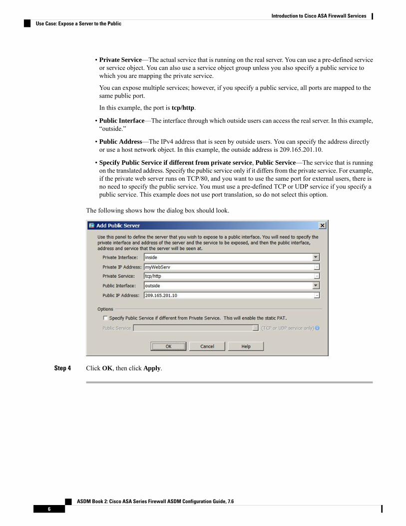
• Private Service—The actual service that is running on the real server. You can use a pre-defined serviceor service object. You can also use a service object group unless you also specify a public service towhich you are mapping the private service.
You can expose multiple services; however, if you specify a public service, all ports are mapped to thesame public port.
In this example, the port is tcp/http.
• Public Interface—The interface through which outside users can access the real server. In this example,“outside.”
• Public Address—The IPv4 address that is seen by outside users. You can specify the address directlyor use a host network object. In this example, the outside address is 209.165.201.10.
• Specify Public Service if different from private service, Public Service—The service that is runningon the translated address. Specify the public service only if it differs from the private service. For example,if the private web server runs on TCP/80, and you want to use the same port for external users, there isno need to specify the public service. You must use a pre-defined TCP or UDP service if you specify apublic service. This example does not use port translation, so do not select this option.
The following shows how the dialog box should look.
Step 4 Click OK, then click Apply.
ASDM Book 2: Cisco ASA Series Firewall ASDM Configuration Guide, 7.66
Introduction to Cisco ASA Firewall ServicesUse Case: Expose a Server to the Public
P A R T IAccess Control
• Access Rules, on page 9• Objects for Access Control, on page 27• Access Control Lists, on page 35• Identity Firewall, on page 51• ASA and Cisco TrustSec, on page 69• ASA FirePOWER Module, on page 93


C H A P T E R 2Access Rules
This chapter describes how to control network access through or to the ASA using access rules. You useaccess rules to control network access in both routed and transparent firewall modes. In transparent mode,you can use both access rules (for Layer 3 traffic) and EtherType rules (for Layer 2 traffic).
To access the ASA interface for management access, you do not also need an access rule allowing the hostIP address. You only need to configure management access according to the general operations configurationguide.
Note
• Controlling Network Access, on page 9• Licensing for Access Rules, on page 15• Guidelines for Access Control, on page 15• Configure Access Control, on page 16• Monitoring Access Rules, on page 24• History for Access Rules, on page 25
Controlling Network AccessAccess rules determine which traffic is allowed through the ASA. There are several different layers of rulesthat work together to implement your access control policy:
• Extended access rules (Layer 3+ traffic) assigned to interfaces—You can apply separate rule sets (ACLs)in the inbound and outbound directions. An extended access rule permits or denies traffic based on thesource and destination traffic criteria.
• Extended access rules assigned globally—You can create a single global rule set, which serves as yourdefault access control. The global rules are applied after interface rules.
• Management access rules (Layer 3+ traffic)—You can apply a single rule set to cover traffic directed atan interface, which would typically be management traffic. In the CLI, these are “control plane” accessgroups. For ICMP traffic directed at the device, you can alternatively configure ICMP rules.
• EtherType rules (Layer 2 traffic) assigned to interfaces (bridge group member interfaces only)—Youcan apply separate rule sets in the inbound and outbound directions. EtherType rules control networkaccess for non-IP traffic. An EtherType rule permits or denies traffic based on the EtherType. You canalso apply extended access rules to bridge group member interfaces to control Layer 3+ traffic.
ASDM Book 2: Cisco ASA Series Firewall ASDM Configuration Guide, 7.69

General Information About RulesThe following topics provide general information about access rules and EtherType rules.
Interface Access Rules and Global Access RulesYou can apply an access rule to a specific interface, or you can apply an access rule globally to all interfaces.You can configure global access rules in conjunction with interface access rules, in which case, the specificinbound interface access rules are always processed before the general global access rules. Global access rulesapply only to inbound traffic.
Inbound and Outbound RulesYou can configure access rules based on the direction of traffic:
• Inbound—Inbound access rules apply to traffic as it enters an interface. Global and management accessrules are always inbound.
• Outbound—Outbound rules apply to traffic as it exits an interface.
“Inbound” and “outbound” refer to the application of an ACL on an interface, either to traffic entering theASA on an interface or traffic exiting the ASA on an interface. These terms do not refer to the movement oftraffic from a lower security interface to a higher security interface, commonly known as inbound, or from ahigher to lower interface, commonly known as outbound.
Note
An outbound ACL is useful, for example, if you want to allow only certain hosts on the inside networks toaccess a web server on the outside network. Rather than creating multiple inbound ACLs to restrict access,you can create a single outbound ACL that allows only the specified hosts. (See the following figure.) Theoutbound ACL prevents any other hosts from reaching the outside network.
ASDM Book 2: Cisco ASA Series Firewall ASDM Configuration Guide, 7.610
Access ControlGeneral Information About Rules

Figure 2: Outbound ACL
Rule OrderThe order of rules is important. When the ASA decides whether to forward or drop a packet, the ASA teststhe packet against each rule in the order in which the rules are listed in the applied ACL. After a match isfound, no more rules are checked. For example, if you create an access rule at the beginning that explicitlypermits all traffic for an interface, no further rules are ever checked.
Implicit PermitsFor routed mode, the following types of traffic are allowed through by default:
• Unicast IPv4 and IPv6 traffic from a higher security interface to a lower security interface.
For transparent mode, the following types of traffic are allowed through by default:
• Unicast IPv4 and IPv6 traffic from a higher security interface to a lower security interface.
• ARPs in both directions. (You can control ARP traffic using ARP inspection, but you cannot control itby access rule.)
• BPDUs in both directions.
For other traffic, you need to use either an extended access rule (IPv4 and IPv6) or an EtherType rule (non-IP).
ASDM Book 2: Cisco ASA Series Firewall ASDM Configuration Guide, 7.611
Access ControlRule Order

Implicit DenyACLs have an implicit deny at the end of the list, so unless you explicitly permit it, traffic cannot pass. Forexample, if you want to allow all users to access a network through the ASA except for particular addresses,then you need to deny the particular addresses and then permit all others.
For management (control plane) ACLs, which control to-the-box traffic, there is no implicit deny at the endof a set of management rules for an interface. Instead, any connection that does not match a managementaccess rule is then evaluated by regular access control rules.
For EtherType ACLs, the implicit deny at the end of the ACL does not affect IP traffic or ARPs; for example,if you allow EtherType 8037, the implicit deny at the end of the ACL does not now block any IP traffic thatyou previously allowed with an extended ACL (or implicitly allowed from a high security interface to a lowsecurity interface). However, if you explicitly deny all traffic with an EtherType rule, then IP and ARP trafficis denied; only physical protocol traffic, such as auto-negotiation, is still allowed.
If you configure a global access rule, then the implicit deny comes after the global rule is processed. See thefollowing order of operations:
1. Interface access rule.
2. Global access rule.
3. Implicit deny.
NAT and Access RulesAccess rules always use the real IP addresses when determining an access rule match, even if you configureNAT. For example, if you configure NAT for an inside server, 10.1.1.5, so that it has a publicly routable IPaddress on the outside, 209.165.201.5, then the access rule to allow the outside traffic to access the insideserver needs to reference the server’s real IP address (10.1.1.5), and not the mapped address (209.165.201.5).
Same Security Level Interfaces and Access RulesEach interface has a security level, and security level checking is performed before access rules are considered.Thus, even if you allow a connection in an access rule, it can be blocked due to same-security-level checkingat the interface level. You might want to ensure that your configuration allows same-security-level connectionsso that your access rules are always considered for permit/deny decisions.
• Connections between the same security level ingress and egress interfaces are subject to thesame-security-traffic inter-interface check.
To allow these connections, enter the same-security-traffic permit inter-interface command.
To allow these connections, choose Configuration > Device Setup > Interface Settings > Interfaces,then select the Enable traffic between two or more interfaces which are configured with the samesecurity levels option.
• Connections with the same ingress and egress interfaces are subject to the same-security-trafficintra-interface check.
To allow these connections, enter the same-security-traffic permit intra-interface command.
To allow these connections, choose Configuration > Device Setup > Interface Settings > Interfaces,then select the Enable traffic between two or more hosts connected to the same interface option.
ASDM Book 2: Cisco ASA Series Firewall ASDM Configuration Guide, 7.612
Access ControlImplicit Deny

Extended Access RulesThis section describes information about extended access rules.
Extended Access Rules for Returning TrafficFor TCP, UDP, and SCTP connections for both routed and transparent mode, you do not need an access ruleto allow returning traffic because the ASA allows all returning traffic for established, bidirectional connections.
For connectionless protocols such as ICMP, however, the ASA establishes unidirectional sessions, so youeither need access rules to allow ICMP in both directions (by applying ACLs to the source and destinationinterfaces), or you need to enable the ICMP inspection engine. The ICMP inspection engine treats ICMPsessions as bidirectional connections. For example, to control ping, specify echo-reply (0) (ASA to host) orecho (8) (host to ASA).
Allowing Broadcast and Multicast TrafficIn routed firewall mode, broadcast and multicast traffic is blocked even if you allow it in an access rule,including unsupported dynamic routing protocols and DHCP. You must configure the dynamic routingprotocols or DHCP relay to allow this traffic.
For interfaces that are members of the same bridge group in transparent firewall mode, you can allow any IPtraffic through using access rules.
Because these special types of traffic are connectionless, you need to apply an access rule to both the inboundand outbound interfaces, so returning traffic is allowed through.
Note
The following table lists common traffic types that you can allow using access rules between interfaces thatare members of the same bridge group.
Table 1: Special Traffic for Access Rules between Members of the Same Bridge Group
NotesProtocol or PortTraffic Type
If you enable the DHCP server, then the ASA doesnot pass DHCP packets.
UDP ports 67 and 68DHCP
—Protocol 88EIGRP
—Protocol 89OSPF
Multicast streams are always destined to a Class Daddress (224.0.0.0 to 239.x.x.x).
The UDP ports vary depending onthe application.
Multicast streams
—UDP port 520RIP (v1 or v2)
Management Access RulesYou can configure access rules that control management traffic destined to the ASA. Access control rules forto-the-box management traffic (such as HTTP, Telnet, and SSH connections to an interface) have higher
ASDM Book 2: Cisco ASA Series Firewall ASDM Configuration Guide, 7.613
Access ControlExtended Access Rules

precedence than a management access rule . Therefore, such permitted management traffic will be allowedto come in even if explicitly denied by the to-the-box ACL.
Unlike regular access rules, there is no implicit deny at the end of a set of management rules for an interface.Instead, any connection that does not match a management access rule is then evaluated by regular accesscontrol rules.
Alternatively, you can use ICMP rules to control ICMP traffic to the device. Use regular extended accessrules to control ICMP traffic through the device.
EtherType RulesThis section describes EtherType rules.
Supported EtherTypes and Other TrafficAn EtherType rule controls the following:
• EtherType identified by a 16-bit hexadecimal number, including common types IPX and MPLS unicastor multicast.
• Ethernet V2 frames.
• BPDUs, which are permitted by default. BPDUs are SNAP-encapsulated, and the ASA is designed tospecifically handle BPDUs.
• Trunk port (Cisco proprietary) BPDUs. Trunk BPDUs have VLAN information inside the payload, sothe ASA modifies the payload with the outgoing VLAN if you allow BPDUs.
• Intermediate System to Intermediate System (IS-IS).
• The IEEE 802.2 Logical Link Control packet. You can control access based on the Destination ServiceAccess Point address.
The following types of traffic are not supported:
• 802.3-formatted frames—These frames are not handled by the rule because they use a length field asopposed to a type field.
EtherType Rules for Returning TrafficBecause EtherTypes are connectionless, you need to apply the rule to both interfaces if you want traffic topass in both directions.
Allowing MPLSIf you allow MPLS, ensure that Label Distribution Protocol and Tag Distribution Protocol TCP connectionsare established through the ASA by configuring bothMPLS routers connected to the ASA to use the IP addresson the ASA interface as the router-id for LDP or TDP sessions. (LDP and TDP allowMPLS routers to negotiatethe labels (addresses) used to forward packets.)
On Cisco IOS routers, enter the appropriate command for your protocol, LDP or TDP. The interface is theinterface connected to the ASA.
mpls ldp router-id interface force
ASDM Book 2: Cisco ASA Series Firewall ASDM Configuration Guide, 7.614
Access ControlEtherType Rules

Or
tag-switching tdp router-id interface force
Licensing for Access RulesAccess control rules do not require a special license.
However, to use sctp as the protocol in a rule, you must have a Carrier license.
Guidelines for Access ControlIPv6 Guidelines
Supports IPv6. (9.0 and later) The source and destination addresses can include any mix of IPv4 and IPv6addresses. For pre-9.0 versions, you must create a separate IPv6 access rule.
Per-User ACL Guidelines
• The per-user ACL uses the value in the timeout uauth command, but it can be overridden by the AAAper-user session timeout value.
• If traffic is denied because of a per-user ACL, syslog message 109025 is logged. If traffic is permitted,no syslog message is generated. The log option in the per-user ACL has no effect.
Additional Guidelines and Limitations
• Over time, your list of access rules can grow to include many obsolete rules. Eventually, the ACLs forthe access groups can become so large that they impact overall system performance. If you find that thesystem is having issues sending syslogmessages, communicating for failover synchronization, establishingand maintaining SSH/HTTPS management access connections, and so forth, you might need to pruneyour access rules. In general, you should actively maintain your rule lists to remove obsolete rules, rulesthat are never hit, FQDN objects that can no longer be resolved, and so forth. Also consider implementingobject group search.
• You can reduce the memory required to search access rules by enabling object group search, but this isat the expense rule of lookup performance and increased CPU utilization. When enabled, object groupsearch does not expand network or service objects, but instead searches access rules for matches basedon those group definitions. You can set this option by clicking the Advanced button below the accessrule table.
For each connection, both the source and destination IP addresses are matched against network objects.If the number of objects matched by the source address times the number matched by the destinationaddress exceeds 10,000, the connection is dropped. This check is to prevent performance degradation.Configure your rules to prevent an excessive number of matches.
ASDM Book 2: Cisco ASA Series Firewall ASDM Configuration Guide, 7.615
Access ControlLicensing for Access Rules

Object group search works with network and service objects only. It does notwork with security group or user objects. Do not enable this feature if the ACLsinclude security groups. The result can be inactive ACLs or other unexpectedbehavior.
Note
• You can improve system performance and reliability by using the transactional commit model for accessgroups. See the basic settings chapter in the general operations configuration guide for more information.The option is under Configurations > Device Management > Advanced > Rule Engine.
• In ASDM, rule descriptions are based on the access list remarks that come before the rule in the ACL;for new rules you create in ASDM, any descriptions are also configured as remarks before the relatedrule. However, the packet tracer in ASDMmatches the remark that is configured after the matching rulein the CLI.
• If you enter more than one item in source or destination address, or source or destination service, ASDMautomatically creates an object group for them with the prefix DM_INLINE. These objects areautomatically expanded to their component parts in the rule table view, but you can see the object namesif you deselect theAuto-expand network and service objects with specified prefix rule table preferencein Tools > Preferences.
• Normally, you cannot reference an object or object group that does not exist in an ACL or object group,or delete one that is currently referenced. You also cannot reference an ACL that does not exist in anaccess-group command (to apply access rules). However, you can change this default behavior so thatyou can “forward reference” objects or ACLs before you create them. Until you create the objects orACLs, any rules or access groups that reference them are ignored. To enable forward referencing, selectthe option in the access rules advanced settings; choose Configuration > Access Rules and click theAdvanced button.
Configure Access ControlThe following topics explain how to configure access control.
Configure Access RulesTo apply an access rule, perform the following steps.
Procedure
Step 1 Choose Configuration > Firewall > Access Rules.
The rules are organized by interface and direction, with a separate group for global rules. If you configuremanagement access rules, they are repeated on this page. These groups are equivalent to the extended ACLthat is created and assigned to the interface or globally as an access group. These ACLs also appear on theACL Manager page.
Step 2 Do any of the following:
ASDM Book 2: Cisco ASA Series Firewall ASDM Configuration Guide, 7.616
Access ControlConfigure Access Control

• To add a new rule, choose Add > Add Access Rule.
• To insert a rule at a specific location within a container, select an existing rule and choose Add > Insertto add the rule above it, or choose Add > Insert After.
• To edit a rule, select it and click Edit.
Step 3 Fill in the rule properties. The primary options to select are:
• Interface—The interface to which the rule applies. Select Any to create a global rule.
• Action: Permit/Deny—Whether you are permitting (allowing) the described traffic or are denying(dropping) it.
• Source/Destination criteria—A definition of the source (originating address) and destination (targetaddress of the traffic flow). You typically configure IPv4 or IPv6 addresses of hosts or subnets, whichyou can represent with network or network object groups. You can also specify a user or user groupname for the source. Additionally, you can use the Service field to identify the specific type of traffic ifyou want to focus the rule more narrowly than all IP traffic. If you implement Trustsec, you can usesecurity groups to define source and destination.
For detailed information on all of the available options, see Access Rule Properties, on page 17.
When you are finished defining the rule, click OK to add the rule to the table.
Step 4 Click Apply to save the access rule to your configuration.
Access Rule PropertiesWhen you add or edit an access rule, you can configure the following properties. In many fields, you can clickthe “...” button on the right of the edit box to select, create, or edit objects that are available for the field.
Interface
The interface to which the rule applies. Select Any to create a global rule.
Action: Permit/Deny
Whether you are permitting (allowing) the described traffic or are denying (dropping) it.
Source Criteria
The characteristics of the originator of the traffic you are trying to match. You must configure Source,but the other properties are optional.
Source
The IPv4 or IPv6 address of the source. The default is any, whichmatches all IPv4 or IPv6 addresses;you can use any4 to target IPv4 only, or any6 to target IPv6 only. You can specify a single hostaddress (such as 10.100.10.5 or 2001:DB8::0DB8:800:200C:417A), a subnet (in 10.100.10.0/24 or10.100.10.0/255.255.255.0 format, or for IPv6, 2001:DB8:0:CD30::/60), the name of a networkobject or network object group, or the name of an interface.
User
If you enable the identity firewall, you can specify a user or user group as the traffic source. TheIP address the user is currently using will match the rule. You can specify a username
ASDM Book 2: Cisco ASA Series Firewall ASDM Configuration Guide, 7.617
Access ControlAccess Rule Properties

(DOMAIN\user), a user group (DOMAIN\\group, note the double \ indicates a group name), or auser object group. For this field, it is far easier to click “...” to select names from your AAA servergroup than to type them in.
Security Group
If you enable Cisco Trustsec, you can specify a security group name or tag (1-65533), or securitygroup object.
More Options > Source Service
If you specify TCP, UDP, or SCTP as the destination service, you can optionally specify a predefinedservice object for TCP, UDP, TCP-UDP, or SCTP, or use your own object. Typically, you definethe destination service only and not the source service. Note that if you define the source service,the destination service protocol must match it (for example, both TCP, with or without portdefinitions).
Destination Criteria
The characteristics of the target of the traffic you are trying to match. You must configure Destination,but the other properties are optional.
Destination
The IPv4 or IPv6 address of the destination. The default is any, which matches all IPv4 or IPv6addresses; you can use any4 to target IPv4 only, or any6 to target IPv6 only. You can specify asingle host address (such as 10.100.10.5 or 2001:DB8::0DB8:800:200C:417A), a subnet (in10.100.10.0/24 or 10.100.10.0/255.255.255.0 format, or for IPv6, 2001:DB8:0:CD30::/60), thename of a network object or network object group, or the name of an interface.
Security Group
If you enable Cisco Trustsec, you can specify a security group name or tag (1-65533), or securitygroup object.
Service
The protocol of the traffic, such as IP, TCP, UDP, and optionally ports for TCP, UDP, or SCTP.The default is IP, but you can select a more specific protocol to target traffic with more granularity.Typically, you would select some type of service object. For TCP, UDP, and SCTP, you can specifyports, for example, tcp/80, tcp/http, tcp/10-20 (for a range of ports), tcp-udp/80 (match any TCP orUDP traffic on port 80), sctp/diameter, and so forth.
Description
A explanation of the purpose of the rule, up to 100 characters per line. You can enter multiple lines; eachline is added as a remark in the CLI, and the remarks are placed before the rule.
If you add remarks with non-English characters on one platform (such as Windows) then try to removethem from another platform (such as Linux), you might not be able to edit or delete them because theoriginal characters might not be correctly recognized. This limitation is due to an underlying platformdependency that encodes different language characters in different ways.
Note
Enable Logging; Logging Level; More Options > Logging Interval
The logging options define how syslog messages will be generated for rules. You can implement thefollowing logging options:
ASDM Book 2: Cisco ASA Series Firewall ASDM Configuration Guide, 7.618
Access ControlAccess Rule Properties

Deselect Enable Logging
This will disable logging for the rule. No syslog messages of any type will be issued for connectionsthat match this rule.
Select Enable Logging with Logging Level = Default
This provides the default logging for rules. Syslog message 106023 is issued for each deniedconnection. If the appliance comes under attack, the frequency of issuing this message could impactservices.
Select Enable Logging with Non-Default Logging Level
This provides a summarized syslog message, 106100, instead of 106023. Message 106100 is issuedupon first hit, then again at each interval configured in More Options > Logging Interval (defaultis every 300 seconds, you can specify 1-600), showing the number of hits during that interval. Therecommended logging level is Informational.
Summarizing deny messages can reduce the impact of attacks and possibly make it easier for youto analyze messages. If you do come under a denial of service attack, youmight see message 106101,which indicates that the number of cached deny flows used to produce the hit count for message106100 has exceeded the maximum for an interval. At this point, the appliance stops collectingstatistics until the next interval to mitigate the attack.
More Options > Traffic Direction
Whether the rule is for the In or Out direction. In is the default, and it is the only option for global andmanagement access rules.
More Options > Enable Rule
Whether the rule is active on the device. Disabled rules appear with strike-through text in the rule table.Disabling a rule lets you stop its application to traffic without deleting it, so you can enable it again laterif you decide you need it.
More Options > Time Range
The name of the time range object that defines the times of day and days of the week when the ruleshould be active. If you do not specify a time range, the rule is always active.
Configure Advanced Options for Access RulesAdvanced access rule options allow you to customize certain aspects of rule behavior, but these options havedefaults that are appropriate in most cases.
Procedure
Step 1 Choose Configuration > Firewall > Access Rules.Step 2 Click the Advanced button below the rule table.Step 3 Configure the following options as required:
• Advanced Logging Settings—If you configure non-default logging, the system caches deny flows todevelop statistics for message 106100, as explained in Evaluating Syslog Messages for Access Rules,on page 24. To prevent unlimited consumption of memory and CPU resources, the ASA places a limiton the number of concurrent deny flows because they can indicate an attack. Message 106101 is issuedwhen the limit is reached. You can control the following aspects related to 106101.
ASDM Book 2: Cisco ASA Series Firewall ASDM Configuration Guide, 7.619
Access ControlConfigure Advanced Options for Access Rules

• Maximum Deny-flows—The maximum number of deny flows permitted before the ASA stopscaching flows, between 1 and 4096. The default is 4096.
• Alert Interval—The amount of time (1-3600 seconds) between issuing system log message 106101,which indicates that the maximum number of deny flows was reached. The default is 300 seconds.
• Per User Override table—Whether to allow a dynamic user ACL that is downloaded for userauthorization from a RADIUS server to override the ACL assigned to the interface. For example, if theinterface ACL denies all traffic from 10.0.0.0, but the dynamic ACL permits all traffic from 10.0.0.0,then the dynamic ACL overrides the interface ACL for that user. Check the Per User Override box foreach interface that should allow user overrides (inbound direction only). If the per user override featureis disabled, the access rule provided by the RADIUS server is combined with the access rule configuredon that interface.
By default, VPN remote access traffic is not matched against interface ACLs. However, if you deselectthe Enable inbound VPN sessions to bypass interface access lists setting on the Configuration >Remote Access VPN > Network (Client) Access > AnyConnect Connection Profiles pane), the behaviordepends on whether there is a VPN filter applied in the group policy (see the Configuration > RemoteAccess VPN > Network (Client) Access > Group Policies > Add/Edit > General > More Options > Filterfield) and whether you set the Per User Override option:
• No Per User Override, no VPN filter —Traffic is matched against the interface ACL.
• No Per User Override, VPN filter —Traffic is matched first against the interface ACL, then againstthe VPN filter.
• Per User Override, VPN filter —Traffic is matched against the VPN filter only.
• Object Group Search Setting—You can reduce the memory required to search access rules that useobject groups by selecting Enable Object Group Search Algorithm, but this is at the expense of rulelookup performance. When enabled, object group search does not expand network objects, but insteadsearches access rules for matches based on those group definitions.
Object group search works with network and service objects only. It does not work with securitygroup objects. Do not enable this feature if the ACLs include security groups. The result canbe inactive ACLs or other unexpected behavior.
Note
• Forward Reference Setting—Normally, you cannot reference an object or object group that does notexist in an ACL or object group, or delete one that is currently referenced. You also cannot reference anACL that does not exist in an access-group command (to apply access rules). However, you can changethis default behavior so that you can “forward reference” objects or ACLs before you create them. Untilyou create the objects or ACLs, any rules or access groups that reference them are ignored. SelectEnablethe forward reference of objects and object-groups to enable forward referencing. Be aware that ifyou enable forward referencing, ASDM cannot tell the difference between a typo reference to an existingobject and a forward reference.
Step 4 Click OK.
ASDM Book 2: Cisco ASA Series Firewall ASDM Configuration Guide, 7.620
Access ControlConfigure Advanced Options for Access Rules
Configure Management Access RulesYou can configure an interface ACL that controls to-the-box management traffic from a specific peer (or setof peers) to the ASA. One scenario in which this type of ACL would be useful is when you want to blockIKE Denial of Service attacks.
Unlike regular access rules, there is no implicit deny at the end of a set of management rules for an interface.Instead, any connection that does not match a management access rule is then evaluated by regular accesscontrol rules.
Procedure
Step 1 Choose Configuration > Device Management > Management Access > Management Access Rules.
The rules are organized by interface. Each group is equivalent to the extended ACL that is created and assignedto the interface as a control plane ACL. These ACLs also appear on the Access Rules and ACL Managerpages.
Step 2 Do any of the following:
• To add a new rule, choose Add > Add Management Access Rule.
• To insert a rule at a specific location within a container, select an existing rule and choose Add > Insertto add the rule above it, or choose Add > Insert After.
• To edit a rule, select it and click Edit.
Step 3 Fill in the rule properties. The primary options to select are:
• Interface—The interface to which the rule applies.
• Action: Permit/Deny—Whether you are permitting (allowing) the described traffic or are denying(dropping) it.
• Source/Destination criteria—A definition of the source (originating address) and destination (targetaddress of the traffic flow). You typically configure IPv4 or IPv6 addresses of hosts or subnets, whichyou can represent with network or network object groups. You can also specify a user or user groupname for the source. Additionally, you can use the Service field to identify the specific type of traffic ifyou want to focus the rule more narrowly than all IP traffic. If you implement Trustsec, you can usesecurity groups to define source and destination.
For detailed information on all of the available options, see Access Rule Properties, on page 17.
When you are finished defining the rule, click OK to add the rule to the table.
Step 4 Click Apply to save the rule to your configuration.
Configure EtherType RulesEtherType rules apply to non-IP layer-2 traffic on bridge group member interfaces (in transparent firewallmode). You can use these rules to permit or drop traffic based on the EtherType value in the layer-2 packet.With EtherType rules, you can control the flow of non-IP traffic across the ASA.
ASDM Book 2: Cisco ASA Series Firewall ASDM Configuration Guide, 7.621
Access ControlConfigure Management Access Rules

You can apply both extended and EtherType access rules to a bridge group member interface. EtherType rulestake precedence over the extended access rules.
Procedure
Step 1 Choose Configuration > Firewall > EtherType Rules.
The rules are organized by interface and direction. Each group is equivalent to the EtherType ACL that iscreated and assigned to the interface.
Step 2 Do any of the following:
• To add a new rule, choose Add > Add EtherType Rule.
• To insert a rule at a specific location within a container, select an existing rule and choose Add > Insertto add the rule above it, or choose Add > Insert After.
• To edit a rule, select it and click Edit.
Step 3 Fill in the rule properties. The primary options to select are:
• Interface—The interface to which the rule applies.
• Action: Permit/Deny—Whether you are permitting (allowing) the described traffic or are denying(dropping) it.
• EtherType—You can match traffic using the following options:
• any—Matches all traffic.
• bpdu—Bridge protocol data units, which are allowed by default. This keyword no longer matchesthe intended traffic. To control BPDUs, instead use dsap 0x42.
• dsap—The IEEE 802.2 Logical Link Control packet's Destination Service Access Point address.You also need to include the address you want to permit or deny in hexadecimal, from 0x01 to 0xff,in DSAP Value. Following are the values for some common addresses:
• 0x42—bridge protocol data units (BPDU).
• 0xe0—Internet Packet Exchange (IPX) 802.2 LLC.
• 0xfe—Intermediate System to Intermediate System (IS-IS).
• 0xff—raw IPX 802.3 format.
• ipx—Internet Packet Exchange (IPX).
• isis—Intermediate System to Intermediate System (IS-IS).
• mpls-multicast—MPLS multicast.
• mpls-unicast—MPLS unicast.
• hex_number—Any EtherType that can be identified by a 16-bit hexadecimal number 0x600 to0xffff. See RFC 1700, “Assigned Numbers,” at http://www.ietf.org/rfc/rfc1700.txt for a list ofEtherTypes.
ASDM Book 2: Cisco ASA Series Firewall ASDM Configuration Guide, 7.622
Access ControlConfigure EtherType Rules

• Description—A explanation of the purpose of the rule, up to 100 characters per line. You can entermultiple lines; each line is added as a remark in the CLI, and the remarks are placed before the rule.
• More Options > Direction—Whether the rule is for the In or Out direction. In is the default.
When you are finished defining the rule, click OK to add the rule to the table.
Step 4 Click Apply to save the rule to your configuration.
Configure ICMP Access RulesBy default, you can send ICMP packets to any interface using either IPv4 or IPv6, with these exceptions:
• The ASA does not respond to ICMP echo requests directed to a broadcast address.
• The ASA only responds to ICMP traffic sent to the interface that traffic comes in on; you cannot sendICMP traffic through an interface to a far interface.
To protect the device from attacks, you can use ICMP rules to limit ICMP access to interfaces to particularhosts, networks, or ICMP types. ICMP rules function like access rules, where the rules are ordered, and thefirst rule that matches a packet defines the action.
If you configure any ICMP rule for an interface, an implicit deny ICMP rule is added to the end of the ICMPrule list, changing the default behavior. Thus, if you want to simply deny a few message types, you mustinclude a permit any rule at the end of the ICMP rule list to allow the remaining message types.
We recommend that you always grant permission for the ICMP unreachable message type (type 3). DenyingICMP unreachable messages disables ICMP path MTU discovery, which can halt IPsec and PPTP traffic.Additionally ICMP packets in IPv6 are used in the IPv6 neighbor discovery process.
Procedure
Step 1 Choose Configuration > Device Management > Management Access > ICMP.Step 2 Configure ICMP rules:
a) Add a rule (Add > Rule, Add > IPv6 Rule, or Add > Insert), or select a rule and edit it.b) Select the ICMP type you want to control, or any to apply to all types.c) Select the interface to which the rule applies. You must create separate rules for each interface.d) Select whether you are permitting or denying access for matching traffic.e) Select Any Address to apply the rule to all traffic. Alternatively, enter the address and mask (for IPv4)
or address and prefix length (for IPv6) of the host or network you are trying to control.f) Click OK.
Step 3 (Optional) To set ICMP unreachable message limits, set the following options. Increasing the rate limit, alongwith enabling the Decrement time to live for a connection option in a service policy (on the Configuration> Firewall > Service Policy Rules > Rule Actions > Connection Settings dialog box), is required to allow atrace route through the ASA that shows the ASA as one of the hops.
• Rate Limit—Sets the rate limit of unreachable messages, between 1 and 100 messages per second. Thedefault is 1 message per second.
• Burst Size—Sets the burst rate, between 1 and 10. This value is not currently used by the system.
ASDM Book 2: Cisco ASA Series Firewall ASDM Configuration Guide, 7.623
Access ControlConfigure ICMP Access Rules

Step 4 Click Apply.
Monitoring Access RulesThe Access Rules page includes hit counts for each rule. Mouse over the hit count to see the update time andinterval for the count. To reset the hit count, right click the rule and select Clear Hit Count, but be awarethat this clears the count for all rules applied to the same interface in the same direction.
Evaluating Syslog Messages for Access RulesUse a syslog event viewer, such as the one in ASDM, to view messages related to access rules.
If you use default logging, you see syslog message 106023 for explicitly denied flows only. Traffic thatmatches the “implicit deny” entry that ends the rule list is not logged.
If the ASA is attacked, the number of syslog messages for denied packets can be very large. We recommendthat you instead enable logging using syslog message 106100, which provides statistics for each rule (includingpermit rules) and enables you to limit the number of syslog messages produced. Alternatively, you can disableall logging for a given rule.
When you enable logging for message 106100, if a packet matches an ACE, the ASA creates a flow entry totrack the number of packets received within a specific interval. The ASA generates a syslog message at thefirst hit and at the end of each interval, identifying the total number of hits during the interval and the timestamp for the last hit. At the end of each interval, the ASA resets the hit count to 0. If no packets match theACE during an interval, the ASA deletes the flow entry. When you configure logging for a rule, you cancontrol the interval and even the severity level of the log message, per rule.
A flow is defined by the source and destination IP addresses, protocols, and ports. Because the source portmight differ for a new connection between the same two hosts, you might not see the same flow incrementbecause a new flow was created for the connection.
Permitted packets that belong to established connections do not need to be checked against ACLs; only theinitial packet is logged and included in the hit count. For connectionless protocols, such as ICMP, all packetsare logged, even if they are permitted, and all denied packets are logged.
See the syslog messages guide for detailed information about these messages.
When you enable logging for message 106100, if a packet matches an ACE, the ASA creates a flow entry totrack the number of packets received within a specific interval. The ASA has a maximum of 32 K loggingflows for ACEs. A large number of flows can exist concurrently at any point of time. To prevent unlimitedconsumption of memory and CPU resources, the ASA places a limit on the number of concurrent deny flows;the limit is placed on deny flows only (not on permit flows) because they can indicate an attack. When thelimit is reached, the ASA does not create a new deny flow for logging until the existing flows expire, andissues message 106101. You can control the frequency of this message, and the maximum number of denyflows cached, in the advanced settings; see Configure Advanced Options for Access Rules, on page 19.
Tip
ASDM Book 2: Cisco ASA Series Firewall ASDM Configuration Guide, 7.624
Access ControlMonitoring Access Rules
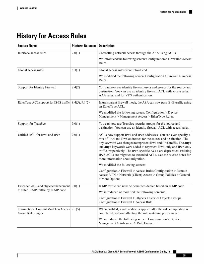
History for Access RulesDescriptionPlatform ReleasesFeature Name
Controlling network access through the ASA using ACLs.
We introduced the following screen: Configuration > Firewall > AccessRules.
7.0(1)Interface access rules
Global access rules were introduced.
We modified the following screen: Configuration > Firewall > AccessRules.
8.3(1)Global access rules
You can now use identity firewall users and groups for the source anddestination. You can use an identity firewall ACL with access rules,AAA rules, and for VPN authentication.
8.4(2)Support for Identity Firewall
In transparent firewall mode, the ASA can now pass IS-IS traffic usingan EtherType ACL.
We modified the following screen: Configuration > DeviceManagement > Management Access > EtherType Rules.
8.4(5), 9.1(2)EtherType ACL support for IS-IS traffic
You can now use TrustSec security groups for the source anddestination. You can use an identity firewall ACL with access rules.
9.0(1)Support for TrustSec
ACLs now support IPv4 and IPv6 addresses. You can even specify amix of IPv4 and IPv6 addresses for the source and destination. Theany keyword was changed to represent IPv4 and IPv6 traffic. The any4and any6 keywords were added to represent IPv4-only and IPv6-onlytraffic, respectively. The IPv6-specific ACLs are deprecated. ExistingIPv6 ACLs are migrated to extended ACLs. See the release notes formore information about migration.
We modified the following screens:
Configuration > Firewall > Access Rules Configuration > RemoteAccess VPN > Network (Client) Access > Group Policies > General> More Options
9.0(1)Unified ACL for IPv4 and IPv6
ICMP traffic can now be permitted/denied based on ICMP code.
We introduced or modified the following screens:
Configuration > Firewall > Objects > Service Objects/GroupsConfiguration > Firewall > Access Rule
9.0(1)Extended ACL and object enhancementto filter ICMP traffic by ICMP code
When enabled, a rule update is applied after the rule compilation iscompleted; without affecting the rule matching performance.
We introduced the following screen: Configuration > DeviceManagement > Advanced > Rule Engine.
9.1(5)Transactional CommitModel onAccessGroup Rule Engine
ASDM Book 2: Cisco ASA Series Firewall ASDM Configuration Guide, 7.625
Access ControlHistory for Access Rules

DescriptionPlatform ReleasesFeature Name
You can now edit ACLs and objects in an isolated configuration session.You can also forward reference objects and ACLs, that is, configurerules and access groups for objects or ACLs that do not yet exist.
9.3(2)Configuration session for editing ACLsand objects.
Forward referencing of objects andACLs in access rules.
You can now create access rules using the sctp protocol, includingport specifications.
We modified the add/edit dialog boxes for access rules on theConfiguration > Firewall > Access Rules page.
9.5(2)Access rule support for Stream ControlTransmission Protocol (SCTP)
You can now write Ethertype access control rules for the IEEE 802.2Logical Link Control packet's Destination Service Access Point address.Because of this addition, the bpdu keyword no longer matches theintended traffic. Rewrite bpdu rules for dsap 0x42.
We modified the following screen: Configuration > Firewall >EtherType Rules.
9.6(2)Ethertype rule support for the IEEE802.2 Logical Link Control packet'sDestination Service Access Pointaddress.
ASDM Book 2: Cisco ASA Series Firewall ASDM Configuration Guide, 7.626
Access ControlHistory for Access Rules

C H A P T E R 3Objects for Access Control
Objects are reusable components for use in your configuration. You can define and use them in Cisco ASAconfigurations in the place of inline IP addresses, services, names, and so on. Objects make it easy to maintainyour configurations because you can modify an object in one place and have it be reflected in all other placesthat are referencing it. Without objects you would have to modify the parameters for every feature whenrequired, instead of just once. For example, if a network object defines an IP address and subnet mask, andyou want to change the address, you only need to change it in the object definition, not in every feature thatrefers to that IP address.
• Guidelines for Objects, on page 27• Configure Objects, on page 28• Monitoring Objects, on page 34• History for Objects, on page 34
Guidelines for ObjectsIPv6 Guidelines
Supports IPv6 with the following restrictions:
• You can mix IPv4 and IPv6 entries in a network object group, but you cannot use a mixed object groupfor NAT.
Additional Guidelines and Limitations
• Objects must have unique names, because objects and object groups share the same name space. Whileyou might want to create a network object group named “Engineering” and a service object group named“Engineering,” you need to add an identifier (or “tag”) to the end of at least one object group name tomake it unique. For example, you can use the names “Engineering_admins” and “Engineering_hosts”to make the object group names unique and to aid in identification.
• If you enter more than one item in source or destination address, or source or destination service, in anACL or access rule, ASDM automatically creates an object group for themwith the prefix DM_INLINE.These objects are not shown on the objects page, but they are defined on the device.
• Object names are limited to 64 characters, including letters, numbers, and these characters:.!@#$%^&()-_{}. Object names are case-sensitive.
ASDM Book 2: Cisco ASA Series Firewall ASDM Configuration Guide, 7.627

• You cannot remove an object or make an object empty if it is used in a command, unless you enableforward referencing (in the access rules advanced settings).
Configure ObjectsThe following sections describe how to configure objects that are primarily used on access control.
Configure Network Objects and GroupsNetwork objects and groups identify IP addresses or host names. Use these objects in access control lists tosimplify your rules.
Configure a Network ObjectA network object can contain a host, a network IP address, a range of IP addresses, or a fully qualified domainname (FQDN).
You can also enable NAT rules on the object (excepting FQDN objects). For more information aboutconfiguring object NAT, see Network Address Translation (NAT), on page 127.
Procedure
Step 1 Choose Configuration > Firewall > Objects > Network Objects/Group.Step 2 Do one of the following:
• Choose Add > Network Object to add a new object. Enter a name and optionally, a description.
• Choose an existing object and click Edit.
Step 3 Configure the address for the object based on the object Type and IP version fields.
• Host—The IPv4 or IPv6 address of a single host. For example, 10.1.1.1 or2001:DB8::0DB8:800:200C:417A.
• Network—The address of a network. For IPv4, include the mask, for example, IP address = 10.0.0.0Netmask = 255.0.0.0. For IPv6, include the prefix, such as IP Address = 2001:DB8:0:CD30:: PrefixLength = 60.
• Range—A range of addresses. You can specify IPv4 or IPv6 ranges. Do not include masks or prefixes.
• FQDN—A fully-qualified domain name, that is, the name of a host, such as www.example.com.
Step 4 Click OK, then click Apply.
You can now use this network object when you create a rule. If you edit an object, the change is inheritedautomatically by any rules using the object.
ASDM Book 2: Cisco ASA Series Firewall ASDM Configuration Guide, 7.628
Access ControlConfigure Objects

Configure a Network Object GroupNetwork object groups can contain multiple network objects as well as inline networks or hosts. Networkobject groups can include a mix of both IPv4 and IPv6 addresses.
However, you cannot use a mixed IPv4 and IPv6 object group for NAT, or object groups that include FQDNobjects.
Procedure
Step 1 Choose Configuration > Firewall > Objects > Network Objects/Groups.Step 2 Do one of the following:
• Choose Add > Network Object Group to add a new object. Enter a name and optionally, a description.
• Choose an existing object and click Edit.
Step 3 Add network objects to the group using any combination of the following techniques:
• Existing Network Objects/Groups—Select any already defined network object or group and clickAddto include them in the group.
• Create New Network Object Member—Enter the criteria for a new network object and click Add. Ifyou give the object a name, when you apply changes, the new object is created and added to the group.The name is optional when adding hosts or networks.
Step 4 After you add all the member objects, click OK, then click Apply.
You can now use this network object group when you create a rule. For an edited object group, the change isinherited automatically by any rules using the group.
Configure Service Objects and Service GroupsService objects and groups identify protocols and ports. Use these objects in access control lists to simplifyyour rules.
Configure a Service ObjectA service object can contain a single protocol specification.
Procedure
Step 1 Choose Configuration > Firewall > Objects > Service Object/Group.Step 2 Do one of the following:
• Choose Add > Service Object to add a new object. Enter a name and optionally, a description.
• Choose an existing object and click Edit.
ASDM Book 2: Cisco ASA Series Firewall ASDM Configuration Guide, 7.629
Access ControlConfigure a Network Object Group

Step 3 Choose the service type and fill in details as needed:
• Protocol—A number between 0-255, or a well-known name, such as ip, tcp, udp, gre, and so forth..
• ICMP, ICMP6—You can leave themessage type and code fields blank tomatch any ICMP/ICMP version6 message. You can optionally specify the ICMP type by name or number (0-255) to limit the object tothat message type. If you specify a type, you can optionally specify an ICMP code for that type (1-255).If you do not specify the code, then all codes are used.
• TCP, UDP, SCTP—You can optionally specify ports for the source, destination, or both. You can specifythe port by name or number. You can include the following operators:
• <—Less than. For example, <80.
• >—Greater than. For example, >80.
• !=—Not equal to. For example, !=80.
• - (hyphen)—An inclusive range of values. For example, 100-200.
Step 4 Click OK, and then Apply.
Configure a Service GroupA service object group includes a mix of protocols, if desired, including optional source and destination portsfor protocols that use them, and ICMP type and code.
Before you begin
You can model all services using the generic service object group, which is explained here. However, youcan still configure the types of service group objects that were available prior to ASA 8.3(1). These legacyobjects include TCP/UDP/TCP-UDP port groups, protocol groups, and ICMP groups. The contents of thesegroups are equivalent to the associated configuration in the generic service object group, with the exceptionof ICMP groups, which do not support ICMP6 or ICMP codes. If you still want to use these legacy objects,for detailed instructions, see the object-service command description in the command reference on Cisco.com.
Procedure
Step 1 Choose Configuration > Firewall > Objects > Service Objects/Groups.Step 2 Do one of the following:
• Choose Add > Service Group to add a new object. Enter a name and optionally, a description.
• Choose an existing object and click Edit.
Step 3 Add service objects to the group using any combination of the following techniques:
• Existing Service/Service Group—Select any already defined service, service object, or group and clickAdd to include them in the group.
• Create New Member—Enter the criteria for a new service object and click Add. If you give the objecta name, when you apply changes, the new object is created and added to the group; otherwise, unnamed
ASDM Book 2: Cisco ASA Series Firewall ASDM Configuration Guide, 7.630
Access ControlConfigure a Service Group

objects are members of this group only. You cannot name TCP-UDP objects; these are members of thegroup only.
Step 4 After you add all the member objects, click OK, then click Apply.
You can now use this service object group when you create a rule. For an edited object group, the change isinherited automatically by any rules using the group.
Configure Local User GroupsYou can create local user groups for use in features that support the identity firewall by including the groupin an extended ACL, which in turn can be used in an access rule, for example.
The ASA sends an LDAP query to the Active Directory server for user groups globally defined in the ActiveDirectory domain controller. The ASA imports these groups for identity-based rules. However, the ASAmighthave localized network resources that are not defined globally that require local user groups with localizedsecurity policies. Local user groups can contain nested groups and user groups that are imported from ActiveDirectory. The ASA consolidates local and Active Directory groups.
A user can belong to local user groups and user groups imported from Active Directory.
Because you can use usernames and user group names directly in an ACL, you need to configure local usergroups only if:
• You want to create a group of users defined in the LOCAL database.
• You want to create a group of users or user groups that are not captured in a single user group definedon the AD server.
Procedure
Step 1 Choose Configuration > Firewall > Objects > Local User Groups.Step 2 Do one of the following:
• Choose Add to add a new object. Enter a name and optionally, a description.
• Choose an existing object and click Edit.
Step 3 Add users or groups to the object using any of these methods:
• Select existing users or groups—Select the domain that contains the user or group, then pick the useror group name from the lists and click Add. For long lists, use the Find box to help locate the user. Thenames are pulled from the server for the selected domain.
• Manually type user names—You can simply type in the user or group names in the bottom edit boxand click Add. When using this method, the selected domain name is ignored, and the default domainis used if you do not specify one. For users, the format is domain_name\username; for groups, there isa double \\, domain_name\\group_name.
Step 4 After you add all the member objects, click OK, then click Apply.
ASDM Book 2: Cisco ASA Series Firewall ASDM Configuration Guide, 7.631
Access ControlConfigure Local User Groups

You can now use this user object group when you create a rule. For an edited object group, the change isinherited automatically by any rules using the group.
Configure Security Group Object GroupsYou can create security group object groups for use in features that support Cisco TrustSec by including thegroup in an extended ACL, which in turn can be used in an access rule, for example.
When integrated with Cisco TrustSec, the ASA downloads security group information from the ISE. The ISEacts as an identity repository, by providing Cisco TrustSec tag-to-user identity mapping and Cisco TrustSectag-to-server resource mapping. You provision and manage security group ACLs centrally on the ISE.
However, the ASA might have localized network resources that are not defined globally that require localsecurity groups with localized security policies. Local security groups can contain nested security groups thatare downloaded from the ISE. The ASA consolidates local and central security groups.
To create local security groups on the ASA, you create a local security object group. A local security objectgroup can contain one or more nested security object groups or Security IDs or security group names. Youcan also create a new Security ID or security group name that does not exist on the ASA.
You can use the security object groups you create on the ASA to control access to network resources. Youcan use the security object group as part of an access group or service policy.
If you create a group with tags or names that are not known to the ASA, any rules that use the group will beinactive until the tags or names are resolved with ISE.
Tip
Procedure
Step 1 Choose Configuration > Firewall > Objects > Security Group Object Groups.Step 2 Do one of the following:
• Choose Add to add a new object. Enter a name and optionally, a description.
• Choose an existing object and click Edit.
Step 3 Add security groups to the object using any of these methods:
• Select existing local security group object groups—Pick from the list of objects already defined andclick Add. For long lists, use the Find box to help locate the object.
• Select security groups discovered from ISE—Pick groups from the list of existing groups and clickAdd.
• Manually add security tags or names—You can simply type in the tag number or security group namein the bottom edit box and click Add. A tag is a number from 1 to 65533 and is assigned to a devicethrough IEEE 802.1X authentication, web authentication, or MAC authentication bypass (MAB) by theISE. Security group names are created on the ISE and provide user-friendly names for security groups.The security group table maps SGTs to security group names. Consult your ISE configuration for thevalid tags and names.
ASDM Book 2: Cisco ASA Series Firewall ASDM Configuration Guide, 7.632
Access ControlConfigure Security Group Object Groups

Step 4 After you add all the member objects, click OK, then click Apply.
You can now use this security group object group when you create a rule. For an edited object group, thechange is inherited automatically by any rules using the group.
Configure Time RangesA time range object defines a specific time consisting of a start time, an end time, and optional recurringentries. You use these objects on ACL rules to provide time-based access to certain features or assets. Forexample, you could create an access rule that allows access to a particular server during working hours only.
You can include multiple periodic entries in a time range object. If a time range has both absolute and periodicvalues specified, then the periodic values are evaluated only after the absolute start time is reached, and theyare not further evaluated after the absolute end time is reached.
Note
Creating a time range does not restrict access to the device. This procedure defines the time range only. Youmust then use the object in an access control rule.
Procedure
Step 1 Choose Configuration > Firewall > Objects > Time Ranges.Step 2 Do one of the following:
• Choose Add to add a new time range. Enter a name and optionally, a description.
• Choose an existing time range and click Edit.
Step 3 Choose the overall start and end time.
The default is to start now and never end, but you can set specific dates and times. The time range is inclusiveof the times that you enter.
Step 4 (Optional) Configure recurring periods within the overall active time, such as the days of the week or therecurring weekly interval in which the time range will be active.a) Click Add, or select an existing period and click Edit.b) Do one of the following:
• Click Specify days of the week and times on which this recurring range will be active, and choosethe days and times from the lists.
• Click Specify a weekly interval when this recurring range will be active, and choose the daysand times from the lists.
c) Click OK.
Step 5 Click OK, and then click Apply.
ASDM Book 2: Cisco ASA Series Firewall ASDM Configuration Guide, 7.633
Access ControlConfigure Time Ranges
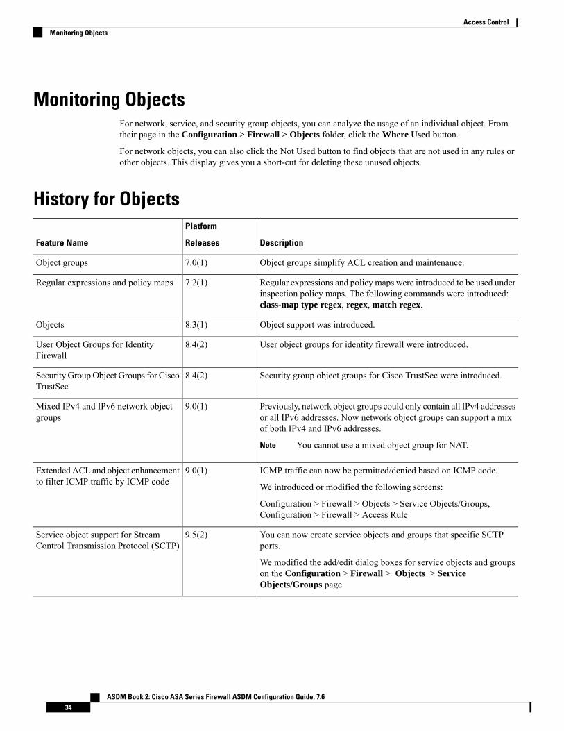
Monitoring ObjectsFor network, service, and security group objects, you can analyze the usage of an individual object. Fromtheir page in the Configuration > Firewall > Objects folder, click the Where Used button.
For network objects, you can also click the Not Used button to find objects that are not used in any rules orother objects. This display gives you a short-cut for deleting these unused objects.
History for Objects
Description
Platform
ReleasesFeature Name
Object groups simplify ACL creation and maintenance.7.0(1)Object groups
Regular expressions and policy maps were introduced to be used underinspection policy maps. The following commands were introduced:class-map type regex, regex, match regex.
7.2(1)Regular expressions and policy maps
Object support was introduced.8.3(1)Objects
User object groups for identity firewall were introduced.8.4(2)User Object Groups for IdentityFirewall
Security group object groups for Cisco TrustSec were introduced.8.4(2)Security GroupObject Groups for CiscoTrustSec
Previously, network object groups could only contain all IPv4 addressesor all IPv6 addresses. Now network object groups can support a mixof both IPv4 and IPv6 addresses.
You cannot use a mixed object group for NAT.Note
9.0(1)Mixed IPv4 and IPv6 network objectgroups
ICMP traffic can now be permitted/denied based on ICMP code.
We introduced or modified the following screens:
Configuration > Firewall > Objects > Service Objects/Groups,Configuration > Firewall > Access Rule
9.0(1)Extended ACL and object enhancementto filter ICMP traffic by ICMP code
You can now create service objects and groups that specific SCTPports.
We modified the add/edit dialog boxes for service objects and groupson the Configuration > Firewall > Objects > ServiceObjects/Groups page.
9.5(2)Service object support for StreamControl Transmission Protocol (SCTP)
ASDM Book 2: Cisco ASA Series Firewall ASDM Configuration Guide, 7.634
Access ControlMonitoring Objects

C H A P T E R 4Access Control Lists
Access control lists (ACLs) are used by many different features. When applied to interfaces or globally asaccess rules, they permit or deny traffic that flows through the appliance. For other features, the ACL selectsthe traffic to which the feature will apply, performing a matching service rather than a control service.
The following sections explain the basics of ACLs and how to configure and monitor them. Access rules,ACLs applied globally or to interfaces, are explained in more detail in Access Rules, on page 9.
• About ACLs, on page 35• Licensing for Access Control Lists, on page 39• Guidelines for ACLs, on page 40• Configure ACLs, on page 41• Monitoring ACLs, on page 48• History for ACLs, on page 49
About ACLsAccess control lists (ACLs) identify traffic flows by one or more characteristics, including source and destinationIP address, IP protocol, ports, EtherType, and other parameters, depending on the type of ACL. ACLs areused in a variety of features. ACLs are made up of one or more access control entries (ACEs).
ACL TypesThe ASA uses the following types of ACLs:
• Extended ACLs—Extended ACLs are the main type that you will use. These ACLs are used for accessrules to permit and deny traffic through the device, and for traffic matching by many features, includingservice policies, AAA rules, WCCP, Botnet Traffic Filter, and VPN group and DAP policies. In ASDM,many of these features have their own rules pages and they cannot use extended ACLs that you definein the ACLManager, althoughACLManager will display the ACLs created on those pages. See ConfigureExtended ACLs, on page 41.
• EtherType ACLs—EtherType ACLs apply to non-IP layer-2 traffic on bridge group member interfacesonly. You can use these rules to permit or drop traffic based on the EtherType value in the layer-2 packet.With EtherType ACLs, you can control the flow of non-IP traffic across the device. See ConfigureEtherType Rules, on page 21.
ASDM Book 2: Cisco ASA Series Firewall ASDM Configuration Guide, 7.635
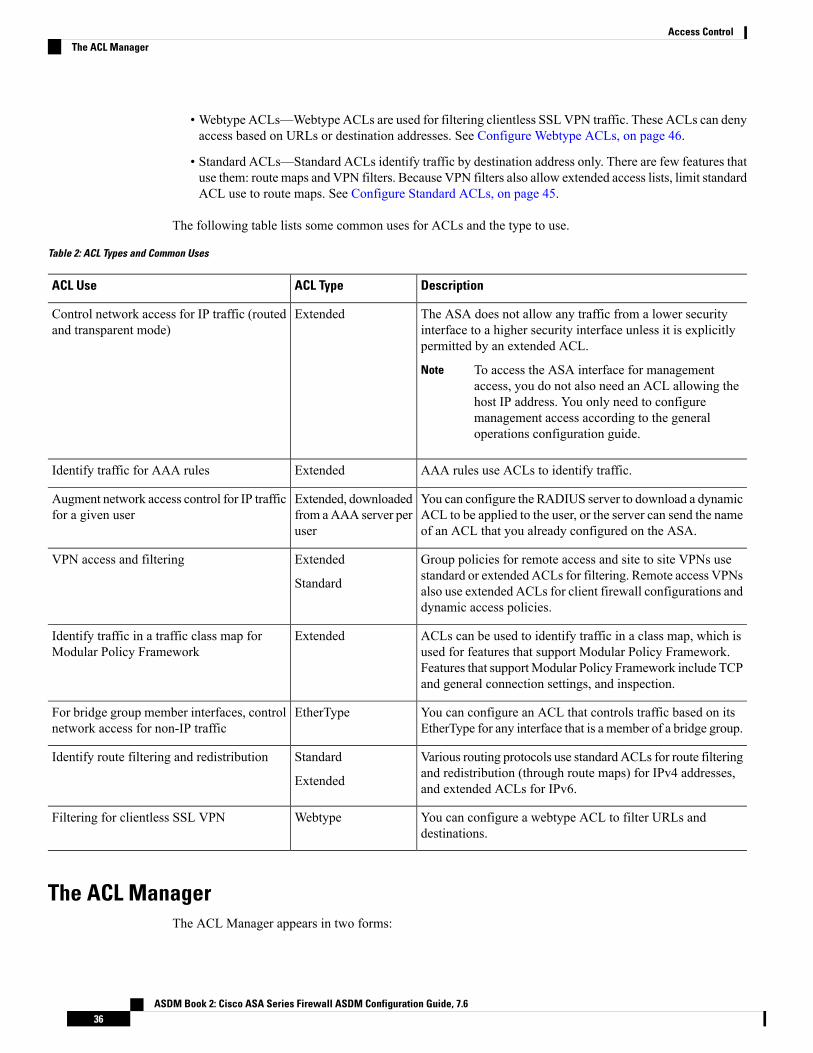
• Webtype ACLs—Webtype ACLs are used for filtering clientless SSL VPN traffic. These ACLs can denyaccess based on URLs or destination addresses. See Configure Webtype ACLs, on page 46.
• Standard ACLs—Standard ACLs identify traffic by destination address only. There are few features thatuse them: route maps and VPN filters. Because VPN filters also allow extended access lists, limit standardACL use to route maps. See Configure Standard ACLs, on page 45.
The following table lists some common uses for ACLs and the type to use.
Table 2: ACL Types and Common Uses
DescriptionACL TypeACL Use
The ASA does not allow any traffic from a lower securityinterface to a higher security interface unless it is explicitlypermitted by an extended ACL.
To access the ASA interface for managementaccess, you do not also need an ACL allowing thehost IP address. You only need to configuremanagement access according to the generaloperations configuration guide.
Note
ExtendedControl network access for IP traffic (routedand transparent mode)
AAA rules use ACLs to identify traffic.ExtendedIdentify traffic for AAA rules
You can configure the RADIUS server to download a dynamicACL to be applied to the user, or the server can send the nameof an ACL that you already configured on the ASA.
Extended, downloadedfrom aAAA server peruser
Augment network access control for IP trafficfor a given user
Group policies for remote access and site to site VPNs usestandard or extended ACLs for filtering. Remote access VPNsalso use extended ACLs for client firewall configurations anddynamic access policies.
Extended
Standard
VPN access and filtering
ACLs can be used to identify traffic in a class map, which isused for features that support Modular Policy Framework.Features that supportModular Policy Framework include TCPand general connection settings, and inspection.
ExtendedIdentify traffic in a traffic class map forModular Policy Framework
You can configure an ACL that controls traffic based on itsEtherType for any interface that is a member of a bridge group.
EtherTypeFor bridge group member interfaces, controlnetwork access for non-IP traffic
Various routing protocols use standard ACLs for route filteringand redistribution (through route maps) for IPv4 addresses,and extended ACLs for IPv6.
Standard
Extended
Identify route filtering and redistribution
You can configure a webtype ACL to filter URLs anddestinations.
WebtypeFiltering for clientless SSL VPN
The ACL ManagerThe ACL Manager appears in two forms:
ASDM Book 2: Cisco ASA Series Firewall ASDM Configuration Guide, 7.636
Access ControlThe ACL Manager

• In themain window, for example, by selectingConfiguration >Firewall >Advanced >ACL Manager.In this case, the ACLManager shows extended ACLs only. These ACLs include those generated by rulesyou create in the Access Rules, Service Policy Rules, and AAA Rules pages. Be careful that edits youmake in ACL Manager do not negatively impact these rules; changes you make here will be reflectedon those other pages.
• From a policy that requires an ACL, by clicking the Manage button next to the field. In this case, theACL Manager can have separate tabs for standard and extended ACLs, if the policy allows either type.Otherwise, the view is filtered to show standard, extended, or webtype ACLs only. The ACL Managernever shows EtherType ACLs.
There are separate pages for standard ACLs and webtype ACLs, so that you can configure them in the mainwindow. These pages are functionally equivalent to the ACL Manager without the name:
• Standard ACLs—Configuration > Firewall > Advanced > Standard ACL.
• Webtype ACLs—Configuration > Remote Access VPN > Clientless SSL VPN Access > Advanced >Web ACLs.
ACL NamesEach ACL has a name or numeric ID, such as outside_in, OUTSIDE_IN, or 101. Limit the names to 241characters or fewer.Consider using all uppercase letters to make it easier to find the name when viewing arunning configuration.
Develop a naming convention that will help you identify the intended purpose of the ACL. For example,ASDM uses the convention interface-name_purpose_direction, such as “outside_access_in”, for an ACLapplied to the “outside” interface in the inbound direction.
Traditionally, ACL IDs were numbers. Standard ACLs were in the range 1-99 or 1300-1999. Extended ACLswere in the range 100-199 or 2000-2699. The ASA does not enforce these ranges, but if you want to usenumbers, you might want to stick to these conventions to maintain consistency with routers running IOSSoftware.
Access Control Entry OrderAn ACL is made up of one or more ACEs. Unless you explicitly insert an ACE at a given line, each ACEthat you enter for a given ACL name is appended to the end of the ACL.
The order of ACEs is important. When the ASA decides whether to forward or drop a packet, the ASA teststhe packet against each ACE in the order in which the entries are listed. After a match is found, no more ACEsare checked.
Thus, if you place a more specific rule after a more general rule, the more specific rule might never be hit.For example, if you want to permit network 10.1.1.0/24, but drop traffic from host 10.1.1.15 on that subnet,the ACE that denies 10.1.1.15 must come before the one that permits 10.1.1.0/24. If the permit 10.1.1.0/24ACE comes first, 10.1.1.15 will be allowed, and the deny ACE will never be matched.
Use the Up and Down buttons to reposition rules as necessary.
ASDM Book 2: Cisco ASA Series Firewall ASDM Configuration Guide, 7.637
Access ControlACL Names

Permit/Deny vs. Match/Do Not MatchAccess control entries either “permit” or “deny” traffic that matches the rule. When you apply an ACL to afeature that determines whether traffic is allowed through the ASA or is dropped, such as global and interfaceaccess rules, “permit” and “deny” mean what they say.
For other features, such as service policy rules, “permit” and “deny” actually mean “match” or “do not match.”In these cases, the ACL is selecting the traffic that should receive the services of that feature, such as applicationinspection or redirection to a service module. “Denied” traffic is simply traffic that does not match the ACL,and thus will not receive the service. (In ASDM, service policy rules actually use Match/Do Not Match, andAAA rules use Authenticate/Do Not Authenticate, for example, but in the CLI, it is always permit/deny.)
Access Control Implicit DenyACLs that are used for through-the-box access rules have an implicit deny statement at the end. Thus, fortraffic controlling ACLs such as those applied to interfaces, if you do not explicitly permit a type of traffic,that traffic is dropped. For example, if you want to allow all users to access a network through the ASA exceptfor one or more particular addresses, then you need to deny those particular addresses and then permit allothers.
For management (control plane) ACLs, which control to-the-box traffic, there is no implicit deny at the endof a set of management rules for an interface. Instead, any connection that does not match a managementaccess rule is then evaluated by regular access control rules.
For ACLs used to select traffic for a service, you must explicitly “permit” the traffic; any traffic not “permitted”will not be matched for the service; “denied” traffic bypasses the service.
For EtherType ACLs, the implicit deny at the end of the ACL does not affect IP traffic or ARPs; for example,if you allow EtherType 8037, the implicit deny at the end of the ACL does not now block any IP traffic thatyou previously allowed with an extended ACL (or implicitly allowed from a high security interface to a lowsecurity interface). However, if you explicitly deny all traffic with an EtherType ACE, then IP and ARP trafficis denied; only physical protocol traffic, such as auto-negotiation, is still allowed.
IP Addresses Used for Extended ACLs When You Use NATWhen you use NAT or PAT, you are translating addresses or ports, typically mapping between internal andexternal addresses. If you need to create an extended ACL that applies to addresses or ports that have beentranslated, you need to determine whether to use the real (untranslated) addresses or ports or the mapped ones.The requirement differs by feature.
Using the real address and port means that if the NAT configuration changes, you do not need to change theACLs.
Features That Use Real IP Addresses
The following commands and features use real IP addresses in the ACLs, even if the address as seen on aninterface is the mapped address:
• Access Rules (extended ACLs referenced by the access-group command)
• Service Policy Rules (Modular Policy Framework match access-list command)
• Botnet Traffic Filter traffic classification (dynamic-filter enable classify-list command)
ASDM Book 2: Cisco ASA Series Firewall ASDM Configuration Guide, 7.638
Access ControlPermit/Deny vs. Match/Do Not Match

• AAA Rules (aaa ... match commands)
• WCCP (wccp redirect-list group-list command)
For example, if you configure NAT for an inside server, 10.1.1.5, so that it has a publicly routable IP addresson the outside, 209.165.201.5, then the access rule to allow the outside traffic to access the inside server needsto reference the server’s real IP address (10.1.1.5), and not the mapped address (209.165.201.5).
Features That Use Mapped IP Addresses
The following features use ACLs, but these ACLs use the mapped values as seen on an interface:
• IPsec ACLs
• capture command ACLs
• Per-user ACLs
• Routing protocol ACLs
• All other feature ACLs.
Time-Based ACEsYou can apply time range objects to extended and webtype ACEs so that the rules are active for specific timeperiods only. These types of rules let you differentiate between activity that is acceptable at certain times ofthe day but that is unacceptable at other times. For example, you could provide additional restrictions duringworking hours, and relax them after work hours or at lunch. Conversely, you could essentially shut yournetwork down during non-work hours.
You cannot create time-based rules that have the exact same protocol, source, destination, and service criteriaof a rule that does not include a time range object. The non-time-based rule always overrides the duplicatetime-based rule, as they are redundant.
Users could experience a delay of approximately 80 to 100 seconds after the specified end time for the ACLto become inactive. For example, if the specified end time is 3:50, because the end time is inclusive, thecommand is picked up anywhere between 3:51:00 and 3:51:59. After the command is picked up, the ASAfinishes any currently running task and then services the command to deactivate the ACL.
Note
Licensing for Access Control ListsAccess control lists do not require a special license.
However, to use sctp as the protocol in an entry, you must have a Carrier license.
ASDM Book 2: Cisco ASA Series Firewall ASDM Configuration Guide, 7.639
Access ControlTime-Based ACEs
Guidelines for ACLsFirewall Mode
• Extended and standard ACLs are supported in routed and transparent firewall modes.
• Webtype ACLs are supported in routed mode only.
• EtherType ACLs are supported in transparent mode only.
Failover and Clustering
Configuration sessions are not synchronized across failover or clustered units. When you commit the changesin a session, they are made in all failover and cluster units as normal.
IPv6
• Extended and webtype ACLs allow a mix of IPv4 and IPv6 addresses.
• Standard ACLs do not allow IPv6 addresses.
• EtherType ACLs do not contain IP addresses.
Additional Guidelines
• When you specify a network mask, the method is different from the Cisco IOS software access-listcommand. The ASA uses a network mask (for example, 255.255.255.0 for a Class C mask). The CiscoIOS mask uses wildcard bits (for example, 0.0.0.255).
• Normally, you cannot reference an object or object group that does not exist in an ACL or object group,or delete one that is currently referenced. You also cannot reference an ACL that does not exist in anaccess-group command (to apply access rules). However, you can change this default behavior so thatyou can “forward reference” objects or ACLs before you create them. Until you create the objects orACLs, any rules or access groups that reference them are ignored. To enable forward referencing, selectthe option in the access rules advanced settings; choose Configuration > Access Rules and click theAdvanced button.
• If you enter more than one item in source or destination address, or source or destination service, ASDMautomatically creates an object group for them with the prefix DM_INLINE. These objects areautomatically expanded to their component parts in the rule table view, but you can see the object namesif you deselect theAuto-expand network and service objects with specified prefix rule table preferencein Tools > Preferences.
• (Extended ACL only) The following features use ACLs, but cannot accept an ACL with identity firewall(specifying user or group names), FQDN (fully-qualified domain names), or Cisco TrustSec values:
• VPN crypto map command
• VPN group-policy command, except for vpn-filter
• WCCP
• DAP
ASDM Book 2: Cisco ASA Series Firewall ASDM Configuration Guide, 7.640
Access ControlGuidelines for ACLs

Configure ACLsThe following sections explain how to configure the various types of generic ACL, except those used as accessrules (including EtherType), service policy rules, AAA rules, and other uses where ASDM provides aspecial-purpose page for those rule-based policies.
Configure Extended ACLsAn extended ACL is represented as a named container of ACEs. To create a new ACL, you must first createthe container. Then, you can add ACEs, edit existing ACEs, and reorder the ACEs using the table in ACLManager.
The extended ACL can include a mix of IPv4 and IPv6 addresses.
Procedure
Step 1 Choose Configuration > Firewall > Advanced > ACL Manager.Step 2 If you are creating a new ACL, choose Add > Add ACL, fill in a name, and click OK.
The ACL container is added to the table. You can later rename it by selecting it and clicking Edit.
Step 3 Do any of the following:
• To add an ACE at the end of the ACL, select the ACL name or any ACE within it and choose Add >Add ACE.
• To insert an ACE at a specific location, select an existing ACE and choose Add > Insert to add the ACEabove the rule, or choose Add > Insert After.
• To edit a rule, select it and click Edit.
Step 4 Fill in the ACE properties. The primary options to select are:
• Action: Permit/Deny—Whether you are permitting (selecting) the described traffic or are denying(deselecting, not matching) it.
• Source/Destination criteria—A definition of the source (originating address) and destination (targetaddress of the traffic flow). You typically configure IPv4 or IPv6 addresses of hosts or subnets, whichyou can represent with network or network object groups. You can also specify a user or user groupname for the source. Additionally, you can use the Service field to identify the specific type of traffic ifyou want to focus the rule more narrowly than all IP traffic. If you implement Cisco TrustSec, you canuse security groups to define source and destination.
For detailed information on all of the available options, see Extended ACE Properties, on page 42.
When you are finished defining the ACE, click OK to add the rule to the table.
Step 5 Click Apply.
ASDM Book 2: Cisco ASA Series Firewall ASDM Configuration Guide, 7.641
Access ControlConfigure ACLs

Extended ACE PropertiesWhen you add or edit an ACE in an extended ACL, you can configure the following properties. In manyfields, you can click the “...” button on the right of the edit box to select, create, or edit objects that are availablefor the field.
Action: Permit/Deny
Whether you are permitting (selecting) the described traffic or are denying (deselecting, not matching)it.
Source Criteria
The characteristics of the originator of the traffic you are trying to match. You must configure Source,but the other properties are optional.
Source
The IPv4 or IPv6 address of the source. The default is any, whichmatches all IPv4 or IPv6 addresses;you can use any4 to target IPv4 only, or any6 to target IPv6 only. You can specify a single hostaddress (such as 10.100.10.5 or 2001:DB8::0DB8:800:200C:417A), a subnet (in 10.100.10.0/24 or10.100.10.0/255.255.255.0 format, or for IPv6, 2001:DB8:0:CD30::/60), the name of a networkobject or network object group, or the name of an interface.
User
If you enable the identity firewall, you can specify a user or user group as the traffic source. TheIP address the user is currently using will match the rule. You can specify a username(DOMAIN\user), a user group (DOMAIN\\group, note the double \ indicates a group name), or auser object group. For this field, it is far easier to click “...” to select names from your AAA servergroup than to type them in.
Security Group
If you enable Cisco TrustSec, you can specify a security group name or tag (1-65533), or securitygroup object.
More Options > Source Service
If you specify TCP, UDP, or SCTP as the destination service, you can optionally specify a predefinedservice object for TCP, UDP, TCP-UDP, or SCTP, or use your own object. Typically, you definethe destination service only and not the source service. Note that if you define the source service,the destination service protocol must match it (for example, both TCP, with or without portdefinitions).
Destination Criteria
The characteristics of the target of the traffic you are trying to match. You must configure Destination,but the other properties are optional.
Destination
The IPv4 or IPv6 address of the destination. The default is any, which matches all IPv4 or IPv6addresses; you can use any4 to target IPv4 only, or any6 to target IPv6 only. You can specify asingle host address (such as 10.100.10.5 or 2001:DB8::0DB8:800:200C:417A), a subnet (in10.100.10.0/24 or 10.100.10.0/255.255.255.0 format, or for IPv6, 2001:DB8:0:CD30::/60), thename of a network object or network object group, or the name of an interface.
ASDM Book 2: Cisco ASA Series Firewall ASDM Configuration Guide, 7.642
Access ControlExtended ACE Properties

Security Group
If you enable Cisco TrustSec, you can specify a security group name or tag (1-65533), or securitygroup object.
Service
The protocol of the traffic, such as IP, TCP, UDP, and optionally ports for TCP, UDP, or SCTP.The default is IP, but you can select a more specific protocol to target traffic with more granularity.Typically, you would select some type of service object. For TCP, UDP, and SCTP, you can specifyports, for example, tcp/80, tcp/http, tcp/10-20 (for a range of ports), tcp-udp/80 (match any TCP orUDP traffic on port 80), sctp/diameter, and so forth. For detailed information on specifying services,see Service Specifications in Extended ACEs, on page 44.
Description
A explanation of the purpose of the ACE, up to 100 characters per line. You can enter multiple lines;each line is added as a remark in the CLI, and the remarks are placed before the ACE.
If you add remarks with non-English characters on one platform (such as Windows) then try to removethem from another platform (such as Linux), you might not be able to edit or delete them because theoriginal characters might not be correctly recognized. This limitation is due to an underlying platformdependency that encodes different language characters in different ways.
Note
Enable Logging; Logging Level; More Options > Logging Interval
The logging options define how syslog messages will be generated for rules. These options apply toACLs that are used as access rules only, that is, those attached to interfaces or applied globally. Theoptions are ignored for ACLs used for other features. You can implement the following logging options:
Deselect Enable Logging
This will disable logging for the rule. No syslog messages of any type will be issued for connectionsthat match this rule.
Select Enable Logging with Logging Level = Default
This provides the default logging for rules. Syslog message 106023 is issued for each deniedconnection. If the appliance comes under attack, the frequency of issuing this message could impactservices.
Select Enable Logging with Non-Default Logging Level
This provides a summarized syslog message, 106100, instead of 106023. Message 106100 is issuedupon first hit, then again at each interval configured in More Options > Logging Interval (defaultis every 300 seconds, you can specify 1-600), showing the number of hits during that interval. Therecommended logging level is Informational.
Summarizing deny messages can reduce the impact of attacks and possibly make it easier for youto analyze messages. If you do come under a denial of service attack, youmight see message 106101,which indicates that the number of cached deny flows used to produce the hit count for message106100 has exceeded the maximum for an interval. At this point, the appliance stops collectingstatistics until the next interval to mitigate the attack.
ASDM Book 2: Cisco ASA Series Firewall ASDM Configuration Guide, 7.643
Access ControlExtended ACE Properties

More Options > Enable Rule
Whether the rule is active on the device. Disabled rules appear with strike-through text in the rule table.Disabling a rule lets you stop its application to traffic without deleting it, so you can enable it again laterif you decide you need it.
More Options > Time Range
The name of the time range object that defines the times of day and days of the week when the ruleshould be active. If you do not specify a time range, the rule is always active.
Service Specifications in Extended ACEsFor the destination service in an extended ACE, you can specify any of the following criteria. The optionsare similar, but more limited, for source service, which is limited to TCP, UDP, TCP-UDP, or SCTP criteria.
Object name
The name of any type of service object or service object group. These objects can include many of thespecifications explained below, allowing you to easily reuse service definitions among ACLs. There aremany pre-defined objects, so you might find what you need without having to manually type thespecification or create your own objects.
Protocol
A number between 1-255, or a well-known name, such as ip, tcp, udp, gre, and so forth.
TCP, UDP, TCP-UDP, SCTP ports
You can include port specifications on the tcp, udp, tcp-udp, and sctp keywords. The tcp-udp keywordlets you define ports for both protocols without having to specify them separately. You can use thefollowing methods to specify ports:
• Single port—tcp/80, udp/80, tcp-udp/80, sctp/3868, or a well-known service name, such as tcp/www,udp/snmp, or sctp/diameter.
• Range of ports—tcp/1-100, udp/1-100, tcp-udp/1-100, sctp/1-100 matches ports 1-100 inclusive.
• Not equal to a port—Add != to the beginning of the specification, for example, !=tcp/80 to matchany TCP traffic except TCP port 80 (HTTP).
• Less than a port number—Add <, for example <tcp/150 to match TCP traffic for any port below150.
• Greater than a port number—Add >, for example, >tcp150 to match TCP traffic for any port above150.
DNS, Discard, Echo, Ident, NTP, RPC, SUNRPC, and Talk each require one definition for TCP and onefor UDP. TACACS+ requires one definition for port 49 on TCP.
Note
ICMP, ICMP6 messages
You can target specific messages (such as ping echo request and reply messages) and even messagecodes. There are many pre-defined objects that cover ICMP (for IPv4) and ICMP6 (for IPv6), so youmight not need to manually define the criteria. The format is:
icmp/icmp_message_type[/icmp_message_code]
ASDM Book 2: Cisco ASA Series Firewall ASDM Configuration Guide, 7.644
Access ControlService Specifications in Extended ACEs

icmp6/icmp6_message_type[/icmp6_message_code]
Where the message type is 1-255 or a well-known name, and the code is 0-255. Ensure that the numberyou select matches to an actual type/code or the ACE will never be matched.
Configure Standard ACLsA standard ACL is represented as a named container of ACEs. To create a new ACL, you must first createthe container. Then, you can add ACEs, edit existing ACEs, and reorder the ACEs using the standard ACLtable. The table can appear as a tab in the ACL Manager when you configure ACLs while configuring thepolicies that use them, in which case the procedures are the same except for how you get to the window.
A standard ACL uses IPv4 addresses only, and defines destination addresses only.
Procedure
Step 1 Choose Configuration > Firewall > Advanced > Standard ACL.Step 2 If you are creating a new ACL, choose Add > Add ACL, fill in a name, and click OK.
The ACL container is added to the table. You cannot rename a standard ACL.
Step 3 Do any of the following:
• To add an ACE at the end of the ACL, select the ACL name or any ACE within it and choose Add >Add ACE.
• To insert an ACE at a specific location, select an existing ACE and choose Add > Insert to add the ACEabove the rule, or choose Add > Insert After.
• To edit a rule, select it and click Edit.
Step 4 Fill in the ACE properties. The options are:
• Action: Permit/Deny—Whether you are permitting (selecting) the described traffic or are denying(deselecting, not matching) it.
• Address—A definition of the destination or target address of the traffic flow. You can specify a hostaddress such as 10.100.1.1, a network (in 10.100.1.0/24 or 10.100.1.0/255.255.255.0 format), or you canselect a network object (which simply loads the contents of the object into the Address field).
• Description—A explanation of the purpose of the ACE, up to 100 characters per line. You can entermultiple lines; each line is added as a remark in the CLI, and the remarks are placed before the ACE.
If you add remarks with non-English characters on one platform (such as Windows) then tryto remove them from another platform (such as Linux), you might not be able to edit or deletethem because the original characters might not be correctly recognized. This limitation is dueto an underlying platform dependency that encodes different language characters in differentways.
Note
When you are finished defining the ACE, click OK to add the rule to the table.
Step 5 Click Apply.
ASDM Book 2: Cisco ASA Series Firewall ASDM Configuration Guide, 7.645
Access ControlConfigure Standard ACLs

Configure Webtype ACLsWebtype ACLs are used for filtering clientless SSLVPN traffic, constraining user access to specific networks,subnets, hosts, and Web servers. If you do not define a filter, all connections are allowed. A webtype ACL isrepresented as a named container of ACEs. To create a new ACL, you must first create the container. Then,you can add ACEs, edit existing ACEs, and reorder the ACEs using the Web ACL table. The table appearsas the ACL Manager when you configure webtype ACLs while configuring the policies that use them, inwhich case the procedures are the same except for how you get to the window.
The webtype ACL can include a mix of IPv4 and IPv6 addresses in addition to URL specifications.
Procedure
Step 1 Choose Configuration > Remote Access VPN > Clientless SSL VPN Access > Advanced > Web >ACLs.
Step 2 If you are creating a new ACL, choose Add > Add ACL, fill in a name, and click OK.
The ACL container is added to the table. You can later rename it by selecting it and clicking Edit.
Step 3 Do any of the following:
• To add an ACE at the end of the ACL, select the ACL name or any ACE within it and choose Add >Add ACE.
• To insert an ACE at a specific location, select an existing ACE and choose Add > Insert to add the ACEabove the rule, or choose Add > Insert After.
• To edit a rule, select it and click Edit.
Step 4 Fill in the ACE properties. The primary options to select are:
• Action: Permit/Deny—Whether you are permitting (selecting) the described traffic or are denying(deselecting, not matching) it.
• Filter—The traffic matching criteria, based on the destination. You can either specify a URL by selectingthe protocol and entering the server name and optionally, path and file name, or you can specify adestination IPv4 or IPv6 address and TCP service.
For detailed information on all of the available options, see Webtype ACE Properties, on page 46.
When you are finished defining the ACE, click OK to add the rule to the table.
Step 5 Click Apply.
Webtype ACE PropertiesWhen you add or edit an ACE in a webtype ACL, you can configure the following properties. In many fields,you can click the “...” button on the right of the edit box to select, create, or edit objects that are available forthe field.
For a given ACE, you can filter on URL or Address, but not both.
ASDM Book 2: Cisco ASA Series Firewall ASDM Configuration Guide, 7.646
Access ControlConfigure Webtype ACLs
• Action: Permit/Deny—Whether you are permitting (selecting) the described traffic or are denying(deselecting, not matching) it.
• Filter on URL—Match traffic based on destination URL. Select the protocol and enter the servername and optionally, path and file name. For example, http://www.example.com or to cover allservers, http://*.example.com. Following are some tips and limitations on specifying URLs:
• Select any to match all URLs.
• ‘Permit url any' will allow all the URLs that have the format protocol://server-ip/path and willblock traffic that does not match this pattern, such as port-forwarding. There should be an ACEto allow connections to the required port (port 1494 in the case of Citrix) so that an implicitdeny does not occur.
• Smart tunnel and ica plug-ins are not affected by an ACL with ‘permit url any’ because theymatch smart-tunnel:// and ica:// types only.
• You can use these protocols: cifs://, citrix://, citrixs://, ftp://, http://, https://, imap4://, nfs://,pop3://, smart-tunnel://, and smtp://. You can also use wildcards in the protocol; for example,htt* matches http and https, and an asterisk * matches all protocols. For example,*://*.example.com matches any type URL-based traffic to the example.com network.
• If you specify a smart-tunnel:// URL, you can include the server name only. The URL cannotcontain a path. For example, smart-tunnel://www.example.com is acceptable, butsmart-tunnel://www.example.com/index.html is not.
• An asterisk * matches none or any number of characters. To match any http URL, enterhttp://*/*.
• A question mark ? matches any one character exactly.
• Square brackets [] are range operators, matching any character in the range. For example, tomatch both http://www.cisco.com:80/ and http://www.cisco.com:81/, enterhttp://www.cisco.com:8[01]/.
• Filter on Address and Service—Match traffic based on destination address and service.
• Address—The IPv4 or IPv6 address of the destination. To match all addresses, you can use any,which matches all IPv4 or IPv6 addresses, any4 to match IPv4 only, or any6 to match IPv6 only.You can specify a single host address (such as 10.100.10.5 or 2001:DB8::0DB8:800:200C:417A),a subnet (in 10.100.10.0/24 or 10.100.10.0/255.255.255.0 format, or for IPv6,2001:DB8:0:CD30::/60), or select a network object, which fills in the field with the contents of theobject.
• Service—A single TCP service specification. The default is tcp with no ports, but you can specifya single port (such as tcp/80 or tcp/www) or port range (such as tcp/1-100). You can include operators;for example, !=tcp/80 excludes port 80; <tcp/80 is all ports less than 80; >tcp/80 is all ports greaterthan 80.
• Enable Logging;Logging Level;More Options > Logging Interval—The logging options define howsyslog messages will be generated for rules that actually deny traffic. You can implement the followinglogging options:
• Deselect Enable Logging—This will disable logging for the rule. No syslog messages of any typewill be issued for traffic denied by this rule.
ASDM Book 2: Cisco ASA Series Firewall ASDM Configuration Guide, 7.647
Access ControlWebtype ACE Properties

• Select Enable Logging with Logging Level = Default—This provides the default logging forrules. Syslog message 106103 is issued for each denied packet. If the appliance comes under attack,the frequency of issuing this message could impact services.
• Select Enable Logging with Non-Default Logging Level—This provides a summarized syslogmessage, 106102, instead of 106103. Message 106102 is issued upon first hit, then again at eachinterval configured in More Options > Logging Interval (default is every 300 seconds, you canspecify 1-600), showing the number of hits during that interval. The recommended logging level isInformational.
• More Options > Time Range—The name of the time range object that defines the times of day anddays of the week when the rule should be active. If you do not specify a time range, the rule is alwaysactive.
Examples for Webtype ACLsFollowing are some examples of URL-based rules for webtype ACLs.
EffectFilter
Denies access to all of Yahoo!url http://*.yahoo.com/Deny
Denies access to all files in thespecified location.
url cifs://fileserver/share/directoryDeny
Denies access to the specified file.url https://www.example.com/directory/file.html
Deny
Permits access to the specifiedlocation.
urlhttps://www.example.com/directory
Permit
Denies HTTPS access to anywherevia port 8080.
url http://*:8080/Deny
Denies HTTP access to10.10.10.10.
url http://10.10.10.10Deny
Permits access to anyURL.Usuallyused after an ACL that denies urlaccess.
url anyPermit
Monitoring ACLsThe ACLManager, Standard ACL,Web ACL, and EtherType ACL tables show a consolidated view of ACLs.But to see exactly what is configured on the device, you can use the following commands. Choose Tools >Command Line Interface to enter the commands.
• show access-list [name]—Displays the access lists, including the line number for each ACE and hitcounts. Include an ACL name or you will see all access lists.
• show running-config access-list [name]—Displays the current running access-list configuration. Includean ACL name or you will see all access lists.
ASDM Book 2: Cisco ASA Series Firewall ASDM Configuration Guide, 7.648
Access ControlExamples for Webtype ACLs
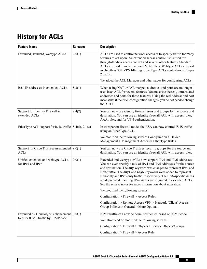
History for ACLsDescriptionReleasesFeature Name
ACLs are used to control network access or to specify traffic for manyfeatures to act upon. An extended access control list is used forthrough-the-box access control and several other features. StandardACLs are used in route maps and VPN filters. Webtype ACLs are usedin clientless SSL VPN filtering. EtherType ACLs control non-IP layer2 traffic.
We added the ACL Manager and other pages for configuring ACLs.
7.0(1)Extended, standard, webtype ACLs
When using NAT or PAT, mapped addresses and ports are no longerused in an ACL for several features. Youmust use the real, untranslatedaddresses and ports for these features. Using the real address and portmeans that if the NAT configuration changes, you do not need to changethe ACLs.
8.3(1)Real IP addresses in extended ACLs
You can now use identity firewall users and groups for the source anddestination. You can use an identity firewall ACL with access rules,AAA rules, and for VPN authentication.
8.4(2)Support for Identity Firewall inextended ACLs
In transparent firewall mode, the ASA can now control IS-IS trafficusing an EtherType ACL.
We modified the following screen: Configuration > DeviceManagement > Management Access > EtherType Rules.
8.4(5), 9.1(2)EtherType ACL support for IS-IS traffic
You can now use Cisco TrustSec security groups for the source anddestination. You can use an identity firewall ACL with access rules.
9.0(1)Support for Cisco TrustSec in extendedACLs
Extended and webtype ACLs now support IPv4 and IPv6 addresses.You can even specify a mix of IPv4 and IPv6 addresses for the sourceand destination. The any keyword was changed to represent IPv4 andIPv6 traffic. The any4 and any6 keywords were added to representIPv4-only and IPv6-only traffic, respectively. The IPv6-specific ACLsare deprecated. Existing IPv6 ACLs are migrated to extended ACLs.See the release notes for more information about migration.
We modified the following screens:
Configuration > Firewall > Access Rules
Configuration > Remote Access VPN > Network (Client) Access >Group Policies > General > More Options
9.0(1)Unified extended and webtype ACLsfor IPv4 and IPv6
ICMP traffic can now be permitted/denied based on ICMP code.
We introduced or modified the following screens:
Configuration > Firewall > Objects > Service Objects/Groups
Configuration > Firewall > Access Rule
9.0(1)Extended ACL and object enhancementto filter ICMP traffic by ICMP code
ASDM Book 2: Cisco ASA Series Firewall ASDM Configuration Guide, 7.649
Access ControlHistory for ACLs

DescriptionReleasesFeature Name
You can now edit ACLs and objects in an isolated configuration session.You can also forward reference objects and ACLs, that is, configurerules and access groups for objects or ACLs that do not yet exist.
We modified the Advanced settings for access rules.
9.3(2)Configuration session for editing ACLsand objects.
Forward referencing of objects andACLs in access rules.
You can now create ACL rules using the sctp protocol, including portspecifications.
We modified the add/edit dialog boxes for access control entries onthe Configuration > Firewall > Advanced > ACL Manager page.
9.5(2)ACL support for Stream ControlTransmission Protocol (SCTP)
You can now write Ethertype access control rules for the IEEE 802.2Logical Link Control packet's Destination Service Access Point address.Because of this addition, the bpdu keyword no longer matches theintended traffic. Rewrite bpdu rules for dsap 0x42.
We modified the following screen: Configuration > Firewall >EtherType Rules.
9.6(2)Ethertype rule support for the IEEE802.2 Logical Link Control packet'sDestination Service Access Pointaddress.
ASDM Book 2: Cisco ASA Series Firewall ASDM Configuration Guide, 7.650
Access ControlHistory for ACLs

C H A P T E R 5Identity Firewall
This chapter describes how to configure the ASA for the Identity Firewall.
• About the Identity Firewall, on page 51• Guidelines for the Identity Firewall, on page 57• Prerequisites for the Identity Firewall, on page 59• Configure the Identity Firewall, on page 60• Monitoring the Identity Firewall, on page 66• History for the Identity Firewall, on page 67
About the Identity FirewallIn an enterprise, users often need access to one or more server resources. Typically, a firewall is not aware ofthe users’ identities and, therefore, cannot apply security policies based on identity. To configure per-useraccess policies, you must configure a user authentication proxy, which requires user interaction (ausername/password query).
The Identity Firewall in the ASA provides more granular access control based on users’ identities. You canconfigure access rules and security policies based on user names and user group names rather than throughsource IP addresses. The ASA applies the security policies based on an association of IP addresses toWindowsActive Directory login information and reports events based on the mapped usernames instead of network IPaddresses.
The Identity Firewall integrates with Microsoft Active Directory in conjunction with an external ActiveDirectory (AD) Agent that provides the actual identity mapping. The ASA uses Windows Active Directoryas the source to retrieve the current user identity information for specific IP addresses and allows transparentauthentication for Active Directory users.
Identity-based firewall services enhance the existing access control and security policymechanisms by allowingusers or groups to be specified in place of source IP addresses. Identity-based security policies can be interleavedwithout restriction between traditional IP address-based rules.
The key benefits of the Identity Firewall include:
• Decoupling network topology from security policies
• Simplifying the creation of security policies
• Providing the ability to easily identify user activities on network resources
• Simplifying user activity monitoring
ASDM Book 2: Cisco ASA Series Firewall ASDM Configuration Guide, 7.651

Architecture for Identity Firewall DeploymentsThe Identity Firewall integrates withWindowActive Directory in conjunction with an external Active Directory(AD) Agent that provides the actual identity mapping.
The identity firewall consists of three components:
• ASA
• Microsoft Active Directory
Although Active Directory is part of the Identity Firewall on the ASA, Active Directory administratorsmanage it. The reliability and accuracy of the data depends on data in Active Directory.
Supported versions include Windows Server 2003, Windows Server 2008, and Windows Server 2008R2 servers.
• Active Directory (AD) Agent
The ADAgent runs on aWindows server. SupportedWindows servers includeWindows 2003,Windows2008, and Windows 2008 R2.
Windows 2003 R2 is not supported for the AD Agent server.Note
The following figure show the components of the Identity Firewall. The succeeding table describes the rolesof these components and how they communicate with one another.
Figure 3: Identity Firewall Components
ASDM Book 2: Cisco ASA Series Firewall ASDM Configuration Guide, 7.652
Access ControlArchitecture for Identity Firewall Deployments

Client <-> ASA: Theclient logs into thenetwork throughMicrosoft ActiveDirectory. The AD Serverauthenticates users andgenerates user loginsecurity logs.
Alternatively, the clientcan log into the networkthrough a cut-throughproxy or VPN.
4On the ASA:Administrators configurelocal user groups andIdentity Firewall policies.
1
ASA <-> Client: Basedon the policies configuredon the ASA, it grants ordenies access to the client.
If configured, the ASAprobes the NetBIOS of theclient to pass inactive andno-response users.
5ASA <-> AD Server: TheASA sends an LDAPquery for the ActiveDirectory groupsconfigured on the ADServer.
The ASA consolidateslocal andActiveDirectorygroups and applies accessrules and Modular PolicyFramework securitypolicies based on useridentity.
2
AD Agent <-> ADServer: The AD Agentmaintains a cache of userID and IP address mappedentries. and notifies theASA of changes.
The AD Agent sends logsto a syslog server.
6ASA <-> AD Agent:Depending on the IdentityFirewall configuration, theASA downloads theIP-user database or sendsa RADIUS request to theAD Agent that asks forthe user’s IP address.
The ASA forwards thenew mapped entries thathave been learned fromweb authentication andVPN sessions to the ADAgent.
3
Features of the Identity FirewallThe Identity Firewall includes the following key features.
ASDM Book 2: Cisco ASA Series Firewall ASDM Configuration Guide, 7.653
Access ControlFeatures of the Identity Firewall

Flexibility
• The ASA can retrieve user identity and IP address mapping from the AD Agent by querying the ADAgent for each new IP address or by maintaining a local copy of the entire user identity and IP addressdatabase.
• Supports host group, subnet, or IP address for the destination of a user identity policy.
• Supports a fully qualified domain name (FQDN) for the source and destination of a user identity policy.
• Supports the combination of 5-tuple policies with ID-based policies. The identity-based feature worksin tandem with the existing 5-tuple solution.
• Supports use with application inspection policies.
• Retrieves user identity information from remote access VPN, AnyConnect VPN, L2TP VPN andcut-through proxy. All retrieved users are populated to all ASAs that are connected to the AD Agent.
Scalability
• Each AD Agent supports 100 ASAs. Multiple ASAs are able to communicate with a single AD Agentto provide scalability in larger network deployments.
• Supports 30 Active Directory servers provided the IP address is unique among all domains.
• Each user identity in a domain can have up to 8 IP addresses.
• Supports up to 64,000 user identity-IP address mapped entries in active policies for the ASA 5500 Seriesmodels. This limit controls the maximum number of users who have policies applied. The total numberof users are the aggregate of all users configured in all different contexts.
• Supports up to 512 user groups in active ASA policies.
• A single access rule can contain one or more user groups or users.
• Supports multiple domains.
Availability
• The ASA retrieves group information from the Active Directory and falls back to web authentication forIP addresses when the AD Agent cannot map a source IP address to a user identity.
• The AD Agent continues to function when any of the Active Directory servers or the ASA are notresponding.
• Supports configuring a primary AD Agent and a secondary AD Agent on the ASA. If the primary ADAgent stops responding, the ASA can switch to the secondary AD Agent.
• If the AD Agent is unavailable, the ASA can fall back to existing identity sources such as cut-throughproxy and VPN authentication.
• The AD Agent runs a watchdog process that automatically restarts its services when they are down.
• Allows a distributed IP address/user mapping database for use among ASAs.
ASDM Book 2: Cisco ASA Series Firewall ASDM Configuration Guide, 7.654
Access ControlFeatures of the Identity Firewall

Deployment ScenariosYou can deploy the components of the Identity Firewall in the followingways, depending on your environmentalrequirements.
The following figure shows how you can deploy the components of the Identity Firewall to allow forredundancy. Scenario 1 shows a simple installation without component redundancy. Scenario 2 also shows asimple installation without redundancy. However, in this deployment scenario, the Active Directory serverand AD Agent are co-located on the same Windows server.
Figure 4: Deployment Scenario without Redundancy
The following figure shows how you can deploy the Identity Firewall components to support redundancy.Scenario 1 shows a deployment with multiple Active Directory servers and a single AD Agent installed on aseparateWindows server. Scenario 2 shows a deployment with multiple Active Directory servers and multipleAD Agents installed on separate Windows servers.
Figure 5: Deployment Scenario with Redundant Components
The following figure shows how all Identity Firewall components—Active Directory server, the AD Agent,and the clients—are installed and communicate on the LAN.
ASDM Book 2: Cisco ASA Series Firewall ASDM Configuration Guide, 7.655
Access ControlDeployment Scenarios
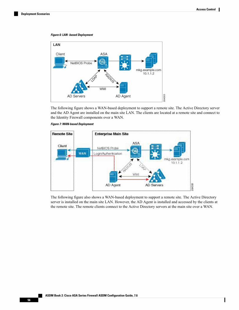
Figure 6: LAN -based Deployment
The following figure shows a WAN-based deployment to support a remote site. The Active Directory serverand the AD Agent are installed on the main site LAN. The clients are located at a remote site and connect tothe Identity Firewall components over a WAN.
Figure 7: WAN-based Deployment
The following figure also shows a WAN-based deployment to support a remote site. The Active Directoryserver is installed on the main site LAN. However, the AD Agent is installed and accessed by the clients atthe remote site. The remote clients connect to the Active Directory servers at the main site over a WAN.
ASDM Book 2: Cisco ASA Series Firewall ASDM Configuration Guide, 7.656
Access ControlDeployment Scenarios
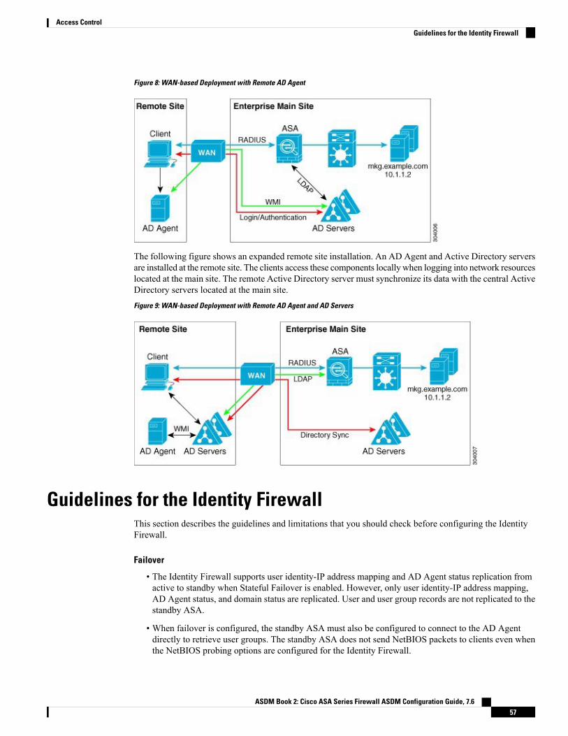
Figure 8: WAN-based Deployment with Remote AD Agent
The following figure shows an expanded remote site installation. An AD Agent and Active Directory serversare installed at the remote site. The clients access these components locally when logging into network resourceslocated at the main site. The remote Active Directory server must synchronize its data with the central ActiveDirectory servers located at the main site.
Figure 9: WAN-based Deployment with Remote AD Agent and AD Servers
Guidelines for the Identity FirewallThis section describes the guidelines and limitations that you should check before configuring the IdentityFirewall.
Failover
• The Identity Firewall supports user identity-IP address mapping and AD Agent status replication fromactive to standby when Stateful Failover is enabled. However, only user identity-IP address mapping,AD Agent status, and domain status are replicated. User and user group records are not replicated to thestandby ASA.
• When failover is configured, the standby ASA must also be configured to connect to the AD Agentdirectly to retrieve user groups. The standby ASA does not send NetBIOS packets to clients even whenthe NetBIOS probing options are configured for the Identity Firewall.
ASDM Book 2: Cisco ASA Series Firewall ASDM Configuration Guide, 7.657
Access ControlGuidelines for the Identity Firewall

• When a client is determined to be inactive by the active ASA, the information is propagated to the standbyASA. User statistics are not propagated to the standby ASA.
• When you have failover configured, you must configure the AD Agent to communicate with both theactive and standby ASAs. See the Installation and Setup Guide for the Active Directory Agent for thesteps to configure the ASA on the AD Agent server.
IPv6
• The AD Agent supports endpoints with IPv6 addresses. It can receive IPv6 addresses in log events,maintain them in its cache, and send them through RADIUS messages. The AAA server must use anIPv4 address.
• NetBIOS over IPv6 is not supported.
Additional Guidelines
• A full URL as a destination address is not supported.
• For NetBIOS probing to function, the network between the ASA, AD Agent, and clients must supportUDP-encapsulated NetBIOS traffic.
• MAC address checking by the Identity Firewall does not work when intervening routers are present.Users logged into clients that are behind the same router have the same MAC addresses. With thisimplementation, all the packets from the same router are able to pass the check, because the ASA isunable to ascertain the actual MAC addresses behind the router.
• Although you can use user specifications in VPN filter ACLs, the user-based rules are interpreteduni-directionally rather than bi-directionally, which is how VPN filter usually works. That is, you canfilter based on user-initiated traffic, but the filter does not apply for going from the destination back tothe user. For example, you could include a rule that allows a specific user to ping a server, but that rulewill not allow the server to ping the user.
• The following ASA features do not support using the identity-based object and FQDN in an extendedACL:
• Crypto maps
• WCCP
• NAT
• Group policy (except for VPN filters)
• DAP
• You can use the user-identity update active-user-database command to actively initiate a user-IPaddress download from the AD agent.
By design, if a previous download session has finished, the ASA does not allow you to issue this commandagain.
As a result, if the user-IP database is very large, the previous download session is not finished yet, andyou issue another user-identity update active-user-database command, the following error messageappears:
ASDM Book 2: Cisco ASA Series Firewall ASDM Configuration Guide, 7.658
Access ControlGuidelines for the Identity Firewall
“ERROR: one update active-user-database is already in progress.”
You need to wait until the previous session is completely finished, then you can issue another user-identityupdate active-user-database command.
Another example of this behavior occurs because of packet loss from the AD Agent to the ASA.
When you issue a user-identity update active-user-database command, the ASA requests the totalnumber of user-IP mapped entries to be downloaded. Then the AD Agent initiates a UDP connection tothe ASA and sends the change of authorization request packet.
If for some reason the packet is lost, there is no way for the ASA to discern this. As a result, the ASAholds the session for 4-5 minutes, during which time this error message continues to appear if you haveissued the user-identity update active-user-database command.
• When you use the Cisco Context Directory Agent (CDA) in conjunction with the ASA or Cisco IronportWeb Security Appliance (WSA), make sure that you open the following ports:
• Authentication port for UDP—1645
• Accounting port for UDP—1646
• Listening port for UDP—3799
The listening port is used to send change of authorization requests from the CDA to the ASA or tothe WSA.
• If the user-identity action domain-controller-down domain_name disable user-identity-rule commandis configured and the specified domain is down, or if the user-identity action ad-agent-down disableuser-identity-rule command is configured and the AD Agent is down, all the logged-in users have thedisabled status.
• For domain names, the following characters are not valid: \/:*?"<>|.
• For usernames, the following characters are not valid: \/[]:;=,+*?"<>|@.
• For user group names, the following characters are not valid: \/[]:;=,+*?"<>|.
• How you configure the Identity Firewall to retrieve user information from the AD Agent affects theamount of memory used by the feature. You specify whether the ASA uses on-demand retrieval or fulldownload retrieval. Choosing on-demand retrieval has the benefit of using less memory, because onlyusers of received packets are queried and stored.
Prerequisites for the Identity FirewallThis section lists the prerequisites for configuring the Identity Firewall.
AD Agent
• The AD Agent must be installed on a Windows server that is accessible to the ASA. Additionally, youmust configure the ADAgent to obtain information from the Active Directory servers and to communicatewith the ASA.
• Supported Windows servers include Windows 2003, Windows 2008, and Windows 2008 R2.
ASDM Book 2: Cisco ASA Series Firewall ASDM Configuration Guide, 7.659
Access ControlPrerequisites for the Identity Firewall

Windows 2003 R2 is not supported for the AD Agent server.Note
• For the steps to install and configure the AD Agent, see the Installation and Setup Guide for the ActiveDirectory Agent.
• Before configuring the AD Agent in the ASA, obtain the secret key value that the AD Agent and theASA use to communicate. This value must match on both the AD Agent and the ASA.
Microsoft Active Directory
• Microsoft Active Directorymust be installed on aWindows server and accessible by the ASA. Supportedversions include Windows 2003, 2008, and 2008 R2 servers.
• Before configuring the Active Directory server on the ASA, create a user account in Active Directoryfor the ASA.
• Additionally, the ASA sends encrypted log-in information to the Active Directory server by using SSLenabled over LDAP. SSL must be enabled on the Active Directory server. See the documentation forMicrosoft Active Directory for how to enable SSL for Active Directory.
Before running the AD Agent Installer, you must install the patches listed in the README First for the CiscoActive Directory Agent on eachMicrosoft Active Directory server that the ADAgent monitors. These patchesare required even when the AD Agent is installed directly on the domain controller server.
Note
Configure the Identity FirewallTo configure the Identity Firewall, perform the following tasks:
Procedure
Step 1 Configure the Active Directory domain in the ASA.Step 2 Configure the AD Agent in ASA.Step 3 Configure Identity Options.Step 4 Configure Identity-based Security Policy. After the AD domain and AD Agent are configured, you can create
identity-based object groups and ACLs for use in many features.
Configure the Active Directory DomainActive Directory domain configuration on the ASA is required for the ASA to download Active Directorygroups and accept user identities from specific domains when receiving IP-user mapping from the AD Agent.
ASDM Book 2: Cisco ASA Series Firewall ASDM Configuration Guide, 7.660
Access ControlConfigure the Identity Firewall

Before you begin
• Active Directory server IP address
• Distinguished Name for LDAP base DN
• Distinguished Name and password for the Active Directory user that the Identity Firewall uses to connectto the Active Directory domain controller
To configure the Active Directory domain, perform the following steps:
Procedure
Step 1 Choose Configuration > Firewall > Identity Options.Step 2 Check the Enable User Identity check box to enable user identity.Step 3 Click Add.
The Domain dialog box appears.
Step 4 Enter a domain name of up to 32 characters consisting of [a-z], [A-Z], [0-9], [!@#$%^&()-_=+[]{};,. ] except'.' and ' ' at the first character. If the domain name includes a space, you must enclose that space character inquotation marks. The domain name is not case sensitive.
When you edit the name of an existing domain, the domain name associated with existing users and usergroups is not changed.
Step 5 Select the Active Directory servers to associate with this domain, or click Manage to add a new server groupto the list.
Step 6 Click OK to save the domain settings and close this dialog box.
Configure Active Directory Server GroupsTo configure the Active Directory server group, perform the following steps:
Procedure
Step 1 Choose Configuration > Firewall > Identity Options > Add > Manage.
The Configure Active Directory Server Groups dialog box appears.
Step 2 Click Add.
The Add Active Directory Server Group dialog box appears.
Step 3 To add servers to an Active Directory server group, select the group from theActive Directory Server Groupslist, then click Add.
The Add Active Directory Server dialog box appears.
ASDM Book 2: Cisco ASA Series Firewall ASDM Configuration Guide, 7.661
Access ControlConfigure Active Directory Server Groups

Step 4 Click OK to save the settings and close this dialog box.
Configure Active Directory Agents
Before you begin
• AD agent IP address
• Shared secret between the ASA and AD agent
To configure the AD Agents, perform the following steps:
Procedure
Step 1 Choose Configuration > Firewall > Identity Options.Step 2 Check the Enable User Identity check box to enable the feature.Step 3 Click Manage in the Active Directory Agent section.
The Configure Active Directory Agents dialog box appears.
Step 4 Click the Add button.Step 5 Click OK to save your changes and close this dialog box.
Configure Active Directory Agent GroupsConfigure the primary and secondary AD Agents for the AD Agent Server Group. When the ASA detectsthat the primary AD Agent is not responding and a secondary agent is specified, the ASA switches to thesecondary AD Agent. The Active Directory server for the AD agent uses RADIUS as the communicationprotocol; therefore, you should specify a key attribute for the shared secret between the ASA and AD Agent.
To configure the AD Agent Groups, perform the following steps:
Procedure
Step 1 Click Add from the Configure Active Directory Agents dialog box.
The Add Active Directory Agent Group dialog box appears.
Step 2 Enter a name for the AD Agent group.Step 3 Specify the interface on which the ASA listens for traffic from the AD Agent server, and enter the FQDN of
the server or IP address in the Primary Active Directory Agent section.Step 4 Enter a timeout interval and the retry interval for the attempts that the ASA will continue to contact the AD
Agent when it is not responding in the Primary Active Directory Agent section.Step 5 Enter the shared secret key that is used between the primary AD Agent and the ASA.
ASDM Book 2: Cisco ASA Series Firewall ASDM Configuration Guide, 7.662
Access ControlConfigure Active Directory Agents

Step 6 Specify the interface on which the ASA listens for traffic from the AD Agent server, and enter the FQDN ofthe server or IP address in the Secondary Active Directory Agent section.
Step 7 Enter a timeout interval and the retry interval for the attempts that the ASAwill continue to perform to contactthe AD Agent when it is not responding in the Secondary Active Directory Agent section.
Step 8 Enter the shared secret key that is used between the secondary AD Agent and the ASA.Step 9 Click OK to save your changes and close this dialog box.
Configure Identity OptionsTo configure the Identity Options for the Identity Firewall, perform the following steps:
Procedure
Step 1 Choose Configuration > Firewall > Identity Options.Step 2 Check the Enable User Identity check box.Step 3 To add a domain for the Identity Firewall, click Add to display the Add Domain dialog box.Step 4 For domains that have already been added to the Domains list, check whether or not to disable rules when the
domain is down because the Active Directory domain controller is not responding.
When a domain is down and this option is checked for that domain, the ASA disables the user identity rulesassociated with the users in that domain. Additionally, the status of all user IP addresses in that domain ismarked as disabled in the Monitoring > Properties > Identity > Users pane.
Step 5 Choose the default domain for the Identity Firewall.
The default domain is used for all users and user groups when a domain has not been explicitly configuredfor those users or groups. When a default domain is not specified, the default domain for users and groups isLOCAL.
Additionally, the Identity Firewall uses the LOCAL domain for all locally defined user groups or locallydefined users (those who log in and authenticate by using a VPN or web portal).
The default domain name that you select must match the NetBIOS domain name configured on theActive Directory domain controller. If the domain name does not match, the AD Agent incorrectlyassociates the user-IP mapping with the domain name that you entered when configuring the ASA.To view the NetBIOS domain name, open the Active Directory user event security log in any texteditor.
For multiple context modes, you can set a default domain name for each context, as well as withinthe system execution space.
Note
Step 6 Choose the AD Agent group from the drop-down list. Click Manage to add AD Agent groups.Step 7 Enter a number between 10 to 65535 seconds in the Hello Timer field.
The hello timer between the ASA and the ADAgent defines how frequently the ASA exchanges hello packets.The ASA uses the hello packet to obtain ASA replication status (in-sync or out-of-sync) and domain status(up or down). If the ASA does not receive a response from the AD Agent, it resends a hello packet after thespecified interval.
ASDM Book 2: Cisco ASA Series Firewall ASDM Configuration Guide, 7.663
Access ControlConfigure Identity Options

Specify the number of times that the ASA will continue to send hello packets to the AD Agent. By default,the number of seconds is set to 30 and the retry times is set to 5.
Step 8 Check the Enable Event Timestamp check box to enable the ASA to keep track of the last event time stampthat it receives for each identifier and to discard any message if the event time stamp is at least 5 minutesolder than the ASA’s clock, or if its time stamp is earlier than the last event’s time stamp.
For a newly booted ASA that does not have knowledge of the last event time stamp, the ASA compares theevent time stamp with its own clock. If the event is at least 5 minutes older, the ASA does not accept themessage.
We recommend that you configure the ASA, Active Directory, and Active Directory agent to synchronizetheir clocks among themselves using NTP
Step 9 Enter the number of hours in the Poll Group Timer field that the ASA uses to query the DNS server to resolvefully qualified domain names (FQDN). By default, the poll timer is set to 4 hours.
Step 10 Choose an option from the list in the Retrieve User Information section:
• On Demand—Specifies that the ASA retrieve the user mapping information of an IP address from theAD Agent when the ASA receives a packet that requires a new connection and the user of its source IPaddress is not in the user-identity database.
• Full Download—Specifies that the ASA send a request to the AD Agent to download the entire IP-usermapping table when the ASA starts and then to receive incremental IP-user mapping when users log inand log out.
Choosing On Demand has the benefit of using less memory because only users of receivedpackets are queried and stored.
Note
Step 11 Choose whether or not to disable rules if the AD Agent is not responding.
When the AD Agent is down and this option is selected, the ASA disables the user identity rules associatedwith the users in that domain. Additionally, the status of all user IP addresses in that domain are marked asdisabled in the Monitoring > Properties > Identity > Users pane.
Step 12 Choose whether or not to remove a user’s IP address when the NetBIOS probe fails.
Choosing this option specifies the action when NetBIOS probing to a user is blocked (for example, the userclient does not respond to a NetBIOS probe). The network connection might be blocked to that client or theclient is not active. When this option is chosen, the ASA disables the identity rules associated with that user’sIP address.
Step 13 Choose whether or not to remove a user’s MAC address when it is inconsistent with the IP address that theASA has currently mapped to that MAC address. When this option is chosen, the ASA disables the useridentity rules associated with the specific user.
Step 14 Choose whether or not to track users that are not found.Step 15 Choose the Idle Timeout option and enter a time in minutes, from 1 minute to 65535. By default, the idle
timeout is set to 60 minutes.
Enabling this option configures a timer when an active user is considered idle, meaning the ASA does notreceive traffic from the user’s IP address for more than the specified time. After the timer expires, the user’sIP address is marked inactive and removed from the local cached IP-user database and the ASA no longernotifies the AD Agent about that IP address. Existing traffic is still allowed to pass. When the Idle Timeoutoption is enabled, the ASA runs an inactive timer even when the NetBIOS Logout Probe is configured.
ASDM Book 2: Cisco ASA Series Firewall ASDM Configuration Guide, 7.664
Access ControlConfigure Identity Options

The Idle Timeout option does not apply to VPN or cut-through proxy users.Note
Step 16 Enable NetBIOS probing and set the probe timer (from 1 to 65535 minutes) before a user's IP addresses isprobed and the retry interval (from 1 to 256 retries) between retry probes.
Enabling this option configures how often the ASA probes the user host to determine whether the user clientis still active. To minimize the NetBIOS packets, ASA only sends a NetBIOS probe to the client when theuser has been idle for more than the specified number of minutes in the Idle Timeout minutes field.
Step 17 Choose an option from the User Name list:
• Match Any—As long as the NetBIOS response from the host includes the username of the user assignedto the IP address, the user identity is be considered valid. Specifying this option requires that the hostenabled the Messenger service and configured a WINS server.
• Exact Match—The username of the user assigned to the IP address must be the only one in the NetBIOSresponse. Otherwise, the user identity of that IP address is considered invalid. Specifying this optionrequires that the host enabled the Messenger service and configured a WINS server.
• User Not Needed—As long as the ASA received a NetBIOS response from the host, the user identityis considered valid.
Step 18 Click Apply to save the Identity Firewall configuration.
Configure Identity-Based Security PolicyYou can incorporate identity-based policy in many ASA features. Any feature that uses extended ACLs (otherthan those listed as unsupported in the Guidelines section) can take advantage of an identity firewall. You cannow add user identity arguments to extended ACLs, as well as network-based parameters.
Features that can use identity include the following:
• Access rules—An access rule permits or denies traffic on an interface using network information. Withan identity firewall, you can control access based on user identity.
• AAA rules—An authentication rule (also known as cut-through proxy) controls network access basedon the user. Because this function is very similar to an access rule plus an identity firewall, AAA rulescan now be used as a backup method of authentication if a user’s AD login expires. For example, forany user without a valid login, you can trigger a AAA rule. To ensure that the AAA rule is only triggeredfor users that do not have valid logins, you can specify special usernames in the extended ACL used forthe access rule and for the AAA rule: None (users without a valid login) and Any (users with a validlogin). In the access rule, configure your policy as usual for users and groups, but then include a AAArule that permits all None users; you must permit these users so they can later trigger a AAA rule. Then,configure a AAA rule that denies Any users (these users are not subject to the AAA rule, and werehandled already by the access rule), but permits all None users. For example:
access-list 100 ex permit ip user CISCO\xyz any anyaccess-list 100 ex deny ip user CISCO\abc any anyaccess-list 100 ex permit ip user NONE any anyaccess-list 100 ex deny any anyaccess-group 100 in interface inside
access-list 200 ex deny ip user ANY any any
ASDM Book 2: Cisco ASA Series Firewall ASDM Configuration Guide, 7.665
Access ControlConfigure Identity-Based Security Policy

access-list 200 ex permit user NONE any anyaaa authenticate match 200 inside user-identity
For more information, see the legacy feature guide.
• VPN filter—Although a VPN does not support identity firewall ACLs in general, you can configure theASA to enforce identity-based access rules on VPN traffic. By default, VPN traffic is not subject toaccess rules. You can force VPN clients to abide by access rules that use an identity firewall ACL (withthe no sysopt connection permit-vpn command). You can also use an identity firewall ACL with theVPN filter feature; a VPN filter accomplishes a similar effect by allowing access rules in general.
Monitoring the Identity FirewallSee the following screens for monitoring the Identity Firewall status:
• Monitoring > Properties > Identity > AD Agent
This pane shows the status of the AD Agents and the domains, and the statistics for the AD Agents.
• Monitoring > Properties > Identity > Memory Usage
This pane shows the memory usage that the Identity Firewall consumes on the ASA.
• Monitoring > Properties > Identity > User
• This pane shows information about all users contained in the IP-user mapping database used by theIdentity Firewall.
• Monitoring > Properties > Identity > Group
This pane shows the list of user groups configured for the Identity Firewall.
• Tools > Command Line Interface
This pane allows you to issue various non-interactive commands and view results.
ASDM Book 2: Cisco ASA Series Firewall ASDM Configuration Guide, 7.666
Access ControlMonitoring the Identity Firewall

History for the Identity FirewallTable 3: History for the Identity Firewall
DescriptionReleasesFeature Name
The Identity Firewall feature wasintroduced.
We introduced or modified the followingscreens:
Configuration > Firewall > IdentityOptions
Configuration > Firewall > Objects >Local User Groups
Monitoring > Properties > Identity.
8.4(2)Identity Firewall
ASDM Book 2: Cisco ASA Series Firewall ASDM Configuration Guide, 7.667
Access ControlHistory for the Identity Firewall

ASDM Book 2: Cisco ASA Series Firewall ASDM Configuration Guide, 7.668
Access ControlHistory for the Identity Firewall

C H A P T E R 6ASA and Cisco TrustSec
This chapter describes how to implement Cisco TrustSec for the ASA.
• About Cisco TrustSec, on page 69• Guidelines for Cisco TrustSec, on page 76• Configure the ASA to Integrate with Cisco Trustsec, on page 79• AnyConnect VPN Support for Cisco TrustSec, on page 88• Monitoring Cisco TrustSec, on page 89• History for Cisco TrustSec, on page 90
About Cisco TrustSecTraditionally, security features such as firewalls performed access control based on predefined IP addresses,subnets, and protocols. However, with enterprises transitioning to borderless networks, both the technologyused to connect people and organizations and the security requirements for protecting data and networks haveevolved significantly. Endpoints are becoming increasingly nomadic and users often employ a variety ofendpoints (for example, laptop versus desktop, smart phone, or tablet), which means that a combination ofuser attributes plus endpoint attributes provide the key characteristics (in addition to existing 6-tuple basedrules), that enforcement devices such as switches and routers with firewall features or dedicated firewalls canreliably use for making access control decisions.
As a result, the availability and propagation of endpoint attributes or client identity attributes have becomeincreasingly important requirements to enable security across the customers’ networks, at the access,distribution, and core layers of the network, and in the data center.
Cisco TrustSec provides access control that builds upon an existing identity-aware infrastructure to ensuredata confidentiality between network devices and integrate security access services on one platform. In theCisco TrustSec feature, enforcement devices use a combination of user attributes and endpoint attributes tomake role-based and identity-based access control decisions. The availability and propagation of this informationenables security across networks at the access, distribution, and core layers of the network.
Implementing Cisco TrustSec into your environment has the following advantages:
• Provides a growing mobile and complex workforce with appropriate and more secure access from anydevice
• Lowers security risks by providing comprehensive visibility of who and what is connecting to the wiredor wireless network
• Offers exceptional control over activity of network users accessing physical or cloud-based IT resources
ASDM Book 2: Cisco ASA Series Firewall ASDM Configuration Guide, 7.669
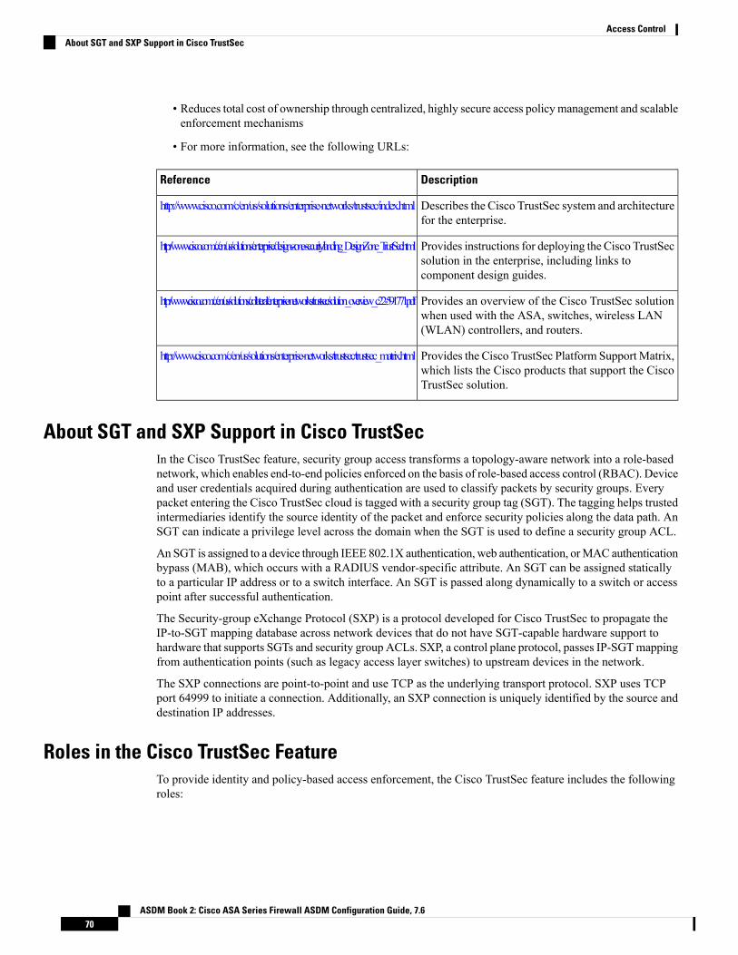
• Reduces total cost of ownership through centralized, highly secure access policymanagement and scalableenforcement mechanisms
• For more information, see the following URLs:
DescriptionReference
Describes the Cisco TrustSec system and architecturefor the enterprise.
http://www.cisco.com/c/en/us/solutions/enterprise-networks/trustsec/index.html
Provides instructions for deploying the Cisco TrustSecsolution in the enterprise, including links tocomponent design guides.
http://www.cisco.com/c/en/us/solutions/enterprise/design-zone-security/landing_DesignZone_TrustSec.html
Provides an overview of the Cisco TrustSec solutionwhen used with the ASA, switches, wireless LAN(WLAN) controllers, and routers.
http://www.cisco.com/c/en/us/solutions/collateral/enterprise-networks/trustsec/solution_overview_c22-591771.pdf
Provides the Cisco TrustSec Platform SupportMatrix,which lists the Cisco products that support the CiscoTrustSec solution.
http://www.cisco.com/c/en/us/solutions/enterprise-networks/trustsec/trustsec_matrix.html
About SGT and SXP Support in Cisco TrustSecIn the Cisco TrustSec feature, security group access transforms a topology-aware network into a role-basednetwork, which enables end-to-end policies enforced on the basis of role-based access control (RBAC). Deviceand user credentials acquired during authentication are used to classify packets by security groups. Everypacket entering the Cisco TrustSec cloud is tagged with a security group tag (SGT). The tagging helps trustedintermediaries identify the source identity of the packet and enforce security policies along the data path. AnSGT can indicate a privilege level across the domain when the SGT is used to define a security group ACL.
An SGT is assigned to a device through IEEE 802.1X authentication, web authentication, orMAC authenticationbypass (MAB), which occurs with a RADIUS vendor-specific attribute. An SGT can be assigned staticallyto a particular IP address or to a switch interface. An SGT is passed along dynamically to a switch or accesspoint after successful authentication.
The Security-group eXchange Protocol (SXP) is a protocol developed for Cisco TrustSec to propagate theIP-to-SGT mapping database across network devices that do not have SGT-capable hardware support tohardware that supports SGTs and security group ACLs. SXP, a control plane protocol, passes IP-SGTmappingfrom authentication points (such as legacy access layer switches) to upstream devices in the network.
The SXP connections are point-to-point and use TCP as the underlying transport protocol. SXP uses TCPport 64999 to initiate a connection. Additionally, an SXP connection is uniquely identified by the source anddestination IP addresses.
Roles in the Cisco TrustSec FeatureTo provide identity and policy-based access enforcement, the Cisco TrustSec feature includes the followingroles:
ASDM Book 2: Cisco ASA Series Firewall ASDM Configuration Guide, 7.670
Access ControlAbout SGT and SXP Support in Cisco TrustSec

• Access Requester (AR)—Access requesters are endpoint devices that request access to protected resourcesin the network. They are primary subjects of the architecture and their access privilege depends on theirIdentity credentials.
Access requesters include endpoint devices such PCs, laptops, mobile phones, printers, cameras, andMACsec-capable IP phones.
• Policy Decision Point (PDP)—A policy decision point is responsible for making access control decisions.The PDP provides features such as 802.1x,MAB, and web authentication. The PDP supports authorizationand enforcement through VLAN, DACL, and security group access (SGACL/SXP/SGT).
In the Cisco TrustSec feature, the Cisco Identity Services Engine (ISE) acts as the PDP. The Cisco ISEprovides identity and access control policy functionality.
• Policy Information Point (PIP)—A policy information point is a source that provides external information(for example, reputation, location, and LDAP attributes) to policy decision points.
Policy information points include devices such as Session Directory, Sensor IPS, and CommunicationManager.
• Policy Administration Point (PAP)—A policy administration point defines and inserts policies into theauthorization system. The PAP acts as an identity repository by providing Cisco TrustSec tag-to-useridentity mapping and Cisco TrustSec tag-to-server resource mapping.
In the Cisco TrustSec feature, the Cisco Secure Access Control System (a policy server with integrated802.1x and SGT support) acts as the PAP.
• Policy Enforcement Point (PEP)—A policy enforcement point is the entity that carries out the decisions(policy rules and actions) made by the PDP for each AR. PEP devices learn identity information throughthe primary communication path that exists across networks. PEP devices learn the identity attributes ofeach AR from many sources, such as endpoint agents, authorization servers, peer enforcement devices,and network flows. In turn, PEP devices use SXP to propagate IP-SGT mapping to mutually trusted peerdevices across the network.
Policy enforcement points include network devices such as Catalyst switches, routers, firewalls(specifically the ASA), servers, VPN devices, and SAN devices.
The Cisco ASA serves the PEP role in the identity architecture. Using SXP, the ASA learns identity informationdirectly from authentication points and uses it to enforce identity-based policies.
Security Group Policy EnforcementSecurity policy enforcement is based on security group name. An endpoint device attempts to access a resourcein the data center. Compared to traditional IP-based policies configured on firewalls, identity-based policiesare configured based on user and device identities. For example, mktg-contractor is allowed to accessmktg-servers; mktg-corp-users are allowed to access mktg-server and corp-servers.
The benefits of this type of deployment include the following:
• User group and resource are defined and enforced using single object (SGT) simplified policymanagement.
• User identity and resource identity are retained throughout the Cisco TrustSec-capable switchinfrastructure.
The following figure shows a deployment for security group name-based policy enforcement.
ASDM Book 2: Cisco ASA Series Firewall ASDM Configuration Guide, 7.671
Access ControlSecurity Group Policy Enforcement
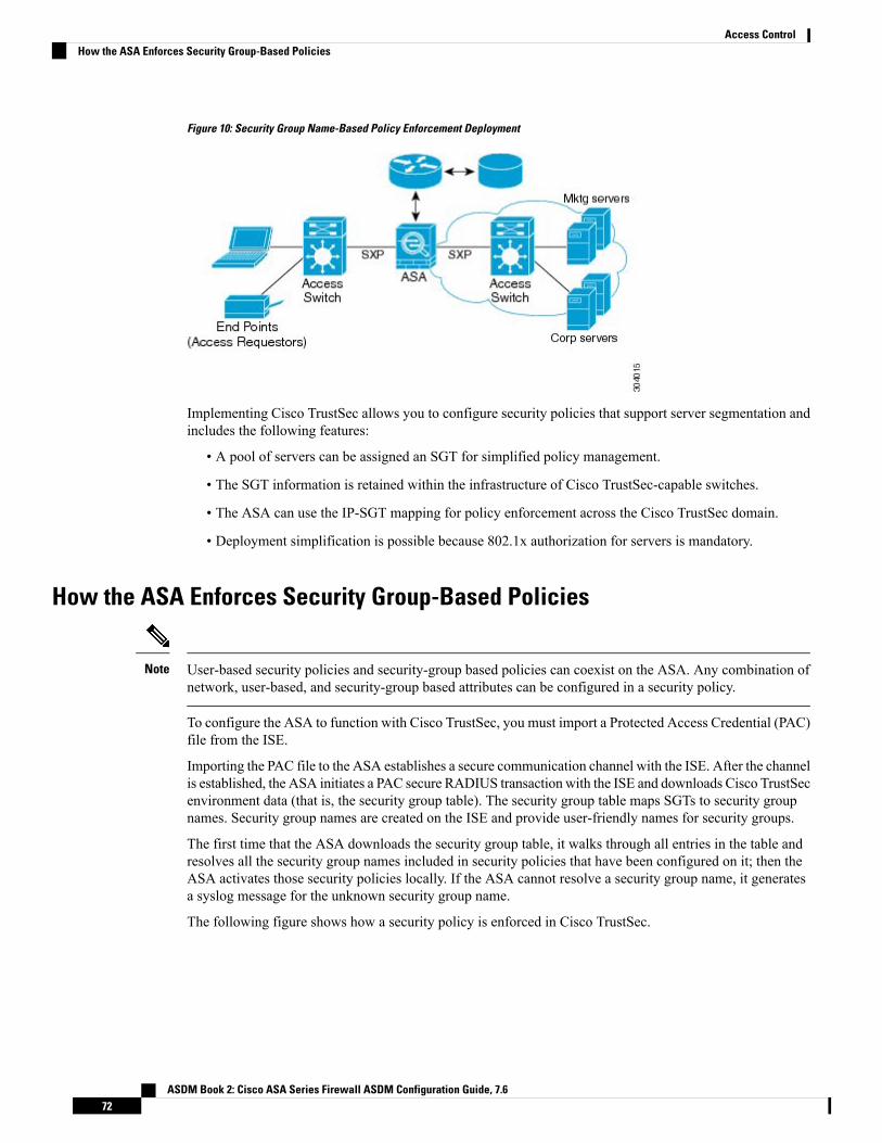
Figure 10: Security Group Name-Based Policy Enforcement Deployment
Implementing Cisco TrustSec allows you to configure security policies that support server segmentation andincludes the following features:
• A pool of servers can be assigned an SGT for simplified policy management.
• The SGT information is retained within the infrastructure of Cisco TrustSec-capable switches.
• The ASA can use the IP-SGT mapping for policy enforcement across the Cisco TrustSec domain.
• Deployment simplification is possible because 802.1x authorization for servers is mandatory.
How the ASA Enforces Security Group-Based Policies
User-based security policies and security-group based policies can coexist on the ASA. Any combination ofnetwork, user-based, and security-group based attributes can be configured in a security policy.
Note
To configure the ASA to function with Cisco TrustSec, you must import a Protected Access Credential (PAC)file from the ISE.
Importing the PAC file to the ASA establishes a secure communication channel with the ISE. After the channelis established, the ASA initiates a PAC secure RADIUS transaction with the ISE and downloads Cisco TrustSecenvironment data (that is, the security group table). The security group table maps SGTs to security groupnames. Security group names are created on the ISE and provide user-friendly names for security groups.
The first time that the ASA downloads the security group table, it walks through all entries in the table andresolves all the security group names included in security policies that have been configured on it; then theASA activates those security policies locally. If the ASA cannot resolve a security group name, it generatesa syslog message for the unknown security group name.
The following figure shows how a security policy is enforced in Cisco TrustSec.
ASDM Book 2: Cisco ASA Series Firewall ASDM Configuration Guide, 7.672
Access ControlHow the ASA Enforces Security Group-Based Policies

Figure 11: Security Policy Enforcement
1. An endpoint device connects to an access layer device directly or via remote access and authenticateswith Cisco TrustSec.
2. The access layer device authenticates the endpoint device with the ISE by using authentication methodssuch as 802.1X or web authentication. The endpoint device passes role and group membership informationto classify the device into the appropriate security group.
3. The access layer device uses SXP to propagate the IP-SGT mapping to the upstream devices.
4. The ASA receives the packet and looks up the SGTs for the source and destination IP addresses using theIP-SGT mapping passed by SXP.
If the mapping is new, the ASA records it in its local IP-SGT Manager database. The IP-SGT Managerdatabase, which runs in the control plane, tracks IP-SGT mapping for each IPv4 or IPv6 address. Thedatabase records the source from which the mapping was learned. The peer IP address of the SXPconnection is used as the source of the mapping. Multiple sources can exist for each IP-SGT mappedentry.
If the ASA is configured as a Speaker, the ASA transmits all IP-SGT mapping entries to its SXP peers.
5. If a security policy is configured on the ASA with that SGT or security group name, the ASA enforcesthe policy. (You can create security policies on the ASA that include SGTs or security group names. Toenforce policies based on security group names, the ASA needs the security group table to map securitygroup names to SGTs.)
If the ASA cannot find a security group name in the security group table and it is included in a securitypolicy, the ASA considers the security group name to be unknown and generates a syslog message. Afterthe ASA refreshes the security group table from the ISE and learns the security group name, the ASAgenerates a syslog message indicating that the security group name is known.
Effects of Changes to Security Groups on the ISEThe ASA periodically refreshes the security group table by downloading an updated table from the ISE.Security groups can change on the ISE between downloads. These changes are not reflected on the ASA untilit refreshes the security group table.
ASDM Book 2: Cisco ASA Series Firewall ASDM Configuration Guide, 7.673
Access ControlEffects of Changes to Security Groups on the ISE
We recommend that you schedule policy configuration changes on the ISE during a maintenance window,then manually refresh the security group table on the ASA to make sure the security group changes have beenincorporated.
Tip
Handling policy configuration changes in this way maximizes the chances of security group name resolutionand immediate activation of security policies.
The security group table is automatically refreshed when the environment data timer expires. You can alsotrigger a security group table refresh on demand.
If a security group changes on the ISE, the following events occur when the ASA refreshes the security grouptable:
• Only security group policies that have been configured using security group names need to be resolvedwith the security group table. Policies that include security group tags are always active.
• When the security group table is available for the first time, all policies with security group names arewalked through, security group names are resolved, and policies are activated. All policies with tags arewalked through, and syslogs are generated for unknown tags.
• If the security group table has expired, policies continue to be enforced according to the most recentlydownloaded security group table until you clear it, or a new table becomes available.
• When a resolved security group name becomes unknown on the ASA, it deactivates the security policy;however, the security policy persists in the ASA running configuration.
• If an existing security group is deleted on the PAP, a previously known security group tag can becomeunknown, but no change in policy status occurs on the ASA. A previously known security group namecan become unresolved, and the policy is then inactivated. If the security group name is reused, the policyis recompiled using the new tag.
• If a new security group is added on the PAP, a previously unknown security group tag can become known,a syslog message is generated, but no change in policy status occurs. A previously unknown securitygroup name can become resolved, and associated policies are then activated.
• If a tag has been renamed on the PAP, policies that were configured using tags display the new name,and no change in policy status occurs. Policies that were configured with security group names arerecompiled using the new tag value.
Speaker and Listener Roles on the ASATheASA supports SXP to send and receive IP-SGTmapping entries to and from other network devices. UsingSXP allows security devices and firewalls to learn identity information from access switches without the needfor hardware upgrades or changes. SXP can also be used to pass IP-SGT mapping entries from upstreamdevices (such as data center devices) back to downstream devices. The ASA can receive information fromboth upstream and downstream directions.
When configuring an SXP connection on the ASA to an SXP peer, you must designate the ASA as a Speakeror a Listener for that connection so that it can exchange Identity information:
• Speaker mode—Configures the ASA so that it can forward all active IP-SGT mapping entries collectedon the ASA to upstream devices for policy enforcement.
ASDM Book 2: Cisco ASA Series Firewall ASDM Configuration Guide, 7.674
Access ControlSpeaker and Listener Roles on the ASA

• Listener mode—Configures the ASA so that it can receive IP-SGT mapping entries from downstreamdevices (SGT-capable switches) and use that information to create policy definitions.
If one end of an SXP connection is configured as a Speaker, then the other end must be configured as aListener, and vice versa. If both devices on each end of an SXP connection are configured with the same role(either both as Speakers or both as Listeners), the SXP connection fails and the ASA generates a syslogmessage.
Multiple SXP connections can learn IP-SGT mapping entries that have been downloaded from the IP-SGTmapping database. After an SXP connection to an SXP peer is established on the ASA, the Listener downloadsthe entire IP-SGT mapping database from the Speaker. All changes that occur after this are sent only when anew device appears on the network. As a result, the rate of SXP information flow is proportional to the rateat which end hosts authenticate to the network.
IP-SGT mapping entries that have been learned through SXP connections are maintained in the SXP IP-SGTmapping database. The samemapping entries may be learned through different SXP connections. Themappingdatabase maintains one copy for each mapping entry learned. Multiple mapping entries of the same IP-SGTmapping value are identified by the peer IP address of the connection from which the mapping was learned.SXP requests that the IP-SGT Manager add a mapping entry when a new mapping is learned the first timeand remove a mapping entry when the last copy in the SXP database is removed.
Whenever an SXP connection is configured as a Speaker, SXP requests that the IP-SGTManager forward allthe mapping entries collected on the device to the peer. When a new mapping is learned locally, the IP-SGTManager requests that SXP forward it through connections that are configured as Speakers.
Configuring the ASA to be both a Speaker and a Listener for an SXP connection can cause SXP looping,which means that SXP data can be received by an SXP peer that originally transmitted it.
Register the ASA with the ISEThe ASA must be configured as a recognized Cisco TrustSec network device in the ISE before the ASA cansuccessfully import a PAC file. To register the ASA with the ISE, perform the following steps:
Procedure
Step 1 Log into the ISE.Step 2 Choose Administration > Network Devices > Network Devices.Step 3 Click Add.Step 4 Enter the IP address of the ASA.Step 5 When the ISE is being used for user authentication, enter a shared secret in the Authentication Settings area.
When you configure the AAA sever on the ASA, provide the shared secret that you create here on the ISE.The AAA server on the ASA uses this shared secret to communicate with the ISE.
Step 6 Specify a device name, device ID, password, and a download interval for the ASA. See the ISE documentationfor how to perform these tasks.
ASDM Book 2: Cisco ASA Series Firewall ASDM Configuration Guide, 7.675
Access ControlRegister the ASA with the ISE

Create a Security Group on the ISEWhen configuring the ASA to communicate with the ISE, you specify a AAA server. When configuring theAAA server on the ASA, you must specify a server group. The security group must be configured to use theRADIUS protocol. To create a security group on the ISE, perform the following steps:
Procedure
Step 1 Log into the ISE.Step 2 Choose Policy > Policy Elements > Results > Security Group Access > Security Group.Step 3 Add a security group for the ASA. (Security groups are global and not ASA specific.)
The ISE creates an entry under Security Groups with a tag.
Step 4 In the Security Group Access area, configure device ID credentials and a password for the ASA.
Generate the PAC FileTo generate the PAC file, perform the following steps.
The PAC file includes a shared key that allows the ASA and ISE to secure the RADIUS transactions thatoccur between them. For this reason, make sure that you store it securely on the ASA.
Note
Procedure
Step 1 Log into the ISE.Step 2 Choose Administration > Network Resources > Network Devices.Step 3 From the list of devices, choose the ASA.Step 4 Under the Security Group Access (SGA), click Generate PAC.Step 5 To encrypt the PAC file, enter a password.
The password (or encryption key) that you enter to encrypt the PAC file is independent of the password thatwas configured on the ISE as part of the device credentials.
The ISE generates the PAC file. The ASA can import the PAC file from flash or from a remote server viaTFTP, FTP, HTTP, HTTPS, or SMB. (The PAC file does not have to reside on the ASA flash before you canimport it.)
Guidelines for Cisco TrustSecThis section includes the guidelines and limitations that you should review before configuring Cisco TrustSec.
ASDM Book 2: Cisco ASA Series Firewall ASDM Configuration Guide, 7.676
Access ControlCreate a Security Group on the ISE

Failover
• You can configure security group-based policies on the ASA in both the Active/Active and Active/Standbyconfigurations.
• When the ASA is part of a failover configuration, you must import the PAC file to the primary ASAdevice. You must also refresh the environment data on the primary device.
• The ASA can communicate with the ISE configured for high availability (HA).
• You can configure multiple ISE servers on the ASA and if the first server is unreachable, it continues tothe next server, and so on. However, if the server list is downloaded as part of the Cisco TrustSecenvironment data, it is ignored.
• If the PAC file downloaded from the ISE expires on the ASA and it cannot download an updated securitygroup table, the ASA continues to enforce security policies based on the last downloaded security grouptable until the ASA downloads an updated table.
Clustering
• When the ASA is part of a clustering configuration, you must import the PAC file to the control unit.
• When the ASA is part of a clustering configuration, you must refresh the environment data on the controlunit.
IPv6
The ASA supports SXP for IPv6 and IPv6-capable network devices. The AAA server must use an IPv4address.
Layer 2 SGT Imposition
• Supported only on physical interfaces, subinterfaces, EtherChannel interfaces, and redundant interfaces.
• Not supported on logical interfaces or virtual interfaces, such as a BVI.
• Does not support link encryption using SAP negotiation and MACsec.
• Not supported on failover links.
• Not supported on cluster control links.
• The ASA does not reclassify existing flows if the SGT is changed. Any policy decisions that were madebased on the previous SGT remain in force for the life of the flow. However, the ASA can immediatelyreflect SGT changes on egress packets, even if the packets belong to a flow whose classification wasbased on a previous SGT.
• The hardware architecture of the ASA 5585-X is designed to load balance regular packets in an optimalway, but this is not the case for inline tagged packets with Layer 2 Security Group Tagging Imposition.Significant performance degradation on the ASA 5585-X may occur when it processes incoming inlinetagged packets. This issue does not occur with inline tagged packets on other ASA platforms, as well aswith untagged packets on the ASA 5585-X. One workaround is to offload access policies so that minimalinline tagged packets go to the ASA 5585-X, which allows the switches to handle tagged policyenforcement. Another workaround is to use SXP so that the ASA 5585-X can map the IP address to thesecurity group tag without the need to receive tagged packets.
ASDM Book 2: Cisco ASA Series Firewall ASDM Configuration Guide, 7.677
Access ControlGuidelines for Cisco TrustSec

• The ASASM does not support Layer 2 Security Group Tagging Imposition.
Additional Guidelines
• The ASA supports SXPVersion 3. The ASA negotiates SXP versions with different SXP-capable networkdevices.
• You can configure the ASA to refresh the security group table when the SXP reconcile timer expires andyou can download the security group table on demand. When the security group table on the ASA isupdated from the ISE, changes are reflected in the appropriate security policies.
• Cisco TrustSec supports the Smart Call Home feature in single context and multi-context mode, but notin the system context.
• The ASA can only be configured to interoperate in a single Cisco TrustSec domain.
• The ASA does not support static configuration of SGT-name mapping on the device.
• NAT is not supported in SXP messages.
• SXP conveys IP-SGT mapping to enforcement points in the network. If an access layer switch belongsto a different NAT domain than the enforcing point, the IP-SGT map that it uploads is invalid, and anIP-SGT mapping database lookup on the enforcement device does not yield valid results. As a result,the ASA cannot apply security group-aware security policy on the enforcement device.
• You can configure a default password for the ASA to use for SXP connections, or you can choose notto use a password; however, connection-specific passwords are not supported for SXP peers. Theconfigured default SXP password should be consistent across the deployment network. If you configurea connection-specific password, connections may fail and a warning message appears. If you configurethe connection with the default password, but it is not configured, the result is the same as when youhave configured the connection with no password.
• The ASA can be configured as an SXP Speaker or Listener, or both. However, SXP connection loopscan form when a device has bidirectional connections to a peer or is part of a unidirectionally connectedchain of devices. (The ASA can learn IP-SGT mapping for resources from the access layer in the datacenter. The ASA might need to propagate these tags to downstream devices.) SXP connection loops cancause unexpected behavior of SXP message transport. In cases where the ASA is configured to be aSpeaker and Listener, an SXP connection loop can occur, causing SXP data to be received by the peerthat originally transmitted it.
• When changing the ASA local IP address, you must ensure that all SXP peers have updated their peerlist. In addition, if SXP peers changes its IP addresses, you must ensure those changes are reflected onthe ASA.
• Automatic PAC file provisioning is not supported. The ASA administrator must request the PAC filefrom the ISE administrative interface and import it into the ASA.
• PAC files have expiration dates. You must import the updated PAC file before the current PAC fileexpires; otherwise, the ASA cannot retrieve environment data updates. If the PAC file downloaded fromthe ISE expires on the ASA and it cannot download an updated security group table, the ASA continuesto enforce security policies based on the last downloaded security group table until the ASA downloadsan updated table.
• When a security group changes on the ISE (for example, it is renamed or deleted), the ASA does notchange the status of any ASA security policies that contain an SGT or security group name associated
ASDM Book 2: Cisco ASA Series Firewall ASDM Configuration Guide, 7.678
Access ControlGuidelines for Cisco TrustSec

with the changed security group; however, the ASA generates a syslog message to indicate that thosesecurity policies changed.
• The multi-cast types are not supported in ISE 1.0.
• An SXP connection stays in the initializing state among two SXP peers interconnected by the ASA; asshown in the following example:
(SXP peer A) - - - - (ASA) - - - (SXP peer B)
Therefore, when configuring the ASA to integrate with Cisco TrustSec, you must enable the no-NAT,no-SEQ-RAND, andMD5-AUTHENTICATIONTCP options on the ASA to configure SXP connections.Create a TCP state bypass policy for traffic destined to SXP port TCP 64999 among the SXP peers. Thenapply the policy on the appropriate interfaces.
For example, the following set of commands shows how to configure the ASA for a TCP state bypasspolicy:
access-list SXP-MD5-ACL extended permit tcp host peerA host peerB eq 64999access-list SXP-MD5-ACL extended permit tcp host peerB host peerA eq 64999
tcp-map SXP-MD5-OPTION-ALLOWtcp-options range 19 19 allow
class-map SXP-MD5-CLASSMAPmatch access-list SXP-MD5-ACL
policy-map type inspect dns preset_dns_mapparametersmessage-length maximum 512
policy-map global_policyclass SXP-MD5-CLASSMAPset connection random-sequence-number disableset connection advanced-options SXP-MD5-OPTION-ALLOWset connection advanced-options tcp-state-bypass
service-policy global_policy global
Configure the ASA to Integrate with Cisco TrustsecTo configure the ASA to integrate with Cisco TrustSec, perform the following tasks.
Before you begin
Before configuring the ASA to integrate with Cisco TrustSec, you must complete the following tasks in ISE:
• Register the ASA with the ISE, on page 75
• Create a Security Group on the ISE, on page 76
• Generate the PAC File, on page 76
ASDM Book 2: Cisco ASA Series Firewall ASDM Configuration Guide, 7.679
Access ControlConfigure the ASA to Integrate with Cisco Trustsec

Procedure
Step 1 Configure the AAA Server for Cisco TrustSec Integration, on page 80Step 2 Import a PAC File, on page 81Step 3 Configure the Security Exchange Protocol, on page 82
This task enables and sets the default values for SXP.
Step 4 Add an SXP Connection Peer, on page 83Step 5 Refresh Environment Data, on page 84
Do this as needed.
Step 6 Configure the Security Policy, on page 85Step 7 Configure Layer 2 Security Group Tagging Imposition, on page 85
Configure the AAA Server for Cisco TrustSec IntegrationThis section describes how to integrate the AAA server for Cisco TrustSec. To configure the AAA servergroup to communicate with the ISE on the ASA, perform the following steps.
Before you begin
• The referenced server group must be configured to use the RADIUS protocol. If you add a non-RADIUSserver group to the ASA, the configuration fails.
• If the ISE is also used for user authentication, obtain the shared secret that was entered on the ISE whenyou registered the ASA with the ISE. Contact your ISE administrator to obtain this information.
Procedure
Step 1 Choose Configuration > Firewall > Identity By TrustSec.Step 2 Click Manage to add a server group to the ASA.
The Configure AAA Server Group dialog box appears.
Step 3 Enter the name of the security group that was created on the ISE for the ASA.
The server group name you specify here must match the name of the security group that was created on theISE for the ASA. If these two group names do not match, the ASA cannot communicate with the ISE. Contactyour ISE administrator to obtain this information.
Step 4 Choose RADIUS from the Protocol drop-down list.
To complete the remaining fields in the AAA Server Group dialog box, see the RADIUS chapter in thegeneral operations configuration guide.
Step 5 Click OK.
ASDM Book 2: Cisco ASA Series Firewall ASDM Configuration Guide, 7.680
Access ControlConfigure the AAA Server for Cisco TrustSec Integration
Step 6 Select the AAA sever group that you just created and click Add in the Servers in the Selected Group areato add a server to a group.
The Add AAA Server dialog box appears.
Step 7 Select the network interface where the ISE server resides.Step 8 Enter the IP address of the ISE server.
To complete the remaining fields in the AAA Server dialog box, see the RADIUS chapter in the generaloperations configuration guide.
Step 9 Click OK.Step 10 Click Apply to save the changes to the running configuration.
Import a PAC FileThis section describes how to import a PAC file.
Before you begin
• The ASA must be configured as a recognized Cisco TrustSec network device in the ISE before the ASAcan generate a PAC file.
• Obtain the password used to encrypt the PAC file when generating it on the ISE. The ASA requires thispassword to import and decrypt the PAC file.
• The ASA requires access to the PAC file generated by the ISE. The ASA can import the PAC file fromflash or from a remote server via TFTP, FTP, HTTP, HTTPS, or SMB. (The PAC file does not need toreside on the ASA flash before you can import it.)
• The server group has been configured for the ASA.
To import a PAC file, perform the following steps:
Procedure
Step 1 Choose Configuration > Firewall > Identity By TrustSec.Step 2 Check the Enable Security Exchange Protocol check box to enable SXP.Step 3 Click Import PACto display theImport PAC dialog box.Step 4 Enter the path and filename for the PAC file by using one of the following formats:
• disk0: Path and filename on disk0
• disk1: Path and filename on disk1
• flash: Path and filename on flash
• ftp: Path and filename on FTP
• http: Path and filename on HTTP
• https: Path and filename on HTTPS
ASDM Book 2: Cisco ASA Series Firewall ASDM Configuration Guide, 7.681
Access ControlImport a PAC File

• smb: Path and filename on SMB
• tftp: Path and filename on TFTP
Multi-mode
• http: Path and filename on HTTP
• https: Path and filename on HTTPS
• smb: Path and filename on SMB
• tftp: Path and filename on TFTP
Step 5 Enter the password used to encrypt the PAC file. The password is independent of the password that wasconfigured on the ISE as part of the device credentials.
Step 6 Reenter the password to confirm it.Step 7 Click Import.Step 8 Click Apply to save the changes to the running configuration.
When you import the PAC file, the file is converted to ASCII HEX format and sent to the ASA innon-interactive mode.
Configure the Security Exchange ProtocolYou need to enable and configure the Security Exchange Protocol (SXP) to use Cisco Trustsec.
Before you begin
At least one interface must be in the UP/UP state. If you enable SXP with all interfaces down, the ASA doesnot display a message indicating that SXP is not working or it could not be enabled. If you check theconfiguration by entering the show running-config command, the command output displays the followingmessage:
“WARNING: SXP configuration in process, please wait for a few moments and try again.”
Procedure
Step 1 Choose Configuration > Firewall > Identity By TrustSec.Step 2 Check the Enable Security Exchange Protocol check box to enable SXP. By default, SXP is disabled.Step 3 (Optional; not recommended.) Enter the default local IP address for SXP connections. The IP address can be
an IPv4 or IPv6 address.
The ASA determines the local IP address for an SXP connection as the outgoing interface IP addressthat is reachable by the peer IP address. If the configured local address is different from the outgoinginterface IP address, the ASA cannot connect to the SXP peer and generates a syslog message. Werecommend that you do not configure a default source IP address for SXP connections and allowthe ASA to perform a route/ARP lookup to determine the source IP address for an SXP connection.
Note
ASDM Book 2: Cisco ASA Series Firewall ASDM Configuration Guide, 7.682
Access ControlConfigure the Security Exchange Protocol

Step 4 (Optional.) Enter the default password for TCP MD5 authentication with SXP peers. By default, SXPconnections do not have a password set.
Configure a default password if and only if you configure the SXP connection peers to use the default password.The password can be up to 80 characters. It is not encrypted.
Step 5 (Optional.) Change the time interval between ASA attempts to set up new SXP connections between SXPpeers in the Retry Timer field.
The ASA continues to make connection attempts until a successful connection is made, waiting the retryinterval before trying again after a failed attempt. You can specify a retry period from 0 to 64000 seconds.The default is 120 seconds. If you specify 0 seconds, the ASA does not try to connect to SXP peers.
We recommend that you configure the retry timer to a different value from its SXP peer devices.
Step 6 (Optional.) Change the reconcile timer value.
After an SXP peer terminates its SXP connection, the ASA starts a hold down timer. If an SXP peer connectswhile the hold down timer is running, the ASA starts the reconciliation timer; then, the ASA updates the SXPmapping database to learn the latest mappings.
When the reconciliation timer expires, the ASA scans the SXP mapping database to identify stale mappingentries (which were learned in a previous connection session). The ASAmarks these connections as obsolete.When the reconciliation timer expires, the ASA removes the obsolete entries from the SXPmapping database.
You can specify a reconciliation period from 1 to 64000 seconds. The default is 120 seconds.
Step 7 (Optional.) InNetwork Map, configure the depth of IPv4 subnet expansion when acting as a speaker to peersthat use SXPv2 or lower.
If a peer uses SXPv2 or lower, the peer cannot understand SGT to subnet bindings. The ASA can expand theIPv4 subnet bindings to individual host bindings (IPv6 bindings are not expanded). This command specifiesthe maximum number of host bindings that can be generated from a subnet binding.
You can specify the maximum number to be from 0 to 65535. The default is 0, which means that subnetbindings are not expanded to host bindings.
Step 8 Click Apply to save the changes to the running configuration.
Add an SXP Connection PeerTo add an SXP connection peer, perform the following steps:
Procedure
Step 1 Choose Configuration > Firewall > Identity By TrustSec.Step 2 Click Addto display the Add Connection dialog box.Step 3 Enter the IPv4 or IPv6 address of the SXP peer. The peer IP address must be reachable from the ASA outgoing
interface.Step 4 Indicate whether or not to use the authentication key for the SXP connection by choosing one of the following
values:
• Default—Use the default password configured for SXP connections.
ASDM Book 2: Cisco ASA Series Firewall ASDM Configuration Guide, 7.683
Access ControlAdd an SXP Connection Peer

• None—Do not use a password for the SXP connection.
Step 5 (Optional) Specify the mode of the SXP connection by choosing one of the following values:
• Local—Use the local SXP device.
• Peer—Use the peer SXP device.
Step 6 Specify whether the ASA functions as a Speaker or Listener for the SXP connection:
• Speaker—The ASA can forward IP-SGT mapping to upstream devices.
• Listener—The ASA can receive IP-SGT mapping from downstream devices.
Step 7 (Optional) Click Advanced and enter the local IPv4 or IPv6 address of the SXP connection.
The ASA uses a route lookup to determine the right interface. If you specify an address, it must match theroute lookup interface address of the outbound interface. We recommend that you do not configure a sourceIP address for an SXP connection and allow the ASA to perform a route/ARP lookup to determine the sourceIP address for the SXP connection.
Step 8 Click OK.Step 9 Click Apply to save your settings to the running configuration.
Refresh Environment DataThe ASA downloads environment data from the ISE, which includes the Security Group Tag (SGT) nametable. The ASA automatically refreshes its environment data that is obtained from the ISE when you completethe following tasks on the ASA:
• Configure a AAA server to communicate with the ISE.
• Import a PAC file from the ISE.
• Identify the AAA server group that the ASA will use to retrieve Cisco TrustSec environment data.
Normally, you do not need to manually refresh the environment data from the ISE; however, security groupscan change on the ISE. These changes are not reflected on the ASA until you refresh the data in the ASAsecurity group table, so refresh the data on the ASA to make sure that any security group changes made onthe ISE are reflected on the ASA.
We recommend that you schedule policy configuration changes on the ISE and the manual data refresh onthe ASA during a maintenance window. Handling policy configuration changes in this way maximizes thechances of security group names getting resolved and security policies becoming active immediately on theASA.
Note
To refresh the environment data, perform the following steps:
ASDM Book 2: Cisco ASA Series Firewall ASDM Configuration Guide, 7.684
Access ControlRefresh Environment Data

Procedure
Step 1 Choose Configuration > Firewall > Identity By TrustSec.Step 2 Click Refresh Environment > Data in the Server Group Setup area.
The ASA refreshes the Cisco TrustSec environment data from the ISE and resets the reconcile timer to theconfigured default value.
Configure the Security PolicyYou can incorporate Cisco TrustSec policy in many ASA features. Any feature that uses extended ACLs(unless listed in this chapter as unsupported) can take advantage of Cisco TrustSec. You can add securitygroup arguments to extended ACLs, as well as traditional network-based parameters.
• To configure access rules, see Configure Access Rules, on page 16. For other extended ACLs, seeConfigure Extended ACLs, on page 41.
• To configure security group object groups that can be used in the ACL, see Configure Security GroupObject Groups, on page 32.
For example, an access rule permits or denies traffic on an interface using network information. With CiscoTrustSec, you can control access based on security group. For example, you could create an access rule forsample_securitygroup1 10.0.0.0 255.0.0.0, meaning the security group could have any IP address on subnet10.0.0.0/8.
You can configure security policies based on combinations of security group names (servers, users, unmanageddevices, and so on), user-based attributes, and traditional IP-address-based objects (IP address, Active Directoryobject, and FQDN). Security group membership can extend beyond roles to include device and locationattributes and is independent of user group membership.
Configure Layer 2 Security Group Tagging ImpositionCisco TrustSec identifies and authenticates each network user and resource and assigns a 16-bit number calleda Security Group Tag (SGT). This identifier is in turn propagated between network hops, which allows anyintermediary devices such as ASAs, switches, and routers to enforce polices based on this identity tag.
SGT plus Ethernet Tagging, also called Layer 2 SGT Imposition, enables the ASA to send and receive securitygroup tags on Ethernet interfaces using Cisco proprietary Ethernet framing (EtherType 0x8909), which allowsthe insertion of source security group tags into plain-text Ethernet frames. The ASA inserts security grouptags on the outgoing packet and processes security group tags on the incoming packet, based on a manualper-interface configuration. This feature allows inline hop-by-hop propagation of endpoint identity acrossnetwork devices and provides seamless Layer 2 SGT Imposition between each hop.
The following figure shows a typical example of Layer 2 SGT Imposition.
ASDM Book 2: Cisco ASA Series Firewall ASDM Configuration Guide, 7.685
Access ControlConfigure the Security Policy

Figure 12: Layer 2 SGT Imposition
Usage ScenariosThe following table describes the expected behavior for ingress traffic when configuring this feature.
Table 4: Ingress Traffic
Untagged Packet ReceivedTagged Packet ReceivedInterface Configuration
SGT value is from the IP-SGT Manager.Packet is dropped.No command is issued.
SGT value is from the IP-SGT Manager.SGT value is from the IP-SGT Manager.The cts manual command is issued.
SGT value is from the policy static sgtsgt_number command.
SGT value is from the policy static sgtsgt_number command.
The cts manual command and the policystatic sgt sgt_number command are bothissued.
SGT value is from the policy static sgtsgt_number command.
SGT value is from the inline SGT in thepacket.
The cts manual command and the policystatic sgt sgt_number trusted commandare both issued.
If there is no matched IP-SGT mapping from the IP-SGT Manager, then a reserved SGT value of “0x0” for“Unknown” is used.
Note
The following table describes the expected behavior for egress traffic when configuring this feature.
ASDM Book 2: Cisco ASA Series Firewall ASDM Configuration Guide, 7.686
Access ControlUsage Scenarios

Table 5: Egress Traffic
Tagged or Untagged Packet SentInterface Configuration
UntaggedNo command is issued.
TaggedThe cts manual command is issued.
TaggedThe cts manual command and the propagate sgtcommand are both issued.
UntaggedThe cts manual command and the no propagate sgtcommand are both issued.
The following table describes the expected behavior for to-the-box and from-the-box traffic when configuringthis feature.
Table 6: To-the-box and From-the-box Traffic
Tagged or Untagged Packet ReceivedInterface Configuration
Packet is dropped.No command is issued on the ingress interface forto-the-box traffic.
Packet is accepted, but there is no policy enforcementor SGT propagation.
The cts manual command is issued on the ingressinterface for to-the-box traffic.
Untagged packet is sent, but there is no policyenforcement. The SGT number is from the IP-SGTManager.
The cts manual command is not issued or the ctsmanual command and no propagate sgt commandare both issued on the egress interface forfrom-the-box traffic.
Tagged packet is sent. The SGT number is from theIP-SGT Manager.
The cts manual command is issued or the cts manualcommand and the propagate sgt command are bothissued on the egress interface for from-the-box traffic.
If there is no matched IP-SGT mapping from the IP-SGT Manager, then a reserved SGT value of “0x0” for“Unknown” is used.
Note
Configure a Security Group Tag on an InterfaceTo configure a security group tag on an interface, perform the following steps:
Procedure
Step 1 Choose one of the following options:
• Configuration > Device Setup > Interfaces> Add Interface > Advanced
• Configuration > Device Setup > Interfaces > Add Redundant Interface > Advanced
ASDM Book 2: Cisco ASA Series Firewall ASDM Configuration Guide, 7.687
Access ControlConfigure a Security Group Tag on an Interface

• Configuration > Device Setup > Interfaces > Add Ethernet Interface > Advanced
Step 2 Check the Enable secure group tagging for Cisco TrustSec check box.Step 3 Check the Tag egress packets with service group tags check box.Step 4 Check the Add a static secure group tag to all ingress packets check box.Step 5 Enter a secure group tag number. Valid values range from 2 - 65519.Step 6 Check the This is a trusted interface. Do not override existing secure group tags check box.Step 7 Click OK to save your settings.
Configure IP-SGT Bindings ManuallyTo configure IP-SGT bindings manually, perform the following steps:
Procedure
Step 1 Choose Configuration > Firewall Identity by TrustSec.Step 2 Click Add in the SGT Map Setup area, or select an SGT map and click Edit.Step 3 In the SGT Map dialog box, enter the SGT Map IP address and the SGT value in the appropriate fields.
SGT numbers can be from 2 to 65519.
To map a network to an SGT, select the Prefix check box and enter the subnet or IPv6 prefix. For example,enter 24 to map 10.100.10.0/24.
Step 4 Click OK, then click Apply to save your settings.
AnyConnect VPN Support for Cisco TrustSecASA supports security group tagging of VPN sessions. You can assign a Security Group Tag (SGT) to a VPNsession using an external AAA server, or by configuring a security group tag for a local user or for a VPNgroup policy. This tag can then be propagated through the Cisco TrustSec system over Layer 2 Ethernet.Security group tags are useful on group policies and for local users when the AAA server cannot provide anSGT.
Following is the typical process for assigning an SGT to a VPN user:
1. A user connects to a remote access VPN that uses a AAA server group containing ISE servers.
2. The ASA requests AAA information from ISE, which might include an SGT. The ASA also assigns anIP address for the user’s tunneled traffic.
3. The ASA uses AAA information to authenticate the user and creates a tunnel.
4. The ASA uses the SGT from AAA information and the assigned IP address to add an SGT in the Layer2 header.
5. Packets that include the SGT are passed to the next peer device in the Cisco TrustSec network.
ASDM Book 2: Cisco ASA Series Firewall ASDM Configuration Guide, 7.688
Access ControlConfigure IP-SGT Bindings Manually

If there is no SGT in the attributes from the AAA server to assign to a VPN user, then the ASA uses the SGTin the group policy. If there is no SGT in the group policy, then tag 0x0 is assigned.
You can also use ISE for policy enforcement using ISE Change of Authorization (CoA). For information onhow to configure policy enforcement, see the VPN configuration guide.
Note
Add an SGT to Remote Access VPN Group Policies and Local UsersTo configure an SGT attribute on remote access VPN group policies, or on the VPN policy for a user definedin the LOCAL user database, perform the following steps.
There is no default SGT for group policies or local users.
Procedure
Step 1 To configure an SGT on a remote access VPN group policy:a) Choose Configuration > Remote Access VPN > Network (Client) Access > Group Policies.b) Click the General tab, then click More Options.c) Enter a value in the Security Group Tag (STG) field, from 2 to 65519.
You can also select None to set no SGT.
d) Click OK.
Step 2 To configure an SGT on for a user in the LOCAL database:a) Choose Configuration > Remote Access VPN > AAA/Local Users > Local Users.b) Select a user, then click Edit.c) Click VPN Policy.d) Enter a value in the Security Group Tag (STG) field, from 2 to 65519.
You can also select None to set no SGT.
e) Click OK.
Monitoring Cisco TrustSecSee the following screens for monitoring Cisco TrustSec:
• Monitoring > Properties > Identity By TrustSec > SXP Connections
Shows the configured default values for the Cisco TrustSec infrastructure and the SXP commands.
• Monitoring > Properties > Connections
Filters the IP address-security group table mapping entries so that you view the data by security grouptable value, security group name, or IP address.
• Monitoring > Properties > Identity By TrustSec > Environment Data
ASDM Book 2: Cisco ASA Series Firewall ASDM Configuration Guide, 7.689
Access ControlAdd an SGT to Remote Access VPN Group Policies and Local Users

Shows the Cisco TrustSec environment information contained in the security group table on the ASA.
• Monitoring > Properties > Identity By TrustSec > IP Mapping
Filters the IP address-security group table mapping entries so that you view the data by security grouptable value, security group name, or IP address. Click Where Used to show where the selected securitygroup object is used in an ACL or nested in another security group object.
• Monitoring > Properties > Identity By TrustSec > PAC
Shows information about the PAC file imported into the ASA from the ISE and includes a warningmessage when the PAC file has expired or is within 30 days of expiration.
History for Cisco TrustSecTable 7: History for Cisco TrustSec
DescriptionPlatformReleasesFeature Name
Cisco TrustSec provides access control that builds on an existingidentity-aware infrastructure to ensure data confidentiality between networkdevices and integrate security access services on one platform. In the CiscoTrustSec feature, enforcement devices use a combination of user attributesand endpoint attributes to make role-based and identity-based accesscontrol decisions.
In this release, the ASA integrates with Cisco TrustSec to provide securitygroup-based policy enforcement. Access policies within the Cisco TrustSecdomain are topology-independent, based on the roles of source anddestination devices rather than on network IP addresses.
The ASA can use Cisco TrustSec for other types of security group-basedpolicies, such as application inspection; for example, you can configurea class map that includes an access policy based on a security group.
We introduced or modified the following screens:
Configuration > Firewall > Identity By TrustSec Configuration > Firewall> Objects > Security Groups Object Groups Configuration > Firewall >Access Rules > Add Access Rules Monitoring > Properties > Identity ByTag.
9.0(1)Cisco TrustSec
ASDM Book 2: Cisco ASA Series Firewall ASDM Configuration Guide, 7.690
Access ControlHistory for Cisco TrustSec

DescriptionPlatformReleasesFeature Name
You can now use security group tagging combined with Ethernet taggingto enforce policies. SGT plus Ethernet Tagging, also called Layer 2 SGTImposition, enables the ASA to send and receive security group tags onEthernet interfaces using Cisco proprietary Ethernet framing (EtherType0x8909), which allows the insertion of source security group tags intoplain-text Ethernet frames.
We modified the following screens:
Configuration > Device Setup > Interfaces > Add Interface > AdvancedConfiguration > Device Setup > Interfaces > Add Redundant Interface >Advanced Configuration > Device Setup > Add Ethernet Interface >Advanced.
9.3(1)Layer 2 Security Group TagImposition
Cisco Trustsec on ASA now implements SXPv3, which enablesSGT-to-subnet bindings, which are more efficient than host bindings.
Wemodified the following screens:Configuration > Firewall > IdentityBy TrustSec and the SGT Map Setup dialog boxes.
9.6(1)Cisco Trustsec support for SecurityExchange Protocol (SXP) version 3.
ASDM Book 2: Cisco ASA Series Firewall ASDM Configuration Guide, 7.691
Access ControlHistory for Cisco TrustSec

ASDM Book 2: Cisco ASA Series Firewall ASDM Configuration Guide, 7.692
Access ControlHistory for Cisco TrustSec

C H A P T E R 7ASA FirePOWER Module
The following topics describe how to configure the ASA FirePOWER module that runs on the ASA.
• About the ASA FirePOWER Module, on page 93• Licensing Requirements for the ASA FirePOWER Module, on page 97• Guidelines for ASA FirePOWER, on page 97• Defaults for ASA FirePOWER, on page 99• Perform Initial ASA FirePOWER Setup, on page 99• Configure the ASA FirePOWER Module, on page 108• Managing the ASA FirePOWER Module, on page 111• Monitoring the ASA FirePOWER Module, on page 120• History for the ASA FirePOWER Module, on page 122
About the ASA FirePOWER ModuleThe ASA FirePOWERmodule supplies next-generation firewall services, including Next-Generation IntrusionPrevention System (NGIPS), Application Visibility and Control (AVC), URL filtering, and AdvancedMalwareProtection (AMP).
The ASA FirePOWER module runs a separate application from the ASA. The module can be a hardwaremodule (on the ASA 5585-X only) or a software module (all other models).
How the ASA FirePOWER Module Works with the ASAYou can configure your ASA FirePOWER module using one of the following deployment models:
• Inline mode—In an inline deployment, the actual traffic is sent to the ASA FirePOWER module, andthe module’s policy affects what happens to the traffic. After dropping undesired traffic and taking anyother actions applied by policy, the traffic is returned to the ASA for further processing and ultimatetransmission.
• Inline tap monitor-only mode (ASA inline)—In an inline tap monitor-only deployment, a copy of thetraffic is sent to the ASA FirePOWER module, but it is not returned to the ASA. Inline tap mode letsyou see what the ASA FirePOWERmodule would have done to traffic, and lets you evaluate the contentof the traffic, without impacting the network. However, in this mode, the ASA does apply its policies tothe traffic, so traffic can be dropped due to access rules, TCP normalization, and so forth.
ASDM Book 2: Cisco ASA Series Firewall ASDM Configuration Guide, 7.693

• Passive monitor-only (traffic forwarding) mode—If you want to prevent any possibility of the ASA withFirePOWER Services device impacting traffic, you can configure a traffic-forwarding interface andconnect it to a SPAN port on a switch. In this mode, traffic is sent directly to the ASA FirePOWERmodule without ASA processing. The traffic is dropped, and nothing is returned from the module, nordoes the ASA send the traffic out any interface. You must operate the ASA in single context transparentmode to configure traffic forwarding.
Be sure to configure consistent policies on the ASA and the ASA FirePOWER. Both policies should reflectthe inline or monitor-only mode of the traffic.
The following sections explain these modes in more detail.
ASA FirePOWER Inline ModeIn inline mode, traffic goes through the firewall checks before being forwarded to the ASA FirePOWERmodule. When you identify traffic for ASA FirePOWER inspection on the ASA, traffic flows through theASA and the module as follows:
1. Traffic enters the ASA.
2. Incoming VPN traffic is decrypted.
3. Firewall policies are applied.
4. Traffic is sent to the ASA FirePOWER module.
5. The ASA FirePOWER module applies its security policy to the traffic, and takes appropriate actions.
6. Valid traffic is sent back to the ASA; the ASA FirePOWER module might block some traffic accordingto its security policy, and that traffic is not passed on.
7. Outgoing VPN traffic is encrypted.
8. Traffic exits the ASA.
The following figure shows the traffic flow when using the ASA FirePOWER module in inline mode. In thisexample, the module blocks traffic that is not allowed for a certain application. All other traffic is forwardedthrough the ASA.
Figure 13: ASA FirePOWER Module Traffic Flow in the ASA
ASDM Book 2: Cisco ASA Series Firewall ASDM Configuration Guide, 7.694
Access ControlASA FirePOWER Inline Mode
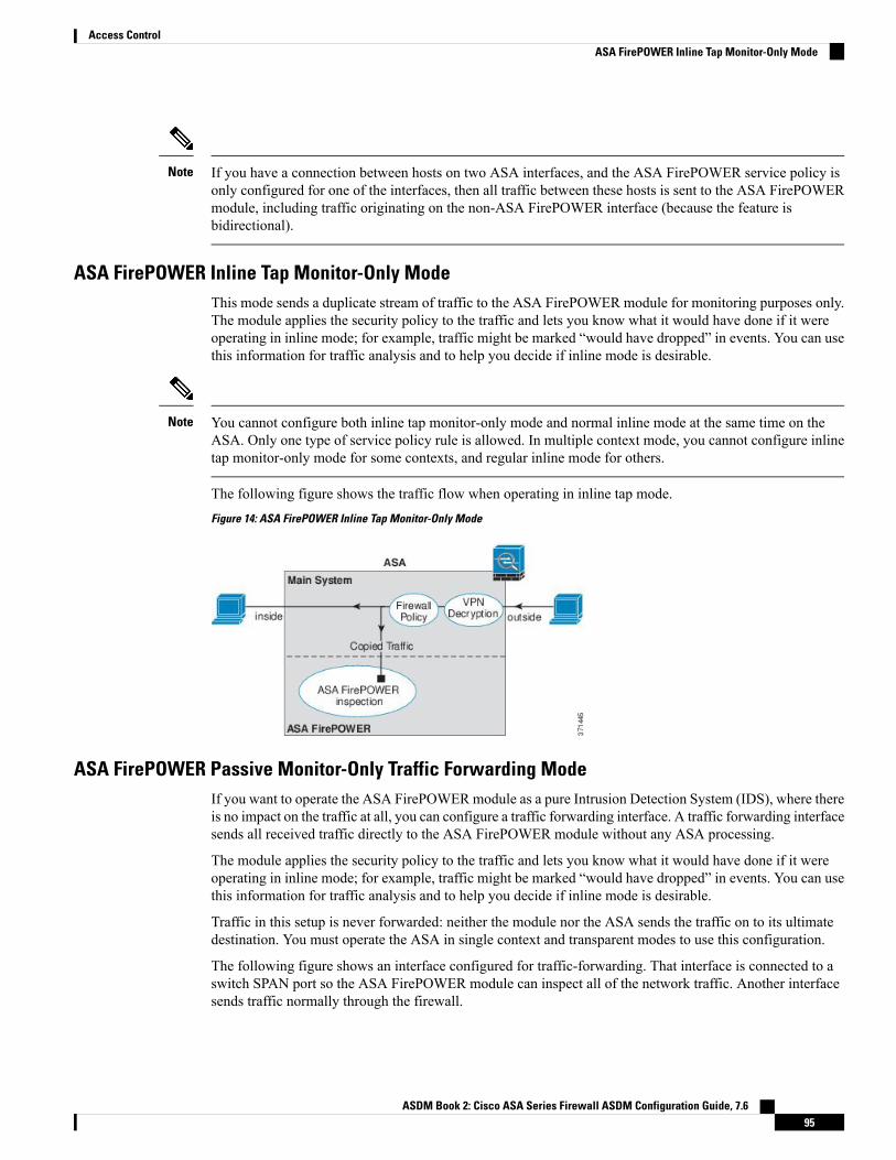
If you have a connection between hosts on two ASA interfaces, and the ASA FirePOWER service policy isonly configured for one of the interfaces, then all traffic between these hosts is sent to the ASA FirePOWERmodule, including traffic originating on the non-ASA FirePOWER interface (because the feature isbidirectional).
Note
ASA FirePOWER Inline Tap Monitor-Only ModeThis mode sends a duplicate stream of traffic to the ASA FirePOWER module for monitoring purposes only.The module applies the security policy to the traffic and lets you know what it would have done if it wereoperating in inline mode; for example, traffic might be marked “would have dropped” in events. You can usethis information for traffic analysis and to help you decide if inline mode is desirable.
You cannot configure both inline tap monitor-only mode and normal inline mode at the same time on theASA. Only one type of service policy rule is allowed. In multiple context mode, you cannot configure inlinetap monitor-only mode for some contexts, and regular inline mode for others.
Note
The following figure shows the traffic flow when operating in inline tap mode.
Figure 14: ASA FirePOWER Inline Tap Monitor-Only Mode
ASA FirePOWER Passive Monitor-Only Traffic Forwarding ModeIf you want to operate the ASA FirePOWERmodule as a pure Intrusion Detection System (IDS), where thereis no impact on the traffic at all, you can configure a traffic forwarding interface. A traffic forwarding interfacesends all received traffic directly to the ASA FirePOWER module without any ASA processing.
The module applies the security policy to the traffic and lets you know what it would have done if it wereoperating in inline mode; for example, traffic might be marked “would have dropped” in events. You can usethis information for traffic analysis and to help you decide if inline mode is desirable.
Traffic in this setup is never forwarded: neither the module nor the ASA sends the traffic on to its ultimatedestination. You must operate the ASA in single context and transparent modes to use this configuration.
The following figure shows an interface configured for traffic-forwarding. That interface is connected to aswitch SPAN port so the ASA FirePOWER module can inspect all of the network traffic. Another interfacesends traffic normally through the firewall.
ASDM Book 2: Cisco ASA Series Firewall ASDM Configuration Guide, 7.695
Access ControlASA FirePOWER Inline Tap Monitor-Only Mode

Figure 15: ASA FirePOWER Passive Monitor-Only, Traffic-Forwarding Mode
ASA FirePOWER ManagementThe module has a basic command line interface (CLI) for initial configuration and troubleshooting only. Youconfigure the security policy on the ASA FirePOWER module using one of the following methods:
• Firepower/FireSIGHTManagement Center—Can be hosted on a separateManagement Center applianceor as a virtual appliance. The Management Center application is called Firepower beginning in version6.0. Previous versions are called FireSIGHT.
• ASDM (check for compatibility with your model/version)—You can manage both the ASA and themodule using the on-box ASDM.
Compatibility with ASA FeaturesThe ASA includes many advanced application inspection features, including HTTP inspection. However, theASA FirePOWER module provides more advanced HTTP inspection than the ASA provides, as well asadditional features for other applications, including monitoring and controlling application usage.
You must follow these configuration restrictions on the ASA:
• Do not configure ASA inspection on HTTP traffic that you send to the ASA FirePOWER module.
• Do not enable the Mobile User Security (MUS) server; it is not compatible with the ASA FirePOWERmodule.
Other application inspections on the ASA are compatible with the ASA FirePOWER module, including thedefault inspections.
What to Do if the ASA FirePOWER Module Cannot Filter URLsThe ASA FirePOWER module obtains its URL filtering data from the managing Firepower ManagementCenter, over HTTP. The module cannot perform URL filtering if it cannot download this database.
If there is a device between the ASAFirePOWERmodule and FirepowerManagement Center that is performingASA HTTP inspection, the inspections can block the ASA FirePOWER module's HTTP GET requests to the
ASDM Book 2: Cisco ASA Series Firewall ASDM Configuration Guide, 7.696
Access ControlASA FirePOWER Management

Firepower Management Center. This problem also occurs if you configure HTTP inspection on the ASA thathosts the ASA FirePOWER module (which is a misconfiguration).
To resolve the issues, do any of the following that apply to your situation:
• If you configured HTTP inspection on the ASA that hosts the ASA FirePOWER module, remove theHTTP inspection configuration. ASAFirePOWER inspection andASAHTTP inspection are incompatible.
• If there is an intervening device doing ASAHTTP inspection, remove the drop protocol violations actionfrom the HTTP inspection policy map:
policy-map type inspect http http_inspection_policyparameters
no protocol-violation action drop-connection
Licensing Requirements for the ASA FirePOWER ModuleCertain areas of ASA FirePOWER module functionality may require additional licenses.
For an ASA FirePOWER module managed by a Firepower/FireSIGHT Management Center, enable licenseson the module using the Management Center. See the licensing chapter of the FireSIGHT System User Guide5.4,Firepower Management Center Configuration Guide 6.0, or the online help on the FireSIGHTManagementCenter for more information.
For the ASAFirePOWERmodulemanaged usingASDM, enable licenses on themodule using the FirePOWERmodule configuration in ASDM. See the licensing chapter of the ASA FirePOWER Module User Guide 5.4,ASA FirePOWER Services Local Management Configuration Guide 6.0, or the online help for the module inASDM for more information.
The ASA itself does not require any additional licenses.
Guidelines for ASA FirePOWERFailover Guidelines
Does not support failover directly; when the ASA fails over, any existing ASA FirePOWER flows aretransferred to the newASA. The ASA FirePOWERmodule in the newASA begins inspecting the traffic fromthat point forward; old inspection states are not transferred.
You are responsible for maintaining consistent policies on theASAFirePOWERmodules in the high-availabilityASA pair to ensure consistent failover behavior.
Create the failover pair before you configure the ASA FirePOWER modules. If the modules are alreadyconfigured on both devices, clear the interface configuration on the standby device before creating thehigh-availability pair. From the CLI on the standby device, enter the clear configure interface command.
Note
ASDM Book 2: Cisco ASA Series Firewall ASDM Configuration Guide, 7.697
Access ControlLicensing Requirements for the ASA FirePOWER Module

ASA Clustering Guidelines
Does not support clustering directly, but you can use these modules in a cluster. You are responsible formaintaining consistent policies on the ASA FirePOWER modules in the cluster.
Create the cluster before you configure the ASA FirePOWERmodules. If the modules are already configuredon the data units, clear the interface configuration on the devices before adding them to the cluster. From theCLI, enter the clear configure interface command.
Note
Model Guidelines
• For ASA model software and hardware compatibility with the ASA FirePOWER module, see the CiscoASA Compatibility.
• For the ASA 5512-X through ASA 5555-X, you must install a Cisco solid state drive (SSD). For moreinformation, see the ASA 5500-X hardware guide. (The SSD is standard on the 5506-X, 5508-X, and5516-X.)
• You cannot change the software type installed on the ASA 5585-X hardware module. If you purchasean ASA FirePOWER module, you cannot later install other software on it.
• The interfaces on the ASA 5585-X ASA FirePOWER hardware module drop traffic for up to 30 secondsduring a module reboot, including reboots that occur during a software upgrade.
ASDM Guidelines for Managing ASA FirePOWER
• The ASA, ASDM, and ASA FirePOWER versions supported for ASDM management differ by model.For supported combinations, see Cisco ASA Compatibility.
• If you enable command authorization on the ASA that hosts the module, you must log in with a username that has privilege level 15 to see the ASA FirePOWER home, configuration, and monitoringpages. Read-only or monitor-only access to ASA FirePOWER pages other than the status page is notsupported.
• If you are using Java 7 update 51 up to Java 8, you need to configure identity certificates for both theASA and the ASA FirePOWER module. See Install an Identity Certificate for ASDM.
• You can never use both ASDM and Firepower Management Center, you must choose one or the other.
Additional Guidelines and Limitations
• See Compatibility with ASA Features, on page 96.
• You cannot configure both normal inline mode and inline tap monitor-only mode at the same time onthe ASA. Only one type of service policy rule is allowed. In multiple context mode, you cannot configureinline tap monitor-only mode for some contexts, and regular inline mode for others.
• If you configure NetFlow on the ASA and include the flow-export delay flow-create command, evenif your ASA FirePOWER access control policy blocks the connection with reset, the connection willremain on the ASA until the connection timeout is reached. If you cannot tolerate this behavior, you needto remove the command from the NetFlow configuration.
ASDM Book 2: Cisco ASA Series Firewall ASDM Configuration Guide, 7.698
Access ControlGuidelines for ASA FirePOWER

• If the module is stuck in recover/init mode, you cannot reload the ASA gracefully. Instead, use the reloadquick command, so the ASA does not wait for the module to shut down gracefully prior to the systemreload. If quick reload does not work, you will have to force-crash the ASA to reload it.
• On the ASA 5500-X series, particularly the smaller models, you can see very intermittent latency,30-60ms, on .02% of the traffic. If you have applications that cannot tolerate this small latency, ensurethat you configure your redirection service policy so that these latency-sensitive applications are notredirected to the ASA FirePOWER module.
Defaults for ASA FirePOWERThe following table lists the default settings for the ASA FirePOWER module.
Table 8: ASA FirePOWER Default Network Parameters
DefaultParameters
System software image: 192.168.45.45/24
Boot image: 192.168.8.8/24
Management IP address
System software image: none
Boot image: 192.168.8.1/24
Gateway
adminSSH or session Username
System software image:
• Release 6.0 and following: Admin123
• Releases prior to 6.0: Sourcefire
Boot image: Admin123
Password
Perform Initial ASA FirePOWER SetupDeploy the ASA FirePOWER module in your network, and then choose your management method.
Deploy the ASA FirePOWER Module in Your NetworkSee the section for your firewall mode and ASA model to determine how to connect the ASA FirePOWERmodule management interface to your network.
Routed Mode
ASA 5585-X (Hardware Module) in Routed Mode
The ASA FirePOWER module includes separate management interfaces from the ASA.
ASDM Book 2: Cisco ASA Series Firewall ASDM Configuration Guide, 7.699
Access ControlDefaults for ASA FirePOWER

All management traffic to and from the ASA FirePOWER module must enter and exit the Management 1/0or 1/1 interface. The ASA FirePOWER module also needs Internet access. Because the Management 1/xinterface is not an ASA data interface, traffic cannot pass through the ASA over the backplane; therefore youneed to physically cable the management interface to an ASA interface. See the following typical cablingsetup to allow ASA FirePOWER access to the Internet through the ASA management interface (or you coulduse a data interface). Other options are possible, depending on how you want to connect your network; forexample, you can make the Management 1/0 interface outside facing; or you can route between it and adifferent ASA interface if you have an inside router.
ASA 5506-X through ASA 5555-X (Software Module) in Routed Mode
These models run the ASA FirePOWER module as a software module, and the ASA FirePOWER moduleshares the Management 0/0 or Management 1/1 interface (depending on your model) with the ASA.
All management traffic to and from the ASA FirePOWER module must enter and exit the Managementinterface. The ASA FirePOWERmodule also needs Internet access. Management traffic cannot pass throughthe ASA over the backplane; therefore you need to physically cable the management interface to an ASAinterface to reach the Internet.
If you do not configure a name and IP address in the ASA configuration for Management, then the interfacebelongs exclusively to the module. In this case, the Management interface is not a regular ASA interface, andyou can:
1. Configure the ASA FirePOWER IP address to be on the same network as a regular ASA data interface.
2. Specify the data interface as the ASA FirePOWER gateway.
3. Directly connect the Management interface to the data interface (using a Layer2 switch).
See the following typical cabling setup to allow ASA FirePOWER access to the Internet through the ASAinside interface.
ASDM Book 2: Cisco ASA Series Firewall ASDM Configuration Guide, 7.6100
Access ControlASA 5506-X through ASA 5555-X (Software Module) in Routed Mode

For the ASA 5506-X, 5508-X, and 5516-X, the default configuration enables the above network deployment;the only change you need to make is to set the module IP address to be on the same network as the ASA insideinterface and to configure the module gateway IP address.
For other models, you must remove the ASA-configured name and IP address for Management 0/0 or 1/1,and then configure the other interfaces as indicated above.
If you want to deploy a separate router on the inside network, then you can route between management andinside. In this case, you canmanage both the ASA and ASA FirePOWERmodule on theManagement interfacewith the appropriate configuration changes, including configuring the ASA name and IP address for theManagement interface (on the same network as the ASA FirePOWER module address).
Note
Transparent Mode
ASA 5585-X (Hardware Module) in Transparent Mode
The ASA FirePOWER module includes separate management interfaces from the ASA.
ASDM Book 2: Cisco ASA Series Firewall ASDM Configuration Guide, 7.6101
Access ControlTransparent Mode
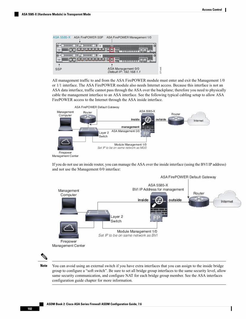
All management traffic to and from the ASA FirePOWER module must enter and exit the Management 1/0or 1/1 interface. The ASA FirePOWER module also needs Internet access. Because this interface is not anASA data interface, traffic cannot pass through the ASA over the backplane; therefore you need to physicallycable the management interface to an ASA interface. See the following typical cabling setup to allow ASAFirePOWER access to the Internet through the ASA inside interface.
If you do not use an inside router, you can manage the ASA over the inside interface (using the BVI IP address)and not use the Management 0/0 interface:
You can avoid using an external switch if you have extra interfaces that you can assign to the inside bridgegroup to configure a “soft switch”. Be sure to set all bridge group interfaces to the same security level, allowsame security communication, and configure NAT for each bridge group member. See the ASA interfacesconfiguration guide chapter for more information.
Note
ASDM Book 2: Cisco ASA Series Firewall ASDM Configuration Guide, 7.6102
Access ControlASA 5585-X (Hardware Module) in Transparent Mode

ASA 5506-X through ASA 5555-X, ISA 3000 (Software Module) in Transparent Mode
These models run the ASA FirePOWER module as a software module, and the ASA FirePOWER moduleshares the Management 0/0 or Management 1/1 interface (depending on your model) with the ASA.
All management traffic to and from the ASA FirePOWER module must enter and exit the Managementinterface. The ASA FirePOWER module also needs Internet access.
The following figure shows the recommended network deployment for the ASA 5500-X or ISA 3000 withthe ASA FirePOWER module:
If you do not use an inside router, you can manage the ASA over the inside interface (using the BVI IP address)and not use the Management interface for ASA management:
You can avoid using an external switch if you have extra interfaces that you can assign to the inside bridgegroup to configure a “soft switch”. Be sure to set all bridge group interfaces to the same security level, allowsame security communication, and configure NAT for each bridge group member. See the ASA interfacesconfiguration guide chapter for more information.
Note
ASDM Book 2: Cisco ASA Series Firewall ASDM Configuration Guide, 7.6103
Access ControlASA 5506-X through ASA 5555-X, ISA 3000 (Software Module) in Transparent Mode

Register the ASA FirePOWER Module with a Management CenterTo register the module with a Firepower/FireSIGHT Management Center, you must access the ASAFirePOWER module CLI. The first time you access the CLI, you are prompted for basic configurationparameters. You must also add the module to the Management Center.
Notes:
• If you want to use ASDM tomanage themodule, skip this section and see Configure the ASA FirePOWERModule for ASDM Management, on page 106.
• If you need to move the module’s management from one management center to another, first removethe device from the management center’s inventory. Then, use the configure manager add commandto point to the newmanagement center. You can then complete the registration from the newmanagementcenter. This process ensures a clean hand-over.
Access the ASA FirePOWER CLITo access the ASA FirePOWER CLI, you can use one of the following methods.
Procedure
Step 1 Console Port:
• ASA 5585-X—This model includes a dedicated console port for the ASA FirePOWERmodule. Use thesupplied DB-9 to RJ-45 serial cable and/or your own USB serial adapter.
• All other models—Connect to the ASA console port using the supplied DB-9 to RJ-45 serial cable and/oryour own USB serial adapter. The ASA 5506-X/5508-X/5516-X also has a mini-USB console port. Seethe hardware guide for instructions on using the USB console port.
At the ASA CLI, session to the ASA FirePOWER module:
session sfr
See also Session to the Software Module From the ASA, on page 119.
Step 2 SSH:
You can connect to the module default IP address (see Defaults for ASA FirePOWER, on page 99) or youcan use ASDM on the ASA to change the management IP address, and then connect using SSH:
In ASDM, choose Wizards > Startup Wizard, and progress through the wizard to the ASA FirePOWERBasic Configuration, where you can set the IP address, mask, and default gateway.
Configure ASA FirePOWER Basic SettingsThe first time you access the ASA FirePOWER module CLI, you are prompted for basic configurationparameters. You must also add the module to the Firepower/FireSIGHT Management Center if you are notusing ASDM.
ASDM Book 2: Cisco ASA Series Firewall ASDM Configuration Guide, 7.6104
Access ControlRegister the ASA FirePOWER Module with a Management Center

Before you begin
Access the module CLI according to Access the ASA FirePOWER CLI, on page 104.
Procedure
Step 1 At the ASA FirePOWER CLI, log in with the username admin.
If this is the first time you are logging in, use the default password. See Defaults for ASA FirePOWER, onpage 99.
Step 2 Complete the system configuration as prompted.
Use the following network settings for the ASAFirePOWERmodule for the recommended network deployment(Deploy the ASA FirePOWER Module in Your Network, on page 99):
• Management interface: 192.168.1.2
• Management subnet mask: 255.255.255.0
• Gateway IP: 192.168.1.1
Example:
System initialization in progress. Please stand by.You must change the password for 'admin' to continue.Enter new password: <new password>Confirm new password: <repeat password>You must configure the network to continue.You must configure at least one of IPv4 or IPv6.Do you want to configure IPv4? (y/n) [y]: yDo you want to configure IPv6? (y/n) [n]:Configure IPv4 via DHCP or manually? (dhcp/manual) [manual]:Enter an IPv4 address for the management interface [192.168.45.45]: 10.86.118.3Enter an IPv4 netmask for the management interface [255.255.255.0]: 255.255.252.0Enter the IPv4 default gateway for the management interface []: 10.86.116.1Enter a fully qualified hostname for this system [Sourcefire3D]: asasfr.example.comEnter a comma-separated list of DNS servers or 'none' []: 10.100.10.15,10.120.10.14Enter a comma-separated list of search domains or 'none' [example.net]: example.comIf your networking information has changed, you will need to reconnect.For HTTP Proxy configuration, run 'configure network http-proxy'(Wait for the system to reconfigure itself.)
This sensor must be managed by a Defense Center. A unique alphanumericregistration key is always required. In most cases, to register a sensorto a Defense Center, you must provide the hostname or the IP address alongwith the registration key.'configure manager add [hostname | ip address ] [registration key ]'
However, if the sensor and the Defense Center are separated by a NAT device,you must enter a unique NAT ID, along with the unique registration key.'configure manager add DONTRESOLVE [registration key ] [ NAT ID ]'
Later, using the web interface on the Defense Center, you must use the sameregistration key and, if necessary, the same NAT ID when you add thissensor to the Defense Center.
Step 3 Register the ASA FirePOWER module to a Management Center:
ASDM Book 2: Cisco ASA Series Firewall ASDM Configuration Guide, 7.6105
Access ControlConfigure ASA FirePOWER Basic Settings

> configure manager add {hostname | IPv4_address | IPv6_address | DONTRESOLVE} reg_key [nat_id]
where:
• {hostname | IPv4_address | IPv6_address | DONTRESOLVE} specifies either the fully qualified hostname or IP address of the Management Center. If the Management Center is not directly addressable,use DONTRESOLVE.
• reg_key is the unique alphanumeric registration key required to register a ASA FirePOWER module tothe Management Center.
• nat_id is an optional alphanumeric string used during the registration process between the ManagementCenter and the ASA FirePOWER module. It is required if the hostname is set to DONTRESOLVE.
Step 4 Close the console connection. For the software module, enter:
> exit
Configure the ASA FirePOWER Module for ASDM ManagementNot supported for all version/model combinations; check for compatibilitywith your model and version.
ASDM can change the ASA FirePOWER module IP address over the ASA backplane, but all furthermanagement requires network access between the ASDM interface and the Management interface, where themodule is reachable.
To use ASDM to manage the module, launch ASDM and run the Startup Wizard.
Procedure
Step 1 On the computer connected to the ASA, launch a web browser.Step 2 In the Address field, enter the following URL: https://192.168.1.1/admin. The Cisco ASDM web page
appears.Step 3 Click one of the available options: Install ASDM Launcher, Run ASDM, or Run Startup Wizard.Step 4 Follow the onscreen instructions to launch ASDM according to the option you chose. The Cisco ASDM-IDM
Launcher appears.
If you click Install ASDM Launcher, in some cases you need to install an identity certificate for theASA and a separate certificate for the ASA FirePOWER module according to Install an IdentityCertificate for ASDM.
Note
Step 5 Leave the username and password fields empty, and click OK. The main ASDM window appears.Step 6 If you are prompted to provide the IP address of the installed ASA Firepower module, cancel out of the dialog
box. You must first set the module IP address to the correct IP address using the Startup Wizard.Step 7 Choose Wizards > Startup Wizard.Step 8 Configure additional ASA settings as desired, or skip screens until you reach the ASA Firepower Basic
Configuration screen.
ASDM Book 2: Cisco ASA Series Firewall ASDM Configuration Guide, 7.6106
Access ControlConfigure the ASA FirePOWER Module for ASDM Management

Set the following values to work with the default configuration:
• IP Address—192.168.1.2
• Subnet Mask—255.255.255.0
• Gateway—192.168.1.1
Step 9 Click I accept the agreement, and click Next or Finish to complete the wizard.Step 10 Quit ASDM, and then relaunch. You should see ASA Firepower tabs on the Home page.
ASDM Book 2: Cisco ASA Series Firewall ASDM Configuration Guide, 7.6107
Access ControlConfigure the ASA FirePOWER Module for ASDM Management
Configure the ASA FirePOWER ModuleConfigure the security policy in the ASA FirePOWER module, and then configure the ASA to send traffic tothe module.
Configure the Security Policy on the ASA FirePOWER ModuleThe security policy controls the services provided by the module, such as Next Generation IPS filtering andapplication filtering. You configure the security policy on the ASA FirePOWER module using one of thefollowing methods.
FireSIGHT Management Center
Use a web browser to open https://DC_address, where DC_address is the DNS name or IP address of themanager you defined in Configure ASA FirePOWER Basic Settings, on page 104. For example,https://dc.example.com.
Alternatively, in ASDM, choose Home > ASA FirePOWER Status and click the link at the bottom of thedashboard.
For more information about ASA FirePOWER configuration, see the Management Center online help,FireSIGHT System User Guide 5.4, or Firepower Management Center Configuration Guide 6.0 (available athttp://www.cisco.com/c/en/us/support/security/defense-center/products-installation-and-configuration-guides-list.html).
ASDM
In ASDM, choose Configuration > ASA FirePOWER Configuration.
For more information about ASA FirePOWER configuration, see the module's online help in ASDM, ASAFirePOWER Module User Guide 5.4, or ASA FirePOWER Services Local Management Configuration Guide6.0 (available at http://www.cisco.com/c/en/us/support/security/asa-firepower-services/products-installation-and-configuration-guides-list.html.
Redirect Traffic to the ASA FirePOWER ModuleFor inline and inline tap (monitor-only) modes, you configure a service policy to redirect traffic to the module.If you want passive monitor-only mode, you configure a traffic redirection interface, which bypasses ASApolicies.
The following topics explain how to configure these modes.
Configure Inline or Inline Tap Monitor-Only ModesRedirect traffic to the ASA FirePOWER module by creating a service policy that identifies specific trafficthat you want to send. In this mode, ASA policies, such as access rules, are applied to the traffic before it isredirected to the module.
ASDM Book 2: Cisco ASA Series Firewall ASDM Configuration Guide, 7.6108
Access ControlConfigure the ASA FirePOWER Module

Before you begin
• Be sure to configure consistent policies on the ASA and the ASA FirePOWER module. Both policiesshould reflect the inline or inline tap mode of the traffic.
• In multiple context mode, perform this procedure within each security context.
Procedure
Step 1 Choose Configuration > Firewall > Service Policy Rules.Step 2 Choose Add > Add Service Policy Rule.Step 3 Choose whether to apply the policy to a particular interface or apply it globally and click Next.Step 4 Configure the traffic match. For example, you could match Any Traffic so that all traffic that passes your
inbound access rules is redirected to the module. Or, you could define stricter criteria based on ports, ACL(source and destination criteria), or an existing traffic class. The other options are less useful for this policy.After you complete the traffic class definition, click Next.
Step 5 On the Rule Actions page, click the ASA FirePOWER Inspection tab.Step 6 Check the Enable ASA FirePOWER for this traffic flow check box.Step 7 In the If ASA FirePOWER Card Fails area, click one of the following:
• Permit traffic—Sets the ASA to allow all traffic through, uninspected, if the module is unavailable.
• Close traffic—Sets the ASA to block all traffic if the module is unavailable.
Step 8 (Optional) Check Monitor-only to send a read-only copy of traffic to the module (inline tap mode).
By default, the traffic is sent in inline mode. Be sure to configure consistent policies on the ASA and the ASAFirePOWER. Both policies should reflect the inline or monitor-only of the traffic.
Step 9 Click Finish and then Apply.
Repeat this procedure to configure additional traffic flows as desired.
Configure Passive Traffic ForwardingIf you want to operate the module in passive monitor-only mode, where the module gets a copy of the trafficand neither it nor the ASA can affect the network, configure a traffic forwarding interface and connect theinterface to a SPAN port on a switch. For more details, see ASA FirePOWER Passive Monitor-Only TrafficForwarding Mode, on page 95.
The following guidelines explain the requirements for this deployment mode:
• The ASA must be in single-context and transparent mode.
• You can configure up to 4 interfaces as traffic-forwarding interfaces. Other ASA interfaces can be usedas normal.
• Traffic-forwarding interfaces must be physical interfaces, not VLANs or BVIs. The physical interfacealso cannot have any VLANs associated with it.
ASDM Book 2: Cisco ASA Series Firewall ASDM Configuration Guide, 7.6109
Access ControlConfigure Passive Traffic Forwarding

• Traffic-forwarding interfaces cannot be used for ASA traffic; you cannot name them or configure themfor ASA features, including failover or management-only.
• You cannot configure both a traffic-forwarding interface and a service policy for ASA FirePOWERtraffic.
Procedure
Step 1 Enter interface configuration mode for the physical interface you want to use for traffic-forwarding.
interface physical_interface
Example:
hostname(config)# interface gigabitethernet 0/5
Step 2 Remove any name configured for the interface. If this interface was used in any ASA configuration, thatconfiguration is removed. You cannot configure traffic-forwarding on a named interface.
no nameif
Step 3 Enable traffic-forwarding.
traffic-forward sfr monitor-only
You can ignore any warnings about traffic forwarding being for demonstration purposes only. Thisis a supported production mode.
Note
Step 4 Enable the interface.
no shutdown
Repeat for any additional interfaces.
Example
The following example makes GigabitEthernet 0/5 a traffic-forwarding interface:
interface gigabitethernet 0/5no nameiftraffic-forward sfr monitor-onlyno shutdown
Enable Captive Portal for Active AuthenticationASA FirePOWER includes identity policies that allow you to collect user identification information. Bycollecting user identity information, you can tailor access control rules to specific users and user groups,selectively allowing and disallowing access based on the user. You can also analyze traffic based on useridentity.
ASDM Book 2: Cisco ASA Series Firewall ASDM Configuration Guide, 7.6110
Access ControlEnable Captive Portal for Active Authentication
For HTTP/HTTPS connections, you can define identity rules that collect user identification through activeauthentication. If you want to implement active authentication identity rules, you must enable captive portalon the ASA to act as the authentication proxy port. When a connection matches an identity rule that requestsactive authentication, the ASA FirePOWERmodule redirects the authentication request to the ASA interfaceIP address/captive portal. The default port is 885, which you can change.
If you do not enable captive portal for the authentication proxy, only passive authentication is available.
Before you begin
• This feature is available in routed mode only for ASA FirePOWER 6.0+ only.
• In multiple context mode, perform this procedure within each security context.
Procedure
Step 1 Select Tools > Command Line Tool.Step 2 Enable captive portal.
captive-portal {global | interface name} [port number]
Where:
• global enables captive portal globally on all interfaces.
• interface name enables captive portal on the specified interface only. You can enter the commandmultipletimes to enable it on more than one interface. You can use this approach if you are redirecting traffic foronly a subset of interfaces to the ASA FirePOWER module.
• port number optionally specifies the authentication port. If you do not include the keyword, port 885 isused. If you do include the keyword, the port number must be 1025 or higher.
Example:
For example, to enable captive portal globally on port 885, enter the following:
ciscoasa(config)# captive-portal globalciscoasa(config)#
Step 3 In the ASA FirePOWER identity policy, ensure that the active authentication settings specify the same portyou configured for captive portal, and configure the other required settings to enable active authentication.
Managing the ASA FirePOWER ModuleThis section includes procedures that help you manage the module.
Install or Reimage the ModuleThis section describes how to install or reimage a software or hardware module.
ASDM Book 2: Cisco ASA Series Firewall ASDM Configuration Guide, 7.6111
Access ControlManaging the ASA FirePOWER Module

Install or Reimage the Software ModuleIf you purchase the ASA with the ASA FirePOWER module, the module software and required solid statedrives (SSDs) come pre-installed and ready to configure. If you want to add the ASA FirePOWER softwaremodule to an existing ASA, or need to replace the SSD, you need to install the ASA FirePOWER boot software,partition the SSD, and install the system software according to this procedure.
Reimaging the module is the same procedure, except you should first uninstall the ASA FirePOWERmodule.You would reimage a system if you replace an SSD.
For information on how to physically install the SSD, see the ASA hardware guide.
Before you begin
• The free space on flash (disk0) should be at least 3GB plus the size of the boot software.
• In multiple context mode, perform this procedure in the system execution space.
• You must shut down any other software module that you might be running; the ASA can run a singlesoftware module at a time. You must do this from the ASA CLI.
• When reimaging the ASA FirePOWER module, use the sw-module module shutdown and uninstallcommands to remove the old image. For example:
sw-module module sfr shutdownsw-module module sfr uninstallreload
• If you have an active service policy redirecting traffic to an IPS or CX module, you must remove thatpolicy. For example, if the policy is a global one, you could use no service-policy ips_policy global. Ifthe service policy includes other rules you want to maintain, simply remove the redirection commandfrom the relevant policy map, or the entire traffic class if redirection is the only action for the class. Youcan remove the policies using CLI or ASDM.
• If you have an active service policy redirecting traffic to another module, you must remove that policy.For example, if the policy is a global one, you could use no service-policy module_policy global.
• Obtain both the ASA FirePOWER Boot Image and System Software packages from Cisco.com.
Procedure
Step 1 Download the boot image to the ASA. Do not transfer the system software; it is downloaded later to the SSD.You have the following options:
• ASDM—First, download the boot image to your workstation, or place it on an FTP, TFTP, HTTP,HTTPS, SMB, or SCP server. Then, in ASDM, choose Tools > File Management, and then choose theappropriate File Transfer command, either Between Local PC and Flash or Between Remote Serverand Flash. Transfer the boot software to disk0 on the ASA.
• ASA CLI—First, place the boot image on a TFTP, FTP, HTTP, or HTTPS server, then use the copycommand to download it to flash. The following example uses TFTP.
ciscoasa# copy tftp://10.1.1.89/asasfr-5500x-boot-5.4.1-58.img
ASDM Book 2: Cisco ASA Series Firewall ASDM Configuration Guide, 7.6112
Access ControlInstall or Reimage the Software Module

disk0:/asasfr-5500x-boot-5.4.1-58.img
Step 2 Download the ASA FirePOWER system software from Cisco.com to an HTTP, HTTPS, or FTP serveraccessible from the ASA FirePOWER management interface. Do not download it to disk0 on the ASA.
Step 3 Set the ASA FirePOWER module boot image location in ASA disk0 by entering the following command:
sw-module module sfr recover configure image disk0: file_path
Example:
hostname# sw-module module sfr recover configure image disk0:asasfr-5500x-boot-5.4.1-58.img
If you see a message like “ERROR: Another service (cxsc) is running, only one service is allowed to run atany time,” it means that you already have a different software module configured. You must shut it down andremove it to install a new module as described in the prerequisites section above.
Step 4 Load the ASA FirePOWER boot image:
sw-module module sfr recover boot
Step 5 Wait approximately 5-15 minutes for the ASA FirePOWER module to boot up, and then open a consolesession to the now-running ASA FirePOWER boot image. You might need to press enter after opening thesession to get to the login prompt. The default username is admin and the default password is Admin123.
hostname# session sfr consoleOpening console session with module sfr.Connected to module sfr. Escape character sequence is 'CTRL-^X'.
Cisco ASA SFR Boot Image 5.3.1asasfr login: adminPassword: Admin123
If the module boot has not completed, the session command will fail with a message about not being able toconnect over ttyS1. Wait and try again.
Step 6 Configure the system so that you can install the system software package:
asasfr-boot> setup
Example:
asasfr-boot> setup
Welcome to SFR Setup[hit Ctrl-C to abort]
Default values are inside []
You are prompted for the following. Note that the management address and gateway, and DNS information,are the key settings to configure.
• Host name—Up to 65 alphanumeric characters, no spaces. Hyphens are allowed.
• Network address—You can set static IPv4 or IPv6 addresses, or use DHCP (for IPv4) or IPv6 statelessautoconfiguration.
ASDM Book 2: Cisco ASA Series Firewall ASDM Configuration Guide, 7.6113
Access ControlInstall or Reimage the Software Module

• DNS information—You must identify at least one DNS server, and you can also set the domain nameand search domain.
• NTP information—You can enable NTP and configure the NTP servers, for setting system time.
Step 7 Install the System Software image:
asasfr-boot> system install [noconfirm] url
Include the noconfirm option if you do not want to respond to confirmation messages. Use an HTTP, HTTPS,or FTP URL; if a username and password are required, you will be prompted to supply them.
When installation is complete, the system reboots. The time required for application component installationand for the ASA FirePOWER services to start differs substantially: high-end platforms can take 10 or moreminutes, but low-end platforms can take 60-80 minutes or longer. (The show module sfr output should showall processes as Up.)
For example:
asasfr-boot> system install http://upgrades.example.com/packages/asasfr-sys-5.4.1-58.pkgVerifyingDownloadingExtractingPackage Detail
Description: Cisco ASA-FirePOWER 5.4.1-58 System InstallRequires reboot: Yes
Do you want to continue with upgrade? [y]: yWarning: Please do not interrupt the process or turn off the system.Doing so might leave system in unusable state.
UpgradingStarting upgrade process ...Populating new system image
Reboot is required to complete the upgrade. Press 'Enter' to reboot the system.(press Enter)Broadcast message from root (ttyS1) (Mon Feb 17 19:28:38 2014):
The system is going down for reboot NOW!Console session with module sfr terminated.
Step 8 Open a session to the ASA FirePOWERmodule. You will see a different login prompt because you are logginginto the fully functional module.
ciscoasa# session sfr console
Example:
ciscoasa# session sfr consoleOpening console session with module sfr.Connected to module sfr. Escape character sequence is 'CTRL-^X'.
Sourcefire ASA5555 v5.4.1 (build 58)Sourcefire3D login:
Step 9 See Configure ASA FirePOWER Basic Settings, on page 104 to complete the setup.
ASDM Book 2: Cisco ASA Series Firewall ASDM Configuration Guide, 7.6114
Access ControlInstall or Reimage the Software Module
Reimage the 5585-X ASA FirePOWER Hardware ModuleIf you need to reimage the ASA FirePOWER hardware module in an ASA 5585-X for any reason, you needto install both the Boot Image and a System Software package, in that order. You must install both packagesto have a functioning system. Under normal circumstances, you do not need to reimage the system to installupgrade packages.
To install the boot image, you need to TFTP boot the image from the Management-0 port on the ASAFirePOWER SSP by logging into the module’s Console port. Because the Management-0 port is on an SSPin the first slot, it is also known as Management1/0, but ROMMON recognizes it as Management-0 orManagement0/1.
The interfaces on the ASA 5585-X ASA FirePOWER hardware module drop traffic for up to 30 secondsduring a module reboot, including reboots that occur during a module reimage.
Note
Before you begin
To accomplish a TFTP boot, you must:
• Place the Boot Image and a System Software package on a TFTP server that can be accessed throughthe Management1/0 interface on the ASA FirePOWER module.
• Connect Management1/0 to the network. You must use this interface to TFTP boot the Boot Image.
Procedure
Step 1 Connect to the module console port.Step 2 Reload the system:
system reboot
Step 3 When prompted, break out of the boot by pressing Esc. If you see grub start to boot the system, you havewaited too long.
This will place you at the ROMMON prompt.
Step 4 At the ROMMON prompt, enter:
set
Configure the following parameters:
• ADDRESS—The management IP address of the module.
• SERVER—The IP address of the TFTP server.
• GATEWAY—The gateway address to the TFTP server. If the TFTP server is directly attached toManagement1/0, use the IP address of the TFTP server. If the TFTP server and management address areon the same subnet, do not configure the gateway or TFTP boot will fail.
• IMAGE—The Boot Image path and image name on the TFTP server. For example, if you place the fileon the TFTP server in /tftpboot/images/filename.img, the IMAGE value is images/filename.img.
ASDM Book 2: Cisco ASA Series Firewall ASDM Configuration Guide, 7.6115
Access ControlReimage the 5585-X ASA FirePOWER Hardware Module
Example:
ADDRESS=10.5.190.199SERVER=10.5.11.170GATEWAY=10.5.1.1IMAGE=asasfrboot-5.4.1-58.img
Step 5 Save the settings:
sync
Step 6 Initiate the download and boot process:
tftp
You will see ! marks to indicate progress. When the boot completes after several minutes, you will see a loginprompt.
Step 7 Log in as admin, with the password Admin123.Step 8 Configure the system so that you can install the system software package:
setup
You are prompted for the following. Note that the management address and gateway, and DNS information,are the key settings to configure.
• Host name—Up to 65 alphanumeric characters, no spaces. Hyphens are allowed.
• Network address—You can set static IPv4 or IPv6 addresses, or use DHCP (for IPv4) or IPv6 statelessautoconfiguration.
• DNS information—You must identify at least one DNS server, and you can also set the domain nameand search domain.
• NTP information—You can enable NTP and configure the NTP servers, for setting system time.
Step 9 Install the System Software image:
system install [noconfirm] url
Example:
asasfr-boot> system install http://upgrades.example.com/packages/asasfr-sys-5.4.1-58.pkg
Include the noconfirm option if you do not want to respond to confirmation messages.
When installation is complete, the system reboots. Allow 10 or more minutes for application componentinstallation and for the ASA FirePOWER services to start.
Step 10 When the boot completes, log in as admin with the defautl password. See Defaults for ASA FirePOWER, onpage 99.
Step 11 See Configure ASA FirePOWER Basic Settings, on page 104 to complete the setup.
ASDM Book 2: Cisco ASA Series Firewall ASDM Configuration Guide, 7.6116
Access ControlReimage the 5585-X ASA FirePOWER Hardware Module
Reset the PasswordIf you forget the password for the admin user, another user with CLI Configuration permissions can log inand change the password.
If there are no other users with the required permissions, you can reset the admin password from the ASA.The default password differs based on software release; see Defaults for ASA FirePOWER, on page 99.
Before you begin
• In multiple context mode, perform this procedure in the system execution space.
• The password-reset option on the ASA hw-module and sw-module commands does not work with ASAFirePOWER.
Procedure
Reset the module password for the user admin to the default:
session {1 | sfr} do password-reset
Use 1 for a hardware module, sfr for a software module.
Reload or Reset the ModuleYou can reload, or to reset and then reload, the module from the ASA.
Before you begin
In multiple context mode, perform this procedure in the system execution space.
Procedure
Enter one of the following commands:
• Hardware module (ASA 5585-X):
hw-module module 1 {reload | reset}
The interfaces on the ASA 5585-X ASA FirePOWER hardware module drop traffic for up to30 seconds during a module reboot, including reboots that occur during a software upgrade.
Note
• Software module (all other models):
sw-module module sfr {reload | reset}
ASDM Book 2: Cisco ASA Series Firewall ASDM Configuration Guide, 7.6117
Access ControlReset the Password

Shut Down the ModuleShutting down themodule software prepares the module to be safely powered off without losing configurationdata.
Before you begin
• In multiple context mode, perform this procedure in the system execution space.
• If you reload the ASA, the module is not automatically shut down, so we recommend shutting down themodule before reloading the ASA.
Procedure
Enter one of the following commands:
• Hardware module (ASA 5585-X):
hw-module module 1 shutdown
• Software module (all other models):
sw-module module sfr shutdown
Uninstall a Software Module ImageYou can uninstall a software module image and its associated configuration.
Before you begin
In multiple context mode, perform this procedure in the system execution space.
Procedure
Step 1 Uninstall the software module image and associated configuration.
sw-module module sfr uninstall
Example:
ciscoasa# sw-module module sfr uninstall
Module sfr will be uninstalled. This will completely remove the disk imageassociated with the sw-module including any configuration that existed within it.
Uninstall module sfr? [confirm]
Step 2 Reload the ASA.
reload
ASDM Book 2: Cisco ASA Series Firewall ASDM Configuration Guide, 7.6118
Access ControlShut Down the Module

You must reload the ASA before you can install a new module.
Session to the Software Module From the ASAUse the ASA FirePOWER CLI to configure basic network settings and to troubleshoot the module.
To access the ASA FirePOWER software module CLI from the ASA, you can session from the ASA. (Youcannot session to a hardware module running on a 5585-X.)
You can either session to the module (using Telnet) or create a virtual console session. A console sessionmight be useful if the control plane is down and you cannot establish a Telnet session. In multiple contextmode, session from the system execution space.
In either a Telnet or a Console session, you are prompted for a username and password. You can log in withany username configured on the ASA FirePOWER. Initially, the admin username is the only one configured(and it is always available). The initial default password differs based on the type of image (full image or bootimage) and software release; see Defaults for ASA FirePOWER, on page 99.
• Telnet session:
session sfr
When in the ASA FirePOWER CLI, to exit back to the ASA CLI, enter any command that would logyou out of the module, such as logout or exit, or press Ctrl-Shift-6, x.
• Console session:
session sfr console
The only way out of a console session is to press Ctrl-Shift-6, x. Logging out of the module leaves youat the module login prompt.
Do not use the session sfr console command in conjunction with a terminal server where Ctrl-Shift-6, x isthe escape sequence to return to the terminal server prompt. Ctrl-Shift-6, x is also the sequence to escape theASA FirePOWER console and return to the ASA prompt. Therefore, if you try to exit the ASA FirePOWERconsole in this situation, you instead exit all the way to the terminal server prompt. If you reconnect theterminal server to the ASA, the ASA FirePOWER console session is still active; you can never exit to theASA prompt. Youmust use a direct serial connection to return the console to the ASA prompt. Use the sessionsfr command instead of the console command when facing this situation.
Note
Upgrade the System SoftwareBefore applying an upgrade, ensure that the ASA is running the minimum required release for the new version;you might need to upgrade the ASA prior to upgrading the module. For more information about applyingupgrades, see the Management Center online help, FireSIGHT System User Guide 5.4, or FirepowerManagement Center Configuration Guide 6.0.
For ASDM management, you can apply upgrades to the system software and components usingConfiguration > ASA FirePOWER Configuration > Updates. Click Help on the Updates page for moreinformation.
ASDM Book 2: Cisco ASA Series Firewall ASDM Configuration Guide, 7.6119
Access ControlSession to the Software Module From the ASA
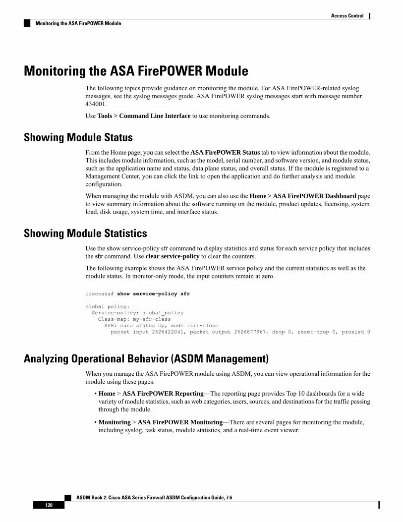
Monitoring the ASA FirePOWER ModuleThe following topics provide guidance on monitoring the module. For ASA FirePOWER-related syslogmessages, see the syslog messages guide. ASA FirePOWER syslog messages start with message number434001.
Use Tools > Command Line Interface to use monitoring commands.
Showing Module StatusFrom the Home page, you can select theASA FirePOWER Status tab to view information about the module.This includes module information, such as the model, serial number, and software version, and module status,such as the application name and status, data plane status, and overall status. If the module is registered to aManagement Center, you can click the link to open the application and do further analysis and moduleconfiguration.
When managing the module with ASDM, you can also use the Home > ASA FirePOWER Dashboard pageto view summary information about the software running on the module, product updates, licensing, systemload, disk usage, system time, and interface status.
Showing Module StatisticsUse the show service-policy sfr command to display statistics and status for each service policy that includesthe sfr command. Use clear service-policy to clear the counters.
The following example shows the ASA FirePOWER service policy and the current statistics as well as themodule status. In monitor-only mode, the input counters remain at zero.
ciscoasa# show service-policy sfr
Global policy:Service-policy: global_policyClass-map: my-sfr-classSFR: card status Up, mode fail-closepacket input 2626422041, packet output 2626877967, drop 0, reset-drop 0, proxied 0
Analyzing Operational Behavior (ASDM Management)When you manage the ASA FirePOWERmodule using ASDM, you can view operational information for themodule using these pages:
• Home > ASA FirePOWER Reporting—The reporting page provides Top 10 dashboards for a widevariety of module statistics, such as web categories, users, sources, and destinations for the traffic passingthrough the module.
• Monitoring > ASA FirePOWER Monitoring—There are several pages for monitoring the module,including syslog, task status, module statistics, and a real-time event viewer.
ASDM Book 2: Cisco ASA Series Firewall ASDM Configuration Guide, 7.6120
Access ControlMonitoring the ASA FirePOWER Module

Monitoring Module ConnectionsTo show connections through the ASA FirePOWER module, enter one of the following commands:
• show asp table classify domain sfr
Shows the NP rules created to send traffic to the ASA FirePOWER module.
• show asp drop
Shows dropped packets. The drop types are explained below.
• show conn
Shows if a connection is being forwarded to a module by displaying the ‘X - inspected by service module’flag.
The show asp drop command can include the following drop reasons related to the ASA FirePOWERmodule.
Frame Drops:
• sfr-bad-tlv-received—This occurs when ASA receives a packet from FirePOWER without a Policy IDTLV. This TLV must be present in non-control packets if it does not have the Standby/Active bit set inthe actions field.
• sfr-request—The frame was requested to be dropped by FirePOWER due a policy on FirePOWERwhereby FirePOWERwould set the actions to Deny Source, Deny Destination, or Deny Pkt. If the frameshould not have been dropped, review the policies on the module that are denying the flow.
• sfr-fail-close—The packet is dropped because the card is not up and the policy configured was ‘fail-close’(rather than ‘fail-open’ which allows packets through even if the card was down). Check card status andattempt to restart services or reboot it.
• sfr-fail—The FirePOWER configuration was removed for an existing flow andwe are not able to processit through FirePOWER it will be dropped. This should be very unlikely.
• sfr-malformed-packet—The packet from FirePOWER contains an invalid header. For instance, the headerlength may not be correct.
• sfr-ha-request—This counter is incremented when the security appliance receives a FirePOWER HArequest packet, but could not process it and the packet is dropped.
• sfr-invalid-encap—This counter is incremented when the security appliance receives a FirePOWERpacket with invalid message header, and the packet is dropped.
• sfr-bad-handle-received—ReceivedBad flow handle in a packet from FirePOWERModule, thus droppingflow. This counter is incremented, flow and packet are dropped on ASA as the handle for FirePOWERflow has changed in flow duration.
• sfr-rx-monitor-only—This counter is incremented when the security appliance receives a FirePOWERpacket when in monitor-only mode, and the packet is dropped.
Flow Drops:
• sfr-request—The FirePOWER requested to terminate the flow. The actions bit 0 is set.
• reset-by-sfr—The FirePOWER requested to terminate and reset the flow. The actions bit 1 is set.
ASDM Book 2: Cisco ASA Series Firewall ASDM Configuration Guide, 7.6121
Access ControlMonitoring Module Connections

• sfr-fail-close—The flowwas terminated because the card is down and the configured policy was 'fail-close'.
Example
The following is sample output from the show asp table classify domain sfr command. Note that if youconfigure redirection globally, only the input table will show data, and the output table will be empty. If youconfigure redirection by interface, both tables should contain data.
ciscoasa# show asp table classify domain sfr
Input Tablein id=0x2aaae04034f0, priority=71, domain=sfr, deny=false
hits=0, user_data=0x2aaadfdedf40, cs_id=0x0, use_real_addr, flags=0x0, protocol=0src ip/id=0.0.0.0, mask=0.0.0.0, port=0, tag=anydst ip/id=0.0.0.0, mask=0.0.0.0, port=0, tag=any, dscp=0x0input_ifc=management, output_ifc=any
Output Table:
L2 - Output Table:
L2 - Input Table:
Last clearing of hits counters: Never
History for the ASA FirePOWER Module
DescriptionPlatformReleasesFeature
TheASAFirePOWERmodule supplies next-generation firewallservices, including Next-Generation IPS (NGIPS), ApplicationVisibility and Control (AVC), URL filtering, and AdvancedMalware Protection (AMP).You can use the module in singleor multiple context mode, and in routed or transparent mode.
We introduced the following screens:
Home > ASA FirePOWER Status Wizards > Startup Wizard >ASAFirePOWERBasic Configuration Configuration > Firewall> Service Policy Rules > Add Service Policy Rule > RuleActions > ASA FirePOWER Inspection
ASA 9.2(2.4)
ASAFirePOWER5.3.1
ASA 5585-X (all models) support for thematching ASA FirePOWER SSP hardwaremodule.
ASA 5512-X through ASA 5555-X support forthe ASA FirePOWER software module.
You can run the ASA FirePOWER softwaremodule on the ASA5506-X. You can manage the module using FireSIGHTManagement Center, or you can use ASDM.
We introduced the following screens:
Home > ASA FirePOWER Dashboard, Home > ASAFirePOWER Reporting, Configuration > ASA FirePOWERConfiguration (including sub-pages), Monitoring > ASAFirePOWER Monitoring (including sub-pages).
ASA 9.3(2)
ASDM 7.3(3)
ASAFirePOWER5.4.1
ASA 5506-X support for the ASA FirePOWERsoftware module, including support forconfiguring the module in ASDM
ASDM Book 2: Cisco ASA Series Firewall ASDM Configuration Guide, 7.6122
Access ControlHistory for the ASA FirePOWER Module

DescriptionPlatformReleasesFeature
You can now configure a traffic forwarding interface to sendtraffic to the module instead of using a service policy. In thismode, neither the module nor the ASA affects the traffic.
We fully supported the following command: traffic-forwardsfr monitor-only. You can configure this in CLI only.
ASA 9.3(2)
ASAFirePOWER5.4.1
ASA FirePOWER passive monitor-only modeusing traffic redirection interfaces
You can manage the module using ASDM instead of usingFireSIGHT Management Center.
No new screens or commands were added.
ASA 9.4(1)
ASDM 7.4(1)
ASAFirePOWER5.4.1
Support formanaging themodule throughASDMfor the 5506H-X, 5506W-X, 5508-X, and5516-X.
You can manage the module using ASDM instead of usingFirepower Management Center (formerly FireSIGHTManagement Center).
No new screens or commands were added.
ASA 9.5.(1.5)
ASDM7.5(1.112)
ASAFirePOWER 6.0
Support formanaging themodule throughASDMfor the 5512-X through 5585-X.
The captive portal feature is required to enable activeauthentication using identity policies starting with ASAFirePOWER 6.0.
We introduced or modified the following commands:captive-portal, clear configure captive-portal, showrunning-config captive-portal.
ASA 9.5.(2)
ASAFirePOWER 6.0
Captive portal for active authentication on ASAFirePOWER 6.0.
ASDM Book 2: Cisco ASA Series Firewall ASDM Configuration Guide, 7.6123
Access ControlHistory for the ASA FirePOWER Module

ASDM Book 2: Cisco ASA Series Firewall ASDM Configuration Guide, 7.6124
Access ControlHistory for the ASA FirePOWER Module

P A R T IINetwork Address Translation
• Network Address Translation (NAT), on page 127• NAT Examples and Reference, on page 191


C H A P T E R 8Network Address Translation (NAT)
The following topics explain Network Address Translation (NAT) and how to configure it.
• Why Use NAT?, on page 127• NAT Basics, on page 128• Guidelines for NAT, on page 132• Dynamic NAT, on page 139• Dynamic PAT, on page 147• Static NAT, on page 166• Identity NAT, on page 178• Monitoring NAT, on page 185• History for NAT, on page 185
Why Use NAT?Each computer and device within an IP network is assigned a unique IP address that identifies the host. Becauseof a shortage of public IPv4 addresses, most of these IP addresses are private, not routable anywhere outsideof the private company network. RFC 1918 defines the private IP addresses you can use internally that shouldnot be advertised:
• 10.0.0.0 through 10.255.255.255
• 172.16.0.0 through 172.31.255.255
• 192.168.0.0 through 192.168.255.255
One of the main functions of NAT is to enable private IP networks to connect to the Internet. NAT replacesa private IP address with a public IP address, translating the private addresses in the internal private networkinto legal, routable addresses that can be used on the public Internet. In this way, NAT conserves publicaddresses because it can be configured to advertise at a minimum only one public address for the entire networkto the outside world.
Other functions of NAT include:
• Security—Keeping internal IP addresses hidden discourages direct attacks.
• IP routing solutions—Overlapping IP addresses are not a problem when you use NAT.
ASDM Book 2: Cisco ASA Series Firewall ASDM Configuration Guide, 7.6127

• Flexibility—You can change internal IP addressing schemes without affecting the public addressesavailable externally; for example, for a server accessible to the Internet, you can maintain a fixed IPaddress for Internet use, but internally, you can change the server address.
• Translating between IPv4 and IPv6 (Routed mode only) (Version 9.0(1) and later)—If you want toconnect an IPv6 network to an IPv4 network, NAT lets you translate between the two types of addresses.
NAT is not required. If you do not configure NAT for a given set of traffic, that traffic will not be translated,but will have all of the security policies applied as normal.
Note
NAT BasicsThe following topics explain some of the basics of NAT.
NAT TerminologyThis document uses the following terminology:
• Real address/host/network/interface—The real address is the address that is defined on the host, beforeit is translated. In a typical NAT scenario where you want to translate the inside network when it accessesthe outside, the inside network would be the “real” network. Note that you can translate any networkconnected to the device, not just an inside network. Therefore if you configure NAT to translate outsideaddresses, “real” can refer to the outside network when it accesses the inside network.
• Mapped address/host/network/interface—The mapped address is the address that the real address istranslated to. In a typical NAT scenario where you want to translate the inside network when it accessesthe outside, the outside network would be the “mapped” network.
During address translation, IP addresses configured for the device interfaces arenot translated.
Note
• Bidirectional initiation—Static NAT allows connections to be initiated bidirectionally, meaning both tothe host and from the host.
• Source and destination NAT—For any given packet, both the source and destination IP addresses arecompared to the NAT rules, and one or both can be translated/untranslated. For static NAT, the rule isbidirectional, so be aware that “source” and “destination” are used in commands and descriptionsthroughout this guide even though a given connection might originate at the “destination” address.
NAT TypesYou can implement NAT using the following methods:
ASDM Book 2: Cisco ASA Series Firewall ASDM Configuration Guide, 7.6128
Network Address TranslationNAT Basics

• Dynamic NAT—A group of real IP addresses are mapped to a (usually smaller) group of mapped IPaddresses, on a first come, first served basis. Only the real host can initiate traffic. See Dynamic NAT,on page 139.
• Dynamic Port Address Translation (PAT)—A group of real IP addresses are mapped to a single IP addressusing a unique source port of that IP address. See Dynamic PAT, on page 147.
• Static NAT—A consistent mapping between a real and mapped IP address. Allows bidirectional trafficinitiation. See Static NAT, on page 166.
• Identity NAT—A real address is statically translated to itself, essentially bypassing NAT. You mightwant to configure NAT this way when you want to translate a large group of addresses, but then wantto exempt a smaller subset of addresses. See Identity NAT, on page 178.
Network Object NAT and Twice NATYou can implement address translation in two ways: network object NAT and twice NAT.
We recommend using network object NAT unless you need the extra features that twice NAT provides. It iseasier to configure network object NAT, and it might be more reliable for applications such as Voice over IP(VoIP). (For VoIP, you might see a failure in the translation of indirect addresses that do not belong to eitherof the objects used in the rule.)
Network Object NATAll NAT rules that are configured as a parameter of a network object are considered to be network object NATrules. This is a quick and easy way to configure NAT for a network object. You cannot create these rules fora group object, however.
After you configure the network object, you can then identify the mapped address for that object, either as aninline address or as another network object or network object group.
When a packet enters an interface, both the source and destination IP addresses are checked against the networkobject NAT rules. The source and destination address in the packet can be translated by separate rules ifseparate matches are made. These rules are not tied to each other; different combinations of rules can be useddepending on the traffic.
Because the rules are never paired, you cannot specify that sourceA/destinationA should have a differenttranslation than sourceA/destinationB. Use twice NAT for that kind of functionality, where you can identifythe source and destination address in a single rule.
Twice NATTwice NAT lets you identify both the source and destination address in a single rule. Specifying both thesource and destination addresses lets you specify that sourceA/destinationA can have a different translationthan sourceA/destinationB.
ASDM Book 2: Cisco ASA Series Firewall ASDM Configuration Guide, 7.6129
Network Address TranslationNetwork Object NAT and Twice NAT
For static NAT, the rule is bidirectional, so be aware that “source” and “destination” are used in commandsand descriptions throughout this guide even though a given connection might originate at the “destination”address. For example, if you configure static NATwith port address translation, and specify the source addressas a Telnet server, and you want all traffic going to that Telnet server to have the port translated from 2323to 23, then you must specify the source ports to be translated (real: 23, mapped: 2323). You specify the sourceports because you specified the Telnet server address as the source address.
Note
The destination address is optional. If you specify the destination address, you can either map it to itself(identity NAT), or you can map it to a different address. The destination mapping is always a static mapping.
Comparing Network Object NAT and Twice NATThe main differences between these two NAT types are:
• How you define the real address.
• Network object NAT—You define NAT as a parameter for a network object. A network objectnames an IP host, range, or subnet so you can then use the object in the NAT configuration insteadof the actual IP addresses. The network object IP address serves as the real address. This methodlets you easily add NAT to network objects that might already be used in other parts of yourconfiguration.
• Twice NAT—You identify a network object or network object group for both the real and mappedaddresses. In this case, NAT is not a parameter of the network object; the network object or groupis a parameter of the NAT configuration. The ability to use a network object group for the realaddress means that twice NAT is more scalable.
• How source and destination NAT is implemented.
• Network Object NAT— Each rule can apply to either the source or destination of a packet. So tworules might be used, one for the source IP address, and one for the destination IP address. Thesetwo rules cannot be tied together to enforce a specific translation for a source/destination combination.
• Twice NAT—A single rule translates both the source and destination. A packet matches one ruleonly, and further rules are not checked. Even if you do not configure the optional destination address,a matching packet still matches one twice NAT rule only. The source and destination are tiedtogether, so you can enforce different translations depending on the source/destination combination.For example, sourceA/destinationA can have a different translation than sourceA/destinationB.
• Order of NAT Rules.
• Network Object NAT—Automatically ordered in the NAT table.
• Twice NAT—Manually ordered in the NAT table (before or after network object NAT rules).
NAT Rule OrderNetwork Object NAT and twice NAT rules are stored in a single table that is divided into three sections.Section 1 rules are applied first, then section 2, and finally section 3, until a match is found. For example, if
ASDM Book 2: Cisco ASA Series Firewall ASDM Configuration Guide, 7.6130
Network Address TranslationComparing Network Object NAT and Twice NAT

a match is found in section 1, sections 2 and 3 are not evaluated. The following table shows the order of ruleswithin each section.
Table 9: NAT Rule Table
Order of Rules within the SectionRule TypeTable Section
Applied on a first match basis, in the order they appear in theconfiguration. Because the first match is applied, you must ensurethat specific rules come before more general rules, or the specificrules might not be applied as desired. By default, twice NAT rulesare added to section 1.
By "specific rules first," we mean:
• Static rules should come before dynamic rules.
• Rules that include destination translation should come beforerules with source translation only.
If you cannot eliminate overlapping rules, where more than onerule might apply based on the source or destination address, beespecially careful to follow these recommendations.
Twice NATSection 1
If a match in section 1 is not found, section 2 rules are applied inthe following order:
1. Static rules.
2. Dynamic rules.
Within each rule type, the following ordering guidelines areused:
1. Quantity of real IP addresses—From smallest to largest. Forexample, an object with one address will be assessed beforean object with 10 addresses.
2. For quantities that are the same, then the IP address numberis used, from lowest to highest. For example, 10.1.1.0 isassessed before 11.1.1.0.
3. If the same IP address is used, then the name of the networkobject is used, in alphabetical order. For example, abracadabrais assessed before catwoman.
Network Object NATSection 2
If a match is still not found, section 3 rules are applied on a firstmatch basis, in the order they appear in the configuration. Thissection should contain your most general rules. You must alsoensure that any specific rules in this section come before generalrules that would otherwise apply.
Twice NATSection 3
For section 2 rules, for example, you have the following IP addresses defined within network objects:
• 192.168.1.0/24 (static)
ASDM Book 2: Cisco ASA Series Firewall ASDM Configuration Guide, 7.6131
Network Address TranslationNAT Rule Order
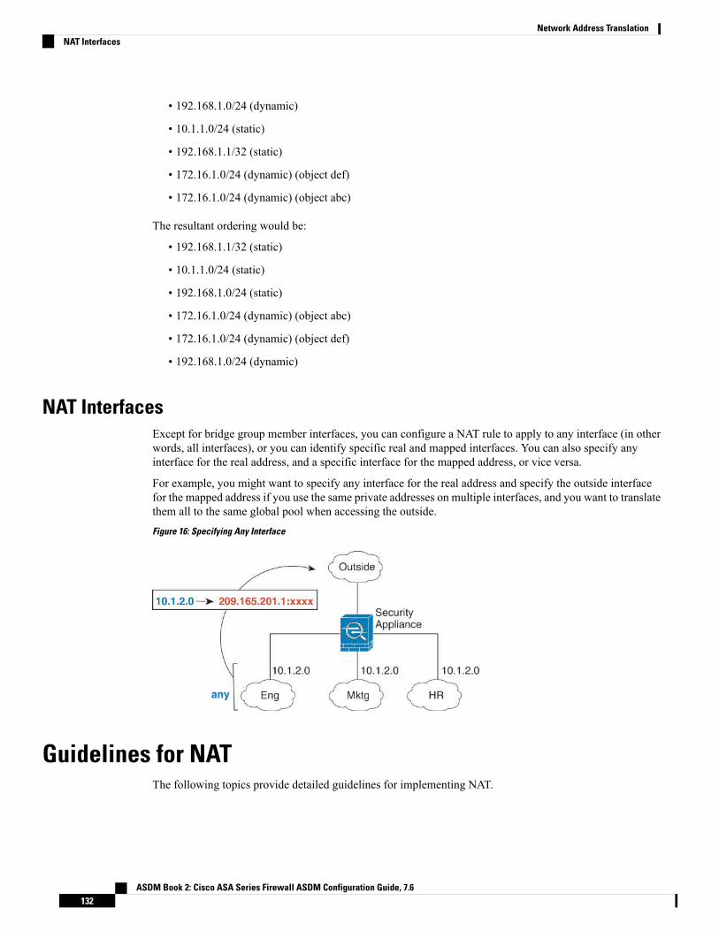
• 192.168.1.0/24 (dynamic)
• 10.1.1.0/24 (static)
• 192.168.1.1/32 (static)
• 172.16.1.0/24 (dynamic) (object def)
• 172.16.1.0/24 (dynamic) (object abc)
The resultant ordering would be:
• 192.168.1.1/32 (static)
• 10.1.1.0/24 (static)
• 192.168.1.0/24 (static)
• 172.16.1.0/24 (dynamic) (object abc)
• 172.16.1.0/24 (dynamic) (object def)
• 192.168.1.0/24 (dynamic)
NAT InterfacesExcept for bridge group member interfaces, you can configure a NAT rule to apply to any interface (in otherwords, all interfaces), or you can identify specific real and mapped interfaces. You can also specify anyinterface for the real address, and a specific interface for the mapped address, or vice versa.
For example, you might want to specify any interface for the real address and specify the outside interfacefor the mapped address if you use the same private addresses on multiple interfaces, and you want to translatethem all to the same global pool when accessing the outside.
Figure 16: Specifying Any Interface
Guidelines for NATThe following topics provide detailed guidelines for implementing NAT.
ASDM Book 2: Cisco ASA Series Firewall ASDM Configuration Guide, 7.6132
Network Address TranslationNAT Interfaces

Firewall Mode Guidelines for NATNAT is supported in routed and transparent firewall mode.
However, configuring NAT on bridge group member interfaces (interfaces that are part of a Bridge GroupVirtual Interface, or BVI) has the following restrictions:
• When configuring NAT for the members of a bridge group, you specify the member interface. Youcannot configure NAT for the bridge group interface (BVI) itself.
• When doing NAT between bridge group member interfaces, you must specify the real and mappedaddresses. You cannot specify “any” as the interface.
• You cannot configure interface PAT when the mapped address is a bridge group member interface,because there is no IP address attached to the interface.
• You cannot translate between IPv4 and IPv6 networks (NAT64/46) when the source and destinationinterfaces are members of the same bridge group. Static NAT/PAT 44/66, dynamic NAT44/66, anddynamic PAT44 are the only allowed methods; dynamic PAT66 is not supported.
IPv6 NAT GuidelinesNAT supports IPv6 with the following guidelines and restrictions.
• For standard routed mode interfaces, you can also translate between IPv4 and IPv6.
• You cannot translate between IPv4 and IPv6 for interfaces that are members of the same bridge group.You can translate between two IPv6 or two IPv4 networks only.
• You cannot use dynamic PAT for IPv6 (NAT66) when translating between interfaces in the same bridgegroup.
• For static NAT, you can specify an IPv6 subnet up to /64. Larger subnets are not supported.
• When using FTP with NAT46, when an IPv4 FTP client connects to an IPv6 FTP server, the client mustuse either the extended passivemode (EPSV) or extended port mode (EPRT); PASV and PORT commandsare not supported with IPv6.
IPv6 NAT Best PracticesYou can use NAT to translate between IPv6 networks, and also to translate between IPv4 and IPv6 networks(routed mode only). We recommend the following best practices:
• NAT66 (IPv6-to-IPv6)—We recommend using static NAT. Although you can use dynamic NAT orPAT, IPv6 addresses are in such large supply, you do not have to use dynamic NAT. If you do not wantto allow returning traffic, you can make the static NAT rule unidirectional (twice NAT only).
• NAT46 (IPv4-to-IPv6)—We recommend using static NAT. Because the IPv6 address space is so muchlarger than the IPv4 address space, you can easily accommodate a static translation. If you do not wantto allow returning traffic, you can make the static NAT rule unidirectional (twice NAT only). Whentranslating to an IPv6 subnet (/96 or lower), the resulting mapped address is by default an IPv4-embeddedIPv6 address, where the 32-bits of the IPv4 address is embedded after the IPv6 prefix. For example, ifthe IPv6 prefix is a /96 prefix, then the IPv4 address is appended in the last 32-bits of the address. Forexample, if youmap 192.168.1.0/24 to 201b::0/96, then 192.168.1.4 will bemapped to 201b::0.192.168.1.4
ASDM Book 2: Cisco ASA Series Firewall ASDM Configuration Guide, 7.6133
Network Address TranslationFirewall Mode Guidelines for NAT
(shown with mixed notation). If the prefix is smaller, such as /64, then the IPv4 address is appended afterthe prefix, and a suffix of 0s is appended after the IPv4 address. You can also optionally translate theaddresses net-to-net, where the first IPv4 address maps to the first IPv6 address, the second to the second,and so on.
• NAT64 (IPv6-to-IPv4)—You may not have enough IPv4 addresses to accommodate the number of IPv6addresses. We recommend using a dynamic PAT pool to provide a large number of IPv4 translations.
Additional Guidelines for NAT• You cannot write NAT rules for a Virtual Tunnel Interface (VTI), which are used in site-to-site VPN.Writing rules for the VTI's source interface will not apply NAT to the VPN tunnel. To write NAT rulesthat will apply to VPN traffic tunneled on a VTI, you must use "any" as the interface; you cannot explicitlyspecify interface names.
• (Network Object NAT only.) You can only define a single NAT rule for a given object; if you want toconfigure multiple NAT rules for an object, you need to create multiple objects with different names thatspecify the same IP address.
• If a VPN is defined on an interface, inbound ESP traffic on the interface is not subject to the NAT rules.The system allows the ESP traffic for established VPN tunnels only, dropping traffic not associated withan existing tunnel. This restriction applies to ESP and UDP ports 500 and 4500.
• If you define a site-to-site VPN on a device that is behind a device that is applying dynamic PAT, so thatUDP ports 500 and 4500 are not the ones actually used, you must initiate the connection from the devicethat is behind the PAT device. The responder cannot initiate the security association (SA) because it doesnot know the correct port numbers.
• If you change the NAT configuration, and you do not want to wait for existing translations to time outbefore the new NAT configuration is used, you can clear the translation table using the clear xlatecommand in the device CLI. However, clearing the translation table disconnects all current connectionsthat use translations.
If you create a new NAT rule that should apply to an existing connection (such as a VPN tunnel), youneed to use clear conn to end the connection. Then, the attempt to re-establish the connection should hitthe NAT rule and the connection should be NAT'ed correctly.
If you remove a dynamic NAT or PAT rule, and then add a new rule with mappedaddresses that overlap the addresses in the removed rule, then the new rule willnot be used until all connections associated with the removed rule time out or arecleared using the clear xlate or clear conn commands. This safeguard ensuresthat the same address is not assigned to multiple hosts.
Note
• When translating SCTP traffic, use static network object NAT only. Dynamic NAT/PAT is not allowed.Although you can configure static twice NAT, this is not recommended because the topology of thedestination part of the SCTP association is unknown.
• Objects and object groups used in NAT cannot be undefined; they must include IP addresses.
• You cannot use an object group with both IPv4 and IPv6 addresses; the object group must include onlyone type of address.
ASDM Book 2: Cisco ASA Series Firewall ASDM Configuration Guide, 7.6134
Network Address TranslationAdditional Guidelines for NAT
• (Twice NAT only.) When using any as the source address in a NAT rule, the definition of “any” traffic(IPv4 vs. IPv6) depends on the rule. Before the ASA performs NAT on a packet, the packet must beIPv6-to-IPv6 or IPv4-to-IPv4; with this prerequisite, the ASA can determine the value of any in a NATrule. For example, if you configure a rule from “any” to an IPv6 server, and that server was mapped froman IPv4 address, then any means “any IPv6 traffic.” If you configure a rule from “any” to “any,” andyou map the source to the interface IPv4 address, then anymeans “any IPv4 traffic” because the mappedinterface address implies that the destination is also IPv4.
• You can use the same mapped object or group in multiple NAT rules.
• The mapped IP address pool cannot include:
• The mapped interface IP address. If you specify “any” interface for the rule, then all interface IPaddresses are disallowed. For interface PAT (routed mode only), specify the interface name insteadof the interface address.
• The failover interface IP address.
• (Transparent mode.) The management IP address.
• (Dynamic NAT.) The standby interface IP address when VPN is enabled.
• Existing VPN pool addresses.
• Avoid using overlapping addresses in static and dynamic NAT policies. For example, with overlappingaddresses, a PPTP connection can fail to get established if the secondary connection for PPTP hits thestatic instead of dynamic xlate.
• You cannot use overlapping addresses in the source address of a NAT rule and a remote access VPNaddress pool.
• For application inspection limitations with NAT or PAT, see Default Inspections and NAT Limitations,on page 272.
• (8.3(1), 8.3(2), and 8.4(1)) The default behavior for identity NAT has proxy ARP disabled. You cannotconfigure this setting. (8.4(2) and later) The default behavior for identity NAT has proxy ARP enabled,matching other static NAT rules. You can disable proxy ARP if desired. See Routing NAT Packets, onpage 219 for more information.
• If you enable the arp permit-nonconnected command, the system does not respond to ARP requests ifthe mapped address is not part of any connected subnet and you also do not specify the mapped interfacein the NAT rule (that is, you specify "any" interface). To resolve this problem, specify the mappedinterface.
• If you specify a destination interface in a rule, then that interface is used as the egress interface ratherthan looking up the route in the routing table. However, for identity NAT, you have the option to use aroute lookup instead. In 8.3(1) through 8.4(1), identity NAT always uses the routing table.
• If you use PAT on Sun RPC traffic, which is used to connect to NFS servers, be aware that the NFSserver might reject connections if the PAT'ed port is above 1024. The default configuration of NFSservers is to reject connections from ports higher than 1024. The error is typically "Permission Denied."Mapping ports above 1024 might happen if you use the "flat range" option to use the higher port numbersif a port in the lower range is not available, especially if you do not select the option to include the lowerrange in the flat range.Mapping ports above 1024 might happen if you use the "flat range" option to usethe higher port numbers if a port in the lower range is not available, especially if you do not select the
ASDM Book 2: Cisco ASA Series Firewall ASDM Configuration Guide, 7.6135
Network Address TranslationAdditional Guidelines for NAT

option to include the lower range in the flat range. You can avoid this problem by changing the NFSserver configuration to allow all port numbers.
• NAT applies to through traffic only. Traffic generated by the system is not subject to NAT.
• You can improve system performance and reliability by using the transactional commit model for NAT.See the basic settings chapter in the general operations configuration guide for more information. Theoption is under Configurations > Device Management > Advanced > Rule Engine.
• Do not name a network object or group pat-pool, using any combination of upper- or lower-case letters.
• The unidirectional option is mainly useful for testing purposes and might not work with all protocols.For example, SIP requires protocol inspection to translate SIP headers using NAT, but this will not occurif you make the translation unidirectional.
• You cannot use NAT on the internal payload of Protocol Independent Multicast (PIM) registers.
Network Object NAT Guidelines for Mapped Address ObjectsFor dynamic NAT, you must use an object or group for the mapped addresses. For the other NAT types, youcan use an object or group, or you have the option of using inline addresses. Network object groups areparticularly useful for creating a mapped address pool with discontinuous IP address ranges or multiple hostsor subnets.
Consider the following guidelines when creating objects for mapped addresses.
• A network object group can contain objects or inline addresses of either IPv4 or IPv6 addresses. Thegroup cannot contain both IPv4 and IPv6 addresses; it must contain one type only.
• See Additional Guidelines for NAT, on page 134 for information about disallowed mapped IP addresses.
• Do not name a network object or group pat-pool, using any combination of upper- or lower-case letters.
• Dynamic NAT:
• You cannot use an inline address; you must configure a network object or group.
• The object or group cannot contain a subnet; the object must define a range; the group can includehosts and ranges.
• If a mapped network object contains both ranges and host IP addresses, then the ranges are used fordynamic NAT, and then the host IP addresses are used as a PAT fallback.
• Dynamic PAT (Hide):
• Instead of using an object, you can optionally configure an inline host address or specify the interfaceaddress.
• If you use an object, the object or group cannot contain a subnet. The object must define a host, orfor a PAT pool, a range. The group (for a PAT pool) can include hosts and ranges.
• Static NAT or Static NAT with port translation:
• Instead of using an object, you can configure an inline address or specify the interface address (forstatic NAT-with-port-translation).
• If you use an object, the object or group can contain a host, range, or subnet.
ASDM Book 2: Cisco ASA Series Firewall ASDM Configuration Guide, 7.6136
Network Address TranslationNetwork Object NAT Guidelines for Mapped Address Objects

• Identity NAT
• Instead of using an object, you can configure an inline address.
• If you use an object, the object must match the real addresses you want to translate.
Twice NAT Guidelines for Real and Mapped Address ObjectsFor each NAT rule, configure up to four network objects or groups for:
• Source real address
• Source mapped address
• Destination real address
• Destination mapped address
Objects are required unless you specify the any keyword inline to represent all traffic, or for some types ofNAT, the interface keyword to represent the interface address. Network object groups are particularly usefulfor creating a mapped address pool with discontinuous IP address ranges or multiple hosts or subnets.
Consider the following guidelines when creating objects for twice NAT.
• A network object group can contain objects or inline addresses of either IPv4 or IPv6 addresses. Thegroup cannot contain both IPv4 and IPv6 addresses; it must contain one type only.
• See Additional Guidelines for NAT, on page 134 for information about disallowed mapped IP addresses.
• Do not name a network object or group pat-pool, using any combination of upper- or lower-case letters.
• Source Dynamic NAT:
• You typically configure a larger group of real addresses to be mapped to a smaller group.
• The mapped object or group cannot contain a subnet; the object must define a range; the group caninclude hosts and ranges.
• If a mapped network object contains both ranges and host IP addresses, then the ranges are used fordynamic NAT, and the host IP addresses are used as a PAT fallback.
• Source Dynamic PAT (Hide):
• If you use an object, the object or group cannot contain a subnet. The object must define a host, orfor a PAT pool, a range. The group (for a PAT pool) can include hosts and ranges.
• Source Static NAT or Static NAT with port translation:
• The mapped object or group can contain a host, range, or subnet.
• The static mapping is typically one-to-one, so the real addresses have the same quantity as themapped addresses. You can, however, have different quantities if desired.
• Source Identity NAT
• The real and mapped objects must match. You can use the same object for both, or you can createseparate objects that contain the same IP addresses.
ASDM Book 2: Cisco ASA Series Firewall ASDM Configuration Guide, 7.6137
Network Address TranslationTwice NAT Guidelines for Real and Mapped Address Objects

• Destination Static NAT or Static NAT with port translation (the destination translation is always static):
• Although the main feature of twice NAT is the inclusion of the destination IP address, the destinationaddress is optional. If you do specify the destination address, you can configure static translationfor that address or just use identity NAT for it. You might want to configure twice NAT without adestination address to take advantage of some of the other qualities of twice NAT, including theuse of network object groups for real addresses, or manually ordering of rules. For more information,see Comparing Network Object NAT and Twice NAT, on page 130.
• For identity NAT, the real and mapped objects must match. You can use the same object for both,or you can create separate objects that contain the same IP addresses.
• The static mapping is typically one-to-one, so the real addresses have the same quantity as themapped addresses. You can, however, have different quantities if desired.
• For static interface NAT with port translation (routed mode only), you can specify the interfacekeyword instead of a network object/group for the mapped address.
Twice NAT Guidelines for Service Objects for Real and Mapped PortsYou can optionally configure service objects for:
• Source real port (Static only) or Destination real port
• Source mapped port (Static only) or Destination mapped port
Consider the following guidelines when creating objects for twice NAT.
• NAT supports TCP, UDP, and SCTP only. When translating a port, be sure the protocols in the real andmapped service objects are identical (for example, both TCP). Although you can configure static twiceNAT rules with SCTP port specifications, this is not recommended, because the topology of the destinationpart of the SCTP association is unknown. Use static object NAT instead for SCTP.
• The “not equal” (neq) operator is not supported.
• For identity port translation, you can use the same service object for both the real and mapped ports.
• Source Dynamic NAT—Source Dynamic NAT does not support port translation.
• Source Dynamic PAT (Hide)—Source Dynamic PAT does not support port translation.
• Source Static NAT, Static NAT with port translation, or Identity NAT—A service object can containboth a source and destination port; however, you should specify either the source or the destination portfor both service objects. You should only specify both the source and destination ports if your applicationuses a fixed source port (such as some DNS servers); but fixed source ports are rare. For example, if youwant to translate the port for the source host, then configure the source service.
• Destination Static NAT or Static NAT with port translation (the destination translation is alwaysstatic)—For non-static source NAT, you can only perform port translation on the destination. A serviceobject can contain both a source and destination port, but only the destination port is used in this case.If you specify the source port, it will be ignored.
ASDM Book 2: Cisco ASA Series Firewall ASDM Configuration Guide, 7.6138
Network Address TranslationTwice NAT Guidelines for Service Objects for Real and Mapped Ports

Dynamic NATThe following topics explain dynamic NAT and how to configure it.
About Dynamic NATDynamic NAT translates a group of real addresses to a pool of mapped addresses that are routable on thedestination network. The mapped pool typically includes fewer addresses than the real group. When a hostyou want to translate accesses the destination network, NAT assigns the host an IP address from the mappedpool. The translation is created only when the real host initiates the connection. The translation is in placeonly for the duration of the connection, and a given user does not keep the same IP address after the translationtimes out. Users on the destination network, therefore, cannot initiate a reliable connection to a host that usesdynamic NAT, even if the connection is allowed by an access rule.
For the duration of the translation, a remote host can initiate a connection to the translated host if an accessrule allows it. Because the address is unpredictable, a connection to the host is unlikely. Nevertheless, in thiscase you can rely on the security of the access rule.
Note
The following figure shows a typical dynamic NAT scenario. Only real hosts can create a NAT session, andresponding traffic is allowed back.
Figure 17: Dynamic NAT
The following figure shows a remote host attempting to initiate a connection to a mapped address. This addressis not currently in the translation table; therefore, the packet is dropped.
ASDM Book 2: Cisco ASA Series Firewall ASDM Configuration Guide, 7.6139
Network Address TranslationDynamic NAT

Figure 18: Remote Host Attempts to Initiate a Connection to a Mapped Address
Dynamic NAT Disadvantages and AdvantagesDynamic NAT has these disadvantages:
• If the mapped pool has fewer addresses than the real group, you could run out of addresses if the amountof traffic is more than expected.
Use PAT or a PAT fall-back method if this event occurs often because PAT provides over 64,000translations using ports of a single address.
• You have to use a large number of routable addresses in the mapped pool, and routable addresses maynot be available in large quantities.
The advantage of dynamic NAT is that some protocols cannot use PAT. PAT does not work with the following:
• IP protocols that do not have a port to overload, such as GRE version 0.
• Some multimedia applications that have a data stream on one port, the control path on another port, andare not open standard.
See Default Inspections and NAT Limitations, on page 272 for more information about NAT and PAT support.
Configure Dynamic Network Object NATThis section describes how to configure network object NAT for dynamic NAT.
Procedure
Step 1 Add NAT to a new or existing network object:
ASDM Book 2: Cisco ASA Series Firewall ASDM Configuration Guide, 7.6140
Network Address TranslationDynamic NAT Disadvantages and Advantages

• To add a new network object, choose Configuration > Firewall > NAT Rules, then click Add > AddNetwork Object NAT Rule.
• To add NAT to an existing network object, choose Configuration > Firewall > Objects > NetworkObjects/Groups, and then edit a network object.
Step 2 For a new object, enter values for the following fields:a) Name—The object name. Use characters a to z, A to Z, 0 to 9, a period, a dash, a comma, or an underscore.
The name must be 64 characters or less.b) Type—Host, Network, or Range.c) IP Addresses—IPv4 or IPv6 addresses, a single address for a host, a starting and ending address for a
range, and for subnet, either an IPv4 network address and mask (for example, 10.100.10.0 255.255.255.0)or IPv6 address and prefix length (for example, 2001:DB8:0:CD30::/60).
Step 3 If the NAT section is hidden, click NAT to expand the section.
Step 4 Check the Add Automatic Translation Rules check box.Step 5 From the Type drop-down list, choose Dynamic.Step 6 To the right of the Translated Addr field, click the browse button and choose the network object or network
object group that contains the mapped addresses.
You can create a new object if necessary.
ASDM Book 2: Cisco ASA Series Firewall ASDM Configuration Guide, 7.6141
Network Address TranslationConfigure Dynamic Network Object NAT

The object or group cannot contain a subnet. The group cannot contain both IPv4 and IPv6 addresses; it mustcontain one type only.
Step 7 (Optional, when mapped interface is a non-bridge group member only.) To use the interface IP address as abackup method when the other mapped addresses are already allocated, check the Fall through to interfacePAT (dest intf) check box, and choose the interface from the drop-down list. To use the IPv6 address of theinterface, also check the Use IPv6 for interface PAT check box.
Step 8 (Optional) Click Advanced, configure the following options in the Advanced NAT Settings dialog box, andclick OK.
• Translate DNS replies for rule—Translates the IP address in DNS replies. Be sure DNS inspection isenabled (it is enabled by default). See Rewriting DNS Queries and Responses Using NAT, on page 238for more information.
• (Required for bridge group member interfaces.) Interface—Specifies the real interface (Source) and themapped interface (Destination) where this NAT rule applies. By default, the rule applies to all interfacesexcept for bridge group members.
Step 9 Click OK, and then Apply.
Configure Dynamic Twice NATThis section describes how to configure twice NAT for dynamic NAT.
Procedure
Step 1 Choose Configuration > Firewall > NAT Rules, and then do one of the following:
• Click Add, or Add > Add NAT Rule Before Network Object NAT Rules.
• Click Add > Add NAT Rule After Network Object NAT Rules.
• Select a twice NAT rule and click Edit.
The Add NAT Rule dialog box appears.
ASDM Book 2: Cisco ASA Series Firewall ASDM Configuration Guide, 7.6142
Network Address TranslationConfigure Dynamic Twice NAT

Step 2 (Required for bridge group member interfaces.) Set the source and destination interfaces.
In routed mode, the default is any interface for both source and destination. You can select specific interfacesfor one or both options. However, you must select the interface when writing a rule for bridge group memberinterfaces; “any” does not include these interfaces.
a) From the Match Criteria: Original Packet > Source Interface drop-down list, choose the sourceinterface.
b) From theMatch Criteria: Original Packet > Destination Interface drop-down list, choose the destinationinterface.
Step 3 Choose Dynamic from the Action: Translated Packet > Source NAT Type drop-down list.
This setting only applies to the source address; the destination translation is always static.
ASDM Book 2: Cisco ASA Series Firewall ASDM Configuration Guide, 7.6143
Network Address TranslationConfigure Dynamic Twice NAT

Step 4 Identify the original packet addresses, either IPv4 or IPv6; namely, the packet addresses as they appear onthe source interface network (the real source address and the mapped destination address). See the followingfigure for an example of the original packet vs. the translated packet.
a) For the Match Criteria: Original Packet > Source Address, click the browse button and choose anexisting network object or group or create a new object or group from the Browse Original Source Addressdialog box. The group cannot contain both IPv4 and IPv6 addresses; it must contain one type only. Thedefault is any.
b) (Optional.) For the Match Criteria: Original Packet > Destination Address, click the browse buttonand choose an existing network object, group, or interface, or create a new object or group from the BrowseOriginal Destination Address dialog box. A group cannot contain both IPv4 and IPv6 addresses; it mustcontain one type only.
Although the main feature of twice NAT is the inclusion of the destination IP address, the destinationaddress is optional. If you do specify the destination address, you can configure static translation for thataddress or just use identity NAT for it. You might want to configure twice NAT without a destinationaddress to take advantage of some of the other qualities of twice NAT, including the use of network objectgroups for real addresses, or manually ordering of rules. For more information, see Comparing NetworkObject NAT and Twice NAT, on page 130.
For static interface NAT with port translation only, choose an interface from the Browse dialog box. Besure to also configure a service translation. For this option, you must configure a specific interface for theSource Interface. See Static NAT with Port Translation, on page 167 for more information.
Step 5 Identify the translated packet addresses, either IPv4 or IPv6; namely, the packet addresses as they appear onthe destination interface network (the mapped source address and the real destination address). You cantranslate between IPv4 and IPv6 if desired.a) For Action: Translated Packet > Source Address, click the browse button and choose an existing
network object or group or create a new object or group from the Browse Translated Source Addressdialog box.
For dynamic NAT, you typically configure a larger group of source addresses to be mapped to a smallergroup.
The object or group cannot contain a subnet.Note
b) For Action: Translated Packet > Destination Address, click the browse button and choose an existingnetwork object or group, or create a new object or group from the Browse Translated Destination Addressdialog box.
For identity NAT for the destination address, simply use the same object or group for both the real andmapped addresses.
ASDM Book 2: Cisco ASA Series Firewall ASDM Configuration Guide, 7.6144
Network Address TranslationConfigure Dynamic Twice NAT

If you want to translate the destination address, then the static mapping is typically one-to-one, so the realaddresses have the same quantity as the mapped addresses. You can, however, have different quantitiesif desired. For more information, see Static NAT, on page 166. See Additional Guidelines for NAT, onpage 134 for information about disallowed mapped IP addresses.
Step 6 (Optional.) Identify the destination service ports for service translation.
• Identify the original packet port (the mapped destination port). For Match Criteria: Original Packet> Service, click the browse button and choose an existing service object that specifies TCP or UDP ports,or create a new object from the Browse Original Service dialog box.
• Identify the translated packet port (the real destination port). For Action: Translated Packet > Service,click the browse button and choose an existing service object that specifies TCP or UDP ports, or createa new object from the Browse Translated Service dialog box.
Dynamic NAT does not support port translation. However, because the destination translation is always static,you can perform port translation for the destination port. A service object can contain both a source anddestination port, but only the destination port is used in this case. If you specify the source port, it will beignored. NAT only supports TCP or UDP.When translating a port, be sure the protocols in the real and mappedservice objects are identical (both TCP or both UDP). For identity NAT, you can use the same service objectfor both the real and mapped ports. The “not equal” (!=) operator is not supported.
For example:
ASDM Book 2: Cisco ASA Series Firewall ASDM Configuration Guide, 7.6145
Network Address TranslationConfigure Dynamic Twice NAT

Step 7 (Optional, when mapped interface is a non-bridge group member only.) To use the interface IP address as abackupmethod if the other mapped source addresses are already allocated, check the Fall through to interfacePAT check box. To use the IPv6 interface address, also check the Use IPv6 for interface PAT check box.
The destination interface IP address is used. This option is only available if you configure a specific DestinationInterface.
Step 8 (Optional.) Configure NAT options in the Options area.
ASDM Book 2: Cisco ASA Series Firewall ASDM Configuration Guide, 7.6146
Network Address TranslationConfigure Dynamic Twice NAT

• Enable rule —Enables this NAT rule. The rule is enabled by default.
• (For a source-only rule) Translate DNS replies that match this rule—Rewrites the DNS A record inDNS replies. Be sure DNS inspection is enabled (it is enabled by default). You cannot configure DNSmodification if you configure a destination address. See Rewriting DNS Queries and Responses UsingNAT, on page 238 for more information.
• Description—Adds a description about the rule up to 200 characters in length.
Step 9 Click OK, then click Apply.
Dynamic PATThe following topics describe dynamic PAT.
About Dynamic PATDynamic PAT translates multiple real addresses to a single mapped IP address by translating the real addressand source port to the mapped address and a unique port.
Each connection requires a separate translation session because the source port differs for each connection.For example, 10.1.1.1:1025 requires a separate translation from 10.1.1.1:1026.
The following figure shows a typical dynamic PAT scenario. Only real hosts can create a NAT session, andresponding traffic is allowed back. The mapped address is the same for each translation, but the port isdynamically assigned.
Figure 19: Dynamic PAT
For the duration of the translation, a remote host on the destination network can initiate a connection to thetranslated host if an access rule allows it. Because the port address (both real and mapped) is unpredictable,a connection to the host is unlikely. Nevertheless, in this case you can rely on the security of the access rule.
After the connection expires, the port translation also expires. For multi-session PAT, the PAT timeout isused, 30 seconds by default. For per-session PAT (9.0(1) and later), the xlate is immediately removed.
We recommend that you use different PAT pools for each interface. If you use the same pool for multipleinterfaces, especially if you use it for "any" interface, the pool can be quickly exhausted, with no ports availablefor new translations.
Note
ASDM Book 2: Cisco ASA Series Firewall ASDM Configuration Guide, 7.6147
Network Address TranslationDynamic PAT

Dynamic PAT Disadvantages and AdvantagesDynamic PAT lets you use a single mapped address, thus conserving routable addresses. You can even usethe ASA interface IP address as the PAT address.
You cannot use dynamic PAT for IPv6 (NAT66) when translating between interfaces in the same bridgegroup.
Dynamic PAT does not work with some multimedia applications that have a data stream that is different fromthe control path. See Default Inspections and NAT Limitations, on page 272 for more information about NATand PAT support.
Dynamic PAT might also create a large number of connections appearing to come from a single IP address,and servers might interpret the traffic as a DoS attack. You can configure a PAT pool of addresses and use around-robin assignment of PAT addresses to mitigate this situation.
PAT Pool Object GuidelinesWhen creating network objects for a PAT pool, follow these guidelines.
For a PAT pool
• If available, the real source port number is used for the mapped port. However, if the real port is notavailable, by default the mapped ports are chosen from the same range of ports as the real port number:0 to 511, 512 to 1023, and 1024 to 65535. Therefore, ports below 1024 have only a small PAT pool thatcan be used. If you have a lot of traffic that uses the lower port ranges, you can specify a flat range ofports to be used instead of the three unequal-sized tiers: either 1024 to 65535, or 1 to 65535.
• If you enable block allocation for a PAT pool, port blocks are allocated in the 1024-65535 range only.Thus, if an application requires a low port number (1-1023), it might not work. For example, an applicationrequesting port 22 (SSH) will get a mapped port within the range of 1024-65535 and within the blockallocated to the host.
• If you use the same PAT pool object in two separate rules, then be sure to specify the same options foreach rule. For example, if one rule specifies extended PAT, then the other rule must also specify extendedPAT.
For extended PAT for a PAT pool
• Many application inspections do not support extended PAT. See Default Inspections and NATLimitations,on page 272 for a complete list of unsupported inspections.
• If you enable extended PAT for a dynamic PAT rule, then you cannot also use an address in the PATpool as the PAT address in a separate static NAT with port translation rule. For example, if the PAT poolincludes 10.1.1.1, then you cannot create a static NAT-with-port-translation rule using 10.1.1.1 as thePAT address.
• If you use a PAT pool and specify an interface for fallback, you cannot specify extended PAT.
• For VoIP deployments that use ICE or TURN, do not use extended PAT. ICE and TURN rely on thePAT binding to be the same for all destinations.
ASDM Book 2: Cisco ASA Series Firewall ASDM Configuration Guide, 7.6148
Network Address TranslationDynamic PAT Disadvantages and Advantages

For round robin for a PAT pool
• If a host has an existing connection, then subsequent connections from that host will use the same PATIP address if ports are available. However, this “stickiness” does not survive a failover. If the device failsover, then subsequent connections from a host might not use the initial IP address.
• IP address “stickiness” is also impacted if you mix PAT pool/round robin rules with interface PAT ruleson the same interface. For any given interface, choose either a PAT pool or interface PAT; do not createcompeting PAT rules.
• Round robin, especially when combined with extended PAT, can consume a large amount of memory.Because NAT pools are created for every mapped protocol/IP address/port range, round robin results ina large number of concurrent NAT pools, which use memory. Extended PAT results in an even largernumber of concurrent NAT pools.
Configure Dynamic Network Object PAT (Hide)This section describes how to configure network object NAT for dynamic PAT (hide), which uses a singleaddress for translation instead of a PAT pool.
Procedure
Step 1 Add NAT to a new or existing network object:
• To add a new network object, choose Configuration > Firewall > NAT Rules, then click Add > AddNetwork Object NAT Rule.
• To add NAT to an existing network object, choose Configuration > Firewall > Objects > NetworkObjects/Groups, and then edit a network object.
Step 2 For a new object, enter values for the following fields:a) Name—The object name. Use characters a to z, A to Z, 0 to 9, a period, a dash, a comma, or an underscore.
The name must be 64 characters or less.b) Type—Host, Network, or Range.c) IP Addresses—IPv4 or IPv6 addresses, a single address for a host, a starting and ending address for a
range, and for subnet, either an IPv4 network address and mask (for example, 10.100.10.0 255.255.255.0)or IPv6 address and prefix length (for example, 2001:DB8:0:CD30::/60).
Step 3 If the NAT section is hidden, click NAT to expand the section.Step 4 Check the Add Automatic Translation Rules check box.Step 5 From the Type drop-down list, choose Dynamic PAT (Hide).
ASDM Book 2: Cisco ASA Series Firewall ASDM Configuration Guide, 7.6149
Network Address TranslationConfigure Dynamic Network Object PAT (Hide)
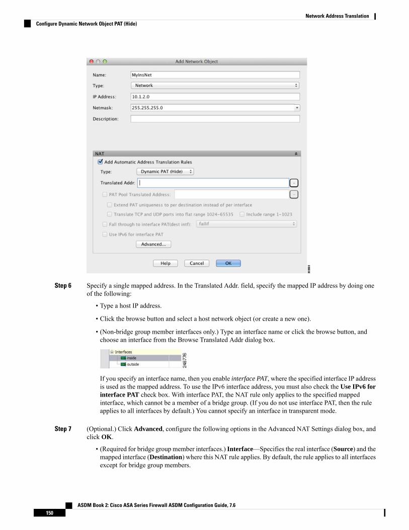
Step 6 Specify a single mapped address. In the Translated Addr. field, specify the mapped IP address by doing oneof the following:
• Type a host IP address.
• Click the browse button and select a host network object (or create a new one).
• (Non-bridge group member interfaces only.) Type an interface name or click the browse button, andchoose an interface from the Browse Translated Addr dialog box.
If you specify an interface name, then you enable interface PAT, where the specified interface IP addressis used as the mapped address. To use the IPv6 interface address, you must also check the Use IPv6 forinterface PAT check box. With interface PAT, the NAT rule only applies to the specified mappedinterface, which cannot be a member of a bridge group. (If you do not use interface PAT, then the ruleapplies to all interfaces by default.) You cannot specify an interface in transparent mode.
Step 7 (Optional.) Click Advanced, configure the following options in the Advanced NAT Settings dialog box, andclick OK.
• (Required for bridge group member interfaces.) Interface—Specifies the real interface (Source) and themapped interface (Destination) where this NAT rule applies. By default, the rule applies to all interfacesexcept for bridge group members.
ASDM Book 2: Cisco ASA Series Firewall ASDM Configuration Guide, 7.6150
Network Address TranslationConfigure Dynamic Network Object PAT (Hide)
Step 8 Click OK, and then Apply.
Configure Dynamic Network Object PAT Using a PAT PoolThis section describes how to configure network object NAT for dynamic PAT using a PAT pool.
Procedure
Step 1 Add NAT to a new or existing network object:
• To add a new network object NAT rule, choose Configuration > Firewall > NAT Rules, then clickAdd > Add Network Object NAT Rule.
• To add NAT to an existing network object, choose Configuration > Firewall > Objects > NetworkObjects/Groups, and then edit a network object.
Step 2 For a new object, enter values for the following fields:a) Name—The object name. Use characters a to z, A to Z, 0 to 9, a period, a dash, a comma, or an underscore.
The name must be 64 characters or less.b) Type—Host, Network, or Range.c) IP Addresses—IPv4 or IPv6 addresses, a single address for a host, a starting and ending address for a
range, and for subnet, either an IPv4 network address and mask (for example, 10.100.10.0 255.255.255.0)or IPv6 address and prefix length (for example, 2001:DB8:0:CD30::/60).
Step 3 If the NAT section is hidden, click NAT to expand the section.
ASDM Book 2: Cisco ASA Series Firewall ASDM Configuration Guide, 7.6151
Network Address TranslationConfigure Dynamic Network Object PAT Using a PAT Pool

Step 4 Check the Add Automatic Translation Rules check box.Step 5 From the Type drop-down list, choose Dynamic even though you are configuring dynamic PAT with a PAT
pool.Step 6 To configure the PAT pool:
a) Do not enter a value for the Translated Addr. field; leave it blank.b) Check thePAT Pool Translated Address check box, then click the browse button and choose the network
object or group that contains the PAT pool addresses. Or create a new object from the Browse TranslatedPAT Pool Address dialog box.
The PAT pool object or group cannot contain a subnet. The group cannot contain both IPv4and IPv6 addresses; it must contain one type only.
Note
c) (Optional) Select the following options as needed:
ASDM Book 2: Cisco ASA Series Firewall ASDM Configuration Guide, 7.6152
Network Address TranslationConfigure Dynamic Network Object PAT Using a PAT Pool

• Round Robin—To assign addresses and ports in a round-robin fashion. By default without roundrobin, all ports for a PAT address will be allocated before the next PAT address is used. Theround-robin method assigns one address/port from each PAT address in the pool before returning touse the first address again, and then the second address, and so on.
• Extend PAT uniqueness to per destination instead of per interface (8.4(3) and later, not including8.5(1) or 8.6(1))—To use extended PAT. Extended PAT uses 65535 ports per service, as opposedto per IP address, by including the destination address and port in the translation information.Normally, the destination port and address are not considered when creating PAT translations, soyou are limited to 65535 ports per PAT address. For example, with extended PAT, you can create atranslation of 10.1.1.1:1027 when going to 192.168.1.7:23 as well as a translation of 10.1.1.1:1027when going to 192.168.1.7:80.
• Translate TCP or UDP ports into flat range (1024-65535) (8.4(3) and later, not including 8.5(1)or 8.6(1))—To use the 1024 to 65535 port range as a single flat range when allocating ports. Whenchoosing the mapped port number for a translation, the ASA uses the real source port number if itis available. However, without this option, if the real port is not available, by default the mappedports are chosen from the same range of ports as the real port number: 1 to 511, 512 to 1023, and1024 to 65535. To avoid running out of ports at the low ranges, configure this setting. To use theentire range of 1 to 65535, also check the Include range 1 to 1023 check box.
• Enable Block Allocation (9.5.1 and later)—Enables port block allocation. For carrier-grade orlarge-scale PAT, you can allocate a block of ports for each host, rather than have NAT allocate oneport translation at a time. If you allocate a block of ports, subsequent connections from the host usenew randomly selected ports within the block. If necessary, additional blocks are allocated if the hosthas active connections for all ports in the original block. Port blocks are allocated in the 1024-65535range only. Port block allocation is compatible with round robin, but you cannot use it with theextended PAT or flat port range options. You also cannot use interface PAT fallback.
Step 7 (Optional, when mapped interface is a non-bridge group member only.) To use the interface IP address as abackup method when the other mapped addresses are already allocated, check the Fall through to interfacePAT check box, and choose the interface from the drop-down list. To use the IPv6 address of the interface,also check the Use IPv6 for interface PAT check box.
Step 8 (Optional) Click Advanced, configure the following options in the Advanced NAT Settings dialog box, andclick OK.
• (Required for bridge group member interfaces.) Interface—Specifies the real interface (Source) and themapped interface (Destination) where this NAT rule applies. By default, the rule applies to all interfacesexcept for bridge group members.
Step 9 Click OK, and then Apply.
ASDM Book 2: Cisco ASA Series Firewall ASDM Configuration Guide, 7.6153
Network Address TranslationConfigure Dynamic Network Object PAT Using a PAT Pool

Configure Dynamic Twice PAT (Hide)This section describes how to configure twice NAT for dynamic PAT (hide), which uses a single address fortranslation instead of a PAT pool.
Procedure
Step 1 Choose Configuration > Firewall > NAT Rules, and then do one of the following:
• Click Add, or Add > Add NAT Rule Before Network Object NAT Rules.
• Click Add > Add NAT Rule After Network Object NAT Rules.
• Select a twice NAT rule and click Edit.
The Add NAT Rule dialog box appears.
Step 2 (Required for bridge group member interfaces.) Set the source and destination interfaces.
ASDM Book 2: Cisco ASA Series Firewall ASDM Configuration Guide, 7.6154
Network Address TranslationConfigure Dynamic Twice PAT (Hide)

In routed mode, the default is any interface for both source and destination. You can select specific interfacesfor one or both options. However, you must select the interface when writing a rule for bridge group memberinterfaces; “any” does not include these interfaces.
a) From the Match Criteria: Original Packet > Source Interface drop-down list, choose the sourceinterface.
b) From theMatch Criteria: Original Packet > Destination Interface drop-down list, choose the destinationinterface.
Step 3 Choose Dynamic PAT (Hide) from the Action: Translated Packet > Source NAT Type drop-down list.
This setting only applies to the source address; the destination translation is always static.
To configure dynamic PAT using a PAT pool, choose Dynamic instead of Dynamic PAT (Hide),see Configure Dynamic Twice PAT Using a PAT Pool, on page 158.
Note
Step 4 Identify the original packet addresses, either IPv4 or IPv6; namely, the packet addresses as they appear onthe source interface network (the real source address and the mapped destination address). See the followingfigure for an example of the original packet vs. the translated packet.
a) ForMatch Criteria: Original Packet > Source Address, click the browse button and choose an existingnetwork object or group or create a new object or group from the Browse Original Source Address dialogbox. The group cannot contain both IPv4 and IPv6 addresses; it must contain one type only. The defaultis any.
ASDM Book 2: Cisco ASA Series Firewall ASDM Configuration Guide, 7.6155
Network Address TranslationConfigure Dynamic Twice PAT (Hide)
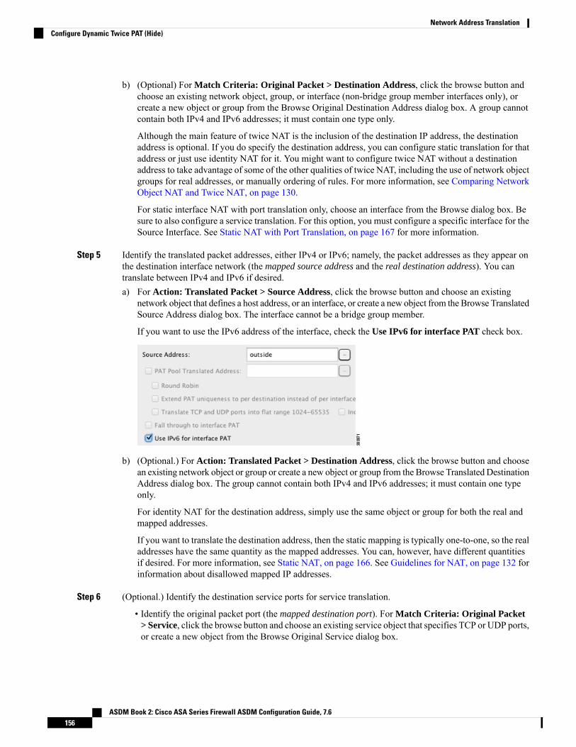
b) (Optional) For Match Criteria: Original Packet > Destination Address, click the browse button andchoose an existing network object, group, or interface (non-bridge group member interfaces only), orcreate a new object or group from the Browse Original Destination Address dialog box. A group cannotcontain both IPv4 and IPv6 addresses; it must contain one type only.
Although the main feature of twice NAT is the inclusion of the destination IP address, the destinationaddress is optional. If you do specify the destination address, you can configure static translation for thataddress or just use identity NAT for it. You might want to configure twice NAT without a destinationaddress to take advantage of some of the other qualities of twice NAT, including the use of network objectgroups for real addresses, or manually ordering of rules. For more information, see Comparing NetworkObject NAT and Twice NAT, on page 130.
For static interface NAT with port translation only, choose an interface from the Browse dialog box. Besure to also configure a service translation. For this option, you must configure a specific interface for theSource Interface. See Static NAT with Port Translation, on page 167 for more information.
Step 5 Identify the translated packet addresses, either IPv4 or IPv6; namely, the packet addresses as they appear onthe destination interface network (the mapped source address and the real destination address). You cantranslate between IPv4 and IPv6 if desired.a) For Action: Translated Packet > Source Address, click the browse button and choose an existing
network object that defines a host address, or an interface, or create a new object from the Browse TranslatedSource Address dialog box. The interface cannot be a bridge group member.
If you want to use the IPv6 address of the interface, check the Use IPv6 for interface PAT check box.
b) (Optional.) For Action: Translated Packet > Destination Address, click the browse button and choosean existing network object or group or create a new object or group from the Browse Translated DestinationAddress dialog box. The group cannot contain both IPv4 and IPv6 addresses; it must contain one typeonly.
For identity NAT for the destination address, simply use the same object or group for both the real andmapped addresses.
If you want to translate the destination address, then the static mapping is typically one-to-one, so the realaddresses have the same quantity as the mapped addresses. You can, however, have different quantitiesif desired. For more information, see Static NAT, on page 166. See Guidelines for NAT, on page 132 forinformation about disallowed mapped IP addresses.
Step 6 (Optional.) Identify the destination service ports for service translation.
• Identify the original packet port (the mapped destination port). For Match Criteria: Original Packet> Service, click the browse button and choose an existing service object that specifies TCP or UDP ports,or create a new object from the Browse Original Service dialog box.
ASDM Book 2: Cisco ASA Series Firewall ASDM Configuration Guide, 7.6156
Network Address TranslationConfigure Dynamic Twice PAT (Hide)
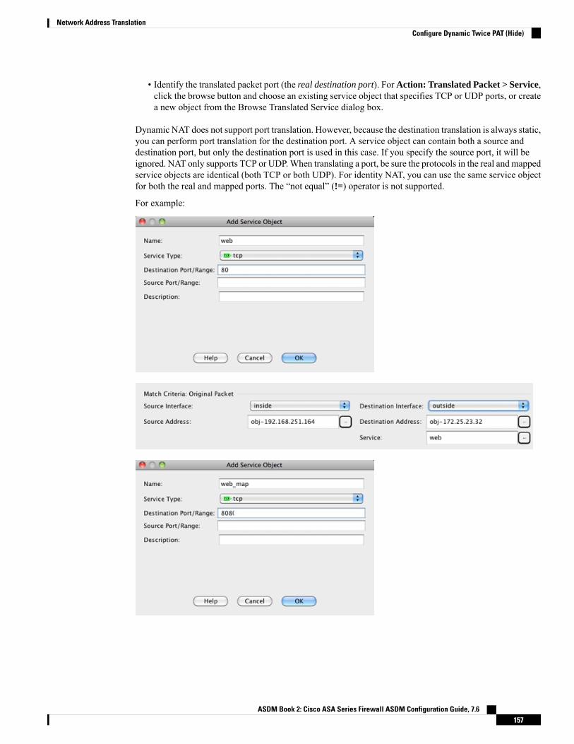
• Identify the translated packet port (the real destination port). For Action: Translated Packet > Service,click the browse button and choose an existing service object that specifies TCP or UDP ports, or createa new object from the Browse Translated Service dialog box.
Dynamic NAT does not support port translation. However, because the destination translation is always static,you can perform port translation for the destination port. A service object can contain both a source anddestination port, but only the destination port is used in this case. If you specify the source port, it will beignored. NAT only supports TCP or UDP.When translating a port, be sure the protocols in the real and mappedservice objects are identical (both TCP or both UDP). For identity NAT, you can use the same service objectfor both the real and mapped ports. The “not equal” (!=) operator is not supported.
For example:
ASDM Book 2: Cisco ASA Series Firewall ASDM Configuration Guide, 7.6157
Network Address TranslationConfigure Dynamic Twice PAT (Hide)

Step 7 (Optional) Configure NAT options in the Options area.
• Enable rule—Enables this NAT rule. The rule is enabled by default.
• Description—Adds a description about the rule up to 200 characters in length.
Step 8 Click OK, then click Apply.
Configure Dynamic Twice PAT Using a PAT PoolThis section describes how to configure twice NAT for dynamic PAT using a PAT pool.
Procedure
Step 1 Choose Configuration > Firewall > NAT Rules, and then do one of the following:
• Click Add, or Add > Add NAT Rule Before Network Object NAT Rules.
• Click Add > Add NAT Rule After Network Object NAT Rules.
• Select a twice NAT rule and click Edit.
The Add NAT Rule dialog box appears.
ASDM Book 2: Cisco ASA Series Firewall ASDM Configuration Guide, 7.6158
Network Address TranslationConfigure Dynamic Twice PAT Using a PAT Pool

Step 2 (Required for bridge group member interfaces.) Set the source and destination interfaces.
In routed mode, the default is any interface for both source and destination. You can select specific interfacesfor one or both options. However, you must select the interface when writing a rule for bridge group memberinterfaces; “any” does not include these interfaces.
a) From the Match Criteria: Original Packet > Source Interface drop-down list, choose the sourceinterface.
b) From theMatch Criteria: Original Packet >Destination Interface drop-down list, choose the destinationinterface.
Step 3 Choose Dynamic from the Action: Translated Packet > Source NAT Type drop-down list.
This setting only applies to the source address; the destination translation is always static.
ASDM Book 2: Cisco ASA Series Firewall ASDM Configuration Guide, 7.6159
Network Address TranslationConfigure Dynamic Twice PAT Using a PAT Pool

Step 4 Identify the original packet addresses, either IPv4 or IPv6; namely, the packet addresses as they appear onthe source interface network (the real source address and the mapped destination address). See the followingfigure for an example of the original packet vs. the translated packet.
a) For the Match Criteria: Original Packet > Source Address, click the browse button and choose anexisting network object or group or create a new object or group from the Browse Original Source Addressdialog box. The group cannot contain both IPv4 and IPv6 addresses; it must contain one type only. Thedefault is any.
b) (Optional.) For the Match Criteria: Original Packet > Destination Address, click the browse buttonand choose an existing network object, group, or interface (non-bridge group member interfaces only),or create a new object or group from the Browse Original Destination Address dialog box. A group cannotcontain both IPv4 and IPv6 addresses; it must contain one type only.
Although the main feature of twice NAT is the inclusion of the destination IP address, the destinationaddress is optional. If you do specify the destination address, you can configure static translation for thataddress or just use identity NAT for it. You might want to configure twice NAT without a destinationaddress to take advantage of some of the other qualities of twice NAT, including the use of network objectgroups for real addresses, or manually ordering of rules. For more information, see Comparing NetworkObject NAT and Twice NAT, on page 130.
For static interface NAT with port translation only, choose an interface from the Browse dialog box. Besure to also configure a service translation. For this option, you must configure a specific interface for theSource Interface. See Static NAT with Port Translation, on page 167 for more information.
Step 5 Identify the translated packet addresses, either IPv4 or IPv6; namely, the packet addresses as they appear onthe destination interface network (the mapped source address and the real destination address). You cantranslate between IPv4 and IPv6 if desired.a) Check the PAT Pool Translated Address check box, then click the browse button and choose an existing
network object or group or create a new object or group from the Browse Translated PAT Pool Addressdialog box. Note: Leave the Source Address field empty.
The object or group cannot contain a subnet.Note
ASDM Book 2: Cisco ASA Series Firewall ASDM Configuration Guide, 7.6160
Network Address TranslationConfigure Dynamic Twice PAT Using a PAT Pool

b) (Optional.) For Action: Translated Packet > Destination Address, click the browse button and choosean existing network object or group, or create a new object or group from the Browse Translated DestinationAddress dialog box.
For identity NAT for the destination address, simply use the same object or group for both the real andmapped addresses.
If you want to translate the destination address, then the static mapping is typically one-to-one, so the realaddresses have the same quantity as the mapped addresses. You can, however, have different quantitiesif desired. For more information, see Static NAT, on page 166. See Guidelines for NAT, on page 132 forinformation about disallowed mapped IP addresses.
Step 6 (Optional.) Identify the destination service ports for service translation.
• Identify the original packet port (the mapped destination port). For Match Criteria: Original Packet> Service, click the browse button and choose an existing service object that specifies TCP or UDPports, or create a new object from the Browse Original Service dialog box.
• Identify the translated packet port (the real destination port). ForAction: Translated Packet > Service,click the browse button and choose an existing service object that specifies TCP or UDP ports, or createa new object from the Browse Translated Service dialog box.
Dynamic NAT does not support port translation. However, because the destination translation is always static,you can perform port translation for the destination port. A service object can contain both a source anddestination port, but only the destination port is used in this case. If you specify the source port, it will beignored. NAT only supports TCP or UDP.When translating a port, be sure the protocols in the real and mappedservice objects are identical (both TCP or both UDP). For identity NAT, you can use the same service objectfor both the real and mapped ports. The “not equal” (!=) operator is not supported.
For example:
ASDM Book 2: Cisco ASA Series Firewall ASDM Configuration Guide, 7.6161
Network Address TranslationConfigure Dynamic Twice PAT Using a PAT Pool

Step 7 (Optional.) For a PAT pool, configure the following options as needed:
• Round Robin —To assign addresses/ports in a round-robin fashion. By default without round robin, allports for a PAT address will be allocated before the next PAT address is used. The round-robin methodassigns one address/port from each PAT address in the pool before returning to use the first addressagain, and then the second address, and so on.
• Extend PAT uniqueness to per destination instead of per interface (8.4(3) and later, not including8.5(1) or 8.6(1).)—To use extended PAT. Extended PAT uses 65535 ports per service, as opposed toper IP address, by including the destination address and port in the translation information. Normally,the destination port and address are not considered when creating PAT translations, so you are limitedto 65535 ports per PAT address. For example, with extended PAT, you can create a translation of10.1.1.1:1027 when going to 192.168.1.7:23 as well as a translation of 10.1.1.1:1027 when going to192.168.1.7:80.
• Translate TCP or UDP ports into flat range (1024-65535) (8.4(3) and later, not including 8.5(1) or8.6(1).)—To use the 1024 to 65535 port range as a single flat range when allocating ports. When choosingthe mapped port number for a translation, the ASA uses the real source port number if it is available.However, without this option, if the real port is not available, by default the mapped ports are chosenfrom the same range of ports as the real port number: 1 to 511, 512 to 1023, and 1024 to 65535. To avoidrunning out of ports at the low ranges, configure this setting. To use the entire range of 1 to 65535, alsocheck the Include range 1 to 1023 check box.
• Translate TCP or UDP ports into flat range (1024-65535) (8.4(3) and later, not including 8.5(1) or8.6(1))—To use the 1024 to 65535 port range as a single flat range when allocating ports. When choosingthe mapped port number for a translation, the ASA uses the real source port number if it is available.However, without this option, if the real port is not available, by default the mapped ports are chosenfrom the same range of ports as the real port number: 1 to 511, 512 to 1023, and 1024 to 65535. To avoidrunning out of ports at the low ranges, configure this setting. To use the entire range of 1 to 65535, alsocheck the Include range 1 to 1023 check box.
ASDM Book 2: Cisco ASA Series Firewall ASDM Configuration Guide, 7.6162
Network Address TranslationConfigure Dynamic Twice PAT Using a PAT Pool

• Enable Block Allocation (9.5.1 and later)—Enables port block allocation. For carrier-grade or large-scalePAT, you can allocate a block of ports for each host, rather than have NAT allocate one port translationat a time. If you allocate a block of ports, subsequent connections from the host use new randomly selectedports within the block. If necessary, additional blocks are allocated if the host has active connections forall ports in the original block. Port blocks are allocated in the 1024-65535 range only. Port block allocationis compatible with round robin, but you cannot use it with the extended PAT or flat port range options.You also cannot use interface PAT fallback.
Step 8 (Optional, when mapped interface is a non-bridge group member only.) To use the interface IP address as abackupmethod if the other mapped source addresses are already allocated, check the Fall through to interfacePAT check box. To use the IPv6 interface address, also check the Use IPv6 for interface PAT check box.
The destination interface IP address is used. This option is only available if you configure a specific DestinationInterface.
Step 9 (Optional.) Configure NAT options in the Options area.
• Enable rule—Enables this NAT rule. The rule is enabled by default.
• Description—Adds a description about the rule up to 200 characters in length.
Step 10 Click OK, then click Apply.
Configure PAT with Port Block AllocationFor carrier-grade or large-scale PAT, you can allocate a block of ports for each host, rather than have NATallocate one port translation at a time (see RFC 6888). If you allocate a block of ports, subsequent connections
ASDM Book 2: Cisco ASA Series Firewall ASDM Configuration Guide, 7.6163
Network Address TranslationConfigure PAT with Port Block Allocation

from the host use new randomly-selected ports within the block. If necessary, additional blocks are allocatedif the host has active connections for all ports in the original block. Blocks are freed when the last xlate thatuses a port in the block is removed.
The main reason for allocating port blocks is reduced logging. The port block allocation is logged, connectionsare logged, but xlates created within the port block are not logged. On the other hand, this makes log analysismore difficult.
Port blocks are allocated in the 1024-65535 range only. Thus, if an application requires a low port number(1-1023), it might not work. For example, an application requesting port 22 (SSH) will get a mapped portwithin the range of 1024-65535 and within the block allocated to the host. You can create a separate NATrule that does not use block allocation for applications that use low port numbers; for twice NAT, ensure therule comes before the block allocation rule.
Before you begin
Usage notes for NAT rules:
• You can include the Round Robin option, but you cannot include the options for extending PATuniqueness, using a flat range, or falling through to interface PAT. Other source/destination address andport information is also allowed.
• As with all NAT changes, if you replace an existing rule, you must clear xlates related to the replacedrule to have the new rule take effect. You can clear them explicitly or simply wait for them to time out.When operating in a cluster, you must clear xlates globally across the cluster.
• For a given PAT pool, you must specify (or not specify) block allocation for all rules that use the pool.You cannot allocate blocks in one rule and not in another. PAT pools that overlap also cannot mix blockallocation settings. You also cannot overlap static NAT with port translation rules with the pool.
Procedure
Step 1 Select Configuration > Firewall > Advanced > PAT Port Block Allocation and configure the followingsettings:
• Size of the block—The number of ports in each block. The range is 32-4096. The default is 512.
If you do not use the default, ensure that the size you choose divides evenly into 64,512 (the number ofports in the 1024-65535 range). Otherwise, there will be ports that cannot be used. For example, if youspecify 100, there will be 12 unused ports.
• Maximum block allocation per host—The maximum number of blocks that can be allocated per host.The limit is per protocol, so a limit of 4 means at most 4 UDP blocks, 4 TCP blocks, and 4 ICMP blocksper host. The range is 1-8, the default is 4.
Step 2 Add NAT rules that use PAT pool block allocation.a) Select Configuration > Firewall > NAT Rules.b) Add or edit an object NAT or twice NAT rule.c) Configure at least the following options:
• (Twice NAT.) Select the object that defines the source address inOriginal Packet > Source Address.
• Type = Dynamic.
ASDM Book 2: Cisco ASA Series Firewall ASDM Configuration Guide, 7.6164
Network Address TranslationConfigure PAT with Port Block Allocation
• Pat Pool Translated Address. Select a network object that defines the pat pool network.
• Enable Block Allocation.
d) Click OK.
Configure Per-Session PAT or Multi-Session PAT (Version 9.0(1) and Higher)By default, all TCP PAT traffic and all UDP DNS traffic uses per-session PAT. To use multi-session PATfor traffic, you can configure per-session PAT rules: a permit rule uses per-session PAT, and a deny rule usesmulti-session PAT.
Per-session PAT improves the scalability of PAT and, for clustering, allows each member unit to own PATconnections; multi-session PAT connections have to be forwarded to and owned by the control unit. At theend of a per-session PAT session, the ASA sends a reset and immediately removes the xlate. This reset causesthe end node to immediately release the connection, avoiding the TIME_WAIT state. Multi-session PAT, onthe other hand, uses the PAT timeout, by default 30 seconds.
For “hit-and-run” traffic, such as HTTP or HTTPS, per-session PAT can dramatically increase the connectionrate supported by one address. Without per-session PAT, the maximum connection rate for one address foran IP protocol is approximately 2000 per second. With per-session PAT, the connection rate for one addressfor an IP protocol is 65535/average-lifetime.
For traffic that can benefit from multi-session PAT, such as H.323, SIP, or Skinny, you can disable per-sessionPAT by creating a per-session deny rule. However, if you also want to use per-session PAT for the UDP portsused by these protocols, you must create the permit rules for them.
Before you begin
By default, the following rules are installed:
• Permit TCP from any (IPv4 and IPv6) to any (IPv4 and IPv6).
• Permit UDP from any (IPv4 and IPv6) to the domain port.
These rules do not show up in the table.
You cannot remove these rules, and they always exist after any manually-created rules. Because rules areevaluated in order, you can override the default rules. For example, to completely negate these rules, youcould add the following:
• Deny TCP from any (IPv4 and IPv6) to any (IPv4 and IPv6).
• Deny UDP from any (IPv4 and IPv6) to the domain port.
Procedure
Step 1 Choose Configuration > Firewall > Advanced > Per-Session NAT Rules.Step 2 Do one of the following:
• Choose Add > Add Per-Session NAT Rule.
ASDM Book 2: Cisco ASA Series Firewall ASDM Configuration Guide, 7.6165
Network Address TranslationConfigure Per-Session PAT or Multi-Session PAT (Version 9.0(1) and Higher)

• Select a rule and click Edit.
Step 3 Configure the rule:
• Action—Click Permit or Deny. A permit rule uses per-session PAT; a deny rule uses multi-sessionPAT.
• Source—Specify the Source Address either by typing an address or clicking the ... button to choose anobject. For the service, select UDP or TCP. You can optionally specify a source port, although normallyyou only specify the destination port. Either type in UDP/port or TCP/port, or click the ... button to selecta common value or object.
• Destination—Specify the Destination Address either by typing an address or clicking the ... button tochoose an object. For the service, select UDP or TCP; this must match the source service. You canoptionally specify a destination port. Either type in UDP/port or TCP/port, or click the ... button to selecta common value or object. You can use the operators != (not equal to), > (greater than), < (less than), orspecify a range using a hyphen, for example, 100-200.
Step 4 Click OK, then click Apply.
Static NATThe following topics explain static NAT and how to implement it.
About Static NATStatic NAT creates a fixed translation of a real address to a mapped address. Because the mapped address isthe same for each consecutive connection, static NAT allows bidirectional connection initiation, both to andfrom the host (if an access rule exists that allows it). With dynamic NAT and PAT, on the other hand, eachhost uses a different address or port for each subsequent translation, so bidirectional initiation is not supported.
The following figure shows a typical static NAT scenario. The translation is always active so both real andremote hosts can initiate connections.
Figure 20: Static NAT
You can disable bidirectionality if desired.Note
ASDM Book 2: Cisco ASA Series Firewall ASDM Configuration Guide, 7.6166
Network Address TranslationStatic NAT

Static NAT with Port TranslationStatic NAT with port translation lets you specify a real and mapped protocol and port.
When you specify the port with static NAT, you can choose to map the port and/or the IP address to the samevalue or to a different value.
The following figure shows a typical static NAT with port translation scenario showing both a port that ismapped to itself and a port that is mapped to a different value; the IP address is mapped to a different valuein both cases. The translation is always active so both translated and remote hosts can initiate connections.
Figure 21: Typical Static NAT with Port Translation Scenario
Static NAT-with-port-translation rules limit access to the destination IP address for the specified port only.If you try to access the destination IP address on a different port not covered by a NAT rule, then the connectionis blocked. In addition, for twice NAT, traffic that does not match the source IP address of the NAT rule willbe dropped if it matches the destination IP address, regardless of the destination port. Therefore, you mustadd additional rules for all other traffic allowed to the destination IP address. For example, you can configurea static NAT rule for the IP address, without port specification, and place it after the port translation rule.
For applications that require application inspection for secondary channels (for example, FTP and VoIP),NAT automatically translates the secondary ports.
Note
Following are some other uses of static NAT with port translation.
Static NAT with Identity Port Translation
You can simplify external access to internal resources. For example, if you have three separate serversthat provide services on different ports (such as FTP, HTTP, and SMTP), you can give external users asingle IP address to access those services. You can then configure static NATwith identity port translationto map the single external IP address to the correct IP addresses of the real servers based on the port theyare trying to access. You do not need to change the port, because the servers are using the standard ones(21, 80, and 25 respectively). For details on how to configure this example, see Single Address for FTP,HTTP, and SMTP (Static NAT-with-Port-Translation), on page 200.
Static NAT with Port Translation for Non-Standard Ports
You can also use static NAT with port translation to translate a well-known port to a non-standard portor vice versa. For example, if inside web servers use port 8080, you can allow outside users to connectto port 80, and then undo translation to the original port 8080. Similarly, to provide extra security, youcan tell web users to connect to non-standard port 6785, and then undo translation to port 80.
ASDM Book 2: Cisco ASA Series Firewall ASDM Configuration Guide, 7.6167
Network Address TranslationStatic NAT with Port Translation
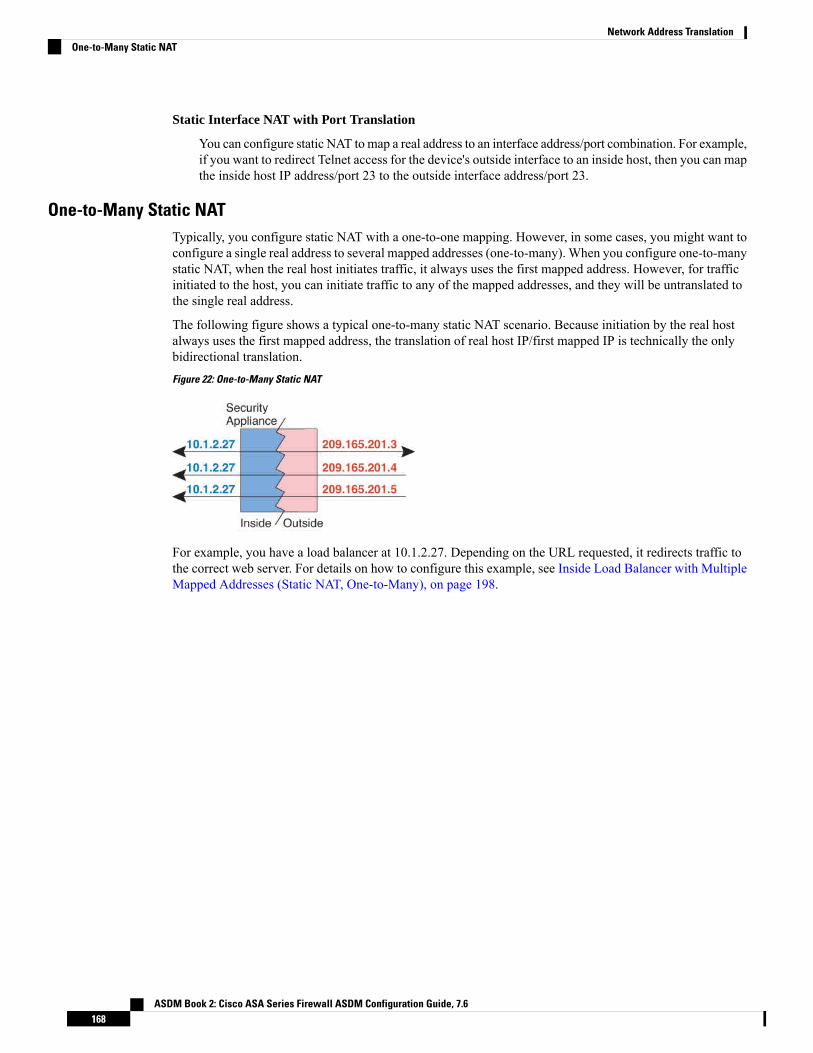
Static Interface NAT with Port Translation
You can configure static NAT tomap a real address to an interface address/port combination. For example,if you want to redirect Telnet access for the device's outside interface to an inside host, then you can mapthe inside host IP address/port 23 to the outside interface address/port 23.
One-to-Many Static NATTypically, you configure static NAT with a one-to-one mapping. However, in some cases, you might want toconfigure a single real address to several mapped addresses (one-to-many). When you configure one-to-manystatic NAT, when the real host initiates traffic, it always uses the first mapped address. However, for trafficinitiated to the host, you can initiate traffic to any of the mapped addresses, and they will be untranslated tothe single real address.
The following figure shows a typical one-to-many static NAT scenario. Because initiation by the real hostalways uses the first mapped address, the translation of real host IP/first mapped IP is technically the onlybidirectional translation.
Figure 22: One-to-Many Static NAT
For example, you have a load balancer at 10.1.2.27. Depending on the URL requested, it redirects traffic tothe correct web server. For details on how to configure this example, see Inside Load Balancer with MultipleMapped Addresses (Static NAT, One-to-Many), on page 198.
ASDM Book 2: Cisco ASA Series Firewall ASDM Configuration Guide, 7.6168
Network Address TranslationOne-to-Many Static NAT

Figure 23: One-to-Many Static NAT Example
Other Mapping Scenarios (Not Recommended)NAT has the flexibility to allow any kind of static mapping scenario: one-to-one, one-to-many, but alsofew-to-many, many-to-few, andmany-to-onemappings.We recommend using only one-to-one or one-to-manymappings. These other mapping options might result in unintended consequences.
Functionally, few-to-many is the same as one-to-many; but because the configuration is more complicatedand the actual mappings may not be obvious at a glance, we recommend creating a one-to-many configurationfor each real address that requires it. For example, for a few-to-many scenario, the few real addresses aremapped to the many mapped addresses in order (A to 1, B to 2, C to 3). When all real addresses are mapped,the next mapped address is mapped to the first real address, and so on until all mapped addresses are mapped(A to 4, B to 5, C to 6). This results in multiple mapped addresses for each real address. Just like a one-to-manyconfiguration, only the first mappings are bidirectional; subsequent mappings allow traffic to be initiated tothe real host, but all traffic from the real host uses only the first mapped address for the source.
The following figure shows a typical few-to-many static NAT scenario.
ASDM Book 2: Cisco ASA Series Firewall ASDM Configuration Guide, 7.6169
Network Address TranslationOther Mapping Scenarios (Not Recommended)

Figure 24: Few-to-Many Static NAT
For a many-to-few or many-to-one configuration, where you have more real addresses than mapped addresses,you run out of mapped addresses before you run out of real addresses. Only the mappings between the lowestreal IP addresses and the mapped pool result in bidirectional initiation. The remaining higher real addressescan initiate traffic, but traffic cannot be initiated to them (returning traffic for a connection is directed to thecorrect real address because of the unique 5-tuple (source IP, destination IP, source port, destination port,protocol) for the connection).
Many-to-few or many-to-one NAT is not PAT. If two real hosts use the same source port number and go tothe same outside server and the same TCP destination port, and both hosts are translated to the same IP address,then both connections will be reset because of an address conflict (the 5-tuple is not unique).
Note
The following figure shows a typical many-to-few static NAT scenario.
Figure 25: Many-to-Few Static NAT
Instead of using a static rule this way, we suggest that you create a one-to-one rule for the traffic that needsbidirectional initiation, and then create a dynamic rule for the rest of your addresses.
Configure Static Network Object NAT or Static NAT-with-Port-TranslationThis section describes how to configure a static NAT rule using network object NAT.
Procedure
Step 1 Add NAT to a new or existing network object:
• To add a new network object, choose Configuration > Firewall > NAT Rules, then click Add > AddNetwork Object NAT Rule.
ASDM Book 2: Cisco ASA Series Firewall ASDM Configuration Guide, 7.6170
Network Address TranslationConfigure Static Network Object NAT or Static NAT-with-Port-Translation
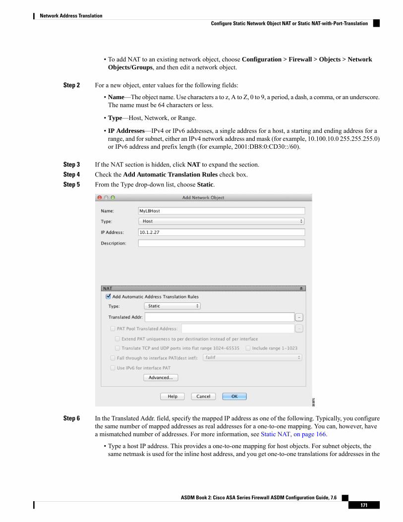
• To add NAT to an existing network object, choose Configuration > Firewall > Objects > NetworkObjects/Groups, and then edit a network object.
Step 2 For a new object, enter values for the following fields:
• Name—The object name. Use characters a to z, A to Z, 0 to 9, a period, a dash, a comma, or an underscore.The name must be 64 characters or less.
• Type—Host, Network, or Range.
• IP Addresses—IPv4 or IPv6 addresses, a single address for a host, a starting and ending address for arange, and for subnet, either an IPv4 network address and mask (for example, 10.100.10.0 255.255.255.0)or IPv6 address and prefix length (for example, 2001:DB8:0:CD30::/60).
Step 3 If the NAT section is hidden, click NAT to expand the section.Step 4 Check the Add Automatic Translation Rules check box.Step 5 From the Type drop-down list, choose Static.
Step 6 In the Translated Addr. field, specify the mapped IP address as one of the following. Typically, you configurethe same number of mapped addresses as real addresses for a one-to-one mapping. You can, however, havea mismatched number of addresses. For more information, see Static NAT, on page 166.
• Type a host IP address. This provides a one-to-one mapping for host objects. For subnet objects, thesame netmask is used for the inline host address, and you get one-to-one translations for addresses in the
ASDM Book 2: Cisco ASA Series Firewall ASDM Configuration Guide, 7.6171
Network Address TranslationConfigure Static Network Object NAT or Static NAT-with-Port-Translation
mapped inline host’s subnet. For range objects, the mapped address includes the same number of hoststhat are in the range object, starting with the mapped host address. For example, if the real address isdefined as a range from 10.1.1.1 through 10.1.1.6, and you specify 172.20.1.1 as the mapped address,then the mapped range will include 172.20.1.1 through 172.20.1.6. For NAT46 or NAT66 translations,this can be an IPv6 network address.
• Click the browse button and select a network object (or create a new one). To do a one-to-one mappingfor a range of IP addresses, select an object that contains a range with the same number of addresses.
• (For static NAT-with-port-translation only.) Type an interface name or click the browse button, andchoose an interface from the Browse Translated Addr dialog box. You cannot select a bridge groupmember interface.
To use the IPv6 interface address, you must also check the Use IPv6 for interface PAT check box. Besure to also click Advanced and configure a service port translation. (You cannot specify an interfacein transparent mode.)
Step 7 (Optional.) For NAT46, check Use one-to-one address translation. For NAT 46, specify one-to-one totranslate the first IPv4 address to the first IPv6 address, the second to the second, and so on. Without thisoption, the IPv4-embedded method is used. For a one-to-one translation, you must use this keyword.
Step 8 (Optional) Click Advanced, configure the following options in the Advanced NAT Settings dialog box, andclick OK.
• Translate DNS replies for rule—Translates the IP address in DNS replies. Be sure DNS inspection isenabled (it is enabled by default). See Rewriting DNS Queries and Responses Using NAT, on page 238for more information.
• Disable Proxy ARP on egress interface—Disables proxy ARP for incoming packets to the mapped IPaddresses. For information on the conditions whichmight require the disabling of proxy ARP, seeMappedAddresses and Routing, on page 219.
• (Required for bridge group member interfaces.) Interface—Specifies the real interface (Source) and themapped interface (Destination) where this NAT rule applies. By default, the rule applies to all interfacesexcept for bridge group members.
• Service—Configures static NAT-with-port-translation. Choose the protocol, then enter the real port andthe mapped port. You can use port numbers or a well-known port name such as http.
Step 9 Click OK, and then Apply.
Because static rules are bidirectional (allowing initiation to and from the real host), the NAT Rules table showstwo rows for each static rule, one for each direction.
ASDM Book 2: Cisco ASA Series Firewall ASDM Configuration Guide, 7.6172
Network Address TranslationConfigure Static Network Object NAT or Static NAT-with-Port-Translation
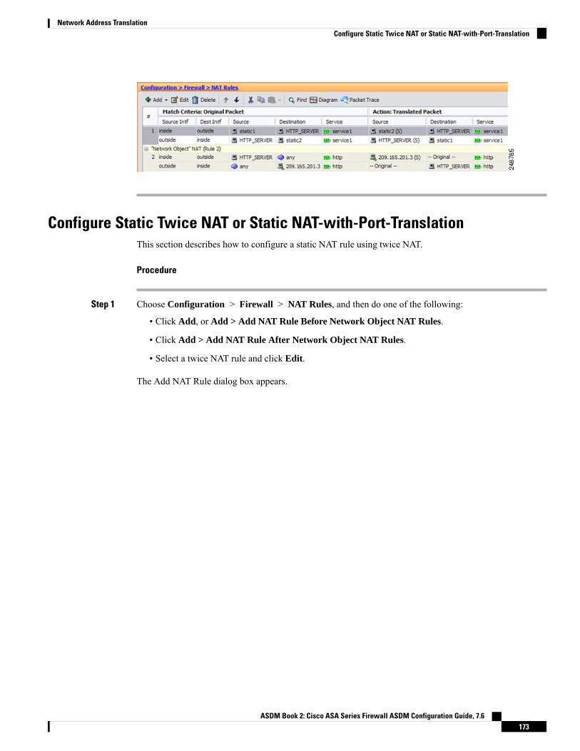
Configure Static Twice NAT or Static NAT-with-Port-TranslationThis section describes how to configure a static NAT rule using twice NAT.
Procedure
Step 1 Choose Configuration > Firewall > NAT Rules, and then do one of the following:
• Click Add, or Add > Add NAT Rule Before Network Object NAT Rules.
• Click Add > Add NAT Rule After Network Object NAT Rules.
• Select a twice NAT rule and click Edit.
The Add NAT Rule dialog box appears.
ASDM Book 2: Cisco ASA Series Firewall ASDM Configuration Guide, 7.6173
Network Address TranslationConfigure Static Twice NAT or Static NAT-with-Port-Translation

Step 2 (Required for bridge group member interfaces.) Set the source and destination interfaces.
In routed mode, the default is any interface for both source and destination. You can select specific interfacesfor one or both options. However, you must select the interface when writing a rule for bridge group memberinterfaces; “any” does not include these interfaces.
a) From the Match Criteria: Original Packet > Source Interface drop-down list, choose the sourceinterface.
b) From theMatch Criteria: Original Packet > Destination Interface drop-down list, choose the destinationinterface.
Step 3 Choose Static from theAction: Translated Packet > Source NAT Type drop-down list. Static is the defaultsetting.
This setting only applies to the source address; the destination translation is always static.
ASDM Book 2: Cisco ASA Series Firewall ASDM Configuration Guide, 7.6174
Network Address TranslationConfigure Static Twice NAT or Static NAT-with-Port-Translation

Step 4 Identify the original packet addresses, either IPv4 or IPv6; namely, the packet addresses as they appear onthe source interface network (the real source address and the mapped destination address). See the followingfigure for an example of the original packet vs. the translated packet.
a) ForMatch Criteria: Original Packet > Source Address, click the browse button and choose an existingnetwork object or group or create a new object or group from the Browse Original Source Address dialogbox. The group cannot contain both IPv4 and IPv6 addresses; it must contain one type only. The defaultis any, but do not use this option except for identity NAT.
b) (Optional) For Match Criteria: Original Packet > Destination Address, click the browse button andchoose an existing network object, group, or interface, or create a new object or group from the BrowseOriginal Destination Address dialog box.
Although the main feature of twice NAT is the inclusion of the destination IP address, the destinationaddress is optional. If you do specify the destination address, you can configure static translation for thataddress or just use identity NAT for it. You might want to configure twice NAT without a destinationaddress to take advantage of some of the other qualities of twice NAT, including the use of network objectgroups for real addresses, or manually ordering of rules. For more information, see Comparing NetworkObject NAT and Twice NAT, on page 130.
Step 5 Identify the translated packet addresses, either IPv4 or IPv6; namely, the packet addresses as they appear onthe destination interface network (the mapped source address and the real destination address). You cantranslate between IPv4 and IPv6 if desired.a) For Action: Translated Packet > Source Address, click the browse button and choose an existing
network object or group or create a new object or group from the Browse Translated Source Addressdialog box.
For static NAT, the mapping is typically one-to-one, so the real addresses have the same quantity as themapped addresses. You can, however, have different quantities if desired.
For static interface NAT with port translation, you can specify the interface instead of a networkobject/group for the mapped address. If you want to use the IPv6 address of the interface, check the UseIPv6 for interface PAT check box. You cannot select a bridge group member interface.
ASDM Book 2: Cisco ASA Series Firewall ASDM Configuration Guide, 7.6175
Network Address TranslationConfigure Static Twice NAT or Static NAT-with-Port-Translation

For more information, see Static NAT with Port Translation, on page 167. See Guidelines for NAT, onpage 132 for information about disallowed mapped IP addresses.
b) (Optional.) For Action: Translated Packet > Destination Address, click the browse button and choosean existing network object or group, or create a new object or group from the Browse Translated DestinationAddress dialog box.
Step 6 (Optional.) Identify the source or destination service ports for service translation.
• Identify the original packet source or destination port (the real source port or the mapped destinationport). For Match Criteria: Original Packet > Service, click the browse button and choose an existingservice object that specifies ports, or create a new object from the Browse Original Service dialog box.
• Identify the translated packet source or destination port (the mapped source port or the real destinationport). For Action: Translated Packet > Service, click the browse button and choose an existing serviceobject that specifies ports, or create a new object from the Browse Translated Service dialog box.
A service object can contain both a source and destination port. You should specify either the source or thedestination port for both the real and mapped service objects. You should only specify both the source anddestination ports if your application uses a fixed source port (such as some DNS servers); but fixed sourceports are rare. In the rare case where you specify both the source and destination ports in the object, the originalpacket service object contains the real source port/mapped destination port; the translated packet service objectcontains the mapped source port/real destination port. When translating a port, be sure the protocols in thereal and mapped service objects are identical (for example, both TCP). For identity NAT, you can use thesame service object for both the real and mapped ports. The “not equal” (!=) operator is not supported.
For example:
ASDM Book 2: Cisco ASA Series Firewall ASDM Configuration Guide, 7.6176
Network Address TranslationConfigure Static Twice NAT or Static NAT-with-Port-Translation

Step 7 (Optional.) For NAT46, check the Use one-to-one address translation check box. For NAT46, specifyone-to-one to translate the first IPv4 address to the first IPv6 address, the second to the second, and so on.Without this option, the IPv4-embedded method is used. For a one-to-one translation, you must use thiskeyword.
Step 8 (Optional.) Configure NAT options in the Options area.
• Enable rule —Enables this NAT rule. The rule is enabled by default.
• (For a source-only rule.) Translate DNS replies that match this rule—Rewrites the DNS A record inDNS replies. Be sure DNS inspection is enabled (it is enabled by default). You cannot configure DNSmodification if you configure a destination address. See Rewriting DNS Queries and Responses UsingNAT, on page 238 for more information.
ASDM Book 2: Cisco ASA Series Firewall ASDM Configuration Guide, 7.6177
Network Address TranslationConfigure Static Twice NAT or Static NAT-with-Port-Translation
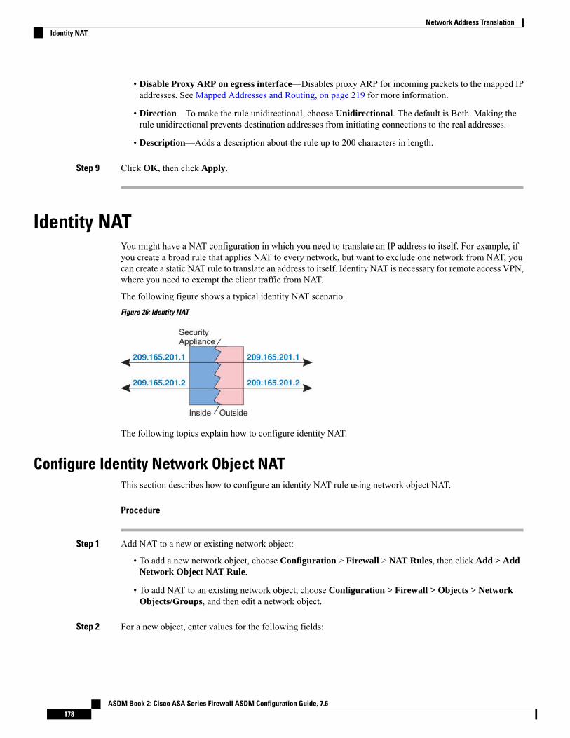
• Disable Proxy ARP on egress interface—Disables proxy ARP for incoming packets to the mapped IPaddresses. See Mapped Addresses and Routing, on page 219 for more information.
• Direction—To make the rule unidirectional, choose Unidirectional. The default is Both. Making therule unidirectional prevents destination addresses from initiating connections to the real addresses.
• Description—Adds a description about the rule up to 200 characters in length.
Step 9 Click OK, then click Apply.
Identity NATYou might have a NAT configuration in which you need to translate an IP address to itself. For example, ifyou create a broad rule that applies NAT to every network, but want to exclude one network from NAT, youcan create a static NAT rule to translate an address to itself. Identity NAT is necessary for remote access VPN,where you need to exempt the client traffic from NAT.
The following figure shows a typical identity NAT scenario.
Figure 26: Identity NAT
The following topics explain how to configure identity NAT.
Configure Identity Network Object NATThis section describes how to configure an identity NAT rule using network object NAT.
Procedure
Step 1 Add NAT to a new or existing network object:
• To add a new network object, choose Configuration > Firewall > NAT Rules, then click Add > AddNetwork Object NAT Rule.
• To add NAT to an existing network object, choose Configuration > Firewall > Objects > NetworkObjects/Groups, and then edit a network object.
Step 2 For a new object, enter values for the following fields:
ASDM Book 2: Cisco ASA Series Firewall ASDM Configuration Guide, 7.6178
Network Address TranslationIdentity NAT

• Name—The object name. Use characters a to z, A to Z, 0 to 9, a period, a dash, a comma, or an underscore.The name must be 64 characters or less.
• Type—Host, Network, or Range.
• IP Addresses—IPv4 or IPv6 addresses, a single address for a host, a starting and ending address for arange, and for subnet, either an IPv4 network address and mask (for example, 10.100.10.0 255.255.255.0)or IPv6 address and prefix length (for example, 2001:DB8:0:CD30::/60).
Step 3 If the NAT section is hidden, click NAT to expand the section.Step 4 Check the Add Automatic Translation Rules check box.Step 5 From the Type drop-down list, choose Static.
Step 6 In the Translated Addr. field, do one of the following:
• For host objects, enter the same address. For range objects, enter the first address in the real range (thesame number of addresses in the range will be used). For subnet objects, enter any address within thereal subnet (all addresses in the subnet will be used).
• Click the browse button and select a network object (or create a new one). Use this option when configuringidentity NAT for a range of addresses.
Step 7 (Optional) Click Advanced, configure the following options in the Advanced NAT Settings dialog box, andclick OK.
ASDM Book 2: Cisco ASA Series Firewall ASDM Configuration Guide, 7.6179
Network Address TranslationConfigure Identity Network Object NAT

• Translate DNS replies for rule—Do not configure this option for identity NAT.
• Disable Proxy ARP on egress interface—Disables proxy ARP for incoming packets to the mapped IPaddresses. For information on the conditions whichmight require the disabling of proxy ARP, seeMappedAddresses and Routing, on page 219.
• (Routed mode; interfaces specified.) Lookup route table to locate egress interface—Determines theegress interface using a route lookup instead of using the interface specified in the NAT command. SeeDetermining the Egress Interface, on page 221 for more information.
• (Required for bridge group member interfaces.) Interface—Specifies the real interface (Source) and themapped interface (Destination) where this NAT rule applies. By default, the rule applies to all interfacesexcept for bridge group members.
• Service—Do not configure this option for identity NAT.
Step 8 Click OK, and then Apply.
Because static rules are bidirectional (allowing initiation to and from the real host), the NAT Rules table showstwo rows for each static rule, one for each direction, unless you select the route lookup option.
Configure Identity Twice NATThis section describes how to configure an identity NAT rule using twice NAT.
Procedure
Step 1 Choose Configuration > Firewall > NAT Rules, and then do one of the following:
• Click Add, or Add > Add NAT Rule Before Network Object NAT Rules.
• Click Add > Add NAT Rule After Network Object NAT Rules.
• Select a twice NAT rule and click Edit.
The Add NAT Rule dialog box appears.
ASDM Book 2: Cisco ASA Series Firewall ASDM Configuration Guide, 7.6180
Network Address TranslationConfigure Identity Twice NAT

Step 2 (Required for bridge group member interfaces.) Set the source and destination interfaces.
In routed mode, the default is any interface for both source and destination. You can select specific interfacesfor one or both options. However, you must select the interface when writing a rule for bridge group memberinterfaces; “any” does not include these interfaces.
a) From the Match Criteria: Original Packet > Source Interface drop-down list, choose the sourceinterface.
b) From theMatch Criteria: Original Packet > Destination Interface drop-down list, choose the destinationinterface.
Step 3 Choose Static from theAction: Translated Packet > Source NAT Type drop-down list. Static is the defaultsetting.
This setting only applies to the source address; the destination translation is always static.
Step 4 Identify the original packet addresses, either IPv4 or IPv6; namely, the packet addresses as they appear onthe source interface network (the real source address and the mapped destination address). See the following
ASDM Book 2: Cisco ASA Series Firewall ASDM Configuration Guide, 7.6181
Network Address TranslationConfigure Identity Twice NAT

figure for an example of the original packet vs. the translated packet where you perform identity NAT on theinside host but translate the outside host.
a) ForMatch Criteria: Original Packet > Source Address, click the browse button and choose an existingnetwork object or group or create a new object or group from the Browse Original Source Address dialogbox. The group cannot contain both IPv4 and IPv6 addresses; it must contain one type only. The defaultis any; only use this option when also setting the mapped address to any.
b) (Optional.) For Match Criteria: Original Packet > Destination Address, click the browse button andchoose an existing network object, group, or interface, or create a new object or group from the BrowseOriginal Destination Address dialog box.
Although the main feature of twice NAT is the inclusion of the destination IP address, the destinationaddress is optional. If you do specify the destination address, you can configure static translation for thataddress or just use identity NAT for it. You might want to configure twice NAT without a destinationaddress to take advantage of some of the other qualities of twice NAT, including the use of network objectgroups for real addresses, or manually ordering of rules. For more information, see Comparing NetworkObject NAT and Twice NAT, on page 130.
For static interface NAT with port translation only, choose an interface. If you specify an interface, besure to also configure a service translation. For more information, see Static NAT with Port Translation,on page 167.
Step 5 Identify the translated packet addresses; namely, the packet addresses as they appear on the destination interfacenetwork (the mapped source address and the real destination address).a) ForAction: Translated Packet > Source Address, click the browse button and choose the same network
object or group from the Browse Translated Source Address dialog box that you chose for the real sourceaddress. Use any if you specified any for the real address.
b) For Match Criteria: Translated Packet > Destination Address, click the browse button and choose anexisting network object or group, or create a new object or group from the Browse Translated DestinationAddress dialog box.
For identity NAT for the destination address, simply use the same object or group for both the real andmapped addresses.
If you want to translate the destination address, then the static mapping is typically one-to-one, so the realaddresses have the same quantity as the mapped addresses. You can, however, have different quantitiesif desired. For more information, see Static NAT, on page 166. See Guidelines for NAT, on page 132 forinformation about disallowed mapped IP addresses.
ASDM Book 2: Cisco ASA Series Firewall ASDM Configuration Guide, 7.6182
Network Address TranslationConfigure Identity Twice NAT

Step 6 (Optional.) Identify the source or destination service ports for service translation.
• Identify the original packet source or destination port (the real source port or the mapped destinationport). For Match Criteria: Original Packet > Service, click the browse button and choose an existingservice object that specifies ports, or create a new object from the Browse Original Service dialog box.
• Identify the translated packet source or destination port (the mapped source port or the real destinationport). For Action: Translated Packet > Service, click the browse button and choose an existing serviceobject that specifies ports, or create a new object from the Browse Translated Service dialog box.
A service object can contain both a source and destination port. You should specify either the source or thedestination port for both the real and mapped service objects. You should only specify both the source anddestination ports if your application uses a fixed source port (such as some DNS servers); but fixed sourceports are rare. In the rare case where you specify both the source and destination ports in the object, the originalpacket service object contains the real source port/mapped destination port; the translated packet service objectcontains the mapped source port/real destination port. When translating a port, be sure the protocols in thereal and mapped service objects are identical (for example, both TCP). For identity NAT, you can use thesame service object for both the real and mapped ports. The “not equal” (!=) operator is not supported.
For example:
ASDM Book 2: Cisco ASA Series Firewall ASDM Configuration Guide, 7.6183
Network Address TranslationConfigure Identity Twice NAT

Step 7 (Optional) Configure NAT options in the Options area.
• Enable rule —Enables this NAT rule. The rule is enabled by default.
• (For a source-only rule.)Translate DNS replies that match this rule—Although this option is availableif you do not configure a destination address, it is not applicable to identity NAT because you aretranslating the address to itself, so the DNS reply does not need modification.
• Disable Proxy ARP on egress interface—Disables proxy ARP for incoming packets to the mapped IPaddresses. See Mapped Addresses and Routing, on page 219 for more information.
• (Routed mode; interfaces specified.) Lookup route table to locate egress interface—Determines theegress interface using a route lookup instead of using the interface specified in the NAT command. SeeDetermining the Egress Interface, on page 221 for more information.
• Direction—To make the rule unidirectional, choose Unidirectional. The default is Both. Making therule unidirectional prevents traffic from initiating connections to the real addresses. You might want touse this setting for testing purposes.
• Description—Adds a description about the rule up to 200 characters in length.
ASDM Book 2: Cisco ASA Series Firewall ASDM Configuration Guide, 7.6184
Network Address TranslationConfigure Identity Twice NAT

Step 8 Click OK, then click Apply.
Monitoring NATYou can view NAT related graphs from the following pages:
• Monitoring > Properties > Connection Graphs > Xlates—Select the Xlate Utilization graph to viewthe in-use and most-used xlates. This is equivalent to the show xlate command.
• Monitoring > Properties > Connection Graphs > Perfmon—Select the Xlate Perfmon graph to seeNAT performance information. This is equivalent to the xlate information from the show perfmoncommand.
History for NAT
DescriptionPlatformReleasesFeature Name
Configures NAT for a network object IP address(es).
We introduced ormodified the following screens: Configuration> Firewall > NAT Rules Configuration > Firewall > Objects> Network Objects/Groups
8.3(1)Network Object NAT
Twice NAT lets you identify both the source and destinationaddress in a single rule.
We modified the following screen: Configuration > Firewall> NAT Rules.
8.3(1)Twice NAT
ASDM Book 2: Cisco ASA Series Firewall ASDM Configuration Guide, 7.6185
Network Address TranslationMonitoring NAT

DescriptionPlatformReleasesFeature Name
In earlier releases for identity NAT, proxy ARP was disabled,and a route lookup was always used to determine the egressinterface. You could not configure these settings. In 8.4(2) andlater, the default behavior for identity NAT was changed tomatch the behavior of other static NAT configurations: proxyARP is enabled, and the NAT configuration determines theegress interface (if specified) by default. You can leave thesesettings as is, or you can enable or disable them discretely.Note that you can now also disable proxy ARP for regular staticNAT.
For pre-8.3 configurations, the migration of NAT exempt rules(the nat 0 access-list command) to 8.4(2) and later nowincludes the following keywords to disable proxy ARP and touse a route lookup: no-proxy-arp and route-lookup. Theunidirectional keyword that was used for migrating to 8.3(2)and 8.4(1) is no longer used for migration. When upgrading to8.4(2) from 8.3(1), 8.3(2), and 8.4(1), all identity NATconfigurations will now include the no-proxy-arp androute-lookup keywords, to maintain existing functionality.The unidirectional keyword is removed.
We modified the following screens: Configuration > Firewall> NAT Rules > Add/Edit Network Object > Advanced NATSettings; Configuration > Firewall > NAT Rules > Add/EditNAT Rule.
8.4(2)/8.5(1)Identity NAT configurable proxy ARP and routelookup
You can now specify a pool of PAT addresses instead of asingle address. You can also optionally enable round-robinassignment of PAT addresses instead of first using all ports ona PAT address before using the next address in the pool. Thesefeatures help prevent a large number of connections from asingle PAT address from appearing to be part of a DoS attackand makes configuration of large numbers of PAT addresseseasy.
We modified the following screens: Configuration > Firewall> NAT Rules > Add/Edit Network Object; Configuration >Firewall > NAT Rules > Add/Edit NAT Rule.
8.4(2)/8.5(1)PAT pool and round robin address assignment
When using a PAT pool with round robin allocation, if a hosthas an existing connection, then subsequent connections fromthat host will use the same PAT IP address if ports are available.
We did not modify any screens.
This feature is not available in 8.5(1) or 8.6(1).
8.4(3)Round robin PAT pool allocation uses the sameIP address for existing hosts
ASDM Book 2: Cisco ASA Series Firewall ASDM Configuration Guide, 7.6186
Network Address TranslationHistory for NAT

DescriptionPlatformReleasesFeature Name
If available, the real source port number is used for the mappedport. However, if the real port is not available, by default themapped ports are chosen from the same range of ports as thereal port number: 0 to 511, 512 to 1023, and 1024 to 65535.Therefore, ports below 1024 have only a small PAT pool.
If you have a lot of traffic that uses the lower port ranges, whenusing a PAT pool, you can now specify a flat range of ports tobe used instead of the three unequal-sized tiers: either 1024 to65535, or 1 to 65535.
We modified the following screens: Configuration > Firewall> NAT Rules > Add/Edit Network Object; Configuration >Firewall > NAT Rules > Add/Edit NAT Rule.
This feature is not available in 8.5(1) or 8.6(1).
8.4(3)Flat range of PAT ports for a PAT pool
Each PAT IP address allows up to 65535 ports. If 65535 portsdo not provide enough translations, you can now enableextended PAT for a PAT pool. Extended PAT uses 65535 portsper service, as opposed to per IP address, by including thedestination address and port in the translation information.
We modified the following screens: Configuration > Firewall> NAT Rules > Add/Edit Network Object; Configuration >Firewall > NAT Rules > Add/Edit NAT Rule.
This feature is not available in 8.5(1) or 8.6(1).
8.4(3)Extended PAT for a PAT pool
ASDM Book 2: Cisco ASA Series Firewall ASDM Configuration Guide, 7.6187
Network Address TranslationHistory for NAT

DescriptionPlatformReleasesFeature Name
In rare situations, you might want to use a VPN peer’s real IPaddress on the inside network instead of an assigned local IPaddress. Normally with VPN, the peer is given an assignedlocal IP address to access the inside network. However, youmight want to translate the local IP address back to the peer’sreal public IP address if, for example, your inside servers andnetwork security is based on the peer’s real IP address.
You can enable this feature on one interface per tunnel group.Object NAT rules are dynamically added and deleted when theVPN session is established or disconnected. You can view therules using the show nat command.
Because of routing issues, we do not recommend using thisfeature unless you know you need it; contact Cisco TAC toconfirm feature compatibility with your network. See thefollowing limitations:
• Only supports Cisco IPsec and AnyConnect Client.
• Return traffic to the public IP addresses must be routedback to the ASA so the NAT policy and VPN policy canbe applied.
• Does not support load-balancing (because of routingissues).
• Does not support roaming (public IP changing).
ASDM does not support this command; enter the commandusing the Command Line Tool.
8.4(3)Automatic NAT rules to translate a VPN peer’slocal IP address back to the peer’s real IP address
NAT now supports IPv6 traffic, as well as translating betweenIPv4 and IPv6. Translating between IPv4 and IPv6 is notsupported in transparent mode.
We modified the following screen: Configuration > Firewall> Objects > Network Objects/Group; Configuration > Firewall> NAT Rules.
9.0(1)NAT support for IPv6
NAT now supports translation of the DNS PTR record forreverse DNS lookups when using IPv4 NAT, IPv6 NAT, andNAT64 with DNS inspection enabled for the NAT rule.
9.0(1)NAT support for reverse DNS lookups
ASDM Book 2: Cisco ASA Series Firewall ASDM Configuration Guide, 7.6188
Network Address TranslationHistory for NAT

DescriptionPlatformReleasesFeature Name
The per-session PAT feature improves the scalability of PATand, for clustering, allows each member unit to own PATconnections; multi-session PAT connections have to beforwarded to and owned by the control unit. At the end of aper-session PAT session, the ASA sends a reset andimmediately removes the xlate. This reset causes the end nodeto immediately release the connection, avoiding theTIME_WAIT state. Multi-session PAT, on the other hand, usesthe PAT timeout, by default 30 seconds. For “hit-and-run”traffic, such as HTTP or HTTPS, the per-session feature candramatically increase the connection rate supported by oneaddress. Without the per-session feature, the maximumconnection rate for one address for an IP protocol isapproximately 2000 per second. With the per-session feature,the connection rate for one address for an IP protocol is65535/average-lifetime.
By default, all TCP traffic and UDP DNS traffic use aper-session PAT xlate. For traffic that requires multi-sessionPAT, such as H.323, SIP, or Skinny, you can disableper-session PAT by creating a per-session deny rule.
We introduced the following screen: Configuration > Firewall> Advanced > Per-Session NAT Rules.
9.0(1)Per-session PAT
When enabled, a NAT rule update is applied after the rulecompilation is completed; without affecting the rule matchingperformance.
We addedNAT to the following screen: Configuration >DeviceManagement > Advanced > Rule Engine.
9.3(1)Transactional Commit Model on NAT RuleEngine
For carrier-grade or large-scale PAT, you can allocate a blockof ports for each host, rather than have NAT allocate one porttranslation at a time (see RFC 6888).
We added the following command: Configuration >Firewall > Advanced > PAT Port Block Allocation. Weadded Enable Block Allocation the object NAT and twiceNAT dialog boxes.
9.5(1)Carrier Grade NAT enhancements
You can now specify SCTP ports in static network object NATrules. Using SCTP in static twice NAT is not recommended.Dynamic NAT/PAT does not support SCTP.
Wemodified the following screen:Configuration >Firewall >NAT add/edit static network object NAT rule,Advanced NATSettings dialog box.
9.5(2)NAT support for SCTP
ASDM Book 2: Cisco ASA Series Firewall ASDM Configuration Guide, 7.6189
Network Address TranslationHistory for NAT

ASDM Book 2: Cisco ASA Series Firewall ASDM Configuration Guide, 7.6190
Network Address TranslationHistory for NAT

C H A P T E R 9NAT Examples and Reference
The following topics provide examples for configuring NAT, plus information on advanced configurationand troubleshooting.
• Examples for Network Object NAT, on page 191• Examples for Twice NAT, on page 204• NAT in Routed and Transparent Mode, on page 217• Routing NAT Packets, on page 219• NAT for VPN, on page 222• Translating IPv6 Networks, on page 228• Rewriting DNS Queries and Responses Using NAT, on page 238
Examples for Network Object NATFollowing are some configuration examples for network object NAT.
Providing Access to an Inside Web Server (Static NAT)The following example performs static NAT for an inside web server. The real address is on a private network,so a public address is required. Static NAT is necessary so hosts can initiate traffic to the web server at a fixedaddress.
ASDM Book 2: Cisco ASA Series Firewall ASDM Configuration Guide, 7.6191

Figure 27: Static NAT for an Inside Web Server
Procedure
Step 1 Choose Configuration > Firewall > NAT.Step 2 Choose Add > Network Object NAT Rule, name the new network object and define the web server host
address.
Step 3 Configure static NAT for the object.
ASDM Book 2: Cisco ASA Series Firewall ASDM Configuration Guide, 7.6192
Network Address TranslationProviding Access to an Inside Web Server (Static NAT)

Step 4 Click Advanced and configure the real and mapped interfaces.
Step 5 Click OK to return to the Edit Network Object dialog box, click OK again, and then click Apply.
ASDM Book 2: Cisco ASA Series Firewall ASDM Configuration Guide, 7.6193
Network Address TranslationProviding Access to an Inside Web Server (Static NAT)
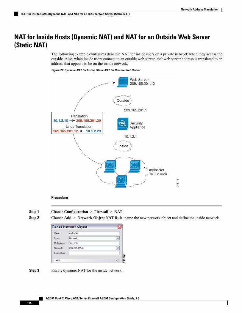
NAT for Inside Hosts (Dynamic NAT) and NAT for an Outside Web Server(Static NAT)
The following example configures dynamic NAT for inside users on a private network when they access theoutside. Also, when inside users connect to an outside web server, that web server address is translated to anaddress that appears to be on the inside network.
Figure 28: Dynamic NAT for Inside, Static NAT for Outside Web Server
Procedure
Step 1 Choose Configuration > Firewall > NAT.Step 2 Choose Add > Network Object NAT Rule, name the new network object and define the inside network.
Step 3 Enable dynamic NAT for the inside network.
ASDM Book 2: Cisco ASA Series Firewall ASDM Configuration Guide, 7.6194
Network Address TranslationNAT for Inside Hosts (Dynamic NAT) and NAT for an Outside Web Server (Static NAT)

Step 4 For the Translated Addr field, add a new network object for the dynamic NAT pool to which you want totranslate the inside addresses by clicking the browse button.a) Choose Add > Network Object, name the new object, define the range of addresses in the NAT pool,
and click OK.
b) Choose the new network object by double-clicking it. Click OK to return to the NAT configuration.
ASDM Book 2: Cisco ASA Series Firewall ASDM Configuration Guide, 7.6195
Network Address TranslationNAT for Inside Hosts (Dynamic NAT) and NAT for an Outside Web Server (Static NAT)

Step 5 Click Advanced and configure the real and mapped interfaces.
Step 6 Click OK to return to the Edit Network Object dialog box, click then click OK again to return to the NATRules table.
Step 7 Choose Add > Network Object NAT Rule and create an object for the outside web server.
Step 8 Configure static NAT for the web server.
ASDM Book 2: Cisco ASA Series Firewall ASDM Configuration Guide, 7.6196
Network Address TranslationNAT for Inside Hosts (Dynamic NAT) and NAT for an Outside Web Server (Static NAT)

Step 9 Click Advanced and configure the real and mapped interfaces.
Step 10 Click OK to return to the Edit Network Object dialog box, click OK again, and then click Apply.
ASDM Book 2: Cisco ASA Series Firewall ASDM Configuration Guide, 7.6197
Network Address TranslationNAT for Inside Hosts (Dynamic NAT) and NAT for an Outside Web Server (Static NAT)

Inside Load Balancer with Multiple Mapped Addresses (Static NAT,One-to-Many)
The following example shows an inside load balancer that is translated to multiple IP addresses. When anoutside host accesses one of the mapped IP addresses, it is untranslated to the single load balancer address.Depending on the URL requested, it redirects traffic to the correct web server.
Figure 29: Static NAT with One-to-Many for an Inside Load Balancer
Procedure
Step 1 Choose Configuration > Firewall > NAT.Step 2 Choose Add > Network Object NAT Rule, name the new network object and define the load balancer
address.
ASDM Book 2: Cisco ASA Series Firewall ASDM Configuration Guide, 7.6198
Network Address TranslationInside Load Balancer with Multiple Mapped Addresses (Static NAT, One-to-Many)

Step 3 Enable static NAT for the load balancer:
Step 4 For the Translated Addr field, add a new network object for the static NAT group of addresses to which youwant to translate the load balancer address by clicking the browse button.a) Choose Add > Network Object, name the new object, define the range of addresses, and click OK.
b) Choose the new network object by double-clicking it. Click OK to return to the NAT configuration.
Step 5 Click Advanced and configure the real and mapped interfaces.
ASDM Book 2: Cisco ASA Series Firewall ASDM Configuration Guide, 7.6199
Network Address TranslationInside Load Balancer with Multiple Mapped Addresses (Static NAT, One-to-Many)
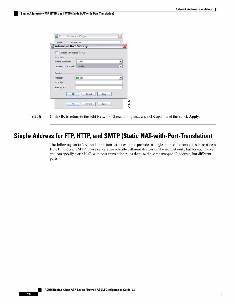
Step 6 Click OK to return to the Edit Network Object dialog box, click OK again, and then click Apply.
Single Address for FTP, HTTP, and SMTP (Static NAT-with-Port-Translation)The following static NAT-with-port-translation example provides a single address for remote users to accessFTP, HTTP, and SMTP. These servers are actually different devices on the real network, but for each server,you can specify static NAT-with-port-translation rules that use the same mapped IP address, but differentports.
ASDM Book 2: Cisco ASA Series Firewall ASDM Configuration Guide, 7.6200
Network Address TranslationSingle Address for FTP, HTTP, and SMTP (Static NAT-with-Port-Translation)
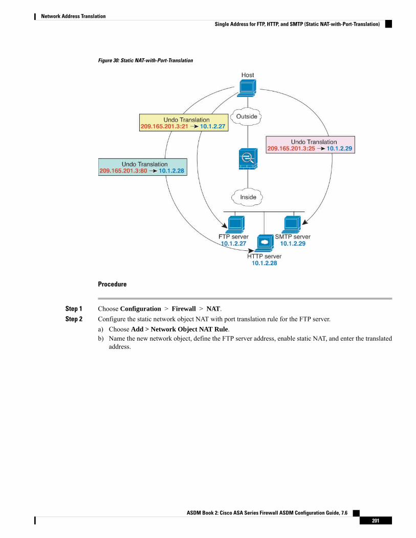
Figure 30: Static NAT-with-Port-Translation
Procedure
Step 1 Choose Configuration > Firewall > NAT.Step 2 Configure the static network object NAT with port translation rule for the FTP server.
a) Choose Add > Network Object NAT Rule.b) Name the new network object, define the FTP server address, enable static NAT, and enter the translated
address.
ASDM Book 2: Cisco ASA Series Firewall ASDM Configuration Guide, 7.6201
Network Address TranslationSingle Address for FTP, HTTP, and SMTP (Static NAT-with-Port-Translation)

c) Click Advanced and configure the real and mapped interfaces and port translation for FTP, mapping theFTP port to itself.
d) Click OK, then OK again to save the rule and return to the NAT page.
Step 3 Configure the static network object NAT with port translation rule for the HTTP server.a) Choose Add > Network Object NAT Rule.b) Name the new network object, define the HTTP server address, enable static NAT, and enter the translated
address.
ASDM Book 2: Cisco ASA Series Firewall ASDM Configuration Guide, 7.6202
Network Address TranslationSingle Address for FTP, HTTP, and SMTP (Static NAT-with-Port-Translation)

c) Click Advanced and configure the real and mapped interfaces and port translation for HTTP, mappingthe HTTP port to itself.
d) Click OK, then OK again to save the rule and return to the NAT page.
Step 4 Configure the static network object NAT with port translation rule for the SMTP server.a) Choose Add > Network Object NAT Rule.b) Name the new network object, define the SMTP server address, enable static NAT, and enter the translated
address.
ASDM Book 2: Cisco ASA Series Firewall ASDM Configuration Guide, 7.6203
Network Address TranslationSingle Address for FTP, HTTP, and SMTP (Static NAT-with-Port-Translation)

c) Click Advanced and configure the real and mapped interfaces and port translation for SMTP, mappingthe SMTP port to itself.
d) Click OK to return to the Edit Network Object dialog box, click OK again, and then click Apply.
Examples for Twice NATThis section includes the following configuration examples:
Different Translation Depending on the Destination (Dynamic Twice PAT)The following figure shows a host on the 10.1.2.0/24 network accessing two different servers. When the hostaccesses the server at 209.165.201.11, the real address is translated to 209.165.202.129:port. When the hostaccesses the server at 209.165.200.225, the real address is translated to 209.165.202.130:port.
ASDM Book 2: Cisco ASA Series Firewall ASDM Configuration Guide, 7.6204
Network Address TranslationExamples for Twice NAT
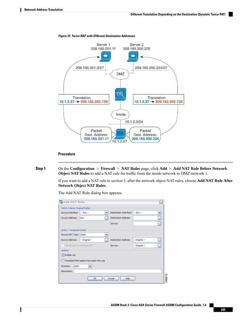
Figure 31: Twice NAT with Different Destination Addresses
Procedure
Step 1 On the Configuration > Firewall > NAT Rules page, click Add > Add NAT Rule Before NetworkObject NAT Rules to add a NAT rule for traffic from the inside network to DMZ network 1.
If you want to add a NAT rule to section 3, after the network object NAT rules, choose Add NAT Rule AfterNetwork Object NAT Rules.
The Add NAT Rule dialog box appears.
ASDM Book 2: Cisco ASA Series Firewall ASDM Configuration Guide, 7.6205
Network Address TranslationDifferent Translation Depending on the Destination (Dynamic Twice PAT)

Step 2 Set the source and destination interfaces.
Step 3 For the Original Source Address, click the browse button to add a new network object for the inside networkin the Browse Original Source Address dialog box.a) Select Add > Network Object.b) Define the inside network addresses, and click OK.
c) Choose the new network object by double-clicking it. Click OK to return to the NAT configuration.
Step 4 For the Original Destination Address, click the browse button to add a new network object for DMZ network1 in the Browse Original Destination Address dialog box.a) Select Add > Network Object.b) Define the DMZ network 1 addresses, and click OK.
c) Choose the new network object by double-clicking it. Click OK to return to the NAT configuration.
ASDM Book 2: Cisco ASA Series Firewall ASDM Configuration Guide, 7.6206
Network Address TranslationDifferent Translation Depending on the Destination (Dynamic Twice PAT)

Step 5 Set the NAT Type to Dynamic PAT (Hide):
Step 6 For the Translated Source Address, click the browse button to add a new network object for the PAT addressin the Browse Translated Source Address dialog box.a) Select Add > Network Object.b) Define the PAT address, and click OK.
c) Choose the new network object by double-clicking it. Click OK to return to the NAT configuration.
Step 7 For the Translated Destination Address, type the name of the Original Destination Address (DMZnetwork1)or click the browse button to choose it.
Because you do not want to translate the destination address, you need to configure identity NAT for it byspecifying the same address for the Original and Translated destination addresses.
ASDM Book 2: Cisco ASA Series Firewall ASDM Configuration Guide, 7.6207
Network Address TranslationDifferent Translation Depending on the Destination (Dynamic Twice PAT)

Step 8 Click OK to add the rule to the NAT table.Step 9 Click Add > Add NAT Rule Before Network Object NAT Rules or Add NAT Rule After Network
Object NAT Rules to add a NAT rule for traffic from the inside network to DMZ network 2.Step 10 Set the source and destination interfaces.
Step 11 For the Original Source Address, type the name of the inside network object (myInsideNetwork) or click thebrowse button to choose it.
Step 12 For the Original Destination Address, click the browse button to add a new network object for DMZ network2 in the Browse Original Destination Address dialog box.a) Select Add > Network Object.b) Define the DMZ network 2 addresses, and click OK.
c) Choose the new network object by double-clicking it. Click OK to return to the NAT configuration.
ASDM Book 2: Cisco ASA Series Firewall ASDM Configuration Guide, 7.6208
Network Address TranslationDifferent Translation Depending on the Destination (Dynamic Twice PAT)

Step 13 Set the NAT Type to Dynamic PAT (Hide):
Step 14 For the Translated Source Address, click the browse button to add a new network object for the PAT addressin the Browse Translated Source Address dialog box.a) Select Add > Network Object.b) Define the PAT address, and click OK.
c) Choose the new network object by double-clicking it. Click OK to return to the NAT configuration.
Step 15 For the Translated Destination Address, type the name of the Original Destination Address (DMZnetwork2)or click the browse button to choose it.
Because you do not want to translate the destination address, you need to configure identity NAT for it byspecifying the same address for the Original and Translated destination addresses.
ASDM Book 2: Cisco ASA Series Firewall ASDM Configuration Guide, 7.6209
Network Address TranslationDifferent Translation Depending on the Destination (Dynamic Twice PAT)

Step 16 Click OK to add the rule to the NAT table.Step 17 Click Apply.
Different Translation Depending on the Destination Address and Port (DynamicPAT)
The following figure shows the use of source and destination ports. The host on the 10.1.2.0/24 networkaccesses a single host for both web services and Telnet services. When the host accesses the server for Telnetservices, the real address is translated to 209.165.202.129:port. When the host accesses the same server forweb services, the real address is translated to 209.165.202.130:port.
ASDM Book 2: Cisco ASA Series Firewall ASDM Configuration Guide, 7.6210
Network Address TranslationDifferent Translation Depending on the Destination Address and Port (Dynamic PAT)
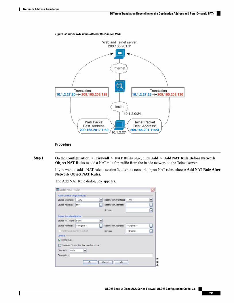
Figure 32: Twice NAT with Different Destination Ports
Procedure
Step 1 On the Configuration > Firewall > NAT Rules page, click Add > Add NAT Rule Before NetworkObject NAT Rules to add a NAT rule for traffic from the inside network to the Telnet server.
If you want to add a NAT rule to section 3, after the network object NAT rules, choose Add NAT Rule AfterNetwork Object NAT Rules.
The Add NAT Rule dialog box appears.
ASDM Book 2: Cisco ASA Series Firewall ASDM Configuration Guide, 7.6211
Network Address TranslationDifferent Translation Depending on the Destination Address and Port (Dynamic PAT)

Step 2 Set the source and destination interfaces.
Step 3 For the Original Source Address, click the browse button to add a new network object for the inside networkin the Browse Original Source Address dialog box.a) Select Add > Network Object.b) Define the inside network addresses, and click OK.
c) Choose the new network object by double-clicking it. Click OK to return to the NAT configuration.
Step 4 For the Original Destination Address, click the browse button to add a new network object for the Telnet/Webserver in the Browse Original Destination Address dialog box.a) Select Add > Network Object.b) Define the server address, and click OK.
c) Choose the new network object by double-clicking it. Click OK to return to the NAT configuration.
ASDM Book 2: Cisco ASA Series Firewall ASDM Configuration Guide, 7.6212
Network Address TranslationDifferent Translation Depending on the Destination Address and Port (Dynamic PAT)

Step 5 For the Original Service, click the browse button to add a new service object for Telnet in the Browse OriginalService dialog box.a) Select Add > Service Object.b) Define the protocol and port, and click OK.
c) Choose the new service object by double-clicking it. Click OK to return to the NAT configuration.
Step 6 Set the NAT Type to Dynamic PAT (Hide):
Step 7 For the Translated Source Address, click the browse button to add a new network object for the PAT addressin the Browse Translated Source Address dialog box.a) Select Add > Network Object.b) Define the PAT address, and click OK.
ASDM Book 2: Cisco ASA Series Firewall ASDM Configuration Guide, 7.6213
Network Address TranslationDifferent Translation Depending on the Destination Address and Port (Dynamic PAT)

c) Choose the new network object by double-clicking it. Click OK to return to the NAT configuration.
Step 8 For the Translated Destination Address, type the name of the Original Destination Address (TelnetWebServer)or click the browse button to choose it.
Because you do not want to translate the destination address, you need to configure identity NAT for it byspecifying the same address for the Original and Translated destination addresses.
Step 9 Click OK to add the rule to the NAT table.Step 10 Click Add > Add NAT Rule Before Network Object NAT Rules or Add NAT Rule After Network
Object NAT Rules to add a NAT rule for traffic from the inside network to the web server.Step 11 Set the real and mapped interfaces.
ASDM Book 2: Cisco ASA Series Firewall ASDM Configuration Guide, 7.6214
Network Address TranslationDifferent Translation Depending on the Destination Address and Port (Dynamic PAT)

Step 12 For the Original Source Address, type the name of the inside network object (myInsideNetwork) or click thebrowse button to choose it.
Step 13 For the Original Destination Address, type the name of the Telnet/web server network object (TelnetWebServer)or click the browse button to choose it.
Step 14 For the Original Service, click the browse button to add a new service object for HTTP in the Browse OriginalService dialog box.a) Select Add > Service Object.b) Define the protocol and port, and click OK.
c) Choose the new service object by double-clicking it. Click OK to return to the NAT configuration.
Step 15 Set the NAT Type to Dynamic PAT (Hide):
Step 16 For the Translated Source Address, click the browse button to add a new network object for the PAT addressin the Browse Translated Source Address dialog box.a) Select Add > Network Object.b) Define the PAT address, and click OK.
ASDM Book 2: Cisco ASA Series Firewall ASDM Configuration Guide, 7.6215
Network Address TranslationDifferent Translation Depending on the Destination Address and Port (Dynamic PAT)

c) Choose the new network object by double-clicking it. Click OK to return to the NAT configuration.
Step 17 For the Translated Destination Address, type the name of the Original Destination Address (TelnetWebServer)or click the browse button to choose it.
Because you do not want to translate the destination address, you need to configure identity NAT for it byspecifying the same address for the Original and Translated destination addresses.
Step 18 Click OK to add the rule to the NAT table.Step 19 Click Apply.
ASDM Book 2: Cisco ASA Series Firewall ASDM Configuration Guide, 7.6216
Network Address TranslationDifferent Translation Depending on the Destination Address and Port (Dynamic PAT)

NAT in Routed and Transparent ModeYou can configure NAT in both routed and transparent firewall mode. The following sections describe typicalusage for each firewall mode.
NAT in Routed ModeThe following figure shows a typical NAT example in routed mode, with a private network on the inside.
Figure 33: NAT Example: Routed Mode
1. When the inside host at 10.1.2.27 sends a packet to a web server, the real source address of the packet,10.1.2.27, is translated to a mapped address, 209.165.201.10.
2. When the server responds, it sends the response to the mapped address, 209.165.201.10, and the ASAreceives the packet because the ASA performs proxy ARP to claim the packet.
3. The ASA then changes the translation of the mapped address, 209.165.201.10, back to the real address,10.1.2.27, before sending it to the host.
NAT in Transparent ModeUsing NAT in transparent mode eliminates the need for the upstream or downstream routers to perform NATfor their networks.
NAT in transparent mode has the following requirements and limitations:
• You cannot configure interface PAT when the mapped address is a bridge group member interface,because there is no IP address attached to the interface.
ASDM Book 2: Cisco ASA Series Firewall ASDM Configuration Guide, 7.6217
Network Address TranslationNAT in Routed and Transparent Mode

• ARP inspection is not supported. Moreover, if for some reason a host on one side of the ASA sends anARP request to a host on the other side of the ASA, and the initiating host real address is mapped to adifferent address on the same subnet, then the real address remains visible in the ARP request.
• Translating between IPv4 and IPv6 networks is not supported. Translating between two IPv6 networks,or between two IPv4 networks is supported.
The following figure shows a typical NAT scenario in transparent mode, with the same network on the insideand outside interfaces. The transparent firewall in this scenario is performing the NAT service so that theupstream router does not have to perform NAT.
Figure 34: NAT Example: Transparent Mode
1. When the inside host at 10.1.1.75 sends a packet to a web server, the real source address of the packet,10.1.1.75, is changed to a mapped address, 209.165.201.15.
2. When the server responds, it sends the response to the mapped address, 209.165.201.15, and the ASAreceives the packet because the upstream router includes this mapped network in a static route directedto the ASA management IP address.
3. The ASA then undoes the translation of the mapped address, 209.165.201.15, back to the real address,10.1.1.1.75. Because the real address is directly-connected, the ASA sends it directly to the host.
4. For host 192.168.1.2, the same process occurs, except for returning traffic, the ASA looks up the routein its routing table and sends the packet to the downstream router at 10.1.1.3 based on the ASA staticroute for 192.168.1.0/24.
ASDM Book 2: Cisco ASA Series Firewall ASDM Configuration Guide, 7.6218
Network Address TranslationNAT in Transparent Mode
Routing NAT PacketsThe ASA needs to be the destination for any packets sent to the mapped address. The ASA also needs todetermine the egress interface for any packets it receives destined for mapped addresses. This section describeshow the ASA handles accepting and delivering packets with NAT.
Mapped Addresses and RoutingWhen you translate the real address to a mapped address, the mapped address you choose determines how toconfigure routing, if necessary, for the mapped address.
See additional guidelines about mapped IP addresses in Additional Guidelines for NAT, on page 134.
The following topics explain the mapped address types.
Addresses on the Same Network as the Mapped InterfaceIf you use addresses on the same network as the destination (mapped) interface, the ASA uses proxy ARP toanswer any ARP requests for the mapped addresses, thus intercepting traffic destined for a mapped address.This solution simplifies routing because the ASA does not have to be the gateway for any additional networks.This solution is ideal if the outside network contains an adequate number of free addresses, a considerationif you are using a 1:1 translation like dynamic NAT or static NAT. Dynamic PAT greatly extends the numberof translations you can use with a small number of addresses, so even if the available addresses on the outsidenetwork is small, this method can be used. For PAT, you can even use the IP address of the mapped interface.
If you configure the mapped interface to be any interface, and you specify a mapped address on the samenetwork as one of the mapped interfaces, then if an ARP request for that mapped address comes in on adifferent interface, then you need to manually configure an ARP entry for that network on the ingress interface,specifying its MAC address. Typically, if you specify any interface for the mapped interface, then you use aunique network for the mapped addresses, so this situation would not occur. Select Configuration > DeviceManagement > Advanced > ARP > ARP Static Table to configure ARP.
Note
Addresses on a Unique NetworkIf you need more addresses than are available on the destination (mapped) interface network, you can identifyaddresses on a different subnet. The upstream router needs a static route for the mapped addresses that pointsto the ASA.
Alternatively for routed mode, you can configure a static route on the ASA for the mapped addresses usingany IP address on the destination network as the gateway, and then redistribute the route using your routingprotocol. For example, if you use NAT for the inside network (10.1.1.0/24) and use the mapped IP address209.165.201.5, then you can configure a static route for 209.165.201.5 255.255.255.255 (host address) to the10.1.1.99 gateway that can be redistributed.
route inside 209.165.201.5 255.255.255.255 10.1.1.99
For transparent mode, if the real host is directly-connected, configure the static route on the upstream routerto point to the ASA: in 8.3, specify the global management IP address; in 8.4(1) and later, specify the bridge
ASDM Book 2: Cisco ASA Series Firewall ASDM Configuration Guide, 7.6219
Network Address TranslationRouting NAT Packets

group IP address. For remote hosts in transparent mode, in the static route on the upstream router, you canalternatively specify the downstream router IP address.
The Same Address as the Real Address (Identity NAT)(8.3(1), 8.3(2), and 8.4(1)) The default behavior for identity NAT has proxy ARP disabled. You cannotconfigure this setting.
(8.4(2) and later) The default behavior for identity NAT has proxy ARP enabled, matching other static NATrules. You can disable proxy ARP if desired. You can also disable proxy ARP for regular static NAT if desired,in which case you need to be sure to have proper routes on the upstream router.
Normally for identity NAT, proxy ARP is not required, and in some cases can cause connectivity issues. Forexample, if you configure a broad identity NAT rule for “any” IP address, then leaving proxy ARP enabledcan cause problems for hosts on the network directly connected to the mapped interface. In this case, when ahost on the mapped network wants to communicate with another host on the same network, then the addressin the ARP request matches the NAT rule (which matches “any” address). The ASA will then proxy ARP forthe address, even though the packet is not actually destined for the ASA. (Note that this problem occurs evenif you have a twice NAT rule; although the NAT rule must match both the source and destination addresses,the proxy ARP decision is made only on the “source” address). If the ASA ARP response is received beforethe actual host ARP response, then traffic will be mistakenly sent to the ASA.
Figure 35: Proxy ARP Problems with Identity NAT
In rare cases, you need proxy ARP for identity NAT; for example for virtual Telnet. When using AAA fornetwork access, a host needs to authenticate with the ASA using a service like Telnet before any other trafficcan pass. You can configure a virtual Telnet server on the ASA to provide the necessary login.When accessingthe virtual Telnet address from the outside, you must configure an identity NAT rule for the address specificallyfor the proxy ARP functionality. Due to internal processes for virtual Telnet, proxy ARP lets the ASA keeptraffic destined for the virtual Telnet address rather than send the traffic out the source interface according tothe NAT rule. (See the following figure).
ASDM Book 2: Cisco ASA Series Firewall ASDM Configuration Guide, 7.6220
Network Address TranslationThe Same Address as the Real Address (Identity NAT)

Figure 36: Proxy ARP and Virtual Telnet
Transparent Mode Routing Requirements for Remote NetworksWhen you use NAT in transparent mode, some types of traffic require static routes. See the general operationsconfiguration guide for more information.
Determining the Egress InterfaceWhen you use NAT and the ASA receives traffic for a mapped address, then the ASA untranslates thedestination address according to the NAT rule, and then it sends the packet on to the real address. The ASAdetermines the egress interface for the packet in the following ways:
• Bridge group interfaces in Transparent mode—The ASA determines the egress interface for the realaddress by using the NAT rule; you must specify the source and destination bridge group memberinterfaces as part of the NAT rule.
• Regular interfaces in Routed mode—The ASA determines the egress interface in one of the followingways:
• You configure the interface in the NAT rule—The ASA uses the NAT rule to determine the egressinterface. (8.3(1) through 8.4(1)) The only exception is for identity NAT, which always uses a routelookup, regardless of the NAT configuration. (8.4(2) and later) For identity NAT, the default behavioris to use the NAT configuration. However, you have the option to always use a route lookup instead.In certain scenarios, a route lookup override is required.
• You do not configure the interface in the NAT rule—The ASA uses a route lookup to determinethe egress interface.
The following figure shows the egress interface selection method in routed mode. In almost all cases, a routelookup is equivalent to the NAT rule interface, but in some configurations, the two methods might differ.
ASDM Book 2: Cisco ASA Series Firewall ASDM Configuration Guide, 7.6221
Network Address TranslationTransparent Mode Routing Requirements for Remote Networks

Figure 37: Routed Mode Egress Interface Selection with NAT
NAT for VPNThe following topics explain NAT usage with the various types of VPN.
NAT and Remote Access VPNThe following figure shows both an inside server (10.1.1.6) and a VPN client (209.165.201.10) accessing theInternet. Unless you configure split tunneling for the VPN client (where only specified traffic goes throughthe VPN tunnel), then Internet-bound VPN traffic must also go through the ASA.When the VPN traffic entersthe ASA, the ASA decrypts the packet; the resulting packet includes the VPN client local address (10.3.3.10)as the source. For both inside and VPN client local networks, you need a public IP address provided by NATto access the Internet. The below example uses interface PAT rules. To allow the VPN traffic to exit the sameinterface it entered, you also need to enable intra-interface communication (also known as “hairpin” networking).
ASDM Book 2: Cisco ASA Series Firewall ASDM Configuration Guide, 7.6222
Network Address TranslationNAT for VPN

Figure 38: Interface PAT for Internet-Bound VPN Traffic (Intra-Interface)
The following figure shows a VPN client that wants to access an inside mail server. Because the ASA expectstraffic between the inside network and any outside network to match the interface PAT rule you set up forInternet access, traffic from the VPN client (10.3.3.10) to the SMTP server (10.1.1.6) will be dropped due toa reverse path failure: traffic from 10.3.3.10 to 10.1.1.6 does not match a NAT rule, but returning traffic from10.1.1.6 to 10.3.3.10 should match the interface PAT rule for outgoing traffic. Because forward and reverseflows do not match, the ASA drops the packet when it is received. To avoid this failure, you need to exemptthe inside-to-VPN client traffic from the interface PAT rule by using an identity NAT rule between thosenetworks. Identity NAT simply translates an address to the same address.
ASDM Book 2: Cisco ASA Series Firewall ASDM Configuration Guide, 7.6223
Network Address TranslationNAT and Remote Access VPN

Figure 39: Identity NAT for VPN Clients
See the following sample NAT configuration for the above network:
! Enable hairpin for non-split-tunneled VPN client traffic:same-security-traffic permit intra-interface
! Identify local VPN network, & perform object interface PAT when going to Internet:object network vpn_localsubnet 10.3.3.0 255.255.255.0nat (outside,outside) dynamic interface
! Identify inside network, & perform object interface PAT when going to Internet:object network inside_nwsubnet 10.1.1.0 255.255.255.0nat (inside,outside) dynamic interface
! Use twice NAT to pass traffic between the inside network and the VPN client without! address translation (identity NAT):nat (inside,outside) source static inside_nw inside_nw destination static vpn_local vpn_local
NAT and Site-to-Site VPNThe following figure shows a site-to-site tunnel connecting the Boulder and San Jose offices. For traffic thatyou want to go to the Internet (for example from 10.1.1.6 in Boulder to www.example.com), you need a publicIP address provided by NAT to access the Internet. The below example uses interface PAT rules. However,for traffic that you want to go over the VPN tunnel (for example from 10.1.1.6 in Boulder to 10.2.2.78 in San
ASDM Book 2: Cisco ASA Series Firewall ASDM Configuration Guide, 7.6224
Network Address TranslationNAT and Site-to-Site VPN
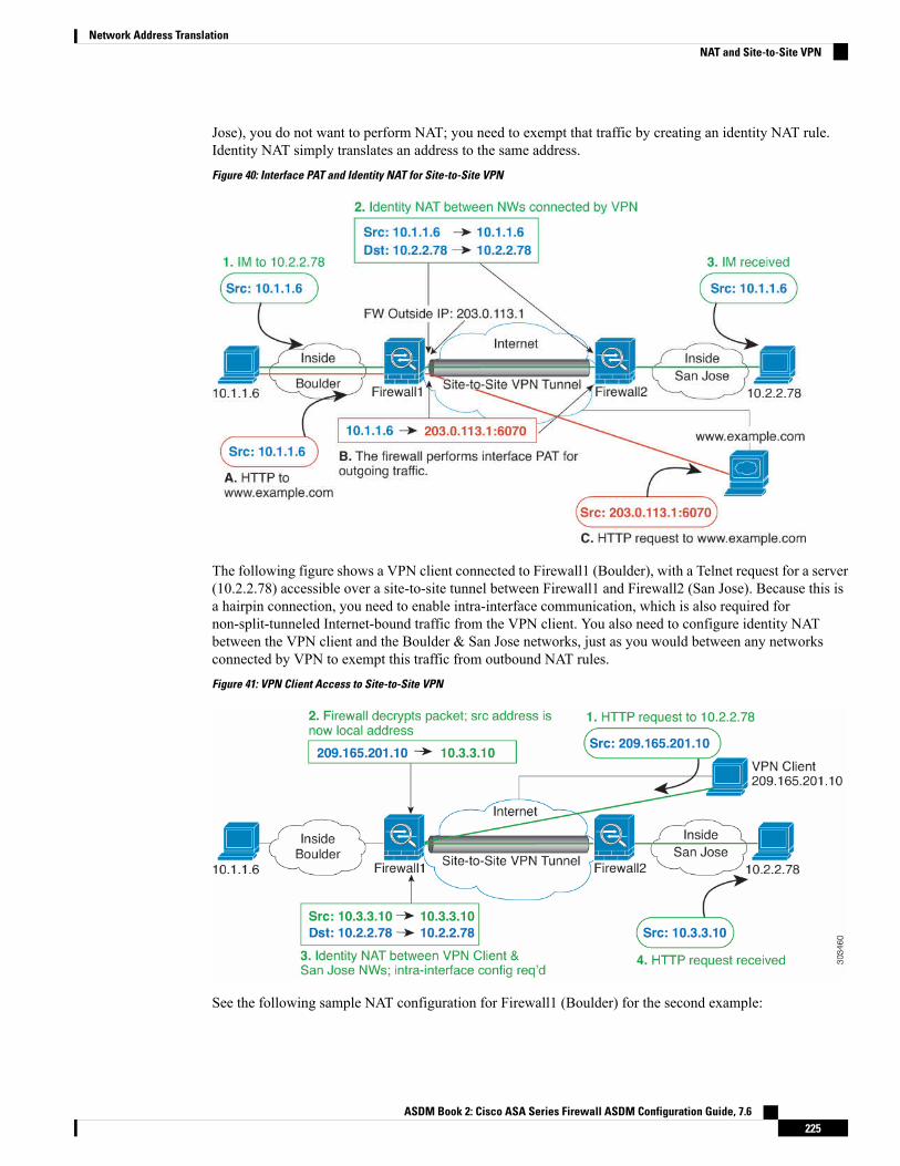
Jose), you do not want to perform NAT; you need to exempt that traffic by creating an identity NAT rule.Identity NAT simply translates an address to the same address.
Figure 40: Interface PAT and Identity NAT for Site-to-Site VPN
The following figure shows a VPN client connected to Firewall1 (Boulder), with a Telnet request for a server(10.2.2.78) accessible over a site-to-site tunnel between Firewall1 and Firewall2 (San Jose). Because this isa hairpin connection, you need to enable intra-interface communication, which is also required fornon-split-tunneled Internet-bound traffic from the VPN client. You also need to configure identity NATbetween the VPN client and the Boulder & San Jose networks, just as you would between any networksconnected by VPN to exempt this traffic from outbound NAT rules.
Figure 41: VPN Client Access to Site-to-Site VPN
See the following sample NAT configuration for Firewall1 (Boulder) for the second example:
ASDM Book 2: Cisco ASA Series Firewall ASDM Configuration Guide, 7.6225
Network Address TranslationNAT and Site-to-Site VPN

! Enable hairpin for VPN client traffic:same-security-traffic permit intra-interface
! Identify local VPN network, & perform object interface PAT when going to Internet:object network vpn_localsubnet 10.3.3.0 255.255.255.0nat (outside,outside) dynamic interface
! Identify inside Boulder network, & perform object interface PAT when going to Internet:object network boulder_insidesubnet 10.1.1.0 255.255.255.0nat (inside,outside) dynamic interface
! Identify inside San Jose network for use in twice NAT rule:object network sanjose_insidesubnet 10.2.2.0 255.255.255.0
! Use twice NAT to pass traffic between the Boulder network and the VPN client without! address translation (identity NAT):nat (inside,outside) source static boulder_inside boulder_insidedestination static vpn_local vpn_local
! Use twice NAT to pass traffic between the Boulder network and San Jose without! address translation (identity NAT):nat (inside,outside) source static boulder_inside boulder_insidedestination static sanjose_inside sanjose_inside
! Use twice NAT to pass traffic between the VPN client and San Jose without! address translation (identity NAT):nat (outside,outside) source static vpn_local vpn_localdestination static sanjose_inside sanjose_inside
See the following sample NAT configuration for Firewall2 (San Jose):
! Identify inside San Jose network, & perform object interface PAT when going to Internet:object network sanjose_insidesubnet 10.2.2.0 255.255.255.0nat (inside,outside) dynamic interface
! Identify inside Boulder network for use in twice NAT rule:object network boulder_insidesubnet 10.1.1.0 255.255.255.0
! Identify local VPN network for use in twice NAT rule:object network vpn_localsubnet 10.3.3.0 255.255.255.0
! Use twice NAT to pass traffic between the San Jose network and Boulder without! address translation (identity NAT):nat (inside,outside) source static sanjose_inside sanjose_insidedestination static boulder_inside boulder_inside
! Use twice NAT to pass traffic between the San Jose network and the VPN client without! address translation (identity NAT):nat (inside,outside) source static sanjose_inside sanjose_insidedestination static vpn_local vpn_local
ASDM Book 2: Cisco ASA Series Firewall ASDM Configuration Guide, 7.6226
Network Address TranslationNAT and Site-to-Site VPN
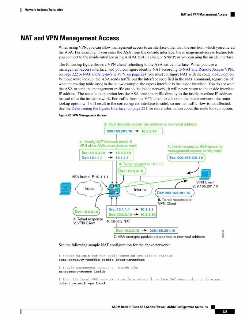
NAT and VPN Management AccessWhen using VPN, you can allowmanagement access to an interface other than the one fromwhich you enteredthe ASA. For example, if you enter the ASA from the outside interface, the management-access feature letsyou connect to the inside interface using ASDM, SSH, Telnet, or SNMP; or you can ping the inside interface.
The following figure shows a VPN client Telnetting to the ASA inside interface. When you use amanagement-access interface, and you configure identity NAT according to NAT and Remote Access VPN,on page 222 or NAT and Site-to-Site VPN, on page 224, you must configure NATwith the route lookup option.Without route lookup, the ASA sends traffic out the interface specified in the NAT command, regardless ofwhat the routing table says; in the below example, the egress interface is the inside interface. You do not wantthe ASA to send the management traffic out to the inside network; it will never return to the inside interfaceIP address. The route lookup option lets the ASA send the traffic directly to the inside interface IP addressinstead of to the inside network. For traffic from the VPN client to a host on the inside network, the routelookup option will still result in the correct egress interface (inside), so normal traffic flow is not affected.See the Determining the Egress Interface, on page 221 for more information about the route lookup option.
Figure 42: VPN Management Access
See the following sample NAT configuration for the above network:
! Enable hairpin for non-split-tunneled VPN client traffic:same-security-traffic permit intra-interface
! Enable management access on inside ifc:management-access inside
! Identify local VPN network, & perform object interface PAT when going to Internet:object network vpn_local
ASDM Book 2: Cisco ASA Series Firewall ASDM Configuration Guide, 7.6227
Network Address TranslationNAT and VPN Management Access

subnet 10.3.3.0 255.255.255.0nat (outside,outside) dynamic interface
! Identify inside network, & perform object interface PAT when going to Internet:object network inside_nwsubnet 10.1.1.0 255.255.255.0nat (inside,outside) dynamic interface
! Use twice NAT to pass traffic between the inside network and the VPN client without! address translation (identity NAT), w/route-lookup:nat (outside,inside) source static vpn_local vpn_localdestination static inside_nw inside_nw route-lookup
Troubleshooting NAT and VPNSee the following monitoring tools for troubleshooting NAT issues with VPN:
• Packet tracer—When used correctly, a packet tracer shows which NAT rules a packet is hitting.
• show nat detail—Shows hit counts and untranslated traffic for a given NAT rule.
• show conn all—Lets you see active connections including to and from the box traffic.
To familiarize yourself with a non-working configuration vs. a working configuration, you can perform thefollowing steps:
1. Configure VPN without identity NAT.
2. Enter show nat detail and show conn all.
3. Add the identity NAT configuration.
4. Repeat show nat detail and show conn all.
Translating IPv6 NetworksIn cases where you need to pass traffic between IPv6-only and IPv4-only networks, you need to use NAT toconvert between the address types. Even with two IPv6 networks, you might want to hide internal addressesfrom the outside network.
You can use the following translation types with IPv6 networks:
• NAT64, NAT46—Translates IPv6 packets into IPv4 and vice versa. You need to define two policies,one for the IPv6 to IPv4 translation, and one for the IPv4 to IPv6 translation. Although you can accomplishthis with a single twice NAT rule, if the DNS server is on the external network, you probably need torewrite the DNS response. Because you cannot enable DNS rewrite on a twice NAT rule when youspecify a destination, creating two network object NAT rules is the better solution.
NAT46 supports static mappings only.Note
• NAT66—Translates IPv6 packets to a different IPv6 address.We recommend using static NAT. Althoughyou can use dynamic NAT or PAT, IPv6 addresses are in such large supply, you do not have to usedynamic NAT.
ASDM Book 2: Cisco ASA Series Firewall ASDM Configuration Guide, 7.6228
Network Address TranslationTroubleshooting NAT and VPN

NAT64 and NAT 46 are possible on standard routed interfaces only. NAT66 is possible on both routed andbridge group member interfaces.
Note
NAT64/46: Translating IPv6 Addresses to IPv4When traffic goes from an IPv6 network to an IPv4-only network, you need to convert the IPv6 address toIPv4, and return traffic from IPv4 to IPv6. You need to define two address pools, an IPv4 address pool tobind IPv6 addresses in the IPv4 network, and an IPv6 address pool to bind IPv4 addresses in the IPv6 network.
• The IPv4 address pool for the NAT64 rule is normally small and typicallymight not have enough addressesto map one-to-one with the IPv6 client addresses. Dynamic PAT might more easily meet the possiblelarge number of IPv6 client addresses compared to dynamic or static NAT.
• The IPv6 address pool for the NAT46 rule can be equal to or larger than the number of IPv4 addressesto be mapped. This allows each IPv4 address to be mapped to a different IPv6 address. NAT46 supportsstatic mappings only, so you cannot use dynamic PAT.
You need to define two policies, one for the source IPv6 network, and one for the destination IPv4 network.Although you can accomplish this with a single twice NAT rule, if the DNS server is on the external network,you probably need to rewrite the DNS response. Because you cannot enable DNS rewrite on a twice NATrule when you specify a destination, creating two network object NAT rules is the better solution.
NAT64/46 Example: Inside IPv6 Network with Outside IPv4 InternetFollowing is a straight-forward example where you have an inside IPv6-only network, and you want to convertto IPv4 for traffic sent to the Internet. This example assumes you do not need DNS translation, so you canperform both the NAT64 and NAT46 translations in a single twice NAT rule.
In this example, you translate the inside IPv6 network to IPv4 using dynamic interface PATwith the IP addressof the outside interface. Outside IPv4 traffic is statically translated to addresses on the 2001:db8::/96 network,allowing transmission on the inside network.
ASDM Book 2: Cisco ASA Series Firewall ASDM Configuration Guide, 7.6229
Network Address TranslationNAT64/46: Translating IPv6 Addresses to IPv4
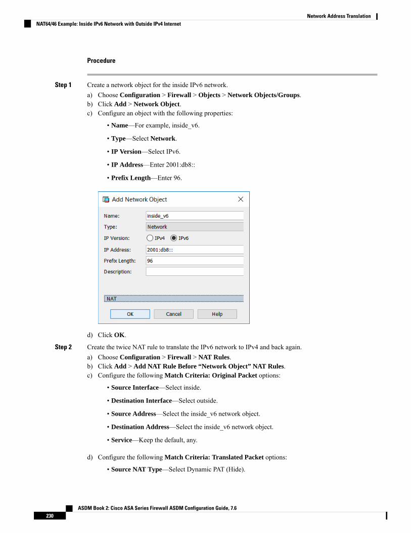
Procedure
Step 1 Create a network object for the inside IPv6 network.a) Choose Configuration > Firewall > Objects > Network Objects/Groups.b) Click Add > Network Object.c) Configure an object with the following properties:
• Name—For example, inside_v6.
• Type—Select Network.
• IP Version—Select IPv6.
• IP Address—Enter 2001:db8::
• Prefix Length—Enter 96.
d) Click OK.
Step 2 Create the twice NAT rule to translate the IPv6 network to IPv4 and back again.a) Choose Configuration > Firewall > NAT Rules.b) Click Add > Add NAT Rule Before “Network Object” NAT Rules.c) Configure the following Match Criteria: Original Packet options:
• Source Interface—Select inside.
• Destination Interface—Select outside.
• Source Address—Select the inside_v6 network object.
• Destination Address—Select the inside_v6 network object.
• Service—Keep the default, any.
d) Configure the following Match Criteria: Translated Packet options:
• Source NAT Type—Select Dynamic PAT (Hide).
ASDM Book 2: Cisco ASA Series Firewall ASDM Configuration Guide, 7.6230
Network Address TranslationNAT64/46 Example: Inside IPv6 Network with Outside IPv4 Internet
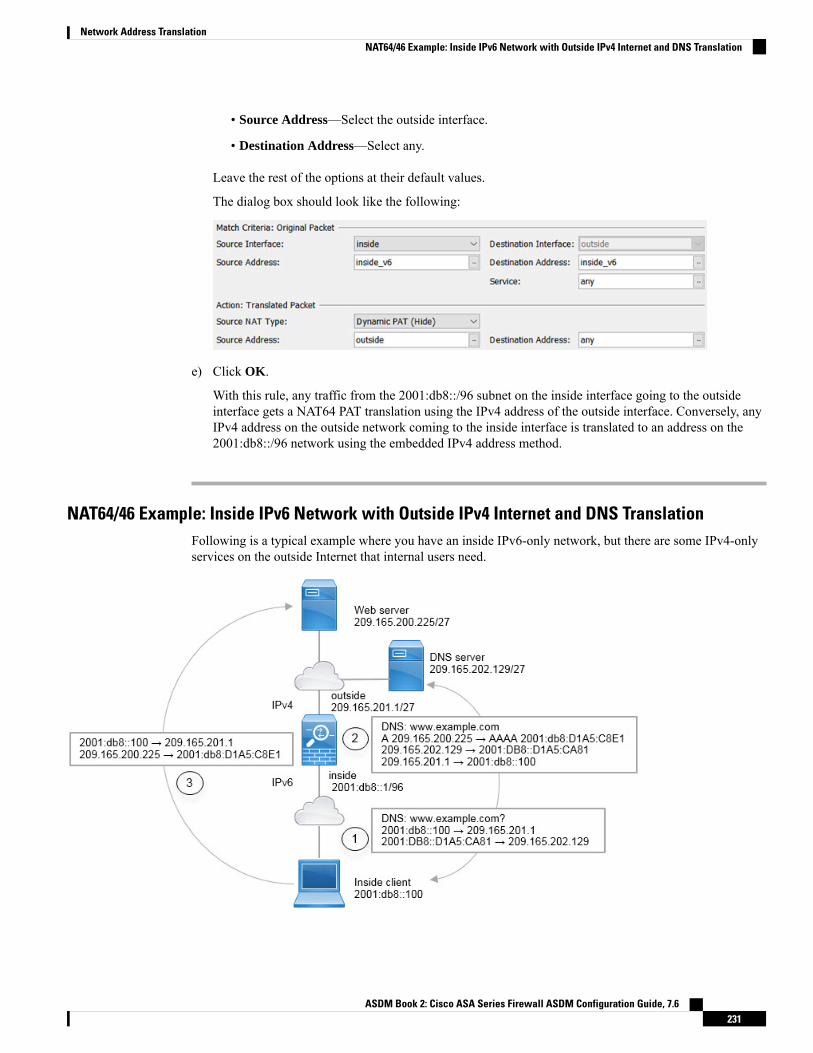
• Source Address—Select the outside interface.
• Destination Address—Select any.
Leave the rest of the options at their default values.
The dialog box should look like the following:
e) Click OK.
With this rule, any traffic from the 2001:db8::/96 subnet on the inside interface going to the outsideinterface gets a NAT64 PAT translation using the IPv4 address of the outside interface. Conversely, anyIPv4 address on the outside network coming to the inside interface is translated to an address on the2001:db8::/96 network using the embedded IPv4 address method.
NAT64/46 Example: Inside IPv6 Network with Outside IPv4 Internet and DNS TranslationFollowing is a typical example where you have an inside IPv6-only network, but there are some IPv4-onlyservices on the outside Internet that internal users need.
ASDM Book 2: Cisco ASA Series Firewall ASDM Configuration Guide, 7.6231
Network Address TranslationNAT64/46 Example: Inside IPv6 Network with Outside IPv4 Internet and DNS Translation

In this example, you translate the inside IPv6 network to IPv4 using dynamic interface PATwith the IP addressof the outside interface. Outside IPv4 traffic is statically translated to addresses on the 2001:db8::/96 network,allowing transmission on the inside network. You enable DNS rewrite on the NAT46 rule, so that replies fromthe external DNS server can be converted fromA (IPv4) to AAAA (IPv6) records, and the addresses convertedfrom IPv4 to IPv6.
Following is a typical sequence for a web request where a client at 2001:DB8::100 on the internal IPv6 networktries to open www.example.com.
1. The client’s computer sends a DNS request to the DNS server at 2001:DB8::D1A5:CA81. The NAT rulesmake the following translations to the source and destination in the DNS request:
• 2001:DB8::100 to a unique port on 209.165.201.1 (The NAT64 interface PAT rule.)
• 2001:DB8::D1A5:CA81 to 209.165.202.129 (The NAT46 rule. D1A5:CA81 is the IPv6 equivalentof 209.165.202.129.)
2. The DNS server responds with an A record indicating that www.example.com is at 209.165.200.225. TheNAT46 rule, with DNS rewrite enabled, converts the A record to the IPv6-equivalent AAAA record, andtranslates 209.165.200.225 to 2001:db8:D1A5:C8E1in the AAAA record. In addition, the source anddestination addresses in the DNS response are untranslated:
• 209.165.202.129 to 2001:DB8::D1A5:CA81
• 209.165.201.1 to 2001:db8::100
3. The IPv6 client now has the IP address of the web server, andmakes anHTTP request to www.example.comat 2001:db8:D1A5:C8E1. (D1A5:C8E1 is the IPv6 equivalent of 209.165.200.225.) The source anddestination of the HTTP request are translated:
• 2001:DB8::100 to a unique port on 209.156.101.54 (The NAT64 interface PAT rule.)
• 2001:db8:D1A5:C8E1 to 209.165.200.225 (The NAT46 rule.)
The following procedure explains how to configure this example.
Procedure
Step 1 Choose Configuration > Firewall > NAT Rules.Step 2 Configure the NAT64 dynamic PAT rule for the inside IPv6 network.
a) Choose Add > Network Object NAT Rule.b) Configure the basic object properties:
• Name—For example, inside_v6.
• Type—Select Network.
• IP Version—Select IPv6.
• IP Address—Enter 2001:db8::.
• Prefix Length—Enter 96.
c) Select Dynamic or Dynamic PAT (Hide) for NAT Type.
ASDM Book 2: Cisco ASA Series Firewall ASDM Configuration Guide, 7.6232
Network Address TranslationNAT64/46 Example: Inside IPv6 Network with Outside IPv4 Internet and DNS Translation
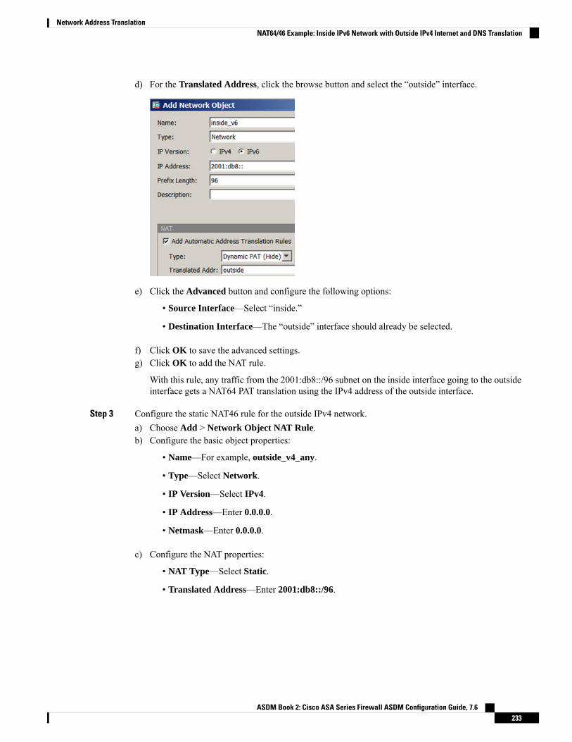
d) For the Translated Address, click the browse button and select the “outside” interface.
e) Click the Advanced button and configure the following options:
• Source Interface—Select “inside.”
• Destination Interface—The “outside” interface should already be selected.
f) Click OK to save the advanced settings.g) Click OK to add the NAT rule.
With this rule, any traffic from the 2001:db8::/96 subnet on the inside interface going to the outsideinterface gets a NAT64 PAT translation using the IPv4 address of the outside interface.
Step 3 Configure the static NAT46 rule for the outside IPv4 network.a) Choose Add > Network Object NAT Rule.b) Configure the basic object properties:
• Name—For example, outside_v4_any.
• Type—Select Network.
• IP Version—Select IPv4.
• IP Address—Enter 0.0.0.0.
• Netmask—Enter 0.0.0.0.
c) Configure the NAT properties:
• NAT Type—Select Static.
• Translated Address—Enter 2001:db8::/96.
ASDM Book 2: Cisco ASA Series Firewall ASDM Configuration Guide, 7.6233
Network Address TranslationNAT64/46 Example: Inside IPv6 Network with Outside IPv4 Internet and DNS Translation

d) Click the Advanced button and configure the following options:
• Translate DNS Replies for Rule—Select this option.
• Source Interface—Select “outside.”
• Destination Interface—Select “inside.”
e) Click OK to save the advanced settings.f) Click OK to add the NAT rule.
With this rule, any IPv4 address on the outside network coming to the inside interface is translated to anaddress on the 2001:db8::/96 network using the embedded IPv4 addressmethod. In addition, DNS responsesare converted from A (IPv4) to AAAA (IPv6) records, and the addresses converted from IPv4 to IPv6.
NAT66: Translating IPv6 Addresses to Different IPv6 AddressesWhen going from an IPv6 network to another IPv6 network, you can translate the addresses to different IPv6addresses on the outside network. We recommend using static NAT. Although you can use dynamic NAT orPAT, IPv6 addresses are in such large supply, you do not have to use dynamic NAT.
ASDM Book 2: Cisco ASA Series Firewall ASDM Configuration Guide, 7.6234
Network Address TranslationNAT66: Translating IPv6 Addresses to Different IPv6 Addresses

Because you are not translating between different address types, you need a single rule for NAT66 translations.You can easily model these rules using network object NAT. However, if you do not want to allow returningtraffic, you can make the static NAT rule unidirectional using twice NAT only.
NAT66 Example, Static Translation between NetworksYou can configure a static translation between IPv6 address pools using network object NAT. The followingexample explains how to convert inside addresses on the 2001:db8:122:2091::/96 network to outside addresseson the 2001:db8:122:2999::/96 network.
Procedure
Step 1 Choose Configuration > Firewall > NAT Rules.Step 2 Configure the static NAT rule for the inside IPv6 network.
a) Choose Add > Network Object NAT Rule.b) Configure the basic object properties:
• Name—For example, inside_v6.
• Type—Select Network.
• IP Version—Select IPv6.
• IP Address—Enter 2001:db8:122:2091::.
• Prefix Length—Enter 96.
c) Select Static for NAT Type.d) For the Translated Address, enter 2001:db8:122:2999::/96.
ASDM Book 2: Cisco ASA Series Firewall ASDM Configuration Guide, 7.6235
Network Address TranslationNAT66 Example, Static Translation between Networks

e) Click the Advanced button and configure the following options:
• Source Interface—Select “inside.”
• Destination Interface—Select “outside.”
f) Click OK to save the advanced settings.g) Click OK to add the NAT rule.
With this rule, any traffic from the 2001:db8:122:2091::/96 subnet on the inside interface going to theoutside interface gets a static NAT66 translation to an address on the 2001:db8:122:2999::/96 network.
NAT66 Example, Simple IPv6 Interface PATA simple approach for implementing NAT66 is to dynamically assign internal addresses to different ports onthe outside interface IPv6 address.
When you configure an interface PAT rule for NAT66, all the global addresses that are configured on thatinterface are used for PAT mapping. Link-local or site-local addresses for the interface are not used for PAT.
ASDM Book 2: Cisco ASA Series Firewall ASDM Configuration Guide, 7.6236
Network Address TranslationNAT66 Example, Simple IPv6 Interface PAT

Procedure
Step 1 Choose Configuration > Firewall > NAT Rules.Step 2 Configure the dynamic PAT rule for the inside IPv6 network.
a) Choose Add > Network Object NAT Rule.b) Configure the basic object properties:
• Name—For example, inside_v6.
• Type—Select Network.
• IP Version—Select IPv6.
• IP Address—Enter 2001:db8:122:2091::.
• Prefix Length—Enter 96.
c) Select Dynamic or Dynamic PAT (Hide) for NAT Type.d) For the Translated Address, click the browse button and select the “outside” interface.e) Select the Use IPv6 for Interface PAT option.
ASDM Book 2: Cisco ASA Series Firewall ASDM Configuration Guide, 7.6237
Network Address TranslationNAT66 Example, Simple IPv6 Interface PAT

f) Click the Advanced button and configure the following options:
• Source Interface—Select “inside.”
• Destination Interface—The “outside” interface should already be selected.
g) Click OK to save the advanced settings.h) Click OK to add the NAT rule.
With this rule, any traffic from the 2001:db8:122:2091::/96 subnet on the inside interface going to theoutside interface gets a NAT66 PAT translation to one of the IPv6 global addresses configured for theoutside interface.
Rewriting DNS Queries and Responses Using NATYou might need to configure the ASA to modify DNS replies by replacing the address in the reply with anaddress that matches the NAT configuration. You can configure DNS modification when you configure eachtranslation rule. DNS modification is also known as DNS doctoring.
ASDM Book 2: Cisco ASA Series Firewall ASDM Configuration Guide, 7.6238
Network Address TranslationRewriting DNS Queries and Responses Using NAT

This feature rewrites the address in DNS queries and replies that match a NAT rule (for example, the A recordfor IPv4, the AAAA record for IPv6, or the PTR record for reverse DNS queries). For DNS replies traversingfrom amapped interface to any other interface, the record is rewritten from the mapped value to the real value.Inversely, for DNS replies traversing from any interface to a mapped interface, the record is rewritten fromthe real value to the mapped value. This feature works with NAT44,NAT 66, NAT46, and NAT64.
Following are the main circumstances when you would need to configure DNS rewrite on a NAT rule.
• The rule is NAT64 or NAT46, and the DNS server is on the outside network. You need DNS rewrite toconvert between DNS A records (for IPv4) and AAAA records (for IPv6).
• The DNS server is on the outside, clients are on the inside, and some of the fully-qualified domain namesthat the clients use resolve to other inside hosts.
• The DNS server is on the inside and responds with private IP addresses, clients are on the outside, andthe clients access fully-qualified domain names that point to servers that are hosted on the inside.
DNS Rewrite Limitations
Following are some limitations with DNS rewrite:
• DNS rewrite is not applicable for PAT because multiple PAT rules are applicable for each A or AAAArecord, and the PAT rule to use is ambiguous.
• If you configure a twice NAT rule, you cannot configure DNSmodification if you specify the destinationaddress as well as the source address. These kinds of rules can potentially have a different translationfor a single address when going to A vs. B. Therefore, the can not accurately match the IP address insidethe DNS reply to the correct twice NAT rule; the DNS reply does not contain information about whichsource/destination address combination was in the packet that prompted the DNS request.
• You must enable DNS application inspection with DNS NAT rewrite enabled for NAT rules to rewriteDNS queries and responses. By default, DNS inspection with DNS NAT rewrite enabled is globallyapplied, so you probably do not need to change the inspection configuration.
• DNS rewrite is actually done on the xlate entry, not the NAT rule. Thus, if there is no xlate for a dynamicrule, rewrite cannot be done correctly. The same problem does not occur for static NAT.
• DNS rewrite does not rewrite DNS Dynamic Update messages (opcode 5).
The following topics provide examples of DNS rewrite in NAT rules.
DNS Reply Modification, DNS Server on OutsideThe following figure shows a DNS server that is accessible from the outside interface. A server, ftp.cisco.com,is on the inside interface. You configure NAT to statically translate the ftp.cisco.com real address (10.1.3.14)to a mapped address (209.165.201.10) that is visible on the outside network.
In this case, you want to enable DNS reply modification on this static rule so that inside users who have accessto ftp.cisco.com using the real address receive the real address from the DNS server, and not the mappedaddress.
When an inside host sends a DNS request for the address of ftp.cisco.com, the DNS server replies with themapped address (209.165.201.10). The system refers to the static rule for the inside server and translates theaddress inside the DNS reply to 10.1.3.14. If you do not enable DNS reply modification, then the inside hostattempts to send traffic to 209.165.201.10 instead of accessing ftp.cisco.com directly.
ASDM Book 2: Cisco ASA Series Firewall ASDM Configuration Guide, 7.6239
Network Address TranslationDNS Reply Modification, DNS Server on Outside

Procedure
Step 1 Choose Configuration > Firewall > NAT.Step 2 Choose Add > Network Object NAT Rule.Step 3 Name the new network object, define the FTP server address, enable static NAT and enter the translated
address.
ASDM Book 2: Cisco ASA Series Firewall ASDM Configuration Guide, 7.6240
Network Address TranslationDNS Reply Modification, DNS Server on Outside

Step 4 Click Advanced and configure the real and mapped interfaces and DNS modification.
Step 5 Click OK to return to the Edit Network Object dialog box, click OK again, and then click Apply.
DNS Reply Modification, DNS Server, Host, and Server on Separate NetworksThe following figure shows a user on the inside network requesting the IP address for ftp.cisco.com, whichis on the DMZ network, from an outside DNS server. The DNS server replies with the mapped address(209.165.201.10) according to the static rule between outside and DMZ even though the user is not on theDMZ network. The ASA translates the address inside the DNS reply to 10.1.3.14.
If the user needs to access ftp.cisco.com using the real address, then no further configuration is required. Ifthere is also a static rule between the inside and DMZ, then you also need to enable DNS reply modificationon this rule. The DNS reply will then be modified two times.In this case, the ASA again translates the addressinside the DNS reply to 192.168.1.10 according to the static rule between inside and DMZ.
ASDM Book 2: Cisco ASA Series Firewall ASDM Configuration Guide, 7.6241
Network Address TranslationDNS Reply Modification, DNS Server, Host, and Server on Separate Networks

Figure 43: DNS Reply Modification, DNS Server, Host, and Server on Separate Networks
DNS Reply Modification, DNS Server on Host NetworkThe following figure shows an FTP server and DNS server on the outside. The system has a static translationfor the outside server. In this case, when an inside user requests the address for ftp.cisco.com from the DNSserver, the DNS server responds with the real address, 209.165.20.10. Because you want inside users to usethe mapped address for ftp.cisco.com (10.1.2.56) you need to configure DNS reply modification for the statictranslation.
ASDM Book 2: Cisco ASA Series Firewall ASDM Configuration Guide, 7.6242
Network Address TranslationDNS Reply Modification, DNS Server on Host Network

Procedure
Step 1 Choose Configuration > Firewall > NAT.Step 2 Choose Add > Network Object NAT Rule.Step 3 Name the new network object, define the FTP server address, enable static NAT and enter the translated
address.
ASDM Book 2: Cisco ASA Series Firewall ASDM Configuration Guide, 7.6243
Network Address TranslationDNS Reply Modification, DNS Server on Host Network

Step 4 Click Advanced and configure the real and mapped interfaces and DNS modification.
Step 5 Click OK to return to the Edit Network Object dialog box, click OK again, and then click Apply.
DNS64 Reply ModificationThe following figure shows an FTP server and DNS server on the outside IPv4 network. The system has astatic translation for the outside server. In this case, when an inside IPv6 user requests the address forftp.cisco.com from the DNS server, the DNS server responds with the real address, 209.165.200.225.
Because you want inside users to use the mapped address for ftp.cisco.com (2001:DB8::D1A5:C8E1, whereD1A5:C8E1 is the IPv6 equivalent of 209.165.200.225) you need to configure DNS reply modification forthe static translation. This example also includes a static NAT translation for the DNS server, and a PAT rulefor the inside IPv6 hosts.
ASDM Book 2: Cisco ASA Series Firewall ASDM Configuration Guide, 7.6244
Network Address TranslationDNS64 Reply Modification

Procedure
Step 1 Choose Configuration > Firewall > NAT.Step 2 Configure static network object NAT with DNS modification for the FTP server.
a) Choose Add > Network Object NAT Rule.b) Name the new network object, define the FTP server address, enable static NAT, and enter the translated
address. Because this is a one-to-one translation for NAT46, select Use one-to-one address translation.
ASDM Book 2: Cisco ASA Series Firewall ASDM Configuration Guide, 7.6245
Network Address TranslationDNS64 Reply Modification

c) Click Advanced to configure the real and mapped interfaces and DNS modification.
d) Click OK to return to the Network Object dialog box, and click OK again to save the rule.
Step 3 Configure static network object NAT for the DNS server.
ASDM Book 2: Cisco ASA Series Firewall ASDM Configuration Guide, 7.6246
Network Address TranslationDNS64 Reply Modification

a) Choose Add > Network Object NAT Rule.b) Name the new network object, define the DNS server address, enable static NAT, and enter the translated
address. Because this is a one-to-one translation for NAT46, select Use one-to-one address translation.
c) Click Advanced to configure the real and mapped interfaces.
ASDM Book 2: Cisco ASA Series Firewall ASDM Configuration Guide, 7.6247
Network Address TranslationDNS64 Reply Modification

d) Click OK to return to the Network Object dialog box, and click OK again to save the rule.
Step 4 Configure PAT for the inside IPv6 network.a) Choose Add > Network Object NAT Rule.b) Name the new network object, define the IPv6 network address, and select Dynamic NAT.c) Select PAT Pool Translated Address, and click the ... (browse) button to create the PAT pool object.d) In the Browse PAT Pool Translated Address dialog box, select Add > Network Object. Name the new
object, enter the address range for the PAT pool, and click OK.
e) In the Browse PAT Pool Translated Address dialog box, double-click the PAT pool object you createdto select it and click OK.
f) Click Advanced to configure the real and mapped interfaces.
g) Click OK to return to the Network Object dialog box.
ASDM Book 2: Cisco ASA Series Firewall ASDM Configuration Guide, 7.6248
Network Address TranslationDNS64 Reply Modification

Step 5 Click OK, and then click Apply.
PTR Modification, DNS Server on Host NetworkThe following figure shows an FTP server and DNS server on the outside. The ASA has a static translationfor the outside server. In this case, when an inside user performs a reverse DNS lookup for 10.1.2.56, theASA modifies the reverse DNS query with the real address, and the DNS server responds with the servername, ftp.cisco.com.
ASDM Book 2: Cisco ASA Series Firewall ASDM Configuration Guide, 7.6249
Network Address TranslationPTR Modification, DNS Server on Host Network

Figure 44: PTR Modification, DNS Server on Host Network
ASDM Book 2: Cisco ASA Series Firewall ASDM Configuration Guide, 7.6250
Network Address TranslationPTR Modification, DNS Server on Host Network

P A R T IIIService Policies and Application Inspection
• Service Policy, on page 253• Getting Started with Application Layer Protocol Inspection, on page 269• Inspection of Basic Internet Protocols, on page 287• Inspection for Voice and Video Protocols, on page 319• Inspection for Mobile Networks, on page 339

C H A P T E R 10Service Policy
Service policies provide a consistent and flexible way to configure ASA features. For example, you can usea service policy to create a timeout configuration that is specific to a particular TCP application, as opposedto one that applies to all TCP applications. A service policy consists of multiple actions or rules applied to aninterface or applied globally.
• About Service Policies, on page 253• Guidelines for Service Policies, on page 259• Defaults for Service Policies, on page 260• Configure Service Policies, on page 261• History for Service Policies, on page 267
About Service PoliciesThe following topics describe how service policies work.
The Components of a Service PolicyThe point of service policies is to apply advanced services to the traffic you are allowing. Any traffic permittedby access rules can have service policies applied, and thus receive special processing, such as being redirectedto a service module or having application inspection applied.
You can have these types of service policy:
• One global policy that gets applied to all interfaces.
• One service policy applied per interface. The policy can be a mix of classes for traffic going through thedevice and management traffic directed at the ASA interface rather than going through it,
Each service policy is composed of the following elements:
1. Service policy map, which is the ordered set of rules, and is named on the service-policy command. InASDM, the policy map is represented as a folder on the Service Policy Rules page.
2. Rules, each rule being a class command within the service policy map and the commands associated withthe class command. In ASDM, each rule is shown on a separate row, and the name of the rule is the classname.
The class command defines the traffic matching criteria for the rule.
ASDM Book 2: Cisco ASA Series Firewall ASDM Configuration Guide, 7.6253

The commands associated with class, such as inspect, set connection timeout, and so forth, define theservices and constraints to apply to matching traffic. Note that inspect commands can point to inspectionpolicy maps, which define actions to apply to inspected traffic. Keep in mind that inspection policy mapsare not the same as service policy maps.
The following example compares how service policies appear in the CLI with how they appear in ASDM.Note that there is not a one-to-one mapping between the figure call-outs and lines in the CLI.
The following CLI is generated by the rules shown in the figure above.
: Access lists used in class maps.: In ASDM, these map to call-out 3, from the Match to the Time fields.access-list inside_mpc line 1 extended permit tcp 10.100.10.0 255.255.255.0 any eq sipaccess-list inside_mpc_1 line 1 extended deny udp host 10.1.1.15 any eq snmpaccess-list inside_mpc_1 line 2 extended permit udp 10.1.1.0 255.255.255.0 any eq snmpaccess-list inside_mpc_2 line 1 extended permit icmp any any: SNMP map for SNMP inspection. Denies all but v3.: In ASDM, this maps to call-out 4, rule actions, for the class-inside policy.snmp-map snmp-v3onlydeny version 1deny version 2deny version 2c
: Inspection policy map to define SIP behavior.: The sip-high inspection policy map must be referred to by an inspect sip command: in the service policy map.: In ASDM, this maps to call-out 4, rule actions, for the sip-class-inside policy.policy-map type inspect sip sip-highparametersrtp-conformance enforce-payloadtypeno traffic-non-sipsoftware-version action mask loguri-non-sip action mask logstate-checking action drop-connection logmax-forwards-validation action drop logstrict-header-validation action drop log
: Class map to define traffic matching for the inside-class rule.: In ASDM, this maps to call-out 3, from the Match to the Time fields.class-map inside-classmatch access-list inside_mpc_1
: Class map to define traffic matching for the sip-class-inside rule.: In ASDM, this maps to call-out 3, from the Match to the Time fields.class-map sip-class-insidematch access-list inside_mpc
: Class map to define traffic matching for the inside-class1 rule.: In ASDM, this maps to call-out 3, from the Match to the Time fields.class-map inside-class1match access-list inside_mpc_2
ASDM Book 2: Cisco ASA Series Firewall ASDM Configuration Guide, 7.6254
Service Policies and Application InspectionThe Components of a Service Policy

: Policy map that actually defines the service policy rule set named test-inside-policy.: In ASDM, this corresponds to the folder at call-out 1.policy-map test-inside-policy: First rule in test-inside-policy, named sip-class-inside. Inspects SIP traffic.: The sip-class-inside rule applies the sip-high inspection policy map to SIP inspection.: In ASDM, each rule corresponds to call-out 2.class sip-class-insideinspect sip sip-high
: Second rule, inside-class. Applies SNMP inspection using an SNMP map.class inside-classinspect snmp snmp-v3only
: Third rule, inside-class1. Applies ICMP inspection.class inside-class1inspect icmp
: Fourth rule, class-default. Applies connection settings and enables user statistics.class class-defaultset connection timeout embryonic 0:00:30 half-closed 0:10:00 idle 1:00:00
reset dcd 0:15:00 5user-statistics accounting
: The service-policy command applies the policy map rule set to the inside interface.: This command activates the policies.service-policy test-inside-policy interface inside
Features Configured with Service PoliciesThe following table lists the features you configure using service policies.
Table 10: Features Configured with Service Policies
See:For ManagementTraffic?
For ThroughTraffic?Feature
• Getting Started with Application Layer ProtocolInspection, on page 269.
• Inspection of Basic Internet Protocols, on page 287.
• Inspection for Voice and Video Protocols, on page319.
• Inspection for Mobile Networks, on page 339.
RADIUSaccounting only
All exceptRADIUSaccounting
Application inspection (multipletypes)
ASA FirePOWER Module, on page 93.NoYesASA FirePOWER (ASA SFR)
See the NetFlow implementation guide.YesYesNetFlow Secure Event Loggingfiltering
Quality of Service, on page 395.NoYesQoS input and output policing
Quality of Service, on page 395.NoYesQoS standard priority queue
Connection Settings, on page 373.YesYesTCP and UDP connection limitsand timeouts, and TCP sequencenumber randomization
Connection Settings, on page 373.NoYesTCP normalization
ASDM Book 2: Cisco ASA Series Firewall ASDM Configuration Guide, 7.6255
Service Policies and Application InspectionFeatures Configured with Service Policies

See:For ManagementTraffic?
For ThroughTraffic?Feature
Connection Settings, on page 373.NoYesTCP state bypass
See the user-statistics command in the commandreference.
YesYesUser statistics for Identity Firewall
Feature DirectionalityActions are applied to traffic bidirectionally or unidirectionally depending on the feature. For features thatare applied bidirectionally, all traffic that enters or exits the interface to which you apply the policy map isaffected if the traffic matches the class map for both directions.
When you use a global policy, all features are unidirectional; features that are normally bidirectional whenapplied to a single interface only apply to the ingress of each interface when applied globally. Because thepolicy is applied to all interfaces, the policy will be applied in both directions so bidirectionality in this caseis redundant.
Note
For features that are applied unidirectionally, for example QoS priority queue, only traffic that enters (or exits,depending on the feature) the interface to which you apply the policy map is affected. See the following tablefor the directionality of each feature.
Table 11: Feature Directionality
Global DirectionSingle Interface DirectionFeature
IngressBidirectionalApplication inspection (multiple types)
IngressBidirectionalASA FirePOWER (ASA SFR)
IngressN/ANetFlow Secure Event Logging filtering
IngressIngressQoS input policing
EgressEgressQoS output policing
EgressEgressQoS standard priority queue
IngressBidirectionalTCP and UDP connection limits and timeouts, andTCP sequence number randomization
IngressBidirectionalTCP normalization
IngressBidirectionalTCP state bypass
IngressBidirectionalUser statistics for Identity Firewall
ASDM Book 2: Cisco ASA Series Firewall ASDM Configuration Guide, 7.6256
Service Policies and Application InspectionFeature Directionality

Feature Matching Within a Service PolicyA packet matches rules in a policy for a given interface according to the following rules:
1. A packet can match only one rule for an interface for each feature type.
2. When the packet matches a rule for a feature type, the ASA does not attempt to match it to any subsequentrules for that feature type.
3. If the packet matches a subsequent rule for a different feature type, however, then the ASA also appliesthe actions for the subsequent rule, if supported. See Incompatibility of Certain Feature Actions, on page258 for more information about unsupported combinations.
Application inspection includes multiple inspection types, and most are mutually exclusive. For inspectionsthat can be combined, each inspection is considered to be a separate feature.
Note
Examples of Packet Matching
For example:
• If a packet matches a rule for connection limits, and also matches a rule for an application inspection,then both actions are applied.
• If a packet matches a rule for HTTP inspection, but also matches another rule that includes HTTPinspection, then the second rule actions are not applied.
• If a packet matches a rule for HTTP inspection, but also matches another rule that includes FTP inspection,then the second rule actions are not applied because HTTP and FTP inspections cannot be combined.
• If a packet matches a rule for HTTP inspection, but alsomatches another rule that includes IPv6 inspection,then both actions are applied because the IPv6 inspection can be combined with any other type ofinspection.
Order in Which Multiple Feature Actions are AppliedThe order in which different types of actions in a service policy are performed is independent of the order inwhich the actions appear in the table.
Actions are performed in the following order:
1. QoS input policing
2. TCP normalization, TCP and UDP connection limits and timeouts, TCP sequence number randomization,and TCP state bypass.
When a the ASA performs a proxy service (such as AAA) or it modifies the TCP payload (such as FTPinspection), the TCP normalizer acts in dual mode, where it is applied before and after the proxy or payloadmodifying service.
Note
3. Application inspections that can be combined with other inspections:
ASDM Book 2: Cisco ASA Series Firewall ASDM Configuration Guide, 7.6257
Service Policies and Application InspectionFeature Matching Within a Service Policy

a. IPv6
b. IP options
c. WAAS
4. Application inspections that cannot be combined with other inspections. See Incompatibility of CertainFeature Actions, on page 258 for more information.
5. ASA FirePOWER (ASA SFR)
6. QoS output policing
7. QoS standard priority queue
NetFlow Secure Event Logging filtering and User statistics for Identity Firewall are order-independent.Note
Incompatibility of Certain Feature ActionsSome features are not compatible with each other for the same traffic. The following list might not includeall incompatibilities; for information about compatibility of each feature, see the chapter or section for thefeature:
• You cannot configure QoS priority queuing and QoS policing for the same set of traffic.
• Most inspections should not be combined with another inspection, so the ASA only applies one inspectionif you configure multiple inspections for the same traffic. Exceptions are listed in Order inWhichMultipleFeature Actions are Applied, on page 257.
• You cannot configure traffic to be sent to multiple modules.
• HTTP inspection is not compatible with ASA FirePOWER.
The Default Inspection Traffic traffic class, which is used in the default global policy, is a special CLI shortcutto match the default ports for all inspections. When used in a policy map, this class map ensures that thecorrect inspection is applied to each packet, based on the destination port of the traffic. For example, whenUDP traffic for port 69 reaches the ASA, then the ASA applies the TFTP inspection; when TCP traffic forport 21 arrives, then the ASA applies the FTP inspection. So in this case only, you can configure multipleinspections for the same class map. Normally, the ASA does not use the port number to determine whichinspection to apply, thus giving you the flexibility to apply inspections to non-standard ports, for example.
Note
Feature Matching for Multiple Service PoliciesFor TCP and UDP traffic (and ICMP when you enable stateful ICMP inspection), service policies operate ontraffic flows, and not just individual packets. If traffic is part of an existing connection that matches a featurein a policy on one interface, that traffic flow cannot also match the same feature in a policy on another interface;only the first policy is used.
ASDM Book 2: Cisco ASA Series Firewall ASDM Configuration Guide, 7.6258
Service Policies and Application InspectionIncompatibility of Certain Feature Actions

For example, if HTTP traffic matches a policy on the inside interface to inspect HTTP traffic, and you havea separate policy on the outside interface for HTTP inspection, then that traffic is not also inspected on theegress of the outside interface. Similarly, the return traffic for that connection will not be inspected by theingress policy of the outside interface, nor by the egress policy of the inside interface.
For traffic that is not treated as a flow, for example ICMP when you do not enable stateful ICMP inspection,returning traffic can match a different policy map on the returning interface.
Guidelines for Service PoliciesInspection Guidelines
There is a separate topic that provides detailed guidelines for application inspection service policies. SeeGuidelines for Application Inspection, on page 271.
IPv6 Guidelines
Supports IPv6 for the following features:
• Application inspection for several, but not all, protocols. For details, see Guidelines for ApplicationInspection, on page 271.
• ASA FirePOWER
• NetFlow Secure Event Logging filtering
• SCTP state bypass
• TCP and UDP connection limits and timeouts, TCP sequence number randomization
• TCP normalization
• TCP state bypass
• User statistics for Identity Firewall
Class Map (Traffic Class) Guidelines
The maximum number of class maps (traffic classes) of all types is 255 in single mode or per context inmultiple mode. Class maps include the following types:
• Layer 3/4 class maps (for through traffic and management traffic).
• Inspection class maps
• Regular expression class maps
• match commands used directly underneath an inspection policy map
This limit also includes default class maps of all types, limiting user-configured class maps to approximately235.
ASDM Book 2: Cisco ASA Series Firewall ASDM Configuration Guide, 7.6259
Service Policies and Application InspectionGuidelines for Service Policies

Service Policy Guidelines
• Interface service policies on ingress interfaces take precedence over the global service policy for a givenfeature. For example, if you have a global policy with FTP inspection, and an interface policy with TCPnormalization, then both FTP inspection and TCP normalization are applied to the interface. However,if you have a global policy with FTP inspection, and an ingress interface policy with FTP inspection,then only the ingress interface policy FTP inspection is applied to that interface. If no ingress or globalpolicy implements a feature, then an interface service policy on the egress interface that specifies thefeature is applied.
• You can only apply one global policy. For example, you cannot create a global policy that includesfeature set 1, and a separate global policy that includes feature set 2. All features must be included in asingle policy.
• When you make service policy changes to the configuration, all new connections use the new servicepolicy. Existing connections continue to use the policy that was configured at the time of the connectionestablishment. Output for the show command will not include data about the old connections.
For example, if you remove a QoS service policy from an interface, then add a modified version, thenthe show service-policy command only displays QoS counters associated with new connections thatmatch the new service policy; existing connections on the old policy no longer show in the commandoutput.
To ensure that all connections use the new policy, you need to disconnect the current connections so theycan reconnect using the new policy. Use the clear conn or clear local-host commands.
Defaults for Service PoliciesThe following topics describe the default settings for service policies and the Modular Policy Framework.
Default Service Policy ConfigurationBy default, the configuration includes a policy that matches all default application inspection traffic and appliescertain inspections to the traffic on all interfaces (a global policy). Not all inspections are enabled by default.You can only apply one global policy, so if you want to alter the global policy, you need to either edit thedefault policy or disable it and apply a new one. (An interface policy overrides the global policy for a particularfeature.)
The default policy includes the following application inspections:
• DNS
• FTP
• H323 (H225)
• H323 (RAS)
• RSH
• RTSP
• ESMTP
• SQLnet
ASDM Book 2: Cisco ASA Series Firewall ASDM Configuration Guide, 7.6260
Service Policies and Application InspectionDefaults for Service Policies

• Skinny (SCCP)
• SunRPC
• SIP
• NetBios
• TFTP
• IP Options
Default Class Maps (Traffic Classes)The configuration includes a default Layer 3/4 class map (traffic class) that the ASA uses in the default globalpolicy called Default Inspection Traffic; it matches the default inspection traffic. This class, which is used inthe default global policy, is a special shortcut to match the default ports for all inspections.
When used in a policy, this class ensures that the correct inspection is applied to each packet, based on thedestination port of the traffic. For example, when UDP traffic for port 69 reaches the ASA, then the ASAapplies the TFTP inspection; when TCP traffic for port 21 arrives, then the ASA applies the FTP inspection.So in this case only, you can configure multiple inspections for the same class map. Normally, the ASA doesnot use the port number to determine which inspection to apply, thus giving you the flexibility to applyinspections to non-standard ports, for example.
Another class map that exists in the default configuration is called class-default, and it matches all traffic.You can use the class-default class if desired, rather than using the Any traffic class. In fact, some featuresare only available for class-default.
Configure Service PoliciesConfiguring a service policy consists of adding one or more service policy rules per interface or for the globalpolicy. ASDM uses a wizard to take you through the process of creating a service policy. For each rule, youidentify the following elements:
1. The interface to which you want to apply the rule, or the global policy.
2. The traffic to which you want to apply actions. You can identify Layer 3 and 4 traffic.
3. The actions to apply to the traffic class. You can apply multiple non-conflicting actions for each trafficclass.
After you create a policy, you can add rules, move, edit, or delete rules or policies. The following topicsexplain how to configure service policies.
Add a Service Policy Rule for Through TrafficTo add a service policy rule for through traffic, use the Add Service Policy Rule wizard. You will be askedto choose the scope of the policy, for a specific interface or global:
• Interface service policies take precedence over the global service policy for a given feature. For example,if you have a global policy with FTP inspection, and an interface policy with TCP connection limits,then both FTP inspection and TCP connection limits are applied to the interface. However, if you have
ASDM Book 2: Cisco ASA Series Firewall ASDM Configuration Guide, 7.6261
Service Policies and Application InspectionDefault Class Maps (Traffic Classes)

a global policy with FTP inspection, and an interface policy with FTP inspection, then only the interfacepolicy FTP inspection is applied to that interface.
• Global service policies provide default services to all interfaces. Unless overridden by an interface-specificpolicy, the global services are applied. By default, a global policy exists that includes a service policyrule for default application inspection. You can add a rule to the global policy using the wizard.
Procedure
Step 1 Choose Configuration > Firewall > Service Policy Rules, and click Add or Add > Add Service PolicyRule.
Step 2 In the Create a Service Policy and Apply To area:a) Choose whether the policy applies to a specific Interface or Global to all interfaces.b) If you select Interface, choose the name of the interface. If the interface already has a policy, then you
are adding a rule to the existing policy.c) If the interface does not already have a service policy, enter the name of the new policy.d) (Optional) Enter a description for the policy.e) (Optional) Check theDrop and log unsupported IPv6 to IPv6 traffic option to generate a syslog (767001)
for IPv6 traffic that is dropped by application inspections that do not support IPv6 traffic. By default,syslogs are not generated.
f) Click Next.
ASDM Book 2: Cisco ASA Series Firewall ASDM Configuration Guide, 7.6262
Service Policies and Application InspectionAdd a Service Policy Rule for Through Traffic

Step 3 On the Traffic Classification Criteria page, choose one of the following options to specify the traffic to whichto apply the policy actions and click Next.
• Create a new traffic class. Enter a traffic class name and an optional description.
Identify the traffic using one of several criteria:
• Default Inspection Traffic—The class matches the default TCP and UDP ports used by allapplications that the ASA can inspect. When you click Next, you are shown the services and portsdefined by this class.
This option, which is used in the default global policy, is a special shortcut that when used in a rule,ensures that the correct inspection is applied to each packet, based on the destination port of thetraffic. For more information, see Default Class Maps (Traffic Classes), on page 261.
See Default Inspections and NAT Limitations, on page 272 for a list of default ports. The ASAincludes a default global policy that matches the default inspection traffic, and applies commoninspections to the traffic on all interfaces. Not all applications whose ports are included in the DefaultInspection Traffic class are enabled by default in the policy map.
You can specify a Source and Destination IP Address class (which uses an ACL) along with theDefault Inspection Traffic class to narrow the matched traffic. Because the Default Inspection Trafficclass specifies the ports and protocols to match, any ports and protocols in the ACL are ignored.
• Source and Destination IP Address (uses ACL)—The class matches traffic specified by anextended ACL.When you clickNext, you are prompted for the attributes of the access control entry,and the wizard builds the ACL.
When defining the ACE, the Match option creates a rule where traffic matching the addresses haveactions applied. The Do Not Match option exempts the traffic from having the specified actionsapplied. For example, you want to match all traffic in 10.1.1.0/24 and apply connection limits to it,except for 10.1.1.25. In this case, create two rules, one for 10.1.1.0/24 using the Match option andone for 10.1.1.25 using the Do Not Match option. Be sure to arrange the rules so that the Do NotMatch rule is above the Match rule, or else 10.1.1.25 will match the Match rule first.
When you create a new traffic class of this type, you can only specify one access controlentry (ACE) initially. After you finish adding the rule, you can add additional ACEs byadding a new rule to the same interface or global policy, and then specifying Add ruleto existing traffic class (see below).
Note
• Tunnel Group—The class matches traffic for a tunnel group (connection profile) to which youwant to apply QoS. You can also specify one other traffic match option to refine the traffic match,excluding Any Traffic, Source and Destination IP Address (uses ACL), or Default Inspection Traffic.
When you click Next, you are prompted to select the tunnel group (you can create a new one ifnecessary). To police each flow, check Match flow destination IP address. All traffic going to aunique IP destination address is considered a flow.
• TCP or UDP Destination Port—The class matches a single port or a contiguous range of ports.When you click Next, you are prompted to choose the protocol and enter the port number; click ...to choose one already defined in ASDM.
For applications that use multiple, non-contiguous ports, use the Source and DestinationIP Address (uses ACL) to match each port.
Tip
• RTP Range—The class map matches RTP traffic. When you click Next, you are prompted to enteran RTP port range, between 2000 and 65534. The maximum number of ports in the range is 16383.
ASDM Book 2: Cisco ASA Series Firewall ASDM Configuration Guide, 7.6263
Service Policies and Application InspectionAdd a Service Policy Rule for Through Traffic

• IP DiffServ CodePoints (DSCP)—The class matches up to eight DSCP values in the IP header.When you click Next, you are prompted to select or enter the desired values (move them into theMatch on DSCP list).
• IP Precedence—The class map matches up to four precedence values, represented by the TOS bytein the IP header. When you click Next, you are prompted for the values.
• Any Traffic—Matches all traffic.
• Add rule to existing traffic class. If you already have a service policy rule on the same interface, oryou are adding to the global service policy, this option lets you add an ACE to an existing ACL. Youcan add an ACE to any ACL that you previously created when you chose the Source and Destination IPAddress (uses ACL) option for a service policy rule on this interface. For this traffic class, you can haveonly one set of rule actions even if you add multiple ACEs. You can add multiple ACEs to the sametraffic class by repeating this entire procedure. When you click Next, you are prompted for the attributesof the access control entry.
• Use an existing traffic class. If you created a traffic class used by a rule on a different interface, youcan reuse the traffic class definition for this rule. Note that if you alter the traffic class for one rule, thechange is inherited by all rules that use that traffic class. If your configuration includes any class-mapcommands that you entered at the CLI, those traffic class names are also available (although to view thedefinition of the traffic class, you need to create the rule).
• Use class default as the traffic class. This option uses the class-default class, which matches all traffic.The class-default class is created automatically by the ASA and placed at the end of the policy. If youdo not apply any actions to it, it is still created by the ASA, but for internal purposes only. You can applyactions to this class, if desired, which might be more convenient than creating a new traffic class thatmatches all traffic. You can only create one rule for this service policy using the class-default class,because each traffic class can only be associated with a single rule per service policy.
Step 4 If you selected a traffic matching criteria that requires additional configuration, enter the desired parametersand click Next.
Step 5 On the Rule Actions page, configure one or more rule actions. See Features Configured with Service Policies,on page 255 for a list of features and actions that you can apply, with pointers to additional details.
Step 6 Click Finish.
Add a Service Policy Rule for Management TrafficTo add a service policy rule for traffic directed to the ASA for management purposes, use the Add ServicePolicy Rule wizard. You will be asked to choose the scope of the policy, for a specific interface or global:
• Interface service policies take precedence over the global service policy for a given feature. For example,if you have a global policy with RADIUS accounting inspection, and an interface policy with connectionlimits, then both RADIUS accounting and connection limits are applied to the interface. However, if youhave a global policy with RADIUS accounting, and an interface policy with RADIUS accounting, thenonly the interface policy RADIUS accounting is applied to that interface.
• Global service policies provide default services to all interfaces. Unless overridden by an interface-specificpolicy, the global services are applied. By default, a global policy exists that includes a service policyrule for default application inspection. You can add a rule to the global policy using the wizard.
ASDM Book 2: Cisco ASA Series Firewall ASDM Configuration Guide, 7.6264
Service Policies and Application InspectionAdd a Service Policy Rule for Management Traffic

Procedure
Step 1 Choose Configuration > Firewall > Service Policy Rules, and click Add or Add > Add ManagementService Policy Rule.
Step 2 In the Create a Service Policy and Apply To area:a) Choose whether the policy applies to a specific Interface or Global to all interfaces.b) If you select Interface, choose the name of the interface. If the interface already has a policy, then you
are adding a rule to the existing policy.c) If the interface does not already have a service policy, enter the name of the new policy.d) (Optional) Enter a description for the policy.e) Click Next.
Step 3 On the Traffic Classification Criteria page, choose one of the following options to specify the traffic to whichto apply the policy actions and click Next.
• Create a new traffic class. Enter a traffic class name and an optional description.
Identify the traffic using one of several criteria:
• Source and Destination IP Address (uses ACL)—The class matches traffic specified by anextended ACL.When you clickNext, you are prompted for the attributes of the access control entry,and the wizard builds the ACL.
When defining the ACE, the Match option creates a rule where traffic matching the addresses haveactions applied. The Do Not Match option exempts the traffic from having the specified actionsapplied. For example, you want to match all traffic in 10.1.1.0/24 and apply connection limits to it,except for 10.1.1.25. In this case, create two rules, one for 10.1.1.0/24 using the Match option andone for 10.1.1.25 using the Do Not Match option. Be sure to arrange the rules so that the Do NotMatch rule is above the Match rule, or else 10.1.1.25 will match the Match rule first.
• TCP or UDP Destination Port—The class matches a single port or a contiguous range of ports.When you click Next, you are prompted to choose the protocol and enter the port number; click ...to choose one already defined in ASDM.
For applications that use multiple, non-contiguous ports, use the Source and DestinationIP Address (uses ACL) to match each port.
Tip
• Add rule to existing traffic class. If you already have a service policy rule on the same interface, oryou are adding to the global service policy, this option lets you add an ACE to an existing ACL. Youcan add an ACE to any ACL that you previously created when you chose the Source and Destination IPAddress (uses ACL) option for a service policy rule on this interface. For this traffic class, you can haveonly one set of rule actions even if you add multiple ACEs. You can add multiple ACEs to the sametraffic class by repeating this entire procedure. When you click Next, you are prompted for the attributesof the access control entry.
• Use an existing traffic class. If you created a traffic class used by a rule on a different interface, youcan reuse the traffic class definition for this rule. Note that if you alter the traffic class for one rule, thechange is inherited by all rules that use that traffic class. If your configuration includes any class-mapcommands that you entered at the CLI, those traffic class names are also available (although to view thedefinition of the traffic class, you need to create the rule).
ASDM Book 2: Cisco ASA Series Firewall ASDM Configuration Guide, 7.6265
Service Policies and Application InspectionAdd a Service Policy Rule for Management Traffic

Step 4 If you selected a traffic matching criteria that requires additional configuration, enter the desired parametersand click Next.
Step 5 On the Rule Actions page, configure one or more rule actions.
• To configure RADIUS accounting inspection, choose an inspect map from the RADIUS AccountingMap drop-down list, or click Configure to add a map. See Features Configured with Service Policies,on page 255 for more information.
• To configure connection settings, see Configure Connection Settings for Specific Traffic Classes (AllServices), on page 387.
Step 6 Click Finish.
Manage the Order of Service Policy RulesThe order of service policy rules on an interface or in the global policy affects how actions are applied totraffic. See the following guidelines for how a packet matches rules in a service policy:
• A packet can match only one rule in a service policy for each feature type.
• When the packet matches a rule that includes actions for a feature type, the ASA does not attempt tomatch it to any subsequent rules including that feature type.
• If the packet matches a subsequent rule for a different feature type, however, then the ASA also appliesthe actions for the subsequent rule.
For example, if a packet matches a rule for connection limits, and also matches a rule for application inspection,then both rule actions are applied.
If a packet matches a rule for application inspection, but also matches another rule that includes applicationinspection, then the second rule actions are not applied.
If your rule includes an ACL with multiple ACEs, then the order of ACEs also affects the packet flow. TheASA tests the packet against each ACE in the order in which the entries are listed. After a match is found, nomore ACEs are checked. For example, if you create an ACE at the beginning of an ACL that explicitly permitsall traffic, no further statements are ever checked.
To change the order of rules or ACEs within a rule, perform the following steps:
Procedure
Step 1 On the Configuration > Firewall > Service Policy Rules pane, choose the rule or ACE that you want tomove up or down.
Step 2 Click the Move Up or Move Down button.
ASDM Book 2: Cisco ASA Series Firewall ASDM Configuration Guide, 7.6266
Service Policies and Application InspectionManage the Order of Service Policy Rules

If you rearrange ACEs in an ACL that is used in multiple service policies, then the change is inheritedin all service policies.
Note
Step 3 When you are done rearranging your rules or ACEs, click Apply.
History for Service PoliciesDescriptionReleasesFeature Name
Modular Policy Frameworkwas introduced.7.0(1)Modular Policy Framework
Themanagement class mapwas introducedfor use with RADIUS accounting traffic.The following commands were introduced:class-map type management, and inspectradius-accounting.
7.2(1)Management class map for use withRADIUS accounting traffic
The inspection policy map was introduced.The following command was introduced:class-map type inspect.
7.2(1)Inspection policy maps
Regular expressions and policy maps wereintroduced to be used under inspectionpolicy maps. The following commandswere introduced: class-map type regex,regex, match regex.
7.2(1)Regular expressions and policy maps
The match any keyword was introducedfor use with inspection policy maps: trafficcanmatch one or more criteria to match theclass map. Formerly, only match all wasavailable.
8.0(2)Match any for inspection policy maps
ASDM Book 2: Cisco ASA Series Firewall ASDM Configuration Guide, 7.6267
Service Policies and Application InspectionHistory for Service Policies

ASDM Book 2: Cisco ASA Series Firewall ASDM Configuration Guide, 7.6268
Service Policies and Application InspectionHistory for Service Policies

C H A P T E R 11Getting Started with Application Layer ProtocolInspection
The following topics describe how to configure application layer protocol inspection.
• Application Layer Protocol Inspection, on page 269• Configure Application Layer Protocol Inspection, on page 276• Configure Regular Expressions, on page 280• Monitoring Inspection Policies, on page 284• History for Application Inspection, on page 285
Application Layer Protocol InspectionInspection engines are required for services that embed IP addressing information in the user data packet orthat open secondary channels on dynamically assigned ports. These protocols require the ASA to do a deeppacket inspection instead of passing the packet through the fast path. As a result, inspection engines can affectoverall throughput. Several common inspection engines are enabled on the ASA by default, but you mightneed to enable others depending on your network.
The following topics explain application inspection in more detail.
When to Use Application Protocol InspectionWhen a user establishes a connection, the ASA checks the packet against ACLs, creates an address translation,and creates an entry for the session in the fast path, so that further packets can bypass time-consuming checks.However, the fast path relies on predictable port numbers and does not perform address translations inside apacket.
Many protocols open secondary TCP or UDP ports. The initial session on a well-known port is used to negotiatedynamically assigned port numbers.
Other applications embed an IP address in the packet that needs to match the source address that is normallytranslated when it goes through the ASA.
If you use applications like these, then you need to enable application inspection.
When you enable application inspection for a service that embeds IP addresses, the ASA translates embeddedaddresses and updates any checksum or other fields that are affected by the translation.
ASDM Book 2: Cisco ASA Series Firewall ASDM Configuration Guide, 7.6269

When you enable application inspection for a service that uses dynamically assigned ports, the ASAmonitorssessions to identify the dynamic port assignments, and permits data exchange on these ports for the durationof the specific session.
Inspection Policy MapsYou can configure special actions for many application inspections using an inspection policy map. Thesemaps are optional: you can enable inspection for a protocol that supports inspection policy maps withoutconfiguring a map. These maps are needed only if you want something other than the default inspectionactions.
An inspection policy map consists of one or more of the following elements. The exact options available foran inspection policy map depends on the application.
• Traffic matching criteria—You match application traffic to criteria specific to the application, such as aURL string, for which you then enable actions.
For some traffic matching criteria, you use regular expressions to match text inside a packet. Be sure tocreate and test the regular expressions before you configure the policy map, either singly or groupedtogether in a regular expression class map.
• Inspection class map—Some inspection policy maps let you use an inspection class map to includemultiple traffic matching criteria. You then identify the inspection class map in the inspection policymap and enable actions for the class as a whole. The difference between creating a class map and definingthe traffic match directly in the inspection policy map is that you can create more complex match criteriaand you can reuse class maps. However, you cannot set different actions for different matches.
• Parameters—Parameters affect the behavior of the inspection engine.
The following topics provide more details.
Replacing an In-Use Inspection Policy MapIf you have an inspection enabled with a policy map in a service policy, replacing the policy map is a two-stepprocess. First, you must remove the inspection from the service policy and apply changes. Then, you add itback, select the new policy map name, and again apply changes.
How Multiple Traffic Classes are HandledYou can specify multiple inspection class maps or direct matches in the inspection policy map.
If a packet matches multiple different classes or direct matches, then the order in which the ASA applies theactions is determined by internal ASA rules, and not by the order they are added to the inspection policy map.The internal rules are determined by the application type and the logical progression of parsing a packet, andare not user-configurable. For example for HTTP traffic, parsing a Request Method field precedes parsingthe Header Host Length field; an action for the Request Method field occurs before the action for the HeaderHost Length field.
If an action drops a packet, then no further actions are performed in the inspection policy map. For example,if the first action is to reset the connection, then it will never match any further match criteria. If the first actionis to log the packet, then a second action, such as resetting the connection, can occur.
If a packet matches multiple match criteria that are the same, then they are matched in the order they appearin the policy map.
ASDM Book 2: Cisco ASA Series Firewall ASDM Configuration Guide, 7.6270
Service Policies and Application InspectionInspection Policy Maps

A class map is determined to be the same type as another class map or direct match based on the lowest prioritymatch option in the class map (the priority is based on the internal rules). If a class map has the same type oflowest priority match option as another class map, then the class maps are matched according to the orderthey are added to the policy map. If the lowest priority match for each class map is different, then the classmap with the higher priority match option is matched first.
Guidelines for Application Inspection
Failover
State information for multimedia sessions that require inspection are not passed over the state link for statefulfailover. The exceptions are GTP and SIP, which are replicated over the state link.
Clustering
The following inspections are not supported in clustering:
• CTIQBE
• H323, H225, and RAS
• IPsec passthrough
• MGCP
• MMP
• RTSP
• SCCP (Skinny)
• WAAS
IPv6
Supports IPv6 for the following inspections:
• Diameter
• DNS over UDP
• FTP
• GTP
• HTTP
• ICMP
• IPsec pass-through
• IPv6
• M3UA
• SCCP (Skinny)
• SCTP
ASDM Book 2: Cisco ASA Series Firewall ASDM Configuration Guide, 7.6271
Service Policies and Application InspectionGuidelines for Application Inspection

• SIP
• SMTP
• VXLAN
Supports NAT64 for the following inspections:
• DNS over UDP
• FTP
• HTTP
• ICMP
• SCTP
Additional Guidelines
• Some inspection engines do not support PAT, NAT, outside NAT, or NAT between same securityinterfaces. For more information about NAT support, see Default Inspections and NAT Limitations, onpage 272.
• For all the application inspections, the ASA limits the number of simultaneous, active data connectionsto 200 connections. For example, if an FTP client opens multiple secondary connections, the FTPinspection engine allows only 200 active connections and the 201 connection is dropped and the adaptivesecurity appliance generates a system error message.
• Inspected protocols are subject to advanced TCP-state tracking, and the TCP state of these connectionsis not automatically replicated. While these connections are replicated to the standby unit, there is abest-effort attempt to re-establish a TCP state.
• If the system determines that a TCP connection requires inspection, the system clears all TCP optionsexcept for the MSS and selective-acknowledgment (SACK) options on the packets before inspectingthem. Other options are cleared even if you allow them in a TCP map applied to the connections.
• TCP/UDP Traffic directed to the ASA (to an interface) is inspected by default. However, ICMP trafficdirected to an interface is never inspected, even if you enable ICMP inspection. Thus, a ping (echorequest) to an interface can fail under specific circumstances, such as when the echo request comes froma source that the ASA can reach through a backup default route.
Defaults for Application InspectionThe following topics explain the default operations for application inspection.
Default Inspections and NAT LimitationsBy default, the configuration includes a policy that matches all default application inspection traffic and appliesinspection to the traffic on all interfaces (a global policy). Default application inspection traffic includes trafficto the default ports for each protocol. You can only apply one global policy, so if you want to alter the globalpolicy, for example, to apply inspection to non-standard ports, or to add inspections that are not enabled bydefault, you need to either edit the default policy or disable it and apply a new one.
ASDM Book 2: Cisco ASA Series Firewall ASDM Configuration Guide, 7.6272
Service Policies and Application InspectionDefaults for Application Inspection

The following table lists all inspections supported, the default ports used in the default class map, and theinspection engines that are on by default, shown in bold. This table also notes any NAT limitations. In thistable:
• Inspection engines that are enabled by default for the default port are in bold.
• The ASA is in compliance with the indicated standards, but it does not enforce compliance on packetsbeing inspected. For example, FTP commands are supposed to be in a particular order, but the ASA doesnot enforce the order.
Table 12: Supported Application Inspection Engines
CommentsStandardsNAT LimitationsDefault Protocol,PortApplication
——No extended PAT.
No NAT64.
(Clustering) No static PAT.
TCP/2748CTIQBE
——No NAT64.TCP/135DCERPC
Requires the Carrier license.RFC 6733No NAT/PAT.TCP/3868
TCP/5868 (forTCP/TLS)
SCTP/3868
Diameter
You must enable DNS/TCPinspection in the DNS inspectionpolicy map to inspect DNS overTCP.
RFC 1123No NAT support is available forname resolution through WINS.
UDP/53
TCP/53
DNS over UDP
DNS over TCP
—RFC 959(Clustering) No static PAT.TCP/21FTP
Requires the Carrier license.—No extended PAT.
No NAT.
UDP/3386(GTPv0)
UDP/2123(GTPv1+)
GTP
—ITU-T H.323,H.245, H225.0,Q.931, Q.932
(Clustering) No static PAT.
No extended PAT.
No NAT on same security interfaces.
No NAT64.
TCP/1720UDP/1718 UDP(RAS) 1718-1719
H.323 H.225 andRAS
Beware ofMTU limitations strippingActiveX and Java. If the MTU is toosmall to allow the Java or ActiveXtag to be included in one packet,stripping may not occur.
RFC 2616—TCP/80HTTP
ASDM Book 2: Cisco ASA Series Firewall ASDM Configuration Guide, 7.6273
Service Policies and Application InspectionDefault Inspections and NAT Limitations

CommentsStandardsNAT LimitationsDefault Protocol,PortApplication
ICMP traffic directed to an ASAinterface is never inspected.
——ICMPICMP
———ICMPICMP ERROR
——No extended PAT.
No NAT64.
TCP/389ILS (LDAP)
—RFC 3860No extended PAT.
No NAT64.
Varies by clientInstantMessaging (IM)
—RFC 791, RFC2113
No NAT64.RSVPIP Options
——No PAT.
No NAT64.
UDP/500IPsec PassThrough
—RFC 2460No NAT64.—IPv6
——No NAT or PAT.—LISP
Requires the Carrier license.RFC 4666No NAT or PAT for embeddedaddresses.
SCTP/2905M3UA
—RFC 2705bis-05No extended PAT.
No NAT64.
(Clustering) No static PAT.
UDP/2427, 2727MGCP
——No extended PAT.
No NAT64.
TCP/5443MMP
NetBIOS is supported by performingNAT of the packets for NBNS UDPport 137 and NBDS UDP port 138.
—No extended PAT.
No NAT64.
UDP/137, 138(Source ports)
NetBIOS NameServer over IP
—RFC 2637No NAT64.
(Clustering) No static PAT.
TCP/1723PPTP
—RFC 2865No NAT64.UDP/1646RADIUSAccounting
—Berkeley UNIXNo PAT.
No NAT64.
(Clustering) No static PAT.
TCP/514RSH
ASDM Book 2: Cisco ASA Series Firewall ASDM Configuration Guide, 7.6274
Service Policies and Application InspectionDefault Inspections and NAT Limitations

CommentsStandardsNAT LimitationsDefault Protocol,PortApplication
No handling for HTTP cloaking.RFC 2326, 2327,1889
No extended PAT.
No NAT64.
(Clustering) No static PAT.
TCP/554RTSP
Requires the Carrier license.
Although you can do static networkobject NAT on SCTP traffic (nodyamic NAT/PAT), the inspectionengine is not used for NAT.
RFC 4960—SCTPSCTP
Does not handle TFTP uploadedCisco IP Phone configurations undercertain circumstances.
RFC 2543No NAT/PAT on interfaces with thesame, or lower to higher, securitylevels.
No extended PAT.
No NAT64 or NAT46.
(Clustering) No static PAT.
TCP/5060UDP/5060
SIP
Does not handle TFTP uploadedCisco IP Phone configurations undercertain circumstances.
—NoNAT on same security interfaces.
No extended PAT.
No NAT64, NAT46, or NAT66.
(Clustering) No static PAT.
TCP/2000SKINNY(SCCP)
—RFC 821, 1123No NAT64.TCP/25SMTP andESMTP
v.2 RFC 1902-1908; v.3 RFC2570-2580.
RFC 1155, 1157,1212, 1213, 1215
No NAT or PAT.UDP/161, 162SNMP
v.1 and v.2.—No extended PAT.
No NAT64.
(Clustering) No static PAT.
TCP/1521SQL*Net
—RFC 5245, 5389(WebRTC) Static NAT/PAT44 only.
(Cisco Spark) Static NAT/PAT44and 64; and dynamic NAT/PAT.
TCP/3478UDP/3478
STUN
——No extended PAT.
No NAT64.
TCP/111
UDP/111
Sun RPC
Payload IP addresses are nottranslated.
RFC 1350No NAT64.
(Clustering) No static PAT.
UDP/69TFTP
ASDM Book 2: Cisco ASA Series Firewall ASDM Configuration Guide, 7.6275
Service Policies and Application InspectionDefault Inspections and NAT Limitations

CommentsStandardsNAT LimitationsDefault Protocol,PortApplication
——No extended PAT.
No NAT64.
TCP/1- 65535WAAS
——No extended PAT.
No NAT64.
(Clustering) No static PAT.
UDP/177XDMCP
Virtual Extensible Local AreaNetwork.
RFC 7348Not applicableUDP/4789VXLAN
Default Inspection Policy MapsSome inspection types use hidden default policy maps. For example, if you enable ESMTP inspection withoutspecifying a map, _default_esmtp_map is used.
The default inspection is described in the sections that explain each inspection type. You can view thesedefault maps using the show running-config all policy-map command; useTools > Command Line Interface.
DNS inspection is the only one that uses an explicitly-configured default map, preset_dns_map.
Configure Application Layer Protocol InspectionYou configure application inspection in service policies.
Inspection is enabled by default globally on all interfaces for some applications on their standard ports andprotocols. See Default Inspections and NAT Limitations, on page 272 for more information on defaultinspections. A commonmethod for customizing the inspection configuration is to customize the default globalpolicy. You can alternatively create a new service policy as desired, for example, an interface-specific policy.
Before you begin
For some applications, you can perform special actions when you enable inspection by configuring inspectionpolicy maps. The table later in this procedure shows which protocols allow inspection policy maps, withpointers to the instructions on configuring them. If you want to configure these advanced features, create themap before configuring inspection.
Procedure
Step 1 Choose Configuration > Firewall > Service Policy Rules.Step 2 Open a rule.
• To edit the default global policy, select the “inspection_default” rule in the Global folder and click Edit.• To create a new rule, click Add > Add Service Policy Rule. Proceed through the wizard to the Rulespage.
ASDM Book 2: Cisco ASA Series Firewall ASDM Configuration Guide, 7.6276
Service Policies and Application InspectionDefault Inspection Policy Maps

• If you have another inspection rule, or a rule to which you are adding an inspection, select it and clickEdit.
If you want to match non-standard ports, then create a new rule for the non-standard ports. See DefaultInspections and NAT Limitations, on page 272 for the standard ports for each inspection engine.
You can combine multiple rules in the same service policy if desired, so you can create one rule to matchcertain traffic, and another to match different traffic. However, if traffic matches a rule that contains aninspection action, and then matches another rule that also has an inspection action, only the first matchingrule is used.
If you are implementing RADIUS accounting inspection, create a management service policy rule instead.See Configure RADIUS Accounting Inspection, on page 363.
Step 3 On the Rule Actions wizard page or tab, select the Protocol Inspection tab.Step 4 (To change an in-use policy) If you are editing any in-use policy to use a different inspection policy map, you
must disable the inspection, and then re-enable it with the new inspection policy map name:a) Uncheck the protocol’s check box.b) Click OK.c) Click Apply.d) Repeat these steps to return to the Protocol Inspections tab.
Step 5 Select the inspection type that you want to apply.
You can select multiple options on the default inspection traffic class only.
Some inspection engines let you control additional parameters when you apply the inspection to the traffic.Click Configure for the inspection type to configure an inspection policy map and other options. You caneither choose an existing map, or create a new one. You can predefine inspection policy maps from theConfiguration > Firewall > Objects > Inspect Maps list.
The following table lists the protocols you can inspect, whether they allow inspection policy maps or inspectionclass maps, and a pointer to detailed information about the inspection.
Table 13: Inspection Protocols
Notes
SupportsInspection ClassMaps
SupportsInspectionPolicy MapsProtocol
See CTIQBE Inspection, on page 319.NoNoCTIQBE
See DCERPC Inspection, on page 287.YesYesDCERPC
See Diameter Inspection, on page 342.
If you want to inspect encrypted Diameter traffic,choose Enable encrypted traffic inspection andselect a TLS proxy (click Manage to create one ifnecessary).
YesYesDiameter
ASDM Book 2: Cisco ASA Series Firewall ASDM Configuration Guide, 7.6277
Service Policies and Application InspectionConfigure Application Layer Protocol Inspection

Notes
SupportsInspection ClassMaps
SupportsInspectionPolicy MapsProtocol
See DNS Inspection, on page 290.
If you are using the Botnet Traffic Filter, chooseEnable DNS snooping. We suggest that you enableDNS snooping only on interfaces where external DNSrequests are going. Enabling DNS snooping on allUDP DNS traffic, including that going to an internalDNS server, creates unnecessary load on the ASA.For example, if the DNS server is on the outsideinterface, you should enable DNS inspection withsnooping for all UDP DNS traffic on the outsideinterface.
YesYesDNS
See SMTP and Extended SMTP Inspection, on page310.
NoYesESMTP
See FTP Inspection, on page 293.
Select Use Strict FTP to select an inspection policymap. Strict FTP increases the security of protectednetworks by preventing web browsers from sendingembedded commands in FTP requests.
YesYesFTP
See GTP Inspection Overview, on page 339.NoYesGTP
See H.323 Inspection, on page 320.YesYesH.323 H.225
See H.323 Inspection, on page 320.YesYesH.323 RAS
See HTTP Inspection, on page 297.YesYesHTTP
See ICMP Inspection, on page 301.NoNoICMP
See ICMP Error Inspection, on page 301.NoNoICMP Error
See ILS Inspection, on page 302.NoNoILS
See Instant Messaging Inspection, on page 302.YesYesIM
See IP Options Inspection, on page 304.NoYesIP-Options
See IPsec Pass Through Inspection, on page 306.NoYesIPSec Pass Thru
See IPv6 Inspection, on page 307.NoYesIPv6
For detailed information on configuring LISP,including inspection, see the clustering chapter in thegeneral configuration guide.
NoYesLISP
See M3UA Inspection, on page 342.NoYesM3UA
See MGCP Inspection, on page 324.NoYesMGCP
ASDM Book 2: Cisco ASA Series Firewall ASDM Configuration Guide, 7.6278
Service Policies and Application InspectionConfigure Application Layer Protocol Inspection

Notes
SupportsInspection ClassMaps
SupportsInspectionPolicy MapsProtocol
See NetBIOS Inspection, on page 309.NoYesNetBIOS
See PPTP Inspection, on page 310.NoNoPPTP
See RADIUS Accounting Inspection Overview, onpage 343.
RADIUS accounting inspection is available for amanagement service policy only. You must select apolicy map to implement this inspection.
NoYesRADIUSAccounting
See RSH Inspection, on page 310.NoNoRSH
See RTSP Inspection, on page 327.NoYesRTSP
See Skinny (SCCP) Inspection, on page 334.
If you want to inspect encrypted SCCP traffic, chooseEnable encrypted traffic inspection and select aTLS proxy (clickManage to create one if necessary).
NoYesSCCP (Skinny)
See SCTPApplication Layer Inspection, on page 341.NoYesSCTP
See SIP Inspection, on page 329.
If you want to inspect encrypted SIP traffic, chooseEnable encrypted traffic inspection and select aTLS proxy (clickManage to create one if necessary).
YesYesSIP
See SNMP Inspection, on page 314.NoYesSNMP
See SQL*Net Inspection, on page 315.NoNoSQLNET
See STUN Inspection, on page 337.NoNoSTUN
See Sun RPC Inspection, on page 315.
The default class map includes UDP port 111; if youwant to enable Sun RPC inspection for TCP port 111,you need to create a new class map that matches TCPport 111, add the class to the policy, and then applySUNRPC inspection to that class.
NoNoSUNRPC
See TFTP Inspection, on page 316.NoNoTFTP
Enables TCP option 33 parsing. Use when deployingCisco Wide Area Application Services products.
NoNoWAAS
See XDMCP Inspection, on page 317.NoNoXDMCP
See VXLAN Inspection, on page 317.NoNoVXLAN
ASDM Book 2: Cisco ASA Series Firewall ASDM Configuration Guide, 7.6279
Service Policies and Application InspectionConfigure Application Layer Protocol Inspection
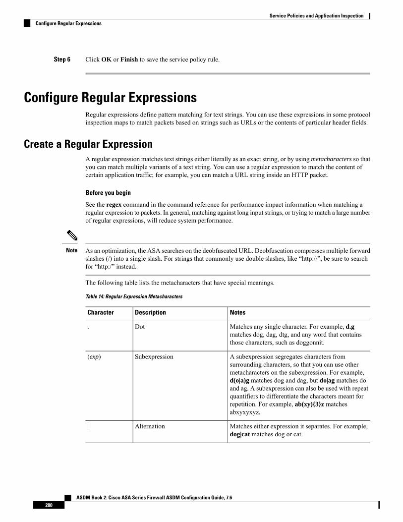
Step 6 Click OK or Finish to save the service policy rule.
Configure Regular ExpressionsRegular expressions define pattern matching for text strings. You can use these expressions in some protocolinspection maps to match packets based on strings such as URLs or the contents of particular header fields.
Create a Regular ExpressionA regular expression matches text strings either literally as an exact string, or by usingmetacharacters so thatyou can match multiple variants of a text string. You can use a regular expression to match the content ofcertain application traffic; for example, you can match a URL string inside an HTTP packet.
Before you begin
See the regex command in the command reference for performance impact information when matching aregular expression to packets. In general, matching against long input strings, or trying to match a large numberof regular expressions, will reduce system performance.
As an optimization, the ASA searches on the deobfuscated URL. Deobfuscation compresses multiple forwardslashes (/) into a single slash. For strings that commonly use double slashes, like “http://”, be sure to searchfor “http:/” instead.
Note
The following table lists the metacharacters that have special meanings.
Table 14: Regular Expression Metacharacters
NotesDescriptionCharacter
Matches any single character. For example, d.gmatches dog, dag, dtg, and any word that containsthose characters, such as doggonnit.
Dot.
A subexpression segregates characters fromsurrounding characters, so that you can use othermetacharacters on the subexpression. For example,d(o|a)g matches dog and dag, but do|ag matches doand ag. A subexpression can also be used with repeatquantifiers to differentiate the characters meant forrepetition. For example, ab(xy){3}z matchesabxyxyxyz.
Subexpression(exp)
Matches either expression it separates. For example,dog|cat matches dog or cat.
Alternation|
ASDM Book 2: Cisco ASA Series Firewall ASDM Configuration Guide, 7.6280
Service Policies and Application InspectionConfigure Regular Expressions

NotesDescriptionCharacter
A quantifier that indicates that there are 0 or 1 of theprevious expression. For example, lo?se matches lseor lose.
Question mark?
A quantifier that indicates that there are 0, 1 or anynumber of the previous expression. For example, lo*sematches lse, lose, loose, and so on.
Asterisk*
A quantifier that indicates that there is at least 1 ofthe previous expression. For example, lo+se matcheslose and loose, but not lse.
Plus+
Repeat at least x times. For example, ab(xy){2,}zmatches abxyxyz, abxyxyxyz, and so on.
Minimum repeat quantifier{x} or {x,}
Matches any character in the brackets. For example,[abc] matches a, b, or c.
Character class[abc]
Matches a single character that is not contained withinthe brackets. For example, [^abc] matches anycharacter other than a, b, or c. [^A-Z] matches anysingle character that is not an uppercase letter.
Negated character class[^abc]
Matches any character in the range. [a-z]matches anylowercase letter. You can mix characters and ranges:[abcq-z] matches a, b, c, q, r, s, t, u, v, w, x, y, z, andso does [a-cq-z].
The dash (-) character is literal only if it is the last orthe first character within the brackets: [abc-] or [-abc].
Character range class[a-c]
Preserves trailing or leading spaces in the string. Forexample, “ test” preserves the leading space when itlooks for a match.
Quotation marks“”
Specifies the beginning of a line.Caret^
When used with a metacharacter, matches a literalcharacter. For example, \[ matches the left squarebracket.
Escape character\
When character is not a metacharacter, matches theliteral character.
Characterchar
Matches a carriage return 0x0d.Carriage return\r
Matches a new line 0x0a.Newline\n
Matches a tab 0x09.Tab\t
Matches a form feed 0x0c.Formfeed\f
ASDM Book 2: Cisco ASA Series Firewall ASDM Configuration Guide, 7.6281
Service Policies and Application InspectionCreate a Regular Expression

NotesDescriptionCharacter
Matches an ASCII character using hexadecimal(exactly two digits).
Escaped hexadecimal number\xNN
Matches an ASCII character as octal (exactly threedigits). For example, the character 040 represents aspace.
Escaped octal number\NNN
Procedure
Step 1 Choose Configuration > Firewall > Objects > Regular Expressions.Step 2 In the Regular Expressions area, do one of the following:
• Choose Add to add a new object. Enter a name and optionally, a description.
• Choose an existing object and click Edit.
Step 3 Either enter the regular expression in the Value field, or click Build to get help creating the expression.
The regular expression is limited to 100 characters in length.
If you click Build, use the following process to create the expression:
a) In the Build Snippet area, create a component of the expression using the following options. Look at theSnippet Preview area at the end of this section to see the expression you are building.
• Starts at the beginning of the line (^)—Indicates that the snippet should start at the beginning of aline, using the caret (^) metacharacter. Be sure to insert any snippet with this option at the beginningof the regular expression.
• Specify Character String—If you are trying to match a specific string, such as a word or phrase, enterthe string.
If there are any metacharacters in your text string that you want to be used literally, choose EscapeSpecial Characters to add the backslash (\) escape character before them. for example, if you enter“example.com,” this option converts it to “example\.com”.
If you want to match upper and lower case characters, choose Ignore Case. For example, “cats” isconverted to “[cC][aA][tT][sS]”.
• Specify Character—If you are trying to match a specific type of character or set of characters, ratherthan a particular phrase, select this option and identify the characters using these options:
• Negate the character—Specifies not to match the character you identify.
• Any character (.)—Inserts the period (.) metacharacter to match any character. For example,d.g matches dog, dag, dtg, and any word that contains those characters, such as doggonnit.
• Character set—Inserts a character set. Text can match any character in the set. For example,if you specify [0-9A-Za-z], then this snippet will match any character from A to Z (upper orlower case) or any digit 0 through 9. The [\n\f\r\t] set matches a new line, form feed, carriagereturn, or a tab.
ASDM Book 2: Cisco ASA Series Firewall ASDM Configuration Guide, 7.6282
Service Policies and Application InspectionCreate a Regular Expression

• Special character—Inserts a character that requires an escape, including \, ?, *, +, |, ., [, (, or^. The escape character is the backslash (\), which is automatically entered when you choosethis option.
• Whitespace character—Whitespace characters include \n (new line), \f (form feed), \r (carriagereturn), or \t (tab).
• Three digit octal number—Matches an ASCII character as octal (up to three digits). Forexample, the character \040 represents a space. The backslash (\) is entered automatically.
• Two digit hexadecimal number—Matches an ASCII character using hexadecimal (exactlytwo digits). The backslash (\) is entered automatically.
• Specified character—Enter any single character.
b) Add the snippet to the regular expression box using one of the following buttons. Note that you can alsotype directly in the regular expression.
• Append Snippet—Adds the snippet to the end of the regular expression.
• Append Snippet as Alternate—Adds the snippet to the end of the regular expression separated bya pipe (|), which matches either expression it separates. For example, dog|cat matches dog or cat.
• Insert Snippet at Cursor—Inserts the snippet at the cursor.
c) Repeat the process to add snippets until the expression is complete.d) (Optional.) In Selection Occurrences, select how often the expression or parts of it must match text to
be considered a match. Select text in the Regular Expression field, click one of the following options, andthen click Apply to Selection. For example, if the regular expression is “test me,” and you select “me”and apply One or more times, then the regular expression changes to “test (me)+”.
• Zero or one times (?)—There are 0 or 1 of the previous expression. For example, lo?se matches lseor lose.
• One or more times (+)—There is at least 1 of the previous expression. For example, lo+se matcheslose and loose, but not lse.
• Any number of times (*)—There are 0, 1 or any number of the previous expression. For example,lo*se matches lse, lose, loose, and so on.
• At least—Repeat at least x times. For example, ab(xy){2,}z matches abxyxyz, abxyxyxyz, and soon.
• Exactly—Repeat exactly x times. For example, ab(xy){3}z matches abxyxyxyz.
e) Click Test to verify your expression will match the intended text. If the test is unsuccessful, you can tryediting it in the test dialog, or return to the expression builder. If you edit the expression in the text dialogand click OK, the edits are saved and reflected in the expression builder.
f) Click OK.
ASDM Book 2: Cisco ASA Series Firewall ASDM Configuration Guide, 7.6283
Service Policies and Application InspectionCreate a Regular Expression

Create a Regular Expression Class MapA regular expression class map identifies one or more regular expression. It is simply a collection of regularexpression objects. You can use a regular expression class map in many cases in replace of a regular expressionobject.
Procedure
Step 1 Choose Configuration > Firewall > Objects > Regular Expressions.Step 2 In the Regular Expressions Classes area, do one of the following:
• Choose Add to add a new class map. Enter a name and optionally, a description.
• Choose an existing class map and click Edit.
Step 3 Select the expressions you want in the map and click Add. Remove any you do not want.Step 4 Click OK.
Monitoring Inspection PoliciesTo monitor inspection service policies, enter the following commands. Select Tools > Command LineInterface to enter these commands. See the command reference on Cisco.com for detailed syntax and examples.
• show service-policy inspect protocol
Displays statistics for inspection service policies. The protocol is the protocol from the inspect command,for example dns. However, not all inspection protocols show statistics with this command. For example:
asa# show service-policy inspect dns
Global policy:Service-policy: global_policyClass-map: inspection_defaultInspect: dns preset_dns_map, packet 0, lock fail 0, drop 0, reset-drop 0,
5-min-pkt-rate 0 pkts/sec, v6-fail-close 0message-length maximum client auto, drop 0message-length maximum 512, drop 0dns-guard, count 0protocol-enforcement, drop 0nat-rewrite, count 0
asa#
• show conn
Shows current connections for traffic passing through the device. This command has a wide range ofkeywords so that you can get information about various protocols.
• Additional commands for specific inspected protocols:
• show ctiqbe
Displays information about the media connections allocated by the CTIQBE inspection engine
ASDM Book 2: Cisco ASA Series Firewall ASDM Configuration Guide, 7.6284
Service Policies and Application InspectionCreate a Regular Expression Class Map

• show h225
Displays information for H.225 sessions.
• show h245
Displays information for H.245 sessions established by endpoints using slow start.
• show h323 ras
Displays connection information for H.323 RAS sessions established between a gatekeeper and itsH.323 endpoint.
• show mgcp {commands | sessions }
Displays the number of MGCP commands in the command queue or the number of existing MGCPsessions.
• show sip
Displays information for SIP sessions.
• show skinny
Displays information for Skinny (SCCP) sessions.
• show sunrpc-server active
Displays the pinholes opened for Sun RPC services.
History for Application InspectionDescriptionReleasesFeature Name
The inspection policy map was introduced.The following command was introduced:class-map type inspect.
7.2(1)Inspection policy maps
Regular expressions and policy maps wereintroduced to be used under inspectionpolicy maps. The following commandswere introduced: class-map type regex,regex, match regex.
7.2(1)Regular expressions and policy maps
The match any keyword was introducedfor use with inspection policy maps: trafficcanmatch one or more criteria to match theclass map. Formerly, only match all wasavailable.
8.0(2)Match any for inspection policy maps
ASDM Book 2: Cisco ASA Series Firewall ASDM Configuration Guide, 7.6285
Service Policies and Application InspectionHistory for Application Inspection

ASDM Book 2: Cisco ASA Series Firewall ASDM Configuration Guide, 7.6286
Service Policies and Application InspectionHistory for Application Inspection

C H A P T E R 12Inspection of Basic Internet Protocols
The following topics explain application inspection for basic Internet protocols. For information on why youneed to use inspection for certain protocols, and the overall methods for applying inspection, see GettingStarted with Application Layer Protocol Inspection, on page 269.
• DCERPC Inspection, on page 287• DNS Inspection, on page 290• FTP Inspection, on page 293• HTTP Inspection, on page 297• ICMP Inspection, on page 301• ICMP Error Inspection, on page 301• ILS Inspection, on page 302• Instant Messaging Inspection, on page 302• IP Options Inspection, on page 304• IPsec Pass Through Inspection, on page 306• IPv6 Inspection, on page 307• NetBIOS Inspection, on page 309• PPTP Inspection, on page 310• RSH Inspection, on page 310• SMTP and Extended SMTP Inspection, on page 310• SNMP Inspection, on page 314• SQL*Net Inspection, on page 315• Sun RPC Inspection, on page 315• TFTP Inspection, on page 316• XDMCP Inspection, on page 317• VXLAN Inspection, on page 317• History for Basic Internet Protocol Inspection, on page 318
DCERPC InspectionDCERPC inspection is not enabled in the default inspection policy, so you must enable it if you need thisinspection. You can simply edit the default global inspection policy to add DCERPC inspection. You canalternatively create a new service policy as desired, for example, an interface-specific policy.
The following sections describe the DCERPC inspection engine.
ASDM Book 2: Cisco ASA Series Firewall ASDM Configuration Guide, 7.6287

DCERPC OverviewMicrosoft Remote Procedure Call (MSRPC), based on DCERPC, is a protocol widely used by Microsoftdistributed client and server applications that allows software clients to execute programs on a server remotely.
This typically involves a client querying a server called the Endpoint Mapper listening on a well known portnumber for the dynamically allocated network information of a required service. The client then sets up asecondary connection to the server instance providing the service. The security appliance allows the appropriateport number and network address and also applies NAT, if needed, for the secondary connection.
The DCERPC inspection engine inspects for native TCP communication between the EPM and client on wellknown TCP port 135. Map and lookup operations of the EPM are supported for clients. Client and server canbe located in any security zone. The embedded server IP address and Port number are received from theapplicable EPM response messages. Since a client may attempt multiple connections to the server port returnedby EPM, multiple use of pinholes are allowed, which have configurable timeouts.
DCE inspection supports the following universally unique identifiers (UUIDs) and messages:
• End point mapper (EPM) UUID. All EPM messages are supported.
• ISystemMapper UUID (non-EPM). Supported messages are:
• RemoteCreateInstance opnum4
• RemoteGetClassObject opnum3
• OxidResolver UUID (non-EPM). Supported message is:
• ServerAlive2 opnum5
• Any message that does not contain an IP address or port information because these messages do notrequire inspection.
Configure a DCERPC Inspection Policy MapTo specify additional DCERPC inspection parameters, create a DCERPC inspection policy map. You canthen apply the inspection policy map when you enable DCERPC inspection.
When defining traffic matching criteria, you can either create a class map or include the match statementsdirectly in the policy map. The difference between creating a class map and defining the traffic match directlyin the inspection policy map is that you can reuse class maps. The following procedure covers inspectionpolicy maps, but also explains the traffic matching criteria available in the class map. To create a class map,select Configuration > Firewall > Objects > Class Maps > DCERPC.
You can configure inspection maps while creating service policies, in addition to the procedure explainedbelow. The contents of the map are the same regardless of how you create it.
Tip
Procedure
Step 1 Choose Configuration > Firewall > Objects > Inspect Maps > DCERPC.
ASDM Book 2: Cisco ASA Series Firewall ASDM Configuration Guide, 7.6288
Service Policies and Application InspectionDCERPC Overview

Step 2 Do one of the following:
• Click Add to add a new map.
• Select a map to view its contents. You can change the security level directly, or click Customize to editthe map. The remainder of the procedure assumes you are customizing or adding a map.
Step 3 For new maps, enter a name (up to 40 characters) and description. When editing a map, you can change thedescription only.
Step 4 In the Security Level view of the DCERPC Inspect Map dialog box, select the level that best matches yourdesired configuration.
If one of the preset levels matches your requirements, you are now done. Just click OK, skip the rest of thisprocedure, and use the map in a service policy rule for DCERPC inspection.
If you need to customize the settings further, click Details and continue with the procedure.
The UUID Filtering button is a shortcut to configure message filtering, which is explained later inthis procedure.
Tip
Step 5 Configure the desired options.
• Pinhole Timeout—Sets the pinhole timeout. Because a client may use the server information returnedby the endpoint mapper for multiple connections, the timeout value is configurable based on the clientapplication environment. Range is from 0:0:1 to 1193:0:0.
• Enforce endpoint-mapper service—Whether to enforce the endpoint mapper service during bindingso that only its service traffic is processed.
• Enable endpoint-mapper service lookup—Whether to enable the lookup operation of the endpointmapper service. You can also enforce a timeout for the service lookup. If you do not configure a timeout,the pinhole timeout is used.
Step 6 (Optional.) Click the Inspections tab and define the actions to take for specific types of messages.
You can define traffic matching criteria based on DCERPC class maps, by configuring matches directly inthe inspection map, or both.
a) Do any of the following:
• Click Add to add a new criterion.
• Select an existing criterion and click Edit.
b) Choose Single Match to define the criterion directly, or Multiple Match, in which case you select theDCERPC class map that defines the criteria.
c) If you are defining the criterion here, choose the match type for the criteria: Match (traffic must matchthe criterion) or No Match (traffic must not match the criterion). Then, select the desired UUID:
• ms-rpc-epm—Matches Microsoft RPC EPM messages.
• ms-rpc-isystemactivator—Matches ISystemMapper messages.
• ms-rpc-oxidresolver—Matches OxidResolver messages.
ASDM Book 2: Cisco ASA Series Firewall ASDM Configuration Guide, 7.6289
Service Policies and Application InspectionConfigure a DCERPC Inspection Policy Map

d) Choose whether to Reset or Log the connection. You can also enable logging if you elect to reset theconnection. Resetting the connection drops the packet, closes the connection, and sends a TCP reset tothe server or client.
e) Click OK to add the criterion. Repeat the process as needed.
Step 7 Click OK.
You can now use the inspection map in a DCERPC inspection service policy.
What to do next
You can now configure an inspection policy to use the map. See Configure Application Layer ProtocolInspection, on page 276.
DNS InspectionDNS inspection is enabled by default. You need to configure it only if you want non-default processing. Thefollowing sections describe DNS application inspection.
Defaults for DNS InspectionDNS inspection is enabled by default, using the preset_dns_map inspection class map:
• The maximum DNS message length is 512 bytes.
• DNS over TCP inspection is disabled.
• The maximum client DNS message length is automatically set to match the Resource Record.
• DNS Guard is enabled, so the ASA tears down the DNS session associated with a DNS query as soonas the DNS reply is forwarded by the ASA. The ASA also monitors the message exchange to ensure thatthe ID of the DNS reply matches the ID of the DNS query.
• Translation of the DNS record based on the NAT configuration is enabled.
• Protocol enforcement is enabled, which enables DNS message format check, including domain namelength of no more than 255 characters, label length of 63 characters, compression, and looped pointercheck.
Configure DNS Inspection Policy MapYou can create a DNS inspection policy map to customize DNS inspection actions if the default inspectionbehavior is not sufficient for your network.
You can optionally create a DNS inspection class map to define the traffic class for DNS inspection. Theother option is to define the traffic classes directly in the DNS inspection policy map. The difference betweencreating a class map and defining the traffic match directly in the inspection map is that you can create morecomplex match criteria and you can reuse class maps. Although this procedure explains inspection maps, thematching criteria used in class maps are the same as those explained in the step relating to the Inspection tab.
ASDM Book 2: Cisco ASA Series Firewall ASDM Configuration Guide, 7.6290
Service Policies and Application InspectionDNS Inspection

You can configure DNS class maps by selecting Configuration > Firewall > Objects > Class Maps >DNS, or by creating them while configuring the inspection map.
You can configure inspection maps while creating service policies, in addition to the procedure explainedbelow. The contents of the map are the same regardless of how you create it.
Tip
Before you begin
Some traffic matching options use regular expressions for matching purposes. If you intend to use one ofthose techniques, first create the regular expression or regular expression class map.
Procedure
Step 1 Choose Configuration > Firewall > Objects > Inspect Maps > DNS.Step 2 Do one of the following:
• Click Add to add a new map.
• Select a map to view its contents. You can change the security level directly, or click Customize to editthe map. The remainder of the procedure assumes you are customizing or adding a map.
Step 3 For new maps, enter a name (up to 40 characters) and description. When editing a map, you can change thedescription only.
Step 4 In the Security Level view of the DNS Inspect Map dialog box, select the level that best matches your desiredconfiguration. The default level is Low.
If one of the preset levels matches your requirements, you are now done. Just click OK, skip the rest of thisprocedure, and use the map in a service policy rule for DNS inspection.
If you need to customize the settings further, click Details, and continue with the procedure.
Step 5 Click the Protocol Conformance tab and choose the desired options:
• Enable DNS guard function—Using DNSGuard, the ASA tears down the DNS session associated witha DNS query as soon as the DNS reply is forwarded by the ASA. The ASA also monitors the messageexchange to ensure that the ID of the DNS reply matches the ID of the DNS query.
• Enable NAT re-write function—Translates the DNS record based on the NAT configuration.
• Enable protocol enforcement—Enables DNS message format check, including domain name lengthof no more than 255 characters, label length of 63 characters, compression, and looped pointer check.
• Randomize the DNS identifier for DNS query.
• Enable TCP inspection—Enables inspection of DNS over TCP traffic. Ensure that DNS/TCP port 53traffic is part of the class to which you apply DNS inspection. The inspection default class includesTCP/53.
• Enforce TSIG resource record to be present in DNS message—You can drop or log non-conformingpackets, and optionally log dropped packets.
Step 6 Click the Filtering tab and choose the desired options.
ASDM Book 2: Cisco ASA Series Firewall ASDM Configuration Guide, 7.6291
Service Policies and Application InspectionConfigure DNS Inspection Policy Map

• Global Settings—Choose whether to drop packets that exceed the specified maximum length regardlessof whether they are from the client or server, from 512 to 65535 bytes.
• Server Settings—Drop packets that exceed specified maximum length and Drop packets sent toserver that exceed length indicated by the RR—Sets the maximum server DNS message length, from512 to 65535 bytes, or sets the maximum length to the value in the Resource Record. If you enable bothsettings, the lower value is used.
• Client Settings—Drop packets that exceed specified maximum length and Drop packets sent toserver that exceed length indicated by the RR—Sets the maximum client DNS message length, from512 to 65535 bytes, or sets the maximum length to the value in the Resource Record. If you enable bothsettings, the lower value is used.
Step 7 Click theMismatch Rate tab and choose whether to enable logging when the DNS IDmismatch rate exceedsthe specified threshold. For example, you could set a threshold of 30 mismatches per 3 seconds.
Step 8 Click the Inspections tab and define the specific inspections you want to implement based on trafficcharacteristics.
You can define traffic matching criteria based on DNS class maps, by configuring matches directly in theinspection map, or both.
a) Do any of the following:
• Click Add to add a new criterion.
• Select an existing criterion and click Edit.
b) Choose Single Match to define the criterion directly, or Multiple Match, in which case you select theDNS class map that defines the criteria.
c) If you are defining the criterion here, choose the match type for the criteria: Match (traffic must matchthe criterion) or No Match (traffic must not match the criterion). For example, if No Match is selectedon the string “example.com,” then any traffic that contains “example.com” is excluded from the classmap. Then, configure the criterion as follows:
• Header Flag—Select whether the flag should equal or contain the specified value, then either selectthe header flag name, or enter the hex value of the header (0x0 to 0xfff). If you select multiple headervalues, “equals” requires that all flags are present, “contains” that any one of the flags is present, inthe packet. Header flag names areAA (AuthoritativeAnswer),QR (Query),RA (RecursionAvailable),RD (Recursion Desired), TC (Truncation).
• Type—The DNS Type field name or value in the packet. Field names are A (IPv4 address), AXFR(full zone transfer),CNAME (canonical name), IXFR (incremental zone transfer),NS (authoritativename server), SOA (start of a zone of authority) orTSIG (transaction signature). Values are arbitrarynumbers in the DNS Type field from 0 to 65535: either enter a specific value or a range of values.
• Class—The DNS Class field name or value in the packet. Internet is the only possible field name.Values are arbitrary numbers in the DNS Class field from 0 to 65535: either enter a specific valueor a range of values.
• Question—The question portion of a DNS message.
• Resource Record—The DNS resource record. Choose whether to match the additional, answer, orauthority resource record section.
ASDM Book 2: Cisco ASA Series Firewall ASDM Configuration Guide, 7.6292
Service Policies and Application InspectionConfigure DNS Inspection Policy Map

d) Choose the primary action to take for matching traffic: drop packet, drop connection, mask (for HeaderFlag matches only) or none.
e) Choose whether to enable or disable logging. You must disable logging if you want to enforce TSIG.f) Chose whether to enforce the presence of a TSIG resource record. You can drop the packet, log it, or drop
and log it. Usually, you must select Primary Action: None and Log: Disable to enforce TSIG. However,for Header Flag matches, you can enforce TSIG along with the mask primary action.
g) Click OK to add the inspection. Repeat the process as needed.
Step 9 Click OK in the DNS Inspect Map dialog box.
You can now use the inspection map in a DNS inspection service policy.
What to do next
You can now configure an inspection policy to use the map. See Configure Application Layer ProtocolInspection, on page 276.
FTP InspectionFTP inspection is enabled by default. You need to configure it only if you want non-default processing. Thefollowing sections describe the FTP inspection engine.
FTP Inspection OverviewThe FTP application inspection inspects the FTP sessions and performs four tasks:
• Prepares dynamic secondary data connection channels for FTP data transfer. Ports for these channels arenegotiated through PORT or PASV commands. The channels are allocated in response to a file upload,a file download, or a directory listing event.
• Tracks the FTP command-response sequence.
• Generates an audit trail.
• Audit record 303002 is generated for each file that is retrieved or uploaded.
• Audit record 201005 is generated if the secondary dynamic channel preparation failed due to memoryshortage.
• Translates the embedded IP address.
If you disable FTP inspection, outbound users can start connections only in passive mode, and all inboundFTP is disabled.
Note
ASDM Book 2: Cisco ASA Series Firewall ASDM Configuration Guide, 7.6293
Service Policies and Application InspectionFTP Inspection

Strict FTPStrict FTP increases the security of protected networks by preventing web browsers from sending embeddedcommands in FTP requests. To enable strict FTP, click theConfigure button next to FTP on the Configuration> Firewall > Service Policy Rules > Edit Service Policy Rule > Rule Actions > Protocol Inspection tab.
When you use strict FTP, you can optionally specify an FTP inspection policy map to specify FTP commandsthat are not permitted to pass through the ASA.
Strict FTP inspection enforces the following behavior:
• An FTP command must be acknowledged before the ASA allows a new command.
• The ASA drops connections that send embedded commands.
• The 227 and PORT commands are checked to ensure they do not appear in an error string.
Using strict FTP may cause the failure of FTP clients that are not strictly compliant with FTP RFCs.Caution
With strict FTP inspection, each FTP command and response sequence is tracked for the following anomalousactivity:
• Truncated command—Number of commas in the PORT and PASV reply command is checked to see ifit is five. If it is not five, then the PORT command is assumed to be truncated and the TCP connectionis closed.
• Incorrect command—Checks the FTP command to see if it ends with <CR><LF> characters, as requiredby the RFC. If it does not, the connection is closed.
• Size of RETR and STOR commands—These are checked against a fixed constant. If the size is greater,then an error message is logged and the connection is closed.
• Command spoofing—The PORT command should always be sent from the client. The TCP connectionis denied if a PORT command is sent from the server.
• Reply spoofing—PASV reply command (227) should always be sent from the server. The TCP connectionis denied if a PASV reply command is sent from the client. This prevents the security hole when the userexecutes “227 xxxxx a1, a2, a3, a4, p1, p2.”
• TCP stream editing—The ASA closes the connection if it detects TCP stream editing.
• Invalid port negotiation—The negotiated dynamic port value is checked to see if it is less than 1024. Asport numbers in the range from 1 to 1024 are reserved for well-known connections, if the negotiated portfalls in this range, then the TCP connection is freed.
• Command pipelining—The number of characters present after the port numbers in the PORT and PASVreply command is cross checked with a constant value of 8. If it is more than 8, then the TCP connectionis closed.
• The ASA replaces the FTP server response to the SYST command with a series of Xs to prevent theserver from revealing its system type to FTP clients. To override this default behavior, use the nomask-syst-reply command in the FTP map.
ASDM Book 2: Cisco ASA Series Firewall ASDM Configuration Guide, 7.6294
Service Policies and Application InspectionStrict FTP

Configure an FTP Inspection Policy MapFTP command filtering and security checks are provided using strict FTP inspection for improved securityand control. Protocol conformance includes packet length checks, delimiters and packet format checks,command terminator checks, and command validation.
Blocking FTP based on user values is also supported so that it is possible for FTP sites to post files fordownload, but restrict access to certain users. You can block FTP connections based on file type, server name,and other attributes. System message logs are generated if an FTP connection is denied after inspection.
If you want FTP inspection to allow FTP servers to reveal their system type to FTP clients, and limit theallowed FTP commands, then create and configure an FTP inspection policy map. You can then apply themap when you enable FTP inspection.
You can optionally create an FTP inspection class map to define the traffic class for FTP inspection. The otheroption is to define the traffic classes directly in the FTP inspection policy map. The difference between creatinga class map and defining the traffic match directly in the inspection map is that you can create more complexmatch criteria and you can reuse class maps. Although this procedure explains inspection maps, the matchingcriteria used in class maps are the same as those explained in the step relating to the Inspection tab. You canconfigure DNS class maps by selecting Configuration > Firewall > Objects > Class Maps > FTP, orby creating them while configuring the inspection map.
You can configure inspection maps while creating service policies, in addition to the procedure explainedbelow. The contents of the map are the same regardless of how you create it.
Tip
Before you begin
Some traffic matching options use regular expressions for matching purposes. If you intend to use one ofthose techniques, first create the regular expression or regular expression class map.
Procedure
Step 1 Choose Configuration > Firewall > Objects > Inspect Maps > FTP.Step 2 Do one of the following:
• Click Add to add a new map.
• Select a map to view its contents. You can change the security level directly, or click Customize to editthe map. The remainder of the procedure assumes you are customizing or adding a map.
Step 3 For new maps, enter a name (up to 40 characters) and description. When editing a map, you can change thedescription only.
Step 4 In the Security Level view of the FTP Inspect Map dialog box, select the level that best matches your desiredconfiguration. The default level is High.
If one of the preset levels matches your requirements, you are now done. Just click OK, skip the rest of thisprocedure, and use the map in a service policy rule for FTP inspection.
If you need to customize the settings further, click Details, and continue with the procedure.
ASDM Book 2: Cisco ASA Series Firewall ASDM Configuration Guide, 7.6295
Service Policies and Application InspectionConfigure an FTP Inspection Policy Map

The File Type Filtering button is a shortcut to configure file media or MIME type inspection, whichis explained later in this procedure.
Tip
Step 5 Click the Parameters tab and choose whether to mask the greeting banner from the server or mask the replyto the SYST command.
Masking these items prevents the client from discovering server information that might be helpful in an attack.
Step 6 Click the Inspections tab and define the specific inspections you want to implement based on trafficcharacteristics.
You can define traffic matching criteria based on FTP class maps, by configuring matches directly in theinspection map, or both.
a) Do any of the following:
• Click Add to add a new criterion.
• Select an existing criterion and click Edit.
b) Choose Single Match to define the criterion directly, or Multiple Match, in which case you select theFTP class map that defines the criteria.
c) If you are defining the criterion here, choose the match type for the criteria: Match (traffic must matchthe criterion) or No Match (traffic must not match the criterion). For example, if No Match is selectedon the string “example.com,” then any traffic that contains “example.com” is excluded from the classmap. Then, configure the criterion as follows:
• File Name—Match the name of the file being transferred against the selected regular expression orregular expression class.
• File Type—Match the MIME or media type of the file being transferred against the selected regularexpression or regular expression class.
• Server—Match the FTP server name against the selected regular expression or regular expressionclass.
• User—Match the name of the logged-in user against the selected regular expression or regularexpression class.
• Request Command—The FTP command used in the packet, any combination of the following:
• APPE—Append to a file.
• CDUP—Changes to the parent directory of the current working directory.
• DELE—Delete a file on the server.
• GET—Gets a file from the server.
• HELP—Provides help information.
• MKD—Makes a directory on the server.
• PUT—Sends a file to the server.
• RMD—Deletes a directory on the server.
• RNFR—Specifies the “rename-from” filename.
ASDM Book 2: Cisco ASA Series Firewall ASDM Configuration Guide, 7.6296
Service Policies and Application InspectionConfigure an FTP Inspection Policy Map

• RNTO—Specifies the “rename-to” filename.
• SITE—Used to specify a server-specific command. This is usually used for remoteadministration.
• STOU—Stores a file using a unique file name.
d) Choose whether to enable or disable logging. The action is always to reset the connection, which dropsthe packet, closes the connection, and sends a TCP reset to the server or client.
e) Click OK to add the inspection. Repeat the process as needed.
Step 7 Click OK in the FTP Inspect Map dialog box.
You can now use the inspection map in a FTP inspection service policy.
What to do next
You can now configure an inspection policy to use the map. See Configure Application Layer ProtocolInspection, on page 276.
HTTP InspectionIf you are not using a purpose-built module for HTTP inspection and application filtering, such as ASAFirePOWER, you can manually configure HTTP inspection on the ASA.
HTTP inspection is not enabled in the default inspection policy, so youmust enable it if you need this inspection.However, the default inspect class does include the default HTTP ports, so you can simply edit the defaultglobal inspection policy to add HTTP inspection. You can alternatively create a new service policy as desired,for example, an interface-specific policy.
Do not configure HTTP inspection in both a service module and on the ASA, as the inspections are notcompatible.
Tip
The following sections describe the HTTP inspection engine.
HTTP Inspection Overview
You can install a service module that performs application and URL filtering, which includes HTTP inspection,such as ASA FirePOWER. The HTTP inspection running on the ASA is not compatible with these modules.Note that it is far easier to configure application filtering using a purpose-built module rather than trying tomanually configure it on the ASA using an HTTP inspection policy map.
Tip
Use the HTTP inspection engine to protect against specific attacks and other threats that are associated withHTTP traffic.
ASDM Book 2: Cisco ASA Series Firewall ASDM Configuration Guide, 7.6297
Service Policies and Application InspectionHTTP Inspection

HTTP application inspection scans HTTP headers and body, and performs various checks on the data. Thesechecks prevent various HTTP constructs, content types, and tunneling andmessaging protocols from traversingthe security appliance.
The enhanced HTTP inspection feature, which is also known as an application firewall and is available whenyou configure an HTTP inspection policy map, can help prevent attackers from using HTTP messages forcircumventing network security policy.
HTTP application inspection can block tunneled applications and non-ASCII characters in HTTP requestsand responses, preventing malicious content from reaching the web server. Size limiting of various elementsin HTTP request and response headers, URL blocking, and HTTP server header type spoofing are alsosupported.
Enhanced HTTP inspection verifies the following for all HTTP messages:
• Conformance to RFC 2616
• Use of RFC-defined methods only.
• Compliance with the additional criteria.
Configure an HTTP Inspection Policy MapTo specify actions when a message violates a parameter, create an HTTP inspection policy map. You canthen apply the inspection policy map when you enable HTTP inspection.
You can optionally create an HTTP inspection class map to define the traffic class for HTTP inspection. Theother option is to define the traffic classes directly in the HTTP inspection policy map. The difference betweencreating a class map and defining the traffic match directly in the inspection map is that you can create morecomplex match criteria and you can reuse class maps. Although this procedure explains inspection maps, thematching criteria used in class maps are the same as those explained in the step relating to the Inspection tab.You can configure HTTP class maps by selecting Configuration > Firewall > Objects > Class Maps >HTTP, or by creating them while configuring the inspection map.
You can configure inspection maps while creating service policies, in addition to the procedure explainedbelow. The contents of the map are the same regardless of how you create it.
Tip
Before you begin
Some traffic matching options use regular expressions for matching purposes. If you intend to use one ofthose techniques, first create the regular expression or regular expression class map.
Procedure
Step 1 Choose Configuration > Firewall > Objects > Inspect Maps > HTTP.Step 2 Do one of the following:
• Click Add to add a new map.
• Select a map to view its contents. You can change the security level directly, or click Customize to editthe map. The remainder of the procedure assumes you are customizing or adding a map.
ASDM Book 2: Cisco ASA Series Firewall ASDM Configuration Guide, 7.6298
Service Policies and Application InspectionConfigure an HTTP Inspection Policy Map
Step 3 For new maps, enter a name (up to 40 characters) and description. When editing a map, you can change thedescription only.
Step 4 In the Security Level view of the HTTP Inspect Map dialog box, select the level that best matches yourdesired configuration. The default level is Low.
If one of the preset levels matches your requirements, you are now done. Just click OK, skip the rest of thisprocedure, and use the map in a service policy rule for HTTP inspection.
If you need to customize the settings further, click Details, and continue with the procedure.
The URI Filtering button is a shortcut to configure Request URI inspection, which is explainedlater in this procedure.
Tip
Step 5 Click the Parameters tab and configure the desired options.
• Body Match Maximum—The maximum number of characters in the body of an HTTP message thatshould be searched in a body match. Default is 200 bytes. A large number will have a significant impacton performance.
• Check for protocol violations—Whether to verify that packets conform to the HTTP protocol. Forviolations, you can drop the connection, reset it, or log it. When dropping or resetting, you can also enablelogging.
• Spoof server string—Replaces the server HTTP header value with the specified string, up to 82 characters.
Step 6 Click the Inspections tab and define the specific inspections you want to implement based on trafficcharacteristics.
You can define traffic matching criteria based on HTTP class maps, by configuring matches directly in theinspection map, or both.
a) Do any of the following:
• Click Add to add a new criterion.
• Select an existing criterion and click Edit.
b) Choose Single Match to define the criterion directly, or Multiple Match, in which case you select theHTTP class map that defines the criteria.
c) If you are defining the criterion here, choose the match type for the criteria: Match (traffic must matchthe criterion) or No Match (traffic must not match the criterion). For example, if No Match is selectedon the string “example.com,” then any traffic that contains “example.com” is excluded from the classmap. Then, configure the criterion as follows:
• Request/Response Content Type Mismatch—Match packets where the content type in the responsedoes not match one of the MIME types in the accept field of the request.
• Request Arguments—Match the arguments of the request against the selected regular expression orregular expression class.
• Request Body Length—Match packets where the body of the request is greater than the specifiednumber of bytes.
• Request Body—Match the body of the request against the selected regular expression or regularexpression class.
ASDM Book 2: Cisco ASA Series Firewall ASDM Configuration Guide, 7.6299
Service Policies and Application InspectionConfigure an HTTP Inspection Policy Map

• Request Header Field Count—Match packets where the number of header fields in the request isgreater than the specified count. You can match the field header type to a regular expression or to apredefined type. The predefined types are: accept, accept-charset, accept-encoding, accept-language,allow, authorization, cache-control, connection, content-encoding, content-language, content-length,content-location, content-md5, content-range, content-type, cookie, date, expect, expires, from, host,if-match, if-modified-since, if-none-match, if-range, if-unmodified-since, last-modified, max-forwards,pragma, proxy-authorization, range, referer, te, trailer, transfer-encoding, upgrade, user-agent, via,warning.
• Request Header Field Length—Match packets where the length of the header field in the request isgreater than the specified bytes. You can match the field header type to a regular expression or to apredefined type. The predefined types are listed above for Request Header Field Count.
• Request Header Field—Match the content of the selected header field in the request against theselected regular expression or regular expression class. You can specify a predefined header type oruse a regular expression to select the headers.
• Request Header Count—Match packets where the number of headers in the request is greater thanthe specified number.
• Request Header Length—Match packets where the length of the header in the request is greater thanthe specified bytes.
• Request Header Non-ASCII—Match packets where the header in the request contains non-ASCIIcharacters.
• Request Method—Match packets where the request method matches the predefined type or theselected regular expression or regular expression class. The predefined types are: bcopy, bdelete,bmove, bpropfind, bproppatch, connect, copy, delete, edit, get, getattribute, getattributenames,getproperties, head, index, lock, mkcol, mkdir, move, notify, options, poll, post, propfind, proppatch,put, revadd, revlabel, revlog, revnum, save, search, setattribute, startrev, stoprev, subscribe, trace,unedit, unlock, unsubscribe.
• Request URI Length—Match packets where the length of the URI of the request is greater than thespecified bytes.
• Request URI—Match the content of the URI of the request against the selected regular expressionor regular expression class.
• Request Body—Match the body of the request against the selected regular expression or regularexpression class, or to ActiveX or Java Applet content.
• Response Body Length—Match packets where the length of the body of the response is greater thanthe specified bytes.
• Response Header Field Count—Match packets where the number of header fields in the response isgreater than the specified count. You can match the field header type to a regular expression or to apredefined type. The predefined types are: accept-ranges, age, allow, cache-control, connection,content-encoding, content-language, content-length, content-location, content-md5, content-range,content-type, date, etag, expires, last-modified, location, pragma, proxy-authenticate, retry-after,server, set-cookie, trailer, transfer-encoding, upgrade, vary, via, warning, www-authenticate.
• Response Header Field Length—Match packets where the length of the header field in the responseis greater than the specified bytes. You can match the field header type to a regular expression or toa predefined type. The predefined types are listed above for Response Header Field Count.
ASDM Book 2: Cisco ASA Series Firewall ASDM Configuration Guide, 7.6300
Service Policies and Application InspectionConfigure an HTTP Inspection Policy Map

• Response Header Field—Match the content of the selected header field in the response against theselected regular expression or regular expression class. You can specify a predefined header type oruse a regular expression to select the headers.
• Response Header Count—Match packets where the number of headers in the response is greater thanthe specified number.
• Response Header Length—Match packets where the length of the header in the response is greaterthan the specified bytes.
• Response Header Non-ASCII—Match packets where the header in the response contains non-ASCIIcharacters.
• Response Status Line—Match the content of the response status line against the selected regularexpression or regular expression class.
d) Choose whether to drop the connection, reset it, or log it. For drop connection and reset, you can enableor disable logging.
e) Click OK to add the inspection. Repeat the process as needed.
Step 7 Click OK in the HTTP Inspect Map dialog box.
You can now use the inspection map in a HTTP inspection service policy.
What to do next
You can now configure an inspection policy to use the map. See Configure Application Layer ProtocolInspection, on page 276.
ICMP InspectionThe ICMP inspection engine allows ICMP traffic to have a “session” so it can be inspected like TCP andUDP traffic. Without the ICMP inspection engine, we recommend that you do not allow ICMP through theASA in an ACL.Without stateful inspection, ICMP can be used to attack your network. The ICMP inspectionengine ensures that there is only one response for each request, and that the sequence number is correct.
However, ICMP traffic directed to an ASA interface is never inspected, even if you enable ICMP inspection.Thus, a ping (echo request) to an interface can fail under specific circumstances, such as when the echo requestcomes from a source that the ASA can reach through a backup default route.
For information on enabling ICMP inspection, see Configure Application Layer Protocol Inspection, on page276.
ICMP Error InspectionWhen ICMP Error inspection is enabled, the ASA creates translation sessions for intermediate hops that sendICMP error messages, based on the NAT configuration. The ASA overwrites the packet with the translatedIP addresses.
ASDM Book 2: Cisco ASA Series Firewall ASDM Configuration Guide, 7.6301
Service Policies and Application InspectionICMP Inspection

When disabled, the ASA does not create translation sessions for intermediate nodes that generate ICMP errormessages. ICMP error messages generated by the intermediate nodes between the inside host and the ASAreach the outside host without consuming any additional NAT resource. This is undesirable when an outsidehost uses the traceroute command to trace the hops to the destination on the inside of the ASA. When theASA does not translate the intermediate hops, all the intermediate hops appear with the mapped destinationIP address.
For information on enabling ICMP Error inspection, see Configure Application Layer Protocol Inspection,on page 276.
ILS InspectionThe Internet Locator Service (ILS) inspection engine provides NAT support for Microsoft NetMeeting,SiteServer, and Active Directory products that use LDAP to exchange directory information with an ILSserver. You cannot use PAT with ILS inspection because only IP addresses are stored by an LDAP database.
For search responses, when the LDAP server is located outside, consider using NAT to allow internal peersto communicate locally while registered to external LDAP servers. If you do not need to use NAT, werecommend that you turn off the inspection engine to provide better performance.
Additional configuration may be necessary when the ILS server is located inside the ASA border. This wouldrequire a hole for outside clients to access the LDAP server on the specified port, typically TCP 389.
Because ILS traffic (H225 call signaling) only occurs on the secondary UDP channel, the TCP connection isdisconnected after the TCP inactivity interval. By default, this interval is 60 minutes and can be adjusted usingthe TCP timeout command. In ASDM, this is on the Configuration > Firewall > Advanced > GlobalTimeouts pane.
Note
ILS inspection has the following limitations:
• Referral requests and responses are not supported.
• Users in multiple directories are not unified.
• Single users having multiple identities in multiple directories cannot be recognized by NAT.
For information on enabling ILS inspection, see Configure Application Layer Protocol Inspection, on page276.
Instant Messaging InspectionThe Instant Messaging (IM) inspect engine lets you control the network usage of IM and stop leakage ofconfidential data, propagation of worms, and other threats to the corporate network.
IM inspection is not enabled in the default inspection policy, so you must enable it if you need this inspection.However, the default inspect class does include the default IM ports, so you can simply edit the default globalinspection policy to add IM inspection. You can alternatively create a new service policy as desired, forexample, an interface-specific policy.
ASDM Book 2: Cisco ASA Series Firewall ASDM Configuration Guide, 7.6302
Service Policies and Application InspectionILS Inspection

If you decide to implement IM inspection, you can also configure an IM inspection policy map to specifyactions when a message violates a parameter. The following procedure explains IM inspection policy maps.
You can optionally create an IM inspection class map to define the traffic class for IM inspection. The otheroption is to define the traffic classes directly in the IM inspection policy map. The difference between creatinga class map and defining the traffic match directly in the inspection map is that you can create more complexmatch criteria and you can reuse class maps. This procedure explains inspection maps, but class maps areessentially the same, except that you do not specify the actions for matching traffic. You can configure IMclass maps by selecting Configuration > Firewall > Objects > Class Maps > Instant Messaging (IM).
You can configure inspection maps while creating service policies, in addition to the procedure explainedbelow. The contents of the map are the same regardless of how you create it.
Tip
Before you begin
Some traffic matching options use regular expressions for matching purposes. If you intend to use one ofthose techniques, first create the regular expression or regular expression class map.
Procedure
Step 1 Choose Configuration > Firewall > Objects > Inspect Maps > Instant Messaging (IM).Step 2 Do one of the following:
• Click Add to add a new map.
• Select a map and click Edit.
Step 3 For new maps, enter a name (up to 40 characters) and description. When editing a map, you can change thedescription only.
Step 4 Define the specific inspections you want to implement based on traffic characteristics.
You can define traffic matching criteria based on IM class maps, by configuring matches directly in theinspection map, or both.
a) Do any of the following:
• Click Add to add a new criterion.
• Select an existing criterion and click Edit.
b) Choose Single Match to define the criterion directly, or Multiple Match, in which case you select theIM class map that defines the criteria. Click Manage to create new class maps.
c) If you are defining the criterion here, choose the match type for the criteria: Match (traffic must matchthe criterion) or No Match (traffic must not match the criterion). For example, if No Match is selectedon the string “example.com,” then any traffic that contains “example.com” is excluded from the classmap. Then, configure the criterion.
• Protocol—Match traffic of a specific IM protocol, such as Yahoo Messenger or MSN Messenger.
• Service—Match a specific IM service, such as chat, file transfer, web cam, voice chat, conference,or games.
ASDM Book 2: Cisco ASA Series Firewall ASDM Configuration Guide, 7.6303
Service Policies and Application InspectionInstant Messaging Inspection

• Version—Match the version of the IM message against the selected regular expression or regularexpression class.
• Client Login Name—Match the source client login name of the IM message against the selectedregular expression or regular expression class.
• Client Peer Login Name—Match the destination peer login name of the IM message against theselected regular expression or regular expression class.
• Source IP Address—Match the source IP address and mask.
• Destination IP Address—Match the destination IP address and mask.
• Filename—Match the filename of the IM message against the selected regular expression or regularexpression class.
d) Choose whether to drop the connection, reset it, or log it. For drop connection and reset, you can enableor disable logging.
e) Click OK to add the inspection. Repeat the process as needed.
Step 5 Click OK in the IM Inspect Map dialog box.
You can now use the inspection map in a IM inspection service policy.
What to do next
You can now configure an inspection policy to use the map. See Configure Application Layer ProtocolInspection, on page 276.
IP Options InspectionYou can configure IP Options inspection to control which IP packets are allowed based on the contents of theIP Options field in the packet header. You can drop packets that have unwanted options, clear the options(and allow the packet), or allow the packet without change.
IP options provide control functions that are required in some situations but unnecessary for most commoncommunications. In particular, IP options include provisions for time stamps, security, and special routing.Use of IP Options is optional, and the field can contain zero, one, or more options.
For a list of IP options, with references to the relevant RFCs, see the IANA page,http://www.iana.org/assignments/ip-parameters/ip-parameters.xhtml.
IP options inspection is enabled by default, but for RSVP traffic only. You need to configure it only if youwant to allow additional options than the default map allows, or if you want to apply it to other types of trafficby using a non-default inspection traffic class map.
IP options inspection does not work on fragmented packets. For example, options are not cleared fromfragments.
Note
The following sections describe IP Options inspection.
ASDM Book 2: Cisco ASA Series Firewall ASDM Configuration Guide, 7.6304
Service Policies and Application InspectionIP Options Inspection

Defaults for IP Options InspectionIP Options inspection is enabled by default for RSVP traffic only, using the _default_ip_options_map inspectionpolicy map.
• The Router Alert option is allowed.
This option notifies transit routers to inspect the contents of the packet even when the packet is notdestined for that router. This inspection is valuable when implementing RSVP and similar protocols thatrequire relatively complex processing from the routers along the packet’s delivery path. Dropping RSVPpackets containing the Router Alert option can cause problems in VoIP implementations.
• Packets that contain any other options are dropped.
Each time a packet is dropped due to inspection, syslog 106012 is issued. The message shows whichoption caused the drop. Use the show service-policy inspect ip-options command to view statistics foreach option.
Configure an IP Options Inspection Policy MapIf you want to perform non-default IP options inspection, create an IP options inspection policy map to specifyhow you want to handle each option type.
You can configure inspection maps while creating service policies, in addition to the procedure explainedbelow. The contents of the map are the same regardless of how you create it.
Tip
Procedure
Step 1 Choose Configuration > Firewall > Objects > Inspect Maps > IP Options.Step 2 Do one of the following:
• Click Add to add a new map.
• Select a map and click Edit.
Step 3 For new maps, enter a name (up to 40 characters) and description. When editing a map, you can change thedescription only.
Step 4 Choose which options you want to allow by moving them from the Drop list to the Allow list.
Consider the following tips:
• The “default” option sets the default behavior for options not included in the map. If you move it to theAllowed list, even options shown in the Drop list will be allowed.
• For any option you allow, you can check the Clear box to remove the option from the packet headerbefore transmitting the packet.
• Some options are listed by option type number. The number is the whole option type octet (copy, class,and option number), not just the option number portion of the octet. These option types might not represent
ASDM Book 2: Cisco ASA Series Firewall ASDM Configuration Guide, 7.6305
Service Policies and Application InspectionDefaults for IP Options Inspection

real options. Non-standard options must be in the expected type-length-value format defined in theInternet Protocol RFC 791, http://tools.ietf.org/html/rfc791.
• If a packet includes more than one type of option, it is dropped so long as the action for one of thosetypes is to drop the packet.
For a list of IP options, with references to the relevant RFCs, see the IANA page,http://www.iana.org/assignments/ip-parameters/ip-parameters.xhtml.
Step 5 Click OK.
You can now use the inspection map in an IP options inspection service policy.
What to do next
You can now configure an inspection policy to use the map. See Configure Application Layer ProtocolInspection, on page 276.
IPsec Pass Through InspectionIPsec Pass Through inspection is not enabled in the default inspection policy, so you must enable it if youneed this inspection. However, the default inspect class does include the default IPsec ports, so you can simplyedit the default global inspection policy to add IPsec inspection. You can alternatively create a new servicepolicy as desired, for example, an interface-specific policy.
The following sections describe the IPsec Pass Through inspection engine.
IPsec Pass Through Inspection OverviewInternet Protocol Security (IPsec) is a protocol suite for securing IP communications by authenticating andencrypting each IP packet of a data stream. IPsec also includes protocols for establishing mutual authenticationbetween agents at the beginning of the session and negotiation of cryptographic keys to be used during thesession. IPsec can be used to protect data flows between a pair of hosts (for example, computer users orservers), between a pair of security gateways (such as routers or firewalls), or between a security gateway anda host.
IPsec Pass Through application inspection provides convenient traversal of ESP (IP protocol 50) and AH (IPprotocol 51) traffic associated with an IKE UDP port 500 connection. It avoids lengthy ACL configurationto permit ESP and AH traffic and also provides security using timeout and max connections.
Configure a policy map for IPsec Pass Through to specify the restrictions for ESP or AH traffic. You can setthe per client max connections and the idle timeout.
NAT and non-NAT traffic is permitted. However, PAT is not supported.
Configure an IPsec Pass Through Inspection Policy MapAn IPsec Pass Through map lets you change the default configuration values used for IPsec Pass Throughapplication inspection. You can use an IPsec Pass Through map to permit certain flows without using an ACL.
ASDM Book 2: Cisco ASA Series Firewall ASDM Configuration Guide, 7.6306
Service Policies and Application InspectionIPsec Pass Through Inspection

The configuration includes a default map, _default_ipsec_passthru_map, that sets no maximum limit on ESPconnections per client, and sets the ESP idle timeout at 10 minutes. You need to configure an inspection policymap only if you want different values, or if you want to set AH values.
You can configure inspection maps while creating service policies, in addition to the procedure explainedbelow. The contents of the map are the same regardless of how you create it.
Tip
Procedure
Step 1 Choose Configuration > Firewall > Objects > Inspect Maps > IPsec Pass Through.Step 2 Do one of the following:
• Click Add to add a new map.
• Select a map to view its contents. You can change the security level directly, or click Customize to editthe map. The remainder of the procedure assumes you are customizing or adding a map.
Step 3 For new maps, enter a name (up to 40 characters) and description. When editing a map, you can change thedescription only.
Step 4 In the Security Level view of the IPsec Pass Through Inspect Map dialog box, select the level that bestmatches your desired configuration.
If one of the preset levels matches your requirements, you are now done. Just click OK, skip the rest of thisprocedure, and use the map in a service policy rule for IPsec Pass Through inspection.
If you need to customize the settings further, click Details, and continue with the procedure.
Step 5 Choose whether to allow ESP and AH tunnels.
For each protocol, you can also set the maximum number of connections allowed per client, and the idletimeout.
Step 6 Click OK.
You can now use the inspection map in an IPsec Pass Through inspection service policy.
IPv6 InspectionIPv6 inspection lets you selectively log or drop IPv6 traffic based on the extension header. In addition, IPv6inspection can check conformance to RFC 2460 for type and order of extension headers in IPv6 packets.
IPv6 inspection is not enabled in the default inspection policy, so you must enable it if you need this inspection.You can simply edit the default global inspection policy to add IPv6 inspection. You can alternatively createa new service policy as desired, for example, an interface-specific policy.
ASDM Book 2: Cisco ASA Series Firewall ASDM Configuration Guide, 7.6307
Service Policies and Application InspectionIPv6 Inspection

Defaults for IPv6 InspectionIf you enable IPv6 inspection and do not specify an inspection policy map, then the default IPv6 inspectionpolicy map is used, and the following actions are taken:
• Allows only known IPv6 extension headers. Non-conforming packets are dropped and logged.
• Enforces the order of IPv6 extension headers as defined in the RFC 2460 specification. Non-conformingpackets are dropped and logged.
• Drops any packet with a routing type header.
Configure an IPv6 Inspection Policy MapTo identify extension headers to drop or log, or to disable packet verification, create an IPv6 inspection policymap to be used by the service policy.
Procedure
Step 1 Choose Configuration > Firewall > Objects > Inspect Maps > IPv6.Step 2 Do one of the following:
• Click Add to add a new map.
• Select a map and click Edit.
Step 3 For new maps, enter a name (up to 40 characters) and description. When editing a map, you can change thedescription only.
Step 4 Click the Enforcement tab and choose whether to permit only known IPv6 extension headers or to enforcethe order of IPv6 extension headers as defined in RFC 2460. Non-conforming packets are dropped and logged.
Step 5 (Optional) Click the Header Matches tab to identify traffic to drop or log based on the headers in IPv6messages.a) Do any of the following:
• Click Add to add a new criterion.
• Select an existing criterion and click Edit.
b) Choose the IPv6 extension header to match:
• Authentication (AH) header.
• Destination Options header.
• Encapsulating Security Payload (ESP) header.
• Fragment header.
• Hop-by-Hop Options header.
• Routing header—Specify either a single header type number or a range of numbers.
ASDM Book 2: Cisco ASA Series Firewall ASDM Configuration Guide, 7.6308
Service Policies and Application InspectionDefaults for IPv6 Inspection

• Header count—Specify the maximum number of extension headers you will allow without droppingor logging the packet.
• Routing header address count—Specify the maximum number of addresses in the type 0 routingheader you will allow without dropping or logging the packet.
c) Choose whether to drop or log the packet. If you drop the packet, you can also enable logging.d) Click OK to add the inspection. Repeat the process as needed.
Step 6 Click OK in the IPv6 Inspect Map dialog box.
You can now use the inspection map in an IPv6 inspection service policy.
What to do next
You can now configure an inspection policy to use the map. See Configure Application Layer ProtocolInspection, on page 276.
NetBIOS InspectionNetBIOS application inspection performs NAT for the embedded IP address in the NetBIOS name service(NBNS) packets and NetBIOS datagram services packets. It also enforces protocol conformance, checkingthe various count and length fields for consistency.
NetBIOS inspection is enabled by default. You can optionally create a policy map to drop or log NetBIOSprotocol violations. The following procedure explains how to configure a NetBIOS inspection policy map.
Procedure
Step 1 Choose Configuration > Firewall > Objects > Inspect Maps > NetBIOS.Step 2 Do one of the following:
• Click Add to add a new map.
• Select a map and click Edit.
Step 3 For new maps, enter a name (up to 40 characters) and description. When editing a map, you can change thedescription only.
Step 4 Select Check for Protocol Violations. There is no reason to create a map if you do not select this option.Step 5 Select the action to take, either to drop the packet or log it. If you drop the packet, you can also enable logging.Step 6 Click OK.
You can now use the inspection map in a NetBIOS inspection service policy.
ASDM Book 2: Cisco ASA Series Firewall ASDM Configuration Guide, 7.6309
Service Policies and Application InspectionNetBIOS Inspection
What to do next
You can now configure an inspection policy to use the map. See Configure Application Layer ProtocolInspection, on page 276.
PPTP InspectionPPTP is a protocol for tunneling PPP traffic. A PPTP session is composed of one TCP channel and usuallytwo PPTP GRE tunnels. The TCP channel is the control channel used for negotiating and managing the PPTPGRE tunnels. The GRE tunnels carry PPP sessions between the two hosts.
When enabled, PPTP application inspection inspects PPTP protocol packets and dynamically creates the GREconnections and xlates necessary to permit PPTP traffic.
Specifically, the ASA inspects the PPTP version announcements and the outgoing call request/responsesequence. Only PPTP Version 1, as defined in RFC 2637, is inspected. Further inspection on the TCP controlchannel is disabled if the version announced by either side is not Version 1. In addition, the outgoing-callrequest and reply sequence are tracked. Connections and xlates are dynamically allocated as necessary topermit subsequent secondary GRE data traffic.
The PPTP inspection engine must be enabled for PPTP traffic to be translated by PAT. Additionally, PAT isonly performed for a modified version of GRE (RFC2637) and only if it is negotiated over the PPTP TCPcontrol channel. PAT is not performed for the unmodified version of GRE (RFC 1701 and RFC 1702).
For information on enabling PPTP inspection, see Configure Application Layer Protocol Inspection, on page276.
RSH InspectionRSH inspection is enabled by default. The RSH protocol uses a TCP connection from the RSH client to theRSH server on TCP port 514. The client and server negotiate the TCP port number where the client listensfor the STDERR output stream. RSH inspection supports NAT of the negotiated port number if necessary.
For information on enabling RSH inspection, see Configure Application Layer Protocol Inspection, on page276.
SMTP and Extended SMTP InspectionESMTP inspection detects attacks, including spam, phising, malformed message attacks, and bufferoverflow/underflow attacks. It also provides support for application security and protocol conformance, whichenforces the sanity of the ESMTP messages as well as block senders/receivers, and block mail relay.
ESMTP inspection is enabled by default. You need to configure it only if you want different processing thanthat provided by the default inspection map.
The following sections describe the ESMTP inspection engine.
ASDM Book 2: Cisco ASA Series Firewall ASDM Configuration Guide, 7.6310
Service Policies and Application InspectionPPTP Inspection
SMTP and ESMTP Inspection OverviewExtended SMTP (ESMTP) application inspection provides improved protection against SMTP-based attacksby restricting the types of SMTP commands that can pass through the ASA and by adding monitoringcapabilities. ESMTP is an enhancement to the SMTP protocol and is similar is most respects to SMTP.
ESMTP application inspection controls and reduces the commands that the user can use as well as the messagesthat the server returns. ESMTP inspection performs three primary tasks:
• Restricts SMTP requests to seven basic SMTP commands and eight extended commands. Supportedcommands are the following:
• Extended SMTP—AUTH, EHLO, ETRN, HELP, SAML, SEND, SOML, STARTTLS, and VRFY.
• SMTP (RFC 821)—DATA, HELO, MAIL, NOOP, QUIT, RCPT, RSET.
• Monitors the SMTP command-response sequence.
• Generates an audit trail—Audit record 108002 is generated when an invalid character embedded in themail address is replaced. For more information, see RFC 821.
ESMTP inspection monitors the command and response sequence for the following anomalous signatures:
• Truncated commands.
• Incorrect command termination (not terminated with <CR><LR>).
• The MAIL and RCPT commands specify who are the sender and the receiver of the mail. Mail addressesare scanned for strange characters. The pipeline character (|) is deleted (changed to a blank space) and“<” ‚”>” are only allowed if they are used to define a mail address (“>” must be preceded by “<”).
• Unexpected transition by the SMTP server.
• For unknown or unsupported commands, the inspection engine changes all the characters in the packetto X, which are rejected by the internal server. This results in a message such as “500 Command unknown:'XXX'.” Incomplete commands are discarded
Unsupported ESMTP commands are ATRN, ONEX, VERB, CHUNKING, and private extensions..
• TCP stream editing.
• Command pipelining.
With ESMTP inspection enabled, a Telnet session used for interactive SMTP may hang if the following rulesare not observed: SMTP commands must be at least four characters in length; they must be terminated withcarriage return and line feed; and you must wait for a response before issuing the next reply.
Note
Defaults for ESMTP InspectionESMTP inspection is enabled by default, using the _default_esmtp_map inspection policy map.
• The server banner is masked. The ESMTP inspection engine changes the characters in the server SMTPbanner to asterisks except for the “2”, “0”, “0” characters. Carriage return (CR) and linefeed (LF)characters are ignored.
ASDM Book 2: Cisco ASA Series Firewall ASDM Configuration Guide, 7.6311
Service Policies and Application InspectionSMTP and ESMTP Inspection Overview

• Encrypted connections are allowed but not inspected.
• Special characters in sender and receiver address are not noticed, no action is taken.
• Connections with command line length greater than 512 are dropped and logged.
• Connections with more than 100 recipients are dropped and logged.
• Messages with body length greater than 998 bytes are logged.
• Connections with header line length greater than 998 are dropped and logged.
• Messages with MIME filenames greater than 255 characters are dropped and logged.
• EHLO reply parameters matching “others” are masked.
Configure an ESMTP Inspection Policy MapTo specify actions when a message violates a parameter, create an ESMTP inspection policy map. You canthen apply the inspection policy map when you enable ESMTP inspection.
Before you begin
Some traffic matching options use regular expressions for matching purposes. If you intend to use one ofthose techniques, first create the regular expression or regular expression class map.
Procedure
Step 1 Choose Configuration > Firewall > Objects > Inspect Maps > ESMTP.Step 2 Do one of the following:
• Click Add to add a new map.
• Select a map to view its contents. You can change the security level directly, or click Customize to editthe map. The remainder of the procedure assumes you are customizing or adding a map.
Step 3 For new maps, enter a name (up to 40 characters) and description. When editing a map, you can change thedescription only.
Step 4 In the Security Level view of the ESMTP Inspect Map dialog box, select the level that best matches yourdesired configuration.
If one of the preset levels matches your requirements, you are now done. Just click OK, skip the rest of thisprocedure, and use the map in a service policy rule for ESMTP inspection.
If you need to customize the settings further, click Details, and continue with the procedure.
The MIME File Type Filtering button is a shortcut to configure file type inspection, which isexplained later in this procedure.
Tip
Step 5 Click the Parameters tab and configure the desired options.
• Mask Server Banner—Whether to mask the banner from the ESMTP server.
ASDM Book 2: Cisco ASA Series Firewall ASDM Configuration Guide, 7.6312
Service Policies and Application InspectionConfigure an ESMTP Inspection Policy Map

• Encrypted Packet Inspection—Whether to allow ESMTP over TLS (encrypted connections) withoutinspection. You can optionally log encrypted connections. The default is to allow TLS sessions withoutinspection. If you deselect the option, the system strips the STARTTLS indication from any encryptedsession connection attempt and forces a plain-text connection.
Step 6 Click the Filtering tab and configure the desired options.
• Configure mail relay—Identifies a domain name for mail relay. You can either drop the connectionand optionally log it, or log it.
• Check for special characters—Identifies the action to take for messages that include the special characterspipe (|), back quote, and NUL in the sender or receiver email addresses. You can either drop the connectionand optionally log it, or log it.
Step 7 Click the Inspections tab and define the specific inspections you want to implement based on trafficcharacteristics.a) Do any of the following:
• Click Add to add a new criterion.
• Select an existing criterion and click Edit.
b) Choose the match type for the criteria:Match (traffic must match the criterion) orNo Match (traffic mustnot match the criterion). For example, if No Match is selected on the string “example.com,” then anytraffic that contains “example.com” is excluded from the class map. Then, configure the criterion:
• Body Length—Matches messages where the length of an ESMTP body message is greater than thespecified number of bytes.
• Body Line Length—Matches messages where the length of a line in an ESMTP body message isgreater than the specified number of bytes.
• Commands—Matches the command verb in the message. You can specify one or more of thefollowing commands: auth, data, ehlo, etrn, helo, help, mail, noop, quit, rcpt, rset, saml, soml, vrfy.
• Command Recipient Count—Matches messages where the number of recipients is greater than thespecified count.
• Command Line Length—Matches messages where the length of a line in the command verb isgreater than the specified number of bytes.
• EHLO Reply Parameters—Matches ESMTPEHLO reply parameters. You can specify one ormoreof the following parameters: 8bitmime, auth, binaryname, checkpoint, dsn, etrn, others, pipelining,size, vrfy.
• Header Length—Matches messages where the length of an ESMTP header is greater than thespecified number of bytes.
• Header Line Length—Matches messages where the length of a line in an ESMTP header is greaterthan the specified number of bytes.
• Header To: Fields Count—Matchesmessages where the number of To fields in the header is greaterthan the specified number.
• Invalid Recipients Count—Matches messages where the number of invalid recipients is greaterthan the specified count.
ASDM Book 2: Cisco ASA Series Firewall ASDM Configuration Guide, 7.6313
Service Policies and Application InspectionConfigure an ESMTP Inspection Policy Map

• MIME File Type—Matches the MIME or media file type against the specified regular expressionor regular expression class.
• MIME Filename Length—Matchesmessages where a file name is longer than the specified numberof bytes.
• MIME Encoding—Matches theMIME encoding type. You can specify one or more of the followingtypes: 7bit, 8bit, base64, binary, others, quoted-printable.
• Sender Address—Matches the sender email address against the specified regular expression orregular expression class.
• Sender Address Length—Matches messages where the sender address is greater than the specifiednumber of bytes.
c) Choose whether to drop the connection, reset it, or log it. For drop connection and reset, you can enableor disable logging. For command and EHLO reply parameter matching, you can also mask the command.For command matching, you can also apply a rate limit in packets per second.
d) Click OK to add the inspection. Repeat the process as needed.
Step 8 Click OK in the ESMTP Inspect Map dialog box.
You can now use the inspection map in a ESMTP inspection service policy.
What to do next
You can now configure an inspection policy to use the map. See Configure Application Layer ProtocolInspection, on page 276.
SNMP InspectionSNMP application inspection lets you restrict SNMP traffic to a specific version of SNMP. Earlier versionsof SNMP are less secure; therefore, denying certain SNMP versions may be required by your security policy.The ASA can deny SNMP versions 1, 2, 2c, or 3. You control the versions permitted by creating an SNMPmap.
SNMP inspection is not enabled in the default inspection policy, so you must enable it if you need thisinspection. You can simply edit the default global inspection policy to add SNMP inspection. You canalternatively create a new service policy as desired, for example, an interface-specific policy.
Procedure
Step 1 Choose Configuration > Firewall > Objects > Inspect Maps > SNMP.Step 2 Click Add, or select a map and click Edit. When adding a map, enter a map name.Step 3 Select the SNMP versions to disallow.Step 4 Click OK.
ASDM Book 2: Cisco ASA Series Firewall ASDM Configuration Guide, 7.6314
Service Policies and Application InspectionSNMP Inspection

What to do next
You can now configure an inspection policy to use the map. See Configure Application Layer ProtocolInspection, on page 276.
SQL*Net InspectionSQL*Net inspection is enabled by default. The inspection engine supports SQL*Net versions 1 and 2, butonly the Transparent Network Substrate (TNS) format. Inspection does not support the Tabular Data Stream(TDS) format. SQL*Net messages are scanned for embedded addresses and ports, and NAT rewrite is appliedwhen necessary.
The default port assignment for SQL*Net is 1521. This is the value used by Oracle for SQL*Net, but thisvalue does not agree with IANA port assignments for Structured Query Language (SQL). If your applicationuses a different port, apply the SQL*Net inspection to a traffic class that includes that port.
Disable SQL*Net inspection when SQL data transfer occurs on the same port as the SQL control TCP port1521. The security appliance acts as a proxy when SQL*Net inspection is enabled and reduces the clientwindow size from 65000 to about 16000 causing data transfer issues.
Note
For information on enabling SQL*Net inspection, see Configure Application Layer Protocol Inspection, onpage 276.
Sun RPC InspectionThis section describes Sun RPC application inspection.
Sun RPC Inspection OverviewSun RPC protocol inspection is enabled by default. You simply need to manage the Sun RPC server table toidentify which services are allowed to traverse the firewall. However, pinholing for NFS is done for any servereven without the server table configuration.
Sun RPC is used by NFS and NIS. Sun RPC services can run on any port. When a client attempts to accessa Sun RPC service on a server, it must learn the port that service is running on. It does this by querying theport mapper process, usually rpcbind, on the well-known port of 111.
The client sends the Sun RPC program number of the service and the port mapper process responds with theport number of the service. The client sends its Sun RPC queries to the server, specifying the port identifiedby the port mapper process.When the server replies, the ASA intercepts this packet and opens both embryonicTCP and UDP connections on that port.
NAT or PAT of Sun RPC payload information is not supported.
Manage Sun RPC ServicesUse the Sun RPC services table to control Sun RPC traffic based on established Sun RPC sessions.
ASDM Book 2: Cisco ASA Series Firewall ASDM Configuration Guide, 7.6315
Service Policies and Application InspectionSQL*Net Inspection

Procedure
Step 1 Choose Configuration > Firewall > Advanced > SUNRPC Server.Step 2 Do one of the following:
• Click Add to add a new server.
• Select a server and click Edit.
Step 3 Configure the service properties:
• Interface Name—The interface through which traffic to the server flows.
• IP Address/Mask—The address of the Sun RPC server.
• Service ID—The service type on the server. To determine the service type (for example, 100003), usethe sunrpcinfo command at the UNIX or Linux command line on the Sun RPC server machine.
• Protocol—Whether the service uses TCP or UDP.
• Port/Port Range—The port or range of ports used by the service.
• Timeout—The idle timeout for the pinhole opened for the connection by Sun RPC inspection.
Step 4 Click OK.Step 5 (Optional.) Monitor the pinholes created for these services.
To display the pinholes open for Sun RPC services, enter the show sunrpc-server active command. SelectTools > Command Line Interface to enter the command. For example:
hostname# show sunrpc-server activeLOCAL FOREIGN SERVICE TIMEOUT-----------------------------------------------1 209.165.200.5/0 192.168.100.2/2049 100003 0:30:002 209.165.200.5/0 192.168.100.2/2049 100003 0:30:003 209.165.200.5/0 192.168.100.2/647 100005 0:30:004 209.165.200.5/0 192.168.100.2/650 100005 0:30:00
The entry in the LOCAL column shows the IP address of the client or server on the inside interface, whilethe value in the FOREIGN column shows the IP address of the client or server on the outside interface.
If necessary, you can clear these services using the clear sunrpc-server active
TFTP InspectionTFTP inspection is enabled by default.
TFTP, described in RFC 1350, is a simple protocol to read and write files between a TFTP server and client.
The inspection engine inspects TFTP read request (RRQ), write request (WRQ), and error notification(ERROR), and dynamically creates connections and translations, if necessary, to permit file transfer betweena TFTP client and server.
ASDM Book 2: Cisco ASA Series Firewall ASDM Configuration Guide, 7.6316
Service Policies and Application InspectionTFTP Inspection

A dynamic secondary channel and a PAT translation, if necessary, are allocated on a reception of a valid read(RRQ) or write (WRQ) request. This secondary channel is subsequently used by TFTP for file transfer orerror notification.
Only the TFTP server can initiate traffic over the secondary channel, and at most one incomplete secondarychannel can exist between the TFTP client and server. An error notification from the server closes the secondarychannel.
TFTP inspection must be enabled if static PAT is used to redirect TFTP traffic.
For information on enabling TFTP inspection, see Configure Application Layer Protocol Inspection, on page276.
XDMCP InspectionXDMCP is a protocol that uses UDP port 177 to negotiate X sessions, which use TCP when established.
For successful negotiation and start of an XWindows session, the ASA must allow the TCP back connectionfrom the Xhosted computer. To permit the back connection, you can use access rules to allow the TCP ports.Alternatively, you can use the established command on the ASA. Once XDMCP negotiates the port to sendthe display, the established command is consulted to verify if this back connection should be permitted.
During the XWindows session, the manager talks to the display Xserver on the well-known port 6000 | n.Each display has a separate connection to the Xserver, as a result of the following terminal setting.
setenv DISPLAY Xserver:n
where n is the display number.
When XDMCP is used, the display is negotiated using IP addresses, which the ASA can NAT if needed.XDCMP inspection does not support PAT.
For information on enabling XDMCP inspection, see Configure Application Layer Protocol Inspection, onpage 276.
VXLAN InspectionVirtual Extensible Local Area Network (VXLAN) inspection works on VXLAN encapsulated traffic thatpasses through the ASA. It ensures that the VXLAN header format conforms to standards, dropping anymalformed packets. VXLAN inspection is not done on traffic for which the ASA acts as a VXLAN TunnelEnd Point (VTEP) or a VXLAN gateway, as those checks are done as a normal part of decapsulating VXLANpackets.
VXLAN packets are UDP, normally on port 4789. This port is part of the default-inspection-traffic class, soyou can simply add VXLAN inspection to the inspection_default service policy rule. Alternatively, you cancreate a class for it using port or ACL matching.
ASDM Book 2: Cisco ASA Series Firewall ASDM Configuration Guide, 7.6317
Service Policies and Application InspectionXDMCP Inspection

History for Basic Internet Protocol InspectionFeature InformationReleasesFeature Name
The ASA started supporting non-EPM DCERPC messages inrelease 8.3, supporting the ISystemMapper UUID messageRemoteCreateInstance opnum4. This change extends supportto the RemoteGetClassObject opnum3 message.
We did not modify any ASDM screens.
9.4(1)DCERPC inspection support for ISystemMapperUUID message RemoteGetClassObject opnum3.
The ASA can inspect the VXLAN header to enforce compliancewith the standard format.
We modified the following screen: Configuration > Firewall> Service Policy Rules > Add Service Policy Rule > RuleActions > Protocol Inspection.
9.4(1)VXLAN packet inspection
The default for ESMTP inspection was changed to allow TLSsessions, which are not inspected. However, this default appliesto new or reimaged systems. If you upgrade a system thatincludes no allow-tls, the command is not changed.
The change in default behavior was also made in these olderversions: 8.4(7.25), 8.5(1.23), 8.6(1.16), 8.7(1.15), 9.0(4.28),9.1(6.1), 9.2(3.2) 9.3(1.2), 9.3(2.2).
9.4(1)ESMTP inspection change in default behavior forTLS sessions.
IP Options inspection now supports all possible IP options. Youcan tune the inspection to allow, clear, or drop any standard orexperimental options, including those not yet defined. You canalso set a default behavior for options not explicitly defined inan IP options inspection map.
We changed the IP Options Inspect Map dialog box to includeadditional options. You now select which options to allow andoptionally clear.
9.5(1)IP Options inspection improvements.
DCERPC inspection now supports NAT for OxidResolverServerAlive2 opnum5 messages. You can also now filter onDCERPC message universally unique identifiers (UUIDs) toreset or log particular message types. There is a new DCERPCinspection class map for UUID filtering.
We added the following screen: Configuration > Firewall >Objects >Class Maps >DCERPC. Wemodified the followingscreen: Configuration > Firewall > Objects > InspectMaps > DCERPC.
9.5(2)DCERPC inspection improvements and UUIDfiltering
You can now inspect DNS over TCP traffic (TCP/53).
We modified the following page: Configuration > Firewall >Objects > Inspection Maps > DNS Add/Edit dialog box.
9.6(2)DNS over TCP inspection.
ASDM Book 2: Cisco ASA Series Firewall ASDM Configuration Guide, 7.6318
Service Policies and Application InspectionHistory for Basic Internet Protocol Inspection

C H A P T E R 13Inspection for Voice and Video Protocols
The following topics explain application inspection for voice and video protocols. For basic information onwhy you need to use inspection for certain protocols, and the overall methods for applying inspection, seeGetting Started with Application Layer Protocol Inspection, on page 269.
• CTIQBE Inspection, on page 319• H.323 Inspection, on page 320• MGCP Inspection, on page 324• RTSP Inspection, on page 327• SIP Inspection, on page 329• Skinny (SCCP) Inspection, on page 334• STUN Inspection, on page 337• History for Voice and Video Protocol Inspection, on page 337
CTIQBE InspectionCTIQBE protocol inspection supports NAT, PAT, and bidirectional NAT. This enables Cisco IP SoftPhoneand other Cisco TAPI/JTAPI applications to work successfully with Cisco CallManager for call setup acrossthe ASA.
TAPI and JTAPI are used by many Cisco VoIP applications. CTIQBE is used by Cisco TSP to communicatewith Cisco CallManager.
For information on enabling CTIQBE inspection, see Configure Application Layer Protocol Inspection, onpage 276.
Limitations for CTIQBE InspectionStateful failover of CTIQBE calls is not supported.
The following summarizes special considerations when using CTIQBE application inspection in specificscenarios:
• If two Cisco IP SoftPhones are registered with different Cisco CallManagers, which are connected todifferent interfaces of the ASA, calls between these two phones fail.
• When Cisco CallManager is located on the higher security interface compared to Cisco IP SoftPhones,if NAT or outside NAT is required for the Cisco CallManager IP address, the mapping must be static as
ASDM Book 2: Cisco ASA Series Firewall ASDM Configuration Guide, 7.6319

Cisco IP SoftPhone requires the Cisco CallManager IP address to be specified explicitly in its Cisco TSPconfiguration on the PC.
• When using PAT or Outside PAT, if the Cisco CallManager IP address is to be translated, its TCP port2748 must be statically mapped to the same port of the PAT (interface) address for Cisco IP SoftPhoneregistrations to succeed. The CTIQBE listening port (TCP 2748) is fixed and is not user-configurableon Cisco CallManager, Cisco IP SoftPhone, or Cisco TSP.
H.323 InspectionH.323 inspection supports RAS, H.225, and H.245, and its functionality translates all embedded IP addressesand ports. It performs state tracking and filtering and can do a cascade of inspect function activation. H.323inspection supports phone number filtering, dynamic T.120 control, H.245 tunneling control, HSI groups,protocol state tracking, H.323 call duration enforcement, and audio/video control.
H.323 inspection is enabled by default. You need to configure it only if you want non-default processing.
The following sections describe the H.323 application inspection.
H.323 Inspection OverviewH.323 inspection provides support for H.323 compliant applications such as Cisco CallManager. H.323 is asuite of protocols defined by the International Telecommunication Union for multimedia conferences overLANs. The ASA supports H.323 through Version 6, including H.323 v3 feature Multiple Calls on One CallSignaling Channel.
With H.323 inspection enabled, the ASA supports multiple calls on the same call signaling channel, a featureintroduced with H.323 Version 3. This feature reduces call setup time and reduces the use of ports on theASA.
The two major functions of H.323 inspection are as follows:
• NAT the necessary embedded IPv4 addresses in the H.225 and H.245messages. Because H.323messagesare encoded in PER encoding format, the ASA uses an ASN.1 decoder to decode the H.323 messages.
• Dynamically allocate the negotiated H.245 and RTP/RTCP connections. The H.225 connection can alsobe dynamically allocated when using RAS.
How H.323 WorksThe H.323 collection of protocols collectively may use up to two TCP connection and four to eight UDPconnections. FastConnect uses only one TCP connection, and RAS uses a single UDP connection forregistration, admissions, and status.
An H.323 client can initially establish a TCP connection to an H.323 server using TCP port 1720 to requestQ.931 call setup. As part of the call setup process, the H.323 terminal supplies a port number to the client touse for an H.245 TCP connection. In environments where H.323 gatekeeper is in use, the initial packet istransmitted using UDP.
H.323 inspection monitors the Q.931 TCP connection to determine the H.245 port number. If the H.323terminals are not using FastConnect, the ASA dynamically allocates the H.245 connection based on theinspection of the H.225 messages. The H.225 connection can also be dynamically allocated when using RAS.
ASDM Book 2: Cisco ASA Series Firewall ASDM Configuration Guide, 7.6320
Service Policies and Application InspectionH.323 Inspection

Within each H.245 message, the H.323 endpoints exchange port numbers that are used for subsequent UDPdata streams. H.323 inspection inspects the H.245 messages to identify these ports and dynamically createsconnections for the media exchange. RTP uses the negotiated port number, while RTCP uses the next higherport number.
The H.323 control channel handles H.225 and H.245 and H.323 RAS. H.323 inspection uses the followingports.
• 1718—Gate Keeper Discovery UDP port
• 1719—RAS UDP port
• 1720—TCP Control Port
Youmust permit traffic for the well-knownH.323 port 1719 for RAS signaling. Additionally, you must permittraffic for the well-known H.323 port 1720 for the H.225 call signaling; however, the H.245 signaling portsare negotiated between the endpoints in the H.225 signaling. When an H.323 gatekeeper is used, the ASAopens an H.225 connection based on inspection of the ACF and RCF messages.
After inspecting the H.225 messages, the ASA opens the H.245 channel and then inspects traffic sent overthe H.245 channel as well. All H.245messages passing through the ASA undergo H.245 application inspection,which translates embedded IP addresses and opens the media channels negotiated in H.245 messages.
Each UDP connection with a packet going through H.323 inspection is marked as an H.323 connection andtimes out with the H.323 timeout as configured in the Configuration > Firewall > Advanced > Global Timeoutspane.
You can enable call setup between H.323 endpoints when the Gatekeeper is inside the network. The ASAincludes options to open pinholes for calls based on the RegistrationRequest/RegistrationConfirm (RRQ/RCF)messages. Because these RRQ/RCF messages are sent to and from the Gatekeeper, the calling endpoint's IPaddress is unknown and the ASA opens a pinhole through source IP address/port 0/0. By default, this optionis disabled.
Note
H.239 Support in H.245 MessagesThe ASA sits between two H.323 endpoints. When the two H.323 endpoints set up a telepresentation sessionso that the endpoints can send and receive a data presentation, such as spreadsheet data, the ASA ensuresuccessful H.239 negotiation between the endpoints.
H.239 is a standard that provides the ability for H.300 series endpoints to open an additional video channelin a single call. In a call, an endpoint (such as a video phone), sends a channel for video and a channel fordata presentation. The H.239 negotiation occurs on the H.245 channel.
The ASA opens pinholes for the additional media channel and the media control channel. The endpoints useopen logical channel message (OLC) to signal a new channel creation. The message extension is part of H.245version 13.
The decoding and encoding of the telepresentation session is enabled by default. H.239 encoding and decodingis preformed by ASN.1 coder.
ASDM Book 2: Cisco ASA Series Firewall ASDM Configuration Guide, 7.6321
Service Policies and Application InspectionH.239 Support in H.245 Messages

Limitations for H.323 InspectionH.323 inspection is tested and supported for Cisco Unified Communications Manager (CUCM) 7.0. It is notsupported for CUCM 8.0 and higher. H.323 inspection might work with other releases and products.
The following are some of the known issues and limitations when using H.323 application inspection:
• PAT is supported except for extended PAT or per-session PAT.
• Static PAT may not properly translate IP addresses embedded in optional fields within H.323 messages.If you experience this kind of problem, do not use static PAT with H.323.
• Not supported with NAT between same-security-level interfaces.
• Not supported with NAT64.
• NAT with H.323 inspection is not compatible with NAT when done directly on the endpoints. If youperform NAT on the endpoints, disable H.323 inspection.
Configure H.323 Inspection Policy MapYou can create an H.323 inspection policy map to customize H.323 inspection actions if the default inspectionbehavior is not sufficient for your network.
You can optionally create a H.323 inspection class map to define the traffic class for H.323 inspection. Theother option is to define the traffic classes directly in the H.323 inspection policy map. The difference betweencreating a class map and defining the traffic match directly in the inspection map is that you can create morecomplex match criteria and you can reuse class maps. Although this procedure explains inspection maps, thematching criteria used in class maps are the same as those explained in the step relating to the Inspection tab.You can configure H.323 class maps by selecting Configuration > Firewall > Objects > Class Maps >H.323, or by creating them while configuring the inspection map.
You can configure inspection maps while creating service policies, in addition to the procedure explainedbelow. The contents of the map are the same regardless of how you create it.
Tip
Before you begin
Some traffic matching options use regular expressions for matching purposes. If you intend to use one ofthose techniques, first create the regular expression or regular expression class map.
Procedure
Step 1 Choose Configuration > Firewall > Objects > Inspect Maps > H.323.Step 2 Do one of the following:
• Click Add to add a new map.
• Select a map to view its contents. You can change the security level directly, or click Customize to editthe map. The remainder of the procedure assumes you are customizing or adding a map.
ASDM Book 2: Cisco ASA Series Firewall ASDM Configuration Guide, 7.6322
Service Policies and Application InspectionLimitations for H.323 Inspection
Step 3 For new maps, enter a name (up to 40 characters) and description. When editing a map, you can change thedescription only.
Step 4 In the Security Level view of the H.323 Inspect Map dialog box, select the level that best matches yourdesired configuration. The default level is Low.
If one of the preset levels matches your requirements, you are now done. Just click OK, skip the rest of thisprocedure, and use the map in a service policy rule for H.323 inspection.
The Phone Number Filtering button is a shortcut to configure called or calling party inspection,which is explained later in this procedure.
Tip
Step 5 If you need to customize the settings further, click Details, and do the following:a) Click the State Checking tab and choose whether to enable state transition checking of RAS and H.225
messages.
You can also check RCF messages and open pinholes for call signal addresses present in RRQ messages,which enables call setup between H.323 endpoints when the Gatekeeper is inside the network. Use thisoption to open pinholes for calls based on the RegistrationRequest/RegistrationConfirm (RRQ/RCF)messages. Because these RRQ/RCF messages are sent to and from the Gatekeeper, the calling endpoint'sIP address is unknown and the ASA opens a pinhole through source IP address/port 0/0. By default, thisoption is disabled.
b) Click the Call Attributes tab and choose whether to enforce a call duration limit (maximum is 1193hours) or to enforce the presence of calling and called party numbers during call setup.
You an also allow H.225 FACILITY messages to arrive before H.225 SETUP messages in accordanceto H.460.18. If you encounter call setup issues, where connections are being closed before being completedwhen using H.323/H.225, select this option to allow early messages. Also, ensure that you enable inspectionfor both H.323 RAS and H.225 (they are both enabled by default).
c) Click the Tunneling and Protocol Conformance tab and choose whether check for H.245 tunneling;you can either drop the connection or log it.
You can also choose whether to check RTP packets that are flowing on the pinholes for protocolconformance. If you check for conformance, you can also choose whether to limit the payload to audioor video, based on the signaling exchange.
Step 6 If necessary, click the HSI Group Parameters tab and define the HSI groups.a) Do any of the following:
• Click Add to add a new group.
• Select an existing group and click Edit.
b) Specify the group ID (from 0 to 2147483647) and the IP address of the HSI.c) To add an endpoint to the HSI group, enter the IP address, select the interface through which the endpoint
is connected to the ASA, and click Add>>. Remove any endpoints that are no longer needed. You canhave up to 10 endpoints per group.
d) Click OK to add the group. Repeat the process as needed.
Step 7 Click the Inspections tab and define the specific inspections you want to implement based on trafficcharacteristics.
You can define traffic matching criteria based on H.323 class maps, by configuring matches directly in theinspection map, or both.
ASDM Book 2: Cisco ASA Series Firewall ASDM Configuration Guide, 7.6323
Service Policies and Application InspectionConfigure H.323 Inspection Policy Map

a) Do any of the following:
• Click Add to add a new criterion.
• Select an existing criterion and click Edit.
b) Choose Single Match to define the criterion directly, or Multiple Match, in which case you select theH.323 class map that defines the criteria.
c) If you are defining the criterion here, choose the match type for the criteria: Match (traffic must matchthe criterion) or No Match (traffic must not match the criterion). Then, configure the criterion as follows:
• Called Party—Match the H.323 called party against the selected regular expression or regularexpression class.
• Calling Party—Match the H.323 calling party against the selected regular expression or regularexpression class.
• Media Type—Match the media type: audio, video, or data.
d) Choose the action to take for matching traffic. For calling or called party matching, you can drop thepacket, drop the connection, or reset the connection. For media type matching, the action is always todrop the packet; you can enable logging for this action.
e) Click OK to add the inspection. Repeat the process as needed.
Step 8 Click OK in the H.323 Inspect Map dialog box.
You can now use the inspection map in an H.323 inspection service policy.
What to do next
You can now configure an inspection policy to use the map. See Configure Application Layer ProtocolInspection, on page 276.
MGCP InspectionMGCP inspection is not enabled in the default inspection policy, so you must enable it if you need thisinspection. However, the default inspect class does include the default MGCP ports, so you can simply editthe default global inspection policy to addMGCP inspection. You can alternatively create a new service policyas desired, for example, an interface-specific policy.
The following sections describe MGCP application inspection.
MGCP Inspection OverviewMGCP is used to control media gateways from external call control elements called media gateway controllersor call agents. A media gateway is typically a network element that provides conversion between the audiosignals carried on telephone circuits and data packets carried over the Internet or over other packet networks.Using NAT and PAT with MGCP lets you support a large number of devices on an internal network with alimited set of external (global) addresses. Examples of media gateways are:
ASDM Book 2: Cisco ASA Series Firewall ASDM Configuration Guide, 7.6324
Service Policies and Application InspectionMGCP Inspection

• Trunking gateways, that interface between the telephone network and a Voice over IP network. Suchgateways typically manage a large number of digital circuits.
• Residential gateways, that provide a traditional analog (RJ11) interface to a Voice over IP network.Examples of residential gateways include cable modem/cable set-top boxes, xDSL devices, broad-bandwireless devices.
• Business gateways, that provide a traditional digital PBX interface or an integrated soft PBX interfaceto a Voice over IP network.
MGCP messages are transmitted over UDP. A response is sent back to the source address (IP address andUDP port number) of the command, but the response may not arrive from the same address as the commandwas sent to. This can happen when multiple call agents are being used in a failover configuration and the callagent that received the command has passed control to a backup call agent, which then sends the response.The following figure illustrates how you can use NAT with MGCP.
Figure 45: Using NAT with MGCP
MGCP endpoints are physical or virtual sources and destinations for data. Media gateways contain endpointson which the call agent can create, modify and delete connections to establish and control media sessions withother multimedia endpoints. Also, the call agent can instruct the endpoints to detect certain events and generatesignals. The endpoints automatically communicate changes in service state to the call agent.
• Gateways usually listen to UDP port 2427 to receive commands from the call agent.
• The port on which the call agent receives commands from the gateway. Call agents usually listen to UDPport 2727 to receive commands from the gateway.
ASDM Book 2: Cisco ASA Series Firewall ASDM Configuration Guide, 7.6325
Service Policies and Application InspectionMGCP Inspection Overview

MGCP inspection does not support the use of different IP addresses for MGCP signaling and RTP data. Acommon and recommended practice is to send RTP data from a resilient IP address, such as a loopback orvirtual IP address; however, the ASA requires the RTP data to come from the same address asMGCP signaling.
Note
Configure an MGCP Inspection Policy MapIf the network has multiple call agents and gateways for which the ASA has to open pinholes, create anMGCPmap. You can then apply the MGCP map when you enable MGCP inspection.
Procedure
Step 1 Choose Configuration > Firewall > Objects > Inspect Maps > MGCP.Step 2 Do one of the following:
• Click Add to add a new map.
• Select a map and click Edit.
Step 3 For new maps, enter a name (up to 40 characters) and description. When editing a map, you can change thedescription only.
Step 4 (Optional) Click the Command Queue tab and specify the maximum number of commands allowed in theMGCP command queue. The default is 200, the allowed range is 1 to 2147483647.
Step 5 Click the Gateways and Call Agents tab and configure the groups of gateways and call agents for the map.a) Click Add to create a new group, or select a group and click Edit.b) Enter the Group ID of the call agent group. A call agent group associates one or more call agents with
one or more MGCP media gateways. The valid range is from 0 to 2147483647.c) Add the IP addresses of the media gateways that are controlled by the associated call agents to the group
by entering them in Gateway to Be Added and clicking Add>>. Delete any gateways that are no longerused.
Amedia gateway is typically a network element that provides conversion between the audio signals carriedon telephone circuits and data packets carried over the Internet or over other packet networks. Normally,a gateway sends commands to the default MGCP port for call agents, UDP 2727.
d) Add the IP addresses of the call agents that control the MGCP media gateways by entering them in CallAgent to Be Added and clicking Add>>. Delete any agents that are no longer needed.
Normally, a call agent sends commands to the default MGCP port for gateways, UDP 2427.
e) Click OK in the MGCP Group dialog box. Repeat the process to add other groups as needed.
Step 6 Click OK in the MGCP Inspect Map dialog box.
You can now use the inspection map in an MGCP inspection service policy.
ASDM Book 2: Cisco ASA Series Firewall ASDM Configuration Guide, 7.6326
Service Policies and Application InspectionConfigure an MGCP Inspection Policy Map

What to do next
You can now configure an inspection policy to use the map. See Configure Application Layer ProtocolInspection, on page 276.
RTSP InspectionRTSP inspection is enabled by default. You need to configure it only if you want non-default processing. Thefollowing sections describe RTSP application inspection.
RTSP Inspection OverviewThe RTSP inspection engine lets the ASA pass RTSP packets. RTSP is used by RealAudio, RealNetworks,Apple QuickTime 4, RealPlayer, and Cisco IP/TV connections.
For Cisco IP/TV, use RTSP TCP ports 554 and 8554.Note
RTSP applications use the well-known port 554 with TCP (rarely UDP) as a control channel. The ASA onlysupports TCP, in conformity with RFC 2326. This TCP control channel is used to negotiate the data channelsthat are used to transmit audio/video traffic, depending on the transport mode that is configured on the client.
The supported RDT transports are: rtp/avp, rtp/avp/udp, x-real-rdt, x-real-rdt/udp, and x-pn-tng/udp.
The ASA parses Setup response messages with a status code of 200. If the response message is travelinginbound, the server is outside relative to the ASA and dynamic channels need to be opened for connectionscoming inbound from the server. If the response message is outbound, then the ASA does not need to opendynamic channels.
RTSP inspection does not support PAT or dual-NAT. Also, the ASA cannot recognize HTTP cloaking whereRTSP messages are hidden in the HTTP messages.
RealPlayer Configuration RequirementsWhen using RealPlayer, it is important to properly configure transport mode. For the ASA, add an access-listcommand from the server to the client or vice versa. For RealPlayer, change transport mode by clickingOptions>Preferences>Transport>RTSP Settings.
If using TCP mode on the RealPlayer, select the Use TCP to Connect to Server and Attempt to use TCPfor all content check boxes. On the ASA, there is no need to configure the inspection engine.
If using UDP mode on the RealPlayer, select the Use TCP to Connect to Server and Attempt to use UDPfor static content check boxes, and for live content not available via multicast. On the ASA, add an inspectrtsp command.
Limitations for RSTP InspectionThe following restrictions apply to the RSTP inspection.
• The ASA does not support multicast RTSP or RTSP messages over UDP.
ASDM Book 2: Cisco ASA Series Firewall ASDM Configuration Guide, 7.6327
Service Policies and Application InspectionRTSP Inspection

• The ASA does not have the ability to recognize HTTP cloaking where RTSP messages are hidden in theHTTP messages.
• The ASA cannot perform NAT on RTSP messages because the embedded IP addresses are contained inthe SDP files as part of HTTP or RTSP messages. Packets could be fragmented and the ASA cannotperform NAT on fragmented packets.
• With Cisco IP/TV, the number of translates the ASA performs on the SDP part of the message isproportional to the number of program listings in the Content Manager (each program listing can haveat least six embedded IP addresses).
• You can configure NAT for Apple QuickTime 4 or RealPlayer. Cisco IP/TV only works with NAT ifthe Viewer and Content Manager are on the outside network and the server is on the inside network.
Configure RTSP Inspection Policy MapYou can create an RTSP inspection policy map to customize RTSP inspection actions if the default inspectionbehavior is not sufficient for your network.
You can optionally create a RTSP inspection class map to define the traffic class for RTSP inspection. Theother option is to define the traffic classes directly in the RTSP inspection policy map. The difference betweencreating a class map and defining the traffic match directly in the inspection map is that you can create morecomplex match criteria and you can reuse class maps. Although this procedure explains inspection maps, thematching criteria used in class maps are the same as those explained in the step relating to the Inspection tab.You can configure RTSP class maps by selecting Configuration > Firewall > Objects > Class Maps >RTSP, or by creating them while configuring the inspection map.
You can configure inspection maps while creating service policies, in addition to the procedure explainedbelow. The contents of the map are the same regardless of how you create it.
Tip
Before you begin
Some traffic matching options use regular expressions for matching purposes. If you intend to use one ofthose techniques, first create the regular expression or regular expression class map.
Procedure
Step 1 Choose Configuration > Firewall > Objects > Inspect Maps > RTSP.Step 2 Do one of the following:
• Click Add to add a new map.
• Select a map to and click Edit.
Step 3 For new maps, enter a name (up to 40 characters) and description. When editing a map, you can change thedescription only.
Step 4 Click the Parameters tab and configure the desired options:
ASDM Book 2: Cisco ASA Series Firewall ASDM Configuration Guide, 7.6328
Service Policies and Application InspectionConfigure RTSP Inspection Policy Map

• Enforce Reserve Port Protection—Whether to restrict the use of reserved ports during media portnegotiation.
• Maximum URL Length—The maximum length of the URL allowed in the message, 0 to 6000.
Step 5 Click the Inspections tab and define the specific inspections you want to implement based on trafficcharacteristics.
You can define traffic matching criteria based on RTSP class maps, by configuring matches directly in theinspection map, or both.
a) Do any of the following:
• Click Add to add a new criterion.
• Select an existing criterion and click Edit.
b) Choose Single Match to define the criterion directly, or Multiple Match, in which case you select theRTSP class map that defines the criteria.
c) If you are defining the criterion here, choose the match type for the criteria: Match (traffic must matchthe criterion) or No Match (traffic must not match the criterion). For example, if No Match is selectedon the string “example.com,” then any traffic that contains “example.com” is excluded from the classmap. Then, configure the criterion as follows:
• URL Filter—Match the URL against the selected regular expression or regular expression class.
• Request Method—Match the request method: announce, describe, get_parameter, options, pause,play, record, redirect, setup, set_parameters, teardown.
d) Choose the action to take for matching traffic. For URL matching, you can drop the connection or log it,and you can enable logging of dropped connections. For Request Method matches, you can apply a ratelimit in packets per second.
e) Click OK to add the inspection. Repeat the process as needed.
Step 6 Click OK in the RTSP Inspect Map dialog box.
You can now use the inspection map in an RTSP inspection service policy.
What to do next
You can now configure an inspection policy to use the map. See Configure Application Layer ProtocolInspection, on page 276.
SIP InspectionSIP is a widely used protocol for Internet conferencing, telephony, presence, events notification, and instantmessaging. Partially because of its text-based nature and partially because of its flexibility, SIP networks aresubject to a large number of security threats.
SIP application inspection provides address translation in message header and body, dynamic opening of portsand basic sanity checks. It also supports application security and protocol conformance, which enforce thesanity of the SIP messages, as well as detect SIP-based attacks.
ASDM Book 2: Cisco ASA Series Firewall ASDM Configuration Guide, 7.6329
Service Policies and Application InspectionSIP Inspection
SIP inspection is enabled by default. You need to configure it only if you want non-default processing, or ifyou want to identify a TLS proxy to enable encrypted traffic inspection. The following topics explain SIPinspection in more detail.
SIP Inspection OverviewSIP, as defined by the IETF, enables call handling sessions, particularly two-party audio conferences, or“calls.” SIP works with SDP for call signaling. SDP specifies the ports for the media stream. Using SIP, theASA can support any SIP VoIP gateways and VoIP proxy servers. SIP and SDP are defined in the followingRFCs:
• SIP: Session Initiation Protocol, RFC 3261
• SDP: Session Description Protocol, RFC 2327
To support SIP calls through the ASA, signaling messages for the media connection addresses, media ports,and embryonic connections for the media must be inspected, because while the signaling is sent over awell-known destination port (UDP/TCP 5060), the media streams are dynamically allocated. Also, SIP embedsIP addresses in the user-data portion of the IP packet. Note that the maximum length of the SIP Request URIthat the ASA supports is 255.
Instant Messaging (IM) applications also use SIP extensions (defined in RFC 3428) and SIP-specific eventnotifications (RFC 3265). After users initiate a chat session (registration/subscription), the IM applicationsuse the MESSAGE/INFO methods and 202 Accept responses when users chat with each other. For example,two users can be online at any time, but not chat for hours. Therefore, the SIP inspection engine opens pinholesthat time out according to the configured SIP timeout value. This value must be configured at least five minuteslonger than the subscription duration. The subscription duration is defined in the Contact Expires value andis typically 30 minutes.
BecauseMESSAGE/INFO requests are typically sent using a dynamically allocated port other than port 5060,they are required to go through the SIP inspection engine.
SIP inspection supports the Chat feature only. Whiteboard, File Transfer, and Application Sharing are notsupported. RTC Client 5.0 is not supported.
Note
Limitations for SIP InspectionSIP inspection is tested and supported for Cisco Unified Communications Manager (CUCM) 7.0, 8.0, 8.6,and 10.5. It is not supported for CUCM8.5, or 9.x. SIP inspection might work with other releases and products.
SIP inspection applies NAT for embedded IP addresses. However, if you configure NAT to translate bothsource and destination addresses, the external address (“from” in the SIP header for the “trying” responsemessage) is not rewritten. Thus, you should use object NAT when working with SIP traffic so that you avoidtranslating the destination address.
Do not configure NAT or PAT for interfaces with the same, or lower (source) to higher (destination), securitylevels. This configuration is not supported.
The following limitations and restrictions apply when using PAT with SIP:
• If a remote endpoint tries to register with a SIP proxy on a network protected by the ASA, the registrationfails under very specific conditions, as follows:
ASDM Book 2: Cisco ASA Series Firewall ASDM Configuration Guide, 7.6330
Service Policies and Application InspectionSIP Inspection Overview

• PAT is configured for the remote endpoint.
• The SIP registrar server is on the outside network.
• The port is missing in the contact field in the REGISTERmessage sent by the endpoint to the proxyserver.
• If a SIP device transmits a packet in which the SDP portion has an IP address in the owner/creator field(o=) that is different than the IP address in the connection field (c=), the IP address in the o= field maynot be properly translated. This is due to a limitation in the SIP protocol, which does not provide a portvalue in the o= field. Because PAT needs a port to translate, the translation fails.
• When using PAT, any SIP header field which contains an internal IP address without a port might notbe translated and hence the internal IP address will be leaked outside. If you want to avoid this leakage,configure NAT instead of PAT.
Default SIP InspectionSIP inspection is enabled by default using the default inspection map, which includes the following:
• SIP instant messaging (IM) extensions: Enabled.
• Non-SIP traffic on SIP port: Permitted.
• Hide server’s and endpoint’s IP addresses: Disabled.
• Mask software version and non-SIP URIs: Disabled.
• Ensure that the number of hops to destination is greater than 0: Enabled.
• RTP conformance: Not enforced.
• SIP conformance: Do not perform state checking and header validation.
Also note that inspection of encrypted traffic is not enabled. You must configure a TLS proxy to inspectencrypted traffic.
Configure SIP Inspection Policy MapYou can create a SIP inspection policy map to customize SIP inspection actions if the default inspectionbehavior is not sufficient for your network.
You can optionally create a SIP inspection class map to define the traffic class for SIP inspection. The otheroption is to define the traffic classes directly in the SIP inspection policy map. The difference between creatinga class map and defining the traffic match directly in the inspection map is that you can create more complexmatch criteria and you can reuse class maps. Although this procedure explains inspection maps, the matchingcriteria used in class maps are the same as those explained in the step relating to the Inspection tab. You canconfigure SIP class maps by selecting Configuration > Firewall > Objects > Class Maps > SIP, or bycreating them while configuring the inspection map.
You can configure inspection maps while creating service policies, in addition to the procedure explainedbelow. The contents of the map are the same regardless of how you create it.
Tip
ASDM Book 2: Cisco ASA Series Firewall ASDM Configuration Guide, 7.6331
Service Policies and Application InspectionDefault SIP Inspection
Before you begin
Some traffic matching options use regular expressions for matching purposes. If you intend to use one ofthose techniques, first create the regular expression or regular expression class map.
Procedure
Step 1 Choose Configuration > Firewall > Objects > Inspect Maps > SIP.Step 2 Do one of the following:
• Click Add to add a new map.
• Select a map to view its contents. You can change the security level directly, or click Customize to editthe map. The remainder of the procedure assumes you are customizing or adding a map.
Step 3 For new maps, enter a name (up to 40 characters) and description. When editing a map, you can change thedescription only.
Step 4 In the Security Level view of the SIP Inspect Map dialog box, select the level that best matches your desiredconfiguration. The default level is Low.
If one of the preset levels matches your requirements, you are now done. Just click OK, skip the rest of thisprocedure, and use the map in a service policy rule for SIP inspection.
Step 5 If you need to customize the settings further, click Details, and do the following:a) Click the Filtering tab and choose whether to enable SIP instant messaging (IM) extensions or to permit
non-SIP traffic on the SIP port.b) Click the IP Address Privacy tab and choose whether to hide the server and endpoint IP addresses.c) Click theHop Count tab and choose whether to ensure that the number of hops to the destination is greater
than 0. This checks the value of the Max-Forwards header, which cannot be zero before reaching thedestination. You must also choose the action to take for non-conforming traffic (drop packet, dropconnection, reset, or log) and whether to enable or disable logging.
d) Click the RTP Conformance tab and choose whether to check RTP packets that are flowing on thepinholes for protocol conformance. If you check for conformance, you can also choose whether to limitthe payload to audio or video, based on the signaling exchange.
e) Click the SIP Conformance tab and choose whether to enable state transition checking and strict validationof header fields. For each option you choose, select the action to take for non-conforming traffic (droppacket, drop connection, reset, or log) and whether to enable or disable logging.
f) Click the Field Masking tab and choose whether to inspect non-SIP URIs in Alert-Info and Call-Infoheaders and to inspect the server’s and endpoint’s software version in the User-Agent and Server headers.For each option you choose, select the action to take (mask or log) and whether to enable or disablelogging.
g) Click theTVS Server tab and identify the Trust Verification Services servers, which enable Cisco UnifiedIP Phones to authenticate application servers during HTTPS establishment. You can identify up to fourservers; enter their IP addresses separated by commas. SIP inspection opens pinholes to each server foreach registered phone, and the phone decides which to use.
Configure the Trust Verification Services server on the CUCM server. If the configuration uses a non-defaultport, enter the port number (in the range 1026 to 32768). The default port is 2445.
Step 6 Click the Inspections tab and define the specific inspections you want to implement based on trafficcharacteristics.
ASDM Book 2: Cisco ASA Series Firewall ASDM Configuration Guide, 7.6332
Service Policies and Application InspectionConfigure SIP Inspection Policy Map

You can define traffic matching criteria based on SIP class maps, by configuring matches directly in theinspection map, or both.
a) Do any of the following:
• Click Add to add a new criterion.
• Select an existing criterion and click Edit.
b) Choose Single Match to define the criterion directly, or Multiple Match, in which case you select theSIP class map that defines the criteria.
c) If you are defining the criterion here, choose the match type for the criteria: Match (traffic must matchthe criterion) or No Match (traffic must not match the criterion). For example, if No Match is selectedon the string “example.com,” then any traffic that contains “example.com” is excluded from the classmap. Then, configure the criterion as follows:
• Called Party—Match the called party, as specified in the To header, against the selected regularexpression or regular expression class.
• Calling Party—Match the calling party, as specified in the From header, against the selected regularexpression or regular expression class.
• Content Length—Match a SIP content header of a length greater than specified, between 0 and65536 bytes.
• Content Type—Match the Content Type header, either the SDP type or a type that matches theselected regular expression or regular expression class.
• IM Subscriber—Match the SIP IM subscriber against the selected regular expression or regularexpression class.
• Message Path—Match the SIPVia header against the selected regular expression or regular expressionclass.
• Request Method—Match the SIP request method: ack, bye, cancel, info, invite, message, notify,options, prack, refer, register, subscribe, unknown, update.
• Third-Party Registration—Match the requester of a third-party registration against the selectedregular expression or regular expression class.
• URI Length—Match a URI in the SIP headers of the selected type (SIP or TEL) that is greater thanthe length specified, between 0 and 65536 bytes.
d) Choose the action to take for matching traffic (drop packet, drop connection, reset, log) and whether toenable or disable logging. For Request Method matches to “invite” and “register,” you can also apply arate limit in packets per second.
e) Click OK to add the inspection. Repeat the process as needed.
Step 7 Click OK in the SIP Inspect Map dialog box.
You can now use the inspection map in a SIP inspection service policy.
ASDM Book 2: Cisco ASA Series Firewall ASDM Configuration Guide, 7.6333
Service Policies and Application InspectionConfigure SIP Inspection Policy Map

What to do next
You can now configure an inspection policy to use the map. See Configure Application Layer ProtocolInspection, on page 276.
Skinny (SCCP) InspectionSCCP (Skinny) application inspection performs translation of embedded IP address and port numbers withinthe packet data, and dynamic opening of pinholes. It also performs additional protocol conformance checksand basic state tracking.
SCCP inspection is enabled by default. You need to configure it only if you want non-default processing, orif you want to identify a TLS proxy to enable encrypted traffic inspection.
The following sections describe SCCP application inspection.
SCCP Inspection OverviewSkinny (SCCP) is a simplified protocol used in VoIP networks. Cisco IP Phones using SCCP can coexist inan H.323 environment. When used with Cisco CallManager, the SCCP client can interoperate with H.323compliant terminals.
The ASA supports PAT and NAT for SCCP. PAT is necessary if you have more IP phones than global IPaddresses for the IP phones to use. By supporting NAT and PAT of SCCP Signaling packets, Skinny applicationinspection ensures that all SCCP signaling and media packets can traverse the ASA.
Normal traffic between Cisco CallManager and Cisco IP Phones uses SCCP and is handled by SCCP inspectionwithout any special configuration. The ASA also supports DHCP options 150 and 66, which it accomplishesby sending the location of a TFTP server to Cisco IP Phones and other DHCP clients. Cisco IP Phones mightalso include DHCP option 3 in their requests, which sets the default route.
The ASA supports inspection of traffic from Cisco IP Phones running SCCP protocol version 22 and earlier.Note
Supporting Cisco IP PhonesIn topologies where Cisco CallManager is located on the higher security interface with respect to the CiscoIP Phones, if NAT is required for the Cisco CallManager IP address, the mapping must be static as a CiscoIP Phone requires the Cisco CallManager IP address to be specified explicitly in its configuration. A staticidentity entry allows the Cisco CallManager on the higher security interface to accept registrations from theCisco IP Phones.
Cisco IP Phones require access to a TFTP server to download the configuration information they need toconnect to the Cisco CallManager server.
When the Cisco IP Phones are on a lower security interface compared to the TFTP server, you must use anACL to connect to the protected TFTP server on UDP port 69. While you do need a static entry for the TFTPserver, this does not have to be an identity static entry. When using NAT, an identity static entry maps to thesame IP address. When using PAT, it maps to the same IP address and port.
ASDM Book 2: Cisco ASA Series Firewall ASDM Configuration Guide, 7.6334
Service Policies and Application InspectionSkinny (SCCP) Inspection

When the Cisco IP Phones are on a higher security interface compared to the TFTP server andCisco CallManager, no ACL or static entry is required to allow the Cisco IP Phones to initiate the connection.
Limitations for SCCP InspectionSCCP inspection is tested and supported for Cisco Unified Communications Manager (CUCM) 7.0, 8.0, 8.6,and 10.5. It is not supported for CUCM 8.5, or 9.x. SCCP inspection might work with other releases andproducts.
If the address of an internal Cisco CallManager is configured for NAT or PAT to a different IP address orport, registrations for external Cisco IP Phones fail because the ASA does not support NAT or PAT for thefile content transferred over TFTP. Although the ASA supports NAT of TFTP messages and opens a pinholefor the TFTP file, the ASA cannot translate the Cisco CallManager IP address and port embedded in the CiscoIP Phone configuration files that are transferred by TFTP during phone registration.
The ASA supports stateful failover of SCCP calls except for calls that are in the middle of call setup.Note
Default SCCP InspectionSCCP inspection is enabled by default using these defaults:
• Registration: Not enforced.
• Maximum message ID: 0x181.
• Minimum prefix length: 4
• Media timeout: 00:05:00
• Signaling timeout: 01:00:00.
• RTP conformance: Not enforced.
Also note that inspection of encrypted traffic is not enabled. You must configure a TLS proxy to inspectencrypted traffic.
Configure a Skinny (SCCP) Inspection Policy MapTo specify actions when a message violates a parameter, create an SCCP inspection policy map. You can thenapply the inspection policy map when you enable SCCP inspection.
Procedure
Step 1 Choose Configuration > Firewall > Objects > Inspect Maps > SCCP (Skinny).Step 2 Do one of the following:
• Click Add to add a new map.
ASDM Book 2: Cisco ASA Series Firewall ASDM Configuration Guide, 7.6335
Service Policies and Application InspectionLimitations for SCCP Inspection

• Select a map to view its contents. You can change the security level directly, or click Customize to editthe map. The remainder of the procedure assumes you are customizing or adding a map.
Step 3 For new maps, enter a name (up to 40 characters) and description. When editing a map, you can change thedescription only.
Step 4 In the Security Level view of the SCCP (Skinny) Inspect Map dialog box, select the level that best matchesyour desired configuration. The default level is Low.
If one of the preset levels matches your requirements, you are now done. Just click OK, skip the rest of thisprocedure, and use the map in a service policy rule for SCCP inspection.
Step 5 If you need to customize the settings further, click Details, and do the following:a) Click the Parameters tab and choose among the following options:
• Enforce endpoint registration—Whether Skinny endpoints must register before placing or receivingcalls.
• Maximum Message ID—The maximum SCCP station message ID allowed. The default maximumis 0x181. The hex number can be 0x0 to 0xffff.
• SCCP Prefix Length—The maximum and minimum SCCP prefix length. The default minimum is4; there is no default maximum.
• Timeouts—Whether to set timeouts for media and signaling connections, and the value of thosetimeouts. The defaults are 5 minutes for media, 1 hour for signaling.
b) Click the RTP Conformance tab and choose whether to check RTP packets that are flowing on thepinholes for protocol conformance. If you check for conformance, you can also choose whether to limitthe payload to audio or video, based on the signaling exchange.
Step 6 (Optional) Click theMessage ID Filtering tab to identify traffic to drop based on the station message ID fieldin SCCP messages.a) Do any of the following:
• Click Add to add a new criterion.
• Select an existing criterion and click Edit.
b) Choose the match type for the criteria:Match (traffic must match the criterion) orNo Match (traffic mustnot match the criterion).
c) In the Value fields, identify the traffic based on the station message ID value in hexadecimal, from 0x0to 0xffff. Either enter the value for a single message ID, or enter the beginning and ending value for arange of IDs.
d) Choose whether to enable or disable logging. The action is always to drop the packet.e) Click OK to add the filter. Repeat the process as needed.
Step 7 Click OK in the SCCP (Skinny) Inspect Map dialog box.
You can now use the inspection map in an SCCP inspection service policy.
ASDM Book 2: Cisco ASA Series Firewall ASDM Configuration Guide, 7.6336
Service Policies and Application InspectionConfigure a Skinny (SCCP) Inspection Policy Map

What to do next
You can now configure an inspection policy to use the map. See Configure Application Layer ProtocolInspection, on page 276.
STUN InspectionSession Traversal Utilities for NAT (STUN), defined in RFC 5389, is used by WebRTC clients forbrowser-based real-time communications so that plug-ins are not necessary. WebRTC clients often use cloudSTUN servers to learn their public IP addresses and ports.WebRTC uses Interactive Connectivity Establishment(ICE, RFC 5245) to verify connectivity between clients. These clients typically use UDP, although they canalso use TCP or other protocols.
Because firewalls often block outgoing UDP traffic,WebRTC products such as Cisco Spark can have problemscompleting connections. STUN inspection opens pinholes for STUN endpoints, and enforces basic STUNand ICE compliance, to allow communications for clients if the connectivity check is acknowledged by bothsides. Thus, you can avoid opening new ports in your access rules to enable these applications.
When you enable STUN inspection on the default inspection class, TCP/UDP port 3478 is watched for STUNtraffic. The inspection supports IPv4 addresses and TCP/UDP only.
There are some NAT limitations for STUN inspection. For WebRTC traffic, static NAT/PAT44 are supported.Cisco Spark can support additional types of NAT, because Spark does not require pinholes. You can also useNAT/PAT64, including dynamic NAT/PAT, with Cisco Spark.
STUN inspection is supported in failover and cluster modes, as pinholes are replicated. However, the transactionID is not replicated among units. In the case where a unit fails after receiving a STUN Request and anotherunit received the STUN Response, the STUN Response will be dropped.
STUN inspection uses transaction IDs to match requests and responses. If you use debug to troubleshootconnection drops, note that the system changes the format (endianness) of the IDs for the debug output, sothey do not compare directly to those you might see in a pcap.
Note
For information on enabling STUN inspection, see Configure Application Layer Protocol Inspection, on page276.
History for Voice and Video Protocol InspectionFeature InformationReleasesFeature Name
You can now inspect IPv6 traffic when using SIP, SCCP, andTLS Proxy (using SIP or SCCP).
We did not modify any ASDM screens.
9.3(1)SIP, SCCP, and TLS Proxy support for IPv6
ASDM Book 2: Cisco ASA Series Firewall ASDM Configuration Guide, 7.6337
Service Policies and Application InspectionSTUN Inspection

Feature InformationReleasesFeature Name
You can now configure Trust Verification Services servers inSIP inspection. You can also use NAT66. SIP inspection hasbeen tested with CUCM 10.5.
We added Trust Verification Services Server support to the SIPinspection policy map.
9.3(2)SIP support for Trust Verification Services,NAT66, CUCM 10.5, and model 8831 phones.
If you havemultiple SIP signaling flows going through an ASAwith multiple cores, SIP inspection performance has beenimproved. However, you will not see improved performance ifyou are using a TLS, phone, or IME proxy.
We did not modify any ASDM screens.
9.4(1)Improved SIP inspection performance on multiplecore ASA.
You can now configure SIP inspection on the ASA cluster. Acontrol flow can be created on any unit (due to load balancing),but its child data flowsmust reside on the same unit. TLS Proxyconfiguration is not supported.
We did not modify any screens.
9.4(1)SIP inspection support in ASA clustering
You can no longer use Phone Proxy or UC-IME Proxy whenconfiguring SIP inspection. Use TLS Proxy to inspect encryptedtraffic.
We removed Phone Proxy and UC-IME Proxy from the SelectSIP Inspect Map service policy dialog box.
9.4(1)SIP inspection support for Phone Proxy andUC-IME Proxy was removed.
You can now configure an H.323 inspection policy map to allowfor H.225 FACILITY messages to come before the H.225SETUP message, which can happen when endpoints complywith H.460.18.
We added an option to the Call Attributes tab in the H.323inspection policy map.
9.6(1)H.323 inspection support for the H.255 FACILITYmessage coming before theH.225 SETUPmessagefor H.460.18 compatibility.
You can now inspect STUN traffic for WebRTC applicationsincluding Cisco Spark. Inspection opens pinholes required forreturn traffic.
We added an option to the Rule Actions > Protocol Inspectiontab of the Add/Edit Service Policy dialog box.
9.6(2)Session Traversal Utilities for NAT (STUN)inspection.
ASDM Book 2: Cisco ASA Series Firewall ASDM Configuration Guide, 7.6338
Service Policies and Application InspectionHistory for Voice and Video Protocol Inspection

C H A P T E R 14Inspection for Mobile Networks
The following topics explain application inspection for protocols used in mobile networks such as LTE. Theseinspections require the Carrier license. For information on why you need to use inspection for certain protocols,and the overall methods for applying inspection, see Getting Started with Application Layer Protocol Inspection,on page 269.
• Mobile Network Inspection Overview, on page 339• Licensing for Mobile Network Protocol Inspection, on page 344• Defaults for GTP Inspection, on page 345• Configure Mobile Network Inspection, on page 345• Monitoring Mobile Network Inspection, on page 364• History for Mobile Network Inspection, on page 368
Mobile Network Inspection OverviewThe following topics explain the inspections available for protocols used in mobile networks such as LTE.There are other services available for SCTP traffic in addition to inspection.
GTP Inspection OverviewGPRS Tunneling Protocol is used in GSM, UMTS and LTE networks for general packet radio service (GPRS)traffic. GTP provides a tunnel control andmanagement protocol to provide GPRS network access for a mobilestation by creating, modifying, and deleting tunnels. GTP also uses a tunneling mechanism for carrying userdata packets.
Service provider networks use GTP to tunnel multi-protocol packets through the GPRS backbone betweenendpoints. In GTPv0-1, GTP is used for signaling between gatewayGPRS support nodes (GGSN) and servingGPRS support nodes (SGSN). In GTPv2, the signaling is between Packet Data Network Gateways (PGW)and the Serving Gateway (SGW) as well as other endpoints. The GGSN/PGW is the interface between theGPRSwireless data network and other networks. The SGSN/SGWperformsmobility, data sessionmanagement,and data compression.
You can use the ASA to provide protection against rogue roaming partners. Place the device between thehome GGSN/PGW and visited SGSN/SGW endpoints and use GTP inspection on the traffic. GTP inspectionworks only on traffic between these endpoints. In GTPv2, this is known as the S5/S8 interface.
GTP and associated standards are defined by 3GPP (3rd Generation Partnership Project). For detailedinformation, see http://www.3gpp.org.
ASDM Book 2: Cisco ASA Series Firewall ASDM Configuration Guide, 7.6339

GTP Inspection LimitationsFollowing are some limitations on GTP inspection:
• GTPv2 piggybacking messages are not supported. They are always dropped.
• GTPv2 emergency UE attach is supported only if it contains IMSI (International Mobile SubscriberIdentity).
• GTP inspection does not inspect early data. That is, data sent from a PGW or SGW right after a CreateSession Request but before the Create Session Response.
• For GTPv2, inspection supports up to 3GPP 29.274 Release 10 version 13. For GTPv1, support is up torelease 6.1 of 3GPP 29.060.
• GTP inspection does not support inter-SGSN handoff to the secondary PDP context. Inspection needsto do the handoff for both primary and secondary PDP contexts.
Stream Control Transmission Protocol (SCTP) Inspection and Access ControlSCTP (StreamControl Transmission Protocol) is described in RFC 4960. The protocol supports the telephonysignaling protocol SS7 over IP and is also a transport protocol for several interfaces in the 4G LTE mobilenetwork architecture.
SCTP is a transport-layer protocol operating on top of IP in the protocol stack, similar to TCP and UDP.However, SCTP creates a logical communication channel, called an association, between two end nodes overone or more source or destination IP addresses. This is called multi-homing. An association defines a set ofIP addresses on each node (source and destination) and a port on each node. Any IP address in the set can beused as either a source or a destination IP address of data packets associated to this association to formmultipleconnections.Within each connection, multiple streamsmay exist to sendmessages. A stream in SCTP representsa logical application data channel.
The following figure illustrates the relationship between an association and its streams.
Figure 46: Relationship Between SCTP Association and Streams
If you have SCTP traffic going through the ASA, you can control access based on SCTP ports, and implementapplication layer inspection to enable connections and to optionally filter on payload protocol ID to selectivelydrop, log, or rate limit applications.
The following sections describe the services available for SCTP traffic in more detail.
ASDM Book 2: Cisco ASA Series Firewall ASDM Configuration Guide, 7.6340
Service Policies and Application InspectionGTP Inspection Limitations

SCTP Stateful InspectionSimilar to TCP, SCTP traffic is automatically inspected at layer 4 to ensure well-structured traffic and limitedRFC 4960 enforcement. The following protocol elements are inspected and enforced:
• Chunk types, flags, and length.
• Verification tags.
• Source and destination ports, to prevent association redirect attacks.
• IP addresses.
SCTP stateful inspection accepts or rejects packets based on the association state:
• Validating the 4-way open and close sequences for initial association establishment.
• Verifying the forward progression of TSN within an association and a stream.
• Terminating an association when seeing the ABORT chunk due to heartbeat failure. SCTP endpointsmight send the ABORT chunk in response to bombing attacks.
If you decide you do not want these enforcement checks, you can configure SCTP state bypass for specifictraffic classes, as explained in Configure Connection Settings for Specific Traffic Classes (All Services), onpage 387.
SCTP Access ControlYou can create access rules for SCTP traffic. These rules are similar to TCP/UDP port-based rules, whereyou simply use sctp as the protocol, and the port numbers are SCTP ports. You can create service objects orgroups for SCTP, or specify the ports directly. See the following topics.
• Configure Service Objects and Service Groups, on page 29
• Configure Extended ACLs, on page 41
• Configure Access Rules, on page 16
SCTP NATYou can apply static network object NAT to the addresses in SCTP association establishment messages.Although you can configure static twice NAT, this is not recommended because the topology of the destinationpart of the SCTP association is unknown. You cannot use dynamic NAT/PAT.
NAT for SCTP depends upon SCTP stateful inspection rather than SCTP application-layer inspection. Thus,you cannot NAT traffic if you configure SCTP state bypass.
SCTP Application Layer InspectionYou can further refine your access rules by enabling SCTP inspection and filtering on SCTP applications.You can selectively drop, log, or rate limit SCTP traffic classes based on the payload protocol identifier(PPID).
If you decide to filter on PPID, keep the following in mind:
ASDM Book 2: Cisco ASA Series Firewall ASDM Configuration Guide, 7.6341
Service Policies and Application InspectionSCTP Stateful Inspection
• PPIDs are in data chunks, and a given packet can have multiple data chunks or even a control chunk. Ifa packet includes a control chunk or multiple data chunks, the packet will not be dropped even if theassigned action is drop.
• If you use PPID filtering to drop or rate-limit packets, be aware that the transmitter will resend anydropped packets. Although a packet for a rate-limited PPID might make it through on the next attempt,a packet for a dropped PPIDwill again be dropped. Youmight want to evaluate the eventual consequenceof these repeated drops on your network.
Diameter InspectionDiameter is an Authentication, Authorization, and Accounting (AAA) protocol used in next-generation mobileand fixed telecom networks such as EPS (Evolved Packet System) for LTE (Long Term Evolution) and IMS(IP Multimedia Subsystem). It replaces RADIUS and TACACS in these networks.
Diameter uses TCP and SCTP as the transport layer, and secures communications using TCP/TLS andSCTP/DTLS. It can optionally provide data object encryption as well. For detailed information on Diameter,see RFC 6733.
Diameter applications perform service management tasks such as deciding user access, service authorization,quality of service, and rate of charging. Although Diameter applications can appear on many differentcontrol-plane interfaces in the LTE architecture, the ASA inspects Diameter command codes and attribute-valuepairs (AVP) for the following interfaces only:
• S6a: Mobility Management Entity (MME) - Home Subscription Service (HSS).
• S9: PDN Gateway (PDG) - 3GPP AAA Proxy/Server.
• Rx: Policy Charging Rules Function (PCRF) - Call Session Control Function (CSCF).
Diameter inspection opens pinholes for Diameter endpoints to allow communication. The inspection supports3GPP version 12 and is RFC 6733 compliant. You can use it for TCP/TLS (by specifying a TLS proxy whenyou enable inspection) and SCTP, but not SCTP/DTLS. Use IPsec to provide security to SCTP Diametersessions.
You can optionally use a Diameter inspection policy map to filter traffic based on application ID, commandcodes, and AVP, to apply special actions such as dropping packets or connections, or logging them. You cancreate custom AVP for newly-registered Diameter applications. Filtering lets you fine-tune the traffic youallow on your network.
Diameter messages for applications that run on other interfaces will be allowed and passed through by default.However, you can configure a Diameter inspection policy map to drop these applications by application ID,although you cannot specify actions based on the command codes or AVP for these unsupported applications.
Note
M3UA InspectionMTP3 User Adaptation (M3UA) is a client/server protocol that provides a gateway to the SS7 network forIP-based applications that interface with the SS7 Message Transfer Part 3 (MTP3) layer. M3UA makes itpossible to run the SS7 User Parts (such as ISUP) over an IP network. M3UA is defined in RFC 4666.
M3UA uses SCTP as the transport layer. SCTP port 2905 is the default port.
ASDM Book 2: Cisco ASA Series Firewall ASDM Configuration Guide, 7.6342
Service Policies and Application InspectionDiameter Inspection

The MTP3 layer provides networking functions such as routing and node addressing, but uses point codes toidentify nodes. The M3UA layer exchanges Originating Point Codes (OPC) and Destination Point Codes(DPC). This is similar to how IP uses IP addresses to identify nodes.
M3UA inspection provides limited protocol conformance.
You can optionally apply access policy based on point codes or Service Indicators (SI). You can also applyrate limiting based on message class and type.
M3UA Protocol ConformanceM3UA inspection provides the following limited protocol enforcement. Inspection drops and logs packetsthat do not meet requirements.
• Common message header. Inspection validates all fields in the common header.
• Version 1 only.
• Message length must be correct.
• Message type class with a reserved value is not allowed.
• Invalid message ID within the message class is not allowed.
• Payload data message.
• Only one parameter of a given type is allowed.
• Data messages on SCTP stream 0 are not allowed.
M3UA Inspection LimitationsFollowing are some limitations on M3UA inspection.
• NAT is not supported for IP addresses that are embedded in M3UA data.
• Segmented M3UA messages will not be inspected and are likely to be dropped.
• SCTP does not support multi-homing or multi-streaming. If you need to support multi-homed flows, youneed to create access lists to allow them.
RADIUS Accounting Inspection OverviewThe purpose of RADIUS accounting inspection is to prevent over-billing attacks on GPRS networks that useRADIUS servers. Although you do not need the Carrier license to implement RADIUS accounting inspection,it has no purpose unless you are implementing GTP inspection and you have a GPRS setup.
The over-billing attack in GPRS networks results in consumers being billed for services that they have notused. In this case, a malicious attacker sets up a connection to a server and obtains an IP address from theSGSN. When the attacker ends the call, the malicious server will still send packets to it, which gets droppedby the GGSN, but the connection from the server remains active. The IP address assigned to the maliciousattacker gets released and reassigned to a legitimate user who will then get billed for services that the attackerwill use.
RADIUS accounting inspection prevents this type of attack by ensuring the traffic seen by the GGSN islegitimate.With the RADIUS accounting feature properly configured, the ASA tears down a connection based
ASDM Book 2: Cisco ASA Series Firewall ASDM Configuration Guide, 7.6343
Service Policies and Application InspectionM3UA Protocol Conformance

on matching the Framed IP attribute in the Radius Accounting Request Start message with the RadiusAccounting Request Stop message.When the Stop message is seen with the matching IP address in the FramedIP attribute, the ASA looks for all connections with the source matching the IP address.
You have the option to configure a secret pre-shared key with the RADIUS server so the ASA can validatethe message. If the shared secret is not configured, the ASA will only check that the source IP address is oneof the configured addresses allowed to send the RADIUS messages.
When using RADIUS accounting inspection with GPRS enabled, the ASA checks for the3GPP-Session-Stop-Indicator in the Accounting Request STOP messages to properly handle secondary PDPcontexts. Specifically, the ASA requires that the Accounting Request STOP messages include the3GPP-SGSN-Address attribute before it will terminate the user sessions and all associated connections. Somethird-party GGSNs might not send this attribute by default.
Note
Licensing for Mobile Network Protocol InspectionInspection of the following protocols requires the license listed in the table below.
• GTP
• SCTP.
• Diameter
• M3UA
License RequirementModel
Carrier license• ASA 5525-X
• ASA 5545-X
• ASA 5555-X
• ASA 5585-X
• ASASM
Carrier license (enabled by default)ASAv (all models)
Carrier licenseASA on the Firepower 4100
Carrier licenseASA on the Firepower 9300
The Carrier license is not available on other models. You cannot inspect these protocols.All other models
ASDM Book 2: Cisco ASA Series Firewall ASDM Configuration Guide, 7.6344
Service Policies and Application InspectionLicensing for Mobile Network Protocol Inspection

Defaults for GTP InspectionGTP inspection is not enabled by default. However, if you enable it without specifying your own inspectionmap, a default map is used that provides the following processing. You need to configure a map only if youwant different values.
• Errors are not permitted.
• The maximum number of requests is 200.
• The maximum number of tunnels is 500. This is equivalent to the number of PDP contexts (endpoints).
• The GTP endpoint timeout is 30 minutes. Endpoints include GSNs (GTPv0,1) and SGW/PGW (GTPv2).
• The PDP context timeout is 30 minutes. In GTPv2, this is the bearer context timeout.
• The request timeout is 1 minute.
• The signaling timeout is 30 minutes.
• The tunneling timeout is 1 hour.
• The T3 response timeout is 20 seconds.
• Unknown message IDs are dropped and logged. This behavior is confined to messages the 3GPP definesfor the S5S8 interface. Messages defined for other GPRS interfaces might be allowed with minimalinspection.
Messages are considered unknown if they are either undefined or are defined in GTP releases that thesystem does not support.
Configure Mobile Network InspectionInspections for protocols used in mobile networks are not enabled by default. You must configure them ifyou want to support mobile networks.
Procedure
Step 1 (Optional.) Configure a GTP Inspection Policy Map, on page 346.Step 2 (Optional.) Configure an SCTP Inspection Policy Map, on page 348.Step 3 (Optional.) Configure a Diameter Inspection Policy Map, on page 349.
If you want to filter on attribute-value pairs (AVP) that are not yet supported in the software, you can createcustom AVP for use in the Diameter inspection policy map. See Create a Custom Diameter Attribute-ValuePair (AVP), on page 352.
Step 4 (Optional.) If you want to inspect encrypted Diameter TCP/TLS traffic, create the required TLS proxy asdescribed in Inspecting Encrypted Diameter Sessions, on page 353
Step 5 (Optional.) Configure an M3UA Inspection Policy Map, on page 359Step 6 Configure the Mobile Network Inspection Service Policy , on page 362.
ASDM Book 2: Cisco ASA Series Firewall ASDM Configuration Guide, 7.6345
Service Policies and Application InspectionDefaults for GTP Inspection

Step 7 (Optional.) Configure RADIUS Accounting Inspection, on page 363.
RADIUS accounting inspection protects against over-billing attacks.
Configure a GTP Inspection Policy MapIf you want to enforce additional parameters on GTP traffic, and the default map does not meet your needs,create and configure a GTP map.
Before you begin
Some traffic matching options use regular expressions for matching purposes. If you intend to use one ofthose techniques, first create the regular expression or regular expression class map.
Procedure
Step 1 Choose Configuration > Firewall > Objects > Inspect Maps > GTP.Step 2 Do one of the following:
• Click Add to add a new map.
• Select a map to view its contents. Click Customize to edit the map. The remainder of the procedureassumes you are customizing or adding a map.
Step 3 For new maps, enter a name (up to 40 characters) and description. When editing a map, you can change thedescription only.
Step 4 In the Security Level view of the GTP Inspect Map dialog box, view the current configuration of the map.
The view indicates whether the map uses default values or if you have customized it. If you need to customizethe settings further, click Details, and continue with the procedure.
The IMSI Prefix Filtering button is a shortcut to configure IMSI prefix filtering, which is explainedlater in this procedure.
Tip
Step 5 Click the Permit Parameters tab and configure the desired options.
• Permit Response—When the ASA performs GTP inspection, by default the ASA drops GTP responsesfrom GSNs or PGWs that were not specified in the GTP request. This situation occurs when you useload-balancing among a pool of GSN/PGW endpoints to provide efficiency and scalability of GPRS.
To configure GSN/PGW pooling and thus support load balancing, create a network object group thatspecifies the GSN/PGW endpoints and select this as a “From Object Group.” Likewise, create a networkobject group for the SGSN/SGW and select it as the “To Object Group.” If the GSN/PGW respondingbelongs to the same object group as the GSN/PGW that the GTP request was sent to and if the SGSN/SGWis in an object group that the responding GSN/PGW is permitted to send a GTP response to, the ASApermits the response.
The network object group can identify the endpoints by host address or by the subnet that contains them.
• Permit Errors—Whether to allow packets that are invalid or that encountered an error during inspectionto be sent through the ASA instead of being dropped.
ASDM Book 2: Cisco ASA Series Firewall ASDM Configuration Guide, 7.6346
Service Policies and Application InspectionConfigure a GTP Inspection Policy Map
Step 6 Click the General Parameters tab and configure the desired options:
• Maximum Number of Requests—The maximum number of GTP requests that will be queued waitingfor a response.
• Maximum Number of Tunnels—Themaximumnumber of activeGTP tunnels allowed. This is equivalentto the number of PDP contexts or endpoints. The default is 500. New requests will be dropped once themaximum number of tunnels is reached.
• Enforce Timeout—Whether to enforce idle timeouts for the following behaviors. Timeouts are inhh:mm:ss format.
• Endpoint—The maximum period of inactivity before a GTP endpoint is removed.
• PDP-Context—The maximum period of inactivity before removing the PDP Context for a GTPsession. In GTPv2, this is the bearer context.
• Request—The maximum period of inactivity after which a request is removed from the requestqueue. Any subsequent responses to a dropped request will also be dropped.
• Signaling—The maximum period of inactivity before GTP signaling is removed.
• T3-Response timeout—The maximum wait time for a response before removing the connection.
• Tunnel—The maximum period of inactivity for the GTP tunnel before it is torn down.
Step 7 Click the IMSI Prefix Filtering tab and configure IMSI prefix filtering if desired.
By default, the security appliance does not check for valid Mobile Country Code (MCC)/Mobile NetworkCode (MNC) combinations. If you configure IMSI prefix filtering, the MCC and MNC in the IMSI of thereceived packet is compared with the configuredMCC/MNC combinations and is dropped if it does not match.
The Mobile Country Code is a non-zero, three-digit value; add zeros as a prefix for one- or two-digit values.The Mobile Network Code is a two- or three-digit value.
Add all permitted MCC and MNC combinations. By default, the ASA does not check the validity of MNCand MCC combinations, so you must verify the validity of the combinations configured. To find moreinformation about MCC and MNC codes, see the ITU E.212 recommendation, Identification Plan for LandMobile Stations.
Step 8 Click the Inspections tab and define the specific inspections you want to implement based on trafficcharacteristics.a) Do any of the following:
• Click Add to add a new criterion.
• Select an existing criterion and click Edit.
b) Choose the match type for the criteria:Match (traffic must match the criterion) orNo Match (traffic mustnot match the criterion). Then, configure the criterion:
• Access Point Name—Matches the access point name against the specified regular expression orregular expression class. By default, all messages with valid access point names are inspected andany name is allowed.
ASDM Book 2: Cisco ASA Series Firewall ASDM Configuration Guide, 7.6347
Service Policies and Application InspectionConfigure a GTP Inspection Policy Map

• Message ID—Matches the message ID, from 1 to 255. You can specify one value or a range ofvalues. You must specify whether the message is for GTPv1 (which includes GTPv0) or GTPv2. Bydefault, all valid message IDs are allowed.
• Message Length—Matches messages where the length of the UDP payload is between the specifiedminimum and maximum length.
• Version—Matches the GTP version, from 0 to 255. You can specify one value or a range of values.By default all GTP versions are allowed.
c) ForMessage IDmatching, choose whether to drop the packet or to apply a rate limit in packets per second.The action for all other matches is to drop the packet. For all matches, you can choose whether to enablelogging.
d) Click OK to add the inspection. Repeat the process as needed.
Step 9 Click OK in the GTP Inspect Map dialog box.
You can now use the inspection map in a GTP inspection service policy.
What to do next
You can now configure an inspection policy to use the map. See Configure the Mobile Network InspectionService Policy , on page 362.
Configure an SCTP Inspection Policy MapTo apply alternative actions to SCTP traffic based on the application-specific payload protocol identifier(PPID), such as rate limiting, create an SCTP inspection policy map to be used by the service policy.
PPIDs are in data chunks, and a given packet can have multiple data chunks or even a control chunk. If apacket includes a control chunk or multiple data chunks, the packet will not be dropped even if the assignedaction is drop. For example, if you configure an SCTP inspection policy map to drop PPID 26, and a PPID26 data chunk is combined in a packet with a Diameter PPID data chunk, that packet will not be dropped.
Note
Procedure
Step 1 Choose Configuration > Firewall > Objects > Inspect Maps > SCTP.Step 2 Do one of the following:
• Click Add to add a new map.
• Select a map and click Edit.
Step 3 For new maps, enter a name (up to 40 characters) and description. When editing a map, you can change thedescription only.
Step 4 Drop, rate limit, or log traffic based on the PPID in SCTP data chunks.a) Do any of the following:
ASDM Book 2: Cisco ASA Series Firewall ASDM Configuration Guide, 7.6348
Service Policies and Application InspectionConfigure an SCTP Inspection Policy Map

• Click Add to add a new criterion.
• Select an existing criterion and click Edit.
b) Choose the match type for the criteria: Match (traffic must match the PPID) or No Match (traffic mustnot match the PPID).
For example, if you select NoMatch is on the Diameter PPID, then all PPIDs except Diameter are excludedfrom the class map.
c) Choose the Minimum Payload PID and optionally, the Maximum Payload PID to match.
You can enter PPIDs by name or number (0-4294967295). Click the ... button in each field to select froma list of PPIDs. If you select a maximum PPID, then the match applies to the range of PPIDs
You can find the current list of SCTP PPIDs athttp://www.iana.org/assignments/sctp-parameters/sctp-parameters.xhtml#sctp-parameters-25.
d) Choose whether to drop (and log), log, or rate limit (in kilobits per second, kbps) the matching packets.e) Click OK to add the inspection. Repeat the process as needed.
Step 5 Click OK in the SCTP Inspect Map dialog box.
You can now use the inspection map in an SCTP inspection service policy.
What to do next
You can now configure an inspection policy to use the map. See Configure the Mobile Network InspectionService Policy , on page 362.
Configure a Diameter Inspection Policy MapYou can create a Diameter inspection policy map to filter on various Diameter protocol elements. You canthen selectively drop or log connections.
To configure Diameter message filtering, you must have a good knowledge of these protocol elements as theyare defined in RFCs and technical specifications. For example, the IETF has a list of registered applications,command codes, and attribute-value pairs athttp://www.iana.org/assignments/aaa-parameters/aaa-parameters.xhtml, although Diameter inspection doesnot support all listed items. See the 3GPP web site for their technical specifications.
You can optionally create a Diameter inspection class map to define the message filtering criteria for Diameterinspection. The other option is to define the filtering criteria directly in the Diameter inspection policy map.The difference between creating a class map and defining the filtering criteria directly in the inspection mapis that you can create more complex match criteria and you can reuse class maps. Although this procedureexplains inspection maps, the matching criteria used in class maps are the same as those explained in the steprelating to the Inspection tab. You can configure Diameter class maps by selectingConfiguration > Firewall> Objects > Class Maps > Diameter, or by creating them while configuring the inspection map.
You can configure inspection maps while creating service policies, in addition to the procedure explainedbelow. The contents of the map are the same regardless of how you create it.
Tip
ASDM Book 2: Cisco ASA Series Firewall ASDM Configuration Guide, 7.6349
Service Policies and Application InspectionConfigure a Diameter Inspection Policy Map

Before you begin
Some traffic matching options use regular expressions for matching purposes. If you intend to use one ofthose techniques, first create the regular expression or regular expression class map.
Procedure
Step 1 Choose Configuration > Firewall > Objects > Inspect Maps > Diameter.Step 2 Do one of the following:
• Click Add to add a new map.
• Select a map and click Edit. to view its contents.
Step 3 For new maps, enter a name (up to 40 characters) and description. When editing a map, you can change thedescription only.
Step 4 Click the Parameters tab and choose the desired options. whether you want to log messages that includeunsupported Diameter elements.
• Unsupported Parameters—Whether you want to log messages that include unsupported Diameterelements. You can log unsupportedApplication ID,Command Code, orAttribute Value Pair elements.
• Strict Diameter Validation Parameters—Enables strict Diameter protocol conformance to RFC 6733.By default, inspection ensures that Diameter frames comply with the RFC. You can add session-relatedmessage validation and state machine validation.
Step 5 Click the Inspections tab and define the specific inspections you want to implement based on trafficcharacteristics.
You can define traffic matching criteria based on Diameter class maps, by configuring matches directly inthe inspection map, or both.
a) Do any of the following:
• Click Add to add a new criterion.
• Select an existing criterion and click Edit.
b) Choose Single Match to define the criterion directly, or Multiple Match, in which case you select theDiameter class map that defines the criteria.
c) If you are defining the criterion here, choose the match type for the criteria: Match (traffic must matchthe criterion) or No Match (traffic must not match the criterion). Then, configure the criterion as follows:
• Application ID—Enter the Diameter application name or number (0-4294967295). If there is a rangeof consecutively-numbered applications that you want to match, you can include a second ID. Youcan define the range by application name or number, and it applies to all the numbers between thefirst and second IDs.
These applications are registered with the IANA. Following are the core supported applications, butyou can filter on other applications.
• 3gpp-rx-ts29214 (16777236)
• 3gpp-s6a (16777251)
• 3gpp-s9 (16777267)
ASDM Book 2: Cisco ASA Series Firewall ASDM Configuration Guide, 7.6350
Service Policies and Application InspectionConfigure a Diameter Inspection Policy Map

• common-message (0). This is the base Diameter protocol.
• Command Code—Enter the Diameter command code name or number (0-4294967295). If there isa range of consecutively-numbered command codes that you want to match, you can include a secondcode. You can define the range by command code name or number, and it applies to all the numbersbetween the first and second codes.
For example, to match the Capability Exchange Request/Answer command code, CER/CEA, entercer-cea.
• Attribute Value Pair—You can match the AVP by attribute only, a range of AVPs, or an AVPbased on the value of the attribute. For the AVP Begin Value, you can specify the name of a customAVP or one that is registered in RFCs or 3GPP technical specifications and is directly supported inthe software. Click the ... button in the field to pick from a list.
If you want to match a range of AVP, specify the AVP End Value by number only. If you want tomatch an AVP by its value, you cannot specify a second code.
You can further refine the match by specifying the optional Vendor ID, from 0-4294967295. Forexample, the 3GPP vendor ID is 10415, the IETF is 0.
You can configure value-matching only if the data type of the AVP is supported. For example, youcan specify an IP address for AVP that have the address data type. The list of AVP shows the datatype for each. How you specify the value differs based on the AVP data type:
• Diameter Identity, Diameter URI, Octet String—Select the regular expression or regularexpression class objects to match these data types.
• Address—Specify the IPv4 or IPv6 address to match. For example, 10.100.10.10 or2001:DB8::0DB8:800:200C:417A.
• Time—Specify the start and end dates and time. Both are required. Time is in 24-hour format.
• Numeric—Specify a range of numbers. The valid number range depends on the data type:
• Integer32: -2147483647 to 2147483647
• Integer64: -9223372036854775807 to 9223372036854775807
• Unsigned32: 0 to 4294967295
• Unsigned64: 0 to 18446744073709551615
• Float32: decimal point representation with 8 digit precision
• Float64: decimal point representation with 16 digit precision
d) Choose the action to take for matching traffic: drop packet, drop connection, or log.e) Click OK to add the inspection. Repeat the process as needed.
Step 6 Click OK in the Diameter Inspect Map dialog box.
You can now use the inspection map in a Diameter inspection service policy.
ASDM Book 2: Cisco ASA Series Firewall ASDM Configuration Guide, 7.6351
Service Policies and Application InspectionConfigure a Diameter Inspection Policy Map

What to do next
You can now configure an inspection policy to use the map. See Configure the Mobile Network InspectionService Policy , on page 362.
Create a Custom Diameter Attribute-Value Pair (AVP)As new attribute-value pairs (AVP) are defined and registered, you can create custom Diameter AVP to definethem and use them in your Diameter inspection policy map. You would get the information you need to createthe AVP from the RFC or other source that defines the AVP.
Create custom AVP only if you want to use them in a Diameter inspection policy map or class map for AVPmatching.
Procedure
Step 1 Select Configuration > Firewall > Objects > Inspect Maps > Diameter AVP.Step 2 Click Add to create a new AVP.
When you edit an AVP, you can change the description only.
Step 3 Configure the following options:
• Name—The name of the custom AVP you are creating, up to 32 characters. You would refer to thisname in a Diameter inspection policy map or class map when defining an attribute-value pair match.
• Custom Code—The custom AVP code value, from 256-4294967295. You cannot enter a code andvendor ID combination that is already defined in the system.
• Data Type—The data type of the AVP. You can define AVP of the following types. If the new AVP isof a different type, you cannot create a custom AVP for it.
• Address (for IP addresses)
• Diameter identity
• Diameter uniform resource identifier (URI)
• 32-bit floating point number
• 64-bit floating point number
• 32-bit integer
• 64-bit integer
• Octet string
• Time
• 32-bit unsigned integer
• 64-bit unsigned integer
• Vendor ID—(Optional.) The ID number of the vendor who defined the AVP, from 0-4294967295. Forexample, the 3GPP vendor ID is 10415, the IETF is 0.
ASDM Book 2: Cisco ASA Series Firewall ASDM Configuration Guide, 7.6352
Service Policies and Application InspectionCreate a Custom Diameter Attribute-Value Pair (AVP)

• Description—(Optional.) A description of the AVP, up to 80 characters.
Step 4 Click OK.
Inspecting Encrypted Diameter SessionsIf a Diameter application uses encrypted data over TCP, inspection cannot see inside the packets to implementyour message filtering rules. Thus, if you create filtering rules, and you want them to also apply to encryptedTCP traffic, you must configure a TLS proxy. You also need a proxy if you want strict protocol enforcementon encrypted traffic. This configuration does not apply to SCTP/DTLS traffic.
The TLS proxy acts as a man-in-the-middle. It decrypts traffic, inspects it, then encrypts it again and sends itto the intended destination. Thus, both sides of the connection, the Diameter server and Diameter client, musttrust the ASA, and all parties must have the required certificates. You must have a good understanding ofdigital certificates to implement TLS proxy. Please read the chapter on digital certificates in the ASA generalconfiguration guide.
The following illustration shows the relationship among the Diameter client and server, and the ASA, and thecertification requirements to establish trust. In this model, a Diameter client is anMME (MobilityManagementEntity), not an end user. The CA certificate on each side of a link is the one used to sign the certificate on theother side of the link. For example, the ASA proxy TLS server CA certificate is the one used to sign theDiameter/TLS client certificate.
Figure 47: Diameter TLS Inspection
ASA proxy TLS server
• Server identity certificate
• CA certificate used to sign theDiameter TLS client's identitycertificate
2Diameter TLS client (MME)
• Client identity certificate
• CA certificate used to sign the ASATLS proxy server's identity certificate
1
Diameter TLS server (full proxy)
• Server identity certificate
• CA certificate used to sign the ASAproxy TLS client's identity certificate
4ASA proxy TLS client
• Client identity (static or LDC)certificate
• CA certificate used to sign theDiameter TLS server identitycertificate
3
ASDM Book 2: Cisco ASA Series Firewall ASDM Configuration Guide, 7.6353
Service Policies and Application InspectionInspecting Encrypted Diameter Sessions

——Diameter TCP server (TLS offload).5
You have the following options for configuring TLS proxy for Diameter inspection:
• Full TLS proxy—Encrypt traffic between the ASA and Diameter clients and the ASA and Diameterserver. You have the following options for establishing the trust relationship with the TLS server:
• Use a static proxy client trustpoint. The ASA presents the same certificate for every Diameter clientwhen communicating with the Diameter server. Because all clients look the same, the Diameterserver cannot provide differential services per client. On the other hand, this option is faster thanthe LDC method.
• Use local dynamic certificates (LDC). With this option, the ASA presents unique certificates perDiameter client when communicating with the Diameter server. The LDC retains all fields from thereceived client identity certificate except its public key and a new signature from the ASA. Thismethod gives the Diameter server better visibility into client traffic, which makes it possible toprovide differential services based on client certificate characteristics.
• TLS offload—Encrypt traffic between the ASA and Diameter client, but use a clear-text connectionbetween the ASA and Diameter server. This option is viable if the Diameter server is in the same datacenter as the ASA, where you are certain that the traffic between the devices will not leave the protectedarea. Using TLS offload can improve performance, because it reduces the amount of encryption processingrequired. It should be the fastest of the options. The Diameter server can apply differential services basedon client IP address only.
All three options use the same configuration for the trust relationship between the ASA and Diameter clients.
TLS proxy uses TLSv1.0 - 1.2. You can configure the TLS version and the cipher suite.Note
The following topics explain how to configure TLS proxy for Diameter inspection.
Configure Server Trust Relationship with Diameter ClientsThe ASA acts as a TLS proxy server in relation to the Diameter clients. To establish the mutual trustrelationship:
• You need to import the Certificate Authority (CA) certificate used to sign the ASA’s server certificateinto the Diameter client. This might be in the client’s CA certificate store or some other location that theclient uses. Consult the client documentation for exact details on certificate usage.
• You need to import the CA certificate used to sign the Diameter TLS client’s certificate so the ASA cantrust the client.
The following procedure explains how to import the CA certificate used to sign the Diameter client’s certificate,and import an identity certificate to use for the ASA TLS proxy server. Instead of importing an identitycertificate, you could create a self-signed certificate on the ASA. Alternatively, you can import these certificateswhen you create the TLS proxy.
ASDM Book 2: Cisco ASA Series Firewall ASDM Configuration Guide, 7.6354
Service Policies and Application InspectionConfigure Server Trust Relationship with Diameter Clients

Procedure
Step 1 Import the CA certificate that is used to sign the Diameter client’s certificate into an ASA trustpoint.
This step allows the ASA to trust the Diameter clients.
a) Select Configuration > Firewall > Advanced > Certificate Management > CA Certificates.b) Click Add and enter a name for the trustpoint. For example, diameter-clients.c) Add the certificate.
You can import the certificate from a file, paste it in PEM format, or use SCEP to import it.
d) Click Install Certificate.
Step 2 Import the certificate and create a trustpoint for the ASA proxy server’s identity certificate and keypair.
This step allows the Diameter clients to trust the ASA.
a) Select Configuration > Firewall > Advanced > Certificate Management > Identity Certificates.b) Click Add and enter a name for the trustpoint. For example, tls-proxy-server-tp.c) Select Import the identity certificate from a file, enter the decryption passphrase, and select the file (in
pkcs12 format).
Alternatively, you can create a new certificate.
d) Click Add Certificate.
Configure Full TLS Proxy with Static Client Certificate for Diameter InspectionIf the Diameter server can accept the same certificate for all clients, you can set up a static client certificatefor the ASA to use when communicating with the Diameter server.
With this configuration, you need to establish the mutual trust relationship between the ASA and clients (asexplained in Configure Server Trust Relationship with Diameter Clients, on page 354), and the ASA andDiameter server. Following are the ASA and Diameter server trust requirements.
• You need to import the CA certificate used to sign the Diameter Server's identity certificate so the ASAcan validate the server's identity certificate during the TLS handshake.
• You need to import the client certificate, one that the Diameter server also trusts. If the Diameter serverdoes not already trust the certificate, import the CA certificate used to sign it into the server. Consult theDiameter server’s documentation for details.
Procedure
Step 1 Select Configuration > Firewall > Unified Communications > TLS Proxy.Step 2 Click Add.Step 3 Give the TLS proxy a name, for example, diameter-tls-static-proxy. Click Next.Step 4 Select the TLS server proxy identity certificate that you added in Configure Server Trust Relationship with
Diameter Clients, on page 354. Click Next.
ASDM Book 2: Cisco ASA Series Firewall ASDM Configuration Guide, 7.6355
Service Policies and Application InspectionConfigure Full TLS Proxy with Static Client Certificate for Diameter Inspection

If you have not already created the identity certificate, you can click Manage to add it. You can also installthe Diameter client’s CA certificate by clicking Install TLS Server’s Certificate.
For testing purposes, or if you are certain that you can trust the Diameter clients, you can skip thisstep and deselect Enable client authentication during TLS Proxy handshake in the TLS proxyconfiguration.
Note
Step 5 Select Specify the proxy certificate for TLS client and do the following:a) Select the certificate for the ASA TLS proxy client.
If you have not already added the certificate, click Manage and add it now.
b) If you have not already added the CA certificate that was used to sign the Diameter server’s certificate,click Install TLS Client’s Certificate and add it.
c) (Optional.) Define the security algorithms (ciphers) that the client can use by moving them from theavailable algorithms to the active algorithms list.
If you do not define the ciphers the TLS proxy can use, the proxy uses the global cipher suite defined bythe Configuration > Device Management > Advanced > SSL Settings encryption settings. By default,the global cipher level is medium, which means all ciphers are available except for NULL-SHA,DES-CBC-SHA, and RC4-MD5. Specify the TLS proxy-specific ciphers only if you want to use a differentsuite than the one generally available on the ASA.
d) Click Next.
Step 6 Click Finish, then click Apply.
What to do next
You can now use the TLS proxy in Diameter inspection. See Configure theMobile Network Inspection ServicePolicy , on page 362.
Configure Full TLS Proxy with Local Dynamic Certificates for Diameter InspectionIf the Diameter server needs unique certificates for each client, you can configure the ASA to generate localdynamic certificates (LDC). These certificates exist for the duration of the client’s connection and are thendestroyed.
With this configuration, you need to establish the mutual trust relationship between the ASA and clients (asexplained in Configure Server Trust Relationship with Diameter Clients, on page 354), and the ASA andDiameter server. The configuration is similar to the one described in Configure Full TLS Proxy with StaticClient Certificate for Diameter Inspection, on page 355, except instead of importing a Diameter client certificate,you set up the LDC on the ASA. Following are the ASA and Diameter server trust requirements.
• You need to import the CA certificate used to sign the Diameter Server's identity certificate so the ASAcan validate the server's identity certificate during the TLS handshake.
• You need to create the LDC trustpoint. You need to export the LDC server’s CA certificate and importit into the Diameter server. The export step is explained below. Consult the Diameter server’sdocumentation for information on importing certificates.
ASDM Book 2: Cisco ASA Series Firewall ASDM Configuration Guide, 7.6356
Service Policies and Application InspectionConfigure Full TLS Proxy with Local Dynamic Certificates for Diameter Inspection

Procedure
Step 1 Select Configuration > Firewall > Unified Communications > TLS Proxy.Step 2 Click Add.Step 3 Give the TLS proxy a name, for example, diameter-tls-ldc-proxy.Step 4 Select the TLS server proxy identity certificate that you added in Configure Server Trust Relationship with
Diameter Clients, on page 354. Click Next.
If you have not already created the identity certificate, you can click Manage to add it. You can also installthe Diameter client’s CA certificate by clicking Install TLS Server’s Certificate.
For testing purposes, or if you are certain that you can trust the Diameter clients, you can skip thisstep and deselect Enable client authentication during TLS Proxy handshake in the TLS proxyconfiguration.
Note
Step 5 Select Specify the internal Certificate Authority to sign for local dynamic certificates and do the following(ignore any text related to IP phones).
This procedure assumes you are creating a new certificate and key. If you have already created the neededcertificate and key, select them and move to the security algorithms step.
a) For Local Dynamic Certificate Key Pair, click New. (You might need to resize the dialog box to see thebutton.)
b) Create a general purpose RSA certificate with a new key pair name, such as ldc-signer-key. ClickGenerateNow to create the key.
You are returned to the Manage Identity Certificates dialog box.
c) Select Certificate and click Manage to create the certificate and key for the ASA TLS proxy client.d) Click Add in the Manage Identity Certificates dialog box.e) Give the trustpoint a name, such as ldc-server.f) Select Add a new identity certificate.g) For Key Pair, select the same key you created for the local dynamic certificate key.h) For Certificate Subnet DN, select the Distinguished Name attributes that you need.
The device’s common name is the default. Check whether the Diameter application has specificrequirements for the subject name.
i) Select Generate self-signed certificate. This is required.j) Select Act as a local certificate authority and issue dynamic certificates to TLS Proxy. This option
make this certificate an LDC issuer.k) Click Add Certificate.
You are returned to the Manage Identity Certificates dialog box.
l) Select the certificate you just created and click Export.
You need to export the certificate so that you can import it into the Diameter server. Specify a file nameand PEM format, and click Export Certificate.
You are returned to the Manage Identity Certificates dialog box.
m) With the certificate still selected, click OK.
ASDM Book 2: Cisco ASA Series Firewall ASDM Configuration Guide, 7.6357
Service Policies and Application InspectionConfigure Full TLS Proxy with Local Dynamic Certificates for Diameter Inspection

You are returned to the TLS Proxy wizard. If the certificate is not selected in the Certificate field, selectit now.
n) (Optional.) Define the security algorithms (ciphers) that the client can use by moving them from theavailable algorithms to the active algorithms list.
If you do not define the ciphers the TLS proxy can use, the proxy uses the global cipher suite defined bythe Configuration > Device Management > Advanced > SSL Settings encryption settings. By default,the global cipher level is medium, which means all ciphers are available except for NULL-SHA,DES-CBC-SHA, and RC4-MD5. Specify the TLS proxy-specific ciphers only if you want to use a differentsuite than the one generally available on the ASA.
o) Click Next.
Step 6 Click Finish, then click Apply.Step 7 You can now import the LDC CA certificate into the Diameter server. Consult the Diameter server’s
documentation for the procedure. Note that the data is in Base64 format. If your server requires binary orDER format, you will need to use OpenSSL tools to convert formats.
What to do next
You can now use the TLS proxy in Diameter inspection. See Configure theMobile Network Inspection ServicePolicy , on page 362.
Configure TLS Proxy with TLS Offload for Diameter InspectionIf you are certain the network path between the ASA and Diameter server is secure, you can avoid theperformance cost of encrypting data between the ASA and server. With TLS offload, the TLS proxyencrypts/decrypts sessions between the Diameter client and the ASA, but uses clear text with the Diameterserver.
With this configuration, you need to establish the mutual trust relationship between the ASA and clients only,which simplifies the configuration. Before doing the following procedure, complete the steps in ConfigureServer Trust Relationship with Diameter Clients, on page 354.
Procedure
Step 1 Select Configuration > Firewall > Unified Communications > TLS Proxy.Step 2 Click Add.Step 3 Give the TLS proxy a name, for example, diameter-tls-offload-proxy.Step 4 Select the TLS server proxy identity certificate that you added in Configure Server Trust Relationship with
Diameter Clients, on page 354. Click Next.
If you have not already created the identity certificate, you can click Manage to add it. You can also installthe Diameter client’s CA certificate by clicking Install TLS Server’s Certificate.
For testing purposes, or if you are certain that you can trust the Diameter clients, you can skip thisstep and deselect Enable client authentication during TLS Proxy handshake in the TLS proxyconfiguration.
Note
ASDM Book 2: Cisco ASA Series Firewall ASDM Configuration Guide, 7.6358
Service Policies and Application InspectionConfigure TLS Proxy with TLS Offload for Diameter Inspection

Step 5 Select Configure the proxy client to use clear text to communicate with the remote TCP client, and clickNext.
Step 6 Click Finish, then click Apply.Step 7 Because the Diameter ports differ for TCP and TLS, configure a NAT rule to translate the TCP port to the
TLS port for traffic going from the Diameter server to the client.
Create an object NAT rule for each Diameter server.
a) Select Configuration > Firewall > NAT.b) Click Add > Object NAT Rule.c) Configure the basic properties:
• Name—The object name, for example, DiameterServerA.
• Type (for the object)—Select Host.
• IP Version—IPv4 or IPv6 as appropriate.
• IP Address—The IP address of the Diameter server, for example, 10.100.10.10.
• Add Automatic Address Translation—Ensure you select this option.
• Type (for the NAT rule)—Select Static.
• Translated Addr—The IP address of the Diameter server. This would be the same as the IP Addressfor the object, for example, 10.100.10.10.
d) Click Advanced and configure the following Interface and Service options:
• Source Interface—Select the interface that connects to the Diameter server.
• Destination Interface—Select the interface that connects to the Diameter client.
• Protocol—Select TCP.
• Real Port—Enter 3868, which is the default Diameter TCP port number.
• Mapped Port—Enter 5868, which is the default Diameter TLS port number.
e) Click OK, then click OK again in the Add Network Object dialog box.
What to do next
You can now use the TLS proxy in Diameter inspection. See Configure theMobile Network Inspection ServicePolicy , on page 362.
Configure an M3UA Inspection Policy MapUse an M3UA inspection policy map to configure access control based on point codes. You can also dropand rate limit messages by class and type.
The default point code format is ITU. If you use a different format, specify the required format in the policymap.
ASDM Book 2: Cisco ASA Series Firewall ASDM Configuration Guide, 7.6359
Service Policies and Application InspectionConfigure an M3UA Inspection Policy Map

If you do not want to apply policy based on point code or message class, you do not need to configure anM3UA policy map. You can enable inspection without a map.
Procedure
Step 1 Choose Configuration > Firewall > Objects > Inspect Maps > M3UA.Step 2 Do one of the following:
• Click Add to add a new map.
• Select a map and click Edit to edit the map.
Step 3 For new maps, enter a name (up to 40 characters) and description. When editing a map, you can change thedescription only.
Step 4 Click the Parameters tab and configure the desired options:
• SS7—The variant of SS7 used in your network: ITU, ANSI, Japan, China. This option determines thevalid format for point codes. After you configure the option and deploy an M3UA policy, you cannotchange it unless you first remove the policy. The default variant is ITU.
• Enforce Timeout >Endpoint—The idle timeout to remove statistics for anM3UA endpoint, in hh:mm:ssformat. To have no timeout, specify 0. The default is 30 minutes (00:30:00).
Step 5 Click the Inspections tab and define the specific inspections you want to implement based on trafficcharacteristics.a) Do any of the following:
• Click Add to add a new criterion.
• Select an existing criterion and click Edit.
b) Choose the match type for the criteria:Match (traffic must match the criterion) orNo Match (traffic mustnot match the criterion). Then, configure the criterion:
• Class ID—Matches theM3UAmessage class and type. The following table lists the possible values.Consult M3UA RFCs and documentation for detailed information about these messages.
Message ID TypeM3UA Message Class
0-10 (Management Messages)
11 (Transfer Messages)
1-62 (SS7 Signaling Network ManagementMessages)
1-63 (ASP State Maintenance Messages)
1-44 (ASP Traffic Maintenance Messages)
1-49 (Routing Key Management Messages)
ASDM Book 2: Cisco ASA Series Firewall ASDM Configuration Guide, 7.6360
Service Policies and Application InspectionConfigure an M3UA Inspection Policy Map

• OPC—Matches the originating point code, that is, the traffic source. Point code is in zone-region-spformat, where the possible values for each element depend on the SS7 variant:
• ITU—Point codes are 14 bit in 3-8-3 format. The value ranges are [0-7]-[0-255]-[0-7].
• ANSI—Point codes are 24 bit in 8-8-8 format. The value ranges are [0-255]-[0-255]-[0-255].
• Japan—Point codes are 16 bit in 5-4-7 format. The value ranges are [0-31]-[0-15]-[0-127].
• China—Point codes are 24 bit in 8-8-8 format. The value ranges are [0-255]-[0-255]-[0-255].
• DPC—Matches the destination point code. Point code is in zone-region-sp format, as explained forOPC.
• Service Indicator—Matches the service indicator number, 0-15. Following are the available serviceindicators. Consult M3UA RFCs and documentation for detailed information about these serviceindicators.
• 0—Signaling Network Management Messages
• 1—Signaling Network Testing and Maintenance Messages
• 2—Signaling Network Testing and Maintenance Special Messages
• 3—SCCP
• 4—Telephone User Part
• 5—ISDN User Part
• 6—Data User Part (call and circuit-related messages)
• 7—Data User Part (facility registration and cancellation messages)
• 8—Reserved for MTP Testing User Part
• 9—Broadband ISDN User Part
• 10—Satellite ISDN User Part
• 11—Reserved
• 12—AAL type 2 Signaling
• 13—Bearer Independent Call Control
• 14—Gateway Control Protocol
• 15—Reserved
c) For Class ID matching, choose whether to drop the packet or to apply a rate limit in packets per second.The action for all other matches is to drop the packet. For all matches, you can choose whether to enablelogging.
d) Click OK to add the inspection. Repeat the process as needed.
Step 6 Click OK in the M3UA Inspect Map dialog box.
You can now use the inspection map in an M3UA inspection service policy.
ASDM Book 2: Cisco ASA Series Firewall ASDM Configuration Guide, 7.6361
Service Policies and Application InspectionConfigure an M3UA Inspection Policy Map

What to do next
You can now configure an inspection policy to use the map. See Configure the Mobile Network InspectionService Policy , on page 362.
Configure the Mobile Network Inspection Service PolicyInspections for the protocols used in mobile networks are not enabled in the default inspection policy, so youmust enable them if you need these inspections. You can simply edit the default global inspection policy toadd these inspections. You can alternatively create a new service policy as desired, for example, aninterface-specific policy.
Procedure
Step 1 Choose Configuration > Firewall > Service Policy, and open a rule.
• To edit the default global policy, select the “inspection_default” rule in the Global folder and click Edit.
• To create a new rule, click Add > Add Service Policy Rule. Proceed through the wizard to the Rulespage.
• If you have a mobile network inspection rule, or a rule to which you are adding these inspections, selectit and click Edit.
Step 2 On the Rule Actions wizard page or tab, select the Protocol Inspection tab.Step 3 (To change an in-use policy.) If you are editing any in-use policy to use a different inspection policy map,
you must disable the inspections, and then re-enable them with the new inspection policy map name:a) Uncheck the relevant already-selected check boxes: GTP, SCTP, Diameter, M3UA.b) Click OK.c) Click Apply.d) Repeat these steps to return to the Protocol Inspections tab.
Step 4 Select the desired mobile network protocols: GTP, SCTP, Diameter, M3UA.Step 5 If you want non-default inspection for one or more of these protocols, click Configure next to the options,
and do the following:a) Choose whether to use the default map or to use an inspection policy map that you configured. You can
create the map at this time.b) (Diameter only.) To enable Diameter inspection of encrypted messages, selectEnable Encrypted Traffic
Inspection, and select a TLS proxy to use for decryption.
If you specify a TLS proxy for Diameter inspection, and you apply NAT port redirection toDiameter server traffic (for example, redirect server traffic from port 5868 to 3868), configureinspection globally or on the ingress interface only. If you apply the inspection to the egressinterface, NATed Diameter traffic bypasses inspection.
Note
c) Click OK in the Select Inspect Map dialog box.
Step 6 Click OK or Finish to save the service policy rule.
ASDM Book 2: Cisco ASA Series Firewall ASDM Configuration Guide, 7.6362
Service Policies and Application InspectionConfigure the Mobile Network Inspection Service Policy

Configure RADIUS Accounting InspectionRADIUS accounting inspection is not enabled by default. You must configure it if you want RADIUSaccounting inspection.
Procedure
Step 1 Configure a RADIUS Accounting Inspection Policy Map, on page 363.Step 2 Configure the RADIUS Accounting Inspection Service Policy, on page 364.
Configure a RADIUS Accounting Inspection Policy MapYou must create a RADIUS accounting inspection policy map to configure the attributes needed for theinspection.
Procedure
Step 1 Choose Configuration > Firewall > Objects > Inspect Maps > RADIUS Accounting.Step 2 Do one of the following:
• Click Add to add a new map.
• Select a map and click Edit.
Step 3 For new maps, enter a name (up to 40 characters) and description. When editing a map, you can change thedescription only.
Step 4 Click the Host Parameters tab and add the IP addresses of each RADIUS server or GGSN.
You can optionally include a secret key so that the ASA can validate the message. Without the key, only theIP address is checked. The ASA receives a copy of the RADIUS accounting messages from these hosts.
Step 5 Click the Other Parameters tab and configure the desired options.
• Send responses to the originator of the RADIUS accounting message—xxWhether to mask the bannerfrom the ESMTP server.
• Enforce user timeout—Whether to implement an idle timeout for users, and the timeout value. Thedefault is one hour.
• Enable detection of GPRS accounting—Whether to implement GPRS over-billing protection. TheASA checks for the 3GPP VSA 26-10415 attribute in the Accounting-Request Stop and Disconnectmessages in order to properly handle secondary PDP contexts. If this attribute is present, then the ASAtears down all connections that have a source IP matching the User IP address on the configured interface.
• Validate Attribute—Additional criteria to use when building a table of user accounts when receivingAccounting-Request Start messages. These attributes help when the ASA decides whether to tear downconnections.
If you do not specify additional attributes to validate, the decision is based solely on the IP address inthe Framed IP Address attribute. If you configure additional attributes, and the ASA receives a start
ASDM Book 2: Cisco ASA Series Firewall ASDM Configuration Guide, 7.6363
Service Policies and Application InspectionConfigure RADIUS Accounting Inspection

accounting message that includes an address that is currently being tracked, but the other attributes tovalidate are different, then all connections started using the old attributes are torn down, on the assumptionthat the IP address has been reassigned to a new user.
Values range from 1-191, and you can enter the command multiple times. For a list of attribute numbersand their descriptions, see http://www.iana.org/assignments/radius-types.
Step 6 Click OK.
You can now use the inspection map in a RADIUS accounting inspection service policy.
Configure the RADIUS Accounting Inspection Service PolicyRADIUS accounting inspection is not enabled in the default inspection policy, so you must enable it if youneed this inspection. Because RADIUS accounting inspection is for traffic directed to the ASA, you mustconfigure it as a management inspection rule rather than a standard rule.
Procedure
Step 1 Choose Configuration > Firewall > Service Policy, and open a rule.
• To create a new rule, click Add > Add Management Service Policy Rule. Proceed through the wizardto the Rules page.
• If you have a RADIUS accounting inspection rule, or amanagement rule to which you are adding RADIUSaccounting inspection, select it, click Edit, and click the Rule Actions tab.
Step 2 (To change an in-use policy) If you are editing any in-use policy to use a different inspection policy map, youmust disable the RADIUS accounting inspection, and then re-enable it with the new inspection policy mapname:a) Select None for the RADIUS Accounting map.b) Click OK.c) Click Apply.d) Repeat these steps to return to the Protocol Inspections tab.
Step 3 Choose the desiredRADIUS Accounting Map. You can create the map at this time. For detailed information,see Configure a RADIUS Accounting Inspection Policy Map, on page 363.
Step 4 Click OK or Finish to save the management service policy rule.
Monitoring Mobile Network InspectionThe following topics explain how to monitor mobile network inspection.
ASDM Book 2: Cisco ASA Series Firewall ASDM Configuration Guide, 7.6364
Service Policies and Application InspectionConfigure the RADIUS Accounting Inspection Service Policy

Monitoring GTP InspectionTo display the GTP configuration, enter the show service-policy inspect gtp command in privileged EXECmode. Select Tools > Command Line Interface to enter commands.
Use the show service-policy inspect gtp statistics command to show the statistics for GTP inspection. Thefollowing is sample output:
firewall(config)# show service-policy inspect gtp statisticsGPRS GTP Statistics:version_not_support 0 msg_too_short 0unknown_msg 0 unexpected_sig_msg 0unexpected_data_msg 0 ie_duplicated 0mandatory_ie_missing 0 mandatory_ie_incorrect 0optional_ie_incorrect 0 ie_unknown 0ie_out_of_order 0 ie_unexpected 0total_forwarded 67 total_dropped 1signalling_msg_dropped 1 data_msg_dropped 0signalling_msg_forwarded 67 data_msg_forwarded 0total created_pdp 33 total deleted_pdp 32total created_pdpmcb 31 total deleted_pdpmcb 30total dup_sig_mcbinfo 0 total dup_data_mcbinfo 0no_new_sgw_sig_mcbinfo 0 no_new_sgw_data_mcbinfo 0pdp_non_existent 1
You can get statistics for a specific GTP endpoint by entering the IP address on the show service-policyinspect gtp statistics ip_address command.
firewall(config)# show service-policy inspect gtp statistics 10.9.9.91 in use, 1 most used, timeout 0:30:00GTP GSN Statistics for 10.9.9.9, Idle 0:00:34, restart counter 0Tunnels Active 0Tunnels Created 1Tunnels Destroyed 0Total Messages Received 1
Signalling Messages Data Messagestotal received 1 0dropped 0 0forwarded 1 0
Use the show service-policy inspect gtp pdp-context command to display PDP context-related information.For GTPv2, this is the bearer context. For example:
ciscoasa(config)# show service-policy inspect gtp pdp-context4 in use, 5 most used
Version v1, TID 050542012151705f, MS Addr 2005:a00::250:56ff:fe96:eec,SGSN Addr 10.0.203.22, Idle 0:52:01, Timeout 3:00:00, APN ssenoauth146
Version v2, TID 0505420121517056, MS Addr 100.100.100.102,SGW Addr 10.0.203.24, Idle 0:00:05, Timeout 3:00:00, APN ssenoauth146
Version v2, TID 0505420121517057, MS Addr 100.100.100.103,SGW Addr 10.0.203.25, Idle 0:00:04, Timeout 3:00:00, APN ssenoauth146
Version v2, TID 0505420121517055, MS Addr 100.100.100.101,SGW Addr 10.0.203.23, Idle 0:00:06, Timeout 3:00:00, APN ssenoauth146
ciscoasa(config)# show service-policy inspect gtp pdp-context detail
ASDM Book 2: Cisco ASA Series Firewall ASDM Configuration Guide, 7.6365
Service Policies and Application InspectionMonitoring GTP Inspection

1 in use, 1 most used
Version v1, TID 050542012151705f, MS Addr 2005:a00::250:56ff:fe96:eec,SGSN Addr 10.0.203.22, Idle 0:06:14, Timeout 3:00:00, APN ssenoauth146
user_name (IMSI): 50502410121507 MS address: 2005:a00::250:56ff:fe96:eecnsapi: 5 linked nsapi: 5primary pdp: Y sgsn is Remotesgsn_addr_signal: 10.0.203.22 sgsn_addr_data: 10.0.203.22ggsn_addr_signal: 10.0.202.22 ggsn_addr_data: 10.0.202.22sgsn control teid: 0x00000001 sgsn data teid: 0x000003e8ggsn control teid: 0x000f4240 ggsn data teid: 0x001e8480signal_sequence: 18 state: Ready
...
The PDP or bearer context is identified by the tunnel ID (TID), which is a combination of the values for IMSIand NSAPI (GTPv0-1) or IMSI and EBI (GTPv2). A GTP tunnel is defined by two associated contexts indifferent GSN or SGW/PGW nodes and is identified with a Tunnel ID. A GTP tunnel is necessary to forwardpackets between an external packet data network and a mobile subscriber (MS) user.
Monitoring SCTPYou can use the following commands to monitor SCTP. Select Tools > Command Line Interface to enterthese commands.
• show service-policy inspect sctp
Displays SCTP inspection statistics. The sctp-drop-override counter increments each time a PPID ismatched to a drop action, but the packet was not dropped because it contained data chunks with differentPPIDs. For example:
ciscoasa# show service-policy inspect sctpGlobal policy:Service-policy: global_policyClass-map: inspection_defaultInspect: sctp sctp, packet 153302, lock fail 0, drop 20665, reset-drop 0,
5-min-pkt-rate 0 pkts/sec, v6-fail-close 0, sctp-drop-override 4910Match ppid 30 35
rate-limit 1000 kbps, chunk 2354, dropped 10, bytes 21408, dropped-bytes 958
Match: ppid 40drop, chunk 5849
Match: ppid 55log, chunk 9546
• show sctp [detail]
Displays current SCTP cookies and associations. Add the detail keyword to see detailed informationabout SCTP associations.
ciscoasa# show sctp
AssocID: 2279da7aLocal: 192.168.107.11/20001 (ESTABLISHED)Remote: 192.168.108.11/40174 (ESTABLISHED)
AssocID: 4924f520Local: 192.168.107.11/20001 (ESTABLISHED)
ASDM Book 2: Cisco ASA Series Firewall ASDM Configuration Guide, 7.6366
Service Policies and Application InspectionMonitoring SCTP

Remote: 192.168.108.11/40200 (ESTABLISHED)
• show conn protocol sctp
Displays information about current SCTP connections.
• show local-host [connection sctp start[-end]]
Displays information on hosts making SCTP connections through the ASA, per interface. Add theconnection sctp keyword to see only those hosts with the specified number or range of SCTP connections.
• show traffic
Displays SCTP connection and inspection statistics per interface if you enable the sysopt trafficdetailed-statistics command.
Monitoring DiameterYou can use the following commands to monitor Diameter. Select Tools > Command Line Interface toenter these commands.
• show service-policy inspect diameter
Displays Diameter inspection statistics. For example:
ciscoasa# show service-policy inspect diameterGlobal policy:Service-policy: global_policyClass-map: inspection_defaultInspect: Diameter Diameter_map, packet 0, lock fail 0, drop 0, -drop 0,
5-min-pkt-rate 0 pkts/sec, v6-fail-close 0Class-map: log_app
Log: 5849Class-map: block_ip
drop-connection: 2
• show diameter
Displays state information for each Diameter connection. For example:
ciscoasa# show diameterTotal active diameter sessions: 5Session 3638
==========ref_count: 1 val = .; 1096298391; 2461;
Protocol : diameter Context id : 0From inside:211.1.1.10/45169 to outside:212.1.1.10/3868
...
• show conn detail
Displays connection information. Diameter connections are marked with the Q flag.
• show tls-proxy
Displays information about the TLS proxy if you use one in Diameter inspection.
ASDM Book 2: Cisco ASA Series Firewall ASDM Configuration Guide, 7.6367
Service Policies and Application InspectionMonitoring Diameter

Monitoring M3UAYou can use the following commands to monitor M3UA. Select Tools > Command Line Interface to enterthese commands.
• show service-policy inspect m3ua drops
Displays drop statistics for M3UA inspection.
• show service-policy inspect m3ua endpoint [IP_address]
Displays statistics for M3UA endpoints. You can specify an endpoint IP address to see information fora specific endpoint. For high availability or clustered systems, the statistics are per unit, they are notsynchronized across units. For example:
ciscoasa# sh service-policy inspect m3ua endpointM3UA Endpoint Statistics for 10.0.0.100, Idle : 0:00:06 :
Forwarded Dropped Total ReceivedAll Messages 21 5 26DATA Messages 9 5 14M3UA Endpoint Statistics for 10.0.0.110, Idle : 0:00:06 :
Forwarded Dropped Total ReceivedAll Messages 21 8 29DATA Messages 9 8 17
• show conn detail
Displays connection information. M3UA connections are marked with the v flag.
History for Mobile Network InspectionFeature InformationReleasesFeature Name
GTP inspection can now handle GTPv2. In addition, GTPinspection for all versions now supports IPv6 addresses.
We changed the GTP Inspect Map > Inspections dialog boxto let you configure separate message ID matching for GTPv1and GTPv2. On the General parameters tab, the GSN timeoutis now the Endpoint timeout.
9.5(1)GTPv2 inspection and improvements to GTPv0/1inspection.
You can now apply application-layer inspection to StreamControl Transmission Protocol (SCTP) traffic to apply actionsbased on payload protocol identifier (PPID).
We added or changed the following screens: Configuration >Firewall > Objects > Inspect Maps > SCTP;Configuration > Firewall > Service Policy add/edit wizard'sRule Actions > Protocol Inspection tab.
9.5(2)SCTP inspection
ASDM Book 2: Cisco ASA Series Firewall ASDM Configuration Guide, 7.6368
Service Policies and Application InspectionMonitoring M3UA

Feature InformationReleasesFeature Name
You can now apply application-layer inspection to Diametertraffic and also apply actions based on application ID, commandcode, and attribute-value pair (AVP) filtering.
We added or changed the following screens: Configuration >Firewall > Objects > Inspect Maps > Diameter andDiameter AVP; Configuration > Firewall > Service Policyadd/edit wizard's Rule Actions > Protocol Inspection tab.
9.5(2)Diameter inspection
You can now inspect Diameter over TCP/TLS traffic, applystrict protocol conformance checking, and inspect Diameterover SCTP in cluster mode.
We added or changed the following screens: Configuration >Firewall > Objects > Inspect Maps > Diameter;Configuration > Firewall > Service Policy add/edit wizard'sRule Actions > Protocol Inspection tab.
9.6(1)Diameter inspection improvements
SCTP stateful inspection now works in cluster mode. You canalso configure SCTP stateful inspection bypass in cluster mode.
We did not add or modify any screens.
9.6(1)SCTP stateful inspection in cluster mode
You can now inspectM3UA traffic and also apply actions basedon point code, service indicator, and message class and type.
We added or modified the following pages: Configuration >Firewall > Objects > Inspection Maps > M3UA; the RuleAction > Protocol Inspection tab for service policy rules.
9.6(2)MTP3 User Adaptation (M3UA) inspection.
ASDM Book 2: Cisco ASA Series Firewall ASDM Configuration Guide, 7.6369
Service Policies and Application InspectionHistory for Mobile Network Inspection

ASDM Book 2: Cisco ASA Series Firewall ASDM Configuration Guide, 7.6370
Service Policies and Application InspectionHistory for Mobile Network Inspection

P A R T IVConnection Management and Threat Detection
• Connection Settings, on page 373• Quality of Service, on page 395• Threat Detection, on page 405


C H A P T E R 15Connection Settings
This chapter describes how to configure connection settings for connections that go through the ASA, or formanagement connections that go to the ASA.
• What Are Connection Settings?, on page 373• Configure Connection Settings, on page 374• Monitoring Connections, on page 390• History for Connection Settings, on page 391
What Are Connection Settings?Connection settings comprise a variety of features related to managing traffic connections, such as a TCPflow through the ASA. Some features are named components that you would configure to supply specificservices.
Connection settings include the following:
• Global timeouts for various protocols—All global timeouts have default values, so you need to changethem only if you are experiencing premature connection loss.
• Connection timeouts per traffic class—You can override the global timeouts for specific types of trafficusing service policies. All traffic class timeouts have default values, so you do not have to set them.
• Connection limits and TCP Intercept—By default, there are no limits on how many connections cango through (or to) the ASA. You can set limits on particular traffic classes using service policy rules toprotect servers from denial of service (DoS) attacks. Particularly, you can set limits on embryonicconnections (those that have not finished the TCP handshake), which protects against SYN floodingattacks. When embryonic limits are exceeded, the TCP Intercept component gets involved to proxyconnections and ensure that attacks are throttled.
• Dead Connection Detection (DCD)—If you have persistent connections that are valid but often idle,so that they get closed because they exceed idle timeout settings, you can enable Dead ConnectionDetection to identify idle but valid connections and keep them alive (by resetting their idle timers).Whenever idle times are exceeded, DCD probes both sides of the connection to see if both sides agreethe connection is valid. The show service-policy command output includes counters to show the amountof activity from DCD.
• TCP sequence randomization—Each TCP connection has two initial sequence numbers (ISN): onegenerated by the client and one generated by the server. By default, the ASA randomizes the ISN of theTCP SYN passing in both the inbound and outbound directions. Randomization prevents an attacker
ASDM Book 2: Cisco ASA Series Firewall ASDM Configuration Guide, 7.6373

from predicting the next ISN for a new connection and potentially hijacking the new session. You candisable randomization per traffic class if desired.
• TCP Normalization—The TCP Normalizer protects against abnormal packets. You can configure howsome types of packet abnormalities are handled by traffic class.
• TCP State Bypass—You can bypass TCP state checking if you use asymmetrical routing in your network.
• SCTP State Bypass—You can bypass StreamControl Transmission Protocol (SCTP) stateful inspectionif you do not want SCTP protocol validation.
• Flow offloading—You can identify select traffic to be offloaded to a super fast path, where the flowsare switched in the NIC itself. Offloading can help you improve performance for data-intensive applicationssuch as large file transfers.
Configure Connection SettingsConnection limits, timeouts, TCPNormalization, TCP sequence randomization, and decrementing time-to-live(TTL) have default values that are appropriate for most networks. You need to configure these connectionsettings only if you have unusual requirements, your network has specific types of configuration, or if youare experiencing unusual connection loss due to premature idle timeouts.
Other connection-related features are not enabled. You would configure these services on specific trafficclasses only, and not as a general service. These features include the following: TCP Intercept, TCP StateBypass, Dead Connection Detection (DCD), SCTP state bypass, flow offload.
The following general procedure covers the gamut of possible connection setting configurations. Pick andchoose which to implement based on your needs.
Procedure
Step 1 Configure Global Timeouts, on page 375. These settings change the default idle timeouts for various protocolsfor all traffic that passes through the device. If you are having problems with connections being reset due topremature timeouts, first try changing the global timeouts.
Step 2 Protect Servers from a SYN Flood DoS Attack (TCP Intercept), on page 377. Use this procedure to configureTCP Intercept.
Step 3 Customize Abnormal TCP Packet Handling (TCP Maps, TCP Normalizer), on page 378, if you want to alterthe default TCP Normalization behavior for specific traffic classes.
Step 4 Bypass TCP State Checks for Asynchronous Routing (TCP State Bypass), on page 381, if you have this typeof routing environment.
Step 5 Disable TCP Sequence Randomization, on page 383, if the default randomization is scrambling data for certainconnections.
Step 6 Offload Large Flows, on page 384, if you need to improve performance in a computing intensive data center.Step 7 Configure Connection Settings for Specific Traffic Classes (All Services), on page 387. This is a catch-all
procedure for connection settings. These settings can override the global defaults for specific traffic classesusing service policy rules. You also use these rules to customize TCP Normalizer, change TCP sequencerandomization, decrement time-to-live on packets, and implement other optional features.
ASDM Book 2: Cisco ASA Series Firewall ASDM Configuration Guide, 7.6374
Connection Management and Threat DetectionConfigure Connection Settings

Configure Global TimeoutsYou can set the global idle timeout durations for the connection and translation slots of various protocols. Ifthe slot has not been used for the idle time specified, the resource is returned to the free pool.
Changing the global timeout sets a new default timeout, which in some cases can be overridden for particulartraffic flows through service policies.
Procedure
Step 1 Choose Configuration > Firewall > Advanced > Global Timeouts.Step 2 Configure the timeouts by checking the boxes for timeouts you want to change and entering the new value.
All durations are displayed in the format hh:mm:ss, with a maximum duration of 1193:0:0 in most cases. Inall cases, except for Authentication absolute and Authentication inactivity, unchecking the check boxes returnsthe timeout to the default value. For those two cases, clearing the check box means to reauthenticate on everynew connection.
Enter 0 to disable a timeout.
• Connection—The idle time until a connection slot is freed. This duration must be at least 5 minutes.The default is 1 hour.
• Half-closed—The idle time until a TCP half-closed connection closes. A connection is consideredhalf-closed if both the FIN and FIN-ACK have been seen. If only the FIN has been seen, the regularconnection timeout applies. The minimum is 30 seconds. The default is 10 minutes.
• UDP—The idle time until a UDP connection closes. This duration must be at least 1 minute. The defaultis 2 minutes.
• ICMP—The idle time after which general ICMP states are closed. The default (and minimum) is 2seconds.
• H.323—The idle time after which H.245 (TCP) and H.323 (UDP) media connections close. The default(and minimum) is 5 minutes. Because the same connection flag is set on both H.245 and H.323 mediaconnections, the H.245 (TCP) connection shares the idle timeout with the H.323 (RTP and RTCP) mediaconnection.
• H.225—The idle time until an H.225 signaling connection closes. The default is 1 hour. To close aconnection immediately after all calls are cleared, a timeout of 1 second (0:0:1) is recommended.
• MGCP—The idle time after which an MGCP media connection is removed. The default is 5 minutes,but you can set it as low as 1 second.
• MGCP PAT—The idle time after which anMGCP PAT translation is removed. The default is 5 minutes.The minimum time is 30 seconds.
• TCP Proxy Reassembly—The idle timeout after which buffered packets waiting for reassembly aredropped, between 0:0:10 and 1193:0:0. The default is 1 minute (0:1:0).
• Floating Connection—When multiple routes exist to a network with different metrics, the system usesthe one with the best metric at the time of connection creation. If a better route becomes available, thenthis timeout lets connections be closed so a connection can be reestablished to use the better route. Thedefault is 0 (the connection never times out). To make it possible to use better routes, set the timeout toa value between 0:0:30 and 1193:0:0.
ASDM Book 2: Cisco ASA Series Firewall ASDM Configuration Guide, 7.6375
Connection Management and Threat DetectionConfigure Global Timeouts

• SCTP—The idle time until a Stream Control Transmission Protocol (SCTP) connection closes, between0:1:0 and 1193:0:0. The default is 2 minutes (0:2:0).
• SUNRPC—The idle time until a SunRPC slot is freed. This duration must be at least 1 minute. Thedefault is 10 minutes.
• SIP—The idle time until a SIP signaling port connection closes. This duration must be at least 5 minutes.The default is 30 minutes.
• SIP Media—The idle time until a SIP media port connection closes. This duration must be at least 1minute. The default is 2 minutes. The SIP media timer is used for SIP RTP/RTCP with SIP UDP mediapackets, instead of the UDP inactivity timeout.
• SIP Provisional Media—The timeout value for SIP provisional media connections, between 1 and 30minutes. The default is 2 minutes.
• SIP Invite—The idle time after which pinholes for PROVISIONAL responses and media xlates will beclosed, between 0:1:0 and 00:30:0. The default is 3 minutes (0:3:0).
• SIP Disconnect—The idle time after which SIP session is deleted if the 200 OK is not received for aCANCEL or a BYE message, between 0:0:1 and 0:10:0. The default is 2 minutes (0:2:0).
• Authentication absolute—The duration until the authentication cache times out and users have toreauthenticate a new connection. This timer is used in cut-through proxy only, which is a AAA rule. Thisduration must be shorter than the Translation Slot timeout. The system waits until the user starts a newconnection to prompt again. Before you disable caching to force authentication on every new connection,consider the following limitations.
• Do not set this value to 0 if passive FTP is used on the connections.
• When Authentication Absolute is 0, HTTPS authentication may not work. If a browser initiatesmultiple TCP connections to load a web page after HTTPS authentication, the first connection ispermitted through, but subsequent connections trigger authentication. As a result, users arecontinuously presented with an authentication page, even after successful authentication. To workaround this, set the authentication absolute timeout to 1 second. This workaround opens a 1-secondwindow of opportunity that might allow non-authenticated users to go through the firewall if theyare coming from the same source IP address.
• Authentication inactivity—The idle time until the authentication cache times out and users have toreauthenticate a new connection. This duration must be shorter than the Translation Slot value. Thistimeout is disabled by default. This timer is used in cut-through proxy only, which is a AAA rule.
• Translation Slot—The idle time until a NAT translation slot is freed. This duration must be at least 1minute. The default is 3 hours.
• PAT Translation Slot (8.4(3) and later, not including 8.5(1) and 8.6(1))—The idle time until a PATtranslation slot is freed, between 0:0:30 and 0:5:0. The default is 30 seconds. You may want to increasethe timeout if upstream routers reject new connections using a freed PAT port because the previousconnection might still be open on the upstream device.
• Connection Holddown—How long the system should maintain a connection when the route used bythe connection no longer exists or is inactive. If the route does not become active within this holddownperiod, the connection is freed. The purpose of the connection holddown timer is to reduce the effect ofroute flapping, where routes might come up and go down quickly. You can reduce the holddown timerto make route convergence happen more quickly. The default is 15 seconds, the range is 00:00:00 to00:00:15.
ASDM Book 2: Cisco ASA Series Firewall ASDM Configuration Guide, 7.6376
Connection Management and Threat DetectionConfigure Global Timeouts

Step 3 Click Apply.
Protect Servers from a SYN Flood DoS Attack (TCP Intercept)A SYN-flooding denial of service (DoS) attack occurs when an attacker sends a series of SYN packets to ahost. These packets usually originate from spoofed IP addresses. The constant flood of SYN packets keepsthe server SYN queue full, which prevents it from servicing connection requests from legitimate users.
You can limit the number of embryonic connections to help prevent SYN flooding attacks. An embryonicconnection is a connection request that has not finished the necessary handshake between source and destination.
When the embryonic connection threshold of a connection is crossed, the ASA acts as a proxy for the serverand generates a SYN-ACK response to the client SYN request using the SYN cookie method (see Wikipediafor details on SYN cookies). When the ASA receives an ACK back from the client, it can then authenticatethat the client is real and allow the connection to the server. The component that performs the proxy is calledTCP Intercept.
The end-to-end process for protecting a server from a SYN flood attack involves setting connection limits,enabling TCP Intercept statistics, and then monitoring the results.
Before you begin
• Ensure that you set the embryonic connection limit lower than the TCP SYN backlog queue on the serverthat you want to protect. Otherwise, valid clients can no longer access the server during a SYN attack.To determine reasonable values for embryonic limits, carefully analyze the capacity of the server, thenetwork, and server usage.
• Depending on the number of CPU cores on your ASA model, the maximum concurrent and embryonicconnections can exceed the configured numbers due to the way each core manages connections. In theworst case scenario, the ASA allows up to n-1 extra connections and embryonic connections, where nis the number of cores. For example, if your model has 4 cores, if you configure 6 concurrent connectionsand 4 embryonic connections, you could have an additional 3 of each type. To determine the number ofcores for your model, enter the show cpu core command.
Procedure
Step 1 Choose Configuration > Firewall > Service Policy.Step 2 Click Add > Add Service Policy Rule.
Alternatively, if you already have a rule for the servers you want to protect, edit the rule.
Step 3 Select whether to apply the rule to a specific interface or globally to all interfaces, and click Next.Step 4 For Traffic Classification, select Source and Destination IP Addresses (uses ACL) and click Next.Step 5 For the ACL rule, enter the IP addresses of the servers inDestination, and specify the protocol for the servers.
Typically, you would use any for the Source. Click Next when finished.
For example, if you want to protect the web servers 10.1.1.5 and 10.1.1.6, enter:
• Source = any
• Destination = 10.1.1.5, 10.1.1.6
ASDM Book 2: Cisco ASA Series Firewall ASDM Configuration Guide, 7.6377
Connection Management and Threat DetectionProtect Servers from a SYN Flood DoS Attack (TCP Intercept)

• Destination Protocol = tcp/http
Step 6 On the Rule Actions page, click the Connection Settings tab and fill in these options:
• Embryonic Connections—Themaximumnumber of embryonic TCP connections per host up to 2000000.The default is 0, whichmeans the maximum embryonic connections are allowed. For example, you couldset this to 1000.
• Per Client Embryonic Connections—The maximum number of simultaneous embryonic TCPconnections for each client up to 2000000. When a new TCP connection is requested by a client thatalready has the maximum per-client number of embryonic connections open through the ASA, the ASAprevents the connection. For example, you could set this to 50.
Step 7 Click Finish to save the rule, and Apply to update the device.Step 8 Choose Configuration > Firewall > Threat Detection, and enable at least the TCP Intercept statistics
under the Threat Detection Statistics group.
You can simply enable all statistics, or just enable TCP Intercept. You can also adjust the monitoring windowand rates.
Step 9 Choose Home > Firewall Dashboard, and look at the Top Ten Protected Servers under SYN Attackdashboard to monitor the results.
Click the Detail button to show history sampling data. The ASA samples the number of attacks 30 timesduring the rate interval, so for the default 30 minute period, statistics are collected every 60 seconds.
You can clear the statistics by entering the clear threat-detection statistics tcp-intercept command usingTools > Command Line Interface.
Customize Abnormal TCP Packet Handling (TCP Maps, TCP Normalizer)The TCPNormalizer identifies abnormal packets that the ASA can act on when they are detected; for example,the ASA can allow, drop, or clear the packets. TCP normalization helps protect the ASA from attacks. TCPnormalization is always enabled, but you can customize how some features behave.
To customize the TCP normalizer, first define the settings using a TCP map. Then, you can apply the map toselected traffic classes using service policies.
Procedure
Step 1 Choose Configuration > Firewall > Objects > TCP Maps.Step 2 Do one of the following:
• Click Add to add a new TCP map. Enter a name for the map.
• Select a map and click Edit.
Step 3 In the Queue Limit field, enter the maximum number of out-of-order packets that can be buffered and put inorder for a TCP connection, between 0 and 250 packets.
ASDM Book 2: Cisco ASA Series Firewall ASDM Configuration Guide, 7.6378
Connection Management and Threat DetectionCustomize Abnormal TCP Packet Handling (TCP Maps, TCP Normalizer)

The default is 0, which means this setting is disabled and the default system queue limit is used dependingon the type of traffic:
• Connections for application inspection and TCP check-retransmission have a queue limit of 3 packets.If the ASA receives a TCP packet with a different window size, then the queue limit is dynamicallychanged to match the advertised setting.
• For other TCP connections, out-of-order packets are passed through untouched.
If you set the Queue Limit to be 1 or above, then the number of out-of-order packets allowed for all TCPtraffic matches this setting. For example, for application inspection and TCP check-retransmission traffic,any advertised settings from TCP packets are ignored in favor of the Queue Limit setting. For other TCPtraffic, out-of-order packets are now buffered and put in order instead of passed through untouched.
Step 4 In the Timeout field, set the maximum amount of time that out-of-order packets can remain in the buffer,between 1 and 20 seconds.
If they are not put in order and passed on within the timeout period, then they are dropped. The default is 4seconds. You cannot change the timeout for any traffic if the Queue Limit is set to 0; you need to set the limitto be 1 or above for the Timeout to take effect.
Step 5 For Reserved Bits, select how to handle packets that have reserved bits in the TCP header: Clear and allow(remove the bits before allowing the packet), Allow only (do not change the bits, the default), or Drop thepacket.
Step 6 Select any of the following options:
• Clear urgent flag—Clears the URG flag in a packet before allowing it. The URG flag is used to indicatethat the packet contains information that is of higher priority than other data within the stream. The TCPRFC is vague about the exact interpretation of the URG flag, therefore end systems handle urgent offsetsin different ways, which may make the end system vulnerable to attacks.
• Drop connection on window variation—Drops a connection that has changed its window sizeunexpectedly. The window size mechanism allows TCP to advertise a large window and to subsequentlyadvertise a much smaller window without having accepted too much data. From the TCP specification,“shrinking the window” is strongly discouraged.
• Drop packets that exceed maximum segment size—Drops packets that exceed the MSS set by thepeer.
• Check if transmitted data is the same as original—Enables the retransmit data checks, which preventinconsistent TCP retransmissions.
• Drop packets which have past-window sequence—Drops packets that have past-window sequencenumbers, namely the sequence number of a received TCP packet is greater than the right edge of theTCP receiving window. To allow these packets, deselect this option and set the Queue Limit to 0(disabling the queue limit).
• Drop SYN Packets with data—Drops SYN packets that contain data.
• Enable TTL Evasion Protection—Have the maximumTTL for a connection be determined by the TTLin the initial packet. The TTL for subsequent packets can decrease, but it cannot increase. The systemwill reset the TTL to the lowest previously-seen TTL for that connection. This protects against TTLevasion attacks.
For example, an attacker can send a packet that passes policy with a very short TTL. When the TTL goesto zero, a router between the ASA and the endpoint drops the packet. It is at this point that the attacker
ASDM Book 2: Cisco ASA Series Firewall ASDM Configuration Guide, 7.6379
Connection Management and Threat DetectionCustomize Abnormal TCP Packet Handling (TCP Maps, TCP Normalizer)
can send amalicious packet with a long TTL that appears to the ASA to be a retransmission and is passed.To the endpoint host, however, it is the first packet that has been received by the attacker. In this case,an attacker is able to succeed without security preventing the attack.
• Verify TCP Checksum—Verifies the TCP checksum, dropping packets that fail verification.
• Drop SYNACK Packets with data—Drops TCP SYNACK packets that contain data.
• Drop packets with invalid ACK—Drops packets with an invalid ACK. You might see invalid ACKsin the following instances:
• In the TCP connection SYN-ACK-received status, if the ACK number of a received TCP packet isnot exactly same as the sequence number of the next TCP packet sending out, it is an invalid ACK.
• Whenever the ACK number of a received TCP packet is greater than the sequence number of thenext TCP packet sending out, it is an invalid ACK.
TCP packets with an invalid ACK are automatically allowed for WAAS connections.Note
Step 7 (Optional.) Click the TCP Options tab and set the action for packets that contain TCP options.
You can clear the options before allowing the packets, allow the packets if they contain a single option of agiven type, or allow the packets even if they have more than one option of a given type. The default is to allowthe five named options as long as a given option appears no more than once per packet (otherwise the packetis dropped), while clearing all other options. You can also elect to drop packets that contain the MD5 or anyof the numbered options. Note that if a TCP connection is inspected, all options are cleared except the MSSand selective-acknowledgment (SACK) options, regardless of your configuration.
a) Select the action for the Selective Acknowledgement, TCP Timestamp, and Window Scale options.
Clearing the timestamp option disables PAWS and RTT.
b) Select the action for the MSS (Maximum Segment Size) option.
In addition to the regular allow, allow multiple, and clear actions, you can select Specify Maximum andenter the maximum segment size, from 68-65535. The default TCPMSS is defined on theConfiguration >Firewall > Advanced > TCP Options page.
c) Select whether you want to Allow packets with the MD5 option.
If you deselect the checkbox, packets that contain the MD5 option are dropped. If you select the option,you can apply the normal actions of allow, allow multiple, or clear.
d) Select the action for options by number range.
Options numbered 6-7, 9-18, and 20-255 are cleared by default. You can instead allow the options, ordrop packets that contain the option. You can specify different actions for different option ranges: simplyenter the lower and upper number for the range, select the action, and click Add. To configure an actionfor a single option, enter the same number for the lower and upper range.
To remove a configured range, select it and click Delete.
Step 8 Click OK and Apply.
You can now use the TCPmap in a service policy. The map affects traffic only when applied through a servicepolicy.
Step 9 Apply the TCP map to a traffic class using a service policy.
ASDM Book 2: Cisco ASA Series Firewall ASDM Configuration Guide, 7.6380
Connection Management and Threat DetectionCustomize Abnormal TCP Packet Handling (TCP Maps, TCP Normalizer)

a) Choose Configuration > Firewall > Service Policy Rules.b) Add or edit a rule. You can apply the rule globally or to an interface. For example, to customize abnormal
packet handling for all traffic, create a global rule that matches any traffic. Proceed to the Rule Actionspage.
c) Click the Connection Settings tab.d) Choose Use TCP Map and select the map you created.e) Click Finish or OK, then click Apply.
Bypass TCP State Checks for Asynchronous Routing (TCP State Bypass)If you have an asynchronous routing environment in your network, where the outbound and inbound flow fora given connection can go through two different ASA devices, you need to implement TCP State Bypass onthe affected traffic.
However, TCP State Bypass weakens the security of your network, so you should apply bypass on veryspecific, limited traffic classes.
The following topics explain the problem and solution in more detail.
The Asynchronous Routing ProblemBy default, all traffic that goes through the ASA is inspected using the Adaptive Security Algorithm and iseither allowed through or dropped based on the security policy. The ASAmaximizes the firewall performanceby checking the state of each packet (new connection or established connection) and assigning it to either thesession management path (a new connection SYN packet), the fast path (an established connection), or thecontrol plane path (advanced inspection).
TCP packets that match existing connections in the fast path can pass through the ASA without recheckingevery aspect of the security policy. This feature maximizes performance. However, the method of establishingthe session in the fast path using the SYN packet, and the checks that occur in the fast path (such as TCPsequence number), can stand in the way of asymmetrical routing solutions: both the outbound and inboundflow of a connection must pass through the same ASA.
For example, a new connection goes to Security Appliance 1. The SYN packet goes through the sessionmanagement path, and an entry for the connection is added to the fast path table. If subsequent packets of thisconnection go through Security Appliance 1, then the packets match the entry in the fast path, and are passedthrough. But if subsequent packets go to Security Appliance 2, where there was not a SYN packet that wentthrough the session management path, then there is no entry in the fast path for the connection, and the packetsare dropped. The following figure shows an asymmetric routing example where the outbound traffic goesthrough a different ASA than the inbound traffic:
ASDM Book 2: Cisco ASA Series Firewall ASDM Configuration Guide, 7.6381
Connection Management and Threat DetectionBypass TCP State Checks for Asynchronous Routing (TCP State Bypass)

Figure 48: Asymmetric Routing
If you have asymmetric routing configured on upstream routers, and traffic alternates between two ASAdevices, then you can configure TCP state bypass for specific traffic. TCP state bypass alters the way sessionsare established in the fast path and disables the fast path checks. This feature treats TCP traffic much as ittreats a UDP connection: when a non-SYN packet matching the specified networks enters the ASA, and thereis not a fast path entry, then the packet goes through the session management path to establish the connectionin the fast path. Once in the fast path, the traffic bypasses the fast path checks.
Guidelines and Limitations for TCP State Bypass
TCP State Bypass Unsupported Features
The following features are not supported when you use TCP state bypass:
• Application inspection—Inspection requires both inbound and outbound traffic to go through the sameASA, so inspection is not applied to TCP state bypass traffic.
• AAA authenticated sessions—When a user authenticates with one ASA, traffic returning via the otherASA will be denied because the user did not authenticate with that ASA.
• TCP Intercept, maximum embryonic connection limit, TCP sequence number randomization—TheASAdoes not keep track of the state of the connection, so these features are not applied.
• TCP normalization—The TCP normalizer is disabled.
• Service module functionality—You cannot use TCP state bypass and any application running on anytype of service module, such as ASA FirePOWER.
• Stateful failover.
ASDM Book 2: Cisco ASA Series Firewall ASDM Configuration Guide, 7.6382
Connection Management and Threat DetectionGuidelines and Limitations for TCP State Bypass

TCP State Bypass NAT Guidelines
Because the translation session is established separately for each ASA, be sure to configure static NAT onboth devices for TCP state bypass traffic. If you use dynamic NAT, the address chosen for the session onDevice 1 will differ from the address chosen for the session on Device 2.
Configure TCP State BypassTo bypass TCP state checking in asynchronous routing environments, carefully define a traffic class thatapplies to the affected hosts or networks only, then enable TCP State Bypass on the traffic class using a servicepolicy. Because bypass reduces the security of the network, limit its application as much as possible.
Procedure
Step 1 Choose Configuration > Firewall > Service Policy.Step 2 Click Add > Add Service Policy Rule.
Alternatively, if you already have a rule for the hosts, edit the rule.
Step 3 Select whether to apply the rule to a specific interface or globally to all interfaces, and click Next.Step 4 For Traffic Classification, select Source and Destination IP Addresses (uses ACL) and click Next.Step 5 For the ACL rule, enter the IP addresses of the hosts on each end of the route in Source and Destination, and
specify the protocol as TCP. Click Next when finished.
For example, if you want to bypass TCP state checking between 10.1.1.1 and 10.2.2.2, enter:
• Source = 10.1.1.1
• Destination = 10.2.2.2
• Destination Protocol = tcp
Step 6 On the Rule Actions page, click the Connection Settings tab and select TCP State Bypass.Step 7 Click Finish to save the rule, and Apply to update the device.
Disable TCP Sequence RandomizationEach TCP connection has two ISNs: one generated by the client and one generated by the server. The ASArandomizes the ISN of the TCP SYN passing in both the inbound and outbound directions.
Randomizing the ISN of the protected host prevents an attacker from predicting the next ISN for a newconnection and potentially hijacking the new session.
You can disable TCP initial sequence number randomization if necessary, for example, because data is gettingscrambled. For example:
• If another in-line firewall is also randomizing the initial sequence numbers, there is no need for bothfirewalls to be performing this action, even though this action does not affect the traffic.
• If you use eBGPmulti-hop through the ASA, and the eBGP peers are usingMD5. Randomization breaksthe MD5 checksum.
ASDM Book 2: Cisco ASA Series Firewall ASDM Configuration Guide, 7.6383
Connection Management and Threat DetectionConfigure TCP State Bypass
• You use a WAAS device that requires the ASA not to randomize the sequence numbers of connections.
• You enable hardware bypass for the ISA 3000, and TCP connections are dropped when the ISA 3000 isno longer part of the data path.
We do not recommend disabling TCP sequence randomization when using clustering. There is a small chancethat some TCP sessions won't be established, because the SYN/ACK packet might be dropped.
Note
Procedure
Step 1 Choose Configuration > Firewall > Service Policy.Step 2 Click Add > Add Service Policy Rule.
Alternatively, if you already have a rule for the targeted traffic, edit the rule.
Step 3 Select whether to apply the rule to a specific interface or globally to all interfaces, and click Next.Step 4 For Traffic Classification, identity the type of traffic match. The class match should be for TCP traffic; you
can identify specific hosts (with an ACL) do a TCP port match, or simply match any traffic. Click Next andconfigure the hosts in the ACL or define the ports, and click Next again.
For example, if you want to disable TCP sequence number randomization for all TCP traffic directed at10.2.2.2, enter:
• Source = any
• Destination = 10.2.2.2
• Destination Protocol = tcp
Step 5 On the Rule Actions page, click the Connection Settings tab and uncheck Randomize Sequence Number.Step 6 Click Finish to save the rule, and Apply to update the device.
Offload Large FlowsIf you deploy the ASA on the Firepower 4100/9300 chassis (FXOS 1.1.3 or later) in a data center, you canidentify select traffic to be offloaded to a super fast path, where traffic is switched in the NIC itself. Offloadingcan help you improve performance for data-intensive applications such as large file transfers.
• High Performance Computing (HPC) Research sites, where the ASA is deployed between storage andhigh compute stations. When one research site backs up using FTP file transfer or file sync over NFS,the large amount of data traffic affects all contexts on the ASA. Offloading FTP file transfer and filesync over NFS reduces the impact on other traffic.
• High Frequency Trading (HFT), where the ASA is deployed between workstations and the Exchange,mainly for compliance purposes. Security is usually not a concern, but latency is a major concern.
ASDM Book 2: Cisco ASA Series Firewall ASDM Configuration Guide, 7.6384
Connection Management and Threat DetectionOffload Large Flows

Before being offloaded, the ASA first applies normal security processing, such as access rules and inspection,during connection establishment. The ASA also does session tear-down. But once a connection is established,if it is eligible to be offloaded, further processing happens in the NIC rather than the ASA.
Offloaded flows continue to receive limited stateful inspection, such as basic TCP flag and option checking,and checksum verification if you configure it. The system can selectively escalate packets to the firewallsystem for further processing if necessary.
To identify flows that can be offloaded, you create a service policy rule that applies the flow offloading service.A matching flow is then offloaded if it meets the following conditions:
• IPv4 addresses only.
• TCP, UDP, GRE only.
• Standard or 802.1Q tagged Ethernet frames only.
• (Transparent mode only.) Multicast flows for bridge groups that contain two and only two interfaces.
Reverse flows for offloaded flows are also offloaded.
Flow Offload LimitationsNot all flows can be offloaded. Even after offload, a flow can be removed from being offloaded under certainconditions. Following are some of the limitations:
Flows that cannot be offloaded
The following types of flows cannot be offloaded.
• Any flows that do not use IPv4 addressing, such as IPv6 addressing.
• Flows for any protocol other than TCP, UDP, and GRE.
PPTP GRE connections cannot be offloaded.Note
• Flows that require inspection. In some cases, such as FTP, the secondary data channel can beoffloaded although the control channel cannot be offloaded.
• Flows that pass through another module, such as ASA Firepower.
• IPsec and TLS/DTLS VPN connections that terminate on the device.
• Flows for which you configured a policy to decrement the time-to-live (TTL) value.
• Flows that require encryption or decryption.
• Multicast flows in routed mode.
• Multicast flows in transparent mode for bridge groups that have three or more interfaces.
• TCP Intercept flows.
• AAA cut-through proxy flows.
• Vpath, VXLAN related flows.
• Flows matching a packet capture filter with the trace option.
ASDM Book 2: Cisco ASA Series Firewall ASDM Configuration Guide, 7.6385
Connection Management and Threat DetectionFlow Offload Limitations

• Flows tagged with security groups.
• Reverse flows that are forwarded from a different cluster node, in case of asymmetric flows in acluster.
• Centralized flows in a cluster, if the flow owner is not the control unit.
Additional Limitations
• Flow offload and Dead Connection Detection (DCD) are not compatible. Do not configure DCDon connections that can be offloaded.
• If more than one flow that matches flow offload conditions are queued to be offloaded at the sametime to the same location on the hardware, only the first flow is offloaded. The other flows areprocessed normally. This is called a collision. Use the show flow-offload flow command in the CLIto display statistics for this situation.
Conditions for reversing offload
After a flow is offloaded, packets within the flow are returned to the ASA for further processing if theymeet the following conditions:
• They include TCP options other than Timestamp.
• They are fragmented.
• They are subject to Equal-Cost Multi-Path (ECMP) routing, and ingress packets move from oneinterface to another.
Configure Flow OffloadTo configure flow offload, you must enable the service and then create service policies to identify the trafficthat is eligible for offloading. Enabling or disabling the service requires a reboot. However, adding or editingservice policies does not require a reboot.
Flow offloading is available on the ASA on the Firepower 4100/9300 chassis (FXOS 1.1.3 or later) only.
For more information on device support, seehttp://www.cisco.com/c/en/us/td/docs/security/firepower/9300/compatibility/fxos-compatibility.html.
Note
Procedure
Step 1 Enable the flow offload service.
You must reload the system whenever you enable or disable the service.
In multiple-context mode, enabling or disabling flow offload enables or disables it for all contexts. You cannothave different settings per context.
There are special considerations for changing the mode for clusters or failover pairs if you want a hitlesschange:
ASDM Book 2: Cisco ASA Series Firewall ASDM Configuration Guide, 7.6386
Connection Management and Threat DetectionConfigure Flow Offload

• Clustering—First enable the service on the control unit, but do not reboot the control unit immediately.Instead, reboot each member of the cluster first, then return to the control unit and reboot it. You canthen configure the offloading service policy on the control unit.
• Failover—First enable the service on the active unit, but do not reboot it immediately. Instead, rebootthe standby unit, then reboot the active unit. You can then configure the offloading service policy on theactive unit.
a) Select Configuration > Firewall > Advanced > Offload Engine.b) Select Enable Offload Engine.c) Click Apply.d) Click Save to save your changes to the startup configuration.e) Select Tools > System Reload to reboot the device.
Step 2 Create the service policy rule that identifies traffic that is eligible for offload.a) Choose Configuration > Firewall > Service Policy.b) Click Add > Add Service Policy Rule.
Alternatively, if you already have a rule for the hosts, edit the rule.
c) Select whether to apply the rule to a specific interface or globally to all interfaces, and click Next.d) For Traffic Classification, matching by access-list (Source and Destination IP Addresses (uses ACL))
or port (TCP or UDP Destination Port) would be the most typical options. Select an option and clickNext.
e) Enter the ACL or port criteria. Click Next when finished.
For example, if you want to make all TCP traffic on the 10.1.1.0/255.255.255.224 subnet eligible foroffload, enter:
• Source = 10.1.1.0/255.255.255.224 (or 10.1.1.0/27)
• Destination = any
• Destination Protocol = tcp
f) On the Rule Actions page, click the Connection Settings tab and select Flow Offload.g) Click Finish to save the rule, and Apply to update the device.
Configure Connection Settings for Specific Traffic Classes (All Services)You can configure different connection settings for specific traffic classes using service policies. Use servicepolicies to:
• Customize connection limits and timeouts used to protect against DoS and SYN-flooding attacks.
• Implement Dead Connection Detection so that valid but idle connections remain alive.
• Disable TCP sequence number randomization in cases where you do not need it.
• Customize how the TCP Normalizer protects against abnormal TCP packets.
• Implement TCP State Bypass for traffic subject to asynchronous routing. Bypass traffic is not subject toinspection.
ASDM Book 2: Cisco ASA Series Firewall ASDM Configuration Guide, 7.6387
Connection Management and Threat DetectionConfigure Connection Settings for Specific Traffic Classes (All Services)

• Implement Stream Control Transmission Protocol (SCTP) State Bypass to turn off SCTP statefulinspection.
• Implement flow offload to improve performance on supported hardware platforms.
• Decrement time-to-live (TTL) on packets so that the ASA will show up on trace route output.
If you decrement time to live, packets with a TTL of 1 will be dropped, but aconnection will be opened for the session on the assumption that the connectionmight contain packets with a greater TTL. Note that some packets, such as OSPFhello packets, are sent with TTL = 1, so decrementing time to live can haveunexpected consequences for transparent mode ASA devices. The decrementtime-to-live settings does not impact the OSPF process when ASA is operatingin a routed mode.
Note
You can configure any combination of these settings for a given traffic class, except for TCP State Bypassand TCP Normalizer customization, which are mutually exclusive.
This procedure shows a service policy for traffic that goes through the ASA. You can also configure theconnection maximum and embryonic connection maximum for management (to the box) traffic.
Tip
Before you begin
If you want to customize the TCP Normalizer, create the required TCP Map before proceeding.
Procedure
Step 1 Choose Configuration > Firewall > Service Policy, and open a rule.
• To create a new rule, click Add > Add Service Policy Rule. Proceed through the wizard to the Rulespage.
• If you have a rule for which you are changing connection settings, select it and click Edit.
Step 2 On the Rule Actions wizard page or tab, select the Connection Settings tab.Step 3 To set maximum connections, configure the following values in the Maximum Connections area:
By default, there are no connection limits. If you implement limits, the systemmust start tracking them, whichcan increase CPU and memory usage and result in operational problems for systems under heavy load,especially in a cluster.
• Maximum TCP, UDP and SCTP Connections—(TCP, UDP, SCTP.) The maximum number ofsimultaneous connections for all clients in the traffic class, up to 2000000. The default is 0, which meansthe maximum possible connections are allowed. For TCP connections, this applies to establishedconnections only.
• Embryonic Connections—Specifies the maximum number of embryonic TCP connections per host upto 2000000. An embryonic connection is a connection request that has not finished the necessary handshake
ASDM Book 2: Cisco ASA Series Firewall ASDM Configuration Guide, 7.6388
Connection Management and Threat DetectionConfigure Connection Settings for Specific Traffic Classes (All Services)
between source and destination. The default is 0, which means the maximum embryonic connections areallowed. By setting a non-zero limit, you enable TCP Intercept, which protects inside systems from aDoS attack perpetrated by flooding an interface with TCP SYN packets. Also set the per-client optionsto protect against SYN flooding.
• Per Client Connections—(TCP, UDP, SCTP.) Specifies the maximum number of simultaneousconnections for each client up to 2000000. When a new connection is attempted by a client that alreadyhas opened the maximum per-client number of connections, the ASA rejects the connection and dropsthe packet. For TCP connections, this includes established, half-open, and half-closed connections.
• Per Client Embryonic Connections—Specifies the maximum number of simultaneous TCP embryonicconnections for each client up to 2000000. When a new TCP connection is requested by a client thatalready has the maximum per-client number of embryonic connections open through the ASA, the ASAprevents the connection.
Step 4 To configure connection timeouts, configure the following values in the TCP Timeout area:
• Embryonic Connection Timeout—The idle time until an embryonic (half-open) TCP connection slotis freed. Enter 0:0:0 to disable timeout for the connection. The default is 30 seconds.
• Half Closed Connection Timeout—The idle timeout period until a half-closed connection is closed,between 0:5:0 (for 9.1(1) and earlier) or 0:0:30 (for 9.1(2) and later) and 1193:0:0. The default is 0:10:0.Half-closed connections are not affected by DCD. Also, the ASA does not send a reset when taking downhalf-closed connections.
• Idle Connection Timeout—The idle time until a connection slot (of any protocol, not just TCP) is freed.Enter 0:0:0 to disable timeout for the connection. This duration must be at least 5 minutes. The defaultis 1 hour.
• Send reset to TCP endpoints before timeout—Whether the ASA should send a TCP reset message tothe endpoints of the connection before freeing the connection slot.
• Dead Connection Detection (DCD)—Whether to enable Dead Connection Detection (DCD). Beforeexpiring an idle connection, the ASA probes the end hosts to determine if the connection is valid. If bothhosts respond, the connection is preserved, otherwise the connection is freed. Set the maximum numberof retries (default is 5, the range is 1-255) and the retry interval, which is the period to wait after eachunresponsive DCD probe before sending another probe (0:0:1 to 24:0:0, default is 0:0:15).When operatingin transparent firewall mode, you must configure static routes for the endpoints. You cannot configureDCD on connections that are also offloaded, so ensure DCD and flow offload traffic classes do notoverlap.You cannot use DCD in a cluster.
For systems that are operating in a high-availability configuration, we recommend that you do not setthe interval to less than one minute (0:1:0). If the connection needs to be moved between systems, thechanges required take longer than 30 seconds, and the connection might be deleted before the change isaccomplished.
Step 5 To disable randomized sequence numbers, uncheck Randomize Sequence Number.
Randomizing the ISN of the protected host prevents an attacker from predicting the next ISN for a newconnection and potentially hijacking the new session.
Step 6 To customize TCP Normalizer behavior, check Use TCP Map and choose an existing TCP map from thedrop-down list (if available), or add a new one by clicking New.
Step 7 To decrement time-to-live (TTL) on packets that match the class, check Decrement time to live for aconnection.
ASDM Book 2: Cisco ASA Series Firewall ASDM Configuration Guide, 7.6389
Connection Management and Threat DetectionConfigure Connection Settings for Specific Traffic Classes (All Services)
Decrementing TTL is necessary for the ASA to show up in trace routes as one of the hops. You must alsoincrease the rate limit for ICMP Unreachable messages on Configuration > Device Management >Management Access > ICMP.
Step 8 To enable TCP state bypass, check TCP State Bypass.Step 9 To enable SCTP state bypass, check SCTP State Bypass.
Implement SCTP State Bypass to turn off SCTP stateful inspection. For more information, see SCTP StatefulInspection, on page 341.
Step 10 (ASA on the Firepower 4100/9300 chassis, FXOS 1.1.3 or later, only.) To enable flow offload, check FlowOffload.
Eligible traffic is offloaded to a super fast path, where the flows are switched in the NIC itself. You must alsoenable the offload service. Select Configuration > Firewall > Advanced > Offload Engine.
Step 11 Click OK or Finish.
Monitoring ConnectionsUse the following pages to monitor connections:
• Home >Firewall Dashboard, and look at theTop Ten Protected Servers under SYN Attack dashboardto monitor TCP Intercept. Click the Detail button to show history sampling data. The ASA samples thenumber of attacks 30 times during the rate interval, so for the default 30 minute period, statistics arecollected every 60 seconds.
• Monitoring > Properties > Connections, to see current connections.
• Monitoring > Properties > Connection Graphs, to monitor performance.
In addition, you can enter the following commands using Tools > Command Line Interface.
• show conn [detail]
Shows connection information. Detailed information uses flags to indicate special connectioncharacteristics. For example, the “b” flag indicates traffic subject to TCP State Bypass.
• show flow-offload {info [detail] | cpu | flow [count | detail] | statistics}
Shows information about the flow offloading, including general status information, CPU usage foroffloading, offloaded flow counts and details, and offloaded flow statistics.
• show service-policy
Shows service policy statistics, including Dead Connection Detection (DCD) statistics.
• show threat-detection statistics top tcp-intercept [all | detail]
View the top 10 protected servers under attack. The all keyword shows the history data of all the tracedservers. The detail keyword shows history sampling data. The ASA samples the number of attacks 30times during the rate interval, so for the default 30 minute period, statistics are collected every 60 seconds.
ASDM Book 2: Cisco ASA Series Firewall ASDM Configuration Guide, 7.6390
Connection Management and Threat DetectionMonitoring Connections

History for Connection SettingsDescriptionPlatform ReleasesFeature Name
This feature was introduced. The following command was introduced:set connection advanced-options tcp-state-bypass.
8.2(1)TCP state bypass
The idle timeout was changed to apply to all protocols, not just TCP.
The following screen wasmodified: Configuration > Firewall > ServicePolicies > Rule Actions > Connection Settings.
8.2(2)Connection timeout for all protocols
When multiple static routes exist to a network with different metrics,the ASA uses the one with the best metric at the time of connectioncreation. If a better route becomes available, then this timeout letsconnections be closed so a connection can be reestablished to use thebetter route. The default is 0 (the connection never times out). To takeadvantage of this feature, change the timeout to a new value.
We modified the following screen: Configuration > Firewall >Advanced > Global Timeouts.
8.2(5)/8.4(2)Timeout for connections using a backupstatic route
When a PAT xlate times out (by default after 30 seconds), and the ASAreuses the port for a new translation, some upstream routers mightreject the new connection because the previous connection might stillbe open on the upstream device. The PAT xlate timeout is nowconfigurable, to a value between 30 seconds and 5 minutes.
We modified the following screen: Configuration > Firewall >Advanced > Global Timeouts.
This feature is not available in 8.5(1) or 8.6(1).
8.4(3)Configurable timeout for PAT xlate
The maximum number of connections for service policy rules wasincreased from 65535 to 2000000.
Wemodified the following screen: Configuration > Firewall > ServicePolicy Rules > Connection Settings.
9.0(1)Increased maximum connection limitsfor service policy rules
The half-closed timeout minimum value for both the global timeoutand connection timeout was lowered from 5 minutes to 30 seconds toprovide better DoS protection.
We modified the following screens:
Configuration > Firewall > Service Policy Rules > Connection Settings;Configuration > Firewall > Advanced > Global Timeouts.
9.1(2)Decreased the half-closed timeoutminimum value to 30 seconds
ASDM Book 2: Cisco ASA Series Firewall ASDM Configuration Guide, 7.6391
Connection Management and Threat DetectionHistory for Connection Settings

DescriptionPlatform ReleasesFeature Name
You can now configure how long the system should maintain aconnection when the route used by the connection no longer exists oris inactive. If the route does not become active within this holddownperiod, the connection is freed. You can reduce the holddown timer tomake route convergence happenmore quickly. However, the 15 seconddefault is appropriate for most networks to prevent route flapping.
We modified the following screen: Configuration > Firewall >Advanced > Global Timeouts.
9.4(3)
9.6(2)
Connection holddown timeout for routeconvergence.
You can set an idle timeout for SCTP connections. You can also enableSCTP state bypass to turn off SCTP stateful inspection on a class oftraffic.
We modified the following screens: Configuration > Firewall >Advanced > Global Timeouts; Configuration > Firewall > ServicePolicy Rules wizard, Connection Settings tab.
9.5(2)SCTP idle timeout and SCTP statebypass
You can identify flows that should be offloaded from the ASA andswitched directly in the NIC (on the Firepower 9300). This providesimproved performance for large data flows in data centers.
This feature requires FXOS 1.1.3.
We added or modified the following screens: Configuration >Firewall > Advanced > Offload Engine, the Rule Actions >Connection Settings tab when adding or editing rules underConfiguration > Firewall > Service Policy Rules.
9.5(2.1)Flow offload for the ASA on theFirepower 9300.
You can identify flows that should be offloaded from the ASA andswitched directly in the NIC for the Firepower 4100 series.
This feature requires FXOS 1.1.4.
There are no new commands or ASDM screens for this feature.
9.6(1)Flow offload support for the ASA onthe Firepower 4100 series.
You can now offload multicast connections to be switched directly inthe NIC on transparent mode Firepower 4100 and 9300 series devices.Multicast offload is available for bridge groups that contain two andonly two interfaces.
There are no new commands or ASDM screens for this feature.
9.6(2)Flow offload support for multicastconnections in transparent mode.
ASDM Book 2: Cisco ASA Series Firewall ASDM Configuration Guide, 7.6392
Connection Management and Threat DetectionHistory for Connection Settings

DescriptionPlatform ReleasesFeature Name
You can now specify actions for the TCP MSS and MD5 options in apacket’s TCP header when configuring a TCP map. In addition, thedefault handling of theMSS, timestamp, window-size, and selective-ackoptions has changed. Previously, these options were allowed, even ifthere were more than one option of a given type in the header. Now,packets are dropped by default if they contain more than one optionof a given type. For example, previously a packet with 2 timestampoptions would be allowed, now it will be dropped.
You can configure a TCP map to allow multiple options of the sametype for MD5, MSS, selective-ack, timestamp, and window-size. Forthe MD5 option, the previous default was to clear the option, whereasthe default now is to allow it. You can also drop packets that containthe MD5 option. For the MSS option, you can set the maximumsegment size in the TCP map (per traffic class). The default for allother TCP options remains the same: they are cleared.
We modified the following screen: Configuration > Firewall >Objects > TCP Maps Add/Edit dialog box.
9.6(2)Changes in TCP option handling.
ASDM Book 2: Cisco ASA Series Firewall ASDM Configuration Guide, 7.6393
Connection Management and Threat DetectionHistory for Connection Settings

ASDM Book 2: Cisco ASA Series Firewall ASDM Configuration Guide, 7.6394
Connection Management and Threat DetectionHistory for Connection Settings
C H A P T E R 16Quality of Service
Have you ever participated in a long-distance phone call that involved a satellite connection? The conversationmight be interrupted with brief, but perceptible, gaps at odd intervals. Those gaps are the time, called thelatency, between the arrival of packets being transmitted over the network. Some network traffic, such asvoice and video, cannot tolerate long latency times. Quality of service (QoS) is a feature that lets you givepriority to critical traffic, prevent bandwidth hogging, and manage network bottlenecks to prevent packetdrops.
For the ASASM, we suggest performing QoS on the switch instead of the ASASM. Switches have morecapability in this area. In general, QoS is best performed on the routers and switches in the network, whichtend to have more extensive capabilities than the ASA.
Note
The following topics describe how to apply QoS policies.
• About QoS, on page 395• Guidelines for QoS, on page 397• Configure QoS, on page 398• Monitor QoS, on page 402• History for QoS, on page 403
About QoSYou should consider that in an ever-changing network environment, QoS is not a one-time deployment, butan ongoing, essential part of network design.
This section describes the QoS features available on the ASA.
Supported QoS FeaturesThe ASA supports the following QoS features:
• Policing—To prevent classified traffic from hogging the network bandwidth, you can limit the maximumbandwidth used per class. See Policing, on page 396 for more information.
ASDM Book 2: Cisco ASA Series Firewall ASDM Configuration Guide, 7.6395

• Priority queuing—For critical traffic that cannot tolerate latency, such as Voice over IP (VoIP), you canidentify traffic for Low Latency Queuing (LLQ) so that it is always transmitted ahead of other traffic.See Priority Queuing, on page 396.
What is a Token Bucket?A token bucket is used to manage a device that regulates the data in a flow, for example, a traffic policer. Atoken bucket itself has no discard or priority policy. Rather, a token bucket discards tokens and leaves to theflow the problem of managing its transmission queue if the flow overdrives the regulator.
A token bucket is a formal definition of a rate of transfer. It has three components: a burst size, an averagerate, and a time interval. Although the average rate is generally represented as bits per second, any two valuesmay be derived from the third by the relation shown as follows:
average rate = burst size / time interval
Here are some definitions of these terms:
• Average rate—Also called the committed information rate (CIR), it specifies how much data can be sentor forwarded per unit time on average.
• Burst size—Also called the Committed Burst (Bc) size, it specifies in bytes per burst how much trafficcan be sent within a given unit of time to not create scheduling concerns.
• Time interval—Also called the measurement interval, it specifies the time quantum in seconds per burst.
In the token bucket metaphor, tokens are put into the bucket at a certain rate. The bucket itself has a specifiedcapacity. If the bucket fills to capacity, newly arriving tokens are discarded. Each token is permission for thesource to send a certain number of bits into the network. To send a packet, the regulator must remove fromthe bucket a number of tokens equal in representation to the packet size.
If not enough tokens are in the bucket to send a packet, the packet waits until the packet is discarded or markeddown. If the bucket is already full of tokens, incoming tokens overflow and are not available to future packets.Thus, at any time, the largest burst a source can send into the network is roughly proportional to the size ofthe bucket.
PolicingPolicing is a way of ensuring that no traffic exceeds the maximum rate (in bits/second) that you configure,thus ensuring that no one traffic class can take over the entire resource. When traffic exceeds the maximumrate, the ASA drops the excess traffic. Policing also sets the largest single burst of traffic allowed.
Priority QueuingLLQ priority queuing lets you prioritize certain traffic flows (such as latency-sensitive traffic like voice andvideo) ahead of other traffic. Priority queuing uses an LLQ priority queue on an interface (see Configure thePriority Queue for an Interface, on page 399), while all other traffic goes into the “best effort” queue. Becausequeues are not of infinite size, they can fill and overflow. When a queue is full, any additional packets cannotget into the queue and are dropped. This is called tail drop. To avoid having the queue fill up, you can increasethe queue buffer size. You can also fine-tune the maximum number of packets allowed into the transmit queue.These options let you control the latency and robustness of the priority queuing. Packets in the LLQ queueare always transmitted before packets in the best effort queue.
ASDM Book 2: Cisco ASA Series Firewall ASDM Configuration Guide, 7.6396
Connection Management and Threat DetectionWhat is a Token Bucket?

How QoS Features InteractYou can configure each of the QoS features alone if desired for the ASA. Often, though, you configure multipleQoS features on the ASA so you can prioritize some traffic, for example, and prevent other traffic from causingbandwidth problems. You can configure:
Priority queuing (for specific traffic) + Policing (for the rest of the traffic).
You cannot configure priority queuing and policing for the same set of traffic.
DSCP (DiffServ) PreservationDSCP (DiffServ) markings are preserved on all traffic passing through the ASA. The ASA does not locallymark/remark any classified traffic. For example, you could key off the Expedited Forwarding (EF) DSCP bitsof every packet to determine if it requires “priority” handling and have the ASA direct those packets to theLLQ.
Guidelines for QoSContext Mode Guidelines
Supported in single context mode only. Does not support multiple context mode.
Firewall Mode Guidelines
Supported in routed firewall mode only. Does not support transparent firewall mode.
IPv6 Guidelines
Does not support IPv6.
Model Guidelines
• (ASA 5512-X through ASA 5555-X) Priority queuing is not supported on theManagement 0/0 interface.
• (ASASM) Only policing is supported.
Additional Guidelines and Limitations
• QoS is applied unidirectionally; only traffic that enters (or exits, depending on the QoS feature) theinterface to which you apply the policy map is affected.
• For priority traffic, you cannot use the class-default class map.
• For priority queuing, the priority queue must be configured for a physical interface.
• For policing, to-the-box traffic is not supported.
• For policing, traffic to and from a VPN tunnel bypasses interface policing.
• For policing, when you match a tunnel group class map, only outbound policing is supported.
ASDM Book 2: Cisco ASA Series Firewall ASDM Configuration Guide, 7.6397
Connection Management and Threat DetectionHow QoS Features Interact

Configure QoSUse the following sequence to implement QoS on the ASA.
Procedure
Step 1 Determine the Queue and TX Ring Limits for a Priority Queue, on page 398.Step 2 Configure the Priority Queue for an Interface, on page 399.Step 3 Configure a Service Rule for Priority Queuing and Policing, on page 400.
Determine the Queue and TX Ring Limits for a Priority QueueUse the following worksheets to determine the priority queue and TX ring limits.
Queue Limit WorksheetThe following worksheet shows how to calculate the priority queue size. Because queues are not of infinitesize, they can fill and overflow. When a queue is full, any additional packets cannot get into the queue andare dropped (called tail drop). To avoid having the queue fill up, you can adjust the queue buffer size accordingto Configure the Priority Queue for an Interface, on page 399.
Tips on the worksheet:
• Outbound bandwidth—For example, DSL might have an uplink speed of 768 Kbps. Check with yourprovider.
• Average packet size—Determine this value from a codec or sampling size. For example, for VoIP overVPN, you might use 160 bytes. We recommend 256 bytes if you do not know what size to use.
• Delay—The delay depends on your application. For example, the recommended maximum delay forVoIP is 200 ms. We recommend 500 ms if you do not know what delay to use.
Table 15: Queue Limit Worksheet
__________
# ofbytes/ms
=125xMbps__________
Outboundbandwidth(Mbps orKbps)
1
__________
# ofbytes/ms
=.125xKbps
ASDM Book 2: Cisco ASA Series Firewall ASDM Configuration Guide, 7.6398
Connection Management and Threat DetectionConfigure QoS

__________
Queuelimit (# ofpackets)
=__________
Delay(ms)
x__________
Averagepacket size(bytes)
÷___________
# ofbytes/msfromStep 1
2
TX Ring Limit WorksheetThe following worksheet shows how to calculate the TX ring limit. This limit determines the maximumnumber of packets allowed into the Ethernet transmit driver before the driver pushes back to the queues onthe interface to let them buffer packets until the congestion clears. This setting guarantees that thehardware-based transmit ring imposes a limited amount of extra latency for a high-priority packet.
Tips on the worksheet:
• Outbound bandwidth—For example, DSL might have an uplink speed of 768 Kbps. Check with yourprovider.
• Maximum packet size—Typically, the maximum size is 1538 bytes, or 1542 bytes for tagged Ethernet.If you allow jumbo frames (if supported for your platform), then the packet size might be larger.
• Delay—The delay depends on your application. For example, to control jitter for VoIP, you should use20 ms.
Table 16: TX Ring Limit Worksheet
__________
# ofbytes/ms
=125xMbps__________
Outboundbandwidth(Mbps orKbps)
1
__________
# ofbytes/ms
=0.125xKbps
__________
TX ringlimit (# ofpackets)
=__________
Delay(ms)
x__________
Maximumpacket size(bytes)
÷___________
# ofbytes/msfromStep 1
2
Configure the Priority Queue for an InterfaceIf you enable priority queuing for traffic on a physical interface, then you need to also create the priority queueon each interface. Each physical interface uses two queues: one for priority traffic, and the other for all othertraffic. For the other traffic, you can optionally configure policing.
Before you begin
• (ASASM) The ASASM does not support priority queuing.
ASDM Book 2: Cisco ASA Series Firewall ASDM Configuration Guide, 7.6399
Connection Management and Threat DetectionTX Ring Limit Worksheet

• (ASA 5512-X through ASA 5555-X) Priority queuing is not supported on theManagement 0/0 interface.
Procedure
Step 1 Choose Configuration > Device Management > Advanced > Priority Queue, and click Add.Step 2 Configure the following options:
• Interface—The physical interface name on which you want to enable the priority queue, or for theASASM, the VLAN interface name.
• Queue Limit—The number of average, 256-byte packets that the specified interface can transmit in a500-ms interval. The range is 0-2048, and 2048 is the default.
A packet that stays more than 500 ms in a network node might trigger a timeout in the end-to-endapplication. Such a packet can be discarded in each network node.
Because queues are not of infinite size, they can fill and overflow. When a queue is full, any additionalpackets cannot get into the queue and are dropped (called tail drop). To avoid having the queue fill up,you can use this option to increase the queue buffer size.
The upper limit of the range of values for this option is determined dynamically at run time. The keydeterminants are the memory needed to support the queues and the memory available on the device.
The Queue Limit that you specify affects both the higher priority low-latency queue and the best effortqueue.
• Transmission Ring Limit—The depth of the priority queues, which is the number of maximum 1550-bytepackets that the specified interface can transmit in a 10-ms interval. The range is 3-511, and 511 is thedefault.
This setting guarantees that the hardware-based transmit ring imposes nomore than 10-ms of extra latencyfor a high-priority packet.
This option sets the maximum number of low-latency or normal priority packets allowed into the Ethernettransmit driver before the driver pushes back to the queues on the interface to let them buffer packetsuntil the congestion clears.
The upper limit of the range of values is determined dynamically at run time. The key determinants arethe memory needed to support the queues and the memory available on the device.
The Transmission Ring Limit that you specify affects both the higher priority low-latency queue and thebest-effort queue.
Step 3 Click OK, then Apply.
Configure a Service Rule for Priority Queuing and PolicingYou can configure priority queuing and policing for different class maps within the same policy map. SeeHow QoS Features Interact, on page 397 for information about valid QoS configurations.
ASDM Book 2: Cisco ASA Series Firewall ASDM Configuration Guide, 7.6400
Connection Management and Threat DetectionConfigure a Service Rule for Priority Queuing and Policing

Before you begin
• You cannot use the class-default class map for priority traffic.
• (ASASM) The ASASM only supports policing.
• For policing, to-the-box traffic is not supported.
• For policing, traffic to and from a VPN tunnel bypasses interface policing.
• For policing, when you match a tunnel group class map, only outbound policing is supported.
• For priority traffic, identify only latency-sensitive traffic.
• For policing traffic, you can choose to police all other traffic, or you can limit the traffic to certain types.
Procedure
Step 1 Choose Configuration > Firewall > Service Policy, and open a rule.
You can configure QoS as part of a new service policy rule, or you can edit an existing service policy.
Step 2 Proceed through the wizard to the Rules page, selecting the interface (or global) and traffic matching criteriaalong the way.
For policing traffic, you can choose to police all traffic that you are not prioritizing, or you can limit the trafficto certain types.
If you use an ACL for traffic matching, policing is applied in the direction specified in the ACLonly. That is, traffic going from the source to the destination is policed, but not the reverse.
Tip
Step 3 In the Rule Actions dialog box, click the QoS tab.Step 4 Select Enable priority for this flow.
If this service policy rule is for an individual interface, ASDM automatically creates the priority queue forthe interface (Configuration > Device Management > Advanced > Priority Queue; for more information, seeConfigure the Priority Queue for an Interface, on page 399). If this rule is for the global policy, then you needto manually add the priority queue to one or more interfaces before you configure the service policy rule.
Step 5 Select Enable policing, then check the Input policing or Output policing (or both) check boxes to enablethe specified type of traffic policing. For each type of traffic policing, configure the following options:
• Committed Rate—The rate limit for this traffic class, from 8000-2000000000 bits per second. Forexample, to limit traffic to 5Mbps, enter 5000000.
• Conform Action—The action to take when the traffic is below the policing rate and burst size. You candrop or transmit the traffic. The default is to transmit the traffic.
• Exceed Action—The action to take when traffic exceeds the policing rate and burst size. You can dropor transmit packets that exceed the policing rate and burst size. The default is to drop excess packets.
• Burst Rate—Themaximum number of instantaneous bytes allowed in a sustained burst before throttlingto the conforming rate value, between 1000 and 512000000 bytes. Calculate the burst size calculated as1/32 of the conform-rate in bytes. For example, the burst size for a 5Mbps rate would be 156250. Thedefault is 1500, but the system can recalculate any value you enter as needed.
ASDM Book 2: Cisco ASA Series Firewall ASDM Configuration Guide, 7.6401
Connection Management and Threat DetectionConfigure a Service Rule for Priority Queuing and Policing
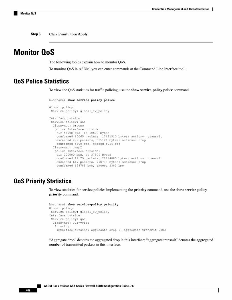
Step 6 Click Finish, then Apply.
Monitor QoSThe following topics explain how to monitor QoS.
To monitor QoS in ASDM, you can enter commands at the Command Line Interface tool.
QoS Police StatisticsTo view the QoS statistics for traffic policing, use the show service-policy police command.
hostname# show service-policy police
Global policy:Service-policy: global_fw_policy
Interface outside:Service-policy: qosClass-map: browsepolice Interface outside:cir 56000 bps, bc 10500 bytesconformed 10065 packets, 12621510 bytes; actions: transmitexceeded 499 packets, 625146 bytes; actions: dropconformed 5600 bps, exceed 5016 bps
Class-map: cmap2police Interface outside:cir 200000 bps, bc 37500 bytesconformed 17179 packets, 20614800 bytes; actions: transmitexceeded 617 packets, 770718 bytes; actions: dropconformed 198785 bps, exceed 2303 bps
QoS Priority StatisticsTo view statistics for service policies implementing the priority command, use the show service-policypriority command.
hostname# show service-policy priorityGlobal policy:Service-policy: global_fw_policyInterface outside:Service-policy: qosClass-map: TG1-voicePriority:Interface outside: aggregate drop 0, aggregate transmit 9383
“Aggregate drop” denotes the aggregated drop in this interface; “aggregate transmit” denotes the aggregatednumber of transmitted packets in this interface.
ASDM Book 2: Cisco ASA Series Firewall ASDM Configuration Guide, 7.6402
Connection Management and Threat DetectionMonitor QoS

QoS Priority Queue StatisticsTo display the priority-queue statistics for an interface, use the show priority-queue statistics command.The results show the statistics for both the best-effort (BE) queue and the low-latency queue (LLQ). Thefollowing example shows the use of the show priority-queue statistics command for the interface namedtest.
hostname# show priority-queue statistics test
Priority-Queue Statistics interface test
Queue Type = BEPackets Dropped = 0Packets Transmit = 0Packets Enqueued = 0Current Q Length = 0Max Q Length = 0
Queue Type = LLQPackets Dropped = 0Packets Transmit = 0Packets Enqueued = 0Current Q Length = 0Max Q Length = 0hostname#
In this statistical report:
• “Packets Dropped” denotes the overall number of packets that have been dropped in this queue.
• “Packets Transmit” denotes the overall number of packets that have been transmitted in this queue.
• “Packets Enqueued” denotes the overall number of packets that have been queued in this queue.
• “Current Q Length” denotes the current depth of this queue.
• “Max Q Length” denotes the maximum depth that ever occurred in this queue.
History for QoSDescriptionPlatform ReleasesFeature Name
We introduced QoS priority queuing andpolicing.
We introduced the following screens:
Configuration > Device Management >Advanced > Priority Queue Configuration> Firewall > Service Policy Rules
7.0(1)Priority queuing and policing
ASDM Book 2: Cisco ASA Series Firewall ASDM Configuration Guide, 7.6403
Connection Management and Threat DetectionQoS Priority Queue Statistics

DescriptionPlatform ReleasesFeature Name
We introduced QoS shaping andhierarchical priority queuing.
We modified the following screen:Configuration > Firewall > Service PolicyRules.
7.2(4)/8.0(4)Shaping and hierarchical priority queuing
We added support for a standard priorityqueue on Ten Gigabit Ethernet interfacesfor the ASA 5585-X.
8.2(3)/8.4(1)Ten Gigabit Ethernet support for a standardpriority queue on the ASA 5585-X
ASDM Book 2: Cisco ASA Series Firewall ASDM Configuration Guide, 7.6404
Connection Management and Threat DetectionHistory for QoS

C H A P T E R 17Threat Detection
The following topics describe how to configure threat detection statistics and scanning threat detection.
• Detecting Threats, on page 405• Guidelines for Threat Detection, on page 407• Defaults for Threat Detection, on page 408• Configure Threat Detection, on page 409• Monitoring Threat Detection, on page 411• History for Threat Detection, on page 412
Detecting ThreatsThreat detection on the ASA provides a front-line defense against attacks. Threat detection works at Layer 3and 4 to develop a baseline for traffic on the device, analyzing packet drop statistics and accumulating “top”reports based on traffic patterns. In comparison, a module that provides IPS or Next Generation IPS servicesidentifies and mitigates attack vectors up to Layer 7 on traffic the ASA permitted, and cannot see the trafficdropped already by the ASA. Thus, threat detection and IPS canwork together to provide amore comprehensivethreat defense.
Threat detection consists of the following elements:
• Different levels of statistics gathering for various threats.
Threat detection statistics can help you manage threats to your ASA; for example, if you enable scanningthreat detection, then viewing statistics can help you analyze the threat. You can configure two types ofthreat detection statistics:
• Basic threat detection statistics—Includes information about attack activity for the system as awhole. Basic threat detection statistics are enabled by default and have no performance impact.
• Advanced threat detection statistics—Tracks activity at an object level, so the ASA can reportactivity for individual hosts, ports, protocols, or ACLs. Advanced threat detection statistics can havea major performance impact, depending on the statistics gathered, so only the ACL statistics areenabled by default.
• Scanning threat detection, which determines when a host is performing a scan. You can optionally shunany hosts determined to be a scanning threat.
ASDM Book 2: Cisco ASA Series Firewall ASDM Configuration Guide, 7.6405
Basic Threat Detection StatisticsUsing basic threat detection statistics, the ASA monitors the rate of dropped packets and security events dueto the following reasons:
• Denial by ACLs.
• Bad packet format (such as invalid-ip-header or invalid-tcp-hdr-length).
• Connection limits exceeded (both system-wide resource limits, and limits set in the configuration).
• DoS attack detected (such as an invalid SPI, Stateful Firewall check failure).
• Basic firewall checks failed. This option is a combined rate that includes all firewall-related packet dropsin this list. It does not include non-firewall-related drops such as interface overload, packets failed atapplication inspection, and scanning attack detected.
• Suspicious ICMP packets detected.
• Packets failed application inspection.
• Interface overload.
• Scanning attack detected. This option monitors scanning attacks; for example, the first TCP packet isnot a SYN packet, or the TCP connection failed the 3-way handshake. Full scanning threat detectiontakes this scanning attack rate information and acts on it by classifying hosts as attackers and automaticallyshunning them, for example.
• Incomplete session detection such as TCP SYN attack detected or UDP session with no return data attackdetected.
When the ASA detects a threat, it immediately sends a system log message (733100). The ASA tracks twotypes of rates: the average event rate over an interval, and the burst event rate over a shorter burst interval.The burst rate interval is 1/30th of the average rate interval or 10 seconds, whichever is higher. For eachreceived event, the ASA checks the average and burst rate limits; if both rates are exceeded, then the ASAsends two separate system messages, with a maximum of one message for each rate type per burst period.
Basic threat detection affects performance only when there are drops or potential threats; even in this scenario,the performance impact is insignificant.
Advanced Threat Detection StatisticsAdvanced threat detection statistics show both allowed and dropped traffic rates for individual objects suchas hosts, ports, protocols, or ACLs.
Enabling advanced statistics can affect the ASA performance, depending on the type of statistics enabled.Enabling host statistics affects performance in a significant way; if you have a high traffic load, you mightconsider enabling this type of statistics temporarily. Port statistics, however, has modest impact.
Caution
ASDM Book 2: Cisco ASA Series Firewall ASDM Configuration Guide, 7.6406
Connection Management and Threat DetectionBasic Threat Detection Statistics

Scanning Threat DetectionA typical scanning attack consists of a host that tests the accessibility of every IP address in a subnet (byscanning through many hosts in the subnet or sweeping through many ports in a host or subnet). The scanningthreat detection feature determines when a host is performing a scan. Unlike IPS scan detection that is basedon traffic signatures, ASA threat detection scanningmaintains an extensive database that contains host statisticsthat can be analyzed for scanning activity.
The host database tracks suspicious activity such as connections with no return activity, access of closedservice ports, vulnerable TCP behaviors such as non-random IPID, and many more behaviors.
If the scanning threat rate is exceeded, then the ASA sends a syslog message (733101), and optionally shunsthe attacker. The ASA tracks two types of rates: the average event rate over an interval, and the burst eventrate over a shorter burst interval. The burst event rate is 1/30th of the average rate interval or 10 seconds,whichever is higher. For each event detected that is considered to be part of a scanning attack, the ASA checksthe average and burst rate limits. If either rate is exceeded for traffic sent from a host, then that host is consideredto be an attacker. If either rate is exceeded for traffic received by a host, then that host is considered to be atarget.
The following table lists the default rate limits for scanning threat detection.
Table 17: Default Rate Limits for Scanning Threat Detection
Burst RateAverage Rate
10 drops/sec over the last 20 second period.5 drops/sec over the last 600 seconds.
10 drops/sec over the last 120 second period.5 drops/sec over the last 3600 seconds.
The scanning threat detection feature can affect the ASA performance and memory significantly while itcreates and gathers host- and subnet-based data structure and information.
Caution
Guidelines for Threat DetectionSecurity Context Guidelines
Except for advanced threat statistics, threat detection is supported in single mode only. In Multiple mode,TCP Intercept statistics are the only statistic supported.
Types of Traffic Monitored
• Only through-the-box traffic is monitored; to-the-box traffic is not included in threat detection.
• Traffic that is denied by an ACL does not trigger scanning threat detection; only traffic that is allowedthrough the ASA and that creates a flow is affected by scanning threat detection.
ASDM Book 2: Cisco ASA Series Firewall ASDM Configuration Guide, 7.6407
Connection Management and Threat DetectionScanning Threat Detection

Defaults for Threat DetectionBasic threat detection statistics are enabled by default.
The following table lists the default settings. You can view all these default settings using the showrunning-config all threat-detection command in Tools > Command Line Interface.
For advanced statistics, by default, statistics for ACLs are enabled.
Table 18: Basic Threat Detection Default Settings
Trigger Settings
Packet Drop Reason Burst RateAverage Rate
400 drops/sec over the last 20second period.
100 drops/sec over the last 600seconds.
• DoS attack detected
• Bad packet format
• Connection limits exceeded
• Suspicious ICMP packetsdetected
320 drops/sec over the last 120second period.
80 drops/sec over the last 3600seconds.
10 drops/sec over the last 20second period.
5 drops/sec over the last 600seconds.
Scanning attack detected
8 drops/sec over the last 120second period.
4 drops/sec over the last 3600seconds.
200 drops/sec over the last 20second period.
100 drops/sec over the last 600seconds.
Incomplete session detected such asTCP SYN attack detected or UDPsession with no return data attackdetected (combined) 160 drops/sec over the last 120
second period.80 drops/sec over the last 3600seconds.
800 drops/sec over the last 20second period.
400 drops/sec over the last 600seconds.
Denial by ACLs
640 drops/sec over the last 120second period.
320 drops/sec over the last 3600seconds.
1600 drops/sec over the last 20second period.
400 drops/sec over the last 600seconds.
• Basic firewall checks failed
• Packets failed applicationinspection 1280 drops/sec over the last 120
second period.320 drops/sec over the last 3600seconds.
8000 drops/sec over the last 20second period.
2000 drops/sec over the last 600seconds.
Interface overload
6400 drops/sec over the last 120second period.
1600 drops/sec over the last 3600seconds.
ASDM Book 2: Cisco ASA Series Firewall ASDM Configuration Guide, 7.6408
Connection Management and Threat DetectionDefaults for Threat Detection

Configure Threat DetectionBasic threat detection statistics are enabled by default, and might be the only threat detection service that youneed. Use the following procedure if you want to implement additional threat detection services.
Procedure
Step 1 Configure Basic Threat Detection Statistics, on page 409.
Basic threat detection statistics include activity that might be related to an attack, such as a DoS attack.
Step 2 Configure Advanced Threat Detection Statistics, on page 409.Step 3 Configure Scanning Threat Detection, on page 410.
Configure Basic Threat Detection StatisticsBasic threat detection statistics is enabled by default. You can disabled it, or turn it on again if you disable it.
Procedure
Step 1 Choose the Configuration > Firewall > Threat Detection.Step 2 Select or deselect Enable Basic Threat Detection as desired.Step 3 Click Apply.
Configure Advanced Threat Detection StatisticsYou can configure the ASA to collect extensive statistics. By default, statistics for ACLs are enabled. Toenable other statistics, perform the following steps.
Procedure
Step 1 Choose Configuration > Firewall > Threat Detection.Step 2 In the Scanning Threat Statistics area, choose one of the following options:
• Enable All Statistics.
• Disable All Statistics.
• Enable Only Following Statistics.
Step 3 If you chose Enable Only Following Statistics, then select one or more of the following options:
ASDM Book 2: Cisco ASA Series Firewall ASDM Configuration Guide, 7.6409
Connection Management and Threat DetectionConfigure Threat Detection

• Hosts—Enables host statistics. The host statistics accumulate for as long as the host is active and in thescanning threat host database. The host is deleted from the database (and the statistics cleared) after 10minutes of inactivity.
• Access Rules (enabled by default)—Enables statistics for access rules.
• Port—Enables statistics for TCP and UDP ports.
• Protocol—Enables statistics for non-TCP/UDP IP protocols.
• TCP-Intercept—Enables statistics for attacks intercepted by TCP Intercept (to enable TCP Intercept,see Protect Servers from a SYN Flood DoS Attack (TCP Intercept), on page 377).
Step 4 For host, port, and protocol statistics, you can change the number of rate intervals collected. In the RateIntervals area, choose 1 hour, 1 and 8 hours, or 1, 8 and 24 hours for each statistics type. The default intervalis 1 hour, which keeps the memory usage low.
Step 5 For TCP Intercept statistics, you can set the following options in the TCP Intercept Threat Detection area:
• Monitoring Window Size—Sets the size of the history monitoring window, between 1 and 1440minutes.The default is 30 minutes. The ASA samples the number of attacks 30 times during the rate interval, sofor the default 30 minute period, statistics are collected every 60 seconds.
• Burst Threshold Rate—Sets the threshold for syslog message generation, between 25 and 2147483647.The default is 400 per second. When the burst rate is exceeded, syslog message 733104 is generated.
• Average Threshold Rate—Sets the average rate threshold for syslog message generation, between 25and 2147483647. The default is 200 per second. When the average rate is exceeded, syslog message733105 is generated.
Click Set Default to restore the default values.
Step 6 Click Apply.
Configure Scanning Threat DetectionYou can configure scanning threat detection to identify attackers and optionally shun them.
Procedure
Step 1 Choose Configuration > Firewall > Threat Detection.Step 2 Select Enable Scanning Threat Detection.Step 3 (Optional) To automatically terminate a host connection when the ASA identifies the host as an attacker,
select Shun Hosts detected by scanning threat and fill in these options if desired:
• To exempt host IP addresses from being shunned, enter an address or the name of a network object inthe Networks excluded from shun field. You can enter multiple addresses or subnets separated bycommas. To choose a network from the list of IP address objects, click the ... button.
• To set the duration of a shun for an attacking host, select Set Shun Duration and enter a value between10 and 2592000 seconds. The default length is 3600 seconds (1 hour). To restore the default value, clickSet Default.
ASDM Book 2: Cisco ASA Series Firewall ASDM Configuration Guide, 7.6410
Connection Management and Threat DetectionConfigure Scanning Threat Detection

Step 4 Click Apply.
Monitoring Threat DetectionThe following topics explain how to monitor threat detection and view traffic statistics.
Monitoring Basic Threat Detection StatisticsChoose Home > Firewall Dashboard > Traffic Overview to view basic threat detection statistics.
Monitoring Advanced Threat Detection StatisticsYou can monitor advanced threat statistics using the following dashboards:
• Home > Firewall Dashboard > Top 10 Access Rules—Displays the most hit access rules. Permits anddenies are not differentiated in this graph. You can track denied traffic in theTraffic Overview > DroppedPackets Rate graph.
• Home > Firewall Dashboard > Top Usage Statistics—The Top 10 Sources and Top 10 Destinationstabs show statistics for hosts. Due to the threat detection algorithm, an interface used as a combinationfailover and state link could appear in the top 10 hosts; this is expected behavior, and you can ignore thisIP address in the display.
The Top 10 Services tab shows statistics for both ports and protocols (both must be enabled for thedisplay), and shows the combined statistics of TCP/UDP port and IP protocol types. TCP (protocol 6)and UDP (protocol 17) are not included in the display for IP protocols; TCP and UDP ports are, however,included in the display for ports. If you only enable statistics for one of these types, port or protocol, thenyou will only view the enabled statistics.
• Home > Firewall Dashboard > Top Ten Protected Servers under SYN Attack—Shows the TCPIntercept statistics. Click the Detail button to show history sampling data. The ASA samples the numberof attacks 30 times during the rate interval, so for the default 30 minute period, statistics are collectedevery 60 seconds.
ASDM Book 2: Cisco ASA Series Firewall ASDM Configuration Guide, 7.6411
Connection Management and Threat DetectionMonitoring Threat Detection

History for Threat DetectionDescriptionPlatform ReleasesFeature Name
Basic and advanced threat detectionstatistics, scanning threat detection wasintroduced.
The following screens were introduced:Configuration > Firewall > ThreatDetection, Home > Firewall Dashboard> Traffic Overview, Home > FirewallDashboard > Top 10 Access Rules,Home> Firewall Dashboard > Top UsageStatus, Home > Firewall Dashboard >Top 10 Protected Servers Under SYNAttack.
8.0(2)Basic and advanced threat detectionstatistics, scanning threat detection
You can now set the shun duration,
The following screens was modified:Configuration > Firewall > ThreatDetection.
8.0(4)/8.1(2)Shun duration
TCP Intercept statistics were introduced.
The following screens were introduced ormodified: Configuration > Firewall >Threat Detection, Home > FirewallDashboard > Top 10 Protected ServersUnder SYN Attack.
8.0(4)/8.1(2)TCP Intercept statistics
You can now customize the number of rateintervals for which statistics are collected.The default number of rates was changedfrom 3 to 1.
The following screen was modified:Configuration > Firewall > ThreatDetection.
8.1(2)Customize host statistics rate intervals
In earlier releases, the burst rate intervalwas 1/60th of the average rate. Tomaximize memory usage, the samplinginterval was reduced to 30 times during theaverage rate.
8.2(1)Burst rate interval changed to 1/30th of theaverage rate.
ASDM Book 2: Cisco ASA Series Firewall ASDM Configuration Guide, 7.6412
Connection Management and Threat DetectionHistory for Threat Detection
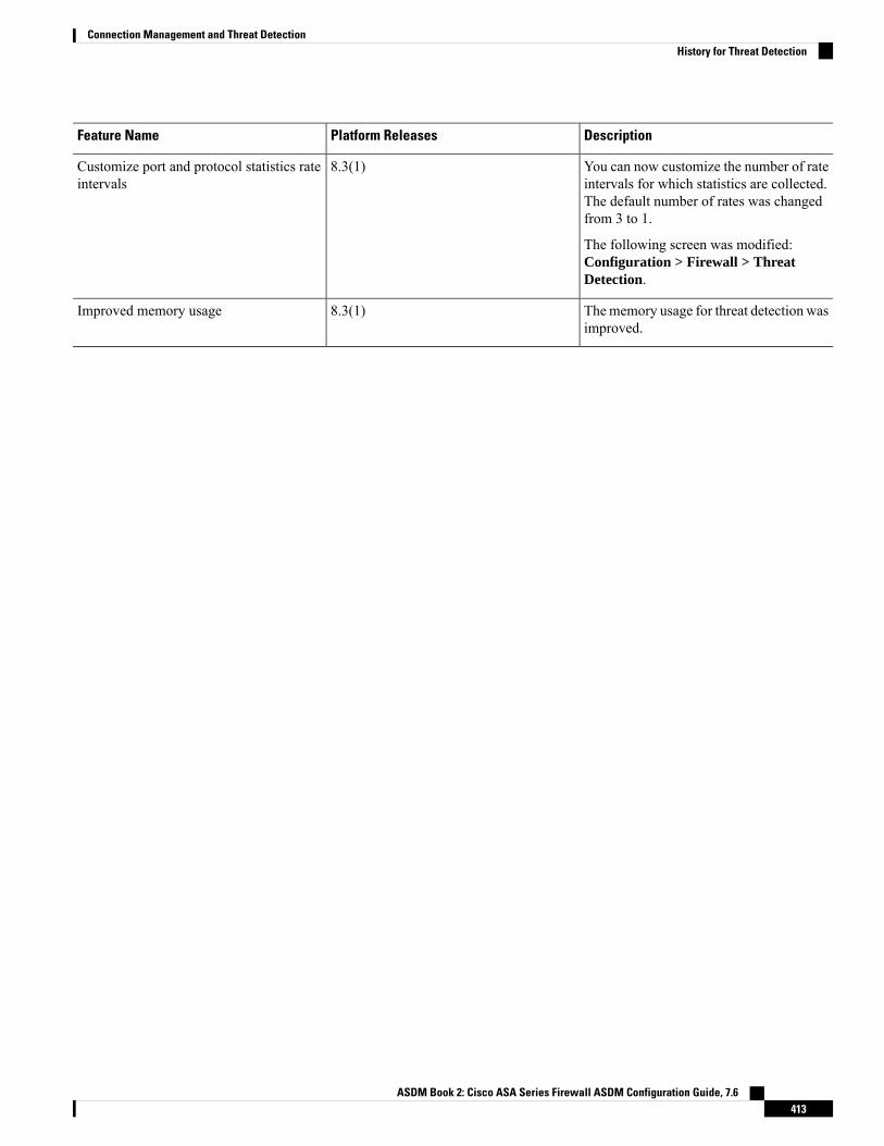
DescriptionPlatform ReleasesFeature Name
You can now customize the number of rateintervals for which statistics are collected.The default number of rates was changedfrom 3 to 1.
The following screen was modified:Configuration > Firewall > ThreatDetection.
8.3(1)Customize port and protocol statistics rateintervals
Thememory usage for threat detection wasimproved.
8.3(1)Improved memory usage
ASDM Book 2: Cisco ASA Series Firewall ASDM Configuration Guide, 7.6413
Connection Management and Threat DetectionHistory for Threat Detection

ASDM Book 2: Cisco ASA Series Firewall ASDM Configuration Guide, 7.6414
Connection Management and Threat DetectionHistory for Threat Detection