
ASA Hydraulik.pdf - Wilson Company
60
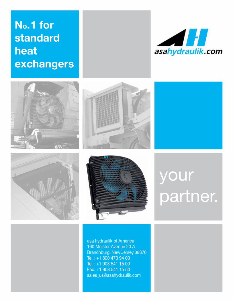
No.1 for standard heat exchangers your partner. asa hydraulik of America 160 Meister Avenue 20 A Branchburg, New Jersey 08876 Tel.: +1 800 473 94 00 Tel.: +1 908 541 15 00 Fax: +1 908 541 15 50 [email protected]
-
Upload
khangminh22 -
Category
Documents
-
view
5 -
download
0
Transcript of ASA Hydraulik.pdf - Wilson Company
No.1 for standard heat exchangers
your partner.
asa hydraulik of America160 Meister Avenue 20 ABranchburg, New Jersey 08876Tel.: +1 800 473 94 00Tel.: +1 908 541 15 00Fax: +1 908 541 15 [email protected]

2
blueasa
progress incooling
1980
2014
asa progress in coolingProgress in cooling stands for developments, advances and innovations al-ready working in our customers’ mobile and stationary applications, world-wide.
More than 30 years experience in heat transfer equipment and special hydrau-lic components has made us become a global leader in advanced technolo-gies. Our experience creates progress to ensure you competitive pricing, consistent product performance and reliability.
asa’s global capacities follow worldwide standards, confirmed by success-ful ISO 9001 quality management and client audits. The modular design and patented solutions of our products offer many advantages for customizing the product to your application.
Over the years, asa has continually developed into a globally active systems supplier. Despite this evolution, we consciously maintained the medium sized structure of a family owned company. As a result we are able to respond quickly and flexibly to our customer’s demands and to promote our innova-tions.
This catalogue provides a technical overview of our standard products. Please contact us, if more detailed information is required or if you cannot find the optimal product for you.
asa hydraulik GmbH, Austria / EU asa of America, New Jersey / USA asa hydraulik of Kunshan / CHINA

3
blueasa blue efficiency keeps you 2 steps ahead!
Best practice standard oil cooler series assures success at all ap-plications.
No limits through the first worldwide, flexible mount-ing and connection system
Optimized air flow from our uniquely quality engineered fan guard and electronic fan speed control options.
Combinations of cooler systems with tank and filter gain from the flexibility of each asa component.
Radiator with integrated bypass system to protect the cooler, e.g.: extremely viscous oil at cold start conditions.
Constant high quality through standard parts.
The most complete standard oil/air cooler program.
Compactness of serial produced parts as a function of capacity and life time.
efficiency
group
overview
LL 01 DC/AC
LL 02 DC/AC
LL 04 DC/AC
LL 06 DC/AC
compact
TT rail DC
TT rail AC
TT rail AC compact
TT rail HYD
ASA DC
ASA AC
ASA HYD
HL 0929 AC/HYD
HL 1247 HL 1508
connector
mounting
electronic
cooler systems
calculation / other
procucts

4
standard isour definition
Pollution reduces performance! Heavy polluted ambient air can clog the air side of the radiator and reduce the performance dramatically.
Our standard oil cooler radiators are designed with smooth wavy air fins to offer higher resistance against clogging.
The smooth air fin surfaces are easy to clean and have a constant performance output. Therefore the cooler can also be used in appli-cations like on agricultural machines, recycling power packs, quarry and construction machines without any additional protection (de-pending on the degree of pollution).
asa coolers offer the advantages of a standard product and a cus-tomized one.
This means proven quality, best lead time and competitive prices, combined with flexibility and perfect fit into a given installation space so that the optimal performance output and best integration in to the system can be achieved.
According to the cooler size, we offer various options and acces-sories to adapt the cooler to the customer’s requirements. The ben-efits achieved, are not only for the application itself, but also for our customers’ end product as an advantage against their competitors.
Customized 4 you with 2 systems (page 32/33)Our asa rail system and asa universal connectors are the frame structure for easy and cost efficient adaption for various mounting systems and electronic control options.
Gain from the benefit of a fan speed control to extend the fan life time and keep the noise level to a minimum. The asa protection housing is designed with rubber vibration absorbers and a very ro-bust metal housing to resist impacts on mobile applications.
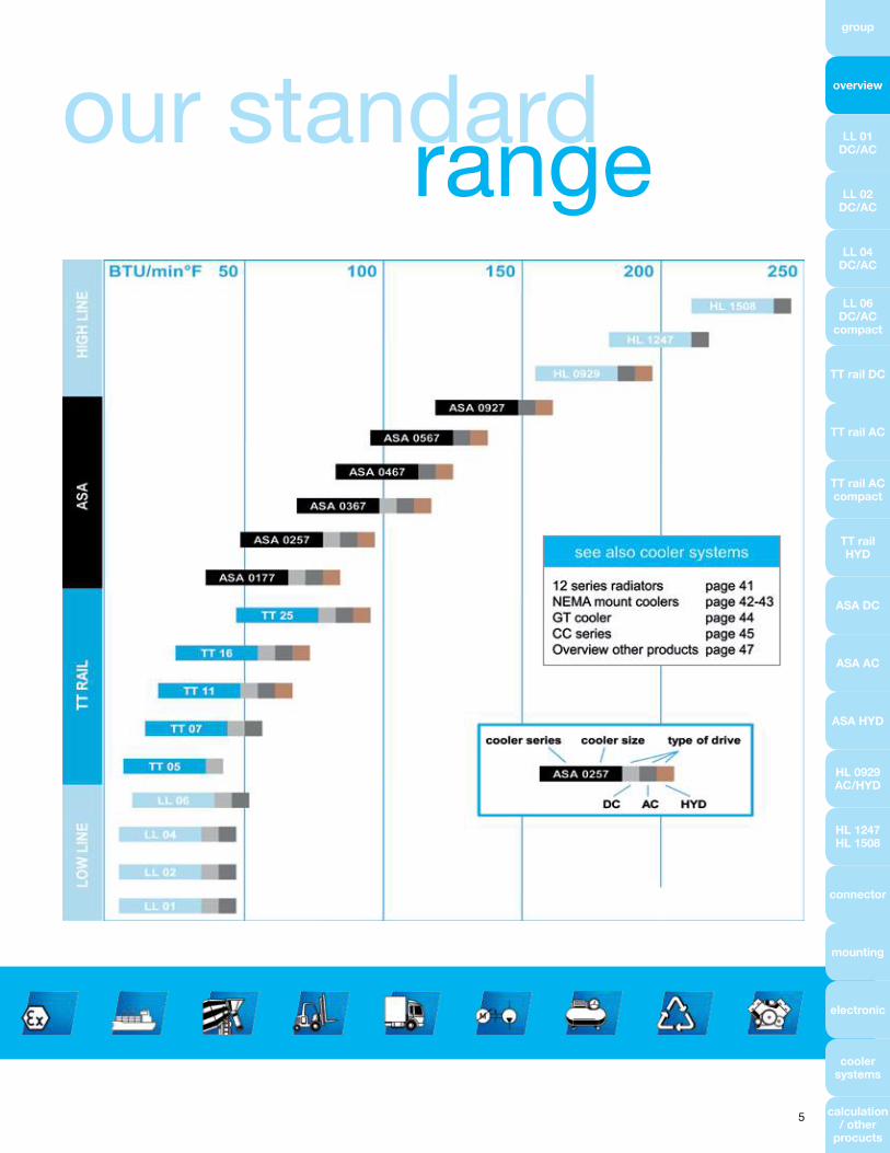
Standard Cooler Series from 0.1 to 250 BTU/min°F
5
our standardrange
group
overview
LL 01 DC/AC
LL 02 DC/AC
LL 04 DC/AC
LL 06 DC/AC
compact
TT rail DC
TT rail AC
TT rail AC compact
TT rail HYD
ASA DC
ASA AC
ASA HYD
HL 0929 AC/HYD
HL 1247 HL 1508
connector
mounting
electronic
cooler systems
calculation / other
procucts

This data sheet shows a technical overview of our products. Please contact us if more exact information is needed. As we are constantly improving our products, their characteristics, dimensions and weights may also change, although we do our best to incorporate these changes continually. The information in this data sheet is intended to be used as a first general guideline only. asa assumes no liability for any information therein, any errors, omissions, misprints, nor any direct or indirect damages, losses or costs resulting therefrom. The cooling performance and the general technical values indicated in this catalogue are measured at a test bench according to asa testing procedures. Because there is no standardized testing procedure, tests used by other manufacturers could have different results. Due to different conditions in testing and application environments the cooling performance may also vary by +/- 15%. Therefore we recommend all coolers to be checked under the system operating conditions. This is also true of vibra-tions and mechanical stress as well as for pressure peaks and thermal stress and any other relevant factors.
© asa hydraulik, March 20146
Oil / Air Cooler LL 01 LowLine12V / 24V DC
Technical Dataorder number description motor power current protection level air flow noise level weight
[HP] [A] [SCFM] [dB (A)] [Ibs]
ASA0013UD01 LL 01 12V DC 0.04 0.30 IP 20 70.6 44 3.08
ASA0013UD02 LL 01 24V DC 0.04 0.15 IP 20 70.6 44 3.08
Performancespecific cooling performance pressure drop at 150 SSU
Radiatormaterial: aluminum
working temperature range: –4°F to 212°F
air fin shape: wavy
working pressure: 370 PSI (static)
Please contact us for further options and assistance. Please read manual before installation!

This data sheet shows a technical overview of our products. Please contact us if more exact information is needed. As we are constantly improving our products, their characteristics, dimensions and weights may also change, although we do our best to incorporate these changes continually. The information in this data sheet is intended to be used as a first general guideline only. asa assumes no liability for any information therein, any errors, omissions, misprints, nor any direct or indirect damages, losses or costs resulting therefrom. The cooling performance and the general technical values indicated in this catalogue are measured at a test bench according to asa testing procedures. Because there is no standardized testing procedure, tests used by other manufacturers could have different results. Due to different conditions in testing and application environments the cooling performance may also vary by +/- 15%. Therefore we recommend all coolers to be checked under the system operating conditions. This is also true of vibra-tions and mechanical stress as well as for pressure peaks and thermal stress and any other relevant factors.
© asa hydraulik, March 2014 7
group
overview
LL 01 DC/AC
LL 02 DC/AC
LL 04 DC/AC
LL 06 DC/AC
compact
TT rail DC
TT rail AC
TT rail AC compact
TT rail HYD
ASA DC
ASA AC
ASA HYD
HL 0929 AC/HYD
HL 1247 HL 1508
connector
mounting
electronic
cooler systems
calculation / other
procucts
Oil / Air Cooler LL 01 LowLine115V / 60Hz
Technical Dataorder number description motor power current protection level air flow noise level weight
[HP] [A] [SCFM] [dB (A)] [Ibs]
ASA0013UE03 LL 01 115V AC 0.03 0.12 IP 20 70.6 41 3.08
Performancespecific cooling performance pressure drop at 150 SSU
Radiatormaterial: aluminum
working temperature range: –4°F to 212°F
air fin shape: wavy
working pressure: 370 PSI (static)
Please contact us for further options and assistance. Please read manual before installation!

This data sheet shows a technical overview of our products. Please contact us if more exact information is needed. As we are constantly improving our products, their characteristics, dimensions and weights may also change, although we do our best to incorporate these changes continually. The information in this data sheet is intended to be used as a first general guideline only. asa assumes no liability for any information therein, any errors, omissions, misprints, nor any direct or indirect damages, losses or costs resulting therefrom. The cooling performance and the general technical values indicated in this catalogue are measured at a test bench according to asa testing procedures. Because there is no standardized testing procedure, tests used by other manufacturers could have different results. Due to different conditions in testing and application environments the cooling performance may also vary by +/- 15%. Therefore we recommend all coolers to be checked under the system operating conditions. This is also true of vibra-tions and mechanical stress as well as for pressure peaks and thermal stress and any other relevant factors.
© asa hydraulik, March 20148
Oil / Air Cooler LL 02 LowLine12V / 24V DC
Technical Dataorder number description motor power current protection level air flow noise level weight
[HP] [A] [SCFM] [dB (A)] [Ibs]
ASA0023UD01 LL 02 12V DC 0.1 5.4 IP 68 247.1 73 5.94
ASA0023UD02 LL 02 24V DC 0.1 2.7 IP 68 247.1 73 5.94
Performancespecific cooling performance pressure drop at 150 SSU
Radiatormaterial: aluminum
working temperature range: –4°F to 212°F
air fin shape: wavy
working pressure: 370 PSI (static)
Optionstemperature switch 122°F, 140°F or 194°F (page 38)
Please contact us for further options and assistance. Please read manual before installation!

This data sheet shows a technical overview of our products. Please contact us if more exact information is needed. As we are constantly improving our products, their characteristics, dimensions and weights may also change, although we do our best to incorporate these changes continually. The information in this data sheet is intended to be used as a first general guideline only. asa assumes no liability for any information therein, any errors, omissions, misprints, nor any direct or indirect damages, losses or costs resulting therefrom. The cooling performance and the general technical values indicated in this catalogue are measured at a test bench according to asa testing procedures. Because there is no standardized testing procedure, tests used by other manufacturers could have different results. Due to different conditions in testing and application environments the cooling performance may also vary by +/- 15%. Therefore we recommend all coolers to be checked under the system operating conditions. This is also true of vibra-tions and mechanical stress as well as for pressure peaks and thermal stress and any other relevant factors.
© asa hydraulik, March 2014 9
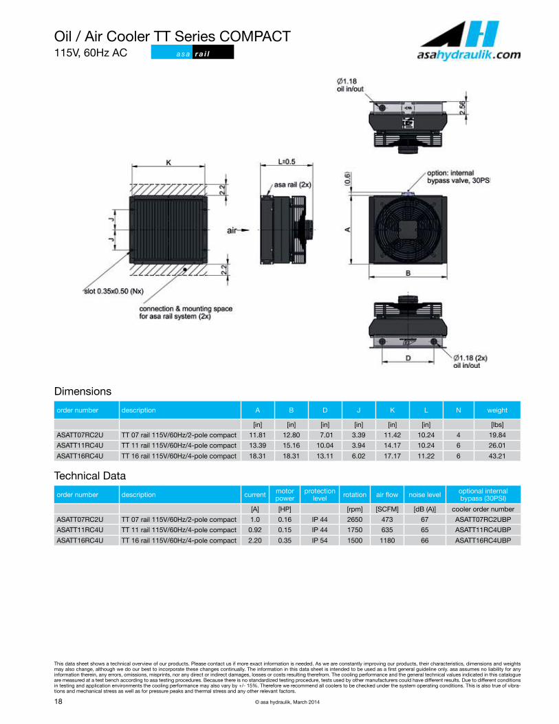
Oil / Air Cooler TT Series115V 60 Hz
group
overview
LL 01 DC/AC
LL 02 DC/AC
LL 04 DC/AC
LL 06 DC/AC
compact
TT rail DC
TT rail AC
TT rail AC compact
TT rail HYD
ASA DC
ASA AC
ASA HYD
HL 0929 AC/HYD
HL 1247 HL 1508
connector
mounting
electronic
cooler systems
calculation / other
procucts
Technical Dataorder number description motor power current protection level air flow noise level weight
[HP] [A] [SCFM] [dB (A)] [Ibs]
ASA0023UE04 LL 02 115V AC 0.05 0.33 IP 20 70.6 54 5.5
Performancespecific cooling performance pressure drop at 150 SSU
Radiatormaterial: aluminum
working temperature range: –4°F to 212°F
air fin shape: wavy
working pressure: 370 PSI (static)
Optionstemperature switch 122°F, 140°F or 194°F (page 38)
Please contact us for further options and assistance. Please read manual before installation!

This data sheet shows a technical overview of our products. Please contact us if more exact information is needed. As we are constantly improving our products, their characteristics, dimensions and weights may also change, although we do our best to incorporate these changes continually. The information in this data sheet is intended to be used as a first general guideline only. asa assumes no liability for any information therein, any errors, omissions, misprints, nor any direct or indirect damages, losses or costs resulting therefrom. The cooling performance and the general technical values indicated in this catalogue are measured at a test bench according to asa testing procedures. Because there is no standardized testing procedure, tests used by other manufacturers could have different results. Due to different conditions in testing and application environments the cooling performance may also vary by +/- 15%. Therefore we recommend all coolers to be checked under the system operating conditions. This is also true of vibra-tions and mechanical stress as well as for pressure peaks and thermal stress and any other relevant factors.
© asa hydraulik, March 201410
Oil / Air Cooler LL 04 LowLine12V /24V DC
Technical Dataorder number description motor power current protection level air flow noise level weight
[HP] [A] [SCFM] [dB (A)] [Ibs]
ASA0043UD01 LL 04 12V DC 0.1 5.4 IP 68 282.4 68 8.8
ASA0043UD02 LL 04 24V DC 0.1 2.7 IP 68 282.4 68 8.8
Performancespecific cooling performance pressure drop at 150 SSU
Radiatormaterial: aluminum
working temperature range: –4°F to 212°F
air fin shape: wavy
working pressure: 370 PSI (static)
Optionstemperature control ILLZTC12-2K or ILLZTC24-2K + ILLZTT5069K (page 36,37)
temperature control reversible ILLZTCB00 (page 40)
temperature switch 122°F, 140°F or 194°F (page 38)
Please contact us for further options and assistance. Please read manual before installation!

This data sheet shows a technical overview of our products. Please contact us if more exact information is needed. As we are constantly improving our products, their characteristics, dimensions and weights may also change, although we do our best to incorporate these changes continually. The information in this data sheet is intended to be used as a first general guideline only. asa assumes no liability for any information therein, any errors, omissions, misprints, nor any direct or indirect damages, losses or costs resulting therefrom. The cooling performance and the general technical values indicated in this catalogue are measured at a test bench according to asa testing procedures. Because there is no standardized testing procedure, tests used by other manufacturers could have different results. Due to different conditions in testing and application environments the cooling performance may also vary by +/- 15%. Therefore we recommend all coolers to be checked under the system operating conditions. This is also true of vibra-tions and mechanical stress as well as for pressure peaks and thermal stress and any other relevant factors.
© asa hydraulik, March 2014 11
Oil / Air Cooler LL 04 LowLine115V 60 Hz AC, 230/460V 60 Hz AC
group
overview
LL 01 DC/AC
LL 02 DC/AC
LL 04 DC/AC
LL 06 DC/AC
compact
TT rail DC
TT rail AC
TT rail AC compact
TT rail HYD
ASA DC
ASA AC
ASA HYD
HL 0929 AC/HYD
HL 1247 HL 1508
connector
mounting
electronic
cooler systems
calculation / other
procucts
ASA0043UI03:
ASA0043UI04:
Technical Dataorder number description motor power current protection level air flow noise level weight
[HP] [A] [SCFM] [dB (A)] [Ibs]
ASA0043UE04 LL 04 115V 60 Hz AC 0.05 0.33 IP 20 158.85 56 9.46
ASA0043UEI03 LL 04 230/460V 60 Hz AC 0.07 0.15 IP 44 264.75 66 12.98
Performancespecific cooling performance pressure drop at 150 SSU
Radiatormaterial: aluminum
working temperature range: –4°F to 212°F
air fin shape: wavy
working pressure: 370 PSI (static)
Optionstemperature switch 122°F, 140°F or 194°F (page 38)
Please contact us for further options and assistance. Please read manual before installation!
ASA0043UI03
ASA0043UE04

This data sheet shows a technical overview of our products. Please contact us if more exact information is needed. As we are constantly improving our products, their characteristics, dimensions and weights may also change, although we do our best to incorporate these changes continually. The information in this data sheet is intended to be used as a first general guideline only. asa assumes no liability for any information therein, any errors, omissions, misprints, nor any direct or indirect damages, losses or costs resulting therefrom. The cooling performance and the general technical values indicated in this catalogue are measured at a test bench according to asa testing procedures. Because there is no standardized testing procedure, tests used by other manufacturers could have different results. Due to different conditions in testing and application environments the cooling performance may also vary by +/- 15%. Therefore we recommend all coolers to be checked under the system operating conditions. This is also true of vibra-tions and mechanical stress as well as for pressure peaks and thermal stress and any other relevant factors.
© asa hydraulik, March 201412
Oil / Air Cooler LL 06 LowLine12V / 24V DC
Technical Dataorder number description motor power current protection level air flow noise level L weight
[HP] [A] [SCFM] [dB (A)] [in] [Ibs]
ASATT06UD03 LL 06 12V DC HP 0.13 7.4 IP 68 510 74 6.14 13.3
ASATT06UD04 LL 06 24V DC HP 0.13 3.7 IP 68 510 74 6.14 13.2
Performancespecific cooling performance pressure drop at 150 SSU
Radiatormaterial: aluminum
working temperature range: –4°F to 212°F
air fin shape: wavy
working pressure: 370 PSI (static)
Optionstemperature control ILLZTC12-2K or ILLZTC24-2K + ILLZTT5069K (page 36,37)
temperature control reversible ILLZTCB00 (page 40)
temperature switch 122°F, 140°F or 194°F (page 38)
internal 30PSI bypass cooler ASATT06UD03BP (12V) / ASATT06UD04BP (24V)
foot mounting option ILLEFUSSTT06K (contact us for more information)
protection housing ILLEGAK0064GT (contact us for more information)
Please contact us for further options and assistance. Please read manual before installation!

This data sheet shows a technical overview of our products. Please contact us if more exact information is needed. As we are constantly improving our products, their characteristics, dimensions and weights may also change, although we do our best to incorporate these changes continually. The information in this data sheet is intended to be used as a first general guideline only. asa assumes no liability for any information therein, any errors, omissions, misprints, nor any direct or indirect damages, losses or costs resulting therefrom. The cooling performance and the general technical values indicated in this catalogue are measured at a test bench according to asa testing procedures. Because there is no standardized testing procedure, tests used by other manufacturers could have different results. Due to different conditions in testing and application environments the cooling performance may also vary by +/- 15%. Therefore we recommend all coolers to be checked under the system operating conditions. This is also true of vibra-tions and mechanical stress as well as for pressure peaks and thermal stress and any other relevant factors.
© asa hydraulik, March 2014 13
Oil / Air Cooler LL 06 LowLine115 V 60 Hz AC compact
group
overview
LL 01 DC/AC
LL 02 DC/AC
LL 04 DC/AC
LL 06 DC/AC
compact
TT rail DC
TT rail AC
TT rail AC compact
TT rail HYD
ASA DC
ASA AC
ASA HYD
HL 0929 AC/HYD
HL 1247 HL 1508
connector
mounting
electronic
cooler systems
calculation / other
procucts
Technical Dataorder number description motor power current protection level air flow noise level weight
[HP] [A] [SCFM] [dB (A)] [Ibs]
ASATT06UC2U LL 06 115V AC compact 0.16 1.0 IP 44 494 67 7.4
Performancespecific cooling performance pressure drop at 150 SSU
Radiatormaterial: aluminum
working temperature range: –4°F to 212°F
air fin shape: wavy
working pressure: 370 PSI (static)
Optionstemperature switch 122°F, 140°F or 194°F (page 38)
internal 30PSI bypass cooler ASATT06UC2EBP
foot mounting option ILLEFUSSTT06K (contact us for more information)
Please contact us for further options and assistance. Please read manual before installation!

This data sheet shows a technical overview of our products. Please contact us if more exact information is needed. As we are constantly improving our products, their characteristics, dimensions and weights may also change, although we do our best to incorporate these changes continually. The information in this data sheet is intended to be used as a first general guideline only. asa assumes no liability for any information therein, any errors, omissions, misprints, nor any direct or indirect damages, losses or costs resulting therefrom. The cooling performance and the general technical values indicated in this catalogue are measured at a test bench according to asa testing procedures. Because there is no standardized testing procedure, tests used by other manufacturers could have different results. Due to different conditions in testing and application environments the cooling performance may also vary by +/- 15%. Therefore we recommend all coolers to be checked under the system operating conditions. This is also true of vibra-tions and mechanical stress as well as for pressure peaks and thermal stress and any other relevant factors.
© asa hydraulik, March 201414
Oil / Air Cooler TT Series12V / 24V DC a s a r a i l
Dimensionsorder number description A B D J P K L N weight
[in] [in] [in] [in] [in] [in] [in] [lbs]
ASATT05RD01 TT 05 rail 12V DC 9.25 9.65 4.65 5.91 – 8.86 5.91 4* 8.58
ASATT05RD02 TT 05 rail 24V DC 9.25 9.65 4.65 5.91 – 8.86 5.91 4* 8.58
ASATT07RD01 TT 07 rail 12V DC 11.81 12.60 7.01 3.39 6.77 11.42 6.03 4 14.30
ASATT07RD02 TT 07 rail 24V DC 11.81 12.60 7.01 3.39 6.77 11.42 6.03 4 14.30
ASATT07RD03 TT 07 rail 12V DC h.p. 11.81 12.60 7.01 3.39 6.77 11.42 6.93 4 15.40
ASATT07RD04 TT 07 rail 24V DC h.p. 11.81 12.60 7.01 3.39 6.77 11.42 6.93 4 15.40
ASATT11RD01 TT 11 rail 12V DC 13.39 14.96 10.04 3.94 7.87 14.17 6.89 6 19.14
ASATT11RD02 TT 11 rail 24V DC 13.39 14.96 10.04 3.94 7.87 14.17 6.89 6 19.14
ASATT16RD01 TT 16 rail 12V DC 18.31 18.11 13.11 6.02 12.05 17.17 7.48 6 32.12
ASATT16RD02 TT 16 rail 24V DC 18.31 18.11 13.11 6.02 12.05 17.17 7.48 6 32.12
ASATT25RD01 TT 25 rail 12V DC 23.82 21.85 16.89 8.21 16.42 20.87 10.12 6 47.74
ASATT25RD02 TT 25 rail 24V DC 23.82 21.85 16.89 8.21 16.42 20.87 10.12 6 47.74
* slot holes with 0.28in x 0.39in
Technical Dataorder number description current motor power protection level air flow noise level optional internal bypass (30 PSI)
[A] [HP] [SCFM] [dB (A)] cooler order number
ASATT05RD01 TT 05 rail 12V DC 9 0.16 IP 68 335.35 74 –
ASATT05RD02 TT 05 rail 24V DC 4.5 0.16 IP 68 335.35 74 –
ASATT07RD01 TT 07 rail 12V DC 10.4 0.18 IP 68 564.8 74 ASATT07RD01BP
ASATT07RD02 TT 07 rail 24V DC 5.2 0.18 IP 68 564.8 74 ASATT07RD02BP
ASATT07RD03 TT 07 rail 12V DC h.p. 16.2 0.29 IP 68 706.0 78 ASATT07RD03BP
ASATT07RD04 TT 07 rail 24V DC h.p. 8.1 0.29 IP 68 706.0 78 ASATT07RD04BP
ASATT11RD01 TT 11 rail 12V DC 20.8 0.37 IP 68 1094.3 77 ASATT11RD01BP
ASATT11RD02 TT 11 rail 24V DC 10.4 0.37 IP 68 1094.3 77 ASATT11RD02BP
ASATT16RD01 TT 16 rail 12V DC 18.6 0.33 IP 68 1200.2 79 ASATT16RD01BP
ASATT16RD02 TT 16 rail 24V DC 9.3 0.33 IP 68 1200.2 79 ASATT16RD02BP
ASATT25RD01 TT 25 rail 12V DC 18.6 0.33 IP 68 1376.7 77 ASATT25RD01BP
ASATT25RD02 TT 25 rail 24V DC 9.3 0.33 IP 68 1376.7 77 ASATT25RD02BP

This data sheet shows a technical overview of our products. Please contact us if more exact information is needed. As we are constantly improving our products, their characteristics, dimensions and weights may also change, although we do our best to incorporate these changes continually. The information in this data sheet is intended to be used as a first general guideline only. asa assumes no liability for any information therein, any errors, omissions, misprints, nor any direct or indirect damages, losses or costs resulting therefrom. The cooling performance and the general technical values indicated in this catalogue are measured at a test bench according to asa testing procedures. Because there is no standardized testing procedure, tests used by other manufacturers could have different results. Due to different conditions in testing and application environments the cooling performance may also vary by +/- 15%. Therefore we recommend all coolers to be checked under the system operating conditions. This is also true of vibra-tions and mechanical stress as well as for pressure peaks and thermal stress and any other relevant factors.
© asa hydraulik, March 2014 15
Oil / Air Cooler TT Series12V / 24V DC a s a r a i l
Performancespecific cooling performance pressure drop at 150 SSU
TT 25 rail
TT 16 rail
TT 11 rail
TT 07 rail h.p.
TT 07 rail
TT 16 rail TT 25 rail
TT 11 rail
TT 07 rail
TT 05 rail
TT 05 rail
Radiatormaterial: aluminum
working temperature range: –4°C to 176°F
air fin shape: wavy
working pressure: 370 PSI (static)
Optionstemperature control ILLZTC12-2K or ILLZTC24-2K + ILLZTT5069K (page 36,37)
temperature control reversible ILLZTCB00 (page 40)
temperature switches 122°F, 140°F or 194°F (page 38)
rail mounting bracket MW3046K (page 34)
foot mounting ILLEFUSSTTHDK (page 34)
protection housing see page 40
internal bypass alternative settings on request
Installation System (more information on page 32) connection UN 1 5/16“ ILLZSET5U16 (1 set per cooler required)
connection UN 1 5/8“ ILLZSET5U20 (1 set per cooler required)
Please contact us for further options and assistance. Please read manual before installation!
a s a r a i l
group
overview
LL 01 DC/AC
LL 02 DC/AC
LL 04 DC/AC
LL 06 DC/AC
compact
TT rail DC
TT rail AC
TT rail AC compact
TT rail HYD
ASA DC
ASA AC
ASA HYD
HL 0929 AC/HYD
HL 1247 HL 1508
connector
mounting
electronic
cooler systems
calculation / other
procucts

This data sheet shows a technical overview of our products. Please contact us if more exact information is needed. As we are constantly improving our products, their characteristics, dimensions and weights may also change, although we do our best to incorporate these changes continually. The information in this data sheet is intended to be used as a first general guideline only. asa assumes no liability for any information therein, any errors, omissions, misprints, nor any direct or indirect damages, losses or costs resulting therefrom. The cooling performance and the general technical values indicated in this catalogue are measured at a test bench according to asa testing procedures. Because there is no standardized testing procedure, tests used by other manufacturers could have different results. Due to different conditions in testing and application environments the cooling performance may also vary by +/- 15%. Therefore we recommend all coolers to be checked under the system operating conditions. This is also true of vibra-tions and mechanical stress as well as for pressure peaks and thermal stress and any other relevant factors.
© asa hydraulik, March 201416
Oil / Air Cooler TT Series230/460V, 60Hz AC a s a r a i l
Dimensionsorder number description A B C D J K L N weight
[in] [in] [in] [in] [in] [in] [in] [lbs]
ASATT07RA44 TT 07 rail 0.34HP AC 11.81 12.8 7.6 7.01 3.39 11.42 15.59 4 42.9
ASATT07RA25 TT 07 rail 0.75HP AC 11.81 12.8 7.6 7.01 3.39 11.42 15.59 4 45.1
ASATT11RA44 TT 11 rail 0.34HP AC 13.39 14.96 7.6 10.04 3.94 14.17 15.67 6 45.54
ASATT11RA27 TT 11 rail 1.5HP AC 13.39 14.96 7.6 10.04 3.94 14.17 15.67 6 47.74
ASATT16RA64 TT 16 rail 0.25HP AC 18.31 18.11 8.58 13.11 6.02 17.17 16.3 6 55.00
ASATT16RA45 TT 16 rail 0.5HP AC 18.31 18.11 8.58 13.11 6.02 17.17 16.3 6 55.44
ASATT16RA27 TT 16 rail 1.5HP AC 18.31 18.11 8.58 13.11 6.02 17.17 16.3 6 57.64
ASATT25RA66 TT 25 rail 0.5HP AC 23.82 21.85 8.58 13.89 8.21 20.87 17.68 6 71.5
ASATT25RA46 TT 25 rail 0.75HP AC 23.82 21.85 8.58 13.89 8.21 20.87 17.68 6 71.06
Technical Data
order number description current motor power protection level rotation air flow noise level optional internalbypass (30 PSI)
[A] [HP] [rpm] [SCFM] [dB (A)] cooler order number
ASATT07RA44 TT 07 rail 0.34HP AC 0.8 0.34 IP 55 1662 335.4 60 ASATT07RA44BP
ASATT07RA25 TT 07 rail 0.75HP AC 1.4 0.75 IP 55 3378 706.0 78 ASATT07RA25BP
ASATT11RA44 TT 11 rail 0.34HP AC 0.8 0.34 IP 55 1662 600.1 73 ASATT11RA44BP
ASATT11RA27 TT 11 rail 1.5HP AC 1.5 1.5 IP 55 3378 1200.2 83 ASATT11RA27BP
ASATT16RA64 TT 16 rail 0.25HP AC 0.9 0.25 IP 55 1104 741.3 62 ASATT16RA64BP
ASATT16RA45 TT 16 rail 0.5HP AC 0.8 0.5 IP 55 1662 1023.7 74 ASATT16RA45BP
ASATT16RA27 TT 16 rail 1.5HP AC 1.4 1.5 IP 55 3378 1517.9 91 ASATT16RA27BP
ASATT25RA66 TT 25 rail 0.5HP AC 1.2 0.5 IP 55 1098 1644.0 75 ASATT25RA66BP
ASATT25RA46 TT 25 rail 0.75HP AC 1.6 0.75 IP 55 1680 2520.0 86 ASATT25RA46BP

This data sheet shows a technical overview of our products. Please contact us if more exact information is needed. As we are constantly improving our products, their characteristics, dimensions and weights may also change, although we do our best to incorporate these changes continually. The information in this data sheet is intended to be used as a first general guideline only. asa assumes no liability for any information therein, any errors, omissions, misprints, nor any direct or indirect damages, losses or costs resulting therefrom. The cooling performance and the general technical values indicated in this catalogue are measured at a test bench according to asa testing procedures. Because there is no standardized testing procedure, tests used by other manufacturers could have different results. Due to different conditions in testing and application environments the cooling performance may also vary by +/- 15%. Therefore we recommend all coolers to be checked under the system operating conditions. This is also true of vibra-tions and mechanical stress as well as for pressure peaks and thermal stress and any other relevant factors.
© asa hydraulik, March 2014 17
Oil / Air Cooler TT Series230/460V, 60Hz AC a s a r a i l
Radiatormaterial: aluminum
working temperature range: –4°C to 176°F
air fin shape: wavy
working pressure: 370 PSI (static)
Optionsmotor data alternative voltages, frequencies, IP classes, etc on request
temperature switches 122°F, 140°F (page 38)
temperature control AC ILLZTCACK (page 39)
mounting bracket MW3046K (page 34)
foot mounting options ILLEFUSSTTK, ILLEFUSSTTHDK (page 34)
internal bypass alternative settings on request
Installation System (more information on page 32) connection UN 1 5/16“ ILLZSET5U16 (1 set per cooler required)
connection UN 1 5/8“ ILLZSET5U20 (1 set per cooler required)
Please contact us for further options and assistance. Please read manual before installation!
a s a r a i l
Performancespecific cooling performance pressure drop at 150 SSU
TT 16 rail
TT 25 rail
TT 11 rail
TT 07 rail
TT 25 rail 0.75HP
TT 25 rail 0.5HP
TT 16 rail 1.5HP
TT 16 rail 0.5HP
TT 16 rail 0.25HP
TT 11 rail 1.5HP
TT 11 rail 0.34HP
TT 07 rail 0.75HP
TT 07 rail 0.34HP
group
overview
LL 01 DC/AC
LL 02 DC/AC
LL 04 DC/AC
LL 06 DC/AC
compact
TT rail DC
TT rail AC
TT rail AC compact
TT rail HYD
ASA DC
ASA AC
ASA HYD
HL 0929 AC/HYD
HL 1247 HL 1508
connector
mounting
electronic
cooler systems
calculation / other
procucts
This data sheet shows a technical overview of our products. Please contact us if more exact information is needed. As we are constantly improving our products, their characteristics, dimensions and weights may also change, although we do our best to incorporate these changes continually. The information in this data sheet is intended to be used as a first general guideline only. asa assumes no liability for any information therein, any errors, omissions, misprints, nor any direct or indirect damages, losses or costs resulting therefrom. The cooling performance and the general technical values indicated in this catalogue are measured at a test bench according to asa testing procedures. Because there is no standardized testing procedure, tests used by other manufacturers could have different results. Due to different conditions in testing and application environments the cooling performance may also vary by +/- 15%. Therefore we recommend all coolers to be checked under the system operating conditions. This is also true of vibra-tions and mechanical stress as well as for pressure peaks and thermal stress and any other relevant factors.
© asa hydraulik, March 201418
Oil / Air Cooler TT Series COMPACT115V, 60Hz AC a s a r a i l
Dimensions
order number description A B D J K L N weight
[in] [in] [in] [in] [in] [in] [lbs]
ASATT07RC2U TT 07 rail 115V/60Hz/2-pole compact 11.81 12.80 7.01 3.39 11.42 10.24 4 19.84
ASATT11RC4U TT 11 rail 115V/60Hz/4-pole compact 13.39 15.16 10.04 3.94 14.17 10.24 6 26.01
ASATT16RC4U TT 16 rail 115V/60Hz/4-pole compact 18.31 18.31 13.11 6.02 17.17 11.22 6 43.21
Technical Data
order number description current motor power
protection level rotation air flow noise level optional internal
bypass (30PSI)
[A] [HP] [rpm] [SCFM] [dB (A)] cooler order number
ASATT07RC2U TT 07 rail 115V/60Hz/2-pole compact 1.0 0.16 IP 44 2650 473 67 ASATT07RC2UBP
ASATT11RC4U TT 11 rail 115V/60Hz/4-pole compact 0.92 0.15 IP 44 1750 635 65 ASATT11RC4UBP
ASATT16RC4U TT 16 rail 115V/60Hz/4-pole compact 2.20 0.35 IP 54 1500 1180 66 ASATT16RC4UBP
This data sheet shows a technical overview of our products. Please contact us if more exact information is needed. As we are constantly improving our products, their characteristics, dimensions and weights may also change, although we do our best to incorporate these changes continually. The information in this data sheet is intended to be used as a first general guideline only. asa assumes no liability for any information therein, any errors, omissions, misprints, nor any direct or indirect damages, losses or costs resulting therefrom. The cooling performance and the general technical values indicated in this catalogue are measured at a test bench according to asa testing procedures. Because there is no standardized testing procedure, tests used by other manufacturers could have different results. Due to different conditions in testing and application environments the cooling performance may also vary by +/- 15%. Therefore we recommend all coolers to be checked under the system operating conditions. This is also true of vibra-tions and mechanical stress as well as for pressure peaks and thermal stress and any other relevant factors.
© asa hydraulik, March 2014 19
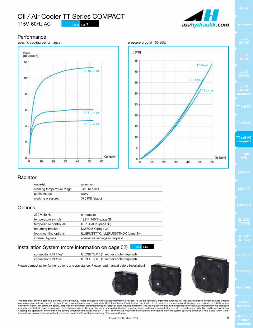
Performancespecific cooling performance pressure drop at 150 SSU
Radiatormaterial: aluminum
working temperature range: –4°F to 176°F
air fin shape: wavy
working pressure: 370 PSI (static)
Options230 V, 50 Hz on request
temperature switch 122°F, 140°F (page 38)
temperature control AC ILLZTCACK (page 39)
mounting bracket MW3046K (page 34)
foot mounting options ILLEFUSSTTK, ILLEFUSSTTHDK (page 34)
internal bypass alternative settings on request
Installation System (more information on page 32)connection UN 1 5/16“ ILLZSET5U16 (1 set per cooler required)
connection UN 1 5/8“ ILLZSET5U20 (1 set per cooler required)
Please contact us for further options and assistance. Please read manual before installation!
TT 16 rail
TT 11 rail
TT 07 rail
TT 16 / 4-pol
TT 11 / 4-pol
TT 07 / 2-pol
Oil / Air Cooler TT Series COMPACT115V, 60Hz AC a s a r a i l
a s a r a i l
group
overview
LL 01 DC/AC
LL 02 DC/AC
LL 04 DC/AC
LL 06 DC/AC
compact
TT rail DC
TT rail AC
TT rail AC compact
TT rail HYD
ASA DC
ASA AC
ASA HYD
HL 0929 AC/HYD
HL 1247 HL 1508
connector
mounting
electronic
cooler systems
calculation / other
procucts

This data sheet shows a technical overview of our products. Please contact us if more exact information is needed. As we are constantly improving our products, their characteristics, dimensions and weights may also change, although we do our best to incorporate these changes continually. The information in this data sheet is intended to be used as a first general guideline only. asa assumes no liability for any information therein, any errors, omissions, misprints, nor any direct or indirect damages, losses or costs resulting therefrom. The cooling performance and the general technical values indicated in this catalogue are measured at a test bench according to asa testing procedures. Because there is no standardized testing procedure, tests used by other manufacturers could have different results. Due to different conditions in testing and application environments the cooling performance may also vary by +/- 15%. Therefore we recommend all coolers to be checked under the system operating conditions. This is also true of vibra-tions and mechanical stress as well as for pressure peaks and thermal stress and any other relevant factors.
© asa hydraulik, March 201420
Oil / Air Cooler TT Series0.73 in3 hydraulic drive a s a r a i l
Dimensionsorder number description A B C D J K L N weight
[in] [in] [in] [in] [in] [in] [in] [lbs]
ASATT11RH12 TT 11 rail 0.73 in³ hydraulic drive 13.39 14.96 7.6 10.04 3.94 14.17 10.91 6 36.74
ASATT16RH12 TT 16 rail 0.73 in³ hydraulic drive 18.31 18.11 8.58 13.11 6.02 17.17 11.89 6 46.64
ASATT25RH12 TT 25 rail 0.73 in³ hydraulic drive 23.82 21.85 8.58 16.89 8.21 20.87 11.89 6 61.16
Technical Data
order number description motor power oil pressure oil flow rotation air flow noise level optional internal bypass (30 PSI)
[HP] [PSI] [gpm] [rpm] [SCFM] [dB (A)] cooler order number
ASATT11RH12 TT 11 rail 0.73 in³ hydraulic drive
0.03 14.5 3.17 1000 370.65 66
ASATT11RH12BP0.26 87.02 6.07 2000 706.0 82
0.88 174.05 9.24 3000 1323.75 90
ASATT16RH12 TT 16 rail 0.73 in³ hydraulic drive
0.11 61 3.3 1000 776.6 61
ASATT16RH12BP0.89 257 6.7 2000 1341.4 79
2.99 578 10 3000 1800.3 91
ASATT25RH12 TT 25 rail 0.73 in³ hydraulic drive
0.2 115 3.3 1000 1341.4 72
ASATT25RH12BP1.58 457 6.7 2000 2665.15 90
5.31 1026 10 3000 3918.3 101

This data sheet shows a technical overview of our products. Please contact us if more exact information is needed. As we are constantly improving our products, their characteristics, dimensions and weights may also change, although we do our best to incorporate these changes continually. The information in this data sheet is intended to be used as a first general guideline only. asa assumes no liability for any information therein, any errors, omissions, misprints, nor any direct or indirect damages, losses or costs resulting therefrom. The cooling performance and the general technical values indicated in this catalogue are measured at a test bench according to asa testing procedures. Because there is no standardized testing procedure, tests used by other manufacturers could have different results. Due to different conditions in testing and application environments the cooling performance may also vary by +/- 15%. Therefore we recommend all coolers to be checked under the system operating conditions. This is also true of vibra-tions and mechanical stress as well as for pressure peaks and thermal stress and any other relevant factors.
© asa hydraulik, March 2014 21
Oil / Air Cooler TT Series0.73 in3 hydraulic drive a s a r a i l
Radiatormaterial: aluminum
working temperature range: –4°F to 176°F
air fin shape: wavy
working pressure: 370 PSI (static)
Optionshydraulic motor alternative displacements on request
temperature switch 122°F, 140°F or 194°F (page 38)
mounting bracket MW3046K (page 34)
foot mounting options ILLEFUSSTTK, ILLEFUSSTTHDK (page 34)
internal bypass alternative settings on request
Installation System (more information on page 32)connection UNF 1 5/16“ ILLZSET5U16 (1 set per cooler required)
connection UN 1 5/8“ ILLZSET5U20 (1 set per cooler required)
Please contact us for further options and assistance. Please read manual before installation!
Performancespecific cooling performance pressure drop at 150 SSU
TT 25 3000rpm
TT 25 2000rpm
TT 16 3000rpm
TT 25 1000rpm
TT 16 2000rpm
TT 11 3000rpmTT 16 1000rpm
TT 11 2000rpm
TT 11 1000rpm
TT 16
TT 11
TT 25
a s a r a i l
group
overview
LL 01 DC/AC
LL 02 DC/AC
LL 04 DC/AC
LL 06 DC/AC
compact
TT rail DC
TT rail AC
TT rail AC compact
TT rail HYD
ASA DC
ASA AC
ASA HYD
HL 0929 AC/HYD
HL 1247 HL 1508
connector
mounting
electronic
cooler systems
calculation / other
procucts

This data sheet shows a technical overview of our products. Please contact us if more exact information is needed. As we are constantly improving our products, their characteristics, dimensions and weights may also change, although we do our best to incorporate these changes continually. The information in this data sheet is intended to be used as a first general guideline only. asa assumes no liability for any information therein, any errors, omissions, misprints, nor any direct or indirect damages, losses or costs resulting therefrom. The cooling performance and the general technical values indicated in this catalogue are measured at a test bench according to asa testing procedures. Because there is no standardized testing procedure, tests used by other manufacturers could have different results. Due to different conditions in testing and application environments the cooling performance may also vary by +/- 15%. Therefore we recommend all coolers to be checked under the system operating conditions. This is also true of vibra-tions and mechanical stress as well as for pressure peaks and thermal stress and any other relevant factors.
© asa hydraulik, March 201422
Oil / Air Cooler ASA Series12V / 24V DC a s a u c
Dimensionsorder number description A B D J K L N P weight
[in] [in] [in] [in] [in] [in] [in] [lbs]
ASA0177AD01 ASA 0177 12V DC 18.50 23.23 21.06 6.02 20.08 8.98 4 2.68 52.1
ASA0177AD02 ASA 0177 24V DC 18.50 23.23 21.06 6.02 20.08 8.98 4 2.68 52.1
ASA0257AD03 ASA 0257 12V DC h.p. 21.85 27.17 25 8.21 20.87 10.20 6 2.68 84.7
ASA0257AD04 ASA 0257 24V DC h.p. 21.85 27.17 25 8.21 20.87 10.20 6 2.68 84.7
ASA0367AD01 ASA 0367 12V DC 25.59 30.31 28.15 6.50 27.32 10.67 6 2.68 112.2
ASA0367AD02 ASA 0367 24V DC 25.59 30.31 28.15 6.50 27.32 10.67 6 2.68 112.2
Technical Data
order number description current motor power protection level air flow noise level optional internal bypass (30PSI)
[A] [HP] [SCFM] [dB (A)] cooler order number
ASA0177AD01 ASA 0177 12V DC 18.6* 0.33 IP 68 1090 79 ASA0177AD01BP
ASA0177AD02 ASA 0177 24V DC 9.3* 0.33 IP 68 1090 79 ASA0177AD02BP
ASA0257AD03 ASA 0257 12V DC h.p. 2×20.8 2×0,73 IP 68 2120 83 ASA0257AD03BP
ASA0257AD04 ASA 0257 24V DC h.p. 2×10.4 2×0,73 IP 68 2120 83 ASA0257AD04BP
ASA0367AD01 ASA 0367 12V DC 2×20.8 2×0,73 IP 68 2029.8 84 ASA0367AD01BP
ASA0367AD02 ASA 0367 24V DC 2×10.4 2×0,73 IP 68 2029.8 84 ASA0367AD02BP
*… single fan

This data sheet shows a technical overview of our products. Please contact us if more exact information is needed. As we are constantly improving our products, their characteristics, dimensions and weights may also change, although we do our best to incorporate these changes continually. The information in this data sheet is intended to be used as a first general guideline only. asa assumes no liability for any information therein, any errors, omissions, misprints, nor any direct or indirect damages, losses or costs resulting therefrom. The cooling performance and the general technical values indicated in this catalogue are measured at a test bench according to asa testing procedures. Because there is no standardized testing procedure, tests used by other manufacturers could have different results. Due to different conditions in testing and application environments the cooling performance may also vary by +/- 15%. Therefore we recommend all coolers to be checked under the system operating conditions. This is also true of vibra-tions and mechanical stress as well as for pressure peaks and thermal stress and any other relevant factors.
© asa hydraulik, March 2014 23
Oil / Air Cooler ASA Series12V / 24V DC a s a u c
Radiatormaterial: aluminum
working temperature range: –4°F to 212°F
air fin shape: wavy
working pressure: 370 PSI (static)
Optionstemperature control ILLZTC12-2K or ILLZTC24-2K + ILLZTT5069K (page 36,37)*
temperature control reversible ILLZTCB00 (page 40)
temperature switch 122°F, 140°F or 194°F (page 38)
internal bypass alternative settings on request
Installation System (more information on page 33)connection NG32-UN 1 5/8“ ILLZASA32U20 (2pcs per cooler required)
connection NG40-UN 1 7/8“ ILLZASA40U24 (2pcs per cooler required)
Please contact us for further options and assistance. Please read manual before installation!
Performancespecific cooling performance pressure drop at 150 SSU
ASA 0367
ASA 0257
ASA 0177
ASA 0257
ASA 0177
ASA 0367
a s a u c
group
overview
LL 01 DC/AC
LL 02 DC/AC
LL 04 DC/AC
LL 06 DC/AC
compact
TT rail DC
TT rail AC
TT rail AC compact
TT rail HYD
ASA DC
ASA AC
ASA HYD
HL 0929 AC/HYD
HL 1247 HL 1508
connector
mounting
electronic
cooler systems
calculation / other
procucts
*

This data sheet shows a technical overview of our products. Please contact us if more exact information is needed. As we are constantly improving our products, their characteristics, dimensions and weights may also change, although we do our best to incorporate these changes continually. The information in this data sheet is intended to be used as a first general guideline only. asa assumes no liability for any information therein, any errors, omissions, misprints, nor any direct or indirect damages, losses or costs resulting therefrom. The cooling performance and the general technical values indicated in this catalogue are measured at a test bench according to asa testing procedures. Because there is no standardized testing procedure, tests used by other manufacturers could have different results. Due to different conditions in testing and application environments the cooling performance may also vary by +/- 15%. Therefore we recommend all coolers to be checked under the system operating conditions. This is also true of vibra-tions and mechanical stress as well as for pressure peaks and thermal stress and any other relevant factors.
© asa hydraulik, March 201424
Oil / Air Cooler ASA Series230/460V 60Hz AC a s a u c
Dimensionsorder number description A B C D E F G H1 H2 J K N L P weight
[in] [in] [in] [in] [in] [in] [in] [in] [in] [in] [in] [in] [in] [lbs]
ASA0177AA64 ASA 0177 0.25HP AC 20.87 22.91 10.24 21.02 16.22 18.19 17.40 4.72 3.54 19.29 17.40 4 18.7 3.50 82.5
ASA0177AA45 ASA 0177 0.5HP AC 20.87 22.91 10.24 21.02 16.22 18.19 17.40 4.72 3.54 19.29 17.40 4 18.7 3.50 84.5
ASA0257AA66 ASA 0257 0.5HP AC 25.00 26.85 10.63 24.96 19.72 22.13 21.34 4.33 4.33 11.02 21.34 6 20.4 3.66 109.8
ASA0257AA46 ASA 0257 0.75HP AC 25.00 26.85 10.63 24.96 19.72 22.13 21.34 4.33 4.33 11.02 21.34 6 20.4 3.66 108.8
ASA0367AA66 ASA 0367 0.5HP AC 28.35 30.31 11.02 28.35 23.46 26.61 25.83 4.72 4.72 12.99 25.83 6 20.8 3.54 128.9
ASA0367AA46 ASA 0367 0.75HP AC 28.35 30.31 11.02 28.35 23.46 26.61 25.83 4.72 4.72 12.99 25.83 6 20.8 3.54 128.2
ASA0367AA48 ASA 0367 1.5HP AC 28.35 30.31 11.02 28.35 23.46 26.61 25.83 4.72 4.72 12.99 25.83 6 22.0 3.54 146.9
ASA0467AA66 ASA 0467 0.5HP AC 30.91 32.95 11.42 31.06 28.61 29.84 29.06 4.92 4.92 14.76 29.06 10 21.4 3.70 170.2
ASA0467AA48 ASA 0467 1.5HP AC 30.91 32.95 11.42 31.06 28.61 29.84 29.06 4.92 4.92 14.76 29.06 10 22.6 3.70 189.7
ASA0467AA4B ASA 0467 4HP AC 30.91 32.95 11.42 31.06 28.61 29.84 29.06 4.92 4.92 14.76 29.06 10 24.5 3.70 236.3
ASA0567AA66 ASA 0567 0.5HP AC 33.86 36.22 11.42 34.25 29.37 32.52 31.73 4.92 4.92 15.75 31.73 10 21.1 3.62 166.7
ASA0567AA48 ASA 0567 1.5HP AC 33.86 36.22 11.42 34.25 29.37 32.52 31.73 4.92 4.92 15.75 31.73 10 22.3 3.62 186.2
ASA0567AA4B ASA 0567 4HP AC 33.86 36.22 11.42 34.25 29.37 32.52 31.73 4.92 4.92 15.75 31.73 10 24.3 3.62 231.3
ASA0927AA6C ASA 0927 3HP AC 43.31 45.87 12.60 44.09 36.26 41.65 40.59 5.12 5.12 19.86 40.59 10 26.2 3.43 367.4
ASA0927AA6F ASA 0927 7.5HP AC 43.31 45.87 12.60 44.09 36.26 41.65 40.59 5.12 5.12 19.86 40.59 10 30.0 3.43 456.0
Technical Dataorder number description current motor power protection level rotation air flow noise level optional internal
bypass (30PSI)
[A] [HP] [rpm] [SCFM] [dB (A)] cooler order number
ASA0177AA64 ASA 0177 0.25HP AC 0.58 0.25 IP 55 1120 815 67 ASA0177AA64BP
ASA0177AA45 ASA 0177 0.5HP AC 0.9 0.5 IP 55 1695 1150 78 ASA0177AA45BP
ASA0257AA66 ASA 0257 0.5HP AC 0.95 0.5 IP 55 1130 1660 73 ASA0257AA66BP
ASA0257AA46 ASA 0257 0.75HP AC 1.25 0.75 IP 55 1690 2500 84 ASA0257AA46BP
ASA0367AA66 ASA 0367 0.5HP AC 0.95 0.5 IP 55 1130 1659.1 76 ASA0367AA66BP
ASA0367AA46 ASA 0367 0.75HP AC 1.25 0.75 IP 55 1690 2118 82 ASA0367AA46BP
ASA0367AA48 ASA 0367 1.5HP AC 2.3 1.5 IP 55 1740 2884 86 ASA0367AA48BP
ASA0467AA66 ASA 0467 0.5HP AC 0.95 0.5 IP 55 1130 2670 80 ASA0467AA66BP
ASA0467AA48 ASA 0467 1.5HP AC 2.3 1.5 IP 55 1740 4070 88 ASA0467AA48BP
ASA0467AA4B ASA 0467 4HP AC 5.2 4 IP 55 1740 5360 93 ASA0467AA4BBP
ASA0567AA66 ASA 0567 0.5HP AC 0.95 0.5 IP 55 1130 2590 80 ASA0567AA66BP
ASA0567AA48 ASA 0567 1.5HP AC 2.3 1.5 IP 55 1740 3816 88 ASA0567AA48BP
ASA0567AA4B ASA 0567 4HP AC 5.2 4 IP 55 1740 5681 93 ASA0567AA4BBP
ASA0927AA6C ASA 0927 3HP AC 4.8 3 IP 55 1200 9440 91 –
ASA0927AA6F ASA 0927 7.5HP AC 11 7.5 IP 55 1175 13690 84 –

This data sheet shows a technical overview of our products. Please contact us if more exact information is needed. As we are constantly improving our products, their characteristics, dimensions and weights may also change, although we do our best to incorporate these changes continually. The information in this data sheet is intended to be used as a first general guideline only. asa assumes no liability for any information therein, any errors, omissions, misprints, nor any direct or indirect damages, losses or costs resulting therefrom. The cooling performance and the general technical values indicated in this catalogue are measured at a test bench according to asa testing procedures. Because there is no standardized testing procedure, tests used by other manufacturers could have different results. Due to different conditions in testing and application environments the cooling performance may also vary by +/- 15%. Therefore we recommend all coolers to be checked under the system operating conditions. This is also true of vibra-tions and mechanical stress as well as for pressure peaks and thermal stress and any other relevant factors.
© asa hydraulik, March 2014 25
Oil / Air Cooler ASA Series230/460V 60Hz AC a s a u c
group
overview
LL 01 DC/AC
LL 02 DC/AC
LL 04 DC/AC
LL 06 DC/AC
compact
TT rail DC
TT rail AC
TT rail AC compact
TT rail HYD
ASA DC
ASA AC
ASA HYD
HL 0929 AC/HYD
HL 1247 HL 1508
connector
mounting
electronic
cooler systems
calculation / other
procucts
Radiatormaterial: aluminum
working temperature range: –4°F to 212°F
air fin shape: wavy
working pressure: 370 PSI (static)
Optionsmotor data alternative voltages, frequencies, IP classes, etc on request
temperature switch 122°F, 140°F or 194°F (page 38)
tread plate & radiator guard see page 35
internal bypass alternative settings on request! not available for ASA 0927!
Installation System (more information on page 33)connection NG 32-UN 1 5/8“ ILLZASA32U20 (2pcs per cooler required)
connection NG 40-UN 1 7/8“ ILLZASA40U24 (2pcs per cooler required)
Please contact us for further options and assistance. Please read manual before installation!
Performancespecific cooling performance pressure drop at 150 SSU
ASA 0927 7.5P
ASA 0927 3HP
ASA 0567 4 HP
ASA 0367 1.5HPASA 0567 0.5HP
ASA 0367 0.75HP
ASA 0367 0.5HP
ASA 0257 0.5HPASA 0177 0.5HPASA 0177 0.25 HP
ASA 0257 0,75HP
ASA 0927
ASA 0567
ASA 0257
ASA 0467
ASA 0177
ASA 0567 1.5HP
a s a u c
ASA 0367
ASA 0467 4HP
ASA 0467 1.5HP
ASA 0467 0.5HP

This data sheet shows a technical overview of our products. Please contact us if more exact information is needed. As we are constantly improving our products, their characteristics, dimensions and weights may also change, although we do our best to incorporate these changes continually. The information in this data sheet is intended to be used as a first general guideline only. asa assumes no liability for any information therein, any errors, omissions, misprints, nor any direct or indirect damages, losses or costs resulting therefrom. The cooling performance and the general technical values indicated in this catalogue are measured at a test bench according to asa testing procedures. Because there is no standardized testing procedure, tests used by other manufacturers could have different results. Due to different conditions in testing and application environments the cooling performance may also vary by +/- 15%. Therefore we recommend all coolers to be checked under the system operating conditions. This is also true of vibra-tions and mechanical stress as well as for pressure peaks and thermal stress and any other relevant factors.
© asa hydraulik, March 201426
Oil / Air Cooler ASA Serieswith 0.73 or 0.67 in3 hydraulic drive a s a u c
Dimensionsorder number description A B C D E F G H1 H2 J K N L P weight
[in] [in] [in] [in] [in] [in] [in] [in] [in] [in] [in] [in] [in] [lbs]
ASA0177AH12 ASA 0177 hyd. motor 0.73in³ 20.87 22.91 10.24 21.02 16.22 18.19 17.40 4.72 3.54 19.29 17.40 4 14.33 3.50 82
ASA0257AH12 ASA 0257 hyd. motor 0.73in³ 25.00 26.85 10.63 24.96 19.72 22.13 21.34 4.33 4.33 11.02 21.34 6 14.57 3.66 110
ASA0367AH11B00 ASA 0367 hyd. motor 0.67in³ 28.35 30.31 11.02 28.35 23.46 26.61 25.83 4.72 4.72 12.99 25.83 6 16.93 3.54 121.9
ASA0467AH11B00 ASA 0467 hyd. motor 0.67in³ 31.91 32.95 11.42 31.06 28.61 29.84 29.06 4.92 4.92 14.76 29.06 10 21.40 3.70 160.9
ASA0567AH11B00 ASA 0567 hyd. motor 0.67in³ 33.86 36.22 11.42 34.25 29.37 32.52 31.73 4.92 4.92 15.75 31.73 10 18.11 3.62 158.2
ASA0927AH11B00 ASA 0927 hyd. motor 0.67in³ 43.31 45.87 12.60 44.09 36.26 41.65 40.59 5.12 5.12 19.86 40.59 10 18.70 3.43 264
Technical Data
order number description motor power oil pressure oil flow rotation air flow noise level optional internal bypass (30PSI)
[HP] [PSI] [gpm] [rpm] [SCFM] [dB (A)] cooler order number
ASA0177AH12 ASA 0177 hyd. motor 0.73in³
0.08 44 3.3 1000 740 61
ASA0177AH12BP0.69 220 6.7 2000 1280 79
2.04 420 10 3000 1710 91
ASA0257AH12 ASA 0257 hyd. motor 0.73in³
0.16 101 3.3 1000 1430 73
ASA0257AH12BP1.29 390 6.7 2000 2880 80
4.35 880 9.24 3000 4300 89
ASA0367AH11B00 ASA 0367 hyd. motor 0.67in³
0.27 169 3.1 1000 1659 73
ASA0367AH11BPB010.92 384 4.6 1500 2700.5 85
2.18 700 6.1 2000 3883 90
ASA0467AH11B00 ASA 0467 hyd. motor 0.67in³
0.32 201 3.1 1000 2225 77
ASA0467AH11BPB001.06 440 4.6 1500 3370 87
2.53 800 6.1 2000 4470 90
ASA0567AH11B00 ASA 0567 hyd. motor 0.67in³
0.31 195 3.1 1000 2136 77
ASA0567AH11BPB001.06 440 4.6 1500 3336 87
2.53 787 6.1 2000 5119 90
ASA0927AH11B00 ASA 0927 hyd. motor 0.67in³
1.5 931 3.1 1000 8825 88
–3.54 1693 4 1300 11473 92
6.39 2500 4.9 1600 14032 97

This data sheet shows a technical overview of our products. Please contact us if more exact information is needed. As we are constantly improving our products, their characteristics, dimensions and weights may also change, although we do our best to incorporate these changes continually. The information in this data sheet is intended to be used as a first general guideline only. asa assumes no liability for any information therein, any errors, omissions, misprints, nor any direct or indirect damages, losses or costs resulting therefrom. The cooling performance and the general technical values indicated in this catalogue are measured at a test bench according to asa testing procedures. Because there is no standardized testing procedure, tests used by other manufacturers could have different results. Due to different conditions in testing and application environments the cooling performance may also vary by +/- 15%. Therefore we recommend all coolers to be checked under the system operating conditions. This is also true of vibra-tions and mechanical stress as well as for pressure peaks and thermal stress and any other relevant factors.
© asa hydraulik, March 2014 27
group
overview
LL 01 DC/AC
LL 02 DC/AC
LL 04 DC/AC
LL 06 DC/AC
compact
TT rail DC
TT rail AC
TT rail AC compact
TT rail HYD
ASA DC
ASA AC
ASA HYD
HL 0929 AC/HYD
HL 1247 HL 1508
connector
mounting
electronic
cooler systems
calculation / other
procucts
Radiatormaterial: aluminum
working temperature range: –4°F to 212°F
air fin shape: wavy
working pressure: 370 PSI (static)
Optionshydraulic motor alternative displacements on request
temperature switch 122°F, 140°F or 194°F (page 38)
tread plate & radiator guard see page 35
internal bypass alternative settings on request ! not available for ASA 0927!
Installation System (more information on page 33)connection NG 32-UN 1 5/8“ ILLZASA32U20 (2pcs per cooler required)
connection NG 40-UN 1 7/8“ ILLZASA40U24 (2pcs per cooler required)
Please contact us for further options and assistance. Please read manual before installation!
ASA 0927, 1600rpm
ASA 0927, 1300rpm
ASA 0927, 1000rpm
ASA 0567, 2000rpm
ASA 0567, 1500rpm
ASA 0467, 1500rpm
ASA 0367, 1500rpmASA 0257, 3000rpm
ASA 0567, 1000rpmASA 0257, 2000rpm
ASA 0177, 3000rpmASA 0367, 1000rpm
ASA 0177, 2000rpm
ASA 0257, 1000rpm
ASA 0177, 1000rpm
Performancespecific cooling performance pressure drop at 150 SSU
Oil / Air Cooler ASA Serieswith 0.73 or 0.67 in3 hydraulic drive a s a u c
a s a u c
ASA 0927
ASA 0567
ASA 0257
ASA 0467
ASA 0177
ASA 0367
ASA 0467, 2000rpmASA 0357, 2000rpm
ASA 467, 1000rpm

This data sheet shows a technical overview of our products. Please contact us if more exact information is needed. As we are constantly improving our products, their characteristics, dimensions and weights may also change, although we do our best to incorporate these changes continually. The information in this data sheet is intended to be used as a first general guideline only. asa assumes no liability for any information therein, any errors, omissions, misprints, nor any direct or indirect damages, losses or costs resulting therefrom. The cooling performance and the general technical values indicated in this catalogue are measured at a test bench according to asa testing procedures. Because there is no standardized testing procedure, tests used by other manufacturers could have different results. Due to different conditions in testing and application environments the cooling performance may also vary by +/- 15%. Therefore we recommend all coolers to be checked under the system operating conditions. This is also true of vibra-tions and mechanical stress as well as for pressure peaks and thermal stress and any other relevant factors.
© asa hydraulik, March 201428
Oil / Air Cooler HL 0929 HighLine230/460V 60Hz AC
Technical Data
order number description current motor power protection level rotation air flow noise level weight
[A] [HP] [rpm] [SCFM] [dB (A)] [lbs]
ASA0929SA6C ASA 0929 3HP AC 4.8 3 IP 55 1200 8500 91 384.1
ASA0929SA6F ASA 0929 7.5HP AC 11 7.5 IP 55 1175 11450 94 468.2
Performancespecific cooling performance pressure drop at 150 SSU
Radiatormaterial: aluminum
working temperature range: –4°F to 212°F
air fin shape: wavy
working pressure: 230 PSI (static)
Optionsmotor data alternative voltages, frequencies, IP classes, etc on request
temperature switch 122°F, 140°F or 194°F (page 38)
Please contact us for further options and assistance. Please read manual before installation!
ASA 0929, 7.5HP
ASA 0929, 3HP

This data sheet shows a technical overview of our products. Please contact us if more exact information is needed. As we are constantly improving our products, their characteristics, dimensions and weights may also change, although we do our best to incorporate these changes continually. The information in this data sheet is intended to be used as a first general guideline only. asa assumes no liability for any information therein, any errors, omissions, misprints, nor any direct or indirect damages, losses or costs resulting therefrom. The cooling performance and the general technical values indicated in this catalogue are measured at a test bench according to asa testing procedures. Because there is no standardized testing procedure, tests used by other manufacturers could have different results. Due to different conditions in testing and application environments the cooling performance may also vary by +/- 15%. Therefore we recommend all coolers to be checked under the system operating conditions. This is also true of vibra-tions and mechanical stress as well as for pressure peaks and thermal stress and any other relevant factors.
© asa hydraulik, March 2014 29
group
overview
LL 01 DC/AC
LL 02 DC/AC
LL 04 DC/AC
LL 06 DC/AC
compact
TT rail DC
TT rail AC
TT rail AC compact
TT rail HYD
ASA DC
ASA AC
ASA HYD
HL 0929 AC/HYD
HL 1247 HL 1508
connector
mounting
electronic
cooler systems
calculation / other
procucts
Oil / Air Cooler HL 0929 HighLinewith 0.67 in³ hydraulic drive
Technical Data
order number description motor power oil pressure oil flow rotation air flow noise level weight
[HP] [PSI] [gpm] [rpm] [SCFM] [dB (A)] [lbs]
ASA0929SH11 ASA 0929 hyd. motor 0.67 in³
1.63 1020 3.1 1000 7695.4 88
3413.54 1700 4.0 1300 9884 92
6.46 2520 4.9 1600 11260.7 97
Performancespecific cooling performance pressure drop at 150 SSU
Radiatormaterial: aluminum
working temperature range: –4°F to 212°F
air fin shape: wavy
working pressure: 230 PSI (static)
Optionsmotor data alternative voltages, frequencies, IP classes, etc on request
temperature switch 122°F, 140°F or 194°F (page 38)
Please contact us for further options and assistance. Please read manual before installation!
1600rpm
1300rpm
1000rpm

This data sheet shows a technical overview of our products. Please contact us if more exact information is needed. As we are constantly improving our products, their characteristics, dimensions and weights may also change, although we do our best to incorporate these changes continually. The information in this data sheet is intended to be used as a first general guideline only. asa assumes no liability for any information therein, any errors, omissions, misprints, nor any direct or indirect damages, losses or costs resulting therefrom. The cooling performance and the general technical values indicated in this catalogue are measured at a test bench according to asa testing procedures. Because there is no standardized testing procedure, tests used by other manufacturers could have different results. Due to different conditions in testing and application environments the cooling performance may also vary by +/- 15%. Therefore we recommend all coolers to be checked under the system operating conditions. This is also true of vibra-tions and mechanical stress as well as for pressure peaks and thermal stress and any other relevant factors.
© asa hydraulik, March 201430
Oil / Air Cooler HL 1247 HighLine230/460V 60Hz AC
Technical Data
order number description current motor power protection level rotation air flow noise level weight
[A] [HP] [rpm] [SCFM] [dB (A)] [lbs]
ASA1247SA6C ASA 1247 3HP AC 4.8 3 IP 55 1200 11684 88 424.6
ASA1247SA6F ASA 1247 7.5HP AC 11 7.5 IP 55 1175 13290 95 424.6
Performancespecific cooling performance pressure drop at 150 SSU
Radiatormaterial: aluminum
working temperature range: –4°F to 212°F
air fin shape: wavy
working pressure: 230 PSI (static)
Please contact us for further options and assistance. Please read manual before installation!
ASA 1247, 7.5HP AC
ASA 1247, 3HP AC

This data sheet shows a technical overview of our products. Please contact us if more exact information is needed. As we are constantly improving our products, their characteristics, dimensions and weights may also change, although we do our best to incorporate these changes continually. The information in this data sheet is intended to be used as a first general guideline only. asa assumes no liability for any information therein, any errors, omissions, misprints, nor any direct or indirect damages, losses or costs resulting therefrom. The cooling performance and the general technical values indicated in this catalogue are measured at a test bench according to asa testing procedures. Because there is no standardized testing procedure, tests used by other manufacturers could have different results. Due to different conditions in testing and application environments the cooling performance may also vary by +/- 15%. Therefore we recommend all coolers to be checked under the system operating conditions. This is also true of vibra-tions and mechanical stress as well as for pressure peaks and thermal stress and any other relevant factors.
© asa hydraulik, March 2014 31
group
overview
LL 01 DC/AC
LL 02 DC/AC
LL 04 DC/AC
LL 06 DC/AC
compact
TT rail DC
TT rail AC
TT rail AC compact
TT rail HYD
ASA DC
ASA AC
ASA HYD
HL 0929 AC/HYD
HL 1247 HL 1508
connector
mounting
electronic
cooler systems
calculation / other
procucts
Oil / Air Cooler HL 1508 HighLine230/460V 60Hz AC
Technical Data
order number description power current protection level revolution air flow noise level weight
[HP] [A] [rpm] [SCFM] [dB (A)] [lbs]
ASA1508SA6GU ASA 1508 208-230/460V 12.2 15.5 IP 55 1155 22592 99 639.3
Performancespecific cooling performance pressure drop at 150 SSU
Radiatormaterial: aluminum
working temperature range: –4°F to 212°F
air fin shape: wavy
working pressure: 230 PSI (static)
Please contact us for further options and assistance. Please read manual before installation!

This data sheet shows a technical overview of our products. Please contact us if more exact information is needed. As we are constantly improving our products, their characteristics, dimensions and weights may also change, although we do our best to incorporate these changes continually. The information in this data sheet is intended to be used as a first general guideline only. asa assumes no liability for any information therein, any errors, omissions, misprints, nor any direct or indirect damages, losses or costs resulting therefrom. The cooling performance and the general technical values indicated in this catalogue are measured at a test bench according to asa testing procedures. Because there is no standardized testing procedure, tests used by other manufacturers could have different results. Due to different conditions in testing and application environments the cooling performance may also vary by +/- 15%. Therefore we recommend all coolers to be checked under the system operating conditions. This is also true of vibra-tions and mechanical stress as well as for pressure peaks and thermal stress and any other relevant factors.
© asa hydraulik, March 201432
Connector Accessories Rail SeriesUN 15/16”, UN 15/8” a s a r a i l
DescriptionThe asa rail system is the first worldwide flexible mounting and connection system for air blast heat exchangers. The flexibility comes from free choice of the port’s direction. Each port on the radiator has 3 possibilities. This well designed radiator concept brings another flexibility innovation hit to the standard cooler market: The oil flow direction can be chosen between u-flow direction and diagonal oil flow on each TT rail cooler!
The radiator rail slots are not only for connecting the hydraulic ports, it is also possible to have the system attached with e.g.: bypass systems, mounting of the cooler to an ag-gregate, measurement devices, and much more. Please contact us to discover the huge potential of this rail system for your application.
Technical Data
ported connector
blind connector
–y –x
x y
Technical Data
order number description connector material o-ring A B C D E G weight
[in] [in] [in] [in] [in] [lbs]
ILLZSET5U16 asa rail connector UN 15/16“ aluminum NBR, 70 shore, 1.38 x 0.12in 1.61 3.23 1.97 1.77 0.83 UN 5/16“ 2.43
ILLZSET5U20 asa rail connector UN 15/8“ aluminum NBR, 70 shore, 1.38 x 0.12in 1.97 3.46 2.20 1.97 0.83 UN 5/8 “ 2.87
Contentported connector 2x
blind connector 2x
o-ring 4x
slot nut 16x
plug screw BSPP ½“ 2x
sealing BSPP ½“ 2x
metric screw M6x25mm 16x
spring ring 16x
Fits On Cooler TypesTT 07, 11, 16, 25
requires 1 set per cooler
Packed size, 1 set

This data sheet shows a technical overview of our products. Please contact us if more exact information is needed. As we are constantly improving our products, their characteristics, dimensions and weights may also change, although we do our best to incorporate these changes continually. The information in this data sheet is intended to be used as a first general guideline only. asa assumes no liability for any information therein, any errors, omissions, misprints, nor any direct or indirect damages, losses or costs resulting therefrom. The cooling performance and the general technical values indicated in this catalogue are measured at a test bench according to asa testing procedures. Because there is no standardized testing procedure, tests used by other manufacturers could have different results. Due to different conditions in testing and application environments the cooling performance may also vary by +/- 15%. Therefore we recommend all coolers to be checked under the system operating conditions. This is also true of vibra-tions and mechanical stress as well as for pressure peaks and thermal stress and any other relevant factors.
© asa hydraulik, March 2014 33
group
overview
LL 01 DC/AC
LL 02 DC/AC
LL 04 DC/AC
LL 06 DC/AC
compact
TT rail DC
TT rail AC
TT rail AC compact
TT rail HYD
ASA DC
ASA AC
ASA HYD
HL 0929 AC/HYD
HL 1247 HL 1508
connector
mounting
electronic
cooler systems
calculation / other
procucts
Connector Accessories ASA SeriesUN 15/8”, UN 17/8” a s a u c
DescriptionThe asa universal connector is a patented system that offers many possibilities regarding dimension and direction of the hydraulic connection.
With each connector you can choose from 3 directions how to install it into the hydraulic circuit. The stream optimized design reduces the total pressure drop on the cooler. The omission of screwed joints reduces the number of sealing surfaces.
The available connector dimensions depend on the cooler size and are shown in the table below.
Technical Data
z
x y
order number description connector material o-ring A B G weight
[in] [in] [lbs]
ILLZASA32U20 AUC NG 32 – UN 15/8“ aluminum NBR, 70 shore, 1.38x0.12in 0.55 1.34 UN 15/8“ 0.68
ILLZASA40U24 AUC NG 40 – UN 17/8“ aluminum NBR, 70 shore, 1.73x0.12in 0.59 1.85 UN 17/8“ 0.64
Contentasa universal connector 1x
o-ring 1x
screw 3x
spring ring 3x
Fits On Cooler TypesASA 0177, 0257, 0367, 0467, 0567, 0927
requires 2 pcs per cooler
Packed size, 2 pieces

This data sheet shows a technical overview of our products. Please contact us if more exact information is needed. As we are constantly improving our products, their characteristics, dimensions and weights may also change, although we do our best to incorporate these changes continually. The information in this data sheet is intended to be used as a first general guideline only. asa assumes no liability for any information therein, any errors, omissions, misprints, nor any direct or indirect damages, losses or costs resulting therefrom. The cooling performance and the general technical values indicated in this catalogue are measured at a test bench according to asa testing procedures. Because there is no standardized testing procedure, tests used by other manufacturers could have different results. Due to different conditions in testing and application environments the cooling performance may also vary by +/- 15%. Therefore we recommend all coolers to be checked under the system operating conditions. This is also true of vibra-tions and mechanical stress as well as for pressure peaks and thermal stress and any other relevant factors.
© asa hydraulik, March 201434
Mounting Accessoriesmounting attachments, foot mounting brackets
Foot MountingThe foot mounting option is available on all rail system coolers. The optional heavy duty design is recommended for use on mobile machines and vehicles or other heavy duty applications. 1 set consists of the 2 feet brackets with mounting material.
order number description fits on cooler type
TT 07 TT 11 TT 16 TT 25
ILLEFUSSTTK mounting feet set TT 07 – 25 • • • •
ILLEFUSSTTHDK mounting feet set TT 07 – 25 HD (heavy duty) • • • •
• … optional available
Mounting BracketsThe mounting brackets for asa rail system coolers offers the possibility to customize the cooler to the application. Each rail system cooler can be attached with one or more of these brackets. 1 set includes 2 brackets with the required mounting material to attach it to the rail (nuts, screws).
order number description fits on cooler type
TT 07 TT 11 TT 16 TT 25
MW3046K rail mounting bracket kit (includes 2 brackets and screws/washers) • • • •
• … optional available
standard mounting set heavy duty mounting set
cooler Kmin Kmax cooler Kmin Kmax
[in] [in] [in] [in]
TT 07 3.94 5.31 TT 07 7.87 7.87
TT 11 5.91 8.46 TT 11 7.87 7.87
TT 16 7.87 11.42 TT 16 7.87 10.63
TT 25 7.87 14.96 TT 25 7.87 14.17

This data sheet shows a technical overview of our products. Please contact us if more exact information is needed. As we are constantly improving our products, their characteristics, dimensions and weights may also change, although we do our best to incorporate these changes continually. The information in this data sheet is intended to be used as a first general guideline only. asa assumes no liability for any information therein, any errors, omissions, misprints, nor any direct or indirect damages, losses or costs resulting therefrom. The cooling performance and the general technical values indicated in this catalogue are measured at a test bench according to asa testing procedures. Because there is no standardized testing procedure, tests used by other manufacturers could have different results. Due to different conditions in testing and application environments the cooling performance may also vary by +/- 15%. Therefore we recommend all coolers to be checked under the system operating conditions. This is also true of vibra-tions and mechanical stress as well as for pressure peaks and thermal stress and any other relevant factors.
© asa hydraulik, March 2014 35
group
overview
LL 01 DC/AC
LL 02 DC/AC
LL 04 DC/AC
LL 06 DC/AC
compact
TT rail DC
TT rail AC
TT rail AC compact
TT rail HYD
ASA DC
ASA AC
ASA HYD
HL 0929 AC/HYD
HL 1247 HL 1508
connector
mounting
electronic
cooler systems
calculation / other
procucts
Mounting Accessoriesprotection housing, tread plate
Protection HousingThe housing serves for flexible, economic and easy mounting for many assembly situations. The mechanical stress, especially at mobile applica-tions can be reduced by the used rubber shock absorbers between housing and cooler. The radiator side is protected by a robust grid.
order number description A B C D E F H L weight
[in] [in] [in] [in] [in] [in] [in] [in] [lbs]
ILLEGAKTT07GT protection housing kit TT 07 13.39 16.73 6.77 11.42 11.81 7.48 15.16 9.45 18.30
ILLEGAKTT11GT protection housing kit TT 11 16.14 18.31 7.87 14.17 14.57 7.48 16.73 9.45 20.94
ILLEGAKTT16GT protection housing kit TT 16 19.29 23.23 12.05 17.17 17.72 8.27 21.65 10.24 30.86
order number description fits on cooler type
TT 07 TT 11 TT 16 TT 25
ILLEGAKTT07GT protection housing kit TT 07 • – – –
ILLEGAKTT11GT protection housing kit TT 11 – • – –
ILLEGAKTT16GT protection housing kit TT 16 – – • –
• … optional available– … not available
Tread Plate / Radiator GuardThe tread plates are accessories for the asa series cooler types with side frames (AC and hydraulic drive versions). The solid plates are used for applications where maintenances and servicing procedures require the cooler as a safe surface to step on. The radiator guard is a solid protec-tion to avoid damages on the radiator air fins and oil channels.
description kit includes: fits on cooler type
ASA 0177* ASA 0257* ASA 0367* ASA 0467* ASA 0567* ASA 0927*
tread plate kit plate, flat screws; ○ • • ○ ○ ○radiator guard grid, screws, washers; ○ • • ○ ○ ○
• … optional available ○ … available on request * … DC drive versions are not compatible with these accessories
tread plate
radiator guard

This data sheet shows a technical overview of our products. Please contact us if more exact information is needed. As we are constantly improving our products, their characteristics, dimensions and weights may also change, although we do our best to incorporate these changes continually. The information in this data sheet is intended to be used as a first general guideline only. asa assumes no liability for any information therein, any errors, omissions, misprints, nor any direct or indirect damages, losses or costs resulting therefrom. The cooling performance and the general technical values indicated in this catalogue are measured at a test bench according to asa testing procedures. Because there is no standardized testing procedure, tests used by other manufacturers could have different results. Due to different conditions in testing and application environments the cooling performance may also vary by +/- 15%. Therefore we recommend all coolers to be checked under the system operating conditions. This is also true of vibra-tions and mechanical stress as well as for pressure peaks and thermal stress and any other relevant factors.
© asa hydraulik, March 201436
Electronic Accessoriestemperature control DC
• energy saving• reduced noise level• EMC compatibility• IP 69K protection to
sensor/switch
This system consists of a temperature sensor (ILLZTT5069K) and a control unit (12V or 24V available). The fan speed varies according to the actual oil temperature on the sensor. This reduces the noise level of the cooler system and increases the durability of the fan motor, because it is not running on the maximum speed all the time. The start up temperature of this system is 111°F and the maximum rotation of the fan is ap-plied when the oil temperature reaches 131°F. The electro-magnetic compatibility (EMC) is tested according to CE (89/336/EC) and E (95/54/EC). Moreover the control unit (ILLZTC12-2K and ILLZTC24-2K) can also be connected with our temperature switches (IP69K switch type). This is a simple on/off mode, according to the switch temperature. The control unit benefit is the soft start curve, extending the life time of the fan motor.
order number description max. power fan motor max. current fan protection weight supply
[W] [A] [lbs] DC
ILLZTC12-2K temperature control 12V DC 310 21 (14,7V DC) IP 67 0.55 12V (9V – 15V)
ILLZTC24-2K temperature control 24V DC 340 12 (24V DC) IP 67 0.55 24V (18V – 32V)
Characteristicsmaterial: polyamide
mounting instructions any mounting position
Measurement inputtemperature sensor ILLZTT5069K (control range 111-131°F)
temperature switch ILLZTH5069K (set point 122°F, soft start)
ILLZTH6069K (set point 140°F, soft start)
ILLZTH9069K (set point 194°F, soft start)
Ambient Conditionsambient temperature range –4°F to +185°F
storage temperature range –76°F to +230°F
Combinations12V and 24V DC coolers LL 04, LL 06 / TT 07 – 25 rail / ASA 0177 – 0367
Please note:The maximum start current is approximately 10% higher than the nominal current of the motor. Observe the maximum allowable supply of the fan motor. The allowed voltage range of the fan might differ from the allowed voltage range of the temperature control. In case of inverse polarity of the supply, the control unit is deactivated. After changing the polarity, the control is ready for use again. If the supply voltage exceeds 16,5V (ILLZTC12-2K) and 32V (ILLZTC24-2K) respectively, the control is switched off to protect the fan. After supply voltage is reducing below 12V or 24V, respectively, the control is activated again, automatically. The closed current is 5mA (ILLZTC12-2K) and 4mA (ILLZTC24-2K), respectively. The recommended fuse is fast acting 25A (ILLZTC12-2K) and 16A (ILLZTC24-2K), respectively. Due to the high currents (21A at the ILLZTC12-2K), the dimension of the electrical wires must be appropriate and in case of a luster terminal it has to be tightened properly.

This data sheet shows a technical overview of our products. Please contact us if more exact information is needed. As we are constantly improving our products, their characteristics, dimensions and weights may also change, although we do our best to incorporate these changes continually. The information in this data sheet is intended to be used as a first general guideline only. asa assumes no liability for any information therein, any errors, omissions, misprints, nor any direct or indirect damages, losses or costs resulting therefrom. The cooling performance and the general technical values indicated in this catalogue are measured at a test bench according to asa testing procedures. Because there is no standardized testing procedure, tests used by other manufacturers could have different results. Due to different conditions in testing and application environments the cooling performance may also vary by +/- 15%. Therefore we recommend all coolers to be checked under the system operating conditions. This is also true of vibra-tions and mechanical stress as well as for pressure peaks and thermal stress and any other relevant factors.
© asa hydraulik, March 2014 37
group
overview
LL 01 DC/AC
LL 02 DC/AC
LL 04 DC/AC
LL 06 DC/AC
compact
TT rail DC
TT rail AC
TT rail AC compact
TT rail HYD
ASA DC
ASA AC
ASA HYD
HL 0929 AC/HYD
HL 1247 HL 1508
connector
mounting
electronic
cooler systems
calculation / other
procucts
Electronic Accessoriestemperature sensor
• NTC sensing• IP 69K protection• compact design
The temperature sensor requires a control unit for the control system which is available in 12V (ILLZTC12-2K) and 24V (ILLZTC24-2K). The fan speed varies according to the actual oil tem-perature on the sensor. This reduces the noise level of the cooler system and increases the du-rability of the fan motor, because it is not running on the maximum speed all the time. The start up temperature of this system is 111°F and the maximum rotation of the fan is applied when the oil temperature reaches 131°F.
Technical Dataorder number description connection protection weight
[lbs]
ILLZTT5069K temperature sensor BSP ½” AMP superseal 1.5 IP 69K 0.20
Characteristicsscrew part material brass
mounting instructions any mounting position
maximum tightening torque 36.8 lbf ft
Measurement Outputconnection AMP superseal 1.5
Ambient Conditionsoil temperature range –4°F to +212°F
ambient temperature range –4°F to +185°F
storage temperature range –76°F to 230°F
Required Accessoriestemperature control unit 12V DC ILLZTC12-2K
temperature control unit 24V DC ILLZTC24-2K
Combinations12V and 24V DC coolers LL 04, LL 06 / TT 07 – 25 rail / ASA 0177 – 0367
Temperature Control
ILLZTC12-2K (12V)ILLZTC24-2K (24V)
ILLZTT5069K

This data sheet shows a technical overview of our products. Please contact us if more exact information is needed. As we are constantly improving our products, their characteristics, dimensions and weights may also change, although we do our best to incorporate these changes continually. The information in this data sheet is intended to be used as a first general guideline only. asa assumes no liability for any information therein, any errors, omissions, misprints, nor any direct or indirect damages, losses or costs resulting therefrom. The cooling performance and the general technical values indicated in this catalogue are measured at a test bench according to asa testing procedures. Because there is no standardized testing procedure, tests used by other manufacturers could have different results. Due to different conditions in testing and application environments the cooling performance may also vary by +/- 15%. Therefore we recommend all coolers to be checked under the system operating conditions. This is also true of vibra-tions and mechanical stress as well as for pressure peaks and thermal stress and any other relevant factors.
© asa hydraulik, March 201438
Electronic Accessoriestemperature switches
order number description connection protection switch temperature differential weight
[°F] [°F] [lbs]
ILLZTH5069K temperature switch 122°F AMP superseal 1.5 IP 69K 122 ± 41 50 0.22
ILLZTH6069K temperature switch 140°F AMP superseal 1.5 IP 69K 140 ± 41 50 0.22
ILLZTH9069K temperature switch 194°F AMP superseal 1.5 IP 69K 194 ± 41 50 0.22
ILLZTH4765K temperature switch 122°F plug (ISO 4400) IP 65 122 ± 41 50 0.20
ILLZTH6065K temperature switch 140°F plug (ISO 4400) IP 65 122 ± 41 50 0.20
Temperature Switch
ILLZTC12-2K (12V)ILLZTC24-2K (24V)
According to the cooler type and size, our temperature switches fit on all coolers and connec-tors with BSP ½“ threads. Please contact us for the compatibility of the products. IP69K switch types (ILLZTH5069K, ILLZTH6069K and ILLZTH9069K) work in combination with our tempera-ture control units ILLZTC12-2K (12V) and also with ILLZTC24-2K (24V). This is a simple on/off mode, according to the switch temperature. The control unit benefit is the soft start curve, extending the life time of the fan motor.
On request we offer various other bi-metal temperature switches with different temperature set-tings, protection classes and connection makes.
Characteristicsscrew part material brass
mounting any position
max. tightening torque 36.8 lbf ft
number of cycles 100,000
counter connector included
Combinationsall coolers and connectors with BSP ½“ threads
Measurement Outputcontact N.O. (normal open)
minimum current 200mA
maximum current 12V AC: 10A
24V AC: 10A
120V AC: 15A
230V AC: 10A
Use power relay for switching!
Ambient Conditionsoil temperature range –4°F to +212°F
ambient temperature range –4°F to +185°F
storage temperature range –140°F to 230°F
ILLZTH5069KILLZTH6069KILLZTH9069K

This data sheet shows a technical overview of our products. Please contact us if more exact information is needed. As we are constantly improving our products, their characteristics, dimensions and weights may also change, although we do our best to incorporate these changes continually. The information in this data sheet is intended to be used as a first general guideline only. asa assumes no liability for any information therein, any errors, omissions, misprints, nor any direct or indirect damages, losses or costs resulting therefrom. The cooling performance and the general technical values indicated in this catalogue are measured at a test bench according to asa testing procedures. Because there is no standardized testing procedure, tests used by other manufacturers could have different results. Due to different conditions in testing and application environments the cooling performance may also vary by +/- 15%. Therefore we recommend all coolers to be checked under the system operating conditions. This is also true of vibra-tions and mechanical stress as well as for pressure peaks and thermal stress and any other relevant factors.
© asa hydraulik, March 2014 39
group
overview
LL 01 DC/AC
LL 02 DC/AC
LL 04 DC/AC
LL 06 DC/AC
compact
TT rail DC
TT rail AC
TT rail AC compact
TT rail HYD
ASA DC
ASA AC
ASA HYD
HL 0929 AC/HYD
HL 1247 HL 1508
connector
mounting
electronic
cooler systems
calculation / other
procucts
Electronic Accessoriestemperature control AC
The AC temperature control is a system with a thermostat, which is non oil touch connected to the rail on the coder. The setting of the switch temperature can be changed by rotating the button on the top of the device. The control box suits on all rail system coolers; also the 12V or 24V DC systems can be attached with this system. The wiring to the fan must be individually completed by the end customer.
Technical Dataorder number description switch control range protection weight
[°F] [lbs]
ILLZTCACK temperature control 115V/230V AC –22 / +248 (–30/+120°C) IP 40 1.23
Characteristicsmaterial housing steel sheet metal, powder coated
mounting instructions any mounting position
Operationswitch control range –22/+248°F
contacts rating C.1–10(2,5)A/250V~
C.2–6(2,5)A/250V~
Ambient Conditionsmax. head temperature +185°F
max. bulb temperature +302°F
storage temperature range 5°F to +131°F
Please note:• The reference room temperature for the setting is 68°F.• superficial current: PTI 250• type of action (ref. EN60730-1): 2B
Overview / Combinationsasa electronics LL 02 LL 04 TT 06 TT 05 TT 07 TT 11 TT 16 TT 25 ASA 0177 ASA 0257 ASA 0367 ASA 0467 ASA 0567 ASA 0927
temperature control ILLZTT5069K + ILLZTC12-2K or 24-2K – • • • • • • • • • • – – –
temperature control reversibleILLZTCB00 + ILLZTH5067K – • • • • • • • • • • – – –
temperature switch ILLZTH5069Ktemperature switch ILLZTH6069Ktemperature switch ILLZTH9069K
• • • • • • • • • • • • • •
temperature switch ILLZTH4765K • • • • • • • • • • • • • •
temperature switch ILLZTH6065K • • • • • • • • • • • • • •
temperature control AC ILLZTCACK – – – – • • • • – – – – – –
• … optional available – … not available

This data sheet shows a technical overview of our products. Please contact us if more exact information is needed. As we are constantly improving our products, their characteristics, dimensions and weights may also change, although we do our best to incorporate these changes continually. The information in this data sheet is intended to be used as a first general guideline only. asa assumes no liability for any information therein, any errors, omissions, misprints, nor any direct or indirect damages, losses or costs resulting therefrom. The cooling performance and the general technical values indicated in this catalogue are measured at a test bench according to asa testing procedures. Because there is no standardized testing procedure, tests used by other manufacturers could have different results. Due to different conditions in testing and application environments the cooling performance may also vary by +/- 15%. Therefore we recommend all coolers to be checked under the system operating conditions. This is also true of vibra-tions and mechanical stress as well as for pressure peaks and thermal stress and any other relevant factors.
© asa hydraulik, March 201440
Temperature Control12V / 24V DC, for reversible fan drive
This system works with of a temperature sensor (ILLZTT5067K – not in scope of delivery) and a control unit (ILLZTCB00 – suitable for 12V and 24V). The fan speed varies according to the actual oil temperature on the sensor. This reduces the noise level of the cooler system and increases the durability of the fan motor, be-cause it is not running on the maximum speed all the time. The start up temperature of this system is 104°F and the maximum rotation of the fan is applied when the oil temperature reaches 140°F. This system is pro-grammed to reverse fan direction according to the operation cycle data below.
• energy saving• reversible fan drive• 12V and 24V supply
Technical Dataorder number description rated power supply protection protection weight
[V] [A] [lbs]
ILLZTCB00 temperature control DC reversible 7–40 30 IP 67 1.23
Operating fan cycleTemperature setup: the fan starts at 104°F and reaches maximum speed at 140°F.
a) thermal switch = ON
b) delay = 30 seconds
c) 20 seconds for accelerations in reverse direction
d) fan reversal = 30 seconds (maximum speed)
e) 20 seconds for deceleration
f) delay = 10 seconds
g) 20 seconds for acceleration in normal direction
h) fan (forward) = 45 minutes (fan speed depending on oil temperature)
i) 20 seconds for deceleration
j) delay = 15 seconds
k) repeat steps c–j
Characteristicsrated power 25A intermediate operation
20A without air velocity over surface of fan control
product is labeled with date of production (month/year)
Product was successfully tested with 20G on all 3 axles with 6 cycles for each axle.
The electronic is self protected against accidental block of the electric fan.
It is necessary to have a fuse (for each single electric fan). The fuse value must be suitable for the input current of the used electric fan.
internal protection against reverse polarity
internal protection against load dump
life time: over 200.000 cycles
standby current 150mA with fan not running
Ambient Conditionsoil temperature range: -4°F to +185°F
ambient temperature range: -40°F to +203°F
System (additional required parts)
temperature sensor kit, 1pc per cooler required.order number: ILLZTT5067K
Compatibility
all asa DC fan units with Metri Pack 280 connection system

This data sheet shows a technical overview of our products. Please contact us if more exact information is needed. As we are constantly improving our products, their characteristics, dimensions and weights may also change, although we do our best to incorporate these changes continually. The information in this data sheet is intended to be used as a first general guideline only. asa assumes no liability for any information therein, any errors, omissions, misprints, nor any direct or indirect damages, losses or costs resulting therefrom. The cooling performance and the general technical values indicated in this catalogue are measured at a test bench according to asa testing procedures. Because there is no standardized testing procedure, tests used by other manufacturers could have different results. Due to different conditions in testing and application environments the cooling performance may also vary by +/- 15%. Therefore we recommend all coolers to be checked under the system operating conditions. This is also true of vibra-tions and mechanical stress as well as for pressure peaks and thermal stress and any other relevant factors.
© asa hydraulik, March 2014 41
12 SERIESfront mount radiators
group
overview
LL 01 DC/AC
LL 02 DC/AC
LL 04 DC/AC
LL 06 DC/AC
compact
TT rail DC
TT rail AC
TT rail AC compact
TT rail HYD
ASA DC
ASA AC
ASA HYD
HL 0929 AC/HYD
HL 1247 HL 1508
connector
mounting
electronic
cooler systems
calculation / other
procucts
The 12 series radiators are very successful in the market with a high recommendation through various applications and branches. The plate and bar design with its proven quality are built to the same standards as on our other standard range coolers.
Dimensions
Technical Dataorder number A B C D E F G H I J K weight
[in] [in] [in] [in] [in] [in] [in] [in] [in] SAE [lbs]
ILLEC1242 11.22 9.44 12.99 7.87 8.66 – 6.00 14.25 15.23 4 #16 5.80
ILLEC1260 19.48 17.71 21.26 7.87 8.66 – 6.00 23.50 23.50 4 #16 8.25
ILLEC1290 19.48 17.71 21.26 11.82 12.60 – 8.00 23.50 23.50 4 #16 11.80
ILLEC1292 19.48 17.71 21.26 15.74 16.53 6.00 12.00 23.50 23.50 6 #16 15.45
ILLEC1296 19.29 17.32 21.26 23.62 24.80 10.00 20.00 23.50 23.50 6 #20 25.50
Performancespecific cooling performance at 1500FPM air flow pressure drop at 150 SSU
Characteristicsmaximum oil temperature 212°F
maximum working pressure 370PSI (static)
radiator material aluminum
ILLEC 1296
ILLEC 1292
ILLEC 1290
ILLEC 1260
ILLEC 1242
ILLEC 1260
ILLEC 1290
ILLEC 1242 and ILLEC 1292
ILLEC 1296

This data sheet shows a technical overview of our products. Please contact us if more exact information is needed. As we are constantly improving our products, their characteristics, dimensions and weights may also change, although we do our best to incorporate these changes continually. The information in this data sheet is intended to be used as a first general guideline only. asa assumes no liability for any information therein, any errors, omissions, misprints, nor any direct or indirect damages, losses or costs resulting therefrom. The cooling performance and the general technical values indicated in this catalogue are measured at a test bench according to asa testing procedures. Because there is no standardized testing procedure, tests used by other manufacturers could have different results. Due to different conditions in testing and application environments the cooling performance may also vary by +/- 15%. Therefore we recommend all coolers to be checked under the system operating conditions. This is also true of vibra-tions and mechanical stress as well as for pressure peaks and thermal stress and any other relevant factors.
© asa hydraulik, March 201442
Oil / Air Cooler Series NEfor NEMA mount, frames 56 to 365T
Main Dimensionsdescription order number order number bypass A B C K N P weight (no bypass) weight (bypass)
[in] [in] [in] [in] [in] [in] [lbs] [lbs]
TT 07 rail NE ASATT07R0 ASATT07R0BP 13.00 15.35 4.29 14.41 11.81 10.02 15.4 17.1
TT 11 rail NE ASATT11R0 ASATT11R0BP 15.35 15.35 4.29 14.41 13.39 12.70 18.0 19.1
TT 16 rail NE ASATT16R0 ASATT16R0BP 18.19 20.08 5.08 19.13 18.27 15.87 29.3 31.3
Dimension D and Edescription without adapter plate with ILLEGEHADA056 with ILLEGEHADA143 with ILLEGEHADA182 with ILLEGEHADA215
Nema size D [in] E [in] Nema size D [in] E [in] Nema size D [in] E [in] Nema size D [in] E [in] Nema size D [in] E [in]
TT 07 rail NE 213T, 215T 5.50 10.67 56 4.00 7.08 143T, 145T 4.00 7.36 182T, 184T 5.00 9.05 213T, 215T – –
TT 11 rail NE 254T, 256T 6.15 12.60 56 4.00 7.08 143T, 145T 4.00 7.36 182T, 184T 5.00 9.05 213T, 215T 5.66 10.80
description without adapter plate with ILLEGEHADA056 with ILLEGEHADA143
Nema size D [in] E [in] Nema size D [in] E [in] Nema size D [in] E [in]
TT 16 rail NE 364T, 365T 9.75 17.00 213T, 215T 7.14 10.80 284T, 286T 9.75 14.62
Technical DataCharacteristics
material aluminium
air fin shape: wavy
working pressure: 370 PSI (static)
Operations*)
asa rail connectors UNF 1 5/16, UNF 1 5/8, BSP 1“, BSP 1 ¼“
*) Please contact us for further options and assistance.
Adapter Table Air FlowNEMA frame TT 07 TT 11 TT 16 NEMA frame air flow
[SCFM]
56 ILLEGEHADA056 ILLEGEHADA056 – 56 40
143T, 145T ILLEGEHADA143 ILLEGEHADA143 – 143T, 145T 50
182T, 184T ILLEGEHADA182 ILLEGEHADA182 – 182T, 184T 80
213T, 215T no adapter required ILLEGEHADA215 ILLEGEHADA215-16 213T, 215T 100
254T, 256T – no adapter required – 254T, 256T 110
284T, 286T – – ILLEGEHADA284-16 284T, 286T 140
324T, 326T – – – 324T, 326T 180
364T, 365T – – no adapter required 364T, 365T 320
The cooling performance data are based on the mentioned air flows. Please note that the air flows can differ, de-pending on make of the motor.

This data sheet shows a technical overview of our products. Please contact us if more exact information is needed. As we are constantly improving our products, their characteristics, dimensions and weights may also change, although we do our best to incorporate these changes continually. The information in this data sheet is intended to be used as a first general guideline only. asa assumes no liability for any information therein, any errors, omissions, misprints, nor any direct or indirect damages, losses or costs resulting therefrom. The cooling performance and the general technical values indicated in this catalogue are measured at a test bench according to asa testing procedures. Because there is no standardized testing procedure, tests used by other manufacturers could have different results. Due to different conditions in testing and application environments the cooling performance may also vary by +/- 15%. Therefore we recommend all coolers to be checked under the system operating conditions. This is also true of vibra-tions and mechanical stress as well as for pressure peaks and thermal stress and any other relevant factors.
© asa hydraulik, March 2014 43
Oil / Air Cooler Series NEfor NEMA mount, frames 56 to 365T
group
overview
LL 01 DC/AC
LL 02 DC/AC
LL 04 DC/AC
LL 06 DC/AC
compact
TT rail DC
TT rail AC
TT rail AC compact
TT rail HYD
ASA DC
ASA AC
ASA HYD
HL 0929 AC/HYD
HL 1247 HL 1508
connector
mounting
electronic
cooler systems
calculation / other
procucts
Performance TT 07 rail NE cooler numberNema frame
specific cooling performance pressure drop at 150 SSU
Performance TT 11 rail NEspecific cooling performance pressure drop at 150 SSU
Performance TT 16 rail NEspecific cooling performance pressure drop at 150 SSU
ASATT07R0213T, 215T
ASATT07R0184T, 185T
ASATT07R0143T, 145TASATT07R056
ASATT11R0254T, 256TASATT11R0213T, 215T
ASATT11R0184T, 185T
ASATT11R0143T, 145TASATT11R056
ASATT16R0364T, 365T
ASATT16R0284T, 285T
ASATT16R0213T, 215T

This data sheet shows a technical overview of our products. Please contact us if more exact information is needed. As we are constantly improving our products, their characteristics, dimensions and weights may also change, although we do our best to incorporate these changes continually. The information in this data sheet is intended to be used as a first general guideline only. asa assumes no liability for any information therein, any errors, omissions, misprints, nor any direct or indirect damages, losses or costs resulting therefrom. The cooling performance and the general technical values indicated in this catalogue are measured at a test bench according to asa testing procedures. Because there is no standardized testing procedure, tests used by other manufacturers could have different results. Due to different conditions in testing and application environments the cooling performance may also vary by +/- 15%. Therefore we recommend all coolers to be checked under the system operating conditions. This is also true of vibra-tions and mechanical stress as well as for pressure peaks and thermal stress and any other relevant factors.
© asa hydraulik, March 201444
Cooling SystemsGT cooler
The GT cooler is a ready mounted cooler package, consisting of a cooler, protection housing, mounted rail connectors and the ready wired electronic temperature control. All standard cooler sizes from LL 06, TT 07 to TT 07 to ASA 0177 are available as a GT cooler. Also the internal bypass version is easy to integrate with the same housing dimensions. The temperature control works in connection with a temperature sensor controlling the fan with the optimal fan speed and a soft start curve (see pages 36, 37). This reduces the noise level and increases the life time of the fan unit. The protection housing is a solid metal framework for rough mobile and special applications. The radiator side is protected by a metal grid and the whole cooler is mounted on the asa rubber vibration absorbers to reduce the mechanical stress.
Performancespecific cooling performance Dimensions
order number description A B C D E F G H J K L weight optional internal bypass (30PSI)
[in] [in] [in] [in] [in] [in] UN [in] [in] [in] [in] [lbs] cooler order number
ASATT07UD01GT TT 07 rail 12V DC GT 13.15 16.73 6.91 13.43 11.81 7.48 15/16" 15.16 4.49 0.79 9.45 30.1 ASATT07UD01BPGT
ASATT07UD02GT TT 07 rail 24V DC GT 13.15 16.73 6.91 13.43 11.81 7.48 15/16" 15.16 4.49 0.79 9.45 30.1 ASATT07UD02BPGT
ASATT07UD03GT TT 07 rail 12V DC h.p. GT 13.15 16.73 6.91 13.43 11.81 7.48 15/16" 15.16 4.49 0.79 9.45 31.0 ASATT07UD03BPGT
ASATT07UD04GT TT 07 rail 24V DC h.p. GT 13.15 16.73 6.91 13.43 11.81 7.48 15/16" 15.16 4.49 0.79 9.45 31.0 ASATT07UD04BPGT
ASATT11UD01GT TT 11 rail 12V DC GT 16.14 18.31 10.08 15.00 14.57 7.48 15/16" 16.73 5.39 0.98 9.45 44.3 ASATT11UD01BPGT
ASATT11UD02GT TT 11 rail 24V DC GT 16.14 18.31 10.08 15.00 14.57 7.48 15/16" 16.73 5.39 0.98 9.45 44.3 ASATT11UD02BPGT
ASATT16UD01GT TT 16 rail 12V DC GT 19.29 23.23 12.91 20.28 17.72 8.27 15/8" 21.65 5.63 0.98 10.24 67.4 ASATT16UD01BPGT
ASATT16UD02GT TT 16 rail 24V DC GT 19.29 23.23 12.91 20.28 17.72 8.27 15/8" 21.65 5.63 0.98 10.24 67.4 ASATT16UD02BPGT
Radiator
material: aluminum
working temperature range: –4°F to 176°F
air fin shape: wavy
working pressure: 370 PSI (static)
TT 16 GT
TT 11 GT
TT 07 GT h.p.
TT 07 GT

This data sheet shows a technical overview of our products. Please contact us if more exact information is needed. As we are constantly improving our products, their characteristics, dimensions and weights may also change, although we do our best to incorporate these changes continually. The information in this data sheet is intended to be used as a first general guideline only. asa assumes no liability for any information therein, any errors, omissions, misprints, nor any direct or indirect damages, losses or costs resulting therefrom. The cooling performance and the general technical values indicated in this catalogue are measured at a test bench according to asa testing procedures. Because there is no standardized testing procedure, tests used by other manufacturers could have different results. Due to different conditions in testing and application environments the cooling performance may also vary by +/- 15%. Therefore we recommend all coolers to be checked under the system operating conditions. This is also true of vibra-tions and mechanical stress as well as for pressure peaks and thermal stress and any other relevant factors.
© asa hydraulik, March 2014 45
group
overview
LL 01 DC/AC
LL 02 DC/AC
LL 04 DC/AC
LL 06 DC/AC
compact
TT rail DC
TT rail AC
TT rail AC compact
TT rail HYD
ASA DC
ASA AC
ASA HYD
HL 0929 AC/HYD
HL 1247 HL 1508
connector
mounting
electronic
cooler systems
calculation / other
procucts
Cooling SystemsCC Series
The oil/ air coolers of our CC series are autonomous cooling systems with an integrated circulation pump. They work as a separate cooling unit or as a filter cooling unit with an adequate filter. The benefits of such circulation coolers are a constant cooling performance and a higher durability, because there are no pressure vibrations or peaks in the cooler unit.
order number description oil flow max. working pressure
motor power
motor current rotation air flow noise level weight
[gpm] [PSI] [HP] [A] [rpm] [SCFM] [dB(A)] [lbs]
ASATT07RA48CC TT 07 rail CC 4-pol 9.5 145 1.50 2.17 1720 335 69 64
ASATT11RA48CC TT 11 rail CC 4-pol 9.5 145 1.50 2.17 1720 600 74 74
ASATT16RA48CC TT 16 rail CC 4-pol 9.5 145 1.50 2.17 1720 1024 79 84
ASATT25RA48CC TT 25 rail CC 4-pol 9.5 75 1.50 2.17 1720 2520 83 106
ASATT07RA67CC TT 07 rail CC 6-pol 6.3 145 0.75 tba* tba* 225 60 66
ASATT11RA67CC TT 11 rail CC 6-pol 6.3 145 0.75 tba* tba* 405 61 76
ASATT16RA67CC TT 16 rail CC 6-pol 6.3 145 0.75 tba* tba* 741 67 86
ASATT25RA67CC TT 25 rail CC 6-pol 6.3 115 0.75 tba* tba* 1644 73 107
The maximum suction pressure is –6 PSI. The viscosity range is <100cStk. Motor voltage: 208-230/460V @ 60Hz**. The protection level is IP 55.tba* ... to be advised
Design
radiator material aluminum
radiator air fin shape wavy
pump type gerotor
pump material (housing) aluminium
sheet metal material powder coated steel
suitable fluids mineral oil
Connectionconnector (UN 15/16”)
ILLZATT53U16K 1 per cooler required
Optionsasa rail connectors UN 15/8“, BSP 1“, BSP 1 ¼“
temperature switch 50°C, 60°C
motor data** alternative voltages, frequencie etc on request
TT 25 6-pol
TT 16 4-pol
TT 16 6-pol
TT 11 4-pol
TT 11 6-polTT 07 4-polTT 07 6-pol
TT 25 4-pol

This data sheet shows a technical overview of our products. Please contact us if more exact information is needed. As we are constantly improving our products, their characteristics, dimensions and weights may also change, although we do our best to incorporate these changes continually. The information in this data sheet is intended to be used as a first general guideline only. asa assumes no liability for any information therein, any errors, omissions, misprints, nor any direct or indirect damages, losses or costs resulting therefrom. The cooling performance and the general technical values indicated in this catalogue are measured at a test bench according to asa testing procedures. Because there is no standardized testing procedure, tests used by other manufacturers could have different results. Due to different conditions in testing and application environments the cooling performance may also vary by +/- 15%. Therefore we recommend all coolers to be checked under the system operating conditions. This is also true of vibra-tions and mechanical stress as well as for pressure peaks and thermal stress and any other relevant factors.
© asa hydraulik, March 201446
Calculation of an oil/air cooler
In all hydraulic systems any kind of restriction heats the oil. The oil temperature becomes higher and higher until the added thermal en-ergy has the same value as the radiation energy and the energy which is caused by convection which both are absorbed by the surrounding atmosphere. After a certain operation time the temperature becomes stationary. If this temperature is too high, the oil must be cooled.
Hot oil costs money:The oil changing period gets shorter. Gaskets and wearing com-ponents must be changed and the hydraulic system efficiency is reduced. In order to choose the required cooler type we must know the cooling performance.
Approximate calculation:The cooling performance PK can generally be calculated as follows:
p × QpPM = PK = PM (1 – η) × 42.44 1714 x η
Hydraulic circuits with constant pumps have a general efficiency from approximately 70–75%, η = 0,7 bis 0,75 Circuits with variable pumps: η = 0,75 bis 0,80
η = general efficiencyPK = cooling performance [BTU/min] PM = required motor power [HP] p = oil pressure [PSI] QP = oil flow [GPM]
How to find out the required cooling perfor-mance with the rise in temperature:For existing hydraulic circuits the heat input to the oil can be accu-rately determined if the rise in temperature is known over a known period of time. This then gives the amount of heat to be dissipated by the cooler in order to maintain the system at an optimum operat-ing temperature.
(t2 – t1)PK = × m × 3.25 T
PK = cooling performance [BTU/min] m = const. mass of the reservoir [GAL] t1 = oil temperature at the begin [°F]t2 = oil temperature at the end [°F]T = heat up time [h]
Temperature behaviour:1. Oil temperature difference ∆tOil by one pass
0.3 × PK ∆tOil = [˚F] QOil
2. Air temperature increase ∆tL
PK × 56.23 ∆tL = [˚F] QL
QL = air flow (SCFM)
Selection of the cooler:After calculation of the required cooling performance (PK) the spe-cific cooling performance (Pspec) must be determined.
PKPspec = [BTU/˚F] tOil – tL
Pspec = specific cooling performance (BTU/min°F)tOil = oil temperature inlet (°F)tL = air temperature inlet (°F)
Enter the value of Pspec (BTU/min°F) on the vertical line on the heat dissipation diagram and determine the junction with the horizontal line for oil flow (l/min) of the required cooler type. In most of the cases it is enough if this line is lying close to a curve in the diagram because the cooling capacity is calculated with enough safeties.
Calculation of the oil pressure drop:If the right cooler is found we recommend to check the oil pressure drop and to avoid too high oil pressure if necessary (e.g. bypass).The values indicated in the diagram are valid for a hydraulic oil with a viscosity of 30cSt (150 SSU). Multiply the pressure drop by the cor-rection factor f according to the used hydraulic oil viscosity.
∆p = ∆p150 SSU × fp
∆p = oil pressure drop [PSI]∆p150SSU = oil pressure drop at 150 oil viscosity [PSI]fp = correction factor for the oil viscosity [1]
We also recommend you to check the oil pressure drop also for extreme situation (e.g. cold start).
Correction factor fH for cooling performance depending on the alti-tude (approximate value)
Correction factor fp for oil pressure drop (approximate value)

47
special accessories other products &
Please contact us for further information or see more products on our website. The calculation program for simple and exact cooler selection and our international correspondence is available for you 24h a day.
www.asahydraulik.com
COMPONENT SYSTEMSLeading quality engineering!
E SERIESBrazed stainless steel plate heat exchanger
MOTOR/PUMP SYSTEMScompact motor units with gerotor pumps
ATEX SERIESATEX certificated air blast coolers acording to CE Ex II 2G EEx c IIB T4
W SERIESSpecial equipped heat exchangers for the wind energy industry, coastal and off shore applications
CUSTOMIZED SYSTEMSDesign and manufacture of customized cooling equipment for various applications
group
overview
LL 01 DC/AC
LL 02 DC/AC
LL 04 DC/AC
LL 06 DC/AC
compact
TT rail DC
TT rail AC
TT rail AC compact
TT rail HYD
ASA DC
ASA AC
ASA HYD
HL 0929 AC/HYD
HL 1247 HL 1508
connector
mounting
electronic
cooler systems
calculation / other
procucts

your partner.
asa hydraulik of America160 Meister Avenue 20 ABranchburg, New Jersey 08876Tel.: +1 800 473 94 00Tel.: +1 908 541 15 00Fax: +1 908 541 15 [email protected]

Oil / Air Cooler TT Series12V / 24 V DC a s a r a i l
1
components rangeLeading quality engineering!
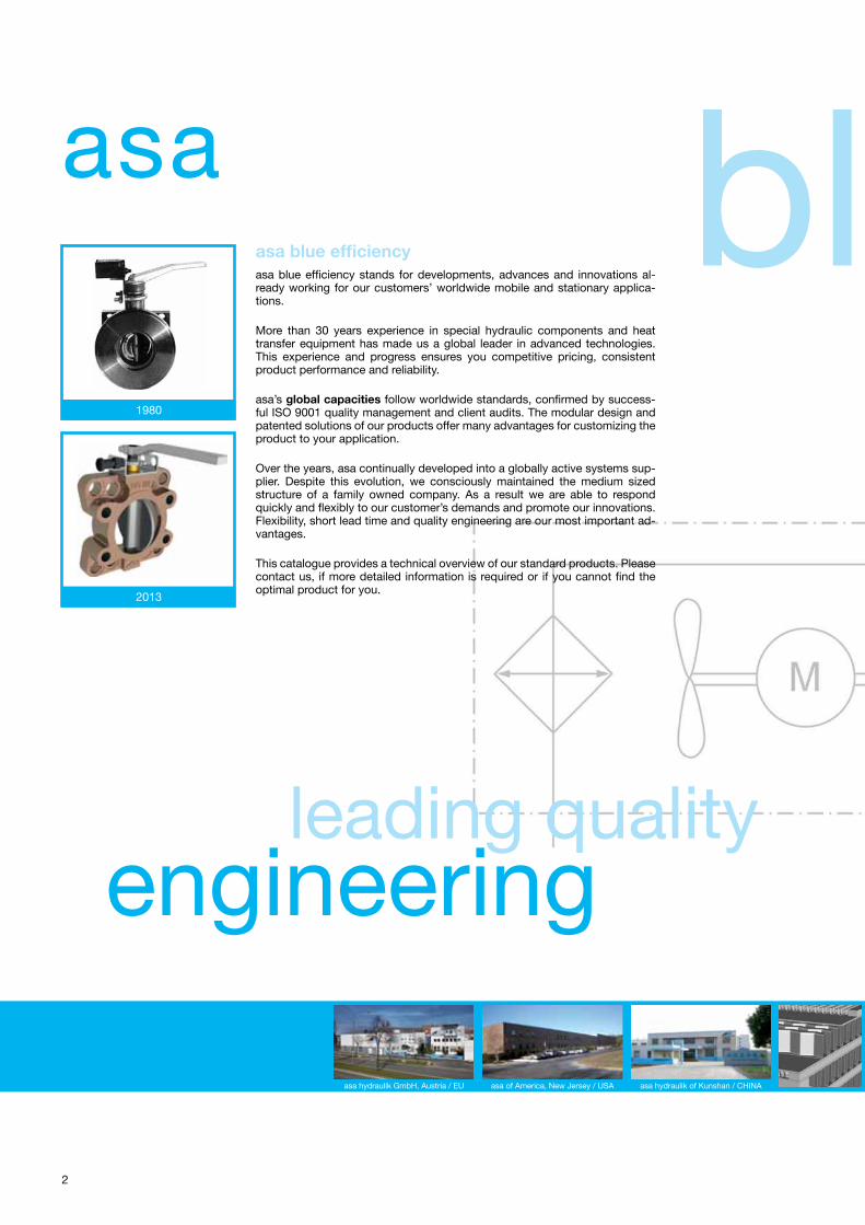
2
blueasa
leading qualityengineering
1980
2013
asa blue efficiencyasa blue efficiency stands for developments, advances and innovations al-ready working for our customers’ worldwide mobile and stationary applica-tions.
More than 30 years experience in special hydraulic components and heat transfer equipment has made us a global leader in advanced technologies. This experience and progress ensures you competitive pricing, consistent product performance and reliability.
asa’s global capacities follow worldwide standards, confirmed by success-ful ISO 9001 quality management and client audits. The modular design and patented solutions of our products offer many advantages for customizing the product to your application.
Over the years, asa continually developed into a globally active systems sup-plier. Despite this evolution, we consciously maintained the medium sized structure of a family owned company. As a result we are able to respond quickly and flexibly to our customer’s demands and promote our innovations. Flexibility, short lead time and quality engineering are our most important ad-vantages.
This catalogue provides a technical overview of our standard products. Please contact us, if more detailed information is required or if you cannot find the optimal product for you.
asa hydraulik GmbH, Austria / EU asa of America, New Jersey / USA asa hydraulik of Kunshan / CHINA

3
blueasa blue efficiency keeps you 2 steps ahead!
Constant quality through standard parts.
Modular design and patented solutions offer cus-tumizing features.
Optimized oil flow on components for better performance and standards.
Flexible design on material and function.
Expanded working ranges through new materials.
Value added vibration absorbers offer the capability to resist highest shear loads!
The smallest depth on serial produced standard butterfly flanges.
Compactness of serial produced parts as a function of capacity and life time.
efficiency
oth
er p
rod
ucts
acce
sso
ries
suct
ion
unit
sco
mp
ensa
tors
but
terfl
y fl
ang
esg
ero
tor
pum
p u
nits
vib
rati
on
abso
rber
sg
roup

This data sheet shows a technical overview of our products. Please contact us if more exact information is needed. As we are constantly improving our products, their characteristics, dimensions and weights may also change, although we do our best to incorporate these changes continually. The information in this data sheet is intended to be used as a first general guideline only. asa assumes no liability for any information therein, any errors, omissions, misprints, nor any direct or indirect damages, losses or costs resulting therefrom. The cooling performance and the general technical values indicated in this catalogue are measured at a test bench according to asa testing procedures Because there is no standardized testing procedure, tests used by other manufacturers could have different results. Due to different conditions in testing and application environments the cooling performance may also vary by +/– 15%. Therefore we recommend all coolers to be checked under the system operating conditions. This is also true for vibrations and mechanical stress as well as for pressure peaks and thermal stress and any other relevant factors. Please read manual before installation.
© asa hydraulik, February 20134
Rubber Vibration AbsorberM8, M10, M12 & M16 Threads
Dimensionsdescription order number A B C M Smax weight
[mm] [mm] [mm] [mm] [mm] [kg]
40x40x30 M8 MDGQ403008IIK 40 30 20 M8 x 10 ± 3 0,127
50x50x45 M10 MDGQ504510IIK 50 45 25 M10 x 12 ± 6 0,280
75x75x55 M12 MDGQ755512IIK 75 55 37,5 M12 x 15 ± 8 0,659
100x100x75 M16 MDGQ1007516IIK 100 75 50 M16 x 16,5 ± 9 1,920
Load Capacities, Maximum Static Loads
description order number compression FD
tensionFZ
compression/ shear FDS
tension/shearFZS
compression/ shear diagonal FDSD
[N] [N] [N] [N] [N]
40x40x30 M8 MDGQ403008IIK 800 250 700 350 950
50x50x45 M10 MDGQ504510IIK 2000 1450 1550 1500 2250
75x75x55 M12 MDGQ755512IIK 4250 2250 2600 2200 3850
100x100x75 M16 MDGQ1007516IIK 11700 8800 6900 6350 8350
Spring Rates
description order number compression CD
tensionCZ
compression/ shear CDS
tension/ shearCZS
compression/ shear diagonal CDSD
[N/mm] [N/mm] [N/mm] [N/mm] [N/mm]
40x40x30 M8 MDGQ403008IIK 267 83 233 117 317
50x50x45 M10 MDGQ504510IIK 333 241 258 250 375
75x75x55 M12 MDGQ755512IIK 531 281 325 275 481
100x100x75 M16 MDGQ1007516IIK 1301 982 770 709 932
Assembly InstructionsAssembly of 4 shock absorbers: Best mounting position:
All 4 arrows have to point towards the middle
fixed metal part
metal part to be loaded
arrows points in direction of the load
Materialmetal zinc coated steelelastomer natural rubberworking temperature –30°C to +80°C
The asa vibration absorbers are rubber metal connected parts to absorb impact loads on components to protect them and to extend the life time of the system. The patented solution is especially designed for highest shear loads. An assembly system can be checked by arrows on the metal parts to help to optimize and raise the load capability of the vibration absorber.

This data sheet shows a technical overview of our products. Please contact us if more exact information is needed. As we are constantly improving our products, their characteristics, dimensions and weights may also change, although we do our best to incorporate these changes continually. The information in this data sheet is intended to be used as a first general guideline only. asa assumes no liability for any information therein, any errors, omissions, misprints, nor any direct or indirect damages, losses or costs resulting therefrom. The cooling performance and the general technical values indicated in this catalogue are measured at a test bench according to asa testing procedures Because there is no standardized testing procedure, tests used by other manufacturers could have different results. Due to different conditions in testing and application environments the cooling performance may also vary by +/– 15%. Therefore we recommend all coolers to be checked under the system operating conditions. This is also true for vibrations and mechanical stress as well as for pressure peaks and thermal stress and any other relevant factors. Please read manual before installation.
© asa hydraulik, February 2013 5
Gerotor Pump Unit30l/min, 230/400V 50Hz
The asa gerotor pump unit fulfills the requirements of a modern hydraulic system. The compactness of the gerotor pump design saves weight and space. Furthermore the solid shape of the pump has high resistance to hydraulic and mechanic impact loads. The low noise level and easy connection makes this product highly flexible and reliable to various applications.
The coupling with a high quality standard motor is the optimal choice for a durable pump unit.
Technical Datadescription order number motor power max. oil viscosity oil flow neg. pressure poles max. current frequency weight
[kW] [cSt] [l/min] [bar] [A] [Hz] [kg]
GERO unit 100 HY0200758G 0,75 / 0,85 100 30 -0,4 4 2,1 50/60 13,8
Pump Characteristic
Materialpump housing aluminium
gerotor sintered steel
sealings NBR
Optionson request other voltages
UL- or CSA approvals
higher protection level
250cSt version
single phase motor
Working Rangeambient temperature –20°C to +40°C
maximum working pressure 10bar
maximum oil temperature 80°C (100°C on request)
fluids mineral oils
oth
er p
rod
ucts
acce
sso
ries
suct
ion
unit
sco
mp
ensa
tors
but
terfl
y fl
ang
esg
ero
tor
pum
p u
nits
vib
rati
on
abso
rber
sg
roup
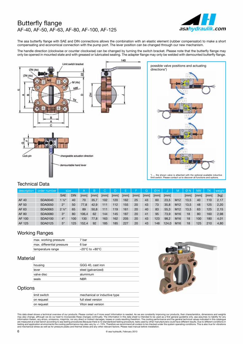
This data sheet shows a technical overview of our products. Please contact us if more exact information is needed. As we are constantly improving our products, their characteristics, dimensions and weights may also change, although we do our best to incorporate these changes continually. The information in this data sheet is intended to be used as a first general guideline only. asa assumes no liability for any information therein, any errors, omissions, misprints, nor any direct or indirect damages, losses or costs resulting therefrom. The cooling performance and the general technical values indicated in this catalogue are measured at a test bench according to asa testing procedures Because there is no standardized testing procedure, tests used by other manufacturers could have different results. Due to different conditions in testing and application environments the cooling performance may also vary by +/– 15%. Therefore we recommend all coolers to be checked under the system operating conditions. This is also true for vibrations and mechanical stress as well as for pressure peaks and thermal stress and any other relevant factors. Please read manual before installation.
© asa hydraulik, February 20136
Butterfly flangeAF-40, AF-50, AF-63, AF-80, AF-100, AF-125
The asa butterfly flange with SAE and DIN connections allows the combination with an elastic element (rubber compensator) to make a short compensating and economical connection with the pump port. The lever position can be changed through our new mechanism.
The handle direction (clockwise or counter clockwise) can be changed by turning the switch bracket. Please note that the butterfly flange may only be opened in mounted state and with greased or lubricated sealing. The adapter flange may only be welded with demounted butterfly flange.
Technical Datadescription order number size A B C D E F G Ø H J M Ø N NW TK weight
SAE DIN [mm] [mm] [mm] [mm] [mm] [mm] [mm] [mm] [mm] [mm] [mm] [mm] [kg]
AF 40 SDA0040 1 ½“ 40 70 35,7 102 120 162 25 43 60 23,5 M12 13,5 40 110 2,17
AF 50 SDA0050 2“ 50 77,8 42,9 111 112 155 20 43 73 35,8 M12 13,5 48 125 2,20
AF 63 SDA0063 2 ½“ 65 89 50,8 111 119 161 20 40 83 55,3 M12 13,5 63 125 2,15
AF 80 SDA0080 3“ 80 106,4 62 144 145 187 20 41 95 73,9 M16 18 80 160 2,98
AF 100 SDA0100 4“ 100 130 77,8 163 162 205 20 43 123 98,2 M16 18 100 180 4,01
AF 125 SDA0125 5“ 125 152,4 92 185 185 227 20 43 148 124,0 M16 18 125 210 4,80
Working Rangesmax. working pressure 7 bar
max. differential pressure 6 bar
temperature range –20°C to +80°C
Materialhousing GGG 40, cast iron
lever steel (galvanized)
valve disc aluminium
seals NBR
Optionslimit switch mechanical or inductive type
on request full steel version
on request Viton seal version
possible valve positions and actuating directions*)
*) … the shown valve is attached with the optional available inductive limit switch. Please contact us to discover all functions and options.

This data sheet shows a technical overview of our products. Please contact us if more exact information is needed. As we are constantly improving our products, their characteristics, dimensions and weights may also change, although we do our best to incorporate these changes continually. The information in this data sheet is intended to be used as a first general guideline only. asa assumes no liability for any information therein, any errors, omissions, misprints, nor any direct or indirect damages, losses or costs resulting therefrom. The cooling performance and the general technical values indicated in this catalogue are measured at a test bench according to asa testing procedures Because there is no standardized testing procedure, tests used by other manufacturers could have different results. Due to different conditions in testing and application environments the cooling performance may also vary by +/– 15%. Therefore we recommend all coolers to be checked under the system operating conditions. This is also true for vibrations and mechanical stress as well as for pressure peaks and thermal stress and any other relevant factors. Please read manual before installation.
© asa hydraulik, February 2013 7
Butterfly flangeAF-50, AF-63 and AF-80 aluminium design
The asa butterfly flanges are now also available with aluminium body. The design is analogous to the standard valves (AF). SAE and DIN con-nections allow the combination with elastic elements (rubber compensator) to make a short and economical connection with the pump port. The lever position can also be changed through the same mechanism. The handle direction (clockwise or counter clockwise) can be changed by turning the switch bracket. Please note that the butterfly flange may only be opened in mounted state and with greased or lubricated sealing. The adapter flange may only be welded with demounted butterfly flange.
Technical Datadescription order number size A B C D E F G Ø H J M Ø N NW TK weight
SAE DIN [mm] [mm] [mm] [mm] [mm] [mm] [mm] [mm] [mm] [mm] [mm] [mm] [kg]
AF 50 Alu. SDA0050A 2“ 50 77,8 42,9 112 112 155 20 43 73 35,8 M12 13,5 48 125 1,05
AF 63 Alu. SDA0063A 2 ½“ 65 89 50,8 111 119 161 20 43 83 55,3 M12 13,5 63 125 1,09
AF 80 Alu. SDA0080A 3“ 80 106,4 62 144 145 187 20 43 95 73,9 M16 18 80 160 1,48
Working Rangesmax. working pressure 7 bar
max. differential pressure 6 bar
temperature range –20°C to +80°C
Materialhousing aluminium
lever steel (galvanized)
valve disc aluminium
seals NBR
Optionslimit switch mechanical or inductive type
on request Viton seal version
possible valve positions and actuating directions*)
*) … the shown valve is attached with the optional available inductive limit switch. Please contact us to discover all functions and options.
oth
er p
rod
ucts
acce
sso
ries
suct
ion
unit
sco
mp
ensa
tors
but
terfl
y fl
ang
esg
ero
tor
pum
p u
nits
vib
rati
on
abso
rber
sg
roup

This data sheet shows a technical overview of our products. Please contact us if more exact information is needed. As we are constantly improving our products, their characteristics, dimensions and weights may also change, although we do our best to incorporate these changes continually. The information in this data sheet is intended to be used as a first general guideline only. asa assumes no liability for any information therein, any errors, omissions, misprints, nor any direct or indirect damages, losses or costs resulting therefrom. The cooling performance and the general technical values indicated in this catalogue are measured at a test bench according to asa testing procedures Because there is no standardized testing procedure, tests used by other manufacturers could have different results. Due to different conditions in testing and application environments the cooling performance may also vary by +/– 15%. Therefore we recommend all coolers to be checked under the system operating conditions. This is also true for vibrations and mechanical stress as well as for pressure peaks and thermal stress and any other relevant factors. Please read manual before installation.
© asa hydraulik, February 20138
CompensatorSize 1”– 5”
Rubber compensators are elastic connectors with turn able SAE flanges. Compensators are used for damping oscillations, vibrations, noises and movements in axial and transversal direction.
DesignRubber compensators have a plain surface vulcanized to a fabric body (inside and outside) of the rubber part. The outside is weather resistant and protects the fabric against ageing, wear and corrosion. The interior of the rubber part consists of nitril-butadien-caoutchouc (BUNA-N). Because compensators have tightening lips on both sides, further seals are not necessary.
Operating range for suction and return lines.All mineral oil products, crude oil, lubrication oil, cooling oil (–20ºC/68°F up to 80ºC/176°F, intermittent 100ºC/212°F), grease, cold water, warm water up to 60ºC (140°F), water/oil emulsions, fuel with 30% aromatic content.
description order number size A B C D E F G H L weight
SAE NG [mm] [mm] [mm] [mm] [mm] [mm] [mm] [mm] [mm] [kg]
K16S – 25 SDKSS025 1“ 25 26,2 52,4 43 25 11 11 59 70 65 0,4
K16S – 32 SDKSS032 1 ¼” 32 30,2 58,7 50 32 11 13 73 81 65 0,5
K16S – 40 SDKSS040 1 ½” 40 35,7 70,0 62 40 13 13 83 95 100 0,8
K16S – 50 SDKSS050 2“ 50 42,9 77,8 72 48 13 13 97 103 100 1,0
K16S – 63 SDKSS063 2 ½” 63 50,8 89,0 87 63 14 13 109 115 100 1,2
K16S – 80 SDKSS080 3“ 80 62,0 106,4 104 80 14 17 131 136 100 1,8
K16S – 90 SDKSS090 3 ½” 90 70,0 120,6 104 80 14 17 140 152 100 1,9
K16S – 100 SDKSS100 4“ 100 77,8 130,2 130 100 16 17 152 162 100 2,5
K16S – 125 SDKSS126 5“ 125 92,0 152,4 155 125 16 17 165 184 130 3,0
NG* ... nominal size / Nenngröße
Materialinside NBR
outside CR
flange steel (galvanized)
Working Pressuremaximum working pressure 0,2–1,5 bar absolute
Please contact us for the maximum movement tolerances of the rubber connection! Note, that dimension and tolerances have to be taken from the corresponding scale drawing.

This data sheet shows a technical overview of our products. Please contact us if more exact information is needed. As we are constantly improving our products, their characteristics, dimensions and weights may also change, although we do our best to incorporate these changes continually. The information in this data sheet is intended to be used as a first general guideline only. asa assumes no liability for any information therein, any errors, omissions, misprints, nor any direct or indirect damages, losses or costs resulting therefrom. The cooling performance and the general technical values indicated in this catalogue are measured at a test bench according to asa testing procedures Because there is no standardized testing procedure, tests used by other manufacturers could have different results. Due to different conditions in testing and application environments the cooling performance may also vary by +/– 15%. Therefore we recommend all coolers to be checked under the system operating conditions. This is also true for vibrations and mechanical stress as well as for pressure peaks and thermal stress and any other relevant factors. Please read manual before installation.
© asa hydraulik, February 2013 9
Suction UnitSAE 1½” – SAE 5”
The asa suction unit has been developed to provide a compact unit in hydraulic systems. The asa butterfly flange with SAE connections al-lows the combination with an elastic element (rubber compensator) to make a short compensating and economical connection with the pump port. The asa suction unit is screwed to the asa adapter flange, which is welded to the tank. Due to low installation costs and compact design, purchasing asa suction units is cost effective. A switch (mechanical or inductive) can be mounted on the standard block for monitoring matters.
At the delivery configuration the lever position corresponds to the valve position (can be changed, see butterfly flanges). Thus the aperture angle is well-defined even in mounted state. The handle direction (clockwise or counter clockwise) can be changed by turning the switch bracket. Please note that the butterfly flange may only be opened in mounted state and with greased or lubricated sealing. The adapter flange may only be welded with demounted butterfly flange.
Technical Datadescription order number size A B C D weight SAE DIN [mm] [mm] [mm] [mm] [kg]ESAF – 40 SDAK0040T 1 ½“ 40 185 168 130 89 5,20ESAF – 50 SDAK0050T 2“ 50 185 168 150 103 6,20ESAF – 63 SDAK0063T 2 ½“ 65 185 165 150 103 6,40ESAF – 80 SDAK0080T 3“ 80 185 166 150 109 7,50ESAF – 100 SDAK0100T 4“ 100 185 168 180 139 9,80ESAF – 125 SDAK0125T 5“ 125 185 198 205 164 11,60
Working Rangesworking pressure range 0,2 – 1,5 bar absolute
temperature range –20°C to +80°C
Materialbutterfly valve housing GGG 40 (0.7040), cast iron
valve disc aluminium
gasket NBR
compensator flange steel (galvanized)
compensator rubber inside NBR
compensator rubber outside CR
adapter flange steel
oth
er p
rod
ucts
acce
sso
ries
suct
ion
unit
sco
mp
ensa
tors
but
terfl
y fl
ang
esg
ero
tor
pum
p u
nits
vib
rati
on
abso
rber
sg
roup

This data sheet shows a technical overview of our products. Please contact us if more exact information is needed. As we are constantly improving our products, their characteristics, dimensions and weights may also change, although we do our best to incorporate these changes continually. The information in this data sheet is intended to be used as a first general guideline only. asa assumes no liability for any information therein, any errors, omissions, misprints, nor any direct or indirect damages, losses or costs resulting therefrom. The cooling performance and the general technical values indicated in this catalogue are measured at a test bench according to asa testing procedures Because there is no standardized testing procedure, tests used by other manufacturers could have different results. Due to different conditions in testing and application environments the cooling performance may also vary by +/– 15%. Therefore we recommend all coolers to be checked under the system operating conditions. This is also true for vibrations and mechanical stress as well as for pressure peaks and thermal stress and any other relevant factors. Please read manual before installation.
© asa hydraulik, February 201310
Adapter Flangeaccessories for use on butterfly flanges
The asa suction unit is screwed to the asa adapter flange, which is welded to the tank. Due to low installation costs and compact design, pur-chasing asa suction units is cost effective. The adapter flange may only be welded with demounted butterfly flange.
material: ST 37 (1.0037)
The adapter flange may only be welded without the butterfly flange attached.
Technical Datadescription order number A B C D E F G H J K weight
[mm] [mm] [mm] [mm] [mm] [mm] [mm] [mm] [mm] [mm] [kg]
adapter 40 SDAET040K 110 49 25 130 22 14 M12 (4x) – – 89 1,9
adapter 50 & 63 SDAET063K 125 63 25 150 22 14 M12 (4x) – – 103 2,45
adapter 80 SDAET080K – 82 25 150 22 16 M16 (4x) 62 106 109 2,15
adapter 100 SDAET100K – 103 25 180 22 16 M16 (4x) 77,8 130 139 2,8
adapter 125 SDAET125K – 128 25 205 22 16 M16 (4x) 92 152 164 3,3
Limit Switchaccessories for use on butterfly flanges and suction units
Mechanical Limit Switch
order number EAFSMK
Control voltage at 15V AC 10A res., 6A ind.
Control voltage at 250V AC 10A res., 4A ind.
Control voltage at 115V AC 0,4A res., 0,05A ind.
Expected mechanical durability 107 (at 50cpm)
Expected electrical durability 105 (at 20cpm)
Ambient temperature –20°C to +60°C (68–140°F)
Ambient humidity max. 95% at 20°C (68°F)
Max. operating speed 120cpm
Protection switch IP 64
Protection connections IP 60
Switch function Two way contact
Rated insulation voltage 250V AC
Rated impulse withstand voltage 2,5kV
Switching over voltage 2,5kV
Rated enclosed thermal current 10A
Conditional short-circuit current 100A
Short circuit protection device 10A fuse
Inductive Limit Switch
order number EAFSIK
Operating voltage 10 to 30V
Switching frequency 0 to 1500Hz
Reverse polarity protection protected
Short-ciruit protection pulsing
Voltage drop = 3V
Operating current 0 to 200mA
Off state current 0 to 0,5mA typ. 0,1μA
No-load supply current = 17mA
Indication of the switching state LED, yellow
Ambient temperature –25°C to 70°C (77°F–158°F)
Switching element function PNP make function
Rated operating distance 2mm
Installation embeddalbe
Assured operating distance 0 to 1,62mm
Reduction factor rAl 0,3
Reduction factor rCu 0,2
Reduction factor rV2A 0,7
Protection degree IP67

oth
er p
rod
ucts
acce
sso
ries
suct
ion
unit
sco
mp
ensa
tors
but
terfl
y fl
ang
esg
ero
tor
pum
p u
nits
vib
rati
on
abso
rber
sg
roup
special accessories other products &
Please contact us for further information or see more products on our website. The calculation program for simple and exact cooler selection and our international correspondence is available for you 24h a day.
www.asahydraulik.com
COMPONENT SYSTEMSLeading quality engineering!
E SERIESBrazed stainless steel plate heat exchanger
MOTOR/PUMP SYSTEMScompact motor units with gerotor pumps
ATEX SERIESATEX certificated air blast coolers acording to CE Ex II 2G EEx c IIB T4
W SERIESSpecial equipped heat exchangers for the wind energy industry, coastal and off shore applications
TANK FILTER SYSTEMSForm follows function and creates innovative combi-nations of filter and tank.

12
Austriaasa hydraulik GmbHPrager Strasse 280A-1210, ViennaTel.: +43 1 292 40 20Fax: +43 1 292 40 [email protected]
USAasa hydraulik of America160 Meister Avenue 20 ABranchburg, New Jersey 08876Tel.: +1 800 473 94 00Fax: +1 908 541 15 [email protected]
CHINAasa hydraulik of Kunshan江苏省昆山市千灯镇七浦西路25号postcode: 215341Tel.: +86 512 57950818Fax: +86 512 [email protected]
progress in cooling