Enerpac Industrial Tools - Wilson Company
294
-
Upload
khangminh22 -
Category
Documents
-
view
5 -
download
0
Transcript of Enerpac Industrial Tools - Wilson Company

1
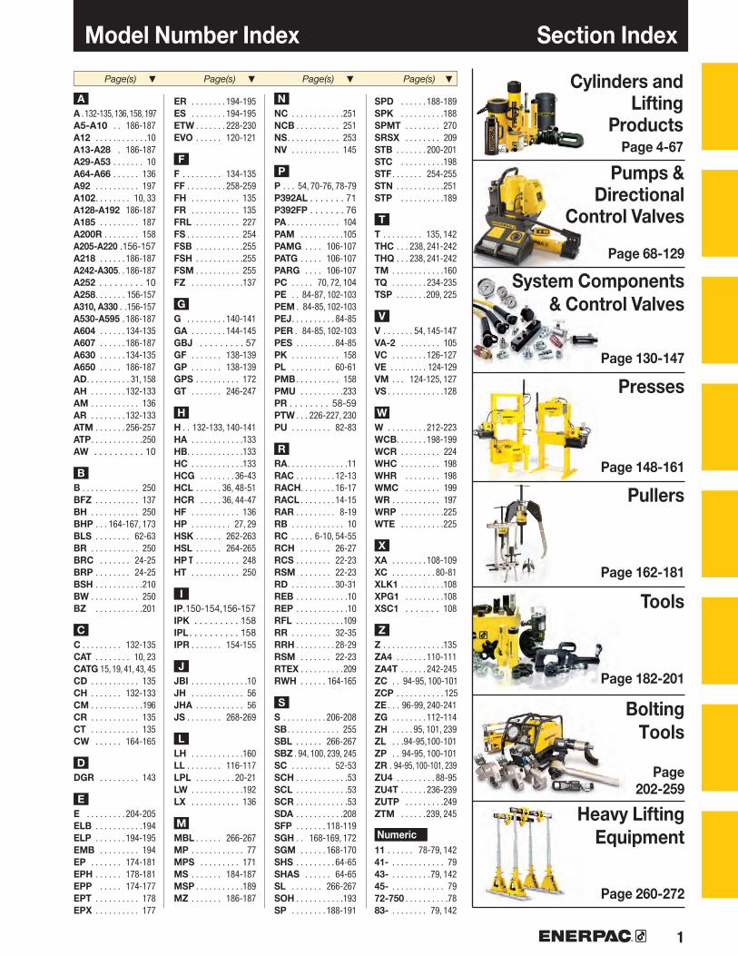
Page(s) ▼ Page(s) ▼ Page(s) ▼ Page(s) ▼ Cylinders and Lifting
Products Page 4-67
Pumps & Directional
Control Valves
Page 68-129
System Components & Control Valves
Page 130-147
Presses
Page 148-161
Pullers
Page 162-181
Bolting Tools
Page 202-259
Heavy Lifting Equipment
Page 260-272
Tools
Page 182-201
AA . 132-135, 136, 158, 197A5-A10 . . 186-187A12 . . . . . . . . . . . .10A13-A28 . 186-187A29-A53 . . . . . . . 10A64-A66 . . . . . . 136A92 . . . . . . . . . . 197A102 . . . . . . . . 10, 33A128-A192 186-187A185 . . . . . . . . . 187A200R . . . . . . . . 158A205-A220 .156-157A218 . . . . . . 186-187A242-A305. . 186-187A252 . . . . . . . . . 10A258 . . . . . . . 156-157A310, A330 . .156-157A530-A595 . 186-187A604 . . . . . . 134-135A607 . . . . . . 186-187A630 . . . . . . 134-135A650 . . . . . 186-187AD . . . . . . . . . . 31, 158AH . . . . . . . . 132-133AM . . . . . . . . . . . 136AR . . . . . . . . 132-133ATM . . . . . . . 256-257ATP . . . . . . . . . . . .250AW . . . . . . . . . . 10
BB . . . . . . . . . . . . . 250BFZ . . . . . . . . . . 137BH . . . . . . . . . . . 250 BHP . . . 164-167, 173BLS . . . . . . . . 62-63BR . . . . . . . . . . . 250BRC . . . . . . . 24-25BRP . . . . . . . . 24-25BSH . . . . . . . . . . .210BW . . . . . . . . . . . 250BZ . . . . . . . . . . .201
CC . . . . . . . . . 132-135CAT . . . . . . . . 10, 23CATG 15, 19, 41, 43, 45CD . . . . . . . . . . . 135CH . . . . . . . 132-133CM . . . . . . . . . . . .196CR . . . . . . . . . . . 135CT . . . . . . . . . . . 135CW . . . . . . 164-165
DDGR . . . . . . . . . 143
EE . . . . . . . . . 204-205ELB . . . . . . . . . . .194ELP . . . . . . . 194-195EMB . . . . . . . . . 194EP . . . . . . . 174-181EPH . . . . . . 178-181EPP . . . . . 174-177EPT . . . . . . . . . . 178EPX . . . . . . . . . . 177
ER . . . . . . . . 194-195ES . . . . . . . . 194-195ETW . . . . . . . 228-230EVO . . . . . . 120-121
FF . . . . . . . . . 134-135FF . . . . . . . . . 258-259FH . . . . . . . . . . . 135FR . . . . . . . . . . . 135FRL . . . . . . . . . . 227FS . . . . . . . . . . . . 254FSB . . . . . . . . . . .255FSH . . . . . . . . . . .255FSM . . . . . . . . . . 255FZ . . . . . . . . . . . .137
GG . . . . . . . . . 140-141GA . . . . . . . . 144-145GBJ . . . . . . . . . 57GF . . . . . . . 138-139GP . . . . . . . 138-139GPS . . . . . . . . . . 172GT . . . . . . . 246-247
HH . . 132-133, 140-141HA . . . . . . . . . . . .133HB. . . . . . . . . . . . .133HC . . . . . . . . . . . .133 HCG . . . . . . . . 36-43HCL . . . . . . 36, 48-51HCR . . . . . 36, 44-47HF . . . . . . . . . . . 136HP . . . . . . . . . 27, 29HSK . . . . . . 262-263HSL . . . . . . 264-265HP T . . . . . . . . . . 248HT . . . . . . . . . . . 250
IIP.150-154,156-157IPK . . . . . . . . . 158IPL . . . . . . . . . . 158IPR . . . . . . . 154-155
JJBI . . . . . . . . . . . . .10JH . . . . . . . . . . . . 56JHA . . . . . . . . . . . 56JS . . . . . . . . 268-269
LLH . . . . . . . . . . . .160LL . . . . . . . . 116-117LPL . . . . . . . . . 20-21LW . . . . . . . . . . . .192LX . . . . . . . . . . . 136
MMBL . . . . . . 266-267MP . . . . . . . . . . . . 77MPS . . . . . . . . . 171MS . . . . . . . 184-187MSP . . . . . . . . . . .189MZ . . . . . . . 186-187
NNC . . . . . . . . . . . .251NCB . . . . . . . . . . 251NS . . . . . . . . . . . . 253NV . . . . . . . . . . . 145
PP . . . 54, 70-76, 78-79P392AL . . . . . . . 71P392FP . . . . . . . 76PA . . . . . . . . . . . . 104PAM . . . . . . . . . .105PAMG . . . . 106-107PATG . . . . . 106-107PARG . . . . 106-107PC . . . . . 70, 72, 104PE . . 84-87, 102-103PEM . 84-85, 102-103PEJ . . . . . . . . . . 84-85PER . 84-85, 102-103PES . . . . . . . . . 84-85PK . . . . . . . . . . . 158PL . . . . . . . . . 60-61PMB . . . . . . . . . . 158PMU . . . . . . . . . .233PR . . . . . . . . 58-59PTW . . . 226-227, 230PU . . . . . . . . . 82-83
RRA . . . . . . . . . . . . . .11RAC . . . . . . . . . 12-13RACH . . . . . . . . 16-17RACL . . . . . . . . 14-15RAR . . . . . . . . . 8-19RB . . . . . . . . . . . . 10RC . . . . . 6-10, 54-55RCH . . . . . . . 26-27RCS . . . . . . . . 22-23RSM . . . . . . . 22-23RD . . . . . . . . . . 30-31REB . . . . . . . . . . . .10REP . . . . . . . . . . . .10RFL . . . . . . . . . . .109RR . . . . . . . . . 32-35RRH . . . . . . . . . 28-29RSM . . . . . . . 22-23RTEX . . . . . . . . . .209RWH . . . . . . 164-165
SS . . . . . . . . . . 206-208SB . . . . . . . . . . . . 255SBL . . . . . . 266-267SBZ . 94, 100, 239, 245SC . . . . . . . . . 52-53SCH . . . . . . . . . . . .53SCL . . . . . . . . . . . .53SCR . . . . . . . . . . . .53SDA . . . . . . . . . . .208SFP . . . . . . . 118-119SGH . . 168-169, 172SGM . . . . . . 168-170SHS . . . . . . . . . 64-65SHAS . . . . . . 64-65SL . . . . . . . 266-267SOH . . . . . . . . . . .193SP . . . . . . . . 188-191
SPD . . . . . . 188-189SPK . . . . . . . . . .188SPMT . . . . . . . . 270SRSX . . . . . . . . 209STB . . . . . . . 200-201STC . . . . . . . . . .198STF . . . . . . . 254-255STN . . . . . . . . . . .251STP . . . . . . . . . .189
TT . . . . . . . . . 135, 142THC . . . 238, 241-242THQ . . . 238, 241-242TM . . . . . . . . . . . .160TQ . . . . . . . . 234-235TSP . . . . . . .209, 225
VV . . . . . . . 54, 145-147 VA-2 . . . . . . . . . 105VC . . . . . . . . 126-127VE . . . . . . . . . 124-129VM . . . 124-125, 127VS . . . . . . . . . . . . .128
WW . . . . . . . . . 212-223WCB . . . . . . . 198-199WCR . . . . . . . . . 224WHC . . . . . . . . . 198WHR . . . . . . . . 198WMC . . . . . . . . 199WR . . . . . . . . . . . 197WRP . . . . . . . . . .225WTE . . . . . . . . . .225
XXA . . . . . . . . 108-109XC . . . . . . . . . . 80-81XLK1 . . . . . . . . . .108XPG1 . . . . . . . . .108XSC1 . . . . . . . 108
ZZ . . . . . . . . . . . . . .135 ZA4 . . . . . . . 110-111 ZA4T . . . . . . 242-245ZC . . 94-95, 100-101ZCP . . . . . . . . . . . 125ZE . . . 96-99, 240-241ZG . . . . . . . . 112-114ZH . . . . . 95, 101, 239 ZL . . .94-95,100-101ZP . . 94-95, 100-101ZR . 94-95, 100-101, 239ZU4 . . . . . . . . . 88-95ZU4T . . . . . . 236-239 ZUTP . . . . . . . . .249ZTM . . . . . .239, 245
Numeric11 . . . . . . 78-79, 14241- . . . . . . . . . . . . 7943- . . . . . . . . .79, 14245- . . . . . . . . . . . . 7972-750 . . . . . . . . . .7883- . . . . . . . . 79, 142
Section IndexModel Number Index

2
▼
2
The World Class Brand
Across every continent, Enerpac’s network of
authorized distributors and service centers can
reach even the most remote locations, supplying
and servicing products that are designed to
enhance productivity and performance, while
making the workplace safer.
With over 150 sales specialists and a network
of service and engineering support in 17
countries across the globe, Enerpac has become
the product of choice in industries such as
manufacturing, construction,
energy, oil and gas, shipbuilding,
railroads, mining, and metals
transformation.
Always at the leading edge of technology,
Enerpac has continued to develop its range of
time and cost-savings tools, utilizing modern
engineered materials to improve productivity
and minimize operator fatigue.
Enerpac’s commitment to the continued
development of quality high force tools ensures
that the products you purchase are the best tools
in the industry. We will continue to lead the way in
the development of quality high force tools for all
industrial applications.
A complete range of quality high-force tools for all industrial applications, with local
availability and after sale service anywhere in the world…. this is what has made Enerpac
the undisputed global market leader in high-pressure hydraulics.

33
Logistics ExcellenceEnerpac’s mission is to
maintain service excellence in the ever-changing world
of modern distribution. Providing our extensive range of products to our thousands
of distributors worldwide demands a logistic expertise
only a market leader can provide.
A Tradition of InnovationEnerpac has a long history of finding new solutions to better meet the challenges of the industries we serve. We were the first to develop a composite hand pump and the first to offer a computerized lifting system. Our latest innovations include the XA-Series of air driven foot pumps, designed for less operator fatigue - with the unique XVARI® technology, delivering variable oil flow and fine metering for precise control, a full range of aluminum cylinders with the strength of steel and the advantages of aluminum and the Z-Class series of power pumps… pumps that were designed to run cooler, use less electricity and are easy to service.
To support the demands of the construction industry, Enerpac continues to develop Heavy Lifting Technologies. These technologies include controlled hydraulic movement for your most challenging applications.
The World Class BrandTotal QualityOur products are tested to the most exacting standards. These high standards guarantee the quality, price and performance requirements of the markets we serve around the globe.
10 Reasons to 10 Work with Enerpac
• Expert Design
• Highly Reliable
• Service Excellence
• Worldwide Experience
• Application Support
• Availability
• Quality
• Value
• Innovative Products
• Systems Solutions
Global NetworkEnerpac has an extensive network of authorized distributors and service centers located in more than 90 countries worldwide. You can rely on Enerpac for the products and technical support you need to get your job done, anywhere in the world.

4 www.enerpac.com
N
A
N
P
W
B
Z1
IZ
X
F
WD
K
E H
X
QF1
3/8"-
18NPT
H K
F
A
J
D
B
E
3/8"-18NPT
44
Enerpac Hydraulic Cylinders & Lifting Products
Unique GR2 Bearing System
surrounds the seal of longer
stroke models resulting in
improved side-load resistance
and extended operating life.
Heavy-duty, pre-tensioned
spring improves retraction
rate for enhanced productivity.
Additional shape and texture to
the cylinder thread protector and
pliable plug-in/pop-off coupler cap
for easy operation with gloved and
oily hands.
Easy assembly and
disassembly using only
standard shop tools.
Enerpac hydraulic cylinders are available
in hundreds of different configurations.
Whatever the industrial application… lifting,
pushing, pulling, bending, holding… whatever
the force capacity, stroke length, or size
restrictions… single- or double-acting, solid
or hollow plunger, you can be sure that
Enerpac has the cylinder to suit your high
force application.
Enerpac jacking cylinders fully comply to
ASME B30.1 (except RD-Series).
Not
e: T
he c
ut-a
way
dra
win
g is
repr
esen
tativ
e of
typi
cal c
ylin
der c
onst
ruct
ion
and
may
not
repr
esen
t all
cylin
ders
in th
is s
ectio
n.
GR2 Bearing Technology
The exclusive GR2 is a unique bearing design on RC-Series DUO cylinders
which absorbs eccentric load stresses to protect your cylinder against abrasion, over-extending or plunger blow-outs and jamming or top-end mushrooming. As a result, RC-Series DUO cylinders provide long, trouble-free operation.

5
610
12141618
20 222324
26 28
30
32
36 4448
52
54
55
5657
58
60
62
64
▶▶
▶▶▶ ▶
▶▶▶ ▶
▶ ▶
▶
▶
▶▶▶ ▶
▶
▶
▶ ▶
▶
▶
▶
▶
N
A
N
P
W
B
Z1
IZ
X
F
WD
K
E H
X
QF1
3/8"-
18NPT
RC-DUO
RAC RACLRACH RAR
LPL RSM RCSBRC BRP
RCH RRH
RD
RR
HCGHCRHCLSC
RC P VSCRSCLSRSJH/JHA GBJ
PR
PL
BLS
SHSSHAS
Cylinder & Lifting Products Section Overview
General Purpose Cylinders, Single-acting Cylinder Accessories
Aluminum Cylinders Single-Acting, Solid Plunger, Lock Nut, Hollow Plunger
Aluminum CylindersDouble-Acting Solid Plunger
Pancake and Low Height Cylinders, Single-Acting
Pull Cylinders, Single-Acting
Hollow Plunger Cylinders Single- and Double-Acting
Precision Production Cylinders, Double-Acting
Long Stroke Cylinders, Double-Acting
High Tonnage Cylinders Single-Acting (S/A), S/A with Mechanical Locknut, Double-Acting
Cylinder - Pump Sets(Single-Acting)
Extreme Environment Products(Valves, cylinders, hand pumps)
Portable Hydraulic Toolbox
Aluminum and Steel JacksIndustrial Bottle Jack
POW’R-RISER® Lifting Jack
Pow’R-LOCK™ Portable Lift System
Climbing Jacks
Synchronous Hoisting Systems
* Capacity(tons)
Stroke Range (in)
Cylinder Type and Functions Series Page
* All cylinder capacities are nominal values, unless otherwise stated. [Maximum] capacities are theoretical and may vary, depending on cylinder condition and application.
5-100
20-150
20-150
5-500
2.5-60
12-150
4-25
10-500
50-1000
5-100
5-25
5-50
7-1502-100
60-200
200
55-220
60-250
.63-14.25
1.97-9.84
1.97-9.84
.25-2.44
5.00-6.00
.31-10.13
1.13-10.25
2.25-48.00
1.97-11.81
1.50-14.25
2.0-6.0
.44-10.13
3.00-6.132.44-18.11
14.0-27.0
14.0 / 24.5
5.91-6.34
19.69-59.06

▼
6 www.enerpac.com
10
10
187
RC-Series DUO Cylinders, Single-Acting
▼ RC cylinder mounting attachments greatly extend the application possibilities (available for 5, 10,15 and 25 ton cylinders).
▼ To re-stabilize the foundation, the 308-ton silo needed to be lifted, levelled and structurally supported. Twenty-five ton RC-Series hydraulic cylinders were attached to a bracket on the top of each steel pier. Powered by a Z-Class pump, the hydraulic cylinders applied 20 tons of force at each placement to lift the silo two inches.
The Industry Standard General Purpose Cylinder
Saddles
All RC cylinders (except RC-50, 101) are equipped with hardened removable grooved saddles. For tilt and flat saddles, see the
RC-Series accessory page.
Page:
Base Plates
To ensure the stability of cylinders for lifting applications, base plates are available for 10, 25 and 50 ton RC cylinders.
Page:
Specialty Attachments
For solving all kinds of application problems, specialty attach ments are available for 5, 10 and 25 ton RC cylinders.
Page:
• Unique GR2 Bearing Design, reduces wear, extending life• Collar threads, plunger threads and base mounting holes
enable easy fixturing (on most models)• Designed for use in all positions • High strength alloy steel for durability• Redesigned cylinder thread protector for ease of use• Heavy-duty, pretensioned spring improves retraction speed• Baked enamel finish for increased corrosion resistance• CR-400 coupler and dust cap included on all models• Plunger wiper reduces contamination, extending
cylinder life
Shown from left to right: RC-506, RC-50, RC-2510, RC-154, RC-10010, RC-55, RC-1010

7
80%
117
12
52
274
▼ QUICK SELECTION CHART For complete technical information see next page.
Single-Acting, General Purpose Cylinders
CylinderEffective
Area
(in2)
CylinderCapacity
tons(maximum)
Stroke
(in)
Collapsed Height
(in)
ModelNumber
OilCapacity
(in3)
Weight
(lbs)
* Available as a set. See note on this page.** RC-50 cylinder has non-removable grooved saddle and no collar thread.
RC Series
Capacity:
5-100 tonsStroke:
.63-14.25 inchesMaximum Operating Pressure:
10,000 psi
Gauges
Minimize the risk of overloading and ensure long, dependable service from your equipment. Refer to
the System Components section for a full range of gauges.
Page:
Think Safety
Manufacturer’s rating of load and stroke are maximum safe limits.
Good practice encourages using only 80% of these ratings!
Page:
Pump and Cylinder Sets
All cylinders marked with an *
are available as sets (cylinder, gauge, couplers, hose and pump) for your ordering convenience.
Page:
Page:
RAC-Series, Single-Acting Cylinders
The lightweight generalpurpose spring returnaluminum cylinders.
RC-Series DUO Cylinders maintain external dimensions for use with existing fixtures.
GR2 Bearing Technology
The exclusive GR2 is a unique bearing design on RC-Series DUO cylinders which
absorbs eccentric load stresses to protect your cylinder against abrasion, over-extending or plunger blow-outs and jamming or top-end mushrooming. As a result, RC-Series DUO cylinders provide long, trouble-free operation.
.99
.99
.99
.99
.99
.992.242.24 2.24 2.24 2.24 2.24 2.24 2.24 3.143.143.143.143.143.143.143.145.165.16 5.16 5.16 5.16 5.16 5.16 5.16 6.4911.0411.04 11.04 11.04 15.9015.9020.6320.63
.631.003.005.007.009.131.002.134.136.138.0010.1312.0014.001.002.004.006.008.0010.0012.0014.001.002.004.006.258.2510.2512.2514.258.252.004.006.2513.256.1313.136.6310.25
1.634.346.508.50
10.7512.753.534.786.759.75
11.7513.7515.7517.754.885.887.88
10.6912.6914.6916.6918.695.506.508.50
10.7512.7514.7516.7518.7515.256.948.94
11.1318.1311.2519.3814.0617.69
.62
.992.984.976.969.072.244.759.2313.7017.8922.6526.8431.313.146.2812.5718.8525.1331.4237.7043.985.1610.3120.6332.2342.5552.8663.1873.4953.5622.0944.1869.03146.3497.41208.74136.67211.45
RC-50**RC-51RC-53RC-55*RC-57RC-59
RC-101RC-102*RC-104RC-106*RC-108RC-1010*RC-1012RC-1014RC-151RC-152RC-154*RC-156*RC-158RC-1510RC-1512RC-1514RC-251RC-252*RC-254*RC-256*RC-258RC-2510RC-2512RC-2514*RC-308RC-502RC-504RC-506*RC-5013RC-756RC-7513RC-1006RC-10010
2.22.33.34.15.36.14.05.17.29.8
12.014.015.018.07.29.0
11.015.018.021.024.026.013.014.018.022.027.031.036.039.040.033.042.051.083.065.0
130.0130.0160.0
5 (4.9)
10 (11.2)
15 (15.7)
25(25.8)
30 (32.4)
50 (55.2)
75 (79.5)
100 (103.1)

8 www.enerpac.com
3/8"-18NPTF
V
U
L***M***D
H
E
A
F
B
D1***
H
W
X
Z
K
A
E
B
O
P
U1
P
O
J
F
V3/8"-18NPTF
DU
283
RC-Series DUO Cylinders, Single-Acting
Extended Height
B(in)
◀ For full features see page 6.
Stroke
(in)
CylinderCapacity
tons (maximum)
CylinderEffective
Area
(in2)
Collapsed Height
A(in)
ModelNumber
Oil Capacity
(in3)
Outside Diameter
D(in)
RC-50
RC-101 only(U1 = .75 inch)
RC-1006 and RC-10010 models
RC-51 to RC-5013 models
* Available as a set. See page 52.** RC-50 cylinder has non-removable grooved saddle and no collar thread.*** D1 = 1.63 inch, L = .81 inch, M = 1.00 inch.
Speed Chart
See the Enerpac Cylinder Speed Chart in our “Yellow Pages” to determine your
approximate cylinder speed.
Page:
RC-50**RC-51RC-53RC-55*RC-57RC-59RC-101RC-102*RC-104RC-106*RC-108RC-1010*RC-1012RC-1014RC-151RC-152RC-154*RC-156*RC-158RC-1510RC-1512RC-1514RC-251RC-252*RC-254*RC-256*RC-258RC-2510RC-2512RC-2514*RC-308RC-502RC-504RC-506*RC-5013RC-756RC-7513RC-1006RC-10010
.631.003.005.007.009.131.002.134.136.138.00
10.1312.0014.001.002.004.006.008.00
10.0012.0014.001.002.004.006.258.25
10.2512.2514.258.252.004.006.25
13.256.13
13.136.63
10.25
.99
.99
.99
.99
.99
.992.242.24 2.24 2.24 2.24 2.24 2.24 2.24 3.143.143.143.143.143.143.143.145.165.16 5.16 5.16 5.16 5.16 5.16 5.16 6.51
11.0411.04 11.04 11.04 15.9015.9020.6320.63
1.634.346.508.50
10.7512.753.534.786.759.75
11.7513.7515.7517.754.885.887.88
10.6912.6914.6916.6918.695.506.508.50
10.7512.7514.7516.7518.7515.256.948.94
11.1318.1311.2519.3814.0617.69
5 (4.9)
10 (11.2)
15 (15.7)
25 (25.8)
30 (32.4)
50 (55.2)
75 (79.5)
100 (103.1)
.62
.992.984.976.969.072.244.759.23
13.7017.8922.6526.8431.313.146.28
12.5718.8525.1331.4237.7043.985.16
10.3120.6332.2342.5552.8663.1873.4953.5622.0944.1869.03
146.3497.41
208.74136.67211.45
2.255.349.50
13.5017.7521.884.536.91
10.8815.8819.7523.8827.7531.755.887.88
11.8816.6920.6924.6928.6932.696.508.50
12.5017.0021.0025.0029.0033.0023.508.94
12.9417.3831.3817.3832.5020.6927.94
2.311.501.501.501.501.502.252.252.252.252.252.252.252.252.752.752.752.752.752.752.752.753.383.383.383.383.383.383.383.384.005.005.005.005.005.755.757.007.00

9www.enerpac.com
Single-Acting, General Purpose Cylinders
CylinderBore Diam.
E(in)
PlungerDiam.
F(in)
Base toAdv. Port
H(in)
SaddleDiam.
J(in)
Weight
(lbs)
Plunger Thread Length
P(in)
Saddle Protrusion from Plngr.
K(in)
PlungerInternal Thread
O(in)
Base Mounting Holes ModelNumber
CollarThread
W(in)
CollarThreadLength
X(in)
Thread
V(in)
ThreadDepth
Z(in)
BoltCircle
U(in)
RC Series
Capacity:
5-100 tonsStroke:
.63-14.25 inchesMaximum Operating Pressure:
10,000 psi
Couplers Included!
CR-400 couplers included on all models. Fits all HC-Series hoses.
RC-50**RC-51RC-53RC-55*RC-57RC-59RC-101RC-102*RC-104RC-106*RC-108RC-1010*RC-1012RC-1014RC-151RC-152RC-154*RC-156*RC-158RC-1510RC-1512RC-1514RC-251RC-252*RC-254*RC-256*RC-258RC-2510RC-2512RC-2514*RC-308RC-502RC-504RC-506*RC-5013RC-756RC-7513RC-1006RC-10010
1.131.131.131.131.131.131.691.691.691.691.691.691.691.692.002.002.002.002.002.002.002.002.562.562.562.562.562.562.562.562.883.753.753.753.754.504.505.135.13
1.001.001.001.001.001.001.50 1.50 1.50 1.50 1.50 1.50 1.50 1.50 1.631.631.631.631.631.631.631.632.252.252.252.252.252.252.252.252.253.133.133.133.133.753.754.134.13
.75
.75
.75
.75
.75
.75
.75
.75
.75
.75
.75
.75
.75
.75
.75
.75
.751.001.001.001.001.001.001.001.001.001.001.001.001.002.251.311.311.381.381.191.191.631.63
**1.001.001.001.001.00
–1.381.381.381.381.381.381.381.501.501.501.501.501.501.501.502.002.002.002.002.002.002.002.002.002.812.812.812.812.812.812.812.81
**.56.56.56.63.63.25.75.75.75.75.75.75.75
1.001.001.001.001.001.001.001.001.001.001.001.001.001.001.001.001.00————————
2.22.33.34.15.36.14.05.17.29.8121415187.29
1115182124261314182227313639403342518365
130130160
**.25.25.25.25.25–
.25
.25
.25
.25
.25
.25
.25
.38
.38
.38
.38
.38
.38
.38
.38
.41
.41
.41
.41
.41
.41
.41
.41
.41
.11
.11
.11
.11
.23
.23
.11
.11
**¾"-16¾"-16¾"-16¾"-16¾"-16
#10-24un
1"- 81"- 81"- 81"- 81"- 81"- 81"- 81"- 81"- 81"- 81"- 81"- 81"- 81"- 81"- 8
1½"-161½"- 161½"- 161½"- 161½"- 161½"- 161½"- 161½"- 161½"- 16
————————
.22¼"-20un
¼"-20un
¼"-20un
¼"-20un
¼"-20un
5•16"-18un
5•16"-18un
5•16"-18un
5•16"-18un
5•16"-18un
5•16"-18un
5•16"-18un
5•16"-18un
⅜"-16un
⅜"-16un
⅜"-16un
⅜"-16un
⅜"-16un
⅜"-16un
⅜"-16un
⅜"-16un
½"-13un
½"-13un
½"-13un
½"-13un
½"-13un
½"-13un
½"-13un
½"-13un
—½"-13un
½"-13un
½"-13un
½"-13un
——
¾"-10un
¾"-10un
—1.131.131.131.131.131.061.131.061.131.061.131.061.061.191.191.191.191.191.191.191.191.941.941.941.941.941.941.941.941.942.192.192.192.191.751.751.751.75
—.56.56.56.56.56.50.50.50.50.50.50.50.50.50.50.50.50.50.50.50.50.75.75.75.75.75.75.75.75—.75.75.75.75——
1.001.00
1.131.001.001.001.001.001.561.561.561.561.561.561.561.561.881.881.881.881.881.881.881.882.312.312.312.312.312.312.312.31—
3.753.753.753.75——
5.505.50
—1½"-161½"-161½"-161½"-161½"-162¼"-142¼"-142¼"-142¼"-142¼"-142¼"-142¼"-142¼"-142¾"-162¾"-162¾"-162¾"-162¾"-162¾"-162¾"-162¾"-16
3-1235•16"-1235•16"-1235•16"-1235•16"-1235•16"-1235•16"-1235•16"-1235•16"-12
5"-125"-125"-125"-12
5¾"-125¾"-1267/8"-1267/8"-12

10 www.enerpac.com
CD
E H
FG
AB
B
E
D G
F
AH
DC
B
E C
A
B
E
GJ
D
F
A
C
H
C
AB
A
B
C
0-5°
A
B 0-5°
E FB
AC D D
AC
EFB
D
A
CE
B
C
D
B
AE
BC
A
C
AB
Tilt
For Use with
Cylinder Capacity
(tons)
Cylinder Accessories
Flat Grooved1) Tilt Base4) Plunger
Base Plate
Saddles MountingBlock
Clevis Eyes
Base4)
Plunger
Model Number
Model Number
Type
A B C D
A
A
B C D E F
A B C
Model Number B C D E F G H
JBI-10, -25
REB REP
AW-51 AW-102 (J=.19)RB-5, -10 RB-15, -25 AW-53
JBI-50
Tilt Saddle Dimensions (in)
Mounting Block Dimensions (in)
Clevis Eye Dimensions (in)
1) Standard on 5-30 ton RC-cylinders 2) Except RC-50 3) Except RC-101 4) Mounting screws are included.
Tilt
Pin to Pin*
(in)
Grooved
A B C
Saddle Dimensions (in)
Flat
▼ DIMENSION CHARTS
Model Number
A-53FA-102FA-12A-29
A-53GA-102GA-152GA-252G
Model Number
CAT-10CAT-50
CAT-100
Base Plate Dimensions (in)
* Pin to Pin– REB and REP Clevises fitted. Add cylinder collapsed height. 4) Mounting screws are included.
▼ SELECTION CHART
E
RB-52), AW-512), AW-532)
RB-10, AW-102RB-15RB-25RB-25
–––
–
JBI-10–
JBI-25–
JBI-50––
5
101525305075100
REB-5REB-10REB-15REB-25 REP-5REP-10REP-25
RB-5AW-51AW-53RB-10AW-102RB-15RB-25
JBI-10JBI-25
JBI-50
9.0011.00
12.00
9.0011.00
.60
5.345.53
3.75
2.293.41
5.19
.811.03
1.25
1.752.503.003.75 1.131.692.25
1.882.632.633.13 1.752.432.81
.561.001.001.50 .561.001.50
.63
.88
.881.25 .63.881.25
.631.001.001.25 .631.001.25
1.001.381.381.63.751.131.38
1½"-161½"-161½"-162¼"-142¼"-142¾"-1635/16"-12
3.502.762.874.503.944.005.00
3.002.36.283.503.254.506.50
–.43.31–
.63––
1.00.98.751.001.181.502.00
–2.132.25
–3.00
––
–¼"-20¼"-20
–7/16"-20
––
–1.62.41–
2.31––
REB-52)
REB-10REB-15 REB-25
––––
REP-52)
REP-103)
REP-10REP-25REP-25
–––
2.373.073.073.45———
.68
.881"-8unC
1½"-16un
.68
.88
.881.40
1.001.382.002.00
1.001.381.501.97
.25
.241.881.88
.25
.24
.37
.37
A-53F2)
A-123), A-102F3)
–A-29A-29
–––
A-53G2)
A-102G3)
A-152GA-252GA-252G
–––
– CAT-103)
CAT-10 CAT-50 CAT-50 CAT-100 CAT-100 CAT-100
.881.40
–
.79
.83
.98
1.381.97
2.80
11
1
2
3
4
5
7
6
80%
▼
274
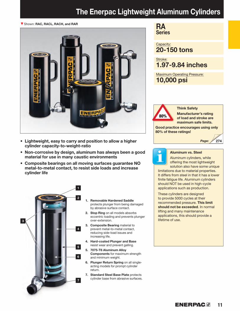
The Enerpac Lightweight Aluminum Cylinders
• Lightweight, easy to carry and position to allow a higher cylinder capacity-to-weight-ratio
• Non-corrosive by design, aluminum has always been a good material for use in many caustic environments
• Composite bearings on all moving surfaces guarantee NO metal-to-metal contact, to resist side loads and increase cylinder life
Capacity:
20-150 tonsStroke:
1.97-9.84 inchesMaximum Operating Pressure:
10,000 psi
1. Removable Hardened Saddle protects plunger from being damaged by abrasive surface contact.
2. Stop Ring on all models absorbs eccentric loading and prevents plunger over-extension.
3. Composite Bearing material to prevent metal-to-metal contact, reducing side-load issues and increasing life.
4. Hard-coated Plunger and Base resist wear and prevent galling.
5. 7075-T6 Aluminum Alloy Components for maximum strength and minimum weight.
6. Plunger Return Spring on all single-acting models for prompt cylinder return.
7. Standard Steel Base Plate protects cylinder base from abrasive surfaces.
RASeries
Think Safety
Manufacturer’s rating of load and stroke are maximum safe limits.
Good practice encourages using only 80% of these ratings!
Shown: RAC, RACL, RACH, and RAR
Page:
Aluminum vs. Steel
Aluminum cylinders, while offering the most lightweight solution also have some unique
limitations due to material properties. It differs from steel in that it has a lower finite fatigue life. Aluminum cylinders should NOT be used in high-cycle applications such as production.
These cylinders are designed to provide 5000 cycles at their recommended pressure. This limit should not be exceeded. In normal lifting and many maintenance applications, this should provide a lifetime of use.

▼
12 www.enerpac.com
RAC-202RAC-204RAC-206RAC-208RAC-2010RAC-302RAC-304RAC-306RAC-308RAC-3010RAC-502RAC-504RAC-506RAC-508RAC-5010RAC-1002RAC-1004RAC-1006RAC-1008RAC-10010RAC-1502RAC-1504RAC-1506RAC-1508RAC-15010
70
RAC-Series, Single-Acting Aluminum Cylinders
Lightweight for Maximum Portability
Shown from left to right: RAC-508, RAC-1506, RAC-304, and RAC-206
• Composite bearings prevent metal-to-metal contact, increasing cylinder life and resistance to side-loads of up to 10%
• Hard coat finish on all surfaces resists damage and extends cylinder life
• Handles included on all models• Steel baseplate and saddle for protection against
load-induced damage• Integral stop ring prevents plunger over-travel and is
capable of withstanding the full cylinder capacity• High-strength return spring for rapid cylinder retraction• CR-400 coupler and dust cap included on all models• All cylinders meet ASME B-30.1 and ISO 10100 standards
Saddles
All RAC cylinders are equipped with bolt-on removable saddles of hardened steel.
CylinderCapacity
tons(maximum)
Stroke*
(in)
ModelNumber
CylinderEffective
Area
(in2)
Lightweight Hand Pumps
Enerpac hand pumps P-392 or P-802 make the optimal lightweight set.
Page:
◀ Enerpac lightweight aluminum RAC-506 cylinders are ideal for wet environments such as this tunnel under the river (Holland High-Speed Train Line).
* Custom strokes available.
1.973.945.917.879.841.973.945.917.879.841.973.945.917.879.841.973.945.917.879.841.973.945.917.879.84
4.834.834.834.834.836.856.856.856.856.85
10.9910.9910.9910.9910.9922.1922.1922.1922.1922.1935.1835.1835.1835.1835.18
20(24.2)
30(34.2)
50(54.9)
100(110.9)
150 (175.9)

13
RAC-202RAC-204RAC-206RAC-208RAC-2010RAC-302RAC-304RAC-306RAC-308RAC-3010RAC-502RAC-504RAC-506RAC-508RAC-5010RAC-1002RAC-1004RAC-1006RAC-1008RAC-10010RAC-1502RAC-1504RAC-1506RAC-1508RAC-15010
K1
J1 0-5˚
CATG-50CATG-150CATG-200
RAC-50RAC-100RAC-150
RAC-20RAC-30RAC-50RAC-100RAC-150
H
K
AE
B
V
Z
J
F
3/8"-18 NPTF
DU
Single-Acting, Spring Return Cylinders
ModelNumber
Weight
(lbs)
SaddleProtrusion
from Plunger
K(in)
SaddleDiameter
J(in)
Base toAdvance
Port
H(in)
PlungerDiameter
F(in)
CylinderBore
Diameter
E(in)
OutsideDiameter
D(in)
Extended Height
B(in)
Collapsed Height
A(in)
OilCapacity
(in3)
RAC Series
Capacity:
20-150 tonsStroke:
1.97-9.84 inchesMaximum Operating Pressure:
10,000 psi
Steel Base Plate
The steel base plate protects the cylinder base from damage, it
should not be removed.
The base holes in these aluminum cylinders are designed for securing the steel base plate. They will not withstand the capacity of the cylinder.
Do not use the base holes in these aluminum cylinders to attach any device to the cylinder.
Cylinder Model / Capacity(ton)
Saddle Diameter
J1
Optional Bolt-on Tilt Saddle Dimensions (in) Model Number*
Saddle Protrusion
from PlungerK1
ThreadDepth 1)
Z
(in)
Thread
V
(mm)
BoltCircle
U
(in)
Steel Base Plate Mounting Holes Cylinder Model / Capacity
(ton)
1) Including Base Plate Height of .25 inches.Four (4) base plate bolts included.
* Tilt saddle not available for less than 50 ton.
9.5219.0328.5538.0147.5313.4926.9940.4853.9167.4021.6543.3064.9586.49108.1443.7187.43131.14174.64218.3569.30138.61207.91276.87346.17
6.858.8210.7912.7614.737.139.0911.0613.0415.017.329.2911.2613.2415.218.7110.6712.6414.6116.589.5611.5313.4915.4717.44
8.8312.7616.7020.6424.589.1013.0416.9820.9124.859.9013.2417.1721.1125.0510.6814.6118.5522.4926.4311.5315.4719.4123.3427.28
3.353.353.353.353.353.943.943.943.943.945.125.125.125.125.127.097.097.097.097.099.069.069.069.069.06
2.482.482.482.482.482.952.952.952.952.953.743.743.743.743.745.325.325.325.325.326.696.696.696.696.69
1.971.971.971.971.972.362.362.362.362.363.153.153.153.153.154.334.334.334.334.335.515.515.515.515.51
1.581.581.581.581.581.581.581.581.581.581.971.971.971.971.973.703.703.703.703.704.454.454.454.454.45
0.120.120.120.120.120.120.120.120.120.120.120.120.120.120.120.120.120.120.120.120.120.120.120.120.12
1.071.071.071.071.071.311.311.311.311.311.191.191.191.191.191.821.821.821.821.822.022.022.022.022.02
7.99.0
10.111.212.39.9
11.513.014.516.118.721.624.527.330.238.143.248.353.458.455.864.673.482.291.1
1.953.574.64
1.021.301.44
.47
.47
.47
.47
.47
M6M6M6
M10M10
2.763.154.335.917.87
.25

▼
14 www.enerpac.com
RACL-202RACL-204RACL-206RACL-208RACL-2010RACL-302RACL-304RACL-306RACL-308RACL-3010RACL-502RACL-504RACL-506RACL-508RACL-5010RACL-1002RACL-1004RACL-1006RACL-1008RACL-10010RACL-1502RACL-1504RACL-1506RACL-1508RACL-15010
132
15
RACL-Series, Aluminum Lock Nut Cylinders Shown from left to right: RACL-1006, RACL-504 and RACL-506
• Aluminum Lock Nut provides mechanical load holding for extended periods
• Hardened steel stop ring increases cylinder life and resistance to side-loads of up to 5%
• Hard coat finish on all surfaces resists damage and extends cylinder life
• Composite bearings increase cylinder life and side load resistance
• Handles included on all models• Steel base plate and saddle for protection against
load-induced damage• Integral stop ring prevents plunger over-travel and is
capable of withstanding the full cylinder capacity • High-strength return spring for rapid cylinder retraction• CR-400 coupler and dust cap included on all models• All cylinders meet ASME B-30.1 and ISO 10100 standards
◀ The portable Lock Nut cylinder RACL-1506 used for extended load support during epoxy injection for bridge reinforcement.
CylinderCapacity
ton (maximum)
Stroke*
(in)
ModelNumber
CylinderEffective
Area
(in2)
To Secure Loads Mechanically
Hoses
Enerpac offers a complete line of high-quality hydraulic hoses. To ensure the integrity of your system,
specify only Enerpac hydraulic hoses.
Saddles
All RACL cylinders are equipped with bolt-on removable saddles of hardened steel. For tilt saddles see next page.
Page:
Page:
* Custom strokes available.
1.973.945.917.879.841.973.945.917.879.841.973.945.917.879.841.973.945.917.879.841.973.945.917.879.84
4.834.834.834.834.836.856.856.856.856.85
10.9910.9910.9910.9910.9922.1922.1922.1922.1922.1935.1835.1835.1835.1835.18
20(24.2)
30 (34.2)
50 (54.9)
100(110.9)
150(175.9)

15
RACL-202RACL-204RACL-206RACL-208RACL-2010RACL-302RACL-304RACL-306RACL-308RACL-3010RACL-502RACL-504RACL-506RACL-508RACL-5010RACL-1002RACL-1004RACL-1006RACL-1008RACL-10010RACL-1502RACL-1504RACL-1506RACL-1508RACL-15010
RACL-20RACL-30RACL-50RACL-100RACL-150
H
K
AE
B
V
Z
J
F
3/8"-18 NPTF
DU
K1
J1 0-5˚
CATG-50CATG-150CATG-200
RACL-50RACL-100RACL-150
Single-Acting, Spring Return, Lock Nut Cylinders
OilCapacity
(in3)
Collapsed Height
A(in)
Extended Height
B(in)
ModelNumber
Weight
(lbs)
Lock NutHeight
S(in)
SaddleProtrusion
from Plunger
K(in)
SaddleDiameter
J(in)
Base toAdvance
Port
H(in)
PlungerDiameter
(Threaded)
F(in)
CylinderBore
Diameter
E(in)
OutsideDiameter
D(in)
RACL Series
Capacity:
20-150 tonsStroke:
1.97-9.84 inchesMaximum Operating Pressure:
10,000 psi
ThreadDepth 1)
Z
(in)
Thread
V
(mm)
BoltCircle
U
(in)
Steel Base Plate Mounting Holes Cylinder Model / Capacity
(ton)
1) Including Base Plate Height of .25 inches.Four (4) base plate bolts included.
Steel Base Plate
The steel base plate protects the cylinder base from damage, it
should not be removed.
The base holes in these aluminum cylinders are designed for securing the steel base plate. They will not withstand the capacity of the cylinder.
Do not use the base holes in these aluminum cylinders to attach any device to the cylinder.
Cylinder Model / Capacity(ton)
Saddle Diameter
J1
Optional Bolt-on Tilt Saddle Dimensions (in) Model Number*
Saddle Protrusion
from PlungerK1
* Tilt saddle not available for less than 50 ton.
9.5219.0328.5538.0147.5313.4926.9940.4853.9167.4021.6543.3064.9586.49108.1443.7187.43131.14174.64218.3569.30138.61207.91276.87346.17
8.810.111.412.714.111.913.414.916.518.020.523.426.229.131.948.253.358.463.468.571.079.888.697.4
106.3
1.971.971.971.971.971.971.971.971.971.972.952.952.952.952.952.952.952.952.952.953.153.153.153.153.15
0.120.120.120.120.120.120.120.120.120.120.120.120.120.120.120.120.120.120.120.120.120.120.120.120.12
1.581.581.581.581.581.581.581.581.581.581.971.971.971.971.973.703.703.703.703.704.454.454.454.454.45
1.071.071.071.071.071.311.311.311.311.311.191.191.191.191.191.821.821.821.821.822.022.022.022.022.02
2.172.172.172.172.172.362.362.362.362.363.153.153.153.153.154.334.334.334.334.335.515.515.515.515.51
2.482.482.482.482.482.952.952.952.952.953.743.743.743.743.745.325.325.325.325.326.696.696.696.696.69
3.353.353.353.353.353.943.943.943.943.945.125.125.125.125.127.097.097.097.097.099.069.069.069.069.06
10.8014.7318.6722.6126.5411.0715.0118.9522.8826.8211.2715.2119.1423.0827.0213.6317.5721.5025.4429.3814.6818.6222.5626.4930.43
8.8310.8012.7614.7316.709.1011.0713.0415.0116.989.2911.2613.2315.2017.1711.6513.6215.5917.5719.5412.7214.6916.6518.6220.59
.47
.47
.47
.47
.47
M6M6M6
M10M10
2.763.154.335.917.87
1.953.574.64
1.021.301.44
.25

▼
16 www.enerpac.com
70
RACH-202RACH-204RACH-206RACH-208RACL-2010RACH-302RACH-304RACH-306RACH-308RACH-3010RACH-602RACH-604RACH-606RACH-608RACH-6010RACH-1002RACH-1004RACH-1006RACH-1008RACH-10010RACH-1502RACH-1504RACH-1506RACH-1508RACH-15010
CylinderCapacity
tons(maximum)
Stroke*
(in)
ModelNumber
CylinderEffective
Area
(in2)
The Lightweight Solution for Tensioning and Testing
Shown from left to right: RACH-1508, RACH-304 and RACH-208
• Hollow plunger design allows for both pull and push forces• Composite bearings increase cylinder life and side
load resistance• Hard coat finish on all surfaces resists damage and
extends cylinder life• Handles included on all models• Floating center tube increases seal life• Steel baseplate and saddle for protection against
load-induced damage• Integral stop ring prevents plunger over-travel and is
capable of withstanding the full cylinder capacity• High-strength return spring for rapid cylinder retraction• CR-400 coupler and dust cap included on all models• All cylinders meet ASME B-30.1 and ISO 10100 standards
◀ An RACH-306, powered by a P-392 hand pump, is used to extract corroded carriage pins from refuse collection vehicles.
RACH-Series, Hollow Aluminum Cylinders
Lightweight Hand Pumps
Enerpac hand pumps P-392 or P-802 make the optimal lightweight set.
Saddles
All RACH-cylinders are equipped with bolt-on removable hardened steel hollow saddles.
Page:
* Custom strokes available.
20 (25.4)
30 (39.6)
60 (65.6)
100 (127.5)
150 (175.0)
1.973.945.917.879.841.973.945.917.879.841.973.945.917.879.841.973.945.917.879.841.973.945.917.879.84
5.075.075.075.075.077.927.927.927.927.92
13.1313.1313.1313.1313.1325.5125.5125.5125.5125.5135.0035.0035.0035.0035.00

17
3/8"-18 NPTF
Z
V
H
A
B
K
F
J
Y U D
E
RACH-20RACH-30RACH-60RACH-100RACH-150
RACH-202RACH-204RACH-206RACH-208RACL-2010RACH-302RACH-304RACH-306RACH-308RACH-3010RACH-602RACH-604RACH-606RACH-608RACH-6010RACH-1002RACH-1004RACH-1006RACH-1008RACH-10010RACH-1502RACH-1504RACH-1506RACH-1508RACH-15010
RACH Series
Capacity:
20-150 tonsStroke:
1.97-9.84 inchesCenter Hole Diameter:
1.06-3.11 inchesMaximum Operating Pressure:
10,000 psi
Single-Acting, Spring Return, Hollow Plunger Cylinders
OilCapacity
(in3)
Collapsed Height
A(in)
Extended Height
B(in)
ModelNumber
Weight
(lbs)
CenterHole
Diameter
Y(in)
SaddleProtrusion
from Plunger
K(in)
SaddleDiameter
J(in)
Base toAdvance
Port
H(in)
PlungerDiameter
F(in)
CylinderBore
Diameter
E(in)
OutsideDiameter
D(in)
ThreadDepth 1)
Z
(in)
Thread
V
(mm)
BoltCircle
U
(in)
Steel Base Plate Mounting Holes CylinderModel / Capacity
(ton)
1) Including Base Plate Height of .25 inches.Four (4) baseplate bolts included.
Steel Base Plate
The steel base plate protects the cylinder base from damage, it
should not be removed.
The base holes in these aluminum cylinders are designed for securing the steel base plate. They will not
withstand the capacity of the cylinder.
Do not use the base holes in these aluminum cylinders to attach any device to the cylinder.
9.9819.9629.9439.8749.9015.5931.1846.7762.3577.9425.8451.6977.53103.37129.2150.21100.43150.64200.85251.0766.08132.17206.72275.62344.53
11.513.515.617.719.817.620.924.628.431.935.642.850.357.265.174.687.8
101.9115.7129.3107.7122.8138.9154.5170.2
1.061.061.061.061.061.341.341.341.341.342.132.132.132.132.133.113.113.113.113.113.113.113.113.113.11
0.400.400.400.400.400.400.400.400.400.400.470.470.470.470.470.550.550.550.550.550.550.550.550.550.55
2.172.172.172.172.172.762.762.762.762.763.943.943.943.943.945.715.715.715.715.715.715.715.715.715.71
1.141.141.141.141.141.141.141.141.141.142.412.412.412.412.412.412.412.412.412.412.412.412.412.412.41
2.172.172.172.172.172.762.762.762.762.763.943.943.943.943.945.715.715.715.715.715.915.915.915.915.91
2.952.952.952.952.953.743.743.743.743.745.125.125.125.125.127.287.287.287.287.288.078.078.078.078.07
3.933.933.933.933.935.125.125.125.125.127.097.097.097.097.099.849.849.849.849.8410.8310.8310.8310.8310.83
9.3813.8318.3222.7627.2510.1714.4619.0223.4327.8811.8616.3520.8725.4029.9312.1316.7421.3125.9530.6013.0018.1222.8427.5732.29
7.419.8912.4114.8917.418.2010.5213.1215.5618.049.8912.4114.9717.5220.0910.1612.8015.4018.0820.7611.0314.1816.9319.6922.45
.47
.47
.47
.47
.47
M6M6M6
M10M10
3.154.336.308.669.65 .25

▼
18 www.enerpac.com
RAR-202RAR-204RAR-206RAR-208RAR-2010RAR-302RAR-304RAR-306RAR-308RAR-3010RAR-502RAR-504RAR-506RAR-508RAR-5010RAR-1002RAR-1004RAR-1006RAR-1008RAR-10010RAR-1502RAR-1504RAR-1506RAR-1508RAR-15010
132
19
CylinderCapacity
(ton)
Stroke*
(in)
ModelNumber
MaximumCylinderCapacity
(ton)
CylinderEffective
Area
(in2)
OilCapacity
(in3)
PullPush
• Double-acting for rapid retraction, regardless of hose lengths and system losses
• Composite bearings increase cylinder life and side load resistance
• Hard coat finish on all surfaces resists damage and extends cylinder life
• Handles included on all models• Steel base plate and saddle
for protection against load- induced damage
• Integral stop ring prevents plunger over-travel and is capable of withstanding the full cylinder capacity
• Built-in safety valve prevents accidental over-pressurization
Shown from left to right: RAR-506, RAR-508, RAR-302
The Lightweight Solution for Double-Acting Applications
Saddles
All RAR-cylinders are equipped with bolt-on removable hardened steel saddles. For tilt
saddles see next page.
Hoses
Enerpac offers a complete line of high-quality hydraulic hoses. To ensure the integrity of your system,
specify only Enerpac hydraulic hoses.
Pull PullPush Push
Page:
◀ An RAR-506 was easy to position under a bulldozer for repair of frame member.
Page:
* Custom strokes available.
RAR-Series, Aluminum Cylinders
1.973.945.917.879.841.973.945.917.879.841.973.945.917.879.841.973.945.917.879.841.973.945.917.879.84
24.224.224.224.224.234.234.234.234.234.25555555555
111111111111111176176176176176
14.414.414.414.414.4191919191921212121216262626262
102102102102102
4.834.834.834.834.836.856.856.856.856.85
10.9910.9910.9910.9910.9922.1922.1922.1922.1922.1935.1835.1835.1835.1835.18
2.882.882.882.882.883.803.803.803.803.803.543.543.543.543.54
12.3312.3312.3312.3312.3320.4520.4520.4520.4520.45
9.5219.0328.5538.0147.5313.4926.9940.4853.9167.4021.6543.3064.9586.49
108.1443.7187.43
131.14174.64218.3569.30
138.61207.91276.87346.17
5.6711.3417.0222.6628.347.49
14.9722.4629.9137.396.97
13.9520.9227.8634.8324.2948.5872.8797.04
121.3340.2980.57
120.86160.94201.23
20(24.2)
30 (34.2)
50 (54.9)
100(110.9)
150(175.9)

19
RAR-202RAR-204RAR-206RAR-208RAR-2010RAR-302RAR-304RAR-306RAR-308RAR-3010RAR-502RAR-504RAR-506RAR-508RAR-5010RAR-1002RAR-1004RAR-1006RAR-1008RAR-10010RAR-1502RAR-1504RAR-1506RAR-1508RAR-15010
RAR-20RAR-30RAR-50RAR-100RAR-150
K1
J1 0-5˚
CATG-50CATG-100CATG-150
RAR-50RAR-100RAR-150
ModelNumber
Weight
(lbs)
Saddle Protrusion
from Plunger
K(in)
SaddleDiameter
J(in)
Top to Retract Port
I (in)
Base to Advance
Port
H(in)
PlungerDiameter
F(in)
CylinderBore
Diameter
E(in)
OutsideDiameter
D(in)
Extended Height
B(in)
CollapsedHeight
A(in)
RAR Series
Double-Acting, Aluminum CylindersCapacity:
20-150 tonsStroke:
1.97-9.84 inchesMaximum Operating Pressure:
10,000 psi
Steel Base Plate
The steel base plate protects the cylinder base from damage, it
should not be removed.
The base holes in these aluminum cylinders are designed for securing the steel base plate. They will not withstand the capacity of the cylinder.
Do not use the base holes in these aluminum cylinders to attach any device to the cylinder.
ThreadDepth 1)
Z
(in)
Thread
V
(mm)
BoltCircle
U
(in)
Steel Base Plate Mounting Holes Cylinder Model / Capacity
(ton)
1) Including Base Plate Height of .25 inches.Four (4) base plate bolts included.
Cylinder Model / Capacity(ton)
Saddle Diameter
J1
Optional Bolt Tilt Saddle Dimensions (in) Model Number*
Saddle Protrusion
from PlungerK1
* Tilt saddle not available for less than 50 ton.
7.459.4211.2913.3515.327.929.8911.8613.8315.807.929.8911.8613.8315.809.8911.8613.8315.8017.769.7711.7413.7115.6819.61
9.4213.3517.2921.2325.179.8913.8317.7621.7025.649.8913.8317.7621.7025.6411.8615.8019.7323.6727.6111.7416.6819.6123.5529.46
4.454.454.454.454.454.924.924.924.924.925.715.715.715.715.717.287.287.287.287.289.069.069.069.069.06
2.482.482.482.482.482.952.952.952.952.953.743.743.743.743.745.325.325.325.325.326.706.706.706.706.70
1.581.581.581.581.581.971.971.971.971.972.952.952.952.952.953.543.543.543.543.544.334.334.334.334.33
1.191.191.191.191.191.191.191.191.191.191.191.191.191.191.191.701.701.701.701.701.501.501.501.501.50
1.971.971.971.971.972.172.172.172.172.172.212.212.212.212.213.153.153.153.153.152.952.952.952.952.95
1.181.181.181.181.181.581.581.581.581.581.971.971.971.971.972.952.952.952.952.953.703.703.703.703.70
0.120.120.120.120.120.120.120.120.120.120.120.120.120.120.120.120.120.120.120.120.120.120.120.120.12
16.317.619.020.321.619.020.922.924.926.924.528.031.535.138.636.242.648.955.361.753.463.773.283.693.9
.47
.47
.47
.47
.47
M6M6M6
M10M10
3.664.134.336.107.87
1.952.813.57
1.021.221.30

▼
20 www.enerpac.com
60100150200250400500
LPL-602LPL-1002LPL-1602LPL-2002LPL-2502LPL-4002LPL-5002
10%10%8%8%5%5%5%
68113179223286450575
LPL-Series, Low Height Lock-Nut Cylinders
Cylinder Capacity
(ton)
Stroke
(in)
MaximumCylinder Cap. at
10,150 psi(ton)
Cylinder Effective
Area
(in2)
ModelNumber
LPL-Series, Low-height Lock Nut Cylinders
• Lock nut provides mechanical load holding for a safe work environment
• Integrated tilt saddle allows for up to 5 degrees of misalignment
• Extreme low-height for use in confined areas• Side-load resistance 5-10% of maximum capacity• Overflow port as stroke limiter to prevent plunger blow-out• Single-acting, gravity-return
The Lowest Power Lifter
▼ Only the extreme low-height LPL-cylinder fits in this confined area to lift the construction. The lock nut provides positive and safe mechanical load holding over a long period of time.
Integrated Tilt Saddles
All LPL-Series cylinders include integral tilt saddles with maximum tilt angles up to 5°.
The Summit Edition
Innovation is at the heart of the new Summit Edition cylinders, delivering the high-quality
construction that you expect from Enerpac. Their durability ensures your job is done safely and reliably.
• Replaceable plunger support bearing adds support for eccentric loads *
• Nitrocarburization surface treatment for improved load and wear resistance and corrosion protection
• Replaceable composite bearing surrounds the seal, providing support for eccentric loads
• Low-wear, high-pressure seals provide longer service life.
* Eccentric load (or “side-load”) is inevitable in heavy lifting. Enerpac's unique Summit Edition features provide the ultimate protection against side load. Increased bearing surface maintains stability, and nitrocarburization treatment prevents scoring on the inside of the cylinder. Side-load poses a real problem.... our new cylinder features are the solution!
Side-load Resistance
of Maximum Capacity
1.971.971.771.771.771.771.77
13.4222.1935.1843.9556.2788.75
113.25

21
H
S
R
90˚
K
A
E
J
F
B
D
4
LPL-602LPL-1002LPL-1602LPL-2002LPL-2502LPL-4002LPL-5002
118
120
Single Acting, Low Height Lock-Nut Cylinders
Saddle Max. Tilt
AngleR
(degrees)
LPL Series
IMPORTANT!
All LPL-Series cylinders require a solid lifting surface for correct
support. The use of these cylinders on surfaces such as sand, mud or dirt, may result in cylinder damage.
INCORRECT!
Rough soil
For more safety instructions see our ‘Learning Center’ on www.enerpac.com
CORRECT!
Flat lifting surface
Longer Stroke Lock- Nut Cylinders
For longer stroke applications HCL-Series Lock-Nut Cylinders are the perfect choice.
Page:
Capacity:
60 - 500 ton
Stroke:
1.77 - 1.97 inch
Maximum Operating Pressure:
10,150 psi
Split-Flow Pumps
SFP-Series pumps with multiple outlets with equal oil flow. For lifting and lowering applications on
multiple points these pumps are a far better alternative than using separately operated pumps.
Page:
Page:
Synchronous Lifting Systems
Pumps for multiple lift-point capabilities. The economical EVOB-Series for basic
applications and the multi-functional EVO-Series lifting system.
Lock NutHeight
S(in)
ExtendedHeight
B(in)
OutsideDiameter
D(in)
Cylinder Bore
DiameterE
(in)
PlungerDiameter
F(mm)
Base toAdvance
PortH
(in)
SaddleDiameter
J(in)
SaddleProtrusion
from Plunger
K(in)
Model Number
Wt.
(lbs)
CollapsedHeight
A(in)
OilCapacity
(in3)
4.945.395.836.106.247.017.56
6.917.367.607.878.018.789.33
5.516.818.669.6510.8313.7815.75
4.135.316.697.488.4610.6312.01
Tr 105 x 4Tr 135 x 6Tr 170 x 6Tr 190 x 6Tr 215 x 6Tr 270 x 6Tr 305 x 6
0.750.831.061.181.261.561.91
3.784.966.307.097.879.84
11.42
0.260.310.350.390.450.450.39
5°5°5°5°5°4°3°
1.101.221.571.691.692.172.42
335494
121155284404
26.443.762.377.999.7157.2200.6
▼
22 www.enerpac.com
23
192
RSM-50 1)
RSM-100RSM-200RSM-300RSM-500RSM-750RSM-1000RSM-1500RCS-101*RCS-201*RCS-302*RCS-502*RCS-1002*
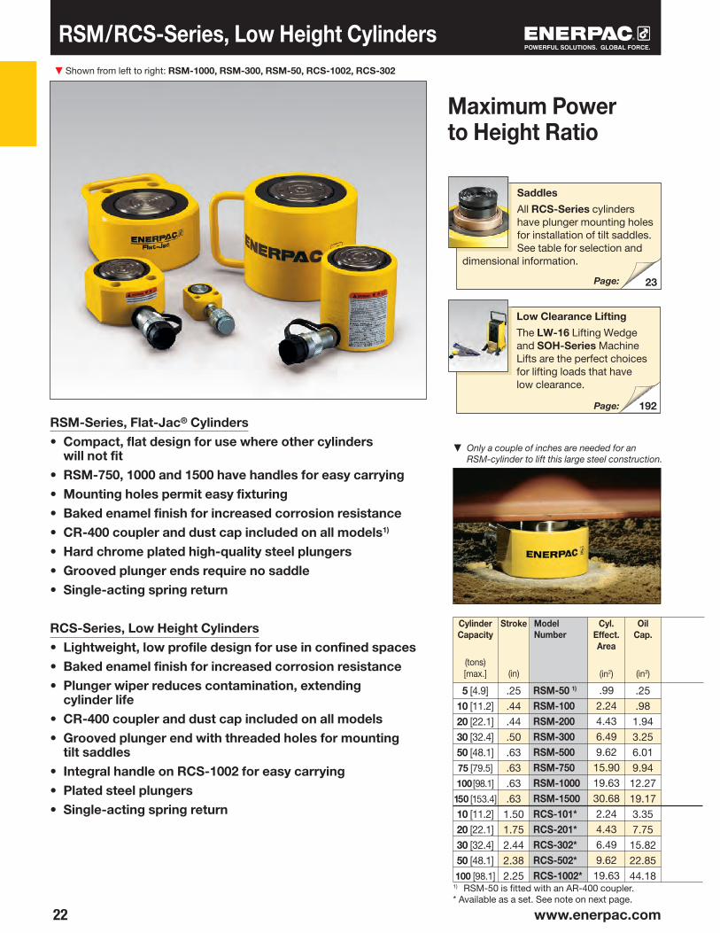
RSM/RCS-Series, Low Height Cylinders
Stroke
(in)
CylinderCapacity
(tons) [max.]
Cyl. Effect. Area
(in2)
Model Number
Oil Cap.
(in3)
Shown from left to right: RSM-1000, RSM-300, RSM-50, RCS-1002, RCS-302
RSM-Series, Flat-Jac® Cylinders• Compact, flat design for use where other cylinders
will not fit• RSM-750, 1000 and 1500 have handles for easy carrying• Mounting holes permit easy fixturing• Baked enamel finish for increased corrosion resistance• CR-400 coupler and dust cap included on all models1)
• Hard chrome plated high-quality steel plungers• Grooved plunger ends require no saddle• Single-acting spring return
RCS-Series, Low Height Cylinders• Lightweight, low profile design for use in confined spaces• Baked enamel finish for increased corrosion resistance• Plunger wiper reduces contami nation, extending
cylinder life• CR-400 coupler and dust cap included on all models• Grooved plunger end with threaded holes for mounting
tilt saddles• Integral handle on RCS-1002 for easy carrying• Plated steel plungers• Single-acting spring return
▼ Only a couple of inches are needed for an RSM-cylinder to lift this large steel construction.
Maximum Power to Height Ratio
Saddles
All RCS-Series cylinders have plunger mounting holes for installation of tilt saddles. See table for selection and
dimensional information.
Low Clearance Lifting
The LW-16 Lifting Wedge and SOH-Series Machine Lifts are the perfect choices for lifting loads that have low clearance.
Page:
1) RSM-50 is fitted with an AR-400 coupler.* Available as a set. See note on next page.
Page:
.25
.44
.44
.50
.63
.63
.63
.631.501.752.442.382.25
.25
.981.943.256.019.94
12.2719.173.357.75
15.8222.8544.18
5 [4.9] 10 [11.2] 20 [22.1] 30 [32.4] 50 [48.1] 75 [79.5]
100 [98.1]
150 [153.4]
10 [11.2] 20 [22.1] 30 [32.4] 50 [48.1] 100 [98.1]
.992.244.436.499.62
15.9019.6330.682.244.436.499.62
19.63

23
H
KF
P
A
D
B
*3/8"-18NPTF
E
O
U
3/8"-18NPTF
E
H
K
F
AB
U1
L
D
VM
A
BC 0-5°
RCS-201, -302, -502RCS-1002
CAT-51CAT-101
52
www.enerpac.com
RSM-50RSM-100RSM-200RSM-300RSM-500RSM-750RSM-1000RSM-1500
RSM-50 1)
RSM-100RSM-200RSM-300RSM-500RSM-750RSM-1000RSM-1500RCS-101*RCS-201*RCS-302*RCS-502*RCS-1002*
Single-Acting, Low Height Cylinders
Extended Height
B(in)
Outside Diameter
D(in)
Cylinder Bore
Diameter
E(in)
PlungerDiameter
F(in)
Weight
(lbs)
Collapsed Height
A(in)
Base to Advance
Port
H(in)
Plunger Protrusion from Base
K(in)
ModelNumber
Bolt Circle
U(in)
Thread
O(mm)
Plungerto
Base
L(in)
Plungerto Mtg.Hole
M(in)
Thread Depth
P(in)
Hole Pitch U1
RSM Cylinder Mounting Hole Dimensions (in)
HoleDiam.
V
CounterBoreDiam.
CounterBore
Depth
Model Number
A B C*
Optional Bolt On Tilt Saddle Dimensions (in)
RSM-SeriesRCS-Series**
RSMRCS Series
Capacity:
5-150 tonsStroke:
.25-2.44 inchesMaximum Operating Pressure:
10,000 psi
* “C” dimension equals saddle protrusion from plunger. Mounting screws are included.
Pump and Cylinder Sets
All cylinders marked with an **
are available as sets (cylinder, gauge, couplers, hose and pump) for your ordering convenience.
Page:
Model Number
** 5° angle position of coupler on RCS-101, 201, 302.
For cylinder model:
2.31 x 1.633.25 x 2.194.00 x 3.004.63 x 3.755.50 x 4.506.50 x 5.507.00 x 6.008.50 x 7.50
2.753.634.004.886.50
1.131.692.382.883.504.505.006.251.692.382.883.505.00
.63
.75
.75
.75
.75
.75
.75
.94
.69
.69
.75
.941.25
2.33.16.810152532586
11152246
1.532.132.472.813.253.754.004.564.975.637.067.197.81
1.001.502.002.502.753.253.634.501.502.002.622.753.63
.04
.04
.04
.08
.08
.08
.08
.08
.20
.13
.13
.08
.06
.811.091.561.882.252.753.003.75
–––––
.881.341.561.752.132.632.943.25
–––––
––––––––
1.031.571.571.572.17
––––––––
M4M5M5M5M8
––––––––
.32
.32
.32
.32
.40
1.121.441.942.062.623.003.004.62
.20
.28
.40
.40
.47
.53
.53
.53
.312
.422
.594
.625
.750
.812
.812
.812
.17
.31
.39
.44
.50
.56
.56
.56
1.972.80
.59
.671.141.39
1.281.692.032.312.633.133.383.943.473.884.634.815.56

▼
24 www.enerpac.com
187
131
BRC/BRP-Series, Pull Cylinders
• High strength alloy steel construction• Plunger blow-out protection to prevent over-extension• Hard chrome-plated plunger for long life• Baked enamel finish for increased corrosion resistance• CR-400 coupler and dust cap included on all models• Plunger wiper reduces contamination, extending
cylinder life• Single-acting spring-return• Replaceable links on BRP-models
Shown from left to right: BRC-25, BRC-46, BRP-306, BRP-606, BRP-106C
▼ Ship building, welding and Enerpac pull cylinders go hand in hand.
▼ To lift a load bearing mast into place, BRP cylinders were used to tension the supporting cables.
The Ultimate in Pulling Power
Attachments and AccessoriesThe BRC-25 and BRC-46 units have base, collar and plunger threads to affix
a range of optional attachments and accessories, such as chains, saddles and extension tubes.
Page:
Gauges
Minimize the risk of over-loading and ensure long, dependable service from your equipment. Refer to the
System Components section for a fullrange of gauges.
Page:

25
N
A TB
L
M
3/8"-18NPTF
E
D J
M30 x 2
AB
N
M
J
L T3/8"-18NPTF
E
DN
D J
M
TAB
E
3/8"-18NPTF
L11/4"-7UNC
M
DN
3/8"-18NPTF
AB
L
T
E
J
M50 x 3
M30 x 2
3/8"-18NPTF
H
Z
V ED
PXA
B
F JQ W
P
Q
BRP-106CBRP-106LBRP-306BRP-606
BRC-25BRC-46BRC-106
BRP-106C
BRP-106L
BRP-306
BRP-606
BRC-25BRC-46BRC-106
Single-Acting, Pull Cylinders
Ext. Height
B(in)
Collap.Height
A(in)
Cyl. Effect. Area
(in2)
Oil Capacity
(in3)
CylinderCapacity
(tons) [maximum]
ModelNumber
Stroke
(in)
Outside Diam.
D(in)
Cyl. Bore Diam.
E(in)
LinkOpen-
ing
L(in)
LinkThick-ness
M(in)
LinkWidth
N(in)
Slot toLinkEnd
T(in)
Weight
(lbs)
LinkHeight
J(in)
Ext.Height
B(in)
Collap.Height
A(in)
Cyl. Effect. Area
(in2)
Oil Cap.
(in3)
CylinderCapacity
(tons) [maximum]
ModelNumber
Stroke
(in)
OutsideDiam.
D(in)
Cyl.Bore Diam.
E(in)
Plgr.Diam.
F(in)
Top to Inlet Port
H(in)
SaddleDiameter
J(in)
PlungerThreadLength
P(in)
PlungerOutsideThread
Q
Weight
(lbs)
BRC Cylinder Mounting Dimensions (in)Base
MountingHole
V
CollarThread
W
CollarThread Length
X
Mtg.Thread Length
Z
ModelNumber
BRC-25 to BRC-106
BRC 106 only
Note: BRP-106C, BRP-106L and BRP-606 are fitted with rubber bellows for rod protection.
BRCBRP Series
Capacity:
2.5-60 tonsStroke:
5.00-6.00 inchesMaximum Operating Pressure:
10,000 psi
2.452.457.1911.17
14.5814.5843.6367.02
23.6622.8743.7128.28
29.5728.7849.7134.28
3.353.355.395.51
2.132.133.504.33
4.132.524.495.12
3.434.696.105.93
1.180.871.381.58
1.381.341.701.89
1.281.262.172.56
3429
139129
10 [11.6]
30 [36.1]60 [58.8]
5.915.916.106.00
2.5 [2.7]5 [5.6]
10 [11.6]
5.005.505.95
1.131.251.02
.551.132.32
2.766.2113.80
10.4411.8811.38
15.4417.3817.33
1.892.253.35
1.131.692.13
.751.191.25
1.771.691.57
¾"-14 NPT
1¼"-11½" NPT
–
11/16"-2413/16"-16M30x2
41021
¾"-14 NPT1¼"-11½" NPT
M30 x 2
1½"-16 un
2¼"-14 un
M85 x 2
.981.061.02
.67
.98
.98

▼
26 www.enerpac.com
27
16
52
RCH-120RCH-121*RCH-1211RCH-123RCH-202*RCH-206RCH-302*RCH-306RCH-603*RCH-606RCH-1003*
RCH-Series, Hollow Plunger Cylinders Shown from left to right: RCH-306, RCH-120, RCH-1003
Stroke
(in)
CylinderCapacity
(tons) [maximum]
Cyl. Effect. Area
(in2)
ModelNumber
Oil Cap.
(in3)
Versatility in Testing, Maintenance and Tensioning Applications
* Available as a set. See note on this page.
Saddles Most RCH-Series cylinders are equipped with smooth saddles. See table at next page for optional threaded saddles and all dimensional information.
Page:
Lightweight Aluminum Hollow Plunger Cylinders
If you need a higher cylinder capacity-to-weight ratio the lightweight RACH-Series
Aluminum Hollow Plunger Cylinders are the perfect choice.
Page:
• Hollow plunger design allows for both pull and push forces• Single-acting spring return• Nickel-plated, floating center tube on models over 20 tons
increases product life• Baked enamel finish for increased corrosion resistance• Collar threads for easy fixturing• RCH-120 includes AR-630 coupler and has 1/4 NPTF port• RCH-121 and RCH-1211 have FZ-1630 reducer and
AR-630 coupler, all other models feature CR-400 coupler
▼ Hollow plunger cylinder RCH-1003 used in an application for intermediate boom suspension on a dragline.
Pump and Cylinder Sets
All cylinders marked with an *
are available as sets (cylinder, gauge, couplers, hose and pump) for your ordering convenience.
Page:
0.311.631.633.002.006.102.506.133.006.003.00
0.864.494.498.299.46
28.6718.0544.2338.2076.4161.88
12[13.8]
20 [23.6]
30[36.1]
60[63.6]
100 [103.1]
2.762.76 2.76 2.76 4.724.72 7.227.22
12.7312.7320.63

27
V
Y U D
H
*3/8"-18NPTF
F
P
OW
X
Z
A
B
E3/8"-
18NPTF
Z
H
X
A
B
KF
P
OJW
Y U D
V
E
132
BC
A
RCH-120RCH-121*RCH-1211RCH-123RCH-202*RCH-206RCH-302*RCH-306RCH-603*RCH-606RCH-1003*
RCH-120RCH-121RCH-1211RCH-123RCH-202RCH-206RCH-302RCH-306RCH-603RCH-606RCH-1003
HP-2015HP-3015HP-5016HP-10016
RCH-202, 206RCH-302, 306RCH-603, 606RCH-1003
ModelNumber
Single-Acting, Hollow Plunger Cylinders
Ext. Height
B(in)
Outside Diam.
D(in)
Cyl. Bore Diam.
E(in)
Plngr.Diam.
F(in)
Weight
(lbs)
Collap. Height
A(in)
Cyl. Base to Advance
Port
H(in)
Saddle Diameter
J(in)
Saddle Protrusion from Plngr.
K(in)
ModelNumber
Center HoleDiam.
Y(in)
Plunger InternalThread
O(in)
CollarThread
W(in)
CollarThreadLength
X(in)
PlungerThreadLength
P(in)
Bolt Circle
U
Base Mounting Hole Dimensions (in) ThreadDepth
Z
Thread
V
RCH-120* to RCH-123 models RCH-202 to RCH-1003 models
RCH Series
Capacity:
12-100 tonsStroke:
.31-6.13 inchesCenter Hole Diameter:
.68-3.11 inches
Saddle Dimensions (in)Saddle Type
ThreadedHollow
Optional Heat Treated Hollow Saddles
A B C
RCH-121 and RCH-1211 have a 1.88" diameter boss that protrudes 0.25" from base.
Cylinder Model No.
Saddle Model No.
Smooth hollow saddles are standard on all RCH-models (12-ton models are not equipped with saddles).
Maximum Operating Pressure:
10,000 psi
Hoses
Enerpac offers a complete line of high quality hydraulic hoses. To ensure the integrity of your system, specify only Enerpac hydraulic hoses.
Page:
* 1/4" NPT for RCH-120 only
2.752.752.752.753.883.884.504.506.256.258.38
2.132.132.132.132.882.883.503.504.884.886.50
––––
2.132.132.502.503.613.614.97
2.194.754.757.256.3812.057.0313.009.7512.7510.00
2.506.386.3810.258.3818.119.5319.1312.7518.7513.00
1.381.381.381.382.132.132.502.503.633.635.00
.38
.98
.98
.98
.75
.75
.851.001.251.251.50
––––
.27
.27
.38
.38
.50
.50
.50
¾"-16 un
–¾"-16 un
–19
16"-16 un
19/16"-16 un
113/16"-16 un
113/16"-16 un
2¾"-16 un
2¾"-16 un
4"-16 un
.68
.77
.68
.771.061.061.311.312.122.123.11
3.26.26.29.8173124486278
132
.63–
.63–
.75
.75
.88
.88
.75
.751.00
1.191.191.191.191.501.501.661.661.911.912.38
2¾"-162¾"-162¾"-162¾"-163⅞"-123⅞"-124½"-124½"-126¼"-126¼"-128⅜"-12
2.00––
2.003.253.253.633.635.135.137.00
5/16"-18 unc
––
5/16"-18 unc
⅜"-16 unc
⅜"-16 unc
⅜"-16 unc
⅜"-16 unc
½"-13 unc
½"-13 unc
⅝"-11 unc
.35––
.50
.37
.37
.55
.55
.55
.55
.75
2.112.493.614.97
.38
.38
.50
.51
1"-81¼"-7
1⅝"-5½"2½"-8

▼
28 www.enerpac.com
29
131
123
RRH-307RRH-3010RRH-603RRH-606RRH-6010RRH-1001RRH-1003RRH-1006RRH-10010RRH-1508
RRH-Series, Hollow Plunger Cylinders
Stroke
(in)
CylinderCapacity
(ton)
Cylinder Effective Area
(in2)
Max. Cylinder Capacity
(ton)
ModelNumber
Oil Capacity
(in3)
AdvanceAdvance AdvanceRetractRetract Retract
Shown from left to right: RRH-3010, RRH-1001, RRH-6010
• Relief valves prevent damage in case of over-pressurization• Baked enamel finish for increased corrosion resistance• Collar threads enable easy fixturing
(except RRH-1001 and RRH-1508)• Double-acting operation for fast retraction• Nickel-plated, floating center tube increases product life• Hollow plunger allows for both pull and push forces• CR-400 couplers and dust caps included on all models• Plunger wiper reduces contamination, extending
cylinder life
Versatility in Testing, Maintenance and Tensioning Applications
Saddles
All RRH-Series cylinders are equipped with smooth saddles. See table on next page for optional threaded
saddles and all dimensional information.
Page:
Gauges
Minimize the risk of overloading and ensure long, dependable service from your equipment. Refer
to the System Components section for a full range of gauges.
Page:
▼ Double-acting hollow-plunger cylinders are applied for bridge launching systems.
Pump Selection
A double-acting cylinder must be powered by a pump with a 4-way valve.
Page:
7.0010.133.506.50
10.121.503.006.00
10.138.00
4.714.718.378.378.37
13.5413.5413.5413.5415.91
50.5573.1244.5782.77
128.9430.9461.88
123.76208.84252.97
32.9947.7129.2154.2484.4920.3240.6481.29
137.17127.23
30
60
100
150
3636646464
103103103103158
24244242426868686880
7.227.22
12.7312.7312.7320.6320.6320.6320.6331.62

29
Z
X
A
B
K
3/8"-18NPTF
H
I
F
P
OJW
E
Y U D
V
30°
BC
A
132
RRH-307RRH-3010RRH-603RRH-606RRH-6010RRH-1001RRH-1003RRH-1006RRH-10010RRH-1508
RRH-307RRH-3010RRH-603RRH-606RRH-6010RRH-1001RRH-1003RRH-1006RRH-10010RRH-1508
HP-3015HP-5016
HP-10016
RRH-307, 3010RRH-603, 606, 6010RRH-1001, 1003, RRH-1006, 10010
Double-Acting, Hollow Plunger Cylinders
Ext. Height
B(in)
Out. Diam.
D(in)
Cyl. Bore Diam.
E(in)
Plngr.Diam.
F(in)
Wt.
(lbs)
Collap. Height
A(in)
Cyl. Baseto Adv.
Port H
(in)
Cyl. Topto Return
Port I
(in)
Saddle Diam.
J(in)
SaddleProtrusionfrom Plngr.
K(in)
ModelNumber
Center HoleDiam.
Y(in)
Thread
O(in)
CollarThreadLength
X(in)
CollarThread
W(in)
PlungerThreadLength
P(in)
Base Mounting Hole Dimensions (in) Bolt
CircleU
ThreadDepth
Z
Thread
V
ModelNumber
RRH Series
Capacity:
30-150 tonsStroke:
1.50-10.13 inches
Saddle Dimensions (in)Optional Heat Treated Saddles
A B CSaddle Type
ThreadedHollow
Cylinder Model Number
Saddle Model No.
Smooth hollow saddles are standard on all RRH-models.Center Hole Diameter:
1.31-3.13 inchesMaximum Operating Pressure:
10,000 psi
Hoses
Enerpac offers a complete line of high-quality hydraulic hoses. To ensure the integrity of your system,
specify only Enerpac hydraulic hoses.
Page:
.38
.50
.51
4.504.506.256.256.258.388.388.388.389.75
3.503.504.884.88 4.886.506.506.506.507.50
2.382.382.632.632.631.753.383.383.382.38
2.502.503.613.613.614.974.974.974.975.00
48606278
10185
135175235245
13.0017.009.7512.7517.256.5010.0013.5018.1313.75
20.0027.1313.2519.2527.388.0013.0019.5028.2521.75
2.502.503.633.633.635.005.005.005.006.00
1.001.001.251.251.251.501.501.501.501.50
.38
.38
.50
.50
.50
.50
.50
.50
.50
.19
113/16"-16113/16"-16 2¾"-162¾"-162¾"-164"-164"-164"-164"-16
4¼"-12
1.311.312.132.132.133.133.133.133.133.13
.88
.88
.75
.75
.751.001.001.001.001.00
1.661.661.911.911.91 –
2.382.382.38 –
4½"-124½"-126¼"-126¼"-126¼"-12
–8⅜"-128⅜"-128⅜"-12
–
3.633.635.125.125.127.007.007.007.00
–
⅜"- 16⅜"- 16½"- 13½"- 13½"- 13⅝"- 11⅝"- 11⅝"- 11⅝"- 11 –
.62
.62
.55
.55
.55
.75
.75
.75
.75–
2.493.61
4.97
1¼"-71⅝"-5½
2½"-8

▼
30 www.enerpac.com
283
RD-41RD-43RD-46RD-91RD-93RD-96RD-910RD-166RD-1610RD-256RD-2510
RD-Series, Precision Production Cylinders
Stroke
(in)
CylinderCapacity
(tons)
Cylinder Effective Area
(in2)
Max. Cylinder Capacity
(tons)
ModelNumber
Oil Capacity
(in3)
AdvanceAdvance AdvanceRetractRetract Retract
Shown from left to right: RD-2510, RD-96, RD-256, RD-41, RD-166
• Designed for long life, the best choice for production applications
• Unique mounting configurations simplify fixturing• Baked enamel finish for increased corrosion resistance• Double-acting operation develops force in both directions,
providing maximum versatility• Plunger wiper reduces contamination, extending
cylinder life
High Precision and High Cycle Performance
Collap. Height
A(in)
Ext. Height
B(in)
Body Length
C(in)
Outside Diam.
D(in)
Cylinder Bore Diam.
E(in)
PlungerDiam.
F(in)
Speed Chart
See the Enerpac Cylinder Speed Chart in our ‘Yellow Pages’ to determine your
approximate cylinder speed.
Page:
▼ Clamping application using Enerpac RD cylinders (with clevis eye attachments on both ends) for their high-pressure capability and mounting flexibility.
1.133.136.131.133.136.1310.136.2510.256.2510.25
444999916162525
2225555881111
.79
.79
.791.771.771.771.773.143.144.914.91
.34
.34
.34
.98
.98
.98
.981.661.662.152.15
.882.454.811.995.52
10.8217.8919.6332.2030.6850.31
.391.072.101.103.076.019.94
10.3516.9813.4222.01
4
9
16
25
7.319.31
12.318.75
10.7813.7817.7815.3119.3116.6920.69
6.388.38
11.387.809.80
12.8016.8114.1318.1115.6319.61
2.002.002.002.502.502.502.503.003.003.633.63
8.4412.4418.449.88
13.9119.9127.9121.5629.5622.9430.94
1.001.001.001.501.501.501.502.002.002.502.50
.75
.75
.751.001.001.001.001.381.381.881.88

31
D
C
E
HC
A
D
B
E
F
E
C
D
AB
E
C AB
D
AB
F
H
M
L
L1
N
A
N
P
W
C
Z1
I
ZX
F
WD
K
E
H
X
B
Q
3/8"-18NPTF
D
C
E
HC
A
D
B
E
F
E
C
D
AB
E
C AB
D
AB
F
H
D
C
E
HC
A
D
B
E
F
E
C
D
AB
E
C AB
D
AB
F
H
D
C
E
HC
A
D
B
E
F
E
C
D
AB
E
C AB
D
AB
F
H
1⅛"-201⅛"-201⅛"-20111/16"-18111/16"-18111/16"-18111/16"-182 3/16"-162 3/16"162¾"-162¾"-16
RD-41RD-43RD-46RD-91RD-93RD-96RD-910RD-166RD-1610RD-256RD-2510
AD-141AD-171AD-181AD-191
AD-142AD-172AD-182AD-192
AD-143AD-173AD-183AD-193
AD-150AD-151AD-152AD-153
Foot Mounting Mounts onto cylinder collar. Mounting screws not included.
Double-Acting, Precision Production Cylinders
Wt.
(lbs)
Bottom to Adv.Port
I(in)
Plunger Protrusion
K(in)
ModelNumber
NeckLength
N(in)
PlungerThread Length
P(in)
PlungerExternal Thread
Q(in)
Cylinder Mounting Dimensions (in)
CollarThread
W
CollarThreadLength
X
Int. BaseThread
Z
Int. Base ThreadLength
Z1
ModelNumber
RD-Cyl:(tons) A B C D E F H
Flange Mounting Mounts onto cylinder collar. Mounting screws not included.
Clevis Eye Threads onto plunger or into cylinder base
Retainer NutFor locking foot or flange mountings. Tightens onto cylinder collar threads (included with foot and flange mounting kits)
Foot Mounting with Retainer Nut
Flange Mounting with Retainer Nut
Retainer Nut
Clevis Eye
RD Series
Capacity:
4-25 tonsStroke:
1.13-10.25 inchesMaximum Operating Pressure:
10,000 psi
Top to Ret.
Port
H(in)
▼ RD CYLINDER ATTACHMENTS
Dimensions (in)
Clevis Eye Mounting Dimensions
L L1 M (in) (in) (in)
Clevis Eye (optional)
4.86.49.09.0
11.014.019.022.029.036.046.0
1.881.881.882.272.272.272.272.902.903.503.50
.94
.94
.94
.98
.98
.98
.981.191.191.061.08
½"-20½"-20½"-20¾"-16¾"-16¾"-16¾"-161⅛"-121⅛"-121½"-121½"-12
1.131.131.131.501.501.501.502.132.132.752.75
.75
.75
.75
.75
.75
.75
.751.001.001.001.00
1⅜"-121⅜"-121⅜"-122"-122"-122"-122"-12
2⅝"-162⅝"-163¼"-163¼"-16
.44
.44
.44
.56
.56
.56
.56
.88
.881.131.13
.35
.35
.35
.55
.55
.55
.55
.94
.941.021.02
491625
491625
491625
491625
1.382.002.633.25
1.382.002.633.25
1.375-12 unf 2.000-12 un
2.625-16 un
3.250-16 un
.500-20 unf
.750-16 unf
1.125-12 unf
1.500-12 unf
3.004.005.006.25
3.884.755.636.50
2.253.003.634.25
1.125- 20 un
1.688-18 unef
2.188-16 uns
2.750-16
.41
.53
.781.03
.41
.41
.53
.66
.25
.27
.27
.27
.63
.751.001.25
.751.001.381.75
.751.001.381.75
.38
.50
.751.00
.621.001.251.50
2.253.254.004.88
––––
––––
.751.001.001.00
1.251.752.062.50
––––
––––
.94
.941.191.06
2.002.883.754.62
3.093.884.565.34
1.812.503.123.75
2.062.253.063.06
1.881.881.882.272.272.272.272.902.903.503.50
10.1212.1215.1211.6113.6616.6620.6619.3223.3220.8624.86
11.2515.2521.2512.7616.7922.7930.7925.5733.5727.1135.11
1.611.611.611.501.501.501.502.052.052.092.09

▼
32 www.enerpac.com
33
123
90
Pump Selection
A double-acting cylinder must be powered by a pump with a 4-way valve.
RR-Series, Double-Acting Cylinders Shown from left to right: RR-10013, RR-1502, RR-20013, RR-1010, RR-7513
• Collar threads, plunger threads and base mounting holes for easy fixturing (on most models)
• Baked enamel finish for increased corrosion resistance• Removable hardened saddles protect plunger during
lifting and pressing• Built-in safety valve prevents accidental
over-pressurization• CR-400 couplers included on all models• Plunger wiper reduces contamination,
extending cylinder life
Most Versatile Performers
Rugged enough for the toughest job site uses and precision designed for high-cycle industrial uses.
Saddles
RR-Series cylinders up to 75-ton have plunger thread for installation of CAT-Series tilt saddles.
Page:
Page:
▼ These long stroke RR-cylinders are attached to a sliding and guiding system pulling the arched roof assembly of Athen’s Olympic Stadium step-by-step into the final position.
▼ RR-cylinders provide power and precision in a special hydraulic press.
Optimum Performance
Enerpac’s range of Z-Class electric pumps, fitted with manual or solenoid operated 4-way valves, offer optimum combinations with RR cylinders.
Page:
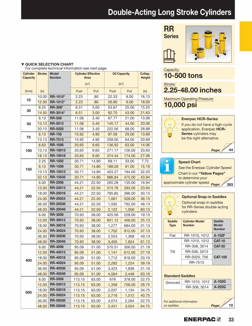
33
283
44
10
RR-1010*RR-1012*RR-308*RR-3014*RR-506RR-5013RR-5020RR-756RR-7513RR-1006RR-10013RR-10018RR-1502RR-1506RR-15013RR-15032RR-2006RR-20013RR-20018RR-20024RR-20036RR-20048RR-3006RR-30012RR-30018RR-30024RR-30036RR-30048RR-4006RR-40012RR-40018RR-40024RR-40036RR-40048RR-5006RR-50012RR-50018RR-50024RR-50036RR-50048
Double-Acting Long Stroke Cylinders
Stroke
(in)
CylinderCapacity
(tons)
Cylinder Effective Area
(in2)
ModelNumber
Oil Capacity
(in3)
Push PushPull Pull
RR Series
Capacity:
10-500 tonsStroke:
2.25-48.00 inchesMaximum Operating Pressure:
10,000 psi
▼ QUICK SELECTION CHART For complete technical information see next page.
Collap. Height
(in)
Optional Snap-in Saddles
Optional snap-in saddles for RR-Series double-acting cylinders:
Standard Saddles
SaddleType
Cylinder Model Number
Saddle Model Number
Flat
Tilt
Page:
Speed Chart
See the Enerpac Cylinder Speed
Chart in our “Yellow Pages” to determine your
approximate cylinder speed. Page:
Enerpac HCR-Series
If you do not have a high-cycle application, Enerpac HCR-Series cylinders may be the right alternative.
Page:
For additional information on saddles:
Grooved
10.0012.008.2514.506.1313.1320.136.1313.136.6313.1318.132.256.1313.1332.136.0013.0018.0024.0036.0048.006.0012.0018.0024.0036.0048.006.0012.0018.0024.0036.0048.006.0012.0018.0024.0036.0048.00
2.232.236.516.5111.0611.0611.0615.9215.9220.6520.6520.6530.7130.7130.7130.7144.2144.2144.2144.2144.2144.2170.9370.9370.9370.9370.9370.9395.0995.0995.0995.0995.0995.09113.15113.15113.15113.15113.15113.15
.80
.803.003.003.403.403.404.904.909.609.609.6014.8014.8014.8014.8022.5022.5022.5022.5022.5022.5038.0038.0038.0038.0038.0038.0051.0051.0051.0051.0051.0051.0063.0063.0063.0063.0063.0063.00
22.3326.8053.6792.7067.77
145.17222.5697.58
209.00136.93271.17374.4469.11
188.28403.27986.84265.28574.78795.851,0611,5922,122
425.56851.121,2771,7022,5533,405
570.511,1411,7122,2823,4234,564678
1,3582,0372,7164,0745,431
8.009.00
25.0043.0021.0044.0068.0029.0064.0063.00
126.00174.0033.0091.00
194.00475.00135.00293.00396.00528.00792.001,056
228.00456.00684.00912.001,3681,824
306.00612.00918.001,2241,8362,448
378.00756.001,1341,5122,2643,024
16.1318.0015.2521.6313.0620.0628.8813.6920.6914.0620.6327.067.72
15.1922.2043.9416.9423.9430.1336.1348.1360.1319.1325.1331.1337.1349.1361.1321.1927.1933.1939.1951.1963.1922.7528.7534.7540.7552.7564.75
RR-1010, 1012RR-1010, 1012RR-308, 3014RR-506, 5013 RR-5020, 756
RR-7513
A-102FCAT-10CAT-50
CAT-100
RR-1010, 1012RR-308, 3014
A-102GA-252G
10
30
50
75
100
150
200
300
400
500

34 www.enerpac.com
P
O
H
X
B
A
*NI
K
3/8"-18NPTF E
D
J
FW
Z
X
A
B
K
W
3/8"-18NPTF
H
I
D
E
F
P
OJ
U
V
V
U
RR-1010*RR-1012*RR-308*RR-3014*RR-506RR-5013RR-5020RR-756RR-7513RR-1006RR-10013RR-10018RR-1502RR-1506RR-15013RR-15032RR-2006RR-20013RR-20018RR-20024RR-20036RR-20048RR-3006RR-30012RR-30018RR-30024RR-30036RR-30048RR-4006RR-40012RR-40018RR-40024RR-40036RR-40048RR-5006RR-50012RR-50018RR-50024RR-50036RR-50048
RR-Series, Double-Acting Cylinders
Stroke
(in)
CylinderCapacity
(ton)
Cylinder Effective Area
(in2)
Max. Cylinder Capacity
(tons)
ModelNumber
Oil Capacity
(in3)
PushPush PushPullPull Pull
◀For full features see page 32.
Ext. Height
B(in)
Collap. Height
A(in)
Outside Diam.
D(in)
RR-1010 to RR-3014 models* For RR-1010 and RR-1012:
N = 1.26 inch; for RR-308 and RR-3014: N = 2.20 inch.
RR-506 to RR-50048 models
No mounting holes: RR-506, 5013RR-756, 7513RR-1502, 15032
RR-1006 to RR-30048
Cylinder retract capacity for certain RR cylinders may be less than theoretical values, as a result of reduced relief valve pressure settings:
RR-308/3014: 4000 psi RR-506/5013/5020: 6950 psi RR-756/7513: 7200 psi
* For RR-1010 and RR-1012: N = 1.26 inch; for RR-308 and RR-3014: N = 2.20 inch.
10
30
50
75
100
150
200
300
400
500
10.0012.008.2514.506.1313.1320.136.1313.136.6313.1318.132.256.1313.1332.136.0013.0018.0024.0036.0048.006.0012.0018.0024.0036.0048.006.0012.0018.0024.0036.0048.006.0012.0018.0024.0036.0048.00
11.111.132.532.555.355.355.379.679.6
103.2103.2103.2153.5153.5153.5153.5221.0221.0221.0221.0221.0221.0354.6354.6354.6354.6354.6354.6475.4475.4475.4475.4475.4475.4565.7565.7565.7565.7565.7565.7
4.04.06.06.0
11.811.811.817.617.648.048.048.074.074.074.074.0
112.5112.5 112.5 112.5 112.5 112.5 190.0190.0190.0190.0190.0190.0255.0255.0255.0255.0255.0255.0315.0315.0315.0315.0315.0315.0
2.232.236.516.5111.0611.0611.0615.9215.9220.6520.6520.6530.7130.7130.7130.7144.2144.2144.2144.2144.2144.2170.9370.9370.9370.9370.9370.9395.0995.0995.0995.0995.0995.09113.15113.15113.15113.15113.15113.15
.80
.803.003.003.403.403.404.904.909.609.609.60
14.8014.8014.8014.8022.5022.5022.5022.5022.5022.5038.0038.0038.0038.0038.0038.0051.0051.0051.0051.0051.0051.0063.0063.0063.0063.0063.0063.00
22.3326.8053.6792.7067.77
145.17222.5697.58
209.00136.93271.17374.4469.11
188.28403.27986.84265.28574.78795.851,0611,5922,122
425.56851.121,2771,7022,5533,405
570.511,1411,7122,2823,4234,564
678.921,3582,0372,7164,0745,431
8.009.00
25.0043.0021.0044.0068.0029.0064.0063.00
126.00174.0033.0091.00
194.00475.00135.00293.00396.00528.00792.001,056
228.00456.00684.00912.0013681824
306.00612.00918.00122418362448
378.00756.001134151222683024
16.1318.0015.2521.6313.0620.0628.8813.6920.6914.0620.6327.067.19
15.1922.2043.9416.9423.9430.1336.1348.1360.1319.1325.1331.1337.1349.1361.1321.1927.1933.1939.1951.1963.1922.7528.7534.7540.7552.7564.75
26.1330.0023.5036.1319.1933.1949.0019.8133.8120.6933.7545.199.44
21.3135.3176.0622.9436.9448.1360.1384.13
108.1325.1337.1349.1361.1385.13
109.1327.1939.1951.1963.1987.19
111.1928.7540.7552.7564.7588.75
112.75
2.882.884.004.005.005.005.005.755.757.007.007.008.008.008.008.009.759.759.759.759.759.75
12.2512.2512.2512.2512.2512.2514.1314.1314.1314.1314.1314.1315.6315.6315.6315.6315.6315.63

35
RR-1010*RR-1012*RR-308*RR-3014*RR-506RR-5013RR-5020RR-756RR-7513RR-1006RR-10013RR-10018RR-1502RR-1506RR-15013RR-15032RR-2006RR-20013RR-20018RR-20024RR-20036RR-20048RR-3006RR-30012RR-30018RR-30024RR-30036RR-30048RR-4006RR-40012RR-40018RR-40024RR-40036RR-40048RR-5006RR-50012RR-50018RR-50024RR-50036RR-50048
Double-Acting Long Stroke Cylinders
Cylinder Bore
Diameter
E(in)
PlungerDiameter
F(in)
Base to Adv.
Port
H(in)
Top to Return
Port
I(in)
SaddleDiameter
J(in)
Weight
(lbs)
Plunger Thread Length
P(in)
Saddle Protrusion from Plngr.
K(in)
Plunger Internal Thread
O(in)
Base Mounting Holes ModelNumber
CollarThread
W(in)
CollarThreadLength
X(in)
Thread
V(in)
Thread Depth
Z(in)
Bolt Cir.Diam.
U(in)
RR Series
Capacity:
10-500 tons
Stroke:
2.25-48.00 inchesMaximum Operating Pressure:
10,000 psi
Couplers Included!
CR-400 couplers included on all models.Fits all HC-Series hoses.
1.381.382.132.133.133.133.133.753.753.753.753.754.504.504.504.505.255.255.255.255.255.256.506.506.506.506.506.507.507.507.507.507.507.508.008.008.008.008.008.00
1.441.441.441.561.131.132.251.191.191.501.501.63.881.941.943.312.252.253.383.383.383.383.503.503.503.503.503.504.254.254.254.254.254.254.754.754.754.754.754.75
2.252.253.193.193.003.003.003.003.192.812.813.632.633.313.313.313.813.814.004.004.004.004.504.504.504.504.504.505.255.255.255.255.255.256.006.006.006.006.006.00
1.381.382.002.002.812.812.812.812.813.003.003.003.674.494.494.495.255.255.255.255.255.256.506.506.506.506.506.507.507.507.507.507.507.508.008.008.008.008.008.00
.24
.24
.41
.41
.11
.11
.11
.25
.25
.13
.13
.13
.06
.75
.75
.75
.88
.88
.88
.88
.88
.881.131.131.131.131.131.131.131.131.131.131.131.131.131.131.131.131.131.13
1-81-8
1½-161½-161-121-121-121-121-12
1¾-121¾-121¾-12
–33•8-1633•8-1633•8-16
–2½ -122½-122½-122½ -122½-122½-122½-122½-122½-122½-122½-123-123-123-123-123-123-12
3¼-123¼-123¼-123¼-123¼-123¼-12
1.001.001.001.001.001.001.001.501.501.381.381.38
– 1.381.381.38
– 2.502.502.502.502.503.253.253.253.253.253.253.753.753.753.753.753.754.254.254.254.254.254.25
– – – – – –
3.00 – –
5.505.505.50
– 6.256.25
– 5.005.005.005.005.005.006.256.256.256.256.256.258.008.008.008.008.008.00 8.008.008.008.008.008.00
– – – – – – – – –
¾-10¾-10¾-10
– ¾-16¾-16
– 1-81-81-81-81-81-8
1¼-71¼-71¼-71¼-71¼-71¼-71½-61½-61½-61½-61½-61½-61¾-51¾-51¾-51¾-51¾-51¾-5
– – – – – – – – –
1.001.001.00
– 1.001.00
– 1.001.001.001.001.001.001.751.751.751.751.751.752.002.002.002.002.002.002.122.122.122.122.122.12
2¼-142¼-1435/16-1235/16-12
5-125-125-12
5¾-125¾-1267/8-1267/8-1267/8-12
– 8-128-128-12
– 9¾-129¾ -129¾ -129¾ -129¾ - 1212¼-1212¼-1212¼-1212¼-1212¼-1212¼-1214⅛-814⅛-814⅛-814⅛-814⅛-814⅛-8155/8-8155/8-8155/8-8155/8-8155/8-8155/8-8
1.061.061.941.942.002.002.001.501.502.002.002.00
–2.362.362.36
– 2.132.132.132.132.132.312.312.312.312.312.312.562.562.562.562.562.563.133.133.133.133.133.13
2831406467
11515092
150135205260110205275525325440450616845
1065441608776
103413851720670880
1000131717462162953
13001500180022102700
1.691.692.882.883.753.753.754.504.505.135.135.136.256.256.256.257.507.507.507.507.507.509.509.509.509.509.509.5011.0011.0011.0011.0011.0011.0012.0012.0012.0012.0012.0012.00

▼
36 www.enerpac.com
Enerpac High-Tonnage Cylinders
Reaching the Summit Edition:Substrate bonded multi-layer treatment• Hardened surface resists side-loading and cyclic wear• Weather protected, inside and out• Low-friction locking rings spin easy, save time and effort 1)
Enclosed polymer bearing system• Upper and lower bearings enclose the cylinder plunger for
support and are able to be replaced along with seals and other soft parts
• State-of-the-art bearing material provides maximum conformity to reduce wear and avoid bore damage even in high side-load conditions
Low-wear, high-pressure seals• Improved geometry and material selection increases
seal performance even in harsh conditions• Low friction improves retraction times
Versatile• Over 200 models in four configurations 1)
• Certified lifting eyes, base mounting holes and collar threads are included for secure handling and cylinder mounting 1)
1) See specific model’s technical data for more information.
▼ Bridge lifting and launching system. The load is balanced on groups of lock nut cylinders. The hydraulic movements are synchronized using the Enerpac PLC-controlled synchronous lift systems.
HCL-1006, HCG-2006, HCR-506
Highest Level of Durability
The Summit Edition
Innovation is at the heart of the new Summit Edition of cylinders, delivering the high
quality construction that you expect from Enerpac. The durability ensures your job gets done safely and reliably.
• Plunger support bearing adds support for eccentric loads 2)
• Nitrocarburization surface treatment for improved wear resistance and corrosion protection
• Replaceable composite bearings surround the seal providing support for eccentric loads
• Low-wear, high-pressure seals provide longer service life
2) Eccentric load (or “side-load”) is inevitable in heavy lifting. Our unique Summit Edition features provide the ultimate protection against side-load. Increased bearing surface maintains stability, and nitrocarburization treatment prevents scoring on the inside of the cylinder. Side-load poses a real problem.... our new cylinder features are the solution!
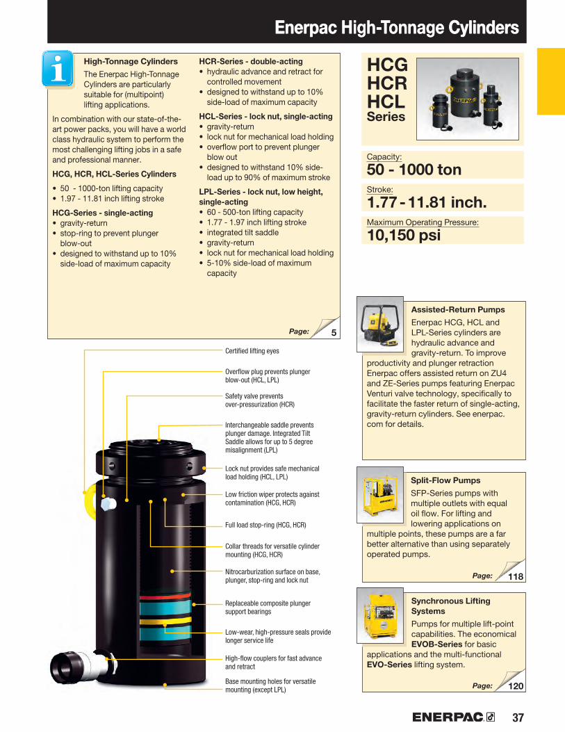
37
5
118
120
Enerpac High-Tonnage CylindersEnerpac High-Tonnage Cylinders
HCG HCRHCLSeries
Capacity:
50 - 1000 tonStroke:
1.77 - 11.81 inch.Maximum Operating Pressure:
10,150 psi
High-Tonnage Cylinders
The Enerpac High-Tonnage Cylinders are particularly suitable for (multipoint) lifting applications.
In combination with our state-of-the-art power packs, you will have a world class hydraulic system to perform the most challenging lifting jobs in a safe and professional manner.
HCG, HCR, HCL-Series Cylinders
• 50 - 1000-ton lifting capacity• 1.97 - 11.81 inch lifting stroke
HCG-Series - single-acting• gravity-return• stop-ring to prevent plunger
blow-out• designed to withstand up to 10%
side-load of maximum capacity
HCR-Series - double-acting• hydraulic advance and retract for
controlled movement• designed to withstand up to 10%
side-load of maximum capacity
HCL-Series - lock nut, single-acting• gravity-return• lock nut for mechanical load holding• overflow port to prevent plunger
blow out• designed to withstand 10% side-
load up to 90% of maximum stroke
LPL-Series - lock nut, low height, single-acting• 60 - 500-ton lifting capacity • 1.77 - 1.97 inch lifting stroke• integrated tilt saddle• gravity-return• lock nut for mechanical load holding• 5-10% side-load of maximum
capacity
Page:
Low friction wiper protects against contamination (HCG, HCR)
Full load stop-ring (HCG, HCR)
Lock nut provides safe mechanical load holding (HCL, LPL)
Nitrocarburization surface on base, plunger, stop-ring and lock nut
High-flow couplers for fast advance and retract
Base mounting holes for versatile mounting (except LPL)
Interchangeable saddle prevents plunger damage. Integrated Tilt Saddle allows for up to 5 degree misalignment (LPL)
Overflow plug prevents plunger blow-out (HCL, LPL)
Safety valve prevents over-pressurization (HCR)
Certified lifting eyes
Collar threads for versatile cylinder mounting (HCG, HCR)
Replaceable composite plunger support bearings
Low-wear, high-pressure seals provide longer service life
Assisted-Return Pumps
Enerpac HCG, HCL and LPL-Series cylinders are hydraulic advance and gravity-return. To improve
productivity and plunger retraction Enerpac offers assisted return on ZU4 and ZE-Series pumps featuring Enerpac Venturi valve technology, specifically to facilitate the faster return of single-acting, gravity-return cylinders. See enerpac.com for details.
Split-Flow Pumps
SFP-Series pumps with multiple outlets with equal oil flow. For lifting and lowering applications on
multiple points, these pumps are a far better alternative than using separately operated pumps.
Page:
Page:
Synchronous Lifting Systems
Pumps for multiple lift-point capabilities. The economical EVOB-Series for basic
applications and the multi-functional EVO-Series lifting system.

38 www.enerpac.com
484440HCG-502HCG-504HCG-506HCG-508HCG-5010HCG-5012HCG-1002HCG-1004HCG-1006HCG-1008HCG-10010HCG-10012HCG-1502HCG-1504HCG-1506HCG-1508HCG-15010HCG-15012HCG-2002HCG-2004HCG-2006HCG-2008HCG-20010HCG-20012HCG-2502HCG-2504HCG-2506HCG-2508HCG-25010HCG-25012HCG-3002HCG-3004HCG-3006HCG-3008HCG-30010HCG-30012
HCL-502HCL-504HCL-506HCL-508HCL-5010HCL-5012HCL-1002HCL-1004HCL-1006HCL-1008HCL-10010HCL-10012HCL-1502HCL-1504HCL-1506HCL-1508HCL-15010HCL-15012HCL-2002HCL-2004HCL-2006HCL-2008HCL-20010HCL-20012HCL-2502HCL-2504HCL-2506HCL-2508HCL-25010HCL-25012HCL-3002HCL-3004HCL-3006HCL-3008HCL-30010HCL-30012
HCR-502HCR-504HCR-506HCR-508HCR-5010HCR-5012HCR-1002HCR-1004HCR-1006HCR-1008HCR-10010HCR-10012HCR-1502HCR-1504HCR-1506HCR-1508HCR-15010HCR-15012HCR-2002HCR-2004HCR-2006HCR-2008HCR-20010HCR-20012HCR-2502HCR-2504HCR-2506HCR-2508HCR-25010HCR-25012HCR-3002HCR-3004HCR-3006HCR-3008HCR-30010HCR-30012
50
100
150
200
250
300
62
113
168
223
286
341
CylinderCapacity
(ton)
Model NumberSingle-Acting
Model NumberSingle-ActingWith Lock Nut
Model NumberDouble-Acting
CollapsedHeight
(in)
CollapsedHeight
(in)
CollapsedHeight
(in)
QUICK SELECTION Stroke
(in)
MaximumCylinderCapacity
at 10,150 psi
(ton)
HCG-Series HCL-SeriesHCR-Series
Page: Page: Page:
Enerpac High-Tonnage Cylinders
1.973.945.917.879.8411.811.973.945.917.879.8411.811.973.945.917.879.8411.811.973.945.917.879.8411.811.973.945.917.879.8411.811.973.945.917.879.8411.81
7.209.17
11.1413.6215.5917.567.959.92
11.8914.9216.8918.868.66
10.6312.6015.6317.6019.579.09
11.0613.0316.0618.0320.009.49
11.4613.4316.9718.9420.9111.6513.6215.5917.5619.5321.50
6.468.43
10.3912.3614.3316.307.369.33
11.3013.2715.2417.208.23
10.2012.1714.1316.1018.079.37
11.3413.3115.2817.2419.219.80
11.7713.7415.7117.6819.6510.9412.9114.8816.8518.8220.79
7.209.17
11.1413.6215.5917.567.959.92
11.8914.9216.8918.868.66
10.6312.6015.6317.6019.579.09
11.0613.0316.0618.0320.009.49
11.4613.4316.9718.9420.9111.6513.6215.5917.5619.5321.50

39
484440HCG-4002HCG-4004HCG-4006HCG-4008HCG-40010HCG-40012HCG-5002HCG-5004HCG-5006HCG-5008HCG-50010HCG-50012HCG-6002HCG-6004HCG-6006HCG-6008HCG-60010HCG-60012HCG-8002HCG-8004HCG-8006HCG-8008HCG-80010HCG-80012HCG-10002HCG-10004HCG-10006HCG-10008HCG-100010HCG-100012
HCL-4002HCL-4004HCL-4006HCL-4008HCL-40010HCL-40012HCL-5002HCL-5004HCL-5006HCL-5008HCL-50010HCL-50012HCL-6002HCL-6004HCL-6006HCL-6008HCL-60010HCL-60012HCL-8002HCL-8004HCL-8006HCL-8008HCL-80010HCL-80012HCL-10002HCL-10004HCL-10006HCL-10008HCL-100010HCL-100012
HCR-4002HCR-4004HCR-4006HCR-4008HCR-40010HCR-40012HCR-5002HCR-5004HCR-5006HCR-5008HCR-50010HCR-50012HCR-6002HCR-6004HCR-6006HCR-6008HCR-60010HCR-60012HCR-8002HCR-8004HCR-8006HCR-8008HCR-80010HCR-80012HCR-10002HCR-10004HCR-10006HCR-10008HCR-100010HCR-100012
400
500
600
800
1000
450
575
673
916
1196
CylinderCapacity
(ton)
Model NumberSingle-Acting
Model NumberSingle-ActingWith Lock Nut
Model NumberDouble-Acting
CollapsedHeight
(in)
CollapsedHeight
(in)
CollapsedHeight
(in)
QUICK SELECTION Stroke
(in)
MaximumCylinderCapacity
at 10,150 psi
(ton)
HCG-Series HCL-SeriesHCR-Series
HCG HCR HCL Series
Page: Page: Page:
Capacity:
50 - 1000 tonStroke:
1.97 - 11.81 inchMaximum Operating Pressure:
10,150 psi
Enerpac High-Tonnage Cylinders
1.973.945.917.879.8411.811.973.945.917.879.8411.811.973.945.917.879.8411.811.973.945.917.879.8411.811.973.945.917.879.8411.81
12.6414.6116.5718.5420.5122.4813.5415.5117.4819.4521.4223.3913.8615.8317.8019.7621.7323.7015.9117.8719.8421.8123.7825.7517.4019.3721.3423.3125.2827.24
12.4814.4516.4218.3920.3522.3214.0616.0217.9919.9621.9323.9014.9616.9318.9020.8722.8324.8016.9318.9020.8722.8324.8026.7719.0621.0222.9924.9626.9328.90
12.6414.6116.5718.5420.5122.4813.5415.5117.4819.4521.4223.3913.8615.8317.8019.7621.7323.7015.9117.8719.8421.8123.7825.7517.4019.3721.3423.3125.2827.24
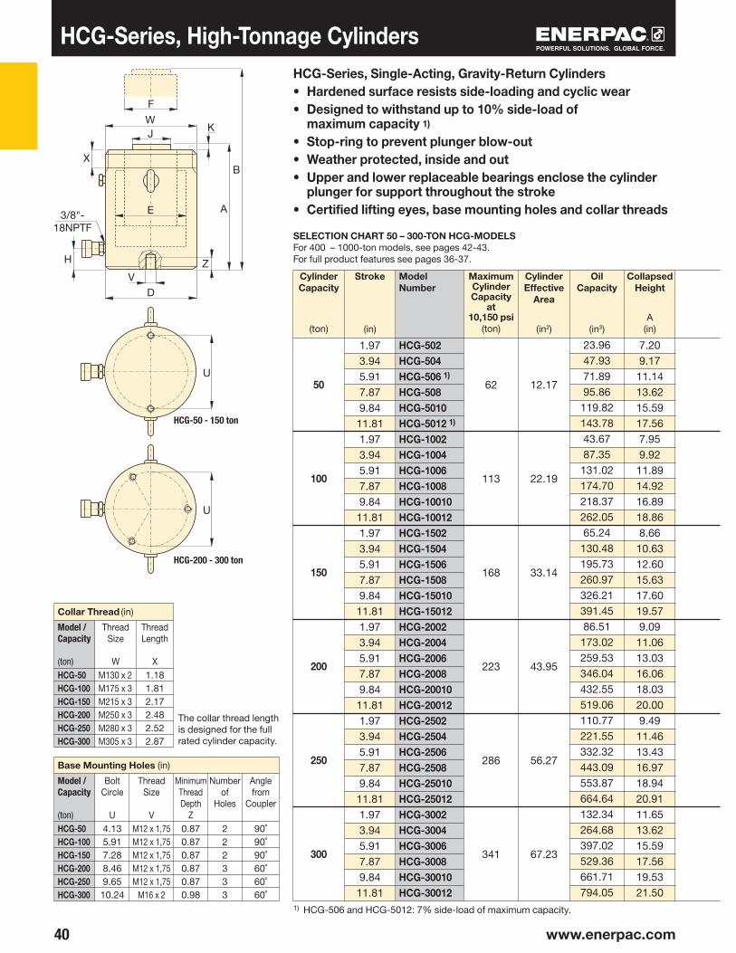
40 www.enerpac.com
X
W
U
U
HCG-502HCG-504HCG-506 1)
HCG-508HCG-5010HCG-5012 1)
HCG-1002HCG-1004HCG-1006HCG-1008HCG-10010HCG-10012HCG-1502HCG-1504HCG-1506HCG-1508HCG-15010HCG-15012HCG-2002HCG-2004HCG-2006HCG-2008HCG-20010HCG-20012HCG-2502HCG-2504HCG-2506HCG-2508HCG-25010HCG-25012HCG-3002HCG-3004HCG-3006HCG-3008HCG-30010HCG-30012
50
100
150
200
250
300
HCG-50HCG-100HCG-150HCG-200HCG-250HCG-300
HCG-50HCG-100HCG-150HCG-200HCG-250HCG-300
M130 x 2M175 x 3M215 x 3M250 x 3M280 x 3M305 x 3
90˚90˚90˚60˚60˚60˚
M12 x 1,75M12 x 1,75M12 x 1,75M12 x 1,75M12 x 1,75
M16 x 2
HCG-50 - 150 ton
HCG-200 - 300 ton
222333
62
113
168
223
286
341
CylinderCapacity
(ton)
Model Number
CollapsedHeight
A(in)
MaximumCylinderCapacity
at 10,150 psi
(ton)
CylinderEffective
Area
(in2)
OilCapacity
(in3)
SELECTION CHART 50 – 300-TON HCG-MODELSFor 400 – 1000-ton models, see pages 42-43.For full product features see pages 36-37.
Stroke
(in)
Model /Capacity
(ton)
Model /Capacity
(ton)
Base Mounting Holes (in)
Collar Thread (in)
BoltCircle
U
ThreadSize
V
ThreadSize
W
MinimumThreadDepth
Z
ThreadLength
X
Numberof
Holes
Anglefrom
Coupler
The collar thread length is designed for the full rated cylinder capacity.
HCG-Series, Single-Acting, Gravity-Return Cylinders• Hardened surface resists side-loading and cyclic wear• Designed to withstand up to 10% side-load of
maximum capacity 1)
• Stop-ring to prevent plunger blow-out• Weather protected, inside and out• Upper and lower replaceable bearings enclose the cylinder
plunger for support throughout the stroke• Certified lifting eyes, base mounting holes and collar threads
HCG-Series, High-Tonnage Cylinders
1) HCG-506 and HCG-5012: 7% side-load of maximum capacity.
12.17
22.19
33.14
43.95
56.27
67.23
1.973.945.917.879.84
11.811.973.945.917.879.84
11.811.973.945.917.879.84
11.811.973.945.917.879.84
11.811.973.945.917.879.84
11.811.973.945.917.879.84
11.81
7.209.17
11.1413.6215.5917.567.959.92
11.8914.9216.8918.868.66
10.6312.6015.6317.6019.579.09
11.0613.0316.0618.0320.009.49
11.4613.4316.9718.9420.9111.6513.6215.5917.5619.5321.50
23.9647.9371.8995.86
119.82143.7843.6787.35
131.02174.70218.37262.0565.24
130.48195.73260.97326.21391.4586.51
173.02259.53346.04432.55519.06110.77221.55332.32443.09553.87664.64132.34264.68397.02529.36661.71794.05
4.135.917.288.469.6510.24
0.870.870.870.870.870.98
1.181.812.172.482.522.87

41
HCG-502HCG-504HCG-506 1)
HCG-508HCG-5010HCG-5012 1)
HCG-1002HCG-1004HCG-1006HCG-1008HCG-10010HCG-100121)
HCG-1502HCG-1504HCG-1506HCG-1508HCG-15010HCG-15012HCG-2002HCG-2004HCG-2006HCG-2008HCG-20010HCG-20012HCG-2502HCG-2504HCG-2506HCG-2508HCG-25010HCG-25012HCG-3002HCG-3004HCG-3006HCG-3008HCG-30010HCG-30012
CATG-50
CATG-100
CATG-150
CATG-200
CATG-250
CATG-300
ExtendedHeight
B(in)
OutsideDiameter
D(in)
Cylinder Bore
Diameter
E(in)
PlungerDiameter
F(in)
Base toAdvance
Port
H(in)
StandardSaddle
Diameter
J(in)
SaddleProtrusion
from Plunger
K(in)
Saddle Model Number
Model Number
Optional Tilt Saddle
CATG-Series Tilt Saddle
Height
K1 (in)
Diameter
J1 (in)
HCG Series
Single-Acting, High-Tonnage CylindersCapacity:
50 - 300 tonStroke:
1.97 - 11.81 inchMaximum Operating Pressure:
10,150 psi
Wt.
(lbs)
1.97 0.943.945.12 2.76 1.50 1.97 0.12
2.87 1.145.316.89 3.74 1.50 2.95 0.12
3.57 1.226.508.46 4.72 1.61 3.70 0.12
4.64 1.377.489.84 5.51 1.85 4.45 0.12
5.67 1.858.4611.02 6.69 2.09 5.71 0.16
6.30 2.519.2512.01 7.87 2.28 6.97 0.16
9.1713.1117.0521.5025.4329.379.9213.8617.8022.8026.7330.6710.6314.5718.5023.5027.4431.3811.0615.0018.9423.9427.8731.8111.4615.3919.3324.8428.7832.7213.6217.5621.5025.4329.3733.31
3745536472807388
102128142157123145168207230253178209240300331363235277318401442484348401454507560613

42 www.enerpac.com
X
W
U
HCG-4002HCG-4004HCG-4006HCG-4008HCG-40010HCG-40012HCG-5002HCG-5004HCG-5006HCG-5008HCG-50010HCG-50012HCG-6002HCG-6004HCG-6006HCG-6008HCG-60010HCG-60012HCG-8002HCG-8004HCG-8006HCG-8008HCG-80010HCG-80012HCG-10002HCG-10004HCG-10006HCG-10008HCG-100010HCG-100012
400
500
600
800
1000HCG-400HCG-500HCG-600HCG-800HCG-1000
HCG-400HCG-500HCG-600HCG-800HCG-1000
M16 x 2M24 x 3M24 x 3M24 x 3M24 x 3
M350 x 3M400 x 4M430 x 4M505 x 5M570 x 5
33333
60˚60˚60˚60˚60˚
450
575
673
916
1196
SELECTION CHART 400 – 1000-TON HCG-MODELSFor 50 – 300-ton models, see pages 40-41.For full product features see pages 36-37.
Model /Capacity
(ton)
Model /Capacity
(ton)
Base Mounting Holes (in)
Collar Thread (in)
BoltCircle
U
ThreadSize
V
ThreadSize
W
MinimumThreadDepth
Z
ThreadLength
X
The collar thread length is designed for the full rated cylinder capacity.
Numberof
Holes
Anglefrom
Coupler
HCG-Series, Single-Acting, Gravity-Return Cylinders• Hardened surface resists side-loading and cyclic wear• Designed to withstand up to 10% side-load of
maximum capacity• Stop-ring to prevent plunger blow-out• Weather protected, inside and out• Upper and lower replaceable bearings enclose the
cylinder plunger for support throughout the stroke• Certified lifting eyes, base mounting holes and
collar threads
HCG-Series, High-Tonnage Cylinders
CylinderCapacity
(ton)
Model Number
CollapsedHeight
A(in)
MaximumCylinderCapacity
at 10,150 psi
(ton)
CylinderEffective
Area
(in2)
OilCapacity
(in3)
Stroke
(in)
88.75
113.25
132.57
180.44
235.68
1.973.945.917.879.84
11.811.973.945.917.879.84
11.811.973.945.917.879.84
11.811.973.945.917.879.84
11.811.973.945.917.879.84
11.81
12.6414.6116.5718.5420.5122.4813.5415.5117.4819.4521.4223.3913.8615.8317.8019.7621.7323.7015.9117.8719.8421.8123.7825.7517.4019.3721.3423.3125.2827.24
174.70349.39524.09698.79873.49
1,048.18222.92445.85668.77891.70
1,114.621,337.55260.97521.94782.90
1,043.871,304.841,565.81355.21710.41
1,065.621,420.821,776.032,131.24463.94927.88
1,391.831,855.772,319.712,783.65
11.8113.3914.5717.3219.69
0.981.421.421.421.42
3.273.543.944.805.39
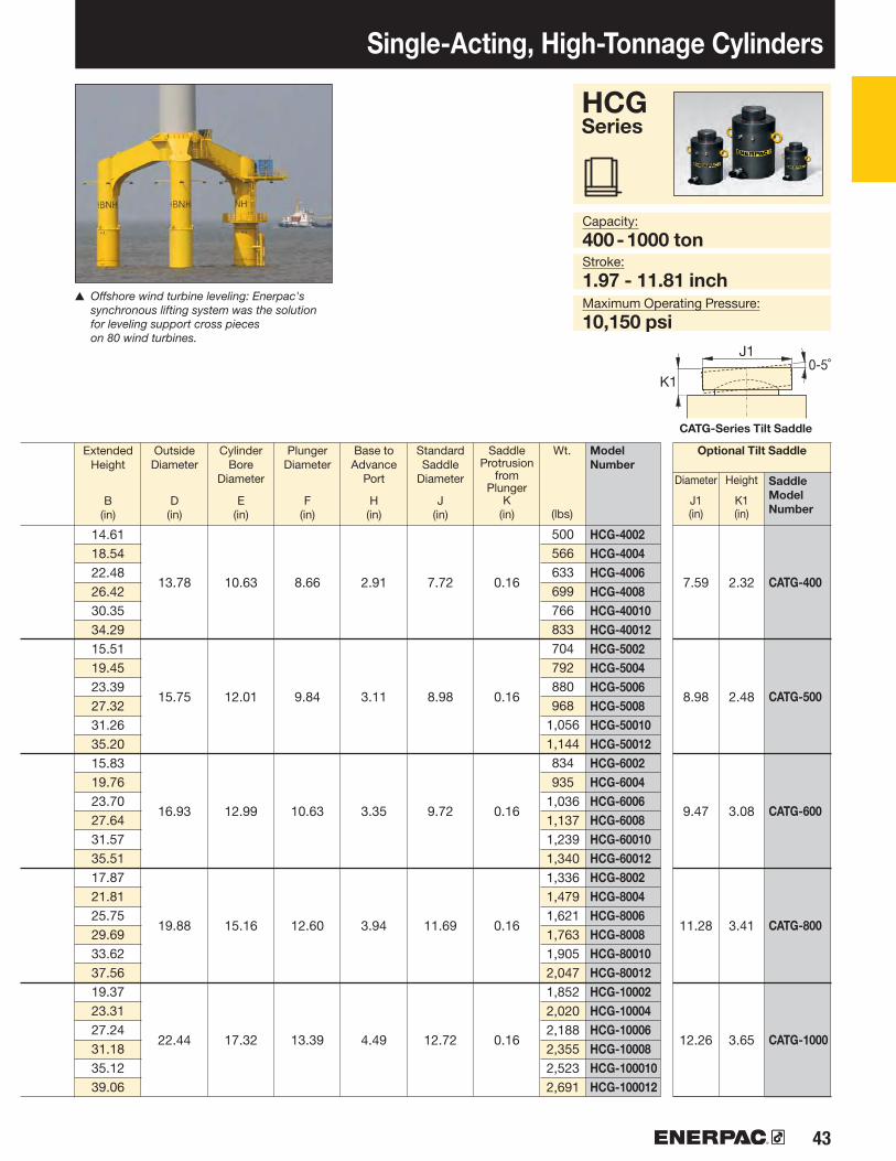
43
HCG-4002HCG-4004HCG-4006HCG-4008HCG-40010HCG-40012HCG-5002HCG-5004HCG-5006HCG-5008HCG-50010HCG-50012HCG-6002HCG-6004HCG-6006HCG-6008HCG-60010HCG-60012HCG-8002HCG-8004HCG-8006HCG-8008HCG-80010HCG-80012HCG-10002HCG-10004HCG-10006HCG-10008HCG-100010HCG-100012
CATG-400
CATG-500
CATG-600
CATG-800
CATG-1000
HCG Series
▲ Offshore wind turbine leveling: Enerpac's synchronous lifting system was the solution for leveling support cross pieces on 80 wind turbines.
Single-Acting, High-Tonnage Cylinders
Capacity:
400 - 1000 tonStroke:
1.97 - 11.81 inchMaximum Operating Pressure:
10,150 psi
CATG-Series Tilt Saddle
ExtendedHeight
B(in)
OutsideDiameter
D(in)
Cylinder Bore
Diameter
E(in)
PlungerDiameter
F(in)
Base toAdvance
Port
H(in)
StandardSaddle
Diameter
J(in)
SaddleProtrusion
from Plunger
K(in)
Saddle Model Number
Model Number
Optional Tilt SaddleWt.
(lbs)
Height
K1 (in)
Diameter
J1 (in)
13.78 7.59 2.3210.63 8.66 2.91 7.72 0.16
15.75 8.98 2.4812.01 9.84 3.11 8.98 0.16
16.93 9.47 3.0812.99 10.63 3.35 9.72 0.16
19.88 11.28 3.4115.16 12.60 3.94 11.69 0.16
22.44 12.26 3.6517.32 13.39 4.49 12.72 0.16
14.6118.5422.4826.4230.3534.2915.5119.4523.3927.3231.2635.2015.8319.7623.7027.6431.5735.5117.8721.8125.7529.6933.6237.5619.3723.3127.2431.1835.1239.06
500566633699766833704792880968
1,0561,144834935
1,0361,1371,2391,3401,3361,4791,6211,7631,9052,0471,8522,0202,1882,3552,5232,691

44 www.enerpac.com
XI
W
U
U
HCR-502HCR-504HCR-506 1)
HCR-508HCR-5010HCR-5012 1)
HCR-1002HCR-1004HCR-1006HCR-1008HCR-10010HCR-10012HCR-1502HCR-1504HCR-1506HCR-1508HCR-15010HCR-15012HCR-2002HCR-2004HCR-2006HCR-2008HCR-20010HCR-20012HCR-2502HCR-2504HCR-2506HCR-2508HCR-25010HCR-25012HCR-3002HCR-3004HCR-3006HCR-3008HCR-30010HCR-30012
50
100
150
200
250
300
HCR-50HCR-100HCR-150HCR-200HCR-250HCR-300
HCR-50HCR-100HCR-150HCR-200HCR-250HCR-300
M12 x 1,75M12 x 1,75M12 x 1,75M12 x 1,75M12 x 1,75
M16 x 2
M130 x 2M175 x 3M215 x 3M250 x 3M280 x 3M305 x 3
222333
90˚90˚90˚60˚60˚60˚
HCR-50 - 150 ton
HCR-200 - 300 ton
62
113
168
223
286
341
SELECTION CHART AND DETAILS OF 50 – 300-TON HCR-MODELSFor 400 – 1000-ton models, see pages 46-47.For full product features see pages 36-37
HCR-Series, Double-Acting Cylinders• Fast advance and retract• Designed to withstand up to 10% side-load of
maximum capacity 1)
• Hardened surface resists side-loading and cyclic wear• Weather protected, inside and out• Upper and lower replaceable bearings enclose the cylinder
plunger for support throughout the stroke• Certified lifting eyes, base mounting holes and collar threads
1) HCR-506 and HCR-5012: 7% side-load of maximum capacity.
HCR-Series, High-Tonnage Cylinders
Model /Capacity
(ton)
Model /Capacity
(ton)
Base Mounting Holes (in)
Collar Thread (in)
BoltCircle
U
ThreadSize
V
ThreadSize
W
MinimumThreadDepth
Z
ThreadLength
X
The collar thread length is designed for the full rated cylinder capacity.
No.of
Holes
Anglefrom
Coupler
CylinderCapacity
(ton)
Model Number
CollapsedHeight
A(in)
MaximumCylinderCapacity
at 10,150 psi
(ton)
CylinderEffective
Area
(in2)
OilCapacity
(in3)
Stroke
(in)
12.17
22.19
33.14
43.95
56.27
67.23
1.973.945.917.879.84
11.811.973.945.917.879.84
11.811.973.945.917.879.84
11.811.973.945.917.879.84
11.811.973.945.917.879.84
11.811.973.945.917.879.84
11.81
7.209.17
11.1413.6215.5917.567.959.92
11.8914.9216.8918.868.66
10.6312.6015.6317.6019.579.09
11.0613.0316.0618.0320.009.49
11.4613.4316.9718.9420.9111.6513.6215.5917.5619.5321.50
23.9647.9371.8995.86
119.82143.7843.6787.35
131.02174.70218.37262.0565.24
130.48195.73260.97326.21391.4586.51
173.02259.53346.04432.55519.06110.77221.55332.32443.09553.87664.64132.34264.68397.02529.36661.71794.05
4.135.917.288.469.6510.24
0.870.870.870.870.870.98
1.181.812.172.482.522.87

45
HCR-502HCR-504HCR-506 1)
HCR-508HCR-5010HCR-5012 1)
HCR-1002HCR-1004HCR-1006HCR-1008HCR-10010HCR-10012HCR-1502HCR-1504HCR-1506HCR-1508HCR-15010HCR-15012HCR-2002HCR-2004HCR-2006HCR-2008HCR-20010HCR-20012HCR-2502HCR-2504HCR-2506HCR-2508HCR-25010HCR-25012HCR-3002HCR-3004HCR-3006HCR-3008HCR-30010HCR-30012
CATG-50
CATG-100
CATG-150
CATG-200
CATG-250
CATG-300
Double-Acting, High-Tonnage CylindersCapacity:
50 - 300 tonStroke:
1.97 - 11.81 inchMaximum Operating Pressure:
10,150 psi
Top to Retract
Port
I(in)
CATG-Series Tilt Saddle
ExtendedHeight
B(in)
OutsideDiameter
D(in)
Cylinder Bore
Diameter
E(in)
PlungerDiameter
F(in)
Base toAdvance
Port
H(in)
StandardSaddle
Diameter
J(in)
SaddleProtrusion
from Plunger
K(in)
Saddle Model Number
Model Number
Optional Tilt SaddleWt.
(lbs)
Height
K1 (in)
Diameter
J1 (in)
HCR Series
1.77
2.17
2.56
3.15
2.76
3.54
3.11
3.82
3.11
4.09
3.98
9.1713.1117.0521.5025.4329.379.9213.8617.8022.8026.7330.6710.6314.5718.5023.5027.4431.3811.0615.0018.9423.9427.8731.8111.4615.3919.3324.8428.7832.7213.6217.5621.5025.4329.3733.31
3746546876847490
105131146161124148172209233257179212244306338371236279322407457500350404458512566620
3.945.12 2.76 1.50
5.316.89 3.74 1.50
6.508.46 4.72 1.61
7.489.84 5.51 1.85
8.4611.02 6.69 2.09
9.2512.01 7.87 2.28
1.97 0.12
2.95 0.12
3.70 0.12
4.45 0.12
5.71 0.16
6.97 0.16
1.97 0.94
2.87 1.14
3.57 1.22
4.64 1.37
5.67 1.85
6.30 2.51

46 www.enerpac.com
XI
W
U
HCR-400HCR-500HCR-600HCR-800HCR-1000
HCR-400HCR-500HCR-600HCR-800HCR-1000
M16 x 2M24 x 3M24 x 3M24 x 3M24 x 3
M350 x 3M400 x 4M430 x 4M505 x 5M570 x 5
HCR-4002HCR-4004HCR-4006HCR-4008HCR-40010HCR-40012HCR-5002HCR-5004HCR-5006HCR-5008HCR-50010HCR-50012HCR-6002HCR-6004HCR-6006HCR-6008HCR-60010HCR-60012HCR-8002HCR-8004HCR-8006HCR-8008HCR-80010HCR-80012HCR-10002HCR-10004HCR-10006HCR-10008HCR-100010HCR-100012
400
500
600
800
1000
450
575
673
916
1196
SELECTION CHART AND DETAILS OF 400 – 1000-TON HCR-MODELSFor 50 – 300-ton models, see pages 44-45.For full product features see pages 36-37.
HCR-Series, Double-Acting Cylinders• Fast advance and retract• Designed to withstand up to 10% side-load of
maximum capacity• Hardened surface resists side-loading and cyclic wear• Weather protected, inside and out• Upper and lower replaceable bearings enclose the cylinder
plunger for support throughout the stroke• Certified lifting eyes, base mounting holes and collar threads
HCR-Series, High-Tonnage Cylinders
Model /Capacity
(ton)
Model /Capacity
(ton)
Base Mounting Holes (in)
Collar Thread (in)
BoltCircle
U
ThreadSize
V
ThreadSize
W
Min.ThreadDepth
Z
ThreadLength
X
The collar thread length is designed for the full rated cylinder capacity.
Numberof
Holes
Anglefrom
Coupler
Model Number
CollapsedHeight
A(in)
MaximumCylinderCapacity
at 10,150 psi
(ton)
CylinderEffective
Area
(in2)
OilCapacity
(in3)
Stroke
(in)
CylinderCapacity
(ton)
11.8113.3914.5717.3219.69
0.981.421.421.421.42
3.273.543.944.805.39
33333
60˚60˚60˚60˚60˚
88.75
113.25
132.57
180.44
235.68
1.973.945.917.879.84
11.811.973.945.917.879.84
11.811.973.945.917.879.84
11.811.973.945.917.879.84
11.811.973.945.917.879.84
11.81
12.6414.6116.5718.5420.5122.4813.5415.5117.4819.4521.4223.3913.8615.8317.8019.7621.7323.7015.9117.8719.8421.8123.7825.7517.4019.3721.3423.3125.2827.24
174.70349.39524.09698.79873.49
1,048.18222.92445.85668.77891.70
1,114.621,337.55260.97521.94782.90
1,043.871,304.841,565.81355.21710.41
1,065.621,420.821,776.032,131.24463.94927.88
1,391.831,855.772,319.712,783.65

47
HCR-4002HCR-4004HCR-4006HCR-4008HCR-40010HCR-40012HCR-5002HCR-5004HCR-5006HCR-5008HCR-50010HCR-50012HCR-6002HCR-6004HCR-6006HCR-6008HCR-60010HCR-60012HCR-8002HCR-8004HCR-8006HCR-8008HCR-80010HCR-80012HCR-10002HCR-10004HCR-10006HCR-10008HCR-100010HCR-100012
CATG-400
CATG-500
CATG-600
CATG-800
CATG-1000
HCR Series
▲ The superlifting and launch of a 43,000 ton floating oil production system in Malaysia for the Gumusut-Kakap offshore field has set high benchmarks for safety through its use of sophisticated EVO-Series synchronous hydraulics to lift, balance, weigh and smoothly launch massive resource structures.
Double-Acting, High-Tonnage Cylinders
Capacity:
400 - 1000 tonStroke:
1.97 - 11.81 inchMaximum Operating Pressure:
10,150 psi
CATG-Series Tilt Saddle
Top to Retract
Port
I(in)
ExtendedHeight
B(in)
OutsideDiameter
D(in)
Cylinder Bore
Diameter
E(in)
PlungerDiameter
F(in)
Base toAdvance
Port
H(in)
StandardSaddle
Diameter
J(in)
SaddleProtrusion
from Plunger
K(in)
Saddle Model Number
Model Number
Optional Tilt SaddleWt.
(lbs)
Height
K1 (in)
Diameter
J1 (in)
13.78 10.63 8.66 2.91 4.37 7.72 0.16 7.59 2.32
15.75 12.01 9.84 3.11 4.76 8.98 0.16 8.98 2.48
16.93 12.99 10.63 3.35 4.76 9.72 0.16 9.47 3.08
19.88 15.16 12.60 3.94 5.63 11.69 0.16 11.28 3.41
22.44 17.32 13.39 4.49 6.02 12.72 0.16 12.26 3.65
14.6118.5422.4826.4230.3534.2915.5119.4523.3927.3231.2635.2015.8319.7623.7027.6431.5735.5117.8721.8125.7529.6933.6237.5619.3723.3127.2431.1835.1239.06
501570638707775843706797887977
1,0671,158836940
1,0441,1481,2521,3561,3401,4851,6311,7771,9222,0681,8582,0312,2052,3792,5522,726

48 www.enerpac.com
S
U
U
HCL-502HCL-504HCL-506HCL-508HCL-5010HCL-5012HCL-1002HCL-1004HCL-1006HCL-1008HCL-10010HCL-10012HCL-1502HCL-1504HCL-1506HCL-1508HCL-15010HCL-15012HCL-2002HCL-2004HCL-2006HCL-2008HCL-20010HCL-20012HCL-2502HCL-2504HCL-2506HCL-2508HCL-25010HCL-25012HCL-3002HCL-3004HCL-3006HCL-3008HCL-30010HCL-30012
50
100
150
200
250
300
HCL-50HCL-100HCL-150HCL-200HCL-250HCL-300
222333
90˚90˚90˚60˚60˚60˚
HCL-50 - 150 ton
HCL-200 - 300 ton
62
113
168
223
286
341
SELECTION CHART 50 – 300-TON HCL-MODELSFor 400 – 1000-ton models, see pages 50-51.For full product features see pages 36-37.
HCL-Series, Single-Acting, Gravity-Return Cylinders• Lock nut provides positive and safe mechanical load holding• Low-friction locking rings spin easy, save time and effort• Designed to withstand 10% side-load up to 90% of maximum stroke• Hardened surface resists side-loading and cyclic wear• Overflow port as stroke limiter to prevent plunger blow-out• Weather protected, inside and out• Replaceable bearings enclose the plunger for support
throughout the stroke• Certified lifting eyes and base mounting holes
HCL-Series, Lock Nut Cylinders
Model /Capacity
(ton)
Base Mounting Holes (in)
BoltCircle
U
ThreadSize
V
MinimumThreadDepth
Z
Numberof
Holes
Anglefrom
Coupler
Model Number
CollapsedHeight
A(in)
MaximumCylinderCapacity
at 10,150 psi
(ton)
CylinderEffective
Area
(in2)
OilCapacity
(in3)
Stroke
(in)
CylinderCapacity
(ton)
12.17
22.19
33.14
43.95
56.27
67.23
1.973.945.917.879.84
11.811.973.945.917.879.84
11.811.973.945.917.879.84
11.811.973.945.917.879.84
11.811.973.945.917.879.84
11.811.973.945.917.879.84
11.81
6.468.43
10.3912.3614.3316.307.369.33
11.3013.2715.2417.208.23
10.2012.1714.1316.1018.079.37
11.3413.3115.2817.2419.219.80
11.7713.7415.7117.6819.6510.9412.9114.8816.8518.8220.79
23.9647.9371.8995.86
119.82143.7843.6787.35
131.02174.70218.37262.0565.24
130.48195.73260.97326.21391.4586.51
173.02259.53346.04432.55519.06110.77221.55332.32443.09553.87664.64132.34264.68397.02529.36661.71794.05
4.135.917.288.469.6510.24
0.390.670.870.870.870.98
M8X1.25M12X1.75M12X1.75M12X1.75M12X1.75
M16X2

49
HCL-502HCL-504HCL-506HCL-508HCL-5010HCL-5012HCL-1002HCL-1004HCL-1006HCL-1008HCL-10010HCL-10012HCL-1502HCL-1504HCL-1506HCL-1508HCL-15010HCL-15012HCL-2002HCL-2004HCL-2006HCL-2008HCL-20010HCL-20012HCL-2502HCL-2504HCL-2506HCL-2508HCL-25010HCL-25012HCL-3002HCL-3004HCL-3006HCL-3008HCL-30010HCL-30012
5.12 CAT-100
6.89 CAT-100
8.46 CAT-200
9.84 CAT-200
11.02 CAT-250
12.01 CAT-300
Lock NutHeight
S(in)
HCL Series
Single-Acting, High-Tonnage Lock Nut CylindersCapacity:
50 - 300 tonStroke:
1.97 - 11.81 inchMaximum Operating Pressure:
10,150 psi
Optional Tilt Saddle
CAT-Series Tilt Saddle
ExtendedHeight
B(in)
OutsideDiameter
D(in)
Cylinder Bore
Diameter
E(in)
PlungerDiameter
F(mm)
Base toAdvance
Port
H(in)
StandardSaddle
Diameter
J(in)
SaddleProtrusion
from Plunger
K(in)
Saddle Model Number
Model Number
Wt.
(lbs)
Height
K1 (in)
Diameter
J1 (in)
3.94 0.94 2.80 0.08 0.98 2.80 0.93Tr 100 x 4
5.31 1.30 2.80 0.08 1.30 2.80 0.93Tr 135 x 6
6.50 1.61 5.12 0.08 1.57 5.12 0.76Tr 165 x 6
7.48 1.85 5.12 0.08 1.77 5.12 0.76Tr 190 x 6
8.46 2.09 5.91 0.08 2.05 5.91 0.76Tr 215 x 6
9.25 2.28 5.49 0.08 2.20 7.68 2.86Tr 235 x 6
8.4312.3616.3020.2424.1728.119.3313.2717.2021.1425.0829.0210.2014.1318.0722.0125.9429.8811.3415.2819.2123.1527.0931.0211.7715.7119.6523.5827.5231.4612.9116.8520.7924.7228.6632.60
3748607183947798
118139160181130161192224255287188231273316358401262316369422476529348411474537601664

50 www.enerpac.com
S
U
HCL-4002HCL-4004HCL-4006HCL-4008HCL-40010HCL-40012HCL-5002HCL-5004HCL-5006HCL-5008HCL-50010HCL-50012HCL-6002HCL-6004HCL-6006HCL-6008HCL-60010HCL-60012HCL-8002HCL-8004HCL-8006HCL-8008HCL-80010HCL-80012HCL-10002HCL-10004HCL-10006HCL-10008HCL-100010HCL-100012
400
500
600
800
1000HCL-400HCL-500HCL-600HCL-800HCL-1000
M16 x 2M24 x 3M24 x 3M24 x 3M24 x 3
33333
60˚60˚60˚60˚60˚
450
575
673
916
1196
SELECTION CHART 400 – 1000-TON HCL-MODELSFor 50 – 300-ton models, see pages 48-49For full product features see pages 36-37.
HCL-Series, Single-Acting, Gravity-Return Cylinders• Lock nut provides positive and safe mechanical
load holding• Low-friction locking rings spin easy, save time and effort• Designed to withstand 10% side-load up to 90% of
maximum stroke• Hardened surface resists side-loading and cyclic wear• Overflow port as stroke limiter to prevent plunger
blow-out• Weather protected, inside and out• Replaceable bearings enclose the plunger for
support throughout the stroke• Certified lifting eyes and base mounting holes
HCL-Series, Lock Nut Cylinders
Model /Capacity
(ton)
Base Mounting Holes (in)
BoltCircle
U
ThreadSize
V
MinimumThreadDepth
Z
Numberof
Holes
Anglefrom
Coupler
Model Number
CollapsedHeight
A(in)
MaximumCylinderCapacity
at 10,150 psi
(ton)
CylinderEffective
Area
(in2)
OilCapacity
(in3)
Stroke
(in)
CylinderCapacity
(ton)
1.973.945.917.879.84
11.811.973.945.917.879.84
11.811.973.945.917.879.84
11.811.973.945.917.879.84
11.811.973.945.917.879.84
11.81
12.4814.4516.4218.3920.3522.3214.0616.0217.9919.9621.9323.9014.9616.9318.9020.8722.8324.8016.9318.9020.8722.8324.8026.7719.0621.0222.9924.9626.9328.90
174.70349.39524.09698.79873.49
1,048.18222.92445.85668.77891.70
1,114.621,337.55260.97521.94782.90
1,043.871,304.841,565.81355.21710.41
1,065.621,420.821,776.032,131.24463.94927.88
1,391.831,855.772,319.712,783.65
11.8113.3914.5717.3219.69
0.951.421.421.421.42
88.75
113.25
132.57
180.44
235.68

51
HCL-4002HCL-4004HCL-4006HCL-4008HCL-40010HCL-40012HCL-5002HCL-5004HCL-5006HCL-5008HCL-50010HCL-50012HCL-6002HCL-6004HCL-6006HCL-6008HCL-60010HCL-60012HCL-8002HCL-8004HCL-8006HCL-8008HCL-80010HCL-80012HCL-10002HCL-10004HCL-10006HCL-10008HCL-100010HCL-100012
CAT-400
CAT-500
CAT-600
CAT-800
CAT-1000
HCL Series
▲ Heavy lifting and foundation levelling. The lock nut provides mechanical load holding over a long period of time.
Single-Acting, High Tonnage, Lock Nut Cylinders
Capacity:
400 - 1000 tonStroke:
1.97 - 11.81 inchMaximum Operating Pressure:
10,150 psi
CAT-Series Tilt Saddle
Lock NutHeight
S(in)
Optional Tilt SaddleExtendedHeight
B(in)
OutsideDiameter
D(in)
Cylinder Bore
Diameter
E(in)
PlungerDiameter
F(mm)
Base toAdvance
Port
H(in)
StandardSaddle
Diameter
J(in)
SaddleProtrusion
from Plunger
K(in)
Saddle Model Number
Model Number
Wt.
(lbs)
Height
K1 (in)
Diameter
J1 (in)
13.78 10.63 2.64 6.27 0.20 2.56 8.86 3.34Tr 270 x 6
15.75 12.01 2.95 7.06 0.20 2.83 9.84 3.57Tr 305 x 6
16.93 12.99 3.19 7.65 0.20 3.15 10.83 3.89Tr 330 x 6
19.88 15.16 3.74 8.83 0.20 3.54 12.60 4.89Tr 385 x 6
22.44 17.32 4.33 9.81 0.20 4.13 14.17 5.36Tr 440 x 6
14.4518.3922.3226.2630.2034.1316.0219.9623.9027.8331.7735.7116.9320.8724.8028.7432.6836.6118.9022.8326.7730.7134.6538.5821.0224.9628.9032.8336.7740.71
520603686770853936751860968
1,0771,1861,294942
1,0671,1931,3191,4441,5701,4721,6461,8191,9922,1662,3392,1152,3352,5562,7772,9983,219

52 www.enerpac.com
▼
▼1
192
Single-Acting, Cylinder Pump Sets Shown cylinder-pump set: SCR-1010H
Nominal Set Capacity
(ton)
Collapsed Height
(in)
Stroke
(in)
CylinderModel No.
The Quickest and Easiest Way to Start Working Right Away
Cylinder Selection
• Optimum match of individual components• All sets are ready to use and include single-acting
cylinder, two-speed pump, 6-foot safety hose, calibrated gauge with gauge adaptor
• RC-Series DUO, general purpose cylinders for maximum versatility
• RCS-Series, low-height cylinders for maximum versatility
• RCH-Series hollow cylinders for pushing and pulling
▼ Cylinder-Pump Sets - optimum match of components. The quickest and easiest way to start working right away.
LW-16 Lifting Wedge
Hydraulic cylinders, jacks and lifting wedges can also be used to assist in positioning and aligning.
The LW-16 only requires an access gap of .39 inch. See our "Specialty Tools" section on www.enerpac.com.
Page:
RC-55RC-102RC-106
RC-1010RC-154RC-156RC-252RC-254RC-256
RC-2514RC-506
RCS-101RCS-201RCS-302RCS-502
RCS-1002RCH-121RCH-202RCH-302RCH-603
RCH-1003
5
10
15
25
5010203050
10012203060
100
5.002.136.13
10.134.006.002.004.006.25
14.256.251.501.752.442.382.251.632.002.503.003.00
8.504.789.75
13.757.88
10.696.508.50
10.7518.7511.133.473.884.634.815.564.756.317.039.75
10.00

53
▶1▶▶32
▼2
▼3
144
Single-Acting, Cylinder Pump Sets
Hand Pump
P-142
Hand Pump
P-392
Hand Pump
P-80
Foot Pump
P-392FP
XC-Series Cordless Pump2) 3)
XC-1202MB
XA-Series Air Pump
XA-11
HoseModel
No.
GaugeModel
No.
Gauge Adaptor
Model No.
Pump selection (See Pump Section of this catalog for full product descriptions) Accessories Included
SELECTION EXAMPLE
Selected cylinder:
• RC-106, Single-acting cylinder with 6.13" stroke
Selected pump:
• P-392, Lightweight hand pump
Set model number:
• SCR-106H
Included:• HC-7206 hose• GF-10P gauge • GA-2 adaptor
SC Series
Capacity:
5-100 tonsStroke:
1.50-14.25 inchesMaximum Operating Pressure:
10,000 psiSET SELECTION:
Select the cylinder
Select the pump
Find the set model number in the gray field of the matrix
1) With XA-12 air pump2) XC Cordless Pump includes 115 V charger, for 230 V charger replace the "B" in the model number with an "E".3) XC Pump Sets include only the HC-7206 Hose and GA45GC Gauge Adaptor accessories
Page:
GA45GC Gauge Adaptor 3)
Protect yourself from system overloading by simply ordering one
part number for a pre-assembled gauge, adaptor block and coupler.
SCR-55H–––––––––––––––
SCH-121H––––
–SCR-102HSCR-106HSCR-1010HSCR-154HSCR-156HSCR-252HSCR-254HSCR-256H
––
SCL-101HSCL-201HSCL-302HSCL-502H
––
SCH-202HSCH-302H
––
–SCR-102XCBSCR-106XCBSCR-1010XCBSCR-154XCBSCR-156XCBSCR-252XCBSCR-254XCBSCR-256XCB
––––
SCL-302XCBSCL-502XCBSCL-1002XCB
–SCH-202XCBSCH-302XCBSCH-603XCB
–
–––––––––
SCR-2514HSCR-506H
––––
SCL-1002H–––
SCH-603HSCH-1003H
–SCR-102XASCR-106XASCR-1010XASCR-154XASCR-156XASCR-252XASCR-254XASCR-256XASCR-2514XA1)
SCR-506XA1)
SCL-101XASCL-201XASCL-302XASCL-502XA
––
SCH-202XASCH-302XASCH-603XA1)
–
HC-7206HC-7206HC-7206HC-7206HC-7206HC-7206HC-7206HC-7206HC-7206HC-7206HC-7206HC-7206HC-7206HC-7206HC-7206HC-7206HB-7206HC-7206HC-7206HC-7206HC-7206
GP-10SGF-10PGF-10PGF-10PGP-10SGP-10SGF-20PGF-20PGF-20PGF-20PGF-50PGF-10P
GF-230PGF-230PGF-510PGF-510PGF-120PGF-813PGF-813PGF-813PGP-10S
GA-4GA-2GA-2GA-2GA-2GA-2GA-2GA-2GA-2GA-2GA-2GA-2GA-2GA-2GA-2GA-2GA-4GA-3GA-3GA-3GA-2
–SCR-102FPSCR-106FPSCR-1010FPSCR-154FPSCR-156FPSCR-252FPSCR-254FP
–––
SCL-101FPSCL-201FPSCL-302FPSCL-502FP
––
SCH-202FPSCH-302FP
––

54 www.enerpac.com
▼
V-66NVV-152NV
RC-53NVRC-102NVRC-106NVRC-256NV
P-142ALSSP-392ALSS
77
Shown from left to right: P-142ALSS, P-392ALSS, V-152NV, V-66NV, RC256NV, RC-106NV, RC-53NV
• Corrosion resistant, nickel-plated valves and cylinders • Stainless steel pump inserts will not corrode• Viton® Seals provide heat and chemical resistance• Anodized aluminum pump reservoirs and plastic
encapsulated pump bodies resist wet environments• Two-speed operation reduces pump handle strokes 78%
compared to single-speed pumps• Pump handles lock for easy carrying
Extreme Environment Products
PressureRating
(psi)
PressureFunction
Valve Type ModelNumber *
Check+- 3% Repeatability
Manual Check ValvePressure Relief Valve
▼VALVE CHART
Pump Type
Oil Capacity
(in3)
ModelNumber *
Pressure Rating
(psi)
Cylinder Capacity
(ton)
Stroke
(in)
ModelNumber *
Oil Capacity
(in3)
Pressure Rating
(psi)
▼ CYLINDER CHART
▼ HAND PUMP CHART
Weight
(lbs)
Weight
(lbs)
Weight
(lbs)
Collapsed Height
(in)
Extended Height
(in)
Outside Diameter
(in)
Oil Displacement
per Stroke
(in3)
Piston Stroke
(in)
Port Dimension
(in)
Two Speed
Applications
Use Enerpac Extreme Environment Products in wet environments such as food
processing, pulp and paper, mining, construction and applications in high temperature or in welding areas.
Maximum Operating Pressure:
10,000 psi
Cylinder Capacity:
5-25 tonsStroke:
2-6 inches
Multifluid Hand Pumps
MP-Series corrosion resistant hand pumps for low pressure filling and high pressure testing applications,
suitable for a wide range of fluids.
Page:
* For cylinder details see pages 7-9; for pump details see pages 70-71; for valve details see pages 146-147.
RC, P, VSeries
10,000800-10,000
3.02.06.06.0
5101025
10,00010,00010,00010,000
3.35.19.8
22.0
2.984.75
13.7032.23
6.504.789.75
10.75
1.502.252.253.38
1/4"-18 nptf
3/8"-18 nptf
0.221 / 0.0550.687 / 0.151
2055
.501.00
200/10,000200/10,000
9.506.91
15.8817.00
4.59.0
4.59.0

55
▼
SCR-55TBSCR-102TBSCR-106TBSCR-1010TBSCR-154TBSCR-256TB
SCL-101TBSCL-201TBSCL-302TBSCL-502TB
SRS-100TBSRS-200TBSRS-300TBSRS-500TB
144
RC-55RC-102RC-106RC-1010RC-154RC-256
RCS-101RCS-201RCS-302RCS-502
RSM-100RSM-200RSM-300RSM-500
51010101525
10203050
10203050
Toolbox Set Model Number
Shown: SCR106TB
• Includes a single-acting cylinder, two-speed lightweight hand pump (P392), gauge adaptor assembly (GA45GC), and 6 ft. rubber hose with couplers (HC9206C)
• Complete and ready-to-use hydraulic system• Easy to carry sturdy toolbox• All components ship inside the toolbox as one package
Portable Hydraulic Toolbox
Stroke
(in)
Capacity
(tons)
CylinderModel
Weight
(lbs)
General Purpose Cylinders
Maximum Operating Pressure:
10,000 psi
Capacity:
5-50 tonsStroke:
.44-10.13 inches
SCR, SCL, SRSSeries
Low-Height Cylinders
Flat-Jac® Cylinders
Gauge Adaptor Assembly
Toolbox sets include a 45 degree angled gauge adaptor assembly for improved operating ergonomics and safety.
Page:
▼ The Hydraulic Toolbox is a versatile tool and applicable everywhere.
RC Series
RCS Series
RSM Series
5.002.136.1310.134.006.25
1.501.752.442.38
0.440.440.500.63
262732363445
28333744
26283137

56 www.enerpac.com
▼
192
194
JH, JHA Series
Aluminum and Steel Jacks Shown from left to right: JHA-356, JHA-156
• All-directional operation on 7, 15 and 35-ton models (JHA- Series)
• Internal relief valve to prevent overloading• Machined flat front and bottom surfaces permit flush
alignment in tight corners• All models include pumping handle• Chrome-plated plungers• Automatic by-pass port to prevent over-extension
(JH-Series)
Aluminum Jack
SteelJack
Jack Capacity
(ton)
Model Number
Stroke
(in)
Jack Effective
Area
(in2)
CollapsedHeight
(in)
Extended Height
(in)
Bottom Plate Dimensions
(W x L)
(in)
Plunger Diameter
(in)
Pump Speed
Weight
(lbs)
Style
Capacity:
7-150 tonsStroke:
3.00-6.13 inchesMaximum Operating Pressure:
10,000 psi
Lifting Wedge and Machine Lifts
Ideal to lift the load the first few inches. The LW-16 Lifting Wedge requires a
very small access gap of only .39 inch.
Page:
SingleSingleSingleSingle
2-SpeedSingle
2-Speed2-Speed
Load Skates
For moving heavy loads easily and safely.
Page:
JHA-73JHA-156JHA-356JHA-756JHA-1506JH-306JH-506JH-1006
71535751503050100
1.493.147.0715.9030.685.949.6220.63
5.259.75
10.1311.2512.8810.0010.2511.31
8.2515.8116.2517.3119.0016.1316.3417.37
2.88 x 6.253.63 x 9.38
4.63 x 10.006.88 x 12.819.50 x 16.063.75 x 9.56
5.00 x 10.197.13 x 12.94
1.191.632.134.506.252.753.505.12
11294094
2105990
184
3.006.066.136.066.136.136.096.06

57
▼
52
Industrial Bottle Jacks
GBJ Series
Capacity:
2-100 tonsStroke:
2.44-18.11 inches
Shown: GBJ-010, GBJ-030, GBJ-003
• Lower handle effort reduces operator fatigue• Fully serviceable• High-strength beam and pump linkage for long life• Pumping handle included on all models• Safety relief valve to prevent overload• Automatic by-pass port to prevent over-extension• Wiper seal for extended life• Thick base material with large area for increased strength
and stability during lifting
Pump and Cylinder Sets
As an alternative to Industrial Bottle Jacks
where the operator is required to stand remote from the
jacking point, see the range of pump and cylinder sets.
Page:
Screw Feature
Heat treated, adjustable extension screw with cleated saddle on selected GBJ models helps adjusting
and prevents slipping.
Jack Cap.
(ton)
Model Number
Stroke
(in)
ScrewExtension
(in)
Min. Height
(in)
Max. Height
(in)
Wt
(lbs)
PlungerDia.
(in)
SaddleDia.
(in)
Base Dims.L x W
(in)
All GBJ Jacks meet or exceed: ANSI, PALD, CE
▼ Enerpac heavy-duty hydraulic bottle jack makes lifting loads easier.
GBJ002LGBJ002GBJ003GBJ005GBJ008GBJ010GBJ010SGBJ015GBJ020GBJ020SGBJ030GBJ050GBJ100
2235810101520203050100
18.113.944.135.915.915.912.445.915.914.135.915.915.91
-1.972.562.952.952.951.182.952.952.172.95
--
22.446.306.618.358.628.625.168.989.217.489.539.9211.81
1.140.830.941.141.301.461.461.752.012.012.263.154.33
13.27.98.6
11.013.014.312.119.826.722.034.262.8
191.8
-0.830.941.141.461.461.461.732.282.282.563.153.70
40.5512.2013.3117.2017.4817.488.7817.8318.0713.7818.3915.8317.72
5.00 x 5.003.74 x 4.373.74 x 4.573.74 x 4.843.74 x 5.433.74 x 5.593.74 x 5.594.41 x 6.425.00 x 6.735.00 x 6.735.59 x 7.727.09 x 9.06
11.65 x 13.11

58 www.enerpac.com
▼
PREMB06014LPREMB06027LPREMB10016LPREMB10027L----PREMB15016LPREMB15027L--
Shown: PRASA10027L and Accessory Locking U-Rings
• 60, 100, 150 and 200-ton capacities with pneumatic or electric pumps for the toughest jobs
• 4-inch ground clearance for transport over rail and rough terrain
• Three-position handle provides easy tilt back and transport
• Complies with ASME/ANSI B30.1:2015 & CE specifications• Easy-to-change external filter minimizes down time• Rugged, fully enclosed 24-inch wide frame with
no exposed fittings or hoses• SUP-R-STACK™ Extension System allows lifting at all
heights without blocking.
PR-Series, POW’R-RISER® Lifting Jack
Safe, Efficient, Mobile Load Lifting
Capacity
(ton)
Stroke
(in)
Electric Pump Model Number
(115 VAC)
Weight
(lbs)
Pendant Cord
Standard 12' pendant cord for air driven units with pneumatic valves and 20' pendant cord
for electric driven units keeps operator away from the load.
(PR-Series not available in Canada. Contact Enerpac.)
▼ Enerpac POW'R-RISER® used in mining operations to lift heavy equipment.142716271627
15.526.515.526.515.324.3
60
100
150
200
390600510600
----
570708
--

59
PRS1PRS2PRS4
PRS3–
PRE5PRE7PRE9PRES6024
PRE11PRE14PRE18
PRAMA06014LPRAMA06027LPRAMA10016LPRAMA10027LPRASA10016LPRASA10027LPRASA15016LPRASA15027L--PRASA20016LPRASA20027L
PRTS60
PRTS60
PRTS150
PRTS200
1)PRUS1262) PRUS1371) PRUS1262) PRUS1373) PRUS15262) PRUS15373) PRUS20262) PRUS2037
PRU13
PRU13
PRU153
PRU203
PRU11
PRU11
PRU151
PRU201
PRU14
PRU14
–
–
–
–
PRU155
PRU205
PRU110
PRU110
PRU1510
PRU2010
PRU11
PRU11
PRU11
PRU11
PRU151
PRU151
PRU201
PRU201
PRU13
PRU13
PRU13
PRU13
PRU153
PRU1510
PRU203
PRU2010
PRU14
PRU14
PRU14
PRU14
PRU155
PRU155
PRU205
PRU205
—
PRU10
—
PRU110
—
—
—
—
D
A
B
C
2X 1X 2X 1X
POW’R-RISER® Lifting Jack
PRSeries
Stroke:
14-27 inches
SUP-R-STACK™ Extensions
Increase useful height from 5" to 18".
Spacers
Fine tune your Extension stack height.
Set includes (2) PRS1, (1) PRS2 and (1) PRS3Extension set includes PRE5,
PRE7, PRE11PRE18
Model No.
Size (in)
Model No.
Size (in)
Rated Lifting Capacity:
60-200 tons
A
(in)
Max. Additional Stack Height Using
Optional Ext. System
(in)
Valve Type
Air Pump Weight
(lbs)
B
(in)
C
(in)
D
(in)
1 in.
Cap.
(ton)
Swivel Load Cap
3 in.
4¼ in.
5½ in.
10 in.
(quantity and model numbers)
Set Model Number
For power source, the following characters should be inserted in the 5th space of the model number.
Ordering Example: Model No. PREMI06014L is a 14" stroke, 60 ton model, with a manual valve and a 208-240 VAC, 1-ph electric motor.
A Air Pump, 50 scfm, 80 psiB 115 VAC, 1ph., 50-60 Hz, 20 AE 208-240 VAC, 1-ph., 50-60 Hz, Euro Plug, 10 AI 208-240 VAC, 1-ph., 50-60 Hz, USA Plug, 10 AG 1)208-240 VAC, 3-ph., 50-60 HzW 1)380-415 VAC, 3-ph., 50-60 HzJ 1)440-480 VAC, 3-ph., 50-60 HzR 1)575 VAC, 3-ph., 50-60 Hz
1) Not available for 60-ton capacity
Manual
Pneumatic
Manual
Pneumatic
Locking U-Rings Locking U-Ring Sets Include
* Based on one 18" and one 11" Extension and one 3" Spacer. ** Based on one 18" Extension and one 3" Spacer.
Model No.
Model No.
Size (in)
Size (in)
1) For 14 and 16" stroke models2) For 27" stroke models3) For 15.5" stroke models
Maximum Operating Pressure:
10,000 psi
WARNING!
Extensions: Any two Extensions may be stacked for loads up to 60 tons. For loads over 60 tons or
strokes over 14" only one Extension and one Spacer can be used.
Spacers: Never exceed 3" in total Spacer height.
Locking U-Rings
For safe mechanical cribbing of a lifted load, accessory Locking U-Rings can be placed around an extended
piston and come in four lengths for each POW'R-Riser® capacity, and are available individually or in sets. Locking U-Rings are accommodated by storage racks integral to the POW'R-Riser®.
12
579
111418
60
100
150
200
3–
390600510600510600570708
--
640825
243726372637263726372637
6.46.47.07.07.07.08.08.08.08.09.59.5
141418181818181818182020
444444555566
32* 11 21** 11 21** 11 21** 11 21** 11 21** 11
56
24

60 www.enerpac.com
▼ Shown: PL20025-ASA and PL20014-ASA
• Provides continuous locking protection during lift, lower and hold functions
• Patent-pending control technology synchronizes cylinder and lock nut for smooth and efficient lifting and lowering
• Unique double-acting cylinder offers a low collapsed height to accommodate more lifting applications
• Simple 2-button pendant allows operation of raise and lower functions from up to 20 feet away
• All exposed load-bearing steel cylinder components utilize a nitrocarburizing treatment to reduce wear and resist corrosion
• Ergonomic handle has six positions for comfortable handling and folds when not in use
• Meets ANSI /ASME B30.1-2015, AS/NZS-2538, AS/NZS-2693 certification criteria
TQ-700 Series, Electric Torque Pump
Efficient Lifting with Continuous, Automatic Load Locking
Tilt Load Cap
All Pow'R-LOCK™ Lift System models feature a Tilt Load Cap to reduce side-loading.
Enerpac declares that this product has been tested and conforms to applicable standards and is approved to
carry the CE mark. An EU Declaration of Conformity is enclosed separately.
PL-Series, Pow’R-LOCK™ Portable Lift System
Pow'R-LOCK™ Self-Locking Lift System
Only the Pow’R-LOCK™ Lift System provides continuous
positive locking of the load through all stages of lifting and lowering. No operator intervention is required to activate or de-activate the automatic locking system.
Two different stroke lengths are available. Both models are powered by an external compressed air system (user-supplied). A convenient two-button pendant controls operation of the Lift System's air motor and directional control valve.
◀ The PL-Series Pow'R-LOCK Portable Lift System.
TQ-700 Series, Electric Torque PumpPL-Series, Pow’R-LOCK™ Portable Lift SystemTQ-700 Series, Electric Torque PumpPL-Series, Pow’R-LOCK™ Portable Lift SystemTQ-700 Series, Electric Torque PumpPow’R-LOCK™ Portable Lift System

61
PL20014-ASAPL20025-ASA
B***
A***
PLC1
PLS1PLS2PLE5PLE7PLE9PLE11PLE14
PLB12
PL20025-ASAPL20014-ASA
PL20014-ASAPL20025-ASA
x
xxxxx––
–
x
xxxxxxx
x
58
Rated Lifting Capacity:
200 tonsStroke:
14 or 24.5 inches
PL Series
Electric Torque PumpPow’R-LOCKTM Portable Lift System
Maximum Operating Pressure:
10,000 psi
Pow'R-RISER® Lifting Jack
When automatic load-locking is not required, the Enerpac Pow'R-RISER® jack provides a mobile lifting solution.
For more information go to: www.enerpac.com
Accessories
Flat Load Cap – Non-tilt load cap has lower profile for tight lifting spaces.
Spacers – Minimize gap between load cap and lifting point to maximize hydraulic stroke of the jack.
Extensions – Stackable, with large alloy steel locating studs to resist effects of side-loading.
Extension Base Adapter – Extension Base Adapter design eliminates risk of improper stacking when using more than one extension.
Safety First
When lifting large, heavy vehicles certain precautions must be followed. Follow your
published safety directions for lifting and cribbing your loads.
The Pow'R-LOCK™ Lift System provides load/lock protection, but you must follow the safety directions for load cribbing operations.
WARNING!
PLE11 and PLE14 Extensions and PLB12 Extension Base Adapter are to be used with
the "short" model PL20014-ASA only.
Use of these extensions on the "tall" model PL20025-ASA will result in an excessive maximum lifting height. Load could become unstable and drop, resulting in possible personal injury and/or property damage.
Capacity
(ton)
Stroke
(in)
Model Number
* Depending on available airflow, regulator setting, pump speed and load weight.** Minimum dynamic air pressure of 55-60 psi, 90-100 psi required to achieve 200-ton capacity.*** Height of items A and B is with swivel load cap installed. Subtract 2-inches if flat load cap is used.
* Using optional PLB and PLE-Series extensions and PLS-Series spacers. Load cap height is NOT included in the stack height.
A***
(in)
B***
(in)
Wt.
(lbs)
▼ ACCESSORIES
Model Number
Height
(in)
Description
Model No. Max. Additional Stack Height* (in)
Flat Load Cap
SpacerSpacer
ExtensionExtensionExtensionExtensionExtension
Extension base adapter
Cylinder Lifting Speed *
in/minNo
LoadLoad
Recommended Air Supply**
(CFM) (psi)
Electric Torque PumpPow’R-LOCKTM Portable Lift SystemElectric Torque PumpPow’R-LOCKTM Portable Lift SystemElectric Torque PumpPL-Series, Pow’R-LOCKTM Portable Lift System
Page: 14.024.5
2002.02.0
2.42.4
130-150 55-10048.070.0
34.045.5
11051320
64.0
38.6
23.6
25.4
5.0
14.5
15.7
89.9
1.3
1.02.05.07.09.011.014.0
12.0
28.09.0
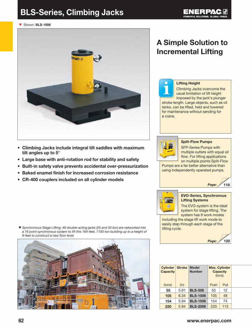
62 www.enerpac.com
▼
BLS-506BLS-1006BLS-1506BLS-2006
55105154220
120
118
• Climbing Jacks include integral tilt saddles with maximum tilt angles up to 5°
• Large base with anti-rotation rod for stability and safety• Built-in safety valve prevents accidental over-pressurization• Baked enamel finish for increased corrosion resistance• CR-400 couplers included on all cylinder models
Shown: BLS-1006
A Simple Solution to Incremental Lifting
Lifting Height
Climbing Jacks overcome the usual limitation of lift height imposed by the jack’s plunger
stroke length. Large objects, such as oil tanks, can be lifted, held and lowered for maintenance without sending for a crane.
EVO-Series, Synchronous Lifting Systems
The EVO-system is the ideal system for stage lifting. The system has 9 work modes
including the stage lift work mode to easily step through each stage of the lifting cycle.
Split-Flow Pumps
SFP-Series Pumps with multiple outlets with equal oil flow. For lifting applications on multiple points Split-Flow
Pumps are a far better alternative than using independently operated pumps.
▼ Synchronous Stage Lifting: 48 double-acting jacks (25 and 50 ton) are networked into a 16 point synchronous system to lift this 164-feet, 1100-ton building up to a height of 8-feet to construct a new floor level.
Push Pull
Cylinder Capacity
(tons)
Max. Cylinder Capacity
(tons)
Stroke
(in)
ModelNumber
BLS-Series, Climbing Jacks
Page:
Page:
5.916.345.945.94
55105154220
124874
113

63
NML
BLS-506BLS-1006BLS-1506BLS-2006
KJ1JIHFDCBA
KJ1L
J1K
0-5
J
A
C
B
H
I
M
N
3/8"-18 NPTF
D
F
◀ Typical stage-lift application using a custom built Enerpac system to lift the 360 ton Akkerwinde wooden bridge in the Netherlands.
BLSSeries
▲Stage Lifting Sequence
Step 1: The Climbing Jack is placed on a solid support under the load (retracted plunger).
Step 2: Plunger extends, lifting the load and giving clearance to insert two outer blocks under the spreading plate.
Capacity per Lifting Point:
55 - 220 tonsStroke per Stage:
5.91 - 6.34 inchesMaximum Operating Pressure:
10,000 psi
Step 1 Step 2
Step 3 Step 4
Double-Acting Climbing Jacks
Step 3: Plunger retracts, giving clear-ance to position the central blocks which will support the plunger plate for the next extension.
Step 4: Plunger extends, lifting the load, giving clearance to insert two new blocks, placed crosswise under the spreading plate.
Push PushPull Pull (lbs)
ModelNumber
Wt.Cylinder Effective
Area (in2)
OilCapacity
(in3)
Climbing Jack Dimensions(in)
Support Blocks *and Dimensions (in)
Material
* Support blocks are not supplied by Enerpac.
Azobe Wood
Solid aluminum
or steel
11.0420.6630.7144.21
67.80136.57188.56264.35
3.339.64
14.7922.50
20.4463.7790.80134.80
15.9817.5218.5820.08
21.8923.8624.5726.02
12.5213.5014.5715.24
5.006.978.009.76
3.113.744.495.24
2.242.993.704.02
1.420.941.541.46
1.972.805.125.12
9.4512.999.06
10.63
20.2826.3818.7021.65
22.2428.3519.6922.64
375695710825
4.726.304.535.31
5.515.915.515.51
2.40

64 www.enerpac.com
▼ SHS-Series 4-Point SyncHoist System
SHS and SHAS-Series SyncHoist
• High-precision load maneuvering using one crane• Reduces the risk of damage from oscillations of wire rope
due to crane jogging and sudden starts/stops • Vastly improving worker safety, operating speed and control• PLC-controlled hydraulics turn lifting into high-accuracy
hoisting and load positioning system• Double-acting push/pull cylinders with load-holding valves
for added safety• Increased efficiency compared to conventional load
positioning methodsOptions for system management and control:• Manual control: system warning functions• Automatic control: fully PLC-monitorized system with
programmable functions using touch screen and system warning functions
• Wireless control: self-contained hydraulics with hand-held control
Accurate Hoisting and Load Positioning Enhancing a Crane’s Capability
▼ A SyncHoist system used to align steel blocks of the ship’s control tower sections allowing gradual lifting and positioning of the load.
▼ Bridge segments are hoisted from the ground, being positioned with a 4-point SyncHoist system with fully monitorized cylinders. ▼ SyncHoist Powerpack to operate the 4 lifting points.
Synchronous Hoisting
Enerpac SyncHoist is a unique crane product for below-the-hook positioning of heavy loads
that require precision placement. The SyncHoist system may reduce the number of cranes needed and reduce the costs of multiple picks.
Functions• High precision horizontal and vertical
load positioning• Pre-programmed positioning, tilting
and aligning
Applications
• Positioning of rotor, stator and propeller blades of wind turbines
• Positioning of roof sections, concrete elements, steel structures
• Positioning of turbines, transformers, fuel rods
• Precise machinery loading, mill rod changes, bearing changes
• Precise positioning of pipe lines, blow out valves
• Positioning and aligning of ship segments prior to assembly

65
A
B
D1
H
E
D2
J
H JED2D1BA
4 x 60 240
4 x 94 376
4 x 120 480
4 x 250
4 x 120 485
991
—
—
SHS 45520 MJSHS 45540 MJSHS 45560 MJSHS 45520 AJSHS 45540 AJSHS 45560 AJSHS 48520 MJSHS 48540 MJSHS 48560 MJSHS 48520 AJSHS 48540 AJSHS 48560 AJSHS 411040 MJSHS 411060 MJSHS 411040 AJSHS 411060 AJSHAS 4 11040 WU 4)
SHAS 4 11060 WU 4)
SHAS 4 22540 WU 4)
SHAS 4 22560 WU 4)
What is SyncHoist?
Enerpac SyncHoist is a hydraulically operated auxiliary attachment for high
precision load positioning for cranes. The SyncHoist system can be used for pre-programmed positioning, tilting and aligning of loads.• Complete system tested in
compliance with European lifting directive and safety requirements
• BTH-1 - 2014 compliant design of below-the-hook lifting devices
SyncHoist improves safety, operating speed and control of load movementGeometric positioning of heavy loads in a horizontal and vertical plane are frequently done using more than one crane. Synchronizing movements between cranes are difficult and risky. The lifting inaccuracy can result in damage to the load and support structures and puts workers at risks. The SyncHoist system can be used for controlled hydraulic horizontal and vertical material handling.
System management and controlContact Enerpac for the following options, or other customized stroke, capacity and control configurations.
1. Manual control• Valves with manual levers• Warnings for thermal motor
protection• Visual check: oil level, filter indicator
2. Automatic control• Load and stroke monitoring, and
stroke control• PLC-control and touch screen• Solenoid valves with pendant• Pre-programmable motions and
data recording• System warnings for: – maximum cylinder load control
setting – stroke and position control – thermal motor protection – oil level and filter indicator
Autonomous (wireless) system • Wireless remote control• Only one electric power connection
per lifting point• Integrated hydraulics, PLC
and controls• No need for hydraulic hoses
and cables• No need for mid-hoist disconnection
of hoses and movement of pump
SyncHoist - High Precision Load Positioning
1) With 4 cylinders and one 460-480 VAC-3 phase-60 Hz power pack (suffix J). For 400 VAC-3 phase-50 Hz power pack change suffix J into W. Example: SHS 4 5560 MW.2) Pump and cylinders include 4x 82 feet hydraulic hoses with couplers. 3) Weight per cylinder.4) WU = with US electrical wiring. Change into suffix "WE" for EU-market. Example: SHAS 4 11060 WE.
Capacity
(ton)
TotalLoad
(ton)
Model Number 1)
460-480 VAC, 3 ph - 60 Hz
CylinderStroke
(in)
ControlSystem
MotorSize
(hp)
Number of Pump Outlets and Oil Flow 2)
(in3/min)
Cylinder Dimensions (in)
Manual
Automatic
Manual
Automatic
Manual
Automatic
Wireless
Wireless
SHS/SHASSeries
Capacity:
60 - 250 tonMaximum Stroke:
19.69 - 59.06 inches
Maximum Operating Pressure:
10,000 psi
Accuracy Over Full Stroke:
± .040 inches
Wt.
(lbs) 3)
19.6939.3759.0619.6939.3759.0619.6939.3759.0619.6939.3759.0639.3759.0639.3759.0639.3759.0639.3759.06
99213781764992
137817641102154319841102154319842138272321382723 2608319270977527
51.1870.8790.5551.1870.8790.5552.3672.0591.7352.3672.0591.7323.0392.7273.0392.72 73.0392.7284.25
103.94
70.87110.24149.6170.78
110.25149.6172.05
111.42150.7972.05
111.42150.79112.40151.77112.40151.77112.40151.77123.62143.31
4 x 85
4 x 128
4 x 128
4 x 128
4 x 128
4 x 128
27.17
27.17
9.65
9.65
2.32
2.32
15.16 3.15
15.16 3.15
27.17 10.43 2.83 15.16 3.94
27.17 10.43 2.83 15.16 3.94
30.71 12.40 3.35 15.55 4.88
30.71
41.85
48.62
12.40
12.40
16.54
3.35
3.36
5.59
15.55 4.88
21.26 4.88
22.83 7.48
4 x 5
4 x 10
10
20
15
20
15
20

66 www.enerpac.com
▼
◂
TQ-700 Series, Electric Torque PumpPL-Series, Pow’R-LOCK™ Portable Lift SystemTQ-700 Series, Electric Torque PumpPL-Series, Pow’R-LOCK™ Portable Lift SystemTQ-700 Series, Electric Torque PumpPL-Series, Pow’R-LOCK™ Portable Lift SystemTQ-700 Series, Electric Torque PumpCustom Hydraulic Cylinders
CUSTOMIZABLE FEATURES:• Stroke
• Capacity
• Paint
• Pressure Rating
• Fitting
• Special Attachments
• Seals
• Imbedded Sensors
• Collapsed Height
• Rod Modifications
• Special Mounting
• Corrosion Resistance
There's no substitute for experience in customizing hydraulic cylinders and Enerpac meets the needs of the most demanding applications.
Cylinders are the primary
workhorse in hydraulic
systems required to push or
pull. Although Enerpac offers
a wide variety of cylinders
to fit many application
requirements there are many
applications which require
customization. These may
include special corrosion
protection, ability to handle
extreme side loads, or having
special mounting needs.
◂ Large capacity cylinders for extreme applications.
◂ Cylinders with special attachments.
◂ Custom private labeled cylinders for OEM applications.
OVERVIEW
▴ Custom 500-ton cylinders with 72-inches of stroke for lifting electric rope shovels.

67
◂ Custom cylinders used for incremental bridge launching systems.
◂ Custom SyncHoist cylinders for placement of stadium roof trusses.
◂ Custom cylinders with embedded sensors for bridge construction.
◂ Custom cylinders for jack and slide operations.
◂ Custom double-acting lock-nut cylinders with internal stroke sensors and an integrated load holding valve for lifting nuclear components.
◂ One of three custom SyncHoist cylinders used to place a 1,140-ton nuclear plant module.
INFRASTRUCTURE
INFRASTRUCTURE
BUILDING CONSTRUCTION
POWERGEN
POWERGENINFRASTRUCTURE
Custom Hydraulic Cylinders

www.enerpac.com
PRES
S
REL
EASE
158
3/8"-18NPTF
254178 8
26
38
176203
1/4"-18NPTF
G1/4"
315
347217
138
121 147
232
276
68 www.enerpac.com
Enerpac Hydraulic Pumps & Directional Valves
Enerpac hydraulic pumps are available
in over 1,000 different configurations.
Whatever your high pressure pump
needs are… speed, control, intermittent
or heavy-duty performance… you can be
sure that Enerpac has the pump to suit
the application.
Featuring Hand, Battery, Electric, Air and
Gasoline powered models, with multiple
reservoir and valve configurations, Enerpac
offers the most comprehensive high pressure
pump line available.
Pump Selection
For help in selecting the correct pump for your application, please review
our “Yellow Pages.”If you require further assistance, contact the Enerpac office located near you.
Torque Wrench Pumps
System matched air and electric pumps provide control to operate Enerpac Torque Wrenches.
Page:
Page:

69
▶
▶
▶
▶
▶
▶
▶
▶
▶
▶
▶
▶
▶
▶
▶
▶
▶▶
▶▶
▶▶
▶▶
P
PP
MP
P
P/11
PU
PE
ZUZEPE
ZA
XA
70
7274
9096
104105
112114
76
77
78
80
82
102
106
108
110
115
116
118
120
123
86
XC
ZG5/ZG6EGM
LL
SFP
EVO
PA
PAPAM
Lightweight Hand PumpsExclusively from Enerpac
ULTIMA Steel Hand PumpsLow-Pressure Hand Pumps
Multifluid Hand PumpsPumping Fluids up to 14,500 psi
Foot PumpFor Hands-Free Operation
Ultra-High Pressure Hand PumpsPressure up to 40,000 psi
Economy SeriesCompact and Portable
Submerged SeriesPowerful and Low-Noise
Z-Class Portable and Powerful
8000-SeriesThe Maximum Flow Pump
ZA4 Air Hydraulic PumpsThe Standard for Air-Hydraulic Pumps
Man
ual
Ele
ctri
cA
irC
ont
rolle
dPower Source
MaximumReservoirCapacity
Pump Types SeriesMax. Flowat Rated Pressure
(in3/min)
PageG
aso
line
155 in3
453 in3
200 in3
60 in3
1 gal.
1.5 gal.
122 in3
10 gal.
.15(in3/stroke)
1.28(in3/stroke)
.15(in3/stroke)
.29
.58(in3/stroke)
.15(in3/stroke)
38 in3
Battery Powered Hydraulic PumpCordless Hydraulic Power
10 gal.
25 gal.
XA-Series Air Hydraulic PumpsControl and Ergonomics
20
20
60200462
80
15
ZG5/ZG6 Gasoline Hydraulic PumpsGas Powered High-Flow Pumps
120 in3 15
10 gal. 200
Pumps and Directional Control Valves Section Overview
Level Lift SystemMulti-point Lifting & Lowering
Split Flow PumpMulti-point Lifting & Lowering
Synchronized Lifting SystemComputer Controlled Monitoring for Precise Lifting
Directional Control Valves
8000-Series Gasoline PumpsFor the Largest Jobs
25 gal.
40 gal.
5 gal.
66 gal.
1.5(gal/min)
1.5(gal/min)
1.25(gal/min)
–
–
Turbo II Air Hydraulic PumpsCompact Air Over Hydraulic
305 in3 10
Air Hydraulic PumpsSingle and Twin-Air Motor
80 in3
2 gal.89
Battery

▼
70 www.enerpac.com
PC-20PC-25
276
283
136
P-Series, Lightweight Hand Pumps
• Lightweight and compact design• Durable glass-filled nylon reservoir and nylon
encapsulated aluminum pump base for maximum corrosion resistance
• Two-speed operation on most models reduces handle strokes by as much as 78% over single speed pumps
• Lower handle effort to minimize operator fatigue • Integral 4-way valve on P-842 for operation of
double-acting cylinders• Handle lock and lightweight construction for easy carrying• Large oil capacities to power a wide range of cylinders
or tools• Non-conductive fiberglass handle for operator safety• Internal pressure relief valve for overload protection
Pumps shown, from top to bottom: P-802, P-842, P-202, P-142
Single speed
Twospeed
Usable OilCapacity
(in3)
PumpType
Pressure Rating*
(psi)
ModelNumber
Oil Displacementper Stroke
(in3)
Exclusively from Enerpac
Max.HandleEffort
(lbs)
* Contact Enerpac for applications where operating pressure is less than 10% of pressure rating.** Available as set, see note on top of next page.*** For use with double-acting cylinders.
▼ P-392 in action with RC-256 cylinders.
Tank Kits
When a return-to-tank port is required, the Tank Kits provide a 7•16-20 port at the rear of the reservoir.
1st stage 1st stage 2nd stage 2nd stage
Speed Chart
To determine how a specific pump will operate your cylinder, see the Pump/Cylinder Speed
Chart in the “Yellow Pages”.
Page:
Cylinder Matching Chart
For help in selecting the correct hand pump for your application, please refer to the Cylinder
Matching Chart located in the “Yellow Pages”.
Page:
Fits P-141, P-142Fits P-202, P-391, P-392
LX-101 Hand Pump Oil
A medium viscosity oil specially formulated for hand pumps. Performs well in low temperatures and requires less pumping effort than
standard Enerpac HF blue oil.
Page:
2055205555
155155
N/AN/A200200200400400
10,00010,00010,00010,00010,00010,00010,000
N/AN/A.221.221.6872.402.40
.055
.151
.055
.055
.151
.151
.151
P-141P-391P-142**P-202P-392**P-802P-842***
72857863939595

71
E
G
PN
J
D A C
M
L
H
38˚ - P-141, P-142, P-20250˚ - P-391, P-392
B
S
E
Q
PN
G
J
D A C
SL
H
50˚
B
J
D A C
SL
H
50˚
B
E
PN
Q
G 132
52
144
Lightweight Hand Pumps
PistonStroke
(in)
Weight
(lbs)
ModelNumber
A B C D E G H J L M N P SQ
Aluminum Reservoir
For applications where composite reservoirs may not be suitable, the P-392AL utilizes an extruded aluminum
reservoir. Also included is a second handle for two-hand use. Contact Enerpac for details.
Hoses
Enerpac offers a complete line of high-quality hydraulic hoses. To ensure the integrity of your system, specify only
genuine Enerpac hydraulic hoses.
Page:
P Series
Reservoir Capacity:
20-155 in3
Flow at Rated Pressure:
.055-.15 in3/strokeMaximum Operating Pressure:
10,000 psi
Dimensions (in)
Release valve
Valve Control
Release Valve
Pump and Cylinder Sets
Pumps marked with an ** are available as
sets (pump, cylinder, gauge, couplers and hose) for your ordering convenience.
Page:
P-141, P-142, P-202, P-391, P-392
P-802
P-842
Page:
GA45GC Gauge Adaptor
Protect yourself from system overloading by simply ordering one part number for a pre-assembled gauge,
adaptor block and coupler.
13.2521.0013.2520.0621.0021.7521.75
P-141P-391P-142**P-202P-392**P-802P-842***
1.131.441.131.441.441.781.78
3.373.933.373.373.935.255.25
1.131.311.131.131.311.39.81
¼"-18 NPTF
⅜"-18 NPTF
¼"-18 NPTF
¼"-18 NPTF
⅜"-18 NPTF
⅜"-18 NPTF
⅜"-18 NPTF
12.5620.5612.5615.7520.5620.7520.75
.751.19.75.75
1.192.192.19
5.637.005.635.697.009.009.00
–.63–
.63
.63––
3.754.753.753.75
–7.127.12
3.25–
3.25––
6.026.02
.28–
.28––
.41
.41
–––––
1.401.44
7.3113.567.3113.5613.5613.3013.30
.501.00.50.501.001.001.00
4.59.05.37.59.0
18.022.0
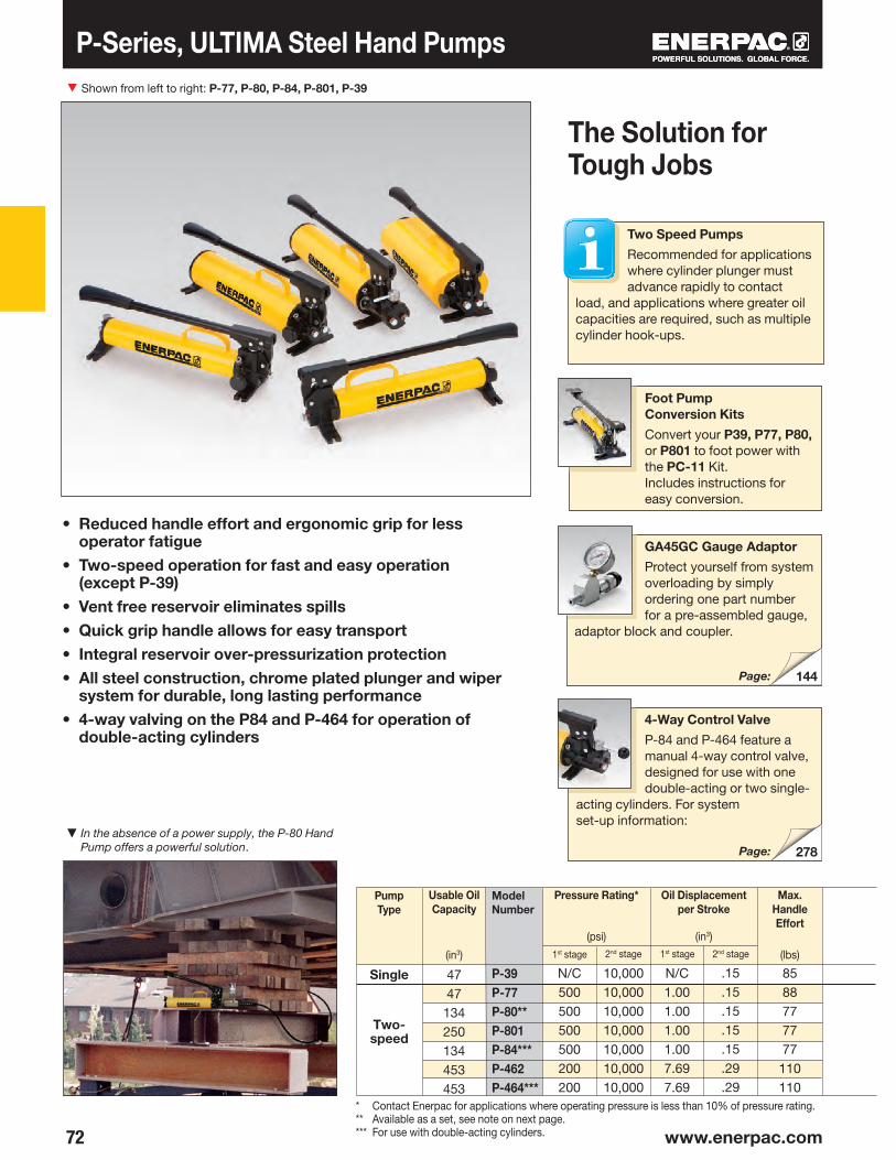
▼
72 www.enerpac.com
P-39P-77P-80**P-801P-84***P-462P-464***
278
144
P-Series, ULTIMA Steel Hand Pumps
• Reduced handle effort and ergonomic grip for less operator fatigue
• Two-speed operation for fast and easy operation (except P-39)
• Vent free reservoir eliminates spills• Quick grip handle allows for easy transport• Integral reservoir over-pressurization protection• All steel construction, chrome plated plunger and wiper
system for durable, long lasting performance• 4-way valving on the P84 and P-464 for operation of
double-acting cylinders
Shown from left to right: P-77, P-80, P-84, P-801, P-39
Two-speed
Single
Usable OilCapacity
(in3)
PumpType
Pressure Rating*
(psi)
Model Number
Oil Displacementper Stroke
(in3)
Max.HandleEffort
(lbs)
▼ In the absence of a power supply, the P-80 Hand Pump offers a powerful solution.
1st stage 1st stage2nd stage 2nd stage
The Solution for Tough Jobs
Two Speed Pumps
Recommended for applications where cylinder plunger must advance rapidly to contact
load, and applications where greater oil capacities are required, such as multiple cylinder hook-ups.
* Contact Enerpac for applications where operating pressure is less than 10% of pressure rating.** Available as a set, see note on next page.*** For use with double-acting cylinders.
Foot Pump Conversion Kits
Convert your P39, P77, P80, or P801 to foot power with the PC-11 Kit. Includes instructions for easy conversion.
4-Way Control Valve
P-84 and P-464 feature a manual 4-way control valve, designed for use with one double-acting or two single-
acting cylinders. For system set-up information:
Page:
Page:
GA45GC Gauge Adaptor
Protect yourself from system overloading by simply ordering one part number for a pre-assembled gauge,
adaptor block and coupler.
N/C500500500500200200
N/C1.001.001.001.007.697.69
8588777777
110110
4747
134250134453453
.15
.15
.15
.15
.15
.29
.29
10,00010,00010,00010,00010,00010,00010,000

73
P-39P-77P-80**P-801P-84***P-462P-464***
H
E
L
D CSS⅜"-18NPTF
⅜"-18NPTFQ
NP
T
®
B
AJF
AB
ME
3/8"-18NPTF JH
74˚
PD
N
C S
QR L 52
276
A B C D E F H J L M N P Q R S T
P-80, P-801, P-84
P-462, P-464
P-39, P-77
H
L
E
B
AD
S
J
C
®
S
3/8"-18NPTF
PN
Steel Hand Pumps
P Series
Reservoir Capacity:
47- 453 in3
Flow at Rated Pressure:
.15 - .29 in3/strokeMaximum Operating Pressure:
10,000 psi
PistonStroke
(in)
Weight
(lbs)
ModelNumber
Dimensions (in)
Pump and Cylinder Sets
P-80 is also available as a set (pump,
cylinder, gauge, couplers and hose) for your ordering convenience.
Page:
Cylinder Matching Chart
For help in selecting the correct hand pump for your application, please refer to the Cylinder
Matching Chart located in the “Yellow Pages.”
Page:
(P-801 only)
Extra Capacity Hand Pumps
P-462 and P-464 feature extra-large reservoirs and a high first-stage flow rate.
These pumps are ideally suited for powering high-capacity cylinders.
18.9119.1920.1220.1220.0612.1312.13
1.181.181.181.181.186.426.42
1.381.381.381.381.38
12.6312.63
1.481.862.172.172.307.687.68
16.3716.6718.1118.1118.11.98.98
5.515.515.915.915.9125.625.6
––––
2.77––
21.6321.6323.5023.5022.7826.4426.44
6.396.397.657.657.65
10.6310.63
–––––
6.896.89
4.374.374.764.764.763.633.63
––
1.651.651.50
–3.50
––––––
2.68
0.330.330.330.330.333.133.13
––
2.932.932.93
––
15.0915.3916.8316.8316.83 8.25 8.35
13.615.623.631.026.061.061.0
1.001.001.001.001.001.501.50
6.936.93

▼
74 www.enerpac.com
136
144
P-18P-25P-50P-51
P-Series, Low Pressure Hand Pumps
• P-25 and P-50 pump oil in both forward and reverse handle movement improving overall efficiency, ideal when mounting space is restricted
• External load-release valve • Internal pressure-relief valve for overload protection• P-51 can be operated in horizontal and vertical position with
pump head and oil outlet facing downwards
Shown from left to right: P-25, P-51, P-18
Single-speed
Usable OilCapacity
(in3)
PumpType
Pressure Rating
(psi)
Model Number
OilDisplace-ment per
Stroke
(in3)
Max.HandleEffort
(lbs)
▼ P-18 hand pump used for locking the rotating table for marble polishing.
When Less Than 10,000 psi is All You Need
LX-101 Hand Pump Oil
A medium viscosity oil specially formulated for hand pumps. Performs well in low temperatures and requires less pumping effort than
standard Enerpac HF blue oil.
Page:
Page:
GA45GC Gauge Adaptor
Protect yourself from system overloading by simply ordering one part number for a pre-assembled gauge,
adaptor block and coupler.
34606061
1820020050
0.160.580.290.25
2,8502,5005,0003,000
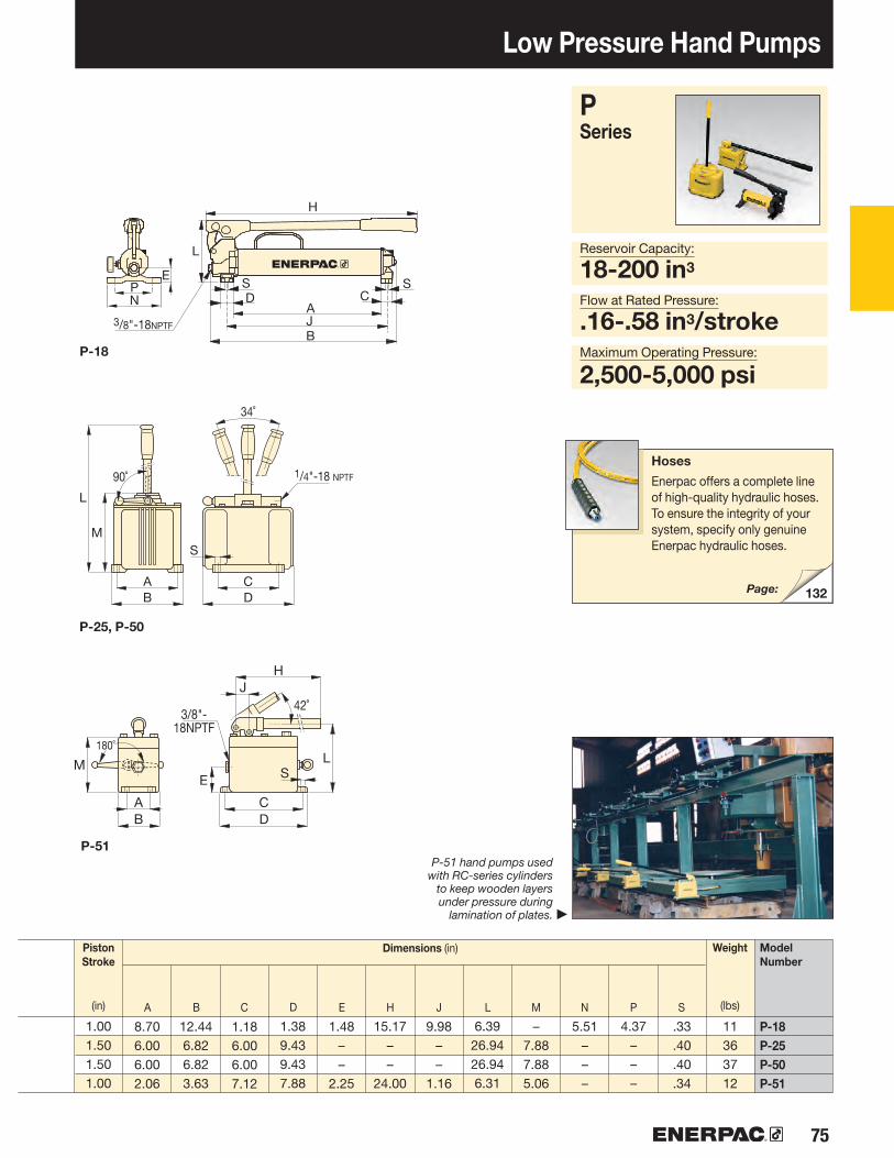
75
1/4"-18 NPTF
34˚
C
S
D
M
L
90˚
AB
L
E
J42˚
H
CD
3/8"-18NPTF
S
AB
M
180˚
132
H
L
E
B
AD
S
J
C
®
S
3/8"-18NPTF
PN
A B C D E H J L M N P S
P-25, P-50
P-51
P-18
P-18P-25P-50P-51
Low Pressure Hand Pumps
P Series
Reservoir Capacity:
18-200 in3
Flow at Rated Pressure:
.16-.58 in3/strokeMaximum Operating Pressure:
2,500-5,000 psi
PistonStroke
(in)
Weight
(lbs)
ModelNumber
Dimensions (in)
P-51 hand pumps used with RC-series cylinders
to keep wooden layers under pressure during
lamination of plates.
Hoses
Enerpac offers a complete line of high-quality hydraulic hoses. To ensure the integrity of your system, specify only genuine Enerpac hydraulic hoses.
Page:
▶
8.706.006.002.06
12.446.826.823.63
1.186.006.007.12
1.389.439.437.88
1.48––
2.25
15.17––
24.00
9.98––
1.16
6.3926.9426.946.31
–7.887.885.06
5.51–––
4.37–––
.33
.40
.40
.34
11363712
1.001.501.501.00
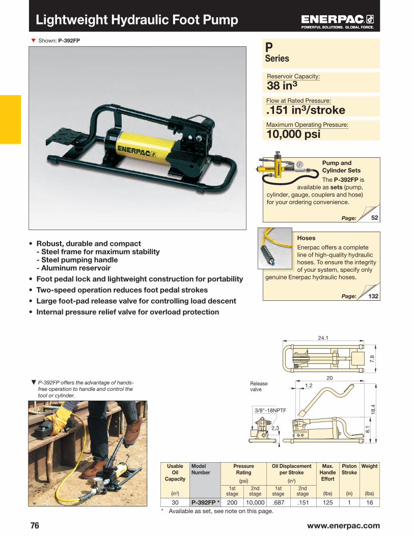
▼
76 www.enerpac.com
P-392FP *
52
132
Lightweight Hydraulic Foot Pump
P Series
Flow at Rated Pressure:
.151 in3/strokeMaximum Operating Pressure:
10,000 psi
Pump and Cylinder Sets
The P-392FP is available as sets (pump,
cylinder, gauge, couplers and hose) for your ordering convenience.
Page:
Release valve
Hoses
Enerpac offers a complete line of high-quality hydraulic hoses. To ensure the integrity of your system, specify only
genuine Enerpac hydraulic hoses.
Page:
Shown: P-392FP
• Robust, durable and compact - Steel frame for maximum stability - Steel pumping handle - Aluminum reservoir
• Foot pedal lock and lightweight construction for portability• Two-speed operation reduces foot pedal strokes• Large foot-pad release valve for controlling load descent• Internal pressure relief valve for overload protection
Max.HandleEffort
(lbs)
* Available as set, see note on this page.
Usable Oil
Capacity
(in3)
Model Number
Pressure Rating
(psi)
Oil Displace ment per Stroke
(in3)1st
stage2nd
stage1st
stage2nd
stage
Weight
(lbs)
PistonStroke
(in)
▼ P-392FP offers the advantage of hands-free operation to handle and control the tool or cylinder.
Reservoir Capacity:
38 in3
30 200 10,000 .687 .151 125 1 16
8.12.3
3/8"-18NPTF 18.4
7.8
24.1
201.2

77
▼
1
2
3
MP-10T
MP-110 MP-350 MP-700 MP-1000
****
78 Page:
Note: MP-Pump includes .060 in. thick gasket for reservoir mounting.* MP-Series pumps require the use of an external reservoir.
Multifluid Hand PumpsShown: MP-110
• Superior corrosion resistance• Impregnated aluminum anodized pump housing with
stainless steel internal pumping components• Standard Nitrile seals – excellent for demineralized
water, oil/water emulsions, water glycols, mineral oils, hydraulic fluids
• Custom EPDM seals available for use with Skydrol® or brake fluids
• Two-speed pumps up to 14,500 psi pressure• Externally adjustable pressure-relief valve• 1/4" NPTF gauge port
TwoSpeed
PumpType
Model Number
▼ MP-Series pumps are ideal for testing and filling applications.
1st stage
2nd stage
1st stage
2ndstage
top view
MP-110, 350, 700, 1000① Suction / Tank return port 3/8"-18 NPTF② Pressure port 3/8"-18 NPTF③ Gauge port 1/4"-18 NPTF
Optional Reservoir Kit
The two-gallon reservoir kit MP-10T* includes tank with skid frame, top plate with reservoir seal, suction pipe and mounting bolts. Useable oil capacity is 1.5 gal.
Also available is model number 11-400.
Usable Oil
Capacity
(in3)
Pressure Rating
(psi)
Oil Displace ment per Stroke
(in3)
Max.HandleEffort
(lbs)
PistonStroke
(in)
Weight
(lbs)
MP Series
Reservoir Capacity:
2 gal. (optional)Flow at Rated Pressure:
.12-1.28 in3/strokeMaximum Operating Pressure:
1,500-14,500 psi
*For use with mineral oil applications only.
500500500500
15005000
10,00014,500
3.23.23.23.2
1.28.43.18.12
99999999
1.041.041.041.04
14.514.514.514.5
12.1
3 4.57
7.09
6.89
12.625.6
11.1
.79
2.72
2.80 .79
ø1.97
3.74
3.74
1.18
6.85
4.65
.37
26.60 .59 .59
ø1.0
0
.90
3.314.691.1
7.48

▼
78 www.enerpac.com
P-2282
T-6010L45-116
43-301 43-701
43-701
45-11643-300
72-75043-00143-701
83-011
T-6010L
P-2282
142
Cone Seal
Stainless Steel High Pressure fittings seal on a “cone” surface and do not require pipe sealer. The Gland Nut holds the sleeve and tubing tight against the cone surface to provide a 40,000 psi seal.
• Two-speed operation on the P-2282 allows for faster fill, reducing cycle times for many testing applications
• 303 Stainless steel construction on the 11-100 and 11-400 models enable use with many different fluids, such as distilled water, alcohol, diesters, silicones, soluble oils and petroleum
• Large release knob for improved control of pressure release
• Outlet ports are 3/4"-16 cone for 40,000 psi rating
Shown from left to right: 11-100, P-2282
P/11 Series, Ultra-High Pressure Hand Pumps
Two-speed
Single-speed
Usable OilCapacity
(in3)
PumpType
PressureRating*
(psi)
ModelNumber
Oil Displacementper Stroke
(in3)
Max.HandleEffort
(lbs)1st
stage1st
stage2nd
stage2nd
stage
Stainless Steel Tubing
Body
Bleed HoleGland Nut
2-Way Shut-Off Valve 72-750
For 40,000 psi applications requiring a shut-off valve or gauge snubber. Made of 318 Stainless Steel and utilizing .38-inch cone
fittings, it is the perfect selection for use with your Ultra-High Pressure Hand Pump.
Test System Gauges
Ideal for monitoring pressure in your hydraulic circuit, Test System Gauges, such as the T-6010L, are available with
cone threads or NPTF threads and in a variety of pressure ranges.
Ultra-High Pressure up to 40,000 psi
▲ Typical Test System
▲ Test System with Gauge and Snubber
* Contact Enerpac for applications where operating pressure is less than 10% of pressure rating.
Page:
To system
To system
Sleeve
604545
40,00010,00040,000
200N/C N/C
.99N/CN/C
.037
.152
.038
P-228211-10011-400
106120120

79
3/4"-16UNF J M
L
H
40˚
F A CB
EN
3/4"-16UNF
CD
E
J
MN
1/4"-20UNC
T
35˚
A
S
B
L
H
11-100*, 11-400
P-2282
.38" cone
.38" cone
.38" cone
.38" cone side/
.25" cone gauge port
.38" cone side/
.25" cone gauge port
.38" cone
.38" cone
.38" cone
.25" cone
4" tube, O.D. .38" *8" tube, O.D. .38" *12" tube, O.D. .38" *
.38" F cone to ¼" M nptf
.38" F cone to ⅜" M nptf
.38" F cone to ¼" F nptf
.38" F cone to ⅜" F nptf
.38" M cone to ⅜" F nptf
Model No.
Ultra-High Pressure Hand Pumps
PistonStroke
(in)
ModelNumber
C D E F H J L M N S T
Weight
(lbs)
Gland Nut Plug
Elbow
Tee
Gauge Tee
Gauge Adaptor
Coupling
Cross
Gland Nut with SleeveGaugeConnector
Tubing
▼ Optional Ultra-High Pressure Fittings and Tubing
ConnectionDescription P/11Series
Reservoir Capacity:
45-60 in3
Flow at Rated Pressure:
.037-.152 in3/strokeMaximum Operating Pressure:
10,000-40,000 psi
WARNING: Maximum working pressure: 10,000 psi onlyAdaptor
Adaptor
Adaptor
Dimensions (in)
Note: .25" cone fittings use 9•16"-18 threads, ⅜" cone fittings use ¾"-16 threads.
* Actual tubing lengths are .75" less than nominal size shown. These dimensions make distance between centers of valves and fittings multiples of 4" spaces.
40,000 psi
Optional T-Series gauge and fitting
*NOTE: Maximum operating pressure for model 11-100 is 10,000 psi.
Release valve
A B
Stainless Steel Construction
Ultra-high Pressure Fittings feature all stainless-steel construction except adaptor
41-366, which features nickel plated carbon steel construction.
Ultra-High Pressure pumps DO NOT have an internal safety pressure relief valve.
P-228211-10011-400
1.00.78.78
13.569.459.45
22.0010.5010.50
1.405.985.98
–7.007.00
1.241.771.77
5.25––
20.7525.0025.00
1.166.416.41
9.004.504.50
.289.339.33
4.7412.3812.38
–.31.31
–.37.37
142222
43-001
43-200
43-300
43-301
83-011
43-400
43-600
43-701
45-11645-12645-136
41-146
41-166
41-246
41-266
43-704
41-366

▼
80 www.enerpac.com
XC-115VCXC-230VC
XSC1
144
Shown: XC-1201
• Lightweight design with integrated handle and carrying strap for portability
• Bladder reservoir prevents contamination and allows pump usage in any position
• Powerful ½ horsepower motor and 28-volt Lithium-Ion battery deliver exceptional speed and run time
• High-strength fiberglass reinforced composite shroud for superior durability in demanding job site environments
• Cordless technology eliminates tripping hazards found in other electric or air powered pumps
• Available in both single-acting and double-acting valve configurations
Performance of a Powered Pump Portability of a Hand Pump
28-Volt Battery
The XC-28V with Lithium-Ion technology for maximum battery performance.
Battery Charger
1-hour quick charger.
Battery packs contain no cadmium, so they are environmentally friendly. Enerpac encourages recycling.
115 VAC230 VAC
XC-Series, Cordless Hydraulic Pump
Hydraulic Swivel Connector
Customer installed swivel connector for optimal orientation of the hydraulic hose.
Order model number 1)
1) Accessories must be ordered separately.
Page:
GA45GC Gauge Adaptor
Protect yourself from system overloading by simply ordering one part number for a pre-assembled gauge,
adaptor block and coupler.
◀ Power and simplicity for the toughest jobs.

81
XC-1201MBXC-1202MBXC-1201MEXC-1202ME XC-1201M*XC-1202M*XC-1401MBXC-1402MBXC-1401MEXC-1402ME XC-1401M*XC-1402M*
②
①
⑧
③
④⑤ ⑤
⑥ ⑦
3-way, 2-pos.
3-way, 2-pos.
3-way, 2-pos.
4-way, 3-pos.
4-way, 3-pos.
4-way, 3-pos.
OilCapacity
(in3)
Output Flow Rate
(in3/min)
Valve Function
ChargerVoltage
(VAC)
Weight
(lbs)
XCSeries
XC-Series Cordless Hydraulic Pump
The XC-Series cordless pump is ideal for jobs
that require a combination of portability, speed, and safety. These cordless pumps are perfect for remote locations without access to power, but also indoors where trip hazards, ergonomics or size is a concern. The XC-Series cordless pump is compatible with all Enerpac hydraulic tools and small to medium sized cylinders.
The Lithium-Ion battery provides superior run time, even under extreme job site conditions.*
• 279 cuts of 3/8 inch reinforcing bar using the WHC-750 Cutter
• 112 lifts with the WR-5 Spreader • 44 splits on 1-inch, grade 8 nuts
using the NC-3241 Nut Splitter• 28 lifts of an RC-104
The XC-Series cordless pump is CSA and CE compliant.
* Actual number of cycles per charge will vary depending on condition of tool, battery and ambient conditions. Battery life with double-acting tools is approximately 75% of that for comparable, single-acting tools.
Reservoir Capacity:
60-120 in3
Flow at Rated Pressure:
15 in3/min.Maximum Operating Pressure:
10,000 psi
No Load
2000 psi
10,000 psi
* Batteries and charger not included.
OIL FLOW vs. PRESSURE
Oil
flow
(in3 /
min
) ▶
Pressure (psi) ▶
Model Number
① Outlet "Advance" Port② Oil Fill (must use funnel)
③ User-Adjustable Relief Valve Access Port
④ Directional Control Valve⑤ Shoulder Strap Connection Points ⑥ Safety Lock Feature⑦ On/Off Switch⑧ Inlet "Retract" Port
(double-acting models only)
Cordless Hydraulic Pump
▼ Take the battery pump anywhere without power cords or air hoses.
125125125125125125125125125125125125
601206012060120601206012060120
21.923.821.923.821.923.822.324.222.324.222.324.2
115
230
–
115
230
–
303030303030303030303030
151515151515151515151515
0 2000 4000 6000 8000 10,000
20
40
60
80
100
120
140
8.2
11.6
18.216.6

▼
82 www.enerpac.com
283
131
132
Gauges
Minimize the risk of over-loading and ensure long, dependable service from your equipment. For use with
the Economy pump, the G-2535L gauge and GA-3 gauge adaptor are suggested.
For a full range of gauges, please refer to the System Components section.
PU-Series, Economy Electric Pumps
• Lightweight and compact design• Large easy-carry handle for maximum portability• Two-speed operation reduces cycle times for
improved productivity • 115 VAC 50/60-cycle universal motor will operate on
voltages as low as 60 volts • 24 VAC remote motor control, 10-ft length for
operator safety• Starts under full load• High strength molded shroud with integral handle,
protects motor from contamination and damage• Designed for intermittent duty cycle
Shown: PUJ-1200B
Single-acting
Double- acting
Usable OilCapacity
(gal)
Used with Cylinder
Pressure Rating
(psi)
ModelNumber*
▼ An Economy Pump, PUJ-1200B, is used with an RCS-302 to reposition a Scissor lift to simplify maintenance.
1st stage 2nd stage
Page:
Speed Chart
To determine how the 0.5 hp Economy pump will operate your cylinder, see the Pump/
Cylinder Speed Chart in the “Yellow Pages”.
Page:
Heavy on Performance, Light on Weight
Hoses
Enerpac offers a complete line of high-quality hydraulic hoses. To ensure the integrity of your system,
specify only Enerpac hydraulic hoses.
Page:
.501.00.50
1.00.50
1.00.50
1.00
200200200200200200200200
10,00010,00010,00010,00010,00010,00010,00010,000
PUD-1100BPUD-1101BPUD-1300BPUD-1301BPUJ-1200BPUJ-1201BPUJ-1400BPUJ-1401B

83
D
C
FA
1/4"-18NPTF
E
J
3/8"-18NPTF
3/8"-18NPTF
B
H
①
②
③
273*
Economy Electric Pumps
ValveType
OutputFlow Rate
(in3/min)
Weight
(lbs)
CurrentDraw
(Amps)
ModelNumber*
HFEDCBA J
SoundLevel
(dBA)
MotorVoltage
(VAC)1st stage 2nd stage
PU Series
Reservoir Capacity:
0.5-1.0 gal.Flow at Rated Pressure:
20 in3/min.Motor Size:
.5 hpMaximum Operating Pressure:
10,000 psi
Dimensions (in)
* For 230 volt applications replace “B” suffix with “E”. (CE conformity marking only applies to pumps with an "E" suffix.)** Electric dump valve for auto-retract of cylinders.
About the Economy Pump
The Economy pump is best suited to power small to medium size cylinders
or hydraulic tools. Its lightweight and compact design makes it ideal for applications which require easy transport of the pump.
The Universal motor works well on long extension cords or generator-driven electrical power supplies.
For further application assistance refer to the “Yellow Pages”.
PUD-1100 Series• Provides advance/auto-retract of
single-acting cylinders• Ideal for punching applications
• For applications not requiring load holding
• 10-ft pendant controls motor and valve operation
PUD-1300 Series• Provides advance/hold/retract of
single-acting cylinders• 10-foot pendant controls motor
and valve operation• Ideal for applications requiring
remote valve operation.
PUJ-Series• Available with 3- and 4-way
valves for single- or double-acting cylinders
• 10-ft cord controls the motor operation
• Manual valves provide advance/retract tool control
OIL FLOW vs. PRESSURE
Pressure (psi) ▶
Page:
Economy PU-Series
Oil
Flo
w (i
n3 /m
in ▶
Dump **
Dump and Hold
3-way, 2-pos.
4-way,3-pos.
① Gauge Port (PUJ-1200/1201 only) ② Outlet Port③ Tank Port
* NOTE: CE conformity marking only applies to pumps with an "E" suffix.
115115115 115115115115115
14.2514.7214.2514.7214.2514.7214.2514.72
9.6212.189.62
12.189.62
12.189.62
12.18
9.6214.509.62
14.509.62
14.509.62
14.50
858585 8585858585
9.59.59.59.59.59.59.59.5
2020202020202020
200200200200200200200200
4.004.154.004.154.004.154.004.15
4.725.124.725.124.725.124.725.12
8.0012.748.00
12.748.00
12.748.00
12.74
.40
.40
.40
.40
.40
.40
.40
.40
5.255.625.255.625.255.625.255.62
2635263524312936
PUD-1100BPUD-1101BPUD-1300BPUD-1301BPUJ-1200BPUJ-1201BPUJ-1400BPUJ-1401B
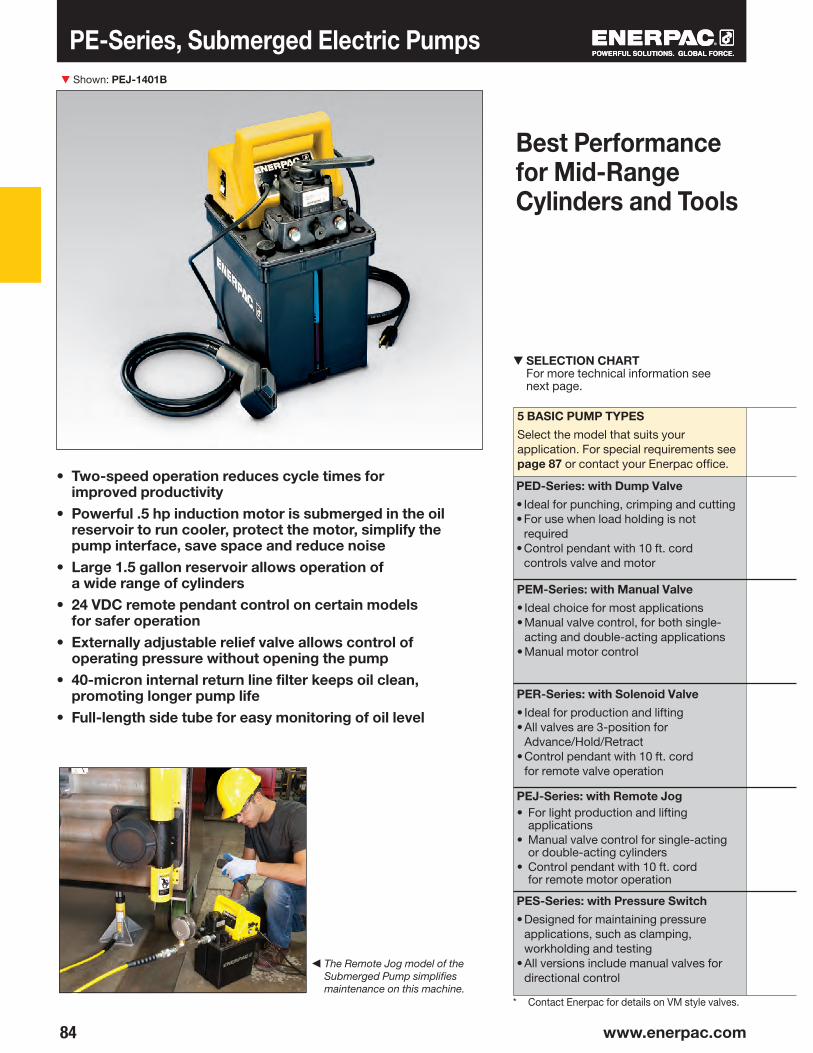
▼
84 www.enerpac.com
PE-Series, Submerged Electric Pumps
• Two-speed operation reduces cycle times for improved productivity
• Powerful .5 hp induction motor is submerged in the oil reservoir to run cooler, protect the motor, simplify the pump interface, save space and reduce noise
• Large 1.5 gallon reservoir allows operation of a wide range of cylinders
• 24 VDC remote pendant control on certain models for safer operation
• Externally adjustable relief valve allows control of operating pressure without opening the pump
• 40-micron internal return line filter keeps oil clean, promoting longer pump life
• Full-length side tube for easy monitoring of oil level
Shown: PEJ-1401B
◀ The Remote Jog model of the Submerged Pump simplifies maintenance on this machine.
Best Performance for Mid-Range Cylinders and Tools
5 BASIC PUMP TYPES
Select the model that suits your application. For special requirements see page 87 or contact your Enerpac office.
▼ SELECTION CHART For more technical information see next page.
* Contact Enerpac for details on VM style valves.
PED-Series: with Dump Valve
• Ideal for punching, crimping and cutting• For use when load holding is not
required• Control pendant with 10 ft. cord
controls valve and motor
PEM-Series: with Manual Valve
• Ideal choice for most applications• Manual valve control, for both single-
acting and double-acting applications• Manual motor control
PER-Series: with Solenoid Valve
• Ideal for production and lifting• All valves are 3-position for
Advance/Hold/Retract• Control pendant with 10 ft. cord
for remote valve operation
PEJ-Series: with Remote Jog• For light production and lifting
applications• Manual valve control for single-acting
or double-acting cylinders• Control pendant with 10 ft. cord
for remote motor operation
PES-Series: with Pressure Switch
• Designed for maintaining pressure applications, such as clamping, workholding and testing
• All versions include manual valves for directional control
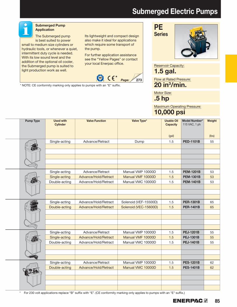
85
273*
Submerged Electric Pumps
Model Number*115 VAC, 1 ph
Used with Cylinder
Valve Type* Usable Oil Capacity
(gal)
Weight
(lbs)
PE Series
Reservoir Capacity:
1.5 gal.Flow at Rated Pressure:
20 in3/min.Motor Size:
.5 hp
Submerged Pump Application
The Submerged pump is best suited to power
small to medium size cylinders or hydraulic tools, or whenever a quiet, intermittent duty cycle is needed. With its low sound level and the addition of the optional oil cooler, the Submerged pump is suited to light production work as well.
Its lightweight and compact design also make it ideal for applications which require some transport of the pump.
For further application assistance see the “Yellow Pages” or contact your local Enerpac office.
Page:
Maximum Operating Pressure:
10,000 psi
PED-1101B
PEM-1201BPEM-1301BPEM-1401B
PER-1301BPER-1401B
PEJ-1201BPEJ-1301BPEJ-1401B
PES-1201BPES-1401B
Single-acting
Single-acting Single-acting Double-acting
Single-acting Double-acting
Single-acting Single-acting Double-acting
Single-actingDouble-acting
Dump
Manual VMP 10000DManual VMF 10000D Manual VMC 10000D
Solenoid (VEF-15500D)Solenoid (VEC-15600D)
Manual VMP 10000DManual VMF 10000D Manual VMC 10000D
Manual VMP 10000D Manual VMC 10000D
Advance/Retract
Advance/RetractAdvance/Hold/RetractAdvance/Hold/Retract
Advance/Hold/RetractAdvance/Hold/Retract
Advance/RetractAdvance/Hold/RetractAdvance/Hold/Retract
Advance/RetractAdvance/Hold/Retract
Pump Type Valve Function
* NOTE: CE conformity marking only applies to pumps with an "E" suffix.
* For 230 volt applications replace “B” suffix with “E”. (CE conformity marking only applies to pumps with an "E" suffix.)
1.5
1.5
1.5
1.5
1.5
1.5
1.5
1.5
1.5
1.5
1.5
55
53
53
53
65
65
55
55
55
62
62

86 www.enerpac.com
3/8"-18NPTF5
283
PE-Series, Submerged Electric Pumps
MotorSize
(hp)
PressureRating
(psi)
Motor ElectricalSpecifications*
(Amps @ Volts-Ph-Hz)
Output Flow Rate**
(in3/min)
Relief ValveAdjustment
Range
(psi)
SoundLevel
(dBA)
* At bypass and maximum pressure. See matrix footnotes on next page for Hz limitations.** All flow data at 60 Hz, 50 Hz data will be 5/6th this number.
1st stage 1st stage2nd stage 2nd stage
Speed Chart
To determine how a submerged pump will operate your cylinder, see the Pump/Cylinder Speed
Chart in the “Yellow Pages”.
Page:
Submerged Pump Performance
◀ This PED-1101B Submerged pump quickly and quietly powers Enerpac's hydraulic Nut Cutter in this maintenance application.
◀ For full features see page 84.
① Heat Exchanger (optional for all models)
② Fill Port
③ Pressure Switch (PES-Series, optional for other models)
④ Oil Level Indicator
⑤ Adjustable Relief Valve
OIL FLOW vs. PRESSURE
Oil
Flo
w (i
n3 /m
in)
▶
Pressure (psi) ▶
Submerged PE-Series (@ 60 Hz)
Dimensions shown in inches.
13 @ 115-1-50/606.75 @ 230-1-50/60
10,000 150 0.5 62-70 1,000-10,000
1,000 20
16.0
07.
30
2.00
4.98 8.428.97
9.42 11
.20
7.06
4.007.73
3.62
3.89
ø 1877.18
2.21
1.00
1.50
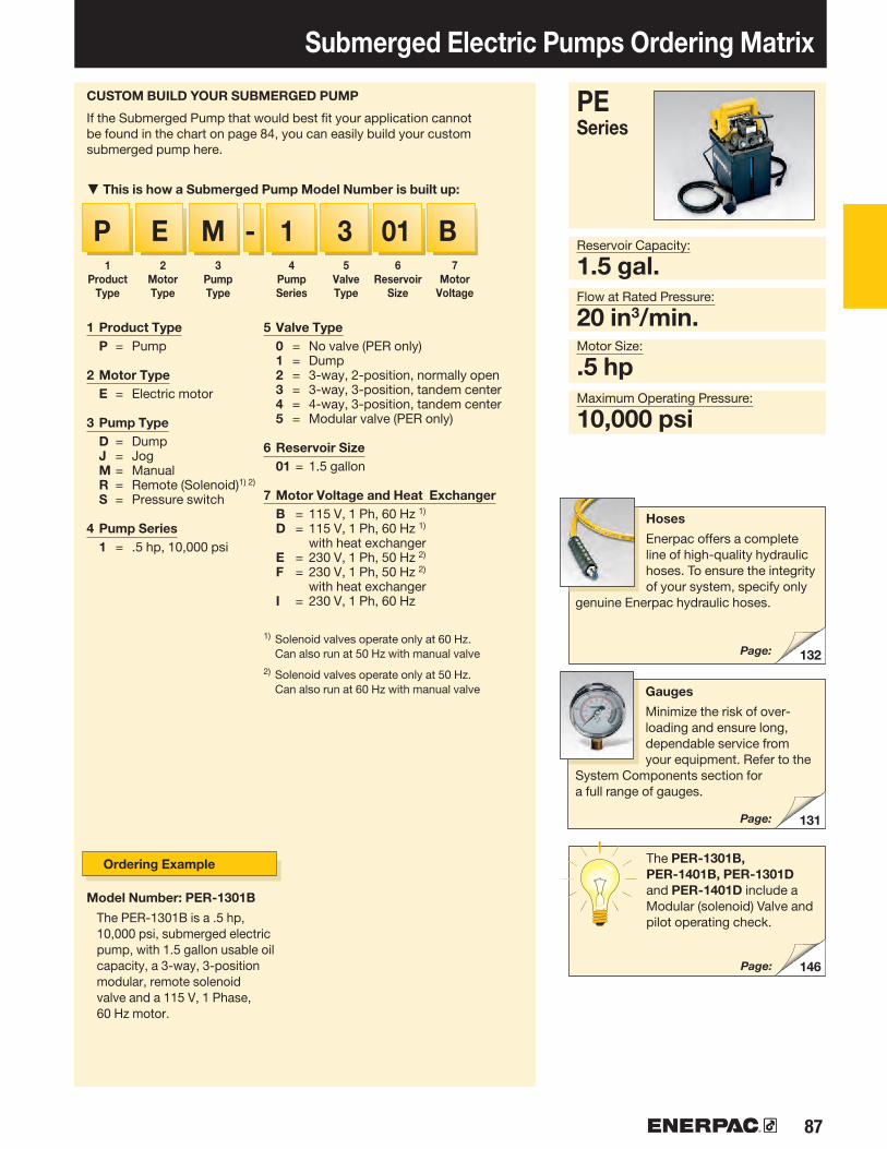
87
132
131
146
P E M - 1 3 01 B
Submerged Electric Pumps Ordering Matrix
1Product
Type
2Motor Type
3Pump Type
4Pump Series
5Valve Type
6Reservoir
Size
7Motor
Voltage
1 Product Type P = Pump
2 Motor Type E = Electric motor
3 Pump Type D = Dump J = Jog M = Manual R = Remote (Solenoid)1) 2)
S = Pressure switch
4 Pump Series 1 = .5 hp, 10,000 psi
5 Valve Type 0 = No valve (PER only) 1 = Dump 2 = 3-way, 2-position, normally open 3 = 3-way, 3-position, tandem center 4 = 4-way, 3-position, tandem center 5 = Modular valve (PER only) 6 Reservoir Size 01 = 1.5 gallon
7 Motor Voltage and Heat Exchanger B = 115 V, 1 Ph, 60 Hz 1)
D = 115 V, 1 Ph, 60 Hz 1) with heat exchanger
E = 230 V, 1 Ph, 50 Hz 2)
F = 230 V, 1 Ph, 50 Hz 2) with heat exchanger
I = 230 V, 1 Ph, 60 Hz
1) Solenoid valves operate only at 60 Hz. Can also run at 50 Hz with manual valve
2) Solenoid valves operate only at 50 Hz. Can also run at 60 Hz with manual valve
CUSTOM BUILD YOUR SUBMERGED PUMP
If the Submerged Pump that would best fit your application cannot be found in the chart on page 84, you can easily build your custom submerged pump here.
▼ This is how a Submerged Pump Model Number is built up:
Model Number: PER-1301B
The PER-1301B is a .5 hp, 10,000 psi, submerged electric pump, with 1.5 gallon usable oil capacity, a 3-way, 3-position modular, remote solenoid valve and a 115 V, 1 Phase, 60 Hz motor.
Ordering Example The PER-1301B, PER-1401B, PER-1301D and PER-1401D include a Modular (solenoid) Valve and pilot operating check.
Page:
Hoses
Enerpac offers a complete line of high-quality hydraulic hoses. To ensure the integrity of your system, specify only
genuine Enerpac hydraulic hoses.
Page:
Gauges
Minimize the risk of over-loading and ensure long, dependable service from your equipment. Refer to the
System Components section for a full range of gauges.
Page:
PE Series
Reservoir Capacity:
1.5 gal.Flow at Rated Pressure:
20 in3/min.Motor Size:
.5 hpMaximum Operating Pressure:
10,000 psi

88 www.enerpac.com
Heavy-duty bearings
Self-priming, high-flow 1st stage pump
Balanced eccentric
Replaceable piston check valves
Introducing the Z-Class power pumps from Enerpac—pumps that run cooler, use less electricity and are easy to service.
Z-Class electric pumps from Enerpac—simply the best pump you will ever use.
Z-Class Pumps
Oil bath
Motor lip seal
Enerpac has used the latest metallurgical, bearing
and seal technologies to produce a pump whose
features and benefits far surpass the electric
pumps that are available today. By reducing the
number of moving parts, improving flow dynamics
and decreasing friction, Z-Class pumps will stay on
the job longer, require less energy to operate and
when needed, have lower service costs.
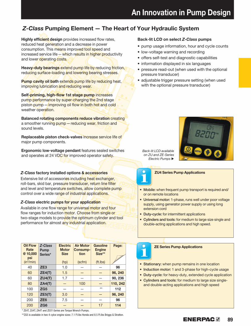
89
ZE3ZE4(T)ZU4(T)ZA4(T)ZG5ZE5(T)ZE6ZG6
9696, 24090, 236110, 242
11296, 240
96114
Z-Class factory installed options & accessoriesExtensive list of accessories including heat exchanger, roll-bars, skid bar, pressure transducer, return line filter and level and temperature switches, allow complete pump control over a wide range of industrial applications.
Z-Class electric pumps for your applicationAvailable in one flow range for universal motor and four flow ranges for induction motor. Choose from single or two-stage models to provide the optimum cylinder and tool performance for almost any industrial application.
An Innovation in Pump Design
Highly efficient design provides increased flow rates, reduced heat generation and a decrease in power consumption. This means improved tool speed and increased service life—which results in higher productivity and lower operating costs.
Heavy-duty bearings extend pump life by reducing friction, reducing surface-loading and lowering bearing stresses.
Pump cavity oil bath extends pump life by reducing heat, improving lubrication and reducing wear.
Self-priming, high-flow 1st stage pump increases pump performance by super-charging the 2nd stage piston pump—improving oil flow in both hot and cold weather operation.
Balanced rotating components reduce vibration creating a smoother running pump—reducing wear, friction and sound levels.
Replaceable piston check-valves increase service life of major pump components.
Ergonomic low-voltage pendant features sealed switches and operates at 24 VDC for improved operator safety.
Back-lit LCD on select Z-Class pumps
• pump usage information, hour and cycle counts• low-voltage warning and recording• offers self-test and diagnostic capabilities• information displayed in six languages• pressure read-out (when used with the optional
pressure transducer)• adjustable trigger pressure setting (when used
with the optional pressure transducer)
ZU4 Series Pump Applications
• Mobile: when frequent pump transport is required and/or on remote locations
• Universal motor: 1-phase, runs well under poor voltage supply, using generator power supply or using long extension cord
• Duty-cycle: for intermittent applications• Cylinders and tools: for medium to large size single and
double-acting applications and high speed.
ZE Series Pump Applications
• Stationary: when pump remains in one location• Induction motor: 1 and 3-phase for high-cycle usage• Duty-cycle: for heavy-duty, extended cycle application• Cylinders and tools: for medium to large size single-
and double-acting applications and high speed
Z-Class Pumping Element — The Heart of Your Hydraulic System
Z-Class PumpSeries*
Electric MotorSize
(hp)
Air MotorConsump-
tion
(scfm)
Gasoline EngineSize**
(ft.lbs)
Page:Oil Flow Rate
@ 10,000 psi
(in3/min)
Back-lit LCD available on ZU and ZE-Series
Electric Pumps ▶
* ZE4T, ZU4T, ZA4T and ZE5T-Series are Torque Wrench Pumps.
**ZG5 is available in two 4-cylce engine sizes: 7.1 Ft.lbs Honda and 8.5 Ft.lbs Briggs & Stratton.
40606080100120200200
1.01.51.7——3.07.5—
———
100————
———— **——17

▼
90 www.enerpac.com
• Features Z-Class high-efficiency pump design; higher oil flow and bypass pressure, cooler running and requires 18% less current draw than comparable pumps
• Powerful 1.7 hp universal electric motor provides high power-to-weight ratio and excellent low-voltage operating characteristics
• High-strength, molded composite shroud protects motor and electronics, while providing an ergonomic, non-conductive handle for easy transport
• Low-voltage pendant provides additional safety for the operator (remote control units)
Pro-Series pump only• LCD readout provides pressure and a number of diagnostic
and readout capabilities never before offered on a portable electric pump
- pump usage information, hour and cycle counts - self-test, diagnostic and read-out capabilities - pressure readout and auto-mode pressure settings
ZU-Series, Electric Pumps
▼ COMMON PUMP MODELS For technical information and other options see next page.
BASIC PUMP TYPES
Select the model that suits your application. For special requirements contact your Enerpac office.
Manual Valve• Ideal choice for most applications• Manual valve control, for single-acting
or double-acting applications• Motor control on shroud
Solenoid Valve• Ideal for lifting applications and where
remote control is required• Motor runs continuously on pumps with
VE33 and VE43 valves. With VE32 valve, motor only runs during the advance function, while holding and retracting, the motor is off
• Low-voltage control pendant with 10 ft. cord for remote motor and valve operation
Dump Valve• Ideal for punching, crimping and cutting• For use when load-holding is not required• Low-voltage control pendant with 10-ft.
cord controls valve and motor
Manual Valve with Pendant• For light production and lifting
applications• Manual valve control for single-acting
or double-acting cylinders• Low-voltage control pendant with
10-ft. cord for remote motor operation
Shown from left to right: ZU4304MB, ZU4420SB-H, ZU4304PB-K
◀ Designed to be tough, the ZU4-Series with steel reservoirs will take the abuse of today’s construction sites.

91
VM22VM22VM33VM33VM43VM43VM22VM22VM22VM33VM43VM43VE32DVE32DVE32D
–––
VE32VE32VE33VE43VE43
––––
ZU4704MBZU4708MBZU4308MBZU4320MBZU4408MBZU4420MBZU4204JBZU4208JBZU4220JBZU4308JBZU4408JBZU4420JBN/AN/AN/A–––N/AN/AN/AN/AN/A––––
ZU4704LBZU4708LBZU4308LBZU4320LBZU4408LBZU4420LBZU4204KBZU4208KBZU4220KBZU4308KBZU4408KBZU4420KBZU4104DBZU4108DBZU4120DB–––ZU4204SBZU4208SBZU4308SBZU4408SBZU4420SB––––
®
®
®••••
••••
•••
•••
••
••
••
•••••••••••••••
•••••
••••
•••
•••••
•••••••••••••••
•••••
ZU4704RBZU4708RBZU4308RBZU4320RBZU4408RBZU4420RBZU4704PBZU4708PBZU4720PBZU4308PBZU4408PBZU4420PBN/AN/AN/A–––N/AN/AN/AN/AN/A––––
1)
Pump Type Pump Control Usable Oil Capacity
(gal)
ManualManualManualManualManualManual
Remote (Man.)Remote (Man.)Remote (Man.)Remote (Man.)Remote (Man.)Remote (Man.)
RemoteRemoteRemote
–––
Remote Remote Remote RemoteRemote
––––
Model Number115 VAC3) 1 Phase
Classic STD Electric Pro Electric
ProProduct Weight
With Oil 4)
(lbs)
Z-Class – A Pump For Every Application
Patented Z-Class pump technology provides high
by-pass pressures for increased productivity—important in applications using long hose runs and high pressure-drop circuits, like heavy lifting or certain double-acting tools.
Enerpac ZU4 Hydraulic Pumps are built to power small to large-sized cylinders or hydraulic tools, or wherever high-speed, intermittent duty, remote hydraulic power is needed.
Classic Electric Pump
• The Classic has traditional electro-mechanical components (transformers, relays and switches) in place of solid-state electronics. The Classic delivers durable, safe
and efficient hydraulic power for demanding markets like construction, post-tensioning and foundation repair.
Standard Electric Pump• For applications that do not require
digital display features of the Premium Pump. Available in all manual or jog versions.
Pro Electric Pump• Digital (LCD) display features a
built-in hour meter and shows self-diagnostic, cycle-count and low voltage warning information.
Pressure can also be displayed when the pump is equipped with an optional pressure transducer.
ZU Series
ZU-Series, Electric Pumps
Reservoir Capacity:
1.0-10.0 gal. Flow at Rated Pressure:
60 in3/min.Motor Size:
1.7 hpMaximum Operating Pressure:
10,000 psi
1) CE conformity marking only applies to pumps with an "E" suffix. “E” voltage versions also meet all requirements of the European EMC-Directive.2) See valves section for technical information on valve types.3) See custom order matrix for other voltage options.4) Subtract 3 lbs. for STD Electric models.
Valve FunctionUsed with Cylinder
Valve Type2)
1.02.02.05.02.05.01.02.05.02.02.05.01.02.05.0–––
1.02.02.02.05.0––––
59697010970109607010971711106373112
–––
63738585124
––––

92 www.enerpac.com
115V
230V
A
ED
F
4XØ .34
C
B
A
D
B
C
A B C D E F
ZU Series, Specifications and Dimensions
ZU4 PerformanceMotorSize
(hp)
Output Flow Rate(in3/min)
Motor ElectricalSpecification
(volts-ph-Hz)
SoundLevel
(dBA)
Relief ValveAdjustment
Range(psi)
Pump Dimensions (in)Usable
Reservoir Capacity
(gal)
Oil Flow and Current vs. Pressure
Oil
flow
(in3
/min
) ▶
Pressure (psi) ▶Flow (in3/min)
Cur
rent
(am
ps)
▶
Current (amps)
① User adjustable relief valve ② Oil fill port, SAE#10③ Oil level sight gauge④ Oil Drain, 1/2" NPTF⑤ M8 x 1.25⑥ Handles on all 2.5, 5.0, and 10.0-gallon reservoirs
Factory installed features and options⑦ Back-lit LCD Electric⑧ Pressure transducer ⑨ Heat exchanger⑩ Skid bar ⑪ Handle guard installed on all 2.5, 5, and 10-gallon reservoirs⑫ Reservoir handles included on all 2.5, 5 and 10-gallon pumps
◀ Increased output flow and extended brush life increase productivity for post-tensioning applications.
ZU-4 Series with 1 and 2 gallon reservoirs
ZU-4 Series with 2.5, 5.0 and 10.0 gallon reservoirs(Left view shown without side handle)
5.6
5.6
6.2
7.1
10.6
11.0
11.0
16.5
16.5
15.7
6.0
8.1
12.0
16.6
19.9
-
-
15.1
19.7
22.7
-
-
11.0
15.6
18.9
1.7 700 535 76 60 115-1-50/60230-1-50/60 85-90 2,000-10,000
1.0
2.0
2.5
5.0
10.0
16.7
16.7
17.3
18.3
21.7
100 psi 700 psi 5000 psi 10,000 psi
1.30
12.00 .51
18.1017.6024.00
25.00
12.50
23.4019.0016.30
9.00
.50
2.50
3.75
.25
20.5
0
10.5
0
25.0019.40
9.45
0 2000 4000 6000 8000 10,0000
100
200
300
400
500
600
700 25
20
15
10
5
0

93
Z U 4 4 08 L B - H K T
283
212
1 Product Type Z = Pump Series
2 Motor Type U = Universal electric motor
3 Flow Group 4 = 60 in3/min @ 10,000 psi
4 Valve Type (see page 128 for more details) 1 Dump (VE32D) 2 3 way/2 position manual or electric (VM32 or VE32) 3 3 way/3 position manual or electric (VM33 or VE33) 4 4 way/3 position manual or electric (VM43 or VE43) 6 3 way/3 position locking manual w/po check (VM33-L) 7 3 way/2 position manual (VM22) 8 4 way/3 position locking manual w/po check (VM43-L) 9 4 way/3 position manual w/power seating (VM43-LPS) 10 3 way/3 position manual, Venturi-Valve (VM33VAC) 11 3 way/3 position electric, Venturi-Valve (VE33VAC)
5 Reservoir Size (useable capacity) 04 = 1.0 gallon 08 = 2.0 gallon 10 = 2.5 gallon (includes side handles) 20 = 5.0 gallon (includes side handles) 40 = 10.0 gallon (includes side handles)
6 Valve Operation D = Dump (solenoid valve w/pendant and LCD Electric) J = Jog (manual valve w/pendant and Standard Electric (i.e. w/o LCD) K = Jog (manual valve w/pendant and LCD Electric) L = Manual valve w/LCD Electric (w/o pendant) P = Manual valve w/pendant and classic electric (i.e.w/o LCD) R = Manual valve w/Classic electric (i.e. w/o LCD) [w/o pendant] M = Manual valve w/Standard Electric (i.e. w/o LCD) [w/o pendant] S = Solenoid valve w/pendant and LCD Electric
7 Voltage B = 115V, 1 ph, 50/60Hz E = 208-240V, 1 ph, 50/60 Hz (w/European plug and CE EMC compliant) I = 208-240V, 1 ph, 50/60 Hz (w/NEMA 6-15 plug)
8 Options and Accessories (see page 94 for possibilities) F = Filter G = 0-15,000 psi gauge (2½") 1)
H = Heat exchanger K = Skidbar (1 and 2 gallon reservoirs only) L = Level/temp switch 2) 3) N = No reservoir handles (includes lifting eyes) R = Roll cage T = Pressure transducer 2) U = Foot switch1) Pressure gauge not available on pump models with pressure transducer 2) These options require LCD electric3) Not available on 1 and 2 gallon reservoirs
ZU Series
Reservoir Capacity:
1.0-10.0 gal.Flow at Rated Pressure:
60 in3/min.Motor Size:
1.7 hpMaximum Operating Pressure:
10,000 psi
CUSTOM BUILD YOUR ZU4 SERIES PUMP
If the ZU4 Series pump that would best fit your application cannot be found in the chart on page 91, you can easily build your custom ZU4 Series pump here.
▼ This is how a ZU-Series pump model number is built up:
2Motor Type
3Flow
Group
4Valve Type
5Reservoir
Size
6Valve
Operation
7Voltage
8Options andAccessories
1Product
Type
ZU-Series, Ordering Matrix
Speed Chart
To determine how a "Z" pump will operate your cylinder, see the Pump/Cylinder Speed Chart
in the “Yellow Pages”. Page:
Ordering Example
Model Number: ZU4408LB-HKTZU4408LB-HKT is a
60 in3/min at 10,000 psi pump with a 4-way, 3-position manual valve, a 2 gal. (8-liter) reservoir, operates on 115V, 1ph, 50/60 Hz and is specified with optional LCD electrical panel, heat exchanger, pressure transducer and skid bar.
Torque Wrench Pumps
System matched air and electric pumps provide control to operate Enerpac Torque Wrenches.
Assisted-Return Pumps
To improve productivity and plunger retraction, Enerpac offers valve configurations designed to accelerate your cylinder retraction speeds. ZU4
and ZE-Series pumps feature Venturi valve technology to facilitate the faster return of single-acting gravity return cylinders. See details on www.enerpac.com
Page:

94 www.enerpac.com
132
131
ZPT-U4 *
ZCF-2 *
ZLS-U4± 0,5%
ZRC-04 *ZRC-04H *ZRB-10 *ZRB-20 *ZRB-40 *
SBZ-4 *SBZ-4L *
Pressure Transducer*• More durable than analog gauges
(against mechanical and hydraulic shock)
• More accurate than analog gauges (0.5% full scale of pump)
• Calibration can be fine-tuned for certification
• “Set pressure” feature turns off motor at user defined pressure (or shifts valve to neutral on models with VE33/VE43 valves)
• Display pressure in psi, bar, or MPa
* Requires LCD Electric
ZU-Series Factory Installed Options & Accessories
Hoses
Enerpac offers a complete line of high-quality hydraulic hoses. To ensure the
integrity of your system, specify only Enerpac hydraulic hoses.
Gauges
Minimize the risk of over loading and ensure long, dependable service from your
equipment. Refer to the System Components section for a full range of gauges.
Page:
Page:
Foot Switch• Hands-free remote control on
solenoid dump and 3-position valves• With 10-foot cord
Accessory Kit No.
Can be used on ZU4Pumps with
* Add suffix U for factory installation.
Solenoid VE-Series valves
Level/Temperature Switch• Ensures feedback on pump oil level
and temperature• Drop-in design allows for easy
installation to pump reservoir• Plugs directly into pump
electrical enclosure• Built-in thermal sensing shuts
off pump when unsafe operating temperature is reached
• Oil level switch shuts down pump before oil reaches an unsafe operating level
ModelNumber
OperatingTemperature
(° F)
Weight
(lbs)
MaximumPressure
(psi)
* Add suffix L for factory installation.* Add suffix T for factory installation.
Accessory Kit Model Number
AdjustablePressure
Range(psi)
Switch-point
repeatability
Dead-band
(psi)
Roll Cage • Protects pump• Provides greater pump stability
Ordering Example: Model No. ZU4208BB-QR
Accessory Kit Number
Fits on Reservoir
* Add suffix R for factory installation. 1) Without heat exchanger 2) With heat exchanger
1 and 2 gallon1)
1 and 2 gallon2)
2.5 gallon5 gallon10 gallon
Skidbar*• Provides easy two-hand lift• Provides greater pump stability on soft
or uneven surfaces• Also available as an add-on kit
(model number SBZ-4) * 1 and 2-gallon reservoirs only
* Add suffix K for factory installation.
Accessory Kit No.
For ZU-Series Pumps with Reservoir
Wt.
(lbs)
1-2 gal. w/o heat exchanger1-2 gal. with heat exchanger
50-10,000 50 40-230 .11150
4.95.5

95
ZPF *ZHE-U115ZHE-U230
F
K
R
H
G
–
–
–
F
K
R
H
G
–
–
–
ZPF
SBZ
ZRC
ZHE
G
–
–
–
ZPF
SBZ
ZRC
ZHE
G
–
–
–
F
K
R
H
G
T
L
U
ZPF
SBZ
ZRC
ZHE
G
ZPT-U4
ZLS-U4
ZCF-2
Heat Exchanger• Removes heat from the bypass oil to
provide cooler operation• Stabilizes oil viscosity, increasing oil
life, and reduces wear of pump and other hydraulic components
Heat Exchanger
• Extends system life• Stabilizes oil temperature at a
maximum of 130° F at 70° F ambient temperature.
Do not exceed maximum oil flow and pressure ratings. Heat exchanger is not suitable for water-glycol or high water based fluids.
ZU-Series Factory Installed Options and Accessories
Accessory Kit Model Number
MaximumPressure
(psi)
MaximumOil Flow
(GPM)
By-passSetting
(psi)
Return Line Filter • 25 micron nominal filter removes
contaminants from return oil flow before allowing it back into tank
• Internal by-pass valve prevents damage if filter is dirty
• With maintenance indicator
ZU Series
Reservoir Capacity:
1.0-10.0 gal.Flow at Rated Pressure:
60 in3/min.Motor Size:
1.7 hpMaximum Operating Pressure:
10,000 psi
* Add suffix F for factory installation. * Add suffix H for factory installation.
Accessory Kit No. *
Can be used on
115V pumps230V pumps
1) Skid Bar not in combination with Roll Cage.
ZU4-Series Options
Accessory Kits can be installed by the customer.
See chart below for all possible options on ZU4-Series pumps:
• Classic Electric, • Standard (STD) Electric (no LCD) • Pro Electric (with LCD). Refer to page 93 for ordering matrix.
ZU4-Series Options Factory Installed
ClassicElectric
StandardElectric
Accessory Kits
ClassicElectric
StandardElectric
Return Line Filter
Skid Bar 1)
Roll Cage
Heat Exchanger
Pressure Gauge
Pressure Transducer
Level/Temperature Switch
Foot Switch
ProElectric
ProElectric
ThermalTransfer *
Btu/h
Maximumpressure
(psi)
Maximumoil flow
(GPM)
Voltage
(VDC)
* At GPM at 70 °F ambient temperature.200 12.0 25
900 900 7.0 12
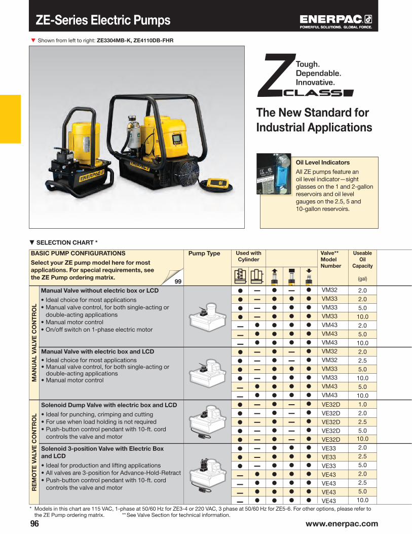
▼
96 www.enerpac.com
®
®
®
••••–––••••––••••••••––––
––––•••––––••––––––––••••
•••••••••••••••••••••••••
–••••••––••••–––––•••••••
•••••••••••••••••••••••••
VM32VM33VM33VM33VM43VM43VM43VM32VM32VM33VM33VM43VM43
VE32DVE32DVE32DVE32DVE32DVE33VE33VE33VE43VE43VE43VE43
99
Useable Oil
Capacity
(gal)
Valve**Model Number
The New Standard for Industrial Applications
Shown from left to right: ZE3304MB-K, ZE4110DB-FHR
Solenoid Dump Valve with electric box and LCD
• Ideal for punching, crimping and cutting• For use when load holding is not required• Push-button control pendant with 10-ft. cord
controls the valve and motor
Manual Valve with electric box and LCD• Ideal choice for most applications• Manual valve control, for both single-acting or
double-acting applications• Manual motor control
Solenoid 3-position Valve with Electric Box and LCD
• Ideal for production and lifting applications• All valves are 3-position for Advance-Hold-Retract• Push-button control pendant with 10-ft. cord
controls the valve and motor
BASIC PUMP CONFIGURATIONS
Select your ZE pump model here for most applications. For special requirements, see the ZE Pump ordering matrix.
Pump Type
▼ SELECTION CHART *
* Models in this chart are 115 VAC, 1-phase at 50/60 Hz for ZE3-4 or 220 VAC, 3 phase at 50/60 Hz for ZE5-6. For other options, please refer to the ZE Pump ordering matrix. ** See Valve Section for technical information.
Used with Cylinder
Manual Valve without electric box or LCD
• Ideal choice for most applications• Manual valve control, for both single-acting or
double-acting applications• Manual motor control• On/off switch on 1-phase electric motor
ZE-Series Electric PumpsR
EM
OT
E V
ALV
E C
ON
TR
OL
MA
NU
AL
VALV
E C
ON
TR
OL
Oil Level Indicators
All ZE pumps feature an oil level indicator—sight glasses on the 1 and 2-gallon reservoirs and oil level gauges on the 2.5, 5 and 10-gallon reservoirs.
2.02.05.0
10.02.05.0
10.02.02.55.0
10.05.0
10.01.02.02.55.0
10.02.02.55.02.02.55.0
10.0
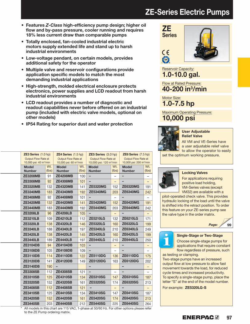
97
ZE3208MBZE3308MBZE3320MBZE3340MBZE3408MBZE3420MBZE3440MBZE3208LBZE3210LBZE3320LBZE3340LBZE3420LBZE3440LBZE3104DBZE3108DBZE3110DBZE3120DBZE3140DBZE3308SBZE3310SBZE3320SBZE3408SBZE3410SBZE3420SBZE3440SB
ZE4208MBZE4308MBZE4320MBZE4340MBZE4408MBZE4420MBZE4440MBZE4208LBZE4210LBZE4320LBZE4340LBZE4420LBZE4440LBZE4104DBZE4108DBZE4110DBZE4120DB–ZE4308SBZE4310SBZE4320SBZE4408SBZE4410SBZE4420SBZE4440SB
––ZE5320MGZE5340MG–ZE5420MGZE5440MG–ZE5210LGZE5320LGZE5340LGZE5420LGZE5440LG––ZE5110DGZE5120DG––ZE5310SGZE5320SG –ZE5410SGZE5420SGZE5440SG
––ZE6320MGZE6340MG–ZE6420MGZE6440MG–ZE6210LGZE6320LGZE6340LGZE6420LGZE6440LG––ZE6110DGZE6120DG––ZE6310SGZE6320SG–ZE6410SGZE6420SGZE6440SG
99
• Features Z-Class high-efficiency pump design; higher oil flow and by-pass pressure, cooler running and requires 18% less current draw than comparable pumps
• Totally enclosed, fan-cooled industrial electric motors supply extended life and stand up to harsh industrial environments
• Low-voltage pendant, on certain models, provides additional safety for the operator
• Multiple valve and reservoir configurations provide application specific models to match the most demanding industrial applications
• High-strength, molded electrical enclosure protects electronics, power supplies and LCD readout from harsh industrial environments
• LCD readout provides a number of diagnostic and readout capabilities never before offered on an industrial pump (included with electric valve models, optional on other models)
• IP54 Rating for superior dust and water protection
ZE Series
Reservoir Capacity:
1.0-10.0 gal.Flow at Rated Pressure:
40-200 in3/minMotor Size:
1.0-7.5 hpMaximum Operating Pressure:
10,000 psi
* All models in this chart are 115 VAC, 1-phase at 50/60 Hz. For other options please refer to the ZE Pump ordering matrix.
ZE3 Series (1.0 hp)Output Flow Rate at
10,000 psi: 40 in3/min
ZE4 Series (1.5 hp)Output Flow Rate at
10,000 psi: 60 in3/min
Model Number
Wt.(lbs)
Single-Stage or Two-Stage
Choose single-stage pumps for applications that require constant flow regardless of pressure, such
as testing or clamping.Two-stage pumps have an increased output flow at low pressure to allow fast movement towards the load, for reduced cycle times and increased productivity.To specify a single-stage pump, place the letter “S” at the end of the model number.
For example: ZE5320LG-S
Locking Valves
For applications requiring positive load holding, VM-Series valves (except VM32) are available with a
pilot-operated check valve. This provides hydraulic locking of the load until the valve is shifted into the retract position. To order this feature on your ZE-series pump see the valve type in the order matrix.
ZE5 Series (3.0 hp)Output Flow Rate at
10,000 psi: 120 in3/min
ZE6 Series (7.5 hp)Output Flow Rate at
10,000 psi: 200 in3/min
ZE-Series Electric Pumps
Model Number
Wt.(lbs)
Model Number
Wt.(lbs)
Model Number
Wt.(lbs)
User Adjustable Relief Valve
All VM and VE-Series have a user adjustable relief valve to allow the operator to easily
set the optimum working pressure.
Page:
9192
13218392
13218396
10913818813818994
105114141190112125152112125152203
100101141192101141192105112146197145197103109122149
121134161121134161212
––
152203
–152203
–132160210160210
––
136163
–147174
– 147174225
––
191242
–191242
–171199249199250
––
175202
––
187213
–187213264
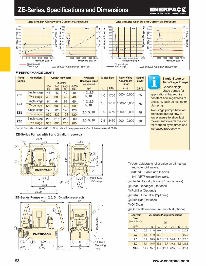
98 www.enerpac.com
ZE3
ZE4
ZE5
ZE6
75
75
75
80
A B C D D1 E H
ZE3 ZE4 ZE5 ZE6
A
B
2
3
6 C
H1
5
7
3
4
B A
D1
A
H
CE
D
1
B
2 4
7 8
Output flow rate is listed at 60 Hz. Flow rate will be approximately 5/6 of these values at 50 Hz.
Pump Series
Output Flow Rate
(in3/min)
Operation SoundLevel
(dBA)
Relief ValveAdjustment
Range
(psi)
Motor SizeAvailable Reservoir Sizes
(useable oil)
(gal)
Single-stageTwo-stage
Single-stageTwo-stage
Single-stageTwo-stage
Single-stageTwo-stage
▼ PERFORMANCE CHART
Oil
Flo
w (i
n3/m
in)
▶
Pressure (psi) ▶
Cur
rent
(Am
ps)
▶
ZE3 and ZE4 Oil Flow and Current vs. Pressure
Two stageSingle stage
ZE5 and ZE6 Amp draw at 208V/3ph Two StageSingle stage
ZE3 and ZE4 Amp draw at 115V/1ph
① User-adjustable relief valve on all manual and solenoid valves:
3/8" NPTF on A and B ports
1/4" NPTF on auxiliary ports
② Electric Box (Optional w/manual valve)
③ Heat Exchanger (Optional)
④ Roll Bar (Optional)
⑤ Return Line Filter (Optional)
⑥ Skid Bar (Optional)
⑦ Oil Drain
⑧ Oil Level/Temperature Switch (Optional)
Oil
Flo
w (i
n3/m
in)
▶Pressure (psi) ▶
Cur
rent
(Am
ps)
▶
Oil
Flo
w (i
n3/m
in)
▶
Pressure (psi) ▶
Cur
rent
(Am
ps)
▶
Oil
Flo
w (i
n3/m
in)
▶
Pressure (psi) ▶
Cur
rent
(Am
ps)
▶
ZE5 and ZE6 Oil Flow and Current vs. Pressure
Reservoir Size
(useable oil)
(gal)
ZE-Series Pump Dimensions
(in)
M8 x 1.25.25" deep
4 x Ø.34Mounting hole
ZE-Series Pumps with 1 and 2 gallon-reservoir
ZE-Series Pumps with 2.5, 5, 10-gallon reservoir
ZE-Series, Specifications and Dimensions
Single-Stage or Two-Stage Pumps
Choose single-stage pumps for
applications that require constant flow regardless of pressure, such as testing or clamping.
Two-stage pumps have an increased output flow at low pressure to allow fast movement towards the load, for reduced cycle times and increased productivity.
100 psi
700 psi
5,000 psi
10,000 psi
4345064650128850220900
40406060120120200200
4338564600126825215890
42426262123123210210
1.0
1.5
3.0
7.5
1750
1750
1750
3450
1000-10,000
1000-10,000
1000-10,000
1000-10,000
1, 2, 2.5, 5, 10
1, 2, 2.5, 5, 10
2.5, 5, 10
2.5, 5, 10
1.0
2.0
2.5
5.0
10.0
5.6
5.6
6.2
7.1
10.6
11.0
11.0
16.5
16.5
15.7
6.0
8.1
12.0
16.6
19.9
–
–
15.1
19.7
22.7
–
–
14.6
19.2
22.5
20.2
20.2
23.6
24.6
28.1
–
–
11.0
15.6
18.9
hp RPM
18.0
0 M
ax.
25.7519.40
19.0025.00
16.30
2.50
12.50
10.509.45
9.00
25.
20
3.75
12.00
27.90
17.60 5.20
25.7
5 M
ax.
4.80
0 2,000 4,000 6,000 8,000 10,000
1000
200300400500600700
900800
1000
0
5
10
15
20
25
0 2,000 4,000 6,000 8,000 10,000
1000
200300400500600700
900800
1000
0
5
10
15
20
25
0 2,000 4,000 6,000 8,000 10,000
1000
200300400500600700
900800
1000
0
5
10
15
20
25
0 2,000 4,000 6,000 8,000 10,000
1000
200300400500600700
900800
1000
0
5
10
15
20
25

99
1Product
Type
2Motor Type
3Flow
Group
4ValveType
6Valve
Opera-tion
5Useable
OilCapacity
7Voltage
CUSTOM BUILD YOUR ZE SERIES PUMPIf the ZE Series pump that would best fit your application cannot be found in the chart on page 97, you can easily build your custom ZE Series pump here.
▼ This is how a ZE Series Pump model is built up:
1 Product Type Z = Pump Class
2 Prime movers E = Induction Electric Motor
3 Flow Group 3 = 40 in3/min @ 10,000 psi 4 = 60 in3/min @ 10,000 psi 5 = 120 in3/min @ 10,000 psi1)
6 = 200 in3/min @ 10,000 psi1)
4 Valve Types 0 = No valve w/cover plate 1 = Dump (VE32D) 2 = 3-way/2-position manual (VM32) 3 = 3-way/3-position manual or
electric (VM33 or VE33) 4 = 4-way/3-position manual or
electric (VM43 or VE43) 6* = 3-way/3-position locking
manual w/po check (VM33L*) 7 = 3-way/2-position manual
(VM22) 8 = 4-way/3-position locking
manual w/po check (VM43L) 9 = 4 way/3 position manual w/
power seating (VM43-LPS) 10 = 3-way/3-position manual,
Venturi-Valve (VM33VAC) 11 = 3-way/3-position electric,
Venturi-Valve (VE33VAC)
5 Useable Oil Capacity 04 = 1.0 gallon 2)
08 = 2.0 gallon 2)
10 = 2.5 gallon 20 = 5.0 gallon 40 = 10.0 gallon
6 Valve Operation D = Dump valve (w/ pendant and LCD) L = Manual valve (w/o pendant, w/ LCD) M = Manual valve 6) (w/o pendant or LCD) N = No valve 6) (no electrical box) S = Solenoid valve (w/ pendant and LCD) W = No valve (w/o pendant and LCD)
7 VoltagesSingle Phase B = 115V 1 ph 50-60Hz 3)
E = 115V 1 ph 50-60Hz 3)
E = 208-240V 1 ph 50-60 Hz European Plug I = 208-240V 1 ph 50-60 Hz USA PlugThree Phase 6)
M = 190-200V 3ph 50-60Hz G = 208-240V 3ph 50-60Hz W = 380-415V 3ph 50-60Hz K = 440V 3ph 50-60Hz J = 460-480V 3ph 50-60Hz R = 575V 3ph 60Hz
8 Options and Accessories(see page 100 for possibilities) F = Filter G = 0-15,000 psi gauge (21/2") 6)
H = Heat exchanger K = Skid bar (1 and 2 gal. reservoirs only) L = Level/temp switch 4)
N = No reservoir handles (includes lifting eyes) R = Roll cage S = Single stage T = Pressure transducer 4) 7)
U = Foot switch 4)
Ordering Example 1
Model Number: ZE4420MB
ZE4420MB is a 60 in3/min, 10,000 psi pump with a 4-way,
3-position manual valve, a 5-gallon reservoir, operates on a 115 VAC 1-ph 50/60 Hz motor and includes standard electrical package.
Ordering Example 2
Model Number: ZE6440SG-HNU
ZE6440SG-HNU is a 200 in3/min, 10,000 psi pump with a 4-way, 3-position electric valve, a 10-gallon reservoir, operates on a 230 VAC, 3-ph, 50/60 Hz motor. It includes LCD electrical package and foot switch on 10-ft cord, no reservoir handles and the optional heat exchanger.
ZE Series
Reservoir Capacity:
1.0-10.0 gal.Flow at Rated Pressure:
40-200 in3/min.Motor Size:
1.0-7.5 hpMaximum Operating Pressure:
10,000 psi
1) ZE5 and ZE6 series pumps only available with 3-phase motors.2) 1 and 2-gallon reservoirs only available on ZE3 and ZE4-series pumps.3) 115-volt pumps are supplied with 15-amp plug for intermittent use. 20-amp circuit
recommended for frequent full pressure use.4) These options require LCD electrical package. Pressure switch option only available
on manual valves without locking valve. The LCD electrical package can accept either a pressure switch or pressure transducer, but not both.
5) Not available with 1 and 2-gallon reservoirs.6) Standard Electric models with 3-phase motors are shipped without cord, motor
starter or overload protection.7) Pressure gauge not available on pump models with pressure transducer. Pressure
transducer provides digital pressure readout on LCD display.
* Not available on ZE5 or ZE6 Series Pumps
ZE Series Electric Pump Ordering Matrix
8Options andAccessories
Assisted-Return Pumps
To improve productivity and plunger retraction, Enerpac offers valve configurations designed to accelerate your cylinder retraction speeds. ZU4
and ZE-Series pumps feature Venturi valve technology to facilitate the faster return of single-acting gravity return cylinders. See details on www.enerpac.com

▼
100 www.enerpac.com
ZRC-04 *ZRC-04H *ZRB-10 *ZRB-20 *ZRB-40 *
SBZ-4 *SBZ-4L * ZCF-2 *
ZPF *ZLS-U4 *
Electric Box 1)
• Back-lit LCD• Pump usage information, hour and
cycle counts• Low-voltage warning and recording• Self-test and diagnostic capabilities• Pressure read-out 2)
• Auto-mode pressure setting 2)
• Information can be displayed in six languages 3)
1) Included on pumps with solenoid valves. Can be factory installed on pumps with manual valve
2) When used with optional pressure transducer
3) English, French, German, Italian, Spanish and Portuguese
Skid Bar • Provides easy two-hand lift• Provides greater pump stability on
soft or uneven surfaces
Roll Cage• For easy portability and hoisting• Protects pump and electric box• Available for all reservoir sizes
Return Line Filter • 25 micron nominal filter removes
contaminants from return oil flow before allowing it back into tank
• Internal by-pass valve prevents damage if filter is dirty
• With maintenance indicator• Replaceable filter element PF25
Level/Temperature Switch 4)
• Shuts down pump before oil level reaches an unsafe level, avoiding damage due to cavitation
• Shuts down pump when unsafe oil temperature is reached
• Ideal if pump is used in remote area without visual access to oil level
4) 24 V, requires Electric Box. Available for 2.5, 5 and 10 gallon reservoirs
Foot Switch 5)
• Hands-free remote control on solenoid dump and 3-position valves
• With 10-foot cord 5) 15 V, requires Electric Box
Accessory Kit Number
For ZE-Series Pumps with Reservoir
Weight
(lbs)
Accessory Kit Model Number
MaximumPressure
(psi)
MaximumOil Flow
(GPM)
By-passSetting
(psi)
* Add suffix F for factory installation, see ordering matrix.
Accessory Kit Model Number
Fixed Temperature
Signal(°F)
Operating Tempera-
ture(°F)
Max.Pressure
(psi)
* Add suffix L for factory installation, see ordering matrix.
Accessory Kit Number
Can be used on ZE-SeriesPumps with
* Add suffix U for factory installation, see ordering matrix.
Solenoid VE-Series valves
1-2 gal. w/o heat exchanger1-2 gal. with heat exchanger
Accessory Kit Number
Fits on Reservoir
* Add suffix R for factory installation, see ordering matrix. 1) Without heat exchanger 2) With heat exchanger
1 and 2 gallon1)
1 and 2 gallon2)
2.5 gallon5 gallon10 gallon
ZE-Series, Options & Accessories
* 1 and 2 gallon reservoirs only. Add suffix K for factory installation, see ordering matrix.
75 40 - 230 150 200 12.0 25
4.95.5

101
ZPT-U4 * ZPS-E3 *
ZCP-1ZCP-3
ZHE-E04 *ZHE-E10 *
± 0,5% ± 2%
VE32DVE32, VE33, VE43
3/8"
F
K
R
S
–
G
–
–
–
–
F
K
R
S
H
G
P
T
L
U
ZPF
SBZ
ZRB
–
–
–
ZPS-E3
–
–
–
ZPF
SBZ
ZRB
–
ZHE
–
–
ZPT-U4
ZLS-U4
ZCF-2
Heat Exchanger 5)
• Removes heat from bypass oil to provide cooler operation
• Stabilizes oil viscosity, increasing oil life, and reduces wear of pump and other hydraulic components
5) 24 VDC, requires electric box
Pressure Transducer 1)
• Displays pressure on LCD in bar, MPa or psi
• More accurate than analog gauge• Calibration can be fine-tuned
for certification• Easy-viewing variable rate display • “Set pressure” feature turns off
motor at user defined pressure (or shifts valve to neutral on models with VE33/ VE43 valves)
1) 24 V, requires Electric Box
Pressure Switch 2) 3)
• Controls pump, monitors system• Adjustable pressure 500-10,000 psi• Includes glycerin filled, 15,000 psi
pressure gauge, G2536L• Accuracy ± 1,5% of full scale 2) 24 V, requires Electric Box. Not available
in combination with pressure transducer.3) Not available on LCD electronics
Pendants 4)
• For pump types with valve operation “W” (No Valve, with Electric Box, without pendant)
4) When ordering Enerpac VE-Series solenoid valve, the pendant must be ordered separately. Pendant connection to be plugged into electric box
Accessory KitModel number
AdjustablePressure
Range(psi)
Switch-point
Repeat-ability
Dead-band
(psi)
* Add suffix T for factory installation, see ordering matrix.
Accessory Kit Model number
Fits on Reservoir
ZPT-U4 Pressure Transducer
More durable against mechanical and hydraulic shock than analog gauges.
• Digital pressure read-out provides accuracy of 5% of full scale.
• Easy-viewing variable rate display automatically varies increments between 44, 203, 508 and 2103 psi as rate of pressure change increases.
• “Set pressure” feature turns off motor at user defined pressure (or shifts valve to neutral on VE33 and VE43 valves).
ZHE-Series Heat Exchangers
Heat exchanger stabilizes oil temperature at 130° F at 70° F ambient temperature. Thermal
transfer at 5 GPM and 70° F ambient temperature: 900 Btu/hour.
Do not exceed maximum oil flow of 7.0 GPM and maximum pressure of 300 psi. Not suitable for water-glycol or high water based fluids.
Accessory KitModel number
Switch-point
Repeat-ability
Deadband
(psi)
OilPorts
(NPT)
* Add suffix P for factory installation, see ordering matrix.
1 and 2 gallon2.5, 5, and 10 gallon
Weight
(lbs)
PendantModel Number
To be used with Solenoid Valve:
ZE-Series, Factory Installed Options & Accessories
* Add suffix H for factory installation, see ordering matrix.
Options
Accessory Kits can be installed by customer. See chart below for options on Standard Electric (without electric
box) or LCD Electric (with electric box). Refer to page 99 for ordering matrix.
ZE-Series Options FactoryInstalled
Return Line Filter
Skid Bar 1)
Roll Cage
Single-stage
Heat Exchanger
Pressure Gauge 2)
Pressure Switch 3)
Pressure Transducer 4)
Level/Temp Switch 5)
Foot Switch 6)
Std.Electr.
LCDElectr.
AccessoryKits
Std.Electr.
LCDElectr.
1) Available for 1 and 2 gallon reservoirs.2) Not available on pumps with pressure transducer.3) Includes 14,500 psi gauge. Only available on
manual valves without locking feature.4) Electric box can accept either pressure switch or
pressure transducer, but not both.5) Available for 2.5, 5, 10, gallon reservoirs.6) For control of solenoid dump and 3-position valves.
50-10,000 50 115-550
9.09.0
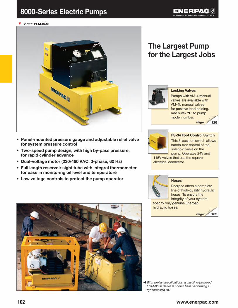
▼
102 www.enerpac.com
126
132
8000-Series Electric Pumps
• Panel-mounted pressure gauge and adjustable relief valve for system pressure control
• Two-speed pump design, with high by-pass pressure, for rapid cylinder advance
• Dual-voltage motor (230/460 VAC, 3-phase, 60 Hz)• Full length reservoir sight tube with integral thermometer
for ease in monitoring oil level and temperature• Low voltage controls to protect the pump operator
The Largest Pump for the Largest Jobs
Shown: PEM-8418
Locking Valves
Pumps with VM-4 manual valves are available with VM-4L manual valves for positive load holding. Add suffix “L” to pump model number.
Page:
FS-34 Foot Control Switch
This 3-position switch allows hands-free control of the solenoid valve on the pump. Operates 24V and
115V valves that use the square electrical connector.
Hoses
Enerpac offers a complete line of high-quality hydraulic hoses. To ensure the integrity of your system,
specify only genuine Enerpac hydraulic hoses.
Page:
◀ With similar specifications, a gasoline-powered EGM-8000 Series is shown here performing a synchronized lift.

103
283
8000-Series Electric Pumps
Single-acting
Double-acting
Usable OilCapacity
(gal)
Used with
Cylinder
PressureRating
(psi)
ValveType
OutputFlow Rate
(gal/min)
Weight
(lbs)
CurrentDraw
(Amps)
Manual(VM-2)
Manual(VM-4)
Solenoid(VE43)
ModelNumber
SoundLevel
(dBA)
MotorVoltage*
(VAC)
ValveFunction
3-way, 2-pos.
4-way,3-pos.
4-way,3-pos.
PE Series
Reservoir Capacity:
25 gal.Flow at Rated Pressure:
2.0 gal/min.Motor Size:
12.5 hpMaximum Operating Pressure:
10,000 psi
1st stage 1st stage 2nd stage
About the 8000 Series
The 8000 Series is the largest pump in the Enerpac line and the best
choice to power most large size cylinders, multiple cylinder circuits, and applications where the need for high speed requires high flow rates.
The 8000 Series, with its large reservoir capacity, is best suited for large jobs and may be the only solution because of the required oil capacity.For further application assistance see our “Yellow Pages”, or consult your local Enerpac office.
Speed Chart
To determine how an 8000- Series pump will operate your cylinder, see the Pump/Cylinder
Speed Chart in the “Yellow Pages”.
Page:
OIL FLOW vs. PRESSUREO
il flo
w (g
al/m
in)
▶
Pressure (psi) ▶8000 Series
Dimensions shown in inches.
* Consult Enerpac for availability of other voltages.
Relief Valve
Fill Port
Gauge Shut Off Valve
Drain Plug
Oil Level and Temperature Gauge
Gauge 15,000 psi
Magnetic Starter
Valve Location
2nd stage
181818181818
3,7003,7003,7003,7003,7003,700
2.02.02.02.02.02.0
720720720720765765
PEM-8218PEM-8218CPEM-8418PEM-8418CPER-8418PER-8418C
78-8478-8478-8478-8478-8478-84
230460230460230460
33.0 16.533.016.533.016.5
10,00010,00010,00010,00010,00010,000
4.44.44.44.44.44.4
46.00
22.2
535
.00
0 2000 4000 6000 8000 10,0000
0.5
1.0
1.5
2.0
2.5
3.0
3.5
4.0
4.5

▼
104 www.enerpac.com
1/4"-18NPTF
1/2"-20UNF 3/8"-18NPTF
1/4"-18NPTF
3/8"-18NPTF3/8"-18NPTF
PA-133 PA-1150
PA-Series, Air Hydraulic Pumps
• Rugged construction – built for long life and easy service• Swivel coupling simplifies hydraulic connection and
pump operation• Three-position treadle pro vides cylinder advance,
hold and retract operation • PA-133 operates in all positi ons for increased
ver satility in use and moun ting• Base mounting slots provided on PA-133
Shown from top to bottom: PA-1150, PA-133
Reservoir Capacity:
36-80 in3
Flow at Rated Pressure:
8 in3/min.Maximum Operating Pressure:
10,000 psi
PC-66 Reservoir Conversion Kit
Double the reservoir capacity of your existing PA-133 with this easy to install conversion kit.
PA Series
Used with
Cylinder
Usable Oil
Capa city
(in3)
ModelNumber
Pressure Rating
(psi)
Output Flow Rate
(in3/min)
Valve Function Air Pressure Range*
(psi)
Air Consump-
tion
(scfm)
Sound Level
(dBA)
Weight
(lbs)
Advance/Hold/RetractAdvance/Hold/Retract
Single- acting
No load Load
Air Input Hydraulic Output
Fill Tank Port
Fill Tank Port
Air Input
Hydraulic Output
* Recommended Regulator-Filter-Lubricator: RFL-102
OIL FLOW vs. PRESSURE
Oil
flow
(in3 /
min
) ▶
Pressure (psi) ▶Air pressure: PA-Series (@ 100 psi)
Dimensions shown in inches.
3680
10,00010,000
4040
88
60-12060-120
99
8585
1218
PA-133PA-1150
0 2000 4000 6000 8000 10,0000
10
20
30
40
50
3.31
4.50
4.04 1.40
1.31 10.007.00 6.25
6.75
ø2.8
7
4.04 1.40
2.75 4.
68
8.25
10.00
11.10
11.00
ø.34 (4x)
14.69
5.71
2.23
5.62

105
▼
1/4"-18NPTF
3/8"-18NPTF
126
VA-2
PAM-Series, Air Hydraulic Pumps
• Twin air motor configuration delivers high-flow performance in first stage, up to 200 psi, for rapid cylinder advance
• 1 and 2-gallon reservoirs for use with a wide range of cylinders
• Integral shroud protects air motors and provides easy portability
Shown: PAM-1041
Reservoir Capacity:
1.0-2.0 gal.Flow at Rated Pressure:
9 in3/min.Maximum Operating Pressure:
10,000 psi
Locking Valves
Pumps with VM-4 manual valves are available with VM-4L manual locking valves instead. Add suffix “L” to pump model number.
Remote Air Valve
For remote operation of PAM-10 series air pumps. Permits either hand or foot operation.
PAM Series
Single-acting
Double-acting
Adv/Hold/RetAdv/Hold/RetAdv/Hold/RetAdv/Hold/Ret
Used with
Cylinder
Usable Oil Capacity
(gal)
Model Number(with Shroud)
Pressure Rating
(psi)
Output Flow Rate
(in3/min)
Valve Function Valve Model
Air Pressure Range*
(psi)
Air Con-sump -
tion
(scfm)
Sound Level
(dBA)
Weight
(lbs)1st stage 2nd stage
Air Input
* Recommended Regulator-Filter-Lubricator: RFL-102
OIL FLOW vs. PRESSURE
Oil
flow
(in3 /
min
) ▶
Pressure (psi) ▶
10 Series (@ 100 psi)
1.0
Gal
lon
2.0
Gal
lon
Hydraulic Output
On/Off Air Valve
Page:
Model number 1)
0.72.00.72.0
650650650650
10,00010,00010,00010,000
9999
60-12060-12060-12060-120
18181818
87878787
50605060
VM-2VM-2VM-4VM-4
PAM-1021PAM-1022PAM-1041PAM-1042
6.38 7.5012.13
.75
15.2
518
.00
.269.0612.63
0 2000 4000 6000 8000 10,0000
100
200
300
400
500
600
700

▼
106 www.enerpac.com
132
RFL102
PA-Series, Turbo II Air Hydraulic Pumps
• High efficiency cast aluminum air motor for increased life and reduced air consumption
• Fully serviceable air motor assembly• Reinforced heavy-duty reservoir for applications
in tough environments• New generation air-saver piston with rugged one-piece
design reduces air consumption and operating costs• Return-to-tank port for use in remote valve applications• Quiet – only 76 dBA with low air consumption of 12 scfm• Operating air pressure: 40-125 psi, enables pump to start
at extremely low pressure• Internal pressure-relief valve provides overload protection
Compact Air Over Hydraulic
Shown left to right: PAMG-1402N, PATG-1102N, PARG-1102N, PATG-1105N
▼ Easily operated by hand or by foot.
RFL-102 Regulator-Filter-Lubricator
Recommended for use with all air pumps. Provides clean, lubricated air and allows
for air pressure adjustment. Steel bowl guards are standard.
Large Reservoir Models
The Turbo II Air Pump is also available with a larger reservoir: PATG-1105N, PAMG-1405N, and PARG-1105N.
Hoses
Enerpac offers a complete line of high-quality hydraulic hoses. To ensure the integrity of your system, specify only
genuine Enerpac hydraulic hoses.
* Available as set. See note on next page.
Single-acting
Double-acting
Usable Oil
Capacity
(in3)
Used with
Cylinder
ModelNumber
Page:
Order model number 1)
127230127230127230
PATG-1102N*PATG-1105NPARG-1102NPARG-1105NPAMG-1402NPAMG-1405N

107
PATGPARGPAMGSeries
Turbo II Air Hydraulic Pumps
Reservoir Capacity:
150-305 in3
Flow at Rated Pressure:
5-10 in3/min.Maximum Operating Pressure:
10,000 psi
Advance/ Hold/
Retract
PressureRating
(psi)
Valve Function
Output Flow Rate
(in3min)
Air Pressure
Range
(psi)
SoundLevel
(dBA)
Air Con -
sumption
(scfm)No load Load
The PATG-models use a foot or hand-operated treadle to control air and valve functions.
The PAMG-models use a treadle with a locking feature and a 4-way manual valve.
The PARG-models use a 15-ft. pendant hose for convenient one-man operation.
Turbo II Air Pump (@ 100 psi)OIL FLOW vs. PRESSURE
Oil
flow
(in3 /
min
) ▶
Pressure (psi) ▶
Weight
(lbs)
ModelNumber
A B C D E F H J K L M
Dimensions
ModelNumber
1) Air supply connected at pendant. 2) Air supply connected at pump shown on flow curve.
PATG & PAMG
PARG
PATG-1102N and PATG-1105N PAMG-1402N and PAMG-1405N
PARG-1102N and PARG-1105N
① Filtered “Permanent” Tank Vent
② Return-to-Tank/Auxiliary Vent/Fill Tank Port
③ Hydraulic Output
④ Swivel Air Input with Filter
⑤ 4 Mounting Holes for #10 thread forming screw. Max.depth into reservoir = .75"
⑥ Air Input Options
PATG and PAMG modelsPARG models 2)
10,00010,00010,000
60511)
482)
1061)
52)
767676
12128
40-12540-12540-125
6.497.926.497.926.497.92
PATG-1102N*PATG-1105NPARG-1102NPARG-1105NPAMG-1402NPAMG-1405N
8.298.227.887.8810.5010.50
9.049.049.049.049.049.04
4.004.004.004.004.004.00
––––
1.421.42
5.155.085.155.085.235.19
5.755.75
––
6.006.00
1.653.281.653.281.653.28
4.434.414.434.414.434.41
13.6217.20
––
12.6015.94
182222262428
12.3315.6012.3315.6012.3315.60
0
10
20
30
40
50
60
20000 4000 6000 8000 10,000

▼
108 www.enerpac.com
XPG1
XLK1
XSC1
II 2 GD ck T4IBExU, Germany
Optional Pressure Gauge
Integrated gauge with calibrated scale reading in psi, bar and MPa for actual pressure reading.
Optional 4-Way 3-Position Valve
For powering double-acting hydraulic cylinders and tools.
Optional 1/2 Gallon Reservoir
Double oil capacity for powering larger hydraulic cylinders and tools.
Pedal Safety Guard
Customer installed frame protects both pedals against accidental activation.
"Joy-stick" Lever Kit
Customer installed set of handles for manual operation of both pedals.
Hydraulic Swivel Connector
Customer installed swivel connector for optimal orientation of the hydraulic hose.
• Higher oil flow for increased productivity• Variable oil flow and fine metering for precise control• Ergonomic design for less operator fatigue• Closed hydraulic system prevents contamination and
allows pump usage in any position• Pedal lock function for retract position• External adjustable pressure setting valve• ATEX Certified.* Includes ground screw for
explosion protection* See explanation of ATEX Certification in "Yellow Pages.
▼ Easily operated by foot. No need to fully lift up foot - rest body weight on heel, resulting in a hands-free and stable working position.
Order model number 1)
Order model number 1)
Order model number 1)
1) Accessories must be ordered separately.
Control and Ergonomics
XA-Series, Air Driven Hydraulic Pumps Shown: XA 11G

109
L
H1H2
A B
XA11 2)
XA12 2)
XA11GXA12GXA11VXA12VXA11VGXA12VG
RFL102
XA1
H1 H2 L
Single-acting
Single-acting
Double- acting
Double- acting
Maximum Pressure
(psi)
Pump Series
No load
Load
Output Flow Rate
(in3/min)
Advance/Hold/Retract
Valve Function
Dynamic Air Pressure
(psi)
Air Driven Hydraulic Pumps
PRODUCTION APPLICATION
XA11 pump is used with a 13-ton hollow cylinder to compress and position diesel engine valve springs.
The operator benefits from the fine metering capabilities to apply the mandatory precise stroke and force.
▼ SELECTION CHART
1) High-flow coupler CR400 and accessories must be ordered separately.2) Available as cylinder pump set, see page 52.
Dimensions (in)For Use With Cylinder Tool
Usable Oil Capacity
(in3)
Model No. 1)
Pressure Gauge
3-Way, 3-Position
Valve
4-Way, 3-Position
Valve
Weight
(lbs)
Order model number 1)
OIL FLOW vs. PRESSURE
Oil
flow
(in3 /
min
) ▶
Pressure (psi) ▶
① 3/8"-18 NPTF Oil Outlet
② 1/4"-18NPTF Air Inlet
③ 4/3 Optional Control Valve
④ 3/8"-18 NPTF Oil Outlet
XASeries
Reservoir Capacity:
61-122 in3
Flow at Rated Pressure:
15 in3/min.Air Consumption:
10-35 scfmMaximum Operating Pressure:
10,000 psi
at 100 psi dynamic air pressure
▼ XA-SERIES PERFORMANCE CHART
Regulator-Filter-Lubricator
Recommended for use with all XA-Series Air pumps. Provides clean, lubricated air and allows for air pressure adjustment.
61122611226112261122
––••––••
••••––––
––––••••
5.98–
5.98–
5.98–
5.98–
–6.69
–6.69
–6.69
–6.69
––––
10.9810.9810.9810.98
19.022.419.422.922.325.722.726.2
10,000 120 15 30-125
0
30
60
90
120
0 1450 2900 4350 5800 7250 8700 10,000
13.82 .91
6.70
3.66
1.89
8.74 .43
2.36
12.0511.50
1.507.17
5.71

▼
110 www.enerpac.com
ZA4204MXZA4208MXZA4220MXZA4404MXZA4408MXZA4410MXZA4420MXZA4440MX
283
118
273II 2 GD ck T4DEKRA 0602
ZA-Series Air Hydraulic Pumps
• Features Z-Class high efficiency pump design, higher oil flow and bypass pressure
• Two-speed operation and high by-pass pressure reduces cycle time for improved productivity
• Internal relief valves. One is factory set for overload protection while the second is user adjustable for pre-setting maximum system pressure
• Sight gauge on 1 and 2-gallon and level gauge on 2.5, 5 and 10-gallon reservoirs allow quick and easy oil level monitoring
• Optional heat exchanger warms exhaust air to prevent freezing and cools the oil
Shown: ZA4208MX, ZA4420MX
Hoses
Enerpac offers a complete line of high-quality hydraulic hoses. To ensure the integrity of your system,
specify only genuine Enerpac hydraulic hoses.
Speed Chart
To determine how a ZA Series pump will operate your cylinder, see the Pump/Cylinder Speed Chart in the “Yellow Pages”.
Page:
Page:
Single- acting
Double-acting
ManualVM32
Manual VM43
Used with
Cylinder
Usable Oil
Capa city
(gal)
Model Number
Output Flow Rate1)
(in3/min)
Valve Model
Number2)
5,000 psi 10,000 psi100 psi 700 psi
1) Actual flow will vary with air supply2) See valve section for hydraulic symbols and details
Valve Function
Advance/Retract
Advance/ Hold/
Retract
ZA4 PerformanceDynamic
Air Pressure Range
(psi)
Air Consumption
(scfm)
SoundLevel
(dBA)
ATEX Certified
See explanation of ATEX certification in the “Yellow Pages.”
Page:
1.01.755.01.01.752.55.010.0
110110110110110110110110
8080808080808080
675675675675675675675675
850850850850850850850850
60-100 20-100 94-97

111
Z A 4 2 08 M X - F H K
C
EA
C
B
DF
G
ZA-Series Air Hydraulic Pump Ordering Matrix
Pressure (psi) ▶
Oil
flow
(in3 /
min
) ▶
OIL FLOW vs. PRESSURE
100 psi Dynamic Air Pressure at 70 scfm
ZA Series
Reservoir Capacity:
1.0-10.0 gal.Flow at Rated Pressure:
80 in3/min.Maximum Operating Pressure:
10,000 psi
CUSTOM BUILD YOUR ZA4 AIR PUMP
1Product
Type
2Motor Type
3Flow
Group
4Valve Type
6Valve
Operation
7Voltage
1 Product Type Z = Pump class
2 Motor Type A = Air motor
3 Flow Group 4 = 80 in3/min@10,000 psi
4 Valve Type 0 = No valve with cover plate 2 = 3-way, 2-position (VM32) 3 = 3-way, 3-position (VM33) 4 = 4-way, 3-position (VM43) 6 = 3-way, 3-position,
locking (VM33L) 7 = 3-way, 2-position (VM22) 8 = 4-way, 3-position,
locking (VM43L)
5 Usable Oil Capacity 04 = 1.0 gallon 08 = 1.75 gallon 10 = 2.5 gallon 20 = 5.0 gallon 40 = 10.0 gallon
6 Valve Operation M = Manual valve N = No valve
7 Voltage X = Not applicable
8 Options (Specify in alphabetical order)
F = Filter G = 0-15,000 psi gauge (2 1/2") H = Heat exchanger* K = Skid bar* N = No reservoir handles (includes lifting
eyes; 2.5, 5, 10 gallon only) R = Roll bars* (1 and 2 gallon reservoirs only)
5
Usable Oil
Capacity
▼ This is how a ZA-Series Pump model number is built up:
8Options
4 x ø.34Mounting Hole
Ordering Example
Model Number: ZA4208MX-FHKZA4208MX-FHK is an air operated pump with a 3-way, 2-position manual valve, a 2.0 gallon reservoir, filter, heat exchanger and skid bar.
① User adjustable relief valve on all manual valves
② Air inlet 1/2" NPTF
③ Return Line Filter (optional)
④ Oil Sight Gauge
⑤ Roll Cage (optional)
⑥ Oil Drain
⑦ Lifting eyes (4) (optional)
⑧ Handles
Skid Bar (Model No. SBZ-4) (optional)
1 and 1.75 gallon reservoirs 2.5, 5, 10 gallon reservoirs
Weight(incl. oil)
(lbs)
Dimensions (in)
B C D E FA G
5.65.67.15.65.66.17.110.6
11.011.016.511.011.016.516.515.7
6.08.116.66.08.112.016.619.9
15.415.416.015.415.416.016.920.4
--
15.6--
11.015.618.9
65.575.7
112.766.776.987.1
113.9164.6
11.611.613.011.611.612.013.016.5
--
18.4--
15.118.423.0
17.5527.90
17.7
5
1.30
12.00
0
100
200
300
400
500
600
700
800
900
0 2000 4000 6000 8000 10,000
9.00
16.3019.00
10.50
19.40
2.50
12.50
3.30
20.5
0
.50
1.00
9.75

▼
112 www.enerpac.com
VM33
VM43
VM33
VM43
VM43L
ZG5310MX-RZG5320MX-RZG5410MX-RZG5420MX-RZG5310MX-BRZG5320MX-BRZG5410MX-BRZG5420MX-BRZG5840MX-BR
Honda
Briggs &Stratton *
88 - 93 88 - 93 88 - 93 88 - 93 91 - 95 91 - 95
91 - 95 91 - 95 91 - 95
283
Shown: ZG5420MX-R
• Features Z-Class high-efficiency pump design, higher oil flow and bypass pressure
• Two-speed operation reduces cycle time for improved productivity
• Full-sight oil level glass on all reservoirs allow quick and easy oil level monitoring
• ZG5 is available in two 4-cycle engine sizes: 7.1 ft.lbs Honda and 8.5 ft.lbs Briggs & Stratton
ZG5/ZG6 Gasoline Hydraulic Pumps
User-Adjustable Relief Valve
All VM-Series directional valves have a user adjustable relief valve to allow the operator to easily
set the optimum working pressure.
▼ SELECTION CHART
Usedwith
Cylinder
MotorManufacturer*
(ft-lbs)
Advance/Hold/
Retract
Single-Acting
Single-Acting
Double-Acting
Double-Acting
ZG-Series, Gasoline Pump Performance
Elevation can affect the performance of any gasoline
engine. ZG-Series pumps are designed to develop rated performance at elevations up to 4921 ft.
For applications above this elevation please consult your Enerpac office.
Output Flow Rate(in3/min)
SoundLevel
(dBA)at
100 psiat
700 psiat
5000 psiat
10,000 psi
*To order Briggs & Stratton motor, place a “B” suffix in the model number.
UsableOil
Capacity
(gal)
Valve Function
Model Number with Roll Cage
ValveModel
Number
Speed Chart
To determine how a ZG Series pump will operate your cylinder, see the Pump/Cylinder Speed Chart in the “Yellow Pages”.
Page:
2.55.02.55.02.55.02.55.010.0
700700700700400400400400400
650650650650380380380380380
110110110110110110110110110
100100100100100100100100100

113
132
114
A B C D
ZG5310MX-RZG5320MX-RZG5410MX-RZG5420MX-RZG5310MX-BRZG5320MX-BRZG5410MX-BRZG5420MX-BRZG5840MX-BR
Z G 5 4 10 M X - F R
ZG5 HondaZG5 Briggs & StrattonZG6 Briggs & Stratton
High-Pressure Hoses
Enerpac offers a complete line of high-quality hydraulic hoses. To ensure the integrity of your system, specify only genuine Enerpac hydraulic hoses.
ZG6-Series 17.0 Ft-lb Pump
The ZG6 pump has a 200 in3/min. oil flow at 10,000 psi, Briggs & Stratton 4-cycle gasoline engine with electric
start and 12 volt charge output for accessories.
Weight
(lbs)
Gasoline Hydraulic Pumps
ZG5 Series
Reservoir Capacity:
2.5 - 5 - 10 gal.Flow at Rated Pressure:
100 in3/min.Engine Size:
7.1 and 8.5 Ft.lbsMaximum Operating Pressure:
10,000 psi
① User-adjustable relief valve on all manual valves. 3/8" NPTF on A and B ports; 1/4" NPTF on auxiliary ports.
② Roll Bar (optional)③ Return Line Filter (optional)④ Oil Level Gauge⑤ Oil Drain
ReliefValve
AdjustmentRange
(psi)
ReservoirSize
(gal)
ZG5 Dimensions (in)
Page:
Page:
Model Number with Roll Cage
CUSTOM BUILD YOUR ZG AIR PUMP
1Product
Type
2Motor Type
3Flow
Group
4Valve Type
6Valve
Operation
7Voltage
1 Product Type Z = Pump class
2 Motor Type G = Gasoline Engine
3 Flow Group 5 = 100 in3/min@10,000 psi 6 = 200 in3/min@10,000 psi (see page 114)
4 Valve Type 0 = No valve with coverplate 1) 2 = 3-way, 2-position (VM32) 3 = 3-way, 3-position (VM33) 4 = 4-way, 3-position (VM43) 6 = 3-way, 3-position,
locking (VM33L) 8 = 4-way, 3-position,
locking (VM43L)1) For remote valve mounting order BSS1090
high pressure connecting plate.
5 Usable Oil Capacity (Reservoir Size) 10 = 2.5 gallon 20 = 5.0 gallon 40 = 10.0 gallon
6 Valve Operation M = Manual valve N = No valve
7 Voltage X = Not applicable
8 Options (Specify in alphabetical order)
B = Briggs & Stratton gasoline engine F = Return Line Filter G = 15,000 psi gauge N = No reservoir handles (includes lifting
eyes; 2.5, 5, 10 gallon only) R = Roll bars
5
Usable Oil
Capacity
▼ This is how a ZG-Series Pump model number is built up:
8Options
Ordering Example
Model Number: ZG5420MX-FRThis is a 10,000 psi hydraulic pump, with a 4/3 manual valve, 2.5 gallon reservoir, with a 7.1 ft-lbs Honda gasoline engine pump, return-line filter and roll bar.
OIL FLOW vs. PRESSURE
Oil
flow
(in3 /
min
) ▶
Pressure (psi) ▶
113.6140.9113.6141.0111.0138.3111.1138.4189.6
2.55.02.55.02.55.0 2.55.010.0
6.17.16.17.16.17.16.17.110.6
16.516.316.516.316.516.316.516.315.7
12.016.612.016.612.016.612.016.619.8
15.119.715.119.715.119.715.119.721.9
1000-10,000
1000-10,000
28.0017.30 5.20
17.5
0
0100200300400500600700800900
1000
0 2000 4000 6000 8000 10,000

▼
114 www.enerpac.com
ZG6440MX-BCFH Briggs & StrattonVM43
Shown: ZG6440MX-BCFH
ZG6 SeriesReservoir Capacity:
10 gal.Flow at Rated Pressure:
200 in3/min.Engine Size:
17.0 Ft.lbsMaximum Operating Pressure:
10,000 psi
ZG6 Gasoline Hydraulic Pumps
• Features Z-Class high-efficiency pump design: - higher oil flow and bypass pressure - patented balanced rotating pump components to
reduce vibration - replaceable piston check valves that increase service
life of pump components• Two-speed operation reduces cycle time for
improved productivity• Full-sight oil level glass on all reservoirs allow quick
and easy oil level monitoring• Sturdy wheeled cart allows transport over uneven terrain
and features collapsible handles• Dual forced-air heat exchangers stabilizes hydraulic oil
temperature• Roll cage for easy portability and hoisting, protects pump• Briggs & Stratton 17 ft.lbs engine with electric start,
pressurized oil and 16-amp charge output for accessories
User Adjustable Relief Valve
All VM-Series directional valves have a user adjustable relief valve to allow the operator to easily
set the optimum working pressure.
Other Options Available
The ZG5/ZG6 pumps are available in a wide range of configurations and options.
Contact Enerpac for further information.
Usedwith
Cylinder
UsableOil
Capacity
(gal)
ValveFunction
Model Number
MotorManufacturer*
MotorSize
(Ft.lbs)
Weight
(lbs)
ValveModel
Number
Advance/Hold/RetractDouble-Acting 334.0 17.010.0

115
126
EGM-8218EGM-8418
▼
8000-Series Gasoline Pumps Shown: EGM-8418
Reservoir Capacity:
25 gal.Flow at Rated Pressure:
1.5 gal/min.Motor Size:
18 hpMaximum Operating Pressure:
10,000 psi
EGM Series
• Industrial grade 18 hp twin-cylinder motor• Panel mounted pressure gauge and adjustable relief
valve for system pressure control• Two-speed pump design with high by-pass pressure
for rapid cylinder advance• Built in oil temperature and oil level gauge• External adjustable relief valve (1,200-10,000 psi) allows
control of operating pressure without opening the pump• Integral priming circuit guarantees quick starts
after transport
Oil
flow
(gal
3 /m
in)
▶
Page:
Top View
Valve Location Relief Valve
Fill PortGauge Shut Off Valve
Drain Plug
Oil Level and Temperature GaugeGauge 15,000 psi
Priming Pump
Single-actingDouble-acting
Usable Oil
Capacity
(gal)
Used with Cylinder
Valve Type Valve Function Sound Level
(dBA)
Weight
(lbs)
Output Flow Rate
(gal/min)
1st stage 2nd stage
Adv./Retr.Adv./Hold/Retr.
3-way, 2-pos.4-way, 3-pos.
Side View
Pressure Rating
(psi)
1st stage 2nd stage
OIL FLOW vs. PRESSURE
Pressure (psi) ▶
Locking Valves
Pumps with VM-4 manual valves are available with VM-4L manual valves for positive load holding. Add suffix “L” to pump model number.
ModelNumber
1818
3.43.4
1.51.5
890890
9494
3,7003,700
10,00010,000
35.0
0
22.2
5
44.03
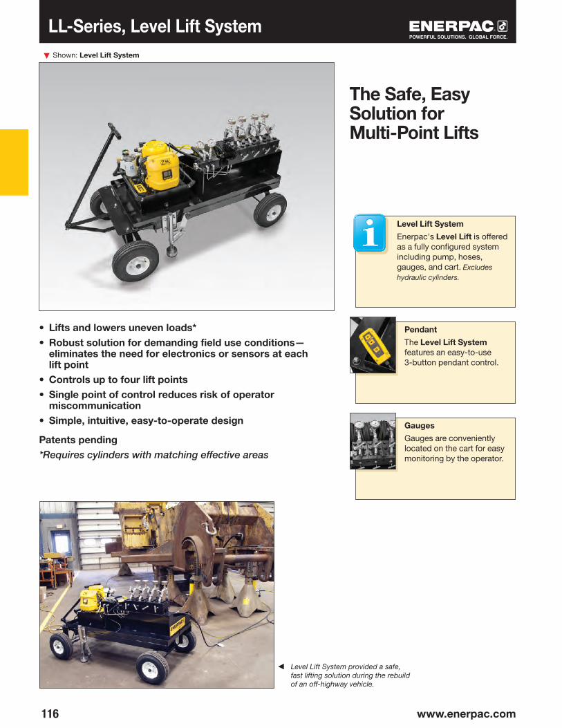
▼
116 www.enerpac.com
Shown: Level Lift System
• Lifts and lowers uneven loads*• Robust solution for demanding field use conditions—
eliminates the need for electronics or sensors at each lift point
• Controls up to four lift points• Single point of control reduces risk of operator
miscommunication• Simple, intuitive, easy-to-operate design
Patents pending*Requires cylinders with matching effective areas
TQ-700 Series, Electric Torque Pump
The Safe, Easy Solution for Multi-Point Lifts
Gauges
Gauges are conveniently located on the cart for easy monitoring by the operator.
Pendant
The Level Lift System features an easy-to-use 3-button pendant control.
PL-Series, Pow’R-LOCK™ Portable Lift System
◀ Level Lift System provided a safe, fast lifting solution during the rebuild of an off-highway vehicle.
TQ-700 Series, Electric Torque PumpPL-Series, Pow’R-LOCK™ Portable Lift SystemTQ-700 Series, Electric Torque PumpPL-Series, Pow’R-LOCK™ Portable Lift SystemTQ-700 Series, Electric Torque PumpLL-Series, Level Lift System
Level Lift System
Enerpac's Level Lift is offered as a fully configured system including pump, hoses, gauges, and cart. Excludes hydraulic cylinders.

117
LL4CELL4CB
30T5T 20T 10T OIL
OILOILOIL
OIL
Number of Lift Points:
4 points
LL Series
Cart Features
• Field proven, preprogrammed ZE4 semi-automated pump with 5-gallon reservoir
• Pendant control
• Simple Lift/Lower Valve (for lifting and lowering)
• Stores four, 50-foot long x 3/8" internal diameter hoses (included)
• Built-in forklift runners for easy transportation
• Large diameter pneumatic tires for easy maneuverability and positioning
• Cart-locking mechanism to prevent unintended movement
Cylinder Compatibility
The Level Lift System is compatible with a wide range of Enerpac single-acting cylinders.
Not recommended for use with cylinders lower than 10-ton capacity or LPL, RSM and RCS-Series Cylinders.
Contact Enerpac for further details.
Electric Torque PumpPow’R-LOCKTM Portable Lift System
Maximum Operating Pressure:
10,000 psi
How Level Lift Works
When the Level Lift System is operated, uneven loads are moved evenly, during both
lifting and lowering operations.
The output flow from the pump is directed to the Level Lift Valve via the Lift/Lower valve. The Level Lift valve contains small pistons, which on each cycle, send a fixed volume of oil to each cylinder as it is lifting or lowering.
This allows each cylinder to be raised or lowered by the same amount regardless of the distribution of the weight, or the resulting pressure on each cylinder — each cylinder must have the same effective area.
Model Number
Wt.
(lbs)
Voltage Oil Displacement (Per cycle of Level Lift Valve)
(in3)
Electric Torque PumpPow’R-LOCKTM Portable Lift SystemElectric Torque PumpPow’R-LOCKTM Portable Lift SystemElectric Torque PumpLevel Lift System
Dimensions are in inches.
208-240V, 1 ph, 50 Hz 115V, 1 ph, 60 Hz
Level Lifting and Lowering of Uneven Loads
Fixed volume of oil to each cylinder (0.8 in3/cycle) regardless of pressure or load size at each lift point.
0.800.80
651651
27.20
37.20
66.74
78.50
62.89
43.0
0

▼
118 www.enerpac.com
132
SFP-Series, Split-Flow Pumps
• 2, 4, 6 or 8 split-flow outlets• Individual or simultaneous operation of valves,
with advance/hold/retract function• Joystick (manual) controlled or pendant (solenoid)
controlled valves• Flow per outlet ranging from 20 to 305 in3/min at 10,000 psi• For double- and single-acting cylinders• Adjustable pressure relief valve per circuit• Reservoir: 5, 10 or 40 gallons• All models include pressure gauges
SFP 421SJ and SFP 404SJ (Gauges and retract valves not shown)
Multiple Outlets with Equal Flow for Lifting and Lowering
▼ Step-by-step stage lifting an old windmill using double-acting RR-506 cylinders powered by a Split-Flow Pump.
Typical Split-Flow Pump Applications
For lifting and lowering applications on multiple points, Split-Flow Pumps are a far better alternative than using independently operated pumps. Where synchronization of maximum 4% is acceptable, Split-Flow Pumps are a safe and economical solution.
The SFP-Series pumps feature both single and synchronized multiple outlet control either through joystick or pendant operation.
Application examples:• Bridge deck lifting for bearing
maintenance• Stage lifting in construction
and shipbuilding• Skidding to move structures
and buildings• Levelling of constructions like
wind turbines
Hoses and Couplers
Enerpac offers a complete line of high-quality hydraulic hoses. To ensure the integrity of your system, specify only genuine
Enerpac System Components.
Remote Control Pendant
Split-Flow Pumps with solenoid valves include a remote pendant with selector switches for each individual outlet, allowing
single or multiple cylinder operation.
Page:

119
–SFP 213SJSFP 228SJSFP 242SJSFP 404SJSFP 409SJSFP 414SJSFP 421SJSFP 604SJSFP 613SJSFP 813SJ
SFP 202MBSFP 213MJSFP 228MJSFP 242MJSFP 404MJSFP 409MJSFP 414MJSFP 421MJSFP 604MJ——
5
MP MP MP MP
1 23 89
6
5
A
BC
1 23 8
6
9
5
A
B C
P P P P
STOP
1
2
3
4
1 28 4
6
9
5
7
A
B C
2
4
6
8
A B C
10,000 psi, Split-Flow Pumps
SFPSeries
Split Flow Outlets:
2, 4, 6 or 8 outlets
Lifting Cylinders
For a complete line of Enerpac cylinders, see the Cylinder and Lifting Products in our catalog.
ReservoirSize
(gal)
Number of
Split FlowOutlets
◀ SFP-Series with 40-gallon reservoir (shown with 4 split- flow outlets)
◀ SFP-Series with 10 gallon reservoir (shown with 4 split-flow outlets)
◀ SFP-Series with 5-gallon reservoir (shown with two split-flow outlets)
Oil Flow per Outlet
@ 10,000 psi
(in3/min)
Motor Size460 V - 3ph
60 Hz
(hp)
Weight
(lbs)
Dimensions (in)Pump Model Number4/3 Valve Operation
Advance/Hold/RetractManual(Joystick)
24 V Solenoid(Pendant)
① Manifold with split-flow outlets and CR-400 couplers
② Adjustable pressure relief valve per circuit③ Manual 4/3 control valves with joysticks④ Solenoid 4/3 control valves (24 VDC)⑤ Power Receptacle⑥ Oil sight gauge(s)⑦ Remote control pendant with 30 ft. cord⑧ Flow control valve⑨ Hydraulic gauge
Reservoir Capacity:
5, 10 or 40 gallons
Flow at Rated Pressure:
20 - 305 in3/minMaximum Operating Pressure:
10,000 psi
Page:
* 115V-1 ph, 60 Hz
20942033053365101153339494
510404010404040104040
1.0*7.510157.57.510157.51520
190529
10761160529
104710761160529
12131300
29.540.154.054.040.154.054.054.040.154.054.0
17.726.023.823.826.023.823.823.826.031.731.7
27.535.444.544.535.444.544.544.535.447.247.2

▼
120 www.enerpac.com
5
132
Ease of Operation
• A single operator controls the entire operation
• User friendly interface: visual screens, icons, symbols and color coding
Enerpac’s family of EVO Synchronous Lifting Systems provides precision control suitable for most lifting/lowering
applications. Custom systems tailored to unique project requirements are also available.
The Standard EVO Synchronous Lift System It's a comprehensive self-contained design that features simple to use software that is extremely efficient at completing basic to complex applications.
The Basic EVOB Synchronous Lift SystemLeveraging Enerpac’s market leading Z-Class pumps and components from the standard EVO, the EVOB offers an economical solution to basic applications requiring stroke only control for a maximum of 8 lifting points.
Lifting Cylinders
For a complete line of Enerpac cylinders, see the cylinder and lifting products in our catalog.
Hoses
Enerpac offers a complete line of high-quality hydraulic hoses. To ensure the integrity of your system, specify only
genuine Enerpac hydraulic hoses.
Page:
EVO-8 (shown with 4 cylinders and stroke sensors, (sold separately)
• Lifting system to control 4, 8 or 12 lifting points (12 points for Standard EVO only)
• Intuitive user interface provides easy set-up and control with multiple lifting options
• Accuracy of up to 0.040 in (1 mm) between leading and lagging cylinders
• For use with standard single- or double-acting cylinders• Built in warning and stop alarms for optimum safety• Available with several flow options for optimal lifting speed
▼ Shown: 3600-ton tunnel boring machine lowered and tilted into its starting position with the EVO-Series Synchronous Lifting System.
The Multi-Functional Synchronous Lifting System
EVO-Series, Synchronous Lifting Systems
Page:

121
®
A
B C
EVOEVOB
EVO 12 40 460 W
▼ Synchronous lift system used to lift a 1000-ton building.
ReservoirCapacity
(gal)
A
(in)
B
(in)
C
(in)
MotorSize
(hp)
Weight
(lbs)
Series
1Product Type
2Lift Points
3Flow Group
4Voltage
5Options
1 Product Type
EVO = Standard SyncLift SystemEVOB = Basic SyncLift System
2 Lift Points
4 = 4 Lift Points 8 = 8 Lift Points 12 = 12 Lift Points (EVO only)
3 Flow Group (in3/min) 60Hz
EVO 21 = 153 40 = 293 EVOB 05 = 40 08 = 60 16 = 120* *only available with 3 Ph motor
4 Voltage 1)
EVO 380 = 380-415 V, 3 Ph, 50-60 Hz 460 = 460-480 V, 3 Ph, 50-60 HzEVOB B = 115 V, 1 Ph, 50-60 Hz E = 208-240 V, 1 Ph, 50-60 Hz G = 208-240 V, 3 Ph, 50-60 Hz W = 380-415 V, 3 Ph, 50-60 Hz J = 460-480 V, 3 Ph, 50-60 Hz R = 575 V, 3 Ph, 60 Hz
5 Options
W = Weighing (Only available with the EVO Standard
SyncLift System) Weighing option includes load cell
inputs with special programming for calibration and center of gravity.
CUSTOM BUILD YOUR OWN SYNCHRONOUS LIFTING SYSTEM
▼ This is how a SyncLift model number is built up.
Ordering Examples:
Model Number: EVO821460WEVO has 8 lift points, 153 in3/min, and voltage is 460-480 V, 3-Phase, 50-60 Hz with weighing option.
Model Number: EVOB408BEVOB has 4 lift points, 60 in3/min, and voltage is 115 V, 1-Phase, 50-60 Hz.
1) 115 VAC supply voltage required for pumps with G, J, R suffixes. 230 VAC supply voltage required for pumps with W suffix.
EVOSeries
Number of Lifting Points:
4, 8 or 12
Reservoir Capacity:
10 or 66 gallons
Accuracy:
0.040 inchMotor Size:
1-10 hpMaximum Operating Pressure:
10,000 psi
Synchronous Lifting Systems
Contact Enerpac!
Contact the Enerpac office nearest to you for advice and technical assistance in the
layout of your ideal solution or visit us on the web: enerpac.com/contact-us.
6610
63.3748.57
54.0734.00
55.0032.43
5-101-3
3000610

▼
122 www.enerpac.com
◂
Custom Hydraulic Pumps
CUSTOMIZABLE FEATURES:• Reservoir and Frame
• Valve Configurations
• Controls
• Oil Types
• Seals
• Pressure and Flow
• Coolers and Heaters
• Paint
• Motor Type
• Human Machine Interface (HMI)
Enerpac offers a wide variety of hydraulic pumps for all your custom needs.
Hydraulic pumps are at the
heart of any hydraulic system.
Different systems require
different flow, pressure and
control. Enerpac offers a wide
variety of hydraulic pumps from
small hand-operated pumps to
large gasoline powered pumps.
Still many applications require
a customized pump to operate
the system. These may include
larger reservoir capacity,
custom valve configurations or
added electrical controls.
Enerpac also specializes in
power units and controls used
for synchronous lifting/lowering
of multiple jacking points.
◂ Private labeled
electric torque
wrench pumps
for OEMs.
◂ Custom pumps
with control
packages.
◂ Pumps with
custom valve
manifolds and
circuits.
OVERVIEW
▴ Custom hydraulic pump for a bridge deck launching system.

123
LQ
K
NJ
PEH
M
R
DC
B
A
3/8"-18NPT
L
QK NJ
P
E
HMR
DC
B
A
3/8"-18NPT
L
Q
K
NJ
P
E
HM
R
DC
B A
3/8"-18NPT
124
126
127
128
VM, VE
VC
VC, VM, VEVE
130
278
Directional Control Valves Section Overview
Enerpac hydraulic valves are available in a wide variety of models and configurations.
Whatever your requirements… directional control, flow control, or pressure control… you can be sure that Enerpac has the correct valve to match your application exactly.
Designed and manufactured for safe operation up to 10,000 psi, the range of Enerpac valves allows for direct pump mounting, remote mounting, manual or solenoid actuation, and in-line installation, giving you flexible solutions to control your hydraulic system.
Valve Type Series
Pressure and Flow Control Valves
For more hydraulic system control with pressure relief valves, shut-off valves,
check valves and sequence valves see our "System Components" section.
Valving Help
See Basic System Set-Up and Valve Information in our ‘Yellow Pages’
Page:
Page:
Pump-Mounted Directional Control Valves
Remote-Manual Directional Control Valves
Valve Dimensions
Modular/Solenoid Operated Directional Control Valves
Series Page

▼
124 www.enerpac.com
Pump Mounted Directional Control Valves Shown from left to right: VM32, VE33, VM33, VM43L, VE43-115
• Advance/Retract and Advance/Hold/Retract operation of single-acting and double-acting cylinders
• Manual or solenoid operation• Pump mounting will retrofit on most Enerpac pumps• Available “locking” option on VM Series valves for load-
holding applications• Standard “locking” feature on VE Series 3-position valves• User adjustable relief valves allow the operator to easily set
the working pressure
▼ ZE4420SB-FH Z-Class pump is mounted next to an Enerpac H-frame press, includes VE43 electric valve to control cylinder operation.
For Reliable Control of Single and Double-Acting Cylinders
Used with Cylinder
Valve Operation
Valve Type
Manual
Solenoid 115 VAC
Solenoid 24 VDC
Manual
Manual
Manual
Manual
Manual
Solenoid 115 VAC
Solenoid 24 VDC
Solenoid 24 VDC
Solenoid 24 VDC
Single-acting
Single-acting
Single-acting
Single-acting
Single-acting ONLY
Single-acting
Double-acting
Double-acting
Double-acting
Double-acting
Single-acting
Single-acting ONLY
3-Way2 Position
3-Way, 3 Position, Tandem Center
3-Way, 3 Position, Tandem Center
3-Way3 Position, Tandem
Center
3-Way3 Position, Tandem
Center, Venturi Return Assist
3-Way3 Position, Tandem
Center, Venturi Return Assist
3-Way3 Position, Tandem
Center, Locking
4-Way3 Position,
Tandem Center
4-Way3 Position, Tandem
Center, Locking
4-Way, 3 Position, Tandem Center
4-Way, 3 Position, Tandem Center
3-Way2 Position,
Dump
For remote valve applications, see page 126.
Manual Single-acting 3-Way2 Position
Solenoid 24 VDC
Single-acting 3-Way2 Position

125
P
A
P T
A
A
P
A
T P
A
T P
A
T P
A
T P
P T
A
P T
A
P T
A
P T
A
P T
A
P T
A
AP
T
P T
A
P T
A
P T
A
P T
A
B
P T
A
B
P T
A
B
P T
A
B
P T
A
B
P T
A
B
TP
B
A
TP
B
A
TP
B
A
VM22
VE33
VM33VAC
VE33VAC
VM33
VM33L
VM43
VM43L
VE43
VE43-115
VE32D A
PT
A
PT
A
PT
ZCP-1ZCP-3
VE32DVE32, VE33, VE43
AP
T
AP
T
V
P
AGA
GP
B
AP
T
AP
T
B
AP
T
AP
T
A
B
P
T
VM32P
A
P T
A
VE33-115
VE32
AP
T
T
AGA
TP
AP
T
A
PT
A
PT
A
PT
Pump Mounted Directional Control Valves
VM, VE Series
Flow Capacity:
4.5 gal/min.Maximum Operating Pressure:
10,000 psi
Locking Valves
For applications that require positive load holding, VM Series valves (except the VM22 and VM32 valve)
are available with a pilot-operated check valve. This option provides hydraulic locking of the load until the valve is shifted into the retract position.
To order this feature, place an “L” at the end of the model number.
Model Number
Schematic Flowpath
Advance Retract
Weight
(lbs)
Hydraulic Symbol
Pendants for VE-Series Solenoid Valves
When ordering Enerpac VE-Series solenoid valves, the pendant must be ordered separately for Z-Class
pumps. Pendant connection to be plugged into electric box of pump.
PendantTo be used with solenoid valves:
All valves feature several gauge ports for “system”, A port and B port pressure monitoring. User-adjustable relief valves are included on all models to allow the operator to easily set the optimum working pressure for each application. VM33 and VE43 valves include “System Check”
feature, for more precise pressure holding and improved system control. The VM33 has improved porting which provides faster cylinder retraction while motor is running.
See page 127 for product dimensions.
Neutral
Assisted Return Pumps
To improve productivity and plunger retraction, Enerpac offers valve configurations designed to accelerate your cylinder retraction speeds. ZU4
and ZE-Series pumps feature Venturi valve technology to facilitate the faster return of single-acting gravity return cylinders. See details on www.enerpac.com
10.7
20.3
20.3
6.8
10.8
20.3
20.3
8.7
22
5.6
6.7
7.5
5.6
8.7

▼
126 www.enerpac.com
P T
A
B
P T
A
B
P T
A
B
A
P T
B
P T
A
B
P T
A
B
P T
A
B
A
P T
B
P T
A B
P T
A B
VC-4
VC-4L
VC-20
VC-20L
P
A
P
A
P T
A
A
P T
P T
A
P T
A
P T
A
A
P T
A
P T
A
P T
VC-15
VC-15L
VC-3
VC-3L
Remote Manual Directional Control Valves
Valve Operation
Manual Double Acting
Valve Type
4-Way, 3 Position, Closed Center
Manual Double Acting
4-Way, 3 Position, Closed Center,
Locking
Manual Double Acting
4-Way, 3 Position, Tandem Center
Manual Double Acting
4-Way, 3 Position, Tandem Center,
Locking
ModelNumber
Schematic Flowpath
Advance Retract
Hydraulic Symbol
Weight(lbs)
Locking Valves
For applications that require positive load holding, VC and VM Series valves are available with a pilot-operated check valve. This
option provides hydraulic locking of the load until the valve is shifted into the retract position.
• Advance/Hold/Retract operation for use with single-acting or double-acting cylinders
Manual Single Acting
Manual Single Acting
Manual Single Acting
Manual Single Acting
3-Way, 3 Position, Tandem Center
3-Way, 3 Position, Tandem Center,
Locking
3-Way, 3 Position, Closed Center
3-Way, 3 Position, Closed Center,
Locking
Shown from left to right: VC-20, VC-4L
Return line kit included with remote valves
Reliable Remote Control
Used with Cylinder
Hold
6.4
10.3
6.4
10.3
6.4
10.3
6.4
10.3

127
.250 - 20 UNC (2x)
.375 - 18 NPTF
B AGPGB
.250 - 18 NPTF
.250 - 18 NPTF
.250 - 18 NPTF
.375 - 18 NPTF
.375 - 18 NPTF
.250 - 18 NPTF
(X2)
B AGPGB
.250 - 18 NPTF
.250 - 18 NPTF
.375 - 18 NPTF
.250 - 18 NPTF
.375 - 18 NPTF
.375 - 18 NPTF
VM33, VM33L VM43, VM43L
VM22, VM32
.375 - 18 NPTF.250 - 18 NPTF
.375 - 18 NPTF
VE33, VE43
GP
.250 - 18 NPTF
.375 - 18 NPTF
.375 - 18 NPTF VE32, VE32D
VE33-115 VE43-115
VC3, VC3L, VC-15, VC15L, VC-4, VC4L, VC20, VC20L 2) VC3L, VC15L, VC4L and VC20L only
Directional Control Valves Dimensions
VC, VM, VE Series
Flow Capacity:
4.5 gal/min.Maximum Operating Pressure:
10,000 psi
Valve dimensions in inches.
1) VM33L and VM43L only
User Adjustable Relief Valve
All VM- and VE-Series have a user adjustable relief valve to allow the operator to easily set the optimum working pressure.
① User Adjustable Relief Valve
② Auxiliary Port
Power Cord Pendant Connection
1) VM22 only
9.50
9.55
1.22
3.50
4.492)
3.001.38.69
3.00
.75
7.19
2)
1.50
2)5.69
5.121.
64
6.941.18
2.87 .89
1.12
1.22
5.75
7.25
1)
1.50
1)
5.12
1.22
3.50
5.74
3.50
5.61
5.05
1)
1.95
1)
5.12

▼
128 www.enerpac.com
A
P T
A
P T
B
A
P T
B
A
P T
B
A
P T
B
A B
P T
A
PB
PA
P T
B
A
P TA
P T
Solenoid Operated Modular Valves
3-Way Check Valve
Use a VS-51 3-way pilot ope ra ted check valve assembly to convert your 3-way modular valve into a load-holding valve.
4-Way Check Valve
Use a VS-61 4-way pilot ope ra ted check valve assembly to convert your 4-way modular valve into a load-holding valve.
System Pressure Control
To add system pressure control to your modular valve, order VS-11 Relief Valve assembly.
Bolt Kits for Accessory Valves With No Manifold
Order Bolt Kit BK-2 when adding one of the accessory valves. Order Bolt Kit BK-3
when adding any combination of two accessory valves.
• Ideal for independent control of multiple cylinders or functions
• Relief valve and pilot-operated check accessory valves are stackable between manifold and valve body
• Remote and pump mounting
How to order one of the 1,300 possible model numbers?
With over 1,300 possible model numbers, Enerpac has the perfect valve for you.Use the “chart” to build your own valve for the specific application you require. This is the complete guide to all the Modular valves that are available.
4-Way, 3-Position (4/3) Open Center
4-Way, 3-Position (4/3)Closed Center
4-Way, 3-Position (4/3)Tandem Center
4-Way, 3-Position (4/3)Float Center
4-Way, 2-Position (4/2)Crossover Offset
3-Way, 3-Position (3/3)Tandem Center
3-Way, 3-Position (3/3)Closed Center
2-Way, 2-Position (2/2)Normally Closed
2-Way, 2-Position (2/2)Normally Open
4-Way, 2-Position (4/2)Float Offset
3-Way, 2-Position (3/2)Normally Open
Double-acting
Double-acting
Double-acting
Double-acting
Double-acting
Single-acting
Single-acting
System Un-loading
Double-acting
Single-acting
A
B
C
D
E
F
G
H*
K*
M
P
Valve Flow Path
Used with Cylinder
Valve Code Hydraulic Symbol
Shown top to bottom: VEC-15600D, VEK-15000B, VEC-15000B
Unmatched Combinations and Possibilities
* Requires use of tank port for dump or unloading.
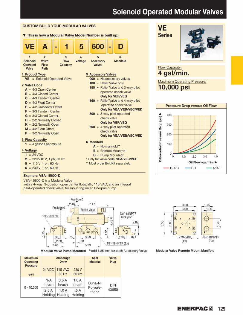
129
6001 5 DAVE - -
A
B
T
P1/4"-18NPTF
3/8"-18NPTF (2x)
3/8"-18NPTF
Pressure Drop versus Oil Flow
Solenoid Operated Modular Valves
VE Series
Flow Capacity:
4 gal/min.Maximum Operating Pressure:
10,000 psi
1Solenoid Operated
Valve
2Valve Flow Path
3Flow
Capacity
4Voltage
5Accessory
Valves
6Manifold
1 Product Type VE = Solenoid Operated Valve
2 Valve Code A = 4/3 Open Center B = 4/3 Closed Center C = 4/3 Tandem Center D = 4/3 Float Center E = 4/2 Crossover Offset F = 3/3 Tandem Center G = 3/3 Closed Center H = 2/2 Normally Closed K = 2/2 Normally Open M = 4/2 Float Offset P = 3/2 Normally Open
3 Flow Capacity 1 = 4 gallons per minute
4 Voltage 1 = 24 VDC 2 = 220/240 V, 1 ph, 50 Hz 5 = 115 V, 1 ph, 60 Hz 6 = 230 V, 1 ph, 60 Hz
5 Accessory Valves 000 = No accessory valves 100 = Relief Valve only 150 = Relief Valve and 3-way pilot
operated check valve Only for VEF/VEG 160 = Relief Valve and 4-way pilot
operated check valve Only for VEA/VEB/VEC/VED 500 = 3-way pilot operated
check valve Only for VEF/VEG 600 = 4-way pilot operated
check valve Only for VEA/VEB/VEC/VED
6 Manifold A = No manifold** B = Remote Mounted D = Pump Mounted** Only for valve code: VEA/VEC/VEF** Must order Bolt Kit separately.
CUSTOM BUILD YOUR MODULAR VALVES
▼ This is how a Modular Valve Model Number is built up:
Example: VEA-15600-DVEA-15600-D is a Modular Valve with a 4-way, 3-position open center flowpath, 115 VAC, and an integral pilot-operated check valve, for mounting on an Enerpac pump.
Oil Flow (gal/min) ▶
P-A/B P-T A/B-T
Diff
eren
tial P
ress
ure
Dro
p (p
si) ▶
Modular Valve Pump Mounted Modular Valve Remote Mount Manifold
Position 0
Position 0Relief Valve
Tank port
MaximumOperatingPressure
(psi)
Amperage Draw
Seal Material
Valve Plug
N/A Inrush
3.6 A Inrush
1.8 A Inrush
2.5 A Holding
1.0 A Holding
.5 A Holding
24 VDC 115 VAC60 Hz
230 V60 Hz
Buna-N, Polyure-
thane
DIN 43650
1) add 1.85 inch for each Accessory Valve
0 - 10,000
3.00
.279-.288(4x)
3.00 1.001.753.50
1.75
3.50
3/8"-18NPTF(4x)
5.393.48.382.08
3.50 1.98 .62
2.09
7.47
6.40
1)
2.46
.75
1.12
1.15
.38
00
100
200
300
400
1.0 2.0 3.0 4.0

130 www.enerpac.com
E
E
AB
BB
3/8"-1
8NPT (7
x)
J
F
C
H
L
A D
CB
A D
C B
H
B
E
FA
D
C
3/8"-1
8NPT (6
x)
AC
DB
273
130 www.enerpac.com
Enerpac System Components & Valves
Enerpac System Components —
All the additional components you need
to complete your high pressure hydraulic
system. Engineered to work with your
Enerpac cylinders, pumps and tools.
All Enerpac components are designed
and manufactured to the most
exacting standards.
With this complete line of hydraulic
hoses, couplers, fittings, manifolds, oil
and gauges Enerpac has the accessories
to compliment your system and ensure
the efficient operation, long life, and
safety of your hydraulic equipment.
Yellow Pages
For sample system set-ups and how to correctly specify your system components, please view the Enerpac Yellow Pages.
Maintain System Integrity
Use Enerpac System Components, designed to interface with Enerpac
Cylinders, Pumps and Tools to ensure your system operates at peak performance.
Page:
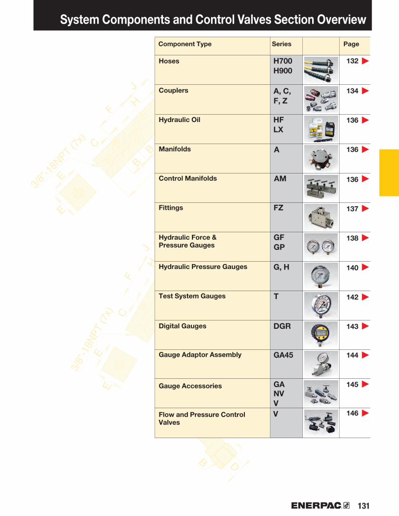
131
E
E
AB
BB
3/8"-1
8NPT (7
x)
J
F
C
H
L
AC
DB
EE
AB
BB
3/8"
-18N
PT (7
x)
J
FC
H
L
▶
▶
▶
▶
▶
▶
▶
▶
▶
▶
▶
▶
▶
132
134
136
136
136
137
138
140
142
143
144
145
146
H700H900
G, H
T
GFGP
A, C, F, Z
HFLX
FZ
DGR
GANVVV
A
AM
GA45
System Components and Control Valves Section Overview
Hoses
Couplers
Hydraulic Oil
Manifolds
Control Manifolds
Fittings
Hydraulic Force & Pressure Gauges
Hydraulic Pressure Gauges
Test System Gauges
Digital Gauges
Gauge Adaptor Assembly
Gauge Accessories
Flow and Pressure Control Valves
Component Type Series Page
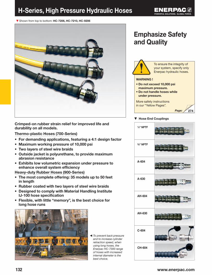
▼
132 www.enerpac.com
274
H-Series, High Pressure Hydraulic Hoses Shown from top to bottom: HC-7206, HC-7210, HC-9206
Crimped-on rubber strain relief for improved life and durability on all models. Thermo-plastic Hoses (700-Series)• For demanding applications, featuring a 4:1 design factor• Maximum working pressure of 10,000 psi• Two layers of steel wire braids• Outside jacket is polyurethane, to provide maximum
abrasion resistance• Exhibits low volumetric expansion under pressure to
enhance overall system efficiencyHeavy-duty Rubber Hoses (900-Series)• The most complete offering: 35 models up to 50 feet
in length• Rubber coated with two layers of steel wire braids• Designed to comply with Material Handling Institute
IJ-100 hose specification• Flexible, with little “memory”, is the best choice for
long hose runs
Emphasize Safety and Quality
▼ Hose End Couplings
◀ To prevent back pressure and to increase cylinder retraction speed, when using long hoses, the Enerpac HC-7300 range of hoses with increased internal diameter is the best choice.
To ensure the integrity of your system, specify only Enerpac hydraulic hoses.
WARNING !
• Do not exceed 10,000 psi maximum pressure.
• Do not handle hoses while under pressure.
More safety instructions in our “Yellow Pages”.
Page:
¼" NPTF
⅜" NPTF
A-604
A-630
AH-604
AH-630
C-604
CH-604

133
136
238
144
High Pressure Hydraulic Hoses
Hose End Assemblies and
Couplers*
Internal Dia.
(in)Model Number
Model Number
Hose Length
(ft)
700-SeriesThermo-plastic
900-SeriesHeavy-duty Rubber
Wt.(lbs)
Wt.(lbs)End one End two
Hose Oil Capacity
When using long hose lengths, it is sometimes necessary to fill the pump reservoir after filling the hoses. To determine the hose oil capacity, use the following:
For .25" internal diameter hoses: Capacity (in3) = .5892 x Length (ft)
For .38" internal diameter hoses: Capacity (in3) = 1.3608 x Length (ft)
H700H900 Series
Inside Diameter:
.25 and .38 inchLength:
2-50 feetMaximum Operating Pressure:
10,000 psi
* For technical information on couplers see next page.
Torque Wrenches Hoses
Use Enerpac 3.5:1 twin safety hoses with double-acting wrenches to ensure the integrity of your hydraulic system. See Selection Matrix.
Fittings
For additional fittings see the fitting page of the System Components section.
Page:
Page:
Page:
GA45GC Gauge Adaptor
Protect yourself from system overloading by simply ordering one part number for a pre-assembled gauge,
adaptor block and coupler.
¼" nptf
⅜" nptf
CH-604
⅜" nptf
¼" nptf ⅜" nptf A-630
AH-630 CH-604
⅜" nptf
A-604
AH-604
AH-630
C-604
CH-604
CH-604
⅜" nptf
CH-604
6666623610203050
610
3610636103610206506102030506810
2.4
2.31.21.52.03.06.2
10.015.4
2.5
2.23.22.22.22.83.91.72.33.36.42.4
15.43.55.4
10.016.215.23.4
5.6
.25
.38
2.62.63.12.93.01.61.92.63.98.0
13.022.0
3.24.5
2.12.94.22.92.93.75.02.23.04.38.33.1
20.04.67.0
13.021.033.04.96.27.3
––HB-7206QB–HC-7206QH-7202H-7203H-7206H-7210H-7220H-7230H-7250–HA-7206B–––HA-7206HA-7210HB-7206HC-7203BHC-7206BHC-7210BHC-7203HC-7206HC-7210HC-7220HC-7206CHC-7250CH-7306H-7310H-7320H-7330H-7350HC-7306– HC-7310
H-9206QH-9206SHB-9206QBHB-9206QHC-9206QH-9202H-9203H-9206H-9210H-9220H-9230H-9250–HA-9206BHA-9210B–HA-9203HA-9206HA-9210HB-9206HC-9203BHC-9206BHC-9210BHC-9203HC-9206HC-9210HC-9220HC-9206CHC-9250CH-9306H-9310H-9320H-9330H-9350HC-9306HC-9308HC-9310
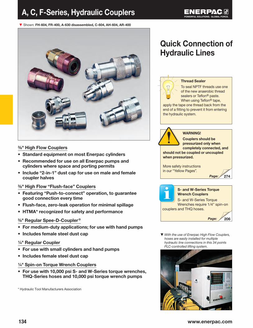
▼
134 www.enerpac.com
274
206
⅜" High Flow Couplers• Standard equipment on most Enerpac cylinders• Recommended for use on all Enerpac pumps and
cylinders where space and porting permits• Include “2-in-1” dust cap for use on male and female
coupler halves
⅜" High Flow “Flush-face” Couplers• Featuring “Push-to-connect” operation, to guarantee
good connection every time• Flush-face, zero-leak operation for minimal spillage• HTMA* recognized for safety and performance
⅜" Regular Spee-D-Coupler®
• For medium-duty applications; for use with hand pumps • Includes female steel dust cap
¼" Regular Coupler• For use with small cylinders and hand pumps• Includes female steel dust cap
¼" Spin-on Torque Wrench Couplers• For use with 10,000 psi S- and W-Series torque wrenches,
THQ-Series hoses and 10,000 psi torque wrench pumps
* Hydraulic Tool Manufacturers Association
A, C, F-Series, Hydraulic Couplers Shown: FH-604, FR-400, A-630 disassembled, C-604, AH-604, AR-400
▼ With the use of Enerpac High Flow Couplers, hoses are easily installed for multiple hydraulic line connections in this 34 points PLC-controlled lifting system.
Quick Connection of Hydraulic Lines
Thread Sealer
To seal NPTF threads use one of the new anaerobic thread sealers or Teflon® paste. When using Teflon® tape,
apply the tape one thread back from the end of a fitting to prevent it from entering the hydraulic system.
WARNING!
Couplers should be pressurized only when completely connected, and
should not be coupled or uncoupled when pressurized.
More safety instructions in our “Yellow Pages”.
Page:
S- and W-Series Torque Wrench Couplers
S- and W-Series Torque Wrenches require 1/4" spin-on
couplers and THQ hoses.
Page:

135
CR-400
FR-400
AR-400
AR-630
TR-630
CH-604
FH-604
AH-604
AH-630
TH-630
C-604
F-604
A-604
A-630
T-630
⅜" nptf
⅜" nptf
⅜" nptf
¼" nptf
¼" nptf
Hydraulic Couplers
Complete Set
Maximum Flow
Capacity(in3/min)
Female Half
Male Half
Dust Cap(s)
A* B C D E F G
Coupler Type
High Flow Coupler
A, C, F, TSeries
Maximum Flow Capacity:
2,500 in3/min.Thread:
¼" and ⅜" nptf
Maximum Operating Pressure:
10,000 psi
Flush-face coupler
Regular Spee-D-Coupler®
Regular Coupler
Spin-on Coupler
Model Numbers Dimensions (in)
* Value A is total length when male and female halves are connected.
Metal Dust CapsSteel dust caps are available for the C-604 series couplers. Order model number: CD-411M for female half CD-415M for male half
Included
female only
Included
female only
Included
—
F-Series
Flush-faced couplers provide reduced pressure drop verses other
types and are preferred in dirty, grimy construction and mining environments due to easy clean, non-dirt trapping faces.
CT-604 Safety ToolUse the Enerpac CT-604 to relieve hydraulic back pressure by safely bleeding the hydraulic coupler. Minimize injuries from
projectile parts and under-skin hydraulic fluid injections by eliminating unsafe coupler bleeding practices. The CT-604 is Enerpac-engineering safe for use at 10,000 psi (700 bar).
NOTE: C-Series only.
3.26
4.36
3.09
2.61
2.87
2.87
2.85
2.53
1.72
2.36
1.38
1.23
1.12
.87
1.14
1.38
1.23
.94
.81
1.14
1.25
1.06
.94
.75
.74
1.00
1.12
.73
.57
.82
2,500
2,500
462
462
695
(2x)CD-411
–
Z-410
Z-640

▼
136 www.enerpac.com
3/8"-18NPTF (6x)
1/4"-20
HF-100HF-101HF-102HF-104LX-101
A-64 A-65
Hydraulic Oil, Manifolds and Fittings
7" Long Manifold with 7 female ports.
14" Long Manifold that allows direct moun ting of control valves to the manifold. 7 female ports.
6-Port Hexagon Manifold Plugs furnished for all ports ⅜"-18 nptf.
Premounted Manifold Functions as split-flow valve to control 2 to 4 single-acting cylinders simultaneously.
All ports ⅜"-18 nptf.
Description
Shown top to bottom: HF-101, HF-100, HF-102, LX-101, A65, and FZ1055
Enerpac System Components
ManifoldsDimensions (in)
HF Oil
• Specially formulated for power pumps
- maximum volumetric efficiency
- maximum heat transfer - prevents cavitation - anti-sludge, anti-rust,
anti-foam additives• Maximum film protective
lubricity - anti-oxidation additives
LX Hand Pump Oil
• Specially formulated for hand pumps
- anti-sludge, anti-rust additives
• Reduced handle effort over HF blue oil
- good low temperature performance
• Not for use in power pumps
Model Number
Contents
▼ Oil Specifications Chart
HF Oil LX Oil
ISO Viscosity Grade 32 15
API Gravity, ASTM D1298 32 34
Viscosity, ASTM D445
SUS @ 212°F 43.7 38
SUS @ 104°F 151 77.5
Viscosity Index, ASTM D2270 95 100
Pour Point, °F, ASTM D97 -36.5 -47.5
Flash Point, °F, ASTM D92 375 370
Color Blue Yellow
Hydraulic Oil
Model No.
High viscosity index ensures maximum lubricity over a wide range of operation temperatures.
open
closed
All ports 3/8"-18 NPTF
NOTE: SAE grades do not apply to hydraulic oil.
1 Quart1 Gallon5 Gallons*55 Gallons1 Gallon**
* Packed in two 2½ gallon cans.
** Hand pump oil.
A-64
A-65
A-66
AM-21
AM-41
1.25
1.25 1.5 1.51.5 1.25
3/8"-18NPT (7x) 2.03.0
.25 3.5
7.0
1.25
1.25 4.04.04.0 1.25
3/8"-18NPT (7x) 3.258.0
.25 7.25
14.5
1.63
2.3
2.0
1.5.25
.82
Ø .28
4.16
Ø .502.503.00
6.00
1.63
3.88
11.0012.00
.501.50
.501.00
.50
1.633.00

137
B
AD
C
A
DC
B
A
DC
B
A
DC
B
A
C
CB
A
C
CB
A
BC
C
A
DC
B
A
C D
B
A
C D
B
3/8"-18NPTF
¼"-18 nptf
½"-27 nptf
⅜"-18 nptf
⅜"-18 nptf
¼"-18 nptf
½"-18 nptf
FZ-1055FZ-1633FZ-1634
¼"-18 nptf
⅛"-27 nptf
¼"-18 nptf
⅜"-18 nptf
G¼"G¼"G⅜"G⅜"
BFZ-16411BFZ-16421BFZ-16323BFZ-16324
¼"-18 nptf
¼"-18 nptf
G¼"
⅜"-18 nptf
½"-14 nptf
⅜"-18 nptf
FZ-1630BFZ-1630BFZ-16301
⅜"-18 nptf –FZ-1613
⅜"-18 nptf ⅜"-18 nptfFZ-1616
⅜"-18 nptf
½"-14 nptf
¼"-18 nptf
⅜"-18 nptf
FZ-1615
FZ-1625
¼"-18 nptf
⅜"-18 nptf
⅜"-18 nptf
¼"-18 nptf
⅜"-18 nptf
⅜"-18 nptf
FZ-1608FZ-1619FZ-1617
⅜"-18 nptf
¼"-18 nptf
⅜"-18 nptf
¼"-18 nptf
FZ-1614
FZ-1605
⅜"-18 nptf
¼"-18 nptf
––
FZ-1612FZ-1637
⅜"-18 nptf
¼"-18 nptf
––
FZ-1610FZ-1638
¼"-18 nptf
½"-14 nptf
½"-14 nptf
⅜"-18 nptf
¼"-18 nptf
⅜"-18 nptf
G¼" G¼"G⅜"G⅜"
¼"-nptf
⅛"-nptf
¼"-nptf
⅜"-nptf
⅜"- nptf
¼"- nptf
⅜"- nptf
¼"-nptf
½"-nptf
G¼"
¼"-nptf
⅜"-nptf
⅜"-nptf
¼"-nptf
⅜"-nptf
⅜"-nptf
⅜"-nptf
¼"-nptf
⅜"-nptf
¼"-nptf
⅜"-nptf
¼"-nptf
⅜"-nptf
¼"-nptf
⅜"-nptf
¼"-nptf
BFZ-16312 ⅜"-18 nptf ⅜"-18 nptf
⅜"-nptf
¼"-nptf
FZ-1660 ⅜"-18 nptf ⅜"-18 nptf
A B C D
Hydraulic Oil, Manifolds and Fittings
A, AMFZ, BFZ, HF, LXSeries
AdaptorFrom: To:
AdaptorFrom: To:
ReducerFrom: To:
Elbow
Street Tee
CrossFrom: ⅜"-NPTF FemaleTo: ⅜"-NPTF Female
Coupling
Street ElbowFrom: ⅜"-NPTF MaleTo: ⅜"-NPTF Female
Reducing ConnectorFrom: ⅜"-NPTF FemaleTo: ¼"-NPTF FemaleFrom: ½"-NPTF FemaleTo: ⅜"-NPTF Female
From:
From: To:
From: To:
From: To:
Street TeeFrom: ⅜"-NPTF FemaleTo: ⅜"-NPTF Male
Swivel FittingFrom: ⅜"-NPTF MaleTo: ⅜"-NPTF Female
Model Number
Dimensions (in)
Hexagon Nipple
10,000 psi Fittings
3/8" Swivel Connector
360° swivel coupler for optimal orientation of the hydraulic connection on cylinders, pumps and hoses. Order Model No. XSC-1.
To:
1.14
2.00
1.14
1.751.181.75
.94
.751.13
1.371.221.691.69
.75
.75
.94
.94
.751.10.75
.75
.86
.75
1.77 1.00
.94 1.30
1.13
1.38
1.00
1.25
1.502.001.47
.63
.75
.75
1.14
1.14
1.00
.75
1.771.77
1.00
.94
1.38
1.41
.88
.94
2.20 1.02
1.59 .88
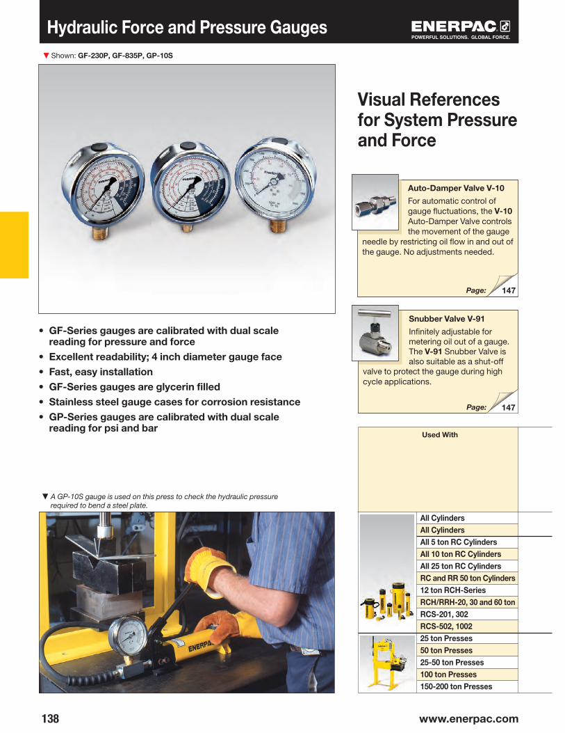
▼
138 www.enerpac.com
147
147
Hydraulic Force and Pressure Gauges
• GF-Series gauges are calibrated with dual scale reading for pressure and force
• Excellent readability; 4 inch diameter gauge face • Fast, easy installation • GF-Series gauges are glycerin filled• Stainless steel gauge cases for corrosion resistance• GP-Series gauges are calibrated with dual scale
reading for psi and bar
▼ A GP-10S gauge is used on this press to check the hydraulic pressure required to bend a steel plate.
Shown: GF-230P, GF-835P, GP-10S
All Cylinders All CylindersAll 5 ton RC CylindersAll 10 ton RC CylindersAll 25 ton RC CylindersRC and RR 50 ton Cylinders 12 ton RCH-SeriesRCH/RRH-20, 30 and 60 tonRCS-201, 302 RCS-502, 100225 ton Presses50 ton Presses25-50 ton Presses 100 ton Presses150-200 ton Presses
Used With
Auto-Damper Valve V-10
For automatic control of gauge fluctuations, the V-10 Auto-Damper Valve controls the movement of the gauge
needle by restricting oil flow in and out of the gauge. No adjustments needed.
Page:
Visual References for System Pressure and Force
Snubber Valve V-91
Infinitely adjustable for metering oil out of a gauge. The V-91 Snubber Valve is also suitable as a shut-off
valve to protect the gauge during high cycle applications.
Page:
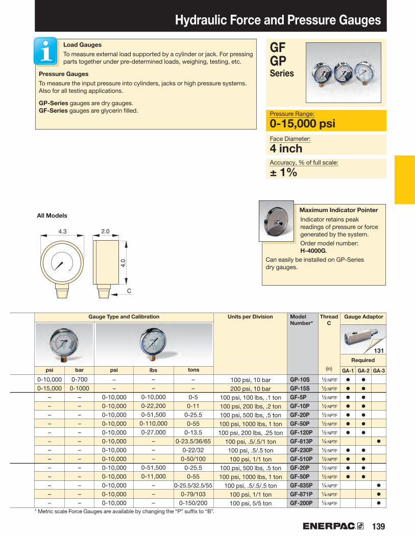
139
131
GA-1 GA-2 GA-3
Hydraulic Force and Pressure Gauges
Accuracy, % of full scale:
± 1%
Face Diameter:
4 inch
Pressure Range:
0-15,000 psi
GFGP Series
Gauge AdaptorThreadC
(in)
Units per Division Model Number*
psi tons
Gauge Type and Calibration
Required
psi
All Models
bar lbs
* Metric scale Force Gauges are available by changing the “P” suffix to “B”.
100 psi, 10 bar200 psi, 10 bar
100 psi, 100 lbs, .1 ton100 psi, 200 lbs, .2 ton100 psi, 500 lbs, .5 ton100 psi, 1000 lbs, 1 ton100 psi, 200 lbs, .25 ton
100 psi, .5/.5/1 ton100 psi, .5/.5 ton100 psi, 1/1 ton
100 psi, 500 lbs, .5 ton100 psi, 1000 lbs, 1 ton
100 psi, .5/.5/.5 ton100 psi, 1/1 ton100 psi, 5/5 ton
Maximum Indicator Pointer
Indicator retains peak readings of pressure or force generated by the system.Order model number: H-4000G.
Can easily be installed on GP-Series dry gauges.
Load Gauges
To measure external load supported by a cylinder or jack. For pressing parts together under pre-determined loads, weighing, testing, etc.
Pressure Gauges
To measure the input pressure into cylinders, jacks or high pressure systems. Also for all testing applications.
GP-Series gauges are dry gauges.GF-Series gauges are glycerin filled.
4.3
4.0
C
2.0
GP-10SGP-15SGF-5PGF-10PGF-20PGF-50PGF-120PGF-813PGF-230PGF-510PGF-20PGF-50PGF-835PGF-871PGF-200P
– –
0-10,0000-10,000 0-10,0000-10,0000-10,0000-10,0000-10,0000-10,0000-10,0000-10,0000-10,0000-10,0000-10,000
– –
0-50-11
0-25.50-55
0-13.50-23.5/36/65
0-22/320-50/100
0-25.5 0-55
0-25.5/32.5/55 0-79/103
0-150/200
½ nptf
½ nptf
½ nptf
½ nptf
½ nptf
½ nptf
½ nptf
¼ nptf
½ nptf
½ nptf
½ nptf
½ nptf
¼ nptf
¼ nptf
¼ nptf
•••••••
••••
•••••••
••••
•
•••
0-10,000 0-15,000
–––––––––––––
0-700 0-1000
–––––––––––––
– –
0-10,000 0-22,200 0-51,500 0-110,000 0-27,000
–––
0-51,500 0-11,000
–––

▼
140 www.enerpac.com
145
144
147
Hydraulic Pressure Gauges
◀ When lifting or pressing, always use a gauge. A gauge is your “window” to the system–it lets you see what’s going on.
Shown: H-4049L, G-2534R, G-4089L, G-2535L, G-4040L
Glycerin Filled (G-Series)• Calibrated in dual scale reading in psi and bar• All pressure sensing parts sealed and dampened
by glycerin for long life• Includes safety blow-out disk and pressure
equalizing membrane• Gauge snubbers or needle valves recommended
for high-cycle applications
High-Cycle Dry Gauges (H-Series)• Calibrated in dual scale reading in psi and bar• Ideal for use in many applications, specifically for
high cycle and harsh environments• Gauge snubbers or needle valves recommended
to shut off gauge when not in use
Visual References for System Pressure
Gauge Adaptor
For easy gauge installation into almost any system, Enerpac offers a complete line of gauge adaptors.
GA45GC Gauge Adaptor Assembly
45° angled gauge adaptor improves safety.
Page:
Page:
Snubber Valve
Infinitely adjustable for metering oil out of a gauge. The V-91 Snubber Valve is also suitable as a shut-off valve to protect the gauge
during high-cycle applications.
Page:

141
A
D
B
C
BC
E
Face Diam.
Dimensions (in)Connection A B C D E
Model Number
Hydraulic Pressure Gauges
Accuracy, % of full scale:
±1% and 1½%
Face Diameter:
2.5-4 inches
Pressure Range:
0-15,000 psi
GHSeries
G -Series
H-Series
Face ø2.5"
¼ nptfLower Mount
Pressure RangeGauge Series
Face ø2.5"
¼ nptfCenter Rear
Face ø4"
¼ nptfLower Mount
Face ø4"
½ nptfLower Mount
Major Graduation
Minor Graduation
Lower MountCenter RearLower MountLower Mount
Note: dimensions for reference only.
▼ SELECTION CHART
(psi) (bar)
Major Graduation
Minor Graduation
(psi) (bar)
Maximum Indicating Pointer
Indicator retains peak readings of pressure or force generated by the system.
Order model number: H-4000G.Note: For use on H-Series gauges only.
Accuracy±1½%
Accuracy±1½%
Accuracy±1%
Accuracy±1%
2.52.54.04.0
2.502.504.04.0
1.461.461.151.93
3.31–
4.805.38
–2.48
––
¼" nptf
¼" nptf
¼" nptf
½" nptf
0-1000-1600-2000-3000-600
0-1,0000-2,0000-3,0000-6,0000-10,0000-15,0000-10,000
G2509LG2510LG2511LG2512LG2513LG2514LG2515LG2516LG2517LG2535LG2536L–
–––––G2531R––G2534RG2537RG2538R–
–––––––––G4088LG4089LH4049L
–––––––––G4039LG4040LH4071L
10105050
100100500500
100020003000
–
–––––––––
100030001000
2255
10205050
100200200
–
–––––––––
100200100
0-70-110-140-200-400-700-1400-2000-4000-7000-10000-700
1115
10101050
100100100
–
–––––––––
100100100
0,010,020,020,50
1125
101020–
–––––––––
102010
(2.5") (4") (2.5") (4") (2.5") (4") (2.5") (4")

▼
142 www.enerpac.com
79
79
T-6001L, -6002L, -6003L T-6007L, -6008L T-6010L, -6011L
Test System Gauges
T Series
Accuracy, % of full scale:
± ½% and ± 1½%
Face Diameter:
6.4 inches
Pressure Range:
0-50,000 psi
• Calibrated for dual scale reading in psi and bar• All gauges have spring-loaded backs with rubber
blow-out plugs to protect case assembly in case of over-pressurization
• 40,000 and 50,000 psi models include flange mounting• 1/2" NPTF versions are made of high-strength alloy steel• .25" cone models are made of 316 stainless steel, with
403 stainless steel on 40,000 and 50,000 psi models• Integral maximum indicator pointer standard on all gauges
Pressure Range
(psi)
Alloy Steel
½" nptf
Stainless Steel
.25" Cone
Number Inter vals
(psi)
Gradu ation Inter vals
(psi)
Model Number
Cone Mount Gauge Adaptor
Contains fittings to connect .25" cone fitting gauge to .38" cone system.
Kit includes 43-301 tee, 43-704 gauge adaptor and 45-116 tubing. Order model number: 83-011.
Cone Mount Gauge Connector
For connecting gauges with .25" cone fitting directly to model number 11-100 or
11-400 pump. May be used with other .25" cone systems.
Order model number: 43-704
▼ An Enerpac P-2282 hand pump equipped with a T-6011L test system gauge is used for proof pressure testing of hydraulic valves.
Page:
Gauge shown: T-6003L
Pressure Range
(bar)
Number Inter vals
(bar)
Gradu ation Inter vals
(bar)
* Accuracy: ± ½% ** Accuracy: ± 1½%
Page:
ø 6.0-6.4 1.93, 2.56
(T-6003L)
.874.61
.751/2"-14 NPTF
ø 6.0-6.4 2.56
1.026.10
ø 7.72
.87
4.61
2.62
0-1,000*0-5,000*
0-10,000*0-20,000*0-40,000**0-50,000**
T-6001L T-6002LT-6003L–––
––T-6007LT-6008LT-6010LT-6011L
100500
1,0001,0005,0005,000
1050
100100200500
0-700-3500-700
0-14000-28000-3500
1050
100200500500
15
10202050

143
▼
1/4" NPTF
ENTER
ZERO MENU
®
DGR-2
145
Digital, Hydraulic Pressure Gauges Gauge shown: DGR-2
Pressure Range:
0-20,000 psiVoltage:
3 VDC (battery)Accuracy, % of full scale:
± 0.25%
DGRSeries
▼ Greater accuracy and easier to read: enhance your ability to monitor and control hydraulic system pressure up to 20,000 psi.
Gauge Adaptor
For easy gauge installation into almost any system, Enerpac offers a complete line of gauge adaptors.
Back-lit Readout
Back-lit readout allows easy reading in less than ideal lighting.
Page:
Model Number
Pressure Rating
(psi)
Range Resolution
Pressure Rating
(bar)
Range Resolution
Pressure Rating
(MPa)
Range Resolution
Pressure Rating
(Kg/cm2)
Range Resolution
• Rated for system pressure up to 20,000 psi• Displays in multiple units: psi, bar, mPA, kg/cm2
(user selectable)• Zero reset – ensures that gauge reads actual
system pressure• Batteries included, condition indicator on read-out• IP65 rated case design• Shut off selectable – menu driven• UL listed, CE and RoHS compliant
0-20,000 1 0-1380 0.1 0-140 0.01 0-1400 0.1
1.063Hex
2.64 1.
99
2.731.61
Ø2.
66
.69
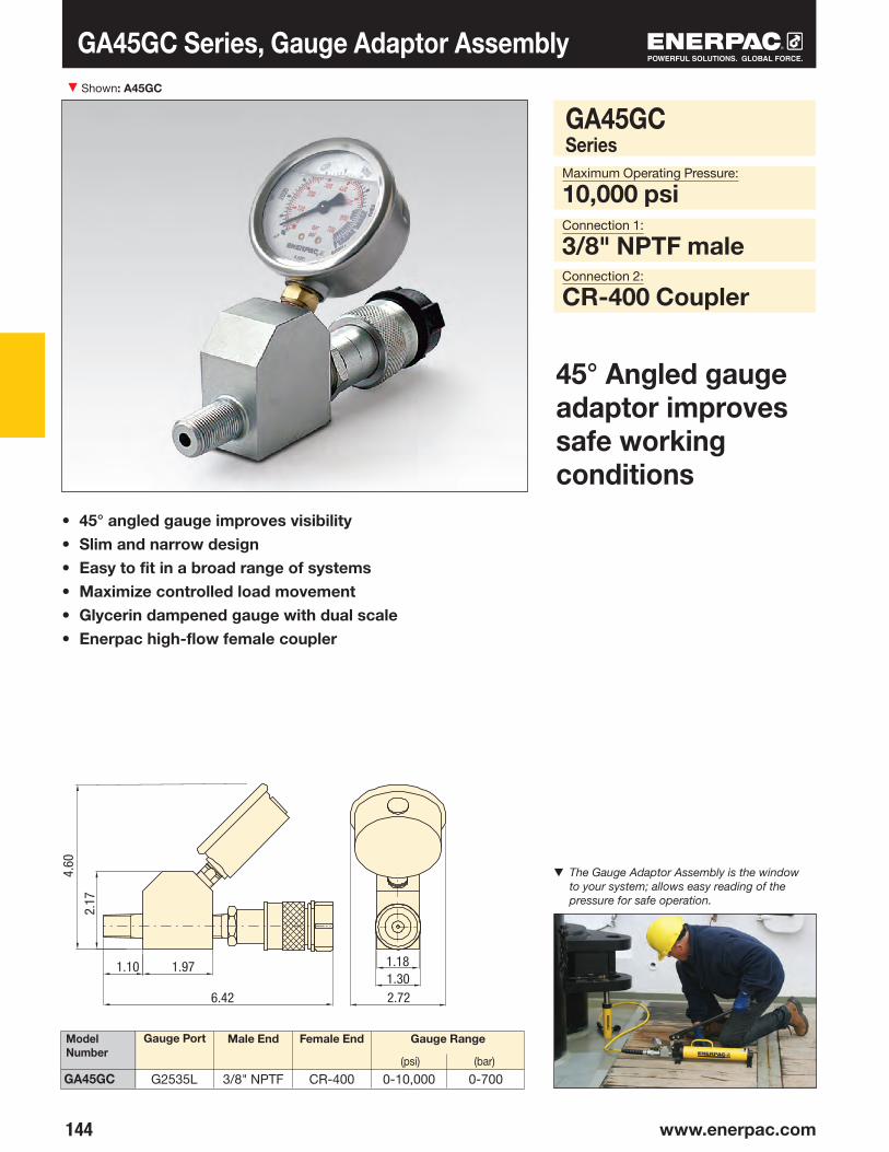
▼
144 www.enerpac.com
GA45GC
Model Number
Gauge Port Male End Female End Gauge Range
(psi) (bar)
Connection 2:
CR-400 Coupler
Connection 1:
3/8" NPTF male
Maximum Operating Pressure:
10,000 psi
Shown: A45GC
• 45° angled gauge improves visibility• Slim and narrow design• Easy to fit in a broad range of systems• Maximize controlled load movement• Glycerin dampened gauge with dual scale• Enerpac high-flow female coupler
45° Angled gauge adaptor improves safe working conditions
GA45GC Series, Gauge Adaptor Assembly
▼ The Gauge Adaptor Assembly is the window to your system; allows easy reading of the pressure for safe operation.
GA45GCSeries
G2535L 3/8" NPTF CR-400 0-10,000 0-700
1.181.10 1.97
4.60
6.421.302.72

145
C F
E
F
B
A
D
A
B
C
D
EF
G
A
S
E BCD
S1 S
F
E
F
CB
A
D
A
C
D
D
E
E
F
BV-91
NV-251
V-91
NV-251
GA-2, GA-3, GA-4
GA-1
A C E FD GB
½" nptf ½" nptf
¼" npt
½" npt
½" nptf
½" nptf
¼" nptf
½" nptf
½" nptf
½" nptf
¼" nptf
½" nptf
⅜" nptf
⅜" nptf
⅜" nptf
¼" nptf
⅜" nptf
⅜" nptf
⅜" nptf
¼" nptf
⅜" nptf
⅜" nptf
⅜" nptf
⅜" nptf
▼
Needle Valves (NV- and V-Series)• Both NV-251 and V-91 provide positive shut-off• 316 stainless steel stem, 24 threads/in.
Swivel Adaptor (GA-918)• Simplifies gauge installation and reading
GA, NV, V SeriesOperating Pressure:
10,000 psi
Model Number
Model Number
Ori fice Thread Size
Model Number
Gauge Port
(nptf)
Male End
(nptf)
Female End
(nptf)
Dimensions (in)
Dimensions (in)
A B C D E F
Dimensions (in)
CBA D E S S1
Gauge Adaptors (GA-Series)• For easy mounting of a pressure gauge into your system• Male end screws into pump or cylinder port, female end accepts hose
or coupler, third port is for gauge connection• GA-918 provides for swivel connection• Simplifies gauge installation and reading
Gauge Accessories Shown left to right: GA-3, V-91, GA-1, GA-2, GA-4, NV-251, GA-918
▼ A gauge is easily installed into your hydraulic system using a gauge adaptor.
4.62 1.72 1.30 1.13 1.50
NV-251V-91
GA-1GA-2GA-3GA-4
GA-918
2.816.105.254.38
1.241.381.381.38
.17
.192.223.50
.751.44
.38
.632.252.50
.72—
⅜
1.251.251.251.25
1.811.25
1.131.25

▼
146 www.enerpac.com
3/8"-18NPTF 3/8"-18NPTF
1/2"-14NPTF
1/2"-14NPTF
3/8"-18NPTF
3/8"-18NPTF
3/8"-18NPTF3/8"-18NPTF
3/8"-18NPTF (3x)3/8"-18NPTF
1/4"-18NPTF
V-91
V-161V-152, V-152NV
V-42
V-8FV-182
V-17
V-66F
V-82
V-10
V-66, V-66NV
264
Flow and Pressure Control Valves
• All valves are rated for 10,000 psi operating pressure• All valves feature NPTF porting to insure against
leakage at rated pressure• All valves are painted, coated, or plated for
corrosion resistance
Shown from left to right: V-152, V-66, V-82, V-161, V-42, V-17
Valve Dimensions in inches.
Your Hydraulic Control Solution
Valve Applications
To see these valves used in typical hydraulic circuits, please see our “Yellow Pages”.
Page:
▼ The V-152 Pressure Relief Valve limits the pressure or force developed in the hydraulic system.
1/2"-14NPTF
2.00
4.00
1.002.253.50
3.50
4.37
1.002.25
2.00
3.50
2.00
2.251.00
4.00
2.00
2.50
2.50
1.25
1.25
1.44.633.
50
1.25

147
AP
136 137
Flow and Pressure Control Valves
V Series
Maximum Operating Pressure:
10,000 psiHydraulic Symbol
V-82: To control cylinder speed. Can also be used as shut-off valve for temporary load holding. ⅜" nptf female ports.V-182: Same as V-82, but with
¼" nptf female ports. Also suitable for gauge snubbing.V-8F: Similar to V-82, but with very fine metering for precise flow control. Not recommended as shut-off valve.
V-91: Adjustable for metering oil out of a gauge to prevent snapping of gauge pointer when load or pressure is suddenly released. Also suitable as shut-off valve to protect
the gauge during high cycling applications. ½" nptf male and female threads for use with GA-1, GA-2 or GA-4 gauge adaptors.
V-10: To be used when gauge pressure must be monitored during high cycle applications. Creates a flow resist ance when load is released sudden ly.
No adjust ments are necessary. ½" nptf male and female threads for use with GA-1, GA-2 or GA-4 gauge adaptors.
V-17: Ruggedly built to resist shock and operate with low pressure drop. Closes smoothly without pounding. ⅜" nptf female ports.
V-42: Can be mounted at the cylinder to hold the load in case of system pressure loss. Normally used with double-acting cylinders where pilot port receives pressure
from a Tee-fitting in the cylinder retract line.⅜" nptf female ports.Pilot pressure ratio 14% (6.5:1).
V-66, V66NV: For load holding applications with single- and double-acting cylinders. Valves allow oil to flow back to tank when cylinder retracts. V66NV with Viton seals, nickel-plated.
V-66F: Similar to V-66, but with very fine metering capability for precise flow control. V-66F not designed for load holding applications.
V-152: Limits pressure developed by the pump in hydraulic circuit, thus limiting the force created by other components. Valve opens whenever preset pressure is reached.
To increase pressure setting, turn handle clockwise. Includes:• 3 ft return line hose kit • ±3% repeatability • 800-10,000 psi adjustment range.
V-161: To control oil flow to a secondary circuit. Flow is blocked until system pressure rises to the V-161 setting. When this pres sure level is reached, the V-161 opens to
allow flow to the se con dary cir cuit. A pressure differen tial is always maintained between the primary and secondary circuit. Min. operating pressure: 2000 psi.
Valve Type and Model Number
Description
Fittings
For additional fittings see the fitting page of the System Components section.
Needle ValveV-82V-182FV-8F
Snubber Valve V-91
Auto Damper® ValveV-10
Check ValveV-17
Pilot Operated Check ValveV-42
Manually Operated Check ValveV66, V66NV*V-66F
Pressure Relief ValveV-152V-152NV*
Sequence ValveV-161
Premounted Manifold
For two or four port manifold with integral flow control valves, see the manifold page of the
System Components section.
Page:
* See page 54 for more information about products for use in high temperature and extreme environment applications.
Page:

148
JFB
DC
GA J
E
H
K
K
C
D
G
B
F
J
EH
A
148 www.enerpac.com
Enerpac Hydraulic Presses are available
in a wide variety of standard capacities and
configurations, or you can “build your own”
with the easy-to-use matrix.
The press frames are a welded construction
for maximum strength and durability, and when
combined with the power of high-pressure
hydraulics, will provide years of safe and
dependable service in your workshop.
Enerpac press capacities range from 10-ton to
200-ton and are available in Bench, C-Frame,
Arbor, H-Frame and Roll-Frame models.
Enerpac Hydraulic Presses
These press features increase productivity and broaden the range of applications:
Standard on many Enerpac IP Presses, the exclusive Hydra-Lift™ offers effortless adjustment to the press daylight by use of a hydraulic lift.
Easy horizontal cylinder position is achieved with the unique “roller-head” cylinder mounting block, standard on most Enerpac IP Presses.
Optional “V-blocks” for positioning of complex parts are designed with high-strength steel for long life.

149
J
F
B
D
CG
A
J
E
H
JFB
DC
GA J
E
H
JFB
DC
GA J
E
H
▶
▶
▶
▶
▶
▶
▶
▶
▶
150
154
156
156
156
158
159
160
161
10-200
50-200
5-20
10-30
10
10-200
10-200
5
1-100
IP
IPR
A
A
AIP
TM
LH
IP
www.enerpac.com
Press Section Overview
H-Frame Presses
Roll Frame Presses
C-Clamp Presses
Arbor Presses
Bench Frame Press
Press AccessoriesPress Speed Chart
Custom Built Presses
Tension Meter
Load Cells
Custom Hydraulic Presses
Capacity(tons)
Press Type and Functions Series Page

▼
150 www.enerpac.com
158
158
158
153
158
IP-Series, H-Frame Presses
• Quality welded frame for maximum strength and long life• Exclusive “Hydra-Lift™” bed for effortless adjustment
of the vertical daylight (10-ton models are manual)• Roller head design is standard to allow movement and
locking of the cylinder from side to side (10-ton, 25-ton and 30-ton are manual)
• All models in the Quick Selection Chart have been matched to a pump, cylinder, hoses and gauge, offering the complete package
Press shown: IPE-5060
Setting the Industry Standard
Cylinder Mounting Block
Allows cylinder mounting into a press frame, while also allowing side to side adjustment of cylinder position.
Page:
Hydra-Lift™
Allows easy, effortless daylight adjustment. Standard on most H-Frame presses.
Page:
Pump Mounting Bracket
Heavy-duty steel brackets allow mounting of one of the Enerpac Power Sources to power your press.
Page:
Gauge Included
All standard press models include a gauge and gauge adaptor, matching the press capacity.
Page:
◀ An Enerpac H-Frame press quickly removes the shaft from this assembly.
V-Blocks
These optional V-Blocks are designed for easy fixturing of round stock and other non-uniform materials. Featuring precise fit into the press bolster.
Page:

151
158
H-Frame Presses
Man. Man.Elec. Air Elec.
Stroke
(in)
Speed
(sec/in)*
Power Source Press ModelNumber
Maximum Vertical Daylight
(in)
Maximum Bed
Width
(in)
PressCapacity
(tons)
Rapid Advance
PressingType Valve
Cylinder
IPSeries
Capacity:
10-200 tonsMaximum Daylight and Width:
54.50 & 48.00 inchesMaximum Operating Pressure:
10,000 psi
▼ QUICK SELECTION CHART For more technical information see next page.
* {--} Speed in strokes per inch plunger travel
Cylinder Types
= Single-acting,
Spring Return
= Double-acting, Hydraulic Return
Ordering Variations
Any variations to a listed part number must be ordered as two separate items. For example,
if you need a different voltage electric pump, please order from the modular matrix on page 159 and the electric pump from the modular matrix on page 99 (electric) or page 111 (air).
Any questions should be directed to our Technical Service Department.
Page:
0.902.20{4}{2}
2.201.50.70
5.20{5}.60.90{7}
1.021.00{2}
{11}2.901.001.00{2}
1.901.90{3}
1.90{3}
2.203.10
6.7013.40{15}{15}
13.4015.407.70
30.90{34}
43.009.80{34}
11.0474.00{38}{73}
28.9022.2011.00{38}
41.2020.60{70}
20.60{70}
15.4022.10
•••
••••
•••••
•••
40.0040.0040.0040.0040.0054.5054.5054.5054.5054.5054.5054.5048.5648.5648.5648.5648.5648.5648.5648.5642.5042.5042.5042.5042.5048.5048.50
IPE-1215IPA-1220IPH-1240IPH-1234IPA-1244IPE-2505IPE-2510IPA-2520IPH-2531IPA-3071IPE-3060IPH-3080IPE-5010IPA-5021IPH-5030IPH-5031IPE-5005IPA-5073IPE-5060IPH-5080IPA-10023IPE-10010IPH-10030IPE-10060IPH-10080IPE-15065IPE-20065
18.6318.6318.6318.6318.6329.0029.0029.0029.0029.0029.0029.0028.7528.7528.7528.7528.7528.7528.7528.7535.0035.0035.0035.0035.0048.0048.00
10
25
30
50
100
150200
••
•••
•••
••••
•
••
•
•
•
•
•
•
••
••
•
•
••
•
•
•
•
•
•
•
•
•
•
•
•
•
•
•
•
••
10101010106
141414141414136666
131313101010136
1313
••••••
•••
•
•••••
••
•
•

152 www.enerpac.com
666
32326666
32323266666
323232666
32323232
8410870721088296108721059672961057272821109672110967296729696
IP-Series, H-Frame Presses
A
(min)
A
(max)
B C D E
Press ModelNumber
PressCapacity
(tons)
H-Frame Press Dimensions (in)PumpModel
Number
◀ For full features see page 137.
Page:Page:
CylinderModel
Number
▼ The moveable “cylinder mounting block” allows the user to quickly adapt the press to a specific job.
IPE-1215IPA-1220IPH-1240IPH-1234IPA-1244IPE-2505IPE-2510IPA-2520IPH-2531IPA-3071IPE-3060IPH-3080IPE-5010IPA-5021IPH-5030IPH-5031IPE-5005IPA-5073IPE-5060IPH-5080IPA-10023IPE-10010IPH-10030IPE-10060IPH-10080IPE-15065IPE-20065
10
25
30
50
100
150200
PEM-1201BXA-12P-392P-84
XA-12VPUJ-1200B
ZE3310SB-NXA-12P-80
PAM-1042ZE3410SB-N
P-84ZE4320SB-N
PAM-1022P-462P-80
PUJ-1200BZA4408MX
ZE4420SB-NP-464
ZA4208MXZE4320SB-N
P-462ZE4420SB-N
P-464ZE5420SG-NZE5420SG-N
RC-1010RC-1010RC-1010RR-1010RR-1010RC-256
RC-2514RC-2514RC-2514RR-3014RR-3014RR-3014RC-5013RC-506RC-506RC-506RC-506RR-5013RR-5013RR-5013
RC-10010RC-10010RC-10010RR-10013RR-1006
RR-15013RR-20013
40.0040.0040.0040.0040.0054.5054.50 54.50 54.50 54.50 54.50 54.50 48.5648.56 48.56 48.56 48.56 48.56 48.56 48.56 42.5042.50 42.50 42.50 42.50 48.5048.50
2.442.44 2.44 2.44 2.44 7.007.007.007.007.007.007.007.067.067.067.067.067.067.067.067.007.007.007.007.00
12.5012.50
––––––––––––
18.7618.7618.7618.7618.7618.7618.7618.7620.0020.0020.0020.0020.0028.0028.00
46.7546.7546.7546.7546.7557.0057.0057.0057.00 57.0057.0057.0054.0054.0054.0054.0054.0054.0054.0054.0051.0051.0051.0051.0051.0054.5054.50
5.005.005.005.005.00
11.8811.8811.8811.8811.8811.8811.8810.3810.3810.3810.3810.3810.3810.3810.3811.6911.6911.6911.6911.6910.0010.00
18.6318.6318.6318.6318.6329.0029.0029.0029.0029.0029.0029.0028.7528.7528.7528.7528.7528.7528.7528.7535.0035.0035.0035.0035.0048.0048.00

153
L
KG
J F
E
M
C
H
D
B
N
131
158
H-Frame Presses
Weight
(lbs)
F G H J K L M N
Press ModelNumber
H-Frame Press Dimensions (in)
IP Series
Capacity:
10-200 tonsMaximum Daylight and Width:
54.50 & 48.00 inchesMaximum Operating Pressure:
10,000 psi
H-Frame Press Gauges
All standard press models include a gauge and gauge adaptor, matching the press capacity:
For more information on gauges, please refer to the System Components section.
Page:
Press Capacity
(tons)
Adaptor Model Number
Gauge Model Number
Hydra-Lift™
Ordering Variations
Any variations to a listed part number must be ordered as two separate items. For
example, if you need a different voltage electric pump, please order from the modular matrix on page 159 and the electric pump from the modular matrix on page 99 (electric) or page 111 (air).
Any questions should be directed to our Technical Service Department.
Page:
A (m
ax.)
A (min.)
IPE-1215IPA-1220IPH-1240IPH-1234IPA-1244IPE-2505IPE-2510IPA-2520IPH-2531IPA-3071IPE-3060IPH-3080IPE-5010IPA-5021IPH-5030IPH-5031IPE-5005IPA-5073IPE-5060IPH-5080IPA-10023IPE-10010IPH-10030IPE-10060IPH-10080IPE-15065IPE-20065
24.8824.8824.8824.8824.8840.5040.5040.5040.5040.5040.5040.5042.7542.7542.7542.7542.7542.7542.7542.7551.0051.0051.0051.0051.0067.1767.17
–––––
4.004.004.004.004.004.004.005.005.005.005.005.005.005.005.006.756.756.756.756.759.129.12
–––––
13.2513.2513.2513.2513.2513.2513.258.758.758.758.758.758.758.758.758.758.758.758.758.753.093.09
29.7529.7529.7529.7529.7530.0030.0030.0030.0030.0030.0030.0036.0036.0036.0036.0036.0036.0036.0036.0036.0036.0036.0036.0036.0044.0044.00
4.254.254.254.254.255.255.255.255.255.255.255.257.257.257.257.257.257.257.257.258.758.758.758.758.7513.1213.12
7.447.447.447.447.4410.6910.6910.6910.6910.6910.6910.6914.3814.3814.3814.3814.3814.3814.3814.3817.2517.2517.2517.2517.2521.8521.85
35.0035.0035.0035.0035.0026.5026.5026.5026.5026.5026.5026.5030.7530.7530.7530.7530.7530.7530.7530.7533.1333.1333.1333.1333.1347.7547.75
52.0052.0052.0052.0052.0076.0076.0076.0076.0076.0076.0076.0076.0076.0076.0076.0076.0076.0076.0076.0076.0076.0076.0076.0076.0090.0090.00
298160158189163605697610620684722664
1,040968968926930
1,0571,0511,0031,6501,7221,6561,7431,6653,9063,906
GF-10PGF-20PGF-835PGF-50PGF-871PGF-200PGF-200P
10253050
100150200
GA-2GA-2GA-3GA-2GA-3GA-3GA-3

▼
154 www.enerpac.com
33 33 33
9696 96
158
158
158
158
• Qualityweldedframeformaximumstrengthandlonglife• Framerollseasilyonfoursteelrollerbearings• Hydraulicclampcylinderslockframeintoposition• Exclusive“Hydra-Lift™”bolsterforeffortlessadjustment
oftheverticaldaylight• Standardrollerheaddesignallowsmovementofthe
cylinderfromsidetoside• AllmodelsintheQuickSelectionCharthavebeen
matchedtoapump,cylinder,hosesandgauge, offeringthecompletepackage
• RollFramedesignfeaturesastationarybedwith theabilitytosupportheavyloads
Shown: IPR-10075
IPR-Series,RollFramePresses
Cylinder,Double-ActingHydraulicReturn
PressModelNumber
Vertical Daylight
A (in)
HorizontalDaylight
E(in)
PressCapacity
(tons)
ModelNumber
Stroke
(in)
RapidAdvance
Pressing
Speed
(sec/in)
PumpModel Number
TheOneandOnly
Page: Page:
CylinderMountingBlock
Allows cylinder mounting into a press frame, while also allowing side to side adjustment of cylinder position.
Page:
PumpMountingBracket
Heavy duty steel brackets to allow conversion to one of the Enerpac Power Sources to power your press.
Page:
Hydra-Lift™
Allows easy, effortless daylight adjustment.
Page:
OptionalV-Blocks
These V-Blocks, 200 ton only, are designed for easy fixturing of round stock and other non-uniform
materials. Featuring precise fit into the press bolster.
Page:
minimum maximum
37.1241.2851.00
6.006.2811.00
IPR-5075IPR-10075IPR-20075
28.7535.0048.00
50100200
RR-5013RR-10013RR-20013
ZE4420SB-NZE5420SG-NZE5420SG-N
13.1313.1313.00
•••
1.01.53.1
11.110.322.1

155
AB
CM
K
N
GJ H
L
E
F
D
131
158
Roll Frame Presses
Weight
(lbs)B C D F G H J K L M N
Press ModelNumber
Roll Frame Press Dimensions (in)
IPR Series
Capacity:
50-200 tonsMaximum Daylight and Width:
51.00 & 48.00 inchesMaximum Operating Pressure:
10,000 psi
Ordering Variations
Any variations to a listed part number must be ordered as two separate items. For
example, if you need a different voltage electric pump, please order from the modular matrix on page 159 and the electric pump from the modular matrix on page 99 (electric) or page 111 (air).
Any questions should be directed to our Technical Service Department.
Roll Frame Press Gauges
All standard press models include a gauge and gauge adaptor, matching the press capacity:
For more information on gauges, please refer to the System Components section. Page:
Press Capacity
(tons)
Adaptor Model Number
Gauge Model Number
Page:
▼ An IPR-20075 Roll Frame Press is used to remove a large shaft from this pillow-block assembly. The Roll Frame design allows this heavy part to be safely loaded with an overhead crane.
IPR-5075IPR-10075IPR-20075
20.7126.5038.75
38.2538.0036.75
10.388.7510.00
36.7545.0064.00
5.005.759.12
55.9263.1984.63
8.008.008.00
10.6310.6315.00
30.0032.0036.00
112.96118.94125.96
1,9613,8497,869
64.0066.0086.50
GF-50PGF-871PGF-200P
GA-2GA-3GA-3
50100200

▼
156 www.enerpac.com
C-Clamp, Arbor and Bench Frame Presses
C-Clamp Press• 5, 10 and 20 ton capacity • Operational in all positions
Arbor Press• Foot mounting holes for horizontal or vertical positioning• Machined work surfaces for easier fixturing• Slotted back to simplify loading and unloading of
longer parts
Bench Frame Press • Cylinder mounting adaptor allows lateral
positioning along rails• Mounting holes for easy mounting to fixed surface
Shown from left to right: A-220, A-330 and A-258
Push Pin A-183
For applications requiring precision pressing, such as shaft removal and insertion. This attachment fits 10 ton
cylinders and requires the use of a threaded adaptor saddle (A-13).
Smooth Saddle A-185
For pressing applications of delicate parts, such as aluminum castings, this saddle decreases surface
marks during the pressing application. Requires 10-ton cylinder and threaded adaptor saddle (A-13).
The Standard In Workshop Tools
* Requires RC cylinder listed, see page 7 for specifications.** Requires RC-25 ton cylinder, limited to 20 tons.*** Complete set includes cylinder and pump.
Arbor
C-Clamp
Bench
Press Type
Press Model Number
Maximum Vertical Daylight
(in)
Maximum Bed
Width
(in)
Cylinder Series
Number*
Weight
(lbs)
Press Capacity
(tons)
▼ A-310 Abor Press
8.9410.256.509.00
11.8815.3815.3815.38
A-310*A-330*A-205*A-210*A-220**A-258*IPA-1022***IPH-1040***
10305
1020101010
RC-10-xRC-30-xRC-5-x
RC-10-x**–
RC-1010RC-1010
62220143783
103140135
5.317.002.003.253.75
15.0015.00 15.00

157
K
K
C
D
O
G
B
L M N
F
J
E H
A
J
FB
D
C
G
A
K
L
M
E
H
▼
H
M
E
N
OA
FD
LJ
K
C
B
G
6
69
C-Clamp, Arbor and Bench Frame Presses
Bench Press Frame A-258
C-Clamp Press A-205, A-210, A-220
Arbor Press A-310, A-330
AIPSeries
Capacity:
5-30 tonMaximum Daylight and Width:
15.38 and 15.00 inchesMounting Capabilities:
Fixed or PortableMaximum Operating Pressure:
10,000 psi
A perfect example of the force and versatility of the Enerpac A-220 C-Clamp press.
Press Adaptor
A-110 V-Block(optional)
For high-cycle production applications, C-Clamp and Arbor presses should be limited in their capacity.
Consult Enerpac Technical Services for specific application details.
Press Model Number
Press Dimensions (in)
A B C D E F G H J K L M N O
Top View Working Surface
Hydraulic Cylinders
Cylinders for C-Clamps and Arbor Presses must be ordered separately.
Hydraulic Pumps
Pumps for C-Clamps and Arbor Presses must be ordered separately.
Page:
Page:
16.3121.9411.4416.0021.2525.63 25.63 25.63
11.0613.888.0011.1313.6318.75 18.7518.75
8.9410.256.509.0011.8816.50 16.5016.50
6.006.003.756.006.0016.00 16.0016.00
5.317.002.883.254.765.75 5.755.75
2.502.501.021.021.021.00 1.001.00
4.815.502.002.252.754.50 4.504.50
.751.002.502.502.751.25 1.251.25
3.816.501.061.691.882.75 2.752.75
6.888.004.757.638.381.88 1.881.88
2.562.631.001.131.135.30 5.305.30
2.133.88
–––
2.20 2.202.20
8.6310.88
–––
2.63 2.632.63
2¼-14 un
35•16-12 un
1½-16 un
2¼-14 un
35•16-12 un
3.253.253.25
A-310A-330A-205A-210A-220A-258IPA-1022IPH-1040
.34(8x)
11.44 (A-310)14.75 (A-330)
.50
1/2"-13UNC
1.63 (A-330)1.38 (A-310)
3.38 (A-330)4.00 (A-310) 2.32
13.92

158 www.enerpac.com
Press Accessories and Press Speed Chart
Cylinder Capacity
(tons)
Cylinder Load
Single Speed
P-391P-392 P-80
P-84P-462P-464
ZE3Series
ZE4Series
ZE5Series
XA PA-133 PAM 10Series
½ hpPort.
½ hpSubm.
Hand Operated Pumps Electric Pumps Air Pumps
Strokes per inch of plunger travel
Two-Speed @100 psi air
Seconds per inch of plunger travel
No loadLoad
No loadLoad
No loadLoad
No loadLoad
No loadLoad
Note: Values are approximate. Cylinder speed may vary in actual application.
Cylinder and Pump Selection Chart
Cylinder Mounting Block
V- Blocks
Hydra-Lift™
PumpMountingBracket
10 ton Bench10 ton H-Frame25 and 30 ton H-Frame50 ton H-Frame100 ton H-Frame200 ton H-Frame
10 ton Bench Press10 ton H-Frame25 and 30 ton H-Frame50 ton H-Frame100 ton H-Frame150 & 200 ton H-Frame200 ton Roll Frame
25-100 ton H-Frame150-200 ton H-Frame50 and 100 ton Roll Frame200 ton Roll Frame
Hand operated and small Air Pumps; P-80, P-84, P-142, P-392, PA-133, XA, Turbo II pumps
Electric, large Hand Pumps, and ZA4 Air Pumps; ZE Series, P-462, P-464, 10/90 Series Air Pumps
• AD-175 converts the Bench press to use an RD-9 ton cylinder
• All mounting blocks allow horizontal movement of cylinder
• Machined from high strength steel for long life
• A-110 includes one V-block • All other model numbers
include two V-blocks
• Allows easy, effortless daylight adjustments
• Includes accessory chain
• Both mounting brackets are pre-drilled to accept a number of different pump models
Description FrameCapacity
ModelNumber
Features
Cylinder SpeedThis chart will help you calculate the time required for an Enerpac cylinder to extend when powered by a 10,000 psi Enerpac hydraulic pump. The Cylinder Speed Chart can also be used to determine the pump type and model best suited for an application when you know the plunger speed required.
ZA4
10
25
30
50
100
1515343443437373137137
4158341043167330137
215534743117321137
18118123238371
.76.71.5
15.51.9
19.53.3
33.26.2
61.9
.96.72.1
15.52.6
19.54.4
33.28.3
61.9
.33.4.7
7.7.9
9.801.5016.62.8
31.0
.22.2.5
5.2.6
6.51.0
11.01.9
20.7
.21.1.4
2.6.5
3.3.8
5.51.5
10.3
1.109.002.60
20.603.20
26.005.50
44.2010.3082.50
2.7016.806.20
38.607.50
48.7013.3082.9224.80
154.70
.2114.90.48
34.30.60
43.301.00
73.701.90
137.50
AD-175IPK-1012IPK-3012PK-501PK-1002PK-2002
A-110A-136A-130A-150A-175A-200A-200R
IPL-100IPL-101IPLR-100IPLR-200
PMB-1
PMB-2
.164.50.36
10.30.46
13.00.80
22.101.50
41.30

159
x=
IP H - 050 S 06 - 1
Custom Built Presses
IP Series
Capacity:
10-200 tonsMaximum Daylight and Width:
54.50 & 48.00 inchesMaximum Operating Pressure:
10,000 psi
“No Load” indicates the plunger speed as it extends toward the load (1st stage). “Load” indicates the plunger
speed as the load is applied at a system pressure of 10,000 psi (2nd stage).
Formula V = A ÷ Q
V (sec/in) = A (in2) ÷ Q (in3/min)
V = Cylinder plunger speed in seconds per inch
A = Cylinder effective area in square inches (in2)
Q = Pump oil flow in cubic inches (in3)
Cylinder Plunger Speed (sec/in)
60 sec1
Cylinder Effective Area (in2)Pump Flow Rate (in3/min)
1Product
Type
2Frame Type
3Press
Capacity
4Cylinder
Type
5Cylinder Stroke
1 Product Type IP = Industrial Press
2 Frame Type H = H-Frame R = Roll Frame 1)
3 Press Capacity 010 = 10 ton 025 = 25 ton 030 = 30 ton 050 = 50 ton 100 = 100 ton 150 = 150 ton 200 = 200 ton
4 Cylinder Type S = Single-Acting (RC-Series) D = Double-Acting (RR-Series)
Model number: IPH-050S06-2
IPH-050S06-2 is a 50-ton H-Frame press with a single-acting, 6 inch stroke cylinder (RC-506). It has a pump mounting kit (for an electric Pump or a Modular Air Pump).
See the cylinder and pump selection chart on previous page for selecting the proper pump.
1) Roll Frame Press: 50-, 100- and 200-ton press capacity only. (Assembly required) 2) Includes hoses for press, except for option 0.
6Pump
Mounting Kit
CUSTOM BUILD YOUR OWN PRESSIf the press that would best fit your application cannot be found in the charts, you can easily build your custom press here. All presses must be ordered with cylinders. The pump is ordered separately.
▼ This is how a press model number is built up:
Ordering Example
5 Cylinder Stroke (in)- 10 ton S/A: 06, 08, 10, 12, 14 10 ton D/A: 10, 12- 25 ton S/A: 06, 10, 12, 14- 30 ton S/A: 08 30 ton D/A: 08, 14- 50 ton S/A: 06, 13 50 ton D/A: 06, 13, 20- 100 ton S/A: 06, 10 100 ton D/A: 06, 13, 18- 150 ton D/A: 06, 13, 32- 200 ton D/A: 13, 18, 24
6 Pump Mounting Kit 2)
0 = No mounting kit 1 = Hand operated and small air pumps: P-80, P-84, P-141, P-142, P-202, P-391, P-392, PA-133 and all Turbo II Air pumps 2 = Electric, large hand operated and modular air pumps: PUJ-12, PEM-12, ZE3-6 Series P-462, P-464 PAM-10 and -90 Series

▼
160 www.enerpac.com
DA
BC
G (2x) EF
G F
A
D
1/2"-13UNC
CB
E
5/8"-11UNC
Tension Meter and Load Cells Shown: LH-102 and TM-5 (in middle)
TM, LHSeriesCapacity:
2,000 to 200,000 lbs. Accuracy, % of full scale:
± 2%
Direct MountedDirect Load Cell Mounted
Remote Mounted with 2 ft. Hose
Remote Mounted with 6 ft. Hose
Model Number
Gauge Capacity
Tension Meter TM-5• Accuracy, ± 2% of full scale• Zinc and bronze plated to resist rust and corrosion• Dual-range readout in kilograms and pounds• Cushioned metal case provides safe storage
and transport• Maximum indicating pointer reading for pre-selected
forces or to maintain maximum force readings
Load Cells LH Series• Accuracy, ± 2% of full scale• Swivel loading pad reduces eccentric loading for
improved accuracy• Maximum indicating pointer reading for pre-selected
forces or to maintain maximum force readings• Dual-range readout in kilograms and pounds
LH-Series
TM-5
Type
(lbs) (kg) A B C D E F G
Minimum Reading
Gauge Increments
(lbs)(kg) (kg)(lbs)
Dimensions (in)
TM and LH models are 100% tested to verify accuracy within a ± 2% range.
If your application requires a calibrated tool, it must be submitted for certification testing.
Certification is NOT available from Enerpac.
10,0002,00010,0002,00010,00020,00050,000100,000200,000
4.753.063.063.063.063.064.005.226.22
9.751.751.751.751.751.752.754.005.00
9.292.252.252.252.252.253.385.006.25
2.002.382.382.382.382.382.382.382.38
4.004.004.005.815.815.815.815.815.81
.8810.0010.0033.3133.1033.1082.4484.0685.31
.75 ¼"-20, 1.75" bc
¼"-20, 1.75" bc
¼"-20, 1.75" bc
¼"-20, 1.75" bc
¼"-20, 1.75" bc
⅜"-24, 2.5" bc
⅜"-24, 3.5" bc
⅜"-24, 4.0" bc
TM-5LH-10LH-50LH-102LH-502LH-1002LH-2506LH-5006LH-10006
4500900450090045009000210004500090000
500100500100500
100025002500
10000
10020
10020
100200500
1,0002,500
10020
10020
100200500
10001000
1,000200
1,000200
1,0002,0005,0005,00020,000
.62
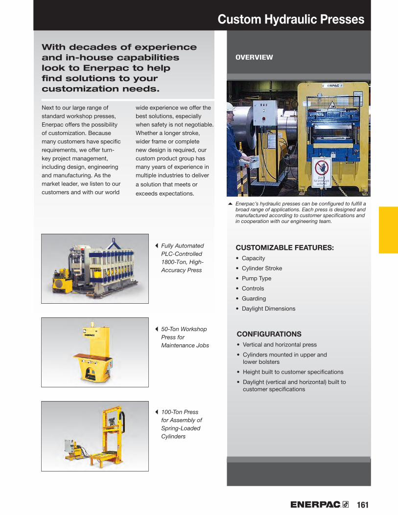
161
FPO
Custom Hydraulic Presses
CUSTOMIZABLE FEATURES:• Capacity
• Cylinder Stroke
• Pump Type
• Controls
• Guarding
• Daylight Dimensions
With decades of experience and in-house capabilities look to Enerpac to help find solutions to your customization needs.
Next to our large range of standard workshop presses, Enerpac offers the possibility of customization. Because many customers have specific requirements, we offer turn-key project management, including design, engineering and manufacturing. As the market leader, we listen to our customers and with our world
wide experience we offer the best solutions, especially when safety is not negotiable. Whether a longer stroke, wider frame or complete new design is required, our custom product group has many years of experience in multiple industries to deliver
a solution that meets or
exceeds expectations.
◂ Fully Automated PLC-Controlled 1800-Ton, High-Accuracy Press
◂ 50-Ton Workshop Press for Maintenance Jobs
◂ 100-Ton Press for Assembly of Spring-Loaded Cylinders
OVERVIEW
▴ Enerpac’s hydraulic presses can be configured to fulfill a broad range of applications. Each press is designed and manufactured according to customer specifications and in cooperation with our engineering team.
CONFIGURATIONS• Vertical and horizontal press
• Cylinders mounted in upper and lower bolsters
• Height built to customer specifications
• Daylight (vertical and horizontal) built to customer specifications

162 www.enerpac.com
AB
FAD
B
H
G
C
Hydraulic and Mechanical Pullers
Enerpac offers a complete line of pullers
with the widest range of sizes, capacities
and styles. Whether your application
requires mechanical, hydraulic or the
patented Posi Lock® system, Enerpac can
satisfy your requirements.
Made of high strength steel alloys, you
can depend on Enerpac pullers to provide
years of trouble-free operation, even in the
harshest environments.
Hydraulic Pullers
These hydraulic pullers eliminate time-consuming and unsafe hammering, heating or prying. Damage to parts is minimized through the use of controlled hydraulic power.
Posi Lock® Pullers
The puller that meets the safety challenge. A control cage holds the pulling jaws securely in working position. This patented feature reduces the possibility of the puller jaws slipping off the
work surface thereby increasing productivity and tool life while reducing dangerous situations for the user. The Posi Lock® feature is available in mechanical or hydraulic versions.
Always wear Safety Goggles and Gloves while using pullers.
CAUTION!
Not all puller components and configurations are rated at the set capacity. Please contact Enerpac for specific details.
WARNINGDo not exceed 50% of the rated puller capacity when using a double crosshead
(2 jaws) or when using puller legs in combination with bearing puller attachment.

163
▶
▶
▶
▶
▶
▶
▶ ▶ ▶
▶
▶
▶
164
165
166173
167
167
168
168
171172
174
178
181
Puller Section Overview
Master Puller Sets Max. Reach: 27.56 in.Spread Range: 43.30 in.
Puller Function Capacity(tons)
PagePuller Type
Grip Puller SetsMax. Reach: 27.56 in.Spread Range: 43.30 in.
Cross-Bearing Puller SetsMax. Reach: 34.00 in.Spread Range: 22.44 in.
Bearing Cup PullersMax. Reach: 5.71 in.Spread Range 14.17 in.
Mechanical Sync Grip PullerMax. Reach: 23.62Spread Range: 26.77
Posi Lock® Mechanical PullersMax. Reach: 14.00 in.Spread Range: 25.00 in.
Hydraulic Sync Grip PullerMax. Reach: 27.56 in.Spread Range: 38.58 in.
Posi Lock® Hydraulic PullersMax. Reach: 14.00 in.Spread Range: 25.00 in.
Posi Lock® Hydraulic PullersMax. Reach: 48.0 in.Spread Range: 70.0 in.
Series
14-50
14-50
7-24
7-25
7-25
1-20
2-40
14-50
10-50
100
Bearing SeparatorMax. Spread: 9.65 in.Max. Width 11.50 in.
When selecting a puller it is important to consider three basic specifications:
1. Capacity: The amount of force the puller is capable of producing.Typically, the capacity required for a job can be determined by using the shaft diameter of the part being pulled.For manual pullers, the center bolt diameter of the puller should be at least half the diameter of the shaft being pulled from.For hydraulic pullers, the capacity in tons should be 7 to 10 times the shaft diameter. Use the following chart:
Shaft PullerDiameter Capacity
0" to 1" 14 ton
1" to 2" 24 ton
2" to 3.5" 36 ton
3.5" to 5.5" 50 ton
2. Reach: The distance between the bottom of the base and the jaw flats. The puller’s reach must equal or exceed the same distance of the part being pulled.
3. Spread: The distance between the jaws. The puller’s spread needs to be greater than the width of the part being pulled.
BHP
BHP
BHP
BHP
BHP
SGM
EP, EPP, EPPMI, EPX
SGHMPS GPS
EPH, EPHR, EPHS
EPHEPHT

▼
164 www.enerpac.com
▶ ▶
▶
▶
▶
▶
▶
▶
▶
▶
10203040
70 2627
133139 145
165166167167
BHP-Series, Master Puller Sets
Master Puller Set Capacity Page Number
BHP-1752 1) BHP-2751G BHP-3751G BHP-5751GIncluded Hydraulics: Set Weight ▶Hand Pump Cylinder SaddleHoseGauge Gauge AdaptorIncluded Pullers:Grip PullerCross Bearing Puller Bearing Cup PullerBearing Separator Storage Case
Model Number ▶
Shown: Master Puller Set BHP-3751G
▼ SELECTION CHART
1) Includes FZ-1630 Adaptor.* Puller capacity at 7,850 psi
82 lbsP-142
RWH-121–
HB-7206QBGF-120P
GA-4
BHP-1762BHP-1772 BHP-180BHP-181
CM-6
198 lbsP-392
RCH-202HP-2015HC-7206GF-813P
GA-3
BHP-252BHP-262 BHP-280BHP-282CW-166
380 lbsP-392
RCH-302HP-3015HC-7206GF-813P
GA-3
BHP-352BHP-362 BHP-380BHP-382CW-550
657 lbsP-80
RCH-603HP-5016HC-7206GF-813P
GA-3
BHP-552BHP-562 BHP-580BHP-582CW-750
▼ Maintenance engineers throughout the industry greatly appreciate Enerpac Master Puller sets.
Multi-Purpose Puller Set
• Supplied with a full hydraulic set including pump, hose, cylinder, gauge and gauge adaptor in a storage case
• High quality, forged steel components provide superior reliability and service
• Sets include speed crank and adjusting screw for fast contact to work before hydraulics are applied
• All Master Puller Sets include a Grip Puller, a Cross Bearing Puller, a Bearing Cup Puller and a Bearing Separator which can be ordered separately. See items 10, 20, 30 and 40
14 ton 24 ton 36 ton 50 ton*
WARNING
Not all puller components and configurations are rated at the set capacity. Please contact Enerpac for specific details.

165
10
▼
Model Number Included ▶
Hydraulics: set weight ▶ Hand Pump Cylinder Saddle Hose Gauge Gauge Adaptor
Grip Puller * Model Number ▶Spread Range (in) 2-jaw 3-jaw Maximum Reach (in) 2-jaw 3-jaw Jaw (in) Thickness WidthAdjusting Screw (in) Thread LengthCase
Grip Puller Sets
BHP Series
Grip Puller Set Capacity
1) Includes FZ-1630 Adaptor.* Grip Puller model number without hydraulics.** Puller capacity at 7,850 psi
▼ SELECTION CHART
Model Number BHP-251G:
Includes Grip Puller BHP-252 and a full hydraulic set. (Hand pump, cylinder, saddle, hose, gauge and gauge adaptor.)
Model Number BHP-252:
Includes Grip Puller mechanical parts only, for use with your existing hydraulics.
• Precise hydraulic control allows fast, efficient and safe pulling
• High quality, forged steel components provide superior reliability and service
• Available with and without full hydraulic set
Shown: Grip Puller Set BHP-351G
Ordering Example
WARNING
Not all puller components and configurations are rated at the set capacity. Please contact Enerpac for specific details.
BHP-251G123 lbsP-392
RCH-202HP-2015HC-7206GF-813P
GA-3BHP-252*
15.7519.6811.8111.810.791.10
1"-8 unc
26.38CW-166
BHP-152 1)
48 lbsP-142
RWH-121–
HB-7206QBGF-120P
GA-4BHP-1762*
9.849.849.929.920.590.94
¾"-16 unf
15.75CW-166
BHP-351G200 lbsP-392
RCH-302HP-3015HC-7206GF-813P
GA-3BHP-352*
23.3831.5015.2515.250.981.50
1¼"-7 unc
31.16CW-350
BHP-551G353 lbsP-80
RCH-603HP-5016HC-7206GF-813P
GA-3BHP-552*
35.4343.3027.5627.561.181.57
1⅝"-5.5 uns 38.39
CW-750
Spread Range:
9.84-43.30 inchesMaximum Operating Pressure:
10,000 psi
Maximum Reach:
9.92-27.56 inches
Capacity:
14, 24, 36 and 50 tons
24 ton14 ton 36 ton 50 ton**

▼
166 www.enerpac.com
20
3040
Model Number ▶ Included Hydraulics: set weight ▶ Hand Pump Cylinder Saddle Hose Gauge Gauge Adaptor
Cross-Bearing Puller Model Number ▶ Spread (in) Maximum Minimum Reach (in) Maximum Adjusting Screw (in) Diameter LengthLeg (in) Length Length Length LengthUpper Leg Ends (in) ThreadLower Leg Ends (in) ThreadBearing Cup Puller Model Number ▶
Bearing Separator Model Number ▶Wooden Case Model Number ▶
BHP-Series, Cross-Bearing Puller Sets
1) Includes FZ-1630 Adaptor.
Shown: Cross-Bearing Puller Set BHP-361G
Cross-Bearing Puller Set Capacity
▼ SELECTION CHART
BHP Series
WARNING!
Not all puller components and configurations are rated at the set capacity. Please contact Enerpac for specific details.
BHP-261G137 lbsP-392
RCH-202HP-2015HC-7206GF-813P
GA-3BHP-262
13.585.51
22.441"-8 unc
26.384.539.45
16.5422.44
¾"-16 unf
⅝"-18 unf
BHP-280
BHP-282CW-166
BHP-162 1)
57 lbsP-142
RWH-121–
HB-7206QBGF-120P
GA-4BHP-1772
10.244.53
14.06¾"-16 unf
15.754.17
14.06––
¾"-16 unf
⅝"-18 unf
BHP-180
BHP-181CW-166
BHP-361G267 lbs P-392
RCH-302HP-3015HC-7206GF-813P
GA-3BHP-362
17.327.09
27.951¼"-7 unc
31.108.07
18.1127.95
– 1"-14 uns
1"-14 uns
BHP-380
BHP-382CW-550
BHP-561G408 lbsP-80
RCH-603HP-5016HC-7206GF-813P
GA-3BHP-562
22.838.66
34.001⅝"-5.50 uns
38.3923.9834.02
––
1¼"-12 unf
1¼"-12 unf
BHP-580
BHP-582CW-750
Maximum Reach:
14.06-34.00 inchesMaximum Spread Range:
10.24-22.83 inchesMaximum Operating Pressure:
5000 psi
• Precise hydraulic control allows fast, efficient and safe pulling
• High quality, forged steel components provide superior reliability and service
• The Cross-Bearing Puller without hydraulics, Bearing Cup Puller and Bearing Puller may be ordered separately. See items 20, 30 and 40.
12 ton7 ton 18 ton 25 ton
Capacity:
7, 12, 18 and 25 tons

167
30
40
▼
▼
Bearing Cup Pullers and Bearing Separators
Spread (in) Max. Min.Width (in) Thread
Capacity**
Model Number ▶
* Bearing separator rated at 50% of puller capacity.
Shown: BHP-180
Shown: BHP-181
Bearing Cup Puller
• Made of high strength steel alloy
• Easily adapted to Cross Bearing Pullers for fast and efficient removal of the most difficult parts
• Adjustable to fit a variety of bearings and seals
Bearing Separator
• Made of high strength steel alloy
• Wedge-shaped edges allow removal of the most hard-to-grip components
• Easily adapted to Cross Bearing Pullers for fast and efficient removal of the most difficult parts
Bearing Separator
Capacity*
▼ SELECTION CHART
Bearing Cup Puller
Model Number ▶Spread (in) Max. Min.Reach (in) Max. Center Screw Thread
BHP Series
Maximum Reach:
4.53-5.91 inchesMaximum Spread Range:
5.71-9.45 inchesMaximum Operating Pressure:
5000 psi
▼ SELECTION CHART
◀ Bearing Cup Puller shown with Cross Bearing Puller attachment.
* Bearing cup puller rated at 50% of puller capacity.
Capacity:
7, 12, 18 and 25 tons
12 ton7 ton 18 ton 25 ton
Bearing Separator
Bearing Separator has wedge shaped edges for placing puller behind hard to reach bearings, gears, etc., where clearance prevents direct
application of grip puller arms.
The Bearing Separator should be used with the Cross Bearing Puller.
Bearing Separator shown with Cross Bearing Puller
attachment. ▶
12 ton7 ton 18 ton 25 ton
WARNING!
Do not exceed 50% of the rated puller capacity when using a double crosshead
(2 grip arms) or when using puller legs in combination with bearing puller attachment.
BHP-2806.301.265.51
1"-8 unc
BHP-1805.711.574.53
¾"-16 unf
BHP-3809.452.365.91
1¼"-7 unc
BHP-5809.452.365.91
1⅝"-5.50 uns
BHP-2825.280.476.10
⅝"-18 unf
BHP-1814.330.394.33
⅝"-18 unf
BHP-3829.840.67
10.241"-14 uns
BHP-5829.840.67
10.241¼"-12 unf

168 www.enerpac.com
SGM01*SGM04*SGM07*SGM10*SGM20
SGH14*SGH24SGH36SGH64
AA B D E FB
147
1020
142436
50**
B
A
F
E
D
Sync Grip Pullers Overview and Dimension Guide
OVERVIEW
The Enerpac Sync Grip multi-purpose puller range
is designed to make your jobs easier and safer
to accomplish.
Remove bearings, bushings, gears, sleeves, wheels
and flywheels, sprockets and other shaft mounted
items simply and effectively.
Mechanical and hydraulic configurations are available
with a variety of optional accessories that expand
application range and increase utility.
Hydraulic models are available in standard sets which
include detachable hydraulic cylinders and a choice of
pump options, along with a gauge assembly and hose
for safe monitoring of applied pulling forces.
Puller Model No.
Standard Reach Jaws
Optional Extended Reach Jaws
Jaw Tip Jaw HoleSpacing
(in)
Wt.***
(lbs)
Mechanical Pullers
Hydraulic Pullers
Sync Grip Pullers Dimensions (in)
Max. Reach
Height Max. Reach
ThicknessMax. Spread
WidthMax. Spread
Puller Capacity
(ton)
▼ DIMENSIONAL DATA
* Puller can be set up as a 2 or 3 jaw configuration. ** Puller capacity at 7,850 psi, maximum cylinder capacity @ 10,000 psi is 64.6 tons.*** With standard legs and cylinder for hydraulic models
WARNING!
Do not exceed 50% of the rated puller capacity when using two jaw configurations.
Always wear safety goggles and gloves while using pullers.
4.137.288.86
16.1423.62
12.6012.6016.1427.56
4.336.899.45
13.7826.77
13.7818.9025.5938.58
———
19.2925.20
15.7517.1320.6733.46
———
15.9428.35
15.9421.2628.3542.52
0.280.310.310.590.94
0.590.690.941.06
0.300.830.980.981.61
0.981.221.611.97
0.752.011.753.274.92
3.274.534.925.91
1.84.4
14.332.0
122.3
55.1108.0165.3363.7
0.310.300.390.490.87
0.490.610.871.18

169
BB B BA AA A C C C D E F
C
A
B
A
B
C
F
E
DB
A
Overview and Dimension Guide Sync Grip Pullers
Sync Grip Pullers: available in both mechanical or hydraulic versions. Some models can be configured as a two jaw puller, however, three jaws are recommended for most even distribution of pulling forces.
Cross Puller: hydraulically powered via detachable cylinder and choice of pump. The Cross Puller can be used individually as a ‘push’ puller or in conjunction with the Bearing Separator or Bearing Cup Puller.
Bearing Separator: use where access is restricted. The Bearing Separator is used in conjunction with the Cross Puller.
Bearing Cup Puller: specifically designed for cup style bearing and other applications requiring an internal style puller.
Detachable Hollow Cylinder: provided with all hydraulic puller models including both the standard Sync Grip and Cross Puller.
In Sync Grip, Cross Bearing and Master Puller Sets a hose and gauge are provided as standard along with your choice of pump including manual hand operated, cordless battery powered, electric or air powered. In each case the pump selection has been optimized for compatibility with the pullers.
Easy To Use
Simple, Safe, Productive
All three jaws close simultaneously making the puller easier and safer to operate.
The synchronous feature of the SGM and SGH-Series Pullers makes positioning the puller simple and helps prevent misalignment.
Maximum Spread
Spread Range Spread RangeDia.
Wt.**
(lbs)
Wt.
(lbs)
Thread Size
Mechanical Pullers Mechanical Pullers Mechanical Pullers
Hydraulic Pullers Hydraulic Pullers Hydraulic Pullers
Cross Puller Dimensions (in) Bearing Separator Dims. (in)
LongLeg
Height
Standard Leg
Height
Jaw Tip
Wt.
(lbs)
Bearing Cup Dimensions (in)
Min. Spread
Max.Spread
Height Width ThicknessMin. Spread
Max. Spread
HeightHeight
▼ DIMENSIONAL DATA
** With cylinder and standard legs
—————
4.174.538.0723.97
—————
4.336.10
10.2410.24
—————
14.0622.4427.9534.01
—————
0.390.470.670.67
—————
10.2413.5817.3222.83
—————
4.335.289.849.84
—————
5/8"- 18 UNF5/8"- 18 UNF1" - 14 UNS
1-1/4"- 12 UNF
—————
40.7776.04
123.42250.15
—————
6.012.662.862.8
—————
4.535.515.915.91
—————
9.3310.4712.2012.20
—————
1.571.262.362.36
—————
5.716.309.459.45
—————
0.180.180.430.43
—————
0.200.180.310.31
—————
1.220.982.172.17
—————
4.415.29
13.2214.11

▼
170 www.enerpac.com
220 168
SGM01SGM04SGM07SGM10SGM20
147
1020
———SG1002KSG3002K
Mechanical Sync Grip Pullers
• Sync Grip mechanism synchronizes movement of all jaws for simultaneous engagement, helping to prevent misalignment for safe and easy use
• Threaded spindle and jaw indexes provide adjustable reach• Three-jaw configuration for even load distribution• Two-jaw configuration for confined access applications
available on all pullers 10 ton and below (not available on SGM20)
• High-strength forged jaws for superior reliability• Suitable for a variety of applications including bearings,
bushings, wheels, gears and pulleys
Shown: SGM10 with three jaws
▼ SGM10 with two jaws.
SGMSeries
Puller Capacity:
1-20 tons
Maximum Spread:
4.3-26.8 inches
Maximum Reach:
4.1-23.6 inches
Page:
DimensionsDimensional information for all puller models is included in the dimensional overview table:
Puller Model No.
Long Jaw Sets Model No.*
Weight
(lbs)
Dimensions (in) Dimensions (in)
Max. Reach
A
Max. Reach
A
Max. Spread
B
Max. Spread
B
PullerCapacity
(ton)
▼ DIMENSIONAL DATA
WARNING!
Do not exceed 50% of the rated puller capacity when using two jaw configurations.
* Jaw sets include three jaws.
4.137.288.86
16.1423.62
4.336.899.45
13.7826.77
1.84.4
14.332.0
122.3
———
19.2925.20
———
15.9428.35

171
220 168
142436
50**
SGH14SGH24SGH36SGH64
MPS14HMPS24HMPS36HMPS64H
MPS14AMPS24AMPS36AMPS64A
SG1002KSG2002KSG3002KSG6002K
MPS14CMPS24CMPS36CMPS64C
MPS14EMPS24EMPS36EMPS64E
▼
GA45GC & HC7206C
*
Hydraulic Sync Grip Master Puller Sets
Page:
DimensionsDimensional information for all puller models is included in the dimensional overview table:
Model No.(Puller and Cylinder)
Long Jaw Sets Model No.***
Dimensions (in) Dimensions (in) Hydraulic Puller Sets
Max. Reach
A
Max. Reach
A
Max. Spread
B
Max. Spread
B
PullerCapacity
(ton)
Stroke
(in)
Wt.
(lbs)
▼ DIMENSIONAL DATA
Shown: MPS14H
MPS SeriesPuller Capacity:
14-50 tons
Maximum Spread:
13.8-38.6 inchesMaximum Operating Pressure:
10,000 psi
Maximum Reach:
12.6-27.6 inches
Hand Pump
Air Pump
Electric Pump
Cordless Pump
* 14-ton sets include an AR-630 female coupler, GA45 gauge adaptor, and G2535L gauge. ** Puller capacity at 7,850 psi, maximum cylinder capacity @ 10,000 psi is 64.6 tons. *** Jaw sets include three jaws.
All Sets Include:
• Sync Grip mechanism synchronizes movement of all jaws for simultaneous engagement
• Hydraulically applied pulling force increases pulling capacity reducing operator fatigue
• Standard jaws adjust to accommodate different reach requirements. Optional long jaw sets available for additional reach requirements
• Designed for applications including pulling, pushing and dismounting gears, bearings, bushings, etc.
Sets Include:1)
1) Choose pump options below.
For 115 V application add “B” suffixFor 230 V application add “E” suffix
12.6012.6016.1427.56
1.02.02.53.0
15.7517.1320.6733.46
15.9421.2628.3542.52
13.7818.9025.5938.58
55.1108.0165.3363.7

▼
172 www.enerpac.com
220
SGH14SGH24SGH36SGH64
GPS14HGPS24HGPS36HGPS64H
GPS14AGPS24AGPS36AGPS64A
GPS14CGPS24CGPS36CGPS64C
GPS14EGPS24EGPS36EGPS64E
GA45GC & HC7206C
142436
50**
SG1002KSG2002KSG3002KSG6002K
*
168
Hydraulic Sync Grip Puller Sets
Model No.(Puller and Cylinder)
Long Jaw Sets Model No.***
Dimensions (in) Dimensions (in) Hydraulic Puller Sets
Max. Reach
A
Max. Reach
A
Max. Spread
B
Max. Spread
B
PullerCapacity
(ton)
Stroke
(in)
Wt.
(lbs)
▼ DIMENSIONAL DATA
Shown: GPS14H
• Sync Grip mechanism synchronizes movement of all jaws for simultaneous engagement
• Hydraulically applied pulling force increases pulling capacity and reduces operator fatigue
• Threaded spindle and jaw indexes provide adjustable reach• Three-jaw configuration for even load distribution• High-strength forged jaws for superior reliability• The versatile puller set facilitates safe and easy dismounting
in a variety of applications
GPS SeriesPuller Capacity:
14-50 tons
Maximum Spread:
13.8-38.6 inchesMaximum Operating Pressure:
10,000 psi
Maximum Reach:
12.6-27.6 inches
Hand Pump
Air Pump
Electric Pump
Cordless Pump
All Sets Include:
Page:
DimensionsDimensional information for all puller models is included in the dimensional overview table:
Sets Include:1)
1) Choose pump options below.
*
* 14-ton sets include an AR-630 female coupler, GA45 gauge adaptor, and G2535L gauge. ** Puller capacity at 7,850 psi, maximum cylinder capacity @ 10,000 psi is 64.6 tons. *** Jaw sets include three jaws.
For 115 V application add “B” suffixFor 230 V application add “E” suffix
12.6012.6016.1427.56
15.7517.1320.6733.46
15.9421.2628.3542.52
13.7818.9025.5938.58
55.1108.0165.3363.7
1.02.02.53.0
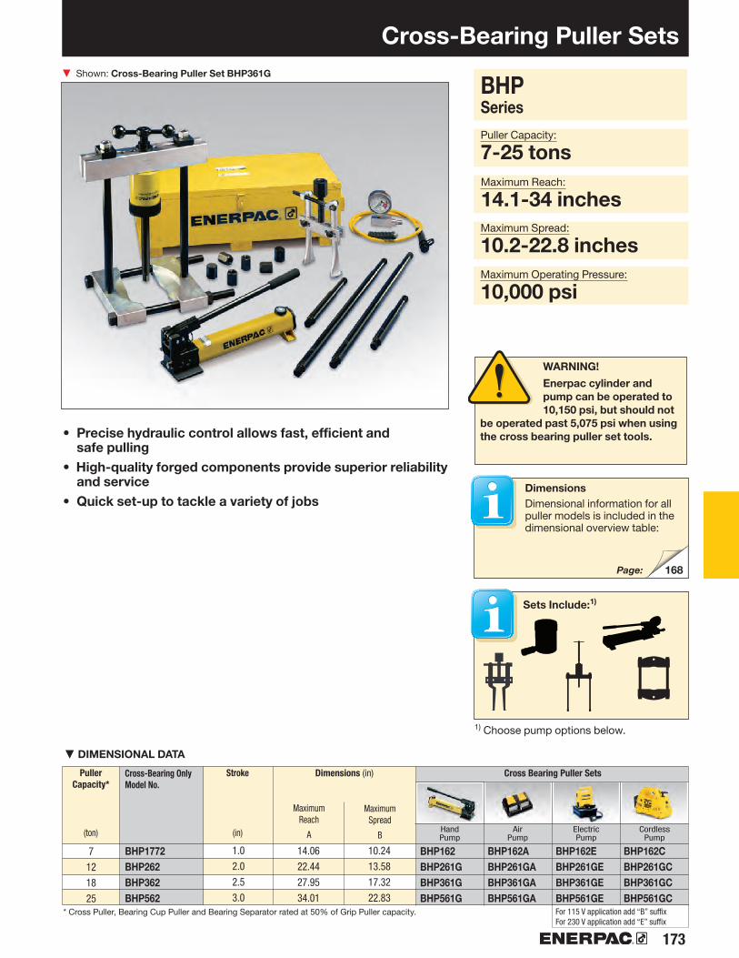
173
220
BHP1772BHP262BHP362BHP562
BHP162BHP261GBHP361GBHP561G
BHP162ABHP261GABHP361GABHP561GA
BHP162EBHP261GEBHP361GEBHP561GE
BHP162CBHP261GCBHP361GCBHP561GC
▼
7121825
168
Cross-Bearing Puller Sets
Sets Include:1)
1) Choose pump options below.
Page:
DimensionsDimensional information for all puller models is included in the dimensional overview table:
Cross-Bearing Only Model No.
Dimensions (in) Cross Bearing Puller Sets
Maximum Reach
A
Maximum Spread
B
Puller Capacity*
(ton)
Stroke
(in)
▼ DIMENSIONAL DATA
BHP SeriesPuller Capacity:
7-25 tons
Maximum Spread:
10.2-22.8 inchesMaximum Operating Pressure:
10,000 psi
Maximum Reach:
14.1-34 inches
Hand Pump
Air Pump
Electric Pump
Cordless Pump
• Precise hydraulic control allows fast, efficient and safe pulling
• High-quality forged components provide superior reliability and service
• Quick set-up to tackle a variety of jobs
Shown: Cross-Bearing Puller Set BHP361G
* Cross Puller, Bearing Cup Puller and Bearing Separator rated at 50% of Grip Puller capacity. For 115 V application add “B” suffixFor 230 V application add “E” suffix
WARNING!
Enerpac cylinder and pump can be operated to 10,150 psi, but should not
be operated past 5,075 psi when using the cross bearing puller set tools.
10.2413.5817.3222.83
14.0622.4427.9534.01
1.02.02.53.0

▼
174 www.enerpac.com
177
177
Shaft Attachments
Shaft protectors and extenders are live centers that fit over the standard puller shaft for tip protection and additional reach.
EP-Series, Posi Lock® Mechanical Grip Pullers Shown from left to right: EP-206, EP-108
• Patented “Safety Cage” jaw retention system• Roll threaded shafts for less effort when applying
high torque• Slim tapered jaws for improved gripping in tight spots• Available in 2 and 3 jaw design and inside and outside
pulling configuration• More efficient pulling, as one man can do the job
where manual pullers often require two operators
For Safer and Faster Pulling
Application Tip
Because of the unique Safety Cage design, Posi Lock® pullers will grip on surfaces where normal pullers would slip off; e.g. tapered bearings.
Long Jaws
Long Jaws are used to increase the reach and spread of manual pullers. They maintain the same
pulling capacity as the standard jaws, but reduces clamping force by 25%.
Page:
Page:
◀ Positioning an EP-104, 3-jaw puller on the drive pulley of an electric motor.

175
EP-204EP-104EP-206EP-106EP-208EP-108EP-210EP-110EP-213EP-113EP-216EP-116
EPPMI-6
Posi Lock® Mechanical Grip Pullers
Application Tip
In determining the correct manual puller capa city for your application, use the following rule:
The center bolt diameter of the puller should be at least 1/2 the diameter of the shaft being pulled on.
Example:
A part being pulled from a shaft with a diameter of 1.5" would require a puller with a center bolt diameter of at least .75".
1 Patented “Safety Cage” guides jaws, holding them securely onto the part.
2 Durable forged jaws provide positive grip.
3 Jaw head provides pivot and reaction point for jaws.
4 Pin, for easy jaw removal and replacement.
5 T-handle provides control of the puller jaws.
6 Drive bolt with rolled threads for increased force with reduced input torque.
7 Snap-ring retains cage to drive bolt and provides quick removal for easy service.
EPEPPSeries
Capacity:
2-40 tons
Spread Range:
0.50-25.00 inches
Maximum Reach:
4.00-14.00 inches
SpreadRange
(in)
MaximumReach
(in)
Capacity
(tons)
Center Bolt Diameter
(in)
Number of
Jaws
ModelNumber
Weight
(lbs)
SpreadRange
(in)
MaximumReach
(in)
JawStyle
Jaw Length
(in)
ModelNumber
Weight
(lbs)
▼ QUICK SELECTION CHART INTERNAL PULLERS For full technical information see next page.
▼ QUICK SELECTION CHART EXTERNAL PULLERS For full technical information see next page.
Always wear Safety Goggles and Gloves while using pullers.
StandardLong
Number of
Jaws
External Puller
Internal Puller
232323232323
256101217142025303540
4.004.006.006.008.008.009.679.6712.0012.0014.0014.00
.5-5
.5-5.5-7.0.5-7.0.75-12.75-121.0-151.0-152.5-182.5-183.0-253.0-25
.56
.56
.66
.66
.79
.79
.79
.791.171.171.231.23
3478
1214131638445768
5.877.70
.56-4.001.0-5.25
6.628.62
8.68.6
3
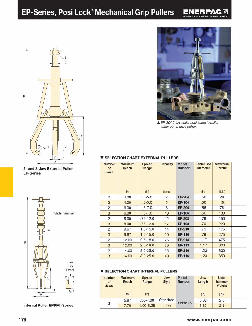
176 www.enerpac.com
J
E
B
H G
FA
C
B
C
AF
E
G
H
EP-204EP-104EP-206EP-106EP-208EP-108EP-210EP-110EP-213EP-113EP-216EP-116
EPPMI-6
EP-Series, Posi Lock® Mechanical Grip Pullers
Number of
Jaws
SpreadRange
(in)
MaximumReach
(in)
Capacity
(tons)
Maximum Torque
(ft.lb)
Center Bolt Diameter
(in)
Slide-hammerWeight
(lbs)
Number of
Jaws
ModelNumber
SpreadRange
(in)
MaximumReach
(in)
JawStyle
Jaw Length
(in)
ModelNumber
StandardLong
▼ SELECTION CHART INTERNAL PULLERS
▼ SELECTION CHART EXTERNAL PULLERS
Jaw Tip
Detail
2- and 3-Jaw External PullerEP-Series
Internal Puller EPPMI-Series
▲ EP-204 2-jaw puller positioned to pull a water pump drive pulley.
Slide hammer
3
232323232323
256
101217142025303540
4.004.006.006.008.008.009.679.67
12.0012.0014.0014.00
.5-5.0
.5-5.0
.5-7.0
.5-7.0.75-12.0.75-12.01.0-15.01.0-15.02.5-18.02.5-18.03.0-25.03.0-25.0
.56
.56
.66
.66
.79
.79
.79
.791.171.171.231.23
204075
130150220175275475600800850
5.877.70
.56-4.001.00-5.25
6.628.62
2.52.5

177
⅞
⅞
11•16
11•16
11•4
11•4
11•4
11•4
111•16
111•16
113•16
113•16
EP-204EP-104EP-206EP-106EP-208EP-108EP-210EP-110EP-213EP-113EP-216EP-116
EPPMI-6
EPP-4EPP-4EPP-6EPP-6EPP-10EPP-10EPP-10EPP-10EPP-1316EPP-1316EPP-1316EPP-1316
EPX-4EPX-4EPX-6EPX-6EPX-10EPX-10EPX-10EPX-10––––
––––EP-11054EP-11054EP-11054LEP-11054LEP-11354LEP-11354L––
EPP-4EPX-4EPP-6EPX-6EPP-10EPX-10EPP-1316
EP-11054EP-11054LEP-11354LEP-10554L*
Posi Lock® Mechanical Grip Pullers
Overall Length
B
Jaw Width
F
Tip Clearance
G
Tip Depth
H
Hex Socket
Size
J
Note: Overall length (B) is dependent on position of center bolt.
ModelNumber
Overall Length
B
Jaw Width
F
Slide Rod Diameter
E
Tip Clearance
G
Tip Depth
H
ModelNumber
EPEPPSeries
Capacity:
2-40 tons
Spread Range:
0.50-25.00 inches
Maximum Reach:
4.00-14.00 inches
SpreadRange
A
MaximumReach
C
Center Bolt
Diameter
E
Dimensions
Dimensions (in)
Shaft Protectors
Extenders Long Jaws
Note: See the chart below to reference matching pullers for these accessories.
Long Jaws
Long Jaws are used to increase the reach and spread of manual pullers. They maintain the same pulling capacity as the standard jaws, but reduces clamping force by 25%.
Shaft Protectors and Extenders
Shaft Protectors and Extenders are live centers that fit over the puller end for tip protection and added reach.
* EPPMI-6 only
Order: Model Number
Spread
(in)
Reach
(in)
Order: Model Number
Dia meter
(in)
Length
(in)
Increases Center Bolt
Length
(in)
▼ Optional Accessories
MaximumReach
C
SpreadRange
A
Always wear Safety Goggles and Gloves while using pullers.
.54
.54
.75
.75
.77
.77
.77
.771.251.251.441.44
.16
.16
.32
.32
.25
.25
.25
.25
.50
.50
.53
.53
.18
.18
.24
.24
.36
.36
.36
.36
.38
.38
.46
.46
9.68-12.759.68-12.7512.75-18.7512.75-18.7516.25-24.2516.25-24.2519.25-29.00 19.25-29.0026.00-38.0026.00-38.0031.50-45.5031.50-45.50
4.004.006.006.008.008.009.679.6712.0012.0014.0014.00
.5-5.0
.5-5.0
.5-7.0
.5-7.0.75-12.0.75-12.01.0-15.01.0-15.02.5-18.02.5-18.03.0-25.03.0-25.0
.56
.56
.66
.66
.79
.79
.79
.791.171.171.231.23
29.0031.00
.52
.52.33.33
.12
.30.06.18
1.5-151.5-221.5-30
1.0-5.26
9.6715.78
208.62
1.00 1.97 1.22 1.971.221.972.00
0.750.750.870.871.001.001.38
0.381.500.501.500.501.500.83
.56-4.001.00-5.25
5.877.70

▼
178 www.enerpac.com
180
EPH-208EPH-108EPH-210EPH-110EPH-213EPH-113EPH-216EPH-116
EPH-Series, Posi Lock® Hydraulic Grip Pullers
MaximumSpread
(in)
Capacity
(ton)
Number of
Jaws
ModelNumber*
Shown: EPHR-110
• Patented “Safety Cage” jaw retention system• High force hydraulic system for effortless pulling
of large components• Slim tapered jaws for better gripping in tight spots• Available in 2 and 3 jaw design• More efficient pulling, as one man can do the job where
normal pullers often require two operators
▼ An EPH –113 hydraulic Posi Lock® puller easily removes machined parts from a heavy-production press.
High-Tech Pulling
Basic Pullers only, cylinder not included.
Application Tip
Because of the unique safety cage design, Posi Lock® pullers will grip on surfaces where normal pullers would slip off; e.g. tapered bearings.
Transport and Store
Conveniently store and transport hydraulic pullers and accessories. Order the EPT-2550 Storage Cart and make your job easier to do!
Long JawsLong Jaws are used to increase the reach and spread of hydraulic pullers. They maintain the same pulling capacity as the
standard jaws, but reduces clamping force by 25%.
Page:
*Cylinder is not included.
SpreadRange
(in)
12.0012.0015.0015.0018.0018.0025.0025.00
23232323
10
15
25
50
.75-12.0
.75-12.01.0-15.01.0-15.02.5-18.02.5-18.03.0-25.03.0-25.0

179
FA
D
B
H G
C
EPH-11052 EPH-11052 EPH-11052EPH-11052EPH-11352EPH-11352EPH-11652EPH-11652
EPH-155EPH-155 EPH-155EPH-155EPH-257EPH-257EPH-508EPH-508
EPH-208EPH-108EPH-210EPH-110EPH-213EPH-113EPH-216EPH-116
EP-11054 EP-11054 EPH-11054LEPH-11054LEPH-11354LEPH-11354L
——
PUJ-1200BHC-9210G-2535LN/A
ZE3208MBHC-9210G-2535LGA-3
EPHR208EPHS208EPHR210EPHS210EPHR213EPHS213EPHR216EPHS216EPHR108EPHS108EPHR110EPHS110EPHR113EPHS113EPHR116EPHS116
Dimensions (in)
Posi Lock® Hydraulic Grip Pullers
SpreadRange
A
Overall Length
B
Max.Reach
C
Jaw Length
D
Jaw Width
F
Tip Clearance
G
Tip Depth
H
Weight
(lbs)
Pump Sets
All Posi Lock Hydraulic Puller Sets that include 115 VAC pumps will feature the following components:
Components for 230 VAC pumps are available on request.
EPHSeries
Capacity:
10-50 tons
Spread Range:
0.75-25.0 inches
Maximum Reach:
8.0-14.0 inches
Maximum Operating Pressure:
10,000 psi
2 Jaw
Puller
3 Jaw
Puller
▼ SETS SELECTION CHART
Weight
(lbs)
Style SetModel Number
Capa -city
(ton)
Basic Puller Cylinder Stroke
(in)
Pump Set
PumpHoseGaugeAdapter
EP-1Pump Set
EP-2Pump Set
For full details on puller accessories see page 170.
ModelNumber
▼ *Optional Accessory
Ram Point Sets
*Long JawsLift Plates
* Long Jaws are available as optional accessories.
.75-12.0
.75-12.01.0-15.01.0-15.02.5-18.02.5-18.03.0-25.03.0-25.0
19.6119.6126.1926.1933.3133.3136.1936.19
8.008.0010.0010.0012.0012.0014.0014.00
9.349.3410.6410.6413.7213.7216.2916.29
.88
.881.001.001.251.251.441.44
.29
.29.441.441.508.508.598.598
.27
.27
.36
.36
.38
.38
.46
.46
14162225475590
100
EPH-208EPH-208EPH-210EPH-210EPH-213EPH-213EPH-216EPH-216EPH-108EPH-108EPH-110EPH-110EPH-113EPH-113EPH-116EPH-116
RC-106RC-106RC-1510RC-1510RC-2514RC-2514RC-5013RC-5013RC-106RC-106RC-1510RC-1510RC-2514RC-2514RC-5013RC-5013
661010
14.2514.2513.2513.25
661010
14.2514.2513.2513.25
–EP-1–EP-1–EP-1–EP-2–EP-1–EP-1–EP-1–EP-2
2460498598
11819221226625288
106126202222
10101515252550501010151525255050

180 www.enerpac.com
EPH-208EPH-108EPH-210EPH-110EPH-213EPH-113 EPH-216EPH-116
EPH-11052EPH-11052EPH-11052EPH-11052EPH-11352EPH-11352EPH-11652EPH-11652
232323
EP-11054
EPH-11054L
EPH-11354L
EPH-208EPH-108EPH-210EPH-110EPH-213EPH-113
Model Number *
Fits Model Number
Set NumberSet Includes
Flat Ram Point
Tapered Ram Point
Ram Point Adaptor
EPH-208 EPH-108 EPH-210 EPH-110
EPH-155Dia. x Length (in)
EPH-213 EPH-113
EPH-257Dia. x Length (in)
EPH-216 EPH-116
EPH-508Dia. x Length (in)
▼ RAM POINT SETS SELECTION CHART
IMPORTANT!
Always wear Safety Goggles and Gloves while using pullers.
▼ LONG JAW SELECTION CHART
◀ EPH-11054L Long Jaws are used to increase the reach and spread of hydraulic pullers. They maintain the same pulling capacity as the standard jaws, but reduces clamping force by 25%.
Model Number
No.of Jaws
Required
SpreadRange
(in)
Max.Reach
(in)
Wt.(each)
(lbs)
Posi Lock® Hydraulic Puller Accessories
▼ LIFT PLATE SELECTION CHART
Fits Puller Set Model Number
Thickness
(in)
Diameter
(in)
* Mounting screws included. Lifting plates are standard included with EPH-Series Pullers.
Fits Puller Set Model Number
EPHSeries
Capacity:
10-50 tons
Spread Range:
1.5-30.0 inches
Maximum Reach:
9.7-20.0 inches
1 x 11 x 3
–1 x 1.51 x 3.5
––
1.5 x 2.252 x 2.25
2 x 41.5 x 2.52 x 2.52 x 4.5
–
2 x 32.75 x 32.75 x 52 x 3.752 x 3.75
2.75 x 5.52.75 x 2.25
2.25 - 15.0
1.5 - 22.0
1.5 - 30.0
9.7
15.8
20.0
2.5
5.5
10.5
.25
.25
.25
.25
.38
.38
.38
.38
6666881010

181
AAH
FG
CD
B
▼
EPH-1002EPH-1003
EPHT-1162EPHT-1163EPHT-1164
Dimensions (in)
SpreadRange
A
Overall Length
B
Reach(max.)
C
Jaw Length
D
Jaw Width
F
Tip Clearance
G
Tip Depth
H
Weight
(lbs)
Pushing AdaptorsAll Posi Lock 100 Ton Hydraulic Pullers include (3) pushing adaptors.
Overall Length
(in)
Diameter
(in)
ModelNumber
Posi Lock® 100-Ton Hydraulic Grip Pullers
Capacity:
100 tons
EPH Series
Maximum Reach:
48 inchesSpread Range:
7.5 - 70 inchesMaximum Operating Pressure:
10,000 psi
• Roller cart with power lift• Adjustable jaw tips• Puller easily detaches from cart• Self-contained unit• Puller height range 26.5" to 66.5"
Max.Spread
(in)
Capacity
(tons)
Number of
Jaws
ModelNumber
EPH-1003
▲ The EPH-1002 quickly and easily removes this drive coupler from its shaft.
1007.5-70.07.5-70.0
77.0077.00
53.0053.00
1.251.25
3.53.5
3.53.5
17001950
48.0048.00
29199
70.0070.00
23
3.53.53.5
40.9
8
min.
26.
50 max
. 66.
54
77.9
5

182
IITURBO
273
202
182182 www.enerpac.com
Enerpac Hydraulic Tools
Enerpac offers an extensive range of
dedicated tools for a variety of specific
and flexible applications. Whatever
your requirement… cutting, punching,
spreading or bending… you can be sure
that Enerpac has the correct tool to do
your job safely and efficiently.
Featuring maintenance sets, machine lifts
and load skates, as well as hole punches,
pipe benders and cable cutters, Enerpac
has the tools to ensure that even your
most demanding applications can be
undertaken with the highest degree of
safety and accuracy.
Pump and Tool Sets
Selected hydraulic tools in this section
are available in sets, for a perfect tool-pump match.
Hydraulic System Set-up
Check out our “Yellow Pages” section for help on system set-ups and valving configurations.
Bolting Tools
More Enerpac Tools can be found in the Bolting Tools section of this catalog.
Page:
Page:

183
▶
▶
▶
▶
▶
▶
▶
▶
▶
▶
184
188
192
193
194
196
197
198
199
200
MS
SPMSPSTP
LW
SOH
ERESELP
CM
AWR
WHCWHRSTC
WMC
STB
2.5 - 12.5
35 - 50
16
8.5 - 20
1-80
.67 - 16 (cubic feet)
.75 - 1.00
3 - 20
3 - 20
Nominal Bore1/2" - 4 inches
Tool Section Overview
Maintenance Sets
Punch, Punch Sets
Lifting Wedge
Hydraulic Machine Lifts
Heavy-Duty Load Skates
Industrial Storage Cases
Hydraulic WedgieSpread Cylinders
Hydraulic CutterheadsCutterheads Pump Sets
Self-Contained Hydraulic Cutters
Pipe Bender Sets
Tool Type and Functions SeriesCapacity(tons)
Page

▼
184 www.enerpac.com
186
▶
MS2-4MSFP-5**MSFP-10MS2-10MS2-20MS2-1020
P-142P-142P-392P-392P-392P-392
HC-7206HC-7206HC-7206HC-7206HC-7206HC-7206
RC-55RC-55RC-106RC-106RC-256RC-102, -106, -256
GP-10SG2535LG2535LGP-10SGP-10SGP-10S
GA-4GA-3GA-3GA-2GA-2GA-2
Set Model Number
MS-Series, Maintenance Sets
• All sets include Enerpac pump, hose, cylinder and gauge• Lock-on or threaded connectors• Complete set for almost every maintenance application
The Universal Hydraulic Tool Box
Maintenance Sets
Enerpac Maintenance sets are a complete assortment of accessories matched to
hydraulic powered tools. Using these sets allows you to quickly configure a unique tool to meet your most difficult jobs.
Built around the Enerpac lightweight hand pump, hose and cylinder, these sets enable you to push, pull, lift, press, straighten, spread and clamp with forces up to 12.5 tons.
▼ QUICK SELECTION CHART
Capacityusing
attachments*
(tons)
Number of Attachment
Components
Weight
(lbs)
* If no attachments are being used, capacity is double these values. Maximum operating pressure is then 10,000 psi.** This set also includes the FZ-1055 Adaptor.
Shown: MS2-10
Clamping a workpiece is just one of the many applications for the
Enerpac maintenance sets.
More Information
For detailed information on all included attachments, see the following pages.
Page:
2.52.555
12.55-12.5
332423351353
5944
105140210350

185
27 22 27
21
27
8
21
6
15
27
19
1
2
4
3
1
4
17 17
18
10
16
18
11
21
MS-Series, Maintenance Sets
MS Series
Capacity (using attachments):
2.5-12.5 tonsMax. Operating Pressure (using attachments):
5,000 psi▼ APPLICATION EXAMPLES
Collar Toe
Lock Pins
Chain with Hook
Threaded Adaptor
Collar Clamp Head
18" Extension Tube
Lock Pin
Lock Pin
Double Chain Plate attached to the plunger using
a Threaded Adaptor 1
Lock-on Clamp Toe
Rubber Flex Head
5" Extension Tube
5" Extension Tube 10" Extension Tube Lock-on Connector
Pipe Coupling
Single Chain Plate
Serrated Saddle, attached to the Plunger using a Threaded Adaptor 1
Base Attachment
Threaded Adaptor
Flat Base
Flat Base, attached to the Base Attachment using a Threaded Connector 5
Smooth Saddle attached to the plunger using a Threaded Adaptor 1
Chain with Hook
WARNING!
Only use attachments provided with set. Non-Enerpac
attachments and longer extension tubes will reduce column strength, potentially creating unsafe conditions.
Double Chain Plate attached to the Base Attachment 2 using a Threaded Connector 5
CAUTION!
When cylinders are used with maintenance set
attach ments or components, the maximum system pressure must be limited to half the rated pressure (5,000 psi).

▼
186 www.enerpac.com
AC D
B
AD
C
B
B
AA
B
C
D
A
B
C
D
A
C
D
B
A
123456789
101112131415
161718
19
20212223242526
1
2
3
4
5
6
MS-Series, Maintenance Sets
* A-243 is a round base model
Note: All dimensions in inches.
Threaded Adaptor
Base/Collar/Plunger AttachmentsCAUTION! When cylinders are used with maintenance set attachments or components, the maximum system pressure must be limited to half the rated pressure (5,000 psi).
Set Model No.
Base/Collar/ Plunger Attachments 2.5 tons 2.5 tons 5.0 tons 5.0 tons 12.5 tons 5-12.5 tons
Cylinder Series RC-5 RC-5 RC-10 RC-10 RC-25 RC-10, RC-25
Tubes, Connectors 2.5 tons 2.5 tons 5.0 tons 5.0 tons 12.5 tons 5-12.5 tonsand Adaptors
Cylinder Series RC-5 RC-5 RC-10 RC-10 RC-25 RC-10, RC-25
Chains and Attach- 2.5 tons 2.5 tons 5.0 tons 5.0 tons 12.5 tons 5-12.5 tonsments for Pulling
Cylinder Series RC-5 RC-5 RC-10 RC-10 RC-25 RC-10, RC-25
Model No.
A-23
A-13
A-28
Model No.
A-25
A-21
A-27
Model No.
A-545
A-10
Model No.
A-1034
A-20
A-595
Model No.
MZ-4010
A-14
A-243*
Tons
2.5
5.0
12.5
Tons
2.5
5.0
12.5
Tons
2.5
5.0
12.5
Tons
2.5
5.0
Model No.
A-8
Tons
5.0
Tons
2.5
5.0
12.5
Capacity Using Attachments
MS2-4 MSFP-5 MSFP-10 MS2-10 MS2-20 MS2-1020
A-23 A-23 A-13 A-13 A-28 A-13 / A-28
A-25 A-25 A-21 A-21 A-27 A-21 / A-27
A-1034 A-1034 A-20 A-20 A-595 A-20 / A-595
MZ-4010 MZ-4010 A-14 A-14 A-243 A-14 / A-243
A-545 A-545 A-10 A-10 — A-10(2x) — — — A-8 — A-8
A-530 A-530 A-6 A-6 — A-6
MZ-4011 — — A-192 — A-192
— — — A-305 — A-305
A-531 A-531 A-18 A-18 — A-18
— — — A-185 — A-185
A-532 A-532 A-15 A-15 — A-15
— — — — A-607 A-607
A-629 A-629 A-129 A-129 — A-129
A-539 A-539 A-128 A-128 — A-128
A-558 — — A-132 A-238 A-132, -238
— — — A-5 (2x) — A-5(2x)
A-557(2x) — — A-141(2x) A-218(2x) A-141(2x) /
A-218(2x)
A-544 — — A-19(2x) A-242(2x) A-19(2x) and
A-242(2x)
WR-5 WR-5 WR-5 A-92 — A-92
MZ-4013(4x) MZ-4013(4x) A-16(4x) A-16(4x) — A-16(4x)
MZ-4007(3x) MZ-4007(3x) MZ-1050(3x) MZ-1050(2x) — MZ-1050(3x)
MZ-4008(2x) — — MZ-1051 — MZ-1051(2x)
MZ-4009 MZ-4009 MZ-1052 MZ-1052 — MZ-1052
— — — A-285 — A-285 A-650 — — — — —
Length: 3" MZ-4002 MZ-4002 — — —
5" MZ-4003 MZ-4003 MZ-1002 MZ-1002 — MZ-1002
10" MZ-4004 MZ-4004 MZ-1003 MZ-1003 A-239 MZ-1003
and A-239
18" MZ-4005(2x) MZ-4005 MZ-1004 MZ-1004 A-240 MZ-1004(2x)
and A-240
23" MZ-4006 MZ-4006 — — — —
30" — — MZ-1005 MZ-1005 A-241 MZ-1005(2x)
and A-241
Case CM-6 CM-6 CW-166 CW-166 CW-166 CW-350 Weight 59 lbs. 44 lbs. 105 lbs. 140 lbs. 210 lbs. 350 lbs.
Base Attachment
Collar Toe
Flat Base
Threaded Connector
Lock-on Clamp Toe
A
¾"-16 un
1"-8 un
1½"-16 un
B
1.13
1.25
1.87
C
1.05
2.19
2.75
B
2.00
2.25
2.50
D
¾"-14 npt
1¼"-11½ npt
2"-11½ npt
B
1.38
1.63
A
¾"-14 npt
1¼"-11½ npt
A
1.69
B
4.13
C
2.00
D
2.25
A
¾"-14 npt
1¼"-11½ npt
2"-11½ npt
A
1½"-16
2¼"-14
35•16"-12
C
.50
.50
.50
D
1.75
2.56
3.88
B
2.13
3.16
4.06
C
1.97
2.25
2.03
D
1.25
2.25
3.18
A
¾"-14 npt
1¼"-11½ npt
2"-11½ npt
B
4.50
6.50
6.50
C
1.25
1.38
2.31
D
2.50
3.50
6.50

187
B
C
D
A
A
C D
B
C
B
D A
A
B
C
B
A
B
AC
B
AC
B
CAD
B
C
AA
BA
DC
AC
B
A
C B
D
AC
B
A CD
B
B
AC
D
C
A
B
AC
B
D
A
B C
B
A
7
8
9
10
11
12
13
14
15
16
22
20
21
17
18
24
25
23
19
26
MS-Series, Maintenance Sets
Chains and Attachments for Pulling
Tubes, Connectors and Adaptors
Model No.
MZ-4013
A-16
Model No.
MZ-4007
MZ-1050
Model No.
A-305
Model No.
MZ-4011
A-192
Model No.
A-530
A-6
Model No.
A-539
A-128
Model No.
A-558
A-132
A-238
Model No.
A-629
A-129
Model No.
WR-5
A-92
Tons
1.0
1.0
Tons
2.5
5.0
Tons
2.5
5.0
Tons
2.5
5.0
Tons
2.5
5.0
Tons
2.5
5.0
Model No.
MZ-4008
MZ-1051
Model No.
MZ-4009
MZ-1052
Model No.
A-285
Model No.
A-650
Tons
2.5
Tons
5.0
Tons
2.5
5.0
Tons
2.5
5.0
Model No.
A-531
A-18
Tons
2.5
5.0
Model No.
A-532
A-15
Tons
2.5
5.0
Model No.
A-185
Tons
5.0
Tons
5.0
Model No.
A-607
Tons
12.5
Tons
2.5
5.0
12.5
Model No.
A-557
A-141
A-218
Chain Length
5 feet
6 feet
8 feet
Tons
2.5
5.0
12.5
Model No.
A-544
A-19
A-242
Tons
2.5
5.0
12.5
Model No.
A-5
Tons
5.0
Tons
2.5
5.0
Threaded Plunger Toe
Collar Clamp Head
Spreader Toe
Serrated Saddle
Smooth Saddle
90° V-Base
Plunger Base
Wedge Head
Rubber Flex-Head
Single Chain Plate
Lock-on Connector
Spreader
Lock Pin
Double Chain Plate
Chain with Hook
Female Lock-on Adaptor
Adjustable Extension
Male Lock-on Adaptor
Pipe Coupling
Slip-Lock Extension
A
¾"-14 npt
1¼"-11½ npt
B
2.25
3.12
C
1.00
1.25
D
1.33
2.25
A
¾"-14 npt
1¼"-11½ npt
B
2.75
4.00
C
1.31
2.00
C
2.00
D
1.13
1.75
A
—
2¼"-14 un
A
.25
.44
A
.75
1.31
B
8.78
9.63
C
.50
1.38
D
3.70
6.25
A
¾"-14 npt
1¼"-11½ npt
B
1.75
3.40
C
2.75
3.40
B
2.38
3.25
B
3.12
5.00
A
¾"-14 npt
1¼"-11½ npt
C
.75
1.31
B
2.38
3.56
A
¾"-14 npt
1¼"-11½ npt
C
.75
1.31
B
2.56
3.81
A
1¼"-11½ npt
B
13.20
C
17.37
D
1.30
A
¾"-14 npt
B
7.88
C
14.37
A
¾"-14 npt
1.69
B
1.95
2.50
C
3.00
2.00
A
¾"-14 npt
1¼"-11½ npt
C
1.09
1.50
B
1.25
2.00
A
¾"-14 npt
1¼"-11½ npt
B
1.50
2.13
C
1.88
2.25
C
1.53
D
1.00
2.13
A
1¼"-11½ npt
B
1.50
C
2.00
A
1¼"-11½ npt
B
4.50
C
1.00
D
2.00
A
2"-11½ npt
B
6.56
A
1½"-16 un
2¼"-14 un
35•16"-12 un
B
7.75
12.12
17.75
C
1.56
2.50
4.03
D
1.75
3.12
4.93
A
¾"-14 npt
1¼"-11½ npt
2"-11½ npt
B
1.69
1.94
3.50
C
1.31
2.15
3.25
A
1¼"-11½ npt
B
6.18
D
4.96
D
1½-16 un
2¼-14 un

▼
188 www.enerpac.com
SP-Series, Lightweight Hydraulic Punch
HoleShape
Hole Size
(in)
HoleSize
(mm)
BoltSize
(in)
BoltSize
(mm)
Imperial* Metric*
▼ STANDARD PUNCH AND DIE SETS SELECTION CHART
• .50" thick mild steel maximum capacity• Round, oblong and square punches and dies are available
to solve your punching applications• Long life Enerpac single-acting, spring return design• Durable case keeps tools and dies together and provides
for easy carrying and storage• CR-400 female coupler included
Much Faster than Drilling...
Tool Kit SPK-10
Included with all 35 ton punches, this tool kit is used to remove and install the punch into the head.
Can be ordered as a replacement under model number SPK-10.
Ordering Information
The 35-ton hydraulic punch may be ordered by itself or as a set, including an electric, air or hand pump.
Please refer to the Quick Selection Chart information on next page. A punch and die may also be ordered as a matched set.
Shown: SP-35S
▼SP-Series, Lightweight Hydraulic Punch – much faster than drilling.
* Material thickness should not exceed hole diameter.
.31
.38
.44
.53
.56
.69
.78
.81
.31
.38
.44
.50.31 x .75.38 x .75.44 x .75.50 x .75
7,99,511,113,514,317,519,820,67,99,511,112,7
7,9 x 199,5 x 1911,1 x 1912,7 x 19
–M8
M10M12
–M16M18
––
M8M10M12
–M8
M10M12
¼
5/16
⅜
7/16
½
⅝
–¾
¼
5⁄16
⅜
7/16
¼
5⁄16
⅜
7⁄16

189
3/8"-18NPTF
1) 2) 3) 4) 5) 6) 7) 8) 9) 10) 11)
SPD-313SPD-375SPD-438SPD-531SPD-563SPD-688SPD-781SPD-813SPD-458SPD-549SPD-639SPD-728SPD-106SPD-125SPD-188SPD-250
SP-35SP-35SSP-35SPMSP-351STP-35HSTP-35A
SP-35SP-35SP-35SP-35SP-35SP-35
Model No.
Single-Acting, Spring Return Hydraulic Punch
Standard Punch & Die Set
Steel Qualities (see table):
1) Mild A-7 2) Boiler Plate 3) Structural A-36 4) Struct Corten (ASTM A242) 5) Cold Rolled C-1018 6) Hot Rolled C-1050 7) Hot Rolled C-1095 8) Hot Rolled C-1095 Annealed 9) Stainless Annealed 10) Stainless 304 Hot Rolled 11) Stainless 316 Cold Rolled
* Punch oil capacity: 4.58 in3
Includes the following punch and die sets: ** SPD-438, SPD-688, SPD-563 and SPD-813 *** SPD-375, SPD-531, SPD-438 and SPD-688
–Standard**Standard**Metric***
Standard**Standard**
ModelNumberPunch and
Die Set
Weight
(lbs)
HosePump
▼ QUICK SELECTION CHART
Included
CAUTION!
Chart below is for reference only! Maximum allowable material thickness to
be punched varies with set wear.
SP, MSP,STP Series
Capacity:
35 tonsHole Sizes:
0.31-0.81 inchMaximum Operating Pressure:
10,000 psi
*
Maximum Allowable Material Thickness To Be Punched (in)(Material thickness should not exceed hole diameter.)
CAUTION!
Material thickness should not exceed hole diameter.
PumpType⧫
⧫ E = Electric H = Hand A = Air operated
.31
.38
.44
.50
.50
.50
.50
.50
.31
.38
.44
.50
.31
.38
.44
.50
.31
.38
.44
.50
.50
.50
.50
.50
.31
.38
.44
.50
.31
.38
.44
.50
.25
.31
.38
.44
.50
.50
.50
.50
.25
.31
.38
.44
.25
.31
.38
.44
.25
.31
.38
.44
.44
.44
.44
.44
.25
.31
.38
.44
.25
.31
.38
.44
.25
.31
.38
.44
.50
.50
.50
.50
.25
.31
.38
.44
.25
.31
.38
.44
.25
.31
.31
.38
.44
.40
.38
.31
.25
.31
.31
.38
.25
.31
.31
.38
.13
.19
.19
.25
.25
.25
.25
.19
.13
.19
.19
.25
.13
.19
.19
.25
.19
.25
.31
.31
.38
.31
.31
.31
.19
.25
.31
.31
.19
.25
.31
.31
.25
.31
.31
.38
.44
.40
.38
.31
.25
.31
.31
.38
.25
.31
.31
.38
.25
.31
.31
.38
.44
.40
.39
.31
.25
.31
.31
.38
.25
.31
.31
.38
.25
.31
.31
.38
.44
.40
.38
.31
.25
.31
.31
.34
.25
.31
.31
.38
3540704055 63
––
HC-7206–
HC-7206HC-7206
––
PUD-1100B–
P-392PATG-1102N
––E–HA
4.45
1.85
1.00
2.688.78
3.743.35
2.87
13.7
0
1.97
.66
ø.26
ø 3.85

▼
190 www.enerpac.com
SP-Series, 50-Ton Hydraulic Punch
• Available as a complete set including electric pump and hoses
• Double-acting cylinder design for fast cycle times• Punch and die changeover tools included• Lifting handle for easy carrying• Adjustable power stripper prevents movement
of the metal during stripping• CR-400 female couplers included
Shown: SP-50100
◀ Save time using this 50-ton Enerpac Punch.
▼ Shown below is the 50-ton punch with SP-120 and SP-110 assembled.
Cuts the Time Spent Forming Holes
Ordering Information
The 50-ton Hydraulic Punch may be ordered by itself or as a set with an electric pump. A punch and die may
be ordered as a matched set. Please refer to the selection chart information.
Foot Mounting Kit
A foot mounting kit for easy mounting of the 50 ton punch to work bench or fixture is available. Please order: SP-120.
Depth Stop
For simplified repetitive punch ing applications an adjust able Depth Stop is avail able. Order model number: SP-110.

191
SP-150SP-170SP-190SP-121SP-123
1) 2) 3) 4) 5) 6) 7) 8) 9) 10) 11)
SP-50
SP-110 SP-120
–ZE4410SB-N
SP-50100SP-5000
Steel Qualities (see table below):
1) Mild A-7 2) Boiler Plate 3) Structural A-36 4) Struct Corten (ASTM A242) 5) Cold Rolled C-1018 6) Hot Rolled C-1050 7) Hot Rolled C-1095 8) Hot Rolled C-1095 Annealed 9) Stainless Annealed 10) Stainless 304 Hot Rolled 11) Stainless 316 Cold Rolled
Standard Punch and Die Set
Maximum Allowable Material Thickness To Be Punched
(in)
HoleShape
Hole Size
(in)
BoltSize
(in)
* Punch Oil Capacity: Advance: 17 in3 Retract: 14 in3
** All standard sets from chart below.
All**All**
Set ModelNumberPunch &
Die SetsModel NumberPunch*
Weight
(lbs)
Hose(2x)
PumpIncluded
50-Ton Hydraulic Punch
Model Numbers
▼ STANDARD PUNCH AND DIE SELECTION CHART
CAUTION!
Material thickness should not exceed hole diameter.
CAUTION!
Chart below is for reference only! Maximum allowable material thickness to be
punched varies with set wear.
SP Series
Capacity:
50 tonsHole Sizes:
0.53-1.03 inchesMaximum Operating Pressure:
10,000 psi
▼ QUICK SELECTION CHART PUNCH SETS
255384
.53
.66
.78
.911.03
½
⅝
¾
7⁄8
1
.53
.56
.56
.56
.56
.53
.56
.56
.56
.56
.53
.56
.56
.56
.56
.53
.50
.50
.50
.44
.53
.56
.56
.56
.56
.49
.51
.49
.35
.31
.32
.32
.32
.22
.19
.40
.40
.40
.35
.31
.49
.51
.49
.35
.31
.49
.51
.50
.35
.31
.49
.51
.49
.35
.31
.50
.44
.197.00
.75
3.10
4.00
3.00
5.157.00
9.00
6.00
1.27
10.53
3.00 5.38
.75.44
.75
1.75 6.00.44
–HC-7206
SP-50SP-50
2.621.254.62
14.25
19.1
3
.67
4.33
5.006.73
.70
21.0
0

▼
192 www.enerpac.com
192
136
LWB-1
LW-16
LW-16
Best Match Manual Pump
To power your Enerpac Lifting Wedge, The Enerpac P-392 Hand Pump or P-392FP Foot Pump is an ideal choice.
Page:
Vertical Lifting Wedge
LWSeries
Minimum Clearance:
.39 inchesMaximum Lift Height:
2.02*-2.72* inches
Shown: LW-16 with SB-2 and optional LWB-1
Split-Flow Manifolds
Split Flow Valves to control two or four lifting wedges simultaneously.
AM-21 with 3 ports 3/8" NPTF.AM-41 with 5 ports 3/8" NPTF.
Page:
Maximum Force:
16 tonsMaximum Operating Pressure:
10,000 psi
• Requires .39 inch access gap
• Lifting force 16 ton at 10,000 psi hydraulic pressure
• Automatic mechanical retraction (single acting)
• Securely raises or lowers 16 tons with no slippage
• Lifting wedge LW-16 includes safety block SB-2
• Use in tandem to lift 32 tons, or 64 tons
• .83 inch of vertical lift from each step (maximum lift to 2.72 inches with optional LWB-1 stepped block)
ModelNo.
Max.Lifting Force
(ton)
MinimumClearance
Gap
(in)
Max. Lift per Stage
(in)
Weight
(lbs)
Max. Lifting Height
(in)
Oil Capacity
(in3)
* Use optional stepped block LWB-1 to increase wedge lifting height 1.18 inches.
Max. Lifting Height Using Stepped
Block
(in)
▼For lifting heavy equipment with minimum floor clearance the LW-16 is the ideal tool. Retracted
Extended
16 .39 2.72.83 15.42.02 4.75
.59 (4X)
1.47
1.18
2.68
4.33
8.27
9.721.77
1.20
1.48
1.75
2.03
4.76
.59 (4x)
.39
.65.93
1.20
3.94
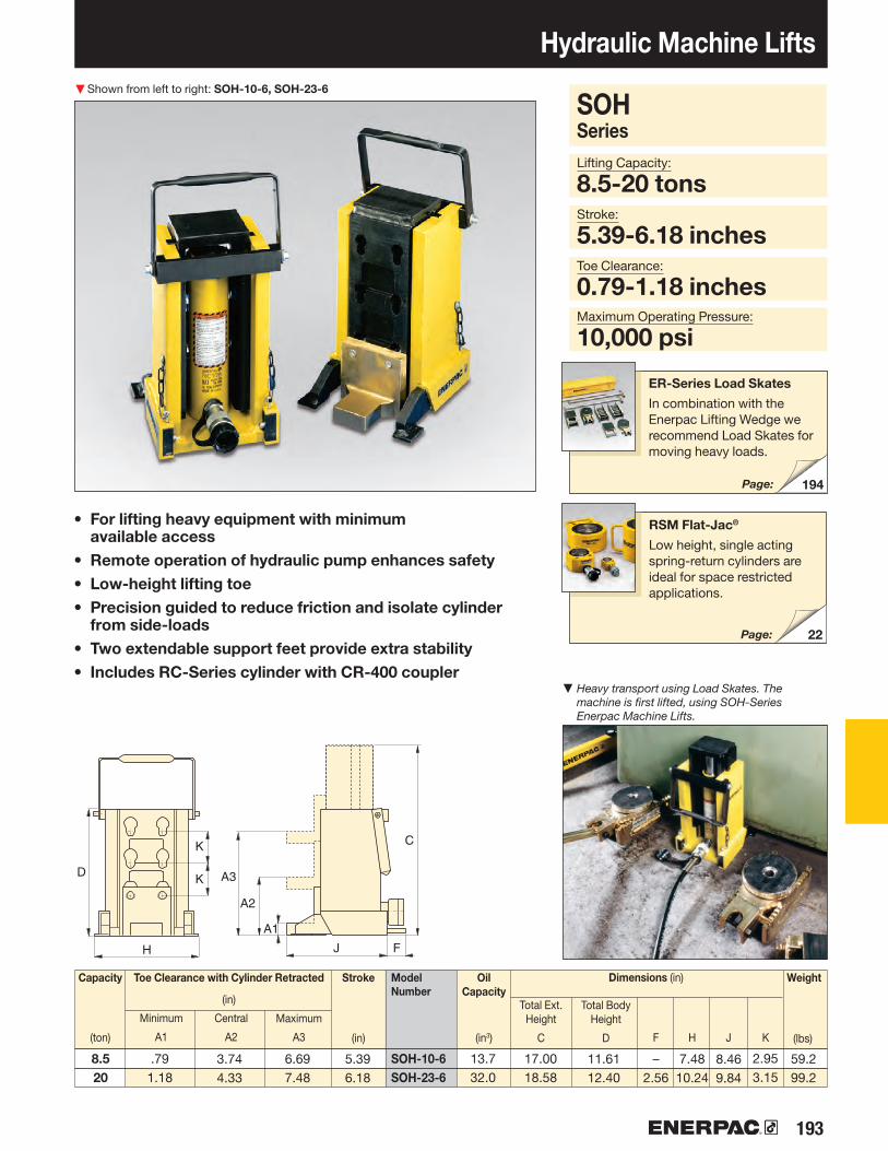
193
▼
K
K
H
D
J F
A1
C
A3
A2
22
194
SOH-10-6SOH-23-6
Hydraulic Machine Lifts Shown from left to right: SOH-10-6, SOH-23-6
• For lifting heavy equipment with minimum available access
• Remote operation of hydraulic pump enhances safety• Low-height lifting toe• Precision guided to reduce friction and isolate cylinder
from side-loads• Two extendable support feet provide extra stability• Includes RC-Series cylinder with CR-400 coupler
Capacity
(ton)
Stroke
(in)
Minimum
A1
Central
A2
Maximum
A3
Total Ext. Height
C
Total BodyHeight
D F H J K
Weight
(lbs)
RSM Flat-Jac®
Low height, single acting spring-return cylinders are ideal for space restricted applications.
Lifting Capacity:
8.5-20 tonsStroke:
5.39-6.18 inchesToe Clearance:
0.79-1.18 inchesMaximum Operating Pressure:
10,000 psi
Toe Clearance with Cylinder Retracted
(in)
Dimensions (in)
SOH Series
Model Number
Page:
ER-Series Load Skates
In combination with the Enerpac Lifting Wedge we recommend Load Skates for moving heavy loads.
Page:
Oil Capacity
(in3)
▼ Heavy transport using Load Skates. The machine is first lifted, using SOH-Series Enerpac Machine Lifts.
8.520
5.396.18
.791.18
3.744.33
6.697.48
17.0018.58
11.6112.40
–2.56
7.4810.24
8.469.84
2.953.15
59.299.2
13.732.0

▼
194 www.enerpac.com
194
Heavy-Duty Caterroller™ Load Skates
Move Heavy Loads Easily and Safely
Shown: Set ERS-20
• Rugged and sturdy construction for long life• Low profile construction for increased stability• Low rolling-resistance allows for easy load movement• Attachable load leveling plates and swivel turntables for
turning corners
Lifting Wedge and Machine Lifts
To place the Load Skates, the load must first be lifted. This can be done easily and
safely using Enerpac Lifting Wedge or Machine Lifts.
Page:
Sets (see table) include all components necessary to handle a variety of applications. Two ELB-1 link-up bars, two ERH-1 handles (34.4" long) and
one EMB-1 metal box are included.Optional long handle ERH-2 (46.4") also available.
▼ Heavy transport using Load Skates. The machine is first lifted, using SOH-Series Enerpac Machine Lifts.
▼ Chemical tank transportation: The first inch(s) the load was lifted with an RCS-Series Low Height Cylinder and then moved onto load skates for transportation.

195
B
C
F ED
A
E
A
C
B
D F
C
E
B
D
A
F
B
A
D
C
A
D
C
B
A
D
C
D
C
A
B
A
B
C
D
ER-10, ER-15, ER-30
ER-1
ER-60, ER-80
A B C D E F
ER1
ES1
ER10
ES10
ER-1ER-10ER-15ER-30ER-60ER-80ES-1ES-10ES-15ES-30ES-60ES-80ELP-10ELP-15ELP-30ELP-60ELP-80
ERS-20ERS-30ERS-60
ER-10ER-15ER-30
ES-10ES-15ES-30
ELP-10ELP-15ELP-30
Heavy-Duty Caterroller™ Load Skates
Turntable Swivel ES-10, ES-15, ES-30
Turntable Swivel ES-1
Turntable Swivel ES-60, ES-80
Leveling PlateELP-10 ELP-15 ELP-30
Leveling PlateELP-60ELP-80
ELP,ER,ES Series
Maximum Carrying Capacity:
80 tons
TurntableSwivel
Load Skates
Leveling Plate
Model Number
Weight
(lbs)
Contact Rolls per Skate
Rollers per Skate
Dimensions (inch)Capacity
(ton)
Load Skates may be ordered separately or as a matched set.
Set Model Number
Load Skates (4)
WeightIncluding handles
and metal box
(lbs)
Set Capacity*
(tons)
Turntable Swivels(2)
Leveling Plates (2)
* Sets are designed to enable two skates to take full load for extra safety on uneven floor surfaces
3.943.944.455.136.637.19
–2.873.393.784.495.042.873.393.784.495.04
6.698.278.6910.6315.0020.888.158.668.669.8410.8314.175.875.877.0110.6313.78
2.562.632.953.634.945.751.021.651.651.892.402.401.651.651.892.402.40
.71
.71
.941.181.651.973.545.125.125.917.488.664.724.725.127.097.87
2.002.002.382.693.003.38
–––––––––––
454446–––––––––––
111513131317–––––––––––
8.411.516.028.670.4
134.22.48.18.1
11.730.141.68.18.1
11.630.441.4
11015306080110153060801015306080
.24
.24
.39
.39
.63
.75–––––––––––
203060
110123167
.15 3.544.72

▼
196 www.enerpac.com
172
CM-6CM-1CM-4CM-7CM-16
Industrial Storage CasesShown: CM-16
• Protect your equipment from dust, water, grease and dirt • Reduce losses on the jobsite, maintenance area or shop• Durable steel, painted with rust-resistant primer and
finished in durable enamel• Heavy-duty hinges and lifting handles• Lockable
▼ When not storing the lifting system, this heavy-duty storage case doubles as a work station.
CMSeries
Case Size:
.67-16 Cubic Ft.
CaseSize
(ft3)
Thickness
(in)
Weight
(lb)
Model Number
Dimensions L x W x H
(in)
Protect your Equipment
Maintenance Sets
Enerpac Maintenance sets are a complete assortment of accessories matched to
hydraulic powered tools. Using these sets allows you to quickly configure a unique tool to meet your most difficult jobs.
Built around the Enerpac lightweight hand pump, hose and cylinder, these sets enable you to push, pull, lift, press, straighten, spread and clamp with forces up to 12.5 tons.
Hydraulic Pullers
These hydraulic pullers eliminate time-consuming and unsafe hammering, heating or prying.
Damage to parts is minimized through the use of controlled hydraulic power.
Page:
.671.134.507.50
16.00
.035
.035
.059
.074
.059
15.417.635.3
125.7121.3
23.5 x 7 x 725 x 11.5 x 6.631 x 18 x 14
47.5 x 15 x 1848 x 24 x 24

197
▼
A-92*WR-15
WR-5
6
70
• Single-acting, spring return• WR-15: For long stroke spreading applications• WR-5: For use in very confined work areas• A-92: Spreader attachment screws onto RC-Series
10-ton cylinders (except RC-101)*
Hydraulic Wedgie and Spread Cylinders Shown clockwise from top: WR-15, WR-5, A-92
Capacity:
0.75-1.00 tonTip Clearance:
0.50-1.38 inchesMaximum Spread Range:
3.70-11.50 inchesMaximum Operating Pressure:
10,000 psi
A, WR Series
RC-Series DUO Cylinders
10 ton RC-Series DUO cylinders (except RC-101) fit into A-92 Spreader Attachment.
Best Match Hand Pump
To power your WR5 and WR15 the P-392 hand pump is an ideal choice.
Page:
Page:
Spreader Capacity
(ton)
Tip Clear ance
(in)
Cylinder Effective
Area
(in2)
Oil Capacity
(in3)
Wt.
(lbs)
Model Number
▼A WR-5 Wedgie cylinder is used to loosen a bridge bearing.
MaximumSpread
(in)
* Maximum system pressure must be limited to half the rated pressure (5000 psi)
2.01
.38
3.70
1.138.78
2.01
3/8"-18NPTF
3/8"-18NPTF
21.65
11.5
0
6.18
2.01
1.26
1.692.24
2.00
2.75
9.63
1.38
6.25
21/4"-14UNS
3.62
1.00.751.00
.501.261.38
1.002.25
–
.613.91
–
3.7011.506.25
5.025.08.0
WR-5WR-15A-92*
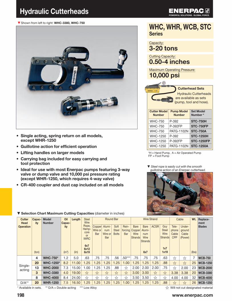
▼
198 www.enerpac.com
WHC-750WHC-750WHC-750WHC-1250WHC-1250WHC-1250
P-392P-392FPPATG-1102NP-392P-392FPPATG-1102N
STC-750HSTC-750FPSTC-750ASTC-1250HSTC-1250FPSTC-1250A
Cutterhead Sets
Hydraulic Cutterheads are available as sets (pump, tool and hose).
Hydraulic Cutterheads
• Single acting, spring return on all models, except WHR-1250
• Guillotine action for efficient operation• Lifting handles on larger models• Carrying bag included for easy carrying and
tool protection• Ideal for use with most Enerpac pumps featuring 3-way
valve or dump valve and 10,000 psi pressure rating (except WHR-1250, which requires 4-way valve)
• CR-400 coupler and dust cap included on all models
Shown from left to right: WHC-3380, WHC-750
WHC, WHR, WCB, STC Series
Capacity:
3-20 tonsCutting Capacity:
0.50-4 inchesMaximum Operating Pressure:
10,000 psi
Cutter Head
Operation
Capac-ity
(ton)
Model Number
Oil Capac-
ity
(in3)
Length
(in)
Steel Wire
Rope,Hemp-
coreor
IWRC
6x76x12 6x19
Copper Wire or
Bar
Alumi- num
Wire or Bar
Soft Steel Bolts
Re in-forcing
Bar
Bare Copper
Wire Strands
Bare Alumi- num Wire
Strands
6x7
ACSR Guy Steel Wire
Strands
1x71x19
Tele-phone Cable CPP
Under-ground Cable
(Power)
Wt.
(lbs)
Single-acting
D/A**
Round Bar Wire Strand Cable
▼Selection Chart Maximum Cutting Capacities (diameter in inches)
* Available in sets. ** D/A = Double-acting *** Low Alloy ☆ Will not cut designated material
Cutter Model Number
Set Model Number *
Pump Model Number
*H = Hand Pump, A = Air Operated PumpFP = Foot Pump
Replace-ment Blades
▼Steel rope is easily cut with the smooth guillotine action of an Enerpac cutterhead.
420133820
1.28.27.34.08.47.5
5.011.0015.0019.0024.0016.50
.631.251.00 ☆
☆
1.25
.751.251.25☆
☆
1.25
.751.251.25☆
☆
1.25
.561.25.88☆
☆
1.25
.50***1.00☆
☆
☆
1.00
.751.252.003.003.501.25
.751.252.003.003.501.25
.751.252.00☆
☆
1.25
.63
.88
.75 ☆☆
.88
☆
☆
☆
3.384.00☆
☆☆
2.003.384.00☆
72523203226
WHC-750*WHC-1250*WHC-2000WHC-3380WHC-4000WHR-1250
WCB-750WCB-1250WCB-2000WCB-3380WCB-4000WCB-1250

199
▼
Self-Contained Hydraulic CuttersShown from left to right: WMC-2000, WMC-750
• Rotating heads for operator convenience• Guillotine action (except WMC-1000) for efficient operation • Carrying bag included for easy carrying and tool protection• Velcro straps to secure handles on larger models for
easy transportation• Spring return on all models• Lightweight, self-contained tool, can be used anywhere
WMC, WCB SeriesCapacity:
3-20 tonsMaximum Material Diameter:
0.38-3.38 inchesMaximum Operating Pressure:
10,000 psi
Capa-city
(ton)
Model Number
Length
(in)
Steel Wire
Rope,Hemp-
coreor
IWRC6x7
6x12 6x19
Copper Wire or
Bar
Alumi-num
Wire or Bar
Soft Steel Bolts
Re in-forcing
Bar
Bare Copper
Wire Strands
Bare Alumi-num Wire
Strands
6x7
ACSRWire
Strands
Guy Steel Wire
Strands
1x7
Guy Steel Wire
Strands
1x19
Tele-phone Cable CPP
Under-ground Cable
(Power)
Round Bar Wire Strand Cable
* Cuts .50" alloy chain grade 70 (type G7 transport or tie-down) or grade 80 (for overhead lifting applications)☆ Will not cut designated material*** Low Alloy
Caution!
A “☆” in the charts on these pages means that this hydraulic cutter is not design ed to cut this
size or type of material. Any attempt to do so may result in personal injury and damage to the unit and will void the warranty.
▼Selection Chart Maximum Cutting Capacities (diameter in inches)
Weight
(lbs)
Replacement Blades
To order 60-62HRc hardened replacement blades use one of the model numbers shown below.
For CutterModel Number
Order BladeModel Number
4420206133
15.0015.0026.7526.7522.0024.7526.00
.63
.75☆
1.25.751.00☆
.63
.75
.751.25.751.25☆
.63
.75
.751.25.751.25☆
.63
.69
.751.25.75.88☆
.63
.75☆
1.251.502.003.00
.63
.75☆
1.251.502.003.00
.63
.75☆
1.251.502.00☆
.56
.56☆
.88
.63
.75☆
.56
.56☆
.88
.63
.75☆
.63
.75☆
☆
1.632.003.38
☆
☆
☆
☆
☆
☆
3.38
.38.50***.75.88☆
☆
☆
88
2523152422
WMC-580WMC-750WMC-1000*WMC-1250WMC-1580WMC-2000WMC-3380
WMC-580WMC-750WMC-1000WMC-1250WMC-1580WMC-2000WMC -3380
WCB-750WCB-750WCB-1000WCB-1250WCB-1580WCB-2000WCB-3380

▼
200 www.enerpac.com
STB-Series, Pipe Bender Sets Shown: STB-101H
• Makes smooth, wrinkle-free bends • Sets include cylinder, hose and manual, air or electric pump • Sets are also available without hydraulics• Bending shoes and bending frame are lightweight,
heat-treated aluminum• All sets include sturdy steel storage case• All sets include BZ-12091 angle indicator for accurate bending• BZ-12377 Shoe Lock Pin included in every set• Eject-O-Matic™ benders (STB-202 models) use a double-
acting cylinder to eject pipe from the bending shoe
‘One Shot’ and ‘Sweep’
One shot shoes give up to a 90° bend without resetting. Sweep shoes are used where
increased radii are required for multiple parallel pipe installations.
Quick, Safe and Wrinkle-free Bending
* See corresponding sections of this catalog for more detailed specifications.1) Eject-O-Matic™ 2) For 230 volt applications change the last digit of Set Model Number from “B” to “E”.
One Shot
Sweep
Hand Pump*
Air Pump*
Electric Pump*
Cylinder* Hose* Steel Case*
SaddleSetModelNumber
Weight(includes
steel case)
(lbs)
▼ SELECTION CHARTPipe Range
Nominal Size (in)
▲ Typical one shot bending operation.
–
––
PUJ-1200B2)
–––––
ZU4408SB2)
–––
PATG-1102N–––––––
––
P-392––––
P-80–––
–RC-1010RC-1010RC-1010RC-1010
–RC-2510RC-2510
–RR-3014RR-3014
-HC-7206HC-7206HC-7206HC-7206
-HC-7206HC-7206
-HC-7206 (2x)HC-7206 (2x)
CM-4CM-4CM-4CM-4CM-4CM-7CM-7CM-7CM-7CM-7CM-7
A-12A-12A-12A-12A-12A-29A-29A-29A-29A-29A-29
½ - 2
1 - 2
1¼ - 4
–
2½ - 4
–
STB-101X STB-101NSTB-101HSTB-101ASTB-101BSTB-221XSTB-221NSTB-221HSTB-202X1)
STB-202N1)
STB-202B1)
88105114119127229263286316383467

201
STB Series
Nominal Pipe Size:
0.5-4 inchesMaximum Bend Angle:
90°Maximum Operating Pressure:
10,000 psi
One Shot or Sweep3) Bending Shoes included SetModelNumber
SweepBending
ShoeModel
Number
One ShotBending
ShoeModel
Number
STB-202
1¼ - 4One Shot
STB-221
1-2One Shot
2½ - 4Sweep
STB-101
½ - 2One Shot
SchedulePipe *
WallThick-ness
(in)
Pipe Bend Inside Radius
(in)
Nominal pipe size (outside
dia.)
(in)
Pivot Shoes**
Pivot Pin**
FrameAssembly
*Schedule Pipe: 40 = Standard; 80 = Extra Heavy; 160 = Double Extra Heavy; DEH = Double Extra Heavy (slightly thicker than 160); WS = Can be bent by using wider spacing for swivel shoes.
3) Shoes are Sweep, all other shoes are One Shot.** Sets include two pivot pins and two pivot shoes.
–
–
–
–
–
–
–
–
–
–
–
–
Yes
Yes
Yes
WS
Yes
Yes
Yes
WS
Yes
Yes
Yes
Yes
Yes
Yes
Yes
Yes
Yes
Yes
Yes
Yes
–
–
–
–
–
–
–
–
Yes
Yes
WS
WS
Yes
Yes
WS
WS
Yes
Yes
WS
WS
Yes
Yes
WS
Yes
WS
WS
Yes
WS
Yes
WS
Yes
–
Yes
Yes
WS
WS
Yes
Yes
WS
WS
Yes
Yes
WS
–
Yes
Yes
WS
–
Yes
Yes
WS
–
Yes
–
–
–
–
–
–
–
–
–
–
–
Pipe Bender Sets
All bender sets are designed to bend mild steel pipe. For other material please consult Enerpac.
–
–
–
–
–
–
BZ-12382
BZ-12383
BZ-12384
BZ-12385
BZ-12011
BZ-12021
BZ-12031
BZ-12041
BZ-12051
BZ-12061
BZ-12341
BZ-12351
BZ-12391
BZ-12392
40
80
160
DEH
40
80
160
DEH
40
80
160
DEH
40
80
160
DEH
40
80
160
DEH
40
80
160
40
80
160
40
80
40
80
40
80
½
(.840)
¾
(1.050)
1(1.315)
1¼
(1.660)
1½
(1.900)
2(2.375)
2½
(2.875)
3(3.500)
3½
(4.000)
4(4.500)
2 7•8
4
5⅛
6 7/16
7 5⁄16
8 5⁄16
9½
11¼
15½
17 ¾
.109
.147
.187
.294
.113
.154
.218
.308
.133
.179
.250
.358
.140
.191
.250
.342
.145
.200
.281
.400
.154
.218
.343
.203
.276
.375
.216
.300
.226
.318
.237
.337
–
BZ-123853)
BZ-12392
–
BZ-123843)
BZ-12391
BZ-12061
BZ-123833)
BZ-12351
BZ-12051
BZ-123823)
BZ-12341
BZ-12041
BZ-12061
BZ-12061
BZ-12031
BZ-12051
BZ-12051
BZ-12021
BZ-12041
BZ-12041
BZ-12011
BZ-12031
–
BZ-12071
BZ-13401
BZ-13401
BZ-12375
BZ-12376
BZ-12376
BZ-12371
BZ-12372
BZ-12374
STB-101XSTB-101NSTB-101HSTB-101ASTB-101BSTB-221XSTB-221NSTB-221HSTB-202X1)
STB-202N1)
STB-202B1)

202 www.enerpac.com
286
Enerpac Bolting Tools
Bolting Integrity Software
Visit www.enerpac.com to access our free on-line bolting
software application and obtain information on tool selection, bolt load calculations and tool pressure settings. A combined application data sheet and joint completion report is also available.
Torque TighteningSee our "Yellow Pages" for information on torque tightening.
Page:
Joint AssemblyFrom simple pipe alignment to complex joint positioning of large structural assemblies, our comprehensive line of joint assembly products range from hydraulic and mechanical alignment tools to PLC-controlled multi-point positioning systems.
Controlled TighteningEnerpac offers a variety of controlled tightening options to best meet the requirements of your application, ranging from manual torque multipliers, to pneumatic torque wrenches, as well as a comprehensive range of hydraulic torque wrenches and inter-connectable bolt tensioning tools.
Joint SeparationEnerpac also provides hydraulic nut splitters and a variety of mechanical and hydraulic spreading tools for joint separation during inspection, maintenance and decommissioning operations.
High-quality bolting solutions from the brand you can trust. See how Enerpac can make your bolting work-flow more accurate, safer and efficient.
Enerpac's Bolting Solutions caters to the complete bolting work-flow, ensuring joint integrity in a variety of applications throughout industry:
All information in this catalog can be changed due to product improvements without prior notice.
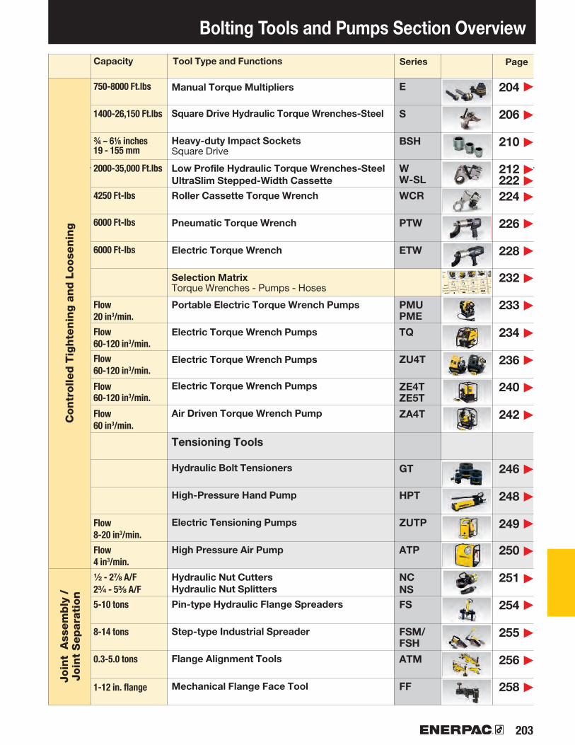
203
E
S
BSH
WW-SL
WCR
PTW
ETW
PMUPME
TQ
ZU4T
ZE4TZE5T
ZA4T
GT
HPT
ZUTP
ATP
NCNSFS
FSM/FSH
ATM
FF
204
206
210
212 222
224
226
228
232
233
234
236
240
242
246
248
249
250
251
254
255
256
258
▶
▶
▶
▶▶
▶
▶
▶
▶
▶
▶
▶
▶
▶
▶
▶
▶
▶
▶
▶
▶
▶
▶
203204
208210
212214
182
188
–
–
–
–
S1500S3000S6000S11000S25000W2000W4000
W8000W15000W22000W35000
Selection Matrix
Optimum Torque Wrench and Pump Combinations
PMU-Series
.5 - 1 Gal. 1 - 1.75 Gal. 1 Gal. 1-10 Gal. 1 Gal. 1 - 1.75 Gal.
Standard duty Standard duty Medium duty Heavy duty Standard duty Heavy duty
Field Field Field/Factory Factory Field Field
ELECTRIC PUMPS
Page: Page: Page: Page: Page: Page:
ZU4-Series
AIR DRIVEN PUMPS
PTA-Series
For optimum speed
and performance
Enerpac recommends
the following
system set-up with
wrench-pump-hose
combinations.
Speed:
Oil Capacity:
Duty Cycle:
Weight:
Field/Factory Work:
ZA4-Series
Optimal
Optimal
TQ-700-Series ZE4/5-Series
Optimal
Optimal
Optimal
Optimal
Optimal
S-S
eri
es
W-S
eri
es
Optimal
Acceptable
Acceptable
Optimal
Bolting Tools and Pumps Section Overview
Contr
olle
d T
ighte
nin
g a
nd L
oose
nin
gJo
int
Ass
em
bly
/
Join
t S
ep
arat
ion
Manual Torque Multipliers
Square Drive Hydraulic Torque Wrenches-Steel
Heavy-duty Impact SocketsSquare Drive
Low Profile Hydraulic Torque Wrenches-SteelUltraSlim Stepped-Width CassetteRoller Cassette Torque Wrench
Pneumatic Torque Wrench
Electric Torque Wrench
Selection MatrixTorque Wrenches - Pumps - Hoses
Portable Electric Torque Wrench Pumps
Electric Torque Wrench Pumps
Electric Torque Wrench Pumps
Electric Torque Wrench Pumps
Air Driven Torque Wrench Pump
Tensioning Tools
Hydraulic Bolt Tensioners
High-Pressure Hand Pump
Electric Tensioning Pumps
High Pressure Air Pump
Hydraulic Nut Cutters Hydraulic Nut Splitters
Pin-type Hydraulic Flange Spreaders
Step-type Industrial Spreader
Flange Alignment Tools
Mechanical Flange Face Tool
Tool Type and Functions SeriesCapacity Page
750-8000 Ft.lbs
1400-26,150 Ft.lbs
¾ – 6⅛ inches19 - 155 mm
2000-35,000 Ft.lbs
4250 Ft-lbs
6000 Ft-lbs
6000 Ft-lbs
Flow 20 in3/min.
Flow 60-120 in3/min.
Flow 60-120 in3/min.
Flow 60-120 in3/min.
Flow 60 in3/min.
Flow 8-20 in3/min.
Flow 4 in3/min.
½ - 2⅞ A/F2¾ - 5⅜ A/F
5-10 tons
8-14 tons
0.3-5.0 tons
1-12 in. flange
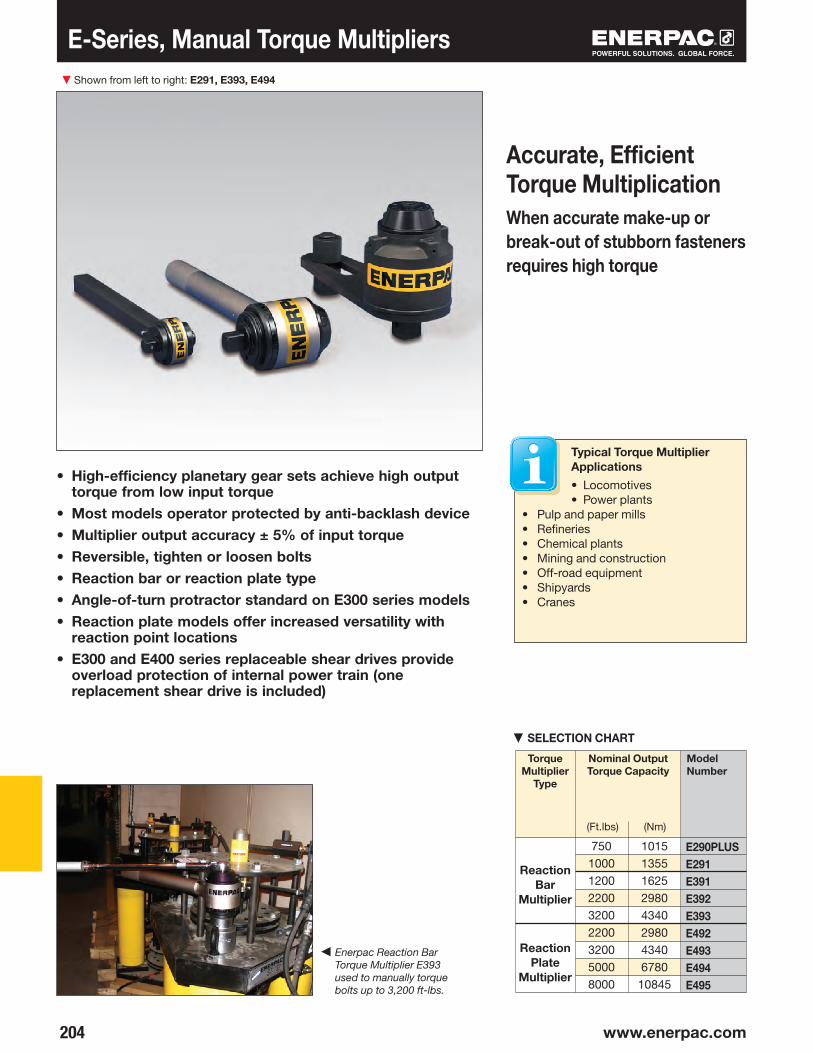
▼
204 www.enerpac.com
E290PLUSE291E391E392E393E492E493E494E495
E-Series, Manual Torque Multipliers
• High-efficiency planetary gear sets achieve high output torque from low input torque
• Most models operator protected by anti-backlash device• Multiplier output accuracy ± 5% of input torque• Reversible, tighten or loosen bolts• Reaction bar or reaction plate type• Angle-of-turn protractor standard on E300 series models• Reaction plate models offer increased versatility with
reaction point locations• E300 and E400 series replaceable shear drives provide
overload protection of internal power train (one replacement shear drive is included)
Accurate, Efficient Torque MultiplicationWhen accurate make-up or break-out of stubborn fasteners requires high torque
Shown from left to right: E291, E393, E494
Typical Torque Multiplier Applications
• Locomotives• Power plants
• Pulp and paper mills • Refineries• Chemical plants• Mining and construction• Off-road equipment• Shipyards• Cranes
◀Enerpac Reaction Bar Torque Multiplier E393 used to manually torque bolts up to 3,200 ft-lbs.
ModelNumber
Torque Multiplier
Type
Reaction Bar
Multiplier
Nominal Output Torque Capacity
(Nm)(Ft.lbs)
Reaction Plate
Multiplier
▼SELECTION CHART
10151355162529804340298043406780
10845
75010001200220032002200320050008000

205
H
L
D
S1
S2
L
L1 L2
H
D
S1
S2
R
E290PLUSE291E391E392E393E492E493E494E495
206
210
Manual Torque Multipliers
Wt.
ESeries
Nominal Output Torque:
750-8000 Ft.lbsTorque Ratio:
3:1-52:1
▲ Angle-of-Turn Protractor
E391, E392 and E393 models include an angle-of-turn protractor (scale) to tighten fasteners using a “torque turn” method. Allows accurate measuring a specific number of degrees of rotation.
◀ Shearable Square Drive
Designed to provide overload protection on E300- and E400-series multiplier power train by shearing when excess input torque is applied. Internal shear pin prevents tool from falling off bolt.
◀ Selector Pawl Models with anti-backlash
protection have directional selector pawls. Set the pawl for clockwise or counter-clockwise rotation.
Manual Torque Multipliers
Enerpac manual torque multipliers provide efficient torque multiplication in
wide clearance applications and when external power sources are not available.
Manual torque multipliers are used in most industrial, construction, and equipment maintenance applications. Hydraulic torque wrenches are better suited for tight tolerance, flange and repetitious bolting applications.
Use Reaction Bar Models:
• where space is limited• where multiple reaction points
are available• when portability is desirable
Use Reaction Plate Models:• above 3200 Ft-lbs. output torque• on flanges and applications where
neighboring bolt or nut is available to react against
• when extreme reaction forces are generated
Reaction Bar Type 1)
CAUTION!
Never use impact type air tools for power driving torque multipliers. Torque multiplier drive train damage will occur.
Multiplier Output Ratio Accuracy:
± 5 %
Input Torque
(Ft.lbs)
Torque Ratio
InputFemaleSquareDrive
S1 (in)
Over-load
Protec-tion
Anti-Back-lash
Dimensions (in)
(lbs)
ModelNumber
Reaction Plate Type 1)
1) E200 and E400-series do not have an Angle-of-Turn Protractor (scale).User must verify manual torque wrench accuracy prior to use to ensure accurate final output torque.
Hydraulic Torque Wrenches
Enerpac offers a complete range of square drive and hexagon cassette torque wrenches.
Output MaleSquare Drive
ReplaceableShear DriveModel No.
NoNoYesYesYesYesYesYesYes
NoNoNoYesYesYesYesYesYes
(Nm) L1 L2 RLD H
Reaction Bar Type 1) Reaction Plate Type 1)
Page:
S2 (in)
Page:
BSH-Series Sockets
Heavy-Duty Impact Sockets for power driven torquing equipment.
338451271219234219234256208
250333200162173162173189154
3 : 13 : 16 : 1
13.6 : 118.5 : 113.6 : 118.5 : 126.5 : 152 : 1
½
½
½
½
½
½
½
½
½
¾
¾
¾
1
1
1
1
1½
1½
2.82.83.94.14.14.94.95.65.8
3.33.34.05.76.55.56.48.7
10.7
8.617.419.619.619.614.014.014.915.2
–––––
5.55.57.07.0
–––––
4.94.93.53.5
–––––
1.31.31.71.9
4.05.5
13.818.315.217.223.434.050.3
––E391SDKE392SDKE393SDKE392SDKE393SDKE494SDKE495SDK

▼
206 www.enerpac.com
S1500X, S3000XS6000X, S11000X
S25000X
SWH6ASWH10A
SWH6SSWH10S
www.enerpac.com
Certificate of Calibration
Certificate number: X048MOR201406 Product Details Calibration Details Description: Enerpac Torque Wrench Calibration Date: 5-Dec-14Type: S3000X Calibration Direction: ClockwiseSerial number: X048 Calibration Result: PASSCapacity: 3225 Ft.lbs
Standards Utilized
Manufacturer Model Serial No. Description Cal. Date Due Date
Norbar Torque Tools LTD T-Box 90846 Readout display July-14 July-15
Norbar Torque Tools LTD Transducer 90187 Torque transducer June-14 June-15
Ashcroft 2174 407170017 Digital gauge July-14 July-15
Calibration Test Actual Torque Readings
S3000X Pressure Setting
(psi)
Torque Setting (Ft-lbs)
Low Limit
(Ft-lbs)
High Limit
(Ft-lbs)
Average Readings
Average Variance from Torque
Setting
Torque: 3225 Ft-lbs.
2,000 645 616 674 658 13
4,000 1,290 1,232 1,348 1,319 29
Pressure: 10,000 psi6,000 1,935 1,848 2,022 1,974 39
8,000 2,580 2,464 2,696 2,616 36
10,000 3,225 3,080 3,370 3,269 44
Calibration performed by Enerpac The torque wrench is calibrated by measuring 5 times on each of the 5 different pressure settings. The recorded results are valid on the date stated. All standards and
associated equipment used to calibrate this instrument have been calibrated and are traceable to national and/or international standards. The estimated measurement
uncertainty of the calibration system is ± 3.4%. The expanded uncertainty of the measurement, including the ± 3% accuracy of the torque wrench, is ± 4.5% of
reading. These uncertainties are at a confidence level of 99%.
Contact Enerpac to have your torque tool calibrated at least once a year.03-090129514
◆
◆
◆
◆
◆
30002500
3500
200015001000
5000
2000 4000 6000 8000 10,000psi
Ft-L
bs
Torque Setting Actual AVG Torque
◆ ◆ ◆
◆
◆ ◆
150100
200
500
-50-100-150-200
2000 4000 6000 8000 10,000psi
Ft-L
bs
Acceptable Variance Actual AVG Torque
CSA/SIRA 15XT072
209
Square Drive Hydraulic Torque Wrenches Shown: S3000X
Setting New Standards in Safety, Simplicity and Performance
Two Handle Styles
Robust angled positioning handles come standard with every S-Series (X-Edition) tool. Straight positioning handles are available as accessories.
Safety and Performance• Compact, high-strength uni-body construction provides
a small operating radius without sacrificing endurance• 35° rotation angle and rapid return stroke for fast operation• Tough manifold design with added safety feature for
enhanced operator safety
Simplicity• 360° click-on reaction arm with quick release lever
provides easier handling, even when wearing gloves• Includes robust handle which mounts on both sides
of tool for extra maneuverability• Push button square drive release for quickly reversing
the square drive for tightening or loosening
Versatility• Available with optional enhanced tilt and swivel TSP300
manifold for horizontal and vertical maneuverability, with greater durability*
Accuracy• Constant torque output provides accuracy of +/-3%
across full stroke• Optional Angle-of-Turn Indicator provides measurement
of rotation
TSP - Pro Series Swivel The optional TSP300 tilt and swivel manifold with robust interlocking design provides 360° X-axis rotation and 160° Y-axis rotation.
How to Order*
Factory fitted to S-Series (X-Edition) wrenches: Insert a "P" prior to the "X" in the tool designation, e.g.: S1500PX.
Order as an accessory using the part number: TSP300, which can be fitted to existing S-Series (X-Edition) wrenches.
*Includes male and female couplers.
Calibration Certificate
All X-Edition tools are CE-ATEX declared, factory calibrated and are shipped complete with a calibration certificate.
II 2 GD ck T4
Compatible S-Series (X-Edition) wrenches
Compatible S-Series (X-Edition) wrenches
Angled positioning
handles(standard)
Straight positioning
handles(optional)
Page:
* TSP300 is designed for X-Edition tools only, and is not compatible with standard edition tools. For replacement components for existing tools, refer to repair sheet on www.enerpac.com
Supplied with an eyebolt handle (SWH10EA)

207
⑤
①
④
⑥
⑨
⑩
⑦
⑧
③
②250%
209
D
E
FG
HC
BA
S25000X
S3000X
S6000X
S11000X
S1500X3/4 17/16 27/162 37/8 45/8 61/8
3690
7380
11,070
14,760
18,450
22,140
25,830
5000
10.000
15.000
20.000
25.000
30.000
35.00019 37 6250 100 115 155
SD15—012SD30—100SD60—108SD110—108SD250—208
S1500XS3000XS6000XS11000XS25000X
AOT15AOT30AOT60AOT110AOT250
S-Series, X-Edition, Square Drive Torque Wrenches
S Series(X-Edition)
▼ The rigid steel design of the S-Series torque wrenches provides durability, reliability and safety.
① Drive Unit② Angled Positioning Handle ③ Straight Positioning Handle (optional)④ Pro Series Swivel (optional)⑤Reaction Tube Extension (optional)
⑥ Standard Reaction Arm⑦ Allen Drive (optional)⑧ Square Drive⑨ Short Reaction Arm (optional)⑩ Extended Reaction Arm (optional)
Select the Right Torque
Choose your Enerpac Torque Wrench using
the untightening rule of thumb: Loosening torque equals about 250% of tightening torque.
Accessory Options
A full list of optional accessories can be found on: page 209.
Page:
*TORQUE WRENCH SELECTION (based on socket size range)
To
rque
Ran
ge
(Ft.l
bs) ▶
To
rque
Ran
ge
(Nm
) ▶
Socket Size Range (inch) ▶
Socket Size Range (mm) ▶
See page 210 for BSH-Sockets.
Torque WrenchModel No.*Size
(in)
(Ft.lbs) (Ft.lbs)
Nominal Torque
at 10,000 psi /
690 bar
Minimum Torque
at 10,000 psi /
690 bar
Dimensions (in)
* To order a S-series (X-Edition) wrench fitted with the TSP swivel, insert a "P" prior to the "X" in the tool designation. e.g., S1500PX.
(lbs)
Model No.(included
with wrench)
Square Drive Angle-of-Turn
Model No.(optional)
Wt.
(Nm) (Nm)
Nominal Torque at 10,000 psi:
26,150 Ft.lbsSquare Drive Range:
¾-2½ inchNose Radius:
.98-2.52 inchMaximum Operating Pressure:
10,000 psi
144032256150
11,17526,150
144323615
1,1182,615
¾"
1"1½"1½"2½"
1.541.892.172.833.50
2.563.153.624.495.63
4.255.316.657.769.69
3.825.046.187.489.61
5.356.817.568.98
11.30
0.981.301.571.952.52
7.012.320.234.770.8
2.763.544.335.247.17
5.086.347.409.02
11.61
A B C D E F G H
195243738338
15.15135.455
195438834
1.5153.545

208 www.enerpac.com
C1
H1
①
④⑥
⑨
⑩
⑦
⑧
③
⑤
②
SDA-Series, Allen Drives
For
SSeries (X-Edition)
Model Number
Model Number
TORQUE WRENCH
OPTIONAL ALLEN DRIVES,
IMPERIAL
MaximumTorque
(Ft.Lbs)
HexagonSize
(in)
Dim.
B1(in)
Model Number
OPTIONAL ALLEN DRIVES,
METRIC
SHORT REACTION ARM FOR
ALLEN DRIVES
MaximumTorque
(Ft.lbs)
HexagonSize
(mm)
Model Number
Dim.
B1(in)
Dimensions(in)
S1500X(1440 Ft-lbs)
S3000X(3225 Ft-lbs)
S6000X(6050 Ft-lbs)
S11000X(11,175 Ft-lbs)
S25000X(26,150 Ft-lbs)
Nominal Torque at 10,000 psi:
26,150 Ft.lbs.① Drive Unit② Angled Positioning Handle ③ Straight Positioning Handle (optional)④ Pro Series Swivel (optional)⑤Reaction Tube Extension (optional)⑥ Standard Reaction Arm⑦ Allen Drive (optional)⑧ Square Drive⑨ Short Reaction Arm (optional)⑩ Extended Reaction Arm (optional)
Hexagon Size Allen Drive:
½-2¼ in. (14-85 mm)
SDA15-008SDA15-010SDA15-012SDA15-014SDA15-100
355690119514001400
½
⅝
¾
7•8
1
2.62.62.82.93.0
SDA30-010SDA30-012SDA30-014SDA30-100SDA30-102SDA30-104–
69011951895282532003200
–
⅝
¾
7•8
1
1⅛
1¼
–
3.03.13.33.43.53.5–
SDA60-010SDA60-012SDA60-014SDA60-100SDA60-102SDA60-104–
69011951895282540255520
–
⅝
¾
7•8
1
1⅛
1¼
–
3.33.53.63.73.83.9–
SDA110-104SDA110-106SDA110-108SDA110-110SDA110-112
552073459535
11,00011,000
1¼
13/8
1½
1⅝
1¾
4.54.64.64.84.9
SDA250-108SDA250-110SDA250-112SDA250-114SDA250-200SDA250-204––––
953512,12015,13518,62022,59526,150
––––
1½
1⅝
1¾
17•8
2
2¼
––––
5.55.75.85.95.96.0––––
SDA15-14SDA15-17SDA15-19SDA15-22SDA15-24
SRA15X
1417192224
2.602.682.762.872.91
2.66 2.56
C1 H1
SDA30-17SDA30-19SDA30-22SDA30-24SDA30-27SDA30-30SDA30-32
SRA30X
850118518352385320032003200
17192224273032
3.033.113.233.313.353.433.46
3.15 2.91
SDA60-17SDA60-19SDA60-22SDA60-24SDA60-27SDA60-30SDA60-32
SRA60X
850118518352385339546555650
17192224273032
3.393.463.583.663.703.783.82
3.60 3.50
SDA110-30SDA110-32SDA110-36SDA110-41SDA110-46
SRA110X
465556508040
11,00011,000
3032364146
4.414.494.614.765.00
5.02 4.17
SDA250-36SDA250-41SDA250-46SDA250-50SDA250-55SDA250-60SDA250-65SDA250-70SDA250-75SDA250-85
SRA250X
804011,88016,77521,54526,15026,15026,15026,15026,15026,150
36414650556065707585
5.515.675.835.946.066.226.346.466.616.89
6.24 5.31
475850
118514001400
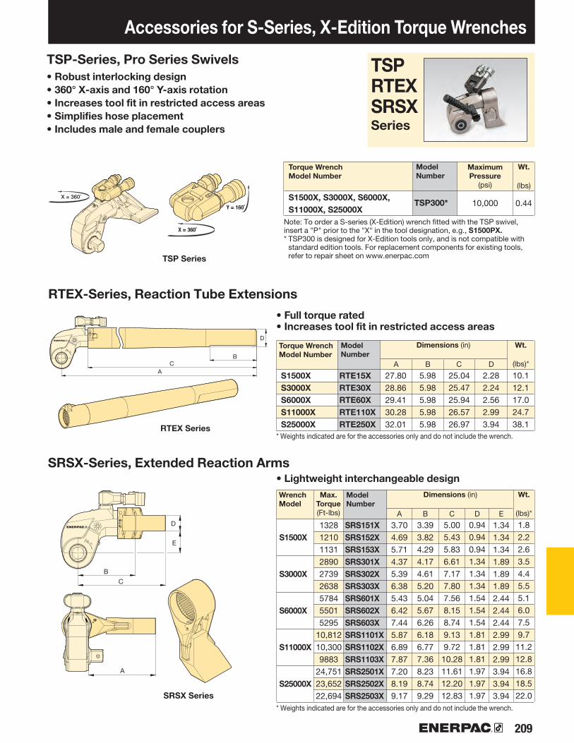
209
S1500X, S3000X, S6000X, S11000X, S25000X
TSP300*
S1500XS3000XS6000XS11000XS25000X
RTE15XRTE30XRTE60XRTE110XRTE250X
S1500XSRS151XSRS152XSRS153XSRS301XSRS302XSRS303XSRS601XSRS602XSRS603XSRS1101XSRS1102XSRS1103XSRS2501XSRS2502XSRS2503X
S3000X
S6000X
S11000X
S25000X
A B C D
Accessories for S-Series, X-Edition Torque Wrenches
Wt.
(lbs)*
TSPRTEXSRSXSeries
• Robust interlocking design• 360° X-axis and 160° Y-axis rotation• Increases tool fit in restricted access areas• Simplifies hose placement• Includes male and female couplers
TSP-Series, Pro Series Swivels
Model Number
Torque Wrench Model Number
Note: To order a S-series (X-Edition) wrench fitted with the TSP swivel, insert a "P" prior to the "X" in the tool designation, e.g., S1500PX. * TSP300 is designed for X-Edition tools only, and is not compatible with
standard edition tools. For replacement components for existing tools, refer to repair sheet on www.enerpac.com
• Full torque rated• Increases tool fit in restricted access areas
RTEX-Series, Reaction Tube Extensions
Dimensions (in)Model Number
Torque Wrench Model Number
Dimensions (in)Model Number
Wrench Model
Max. Torque(Ft-lbs)
• Lightweight interchangeable designSRSX-Series, Extended Reaction Arms
MaximumPressure
(psi)
* Weights indicated are for the accessories only and do not include the wrench.
* Weights indicated are for the accessories only and do not include the wrench.
Wt.
(lbs)*
Wt.
(lbs)
RTEX Series
SRSX Series
TSP Series
0.44
27.8028.8629.4130.2832.01
5.985.985.985.985.98
25.0425.4725.9426.5726.97
2.282.242.562.993.94
10.112.117.024.738.1
A B C D
3.704.695.714.375.396.385.436.427.445.876.897.877.208.199.17
3.393.824.294.174.615.205.045.676.266.186.777.368.238.749.29
5.005.435.836.617.177.807.568.158.749.139.72
10.2811.6112.2012.83
0.940.940.941.341.341.341.541.541.541.811.811.811.971.971.97
1.82.22.63.54.45.55.16.07.59.7
11.212.816.818.522.0
E
1.341.341.341.891.891.892.442.442.442.992.992.993.943.943.94
132812101131289027392638578455015295
10,81210,3009883
24,75123,65222,694
10,000

210 www.enerpac.com
250%
BSH7519BSH75088BSH75094BSH7527BSH7530BSH75125BSH75131BSH7535BSH75144BSH7538BSH75156BSH75163BSH7543BSH75175BSH7546BSH75188BSH75194BSH75200
¾"7•8"
15•16"1 1•16"1 3•16"1 ¼"1 5•16"1 ⅜"1 7•16"1 ½"1 9•16"1 ⅝"
1 11•16"1 ¾"
1 13•16"1 7•8"
1 15•16"2"
BSH1019BSH10088BSH10094BSH1027BSH1030BSH10125BSH10131BSH1035BSH10144BSH1038BSH10156BSH10163BSH1043BSH10175BSH1046BSH10188BSH10194BSH10200BSH10206BSH10213BSH10219BSH10225
¾"7•8"
15•16"1 1•16"1 3•16"1 ¼"1 5•16"1 ⅜"1 7•16"1 ½"1 9•16"1 ⅝"
1 11•16"1 ¾"
1 13•16"1 7•8"
1 15•16"2"
2 1•16"2 ⅛"2 3•16"2 ¼"
BSH10231BSH10238BSH10244BSH10250BSH1065BSH10263BSH10269BSH1070BSH10281BSH10288BSH1075BSH10300BSH10306BSH10313BSH10319BSH10325BSH10338BSH10350BSH10363BSH1095BSH10388
2 5•16"2 ⅜"2 7•16"2 ½"2 9•16"2 ⅝"
2 11•16"2 ¾"
2 13•16"2 7•8"2 15•16
3"3 1•16"3 ⅛"3 3•16"3 ¼"3 ⅜"3 ½"3 5•8"3 ¾"3 7•8"
BSH15144BSH1538BSH15156BSH15163BSH1543BSH15175BSH1546BSH15188BSH15194BSH15200BSH15206BSH15213BSH15219BSH15225BSH15231BSH15238BSH15244BSH15250BSH1565BSH15263BSH15269BSH1570
1 7•16"1 ½"1 9•16"1 5•8"
1 11•16"1 ¾"
1 13•16"1 7•8"
1 15•16"2"
2 1•16"2 ⅛"2 3•16"2 ¼"2 5•16"2 3•8"2 7•16"2 ½"2 9•16"2 ⅝"
2 11•16"2 ¾"
BSH15281BSH15288BSH1575BSH15300BSH15306BSH15313BSH15319BSH15325BSH15338BSH15350BSH15363BSH1595BSH15388BSH15100BSH15400BSH15105BSH15419BSH15425BSH15110BSH15438BSH15450BSH15463
2 13•16"2 7•8"
2 15•16"3"
3 1•16"3 ⅛"3 3•16"3 ¼"3 ⅜"3 ½"3 ⅝"3 ¾"3 7•8"
3 15•16"4"
4 ⅛"4 3•16"4 ¼"4 5•16"4 ⅜"4 ½"4 ⅝"
BSH25244BSH25250BSH2565BSH25263BSH25269BSH2570BSH25281BSH25288BSH2575BSH25300BSH25306BSH25313BSH25319BSH25325BSH25338BSH25350BSH25363BSH2595BSH25388BSH25100BSH25400BSH25105
BSH25419BSH25425BSH25110BSH25438BSH25450BSH25463BSH25475BSH25488BSH25500BSH25513BSH25519BSH25525BSH25538BSH25140BSH25575BSH25150BSH25600BSH25613
4 3•16"4 ¼"4 5•16"4 3•8"4 ½"4 ⅝"4 ¾"4 7•8"
5"5 1•8"5 3•16"5 ¼"5 ⅜"5 ½"5 ¾"5 7•8"
6"6 1•8"
2 7•16"2 ½"2 9•16"2 ⅝"
2 11•16"2 ¾"
2 13•16"2 7•8"
2 15•16"3"
3 1•16"3 ⅛"3 3•16"3 ¼"3 ⅜"3 ½"3 ⅝"3 ¾"3 7•8"
3 15•16"4"
4 ⅛"
BSH7519BSH7524BSH7527BSH7530BSH7532BSH7536BSH75163BSH7546BSH7550
BSH1019BSH1024BSH1027BSH1030BSH1032BSH1036BSH10163BSH1046BSH1050BSH1055BSH1060BSH1065BSH1070BSH1075BSH1080BSH1085BSH1090BSH1095BSH10100
BSH1536BSH15163BSH1546BSH1550BSH1555BSH1560BSH1565BSH1570BSH1575BSH1580BSH1585BSH1590BSH1595BSH15100BSH15105BSH15110BSH15115
BSH2565BSH2570BSH2575BSH2580BSH2585BSH2590BSH2595BSH25100BSH25105BSH25110BSH25115BSH25120BSH25125BSH25135BSH25140BSH25145BSH25150BSH25155
65707580859095
100105110115120125135140145150155
36414650556065707580859095100105110115
192427303236414650556065707580859095100
192427303236414650
A/F
A/F(in)
IMPERIAL SOCKETS
3/4" Square Drive 1" Square Drive 1 1/2" Square Drive
Model Number
2 1/2" Square Drive
A/F(in)
Model Number
A/F(in)
Model Number
A/F(in)
Model Number
A/F(in)
Model Number
A/F(in)
Model Number
A/F(in)
Model Number
A/F(mm)
3/4" Square Drive 1" Square Drive 1 1/2" Square Drive
Model Number
2 1/2" Square DriveA/F
(mm)Model Number
A/F(mm)
Model Number
A/F(mm)
Model Number
METRIC SOCKETS
BSH-Series Sockets
• Heavy-duty impact sockets• Supplied with "Pin and Ring"
Pin and RingAll sockets are supplied with a "Pin and Ring" to hold the socket in place on the square
drive of the tool.
Select the Right Torque
Choose your Enerpac Torque Wrench using the untightening rule of thumb:
Loosening torque equals about 250% of tightening torque.
Hexagon Sizes:
¾ - 6⅛ inch(19 - 155 mm)

211
F
D
H
G
E
C
H
A
G
F
E
B
FD
HG
E
Bolting Application Ideas
S3000X on an Oil and Gas Flange
During maintenance, quick turnaround times are essential; S-Series wrenches provide a large angle
of nut rotation per stroke, offering speed and accuracy in a compact ergonomic tool.
ENERPAC professional series steel
torque wrenches provide reliable
controlled tightening solutions across
many industries.
S3000X Square Drive Torque Wrench on Wind Turbine Assembly and Maintenance
S3000X used to connect wind turbine segments during assembly and maintenance. A robust but compact solution
is required for bolt tightening on wind tower sections. Large numbers of fasteners require precise application of torque
to ensure joint integrity is achieved and maintained.
The Enerpac S-Series wrench offers simple and reliable operation while providing accurate
and repeatable results.
W4000X Low Profile Torque Wrench on an API Pipe Flange
Throughout the Oil and Gas, Petrochemical and Processing Industries, pipeline joints, valves, pumps and machinery present challenges for controlled bolting.
The restricted access on this flange was easily overcome with an Enerpac W-Series Torque Wrench. The W Wrenches offer reliability and control, ensuring even and consistent torque is applied to all bolts.

212 www.enerpac.com
▼
www.enerpac.com
Certificate of Calibration
Certificate number: X048MOR201406 Product Details Calibration Details Description: Enerpac Torque Wrench Calibration Date: 5-Dec-14Type: S3000X Calibration Direction: ClockwiseSerial number: X048 Calibration Result: PASSCapacity: 3225 Ft.lbs
Standards Utilized
Manufacturer Model Serial No. Description Cal. Date Due Date
Norbar Torque Tools LTD T-Box 90846 Readout display July-14 July-15
Norbar Torque Tools LTD Transducer 90187 Torque transducer June-14 June-15
Ashcroft 2174 407170017 Digital gauge July-14 July-15
Calibration Test Actual Torque Readings
S3000X Pressure Setting
(psi)
Torque Setting (Ft-lbs)
Low Limit
(Ft-lbs)
High Limit
(Ft-lbs)
Average Readings
Average Variance from Torque
Setting
Torque: 3225 Ft-lbs.
2,000 645 616 674 658 13
4,000 1,290 1,232 1,348 1,319 29
Pressure: 10,000 psi6,000 1,935 1,848 2,022 1,974 39
8,000 2,580 2,464 2,696 2,616 36
10,000 3,225 3,080 3,370 3,269 44
Calibration performed by Enerpac The torque wrench is calibrated by measuring 5 times on each of the 5 different pressure settings. The recorded results are valid on the date stated. All standards and
associated equipment used to calibrate this instrument have been calibrated and are traceable to national and/or international standards. The estimated measurement
uncertainty of the calibration system is ± 3.4%. The expanded uncertainty of the measurement, including the ± 3% accuracy of the torque wrench, is ± 4.5% of
reading. These uncertainties are at a confidence level of 99%.
Contact Enerpac to have your torque tool calibrated at least once a year.03-090129514
◆
◆
◆
◆
◆
30002500
3500
200015001000500
02000 4000 6000 8000 10,000
psi
Ft-L
bs
Torque Setting Actual AVG Torque
◆ ◆ ◆
◆
◆ ◆
150100
200
500
-50-100-150-200
2000 4000 6000 8000 10,000psi
Ft-L
bs
Acceptable Variance Actual AVG Torque
W2000X, W4000XW8000X, W15000X
W22000X, W35000X
SWH6ASWH10A
SWH6SSWH10S
225
II 2 GD ck T4CSA/SIRA 15XT072
Shown: W4206X cassette with W4000X drive unit (Rear model shows optional straight handle)
Safety and Performance• Superior strength to size ratio provides easy
access to difficult to reach applications without sacrificing endurance
• 30° rotation angle and rapid return stroke provide fast operation
• Tough manifold design with added safety feature for enhanced operator safety
Simplicity• Fast release drive unit enables rapid exchange of
cassettes, no tools required and no pins to lose• Includes robust handles which mount on both sides, and
the tops of cassettes to allow for extra maneuverability• Quick and easy disassembly for maintenance
without special toolsVersatility• Available with optional enhanced tilt and swivel TSP300
manifold for horizontal and vertical maneuverability, with greater durability*
• X-Edition drive units, cassettes and most accessories are compatible with standard edition tools*
• Drive unit compatible with UltraSlim and WCR-Series cassettes
Accuracy• Constant torque output provides accuracy of
+/-3% across full stroke
TSP - Pro Series SwivelThe optional TSP300 tilt and swivel manifold with robust interlocking design provides 360° X-axis rotation and 160° Y-axis rotation.
How to OrderFactory fitted to new W-Series (X-Edition) wrenches: Insert a "P" prior to the "X" in the tool designation, e.g.: W2000PX.
Order as an accessory using the part number: TSP300, which can be fitted to existing W-Series (X-Edition) wrenches.
Two Handle StylesRobust angled positioning handles come standard with every W-Series (X-Edition) tool. Straight positioning handles designed for
extreme limited access applications are available as accessories.
Setting New Standards in Safety, Simplicity and Performance
Calibration Certificate
All X-Edition tools are CE-ATEX declared, factory calibrated and are shipped complete with a calibration certificate.
Angled positioning
handles (standard)
Compatible W-Series (X-Edition) wrenches
Straight positioning
handles (optional)
Page:
* TSP300 is designed for X-Edition tools only, and is not compatible with standard edition tools. For replacement components for existing tools, refer to repair sheet on www.enerpac.com
Supplied with an eyebolt handle (SWH10EA)
Low Profile Hexagon Wrenches

213
W2000X
W8000X
W4000X
W15000X
W22000X
W35000X80 85 105 115 135
47.453
30.506
20.337
10.846
54232712
11/16 17/8 27/16215/16
33/815/16 23/8 31/8 41/8 45/8 53/8 61/8
35,000
22,000
15,000
8000
40002000
30 36 50 60 6575
155
232
214
W2000XW4000XW8000XW15000XW22000XW35000X
A B C D F
D
AB
F
H G
SC
Hexagon Cassettes and Reducer Inserts
Full range of interchangeable hexagon cassettes and reducing inserts provides maximum
versatility. Details available at www.enerpac.com
① Hexagon Cassette② Drive Unit ③ Angled Positioning Handle④ Straight Positioning Handle (optional)
⑤ Pro Series Swivel (optional)⑥ Extended Reaction Arm (optional)⑦ Reducer Insert (optional)⑧ Reaction Paddle (optional)
To
rque
Ran
ge
(Ft.l
bs) ▶
To
rque
Ran
ge
(Nm
) ▶
Hexagon Size Range1) (inch) ▶
Hexagon Size Range1) (mm) ▶
DRIVE UNIT AND INTERCHANGEABLE CASSETTE SELECTION
Nominal Torque at 10,000 psi:
35,000 Ft.lbsHexagon Range:
11•16 -6⅛ inchNose Radius:
1.22-4.52 inchMaximum Operating Pressure:
10,000 psi
Torque Wrench Pump Selection Matrix
For optimum speed and performance see the torque wrench and pump matrix.
Page:
▼ These rigid steel wrenches with low profile interchangeable hexagon cassettes guarantee durability and maximum versatility in bolting applications.
▼ SELECTION CHART Hexagon Range * Nominal Torque
at 10,000 psi
(mm)(in) (Ft.lbs)
Drive Unit Model Number **
MinimumTorque
(Ft.lbs)
Dimensions(see pages 214-221 for dimensions H, G, and S)
(in)
Weight(Drive unit
without hexagoncassette)
(lbs)
* With in-line reaction foot. ** To order a W-series (X-Edition) wrench fitted with the TSP swivel, insert a "P" prior to the "X" in the tool
designation. e.g., W2000PX.
Page:
(Nm) (Nm)
W-Series, X-Edition Hexagon Wrenches
WSeries(X-Edition)
1 ) See page 285 for table of hexagon sizes of bolts, nuts and related thread diameters.
30 - 6036 - 8550 - 10565 - 11575 - 13580-155
11•16 - 2⅜
15•16 - 3⅜
17⁄8 - 4⅛
27•16 - 4⅝
215•16 - 5⅜
31•8 - 6⅛
204041758470
15,33022,50035,000
4.295.356.778.158.94
10.54
5.556.578.079.45
10.4611.94
5.837.018.199.96
11.6813.60
1.261.612.072.483.033.57
3.044.446.5910.7216.9826.40
.79
.79
.98
.791.381.98
27665661
11,48420,78530,50647,453
204418847
153322503500
277566
1148207930504745
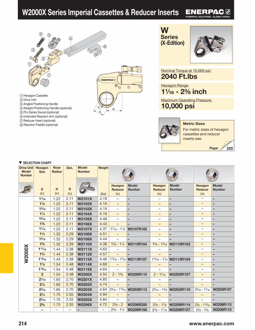
214 www.enerpac.com
W2101XW2102XW2103XW2104XW2105XW2106XW2107XW2108XW2109XW2110XW2111XW2112XW2113XW2114XW2115XW2200XW2201XW2202XW2203XW2204XW2205XW2206X–
––––––W2107R102––W2110R104––W2113R107––W2200R110––W2203R113––W2206R200W2206R108
–––––––––W2110R103––W2113R104––W2200R107––W2203R110––W2206R114W2206R107
––––––––––––––––––W2203R107––W2206R113W2206R110
W20
00X
220
H GS
WSeries (X-Edition)
Nominal Torque at 10,000 psi:
2040 Ft.lbsHexagon Range:
11•16 - 2⅜ inchMaximum Operating Pressure:
10,000 psi
W2000X Series Imperial Cassettes & Reducer Inserts
▼SELECTION CHARTDrive Unit
Model Number
Model Number
Weight
(lbs)
HexagonReducer
(in)
Model Number
Model Number
HexagonReducer
(in)
Model Number
HexagonReducer
(in)
HexagonSize
S(in)
Nose Radius
H(in)
Dim.
G(in)
Metric Sizes
For metric sizes of hexagon cassettes and reducer inserts see:
Page:
① Hexagon Cassette② Drive Unit ③ Angled Positioning Handle④ Straight Positioning Handle (optional)⑤ Pro Series Swivel (optional)⑥ Extended Reaction Arm (optional)⑦ Reducer Insert (optional)⑧ Reaction Paddle (optional)
1.221.221.221.221.221.221.221.321.321.321.441.441.441.541.541.541.651.651.651.751.751.75
–
11•16
1⅛
13•16
1¼
15•16
1⅜
17•16
1½
19/16
1⅝
111•16
1¾
113•16
17•8
115/16
2
21⁄16
2⅛
23•16
2¼
25•16
2⅜
–
2.112.112.112.112.112.112.112.292.292.292.382.382.382.482.482.482.702.702.702.552.552.55
–
––––––
17•16 - 1⅛
––
1⅝ - 1¼
––
113•16 - 17/16
––
2 - 1⅝
––
23•16 - 113•16
––
2⅜ - 22⅜ - 1½
–––––––––
1⅝ - 13•16
––
113•16 - 1¼
––
2 - 17/16
––
23•16 - 1⅝
––
2⅜ - 17•8
2⅜ - 17•16
––––––––––––––––––
23•16 - 17•16
––
2⅜ - 113•16
2⅜ - 1⅝
4.194.194.194.194.484.434.374.514.444.384.634.574.464.694.644.544.834.744.644.944.844.72
–
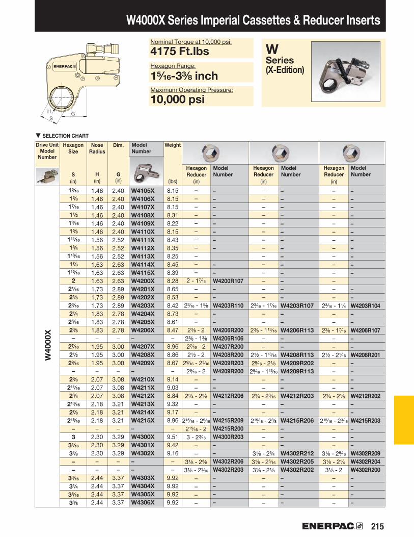
215
W4105XW4106XW4107XW4108XW4109XW4110XW4111XW4112XW4113XW4114XW4115XW4200XW4201XW4202XW4203XW4204XW4205XW4206X–W4207XW4208XW4209X–W4210XW4211XW4212XW4213XW4214XW4215X–W4300XW4301XW4302X––W4303XW4304XW4305XW4306X
––––––––
––W4200R107––W4203R110––W4206R200W4206R106W4207R200W4208R200W4209R203W4209R200––W4212R206––W4215R209W4215R200W4300R203––W4302R206W4302R203––––
––––––––––––––W4203R107––W4206R113––W4208R113W4209R202W4209R113––W4212R203––W4215R206–––W4302R212W4302R205W4302R202––––
–––––––––––
––W4203R104––W4206R107––W4208R201––––W4212R202––W4215R203–––W4302R209W4302R204W4302R200––––
W40
00X
H GS
H GS
▼SELECTION CHART
W4000X Series Imperial Cassettes & Reducer Inserts
WSeries (X-Edition)
Nominal Torque at 10,000 psi:
4175 Ft.lbsHexagon Range:
15•16-3⅜ inchMaximum Operating Pressure:
10,000 psi
Drive Unit Model
Number
Model Number
Weight
(lbs)
HexagonReducer
(in)
Model Number
Model Number
HexagonReducer
(in)
Model Number
HexagonReducer
(in)
Dim.
G(in)
HexagonSize
S(in)
Nose Radius
H(in)
1.461.461.461.461.461.461.561.561.561.631.631.631.731.731.731.831.831.83
–1.951.951.95
–2.072.072.072.182.182.18
–2.302.302.30
––
2.442.442.442.44
15•16
1⅜
17•16
1½
19•16
1⅝
111/16
1¾
113•16
17•8
115•16
2
21/16
2⅛
23⁄16
2¼
25•16
2⅜
–27/16
2½
29•16
–2⅝
211/16
2¾
213/16
27•8
215•16
–3
31/16
3⅛
––
33•16
3¼
35•16
3⅜
2.402.402.402.402.402.402.522.522.522.632.632.632.892.892.892.782.782.78
–3.003.003.00
–3.083.083.083.213.213.21
–3.293.293.29
––
3.373.373.373.37
–––––––––––
2 - 17•16
––
23•16 - 1⅝
––
2⅜ - 22⅜ - 1⅜
27•16 - 22½ - 2
29•16 - 23•16
29•16 - 2––
2¾ - 2⅜
––
215/16 - 29•16
215/16 - 23 - 23•16
––
3⅛ - 2⅜
3⅛ - 23/16
––––
––––––––––––––
23•16 - 17•16
––
2⅜ - 113⁄16
––
2½ - 113•16
29•16 - 2⅛
29•16 - 113•16
––
2¾ - 23•16
––
215/16 - 2⅜
–––
3⅛ - 2¾
3⅛ - 25•16
3⅛ - 2⅛
––––
––––––––––––––
23•16 - 1¼
––
2⅜ - 17•16
––
2½ - 21•16
––––
2¾ - 2⅛
––
215•16 - 23•16
–––
3⅛ - 29•16
3⅛ - 2¼
3⅛ - 2––––
8.158.158.158.318.228.158.438.358.258.458.398.288.658.538.428.738.618.47
–8.968.868.67
–9.149.038.849.329.178.96
–9.519.429.16
––
9.929.929.929.92
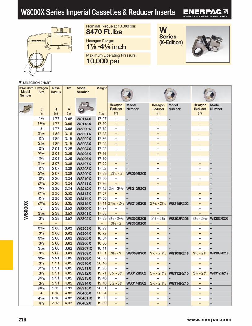
216 www.enerpac.com
W80
00X
W8114XW8115XW8200XW8201XW8202XW8203XW8204XW8205XW8206XW8207XW8208XW8209XW8210XW8211XW8212XW8213XW8214XW8215XW8300XW8301XW8302X–W8303XW8304XW8305XW8306XW8307IXW8308XW8309XW8310XW8311XW8312XW8313XW8314XW8315XW8400XW8401IXW8402X
–––––––––––W8209R200––W8212R203––W8215R206––W8302R209W8302R200–––––W8308R300–––W8312R302–W8314R302––––
–––––––––––––––––W8215R203––W8302R206––––––W8308R215–––W8312R215–W8314R215––––
––––––––––––––––––––W8302R203––––––W8308R212–––W8312R212––––––
H GS
▼SELECTION CHART
HexagonSize
S(in)
W8000X Series Imperial Cassettes & Reducer InsertsNominal Torque at 10,000 psi:
8470 Ft.lbsHexagon Range:
17•8 -4⅛ inchMaximum Operating Pressure:
10,000 psi
Drive Unit Model
Number
Model Number
Weight
(lbs)
HexagonReducer
(in)
Model Number
Model Number
HexagonReducer
(in)
Model Number
HexagonReducer
(in)
WSeries (X-Edition)
Nose Radius
H(in)
Dim.
G(in)
1.771.771.771.891.891.892.012.012.012.072.072.072.202.202.202.282.282.282.382.382.38
–2.602.602.602.602.602.602.912.912.912.912.912.913.133.133.133.13
17/8
115/16
2
21/16
2⅛
23/16
2¼
25•16
2⅜
27•16
2½
29•16
2⅝
211•16
2¾
213/16
27•8
215•16
3
31/16
3⅛
–33•16
3¼
35/16
33/8
37⁄16
3½
39/16
35•8
311•16
3¾
313/16
37•8
315/16
4
41/16
4⅛
–––––––––––
29•16 - 2––
2¾ - 23•16
––
215/16 - 2⅜
––
3⅛ - 29•16
3⅛ - 2–––––
3½ - 3–––
3¾ - 3⅛
–37•8 - 3⅛
––––
–––––––––––
––
––
215•16 - 23•16
––
3⅛ - 2⅜
––––––
3½ - 215•16
–––
3¾ - 215•16
–37•8 - 215•16
––––
–––––––––––
––
–––––
3⅛ - 23/16
––––––
3½ - 2¾
–––
3¾ - 2¾
––––––
17.9717.8917.7517.5217.3617.2217.9217.7617.5917.6517.5217.2917.5017.3617.1217.5717.3817.1117.7717.6517.33
–18.9918.7218.5418.3618.1117.8120.3620.1819.9319.7119.4619.1020.3120.0419.8019.39
3.083.083.083.153.153.153.253.253.253.383.383.383.343.343.343.353.353.353.523.523.52
–3.633.633.633.633.633.634.054.054.054.054.054.054.334.334.334.33

217
W15
000X
W15207XW15208XW15209XW15210XW15211XW15212XW15213XW15214XW15215XW15300XW15301XW15302XW15303XW15304XW15305XW15306XW15307IXW15308XW15309XW15310XW15311XW15312XW15313XW15314XW15315XW15400XW15401IXW15402XW15403IXW15404XW15405XW15406XW15407XW15408IXW15409IXW15410IX–
–––––––––W15300R202–W15302R209–––––W15308R215–––W15312R302–W15314R302–––W15402R308–W15404R308–––––W15410R315W15410R308
–––––––––––––––––W15308R212–––W15312R215–W15314R215–––W15402R305–W15404R302–––––W15410R314–
–––––––––––
–––––––––––––––
W15402R304–––––––
W15410R312–
H GS
▼SELECTION CHART
W15000X Series Imperial Cassettes & Reducer InsertsNominal Torque at 10,000 psi:
15,330 Ft.lbsHexagon Range:
27•16-4⅝ inchMaximum Operating Pressure:
10,000 psi
HexagonSize
S(in)
Drive Unit Model
Number
Model Number
Weight
(lbs)
HexagonReducer
(in)
Model Number
Model Number
HexagonReducer
(in)
Model Number
HexagonReducer
(in)
Nose Radius
H(in)
Dim.
G(in)
WSeries (X-Edition)
2.322.322.322.322.322.322.442.442.442.542.542.542.742.742.742.742.742.742.952.952.952.952.952.953.173.173.173.173.173.173.443.443.443.443.443.44
–
27•16
2½
29•16
2⅝
211•16
2¾
213/16
27/8
215•16
3
31•16
3⅛
33/16
3¼
35⁄16
3⅜
37/16
3½
39•16
3⅝
311/16
3¾
313•16
37•8
315•16
4
41•16
4⅛
43•16
4¼
45•16
4⅜
47•16
4½
49•16
45•8
–
3.493.493.493.493.493.493.563.563.563.663.663.663.803.803.803.803.803.804.014.014.014.014.014.014.064.064.064.064.064.064.524.524.524.524.524.52
–
–––––––––
3 - 2⅛
– 3⅛ - 29•16
–––––
3½ - 215•16
–––
3¾ - 3⅛
–37•8 - 3⅛
–––
4⅛ - 3½
–4¼ - 3½
–––––
4⅝ - 315/16
4⅝ - 3½
–––––––––––
–––––
3½ - 2¾
–––
3¾ - 215•16
–37•8 - 215/16
–––
4⅛ - 35/16
–4¼ - 31⁄8
–––––
4⅝ - 37•8
–
–––––––––––
–––––
–––
–––––
4⅛ - 3¼
–––––––
4⅝ - 3¾
–
30.7230.7230.7230.7230.7230.7230.6230.3930.0830.8630.7130.3432.3832.0731.8531.6331.3230.9831.7031.7031.7031.7031.7031.7034.0233.7033.4133.0932.8132.2935.6135.3234.9934.6334.2833.72
–
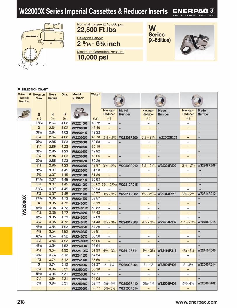
218 www.enerpac.com
W22
000X
W22215XW22300XW22301XW22302XW22303XW22304XW22305XW22306XW22307XW22308XW22309XW22310XW22311XW22312XW22313XW22314XW22315XW22400XW22401IXW22402XW22403XW22404XW22405XW22406XW22407XW22408IXW22409XW22410IXW22412XW22414XW22500XW22502XW22503XW22504XW22506XW22506X
–––W22302R206–––––W22308R212–––W22312R215–W22314R302–––––W22404R308–––––W22410R314––W22500R404–––W22506R410W22506R314
––– W22302R203–––––W22308R209–––––W22314R215–––––W22404R302–––––W22410R312––W22500R402–––W22506R404–
–––
3⅛ - 2⅜
–––––
3½ - 2¾
–––
3¾ - 215∕16
–3⅞ - 3⅛
–––––
4¼ - 3½
–––––
4⅝ - 3⅞
–5 - 4¼
–––
5⅜- 4⅝
5⅜- 3⅞
–––
3⅛ - 23•16
–––––
3½ - 29⁄16
–––––
3⅞ - 215∕16
–––––
4¼ - 3⅛
–––––
4⅝ - 3¾
––
5 - 4⅛
–––
5⅜- 41•4
–
–––––––––
3½ - 23•8
–––––
3⅞ - 2¾
–––––
4¼ - 215⁄16
–––––
4⅝ - 3½
––
5 - 3⅞
–––
5⅜- 41•8
–
215/16
3
31/16
31/8
33/16
31/4
35/16
33/8
37/16
31/2
39•16
35/8
311/16
33/4
313/16
37/8
315/16
4
41/16
41/8
43/16
41/4
45/16
43/8
47•16
41/2
49•16
45/8
43/4
47•8
5
51/8
53/16
51/4
53/8
–
–––––––––W22308R206
–––––
W22314R212–––––W22404R215–––––W22410R308––W22500R314–––W22506R402–
H GS
W22000X Series Imperial Cassettes & Reducer Inserts
▼SELECTION CHART
HexagonSize
S(in)
Drive Unit Model
Number
Model Number
Weight
(lbs)
HexagonReducer
(in)
Model Number
Model Number
HexagonReducer
(in)
Model Number
HexagonReducer
(in)
Nose Radius
H(in)
Dim.
G(in)
Nominal Torque at 10,000 psi:
22,500 Ft.lbsHexagon Range:
215∕16 - 5⅜ inchMaximum Operating Pressure:
10,000 psi
WSeries (X-Edition)
2.642.642.642.642.852.852.852.852.852.853.073.073.073.073.073.073.353.353.353.353.353.353.543.543.543.543.543.543.743.743.743.943.943.943.94
–
4.024.024.024.024.234.234.234.234.234.234.454.454.454.454.454.454.724.724.724.724.724.724.924.924.924.924.924.925.125.125.125.315.315.315.31
–
48.7248.4048.2247.7850.5850.1949.9249.6650.2948.8751.5851.3050.9350.6250.2449.7753.5753.1952.8252.4352.0951.4854.2653.9153.5053.0652.6451.9954.5453.6052.3755.1054.7154.0552.7752.77

219
W35
000X
W35302R200–––––W35308R205–––––W35314R211W35315R213––––W35404R301–––––W35410R310W35412R312–W35500R400W35502R402––W35506R405–––W35512R412W35514R414
W35602R502
31/8 – 2–––––
3½ - 25•16
–––––
3⅞ - 211•16
315∕16 - 213•16
–––
4¼ - 31•16
–––––
45•8 - 3⅝
4¾ - 3¾
–5 - 4
5⅛ - 4⅛
––
5⅜ - 45•16
–––
5¾ - 4¾
5⅞ - 4⅞
–6⅛ - 5⅛
31/8
33/16
3¼
35/16
3⅜
37/16
3½
39/16
3⅝
311•16
3¾
313•16
3⅞
315⁄16
4
41⁄16
41⁄8
43⁄16
41⁄4
45⁄16
43⁄8
47⁄16
4½
49⁄16
4⅝
43⁄4
4⅞
5
51/8
53/16
51/4
53/8
51/2
59/16
55/8
53/4
5⅞
6
6⅛
W35302XW35303XW35304XW35305XW35306XW35307IXW35308XW35309XW35310XW35311XW35312XW35313XW35314XW35315XW35400XW35401XW35402XW35403XW35404XW35405XW35406XW35407XW35408XW35409IXW35410IXW35412XW35414XW35500XW35502XW35503XW35504XW35506XW35508XW35509XW35510XW35512XW35514XW35600XW35602X
H GS
▼SELECTION CHART
Hexagon Range:
3⅛-6⅛ inchesMaximum Operating Pressure:
10,000 psi
W35000X Series Imperial Cassettes & Reducer Inserts
HexagonSize
S(in)
Drive Unit Model
Number
Model Number
Weight
(lbs)
HexagonReducer
(in)
Model Number
Nose Radius
H(in)
Dim.
G(in)
Nominal Torque at 10,000 psi:
35,000 Ft.lbs
WSeries (X-Edition)
3.023.023.023.023.023.023.023.233.233.233.233.233.233.453.453.453.453.453.453.693.693.693.693.693.693.913.913.914.094.094.094.094.314.314.314.314.524.524.52
4.994.994.994.994.994.994.995.225.225.225.225.225.225.395.395.395.395.395.395.635.635.635.635.635.635.855.855.856.026.026.026.026.246.246.246.246.466.466.46
72.3072.1071.7071.4071.0070.5070.1071.4073.4073.0072.5072.1071.4070.8074.7074.3073.9073.4072.8076.9076.5076.1075.6075.2074.5078.5076.9075.6078.9078.5077.6076.3079.8079.4078.5076.9080.9079.6077.80

220 www.enerpac.com
W20
00X
W40
00X
W80
00X
––––W2110R103W2113R104W2200R107W2203R110W2206R113–––––W4203R107W4206R113W4209R200W4212R203W4215R206W4215R200W4302R212W4302R200––––––W8215R203W8302R206–W8085R065M––W8312R215––
––––W2110R024M––W2203R107W2206R110–––––W4203R104W4206R107W4209R113–––W4302R209––––––––W8302R203–W8085R060M–––––
W2103XW2104XW2107XW2108XW2110XW2113XW2200XW2203XW2206X–W4107XW4110XW4113XW4200XW4203XW4206XW4209XW4212XW4215X
W4302X
W4085MXW8200XW8203XW8206XW8209XW8212XW8215XW8302X–W8085MX–W8090MXW8312XW8315XW8402X
––––W2110R104W2113R107W2200R110W2203R113W2206R200W2206R107–––W4200R107W4203R110W4206R200W4209R203W4212R206W4215R209W4215R203W4302R215W4302R203––––W8209R200W8212R203W8215R206W8302R209W8302R200W8085R070MW8085R055MW8090R075MW8312R302––
H GS
Drive Unit Model
Number
Model Number
HexagonSize
S(mm)
Wt.
(lbs)
HexagonReducer
(mm)
Model Number
Model Number
HexagonReducer
(mm)
Model Number
HexagonReducer
(mm)
W-Series Metric Cassettes and Reducer Inserts
Nose Radius
H(in)
Dim.
G(in)
▼SELECTION CHART
Hexagon Range:
30-105 mmMaximum Operating Pressure:
10,000 psi (690 bar)
WSeries (X-Edition)
1.221.221.221.321.321.441.541.651.75
–1.461.461.561.631.731.831.952.072.18
–2.30
–2.441.771.892.012.072.072.282.38
–2.60
–2.912.913.133.13
30
3236384146505560–
364146505560657075–
80–
8550556065707580–
85–
9095100105
2.112.112.112.292.292.382.482.702.55
–2.402.402.522.632.892.783.003.083.21
–3.29
–3.373.083.153.253.383.343.353.52
–3.63
–4.054.054.334.33
––––
41 - 3246 - 3650 - 4155 - 4660 - 5060 - 36
–––
50 - 3655 - 4160 - 5065 - 5570 - 6075 - 6575 - 5580 - 7580 - 55
––––
65 - 5070 - 5575 - 6080 - 6580 - 5085 - 7085 - 5590 - 7595 - 80
––
––––
41 - 3046 - 3250 - 3655 - 4160 - 46
–––––
55 - 3660 - 4665 - 5070 - 5575 - 6075 - 5080 - 7080 - 50
––––––
75 - 5580 - 60
85 - 65––
95 - 75––
––––
41 - 24––
55 - 3660 - 41
–––––
55 - 3260 - 3665 - 46
–––
80 - 65
–––––––
80 - 55–
85 - 60–––––
4.194.194.194.514.384.694.544.644.72
–7.727.727.948.288.428.478.678.848.96
–9.16
–9.48
17.7517.2217.5917.2917.1217.1117.33
–18.42
–20.4619.7120.3119.39

221
W15
000X
W22
000X
W35
000X
W15209XW15212XW15215XW15302XW15085MXW15090MXW15312XW15315XW15402XW15405XW15115MXW22215XW22302XW22085MXW22090MXW22312XW22315XW22402XW22404XW22115MXW22412XW22123MXW22502XW22506XW35302XW35085MXW35090MXW35312XW35315XW35402XW35405XW35115MXW35412XW35123MXW35502XW35506XW35508XW35512XW35514XW35151MXW35602X
–––W15302R209W15085R070MW15090R075MW15312R302–W15402R090MW15110R095MW15115R100M–W22302R206W22085MR209W22090M212W22312R215–––––––W22506R402W35302R200–W35090R206–––W35405R085M–W35412R312–W35502R402W35506R405W35508R115MW35512R412––W35602R502
––––
–W15312R215––––
W22302R203W22085MR206W22090MR206––––––––––
–––––––––––––––
6570758085909510010511011575
80
85
90
95
100
105
110
115
120
123
130
135
80
85
90
95
100
105
110
115
120
123
130
135
140
145
150
151
155
––––––
95 - 75–––––
80 - 5585 - 6090 - 60
––––––––––––––––––––––––––
–––
80-6585-7090-7595-80
–105-90110-95115-100
–80-6085-6590-7095-75
–––––––
135 - 10580-50
–90-60
–––
110-85–
120-95–
130-105135-110140-115145-120
––
155-130
H GS
Drive Unit Model
Number
Model Number
HexagonSize
S(mm)
Wt.
(lbs)
HexagonReducer
(mm)
Model Number
HexagonReducer
(mm)
Model Number
W-Series Metric Cassettes and Reducer Inserts
Nose Radius
H(in)
Dim.
G(in)
▼SELECTION CHART
Hexagon Range:
65-155 mmMaximum Operating Pressure:
10,000 psi (690 bar)
WSeries (X-Edition)
2.322.322.442.542.742.952.953.173.173.443.442.642.642.853.073.073.353.353.543.543.743.743.943.943.023.023.233.233.453.453.693.693.913.914.094.094.314.314.524.524.52
3.493.493.563.663.804.014.014.064.064.524.524.024.024.234.454.454.724.724.924.925.125.125.315.315.085.085.335.305.485.485.755.756.016.016.306.306.436.436.676.676.67
30.7230.7230.0830.3431.7033.3231.7034.0233.0935.6134.4848.7247.7849.7451.7250.6253.5752.0951.4852.8854.5453.8055.1052.7772.3033.1034.3072.5070.8073.9076.9077.1078.5078.9078.9076.3079.8076.9080.9082.1077.80
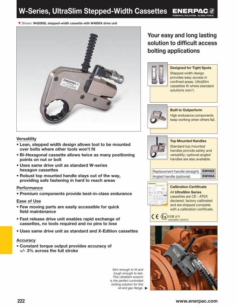
▼
222 www.enerpac.com
▶
www.enerpac.com
Certificate of Calibration
Certificate number: X048MOR201406 Product Details Calibration Details Description: Enerpac Torque Wrench Calibration Date: 5-Dec-14Type: S3000X Calibration Direction: ClockwiseSerial number: X048 Calibration Result: PASSCapacity: 3225 Ft.lbs
Standards Utilized
Manufacturer Model Serial No. Description Cal. Date Due Date
Norbar Torque Tools LTD T-Box 90846 Readout display July-14 July-15
Norbar Torque Tools LTD Transducer 90187 Torque transducer June-14 June-15
Ashcroft 2174 407170017 Digital gauge July-14 July-15
Calibration Test Actual Torque Readings
S3000X Pressure Setting
(psi)
Torque Setting (Ft-lbs)
Low Limit
(Ft-lbs)
High Limit
(Ft-lbs)
Average Readings
Average Variance from Torque
Setting
Torque: 3225 Ft-lbs.
2,000 645 616 674 658 13
4,000 1,290 1,232 1,348 1,319 29
Pressure: 10,000 psi6,000 1,935 1,848 2,022 1,974 39
8,000 2,580 2,464 2,696 2,616 36
10,000 3,225 3,080 3,370 3,269 44
Calibration performed by Enerpac The torque wrench is calibrated by measuring 5 times on each of the 5 different pressure settings. The recorded results are valid on the date stated. All standards and
associated equipment used to calibrate this instrument have been calibrated and are traceable to national and/or international standards. The estimated measurement
uncertainty of the calibration system is ± 3.4%. The expanded uncertainty of the measurement, including the ± 3% accuracy of the torque wrench, is ± 4.5% of
reading. These uncertainties are at a confidence level of 99%.
Contact Enerpac to have your torque tool calibrated at least once a year.03-090129514
◆
◆
◆
◆
◆
30002500
3500
200015001000
5000
2000 4000 6000 8000 10,000psi
Ft-L
bs
Torque Setting Actual AVG Torque
◆ ◆ ◆
◆
◆ ◆
150100
200
500
-50-100-150-200
2000 4000 6000 8000 10,000psi
Ft-L
bs
Acceptable Variance Actual AVG Torque
SWH6S SWH6A
II 2 GD ck T4CSA/SIRA 15XT072
Shown: W4206SL stepped-width cassette with W4000X drive unit
Top Mounted Handles
Standard top mounted handles provide safety and versatility; optional angled handles are also available.
Built to Outperform
High endurance components keep working when others fail.
Designed for Tight Spots
Stepped width design provides easy access in confined areas. UltraSlim cassettes fit where standard solutions won't.
Your easy and long lasting solution to difficult access bolting applications
Versatility• Lean, stepped width design allows tool to be mounted
over bolts where other tools won’t fit• Bi-Hexagonal cassette allows twice as many positioning
points on nut or bolt • Uses same drive unit as standard W-series
hexagon cassettes• Robust top mounted handle stays out of the way,
providing safe fastening in hard to reach areas
Performance• Premium components provide best-in-class endurance
Ease of Use• Few moving parts are easily accessible for quick
field maintenance
• Fast release drive unit enables rapid exchange of cassettes, no tools required and no pins to lose
• Uses same drive unit as standard and X-Edition cassettes
Accuracy• Constant torque output provides accuracy of
+/- 3% across the full stroke
Calibration Certificate
All UltraSlim Series cassettes are CE - ATEX declared, factory calibrated and are shipped complete with a calibration certificate.
Slim enough to fit and tough enough to last. This UltraSlim wrench
is the perfect controlled bolting solution for this
oil and gas flange.
Replacement handle (straight) Angled handle (optional)
W-Series, UltraSlim Stepped-Width Cassettes

223
H GS
W2113SLW2203SLW2206SLW4203SLW4206SLW4209SLW4212SLW4215SL
W2000X
W4000X
D1
F
D
J
E
S
CG
H
AB
THQ-706TTHQ-712T
0
20,000
40,000
60,000
AG B C D D1 E J
232
Cassette Model Number
Drive Unit Model*(sold separately)
Weight
(lbs)
HexagonSize
S(in)
Minimum Torque @ 1000 psi
(Ft.lbs)
Nominal Torque @ 10,000 psi
(Ft.lbs)
Nose Radius
H(in)
Dimensions (in)
▼SELECTION CHART
WSeries Ultra- Slim
Nominal Torque at 10,000 psi:
4360 Ft.lbs.Hexagon Range:
113/16 -215/16 inchesMaximum Operating Pressure:
10,000 psi
Torque Wrench Pumps
Visit enerpac.com for system matched air and electric torque wrench pumps that are ideal for use with hydraulic torque wrenches.
Torque Wrench Hoses
Use Enerpac THQ-700 Series hoses with W-Series torque wrenches to ensure the integrity of your hydraulic system.
19.5 feet long, 2 hoses39 feet long, 2 hoses
UltraSlim Stepped-Width Cassettes
Accessing narrow spaces normally requires significantly
reducing the width of the torque wrench. For the tool operator, this has always meant vastly reduced tool durability, and/or reduced torque output.
By using the highest grade materials, perfecting the geometry, and placing the positioning handle on top of the tool, Enerpac UltraSlim cassettes are able to provide greater torque, get into tighter spaces, and vastly outperform the competition in product durability.*
* Average test results, whereby three Enerpac 113•16" UltraSlim cassettes and three competitor 113•16" cassettes were tested at 4000 ft-lbs for 50,000 cycles. The Enerpac sideplates never broke for the full duration of the test.
Durability of Key Components*
Side Plates
Num
ber o
f Cyc
les
Ratchet LeversCompetitor
* May also be used with W2000PX and W4000PX drive units, featuring double-swivel manifolds.
F(radius)
Enerpac
UltraSlim Stepped-Width Cassettes
Page:
113/16
23/16
2⅜
23/16
2⅜
29/16
2¾
215/16
200200200430430430430430
1.441.631.751.731.891.992.112.20
2.352.492.562.702.822.922.982.99
5.54
6.91
4.30
5.69
1.28
1.59
5.81
7.03
1.00
1.13
0.94
1.61
0.79
0.79
4.72
4.72
4.874.874.88
10.1510.3610.3710.4210.37
19801980198043604360436043604360

▼
224 www.enerpac.com
WCR4000
S
RW4000XWCR4000
W4107CSW4108CSW4110CSW4113CSW4114CSW4200CSW4203CSW4206CSW4209CSW4212CSW4215CSW4302CS
WCR-Series, Roller Cassette Torque Wrench
• Spanners available to fit most commonly used API flanges• Small nose radius – resolves bolt to pipe restrictions• Slim spanner design – reduces bolt height restrictions• Wide range of spanners ranging from 17•16 - 3⅛ inches
(36 - 80 mm)• Includes handle to improve tool handling and safety• Rigid solid steel body for maximum endurance and
minimum downtime
WCR4000 Roller Cassette with Spanner and W4000 Drive Unit
Bi-Hexagonal Spanner Size:
17•16-3⅛ inchSpanner Nose Radius:
1.22-2.18 inchNominal Torque:
4250 Ft-lbsMaximum Operating Pressure:
10,000 psi
Drive Unit Model No.
Roller CassetteAssy Model No.**
SpannerRadius
R(in)
Weight
*(lb)
Closed SpannerHexagon Size
S (in) (mm)
Closed SpannerModel Number
*For total weight add 13.89 lbs for WCR4000, 4.40 lbs. for W4000X and weight of the spanner.** The WCR4000 cassettes, spanners and drive units are all sold separately.
WCR4000 Torque Wrench
The WCR4000 combines power and durability with a slim spanner design to provide
bolting professionals with one of the most versatile and high performing limited access tools on the market today.
The tool was designed for use in narrow access applications, particularly in the height above the nut, and between the bolt center, and the inside of the joint.
Ideal for bolting API flanges, the WCR4000 is available with a wide range of ring type spanners, and is powered by the standard W4000X drive unit.
WCRSeries
6.26 7.
56
1.22
8.909.49
3.74
5.16
1.61
3.15
5.04 1.18
1.221.291.291.401.511.511.621.771.841.952.052.18
4.24.44.24.34.74.24.34.64.64.74.64.9
17⁄16
1½
1⅝
113•16
1⅞
2
23/16
2⅜
29•16
2¾
215•16
3⅛
363841464850556065707580

225
W2000XW4000XW8000XW15000XW22000XW35000X
WTE20WTE40WTE80WTE150WTE220WTE350
W2000XW4000XW8000XW15000XW22000XW35000X
WRP20WRP40WRP80WRP150WRP220WRP350
A B C D E
W2000X, W4000X, W8000X, W15000X, W22000X, W35000X
TSP300*
®
CBA
Accessories for W-Series, X-Edition Torque Wrenches
• Full torque rated• Increases tool fit in restricted access areas
• Lightweight interchangeable design• Allows for offset reaction when in-line reaction is
not available
Model Number
Dimensions (in)Torque Wrench Model Number
WTE-Series, Extended Reaction Arm
① Hexagon Cassette② Drive Unit ③ Angled Positioning Handle④ Straight Positioning Handle (optional)⑤ Pro Series Swivel (optional)⑥ Extended Reaction Arm (optional)⑦ Reducer Insert (optional)⑧ Reaction Paddle (optional)
TSPWTEWRPSeries
TSP-Series
• Robust interlocking design• 360° X-axis and 160° Y-axis rotation• Increases tool fit in restricted access areas• Simplifies hose placement• Includes male and female couplers
TSP-Series, Pro Series Swivels
Model Number
Torque Wrench Model Number
Note: To order a W-series (X-Edition) wrench fitted with the TSP swivel, insert a "P" prior to the "X" in the tool designation, e.g., W2000PX. * TSP300 is designed for X-Edition tools only, and is not compatible with
standard edition tools. For replacement components for existing tools, refer to repair sheet on www.enerpac.com
Wt.
(lbs)
Model Number
Dimensions (in)Torque Wrench Model Number
WRP-Series Reaction Paddles
WTE-Series
WRP-Series
* Weights indicated are for the accessories only and do not include the wrench.
* Weights indicated are for the accessories only and do not include the wrench.
MaximumPressure
(psi)
Wt.*
(lbs)
Wt.*
(lbs)
.4410,000
15.6717.1717.6819.6120.5116.48
2.202.603.354.024.495.00
2.662.912.152.833.035.23
5.7310.1416.7626.4638.1439.24
0.630.831.021.261.521.79
3.314.295.376.508.159.22
5.837.488.78
10.1212.4813.98
.881.764.418.60
15.8723.37
1.401.872.252.743.583.58
1.772.322.723.435.287.17

▼
226 www.enerpac.com
www.enerpac.com
Certificate of Calibration
Certificate number: PTW048COL201406
Manufacturer Model Serial No. Description Cal. Date Due DateNorbar Torque Tools LTD T-Box 79133 Readout display July-14 July-15
Norbar Torque Tools LTD Transducer 54646 Torque transducer June-14 June-15
Air pressure gauge July-14 July-15
Product Details Measurement DetailsDescription Pneumatic Torque Wrench Measurement date Nov. 1, 2014
Model 1000 Direction of rotation CW
Nominal Capacity 1000 Ft.-Lbs. @ rated pressure of 70
Serial Number A21414101C
Actual Torque Readings @ 95% Rated Pressure958 961 950 963 970
946 967 948 949 959
963 973 939 953 952
927 941 952 947 947
943 953 951 938 949
Pressure (psi) 21 28 35 42 49 56 63 70
Torque (Ft.-Lbs.) 300 400 500 600 700 800 900 1000
Calibration performed by Enerpac The torque wrench is calibrated by measuring 25 times at rated pressure and extrapolating a line back to 0. All standards and associated equipment used to calibrate
have been calibrated and are traceable to national standards. The estimated measuring uncertainty of the calibration systems is The expanded measurement
uncertainty, including the =/- accuracy of the torque wrench is +/- % of full scale. These uncertainties are at a confidence level of 99%.
Contact Enerpac to have your torque tool calibrated at least once a year.
◆◆
◆◆
◆◆
◆◆
12001000
800600400200
00 10 20 30 40 50 60 70 80
Torque vs. Air Pressure
Air Pressure (psi) ▶
Torq
ue (F
t-Lb
s) ▶
03-090129414
PTW-Series, Pneumatic Torque Wrenches Shown: PTW1000
Continuous RotationControlled Torque
Typical Pneumatic Torque Wrench Applications
Mining- Track maintenance- Undercarriage maintenance- Wheel maintenance- Shovel maintenance
Power Generation- Turbine bolts- Tower segments- Turbine casings
Oil and Gas - Pipe flanges- Valves- Manway covers- Pressure vessels
Productivity• High speed continuous rotation for constant torque output• Low friction planetary gearbox design minimizes wear and
extends uptimeSafety• Ergonomic, low vibration design reduces fatigue and the
risk of vibration related injuries for the operator• Low noise air motor provides quiet, consistent
performance for indoor and outdoor applicationsConvenience• Provided with standard reaction arm; wide assortment of
custom arms and accessories are available• Available with or without Filter-Regulator-Lubricator (FRL)• Unique calibration certificate provided with each tool
▼PTW-Series Pneumatic Torque Wrenches are ideal for applications where speed and precision are critical, such as track maintenance.
◀The PTW1000 makes quick work of this flange maintenance job.
Calibration Certificate
All PTW tools are CE declared and are shipped complete with a calibration certificate.

227
FRL120C
PTW1000CPTW2000CPTW3000CPTW6000C
A B C D
①
③
②
④
230
210
203
C
D
AB
®
PTW1000
Pneumatic Torque Wrenches
PTWSeries
Nominal Output Torque:
6000 Ft.lbsSquare Drive Range:
1 - 1½ inch
BSH-Series Sockets
Heavy-Duty Impact Sockets for power driven torquing equipment.
Pneumatic Torque Wrench Accessories
Enerpac offers a full line of accessories including a range of reaction arms and drives.
PTW-Series Pneumatic Torque Wrenches
Enerpac PTW-Series Pneumatic Torque
Wrenches are designed for applications that require speed and control. The standard package includes a Torque Wrench with a calibration certificate, an FRL (Filter/Regulator/Lubricator), and a 10 ft. (3 m) long, ½" (13 mm) diameter air hose, which connects the FRL to the wrench.Once the air hoses are connected, the operator simply adjusts the air pressure on the FRL to achieve the desired torque using the calibration certificate. After this, the tool is ready to go to work!*
The air source used with the PTW system must be regulated and/or limited to 120 psi (8.3 bar), and must be capable of providing a volume of at least 50 CFM (85 CMH) at 100 psi (6.9 bar). A separate ½" (13 mm) hose (not included) must be used to connect the FRL to the air supply.
* See instruction manual for comprehensive instructions
Order model number*
Filter-Regulator-Lubricator
Recommended for use with all PTW pneumatic torque wrenches.
Provides clean, lubricated air and allows for air pressure adjustment.
All tools are shipped complete with standard reaction arm and FRL*.
① PTW Torque Wrench ② Hose ③ Filter-Regulator-Lubricator④Reaction Arm
Weight**
(lbs)
RPMSquare Drive
(in)
Dimensions (in)ModelNumber*
Minimum Torque
Nominal Torque
* To order without FRL and hose, remove “C” Suffix (e.g. PTW3000).** Weight of wrench only without reaction arm. Reaction arm weight for PTW1000, PTW2000, PTW3000 is 2.9 lbs. and for the PTW6000 is 7.75 lbs.
(Ft.lbs)(Ft.lbs)
Hydraulic Torque Wrenches
Enerpac offers a complete range of square drive and hexagon cassette torque wrenches. Details on
www.enerpac.com.
▼ SELECTION CHART
Page:
Page:
Page:
10.7011.2613.5014.40
3.273.273.274.49
2.833.113.745.00
5.125.245.247.00
111
1½
1819.52339
1000200030006000
3005009001300
1356271240678135
40767812201763
12.68.03.12.5
(Nm) (Nm)
9.69
11.7
7
11.02

▼
228 www.enerpac.com
www.enerpac.com
Certificate of Calibration
Certificate number: PTW048COL201406
Manufacturer Model Serial No. Description Cal. Date Due DateNorbar Torque Tools LTD T-Box 79133 Readout display July-14 July-15
Norbar Torque Tools LTD Transducer 54646 Torque transducer June-14 June-15
Air pressure gauge July-14 July-15
Product Details Measurement DetailsDescription Pneumatic Torque Wrench Measurement date Nov. 1, 2014
Model 1000 Direction of rotation CW
Nominal Capacity 1000 Ft.-Lbs. @ rated pressure of 70
Serial Number A21414101C
Actual Torque Readings @ 95% Rated Pressure958 961 950 963 970
946 967 948 949 959
963 973 939 953 952
927 941 952 947 947
943 953 951 938 949
Pressure (psi) 21 28 35 42 49 56 63 70
Torque (Ft.-Lbs.) 300 400 500 600 700 800 900 1000
Calibration performed by Enerpac The torque wrench is calibrated by measuring 25 times at rated pressure and extrapolating a line back to 0. All standards and associated equipment used to calibrate
have been calibrated and are traceable to national standards. The estimated measuring uncertainty of the calibration systems is The expanded measurement
uncertainty, including the =/- accuracy of the torque wrench is +/- % of full scale. These uncertainties are at a confidence level of 99%.
Contact Enerpac to have your torque tool calibrated at least once a year.
◆◆
◆◆
◆◆
◆◆
12001000
800600400200
00 10 20 30 40 50 60 70 80
Torque vs. Air Pressure
Air Pressure (psi) ▶
Torq
ue (F
t-Lb
s) ▶
03-090129414
C
®
US
ETW-Series, Electric Torque Wrenches
Touchscreen Control Box
ETW tools feature an easy to use, interactive touch-screen control box, which helps make even the most complex jobs simple to complete.
A single control box may be used to operate multiple wrench models.
Firmware upgrades may be uploaded online and easily transferred to the tool via a USB connection.
Easy Access to Controls
Controls on back of wrench with LED display allow user to directly input desired torque, change direction of rotation, and monitor the fastening process.
Your Simple Solution for Smart Bolting
Versatility• Patented firmware design provides accurate fastening on soft, hard,
or pre-tightened joints • Single control box may be used to operate multiple wrench models• Wrenches and control boxes may be purchased separately or
as a setPerformance• High speed continuous rotation gets the job done faster• Torque and angle functionality allows input of nominal torque value
followed by a specific angle of rotation• Pass/Fail LED indicator on back of tool verifies fastening has been
completed according to specified inputSimplicity• Control box with large 7-inch touchscreen simplifies tool operation• Controls on back of wrench enable operator to monitor
and manage the fastening process without returning to the control box
• Brightly lit three line LED display on wrench is easy to read in any environment
Traceability• Fastening record can be viewed on-screen and transferred
to a computer• Each tool is performance tested and shipped complete
with a factory calibration certificateSafety• Lift points on wrench enable use with positioning handle
or lifting device for greater handling safety • Ground fault detector protects operator in the event of
insufficient grounding* NOTE: Wrench cannot be used without control box.
▼ETW-Series Electric Torque Wrenches are ideal for high volume fastening applications that require precision and traceability, such as this wind tower job.
Certifications, Declarations
All ETW tools:
- Are shipped complete with a calibration certificate
- Are certified for North American Electrical Safety by CSA International
- Carry a CSA US and Canada mark
- Are CE declared
Shown: TW3000B (torque wrench shown without servo motor cord)*

229
230
ETW1000BETW1000IETW1000EETW2000B ETW2000IETW2000EETW3000BETW3000I ETW3000EETW6000BETW6000IETW6000E
ETWCB-BETWCB-IETWCB-EETWCB-BETWCB-IETWCB-EETWCB-BETWCB-IETWCB-EETWCB-BETWCB-IETWCB-E
TW1000BTW1000EITW1000EITW2000BTW2000EITW2000EITW3000BTW3000EITW3000EITW6000BTW6000EITW6000EI
A B C D
115V 60 Hz230V 60 Hz230V 50 Hz115V 60 Hz230V 60 Hz230V 50 Hz115V 60 Hz230V 60 Hz230V 50 Hz115V 60 Hz230V 60 Hz230V 50 Hz
9.815.215.25.89.09.02.84.34.31.92.92.9
1.01.01.01.01.01.01.01.01.01.51.51.5
210
D
C
B A
j
l
k
Electric Torque Wrenches
ETWSeries
Torque Wrench Accessories
Enerpac offers a full line of accessories including a wide range of reaction arms and drives.
ETW-Series Electric Torque Wrenches
Enerpac ETW-Series Electric Torque Wrenches
are particularly well suited to complex jobs which demand precision and traceability. The tools feature an automatic mode, which helps simplify and automate complex jobs, including those with torque and angle specifications, through the creation of presets.
Using the touchscreen, simply input the number of fasteners and desired torque value for each fastening step, followed by the required angle of turn. This sequence may then be saved as an automatic preset for future use.
Once the input torque is achieved, the tool stalls, and a pass/fail indicator verifies that it is ready to move on to the next fastener.
When the job is completed, the fastening record can be viewed on the touch screen, or exported to a computer via a USB connection on the control box.
Page:
Page:
Nominal Output Torque:
6000 Ft.lbsSquare Drive Range:
1 - 1½ inch
Wrench Weight1)
(lbs)
Dimensions (in)ETW SetModelNumber
Wrench Model No.2)
Control Box Model No.2)
ETW Set Includes Voltage Nominal Speed RPMs
Minimum Torque
Nominal Torque
1) Weight of wrench only without reaction arm. Reaction arm weight for ETW1000, ETW2000, ETW3000 is 2.9 lbs. and for the ETW6000 is 7.75 lbs. Standard reaction arm included with TW-models. Weight of control box is 20 lbs.
2) Use of ETW requires both wrench and control box. These may be purchased separately, or as a calibrated set.
(Ft.lbs) (Ft.lbs)
Square Drive
(in)
BSH-Series Sockets
Heavy-Duty Impact Sockets for power driven torquing equipment. Details on www.enerpac.com.
(Nm) (Nm)
Voltage: (Model No. ending with suffix)
B = 115V, 60 Hz I = 230V, 60 Hz (with NEMA 6-15 plug) E = 230V, 50 Hz (with commonly used
European (SCHUKO) plug)
ETW Set① ETW Torque Wrench (with 20 ft. servo cord)② Control Box (with 6 ft. power cord)③Reaction Arm
ETW Torque WrenchETWCB
Control Box
200200200400400400600600600120012001200
270270270540540540810810810162516251625
100010001000200020002000300030003000600060006000
14.414.414.415.015.015.017.117.117.117.817.817.8
18.118.118.119.719.719.726.326.326.342.142.142.1
3.33.33.33.33.33.33.33.33.34.54.54.5
2.82.82.83.13.13.13.73.73.75.05.05.0
5.25.25.25.25.25.25.25.25.27.07.07.0
135513551355271027102710406540654065813581358135
17.2
6.5
13.7

230 www.enerpac.com
ED6TWSED12TWSED18TWSRATWSERATWSSLRATWSDSATWSSRATWSBLTWS
ED6TWLED12TWLRATWL ERATWL SLRATWLDSATWLSRATWL BLTWL
B
A
C
D
CD
B
A2
B C
A
1
B
C
D
A
4
B
A
C
D
D
B
A
C
3
B
A
C
D
5 6 7
A B C D
PTW/ETW6000
PTW/ETW3000
PTW/ETW2000
PTW/ETW1000
60 98 1173619
1356
2712
4067
5423
6779
8135
1000
0 0
2000
3000
4000
5000
6000
2⅜ 3⅞ 4⅝17/16¾ 2
50
210
111234567
11234567
PTW and ETW-Series Torque Wrenches
Enerpac offers the following accessories to support a wide variety of applications in industries such as mining, power generation and oil and gas. For additional custom accessories not pictured here, please contact Enerpac.
PTW ETW Series
Nominal Output Torque:
6000 Ft.lbsSquare Drive Range:
1 - 1½ inch
PTW/ETW-Series, Torque Wrench Accessories
▼ Optional accessories for use with PTW1000, ETW1000, PTW2000, ETW2000, PTW3000, ETW3000 models
▼ For use with PTW6000, ETW6000 models
No.Dimensions in inches
Description Model No. Application
* Time to reposition arm when repeatedly moving from tightening to loosening.** WARNING: Blank reaction arms must be heat treated to HRc 38-42 prior to use.
Extended Drive, 6 inch (152 mm)Extended Drive, 12 inch (305 mm)Extended Drive, 18 inch (457 mm)Standard Reaction ArmExtended Reaction ArmSliding Reaction Arm Double Straight Reaction Arm Straight Reaction ArmBlank Reaction Arm **
Extended Drive 6 inch (152 mm)Extended Drive 12 inch (305 mm)Standard Reaction ArmExtended Reaction Arm Sliding Reaction ArmDouble Straight ArmStraight Reaction Arm Blank Reaction Arm **
Nose extension, primarily for truck wheel bolts
Standard arm included with PTW/ETW modelLong plate for use with deep well sockets For widely spaced and uneven bolt centersReduces time to reposition arm *Long plate for wide spaced reaction pointsWeldable blank for custom applications **
Standard arm included with PTW/ETW modelLong plate for use with deep well sockets For widely spaced and uneven bolt centersReduces time to reposition arm *Long plate for wide spaced reaction pointsWeldable blank for custom applications **
Nose extension, primarily for truck wheel bolts
TORQUE WRENCH SELECTION*
Torq
ue R
ange
(Ft.l
bs) ▶
Torq
ue R
ange
(Nm
) ▶
Socket Size Range (inch) ▶
Socket Size Range (mm) ▶
BSH-Series Sockets
Heavy-Duty Impact Sockets for power driven torquing equipment. Details on www.enerpac.com.
2.442.442.442.99 2.874.412.872.872.83
3.313.314.02 4.02 5.984.024.02 4.02
8.1115.1220.126.775.91
15.0015.989.45 5.94
9.1315.129.02
10.0016.50 20.0012.01 5.98
2.872.872.874.027.957.990.750.75 0.98
4.024.025.757.247.481.261.26 1.26
———
0.832.014.024.022.012.01
——
1.262.524.492.242.242.24

231
CUSTOMIZABLE FEATURES:• Reaction Arms
• Torque Links (split or layered for extremely space restricted applications)
• Reaction Roller Assemblies
• Sockets (direct drive, castellated, peg drive, stacked)
• Drives (direct Allen, spline, square drive size)
• Hex Reducing and Square Drive Inserts
Looking for customized components to help solve your torquing problems? Enerpac has the experience and capabilities to help find solutions to your problems.
Enerpac hydraulic torque
wrenches are designed to
accommodate most bolting
applications. However,
due to space constraints,
location of reaction points
or need for special sockets
and adapters, there is often
a need for customized
components.
◂ Custom hydraulic torque wrench for a fracking pump.
◂ Custom S6000X hydraulic torque wrench fitted with a custom reaction arm/socket.
◂ Custom hydraulic torque wrenches with reaction paddles for use with a flexible flowline.
OVERVIEW
Custom Hydraulic Torque Wrenches
▴ Custom S11000X torque wrench with a custom torque link and reaction roller

232 www.enerpac.com
233 240236 234 242
206
212
–
–
S1500XS3000XS6000XS11000XS25000XW2000XW4000XW8000XW15000XW22000XW35000X
19.5 feet long, 2 hoses
39 feet long, 2 hoses
19.5 pies de longitud, 2 mangueras19.5 pies de longitud, 2 mangueras
39 pies de longitud, 2 mangueras39 pies de longitud, 2 mangueras
19.5 pies de longitud, 2 mangueras
39 pies de longitud, 2 mangueras19.5 pies de longitud, 2 mangueras
19.5 pies de longitud, 2 mangueras
39 pies de longitud, 2 mangueras
39 pies de longitud, 2 mangueras
19.5 feet long, 2 hoses
39 feet long, 2 hoses
11,600 psi
10,000 psi
19.5 pies de longitud, 2 mangueras
39 pies de longitud, 2 mangueras
THC-7122
THQ-706T
THQ-712T
THC-7062
134
Selection Matrix
ZU4 Electric Torque Wrench Pump
Utilizing a universal motor, the ZU4-Series has excellent low voltage
characteristics. It works well with long extension cords or generator driven electrical power supplies. A field proven, efficient design ensures this pump is dependable and will draw less current—lowering your operating cost. The pumps are available in Pro and Classic formats.
ZU4 Pro pumps have an LCD feature to display torque or pressure, selectable torque wrench, and self-diagnostics – premium features not available on any other pump.
ZU4 Classic pumps feature an analogue gauge and a basic electrical package to deliver durable, safe and efficient hydraulic power.
ZE-Series Electric Torque Wrench Pump
The ZE-Series features premium options, such as the LCD to display torque or pressure values, and self-diagnostics. These pumps utilize an induction motor, making the ZE-Series the coolest and quietest pumps in their class.
ZA-Series Air Driven Torque Wrench Pump
Utilizing the highly efficient design of the Z-Class pumping element, this air driven pump is best suited to power medium to large size torque wrenches
TQ-700 Series Electric Torque Wrench Pump
Designed for both portability and production, the TQ-700 features optimized flow technology to deliver superior bolting speed.
Optimum Torque Wrench and Pump Combinations
PMU-Series
.5 - 1 Gal. 1 - 1.75 Gal. 1 Gal. 1-10 Gal. 1 - 1.75 Gal.
Standard duty Standard duty Medium duty Heavy duty Heavy duty
Field Field Field/Factory Factory Field
ELECTRIC PUMPS
Page: Page: Page: Page: Page:
ZU4-Series
AIR DRIVEN PUMP
For optimum speed and performance Enerpac recommends the following system set-up with wrench-pump-hose combinations.
Speed:
Oil Capacity:
Duty Cycle:
Weight:
Field/Factory Work:
ZA4-Series
Optimal Optimal
TQ-700-Series ZE4/5-Series
Optimal
Optimal
Optimal
S-S
eri
es
W-S
eri
es
Optimal
Acceptable
Acceptable
Optimal
Twin Torque Wrench HosesUse Enerpac THQ-700 series twin hoses with 10,000 psi pumps, or use
THC-700 series twin hoses with 11,600 psi pumps.
Torque Wrench Couplers For torque wrench couplers see our "System Components"
section in this catalog.
19.5' long, 2 hoses
19.5' long, 2 hoses
39' long, 2 hoses
39' long, 2 hoses
For SQD & HXD (11,600 psi)
For S & W (10,000 psi)
Page:

233
▼
19.5 feet long, 2 hoses39 feet long, 2 hoses
10,000 psi19.5 pies de longitud, 2 mangueras19.5 pies de longitud, 2 mangueras39 pies de longitud, 2 mangueras
THC-7062THC-712239 pies de longitud, 2 manguerasTHC-7062THC-7122THQ-706TTHQ-712T
19.5 pies de longitud, 2 mangueras39 pies de longitud, 2 mangueras
THC-7062THC-7122
19.5 pies de longitud, 2 mangueras
19.5 pies de longitud, 2 mangueras39 pies de longitud, 2 mangueras
THQ-706TTHQ-712T
39 pies de longitud, 2 manguerasTHC-7062THC-7122
19.5 feet long, 2 hoses39 feet long, 2 hoses11,600 psi
10,000 psi
19.5 pies de longitud, 2 mangueras39 pies de longitud, 2 mangueras
THQ-706TTHQ-712TTHC-7122
THQ-706TTHQ-712T
THC-7062
S1500X W2000X S3000X W4000X
SQD-25-I HXD-30 SQD-50-I HXD-60
PMU-10427-QPMU-10447-QPMU-10422-QPMU-10442-QPMU-10427PMU-10447PMU-10422PMU-10442
Portable Electric Torque Wrench Pumps
• Powerful two-speed pump is lightweight and easy to carry• Standard heat exchanger package keeps pump cool under
extreme use• Glycerin filled gauge with scales reading in psi and bar• Transparent overlays in Ft.lbs and Nm for all Enerpac
torque wrenches provide a quick torque reference• Universal motor for a high power-to-weight ratio;
generates full pressure on as little as 50% of the rated line voltage
• Adjustable pressure relief valve for accurate torque adjustments and precise repeatability
Shown: PMU-10427
Reservoir Capacity:
0.5-1 gal.Flow at 10,000 psi:
20 in3/min.
Maximum Operating Pressure:
10,000 and 11,600 psi
Motor Size:
0.5 hp
PMU/PMESeries
Oil Flow Rate
(in3/min) 1st stage 2nd stage
Useable Oil
Capacity(gal)
ModelNumber
Electric Motor
DimensionsL x W x H
(in)
Weight
(lbs)
Maximum Pressure Rating
(psi) 1st stage 2nd stage
115V- 1 ph -50/60Hz115V- 1 ph -50/60Hz230V- 1 ph -50/60Hz230V- 1 ph -50/60Hz115V- 1 ph -50/60Hz115V- 1 ph -50/60Hz230V- 1 ph -50/60Hz230V- 1 ph -50/60Hz
For Use With Torque Wrenches
Twin Torque Wrench Hoses
Use Enerpac THQ-700 series twin hoses with 10,000 psi pumps, or use THC-700 series twin hoses
with 11,600 psi pumps.
19.5 feet long, 2 hoses39 feet long, 2 hoses
19.5 feet long, 2 hoses39 feet long, 2 hoses
11,600 psi
10,000 psi
Pump Ratings
-Q suffix pumps are for 10,000 psi torque wrenches, and include spin-on couplers.
-E suffix pumps are for use with 11,600 psi rated torque wrenches, and include polarized lock-ring safety couplers.
▼ SELECTION CHART
* For pump without heat exchanger change PMU into PME. Example: PME-10442-Q. PME-Series pump size 10 x 10 x 14 inches. Weight 37.5 lbs. (.50 gallon) and 44 lbs (1 gallon).
200200200200200200200200
.501.0.501.0.501.0.501.0
17 x 11 x 1517 x 13 x 1517 x 11 x 1517 x 13 x 1517 x 11 x 1517 x 13 x 1517 x 11 x 1517 x 13 x 15
4653465346534653
2020202020202020
700700700700700700700700
10,00010,00010,00010,00011,60011,60011,600 11,600

▼
234 www.enerpac.com
THC-7062THQ-706TTHQ-712T
203
Shown: TQ-700E
TQ-700 Series, Electric Torque Wrench Pump
Lightweight Electric Torque Wrench Pump
▼ The TQ-700E and the W-Series wrenches are a productive combination in wind applications.
Twin Torque Wrench Hoses
Use Enerpac THQ-700 series twin hoses with 10,000 psi pumps.
Four Port Manifold
The TQ-700 Classic offers an optional four wrench manifold as an accessory (TQM) factory installed. (Add suffix “M” at the end of the model number. For example: TQ700EM)
19.5 feet long, 2 hoses39 feet long, 2 hoses
10,000 psi
Page:
Optimized for S- and W-series Hydraulic Torque Wrenches
Enerpac offers a complete range of square drive and
hexagon cassette torque wrenches.
Pendant Control The TQ-700 comes equipped with a 20-foot pendant cord which allows the user to pressurize the pump from a distance increasing productivity and speed of setup.
• Three stage pump design delivers optimized flow rates and enables up to 50% faster bolting than competing pumps
• Compact and lightweight design fits through tight openings and provides easy handling
• Built-in protection for controls, gauge, and pendant for job-site durability
• IP55 rating for superior dust and water protection• Advanced brushless motor provides for quiet, continuous
operation, high voltage tolerance, and low maintenance• Heat exchanger prevents breakdown of oil during heavy
usage in hot environments• Simple pressure setting and convenient pendant control
for hassle-free operation
Gauge Overlay Kit
Gauge overlay kits are also available separately.
GT-4015-Q includes overlays for all S- and W-Series
Torque Wrenches.
GT-4015 includes overlays for all SQD and HXD torque wrenches.

235
Enerpac0
100
200
300
400
500
600612
414
322
TQ-700B
TQ-700E2)
TQ-700I3)
S1500X
S3000X
S6000X
W2000X
W4000X
W8000X
S11000X
S25000X
W15000X
W22000X
W35000X
115V 230V
(115V, 60 HZ) (230V, 50 HZ)
82-85
82-85
82-85
▼ The TQ-700E and the W-Series wrenches are a productive combination.
Reservoir Capacity:
1 gallon
Maximum Operating Pressure:
10,000 psi
TQ Series
TQ-700 Series Pump Applications
The TQ-700 Series pump is ideal for powering hydraulic wrenches for the Power Generation and Wind Markets.
The TQ-700 has been engineered with Optimized Flow Technology to deliver up to 50% faster bolt tightening than competing pumps.
Bolting speed is more complex than how much flow per minute the pump produces. The key is optimizing the flow rate across the entire bolting cycle. With more oil flowing at the right time and at the right volume, you achieve the optimized flow for a hydraulic bolting system.
The result of this optimized flow is more bolts tightened faster and a more productive work team.
Internal laboratory testing based on standard torquing procedure on a pipe flange with 14, 1⅞" bolts.
Electric Torque Wrench Pump
Dimensions shown in inches.
Bolts Tightened per Hour
CompetitorA
CompetitorB
For Use with Torque Wrenches
Motor Electrical
Specification
ModelNumber1)
Pressure Rating
(psi)
Usable Oil Capacity
(gal)
Weight (no oil)
(lbs)
Acc
epta
ble
Opt
imal
Perf
orm
ance
115V-1 ph, 50 / 60 Hz
230V-1 ph, 50 Hz
230V-1 ph, 60 Hz
IP55 Rating for Superior Dust and Water Protection
The IP Code (or Ingress Protection Rating) classifies
and rates the degrees of protection provided against the intrusion of solid objects and water in mechanical casings and electrical enclosures.
An IP55 rating means the TQ-700 offers complete protection against contact with mechanical and electrical components, and that dust will not enter in a sufficient quantity to interfere with the operation of the equipment.
The IP55 rating also means water jets sprayed against the TQ-700 from any direction will not have any harmful effects.
1) All models meet CE safety requirements and all TÜV requirements 2) European plug and CE EMC directive compliant3) With NEMA 6-15 plug
Cur
rent
(am
ps) ▶
Cur
rent
(am
ps) ▶
OIL FLOW and CURRENT vs PRESSURE OIL FLOW and CURRENT vs PRESSURE
Oil
Flo
w (
in3 /
min
) ▶
Oil
Flo
w (
in3 /
min
) ▶
Pressure (psi) ▶ Pressure (psi) ▶Oil Flow Oil FlowCurrent Current
Sound Level
(dBA)
Motor Size:
1.0 hp
12.63
5.98
10.98
19.25
7.97
15.0
0
7.22
17.93
10,000
68
66
66
1
1
1
0
50
100
150
200
250
300
350
400
0
2
4
6
8
10
12
14
16
0 2000 4000 6000 8000 10,0000
50
100
150
200
250
300
350
0
1
2
3
4
5
6
7
0 2000 4000 6000 8000 10,000

▼
236 www.enerpac.com
www.enerpac.com
ZU4T Electric Torque Wrench Pumps
• Features Z-Class high-efficiency pump design; higher oil flow and bypass pressure, cooler running and requires 18% less current draw than comparable pumps
• Powerful 1.7 hp universal electric motor provides high power-to-weight ratio and excellent low-voltage operating characteristics
• High-strength, molded composite shroud protects motor and electrical components, while providing an ergonomic, non-conductive handle for easy transport
• Low-voltage pendant provides additional safety for the operator
Pro-Series• LCD readout provides pressure and torque display and
a number of diagnostic and readout capabilities never before offered on a portable electric pump
• Auto cycle feature provides continuous cycle operation of the torque wrench as long as the advance button is pressed. (Pump can be used with or without auto cycle feature)
Shown: ZU4204TB-Q and ZU4204BB-Q
◀ Any brand of hydraulic torque wrench can be powered by the portable ZU4-Series torque wrench pump.
Classic Electrical
Basic electrical package includes mechanical contactor, ON/OFF toggle switch, pendant with
electro-mechanical pushbuttons, 24V transformer timer and operator accessible circuit breaker.
Back-lit LCD Display for Pro Series
• Digital pressure or torque read-out
• Programmable "Auto-Cycle" setting
• "Auto-Cycle" setting easily programmable
• Torque wrench model is selectable
• Display torque in Nm or Ft.lbs
• Pump usage information, hour and cycle counts
• Low-voltage warning and recording
• Self-test and diagnostic capabilities
• Information can be displayed in English, French, German, Italian, Spanish and Portuguese
• Pressure transducer is more accurate and durable than analog gauges
FIRMWARE for Pro-Series
• Display torque in Ft.lbs. or Nm• Display pressure in bar, MPa
or psi• Torque wrench model is selectable• “Auto cycle” setting easily programmable

237
ZU4204TB-QZU4208TB-QZU4204TE-Q 2)
ZU4208TE-Q2)
ZU4204TI-Q3)
ZU4208TI-Q3)
ZU4204BB-QHZU4204BB-QZU4208BE-QH2)
ZU4204BE-Q2)
ZU4208BI-QH3)
ZU4208BI-Q3)
32
www.enerpac.com
20
24
4424
8304
4333
186
192
–
–
–
–
–
–
SQD-25-I
SQD-50-I
SQD-75-I
SQD-100-I
SQD-160-I
SQD-270-I
HXD-30HXD-60HXD-120
HXD-240
S1500S3000S6000S11000S25000
W2000W4000
W8000W15000W22000W35000
––
–
40
TQ-700 Series
Designed for both
portability and
production, the
TQ-700 features
optimized flow technology to
deliver superior bolting speed.
Call Enerpac!
For other combinations,
consult your Enerpac
bolting expert or your
authorized Enerpac distributor.
ZU4-Series Electric Torque Wrench Pump
Utilizing a universal motor, the ZU4-Series has excellent low voltage characteristics.
It works well with long extension cords or generator driven electrical power supplies.
A field proven, e�cient design ensures this pump is dependable and will draw less
current—lowering your operating cost. The pumps are available in Pro and Classic
formats. ZU4 Pro pumps have an LCD feature to display torque or pressure, selectable torque
wrench, and self-diagnostics – premium features not available on any other pump. ZU4 Classic
pumps feature an analogue gauge and a basic electrical package to deliver durable, safe and
e�cient hydraulic power.
ZE-Series Electric Torque Wrench Pump
The ZE-Series features premium options, such as the LCD to display torque or pressure values,
and self-diagnostics. These pumps utilize an induction motor, making the ZE-Series the coolest
and quietest pumps in their class.
ZA-Series Air Torque Wrench Pump
Utilizing the highly e�cient design of the Z-Class pumping element, this air driven pump is best
suited to power medium to large size torque wrenches
Selection Matrix
Optimum Torque Wrench and Pump Combinations
PMU-Series
.5 - 1 Gal. 1 - 1.75 Gal. 1 Gal. 1-10 Gal. 1 Gal. 1 - 1.75 Gal.
Standard duty Standard duty Medium duty Heavy duty Standard duty Heavy duty
Field Field Field/Factory Factory Field Field
ELECTRIC PUMPS
Page: Page:
Page: Page:
Page: Page:
ZU4-Series
AIR DRIVEN PUMPS
PTA-Series
For optimum speed
and performance
Enerpac recommends
the following system
set-up with wrench-
pump-hose
combinations.
Speed:
Oil Capacity:
Duty Cycle:
Weight:
Field/Factory Work:
ZA4-Series
Optimal
Optimal
Optimal
Optimal
TQ-700-Series ZE4/5-Series
Optimal
lamitpO
lamitpO
lamitpO
lamitpO
S-S
eri
es
SQ
D-S
eri
es
W-S
eri
es
HX
D-S
eri
es
Optimal
Acceptable
Acceptable
Optimal
lamitpO
lamitpO
lamitpO
lamitpO
Page:
www.enerpac.com
115V
230V
238
232
Cur
rent
(am
ps) ▶
OIL FLOW and CURRENT vs PRESSURE
Oil
Flo
w (
in3 /
min
) ▶
Pressure (psi) ▶
ZU4T Torque Wrench Pumps
Reservoir Capacity:
1 and 1.75 gal.Flow at 10,000 psi:
60 in3/min.Motor Size:
1.7 hp
ZU4TSeries
Maximum Operating Pressure:
10,000 psi
Oil FlowCurrent
1) All models meet CE safety requirements and all TÜV requirements 2) European plug and CE EMC directive compliant3) With NEMA 6-15 plug4) Replace the Q- suffix with an -E suffix for Enerpac SQD and HXD 11,600 psi torque wrench pumps
Model Number 1) 4)
Usable Oil Capacity
(gal)
Weight with Oil
(lbs)
Motor Electrical Specification
Z-Class – A Pump For Every Application
Patented Z-Class pump technology provides
high by-pass pressures for increased productivity—important in applications using long hose runs and high pressure-drop circuits, like heavy lifting or certain double-acting tools.
Enerpac ZU4 Hydraulic Pumps are built to power small to large torque wrenches. Choosing the right ZU4 torque wrench pump for your application is easy.
Classic Electric Torque Wrench Pump• The Classic has an analog gauge
and traditional electro-mechanical components (transformers, relays and switches) in place of solid-state electronics. The Classic
delivers durable, safe and efficient hydraulic power.
Pro Series Electric Torque Wrench Pump• Digital (LCD) display features
a built-in hour meter, pressure and torque display, and shows self-diagnostic, cycle-count and low voltage warning information. These premium features are not available on any other pump—anywhere!
• AutoCycle feature provides continuous cycle operation of the torque wrench as long as the advance button is pressed. (Pump can be used with or without AutoCycle feature).
▼ COMMON PUMP MODELS
For Use With Torque Wrenches
115 V-1 ph115 V-1 ph
208-240 V-1 ph208-240 V-1 ph208-240 V-1 ph208-240 V-1 ph
115 V-1 ph115 V-1 ph
208-240 V-1 ph208-240 V-1 ph208-240 V-1 ph208-240 V-1 ph
Pro
Serie
sC
lass
ic
All wrenches
All wrenches
Page:
Torque Wrench Pump Selection Matrix
For optimum speed and performance see the torque wrench pump and hose selection matrix.
Pump Ratings
-Q suffix pumps are for 10,000 psi torque wrenches, and include spin-on couplers.
-E suffix pumps are for use with Enerpac SQD and HXD 11,600 psi torque wrenches, and include polarized lock-ring safety couplers.
Page:
Gauge Overlay Kit
Gauge overlay kits are also available separately.
GT-4015-Q includes overlays for all S- and W-Series
torque wrenches.
GT-4015 includes overlays for all SQD and HXD torque wrenches.
1.01.751.0
1.751.0
1.751.01.01.751.01.751.75
707670767076827383748879
0 2000 4000 6000 8000 10,0000
100
200
300
400
500
600
700 25
20
15
10
5
0

238 www.enerpac.com
Z 4 2 08 T E - Q H MU
19.5 feet long, 2 hoses39 feet long, 2 hoses
10,000 psi19.5 pies de longitud, 2 mangueras19.5 pies de longitud, 2 mangueras39 pies de longitud, 2 mangueras
THC-7062THC-712239 pies de longitud, 2 manguerasTHC-7062THC-7122THQ-706TTHQ-712T
19.5 pies de longitud, 2 mangueras39 pies de longitud, 2 mangueras
THC-7062THC-7122
19.5 pies de longitud, 2 mangueras
19.5 pies de longitud, 2 mangueras39 pies de longitud, 2 mangueras
THQ-706TTHQ-712T
39 pies de longitud, 2 manguerasTHC-7062THC-7122
19.5 feet long, 2 hoses39 feet long, 2 hoses11,600 psi
10,000 psi
19.5 pies de longitud, 2 mangueras39 pies de longitud, 2 mangueras
THQ-706TTHQ-712TTHC-7122
THQ-706TTHQ-712T
THC-7062
* 50/60 HZ** Pump type (-Q) shown, (-E) range is 1,800 - 11,600 psi.
8Options
Dimensions shown in inches
ZU4T Ordering Matrix and Specifications
Reservoir Size(useable gallons)
① User adjustable relief valve② Heat exchanger (optional)③ Skidbar (optional)④ 4-wrench manifold (optional)⑤ Roll cage (optional)
ZU4-Series Torque Wrench Pumps
1Product
Type
2Motor Type
3Flow
Group
4Valve Type
5Reser voir
Size
6Valve
Operation
7Voltage
▼ This is how a ZU4 Series pump model number is built up:
1 Product Type
Z = Pump series
2 Motor Type
U = Universal electric motor
3 Flow Group
4 = 60 in3/min @ 10,000 psi
4 Valve Type
2 = Torque wrench valve
5 Reservoir Size (useable capacity)
04 = 1.0 gallon 08 = 1.75 gallons
6 Valve Operation
T = Solenoid valve with pendant, LCD Electric and pressure
transducer B = Solenoid valve with pendant,
classic electrical
7 Voltage
B = 115V, 1 ph, 50/60 Hz E = 208-240V, 1 ph, 50/60 Hz (with
European plug CE RF compliant) I = 208-240V, 1 ph, 50/60 Hz (with
NEMA 6-15 plug)
8 Factory installed features and options
E = 11,600 coupler for use with HXD-, SQD-Series or other wrenches
Q = 10,000 coupler for use with S- and W-Series or other wrenches
H = Heat exchanger K = Skidbar M = 4-wrench manifold R = Roll cage
MotorSize
(hp)
*Motor ElectricalSpecification
Output Flow Rate
(in3/min)
Relief ValveAdjustment
Range
(psi)
SoundLevel
(dBA)100 psi
5,000 psi
700 psi
10,000 psi
ZU4 Performance
8Options
8Must be E or Q
A(in)
▼ Most hydraulic torque wrenches can be powered by the Enerpac ZU4-Series torque wrench pump.
115 VAC, 1-ph208-240 VAC, 1-ph
How to order your ZU4T-Series torque wrench pump
Ordering Example 1
Model No. ZU4208TB-QMHK10,000 psi pump for use with Enerpac S- and W-Series and other 10,000 psi torque wrenches, 115V motor, 1.75 gallon reservoir, 4-wrench manifold, heat exchanger and skidbar.
Refer to the torque wrench pump selection matrix for optimum wrench, pump and hose combinations.
Twin Torque Wrench Hoses
Use Enerpac THQ-700 series twin hoses with 10,000 psi pumps, or use THC-700 series twin hoses
with 11,600 psi pumps.
19.5 feet long, 2 hoses39 feet long, 2 hoses
19.5 feet long, 2 hoses39 feet long, 2 hoses
11,600 psi
10,000 psi
11.75
85-90535 761.7 1,800-10,000**700 60
6.08.1
9.00
19.4025.75
5.60
1.00
20.5
0
1.19
4.63
1.63
2.75
5.76
.50
16.29
25.0019.00
23.40
3.75
9.46A11.00
17.0
10.5012.50

239
SBZ-4LSBZ-4
ZHE-U115ZHE-U230
ZRC-04ZRC-04H
ZTM-EZTM-Q
ZU4T Torque Wrench Pump Options
Heat Exchanger• Removes heat from the bypass oil
to provide cooler operation
• Stabilizes oil viscosity, increasing oil life and reduces wear of pump and other hydraulic components
4-Wrench Manifold• For simultaneous operation of
multiple torque wrenches
• Can be factory installed or ordered separately
Skidbar • Provides greater pump stability
on soft or uneven surfaces
• Provides easy two-handed lift
Accessory Kit No. *
Can be used on ZU4-Seriestorque wrench pumps
* Add suffix M to pump model number for factory installation.
Ordering Example: Model No. ZU4208TB-QM
Accessory Kit No. *
Can be used on ZU4-Series torque wrench pumps
* Add suffix K to pump model number for factory installation.
1) Without heat exchanger 4.9 lbs.2) With heat exchanger 7.0 lbs.
Ordering Example: Model No. ZU4208TB-QK
1 and 1.75 gallon1)
ZU4T Series
Reservoir Capacity:
1 and 1.75 gal.Flow at 10,000 psi:
60 in3/min.Motor Size:
1.7 hpMaximum Operating Pressure:
10,000 psi
Accessory Kit No. *
Can be used with:
* Add suffix H to pump model number for factory installation.
Heat Exchanger adds 9.1 lbs. to pump weight.
Ordering Example: Model No. ZU4208TB-H
115V pumps230V pumps
1 and 1.75 gallon2)
Roll Cage • Protects pump
• Provides greater pump stability
Accessory Kit No. *
Can be used on ZU4-Series torque wrench pumps
1 and 1.75 gallon reservoir1)
1 and 1.75 gallon reservoir2)
* Add suffix R for factory installation.1) For use with pumps without a heat
exchanger fitted2) For use with pumps with a heat
exchanger fittedOrdering Example: Model No. ZU4208BB-QR
for 11,600 psi torque wrenchesfor 10,000 psi torque wrenches

▼
240 www.enerpac.com
www.enerpac.com
ZE Series Electric Torque Wrench Pumps
• Auto cycle feature provides continuous cycle operation of the torque wrench as long as the advance button is pressed (Pump can be used with or without auto cycle feature)
• LCD readout provides pressure and torque display and a number of diagnostic and readout capabilities never before offered on a portable electric pump
• Totally enclosed, fan-cooled industrial electric motors supply extended life and stand up to harsh industrial environments
• High-strength, molded electrical enclosure protects electronics, power supplies and LCD readout from harsh environments
Shown: ZE4204TB-QHR
◀ The ZE4 torque wrench pumps are perfectly matched for this W2000X wrench.
Back-lit LCD Display
• Digital pressure or torque read-out
• Programmable "Auto-Cycle" setting
• "Auto-Cycle" setting easily programmable
• Torque wrench model is selectable
• Display torque in Nm or Ft.lbs
• Pump usage information, hour and cycle counts
• Low-voltage warning and recording
• Self-test and diagnostic capabilities
• Information can be displayed in English, French, German, Italian, Spanish and Portuguese
• Pressure transducer is more accurate and durable than analog gauges
FIRMWARE for Pro-Series
• Display torque in Ft.lbs. or Nm• Display pressure in bar, MPa
or psi• Torque wrench model is selectable• “Auto cycle” setting easily
programmable

241
239
ZE4 ZE5
ZE4TZE5T
�
7575
19.5 feet long, 2 hoses39 feet long, 2 hoses
10,000 psi19.5 pies de longitud, 2 mangueras19.5 pies de longitud, 2 mangueras39 pies de longitud, 2 mangueras
THC-7062THC-712239 pies de longitud, 2 manguerasTHC-7062THC-7122THQ-706TTHQ-712T
19.5 pies de longitud, 2 mangueras39 pies de longitud, 2 mangueras
THC-7062THC-7122
19.5 pies de longitud, 2 mangueras
19.5 pies de longitud, 2 mangueras39 pies de longitud, 2 mangueras
THQ-706TTHQ-712T
39 pies de longitud, 2 manguerasTHC-7062THC-7122
19.5 feet long, 2 hoses39 feet long, 2 hoses11,600 psi
10,000 psi
19.5 pies de longitud, 2 mangueras39 pies de longitud, 2 mangueras
THQ-706TTHQ-712TTHC-7122
THQ-706TTHQ-712T
THC-7062
Reservoir Capacity:
1.0 -10 gal.Flow at 10,000 psi:
60-120 in3/min.Motor Size:
1.5-3.0 hpMaximum Operating Pressure:
10,000 and 11,600 psi
▼ COMMON PUMP MODELS
Accessory OptionsA full list of optional accessories can be found in the ZU4 section.
▼ PERFORMANCE CHART
Dimensions shown in inches.① User adjustable relief valve② Heat Exchanger (optional)③ Roll cage (optional)
Page:
ZE Series Electric Torque Wrench PumpsZE4 and ZE5 Oil Flow and Current vs. Pressure
ZE5 Current draw at 208V/3ph Oil FlowZE4 Current draw at 115V/1ph
Oil
Flo
w (i
n3/m
in)
▶
Pressure (psi) ▶C
urre
nt (A
mps
) ▶
Oil
Flo
w (i
n3/m
in)
▶
Pressure (psi) ▶
Cur
rent
(Am
ps)
▶
Output Flow Rate (in3/min)
SoundLevel
(dBA)
Relief ValveAdjustment
Range
(psi)
Motor Size
Flow rate will be approximately 5/6 of these values at 50 Hz.
1) Reservoir sizes available: 1, 2, 2.5, 5, 10 gallon. Contact Enerpac.
Model Number with Heat Exchanger and Roll Cage
Max.OperatingPressure
(psi)
MotorElectrical
Specification
Usable Oil
Capacity1)
(gal)
WeightwithOil
(lbs)
PumpSeries
Reservoir Size
(useable gallons)A
(in)
Oil Flow
hp RPM
115 V-1 ph230 V-1 ph230 V-3 ph400 V-3 ph115 V-1 ph230 V-1 ph230 V-3 ph400 V-3 ph
For Use With Torque
Wrenches
All S- and W-Series Wrenches
All SQD and HXD-Series Wrenches
ZE Series
Twin Torque Wrench Hoses
Use Enerpac THQ-700 series twin hoses with 10,000 psi pumps, or use THC-700 series twin hoses with 11,600 psi pumps.
19.5 feet long, 2 hoses39 feet long, 2 hoses
19.5 feet long, 2 hoses39 feet long, 2 hoses
11,600 psi
10,000 psi
650850
60120
600825
62123
1.53.0
17501750
1000 - 11,6001000 - 11,600
0 2,000 4,000 6,000 8,000 10,000
100
0
200
300
400
500
600
700
900
800
1000
0
5
10
15
20
25
0 2,000 4,000 6,000 8,000 10,000
100
0
200
300
400
500
600
700
900
800
1000
0
5
10
15
20
25
100 psi
700 psi
5,000 psi
10,000 psi
22222222
10,00010,00010,00010,00011,60011,60011,60011,600
6.08.1
11.75
129129131131138129141132
ZE4208TB-QHRZE4208TI-QHRZE4208TG-QHRZE5208TW-QHRZE4208TB-EHRZE4208TI-EHRZE4208TG-EHRZE5208TW-EHR
9.00
19.4025.75
5.60
5.60
20.5
017
.25 1.19
16.304.809.46
A11.00

▼
242 www.enerpac.com
ZA4T Air Driven Torque Wrench Pumps
• Two-speed operation and high by-pass pressure reduces cycle time for improved productivity
• Glycerin filled pressure gauge with transparent overlays in Ft.lbs and Nm for Enerpac torque wrenches provide a quick torque reference
• Regulator-Filter-Lubricator with removable bowls and auto drain is standard
• Ergonomic pendant allows remote operation up to 20 feet• Valve technology reduces oil operating temperatures and
withstands contaminants to increase pump reliability
Shown: ZA4204TX-QR
◀ Most hydraulic torque wrenches can be powered by the Enerpac ZA4-Series torque wrench pump.
Twin Torque Wrench Hoses
Use Enerpac THQ-700 series twin hoses with 10,000 psi pumps, or use THC-700 series twin hoses with 11,600 psi pumps.
19.5 feet long, 2 hoses39 feet long, 2 hoses
THC-7062THC-7122
11,600 psi19.5 feet long, 2 hoses
THQ-706TTHQ-712T
10,000 psi
39 feet long, 2 hoses
Gauge Overlay Kit
Gauge overlay kits are also available separately.
GT-4015-Q includes overlays for all S- and
W-Series torque wrenches.
GT-4015 includes overlays for all SQD and HXD torque wrenches.

243
32
www.enerpac.com
20
24
4424
8304
4333
186
192
–
–
–
–
–
–
SQD-25-I
SQD-50-I
SQD-75-I
SQD-100-I
SQD-160-I
SQD-270-I
HXD-30HXD-60HXD-120
HXD-240
S1500S3000S6000S11000S25000
W2000W4000
W8000W15000W22000W35000
––
–
40
TQ-700 Series
Designed for both
portability and
production, the
TQ-700 features
optimized flow technology to
deliver superior bolting speed.
Call Enerpac!
For other combinations,
consult your Enerpac
bolting expert or your
authorized Enerpac distributor.
ZU4-Series Electric Torque Wrench Pump
Utilizing a universal motor, the ZU4-Series has excellent low voltage characteristics.
It works well with long extension cords or generator driven electrical power supplies.
A field proven, e�cient design ensures this pump is dependable and will draw less
current—lowering your operating cost. The pumps are available in Pro and Classic
formats. ZU4 Pro pumps have an LCD feature to display torque or pressure, selectable torque
wrench, and self-diagnostics – premium features not available on any other pump. ZU4 Classic
pumps feature an analogue gauge and a basic electrical package to deliver durable, safe and
e�cient hydraulic power.
ZE-Series Electric Torque Wrench Pump
The ZE-Series features premium options, such as the LCD to display torque or pressure values,
and self-diagnostics. These pumps utilize an induction motor, making the ZE-Series the coolest
and quietest pumps in their class.
ZA-Series Air Torque Wrench Pump
Utilizing the highly e�cient design of the Z-Class pumping element, this air driven pump is best
suited to power medium to large size torque wrenches
Selection Matrix
Optimum Torque Wrench and Pump Combinations
PMU-Series
.5 - 1 Gal. 1 - 1.75 Gal. 1 Gal. 1-10 Gal. 1 Gal. 1 - 1.75 Gal.
Standard duty Standard duty Medium duty Heavy duty Standard duty Heavy duty
Field Field Field/Factory Factory Field Field
ELECTRIC PUMPS
Page: Page:
Page: Page:
Page: Page:
ZU4-Series
AIR DRIVEN PUMPS
PTA-Series
For optimum speed
and performance
Enerpac recommends
the following system
set-up with wrench-
pump-hose
combinations.
Speed:
Oil Capacity:
Duty Cycle:
Weight:
Field/Factory Work:
ZA4-Series
Optimal
Optimal
Optimal
Optimal
TQ-700-Series ZE4/5-Series
Optimal
lamitpO
lamitpO
lamitpO
lamitpO
S-S
eri
es
SQ
D-S
eri
es
W-S
eri
es
HX
D-S
eri
es
Optimal
Acceptable
Acceptable
Optimal
lamitpO
lamitpO
lamitpO
lamitpO
Page:
232
II 2 GD ck T4
245
DEKRA 0602
ZA4204TX-QZA4208TX-QZA4204TX-QRZA4208TX-QR ZA4204TX-EZA4208TX-EZA4204TX-ERZA4208TX-ER
Pump Ratings
-Q suffix pumps are for 10,000 psi torque wrenches, and include spin-on couplers.
-E suffix pumps are for use with Enerpac SQD and HXD 11,600 psi torque wrenches, and include polarized lock-ring safety couplers.
Page:
ZA4T Air Driven Torque Wrench Pumps
ZA4T Series
Reservoir Capacity:
1 and 1.75 gal.Flow at 10,000 psi:
60 in3/min.
Maximum Operating Pressure:
10,000 and 11,600 psi
Oil
Flo
w (i
n3 /m
in)
▶
Pressure (psi) ▶
100 psi dynamic air pressure at 70 scfm
OIL FLOW vs PRESSURE
Torque Wrench Pump Selection Matrix
For optimum speed and performance see the torque wrench, pump and hose selection matrix.
ZA4-Series Pump Applications
The ZA4-Series pump is best suited to power medium to large size torque wrenches.
Patent-pending Z-Class technology provides high by-pass pressures for increased productivity. Its high power-to-weight ratio and compact design make it ideal for applications which require easy transport of the pump.
For further application assistance contact your local Enerpac office.
ATEX Certified
The ZA-series pumps are tested and certified according to the Equipment Directive 94 / 9 / EC “ATEX Directive”.
The explosion protection is for equipment group II, equipment category 2 (hazardous area zone 1), in gas and/or dust atmospheres. The ZA-series pumps are marked with: Ex II 2 GD ck T4.
Accessory OptionsAvailable by placing the following additional suffix at the end of the model number:
K = SkidbarM = 4-wrench manifoldR = Roll cage
Page:
▼ COMMON PUMP MODELSModel Number 1)
MaximumOperatingPressure
(psi)
Usable Oil
Capacity
(gal)
Weight with Oil
(lbs)
For Use With Torque Wrenches
1) All models meet CE safety requirements and all TÜV requirements.
For all S- and W- Series (X-Edition)
For all SQD- and HXD-Series
Air Consumption:
20-100 scfm
1.01.751.0
1.75 1.0
1.751.0
1.75
10,00010,00010,00010,00011,60011,60011,60011,600
9410010111294
100101112
600
500
400
300
200
100

244 www.enerpac.com
Z 4 2 08 T X - Q M RA
� �
�
�
�
➄
➃
➅
⑧
ZA4T Ordering Matrix and Specifications
A
(in)
Air Consumption
(scfm)
Dynamic Air Pressure
Range
(psi)
Relief ValveAdjustment
Range
(psi)
Sound Level at 100 psi Dynamic
(dBA)
ZA4 Performance
Dimensions shown in inches.
* Pump type (-Q) shown.
1Product
Type
2Motor Type
3Flow
Group
4Valve Type
5Reser voir
Size
6Valve
Operation
7Voltage
▼ This is how a ZA4-Series pump model number is built up:
1 Product Type
Z = Pump Series
2 Motor Type
A = Air motor
3 Flow Group
4 = 60 in3/min @ 10,000 psi
4 Valve Type
2 = Torque Wrench Valve 5 Reservoir Size (useable capacity)
04 = 1.0 gallon 08 = 1.75 gallons
8Options
6 Valve Operation
T = Air operated valve with pendant
7 Voltage
X = Not applicable
8 Factory installed features and options
E = 11,600 psi coupler for use with HXD- and SQD-Series wrenches
Q = 10,000 psi coupler for use with S- and W-Series or other wrenches
K = Skidbar M = 4-wrench manifold R = Roll cage
8Options
8Must be E or Q
How to order your ZA4-Series torque wrench pump
Ordering Example 1
Model No. ZA4208TX-QMR
10,000 psi pump for use with Enerpac S- and W-Series and other 10,000 psi torque wrenches, 1.75 gallon reservoir, 4-wrench manifold, and roll cage.
Refer to the torque wrench pump selection matrix for optimum wrench, pump and hose combinations.
ZA4T Ordering Matrix and Specifications
Reservoir Size
(useable gallons)
ZA4-Series Torque Wrench Pumps① User adjustable relief valve② Roll bar cage (optional)③ Gauge with overlays④ Filter/lubricator/regulator⑤ Oil level sight gauge⑥ Air input 1/2" NPTF⑦ Standard handle⑧ Oil drain⑨ 1/4"-18 NPTF Oil Outlet
Output Flow Rate
(in3/min)
▼ Most hydraulic torque wrenches can be powered by the Enerpac ZA4-Series torque wrench pump.
100 psi
5,000 psi
700 psi
10,000 psi
11.75
80-9560-100600 1,400-10,000*20-100500 80 60
6.08.1
A9.46
1.0
20.5
0
.25
M8 X 123.75
12.50
11,600 psi
55
.7711.0 .5
0
3.0
5.9
1.19
5.6
16.28 2.06
9.00
19.40
11.6

245
ZTM-EZTM-Q
SBZ-4
ZRC-04
134
ZA4T Torque Wrench Pump Options
4-Wrench Manifold• For simultaneous operation of
multiple torque wrenches
• Can be factory installed or ordered separately
Skidbar • Provides greater pump stability
on soft or uneven surfaces
• Provides two-handed lift
Accessory Kit No. *
Can be used on ZA4-Seriestorque wrench pumps
* Add suffix M for factory installation.Ordering Example: Model No. ZA4208TX-QM
for 11,600 psi torque wrenches
Accessory Kit No. *
Can be used on ZA4-Series torque wrench pumps
* Add suffix K for factory installation. Skidbar weight 4.9 lbs.Ordering Example: Model No. ZA4208TX-QK
1 and 1.75 gallon reservoir
ZA4T Torque Wrench Pump Options
Gauge Overlay Kit
Gauge overlay kits are also available separately. GT-4015 includes overlays for all SQD and HXD torque wrenches. GT-4015-Q
includes overlays for all S- and W-Series torque wrenches.
Roll Cage • Protects pump
• Provides greater pump stability
* Add suffix R for factory installation. Roll bar cage weight 7.5 lbs.Ordering Example: Model No. ZA4208TX-QR
Accessory Kit No. *
Can be used on ZA4-Series torque wrench pumps
1 and 1.75 gallon reservoir
for 10,000 psi torque wrenches
Twin Torque Wrench Hoses
Use Enerpac THQ-700 series twin hoses with 10,000 psi pumps, or use THC-700 series twin hoses with 11,600 psi pumps.
19.5 feet long, 2 hoses39 feet long, 2 hoses
THC-7062THC-7122
11,600 psi19.5 feet long, 2 hoses
THQ-706TTHQ-712T
10,000 psi
39 feet long, 2 hoses
Page:
Torque Wrench Couplers
For Enerpac torque wrench couplers see our "System Components" section in this catalog.
ZA4T Series
Reservoir Capacity:
1 and 1.75 gal.Flow at 10,000 psi:
60 in3/min.
Maximum Operating Pressure:
10,000 and 11,600 psi
Air Consumption:
20-100 scfm

▼
246 www.enerpac.com
N
C
80˚
D
A B
E
D
GT1-LCBGT2-LCBGT3-LCBGT4-LCBGT5-LCBGT6-LCB
248
250
• Six load cells from ⅝" to 3¾" or from M16 to M95• Twin ports for quick connection of multiple tools• Only one size of bridge per size of load cell• Detachable and rotational bridge simplifies
tool positioning• Full bridge window• Piston stroke indicator• Black surface treatment protects against corrosion• Anti-slip grip for more secure handling• Universal and multi-use tool
Threaded Fastener Range
(in) (mm)
Load Celland BridgeReference
Technical DataCylinder Effective
Area (in2)
Dimensions (in)
A
Stroke
(in)
Load Capacity
(ton) B C D
Shown: GT-Series bolt tensioners
Nearest obstruction.
Minimum Stud Protrusion
Pumps and Accessories
High pressure pumps, hoses and fittings matched for use with the Enerpac GT Bolt Tensioning system.
Accurate & Reliable
Extreme PerformanceBolt Tensioner
▼ GT2 Bolt Tensioner on a flange joint.
Page:
Weight
(lbs)
L Minimum = 1 X D
GT-Series Hydraulic Bolt Tensioners
Ultra High Pressure
These products operate at ultra-high pressure, use only the specified fittings and
hoses designed for these pressures.
Page:
5.315.356.307.097.958.62
⅝"-1"1⅛"-1½"1½"-2"2"-2½"
2½"-3¼"3¼"- 3¾"
M16-M30M30-M39M39-M52M52-M68M68-M80M80-M95
2.324.157.95
15.1623.3729.41
25.245.186.4
164.9254.1319.8
0.390.390.390.390.390.39
4.454.374.965.556.186.81
1.061.381.812.443.073.23
3.394.215.436.858.279.45
6.609.02
15.4026.8441.1461.16

247
GT1-LCB
GT2-LCB
GT3-LCB
GT4-LCB
GT5-LCB
GT6-LCB
GT1PM-NRS01620 GT1PM-NRS01825 GT1PM-NRS02025 GT1PM-NRS02430 GT1PM-NRS02730 GT1PM-NRS03035 GT1P-NRS0625U11 GT1P-NRS0750U10 GT1P-NRS0875U09 GT1P-NRS1000U08 GT1P-NRS1125U08 GT2PM-NRS03035 GT2PM-NRS03335 GT2PM-NRS03640 GT2PM-NRS03940 GT2P-NRS1125U08 GT2P-NRS1250U08 GT2P-NRS1375U08 GT2P-NRS1500U08 GT3PM-NRS03940 GT3PM-NRS04245 GT3PM-NRS04545 GT3PM-NRS04850 GT3PM-NRS05250 GT3P-NRS1500U08 GT3P-NRS1625U08 GT3P-NRS1750U08 GT3P-NRS1875U08 GT3P-NRS2000U08 GT4PM-NRS05250 GT4PM-NRS05655 GT4PM-NRS06055 GT4PM-NRS06460 GT4PM-NRS06860 GT4P-NRS2000U08 GT4P-NRS2250U08 GT4P-NRS2500U08 GT5PM-NRS06860 GT5PM-NRS07260 GT5PM-NRS07660 GT5PM-NRS08060 GT5P-NRS2500U08 GT5P-NRS2750U08 GT5P-NRS3000U08 GT5P-NRS3250U08 GT6PM-NRS08060 GT6PM-NRS08560 GT6PM-NRS09060 GT6PM-NRS09560 GT6P-NRS3250U08 GT6P-NRS3500U08 GT6P-NRS3750U08
www.enerpac.com
GTSeries
Bolt Range:
⅝"-3¾" | M16-M95Load:
0-319.8 tonsMaximum Operating Pressure
21,750 psi
How to Order
To provide maximum flexibility Load Cell and Bridges are ordered separately from Adaptor Kits.
Example, to order a complete tensioner for a 1" threaded bolt order:
1 x Load Cell and Bridge: GT1-LCB
1 x Adaptor Kit: GT1P-NRS1000U08
Load Celland BridgeReference
ThreadSize
Adaptor KitModel Number
PitchBetween
BoltsN (in)
MinimumHeight
E (in)
Bolting Integrity Software
A comprehensive on-line software solution for Bolted Joint integrity.
Integral databases hold data for:
• BS1560, MSS SP44, API 6A and 17D flanged joints
• Common gasket materials and configurations
• Comprehensive range of bolt materials
• Comprehensive range of lubricants
• Enerpac's Controlled Bolting Equipment including: Torque Multipliers, Hydraulic Wrenches and Bolt Tensioning tools
Custom Joint information can also be entered.
The software offers Tool selection, Bolt Load calculations and Tool pressure settings, as well as, a combined Application data sheet and Joint completion report.
Weight
(lbs)
GT-Series Hydraulic Bolt Tensioners
2.172.202.242.322.442.562.172.202.322.442.562.802.913.033.152.802.913.033.153.623.783.904.134.253.623.783.904.134.254.654.764.885.005.124.654.765.005.715.875.986.385.675.875.986.386.656.657.017.136.657.017.13
6.656.506.506.466.576.696.656.506.466.576.696.816.856.977.096.816.856.977.098.358.468.588.508.668.358.468.588.508.669.459.619.769.92
10.089.459.619.92
10.9411.1011.2611.5410.7911.1011.2611.5412.2812.2812.4812.6812.2812.4812.68
3.483.323.152.882.552.223.453.172.862.682.315.685.214.774.255.815.324.844.29
12.5011.7710.9610.259.20
12.5611.7010.8910.109.17
23.6322.2220.7719.3217.8023.6321.2318.6338.0236.0634.0332.0139.1635.8432.4528.8649.0246.2042.5739.6945.5641.4336.94
M16 x 2M18 x 2.5M20 x 2.5M24 x 3M27 x 3
M30 x 3.55/8" 11un
¾" 10un
7/8" 9un
1" 8un
11/8" 8un
M30 x 3.5M33 x 3.5M36 x 4M39 x 411/8" 8un
1¼" 8un
13/8" 8un
1½" 8un
M39 x 4M42 x 4.5M45 x 4.5M48 x 5M52 x 51½" 8un
15/8" 8un
1¾" 8un
17/8" 8un
2" 8un
M52 x 5M56 x 5.5M60 x 5.5M64 x 6M68 x 62" 8un
2¼" 8un
2½" 8un
M68 x 6M72 x 6M76 x 6M80 x 62½" 8un
2¾" 8un
3" 8un
3¼" 8un
M80 x 6M85 x 6M90 x 6M95 x 63¼" 8un
3½" 8un
3¾" 8un

▼
248 www.enerpac.com
250
246
50°
Ultra High Pressure
These products operate at ultra-high pressure, use only the specified fittings and
hoses designed for these pressures.
Page:
High Pressure Hand Pump with Gauge
DescriptionModelNumber
Pressure Rating (psi)
Oil Displacement per Stroke
(in3)
UsableOil
Capacity
(in3)HPT-1500
HPTSeries
Reservoir Capacity:
155 in3
Flow at 10,000 psi:
.037-.99 in3/strokeMaximum Operating Pressure:
21,750 psi (1500 bar)
Shown: HPT-1500
▼ 21,750 PSI ULTRA HIGH PRESSURE PUMP
• Lightweight and portable high-pressure hand pump• Two-speed operation displaces a larger volume of oil per
stroke, reducing cycle times for many testing applications• Includes a gauge and coupler for direct connection to
GT-Series bolting tools• Integrated relief valve set at 21,750 psi
Applications
The Enerpac HPT high-pressure Hand Pump is ideally suited for use with hydraulic bolt tensioning tools and hydraulic nuts.
1st stage
1st stage
2nd stage
2nd stage
Page:
Weight
(lbs)
HPT Pump
155 .99 0.037 200 21,750
1.24
8.341.61
1.75
9.00
2.80
.49 22.08.57
20.75.29
4.74
19
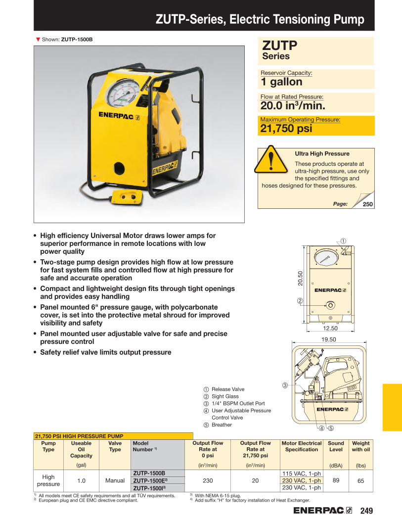
249
ZUTP-1500BZUTP-1500E2)
ZUTP-1500I3)
250
➀
3
2
4 5
▼
ZUTP-Series, Electric Tensioning Pump Shown: ZUTP-1500B
• High efficiency Universal Motor draws lower amps for superior performance in remote locations with low power quality
• Two-stage pump design provides high flow at low pressure for fast system fills and controlled flow at high pressure for safe and accurate operation
• Compact and lightweight design fits through tight openings and provides easy handling
• Panel mounted 6" pressure gauge, with polycarbonate cover, is set into the protective metal shroud for improved visibility and safety
• Panel mounted user adjustable valve for safe and precise pressure control
• Safety relief valve limits output pressure
21,750 PSI HIGH PRESSURE PUMPOutput Flow
Rate at0 psi
(in3/min)
ModelNumber 1)
UseableOil
Capacity
(gal)
PumpType
ValveType
ManualHigh pressure
Reservoir Capacity:
1 gallonFlow at Rated Pressure:
20.0 in3/min. Maximum Operating Pressure:
21,750 psi
Motor Electrical Specification
Sound Level
(dBA)
Weightwith oil
(lbs)
Output Flow Rate at
21,750 psi
(in3/min)
① Release Valve② Sight Glass③ 1/4" BSPM Outlet Port④ User Adjustable Pressure
Control Valve⑤ Breather
1) All models meet CE safety requirements and all TÜV requirements.2) European plug and CE EMC directive compliant.
3) With NEMA 6-15 plug.4) Add suffix "H" for factory installation of Heat Exchanger.
115 VAC, 1-ph230 VAC, 1-ph230 VAC, 1-ph
Ultra High Pressure
These products operate at ultra-high pressure, use only the specified fittings and
hoses designed for these pressures.
Page:
ZUTPSeries
230 20 89 651.0
19.50
12.50
20.50

▼
250 www.enerpac.com
HT-1503
HT-1510
HT-1503HR*
HT-1510HR*
ATP-1500
B150
BW150AW
B150B
BR150
—
—
BH150
—
—
II 2 GD ck T4IBExU 070/10
ATP-Series Ultra High Pressure Air Pump Shown: ATP-1500
Flo
w (i
n3 /m
in) ▶
Flow (in3/min) at 90 psi air inputPressure (psi) ▶
OIL FLOW vs. PRESSURE
Air Pressure
Range
(psi)
Pressure Rating
(psi)
Output Flow Rate at
0 psi
(in3/min)
ModelNumber
UseableOil
Capacity
(gal)
PumpType
High pressure
Air Consumption
(sfcm)
Sound Level
(dBA)
Weight
(lbs)
Output Flow Rate at
21,750 psi
(in3/min)
• General purpose, high pressure air driven pump unit for products requiring up to 21,750 psi hydraulic pressure
• Compact, lightweight, rugged steel frame for protection and easy handling
• Prelubricated pump element, does not require an airline lubricator
• Easily adjustable output pressure control• Integrated and protected easy to read glycerin filled gauge• Safety relief valve limits output pressure• ATEX Certified
The ATP-series pump was tested and certified according to the Equipment Directive 94 / 9 / EC “ATEX Directive”. The explosion protection is for equipment group II, equipment category 2 (hazardous area zone 1), in gas and/or dust atmospheres. The ATP-series pump is marked with: Ex II 2 GD ck T4.
These products operate at ultra-high pressure, use only the specified fittings and hoses designed for these pressures.
Reservoir Capacity:
1.0 gallonFlow at Rated Pressure:
4 in3/min.Maximum Operating Pressure:
21,750 psi
ATP Series
① HPT Shut-off Valve② 1/4" BSPP HPT Out Port③ Filter/Regulator④ Air On/Off Valve
ModelNumber
End 1 Length
(ft)
End 2 Description Complete Set
MaleHalf
FemaleHalf
Quick Disconnect Coupler*
Quick Disconnect Coupler and Adaptor Kit*
Quick Disconnect Blanking Coupler Set*
1/4 BSPM 120º Cone1/4 BSPM 120º Cone
BH150
BH150
3.28
9.84
3.28
9.84
1/4 BSPM 120º Cone1/4 BSPM 120º Cone
BR150
BR150
* Includes dust caps * Includes dust caps
Fittings Hoses
21,750 80-901.0 70 70 6526 4
0
5
10
15
20
25
30
5000
0
10000 15000 20000 250000
15.0015.75
15.3
0

251
D
F
B
H
3/8"-18NPTF
A
C
J
▼
NC-1319NC-1924*NC-2432*NC-3241*NC-4150NC-5060NC-6075
NCB-1319NCB-1924NCB-2432NCB-3241NCB-4150NCB-5060NCB-6075
STN-1924HSTN-2432HSTN-3241H
Hydraulic Nut Cutters Shown from left to right: NC-3241, NC-1319, NC-1924
• Compact and ergono mic design, easy to use• Unique angled head allows flush access• Single-acting, spring return cylinder• Heavy-duty chisels can be reground• Applications include servicing trucks, piping industry, tank
cleaning, petrochemical, steel construction and mining
Bolt Range
(in)
Capa city
(ton)
OilCapa city
(in3)
Weight
(lbs)
ModelNumber
Capacity:
5-90 tons
NC, STN Series
Hexagon Nut Range:
0.5-2.88 inchesMaximum Operating Pressure:
10,000 psi
Ordering Notes: Maximum allowable hardness to split is HRc-44. Not to be used on square nuts. Larger sizes available upon request.* Available as Tool-Pump set, see note on this page.
Dimensions (in)
Enerpac Nut Cutters
Nut Cutters include a spare chisel, a spare set screw and the wrench used to secure the chisel. A CR-400 coupler is standard.
ReplacementChiselModelNumber
Nut Cutter Sets
Hydraulic Nut Cutters are available as sets (pump, tool, gauge, adaptor and hose).
Splitter Model Number
Set Model Number
Pump Model Number
◀ Easily removing rusty nuts during railroad construction is just one of many application examples for the Enerpac Nut Cutters.
Hexagon Nut Range
(in) A B C D F H J
.31-.50
.50-.63
.63-.88.88-1.131.13-1.381.38-1.501.50-1.88
.50-.75
.75-.94.94-1.131.13-1.561.56-2.002.00-2.252.38-2.88
5101520355090
.921.223.664.889.4614.6430.00
1.892.802.993.504.294.967.09
1.84.46.69.7
18.026.075.1
1.101.501.932.602.873.634.33
.75
.981.221.381.772.132.95
.24
.32
.39
.59
.831.061.06
7.878.94
10.2411.2612.8014.4114.43
1.572.172.602.953.784.176.14
NC-1924NC-2432NC-3241
P-392P-392P-392
.831.001.301.692.132.383.07

▼
252 www.enerpac.com
251
254
256
NS-Series Hydraulic Nut Splitters
• Specially designed to suit standard ANSI B16.5 / BS1560 flanges
• Single-acting, spring return cylinder• Tri-blade technology provides three cutting surfaces
on a single blade • Interchangeable heads provide maximum nut range flexibility• Preset scale allows controlled blade extension, which avoids
damage to bolt threads• Grip tape and handle included for more secure maneuverability• Nickel-plated cylinder body for excellent corrosion protection
and improved durability in harsh environments• Internal Pressure Relief Valve for overload protection
Shown: NS-7080, NS-70105
Hydraulic Nut Cutters
The NC-Series models are available featuring an angle-head design for 0.50"-2.88" hexagon nuts.
Blade Cutting Depth Scale
Adjustable cutting depth scale for controlled blade extension, which avoids damage to bolt threads.
The scale indicates the bolt range in metric and imperial values on each cutting head.
FS-Series Spreaders
FS-Series Flange Spreaders provide quick and easy joint separation using hydraulic or mechanical force.
ATM Flange Alignment Tools
The ATM series provides safe high-precision flange alignment tools that fit
most commonly used ANSI, API, BS, and DIN flanges.
Power and Precision
High PerformanceNut Splitter
◀ Heavily corroded and weathered nuts are quickly split and removed using an NS-Series Nut Splitter.
Page:
Page:
Page:

253
NS-70105NS-70105NS-70105NS-70105NS-110130NS-110130NS-110130NS-110130
P392–––
P802–––
–XA-11G*
–––
XA-11G*––
––
XC-1202MB–––
XC-1202MB–
GA-2–
GA-2GA-2
–
GA-2
HC-7206HC-7206HC-7206HC-7206HC-7206HC-7206HC-7206HC-7206
CM-4CM-4CM-4CM-7CM-4CM-4CM-4CM-7
NS-7080NS-7085NS-7095NS-70105NS-110115NS-110130
A B C D E F G
NSB-70NSB-70NSB-70NSB-70
NSB-110NSB-110
NSC-70NSC-70NSC-70NSC-70
NSC-110NSC-110
NSH-7080NSH-7085NSH-7095
NSH-70105NSH-110115NSH-110130
▼ 2▼ 1
BF
DG
C EA
*3/8˝ NPTF*3/8˝ NPTF
▶
▶ 2
1
GA45GC
GA45GC
–––
PUD-1100B–––
PUD-1100B
Nut Splitter Sets
To provide maximum flexibility, NS-Series Nut Splitters can also be ordered in sets
(NS-xxxSx). Select Nut Splitter size and pump style from the chart below.
To order additional Cutting Heads (NSH-xxxxxx), Cylinders (NSC-xxx) or Replacement Blades (NSB-xxx), see Selection Chart below.
Hydraulic Nut Splitters
NSSeries
Hand Pump
Model No.
Air Pump
Model No.
Cordless Pump
Model No.1)
Electric Pump
Model No.
Gauge Adaptor
Model No.
Gauge Model No.
Hose Model No.
Storage Case
Model No.
Bolt Range
Cap. WeightModel Number*
Replacement Blade
NSCylinder
NS Cutting Head
* NS-Series Nut Splitters ship in two cases: One containing the NSC Cylinder and one containing the NSH Cutting Head. Assembly required.** Maximum allowable hardness to split is HRc-44.
Dimensions (in)
Pump Options Accessories IncludedNut Splitter Model Number
Set Model Number
OilCap.
GP-10Sintegrated*
GP-10SGP-10S
integrated*
GP-10S
SET SELECTION:
Select your Nut Splitter
Select your pump type
*Fitted with CR400
Capacity:
103.2-192.5 tonsHexagon Nut Range:
2.75-5.38 inchesMaximum Operating Pressure:
10,000 psi
(lbs)(ton)(in) (in3)
1) XC Cordless Pump includes 115 V charger, for 230 V charger replace the "B" in the model number with an "E".* XA-11G air pump features an integrated pressure gauge.
Hexagon Nut
Range**
(in)
1.75-2.001.75-2.251.75-2.501.75-2.752.75-3.002.75-3.50
103.2103.2103.2103.2192.5192.5
1.11.21.31.41.41.6
7.17.17.17.19.29.2
0.30.30.30.40.10.1
3.23.23.23.24.44.4
7.37.77.98.29.29.5
16.216.617
17.518.619.4
5.25.76.36.97.48.6
81.482.784.987.1
151.6158.3
NS-70105SHNS-70105SANS-70105SCBNS-70105SENS-110130SHNS-110130SANS-110130SCBNS-110130SE
23.0 23.0 23.0 23.050.0 50.0
2.75-3.132.75-3.502.75-3.882.75-4.254.25-4.634.25-5.38

▼
254 www.enerpac.com
J
H
F
C
E
D
B
A
I
255
Flange Spreader Sets*
Both Hydraulic Flange Spreaders are available as sets (includes pump, tool, gauge, adaptor and hose).
Page:
Pipe Size (in)
FS-56 FS-109
Pin Type Hydraulic Flange Spreaders Shown: FS-56
• Lightweight, ergono mic design for ease of use• Adjustable jaw widths from 2.75" to 8.50" for a wide
range of applications• Single-acting, spring return RC Series cylinders for fast
trouble-free operation
FS, STF Series
Capacity:
5-10 tonsSpread:
2.75 - 8.50 inchesMaximum Operating Pressure:
10,000 psi
Maximum Flange
Thickness
(in)
Stud Size
(in)
Standard Wedge
(in)
Cap.
(ton)
Stroke
(in)
Oil Cap.
(in3)
Model Number
Min. Max.
Dimensions (in) Weight
(lbs)
Flange Spreader Matching ChartASA
Rating
(psi)
Spreader Model Number
Set Model Number
Pump Model Number
Wedge Spreaders
Friction-free, smooth and parallel wedge movement with unique interlock wedge design. Eliminates
flange damage and risk of spreading arm failure.
* Available as Tool-Pump Set, see note on this page.
2 x 2.252 x 3.63
.75-1.131.25-1.63
.13-1.13
.13-1.13510
1.502.13
1.504.80
2.754.10
6.108.50
7.716.00
3.454.50
1.001.50
8.1010.75
.751.25
2640
8.2511.00
3.004.25
FS-56*FS-109*
150300400500900
15002500
5-202.50-142.50-122.50-10.50-6
.50-3.50
.50-2.50
22-4216-2814-2412-208-164-83-4
1.281.98
FS-56FS-109FS-109
STF-56HSTF-109HSTF-109A
P-392P-392PATG-1102N
A B E F H I JD
C

255
▼
FSH-14 FSM-8
SB-1
SW-22
FSM-8FSH-14*
FSH-14 P-392 STF-14H
Tip Clearance / Maximum Spread*:
0.24/3.16 inches
FSM/FSH/STFSeries
Maximum Spread Force:
8-14 tonsMaximum Operating Pressure:
10,000 psi (FSH-14)
Stepped Blocks FSB-1
Use this pair of stepped blocks to increase wedge opening up to 3.16 in. (81 mm). Fits both FSH-14 and FSM-8.
Hydraulic and Mechanical Industrial Spreaders Shown: FSH-14 and FSM-8 with safety blocks SB1
• Integrated wedge concept: friction-free, smooth, parallel wedge movement eliminates flange damage and spreading arm failure
• Unique interlocking wedge design: no first step bending and risk of slipping out of joint
• Requires very small access gap of only .24 inch (6 mm)• Stepped spreader arm design: each step can spread
under full load• Few moving parts means durability and low maintenance• Safety block SB-1 and ratchet spanner SW-22 included
with FSM-8 • Safety block and Enerpac RC-102 cylinder included
with FSH-14
▼ Two FSH-14 spreaders used simultaneously with Enerpac handpump, hoses and AM-21 split-flow manifold.
SteppedblocksFSB-1
Flange Spreader Sets
The hydraulic flange spreader, FSH-14, is available as a set (pump, tool, gauge, gauge adaptor, couplers and hose) for your ordering convenience
Handpump Model No.
Spreader Model No.
Set Model Number
Closed OpenedSafety Block Closed Opened
MechanicalHydraulic
Max. Spreading
Force(ton)
Tip Clearance
(in)
ModelNumber
Max. Spread1)
(in)
Type Weight
(lbs)
Oil Capacity
(in3)
1) Using stepped blocks FSB-1.* Available as Tool-Pump Set, see note on this page.
814
.24
.243.163.16
14.315.7
-4.76
.24
.98
.98
12.09
.86
1.21
1.33
2.38
10.7
3
11.3
1
.24
.59
1.211.21
1.33
2.38
11.3
1
12.7
9
.24
.59
1.21
3.90
.78
1.091.481.872.263.04
2.6 2.60

▼
256 www.enerpac.com
131
• Enerpac ATM-Series tools rectify twist and rotational misalignment quickly, safely, and without the need for an external power source
• Appropriate for use on most ANSI, API, BS and DIN flanges• No slings, hooks or lifting gear required• Can be installed and used in any position (horizontally
or vertically)• Portable, lightweight design enables easy transport and use,
even in remote locations
Adjustable Reach
The highly adjustable reach of the wing and drop leg on the ATM-4 and ATM-9 allows precise alignment.
▼ The compact ATM-2 is actuated by simply hand turning the crank.
From left to right: ATM-4, ATM-9, ATM-2
ATM-Series, Flange Alignment Tools
▼ The ATM-9 is shown here with optional pressure gauge and gauge adaptor.
The faster, simpler and safer way to align flanges
Gauge and Adaptor
The ATM-9 includes P-142 hand pump and HC-7206C 6 ft. long hose. Enerpac recommend the use of the
pressure gauge GP-10S and gauge adaptor GA-4 for easy mounting of the gauge onto your system.
Page:

257
ATM-2
ATM-9
ATM-4
ATM-2ATM-4ATM-9**
ATM-4 21 3 4
ATM-2 ATM-4
ATM-9
52
258
ATMSeries
Minimum Bolt Size:
.63-1.24 inchesFlange Wall Thickness:
.55-9.00 inchesMaximum Lifting Force:
1-10 tons
* At 10,000 psi maximum operating pressure.** ATM-9 includes an Enerpac hand pump and hydraulic hose (gauge and adaptor sold separately).
ATM-9 weight includes tool only.
Model Number
MaximumLifting Force
(ton)* (kN)*
Minimum Bolt Size**
(mm)(mm) (in)(in)
Flange Wall Thickness(max)
Wt.
(lbs)
ATM-Series, Flange Alignment Tools
▼ The ATM-Series – the faster, simpler and safer way to align flanges.
Cylinder-Pump Sets
Hydraulic cylinders, jacks and lifting wedges can also be used to assist in pipe line positioning and aligning.
Pipe Flange Face Tool
The portable, hand powered tool FF-120 makes even the hardest to reach pipe flanges resurfaceable in a safe and convenient way.
Applications
Enerpac ATM-Series Tools help correct flange misalignment, and allow
bolts to be placed into joints. This alignment takes place during pipework construction, or maintenance.
These tools provide pipe installers and maintenance personnel with some of the simplest, safest and most productive solutions available for flange alignment in the market today.
① Extendable wing provides usage on wide variety of flanges.
② Portable, light weight design enables easy transport and use.
③ Hand-adjustable base for easy positioning by a single operator.
④ Safety strap helps provide secure operation from a horizontal or vertical position.
Page:
Page:
1 410
104090
3.51932
.63
.951.24
1624
31,5
.55 - 3.291.18 - 5.233.66 - 9.00
14 - 8230 - 13393 - 228
.71
.43
3.19
7.60
3.66
11.3411.50
1.54
1.46
12.9514.45
18.90
1.776.22
ø 3.94
2.13
11.5
014
.06
4.13 ø 3.949.45
20.5125.83
3.23
1.85
3.23
8.07
17.8
3 11.5
7

▼
258 www.enerpac.com
256
254
Page:
Page:
Joint Assembly Tools
Rectify twist and rotational alignment without additional stress in pipe lines using the ATM-Series flange alignment tools.
• Refacing made easy — hand-operated machine tool can be set up anywhere without the need for air, electric or hydraulic power support
• Lightweight and portable — easily transported to remote locations for increased productivity
• Adjustable cutting range for flange diameters between 1-12 inches [25,4-304,8 mm]
• Interchangeable collets for ID mounting range from 1-6 inches allowing the user to work on many different flanges with minimal time between set-ups
• Interchangeable lead screws suitable for refacing damaged raised-face (RF), flat-face (FF) or lens-ring joint flanges
• Tool body with expanding collets centers itself providing real concentric operation
FF-Series, Mechanical Flange Face Tool Shown: FF-120
Joint Separation Tools
FS and FSH-Series parallel wedge spreaders provide quick and easy joint separation using hydraulic or mechanical force.
Safe, efficient and accurate refacing of flat pipe flange surfaces
▼ The Enerpac FF-120 used to face a pipe flange.
Complete In-Wheeled Carrying Case
The FF-120 comes as portable set (15 kg). Can be transported, easy set-up
and operated by a single technician. Set includes:
• FFL-kit with locators, O-Rings and extensions
• FSS-kit with feed screw and nut ½"-20 UN for surface roughness Ra 64 - 96 µin.
• FSF-kit with feed screw and nut ½"-11 UNF for surface roughness Ra 125 - 250 µin.

259
FF-120
1 2 3
1
2
3
5
7
8
9
10
11
12
6
4
4 75 6
(in) (in) (m)(mm) (mm) (in)
Pipe Flange Cutting Diameter Range:
1-12 in (25-305 mm)Internal Pipe Mounting Diameter Range:
1-6 in (25-152 mm)Average Roughness:
125-250 µin (3,18-6,35) µm
▼ TOOL SELECTION CHART
FF Series
* without locator extensions.
Model Number
Average Roughness
(Ra μ)
Pipe Flange Cutting Diameter Range
Internal Pipe Mounting Diameter Range
Wt.
(lbs)
▼ The Enerpac FF-120 Quick Face has same precision and quality of finish as powered machines.
* When using fine thread feed screw, FF120FSF.
1 Hand-operated cold work tool – no need for external power and hot work permits.
2 Calibrated cross slide for accurate cutting control.
3 Adjustable cutting head for reface of flat flange surfaces of pipes with flange OD facing range ø 1-12 inch [25,4-304,8 mm].
4 Interchangeable lead screws enable selection of surface finish between Ra 125-250 µin.
5 Utilizes standard 3/8 inch or 10 mm tool steel.
6 Range of interchangeable collets allow the tool to accommodate ø 1 - 6 inch [25,4 - 152,4 mm] pipe ID.
7 Tool body with expanding collets centers in the bore ensuring concentric and accurate set-up.
QuickFace, Mechanical Flange Face Tool
Portable, hand powered tool makes even the hardest to reach pipe flanges resurfaceable in a safe and convenient way.
Makes refacing easyA simple and cost effective solution – the FF-120 turns a two man operation with heavy equipment, compressors and portable generators into a one man job.
The FF-120 has interchangeable lead screws that make it suitable for resurfacing damaged flat-faced, raised-face or lens-ring joint flanges to the high safety standards required. After selecting the correct lead screw for the operation, the tool body is inserted in the pipe end and centers itself with adjustable locators to provide real concentric operation.
The tool arm is then rotated by hand using a worm-gear mechanism to provide a perfect spiral “gramophone” finish.
The tool can be adjusted with a calibrated slide to define cut depth and the correct finish.
Surface finish and accuracyA serrated finish with 30-55 grooves per inch and a resultant roughness of between Ra 125-250 micro inches (3,18-6,35 µm).
The FF-120 has the same precision and quality of finish as a lathe.
Cost effective solutionSmall and portable enough to be a permanent addition to your equipment range, Enerpac’s FF-120 is the perfect solution to all of your small diameter facing problems.
Quick Face, Mechanical Flange Face Tool
1 Feed Knob2 Gear Box3 Cutting Depth
Adjustment with indicator: .005 inch (0,127 mm) per mark
4 Locking Collar5 Lead/Feed Screw
6 Tool Block7 Swivel Slide8 HSS 3/8” Tool Bits9 Mandrel Locking
Knob10 Locator Extensions11 Adjustable Locators12 O-Ring
25,4-152,41.0-6.025,4-304,81.0-12.0 3,18-6,351,52-2,54*
125-25060-100*
15
R1.2
1.0-6.0
Ø 1.0-12.0 *R2.18
8.510.011.0
2.8
5.0
4.8
7.6 9.
2
2.1

260 www.enerpac.com
Enerpac Heavy Lifting Technology
Enerpac’s Heavy Lifting Technology provides customers with tailored solutions, combining hydraulics, steel fabrication and electronic controls for safe, precise movement of heavy loads.
With more than 50 years supporting industrial markets, Enerpac has gained the unique and in-depth expertise that is respected by industrial professionals around the world.
Enerpac’s complete line of standard and customized products and a unique systems approach offers the benefits of safety and efficiency to applications where high forces are required.
Whether constructing a signature bridge, performing a heavy load out, fabricating a new ship or positioning a large transformer, Enerpac will supply the hydraulic solutions to get the job done safely and efficiently.
EXPERIENCE and
EXPERTISE
ELECTRONICSOur in-house team of electrical engineers combine their knowledge of heavy lifting equipment to tailor system controls to match unique project requirements.
STEEL FABRICATIONEnerpac has a dedicated facility for steel fabrication and welding. We design and manufacture custom structures used in demanding heavy-lifting applications.
HYDRAULICSMoving heavy loads with hydraulic systems is our core expertise. Enerpac designs, manufactures, integrates and tests complete hydraulic systems in house.
Jacking with high capacity precision control
Synchronous superlift and launch
Synchronous hoisting and load positioning
Precision lift and position of heavy loads

261
▶
▶
▶
▶
▶
▶
262
264
266
268
270
272
HSK
HSL
SLSBLMBL
JS
SPMT
140-280
17-1405
67-1178
140-840
67
Capabilities SeriesCapacity (tons)
Page
Heavy Lifting Equipment Section Overview
Contact Enerpac!
Contact the Enerpac office nearest to you for advice and technical assistance in the
layout of your ideal solution or visit us on the web: enerpac.com/contact-us
Skidding Systems
Heavy Lifting Strand Jacks
Hydraulic Gantries
Jack-Up Systems
Self-Propelled Modular Transporter
Custom Solutions
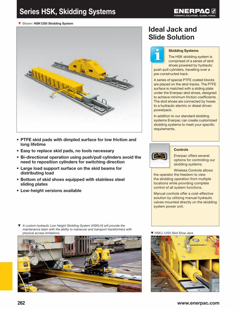
▼
262 www.enerpac.com
Series HSK, Skidding SystemsShown: HSK1250 Skidding System
• PTFE skid pads with dimpled surface for low friction and long lifetime
• Easy to replace skid pads, no tools necessary• Bi-directional operation using push/pull cylinders avoid the
need to reposition cylinders for switching direction• Large load support surface on the skid beams for
distributing load• Bottom of skid shoes equipped with stainless steel
sliding plates• Low-height versions available
Ideal Jack and Slide Solution
Controls
Enerpac offers several options for controlling our skidding systems.
Wireless Controls allows the operator the freedom to view the skidding operation from multiple locations while providing complete control of all system functions.
Manual controls offer a cost-effective solution by utilizing manual hydraulic valves mounted directly on the skidding system power unit.
Skidding Systems
The HSK skidding system is comprised of a series of skid shoes powered by hydraulic
push-pull cylinders, travelling over a pre-constructed track.
A series of special PTFE coated blocks are placed on the skid-tracks. The PTFE surface is matched with a sliding plate under the Enerpac skid shoes, designed to achieve minimum friction coefficients. The skid shoes are connected by hoses to a hydraulic electric or diesel driven powerpack.
In addition to our standard skidding systems Enerpac can create customized skidding systems to meet your specific requirements.
▼ A custom hydraulic Low Height Skidding System (HSKLH) will provide the maintenance team with the ability to maneuver and transport transformers with physical access limitations. ▼ HSKJ-1250 Skid Shoe Jack.

263
A
B
E F
C D
HSKB 1250HSK J1250HSK LH 2000HSK B 2500HSK J 2500
140140225280280
2525294545
1818163030
Skidding Systems
Skidding Systems
Enerpac Skidding Systems are available in several versions:
• HSKB-Series (Skid Shoe Beam) utilizes a tall skid shoe with built-in push/pull cylinders. Skidding direction can be easily switch by flipping a lever on the attached gripper box.
• HSKJ-Series (Skid Shoe Jack) provide the same functionality as the HSKB with the added benefit of having a built-in cylinder for lifting or leveling the load.
To calculate the minimum required capacity per shoe, the entire load has to be able to rest safely on 2 of the 4 shoes. To skid a load of 500 tons, the required skidding system is HSKB2500 or HSKJ2500.
Capacity:
140-280 tonsStroke Push/Pull:
23.62 inchesLifting Stroke*:
6.89 inches
Skid Tracks
Include specially constructed and easily replaceable PTFE coated pads.
Hydraulic Power Packs
Enerpac offers a comprehensive range of hydraulic power packs that are optimized for use with their industry leading Skidding Systems.
HSK Series
* Skid shoe jack version only.
The Power Pack can operate up to 4 push/pull cylinders. Typically 4 skid shoes are used to skid a load. All details below
are for the skid shoe and track. Skid track is sold separately.
Skidding System Requirements
① Skid Track
② Skid Beam
③ Hydraulic Power Pack
④ Hydraulic Push/Pull Unit
MaximumLifting
Capacity(per shoe)
(ton)
Maximum SkiddingCapacity
(ton)
Model Number
Skid Shoe
Height(with track)
A(in)
LiftingStroke
B(in)
Push/PullStroke
C(in)
Skid Shoe
Length
D(in)
Skid Shoe
Weight
(lbs)
SkidTrackWidth
E(in)
SkidTrack
Length
F(in)
SkidTrack
Weight
(lbs)Push Pull
12.1719.768.03
14.7223.62
–6.89
––
6.89
23.6223.6223.6223.6223.62
98.4366.54
114.25118.1170.23
1,6311,742750
2,2493,197
15.7515.7521.2623.6223.62
78.0778.0778.6676.6176.61
265265220640640

▼
264 www.enerpac.com
Shown: HSL50006 Strand Jack
HSL-Series, Heavy Lifting Strand Jacks
Strand Jacks
Enerpac strand jacks are the strand jacks of choice for customers seeking precise
synchronous control with heavy lifting capacity in an economical, compact, and reliable foot print.
Enerpac strand jacks are powered by electrical or diesel driven hydraulic power packs and controlled by Enerpac’s proprietary SCC-Smart Cylinder Control System to ensure full control of lifting and lowering operations.
Enerpac continually improves reliability, durability, and safety of their strand jacks, making them an industry standard for heavy lifting.
Heavy Lifting Strand JacksHigh Capacity - Precision Control
• Precision control of synchronous lifting and lowering• Can be controlled by a single operator from a central
location for increased safety• Automated locking - unlocking operation• Two strand sizes: 0.62 in (15.7 mm) and 0.71 in (18 mm)• Telescopic strand guide pipes prevent bird caging• Internal components are coated with Lunac, an
anti-corrosion coating, making it suitable for marine environments
• Lifting anchor included with all strand jacks• Lloyds witness tested to 125% of maximum working load
▼ Shown: HSL85007 Strand Jack System used on Enerpac custom Self-Erecting Tower.
▼ Enerpac's SCC-Smart Cylinder Control System simplifies synchronous operation with intuitive controls and a user-friendly graphical interface.

265
HSL3006HSL7006HSL20006HSL30006HSL50006HSL1507HSL4507HSL6007HSL10007HSL20007HSL30007HSL45007HSL65007HSL85007HSL100007HSL125007
A
B
H
F
E
E
C
G
D
F
A
B
H
F
E
E
C
G
D
F
①
②
③
④
⑤
⑥
Strand Diameter
inch (mm)
No. of
Strands
ModelNumber
Capacity
(tons)
Stroke
(in)
A
(in)
B
(in)
C
(in)
D
(in)
Wt.
(lbs)
Heavy Lifting Strand Jacks
HSL Series
Capacity:
17-1405 tonsStroke:
9.8-23.6 inchesMaximum Operating Pressure:
5,000 psi
Strand Jacks
A strand jack can be considered a linear winch. In a strand jack, a bundle
of steel strands are guided through a main “lifting” jack. Above and below the cylinder are anchor systems with wedges that grip the strand bundle simultaneously. Lifting and lowering a load is achieved by hydraulically controlling the main jack and both mini jacks alternately.
In the case of system pressure loss, the wedges are mechanically closed automatically, holding the suspended load in place.
Today, strand jacks are widely recognized as the most sophisticated heavy lifting solution. They are used all over the world to erect bridges, load out offshore structures, and lift/lower heavy loads where the use of conventional cranes is neither economical nor practical.
▼ Strand Jack Accessories – Contact Enerpac for assistance at enerpac.com/contact-us
Shown: HSL20006 Strand Jack
SG-Series Strand GuideProvides a guide for the strand as a strand jack lifts the load.
SR-Series Strand Recoiler
Passively pays in or pays out strands while jacking and lowering.
SD1 Strand Dispenser
Essential to safely unbundle a new strand coil.
① Strand Guide② Top Mini Jack③ Main Lifting Jack④ Counter Balance Valve⑤ Bottom Mini Jack⑥ Chair SLPP-Series Hydraulic
Power Packs
Enerpac offers a comprehensive range of hydraulic power packs that are optimized for use with their industry leading strand jacks.
Lifting Anchor
Each Strand Jack includes a lifting anchor for attaching strand to the load.
72.975.478.480.684.148.968.069.075.878.880.987.588.194.6100.7104.6
13.814.220.626.528.98.713.815.716.120.626.528.933.535.443.043.3
19.722.625.626.528.98.719.724.624.625.626.528.933.535.443.043.3
2.33.76.78.510.70.82.93.54.66.58.310.713.814.317.218.0
1,1021,4112,8604,8206,930220
1,1021,4331,8743,0864,2906,7248,69011,02316,86518,298
18.918.918.918.918.99.818.918.918.918.918.918.918.918.918.923.6
347922533756217516711222533750673195511241405
37193148134712193143556684
0.62(15.7)
0.71(18)

▼
266 www.enerpac.com
SL60SL125SL300SL400SBL500SBL900SBL1100MBL500MBL600
Shown: SBL1100 with STSBL Skid Tracks, Header Beams and Side Shifts
• Self-contained hydraulics and electronics• Intelli-Lift wireless control system• Self-propelled wheels or tank rollers• Foldable boom on SBL900, SBL1100, MBL500 and MBL600• Full range of supplementary equipment: header beams,
lifting lugs, side shift, skid tracks• Designed and tested to meet ASME B30.1-2015
safety standards• Lloyds witness tested to 120% of maximum working load
Hydraulic Gantries
▼ Shown: SBL1100
INTELLI-LIFT
The Intelli-Lift wireless control system is included with all Enerpac hydraulic gantries. The Intelli-Lift
controller offers superior safety and control and includes the following features:
• Encrypted bi-directional communication that eliminates interference from other devices
• Remote operation using multi-channel wireless (2.4 GHz) or wired (RS-485) control
• High and low speed settings
• Automatic synchronization of lifting with an accuracy of 0.95 inch (24 mm)
• Automatic synchronization of travelling with an accuracy of 0.60 inch (15 mm)
• Overload and stroke alarms
• Remote side shift control
• Emergency stop switch
Precision Lift and Position of Heavy LoadsThe Ultimate in Safety and Control
Maximum Capacity (4 legs)
(tons)
Retracted Height
A
(ft)
Model No.
6.578.668.87
10.399.93
16.4214.3420.0121.50
67141337450585
10091178562674

267
SL60SL125SL300SL400SBL500SBL900SBL1100MBL500MBL600
A
E
C
B
Capacity:
67-1178 tonsLift Height:
15.43-47.74 feet
Skid Tracks
Skid tracks used for leveling and load distribution. Available in two standard lengths, 10 feet and 20 feet.
Header Beams
Sold in pairs and includes lifting points and fork pockets for easy positioning on gantry towers.
Available in 26.24 ft., 32.80 ft. and 39.36 ft. lengths.
Powered Side Shift
Electric propulsion controlled by standard gantry controls. Each set consists of 4 units.
Lifting Anchors
Designed to transfer the load to the top of the header beam. Can accommodate a 250 ton shackle or attach directly to the lifted load.
SL, SBL, MBL Series, Hydraulic Gantry
Model No.(4 towers)
Stage 1 Stage 2 1) Stage 3
Max. Height
B (ft)
Max. Height
B (ft)
Max. Height
B (ft)
Max. Cap.
(ton)
Max. Cap.
(ton)
Max. Cap.
(ton)
Transport Height
C(ft)
Base Width
E(in)
Weightper Leg
(with oil)
(lbs) 2)
SL, SBL, MBL Series
▼ Additional Accessories – Contact Enerpac for assistance at enerpac.com/contact-us
1) MBL500 and MBL600 are two stage gantries; stages 1 and 2 extend simultaneously and provide full capacity at any height.
2) Weight per tower
Hydraulic Gantries
Hydraulic Gantries are a safe, efficient way to lift and position heavy loads
in applications where traditional cranes will not fit and permanent overhead structures for job cranes are not an option.
Hydraulic Gantries are placed on skid tracks to provide a means for moving and placing heavy loads, many times with only one pick.
Enerpac offers three series of Hydraulic Gantry systems:
• SL-Series Super Lift The cost-effective SL-Series Super Lift offer control and stability for everyday lifting applications below 450 ton up to 25 feet.
• SBL-Series Super Boom Lift The heavy-duty SBL-Series Super Boom Lift boom style gantries offer increased lifting capacity of over 450 ton to heights of almost 40 feet.
• MBL-Series Mega Boom Lift The massive MBL-Series Mega Boom Lift offers capacities and lifting heights of over 600 ton at almost 47.7 feet extreme lifting conditions.
All Enerpac gantries are delivered with specific properties and control systems to ensure optimum stability and safety.
Drawing shows SBL-series, SL-sereis without boom.
173584112146252295
––
11.1715.0115.1117.1416.4027.2422.98
––
15.4321.7821.9823.7322.6637.0731.7242.21 47.74
173556112146166190141 169
–––
29.9928.27
–39.38
––
–––
5284–
106––
––
8.87––
7.367.36 7.368.28
31.5036.6934.6549.4550.4355.4355.4383.9095.71
231546967165
10,14113,88929,43226,34543,54146,187

▼
268 www.enerpac.com
JS-Series, Jack-Up Systems Shown: JS-250-Series Jack-Up System (one lifting tower shown)
Incremental Lifting System – Synchronously Lift and Mechanically Hold
▼ The steel barrels are stacked together to mechanically hold the load.▼ Lifting an oil and gas pipe module
▼ A load is lifted in increments as barrels are slid into the system, lifted, and stacked; forming ‘lifting towers’.
• Self-contained hydraulics in each jack-up unit for uncluttered work area
• Synchronously lift loads with multiple jack-up units. The most common system set-up includes four jack-up units but can be expanded to include more
• Lifting barrels are stacked together to mechanically hold the load
• Up to 5% side load capacity depending on capacity and lift height
• Computer controls for operating the Jack-Up System with automatic and manual lifting settings
Computer Controls
Enerpac Jack-Up Systems provide precision control suitable for many demanding lifting and
lowering applications. The comprehensive self-contained design features simple to use software.
• Computer control for operating the Jack-Up system with automatic and manual lifting settings
• Automatic synchronization of multiple networked lift points
• Center of Gravity calculation
• Overload and stroke alarms
• Emergency stop switch at jack-up units and controls
Typical Applications
• Bridge construction and demolition
• Port crane lifting
• Shovel undecking
• Top side lifting
• Ship hull block installation
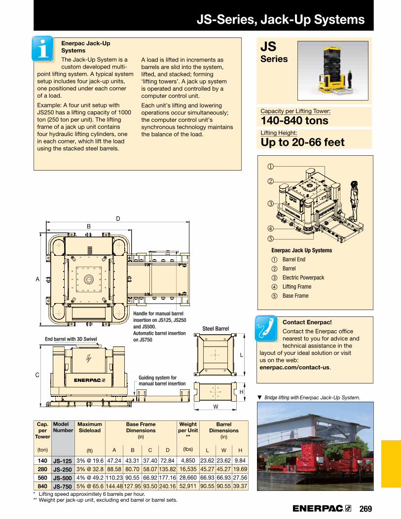
269
JS-125JS-250JS-500JS-750
140280560840
A B C D
W
L
H
BD
A
C®
j
k
l
mn
L W H
Cap.per
Tower
(ton)
Weight per Unit
**
(lbs)
ModelNumber
MaximumSideload
(ft)
Base Frame Dimensions
(in)
* Lifting speed approximitely 6 barrels per hour. ** Weight per jack-up unit, excluding end barrel or barrel sets.
Barrel Dimensions
(in)
Steel Barrel
▼ Bridge lifting with Enerpac Jack-Up System.
JSSeries
Contact Enerpac!
Contact the Enerpac office nearest to you for advice and technical assistance in the
layout of your ideal solution or visit us on the web: enerpac.com/contact-us.
Capacity per Lifting Tower:
140-840 tonsLifting Height:
Up to 20-66 feet
End barrel with 3D Swivel
Guiding system for manual barrel insertion
Enerpac Jack Up Systems
① Barrel End
② Barrel
③ Electric Powerpack
④ Lifting Frame
⑤ Base Frame
Enerpac Jack-Up Systems
The Jack-Up System is a custom developed multi-
point lifting system. A typical system setup includes four jack-up units, one positioned under each corner of a load.
Example: A four unit setup with JS250 has a lifting capacity of 1000 ton (250 ton per unit). The lifting frame of a jack up unit contains four hydraulic lifting cylinders, one in each corner, which lift the load using the stacked steel barrels.
A load is lifted in increments as barrels are slid into the system, lifted, and stacked; forming ‘lifting towers’. A jack up system is operated and controlled by a computer control unit.
Each unit’s lifting and lowering operations occur simultaneously; the computer control unit’s synchronous technology maintains the balance of the load.
JS-Series, Jack-Up Systems
Handle for manual barrel insertion on JS125, JS250 and JS500.Automatic barrel insertion on JS750
47.2488.58
110.23144.48
43.3180.7090.55
127.95
37.4058.0766.9293.50
72.84135.82177.16240.16
4,85016,53528,66052,911
3% @ 19.63% @ 32.84% @ 49.25% @ 65.6
23.6245.2766.9390.55
23.6245.2766.9390.55
9.8419.6927.5639.37

▼
270 www.enerpac.com
®
L
AB
SPMT600-100SPMT600-360
MTPP-100MTPP-360
674 x 26 x 2
±50°±179°
••
–•
Self-Propelled Modular TransporterShown: SPMT600-360
• Modular design for multiple configurations• Minimized height and slim design are ideal for in-plant operation• Intelli-Drive wireless control system is intuitive and easy to use• One power pack can operate 2-3 trailers maximum depending
on model• Two trailers and power pack can be shipped inside
a 20 ft. container• Hydraulic power unit is tier-4 diesel engine for
reduced emissions
Self-Propelled Modular Transporter
The Enerpac Self-Propelled Modular Transporter (SPMT)
features a minimized height and slim design, which makes it very easy to operate in confined spaces. Each wheel unit has a steering function as well as a lifting cylinder at its disposal. Wheel propulsion is established by wheel drives.
The SPMT is operated by the Intelli-Drive Remote Controller. This remote controller can be used both hard wired and wireless (based on radio frequency).
The SPMT is a modular system comprised of trailers with 3 axle lines each and diesel hydraulic power units (HPU). Depending on the model number, the trailers and HPUs can be configured to a maximum of 4 trailers in 2 rows (4x2) or 6 trailers in 2 rows (6x2).
This is the maximum setup of units that can work together on just one Intelli-Drive Remote Controller.
Capacity (per transporter):
67 tonsTransport Speed (unloaded-loaded):
1.9 - 1.0 mphMotor Size:
75 hp
SPMT Series
Capacity(per
transporter)
(ton)
Transporter Model Number
HPU *Model No.
Maximum Configuration
(transporters in rows)
Steering Range
(degrees)
Steering Mode Retracted Height
A(in)
Average Travel Height
B(in)
Overall Length
L(ft)
Lifting Stroke
(in)
Wt. (SPMT)
(lbs)
Wt.(HPU*)
(lbs)crab carousel
* HPU = 54 kW Power Pack Diesel. HPU is sold separately.
30.2030.07
37.7637.64
14.9617.02
15.1215.12
10´
7.5´
ø 17
.7"
58.4"
31
.8
35.9"
15,43217,637
55125512

271
When your application requires something other than our standard product offering, look to Enerpac's Heavy Lifting Technology, experience, and expertise.
Our group of engineers, designers, and specialists will work with you to understand your specific application and provide a turn-key solution that will exceed your expectations.
ELECTRONICSEnerpac designs all control systems in-house. This capability keeps control technology close to the design engineers who are developing the rest of the system. In doing so, we can tailor the control system to match unique project requirements.
MAINTENANCE and REPAIRDue to the unique nature of Enerpac’s Heavy- Lifting Technology systems, we offer complete maintenance and repair services. Our M&R group is available to assist customers who do not have access to local service facilities qualified to work on these systems.
ENGINEERINGEnerpac’s multi-disciplined Heavy Lifting Technology team is capable of the design and development of all aspects of an integrated system. Leveraging design and application experience with the latest in methodologies, computer design, rapid prototyping and analysis ensures delivery of the highest quality.
MACHININGEnerpac utilizes the latest in CNC machining technologies and manufactures all large and special hydraulic cylinders in-house. We can machine diameters up to 3 inches with lengths to 25 inches.
HYDRAULIC POWER UNITSEnerpac designs, assembles and tests small to large hydraulic power units in-house. Power units range from 0.5 to 300 hp and are tested with the system they are intended to operate.
FIELD SUPPORTEnerpac’s Heavy Lifting-Technology team is available to provide on-site support including training and troubleshooting of systems. Enerpac also stocks repair parts and consumable items at several locations to ensure fast delivery for minimal downtime.
STEEL FABRICATIONEnerpac has a dedicated facility for steel fabrication and welding. We design and manufacture custom structures used in demanding Heavy Lifting applications.
Custom Heavy Lifting Solutions

272 www.enerpac.com
Custom Heavy Lifting Solutions
ROTOR REMOVAL AND INSTALLATION SYSTEM
The generator rotor removal and installation system is a custom developed product for removing and installing the rotor (field) in a power plant’s generator. The system is designed to comply with the varying dimensions and challenging accessibility of a plant’s generator.
LAS VEGAS WHEEL
Our expertise has been acknowledged by the world’s leading industrial professionals and has contributed to the successful movement of a number of the most recognizable structures on earth. At the time of construction, the Las Vegas High Roller was the largest observation wheel in the world. A custom hydraulic drive system was developed to propel the wheel for daily use and was also used to construct the wheel in sections.
TRAVEL GANTRY
The travel gantry combines the safety and efficiency of a hydraulic gantry with the ease of use of SPMT (Self-Propelled Modular Transporter) technology. With a lifting capacity of 67 tons, the travel gantry sets a new standard in equipment and container handling.
BRIDGE LAUNCH
Providing a solution for the most complex and demanding bridge construction applications, Enerpac has over 20 years experience providing unique customer bridge launching systems.
JACK-UP SYSTEM
The Jack-Up system is a custom developed multipoint lifting system. A typical system setup includes four jack up units, one positioned under each corner of a load. A four unit setup has a lifting capacity of 2200 tons (567 tons per unit).
STRAND JACK GANTRY
The Strand Jack gantry is a steel structure to facilitate erection and skidding back, forth and sideways of heavy loads. The Enerpac strand jack gantry can be used with either skidding systems or hydraulic gantries on top.
SELF-ERECTING TOWER
The Enerpac Self-Erecting Tower (ESET) is a self-erecting tower lift system that enables you to build a free standing gantry from ground level. The ESET can be supplied in various capacities and lifting heights and is built with standard modular components, enabling a flexible solution to future project demands.
CUSTOM HYDRAULIC PRESSES
Our hydraulic presses can be configured to fulfill a broad range of applications. Each press is designed and manufactured according to customer specifications and in cooperation with our engineering team.
AUTONOMOUS SYNCHRONOUS HOIST SYSTEMS
The SHAS-Series Synchronous Hoist System is a below-the-hook crane attachment comprised of multiple self-contained, PLC-controlled hydraulic lifting devices. The system enables a single crane to precisely position heavy and unbalanced loads.

273
???
!!P T
A
B
274-275
276-277
278-279
280-281
282-283
284 285
286-2891
55
9
333
7
711
2226
6
10
4
8
11
44
812
▶
▶
▶
▶
▶
▶
▶
▶
Yellow Pages Overview
PageSection
Safety Instructions
Product Selection & Worksheet
Basic System Set-ups
Basic Hydraulics
Conversion Tables and Speed Charts
Valve InformationHexagon Bolt and Nut Sizes
Torque TighteningTorque Tensioning
Enerpac “Yellow Pages”stand for
Hydraulic Information!
ENERPAC WARRANTY STATEMENT
www.enerpac.comVisit our website for the complete Enerpac Global Warranty or call your Enerpac representative or Enerpac Authorized Service Center.
If selecting hydraulic equipment is not your daily
routine then you will appreciate these pages. The
“Yellow Pages” are designed to help you work with
hydraulics. They will help you to better understand
the basics of hydraulics, of system set-ups and of
the most commonly used hydraulic techniques.
The better your choice of equipment, the better
you will appreciate hydraulics. Take the time to go
through these “Yellow Pages” and you will benefit
even more from Enerpac High Pressure Hydraulics.
ISO 9001REGISTERED
ENERPAC, 199 Gateway Court, Columbus WI 53925 USA
Enerpac is certified for several quality standards. These standards require compliance with standards for management, administration, product development and manufacturing.
Enerpac works hard to maintain the ISO 9001 quality rating, in its ongoing pursuit of excellence.
CE Marking & ConformityEnerpac provides Declarations of Conformity, Declarations of Incorporation, and CE marking for products that conform to the European Community Directives.
Where specified, Enerpac electric power units meet the design, assembly and test requirements of The Standards Council of Canada (CAN C22.2 No. 68-92), and UL73 for the United States. Units were tested and certified for both USA and Canada by TUV, a nationally recognized testing laboratory.
EMC Directive
Where specified, Enerpac electric power pumps meet the requirements for Electro-magnetic Compatibility per EMC Directive 2004/108/EC.
II 2 GD ck T4
II 2 GD ck T4
ATP-1500, ZA and XA-Series air-motor driven pumps, and S- and W-Series Torque Wrenches are tested and certified according to the Directive 2014 / 34 / EU “ATEX Directive”. The explosion protection is for equipment group II, equipment category 2 (hazardous area zone 1), in gas and/or dust atmospheres. ATP-1500, ZA and XA-Series pumps are marked with: Ex II 2 GD ck T4.
ASME B30.1–2015Our cylinders fully comply with the criteria set forth by the American Society of Mechanical Engineers (except RD, BRD, CLL, CLS and CLP-Series).
ISO1402, ISO4672, ISO6803Enerpac thermoplastic hoses are related to the criteria set forth in these standards.
Product Design CriteriaAll hydraulic components are designed and tested to be safe for use at maximum 10,000 psi unless otherwise specifically noted.
DEKRA & IBEx

274 www.enerpac.com
✓
Safety Instructions
When used correctly, hydraulic power is one of the safest methods of applying force to your work. To that end we offer some DO’s and DON’Ts, simple common sense points which apply to practically all Enerpac hydraulic products.
The illustrations and application photos of Enerpac products throughout this catalog are used to portray how some of our customers
have used hydraulics in industry. In designing similar systems, care must be taken to select the proper components that provide safe operation and fit your needs. Check to see if all safety measures have been taken to avoid the risk of injury and property damage from your application or system. Enerpac cannot be held responsible for damage or injury caused by unsafe use, maintenance or application of its products.
Please contact the Enerpac office or a representative for guidance when you are in doubt as to the proper safety precautions to be taken in designing and setting up your particular system.
In addition to these tips, every Enerpac product comes with specific safety information and instructions. Please read them carefully.
◀Provide a
level and solid
support for
the entire jack
base area.
Cylinders
◀Never place any
part of your body
under the load.
Ensure the load
is on a solid
support before
venturing under.
◀Provide a solid
support for the
entire cylinder
base area. Use
cylinder base
attachment for
more stability.
◀Do not use
cylinder without
saddle. This will
cause plunger
to “mushroom”.
Saddles distribute
load evenly on
the plunger.
◀Always protect
cylinder threads
for use with
attachments.
◀The entire jack
saddle must be in
contact with the
load. Movement
of the load must
be in the same
direction as
jack plunger.
◀Remove the jack
handle when it is
not being used.
◀The entire cylinder
saddle must be in
contact with the
load. Movement
of the cylinder
must be parallel
with the movement
of the load.
◀As with jacks,
never place any
part of your body
under the load.
Load must be on
cribbing before
venturing under.
◀Keep hydraulic
equipment away
from open fire and
temperatures above
150 °F (65 °C).
THINKSAFETY
• Lift slowly and check often
• Avoid standing in the line of force
• Anticipate possible problems and take steps to avoid them
Jacks

275
Safety Instructions
◀Don’t use handle
extenders.
Hand pumps
should be easy
to operate when
used correctly.
Pumps
Hoses and couplers
◀Fill pump only to
recommended
level. Fill only
when connected
cylinder is fully
retracted.
◀Clean both
coupler
parts before
connecting.
Use dust caps
when coupler
parts are not
connected.
◀Keep hoses away
from the area
beneath loads.
◀Don’t lift
hydraulic
equipment by
the hoses.
◀Close release
valve finger
tight. Using
force will ruin
the valve.
◀Always use
genuine Enerpac
hydraulic oil.
◀Don’t kink hoses.
Bending radius
should be at
least 41∕₂ inch.
Don’t drive over
or drop heavy
objects on
hoses.
◀Always read
instructions and
safety warnings
that come with
your Enerpac
hydraulic
equipment.
◀Both couplers
must be
connected when
using double-
acting cylinders.
Ensure return
hose is fitted.
General
R = 4½"
◀Detach cylinder
only when fully
retracted or use
shut-off valves
or safety
valves to lock-
in cylinder
pressure.
Manufacturer’s rating of load and stroke are maximum safe limits.Good practice encourages using only 80% of these ratings!
◀Never allow the
cylinder to be lifted
off of the ground
through the couplers.
80% 80%

276 www.enerpac.com
72 70 72
82 84 90 96 96 118
5 t 10 t 15 t 25 t 30 t 50 t 60 t 75 t 100 t 150 t
Pump Selection
Oil Flow*Reservoir Oil Capacity
Duty Cycle**
Portable/Stationary***
Recommended Series
▼Stroke (inches)Capacity (tons) ▶
Low (20 in3/min)
Intermittent
Portable Portable
PU-Series Economy
PE-Series Submerged
ZU4-Series ZE3-5 Series ZE6 Series SFP Series
Stationary Stationary Stationary Stationary
Extended ExtendedIntermittent Extended Extended
Medium (60 to 100 in3/min)
High (33 to 305 in3/min)
* Oil Flow • Determined by motor size • Directly affects electrical power requirements • Determines cylinder or tool speed
** Duty Cycle • Extended applications require more than one hour of uninterrupted pump use • Intermittent use – from 20 minutes to one hour, depending on reservoir capacity
(contact Enerpac for details)
*** Portability Portable Stationary • Ergonomic handles • Mounting options • Flexible power requirements • Normally requires stable power
Note: Selection based on oil capacity requirements of cylinders.
▼ HAND PUMP AND SINGLE-ACTING CYLINDER MATCHING CHART
▼ POWER PUMP SELECTION CHART
Page: Page: Page: Page: Page: Page:
Page: Page: Page:
0.5-1 gal. 1.5 gal. 1.0-10 gal.1.0-10 gal. 2.5-10 gal. 10-40 gal.
< 1.00 1.00 2.00 3.00 4.00 5.00 6.00 7.00 8.00 9.00 10.00 12.00 13.00 14.00
P-392 P-80 P-462

277
Product Selection Worksheet
Question: Tips/help Data Model Number Total force required in tons: Total load Number of cylinders required: Number of lifting points Force per cylinder in tons: Should be 80% of total cylinder cap. Stroke required: Plunger travel Single or double acting (D/A): D/A used when pull force is required, or retract speed is critical Type of plunger required: Hollow or solid Collapsed height required: Height with plunger fully retracted Optional saddle required: Tilt, Grooved, Flat Cylinder base: Improves stability Cylinder attachments: (RC-series) Expanded functions
Selected cylinder model: ▶ Including coupler model:
Available power source: •Manual •Battery •Electric •Compressed Air •Gasoline
Hand pump Not for high-cycle applications Single- or double-acting operation Use 4-way valve for D/A applications Check speed chart on page 283 for number of strokes per inch) Selected hand pump: ▶
Electric or compressed air pump Need for portability: Weight and power requirements Duty cycle: Intermittent or extended Required usable oil capacity: Intermittent =1.2 x cylinder oil capacity high cycle = 2 x cylinder oil capacity Available voltage: Single phase or Three phase Lifting speed (Important/not important): Use speed chart on page 283 Type of control: Manual/remote pendant Type of actuation/function: Advance/hold/retract Accessories: Roll bar, Oil Filter kit, ...
Selected pump: ▶
To suit hose: Oil connection
Number of hoses and length required: Selected hoses: ▶
Manifold or tee: ▶
Extra hose per manifold (2): ▶
Gauge (psi, lbs or tons scale): GF-series glycerine for high cycle ▶ Gauge adaptor: ▶
Fittings: ▶
Pressure relief safety valve: ▶
Load-holding valve(s): ▶
Hydraulic oil: ▶
Cylinder Selection
▼ Complete the following information to select the right products:
Pump SelectionThe three most commonly selected pumps are hand pumps, electric pumps and air-driven pumps. Gas powered pumps, how-ever can be selected in the same way.
System Compo nents

278 www.enerpac.com
Basic System Set-ups
1 Cylinder Applies hydraulic force. Page 5
2 Cylinder Base Plate For applications such as lifting where additional cylinder stability is required. Page 10
3 Pump Provides hydraulic flow. Page 68
4 Hose Transports hydraulic fluid. Page 132-133
5 Male Coupler For quick connection of the hose to system components. Page 134-135
6 Female Coupler For quick connection of the hose end to the system components. Page 134-135
7 Gauge To monitor pressure of the hydraulic circuit. Page 138-139
8 Gauge Adaptor For quick and easy gauge installation. Page 144
9 Swivel Connector Allows proper allignment of valves and/or gauges. Used when units being connected cannot be rotated. Page 145
10 Auto-damper Valve V-10 Used to protect gauge from damage due to sudden pulses in the system. Needs no adjustment and allows correct positioning of gauge, prior to tightening. Page 146-147
Single-acting push application, such as in a press. The hand pump offers controlled cylinder advance, but may require many hand pump strokes in longer stroke applications when the cylinder capacity is 25 ton or above.
Examples of pump, hose and cylinder sets can be found on page 52.
Single-acting cylinder with longer stroke used for lifting applications.
Double-acting cylinder set-up used for lifting applications where a slow controlled descent of the load must be maintained.
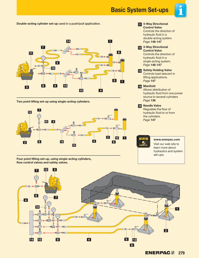
279
Basic System Set-ups
Two point lifting set-up using single-acting cylinders.
Four point lifting set-up, using single-acting cylinders, flow control valves and safety valves.
11 4-Way Directional Control Valve Controls the direction of hydraulic fluid in a double-acting system. Page 146-147
12 3-Way Directional Control Valve Controls the direction of hydraulic fluid in a single-acting system. Page 146-147
13 Safety Holding Valve Controls load descent in lifting applications. Page 147
14 Manifold Allows distribution of hydraulic fluid from one power source to several cylinders Page 136
15 Needle Valve Regulates the flow of hydraulic fluid to or from the cylinders. Page 147
Double-acting cylinder set-up used in a push/pull application.
www.enerpac.com
Visit our web site to learn more about hydraulics and system set-ups.

280 www.enerpac.com
131
✓
Basic Hydraulics
Flow Pressure
Pascal’s Law
A hydraulic pump produces flow
Pressure occurs when there is resistance to flow
Pressure applied at any point upon a confined liquid is transmitted undiminished in all directions (Fig.1).
This means that when more than one hydraulic cylinder is being used, each cylinder will lift at its own rate, depending on the force requir ed to move the load at that point (Fig. 2).
Cylinders with the lightest load will move first, and cylinders with the heaviest load will move last (Load A), as long as the cylinders have the same capacity.
To have all cylinders operate uniformly so that the load is being lifted at the same rate at each point, either control valves (see Valve section) or Synchronous Lift System components (see Cylinder section) must be added to the system (Load B).
GaugePump
Load B
Synchronous Lift or Control Valves to provide uniform lifting of load.
Manifold Cylinder
Figure 2
Figure 1
CAUTION!
When lifting or pressing, always use a gauge. A gauge is your “window”
to the system. It lets you see what’s going on. You will find the gauges in the System Components section.
Page:
INCORRECT CORRECT
Learn more about hydraulics
Visit www.enerpac.com to learn more about hydraulics and system set-ups.

281
x=
x=
x=
136
Basic Hydraulics
Use this formula to determine either force, pressure or effective area if two of the variables are known.
Force The amount of force a hydraulic cylinder can generate is equal to the hydraulic pressure times the “effective area” of the cylinder (see cylinder selection charts).
Hydraulic Working Pressure
Cylinder Effective
AreaForce
P AF
Example 1An RC-106 cylinder with 2.24 in2 effective area ope rating at 8,000 psi will generate what force?Force = 8,000 psi x 2.24 in2 = 17,920 lbs.
Example 2An RC-106 cylinder lifting 14,000 lbs will require what pressure?Pressure = 14,000 lbs ÷ 2.24 in2 = 6,250 psi.
Example 3 An RC-256 cylinder with 5.15 in2 effective area is required to produce a force of 41,000 lbs. What pressure is required? Pressure = 41,000 lbs. ÷ 5.15 in2 = 7961 psi.
Example 4 Four RC-308 cylinders each with 6.49 in2 effective area are required to produce a force of 180,000 lbs. What pressure is required? Pressure = 180,000 lbs ÷ (4 x 6.49 in2) = 6933 psi. Remember, since four cylinders are used together, the area for one cylinder must be multiplied by the number of cylinders used.
Example 5 A CLL-2506 cylinder with 56.79 in2 effective area is going to be used with a power source that is capable of 7,500 psi. What is the theoretical force available from that cylinder?Force = 7,500 psi x 56.79 in2 = 425,925 lbs.
Plunger
Force (Load)
Stroke
Effective Area
Cylinder Oil Capacity
The volume of oil required for a cylinder (cylinder oil capacity) is equal to the effective area of the cylinder times the stroke*.
* Note: these are theoretical examples and do not take into account the compressibility of oil under high pressure.
Cylinder Oil
Capacity
Cylinder Effective
Area
Cylinder Stroke
Example 1An RC-158 cylinder with 3.14 in2 effective area and an 8 in. stroke will require what volume of oil?Oil Capacity = 3.14 in2 x 8 in = 25.12 in3
Example 2 An RC-5013 cylinder has an effective area of 11.05 in2 and a stroke of 13.25 in. How much oil will be required?Oil Capacity = 11.05 in2 x 13.25 in = 146.41 in3
Example 3 An RC-10010 cylinder has an effective area of 20.63 in2 and a stroke of 10.25 in. How much oil will it require?Oil Capacity = 20.63 in2 x 10.25 in = 211.46 in3
Example 4Four RC-308 cylinders are being used, each with an effective area of 6.49 in2 and stroke of 8.25 in. How much oil will be required?Oil Capacity = 6.49 in2 x 8.25 in = 53.54 in3 for one cylinderMultiply by four to obtain the required capacity: 214.17 in3
Stroke
Oil Capacity
CAUTION!
Enerpac oil will compress 2.28% at 5,000 psi and 4.1% at 10,000 psi.
Page:

282 www.enerpac.com
Z
X
A
B
K
G
NHX1
I
C
F
P
OJW
E
W
Y
V
U DM
3/8"-18NPTF
V
U
LM
D
H
E
A
F
B
D1
Conversion Tables
Pressure:
1 psi = .069 bar1 bar = 14.50 psi1 kPa = .145 psi
Volume:
1 in3 = 16.387 cm3
1 cm3 = .061 in3
1 liter = 61.02 in3
1 liter = .264 gal1 US gal = 3,785 cm3
= 3.785 l = 231 in3
Weight:
1 pound (lb) = .4536 kg1 kg = 2.205 lbs1 metric ton = 2,205 lbs1 ton (short) = 2,000 lbs1 ton (short) = 907.18 kg
Temperature:
To convert °F to °C:T°
C = (T°F – 32) ÷ 1.8To convert °C to °F:T°F = (T°C x 1.8) + 32
Torque:
1 Ft.lbs = 1.356 Nm = 0.138 kgf.m1 Nm = .738 Ft.lbs = 0.102 kgf.m
Other measurements:
1 in = 25.4 mm1 mm = .039 in1 in2 = 6.452 cm2
1 cm2 = .155 in2
1 hp = .735 kW1 kW = 1.359 hp1 Nm = .73756 Ft.lbs1 Ft.lbs = 1.355818 Nm
All capacities and measurements in the catalog are expressed in uniform values.
The conversion chart provides helpful information for their translation into equivalent systems.
You can also visit our website at www.enerpac.com to download a FREE conversion calculator.
A = Collapsed height
B = Extended height
C = Cylinder body length
D = Cylinder outside diameter
D1 = Cylinder width
E = Cylinder inside diameter (bore)
F = Plunger rod diameter
G = Oil inlet thread
H = Cylinder bottom to advance port
I = Cylinder top to retract port
J = Saddle outside diameter
K = Cylinder rod protrusion at collapsed height
L = Plunger center to side of base
M = Mounting holes to plunger center
N = Length of smaller cylinder part
O = Plunger hole or thread of saddle
P = Plunger thread length
Q = Plunger outside thread (pull cylinders only)
U = Bolt circle diameter of mounting holes
V = Thread of cylinder mounting holes
W = Collar thread
X = Collar thread length
Y = Center hole diameter (hollow cylinders only)
Z = Depth of internal base thread
Dimensions shown in the Selection Charts of the cylinder section are identified on the relevant drawings by the capital letter references listed here: A for collapsed height through Z for depth of internal base thread.
Key to cylinder dimensions
Key to measurements Imperial to metric
Inches Decimal mm1•16
⅛
3•16
¼
5•16
⅜
7•16
½
9•16
⅝
11•16
¾
13•16
⅞
15•16
1
1.59 3.18 4.76 6.35 7.94 9.53 11.11 12.70 14.29 15.88 17.46 19.05 20.64 22.23 23.81 25.40
.06 .13 .19 .25 .31 .38 .44 .50 .56 .63 .69 .75 .81 .88 .94 1.00
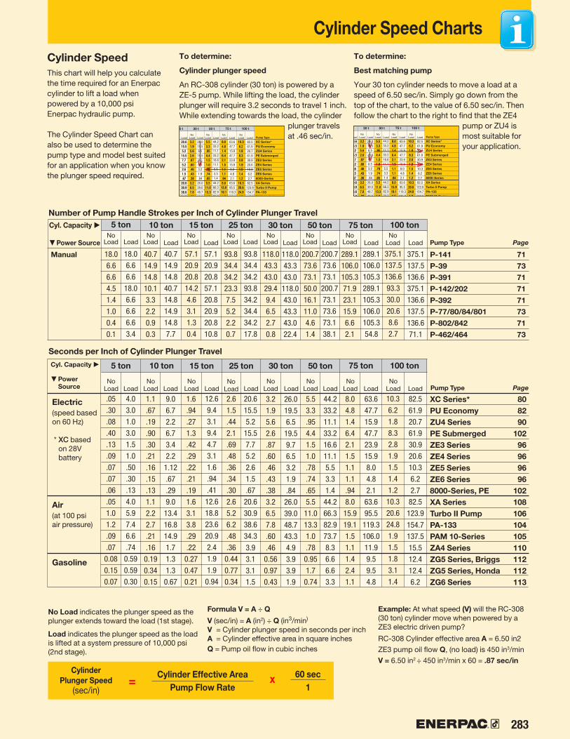
283
x=
P-141 71P-39 73P-391 71P-142/202 71P-392 71P-77/80/84/801 73P-802/842 71P-462/464 73
72 74
82 76
90 90 90 90 94
100 98
96 97
102 106
104 104
104
72 74
82 76
90 90 90 90 94
100 98
96 97
102 106
104 104
104
Cylinder Speed Charts
Cyl. Capacity ▶
Cyl. Capacity ▶
5 ton 10 ton 15 ton 25 ton 30 ton 50 ton 75 ton 100 tonNo
LoadNo
LoadNo
LoadNo
LoadNo
LoadNo
LoadNo
LoadNo
LoadLoad Load Load Load Load Load Load Load
Manual
Pump Type Page
5 ton 10 ton 15 ton 25 ton 30 ton 50 ton 75 ton 100 ton
Electric(speed based on 60 Hz)
* XC based on 28V battery
Air(at 100 psi air pressure)
Gasoline
Pump Type Page
Number of Pump Handle Strokes per Inch of Cylinder Plunger Travel
Seconds per Inch of Cylinder Plunger Travel
Formula V = A ÷ Q
V (sec/in) = A (in2) ÷ Q (in3/min)
V = Cylinder plunger speed in seconds per inchA = Cylinder effective area in square inchesQ = Pump oil flow in cubic inches
▼Power Source
▼Power Source
Cylinder Plunger Speed
(sec/in)
60 sec1
Cylinder Effective Area Pump Flow Rate
Example: At what speed (V) will the RC-308 (30 ton) cylinder move when powered by a ZE3 electric driven pump?
RC-308 Cylinder effective area A = 6.50 in2 ZE3 pump oil flow Q, (no load) is 450 in3/minV = 6.50 in2 ÷ 450 in3/min x 60 = .87 sec/in
To determine:
Cylinder plunger speed
An RC-308 cylinder (30 ton) is powered by a ZE-5 pump. While lifting the load, the cylinder plunger will require 3.2 seconds to travel 1 inch. While extending towards the load, the cylinder
plunger travels at .46 sec/in.
Cylinder SpeedThis chart will help you calculate the time required for an Enerpac cylinder to lift a load when powered by a 10,000 psi Enerpac hydraulic pump.
The Cylinder Speed Chart can also be used to determine the pump type and model best suited for an application when you know the plunger speed required.
To determine:
Best matching pump
Your 30 ton cylinder needs to move a load at a speed of 6.50 sec/in. Simply go down from the top of the chart, to the value of 6.50 sec/in. Then follow the chart to the right to find that the ZE4
pump or ZU4 is most suitable for your application.
XC Series* 80PU Economy 82ZU4 Series 90PE Submerged 102ZE3 Series 96ZE4 Series 96ZE5 Series 96ZE6 Series 968000-Series, PE 102XA Series 108Turbo II Pump 106PA-133 104PAM 10-Series 105ZA4 Series 110ZG5 Series, Briggs 112ZG5 Series, Honda 112ZG6 Series 113
No Load
No Load
No Load
No Load
No Load
No Load
No Load
No Load LoadLoadLoadLoad Load Load Load Load
XC Series*PU EconomyZU4 SeriesPE SubmergedZE3 Series ZE4 SeriesZE5 SeriesZE6 Series8000-SeriesXA SeriesTurbo II PumpPA-133PAM 10-SeriesZA4 SeriesPGM2 AtlasZG5 Series, BriggsZG5 Series, HondaZG6 Series
Pump Type PageLoadNo
LoadNo
LoadNo
LoadNo
LoadNo
LoadNo
LoadNo
Load LoadLoadLoadLoad Load Load Load LoadNo
.05
.30
.08
.40
.13
.09
.07
.07
.06
.051.01.2.09.070.3
0.080.150.07
4.03.01.03.01.51.0.50.30.134.05.97.46.6.741.5
0.590.590.30
1.1.67.19.90.30.21.16.15.131.12.22.7.21.160.7
0.190.340.15
9.06.72.26.73.42.2
1.12.67.299.0
13.416.814.91.73.41.31.3
0.67
1.6.94.271.3.42.29.22.21.191.63.13.8.29.220.9
0.270.470.21
12.69.43.19.44.73.11.6.94.41
12.618.823.620.92.44.71.91.9
0.94
2.61.5.442.1.69.48.36.34.302.65.26.2.48.361.5
0.440.770.34
20.615.55.2
15.57.75.22.61.5.67
20.630.938.634.33.97.73.13.11.5
3.21.95.62.6.87.60.46.43.383.26.57.8.60.461.9
0.560.970.43
26.019.56.5
19.59.76.53.21.9.84
26.039.048.743.34.99.73.93.91.9
5.53.3.954.41.51.0.78.74.655.5
11.013.31.0.783.3
0.951.7
0.74
44.233.211.133.216.611.15.53.31.4
44.266.382.973.78.3
16.66.66.63.3
8.04.81.46.42.11.51.11.1.948.0
15.919.11.51.14.81.42.41.1
63.647.715.947.723.915.98.04.82.1
63.695.5
119.3106.011.923.99.59.54.8
10.36.21.88.32.81.91.51.41.2
10.320.624.81.91.56.21.83.11.4
82.561.920.761.930.920.610.36.22.7
82.5 123.9154.7137.515.530.912.412.46.2
.05
.30
.08
.40
.13
.09
.07
.07
.06
.051.01.2.09.070.3
0.080.150.07
4.03.01.03.01.51.0.50.30.134.05.97.46.6.741.5
0.590.590.30
1.1.67.19.90.30.21.16.15.131.12.22.7.21.160.7
0.190.340.15
9.06.72.26.73.42.2
1.12.67.299.0
13.416.814.91.73.41.31.3
0.67
1.6.94.271.3.42.29.22.21.191.63.13.8.29.220.9
0.270.470.21
12.69.43.19.44.73.11.6.94.41
12.618.823.620.92.44.71.91.9
0.94
2.61.5.442.1.69.48.36.34.302.65.26.2.48.361.5
0.440.770.34
20.615.55.2
15.57.75.22.61.5.67
20.630.938.634.33.97.73.13.11.5
3.21.95.62.6.87.60.46.43.383.26.57.8.60.461.9
0.560.970.43
5.53.3.954.41.51.0.78.74.655.5
11.013.31.0.783.3
0.951.7
0.74
8.04.81.46.42.11.51.11.1.948.0
15.919.11.51.14.81.42.41.1
10.36.21.88.32.81.91.51.41.2
10.320.624.81.91.56.21.83.11.4
5 t 10 t 15 t 25 t 30 t 50 t 75 t 100 t
XC Series*PU EconomyZU4 SeriesPE SubmergedZE3 Series ZE4 SeriesZE5 SeriesZE6 Series8000-SeriesXA SeriesTurbo II PumpPA-133PAM 10-SeriesZA4 SeriesPGM2 AtlasZG5 Series, BriggsZG5 Series, HondaZG6 Series
Pump Type PageLoadNo
LoadNo
LoadNo
LoadNo
LoadNo
LoadNo
LoadNo
Load LoadLoadLoadLoad Load Load Load LoadNo
.05
.30
.08
.40
.13
.09
.07
.07
.06
.051.01.2.09.070.30.080.150.07
4.03.01.03.01.51.0.50.30.134.05.97.46.6.741.50.590.590.30
1.1.67.19.90.30.21.16.15.131.12.22.7.21.160.70.190.340.15
9.06.72.26.73.42.21.12.67.299.013.416.814.91.73.41.31.30.67
1.6.94.271.3.42.29.22.21.191.63.13.8.29.220.90.270.470.21
12.69.43.19.44.73.11.6.94.4112.618.823.620.92.44.71.91.90.94
2.61.5.442.1.69.48.36.34.302.65.26.2.48.361.50.440.770.34
20.615.55.215.57.75.22.61.5.6720.630.938.634.33.97.73.13.11.5
3.21.95.62.6.87.60.46.43.383.26.57.8.60.461.90.560.970.43
26.019.56.519.59.76.53.21.9.8426.039.048.743.34.99.73.93.91.9
5.53.3.954.41.51.0.78.74.655.511.013.31.0.783.30.951.70.74
44.233.211.133.216.611.15.53.31.444.266.382.973.78.316.66.66.63.3
8.04.81.46.42.11.51.11.1.948.015.919.11.51.14.81.42.41.1
63.647.715.947.723.915.98.04.82.163.695.5119.3106.011.923.99.59.54.8
10.36.21.88.32.81.91.51.41.210.320.624.81.91.56.21.83.11.4
82.561.920.761.930.920.610.36.22.7
82.5 123.9154.7137.515.530.912.412.46.2
.05
.30
.08
.40
.13
.09
.07
.07
.06
.051.01.2.09.070.30.080.150.07
4.03.01.03.01.51.0.50.30.134.05.97.46.6.741.50.590.590.30
1.1.67.19.90.30.21.16.15.131.12.22.7.21.160.70.190.340.15
9.06.72.26.73.42.21.12.67.299.013.416.814.91.73.41.31.30.67
1.6.94.271.3.42.29.22.21.191.63.13.8.29.220.90.270.470.21
12.69.43.19.44.73.11.6.94.4112.618.823.620.92.44.71.91.90.94
2.61.5.442.1.69.48.36.34.302.65.26.2.48.361.50.440.770.34
20.615.55.215.57.75.22.61.5.6720.630.938.634.33.97.73.13.11.5
3.21.95.62.6.87.60.46.43.383.26.57.8.60.461.90.560.970.43
5.53.3.954.41.51.0.78.74.655.511.013.31.0.783.30.951.70.74
8.04.81.46.42.11.51.11.1.948.015.919.11.51.14.81.42.41.1
10.36.21.88.32.81.91.51.41.210.320.624.81.91.56.21.83.11.4
5 t 10 t 15 t 25 t 30 t 50 t 75 t 100 t
No Load indicates the plunger speed as the plunger extends toward the load (1st stage).
Load indicates the plunger speed as the load is lifted at a system pressure of 10,000 psi (2nd stage).
18.06.66.64.51.41.00.40.1
18.06.66.618.06.66.66.63.4
40.714.914.810.13.32.20.90.3
40.714.914.840.714.814.914.87.7
57.120.920.814.24.63.11.30.4
57.120.920.857.120.820.920.810.8
93.834.434.223.37.55.22.20.7
118.043.343.029.49.46.52.70.8
93.834.434.293.834.234.434.217.8
118.043.343.0
118.043.043.343.022.4
200.773.673.150.016.111.04.61.4
200.773.673.1
200.773.173.673.138.1
289.1106.0105.371.923.115.96.62.1
289.1106.0105.3289.1105.3106.0105.354.8
375.1137.5136.693.330.020.68.62.7
375.1137.5136.6375.1136.6137.5136.671.1
.05
.30
.08
.40
.13
.09
.07
.07
.06
.051.01.2.09.07
0.080.150.07
4.03.01.03.01.51.0.50.30.134.05.97.46.6.740.590.590.30
1.1.67.19.90.30.21.16.15.131.12.22.7.21.160.190.340.15
9.06.72.26.73.42.21.12.67.299.013.416.814.91.71.31.30.67
1.6.94.271.3.42.29.22.21.191.63.13.8.29.220.270.470.21
12.69.43.19.44.73.11.6.94.4112.618.823.620.92.41.91.90.94
2.61.5.442.1.69.48.36.34.302.65.26.2.48.360.440.770.34
20.615.55.2
15.57.75.22.61.5.67
20.630.938.634.33.93.13.11.5
3.21.95.62.6.87.60.46.43.383.26.57.8.60.46
0.560.970.43
26.019.56.5
19.59.76.53.21.9.84
26.039.048.743.34.93.93.91.9
5.53.3.954.41.51.0.78.74.655.5
11.013.31.0.78
0.951.7
0.74
44.233.211.133.216.611.15.53.31.4
44.266.382.973.78.36.66.63.3
8.04.81.46.42.11.51.11.1.948.0
15.919.11.51.11.42.41.1
63.647.715.947.723.915.98.04.82.1
63.695.5
119.3106.011.99.59.54.8
10.36.21.88.32.81.91.51.41.2
10.320.624.81.91.51.83.11.4
82.561.920.761.930.920.610.36.22.7
82.5 123.9154.7137.515.512.412.46.2

284 www.enerpac.com
P T
A
P T
A
P T
A
P T
A
B
P T
A
B
P T
A
B
Retract
The oil flows from the pump port P and cylinder port
A to the tank T: the cylinder plunger will retract.
Hold
The oil flows from the pump pressure port P to the tank T.
The cylinder port A is closed: the cylinder plunger will maintain its position.
Advance
The oil flows from the pump pressure port P to the
cylinder port A: the cylinder plunger will extend.
Retract
The oil flows from the pump pressure port P to cylinder
port B, and from cylinder port A to tank T: the cylinder plunger will retract.
Hold
The oil flows from the pump pressure port P to the tank
T. The cylinder ports A and B are closed: the cylinder plunger will maintain position.
Valve Information
Directional Control Valves
AdvanceHold Retract
3-Way Valves
are used with single- acting cylinders
Valves may be either pump mounted or remote mounted.
Pump Mounted
Valves may be either manually or solenoid operated.
Manually Operated Solenoid Operated
Remote Mounted
4-Way Valves
are used with double- acting cylinders
WaysThe (oil) ports on a valve.A 3-way valve has 3 ports: pressure (P), tank (T), and cylinder (A).A 4-way valve has 4 ports:pressure (P), tank (T), advance (A) and retract (B).
Single-acting cylinders require at least a 3-way valve, and can, under certain instances, be operated with a 4-way valve.
Double-acting cylinders require a 4-way valve, providing control of the flow to each cylinder port.
PositionsThe number of control points a valve can provide. A 2-position valve has the ability to control only the advance or retraction of the cylinder. To be able to control the cylinder with a hold position, the valve requires a 3rd position.
Center ConfigurationThe center position of a valve is the position at which there is no movement required of the hydraulic component, whether a tool or cylinder.
Tandem Center
A
P T
Float Center
A B
P T
Crossover
A B
P T
Normally Open
A
P
Open Center
P T
A B
Closed Center
P T
A B
The most common is the Tandem Center. This configuration provides for little to no movement of the
cylinder and the unloading of the pump. This provides for minimum heat build-up.
Tandem Center
A
P T
Float Center
A B
P T
Crossover
A B
P T
Normally Open
A
P
Open Center
P T
A B
Closed Center
P T
A B The next most common is the Closed Center configuration, which is used
mostly for independent control of multi-cylinder applications. This configuration again provides for little to no movement of the cylinder, but also dead-heads the pump, isolating it from the circuit.Use of this type of valve may require some means of unloading the pump to prevent heat build-up.
There are many more types of valves, such as Open Center and Float Center. These valves are used mostly in complex hydraulic circuits and require other special considerations.
Single-acting cylinder
Controlled by a 3-way, 3-position valve.
Double-acting cylinder
Controlled by a 4-way, 3-position valve.
Advance
The oil flows from the pump pressure port P to the
cylinder port A, and from cylinder port B to tank T: the cylinder plunger will extend.
Tandem Center
A
P T
Float Center
A B
P T
Crossover
A B
P T
Normally Open
A
P
Open Center
P T
A B
Closed Center
P T
A B
Open Center
Tandem Center
A
P T
Float Center
A B
P T
Crossover
A B
P T
Normally Open
A
P
Open Center
P T
A B
Closed Center
P T
A B
Float Center
Tandem Center
A
P T
Float Center
A B
P T
Crossover
A B
P T
Normally Open
A
P
Open Center
P T
A B
Closed Center
P T
A B
Tandem Center
A
P T
Float Center
A B
P T
Crossover
A B
P T
Normally Open
A
P
Open Center
P T
A B
Closed Center
P T
A B
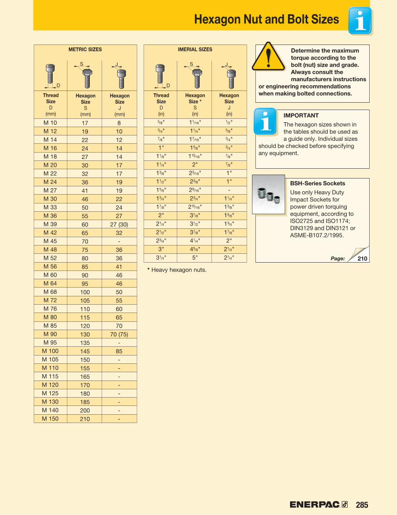
285
S J
D
S J
D
S J
D
S J
D
S J
D
S J
D
210
METRIC SIZES
ThreadSize
D(mm)
HexagonSize
S(mm)
HexagonSize
J(mm)
Determine the maximum torque according to the bolt (nut) size and grade. Always consult the manufacturers instructions
or engineering recommendations when making bolted connections.
IMPORTANT
The hexagon sizes shown in the tables should be used as a guide only. Individual sizes
should be checked before specifying any equipment.
BSH-Series Sockets
Use only Heavy Duty Impact Sockets for power driven torquing equipment, according to ISO2725 and ISO1174; DIN3129 and DIN3121 or ASME-B107.2/1995.
* Heavy hexagon nuts.
IMERIAL SIZES
ThreadSize
D(in)
HexagonSize *
S(in)
HexagonSize
J(in)
Hexagon Nut and Bolt Sizes
Page:
M 10M 12M 14M 16M 18M 20M 22M 24M 27M 30M 33M 36M 39M 42M 45M 48M 52M 56M 60M 64M 68M 72M 76M 80M 85M 90M 95M 100M 105M 110M 115M 120M 125M 130M 140M 150
1719222427303236414650556065707580859095100105110115120130135145150155165170180185200210
81012141417171919222427
27 (30)32-
36364146465055606570
70 (75)-
85--------
5/8"3/4"7/8"1"
11/8"11/4"13/8"11/2"15/8"13/4"17/8"2"
21/4"21/2"23/4"3"
31/4"
11/16"11/4"17/16"15/8"
113/16"2"
23/16"23/8"29/16"23/4"
215/16"31/8"31/2"37/8"41/4"45/8"5"
1/2"5/8"3/4"3/4"7/8"7/8"1"1"-
11/4"13/8"15/8"13/4"17/8"2"
21/4"21/4"
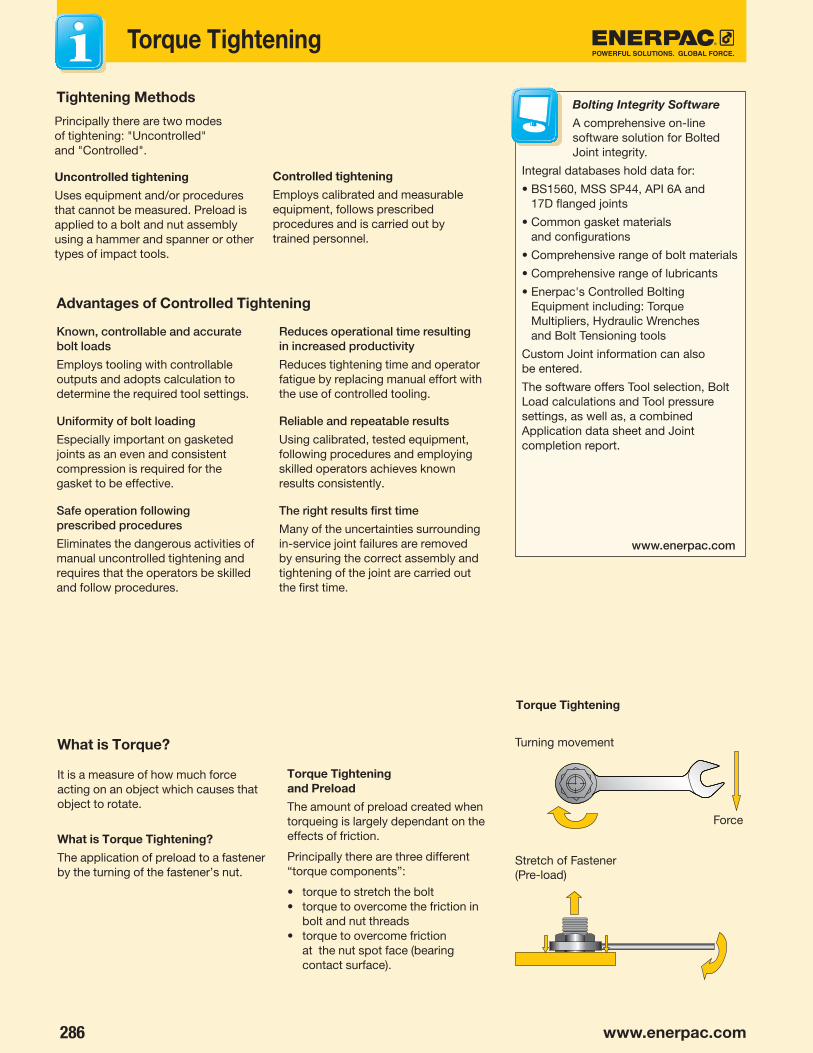
286 www.enerpac.com
www.enerpac.com
Torque Tightening
Tightening Methods
Advantages of Controlled Tightening
Known, controllable and accurate bolt loads
Employs tooling with controllable outputs and adopts calculation to determine the required tool settings.
Uniformity of bolt loading
Especially important on gasketed joints as an even and consistent compression is required for the gasket to be effective.
Safe operation following prescribed procedures
Eliminates the dangerous activities of manual uncontrolled tightening and requires that the operators be skilled and follow procedures.
Reduces operational time resulting in increased productivity
Reduces tightening time and operator fatigue by replacing manual effort with the use of controlled tooling.
Reliable and repeatable results
Using calibrated, tested equipment, following procedures and employing skilled operators achieves known results consistently.
The right results first time
Many of the uncertainties surrounding in-service joint failures are removed by ensuring the correct assembly and tightening of the joint are carried out the first time.
Principally there are two modes of tightening: "Uncontrolled" and "Controlled".
Uncontrolled tightening
Uses equipment and/or procedures that cannot be measured. Preload is applied to a bolt and nut assembly using a hammer and spanner or other types of impact tools.
Controlled tightening
Employs calibrated and measurable equipment, follows prescribed procedures and is carried out by trained personnel.
What is Torque?
It is a measure of how much force acting on an object which causes that object to rotate.
What is Torque Tightening?
The application of preload to a fastener by the turning of the fastener’s nut.
Torque Tightening and Preload
The amount of preload created when torqueing is largely dependant on the effects of friction.
Principally there are three different “torque components”:
• torque to stretch the bolt• torque to overcome the friction in
bolt and nut threads• torque to overcome friction
at the nut spot face (bearing contact surface).
Turning movement
Torque Tightening
Stretch of Fastener (Pre-load)
Force
Bolting Integrity Software
A comprehensive on-line software solution for Bolted Joint integrity.
Integral databases hold data for:
• BS1560, MSS SP44, API 6A and 17D flanged joints
• Common gasket materials and configurations
• Comprehensive range of bolt materials
• Comprehensive range of lubricants
• Enerpac's Controlled Bolting Equipment including: Torque Multipliers, Hydraulic Wrenches and Bolt Tensioning tools
Custom Joint information can also be entered.
The software offers Tool selection, Bolt Load calculations and Tool pressure settings, as well as, a combined Application data sheet and Joint completion report.

287
15
59
333
7
711
2226
6
10
4
8
11
44
812
Friction points should always be lubricated when using the torque tightening method.
Preload (residual load) = Applied Torque minus Frictional Losses
Lubrication Reduces Friction
Lubrication reduces the friction during tightening, decreases bolt failure during installation and increases bolt service life. Variation in friction coefficients affect the amount of preload achieved at a specified torque. Higher friction results in less conversion of torque to preload. The value for the friction coefficient provided by the lubricant manufacturer must be known to accurately establish the required torque value.
Lubricant or anti-seizure compounds should be applied to both the nut bearing surface and the male threads.
Frictional Losses
Frictional Losses (dry steel bolt)
10% convertedto preload
50% at nut face
40% in threads
Select the Right Wrench
Choose your Enerpac torque wrench using the untightening rule of thumb:
• When loosening a nut or bolt more torque is usually required than when tightening.
• For general conditions it can take up to 2½ times the input torque to breakout.
• Do not apply more than 75% of the maximum torque output of the tool when loosening nuts or bolts.
Conditions of bolted joints
• Humidity corrosion (rust) requires up to twice the torque required for tightening.
• Sea water and chemical corrosion requires up to 21⁄2 times the torque required for tightening.
• Heat corrosion requires up to 3 times the torque required for tightening.
Step 1 Spanner tight ensuring that 2 - 3 threads extend above nut.
Step 2 Tighten each bolt to one-third of the final required torque following the pattern as shown above.
Step 3 Increase the torque to two-thirds following the pattern shown above.
Step 4 Increase the torque to full torque following the pattern shown above.
Step 5 Perform one final pass on each bolt working clockwise from bolt 1, at the full f inal torque.
Torque Procedure
When torquing it is common to tighten only one bolt at a time, this can result in Point Loading and Load Scatter. To avoid this, torque is applied in stages following a prescribed pattern:
Torque Sequence
Breakout Torque
When loosening bolts a torque value higher than the tightening torque is normally required.
This is mainly due to corrosion and deformations in the bolt and nut threads.
Breakout torque cannot be accurately calculated, however, depending on conditions it can take up to 2½ times the input torque to breakout.
The use of penetrating oils or anti-seize products is always recommended when performing breakout operations.
Torque Tightening
Example of how a lubricant can reduce the effect of friction and convert more torque to bolt preload.
Lubricated with Moly grease (µ = 0.1) Light oil (µ = 0.15) Dry unlubricated (µ = 0.2)
Res
idua
l Bo
lt Lo
ad (t
ons)
▸
Torque (ft.lbs) ▸(Applied load)
Lubrication Reduces Friction
11
10
9
8
7
6
5
4
3
2
1
00 20 40 60 80 100 120

288 www.enerpac.com
✓
Tensioning
Tensioning requires longer bolts What is Bolt Tensioning
Tensioning is the direct axial stretching of the bolt to achieve preload. Inaccuracies created through friction are eliminated. Massive mechanical effort to create torque is replaced with simple hydraulic pressure. A uniform load can be applied by tensioning multiple studs simultaneously.
Tensioning requires longer bolts, and a seating area on the assembly around the nut. Tensioning can be done using detachable Bolt Tensioners or Hydraulic Nuts.
What is Load Loss
Load loss is a loss of bolt elongation depending on factors such as thread deflections, radial expansion of the nut, and embedding of the nut into the contact area of the joint. Load loss is accounted for in calculation and is added to the preload value to determine the initial Applied Load.
The preload depends on Applied Load and Load Loss (load loss factor).
INCORRECT
CORRECT
L Minimum = 1 X D
Preload (residual load) = Applied Load minus Load Losses
GLOSSARY OF TERMS
Applied Load: The load applied to a bolt during tensioning which includes an allowance for Load Loss.
Bolt Tensioning: A method of controlled tightening which applies preload to a bolt by stretching it axially.
Breakout Torque: The amount of torque required to loosen a tightened bolt. (Usually more torque is required to loosen a bolt than was used to tighten it.)
Elastic Range: The range on a bolt's stress / strain curve where stress is directionally proportional to strain.
Load Loss: The losses in a bolt which occur on transfer of load from a tensioning device to the bolt assembly (these may arise from phenomena such as thread deflection and embedding of
the nut to the contact area of the joint, and is calculated as a factor of the length to diameter ratio of the bolt).
Load Scatter: The spread of differing loads in a sequence of bolts after they have been loaded. It is mostly due to the elastic interaction of the bolts and the joint member; as subsequently tightened bolts further compress the joint, previously tightened bolts are subject to some relaxation.
Plastic Range: The range on a stress/strain curve where the tensile load applied to a bolt results in permanent deformation.
Preload: The load in a bolt immediately after it has been tightened.
Proof Load: Proof load is often used interchangeably with Yield Strength but is usually measured at 0.2% plastic strain.
Tensile Point: The point at which the tensile loading on a bolt causes the bolt to rupture.
Torque Tightening: The application of Preload to a bolt by turning of the bolt's nut.
Ultimate Strength: The maximum tension which can be created by tensile load on a bolt.
Yield Strength: The point at which a bolt begins to plastically deform under tensile loading.
NOTE: Bolt is used as a generic term for a threaded fastener.

289
Tensioning
Step 1 Step 2 Step 3 Step 4
General Procedure
Step 1: The bolt Tensioner is fitted over the stud
Step 2: Hydraulic pressure is applied to the tensioner which then stretches the stud.
Step 3: The Stud’s nut is wound down against the joint face
Step 4: Pressure is released and the tool removed.
The bolt behaves like a spring, when the pressure is released the bolt is under tension and attempts to contract, creating the required clamping force across the joint.
Read Instruction Manuals
Please refer to the product Instruction Sheets for safe use guidelines and detail on the
correct set up and operation of the equipment.
Less than 100% Tensioning
Not all applications allow for the simultaneous fit of a tensioning device on each bolt, in these cases at least two tensioning pressures are applied. This is to account for a load loss in those bolts already tensioned as the next sets are tightened. The load losses are accounted for in calculation and a higher load is applied to allow the first sets to relax back to the target preload.
Tensioning Operation
Tensioning permits the simultaneous tightening of multiple bolts; the tools are connected in sequence via a high-pressure hose assembly to a single pump unit. This ensures each tool develops the exact same load and provides a uniform clamping force across the joint. This is especially important for pressure containing vessels requiring even gasket compression to affect a seal.
Set-up using a 100% tensioning procedure
All bolts are tensioned simultaneously.
Set-up using a 50% tensioning procedure
Half the bolts are tensioned simultaneously, the tools are relocated on the remaining bolts and they are subsequently tensioned.
Manufacturer’s rating of pressure and load are maximum safe limits. Good practice encourages using only 80% of these ratings!

290 www.enerpac.comwww.enerpac.com
Po
we
rf
ul
So
lu
tio
nS
. Glo
ba
l f
or
ce
.
e2
15e
21
5
uS
uS
Swing Clamps20-42
Valves134-159
Linear Cylinders52-93
System Components186-196
Yellow Pages197-228
Collet Lok® Products8-19
Power Sources94-133
Work Supports43-51
Pallet Components160-185
australia and new Zealandactuant australia ltd. Block V Unit 3Regents Park Estate391 Park RoadRegents Park NSW 2143(P.O. Box 261) AustraliaT +61 297 438 988F +61 297 438 [email protected]
brazil Power Packer do Brasil Ltda.Rua Luiz Lawrie Reid, 54809930-760 - Diadema (SP)-BrasilT +55 11 5525 2311Toll Free: 0800 891 [email protected]
canadaActuant Canada Corporation6615 Ordan Drive, Unit 14-15Mississauga, Ontario L5T 1X2T +1 905 564 5749F +1 905 564 0305Toll Free:T +1 800 268 4987F +1 800 461 [email protected]
chinaActuant (China) Industries Co. Ltd.No. 6 Nanjing Road,Taicang Economic Dep ZoneJiangsu, ChinaT +86 0512 5328 7500 F +86 0512 5335 9690Toll Free: +86 400 885 [email protected]
france, Switzerland, north africa and french speaking african countriesENERPAC Une division d’ACTUANT France S.A.S.ZA de Courtaboeuf32, avenue de la Baltique 91140 VILLEBON /YVETTEFranceT +33 1 60 13 68 68F +33 1 69 20 37 [email protected]
Germany and austriaENERPAC GmbHP.O. Box 300113D-40401 DüsseldorfWillstätterstrasse 13D-40549 Düsseldorf, GermanyT +49 211 471 490F +49 211 471 49 [email protected]
indiaENERPAC Hydraulics Pvt. Ltd.No. 1A, Peenya Industrial AreaIInd Phase, Bangalore, 560 058, IndiaT +91 80 40 792 777F +91 80 40 792 [email protected]
italyENERPAC S.p.A.Via Canova 420094 Corsico (Milano)T +39 02 4861 111F +39 02 4860 [email protected]
JapanApplied Power Japan LTD KKBesshocho 85-7Kita-ku, Saitama-shi 331-0821, JapanT +81 48 662 4911F +81 48 662 [email protected]
Middle east, egypt and libyaENERPAC Middle East FZEOffice 423, LOB 15P.O. Box 18004, Jebel Ali, DubaiUnited Arab EmiratesT +971 (0)4 8872686F +971 (0)4 [email protected]
russiaRep. office EnerpacRussian FederationAdmirala Makarova Street 8125212 Moscow, RussiaT +7 495 98090 91F +7 495 98090 [email protected]
Southeast asia, Hong Kong and taiwanActuant Asia Pte Ltd.83 Joo Koon Circle Singapore 629109T +65 68 63 0611F +65 64 84 5669Toll Free: +1800 363 [email protected]
South KoreaActuant Korea Ltd.3Ba 717, Shihwa Industrial ComplexJungwang-Dong, Shihung-Shi, Kyunggi-DoRepublic of Korea 429-450T +82 31 434 4506F +82 31 434 [email protected]
Spain and PortugalENERPAC SPAIN, S.L. Avda. Los Frailes, 40 – Nave C & DPol. Ind. Los Frailes28814 Daganzo de Arriba(Madrid) SpainT +34 91 884 86 06F +34 91 884 86 [email protected]
Sweden, Denmark, norway, finland and icelandEnerpac Scandinavia ABFabriksgatan 7412 50 GothenburgSwedenT +46 (0) 31 799 0281F +46 (0) 31 799 [email protected]
the netherlands, belgium, luxembourg, central and eastern europe, baltic States, Greece, turkey and ciS countries
ENERPAC B.V.Galvanistraat 1156716 AE Ede P.O. Box 80976710 AB EdeThe NetherlandsT +31 318 535 911 F +31 318 535 [email protected]
enerpac integrated Solutions b.V.Opaalstraat 447554 TS HengeloP.O. Box 4217550 AK HengeloThe NetherlandsT +31 74 242 20 45F +31 74 243 03 [email protected]
South africa and other english Speaking african countriesEnerpac Africa Pty LtdNo5 Bauhinia AvenueCambridge Office ParkBlock EHighveld techno ParkCenturion 0157South Africa T: +0027 (0) 12 940 [email protected]
united Kingdom and irelandENERPAC Ltd., Bentley Road SouthDarlaston, West MidlandsWS10 8LQEnglandT +44 (0)121 50 50 787F +44 (0)121 50 50 [email protected]
uSa, latin america and caribbeanENERPAC P.O. Box 3241 Milwaukee, WI 53201 USAT +1 262 293 1600F +1 262 293 7036User inquiries: +1 800 433 2766Distributor inquiries/orders:T +1 800 558 0530F +1 800 628 0490Technical inquiries:[email protected]@enerpac.com
02/2013
e-mail: [email protected] internet: www.enerpacwh.com
Enerpac © 2013 800US
E4
12
US
About Enerpac
Enerpac manufactures high-force hydraulics (cylinders, pumps, valves, presses, pullers, tools, accessories and system components) for industry and construction and provides hydraulic workholding and OEM solutions to industries worldwide.
With an 80-year history of quality and innovation, the broadest line in the business, and more than 4,000 distributors and factory-trained service centers around the world, Enerpac leads the industry by setting new standards in design, strength, durability and local support. Strict quality programs, zero tolerance for defects, and ISO-9001 certification are your assurance of safe, trouble-free operation.
Enerpac is ready to tackle your toughest challenge and provide the hydraulic advantage you need to increase productivity, labor efficiency and speed of operation. • Learn more about hydraulics
• Promotions• New products• Electronic Catalogs• Trade shows• Manuals (instruction and
repair sheets)• Nearest Distributors &
Service Centers• Enerpac products in action• Heavy Lifting Technology
Ordering Products and Catalogs
To find the name of the closest Enerpac distributor or service center, to request literature or technical application assistance, contact Enerpac at: enerpac.com/contact-us
While every care has been taken in the preparation of this catalog and all data contained within is deemed accurate at the time of printing, Enerpac does reserve the right to make changes to the specifications of any product, or discontinue any product, contained within this catalog without prior notice.
All illustrations, performance specifications, weights and dimensions reflect the nominal values and slight variations may occur due to manufacturing tolerances. Please consult Enerpac if final dimensions are critical.
All information in this catalog can be changed due to product improvements without prior notice.
© Copyright 2017, Enerpac.
All rights reserved. Any copying or other use of material in this catalog (text, illustrations, drawings, photos) without express written consent is prohibited.
E215, Workholding Catalog: Offers innovative products and solutions to provide powerful clamping and positioning force to every type of manufacturing process. Enerpac Workholding solutions increase product quality and production output.
Enerpac catalogs/brochures to meet your needs: To obtain your copy just give us a call, or visit our Internet site www.enerpac.com
E413, Bolting Solutions Catalog: Caters to the complete bolting workflow, ensuring joint integrity in a variety of applications throughout industry, including: joint assembly, controlled tightening and joint separation.
www.enerpac.com for latest Enerpac information

291
The Enerpac Academy is our in-house training program, offering Enerpac product operators and maintenance staff the opportunity to be trained in the use and maintenance of high-pressure hydraulic tools.
Operating these tools requires sound knowledge of how they work and how they should be maintained. Correct use of these tools increases safety and reduces risk – both for the operator and the environment in which the tools are used. Having the right training enables the operator to use the tools safely and properly.
Enerpac Academy• Safety focus for operators, tools and environment• Dedicated in-house Enerpac training centers• Both standard training courses and specialized
training services• Highly experienced trainers• Selection of training courses with a proven
(value-added) track record• Knowledge and experience sharing
• Columbus, Wisconsin (USA)• Ede (The Netherlands)• Hosur, Bangalore area (India)• Singapore• Sydney (Australia)
Enerpac Academy offers a meticulously compiled training program covering tool knowledge, repairs and maintenance, and safe operation of Enerpac hydraulic tools. If you would like to schedule a training course, please contact Enerpac for a training calendar, application form, and brochure at www.enerpac.com.
Do you work with high-pressure hydraulic tools on a regular basis or even every day? The training courses are designed to be highly interactive with a strong hands-on element. Each training course is led by a qualified trainer, an Enerpac specialist capable of providing high quality training. A written or practical exam is part of certain training courses.
Training Center LocationsIn-house Training Centers
Enerpac Academy - The Power of Knowledge

292 www.enerpac.com
Africa (South Africa and other English speaking African countries)ENERPAC AFRICA (PTY) Ltd.5 Bauhinia Avenue Cambridge Office Park, Block EHighveld Techno Park, Centurion0157, Republic of South-AfricaT +0027 (0) 12 940 0656
Australia and New ZealandActuant Australia Ltd.P.O. Box 6867, Wetherill Park, NSW 1851Block V Unit 3, Regents Park Estate391 Park Road, Regents Park, NSW 2143AustraliaT +61 287 177 200F +61 297 438 648
Brazil Power Packer do Brasil Ltda.Rua Luiz Lawrie Reid, 54809930-760 - Diadema (SP)-BrasilT +55 11 5687 2211Toll Free: 0800 891 5770
China (Taicang)Actuant (China) Industries Co. Ltd.No. 6 Nanjing East RoadTaicang Economic Dep ZoneJiangsu, ChinaT +86 0512 5328 7500 F +86 0512 5335 9690Toll Free: +86 400 885 0369
Enerpac Heavy Lifting Technology B.VSpinelstraat 15, 7554 TW HengeloPO Box 421, 7550 AK HengeloThe NetherlandsT +31 74 242 20 45F +31 74 243 03 38
France, Switzerland, North Africa and French speaking African countriesENERPAC Une division d’ACTUANT France S.A.S.Zone Orlytech, Bâtiment 5161 allée du commandant MouchotteCS 4035191550 Paray-Vieille-Poste, FranceT +33 1 60 13 68 68F +33 1 69 20 37 50
Germany and AustriaActuant GmbHPO Box 300113D-40401 DüsseldorfWillstätterstrasse 13D-40549 Düsseldorf, GermanyT +49 211 471 490F +49 211 471 49 28
IndiaActuant India Private LimitedNo. 10, Bellary Road, Sadashivanagar Bangalore, Karnataka 560 080, IndiaT +91 80 3928 9000
ItalyENERPAC SPAVia Leonardo da Vinci, 9720090 Trezzano S/NMilano ItalyT +39 02 4861 111F +39 02 4860 1288
JapanEnerpac Co., LtdBesshocho 85-7Kita-ku, Saitama-shi 331-0821, JapanT +81 48 662 4911F +81 48 662 4955
Middle East, Egypt and LibyaENERPAC Middle East FZEPlot M00737m 1242nd StreetJebel Ali Free Zone NorthP.O. Box 18004, DubaiUnited Arab EmiratesT +971 (0)4 8872686F +971 (0)4 8872687
NorwaySales Office NorwayUnit 524, Nydalsveien 28, 0484 OsloP.O. Box 4814 Nydalen 0422 OsloNorwayTel: +47 91 578 300
RussiaRep. office EnerpacRussian FederationAdmirala Makarova Street 8125212 Moscow, RussiaT +7 495 98090 91F +7 495 98090 92
Southeast Asia, Hong Kong and TaiwanActuant Asia Pte Ltd.83 Joo Koon Circle, Singapore 629109T +65 68 63 0611F +65 64 84 5669Toll Free: +1800 363 7722
South KoreaActuant Korea Ltd.3Ba 717, Shihwa Industrial ComplexJungwang-Dong, Shihung-Shi Kyunggi-Do, Republic of Korea 429-450T +82 31 434 4506F +82 31 434 4507
Spain and PortugalENERPAC SPAIN, S.L. Avenida Valdelaparra N° 27 3ª - L828108 Alcobendas(Madrid) SpainT +34 91 884 86 06F +34 91 884 86 11
Sweden, Denmark, Finland and IcelandEnerpac Scandinavia ABKopparlundsvägen 14,721 30 Västerås, SwedenT +46 (0) 771 415000
The Netherlands, Belgium, Luxembourg, Central and Eastern Europe, Baltic States, Greece, Turkey and CIS countriesENERPAC B.V.Galvanistraat 115, 6716 AE Ede P.O. Box 8097, 6710 AB EdeThe NetherlandsT +31 318 535 911 F +31 318 535 848
United Kingdom and IrelandENERPAC UK Ltd.,5 Coopies FieldMorpeth, NorthumberlandNE61 6JR, EnglandTel: +44 1670 5010 00
USA, Latin America and CaribbeanENERPAC World HeadquartersP.O. Box 3241Milwaukee, WI 53201-3241 USAN86 W12500 Westbrook CrossingMenomonee Falls, Wisconsin 53051T +1 262 293 1600F +1 262 293 7036User inquiries: +1 800 433 2766Distributor inquiries/orders: +1 800 558 0530 +1 800 628 0490Technical inquiries:Technical inquiries:enerpac.com/en/contact-us 06/01/17
Enerpac Worldwide Locations
http://www.enerpac.com/en/enerpac-locations