Hydraulic Power Unit Part Number 35-16018 - Wilson Company
131
Hydraulic Power Unit Part Number 35-16018
-
Upload
khangminh22 -
Category
Documents
-
view
1 -
download
0
Transcript of Hydraulic Power Unit Part Number 35-16018 - Wilson Company

Hydraulic Power Unit Part Number 35-16018

1 | P a g e
To our Valued Customers
I want to thank you for buying your Fluid Power System from the Wilson Company’s Systems Division. This unit has been designed with high quality materials and components and been carefully assembled by our experienced technicians. With proper installation and maintenance, it should provide you with many years of service.
If you have any question about this equipment before startup, contact me or a member of our staff.
If you have other applications for fluid power or fluid connector Products, please contact your local Wilson Company sales associate, or call our Main Office at 800-580-1212.
Thank you again for electing Wilson Company as your source for fluid power equipment.
Sincerely,
Les JaynesPresident
972-931-8666 972-248-1177 Fax 800-580-1212
WILSON COMPANY 4501 RATLIFF LN. ADDISON, TX. 75001
MAILING ADDRESS: P.O. BOX 217 ADDISON, TX. 75001

DRAWINGS Parts List, Schematics, & Specifications
LITERATURE - HYDRAULIC Hydraulic Motors, Pumps, & Valves
Hydraulic Filters & Strainers Hydraulic Fittings & Hose
Misc. Components
LITERATURE - ELECTRICAL Starters, Relays
Transducers, Pressure Switches… etc
HYD. POWER UNITS Maintenance & Installation
ELECTRIC MOTORS Maintenance & Installation
WARRANTY

HYD. POWER UNITS Maintenance & Installation


4551 Ratliff Ln. Addison TX 75001 Phone: 972-931-8666 Fax: 972-248-1177
WARRANTY
The Company MAKES NO WARRANTY WHATSOEVER concerning products manufactured by others, but will extend to the Buyer such warranties respecting such products as are permissible under the terms thereof. The Company will repair or replace products manufactured by it which prove defective within one (1) year from date of shipment, 6 months of installation or 1000 hours of use, whichever occurs first. Upon return of the same at Buyer’s expense when such defects are due to the defective material supplied by the Company or defective workmanship of its employees, provided the products shall have been properly assembled and utilized in accordance with the Company’s design thereof and instructions relating thereto, it being understood that the foregoing warranty shall be of no effect whatsoever in the event any changes are made in the products prior to or in connection with their assembly or use.THE ABOVE WARRANTY COMPRISES SELLER’S SOLE AND ENTIRE WARRANTY OBLIGATION AND LIABILITY TO BUYER, ITS CUSTOMERS AND ASSIGNS IN CONNECTION WITH GOODS SOLD HEREUNDER. ALL OTHER WARRANTIES EXPRESS OR IMPLIED, INCLUDING BUT NOT LIMITED TO WARRANTIES OF MERCHANTABILITY AND FITNESS, ARE EXPRESSLY EXCLUDED.

DRAWINGS Parts List, Schematics, & Specifications

WILSON COMPANYã
SYSTEMSDIVISION
A35-16018
AutoCAD SHX Text
1
AutoCAD SHX Text
2
AutoCAD SHX Text
3
AutoCAD SHX Text
6
AutoCAD SHX Text
P
AutoCAD SHX Text
11A
AutoCAD SHX Text
5
AutoCAD SHX Text
T
AutoCAD SHX Text
GENERAL SPECIFICATIONS
AutoCAD SHX Text
RESERVOIR FILL
AutoCAD SHX Text
RELIEF SETTING
AutoCAD SHX Text
COMPENSATOR SETTING
AutoCAD SHX Text
10
AutoCAD SHX Text
G
AutoCAD SHX Text
7
AutoCAD SHX Text
FLOW RATE
AutoCAD SHX Text
HORSEPOWER
AutoCAD SHX Text
SERIAL NUMBER
AutoCAD SHX Text
PART NUMBER
AutoCAD SHX Text
P
AutoCAD SHX Text
T
AutoCAD SHX Text
1000 PSI
AutoCAD SHX Text
10HP, 1800 RPM, 3PH, 460V
AutoCAD SHX Text
7.8 GPM @ 1800 RPM
AutoCAD SHX Text
3000 PSI
AutoCAD SHX Text
30 GALLONS
AutoCAD SHX Text
E49645A+B
AutoCAD SHX Text
35-15051
AutoCAD SHX Text
11B
AutoCAD SHX Text
4A
AutoCAD SHX Text
4B
AutoCAD SHX Text
4C
AutoCAD SHX Text
4D
AutoCAD SHX Text
9A
AutoCAD SHX Text
9B
AutoCAD SHX Text
14
AutoCAD SHX Text
15
AutoCAD SHX Text
A
AutoCAD SHX Text
B
AutoCAD SHX Text
SCALE
AutoCAD SHX Text
SIZE
AutoCAD SHX Text
SHT
AutoCAD SHX Text
OF
AutoCAD SHX Text
REV
AutoCAD SHX Text
TITLE
AutoCAD SHX Text
REV
AutoCAD SHX Text
DATE
AutoCAD SHX Text
DR
AutoCAD SHX Text
ENG
AutoCAD SHX Text
DESCRIPTION
AutoCAD SHX Text
USE ENGINEERING STANDARD FOR TOLERANCES
AutoCAD SHX Text
ALL DIMENSIONS IN INCHES UNLESS OTHERWISE NOTED
AutoCAD SHX Text
DO NOT SCALE THIS DRAWING
AutoCAD SHX Text
CONFIDENTIAL - This drawing is the confidential and proprietary copyrighted
AutoCAD SHX Text
property of Wilson Company, 16301 Addison Road, Addison, Texas USA 75001.
AutoCAD SHX Text
All information contained herein is confidential and shall not be reproduced,
AutoCAD SHX Text
copied, lent, or disclosed without the written permission of Wilson Company.
AutoCAD SHX Text
RVWD
AutoCAD SHX Text
DRAWING NUMBER
AutoCAD SHX Text
CONTRACT
AutoCAD SHX Text
FORM 600086-19, REV F
AutoCAD SHX Text
Copyright ã 2006 by Wilson Company. All rights reserved.2006 by Wilson Company. All rights reserved.
AutoCAD SHX Text
WILSON
AutoCAD SHX Text
4651 RATLIFF LANE, ADDISON, TEXAS, 75001
AutoCAD SHX Text
NONE
AutoCAD SHX Text
1
AutoCAD SHX Text
1
AutoCAD SHX Text
WILSON HPU
AutoCAD SHX Text
HYDRAULIC POWER UNIT
AutoCAD SHX Text
AS BUILD
AutoCAD SHX Text
10/2016
AutoCAD SHX Text
SHAFT COUPLING SPIDER
AutoCAD SHX Text
MAGNALOY
AutoCAD SHX Text
1
AutoCAD SHX Text
4B
AutoCAD SHX Text
M270H5
AutoCAD SHX Text
11A
AutoCAD SHX Text
11B
AutoCAD SHX Text
1
AutoCAD SHX Text
1
AutoCAD SHX Text
9B
AutoCAD SHX Text
10
AutoCAD SHX Text
1
AutoCAD SHX Text
1
AutoCAD SHX Text
1
AutoCAD SHX Text
9A
AutoCAD SHX Text
1
AutoCAD SHX Text
7
AutoCAD SHX Text
6
AutoCAD SHX Text
1
AutoCAD SHX Text
1
AutoCAD SHX Text
1
AutoCAD SHX Text
4D
AutoCAD SHX Text
5
AutoCAD SHX Text
1
AutoCAD SHX Text
4C
AutoCAD SHX Text
1
AutoCAD SHX Text
40CN110QEBM2GS164
AutoCAD SHX Text
936708Q
AutoCAD SHX Text
SMK201/4NPTVDC6F
AutoCAD SHX Text
J6O
AutoCAD SHX Text
PARKER
AutoCAD SHX Text
PARKER
AutoCAD SHX Text
STAUFF
AutoCAD SHX Text
McDANIEL
AutoCAD SHX Text
PRESSURE TEST COUPLING
AutoCAD SHX Text
FILTER ELEMENT
AutoCAD SHX Text
RETURN FILTER ASSEMBLY
AutoCAD SHX Text
LIQUID FILLED GAUGE
AutoCAD SHX Text
DGA 20-1/4NPT
AutoCAD SHX Text
SM-20151109
AutoCAD SHX Text
RAH101S30
AutoCAD SHX Text
STAUFF
AutoCAD SHX Text
WILSON
AutoCAD SHX Text
PARKER
AutoCAD SHX Text
M182502A
AutoCAD SHX Text
CEM4774T
AutoCAD SHX Text
M20011210
AutoCAD SHX Text
MAGNALOY
AutoCAD SHX Text
BALDOR
AutoCAD SHX Text
MAGNALOY
AutoCAD SHX Text
MANIFOLD
AutoCAD SHX Text
RELIEF VALVE
AutoCAD SHX Text
DIRECT GAUGE ADAPTER
AutoCAD SHX Text
SHAFT COUPLING HUB
AutoCAD SHX Text
PUMP TO MOTOR ADAPTER
AutoCAD SHX Text
10 HP; ELECTRIC MOTOR
AutoCAD SHX Text
4A
AutoCAD SHX Text
1
AutoCAD SHX Text
3
AutoCAD SHX Text
2
AutoCAD SHX Text
1
AutoCAD SHX Text
1
AutoCAD SHX Text
SYM
AutoCAD SHX Text
QTY
AutoCAD SHX Text
1
AutoCAD SHX Text
1
AutoCAD SHX Text
M20002406
AutoCAD SHX Text
PVP1636R212
AutoCAD SHX Text
SS-010P100-1-0
AutoCAD SHX Text
MAGNALOY
AutoCAD SHX Text
MAGNALOY
AutoCAD SHX Text
PARKER
AutoCAD SHX Text
PART NUMBER
AutoCAD SHX Text
JIC30-FT
AutoCAD SHX Text
MFGR
AutoCAD SHX Text
MAGNALOY
AutoCAD SHX Text
SUCTION STRAINER
AutoCAD SHX Text
HYDRAULIC PUMP
AutoCAD SHX Text
SHAFT COUPLING HUB
AutoCAD SHX Text
30-GALLON RESERVOIR
AutoCAD SHX Text
DESCRIPTION
AutoCAD SHX Text
FB-D108Y
AutoCAD SHX Text
14
AutoCAD SHX Text
1
AutoCAD SHX Text
FILLER BREATHER CAP
AutoCAD SHX Text
SLLG-05T-C
AutoCAD SHX Text
15
AutoCAD SHX Text
1
AutoCAD SHX Text
SIGHT GAUGE
AutoCAD SHX Text
MAGNALOY
AutoCAD SHX Text
MAGNALOY

LITERATURE - HYDRAULIC Hydraulic Motors, Pumps, & Valves
Hydraulic Filters & Strainers Hydraulic Fittings & Hose
Misc. Components

Parker Hannifin CorporationHydraulic Pump DivisionMarysville, Ohio USA
hpm102-1.p65, lw, jk
1
Catalog HY28-2662-CD/US
Series PVPVariable VolumePiston Pumps
Catalog HY28-2662-CD/USRevised June, 2012

Parker Hannifin CorporationHydraulic Pump DivisionMarysville, Ohio USA
hpm102-1.p65, lw, jk
2
Catalog HY28-2662-CD/US Variable Volume Piston PumpsSeries PVPNotes

Parker Hannifin CorporationHydraulic Pump DivisionMarysville, Ohio USA
hpm102-1.p65, lw, jk
3
Catalog HY28-2662-CD/US Variable Volume Piston PumpsSeries PVPIntroduction
Quick Reference Data Chart
DisplacementPump Delivery † Approx. Noise Levels dB(A) Input Power At
OperatingPressure
Pumpcc/rev
@ 21 bar (300 PSI) @ Full Flow 1800 RPM (1200 RPM) 1800 RPM, Max.Speed (RPM)
bar (PSI)Model
(In3/rev)in LPM (GPM) 34 bar 69 bar 138 bar 207 bar 248 bar Displacement &
(Maximum)Continuous
1200 RPM 1800 RPM (500 PSI) (1000 PSI)(2000 PSI)(3000 PSI)(3600 PSI) 248 bar (3600 PSI) (Maximum)
PVP16 16 (.98) 19.7 (5.2) 29.5 (7.8) 53 (47) 55 (50) 59 (54) 62 (56) 65 (59) 13.1 kw (17.5 hp) 3000 248 (3600)
PVP23 23 (1.4) 28.0 (7.4) 42.0 (11.1) 61 (57) 64 (59) 67 (63) 69 (65) 70 (65) 19.7 kw (26.5 hp) 3000 248 (3600)
PVP33 33 (2.0) 39.4 (10.4) 59.0 (15.6) 64 (59) 66 (59) 68 (62) 70 (64) 71 (65) 27.2 kw (36.5 hp) 3000 248 (3600)
PVP41 41 (2.5) 49.2 (13.0) 73.8 (19.5) 68 (60) 70 (61) 73 (65) 74 (67) 75 (69) 33.2 kw (44.5 hp) 2800 248 (3600)
PVP48 48 (2.9) 57.6 (15.2) 86.4 (22.8) 69 (60) 71 (62) 73 (65) 75 (68) 76 (69) 40.3 kw (54.0 hp) 2400 248 (3600)
† Measured in an anechoic chamber to DIN 45635, measuring error + 2 dB(A).Fluid used: petroleum oil to ISO VG 46; temperature = 50°C (122°F).
Since many variables such as mounting, tank style, plant layout, etc., effect noise levels, it cannot be assumed thatthe above readings will be equal to those in the field. The above values are for guidance in selecting the proper pump.
Series Sizes 60 - 140Phased Out
For Reference OnlyPlease see P1/PD Series
Parker Hannifin CorporationHydraulic Pump DivisionMarysville, Ohio USA
hpm102-1.p65, lw, jk
4
Catalog HY28-2662-CD/US
Features• High Strength Cast-Iron Housing
• Fast Response Times
• Two Piece Housing For Ease of Service
• Metric Pilot, Shaft and Ports Available
• Replaceable Bronze Clad Port Plate
• Thru-Shaft Capability
• Low Noise Levels
• Replaceable Piston Slipper Plate
Controls• Pressure Compensation
• Load Sensing
• Horsepower Limiting
• Horsepower and Load Sensing
• Remote Pressure Compensation
• Adjustable Maximum Volume Stop
• Hi/Lo Torque (Power) Limiting(PVP 41/48, 60/76, 100/140 Only)
• Low Pressure Standby
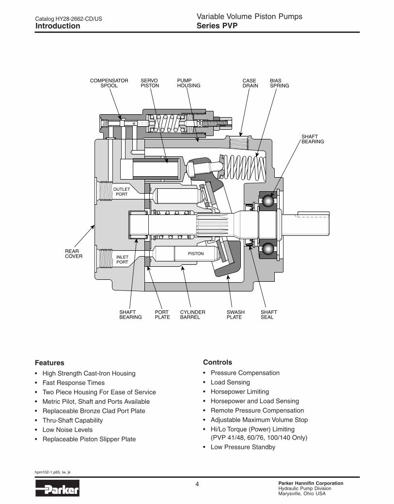
Variable Volume Piston PumpsSeries PVPIntroduction
OUTLETPORT
PISTONINLETPORT
SERVOPISTON
COMPENSATORSPOOL
PUMPHOUSING
CASEDRAIN
BIASSPRING
SHAFTBEARING
REARCOVER
SWASHPLATE
CYLINDERBARREL
PORTPLATE
SHAFTBEARING
SHAFTSEAL

Parker Hannifin CorporationHydraulic Pump DivisionMarysville, Ohio USA
hpm102-1.p65, lw, jk
5
Catalog HY28-2662-CD/US
General Description
All control is achieved by the proper positioning of theswash plate. This is achieved by a servo piston actingon one end of the swash plate working against thecombined effect of the off-setting forces of the pistonsand centering spring on the other end. The controlspool acts as a metering valve which varies thepressure behind the servo piston.
As shown in Figure 1, the amount of flow produced bythe Parker Piston Pump is dependent upon the lengthof stroke of the pumping pistons. This length of stroke,in turn, is determined by the position of the swashplate. Maximum flow is achieved at an angle of 15-17
degrees. The rotating barrel, driven by the prime mover,moves the pistons in a circular path and the pistonslippers are supported hydrostatically against the faceof the swash plate. When the swash plate is in a verticalposition, perpendicular to the centerline of the pistonbarrel, there is no piston stroke and consequently nofluid displacement. When the swash plate is positionedat an angle, the pistons are forced in and out of thebarrel and fluid displacement takes place. The greaterthe angle of the swash plate, the greater the pistonstroke.
FIGURE 1
Variable Volume Piston PumpsSeries PVPControl Options
SERVO PISTON
INLET
OUTLET
PISTON
CYLINDERBARREL
SWASHPLATE
BIASSPRING
DRIVESHAFT

Parker Hannifin CorporationHydraulic Pump DivisionMarysville, Ohio USA
hpm102-1.p65, lw, jk
6
Catalog HY28-2662-CD/US
Pressure Compensated Control (OMIT)
The swash plate angle controls the output flow of thepump. Swash plate angle is generated by thehydraulic force of the pumping pistons and themechanical force of the swash plate bias spring.
Control of the pump’s outlet flow is obtained by over-riding the force of the pumping pistons and biasspring with the hydraulic force of the servo piston bymeans of internal porting. Pressure is connected fromthe outlet port to the servo piston via a compensatorspool.
The compensator spool is held against the springguide by the outlet pressure. When the outlet pressurereaches the setting of the compensator control, thecompensator spool moves, allowing outlet pressure oilto be metered into the servo piston. This metered oil
provides adequate force to power the servo pistonand override swash plate forces. The outlet pressurecauses the servo piston to move which reduces theangle of the swash plate and thereby reduces thepump’s output flow. When flow is again demanded bythe system, the outlet pressure will momentarily fallallowing the compensator spool to move. Thismovement closes off the outlet pressure to the servopiston and vents the servo piston to case. The resultof this venting allows the swash plate forces to movethe swash plate angle to maximum displacement,thus responding to the demand for additional flow.Note that the compensator spring chamber is ventedto the pump case via a hole internal to thecompensator spool.
FIGURE 2
Variable Volume Piston PumpsSeries PVPControl Options
-Q
+Q
CASE DRAINPORT
INLET PORT
OUTLET PORT
OUTLETPORT
PISTONINLETPORT
SERVO PISTON

Parker Hannifin CorporationHydraulic Pump DivisionMarysville, Ohio USA
hpm102-1.p65, lw, jk
7
Catalog HY28-2662-CD/US
OUTLETPORT
PISTONINLETPORT
SERVO PISTON
"A" PORT
Remote Pressure Control (M)
The pump swash plate actuation is identical to thestandard pressure compensator but can be controlledvia a remote pressure control.
Remote control of the pump output pressure canbe achieved by controlling the pressure at port A, Figure3 on the compensator. Flow is metered through theorifice in the spool from outlet pressure into the springchamber. The spring chamber pressure is limited byan external relief connected to port A. The controlledpressure at port A is sensed at the differential springchamber. The compensator spool will move to the rightwhen the pump outlet pressure reaches a force equalto the differential spring setting plus the controlled port
pressure setting. When the spool moves to the right,outlet pressure oil is metered to the servo piston andthe pump swash plate angle is controlled accordingly.With this option the pump outlet pressure can becontrolled and varied from a remote location.
This control also incorporates a pressure limiting featurepreset at the factory. When the pressure in thedifferential spring chamber reaches the maximum reliefsetting, the dart unseats allowing the spring chamberto vent to the pump case and limits the maximumpressure attainable.
FIGURE 3
Variable Volume Piston PumpsSeries PVPControl Options
PVP SERIESREMOTE PRESSURE COMPENSATOR
CONTROL OPTION "M"
("A" PORT)REMOTE PORT
-Q
+Q
CASE DRAINPORT
INLET PORT
OUTLET PORT

Parker Hannifin CorporationHydraulic Pump DivisionMarysville, Ohio USA
hpm102-1.p65, lw, jk
8
Catalog HY28-2662-CD/US
Flow Control (Load Sensing) (A)Figure 4 shows a PVP pump with flow control. Thecontrol is identical to the remote pressure compensationcontrol except for an integral orifice, a solid compensatorspool and adjustable differentialpressure control. Port A is connected downstream ofan orifice (variable or fixed) to sense the actual workingpressure required. This pressure plus the differentialspring force act on the right side of the compensator
FIGURE 4
spool and will urge the spool to the left until outputpressure acting on the left side of the spool balancesthe forces. As the load increases, output pressurewill increase and maintain a constant differentialpressure across the orifice and thus a constant flow.Maximum pressure is limited by the internal dart setting.This setting is adjustable up to the maximum preset atthe factory.
Variable Volume Piston PumpsSeries PVPControl Options
SIGNAL LINE
COMPENSATORSPOOL
OUTLETPORT
PISTON
MAX. PRESSUREADJUSTMENT
DIFFERENTIALADJUSTMENT
VARIABLE ORFIXED ORIFICE
INLETPORT
SERVO PISTON
DIFFERENTIALSPRINGCHAMBER
SYSTEM PRESSURE
ORIFICE
PORT “A”
SENSE PORT
SENSE LINEVARIABLE OR FIXED ORIIFICE
REMOTE PORT
ORIFICE
-Q
+Q
CASE DRAINPORT
INLET PORT
OUTLET PORT

Parker Hannifin CorporationHydraulic Pump DivisionMarysville, Ohio USA
hpm102-1.p65, lw, jk
9
Catalog HY28-2662-CD/US
INLETPORT
PISTON
SERVO PISTON
SHOWN AT FULL STROKE.CAM WILL ROTATE CWAS PUMP GOES TOWARDZERO STROKE.
OUTLETPORT
Pressure & Power Control (H)
This control option is a Torque Limiting Control, but forconstant speed applications it is generally referred toas a Horsepower Control. This control works inconjunction with the Remote Pressure Compensator,control option “M”. A second pressure control devicecalled a horsepower control block, is assembled to themain pump housing. The HP block is plumbed to oneof the ports on the remote compensator via steel tubing.The control dart in the HP block and the maximumpressure compensator dart in the remote compensatorare connected in parallel. What makes the control dartin the HP block different from any other external reliefvalve is the pressure setting is mechanically linked tothe pump swashplate angle.
The cracking pressure of the HP dart is generally lowerthan the cracking pressure of the remote compensatordart. When the HP dart opens the pressure in the
FIGURE 5
differential spring cavity is lowered allowing thecompensator spool to meter system pressure in theservo piston. As the servo piston extends, it rotatesthe swashplate and in turn rotates the HP cam. As thecam rotates it increases the force on the HP dart controlspring. As the system pressure is allowed to increase,the pump gradually reduces its stroke (flow). When thesystem pressure reaches the setting of the maximumpressure dart the normal action of the remotecompensator takes over. If the HP control is set lowenough, the pump may reach zero stroke before thesystem pressure ever gets a chance to open themaximum compensator dart. This should be consideredwhen making low power settings on systems requiringhigh working pressures.
Variable Volume Piston PumpsSeries PVPControl Options
REMOTE PORT
-Q
+Q
CASE DRAINPORT
INLET PORT
OUTLET PORT

Parker Hannifin CorporationHydraulic Pump DivisionMarysville, Ohio USA
hpm102-1.p65, lw, jk
10
Catalog HY28-2662-CD/US
SIGNAL LINE
COMPENSATORSPOOL
OUTLETPORT
INLETPORT
PISTON
MAX. PRESSUREADJUSTMENT
DIFFERENTIALADJUSTMENT
VARIABLE ORFIXED ORIFICE
SERVO PISTON
DIFFERENTIALSPRINGCHAMBER
SYSTEMPRESSURE
ORIFICE
SHOWN AT FULL STROKE.CAM WILL ROTATE CWAS PUMP GOES TOWARDZERO STROKE.
Pressure, Power & Flow Control (C)
Refer to the previous section(s) on Flow Control andPower Control. This is another case where multiplecontrols can be combined in parallel. Since the PowerControl is just a special version of Remote PressureControl, it can be combined with the Flow Control (LoadSense) option. The main point to remember here isthat the pressure drop which is required to begin andmaintain compensation comes from an external device(such as a proportional valve). This sensed pressuredrop will control flow until one of the limits of the othercontrols has been exceeded. The pump will alwaysrespond to the lowest control setting for any givenpressure. In addition to Load Sensing, Power Control,
FIGURE 6
and on-pump Pressure Control, Remote PressureControl can also be included in this parallel devicepackage. There is a remote port on the compensatorbody and one on the HP Control body, either of whichmay be used for remote pressure control. The importantconcept to remember in load sense circuits is thateach pressure control device in and connected to thecompensator must be protected from saturation. Forthis reason, use only the uppermost port on thecompensator for connection of the load sense line andinsure that an appropriate orifice is installed. All controloptions using a load sense compensator spool aresupplied with this orifice.
Variable Volume Piston PumpsSeries PVPControl Options
SENSE PORT
SENSE LINE
REMOTE PORT
-Q
+Q
CASE DRAINPORT
INLET PORT
OUTLET PORT

Parker Hannifin CorporationHydraulic Pump DivisionMarysville, Ohio USA
hpm102-1.p65, lw, jk
11
Catalog HY28-2662-CD/US
INLETPORT
PISTON
SERVO PISTON
OUTLETPORT
Hi/Lo Power Control (HLM)(Available with PVP41 and PVP48 Only)
The graph shown below represents the flow-pressurecharacteristics of a Hi-Lo control for PVP pumps. Thereare up to four separate adjustments that must be madewith the pump controls to get a particular setting, all ofwhich influence the shape of the curve. To get theproper settings, it is very important that all pertinentinformation is supplied with each Hi-Lo pump ordered.As you can see from the graph below, there are twopeak power points. Our intention is to have the samemagnitude of power required for both peaks. Of coursemany combination of settings are possible butspecification of the settings becomes very difficult. Tomake factory settings, we need to know the requiredflow (applicable if pump has a maximum volumestop), the shaft speed, the required Power limit, andthe compensation pressure. Based on theserequirements, we will adjust the low pressure set pointand the reduced flow set point of the Hi-Lo control tobest match the requested parameters called out onthe order.
Important note: As with power controls, not allcombinations of flow, power, pressure, etc. are possible.The first rule is that the settings must conceptually beachievable (i.e. power out is ALWAYS less than powerin). Be careful in assuming efficiencies when estimatingthe Out/In relationship, since a pump operating at low
pressure or in a de-stroked condition can have a muchlower overall efficiency than expected. The other thingto keep in mind is that the pump will require the peakpower at only two points. All other operating pressureswill require less than maximum power and thereforethe pump will deliver less hydraulic power in theappropriate ratio based on the actual pump efficiencyat those conditions.
System PressureO
utl
et F
low
Typical Hi-Lo ControlFlow/Pressure Characteristics
LOW PRESSUREADJUSTMENT
LOW FLOW SETTINGADJUSTMENT
MAX. PSIADJUST
CONSTANT POWER CURVE
Variable Volume Piston PumpsSeries PVPControl Options
FIGURE 7
OUTLET PORT REMOTE PORT
PVP SERIESPRESSURE & POWER COMPENSATOR
CONTROL OPTION "HLM"
INLET PORT CASE DRAINPORT
HIGH P
LOW P

Parker Hannifin CorporationHydraulic Pump DivisionMarysville, Ohio USA
hpm102-1.p65, lw, jk
12
Catalog HY28-2662-CD/US
Performance InformationSeries PVP16 Pressure Compensated,Variable Volume, Piston Pump
Features• High Strength Cast-Iron Housing for Reliability and
Quiet Operation
• Optional Inlet/Outlet Locations for Ease ofInstallation
• Replaceable Bronze Port Plate
• Replaceable Piston Slipper Plate
• Thru-Shaft Capability SAE A Pilots Offered
• Low Noise Levels - Promote More ComfortableOperating Environment
• Fast Response Times
• Metric Pilot Shaft and Ports Available
Controls• Pressure Compensation• Remote Pressure Compensation• Load Sensing• Torque (Power) Limiting• Adjustable Maximum Volume Stop• Low Pressure Standby
Schematic Symbol(Basic Pump)
Quick Reference Data Chart
DisplacementPump Delivery † Approx. Noise Levels dB(A) Input Power At
Pumpcc/rev
@ 21 bar (300 PSI) @ Full Flow 1800 RPM (1200 RPM) 1800 RPM, Max.Model
(In3/rev)in LPM (GPM) 34 bar 69 bar 138 bar 207 bar 248 bar Displacement &
1200 RPM 1800 RPM (500 PSI) (1000 PSI) (2000 PSI) (3000 PSI) (3600 PSI) 248 bar (3600 PSI)
PVP16 16.4 (1.0) 19.7 (5.2) 29.5 (7.8) 53 (47) 55 (50) 59 (54) 62 (56) 65 (59) 13.1 kw (17.5 hp)
† Measured in an anechoic chamber to DIN 45635, measuring error + 2 dB(A).Fluid used: petroleum oil to ISO VG 46; temperature = 50°C (122°F).
Since many variables such as mounting, tank style, plant layout, etc., effect noise levels, it cannot be assumed thatthe above readings will be equal to those in the field. The above values are for guidance in selecting the proper pump.
SpecificationsPressure Ratings
Outlet Port: 248 bar (3600 PSI) Continuous (P1)310 bar (4500 PSI) Peak (P3)
Inlet Port: 1.72 bar (25 PSI) Maximum.17 bar (5 In. Hg.) Vacuum Minimum@ 1800 RPM (See inlet chart forother speeds)
Speed Ratings: 600 to 3000 RPM
Operating Temperature Range: – 40°C to 71°C(– 40°F to 160°F)
Housing Material: Cast-Iron
Filtration: Maintain SAE Class 4,ISO 16/13,ISO 18/15 Maximum
Mounting: SAE “A” or Metric 2-BoltFlange Mount
Installation Data: See page 42 of this catalog forspecific recommendations pertaining to systemcleanliness, fluids, start-up, inlet conditions, shaftalignment, drain line restrictions and other importantfactors relative to the proper installation and use ofthese pumps.
Variable Volume Piston PumpsSeries PVP16Technical Information

Parker Hannifin CorporationHydraulic Pump DivisionMarysville, Ohio USA
hpm102-1.p65, lw, jk
13
Catalog HY28-2662-CD/US
Code Control Options
Omit Pressure Compensated
**M Remote Pressure (Int.)**ME Remote Pressure (Ext.)
A Pressure and Flow
*C Pressure, Flow, and Power
*H Pressure Compensatedand Power
*Specify HP, RPM & comp setting whenordering or will will get default.** "M" (May be remotely controlled) "ME" (Requires external pilot)
Code Rotation*
R (CW)
L (CCW)
* Viewed fromshaft end.
Code Multiple Pumps
Omit Single Pump
Factory Mounted— to Rear of
Another Pump
Code Painting
Omit No PaintP Paint
CodeCM3/REV(In3/Rev.)
16 16.4 (1.0)
Code Pressure Range*
10 17-69 bar (250-1000 PSI)
20 17-138 bar (250-2000 PSI)
30 17-207 bar (250-3000 PSI)
36 17-248 bar (250-3600 PSI)
* Minimum value of pressure range onlyapplies on control option “omit” code.
Code Volume Stop Options
Omit No Volume Stop
2 Adj. Maximum Volume Stop
Code Thru-Shaft Threads
Omit No Thru-Shaft
6* UNC
9** Metric
* Available with 2 or 4 port
* Available with CW rotation only.
option and CW rotation only.** Available with 8 or 9 port
option and CW rotation only.
PVP 16
Multiple Pump Displace- Shaft Port & Rotation Volume Thru- Thru- Control Seals Paint MultiplePumps Variable ment Pressure Flange Stop Shaft Shaft Option Pumps
Piston Range Sizes Option Threads Option
* “FLUOROELASTOMERSare available undervarious registeredtrademarks, includingFLUOROCARBON (aregistered trademark ofDuPont) and FLUOREL (aregistered trademark of3M).”
Code Seals
Omit Nitrile
V Fluoroelastomers*
CodePorts
Type Location
Omit SAE Rear - Straight Thread
2 SAE Side - Flange
4 SAE Side - Straight Thread
8*ISO Side - Flange6149 (Metric Threads)
9* BSPPSide - Flange(Metric Threads)
Code Thru-Shaft Options
Omit No Thru-Shaft
A4 SAE “A” Pilot / SAE “A” 9T Spline
Code Multiple Pumps
Omit Single Pump
—Pump FactoryMounted on Rear
Variable Volume Piston PumpsSeries PVP16Ordering Information
Code Shaft Option Pilot
Omit 3/4" Keyed SAE “A”
B* 9T Spline (SAE A) SAE “A”
C 11 Tooth Spline SAE “A”
K† 18mm Keyed Metric
* Total input torque not to exceed58.2 N•m (517 In.-Lbs.)
† Available with port option 8 and 9 only.

Parker Hannifin CorporationHydraulic Pump DivisionMarysville, Ohio USA
hpm102-1.p65, lw, jk
14
Catalog HY28-2662-CD/US
Typical Performance Data - Fluid: Standard Hydraulic Oil 100 SSU @ 49°C (120°F)
NOTE: The efficiencies and data in the graph are nominalvalues and good only for pumps running at 1800 RPM andstroked to maximum. To calculate approximate horsepowerfor the other conditions, use the following formula:
Actual GPM is directly proportional to drive speed andmaximum volume setting. Flow loss, however, is a function ofpressure only.
HP = Q x (PSI) + (CHp) 1714[ ]
WHERE:Q = Actual Output Flow in GPMPSI = Pressure At Pump OutletCHp = Input Horsepower @ Full Compensation @ 1800
RPM(from graph read at operating pressure)
Variable Volume Piston PumpsSeries PVP16Performance Data
4
5
6
7
8
9
10100
90
80
70
Flo
w
Eff
icie
ncy
- %
Po
wer
PVP16 @ 1200 RPM
0
2
1
3
15.1
18.9
22.7
26.5
30.3
34.1
37.9
0
7.6
3.8
11.4
Volumetric Efficiency
Flow
Overall Efficiency
0
0
Bar
PSI69
1000
138
2000
207
3000
275
4000
Pressure
GPMLPM
0
3.0
6.0
8.9
11.9
14.9
0
4.0
8.0
12.0
16.0
20.0HPKW
Input Power at Full Flow
Compensated Power
4
5
6
7
8
9
10100
90
80
70
60
Flo
w
Eff
icie
ncy
- %
Po
wer
PVP16 @ 1800 RPM
0
2
1
3
15.1
18.9
22.7
26.5
30.3
34.1
37.9
0
7.6
3.8
11.4
0
0
Bar
PSI69
1000
138
2000
207
3000
275
4000
Pressure
GPMLPM
0
3.0
6.0
8.9
11.9
14.9
0
4.0
8.0
12.0
16.0
20.0HPKW
Volumetric Efficiency
Overall Efficiency
Flow
Input Power a
t Full F
low
Compensated Power
12.0
15.0
Ou
tlet
Flo
w @
Max
. Dis
pla
cem
ent
Flow vs. Speed
0 1000 2000 3000500 1500 2500
Shaft Speed - RPM
0
6.0
3.0
9.0
45.5
57.8
0
22.7
11.4
34.1
GPMLPM
PVP16Inlet Characteristics at Full Displacement
(Graph only valid at sea level)
0 1000 1500500 2000 2500 3000
Shaft Speed - RPM
DO NOT OPERATEIN THIS REGION
RecommendedOperating Condition
Vac
uu
m
Inle
t P
ress
ure
6.41
4.28
2.14
PSIbar
00
5.17
10.34
15.51
20.68
In-Hgbar

Parker Hannifin CorporationHydraulic Pump DivisionMarysville, Ohio USA
hpm102-1.p65, lw, jk
15
Catalog HY28-2662-CD/US
Typical Performance Data - Fluid: Standard Hydraulic Oil 100 SSU @ 49°C (120°F)
Power Control
Variable Volume Piston PumpsSeries PVP16Performance Data
PVP16 @ 1200 RPM
2 HP
3 HP
5 HP
10 HP7.5 HP
Full FlowTorque
0
0
Bar
PSI69
1000
138
2000
207
3000
275
4000
Pressure
4
5
6
Flo
w
To
rqu
e
0
2
1
3
15.1
18.9
22.7
0
7.6
3.8
11.4
GPMLPM
0
12.4
24.8
37.0
49.5
61.9
0
110
220
330
440
550
74.3 660In-LbsN·m
PVP16 @ 1800 RPM
2 HP
3 HP5 H
P
10 HP7.5 HP
15 HP
Full FlowTorque
0
0
Bar
PSI69
1000
138
2000
207
3000
275
4000
Pressure
4
5
6
Flo
w
To
rqu
e
0
2
1
3
15.1
18.9
22.7
0
7.6
3.8
11.4
0
9.0
18.0
27.0
36.0
45.0
0
80
160
240
320
400
54.0 480
7
8
26.5
30.3GPMLPM
63.0 560
72.0 640In-LbsN·m
100
125
150
200
Tim
e (m
illis
ec)
PVP16 @ 1200 RPM
0
50
25
75
On-Stroking
De-Stroking
0
0
Bar
PSI69
1000
138
2000
207
3000
275
4000
Pressure
100
125
150
200T
ime
(mill
isec
)PVP16 @ 1800 RPM
0
50
25
75
On-Stroking
De-Stroking
0
0
Bar
PSI69
1000
138
2000
207
3000
275
4000
Pressure
PVP16Compensated Power
@ 1800 RPM
0
0
Bar
PSI69
1000
138
2000
207
3000
275
4000
Pressure
2.0
2.5
3.0
Po
wer
0
1.0
.5
1.5
1.5
1.9
2.2
0
.75
.37
1.1
HPKW
PVP16Approximate Case Drain Flow
@ 1800 RPM
Remote Comp - Zero Stroke
Standard Comp - Zero Stro
ke
Full Flow
0
0
Bar
PSI69
1000
138
2000
207
3000
275
4000
Pressure
.4
.5
.6
Flo
w
0
.2
.1
.3
1.5
1.9
2.3
0
.8
.4
1.1
GPMLPM
Response Times

Parker Hannifin CorporationHydraulic Pump DivisionMarysville, Ohio USA
hpm102-1.p65, lw, jk
16
Catalog HY28-2662-CD/US
Rear Ported Pump Dimensions* Inch equivalents for millimeter dimensions are shown in (**).
NOTE:
Illustration shows Righthand (CW) rotation pump. Lefthand (CCW)pumps will have inlet and outlet ports reversed with compensator onoutlet side.
OUTLET PORT SAE-12STRAIGHT THREADO-RING PORT(1-1/16-12 UN-2B REF.)
INLET PORT SAE-12STRAIGHT THREADO-RING PORT(1-1/16-12 UN-2B REF.)
DRAIN PORT SAE-6STRAIGHT THREAD O-RING PORT (9/16-18 UNF-2B)(INCLUDED IN “5” OPTION ONLY)
4.78 (.188)SAE KEY
6.35 (.25)FLAT
COMPENSATEDPRESSUREADJUSTMENT37.9 BAR (550 PSI) PER TURN
ADJ. MAX. VOLUME STOP(1.6 CC/REV/TURN)
“OPTION 2”
22.61 (.89)REF.
174.75(6.88)
21.16 (.833)20.98 (.826)
199.64 (7.86)MAX.
CLEARANCE FOR 3/8"MOUNTING BOLTS
61.47(2.42)
89.92(3.54)
91.95(3.62)
44.20(1.74)
78.99(3.11)
84.33(3.32)
94.23(3.71)
53.09(2.09)
53.09(2.09)
89.92(3.54)
89.92(3.54)
66.55(2.62)
66.55(2.62)
57.91(2.28)
CASE DRAIN PORT SAE-6 STRAIGHT THREAD (9/16-18 UNC)
ROTATIONARROW
IN
NAMEPLATE
ALTERNATEDRAIN PORT OR CASE PRE-FILL PORT SAE-6 STRAIGHT THREAD (9/16-18 UNC)
12.70(.50)
6.09(.24)44.45(1.75)
82.55 (3.250)82.50 (3.248)
19.05 (.750)19.02 (.749)115.9 N·m
(1,030 IN-LBS)MAX TORQUE
69.08(2.72)
39.62(1.56)
107.95(4.25)
OPTION “B”SPLINE SHAFTSAE “A” 9T 16/32 DP30˚ INVOLUTE SPLINEMAX TORQUE = 58.2 N·m (517 IN-LBS)
OPTION “C”SPLINE SHAFT11T 16/32 DP30˚ INVOLUTE SPLINEMAX TORQUE = 102.3 N·m (909 IN-LBS)
31.75(1.25)
31.75(1.25)
Ø
Ø
Top ViewRear View
Front View
Side View
A
CC
D
Variable Volume Piston PumpsSeries PVP16Dimensional Data
Pilot DimensionsPilot
A C DOption
OMIT N/A32.00 173.23(1.26) (6.82)
538.10 28.44 144.53(1.50) (1.12) (6.44)

Parker Hannifin CorporationHydraulic Pump DivisionMarysville, Ohio USA
hpm102-1.p65, lw, jk
17
Catalog HY28-2662-CD/US
4.78 (.188)SAE KEY
6.35 (.25)FLAT
COMPENSATEDPRESSUREADJUSTMENT37.9 BAR (550 PSI) PER TURN
ADJ. MAX.VOLUME STOP(1.6 CC/REV/TURN)
“OPTION 2”
22.61 (.89)REF.
174.75(6.91)
21.16 (.833)20.98 (.826)
210.06 (8.27)MAX.
CLEARANCE FOR 3/8"MOUNTING BOLTS
61.47(2.42)
89.92(3.54)
91.95(3.62)
44.20(1.74)
53.09(2.09)
53.09(2.09)
78.99(3.11)
83.33(3.32)
94.23(3.71)
INLET PORT OUTLET PORT
89.92(3.54)
89.92(3.54)
67.56(2.66)
67.56(2.66)
57.91(2.28)
ROTATIONARROW
IN NAMEPLATE
ALTERNATE DRAIN PORTOR CASE PRE-FILL PORT SEE TABLE FOR SIZE
CASE DRAIN PORT SEE TABLE FOR SIZE
12.70(.50)
44.45(1.75)
6.09(.24)
19.05 (.750)19.02 (.749)
69.08(2.72)
39.62(1.56)
107.95(4.25)
A
Ø
Top View
Rear View
Front ViewSide View
OPTION “B”SPLINE SHAFTSAE “A” 9T 16/32 DP30˚ INVOLUTE SPLINEMAX TORQUE = 58.2 N·m (517 IN-LBS)
OPTION “C”SPLINE SHAFT11T 16/32 DP30˚ INVOLUTE SPLINEMAX TORQUE = 102.3 N·m (909 IN-LBS)
31.75(1.25)
31.75(1.25)
Side Ported – Options 2 & 4Dimensions* Inch equivalents for millimeter dimensions are shown in (**).
NOTE:
Illustration shows Righthand (CW) rotation pump.Lefthand (CCW) pumps will have inlet and outlet portsreversed with compensator on outlet side.
Port Size Type and LocationOption A Inlet and Outlet Ports Drain Port
148.843/4" SAE 4-Bolt Flange
SAE-6 Straight Thread2(5.86)
3/8-16 Thread(9/16-18UNC)Std PSI Series (Code 61)
4152.40 SAE-16 Straight Thread SAE-6 Straight Thread(6.00) (1-5/16-12UN-2B) (9/16-18UNC)
Variable Volume Piston PumpsSeries PVP16Dimensional Data

Parker Hannifin CorporationHydraulic Pump DivisionMarysville, Ohio USA
hpm102-1.p65, lw, jk
18
Catalog HY28-2662-CD/US
Pilot DimensionsShaft
A B C DOption
Omit 82.55/82.50 6.10 53.09ø 3/8"B, C
ø (3.250/3.248) (.24) (2.09)
K80.00/79.95 7.24 55.63
ø 10mmø (3.149/3.147) (.285) (2.19)
Side Ported – Options 8 & 9 Dimensions* Inch equivalents for millimeter dimensions are shown in (**).
NOTE:
Illustration shows Righthand (CW) rotation pump.
3/4" SAE 4-BOLTFLANGE -M10 X 1.5THREADSSTANDARDPRESSURESERIES(CODE 61)BOTH SIDES
6 mm KEY
OPTION “K”M6 THREADMAX TORQUE = 115.9 N·m (1,030 IN-LBS)
4.78 (.188)SAE KEY
6.35 (.25)FLAT
COMPENSATEDPRESSUREADJUSTMENT37.9 BAR (550 PSI) PER TURN
ADJ. MAX.VOLUME STOP(1.6 CC/REV/TURN)
“OPTION 2”
22.61 (.89)REF.
175.75(6.91)
21.16 (.833)20.98 (.826)
20.50 (.807)20.22 (.796)
18.01 (.7087)17.99 (.7083)
210.06 (8.27)MAX.
148.84(5.86)
CLEARANCE FOR “D”MOUNTING BOLTS
61.47(2.42)
89.92(3.54)
91.95(3.62)
44.20(1.74)
78.99(3.11)
83.33(3.32)
94.23(3.71)
INLET PORT OUTLET PORT
89.92(3.54)
89.92(3.54)
67.56(2.66)
67.56(2.66)
57.91(2.28)
CASE DRAIN PORTOPTION “8” –ISO 6149-6 (M16X1.5)OPTION “9” 3/8" BSPP
ROTATIONARROW
IN NAMEPLATE
ALTERNATE DRAIN PORTOR CASE PRE-FILL PORT OPTION “8” – ISO 6149-6 (M16X1.5)OPTION “9” – 3/8" BSPP
12.70(.50)
44.45(1.75)
19.05 (.750)19.02 (.749)
69.08(2.72)
39.62(1.56)
107.95(4.25)
35.31(1.39)
C C
B
A
Ø
Ø
Top View
Rear View
Front ViewSide View
OPTION “B”SPLINE SHAFTSAE “A” 9T 16/32 DP30˚ INVOLUTE SPLINEMAX TORQUE = 58.2 N·m (517 IN-LBS)
OPTION “C”SPLINE SHAFT11T 16/32 DP30˚ INVOLUTE SPLINEMAX TORQUE = 102.3 N·m (909 IN-LBS)
31.75(1.25)
31.75(1.25)
Variable Volume Piston PumpsSeries PVP16Dimensional Data

Parker Hannifin CorporationHydraulic Pump DivisionMarysville, Ohio USA
hpm102-1.p65, lw, jk
19
Catalog HY28-2662-CD/US
4
13.5 N·m(120 IN-LB)TORQUE
4.78 (.188)SAE KEY
COMPENSATEDPRESSUREADJUSTMENT37.9 BAR (550 PSI) PER TURN
21.16 (.833)20.98 (.826)
84.33(3.32)
INLET PORT OUTLET PORT
67.56(2.66)
67.56(2.66)
CASE DRAINPORT SEE TABLEFOR SIZE
ROTATIONARROW
IN NAMEPLATE
12.70(.50)
6.09(.24)44.45(1.75)
82.55 (3.250)82.50 (3.248)
19.05 (.750)19.02 (.749)
39.62(1.56)
107.95(4.25)
A
C
D
EG
F
C
H
Ø
Top View
Side ViewRear View
Ø
Thru-Shaft Pump Dimensions* Inch equivalents for millimeter dimensions are shown in (**).
NOTES:
1. Righthand (CW) rotation pump shown above.Counterclockwise (CCW) pump will have inlet and outletports reversed with the compensator over the outlet port.
2. Splined shaft (option “B”) not recommended withThru-Shaft pumps.
3. The maximum torque transmitting capacity for rearmounting of pumps is limited by the allowable torqueof the input shaft.
4. Options 6A4 and 9A4 Design Series 12 have a gasket.All other options incorporate an o-ring seal and have ano-ring groove.
Port Size Type and LocationOption A Inlet and Outlet Ports Drain Port
148.843/4" SAE 4-Bolt Flange
SAE-6 Straight Thread2 (5.86) 3/8-16 Thread(9/16-18UNC)Std PSI Series (Code 61)
4152.40 SAE-16 Straight Thread SAE-6 Straight Thread(6.00) (1-5/16-12UN-2B) (9/16-18UNC)
148.84 3/4" SAE 4-Bolt FlangeISO 6149-68 (5.86) M10 ThreadM16 x 1.50Std PSI Series (Code 61)
148.84 3/4" SAE 4-Bolt Flange9 (5.86) M10 Thread 3/8" - BSPP
Std PSI Series (Code 61)
Variable Volume Piston PumpsSeries PVP16Dimensional Data
Dimensions – Thru Shaft Options
VARIATION HGF EDC
6A4 53.19 (2.09) 82.58/82.60 (3.251/3.252) N/A 3/8–16UNC–2B 9 Tooth 16/32 Pitch 207.26 (8.16)
9A4 53.19 (2.09) 82.58/82.60 (3.251/3.252) N/A M10 x 1.50 9 Tooth 16/32 Pitch 207.26 (8.16)

Parker Hannifin CorporationHydraulic Pump DivisionMarysville, Ohio USA
hpm102-1.p65, lw, jk
20
Catalog HY28-2662-CD/US
Remote Compensator Control Pump Dimensions* Inch equivalents for millimeter dimensions are shown in (**).
NOTES:
1. Righthand (CW) rotation pump shown below. Lefthand (CCW) pumps will havecompensator on opposite side.
2. When controlling pump compensator pressure with remote relief valve, remote reliefvalve must be capable of passing 1.89 LPM (.5 GPM).
3. Remote compensator option “M”, “ME” & “A” available on pumps withany port location.
FOR “M”, “ME”, “A”,“H” & “C” OPTION
FOR “A” & “C” OPTION
DIFFERENTIAL ADJUSTMENT(INCLUDED ON “A”& “C” OPTION)27.5 BAR (400 PSI)PER TURN
25.40(1.00)
77.72(3.06)
53.34(2.10)REF.45.72(1.80)REF.
ADAPTOR FITTINGSUPPLIED WITHPORT OPTION “8”PUMPS
ISO 6149-4(M12X1.5)
130.56(5.14)REF
17.02(.67)
ADAPTOR FITTINGSUPPLIED WITH“9” OPTION
1/4"BSPP
130.56(5.14)REF
22.86(.90)
REMOTE CONTROL PORTSAE-4 STRAIGHT THREADO-RING PORT(7/16-20UN-2B REF)
NAMEPLATE
DRAIN PORT SAE-6STRAIGHT THREAD O-RING PORT(9/16-18UNF-2B)
INTERNAL ORIFICEINSTALLED ONOPTIONS “ME”, “A” & “C”
44.19(1.74)
65.79(2.59)
65.79(2.59)
COMPENSATEDPRESSURE ADJUSTMENT64.8 BAR (940 PSI) PER TURN
130.56(5.14)
130.56(5.14)
ROTATIONARROW
IN
102.62(4.04)
C OF PUMP
L
Top View
Side View Front View
Variable Volume Piston PumpsSeries PVP16Dimensional Data

Parker Hannifin CorporationHydraulic Pump DivisionMarysville, Ohio USA
hpm102-1.p65, lw, jk
21
Catalog HY28-2662-CD/US
Power (Torque) Control Pump Dimensions* Inch equivalents for millimeter dimensions are shown in (**).
NOTES:
1. Righthand (CW) rotation rear ported pump shown. Counterclockwise (CCW)pumps will have inlet and outlet ports reversed with compensator and powerblock on outlet side.
2. Power control shown on rear ported pump. Also available on side ported or thru-shaft option pumps.
TORQUE LIMIT ADJUSTMENTCONTROL OPTION “H”SENSITIVITY APPROX.21.4 N·m (190 IN-LB)PER TURN
SAE-4 STRAIGHT THREAD PORTFOR REMOTE PRESSURE LIMITINGIF DESIRED (CONTROL OPTION “H”)OR LOAD SENSE PORT(CONTROL OPTION “C”)
112.01(4.41)
OPTIONAL REMOTE PRESSURE COMPENSATOR SIGNAL PORT ON “H” OR “C” OPTION PUMPS (SAE-4 STRAIGHT THREAD PORT)
DO NOT USE THIS PORT FOR LOAD SENSE SIGNAL
103.12(4.06)
29.72(1.17)
44.19(1.74)
135.89(5.35)
IN
Top View
Side View Front View
Variable Volume Piston PumpsSeries PVP16Dimensional Data

Parker Hannifin CorporationHydraulic Pump DivisionMarysville, Ohio USA
hpm102-1.p65, lw, jk
42
Catalog HY28-2662-CD/US
Use of a Relief ValveThe use of a relief valve, while not mandatory isrecommended in the main circuit to suppresshydraulic shock loads and adds additionalsystem protection.
Fluid RecommendationsPremium quality hydraulic oil with a viscosity rangebetween 150-250 SSU (30-50 cst.) at 38°C (100°F).Normal operating viscosity range between 80-1000SSU (17-180 cst.). Maximum start-up viscosity is4000 SSU (1000 cst.).
NOTE: Consult Parker when exceeding 71°C (160°F)Inlet Fluid Temperatures. Oil shouldhave maximum anti-wear properties, rust andoxidation treatment.
FiltrationFor maximum pump and system component life,the system should be protected from contamination ata level not to exceed 125 particles greater than10 microns per milliliter of fluid. (SAE Class 4/ISO16/13.) Due to the nature of variable displacementpumps, variations in pump inlet conditions, fluidacceleration losses, system aeration, and duty cyclewe do not recommend suction line filters. We dorecommend the use of a properly sized, in-tank,suction strainer. Contact your Parker representativefor assistance.
Start-UpOn initial start-up, the case should be filled with oil,pressure adjustments should be reduced and thecircuit should be open to permit priming.
Inlet ConditionsNot to exceed .17 bar (5 In. Hg.) Vacuum at 1800RPM on petroleum base fluids. See recommendedspeed spectrum for specific inlet conditions.
Shaft Rotation and Line UpPump and motor shaft alignment must be within.010 TIR maximum, using a standard floatingcoupling. Please follow coupling manufacturer’srecommended installation instructions to prevent endthrust on pump shaft. Turn pump to assure freedom ofrotation. Pump and motor must be on a rigid base.
The coupling should be sized to absorb the peakhorsepower developed.
Installation and MountingWhen mounting a PVP Series Pump, the “case drain”must be on top of the pump. The “case drain” shouldbe a separate line unrestricted to the reservoir andextend below the oil level as far from the inlet lineas possible. The “case drain” line must not exceed .7bar (10 PSI) back pressure. Suggested maximum linelength is 10 feet.
Special InstallationsConsult your Parker representative for any applicationrequiring the following:
Pressure above rated, drive speed above maximum,indirect drive, fluid other than petroleum oil, oiltemperature above 71°C (160°F).
Inlet PressureNot to exceed 1.72 bar (25 PSI).
Variable Volume Piston PumpsSeries PVPInstallation Information

Catalog HY15-3502/US Pilot Operated Relief ValveSeries RAH101
PC37
CheckValves
ShuttleValves
Load/Motor
ControlsFlow
ControlsPressureControls
LogicElem
entsDirectional
ControlsM
anualValves
SolenoidValves
ProportionalValves
Coils &Electronics
Bodies &Cavities
TechnicalData
SH
CV
LM
FC
PC
LE
DC
MV
SV
PV
CE
BC
TD
Parker Hannifin CorporationHydraulic Cartridge Systems
Technical Information
Specifications
Rated Flow 113 LPM (30 GPM)
Maximum Inlet 380 Bar (5500 PSI)Pressure
Maximum 350 Bar (5000 PSI)Pressure Setting
Maximum Tank 350 Bar (5000 PSI)Pressure
Reseat Pressure 90% of crack pressure
Leakage at 5 cc per 100 PSI (6.8 Bar) setting150 SSU (32 cSt)
Cartridge Material All parts steel. All operatingparts hardened steel.
Operating Temp. -45°C to +93.3°C (“D”-Ring)Range/Seals (-50°F to +200°F)
-31.7°C to +121.1°C (Fluorocarbon)(-25°F to +250°F)
Fluid Mineral-based or synthetic withCompatibility/ lubricating properties at viscositiesViscosity of 45 to 2000 SSU (6 to 420 cSt)
Filtration ISO Code 16/13,SAE Class 4 or better
Approx. Weight .23 kg (.50 lbs.)
Cavity C10-2(See BC Section for more details)
Form Tool Rougher NoneFinisher NFT10-2F
Performance CurvesFlow vs. Inlet Pressure(Pressure rise through cartridge only)
General DescriptionPilot Operated Spool-Type Relief Valve.For addition information see TechnicalTips on pages PC1-PC6.
Features• Hardened, precision ground parts for durability
• Low profile adapter for minimal space requirements
• Fully guided poppet for more consistent reseat
• Steel adapters are coated with yellow zinc dichromate forprotection from salt spray
• Polyurethane “D”-Ring eliminates backup rings andprevents hydrolysis
• Internal screening protects pilot spring from debris
(2)(1) (2)
(1)
Flow (Q)
68.1
18
22.7
6
45.3
12
LPM
GPM0
90.8
24
113.6
30
Hydraulic Oil 150 SSU @ 100°F (32 cSt)
0
1000
2000
345
414
207
276
69
138
5000
6000PSI Bar
3000
4000
Pre
ssu
re,P
SI
Flow (Q)
68.1
18
22.7
6
45.3
12
LPM
GPM0
90.8
24
113.6
30
Hydraulic Oil 150 SSU @ 100°F (32 cSt)
0
100
20.7
27.6
13.8
6.9
300
400PSI Bar
200
Pre
ssu
re,P
SI
RAH101S10(minimum setting)
Pilot Operated Relief ValveSeries RAH101
Catalog HY15-3502/US
PC38
Chec
kVa
lves
Shut
tleVa
lves
Load
/Mot
orCo
ntro
lsFl
owCo
ntro
lsPr
essu
reCo
ntro
lsLo
gic
Elem
ents
Dire
ctio
nal
Cont
rols
Man
ual
Valv
esPr
opor
tiona
lVa
lves
Coils
&El
ectro
nics
Tech
nica
lDa
ta
SH
CV
LM
FC
PC
LE
DC
MV
SV
PV
CE
BC
TD
Bodi
es &
Cavi
ties
Sole
noid
Valv
es
Parker Hannifin CorporationHydraulic Cartridge Systems
Technical Information
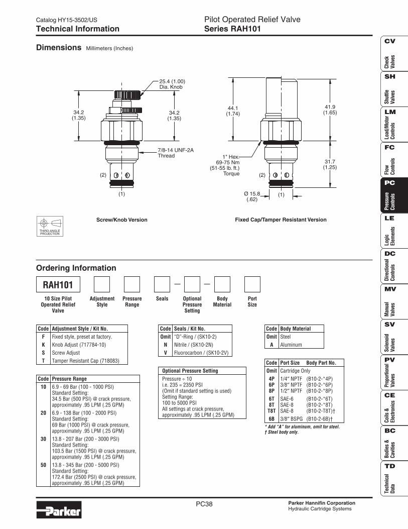
Dimensions Millimeters (Inches)
Ordering Information
THIRD-ANGLEPROJECTION
SealsPressureRange
AdjustmentStyle
BodyMaterial
PortSize
OptionalPressureSetting
Code Seals / Kit No.Omit “D”-Ring / (SK10-2)
N Nitrile / (SK10-2N)V Fluorocarbon / (SK10-2V)
Code Pressure Range10 6.9 - 69 Bar (100 - 1000 PSI)
Standard Setting:34.5 Bar (500 PSI) @ crack pressure,approximately .95 LPM (.25 GPM)
20 6.9 - 138 Bar (100 - 2000 PSI)Standard Setting:69 Bar (1000 PSI) @ crack pressure,approximately .95 LPM (.25 GPM)
30 13.8 - 207 Bar (200 - 3000 PSI)Standard Setting:103.5 Bar (1500 PSI) @ crack pressure,approximately .95 LPM (.25 GPM)
50 13.8 - 345 Bar (200 - 5000 PSI)Standard Setting:172.4 Bar (2500 PSI) @ crack pressure,approximately .95 LPM (.25 GPM)
Code Body MaterialOmit Steel
A Aluminum
Code Adjustment Style / Kit No.F Fixed style, preset at factory.K Knob Adjust (717784-10)S Screw AdjustT Tamper Resistant Cap (718083)
Optional Pressure SettingPressure ÷ 10i.e. 235 = 2350 PSI(Omit if standard setting is used)Setting Range:100 to 5000 PSIAll settings at crack pressure,approximately .95 LPM (.25 GPM)
RAH10110 Size Pilot
Operated ReliefValve
* Add “A” for aluminum, omit for steel.† Steel body only.
Code Port Size Body Part No.Omit Cartridge Only4P 1/4″ NPTF (B10-2-*4P)6P 3/8″ NPTF (B10-2-*6P)8P 1/2″ NPTF (B10-2-*8P)6T SAE-6 (B10-2-*6T)8T SAE-8 (B10-2-*8T)
T8T SAE-8 (B10-2-T8T)†6B 3/8″ BSPG (B10-2-6B)†
34.2(1.35)
(1)
(2)
34.2(1.35)
25.4 (1.00)Dia. Knob
7/8-14 UNF-2AThread
Screw/Knob Version Fixed Cap/Tamper Resistant Version
44.1(1.74)
1" Hex.69-75 Nm
(51-55 lb. ft.)Torque
41.9(1.65)
31.7(1.25)
Ø 15.8(.62)
(1)
(2)

77
Parker Hannifin
Hydraulic Filter Division Europe
FDHB500UK.
An economical
alternative for
quality tank top
mounted filtration
In to out flow design avoids
re-contamination of the
hydraulic system
The PT tank top mounted filter
features an aluminium filter head
and screw-in style filter elements.
This offers the opportunity to use
the filter element as screw-in style
for co-polymer reservoirs. With a
patented design that protects the
quality of filtration, the PT offers a
modularity and value for money.
Product Features:
• Compact tank top mounted return line filter.
• Filter element can be used for direct screw-in mounting with
co-polymer reservoirs.
• Patented filter element.
• In to Out flow avoids re-contamination of the system.
• Flow capability up to 400 l/min at 10 bar working pressure.
• Full options available July 2010.
Contact Information:
Parker Hannifin
Hydraulic Filter Division Europe
European Product
Information Centre
Freephone: 00800 27 27 5374
(from AT, BE, CH, CZ, DE, EE, ES,
FI, FR, IE, IT, PT, SE, SK, UK)
www.parkerhfde.com
PT Tank Top MountedfiltersMax. 400 l/min - 10 bar

78
Parker Hannifin
Hydraulic Filter Division Europe
FDHB500UK.
Typical Applications
Lorry mounted cranes
Agricultural equipment
Grass cutting equipment
Container hook loaders
Features & Benefits
Features
Aluminium filter head
In-to-Out filtration
Disposable filter cartridge
Microglass III media
Advantages
Low profile, lightweight and durable
All captured contamination retains inside
the element
Easy to change cartridge
Multi-layered design produces high
capacity and efficiency
Benefits
Less weight, smaller envelope and cleaner appearance.
No recontamination of the system during change of
element
New housing cover and seals provided with
each element change
Reliable performance. Reduced downtime
PT Tank Top Mounted filtersMax. 400 l/min - 10 bar
The Parker Filtration PT tank topmounted series
The PT Series filter is available in various sizescovering a flow rate up to 400 l/min. Using theMicroglass III media in 2, 5, 10 and 20 microns itprovides premium particle removal efficiency.
This unique design simply threads into a portedtank ring, which can be bolted to a metal reservoir.
The disposable filter cartridge is a single-piececonstruction, which incorporates the nylon coverand integral 2 bar bypass valve. The flow path isinside-out and requires no special tools for service.
This concept assures minimal installation costswith the least space requirements for return lineapplications.

79
Parker Hannifin
Hydraulic Filter Division Europe
FDHB500UK.
Specification
Pressure ratings:Max. 10 bar.
Connections
PT2: G¾” and G1”
PT4: G1”or G1¼”
Filter housing:Aluminium
Filter element:Patented design including cover for filter housing (one disposableunit)
Seal material:Nitrile, Fluoroelastomer
Operation temperature:-20°C to + 100°C
Bypass:1.7 bar
Degree of filtration:Determined by multipass test in accordance to ISO16889
Flow fatigue:Filter media is supported so that the optimal fatigue life is achieved(ISO3724)
Filter Media:Microglass III
Indicator options:Visual and electrical switch (NO/NC) type
Fluid compatibility:Mineral and HEES type fluids
Principle of Filtration
The PT applies In-to-Out Filtration, this ensures that captured contamination is retained in the element during
servicing the filter.
Bypass valve is integrated in the filter bottom element end cap. The filter element is completely disposable.
Safety First
Each spare filter element is including seals for the sealing between tank top mounted filter housing and filter element.
Because all seals are pre-mounting, no risk that (incorrect) seals are not replaced.
PT Reservoir ‘screw-in’ solution to reduce costs and space
The PT applies In-to-Out Filtration, this ensures that captured contamination
is retained. The PT element can be integrated directly into a co-polymer reservoir.
Parker Filtration can provide cavity details to co-polymer reservoir
manufacturers to support this innovative solution.
This cavity includes the integrated return line port and optional connection
for the pressure switch.
Thanks to the complete screw-in style solution, typically over 30% of the first
fit cost can be reduced, the reservoir surface remains flat and hence can
support more compact solutions, in particular for mobile applications.
Compared to the traditional tank top mounted filter, improved sealing
between the reservoir and the filter can be achieved, eliminating potential
leakage areas by 50% typically.
Please consult Parker Filtration for engineered reservoir solutions
PT2 Length 1
PT2 Length 2
PT2 Length 3
PT4 Length 1
PT4 Length 1
PT4 Length 1
Installation InformationImportant information when applying airtight
funnels
Recommended opening in the tank top plate for the PT
supplied with air tight funnel:
PT2 : 63.5 mm +/- 0.2 mm
PT4 : 98.5 mm +/- 0.2 mm
Build in length in tank (mm)
95
185
280
98
189
310

80
Parker Hannifin
Hydraulic Filter Division Europe
FDHB500UK.
PT Tank Top Mounted filtersMax. 400 l/min - 10 bar
Specification (cont)
A A
b
1/8 BSP (2x)
ØD1
ØD
ØD2
h
H2MINIMUM CLEARANCEFROM TANK BOTTOM
Ød h1
H1
R
R1
45°
90°
H3
ELEM
ENTREM
OVALCLEARA
NCE
K
16mm HEXTORQUE LOAD
13 - 16 Nm
C C
16mm HEXTORQUE LOAD 13-16 Nm
R1
R
90°
1/8 BSP (2x)
45°
Kb
H3
ELEMENTREMOVALCLEARANCE
H2MINIMUM CLEARANCEFROM TANK BOTTOM
ØD2
Ød
h
h1
H1
ØD1
ØD
3,2
c 0,2
PT2 Assembly without funnel
PT2 Assembly with funnel
Type Connection Options H1 H2 H3 h h1 ØD ØD1 ØD2 b R R1 K
PT2-1 G3/4, G1 78 6,5 190 25.4 56 Ø46 Ø51 Ø64 53 48 12 4x8,8
PT2-2 G3/4, G1 181 6.5 293 25,4 56 Ø46 Ø51 Ø64 53 48 12 4x8,8
PT2-3 G3/4, G1 277 6,5 389 25,4 56 Ø46 Ø51 Ø64 53 48 12 4x8,8
Type Connection Options H1 H2 H3 h h1 ØD ØD1 +/–0,5 ØD2 b R R1 K
PT2-1 G3/4, G1 78 6,5 190 25.4 56 Ø62 Ø64 Ø64 53 48 12 4x8,8
PT2-2 G3/4, G1 181 6.5 293 25,4 56 Ø62 Ø64 Ø64 53 48 12 4x8,8
PT2-3 G3/4, G1 277 6,5 389 25,4 56 Ø62 Ø64 Ø64 53 48 12 4x8,8
PT2 Screw-in Filter
PT2 Screw-in Filter

81
Parker Hannifin
Hydraulic Filter Division Europe
FDHB500UK.
Specification (cont)
Type Connection Options H1 H2 H3 h h1 ØD ØD1 +/–0,5 ØD2 b R R1 K
PT4-1 G1, G1-1/4 94 10 222 28.2 64 Ø97 Ø99 Ø103 69 70 12 5xØ8,8
PT4-2 G1, G1-1/4 185 10 313 28.2 64 Ø97 Ø99 Ø103 69 70 12 5xØ8,8
PT4-3 G1, G1-1/4 306 10 434 28.2 64 Ø97 Ø99 Ø103 69 70 12 5xØ8,8
PT4 Screw-in Filter
PT4 Assembly without funnel
PT4 Assembly with funnel
Type Connection Options H1 H2 H3 h h1 ØD ØD1 ØD2 b R R1 K
PT4-1 G1, G1-1/4 94 10 222 28.2 64 Ø78.5 Ø85 Ø103 69 70 12 5xØ8,8
PT4-2 G1, G1-1/4 185 10 313 28.2 64 Ø78.5 Ø85 Ø103 69 70 12 4xØ8,8
PT4-3 G1, G1-1/4 306 10 434 28.2 64 Ø78.5 Ø85 Ø103 69 70 12 4xØ8,8
PT4 Screw-in Filter
A A
ØD
ØD2
h
24mm HEXTORQUE LOAD
23 - 27 Nm
H2MINIMUM CLEARANCEFROM TANK BOTTOM
ØD1
b
R
R11/8" BSP (2x)
36°
72°
Ød h1
H1
H3
ELEM
ENTREMOVALCLEARA
NCE
K
A A
ØD
ØD2
h
24mm HEXTORQUE LOAD23 - 27 Nm
H2MINIMUM CLEARANCEFROM TANK BOTTOM
b
R
R11/8" BSP (2x)
36°
72°
Ød h1
H1
K
H3
ELEMENTREMOVALCLEARANCE
ØD1
3,2
c 0,2

82
Parker Hannifin
Hydraulic Filter Division Europe
FDHB500UK.
PT Tank Top Mounted filtersMax. 400 l/min - 10 bar
Flow Performance Charts - PT4 Series
Pressure Drop Curves (Type SR1)
Flow Performance Charts - PT2 Series
All delta-p values are based on 30 cSt fluid and 0,87 kg/l density
0
1.2
0.8
0.6
0.4
0.2
1
1.4
1.6
1.8
0 20 40 60
Flow (l/min)
Δp(bar)
02Q
05Q
10Q
20Q
Δp(PSID
)0
2.9
5.8
8.7
11.6
14.5
17.4
26.1
23.2
20.3
PT2 Length 1
0
1.2
0.8
0.6
0.4
0.2
1
1.4
1.6
1.8
0 30 60 90
Flow (l/min)Δp
(bar)
02Q
05Q
10Q
20Q
Δp(PSID
)
0
2.9
5.8
8.7
11.6
14.5
17.4
26.1
23.2
20.3
PT2 Length 2
0
1.2
0.8
0.6
0.4
0.2
1
1.4
1.6
1.8
0 50 100 150 200
Flow (l/min)
Δp(bar)
02Q
05Q
10Q
20Q
Δp(PSID
)
0
2.9
5.8
8.7
11.6
14.5
17.4
26.1
23.2
20.3
PT4 Length 1
0
1.2
0.8
0.6
0.4
0.2
1
1.4
1.6
1.8
0 50 100 150 200 250 300
Flow (l/min)
Δp(bar)
02Q
05Q
10Q
20QΔp
(PSID
)
0
2.9
5.8
8.7
11.6
14.5
17.4
26.1
23.2
20.3
PT4 Length 2

83
Parker Hannifin
Hydraulic Filter Division Europe
FDHB500UK.
Indicator Information
Indicator PS NO/NC pressure switch
G1/8 (BSP)
Ø28
9
Protective cover
24 A/F55
74
Normally open contacts
Normally closed contacts
Elec. rating
Thread connection
Elec. connection
Protection
Switch type
Code
42V / 2A
G1/8
AMP terminal 6.3 x 0.8
IP65 (terminal IP00)
NO or NC
FMUS2EBMG02L (NO switch)
FMUS3EBMG02L (NC switch)
Specifications
Flow Performance Charts - PT4 Series
0
1.2
0.8
0.6
0.4
0.2
1
1.4
1.6
1.8
0 50 100 150 200 350300250 400
Flow (l/min)
Δp(bar)
02Q
05Q
10Q
20Q
Δp(PSID
)
0
2.9
5.8
8.7
11.6
14.5
17.4
26.1
23.2
20.3
PT4 Length 3

84
Parker Hannifin
Hydraulic Filter Division Europe
FDHB500UK.
Product configurator
Configurator example PT filter
Box 1
PT2
Box 2
1
Box 3
10Q
Box 4
B
Box 5
P
Box 6
G
Box 7
G12
Box 8
I
Note 1: Part numbers featured with bold highlighted codes will ensure a ‘standard’ product selection.
Note 2: Alternate displayed part number selection will require you to contact Parker Filtration for availability.
20Q 936753Q 936757Q 936745Q 936749Q 936879Q
10Q 936752Q 936756Q 936744Q 936748Q 936878Q
05Q 936751Q 936755Q 936743Q 936747Q 936877Q
02Q 936750Q 936754Q 936742Q 936746Q 936876Q
Media PT2-1 PT2-2 PT4-1 PT4-2 PT4-3
Spare Filter Elements
Filter Media Efficiency
PT2
PT4
B
V
1
4
G
1
2
3
02Q
05Q
10Q
20Q
G12
G16
G20
P
S2
S3
PT2
PT4
Nitrile
Viton
No diffuser required
Airtight diffuser
1.7 bar
Length 1
Length 2
Length 3 (PT4 only)
2 micron
5 micron
10 micron
20 micron
G3/4 (PT2 only)
G1
G11/4 (PT4 only)
Plugged port
Pressure Switch 24V, 1.2 bar setting, NO
Pressure Switch 24V, 1.2 bar setting, NC
Housing Code
Seal Material Code
Options Code
Bypass Valve Code
Element Length Code
Filter media (Microglass III) Code
Ports Code
Indicator Code
Box 1
Box 4
Box 8
Box 6
Box 2
Box 3
Box 7
Box 5
Average filtration beta ratio ß (ISO 16889) / particle size μm [c]
% efficiency, based on the above beta ratio (ßx)
ßx(c)=2
50.0%
N/A
N/A
N/A
6
Degree of filtration
Media
codeßx(c)=10
90.0%
N/A
N/A
6
11
ßx(c)=75
98.7%
N/A
4.5
8.5
17
ßx(c)=100
99.0%
N/A
5
9
18
ßx(c)=200
99.5%
N/A
6
10
20
ßx(c)=1000
99.9%
4.5
7
12
22
02Q/02QL
05Q/05QL
10Q/10QL
20Q/20QL
Item is standard
Item is standard green option
Item is semi standard
Item is non standard
123
123
123
123
Highlights Key (Denotes part number availability)
Note: Standard items are in stock, semi standard items are available within four weeks
Ordering Information

Quality and ServiceWorldwide
Test

TEST 20 TYPE SMKCONNECTION THREAD M 16 X 2
TEST
3/00
48
Test hosewith swivel nut
The complete STAUFF-TEST-20-Type-SMK range is alsoavailable with hexagonal protection cap made of steel orplastic protection cap
FAST COUPLING FOR:• Monitoring and control of pressure• Venting• Sampling
ADVANTAGES:• Test system at working pressure• Connection is leakproof before ball check is open• Simple connection to measurement,
control and switching devices• Self locking metal protective cap• Minimizes introduction of contamination
into hydraulic systems
WORKING PRESSURE:• Max. working pressure 9000 Psi (630 bar)
For SMK style G, K and S the recommended workingpressure of fitting manufacturer should be noted
• Connection under pressure up to 5800 Psi (400 bar) max.
MATERIALS:• Metal parts: Steel, Stainless Steel on request• Ball: Stainless Steel• Seals:
P = NBR-BUNA Temperature range – 4°F to +195°F(– 20° C to +90° C)
V = FPM-VITON Temperature range – 4°F to +392°F(– 20° C to +200° C)
E = EPDM Ethylene Propylene (for Brake Fluid)Temperature range – 40°F to +302°F
(– 40° C to + 150° C)• Hose: Polyamide Temperature range –31°F to +212°F
(–35° C to +100° C)
MEDIA:• Suitable for hydraulic oils and other mineral oil based fluids
(Check compatibility of seal material)• For use with other liquid media please
consult STAUFF for availability of alternate seals
Test coupling
Protective cap

TEST-HOSES DN 2 + DN 4
WORKING PRESSURE UP TO 630 BAR
TEST
3/00
TEST 20 TYPE SMK
CONNECTION THREAD M 16 X 2
TEST
49
PORT CONNECTIONS AND SEALS
Type A Type B Type C Type D Type E
G d1 d2 t1 t2 aG t1 t2G d1 t1 t2 aG d1 t1 t2 aG d1 t1 t2
5/16 – 24 UNF
7/16 – 20 UNF
1/2 – 20 UNF
9/16 – 18 UNF
R 1/8 taper
R 1/4 taper
1/8 NPT
1/4 NPT
M12 x 1,5
G 1/8
G 1/4
M14 x 1,5
M16 x 1,5
G 1/4
G 3/8
M8 x 1
M10 x 1
h
Hex
M 16
G
17 10
M8 x 1 SMK 20 – M8 x 1 – PA SMK 20 – M8 x 1 – VA O-Ring Type A
M10 x 1 SMK 20 – M10 x 1 – PA SMK 20 – M10 x 1 – VA O-Ring Type A
M12 x 1.5 SMK 20 – M12 x 1.5 – PC SMK 20 – M12 x 1.5 – VC O-Ring Type C
M14 x 1.5 SMK 20 – M14 x 1.5 – PB SMK 20 – M14 x 1.5 – VB Metal joint Type B
M16 x 1.5 SMK 20 – M16 x 1.5 – PB SMK 20 – M16 x 1.5 – VB Metal joint Type B
G1/8 SMK 20 – G1/8 – PC SMK 20 – G1/8 – VC O-Ring Type C
G1/4 SMK 20 – G1/4 – PB SMK 20 – G1/4 – VB Metal joint Type B
G1/4 SMK 20 – G1/4 – PC SMK 20 – G1/4 – VC O-Ring Type C
G3/8 SMK 20 – G3/8 – PB SMK 20 – G3/8 – VB Metal joint Type B
R 1/8 taper SMK 20 – R 1/8 K-PD SMK 20 – R 1/8 K-VD Taper Type D
R 1/4 taper SMK 20 – R 1/4 K-PD SMK 20 – R 1/4 K-VD Taper Type D
1/8 NPT SMK 20 – 1/8 NPT-PD SMK 20 – 1/8 NPT-VD Taper Type D
1/4 NPT SMK 20 – 1/4 NPT-PD SMK 20 – 1/4 NPT-VD Taper Type D
5/16 – 24 UNF SMK 20 – 5/16 UNF-PE SMK 20 – 5/16 UNF-VE O-Ring Type E
7/16 – 20 UNF SMK 20 – 7/16 UNF-PE SMK 20 – 7/16 UNF-VE O-Ring Type E
1/2 – 20 UNF SMK 20 – 1/2 UNF-PE SMK 20 – 1/2 UNF-VE O-Ring Type E
9/16 – 18 UNF SMK 20 – 9/16 UNF-PE SMK 20 – 9/16 UNF-VE O-Ring Type E
Thread h Hex Order No.
G Seal TypeNBR (BUNA) FPM (VITON) (see below)
TEST COUPLING WITH PROTECTIVE CAP SMK (formerly TCM)
Other port connections and seals on request.
d1
G
90°
t 1t 2
a
d1
G
90°
t 1t 2
a
G
90°
t 1t 2
G
d1
1,6
at 1 t 2
12°d2
G
d1
0,5
2,5
t 1 t 2
30°
mm
37
37
37
37
37
39
37
37
37
37
36
36
35
38
38
38
37
1.46
1.46
1.46
1.46
1.46
1.54
1.46
1.46
1.46
1.46
1.42
1.42
1.38
1.50
1.50
1.50
1.46
17
17
17
19
22
17
19
19
22
17
17
17
17
17
17
17
19
0.67
0.67
0.67
0.75
0.87
0.67
0.75
0.75
0.87
0.67
0.67
0.67
0.67
0.67
0.67
0.67
0.75
inmm
in
mm
in
0.37
9,5 + 0,1
11,5 + 0,1
0.45
mm
in
mm
in
11
0.43
15,5
0.6112
0.47
16,5
0.65
mm
in
20
0.7922
0.8719
0.7523
0.91
mm
in
mm
in
mm
in
12
0.47
18,5
0.73
1,5
0.0612
0.47
18,5
0.73
1,5
0.0612
0.47
18,5
0.73
1,5
0.0612
0.47
18,5
0.73
2
0.08
mm
in
18
0.7115
0.5919
0.75
mm
in
mm
in
mm
in
mm
in
mm
in
5,5
0.22
9,5
0.378,5
0.33
13,5
0.536,9
0.27
11,6
0.4610
0.39
16,4
0.65
0.06
12
0.47
18,5
0.73
1,5
8
0.31
13
0.51
1,0
0.0412
0.47
18,5
0.73
1,5
0.06
mm
in
9,1
0.3612,4
0.4914
0.55
mm
in
mm
in
mm
in
0.47
17
0.67
10
0.39
12
21
0.83
11,5
0.45
14
0.5523
0.91
11,5
0.45
14
0.55
mm
in
0.07
1,9
2,4
0.092,4
0.0915,6
0.61
25
0.98
12,7
0.50
15,5
0.61
2,5
0.10
0.67” 0.4”

TEST 20 TYPE SMKCONNECTION THREAD M 16 X 2
TEST
3/00
50
6 SMK 20 – 6L–PG SMK 20 – 6L–PK SMK 20 – 6–PS
8 SMK 20 – 8L–PG SMK 20 – 8L–PK SMK 20 – 8–PS
31510 SMK 20 – 10L–PG SMK 20 – 10L–PK SMK 20 – 10–PS
12 SMK 20 – 12L–PG SMK 20 – 12L–PK SMK 20 – 12–PS
L15 SMK 20 – 15L–PG SMK 20 – 15L–PK SMK 20 – 15–PS
18 SMK 20 – 18L–PG SMK 20 – 18L–PK SMK 20 – 18–PS
22 SMK 20 – 22L–PG SMK 20 – 22L–PK SMK 20 – 22–PS
16028 SMK 20 – 28L–PG SMK 20 – 28L–PK SMK 20 – 28–PS
35 SMK 20 – 35L–PG SMK 20 – 35L–PK SMK 20 – 35–PS
42 SMK 20 – 42L–PG SMK 20 – 42L–PK SMK 20 – 42–PS
6 SMK 20 – 6S–PG SMK 20 – 6S–PK SMK 20 – 6–PS
8 SMK 20 – 8S–PG SMK 20 – 8S–PK SMK 20 – 8–PS
630 10 SMK 20 – 10S–PG SMK 20 – 10S–PK SMK 20 – 10–PS
12 SMK 20 – 12S–PG SMK 20 – 12S–PK SMK 20 – 12–PS
S14 SMK 20 – 14S–PG SMK 20 – 14S–PK SMK 20 – 14–PS
16 SMK 20 – 16S–PG SMK 20 – 16S–PK SMK 20 – 16–PS
40020 SMK 20 – 20S–PG SMK 20 – 20S–PK SMK 20 – 20–PS
25 SMK 20 – 25S–PG SMK 20 – 25S–PK SMK 20 – 25–PS
30 SMK 20 – 30S–PG SMK 20 – 30S–PK SMK 20 – 30–PS
315 38 SMK 20 – 38S–PG SMK 20 – 38S–PK SMK 20 – 38–PS
l2 l3 h SW 1 SW 2 Order No.*Series PN Pipe
Ød Type G Type K Type S
TEST COUPLING SMK (COMPRESSION RING FITTINGS ACC. TO DIN 2353)
* For ordering VITON seals please replace “P” with “V”* For EPDM seals replace “P” with “E”
Type G Test coupling completewith straight fitting
h
Ød
SW 2
SW 1 SW 17
Type S Test coupling for com-pression ring assembly
(not to be used for new constructions)
35
SW17
Ød
l 3
37
SW17
l 3
Ød
Type K Test coupling for 24° conefittings
35
SW17
Ød
l 2
SW2
mmin
mmin
mmin
mmin
mmin
15,50.61
15,50.61
16,50.65
17,50.69
210.83
19,50.77
20,50.81
250.98
301.18
311.22
14,50.57
16,50.65
16,50.65
17,50.69
19,50.77
180.71
240.94
261.02
301.18
341.34
200.79
200.79
220.87
220.87
250.98
281.10
301.18
321.26
421.65
451.77
200.79
200.79
220.87
220.87
220.87
281.10
301.18
361.42
411.61
481.89
491.93
491.93
491.93
50,51.99
522.05
532.09
552.17
57,52.26
602.36
64,52.54
491.93
491.93
491.93
491.93
50,51.99
522.05
552.17
57,52.26
602.36
64,52.54
240.94
240.94
240.94
271.06
301.18
321.26
361.42
411.61
461.81
552.17
240.94
240.94
240.94
240.94
271.06
301.18
361.42
411.61
461.81
552.17
140.55
170.67
190.75
220.87
271.06
321.26
361.42
411.61
501.97
602.36
170.67
190.75
220.87
240.94
271.06
301.18
361.42
461.81
501.97
602.36

TEST 20 TYPE SMK
CONNECTION THREAD M 16 X 2
TEST
3/00
51
Pipe JIC hex TypeSize Size G H SW Order No.inch UNF mm inch 1 2
1/4” – 4 7/16” – 20 52 2.047 17 17 1 SMK20-JIC1/4-VK5/16” – 5 1/2” – 20 53 2.087 17 17 1 SMK20-JIC5/16-VK3/8” – 6 9/16” – 18 55 2.165 19 17 1 SMK20-JIC3/8-VK1/2” – 8 3/4” – 16 56 2.205 22 19 1 SMK20-JIC1/2-VK5/8” – 10 7/8” – 14 59 2.323 27 22 1 SMK20-JIC1/4-VK3/4” – 12 1–1/16” – 12 70 2.756 32 2 SMK20-JIC5/8-VK
1” – 16 1–5/16” – 12 69 2.716 38 2 SMK20-JIC3/4-VK
11/4” – 20 1–5/8” – 12 72 2.835 50 2 SMK20-JIC1-VK
11/2” – 24 1–7/8” – 12 75 2.953 60 2 SMK20-JIC1-1/4-VK
TEST COUPLING SMK – JIC CONNECTION
* For EPDM seals replace “P” with “E”
Type 1 Type 2
Pipe JIC hex L INenngröβe Size G H SW Order No.
inch UNF mm inch
1/4” – 4 7/16” – 20 61 2.401 24 43 14 SMK20-JIC1/4-VG5/16” – 5 1/2” – 20 61 2.401 24 43 14 SMK20-JIC5/16-VG3/8” – 6 9/16” – 18 61 2.401 24 43.2 14.1 SMK20-JIC3/8-VG1/2” – 8 3/4” – 16 67 2.638 30 48.4 16.7 SMK20-JIC1/2-VG5/8” – 10 7/8” – 14 67 2.638 30 53.6 19.3 SMK20-JIC1/4-VG3/4” – 12 1–1/16” – 12 73 2.874 36 58.8 21.9 SMK20-JIC5/8-VG
1” – 16 1–5/16” – 12 78 3.071 41 61.2 23.1 SMK20-JIC3/4-VG
11/4” – 20 1–5/8” – 12 83 3.268 46 65.6 24.3 SMK20-JIC1-VG
11/2” – 24 1–7/8” – 12 92 3.622 55 72 27.5 SMK20-JIC1-1/4-VG
Type 1

TEST 20
CONNECTION THREAD M 16 X 2
TEST
3/00
52
Type A Type B
M16 x 1,5 A SAD 20/15-P SAD 20/15-V
plug in B SAD 20/10-P SAD 20/10-V
S121) A SAD 20/12-P SAD 20/12-V
39
37
39
1.53
1.45
1.53
h Order No.G Type
NBR (BUNA) FPM (VITON)
TRANSITION ADAPTOR SAD
h
M16
G
M16
h
TEST HOSE SMS (formerly HFF)(for gaseous media Specify Type SGS)
1) Special thread: buttress thread S12,65 x 1,5
1) Bending protection and1) other lengths on request
2) Special thread: buttress thread S12,65 x 1,5 3) Gauge adaptor 1/4 NPT,G 1/2 and 1/2 NPT on request
12” SMS-20 – 012-A SMS-15/20 – 012-A SMS-10/20 – 012-A SMS-12/20 – 012-A SMS-20/M1/4-P-OR – 012-A
24” SMS-20 – 024-A SMS-15/20 – 024-A SMS-10/20 – 024-A SMS-12/20 – 024-A SMS-20/M1/4-P-OR – 024-A
36” SMS-20 – 036-A SMS-15/20 – 036-A SMS-10/20 – 036-A SMS-12/20 – 036-A SMS-20/M1/4-P-OR – 036-A
48” SMS-20 – 048-A SMS-15/20 – 048-A SMS-10/20 – 048-A SMS-12/20 – 048-A SMS-20/M1/4-P-OR – 048-A
60” SMS-20 – 060-A SMS-15/20 – 060-A SMS-10/20 – 060-A SMS-12/20 – 060-A SMS-20/M1/4-P-OR – 060-A
72” SMS-20 – 072-A SMS-15/20 – 072-A SMS-10/20 – 072-A SMS-12/20 – 072-A SMS-20/M1/4-P-OR – 072-A
96” SMS-20 – 096-A SMS-15/20 – 096-A SMS-10/20 – 096-A SMS-12/20 – 096-A SMS-20/M1/4-P-OR – 096-A
120” SMS-20 – 120-A SMS-15/20 – 120-A SMS-10/20 – 120-A SMS-12/20 – 120-A SMS-20/M1/4-P-OR – 120-A
Custom lengths available on request
Length L1) Order No.
Stauff-Test 20/20 Stauff-Test 15/20 Stauff-Test 10/20 Stauff-Test 12/20 2) Stauff-Test 20/G1/4Max. workingpressure 5800 Psi
(400 bar)
Test hose:Nominal bore 0.08”
(2 mm)
Minimum bendingradius 0.75”
(20 mm)
Nominal bore 0.16”4 mm also available
Pressure/t° factor:to 0°C 122 %at 30°C 110 %at 50°C 100 %at 80°C 86 %at 100°C 77 %
Hose construction:Hose-core and-cover PA
Reinforcement:Synthetic fibre
Bursting pressure:15,950 Psi (1100 bar)
STAUFF-TEST 20 STAUFF-TEST 20 STAUFF-TEST 20 STAUFF-TEST 20 STAUFF-TEST 20
STAUFF-TEST 20 STAUFF-TEST 15 STAUFF-TEST 10 STAUFF-TEST 12 GAUGE ADAPTOR
Ø 5
L
M16
Ø 5
L
M16 x 1,5
Ø 5
L
Ø 5
L
S12,65x1,5
Ø 5 L
G1/4
mmin

TEST 20
CONNECTION THREAD M 16 X 2
TEST
3/00
53
BULKHEAD SSK (for gaseous medium Type SSK)
Type A Type B
SW 19h
G
SW 19
max
.12
SW 22
h
G
SW 22
max
. 12
GAUGE ADAPTOR SMA
max
.12
SW19
M16
G
SW
h
DIRECT GAUGE ADAPTOR SMD
M16
G
SW
h
WELDING ADAPTOR SAS
Ød
G
h
4 x
45°
THREAD ADAPTOR SRS
M10 x 1
G
SW
h M16 x 1,5 SRS 20 – M16 x 1,5-B
G1/8 SRS 20 – G1/8-B
G3/8 SRS 20 – G3/8-B
G1/2 SRS 20 – G1/2-B
R1/4 taper SRS 20 – R1/4 K-D Port Connection Type D
Thread h SW
G Order No. Seal
G1/4 SMA 20 – G1/4 – P-OR SMA 20 – G1/4 – V-OR
G1/2 SMA 20 – G1/2 – P-OR SMA 20 – G1/2 – V-OR
1/4 NPT SMA 20 – 1/4 NPT–P SMA 20 – 1/4 NPT–V
1/2 NPT SMA 20 – 1/2 NPT–P SMA 20 – 1/2 NPT–V
Damping element on request
h SW Order No.G
NBR (BUNA) FPM (VITON)
M16 A SSK 20–P SSK 20–V
M16 x 1,51) B SSK 20/08 S–P SSK 20/08 S–V
M18 x 1,51) B SSK 20/12 L–P SSK 20/12 L–V
7/16 UNF(– 4 JIC) A N/A SSK20– 7/16 JIC–MV
1) Compression ring assembly 8 S/12 L acc. to DIN 2353
Order No.G Type
NBR (BUNA) FPM (VITON)
Metal jointDIN 3852
Type B
M10 x 1 SAS – M10 x 1
G1/4 SAS – G1/4
Material: St 37
Coupling h Ø dthread Order No.
G
G1/4 SMD 20 – G1/4 – P-OR SMD 20 – G1/4 – V-OR
G1/2 SMD 20 – G1/2 – P-OR SMD 20 – G1/2 – V-OR
1/4 NPT SMD 20 – 1/4 NPT– P SMD 20 – 1/4 NPT–V
1/2 NPT SMD 20 – 1/2 NPT– P SMD 20 – 1/2 NPT–V
Damping element on request
h SW Order No.G
NBR (BUNA) FPM (VITON)
Through-holeØ 18
mm
h
in72
2.872
2.872
2.863
2.48
542.12
642.52
542.12
642.52
19.75
271.06
19.75
271.06
411.61
512.0
411.61
512.0
19.75
271.06
25.98
301.18
20.78
22.86
8.31
15,5.61
22.86
17.67
10,5.41
22.86
10,5.41
271.06
13.51
17.67
19.75
271.06
mmin
mmin
mmin
mmin
mmin
mmin
mmin
mmin

McDANIELMC
Liquid Filled, Stainless Steel CaseUtility Gauges
“For the price-conscious buyer . . .
McDaniel utility gauges are designed for the price-conscious buyer and user who have an emphasis onmaintaining quality and accuracy in a generalpurpose gauge.
Our utility line offers trusted McDaniel quality in aneconomical package. Special consideration given torigorous McDaniel standards for durability, accuracy,and quality of construction.
Our Series 6: Glycerin filled, stainless steel caseutility gauges with brass internals. Designed forapplications with a corrosive atmosphere and wherepulsation and/or vibration are present.
Standard features include a restrictor screw(removable) in the inlet port for pulsation dampening.
. . . and quality user.”
SPECIFICATIONS
Accuracy:ASME B40.1 standard (Grade B) (3 – 2 – 3%)
Dial:White enameled aluminum. Black figures.
Case:304 Stainless steel.
Pointer:Black enameled aluminum.
Lens:Polycarbonate.
Precision MovementBrass.
Bourdon Tube:Copper alloy (C Form 600 PSI & below).Phosphorous bronze (Spiral 800 PSI & above).
Temperature Utilization:-4 + 176 degrees Farenheit.-20 + 80 degrees Celsius.
Pressure Utilization:Static: 75% maximum scale.Dynamic: 66% maximum scale.
Stem and Socket:Brass. Restrictor screw standard. J6 = 1/4” NPT (1/8” special order available)T6 = 1/4” or 1/8” NPT available
Dial Sizes / Ranges Available 2” - (T6) / Vac, Comp, Rec 3-15, up to 5,000 psi2 1/2”- (J6) / Vac, Comp, Rec 3-15, up to 15,000 psi
Configurations Available:Bottom connected standard
(L) = Center-back connected(U) = U-Clamp mounted, Center-back connected(P) = Front flange, Center-back connected
McDaniel Controls, Inc.P. O. Box 187, Luling, LA 70070 • 14148 Highway 90, Boutte, LA 70039 U.S.A.
(985) 758-2782 • New Orleans (504) 467-1333 • Fax (985) 758-1688www.mcdanielcontrols.com

Range Range Minor code psi Increments
A 0 - 15 .5B 0 - 30 1C 0 - 60 1D 0 - 100 2E 0 - 160 5F 0 - 200 5G 0 - 300 10H 0 - 400 10I 0 - 600 20J 0 - 800 20
1K* 0 - 1000 20L 0 - 1500 50M 0 - 2000 50N 0 - 3000 1004k 0 - 4000 100O 0 - 5000 1006k 0 - 6000 200P 0 - 10000 200Q 0 - 15000 500
VACUUM VACUUM VACUUM S VAC 30”Hg - 0 1
RECEIVER RECEIVER RECEIVERT REC 3 - 15** 2
COMPOUND COMPOUND COMPOUNDU 30”Hg + 15 1-0-2V 30”Hg + 30 1-0-2W 30”Hg + 60 2-0-5X 30”Hg + 100 2-0-5Y 30”Hg + 160 2-0-102k 30”Hg + 200 5-0-15Z 30”Hg + 300 10-0-30
HOW TO ORDER
1 - Select the model number (T6 or J6)2 - Specify range code from list at left.3 - Specify mounting code:
(Bottom connection is standard, no code)“L” = (Center-back connection)“U” = (U-Clamp, Center-back connection)“P” = (Panel mount w/front flange, Center-back connection)
4 - Specify any other special configurations or options. (special NPT size, dual-scales, etc.)
Model #(Example: T6E: “T6” = 2” (50mm) Dial - “E” = (0 - 160 psi range)
J61kP: “J6” = 2 1/2” (63mm) Dial - “1k” = (1000 psi range) - “P” = (Panel mount)
DIMENSIONAL DATA
Limited Warranty McDaniel warrants our utility gauges to be free of defects in material and workmanship: Replacement of any defective
gauge will be made at no cost to the purchaser. Gauge failures determined to be caused by over-range and incompatibility withenvironment/product media or abuse will not be considered under this warranty.
DISTRIBUTED BY:
61∅28
1⁷⁄₆₄
52∅
2³⁄
₆₄
532
³⁄₃₂
281⁷⁄₆₄
53∅
2³⁄
₃₂
281⁷⁄₆₄
62∅
2¹⁄
₁₆
57 2¹⁄
₄
7⁹⁄₃₂
552³⁄₁₆
281⁷⁄₆₄
63∅
2³¹
⁄₆₄
8⁵⁄₁₆
562⁷⁄₃₂
20²⁵⁄₃₂
281⁷⁄₆₄
572¹⁄₄
833
¹⁷⁄₆
₄
62∅
2¹⁄
₁₆
281⁷⁄₆₄
2¹⁄
₁₆
572¹⁄₄
62∅
552³⁄₁₆
52∅
2³⁄
₆₄
281⁷⁄₆₄
592
²¹⁄₆
₄
5¹³⁄₆₄
281⁷⁄₆₄
2³⁄
₆₄
562⁷⁄₃₂
52∅
572¹⁄₄
572¹⁄₄
702³⁄₄
572¹⁄₄
672⁴¹⁄₆₄
672⁴¹⁄₆₄
682
⁴³⁄₆
₄
672⁴¹⁄₆₄
903
²⁵⁄₆
₄
2¹³⁄₃₂
883¹⁵⁄₃₂
75∅2⁶¹⁄₆₄
3.5∅⁹⁄₆₄
3.5∅⁹⁄₆₄
It is recommended that users of pressure gauges becomefamiliar with American National Standard ASME B40.1, entitledGauges, Pressure and Vacuum – Indicating Dial Type – ElasticElement. This specification is available from:
American Society of Mechanical Engineers3 Park Avenue
New York, New York 10016Phone: 212-591-7722
UG6 1201George A. Rau & Co. Gretna, LA 70053 - 504-367-7822
T 6 2 inch (50mm) J 6 2¹⁄₂ inch (63mm)
BOTTOM CONNECT PANEL MOUNTBOTTOM CONNECT PANEL MOUNT
CENTER BACK U –– CLAMP CENTER BACK U –– CLAMP
In millimeters (mm) and inches (in.)
* Use 1K on T6 and J6 for 0 - 1000 psi range.* * Receiver gauge is dual scale. (0 - 100% primary, 0 - 10 square root secondary)
McDaniel also makes gauges in other materials; in sizes and ranges to fit a wide variety of applications, andin many special configurations.
Ask your representative about McDaniel gauges with stainless steel or Monel® internals, all brass or allstainless steel gauges, test gauges, or other requirements.® Monel is a registered trademark of INCO family of companies.
* See website for dimensional data and downloadable AutoCAD files: www.mcdanielcontrols.com
Special Configuration Adder Codes
B = psi/Bar (dual scale) (nonstock)K = psi/kPa (dual scale) (nonstock)
¹⁄₈ = ¹⁄₈” NPT (non stock on J6)

magnaloy coupling company 501 Commerce Drive Alpena, MI 49707 989 356-2186A Division of Douville Johnston Corporation Fax: 989 354-4190 http://www.magnaloy.com
4455
3
Magnaloy Hydraulic Bar Manifolds
SECTION 3
MAGNALOY HYDRAULIC BAR MANIFOLDSAND MANIFOLDING ACCESSORIES
NOTE: Due to Magnaloy’s policy of continuous improvement, specificaitons are subject to change without notice. Check with the factory or our Web Site at www.magnaloy.com for the latest information.

Hydraulic Bar Manifolds
3333 magnaloy coupling company 501 Commerce Drive Alpena, MI 49707 989 356-2186A Division of Douville Johnston Corporation Fax: 989 354-4190 http://www.magnaloy.com
4466
3
B
A
PRTK
Standard Bar Manifold - includes specified NFPA valve patternmounting on top of the manifold, A & B ports per specified threadtype on the face of the manifold and pressure and tank ports perthe specified thread type on each end of the manifold. Mountingprovisions are included and defined on following manifold pages.
Options: Z - No Options - indicates no options are provided (standard manifold)B - Bottom PR -TK ports - additional pressure and tank ports per specified thread type
located on the bottom of the manifold.C - Relief Valve Common Cavity configurations added to the back surface of the manifold.G - Gauge Port - addition of gauge port per specified thread type (see port size chart) to the
face of the manifold to allow monitoring of the pressure “PR” passage.G4 -With Retro Design Manifolds Only - #4 SAE Gauge Port (with “S” thread code). Standard
Gauge Port is #6 SAE (with “S” thread code) or 1/4 NPT (with “P” thread code).G6 - With Standard Design Manifolds - #6 SAE Gauge Port (with “S” thread code). Standard
Gauge Port is #4 SAE (with “S” thread code) or 1/4 NPT (with “P” thread code).S - Relief Valve Sun Cavity configuration added to the back surface of the manifold.H - Hard Metric Thread - When British or Metric Thread type is specified, the valve and
manifold mounting holes are also Metric Threaded.M - Soft Metric Thread - indicates mixed metric threading. When NPT or SAE thread type is
specified, valve mounting holes are metric threaded. No code “M” indicates the valve andmanifold mounting holes are English threaded.
I - Isolation Plug - addition of an isolation plug(s) in the pressure or tank passage to provide signal isolation for valve operation. The location of the isolation plug is specified by indicating which station it is installed between. With the manifold positioned with the A & Bports facing forward, the valve mounting surfaces up and numbering from left to right,location A is between stations 1 & 2, location B is between stations 2 & 3, location C is between stations 3 & 4, etc. Isolation plugs can be installed in the pressure or tank passages or both. (See Note 1, next page and Reference Section, page 194)
L - L Port - addition of a drain port to the valve pattern on top of the manifold with a connecting port outlet on the back surface on the manifold. One port per station.
O - Oversized A & B Ports - (D05 High Flow and D05H-Alt.B only) - provides A & B ports machined oversized from the standard port size for additional flow capacity - see portsize charts.
P - Pilot Pressure (D08 only) - addition of a pilot pressure signal port to the back surface ofthe manifold. One port per station.
3
General Information:

In-line Bar Manifolds
3344magnaloy coupling company 501 Commerce Drive Alpena, MI 49707 989 356-2186A Division of Douville Johnston Corporation Fax: 989 354-4190 http://www.magnaloy.com
4477
3
INDEX:page Standard Bar Manifolds40 NFPA D03 Directional Valves in Parallel Circuits42 NFPA D03 Directional Valves in Series Circuits44 NFPA D03 Retro Design Directional Valves in Parallel Circuits46 NFPA D03 High Flow Retro Design Directional Valves in Parallel Circuits48 NFPA D05 Directional Valves in Parallel Circuits50 NFPA D05 Directional Valves in Series Circuits52 NFPA D05 High Flow Directional Valves in Parallel Circuits54 NFPA D05E Alt.A Directional Valves in Parallel Circuits56 NFPA D05H Alt.B Directional Valves in Parallel Circuits58 NFPA D08 Directional Valves in Parallel Circuits60 NFPA D08 High Flow Retro Design Directional Valves in Parallel Circuits62 NFPA D08 Directional Valve in Series Circuits
Bar Manifold Hardware177 Isolation Plugs for factory and field installation177 Mounting Bracket Kits
3

B M - A H P 0 3 P 2 - 0 2 - 1 / CProduct Code BM-Inline Bar Manifold
Circuit Code HP - High Flow Parallel Circuit
NFPA Pattern Code 03 - D03
Thread Code P - NPTF Pipe S - SAE O’Ring B - BSPP British Parallel T - BSPT British Taper M - Metric - ISO 6149(See Port Size Chart for Standard Port Sizes)
Options Z - No Option B - Bottom PR-TK Ports C - Relief Valve Cavity C-10-2 G - Gauge Port #4 SAE or 1/4” NPTF G6 - Gauge Port #6 SAE S - Relief Valve Cavity Sun T-10A H - Hard Metric Threading 2 (See Notes: Page 1) M - Soft Metric Threading 3 (See Notes: Page 1) I - Isolation Plug 1 - List as last option designated (See Notes: Page 1)Note: For more than two combined options, please consult factory.
Number of Valve Stations 01 - 1 stations 02 - 2 stations
etc.Valve Spacing Code 2 - 2.00” 4 - 4.00”(For Special Spacing requirements, please consult factory.)
Material Code A - Aluminum S - Ductile/Steel
Design Series
S
Inline Bar Manifold D03 Standard Flow Bar Manifold - Parallel
3355 magnaloy coupling company 501 Commerce Drive Alpena, MI 49707 989 356-2186A Division of Douville Johnston Corporation Fax: 989 354-4190 http://www.magnaloy.com
4488
3
2.95"
2.75"
L
Flow from P to A/B Port
140
120
100
80
60
40
20
5 6 6.5 8 9 10
Pre
ssur
e D
rop
(PS
IG)
Flow (GPM)
with 150 SUS Oil at 100° F
Features & Advantages* The efficient design provides excellent flow rates with minimal
pressure drop.* Standard end mount and through holes make mounting easy
and flexible. Also, (when requested) mounting bracket kit BK-A03 (no charge) or flange mount kit FK-03 (additional cost)is available with the manifold as alternative mounting styles.
* Available with SAE, NPTF, BSPP, BSPT or Metric Threads to cover a wide range of applications.
* Options include relied valve cavity, bottom PR & TK ports, andgauge port to fit specific circuit requirements.
DimensionsNo of Stations L E F
1 2.75” * 2.00” -2 4.75” 4.00” -3 6.75” 6.00” -4 8.75” 8.00” -5 10.75” 10.00” -6 12.75” 12.00” -7 14.75” 14.00” 8.00”8 16.75” 16.00” 8.00”9 18.75” 18.00” 8.00”10 20.75” 20.00” 10.00”11 22.75” 22.00” 8.00” & 16.00”12 24.75” 24.00” 8.00” & 16.00”13 26.75” 26.00” 8.00” & 16.00”14 28.75” 28.00” 10.00” & 20.00”
Shaded area - Please consult factory for delivery.* For Single Station with B, C, S, G, or G6 Options, “L” = 3.75”
SSPP -- SSttaannddaarrdd FFllooww PPaarraalllleell CCiirrccuuiitt
3
(See Note 2, page 47)(See Note 3, page 47)
(See Note 1, page 47)

Inline Bar ManifoldD03 Standard Flow Bar Manifold - Parallel
3366magnaloy coupling company 501 Commerce Drive Alpena, MI 49707 989 356-2186A Division of Douville Johnston Corporation Fax: 989 354-4190 http://www.magnaloy.com
4499
3
PR
2.38"(60.5)
1.48"(37.6)
2.06"(52.3)
2.75"(69.8)
2.19"(55.6)
.344"(8.7)
1.38"(35.0)
2.00"(50.8)
.38"(9.7)
2.95"(74.9)
OptionalCavity for Relief Valve
Cartridge(Option Code C or S)
E
L
BTK
PRTK
B
A A
CounterboredMounting Holes for 5/16" SHCS
(See Dimension Table for Usage).75" Deep
Optional Gauge Port(Option Code G or G6)
5/16-18 or M8-1.25 End Mounting Holes
2-Holes Each End.50" Deep
2.37"(60.2)
3.34"(84.8)
2.33"(59.2)
.80"(20.3)
OptionalBottom PR-TK Ports
(Option Code B)
A
F
.38"(9.7)2.00"
(50.8)
.58"(14.7)
1.59"(40.4)
10-24 or M5-.80 ThdValve Mounting Holes4-Holes Each Station
.50" Deep
.82"(20.8)
1.34"(34.0)
5/16-18 or M8-1.25 End Mounting Holes
2-Holes Each End.63" Deep
Option Code A
C.69”(17.5)
S.81”(20.6)
THREADCODE
PR TK A & BOPTIONAL
GAUGE PORTS
P 1/2” NPT 1/2” NPT 3/8” NPT 1/4” NPT
S #10 SAE #10 SAE #8 SAE#4 SAE
G6 - #6 SAE
B 1/2” BSPP 1/2” BSPP 3/8” BSPP -
T 1/2” BSPT 1/2” BSPT 3/8” BSPT -
M M22 M22 M18 -
PORT SIZE CHART
NOTE: For End Mounting Bracket Kit (BK-A03) and Mounting Flange Kit (FK-A03)dimensions, see Reference Section, page 193.
3

magnaloy coupling company 501 Commerce Drive Alpena, MI 49707 989 356-2186A Division of Douville Johnston Corporation Fax: 989 354-4190 http://www.magnaloy.com
1124
JIC Series ReservoirsRJICxx-FT* JIC Series Reservoirs:
Size Ends Form Top Baffle10 gal 7 ga 11 ga 7 ga 12 ga15 gal 7 ga 11 ga 7 ga 12 ga20 gal 7 ga 11 ga 7 ga 12 ga30 gal 7 ga 11 ga 7 ga 12 ga40 gal 7 ga 11 ga 7 ga 12 ga50 gal 7 ga 11 ga 7 ga 12 ga60 gal 7 ga 11 ga 1/4” 12 ga80 gal 7 ga 11 ga 3/8” 12 ga100 gal 7 ga 11 ga 3/8” 12 ga120 gal 3/8” 11 ga 3/8” 12 ga150 gal 3/8” 11 ga 3/8” 12 ga200 gal 3/8” 7 ga 3/8” 12 ga
Includes:1 - Sight Level Gauge (front mount)
(SLLG-05T-C)2 - End Cover w/3/4” NPT Drain
End Cover w/out Drain (opposite end)3 - Sloped Bottom4 - Filler Breather Cap and Riser
(FB-H008)5 - Baffle w/Circulation CutoutPrimer Coated ExteriorRust Inhibitor Coated Interior
PartNumber
CapacityGallons
Reservoir Dimensions (Inches) EndCoverA B C D E
RJIC010-FT 10 22 18 19 18.25 16.5 12”RJIC015-FT 15 26 18 19 22.25 16.5 12”RJIC020-FT 20 30 18 19 26.25 16.5 12”RJIC030-FT 30 36 24 19.38 32.25 22.5 12”RJIC040-FT 40 36 24 21 32.25 22.5 12”RJIC050-FT 50 36 24 23 32.25 22.5 16”RJIC060-FT 60 48 27 20.69 44.25 25.5 16”RJIC080-FT 80 60 27 21.5 56.25 25.5 16”RJIC100-FT 100 60 27 23.5 56.25 25.5 16”RJIC120-FT 120 60 30 27 56.25 28.5 16”RJIC150-FT 150 60 30 31 56.25 28.5 16”RJIC200-FT 200 72 36 29.38 68.25 34.5 18”
NOTE: Couplings, both SAE & NPT can be installed per your specifications* Also available with Removable Top (substitute RT for FT) and Removable Baffle (substitute RB for FT)NOTE: Due to Magnaloy’s policy of continuous improvement, specifications are subject to change without notice.
4

magnaloy coupling company 501 Commerce Drive Alpena, MI 49707 989 356-2186A Division of Douville Johnston Corporation Fax: 989 354-4190 http://www.magnaloy.com
112299
5
Filler BreathersAllows Filtered Air to Easily Flow in and out of the HydraulicReservoir while Preventing Airborne Contaminants fromEntering the System.
Filler Breather Caps
Types & Features:A Cap - 20 GPM, 10 Micron Filter, Stainless SteelD Cap - 30 GPM, 10 Micron Filter, Stainless SteelH Cap - 120 GPM, 10 Micron Filter, Stainless SteelK Cap - Pressure Cap, 20 PSI-no relief, 10 Micron Filter, Chrome PlatedMB Cap - 10 GPM, 10 Micron Filter, Shatter Resistant Plastic (Temp Rating 225
oF)
Mounting FlangesFeatures:
Blue Zinc PlatedAvailable in Three Lengths
Type Part Number Mounting Type Overall Height Outside DiameterA FB-C-A Bayonet 1.33 2.55D FB-C-D Bayonet 1.30 2.55H FB-C-H Bayonet 1.33 2.55K FB-C-K Bayonet .94 2.88MB FB-C-MB-P004 1/4 NPT 1.80 1.70MB FB-C-MB-P006 3/8 NPT 1.50 1.70MB FB-C-MB-P008 1/2 NPT 1.60 1.70MB FB-C-MB-P012 3/4 NPT 1.60 1.70
Part Number Height Description Code
FB-F-008 .500 008 Mounting Flange 008
FB-F-108 1.50 108 Mounting Flange 108
FB-F-600 6.00 600 Mounting Flange 600
MB Type - Mini Breather
Filler Breather ScreensMaterials & Features:
* Check with factory for availability
Part Number Code Mesh Material LengthFB-S-N * N 200 Mesh Brass 6.00FB-S-P P 30 Mesh Nylon 4.00FB-S-R * R 30 Mesh Brass 4.00FB-S-V * V 30 Mesh Brass 9.25FB-S-W W 30 Mesh Stainless 3.25FB-S-X X 30 Mesh Stainless 6.25FB-S-Y Y 30 Mesh Stainless 8.25FB-S-Z Z 30 Mesh Stainless 10.25

magnaloy coupling company 501 Commerce Drive Alpena, MI 49707 989 356-2186A Division of Douville Johnston Corporation Fax: 989 354-4190 http://www.magnaloy.com
113300
5
Filler BreathersFiller Breather Options:
PL - Pad Lock L - Locking Cap SM - Side Mounting Kit D - Dipstick
Part Number Code DescriptionFB-O-PL PL Pad Lock - not included with locking cap optionFB-O-L L Cap Lock KitFB-O-SM SM Side Mounting KitFB-O-D* D Dipstick - specify length, measured from bottom of mounting flange to end of dipstick
How to Order:Standard Assemblies:
Custom Assemblies:FB - A 008 Y - D8
Code OptionBlank No OptionsPL Pad LockL Locking CapSM Side MountD Dipstick
Code Screen MaterialN 6” BrassP 4” NylonR 4” BrassS 14 1/2” Zinc PlatedV 9 1/4” BrassW 3 1/4” StainlessX 6 1/4” StainlessY 8 1/2” StainlessZ 10 1/4” Stainless
Code Cap TypeA A CapD D CapH H CapK K Cap
Code Mounting Flange008 1/2” Height108 1 1/2” Height600 6” Height
Select the components that best meet your particularhydraulic system requirements and custom build thepart number as follows:
Code Description
FB-A008WStainless Steel, Weatherproof, 10 micron, 20 GPM Cap; 1/2” Mounting Flange; 30 mesh, 3 1/4”, Stainless Steel Screen
FB-A008PStainless Steel, Weatherproof, 10 micron, 20 GPM Cap; 1/2” Mounting Flange; 30 mesh, 4”, Nylon Screen
FB-K008WPressurized, Chrome Plated, 20 PSI Cap; 1/2” Mounting Flange;30 mesh, 3 1/4”, stainless steel Screen
DIPSTICKLENGTH
* Dipstick Option can be ordered as part of a cap assembly ONLY.

magnaloy coupling company 501 Commerce Drive Alpena, MI 49707 989 356-2186A Division of Douville Johnston Corporation Fax: 989 354-4190 http://www.magnaloy.com
115544
5
Liquid Level GaugesFor Continuous reading of Fluid Level and Temperature
Standard Line - Liquid Column SeriesFeatures:- UV Resistant Transparent Dupont Grilamid Case- All-Around Visibility of the Fluid Level- Buna-N O-ring Seals- Zinc Plated Bolts- Available with Optional Cast Aluminum Cover to Provideadditional breakage protection
- Includes Thermometer with Blue Fluid for easy readings- 2120 F Maximum Temperature Rating- For use with Petroleum and Water Base Hydraulic Fluids,consult factory for other fluids
W/Out Cover With Cover
Part Number Description A B C D E
SLLG-03T Std 3” w/temp 3.00” 4.22” 1.22” 0.81” 1.16”
SLLG-03T-C Std 3” w/temp & Cover 3.00” 4.75” 1.75” 0.93” 0.82”
SLLG-05T Std 5” w/temp 5.00” 6.22” 1.22” 0.81” 1.16”
SLLG-05T-C Std 5” w/temp & Cover 5.00” 6.75” 1.75” 0.93” 0.82”
SLLG-10T Std 10” w/temp 10.00” 11.22” 1.22” 0.81” 1.16”
SLLG-10T-C Std 10” w/temp & Cover 10.00” 11.75” 1.75” 0.93” 0.82”
Premium Line - Liquid Column SeriesFeatures:- Borosilicate sight glass compatible with all hydraulic fluidsand will not discolor
- 20 PSI maximum working pressure at 2500 F- May be front mounted by threaded tank holes or rearmounted with provided nuts
- Mounting bolts provide 1/16” alignment adjustment tofacilitate installation
- Low profile body offers wide sight opening for visibility- Machined from solid Aluminum bar stock- Includes internal thermometer - external thermometeravailable - consult factory

magnaloy coupling company 501 Commerce Drive Alpena, MI 49707 989 356-2186A Division of Douville Johnston Corporation Fax: 989 354-4190 http://www.magnaloy.com
115555
5
Liquid Level Gauges
Part Number Description A B C D E
PLLG-03T Premium 3” w/temp 3.00” 4.63” 1.00” 1.23” 0.75”
PLLG-05T Premium 5” w/temp 5.00” 6.63” 1.00” 1.23” 0.75”
PLLG-10T Premium 10” w/temp 10.00” 11.63” 1.00” 1.23” 0.75”
Premium Line (continued)
Sight Glass SeriesFeatures:- Clear Nylon Fluid Level sight glass with Steel Collar for weld attachment to reservoir - 400 PSI maximum working pressure - Temperature Range: -65° F to 150° F for pressure applications- For use with Petroleum Base and Water Base Hydraulic Fluids
Order Part Number: SLSG-100
How to Order: SLLG-03T-C-2
Code SeriesSLLG Standard Liquid Level Gauge PLLG Premium Liquid Level Gauge
Code Bolt Center Distance03 3” 05 5” 10 10”
Code Mounting Bolt Option Blank 1/2-13 UNC (1) 2 M12 x 1.75 Metric (2) 3 M10 x 1.50 Metric (2)
Code Cover (Guard) Option Blank No CoverC with Cover (3)
Notes:1 - 1/2-20 UNF with Premium Line2 - Not Available with Premium Line3 - Premium Line design incorporates integral gauge guard

magnaloy coupling company 501 Commerce Drive Alpena, MI 49707 989 356-2186A Division of Douville Johnston Corporation Fax: 989 354-4190 http://www.magnaloy.com
114411
5
Suction Strainers
Features:- Die cast aluminum end covers.- By-Pass valve available on most models(see tables).- End caps are designed to provide a positive interlock withepoxy bond to prevent leakage.
- Rated flow capacity at 5 ft/sec.- Suitable with all petroleum base oils and fire retardanthydraulic fluids, coolants and lubricants.
Internally Mounted Tank Filters - your front-line defense against particle contamination
Part NumberA
Outlet PortB
Wrench FlatC
Overall LengthD
Outside DiameterRated Flow@ 5 ft/sec
SS-003P006-1-01 3/8” NPT 1.20” 3.00” 2.75” 3 GPMSS-005P008-1-X1 1/2” NPT 1.20” 3.25” 2.75” 5 GPMSS-008P012-1-X1 3/4” NPT 1.50” 3.25” 2.75” 8 GPMSS-010P100-1-X1 1” NPT 1.75” 5.50” 2.75” 10 GPMSS-023P104-X-X 1 1/4” NPT 2.25” 6.60” 3.20” 23 GPMSS-032P108-X-X 1 1/2” NPT 2.35” 8.60” 3.20” 32 GPMSS-053P200-X-X 2” NPT 3.00” 7.20” 4.20” 53 GPMSS-075P208-X-X 2 1/2” NPT 3.50” 9.30” 4.20” 75 GPM
How to Order: SS-003P006-1-0
Model Code003P006005P008008P012014P100023P104032P108053P200075P208
Code By-Pass Valve Setting0 No By-Pass Valve3 3 PSI5 5 PSI
Code Wire Cloth Mesh1 100 Mesh (Std)2 200 Mesh3 30 Mesh6 60 Mesh
1 - Standard 100 Mesh, contact factory for other Mesh sizes.

magnaloy coupling company 501 Commerce Drive Alpena, MI 49707 989 356-2186A Division of Douville Johnston Corporation Fax: 989 354-4190 http://www.magnaloy.com
114422
5
Suction StrainersExternally Mounted Tank Filters - your front-line defense against particle contamination
Features:- Die cast aluminum end covers.- By-Pass valve available on most models(see tables).- End caps are designed to provide a positive interlockwith epoxy bond to prevent leakage.
- Rated flow capacity at 5 ft/sec.- Suitable with all petroleum base oils and fire retardant hydraulic fluids, coolants and lubricants.
Part NumberA
Outlet PortB
Hex SizeC
Male ThreadD
Fitting LengthE
Overall LengthF
Cover DiameterRated Flow@ 5 ft/sec
SS-008P012/P104-X-X 3/4” NPT 1.50” 1 1/4” NPT 1.10” 6.90” 1.50” 8 GPMSS-014P100/P108-X-X 1” NPT 1.75” 1 1/2” NPT 1.10” 6.90” 1.70” 14 GPMSS-014P100/P300-X-X 1” NPT 2.50” 3” NPT 1.50” 4.70” 3.20” 14 GPMSS-014S020/P300-X-X #20 SAE 2.50” 3” NPT 1.50” 8.70” 3.20” 14 GPMSS-021S024/P300-X-X #24 SAE 2.50” 3” NPT 1.50” 8.70” 3.20” 21 GPMSS-023P104/P200-X-X 1 1/4” NPT 2.10” 2” NPT 1.20” 9.10” 2.20” 23 GPMSS-023P104/P300-X-X 1 1/4” NPT 2.50” 3” NPT 1.50” 6.70” 3.20” 23 GPMSS-032P108/P300-X-X 1 1/2” NPT 2.50” 3” NPT 1.50” 8.70” 3.20” 32 GPMSS-053P200/P300-X-X 2” NPT 3.06” 3” NPT 1.60” 8.80” 3.20” 53 GPMSS-053P200/P400-X-X 2” NPT 4.13” 4” NPT 1.80” 7.70” 4.20” 53 GPMSS-075P208/P400-X-X 2 1/2” NPT 4.13” 4” NPT 2.10” 9.70” 4.20” 75 GPM
How to Order: SS-008P012/P104-1-0Model Code
008P012/P104014P100/P108014P100/P300014S020/P300021S024/P300023P104/P200023P104/P300032P108/P300053P200/P300053P200/P400075P208/P400
Code By-Pass Valve Setting0 No By-Pass Valve3 3 PSI5 5 PSI
Code Wire Cloth Mesh1 100 Mesh (Std)2 200 Mesh3 30 Mesh6 60 Mesh

magnaloy coupling company 501 Commerce Drive Alpena, MI 49707 989 356-2186A Division of Douville Johnston Corporation Fax: 989 354-4190 http://www.magnaloy.com
11
1
Magnaloy Flexible Drive Couplings
NOTE: Due to Magnaloy’s policy of continuous improvement, specificaitons are subject to change without notice. Check with the factory or our Web Site at www.magnaloy.com for the latest information.
SECTION 1
MAGNALOY FLEXIBLE DRIVE COUPLINGS

Magnaloy Coupling Design Features
magnaloy coupling company 501 Commerce Drive Alpena, MI 49707 989 356-2186A Division of Douville Johnston Corporation Fax: 989 354-4190 http://www.magnaloy.com
22
1
Load-Lock Design... is simple and effective. The drive lugconfiguration is tapered from top to base, as are the matinglugs of the opposing coupling hub. Under load, the insert conforms to the tapers, inter-locking the two hubs. This load-lockdesign protects bearings and equipment by eliminating endthrust in both directions.... and it requires only one set-screw ineach hub.
1 Radial Lug Design... is logical and efficient. The most common failure of anelastomeric insert type drive coupling is hysteresis failure of the elastomericelement - breakdown of the elastomer due to cyclical overworking and theassociated heat generation. Magnaloy Coupling’s drive lugs are in a trueradial orientation. Applied forces are evenly distributed in the compressivedirection only, eliminating the heat generating radial component. Truecompressive loading reduces internal heat generation and improves elastomerlife.
Magnaloy Coupling Design...Under loaded conditions, the resultant forces applied on the element segments are evenly distributed in the compressive direction only. This results in no radial forces to multiply the internal heat generation.
Conventional Design A...Under loaded conditions this jaw design results in the applied forces exerting components in the compressive and radial directions. These forceschange direction and magnitude along the jaw arc which greatly increasethe internal movement of the element which causes heat generation.
Conventional Design B...This more conventional straight sided jaw design also exerts componentforces in the compressive and radial directions when under load. The radial component is outward (acting to extrude the element) and changesin magnitude only, as does the compressive component, along the jaw surface. The component forces resulting from this design also causesincreased internal movement in the element.
A note about Set-Screws ...The Premium Line of Magnaloy Couplings comes standard with a single set-screw over the keyway. OptionalDouble Set-Screws are available at either 45o or 90o to the keyway. Double set-screws help improve shaft gripping forces by increasing the hoop-stresses generated from tightening a single set-screw. Double set-screwsat 45o will produce greater forces than double set-screws at 90o. Either are available upon request by specifying ‘DSS45’ or ‘DSS90’ following the hub part number. M30011210DSS45Magnaloy’s Clamp feature is also availble with bored and keyed hubs, specify ‘C’ following the hub part number. M30011210C

Premium Flexible Drive Couplings
magnaloy coupling company 501 Commerce Drive Alpena, MI 49707 989 356-2186A Division of Douville Johnston Corporation Fax: 989 354-4190 http://www.magnaloy.com
33
1
Magnaloy is the original lightweight, heavy-duty flexible drive coupling. Light weight magnesium construction makes Magnaloy couplings 76% lighter thancast iron and 36% lighter than aluminum units... andthey’re stronger than either!
The benefits are many... Reduced loads on bearings,shafts and pumps, for longer component life. Easier handling and installation. Rust proof and corrosion resistant.
Magnaloy’s close machining tolerances (TIR of .002”)assures vibration-free operation and easy, accuratealignment without need for special tools. Solid magnesium alloy permanent mold castings are heattreated and offer the highest strength-to-weight ratioavailable.
CouplingModel
MaximumBore
Wr2
lb-ft2Insert
Number
RatedTorquelb-in
TorsionalRigidity
lb-in/Deg
Horse Power Rating @100rpm
1200rpm
1800rpm
100 1 1/8 0.0046170N170U170H
340.7511.01,022.1
4253182
0.550.821.65
6.59.819.8
9.814.729.7
200 1 3/8 0.0068270N270U270H
398.3597.41,194.9
5568234
0.640.961.92
7.611.523.0
11.517.234.5
300 1 5/8 0.022370N370U370H
701.41,052.12,104.2
81148336
1.121.683.36
13.520.240.4
20.230.360.6
400 1 7/8 0.031470N470U470H
1,056.31,584.53,168.9
138310488
1.692.505.10
20.330.460.8
30.445.691.3
500 2 3/8 0.071570N570U570H
2,194.83,292.26,584.4
3146951,571
3.505.3010.50
42.163.2146.4
63.294.8189.6
600 2 5/8 0.16670N670U670H
4,946.77,420.114,840.1
6761,5102,960
7.9011.9023.70
94.9142.5284.9
142.5213.7427.4
700 2 7/8 0.34770N770U770H
11,639.817,459.729,099.5
1,8052,1045,960
18.6027.9046.50
223.5335.2558.8
335.2502.8838.0
800 3 7/8 0.95870N870U870H
21,889.432,834.147,062.2
3,680-
11,950
35.0052.5075.20
420.3630.4903.0
630.4945.61,354.5
900 4 3/4 4.20970N970U
47,842.371,763.5
8,428-
76.50114.80
918.61,377.9
1,377.92,066.8
Coupling Performance Specifications
1

600 700 800 900A 5.98 6.99 7.99 10.15B 5.975 6.900 8.600 11.400C 4.50 5.19 7.00 8.30D 1.60 2.08 2.25 2.75E 1.33 1.32 1.62 2.20F 0.62 0.89 1.00 1.32G 1.13 1.13 1.58 1.88W 1/16 1/16 1/16 1/16X 1.36 1.97 2.25 2.89T 3/8-16 1/2-13 1/2-13 3/4-10
Dimensional Specifications
magnaloy coupling company 501 Commerce Drive Alpena, MI 49707 989 356-2186A Division of Douville Johnston Corporation Fax: 989 354-4190 http://www.magnaloy.com
44
1
Magnaloy Coupling Dimensional Specifications
Models 100, 200, 300, 400
Models 600, 600, 800, 900
Model 500
100 200 300 400A 2.54 3.10 3.58 4.24B 2.600 2.900 3.450 3.980C 2.00 2.25 2.90 3.05D 0.56 0.68 0.78 1.00E 0.68 0.84 0.96 1.06F 0.42 0.42 0.44 0.54G 0.31 0.43 0.56 0.73W 1/16 1/16 1/16 1/16X 0.90 0.90 0.98 1.20T 1/4-20 5/16-18 5/16-18 3/8-16
500A 4.67B 4.800C 4.00D 1.04E 1.23F .064G .070W 1/16X 1.41T 3/8-16
X*: Maximum Space betweenshaft ends to allow fullshaft engagement inHub Bore.
W*: Minimum Space betweenshaft ends.
* Given for reference only.
TOLERANCES: 2 Place Decimals ± .013 Place Decimals ± .001
TOLERANCES: 2 Place Decimals ± .013 Place Decimals ± .001
TOLERANCES: 2 Place Decimals ± .013 Place Decimals ± .001
1

Bore & Keyway Combinations
magnaloy coupling company 501 Commerce Drive Alpena, MI 49707 989 356-2186A Division of Douville Johnston Corporation Fax: 989 354-4190 http://www.magnaloy.com
55
1
Standard Bore and Keyway CombinationsMagnaloy “Standard” Bore Key Combinations
Model Bore/KeyCode Code
Model 100200300400500600700800900
Bore KeyM _ _ _ 01203M _ _ _ 01403M _ _ _ 01404M _ _ _ 01604M _ _ _ 01804M _ _ _ 02005M _ _ _ 02006M _ _ _ 02206M _ _ _ 02404M _ _ _ 02406M _ _ _ 02806M _ _ _ 02808M _ _ _ 03008M _ _ _ 10006M _ _ _ 10008M _ _ _ 10408M _ _ _ 10608M _ _ _ 10808M _ _ _ 10810M _ _ _ 11210M _ _ _ 11212M _ _ _ 11412M _ _ _ 11610M _ _ _ 11612M _ _ _ 12012M _ _ _ 12412
3/8 x 3/327/16 x 3/327/16 x 1/8
1/2 x 1/89/16 x 1/8
5/8 x 5/325/8 x 3/16
11/16 x 3/163/4 x 1/83/4 x 3/167/8 x 3/167/8 x 1/4
15/16 x 1/41 x 3/161 x 1/4
1 1/8 x 1/41 3/16 x 1/4
1 1/4 x 1/41 1/4 x 5/161 3/8 x 5/161 3/8 x 3/8
1 7/16 x 3/81 1/2 x 5/161 1/2 x 3/81 5/8 x 3/81 3/4 x 3/8
****************
****************
***
*******************
**
**
***
***
***
*****
***
*******
*****
***
***
***
****
**
***
**
***
Magnaloy “Standard” Bore Key CombinationsModel Bore/KeyCode Code
Model 100200300400500600700800900
Bore KeyM _ _ _ 12414M _ _ _ 12816M _ _ _ 13016M _ _ _ 20016M _ _ _ 20416M _ _ _ 20816M _ _ _ 21220M _ _ _ 21620M _ _ _ 22020M _ _ _ 22420M _ _ _ 22824M _ _ _ 30024M _ _ _ 30824M _ _ _ 31228M _ _ _ 31628M _ _ _ 32028M _ _ _ 32428M _ _ _ 32832M _ _ _ 40032M _ _ _ 40432M _ _ _ 40832M _ _ _ 41232M _ _ _ 41632M _ _ _ 41640M _ _ _ 42040M _ _ _ 42440
1 3/4 x 7/161 7/8 x 1/2
15/16 x 1/22 x 1/2
2 1/8 x 1/22 1/4 x 1/22 3/8 x 5/82 1/2 x 5/82 5/8 x 5/82 3/4 x 5/82 7/8 x 3/4
3 x 3/43 1/4 x 3/43 3/8 x 7/83 1/2 x 7/83 5/8 x 7/83 3/4 x 7/83 7/8 x 1
4 x 14 1/8 x 14 1/4 x 14 3/8 x 14 1/2 x 14 1/2 x 1 1/44 5/8 x 1 1/44 3/4 x 1 1/4
*********
*********
**
********
**
***************
*
***********************
Shaded Area: AGMA semi-standard bore key combinations.
Part Number Usage: Magnaloy Coupling Hub part numbers may be specifiedusing the following format: Start with letter “M” designating Magnaloy, followed by 3 digit Model Code (100, 200, etc.), then the specific 5 digitBore/Key Code.
Example: Model 500 Hub with a 1 /38 bore and 5/16 keyway would bespecified as: M50011210 - No bore hubs are designated as “R” code, ie.M500R.
Over Include Tolerance
--1234
12345
+.0008/+.0003+.0013/+.0005+.0018/+.0008+.0020/+.0010+.0023/+.0010
Bore Tolerances
Model Number 100 200 300 400 500 600 700 800 900
Maximum Bore 1 1/8 1 3/8 1 5/8 1 7/8 2 3/8 2 5/8 2 7/8 3 7/8 4 3/4Complete Coupling Approx. Weight
(Solid Hub)3/4 1 2 3 4 7 12 18 38
Number of Drive Lugs 3 3 3 3 4 6 6 6 6Hub Movement for Insert Removal .74 .74 .75 .98 1.12 1.02 1.50 1.63 2.27Basic Insert Number 170 270 370 470 570 670 770 870 970
Additional Coupling Specifications
1

Splined Couplings
55 magnaloy coupling company 501 Commerce Drive Alpena, MI 49707 989 356-2186A Division of Douville Johnston Corporation Fax: 989 354-4190 http://www.magnaloy.com
66
1
Magnaloy Couplings are available with a variety of special features which include splined bores. The “Splined CouplingSpecifications” chart on page 6 shows several “In-house” splinesavailable for quick delivery. Many additional splined bores areavailable by contacting the factory, including straight sided“PTO” type splines and metric splines.
The Clamp-Type Coupling utilized the basic Magnaloy couplingwith the addition of the clamp feature. Developed to compensatefor variations in spline formation methods and tolerances. Assurescentering of the coupling and positive retention on the shaft. Theclamp feature is suggested for all splined couplings, but is alsoavailable in smooth bored and keyed models.
Magnaloy’s Steel Bushed Splined Bore* Coupling combines all thedesign and lightweight features of the Magnaloy Coupling withthe added spline tooth strength and wear resistance of steel.Under normal conditions the standard “Splined Bore” coupling willperform satisfactorily and the addition of the “Clamp Feature”compensates for various fit conditions. When heavy cyclic loads,reverse loading and high torque loads exist in combination with fitvariations, spline tooth failures and fretting can be corrected byutilizing Magnaloy’s steel bushed coupling. Of course, to achieveoptimum benefits, Magnaloy’s clamp feature is recommended -assuring accurate centering and positive retention of the couplingon the shaft.* Although the steel bushing feature was designed primarily for spline bores, it is alsoavailable in smooth bored and keyed sizes.
1

Splined & Clamp Specifications
66magnaloy coupling company 501 Commerce Drive Alpena, MI 49707 989 356-2186A Division of Douville Johnston Corporation Fax: 989 354-4190 http://www.magnaloy.com
77
1
Spline Size PressureAngle
(Degrees)
SAEDesignation
MajorDiameter(Inches)
Std CouplingAvailable
Model Sizes
Steel Bushed CouplingNumberof Teeth
PitchRatio
SplineCode
BushingDiameter
AvailableModel Sizes
913131415151721232740
16/328/1616/3212/248/1616/3212/2416/3216/3216/3216/32
09161308131614121508151617122116231627164016
300
300
300
300
300
300
300
300
300
300
300
AD, EBCFBBCC
0.6251.7500.8751.2502.0001.0001.5001.3751.5001.7502.562
100 - 900400 - 900100 - 900200 - 900500 - 900100 - 900300 - 900300 - 900300 - 900400 - 900600 - 900
1.2502.6251.5002.2503.5001.7502.2502.2502.2501
2.6252
3.875
200 - 600600 - 900300 - 800500 - 900800 - 900400 - 800500 - 900500 - 900500 - 900600 - 900800 - 900
Note: 1 - With Model 600 - 900, Bushing O.D. is 2.625.2 - With Model 700 & 800, Bushing O.D. is 2.875.
Spline Type Identifier Code: A = Spline, B = Steel BushingClamp Type Code: C = Clamp Type.
Spline Coupling Specifications
Part Number Usage: Magnaloy Splined Coupling part numbers may be specified using the following format:Start with letter “M” designating Magnaloy, follow with 3 digit Model Code (100, 200, etc.), next use a singleletter Spline Type Identifier Code (“A” for regular spline or “B” for steel bushing), then the specific 4 digit SplineCode. If a clamp type coupling is desired, use the letter code “C” after the Spline Code.
Examples: Model 300 hub with 13 tooth 16/32 splined bore: M300A1316. Same item with steel bushing:M300B1316. Same item with steel bushing and clamp: M300B1316C.
CouplingModel
Bolt Location UZ Y Bolt Size Torque Spec.
100200300400500600700800900*
0.310.430.470.690.721.131.131.30
0.75 & 2.19
0.680.750.9501061.251.501.752.563.00
1/4 - 201/4 - 205/16 - 185/16 - 183/8 - 167/16 - 147/16 - 141/2 - 133/4 - 10
130-140 in lbs130-140 in lbs210-220 in lbs210-220 in lbs300-310 in lbs35-36 ft lbs35-36 ft lbs49-50 ft lbs100-110 ft lbs
* Model 900 utilizes two bolt clamp design.
Clamp Type Coupling Specifications
1

Insert Selection Guide
77 magnaloy coupling company 501 Commerce Drive Alpena, MI 49707 989 356-2186A Division of Douville Johnston Corporation Fax: 989 354-4190 http://www.magnaloy.com
88
1
Magnaloy Coupling’s full range of flexible inserts permit custom design performance for a wide range of applications.All insert materials offer complete electrical insulation, asMagnaloy’s design eliminates all metal-to-metal contact.
Neoprene (Code N) - Black material - Standardmaterial with Magnaloy Coupling. Good generalpurpose material offering good resiliency andload capabilities. Temp range -300F to +2500F (-340C to -1210C). Optional 80A durometer(painted Gold) and 90A durometer (painted Silver) are available for slight increased load capability and less resiliency.Nitrile (Buna N)(Code B) - Painted Blue. Excellentmaterial with petroleum products. Excellent compression set and abrasion resistance characteristics. Temp range -600F to +2500F (-510C to +1210C).Urethane (Code U) - Yellow material. Excellent mechanical and physical properties. Offers goodmedium duty durability and resiliency. Urethanetends to soften at higher temperatures and humidconditions. Temp range -300F to +1500F (-340Cto +660C).Viton (Fluorocarbon)(Code V) - Red material. Excellent fluid compatibility and high temperaturecharacteristics. Good compression set and resiliency. Temp range -200F to +3500F (-290C to+1770C).Hytrel (Code H) - Blue material. Superior physicaland mechanical properties and excellent fluid compatibility and high temperature characteristics.Hardness (50D) approaches that of plastic and offers little resiliency. Excellent performanceunder heavy duty conditions. Temp range -650F to+3000F (-540C to +1490C).Other materials are available for special applications. Consult factory for recommendations and availability.
Part Number Usage: Magnaloy Coupling Insert partnumbers may be specified using the following format:Start with the letter “M” for Magnaloy, followed by the 3digit Basic Insert Number Code (170, 270, etc.), then thespecific single letter Insert Material Code. If an optionaldurometer is being specified, after the Material Codesupply the durometer number divided by 10.
Examples: Urethane insert for Model 300: M370U. 80Durometer Neoprene for Model 200: M270N8.
1

Coupling Selection Guide
88magnaloy coupling company 501 Commerce Drive Alpena, MI 49707 989 356-2186A Division of Douville Johnston Corporation Fax: 989 354-4190 http://www.magnaloy.com
99
1
Type of Prime MoverLoad
ClassificationStandard Motor
or TurbineHigh Torque
MotorI.C. Engine
6 or more cyl.I.C. Engine
less than 6 cyl.
Uniform (U) 1.0 1.5 1.5 2.0*
Moderate (M) 1.5 2.0 2.0 2.5*
Heavy (H) 2.0* 2.5* 2.5* 3.0*
Uniform Load: Steady loading, non-reversing, torque does not exceed rating.Moderate Load: Uneven loading with moderate shock, frequent starts, infrequent reversals,peak torque may exceed average rating of prime mover by up to 125%.Heavy Load: Uneven loading with heavy shock, frequent reversals, peak torque may exceedaverage rating of prime mover by up to 150%.* Recommend use of Hytrel Insert.
Service Factors - Load Characteristics
Drive Unit Load Sym.Agitators UBlowers UCompressors - Centrifugal
- Rotary- Reciprocating
UMH*
Conveyors - - Reciprocating- Screw- Shaker
UMMH
Cranes & Hoists MCrushers H*Elevators
- Freight & Pass.MH*
Fans - Centrifugal- Propeller- Cooling Tower
UMH
Generators- Welding
UH
Mills H*Machine Tools MMixers MPaper Mill Machinery MPumps - Centrifugal
- Rotary- Reciprocating- On InjectionMolding Equip.
UMH*H*
Screens - Air & WaterWashing
- Freight & Pass.
U
HStokers UTextile Machinery MWoodworking Machinery MWinches H*
Selection Method
1. Several specifics must be considered to make the bestchoice of couplings:A. Type of prime mover and load characteristics (see tableabove)
B. Shaft diameter and key size or spline configuration (No. ofteeth, pitch ratio, pressure angle)
C. Horsepower rating of loads to be transmitted.D. Maximum operating speed (rpm)E. Maximum operating misalignmentF. Clearance limitations
2. Calculate effective hp/100 rpm by use of table above andselect the minimum size coupling recommended
3. VERIFY YOUR SELECTION:A. Check for maximum bore sizeB. Check dimensions for adequate clearanceC. Indicate any special insert specification and/or couplingcoating for environmental protection, if required
Equation: Effective HP per 100 RPM = rated HP x ServiceFactor x 100 / RPM
Example: 150 HP, 4 cyl. Diesel Engine Driving a ReciprocatingIrrigation Pump operating at 3250 RPM Service Factor - 3.0 (Hytrel Insert Recommended)Eff. HP per 100 RPM = 150 HP x 3.0 x 100 / 3250 RPM = 13.85 HP/100 RPM. Model 600rating with Hytrel Insert is 23.7 HP/100 RPM.
Note: Above service factors are intended for use as a general guide only.*Recommend use of Steel Bushing and Clamp with Splined Bores.
1

Installation Instructions
99 magnaloy coupling company 501 Commerce Drive Alpena, MI 49707 989 356-2186A Division of Douville Johnston Corporation Fax: 989 354-4190 http://www.magnaloy.com
1100
1
Shaft spacing should be within range given by dimensions ‘W’ and ‘X’ as shown in charts on page 4.Position each hub on proper size shaft - Magnaloycouplings are bored to standard “push fit” tolerances,if a tight fit exists, check shaft for burrs.Maximum benefits are obtained with hubs positionedto allow complete shaft engagement within bore. However, some equipment designs do not permit thiscondition - maximum shaft engagement should be utilized in any case.
Secure equipment mounts and recheck alignment formovement.Install the insert in the coupling positioning hubs incontact with lip around outside of insert.Before tightening set screws, run the coupling andcheck for separation of hubs or “creep”. Recheckalignment and tighten set screws.With the Steel Bushed/Clamp type couplings, to facilitate installation on the shaft, it may be necessary to slightly loosen the set-screw over thekeystock. When securing the coupling on the shaft,first tighten the clamp bolt, then tighten the set-screwagainst the keystock.
Alignment - Place a straight edge (scale) at top andside of coupling. Use a .005 inch feeler gauge underscale for final inspection. This will indicate accurateparallel and angular alignment.Magnaloy’s precision machined outside surfacespermit this simple, but accurate alignment method.
1

Mis-Alignment Capabilities
1100magnaloy coupling company 501 Commerce Drive Alpena, MI 49707 989 356-2186A Division of Douville Johnston Corporation Fax: 989 354-4190 http://www.magnaloy.com
1111
1
Magnaloy Couplings offer four-way flexibility (parallel, angular, axial andtorsional) and require no lubrication. They are easily installed andproperly aligned without use of special tools or equipment - a straightedge and hex wrench ar the only tools required. Magnaloy’s insertreduces noise and vibration and permits needed flexibility for properoperation within alignment capabilities.
Recommended Torques for Fasteners
Model Set Screw Clamp Screw100200300400500600700800900
60 - 70 in lbs75 - 85 in lbs75 - 85 in lbs190 - 200 in lbs190 - 200 in lbs190 - 200 in lbs300 - 310 in lbs300 - 310 in lbs100 - 110 ft lbs
130 - 140 in lbs130 - 140 in lbs210 - 220 in lbs210 - 220 in lbs300 - 310 in lbs35 - 36 ft lbs35 - 36 ft lbs49 - 50 ft lbs100 - 110 ft lbs
Perfect alignment of equipment shafts, in most cases, is impractical to obtain or maintain, and misalignedequipment produces, excess stress on bearings and the coupling. Magnaloy’s insert design will accept misalignment strain and, when excessive, will cause insert wear as a visual and audible indication of misalignment problems. However, Magnaloy’s inserts are inexpensive and easily replaces; under normal conditions the insert seldom requires replacement.
Intended as a general guide for fastener torques with Magnaloy Couplings.
1

Technical Bulletin & Notes
1111 magnaloy coupling company 501 Commerce Drive Alpena, MI 49707 989 356-2186A Division of Douville Johnston Corporation Fax: 989 354-4190 http://www.magnaloy.com
1122
1
Keystock Interference with Drive LugSince the Magnaloy Coupling keyway, in a bored and keyed hub, is broached between the drive lugs, there is apotential for interference with the keystock of the drive hub and the drive lugs of the opposing hub. This interference will result when ALL the following conditions exist:
A) The shaft diameter is Greater than listed belowB) This shaft extends into the hub insert core areaC) The keystock on this shaft extends with the shaft into the insert core area
The interference condition can be corrected by shortening the keystock so it does not extend into the insert corearea. The insert length should be limited to the length of the coupling hub bore.
Interference Potential exists whenshaft diameters are greater than
shown in this chart.Model Size Shaft Diameter Key Size
100200300400500600700800900
7/81 3/161 5/161 1/21 15/162 1/22 3/43 1/24 1/2
1/41/45/163/81/25/85/87/81 1/4
Failure to correct this condition will result in assembly difficulty and could cause damage to the driveor driven equipment. Check our web site at www.magnaloy.com for other bulletins.
N o t e s
1

When your priorities for a coupling are economy and strength...specify the all-new Magnaloy Type PM90.The PM90 is made from high-density powdered metal and is available in standard bores up to 1 1/8 inch maximum. Double set screws are standard in all bores 1/2 inch and over. The set screws are placed over the keyway and at a 450 angle to the keyway to allow greater hoop-stress generation and maximum shaft gripping. The increased drive lug surface area on the PM90 provides low unit loads on the insert drive segments while insuring more rapid heat dissipation. Magnaloy’s exclusive insert design allows easy installation and replacement without hub removal. The drive lug design provides even compressive loading with no radialloading of insert drive elements.
Powdered Metal PM90 Coupling
1122magnaloy coupling company 501 Commerce Drive Alpena, MI 49707 989 356-2186A Division of Douville Johnston Corporation Fax: 989 354-4190 http://www.magnaloy.com
1133
1
The Strong, High Quality, Low Cost Powdered Metal Coupling from Magnaloy
It is a well established fact that the major cause of failure in an elastomeric insert type drive coupling is hysteresis failure which results from overworking the insert by application of cyclic loads and the associated heat generation. These cyclic loads can be internal in origin as a result of coupling design (see page 2) and whencoupled with externally applied loads can greatly reduce elastomer life. Specifying Magnaloy’s Type PM Coupling with radial designed drive lugs results in true compressive loads and improved insert life.
1

PM90 Specifications
1133 magnaloy coupling company 501 Commerce Drive Alpena, MI 49707 989 356-2186A Division of Douville Johnston Corporation Fax: 989 354-4190 http://www.magnaloy.com
1144
1
Model PM90 Performance Specifications
MaximumBore
MinimumBore
InsertNumber
TorqueRating(in lb)
HP Ratingper 100
RPM
TorsionalRigidity
(in lb/deg)
Complete CouplingApprox Weight (lb)
Wr2
(lb ft2)(solid)Solid Max Bore
1 1/8 7/16P097N7 224 0.36 38.3
1.8 1.3 0.946P097U9 336 0.54 69.9P097H5 672 1.08 158.7
Model PM90 Dimensional Specifications
A -B -T -W -X -Y -
Over all length (Assembled) - 2.78Outside Diameter - 2.125Set Screw Size - 1/4-20 UNC, 2 placesDistance between shaft ends - 3/16 minDistance between shaft ends - 3/4 maxHub movement required for insert removal - 1.20 total
N o t e s
1

PM90 Specifications
1144magnaloy coupling company 501 Commerce Drive Alpena, MI 49707 989 356-2186A Division of Douville Johnston Corporation Fax: 989 354-4190 http://www.magnaloy.com
1155
1
Model PM90 - Standard Bore / Keyway Sizes (per AGMA Class 1, Clearance Fit)
PartNumber
Bore & KeywayCombinations
Bore Size** Key Width Key DepthSet Screw
Size QuantityP090014N 7/16 x No Key 0.4375 / 0.4385 0.0938 / 0.0958 - 1/4-20 UNC 1
P09001403 7/16 x 3/32 0.4375 / 0.4385 0.125 / 0.127 0.484 / 0.495 1/4-20 UNC 1
P09001404 7/16 x 1/8 0.4375 / 0.4385 0.125 / 0.127 0.496 / 0.507 1/4-20 UNC 2
P09001604 1/2 x 1/8 0.500 / 0.501 0.125 / 0.127 0.560 / 0.571 1/4-20 UNC 2
P09001804 9/16 x 1/8 0.5625 / 0.5635 0.125 / 0.127 0.623 / 0.634 1/4-20 UNC 2
P09002005 5/8 x 5/32 0.625 / 0.626 0.1562 / 0.1582 0.698 / 0.709 1/4-20 UNC 2
P09002006 5/8 x 3/16 0.625 / 0.626 0.1875 / 0.1895 0.709 / 0.720 1/4-20 UNC 2
P09002206 11/16 x 3/16 0.6875 / 0.6885 0.1875 / 0.1895 0.773 / 0.784 1/4-20 UNC 2
P09002404 3/4 x 1/8 0.750 / 0.751 0.125 / 0.127 0.812 / 0.823 1/4-20 UNC 2
P09002406 3/4 x 3/16 0.750 / 0.751 0.1875 / 0.1895 0.837 / 0.848 1/4-20 UNC 2
P09002806 7/8 x 3/16 0.875 / 0.876 0.1875 / 0.1895 0.964 / 0.975 1/4-20 UNC 2
P09002808 7/8 x 1/4 0.875 / 0.876 0.250 / 0.252 0.982 / 0.993 1/4-20 UNC 2
P09010006 1 x 3/16 1.000 / 1.001 0.1875 / 0.1895 1.090 / 1.101 1/4-20 UNC 2
P09010008 1 x 1/4 1.000 / 1.001 0.250 / 0.252 1.114 / 1.125 1/4-20 UNC 2
P09010408 1 1/8 x 1/4 1.125 / 1.126 0.205 / 0.252 1.241 / 1.252 1/4-20 UNC 2
* Shaded combinations are Semi-special - see price sheet** Other Bore/Keyway combinations are available. Consult factory for quotation.
Model PM90 Bore Tolerances
Feature ToleranceBore -.000 / +.001
Key Width -.000 / +.002Key Depth +.005 / +.016
As with Magnaloy’s standard line of couplings, insert elastomer selection allows variable performance characteristics. Insert design eliminates metal-to-metal contact and assures electrical isolation of shafts.
Nitrile, 70A Durometer.....Standard elastomer material offering excellent resistance to petroleum products and superior compression set characteristics.Urethane, 90A Durometer.....Excellent mechanical and physical properties. Note:Urethane material tends to soften when exposed toelevated temperatures or humid conditions.Hytrel, 50D Durometer....Superior mechanical and physical properties and offers excellent fluid compatibility and high temperature characteristics.
Additional insert materials available upon request from factory.See page 8 for additional information on insert selection.
1

magnaloy coupling company 501 Commerce Drive Alpena, MI 49707 989 356-2186A Division of Douville Johnston Corporation Fax: 989 354-4190 http://www.magnaloy.com
1166
1

LITERATURE - ELECTRICAL Starters, Relays
Transducers, Pressure Switches… etc


1


4

5

6

7

8

9


Product Information Packet
CEM2333T 15HP,1765RPM,3PH,60HZ,254TC,0944M,TEFC,F
Copyright © All product information within this document is subject to Baldor Electric Company copyright © protection, unless otherwise noted.

Page 2 of 11
Product Information Packet: CEM2333T - 15HP,1765RPM,3PH,60HZ,254TC,0944M,TEFC,F
Part Detail
Revision: L Status: PRD/A Change #: Proprietary: No
Type: AC Prod. Type: 0944M Elec. Spec: 09WGZ910 CD Diagram: CD0005
Enclosure: TEFC Mfg Plant: Mech. Spec: 09C102 Layout: 09LYC102
Frame: 254TC Mounting: F1 Poles: 04 Created Date: 11-09-2012
Base: RG Rotation: R Insulation: F Eff. Date: 03-15-2017
Leads: 9#12 Replaced By:
Literature: Elec. Diagram:

Page 3 of 11
Product Information Packet: CEM2333T - 15HP,1765RPM,3PH,60HZ,254TC,0944M,TEFC,F
Nameplate NP3441LUA
CAT.NO. CEM2333TSPEC. 09C102Z910G1
HP 15VOLTS 230/460
AMP 36.2/18.1RPM 1765
FRAME 254TC HZ 60 PH 3SER.F. 1.15 CODE H DES A CL F
NEMA-NOM-EFF 92.4 PF 83RATING 40C AMB-CONT
CC 010A USABLE AT 208V 38DE 6309 ODE 6208
ENCL TEFC SNVPWM INVERTER READY
CT6-60H(10:1)VT3-60H(20:150Hz 15HP 190/380V 43.2/21.6A SF1.0

Page 4 of 11
Product Information Packet: CEM2333T - 15HP,1765RPM,3PH,60HZ,254TC,0944M,TEFC,F
Parts List
Part Number Description Quantity
SA254029 SA 09C102Z910G1 1.000 EA
RA240840 RA 09C102Z910G1 1.000 EA
HW1002A63 WASHER, 5/8 HI-COLLAR SPRLCKWASHER 1.000 EA
09CB3002SP CB W/1.38 LEAD HOLE FOR 37, 39, 307 & 30 1.000 EA
09GS1000SP GASKET-CONDUIT BOX, 1/16 THICK LEXIDE 1.000 EA
10XN2520K12 1/4-20 X.75 GRD 5 2.000 EA
HW1001A25 LOCKWASHER 1/4, ZINC PLT .493 OD, .255 I 2.000 EA
09EP1300A155 PUEP MACH W/309 BRG & "O" DRAIN, SLINGER 1.000 EA
HW4600B44 V-RING SLINGER 1.500 X 1.810 X .28 VITON 1.000 EA
WD1000B17 T&B CX35TN TERMINAL 1.000 EA
11XW1032G06 10-32 X .38, TAPTITE II, HEX WSHR SLTD U 1.000 EA
09FE1100A194 FREP 09EP1100A194 FOR PLANT ROUTING 1.000 EA
HW1001A38 LOCKWASHER 3/8, ZINC PLT .688 OD, .382 I 4.000 EA
XY3816A12 3/8-16 FINISHED NUT 4.000 EA
HW5100A08 W3118-035 WVY WSHR (WB) 1.000 EA
10XN2520K28 1/4-20 X 1.75" HX HD SCRWGRADE 5, ZINC P 2.000 EA
HW1001A25 LOCKWASHER 1/4, ZINC PLT .493 OD, .255 I 2.000 EA
10XN2520K36 1/4-20 X 2.25" HX HD SCRWGRADE 5, ZINC P 4.000 EA
HW1001A25 LOCKWASHER 1/4, ZINC PLT .493 OD, .255 I 4.000 EA
HA3113A02 THRUBOLT 3/8-16 X 16.750 4.000 EA
HW1001A38 LOCKWASHER 3/8, ZINC PLT .688 OD, .382 I 4.000 EA
HA2081A05 SPACER TUBE, 309 FAN HSG, 2.00 LONG 4.000 EA
XY3816A12 3/8-16 FINISHED NUT 4.000 EA
HW1001A38 LOCKWASHER 3/8, ZINC PLT .688 OD, .382 I 4.000 EA
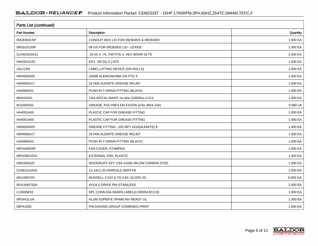
Page 5 of 11
Product Information Packet: CEM2333T - 15HP,1765RPM,3PH,60HZ,254TC,0944M,TEFC,F
Parts List (continued)
Part Number Description Quantity
09CB3501SP CONDUIT BOX LID FOR 09CB3001 & 09CB3002 1.000 EA
09GS1013SP 09 GS FOR 09CB3501 LID - LEXIDE 1.000 EA
51XW2520A12 .25-20 X .75, TAPTITE II, HEX WSHR SLTD 2.000 EA
HW2501G25 KEY, 3/8 SQ X 2.875 1.000 EA
LB1115N LABEL,LIFTING DEVICE (ON ROLLS) 1.000 EA
HW4500A05 1669B ALEM/UNIV860 GR FTG X 1.000 EA
HW4500A17 317400 ALEMITE GREASE RELIEF 1.000 EA
HA4066A01 PUSH IN T-DRAIN FITTING (BLACK) 1.000 EA
MN416A01 TAG-INSTAL-MAINT no wire (1000/bx) 11/14 1.000 EA
MJ1000A02 GREASE, POLYREX EM EXXON (USe 4824-15A) 0.080 LB
HA4051A00 PLASTIC CAP FOR GREASE FITTING 1.000 EA
HA4051A00 PLASTIC CAP FOR GREASE FITTING 1.000 EA
HW4500A03 GREASE FITTING, .125 NPT 1610(ALEMITE) 8 1.000 EA
HW4500A17 317400 ALEMITE GREASE RELIEF 1.000 EA
HA4066A01 PUSH IN T-DRAIN FITTING (BLACK) 1.000 EA
09FH4000SP FAN COVER, STAMPED 1.000 EA
09FN3001D01 EXTERNAL FAN, PLASTIC 1.000 EA
HW2500A25 WOODRUFF KEY USA #1008 #BLOW CARBON STEE 1.000 EA
51XB1214A20 12-14X1.25 HXWSSLD SERTYB 1.000 EA
MG1000Y03 MUNSELL 2.53Y 6.70/ 4.60, GLOSS 20, 0.050 GA
85XU0407S04 4X1/4 U DRIVE PIN STAINLESS 2.000 EA
LC0005E02 SPL CONN.DIA./WARN.LABEL(LC0005/LB1119) 1.000 EA
NP3441LUA ALUM SUPER-E VPWM INV READY UL 1.000 EA
09PA1000 PACKAGING GROUP COMBINED PRINT 1.000 EA

Page 6 of 11
Product Information Packet: CEM2333T - 15HP,1765RPM,3PH,60HZ,254TC,0944M,TEFC,F
AC Induction Motor Performance DataRecord # 40347 - Typical performance - not guaranteed values
Winding: 09WGZ910-R001 Type: 0944M Enclosure: TEFC
Nameplate Data460 V, 60 Hz: High Voltage Connection
Rated Output (HP) 15 Full Load Torque 44.5 LB-FT
Volts 230/460 Start Configuration direct on line
Full Load Amps 36.2/18.1 Breakdown Torque 153 LB-FT
R.P.M. 1765 Pull-up Torque 69.5 LB-FT
Hz 60 Phase 3 Locked-rotor Torque 86.5 LB-FT
NEMA Design Code A KVA Code H Starting Current 127 A
Service Factor (S.F.) 1.15 No-load Current 7.56 A
NEMA Nom. Eff. 92.4 Power Factor 83 Lineline Res. @ 25ºC 0.59555 Ω
Rating - Duty 40C AMB-CONT Temp. Rise @ Rated Load 54°C
S.F. Amps Temp. Rise @ S.F. Load 67°C
Locked-rotor Power Factor 33.1
Rotor inertia 1.92 LB-FT2
Load Characteristics 460 V, 60 Hz, 15 HP
% of Rated Load 25 50 75 100 125 150 S.F.
Power Factor 45 69 79 83 85 87 84
Efficiency 88.2 92.2 92.7 92.4 91.5 90.4 91.9
Speed 1791.3 1783.1 1774 1765.2 1754.6 1743.1 1759
Line amperes 8.62 11 14.5 18.1 22.6 26.9 20.8

Page 7 of 11
Product Information Packet: CEM2333T - 15HP,1765RPM,3PH,60HZ,254TC,0944M,TEFC,F
Performance Graph at 460V, 60Hz, 15.0HP Typical performance - Not guaranteed values

Page 8 of 11
Product Information Packet: CEM2333T - 15HP,1765RPM,3PH,60HZ,254TC,0944M,TEFC,F

Page 9 of 11
Product Information Packet: CEM2333T - 15HP,1765RPM,3PH,60HZ,254TC,0944M,TEFC,F

ELECTRIC MOTORS Maintenance & Installation

Integral HorsepowerAC Induction Motors
ODP, WPI, WPII EnclosureTEFC EnclosureExplosion Proof
Installation & Operating Manual
2/07 MN400

Table of Contents
Table of Contents iMN400
Section 1General Information 1‐1. . . . . . . . . . . . . . . . . . . . . . . . . . . . . . . . . . . . . . . . . . . . . . . . . . . . . . . . . . . . . . . . . . . . . . . . . . . . . .
Overview 1‐1. . . . . . . . . . . . . . . . . . . . . . . . . . . . . . . . . . . . . . . . . . . . . . . . . . . . . . . . . . . . . . . . . . . . . . . . . . . . . . . . . . . .
Limited Warranty 1‐1. . . . . . . . . . . . . . . . . . . . . . . . . . . . . . . . . . . . . . . . . . . . . . . . . . . . . . . . . . . . . . . . . . . . . . . . . . . . . .
Safety Notice 1‐2. . . . . . . . . . . . . . . . . . . . . . . . . . . . . . . . . . . . . . . . . . . . . . . . . . . . . . . . . . . . . . . . . . . . . . . . . . . . . . . . .
Receiving 1‐4. . . . . . . . . . . . . . . . . . . . . . . . . . . . . . . . . . . . . . . . . . . . . . . . . . . . . . . . . . . . . . . . . . . . . . . . . . . . . . . . . . . .
Storage 1‐4. . . . . . . . . . . . . . . . . . . . . . . . . . . . . . . . . . . . . . . . . . . . . . . . . . . . . . . . . . . . . . . . . . . . . . . . . . . . . . . . . . . . . .
Unpacking 1‐4. . . . . . . . . . . . . . . . . . . . . . . . . . . . . . . . . . . . . . . . . . . . . . . . . . . . . . . . . . . . . . . . . . . . . . . . . . . . . . . . . . .
Handling 1‐4. . . . . . . . . . . . . . . . . . . . . . . . . . . . . . . . . . . . . . . . . . . . . . . . . . . . . . . . . . . . . . . . . . . . . . . . . . . . . . . . . . . . .
Section 2Installation & Operation 2‐1. . . . . . . . . . . . . . . . . . . . . . . . . . . . . . . . . . . . . . . . . . . . . . . . . . . . . . . . . . . . . . . . . . . . . . . . . . .
Overview 2‐1. . . . . . . . . . . . . . . . . . . . . . . . . . . . . . . . . . . . . . . . . . . . . . . . . . . . . . . . . . . . . . . . . . . . . . . . . . . . . . . . . . . .
Location 2‐1. . . . . . . . . . . . . . . . . . . . . . . . . . . . . . . . . . . . . . . . . . . . . . . . . . . . . . . . . . . . . . . . . . . . . . . . . . . . . . . . . . . . .
Mounting 2‐1. . . . . . . . . . . . . . . . . . . . . . . . . . . . . . . . . . . . . . . . . . . . . . . . . . . . . . . . . . . . . . . . . . . . . . . . . . . . . . . . . . . . .
Alignment 2‐1. . . . . . . . . . . . . . . . . . . . . . . . . . . . . . . . . . . . . . . . . . . . . . . . . . . . . . . . . . . . . . . . . . . . . . . . . . . . . . . . . . . .
Doweling & Bolting 2‐2. . . . . . . . . . . . . . . . . . . . . . . . . . . . . . . . . . . . . . . . . . . . . . . . . . . . . . . . . . . . . . . . . . . . . . . . . . . .
Power Connection 2‐2. . . . . . . . . . . . . . . . . . . . . . . . . . . . . . . . . . . . . . . . . . . . . . . . . . . . . . . . . . . . . . . . . . . . . . . . . . . . .
Conduit Box 2‐2. . . . . . . . . . . . . . . . . . . . . . . . . . . . . . . . . . . . . . . . . . . . . . . . . . . . . . . . . . . . . . . . . . . . . . . . . . . . . .
AC Power 2‐2. . . . . . . . . . . . . . . . . . . . . . . . . . . . . . . . . . . . . . . . . . . . . . . . . . . . . . . . . . . . . . . . . . . . . . . . . . . . . . . .
First Time Start Up 2‐4. . . . . . . . . . . . . . . . . . . . . . . . . . . . . . . . . . . . . . . . . . . . . . . . . . . . . . . . . . . . . . . . . . . . . . . . . . . .
Coupled Start Up 2‐4. . . . . . . . . . . . . . . . . . . . . . . . . . . . . . . . . . . . . . . . . . . . . . . . . . . . . . . . . . . . . . . . . . . . . . . . . . . . . .
Jogging and Repeated Starts 2‐4. . . . . . . . . . . . . . . . . . . . . . . . . . . . . . . . . . . . . . . . . . . . . . . . . . . . . . . . . . . . . . . . . . .
Section 3Maintenance & Troubleshooting 3‐1. . . . . . . . . . . . . . . . . . . . . . . . . . . . . . . . . . . . . . . . . . . . . . . . . . . . . . . . . . . . . . . . . . .
General Inspection 3‐1. . . . . . . . . . . . . . . . . . . . . . . . . . . . . . . . . . . . . . . . . . . . . . . . . . . . . . . . . . . . . . . . . . . . . . . . . . . .
Lubrication & Bearings 3‐1. . . . . . . . . . . . . . . . . . . . . . . . . . . . . . . . . . . . . . . . . . . . . . . . . . . . . . . . . . . . . . . . . . . . . . . . .
Type of Grease 3‐1. . . . . . . . . . . . . . . . . . . . . . . . . . . . . . . . . . . . . . . . . . . . . . . . . . . . . . . . . . . . . . . . . . . . . . . . . . .
Relubrication Intervals 3‐1. . . . . . . . . . . . . . . . . . . . . . . . . . . . . . . . . . . . . . . . . . . . . . . . . . . . . . . . . . . . . . . . . . . . .
Relubrication Procedure 3‐3. . . . . . . . . . . . . . . . . . . . . . . . . . . . . . . . . . . . . . . . . . . . . . . . . . . . . . . . . . . . . . . . . . .
Accessories 3‐4. . . . . . . . . . . . . . . . . . . . . . . . . . . . . . . . . . . . . . . . . . . . . . . . . . . . . . . . . . . . . . . . . . . . . . . . . . . . . . . . . .
Troubleshooting Chart 3‐5. . . . . . . . . . . . . . . . . . . . . . . . . . . . . . . . . . . . . . . . . . . . . . . . . . . . . . . . . . . . . . . . . . . . . . . . .

Section 1General Information
General Information 1‐1MN400
Overview This manual contains general procedures that apply to Baldor Motor products. Be sure to read andunderstand the Safety Notice statements in this manual. For your protection, do not install, operate orattempt to perform maintenance procedures until you understand the Warning and Caution statements. AWarning statement indicates a possible unsafe condition that can cause harm to personnel. A Cautionstatement indicates a condition that can cause damage to equipment.
Important: This instruction manual is not intended to include a comprehensive listing of all details for allprocedures required for installation, operation and maintenance. This manual describes generalguidelines that apply to most of the motor products shipped by Baldor. If you have a questionabout a procedure or are uncertain about any detail, Do Not Proceed. Please contact your Baldordistributor for more information or clarification.
Before you install, operate or perform maintenance, become familiar with the following:� NEMA Publication MG‐2, Safety Standard for Construction and guide
for Selection, Installation and Use of Electric Motors and Generators.� The National Electrical Code� Local codes and Practices
Limited Warranty
1. Most Baldor products are warranted for 18 months from the date of shipment to Baldor's customer from Baldor'sdistrict warehouse or, if applicable, from Baldor's factory. Baldor Standard-E® standard efficient motors arewarranted for 24 months. Standard-E is limited to three phase, general purpose, 1-200 HP ratings that fall underthe Energy Policy Act (EPAct). Baldor Super-E® premium efficient motors are warranted for 36 months. BaldorIEEE841 motors are warranted for 60 months. All warranty claims must be submitted to a Baldor Service Centerprior to the expiration of the warranty period.
2. Baldor will, at its option repair or replace a motor which fails due to defects in material or workmanship during thewarranty period if:
a. the purchaser presents the defective motor at or ships it prepaid to, the Baldor plant in Fort Smith, Arkansasor one of the Baldor Authorized Service Centers and
b. the purchaser gives written notification concerning the motor and the claimed defect including the datepurchased, the task performed by the Baldor motor and the problem encountered.
3. Baldor will not pay the cost of removal of any electric motor from any equipment, the cost of delivery to Fort Smith,Arkansas or a Baldor Authorized Service Center, or the cost of any incidental or consequential damages resultingfrom the claimed defects. (Some states do not allow the exclusion or limitation of incidental or consequentialdamages, so the above exclusion may not apply to you.) Any implied warranty given by laws shall be limited tothe duration of the warranty period hereunder. (Some states do not allow limitations on how long an impliedwarranty lasts, so the above limitation may not apply to you.)
4. Baldor Authorized Service Centers, when convinced to their satisfaction that a Baldor motor developed defects inmaterial or workmanship within the warranty period, are authorized to proceed with the required repairs to fulfillBaldor's warranty when the cost of such repairs to be paid by Baldor does not exceed Baldor's warranty repairallowance. Baldor will not pay overtime premium repair charges without prior written authorization.
5. The cost of warranty repairs made by centers other than Baldor Authorized Service Centers WILL NOT be paidunless first authorized in writing by Baldor.
6. Claims by a purchaser that a motor is defective even when a failure results within one hour after being placed intoservice are not always justified. Therefore, Baldor Authorized Service Centers must determine from the conditionof the motor as delivered to the center whether or not the motor is defective. If in the opinion of a BaldorAuthorized Service Center, a motor did not fail as a result of defects in material or workmanship, the center is toproceed with repairs only if the purchaser agrees to pay for such repairs. If the decision is in dispute, thepurchaser should still pay for the repairs and submit the paid invoice and the Authorized Service Center's signedservice report to Baldor for further consideration.
7. This warranty gives you specific legal rights, and you may also have other rights which vary from state to state.

1‐2 General Information MN400
Safety Notice: This equipment contains high voltage! Electrical shock can cause serious or fatal injury.Only qualified personnel should attempt installation, operation and maintenance ofelectrical equipment.
Be sure that you are completely familiar with NEMA publication MG‐2, safety standardsfor construction and guide for selection, installation and use of electric motors andgenerators, the National Electrical Code and local codes and practices. Unsafeinstallation or use can cause conditions that lead to serious or fatal injury. Only qualifiedpersonnel should attempt the installation, operation and maintenance of this equipment.
WARNING: Do not touch electrical connections before you first ensure thatpower has been disconnected. Electrical shock can cause seriousor fatal injury. Only qualified personnel should attempt theinstallation, operation and maintenance of this equipment.
WARNING: Be sure the system is properly grounded before applying power.Do not apply AC power before you ensure that all groundinginstructions have been followed. Electrical shock can causeserious or fatal injury. National Electrical Code and Local codesmust be carefully followed.
WARNING: Avoid extended exposure to machinery with high noise levels. Besure to wear ear protective devices to reduce harmful effects toyour hearing.
WARNING: This equipment may be connected to other machinery that hasrotating parts or parts that are driven by this equipment. Improperuse can cause serious or fatal injury. Only qualified personnelshould attempt to install operate or maintain this equipment.
WARNING: Do not by‐pass or disable protective devices or safety guards.Safety features are designed to prevent damage to personnel orequipment. These devices can only provide protection if theyremain operative.
WARNING: Avoid the use of automatic reset devices if the automatic restartingof equipment can be hazardous to personnel or equipment.
WARNING: Be sure the load is properly coupled to the motor shaft beforeapplying power. The shaft key must be fully captive by the loaddevice. Improper coupling can cause harm to personnel orequipment if the load decouples from the shaft during operation.
WARNING: Use proper care and procedures that are safe during handling,lifting, installing, operating and maintaining operations. Improper methods may cause muscle strain or other harm.
WARNING: Before performing any motor maintenance procedure, be sure thatthe equipment connected to the motor shaft cannot cause shaftrotation. If the load can cause shaft rotation, disconnect the loadfrom the motor shaft before maintenance is performed. Unexpectedmechanical rotation of the motor parts can cause injury or motordamage.
WARNING: Disconnect all electrical power from the motor windings andaccessory devices before disassembly of the motor. Electricalshock can cause serious or fatal injury.
WARNING: Do not use non UL/CSA listed explosion proof motors in thepresence of flammable or combustible vapors or dust. Thesemotors are not designed for atmospheric conditions that requireexplosion proof operation.

Section 1General Information
General Information 1‐3MN400
Safety Notice Continued
WARNING: Motors that are to be used in flammable and/or explosiveatmospheres must display the UL label on the nameplate along withCSA listed logo.
Specific service conditions for these motors are defined in NFPA 70 (NEC) Article 500.
WARNING: UL Listed motors must only be serviced by UL ApprovedAuthorized Baldor Service Centers if these motors are to bereturned to a hazardous and/or explosive atmosphere.
Caution: To prevent premature equipment failure or damage, only qualifiedmaintenance personnel should perform maintenance.
Caution: Do not over-lubricate motor as this may cause premature bearingfailure.
Caution: Do not lift the motor and its driven load by the motor liftinghardware. The motor lifting hardware is adequate for lifting only themotor. Disconnect the load from the motor shaft before moving themotor.
Caution: If eye bolts are used for lifting a motor, be sure they are securelytightened. The lifting direction should not exceed a 20° angle fromthe shank of the eye bolt or lifting lug. Excessive lifting angles cancause damage.
Caution: To prevent equipment damage, be sure that the electrical service isnot capable of delivering more than the maximum motor rated ampslisted on the rating plate.
Caution: If a HI POT test (High Potential Insulation test) must be performed,follow the precautions and procedure in NEMA MG1 and MG2standards to avoid equipment damage.
If you have any questions or are uncertain about any statement or procedure, or if yourequire additional information please contact your Baldor distributor or an AuthorizedBaldor Service Center.

Section 1General Information
1‐4 General Information MN400
Receiving Each Baldor Electric Motor is thoroughly tested at the factory and carefully packaged forshipment. When you receive your motor, there are several things you should doimmediately.
1. Observe the condition of the shipping container and report any damageimmediately to the commercial carrier that delivered your motor.
2. Verify that the part number of the motor you received is the same as the partnumber listed on your purchase order.
Storage If the motor is not put into service immediately, the motor must be stored in a clean, dryand warm location. Several precautionary steps must be performed to avoid motordamage during storage.
1. Use a “Megger” periodically to ensure that the integrity of the winding insulationhas been maintained. Record the Megger readings. Immediately investigateany significant drop in insulation resistance.
2. Do not lubricate bearings during storage. Motor bearings are packed withgrease at the factory. Excessive grease can damage insulation quality.
3. Rotate motor shaft at least 10 turns every two months during storage (morefrequently if possible). This will prevent bearing damage due to storage.
4. If the storage location is damp or humid, the motor windings must be protectedfrom moisture. This can be done by applying power to the motors' spaceheater (if available) while the motor is in storage.
Unpacking Each Baldor motor is packaged for ease of handling and to prevent entry ofcontaminants.
1. To avoid condensation inside the motor, do not unpack until the motor hasreached room temperature. (Room temperature is the temperature of the roomin which it will be installed). The packing provides insulation from temperaturechanges during transportation.
2. When the motor has reached room temperature, remove all protective wrappingmaterial from the motor.
Handling The motor should be lifted using the lifting lugs or eye bolts provided.
1. Use the lugs or eye bolts provided to lift the motor. Never attempt to lift themotor and additional equipment connected to the motor by this method. Thelugs or eye bolts provided are designed to lift only the motor. Never lift themotor by the motor shaft or the hood of a WPII motor.
2. When lifting a WPII (Weather Proof Type 2) motor, do not lift the motor byinserting lifting lugs into holes on top of the cooling hood. These lugs are to beused for hood removal only. A spreader bar should be used to lift the motor bythe cast lifting lugs located on the motor frame.
3. If the motor must be mounted to a plate with the driven equipment such aspump, compressor etc., it may not be possible to lift the motor alone. For thiscase, the assembly should be lifted by a sling around the mounting base. Theentire assembly can be lifted as an assembly for installation. Do not lift usingthe motor lugs or eye bolts provided.
If the load is unbalanced (as with couplings or additional attachments)additional slings or other means must be used to prevent tipping. In any event,the load must be secure before lifting.

Section 2Installation & Operation
Installation & Operation 2‐1MN400
Overview Installation should conform to the National Electrical Code as well as local codes andpractices. When other devices are coupled to the motor shaft, be sure to install protectivedevices to prevent future accidents. Some protective devices include, coupling, beltguard, chain guard, shaft covers etc. These protect against accidental contact withmoving parts. Machinery that is accessible to personnel should provide further protectionin the form of guard rails, screening, warning signs etc.
Location It is important that motors be installed in locations that are compatible with motorenclosure and ambient conditions. Improper selection of the motor enclosure andambient conditions can lead to reduced operating life of the motor.
Proper ventilation for the motor must be provided. Obstructed airflow can lead toreduction of motor life.
1. Open Drip-Proof/WPI motors are intended for use indoors where atmosphere isrelatively clean, dry, well ventilated and non-corrosive.
2. Totally Enclosed and WPII motors may be installed where dirt, moisture or dust arepresent and in outdoor locations.
Severe Duty, IEEE 841 and Washdown Duty enclosed motors are designed forinstallations with high corrosion or excessive moisture conditions. These motors shouldnot be placed into an environment where there is the presence of flammable orcombustible vapors, dust or any combustible material, unless specifically designed forthis type of service.
Mounting The motor must be securely installed to a rigid foundation or mounting surface tominimize vibration and maintain alignment between the motor and shaft load. Failure toprovide a proper mounting surface may cause vibration, misalignment and bearingdamage.
Foundation caps and sole plates are designed to act as spacers for the equipment theysupport. If these devices are used, be sure that they are evenly supported by thefoundation or mounting surface.
After installation is complete and accurate alignment of the motor and load isaccomplished, the base should be grouted to the foundation to maintain this alignment.
The standard motor base is designed for horizontal or vertical mounting. Adjustable orsliding rails are designed for horizontal mounting only. Consult your Baldor distributor orauthorized Baldor Service Center for further information.
Alignment Accurate alignment of the motor with the driven equipment is extremely important.
1. Direct CouplingFor direct drive, use flexible couplings if possible. Consult the drive or equipmentmanufacturer for more information. Mechanical vibration and roughness duringoperation may indicate poor alignment. Use dial indicators to check alignment. Thespace between coupling hubs should be maintained as recommended by thecoupling manufacturer.
2. End‐Play AdjustmentThe axial position of the motor frame with respect to its load is also extremelyimportant. The motor bearings are not designed for excessive external axial thrustloads. Improper adjustment will cause failure.
3. Pulley RatioThe pulley ratio should not exceed 8:1.
4. Belt DriveAlign sheaves carefully to minimize belt wear and axial bearing loads (see End‐PlayAdjustment). Belt tension should be sufficient to prevent belt slippage at rated speedand load. However, belt slippage may occur during starting.
Caution: Do not over tension belts.
5. Sleeve bearing motors are only suitable for coupled loads.

Section 1General Information
2‐2 Installation & Operation MN400
Doweling & Bolting After proper alignment is verified, dowel pins should be inserted through the motor feetinto the foundation. This will maintain the correct motor position should motor removal berequired. (Baldor motors are designed for doweling.)
1. Drill dowel holes in diagonally opposite motor feet in the locations provided.
2. Drill corresponding holes in the foundation.
3. Ream all holes.
4. Install proper fitting dowels.
5. Mounting bolts must be carefully tightened to prevent changes in alignment. Use aflat washer and lock washer under each nut or bolt head to hold the motor feetsecure. Flanged nuts or bolts may be used as an alternative to washers.
Power Connection Motor and control wiring, overload protection, disconnects, accessories and groundingshould conform to the National Electrical Code and local codes and practices.
Conduit Box For ease of making connections, an oversize conduit box is provided. The box can berotated 360° in 90° increments. Auxiliary conduit boxes are provided on some motors foraccessories such as space heaters, RTD's etc.
AC Power Connect the motor leads as shown on the connection diagram located on the name plateor inside the cover on the conduit box. Be sure the following guidelines are met:
1. AC power is within ±10% of rated voltage with rated frequency. (See motor nameplate for ratings). OR
2. AC power is within ±5% of rated frequency with rated voltage. OR
3. A combined variation in voltage and frequency of ±10% (sum of absolute values) ofrated values, provided the frequency variation does not exceed ±5% of ratedfrequency.
Performance within these voltage and frequency variations are shown in Figure 2‐2.
Figure 2‐1 Accessory Connections
One heater is installed in each end of motor. Leads for each heater are labeled H1 & H2. (Like numbers should be tied together).
Three thermisters are installed in windings and tied in series.Leads are labeled T1 & T2.
Winding RTDs are installed in windings (2) per phase. Each set of leads is labeled W1, W2, W3, W4, W5, & W6.
* One bearing RTD is installed in Drive endplate (PUEP), leads are labeled RTDDE.
* One bearing RTD is installed in Opposite Drive endplate (FREP), leads are labeled RTDODE.
* Note RTD may have 2-Red/1-White leads; or 2-White/1-Red Lead.

Section 1General Information
Installation & Operation 2‐3MN400
Figure 2‐2 Typical Motor Performance VS Voltage Variations+20
+15
+10
+5
0
-5
-10
-15
-20-15 -10 -5 0 +5 +10 +15
Voltage Variations (%)
Ch
ang
es in
Mo
tor
Per
form
ance
(%
)Full ‐LoadCurrent
Full ‐LoadCurrentPower
Factor
PowerFactor
Efficiency Efficiency
MaximumTorque
MaximumTorque

Section 1General Information
2‐4 Installation & Operation MN400
First Time Start Up Be sure that all power to motor and accessories is off. Be sure the motor shaft isdisconnected from the load and will not cause mechanical rotation of the motor shaft.
1. Make sure that the mechanical installation is secure. All bolts and nuts are tightenedetc.
2. If motor has been in storage or idle for some time, check winding insulation integritywith a Megger.
3. Inspect all electrical connections for proper termination, clearance, mechanicalstrength and electrical continuity.
4. Be sure all shipping materials and braces (if used) are removed from motor shaft.
5. Manually rotate the motor shaft to ensure that it rotates freely.
6. Replace all panels and covers that were removed during installation.
7. Momentarily apply power and check the direction of rotation of the motor shaft.
8. If motor rotation is wrong, be sure power is off and change the motor leadconnections. Verify rotation direction before you continue.
9. Start the motor and ensure operation is smooth without excessive vibration or noise.If so, run the motor for 1 hour with no load connected.
10. After 1 hour of operation, disconnect power and connect the load to the motor shaft.Verify all coupling guards and protective devices are installed. Ensure motor isproperly ventilated.
Coupled Start Up This procedure assumes a coupled start up. Also, that the first time start up procedurewas successful.
1. Check the coupling and ensure that all guards and protective devices are installed.
2. Check that the coupling is properly aligned and not binding.
3. The first coupled start up should be with no load. Apply power and verify that theload is not transmitting excessive vibration back to the motor though the coupling orthe foundation. Vibration should be at an acceptable level.
4. Run for approximately 1 hour with the driven equipment in an unloaded condition.
The equipment can now be loaded and operated within specified limits. Do not exceedthe name plate ratings for amperes for steady continuous loads.
Jogging and Repeated Starts Repeated starts and/or jogs of induction motors generally reduce the life of the motorwinding insulation. A much greater amount of heat is produced by each acceleration orjog than by the same motor under full load. If it is necessary to repeatedly start or jog themotor, it is advisable to check the application with your local Baldor distributor or BaldorService Center.
Heating ‐ Duty rating and maximum ambient temperature are stated on the motor nameplate. Do not exceed these values. If there is any question regarding safe operation,contact your local Baldor distributor or Baldor Service Center.

Section 3Maintenance & Troubleshooting
Maintenance & Troubleshooting 3‐1MN400
WARNING: UL Listed motors must only be serviced by UL ApprovedAuthorized Baldor Service Centers if these motors are to bereturned to a hazardous and/or explosive atmosphere.
General Inspection Inspect the motor at regular intervals, approximately every 500 hours of operation orevery 3 months, whichever occurs first. Keep the motor clean and the ventilationopenings clear. The following steps should be performed at each inspection:
WARNING: Do not touch electrical connections before you first ensure thatpower has been disconnected. Electrical shock can cause seriousor fatal injury. Only qualified personnel should attempt theinstallation, operation and maintenance of this equipment.
1. Check that the motor is clean. Check that the interior and exterior of the motoris free of dirt, oil, grease, water, etc. Oily vapor, paper pulp, textile lint, etc. canaccumulate and block motor ventilation. If the motor is not properly ventilated,overheating can occur and cause early motor failure.
2. Use a “Megger” periodically to ensure that the integrity of the windinginsulation has been maintained. Record the Megger readings. Immediatelyinvestigate any significant drop in insulation resistance.
3. Check all electrical connectors to be sure that they are tight.
Relubrication & Bearings Bearing grease will lose its lubricating ability over time, not suddenly. The lubricatingability of a grease (over time) depends primarily on the type of grease, the size of thebearing, the speed at which the bearing operates and the severity of the operatingconditions. Good results can be obtained if the following recommendations are used inyour maintenance program.
Type of Grease A high grade ball or roller bearing grease should be used. Recommended grease forstandard service conditions is Polyrex EM (Exxon Mobil).
Equivalent and compatible greases include:Texaco Polystar, Rykon Premium #2, Pennzoil Pen 2 Lube and Chevron SRI.
Relubrication Intervals Recommended relubrication intervals are shown in Table 3‐1. It is important to realizethat the recommended intervals of Table 3‐1 are based on average use.
Refer to additional information contained in Tables 3‐2, 3‐3 and 3‐4.
Table 3‐1 Relubrication Intervals *
NEMA / (IEC) Frame SizeRated Speed ‐ RPM
10000 6000 3600 1800 1200 900Up to 210 incl. (132) ** 2700 Hrs. 5500 Hrs. 12000 Hrs. 18000 Hrs. 22000 Hrs.Over 210 to 280 incl. (180) ** 3600 Hrs. 9500 Hrs. 15000 Hrs. 18000 Hrs.Over 280 to 360 incl. (225) ** * 2200 Hrs. 7400 Hrs. 12000 Hrs. 15000 Hrs.Over 360 to 5800 incl. (300) ** *2200 Hrs. 3500 Hrs. 7400 Hrs. 10500 Hrs.
* Relubrication intervals are for ball bearings. For vertically mounted motors and roller bearings, divide the relubrication interval by 2.
** For motors operating at speeds greater than 3600 RPM, contact Baldor for relubrication recommendations.

3‐2 Maintenance & Troubleshooting MN400
Table 3‐2 Service Conditions
Severity of Service Hours per dayof Operation
Ambient TemperatureMaximum
AtmosphericContamination
Standard 8 40° C Clean, Little CorrosionSevere 16 Plus 50° C Moderate dirt, CorrosionExtreme 16 Plus >50° C* or
Class H InsulationSevere dirt, Abrasive dust, Corrosion, Heavy
Shock or VibrationLow Temperature <-29 ° C **
* Special high temperature grease is recommended (Dow Corning DC44). Note that Dow Corning DC44 grease doesnot mix with other grease types. Thoroughly clean bearing & cavity before adding grease.
** Special low temperature grease is recommended (Aeroshell 7).
Table 3‐3 Relubrication Interval Multiplier
Severity of Service MultiplierStandard 1.0Severe 0.5Extreme 0.1
Low Temperature 1.0
Some motor designs use different bearings on each motor end. This is normally indicated on the motor nameplate. In this case, the larger bearing is installed on the motor Drive endplate. For best relubrication results, only use theappropriate amount of grease for each bearing size (not the same for both).
Table 3‐4 Bearings Sizes and Types
Frame SizeNEMA (IEC)
Bearing Description(These are the “Large” bearings (Shaft End) in each frame size)
BearingWeight of Grease to
add *oz (Grams)
Volume of greaseto be added
in3 teaspoon56 to 140 (90) 6203 0.08 (2.4) 0.15 0.5
140 (90) 6205 0.15 (3.9) 0.2 0.8180 (100-112) 6206 0.19 (5.0) 0.3 1.0
210 (132) 6307 0.30 (8.4) 0.6 2.0250 (160) 6309 0.47 (12.5) 0.7 2.5280 (180) 6311 0.61 (17) 1.2 3.9320 (200) 6312 0.76 (20.1) 1.2 4.0360 (225) 6313 0.81 (23) 1.5 5.2400 (250) 6316 1.25 (33) 2.0 6.6440 (280) 6319 2.12 (60) 4.1 13.4
5000 to 5800 (315-450) 6328 4.70 (130) 9.2 30.05000 to 5800 (315-450) NU328 4.70 (130) 9.2 30.0360 to 449 (225-280) NU319 2.12 (60) 4.1 13.4
AC Induction Servo76 Frame 180 (112) 6207 0.22 (6.1) 0.44 1.477 Frame 210 (132) 6210 0.32 (9.0) 0.64 2.180 Frame 250(160) 6213 0.49 (14.0) 0.99 3.3
* Weight in grams = .005 DBof grease to be added
Note: Not all bearing sizes are listed. For intermediate bearing sizes, use thegrease volume for the next larger size bearing.

Maintenance & Troubleshooting 3‐3MN400
Caution: To avoid damage to motor bearings, grease must be kept free of dirt.For an extremely dirty environment, contact your Baldor distributor oran authorized Baldor Service Center for additional information.
Relubrication Procedure Be sure that the grease you are adding to the motor is compatible with the greasealready in the motor. Consult your Baldor distributor or an authorized service center if agrease other than the recommended type is to be used.
Caution: Do not over-lubricate motor as this may cause premature bearingfailure.
With Grease Outlet Plug
1. With the motor stopped, clean all grease fittings with a clean cloth.
2. Remove grease outlet plug.
Caution: Over-lubricating can cause excessive bearing temperatures,premature lubrication breakdown and bearing failure.
3. Add the recommended amount of grease.
4. Operate the motor for 15 minutes with grease plug removed. This allows excess grease to purge.
5. Re‐install grease outlet plug.
Without Grease Provisions
Note: Only a Baldor authorized and UL or CSA certified service center candisassemble a UL/CSA listed explosion proof motor to maintain it'sUL/CSA listing.
1. Disassemble the motor.
2. Add recommended amount of grease to bearing and bearing cavity. (Bearingshould be about 1/3 full of grease and outboard bearing cavity should be about1/2 full of grease.)
3. Assemble the motor.
Sample Relubrication Determination
Assume ‐ NEMA 286T (IEC 180), 1750 RPM motor driving an exhaust fan in an ambienttemperature of 43° C and the atmosphere is moderately corrosive.
1. Table 3‐1 list 9500 hours for standard conditions.
2. Table 3‐2 classifies severity of service as “Severe”.
3. Table 3‐4 shows that 1.2 in3 or 3.9 teaspoon of grease is to be added.
Note: Smaller bearings in size category may require reduced amounts of grease.

Section 1General Information
3‐4 Maintenance & Troubleshooting MN400
Table 3‐5 Troubleshooting Chart
Symptom Possible Causes Possible SolutionsMotor will not start Usually caused by line trouble, such
as, single phasing at the starter.Check source of power. Check overloads, fuses,controls, etc.
Excessive humming High Voltage. Check input line connections.Eccentric air gap. Have motor serviced at local Baldor service center.
Motor Over Heating Overload. Compare actual amps(measured) with nameplate rating.
Locate and remove source of excessive friction inmotor or load.Reduce load or replace with motor of greater capacity.
Single Phasing. Check current at all phases (should be approximatelyequal) to isolate and correct the problem.
Improper ventilation. Check external cooling fan to be sure air is movingproperly across cooling fins.Excessive dirt build‐up on motor. Clean motor.
Unbalanced voltage. Check voltage at all phases (should be approximatelyequal) to isolate and correct the problem.
Rotor rubbing on stator. Check air gap clearance and bearings.Tighten “Thru Bolts”.
Over voltage or under voltage. Check input voltage at each phase to motor.Open stator winding. Check stator resistance at all three phases for
balance.Grounded winding. Perform dielectric test and repair as required.Improper connections. Inspect all electrical connections for proper
termination, clearance, mechanical strength andelectrical continuity. Refer to motor lead connectiondiagram.
Bearing Over Heating Misalignment. Check and align motor and driven equipment.Excessive belt tension. Reduce belt tension to proper point for load.Excessive end thrust. Reduce the end thrust from driven machine.Excessive grease in bearing. Remove grease until cavity is approximately 3/4 filled.Insufficient grease in bearing. Add grease until cavity is approximately 3/4 filled.Dirt in bearing. Clean bearing cavity and bearing. Repack with correct
grease until cavity is approximately 3/4 filled.Vibration Misalignment. Check and align motor and driven equipment.
Rubbing between rotating parts andstationary parts.
Isolate and eliminate cause of rubbing.
Rotor out of balance. Have rotor balance checked are repaired at yourBaldor Service Center.
Resonance. Tune system or contact your Baldor Service Centerfor assistance.
Noise Foreign material in air gap orventilation openings.
Remove rotor and foreign material. Reinstall rotor.Check insulation integrity. Clean ventilation openings.
Growling or whining Bad bearing. Replace bearing. Clean all grease from cavity andnew bearing. Repack with correct grease until cavityis approximately 3/4 filled.

Maintenance & Troubleshooting 3‐5MN400
Suggested bearing and winding RTD setting guidelinesMost large frame AC Baldor motors with a 1.15 service factor are designed to operatebelow a Class B (80°C) temperature rise at rated load and are built with a Class Hwinding insulation system. Based on this low temperature rise, RTD (ResistanceTemperature Detectors) settings for Class B rise should be used as a starting point.Some motors with 1.0 service factor have Class F temperature rise.
The following tables show the suggested alarm and trip settings for RTDs. Properbearing and winding RTD alarm and trip settings should be selected based on thesetables unless otherwise specified for specific applications.
If the driven load is found to operate well below the initial temperature settings undernormal conditions, the alarm and trip settings may be reduced so that an abnormalmachine load will be identified.
The temperature limits are based on the installation of the winding RTDs imbedded inthe winding as specified by NEMA. Bearing RTDs should be installed so they are incontact with the outer race on ball or roller bearings or in direct contact with the sleevebearing shell.
Winding RTDs - Temperature Limit In �C (40�C Maximum Ambient)
Motor LoadClass B Temp Rise � 80°C
(Typical Design) Class F Temp Rise � 105°C Class H Temp Rise � 125°C
Alarm Trip Alarm Trip Alarm Trip� Rated Load 130 140 155 165 175 185Rated Load to 1.15 S.F.
140 150 160 165 180 185
Note: � Winding RTDs are factory production installed, not from Mod-Express.� When Class H temperatures are used, consider bearing temperatures and relubrication requirements.
Bearing RTDs - Temperature Limit In �C (40�C Maximum Ambient)
Bearing TypeOil or Grease
Anti-Friction SleeveAlarm Trip Alarm Trip
Standard* 95 100 85 95High Temperature** 110 115 105 110
Note: * Bearing temperature limits are for standard design motors operating at Class B temperature rise.** High temperature lubricants include some special synthetic oils and greases.
Greases that may be substituted that are compatible with Polyrex EM (but considered as“standard” lubricants) include the following: - Texaco Polystar - Rykon Premium #2 - Chevron SRI #2- Mobilith SHC-100 - Pennzoil Pennzlube EM-2 - Chevron Black Pearl- Darmex 707 - Darmex 711 - Petro-Canada Peerless LLG
See the motor nameplate for replacement grease or oil recommendation. Contact Baldor application engineering for special lubricants or further clarifications.

© Baldor Electric CompanyMN400
Printed in USA2/07
BALDOR ELECTRIC COMPANYWorld Headquarters
P.O. Box 2400 Fort Smith, AR 72901-2400(479) 646-4711 Fax (479) 648-5792
www.baldor.com