My Account - Wilson Tool
92
WILSON TOOL INTERNATIONAL WT-STYLE PRESS BRAKE TOOLING 2022 A v a i l a b l e 2 4 / 7 My Account by Wilson Tool International
-
Upload
khangminh22 -
Category
Documents
-
view
0 -
download
0
Transcript of My Account - Wilson Tool

WILSON TOOL INTERNATIONAL
W T- S T Y L EPRESS BRAKE TOOLING
2022
A
vailable 24/7
My Accountby Wilson Tool International

2 Visit wilsontool.com/MyAccount for 24/7 Online Access Quotes, Orders, Drawings, Invoices, Tracking Numbers & More!
TERMS AND CONDITIONS
ORDER Minimum order is $50.00
CREDIT REQUIREMENTS All orders are subject to approval by our Credit Department. If you are a new account, please furnish us with your tax exempt status, a bank reference, three current supplier references and/or your current D&B rating with your first order. A credit limit will be imposed on new accounts until credit has been established.
PAYMENT TERMS Terms are net 10 days. Catalog prices are subject to change without notice.
FREIGHT Orders are shipped F.O.B. from our manufacturing facility. (International Shipments are Incoterms: Ex Works).
ORDER CANCELLATION If an order is cancelled, an additional charge will be assessed to cover the cost of labor and material.
RETURNED MATERIAL A handling/restocking fee will be applied to all standard products returned for credit. A return authorization number and shipping instructions must be obtained in advance before an item can be returned.
CLAIMS All claims or product shortages must be made within 30 days of the invoice date.
CONNECT WITH WILSON TOOLKeep up with everything that’s new at Wilson Tool International! Visit our website or find us on LinkedIn and YouTube for the latest information, news, videos and product releases. Sign up to get our e-newsletters at wilsontool.com/signup.
Wilson Tool customers can now enjoy 24/7 access their account online! My Account features include:
• Online Ordering• Request Quotes• Access Drawings• View Invoices• Track Packages• View Order History
wilsontool.com/MyAccount
My Account
3US Headquarters tel: [email protected]
Canada tel: [email protected]
Mexico tel: [email protected]
TAB
LE OF C
ON
TENTS
WT-STYLE PRESS BRAKE TOOLING
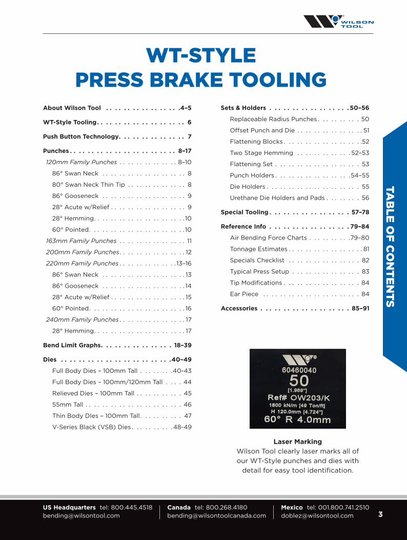
About Wilson Tool . . . . . . . . . . . . . . . . .4–5
WT-Style Tooling . . . . . . . . . . . . . . . . . . . . 6
Push Button Technology. . . . . . . . . . . . . . . 7
Punches . . . . . . . . . . . . . . . . . . . . . . . . 8–17
120mm Family Punches . . . . . . . . . . . . . . 8–10
86° Swan Neck . . . . . . . . . . . . . . . . . . . . 8
80° Swan Neck Thin Tip . . . . . . . . . . . . . . 8
86° Gooseneck . . . . . . . . . . . . . . . . . . . . 9
28° Acute w/Relief . . . . . . . . . . . . . . . . . . 9
28° Hemming . . . . . . . . . . . . . . . . . . . . . . 10
60° Pointed . . . . . . . . . . . . . . . . . . . . . . . 10
163mm Family Punches . . . . . . . . . . . . . . . . 11
200mm Family Punches . . . . . . . . . . . . . . . . 12
220mm Family Punches . . . . . . . . . . . . . . 13–16
86° Swan Neck . . . . . . . . . . . . . . . . . . . . 13
86° Gooseneck . . . . . . . . . . . . . . . . . . . . 14
28° Acute w/Relief . . . . . . . . . . . . . . . . . . 15
60° Pointed . . . . . . . . . . . . . . . . . . . . . . . 16
240mm Family Punches . . . . . . . . . . . . . . . . 17
28° Hemming . . . . . . . . . . . . . . . . . . . . . . 17
Bend Limit Graphs. . . . . . . . . . . . . . . . 18–39
Dies . . . . . . . . . . . . . . . . . . . . . . . . .40–49
Full Body Dies – 100mm Tall . . . . . . . .40-43
Full Body Dies – 100mm/120mm Tall . . . . 44
Relieved Dies – 100mm Tall . . . . . . . . . . . 45
55mm Tall . . . . . . . . . . . . . . . . . . . . . . . 46
Thin Body DIes – 100mm Tall . . . . . . . . . . 47
V-Series Black (VSB) Dies . . . . . . . . . .48-49
Sets & Holders . . . . . . . . . . . . . . . . . . 50–56
Replaceable Radius Punches . . . . . . . . . . 50
Offset Punch and Die . . . . . . . . . . . . . . . . 51
Flattening Blocks . . . . . . . . . . . . . . . . . . .52
Two Stage Hemming . . . . . . . . . . . . . 52–53
Flattening Set . . . . . . . . . . . . . . . . . . . . 53
Punch Holders . . . . . . . . . . . . . . . . . .54–55
Die Holders . . . . . . . . . . . . . . . . . . . . . . 55
Urethane Die Holders and Pads . . . . . . . . 56
Special Tooling . . . . . . . . . . . . . . . . . . 57–78
Reference Info . . . . . . . . . . . . . . . . . . 79–84
Air Bending Force Charts . . . . . . . . . .79–80
Tonnage Estimates . . . . . . . . . . . . . . . . . . 81
Specials Checklist . . . . . . . . . . . . . . . . . 82
Typical Press Setup . . . . . . . . . . . . . . . . 83
Tip Modifications . . . . . . . . . . . . . . . . . . 84
Ear Piece . . . . . . . . . . . . . . . . . . . . . . . 84
Accessories . . . . . . . . . . . . . . . . . . . . 85–91
Laser Marking
Wilson Tool clearly laser marks all of our WT-Style punches and dies with
detail for easy tool identification .

4 Visit wilsontool.com/MyAccount for 24/7 Online Access Quotes, Orders, Drawings, Invoices, Tracking Numbers & More!
WILSON TOOL INTERNATIONAL
From humble beginnings in a small manufacturing facility in St. Paul, Minnesota, Wilson Tool International has added innovation, tooling divisions, manufacturing facilities and sales channels around the world to better serve thousands of global customers. Throughout our expansion, our mission has never wavered — we continue to offer products and services that help you, our customers, to be more successful.
Innovation is key at Wilson Tool International. It’s true what they say: no two jobs are the same. In manufacturing, change is the only constant. So working with a press brake tooling supplier that’s flexible, nimble and knowledgeable is important.
Wilson Tool International continues to invest in your success. We now have more than 50 sales engineers nationwide who are available to answer questions, proactively suggest innovative solutions to save you time and money, and keep you up and running. That’s more than all of our North American competitors combined.
Leverage our sales engineers. Challenge them with a problem. Put their knowledge to work for you. You can connect with them in person, by phone and through e-mail.
And be assured, with every order, you’ll always get our quality guarantee: Your success is our priority. If you’re ever unsatisfied with a Wilson Tool International product, we’ll do everything we can to make it right and keep you up and running.
From all of us at Wilson Tool International, thank you for the trust you have placed in us to provide you with the products and services that support your business. We look forward to our partnership in the future.
Sincerely, Brian Robinson CEO, Wilson Enterprises

5US Headquarters tel: [email protected]
Canada tel: [email protected]
Mexico tel: [email protected]
BENDING
Wilson Tool’s Bending division
delivers the most complete line
of tooling and clamping
solutions available anywhere.
Whether you use American,
European, WT or LVD-style
precision or conventional tooling,
Wilson Tool has a solution for
you. Our clamping options
cover these styles as well.
With hydraulic push button,
quick release mechanical or
standard manual clamps, we
have a clamping solution for
any style of machine or budget.
And our custom tooling
manufacturing capabilities are
the envy of the industry with
innovative solutions for
complex bending challenges.
With manufacturing facilities
located
in the
USA and
Canada,
our delivery
times to
North American
fabricators are
the fastest in
the industry.
PUNCHING
Wilson Tool’s Punching division
continues to drive the industry
with new levels of quality,
delivery, service and innovation.
From the early days of Series 80
to the Wilson Wheel® Family to
EXP® technology, our punching
division has been the industry-
leading innovation driver.
Combined with the most
experienced customer support
professionals in the industry,
Wilson Tool continues to raise the
bar. Thick turret, TRUMPF-style,
Salvagnini-style, or any other
style of punch press you may
be using, Wilson Tool offers the
most complete line of tooling
solutions available today.
TRUMPF is a trademark of TRUMPF GmbH + Co. KG.
STAMPING
Wilson Tool’s Stamping division,
Impax Tooling Solutions®,
offers high quality punch
and die components,
accessories and retainers
for the stamping industry.
Innovative products such as our
HP Accu-Lock® Retainer Inserts
and extensive coating options,
combined with our world-class
customer service, have enabled
us to quickly grow into a world-
class provider. With a direct
sales force throughout North
America, we deliver products
straight from the factory to you,
enabling the fastest deliveries
in the industry. Our custom
tooling expertise is second to
none with many customers
coming to us for their most
difficult stamping challenges.
TABLETING
Wilson Tool’s Tableting division
delivers standard and custom
tooling for superior production
capability by utilizing the latest
innovations in tableting science.
Wilson Tool’s punches and dies for
the pharmaceutical, nutraceutical, confectionery and
related industries provide the best tooling per application.
We collaborate with you to create the punch and die most suited
to meet the specific needs of your tableting application.
AB
OU
T WILSO
N TO
OL
ACCESSORIES
Whether you need storage
systems, grinders, urethane rolls,
hand tools or related supplies,
we offer a wide range of solutions
to help you be more productive,
organized and efficient.

6 Visit wilsontool.com/MyAccount for 24/7 Online Access Quotes, Orders, Drawings, Invoices, Tracking Numbers & More!
Precision Manufactured for Consistent Results.
WT Precision press brake tooling is precision manufactured to a
tolerance of ± .0004" (.01mm) on all critical dimensions. Lengths
of 19.69" [500mm] solid and sectionalized sets with various
pieces can be mixed and matched for consistent bending quality
throughout multiple jobs.
• Tools can be loaded by a single operator
• Easy to store – Cabinets available
• Sectionalized tools come in twelve pieces
• Sectionalized punches include two ear pieces (horns)
• Heat treat options include Nitrex® and laser hardening
• Nitrex® [HRC-70] is standard on dies
Standard Punch & Die Lengths
Solid
200 7.87" [200mm]
500 19.7" [500mm]
Sectionalized
X 41.3" [1050] All Sections
X1
19.7" [500mm]
.98" [25mm] Qty. 2
1.18" [30mm]
1.37" [35mm]
1.57" [40mm]
1.77" [45mm]
3.93" [100mm] Left Ear
3.93" [100mm]
3.93" [100mm] Right Ear
X2
21.65" [550mm]
1.96" [50mm]
7.87" [200mm]
11.81" [300mm]
WT-
STY
LE T
OO
LIN
G
WT-STYLE PRESS BRAKE TOOLING
STANDARD PUNCH & DIE SECTION LENGTHS
FRONT VIEW
FRONT VIEW
inch 3.93 3.93 7.87 11.81 .98 .98 1.18 1.37 1.57 1.77 1.96 3.93 mm 100 100 200 300 25 25 30 35 40 45 50 100
X
X1X1 X1X2 X2
120°
W
A
C
B
R .375[9.5](2)
120°
3.937[100]
1.220[31]
.476[12.1]
R .375[9.5](2)
STANDARDEAR PIECE
SPECIALEAR PIECE
To order a specialear section, indicate
the A, B, C & W dimensions.
7US Headquarters tel: [email protected]
Canada tel: [email protected]
Mexico tel: [email protected]
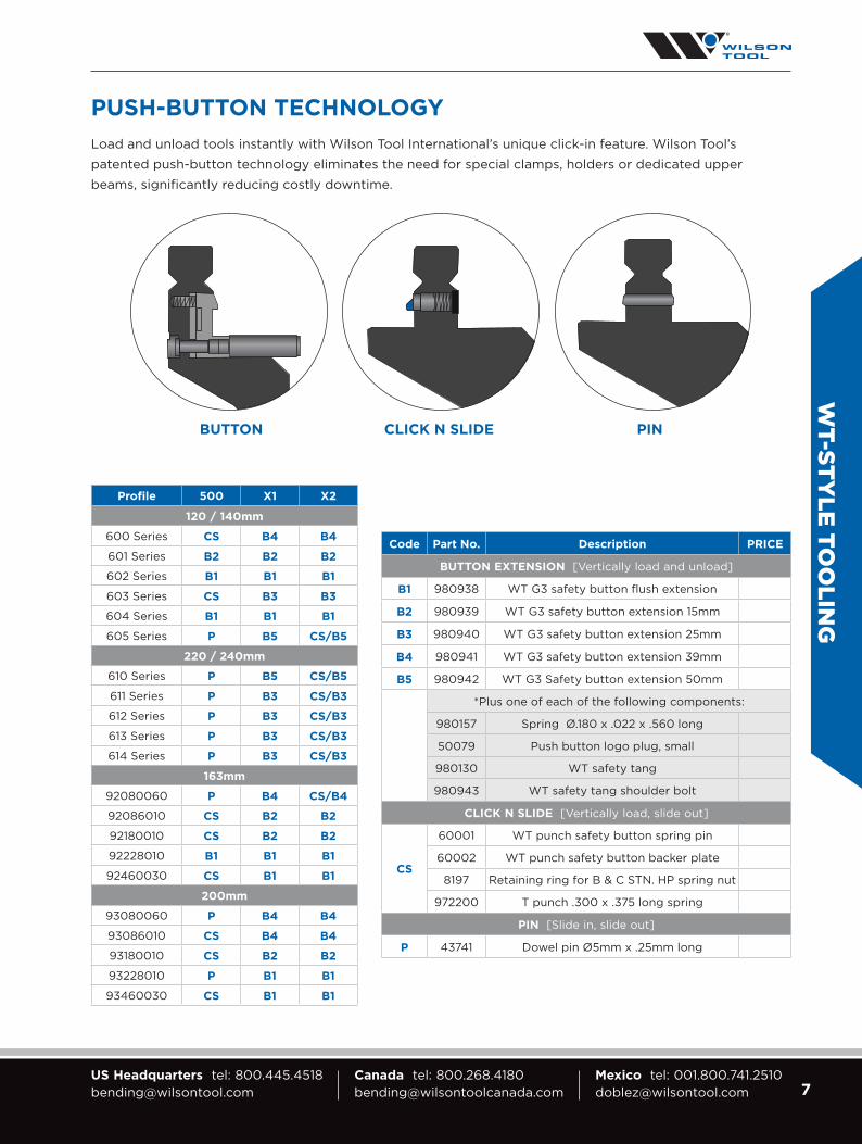
Code Part No. Description PRICE
BUTTON EXTENSION [Vertically load and unload]
B1 980938 WT G3 safety button flush extension
B2 980939 WT G3 safety button extension 15mm
B3 980940 WT G3 safety button extension 25mm
B4 980941 WT G3 safety button extension 39mm
B5 980942 WT G3 Safety button extension 50mm
*Plus one of each of the following components:
980157 Spring Ø.180 x .022 x .560 long
50079 Push button logo plug, small
980130 WT safety tang
980943 WT safety tang shoulder bolt
CLICK N SLIDE [Vertically load, slide out]
CS
60001 WT punch safety button spring pin
60002 WT punch safety button backer plate
8197 Retaining ring for B & C STN. HP spring nut
972200 T punch .300 x .375 long spring
PIN [Slide in, slide out]
P 43741 Dowel pin Ø5mm x .25mm long
Profile 500 X1 X2
120 / 140mm
600 Series CS B4 B4
601 Series B2 B2 B2
602 Series B1 B1 B1
603 Series CS B3 B3
604 Series B1 B1 B1
605 Series P B5 CS/B5
220 / 240mm
610 Series P B5 CS/B5
611 Series P B3 CS/B3
612 Series P B3 CS/B3
613 Series P B3 CS/B3
614 Series P B3 CS/B3
163mm
92080060 P B4 CS/B4
92086010 CS B2 B2
92180010 CS B2 B2
92228010 B1 B1 B1
92460030 CS B1 B1
200mm
93080060 P B4 B4
93086010 CS B4 B4
93180010 CS B2 B2
93228010 P B1 B1
93460030 CS B1 B1
BUTTON CLICK N SLIDE PIN
WT-STY
LE TOO
LING
PUSH-BUTTON TECHNOLOGY
Load and unload tools instantly with Wilson Tool International’s unique click-in feature. Wilson Tool’s
patented push-button technology eliminates the need for special clamps, holders or dedicated upper
beams, significantly reducing costly downtime.

8 Visit wilsontool.com/MyAccount for 24/7 Online Access Quotes, Orders, Drawings, Invoices, Tracking Numbers & More!
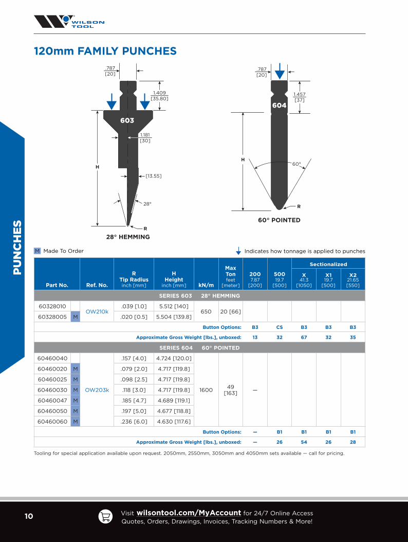
Part No. Ref. No.
R Tip Radius inch [mm]
H Height
inch [mm] kN/m
Max Tonfeet
[meter]
2007.87
[200]
50019.7
[500]
Sectionalized
X41.3
[1050]
X119.7
[500]
X221.65 [550]
SERIES 600 86° SWAN NECK
60086010
OW200k
.039 [1.0] 4.724 [120.0]
850 26 [87]
60086005 M .020 [0.5] 4.717 [119.8]
60086016 M .063 [1.6] 4.693 [119.2]
60086020 M .079 [2.0] 4.693 [119.2]
60086023 M .091 [2.3] 4.685 [119.0]
60086025 M .098 [2.5] 4.685 [119.0]
60086030 M .118 [3.0] 4.673 [118.7]
60086032 M .126 [3.2] 4.669 [118.6]
60086040 M .157 [4.0] 4.657 [118.3]
Button Options: B4 CS B4 B4 B4
Approximate Gross Weight [lbs.], unboxed: 13 32 63 28 35
SERIES 605 80° SWAN NECK THIN TIP
60580005 OW280k .020 [0.5] 5.512 [140] 400 12 [40] —
Button Options: — P CS/B5 B5 CS/B5
Approximate Gross Weight [lbs.], unboxed: 29 73 153 72 80
Tooling for special application available upon request. 2050mm, 2550mm, 3050mm and 4050mm sets available — call for pricing.
Indicates how tonnage is applied to punches
PUN
CH
ES
Made To OrderM
H
R
.787[20]
1.457[37]
1.772[45]
.315[8]
600
86°
86° SWAN NECK
.787[20]
[140]
1.457[37]
.197[5]
605
1.772[45]
80°
80° SWAN NECK THIN TIP
120mm FAMILY PUNCHES

9US Headquarters tel: [email protected]
Canada tel: [email protected]
Mexico tel: [email protected]
Part No. Ref. No.
R Tip Radius inch [mm]
H Height
inch [mm] kN/m
Max Tonfeet
[meter]
50019.7
[500]
Sectionalized
X41.3
[1050]
X119.7
[500]
X221.65 [550]
SERIES 601 86° GOOSENECK
60186010
OW201k
.039 [1.0] 4.724 [120.0]
900 28 [92]
60186005 M .020 [0.5] 4.717 [119.8]
60186016 M .063 [1.6] 4.701 [119.4]
60186020 M .079 [2.0] 4.693 [119.2]
60186023 M .091 [2.3] 4.685 [119.0]
60186025 M .098 [2.5] 4.685 [119.0]
60186030 M .118 [3.0] 4.677 [118.8]
60186032 M .126 [3.2] 4.669 [118.6]
60186040 M .157 [4.0] 4.654 [118.2]Button Options: B2 B2 B2 B2
Approximate Gross Weight [lbs.], unboxed: 27 52 23 29
SERIES 602 28° ACUTE W/RELIEF
60228010
OW202k
.039 [1.0] 4.724 [120.0]
1000 31 [102]
60228005 M .020 [0.5] 4.717 [119.8]
60228016 M .063 [1.6] 4.614 [117.2]
60228020 M .079 [2.0] 4.567 [116.0]
60228023 M .091 [2.3] 4.531 [115.1]
60228025 M .098 [2.5] 4.504 [114.4]
60228030 M .118 [3.0] 4.441 [112.8]
60228032 M .126 [3.2] 4.437 [112.7]
60228040 M .157 [4.0] 4.323 [109.8]Button Options: B1 B1 B1 B1
Approximate Gross Weight [lbs.], unboxed: 21 45 21 24
Tooling for special application available upon request. 2050mm, 2550mm, 3050mm and 4050mm sets available — call for pricing.
Indicates how tonnage is applied to punches
PUN
CH
ES
Made To OrderM
H
R
.787[20]
.787
[20]
1.457[37]
.394[10]
601
86°
86° GOOSENECK
H
R
.787[20]
1.457[37]
.551
[14]
602
28°
28° ACUTE w/RELIEF
120mm FAMILY PUNCHES
10 Visit wilsontool.com/MyAccount for 24/7 Online Access Quotes, Orders, Drawings, Invoices, Tracking Numbers & More!
PUN
CH
ES
Part No. Ref. No.
R Tip Radius inch [mm]
H Height
inch [mm] kN/m
Max Tonfeet
[meter]
2007.87
[200]
50019.7
[500]
Sectionalized
X41.3
[1050]
X119.7
[500]
X221.65 [550]
SERIES 603 28° HEMMING
60328010OW210k
.039 [1.0] 5.512 [140]650 20 [66]
60328005 M .020 [0.5] 5.504 [139.8]
Button Options: B3 CS B3 B3 B3
Approximate Gross Weight [lbs.], unboxed: 13 32 67 32 35
SERIES 604 60° POINTED
60460040
OW203k
.157 [4.0] 4.724 [120.0]
1600 49 [163] —
60460020 M .079 [2.0] 4.717 [119.8]
60460025 M .098 [2.5] 4.717 [119.8]
60460030 M .118 [3.0] 4.717 [119.8]
60460047 M .185 [4.7] 4.689 [119.1]
60460050 M .197 [5.0] 4.677 [118.8]
60460060 M .236 [6.0] 4.630 [117.6]
Button Options: — B1 B1 B1 B1
Approximate Gross Weight [lbs.], unboxed: — 26 54 26 28
Tooling for special application available upon request. 2050mm, 2550mm, 3050mm and 4050mm sets available — call for pricing.
Indicates how tonnage is applied to punchesMade To OrderM
H
R
.787[20]
1.409[35.80]
1.181[30]
[13.55]
28°
603
28° HEMMING
H
R
.787[20]
1.457[37]
604
60°
60° POINTED
120mm FAMILY PUNCHES

11US Headquarters tel: [email protected]
Canada tel: [email protected]
Mexico tel: [email protected]
PUN
CH
ES
163mm FAMILY PUNCHES
Part No.[Ref. #]
H Height
inch [mm]
R Tip Radius
inch [mm] A
An
gle
kN
/m
Max Tonfeet
[meter]
2007.87
[200]
50019.7
[500]
Sectionalized
X41.3
[1050]
X119.7
[500]
X221.65 [550]
92080060[BIU-025]
6.417 [163.0]
.236 [6] 80 1270 39 [130] B4 PCS/B4
B4CS/B4
Approx. Gross Weight, unboxed: 23 lbs. 58 lbs. 122 lbs. 58 lbs. 64 lbs.
92086010[BIU-023]
.039 [1] 86 640 20 [65] B2 CS B2 B2 B2
Approx. Gross Weight, unboxed: 16 lbs. 41 lbs. 86 lbs. 41 lbs. 45 lbs.
92180010[BIU-022]
M.039 [1] 80 780 24 [80] B2 CS B2 B2 B2
Approx. Gross Weight, unboxed: 14 lbs. 34 lbs. 71 lbs. 34 lbs. 37 lbs.
92228010[BIU-021]
.039 [1] 28 690 21 [70] — — B1 B1 B1 B1
Approx. Gross Weight, unboxed: — 26 lbs. 54 lbs. 26 lbs. 28 lbs.
92460030[BIU-024]
.118 [3] 60 1570 48 [160] B1 CS B1 B1 B1
Approx. Gross Weight, unboxed: 14 lbs. 34 lbs. 71 lbs. 34 lbs. 37 lbs.
Button Options shown in blue above
Indicates how tonnage is applied to punchesMade To OrderM
.787[20]
86°
R
.315[8.0]
1.378[35]
.787[20]
80°
R
.394[10]
.787[20]
.787[20]
1.457[37.01]
80°
R
6.417[163]
.732[18.6]
1.967[50]
.787[20]
R.866[22]
.551[14]
28°
.787[20]
60°
R
92080060 92460030922280109218001092086010

12 Visit wilsontool.com/MyAccount for 24/7 Online Access Quotes, Orders, Drawings, Invoices, Tracking Numbers & More!
200mm FAMILY PUNCHES
PUN
CH
ES
Part No.[Ref. #]
H Height
inch [mm]
R Tip
Radius inch [mm] A
An
gle
kN
/m
Max Tonfeet
[meter]
2007.87
[200]
50019.7
[500]
Sectionalized
X41.3
[1050]
X119.7
[500]
X221.65 [550]
93080060BIU-235
7.874 [200]
.236 [6] 80 1430 44 [130] B4 P B4 B4 B4
Approx. Gross Weight, unboxed: 28 lbs. 70 lbs. 139 lbs. 62 lbs. 77 lbs.
93086010BIU-033 M
.039 [1] 86 490 15 [50] B4 CS B4 B4 B4
Approx. Gross Weight, unboxed: 19 lbs. 48 lbs. 101 lbs. 48 lbs. 53 lbs.
93180010BIU-032 M
.039 [1] 80 780 24 [80] B2 CS B2 B2 B2
Approx. Gross Weight, unboxed: 16 lbs. 40 lbs. 84 lbs. 40 lbs. 44 lbs.
93228010BIU-031 M
.039 [1] 28 590 18 [60] B1 P B1 B1 B1
Approx. Gross Weight, unboxed: 12 lbs. 31 lbs. 65 lbs. 31 lbs. 34 lbs.
93460030BIU-034 M
.118 [3] 60 1570 48 [160] B1 CS B1 B1 B1
Approx. Gross Weight, unboxed: 16 lbs. 40 lbs. 84 lbs. 40 lbs. 44 lbs.
Button Options shown in blue above
Indicates how tonnage is applied to punchesMade To OrderM
1.457[37.01]
80°
7.87[200]
1.32[33.5]
.807[20.5]
93080060
.787[20]
R
86°
1.772[45]
.315[8.0]
93086010
.787[20]
R
80°
.787[20]
.394[10]
93180010
.787[20]
R
93460030
.787[20]
R
60°
28°
.551[14]
93228010
.787[20]
R
.866[22]

13US Headquarters tel: [email protected]
Canada tel: [email protected]
Mexico tel: [email protected]
220mm FAMILY PUNCHES
PUN
CH
ES
Part No. Ref. No.
R Tip Radius inch [mm]
H Height
inch [mm] kN/m
Max Tonfeet
[meter]
2007.87
[200]
50019.7
[500]
Sectionalized
X41.3
[1050]
X119.7
[500]
X221.65 [550]
SERIES 610 86° SWAN NECK
61086010
OW200s
.039 [1.0] 8.661 [220.0]
850 26 [87]
61086005 M .020 [0.5] 8.654 [219.8]
61086016 M .063 [1.6] 8.630 [219.2]
61086020 M .079 [2.0] 8.630 [219.2]
61086023 M .091 [2.3] 8.622 [219.0]
61086025 M .098 [2.5] 8.610 [218.7]
61086030 M .118 [3.0] 8.602 [218.5]
61086032 M .126 [3.2] 8.602 [218.5]
61086040 M .157 [4.0] 8.594 [218.3]
Button Options: B5 P CS/B5 B5 CS/B5
Approximate Gross Weight [lbs.], unboxed: 29 73 153 73 80
Tooling for special application available upon request. 2050mm, 2550mm, 3050mm and 4050mm sets available — call for pricing.
Indicates how tonnage is applied to punches
Made To OrderM
H
R
.787[20]
1.409[35.80]
.394[10]
2.165[55]
86°
610
86° SWAN NECK

14 Visit wilsontool.com/MyAccount for 24/7 Online Access Quotes, Orders, Drawings, Invoices, Tracking Numbers & More!
PUN
CH
ES
Indicates how tonnage is applied to punches
Made To OrderM
H
R
.787[20]
1.409[35.80]
.394[10]
1.181[30]
86°
611
86° GOOSENECK
Part No. Ref. No.
R Tip Radius inch [mm]
H Height
inch [mm] kN/m
Max Tonfeet
[meter]
2007.87
[200]
50019.7
[500]
Sectionalized
X41.3
[1050]
X119.7
[500]
X221.65 [550]
SERIES 611 86° GOOSENECK
61186010
OW201s
.039 [1.0] 8.661 [220.0]
900 28 [92]
61186005 M .020 [0.5] 8.654 [219.8]
61186016 M .063 [1.6] 8.638 [219.4]
61186020 M .079 [2.0] 8.630 [219.2]
61186023 M .091 [2.3] 8.622 [219.0]
61186025 M .098 [2.5] 8.610 [218.7]
61186030 M .118 [3.0] 8.614 [218.8]
61186032 M .126 [3.2] 8.606 [218.6]
61186040 M .157 [4.0] 8.594 [218.3]
Button Options: B3 P CS/B3 B3 CS/B3
Approximate Gross Weight [lbs.], unboxed: 25 62 131 62 69
Tooling for special application available upon request. 2050mm, 2550mm, 3050mm and 4050mm sets available — call for pricing.
220mm FAMILY PUNCHES

15US Headquarters tel: [email protected]
Canada tel: [email protected]
Mexico tel: [email protected]
PUN
CH
ES
Part No. Ref. No.
R Tip Radius inch [mm]
H Height
inch [mm] kN/m
Max Tonfeet
[meter]
2007.87
[200]
50019.7
[500]
Sectionalized
X41.3
[1050]
X119.7
[500]
X221.65 [550]
SERIES 612 28° ACUTE W/RELIEF
61228010
OW202s
.039 [1.0] 8.661 [220.0]
1000 31 [102]
61228005 M .020 [0.5] 8.654 [219.8]
61228016 M .063 [1.6] 8.575 [217.8]
61228020 M .079 [2.0] 8.504 [216.0]
61228023 M .091 [2.3] 8.488 [215.6]
61228025 M .098 [2.5] 8.425 [214.0]
61228030 M .118 [3.0] 8.378 [212.8]
61228032 M .126 [3.2] 8.374 [212.7]
61228040 M .157 [4.0] 8.260 [209.8]
Button Options: B3 P CS/B3 B3 CS/B3
Approximate Gross Weight [lbs.], unboxed: 22 54 114 54 60
Tooling for special application available upon request. 2050mm, 2550mm, 3050mm and 4050mm sets available — call for pricing.
Indicates how tonnage is applied to punches
Made To OrderM
H
R
.787[20]
1.409[35.80]
28°
1.181[30]
612
28° ACUTE w/RELIEF
220mm FAMILY PUNCHES

16 Visit wilsontool.com/MyAccount for 24/7 Online Access Quotes, Orders, Drawings, Invoices, Tracking Numbers & More!
PUN
CH
ES
Part No. Ref. No.
R Tip Radius inch [mm]
H Height
inch [mm] kN/m
Max Tonfeet
[meter]
2007.87
[200]
50019.7
[500]
Sectionalized
X41.3
[1050]
X119.7
[500]
X221.65 [550]
SERIES 614 60° POINTED
61460040
OW203s
.157 [4.0] 8.661 [220.0]
1600 49 [163]
61460020 M .079 [2.0] 8.654 [219.8]
61460025 M .098 [2.5] 8.654 [219.8]
61460030 M .118 [3.0] 8.654 [219.8]
61460047 M .185 [4.7] 8.622 [219.0]
61460050 M .197 [5.0] 8.606 [218.6]
61460060 M .236 [6.0] 8.567 [217.6]
Button Options: B3 P CS/B3 B3 CS/B3
Approximate Gross Weight [lbs.], unboxed: 23 57 108 51 57
Tooling for special application available upon request. 2050mm, 2550mm, 3050mm and 4050mm sets available — call for pricing.
H
R
.787[20]
1.409[35.80]
60°
1.181[30]
614
60° POINTED
220mm FAMILY PUNCHES
Indicates how tonnage is applied to punches
Made To OrderM

17US Headquarters tel: [email protected]
Canada tel: [email protected]
Mexico tel: [email protected]
PUN
CH
ES
H
R
.787[20]
1.409[35.80]
28°
1.181[30]
613
28° HEMMING
Part No. Ref. No.
R Tip Radius inch [mm]
H Height
inch [mm] kN/m
Max Tonfeet
[meter]
2007.87
[200]
50019.7
[500]
Sectionalized
X41.3
[1050]
X119.7
[500]
X221.65 [550]
SERIES 613 28° HEMMING
61328010OW210s
.039 [1.0] 9.449 [240.0]650 20
[66]61328005 M .020 [0.5] 9.441 [239.8]
Button Options: B3 P CS/B3 B3 CS/B3
Approximate Gross Weight [lbs.], unboxed: 21 52 103 46 57
Tooling for special application available upon request. 2050mm, 2550mm, 3050mm and 4050mm sets available — call for pricing.
240mm FAMILY PUNCHES
Indicates how tonnage is applied to punches
Made To OrderM

18 Visit wilsontool.com/MyAccount for 24/7 Online Access Quotes, Orders, Drawings, Invoices, Tracking Numbers & More!
BEN
D L
IMIT
GR
APH
S
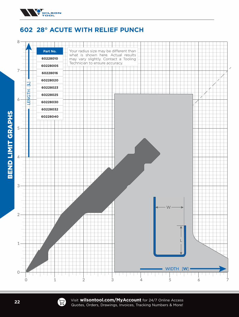
HOW TO USE A BEND LIMIT GRAPH
Although a bend limit graph won’t help with bend sequencing, it will help determine what punch profile is
best for you. Visit our YouTube channel for a step-by-step video on using these graphs.
• The graphs are 1:1
• Your part can be laid on top of the catalog page
• Use inside dimensions - always account for material thickness
8
7
2
3
4
5
6
1
0 72 3 4 5 61
LE
NG
TH
[L
]
WIDTH [W]
W
L
8
7
2
3
4
5
6
1
0 72 3 4 5 61L
EN
GT
H [
L]
WIDTH [W]
W
L
1.750
2.500
1.750
2.500
8
7
2
3
4
5
6
1
0 72 3 4 5 61
LEN
GT
H [
L]
WIDTH [W]
W
L
8
7
2
3
4
5
6
1
0 72 3 4 5 61
LEN
GT
H [
L]
WIDTH [W]
W
L
1.750
2.500
1.750
2.500Use inside
dimensions.This application works.
This application doesn’t work.
Watch the video on our YouTube Channel!

19US Headquarters tel: [email protected]
Canada tel: [email protected]
Mexico tel: [email protected]
BEN
D LIM
IT GR
APH
S
600 86° SWAN NECK
8
7
2
3
4
5
6
1
0
72 3 4 5 610
LEN
GT
H
[L]
WIDTH [W]
W
L
Part No.
60086010
60086005
60086016
60086020
60086023
60086025
60086030
60086032
60086040
Your radius size may be different than what is shown here. Actual results may vary slightly. Contact a Tooling Technician to ensure accuracy.

20 Visit wilsontool.com/MyAccount for 24/7 Online Access Quotes, Orders, Drawings, Invoices, Tracking Numbers & More!
BEN
D L
IMIT
GR
APH
S
8
7
2
3
4
5
6
1
0
72 3 4 5 610
LEN
GT
H
[L]
WIDTH [W]
W
L
605 80° THIN TIP SWAN NECK PUNCH
Part No.
60580005
Your radius size may be different than what is shown here. Actual results may vary slightly. Contact a Tooling Technician to ensure accuracy.

21US Headquarters tel: [email protected]
Canada tel: [email protected]
Mexico tel: [email protected]
BEN
D LIM
IT GR
APH
S
8
7
2
3
4
5
6
1
0
72 3 4 5 610
LEN
GT
H
[L]
WIDTH [W]
W
L
601 86° GOOSENECK PUNCH
Part No.
60186010
60186005
60186016
60186020
60186023
60186025
60186030
60186032
60186040
Your radius size may be different than what is shown here. Actual results may vary slightly. Contact a Tooling Technician to ensure accuracy.
22 Visit wilsontool.com/MyAccount for 24/7 Online Access Quotes, Orders, Drawings, Invoices, Tracking Numbers & More!
BEN
D L
IMIT
GR
APH
S
8
7
2
3
4
5
6
1
0
72 3 4 5 610
LEN
GT
H
[L]
WIDTH [W]
W
L
Part No.
60228010
60228005
60228016
60228020
60228023
60228025
60228030
60228032
60228040
Your radius size may be different than what is shown here. Actual results may vary slightly. Contact a Tooling Technician to ensure accuracy.
602 28° ACUTE WITH RELIEF PUNCH

23US Headquarters tel: [email protected]
Canada tel: [email protected]
Mexico tel: [email protected]
BEN
D LIM
IT GR
APH
S
8
7
2
3
4
5
6
1
0
72 3 4 5 610
LEN
GT
H
[L]
WIDTH [W]
W
L
603 28° HEMMING PUNCH
Part No.
60328010
60328005
Your radius size may be different than what is shown here. Actual results may vary slightly. Contact a Tooling Technician to ensure accuracy.

24 Visit wilsontool.com/MyAccount for 24/7 Online Access Quotes, Orders, Drawings, Invoices, Tracking Numbers & More!
BEN
D L
IMIT
GR
APH
S
8
7
2
3
4
5
6
1
0
72 3 4 5 610
LEN
GT
H
[L]
WIDTH [W]
W
L
Part No.
60460040
60460020
60460025
60460030
60460047
60460050
60460060
Your radius size may be different than what is shown here. Actual results may vary slightly. Contact a Tooling Technician to ensure accuracy.
604 60° POINTED/BOTTOMING PUNCH

25US Headquarters tel: [email protected]
Canada tel: [email protected]
Mexico tel: [email protected]
BEN
D LIM
IT GR
APH
S
8
7
2
3
4
5
6
1
0
72 3 4 5 610
LEN
GT
H
[L]
WIDTH [W]
W
L
920 80° LARGE TIP SWAN NECK PUNCH
Part No.
92080060
Your radius size may be different than what is shown here. Actual results may vary slightly. Contact a Tooling Technician to ensure accuracy.
26 Visit wilsontool.com/MyAccount for 24/7 Online Access Quotes, Orders, Drawings, Invoices, Tracking Numbers & More!
BEN
D L
IMIT
GR
APH
S
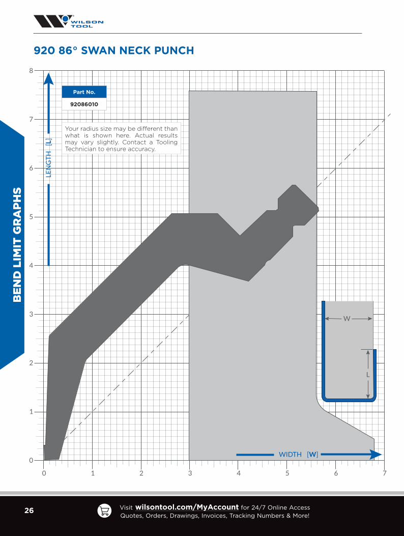
920 86° SWAN NECK PUNCH
8
7
2
3
4
5
6
1
0
72 3 4 5 610
LEN
GT
H
[L]
WIDTH [W]
W
L
Part No.
92086010
Your radius size may be different than what is shown here. Actual results may vary slightly. Contact a Tooling Technician to ensure accuracy.
27US Headquarters tel: [email protected]
Canada tel: [email protected]
Mexico tel: [email protected]
BEN
D LIM
IT GR
APH
S
8
7
2
3
4
5
6
1
0
72 3 4 5 610
LEN
GT
H
[L]
WIDTH [W]
W
L
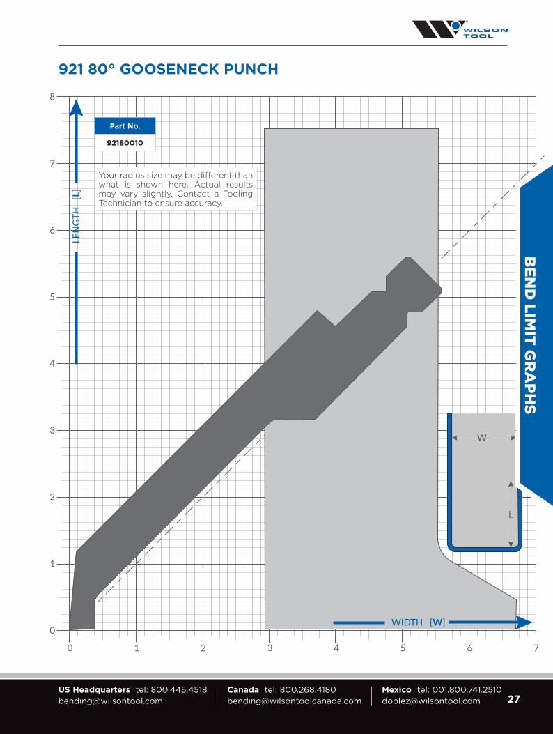
921 80° GOOSENECK PUNCH
Part No.
92180010
Your radius size may be different than what is shown here. Actual results may vary slightly. Contact a Tooling Technician to ensure accuracy.

28 Visit wilsontool.com/MyAccount for 24/7 Online Access Quotes, Orders, Drawings, Invoices, Tracking Numbers & More!
BEN
D L
IMIT
GR
APH
S
922 28° ACUTE PUNCH
8
7
2
3
4
5
6
1
0
72 3 4 5 610
LEN
GT
H
[L]
WIDTH [W]
W
L
Part No.
92228010
Your radius size may be different than what is shown here. Actual results may vary slightly. Contact a Tooling Technician to ensure accuracy.

29US Headquarters tel: [email protected]
Canada tel: [email protected]
Mexico tel: [email protected]
BEN
D LIM
IT GR
APH
S
8
7
2
3
4
5
6
1
0
72 3 4 5 610
LEN
GT
H
[L]
WIDTH [W]
W
L
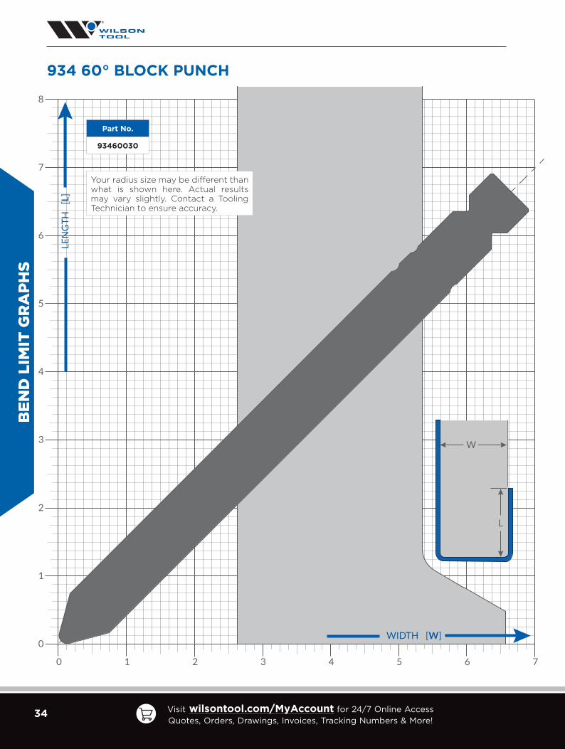
924 60° BLOCK PUNCH
Part No.
92460030
Your radius size may be different than what is shown here. Actual results may vary slightly. Contact a Tooling Technician to ensure accuracy.

30 Visit wilsontool.com/MyAccount for 24/7 Online Access Quotes, Orders, Drawings, Invoices, Tracking Numbers & More!
8
7
2
3
4
5
6
1
0
72 3 4 5 610
LEN
GT
H
[L]
WIDTH [W]
W
L
BEN
D L
IMIT
GR
APH
S
930 80° LARGE TIP SWAN NECK PUNCH
Part No.
93080060
Your radius size may be different than what is shown here. Actual results may vary slightly. Contact a Tooling Technician to ensure accuracy.

31US Headquarters tel: [email protected]
Canada tel: [email protected]
Mexico tel: [email protected]
8
7
2
3
4
5
6
1
0
72 3 4 5 610
LEN
GT
H
[L]
WIDTH [W]
W
L
Part No.
93086010
Your radius size may be different than what is shown here. Actual results may vary slightly. Contact a Tooling Technician to ensure accuracy.
BEN
D LIM
IT GR
APH
S
930 86° SWAN NECK PUNCH

32 Visit wilsontool.com/MyAccount for 24/7 Online Access Quotes, Orders, Drawings, Invoices, Tracking Numbers & More!
8
7
2
3
4
5
6
1
0
72 3 4 5 610
LEN
GT
H
[L]
WIDTH [W]
W
L
BEN
D L
IMIT
GR
APH
S
931 80° GOOSENECK PUNCH
Part No.
93180010
Your radius size may be different than what is shown here. Actual results may vary slightly. Contact a Tooling Technician to ensure accuracy.

33US Headquarters tel: [email protected]
Canada tel: [email protected]
Mexico tel: [email protected]
8
7
2
3
4
5
6
1
0
72 3 4 5 610
LEN
GT
H
[L]
WIDTH [W]
W
L
BEN
D LIM
IT GR
APH
S
931 28° ACUTE PUNCH
Part No.
93228010
Your radius size may be different than what is shown here. Actual results may vary slightly. Contact a Tooling Technician to ensure accuracy.
34 Visit wilsontool.com/MyAccount for 24/7 Online Access Quotes, Orders, Drawings, Invoices, Tracking Numbers & More!
8
7
2
3
4
5
6
1
0
72 3 4 5 610
LEN
GT
H
[L]
WIDTH [W]
W
L
BEN
D L
IMIT
GR
APH
S
934 60° BLOCK PUNCH
Part No.
93460030
Your radius size may be different than what is shown here. Actual results may vary slightly. Contact a Tooling Technician to ensure accuracy.

35US Headquarters tel: [email protected]
Canada tel: [email protected]
Mexico tel: [email protected]
BEN
D LIM
IT GR
APH
S
8
7
2
3
4
5
6
1
0
72 3 4 5 610
LEN
GT
H
[L]
WIDTH [W]
W
L
Part No.
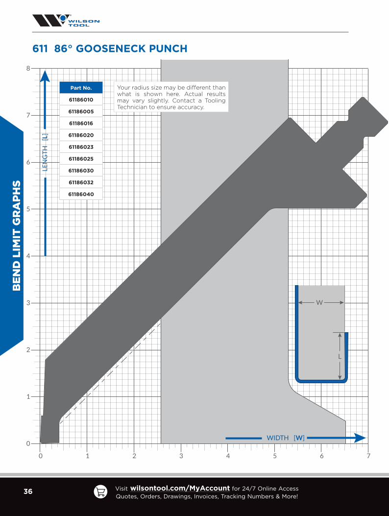
61086010
61086005
61086016
61086020
61086023
61086025
61086030
61086032
61086040
Your radius size may be different than what is shown here. Actual results may vary slightly. Contact a Tooling Technician to ensure accuracy.
610 86° SWAN NECK PUNCH
36 Visit wilsontool.com/MyAccount for 24/7 Online Access Quotes, Orders, Drawings, Invoices, Tracking Numbers & More!
BEN
D L
IMIT
GR
APH
S
8
7
2
3
4
5
6
1
0
72 3 4 5 610
LEN
GT
H
[L]
WIDTH [W]
W
L
Part No.
61186010
61186005
61186016
61186020
61186023
61186025
61186030
61186032
61186040
Your radius size may be different than what is shown here. Actual results may vary slightly. Contact a Tooling Technician to ensure accuracy.
611 86° GOOSENECK PUNCH

37US Headquarters tel: [email protected]
Canada tel: [email protected]
Mexico tel: [email protected]
BEN
D LIM
IT GR
APH
S
8
7
2
3
4
5
6
1
0
72 3 4 5 610
LEN
GT
H
[L]
WIDTH [W]
W
L
612 28° ACUTE WITH RELIEF PUNCH
Part No.
61228010
61228005
61228016
61228020
61228023
61228025
61228030
61228032
61228040
Your radius size may be different than what is shown here. Actual results may vary slightly. Contact a Tooling Technician to ensure accuracy.

38 Visit wilsontool.com/MyAccount for 24/7 Online Access Quotes, Orders, Drawings, Invoices, Tracking Numbers & More!
BEN
D L
IMIT
GR
APH
S
8
7
2
3
4
5
6
1
0
72 3 4 5 610
LEN
GT
H
[L]
WIDTH [W]
W
L
614 60° POINTED PUNCH
Part No.
61460040
61460020
61460025
61460030
61460047
61460050
61460060
Your radius size may be different than what is shown here. Actual results may vary slightly. Contact a Tooling Technician to ensure accuracy.

39US Headquarters tel: [email protected]
Canada tel: [email protected]
Mexico tel: [email protected]
8
7
2
3
4
5
6
1
0
72 3 4 5 610
LEN
GT
H
[L]
WIDTH [W]
W
L
Part No.
61328010
61328005
Your radius size may be different than what is shown here. Actual results may vary slightly. Contact a Tooling Technician to ensure accuracy.
613 28° HEMMING PUNCH
BEN
D LIM
IT GR
APH
S

40 Visit wilsontool.com/MyAccount for 24/7 Online Access Quotes, Orders, Drawings, Invoices, Tracking Numbers & More!
Part No.[Ref. #] A
ng
le
V
Op
en
ing
inch
[m
m]
W Wid
thin
ch [
mm
]
SR
Sh
ou
lde
rR
ad
ius
kN
/m
MaxTo
nfe
et[m
eter
] Approx. Gross Weight (lbs)
50019.7
[500]
Sectionalized
50
0
X X1
X2
X41.3
[1050]
X119.7
[500]
X221.65 [550]
SERIES 650
65084006EV W6/84 M
84°
.236 [6]
.787 [20]
.024 [0.6] 1200 37
[122] 19 40 19 21
65084008EV W8/84 M .315
[8].787 [20]
.032 [0.8] 1100 34
[112] 19 40 19 21
65084010EV W10/84 M .394
[10].787 [20]
.039 [1.0] 900 28
[92] 19 40 19 21
65084012EV W12/84 M .472
[12].984 [25]
.039 [1.0] 1200 37
[122] 23 49 23 26
65084016EV W16/84 M .630
[16]1.181 [30]
.063 [1.6] 1300 40
[133] 27 57 27 30
65084020EV W20/84 M .787
[20]1.181 [30]
.708 [2.0] 1400 43
[143] 27 57 27 30
65086006EV 020/86
86°
.236 [6]
.787 [20]
.024 [0.6] 1200 37
[122] 19 40 19 21
65086008EV 021/86
.315 [8]
.787 [20]
.032 [0.8] 1100 34
[112] 19 40 19 21
65086010EV 022/86
.394 [10]
.787 [20]
.039 [1.0] 900 28
[92] 19 40 19 21
65086012EV 023/86
.472 [12]
.984 [25]
.039 [1.0] 1200 37
[122] 23 49 23 26
65086016EV 024/86
.630 [16]
1.181 [30]
.063 [1.6] 1300 40
[133] 27 57 27 30
65086020EV 025/86
.787 [20]
1.181 [30]
.078 [2.0] 1400 43
[143] 27 57 27 30
65086024EV 026/86
.945 [24]
1.378 [35]
.098 [2.5] 1500 46
[153] 31 65 31 34
65086030EV 027/86
1.181 [30]
1.772 [45]
.118 [3.0] 1500 46
[153] 39 81 39 42
65086040EV 028/86
1.575 [40]
2.165 [55]
.118 [3.0] 1500 46
[153] 45 95 45 50
65086050EV 029/86
1.969 [50]
2.950 [75]
.118 [3.0] 1500 46
[153] 61 128 61 67
DIE
S
Made To OrderM
84°86°
W
.787[20]
V
3.937[100]
.512[13]
SRFULL BODY DIES — 100mm TALL
41US Headquarters tel: [email protected]
Canada tel: [email protected]
Mexico tel: [email protected]
Part No. Ref. No. An
gle
V O
pe
nin
gin
ch [
mm
]
W W
idth
inch
[m
m]
SR
Sh
ou
lde
rR
ad
ius
kN
/m
MaxTo
nfe
et[m
eter
] Approx. Gross Weight (lbs)
50019.7
[500]
Sectionalized
50
0
X X1
X2
X41.3
[1050]
X119.7
[500]
X221.65 [550]
SERIES 650
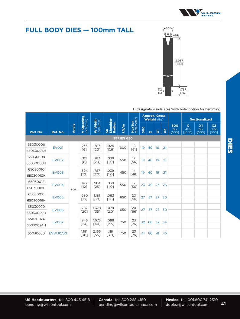
65030006EV001
30°
.236 [6]
.787 [20]
.024 [0.6] 600 18
[61] 19 40 19 2165030006H
65030008EV002 .315
[8].787 [20]
.039 [1.0] 550 17
[56] 19 40 19 2165030008H
65030010EV003 .394
[10].787 [20]
.039 [1.0] 450 14
[46] 19 40 19 2165030010H
65030012EV004 .472
[12].984 [25]
.039 [1.0] 550 17
[56] 23 49 23 2665030012H
65030016EV005 .630
[16]1.181 [30]
.063 [1.6] 650 20
[66] 27 57 27 3065030016H
65030020EV006
.787 [20]
1.378 [35]
.078 [2.0] 650 20
[66] 27 57 27 3065030020H
65030024EV007 .945
[24]1.575 [40]
.098 [2.5] 750 23
[76] 32 66 32 3465030024H
65030030 EVW30/30 1.181 [30]
2.165 [55]
.118 [3.0] 750 23
[76] 41 86 41 45
DIES
H designation indicates ‘with hole’ option for hemming
W
30°
SRV
.787[20]
3.937[100]
.512[13]
FULL BODY DIES — 100mm TALL

42 Visit wilsontool.com/MyAccount for 24/7 Online Access Quotes, Orders, Drawings, Invoices, Tracking Numbers & More!
DIE
S
FULL BODY DIES — 100mm TALL
Part No. Ref. No. A A
ng
le
V O
pe
nin
gin
ch [
mm
]
W Wid
thin
ch [
mm
]
SR
Sh
ou
lde
rR
ad
ius
kN
/mMax Tonfeet
[meter]
Approx. Gross Weight (lbs)
50019.7
[500]
Sectionalized
50
0
X X1
X2
X41.3
[1050]
X119.7
[500]
X221.65 [550]
SERIES 652
65230006 M EV001 R3
30°
.236 [6]
.787 [20]
.118 [3]
600 18 [61] 19 41 19 22
65230008 M EV002 R3 .315 [8]
.787 [20] 550 17
[56] 19 41 19 22
65230010 M EV003 R3 .394 [10]
.787 [20] 450 14
[46] 19 41 19 22
65230012 M EV004 R3 .472 [12]
.984 [25] 550 17
[56] 22 47 22 25
65230016 M EV005 R3 .630 [16]
1.181 [30] 650 20
[66] 26 55 26 29
Part No. Ref. No. A A
ng
le
V O
pe
nin
gin
ch [
mm
]
W W
idth
inch
[m
m]
SR
Sh
ou
lde
rR
ad
ius
kN
/m
Max Tonfeet
[meter]
Approx. Gross Weight (lbs)
2007.87
[200]
50019.7
[500]
Sectionalized
20
0
50
0
X1
X2
X119.7
[500]
X221.65 [550]
SERIES 960 – LARGE SHOULDER RADIUS
96030016 OZU-353
30°
.630 [16]
1.181 [30]
.138 [3.5]
78027
[80]
10 26 26 28
96030020 OZU-363.787 [20]
1.378 [35]
.157 [4.0]
12 29 29 32
96030024 OZU-354.945 [24]
1.575 [40]
.197 [5.0]
13 32 32 35
96040030 OZU-328
40°
1.181 [30]
1.772 [45]
.236 [6.0]
100034
[100]15 39 36 39
96040040 OZU-3291.575 [40]
2.165 [55]
.315 [8.0]
123042
[125]17 41 41 45
Made To OrderM
3.937[100]
W
.512[13]
V
A
SR

43US Headquarters tel: [email protected]
Canada tel: [email protected]
Mexico tel: [email protected]
DIES
FULL BODY DIES — 100mm/120mm TALL
Part No. Ref. No. A A
ng
le
V O
pe
nin
gin
ch [
mm
]
W W
idth
inch
[m
m]
SR
Sh
ou
lde
rR
ad
ius
kN
/m
Max Tonfeet
[meter]
Approx. Gross Weight (lbs)
2007.87
[200]
50019.7
[500]
Sectionalized
20
0
50
0
X1
X2
X119.7
[500]
X221.65 [550]
SERIES 960 – LARGE SHOULDER RADIUS – 100mm TALL
96086016 OZU-312
86°
.630 [16]
.984 [25]
.138 [3.5]
118040
[120]
9 23 23 25
96086020 OZU-323.787 [20]
1.181 [30]
.157 [4.0]
11 27 27 30
96080024 OZU-313
80°
.945 [24]
1.378 [35]
.197 [5.0]
123042
[125]
12 31 31 34
96080030 OZU-3241.181 [30]
1.575 [40]
.236 [6.0]
14 34 34 38
96080040 OZU-3251.575 [40]
2.165 [55]
.315 [8.0]
18 45 45 50
96080050 OZU-3261.969 [50]
2.56 [65]
.394 [10.0]
150050
[150]21 52 52 57
96060060 OZU-327 60°2.362 [60]
3.150 [80]
.472 [12.0]
123042
[125]23 58 58 63
96080080 OZU-317 80°3.15 [80]
4.331 [110]
.630 [16.0]
150050
[150]32 80 80 88
96060080 OZU-372 60° 220075
[220]29 73 73 80
Part No. Ref. No. A A
ng
le
V O
pe
nin
gin
ch [
mm
]
W W
idth
inch
[m
m]
SR
Sh
ou
lde
rR
ad
ius
kN
/m
Max Tonfeet
[meter]
Approx. Gross Weight (lbs)
2007.87
[200]
50019.7
[500]
Sectionalized
20
0
50
0
X1
X2
X119.7
[500]
X221.65 [550]
SERIES 960 – LARGE SHOULDER RADIUS – 120mm TALL
96080100 OZU-318 80° 3.937 [100]
5.512 [140]
.787 [20.0]
150050
[150]
44 110 110 121
96060100 QZU-373 60° 44 110 110 120
W
.512[13]
V 100mm
3.937[100]
4.724[120]
W
.512[13]
V16–60mm
SR
W
.512[13]
V 80mm
SR
SRAA
A

44 Visit wilsontool.com/MyAccount for 24/7 Online Access Quotes, Orders, Drawings, Invoices, Tracking Numbers & More!
DIE
S
Part No.[Ref. #] A
ng
le
V
Op
en
ing
inch
[m
m]
W Wid
thin
ch [
mm
]
SR
Sh
ou
lde
rR
ad
ius
kN
/m
Max Tonfeet
[meter]
2007.87
[200]
30011.81
[300]
50019.7
[500]
Sectionalized
X41.3
[1050]
X119.7
[500]
X221.65 [550]
SERIES 650 100mm TALL DIES
65080024EV W24/80
80°
.945 [24] 1.378 [35] .098 [2.5] 700 21 [71] — —
Approximate Gross Weight [lbs.], unboxed: — — 31 65 31 34
65080030EV W30/80
1.181 [30] 1.772 [45] .197 [5.0] 900 28 [92] — —
Approximate Gross Weight [lbs.], unboxed: — — 38 81 38 42
65080040EV W40/80
1.575 [40] 2.165 [55] .197 [5.0] 1200 37 [122] — —
Approximate Gross Weight [lbs.], unboxed: — — 45 94 45 49
65080050EV W50/80
1.969 [50] 2.559 [65] .197 [5.0] 1500 46 [153] — —
Approximate Gross Weight [lbs.], unboxed: — — 51 107 51 56
65080060EV W60/80
2.362 [60] 2.953 [75] .197 [5.0] 1500 46 [153] —
Approximate Gross Weight [lbs.], unboxed: 23 34 — 119 57 62
65080080EV W80/80
3.150 [80] 3.937 [100] .197 [5.0] 1500 46 [153] —
Approximate Gross Weight [lbs.], unboxed: 28 41 — 145 69 76
SERIES 650 120mm TALL DIES
65080100EV W100/80
80°3.937 [100] 4.724 [120] .315 [8.0] 1500 46 [153] —
Approximate Gross Weight [lbs.], unboxed: 39 59 — 201 96 105
FULL BODY DIES — 100mm/120mm TALL
V24–60mm
80°80°
3.937[100]
3.150[80]
80°
3.937[100]
4.724[120]
3.937[100]
WW
.787[20]
.512[13]
.787[20]
.512[13]
W
.787[20]
.512[13]
45US Headquarters tel: [email protected]
Canada tel: [email protected]
Mexico tel: [email protected]
DIES
Part No. Ref. No. An
gle
V
Op
en
ing
inch
[m
m]
W Wid
thin
ch [
mm
]
CL
Wid
thin
ch [
mm
]
SR
Sh
ou
lde
rR
ad
ius
kN
/m
Max Tonfeet
[meter]
50019.7
[500]
Sectionalized
X119.7
[500]
X221.65 [550]
SERIES 651
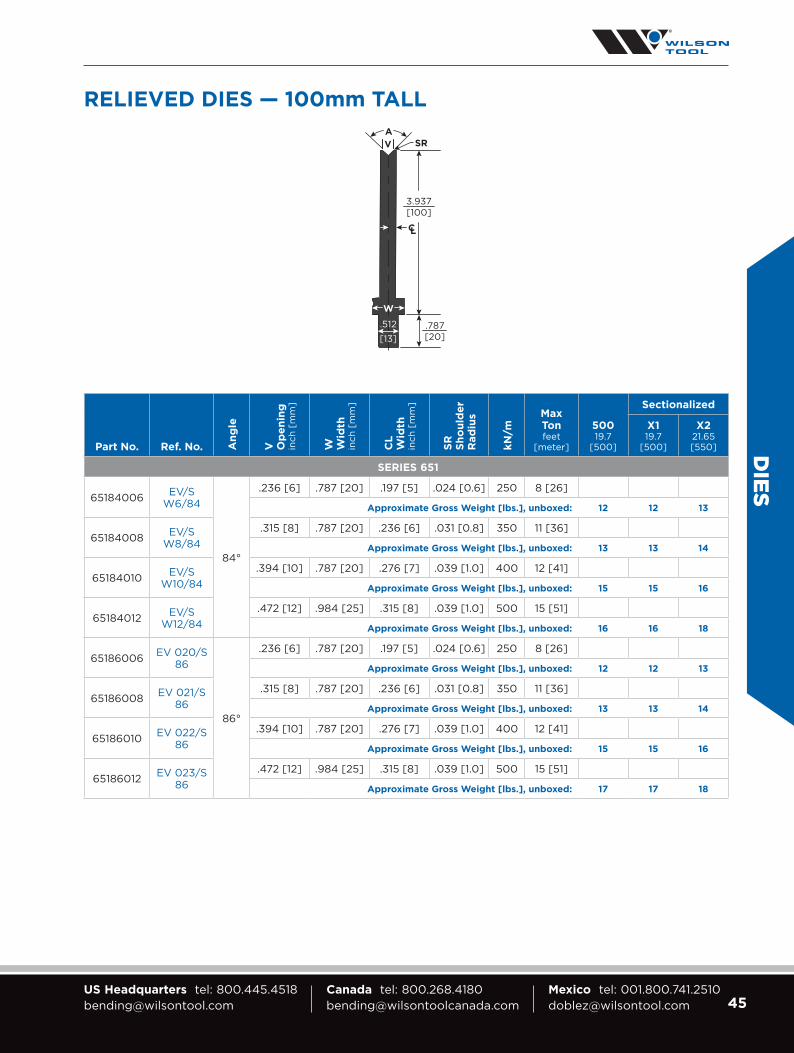
65184006 EV/S W6/84
84°
.236 [6] .787 [20] .197 [5] .024 [0.6] 250 8 [26]
Approximate Gross Weight [lbs.], unboxed: 12 12 13
65184008 EV/S W8/84
.315 [8] .787 [20] .236 [6] .031 [0.8] 350 11 [36]
Approximate Gross Weight [lbs.], unboxed: 13 13 14
65184010 EV/S W10/84
.394 [10] .787 [20] .276 [7] .039 [1.0] 400 12 [41]
Approximate Gross Weight [lbs.], unboxed: 15 15 16
65184012 EV/S W12/84
.472 [12] .984 [25] .315 [8] .039 [1.0] 500 15 [51]
Approximate Gross Weight [lbs.], unboxed: 16 16 18
65186006 EV 020/S 86
86°
.236 [6] .787 [20] .197 [5] .024 [0.6] 250 8 [26]
Approximate Gross Weight [lbs.], unboxed: 12 12 13
65186008 EV 021/S 86
.315 [8] .787 [20] .236 [6] .031 [0.8] 350 11 [36]
Approximate Gross Weight [lbs.], unboxed: 13 13 14
65186010 EV 022/S 86
.394 [10] .787 [20] .276 [7] .039 [1.0] 400 12 [41]
Approximate Gross Weight [lbs.], unboxed: 15 15 16
65186012 EV 023/S 86
.472 [12] .984 [25] .315 [8] .039 [1.0] 500 15 [51]
Approximate Gross Weight [lbs.], unboxed: 17 17 18
RELIEVED DIES — 100mm TALL
SRVA
3.937[100]
.787[20]
W
.512
[13]

46 Visit wilsontool.com/MyAccount for 24/7 Online Access Quotes, Orders, Drawings, Invoices, Tracking Numbers & More!
DIE
S
Part No. Ref. No. An
gle
V O
pe
nin
gin
ch [
mm
]
W Wid
thin
ch [
mm
]
SR
Sh
ou
lde
rR
ad
ius
kN/m
Max Tonfeet
[meter]
Approx. Gross
Weight (lbs)
50019.7
[500]
Sectionalized
50
0
X X1
X2
X41.3
[1050]
X119.7
[500]
X221.65 [550]
SERIES 950
95030006 M OZU-061
30°
.236 [6] .630
[16]
.039 [1.0]
780 24 [80]
10 21 10 11
95030008 M 0ZU-051 .315 [8] 10 21 10 11
95030010 M OZU-062 .394 [10] .787
[20]
11 23 11 12
95030012 M OZU-052 .472 [12] 11 23 11 12
95030016 M OZU-053 .630 [16]
1.181 [30]
.059 [1.5] 14 30 14 16
95030020 M OZU-063 .787 [20]
1.378 [35]
.078 [2.0] 15 32 15 17
95030024 M OZU-054 .945 [24]
1.575 [40]
.098 [2.5] 17 35 17 18
95080024 M OZU-013
80°
.945 [24]
1.378 [35] .118
[3.0]
1230 38 [125]
17 35 17 18
95080030 M OZU-014 1.181 [30]
1.575 [40] 19 39 19 20
95080040 M OZU-015 1.575 [40]
1.969 [50] .157
[4.0]
22 46 22 24
95080050 M OZU-035 1.969 [50]
2.952 [75] 31 65 31 34
95086006 M OZU-021
86°
.236 [6] .630
[16]
.039 [1.0]
1180 36 [120]
19 39 19 20
95086008 M OZU-010 .315 [8] 19 39 19 20
95086010 M OZU-022 .394 [10] .787
[20]
19 39 19 20
95086012 M OZU-011 .472 [12] 23 49 23 26
95086016 M OZU-012 .630 [16]
.984 [25]
.059 [1.5] 27 57 27 30
95086020 M OZU-023 .787 [20]
1.181 [30]
.078 [2.0] 27 57 27 30
Tooling for special application available upon request. 2050mm, 2550mm, 3050mm and 4050mm sets available — call for pricing.
55mm TALL
2.165[55]
1.693[43]
30° & 86°6-12mm
80° 86°16-50mm
30°16-20mm
30°
2.165[55]
2.165[55]
SR SRSR
A
VV V
86°
SRV
80°
2.165[55]
W
W WW
.512
[13]
.512
[13]
.512
[13]
.512
[13]
Made To OrderM

47US Headquarters tel: [email protected]
Canada tel: [email protected]
Mexico tel: [email protected]
DIES
Part No. Ref. No. An
gle
V O
pe
nin
gin
ch [
mm
]
W W
idth
inch
[m
m]
CL
Wid
thin
ch [
mm
]
SR
Sh
ou
lde
rR
ad
ius
kN
/m
Max T
on
feet
[m
eter
] Approx. Gross Weight (lbs)
50019.7
[500]
Sectionalized
50
0
X X1
X2
X41.3
[1050]
X119.7
[500]
X221.65 [550]
SERIES 651 – LARGE SHOULDER RADIUS
65130006M EV001/S
30°
.236 [6]
.787 [20]
.236 [6]
.024 [0.6] 170 6
[17.3] 16 34 16 1865130006H
65130008M EV002/S .315
[8].787 [20]
.275 [7]
.039 [1.0]
200 7 [20.3] 17 35 17 18
65130008H
65130010M EV003/S .394
[10].787 [20]
.315 [8] 200 7
[20.3] 17 35 17 1865130010H
65130012M EV004/S .472
[12].984 [25]
.354 [9] 295 9
[25.5] 20 42 20 2265130012H
H designation indicates ‘with hole’ option for hemmingMade To OrderM
Part No. Ref. No. An
gle
V O
pe
nin
gin
ch [
mm
]
W W
idth
inch
[m
m]
SR
Sh
ou
lde
rR
ad
ius
kN
/m
Max Tonfeet
[meter]
Approx. Gross Weight (lbs)
2007.87
[200]
50019.7
[500]
Sectionalized
20
0
50
0
X1
X2
X119.7
[500]
X221.65 [550]
SERIES 961
96186006 OZU-321
86°
.236 [6]
.630 [16]
.079 [2.0]
1180 40 [120]
7 16 16 18
96186008 OZU-310 .315 [8]
.630 [16]
.098 [2.5] 7 16 16 18
96186010 OZU-322 .394 [10]
.787 [20]
.098 [2.5] 8 19 19 21
96186012 OZU-311 .472 [12]
.787 [20]
.118 [3.0] 8 19 19 21
96130006 OZU-361
30°
.236 [6]
.630 [16]
.079 [2.0]
780 27 [80]
7 16 16 18
96130008 OZU-351 .315 [8]
.630 [16]
.098 [2.5] 7 16 16 18
96130010 OZU-362 .394 [10]
.787 [20]
.098 [2.5] 8 16 16 18
96130012 OZU-352 .472 [12]
.787 [20]
.118 [3.0] 8 16 16 18
THIN BODY DIES — 100mm TALL
SR
A
V
.512
[13]
3.937[100]
W
SR SR
AA
V V
WW
.512
[13]
.512
[13]
3.937[100]
3.937[100]

48 Visit wilsontool.com/MyAccount for 24/7 Online Access Quotes, Orders, Drawings, Invoices, Tracking Numbers & More!
V-S
ERIE
S B
LAC
K (
VSB
) D
IES
MODEL 1 SOLID SECTIONAL X1 X2
Length 9.84" [250mm] 19.68" [500mm] 21.65" [550mm] 10.83" [275mm] 10.83" [275mm]
Height 55mm 100mm 55mm 100mm 55mm 100mm 55mm 100mm 55mm 100mmAssemblyPart No.
61055-250
61100-250
61055-500
61100-500
61055-550
61100-550 61055x1 61100x1 61055x2 61100x2
Spring 980683 981031 980683 981031 980683 981031 980683 981031 980683 981031
Weight 6 lbs. 10 lbs. 11 lbs. 20 lbs. 13 lbs. 22 lbs. 6 lbs. 11 lbs. 6 lbs. 11 lbs.
Price
InsertPart No.
— (4) 980872A 980873A & 980874A 987158 987159
MODEL 2 SOLID SECTIONAL X1 X2
Length 9.84" [250mm] 19.68" [500mm] 21.65" [550mm] 10.83" [275mm] 10.83" [275mm]
Height 60mm 100mm 60mm 100mm 60mm 100mm 60mm 100mm 60mm 100mmAssemblyPart No.
62060-250
62100-250
62060-500
62100-500
62060-550
62100-550 62060x1 62100x1 62060x2 62100x2
Spring 980682 981032 980682 981032 980682 981032 980682 981032 980682 981032
Weight 9 lbs. 14 lbs. 15 lbs. 25 lbs. 17 lbs. 29 lbs. 8 lbs. 14 lbs. 8 lbs. 14 lbs.
Price
InsertPart No.
— (4) 980948 980949 & 980950 987160 987161
MODEL 3 SOLID
Length 3.94" [100mm] 9.84" [250mm] 17.91" [455mm]
Height 70mm 70mm 70mmAssemblyPart No.
63070.2-100 63070.2-250 63070.2-455
Spring 980881 980881 980881
Weight 11 lbs. 27 lbs. 47 lbs.
Price
InsertPart No.
987163 980959 980960 & 980977
SPRINGS
Part No. 980682 981031 980683 981032 980881
500mm Qty.
40 40 40 40 8
550mm Qty.
44 44 44 44 18
Installation Tools
Description Part No. Price
Spring Installation Tool Kit 981002
Spring Extension Wire (short) 981003
Spring Extension Wire (long) 981004
ZIP-MAR URETHANE SHOULDER STRIPS
[54' Roll, .020" Thick]
Width Part No. Price
Model 1 1/2" 980953
Model 2 3/4" 980954
Model 3 1-5/8" 980955
MODEL 16105561100
MODEL 363070
MODEL 26206062100
2.756[70]
3.937[100]
3.937[100]
2.362[60]
2.162[55]
.512[13]
.512[13]
.512[13]
.512[13]
3.54[90]
1.634[41.5]
1.122[28.5]
1.634[41.5]
1.122[28.5]
V-SERIES BLACK (VSB) DIES
Watch the video on our YouTube Channel!

49US Headquarters tel: [email protected]
Canada tel: [email protected]
Mexico tel: [email protected]
V-SER
IES BLA
CK
(VSB
) DIES
V-Series Black (VSB) Standard Lengths
ModelShoulder Radius
inch [mm]Desired Angle
Theoretical V (Metric)
Theoretical V (Imperial)
V OPENING AND SHOULDER RADIUS DIMENSIONS
1 .040 [1.0]90° 7.2 0.28334° 6.5 0.256
2 .051 [1.3]90° 13.9 0.54742° 13.3 0.524
3 .236 [6.0]90° 33.0 1.29965° 31.4 1.236
Mo
de
l Material Thicknessinch [mm]
Min. Outside Flange
inch [mm]
Ton/Ft.
Min. Angle
Punch Tip Required
to Achieve Angle
Max OR Radius @ Min. Angle
inch [mm]
Max OR Radius @
90°inch [mm]
Tonnage Cap/Ft.
T/M kN/M
V-SERIES BLACK (VSB) SPECIFICATIONS
1
.018 [.45]
.118 [3.0]
1.8
34°
0.054
.125 [3.17] .175 [4.45] 34 112 1100
.020 [.50] 1.8 0.052
.024 [.60] 2.0 0.047
.030 [.80] 2.5 0.042
.036 [.90] 3.3 0.036.040 [1.0]
.153 [3.9]4.0
0.031.048 [1.2] 5.8.063 [1.5] .165 [4.2] 9
2
.074 [1.9] .335 [8.5] 7
42°
0.122
.216 [5.5].354 [9.0] 50 168 1650
.105 [2.9] .347 [8.8] 13 0.112.118 [3.0]
.366 [9.3]15 0.099
.126 [3.2] 20 0.091
.135 [3.4] 22 55° 0.082 .276 [7.9]
3.157 [4.0]
.886 [22.5]9
65°0.078
.453 [11.5] .500 [12.7] 60 204 2000.187 [4.75] 26 0.094.250 [6.35] 28 0.125
100mm3.937"
45mm1.771"
50mm1.968"
60mm2.362"
100mm3.937"
100mm3.937"
Sectional Total Length: 455mm (17.91")
Solid Length Available: 250mm (9.84")Sectional Total Length Shown: 455mm (17.91") MODEL 3
Sectional X1: 255mm (10.04")
Sectional X1: 275mm (10.83") Sectional X2: 275mm (10.83")
Sectional Total Length: 550mm (21.65")
Solid Length Available: 500mm (19.68")Sectional Total Length Shown: 550mm (21.65") MODELS 1 & 2
100mm3.937"
100mm3.937"
50mm1.968"
35mm1.378"
30mm1.181"
25mm.984"
25mm.984"
45mm1.771"
40mm1.574"
100mm3.937"

50 Visit wilsontool.com/MyAccount for 24/7 Online Access Quotes, Orders, Drawings, Invoices, Tracking Numbers & More!
Radius Part No.
Radius Sizeinch [mm]
Radius Price
Radius Approx. Weight
Holder Part No.
Holder Width
inch [mm]
Holder Price
Holder Approx. Weight
Assembled Height
inch [mm]Max.
Ton/Ft
REPLACEABLE RADIUS PUNCHES & HOLDERS LENGTH: 19.69" [500mm]
6R095-500 .375 [9.5] 3 lbs
60T35-500 1.3778 [35]
28 lbs[12.8]
4.684 [119]
700 kN/m
71 T/m
21 T/Ft
6R127-500 .500 [12.7] 5 lbs 4.953 [125.8]
6R158-500 .625 [15.8] 7 lbs 5.223 [132.7]
6R190-500 .750 [19.0] 10 lbs 5.492 [139.5]
6R222-500 .875 [22.2] 14 lbs 5.762 [146.4]
6R254-500 1.000 [25.4] 18 lbs6.031 [153.2]
60T55-500 2.165 [55]
44 lbs[20.1]
5.606 [142.4]
6R381-500 1.500 [38.1] 40 lbs 6.747 [171.37]
6R508-500 2.000 [50.8] MTO 72 lbs 7.761 [197.1]
REPLACEABLE RADIUS PUNCHES & HOLDERS LENGTH: 9.84" [250mm]
6R381-250 1.500 [38.1] 20 lbs60T55-250 2.165
[55]22 lbs[10.5]
6.747 [171.37] 700 kN/m71 T/m21 T/Ft6R508-250 2.000 [50.8] 36 lbs 7.761 [197.1]
HO
LDER
AN
D P
UN
CH
TIP
S
REPLACEABLE RADIUS PUNCHES
NOTE: The large radius assemblies shown above are not designed to stage bend. Contact a Tooling Technician if stage bending is needed. Make to order (MTO) sizes are available upon request.
CAUTION: Do not load the radius tip into the holder while in the machine. Remove the holder from the machine to change radius.
Maximum radius size shown on each holder.
50mm
25mm
Indicates how tonnage is applied to punches
51US Headquarters tel: [email protected]
Canada tel: [email protected]
Mexico tel: [email protected]
Part No.
**T Offset
Dim. inch [mm]
Effective V
inch [mm]
50019.7
[500]
Sectionalized
Load Style W
Wid
thin
ch [
mm
]
R1/
R2
= P
un
ch
&
Die
Rad
. in
ch [
mm
]
R3
=
Sh
. R
ad
.in
ch [
mm
]
D C
en
terl
ine
D
im.
inch
[m
m]
Max. Load
X41.3
[1050]
X119.7
[500]
X221.65 [550]
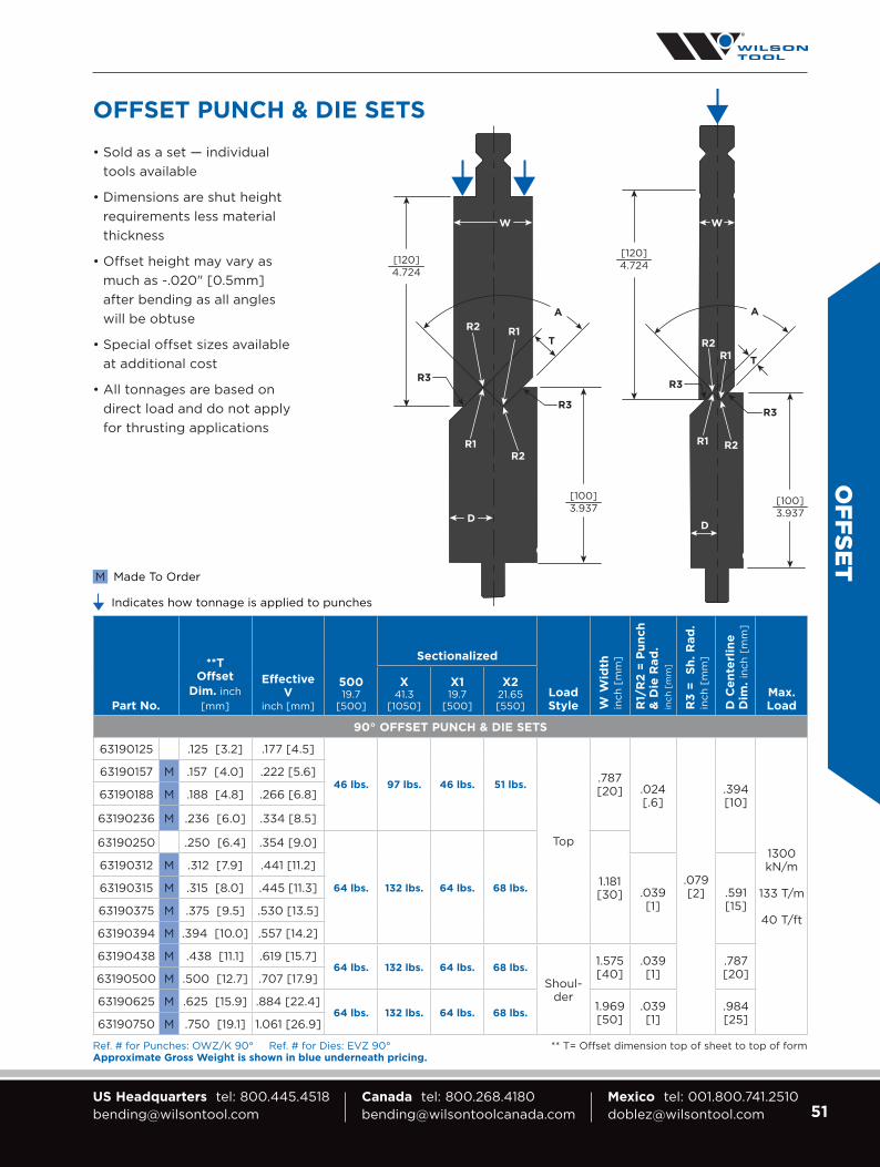
90° OFFSET PUNCH & DIE SETS
63190125 .125 [3.2] .177 [4.5]
46 lbs. 97 lbs. 46 lbs. 51 lbs.
Top
.787[20] .024
[.6]
.079 [2]
.394 [10]
1300 kN/m
133 T/m
40 T/ft
63190157 M .157 [4.0] .222 [5.6]
63190188 M .188 [4.8] .266 [6.8]
63190236 M .236 [6.0] .334 [8.5]
63190250 .250 [6.4] .354 [9.0]
64 lbs. 132 lbs. 64 lbs. 68 lbs.1.181 [30]
63190312 M .312 [7.9] .441 [11.2]
.039 [1]
.591[15]
63190315 M .315 [8.0] .445 [11.3]
63190375 M .375 [9.5] .530 [13.5]
63190394 M .394 [10.0] .557 [14.2]
63190438 M .438 [11.1] .619 [15.7]64 lbs. 132 lbs. 64 lbs. 68 lbs.
Shoul-der
1.575 [40]
.039 [1]
.787 [20]63190500 M .500 [12.7] .707 [17.9]
63190625 M .625 [15.9] .884 [22.4]64 lbs. 132 lbs. 64 lbs. 68 lbs.
1.969 [50]
.039 [1]
.984 [25]63190750 M .750 [19.1] 1.061 [26.9]
Ref. # for Punches: OWZ/K 90° Ref. # for Dies: EVZ 90° ** T= Offset dimension top of sheet to top of formApproximate Gross Weight is shown in blue underneath pricing.
• Sold as a set — individual tools available
• Dimensions are shut height requirements less material thickness
• Offset height may vary as much as -.020" [0.5mm] after bending as all angles will be obtuse
• Special offset sizes available at additional cost
• All tonnages are based on direct load and do not apply for thrusting applications
OFFSET
OFFSET PUNCH & DIE SETS
Indicates how tonnage is applied to punches
Made To OrderM
[120]4.724
R2
R3
R1 T
R1
R3
R2
[100]3.937
D
A
R2
R3
R1
W W
T
R1
R3
R2
D
[120]4.724
[100]3.937
A

52 Visit wilsontool.com/MyAccount for 24/7 Online Access Quotes, Orders, Drawings, Invoices, Tracking Numbers & More!
Part No. kN/m
Max. Ton
ft [m]
50019.7
[500]
Sectionalized
X41.3
[1050]
X119.7
[500]
X221.65 [550]
65300001 (I Shape) 1000 31
[102]
Approx. Gross Weight, unboxed: 12 lbs. 25 lbs. 12 lbs. 13 lbs.
65300002 (L Shape) 1000 31
[102]
Approx. Gross Weight, unboxed: 16 lbs. 34 lbs. 16 lbs. 18 lbs.
Part No.
V1inch
[mm]
HHeight
inch [mm]
Max. Ton
ft [m]
Approx. Gross Weight [lbs]
Max. Material
LT32.87 [835]
ST16.34 [415]LT ST
42601c .236 [6.0]
4.587 [116.5] 20 [67] 86 43 20 GA.
CRS
42602c .315 [8.0]
4.587 [116.5] 20 [67] 86 43 16 GA.
CRS
42603c .394 [10.0]
4.902 [124.5] 20 [67] 89 45 14 GA.
CRS
42608c .394 [10.0]
5.402 [137.2] 25 [83] 103 52 14 GA.
CRS
Part No.
V Opening
mm
50019.7 [500]
(7 incl.)
X41.3 [1050]
(13 incl.)
MOUNTING HARDWARE KIT
H/6-10 6-10H/12 12H/16 16
Each kit includes: (2) socket head cap screws; (1) nut
980883 M8 x 1.25 Hex Nut Class 10
970508 M8 x 30mm LG socket head cap screw
8001944 M8 x 45mm LG socket head cap screw
HEM
MIN
G &
FLA
TTEN
ING
TWO STAGE HEMMING DIES
2.362[60]
H
FLATTENING SPACER BLOCK ATTACHMENTS
3.937[100]
.591
[15]
3.937[100]
1.138[28.90]
1.102[28]
13.9mm
Fron
t of
Bra
ke
Fron
t of
Bra
ke

53US Headquarters tel: [email protected]
Canada tel: [email protected]
Mexico tel: [email protected]
Part No. H H
eig
ht
inch
[m
m]
kN
/m
Max. Ton
ft [m]
50019.7
[500]
Sectionalized
X41.3
[1050]
X119.7
[500]
X221.65 [550]
28° TWO STAGE HEMMING PUNCH
69528010 5.512 [140] 1000 31
[102]
Approx. Gross Weight [lbs.], unboxed: 27 57 27 30
60528010 4.724 [120] 1000 31
[102]
Approx. Gross Weight [lbs.], unboxed: 23 49 23 26
Button Options: CS B1 B1 B1
TWO STAGE HEMMING DIE
65530010 — 1000 31 [102] — — —
Approx. Gross Weight [lbs.], unboxed: 46 — — —
Tonnage is based on direct load and does not apply for thrusting applications.
Maximum material is 16ga. cold rolled steel.
Part No.Max. Ton
50019.7
[500]
X119.7
[500]
X221.65 [550]
FLATTENING PUNCH
695000001300 kN/m
133 T/m40 T/ft
Button Options: P B1 B1
Approx. Gross Weight [lbs.], unboxed:
57 57 62
FLATTENING DIE
653000031300 kN/m
133 T/m40 T/ft
Approx. Gross Weight [lbs.], unboxed:
55 55 61
HEM
MIN
G &
FLATTEN
ING
TWO STAGE HEMMING FLATTENING SET
.512[13]
1.457[37.01]
.984[25]
H
28°
R
.787[20]
3.840[97.52]
.394[10]
.787[20]
Two Stage HemmingPunch & Die Assembled
2.50[63.5]
.039[1.0]
1.968[50]
4.724[120]
3.937[100]

54 Visit wilsontool.com/MyAccount for 24/7 Online Access Quotes, Orders, Drawings, Invoices, Tracking Numbers & More!
Part No.
H Height
inch [mm] k
N/m
Max. Ton
ft [m]
50019.7
[500]
Sectionalized
X41.3
[1050]
X119.7
[500]
X221.65 [550]
WT TO AMERICAN PUNCH HOLDER
6PH50 1.969 [50] 1900 60
[197]
Button Options: P P/B3 B3 P/B3
Approx. Gross Weight [lbs.], unboxed: 28 59 28 31
Tonnage is based on direct load and does not apply for thrusting applications.
Set screws every 2".
Part No.
H Height
inch [mm] k
N/m
Max. Ton
ft [m]
50019.7
[500]
Sectionalized
X41.3
[1050]
X119.7
[500]
X221.65 [550]
WT TO WT PUNCH HOLDER
6PH100 3.937 [100] 2300 70
[232]
Button Options: P P/B3 B3 P/B3
Approx. Gross Weight [lbs.], unboxed: 51 109 51 58
Set screws every 2".
HO
LDER
S
PUNCH HOLDERS
.787[20]
1.409[35.8]
1.969[50]
2.362[60]
.520[13.2]
6PH50
.787[20]
.787[20]
1.409[35.8]
3.937[100]
2.362[60]
6PH100

55US Headquarters tel: [email protected]
Canada tel: [email protected]
Mexico tel: [email protected]
Part No.
Mount Style
50019.7
[500]
Sectionalized
X41.3
[1050]
X119.7
[500]
X221.65 [550]
EUROPEAN TO WT PUNCH HOLDER
4PHZ1 Lengths and heights are configurable
to your needs. Call for price.Z2
Part No.
H Height
inch [mm] kN/m
Max. Ton
ft [m]
50019.7
[500]
Sectionalized
X41.3
[1050]
X119.7
[500]
X221.65 [550]
6DH45 1.772 [45] 1700 52 [175]
Approx. Gross Weight [lbs.], unboxed: 16 34 16 17
Set screws every 2".
HO
LDER
S
PUNCH HOLDERS
DIE HOLDER
7mmZ1 Z2
2.362[60]
2.362[60]
20mm
.787[20]
.787[20]
.512[13]
1.772[45]
.2559[6.50]
.275[6.99]
.531[13.49]
1.634[41.5]

56 Visit wilsontool.com/MyAccount for 24/7 Online Access Quotes, Orders, Drawings, Invoices, Tracking Numbers & More!
HO
LDER
S
Part No.
Description/ Shore
Hardness
Appx. Gross Weight [lbs] L
32.87" 835mm
S16.34" 415mmL S
42501c M Holder 10 6 Call for Price
42511 Pad 80A Red 2 1
42521 Pad 90A Blue 2 1
Part No.
Description/ Shore
Hardness
Appx. Gross Weight [lbs] L
32.87" 835mm
S16.34" 415mmL S
42502c M Holder 33 17 Call for Price
42512 Pad 80A Red 6 3
42522 Pad 90A Blue 6 3
Part No.
Description/ Shore
Hardness
Appx. Gross Weight [lbs] L
32.87" 835mm
S16.34" 415mmL S
42503c M Holder 35 19 Call for Price
42513 Pad 80A Red 6 3
42523 Pad 90A Blue 6 3
Part No.
Description/ Shore
Hardness
Appx. Gross Weight [lbs] L
32.87" 835mm
S16.34" 415mmL S
42504c M Holder 52 27 Call for Price
42514 Pad 80A Red 11 6
42524 Pad 90A Blue 11 6
URETHANE DIE HOLDERS & PADSAll urethane die holders are machined from 6061-T6 aluminum.Check height against machine stroke prior to ordering.
2.362[60]
1.181[30]
1.693[43]
.984[25]
Made To OrderM
Made To OrderM
Made To OrderM
Made To OrderM
2.362[60]
4.724[120]
3.268[83]
3.150[80]
1.181[30]
2.362[60]
1.969[50]
3.583[91]
3.937[100]
1.969[50]
2.362[60]
5.906[150]
4.331[110]
4.252[108]
1.772[45]

57US Headquarters tel: [email protected]
Canada tel: [email protected]
Mexico tel: [email protected]
SPECIA
LS
SPECIAL TOOLING
CHALLENGE OUR “NEVER SAY NO” ATTITUDEWe regularly help customers with their most challenging applications. Our
innovative solutions simplify complex bends and make the impossible possible.
We are defined by our “never say no” attitude. Bring us your most complex
problem and we will work with you until we’ve found an effective solution.
Quality Materials — Quality Control
We combine premium materials with
specialized manufacturing systems to
produce extraordinary products that
outlast the competition.
Quick Quotes — Short Lead Times
With the fastest lead times in the
industry, our tool might ship before the
competition even provides a quote.

58 Visit wilsontool.com/MyAccount for 24/7 Online Access Quotes, Orders, Drawings, Invoices, Tracking Numbers & More!
SPEC
IALS
BRAKE PARTNER®
Make Punch Press Forms in the Press Brake
Brake Partner® from Wilson Tool International
lets shops use new or existing punch press
tooling to make forms in the press brake.
For fabricators who have migrated away
from punch presses to laser cutting
machines, or for those whose punch
presses are running at full capacity,
this is an especially helpful solution.
The Brake Partner, manufactured to fit
in virtually any press brake, features a
pressure-pad system which provides
blank-holding and stripping, and can
be used with or without guide posts,
depending on the application.
Enjoy These Cost Saving Benefits
• Use existing punch press tooling
• Reduce press brake special tooling costs
• Punch press tooling has shorter lead times
• Put your existing press brakes to work on applications
that were previously impossible on a punching machine
• Reduce outsourcing of punching applications
• Streamline equipment usage and create more flexibility
in your shop
Watch the video on our YouTube Channel!
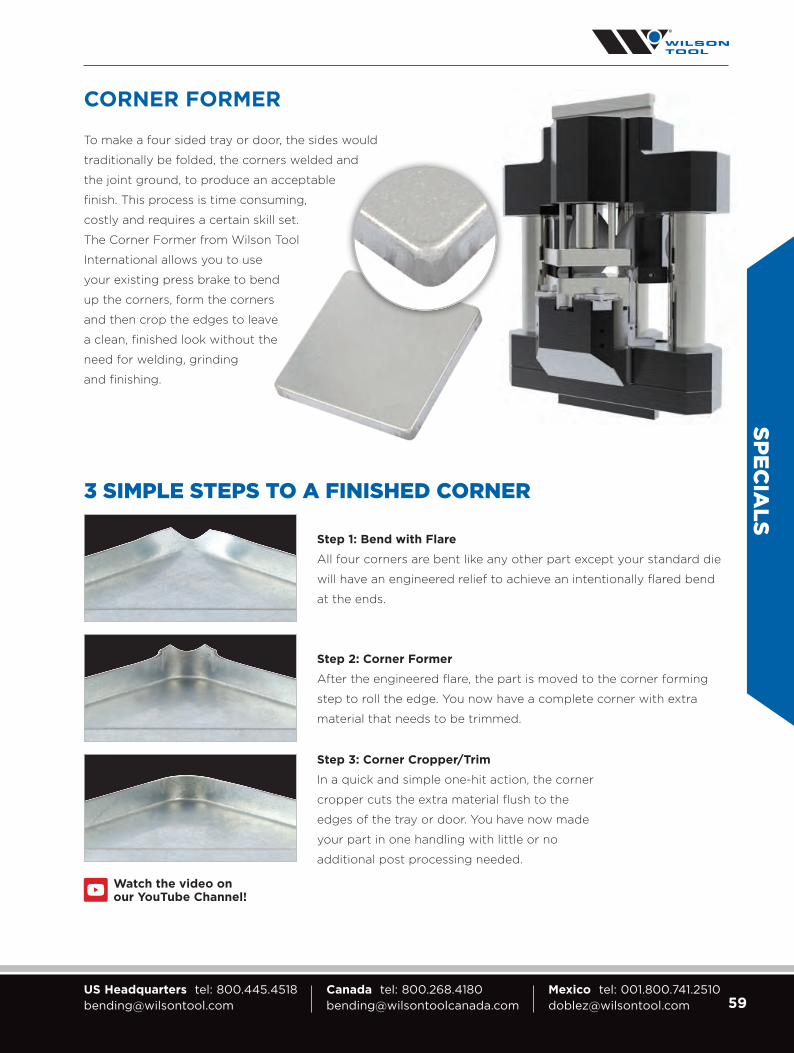
59US Headquarters tel: [email protected]
Canada tel: [email protected]
Mexico tel: [email protected]
SPECIA
LS
CORNER FORMER
To make a four sided tray or door, the sides would
traditionally be folded, the corners welded and
the joint ground, to produce an acceptable
finish. This process is time consuming,
costly and requires a certain skill set.
The Corner Former from Wilson Tool
International allows you to use
your existing press brake to bend
up the corners, form the corners
and then crop the edges to leave
a clean, finished look without the
need for welding, grinding
and finishing.
Step 1: Bend with Flare
All four corners are bent like any other part except your standard die
will have an engineered relief to achieve an intentionally flared bend
at the ends.
Step 3: Corner Cropper/Trim
In a quick and simple one-hit action, the corner
cropper cuts the extra material flush to the
edges of the tray or door. You have now made
your part in one handling with little or no
additional post processing needed.
Step 2: Corner Former
After the engineered flare, the part is moved to the corner forming
step to roll the edge. You now have a complete corner with extra
material that needs to be trimmed.
3 SIMPLE STEPS TO A FINISHED CORNER
Watch the video on our YouTube Channel!

60 Visit wilsontool.com/MyAccount for 24/7 Online Access Quotes, Orders, Drawings, Invoices, Tracking Numbers & More!
SPEC
IALS
CUSTOM HEMMING
AH1 — ANGLE HEM
Typically used to form seams in excess of 1/2 inch.
HDH1 — HEAVY DUTY HEM
Heavy duty hemming for thick gauge applications.
PH1 — PNEUMATIC HEM
This tool set introduces pneumatic cylinders to rapidly open and close the pre-form insert. This set removes the inconsistency associated with pre-forming or acute bending on a spring
actuated insert.
FSH1 — FLAT SHEET HEM
Hit #1
Hit #2
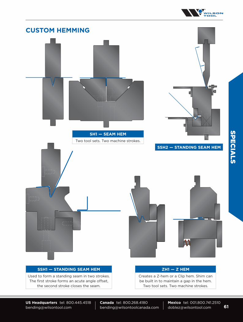
61US Headquarters tel: [email protected]
Canada tel: [email protected]
Mexico tel: [email protected]
SPECIA
LS
CUSTOM HEMMING
SH1 — SEAM HEM
Two tool sets. Two machine strokes.
SSH1 — STANDING SEAM HEM
Used to form a standing seam in two strokes. The first stroke forms an acute angle offset,
the second stroke closes the seam.
ZH1 — Z HEM
Creates a Z-hem or a Clip hem. Shim can be built in to maintain a gap in the hem.
Two tool sets. Two machine strokes.
SSH2 — STANDING SEAM HEM

62 Visit wilsontool.com/MyAccount for 24/7 Online Access Quotes, Orders, Drawings, Invoices, Tracking Numbers & More!
SPEC
IALS
OFFSET TOOLS
LO1 — LARGE OFFSET
Used for heavy gauge, large offset bending.
HO1 — HORIZONTAL OFFSET
For offsets that are approximately one material thickness. Prevents
material whip up. Thrust plates and adjustable back gauging are provided.
NPO1 — NON PARALLEL OFFSET
For offsets that have non-parallel flanges. Inset shows punch hidden for a clear view of the formed sheet.
AO1 — ANGLED OFFSET
Watch the video on our YouTube Channel!

63US Headquarters tel: [email protected]
Canada tel: [email protected]
Mexico tel: [email protected]
SPECIA
LS
ADJUSTABLE DIES
Adjustable dies are a great solution when bending thick materials and you need the flexibility to adjust the
width of the V opening. Instead of buying several dies, adjustable dies enable you to alter the width, rather
than changing out the die.
Adjustable Die Features
• Riding on spring-loaded ball bearings, openings are easily adjusted by one operator
• Available openings range from 1 to 24 inches and can be adjusted in 1-inch increments
• Capable of withstanding tonnage of up to 400 tons
per foot, allowing easy thick material bending
• Induction hardened and hard chrome rollers help
reduce required tonnage by as much as 20%
• Chrome rollers can be replaced at your facility
Adjustable Die Options
• Die assembly can be configured to remain
on the press permanently and function as a
standard die holder
• Cover bellows are available to keep the
grooves that are used to adjust the dies
free from dirt and dust
• Available clamping options for side
blocks include manual and automated
release and/or movement
• Available with Manual, Ball Screw,
Hydraulic and CNC options
Watch the video on our YouTube Channel!
Heavy Duty Chrome Rollers V-Series Black
Shoulder Inserts
Die Holder Slots
Shoulder SlotBottom Slot
Opening Adjustments
Manual ElectricRatchet

64 Visit wilsontool.com/MyAccount for 24/7 Online Access Quotes, Orders, Drawings, Invoices, Tracking Numbers & More!
SPEC
IALS
REPLACEABLE SHOULDER DIES
Dies that have a replaceable shoulder radius are
ideal for extreme wear conditions like heavy plate
and abrasive materials. Replacing the shoulder insert
saves on replacement cost.
Since the radius is able to rotate during bending, friction
and tonnage are reduced, resulting in reduced part
marking and less tonnage on tooling and machinery.
DOVETAIL HOLDER AND RADIUS
Lighten Your Load with Two-Piece Punches
Replaceable radius punches help limit tooling costs, reduce setup time and lighten tool changes.
Tip inserts simply slide on and off the universal punch body, increasing the flexibility of each punch
and minimizing heavy lifting for the operator.
Replaceable Radius Punch Highlights
• Setup is as simple as sliding the tip insert on and off the tool body
• No adjustment is required between punch radius changes
• Tip is lighter than a standard punch for easier tool changes
• Lighter tools reduces need for multiple operators
• Lighter tools creates a safer handling environment for operators
• Tool costs are minimized when purchasing one body with multiple tips
• Various angles and radii can be loaded into the same punch holder
Details
• Made to suit specific needs
• Designed to tackle light or heavy-duty bending
• Ground and induction hardened for optimal life and performance
• Dovetail or “T” style attachment featureWatch the video on our YouTube Channel!
Dovetail“T” Style

65US Headquarters tel: [email protected]
Canada tel: [email protected]
Mexico tel: [email protected]
SPECIA
LS
LARGE RADII
LR1 — LARGE RADIUS
Bottoming radius set with spring-back allowance built in. It is manufactured to form a radius in a specific type and thickness of material for tight tolerance requirements.
LR3 — MULTI-HIT RADIUS
Used when the return flange starts at the radius end. The solution may
require multiple strokes.
LR2 — MULTI-HIT RADIUS
Used when a full radius is required before the flange. The solution may
require multiple strokes.
Watch the video on our YouTube Channel!

66 Visit wilsontool.com/MyAccount for 24/7 Online Access Quotes, Orders, Drawings, Invoices, Tracking Numbers & More!
SPEC
IALS
STRENGTHENING RIB
V-RIB
SR1 — STRENGTHENING RIB
Produce a strengthening rib in one stroke. Spring back allowance is built in. Closed end and open end ribs are available.
VR1 — V RIB
Produce a V rib in one stroke. Spring back allowance is built in.
Watch the video on our YouTube Channel!

67US Headquarters tel: [email protected]
Canada tel: [email protected]
Mexico tel: [email protected]
SPECIA
LS
FORMING
RB1 — ROD BENDING
Provides nesting for the rod during the forming process.
W1 — WINDOW
Used when minimum return flange clearance is required.
OH1 — OPEN HATFM3 — FORMINGFM2 — FORMINGFM1 — FORMING
A large variety of custom forming sets are available. Custom built to suit any specific requirement. Call for specific application requirements.
Watch the video on our YouTube Channel!
Watch the video on our YouTube Channel!
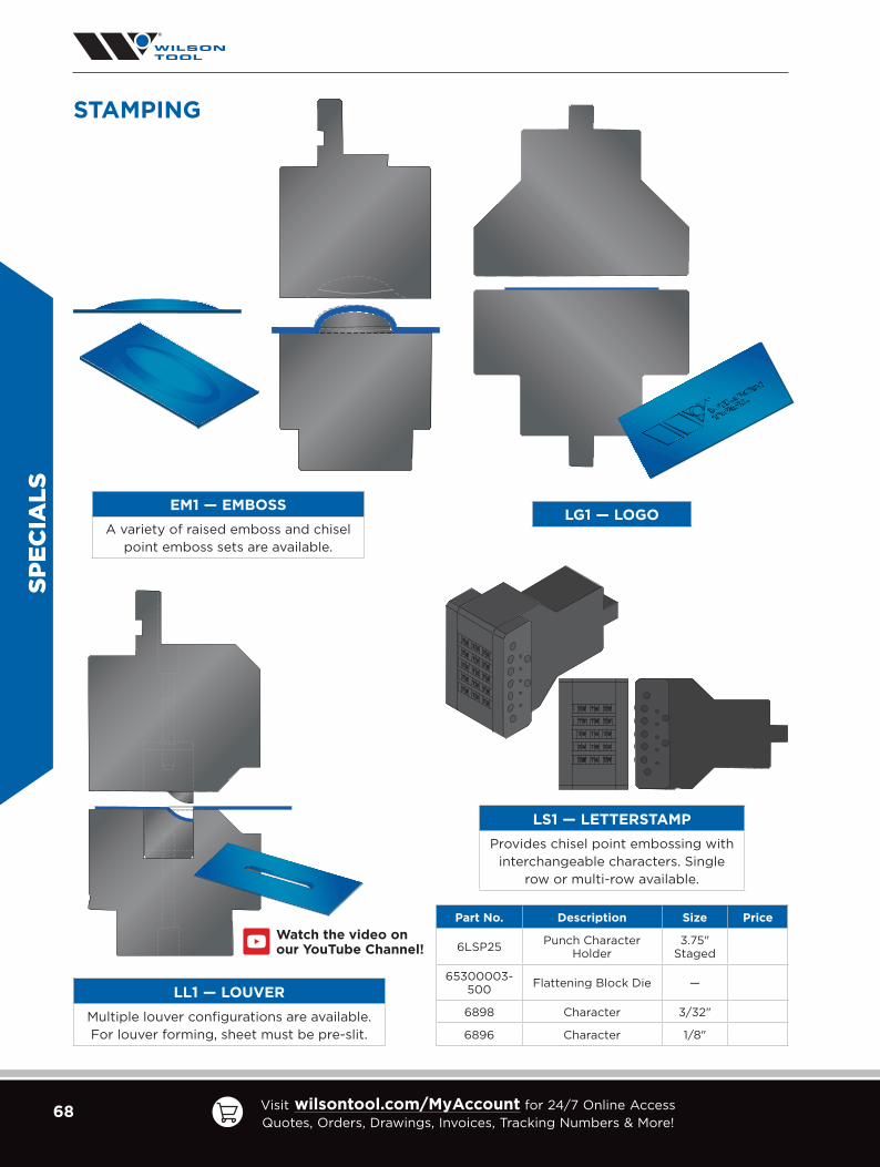
68 Visit wilsontool.com/MyAccount for 24/7 Online Access Quotes, Orders, Drawings, Invoices, Tracking Numbers & More!
SPEC
IALS
STAMPING
EM1 — EMBOSS
A variety of raised emboss and chisel point emboss sets are available.
LL1 — LOUVER
Multiple louver configurations are available. For louver forming, sheet must be pre-slit.
LS1 — LETTERSTAMP
Provides chisel point embossing with interchangeable characters. Single
row or multi-row available.
LG1 — LOGO
Watch the video on our YouTube Channel!
Part No. Description Size Price
6LSP25 Punch Character Holder
3.75" Staged
65300003-500 Flattening Block Die —
6898 Character 3/32"
6896 Character 1/8"
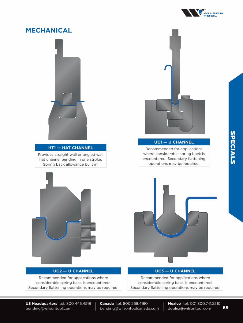
69US Headquarters tel: [email protected]
Canada tel: [email protected]
Mexico tel: [email protected]
SPECIA
LS
MECHANICAL
UC1 — U CHANNEL
Recommended for applications where considerable spring back is encountered. Secondary flattening
operations may be required.
HT1 — HAT CHANNEL
Provides straight wall or angled wall hat channel bending in one stroke.
Spring back allowance built in.
UC2 — U CHANNEL
Recommended for applications where considerable spring back is encountered.
Secondary flattening operations may be required.
UC3 — U CHANNEL
Recommended for applications where considerable spring back is encountered.
Secondary flattening operations may be required.

70 Visit wilsontool.com/MyAccount for 24/7 Online Access Quotes, Orders, Drawings, Invoices, Tracking Numbers & More!
SPEC
IALS
C4 — ROTARY BEND CHANNEL
For deep channels when the channel bottom needs to remain flat.
MECHANICAL
C1 — CHANNEL
For deep channels when the channel bottom needs to remain flat.
C3 — CHANNEL
For deep channels when the channel bottom needs to remain flat.
C2 — CHANNEL
For deep channels when the channel bottom needs to remain flat.
Watch the video on our YouTube Channel!
Watch the video on our YouTube Channel!

71US Headquarters tel: [email protected]
Canada tel: [email protected]
Mexico tel: [email protected]
SPECIA
LS
MECHANICAL
CL1 — CURL TOOL SET
Two tool sets, three machine strokes.
CL2 — CURL TOOL SET
Typically used for thick materials and large diameter curls.
One tool set, three machine strokes.
CL3 — CURL
Used for hinges and corner beading. Two tool sets, two machine strokes.
Watch the video on our YouTube Channel!

72 Visit wilsontool.com/MyAccount for 24/7 Online Access Quotes, Orders, Drawings, Invoices, Tracking Numbers & More!
SPEC
IALS
MECHANICAL
CL4 — CENTER CURL APPLICATION
Two tool sets, three machine strokes.
CL5 DOUBLE DECKER TOOL SET
Used for hinges and corner beading. One tool set, two machine strokes.
Watch the video on our YouTube Channel!
Watch the video on our YouTube Channel!

73US Headquarters tel: [email protected]
Canada tel: [email protected]
Mexico tel: [email protected]
SPECIA
LS
SPECIAL SHAPE PUNCHES
PR1
PR4 PR5 PR6
PR2 PR3

74 Visit wilsontool.com/MyAccount for 24/7 Online Access Quotes, Orders, Drawings, Invoices, Tracking Numbers & More!
SPEC
IALS
PUNCH HOLDERS
WT — AMERICAN AMERICAN SELF-SEAT HOLDER
PUNCH HOLDERS
Stack punch holders to make a taller punch to bend tall side flanges or to replace worn OEM punch holders that need replacement. These holders can be made in small sections or one piece to fit the length of your brake.
AMERICAN DEEP GOOSENECK HOLDER
EURO Z1 OR Z2 CLAMPING
Part No. 43002

75US Headquarters tel: [email protected]
Canada tel: [email protected]
Mexico tel: [email protected]
SPECIA
LS
PUNCH HOLDERS
DIE HOLDERS
Die holders can raise the die to help with down flange interference or to replace worn
OEM die holders that need replacement. These holders can be made in small sections or one piece to fit the length of your brake.
RA1 — DOG BONE RA3 — CLAMP PLATERA2 — SET SCREW
Holders are commonly made to replace any original OEM punch and/or die holders or to accommodate part configuration. These designs can be one solid length or sections that are easier to handle.
DIE HOLDERS

76 Visit wilsontool.com/MyAccount for 24/7 Online Access Quotes, Orders, Drawings, Invoices, Tracking Numbers & More!
SPEC
IALS
WIPING AND ROTARY BENDING
WD1 — WIPE DOWN
Holds the sheet flat while wiping the flange down. Ideal for large panels and high production.
WO1 — WIPING FORM
Holds the sheet flat while wiping the flange down. Ideal for large panels and high production.
RTD — FORM DOWN RTU — FORM UP
ROTARY FLANGE FORMING
Holds sheet flat while forming. Overbend allowance is built in to compensate for material springback. Ideal for large panels and high production.
Watch the video on our YouTube Channel!
Watch the video on our YouTube Channel!
Watch the video on our YouTube Channel!

77US Headquarters tel: [email protected]
Canada tel: [email protected]
Mexico tel: [email protected]
SPECIA
LS
Left and right ear sections shown in illustration.
30/60 DEEP BOX BENDING
SWING EAR SECTIONS
When forming a 4-sided box, the punch must be sufficient height to prevent the pre-formed side from striking the upper beam. This is a thrusting application and not suitable for all press brakes.
• Box bending with return flanges.
• Standard bend length 150mm each ear on all punch profiles. 100mm length available on select profiles.
• Ear(s) recess/fall in left to right .50–.75", not to be confused with vertical movement. There will be approximately 1.0–1.5" of relief to rotate and drop the finished part.
• Punch profile will match the standard profile only in height, angle and radius. Width will be wider where hinged.
Watch the video on our YouTube Channel!
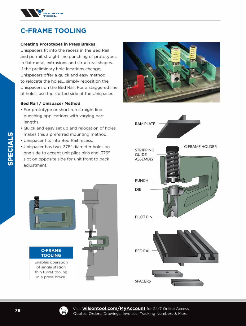
78 Visit wilsontool.com/MyAccount for 24/7 Online Access Quotes, Orders, Drawings, Invoices, Tracking Numbers & More!
PILOT PIN
DIE
PUNCH
STRIPPING GUIDEASSEMBLY
C-FRAME HOLDER
RAM PLATE
BED RAIL
SPACERS
C-FRAME TOOLING
C-FRAME TOOLING
Enables operation of single station
thin turret tooling in a press brake.
Creating Prototypes in Press Brakes
Unispacers fit into the recess in the Bed Rail and permit straight line punching of prototypes in flat metal, extrusions and structural shapes. If the preliminary hole locations change, Unispacers offer a quick and easy method to relocate the holes… simply reposition the Unispacers on the Bed Rail. For a staggered line of holes, use the slotted side of the Unispacer.
Bed Rail / Unispacer Method
• For prototype or short run straight line punching applications with varying part lengths.
• Quick and easy set up and relocation of holes makes this a preferred mounting method.
• Unispacer fits into Bed Rail recess.• Unispacer has two .376" diameter holes on
one side to accept unit pilot pins and .376" slot on opposite side for unit front to back adjustment.SP
ECIA
LS

79US Headquarters tel: [email protected]
Canada tel: [email protected]
Mexico tel: [email protected]
REFER
ENC
E
V
MF
T
IR
So
ft Brass =
So
ft Alum
inum =
Heat Treated
Alum
inum A
lloys =S
tainless Steel =
Hig
h Streng
th Steel =
Tons x 50
%To
ns x 50%
Tons x 10
0%
Tons x 150
%To
ns x 275%
AIR
BE
ND
ING
FO
RC
E C
HA
RT
M
ET
RIC
V-O
PE
NIN
GS
& IM
PE
RIA
L T
ON
NA
GE
STA
ND
AR
D F
OR
MU
LA
S F
OR
SE
LE
CT
ING
A V
-OP
EN
ING
Mate
rial T
hic
kn
ess:
2.6m
m o
r Less = T
x 6
3.0
0m
m – 8
.0m
m =
T x 8
9
.00
mm
– 12.00
mm
= T
x 10
14.0
0m
m &
Th
icker = T
x 12
NO
TE
: Fo
rmulas and
chart are for reference o
nly.
NO
TE
: The chart ab
ove is based
on m
ild steel (tensile streng
th of 6
0,0
00
PS
I) form
ed
to an includ
ed ang
le of 8
8°. S
ee chart to the rig
ht for o
ther materials. F
orm
ing to
o
ther angles w
ill change the M
inimum
Flang
e (MF
), Inside R
adius (IR
) and to
nnage.
T =
Material T
hickn
ess; V =
V-O
pen
ing
; MF
= M
inim
um
Flan
ge Len
gth
; IR =
Insid
e Rad
ius
Watc
h th
e v
ide
o o
n
ou
r Yo
uTu
be
Ch
an
ne
l!
V (m
m)
46
78
1012
1416
182
02
53
24
05
06
38
010
012
5
GAUGE
V (in.)
0.15
70
.23
60
.276
0.3
150
.39
40
.47
20
.55
10
.63
00
.70
90
.78
70
.98
41.2
60
1.575
1.96
92
.48
03
.150
3.9
37
4.9
21
DE
C.
inch [mm
]
MF
0.110
0.16
50
.193
0.2
20
0.2
76
0.3
31
0.3
97
0.4
54
0.5
100
.56
70
.70
90
.94
51.18
11.4
76
1.86
02
.36
22
.95
33
.78
9
IR0
.02
60
.03
90
.04
60
.05
20
.06
60
.07
90
.09
20
.105
0.118
0.13
10
.164
0.2
100
.26
20
.32
80
.413
0.5
25
0.6
56
0.8
20
20
0.0
36
[.9
]
TONS PER FOOT
5.43
.63.0
2.52.0
1.7
18 0
.04
8
[1.2]
7.25
.84
.83.7
2.72.4
2.0
16 0
.06
0
[1.5]
7.86
.05.0
4.2
3.53.1
2.7
14 0
.075
[1.9
]11.3
7.57.1
5.64
.84
.13.2
13 0
.09
0
[2.3
]12.5
10.1
8.2
7.25.4
3.7
12 0
.105
[2
.7]
15.813.0
10.5
9.5
7.55.6
4.0
11 0
.120
[3
]16
.113.1
10.1
7.25.0
3.8
10 0
.135
[3
.4]
12.08
.16
.24
.73.5
9 0
.150
[3
.8]
13.19
.06
.75.2
3/16
" 0
.188
[4
.8]
24.1
15.011.3
7.55.8
1/4"
0.2
50
[6
.35
]30
.020
.015
.010
.58
.5
5/16
" 0
.313
[8
]37.6
25.018
.813.1
10.0
3/8
" 0
.375
[9
.5]
38.3
28.1
22.515
.011.3
7/16"
0.4
38
[11.1]
35.028
.024
.017.0
1/2"
0.5
00
[12
.7]
52.039
.030
.02
2.0
5/8
" 0
.62
5
[16]
70.0
52.537.5
3/4
" 0
.75
0
[19]
66
.0
1" 1.0
00
[2
5.4
]
Sm
alle
r v-o
pe
nin
gs g
en
era
te in
cre
ase
d
ton
nag
e a
nd
are
NO
T re
co
mm
en
de
d.
Larg
er v
-op
en
ing
s ge
ne
rate
less to
nn
ag
e.

80 Visit wilsontool.com/MyAccount for 24/7 Online Access Quotes, Orders, Drawings, Invoices, Tracking Numbers & More!
REF
EREN
CE
AIR
BE
ND
ING
FO
RC
E C
HA
RT
I
MP
ER
IAL
V-O
PE
NIN
GS
& I
MP
ER
IAL
TO
NN
AG
ES
TA
ND
AR
D F
OR
MU
LA
S F
OR
SE
LE
CT
ING
A V
-OP
EN
ING
Mate
rial
Th
ickn
ess
: .10
5"
or
Less
= T
x 6
.12
0"
– .3
13"
= T
x 8
.3
75"
– .5
00
" =
T x
10
.6
25"
& T
hic
ker
= T
x 1
2
NO
TE
: Fo
rmul
as a
nd c
hart
are
fo
r re
fere
nce
onl
y.
T =
Mat
eria
l Th
ickn
ess;
V =
V-O
pen
ing
; MF
= M
inim
um
Fla
ng
e Le
ng
th; I
R =
Insi
de
Rad
ius
So
ft B
rass
=S
oft
Alu
min
um =
Hea
t Tr
eate
d A
lum
inum
Allo
ys =
Sta
inle
ss S
teel
=H
igh
Str
eng
th S
teel
=
Tons
x 5
0%
Tons
x 5
0%
Tons
x 1
00
%To
ns x
150
%To
ns x
275
%
NO
TE
: The
cha
rt a
bov
e is
bas
ed o
n m
ild s
teel
(te
nsile
str
eng
th o
f 6
0,0
00
PS
I) f
orm
ed
to a
n in
clud
ed a
ngle
of
88
°. S
ee c
hart
to
the
rig
ht f
or
oth
er m
ater
ials
. Fo
rmin
g t
o
oth
er a
ngle
s w
ill c
hang
e th
e M
inim
um F
lang
e (M
F),
Insi
de
Rad
ius
(IR
) an
d t
onn
age.
V
MF
T
IR
Watc
h t
he
vid
eo
on
o
ur
Yo
uTu
be
Ch
an
ne
l!
GAUGE
V (
in.)
0.2
50
0.3
130
.375
0.5
00
0.6
25
0.7
50
0.8
75
1.0
00
1.12
51.
25
01.
50
02
.00
02
.50
03
.00
03
.50
04
.00
05
.00
0
DE
C.
inc
h [
mm
]
MF
0.1
80
0.2
25
0.2
70
0.3
60
0.4
50
0.5
40
0.6
30
0.7
20
0.8
100
.90
01.
08
01.
44
01.
80
02
.15
92
.519
2.8
79
3.5
99
IR0
.04
20
.05
20
.06
30
.08
40
.10
40
.12
50
.14
60
.16
70
.18
80
.20
90
.25
10
.33
40
.418
0.5
01
0.5
85
0.6
68
0.8
35
20
0.0
36
[.
9]
TONS PER FOOT2
.92.
21.7
1.21.0
18 0
.04
8
[1.2
]7.
04
.02.
92.
21.6
1.3
16 0
.06
0
[1.5
]7.
85
.63.
62.
72.
21.7
14 0
.075
[1
.9]
11.7
6.0
4.5
3.4
3.0
2.5
2.1
13 0
.09
0
[2.3
]12
.26
.85.
44
.33.
73.
32.
9
12
0.1
05
[2
.7]
10.1
7.4
6.3
5.4
4.4
4.0
3.2
11
0.1
20
[3
]10
.58
.87.
26
.25.
44
.33.
2
10
0.1
35
[3
.4]
11.3
9.6
8.4
7.0
5.6
4.1
9
0.1
50
[3
.8]
13.1
11.9
9.0
6.7
5.2
3.5
7
0.1
88
[4
.8]
16.4
14.0
11.2
7.6
5.8
4.5
1/4
" 0
.25
0
[6.3
5]
28.8
22.0
15.3
11.5
9.1
7.5
6.2
5/1
6"
0
.312
[8
]38
.026
.019
.216
.012
.510
.67.
6
3/8
"
0.3
75
[9
.5]
41.0
29.9
24.0
19.4
16.0
12.3
7/16
" 0
.43
8
[11.
1]4
5.2
35.0
28.0
24
.017
.0
1/2
" 0
.50
0
[12
.7]
47.
939
.033
.12
4.0
5/8
" 0
.62
5
[16
]6
9.5
58.0
42.
2
3/4
" 0
.75
0
[19
]9
2.0
69
.0
7/8
"
0.8
75
[2
2]
104
.0
1" 1.
00
0
[25
.4]
Sm
all
er
v-o
pe
nin
gs
ge
ne
rate
in
cre
ase
d
ton
nag
e a
nd
are
NO
T r
eco
mm
en
de
d.
Larg
er
v-o
pe
nin
gs
ge
ne
rate
le
ss t
on
nag
e.

81US Headquarters tel: [email protected]
Canada tel: [email protected]
Mexico tel: [email protected]
REFER
ENC
E
TONNAGE ESTIMATES
Making Multiple Bends Formula on a Press Brake
For shape as shown, in mild steel with radii equal to the metal thickness unless otherwise noted.
Stainless Steel [18-8 Annealed] Type 304 1.55
Aluminum
3303-H14 [1/2Hard] .35
5052-H34 [1/2Hard] .65
6061-T64 .75
Brass 70/30 [1/2Hard] 1.10
SHAPE DESCRIPTION AIRFORM BOTTOMING
VEE DIE 60 150
WIPING — 250
OFFSET 150 300/600
MATERIAL THICK OFFSET 300 600
CHANNEL 300 600
VEE RIB 200 600
W DIE 300 600
OPEN HAT CHANNEL 300 450
SQUARE HAT CHANNEL — 600
PREFORM CURL — 300
PREFORM CURL — 200
CLOSED CURL — 300
RADIUS — 180/300
(Air) TEAR DROP — 200
CRUSHED HEM — 400
SHAPE CONSIDERATIONSLarge Radii
Angle VariationConcave/Convex sides
Material Thick RadiiMin. Angle Variation
Maintain Flatness
MULTIPLY METAL THICKNESS BY FACTOR = TONS PER FT.

82 Visit wilsontool.com/MyAccount for 24/7 Online Access Quotes, Orders, Drawings, Invoices, Tracking Numbers & More!
REF
EREN
CE
PRESS BRAKE SPECIALS CHECKLIST
Company:
Contact:
Phone: Sales Engineer:
Quote #: Sales Desk Contact:
MACHINE SPECIFICATIONS
BRAKE MAKE / MODEL
OPEN HEIGHT
TONNAGE
TOLERANCE BLOCK
PART RADII TOLERANCE Tolerances tighter than +–5% may affect price/lead time.
PART BEND ANGLE TOLERANCE Tolerances tighter than +–3% may affect price/lead time.
ESTIMATED ANNUAL USAGE
TOOLING AND APPLICATION
TOOLING TYPE American European WT Other:
LENGTH OF BEND
MATERIAL TYPE THICKNESS
Is customer currently performing this bend? Yes No
If YES, specify if this is a Wilson Tool Repeat Replicate Customer Tool Redesign
Explain:

83US Headquarters tel: [email protected]
Canada tel: [email protected]
Mexico tel: [email protected]
REFER
ENC
E
TYPICAL PRESS SETUP
OPEN HEIGHT
RISER BLOCK
PRESS BED
RAM
* Scribe line indicates
the front of the tool.

84 Visit wilsontool.com/MyAccount for 24/7 Online Access Quotes, Orders, Drawings, Invoices, Tracking Numbers & More!
Tip modifications are available in all styles and sizes.
TIP MODIFICATIONS
C
A
W
B
R.375
Ear Piece
When ordering a
special ear section from
Wilson Tool, please
indicate the dimensions
on the diagram.
REF
EREN
CE

85US Headquarters tel: [email protected]
Canada tel: [email protected]
Mexico tel: [email protected]
TOOL STORAGE AND TRANSPORTATION
XTREME LIFT
Part No. 90064
• Punch support arm, and gates on both ends of roller top, keep tooling in place (Additional arms can be purchased separately)
• Rollers allow for easy loading and unloading of tooling • Hand-pump hydraulic unit for easy raising and lowering• Two (2) locking casters prevent unwanted cart movement
Note: The Xtreme Lift is currently only available in the U.S. market.
Part No. Description
90064 Full Assembly (Xtreme Lift and Punch Support Arm)
90067 Punch Support Arm Only
MOBILE STORAGE CART
Part No. 988491
Retainer top; Non-marking, non-scratching; Heavy duty casters (2 stationary, 2 swivel locking);
Side-mounted handle for easy mobility
Specifications
Drawer Weight Capacity 250 lbs.
Shelf Weight Capacity 250 lbs.
Overall Cart (W x L x T) 25-3/8" x 42-1/4" x 38"
Top Tray (W x L x D) 20-15/16" x 37-15/16" x 3/4"
Specifications
Length Capacity 53"
Weight Capacity 500 lbs.
Height 52" max. / 21" min.
Double Tray Width 12"
AC
CESSO
RIES

86 Visit wilsontool.com/MyAccount for 24/7 Online Access Quotes, Orders, Drawings, Invoices, Tracking Numbers & More!
TOOL STORAGE
LAY-DOWN CABINET FOR PRESS BRAKE TOOLING
• 9 drawers for punches and dies lined with blue, industrial-strength, closed cell foam
• Lay down design displays laser markings and makes for easy identification of tools
• Heavy-duty construction with reinforced drawers for industry leading twist strength
• Solid steel construction
• Rated capacity of 3,600 lbs.
• Total weight capacity: 440 lbs. per drawer
• One-drawer-at-a-time integrated locking
• Retainer top with rubber mat
• Stationary cabinets have a removable kick-plate for fork lift transportation
• Mobile base option with side handle has heavy-duty casters and extended wheel base to prevent tipping
• Cabinets ship via freight truck
Additional cabinets available — Contact our Tooling Technicians for pricing and lead times.
*Colors may di�er slightly from those shown. Allow 15 working days lead time for custom colors.
CUSTOM COLOR OPTIONS
Modern Gray
745
Glossy Carbon Black
741
Charcoal Gray
072
White
616
Everest Blue
051
Glossy EverGreen
1025
Classic Blue
052
Glossy Yellow
208
Frost White
061
Black
091
Beige
041
Glossy Cranberry Red
815
Midnight Blue
057
Flame Red
081
Light Gray
071
Glossy Black
902
Avalanche Blue
055
Sienna Orange
085
Glossy Carmine Red
806
Glossy Sapphire Blue
560
Part No. Description W x D x H Drawer Sizes
90021HDS Stationary 48" x 27" x 49" 5 - 2.25" [57.1mm]4 - 3.25" [82.5mm]90021HDM Mobile 48" x 27" x 53.5"
Lead Time = 5 to 15 Days
AC
CES
SOR
IES
Removable Kick-Plate
90021HDM
90021HDS
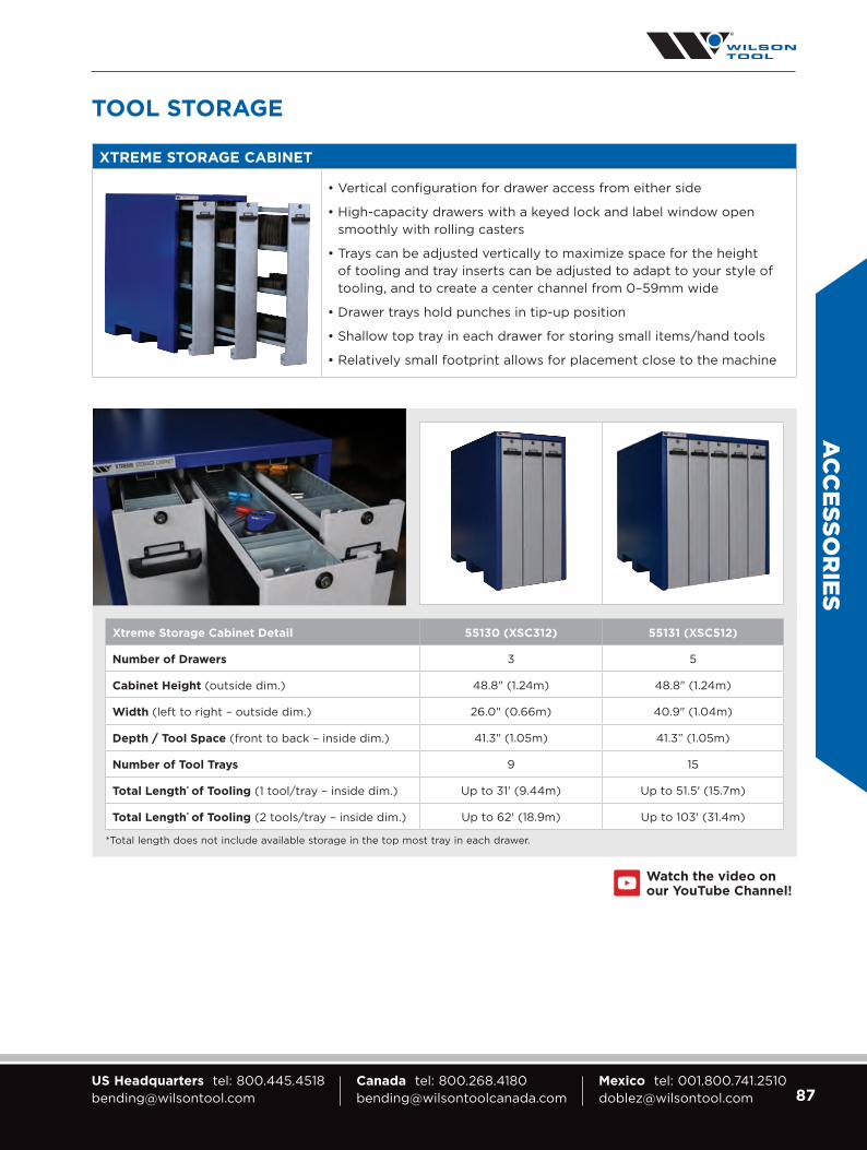
87US Headquarters tel: [email protected]
Canada tel: [email protected]
Mexico tel: [email protected]
XTREME STORAGE CABINET
• Vertical configuration for drawer access from either side
• High-capacity drawers with a keyed lock and label window open smoothly with rolling casters
• Trays can be adjusted vertically to maximize space for the height of tooling and tray inserts can be adjusted to adapt to your style of tooling, and to create a center channel from 0–59mm wide
• Drawer trays hold punches in tip-up position
• Shallow top tray in each drawer for storing small items/hand tools
• R elatively small footprint allows for placement close to the machine
TOOL STORAGE
Xtreme Storage Cabinet Detail 55130 (XSC312) 55131 (XSC512)
Number of Drawers 3 5
Cabinet Height (outside dim.) 48.8" (1.24m) 48.8" (1.24m)
Width (left to right – outside dim.) 26.0" (0.66m) 40.9" (1.04m)
Depth / Tool Space (front to back – inside dim.) 41.3" (1.05m) 41.3” (1.05m)
Number of Tool Trays 9 15
Total Length* of Tooling (1 tool/tray – inside dim.) Up to 31' (9.44m) Up to 51.5' (15.7m)
Total Length* of Tooling (2 tools/tray – inside dim.) Up to 62' (18.9m) Up to 103' (31.4m)
*Total length does not include available storage in the top most tray in each drawer.
Watch the video on our YouTube Channel!
AC
CESSO
RIES

88 Visit wilsontool.com/MyAccount for 24/7 Online Access Quotes, Orders, Drawings, Invoices, Tracking Numbers & More!
DIGITAL PROTRACTOR SET
Part No. 980065
Lightweight, easy-to-use, highly accurate protractors measure angles from 0° to 360° with an accuracy of ± .01°. Set angles in .05° increments. Front locking lever to hold the arm
position. A hold function and reverse reading capability.
MEASURING TOOLS
DIGITAL ANGLE CUBE
Part No. 974119
The compact size of the Digital Cube allows you to quickly read bend angles of work material. Real time display of angle
comparison. Magnets on three sides. Self-rotating display for 180° readings.
DIGITAL THICKNESS GAUGE
Part No. 974117
Compact size with spring loaded jaw mechanism. Accuracy to
0.002". Readings in millimeters, inches and fractions.
AC
CES
SOR
IES

89US Headquarters tel: [email protected]
Canada tel: [email protected]
Mexico tel: [email protected]
PROTECTIVE FABRIC DRAPE
Forms a protective barrier between the sheet metal and the die shoulders during the bending process.
Lasts 5-8 times longer than a urethane drape.
Part No. Description
55335 12.5m [41'] length x 120mm [4.7"] width
55337 12.5m [41'] length x 240mm [9.5"] width
988156 3/8" x 1/2" Cylinder Magnet w/Blue Grip Cover
MARK-FREE BENDING
URETHANE ROLLS — 6 in. x 100 ft.
Part No. Thickness Durometer Description
42530 .015" [.4mm] 85A
(Milky White)
• More elastic than blue
• Well suited for deeper draw applications
• Will not last as long as blue for 90° bends
42531 .030" [.8mm]
42532 .022" [.56mm]
95A
(Blue)
• A more ridged solution
• lasts considerably longer than the white options in many applications
• Harder and less elastic than blue
• Not suited for deeper draw applications
Note: This is not a good time to cheat the V opening and make it smaller. Keep in mind you are filling the V-opening with two thicknesses of urethane so it would be safer to oversize the V-opening a bit. The larger the shoulder radius, the larger the V-opening relative to the material type and thickness, the longer the life will be realized.
AC
CESSO
RIES
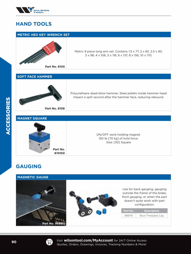
90 Visit wilsontool.com/MyAccount for 24/7 Online Access Quotes, Orders, Drawings, Invoices, Tracking Numbers & More!
METRIC HEX KEY WRENCH SET
Part No. 6105
Metric 9 piece long arm set. Contains 1.5 x 77, 2 x 83, 2.5 x 90, 3 x 98, 4 x 10⁶, 5 x 118, 6 x 137, 8 x 156, 10 x 170.
SOFT FACE HAMMER
Part No. 6106
Polyurethane dead-blow hammer. Steel pellets inside hammer head impact a split second after the hammer face, reducing rebound.
HAND TOOLS
MAGNET SQUARE
Part No. 974150
ON/OFF work holding magnet.150 lb [70 kg] of hold force.
Size: [30] Square
GAUGING
MAGNETIC GAUGE
Part No. 988611
Use for back gauging, gauging outside the frame of the brake, front gauging, or when the part
doesn’t quite work with part configuration.
Part No. Description
988741 Blue Threaded Cap
AC
CES
SOR
IES

91US Headquarters tel: [email protected]
Canada tel: [email protected]
Mexico tel: [email protected]
GAUGING
MAGNETIC SQUARING ARM
Part No. 42750
Increase bending accuracy with this simple hand tool. Suitable for any press
brake die with a flat surface for easy attachment. Adjustable from
0° or 90° and is available in a left-handed or right-handed version.
Part No. Description
42750L Magnetic Squaring Arm LEFT
42750R Magnetic Squaring Arm RIGHT
MAGNETIC SQUARING BLOCK
Part No. 55396
Versatile, durable, 90° squaring block for left or right support and gauging. Strong magnets hold the lightweight tool in place while allowing for easy
repositioning.
AC
CESSO
RIES
DIAL ADJUSTABLE SQUARING ARM
Part No. 55400
Infinite angle squaring arm with tool-free adjustment can be used
as a left or right hand gauge. Significant magnetic holding power keeps the unit in place. Small enough to be out of the way, yet big enough to provide
a sizable surface to rest the material being bent.
Available in early 2022.

United States
Brazil
Canada
Italy
England
Manufacturing and Sales Sites
Mexico
France
Germany
Denmark
Additional Sales Offices
B352C (1.2022)
© Wilson Tool International. All rights reserved.All trademarks are the property of their respective owners.
COMMITTED TO YOUR SUCCESSWilson Tool International is committed to your success. Every product you buy, every employee with
whom you communicate, and every training event you attend, is designed to help customers just
like you be more successful. We will work with you to find the best possible solution to whatever
challenge you may be facing. And, as always, with every order, you’ll get our quality guarantee:
Your success is our priority. If you’re ever unsatisfied with a Wilson Tool International product,
we’ll do everything we can to make it right and keep you up and running.
WILSON TOOL INTERNATIONAL HEADQUARTERS12912 Farnham Avenue N, White Bear Lake, MN 55110, USA800-445-4518 | [email protected]
Canada 800-268-4180 [email protected] 001-800-741-2510 [email protected]