Cylindrical and Conical Mirror Anamorphosis for Image Display
16
International Journal of Signal Processing, Image Processing and Pattern Recognition Vol.9, No.3 (2016), pp.383-398 http://dx.doi.org/10.14257/ijsip.2016.9.3.33 ISSN: 2005-4254 IJSIP Copyright ⓒ 2016 SERSC Cylindrical and Conical Mirror Anamorphosis for Image Display Fan Guo * , Hui Peng, Jin Tang School of Information Science and Engineering, Central South University, Changsha 410083, China [email protected] Abstract Anamorphosis is a deformed image that appears in its true shape only from a certain point of view, out of which it is seen distorted and the illusionary effect is lost. In this paper, we describe a simple method for achieving anamorphosis by utilizing image coordinate transformation. The novelty of this work is the creation of the framework for the implementation of cylindrical and conical mirror anamorphosis, resulting in a tool for artists and designers. A qualitative evaluation approach is proposed to carry on comparative study with other methods. Experimental results demonstrate that using the proposed method one may get a good undistorted image in a mirror with much less user- interaction compared to other approaches. In addition to implementing the illusionary effect, some applications of the anamorphosis are also presented. Keywords: anamorphosis, cylindrical mirror, conical mirror, applications 1. Introduction “Anamorphosis” is a painting technique of drawing distorted images. The viewers are required to use special devices or to take a specific perspective to recognize the undistorted image. The term “Anamorphosis” can be defined as a distorted or monstrous projection or representation of an image on a plane or curved surface, which when view from a certain point, or as reflected from a curved mirror, appears regular and in proportion. Specifically, the anamorphoses that use a cylindrical mirror are called cylindrical anamorphoses. Similarly, the anamorphoses that use a conical mirror are called conical anamorphoses. Given the importance of anamorphosis, many studies on anamorphosis have been conducted. For example, Suga et. al., [1] presented an interactive system which takes the technique of Anamorphosis, with a 2D display and a cylinder mirror. In this system, a distorted image is shown on a flat panel display, and the original image will appear on the cylindrical mirror when a user puts it on the display. Kent [2] developed an executive software call “Anamorph Me” to allow users to carry out the anamorphic transformations. Ravnik et. al., [3] proposed a dynamic anamorphosis which adapts itself to the changing position of the observer so that wherever the observer moves, he sees the same undeformed image. Hansford et. al., [4] presented a method for achieving anamorphosis of 3D objects by utilizing a variation of a projective map that is well- known in the computer graphics literature. The novelty of this work is the creation of anamorphic 3D digital models. However, the specific implementation steps of cylindrical mirror anamorphosis or conical mirror anamorphosis are not the focus of these references. In this paper, we show how to produce cylindrical and conical anamorphoses, which results a good tool for artists and designers to create more maps rendering works. Some applications of the anamorphoses are also discussed. The organizations of this paper are * Corresponding Author
-
Upload
khangminh22 -
Category
Documents
-
view
1 -
download
0
Transcript of Cylindrical and Conical Mirror Anamorphosis for Image Display
International Journal of Signal Processing, Image Processing and Pattern Recognition
Vol.9, No.3 (2016), pp.383-398
http://dx.doi.org/10.14257/ijsip.2016.9.3.33
ISSN: 2005-4254 IJSIP
Copyright ⓒ 2016 SERSC
Cylindrical and Conical Mirror Anamorphosis for Image Display
Fan Guo*, Hui Peng, Jin Tang
School of Information Science and Engineering, Central South University,
Changsha 410083, China
Abstract
Anamorphosis is a deformed image that appears in its true shape only from a certain
point of view, out of which it is seen distorted and the illusionary effect is lost. In this
paper, we describe a simple method for achieving anamorphosis by utilizing image
coordinate transformation. The novelty of this work is the creation of the framework for
the implementation of cylindrical and conical mirror anamorphosis, resulting in a tool
for artists and designers. A qualitative evaluation approach is proposed to carry on
comparative study with other methods. Experimental results demonstrate that using the
proposed method one may get a good undistorted image in a mirror with much less user-
interaction compared to other approaches. In addition to implementing the illusionary
effect, some applications of the anamorphosis are also presented.
Keywords: anamorphosis, cylindrical mirror, conical mirror, applications
1. Introduction
“Anamorphosis” is a painting technique of drawing distorted images. The viewers are
required to use special devices or to take a specific perspective to recognize the
undistorted image. The term “Anamorphosis” can be defined as a distorted or monstrous
projection or representation of an image on a plane or curved surface, which when view
from a certain point, or as reflected from a curved mirror, appears regular and in
proportion. Specifically, the anamorphoses that use a cylindrical mirror are called
cylindrical anamorphoses. Similarly, the anamorphoses that use a conical mirror are
called conical anamorphoses.
Given the importance of anamorphosis, many studies on anamorphosis have been
conducted. For example, Suga et. al., [1] presented an interactive system which takes the
technique of Anamorphosis, with a 2D display and a cylinder mirror. In this system, a
distorted image is shown on a flat panel display, and the original image will appear on the
cylindrical mirror when a user puts it on the display. Kent [2] developed an executive
software call “Anamorph Me” to allow users to carry out the anamorphic
transformations. Ravnik et. al., [3] proposed a dynamic anamorphosis which adapts itself
to the changing position of the observer so that wherever the observer moves, he sees the
same undeformed image. Hansford et. al., [4] presented a method for achieving
anamorphosis of 3D objects by utilizing a variation of a projective map that is well-
known in the computer graphics literature. The novelty of this work is the creation of
anamorphic 3D digital models. However, the specific implementation steps of cylindrical
mirror anamorphosis or conical mirror anamorphosis are not the focus of these
references.
In this paper, we show how to produce cylindrical and conical anamorphoses, which
results a good tool for artists and designers to create more maps rendering works. Some
applications of the anamorphoses are also discussed. The organizations of this paper are
* Corresponding Author
International Journal of Signal Processing, Image Processing and Pattern Recognition
Vol.9, No.3 (2016)
384 Copyright ⓒ 2016 SERSC
as follows: we first discuss the classic principle and philosophy of anamorphosis in
Section 2. Next, in Section 3 we describe the implementation steps of the cylindrical and
conical mirror anamorphosis. The experimental results for the anamorphosis are given in
Section 4. In Section 5, we discuss the possible applications of the anamorphosis.
Conclusions are provided in Section 6.
2. Anamorphosis
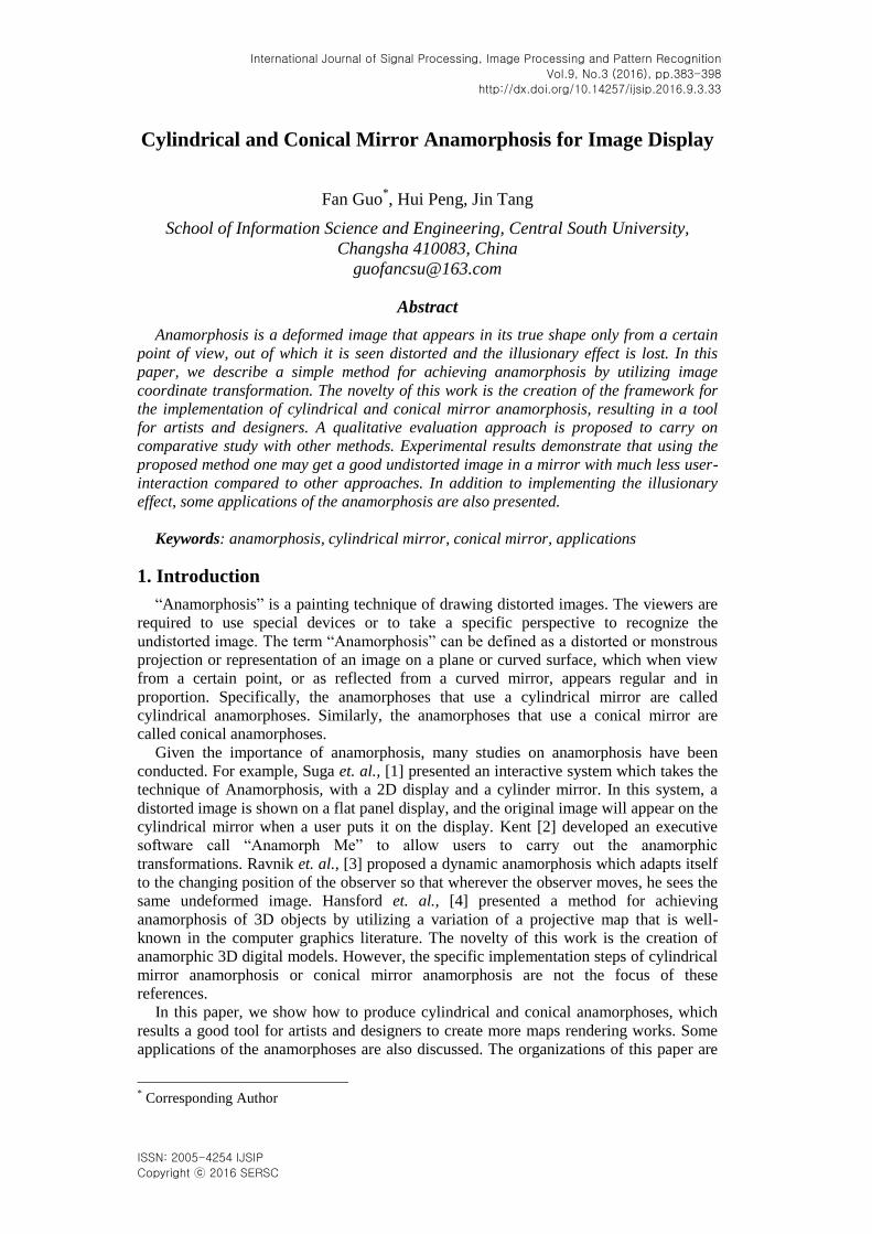
Traditionally, anamorphosis has been created using grid templates [5, 6]. One starts by
marking the anamorphic transformation of an empty square grid, according to certain
choice about the position of the viewpoint, the size and angles of the mirrors, etc. Then,
the square grid is put on top of the original picture, and the contents of each small grid
element are copied across to the corresponding element of the distorted grid. Once this is
done, the grid must be removed to leave the anamorphosis. Figure 1 shows a set of grids
prepared by Jean-Francois Niceron to make a cylindrical mirror anamorphosis.
Figure 1. Making a Cylindrical Mirror Analysis
Needless to say, using grids is a time-consuming business, and requires a fair amount
of artistic skill. With computers, anamorphosis is much easier to make because the
algorithms for anamorphic distortions can be written as computer programs, which can
then be directly applied to many thousands of individual pixels of a digital image.
Therefore, in this paper, we mainly present the generation algorithms of cylindrical and
conical anamorphoses.
As far as we know, there are some explanations behind the physical phenomenon. Our
mind is constantly interpreting and giving structure to the raw visual input from our eyes.
We prefer an ordered world, familiar shapes and regular patterns. One of such features of
human perception is that our brain tends to order visual features in a regular, orderly,
symmetric and simple manner, as formulated by the Gestalt school in psychology [7].
Therefore where possible, we see stable rectangular forms although these forms appear
most of the time distorted due to perspective projection. This principle is called shape
constancy [8]. Perspectival anamorphosis or anamorphic projection was discovered in art
in the late fifteenth century both as a challenge and as a confirmation of the rules of linear
perspective which were discovered at the same time [9]. Classical linear perspective is
based upon the Euclidean paradigm that light travels in straight lines and when light
reflected from an object intersects a planar surface an accurate representation of the
original object is reflected on that surface. While we normally look at images frontally
from a limited range of viewing angles, the viewer of an anamorphic image must usually
be at a radically oblique angle to the picture plane to see the anamorphic image
undistorted. The anamorphic image looked at up front is in such cases usually so
distorted as to be unrecognizable.
Probably the most famous example of anamorphosis in art history is the painting “The
Ambassadors”, by Hans Holbein [see Figure 2(a)]. On the bottom of this painting appears

International Journal of Signal Processing, Image Processing and Pattern Recognition
Vol.9, No.3 (2016)
Copyright ⓒ 2016 SERSC 385
a diagonal blur which appears as a human skull when viewed from the upper right [10].
Nowadays, the cylindrical mirror anamorphosis and conical mirror anamorphosis have
attracted more attentions due to their strong vision impact. Figure 2(b) and Figure 2(c)
show some examples of the two kinds of mirror anamorphosis. As can be seen in the
figure, we can see an undeformed car or an umbrella with the help of cylindrical mirror
or conical mirror.
(a) (b) (c)
Figure 2. Anamorphosis examples. (a) The Ambassadors by Hans Holbein. (b) Cylindrical mirror anamorphosis. (c) Conical mirror anamorphosis.
Besides, since the appreciation of anamorphic images requires an eccentric viewing
point as opposed to a normal or orthogonal viewing point, anamorphosis becomes a term
popular with many postmodern theorists used mainly as a metaphor for the relativity of
vision or the subjectivity of human experience [10]. Anamorphosis serves as a model for
the concept of the gaze, which suggests that visual appreciation rather than passive
looking requires active observing [11, 12]. To appreciate an anamorphic image requires
indeed from the observer that he positions himself precisely in the right spot and directs
his gaze in the right direction as opposed from the normal or centric vision [13] where the
viewer sees himself at the center of the world. Further philosophical considerations of
anamorphosis are nicely summed up by Massey [14]. The exact mechanism that supports
correct space perception from deformed retinal images is still disputed in the human
perception research community. Cutting [15], for example, explains that the visual
system corrects the distortions based on the assumption that objects are rigid. Sedgwick
[16] gives a theoretical analysis based on the concept of available visual information.
More recent research in human perception has shown that the adjustment to oblique
viewing is achieved before the contents of the image are interpreted [17]. As an
unconventional way of seeing, anamorphosis opens a door to artistic creation. Here we
describe a simple method for achieving anamorphosis of original input image by utilizing
a simple image coordinate transformation. The novelty of this work is the creation of a
framework for cylindrical mirror anamorphosis and conical mirror anamorphosis,
resulting in a tool for artists and designers.
3. Implementation
3.1. Algorithm Procedure
Specifically, the proposed algorithms have two steps to produce cylindrical mirror
anamorphosis or conical mirror anamorphosis: the first one is to determine the size of
distorted image according to the mirror radius and angular size. The second step is to find
out the corresponding relations between the original input image and the final distorted
image by using coordinate transformation, and then assign pixel value for the distorted
results. The goal of our algorithms is to let the distorted image appear normal when
International Journal of Signal Processing, Image Processing and Pattern Recognition
Vol.9, No.3 (2016)
386 Copyright ⓒ 2016 SERSC
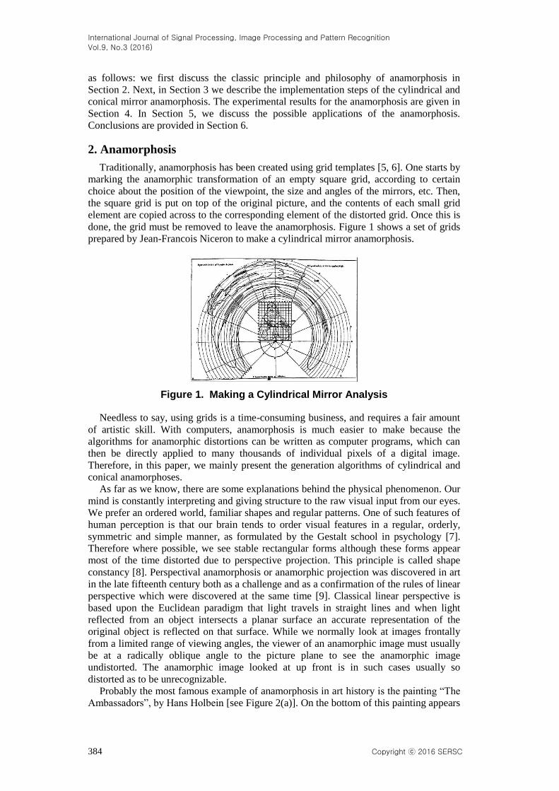
viewed with or reflected from a cylindrical or a conical mirror. The flowchart of our
method is depicted in Figure 3.
original image
coordinate
transformationparameter
setting
pixel value
assignmentdistorted image
Figure 3. Flowchart of the Proposed Algorithm
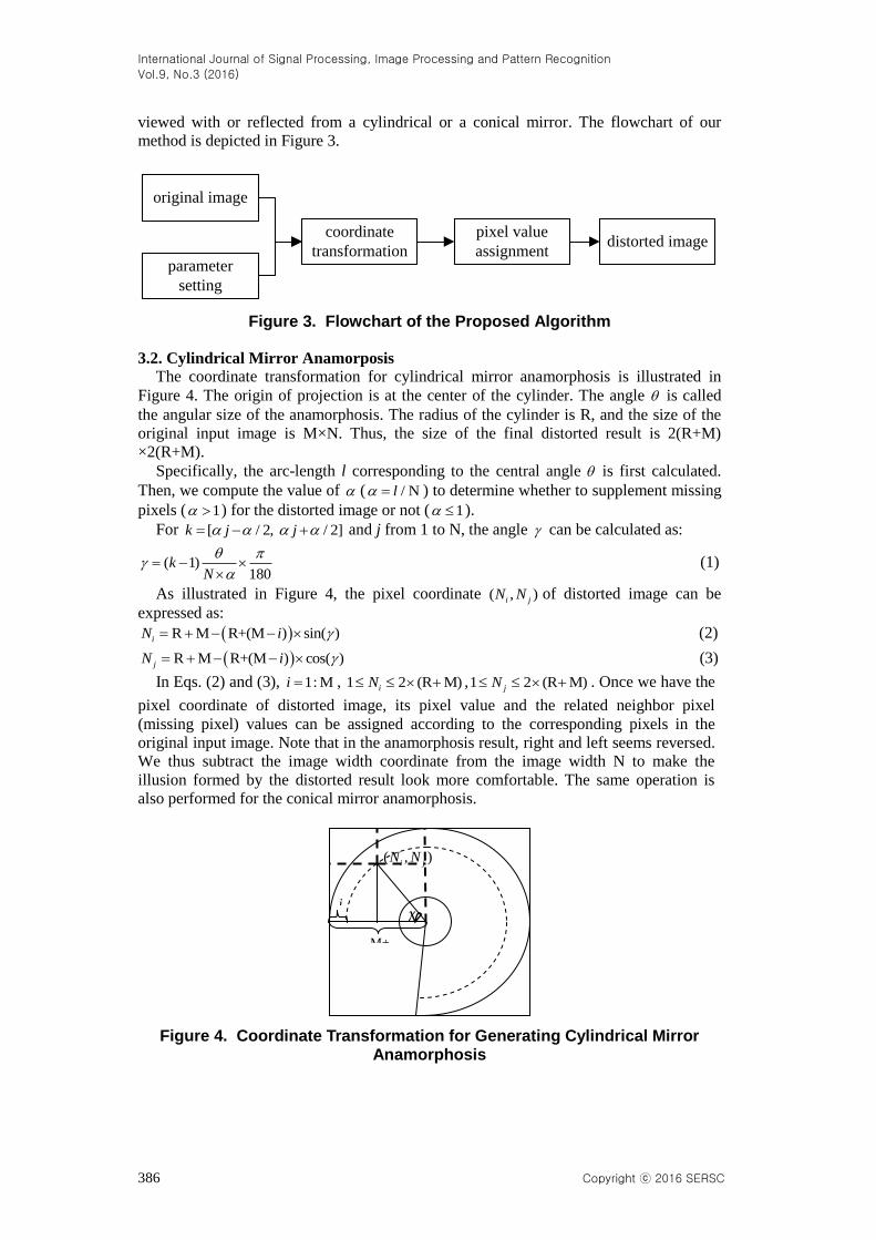
3.2. Cylindrical Mirror Anamorposis
The coordinate transformation for cylindrical mirror anamorphosis is illustrated in
Figure 4. The origin of projection is at the center of the cylinder. The angle is called
the angular size of the anamorphosis. The radius of the cylinder is R, and the size of the
original input image is M×N. Thus, the size of the final distorted result is 2(R+M)
×2(R+M).
Specifically, the arc-length l corresponding to the central angle is first calculated.
Then, we compute the value of ( / Nl ) to determine whether to supplement missing
pixels ( 1 ) for the distorted image or not ( 1 ).
For [ / 2, / 2]k j j and j from 1 to N, the angle can be calculated as:
( 1)180
kN
(1)
As illustrated in Figure 4, the pixel coordinate ( , )i jN N of distorted image can be
expressed as:
R M R+(M ) sin( )iN i (2)
R M R+(M ) cos( )jN i (3)
In Eqs. (2) and (3), 1: Mi , 1 2 (R M)iN ,1 2 (R M)jN . Once we have the
pixel coordinate of distorted image, its pixel value and the related neighbor pixel
(missing pixel) values can be assigned according to the corresponding pixels in the
original input image. Note that in the anamorphosis result, right and left seems reversed.
We thus subtract the image width coordinate from the image width N to make the
illusion formed by the distorted result look more comfortable. The same operation is
also performed for the conical mirror anamorphosis.
Figure 4. Coordinate Transformation for Generating Cylindrical Mirror Anamorphosis
i
M+
R
( , )i jN N
International Journal of Signal Processing, Image Processing and Pattern Recognition
Vol.9, No.3 (2016)
Copyright ⓒ 2016 SERSC 387
In our algorithm, there are two inputs: the mirror radius R and the angular size of the
anamorphosis . The operation is performed on three color channels independently. The
pseudocode of the cylindrical mirror anamorphosis generation is presented in Figure 5.
Algorithm 1 : Cylindrical mirror anamorphosis generation
Input: Original input image I, Mirror radius R, Angle size
Output: Distorted image Inew
Step 1 // Initialize the distorted image
1.1 mrows 2 (R M) ; ncols 2 (R M) ;
1.2 Set the size of the three color channel in the distorted image to be mrows×ncols, respectively.
Step 2 // Coordinate transformation and pixel value assignment
2.1 Determine whether the missing pixel exists.
R M / 180 ; [1,M];i N i
if 1
1 ;
end
2.2 // Coordinate transformation
For [1,M], [1,N], [ /2, /2]i j k j j , we have
( 1) ( / (N )) ( /180)k ;
R M R+(M ) sin( )iN i ;
R M R+(M ) cos( )jN i ;
2.3 // Pixel value assignment
For [1,M], [1,N], {R,G,B}i j c , we have
( , ) ( ,N 1); [1,mrows], [1,ncols];c c
new i j i jI N N I i j N N
( 1, 1) ( ,N 1); 1 [1,mrows], 1 [1,ncols];c c
new i j i jI N N I i j N N
( 1, 1) ( ,N 1); 1 [1,mrows], 1 [1,ncols];c c
new i j i jI N N I i j N N
( , 1) ( ,N 1); [1,mrows], 1 [1,ncols].c c
new i j i jI N N I i j N N
Step 3 // Result display
3.1 Combine the three color channel of the distorted image;
3.2 Display the cylindrical mirror anamorphosis result Inew.
Figure 5. The Pseudo-Code of the Cylindrical Mirror Anamorphosis Generation
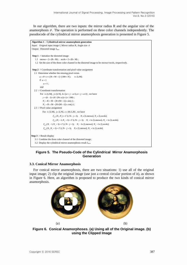
3.3. Conical Mirror Anamorphosis
For conical mirror anamorphosis, there are two situations: 1) use all of the original
input image; 2) clip the original image (use just a central circular portion of it), as shown
in Figure 6. Here, an algorithm is proposed to produce the two kinds of conical mirror
anamorphosis.
(a) (b)
Figure 6. Conical Anamorphoses. (a) Using all of the Original image. (b) using the Clipped Image
International Journal of Signal Processing, Image Processing and Pattern Recognition
Vol.9, No.3 (2016)
388 Copyright ⓒ 2016 SERSC
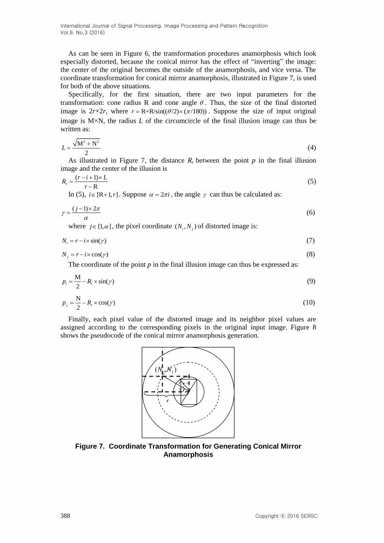
As can be seen in Figure 6, the transformation procedures anamorphosis which look
especially distorted, because the conical mirror has the effect of “inverting” the image:
the center of the original becomes the outside of the anamorphosis, and vice versa. The
coordinate transformation for conical mirror anamorphosis, illustrated in Figure 7, is used
for both of the above situations.
Specifically, for the first situation, there are two input parameters for the
transformation: cone radius R and cone angle . Thus, the size of the final distorted
image is 2r×2r, where R+R/sin(( /2) ( /180))r . Suppose the size of input original
image is M×N, the radius L of the circumcircle of the final illusion image can thus be
written as:
2 2M N
2L
(4)
As illustrated in Figure 7, the distance Rr between the point p in the final illusion
image and the center of the illusion is
( 1)
Rr
r i LR
r
(5)
In (5), [R 1, ]i r . Suppose 2 i , the angle can thus be calculated as:
( 1) 2j
(6)
where [1, ]j , the pixel coordinate ( , )i jN N of distorted image is:
sin( )iN r i (7)
cos( )jN r i (8)
The coordinate of the point p in the final illusion image can thus be expressed as:
Msin( )
2i rp R (9)
Ncos( )
2j rp R (10)
Finally, each pixel value of the distorted image and its neighbor pixel values are
assigned according to the corresponding pixels in the original input image. Figure 8
shows the pseudocode of the conical mirror anamorphosis generation.
Figure 7. Coordinate Transformation for Generating Conical Mirror Anamorphosis
( , )i jN N
r
p

International Journal of Signal Processing, Image Processing and Pattern Recognition
Vol.9, No.3 (2016)
Copyright ⓒ 2016 SERSC 389
Algorithm 2: Conical anamorphosis generation using the whole input image
Input: Original input image I, Mirror radius R, Angle size
Output: Distorted image Inew
Step 1 // Initialize the distorted image
1.1 R R / sin(( / 2) ( /180))r ;
mrows 2 ;r ncols 2 ;r 2 2(1 / 2) M NL ; // L is the radius of the circumcircle of the final illusion image
1.2 Set the size of the three color channel in the distorted image to be 2r×2r, respectively.
Step 2 // Coordinate transformation and pixel value assignment
2.1 Determine the distance between the point p in the final illusion image and the center of the illusion
=(( - +1)/( -R ; [R , ])) 1r i rR r i r L
2.2 // Coordinate transformation
For [R 1, ]i r , we have 2 i
For [1, ]j , we have
=(( -1) (2 ))/j ;
sin( )iN r i ; cos( )jN r i ;
M / 2 sin( )i rp R ; N / 2 cos( )j rp R ;
2.3 // Pixel value assignment
For [R 1, ], [1, ], {R,G,B}i r j c , we have
( , ) ( ,N 1 ); [1,mrows], [1,ncols], [1,M], [1,N];c c
new i j i j i j i jI N N I p p N N p p
( 1, 1) ( ,N 1 ); 1 [1,mrows], 1 [1,ncols], [1,M], [1,N];c c
new i j i j i j i jI N N I p p N N p p
( 1, 1) ( ,N 1 ); 1 [1,mrows], 1 [1,ncols], [1,M], [1,N];c c
new i j i j i j i jI N N I p p N N p p
( , 1) ( ,N 1 ); [1,mrows], 1 [1,ncols], [1,M], [1,N].c c
new i j i j i j i jI N N I p p N N p p
Step 3 // Result display
3.1 Combine the three color channel of the distorted image;
3.2 Display the conical mirror anamorphosis result Inew using the whole input image.
Figure 8. The Pseudo-code of the Conical Anamorphoses Generated using the Whole Image
For the second situation, the image used for display is first clipped according to the
minimum value of image height M and image width N. Suppose the minimum value is
Len, Len = min(M, N). Thus, the radius of the circumcircle of the final illusion image is
L = Len/2. The maximum value between M and N is denoted as Len_max, that is
Len_max = max(M, N). Using Eqs. (5) to (10), we can obtain our final distorted result, as
shown in Figure 6(b). However, different from the first situation that performs the
operations on the whole input image, the value range of the coordinate of a point p in the
final illusion image is assigned according to the clipped image. Therefore, the procedure
for assigning pixel values is as follows. Given is an original input image I with a size of
M×N, and the output is the distorted image Inew.
(1) If M > N, we have
( , ) ( , N 1 );
[1,mrows], [1,ncols], [(len_max len) / 2,(len_max len) / 2], [1, len];
c c
new i j i j
i j i j
I N N I p p
N N p p
( 1, 1) ( , N 1 );
1 [1,mrows], 1 [1,ncols], [(len_max len) / 2,(len_max len) / 2], [1, len];
c c
new i j i j
i j i j
I N N I p p
N N p p
( 1, 1) ( , N 1 );
1 [1,mrows], 1 [1,ncols], [(len_max len) / 2,(len_max len) / 2], [1, len];
c c
new i j i j
i j i j
I N N I p p
N N p p
International Journal of Signal Processing, Image Processing and Pattern Recognition
Vol.9, No.3 (2016)
390 Copyright ⓒ 2016 SERSC
( , 1) ( , N 1 );
[1,mrows], 1 [1,ncols], [(len_max len) / 2,(len_max len) / 2], [1, len].
c c
new i j i j
i j i j
I N N I p p
N N p p
(2) If M <= N, we have similar operations, the only difference is that the value range
of pi now change into [1, Len], and the range of pj now change into [(Len_max-Len)/2,
(Len_max+Len)/2].
This procedure ensures the final illusion image within the range of the clipped image.
4. Experimental Results
In our experiment, we use light reflecting plastic or the stainless steel cylinders which
are polished to high reflectiveness as our reflective materials. iPad is also used here for
displaying the distorted results and placing the reflective mirrors.
4.1. Parameter Setting
Two parameters R and are used to control the appearance of the distorted results for
both cylindrical and conical mirror anamorphosis. The value of R control the mirror
radius, and the value of controls the angle of the sector in distorted result.
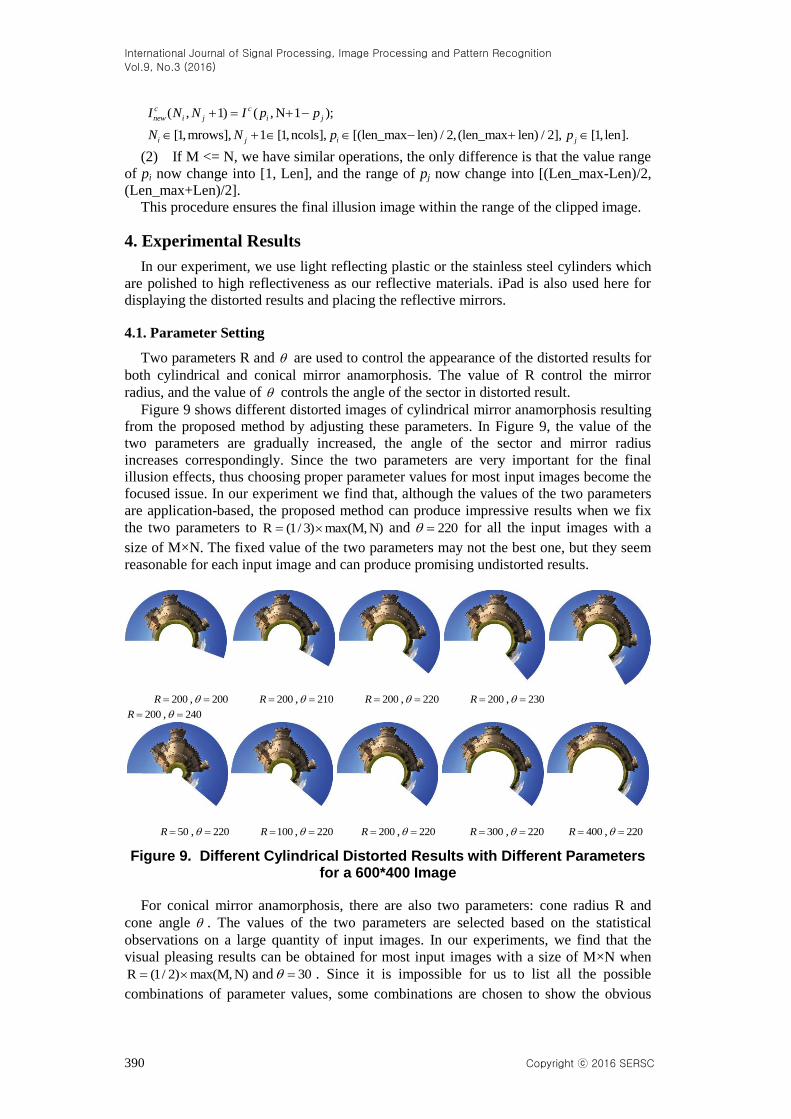
Figure 9 shows different distorted images of cylindrical mirror anamorphosis resulting
from the proposed method by adjusting these parameters. In Figure 9, the value of the
two parameters are gradually increased, the angle of the sector and mirror radius
increases correspondingly. Since the two parameters are very important for the final
illusion effects, thus choosing proper parameter values for most input images become the
focused issue. In our experiment we find that, although the values of the two parameters
are application-based, the proposed method can produce impressive results when we fix
the two parameters to R (1/ 3) max(M, N) and 220 for all the input images with a
size of M×N. The fixed value of the two parameters may not the best one, but they seem
reasonable for each input image and can produce promising undistorted results.
200R , 200 200R , 210 200R , 220 200R , 230
200R , 240
50R , 220 100R , 220 200R , 220 300R , 220 400R , 220
Figure 9. Different Cylindrical Distorted Results with Different Parameters for a 600*400 Image
For conical mirror anamorphosis, there are also two parameters: cone radius R and
cone angle . The values of the two parameters are selected based on the statistical
observations on a large quantity of input images. In our experiments, we find that the
visual pleasing results can be obtained for most input images with a size of M×N when
R (1/ 2) max(M, N) and 30 . Since it is impossible for us to list all the possible
combinations of parameter values, some combinations are chosen to show the obvious
International Journal of Signal Processing, Image Processing and Pattern Recognition
Vol.9, No.3 (2016)
Copyright ⓒ 2016 SERSC 391
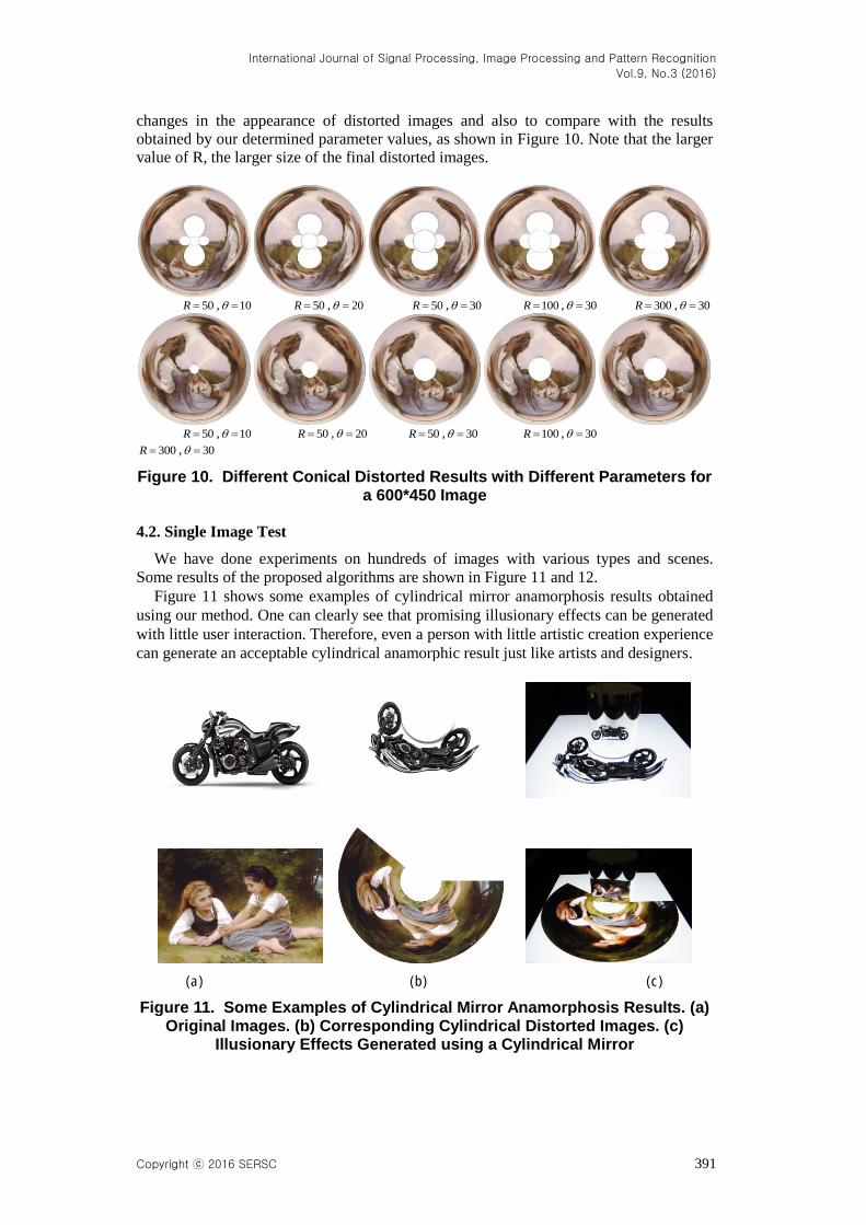
changes in the appearance of distorted images and also to compare with the results
obtained by our determined parameter values, as shown in Figure 10. Note that the larger
value of R, the larger size of the final distorted images.
50R , 10 50R , 20 50R , 30 100R , 30 300R , 30
50R , 10 50R , 20 50R , 30 100R , 30
300R , 30
Figure 10. Different Conical Distorted Results with Different Parameters for a 600*450 Image
4.2. Single Image Test
We have done experiments on hundreds of images with various types and scenes.
Some results of the proposed algorithms are shown in Figure 11 and 12.
Figure 11 shows some examples of cylindrical mirror anamorphosis results obtained
using our method. One can clearly see that promising illusionary effects can be generated
with little user interaction. Therefore, even a person with little artistic creation experience
can generate an acceptable cylindrical anamorphic result just like artists and designers.
(a) (b) (c)
Figure 11. Some Examples of Cylindrical Mirror Anamorphosis Results. (a) Original Images. (b) Corresponding Cylindrical Distorted Images. (c)
Illusionary Effects Generated using a Cylindrical Mirror

International Journal of Signal Processing, Image Processing and Pattern Recognition
Vol.9, No.3 (2016)
392 Copyright ⓒ 2016 SERSC
Figure 12 displays some examples of conical anamorphosis results obtained using our
algorithms. As shown in Figure 12(b), conical distorted image can be generated using the
whole input image or clipped image. From Figure 12(c), we can see that both the two
ways can generate visual pleasing illusionary effects with the help of a conical mirror.
(a) (b) (c)
Figure 12. Some Examples of Conical Mirror Anamorphosis Results. (a) Original images. (b) Corresponding Conical Distorted Images. Up: Using
the Whole Input Image, Down: using the Clipped Image. (c) Illusionary Effects Generated using a Conical Mirror
To verify the effectiveness of the proposed algorithms, some anamorphic methods are
used here to compare with our algorithm. These existing methods include Suga’s method
[1] which using Photoshop’s polar coordinates filter to obtain the distorted images, and
Kent’s “Anamorph Me” software [2] to implement the cylindrical and conical mirror
anamorphosis.
For Suga’s method, the whole procedure of using Photoshop’s polar coordinates filter
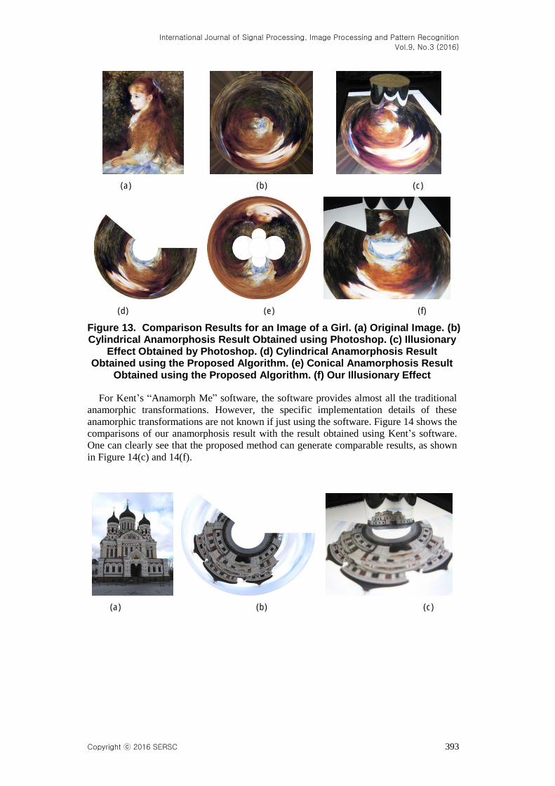
has some steps and each step need user involvement. Figure 13 shows the comparison of
our result with that obtained using Photoshop. One can clearly see that the illusionary
effect produced by the polar coordinates filter is not satisfying owing to the limited
information it used for transformation, while our method can produce better illusionary
effect with less user-interaction. Besides, the polar coordinates filter can only produce
cylindrical anamorphic image, while using the proposed algorithms we can obtain both
cylindrical and conical anamorphic results, as shown in Figure 13.
International Journal of Signal Processing, Image Processing and Pattern Recognition
Vol.9, No.3 (2016)
Copyright ⓒ 2016 SERSC 393
(a) (b) (c)
(d) (e) (f)
Figure 13. Comparison Results for an Image of a Girl. (a) Original Image. (b) Cylindrical Anamorphosis Result Obtained using Photoshop. (c) Illusionary
Effect Obtained by Photoshop. (d) Cylindrical Anamorphosis Result Obtained using the Proposed Algorithm. (e) Conical Anamorphosis Result
Obtained using the Proposed Algorithm. (f) Our Illusionary Effect
For Kent’s “Anamorph Me” software, the software provides almost all the traditional
anamorphic transformations. However, the specific implementation details of these
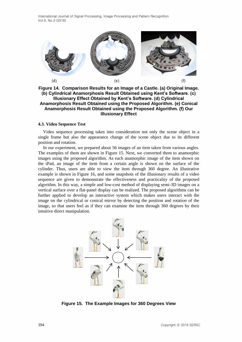
anamorphic transformations are not known if just using the software. Figure 14 shows the
comparisons of our anamorphosis result with the result obtained using Kent’s software.
One can clearly see that the proposed method can generate comparable results, as shown
in Figure 14(c) and 14(f).
(a) (b) (c)
International Journal of Signal Processing, Image Processing and Pattern Recognition
Vol.9, No.3 (2016)
394 Copyright ⓒ 2016 SERSC
(d) (e) (f)
Figure 14. Comparison Results for an Image of a Castle. (a) Original Image. (b) Cylindrical Anamorphosis Result Obtained using Kent’s Software. (c)
Illusionary Effect Obtained by Kent’s Software. (d) Cylindrical Anamorphosis Result Obtained using the Proposed Algorithm. (e) Conical
Anamorphosis Result Obtained using the Proposed Algorithm. (f) Our Illusionary Effect
4.3. Video Sequence Test
Video sequence processing takes into consideration not only the scene object in a
single frame but also the appearance change of the scene object due to its different
position and rotation.
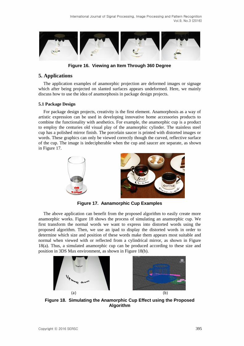
In our experiment, we prepared about 56 images of an item taken from various angles.
The examples of them are shown in Figure 15. Next, we converted them to anamorphic
images using the proposed algorithm. As each anamorphic image of the item shown on
the iPad, an image of the item from a certain angle is shown on the surface of the
cylinder. Thus, users are able to view the item through 360 degree. An illustrative
example is shown in Figure 16, and some snapshots of the illusionary results of a video
sequence are given to demonstrate the effectiveness and practicality of the proposed
algorithm. In this way, a simple and low-cost method of displaying semi-3D images on a
vertical surface over a flat-panel display can be realized. The proposed algorithms can be
further applied to develop an interactive system which makes users interact with the
image on the cylindrical or conical mirror by detecting the position and rotation of the
image, so that users feel as if they can examine the item through 360 degrees by their
intuitive direct manipulation.
Figure 15. The Example Images for 360 Degrees View
International Journal of Signal Processing, Image Processing and Pattern Recognition
Vol.9, No.3 (2016)
Copyright ⓒ 2016 SERSC 395
Figure 16. Viewing an Item Through 360 Degree
5. Applications
The application examples of anamorphic projection are deformed images or signage
which after being projected on slanted surfaces appears undeformed. Here, we mainly
discuss how to use the idea of anamorphosis in package design projects.
5.1 Package Design
For package design projects, creativity is the first element. Anamorphosis as a way of
artistic expression can be used in developing innovative home accessories products to
combine the functionality with aesthetics. For example, the anamorphic cup is a product
to employ the centuries old visual play of the anamorphic cylinder. The stainless steel
cup has a polished mirror finish. The porcelain saucer is printed with distorted images or
words. These graphics can only be viewed correctly though the curved, reflective surface
of the cup. The image is indecipherable when the cup and saucer are separate, as shown
in Figure 17.
Figure 17. Aanamorphic Cup Examples
The above application can benefit from the proposed algorithm to easily create more
anamorphic works. Figure 18 shows the process of simulating an anamorphic cup. We
first transform the normal words we want to express into distorted words using the
proposed algorithm. Then, we use an ipad to display the distorted words in order to
determine which size and position of these words make them appears most suitable and
normal when viewed with or reflected from a cylindrical mirror, as shown in Figure
18(a). Thus, a simulated anamorphic cup can be produced according to these size and
position in 3DS Max environment, as shown in Figure 18(b).
(a) (b)
Figure 18. Simulating the Anamorphic Cup Effect using the Proposed Algorithm
International Journal of Signal Processing, Image Processing and Pattern Recognition
Vol.9, No.3 (2016)
396 Copyright ⓒ 2016 SERSC
5.2. Other Applications
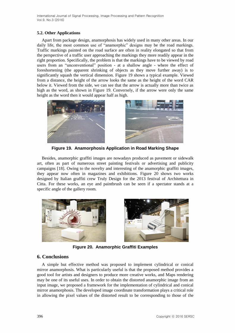
Apart from package design, anamorphosis has widely used in many other areas. In our
daily life, the most common use of “anamorphic” designs may be the road markings.
Traffic markings painted on the road surface are often in reality elongated so that from
the perspective of a traffic user approaching the markings they more readily appear in the
right proportion. Specifically, the problem is that the markings have to be viewed by road
users from an “unconventional” position - at a shallow angle - where the effect of
foreshortening (the apparent shrinking of objects as they move further away) is to
significantly squash the vertical dimension. Figure 19 shows a typical example. Viewed
from a distance, the height of the arrow looks the same as the height of the word CAR
below it. Viewed from the side, we can see that the arrow is actually more than twice as
high as the word, as shown in Figure 19. Conversely, if the arrow were only the same
height as the word then it would appear half as high.
Figure 19. Anamorphosis Application in Road Marking Shape
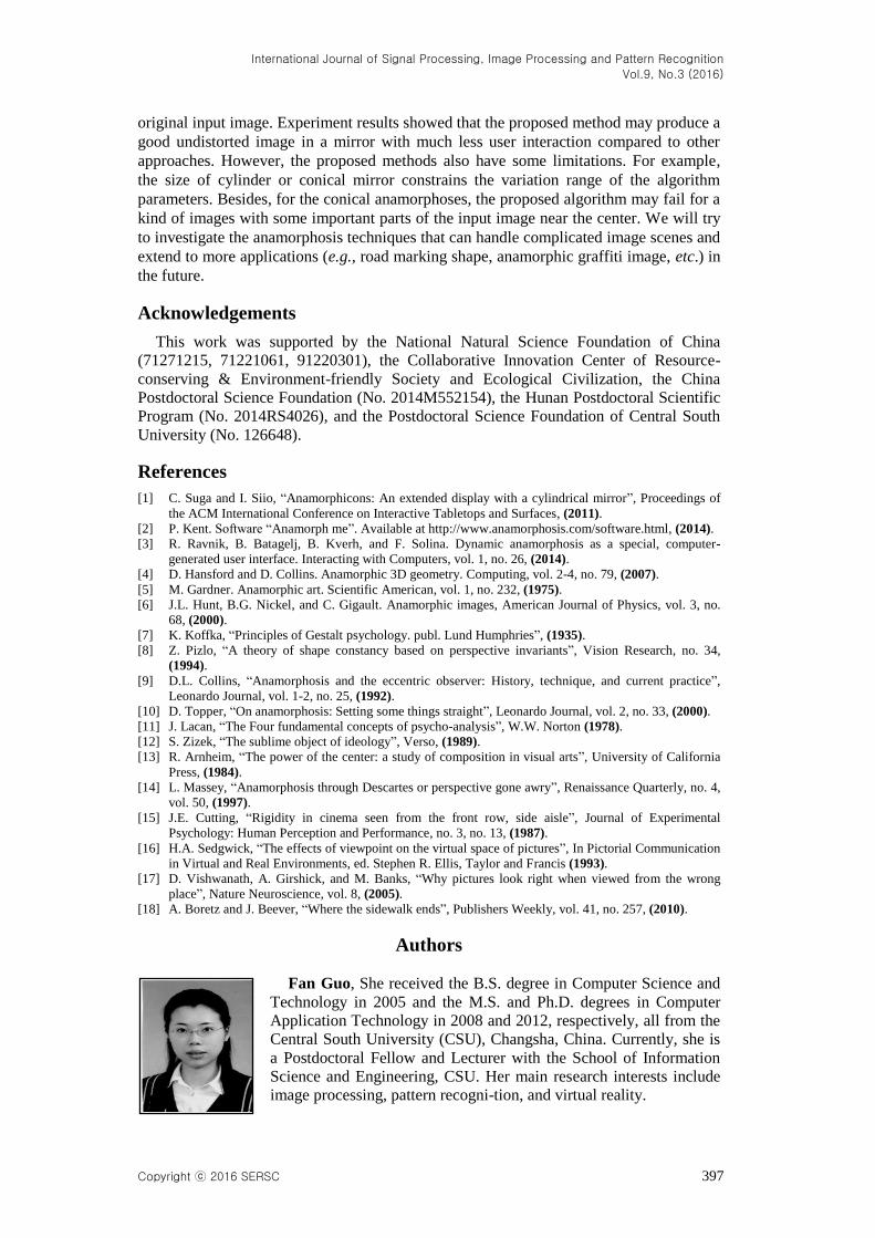
Besides, anamorphic graffiti images are nowadays produced as pavement or sidewalk
art, often as part of numerous street painting festivals or advertising and publicity
campaigns [18]. Owing to the novelty and interesting of the anamorphic graffiti images,
they appear now often in magazines and exhibitions. Figure 20 shows two works
designed by Italian graffiti crew Truly Design for the 2013 festival of Architettura in
Citta. For these works, an eye and paintbrush can be seen if a spectator stands at a
specific angle of the gallery room.
Figure 20. Anamorphic Graffiti Examples
6. Conclusions
A simple but effective method was proposed to implement cylindrical or conical
mirror anamorphosis. What is particularly useful is that the proposed method provides a
good tool for artists and designers to produce more creative works, and Maps rendering
may be one of its useful uses. In order to obtain the distorted anamorphic image from an
input image, we proposed a framework for the implementation of cylindrical and conical
mirror anamorphosis. The developed image coordinate transformation plays a critical role
in allowing the pixel values of the distorted result to be corresponding to those of the
International Journal of Signal Processing, Image Processing and Pattern Recognition
Vol.9, No.3 (2016)
Copyright ⓒ 2016 SERSC 397
original input image. Experiment results showed that the proposed method may produce a
good undistorted image in a mirror with much less user interaction compared to other
approaches. However, the proposed methods also have some limitations. For example,
the size of cylinder or conical mirror constrains the variation range of the algorithm
parameters. Besides, for the conical anamorphoses, the proposed algorithm may fail for a
kind of images with some important parts of the input image near the center. We will try
to investigate the anamorphosis techniques that can handle complicated image scenes and
extend to more applications (e.g., road marking shape, anamorphic graffiti image, etc.) in
the future.
Acknowledgements
This work was supported by the National Natural Science Foundation of China
(71271215, 71221061, 91220301), the Collaborative Innovation Center of Resource-
conserving & Environment-friendly Society and Ecological Civilization, the China
Postdoctoral Science Foundation (No. 2014M552154), the Hunan Postdoctoral Scientific
Program (No. 2014RS4026), and the Postdoctoral Science Foundation of Central South
University (No. 126648).
References
[1] C. Suga and I. Siio, “Anamorphicons: An extended display with a cylindrical mirror”, Proceedings of
the ACM International Conference on Interactive Tabletops and Surfaces, (2011).
[2] P. Kent. Software “Anamorph me”. Available at http://www.anamorphosis.com/software.html, (2014).
[3] R. Ravnik, B. Batagelj, B. Kverh, and F. Solina. Dynamic anamorphosis as a special, computer-
generated user interface. Interacting with Computers, vol. 1, no. 26, (2014).
[4] D. Hansford and D. Collins. Anamorphic 3D geometry. Computing, vol. 2-4, no. 79, (2007).
[5] M. Gardner. Anamorphic art. Scientific American, vol. 1, no. 232, (1975).
[6] J.L. Hunt, B.G. Nickel, and C. Gigault. Anamorphic images, American Journal of Physics, vol. 3, no.
68, (2000).
[7] K. Koffka, “Principles of Gestalt psychology. publ. Lund Humphries”, (1935).
[8] Z. Pizlo, “A theory of shape constancy based on perspective invariants”, Vision Research, no. 34,
(1994).
[9] D.L. Collins, “Anamorphosis and the eccentric observer: History, technique, and current practice”,
Leonardo Journal, vol. 1-2, no. 25, (1992).
[10] D. Topper, “On anamorphosis: Setting some things straight”, Leonardo Journal, vol. 2, no. 33, (2000).
[11] J. Lacan, “The Four fundamental concepts of psycho-analysis”, W.W. Norton (1978).
[12] S. Zizek, “The sublime object of ideology”, Verso, (1989).
[13] R. Arnheim, “The power of the center: a study of composition in visual arts”, University of California
Press, (1984).
[14] L. Massey, “Anamorphosis through Descartes or perspective gone awry”, Renaissance Quarterly, no. 4,
vol. 50, (1997).
[15] J.E. Cutting, “Rigidity in cinema seen from the front row, side aisle”, Journal of Experimental
Psychology: Human Perception and Performance, no. 3, no. 13, (1987).
[16] H.A. Sedgwick, “The effects of viewpoint on the virtual space of pictures”, In Pictorial Communication
in Virtual and Real Environments, ed. Stephen R. Ellis, Taylor and Francis (1993).
[17] D. Vishwanath, A. Girshick, and M. Banks, “Why pictures look right when viewed from the wrong
place”, Nature Neuroscience, vol. 8, (2005).
[18] A. Boretz and J. Beever, “Where the sidewalk ends”, Publishers Weekly, vol. 41, no. 257, (2010).
Authors
Fan Guo, She received the B.S. degree in Computer Science and
Technology in 2005 and the M.S. and Ph.D. degrees in Computer
Application Technology in 2008 and 2012, respectively, all from the
Central South University (CSU), Changsha, China. Currently, she is
a Postdoctoral Fellow and Lecturer with the School of Information
Science and Engineering, CSU. Her main research interests include
image processing, pattern recogni-tion, and virtual reality.
International Journal of Signal Processing, Image Processing and Pattern Recognition
Vol.9, No.3 (2016)
398 Copyright ⓒ 2016 SERSC
Hui Peng, He received the B.Eng. and M.Eng. degrees in Control
Engineering from Central South University (CSU), Changsha, China,
in 1983 and 1986, respectively, and the Ph.D. degree in Statistical
Science from the Graduate University for Advanced Studies,
Hayama, Japan, in 2003. He is currently a Professor with the School
of Information Science and Engineering, CSU. His research interests
include nonlinear system modeling, statistical modeling, system
identification, parameter optimization, signal processing, predictive
control, robust control, and process control.
Jin Tang, He received the B.S. and M.S. degrees from Peking
University, Beijing, China, in 1987 and 1990, respectively, and the
Ph.D. degree in pattern recognition and intelligence system from
Central South University (CSU), Hunan, China, in 2002. He is
currently a Professor with the School of Information Science and
Engineering, CSU, Changsha, China. His current research interests
include image processing, pattern recognition, and computer vision.