Cyclic Response of Non-ductile RC Frame with Steel Fibers at Beam-column Joints and Plastic Hinge...
22
This article was downloaded by: [Indian Institute of Technology - Delhi], [Dipti Ranjan Sahoo] On: 03 July 2014, At: 22:49 Publisher: Taylor & Francis Informa Ltd Registered in England and Wales Registered Number: 1072954 Registered office: Mortimer House, 37-41 Mortimer Street, London W1T 3JH, UK Journal of Earthquake Engineering Publication details, including instructions for authors and subscription information: http://www.tandfonline.com/loi/ueqe20 Cyclic Response of Non-ductile RC Frame with Steel Fibers at Beam-Column Joints and Plastic Hinge Regions Romanbabu M. Oinam a , Dipti Ranjan Sahoo a & Rahul Sindhu a a Department of Civil Engineering, Indian Institute of Technology Delhi, New Delhi, India Accepted author version posted online: 23 Apr 2014.Published online: 01 Jul 2014. To cite this article: Romanbabu M. Oinam, Dipti Ranjan Sahoo & Rahul Sindhu (2014) Cyclic Response of Non-ductile RC Frame with Steel Fibers at Beam-Column Joints and Plastic Hinge Regions, Journal of Earthquake Engineering, 18:6, 908-928, DOI: 10.1080/13632469.2014.916239 To link to this article: http://dx.doi.org/10.1080/13632469.2014.916239 PLEASE SCROLL DOWN FOR ARTICLE Taylor & Francis makes every effort to ensure the accuracy of all the information (the “Content”) contained in the publications on our platform. However, Taylor & Francis, our agents, and our licensors make no representations or warranties whatsoever as to the accuracy, completeness, or suitability for any purpose of the Content. Any opinions and views expressed in this publication are the opinions and views of the authors, and are not the views of or endorsed by Taylor & Francis. The accuracy of the Content should not be relied upon and should be independently verified with primary sources of information. Taylor and Francis shall not be liable for any losses, actions, claims, proceedings, demands, costs, expenses, damages, and other liabilities whatsoever or howsoever caused arising directly or indirectly in connection with, in relation to or arising out of the use of the Content. This article may be used for research, teaching, and private study purposes. Any substantial or systematic reproduction, redistribution, reselling, loan, sub-licensing, systematic supply, or distribution in any form to anyone is expressly forbidden. Terms & Conditions of access and use can be found at http://www.tandfonline.com/page/terms- and-conditions
Transcript of Cyclic Response of Non-ductile RC Frame with Steel Fibers at Beam-column Joints and Plastic Hinge...

This article was downloaded by: [Indian Institute of Technology - Delhi], [Dipti RanjanSahoo]On: 03 July 2014, At: 22:49Publisher: Taylor & FrancisInforma Ltd Registered in England and Wales Registered Number: 1072954 Registeredoffice: Mortimer House, 37-41 Mortimer Street, London W1T 3JH, UK
Journal of Earthquake EngineeringPublication details, including instructions for authors andsubscription information:http://www.tandfonline.com/loi/ueqe20
Cyclic Response of Non-ductile RC Framewith Steel Fibers at Beam-Column Jointsand Plastic Hinge RegionsRomanbabu M. Oinama, Dipti Ranjan Sahooa & Rahul Sindhua
a Department of Civil Engineering, Indian Institute of TechnologyDelhi, New Delhi, IndiaAccepted author version posted online: 23 Apr 2014.Publishedonline: 01 Jul 2014.
To cite this article: Romanbabu M. Oinam, Dipti Ranjan Sahoo & Rahul Sindhu (2014) Cyclic Responseof Non-ductile RC Frame with Steel Fibers at Beam-Column Joints and Plastic Hinge Regions, Journalof Earthquake Engineering, 18:6, 908-928, DOI: 10.1080/13632469.2014.916239
To link to this article: http://dx.doi.org/10.1080/13632469.2014.916239
PLEASE SCROLL DOWN FOR ARTICLE
Taylor & Francis makes every effort to ensure the accuracy of all the information (the“Content”) contained in the publications on our platform. However, Taylor & Francis,our agents, and our licensors make no representations or warranties whatsoever as tothe accuracy, completeness, or suitability for any purpose of the Content. Any opinionsand views expressed in this publication are the opinions and views of the authors,and are not the views of or endorsed by Taylor & Francis. The accuracy of the Contentshould not be relied upon and should be independently verified with primary sourcesof information. Taylor and Francis shall not be liable for any losses, actions, claims,proceedings, demands, costs, expenses, damages, and other liabilities whatsoever orhowsoever caused arising directly or indirectly in connection with, in relation to or arisingout of the use of the Content.
This article may be used for research, teaching, and private study purposes. Anysubstantial or systematic reproduction, redistribution, reselling, loan, sub-licensing,systematic supply, or distribution in any form to anyone is expressly forbidden. Terms &Conditions of access and use can be found at http://www.tandfonline.com/page/terms-and-conditions

Journal of Earthquake Engineering, 18:908–928, 2014Copyright © A. S. ElnashaiISSN: 1363-2469 print / 1559-808X onlineDOI: 10.1080/13632469.2014.916239
Cyclic Response of Non-ductile RC Frame withSteel Fibers at Beam-Column Joints
and Plastic Hinge Regions
ROMANBABU M. OINAM, DIPTI RANJAN SAHOO,and RAHUL SINDHU
Department of Civil Engineering, Indian Institute of Technology Delhi,New Delhi, India
An experimental study has been conducted on a reduced-scale gravity-load designed test frame toinvestigate its overall performance due to the addition of steel fiber-reinforced concrete (SFRC) at thecritical regions. Two geometrically similar specimens, namely, reinforced concrete (RC) and SFRC,are tested under slow-cyclic lateral loading. End-hooked steel fibers (aspect ratio = 80) of 1.0%volume fraction were used in the SFRC mix for a distance of one-and-half times the member size nearthe joint regions. The addition of steel fibers improved the damage tolerance, lateral load resistingcapacity, lateral stiffness, ductility, and energy dissipation of the frame.
Keywords Beam-Column Joint; Plastic Hinge; Quasi-Static Cyclic Test; RC Frame; Steel FiberReinforced Concrete
1. Introduction
Reinforced concrete (RC) framed structures should have adequate lateral strength, lateralstiffness, ductility, and energy dissipating potential to survive the major seismic excitations.The typical structural deficiencies in RC buildings are: (a) the inadequate confinement ofconcrete in the potential plastic hinge regions; (b) the insufficient amount of transversereinforcement in the joint regions; (c) the insufficient amount of longitudinal and trans-verse steel in main members, (d) the inadequate anchorage detailing of reinforcementbars; and (e) the improper lap splicing of longitudinal reinforcement. Significant lack ofductility, rather than the inadequate lateral strength, has been recognized as the primarysource of deficiency in the seismic performance of the gravity-load designed RC build-ings [Priestley, 1997]. Because of the improper reinforcement detailing and the absence ofseismic design principles (e.g., capacity design philosophy), the possibility of soft-storymechanisms increases which results in the formation of plastic hinges in columns due toweak-column/strong-beam system at the global level. While the formation of flexural oraxial-flexural plastic hinges leads to the ductile failure only for well-designed plastic hingeregions, the failure of columns is, very often, dominated by the brittle shear action due toinadequate transverse stirrups. At the local level, the brittle failure of panel zone is alsoexpected within the beam-column joint subassemblies of the RC frame [Pampanin et al.,2002].
Received 17 August 2013; accepted 8 April 2014.Address correspondence to Dipti Ranjan Sahoo, Department of Civil Engineering, Indian Institute of
Technology Delhi, New Delhi, 110016 India. E-mail: [email protected] versions of one or more of the figures in the article can be found online at www.tandfonline.com/ueqe.
908
Dow
nloa
ded
by [
Indi
an I
nstit
ute
of T
echn
olog
y -
Del
hi],
[D
ipti
Ran
jan
Saho
o] a
t 22:
49 0
3 Ju
ly 2
014

Cyclic Response of Non-ductile SFRC Frame 909
Various international building codes recommend the minimum amount of longitudinaland transverse steel and the typical detailing of reinforcement bars in the main members andthe beam-column joints in order to achieve a better seismic performance of the RC frame.Considerable amount of transverse steel is required to resist the horizontal shear forces andto control the crack width in the beam-column joint regions. For example, the AmericanConcrete Code [ACI Committee 318-08, 2008] provisions require the closely-spaced trans-verse stirrups in the end regions of laterally loaded columns. This results in the complex andhighly-congested joint regions resulting difficulties in the construction. Further, the smallerspacing of transverse hoops leads to the improper bonding between the reinforcement barsand the concrete, and hence, the proper concrete confinement within the joint regions maynot be possible. A number of non conventional methods have been developed to improvethe performance of the deficient RC frames under the seismic loading. This includes theuse of fiber-reinforced polymer [Ghobarah and Said, 2001; Thermou and Elnashai, 2006;Karayannis and Sirkelis, 2008], concrete jackets [Bousiasa et al., 2007; Karayannis et al.,2008], steel jacketing [Aboutaha et al., 1999; Sakino and Sun, 2000; Nagaprasad et al.,2009], ferro-cement jackets [Abdullah, 2003] and fiber-reinforced concrete [Sood andGupta, 1987; Olariu et al., 1992; Gebman, 2001]. While most of these methods are usuallyadopted in the strengthening of the existing RC buildings, fiber-reinforced concrete can beused in the new buildings in order to reduce the reinforcement detailing requirements in theRC frames. The effectiveness of addition of steel fibers into the concrete mix on the overallperformance of RC members has been investigated by various researchers in the past andare summarized in the following sections.
The addition of randomly oriented discontinuous steel fibers into the concrete mix sig-nificantly improves the ductility, toughness, and post-cracking tensile resistance of concrete[Hennant, 1978]. A large number of small-sized (micro) steel fibers in the concrete matrixarrest the further propagation of micro-cracks existing in the RC members. A relativelylarge-sized (macro) steel fibers, on the other hand, helps in crack bridging mechanism whenproperly bonded with the concrete. The bond strength between the reinforcing bars and theconcrete is enhanced with an increase in the fiber content or the concrete compressivestrength [Harajli et al., 1995; Hota and Naaman, 1997]. Another important property ofsteel fiber-reinforced concrete (SFRC) is the pull-out resistance (dowel action) which helpsin enhancing the post-peak tensile resistance. Various researchers have concluded that theaddition of steel fibers into the concrete matrix can significantly enhance the shear strength[Swamy and Bahia, 1985; Narayanan and Darwish, 1987; Ashour et al., 1992; Khuntiaet al., 1992; Swamy et al., 1993; Kwak et al., 2002; Cho and Kim, 2003; Dihn et al.,2010], the flexural strength and ductility [Ramakrishnan et al., 1980; Khaloo and Kim,1996; Song and Hwang, 2004; Thomas and Ramaswamy, 2007], and the fracture proper-ties [Bencardino et al., 2010] of the concrete flexural members. These studies consideredvarious important parameters, such as, fiber dosage, fiber aspect ratio, percentage of lon-gitudinal reinforcement, shear span-to-depth ratio, type of fibers, tensile strength of fibers,and concrete compressive strength in the experimental investigations.
In addition to the increase in shear strength, flexural strength and ductility of RCbeams, SFRC is found to be very effective in improving seismic performance of beam-column joints. Past research showed that SFRC beam-column joints have the higherultimate moment capacity, the higher lateral stiffness, the enhanced ductility and energydissipation potential, and the better damage tolerance limit [Henagar, 1977; Lakshmipathyand Santhakumar, 1986; Jindal and Sharma, 1987; Olariu et al., 1992]. The high-sheardemand on the beam-column joints under the action of lateral loading is resisted by the
Dow
nloa
ded
by [
Indi
an I
nstit
ute
of T
echn
olog
y -
Del
hi],
[D
ipti
Ran
jan
Saho
o] a
t 22:
49 0
3 Ju
ly 2
014

910 R. M. Oinam et al.
improved shear strength of SFRC. Because of the progressive crack formation, the rein-forcement bars in the joint regions become more effective in resisting the lateral loadwhich also results in the ductile failure of SFRC beam-column joints [Craig et al., 1984;Filiatrault et al., 1995; Gebman, 2001]. Billington and Yoon [2004] showed that the useof polymeric fibers in the plastic hinge regions of bridge precast columns with unboundedposttensioning improved their lateral load resistance, energy dissipation potential and dam-age tolerance level. Kumar et al. [2011] concluded that the columns with self-compactinghybrid fiber reinforced concrete exhibited better load carrying capacity and damage toler-ance as compared to the conventional RC columns, even though only 50% of transversereinforcement was used the former case. While most of these studies have focused on thebehavior of members or joints through the component testing, the investigation on overallperformance through global (frame) level testing is rather limited. Hence, further investiga-tion is required to study the improvement of structural behavior due to the addition of steelfibers into the concrete matrix.
2. Research Significance
Under the combined action of the gravity loads and the lateral loads, the maximum bend-ing moment and shear force are developed at the both ends of beams and columns (Fig. 1).Beam-column joints are subjected to the bending moment-shear force interaction and arealso the potential locations for the formation of flexural/shear plastic hinges. As discussedearlier, the addition of steel fibers into the concrete mix improves the flexural strength, shearstrength and ductility of RC members. In this study, the overall behavior of the RC frameshas been investigated under a constant gravity load and gradually increased reversed-cycliclateral displacements. Two geometrically similar specimens, namely, RC and SFRC, weretested. In case of the SFRC specimen, fiber reinforce concrete was used only at the criticalregions as shown in Fig. 1a. Since the flexural demand near the mid-span regions of beamsand columns is usually very small as compared to that at the end sections, the plain con-crete was used in these regions of the SFRC specimen. The objectives of this study are (a)to evaluate the improvement in the lateral strength, ductility, lateral stiffness, and energydissipating potential of the RC and SFRC specimens, and (b) to investigate the crack prop-agation and the failure mechanisms of test specimens under cyclic loading condition. Theaim is to compare the overall behavior of specimens for a cost-effective use of steel fibersin the construction industry.
(a) (b) (c)
Gravity loadLateralload
Beam
Col
umn C
olumn
Max. BM & SFregions
FIGURE 1 (a) Single-story RC frame under gravity and lateral loads showing the regionsof maximum bending moment (BM) and shear force (SF), (b) BM diagram, and (c) SFdiagram.
Dow
nloa
ded
by [
Indi
an I
nstit
ute
of T
echn
olog
y -
Del
hi],
[D
ipti
Ran
jan
Saho
o] a
t 22:
49 0
3 Ju
ly 2
014

Cyclic Response of Non-ductile SFRC Frame 911
3. Experimental Investigation
The details of test specimens, materials used, test set-up, loading history, and instrumenta-tion used in this study are discussed in the following sections.
3.1. Test Specimens
A single-story and single-bay RC frame representing an interior bay of a prototype framedstructure was considered as the test frame in this study. Figure 2a shows the details ofgeometric properties of the test frame. The test frame was a reduce-scale (1:2.5) modelof a non ductile (gravity-load designed) five-story prototype RC frame. The dimensionsof frame members and the amount of reinforcement bars in the test frame were estimatedusing a scale (length) factor of 0.4 in the similitude relationships for the respective parame-ters of the prototype frame. In order to investigate the effectiveness of the steel fibers in theconcrete mix on the overall performance of the test frame, a non ductile RC frame was cho-sen without considering the ductile detailing requirements. The overall width and height ofthe test frame were 3200 mm and 2130 mm, respectively. All columns were of 160 mm x160 mm (square) cross-section, whereas the size of beam was 160 mm x 130 mm. A mono-lithic RC slab of 50 mm thick and 500 mm width was constructed over the beam to includethe slab-beam action in the overall behavior. Figure 2b shows the details of reinforcementbars used in the test frame. The detailing of reinforcement bars in the test frame was carriedout as per the Indian Standard [IS: 456-2000, 2000] code provisions without consideringthe ductile detailing requirements, such as, anchorage lengths and special confining rein-forcement at the joints, maximum spacing of transverse stirrups, 135◦ end hooks, stirruprequirement near the joints considering the moment capacity of beams and columns, etc.A simple detailing scheme was used in the beam-column joints in which the reinforcingbars of beams and columns are extended beyond the joint regions. No special inclined barswere provided in these joints to restrict the probable crack propagation due to the joint sheardeformation. The extended beam portion beyond the face of column also helped in apply-ing the lateral load. The clear cover to the main reinforcement bars in columns, beam, slab,and footing of the specimens was kept as 16 mm, 10 mm, 8 mm, and 24 mm, respectively.The percentage of longitudinal reinforcement in columns was 3.1% with 6 mm diametershear stirrups at a constant spacing of 175 mm on centers. The spacing of stirrups in thebeam varied from 50 mm near the support to 100 mm near the mid-span regions.
(a) (b)
Footing (250 x 300)
Slab (500x50)
Beam (160x180)
Column (160 x 160)
300 160 3001602280
300
1350
18
0 30
0
c
c
a
a
bb(Section b-b) (Section c-c)
(Section a-a)
SFRC mix SFRC mix
SFRC mixSFRC mix
8φ@250 c/c
(Footing)
3–10
(Beam)
6φ@100 c/c
Beam
6φ@50 c/c
(Beam)
FIGURE 2 Schematic diagrams of the test frame showing (a) the geometric details and(b) the reinforcement detailing (all dimensions are in millimeters).
Dow
nloa
ded
by [
Indi
an I
nstit
ute
of T
echn
olog
y -
Del
hi],
[D
ipti
Ran
jan
Saho
o] a
t 22:
49 0
3 Ju
ly 2
014
912 R. M. Oinam et al.
Two test specimens, namely, RC and SFRC, were casted in this study. The geometricdimensions, grade of concrete and steel, the amount and detailing of reinforcement barswere kept constant in both specimens. The shaded regions, as shown in Fig. 2a, denotethe locations where steel fibers in the concrete mix were used in the SFRC specimen. Thedistance of SFRC in the test specimen was finalized based on the probable effective length(lp) of plastic hinges estimated using the following expression [Pauley and Priestley, 1992]:
lp = 0.08l + 0.022dbfy (MPa), (1)
where l is the length of member, db is the diameter of reinforcement bar, fy is the yieldstrength of reinforcement. Using the value of l as 1350 mm, db as 16 mm, and fy as 415 MPa,the value of lp for columns is found to be about 1.6 times the column size. Hence, the SFRCmix was used for a distance approximately equal to 1.5 times the member size from theadjoining faces in the SFRC specimen in this study.
3.2. Materials Used
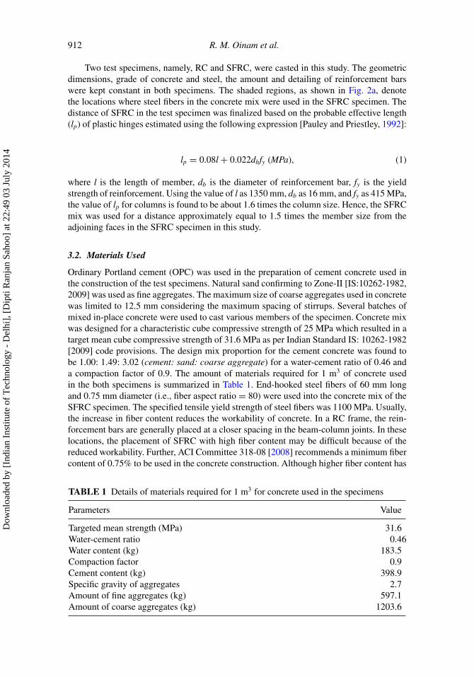
Ordinary Portland cement (OPC) was used in the preparation of cement concrete used inthe construction of the test specimens. Natural sand confirming to Zone-II [IS:10262-1982,2009] was used as fine aggregates. The maximum size of coarse aggregates used in concretewas limited to 12.5 mm considering the maximum spacing of stirrups. Several batches ofmixed in-place concrete were used to cast various members of the specimen. Concrete mixwas designed for a characteristic cube compressive strength of 25 MPa which resulted in atarget mean cube compressive strength of 31.6 MPa as per Indian Standard IS: 10262-1982[2009] code provisions. The design mix proportion for the cement concrete was found tobe 1.00: 1.49: 3.02 (cement: sand: coarse aggregate) for a water-cement ratio of 0.46 anda compaction factor of 0.9. The amount of materials required for 1 m3 of concrete usedin the both specimens is summarized in Table 1. End-hooked steel fibers of 60 mm longand 0.75 mm diameter (i.e., fiber aspect ratio = 80) were used into the concrete mix of theSFRC specimen. The specified tensile yield strength of steel fibers was 1100 MPa. Usually,the increase in fiber content reduces the workability of concrete. In a RC frame, the rein-forcement bars are generally placed at a closer spacing in the beam-column joints. In theselocations, the placement of SFRC with high fiber content may be difficult because of thereduced workability. Further, ACI Committee 318-08 [2008] recommends a minimum fibercontent of 0.75% to be used in the concrete construction. Although higher fiber content has
TABLE 1 Details of materials required for 1 m3 for concrete used in the specimens
Parameters Value
Targeted mean strength (MPa) 31.6Water-cement ratio 0.46Water content (kg) 183.5Compaction factor 0.9Cement content (kg) 398.9Specific gravity of aggregates 2.7Amount of fine aggregates (kg) 597.1Amount of coarse aggregates (kg) 1203.6
Dow
nloa
ded
by [
Indi
an I
nstit
ute
of T
echn
olog
y -
Del
hi],
[D
ipti
Ran
jan
Saho
o] a
t 22:
49 0
3 Ju
ly 2
014

Cyclic Response of Non-ductile SFRC Frame 913
been used in different research applications, a fiber content of 1% has been used in theSFRC frame in this study. Nevertheless, the effectiveness of using higher fiber contentshould be explored in the future research. To achieve a better workability, super-plasticizerof 0.5% volume/volume of water was used in the mixing of SFRC.
Standard cubes of size 150 mm x 150 mm x 150 mm were also prepared to mea-sure the concrete compressive strengths as per Indian Standard IS:516-1959 [2004] codeprovisions. Table 2 shows the average values of compressive strengths of concrete cubestested at the 28-days of standard curing. The average 28-days compressive strength ofplain concrete was 34.6 MPa which was slightly higher than the target mean strength of31.6 MPa. However, the compressive strength of concrete at the day of testing (which wasabout 45 days of casting) was found to be 44.2 MPa, which was about 27.7% higher thanthe 28-days compressive strength. In case of SFRC, the 28-days compressive strength wasfound to be 39.1 MPa which increased to a value of 46.3 MPa at the day of testing. Thisshowed a minor increase of about 10% in the compressive strength of SFRC as comparedto the plain concrete. The cylinder strengths at the 28-days of curing and at the day of test-ing are also summarized in Table 2. Split-tensile tests were carried out on plain concretecylinders to evaluate their tensile strengths. The average tensile strength of plain concretewas 2.9 MPa. In order to evaluate the flexural tensile strength of SFRC members, threesmall-scale beams of size 100 mm x 100 mmx 500 mm were casted and tested under three-point loading as per ASTM C1609 [2006] provisions. The average value of the equivalentbending strength, feq, of the SFRC beams was computed as per the following equation:
feq = 6PL
BD2(2)
where P = Ultimate load carried by the SFRC beams; L = span of the SFRC beams(300 mm); B = Width of beam; and D = Depth of beam. The value of feq of SFRC beamsat 28-days of curing was found to be 8.9 MPa. Thermo-mechanically treated (TMT) steelreinforcement bars were used as both longitudinal reinforcement and transverse stirrups in
TABLE 2 Compressive strength of plain and steel fiber reinforced concrete
Specimen type Test Timing
Cube comp.strength(MPa)
Mean cubecomp.
strength(MPa)
Cylindercomp.
strength(MPa)
Mean cylindercomp. strength
(MPa)
Plain cementconcrete
28-days 37.0 34.6 26.2 24.633.6 22.533.1 25.0
Day of testing 42.9 44.2 32.2 33.145.5 34.544.1 32.6
Steel fiber 28-days 37.5 39.1 28.7 28.0reinforced 40.1 27.5concrete 39.7 27.5
Day of testing 46.9 46.3 36.1 34.644.5 32.947.7 34.8
Dow
nloa
ded
by [
Indi
an I
nstit
ute
of T
echn
olog
y -
Del
hi],
[D
ipti
Ran
jan
Saho
o] a
t 22:
49 0
3 Ju
ly 2
014

914 R. M. Oinam et al.
FIGURE 3 Sequence of construction of the SFRC specimen.
both the specimens. The minimum specified values of yield stress, ultimate stress, and elon-gation of TMT bars are 415 MPa, 485 MPa, and 14.5%. Since these bars do not exhibit adefinite yield point, the 0.2% proof stress values is generally considered as the yield stress.Sufficient development length of reinforcement bars was provided at the required locations.Further, no lapping of reinforcement was used in both the specimens in order to focus onthe effectiveness of steel fibers at the critical locations of the test frame. Figure 3 shows thesequence of construction of the SFRC specimen. Footing of the specimen was constructedfirst using plain concrete followed by the portion of column (bottom) casted using SFRC.Similar procedure was followed till the top of columns. Then, the beam-column joints andslab was constructed using SFRC. Finally, the remaining portion of beam-slab was castedusing plain concrete.
3.3. Test Set-up
A servo-hydraulic actuator of 250 kN capacity and stroke length of 125 mm was used toapply the cyclic lateral displacements at the beam-slab level of the specimen. The actua-tor was supported by a reaction frame firmly held to the laboratory strong floor. Figure 4ashows the test set-up used in this study. The specimens were firmly attached to the strongfloor at the footing level using high-strength bolts to prevent their possible vertical move-ments under the lateral loading. Additional supports were also placed at both ends of thefooting to eliminate the longitudinal sliding of the specimens. The out-of-plane movementof the test specimens under cyclic lateral loading was restrained through the lateral sup-ports, as shown in Fig. 4a. A sliding roller arrangement, as shown in Fig. 4b, was used toallow the smooth in-plane movements of the specimens. In order to avoid the crushing ofconcrete at the roller locations, steel angle sections properly anchored with the slab wereused to provide a smooth sliding surface at the interface of the rollers. Four sliding rollerswere used at the slab level near the columns of the specimens. Figure 5 shows the detailsof the attachment of the actuator with the test specimens. Special arrangements were madeusing anchor bolts in the extended portion of the beam-slab of the specimens. A steel plate
Dow
nloa
ded
by [
Indi
an I
nstit
ute
of T
echn
olog
y -
Del
hi],
[D
ipti
Ran
jan
Saho
o] a
t 22:
49 0
3 Ju
ly 2
014

Cyclic Response of Non-ductile SFRC Frame 915
FIGURE 4 (a) Test set-up and (b) a close-up view of sliding rollers used in lateral supports.
FIGURE 5 Details of actuator-to-test specimen attachment used in this study.
was attached to the face of beam-slab so that the actuator can be connected to the specimenusing the high-strength bolts. A steel jack was used in the space between the test specimenand the actuator for smooth transfer of actuator load at the beam-slab level.
3.4. Instrumentations and Sensors
The lateral load resisted by the specimens and the corresponding displacements were mea-sured through the load cell and the displacement sensor inbuilt in the servo-hydraulicactuator. A linear varying differential transformer (LVDT) was installed at the free end ofthe beam to measure the lateral displacement of the specimen. Several uniaxial electrical-resistance strain gauges were installed to the main reinforcement bars of various membersto monitor the state of strain at different locations. Figure 6 shows the arrangements andthe position of strain gauges in columns and beams. These locations were fixed based onthe expected plastic hinge in the members.
Dow
nloa
ded
by [
Indi
an I
nstit
ute
of T
echn
olog
y -
Del
hi],
[D
ipti
Ran
jan
Saho
o] a
t 22:
49 0
3 Ju
ly 2
014

916 R. M. Oinam et al.
FIGURE 6 Arrangement and the position of uniaxial strain gauges in the specimens.
3.5. Displacement History
As stated earlier, test specimens were subjected to gradually-increased reversed cyclic lat-eral displacements in addition to a constant gravity load. Displacement history as specifiedin ACI Committee 374.1-05 [2006] was used for the slow-cyclic testing of specimens in thisstudy. This displacement history consisted of drift cycles of 0.20%, 0.35%, 0.50%, 0.75%,1.10%, 1.40%, 1.75%, 2.20%, 2.75%, 3.50%, and 4.50% (Fig. 7). Story drift (or drift ratio)may be defined as the ratio of the roof displacement to height of the story measured fromthe top of footing to the center line of beam. Each displacement cycle was repeated for threetimes at any drift ratio and then, followed by a single drift cycle of the smaller magnitude.A constant gravity load of 7.23 kN was applied at the slab level of the specimens by meansof concrete cubes as shown in Fig. 4a. Since the axial load ratio in columns is found to benearly 10% in practice, the applied axial load does not truly represent the site condition.Instead, the applied axial load in this study helped in providing the axial stability to the testspecimens to some extent.
FIGURE 7 Displacement history used in slow-cyclic testing.
Dow
nloa
ded
by [
Indi
an I
nstit
ute
of T
echn
olog
y -
Del
hi],
[D
ipti
Ran
jan
Saho
o] a
t 22:
49 0
3 Ju
ly 2
014

Cyclic Response of Non-ductile SFRC Frame 917
4. Test Results
Two tests, namely, force-vibration test and slow-cyclic test, were carried out on the testspecimens. Forced-vibration test was conducted to determine the dynamic properties ofthe specimens, whereas the slow-cyclic test was carried out to study the overall behaviorunder the action of lateral loading condition. The results of these tests are discussed in thefollowing sections.
4.1. Forced-Vibration Test
Natural frequency of a structure plays an important role in its behavior under dynamicloading. In this study, the natural frequencies of test specimens were obtained by forcedvibration tests using an APS-400 Electro-Seis long-stroke shaker. The shaker was placedat the mid region of the slab as shown in Fig. 4a. The peak amplitude of lateral deforma-tion was set to 2.0 mm. An accelerometer was attached at the beam end to monitor theresponse of the test specimens under the input excitation applied through the shaker. Theinput excitation frequency was varied in the range of 1–20 Hz at an increment of 1.0 Hz.The input frequency corresponding to the maximum acceleration response of the speci-mens was considered as damped natural frequency. The natural frequencies of the RC andthe SFRC specimens were noticed as 10.0 Hz and 11.0 Hz, respectively. The correspondingdamped natural frequency of the RC and the SFRC specimens were found to be 62.8 rad/sand 69.1 rad/s, respectively. This indicates that the lateral stiffness of the SFRC specimenwas 21% higher than that of the RC specimen. This is because of the improved flexural andshear rigidity of frame members due to the addition of steel fibers in the concrete mix. Thedamping ratio of both specimens was about 4.5% computed using Half-bandwidth method.
4.2. Slow-Cyclic Test
As discussed earlier, slow-cyclic testing of the specimens was carried out for the dis-placement history as per ACI Committee 374.1-05 [2006] specifications in addition to aconstant gravity load. The main parameters studied are overall behavior, load-displacementresponse, stiffness degradation, energy dissipation, damping, and state of strain in thereinforcement bars as discussed in the following sections.
4.2.1. Overall Behavior. As expected, both specimens did not show any visible damagesat the smaller story drift levels indicating their linear elastic behavior. Some minor shearand flexural cracks were observed in the cover concrete of the beam and columns of the RCspecimen at a story drift of 1.0%. As the amplitude of story drift increased, a number ofcracks were noticed at the column bases. Figure 8 shows the comparison of cracks observedin different faces of columns near the footing of the specimens. As compared to the RCspecimen, a large number of hairline cracks were noticed in the columns of the SFRCspecimen. A single major (horizontal) crack was noticed at 2.75% drift level at which theultimate lateral load resistance was noticed in the push direction. Significant crushing ofconcrete in the column base was observed at 3.5% drift level. Test was stopped at thisdrift level for the RC specimens and the drift cycles of amplitude 4.5% were not appliedowing to its instability. This showed the flexural plastic hinges were formed at both ends ofthe columns at the mechanism state of the RC specimen. In contrast, such flexural crackswere not noticed till 4.5% drift cycles in case of the SFRC specimen. Some minor crackswere appeared on the column faces at 0.75% drift level. A large number of horizontal andinclined cracks were distributed near the column base regions indicating the fiber-bridging
Dow
nloa
ded
by [
Indi
an I
nstit
ute
of T
echn
olog
y -
Del
hi],
[D
ipti
Ran
jan
Saho
o] a
t 22:
49 0
3 Ju
ly 2
014
918 R. M. Oinam et al.
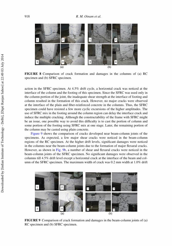
FIGURE 8 Comparison of crack formation and damages in the columns of (a) RCspecimen and (b) SFRC specimen.
action in the SFRC specimen. At 4.5% drift cycle, a horizontal crack was noticed at theinterface of the column and the footing of this specimen. Since the SFRC was used only inthe column portion of the joint, the inadequate shear strength at the interface of footing andcolumn resulted in the formation of this crack. However, no major cracks were observedat the interface of the plain and fiber-reinforced concrete in the columns. Thus, the SFRCspecimen could have resisted a few more cyclic excursions of the higher amplitudes. Theuse of SFRC mix in the footing around the column region can delay the interface crack andinduce the multiple cracking. Although the constructability of the frame with SFRC mightbe an issue, one possible way to avoid this difficulty is to cast the portion of column andsome portion of the footing using SFRC mix at one stage. Later, the remaining portion ofthe column may be casted using plain concrete.
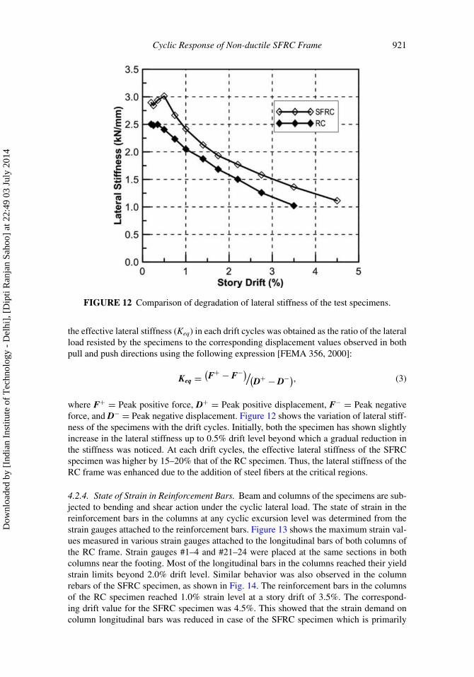
Figure 9 shows the comparison of cracks developed near beam-column joints of thespecimens. As expected, a few major shear cracks were noticed in the beam-columnregions of the RC specimen. At the higher drift levels, significant damages were noticedin the columns near the beam-column joints due to the formation of major flexural cracks.However, as shown in Fig. 9b, a number of shear and flexural cracks were noticed in thebeam-column joints of the SFRC specimen. No significant damages were observed in thecolumns till 4.5% drift level except a horizontal crack at the interface of the beam and col-umn of the SFRC specimen. The maximum width of crack was 0.2 mm width at 1.0% drift
FIGURE 9 Comparison of crack formation and damages in the beam-column joints of (a)RC specimen and (b) SFRC specimen.
Dow
nloa
ded
by [
Indi
an I
nstit
ute
of T
echn
olog
y -
Del
hi],
[D
ipti
Ran
jan
Saho
o] a
t 22:
49 0
3 Ju
ly 2
014

Cyclic Response of Non-ductile SFRC Frame 919
level, which increased to a value of 2.0 mm at 4.5% drift level. In addition, some minorflexural cracks were noticed at the mid-segment of the beam of both the specimens. Thisshows that the addition of steel fibers at the potential plastic hinge regions reduced the dam-age levels in the frame members because of the fiber bridging action of steel fibers insidethe concrete.
4.2.2. Lateral Load-Displacement Response. Figure 10 shows the comparison of lateralload-displacement (hysteretic) response of the specimens. The yield drift values for theRC and the SFRC specimens were 0.5% (7.5 mm) and 0.75% (11.2 mm), respectively,indicating that the SFRC specimen had an extended elastic behavior due to the improvedtensile strength of SFRC. The RC specimen showed the ultimate lateral load resistanceat 2.75% drift level in the push direction. However, the maximum value of lateral loadresisted by the RC frame at 3.5% story drift was nearly same in both directions and wasnoted as 56.7 kN, and -57.0 kN in the push and the pull directions, respectively. The testspecimens exhibited a larger lateral stiffness during the loading phase of the first cycle
FIGURE 10 Hysteresis response of test specimens (a) smaller drift cycles and (b) all driftcycles.
Dow
nloa
ded
by [
Indi
an I
nstit
ute
of T
echn
olog
y -
Del
hi],
[D
ipti
Ran
jan
Saho
o] a
t 22:
49 0
3 Ju
ly 2
014

920 R. M. Oinam et al.
FIGURE 11 Comparison of backbone curves of test specimens.
of hysteretic loops at the higher story drift levels. However, no further degradation in thelateral stiffness was noticed in the subsequent repetitive cycles of the same excursion level.The maximum value of lateral load resisted by the SFRC specimen at 4.5% drift levelwas 72.2 kN and -77.6 kN in the pull and push directions, respectively. Both specimensexhibited similar hysteretic response with moderate pinching at the higher drift levels. Thepinching effect in the hysteresis loop is usually noticed due to the opening and closing ofthe cracks and/or bond-slip behavior of reinforcing bars in the concrete structures. Thisbehavior was more evident at the larger displacement excursions because of the majorcracks in the beam-column joints and the column bases as described earlier.
Figure 11 shows the comparison of the backbone curves of the specimens. Both speci-mens showed the nearly symmetric backbone curves in push and pull directions. A gradualincrease in the lateral resistance with the increase in the drift levels was noted for the SFRCspecimen till 4.5% cyclic excursions. Further, the magnitude of lateral resistance at eachdrift level was higher for the SFRC specimen as compared to the RC specimen. A large dif-ference in lateral load resistance between the RC and the SFRC specimens was noticed inthe larger amplitudes of cyclic excursions. This shows that the incorporation of steel fibersinto the concrete mix at the critical locations enhanced the lateral load carrying capacity atthe higher drift levels once the cracks were initiated in the members.
4.2.3. Lateral Stiffness. Prior to the displacement-controlled slow-cyclic test, a load-controlled cyclic test was carried out for a maximum amplitude of 10 kN in order todetermine the initial stiffness of the test specimens. Using the peak values of lateral loadand displacement, the average value of initial lateral stiffness of the RC and the SFRC spec-imens was computed as 2.5 kN/mm and 3.1 kN/mm, respectively. This indicates that theSFRC specimen was about 25% stiffer than the RC specimen, which was also consistentwith the results of the forced-vibration test. In case of the displacement-controlled loading,
Dow
nloa
ded
by [
Indi
an I
nstit
ute
of T
echn
olog
y -
Del
hi],
[D
ipti
Ran
jan
Saho
o] a
t 22:
49 0
3 Ju
ly 2
014
Cyclic Response of Non-ductile SFRC Frame 921
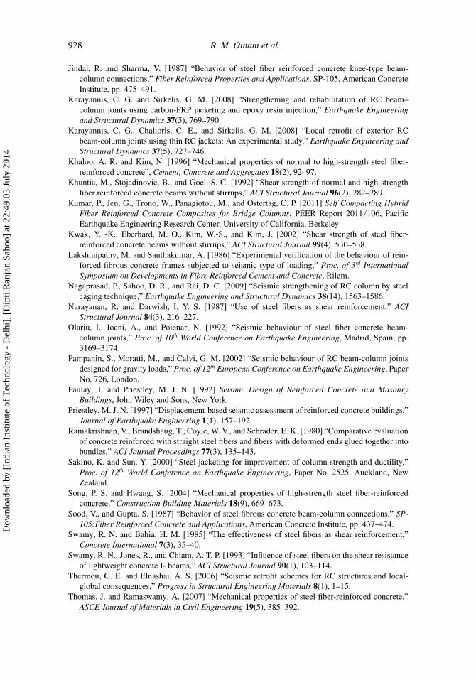
FIGURE 12 Comparison of degradation of lateral stiffness of the test specimens.
the effective lateral stiffness (Keq) in each drift cycles was obtained as the ratio of the lateralload resisted by the specimens to the corresponding displacement values observed in bothpull and push directions using the following expression [FEMA 356, 2000]:
Keq =(F+ − F−)/(
D+ − D−), (3)
where F+ = Peak positive force, D+ = Peak positive displacement, F− = Peak negativeforce, and D− = Peak negative displacement. Figure 12 shows the variation of lateral stiff-ness of the specimens with the drift cycles. Initially, both the specimen has shown slightlyincrease in the lateral stiffness up to 0.5% drift level beyond which a gradual reduction inthe stiffness was noticed. At each drift cycles, the effective lateral stiffness of the SFRCspecimen was higher by 15–20% that of the RC specimen. Thus, the lateral stiffness of theRC frame was enhanced due to the addition of steel fibers at the critical regions.
4.2.4. State of Strain in Reinforcement Bars. Beam and columns of the specimens are sub-jected to bending and shear action under the cyclic lateral load. The state of strain in thereinforcement bars in the columns at any cyclic excursion level was determined from thestrain gauges attached to the reinforcement bars. Figure 13 shows the maximum strain val-ues measured in various strain gauges attached to the longitudinal bars of both columns ofthe RC frame. Strain gauges #1–4 and #21–24 were placed at the same sections in bothcolumns near the footing. Most of the longitudinal bars in the columns reached their yieldstrain limits beyond 2.0% drift level. Similar behavior was also observed in the columnrebars of the SFRC specimen, as shown in Fig. 14. The reinforcement bars in the columnsof the RC specimen reached 1.0% strain level at a story drift of 3.5%. The correspond-ing drift value for the SFRC specimen was 4.5%. This showed that the strain demand oncolumn longitudinal bars was reduced in case of the SFRC specimen which is primarily
Dow
nloa
ded
by [
Indi
an I
nstit
ute
of T
echn
olog
y -
Del
hi],
[D
ipti
Ran
jan
Saho
o] a
t 22:
49 0
3 Ju
ly 2
014

922 R. M. Oinam et al.
FIGURE 13 Strain in column rebars of RC specimen at the (a) actuator end and (b) rearend.
FIGURE 14 Strain in column rebars of SFRC specimen at the (a) actuator end and (b) rearend.
attributed to the additional tensile resistance offered by the fiber-reinforced concrete. Sincethe strain demand on beam rebars was very small, the yielding behavior was not noticed inboth the test specimens.
4.2.5. Energy Dissipation and Damping. The capacity of a structural element to resist anearthquake largely depends on its potential to dissipate the seismic energy. The area underthe hysteresis loops is a measure of the energy dissipated by the element. In this study, thecumulative energy dissipated by the test specimens at each drift cycle was computed fromthe average area under the hysteresis loops for three cycles. Figure 15 compares the energydissipated by the RC and the SFRC specimens at different drift levels. As expected, nosignificant difference in the energy dissipation was noted between the RC and the SFRCspecimen at the smaller drift levels. The SFRC specimen showed slightly larger energydissipation at each drift levels. The cumulative energy dissipated by the RC and the SFRCspecimen at 3.5% drift level was 3.1 kNm and 3.7 kNm, respectively. This indicates anincrease of 20% energy dissipation for the SFRC specimen as compared to the RC spec-imen, which can be attributed to the multiple cracking at the fiber-reinforced concreteregions. The maximum value of energy dissipation in the SFRC specimen was noted as
Dow
nloa
ded
by [
Indi
an I
nstit
ute
of T
echn
olog
y -
Del
hi],
[D
ipti
Ran
jan
Saho
o] a
t 22:
49 0
3 Ju
ly 2
014

Cyclic Response of Non-ductile SFRC Frame 923
FIGURE 15 Comparison of energy dissipation of test specimens.
5.6 kNm at 4.5% drift level showing an increase of about 80% in the overall energy dis-sipation for the SFRC specimen as compared to the RC specimen. The equivalent viscousdamping potential of the specimens was computed using the expression recommended byFEMA 356 [2000] as follows:
βeq = (2/π )[Eloop/Keq
(D+ − D−)2
], (4)
where βeq = Equivalent viscous damping and Eloop = Dissipated energy per hysteretic loopat a drift cycle. Table 3 and 4 shows the computation of the equivalent damping potentialat different drift cycles of the RC and the SFRC specimen, respectively. The equivalentdamping values varied from 6.0% at 0.2% drift level to a value of 17.8% at 4.5% drift level.The equivalent damping ratio values for the RC and SFRC specimen at 0.2% drift levelwere estimated as 6.2% and 5.7%, respectively, which are comparable with the dampingvalue of 4.5% obtained from the forced-vibration testing. No significant difference in thedamping potential was noted between the RC and the SFRC specimens. At 3.5% drift level,the RC specimen exhibited a higher damping value as compared to the SFRC specimen dueto significant damages observed in the columns.
5. Summary and Conclusions
An experiment investigation was carried out on a reduced-scale single-story single-baygravity-load designed non ductile RC frame to study the overall behavior due to the additionof steel fibers at the critical locations. Two geometrically similar specimens (i.e., RC andSFRC) were tested under the displacement-controlled slow-cyclic loading. Steel fibers wereadded into the concrete mix used only at both ends of the columns and at the beam-columnjoints for a distance of one-and-half of the member size. The main parameters studied
Dow
nloa
ded
by [
Indi
an I
nstit
ute
of T
echn
olog
y -
Del
hi],
[D
ipti
Ran
jan
Saho
o] a
t 22:
49 0
3 Ju
ly 2
014

TA
BL
E3
Com
puta
tion
ofeq
uiva
lent
dam
ping
pote
ntia
lof
the
RC
spec
imen
Dri
ftle
vel(
%)
Peak
posi
tive
disp
lace
men
t,�
+(m
m)
Peak
nega
tive
disp
lace
men
t,�
−(m
m)
Peak
posi
tive
forc
e,F
+(k
N)
Peak
nega
tive
forc
e,F
−(k
N)
Ene
rgy
diss
ipat
ion,
Elo
op(k
Nm
m)
Eff
ectiv
est
iffn
ess,
Keq
(kN
/m
m)
Equ
ival
ent
dam
ping
,βeq
(%)
0.20
3.06
−2.8
96.
15−8
.73
7.90
2.50
5.69
0.25
3.94
−3.5
47.
93−1
0.65
18.3
82.
488.
420.
355.
68−4
.97
11.4
4−1
5.14
36.8
42.
508.
290.
508.
24−7
.17
17.6
6−1
9.43
74.2
42.
418.
270.
7512
.51
−10.
9126
.34
−25.
9715
4.78
2.23
8.05
1.00
16.7
4−1
4.54
32.4
6−3
1.62
282.
712.
058.
981.
4023
.27
−20.
6242
.25
−40.
0156
9.57
1.87
10.0
51.
7529
.02
−26.
3847
.56
−45.
6687
2.87
1.68
10.7
62.
2036
.36
−33.
0253
.75
−50.
4513
81.4
01.
5012
.17
2.75
45.2
4−4
1.75
56.2
4−5
3.21
2213
.90
1.26
14.8
13.
5057
.09
−53.
6956
.63
−56.
8734
61.0
01.
0217
.53
924
Dow
nloa
ded
by [
Indi
an I
nstit
ute
of T
echn
olog
y -
Del
hi],
[D
ipti
Ran
jan
Saho
o] a
t 22:
49 0
3 Ju
ly 2
014

TA
BL
E4
Com
puta
tion
ofeq
uiva
lent
dam
ping
pote
ntia
lof
the
SFR
Csp
ecim
en
Dri
ftle
vel(
%)
Peak
posi
tive
disp
lace
men
t,�
+(m
m)
Peak
nega
tive
disp
lace
men
t,�
−(m
m)
Peak
posi
tive
forc
e,F
+(k
N)
Peak
nega
tive
forc
e,F
−(k
N)
Ene
rgy
diss
ipat
ion,
Elo
op(k
Nm
m)
Eff
ectiv
est
iffn
ess,
Keq
(kN
/m
m)
Eff
ectiv
eda
mpi
ng,
βeq
(%)
0.20
2.97
−2.6
87.
48−8
.87
8.96
2.89
6.17
0.25
3.67
−3.5
79.
46−1
1.14
21.5
72.
849.
210.
355.
24−4
.89
14.1
5−1
5.64
43.5
02.
949.
180.
507.
48−7
.06
21.1
7−2
2.63
89.0
73.
018.
910.
7511
.20
−10.
7728
.77
−29.
7719
5.76
2.66
9.69
1.00
14.9
2−1
4.47
34.8
0−3
6.18
354.
302.
4110
.82
1.40
20.8
9−2
0.43
43.7
1−4
4.12
671.
502.
1311
.78
1.75
26.1
2−2
6.75
49.8
1−5
2.26
1030
.23
1.93
12.1
62.
2032
.83
−32.
5857
.04
−58.
8415
62.5
71.
7713
.13
2.75
41.1
2−4
0.87
63.3
8−6
6.47
2369
.67
1.58
14.1
83.
5052
.37
−52.
1968
.74
−73.
5336
61.0
01.
3615
.68
4.50
67.2
9−6
7.06
72.1
8−7
7.37
5616
.00
1.11
17.8
0
925
Dow
nloa
ded
by [
Indi
an I
nstit
ute
of T
echn
olog
y -
Del
hi],
[D
ipti
Ran
jan
Saho
o] a
t 22:
49 0
3 Ju
ly 2
014

926 R. M. Oinam et al.
are hysteretic response, lateral stiffness, energy dissipation, damping potential and stateof strain the reinforcement bars. Based on this study, the following conclusions can bedrawn.
● The addition of steel fiber reinforced concrete at the potential plastic hinge regionsenhanced the lateral load resisting capacity of the test frame by 30%. No degradationin the lateral strength was noticed even up to 4.5% drift level of the SFRC frame.The SFRC frame also showed a high level of ductility as compared to the RC framethat showed the degradation of lateral strength at 2.75 % drift level.
● At the failure state, the RC specimen showed the formation of flexural plastic hingesat both ends of columns. The addition of steel fibers at these locations delayed theformation of plastic hinges. No major cracks were noticed in the columns till 4.5%drift level of the SFRC specimen. However, a multiple minor cracks were noticed inthe beam-column joint regions of the SFRC frame.
● The lateral stiffness of the RC frame was increased by 25% due to the additionof steel fibers at the joints and the column ends. No sudden degradation of lateralstiffness was noticed with the increased level of drift cycles till 4.5% drift level.
● The addition of steel fibers at the critical locations of the RC frame enhanced itsenergy dissipation potential by more than 80%. However, both RC and SFRC spec-imens exhibited the maximum equivalent damping ratio of about 18% at 3.5% and4.5% drift levels, respectively.
In general, the use of steel fiber reinforced concrete in discrete regions of the frame structurewill increase the construction-related tasks, such as, modifications in the formwork, numberof batching required for SFRC, curing time, etc. However, the test results of this studyhave shown that addition of SFRC can improve the overall behavior of the RC frame undercyclic loading condition. Further study is required to quantify the improvement of structuralperformance with the varying fiber content and the reduced amount of transverse steel.A higher value of column axial load ratio should be used in order to consider the second-order moment effect at the larger drift levels. Newly constructed structures located in thehigh seismic regions are usually built as per the ductile detailing provisions. Hence, futurestudy should also take the ductile detailing requirements as well as strong-column weak-beam philosophy into account in the design of test specimens in addition to the SFRC atthe critical regions.
Acknowledgments
The authors are thankful to the Structural Engineering laboratory staffs of the Departmentof Civil Engineering, IIT Delhi for their help in casting and testing of specimens.The authors are also thankful to the reviewers for their valuable suggestions for theimprovement of the manuscript.
Funding
The financial support received from the Ministry of Human Resources Development(MHRD), Government of India, is highly acknowledged. The authors are thankful toBekaert Steel Wire Co. for the donation of steel fibers for this research.
Dow
nloa
ded
by [
Indi
an I
nstit
ute
of T
echn
olog
y -
Del
hi],
[D
ipti
Ran
jan
Saho
o] a
t 22:
49 0
3 Ju
ly 2
014

Cyclic Response of Non-ductile SFRC Frame 927
References
Abdullah, T. K. [2003] “An investigation into the behavior and strength of reinforced concretecolumns strengthened with ferrocement jackets,” Cement and Concrete Composites 98, 233–242.
Aboutaha, S., Engelhardt, M. D., Jirsa, J. O., and Kreger, M. E. [1999] “Rehabilitation of shear criticalconcrete columns by use of rectangular steel jackets,” ACI Structural Journal 96(1), 68–78.
ACI Committee 374.1-05 [2006] Acceptance Criteria for Moment Frames based on Structural Testingand Commentary- An ACI Standard, American Concrete Institute, Farmington Hills, Michigan.
ACI Committee 318-08 [2008] Building Code Requirements for Structural Concrete (ACI 318-08) and Commentary (ACI 318R-08), American Concrete Institute, Farmington Hills, Michigan.
Ashour, S. A., Hasanain, G. S., and Wafa, F. F. [1992] “Shear behavior of high-strength fiberreinforced concrete beams,” ACI Structural Journal 89(2), 176–184.
ASTM C1609 [2006] Standard Test Method for Flexural Performance of Fiber Reinforced Concrete(using Beam with Third-point Loading), ASTM C1609/C1609M-05, West Conshohocken,Pennsylvania.
Bencardino, F., Rizzuti, L., Spadea, G., and Swamy, R. N. [2010] “Experimental evaluation of fiberreinforced concrete fracture properties,” Composites Part B: Engineering 41(1), 17–24.
Billington, S. L. and Yoon, J. K. [2004] “Cyclic response of unbonded posttensioned precast columnswith ductile fiber-reinforced concrete,” ASCE Journal of Bridge Engineering 9(4), 353–363.
Bousiasa, S., Spathisa, A.-L., and Fardisa, M. N. [2007] “Seismic retrofitting of columns with lapspliced smooth bars through FRP or concrete jackets,” Journal of Earthquake Engineering 11(5),653–674.
Cho, S. -H. and Kim, Y.-I. [2003] “Effects of steel fibers on short beams loaded in shear,” ACIStructural Journal 100(6), 765–774.
Craig, R., Mahadev, S., Patel, C. C., Viteri, M., and Kertesz, C. [1984] “Behavior of joints usingreinforced fibrous concrete,” Proc. of Fiber Reinforced Concrete International Symposium, SP-81,American Concrete Institute, 125–167.
Dinh, H. H., Parra-Montesinos, G. J., and Wight, J. K. [2010] “Shear strength of steel fiber reinforcedconcrete beams without stirrup reinforcement,” ACI Structural Journal 107(5), 597–606.
FEMA 356 [2000] Prestandard and Commentary for the Seismic Rehabilitation of Buildings. FederalEmergency Management Agency, Washington, D.C.
Filiatrault, A., Pineau, S., and Houde, J., [1995] “Seismic behavior of steel-fiber reinforced concreteinterior beam-column joints,” ACI Structural Journal 92(5), 543–552.
Gebman, M. [2001] “Application of steel fiber reinforced concrete in seismic beam-column joints,”Master’s thesis, Dept. of Civil and Env. Engineering, San Diego State University, San Diego,California.
Ghobarah, A. and Said, A. [2001] “Seismic rehabilitation of beam-column joints using FRPLaminates,” Journal of Earthquake Engineering 5(1), 113–129.
Hannant, D. J. [1978] Fibre Cements and Fibre Concretes, Wiley-Interscience, New York.Harajli, M. H., Hout, M., and Jalkh, W. [1995] “Local bond stress-slip behavior of reinforcing bars
embedded in plain and fiber concrete,” ACI Materials Journal 92(4), 343–354.Henager, C. H. [1977] “Steel fibrous, ductile concrete joint for seismic resistant structures,”
Reinforced Concrete Structures in Seismic Zones, SP 53–14, American Concrete Institute, pp.371–386.
Hota, S. and Naaman, A. E. [1997] “Bond stress-slip response of reinforcing bars embedded in FRCmatrices under monotonic and cyclic loading,” ACI Structural Journal 90(5), 525–537.
IS:10262-1982 [2009] Indian Standard Recommended Guidelines for Concrete Mix Design, Bureauof India Standard, New Delhi.
IS:456-2000 [2000] Indian Standard Plain and Reinforced Concrete-Code of Practice, Fourthrevision, Bureau of India Standard, New Delhi.
IS:516-1959 [2004] Indian Standard Methods for Test on Concrete, Bureau of India Standard, NewDelhi.
Dow
nloa
ded
by [
Indi
an I
nstit
ute
of T
echn
olog
y -
Del
hi],
[D
ipti
Ran
jan
Saho
o] a
t 22:
49 0
3 Ju
ly 2
014
928 R. M. Oinam et al.
Jindal, R. and Sharma, V. [1987] “Behavior of steel fiber reinforced concrete knee-type beam-column connections,” Fiber Reinforced Properties and Applications, SP-105, American ConcreteInstitute, pp. 475–491.
Karayannis, C. G. and Sirkelis, G. M. [2008] “Strengthening and rehabilitation of RC beam–column joints using carbon-FRP jacketing and epoxy resin injection,” Earthquake Engineeringand Structural Dynamics 37(5), 769–790.
Karayannis, C. G., Chalioris, C. E., and Sirkelis, G. M. [2008] “Local retrofit of exterior RCbeam-column joints using thin RC jackets: An experimental study,” Earthquake Engineering andStructural Dynamics 37(5), 727–746.
Khaloo, A. R. and Kim, N. [1996] “Mechanical properties of normal to high-strength steel fiber-reinforced concrete”, Cement, Concrete and Aggregates 18(2), 92–97.
Khuntia, M., Stojadinovic, B., and Goel, S. C. [1992] “Shear strength of normal and high-strengthfiber reinforced concrete beams without stirrups,” ACI Structural Journal 96(2), 282–289.
Kumar, P., Jen, G., Trono, W., Panagiotou, M., and Ostertag, C. P. [2011] Self Compacting HybridFiber Reinforced Concrete Composites for Bridge Columns, PEER Report 2011/106, PacificEarthquake Engineering Research Center, University of California, Berkeley.
Kwak, Y. -K., Eberhard, M. O., Kim, W.-S., and Kim, J. [2002] “Shear strength of steel fiber-reinforced concrete beams without stirrups,” ACI Structural Journal 99(4), 530–538.
Lakshmipathy, M. and Santhakumar, A. [1986] “Experimental verification of the behaviour of rein-forced fibrous concrete frames subjected to seismic type of loading,” Proc. of 3rd InternationalSymposium on Developments in Fibre Reinforced Cement and Concrete, Rilem.
Nagaprasad, P., Sahoo, D. R., and Rai, D. C. [2009] “Seismic strengthening of RC column by steelcaging technique,” Earthquake Engineering and Structural Dynamics 38(14), 1563–1586.
Narayanan, R. and Darwish, I. Y. S. [1987] “Use of steel fibers as shear reinforcement,” ACIStructural Journal 84(3), 216–227.
Olariu, I., Ioani, A., and Poienar, N. [1992] “Seismic behaviour of steel fiber concrete beam-column joints,” Proc. of 10th World Conference on Earthquake Engineering, Madrid, Spain, pp.3169–3174.
Pampanin, S., Moratti, M., and Calvi, G. M. [2002] “Seismic behaviour of RC beam-column jointsdesigned for gravity loads,” Proc. of 12th European Conference on Earthquake Engineering, PaperNo. 726, London.
Paulay, T. and Priestley, M. J. N. [1992] Seismic Design of Reinforced Concrete and MasonryBuildings, John Wiley and Sons, New York.
Priestley, M. J. N. [1997] “Displacement-based seismic assessment of reinforced concrete buildings,”Journal of Earthquake Engineering 1(1), 157–192.
Ramakrishnan, V., Brandshaug, T., Coyle, W. V., and Schrader, E. K. [1980] “Comparative evaluationof concrete reinforced with straight steel fibers and fibers with deformed ends glued together intobundles,” ACI Journal Proceedings 77(3), 135–143.
Sakino, K. and Sun, Y. [2000] “Steel jacketing for improvement of column strength and ductility,”Proc. of 12th World Conference on Earthquake Engineering, Paper No. 2525, Auckland, NewZealand.
Song, P. S. and Hwang, S. [2004] “Mechanical properties of high-strength steel fiber-reinforcedconcrete,” Construction Building Materials 18(9), 669–673.
Sood, V., and Gupta. S. [1987] “Behavior of steel fibrous concrete beam-column connections,” SP-105:Fiber Reinforced Concrete and Applications, American Concrete Institute, pp. 437–474.
Swamy, R. N. and Bahia, H. M. [1985] “The effectiveness of steel fibers as shear reinforcement,”Concrete International 7(3), 35–40.
Swamy, R. N., Jones, R., and Chiam, A. T. P. [1993] “Influence of steel fibers on the shear resistanceof lightweight concrete I- beams,” ACI Structural Journal 90(1), 103–114.
Thermou, G. E. and Elnashai, A. S. [2006] “Seismic retrofit schemes for RC structures and local-global consequences,” Progress in Structural Engineering Materials 8(1), 1–15.
Thomas, J. and Ramaswamy, A. [2007] “Mechanical properties of steel fiber-reinforced concrete,”ASCE Journal of Materials in Civil Engineering 19(5), 385–392.
Dow
nloa
ded
by [
Indi
an I
nstit
ute
of T
echn
olog
y -
Del
hi],
[D
ipti
Ran
jan
Saho
o] a
t 22:
49 0
3 Ju
ly 2
014