Failure of pipe joints during hydrostatic testing
8
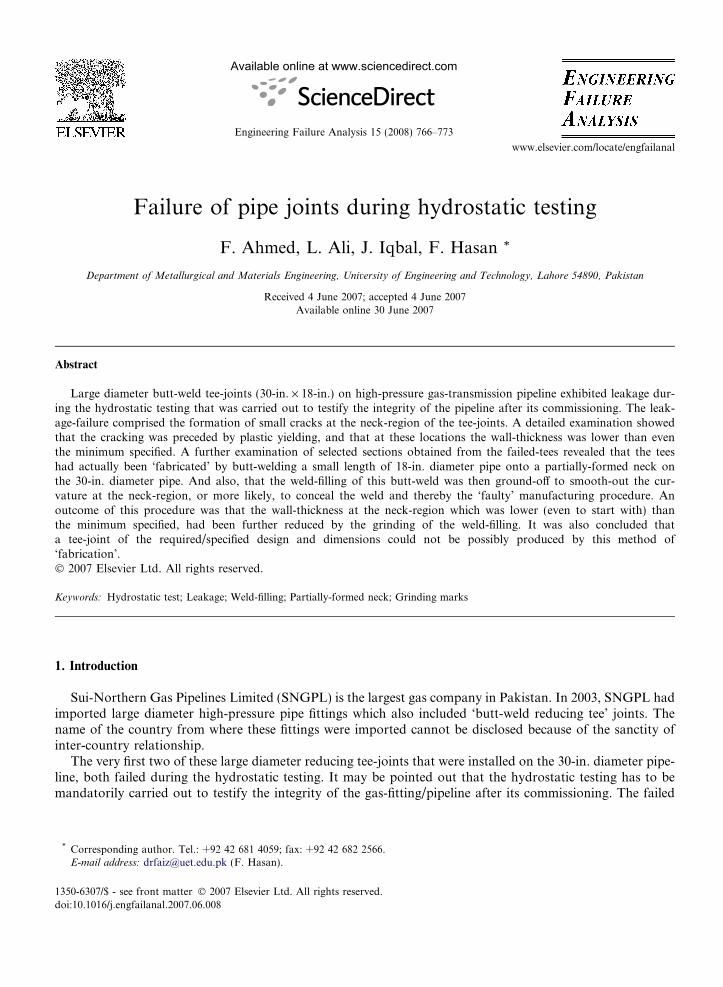
Failure of pipe joints during hydrostatic testing F. Ahmed, L. Ali, J. Iqbal, F. Hasan * Department of Metallurgical and Materials Engineering, University of Engineering and Technology, Lahore 54890, Pakistan Received 4 June 2007; accepted 4 June 2007 Available online 30 June 2007 Abstract Large diameter butt-weld tee-joints (30-in. · 18-in.) on high-pressure gas-transmission pipeline exhibited leakage dur- ing the hydrostatic testing that was carried out to testify the integrity of the pipeline after its commissioning. The leak- age-failure comprised the formation of small cracks at the neck-region of the tee-joints. A detailed examination showed that the cracking was preceded by plastic yielding, and that at these locations the wall-thickness was lower than even the minimum specified. A further examination of selected sections obtained from the failed-tees revealed that the tees had actually been ‘fabricated’ by butt-welding a small length of 18-in. diameter pipe onto a partially-formed neck on the 30-in. diameter pipe. And also, that the weld-filling of this butt-weld was then ground-off to smooth-out the cur- vature at the neck-region, or more likely, to conceal the weld and thereby the ‘faulty’ manufacturing procedure. An outcome of this procedure was that the wall-thickness at the neck-region which was lower (even to start with) than the minimum specified, had been further reduced by the grinding of the weld-filling. It was also concluded that a tee-joint of the required/specified design and dimensions could not be possibly produced by this method of ‘fabrication’. Ó 2007 Elsevier Ltd. All rights reserved. Keywords: Hydrostatic test; Leakage; Weld-filling; Partially-formed neck; Grinding marks 1. Introduction Sui-Northern Gas Pipelines Limited (SNGPL) is the largest gas company in Pakistan. In 2003, SNGPL had imported large diameter high-pressure pipe fittings which also included ‘butt-weld reducing tee’ joints. The name of the country from where these fittings were imported cannot be disclosed because of the sanctity of inter-country relationship. The very first two of these large diameter reducing tee-joints that were installed on the 30-in. diameter pipe- line, both failed during the hydrostatic testing. It may be pointed out that the hydrostatic testing has to be mandatorily carried out to testify the integrity of the gas-fitting/pipeline after its commissioning. The failed 1350-6307/$ - see front matter Ó 2007 Elsevier Ltd. All rights reserved. doi:10.1016/j.engfailanal.2007.06.008 * Corresponding author. Tel.: +92 42 681 4059; fax: +92 42 682 2566. E-mail address: [email protected] (F. Hasan). Available online at www.sciencedirect.com Engineering Failure Analysis 15 (2008) 766–773 www.elsevier.com/locate/engfailanal
-
Upload
independent -
Category
Documents
-
view
0 -
download
0
Transcript of Failure of pipe joints during hydrostatic testing
Available online at www.sciencedirect.com
Engineering Failure Analysis 15 (2008) 766–773
www.elsevier.com/locate/engfailanal
Failure of pipe joints during hydrostatic testing
F. Ahmed, L. Ali, J. Iqbal, F. Hasan *
Department of Metallurgical and Materials Engineering, University of Engineering and Technology, Lahore 54890, Pakistan
Received 4 June 2007; accepted 4 June 2007Available online 30 June 2007
Abstract
Large diameter butt-weld tee-joints (30-in. · 18-in.) on high-pressure gas-transmission pipeline exhibited leakage dur-ing the hydrostatic testing that was carried out to testify the integrity of the pipeline after its commissioning. The leak-age-failure comprised the formation of small cracks at the neck-region of the tee-joints. A detailed examination showedthat the cracking was preceded by plastic yielding, and that at these locations the wall-thickness was lower than eventhe minimum specified. A further examination of selected sections obtained from the failed-tees revealed that the teeshad actually been ‘fabricated’ by butt-welding a small length of 18-in. diameter pipe onto a partially-formed neck onthe 30-in. diameter pipe. And also, that the weld-filling of this butt-weld was then ground-off to smooth-out the cur-vature at the neck-region, or more likely, to conceal the weld and thereby the ‘faulty’ manufacturing procedure. Anoutcome of this procedure was that the wall-thickness at the neck-region which was lower (even to start with) thanthe minimum specified, had been further reduced by the grinding of the weld-filling. It was also concluded thata tee-joint of the required/specified design and dimensions could not be possibly produced by this method of‘fabrication’.� 2007 Elsevier Ltd. All rights reserved.
Keywords: Hydrostatic test; Leakage; Weld-filling; Partially-formed neck; Grinding marks
1. Introduction
Sui-Northern Gas Pipelines Limited (SNGPL) is the largest gas company in Pakistan. In 2003, SNGPL hadimported large diameter high-pressure pipe fittings which also included ‘butt-weld reducing tee’ joints. Thename of the country from where these fittings were imported cannot be disclosed because of the sanctity ofinter-country relationship.
The very first two of these large diameter reducing tee-joints that were installed on the 30-in. diameter pipe-line, both failed during the hydrostatic testing. It may be pointed out that the hydrostatic testing has to bemandatorily carried out to testify the integrity of the gas-fitting/pipeline after its commissioning. The failed
1350-6307/$ - see front matter � 2007 Elsevier Ltd. All rights reserved.
doi:10.1016/j.engfailanal.2007.06.008
* Corresponding author. Tel.: +92 42 681 4059; fax: +92 42 682 2566.E-mail address: [email protected] (F. Hasan).

F. Ahmed et al. / Engineering Failure Analysis 15 (2008) 766–773 767
tees were of 30-in. diameter with an 18-in. outlet. The present paper describes the failure analysis of thesefailed tee-joints.
2. Description of the failure
Two (2) butt-weld reducing tee-joints of 3000 · 1800 size, which were installed on a high-pressure gas-trans-mission line, ‘failed’ during the hydrostatic tests carried out to testify the integrity of the tee-joint as well as ofthe weld. The hydrostatic test pressure was 2200 psi for the present tee-joints for the operating pressure of�1400 psi. However, it was reported [1] that:
1. Tee #1: which was the first of the batch to be tested, ruptured catastrophically on achieving a hydrostaticpressure of 1750 psi.
2. Tee #2: developed small leakage-cracks on achieving a test pressure of 1500 psi, following which the testwas interrupted.
Both the failed tees were removed from the pipeline by gas-cutting close to the welds at all the three joints,and were sent to the author of this paper for a detailed failure analysis.
Photographs of the two failed tees are shown in Fig. 1, while a diagrammatic illustration of the geometry ofruptures is given in Fig. 2. A preliminary examination of these tee-joints showed that the fracture in the rup-tured tee (Tee #1) had initiated inside the neck-region, and that the leakage-cracks in Tee #2 had also formedin the neck-region. Accordingly, it was considered that a detailed examination of only the Tee #2 would bemore appropriate as well as sufficient.
3. Visual examination of ‘cracked’ tee
Fig. 3 shows the locations of small leakage-cracks formed in the tee during the hydrostatic test. To locatethe cracks more accurately, ‘Magnetic Particles Inspection’ was carried out which revealed that in this tee twocracks had formed in the neck-region. The locations of the cracks are indicated with arrowheads in Fig. 3a andb, while magnified views of one of the cracks are given in Fig. 3c and d. A detailed visual examination of thecracks revealed two important things:
Fig. 1. Photographs taken from the failed tees. The arrowheads point at the locations of the crack initiation, which are located within theneck-region in both the tees.

Fig. 2. Schematic diagrams of the two ruptured tees, illustrating the geometry of the rupture.
Fig. 3. (a) The locations of leakage-cracks formed in the tee during the hydrostatic test. (b) One of the leakage-cracks as revealed by‘Magnetic Particles Inspection’, (c and d) Magnified views of the crack seen in b. The presence of grinding marks may also be noted in d.
768 F. Ahmed et al. / Engineering Failure Analysis 15 (2008) 766–773
� The location of the cracks (as seen in Fig. 3a) appeared to be somehow linked to the positions of the cross-bars welded inside the 18-in. outlet of the tee-joint. (The three cross-bars which have been welded inside the18-in. outlet are meant to avoid the pigging tool getting into the 18-in. branch during the cleaning/sweepingof the line).

Fig. 4. A diagrammatic illustration of the ‘specified’ profile of the tee-wall, reproduced from ASME-specification handbook [2] showingextra reinforcement at the neck-region as specified by ASME.
F. Ahmed et al. / Engineering Failure Analysis 15 (2008) 766–773 769
� When the thin layer of ‘black’ paint was cleaned-off the surface of the tee with acetone, the surface showedthe presence of grinding marks, as may be seen in Fig. 3d.
The presence of the grinding marks on the neck of the tee was an unexpected observation as well as mys-terious. In order to understand whether the grinding at the neck had affected the wall-thickness of the tee atthis location, a detailed measurement of the wall-thickness was carried out on the entire body of the tee withan ‘Ultrasonic Thickness Meter’. The results of this exercise revealed that the wall-thickness, at most places onthe tee body was around 14.5 mm, which complied with the specifications, but in the ‘neck’ region the wall-thickness was generally about 11–11.5 mm, while at one location it was found to be only 10.7 mm. Addition-ally, it was also observed that there were considerable variations in the wall-thickness within close distances.
Measurements of the wall-thickness were also carried out on the unused tees, i.e., those which had not beeninstalled on the pipeline and put to hydrostatic test. It was observed that all the tees had a comparatively thin-ner wall in the ‘neck’ region. It shall be appropriate to mention here according to the ASME standards relatedto the gas-fittings, the extruded outlets like the tees under discussion, should have extra ‘reinforcement’ at thecurved (neck) region [2] to counter the shear-stresses produced by the pressure acting on the area of the branchopening, and any external loading due to thermal movement, weight, vibration, etc. A simplified reproductionof a sketch of the tee fitting from the ASME Specification Handbook is given in Fig. 4.
4. Macroscopic examination
The failed tee was sectioned at and around the neck-region and prepared for macroscopic examination. Oneof the macro-sections, which was taken across the line of the crack (seen in Fig. 3d) is shown in Fig. 5. Someimportant observations that can be made from Fig. 5 are
� A reduction in the cross-section is associated with this location, which indicates that plastic yielding haspreceded the formation of crack.� The crack is oriented about 45� to the direction of the Hoop stress (circumferential tensile stress in the pipe-
wall) indicating that it was a slant shear crack.� The location of the cracking appears to be linked with the position of the cross-bars.
From the above observations, it is clearly indicated that the failure was essentially a ductile fracture causedby over-stressing, i.e., the applied Hoop stress due to the internal hydraulic pressure was high enough to causea plastic yielding of the pipe-wall. However, it also appears from the position of the ‘necking’ that the presenceof the cross-bar (see Figs. 3a and 5a) may have played a part in establishing the ‘over-stressing’ at thislocation.

Fig. 5. (a) A macro-section taken across the line of the crack of Fig. 3d, (b) an undercut along the cross-bar weld. Tensile necking(yielding) of the tee-wall may be noted in a.
770 F. Ahmed et al. / Engineering Failure Analysis 15 (2008) 766–773
The over-stressing caused by the presence of the cross-bars in the neck of the tee could be related to one ormore of the following factors:
� Softening/normalizing of the microstructure in the HAZ of weld.� A tri-axial stress system set up in the region of necking by the presence of the cross-bar.� Stress concentration at a possible undercut along the weld.
It is also possible that the above factors could be jointly responsible for the over-stressing leading to theplastic yielding. However, since the cross-bars have always been welded inside the tee-joints by SNGPL [1],

F. Ahmed et al. / Engineering Failure Analysis 15 (2008) 766–773 771
and have never caused any problem of the present type, it appears logical to believe that the main source of theover-stressing in the present case was the low value of the wall-thickness in the neck-region of the tee.
At this stage, therefore, concentration was focused onto the reduced wall-thickness at the neck-region aswell as the grinding marks in that area. Accordingly, a detailed survey of the entire surface of the tee was car-ried out which showed that such grinding marks were present all around the neck and nowhere else on the teesurface. It was noted that the grinding marks were also present on the inside surface of the tee at the neck-region.
Fig. 6. (a) Isometric sketches of the tee, showing the locations and the orientations of the samples cut-off for metallographic examination,(b) macro-sections of samples taken from Tee #2 (in the manner illustrated in a), showing the presence of weld-joint around the neck of thetee.

772 F. Ahmed et al. / Engineering Failure Analysis 15 (2008) 766–773
Thus in order to explore why these grinding marks were present around the neck of the tee, samples weretaken from the neck-region in a manner as illustrated in Fig. 6a, and prepared for macroscopic examination.Fig. 6b shows the macrostructure of two of such samples. It can be easily seen from Fig. 6b that a ‘weld-line’was present all around the neck circle, which indicated that the 18-in. outlet of the tee has not been made bya forming (or forging) operation, but instead this outlet has been ‘fabricated’ by welding a 2-in. long piece of18-in. pipe onto a partially-formed neck. The method followed for making the tee is illustrated in Fig. 7.
It also became clear from this finding that the grinding on the neck-region had been carried out to smooth-off the weld-filling or more likely, to conceal the weld as well as the method with which the neck had beenmade. However, in this attempt to conceal the weld by grinding, a reduction in the wall-thickness had alsooccurred.
The calculations of the Hoop stress [3] show that with a wall-thickness of 14.5 mm (the nominal as wellas measured wall-thickness of the 30-in. diameter tee), the recommended test pressure of 2200 psi wouldcreate a stress of about 58,000 psi, i.e., just below the specified minimum yield strength (SMYS) of theX60 grade steel [4]. On the other hand, the hydrostatic testing had caused the first leakage-cracks to formon achieving a hydraulic pressure of 1500 psi in the neck-region of the tee where the wall-thickness wasmeasured to be as low as 10.5–11.0 mm. Using this data, it can be shown that at this stage a Hoop stressof about 54,000 psi was set up in the wall of the tee, i.e., around 90% of the SMYS. An analysis of thesecalculations suggests that there must have been contributory factors (in addition to the reduced wall-thick-ness) to cause the weakening of the wall in the region where the necking occurred, and also that thesefactors must be linked with the actual location where the necking had occurred. It is logical to believethat:
(a) The yield strength of the steel at the location of the necking (i.e., the HAZ of the cross-bar weld) musthave been lowered by the ‘tempering’ of the microstructure in this part of the HAZ.
(b) An ‘undercut’ (like the one that can be seen in Fig. 5b) along the cross-bar weld may have caused a stressconcentration.
Fig. 7. An isometric sketch of the tee illustrating the manner in which the tee had been fabricated by welding an 18-in. diameter ring onto apartially extruded neck on the 30-in. diameter pipe.

F. Ahmed et al. / Engineering Failure Analysis 15 (2008) 766–773 773
Accordingly, it may be inferred that the tee was indeed over-stressed in the neck-region of the tee. The over-stressing was mainly caused by the reduced wall-thickness, however, the ‘softening’ of the microstructure atthe HAZ, and an undercut along the cross-bar weld had played a part.
5. Conclusions
1. The wall-thickness at the neck of the extruded outlet was lower than the nominal wall-thickness of the fit-
tings and was the primary reason for the over-stressing and a consequent formation of leakage-cracks dur-ing hydrostatic testing.2. The failed tee fittings had been made by welding 1800 diameter rings on the partially extruded outlets, fol-lowed by the grinding of the weld-filling with the result that some grinding and a consequent thinning of thetee wall had also occurred. Clearly, a tee-fitting fabricated by this method shall neither be in compliancewith the specifications, nor sturdy enough to stand the hydraulic test.
References
[1] Private Communication: Sui-Northern Gas Pipeline (Transmission Division); 2004.[2] ASME B 31.8, Gas Transmission and Distribution Piping System, 1999 ed. p.129.[3] Beer FP, Junior ERJ, DeWulf JT. Mechanics of materials. New York: McGraw-Hill; 2001. p. 462.[4] API specification 5L, specification for line pipe. 42nd ed.; January, 2000. p. 38.