Creating Personalized Head Models from Image Series
7
Creating Personalized Head Models from Image Series Denis Ivanov, Victor Lempitsky, Anton Shokurov, Andrey Khropov and Yevgeniy Kuzmin Department of Mathematics and Mechanics, Moscow State University Moscow, Russia Abstract This paper overviews the technologies aiming at creating personalized head models by calibrating generic model of an average head. The models can be created from two photographs taken in front and profile directions, a collection of photographs taken in arbitrary directions and a video stream showing continuous rotation of a head from one profile to the other. The calibration process is designed as a pipeline of sequential stages that register available views in a framework associated with the head, adjust the geometry of a model in order to obtain precise matching with the input data, and generate a consistent texture by merging the texture candidates obtained through inverse texture mapping. The visual quality of the obtained models depends on the spatial resolution of a generic mesh and the resolution of initial images, which allows the proposed calibration pipeline to be used in a wide range of applications including computer games, film production and video conferencing. Keywords: head model, model calibration, model adaptation, texture, video processing, camera registration 1. INTRODUCTION Animated models of a human head are demanded in a large variety of modern applications, including computer games, film production, and video conferencing. However, the problem of the effortless generation of a realistic looking, high quality model has been one of the most difficult in computer graphics, as no general, complete and efficient solution seems to be available yet. On the one hand, being a solid object in a 3D world, the human head can be digitized using commercially available 3D scanning machinery based on laser range finders [14,16] or similar technologies. This approach allows the generation of a relatively accurate shape of the model and accompanying texture; however, the produced data are not directly suitable for animation, and proper adaptation usually requires a great deal of an effort. On the other hand, using a priori knowledge about the underlying structure of a head enables one to obtain a better result. This idea is typically realized in the calibration strategies where an existing model of a generic head is adjusted so that it matches the available input data [7,10,13,17] or an existing set of models is considered as the formal basis in some vector space [2]. The resulting model is usually more suitable for animation, as it is based on a priori knowledge about the human head. Head model calibration methods can be classified by the source data, which they are based upon. As depth information is expensive to obtain, raster images are usually considered as the only input. Thus, there exist techniques of calibration from one image [2], a pair of orthogonal images [10,11], and a sequence of images or a video stream [4,6,17]. It is also important whether a special setup of the camera, lighting or viewing parameters is required, and having no special restrictions is obviously preferable. The other property that characterizes calibration methods is the amount of the user participation in the process. Some methods are fully automatic [2,7], some require several points be selected on images [4,6], while others demand much additional effort from the user [11,12,17]. On average, manual input of some parameters allows a model of better quality to be produced, while automatic techniques are obviously more preferable from the customer’s point of view. The goal of our research was to develop a complete calibration pipeline that would allow for the adjustment of a polygonal model of a generic head based on a set of photographs. Textured polygonal models were taken into consideration because there exist several solutions for their animation [5,8,9] that take advantage of modern GPU features. We have started our research by considering two orthogonal views of front and profile as input data, which conceptually follows [10,11]. However, our analysis ended up with the conclusion that these two images with no other supporting data, such as, for example, images taken from other angles or a database of head models for reference, cannot provide realistic model for high-resolution rendering. Our further research was focused on processing of several images, typically from 5 to 10, taken at different viewing angles by a still digital camera. Such approach allowed for reconstructing models of better quality in terms of their perceptual similarity compared to the real objects. However, we faced the necessity of selecting more facial features on the images, which might not be amenable to automatic selection. In order to provide further improvement of resulting model quality, more suitable environment for facial feature detection and tracking (due to estimated temporal smoothness of head movements on video) and more user-friendly processing we are currently working on fully automatic creation of a complete personalized 3D model of a head from a video stream taken by consumer digital video camera. 2. PIPELINE OVERVIEW The head calibration process is organized as a pipeline comprising a sequence of separate stages, which are schematically shown in Figure 2. Each stage processes the data obtained from its predecessors and performs the corresponding operations. The input data of the calibration process can be either • A pair of images taken at front and profile directions, or • A collection of images taken at arbitrary directions, or • A video stream having front and both profile views. If only two images are considered as a source data, they should be taken from viewing angles close to the front and profile ones. However, required level accuracy is quite reasonable in the sense that no special setup (or equipment) is generally required to position the head. Images are taken by still camera from the directions, which are identified by the photographer as front and profile. In case of a collection of images, they can generally be taken from any arbitrary positions. However, in practice, such approach allows for getting advantage of it if at least 5 images are present: front, two profiles and 2 images oriented at 45 degrees between International Conference Graphicon 2003, Moscow, Russia, http://www.graphicon.ru/
-
Upload
independent -
Category
Documents
-
view
3 -
download
0
Transcript of Creating Personalized Head Models from Image Series
Creating Personalized Head Models from Image Series Denis Ivanov, Victor Lempitsky, Anton Shokurov, Andrey Khropov and Yevgeniy Kuzmin
Department of Mathematics and Mechanics, Moscow State University Moscow, Russia
Abstract This paper overviews the technologies aiming at creating personalized head models by calibrating generic model of an average head. The models can be created from two photographs taken in front and profile directions, a collection of photographs taken in arbitrary directions and a video stream showing continuous rotation of a head from one profile to the other. The calibration process is designed as a pipeline of sequential stages that register available views in a framework associated with the head, adjust the geometry of a model in order to obtain precise matching with the input data, and generate a consistent texture by merging the texture candidates obtained through inverse texture mapping. The visual quality of the obtained models depends on the spatial resolution of a generic mesh and the resolution of initial images, which allows the proposed calibration pipeline to be used in a wide range of applications including computer games, film production and video conferencing. Keywords: head model, model calibration, model adaptation, texture, video processing, camera registration
1. INTRODUCTION Animated models of a human head are demanded in a large variety of modern applications, including computer games, film production, and video conferencing. However, the problem of the effortless generation of a realistic looking, high quality model has been one of the most difficult in computer graphics, as no general, complete and efficient solution seems to be available yet. On the one hand, being a solid object in a 3D world, the human head can be digitized using commercially available 3D scanning machinery based on laser range finders [14,16] or similar technologies. This approach allows the generation of a relatively accurate shape of the model and accompanying texture; however, the produced data are not directly suitable for animation, and proper adaptation usually requires a great deal of an effort. On the other hand, using a priori knowledge about the underlying structure of a head enables one to obtain a better result. This idea is typically realized in the calibration strategies where an existing model of a generic head is adjusted so that it matches the available input data [7,10,13,17] or an existing set of models is considered as the formal basis in some vector space [2]. The resulting model is usually more suitable for animation, as it is based on a priori knowledge about the human head. Head model calibration methods can be classified by the source data, which they are based upon. As depth information is expensive to obtain, raster images are usually considered as the only input. Thus, there exist techniques of calibration from one image [2], a pair of orthogonal images [10,11], and a sequence of images or a video stream [4,6,17]. It is also important whether a special setup of the camera, lighting or viewing parameters is required, and having no special restrictions is obviously preferable. The other property that characterizes calibration methods is the amount of the user participation in the process. Some methods are
fully automatic [2,7], some require several points be selected on images [4,6], while others demand much additional effort from the user [11,12,17]. On average, manual input of some parameters allows a model of better quality to be produced, while automatic techniques are obviously more preferable from the customer’s point of view. The goal of our research was to develop a complete calibration pipeline that would allow for the adjustment of a polygonal model of a generic head based on a set of photographs. Textured polygonal models were taken into consideration because there exist several solutions for their animation [5,8,9] that take advantage of modern GPU features. We have started our research by considering two orthogonal views of front and profile as input data, which conceptually follows [10,11]. However, our analysis ended up with the conclusion that these two images with no other supporting data, such as, for example, images taken from other angles or a database of head models for reference, cannot provide realistic model for high-resolution rendering. Our further research was focused on processing of several images, typically from 5 to 10, taken at different viewing angles by a still digital camera. Such approach allowed for reconstructing models of better quality in terms of their perceptual similarity compared to the real objects. However, we faced the necessity of selecting more facial features on the images, which might not be amenable to automatic selection. In order to provide further improvement of resulting model quality, more suitable environment for facial feature detection and tracking (due to estimated temporal smoothness of head movements on video) and more user-friendly processing we are currently working on fully automatic creation of a complete personalized 3D model of a head from a video stream taken by consumer digital video camera.
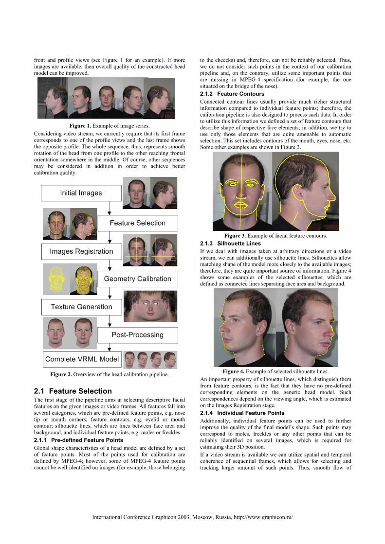
2. PIPELINE OVERVIEW The head calibration process is organized as a pipeline comprising a sequence of separate stages, which are schematically shown in Figure 2. Each stage processes the data obtained from its predecessors and performs the corresponding operations. The input data of the calibration process can be either
• A pair of images taken at front and profile directions, or • A collection of images taken at arbitrary directions, or • A video stream having front and both profile views.
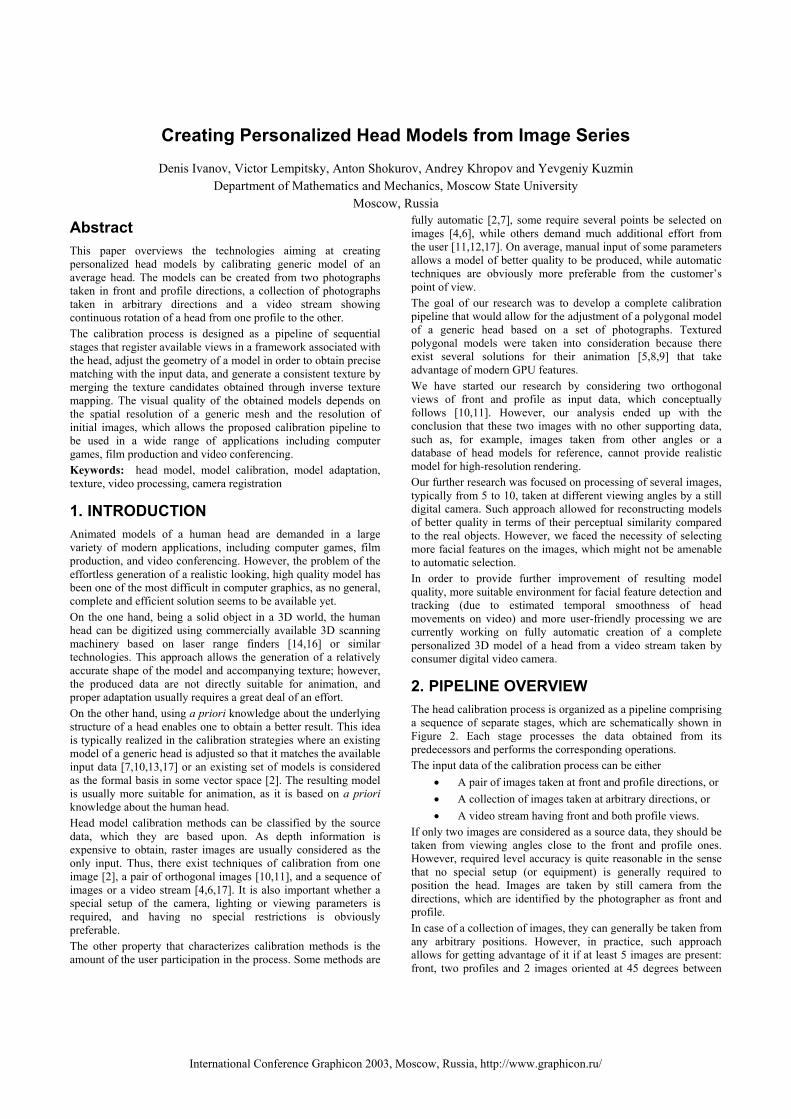
If only two images are considered as a source data, they should be taken from viewing angles close to the front and profile ones. However, required level accuracy is quite reasonable in the sense that no special setup (or equipment) is generally required to position the head. Images are taken by still camera from the directions, which are identified by the photographer as front and profile. In case of a collection of images, they can generally be taken from any arbitrary positions. However, in practice, such approach allows for getting advantage of it if at least 5 images are present: front, two profiles and 2 images oriented at 45 degrees between
International Conference Graphicon 2003, Moscow, Russia, http://www.graphicon.ru/
front and profile views (see Figure 1 for an example). If more images are available, then overall quality of the constructed head model can be improved.
Figure 1. Example of image series.
Considering video stream, we currently require that its first frame corresponds to one of the profile views and the last frame shows the opposite profile. The whole sequence, thus, represents smooth rotation of the head from one profile to the other reaching frontal orientation somewhere in the middle. Of course, other sequences may be considered in addition in order to achieve better calibration quality.
Figure 2. Overview of the head calibration pipeline.
2.1 Feature Selection The first stage of the pipeline aims at selecting descriptive facial features on the given images or video frames. All features fall into several categories, which are pre-defined feature points, e.g. nose tip or mouth corners; feature contours, e.g. eyelid or mouth contour; silhouette lines, which are lines between face area and background, and individual feature points, e.g. moles or freckles. 2.1.1 Pre-defined Feature Points Global shape characteristics of a head model are defined by a set of feature points. Most of the points used for calibration are defined by MPEG-4; however, some of MPEG-4 feature points cannot be well-identified on images (for example, those belonging
to the cheecks) and, therefore, can not be reliably selected. Thus, we do not consider such points in the context of our calibration pipeline and, on the contrary, utilize some important points that are missing in MPEG-4 specification (for example, the one situated on the bridge of the nose). 2.1.2 Feature Contours Connected contour lines usually provide much richer structural information compared to individual feature points; therefore, the calibration pipeline is also designed to process such data. In order to utilize this information we defined a set of feature contours that describe shape of respective face elements; in addition, we try to use only those elements that are quite amenable to automatic selection. This set includes contours of the mouth, eyes, nose, etc. Some other examples are shown in Figure 3.
Figure 3. Example of facial feature contours.
2.1.3 Silhouette Lines If we deal with images taken at arbitrary directions or a video stream, we can additionally use silhouette lines. Silhouettes allow matching shape of the model more closely to the available images; therefore, they are quite important source of information. Figure 4 shows some examples of the selected silhouettes, which are defined as connected lines separating face area and background.
Figure 4. Example of selected silhouette lines.
An important property of silhouette lines, which distinguish them from feature contours, is the fact that they have no pre-defined corresponding elements on the generic head model. Such correspondences depend on the viewing angle, which is estimated on the Images Registration stage. 2.1.4 Individual Feature Points Additionally, individual feature points can be used to further improve the quality of the final model’s shape. Such points may correspond to moles, freckles or any other points that can be reliably identified on several images, which is required for estimating their 3D position. If a video stream is available we can utilize spatial and temporal coherence of sequential frames, which allows for selecting and tracking larger amount of such points. Thus, smooth flow of
International Conference Graphicon 2003, Moscow, Russia, http://www.graphicon.ru/
individual feature points in a video stream can be reconstructed, which is conceptually similar to the technique described in [19]. An example of such feature flow is shown in Figure 5.
Figure 5. Example of individual feature flow.
Similar to silhouette lines, such points have no predefined correspondences on the head model. Such correspondences should be determined on the Geometry Calibration stage.
2.2 Images Registration When all feature elements have been selected on available images, we have to estimate extrinsic (position and orientation) and intrinsic (focal length) parameters of each camera with respect to the head under consideration. In other words, we register the camera in the coordinate system associated with the head. The registration process depends on the camera model that is being used. It is worth noting that we do not require any preliminary calibration of the intrinsic camera parameters, which means that no information other then images or video is assumed to be available. 2.2.1 Orthogonal camera model When front and profile images are the only data available, we use orthogonal projection for a camera model. Considering such projection, we assume that front and profile images are defined as those taken from the directions collinear to the Z and X axes respectively (in the coordinate system specified by MPEG-4). Under this assumption, the process of image registration reduces to defining coordinate axes projections onto the image planes. We first consider the front view and let the Y axis be the line of symmetry for a face. Then we restore X, which is orthogonal to Y. As the profile image also has a nontrivial projection of the Y axis, we have not only to estimate its direction but also bring its unit vector into synchronization with the one defined on the front view. This estimation is made by minimizing the least squares error between several corresponding points selected on the front and profile images. The Z axis is defined as the one orthogonal to Y in the profile projection. An example of the coordinate axes projections is shown in Figure 6.
Figure 6. Example of orthogonal front and profile camera setup.
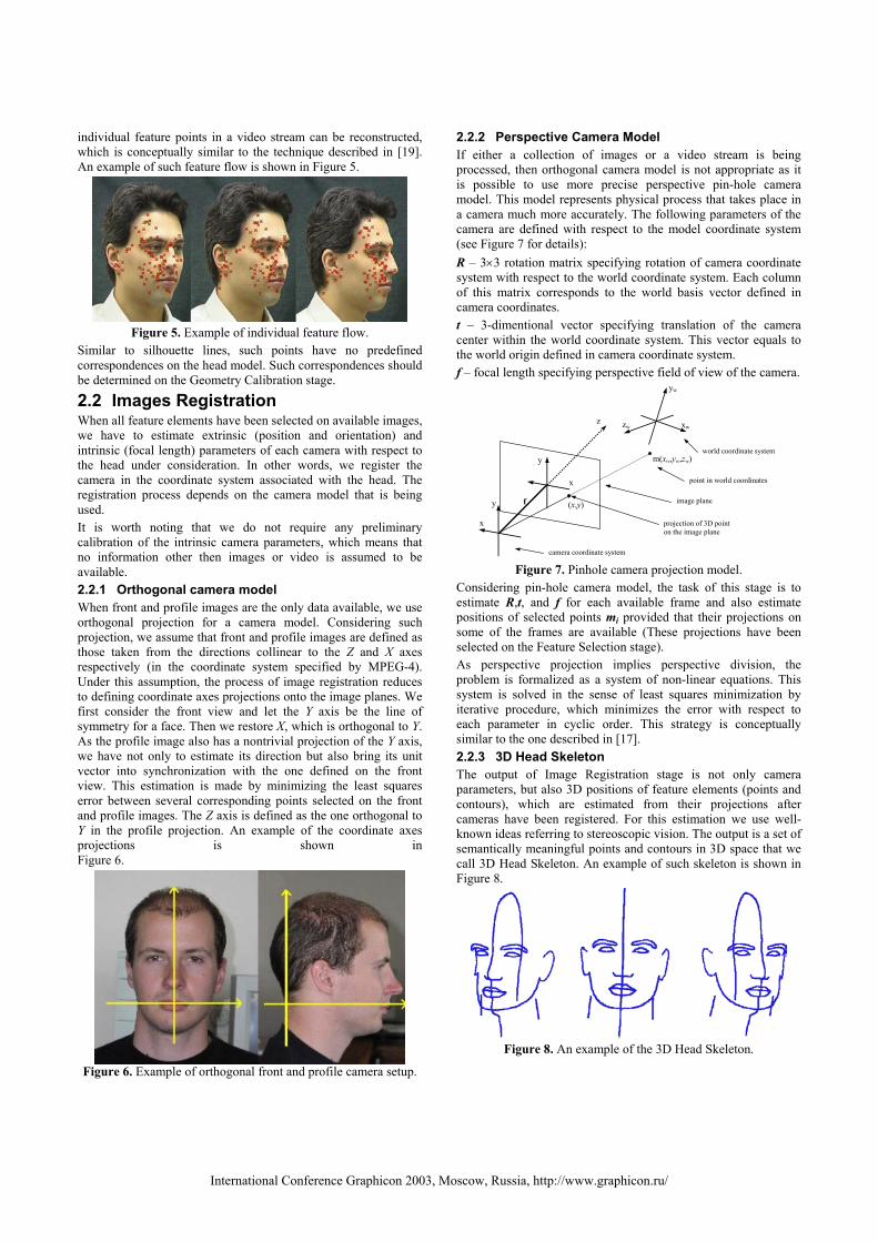
2.2.2 Perspective Camera Model If either a collection of images or a video stream is being processed, then orthogonal camera model is not appropriate as it is possible to use more precise perspective pin-hole camera model. This model represents physical process that takes place in a camera much more accurately. The following parameters of the camera are defined with respect to the model coordinate system (see Figure 7 for details): R – 3×3 rotation matrix specifying rotation of camera coordinate system with respect to the world coordinate system. Each column of this matrix corresponds to the world basis vector defined in camera coordinates. t – 3-dimentional vector specifying translation of the camera center within the world coordinate system. This vector equals to the world origin defined in camera coordinate system. f – focal length specifying perspective field of view of the camera.
x
y
z xw
yw
zw
f
m(xw,yw,zw)
(x,y)
camera coordinate system
point in world coordinates
world coordinate system
image plane
projection of 3D point on the image plane
x
y
Figure 7. Pinhole camera projection model.
Considering pin-hole camera model, the task of this stage is to estimate R,t, and f for each available frame and also estimate positions of selected points mi provided that their projections on some of the frames are available (These projections have been selected on the Feature Selection stage). As perspective projection implies perspective division, the problem is formalized as a system of non-linear equations. This system is solved in the sense of least squares minimization by iterative procedure, which minimizes the error with respect to each parameter in cyclic order. This strategy is conceptually similar to the one described in [17]. 2.2.3 3D Head Skeleton The output of Image Registration stage is not only camera parameters, but also 3D positions of feature elements (points and contours), which are estimated from their projections after cameras have been registered. For this estimation we use well-known ideas referring to stereoscopic vision. The output is a set of semantically meaningful points and contours in 3D space that we call 3D Head Skeleton. An example of such skeleton is shown in Figure 8.
Figure 8. An example of the 3D Head Skeleton.
International Conference Graphicon 2003, Moscow, Russia, http://www.graphicon.ru/

2.3 Geometry Calibration On the next stage we adjust a generic head model to the obtained 3D head skeleton and other selected data. Although there exists many approaches to the problem of mesh deformation, we have implemented two of them, which are, in our opinion, the most applicable to our case. The first is based on radial basis functions and the second is based on displacement-based deformation. 2.3.1 Radial Basis Function (RBF) Radial basis function deformation is a well-known approach to the generic model deformation ([1,12]). It is a smooth deformation of the mesh that moves feature vertices to corresponding feature points. Unfortunately, it is impossible to control the deformation of the surface between feature vertices. The shape of the surface often becomes unnatural for human head. Moreover, it does not give mechanism of employing other geometry data, such as contours, 2D feature points, etc. Therefore, we found it suitable for front and profile setup only. 2.3.2 Displacement-based deformation Our implementation of displacement-based deformation allows for employing all geometrical data extracted from the images, still providing smooth model deformation. It is implemented in several steps. On the first step we affinely deform generic model according to our skeleton, taking into consideration feature vertices of the generic model and actual positions of respective 3D features. Once, the generic model is properly positioned, the calibration procedure searches for the displacement vectors for every mesh vertex. Being added to vertices, these displacement vectors deform the mesh to suit given geometric data. We formalize all available geometry information in the context of a system of linear equations with respect to coordinates of displacement vectors. Each equation represents certain constraint applied to the respective vertex. Thus, there exist several groups of such equations depending on the types of constraints. Smoothness constraint results in the per-vertex equations, equating the displacement vector of every vertex to the average displacements of its neighbors. As feature points naturally correspond to the vertices of the generic head mesh, we can equate displacements of those vertices to vectors moving them to corresponding feature points. Feature contours also correspond to the chains of vertices on the mesh and hence yield another group of equations on displacement coordinates. Feature point and feature contour constraints are called skeleton constraints. The obtained system of linear equation is sparse, very large and over-constrained. Its solution in the least-squares sense can be efficiently found with conjugate gradients method (Figure 9).
Figure 9. 3D skeleton, mesh after affine transformation, and the
deformed mesh after applying skeleton constraints. Silhouette lines and individual feature points should also participate in model deformation with some constraints. 2D
feature points and feature contours, i.e. skeleton elements selected on the only image, and thus not contributing to 3D skeleton, define another group of constraints. Expressing these constraints with linear equations on displacement coordinates causes two main problems, namely determining corresponding vertices and expressing projective geometry constraints with linear equations. Both problems can be solved for the small deformations. In case of small deformation, perspective projection can be locally approximated with affine projection, whereas corresponding vertices are found as the closest vertices (in 3D space for individual points and in 2D image plane for silhouette lines). To assure that the deformation is really small, we deform the mesh with smoothness and skeleton constraints first. After that we supplement our system with remaining equations and search for a more precise solution. The fewer elements the 3D skeleton contains, the more important is the role of additional constraints (Figure 10).
Figure 10. Adjusting geometry with additional constraints:
skeleton-based geometry (left), final model (middle), one of the initial photographs of Max Planck bust (right).
2.4 Texture Generation A high-quality texture is very important for the realism of a head model. Texture generation is performed in two steps: texture fragments extraction and texture fragments merging. 2.4.1 Texture Extraction
Figure 11. Texture fragment extraction
On the first step, texture fragment is created from every image, superimposing the deformed model on the image (this operations assumes that texture coordinates are provided with the generic mesh and do not change during the calibration process). This texture fragment is supplied with the weight map, representing local texture quality. Texture quality is assumed to be proportional to the dot product of the surface normal and the viewing direction. Thus, a set of weighted texture fragments is obtained (see Figure 11 for an example). Extracted fragments should be merged into the unified texture map. Several approaches can be used. The simplest algorithm calculates texture map as a weighted per-pixel
International Conference Graphicon 2003, Moscow, Russia, http://www.graphicon.ru/
sum of texture fragments [17]. However, the visual quality of such texture map is very low. We have developed several approaches that yield textures with visual quality nearly equal to the original images. 2.4.2 Color Balancing Approach
Figure 12. Merging lines
This merging method generates texture from three texture fragments, corresponding to frontal and two profile images (in the case of reconstruction from two views, the only profile fragment is flipped horizontally to substitute the opposite one). The method searches for merging lines between fragments, minimizing color differences along the lines and maximizing the quality of texture parts included in the resulting texture (Figure 12). After merging lines have been found, color balancing algorithm calculates smooth addition for every profile fragment, eliminating inevitable differences along merging lines (see Figure 13 for an example).
Figure 13. Color balancing
This method preserves high frequency elements of the fragments, avoiding any blurring of the texture. However it faces some problems with low frequencies, if images were taken under different lighting condition, for example when the flashbulb was applied. More details on color balancing can be found in [15]. 2.4.3 Pyramidal texture merging This method can operate with an arbitrary number of images. It works with the pyramidal representations of texture fragments, and, thus, conceptually follows [3].
Figure 14. Decomposing texture fragments into gaussian (left)
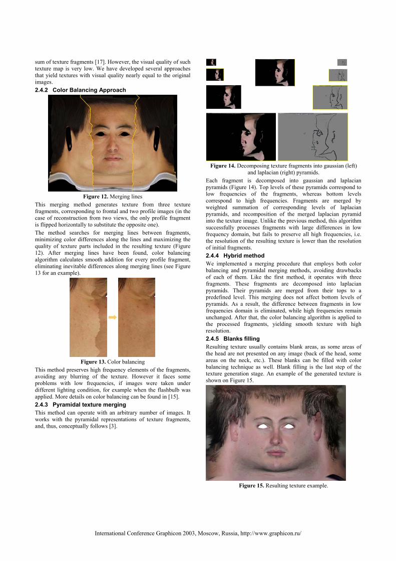
and laplacian (right) pyramids. Each fragment is decomposed into gaussian and laplacian pyramids (Figure 14). Top levels of these pyramids correspond to low frequencies of the fragments, whereas bottom levels correspond to high frequencies. Fragments are merged by weighted summation of corresponding levels of laplacian pyramids, and recomposition of the merged laplacian pyramid into the texture image. Unlike the previous method, this algorithm successfully processes fragments with large differences in low frequency domain, but fails to preserve all high frequencies, i.e. the resolution of the resulting texture is lower than the resolution of initial fragments. 2.4.4 Hybrid method We implemented a merging procedure that employs both color balancing and pyramidal merging methods, avoiding drawbacks of each of them. Like the first method, it operates with three fragments. These fragments are decomposed into laplacian pyramids. Their pyramids are merged from their tops to a predefined level. This merging does not affect bottom levels of pyramids. As a result, the difference between fragments in low frequencies domain is eliminated, while high frequencies remain unchanged. After that, the color balancing algorithm is applied to the processed fragments, yielding smooth texture with high resolution. 2.4.5 Blanks filling Resulting texture usually contains blank areas, as some areas of the head are not presented on any image (back of the head, some areas on the neck, etc.). These blanks can be filled with color balancing technique as well. Blank filling is the last step of the texture generation stage. An example of the generated texture is shown on Figure 15.
Figure 15. Resulting texture example.
International Conference Graphicon 2003, Moscow, Russia, http://www.graphicon.ru/
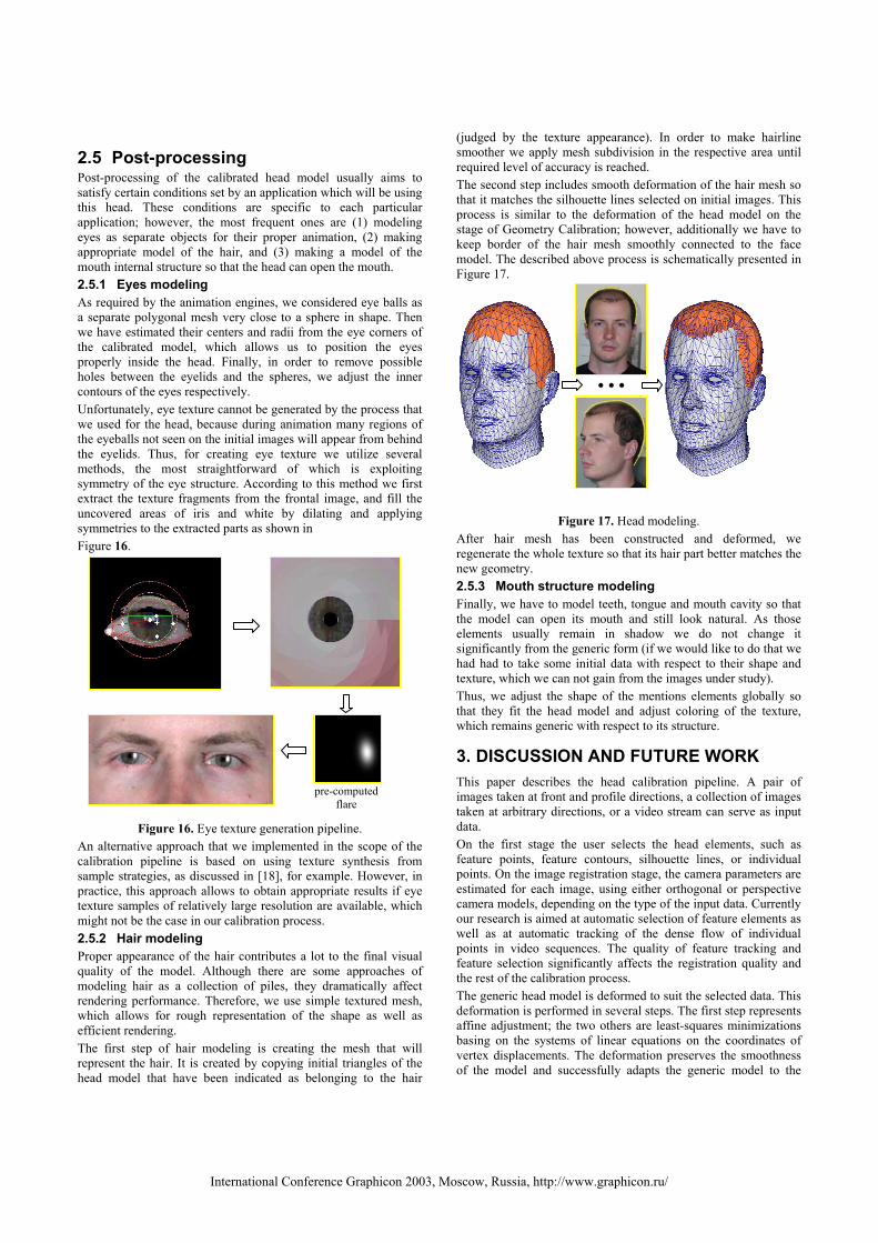
2.5 Post-processing Post-processing of the calibrated head model usually aims to satisfy certain conditions set by an application which will be using this head. These conditions are specific to each particular application; however, the most frequent ones are (1) modeling eyes as separate objects for their proper animation, (2) making appropriate model of the hair, and (3) making a model of the mouth internal structure so that the head can open the mouth. 2.5.1 Eyes modeling As required by the animation engines, we considered eye balls as a separate polygonal mesh very close to a sphere in shape. Then we have estimated their centers and radii from the eye corners of the calibrated model, which allows us to position the eyes properly inside the head. Finally, in order to remove possible holes between the eyelids and the spheres, we adjust the inner contours of the eyes respectively. Unfortunately, eye texture cannot be generated by the process that we used for the head, because during animation many regions of the eyeballs not seen on the initial images will appear from behind the eyelids. Thus, for creating eye texture we utilize several methods, the most straightforward of which is exploiting symmetry of the eye structure. According to this method we first extract the texture fragments from the frontal image, and fill the uncovered areas of iris and white by dilating and applying symmetries to the extracted parts as shown in Figure 16.
Figure 16. Eye texture generation pipeline.
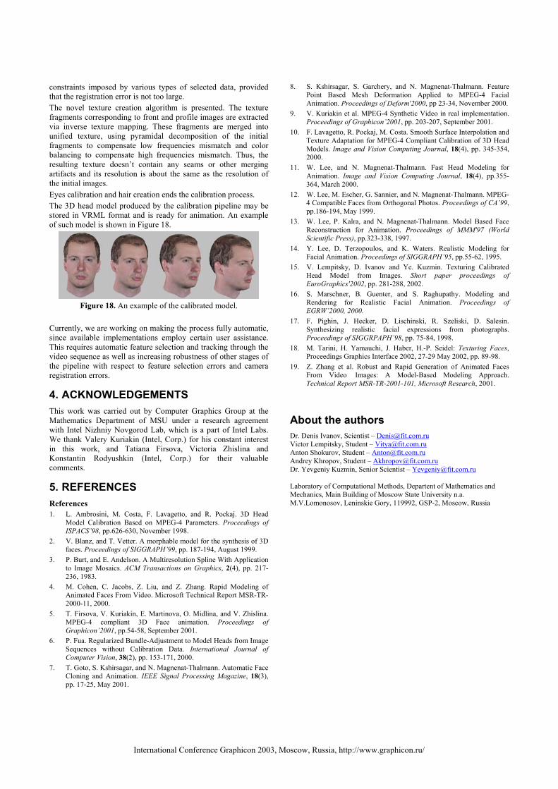
An alternative approach that we implemented in the scope of the calibration pipeline is based on using texture synthesis from sample strategies, as discussed in [18], for example. However, in practice, this approach allows to obtain appropriate results if eye texture samples of relatively large resolution are available, which might not be the case in our calibration process. 2.5.2 Hair modeling Proper appearance of the hair contributes a lot to the final visual quality of the model. Although there are some approaches of modeling hair as a collection of piles, they dramatically affect rendering performance. Therefore, we use simple textured mesh, which allows for rough representation of the shape as well as efficient rendering. The first step of hair modeling is creating the mesh that will represent the hair. It is created by copying initial triangles of the head model that have been indicated as belonging to the hair
(judged by the texture appearance). In order to make hairline smoother we apply mesh subdivision in the respective area until required level of accuracy is reached. The second step includes smooth deformation of the hair mesh so that it matches the silhouette lines selected on initial images. This process is similar to the deformation of the head model on the stage of Geometry Calibration; however, additionally we have to keep border of the hair mesh smoothly connected to the face model. The described above process is schematically presented in Figure 17.
Figure 17. Head modeling. After hair mesh has been constructed and deformed, we regenerate the whole texture so that its hair part better matches the new geometry. 2.5.3 Mouth structure modeling Finally, we have to model teeth, tongue and mouth cavity so that the model can open its mouth and still look natural. As those elements usually remain in shadow we do not change it significantly from the generic form (if we would like to do that we had had to take some initial data with respect to their shape and texture, which we can not gain from the images under study). Thus, we adjust the shape of the mentions elements globally so that they fit the head model and adjust coloring of the texture, which remains generic with respect to its structure.
3. DISCUSSION AND FUTURE WORK This paper describes the head calibration pipeline. A pair of images taken at front and profile directions, a collection of images taken at arbitrary directions, or a video stream can serve as input data. On the first stage the user selects the head elements, such as feature points, feature contours, silhouette lines, or individual points. On the image registration stage, the camera parameters are estimated for each image, using either orthogonal or perspective camera models, depending on the type of the input data. Currently our research is aimed at automatic selection of feature elements as well as at automatic tracking of the dense flow of individual points in video sequences. The quality of feature tracking and feature selection significantly affects the registration quality and the rest of the calibration process. The generic head model is deformed to suit the selected data. This deformation is performed in several steps. The first step represents affine adjustment; the two others are least-squares minimizations basing on the systems of linear equations on the coordinates of vertex displacements. The deformation preserves the smoothness of the model and successfully adapts the generic model to the
pre-computedflare
International Conference Graphicon 2003, Moscow, Russia, http://www.graphicon.ru/
constraints imposed by various types of selected data, provided that the registration error is not too large. The novel texture creation algorithm is presented. The texture fragments corresponding to front and profile images are extracted via inverse texture mapping. These fragments are merged into unified texture, using pyramidal decomposition of the initial fragments to compensate low frequencies mismatch and color balancing to compensate high frequencies mismatch. Thus, the resulting texture doesn’t contain any seams or other merging artifacts and its resolution is about the same as the resolution of the initial images. Eyes calibration and hair creation ends the calibration process. The 3D head model produced by the calibration pipeline may be stored in VRML format and is ready for animation. An example of such model is shown in Figure 18.
Figure 18. An example of the calibrated model.
Currently, we are working on making the process fully automatic, since available implementations employ certain user assistance. This requires automatic feature selection and tracking through the video sequence as well as increasing robustness of other stages of the pipeline with respect to feature selection errors and camera registration errors.
4. ACKNOWLEDGEMENTS This work was carried out by Computer Graphics Group at the Mathematics Department of MSU under a research agreement with Intel Nizhniy Novgorod Lab, which is a part of Intel Labs. We thank Valery Kuriakin (Intel, Corp.) for his constant interest in this work, and Tatiana Firsova, Victoria Zhislina and Konstantin Rodyushkin (Intel, Corp.) for their valuable comments.
5. REFERENCES References 1. L. Ambrosini, M. Costa, F. Lavagetto, and R. Pockaj. 3D Head
Model Calibration Based on MPEG-4 Parameters. Proceedings of ISPACS’98, pp.626-630, November 1998.
2. V. Blanz, and T. Vetter. A morphable model for the synthesis of 3D faces. Proceedings of SIGGRAPH’99, pp. 187-194, August 1999.
3. P. Burt, and E. Andelson. A Multiresolution Spline With Application to Image Mosaics. ACM Transactions on Graphics, 2(4), pp. 217-236, 1983.
4. M. Cohen, C. Jacobs, Z. Liu, and Z. Zhang. Rapid Modeling of Animated Faces From Video. Microsoft Technical Report MSR-TR-2000-11, 2000.
5. T. Firsova, V. Kuriakin, E. Martinova, O. Midlina, and V. Zhislina. MPEG-4 compliant 3D Face animation. Proceedings of Graphicon’2001, pp.54-58, September 2001.
6. P. Fua. Regularized Bundle-Adjustment to Model Heads from Image Sequences without Calibration Data. International Journal of Computer Vision, 38(2), pp. 153-171, 2000.
7. T. Goto, S. Kshirsagar, and N. Magnenat-Thalmann. Automatic Face Cloning and Animation. IEEE Signal Processing Magazine, 18(3), pp. 17-25, May 2001.
8. S. Kshirsagar, S. Garchery, and N. Magnenat-Thalmann. Feature Point Based Mesh Deformation Applied to MPEG-4 Facial Animation. Proceedings of Deform'2000, pp 23-34, November 2000.
9. V. Kuriakin et al. MPEG-4 Synthetic Video in real implementation. Proceedings of Graphicon’2001, pp. 203-207, September 2001.
10. F. Lavagetto, R. Pockaj, M. Costa. Smooth Surface Interpolation and Texture Adaptation for MPEG-4 Compliant Calibration of 3D Head Models. Image and Vision Computing Journal, 18(4), pp. 345-354, 2000.
11. W. Lee, and N. Magnenat-Thalmann. Fast Head Modeling for Animation. Image and Vision Computing Journal, 18(4), pp.355-364, March 2000.
12. W. Lee, M. Escher, G. Sannier, and N. Magnenat-Thalmann. MPEG-4 Compatible Faces from Orthogonal Photos. Proceedings of CA’99, pp.186-194, May 1999.
13. W. Lee, P. Kalra, and N. Magnenat-Thalmann. Model Based Face Reconstruction for Animation. Proceedings of MMM'97 (World Scientific Press), pp.323-338, 1997.
14. Y. Lee, D. Terzopoulos, and K. Waters. Realistic Modeling for Facial Animation. Proceedings of SIGGRAPH’95, pp.55-62, 1995.
15. V. Lempitsky, D. Ivanov and Ye. Kuzmin. Texturing Calibrated Head Model from Images. Short paper proceedings of EuroGraphics'2002, pp. 281-288, 2002.
16. S. Marschner, B. Guenter, and S. Raghupathy. Modeling and Rendering for Realistic Facial Animation. Proceedings of EGRW’2000, 2000.
17. F. Pighin, J. Hecker, D. Lischinski, R. Szeliski, D. Salesin. Synthesizing realistic facial expressions from photographs. Proceedings of SIGGRPAPH’98, pp. 75-84, 1998.
18. M. Tarini, H. Yamauchi, J. Haber, H.-P. Seidel: Texturing Faces, Proceedings Graphics Interface 2002, 27-29 May 2002, pp. 89-98.
19. Z. Zhang et al. Robust and Rapid Generation of Animated Faces From Video Images: A Model-Based Modeling Approach. Technical Report MSR-TR-2001-101, Microsoft Research, 2001.
About the authors Dr. Denis Ivanov, Scientist – [email protected] Victor Lempitsky, Student – [email protected] Anton Shokurov, Student – [email protected] Andrey Khropov, Student – [email protected] Dr. Yevgeniy Kuzmin, Senior Scientist – [email protected] Laboratory of Computational Methods, Departent of Mathematics and Mechanics, Main Building of Moscow State University n.a. M.V.Lomonosov, Leninskie Gory, 119992, GSP-2, Moscow, Russia
International Conference Graphicon 2003, Moscow, Russia, http://www.graphicon.ru/