Correct configuration of FG Generator Stator with Lead ...
11
Correct Configuration of FG Generator Stator with Lead Current www.siemens.com/siprotec
-
Upload
khangminh22 -
Category
Documents
-
view
0 -
download
0
Transcript of Correct configuration of FG Generator Stator with Lead ...

Correct Configuration of FG Generator Stator with Lead Current
www.siemens.com/siprotec
SIPROTEC 5 Application Correct Configuration of FG Generator Stator with Lead Current
APN-080 2 Edition 1
SIPROTEC 5 Application
Correct Configuration of FG Generator Stator with Lead Current
APN-080, Edition 1
Content 1 Correct Configuration of FG Generator Stator with Lead Current ......................................................................... 3
1.1 Introduction ...................................................................................................................................................... 3
1.2 Conventional Connection with Neutral Current .................................................................................................. 3
1.3 Non-conventional Connection with Lead Current – Incorrect Configuration ........................................................ 4
1.4 Non-conventional Connection with Lead Current – Correct Configuration ........................................................... 7
1.5 Conclusion ...................................................................................................................................................... 10
SIPROTEC 5 Application Correct Configuration of FG Generator Stator with Lead Current
Edition 1 3 APN-080
1 Correct Configuration of FG Generator Stator with Lead Current
1.1 Introduction For generator protection application, most of the 3-ph functions such as reverse power protection (ANSI 32R), under-
excitation protection (ANSI 40), out-of-step protection (ANSI 78), etc., are typically using the neutral side current. In some
cases, we are required by the customer to use the lead side current for these functions. This will lead to un-favorite
functional behavior if no special treatment during the configuration is done.
The correct configuration for this connection is described in this application note.
1.2 Conventional Connection with Neutral Current In power generation application, the generator-transformer block can be protected by the protection device 7UM85. The
following Figure 1 is to demonstrate the connection diagram of the 3-ph system. The injected phasors into the protection
device with rated operation condition are also illustrated.
MP I-3ph 3
Measured values
I-3ph
FG Transformer side 1 FG Transformer diff.
87T
MP I-3ph 2
MP I-3ph 1
Measured values
I-3ph 1
FG Transformer side 2
Measured values
I-3ph
FG Generator stator
Measured values
I-3ph
FG Generator side
MP V-3ph 1
V-3ph
FG Generator diff.
87G
24 32R 40
46 51V
59 78 81
3~ 49
CT1 25,000A / 1A
525kV/20kV720MVAYnD11
MP I-3ph 4
20kV/10.5kV-10.5kV68MVA/34MVA-34MVADYn1Yn1
20kV600MWCosφ = 0.85
CT2 25,000A / 1A
CT3 1,000A / 1A
CT4 25,000A / 1A
VT1 20kV:√3 / 0.1kV:√3
I-3ph 2
‘X’
‘X’
‘X’
‘X’
0.815 A∠-31.79°
57.735 V∠0.00°
0.815 A∠148.21°
0.079 A∠148.21°
0.702 A∠118.21°
GEN
UAT
GSUT
_:8881:116 Neutr.point in dir.of ref.obj = yes
_:8881:116 Neutr.point in dir.of ref.obj =
1
2
SIPROTEC 5 7UM85
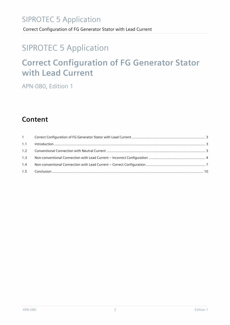
Figure 1: Conventional Connection Diagram for FG Generator Stator
This is a conventional diagram for the block protection. In the above diagram we see that most of the generator
protection functions are allocated in FG Generator Stator to which the neutral side current transformer CT1 is connected.
The generator differential protection (ANSI 87G) calculates the differential current ΔI from the FGs of Generator Stator
and Generator Side.
According to the diagram, based on the rule of generator (GEN) differential protection or generator step-up transformer
(GSUT) differential protection, the parameter “_:8881:116 Neutr.point in dir.of ref.obj” for measuring points of MP I-3ph
1, MP I-3ph 3 and MP I-3ph 4 is set to “yes”. For measuring point MP I-3ph 2, it can be set to “yes” if it’s referred to
protected object “GEN”, or “no” if it’s referred to protected object “GSUT”.

SIPROTEC 5 Application Correct Configuration of FG Generator Stator with Lead Current
APN-080 4 Edition 1
If above mentioned setting is “yes”, the MP I-3ph 2 must be routed with “X(routed)” for FG Generator Side. As request
from GSUT differential protection, it must be routed with “I(routed - with inverted direction)” for FG Transformer Side 2.
Please refer to below Figure 2.
Figure 2: Route Measuring Points if “yes” : ①= ‘I’, ②= ’X’
If the setting is “no”, the MP I-3ph 2 must be routed with “X(routed)” for FG Transformer Side 2. As request from GEN
differential protection, it must be routed with “I(routed - with inverted direction)” for FG Generator Side. Please refer to
below Figure 3.
Figure 3: Route Measuring Points if “no”: ①= ‘X’, ②= ’I’
Below pictures show the correct operational and functional values.
Figure 4: Correct Values of FG Generator Stator with Neutral Side Current
1.3 Non-conventional Connection with Lead Current – Incorrect Configuration
Many reasons lead to a non-conventional connection, that is, to connect lead side current to FG Generator Stator. Let’s
see what will happen if the following connection diagram of 3-ph system is applied.

SIPROTEC 5 Application Correct Configuration of FG Generator Stator with Lead Current
Edition 1 5 APN-080
MP I-3ph 3
Measured values
I-3ph
FG Transformer side 1 FG Transformer diff.
87T
MP I-3ph 2
MP I-3ph 1
Measured values
I-3ph 1
FG Transformer side 2
Measured values
I-3ph
FG Generator stator
Measured values
I-3ph
FG Generator side
MP V-3ph 1
V-3ph
FG Generator diff.
87G
24 32R 40
46 51V
59 78 81
3~
49
CT1 25,000A / 1A
525kV/20kV720MVAYnD11
MP I-3ph 4
20kV/10.5kV-10.5kV68MVA/34MVA-34MVADYn1Yn1
20kV600MWCosφ = 0.85
CT2 25,000A / 1A
CT3 1,000A / 1A
CT4 25,000A / 1A
VT1 20kV:√3 / 0.1kV:√3
I-3ph 2
‘X’
‘X’
‘X’
‘X’
0.815 A∠-31.79°
57.735 V∠0.00°
0.815 A∠148.21°
0.079 A∠148.21°
0.702 A∠118.21°
GEN
UAT
GSUT
_:8881:116 Neutr.point in dir.of ref.obj = yes
_:8881:116 Neutr.point in dir.of ref.obj =
1
2
SIPROTEC 5 7UM85
Figure 5: Connection Diagram with Lead Current for FG Generator Stator – Incorrect Solution
Following the same configuration as with the conventional connection diagram, we see the wrong operational and
functional values as below.
Figure 6: Wrong Values of FG Generator Stator with Lead Side Current
Compared to Figure 4, we see that the calculated power and impedance are inverted with the direction. This must lead to
un-favorite behavior, e.g. over-function of reverse power protection.
1.3.1 Analysis
When we are talking about the parameter “_:8881:116 Neutr.point in dir.of ref.obj”, we are talking about the protected
object. This setting is crucial for proper behavior of differential, directional and power protection. For the example shown
in Figure 5, the neutral point of MP I-3ph 2 is in direction of GEN, but not in direction of GSUT.

SIPROTEC 5 Application Correct Configuration of FG Generator Stator with Lead Current
APN-080 6 Edition 1
Let’s see respectively the results of protected object “GEN” and “GSUT”
Calculation with Protected Object GEN
Based on Figure 5, the parameter “_:8881:116 Neutr.point in dir.of ref.obj” is set to “yes”, the MP I-3ph 2 must be routed
with “X(routed)” for FG Generator Stator. As request from GSUT differential protection, it must be routed with “I(routed -
with inverted direction)” for FG Transformer Side 2.
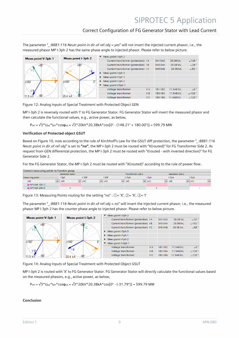
The parameter “_:8881:116 Neutr.point in dir.of ref.obj = yes” will not invert the injected current phasor, i.e., the
measured current phasor MP I-3ph 2 has the same phase angle as the injected current phasor. Please refer to below
picture.
Figure 7: Measured Phasors with Protected Object GEN
MP I-3ph 2 is routed to FG Generator Stator with ‘X’. FG Generator Stator will directly calculate the functional values based
on the measured phasor, e.g., active power, as below,
Ptot = √3*Upp*Iph*cosφUI = √3*20kV*20.38kA*cos(0° - 148.21°) = -599.79 MW
Calculation with Protected Object GSUT
Based on Figure 5, the parameter “_:8881:116 Neutr.point in dir.of ref.obj” is set to “no”, the MP I-3ph 2 must be routed
with “X(routed)” for FG Transformer Side 2. As request from GEN differential protection, it must be routed with “I(routed -
with inverted direction)” for FG Generator Stator.
The parameter “_:8881:116 Neutr.point in dir.of ref.obj = no” will invert the injected current phasor, i.e., the measured
phasor MP I-3ph 2 has the counter phase angle to injected phasor. Please refer to below picture.
Figure 8: Measured Phasors with Protected Object GSUT
MP I-3ph 2 is reversely routed to FG Generator Stator with ‘I’. FG Generator Stator will invert the measured phasor and
then calculate the functional values, e.g., active power, as below,
Ptot = √3*Upp*Iph*cosφUI = √3*20kV*20.38kA*cos[0° - (-31.79° + 180.00°)] = -599.79 MW
Conclusion
From the above two setting cases we see, independent of the parameter “_:8881:116 Neutr.point in dir.of ref.obj” of MP
I-3ph 2 setting to “yes” or “no”, we have always the same wrong results for both the measurement values and the function
values for example for reverse power, under-excitation, out-of-step, etc.
SIPROTEC 5 Application Correct Configuration of FG Generator Stator with Lead Current
Edition 1 7 APN-080
If we focus on FG Generator Differential, we shall set the parameter “_:8881:116 Neutr.point in dir.of ref.obj”(value “yes”
or “no”) and route the matrix value(“X” or “I”) based on the rule of Kirchhoff’s Law. This means, the adapted current phasor
should point towards “GEN”.
GEN is generating power to the grid during normal operation. If we focus on FG Generator Stator with lead current, we
shall determine the above values based on the rule of power flow. This means, the adapted current phasor should point
towards “HV Busbar”.
Both rules are consistent at the measuring point of the neutral side (both of “GEN” and “HV Busbar” are in direction of
power grid), so the differential protection and the direction dependent functions in the FG Generator Stator work
correctly.
However, both rules are inconsistent at the measuring point of lead side (“HV Busbar” is in direction of power grid but
“GEN” is in the opposite direction). We have this conflict because the FG Generator stator was originally designed to be
connected only to the measuring point of the neutral side where both rules are consistent. This is the root cause for the
wrong behavior of FG Generator Stator when connected to the lead measuring point which we saw before.
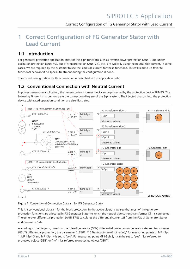
1.3.2 Special Notice to Reversed P, Q Sign
There is a parameter “_:14611:158 P,Q sign” under path \FG Generator Stator\General\Further settings\Measurements.
This parameter with setting “reversed” is to reverse only the displayed operational values. Please pay special attention, this
setting has no influence on functional values and cannot avoid the un-favorite behavior. With the setting value “reversed”,
we can see the correct operational values (green marking) but wrong functional values (red marking) like impedance and
reverse power values as shown below.
Figure 9: Correct Operational Values but Wrong Functional Values
1.4 Non-conventional Connection with Lead Current – Correct Configuration
Knowing now the reason for the incorrect behavior, we present a possible solution in Figure 10.

SIPROTEC 5 Application Correct Configuration of FG Generator Stator with Lead Current
APN-080 8 Edition 1
MP I-3ph 3
Measured values
I-3ph
FG Transformer side 1 FG Transformer diff.
87T
MP I-3ph 2
MP I-3ph 1
Measured values
I-3ph 1
FG Transformer side 2
Measured values
I-3ph
FG Generator stator
Measured values
I-3ph
FG Generator side 1
MP V-3ph 1
V-3ph
FG Generator diff.
87G
24 32R 40
46 51V
59 78 81
3~
49
CT1 25,000A / 1A
525kV/20kV720MVAYnD11
MP I-3ph 4
20kV/10.5kV-10.5kV68MVA/34MVA-34MVADYn1Yn1
20kV600MWCosφ = 0.85
CT2 25,000A / 1A
CT3 1,000A / 1A
CT4 25,000A / 1A
VT1 20kV:√3 / 0.1kV:√3
I-3ph 2
‘X’
‘X’
‘X’
‘X’
0.815 A∠-31.79°
57.735 V∠0.00°
0.815 A∠148.21°
0.079 A∠148.21°
0.702 A∠118.21°
GEN
UAT
GSUT
_:8881:116 Neutr.point in dir.of ref.obj = yes
_:8881:116 Neutr.point in dir.of ref.obj =
1
2
SIPROTEC 5 7UM85Measured values
I-3ph
FG Generator side 2
3
Figure 10: Connection Diagram with Lead Current for FG Generator Stator – Correct Configuration
Isolation of the Connection between FG Generator Stator and FG Generator Differential.
We set up a FG Generator Stator which is independent of FG Generator Differential. For the latter we create an additional
FG Generator Side 2 routed to the CT on the lead side. The FG Generator Differential is now connected to FG Generator
Side 1 and FG Generator Side 2 (see Figure 10)
Then, we determine the parameter “_:8881:116 Neutr.point in dir.of ref.obj” and route the matrix value based on the rule
of Kirchhoff’s Law for the Generator Side 2 and based on the rule of power flow for the FG Generator Stator.
Verification of Protected Object GEN
Based on Figure 10, we follow the rule of Kirchhoff’s Law for the GEN differential protection and set the parameter
“_:8881:116 Neutr.point in dir.of ref.obj” to “yes”. Then the MP I-3ph 2 must be routed with “X(routed)” for FG Generator
Side 2. As request from GSUT differential protection, the MP I-3ph 2 must be routed with “I(routed - with inverted
direction)” for FG Transformer Side 2.
For the FG Generator Stator the MP I-3ph 2 is routed with “I(routed - with inverted direction)” according to the rule of
power flow (the CT star-point at the generator lead side must have the same direction as the CT star-point at the
generator neutral side, so that the functions of both sides have the same correct values).
Figure 11: Measuring Points routing for the setting “yes” : ①= ‘I’, ②= ’I’,③= ‘X’
SIPROTEC 5 Application Correct Configuration of FG Generator Stator with Lead Current
Edition 1 9 APN-080
The parameter “_:8881:116 Neutr.point in dir.of ref.obj = yes” will not invert the injected current phasor, i.e., the
measured phasor MP I-3ph 2 has the same phase angle to injected phasor. Please refer to below picture.
Figure 12: Analog Inputs of Special Treatment with Protected Object GEN
MP I-3ph 2 is reversely routed with ‘I’ to FG Generator Stator. FG Generator Stator will invert the measured phasor and
then calculate the functional values, e.g., active power, as below,
Ptot = √3*Upp*Iph*cosφUI = √3*20kV*20.38kA*cos[0° - (148.21° + 180.00°)] = 599.79 MW
Verification of Protected object GSUT
Based on Figure 10, now according to the rule of Kirchhoff’s Law for the GSUT diff protection, the parameter “_:8881:116
Neutr.point in dir.of ref.obj” is set to “no”, the MP I-3ph 2 must be routed with “X(routed)” for FG Transformer Side 2. As
request from GEN differential protection, the MP I-3ph 2 must be routed with “I(routed - with inverted direction)” for FG
Generator Side 2.
For the FG Generator Stator, the MP I-3ph 2 must be routed with “X(routed)” according to the rule of power flow.
Figure 13: Measuring Points routing for the setting “no” : ①= ‘X’, ②= ‘X’, ③= ‘I’
The parameter “_:8881:116 Neutr.point in dir.of ref.obj = no” will invert the injected current phasor, i.e., the measured
phasor MP I-3ph 2 has the counter phase angle to injected phasor. Please refer to below picture.
Figure 14: Analog Inputs of Special Treatment with Protected Object GSUT
MP I-3ph 2 is routed with ‘X’ to FG Generator Stator. FG Generator Stator will directly calculate the functional values based
on the measured phasors, e.g., active power, as below,
Ptot = √3*Upp*Iph*cosφUI = √3*20kV*20.38kA*cos[0° - (-31.79°)] = 599.79 MW
Conclusion

SIPROTEC 5 Application Correct Configuration of FG Generator Stator with Lead Current
APN-080 10 Edition 1
After the special treatment for FG Generator Stator, with the parameter “_:8881:116 Neutr.point in dir.of ref.obj” of MP I-
3ph 2 setting “yes” or “no” and the MP routing (“I” or “X”) , the FG Generator Stator can properly handle the calculation of
the power, the impedance, etc. that is to say, the 3-ph protection functions work well.
The correct operational and functional values are shown on the display as in Figure 4.
1.5 Conclusion For generator protection application, normally we allocate the 3-ph functions in FG Generator Stator with neutral side
current. This is also the default design of SIPROTEC 5.
In some cases, we are required, or must use the lead side current for 3-ph functions. With the before presented
configuration we ensure a correct behavior of the generator differential protection and also of the directional functions of
the FG generator stator like reverse power(ANSI 32R), under-excitation(ANSI 40), impedance protection(ANSI 21T) or out
of step(ANSI 78) protection etc.

Published by Siemens AG Smart Infrastructure Digital Grid Humboldtstrasse 59
90459 Nuremberg, Germany
www.siemens.com/siprotec
For more information, please
contact our Customer Support
Center.
Tel.: +49 180 524 70 00
Fax: +49 180 524 24 71
(Charges depending on provider)
Customer Support: www.siemens.com/csc
© 2020 Siemens. Subject to changes and errors. The information given in this document only contains general descriptions and/or performance features which may not always specifically reflect those described, or which may undergo modification in the course of further development of the products. The requested performance features are binding only when they are expressly agreed upon in the concluded contract.
For all products using security features of OpenSSL, the following shall apply: This product includes software developed by the OpenSSL Project for use in the OpenSSL Toolkit. (http://www.openssl.org/ ) This product includes cryptographic software written by Eric Young ([email protected] ) This product includes software developed by Bodo Moeller.
For the U.S. published by
Siemens Industry Inc.
100 Technology Drive
Alpharetta, GA 30005
United States