Management of business process reengineering projects: a case study
Upload
khangminh22Category
view
0download
0
!!
16. Workshop Software-Reengineering
und -Evolution der GI-Fachgruppe Software-Reengineering (SRE) !!
6. Workshop „Design for Future“ !
des GI-Arbeitskreises „Langlebige Softwaresysteme“ (L2S2) !!Bad Honnef
28.-30. April 2014
!!!
!
16. Workshop Software-Reengineering und -Evolution der GI-Fachgruppe Software Reengineering (SRE)
6. Workshop „Design for Future 2014“
des GI-Arbeitskreises „Langlebige Softwaresysteme“ (L2S2)
28.-30. Mai 2014 Physikzentrum Bad Honnef !
Die Workshops Software Reengineering (WSR) im Physikzentrum Bad Honnef wurden mit dem ersten WSR 1999 von Jürgen Ebert und Franz Lehner ins Leben gerufen, um ne-ben den internationalen erfolgreichen Tagun-gen im Bereich Reengineering (wie etwa WCRE und CSMR) auch ein deutschsprachi-ges Diskussionsforum zu schaffen. Dieses Jahr haben wir erstmals explizit das Thema Soft-ware-Evolution in den Titel mit aufgenommen, um eine breitere Zielgruppe anzusprechen und auf den Workshop aufmerksam zu machen. Damit ist das neue Kürzel entsprechend WSRE.!
Ziel der Treffen ist es nach wie vor, einan-der kennen zu lernen und auf diesem Wege eine direkte Basis der Kooperation zu schaffen, so dass das Themengebiet eine weitere Konso-lidierung und Weiterentwicklung erfährt.
Durch die aktive und gewachsene Beteili-gung vieler Forscher und Praktiker hat sich der WSRE als zentrale Reengineering-Konferenz im deutschsprachigen Raum etabliert. Dabei wird er weiterhin als Low-Cost-Workshop ohne eigenes Budget durchgeführt. Bitte tragen auch Sie dazu bei, den WSRE weiterhin erfolg-reich zu machen, indem Sie interessierte Kol-legen und Bekannte darauf hinweisen.
Auf Basis der erfolgreichen WSR-Treffen der ersten Jahre wurde 2004 die GI-Fachgrup-pe Software Reengineering gegründet, die un-ter http://www.fg-sre.gi-ev.de/ präsent ist. Durch die Fachgruppe wurden seitdem neben dem WSR(E) auch verwandte Tagungen zu Spezialthemen organisiert. Seit 2010 ist der Arbeitskreis Langlebige Softwaresysteme (L2S2) mit seinen „Design For Future“-Work-shops (DFF) aufgrund der inhaltlichen Nähe ebenfalls bei der Fachgruppe Reengineering aufgehängt. Alle zwei Jahre findet seitdem ein gemeinsamer Workshop von WSR und DFF statt - so auch in diesem Jahr. Diese Kombina-tion soll den Austausch zwischen den beiden Gruppen fördern. Während beim DFF der Schwerpunkt auf wartbaren Architekturen liegt, widmet sich der WSRE weiterhin dem allgemeinen Thema Reengineering in allen seinen Facetten.
Der WSRE ist weiterhin die zentrale Ta-gungsreihe der Fachgruppe Software-Reengi-neering. Er bietet eine Vielzahl aktueller Reen-gineering-Themen, die gleichermaßen wissen-schaftlichen wie praktischen Informationsbe-darf abdecken. In diesem Jahr gibt es wieder Beiträge zu einem breiten Spektrum von Re-engineering-Themen.
Die Organisatoren danken allen Beitragen-den für ihr Engagement – insbesondere den Vortragenden, Autorinnen und Autoren. Unser Dank gilt auch den Mitarbeiterinnen und Mit-arbeitern des Physikzentrums Bad Honnef, die es wie immer verstanden haben, ein angeneh-mes und problemloses Umfeld für den Work-shop zu schaffen. !Für die FG SRE: Volker Riediger, Universität Koblenz-Landau Jochen Quante, Robert Bosch GmbH, Stuttgart Jens Borchers, Steria Mummert, Hamburg Jan Jelschen, Universität Oldenburg !Für den AK L2S2: Stefan Sauer, s-lab, Universität Paderborn Benjamin Klatt, FZI Karlsruhe Thomas P. Ruhroth, TU Dortmund
Qualitat in Echtzeit mit Teamscale∗
Nils Gode, Lars Heinemann, Benjamin Hummel, Daniela Steidl
CQSE GmbHLichtenbergstr. 8, 85748 Garching bei Munchen{goede, heinemann, hummel, steidl}@cqse.eu
Zusammenfassung
Existierende Werkzeuge fur statische Qualitatsanaly-sen arbeiten im Batch-Modus. Die Analyse benotigtfur jede Ausfuhrung eine gewisse Zeit, was dazu fuhrt,dass Entwickler sich oftmals bereits mit anderen The-men beschaftigen wenn die Ergebnisse verfugbar sind.Zudem lasst sich aufgrund der getrennten Ausfuhrun-gen nicht zwischen alten und neuen Qualitatsdefizitenunterscheiden – eine Grundvoraussetzung fur Qua-litatsverbesserung in der Praxis. In diesem Artikelstellen wir das Werkzeug Teamscale vor, mit demsich Qualitatsdefizite zuverlassig wahrend der Evolu-tion des analysierten Systems verfolgen lassen. Durchdie inkrementelle Funktionsweise stehen Analyseer-gebnisse wenige Sekunden nach einem Commit zurVerfugung, wodurch sich Qualitat in Echtzeit uber-wachen und steuern lasst.
1 Einleitung
Es existiert bereits eine Vielzahl an statischen Analy-sewerkzeugen um Qualitatsdefizite in Softwaresyste-men aufzudecken. Hierzu zahlen unter anderem Con-QAT [5], SonarQube [8] und die Bauhaus Suite [4].Obwohl diese Werkzeuge eine umfangreiche Auswahlan Analysen bieten, haben sie doch zwei Problemegemein. Zunachst werden die Werkzeuge im Batch-Modus ausgefuhrt. Bei aufeinanderfolgenden Analy-sen wird das komplette System neu analysiert – selbstwenn sich nur wenige Teile geandert haben. In derZeit, die vom Anstoßen der Analyse bis zur Verfugbar-keit der Ergebnisse vergeht, beschaftigen sich Ent-wickler oftmals schon mit anderen Themen. Das fuhrtdazu, dass die aufgedeckten Qualitatsdefizite in derPraxis oft keine unmittelbare Beachtung finden. DieWahrscheinlichkeit, dass ein solches Defizit zu einemspateren Zeitpunkt behoben wird, ist sehr gering.
Das zweite große Problem besteht darin, dass diegetrennte Ausfuhrung der Analysen fur verschiedeneVersionsstande kein zuverlassiges Verfolgen von Qua-litatsdefiziten uber die Zeit zulasst. Zwar kann im
∗Das diesem Artikel zugrundeliegende Vorhaben wurde mitMitteln des Bundesministeriums fur Bildung und Forschung un-ter dem Forderkennzeichen EvoCon, 01IS12034A gefordert.Die Verantwortung fur den Inhalt dieser Veroffentlichung liegtbei den Autoren.
Nachgang versucht werden die Ergebnisse verschie-dener Analysen aufeinander abzubilden, dies fuhrtaber in den meisten Fallen zu ungenauen oder un-vollstandigen Ergebnissen aufgrund fehlender Infor-mationen (z.B. Umbenennung von Dateien). Zudembenotigt die Abbildung zusatzliche Zeit.
Fur die kontinuierliche Qualitatsverbesserung ist esnotwendig, dass Entwickler ohne nennenswerte zeitli-che Verzogerung nach Durchfuhrung ihrer Anderun-gen uber neue Probleme informiert werden. Dabei istes ebenso wichtig, dass ein Qualitatsdefizit nur dannals neu markiert wird, wenn dies auch der Tatsacheentspricht und es sich nicht um ein schon lange beste-hendes Legacy-Problem handelt. Sowohl das zeitlicheProblem als auch das Verfolgen von Qualitatsdefizitenwird von dem Werkzeug Teamscale [6, 7] gelost.
2 Teamscale
Teamscale ist ein inkrementelles Analysewerkzeugdas die kontinuierliche Qualitatsuberwachung und-verbesserung unterstutzt. Teamscale analysiert einenCommit innerhalb von Sekunden und informiert so-mit in Echtzeit daruber, wie sich aktuelle Anderun-gen auf die Qualitat – insbesondere die Wartbar-keit des Quelltextes – ausgewirkt haben. Teamscalespeichert die komplette Qualitatshistorie des Systemsund ermoglicht es dadurch mit minimalem Aufwandherauszufinden wann und wodurch Qualitatsdefizi-te entstanden sind. Durch den Einsatz verschiedenerHeuristiken werden Defizite auch verfolgt wenn diesesich zwischen Methoden oder Dateien bewegen [10].Die zuverlassige Unterscheidung von neuen und al-ten Qualitatsdefiziten erlaubt es sich auf kurzlich ein-gefuhrte Defizite zu konzentrieren. Die Weboberflacheund IDE Plug-Ins stellen die Informationen Entwick-lern und anderen Beteiligten zur Verfugung.
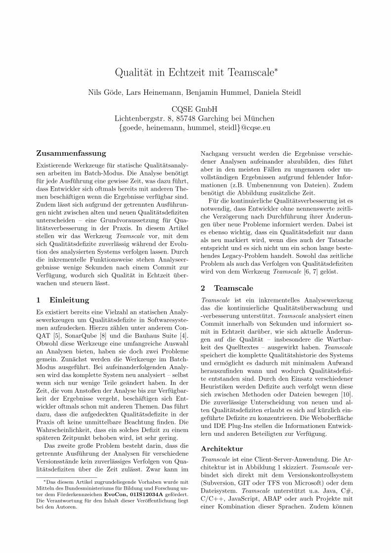
Architektur
Teamscale ist eine Client-Server-Anwendung. Die Ar-chitektur ist in Abbildung 1 skizziert. Teamscale ver-bindet sich direkt mit dem Versionskontrollsystem(Subversion, GIT oder TFS von Microsoft) oder demDateisystem. Teamscale unterstutzt u.a. Java, C#,C/C++, JavaScript, ABAP oder auch Projekte miteiner Kombination dieser Sprachen. Zudem konnen
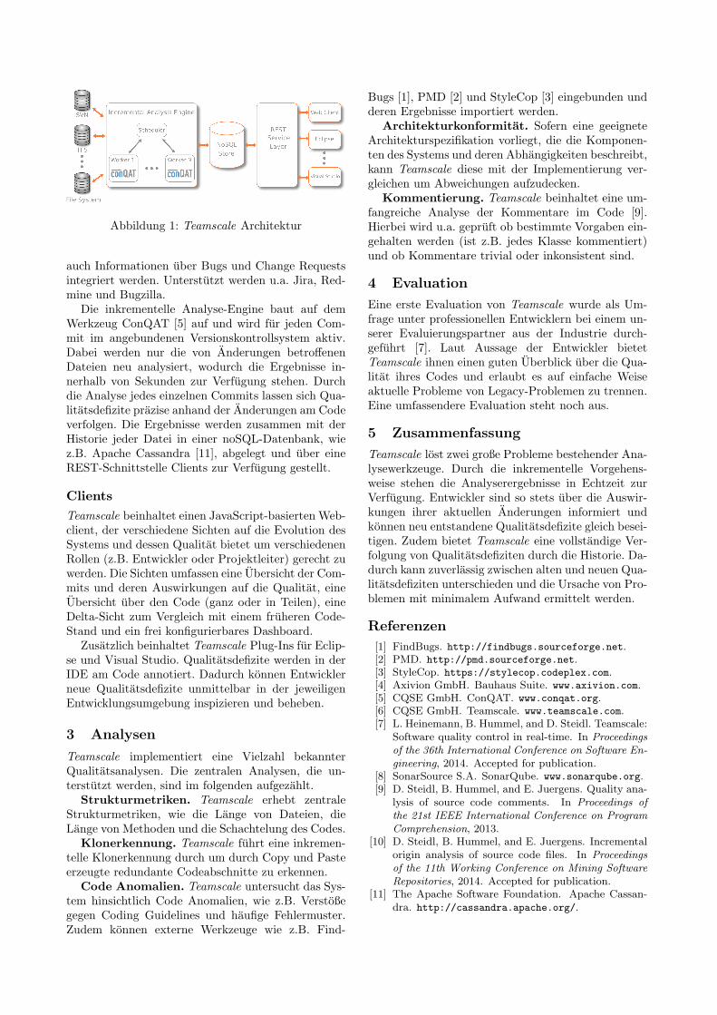
Abbildung 1: Teamscale Architektur
auch Informationen uber Bugs und Change Requestsintegriert werden. Unterstutzt werden u.a. Jira, Red-mine und Bugzilla.
Die inkrementelle Analyse-Engine baut auf demWerkzeug ConQAT [5] auf und wird fur jeden Com-mit im angebundenen Versionskontrollsystem aktiv.Dabei werden nur die von Anderungen betroffenenDateien neu analysiert, wodurch die Ergebnisse in-nerhalb von Sekunden zur Verfugung stehen. Durchdie Analyse jedes einzelnen Commits lassen sich Qua-litatsdefizite prazise anhand der Anderungen am Codeverfolgen. Die Ergebnisse werden zusammen mit derHistorie jeder Datei in einer noSQL-Datenbank, wiez.B. Apache Cassandra [11], abgelegt und uber eineREST-Schnittstelle Clients zur Verfugung gestellt.
Clients
Teamscale beinhaltet einen JavaScript-basierten Web-client, der verschiedene Sichten auf die Evolution desSystems und dessen Qualitat bietet um verschiedenenRollen (z.B. Entwickler oder Projektleiter) gerecht zuwerden. Die Sichten umfassen eine Ubersicht der Com-mits und deren Auswirkungen auf die Qualitat, eineUbersicht uber den Code (ganz oder in Teilen), eineDelta-Sicht zum Vergleich mit einem fruheren Code-Stand und ein frei konfigurierbares Dashboard.
Zusatzlich beinhaltet Teamscale Plug-Ins fur Eclip-se und Visual Studio. Qualitatsdefizite werden in derIDE am Code annotiert. Dadurch konnen Entwicklerneue Qualitatsdefizite unmittelbar in der jeweiligenEntwicklungsumgebung inspizieren und beheben.
3 Analysen
Teamscale implementiert eine Vielzahl bekannterQualitatsanalysen. Die zentralen Analysen, die un-terstutzt werden, sind im folgenden aufgezahlt.
Strukturmetriken. Teamscale erhebt zentraleStrukturmetriken, wie die Lange von Dateien, dieLange von Methoden und die Schachtelung des Codes.
Klonerkennung. Teamscale fuhrt eine inkremen-telle Klonerkennung durch um durch Copy und Pasteerzeugte redundante Codeabschnitte zu erkennen.
Code Anomalien. Teamscale untersucht das Sys-tem hinsichtlich Code Anomalien, wie z.B. Verstoßegegen Coding Guidelines und haufige Fehlermuster.Zudem konnen externe Werkzeuge wie z.B. Find-
Bugs [1], PMD [2] und StyleCop [3] eingebunden undderen Ergebnisse importiert werden.
Architekturkonformitat. Sofern eine geeigneteArchitekturspezifikation vorliegt, die die Komponen-ten des Systems und deren Abhangigkeiten beschreibt,kann Teamscale diese mit der Implementierung ver-gleichen um Abweichungen aufzudecken.
Kommentierung. Teamscale beinhaltet eine um-fangreiche Analyse der Kommentare im Code [9].Hierbei wird u.a. gepruft ob bestimmte Vorgaben ein-gehalten werden (ist z.B. jedes Klasse kommentiert)und ob Kommentare trivial oder inkonsistent sind.
4 Evaluation
Eine erste Evaluation von Teamscale wurde als Um-frage unter professionellen Entwicklern bei einem un-serer Evaluierungspartner aus der Industrie durch-gefuhrt [7]. Laut Aussage der Entwickler bietetTeamscale ihnen einen guten Uberblick uber die Qua-litat ihres Codes und erlaubt es auf einfache Weiseaktuelle Probleme von Legacy-Problemen zu trennen.Eine umfassendere Evaluation steht noch aus.
5 Zusammenfassung
Teamscale lost zwei große Probleme bestehender Ana-lysewerkzeuge. Durch die inkrementelle Vorgehens-weise stehen die Analyserergebnisse in Echtzeit zurVerfugung. Entwickler sind so stets uber die Auswir-kungen ihrer aktuellen Anderungen informiert undkonnen neu entstandene Qualitatsdefizite gleich besei-tigen. Zudem bietet Teamscale eine vollstandige Ver-folgung von Qualitatsdefiziten durch die Historie. Da-durch kann zuverlassig zwischen alten und neuen Qua-litatsdefiziten unterschieden und die Ursache von Pro-blemen mit minimalem Aufwand ermittelt werden.
Referenzen
[1] FindBugs. http://findbugs.sourceforge.net.[2] PMD. http://pmd.sourceforge.net.[3] StyleCop. https://stylecop.codeplex.com.[4] Axivion GmbH. Bauhaus Suite. www.axivion.com.[5] CQSE GmbH. ConQAT. www.conqat.org.[6] CQSE GmbH. Teamscale. www.teamscale.com.[7] L. Heinemann, B. Hummel, and D. Steidl. Teamscale:
Software quality control in real-time. In Proceedingsof the 36th International Conference on Software En-gineering, 2014. Accepted for publication.
[8] SonarSource S.A. SonarQube. www.sonarqube.org.[9] D. Steidl, B. Hummel, and E. Juergens. Quality ana-
lysis of source code comments. In Proceedings ofthe 21st IEEE International Conference on ProgramComprehension, 2013.
[10] D. Steidl, B. Hummel, and E. Juergens. Incrementalorigin analysis of source code files. In Proceedingsof the 11th Working Conference on Mining SoftwareRepositories, 2014. Accepted for publication.
[11] The Apache Software Foundation. Apache Cassan-dra. http://cassandra.apache.org/.
Assessing Third-Party Library Usage in Practice
Veronika Bauer
Technische Universitat [email protected]
Florian Deissenboeck, Lars Heinemann
CQSE GmbH{deissenboeck, heinemann}@cqse.eu
Abstract
Modern software systems build on a significant num-ber of external libraries to deliver feature-rich andhigh-quality software in a cost-e�cient and timelymanner. As a consequence, these systems containa considerable amount of third-party code. Exter-nal libraries thus have a significant impact on main-tenance activities in the project. However, most ap-proaches that assess the maintainability of softwaresystems largely neglect this factor. Hence, risks mayremain unidentified, threatening the ability to e↵ec-tively evolve the system in the future. We propose astructured approach to assess the third-party libraryusage in software projects and identify potential prob-lems. Industrial experience strongly influences our ap-proach, which we designed in a lightweight way to en-able easy adoption in practice.
1 Introduction
A plethora of external software libraries form a sig-nificant part of modern software systems [3]. Conse-quently, external libraries and their usage have a sig-nificant impact on the maintenance of the includingsoftware. Unfortunately, third-party libraries are of-ten neglected in quality assessments of software, lead-ing to unidentified risks for the future evolution ofthe software. Based on industry needs, we proposea structured approach for the systematic assessmentof third-party library usage in software projects. Theapproach is supported by a comprehensive assessmentmodel relating key characteristics of software libraryusage to development activities. The model defineshow di↵erent aspects of library usage influence theactivities and, thus, allows to assess if and to what ex-tent the usage of third-party libraries impacts the de-velopment activities of a given project. Furthermore,we provide guidance for executing the assessment inpractice, including tool support.
2 Assessment model
The proposed assessment model is inspired byactivity-based quality models [2].The model containsentities, “the objects we observe in the real world”,and attributes, “the properties that an entity pos-sesses” [4]. Entities are structured in a hierarchical
manner to foster completeness. The combination ofone or more entities and an attribute is called a fact.Facts are expressed as [Entities | ATTRIBUTE]. To expressthe impact of a fact, the model relates the fact toa development activity. This relation can either bepositive, i. e., the fact eases the a↵ected activity, ornegative, i. e., the fact impedes the activity.
Impacts are expressed as [Entity | ATTRIBUTE] +/��! [Ac-tivity]. Each impact is backed by a justification, whichprovides the rationale for its inclusion in the model.We quantify facts with the three-value ordinal scale{low, medium, high}.
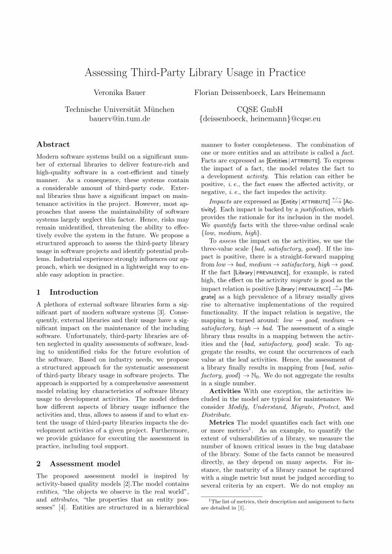
To assess the impact on the activities, we use thethree-value scale {bad, satisfactory, good}. If the im-pact is positive, there is a straight-forward mappingfrom low ! bad, medium ! satisfactory, high ! good.If the fact [Library | PREVALENCE], for example, is ratedhigh, the e↵ect on the activity migrate is good as theimpact relation is positive [Library | PREVALENCE] +�! [Mi-grate] as a high prevalence of a library usually givesrise to alternative implementations of the requiredfunctionality. If the impact relation is negative, themapping is turned around: low ! good, medium !satisfactory, high ! bad. The assessment of a singlelibrary thus results in a mapping between the activ-ities and the {bad, satisfactory, good} scale. To ag-gregate the results, we count the occurrences of eachvalue at the leaf activities. Hence, the assessment ofa library finally results in mapping from {bad, satis-factory, good} ! N0. We do not aggregate the resultsin a single number.
Activities With one exception, the activities in-cluded in the model are typical for maintenance. Weconsider Modify, Understand, Migrate, Protect, andDistribute.
Metrics The model quantifies each fact with oneor more metrics1. As an example, to quantify theextent of vulnerabilities of a library, we measure thenumber of known critical issues in the bug databaseof the library. Some of the facts cannot be measureddirectly, as they depend on many aspects. For in-stance, the maturity of a library cannot be capturedwith a single metric but must be judged according toseveral criteria by an expert. We do not employ an
1The list of metrics, their description and assignment to facts
are detailed in [1].
Table IIEXAMPLE FOR ASSESSMENT AGGREGATION
Library Modify Understand Migrate Protect Distribute Overall
LibraryG:S:B:
221
G:S:B:
212
G:S:B:
103
G:S:B:
020
G:S:B:
001
G:S:B:
557
Legend: G: # of good impacts, S: # of satisfactory impacts, B: # of bad impacts
open source software quality assessment toolkit ConQAT5,a modular toolkit for creating quality dashboards whichintegrate the results of multiple quality analyses. The currentimplementation is targeted at analyzing the library usage ofJava systems but could be adapted to other programminglanguages with a library reuse concept and for which a parserAPI in Java is available.
The analysis requires the source and byte code of theproject as well as the included libraries as input. The outputis a set of HTML and data files showing the metric valuesfor each library in a tabular fashion. The analysis traversesthe abstract syntax tree (AST) for each class in the projectand determines all method calls to external libraries. Foreach library, it determines the following five metrics (seealso Table I):
• Number of API method calls• Number of distinct API method calls• Percentage of affected classes• Scatteredness of the API• Percentage of API utilizationThe number of total and distinct API method calls as
well as the percentage of affected classes are aggregatedduring the AST-traversal. The scatteredness metric requiresmore computation: it expresses the degree of distribution ofAPI calls over the system structure. API calls within onepackage are considered as local. We would expect localcalls for specific functionality, e. g., calls to networking orimage rendering libraries. These would be expected to beconcentrated to small parts of the system. Contrarily, li-braries providing cross cutting functionality such as loggingwould be expected to be called from a large portion of thesystem, therefore exhibiting a high scatteredness value. Wecompute scatteredness as the sum of the distances betweenall pairs of package nodes in the package tree with calls to aspecific API. The distance of two nodes in the package treeis given by the sum of the distance from each node to theirleast common ancestor. It is important to note that sincethe scatteredness metric depends on the system structure(i. e., the depth of the package tree) its values cannot becompared in a meaningful way across different softwaresystems. The percentage of API utilization is computed asfraction between the number of distinct API methods calledand the total number of API methods in the library. Thecomplete tool support is available as a ConQAT extension
5http://www.conqat.org/
and can be downloaded as a self-contained bundle includingConQAT6.
VI. CASE STUDY
A. Study Goal
To show the applicability of our approach, we performeda case study on a real-world software system of azhAbrechnungs- und IT-Dienstleistungszentrum fur HeilberufeGmbH, a customer of CQSE GmbH (see Section II).
B. Analyzed System
The analyzed system is a distributed billing applicationwith a distinct data entry component running on a J2EEapplication server which is accessed from around 350 fatclients (based on Java Swing). The system’s source codecomprises about 3.5 MLOC. The system’s files include 87Java Archive Files (JARs).
C. Study Procedure
We executed our assessment approach (see Section IV)on the study object and recorded our observations duringthe process. We presented our results to the stakeholders inthe company and qualitatively captured their feedback. Forthis we used the following guiding questions:
• Does the report contain the central libraries?• Does the assessment conform to the stakeholders’ in-
tuition?• Are important aspects missing in the assessment?• Were parts of the assessment result surprising?
D. Results and Observations
The pre-selection step revealed that out of the 87 JARfiles included by the project files, the system’s source codedirectly calls methods from 47. The extent of entanglednessbetween the system and these libraries differs significantly,as illustrated in Figure 3(a). For some libraries, only onemethod is called while for others, there are several thousandmethod calls indicating the difference in importance for theproject. Also the degree of scatteredness varies significantly,as shown in Figure 3(b).7
6http://www4.in.tum.de/�ccsm/library-usage-assessment/7Note that the long tail of libraries with only one method call or
scatteredness of 1 or 0 is represented by the blanks in Figures 3(a) and 3(b),as they are not visible due to the log-scale.
Figure 1: Example of the assessment overview of a library. The library’s characteristics su�ciently support theactivity modify. However, it incurs more risks than benefits for the activities migrate and distribute.
automatic, e. g., threshold-based, mapping from met-ric values to the {low, medium, high} scale but fullyrely on the experts capabilities.
Impacts define how facts influence activities. Ajustification for each impact provides a rationale forthe impact which increases confirmability of the modeland the assessments based on the model. The com-plete list of impacts is available online2.
Our assessment process provides guidance to op-erationalize the model for assessing library usage ina specific software project. When assessing a real-world project, the sheer number of libraries require apossibility to address the most relevant libraries first.Therefore, the first step of the process structures andranks the libraries according to their entanglednesswith the system. This pre-selection directs the e↵ortof the second step of our process: the expert assess-ment of the libraries. The last step collects the resultsin an assessment report.
During preselection, we determine the followingvalues for all libraries: The number of total method
calls to a library allows to rank all external librariesaccording to the strength of their direct relations thesystem. The number of distinct method calls to a li-brary adds information about the implicit entangled-ness of libraries and system. The scatteredness of
method calls to a library describes whether the usageof the library is concentrated to a specific part of thesystem, or scattered across it. The percentage of af-
fected classes gives a complementary overview aboutthe impact a migration could have on the system.
Our model guides the expert during the assessmentprocess. The automated analyses have provided theinformation which can be extracted from the sourcecode. The expert now needs to evaluate the remainingmetrics. For this, he or she requires detailed knowl-edge about the project and its domain and needs toresearch detailed information about the libraries.
Subsequent to the assessment, a report can be gen-erated from our model, containing the detailed infor-mation for each library in textual and tabular (seeFigure 1) form.
2http://www4.in.tum.de/
~
ccsm/
library-usage-assessment/
3 Tool support
The assessment model includes five metrics that canbe automatically determined by static code analyses.The tool support for the assessment is implemented inJava on top of the open source software quality assess-ment toolkit ConQAT3. The current implementationis targeted at analyzing the library usage of Java sys-tems.
4 Case Study
To show the applicability of our approach, we per-formed a case study on a real-world software system.
The analyzed system is a distributed billing appli-cation with a distinct data entry component runningon a J2EE application server which is accessed fromaround 350 fat clients (based on Java Swing). Thesystem’s source code comprises about 3.5 MLOC. Thesystem’s files include 87 Java Archive Files (JARs).
The results indicate that our approach gives a com-prehensive overview on the external library usage ofthe analyzed system. It outlines which maintenanceactivities are supported to which degree by the em-ployed libraries. Furthermore, the semi-automatedpre-selection allowed for a significant reduction of thetime required by the expert assessment.
Remarks
This paper presents a condensed version of previouswork [1], published at the International Conference onSoftware Maintenance, 2012.
References
[1] V. Bauer, L. Heinemann, and F. Deissenboeck. AStructured Approach to Assess Third-Party LibraryUsage. In ICSM’12, 2012.
[2] F. Deissenboeck, S. Wagner, M. Pizka, S. Teuchert,and J. Girard. An activity-based quality model formaintainability. In ICSM’07, 2007.
[3] L. Heinemann, F. Deissenboeck, M. Gleirscher,B. Hummel, and M. Irlbeck. On the Extent and Na-ture of Software Reuse in Open Source Java Projects.In ICSR’11, 2011.
[4] B. Kitchenham, S. Pfleeger, and N. Fenton. Towards aframework for software measurement validation. Soft-ware Engineering, IEEE Transactions on, 21(12):929–944, 1995.
3http://www.conqat.org/
Quality Measurement Scenarios in Software Migration
Gaurav Pandey, Jan Jelschen, Dilshodbek Kuryazov, Andreas Winter
Carl von Ossietzky Universitat, Oldenburg, Germany
{pandey,jelschen,kuryazov,winter}@se.uni-oldenburg.de
Abstract. Legacy systems are migrated to newertechnology to keep them maintainable and to meetnew requirements. To aid choosing between migra-tion and redevelopment, a quality prognosis of themigrated software, compared with the legacy systemis required. Moreover, as the driving forces behind amigration e↵ort di↵er, migration tooling has to be tai-lored according to project-specific needs, to producea migration result meeting significant quality criteria.
Available metrics may not all be applicable identi-cally for both legacy and migrated systems, e.g. be-cause of paradigm shifts during migration. To thisend, this paper describes identifies three scenarios forutilizing quality measurement in a migration project.
1 Introduction
Migration, i. e. transferring the legacy systems intonew environments and technologies without changingtheir functionality, is a key technique of software evo-lution [4]. It removes the cost and risk of develop-ing a new system from scratch and allows to continuemodernization of the system. However, it needs to befound out whether the conversion leads to a change ininternal software quality. To decide between softwaremigration and redevelopment, the quality measure-ment and comparison of legacy and migrated systemsis required. Moreover, a migration project requires anespecially tailored toolchain [3]. To choose the tools tocarry out an automatic migration, assessment of thequality of migrated code is needed against the combi-nation of involved tools.
The identification of project-specific quality crite-ria and corresponding metrics for quality comparisoncan be achieved with the advice from project experts.However in a language based migration, e.g. fromCOBOL to Java, there is a shift from procedural toobject-oriented paradigm. This can lead to limitingthe usability of a metric, as its validity and interpre-tation might not hold in both platforms. For example,the metrics calculating object-oriented properties likeinheritance or encapsulation, can be used on migratedJava code but not on COBOL source code. To over-come this, it is required to have a strategy regardingutilization and comparison of metrics in migration. Tothis end, this paper identifies the quality measurementscenarios with suitable metrics, enabling the qualitycalculation in di↵erent situations. The next two sec-tions explain the Q-MIG project and the measurementscenarios and are followed by a Conclusion.
2 Q-MIG Project
The Q-MIG-project (Quality-driven software MIGra-tion)1 is a joint venture of pro et con Innovative In-formatikanwendungen GmbH, Chemnitz and Carl vonOssietzky University’s Software Engineering Group.Q-MIG is aimed at advancing a toolchain for auto-mated software migration [2]. To aid in deciding foror against a migration, selecting a migration strategy,and tailoring the toolchain and individual tools, thetoolchain is to be complemented with a quality controlcenter measuring, comparing, and predicting internalquality of software systems under migration.
The project aims at enabling quality-driven de-cisions on migration strategies and tooling [6]. Toachieve this, the Goal /Question /Metric approach [1]is used. The goal is to measure and compare thequality of the software before and after migration,to enable migration decisions and toolchain selection.The questions are the quality criteria based on whichthe quality assessment and comparison needs to becarried out. The Q-MIG project considers internalquality attributes, i. e. focuses on quality criteriamaintainability and transferability in terms of theISO quality standard [5]. Moreover, expert advice istaken for selecting and identifying criteria relevant forsoftware migrations. For example, maintainability-related metrics are important in a project that needsto keep on evolving, but not when the migratedproject is meant to be an interim solution, until a re-developed system can replace it. Then, to measure thequality criteria, metrics need to be identified. How-ever, a metric that is valid for the legacy code mightnot be valid for the migrated code and vice versa. Inorder to identify the metrics for quality criteria cal-culation, the metrics are categorized as per the usecase they can be utilized in. To achieve this, scenar-ios for quality comparison and toolchain componentselection are defined in Section 3.
3 Measurement Scenarios
This section presents the quality measurement sce-narios that utilize the quality metrics according tothe properties measured and their applicability to thelegacy and migrated platforms. While the first twoscenarios facilitate the quality comparison between
1Q-MIG is funded by Central Innovation Program SME of
the German Federal Ministry of Economics and Technology –
BMWi (KF3182501KM3).
the legacy and the migrated systems, the third sce-nario is particularly useful for selecting componentsof the migration toolchain. While the Q-MIG projectfocuses on quality measurement of a COBOL to Javamigration, the essence of the scenarios presented re-mains the same for other combinations of platforms.
Same Interpretation and Implementation:
This scenario facilitates quality comparison of legacycode (COBOL) and migrated code (Java) to help inproject planning. It is achieved by utilizing the qual-ity metrics that are valid and have the same imple-mentations and interpretations in both platforms, andhence allowing for direct quality comparison betweenthe systems. For example, Lines of Code, measur-ing the size of the project, is calculated identically forCOBOL and Java (In some cases Lines of Code can beplatform specific requiring adaptations like FunctionPoint Analysis). Similarly Number of GOTOs, Com-ments Percentage, Cyclomatic Complexity (Mc CabeMetric) and Duplicates Percentage can be calculatedfor both languages in the same fashion.
Same Interpretation Di↵erent Implementa-
tion: In this scenario the metrics that have di↵er-ent implementations but same interpretation in legacyand target code are utilized for quality comparison.COBOL and Java codes are di↵erent in construct andthe building blocks. So, certain metrics can have sameinterpretation but di↵erent ways of calculation in theplatforms. For example, Cohesion is the degree of in-dependence between the building blocks of a system.So, it can be calculated in the COBOL code consid-ering procedures as building blocks, while in the mi-grated Java code they can be represented by classes.The two calculations can provide comparable metrics,hence enabling quality comparison. Similarly, othermetrics can be utilized for quality comparison, thatmight not have exactly the same implementation forCOBOL and Java. Some metrics conforming to thisscenario are: Halstead’s metrics (because it uses oper-ators and operands, that di↵er among the languages),Average Complexity per Unit and Average Unit Size.
Target Specific Metrics: In this scenario, themetrics that are specific to target platform Java (andmay not be applicable to COBOL legacy code) areutilized for toolchain selection and improvement. Forexample, the metric Depth of Inheritance can be cal-culated for Java, but not for COBOL (procedural lan-guages have no inheritance). Also, value of the met-ric can change on changing components of migrationtoolchain or by additional reengineering steps. Thisallows to use the metrics to choose a suitable toolchainby analyzing how the quality of migrated softwarechanges with respect to the chosen components.
But, in a one-to-one migration from COBOL toJava that introduces no restructuring, Depth of In-heritance metric value would not change with respectto the migration tools. This is because such migra-
tion will not introduce inheritance in the target code.However, the source code can be refactored before mi-gration. And, an analysis of the metrics against thecombination of refactoring tools allows the selectionof the components of the refactoring toolchain.
This scenario allows the metrics relevant to Q-MIGproject and applicable for Java code, to be utilized forselecting the migration and refactoring tools. Here,various object-oriented metrics are used like: Numberof Classes representing level of abstraction in code.Also, Attribute Hiding Factor and Method HidingFactor that calculate the percentages of hidden at-tributes and methods respectively, are related to mod-ifiability. Moreover, Average Number of Methods perClass calculates complexity of the code. Also, themetrics that are applicable in previous two scenarioscan be used here, as they are applicable to the mi-grated code. However, the reverse might not be true.
4 Conclusion
This paper identified three scenarios for measuringand comparing internal quality of software systemsunder migration, paired with applicable metrics. Thescenarios stress the challenge of comparing qualitymeasurements in the context of paradigm shifts, e. g.when migrating from procedural COBOL to object-oriented Java. They delimitate pre-/post-migrationcomparison to assess suitability of migrating, fromcomparing migration results using di↵erent toolchainconfigurations to improve the tools and tailor thetoolchain to project-specific needs. Further steps inthe project include the design and evaluation of aquality model by identifying relevant quality criteria,and making them measurable using appropriate met-rics, with the scenarios providing an initial structure.
References
[1] V. R. Basili, G. Caldiera, and H. D. Rombach. Thegoal question metric approach. In Encyclopedia ofSoftware Engineering. Wiley, 1994.
[2] C. Becker and U. Kaiser. Test der semantischenAquivalenz von Translatoren am Beispiel von CoJaC.Softwaretechnik-Trends, 32(2), 2012.
[3] J. Borchers. Erfahrungen mit dem Einsatz einerReengineering Factory in einem großen Umstel-lungsprojekt. HMD, 34(194):77–94, mar 1997.
[4] A. Fuhr, A. Winter, U. Erdmenger, T. Horn,U. Kaiser, V. Riediger, and W. Teppe. Model-DrivenSoftware Migration - Process Model, Tool Support andApplication. In A. D. Ionita, M. Litoiu, and G. Lewis,editors, Migrating Legacy Applications: Challenges inService Oriented Architure and Cloud Computing En-vironments. IGI Global, Hershey, PA, USA, 2012.
[5] ISO/IEC. ISO/IEC 25010 - Systems and softwareengineering - Systems and software Quality Require-ments and Evaluation (SQuaRE) - System and soft-ware quality models. Technical report, 2010.
[6] J. Jelschen, G. Pandey, and A. Winter. Towardsquality-driven software migration. In Proceedingsof the 1st Collaborative Workshop on Evolution andMaintenance of Long-Living Systems, 2014.
Semi-automated decision making support for undocumented evolutionary changes
Jan Ladiges, Alexander Fay
Automation Technology Institute Helmut Schmidt University
Holstenhofweg 85, 22043 Hamburg, Germany Email: {ladiges, fay}@hsu-hh.de
Christopher Haubeck, Winfried Lamersdorf
Distributed Systems and Information Systems University of Hamburg
Vogt-Kölln-Straße 30, 22527 Hamburg, Germany Email: {haubeck, lamersdorf}@informatik.uni-hamburg.de
1 Introduction Long-living systems evolve under boundary conditions as diverse as the systems themselves. In the industrial practice of the production automation domain, for example, adaptations and even the initial engineering of control software are often performed without a formalized requirement specification [1]. Nevertheless, operators must decide during operation if such an undocumented change is consistent to the (informal) specification since changed behavior can also occur due to unintended side effects of changes or due to other influences (like wear and tear). In addition, the system behavior is strongly dependent on both, the software and the physical plant. Accordingly, approaches are needed to extract requirements out of the interdisciplinary system behavior and present it to the operator in a suitable format. The FYPA²C project (Forever Young Production Automation with Active Components) tries to realize an extraction of behavior related to non-functional requirements (NFR) by monitoring and analyzing signal traces of production systems. In doing so, the specific boundary conditions of the production automation domain should be considered.
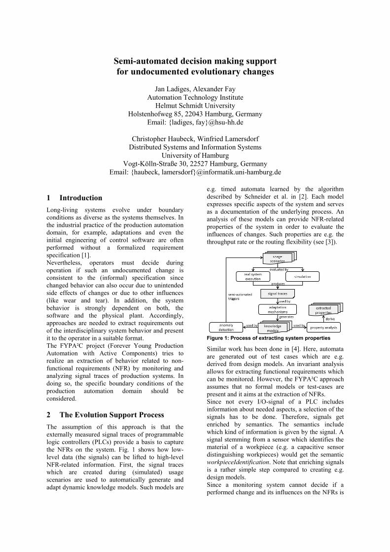
2 The Evolution Support Process The assumption of this approach is that the externally measured signal traces of programmable logic controllers (PLCs) provide a basis to capture the NFRs on the system. Fig. 1 shows how low-level data (the signals) can be lifted to high-level NFR-related information. First, the signal traces which are created during (simulated) usage scenarios are used to automatically generate and adapt dynamic knowledge models. Such models are
e.g. timed automata learned by the algorithm described by Schneider et al. in [2]. Each model expresses specific aspects of the system and serves as a documentation of the underlying process. An analysis of these models can provide NFR-related properties of the system in order to evaluate the influences of changes. Such properties are e.g. the throughput rate or the routing flexibility (see [3]).
Figure 1: Process of extracting system properties
Similar work has been done in [4]. Here, automata are generated out of test cases which are e.g. derived from design models. An invariant analysis allows for extracting functional requirements which can be monitored. However, the FYPA²C approach assumes that no formal models or test-cases are present and it aims at the extraction of NFRs. Since not every I/O-signal of a PLC includes information about needed aspects, a selection of the signals has to be done. Therefore, signals get enriched by semantics. The semantics include which kind of information is given by the signal. A signal stemming from a sensor which identifies the material of a workpiece (e.g. a capacitive sensor distinguishing workpieces) would get the semantic workpieceIdentification. Note that enriching signals is a rather simple step compared to creating e.g. design models. Since a monitoring system cannot decide if a performed change and its influences on the NFRs is

intended (or at least acceptable), a practical semi-automated evolution support process with a “user in the loop” is used. At first an anomaly detection engine detects whenever a behavior is observed that contradicts the knowledge models and, therefore, can indicate an evolutionary change. In case of timed automata the anomaly detection method presented in [2] is used. This anomaly is, in a first step, reported to the user. At this point only the actual anomaly, the context it occurs in, and a limited amount of current properties and probable influences can be reported since only influences on the already observed scenarios can be considered. Deductions on the overall properties are very restricted at this point. If a decision cannot be made here, the changed behavior is added to the concerned knowledge models in order to evaluate the effects on the system properties in detail. This is done by an analysis based on the extracted scenarios that are applied on the plant or a simulation. The advantage of these steps is that the operator can be informed based on the overall NFR-related properties of the system. As a reaction the change can be reverted if unintended or, if it is intended, adapted scenarios and models can be treated as valid.
Figure 2: Semi-automated evolution support process
If there is no possibility for a proactive determination of the system properties (missing of simulation and no availability of the system for tests), an adaptation of the models during operation is the only remaining option and just the already observed changes can be evaluated. When an unacceptable influence is observed the operator can react accordingly. However, the scenarios observed after the occurring change can be compared to the stored ones in order to estimate the completeness of the adapted knowledge models. To be more precisely, consider the following simple example: A conveyor system is responsible for transporting workpieces to a machine located at the
end of the conveyor system. Workpieces are detected by lightbarriers at both ends of all conveyors. A requirement on the throughput rate demands that the transport does not take longer than 60 seconds. A PLC collects the signals stemming from the lightbarriers and starts the transport when a workpiece reaches the first conveyor and stops it, when the workpiece reaches the machine. Conveyor speed can be parameterized within the PLC-program. A timed automaton (as a knowledge model) represents the transportation and is learned based on the observed signal traces by the learning algorithm in [2]. The automaton should just include signals related to the transportation. Therefore all I/O signals of the PLC are enriched by simple semantics and the learning algorithm is applied only on signals with the given semantic workpieceDetection. These are all signals stemming from lightbarriers. Accordingly, an analysis on the automaton enables deducing the transporting times by aggregating the transition times. Due to maintenance the motors of the conveyors are exchanged by motors with a higher slip resulting in a slower transportation. Unfortunately, the operator did not adapt the parameters in the PLC. During the first run of the plant the slower transportation is detected as a time-anomaly and reported to the operator after the workpiece passed the first conveyor. The operator can now decide if the anomaly is intended (or at least acceptable) or not. If he is not able to do this decision, for example due to a high complexity of the conveyor system, he can declare the anomaly as uncertain and the knowledge model gets further adapted during the transportation until a deduction about the fulfillment or violation of the throughput requirement can be done. If the requirement is violated the operator can react accordingly by changing the parameters in the PLC code. References [1] G. Frey, L. Litz, “Formal methods in PLC programming,” in Intl Conf on : Systems, Man, and Cybernetics, vol.4, 2000. [2] S. Schneider, L. Litz, and M. Danancher, “Timed residuals for fault detection and isolation in discrete event systems,” in Workshop on : Dependable Control of Discrete Systems, 2011. [3] J. Ladiges, C. Haubeck, A. Fay, and W. Lamersdorf, “Operationalized Definitions of Non-Functional Requirements on Automated Production Facilities to Measure Evolution Effects with an Automation System,” in Intl. Conf. on Emerging Technologies and Factory Automation, 2013. [4] C. Ackermann, R. Cleaveland, S. Huang, A. Ray, C. Shelton, E. Latronico, „Automatic requirement extraction from test cases,“ in Intl. Conf. on Runtime Verification, 2010.
Checkable Code Decisions to Support Software Evolution
Martin Kuster, Klaus KrogmannFZI Forschungszentrum Informatik
Haid-und-Neu-Str. 10-14, 76131 Karlsruhe, Germany{kuester,krogmann}@fzi.de
1 Introduction
For the evolution of software, understanding of thecontext, i.e. history and rationale of the existing ar-tifacts, is crucial to avoid “ignorant surgery” [3], i.e.modifications to the software without understandingits design intent. Existing works on recording archi-tecture decisions have mostly focused on architecturalmodels. We extend this to code models, and intro-duce a catalog of code decisions that can be foundin object-oriented systems. With the presented ap-proach, we make it possible to record design decisionsthat are concerned with the decomposition of the sys-tem into interfaces, classes, and references betweenthem, or how exceptions are handled. Furthermore,we indicate how decisions on the usage of Java frame-works (e.g. for dependency injection) can be recorded.All decision types presented are supplied with OCL-constraints to check the validity of the decision basedon the linked code model.
We hope to solve a problem of all long-lived sys-tems: that late modifications are not in line with theinitial design of the system and that decisions are (un-conciously) overruled. The problem is that develop-ers will not check all decisions taken in earlier stages,and whether the current implementation still complieswith them. Automation of the validation of a large setof decisions, as presented in this work, is a key factorfor more concious evolution of software systems.
2 Decision Catalog
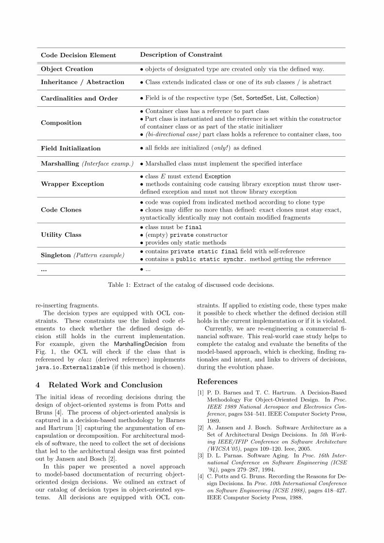
We developed an extensive catalog of recurring designdecisions in Java-based systems. Some of the decisiontypes are listed in Table 1. It lists the decision typesand the associated constraints (in natural language)that are checked by the OCL interpreter.
Due to space restrictions, we cannot go into detailof each decision type. Elements of all object-orientedlanguages, such as class declarations including gen-eralizations and interface implementations, are cov-ered as well as member declarations, such as fieldand method declarations. To show that the ap-proach is not restricted to elementary decisions inobject-oriented systems, we give more complex deci-sion types, such as wrapper exception or code clone.Especially code clones can be acceptable if the deci-sion model records the intention of the developer that
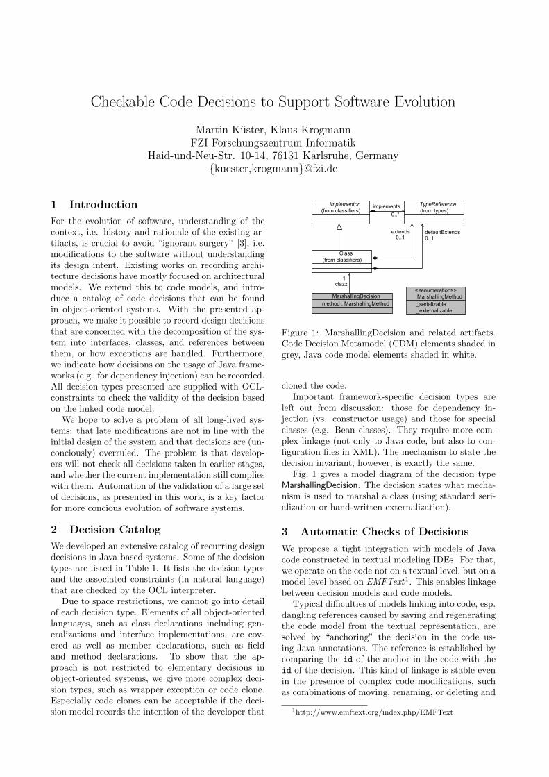
Figure 1: MarshallingDecision and related artifacts.Code Decision Metamodel (CDM) elements shaded ingrey, Java code model elements shaded in white.
cloned the code.Important framework-specific decision types are
left out from discussion: those for dependency in-jection (vs. constructor usage) and those for specialclasses (e.g. Bean classes). They require more com-plex linkage (not only to Java code, but also to con-figuration files in XML). The mechanism to state thedecision invariant, however, is exactly the same.
Fig. 1 gives a model diagram of the decision typeMarshallingDecision. The decision states what mecha-nism is used to marshal a class (using standard seri-alization or hand-written externalization).
3 Automatic Checks of Decisions
We propose a tight integration with models of Javacode constructed in textual modeling IDEs. For that,we operate on the code not on a textual level, but on amodel level based on EMFText
1. This enables linkagebetween decision models and code models.
Typical di�culties of models linking into code, esp.dangling references caused by saving and regeneratingthe code model from the textual representation, aresolved by “anchoring” the decision in the code us-ing Java annotations. The reference is established bycomparing the id of the anchor in the code with theid of the decision. This kind of linkage is stable evenin the presence of complex code modifications, suchas combinations of moving, renaming, or deleting and
1http://www.emftext.org/index.php/EMFText
Code Decision Element Description of Constraint
Object Creation • objects of designated type are created only via the defined way.
Inheritance / Abstraction • Class extends indicated class or one of its sub classes / is abstract
Cardinalities and Order • Field is of the respective type (Set, SortedSet, List, Collection)
Composition
• Container class has a reference to part class• Part class is instantiated and the reference is set within the constructorof container class or as part of the static initializer• (bi-directional case) part class holds a reference to container class, too
Field Initialization • all fields are initialized (only! ) as defined
Marshalling (Interface examp.) • Marshalled class must implement the specified interface
Wrapper Exception• class E must extend Exception
• methods containing code causing library exception must throw user-defined exception and must not throw library exception
Code Clones• code was copied from indicated method according to clone type• clones may di↵er no more than defined: exact clones must stay exact,syntactically identically may not contain modified fragments
Utility Class• class must be final• (empty) private constructor• provides only static methods
Singleton (Pattern example)
• contains private static final field with self-reference• contains a public static synchr. method getting the reference
... • ...
Table 1: Extract of the catalog of discussed code decisions.
re-inserting fragments.The decision types are equipped with OCL con-
straints. These constraints use the linked code el-ements to check whether the defined design de-cision still holds in the current implementation.For example, given the MarshallingDecision fromFig. 1, the OCL will check if the class that isreferenced by clazz (derived reference) implementsjava.io.Externalizable (if this method is chosen).
4 Related Work and Conclusion
The initial ideas of recording decisions during thedesign of object-oriented systems is from Potts andBruns [4]. The process of object-oriented analysis iscaptured in a decision-based methodology by Barnesand Hartrum [1] capturing the argumentation of en-capsulation or decomposition. For architectural mod-els of software, the need to collect the set of decisionsthat led to the architectural design was first pointedout by Jansen and Bosch [2].
In this paper we presented a novel approachto model-based documentation of recurring object-oriented design decisions. We oulined an extract ofour catalog of decision types in object-oriented sys-tems. All decisions are equipped with OCL con-
straints. If applied to existing code, these types makeit possible to check whether the defined decision stillholds in the current implementation or if it is violated.
Currently, we are re-engineering a commercial fi-nancial software. This real-world case study helps tocomplete the catalog and evaluate the benefits of themodel-based approach, which is checking, finding ra-tionales and intent, and links to drivers of decisions,during the evolution phase.
References
[1] P. D. Barnes and T. C. Hartrum. A Decision-BasedMethodology For Object-Oriented Design. In Proc.
IEEE 1989 National Aerospace and Electronics Con-
ference, pages 534–541. IEEE Computer Society Press,1989.
[2] A. Jansen and J. Bosch. Software Architecture as aSet of Architectural Design Decisions. In 5th Work-
ing IEEE/IFIP Conference on Software Architecture
(WICSA’05), pages 109–120. Ieee, 2005.[3] D. L. Parnas. Software Aging. In Proc. 16th Inter-
national Conference on Software Engineering (ICSE
’94), pages 279–287, 1994.[4] C. Potts and G. Bruns. Recording the Reasons for De-
sign Decisions. In Proc. 10th International Conference
on Software Engineering (ICSE 1988), pages 418–427.IEEE Computer Society Press, 1988.
Guidance for Design Rationale Capture to Support Software Evolution
Mathias Schubanz1,Andreas Pleuss2,Howell Jordan2,Goetz Botterweck2
1Brandenburg University of Technology, Cottbus - Senftenberg, Germany,
2Lero – The Irish Software Engineering Research Centre, Limerick, Ireland,
[email protected], {Andreas.Pleuss, Howell.Jordan, Goetz.Botterweck}@lero.ie
Abstract Documenting design rationale (DR)helps to preserve knowledge over long time to diminishsoftware erosion and to ease maintenance and refac-toring. However, use of DR in practice is still limited.One reason for this is the lack of concrete guidancefor capturing DR. This paper provides a first step to-wards identifying DR questions that can guide DRcapturing and discusses required future research.
Introduction Software continuously evolves. Thisleads over time to software erosion resulting in signif-icant costs when dealing with legacy software.
Documenting design rationale (DR) can help devel-opers to deal with the complexity of software main-tenance and software evolution [4, 6]. DR reflectsthe reasoning (i.e., the “Why?”) underlying a certaindesign. It requires designers to explicate their tacitknowledge about the given context, their intentions,and the alternatives considered [1]. This helps on theone hand to increase software quality and prevent soft-ware erosion based on capabilities to 1) enable com-munication amongst team members [6], 2) supportimpact analyses [7], and 3) prevent engineers from re-peating errors or entering dead-end paths [1]. On theother hand, DR supports refactoring long-living sys-tems to perform the leap towards new platforms ortechnologies without introducing errors due to miss-ing knowledge about previous decisions.
In general, once documented, DR can support soft-ware development in many ways, including debug-ging, verification, development automation or soft-ware modification [4]. This has been confirmed inindustrial practise (e.g., [2, 5]).
Problem Despite its potential benefits, systematicuse of DR has not found its way into wider industrialpractise. Burge [3] outlines that the lack of indus-trial application is due to the uncertainty connectedto DR usage. There are too many barriers to captureDR accompanied by the uncertainty on its potentialpayo↵, as DR often unfolds its full potential late inthe software lifecycle. The problem of DR elicitationhas been described many times [1, 4, 6]. For instance,engineers might not collect the right information [6].This – based on the statement that DR answers ques-tions [4] – could be due to posing the wrong or noquestions. General questions in the literature, suchas “Why was a decision made?”, are rather unspe-cific and ambiguous. This can easily lead to over- orunderspecified DR and compromise a developer’s mo-tivation. A first approach to guide DR capture has
been proposed by Bass et al. [1]. They provide gen-eral guidelines on how to capture DR such as ”Docu-ment the decision, the reason or goal behind it, and thecontext for making the decision“. However, consider-ing those guidelines, general questions (e.g., “Why?”)alone are not su�cient to cover all relevant aspectsand guide developers.
Our goal is provide better support for software evo-lution by leveraging the benefits from DR manage-ment. Hence, we aim to integrate guidance for DRelicitation into software design and implementation.For this, we aim to identify concrete, specific DR ques-tions that guide engineers in capturing DR and can beused as a basis for building relevant tool support. Tothe best of our knowledge, concrete DR questions toask developers have not been investigated in a sys-tematic way yet. Until now, there is just exemplaryusage of DR questions in the literature.
We aim to provide a first step in this paper byanalysing DR questions that can be found in the lit-erature up to now. For this we perform the follow-ing steps: (1) We perform a literature analysis andsystematically collect DR questions. (2) We normal-ize the collected questions by rephrasing them. (3)
We structure them in accordance to common decisionmaking principles. As a result, we suggest a first setof DR questions as a basis towards guiding engineersin capturing DR.
In the remainder of this paper we describe thisanalysis and the resulting set of DR questions as afirst basis towards guiding engineers in capturing DR.Subsequently, the paper discusses the required futurework.
Question Elicitation To derive a set of specific DRquestions to support software evolution we reviewedexisting knowledge in DR related literature in a sys-tematic way. Therefore, we collected all questions thatwe found in the literature, generalized and structuredthem, and eliminated duplicates.
Based on an extensive literature review, we foundconcrete questions for DR capturing in 19 literaturesources, for instance “What does the hardware needto do?”, “What other alternatives were considered?”,or “How did other people deal with this problem?”.This resulted in 150 questions that we collected in aspreadsheet.
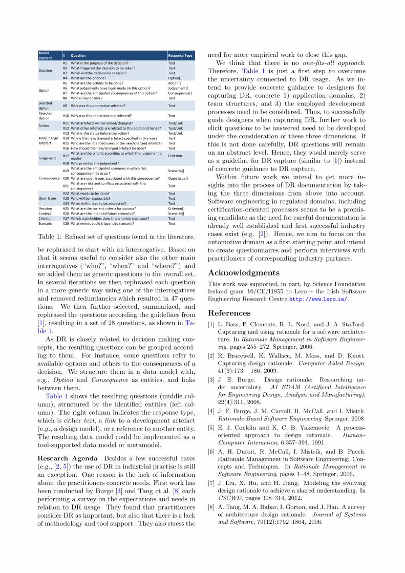
In the next step, we normalised the questions: Sort-ing the questions reveals di↵erent interrogatives used.Most questions are “how?” (24), “what?” (73) and“why?” (24) questions. The 29 other questions could
Model
Element# Question Response Type
#1 What is the purpose of the decision? Text#2 What triggered the decision to be taken? Text#3 When will the decision be realized? Text#4 What are the options? Option[]#5 What are the actions to be done? Action[]#6 What judgements have been made on this option? Judgement[]#7 What are the anticipated consequences of this option? Consequence[]#8 Who is responsible? Text
Selected Option
#9 Why was this alternative selected? Text
Rejected Option
#10 Why was this alternative not selected? Text
#11 What artefacts will be added/changed? Text/Link#12 What other artefacts are related to this addition/change? Text/Link#13 What is the status before the action? Text/Link#14 Why is the new/changed artefact specified in this way? Text#15 Who are the intended users of the new/changed artefact? Text#16 How should the new/changed artefact be used? Text
#17What are the criteria according to which this judgement is made?
Criterion
#18 Who provided the judgement?
#19What are the anticipated scenarios in which this consequence may occur?
Scenario[]
#20 What are open issues associated with this consequence? Open Issue[]
#21What are risks and conflicts associated with this consequence?
Text
#22 What needs to be done? Text#23 Who will be responsible? Text#24 When will it need to be addressed? Text#25 What are the current criteria for success? Criterion[]#26 What are the intended future scenarios? Scenario[]
Criterion #27 Which stakeholders does this criterion represent? TextScenario #28 What events could trigger this scenario? Text
Open Issue
Decision Context
Decision
Option
Action
Add/Change Artefact
Judgement
Consequence
Table 1: Refined set of questions found in the literature.
be rephrased to start with an interrogative. Based onthat it seems useful to consider also the other maininterrogatives (“who?”, “when?” and “where?”) andwe added them as generic questions to the overall set.In several iterations we then rephrased each questionin a more generic way using one of the interrogativesand removed redundancies which resulted in 47 ques-tions. We then further selected, summarized, andrephrased the questions according the guidelines from[1], resulting in a set of 28 questions, as shown in Ta-ble 1.
As DR is closely related to decision making con-cepts, the resulting questions can be grouped accord-ing to them. For instance, some questions refer toavailable options and others to the consequences of adecision. We structure them in a data model with,e.g., Option and Consequence as entities, and linksbetween them.
Table 1 shows the resulting questions (middle col-umn), structured by the identified entities (left col-umn). The right column indicates the response type,which is either text, a link to a development artefact(e.g., a design model), or a reference to another entity.The resulting data model could be implemented as atool-supported data model or metamodel.
Research Agenda Besides a few successful cases(e.g., [2, 5]) the use of DR in industrial practise is stillan exception. One reason is the lack of informationabout the practitioners concrete needs. First work hasbeen conducted by Burge [3] and Tang et al. [8] eachperforming a survey on the expectations and needs inrelation to DR usage. They found that practitionersconsider DR as important, but also that there is a lackof methodology and tool support. They also stress the
need for more empirical work to close this gap.We think that there is no one-fits-all approach.
Therefore, Table 1 is just a first step to overcomethe uncertainty connected to DR usage. As we in-tend to provide concrete guidance to designers forcapturing DR, concrete 1) application domains, 2)team structures, and 3) the employed developmentprocesses need to be considered. Thus, to successfullyguide designers when capturing DR, further work toelicit questions to be answered need to be developedunder the consideration of these three dimensions. Ifthis is not done carefully, DR questions will remainon an abstract level. Hence, they would merely serveas a guideline for DR capture (similar to [1]) insteadof concrete guidance to DR capture.
Within future work we intend to get more in-sights into the process of DR documentation by tak-ing the three dimensions from above into account.Software engineering in regulated domains, includingcertification-oriented processes seems to be a promis-ing candidate as the need for careful documentation isalready well established and first successful industrycases exist (e.g. [2]). Hence, we aim to focus on theautomotive domain as a first starting point and intendto create questionnaires and perform interviews withpractitioners of corresponding industry partners.
Acknowledgments
This work was supported, in part, by Science FoundationIreland grant 10/CE/I1855 to Lero – the Irish SoftwareEngineering Research Centre http://www.lero.ie/.
References
[1] L. Bass, P. Clements, R. L. Nord, and J. A. Sta↵ord.Capturing and using rationale for a software architec-ture. In Rationale Management in Software Engineer-ing, pages 255–272. Springer, 2006.
[2] R. Bracewell, K. Wallace, M. Moss, and D. Knott.Capturing design rationale. Computer-Aided Design,41(3):173 – 186, 2009.
[3] J. E. Burge. Design rationale: Researching un-der uncertainty. AI EDAM (Artificial Intelligencefor Engineering Design, Analysis and Manufacturing),22(4):311, 2008.
[4] J. E. Burge, J. M. Carroll, R. McCall, and I. Mistrk.Rationale-Based Software Engineering. Springer, 2008.
[5] E. J. Conklin and K. C. B. Yakemovic. A process-oriented approach to design rationale. Human–Computer Interaction, 6:357–391, 1991.
[6] A. H. Dutoit, R. McCall, I. Mistrık, and B. Paech.Rationale Management in Software Engineering: Con-cepts and Techniques. In Rationale Management inSoftware Engineering, pages 1–48. Springer, 2006.
[7] J. Liu, X. Hu, and H. Jiang. Modeling the evolvingdesign rationale to achieve a shared understanding. InCSCWD, pages 308–314, 2012.
[8] A. Tang, M. A. Babar, I. Gorton, and J. Han. A surveyof architecture design rationale. Journal of Systemsand Software, 79(12):1792–1804, 2006.
Parsing Variant C Code: An Evaluation on Automotive Software
Robert Heumuller
Universitat MagdeburgMagdeburg, Germany
Jochen Quante and Andreas Thums
Robert Bosch GmbH, Corporate ResearchStuttgart, Germany
{Jochen.Quante, Andreas.Thums}@de.bosch.com
Abstract
Software product lines are often implemented usingthe C preprocessor. Di↵erent features are selectedbased on macros; the corresponding code is activatedor deactivated using #if. Unfortunately, C prepro-cessor constructs are not parseable in general, sincethey break the syntactical structure of C code [1].This imposes a severe limitation on software analyses:They usually cannot be performed on unpreprocessedC code. In this paper, we will discuss how and to whatextent large parts of the unpreprocessed code can beparsed anyway, and what the results can be used for.
1 Approaches
C preprocessor (Cpp) constructs are not part of the Csyntax. Code therefore has to be preprocessed beforea C compiler can process it. Only preprocessed codeconforms to C syntax. In order to perform analyseson unpreprocessed code, this code has to be madeparseable first. Several approaches have been pro-posed for that:
• Extending a C parser. Preprocessor con-structs are added at certain points in the syntax.This requires that these constructs are placed ina way compatible with the C syntax. However,preprocessor constructs can be added anywhere,so this approach cannot cover all cases [1].
• Extending a preprocessor parser. TheC snippets inside preprocessor conditionals areparsed individually, e. g., using island gram-mars [4]. This approach is quite limited, becausethe context is missing, which is often importantfor decisions during parsing.
• Analyzing all variants separately and
merging results. This approach can build onexisting analysis tools. However, for a large num-ber of variance points, it is not feasible due to theexponential growth in the number of variants.
• Replacing Cpp with a better alternative. Adi↵erent language for expressing conditional com-pilation and macros was for example proposedby McCloskey et al. [3]. Such a language can be
designed to be better analyzable and better in-tegrate with C. However, it is a huge e↵ort tochange a whole code base to a new preprocessinglanguage.
We chose to base our work on the first approach.We took ANTLR’s standard ANSI C grammar1 andextended it by preprocessor commands in well-formedplaces. This way, we were already able to processabout 90% of our software. In order to further in-crease the amount of successfully processable files, itwas necessary to discover where this approach failed,and to come up with a strategy for dealing with thesefailures. An initial regex-based evaluation indicatedthat the two main reasons for failures were a) the exis-tence of conditional branches with incomplete syntaxunits, and b) the use of troublesome macros.
2 Normalization
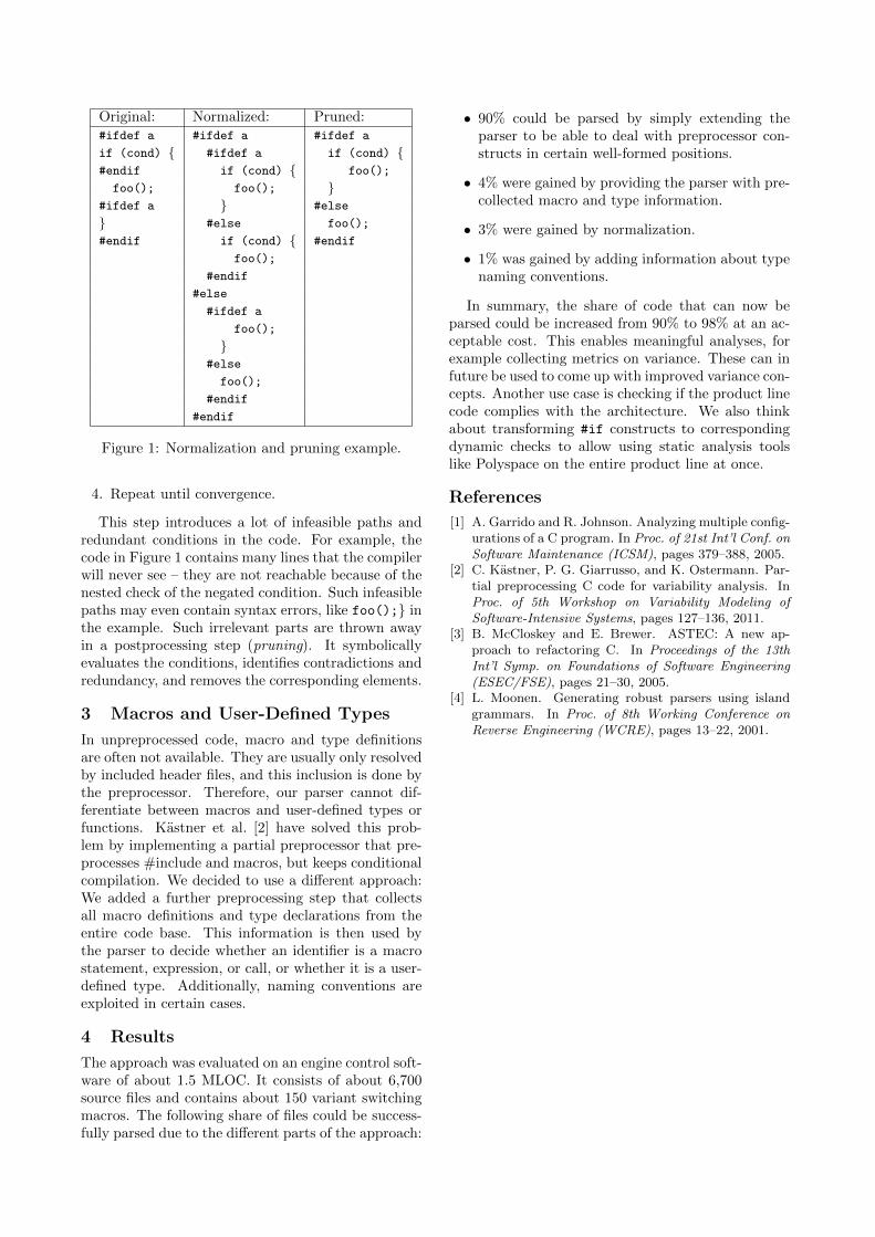
To be able to deal with incomplete conditionalbranches, we implemented a pre-preprocessor as pro-posed by Garrido et al. [1]. The idea is to transformpreprocessor constructs that break the C structure tosemantically equivalent code that fits into the C struc-ture. The transformation basically adds code to theconditional code until the condition is at an allowedposition. Figure 1 shows a typical example of un-parseable code and its normalized equivalent.
The code is read into a tree that corresponds tothe hierarchy of the input’s conditional compilationdirectives. The normalization can then be performedon this tree using a simple fix-point algorithm:
1. Find a Cpp conditional node with incomplete Csyntax units in at least one of its branches. “In-completeness” is checked based on token blackand white lists. For example, a syntactical unitmay not start with tokens like else or &&.
2. Copy missing tokens from before/after the condi-tional into all of the conditional’s branches. Thisway, some code is duplicated, but the resultingcode becomes parseable by the extended parser.
3. Delete the copied tokens at their original location.
1http://www.antlr3.org/grammar/list.html
Original: Normalized: Pruned:#ifdef a #ifdef a #ifdef a
if (cond) { #ifdef a if (cond) {#endif if (cond) { foo();
foo(); foo(); }#ifdef a } #else
} #else foo();
#endif if (cond) { #endif
foo();
#endif
#else
#ifdef a
foo();
}#else
foo();
#endif
#endif
Figure 1: Normalization and pruning example.
4. Repeat until convergence.
This step introduces a lot of infeasible paths andredundant conditions in the code. For example, thecode in Figure 1 contains many lines that the compilerwill never see – they are not reachable because of thenested check of the negated condition. Such infeasiblepaths may even contain syntax errors, like foo();} inthe example. Such irrelevant parts are thrown awayin a postprocessing step (pruning). It symbolicallyevaluates the conditions, identifies contradictions andredundancy, and removes the corresponding elements.
3 Macros and User-Defined Types
In unpreprocessed code, macro and type definitionsare often not available. They are usually only resolvedby included header files, and this inclusion is done bythe preprocessor. Therefore, our parser cannot dif-ferentiate between macros and user-defined types orfunctions. Kastner et al. [2] have solved this prob-lem by implementing a partial preprocessor that pre-processes #include and macros, but keeps conditionalcompilation. We decided to use a di↵erent approach:We added a further preprocessing step that collectsall macro definitions and type declarations from theentire code base. This information is then used bythe parser to decide whether an identifier is a macrostatement, expression, or call, or whether it is a user-defined type. Additionally, naming conventions areexploited in certain cases.
4 Results
The approach was evaluated on an engine control soft-ware of about 1.5 MLOC. It consists of about 6,700source files and contains about 150 variant switchingmacros. The following share of files could be success-fully parsed due to the di↵erent parts of the approach:
• 90% could be parsed by simply extending theparser to be able to deal with preprocessor con-structs in certain well-formed positions.
• 4% were gained by providing the parser with pre-collected macro and type information.
• 3% were gained by normalization.
• 1% was gained by adding information about typenaming conventions.
In summary, the share of code that can now beparsed could be increased from 90% to 98% at an ac-ceptable cost. This enables meaningful analyses, forexample collecting metrics on variance. These can infuture be used to come up with improved variance con-cepts. Another use case is checking if the product linecode complies with the architecture. We also thinkabout transforming #if constructs to correspondingdynamic checks to allow using static analysis toolslike Polyspace on the entire product line at once.
References
[1] A. Garrido and R. Johnson. Analyzing multiple config-urations of a C program. In Proc. of 21st Int’l Conf. on
Software Maintenance (ICSM), pages 379–388, 2005.[2] C. Kastner, P. G. Giarrusso, and K. Ostermann. Par-
tial preprocessing C code for variability analysis. InProc. of 5th Workshop on Variability Modeling of
Software-Intensive Systems, pages 127–136, 2011.[3] B. McCloskey and E. Brewer. ASTEC: A new ap-
proach to refactoring C. In Proceedings of the 13th
Int’l Symp. on Foundations of Software Engineering
(ESEC/FSE), pages 21–30, 2005.[4] L. Moonen. Generating robust parsers using island
grammars. In Proc. of 8th Working Conference on
Reverse Engineering (WCRE), pages 13–22, 2001.
Consolidating Customized Product Copies to Software Product Lines
⇤
Benjamin Klatt, Klaus KrogmannFZI Research Center for Information Technology
Haid-und-Neu-Str. 10-14,76131 Karlsruhe, Germany{klatt,krogmann}@fzi.de
Christian WendeDevBoost GmbH
Erich-Ponto-Str. 19,01097 Dresden, Germany
{christian.wende}@devboost.de
1 Introduction
Reusing existing software solutions as initial pointfor new projects is a frequent approach in softwarebusiness. Copying existing code and adapting it tocustomer-specific needs allows for flexible and e�cientsoftware customization in the short term. But in thelong term, a Software Product Line (SPL) approachwith a single code base and explicitly managed vari-ability reduces maintenance e↵ort and eases instanti-ation of new products.
However, consolidating custom copies into an SPLafterwards, is not trivial and requires a lot of manuale↵ort. For example, identifying relevant di↵erencesbetween customized copies requires to review a lot ofcode. State-of-the-art software di↵erence analysis nei-ther considers characteristics specific for copy-basedcustomizations nor supports further interpretations ofthe di↵erences found (e.g. relating thousands of low-level code changes). Furthermore, deriving a reason-able variability design requires experience and is nota software developer’s everyday task.
In this paper, we present our product copy con-solidation approach for software developers. It con-tributes i) a di↵erence analysis adapted for code copydi↵erencing, ii) a variability analysis to identify re-lated di↵erences, and iii) the derivation of a reason-able variability design.
2 Consolidation Process
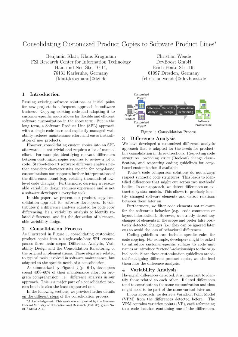
As illustrated in Figure 1, consolidating customizedproduct copies into a single-code-base SPL encom-passes three main steps: Di↵erence Analysis, Vari-ability Design and the Consolidation Refactoring ofthe original implementations. These steps are relatedto typical tasks involved in software maintenance, butadapted to the specific needs of a consolidation.
As summarized by Pigoski [2](p. 6-4), developersspend 40%–60% of their maintenance e↵ort on pro-gram comprehension, i.e. di↵erence analysis in ourapproach. This is a major part of a consolidation pro-cess but it is also the least supported one.
In the following sections, we provide further detailson the di↵erent steps of the consolidation process.
⇤Acknowledgment: This work was supported by the German
Federal Ministry of Education and Research (BMBF), grant No.
01IS13023 A-C.
Customized Copy 1
Customized Copy 2
Original Product
Software Product Line
Difference Analysis
Variability Design
Consolidation Refactoring
Figure 1: Consolidation Process
3 Di↵erence Analysis
We have developed a customized di↵erence analysisapproach that is adapted for the needs for product-line consolidation in three directions: Respecting codestructures, providing strict (Boolean) change classi-fication, and respecting coding guidelines for copy-based customization if available.
Today’s code comparison solutions do not alwaysrespect syntactic code structures. This leads to iden-tified di↵erences that might cut across two methods’bodies. In our approach, we detect di↵erences on ex-tracted syntax models. This allows to precisely iden-tify changed software elements and detect relationsbetween them later on.
Furthermore, we filter code elements not relevantfor the software’s behavior (e.g. code comments orlayout information). However, we strictly detect anychanges of elements in the scope and prefer false posi-tively detected changes (i.e. they can be ignored lateron) to avoid the loss of behavioral di↵erences.
Coding-guidelines can include specific rules forcode copying. For example, developers might be askedto introduce customer-specific su�xes to code unitnames or introduce “extend”-relationships to the orig-inal code. Since these customization guidelines are vi-tal for aligning di↵erent product copies, we also feedthem into the di↵erence analysis.
4 Variability Analysis
Having all di↵erences detected, it is important to iden-tify those related to each other. Related di↵erencestend to contribute to the same customization and thusmight need to be part of the same variant later on.
In our approach, we derive a Variation Point Model(VPM) from the di↵erences detected before. TheVPM contains variation points (VP), each referencingto a code location containing one of the di↵erences.
At each VP, the code alternatives of the di↵erence arereferenced by variant elements.
Starting with this fine-grained model, we analyzethe VPs to identify related ones and recommend rea-sonable aggregations. Recommending and applyingaggregations is an iterative approach until the personresponsible for the consolidation is satisfied with theVPs (i.e. the variability design). With each itera-tion, it is his decision to accept or decline the rec-ommended aggregations. This allows him to considerorganization aspects such as decisions to not consoli-date specific code copies.
The variation point relationship analysis itself com-bines basic analyses, each able to identify a spe-cific type of relationship (e.g. VP location, similarterms used in the code, common modifications or pro-gram dependencies). Based on the identified relation-ships, reasonable aggregations are recommended. Ba-sic analyses can be individually combined to matchproject-specific needs (e.g. indicators for code belong-ing together).5 Consolidation Refactoring
As a final step, the code copies’ implementation mustbe transformed to a single code base according to thechosen variability design and selected variability real-ization techniques. Opposed to traditional refactor-ings (i.e. not changing the external behavior of soft-ware), consolidation refactorings might extend (i.e.change) the external behavior. The underlying goalof consolidation refactoring is to keep each individualvariant/product copy functional. However, new func-tional combinations enabled by introducing variabilityare valid considered consolidation refactorings.
To implement consolidation refactorings, we areworking on i) a refactoring method that explicitlydistinguishes between introducing variability andrestructuring code, and ii) specific refactoring au-tomation to introduce variability mechanisms. Theformer focuses on guidelines and decision support.The latter is about novel refactoring specificationsusing well known formalization concepts, such asrefactoring patterns described by Fowler et al. [3]or the refactoring role model defined by Reimannet al. [6]. Based on this formalization, we willautomate the refactoring specifications to reduce theprobability of errors compared to manual refactoring.
6 Existing Consolidation Approaches
SPLs and variability are established research topicsnowadays. However, only a few existing approachestarget the consolidation of customized code copies intoan SPL with a single code base.
Rubin et al. [7] have developed a conceptual frame-work of how to merge customized product variants ingeneral. They focus on a model level, but their generalhigh-level algorithm matches to our approach.
In [8] Schutz presents a consolidation process, de-scribes state-of-the-art capabilities and argues for theneed of an automation as we target. In a similar way,
others like Alves et al. [1], focus on refactoring exist-ing SPLs, but also identified the lack of support forconsolidating customized product copies and the ne-cessity for automation.
Koschke et al. [5] presented an approach for con-solidating customized product copies by assigning fea-tures to module structures and thus identifying di↵er-ences between the customized copies. Their approachis complimentary to ours and could be used as anadditional variability analysis if according module de-scriptions are available.
7 Prototype & Research Context
In our previous work [4], we presented the idea of toolsupport for evolutionary SPL development. Mean-while, we are working on the integration with state-of-the-art development environments. Furthermore,in the project KoPL 1, we refine and enhance the ap-proach for industrial applicability. This encompassesthe adaptation of the analysis to be used by softwaredevelopers in terms of required input and result pre-sentation. Furthermore, extension points are intro-duced to support additional types of software arti-facts, analyses and variability mechanisms.
Currently, a prototype of the analysis part is al-ready available and evaluated with an open sourcecase study based on ArgoUML-SPL and an industrialcase study. The refactoring is in a design state andwill be focused later in the project.
As lessons learned: A strong input of how de-sired SPL characteristics should look like (e.g. real-ization techniques or quality attributes) improves theapproach. We call this an SPL Profile. Furthermore,the first step of ”understanding” is the most crucialone for a consolidation.
References
[1] V. Alves, R. Gehyi, T. Massoni, U. Kulesza, P. Borba,and C. Lucena. Refactoring product lines. In Proceed-
ings of GPCE 2006. ACM.[2] P. Bourque and R. Dupuis. Guide to the Software
Engineering Body of Knowledge. IEEE, 2004.[3] M. Fowler, K. Beck, J. Brant, and W. Opdyke.
Refactoring: Improving the Design of Existing Code.Addison-Wesley Professional, 1999.
[4] B. Klatt and K. Krogmann. Towards Tool-Support forEvolutionary Software Product Line Development. InProceedings of WSR 2011.
[5] R. Koschke, P. Frenzel, A. P. J. Breu, and K. Angst-mann. Extending the reflexion method for consoli-dating software variants into product lines. Software
Quality Journal, 2009.[6] J. Reimann, M. Seifert, and U. Aß mann. On the
reuse and recommendation of model refactoring spec-ifications. Software & Systems Modeling, 12(3), 2012.
[7] J. Rubin and M. Chechik. A Framework for Manag-ing Cloned Product Variants. In Proceedings of ICSE
2013. IEEE.[8] D. Schutz. Variability Reverse Engineering. In Pro-
ceedings of EuroPLoP 2009.
1http://www.kopl-project.org
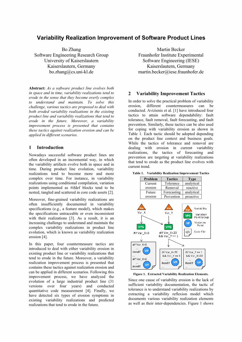
Variability Realization Improvement of Software Product Lines
Bo Zhang Software Engineering Research Group
University of Kaiserslautern Kaiserslautern, Germany [email protected]
Martin Becker Fraunhofer Institute Experimental
Software Engineering (IESE) Kaiserslautern, Germany
[email protected] Abstract: As a software product line evolves both in space and in time, variability realizations tend to erode in the sense that they become overly complex to understand and maintain. To solve this challenge, various tactics are proposed to deal with both eroded variability realizations in the existing product line and variability realizations that tend to erode in the future. Moreover, a variability improvement process is presented that contains these tactics against realization erosion and can be applied in different scenarios.
1 Introduction Nowadays successful software product lines are often developed in an incremental way, in which the variability artifacts evolve both in space and in time. During product line evolution, variability realizations tend to become more and more complex over time. For instance, in variability realizations using conditional compilation, variation points implemented as #ifdef blocks tend to be nested, tangled and scattered in core code assets [2].
Moreover, fine-grained variability realizations are often insufficiently documented in variability specifications (e.g., a feature model), which makes the specifications untraceable or even inconsistent with their realizations [3]. As a result, it is an increasing challenge to understand and maintain the complex variability realizations in product line evolution, which is known as variability realization erosion [4].
In this paper, four countermeasure tactics are introduced to deal with either variability erosion in existing product line or variability realizations that tend to erode in the future. Moreover, a variability realization improvement process is presented that contains these tactics against realization erosion and can be applied in different scenarios. Following this improvement process, we have analyzed the evolution of a large industrial product line (31 versions over four years) and conducted quantitative code measurement [4]. Finally, we have detected six types of erosion symptoms in existing variability realizations and predicted realizations that tend to erode in the future.
2 Variability Improvement Tactics In order to solve the practical problem of variability erosion, different countermeasures can be conducted. Avizienis et al. [1] have introduced four tactics to attain software dependability: fault tolerance, fault removal, fault forecasting, and fault prevention. Similarly, these tactics can be also used for coping with variability erosion as shown in Table 1. Each tactic should be adopted depending on the product line context and business goals. While the tactics of tolerance and removal are dealing with erosion in current variability realizations, the tactics of forecasting and prevention are targeting at variability realizations that tend to erode as the product line evolves with current trend.
Table 1. Variability Realization Improvement Tactics
Problem Tactics Type Current erosion
Tolerance analytical Removal reactive
Future erosion
Forecasting analytical Prevention proactive
Figure 1. Extracted Variability Realization Elements.
Since one cause of variability erosion is the lack of sufficient variability documentation, the tactic of tolerance is to understand variability realizations by extracting a variability reflexion model which documents various variability realization elements as well as their inter-dependencies. Figure 1 shows

variability realization elements using conditional compilation, which can be automatically extracted into a hierarchical structure. The variability reflexion model does not focus on a specific eroded variability code element, but helps to understand fine-grained variability elements especially for product line maintenance. This tolerance tactic is an analytical approach because it does not change any existing product line artifact. On the contrary, the tactic of removal is to identify and fix eroded elements in existing variability realizations, which is a reactive improvement approach.
Besides tackling existing erosion, the tactic of forecasting is to predict future erosion trends and their likely consequences based on the current product line evolution trends (also an analytical approach). If the prediction of future erosion turns out to be non-trivial, then the tactic of prevention should be conducted as a proactive approach to avoid erosion and its consequences in the future. While the tactics of tolerance and forecasting are both analytical, the other two tactics (i.e., removal and prevention) need to change and quality-assure product line realizations with additional effort.
3 Variability Improvement Process Given the four aforementioned tactics, a variability realization improvement process is presented to investigate the variability erosion problem and conduct relevant countermeasures against variability realization erosion. The improvement process contains four activities (Monitor, Analyze, Plan, and Execute) as shown in Figure 2. The aforementioned four countermeasure tactics are conducted in one or multiple activities.
Figure 2. Variability Realization Improvement Process.
The first activity is “Monitor”, which extracts a variability reflexion model from variability realizations and product configurations (Tolerance tactic). Then in the activity “Analyze” the extracted variability reflexion model is analyzed to identify various realization erosion symptoms (part of the Removal tactic) and predict future erosion trends (Forecasting tactic). Both activities have been conducted in an industrial case study in our
previous work [4]. In the third activity “Plan”, countermeasures against those erosion symptoms are designed to either fix eroded variability elements (Removal tactic) or prevent future erosion (Prevention tactic). Finally, in the fourth activity “Execute” the designed countermeasures of erosion removal or prevention are executed. While the activities of “Monitor” and “Execute” can be fully automated depending on variability realization techniques, the activities of “Analyze” and “Plan” are technique-independent and require domain knowledge.
Since the four tactics have different applicability with respect to variability realization improvement, a product line organization can selectively conduct either one or multiple tactics for different improvement purposes. As shown in Figure 2, the improvement process begins with the activity “Monitor”, and the derived variability reflexion model is the basis of all following activities. In other words, the tactic of tolerance conducted in the “Monitor” activity is a prerequisite of all other tactics. Based on the variability reflexion model, a product line organization can decide to either identify and fix eroded variability elements in existing realizations (Removal tactic) or predict and avoid variability erosion in future realizations (Forecasting and Prevention tactics).
4 Conclusion This paper introduces a product line improvement process containing four tactics with different applying scenarios to deal with variability realization erosion either at present or in the future. References [1] A. Avizienis, J. C. Laprie, B. Randell, and C.
Landwehr, "Basic concepts and taxonomy of dependable and secure computing," Dependable and Secure Computing, IEEE Transactions on, vol. 1, no. 1, pp. 11-33, Jan. 2004.
[2] J. Liebig, S. Apel, C. Lengauer, C. Kästner, and M. Schulze, “An analysis of the variability in forty preprocessor-based software product lines,” in Proceedings of the 32nd ACM/IEEE International Conference on Software Engineering - Volume 1, ser. ICSE '10. New York, NY, USA: ACM, 2010, pp. 105-114.
[3] T. Patzke, "Sustainable evolution of product line infrastructure code," Ph.D. dissertation, 2011.
[4] B. Zhang, M. Becker, T. Patzke, K. Sierszecki, and J. E. Savolainen, "Variability evolution and erosion in industrial product lines: a case study," in Proceedings of the 17th International Software Product Line Conference, ser. SPLC '13. New York, NY, USA: ACM, 2013, pp. 168-177.
Increasing the Reusability of Embedded Real-time Software by a
Standardized Interface for Paravirtualization
Stefan Groesbrink · Heinz Nixdorf Institute, University of Paderborn · [email protected]
Applying System Virtualization to Reuse Soft-
ware. Hypervisor-based virtualization refers to thedivision of the resources of a computer system in-to multiple execution environments in order to sha-re the hardware. Multiple existing software stacks ofoperating system and applications such as third par-ty components, trusted legacy software, and newlydeveloped application-specific software can be com-bined in isolated virtual machines to implement therequired functionality as a system of systems. Virtua-lization is a promising software architecture to meetthe high functional requirements of complex embed-ded and cyber-physical systems. The consolidation ofsoftware stacks leads in many cases to reduced bill ofmaterial costs, size, weight, and power consumptioncompared to multiple hardware units.
This work focuses on the increase of reusability ofembedded real-time software by a standardized inter-face between hypervisor and operating system. Vir-tualization o↵ers in this regard the following benefits:
• Migration to Multi-core: The integration of mul-tiple single-core software stacks is a way to migra-te to multi-core platforms. The required e↵ort issignificantly lower compared to a multi-core rede-sign or the parallelization of sequential programs.
• Operating System Heterogeneity: The granulari-ty of virtualization facilitates to provide an ade-quate operating system for the subsystems’ dif-fering demands, for example a deterministic real-time operating system for safety-critical controltasks and a feature-rich general purpose ope-rating system for the human-machine interface.This enables the integration of legacy softwareincl. the required operating system without ha-ving to port the application software.
• Cross-Platform Portability: By applying emulati-on techniques, virtualization enables the executi-on of software that was developed for a di↵erenthardware platform without a redesign. A hyper-visor might emulate an I/O device, a memory mo-dule, or even the CPU (di↵erent instruction setarchitecture) transparent to the guest systems.This is valuable if hardware is no longer availableor if legacy software and new software shall becombined on state-of-the-art hardware.
The increased software reusability reduces deve-lopment time and costs, plus, extends the lifetimeof software. It protects investments and makes acompany less vulnerable to unforeseen technologicalchange. This is in particular valuable for embedded
real-time systems that require a time-consuming andcost-intensive certification of functional safety, such astransportation or medical systems.
Virtualization of Real-time Systems. Thehypervisor-based integration of independently deve-loped and validated real-time systems implies schedu-ling decisions on two levels (hierarchical scheduling).On the first level, if the number of virtual machinesexceeds the number of cores, the hypervisor schedulesthe virtual machines. On the second level, the hostedguest operating systems schedule application tasks ac-cording to their specific local scheduling policies. Anappropriate hierarchical scheduling provides temporalpartitioning among guest systems, so that multiple in-dependently developed systems can be integrated wi-thout violating their temporal properties.
Paravirtualization: Both a Blessing and a Cur-
se. One distinguishes between two kinds of virtua-lization based on the virtualization awareness of theguest system. Full virtualization is transparent to theoperating system. In case of paravirtualization, theoperating system is aware of being virtualized and hasto be ported to the hypervisor’s paravirtualization ap-plication binary interface (ABI) [1]. It uses hypercallsto communicate directly with the hypervisor and ac-cess services provided by it, analogous to systems callsof an application to the operating system.
Paravirtualization is the prevailing approach in theembedded domain [2]. The need to modify the guestoperating system is outweighed by the advantages interms of easier I/O device sharing, e�ciency (reducedoverhead), and in terms of run-time flexibility of anexplicit communication and the hereby facilitated co-operation of hypervisor and guest operating system.The major drawback is the need to port an operatingsystem, which involves modifications of critical ker-nel parts. If legal or technical issues preclude this foran operating system, it is not possible to host it. Forboth kinds of virtualization, the applications executedby the operating system do not have to be modified.
It is an important observation that many hierarchi-cal real-time scheduling approaches require paravir-tualization, since an explicit communication of sche-duling information is needed [3]. The operating sy-stem has to provide the hypervisor a certain level ofinsight in order to support its scheduling. The hy-pervisor might in turn inform the operating systemsabout its decisions. Moreover, an explicit communica-tion between hypervisor and guest operating systemis mandatory for the implementation of any dynamicor adaptive scheduling policy in order to inform the
hypervisor about dynamic parameters or adaptationtriggering events such as task mode changes. Final-ly, instead of running the idle task, a paravirtualizedoperating system can yield to the hypervisor, whichthen can execute another virtual machine.
On a side note, hardware-assisted virtualization(e.g. Intel VT-x or AMD-V) introduced processor as-sists to trap and execute certain instructions on behalfof guest operating systems, increased the e�ciency ofx86 virtualization, and removed the need for para-virtualization on x86 platforms. However, it does nothelp to reconcile virtualization and real-time.
Proposal: A Standardized Paravirtualization
Application Binary Interface. The drawbacks ofparavirtualization are the limited applicability (someoperating systems cannot be ported for technical or le-gal issues) and the porting e↵ort. These issues are infact the major obstacle regarding the goal to increasethe reusability of software by virtualization. A stan-dard for the interface between hypervisor and opera-ting system could imply the following benefits:
• Paravirtualize Once: An operating system has tobe paravirtualized specifically for a particular hy-pervisor. A standardized interface would makethe porting independent from specific characte-ristics of a hypervisor.
• Let Paravirtualize: The existence of a standardwould increase the pressure on operating systemsuppliers to provide an implementation of the in-terface with the result that the customer does nothave to touch the operating system himself.
To the best of our knowledge, a standardized para-virtualization interface for real-time systems was notyet proposed. VMWare proposed an interface for non-real-time systems on the x86 architecture [4], but didnot follow up due to the entering of hardware assistan-ce. Our proposal includes hypercalls for hierarchicalscheduling, communication between guest systems (ifsystems that have to communicate with each other areconsolidated), and access to I/O devices:
sched yield : notifies the hypervisor about idling(optional parameter denotes for how long, if known)
sched pass param: pass scheduling parameter, e.g.applied task scheduler, mode change, task deadlines
ipc create tunnel : creates a shared memory tunnelto another virtual machine
io send mac: sets MAC address of the I/O deviceio send packets: signals hypervisor that ring con-
tains packets to sendThe virtualization of I/O devices assumes access
via memory mapped I/O and packet-oriented com-munication. The hypervisor provides a ring bu↵er inwhich the guests place their packets. This proposalhas to be extended for other kinds of I/O devices.The hypervisor might pass information to the ope-
rating system via shared memory communication. Amemory region within the guest’s memory space is de-dicated to paravirtualization communication, accessi-ble by the hypervisor but not by any other guest. A li-brary provides read and write methods for the guest’saccess to the shared memory.
The major goal of this proposal is minimality, sin-ce a small interface reduces the e↵ort to both port anoperating system and add the interface to a hyper-visor. In contrast to the server and desktop domainwith its dominance of the x86 architecture, a spe-cific challenge for the embedded domain is the sup-port of di↵erent processor architectures (at least x86,ARM, PowerPC, and MIPS). The ABI has to inclu-de architecture-specific parts. Problematic for virtua-lization are instruction sets with instructions that aresensitive (i.e. attempt to change the processor’s confi-guration or whose behavior depends on the configura-tion), but not privileged (i.e. do not trap if executed inuser mode). Since only the hypervisor can be executedin supervisor mode, these instructions can a↵ect theexecution of the other guests and eliminate the isola-tion. To cope with this issue, our proposal demands ahypercall for each such instruction. Finally, the ABIdefines for each processor architecture registers for thepassing of the hypercall ID and hypercall parameters.
An implementation of the interface with our hy-pervisor Proteus and our real-time operating systemOrcos on PowerPC 405 (@300 MHz) showed an addi-tional memory footprint of 400 bytes for the hyper-visor (to a total of 15 KB) and hypercall executiontimes between 0.5us and 1us. Hypercalls speed up theexecution of privileged instructions in average by 39%,due to the significantly lower overhead for dispatchingto the correct subroutine.
In future work, we plan to evaluate the proposalby analyzing the e↵ort of porting both popular opensource hypervisors (e.g. RT-Xen, Linux KVM) andreal-time operating systems (e.g. FreeRTOS, uC/OS,Linux), as well as investigating whether popular hier-archical scheduling techniques can be realized with theo↵ered hypercalls.
Literatur
[1] Paul Barham et al., Xen and the Art of Virtualiza-tion. In: Proc. Symposium on Operating SystemsPrinciples, 2003.
[2] Z. Gu and Q. Zhao, A State-of-the-Art Survey onReal-Time Issues in Embedded Systems Virtuali-zation. In: Journal of Software Engineering andApplications, 4(5), pp. 277–290, 2012.
[3] Jan Kiszka, Towards Linux as a Real-Time Hyper-visor. In: Proc. Real Time Linux Workshop, 2009.
[4] Z. Amsden et al., VMI: An Interface for Paravir-tualization In: Proc. Ottawa Linux Symposium,2006.
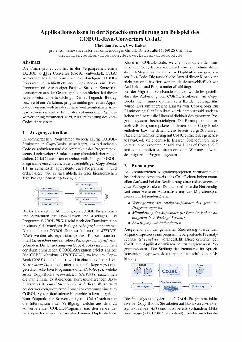
Applikationswissen in der Sprachkonvertierung am Beispiel desCOBOL-Java-Converters CoJaC
Christian Becker, Uwe Kaiserpro et con Innovative Informatikanwendungen GmbH, Dittesstraße 15, 09126 Chemnitz
[email protected],[email protected]
AbstractDie Firma pro et con hat in der Vergangenheit einenCOBOL to Java Converter (CoJaC) entwickelt. CoJaCkonvertiert aus einem einzelnen, vollständigen COBOL-Programm einschließlich der Copy-Books ein Java-Programm mit zugehöriger Package-Struktur. Kontextin-formationen aus der Gesamtapplikation blieben bei dieserArbeitsweise unberücksichtigt. Der vorliegende Beitragbeschreibt ein Verfahren, programmübergreifendes Appli-kationswissen, welches durch eine werkzeugbasierte Ana-lyse gewonnen und während der automatischen Sprach-konvertierung verarbeitet wird, zur Optimierung des Ziel-Codes einzusetzen.
1 AusgangssituationIn kommerziellen Programmen werden häufig COBOL-Strukturen in Copy-Books ausgelagert, um redundantenCode zu reduzieren und die Architektur des Programmsy-stems durch weitere Strukturierung übersichtlicher zu ge-stalten. CoJaC konvertiert einzelne, vollständige COBOL-Programme einschließlich der dazugehörigen Copy-Books1:1 in semantisch äquivalente Java-Programme[1] undordnet diese, wie in Java üblich, in einer hierarchischenJava-Package-Struktur (Packages) ein.
Die Grafik zeigt die Abbildung von COBOL-Programmenund -Strukturen auf Java-Klassen und -Packages. DasProgramm COBOL-PRG-1 wird nach der Transformationin einem gleichnamigen Package cobolprg1 eingeordnet.Die enthaltenen COBOL-Datenstrukturen (hier STRUCT-ONE) werden als eigenständige Java-Klassen transfor-miert (StructOne) und im selben Package (cobolprg1) ein-gebunden. Die Umsetzung von Copy-Books einschließlichder darin enthaltenen COBOL-Strukturen erfolgt analog.Die COBOL-Struktur STRUCT-TWO, welche im Copy-Book COPY-1 enthalten ist, wird in eine äquivalente Java-Klasse StructTwo transformiert und im Package copy1 ein-geordnet. Alle Java-Programme (hier CobolPrg1), welchezuvor Copy-Books verwendeten (COPY-1), nutzen nundie nur einmal existierenden, korrespondierenden Java-Klassen (z.B. copy1.StructTwo). Auf diese Weise wirdbei der werkzeuggestützten Sprachkonvertierung eine zumCOBOL-System äquivalente Hierarchie in Java aufgebaut.Zum Zeitpunkt der Konvertierung mit CoJaC stehen nurdie Informationen zur Verfügung, welche aus dem zukonvertierenden COBOL-Programm und den verwende-ten Copy-Books ermittelt werden können. Duplikate bzw.
Klone im COBOL-Code, welche nicht durch den Ein-satz von Copy-Books eliminiert wurden, führen durchdie 1:1-Migration ebenfalls zu Duplikaten im generier-ten Java-Code. Die tatsächliche Anzahl dieser Klone kannnicht pauschal beziffert werden, da sie ausschließlich vonArchitektur und Programmierstil abhängt.Bei der Migration von Kundensourcen wurde festgestellt,dass die Aufteilung von COBOL-Strukturen auf Copy-Books nicht immer optimal vom Kunden durchgeführtwurde. Der umfangreiche Einsatz von Copy-Books zurEliminierung aller Duplikate würde deren Anzahl stark er-höhen und somit die Übersichtlichkeit des gesamten Pro-grammsystems beeinträchtigen. Die Firma pro et con er-hielt z.B. Programmpakete, in denen keine Copy-Booksenthalten bzw. in denen diese bereits aufgelöst waren.Nach einer Konvertierung mit CoJaC enthielt der generier-te Java-Code viele identische Klassen. Solche führen ihrer-seits zu einer erhöhten Anzahl von Lines of Code (LOC)und somit implizit zu einem erhöhten Wartungsaufwanddes migrierten Programmsystems.
2 PreanalyseBei kommerziellen Migrationsprojekten verursachte diebeschriebene Arbeitsweise des CoJaC einen hohen manu-ellen Aufwand bei der Realisierung einer redundanzfreienJava-Package-Struktur. Daraus resultierte die Notwendig-keit einer weiteren Automatisierung des Migrationspro-zesses mit folgenden Zielen:
• Verringerung des Analyseaufwandes des gesamtenProgrammsystems
• Minimierung des Aufwandes zur Erstellung einer ho-mogenen Java-Package-Struktur
• Beseitigung von Redundanzen
Ausgehend von der genannten Zielsetzung wurde demMigrationsprozess eine programmübergreifende Preanaly-sephase (Preanalyse) vorangestellt. Diese erweitert denCoJaC um Applikationswissen des zu migrierenden Pro-grammsystems. Die Stellung der Preanalyse im Sprach-konvertierungsprozess dokumentiert die nachfolgende Ab-bildung:
Die Preanalyse analysiert alle COBOL-Programme inklu-sive der Copy-Books. Sie arbeitet auf Basis von abstraktenSyntaxbäumen (AST) und nutzt bereits vorhandene Meta-werkzeuge (z.B. COBOL-Frontend), welche auch bei der
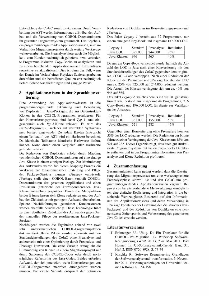
Entwicklung des CoJaC zum Einsatz kamen. Durch Verar-beitung der AST werden Informationen z.B. über den Auf-bau und die Verwendung von COBOL-Datenstrukturenim gesamten Programmsystem gesammelt. Das Ergebnis,ein programmübergreifendes Applikationswissen, wird imVerlauf des Migrationsprojektes durch weitere Werkzeugeweiterverarbeitet. Die Preanalyse bietet auch die Möglich-keit, vom Kunden nachträglich gelieferte bzw. veränder-te Programme inklusive Copy-Books zu analysieren undzu einem bestehenden Applikationswissen hinzuzufügenrespektive zu aktualisieren. Dies ist dann der Fall, wennder Kunde im Verlauf eines Projektes Sanierungsarbeitendurchführt und die betroffenen Quellen erst nachträglichliefert. Solche Nachlieferungen sind gängige Praxis.
3 Applikationswissen in der Sprachkonver-tierung
Eine Anwendung des Applikationswissens ist dieprogrammübergreifende Erkennung und Beseitigungvon Duplikaten in Java-Packages, die aus Datenstruktur-Klonen in den COBOL-Programmen resultieren. Fürden Konvertierungsprozess sind dabei Typ 1- und ein-geschränkt auch Typ 2-Klone relevant. Es wird dasBaxter-Verfahren[2], welches auf abstrakten Syntaxbäu-men basiert, angewendet. Zu jedem Knoten (entsprichteinem Teilbaum) des AST wird ein Hashwert berechnet.Da identische Teilbäume identische Hashwerte liefern,können Klone durch einen Vergleich aller Hashwertegefunden werden.Die Reduktion von Duplikaten erfolgt durch Mappingvon identischen COBOL-Datenstrukturen auf eine einzigeJava-Klasse in einem einzigen Package. Zur Minimierungdes Aufwandes wurde für diesen Mapping-Prozess einWerkzeug zur teilautomatischen Erstellung und Pflegeder Package-Struktur namens JPackage entwickelt.JPackage stellt einen COBOL-Baum (enthält COBOL-Datenstrukturen der gesamten Applikation) und einenJava-Baum (entspricht der korrespondierenden Java-Klassenhierarchie) gegenüber. Durch die Manipulationbeider Bäume lassen sich Klone reduzieren und der Auf-bau der Zielstruktur mit geringem Aufwand überarbeiten.Spätere Nachlieferungen geänderter Kundensourcenwerden ebenfalls berücksichtigt. Diese Technologie führtzu einer deutlichen Reduktion des Aufwandes gegenüberder manuellen Pflege der resultierenden Java-Package-Struktur.Nachfolgend werden die Ergebnisse anhand von zweisehr unterschiedlichen COBOL-Programmpaketendokumentiert. Beide Pakete wurden einerseits mit denStandardeinstellungen des CoJaC ohne Preanalyse undandererseits mit einer Optimierung durch Preanalyse undJPackage konvertiert. Die erste Variante ermöglicht dieEliminierung von Klonen in einem Migrationsprojekt nurdurch Sanierung des COBOL-Codes oder durch nach-trägliches Refactoring des Java-Codes. Beides erfordertAufwand, der sich potenziert, wenn Konvertierungen vonCOBOL-Programmen mehrfach durchgeführt werdenmüssen. Die zweite Variante entspricht der optimalen
Reduktion von Duplikaten im Konvertierungsprozess mitJPackage.Das Paket Legacy 1 besteht aus 32 Programmen, nureinem einzigen Copy-Book und insgesamt 157.000 LOC.
Legacy 1 Standard Preanalyse ReduktionJava LOC 325.000 244.000 25%Java-Klassen 946 565 40%
Da nur ein Copy-Book verwendet wurde, hat sich die An-zahl der LOC in Java nach einer Konvertierung mit denStandardeinstellungen des CoJaC gegenüber dem origina-len COBOL-Code verdoppelt. Nach einer Reduktion derKlone mit der Preanalyse und JPackage konnten die LOCum ca. 25% von 325.000 auf 244.000 reduziert werden.Die Anzahl der Klassen verringerte sich um ca. 40% von946 auf 565.Das Paket Legacy 2, welches bereits in COBOL gut struk-turiert war, bestand aus insgesamt 44 Programmen, 216Copy-Books und 196.000 LOC. Es diente zur Verifikati-on des Ansatzes.
Legacy 2 Standard Preanalyse ReduktionJava LOC 331.000 155.000 53%Java-Klassen 521 282 45%
Gegenüber einer Konvertierung ohne Preanalyse konnten53% der LOC reduziert werden. Die Reduktion der Kloneführte zu einer Verringerung der Java-Klassen um 45% von521 auf 282. Dieses Ergebnis zeigt, dass auch gut struktu-rierte Programmsysteme mit vielen Copy-Books Duplika-te enthalten und in der Programmtransformation von Pre-analyse und Klone-Reduktion profitieren.
4 ZusammenfassungZusammenfassend kann gesagt werden, dass die Erweite-rung des Migrationsprozesses um eine werkzeugbasiertePreanalysephase sinnvoll ist und den CoJaC um pro-grammübergreifendes Applikationswissen ergänzt. Beipro et con bereits vorhandene Metawerkzeuge ermöglich-ten eine einfache Realisierung und Integration in die be-stehende Werkzeugkette. Basierend auf den Informatio-nen des Applikationswissens und deren Verwendung inJPackage konnte bei der Erstellung der Zielstruktur (Java-Packages) und der Reduktion von Duplikaten eine nen-nenswerte Zeitersparnis und Verbesserung des generiertenJava-Codes erreicht werden.
Literaturverzeichnis[1] Erdmenger, U.; Uhlig, D.: Ein Translator für die
COBOL-Java-Migration. 13. Workshop Software-Reengineering (WSR 2011), 2.-4. Mai 2011, BadHonnef. In: GI-Softwaretechnik-Trends, Band 31,Heft 2, ISSN 0720-8928, S. 73-74
[2] Koschke R.: Software Reengineering Grundlagender Softwareanalyse und -transformation. 3. Novem-ber 2011. Vorlesungsunterlagen der Universität Bre-men (eBook), S. 154-158

ClientJS: Migrating Java UI Clients to HTML 5 and JavaScript - An Experience Report
Udo Borkowskiabego Software GmbH
Aachen, GermanyEmail: [email protected]
Patrick MuchmoreUniversity of Southern California
Los Angeles, CA, USAEmail: [email protected]
Abstract: We were tasked with migrating an existingweb based Java applet User Interface (UI) to a UIsolution based on HTML 5 and JavaScript. This newUI addresses problems with multiple browsers, JavaRuntime Environments (JREs), and operating systemincompatibilities and allows for display on mobiledevices that do not support JRE. This report brieflydescribes the approach we used for the ClientJSproject, and summarizes some of the complicationsthat were encountered along the way.
1 Background and MotivationCodoniX established in 1995 has a web based Electro-nic Health Record (EHR) which has used Java applettechnology in its user interface for the last 12 years [1].At the server side all of the medical knowledge isstored as XML files in a master Medical Knowledgebase (KB) and represents >200,000 hours of clinicaldevelopment. Each self-contained xml file or “MedicalProblem” (MP) contains all of the clinical logic as wellas graphical information to be rendered by the Javaapplet in a compatible browser. When new modules were added to the system theyemployed the UI technology current at the time. Asextensions to the application were made over a periodof many years the resulting code base contains a mix ofAWT and Swing based modules. The original system was hospital based, but hasgrown to support physician clinics throughout the Uni-ted States. In 2001, when the system was first de-signed there was a single major browser (IE) used byvirtually all hospitals who uniformly used MS Win-dows. Over time that landscape has changed dramati-cally. There are now at least 4 major browsersconstantly adding patches which often require differentversions of JRE, add to that the overlay of strictersecurity considerations and certain business decisionsby operating system and device vendors and the neteffect has made using Java applets in web browsersprogressively more difficult, or even impossible. Because of the huge investment in the medical KB,any replacement for the applet based UI had to be100% compatible with the existing clinical KB design.An analysis of current end user technologies revealedHTML 5 and JavaScript (JS) to be the best candidatesfor use as the base of the alternative UI, leading to theClientJS project.
2 PrototypingTo better judge the feasibility of a pure HTML 5 /JavaScript solution we re-implemented a small verticalslice through one UI module using only HTML 5 andJS. One goal was to ensure the technologies workedwell with the server backend. In addition, the experi-ence acquired during this phase led to a better under-standing of the technologies employed and the deve-lopment environment they would require.
The prototypical re-implementation was success-ful. However, developing the prototype revealed somerisks in using these technologies, e.g. the lack of astatic type system in JS. It was also clear that manuallyre-implementing the legacy Java code in JS would beboth time consuming (expensive) and error prone.
Moreover, it became clear that, at least initially,some non-clinical features outside of the KB would notbe available in ClientJS. For example, the Java UI sup-ports connectivity to hardware components such as sig-nature pads and scanners for which no comparablebrowser based solution is available. This meant theClientJS project could not fully replace the Java UI.Rather, both UIs would co-exist, at least for severalyears, and both UIs need to be maintained in parallel.
3 Java to JavaScriptThe expected high cost of a manual re-write of the UIin JS, coupled with the need to maintain both the Javaand ClientJS UI, led to the decision to reuse as muchcode as possible from the legacy Java UI in ClientJS.Ideally, there would be a single (Java) source base forthe majority of both the Java and ClientJS UIs.
To make this work we looked for a “Java to Java-Script” compiler. Most of the products we found didnot fit our needs, variously because they would haverequired us to also re-implement our Java UI code, didnot support the full Java language, or did not seem tobe mature enough.
We finally ended up with Java2Script (J2S) [2], anopen source project providing an Eclipse plug-in thatcompiles Java source into JS. In doing so it emulatesessential Java language functionality, such as classes,inheritance, and method overloading. Java2Script alsoincludes a re-implementation of parts of the Java Run-time Environment. By design J2S makes it easy to mixJava and JavaScript code, and it even supports embed-ding JavaScript in Java source files.
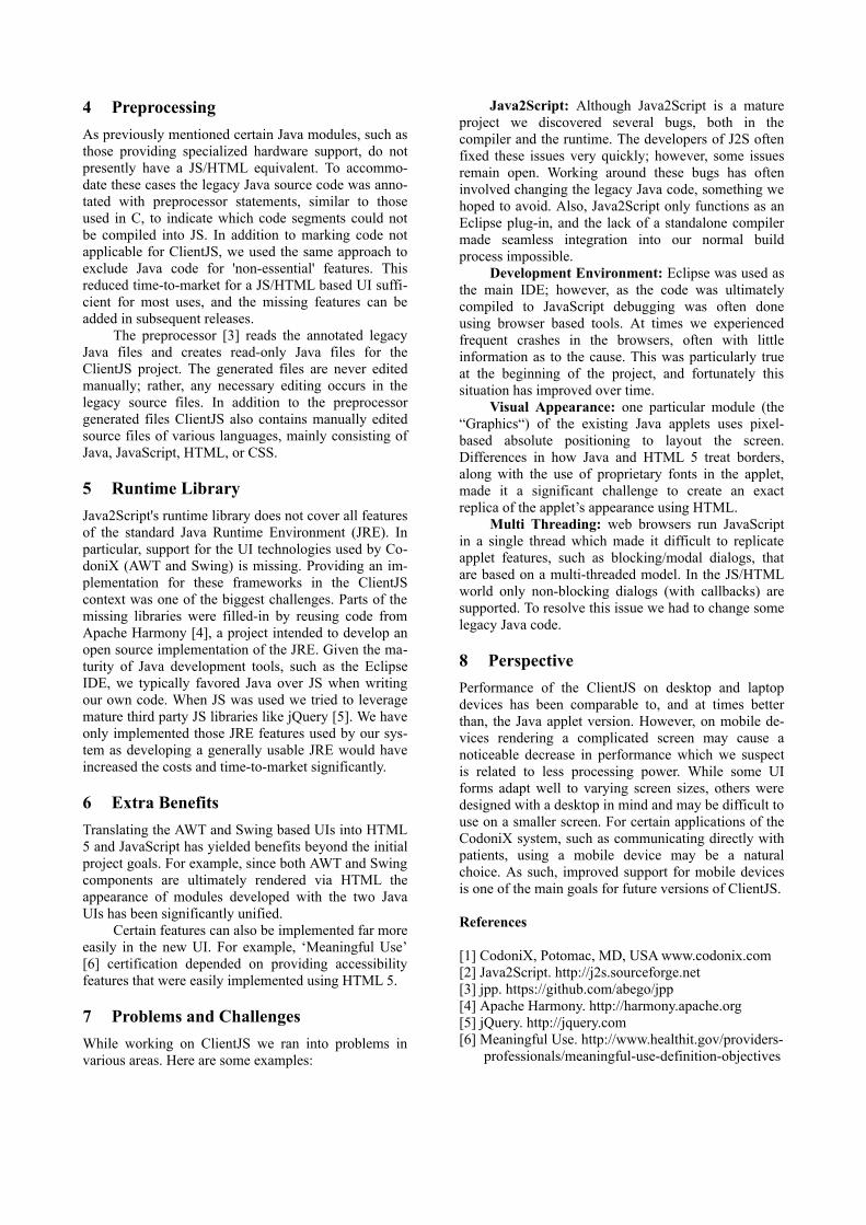
4 PreprocessingAs previously mentioned certain Java modules, such asthose providing specialized hardware support, do notpresently have a JS/HTML equivalent. To accommo-date these cases the legacy Java source code was anno-tated with preprocessor statements, similar to thoseused in C, to indicate which code segments could notbe compiled into JS. In addition to marking code notapplicable for ClientJS, we used the same approach toexclude Java code for 'non-essential' features. Thisreduced time-to-market for a JS/HTML based UI suffi-cient for most uses, and the missing features can beadded in subsequent releases.
The preprocessor [3] reads the annotated legacyJava files and creates read-only Java files for theClientJS project. The generated files are never editedmanually; rather, any necessary editing occurs in thelegacy source files. In addition to the preprocessorgenerated files ClientJS also contains manually editedsource files of various languages, mainly consisting ofJava, JavaScript, HTML, or CSS.
5 Runtime LibraryJava2Script's runtime library does not cover all featuresof the standard Java Runtime Environment (JRE). Inparticular, support for the UI technologies used by Co-doniX (AWT and Swing) is missing. Providing an im-plementation for these frameworks in the ClientJScontext was one of the biggest challenges. Parts of themissing libraries were filled-in by reusing code fromApache Harmony [4], a project intended to develop anopen source implementation of the JRE. Given the ma-turity of Java development tools, such as the EclipseIDE, we typically favored Java over JS when writingour own code. When JS was used we tried to leveragemature third party JS libraries like jQuery [5]. We haveonly implemented those JRE features used by our sys-tem as developing a generally usable JRE would haveincreased the costs and time-to-market significantly.
6 Extra BenefitsTranslating the AWT and Swing based UIs into HTML5 and JavaScript has yielded benefits beyond the initialproject goals. For example, since both AWT and Swingcomponents are ultimately rendered via HTML theappearance of modules developed with the two JavaUIs has been significantly unified.
Certain features can also be implemented far moreeasily in the new UI. For example, ‘Meaningful Use’[6] certification depended on providing accessibilityfeatures that were easily implemented using HTML 5.
7 Problems and ChallengesWhile working on ClientJS we ran into problems invarious areas. Here are some examples:
Java2Script: Although Java2Script is a matureproject we discovered several bugs, both in thecompiler and the runtime. The developers of J2S oftenfixed these issues very quickly; however, some issuesremain open. Working around these bugs has ofteninvolved changing the legacy Java code, something wehoped to avoid. Also, Java2Script only functions as anEclipse plug-in, and the lack of a standalone compilermade seamless integration into our normal buildprocess impossible.
Development Environment: Eclipse was used asthe main IDE; however, as the code was ultimatelycompiled to JavaScript debugging was often doneusing browser based tools. At times we experiencedfrequent crashes in the browsers, often with littleinformation as to the cause. This was particularly trueat the beginning of the project, and fortunately thissituation has improved over time.
Visual Appearance: one particular module (the“Graphics“) of the existing Java applets uses pixel-based absolute positioning to layout the screen.Differences in how Java and HTML 5 treat borders,along with the use of proprietary fonts in the applet,made it a significant challenge to create an exactreplica of the applet’s appearance using HTML.
Multi Threading: web browsers run JavaScriptin a single thread which made it difficult to replicateapplet features, such as blocking/modal dialogs, thatare based on a multi-threaded model. In the JS/HTMLworld only non-blocking dialogs (with callbacks) aresupported. To resolve this issue we had to change somelegacy Java code.
8 PerspectivePerformance of the ClientJS on desktop and laptopdevices has been comparable to, and at times betterthan, the Java applet version. However, on mobile de-vices rendering a complicated screen may cause anoticeable decrease in performance which we suspectis related to less processing power. While some UIforms adapt well to varying screen sizes, others weredesigned with a desktop in mind and may be difficult touse on a smaller screen. For certain applications of theCodoniX system, such as communicating directly withpatients, using a mobile device may be a naturalchoice. As such, improved support for mobile devicesis one of the main goals for future versions of ClientJS.
References
[1] CodoniX, Potomac, MD, USA www.codonix.com[2] Java2Script. http://j2s.sourceforge.net[3] jpp. https://github.com/abego/jpp[4] Apache Harmony. http://harmony.apache.org[5] jQuery. http://jquery.com[6] Meaningful Use. http://www.healthit.gov/providers-
professionals/meaningful-use-definition-objectives
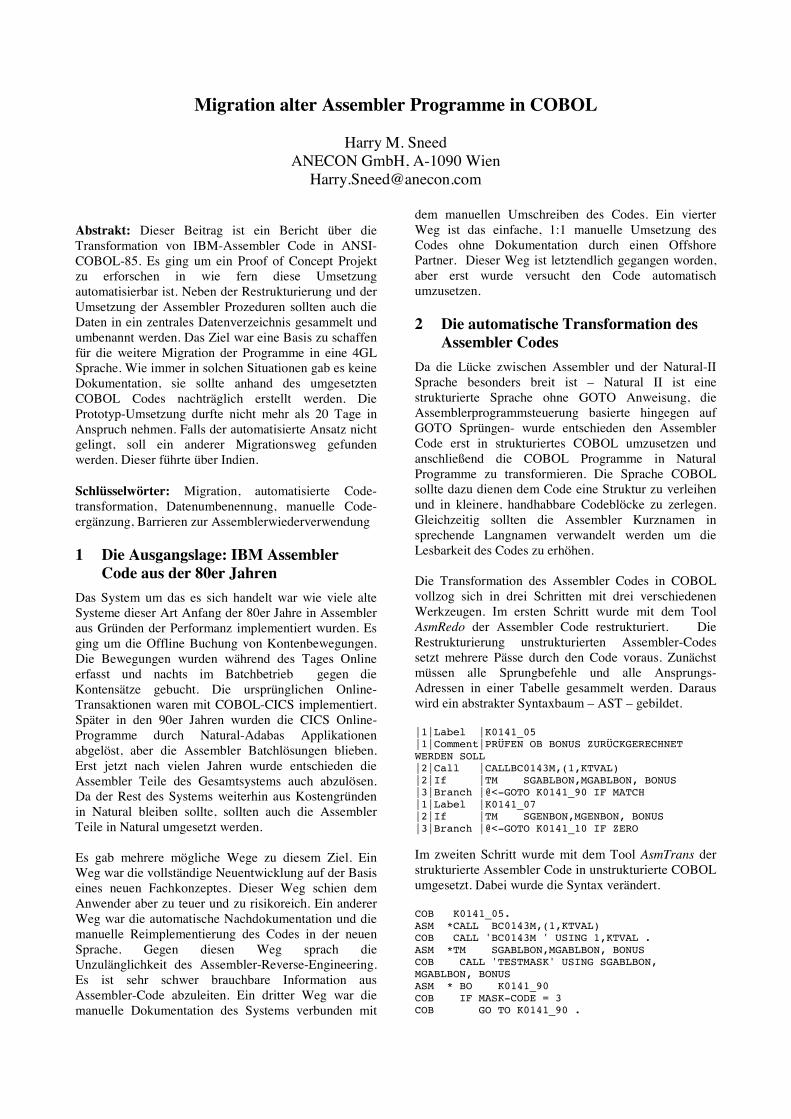
Migration alter Assembler Programme in COBOL
Harry M. Sneed ANECON GmbH, A-1090 Wien
Abstrakt: Dieser Beitrag ist ein Bericht über die Transformation von IBM-Assembler Code in ANSI-COBOL-85. Es ging um ein Proof of Concept Projekt zu erforschen in wie fern diese Umsetzung automatisierbar ist. Neben der Restrukturierung und der Umsetzung der Assembler Prozeduren sollten auch die Daten in ein zentrales Datenverzeichnis gesammelt und umbenannt werden. Das Ziel war eine Basis zu schaffen für die weitere Migration der Programme in eine 4GL Sprache. Wie immer in solchen Situationen gab es keine Dokumentation, sie sollte anhand des umgesetzten COBOL Codes nachträglich erstellt werden. Die Prototyp-Umsetzung durfte nicht mehr als 20 Tage in Anspruch nehmen. Falls der automatisierte Ansatz nicht gelingt, soll ein anderer Migrationsweg gefunden werden. Dieser führte über Indien.
Schlüsselwörter: Migration, automatisierte Code-transformation, Datenumbenennung, manuelle Code-ergänzung, Barrieren zur Assemblerwiederverwendung
1 Die Ausgangslage: IBM Assembler Code aus der 80er Jahren
Das System um das es sich handelt war wie viele alte Systeme dieser Art Anfang der 80er Jahre in Assembler aus Gründen der Performanz implementiert wurden. Es ging um die Offline Buchung von Kontenbewegungen. Die Bewegungen wurden während des Tages Online erfasst und nachts im Batchbetrieb gegen die Kontensätze gebucht. Die ursprünglichen Online-Transaktionen waren mit COBOL-CICS implementiert. Später in den 90er Jahren wurden die CICS Online-Programme durch Natural-Adabas Applikationen abgelöst, aber die Assembler Batchlösungen blieben. Erst jetzt nach vielen Jahren wurde entschieden die Assembler Teile des Gesamtsystems auch abzulösen. Da der Rest des Systems weiterhin aus Kostengründen in Natural bleiben sollte, sollten auch die Assembler Teile in Natural umgesetzt werden. Es gab mehrere mögliche Wege zu diesem Ziel. Ein Weg war die vollständige Neuentwicklung auf der Basis eines neuen Fachkonzeptes. Dieser Weg schien dem Anwender aber zu teuer und zu risikoreich. Ein anderer Weg war die automatische Nachdokumentation und die manuelle Reimplementierung des Codes in der neuen Sprache. Gegen diesen Weg sprach die Unzulänglichkeit des Assembler-Reverse-Engineering. Es ist sehr schwer brauchbare Information aus Assembler-Code abzuleiten. Ein dritter Weg war die manuelle Dokumentation des Systems verbunden mit
dem manuellen Umschreiben des Codes. Ein vierter Weg ist das einfache, 1:1 manuelle Umsetzung des Codes ohne Dokumentation durch einen Offshore Partner. Dieser Weg ist letztendlich gegangen worden, aber erst wurde versucht den Code automatisch umzusetzen.
2 Die automatische Transformation des Assembler Codes
Da die Lücke zwischen Assembler und der Natural-II Sprache besonders breit ist – Natural II ist eine strukturierte Sprache ohne GOTO Anweisung, die Assemblerprogrammsteuerung basierte hingegen auf GOTO Sprüngen- wurde entschieden den Assembler Code erst in strukturiertes COBOL umzusetzen und anschließend die COBOL Programme in Natural Programme zu transformieren. Die Sprache COBOL sollte dazu dienen dem Code eine Struktur zu verleihen und in kleinere, handhabbare Codeblöcke zu zerlegen. Gleichzeitig sollten die Assembler Kurznamen in sprechende Langnamen verwandelt werden um die Lesbarkeit des Codes zu erhöhen. Die Transformation des Assembler Codes in COBOL vollzog sich in drei Schritten mit drei verschiedenen Werkzeugen. Im ersten Schritt wurde mit dem Tool AsmRedo der Assembler Code restrukturiert. Die Restrukturierung unstrukturierten Assembler-Codes setzt mehrere Pässe durch den Code voraus. Zunächst müssen alle Sprungbefehle und alle Ansprungs-Adressen in einer Tabelle gesammelt werden. Daraus wird ein abstrakter Syntaxbaum – AST – gebildet. |1|Label |K0141_05 |1|Comment|PRÜFEN OB BONUS ZURÜCKGERECHNET WERDEN SOLL |2|Call |CALLBC0143M,(1,KTVAL) |2|If |TM SGABLBON,MGABLBON, BONUS |3|Branch |@<-GOTO K0141_90 IF MATCH |1|Label |K0141_07 |2|If |TM SGENBON,MGENBON, BONUS |3|Branch |@<-GOTO K0141_10 IF ZERO Im zweiten Schritt wurde mit dem Tool AsmTrans der strukturierte Assembler Code in unstrukturierte COBOL umgesetzt. Dabei wurde die Syntax verändert. COB K0141_05. ASM *CALL BC0143M,(1,KTVAL) COB CALL 'BC0143M ' USING 1,KTVAL . ASM *TM SGABLBON,MGABLBON, BONUS COB CALL 'TESTMASK' USING SGABLBON, MGABLBON, BONUS ASM * BO K0141_90 COB IF MASK-CODE = 3 COB GO TO K0141_90 .
COM * Forward Jump ===>> In dem dritten Schritt wurden mit dem Tool COBRedo der COBOL Code restrukturiert, die Literale durch Variable ersetzt und die Datennamen, soweit bekannt, umgetauscht. *K0141_05. CALL BC0143M,(1,KTVAL) * <K0141_05 CALL BC0143M,(1,KTVAL)> * The parameter list is possibly dynamically modified during execution! CALL 'BC0143M' USING LIT-F-1, KTVAL CALL 'Test-Under-Mask' USING CONDITION-CODE SGABLBON_GENERALI_ABLAUEFER_BONUS(1:1) MGABLBON IF CC-BO GO TO K0141_90 END-IF.
3 Die Deklaration der Daten Die Assembler Register wurden als Arbeitsfelder in der Data Division des COBOL Programmes deklariert und zwar sowohl als Binärnummer als auch als Zeichenfolge, damit sie als Strings und als Zahlen behandelt werden konnten. 01 REGISTERS. 05 R0-REGISTER PIC S9(9) BINARY. 05 R0-REGISTER-X REDEFINES R0-REGISTER PIC X(4) 05 R1-REGISTER PIC S9(9) BINARY. 05 R1-REGISTER-X REDEFINES R1-REGISTER PIC X(4) Die Konstanten, die in den prozeduralen Anweisungen vorkamen wurden als symbolische Konstanten mit festen Werten vereinbart. 05 LIT-F-1015-N PIC S9(9) BINARY VALUE 1015. 05 LIT-F-12-N PIC S9(9) BINARY VALUE 12. 05 LIT-F-14-N PIC S9(9) BINARY VALUE 14. 77 LIT-C-POSTBAR PIC X(07) VALUE 'POSTBAR'. 77 LIT-C-POSTLAG PIC X(07) VALUE 'POSTLAG'. 77 LIT-C-S PIC X VALUE 'S'. 77 LIT-C-V PIC X VALUE 'V'. Die anderen einzelnen Daten wurden 1:1 als Stufe 1 Arbeitsfelder in die Data Division übernommen. * RESTLÄNGE DER KARTE BEI KTG5 01 ALAENGE_RESTLAENGE_KARTE PIC S9(9) BINARY. 01 ZKEST PIC S9(9) BINARY. 01 SPES15_WORT PIC S9(9) BINARY. 01 ZBETR PIC S9(9) BINARY. 01 FKZI PIC S9(9) BINARY. * LFD. TAGESZAHL STICHTAG 01 ZSTICHT_TAGESZAHL_STICHTAG PIC S9(9)BINARY. Die als Datensätze erkannten Datenstrukturen wurden wiederum in COPY Members zusammengelegt, wo sie von allen Programmen gemeinsam benutzt werden konnten. Diese Sätze hatten eine dreistufige Struktur.
4 Der Aufbau einer Data Dictionary Ein besonderes Problem bei der Konvertierung vom Assembler Code ist die Benennung der Daten.
Assembler Variabeln haben nur maximal 8-stellige Namen, aber oft sind längere Namen in Kommentaren hinter der Datendefinition. In einem Nebenprojekt wurden alle Datennamen gesammelt zusammen mit ihren Kommentaren und in eine Datentabelle abgelegt. Diese Tabelle wurde anschließend verwendet um bei der Umsetzung des Codes die Kurznamen durch Langnamen auszutauschen. Der ursprüngliche Kurzname wurde als Präfix zu dem neuen langen Namen beibehalten um die Verbindung zu dem Assembler Code zu erhalten. B4JRR;F;B4JRR_RUECKRECHNUNGSGEBUEHR B4JZI;F;B4JZI_ZINSEN_DER_VERLAENGERUN BABLDAT;H;BABLDAT_VORAUSSICHT_ABLAUFD BAKKZIF;F ;BAKKZIF_FIKTIVE_ZINSEN BAMART ;X ;BAMART_MITARBEITERART BAZI45 ;F ;BAZI45_AKKUM_ZINSEN BBSAZ ;C ;BBSAZ_SATZART Auf dieser Weise wurden über 2000 Datentypen gesammelt und umbenannt.
5 Der größte Stolperstein Als größter Stolperstein in diesem Projekt erwiesen sich die dynamisch veränderbaren Anweisungen. Das sind Sprungbefehle deren Ansprungsadresse zur Laufzeit überschrieben wird. Solche Befehle müssten manuell umgeschrieben werden, da eine automatisierte Lösung nicht gefunden werden konnte. Diese Befehle machen zwar weniger als 2% des Codes aus, aber das ist genug um eine vollständig automatisierte Transformation zu verhindern. Daran ist dieser Ansatz letztendlich gescheitert. In dem Moment in dem händisch in den Code eingegriffen werden muss, sind die Kostenvorteile der Automation verloren.
6 Verwandte Forschung Forschung zum Thema Assembler Konvertierung wird seit den 60er Jahren betrieben. Besonders erwähnenswert ist die Arbeit von C.Cifentues, die sich mit der Decompilierung von Assembler Code befasste und M. Ward, der das Tool Fermat an der Universität Durham entwickelte und immer noch weiterentwickelt. Dieser Autor hat schon in den 80er Jahren den Vorgänger zum Tool ASMTran entwickelt und damit mehrere Migrationsprojekte durchgeführt, u.a. für die Credit Swiss und die UBS. Auch in diesen Projekten mussten die letzten 5% manuell fertiggestellt werden aber das hat damals niemanden gestört. Die Kunden waren bereit diesen Preis zu bezahlen. In Anbetracht der indischen Konkurrenz ist dies heute nicht mehr der Fall. Literaturhinweise: Cifuentes, C., Gough,K.:„Decompilation of binary programs“, Software Practice,Vol. 25,Nr.7, 1995, p. 811 Sneed, H., Wolf, E., Heilmann, H.: “Software Migration in der Praxis”, dpunkt.verlag, Heidelberg, 2010. Ward,M., Zedan,H.: „Legacy Assembler Reengineering and Migration, Proc. of 20th ICSM, Chicago, Sept. 2004, p. 157.
Data Reengineering and Evolution in (industriellen) Legacy Systemen
Werner TeppeAmadeus Germany GmbHBad Homburg, [email protected]
Abstract
Auf fruheren Workshops wurde uber ARNO, eingroßes industrielles Migrationsprojekt, berichtet. Indiesem Projekt haben wir erfolgreich eine On-linetransaktionapplikation / Realtimeapplikation vonBS2000 nach Solaris migriert.
Die aus mehr als 6 Millionen Lines of Code beste-hende Applikation wurde von SPL (PL1 Subset) nachC++, die mehr als 5000 Jobs von SDF nach Perl unddas hochperformante Filehandlingsystem von rund800 Dateien nach Oracle migriert.
Um die Komplexitat der Migration zu beherrschen,entschieden wir damals, die Datenmigration einfachzu halten. Daher wurden aus Datensatzen im BS2000nun einfache Relationen in Oracle. Sie bestehen nuraus einem Index und aus einem einzigen langen Feld(BLOB). So konnten wir erreichen, dass die in derAnwendung enthaltene Navigation auf den Daten nurwenig geandert werden musste.
Um die Weiterentwicklung der Anwendungen zu er-leichtern, soll nun die Datenhaltung auf ein ”‘echt”’relationales System umgestellt werden. Die Her-ausforderungen, das Vorgehen und die angestrebtenLosungen, die in einem ganz konkreten Praxisfallanstehen, werden in dem Vortrag auf demWSRE 2014dargestellt und diskutiert.
References
[1] Werner Teppe: Redesign der START AmadeusAnwendungssoftware. Softwaretechnik-Trends23(2) (2003)
[2] Werner Teppe: The ARNO Project: Chal-lenges and Experiences in a Large-Scale Indus-trial Software Migration Project. ProceedingsEuropean Conference on Software Maintenanceand Reengineering (CSMR), pp. 149-158, 2009
[3] Werner Teppe: Teststrategien in komplexenMigrationsprojekten. Softwaretechnik-Trends 29(2009)
[4] Werner Teppe: Wiedergewinnung von Informa-tionen uber Legacy-Systeme in Reengineering-projekten. Softwaretechnik-Trends 30 (2010)
[5] Werner Teppe: Ein Framework fur Integra-tion, Build und Deployment bei Maintenance-und Reengineering-Prozessen. Softwaretechnik-Trends 31(2) (2011)
[6] Christian Zillmann, Andreas Winter, Alex Her-get, Werner Teppe, Marianne Theurer, AndreasFuhr, Tassilo Horn, Volker Riediger, Uwe Erd-menger, Uwe Kaiser, Denis Uhlig, Yvonne Zim-mermann: The SOAMIG Process Model in In-dustrial Applications. CSMR 2011: 339-342
[7] Werner Teppe: Migrationen - (K)eine Al-ternative fur Langlebige Softwaresysteme?Softwaretechnik-Trends 33(2) (2013)
[8] Uwe Kaiser, Uwe Erdmenger, Denis Uhlig,Andreas Loos: Methoden und Werkzeuge furdie Software Migration. In proceedings of 10thWorkshop Software Reengineering, 5-7 May2008, Bad Honnef
[9] Uwe Erdmenger, Denis Uhlig: Konvertierungder Jobsteuerung am Beispiel einer BS2000-Migration. Softwaretechnik-Trends 27(2) (2007)
[10] Uwe Erdmenger: SPL-Sprachkonvertierungim Rahmen einer BS2000 Migration.Softwaretechnik-Trends 26(2) (2006)
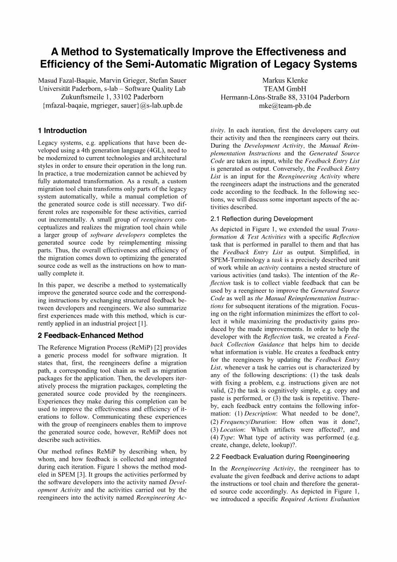
A Method to Systematically Improve the Effectiveness and Efficiency of the Semi-Automatic Migration of Legacy Systems
Masud Fazal-Baqaie, Marvin Grieger, Stefan Sauer Universität Paderborn, s-lab – Software Quality Lab
Zukunftsmeile 1, 33102 Paderborn {mfazal-baqaie, mgrieger, sauer}@s-lab.upb.de
Markus Klenke TEAM GmbH
Hermann-Löns-Straße 88, 33104 Paderborn [email protected]
1 Introduction Legacy systems, e.g. applications that have been de-veloped using a 4th generation language (4GL), need to be modernized to current technologies and architectural styles in order to ensure their operation in the long run. In practice, a true modernization cannot be achieved by fully automated transformation. As a result, a custom migration tool chain transforms only parts of the legacy system automatically, while a manual completion of the generated source code is still necessary. Two dif-ferent roles are responsible for these activities, carried out incrementally. A small group of reengineers con-ceptualizes and realizes the migration tool chain while a larger group of software developers completes the generated source code by reimplementing missing parts. Thus, the overall effectiveness and efficiency of the migration comes down to optimizing the generated source code as well as the instructions on how to man-ually complete it.
In this paper, we describe a method to systematically improve the generated source code and the correspond-ing instructions by exchanging structured feedback be-tween developers and reengineers. We also summarize first experiences made with this method, which is cur-rently applied in an industrial project [1].
2 Feedback-Enhanced Method The Reference Migration Process (ReMiP) [2] provides a generic process model for software migration. It states that, first, the reengineers define a migration path, a corresponding tool chain as well as migration packages for the application. Then, the developers iter-atively process the migration packages, completing the generated source code provided by the reengineers. Experiences they make during this completion can be used to improve the effectiveness and efficiency of it-erations to follow. Communicating these experiences with the group of reengineers enables them to improve the generated source code, however, ReMiP does not describe such activities.
Our method refines ReMiP by describing when, by whom, and how feedback is collected and integrated during each iteration. Figure 1 shows the method mod-eled in SPEM [3]. It groups the activities performed by the software developers into the activity named Devel-opment Activity and the activities carried out by the reengineers into the activity named Reengineering Ac-
tivity. In each iteration, first the developers carry out their activity and then the reengineers carry out theirs. During the Development Activity, the Manual Reim-plementation Instructions and the Generated Source Code are taken as input, while the Feedback Entry List is generated as output. Conversely, the Feedback Entry List is an input for the Reengineering Activity where the reengineers adapt the instructions and the generated code according to the feedback. In the following sec-tions, we will discuss some important aspects of the ac-tivities described.
2.1 Reflection during Development As depicted in Figure 1, we extended the usual Trans-formation & Test Activities with a specific Reflection task that is performed in parallel to them and that has the Feedback Entry List as output. Simplified, in SPEM-Terminology a task is a precisely described unit of work while an activity contains a nested structure of various activities (and tasks). The intention of the Re-flection task is to collect viable feedback that can be used by a reengineer to improve the Generated Source Code as well as the Manual Reimplementation Instruc-tions for subsequent iterations of the migration. Focus-ing on the right information minimizes the effort to col-lect it while maximizing the productivity gains pro-duced by the made improvements. In order to help the developer with the Reflection task, we created a Feed-back Collection Guidance that helps him to decide what information is viable. He creates a feedback entry for the reengineers by updating the Feedback Entry List, whenever a task he carries out is characterized by any of the following descriptions: (1) the task deals with fixing a problem, e.g. instructions given are not valid, (2) the task is cognitively simple, e.g. copy and paste is performed, or (3) the task is repetitive. There-by, each feedback entry contains the following infor-mation: (1) Description: What needed to be done?, (2) Frequency/Duration: How often was it done?, (3) Location: Which artifacts were affected?, and (4) Type: What type of activity was performed (e.g. create, change, delete, lookup)?.
2.2 Feedback Evaluation during Reengineering
In the Reengineering Activity, the reengineer has to evaluate the given feedback and derive actions to adapt the instructions or tool chain and therefore the generat-ed source code accordingly. As depicted in Figure 1, we introduced a specific Required Actions Evaluation
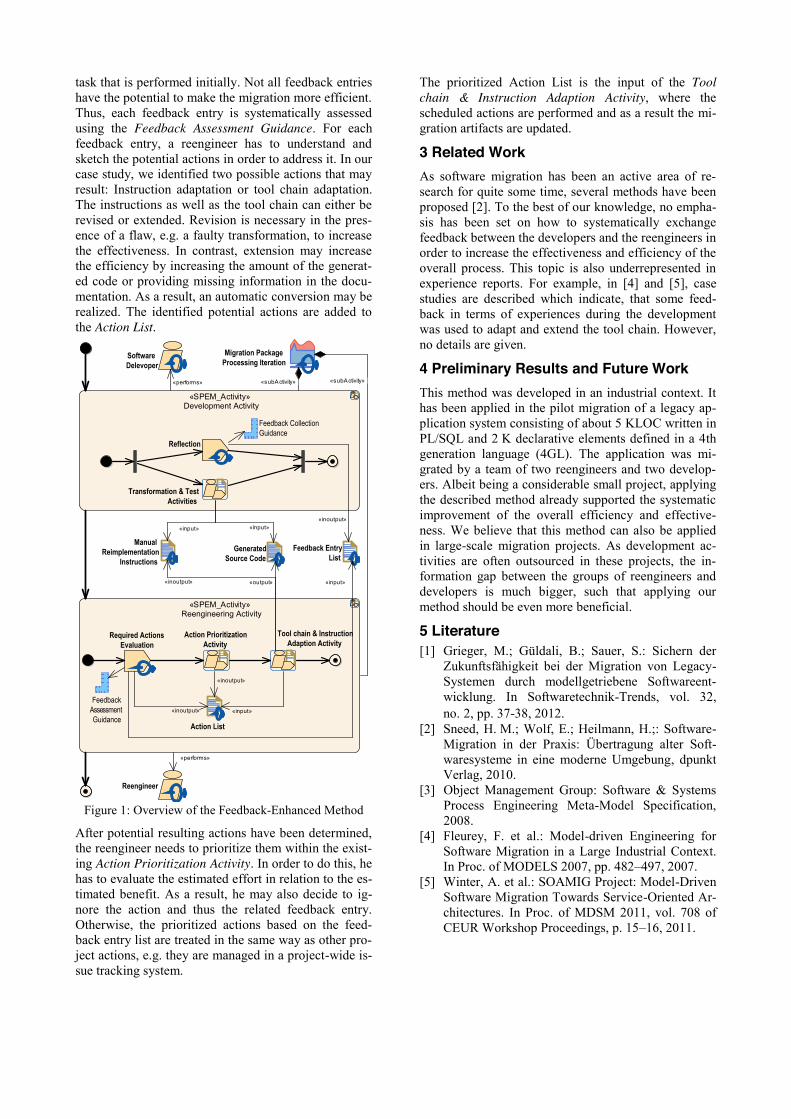
task that is performed initially. Not all feedback entries have the potential to make the migration more efficient. Thus, each feedback entry is systematically assessed using the Feedback Assessment Guidance. For each feedback entry, a reengineer has to understand and sketch the potential actions in order to address it. In our case study, we identified two possible actions that may result: Instruction adaptation or tool chain adaptation. The instructions as well as the tool chain can either be revised or extended. Revision is necessary in the pres-ence of a flaw, e.g. a faulty transformation, to increase the effectiveness. In contrast, extension may increase the efficiency by increasing the amount of the generat-ed code or providing missing information in the docu-mentation. As a result, an automatic conversion may be realized. The identified potential actions are added to the Action List.
Figure 1: Overview of the Feedback-Enhanced Method
After potential resulting actions have been determined, the reengineer needs to prioritize them within the exist-ing Action Prioritization Activity. In order to do this, he has to evaluate the estimated effort in relation to the es-timated benefit. As a result, he may also decide to ig-nore the action and thus the related feedback entry. Otherwise, the prioritized actions based on the feed-back entry list are treated in the same way as other pro-ject actions, e.g. they are managed in a project-wide is-sue tracking system.
The prioritized Action List is the input of the Tool chain & Instruction Adaption Activity, where the scheduled actions are performed and as a result the mi-gration artifacts are updated.
3 Related Work As software migration has been an active area of re-search for quite some time, several methods have been proposed [2]. To the best of our knowledge, no empha-sis has been set on how to systematically exchange feedback between the developers and the reengineers in order to increase the effectiveness and efficiency of the overall process. This topic is also underrepresented in experience reports. For example, in [4] and [5], case studies are described which indicate, that some feed-back in terms of experiences during the development was used to adapt and extend the tool chain. However, no details are given.
4 Preliminary Results and Future Work This method was developed in an industrial context. It has been applied in the pilot migration of a legacy ap-plication system consisting of about 5 KLOC written in PL/SQL and 2 K declarative elements defined in a 4th generation language (4GL). The application was mi-grated by a team of two reengineers and two develop-ers. Albeit being a considerable small project, applying the described method already supported the systematic improvement of the overall efficiency and effective-ness. We believe that this method can also be applied in large-scale migration projects. As development ac-tivities are often outsourced in these projects, the in-formation gap between the groups of reengineers and developers is much bigger, such that applying our method should be even more beneficial.
5 Literature [1] Grieger, M.; Güldali, B.; Sauer, S.: Sichern der
Zukunftsfähigkeit bei der Migration von Legacy-Systemen durch modellgetriebene Softwareent-wicklung. In Softwaretechnik-Trends, vol. 32, no. 2, pp. 37-38, 2012.
[2] Sneed, H. M.; Wolf, E.; Heilmann, H.;: Software-Migration in der Praxis: Übertragung alter Soft-waresysteme in eine moderne Umgebung, dpunkt Verlag, 2010.
[3] Object Management Group: Software & Systems Process Engineering Meta-Model Specification, 2008.
[4] Fleurey, F. et al.: Model-driven Engineering for Software Migration in a Large Industrial Context. In Proc. of MODELS 2007, pp. 482–497, 2007.
[5] Winter, A. et al.: SOAMIG Project: Model-Driven Software Migration Towards Service-Oriented Ar-chitectures. In Proc. of MDSM 2011, vol. 708 of CEUR Workshop Proceedings, p. 15–16, 2011.
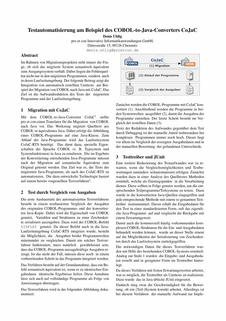
Testautomatisierung am Beispiel des COBOL-to-Java-Converters CoJaCDenis Uhlig
pro et con Innovative Informatikanwendungen GmbH,Dittesstraße 15, 09126 [email protected]
AbstractIm Rahmen von Migrationsprojekten steht immer die Fra-ge, ob sich das migrierte System semantisch äquivalentzum Ausgangssystem verhält. Dabei liegen die Fehlerquel-len nicht nur in den migrierten Programmen, sondern auchin deren Laufzeitumgebung. Der folgende Beitrag zeigt dieIntegration von automatisch erstellten Unittests am Bei-spiel der Migration von COBOL nach Java mit CoJaC. DasZiel ist die Aufwandreduktion des Tests der migriertenProgramme und der Laufzeitumgebung.
1 Migration mit CoJaCMit dem COBOL-to-Java-Converter CoJaC1 stelltepro et con einen Translator für die Migration von COBOLnach Java vor. Das Werkzeug migriert Quelltext ausCOBOL in äquivalentes Java. Dabei erfolgt die Abbildungeines COBOL-Programms auf eine Java-Klasse. ZumAblauf der Java-Programme wird das LaufzeitsystemCoJaC-RTS benötigt. Das dient dazu, spezielle Eigen-schaften der Sprache COBOL (z. B. Typsystem undSystemfunktionen) in Java zu emulieren. Die im Ergebnisder Konvertierung entstehenden Java-Programme müssennach der Migration auf semantische Äquivalenz zumOriginal getestet werden. Das Ziel war es, die Tests dermigirerten Java-Programme, als auch des CoJaC-RTS zuautomatisieren. Die dazu entwickelte Technologie basiertauf einem bereits vorgestellten Testverfahren2.
2 Test durch Vergleich von AusgabenDie erste Ausbaustufe des automatisierten Testverfahrensbesteht in einem textbasierten Vergleich der Ausgabendes originalen COBOL-Programmes und der konvertier-ten Java-Kopie. Dabei wird die Eigenschaft von COBOLgenutzt, Variablen und Strukturen zu einer Zeichenket-te serialisiert auszugeben. Dazu wird der COBOL-BefehlDISPLAY genutzt. Da dieser Befehl auch in die Java-Laufzeitumgebung CoJaC-RTS integriert wurde, bestehtdie Möglichkeit, die Ausgaben beider Programmweltenmiteinander zu vergleichen. Damit ein solches Testver-fahren funktioniert, muss natürlich gewährleistet sein,dass das COBOL-Programm aussagekräftige Ausgaben er-zeugt. Ist das nicht der Fall, müssen diese noch in einemvorbereitenden Schritt in das Programm integriert werden.
Das Verfahren besteht auf der Grundannahme, dass ein Be-fehl semantisch äquivalent ist, wenn er zu identischen Ein-gabedaten identische Ergebnisse liefert. Diese Annahmelässt sich auch auf vollständige Programme als Folge vonAnweisungen übertragen.
Das Testverfahren wird in der folgenden Abbildung doku-mentiert:
Zunächst werden die COBOL-Programme mit CoJaC kon-vertiert (1). Anschließend werden die Programme in bei-den Systemwelten ausgeführt (2), damit die Ausgaben derProgramme entstehen. Der letzte Schritt besteht im Ver-gleich der erstellten Daten (3).Trotz der Reduktion des Aufwandes gegenüber dem Testdurch Debugging ist der manuelle Anteil insbesondere beikomplexen Programmen immer noch hoch. Dieser liegtvor allem im Vergleich der erzeugten Ausgabedaten und inder manuellen Bewertung der gefundenen Unterschiede.
3 Testtreiber und JUnitEine weitere Reduzierung des Testaufwandes war zu er-warten, wenn die Vergleichsmöglichkeiten und Testbe-wertungen zumindest teilautomatisiert erfolgen. Zunächstwurden dazu in einer Analyse des Quelltextes Methodenermittelt, welche als Einstiegspunkte in die Verarbeitungdienen. Diese sollten in Folge genutzt werden, um die ent-sprechenden Teilprogramme/Teilsysteme zu testen. Dazuwurde in die konvertierten Java-Quellen eingegriffen undjede entsprechende Methode mit einem so genannten Test-treiber instrumentiert. Dieser erhält die Eingabedaten fürden Test in einer standardisierten Form, ruft das eigentli-che Java-Programm auf und vergleicht die Rückgabe miteinem Erwartungswert.Damit auch die kommerziell häufig vorkommenden kom-plexen COBOL-Strukturen für die Ein- und Ausgabedatenbehandelt werden können, wurde an dieser Stelle erneutauf die Möglichkeiten der Serialisierung von Zeichenket-ten durch das Laufzeitsystem zurückgegriffen.Die notwendigen Daten für dieses Testverfahren wur-den mit Hilfe des bestehenden COBOL-Systems ermittelt.Analog zur Stufe 1 wurden die Eingabe- und Ausgabeda-ten erstellt und in geeigneter Form im Testtreiber hinter-legt.Da dieses Verfahren mit festen Erwartungswerten arbeitet,war es möglich, die Testtreiber als Unittests zu realisieren.Dazu wurde das in Java übliche JUnit eingesetzt.Dadurch stieg zwar die Geschwindigkeit für die Bewer-tung, ob ein (Teil-)System korrekt arbeitet. Allerdings istbei diesem Verfahren der manuelle Aufwand zur Imple-
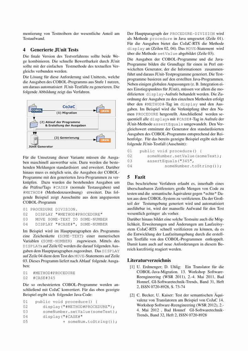
mentierung von Testtreibern der wesentliche Anteil amTestaufwand.
4 Generierte JUnit TestsDie finale Version des Testverfahrens sollte beide We-ge kombinieren. Die schnelle Bewertbarkeit durch JUnitsollte mit der einfachen Testmethode des textuellen Ver-gleichs verbunden werden.Die Lösung für diese Anforderung sind Unittests, welchedie Ausgaben des COBOL-Programms aus Stufe 1 nutzen,um daraus automatisiert JUnit-Testfälle zu generieren. Diefolgende Abbildung zeigt das Verfahren.
Für die Umsetzung dieser Variante müssen die Ausga-ben maschinell auswertbar sein. Dazu werden die beste-henden Meldungen standardisiert und erweitert. Darüberhinaus muss es möglich sein, die Ausgaben der COBOL-Programme mit den generierten Java-Programmen zu ver-knüpfen. Dazu wurden die bestehenden Ausgaben umdie Präfixe/Tags #CASE# (normale Testausgaben) und#METHOD# (Methodenzuordnung) erweitert. Das fol-gende Beispiel zeigt Ausschnitte aus dem angepasstenCOBOL-Programm
01 PROCEDURE DIVISION.02 DISPLAY "#METHOD#PROCEDURE"03 MOVE SOME-TEXT TO SOME-NUMBER04 DISPLAY "#CASE#", SOME-NUMBER
Im Beispiel wird im Hauptparagraphen des Programmseine Zeichenkette (SOME-TEXT) einer numerischenVariablen (SOME-NUMBER) zugewiesen. Mittels desDISPLAYs auf Zeile 02 werden die darauf folgenden Aus-gaben dem Hauptparagraphen zugeordnet. Das DISPLAYauf Zeile 04 dient dem Test des MOVE-Statements auf Zeile03. Dieses Programm liefert nach Ablauf folgende Ausga-ben:
01 #METHOD#PROCEDURE02 #CASE#345
Die so orchestrierten COBOL-Programme werden an-schließend mit CoJaC konvertiert. Für das oben gezeigteBeispiel ergibt sich folgender Java-Code:
01 public void procedure() {02 display("#METHOD#PROCEDURE");03 someNumber.setValue(someText);04 display("#CASE#"05 + someNum.toString());
Der Hauptparagraph der PROCEDURE-DIVISION wirdals Methode procedure in Java umgesetzt (Zeile 01).Für die Ausgaben bietet das CoJaC-RTS die Methodedisplay an (Zeilen 02, 04). Das MOVE-Statement wirdüber die Methode setValue abgebildet (Zeile 03).Die Ausgaben der COBOL-Programme und die Java-Programme bilden die Grundlage für einen in Perl ent-wickelten Generator, der die Informationen zusammen-führt und daraus JUnit-Testprogramme generiert. Die Test-programme basieren auf den erstellten Java-Programmen.Neben einigen globalen Anpassungen (z. B. Integration ei-nes Einstiegspunktes für JUnit), müssen vor allem die mo-difizierten display-Aufrufe behandelt werden. Die Zu-ordnung der Ausgaben zu den einzelnen Methoden erfolgtüber den #METHOD#-Tag im display und den Aus-gaben. Im Beispiel wird die Verknüpfung über den Na-men PROCEDURE hergestellt. Anschließend werden se-quentiell alle displays mit #CASE#-Tag in Aufrufe derJUnit-Methode assertEquals umgewandelt. Den Ver-gleichswert entnimmt der Generator den standardisiertenAusgaben des COBOL-Programms entsprechend der Rei-henfolge. Für das bereits gezeigte Beispiel ergibt sich derfolgende JUnit-Testfall (Auschnitt):
01 public void procedure() {02 someNumber.setValue(someText);03 assertEquals("345",04 someNumber.toString());
5 FazitDas beschriebene Verfahren erlaubt es, innerhalb einesüberschaubaren Zeitfensters große Mengen von Code zutesten und die semantische Äquivalenz gegen "echte"Da-ten aus dem COBOL-System zu verifizieren. Da der Groß-teil der Testumgebung generiert wird und automatisiertausführbar ist, wird der manuelle Aufwand für den Testwesentlich geringer als vorher.Darüber hinaus bildet eine solche Testsuite auch die Mög-lichkeit, Erweiterungen und Änderungen am Laufzeitsy-stem CoJaC-RTS schnell verifizieren zu können, da esdie Entwicklung der Laufzeitumgebung durch die erstell-ten Testfälle von den COBOL-Programmen entkoppelt.Damit kann auch auf neue Anforderungen in diesem Be-reich kurzfristig reagiert werden.
Literaturverzeichnis[1] U. Erdmenger; D. Uhlig: Ein Translator für die
COBOL-Java-Migration. 13. Workshop Software-Reengineering (WSR 2011), 2.-4. Mai 2011, BadHonnef, GI-Softwaretechnik-Trends, Band 31, Heft2, ISSN 0720-8928, S. 73-74
[2] C. Becker, U. Kaiser: Test der semantischen Äqui-valenz von Translatoren am Beispiel von CoJaC 14.Workshop Software-Reengineering (WSR 2012), 2.-4. Mai 2012 , Bad Honnef GI-Softwaretechnik-Trends, Band 32, Heft 2, ISSN 0720-8928

Mitigating the Risk of Software Change in Practice Retrospective on More Than 50 Architecture Evaluations in Industry (Keynote Paper)
Jens Knodel, Matthias Naab Fraunhofer IESE
Fraunhofer-Platz 1, 67663 Kaiserslautern, Germany {jens.knodel, matthias.naab}@iese.fraunhofer.de
Abstract—Architecture evaluation has become a mature instrument to make decisions about software systems, assess and mitigate risks, and to identify ways for improvement and migration of software systems. While scientific literature on approaches is available, publications on practical experiences are rather limited. In this paper, we share our experiences - after having performed more than 50 architecture evaluations for industrial customers in the last decade. We compiled facts and consolidate our findings about architecture evaluations in industry and especially highlight the role of reverse engineering in these projects. We share our lessons learned and provide data on common believes and provide examples for common misconceptions on the power of reverse engineering. This industrial and practical perspective allows practitioners to benefit from our experience in their daily architecture work and how to guide research of the scientific community.
Keywords—architecture evaluation, empirical evidences, experience report
I. INTRODUCTION Software architecture evaluation is a powerful means to
make decisions about software systems, assess and mitigate risks, and to identify ways for improvement and migration of software systems. Architecture evaluation achieves these goals by predicting properties of software systems before they have been built or by answering questions about existing systems. Architecture evaluation is both effective and efficient: effective as it is based on abstractions of the system under evaluation and efficient as it can always focus only on those facts that are relevant to answer the questions at hand. From 2004 to 2013, we conducted more than 50 architecture evaluations for industrial customers at Fraunhofer IESE (an applied research institute for software engineering located in Kaiserslautern, Germany). These projects covered a large number of types of systems, industries involved, evaluation questions asked, and of course a whole spectrum of different evaluation results.
The contribution of this paper is to present our experiences together with context factors, empirical data, and lessons learned. By this we aim at complementing the methodical publications on architecture evaluation. Of course, the companies and systems under evaluation have been anonymized. Target audience for this experience report are both, practitioners and researchers. On the one hand, we aim at encouraging practitioners to conduct architecture evaluations by showing their impact and at lowering the hurdles to make first attempts on their own. On the other hand,
we aim at giving researchers insight in industrial architecture evaluations, which can serve as basis to guide research in this area. In particular, we focus on aspects concerning architecture reconstruction and reverse engineering.
II. OUR ARCHITECTURE EVALUATION APPROACH Our architecture evaluation approach RATE (Rapid
ArchiTecture Evaluation) has been developed, refined calibrated, and, of course, applied for more than 10 years now. It is a compilation and calibration of existing approaches. This is following the philosophy of Fraunhofer to enhance, scale and tailor existing methods for industrial application. The evolution of RATE is always driven by the projects with industrial customers. We only briefly sketch the method as this paper is mainly on the experiences about architecture evaluations.
Figure 1: Architecture evaluation approach RATE
III. CONTEXT System Types: Different industries with different types of
software-intensive systems were involved in the architecture evaluations. Examples are: airline, agriculture, finance and insurance, automotive, online media and media production, plant engineering, energy management, mobile systems across different industries. This covered both, classical embedded systems and information systems, but also systems spanning both system types. The variety of industries results to a diverse bandwidth of quality challenges, typical architectural solutions, and technologies.
System Size: The size of the systems under evaluation is roughly measured in Lines of Code (LoC). Due to different implementation languages, this is not fully comparable and only indicates rough ranges of size. The size of systems under evaluation spans from around 10 KLoC to around 10 MLoC and a distribution is depicted in Figure 2. We cannot provide
Implementation/system
Architecture
Stakeholder / Requirements
Concerns / Questions
Knowledge
Models
Documents
Source code
Code metrics
011001
ScenariosRating
Solution adequacy assessment
Documentation assessment
Compliance assessment 011001
011001
Interpretation
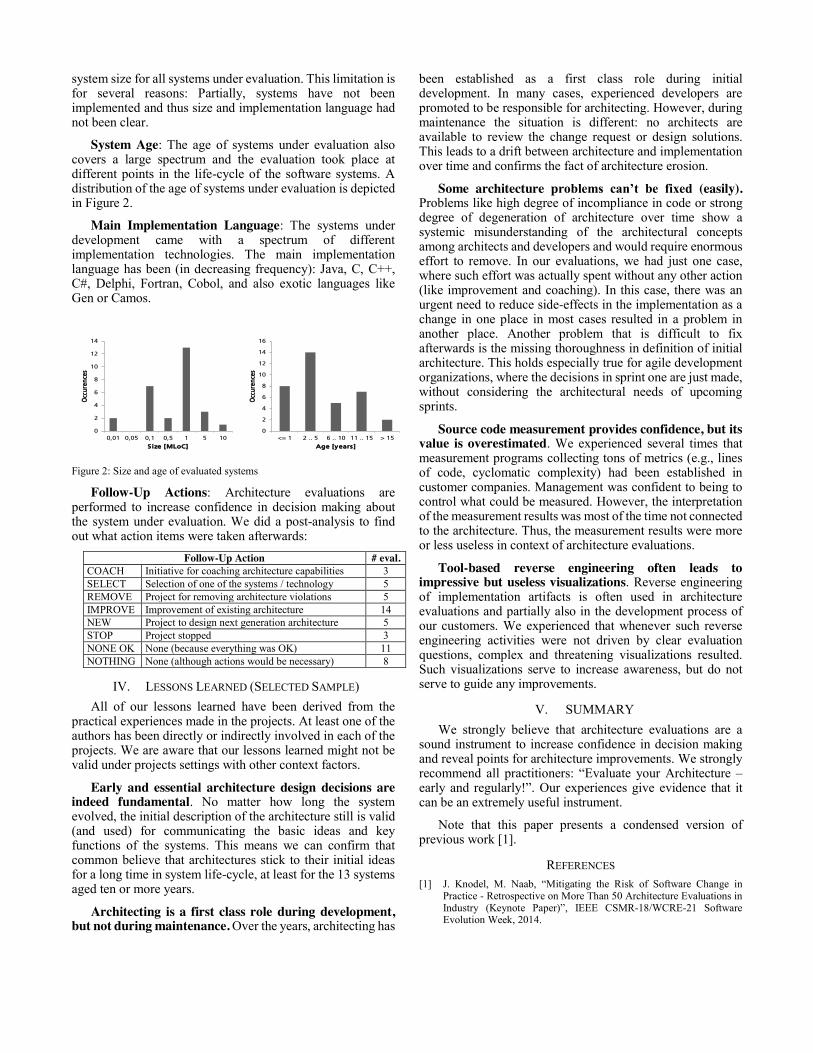
system size for all systems under evaluation. This limitation is for several reasons: Partially, systems have not been implemented and thus size and implementation language had not been clear.
System Age: The age of systems under evaluation also covers a large spectrum and the evaluation took place at different points in the life-cycle of the software systems. A distribution of the age of systems under evaluation is depicted in Figure 2.
Main Implementation Language: The systems under development came with a spectrum of different implementation technologies. The main implementation language has been (in decreasing frequency): Java, C, C++, C#, Delphi, Fortran, Cobol, and also exotic languages like Gen or Camos.
Figure 2: Size and age of evaluated systems
Follow-Up Actions: Architecture evaluations are performed to increase confidence in decision making about the system under evaluation. We did a post-analysis to find out what action items were taken afterwards:
Follow-Up Action # eval. COACH Initiative for coaching architecture capabilities 3 SELECT Selection of one of the systems / technology 5 REMOVE Project for removing architecture violations 5 IMPROVE Improvement of existing architecture 14 NEW Project to design next generation architecture 5 STOP Project stopped 3 NONE OK None (because everything was OK) 11 NOTHING None (although actions would be necessary) 8
IV. LESSONS LEARNED (SELECTED SAMPLE) All of our lessons learned have been derived from the
practical experiences made in the projects. At least one of the authors has been directly or indirectly involved in each of the projects. We are aware that our lessons learned might not be valid under projects settings with other context factors.
Early and essential architecture design decisions are indeed fundamental. No matter how long the system evolved, the initial description of the architecture still is valid (and used) for communicating the basic ideas and key functions of the systems. This means we can confirm that common believe that architectures stick to their initial ideas for a long time in system life-cycle, at least for the 13 systems aged ten or more years.
Architecting is a first class role during development, but not during maintenance. Over the years, architecting has
been established as a first class role during initial development. In many cases, experienced developers are promoted to be responsible for architecting. However, during maintenance the situation is different: no architects are available to review the change request or design solutions. This leads to a drift between architecture and implementation over time and confirms the fact of architecture erosion.
Some architecture problems can’t be fixed (easily). Problems like high degree of incompliance in code or strong degree of degeneration of architecture over time show a systemic misunderstanding of the architectural concepts among architects and developers and would require enormous effort to remove. In our evaluations, we had just one case, where such effort was actually spent without any other action (like improvement and coaching). In this case, there was an urgent need to reduce side-effects in the implementation as a change in one place in most cases resulted in a problem in another place. Another problem that is difficult to fix afterwards is the missing thoroughness in definition of initial architecture. This holds especially true for agile development organizations, where the decisions in sprint one are just made, without considering the architectural needs of upcoming sprints.
Source code measurement provides confidence, but its value is overestimated. We experienced several times that measurement programs collecting tons of metrics (e.g., lines of code, cyclomatic complexity) had been established in customer companies. Management was confident to being to control what could be measured. However, the interpretation of the measurement results was most of the time not connected to the architecture. Thus, the measurement results were more or less useless in context of architecture evaluations.
Tool-based reverse engineering often leads to impressive but useless visualizations. Reverse engineering of implementation artifacts is often used in architecture evaluations and partially also in the development process of our customers. We experienced that whenever such reverse engineering activities were not driven by clear evaluation questions, complex and threatening visualizations resulted. Such visualizations serve to increase awareness, but do not serve to guide any improvements.
V. SUMMARY We strongly believe that architecture evaluations are a
sound instrument to increase confidence in decision making and reveal points for architecture improvements. We strongly recommend all practitioners: “Evaluate your Architecture – early and regularly!”. Our experiences give evidence that it can be an extremely useful instrument.
Note that this paper presents a condensed version of previous work [1].
REFERENCES [1] J. Knodel, M. Naab, “Mitigating the Risk of Software Change in
Practice - Retrospective on More Than 50 Architecture Evaluations in Industry (Keynote Paper)”, IEEE CSMR-18/WCRE-21 Software Evolution Week, 2014.
0
2
4
6
8
10
12
14
0,01 0,05 0,1 0,5 1 5 10
Occ
uren
ces
S ize [MLoC]
0
2
4
6
8
10
12
14
16
<= 1 2 .. 5 6 .. 10 11 .. 15 > 15
Occ
uren
ces
Age [years]
Measuring Program Comprehension with fMRI
Janet Siegmund
University of Passau, Germany
1 Introduction
Software development is in essence a human-centeredactivity, because humans design, implement, andmaintain software. Thus, the human factor playsan important role in software engineering. Oneof the major activities during the entire software-development cycle is program comprehension: Devel-opers spend most of their time with comprehendingsource code [14]. Thus, if we can support developersin program comprehension, we can reduce time andcost of software development.
To improve program comprehension, for example,by tools or programming languages, we need to mea-sure it reliably—otherwise, we cannot know how orwhy tools or programming languages a↵ect programcomprehension. However, program comprehension isan internal cognitive process that inherently eludesmeasurement.
2 Measuring Program Comprehension
In a previous paper, we described the state-of-the artmeasurements techniques that researchers have devel-oped in the past: software measures, subjective rating,measurement of human performance, and think-aloudprotocols [4].
First, with software measures, such as lines ofcode or cyclcomatic complexity [5], researchers canmake statements about comprehensibility, like “themore lines of code or execution paths source code has,the more di�cult it is to understand”. However, soft-ware measures do not take into account the developerwho understands the source code, so their reliabil-ity as program-comprehension indicators is limited.Second, using subjective rating, researchers showsource code to developers and ask them how muchthey understood of the source code. While this ap-proach takes the developer into account, the percep-tion of the developer is subjective and can easily bebiased. Third, instead of using subjective rating, re-searchers measure performance of developers tomeasure program comprehension. For example, de-velopers are asked to fix a bug, and the time theyneeded to succeed is taken as comprehensibility indi-cator; the faster developers provide a correct bug fix,the more easier source code is to understand. How-ever, this does not allow researchers to make any state-ments about the comprehension process, but only theresult of the process. Fourth, with think-aloud pro-
tocols [13], developers verbalize their thoughts duringworking with source code. This way, the process canbe observed, but can also be biased, in that developersfilter their thoughts before saying them out loud.
Thus, all state-of-the-art approaches are fundamen-tally limited: When evaluating whether a new tool orlanguage improves program comprehension, we canonly observe that an improvement took place, but notwhy or how. While we slowly proceed toward bet-ter tools or programming languages, we still have noclear understanding of what happens during programcomprehension.
3 Program Comprehension and fMRI
To overcome the limitations of the state-of-the-art ap-proaches, we decided to use functional magnetic res-
onance imaging (fMRI) to measure program compre-hension. fMRI has proved successful in cognitive neu-roscience to observe cognitive processes, such as lan-guage comprehension or problem solving [2]. Sinceprogram comprehension as we currently understandit is a similar cognitive process, we decided to con-duct a first study to measure program comprehensionwith fMRI.
fMRI measures changes in the oxygen levels ofblood caused by localized brain activity. If a brain re-gion becomes active, its oxygen need increases, whichmanifests in a higher blood oxygen level of that region,which is measured with an fMRI scanner. Thus, whendevelopers understand source code, the blood oxygenlevels of certain regions increase. However, there arealso activations that are not specific to program com-prehension. For example, in our study, participantsshould understand source code, which included see-
ing the source code. We needed to exclude activationcaused by visual processing, because it is not specificto program comprehension. To filter out such irrele-vant processes, we designed control tasks that di↵eredonly in the absence of the program-comprehensionprocess: Participants should locate syntax errors thatdid not require understanding the source code (e.g.,quotation marks or parentheses that do not match andmissing semicolons or identifiers). To observe whichbrain regions are relevant only for program compre-hension, we determined the di↵erence in the brain ac-tivation caused between the program-comprehensiontasks and the syntax-error-locating tasks.

Fig. 1: Activation pattern for program comprehension.
Study Design: We designed several program-comprehension and syntax-error-locating tasks, whichwe tested in two pilot studies (see project’s websitetinyurl.com/ProgramComprehensionAndfMRI/).For a reliable measurement of the change in theoxygen levels, participants should need between30 and 120 seconds to complete a task, that is,understand one source-code snippet or find all syntaxerrors in one snippet. We excluded all tasks for whichparticipants needed less or more time, resulting in 12program-comprehension and 12 syntax-error-locatingtasks (in [10], we present the pilot study in detail).
Results and Discussion: With these tasks, wemeasured 17 participants with an fMRI scanner [11].We computed the average over all tasks and all partic-ipants. In Figure 1, we show the resulting activationpattern. The highlighted regions are related to lan-guage processing, working memory, and problem solv-ing, which is in line with the current understanding ofprogram comprehension. For example, there is a lineof fMRI research that observes natural-language andartificial-language processing by letting participantsunderstand natural-language text or artificial wordsthat follow or not follow grammars [1, 7, 12]. Re-garding problem solving, researchers observed similaractivated brain regions as we did when participantscompleted Raven’s progressive matrices test [9] (i.e.,completing rows of figures by adding the correct fig-ure) or the Wisconsin card sorting test [3] (i.e., dis-covering rules according to which cards need to besorted) [6, 8].
Thus, we found that fMRI is very promising togive us a detailed understanding of program compre-hension. In the long run, we can understand whycertain tools or programming languages improve pro-gram comprehension. Furthermore, as the measure-ment equipment will get cheaper in the future, wehope to establish fMRI as common measurement tech-nique in empirical software engineering.
Acknowledgments
Thanks to my colleagues Andre Brechmann, SvenApel, Christian Kastner, Chris Parnin, Anja Beth-
mann, Thomas Leich, and Gunter Saake.
References
[1] J. Bahlmann, R. Schubotz, and A. Friederici. Hi-erarchical Artificial Grammar Processing EngagesBroca’s Area. NeuroImage, 42(2):525–534, 2008.
[2] J. Belliveau, D. Kennedy, R. McKinstry, B. Buch-binder, R. Weissko↵, M. Cohen, M. Vevea, T. Brady,and B. Rosen. Functional Mapping of the HumanVisual Cortex by Magnetic Resonance Imaging. Sci-
ence, 254(5032):716–719, 1991.
[3] E. Berg. A Simple Objective Technique for MeasuringFlexibility in Thinking. Journal of General Psychol-
ogy, 39(1):15–22, 1948.
[4] J. Feigenspan, N. Siegmund, and J. Fruth. Onthe Role of Program Comprehension in Em-bedded Systems. In Proc. Workshop Soft-
ware Reengineering (WSR), pages 34–35, 2011.http://wwwiti.cs.uni-magdeburg.de/iti\_db/
publikationen/ps/auto/FeSiFr11.pdf.
[5] N. Fenton and S. Pfleeger. Software Metrics: A Rig-
orous and Practical Approach. International Thom-son Computer Press, second edition, 1997.
[6] Y. Nagahama, H. Fukuyama, H. Yamauchi, S. Mat-suzaki, J. Konish, and H. S. J. Kimura. Cerebral Ac-tivation during Performance of a Card Sorting Test.Brain, 119(5):1667–1675, 1996.
[7] K. Petersson, V. Folia, and P. Hagoort. What Artifi-cial Grammar Learning Reveals about the Neurobiol-ogy of Syntax. Brain and Language, 298(1089):199–209, 2012.
[8] V. Prabhakaran, J. Smith, J. Desmond, G. Glover,and J. Gabrieli. Neural Substrates of Fluid Reason-ing: An fMRI Study of Neocortical Activation Dur-ing Performance of the Raven’s Progressive MatricesTest. Cognitive Psychology, 33(1):43–63, 1996.
[9] J. Raven. Mental Tests Used in Genetic Studies: ThePerformances of Related Individuals in Tests MainlyEducative and Mainly Reproductive. Master’s thesis,University of London, 1936.
[10] J. Siegmund, A. Brechmann, S. Apel, C. Kastner,J. Liebig, T. Leich, and G. Saake. Toward Measur-ing Program Comprehension with Functional Mag-netic Resonance Imaging. In Proc. Int’l Sympo-
sium Foundations of Software Engineering–New Ideas
Track (FSE-NIER), pages 24:1–24:4. ACM, 2012.
[11] J. Siegmund, C. Kastner, S. Apel, C. Parnin, A. Beth-mann, T. Leich, G. Saake, and A. Brechmann. Under-standing Understanding Source Code with FunctionalMagnetic Resonance Imaging. In Proc. Int’l Conf.
Software Engineering (ICSE), 2014. To appear.
[12] P. Skosnik, F. Mirza, D. Gitelman, T. Parrish,M. Mesulam, and P. Reber. Neural Correlates of Ar-tificial Grammar Learning. NeuroImage, 17(3):1306–1314, 2008.
[13] M. Someren, Y. Barnard, and J. Sandberg. The ThinkAloud Method: A Practical Guide to Modelling Cog-
nitive Processes. Academic Press, 1994.
[14] R. Tiarks. What Programmers Really Do: An Obser-vational Study. Softwaretechnik-Trends, 31(2):36–37,2011.
Developing Stop Word Lists for Natural Language Program Analysis
⇤
Benjamin Klatt, Klaus KrogmannFZI Research Center for Information Technology
Haid-und-Neu-Str. 10-14,76131 Karlsruhe, Germany{klatt,krogmann}@fzi.de
Volker Kuttru↵CAS software AGCAS-Weg 1-5,
76131 Karlsruhe, Germanyvolker.kuttru↵@cas.de
1 Introduction
When implementing a software, developers expressconceptual knowledge (e.g. about a specific feature)not only in program language syntax and semanticsbut also in linguistic information stored in identifiers(e.g. method or class names) [6]. Based on this habit,Natural Language Program Analysis (NLPA) is usedto improve many di↵erent areas in software engineer-ing such as code recommendations or program anal-ysis [7]. Simplified, NLPA algorithms collect identi-fier names and apply term processing such as camelcase splitting (i.e. “MyIdentifier” to “My” and “Iden-tifier”) or stemming (i.e. “records” to “record”) tosubsequently perform further analyzes [10]. In our re-search context, we search for code locations sharingsimilar terms to link them with each other. In suchtypes of analysis, filtering stop words is essential toreduce the number of useless links.
Just collecting, splitting, and stemming the identi-fier names, can result in a list of terms with divergentgrade of usefulness. For example, the terms “get”and “set” are used in most Java application due tocommon coding practices and not to express any con-ceptual knowledge. These terms corrupt the programanalysis leading to unreasonable findings.
To reduce this noise, a typical approach in naturallanguage processing is to filter terms known as useless(aka “stop words”). For natural languages, many stopword lists are publicly available. However, as Høst etal. [5] identified, developers use a more specific vocab-ulary than in general spoken language. So commonstop word lists are not reasonable to be used in pro-gram analysis, they even depend on domain, applica-tion type, developing company, and project settings.
In this paper, we propose an approach to developreusable stop word lists to improve NLPA. We i) pro-pose to distinguish di↵erent scopes a stop word list ap-plies to (i.e. programming language, technology, anddomain) and ii) recommend types of sources for termsto include. Our approach is closely related to the workof Ratiu [8], who recommended considering domainknowledge for program analysis in general. We pro-pose a specific application of the concept as guidelines
⇤Acknowledgment: This work was supported by the German
Federal Ministry of Education and Research (BMBF), grant No.
01IS13023 A-C.
for developing stop word lists. Our approach is notlimited to a specific technology but, according to ourresearch context, examples in this paper are based onJava technology.
2 Stop Word Scopes
In general natural language processing, it is com-mon sense, that di↵erent languages have di↵erent stopwords. For example, a stop word list for analyzingEnglish language contains the term “and”, while forGerman language it would contain the term “und”.Furthermore, a stop word list for a scientific domainwould di↵er from a list for a sport domain. Theselists cannot be reused between the domains’ scopesbut reused within the same.In a similar way, we propose to not develop a globalstop word list, but to build stop word lists for di↵er-ent scopes. More specific, we recommend distinguish-ing three di↵erent dimensions: Programing language,technology and domain.
Programming Language Most state-of-the-artprogramming languages allow to use nearly all char-acters in identifier names (e.g. Java accepts all UTF-8characters except of digits at the beginning of iden-tifiers). However, for each programming language,there are a lot of common sense naming conventions.For example, in Java, methods to access an object’sattribute should start with the term “get”. We pro-pose to build programming language specific stopword lists, that reflect those common sense terms usedas part of identifier names to express specific technicalbut not conceptual knowledge.
Technology On top of programming languages, de-velopers build di↵erent types of applications (e.g.desktop or web applications) with according technolo-gies, each of them leading to specific terms used inidentifiers. For example, the terms “dialog” or “but-ton” are often used in desktop applications with aSwing-based Graphical User Interface (GUI). A stopword list containing those terms could be reused foranalyzing other Swing-based GUI-applications.
Domain Every domain has common terms that areused frequently and are not specific to implementedconcepts. For example, in applications for literaturemanagement, the term ISBN might be used quite fre-quently as global identifier with low contribution tospecific features. Developing a domain specific stop
word list (e.g. for a company or a product), wouldallow to improve the NLPA for this domain and couldbe reused and evolve within this context.
3 Stop Word Sources
Developing a stop word list depends on the scope andcontext it is used in. On the one side, developing a listfor the context of analyzing arbitrary applications inthe scope of a specific programming language, allowsfor using generic and publicly available sources andstudies. On the other side, developing a stop wordlist to be used in the context of an analysis projectwithin a company developing niche products allowsto use less publicly available but even more specificsources such as interviewing developers.
So far, we have identified di↵erent sources for de-veloping stop word lists for di↵erent scopes and con-texts. As scopes and contexts vary, there will be nofinite list of sources. However, we identified types ofsources that one could use for developing or reusingstop word lists. The types of sources presented be-low result from investigating systems in our researchproject. Accordingly, we do not claim for complete-ness but for a reasonable set to consider.
Programming Language Naming ConventionsAlmost every programming language o↵er either ex-plicit or common sense coding conventions includingterms to be used, such as the “get” prefix in Javamentioned before (e.g. JavaBeans Specification [3]).One should exploit such conventions when developinga stop word list for a specific technology.
Programming Habit Observations In the con-text of NLPA, researchers have analyzed existing ap-plications to identify typical programming habits dur-ing identifier naming. For example, Høst et al. [4],Sajaniemi et al. [9], and Caprile et al. [1] analyzedprograms to identify frequently used terms expressingmore technical and less conceptual knowledge.
Design Patterns When implementing design pat-terns, developers tend to identify the role of a classor interface within the pattern as part of its iden-tifier (e.g. “AccountModel”, or “”AccountView”).These role names can be received from pattern cat-alogs as provided by Gamma et al. [2]. Nowadays,many pattern catalogs exist for general purpose aswell as specific applications. One must use a catalogthat matches the scope of the stop word list developed.
Framework and Library Terms Frameworks andprogramming libraries cause developers to use termsin identifier names resulting from specific frameworkor library features. For example, developing OSGi1
components includes classes to control the life-cycle ofa component. The identifier of such a class typicallyincludes the term “Activator”. This is additionallystimulated by development environments (IDE) sup-porting a framework or library. It is recommendedto check the framework, library, or IDE support for
1www.osgi.org
terms that are typically used when developing a stopword list for analyzing applications based on them.
Company Guidelines Explicitly documented ornot, most companies have naming guidelines or cul-tures. They can range from acronyms to shorten iden-tifiers up to terms resulting from code libraries sharedwithin a company. Collecting such terms requires tointerview experts because they are rarely documented.
4 Limitations & Future Work
Stop word lists are only one technique used in NLPA.However, we rate filtering stop words as a valuable andtraceable one. We claim stop word list development tobe significantly improved by considering programminglanguage, application type or domain-specific scopesand sources as presented in this paper.
In the context of the KoPL project2, we are work-ing on such stop word lists, planing to publish thosefor common programming languages and technologiesand to build a company internal repository. This workis still in progress, but results are promising and willalso be published as part of our future work. To eval-uate di↵erent lists, we are going to facilitate them inour analyzes and present the results to developers forassessing them with a focus on which terms have beenfiltered out and which have not.
References
[1] B. Caprile and P. Tonella. Nomen est omen: analyz-ing the language of function identifiers. In Proceed-
ings of WCRE 1999. IEEE.[2] E. Gamma, R. Helm, R. Johnson, and J. Vlissides.
Design patterns: elements of reusable object-oriented
software. Addison-Wesley, 1995.[3] G. Hamilton. Sun Microsystems JavaBeans. Techni-
cal report, Sun Microsystems, 1997.[4] E. W. Høst and B. M. Østvold. The Programmer’s
Lexicon , Volume I : The Verbs. In Proceedings of
SCAM 2007. IEEE.[5] E. W. Høst and B. M. Østvold. The Java Program-
mer’s Phrase Book. In Software Language Engineer-
ing, volume 5452 of Lecture Notes in Computer Sci-
ence, pages 322–341. Springer, 2009.[6] A. Kuhn, S. Ducasse, and T. Girba. Semantic clus-
tering: Identifying topics in source code. Information
and Software Technology, 49(3):230–243, 2007.[7] L. Pollock, K. Vijay-Shanker, E. Hill, G. Sridhara,
and D. Shepherd. Natural Language-Based SoftwareAnalyses and Tools for Software Maintenance. InISSSE 2009-2011, pages 102–134, 2012.
[8] D. Ratiu. Domain Knowledge Driven Program Anal-ysis. Softwaretechnik-Trends, 29(2), 2009.
[9] J. Sajaniemi and R. N. Prieto. An Investigation intoProfessional Programmers’ Mental Representationsof Variables. In Proceedings of IWPC 2005. IEEE.
[10] P. van der Spek, S. Klusener, and P. van de Laar. To-wards Recovering Architectural Concepts Using La-tent Semantic Indexing. In Proceedings of CSMR
2008. IEEE.
2http://www.kopl-project.org
A Canonical Form of Arithmetic and Conditional Expressions
Torsten Görg, Mandy Northover University of Stuttgart
Universitaetsstr. 38, 70569 Stuttgart, Germany {torsten.goerg, mandy.northover}@informatik.uni-stuttgart.de
Abstract: This paper contributes to code clone detection by providing an algorithm that calculates canonical forms of arithmetic and conditional expressions. An experimental evaluation shows the relevance of such expressions in real code. The proposed normalization can be used in addition to dataflow normalizations.
1 Introduction Clone detection techniques [1] try to find program code fragments that are semantically equivalent or similar. It is not possible to solve this problem completely because semantic equivalence is not decidable for arbitrary code fragments. A common approach to compute equivalence is to use a normal form. Because of the undecidability of semantic equivalence, a unique normal form is also not achievable for usual source code. Nevertheless, it is useful to establish canonical code representations as partial normalizations to support clone detection. E.g., program dependence graphs (PDG) are used in several clone detection tools to normalize data flows [2]. Roy and Cordy [1] also mention a transformation step as part of a general clone detection process. We introduce a canonical form of arithmetic and conditional expressions. Through mathematical term transformations, many code variations are possible on expressions. Most of these variations are not handled by PDG. Our normalization is based on heuristics, so that most expressions occuring in real code are mapped to a unique canonical form.
2 Relevance Evaluation As a first step, we evaluated the relevance of a canonical form of simple expressions like operators on basic type values, literals, variable access, and reads on components of arrays and records. Assign-ments, function calls, and control constructs like loops and gotos were excluded. The expressions obeying these constraints were located as subtrees at the bottom of the AST. We measured the amount of such expressions in relation to the total code size for several open source systems. Table 1 shows the results for make, bison, bash, gnuplot, and unzip. Our measurements were based on the program
analysis framework Bauhaus and its intermediate representation (IML) [3]. The total code size is measured in SLOC and the number of all nodes in the IML graph, including the declarative parts of the code. The following columns show the number and percentage of nodes in simple expressions. The
Name SLOC #all #exp %exp Avg make 17427 82521 32643 39.6% 2.85 bison 20395 197226 74844 37.9% 2.55 bash 88401 514265 200790 39.0% 2.97
gnuplot 61494 549746 247497 45,0% 2.91 unzip 49127 82480 35535 43.1% 3.33
Table 1. Measured relevance of simple expressions
average number of nodes in these subtrees are given in the last column to indicate the size of the expres-sions. An average of 41% in the second last column indicates a high relevance of simple expressions.
3 Normalization Process To normalize expressions, we define a set of rewrite rules. For gaining unique normal forms, termination and confluence have to be guaranteed, i.e., equivalent expressions have to be mapped to the same form [4]. All our transformations termi-nate. Confluence is heuristically approximated. As described by Metzger and Wen [5], many variations result from permutations on the operands of commutative operators like add or multiply. To eliminate these variations we define a partitial order on expressions and sort the operands of commuta-tive operators based on this order. The transforma-tion is done in the following steps: 1. As is usual in intermediate representations, Bauhaus IML constructs expressions from binary and unary operators. To handle arbitrary sums, cohesive binary add nodes are contracted to a single sum node, based on these rules:
add(o1,o2) → sum(o1,o2) sum(...,add(o3,o4),...) → sum(...,o3,o4,...)
Multiply nodes are contracted to products in the same way, as are logical and bitwise disjunctions
and conjunctions. Although logical operations are usually evaluated lazily, this is no problem here because the constraints specified in the previous section exclude side effects and guarantee referen-tial transparency. Inverse operations are also included in the contrac-ted representation, e.g., subtracts in sums. To express this, each operand has a sign:
sub(o1,o2) → sum(o1,-o2)
Divisions are handled similarly. 2. Unary plus operators are simply eliminated because they have no semantic effect in arithmetic expressions. 3. A unary minus operator toggles the signs of the operands that it dominates. Thus it is also integrated in the contracted representation. 4. The operands of each contracted sum or product are reordered based on several sorting criteria (beginning with the highest priority):
o The type of the root node of the subtree representing the operand.
o The number of operands. o Successive comparison of operands. o The value of a literal. o The IML node ID of the declaration for a
variable access. After the contractions and operand reorderings, further transformations are processed to improve the confluence: 1. Constant folding reduces the number of literal nodes. The reordering in the previous step has already grouped literal operands together. Because calculations on literal values may introduce rounding imprecisions, the comparison of canonical forms allows some tolerance. 2. The contractions may result in sums and products in multiple layers:
sum(...,product(...,sum(...),...)
Applying the distributive law eliminates this. 3. Additional mathematical laws are applied, e.g., absorption, idempotence, and complement. Another problem is the unification of corresponding variable accesses. Semantically equivalent expres-sions usually access different free variables. To get a more unique form, variable accesses are replaced by numbered surrogate nodes, e.g.:
a + b + 2*b2 → s2 + s1 + 2*s12
But in some cases this is still not unique. To cope with this problem, a heuristic approach simliar to the technique described by Metzger and Wen [5] is
used. It identifies the unique variable accesses in a term to order them uniquely. Numbering a variable may unify a variable access that was ambiguous previously. In the example above, b is uniquely represented by s1 because of the unique subterm 2*b2. Subsequently a is uniquely numbered as s2. Variables that are not orderd uniquely have to be renumbered during the comparison of normalized terms.
4 Application The suggested normalization can easily be com-bined with PDG techniques. After normalizing and comparing the expressions, they are contracted to surrogate nodes. All variable accesses are incoming data flows. The result of an expression is its only outgoing data flow. In contrast to the fine grained PDG technique of Krinke [2], this handles more variations and reduces the number of PDG nodes. An evaluation of our approach is future work.
5 Related Work Metzger and Wen [5] use canonical forms to handle variations in code that hamper the recognition of known algorithms taken from a knowledge base. They focus on reordering the operands of commuta-tive operations and do not process any further transformations. Zhou and Burleson [6] apply canonical arithmetic expressions to identify datapaths with equivalent path predicates in designs of digital signal proces-sing systems. References [1] Chanchal Kumar Roy and James R. Cordy, “A
survey on software clone detection research,” technical report, Queen’s University, Canada, 2007.
[2] Jens Krinke, “Identifying Similar Code with Program Dependence Graphs,” in Proc. Eight Working Conference on Reverse Engineering (WCRE 2001), Stuttgart, Germany, pp. 301-309, October 2001
[3] Aoun Raza, Gunther Vogel, and Erhard Plödereder, “Bauhaus – A Tool Suite for Program Analysis and Reverse Engineering,” in Proceedings of Ada Europe 2006, LNCS 4006, pp. 71-82.
[4] N. Dershowitz, “Rewrite systems,” in “Handbook of Theoretical Computer Science,” pp. 243-320, Elsevier Science Publishers B.V., 1990.
[5] Robert Metzger and Zhaofang Wen, “Automatic Algorithm Recognition and Replacement – A New Approach to Program Optimization,” MIT, 2000
[6] Zheng Zhou and Wayne Burleson, “Equivalence Checking of Datapaths Based on Arithmetic Expressions,” in Proceedings of 32nd ACM/IEEE Design Automation Conference, ACM, 1995.
Dead Code Detection On Class Level
Fabian Streitel, Daniela Steidl, Elmar Jürgens
CQSE GmbH, Garching bei München, Germany{streitel, steidl, juergens}@cqse.eu
Abstract
Many software systems contain usused code. Whileunused code is an unnecessary burden for mainte-nance, it is often unclear which parts of a modernsoftware system can actually be removed. We presenta semi-automatic, iterative, language-independent ap-proach to identify unused classes in large object-oriented systems. It combines static and runtime in-formation about an application and aids developers inidentifying unused code in their system with high pre-cision. A case study on three real-life systems showsits effectiveness and feasibility in practice.
1 Introduction
Unused code in software systems can be problematic,as Eder et al. noted in [2], since it has to be main-tained by the developers along with the actually usedcode. Therefore, it creates an unnecessary mainte-nance overhead that could be avoided, were it knownwhich parts of the system are no longer necessary.
Unfortunately, determining if code is inused is ingeneral undecidable statically [3], due to the way pro-gramming languages evolved over the years. Featuressuch as inheritance and virtual method calls makeit impossible to know statically which exact piecesof code will be executed at runtime when a certainmethod is called. Furthermore, reflection allows notonly to construct classes at runtime which are not ref-erenced in the source code at compile time, but alsoto call arbitrary methods on objects the same way.Static analysis alone is thus not sufficient to solve theproblem.
Using only dynamic information instead is, in ourview, also not an adequate solution. Firstly, as statedin [2], profiling an application to obtain such infor-mation has a performance impact. Furthermore, toget an accurate picture of the usage of classes, a sys-tem has to be profiled for a long time. Secondly, evenruntime traces that were collected over such extendedperiods of time may not cover all used classes, dueto e.g. exception handling mechanisms that were nottriggered or important features that were by chancenot used in the considered time period, e.g. since theyare only necessary once every year.
In this paper, we propose a semi-automatic,language-independent, iterative approach that com-
bines static and dynamic information. The neededdynamic information can be obtained in a relativelyshort amount of time and with little overhead. Witha case study we show that this analysis can with highprecision identify unused classes in large systems.
2 Approach
Our approach consists of a manual iterative procedurethat is aided by tool support. It works on the class-level to identify classes that can be removed entirelyfrom the system. We use static analysis to create aclass dependency graph of the system, including theknown entry points of the source language, e.g. mainmethods in Java. With this data, we can compute aset of definitely used classes by finding all classes thatare transitively reachable in the dependency graphfrom at least one entry point. All other classes arepossibly unused.
Some of these classes may, however, be loaded atruntime via a reflection mechanism. Each time a classis loaded this way, this corresponds to a missing linkin the dependency graph between the class that per-forms the loading and the class that is being loaded.To increase the precision of our analysis, we try toidentify these links in the next step and improve ourdependency model with them.
This requires knowledge about how the class load-ing mechanisms work. A developer can often supplythis information directly. Large systems can, how-ever, employ many different such mechanisms and itis therefore easy to forget some. Thus, we use run-time data to assist in this step. During the executionof the application, we gather a list of all classes thatcontain at least one method that was executed. Theseclasses are obviously used. Gathering this list can beachieved easily with a profiler. Techniques such asephemeral profiling [4] even allow such profiling onproduction systems without a major performance im-pact. Furthermore, even running such a profiler on atest system may be sufficient to record the necessaryinformation.
If we compare this list to the list of classes that arestatically not reachable from an entry point, we geta list of classes that were loaded via reflection. Forat least one such class, the developer must manuallysearch the source code for the mechanism that loaded
it.Once it is found, the information which classes may
be loaded by that mechanism can be fed back into thestatic analysis. All of these classes are simply treatedas entry points and reachability is recalcluated. Start-ing again with comparing the resulting list of unusedclasses to the list of classes executed at runtime, theiterative procedure begins anew. The list of possiblyunused classes is thus narrowed down in each step,until no more classes remain that were executed atruntime and are identified as unreachable statically.
Note that our approach cannot find classes thatare unused but are still referenced in the source code,e.g. if all references to the class are enclosed withinif (false). This would require a more in-depth analy-sis of the source code, e.g. with a data flow analysis.
We implemented our approach in Java using thequality analysis engine ConQAT [1]. It facilitates theanalysis of quality characteristics of a software systemusing a pipes and filters approach.
3 Evaluation
To evaluate our approach in practice, we performedthe analysis on three different systems: JabRef1 (81kLOC), an Open Source Java reference manager; Con-QAT (191 kLOC), which we had used to implementthe approach; A business information system writtenin C# at Munich Re Group (360 kLOC). For thesesystems, we answered the following research questions:
How many different mechanisms for reflectiondo we find? In JabRef we identified 2, in ConQAT3 different class loading mechanisms, and 7 differentones in the business information system.
How much unused code do we find with ourapproach? We found that among the three testedsystems, unused code as identified by our approachranged between 1.7 for JabRef and 9 percent of thesystem size for the business information system. Thiscorresponded to between 2 and 22 percent of theclasses of those systems, since unused classes are oftenshorter than used ones.
What are the precision of our approach? Toanswer this question, we compiled a sample of classesfrom ConQAT’s code base, which our approach hadidentified as used or unused. We showed them to agroup of 6 ConQAT developers and asked them torate these as correct or incorrect findings. Using thefalse positives (classes wrongly categorized as unused),we calculated a precision of 72 percent.
How much of the unused code can actually beremoved from the system? There may be goodreasons for keeping unused code in a system. There-fore, the amount of code that can be removed from asystem is not equal to the amount of unused code. We
1http://jabref.sourceforge.net/
asked the same ConQAT developers whether a classthey had previously identified as unused could alsobe deleted. For about half of those classes, the studysubjects answered positively. Reasons for keeping aclass included a possible future use of the class, e.g.for debugging, or that another system, which was notconsidered in the analysis, used that code.
4 Conclusion
We presented a language-independent, iterative, semi-automatic approach to detect unused classes in soft-ware systems which combines static information ob-tained from the source code and binaries of a systemwith dynamic information obtained during its execu-tion. Our analysis also deals with the problems posedby the use of reflection in modern software systems.
Our studies showed that real-life software systemscan contain a large number of such class loading mech-anisms, making it hard to identify unused code with-out tool assistance. Runtime information about theanalyzed application can help with the identificationand improve analysis results.
In a case study, our approach categorised up to 9%of the analysed systems’ code base as unused. Of theseclasses, about half could actually be removed from theaffected system, saving about 16 kLOC. We thereforeestimate that for large systems, a significant amountof code can be removed after applying our analysis.
Due to its semi-automatic nature, however, the ap-proach cannot replace an expert as he is still neededto accurately detect all reflection mechanisms used inthe application. In the future, more accurate runtimeinformation and language specific knowledge could beused to further automate this step, giving the devel-oper more guidance as to where the reflection occurrsin the source code.
5 Acknowledgement
We would like to thank Sebastian Eder, Moritz Bellerand Thomas Kinnen for their helpful comments, theConQAT team for participating in the study, as wellas the Munich Re Group for providing one of theirsystems as a study object.
References
[1] F. Deissenböck, M. Pizka, and T. Seifert. Tool supportfor continuous quality assessment. In STEP ’05, 2005.
[2] S. Eder, M. Junker, E. Jürgens, B. Hauptmann,R. Vaas, and K. Prommer. How much does unusedcode matter for maintenance? In ICSE ’12, 2012.
[3] F. Tip, C. Laffra, P. F. Sweeney, and D. Streeter.Practical Experience with an Application Extractorfor Java. In OOPSLA ’99, 1999.
[4] O. Traub, S. Schechter, and M. D. Smith. EphemeralInstrumentation for Lightweight Program Profiling.Technical report, Harvard University, 2000.
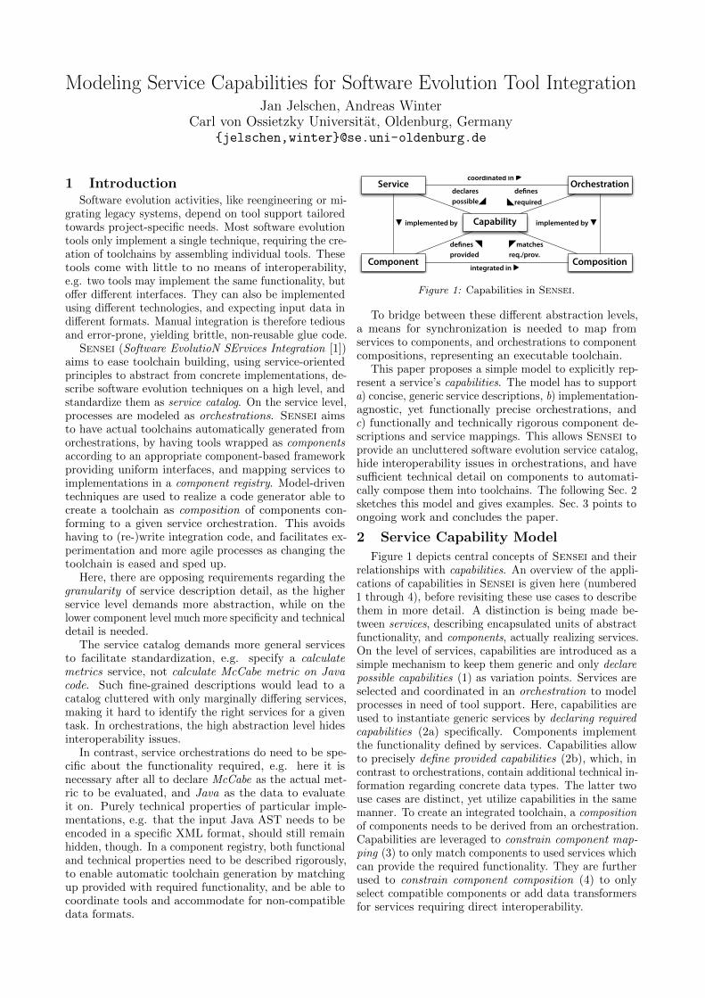
Modeling Service Capabilities for Software Evolution Tool Integration
Jan Jelschen, Andreas WinterCarl von Ossietzky Universitat, Oldenburg, Germany
{jelschen,winter}@se.uni-oldenburg.de
1 IntroductionSoftware evolution activities, like reengineering or mi-
grating legacy systems, depend on tool support tailoredtowards project-specific needs. Most software evolutiontools only implement a single technique, requiring the cre-ation of toolchains by assembling individual tools. Thesetools come with little to no means of interoperability,e.g. two tools may implement the same functionality, buto↵er di↵erent interfaces. They can also be implementedusing di↵erent technologies, and expecting input data indi↵erent formats. Manual integration is therefore tediousand error-prone, yielding brittle, non-reusable glue code.
Sensei (Software EvolutioN SErvices Integration [1])aims to ease toolchain building, using service-orientedprinciples to abstract from concrete implementations, de-scribe software evolution techniques on a high level, andstandardize them as service catalog. On the service level,processes are modeled as orchestrations. Sensei aimsto have actual toolchains automatically generated fromorchestrations, by having tools wrapped as componentsaccording to an appropriate component-based frameworkproviding uniform interfaces, and mapping services toimplementations in a component registry. Model-driventechniques are used to realize a code generator able tocreate a toolchain as composition of components con-forming to a given service orchestration. This avoidshaving to (re-)write integration code, and facilitates ex-perimentation and more agile processes as changing thetoolchain is eased and sped up.
Here, there are opposing requirements regarding thegranularity of service description detail, as the higherservice level demands more abstraction, while on thelower component level much more specificity and technicaldetail is needed.
The service catalog demands more general servicesto facilitate standardization, e.g. specify a calculatemetrics service, not calculate McCabe metric on Javacode. Such fine-grained descriptions would lead to acatalog cluttered with only marginally di↵ering services,making it hard to identify the right services for a giventask. In orchestrations, the high abstraction level hidesinteroperability issues.
In contrast, service orchestrations do need to be spe-cific about the functionality required, e.g. here it isnecessary after all to declare McCabe as the actual met-ric to be evaluated, and Java as the data to evaluateit on. Purely technical properties of particular imple-mentations, e.g. that the input Java AST needs to beencoded in a specific XML format, should still remainhidden, though. In a component registry, both functionaland technical properties need to be described rigorously,to enable automatic toolchain generation by matchingup provided with required functionality, and be able tocoordinate tools and accommodate for non-compatibledata formats.
Service Orchestration
Component Composition
Capability
coordinated in ▶
integrated in ▶
▼ implemented by implemented by ▼
defines◣required
declarespossible◢
defines ◥provided
◤matchesreq./prov.
Figure 1: Capabilities in Sensei.
To bridge between these di↵erent abstraction levels,a means for synchronization is needed to map fromservices to components, and orchestrations to componentcompositions, representing an executable toolchain.
This paper proposes a simple model to explicitly rep-resent a service’s capabilities. The model has to supporta) concise, generic service descriptions, b) implementation-agnostic, yet functionally precise orchestrations, andc) functionally and technically rigorous component de-scriptions and service mappings. This allows Sensei toprovide an uncluttered software evolution service catalog,hide interoperability issues in orchestrations, and havesu�cient technical detail on components to automati-cally compose them into toolchains. The following Sec. 2sketches this model and gives examples. Sec. 3 points toongoing work and concludes the paper.
2 Service Capability Model
Figure 1 depicts central concepts of Sensei and theirrelationships with capabilities. An overview of the appli-cations of capabilities in Sensei is given here (numbered1 through 4), before revisiting these use cases to describethem in more detail. A distinction is being made be-tween services, describing encapsulated units of abstractfunctionality, and components, actually realizing services.On the level of services, capabilities are introduced as asimple mechanism to keep them generic and only declarepossible capabilities (1) as variation points. Services areselected and coordinated in an orchestration to modelprocesses in need of tool support. Here, capabilities areused to instantiate generic services by declaring requiredcapabilities (2a) specifically. Components implementthe functionality defined by services. Capabilities allowto precisely define provided capabilities (2b), which, incontrast to orchestrations, contain additional technical in-formation regarding concrete data types. The latter twouse cases are distinct, yet utilize capabilities in the samemanner. To create an integrated toolchain, a compositionof components needs to be derived from an orchestration.Capabilities are leveraged to constrain component map-ping (3) to only match components to used services whichcan provide the required functionality. They are furtherused to constrain component composition (4) to onlyselect compatible components or add data transformersfor services requiring direct interoperability.
1 Declaring possible capabilities. Generic cata-log services use capabilities to declare variation points,establishing a domain of capabilities to choose from whenreferring to services. A distinction can be made betweenfunctional and technical capabilities. While the formerrefer to what a service can do, the latter are used mostlyonly with respect to component implementations, to spec-ify how a functionality is realized, especially with respectto used data formats. Capabilities can also restrict typesof service parameters to specific sub-types. This allowsto derive capabilities based on runtime data, and can beleveraged during toolchain generation (see Par. 3).
In the service catalog, capabilities serve to keep ituncluttered and clear-cut, which eases service selectionfor software evolution practitioners.
Example: A metric service may have two classes ofcapabilities: the programming language on which it canoperate, and the actual metrics it supports. Capabilitiesof the former class would be Java, COBOL, C, etc., andcapabilities of the latter would be McCabe, Halstead,inheritance tree depth (ITD), etc. The programminglanguage capabilities also define restrictions on the ser-vice’s data types. E.g. the Java capability would restrictthe input parameter from a generic source code datastructure to Java source code.
2 Defining required and provided capabilities.
These two use cases refer to the activities of selectingservices for a service orchestration, and registering com-ponents for service implementation, respectively. In bothcases, capabilities are chosen from the domain declaredin the service catalog to narrow a service’s functionalitydown to specific ranges. Here, the capability mecha-nism allows tool builders to accurately specify their toolsprovided functionality, and practitioners to define anddelimit functionality as required for their projects’ tasks.While the latter will mostly only be concerned withfunctional capabilities, the former also needs to specifytechnical capabilities, i.e. what concrete data types com-ponents expect as input or make available as outputresult. Technical capabilities are revisited in Par. 4.
Example: To use a metric service in an orchestra-tion, capabilities are chosen according to project needs.Assuming the project entails evaluating metrics on bothJava and COBOL code, and calculating McCabe on bothlanguages, as well as calculating inheritance tree depth(ITD) on Java only, capabilities would look like this:
✓Java
McCabe
◆,
✓COBOLMcCabe
◆,
✓JavaITD
◆.
Capabilities are used likewise to register componentsimplementing a metric service. This example assumesthere are two implementing components, JMetrics andCMetrics, with the following capabilities declared:
JMetrics :
✓Java
McCabe
◆,
✓JavaITD
◆;CMetrics :
✓COBOLMcCabe
◆.
For toolchain generation, synchronization of requiredcapabilities from orchestrated services with providedcapabilities of registered components is needed. This iscovered by the following two use cases.
3 Constraining component mapping. The in-formation provided via the previous use cases through
capabilities can be exploited to automatically find com-ponents for services used in orchestrations, by matchingrequired to provided capabilities. Since components mayimplement more than one service, each with the provi-sion of multiple capabilities, the same component can bechosen for distinct services and their required capabilities.A single orchestrated service might also be mapped todi↵erent components, each providing at least one of itsrequired capabilities.
Example: In the previous example, no single com-ponent satisfied all required capabilities. Instead, theJMetrics and CMetrics tools need to be combined tomatch all capabilities. Also, the orchestration does not(and need not) directly model when a specific capabilityshould be chosen at runtime – this information is em-bodied in data type restrictions. Using restrictions, therequired branching logic to check input data at runtimeand select a component, can be generated automatically.
This allows to automate the creation of potentiallycomplex integration logic using a constraint solver,thereby further easing the task of toolchain design.
4 Constraining component composition.
When choosing components to compose in conformancewith an orchestration, additional constraints have tobe taken into consideration, chiefly regarding concreteinput and output data types and representations.These additional constraints are expressed by technicalcapabilities in the component registry, and, if a scenariorequires using a specific data type, also in orchestrations.
Example: The metrics service’s inputs are the met-ric to be evaluated, and the data to evaluate it over. Acomponent implementing this service has to take severaldesign decisions to concretize these abstract data struc-tures. If the component has the capability to evaluatemetrics over Java ASTs, the actual Java meta-modelunderstood, and the expected data representation (e.g.XML, JSON, or a binary format) has to be specified.
Toolchain generation can leverage these constraints toeither select components with compatible data outputsand inputs for directly interoperating services, or placean appropriate transformer in between. This facilitatesreuse of data transformers through the creation of alibrary.
3 Outlook
This paper introduced the notion of capabilities in thecontext of the Sensei software evolution tool integrationapproach, to control the granularity level of service de-scriptions, and enable automatic toolchain generation.While Sensei focuses on the field of software evolution,as toolchain building is of particular importance here,the approach to tool integration is a general one.
Current work is focused on implementing a toolchaingenerator based on TGraphs and the GReTL transfor-mation language [2], solving constraints formed by capa-bilities, for automatic creation of versatile and complextoolchains based on clear and incisive orchestrations.
References
[1] J. Jelschen, “SENSEI: Software Evolution Service Integration,”in Softw. Evol. Week — Conf. Softw. Maintenance,
Reengineering, Reverse Eng. Antwerp: IEEE, Feb. 2014, pp.469—-472.
[2] J. Ebert and T. Horn, “GReTL: an extensible, operational,graph-based transformation language,” Softw. Syst. Model.,13(1), pp. 301–321, May 2012.
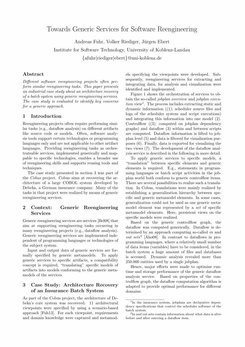
Towards Generic Services for Software Reengineering
Andreas Fuhr, Volker Riediger, Jurgen Ebert
Institute for Software Technology, University of Koblenz-Landau
{afuhr|riediger|ebert}@uni-koblenz.de
Abstract
Di↵erent software reengineering projects often per-
form similar reengineering tasks. This paper presents
an industrial case study about an architecture recovery
of a batch system using generic reengineering services.
The case study is evaluated to identify key concerns
for a generic approach.
1 Introduction
Reengineering projects often require performing simi-lar tasks (e.g., dataflow analysis) on di↵erent artifactslike source code or models. Often, software analy-sis tools support certain technologies or programminglanguages only and are not applicable to other artifactlanguages. Providing reengineering tasks as orches-trateable services, implemented generically and map-pable to specific technologies, enables a broader useof reengineering skills and supports reusing tools andtechniques.
The case study presented in section 3 was part ofthe Cobus project. Cobus aims at recovering the ar-chitecture of a large COBOL system developed byDebeka, a German insurance company. Many of thetasks in that project were realized by means of genericreengineering services.
2 Context: Generic Reengineering
Services
Generic reengineering services are services [Bel08] thataim at supporting reengineering tasks occurring inmany reengineering projects (e.g., dataflow analysis).Generic reengineering services are implemented inde-pendent of programming languages or technologies ofthe subject system.
Input and output data of generic services are for-mally specified by generic metamodels. To applygeneric services to specific artifacts, a compatibilityconcept is required, “translating” specific models ofartifacts into models conforming to the generic meta-models of the services.
3 Case Study: Architecture Recovery
of an Insurance Batch System
As part of the Cobus project, the architecture of De-beka’s core system was recovered. 11 architecturalviewpoints were specified by using a scenario-basedapproach [Fuh13]. For each viewpoint, requirementsand domain knowledge were captured and metamod-
els specifying the viewpoints were developed. Sub-sequently, reengineering services for extracting andintegrating data, for analysis and visualization wereidentified and implemented.
Figure 1 shows the orchestration of services to ob-tain the so-called jobplan overview and jobplan execu-
tion view1. The process includes extracting static anddynamic information ((1); scheduler source files andlogs of the scheduler system and script executions)and integrating this information into one model (2).Controlflow ((3); computed on jobplan dependencygraphs) and dataflow (3) within and between scriptsare computed. Dataflow information is lifted to job-plan level (5) and data is filtered for visualization pur-poses (6). Finally, data is exported for visualizing thetwo views (7). The development of the dataflow anal-ysis service is described in the following in more detail.
To apply generic services to specific models, a“translation” between specific elements and genericelements is required. E.g., statements in program-ming languages or batch script activities in the job-plan world both conform to generic controlflow items.There are several possibilities to realize such a transla-tion. In Cobus, translations were mainly realized byestablishing a generalization hierarchy between spe-cific and generic metamodel elements. In some cases,generalization could not be used as one generic meta-model element was represented by a set of specificmetamodel elements. Here, persistent views on thespecific models were realized.
Based on the generic controlflow graph, thedataflow was computed generically. Dataflow is de-termined by an approach computing so-called in andout sets
2 [Aho08]. In contrast to dataflows in pro-gramming languages, where a relatively small numberof data items (variables) have to be considered, in thebatch system a huge amount of files and databasesis accessed. Dynamic analysis revealed more than250.000 entities used by a single jobplan.
Hence, major e↵orts were made to optimize run-time and storage performance of the generic dataflowanalysis service. Based on properties of the con-trolflow graph, the dataflow computation algorithm isadapted to provide optimal performance for di↵erentdomains.
1In the insurance system, jobplans are declarative depen-dency specifications that control the scheduler software of thebatch system.
2In and out sets contain information about what data is alivebefore and after entering a dataflow item.
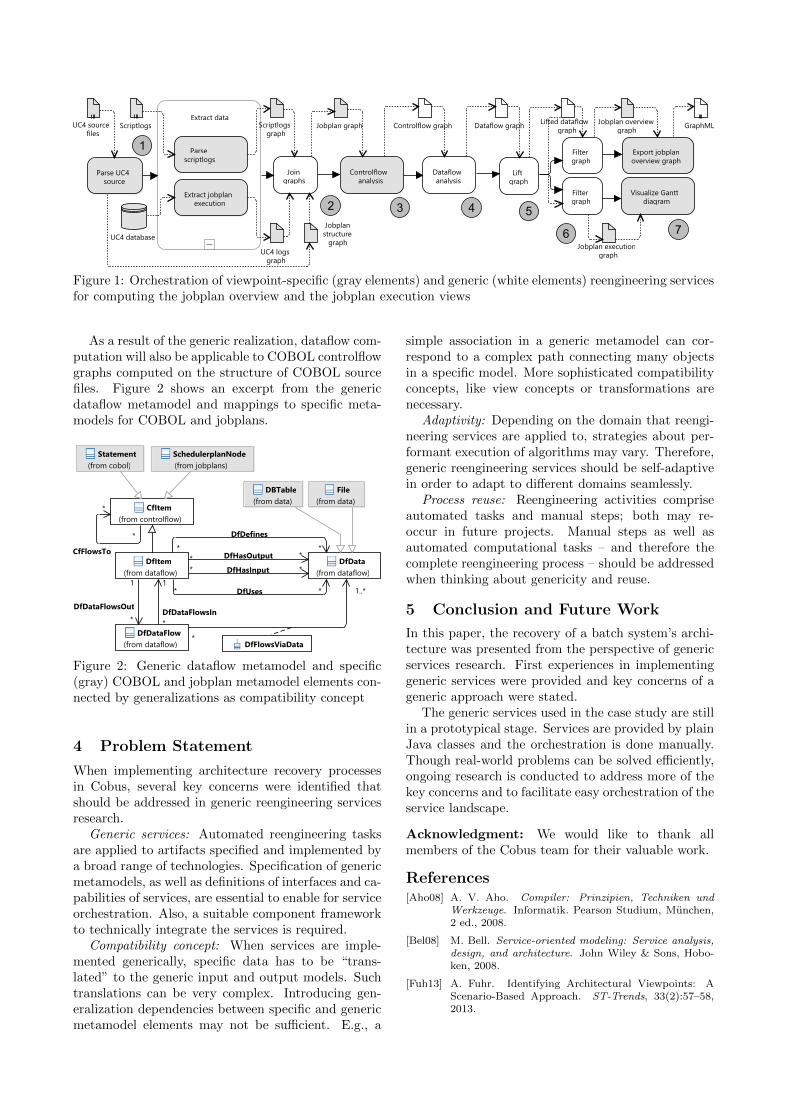
Figure 1: Orchestration of viewpoint-specific (gray elements) and generic (white elements) reengineering servicesfor computing the jobplan overview and the jobplan execution views
As a result of the generic realization, dataflow com-putation will also be applicable to COBOL controlflowgraphs computed on the structure of COBOL sourcefiles. Figure 2 shows an excerpt from the genericdataflow metamodel and mappings to specific meta-models for COBOL and jobplans.
Figure 2: Generic dataflow metamodel and specific(gray) COBOL and jobplan metamodel elements con-nected by generalizations as compatibility concept
4 Problem Statement
When implementing architecture recovery processesin Cobus, several key concerns were identified thatshould be addressed in generic reengineering servicesresearch.
Generic services: Automated reengineering tasksare applied to artifacts specified and implemented bya broad range of technologies. Specification of genericmetamodels, as well as definitions of interfaces and ca-pabilities of services, are essential to enable for serviceorchestration. Also, a suitable component frameworkto technically integrate the services is required.
Compatibility concept: When services are imple-mented generically, specific data has to be “trans-lated” to the generic input and output models. Suchtranslations can be very complex. Introducing gen-eralization dependencies between specific and genericmetamodel elements may not be su�cient. E.g., a
simple association in a generic metamodel can cor-respond to a complex path connecting many objectsin a specific model. More sophisticated compatibilityconcepts, like view concepts or transformations arenecessary.
Adaptivity: Depending on the domain that reengi-neering services are applied to, strategies about per-formant execution of algorithms may vary. Therefore,generic reengineering services should be self-adaptivein order to adapt to di↵erent domains seamlessly.
Process reuse: Reengineering activities compriseautomated tasks and manual steps; both may re-occur in future projects. Manual steps as well asautomated computational tasks – and therefore thecomplete reengineering process – should be addressedwhen thinking about genericity and reuse.
5 Conclusion and Future Work
In this paper, the recovery of a batch system’s archi-tecture was presented from the perspective of genericservices research. First experiences in implementinggeneric services were provided and key concerns of ageneric approach were stated.
The generic services used in the case study are stillin a prototypical stage. Services are provided by plainJava classes and the orchestration is done manually.Though real-world problems can be solved e�ciently,ongoing research is conducted to address more of thekey concerns and to facilitate easy orchestration of theservice landscape.
Acknowledgment: We would like to thank allmembers of the Cobus team for their valuable work.
References
[Aho08] A. V. Aho. Compiler: Prinzipien, Techniken und
Werkzeuge. Informatik. Pearson Studium, Munchen,2 ed., 2008.
[Bel08] M. Bell. Service-oriented modeling: Service analysis,
design, and architecture. John Wiley & Sons, Hobo-ken, 2008.
[Fuh13] A. Fuhr. Identifying Architectural Viewpoints: AScenario-Based Approach. ST-Trends, 33(2):57–58,2013.

103 104 105 1060
100
200
300
n
[Byte
Nodes]
103 104 105 10610−2
100
102
n
[secon
d]
Copyright © 2022 FDOKUMEN