Equestrian Demand and Dealers: The Early Indian Scenario ( up to c. 1300)
Upload
khangminh22Category
view
1download
0
FG-1300FIBER OPTIC SENSOR AMPLIFIER
Instruction Manual
ONO SOKKI CO., LTD.

■ Warranty ■1. This product is covered by a warranty for a period of one year from the date of purchase.
2. This warranty covers free-of-charge repair for defects judged to be the responsibility of the manufac-turer, i.e., defects occurred while the product is used under normal operating conditions according to descriptions in this manual and notices on the unit label.
3. For free-of-charge repair, contact either your sales representative or our sales office nearby.
4. The following failures will be handled on a fee basis even during the warranty period.(a) Failures occurring through misuse, mis-operation, or modification(b) Failures occurring through mishandling (dropping) or transportation(c) Failures occurring through natural calamities (fires, earthquakes, flooding, and lightening), environmental
disruption, or abnormal voltage.
* For repairs after the warranty period expired, contact your sales representative or our sales office nearby.
1. This document may not be reproduced, in whole or part, in any form or by any means without the prior written permission of the publisher.
2. The contents of this document are subject to change without notice.3. This document has been produced based on a series of strict verifications and inspections.
Should a failure occur nonetheless, please inform our sales representative or sales office.4. Ono Sokki shall have no liability for any effect resulting from any operation, whether or not the
effect is attributable to a defect in the documentation. Copyright © ONO SOKKI CO., LTD. 2015 All rights reserved.
*Outer appearance and specifications are subject to change without prior notice.HOME PAGE: http://www.onosokki.co.jp/English/english.htm
WORLDWIDE ONO SOKKI CO., LTD.1-16-1 Hakusan, Midori-ku, Yokohama 226-8507, JapanPhone : +81-45-935-3918 / Fax : +81-45-930-1808E-mail : [email protected]

1
FG-1300 Fiber Optic Detector
IntroductionThank you for purchasing the FG-1300 Fiber Optic Detector .
This instruction manual describes the functions, specifi cations, connecting method and precau-tions on the FG-1300 Fiber Optic Detector.
To ensure proper use of the FG-1300 Fiber Optic Detector, be sure to read this manual before using the product.
This manual contains some precautions which, if ignored, could cause property damage. In han-dling the product, make sure to follow the instructions described in this manual.
Please keep this manual in a safe place after reading and refer to it whenever you feel uncertain of handling and operating this product.
• The contents of this document are subject to change in future editions without prior notice.
• No part of the contents of this document may be reprinted or reproduced without authoriza-tion.
• While the contents of this document have been prepared in our best eff orts for perfection, should there be any unclear point, error, or any other questionable point, please advise us of them.
• Please be advised that we should not be responsible for results of your operation, regard-less of the preceding paragraph.
• All corporate names and product names used herein are either trade names or registered trade names of their respective holders.
2
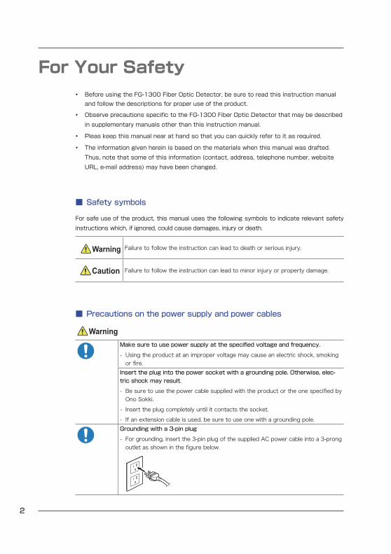
For Your Safety• Before using the FG-1300 Fiber Optic Detector, be sure to read this instruction manual and follow the descriptions for proper use of the product.
• Observe precautions specifi c to the FG-1300 Fiber Optic Detector that may be described in supplementary manuals other than this instruction manual.
• Pleas keep this manual near at hand so that you can quickly refer to it as required.
• The information given herein is based on the materials when this manual was drafted. Thus, note that some of this information (contact, address, telephone number, website URL, e-mail address) may have been changed.
■ Safety symbols
For safe use of the product, this manual uses the following symbols to indicate relevant safety instructions which, if ignored, could cause damages, injury or death.
Warning Failure to follow the instruction can lead to death or serious injury.
Caution Failure to follow the instruction can lead to minor injury or property damage.
■ Precautions on the power supply and power cables
WarningMake sure to use power supply at the specifi ed voltage and frequency.
• Using the product at an improper voltage may cause an electric shock, smoking or fi re.
Insert the plug into the power socket with a grounding pole. Otherwise, elec-tric shock may result.
• Be sure to use the power cable supplied with the product or the one specifi ed by Ono Sokki.
• Insert the plug completely until it contacts the socket.• If an extension cable is used, be sure to use one with a grounding pole.Grounding with a 3-pin plug
• For grounding, insert the 3-pin plug of the supplied AC power cable into a 3-prong outlet as shown in the fi gure below.

3
FG-1300 Fiber Optic Detector
Avoid connecting the plug to a not grounded outlet. Otherwise, electric shock may result.
• Do not use 3-prong to 2-prong adapter.If any foreign object or water enters inside of the product, immediately discon-nect the power plug.
• Using the product under such condition may cause fi re or electric shock.When the product is not used for a long time, remove the plug from the outlet.• Failure to do so gives rise to a risk of electric leakage fi re due to degraded insula-tion.
■ General precautions
Warning
Never disassemble or overhaul the FG-1300 Fiber Optic Detector.
• It could cause a failure or electric shock.• When it is necessary to make internal adjustments, inspection or repair of the product, contact the nearest Ono Sokki sales offi ce or the distributor where you purchased the product.Do not splash or spill water on the FG-1300 Fiber Optic Detector.
• Otherwise, a fi re or electric shock due to short circuit may occur.
Do not look at the light source of the fi ber optic sensor with your bare eyes.
• Otherwise, it could cause you an eye defi ciency.
Do not use the product for detecting human body.
• The FG-1300 Fiber Optic Detector is not designed to serve for detecting human body.
Caution
Do not install the product in an unstable place.
• Otherwise, the product may drop or fall, and thus may cause an injury.Do not put any large or heavy item on the product.
• The item placed on the product may drop, causing an injury.Do not install the product in locations where there is oily smoke, steam, high humidity, or a lot of dust.
• It may cause a fi re or electric shock.

4
CONTENTS
Introduction - - - - - - - - - - - - - - - - - - - - - - - - - - - - - - - - - - - - 1
For Your Safety - - - - - - - - - - - - - - - - - - - - - - - - - - - - - - - - - - 2
1. Overview of the FG-1300 Fiber Optic Detector - - - - - - - - - - - - - - - 5
1.1 Overview and Features of the FG-1300 Fiber Optic Detector - - - - - - - 5
1.2 Checking Supplied Items - - - - - - - - - - - - - - - - - - 6
2. Component Names and Functions - - - - - - - - - - - - - - - - - - - - - - 7
2.1 Front Panel - - - - - - - - - - - - - - - - - - - - - - 7
2.2 Rear Panel - - - - - - - - - - - - - - - - - - - - - - 9
3. Preparation and Operation of the FG-1300 Fiber Optic Detector - - - - - 11
3.1 Pre-operational Checks and Precautions - - - - - - - - - - - - -11
3.2 Preparations for Operation- - - - - - - - - - - - - - - - - -12
3.3 Fiber Optic Sensor Installation - - - - - - - - - - - - - - - -14
3.4 Adjustment for Operation - - - - - - - - - - - - - - - - - -16
4. Specifi cations - - - - - - - - - - - - - - - - - - - - - - - - - - - - - - - -18
4.1 Input Section- - - - - - - - - - - - - - - - - - - - - -18
4.2 Output Section (MONITOR/PULSE OUT) - - - - - - - - - - - - -18
4.3 General Specifi cations - - - - - - - - - - - - - - - - - - -18
5. External Dimensions - - - - - - - - - - - - - - - - - - - - - - - - - - - - -20
5.1 External Dimension of the FG-1300 Fiber Optic Detector - - - - - - - 20
6. Appendix - - - - - - - - - - - - - - - - - - - - - - - - - - - - - - - - - -22
6.1 Specifi cations of the FS-540 Fiber Optic Sensor - - - - - - - - - - 22
6.2 External Dimensions of the FS-540 Fiber Optic Sensor (Optional) - - - - - 23

5
Overview of the FG-1300 Fiber Optic Detector
FG-1300 Fiber Optic Detector
1. Overview of the FG-1300 Fiber Optic Detector
1.1 Overview and Features of the FG-1300 Fiber Optic DetectorCombined with a optical fi ber sensor, the FG-1300 Fiber Optic Detector projects visible light to the measured object through the optical fi ber, and receives the refl ected light coming back through the optical fi ber, thus detecting the variation in refl ected light intensity.
This product is an eff ective device to measure and detect the rotation of thin objects such as a motor rotation shaft or the rotation of objects to be measured from a distance.
■ Features
□ The pulsed lighting system employed in the device inhibits the noise of ambient light.
□ High sensitivity to minimal variation in light intensity.
□ Compact and light-weight design facilitating the installation and handling.
□ Automatic adjustment of threshold level is feasible.
□ Pulse dividing function enables the frequency division ranging from 1 to 10.
□ Detection distance adjusting function allows the detection from a proximity of 10 mm to a distance of 44 to 69 mm (when the refl ection mark supplied with the fi ber optic sensor is pasted).

6
Overview of the FG-1300 Fiber Optic Detector
1.2 Checking Supplied ItemsThe delivered package contains accessories besides the FG-1300 Fiber Optic Detector. Using the following list of items, check and ensure that all of the items are included in the package.
If any item is missing or damaged, immediately contact the nearest Ono Sokki sales offi ce or the distributor where you purchased the product.
① ② ③
LA-1440LA-4440
■ List of supplied items
Number Item Quantity
① Power cable 1
② Instruction manual (this document) 1
③ Rubber pod 4
• The delivered package does not include a fi ber optic sensor or panel mounting hardware, which should be purchased separately. For the purchase of these items, please contact nearest Ono Sokki sales offi ce or distributor.

7
Component Names and Functions
FG-1300 Fiber Optic Detector
2. Component Names and Functions
2.1 Front Panel
⑥
②① ③ ④
⑤ ⑦ ⑧
① POWERPower supply indicator.
Lit while the power is turned ON.
② SIGNALSignal indicator.
Lit when the intensity of refl ected light exceeds the preset threshold.
③ DIV ONFrequency division indicator. Lit while the frequency dividing function is enabled.

8
Component Names and Functions
Lit when a division ratio is set (when the division ratio is set to 0 or any value from 2 to 9 with the DIV SET switch on the rear panel).
④ AUTO/MANUAL switchUsed for switching between the automatic setting (AUTO) and manual setting (MANUAL) of a THRESHOLD level.
The automatic setting is performed at approximately 50% of a signal amplitude (peak value). The operational voltage range is 1 V or more.
In the MANUAL setting, you can adjust the pulsating level with the THRESHOLD control knob.
• Since a time constant is involved in the automatic threshold setting, it takes approximately 1 second to stabilize the amplifi er operation after the fi rst signal is input. In such a case, use the amplifi er in the manual threshold setting (MANUAL) mode. (ex.: If the motor is started from a stopped state, it will take 1 second before the amplifi er starts to operate properly.)
⑤ SENSOR connectorConnect a fi ber optic sensor to the connector.
⑥ LEVEL indicatorIndicates the intensity of refl ected light.
⑦ GAIN control knobAdjusts the gain according to the detected light intensity.
Used for setting an optimum signal level by adjusting the GAIN control knob while monitoring the refl ected light intensity displayed on the LEVEL indicator ( ⑥ ).
⑧ THRESHOLD control knobUsed for THRESHOLD level setting that is enabled when THRESHOLD level (④) is switched to manual setting (MANUAL) mode.
Adjust the THRESHOLD level to obtain a stabilized pulse signal while monitoring the SIGNAL indicator ( ② ).

9
Component Names and Functions
FG-1300 Fiber Optic Detector
2.2 Rear Panel
⑬⑪⑩ ⑫⑨
⑭
⑨ MONITORConnector to acquire an analog output according to the refl ected light intensity.
⑩ PULSE OUTThis is a pulse output connector for pulsed outputs of the variation in refl ected light intensity at a preset THRESHOLD level.

10
Component Names and Functions
⑪ DIV SET (division ratio setting switch)This switch allows you to set the division ratio (range: 1 to 10) of output pulse count corre-sponding to input signal.
To select a setting value, turn the rotary switch using a fl at-head screwdriver.
For setting the division ratio to 10, select 0. Its output width will be the same as that of divi-sion ratio 1, regardless of the division ratio selected.
Nevertheless, it is delayed by the minimum pulse width in the falling edge as follows:
PULSE WOFF 10 μ sON 160 μ s
<Division ratio>
Division ratioDIV SET (division ratio setting
switch)DIV ON (division indicator)
1 1 OFF2 to 9 2 to 9 ON10 0 ON
⑫ FUNCTION (bit switch)Switching the bit switch to ON or OFF validates the setting of each of the following functions.
Use a fl at-head screwdriver to turn on and off the bit switch.
<Set functions>
Item FunctionInitial setting
RANGE
Switching the detection distance (between the fi ber optic sensor and the measured object) OFFON Proximate (10 mm), when a refl ection mark is usedOFF Normal (44 to 69 mm), when the refl ection mark is used
PULSE WSwitching the minimum width of output pulse
OFFON 160 μ sOFF 10 μ s
HOLD TIME
Switching the following capability after the THRESHOLD level is switched to AUTO setting mode OFFON 10 seconds (when the speed is constant or fl uctuates slow)OFF 1 second (when the speed fl uctuates sharply)
LPF
Determining the responsiveness of MONITOR or switching the cut-off frequency of low path fi lter OFFON fc = 72 HzOFF fc = 14 kHz
⑬ POWER switchPower supply switch to the FG-1300 Fiber Optic Detector.
⑭ AC inletThis is a connector for power supply.
Be sure to use the power cable supplied together with the product.

11
Preparation and Operation of the FG-1300 Fiber Optic Detector
FG-1300 Fiber Optic Detector
3. Preparation and Operation of the FG-1300 Fiber Optic DetectorSet up the FG-1300 Fiber Optic Detector in the order beginning with connecting the cables and devices, attaching the fi ber optic sensor and adjusting the product for measurement as de-scribed below. This chapter describes the operation procedure in the case of using the FS-540 fi ber optic sensor. When using another type of fi ber optic sensor, refer to the instruction manual supplied with the fi ber optic sensor to be used.
3.1 Pre-operational Checks and PrecautionsThe following describes the items to be checked and precautions that should be observed be-fore using the FG-1300 Fiber Optic Detector. See “For Your Safety” on page 2 before handling the product.
● Precautions against sunlight
CautionAvoid using the product and measurement under direct sunlight.
• Note that direct sunlight may be adversely aff ect the measurement with the fi ber optic sensor.
● Precautions for electric appliances (such as remote control)
Do not operate the remote control for home appliances such as TV, DVD player or the like by directing it to the FG-1300 Fiber Optic Detector. Otherwise, the remote control may adversely aff ect the FG-1300 Fiber Optic Detector, resulting in a malfunction.
CautionAvoid using the FG-1300 Fiber Optic Detector near infrared remote controls of elec-tric appliances.
• Otherwise, it could impairs the remote control function.
● Precautions for using the FS-540 fi ber optic sensor
WarningDo not use the product for detecting human body.
• The FG-1300 Fiber Optic Detector is not designed to serve for detecting human body.
Do not look at the light source of the fi ber optic sensor with your bare eyes.
• Otherwise, it could cause you an eye defi ciency.

12
Preparation and Operation of the FG-1300 Fiber Optic Detector
3.2 Preparations for OperationComplete the connection of a fi ber optic sensor and power cable to the FG-1300 Fiber Optic Detector in the following procedure:
Measured object (e.g. motor)
100 VAC, 50/60 Hz
③-2①
②-1②-2 ④
③-1 OFF
⑤ON
FT-2500 advanced tachometerCF-9400 FFT analyzer
TM-3100 digital tachometer
FS-540 fiber optic sensor
Supplied power cable
① Connect the FG-1300 Fiber Optic Detector with the FS-540 fi ber optic sensor.Connect the FS-540 fi ber optic sensor to the sensor connector on the front panel of the sen-sor amplifi er.
Since the FS-540 fi ber optic sensor consists of fi ne glass fi bers, and thus stretching the fi bers with violent forces or bending them at a sharp angle will result in fi ber breakage.
When bending the FS-540 fi ber optic sensor, allow a radius of at least 50 mm.

13
Preparation and Operation of the FG-1300 Fiber Optic Detector
FG-1300 Fiber Optic Detector
② Connect peripheral devices that suit intended usage or purpose to the FG-1300 Fiber Optic Detector.
Connect peripheral devices appropriate to intended measurement to the MONITOR and PULSE OUT connectors on the rear panel of the FG-1300 Fiber Optic Detector.
For example, connect the Ono Sokki FT-2500 Advanced Tachometer that is eff ective for measuring a rotational speed to the MONITOR (analog output) connector.
Likewise, connect the PULSE OUT (pulse output) connector to the trigger signal input termi-nal of an TM-3100 series tachometer and an FFT analyzer such as CF-9400 model.
• For details of peripheral devices and their confi guration appropriate to your intended usage and purposes, contact the nearest Ono Sokki sales offi ce or distributor.
③ Connect the power cable to the FG-1300 Fiber Optic DetectorFirst, turn the POWER switch to OFF.
Then, connect the supplied power cable to the AC inlet on the rear panel of the amplifi er.
Warning Be sure to use a 3-pin plug and outlet.Make sure to use the power cable and plug that are specifi ed or sup-plied with the product.Precautions for using at over 125 VAC
• When using the product at over 125 VAC, be sure to use the specifi ed power cable provided as an optional item. (For the details, contact the nearest Ono Sokki sales offi ce or the distributor where you purchased the product.)
④ Set the detector end of the FS-540 fi ber optic sensor against the measured object and confi gure the service conditions.
When the detection distance is 10 mm, set the RANGE bit switch (in FUNCTION) to ON on the rear panel of the product.
Set the frequency dividing conditions of PULSE OUT by using the DIV SET (division ratio set-ting) switch on the rear panel.
For details of the FS-540 fi ber optic sensor, see “3.3 Fiber Optic Sensor Installation” on page 14 on the following page.
⑤ Turn on the power to the FG-1300 Fiber Optic Detector.Finally, turn the POWER switch to ON on the rear panel of the product.

14
Preparation and Operation of the FG-1300 Fiber Optic Detector
3.3 Fiber Optic Sensor InstallationThe following describes the installation procedure of the FS-540 fi ber optic sensor.
When using another type of fi ber optic sensor, refer to the instruction manual supplied with the fi ber optic sensor to be used.
■ Precautions for handling the FS-540 fi ber optic sensor
Before using the FS-540 fi ber optic sensor, pay attention to the following:
• Since the FS-540 fi ber optic sensor consists of fi ne glass fi bers, and thus stretching the fi bers with violent forces or bending them at a sharp angle will result in fi ber breakage.
• When bending the FS-540 fi ber optic sensor, allow a radius of at least 50 mm.
■ Detection with the refl ection mark
As illustrated below, pasting a dedicated refl ection tape on the spindle allow the device to per-form detection from a distance of 44 to 69 mm away.
Angle bracket (separately prepared)
Reflection mark (supplied with FS-540)
Rotating shaft
Mounting nut (supplied with FS-540)
44 to 69 mm
FS-540
■ Detection using the keyway
Rotation of a concave part such as a keyway can be detected at a distance of 7 to 14 mm away.
Angle bracket (separately prepared)
Rotating shaft keyway Mounting nut (supplied with FS-540)
7 to 14 mm
FS-540

15
Preparation and Operation of the FG-1300 Fiber Optic Detector
FG-1300 Fiber Optic Detector
■ Detection using a keyway and D-cut face
The following illustrates an example of set-up for the detection using a keyway and D-cut face.
Angle bracket (separately prepared)
Mounting nut (supplied with FS-540)
FS-540

16
Preparation and Operation of the FG-1300 Fiber Optic Detector
3.4 Adjustment for OperationAfter completing the connection and installation of FS-540 fi ber optic sensor, perform the ad-justment of FG-1300 Fiber Optic Detector in the following procedure:
The control knobs, switches and indicator used for adjustment are shown below. For the details, see “2. Component Names and Functions” on page 7.
• AUTO/MANUAL switch
• FUNCTION bit switch
Measured object (e.g. motor)
FS-540 fiber optic sensor
• THRESHOLD control knob
• GAIN control knob
• LEVEL indicator
1 Adjust the FG-1300 Fiber Optic Detector to detect the desired signal from the measured object.
Adjust the GAIN control knob while monitoring the LEVEL indicator.
The desired signal from the measured object can be detected when three or more segments of the LEVEL indicator are lit with the refl ection mark in light.
2 Adjust the THRESHOLD control knob.When the AUTO/MANUAL switch is set to MANUAL, adjust the THRESHOLD control knob so that the SIGNAL will fl ash constantly.

17
Preparation and Operation of the FG-1300 Fiber Optic Detector
FG-1300 Fiber Optic Detector
When the AUTO/MANUAL switch is set to AUTO, the THRESHOLD level is automatically set to approximately 50% of the signal amplitude (peak value).
3 Set up the HOLD TIME and PULSE W.When the rotation speed is low (over 1 second per cycle), set the HOLD TIME bit switch to ON in the FUNCTION on the rear panel.
When synchronizing with a rotating object, use the rising edge of a pulse. In a falling edge, a delay of 10 μ s or 160 μs may occur.
To adjust the minimum pulse width to 160 μs, set the PULSE W bit switch in the FUNCTION on the rear panel.
4 Adjust the GAIN control knob to use the analog output from the MONITOR connector.For using analog signal, adjust the GAIN control knob while checking the output from the MONITOR connector with the digital voltmeter.
Set the LPF bit switch in FUNCTION according to the responsiveness of output signal from the MONITOR connector.
OFF : High speed (fc = 14 kHz)ON : Low speed (fc = 72 Hz)
■ Relationships between refl ected light intensity and signal output
Voltage ↑
*
→ Time
→ Time
→ Time
→ Time
Analog output
Preset level
Hi
Lo
MONITOR (analog output)
PULSE OUT (pulse output)
PULSE W OFF: 10μs
ON: 160μs
*: The output delays by the minimum pluse width in the falling edge.
Ref
lect
ed
light
inte
rsity
→
Vol
tage
→
Leve
l →

18
Specifi cations
4. Specifi cations
4.1 Input SectionCompatible sensor FS-540 fi ber optic sensorInput/output detection element PhototransistorResponse frequency range 0 to 10 kHzInput connector Integrated light projection/reception connector (exclusive)Light source Pulse-lighting red LED
4.2 Output Section (MONITOR/PULSE OUT)Output signal Analog and pulse outputsMONITOR Analog output Voltage in proportion to refl ected light intensity
Output voltage range 0 to 10 VOutput connector C02 (BNC)Output impedance 50 Ω or less
PULSE OUT Pulse Output Digitizes the refl ected light intensity and outputs at Hi and Lo levels
Output format TTL (Hi: 4.5 V, min.; low: 0.5 V, max.)Output connector C02 (BNC)
LEVEL indicator Light intensity monitor (interlocked with the MONITOR output)
Caution • Precaution for isolationBe aware that the signal ground is at the same potential as that of the enclosure.
4.3 General Specifi cationsWithstand voltage 1500 VAC (1 minute)Dielectric resistance 10 MΩ or more (500 VDC)Resistance to vibration Vibrational acceleration 9.8 m/s²
Frequency range 10 to 150 Hz, sinusoidal vibra-tion
Vibration applying direction and number of cycles
20 cycles each in the X, Y and Z directions (for approx. 150 minutes)

19
Specifi cations
FG-1300 Fiber Optic Detector
Shock resistance Impact acceleration 147 m/s²Duration 11 msImpact applying direction and number of applying times
3 times in each of ± X, ± Y and ± Z directions
Power 100 to 240 VAC (50/60 Hz)Power consumption 100 VAC: 10 VA or less
240 VAC: 15 VA or lessOperating temperature range 0 to +40°CRelative humidity range for operation 5 to 80% RH (no condensation allowed)Storage temperature range -10 to +50°CRelative humidity range for storage 5 to 80% RH (no condensation allowed)Mass Approx. 1 kgExternal dimensions 144 (W) × 72 (H) × 180 (D) mm (no protrusion included)
■ Conforming standards
CE marking LVD Directive 2006/95/EC
Standard EN61010-1EMC Dirtective 2004/108/EC
Standard EN61326-1RoHS Directive 2011/65/EU
Standard EN50581FCC CFR47 Part15 Subpart B
Note: This equipment has been tested and found to comply with the limits for a Class A digital device, pursuant to part 15 of the FCC Rules. These limits are designed to provide reasonable protection against harmful interference when the equipment is operated in a commercial environment. This equipment generates, uses, and can radiate radio frequency energy and, if not installed and used in accordance with the instruction manual, may cause harmful interference to radio communications. Opera-tion of this equipment in a residential area is likely to cause harmful interference in which case the user will be required to correct the interference at his own expense.
• For details, see: http://www.onosokki.co.jp/English/english.htm
■ Accessories
Instruction manual 1Power cable 1Rubber pod 4
■ Optional
Panel mounting hardware
Stand

20
External Dimensions
5. External Dimensions
5.1 External Dimension of the FG-1300 Fiber Optic De-tector
Rear view
When the stand is mounted

21
External Dimensions
FG-1300 Fiber Optic Detector
Panel cutout dimensions
Panel mounting hardware (optional)
Rubber pod (supplied)
Stand (optional)

22
Appendix
6. Appendix
6.1 Specifi cations of the FS-540 Fiber Optic SensorFiber optic sensor Length (standard specifi cations) 1 m
Fiber diameter 4 mmScrew M8 × 1.0
Detection distance Adjustable within the following approximate values by the gain adjustmentRefl ecting object (contrast type) Detection distance (mm)When the glossy spindle is coated with a matt-fi nished black enamel
7 to 14
When the dedicated refl ection mark (12 mm square) is attached to the spindle
44 to 69
Operating temperature range
-10°C to +70°C

23
Appendix
FG-1300 Fiber Optic Detector
6.2 External Dimensions of the FS-540 Fiber Optic Sensor (Optional)
Mounting nut × 2
M8 × 1
Fiber dimensions
φ10
φ4
1000
75
50
Connector
Spread angle: approx. 20°

24
External Dimensions


B00002423/IM14091701 (1.1)
*Outer appearance and specifications are subject to change without prior notice.HOME PAGE: http://www.onosokki.co.jp/English/english.htm
WORLDWIDEONO SOKKI CO., LTD.1-16-1 Hakusan, Midori-ku,Yokohama 226-8507, JapanPhone : +81-45-935-3918Fax : +81-45-930-1808E-mail : [email protected]
Copyright © 2022 FDOKUMEN