Cooperative Pair Driven Quenching of Yb 3+ Emission in Nanocrystalline ZrO 2 :Yb 3
15
Cooperative Pair Driven Quenching of Yb 3+ Emission in Nanocrystalline ZrO 2 :Yb 3+ O. Meza 1 , L.A. Diaz-Torres 1,a , P. Salas 2 , E. De la Rosa 1 , C. Angeles-Chavez 3 , and D. Solis 1 1 Centro de Investigaciones en Optica A.C., Leon, Gto. 37150 Mexico. 2 Centro de Física Aplicada y Tecnología Avanzada, Universidad Nacional Autónoma de México, Querétaro 76000, México 3 Instituto Mexicano del Petróleo, Cd. México D.F.,07730 Mexico. a [email protected] (corresponding author) Received: January 29th, 2008; Revised: June 8th, 2008; Accepted: July 14th, 2008 Keywords: Cooperative Upconversion, Nanocrystals, Ytterbium, Zirconium Oxide Abstract. The concentration luminescence quenching of the NIR emission of Yb 3+ in nanocrystalline ZrO 2 is studied. It is found that the quenching is dominated by cooperative energy transfer processes from isolated Yb 3+ ions to Yb-Yb pairs (Yb dimers). The Yb dimer concentration depends on the crystallite phase and size, which on time depends on Yb concentration. An extended energy transfer model was developed to predict the IR and cooperative visible fluorescence emissions by taking in to account the crystalline phase, the nanocrystals size, and the geometrical construction of Yb dimers. Our model succeeds to fit simultaneously both experimental VIS and NIR emissions, and the corresponding interaction parameters are reported. Introduction Trivalent ytterbium (Yb 3+ ) ion introduced in various transparent hosts is considered as a laser ion of big prospect for construction of efficient, low heat, diode laser pumped solid-state lasers in the 1 m range. Trivalent Ytterbium is one of the most versatile laser ions employed in solid state laser hosts [1] and has been considered a good dopant ion to investigate cooperative transitions [2,3]. It has several very attractive features, in particular an unusually broad absorption band, for the ground state transition 2 F 7/2 → 2 F 5/2 , that stretches from below 850 nm to above 1070 nm. Another well- known advantage of Yb 3+ is the simplicity of its energy level diagram. Yb 3+ exhibits only a ground state ( 2 F 7/2 ) and a metastable state ( 2 F 5/2 ) spaced by approximately 10,000cm -1 . This very simple energy level structure in principle prevents the existence of several de-excitation processes that could affect the dynamics of populations of the energy levels as in other rare earth laser ions with more complex electronic structure, such as the excited state absorption, cross-relaxation, or upconversion inside the system of active ions. The special electronic configuration of Yb 3+ makes the 4f electrons less shielded than in other ions of the lanthanide series, showing higher tendency to interact with neighbor ions. Such interaction is not restricted to different ion. It has been reported that Yb-Yb pair (dimer molecule) interaction produce visible emission [4-9]. Such emission is named cooperative upconversion (CUC) and was first observed by Nakazawa in YbPO 4 [5]. In this case, two excited Yb 3+ ions decay simultaneously to the ground state, with the subsequent emission of a visible photon with the double of energy. The sense of “dimer molecule” instead of the isolated two-ion model of Nakazawa was first considered by Hehlen and Güdel, who used the notation Yb 2 Br 2 3+ in the Cs 3 Yb 2 Br 9 crystal to describe the so called dimmer [6]. Their experimental work covered not only the well-studied cooperative emission transitions but also the absorption ( 2 F 7/2 , 2 F 7/2 ) →( 2 F 5/2 , 2 F 5/2 ) ones too, and the cooperative transition probabilities were estimated. One important figure of the Yb-Yb dimer is that it is considered to have three energy levels, see Fig. 1a, being the upper level ( 2 F 5/2 , 2 F 5/2 ) the one responsible of the so called CUC emission. The Journal of Nano Research Vol. 5 (2009) pp 121-134 online at http://www.scientific.net © (2009) Trans Tech Publications, Switzerland Online available since 2009/Feb/06 All rights reserved. No part of contents of this paper may be reproduced or transmitted in any form or by any means without the written permission of the publisher: Trans Tech Publications Ltd, Switzerland, www.ttp.net. (ID: 187.142.20.64-22/03/09,19:36:34)
-
Upload
independent -
Category
Documents
-
view
1 -
download
0
Transcript of Cooperative Pair Driven Quenching of Yb 3+ Emission in Nanocrystalline ZrO 2 :Yb 3

Cooperative Pair Driven Quenching of Yb3+ Emission in Nanocrystalline ZrO2:Yb3+
O. Meza1, L.A. Diaz-Torres1,a, P. Salas2, E. De la Rosa1, C. Angeles-Chavez3, and D. Solis1
1Centro de Investigaciones en Optica A.C., Leon, Gto. 37150 Mexico.
2Centro de Física Aplicada y Tecnología Avanzada, Universidad Nacional Autónoma de México, Querétaro 76000, México
3Instituto Mexicano del Petróleo, Cd. México D.F.,07730 Mexico. [email protected] (corresponding author)
Received: January 29th, 2008; Revised: June 8th, 2008; Accepted: July 14th, 2008
Keywords: Cooperative Upconversion, Nanocrystals, Ytterbium, Zirconium Oxide
Abstract. The concentration luminescence quenching of the NIR emission of Yb3+
in
nanocrystalline ZrO2 is studied. It is found that the quenching is dominated by cooperative energy
transfer processes from isolated Yb3+
ions to Yb-Yb pairs (Yb dimers). The Yb dimer concentration
depends on the crystallite phase and size, which on time depends on Yb concentration. An extended
energy transfer model was developed to predict the IR and cooperative visible fluorescence
emissions by taking in to account the crystalline phase, the nanocrystals size, and the geometrical
construction of Yb dimers. Our model succeeds to fit simultaneously both experimental VIS and
NIR emissions, and the corresponding interaction parameters are reported.
Introduction
Trivalent ytterbium (Yb3+
) ion introduced in various transparent hosts is considered as a laser ion of
big prospect for construction of efficient, low heat, diode laser pumped solid-state lasers in the 1
m range. Trivalent Ytterbium is one of the most versatile laser ions employed in solid state laser
hosts [1] and has been considered a good dopant ion to investigate cooperative transitions [2,3]. It
has several very attractive features, in particular an unusually broad absorption band, for the ground
state transition 2F7/2→
2F5/2, that stretches from below 850 nm to above 1070 nm. Another well-
known advantage of Yb3+
is the simplicity of its energy level diagram. Yb3+
exhibits only a ground
state (2F7/2) and a metastable state (
2F5/2) spaced by approximately 10,000cm
-1. This very simple
energy level structure in principle prevents the existence of several de-excitation processes that
could affect the dynamics of populations of the energy levels as in other rare earth laser ions with
more complex electronic structure, such as the excited state absorption, cross-relaxation, or
upconversion inside the system of active ions. The special electronic configuration of Yb3+
makes
the 4f electrons less shielded than in other ions of the lanthanide series, showing higher tendency to
interact with neighbor ions. Such interaction is not restricted to different ion. It has been reported
that Yb-Yb pair (dimer molecule) interaction produce visible emission [4-9]. Such emission is
named cooperative upconversion (CUC) and was first observed by Nakazawa in YbPO4 [5]. In this
case, two excited Yb3+
ions decay simultaneously to the ground state, with the subsequent emission
of a visible photon with the double of energy. The sense of “dimer molecule” instead of the isolated
two-ion model of Nakazawa was first considered by Hehlen and Güdel, who used the notation
Yb2Br23+
in the Cs3Yb2Br9 crystal to describe the so called dimmer [6]. Their experimental work
covered not only the well-studied cooperative emission transitions but also the absorption
(2F7/2,
2F7/2) →(
2F5/2,
2F5/2)
ones too, and the cooperative transition probabilities were estimated. One
important figure of the Yb-Yb dimer is that it is considered to have three energy levels, see Fig. 1a,
being the upper level (2F5/2,
2F5/2) the one responsible of the so called CUC emission. The
Journal of Nano Research Vol. 5 (2009) pp 121-134online at http://www.scientific.net© (2009) Trans Tech Publications, SwitzerlandOnline available since 2009/Feb/06
All rights reserved. No part of contents of this paper may be reproduced or transmitted in any form or by any means without the written permission of thepublisher: Trans Tech Publications Ltd, Switzerland, www.ttp.net. (ID: 187.142.20.64-22/03/09,19:36:34)
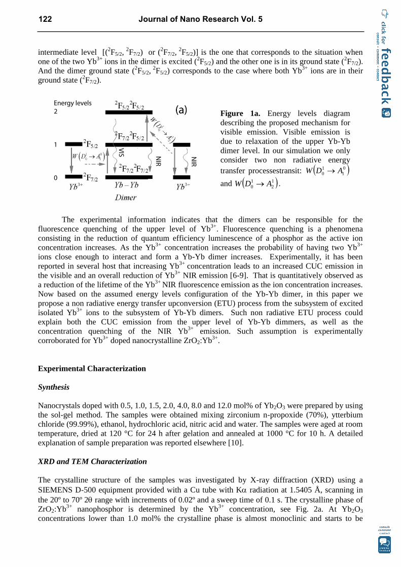
intermediate level [(2F5/2,
2F7/2) or (
2F7/2,
2F5/2)] is the one that corresponds to the situation when
one of the two Yb3+
ions in the dimer is excited (2F5/2) and the other one is in its ground state (
2F7/2).
And the dimer ground state (2F5/2,
2F5/2) corresponds to the case where both Yb
3+ ions are in their
ground state (2F7/2).
The experimental information indicates that the dimers can be responsible for the
fluorescence quenching of the upper level of Yb3+
. Fluorescence quenching is a phenomena
consisting in the reduction of quantum efficiency luminescence of a phosphor as the active ion
concentration increases. As the Yb3+
concentration increases the probability of having two Yb3+
ions close enough to interact and form a Yb-Yb dimer increases. Experimentally, it has been
reported in several host that increasing Yb3+
concentration leads to an increased CUC emission in
the visible and an overall reduction of Yb3+
NIR emission [6-9]. That is quantitatively observed as
a reduction of the lifetime of the Yb3+
NIR fluorescence emission as the ion concentration increases.
Now based on the assumed energy levels configuration of the Yb-Yb dimer, in this paper we
propose a non radiative energy transfer upconversion (ETU) process from the subsystem of excited
isolated Yb3+
ions to the subsystem of Yb-Yb dimers. Such non radiative ETU process could
explain both the CUC emission from the upper level of Yb-Yb dimmers, as well as the
concentration quenching of the NIR Yb3+
emission. Such assumption is experimentally
corroborated for Yb3+
doped nanocrystalline ZrO2:Yb3+
.
Experimental Characterization
Synthesis
Nanocrystals doped with 0.5, 1.0, 1.5, 2.0, 4.0, 8.0 and 12.0 mol% of Yb2O3 were prepared by using
the sol-gel method. The samples were obtained mixing zirconium n-propoxide (70%), ytterbium
chloride (99.99%), ethanol, hydrochloric acid, nitric acid and water. The samples were aged at room
temperature, dried at 120 °C for 24 h after gelation and annealed at 1000 °C for 10 h. A detailed
explanation of sample preparation was reported elsewhere [10].
XRD and TEM Characterization
The crystalline structure of the samples was investigated by X-ray diffraction (XRD) using a
SIEMENS D-500 equipment provided with a Cu tube with K radiation at 1.5405 Å, scanning in
the 20º to 70º 2 range with increments of 0.02º and a sweep time of 0.1 s. The crystalline phase of
ZrO2:Yb3+
nanophosphor is determined by the Yb3+
concentration, see Fig. 2a. At Yb2O3
concentrations lower than 1.0 mol% the crystalline phase is almost monoclinic and starts to be
Figure 1a. Energy levels diagram
describing the proposed mechanism for
visible emission. Visible emission is
due to relaxation of the upper Yb-Yb
dimer level. In our simulation we only
consider two non radiative energy
transfer processestransit: 0
1
1
0 ADW
and 1
2
1
0 ADW .
122 Journal of Nano Research Vol. 5

Figure 1b. The Yb-Yb dimer is
constituted of two Yb3+
ions and
bridging Oxygen. In our simulation we
construct a Yb-Yb dimer by
substituting two Yb3+
ions by a single
dimer located at the mean distance (Rc)
between the corresponding Yb3+
ions.
20 30 40 50 60 70 80
(-1
,1,1
) m
(-1
,1,2
) m
(0,0
,2) m
(1,1
,1) m
2
0.5 %(-1
,1,1
) m
(1,1
,0) m
2.0 %(0,1
,1) t
(2,1
,1) t
(1,1
,2) t
(1,1
,2) t
(2,1
,1) t
(0,1
,1) t
4.0 %
(4,0
,0) c
(3,1
,1) c
(2,2
,0) c
(2,0
,0) c
12.0 %
(1,1
,1) ca)
transformed to tetragonal as the dopant concentration increases. For 2 mol% of Yb2O3, the main
crystalline phase is tetragonal but monoclinic is still present. Pure tetragonal and cubic phases were
obtained for 4 and 12 mol% doped samples, respectively. The monoclinic, tetragonal, and cubic
XRD patterns were in correspondence with the JCPDS card numbers 37-1484, 50-1089, and 49-
1642, respectively. The average particle sizes obtained from XRD patterns using the Scherer
equation were between 50 and 70 nm. Crystalline structures were refined with the Rietveld
technique by using DBWS-9411 [11] and FULLPROF-V3.5d codes, peak profiles modeled with a
pseudo-Voigt function contained average crystallite size as one of its characteristic parameters [12].
To refine the crystalline structures of the solids by using the Rietveld method, the monoclinic,
tetragonal and cubic unit cells symmetries were described with the space groups P21/a (14),
P42/nmc (137) and Fm3m (225) and atomic positions given in Table 1. The lattice parameters of
the monoclinic, tetragonal and cubic phases, as well as the phase compositions for each Yb2O3
concentration are reported in Table 2. Transmission electron microscopy (TEM) was performed in
JEM-2200FS transmission electron microscope with accelerating voltage of 200 kV, see Figs. 2b-
2e. The microscope is equipped with a Schottky-type field emission gun and an S-Twin objective
lens (Cs=1.2 mm; Cc 1.4 mm; point to point resolution, 0.20 nm). Samples were suspended in
isopropanol at room temperature and dispersed with ultrasonic stirring, and then aliquots of the
solution were dropped on 3 mm diameter lacey carbon copper grids. The observed sizes in TEM
micrographs are in agreement with the sizes reported in Table 2 as predicted from the XRD
patterns.
Figure 2a. X-ray diffraction patterns for ZrO2:Yb3+
with 0.5, 2.0, 4.0, and 12.0 mol% of Y2O3.
Journal of Nano Research Vol. 5 123

b
)
c
) d
)
e
)
Figure 2b)-e). TEM micrographs
ZrO2:Yb3+
with b) 0.5, c) 2.0, d) 4.0
and e)12.0 mol% of Y2O3.
Table 1. Atomic positions within the unit cell for
monoclinic, tetragonal and cubic ZrO2 phases.
Phase Atom X Y Z
Monoclinic Zr 0.2742 0.389 0.2095
O 0.0630 0.3289 0.3476
O 0.4491 0.7548 0.4827
Tetragonal Zr 0.75 0.25 0.25
O 0.25 0.25 0.4546
Cubic Zr 0 0 0
O 0.25 0.25 0.25
Table 2. XRD Rietveld refinement parameters of ZrO2:Yb3+
nanoparticles.
Yb2O3
(mol %
)
ZrO2 Phase
Composition
(%
)
Cell Parameters (Å) Crystallite
Size
(nm) ao bo co θ V (A3)
2.0 Tetragonal (60.7) 3.600 3.600 5.175 67.10 92.9
Monoclinic (39.3) 5.159 5.209 5.313 99.00 142.81 52.1
4.0 Tetragonal (100) 3.605 3.605 5.164 67.13 92.2
12.0 Cubic (100) 5.130 5.130 5.130 135.05 51.9
Photoluminescence Characterization
For absorption spectra, 7 mm diameter pellets were obtained by pressing the powder samples at 1
Ton pressure. Visible absorption spectra were carried out in a Lamda900 Perkin Elmer
spectrophotometer in the reflectance mode with a 1 inch integrating sphere from Labsphere Co. For
photoluminescence, the samples were pumped at 967 nm and the corresponding Yb3+
NIR emission
was collected with a PMT through a monochromator perpendicular to the pumping beam. The
124 Journal of Nano Research Vol. 5

pump laser was modulated by a chopper at 100 MHz. The fluorescence emission was analyzed with
a Acton Pro 500i monochromator and two Hamamatsu photomultiplier tubes (R7400U-1 for VIS
and for R955 NIR) connected to a lock-in amplifier SR360 (Stanford). Fluorescence decay times
were recorded in a 500 MHz Lecroy Osciloscope in the sampling mode with channel impedances
set at 50 Ohms. The system was controlled with a PC where emission spectra where registered. All
photoluminescence measurements were done at room temperature, and samples were supported in 1
mm capillary tube in order to guarantee the same volume of excited material. Special care was
taken to maintain the alignment of the set up in order to compare the intensity of the upconverted
signal between different characterized samples.
Model of Non radiative Energy Transfer from Yb3+
to Yb-Yb Dimers.
The microscopic origin for non-radiative energy transfer processes can be visualized as an
interaction between an excited ion, the donor D, and another not excited ion, the acceptor A, with
an absorption transition resonant with the de-excitation of the first one [4,13-16]. For simplicity we
represent this process by ji
IS
ES
IS
FS AD . This notation indicates that the j-th donor ion Dj has a non
radiative relaxation from an initial state IS to a final state FS, and the freed energy excites the i-th
acceptor ion Ai from an initial state IS up to an excited state ES. The corresponding rate from this
non radiative energy transfer to take place is given by [4,13-16]
100
1
1
0010
0
1
1
008
60
1
1
0060
1
1
010
1
ijijij ADADADD
jiR
ADR
R
ADR
R
ADRADW
(1)
where 0
1
1
00 ADR S defines the critical distance of the non radiative transfer and the values of S =
6, 8, 10 define the type of electrostatic interaction that drives the transfer process: dipole-dipole,
dipole-quadrupole and quadupole-quadrupole, respectively [4,13-16]. ISFSD
is the radiative life time
of a donor relaxing radiatively from the initial state IS to a final state FS. ij ADR is the distance
between the j-th Donor and the i-th Acceptor. In general it is assumed a crystalline host, and in
consequence the D and A ions are uniformly distributed in the possible crystalline sites within the
crystal lattice. Under such conditions the distance between an arbitrary donor and an acceptor,
ij ADR , is a discrete random variable that depends on the dopants concentration as well as the
crystalline phase of the host.
It is worth to notice that such discreteness [17] is an important feature not considered by the
previous well knows models of Foster-Dexter [4] and Inokuti-Hitayama [18] which assume a
continuous distribution of luminescent centers within the system [4,14-18]. By not taken in to
account the discreteness of ij ADR these models can not model the effects of the crystalline phase on
the interactions that drive the energy transfer processes [14-17]. These feature become more
important at the nanoscale level where the discreteness hardly can be approached by a continuous
distribution of dopants within a very finite nanocrystal. For these models it is not possible to
consider the sum of different interactions as depicted in Eq. (1), that is, each multipolar interaction
as to be modeled separately [4,18]. In our model, Eq (1) naturally allows the inclusion of as many
interactions as required.
In order to study the non radiative energy transfer upconversion (ETU) from the Yb3+
ions to
the Yb-Yb dimers, we have to consider that the donor ions (Yb3+
) are two level ions whereas the
acceptors ions (Yb-Yb dimers) are three level entities, see Fig. 1a. Now, if we consider an arbitrary
co-doped nanocrystallite with fixed donor and acceptor concentrations, ND and NA, respectively.
Journal of Nano Research Vol. 5 125

(2.2)
Such active donor ions, Dj (or isolated Yb3+
), and acceptor ions, Ai ( or Yb-Yb dimers), will be
uniformly distributed at the available crystallite sites within the nanocrystallite, with j running from
1 to ND whereas i runs from 1 to NA. Under this assumption, we represent the probability of the j-th
D ion to remain in its excited energy level n (n = 1) at time t by tPn
D j; and the probability of the i-
th acceptor A to remain in its excited energy level m (m = 1, or 2) at time t by tPm
Ai. Once an
arbitrary ion is at an excited level, besides its common radiative relaxation there are additional de-
excitation channels due to some of the following non radiative energy transfer processes:
ji
AD 0
1
1
0 direct donor to acceptor energy transfer, ji
DA 0
1
1
0 acceptor to donor back transfer,
ji
DD 0
1
1
0 migration among donor ions, ji
AA 0
1
1
0 migration among acceptor ions between
levels 0 and 1, ji
AA 1
2
2
1 migration among acceptor ions between levels 1 and 2, ji
AA 0
2
2
0
migration among acceptor ions between levels 0 and 2, ji
AD 1
2
1
0 direct donor to acceptor
upconversion, ji
AA 1
2
1
0 direct acceptor to acceptor upconversion, ji
DA 0
1
2
1 acceptor to
donor cross relaxation, ji
AA 0
1
2
1 acceptor to acceptor cross relaxation. Thus, the temporal rate
of change for each individual excited state of all the active ions within the nanocrystallite is
described by the system of 2ND+3NA nonlinear coupled differential equations for tPn
D j and
tPm
Ai, (n =0 or 1, m = 0, 1, 2, j = 1..ND, i = 1,…,NA):
NA
j
DAjiij
NA
j
DAjiijij
ND
j
AjiA
NA
jjiD
ND
jji
D
NA
jij
ND
jij
D
D
ij
ij
jjj
i
i
PPDAWADW
PPDAWADWADW
PDAWPDAWPDDW
PADWDDW
dt
dP
1
120
1
2
1
0
1
1
0
1
110
1
1
0
1
2
1
0
0
1
1
0
1
20
1
2
1
1
1
0
1
1
0
1
1
0
1
1
0
1
1
0
1
1
0
1
0
1
1
0
1
10
1
(2.1)
NA
j
AAjiij
NA
j
AAjiijij
ND
j
ADijji
NA
j
AAijjiij
ND
j
ADjijiij
A
ND
j
ij
ND
j
ij
A
A
ND
jij
ND
jij
A
A
ij
ij
ij
ij
ij
i
i
i
PPAAWAAW
PPAAWAAWAAW
PPDAWADW
PPAAWAAWAAW
PPADWADWDAW
PAAWDAW
PAAWDAW
dt
dP
1
220
1
2
1
0
1
2
1
1
210
1
1
0
1
2
2
1
0
1
2
1
1
210
1
2
1
0
1
1
0
1
121
2
2
1
0
1
2
1
0
1
1
0
1
111
2
1
0
0
1
1
0
0
1
1
0
2
1
0
1
2
1
1
0
1
2
1
1
1
0
1
1
0
1
0
1
1
0
1
21
10
1
1
126 Journal of Nano Research Vol. 5

NA
j
AAij
NA
j
AAijijij
ND
j
ADij
NA
j
AAjiji
NA
j
ND
j
NA
j
AAjiADjiAji
A
NA
jij
ND
jij
NA
jij
AA
A
ij
ij
ijij
ijijj
i
i
PPAAW
PPAAWAAWAAW
PPDAWPPAAWAAW
PPAAWPPADWPAAW
PAAWDAWAAW
dt
dP
1
220
1
2
1
1
211
2
2
1
0
1
2
1
0
2
2
0
1
210
1
2
1
1
120
2
2
0
1
2
2
1
1 1 1
111
2
1
0
111
2
1
0
20
2
2
0
2
1
0
1
2
1
1
0
1
2
1
1
0
2
2
0
2
20
21
11
(2.3)
where ND and NA are de number of D and A ions within an arbitrary nanocrystal. The rates of non
radiative transfer ji
IS
ES
IS
FS ZXW with X,Z=A,D are defined by,
ji
jiR
ZXR
ZXWS
S
ZX
IS
ES
IS
FSS
Xji
IS
ES
IS
FSji
ISFS
for 0
for 1
10,7,6
0
(3)
This notation indicates that the j-th X ion has a non radiative relaxation from an initial state IS to a
final state FS, and the freed energy excites the i-th Z ion from an initial state IS up to an excited
state ES. ISFSX
is the radiative life time of the free ion of species X relaxing radiatively from the
initial state IS to a final state FS. ij ZXR is the distance between the j-th X ion and the i-th Z ion.
IS
ES
IS
FSS ZXR 0 defines the critical distance of the non radiative transfer and the values of S = 6, 8,
10 define the type of electrostatic interaction that drives the transfer process: dipole-dipole, dipole-
quadrupole and quadupole-quadrupole, respectively.
Now by defining the Excited states Probability vector P(t) as [14-16],
tAAAADD NANANDPPPPPPP 221111 ,...,,,...,,,...,
111 (4)
Eqs. (2) can be rewritten in matrix form as,
1 1 2 2
dPW T P Q K Q K P
dt (5)
where the matrices W and T correspond to the linear energy transfer processes (direct transfer, back
transfer, and migration) [3,14-17], the matrix K1 corresponds to the non linear off-resonance
between the direct energy transfer and the back transfer processes considered in matrix T and W;
matrix K2 represents the non linear upconversion processes that lead to fluorescence emissions with
energies higher than the pumping photons; Matrices Q1 and Q2 , represent the excited state levels
from where the non linear energy transfer processes depart, and are composed of elements of vector
P(t). See Appendix for the definition of matrices W, T, K1, K2, Q1, and Q2. These matrices Q1 and
Q2 are the origin of the quadratic dependence on excited population of the non resonant energy
transfer and the upconversion processes. By solving Eq. 5 one is able to predict at any time t > 0 all
Journal of Nano Research Vol. 5 127

the individual populations of all the excited states of all the active ions within the nanocrystallite.
The macroscopic normalized fluorescence emission of the excited state ES of species X (X= D or A)
from an aggregate of k nanocrystallites is proportional to,
kover
NN
l
l
N
m
ES
X
X AD
X
i
ES
P
tP
t
2
1
1
)0(
)(
)(
(6)
where NX is the number of ions corresponding to the fixed concentration of species X in an arbitrary
nanocrystallite, )(tPES
X i are the elements of the solution column vector P(t), and Pl(0) are initial
conditions of the elements of P(t) at t=0. Here, we solve the complex non linear matrix equation in
(5) by means of a 6th
order Runge-Kutta numerical method [19], and then use it to evaluate Eq. (6)
for each excited level of interest.
The Yb-Yb Dimers as Acceptors
In order to apply the above described model to any Yb3+
doped nanocrystalline phosphor, and in
particular to the nanocrystalline ZrO2:Yb3+
, it is necessary to identify which of the dopant ions play
the roles of donors and acceptors. Once that is decided, the positions of donors and acceptor within
the available sites of the nanocrystallite lattice have to be determined. The customary consideration
for the constitution of an Yb-Yb dimer is that two Yb3+
ions are close enough so their electronic
wavefunctions overlap. A new approach was recently proposed by Takugo Ishii [2]. In his work a
Yb-Yb dimer is constituted of two Yb3+
ions and bridging Oxygen, see Fig. 1b. So the cooperative
transition results from the overlap of the Yb3+
4f orbitals trough the 2p orbital of the bridging
oxygen. His work shows that cooperative transitions occur via the 4f −2p overlaps between the Yb3+
and O atoms. As result of this overlap, the resulting entity Yb-O-Yb has a three level energy
structure (see Fig. 1a) where the higher level corresponds to the cooperative transitions. And of
course the intermediate level corresponds to the situations in which only one of the Yb3+
ions in the
dimer is excited. Thus, we can start to construct the Yb-Yb dimers by substituting two Yb3+
ions by
a single dimer located at the mean distance between the corresponding Yb3+
ions. Such substitution
is performed only if the Yb3+
ions are separated at last by a characteristic dimer distance Rd from
each other, and if it is verified that there is a bridging oxygen between the Yb3+
ions which also is a
first neighbor of both Yb3+
ions, see Fig. 1b. We can do that since the crystalline phase
composition of the nanocrystallites is already known from the XDR characterization, and in
consequence its spatial group and lattice coordinates for all the ions that constitute the unitary cell
are also known, see Tables 1 and 2.
Results and Discussion
Under excitation at 978 nm the concentration quenching of the NIR emission at 1042 nm for the 4F5/2 excited state of Yb
3+ is clearly observable in Fig. 3a. The main fluorescence peak increases as
Yb2O3 concentration increases from 0.5 up to 2.0 mol%. Then for higher concentrations there is a
decrease in emission intensity as Yb2O3 concentration increases up to 12 mol%. Inset in Fig. 3a
shows the calculated effective lifetimes eff at the 1042 nm NIR Yb3+
emission. The effective
lifetime is obtained from the experimental fluorescence decay by means of the expression,
dttII
eff )()0(
1 (7)
128 Journal of Nano Research Vol. 5

Figure 3a). NIR emission
spectra of ZrO2:Yb3+
. Inset
shows the effective lifetime at
1042 nm vs Yb3+
content.
0 2 4 6 8 10 12150
225
300
375
450
ems = 505 nm
Lifetim
e [s
]
Yb3+ [mol%]
460 480 500 520 540 560 5800.0
0.5
1.0
1.5
Inte
nsity
[a.u
.]
Wavelength [nm]
Yb3+ mol%
1.0
1.5
2.0
4.0
12.0
b)
1020 1040 1060 10800
1
2
3
4
5
6
Inte
nsity
[a.u
.]
Wavelength [nm]
Yb3+ mol%
0.5
1.0
1.5
2.0
4.0
8.0
12.0
0 2 4 6 8 10 12
600
675
750
825
900
Yb3+ [mol%]
Lifetim
e [s
]
ems
= 1042 nm a)
Figure 3b). Yb-Yb dimers VIS
emission ZrO2:Yb3+
. Inset
shows the effective lifetime at
505 nm vs Yb3+
content.
where I(t) is the measured intensity of the fluorescence decay. From this is clear that the quenching
process is present even at the lowest Yb2O3 concentration, being the NIR life time lower that the
usual 900s. The behavior of the NIR effective lifetime shown in the inset of Fig. 3a suggest that
the quenching process could be starting even at lower than 0.5 mol% Yb2O3 concentrations. It is
worth to notice a recovery of the effective lifetime for a concentration of 12 mol% Yb2O3. That
could be an indication of the saturation of the mechanisms responsible of the NIR quenching. On
Fig. 3b it is shown the 505 nm visible emission known as the cooperative upconversion emission.
Here we assume such emission comes from the relaxation of the upper level of the Yb-Yb dimers.
From the inset in Fig. 3b one can observe that the visible emission also is subject to concentration
quenching, but it seems to start at Yb2O3 concentrations higher than 2 mol%.
When cooperative emission is observed, it is customary to expect e ratio between CUC and
NIR emission lifetime 5.0~nircuc as a confirmation that CUC emission is the result of the
simultaneous excitation of both active ions in the molecule Yb-Yb [5-9,13]. From data in the insets
of Figs. 3a and 3b one can notice that for our samples such ratio is not maintained as the
concentration increases. In fact nir decrease faster than cuc suggesting more complex mechanism
of de-excitation. As the Yb concentration increases there will be more dimers and less isolated Yb3+
ions. That implies an increase in acceptor concentration whereas the donor concentration decreases,
thus one can expect a increased quenching of the donor emission, the Yb3+
ions in these case.
Journal of Nano Research Vol. 5 129

In order to apply the model proposed in sections 3 and 4 to study the decay time quenching
of both NIR and VIS fluorescence from ZrO2:Yb3+
we have to make a couple of considerations:
1) The overall (nominal) concentration of Yb3+
ions is to be divided in to subsystems: Donors or
isolated Yb3+
ions, and Acceptors or Yb-Yb dimers. Dimers are constructed as described in section
4, see Fig. 1b. The characteristic dimer distance Rd was considered to be the first neighbor distance
among Zr4+
sites for the corresponding crystallite phase. It is worth to remember that the crystalline
phase depends on Yb3+
concentration and in consequence Rd varies as Yb3+
does.
2) It is considered by simplicity that at t=0 all Yb3+
ions are excited by the excitation pulse at 978
nm. That means that both the donors (single Yb3+
ions) and acceptors in its first energy level, are
excited at t=0. That is, the dimers are not excited at the upper level, see Fig. 1.
3). In order to evaluate Eq. (6), for each observed fluorescence emission decay an ensemble of k
numerically generated nanocrystallites is constructed. For each generated nanocrystallite Eq. (5) is
solved, and then Eq. (6) is averaged over the k solutions.
4) For each nanocrystallite k, the Yb3+
ions are randomly placed at the corresponding Zr4+
lattice
sites within the corresponding crystalline phase composition for the respective Yb3+
concentration,
see Tables 1 and 2.
5) For simplicity only dipole-dipole electrostatic interactions, Eq. (1), are considered to drive the
energy transfer processes depicted in Fig. 1: i) direct transfer from excited level of isolated Yb3+
to
level 1 of Yb-Yb dimer ji
AD 0
1
1
0 , and ii) direct Yb3+
to Yb-Yb dimer upconversion
ji
AD 1
2
1
0 .
6) It is assumed that the critical distances for the interaction driving the energy transfer processes
are concentration independent. That is, these parameters are characteristic of the interacting Donor-
Acceptor pair and their host. Thus, in order to simultaneously fit with Eq. (6) the experimental NIR
(donor) and VIS (acceptor) decays for all Yb3+
concentrations, the only free parameters are the
critical distances: 0
1
1
006 ADR and 1
2
1
006 ADR .
The best fitting curves for both the NIR and VIS fluorescence decays at 1.5, 2.0, and 4.0
mol% Yb2O3 concentrations are shown in Fig. 4. All depicted fits were obtained with the same
critical distances of 0
1
1
006 ADR = 0.4 nm and 1
2
1
006 ADR = 0.85 nm. It is worth to notice that
such values allow fitting simultaneously the decay trend of the NIR and VIS emission of ZrO2:Yb3+
for all the studied Yb3+
concentrations. That fact gives this values a character of physical constants
for the direct energy transfer interactions from single Yb3+
ion to the Yb-Yb dimer, no matter which
is the crystalline phase of ZrO2 or the overall Yb concentration, or the crystallite size. That is, we
have microscopic quantum characteristic interaction parameters that do not depend on the number
of interacting donor-acceptor pairs or host environment.
0.0 0.5 1.0 1.5
0.1
1
0 1 2 3
0.1
1
Time (ms)
VIS
Model
Time (ms)
NIR
Model
No
rma
lize
d in
ten
sity
a) 1.5%
Figure 4. NIR (left) and
VIS (right) fluorescence
decays of ZrO2:Yb3+
with
a) 1.5, b) 2.0 and c) 4.0
mol% of Y2O3.. The black
and green lines represent
the experimental NIR VIS
decays, The red and blue
doted lines are the
numerical solution of Eq.
(6) for NIR VIS
emissions.
130 Journal of Nano Research Vol. 5

In our simulations we find that 0
1
1
006 ADR < 1
2
1
006 ADR , this mean that
1 0 1 1
0 1 0 2ji jiW D A W D A , that is to say 1 1
0 2 jiW D A is more probably that 1 0
0 1 jiW D A .
This is logical result due to our initial condition at t=0. At the beginning most the donors and
acceptors are excited at their first energy level. Then an excited donor has two possibilities of de
excitation: relax radiatively to its ground state, or transfer its energy to an acceptor. Since the most
of the acceptors are at their first excited state, once the transfer take place the interacting acceptor
will end up at its second excited state. Once the acceptor is at the second excited level it can relax
radiatively emitting a visible photon. These mechanism results in a diminished number of excited
Yb3+
ions as well as of Yb-Yb dimers excited at the first level. The reduction on the number of
available first level excited Yb-Yb dimers preclude the upconversion transfer ji
AD 1
2
1
0 to take
place, this in turn leads to quenching of the VIS emission. Therefore, based on the critical distance
parameters we have that the Upconversion driven quenching of the NIR fluorescence is also
responsible of the VIS fluorescence quenching.
Conclusions
The NIR and VIS fluorescent decay of ZrO2:Yb3+
for several Yb3+
concentrations is analyzed by
means of a microscopic energy transfer model governed by a set of complex non linear coupled
differential equations. The numerical solutions agree with the experimental decays and lead to the
determination of he characteristic donor-acceptor critical distances that drive the direct Yb3+
to Yb-
Yb dimers transfer processes responsible of the upconversion emission as well as for the NIR and
VIS emission quenching. The critical distance parameters 0
1
1
006 ADR = 0.4 nm and
1
2
1
006 ADR = 0.85 nm do not depend on the crystalline phase of ZrO2, or the overall Yb3+
concentration, or the crystallite size. To predict the quenching of the IR and VIS emission of the
Yb3+
ions only dipole-dipole interaction are considered. Yb-Yb dimers are considered to play the
acceptor role having three energy levels, being the upper one the responsible for the VIS emission.
Such dimers are naturally formed (constructed) within the nanocrystallites by using the first
neighbor distance as the distance that defines the Yb dimer.
References
[1] M. Digonnet, Rare earth doped fiber lasers and amplifiers, Ed. Marcel Dekker (2001)
[2] T. Ishii, J. Chem. Phys. Vol. 122 (2005), p. 024705
[3] R. C. Powell, Physics of Solids-State Laser Materials. Ed. Springer (1998)
[4] D. L. Dexter, Phys. Rev. Vol. 126 (1962), p. 1962
[5] E. Nakazawa and S. Shionoya, Phys. Rev. Lett. Vol. 25 (1970), p. 1710
[6] M. P. Hehlen and H. U. Gudel, J. Chem. Phys. Vol. 98 (1993), p. 1768
[7] H. Canibano, Y. Guyot, C. Goutaudier, L. Laversenne, and G. Boulon, Journal de Physique IV
Vol. 119 (2004), p. 143
[8] M. Malinowski, M. Kaczkan, and A. Wnuk, J. Lumin. Vol. 106 (2004), p. 269
[9] L.A. Díaz-Torres, E. De la Rosa, P. Salas, and H. Desirena, Opt. Mater. Vol. 27 (2005), p. 1305
[10] E. De la Rosa, L.A. Diaz-Torres, P. Salas, and R.A. Rodríguez, Opt. Mat. Vol. 27 (2005), p.
1320
[11] R.A. Young, A. Sakthivel, T.S. Moss, C.O. Paiva-Santos, J. Appl. Crystallogr. Vol. 28 (1995),
p. 366
Journal of Nano Research Vol. 5 131
[12] P. Thompson, D.E. Cox, J.B. Hasting, J. Appl. Crystallogr. Vol. 20 (1987), p. 79
[13] F. Auzel, Chem. Rev. Vol. 104 (2004), p. 139
[14] L.A. Diaz-Torres, O. Barbosa-Garcia, C.W. Struck, and R.A. McFarlane, J. Lumin. Vol. 78
(1998), p. 69
[15] J.T. Vega-Duran, L.A. Diaz-Torres, M.A. Menesses-Nava, and S.F. Mosiño, J. Lumin. Vol. 91
(2000), p. 233
[16] G.A. Kumar, R.E. Riman, L.A. Diaz-Torres, S. Banerjee, A.D. Romanelli, T.J. Emge, and J.G.
Brennan, Chem. Mater. Vol. 19 (2007), p. 2937
[17] S.O. Vásquez, Phys. Rev. B. Vol. 60 (1999), p. 12
[18] M. Inokuti and F. Hirayama. J. Chem. Phys. Vol. 43 (1965), p. 1978
[19] J. Kiusalaas, Numerical Methods in Engineering with MATLAB, Ed. Cambridge University
Press (2005)
132 Journal of Nano Research Vol. 5

Appendix
In order to rewrite Eqs. (2) as Eq. (5):
1 1 2 2
dPW T P Q K Q K P
dt
it is necessary to make the following matrix definitions:
1 1 1
1 1 1
1 1
1 1 1 1 2 2
1 1 1 1 1 1
1
2 2 2 2
2
,..., , ,..., , ,...,
,..., , ,..., , ,...,
0,..., 0, ,..., , ,...,
ND NA NA
ND NA NA
NA NA
t
D D A A A A
D D A A A A
A A A A
P P P P P P P
Q diag P P P P P P
Q diag P P P P
0
2
2
0
0
1
2
1
0
1
1
0
0
1
1
0
0
1
2
1
0
1
1
0
0
1
1
0
,, AAWNANAzerosNDNAzeros
AAWAAWADW
DAWDAWDDW
W
0
2
2
0
1
2
2
1
1
33
1
2
1
0
1
32
1
2
1
0
1
31
1
2
2
1
0
1
2
1
0
1
1
0
1
23
1
2
1
0
0
1
1
0
0
1
1
0
1
21
0
1
2
1
0
1
1
0
1
13
1
2
1
0
0
1
1
0
0
1
1
0
1
12
1
22
1
11
1
33
1
32
1
31
1
23
1
22
1
21
1
13
1
12
1
11
1
0,
AAWAAWK
AAWK
ADWK
AAWAAWAAWK
ADWADWDAWK
DAWADWK
ADWDAWADWK
KK
KKK
KKK
KKK
K
t
t
t
tt
t
ttt
t
t
tt
AAWK
AAWAAWAAWK
DAWK
AAWAAWK
AAWAAWAAWK
DAWADWK
KKK
KKK
KKK
KKK
K
0
1
2
1
2
33
1
2
2
1
0
1
2
1
0
2
2
0
2
32
0
1
2
1
2
31
0
1
2
1
0
1
2
1
2
23
0
1
1
0
0
1
2
1
1
2
2
1
2
22
0
1
2
1
0
1
1
0
2
21
2
13
2
12
2
11
2
33
2
32
2
31
2
23
2
22
2
21
2
13
2
12
2
11
2
0,,
where the submatrices W and T are defined by,
Journal of Nano Research Vol. 5 133

NXjiji
jiAXWDXWXT
YNANAzerosNDNAzeros
ATATNDNAzeros
NANDzerosNANDzerosDT
T
NA
kik
m
n
ND
kik
m
n
Xij
m
n
,...,1, with for 0
for 1
,,
,
,,
1
0
1
1
0
1
2
1
1
0
1
0
10
(4)
NAjiji
jiAAWATY
NA
kik
A
ij
ij
,...,1,ith w for 0
for 1
1
0
2
2
0
2
120
NZNX
IS
ES
IS
FSNX
IS
ES
IS
FSNX
IS
ES
IS
FS
NZ
IS
ES
IS
FS
IS
ES
IS
FS
IS
ES
IS
FS
NZ
IS
ES
IS
FS
IS
ES
IS
FS
IS
ES
IS
FS
IS
ES
IS
FS
ZXWZXWZXW
ZXWZXWZXW
ZXWZXWZXW
ZXW
,2,1,
,22,21,2
,12,11,1
134 Journal of Nano Research Vol. 5

Journal of Nano Research Vol. 5 doi:10.4028/www.scientific.net/JNanoR.5 Cooperative Pair Driven Quenching of Yb<sup>3+</sup> Emission inNanocrystalline ZrO<sub>2</sub>:Yb<sup>3+</sup> doi:10.4028/www.scientific.net/JNanoR.5.121
Journal of Nano Research Vol. 5 135