Continuous Emission Monitoring Systems (CEMS)
226
Product guide PG/ANALYTICAL/002–EN Continuous Emission Monitoring Systems (CEMS) Innovative product solutions keeping you compliant and operational for over 50 years Our goal is to make cost-effective CEM products and solutions delivering highly accurate and repeatable measurements that just work, all the time – so you can focus on your business Measurement made easy Introduction This publication provides an overview of the following Continuous Emission Monitoring (CEM) solutions offered by ABB Inc.: — LGR cavity enhanced absorption analyzer — ACF5000 multi-component FTIR CEMS — AO2000 series continuous gas analyzers — EL3000 series continuous gas analyzers — AZ20 Zirconia O2 probe — FPD580 Stack DP flow measurement For more information Further details of the ABB CEM solutions are available for free download from www.abb.com/analytical or by scanning this code: LGR ACF5000 AO2000 EL3000 AZ20 FPD580
-
Upload
khangminh22 -
Category
Documents
-
view
3 -
download
0
Transcript of Continuous Emission Monitoring Systems (CEMS)

Product guide PG/ANALYTICAL/002–EN
Continuous Emission Monitoring Systems (CEMS)Innovative product solutions keeping you compliant and operational for over 50 years
Our goal is to make cost-effective CEM products and solutions delivering highly accurate and repeatable measurements that just work, all the time – so you can focus on your business
Measurement made easy
Introduction
This publication provides an overview of the following Continuous Emission Monitoring (CEM) solutions offered by ABB Inc.:— LGR cavity enhanced absorption analyzer— ACF5000 multi-component FTIR CEMS— AO2000 series continuous gas analyzers— EL3000 series continuous gas analyzers— AZ20 Zirconia O2 probe— FPD580 Stack DP flow measurement
For more information
Further details of the ABB CEM solutions are available for free download from www.abb.com/analytical or by scanning this code:
LGR ACF5000
AO2000 EL3000
AZ20 FPD580

Continuous Emission Monitoring Systems (CEMS)Innovative product solutions keeping you compliant and operational for over 50 years
2 PG/ANALYTICAL/002–EN | Continuous Emission Monitoring Systems (CEMS)
LGR cavity enhanced absorption
The acquisition of Los Gatos Research (LGR) in 2013 added a new line of high-performance and innovative laser-based analyzers to ABB’s product offering.
— Trace level measurement (0.2 ppb detection limit)— Compatible with dilution-extractive systems— Ideal for HCl measurement on exhaust stacks— Combination with NH3 also possible in one unit— Very robust – exact alignment, gas pressure, gas
temperature are not critical— Mirrors may be cleaned anywhere by anyone— Portable and 19 in. rack mount packaging options
ACF5000 multi-component FTIR
ABB were the pioneers of FTIR based CEMS introducing the first system to the market in 1993 and now with over 1500 installations worldwide:
— Pre-engineered system based on >20 yrs experience— Close-coupled design ensures no cold spots— No heated pump; injector with no moving parts— Automatic emergency purge to protect system— High resolution spectrometer (1 cm–1) and TE-cooled
DTGS detector offer improved sensitivity— Long-life laser (20 yrs) and IR source (>5 yrs)— Full remote system control via cellular network
Regulations recently promulgated by the US EPA require qualifying Power and Portland Cement plants to monitor Hydrogen Chloride (HCl) along with other toxic air pollutants:— MATS for Power Plants is a new rule aiming to reduce mercury & other toxins at all coal- and oil-fired units with a capacity
of 25 megawatts or greater. — NESHAP for Portland Cement Plants sets new emission limits for Hg, THC, PM and HCl from new and existing cement
kilns.Whether you plan to retrofit HCl measurement to your existing system or install a new multi-component CEMS, ABB offers very compelling solutions.
Fig. 1: LGR cavity enhanced absorption analyzer Fig. 2: ACF5000 multi-component FTIR CEMS
Continuous Emission Monitoring Systems (CEMS) | PG/ANALYTICAL/002–EN 3
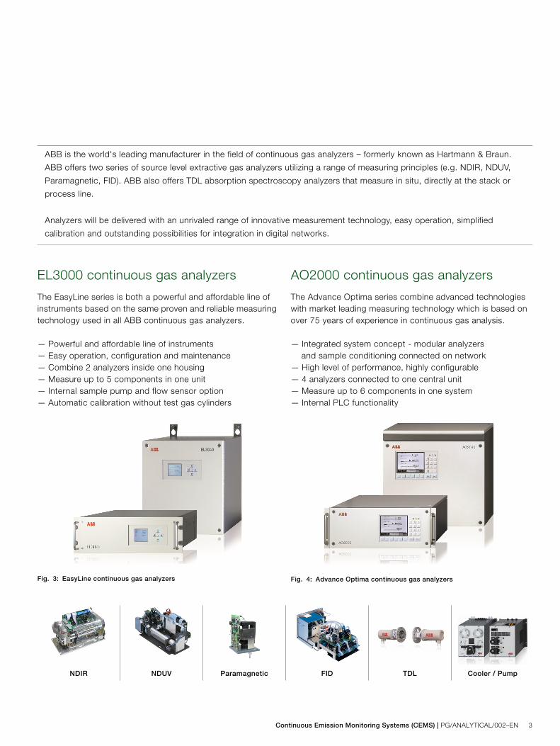
EL3000 continuous gas analyzers
The EasyLine series is both a powerful and affordable line of instruments based on the same proven and reliable measuring technology used in all ABB continuous gas analyzers.
— Powerful and affordable line of instruments— Easy operation, configuration and maintenance— Combine 2 analyzers inside one housing— Measure up to 5 components in one unit— Internal sample pump and flow sensor option— Automatic calibration without test gas cylinders
AO2000 continuous gas analyzers
The Advance Optima series combine advanced technologies with market leading measuring technology which is based on over 75 years of experience in continuous gas analysis.
— Integrated system concept - modular analyzers and sample conditioning connected on network
— High level of performance, highly configurable— 4 analyzers connected to one central unit— Measure up to 6 components in one system— Internal PLC functionality
ABB is the world's leading manufacturer in the field of continuous gas analyzers – formerly known as Hartmann & Braun.
ABB offers two series of source level extractive gas analyzers utilizing a range of measuring principles (e.g. NDIR, NDUV,
Paramagnetic, FID). ABB also offers TDL absorption spectroscopy analyzers that measure in situ, directly at the stack or
process line.
Analyzers will be delivered with an unrivaled range of innovative measurement technology, easy operation, simplified
calibration and outstanding possibilities for integration in digital networks.
Fig. 3: EasyLine continuous gas analyzers Fig. 4: Advance Optima continuous gas analyzers
NDIR NDUV Paramagnetic FID TDL Cooler / Pump
Contact us
PG
/AN
ALY
TIC
AL/
002–
EN
07.2
014
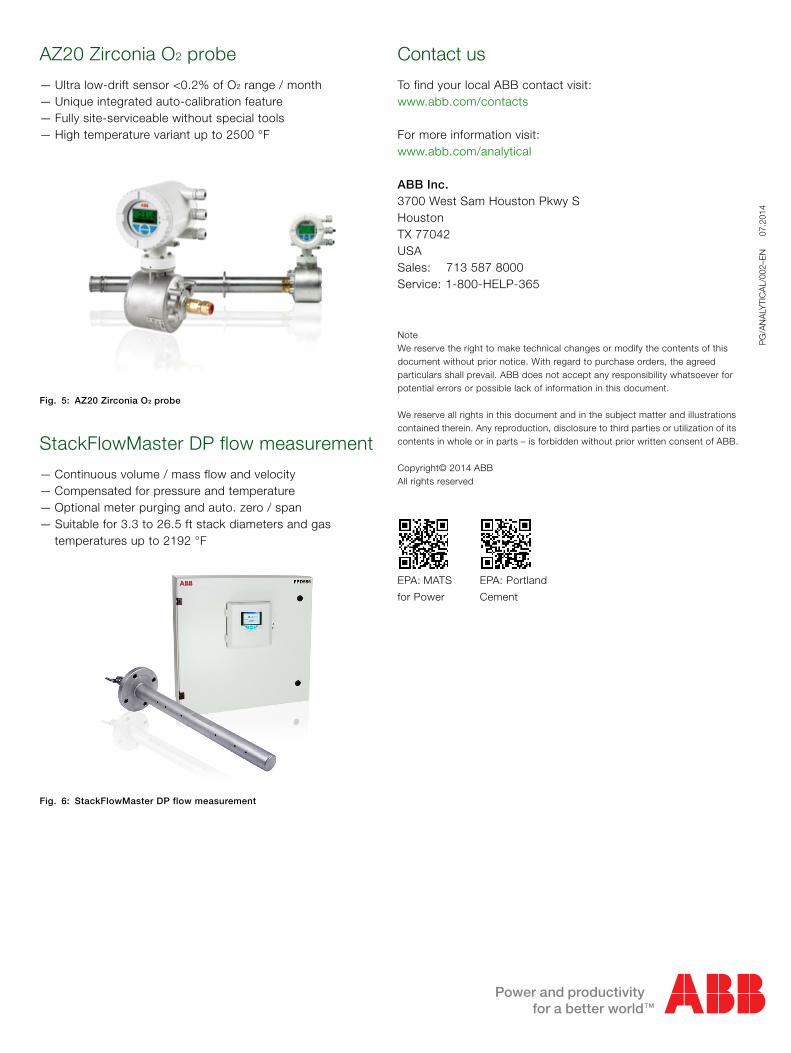
AZ20 Zirconia O2 probe
— Ultra low-drift sensor <0.2% of O2 range / month— Unique integrated auto-calibration feature— Fully site-serviceable without special tools— High temperature variant up to 2500 °F
StackFlowMaster DP flow measurement
— Continuous volume / mass flow and velocity— Compensated for pressure and temperature— Optional meter purging and auto. zero / span— Suitable for 3.3 to 26.5 ft stack diameters and gas
temperatures up to 2192 °F
Fig. 5: AZ20 Zirconia O2 probe
Fig. 6: StackFlowMaster DP flow measurement
NoteWe reserve the right to make technical changes or modify the contents of this document without prior notice. With regard to purchase orders, the agreed particulars shall prevail. ABB does not accept any responsibility whatsoever for potential errors or possible lack of information in this document.
We reserve all rights in this document and in the subject matter and illustrations contained therein. Any reproduction, disclosure to third parties or utilization of its contents in whole or in parts – is forbidden without prior written consent of ABB.
Copyright© 2014 ABBAll rights reserved
To find your local ABB contact visit:www.abb.com/contacts
For more information visit:www.abb.com/analytical
ABB Inc.3700 West Sam Houston Pkwy SHouston TX 77042USASales: 713 587 8000Service: 1-800-HELP-365
EPA: MATS
for Power
EPA: Portland
Cement
ABB Analyzer systems integrationComplete process analyzer and emission monitoring solutions
Measurement & Analytics - Measurement made easy
2 | Analyzer systems integratione
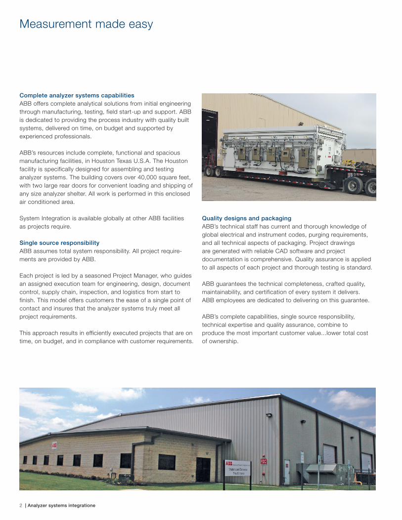
Complete analyzer systems capabilitiesABB offers complete analytical solutions from initial engineering through manufacturing, testing, field start-up and support. ABB is dedicated to providing the process industry with quality built systems, delivered on time, on budget and supported by experienced professionals.
ABB’s resources include complete, functional and spacious manufacturing facilities, in Houston Texas U.S.A. The Houston facility is specifically designed for assembling and testing analyzer systems. The building covers over 40,000 square feet, with two large rear doors for convenient loading and shipping of any size analyzer shelter. All work is performed in this enclosed air conditioned area.
System Integration is available globally at other ABB facilities as projects require.
Single source responsibilityABB assumes total system responsibility. All project require-ments are provided by ABB.
Each project is led by a seasoned Project Manager, who guides an assigned execution team for engineering, design, document control, supply chain, inspection, and logistics from start to finish. This model offers customers the ease of a single point of contact and insures that the analyzer systems truly meet all project requirements.
This approach results in efficiently executed projects that are on time, on budget, and in compliance with customer requirements.
Quality designs and packagingABB’s technical staff has current and thorough knowledge of global electrical and instrument codes, purging requirements, and all technical aspects of packaging. Project drawings are generated with reliable CAD software and project documentation is comprehensive. Quality assurance is applied to all aspects of each project and thorough testing is standard.
ABB guarantees the technical completeness, crafted quality, maintainability, and certification of every system it delivers. ABB employees are dedicated to delivering on this guarantee.
ABB’s complete capabilities, single source responsibility, technical expertise and quality assurance, combine to produce the most important customer value...lower total cost of ownership.
Measurement made easy

Analyzer systems integration | 3
As a single source provider, ABB can guarantee the certification of your CEMS.ABB combines the best systems practices, with conformance to government environmental requirements, to produce Contin-uous Emissions Monitoring Systems that pass certification and comply with plant requirements for analyzer systems.
ABB provides CEMS that meet plant area electrical classification requirements and systems with multiple streams. ABB also builds systems that are packaged in air conditioned shelters.
ABB also offers wide flexibility in system packaging, data acquisition and reporting systems, field start up and calibration services.
ABB Analytical Products and PartnershipABB has direct access to the industry’s most complete source for high quality process analyzers and process analyzer applications technology.
ABB Measurement & Analytics manufactures over fifty process analyzer products, including Gas Chromatographs, Continuous Liquid and Continuous Gas Analyzers, Reid Vapor Pressure Analyzers, TDL Analyzers, and FTIR Analyzers. ABB is always developing new and more powerful analyzer products, and creating more effective applications technology.
ABB Analyzer Systems Integration has full access to ABB’s analytical products, technology and resources offering the analyzer system customer a remarkable advantage.
When it serves the customer’s objectives, ABB also employs quality products from other manufacturers. The customer’s needs take top priority on ABB projects.
Contact ABB, the Analytical System Integration experts for all your analytical needs:
Prepackaged Analyzer Systems Engineering and DesignSample Conditioning SystemsAnalyzer Buildings and SheltersComprehensive Supply Chain ManagementComplete System AssemblyComprehensive System Testing
Complete DocumentationDrawings on Auto-CADAnalyzer and Systems ManualsStart-up ProceduresMaintenance Procedures
Emissions Monitoring systems For Regulatory ComplianceCO - O2 - NOx – SOx –CO2 - Opacity – HCl –NH3 HRVOC’s – Sulfur – H2S - BTUComplete, Integrated Field PackagesField Certification — Quarterly AuditsData-Acquisition Systems
Complete ServicesApplications and SolutionsInstallation and SupervisionPre-Commissioning and Start UpMaintenance and ServiceTraining — Classroom and FieldAnalyzer Field Surveys

Contact us
9AK
K10
103A
0900
05
.15 ABB Analytical Systems Integration
6820 Willowbrook ParkHouston, TX 77066 USA Phone: +1 713 587 8058Fax: +1 713 266 4082 E-Mail: [email protected]
www.abb.com/measurement
Contact your local sales representative
www.abb.com/contacts
Data sheet DS/AZ20–EN Rev. H
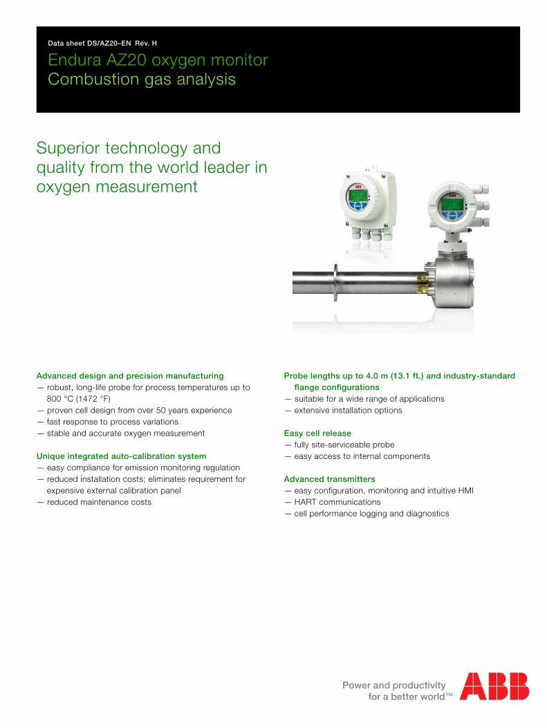
Endura AZ20 oxygen monitorCombustion gas analysis
Superior technology and quality from the world leader in oxygen measurement
Advanced design and precision manufacturing— robust, long-life probe for process temperatures up to
800 °C (1472 °F)— proven cell design from over 50 years experience— fast response to process variations— stable and accurate oxygen measurement
Unique integrated auto-calibration system— easy compliance for emission monitoring regulation— reduced installation costs; eliminates requirement for
expensive external calibration panel— reduced maintenance costs
Probe lengths up to 4.0 m (13.1 ft.) and industry-standard flange configurations
— suitable for a wide range of applications— extensive installation options
Easy cell release— fully site-serviceable probe— easy access to internal components
Advanced transmitters— easy configuration, monitoring and intuitive HMI— HART communications— cell performance logging and diagnostics
Endura AZ20 oxygen monitorCombustion gas analysis
2 DS/AZ20–EN Rev. H
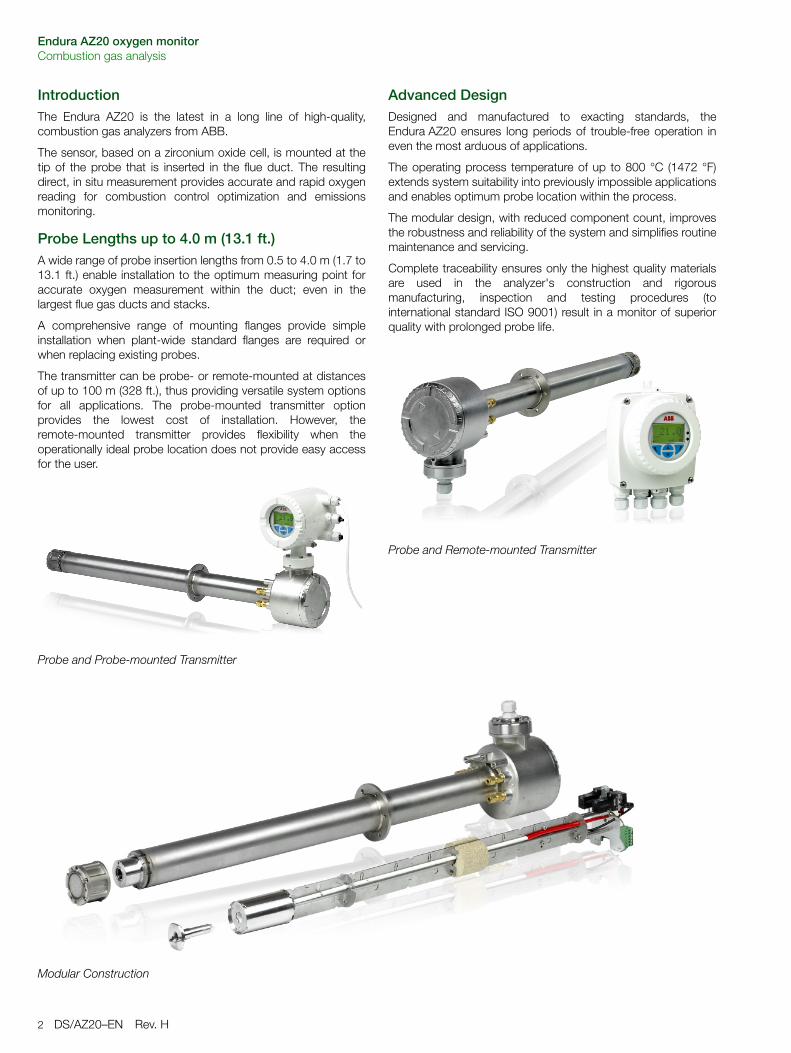
IntroductionThe Endura AZ20 is the latest in a long line of high-quality,combustion gas analyzers from ABB.
The sensor, based on a zirconium oxide cell, is mounted at thetip of the probe that is inserted in the flue duct. The resultingdirect, in situ measurement provides accurate and rapid oxygenreading for combustion control optimization and emissionsmonitoring.
Probe Lengths up to 4.0 m (13.1 ft.)A wide range of probe insertion lengths from 0.5 to 4.0 m (1.7 to13.1 ft.) enable installation to the optimum measuring point foraccurate oxygen measurement within the duct; even in thelargest flue gas ducts and stacks.
A comprehensive range of mounting flanges provide simpleinstallation when plant-wide standard flanges are required orwhen replacing existing probes.
The transmitter can be probe- or remote-mounted at distancesof up to 100 m (328 ft.), thus providing versatile system optionsfor all applications. The probe-mounted transmitter optionprovides the lowest cost of installation. However, theremote-mounted transmitter provides flexibility when theoperationally ideal probe location does not provide easy accessfor the user.
Advanced DesignDesigned and manufactured to exacting standards, theEndura AZ20 ensures long periods of trouble-free operation ineven the most arduous of applications.
The operating process temperature of up to 800 °C (1472 °F)extends system suitability into previously impossible applicationsand enables optimum probe location within the process.
The modular design, with reduced component count, improvesthe robustness and reliability of the system and simplifies routinemaintenance and servicing.
Complete traceability ensures only the highest quality materialsare used in the analyzer's construction and rigorousmanufacturing, inspection and testing procedures (tointernational standard ISO 9001) result in a monitor of superiorquality with prolonged probe life.
Probe and Probe-mounted Transmitter
Probe and Remote-mounted Transmitter
Modular Construction
Endura AZ20 oxygen monitorCombustion gas analysis
DS/AZ20–EN Rev. H 3
Easy Cell ReleaseThe Endura AZ20 probe has retained the easy-access cellarrangement of the previous generation ZFG2 probes. Cellreplacement can be performed on-site using basic hand tools;even after long periods of high temperature operation wherescrew threads have 'seized' and can no longer be released.
Kits containing all the parts needed to complete maintenanceare available from ABB to ensure a technician can performservices quickly, efficiently and at minimum cost.
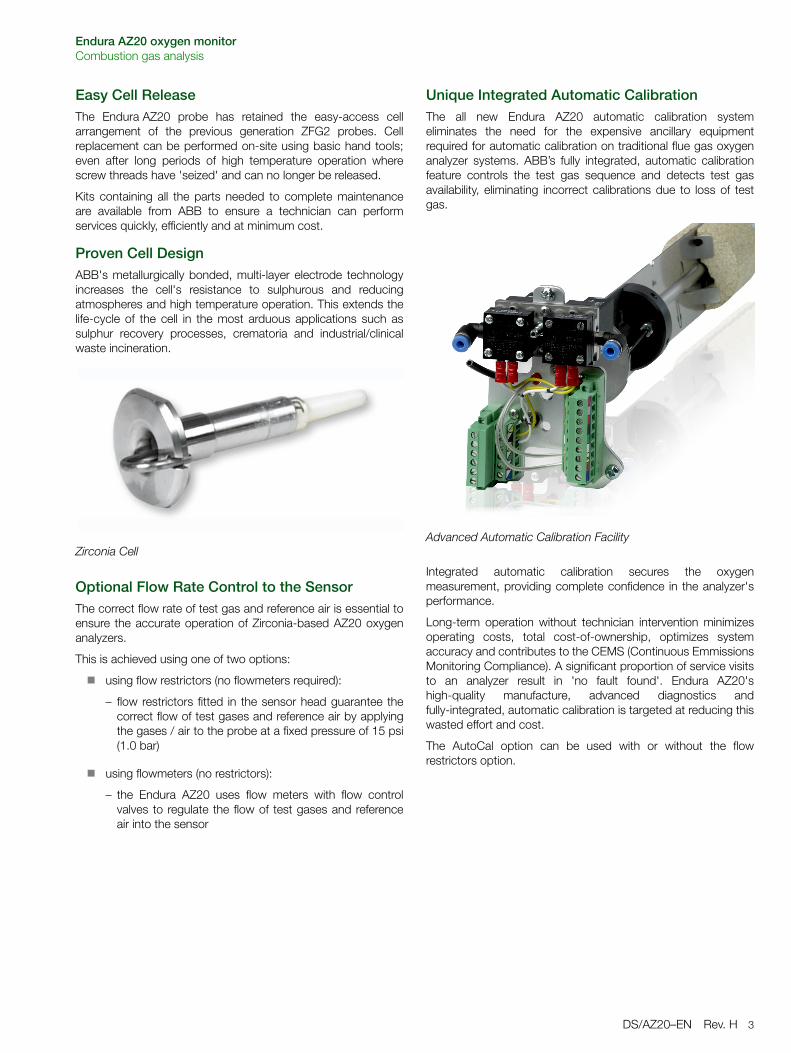
Proven Cell DesignABB's metallurgically bonded, multi-layer electrode technologyincreases the cell's resistance to sulphurous and reducingatmospheres and high temperature operation. This extends thelife-cycle of the cell in the most arduous applications such assulphur recovery processes, crematoria and industrial/clinicalwaste incineration.
Optional Flow Rate Control to the SensorThe correct flow rate of test gas and reference air is essential toensure the accurate operation of Zirconia-based AZ20 oxygenanalyzers.
This is achieved using one of two options:
using flow restrictors (no flowmeters required):
– flow restrictors fitted in the sensor head guarantee thecorrect flow of test gases and reference air by applyingthe gases / air to the probe at a fixed pressure of 15 psi(1.0 bar)
using flowmeters (no restrictors):
– the Endura AZ20 uses flow meters with flow controlvalves to regulate the flow of test gases and referenceair into the sensor
Unique Integrated Automatic CalibrationThe all new Endura AZ20 automatic calibration systemeliminates the need for the expensive ancillary equipmentrequired for automatic calibration on traditional flue gas oxygenanalyzer systems. ABB’s fully integrated, automatic calibrationfeature controls the test gas sequence and detects test gasavailability, eliminating incorrect calibrations due to loss of testgas.
Integrated automatic calibration secures the oxygenmeasurement, providing complete confidence in the analyzer'sperformance.
Long-term operation without technician intervention minimizesoperating costs, total cost-of-ownership, optimizes systemaccuracy and contributes to the CEMS (Continuous EmmissionsMonitoring Compliance). A significant proportion of service visitsto an analyzer result in 'no fault found'. Endura AZ20'shigh-quality manufacture, advanced diagnostics andfully-integrated, automatic calibration is targeted at reducing thiswasted effort and cost.
The AutoCal option can be used with or without the flowrestrictors option.
Zirconia CellAdvanced Automatic Calibration Facility
Endura AZ20 oxygen monitorCombustion gas analysis
4 DS/AZ20–EN Rev. H
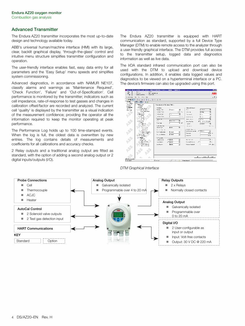
Advanced TransmitterThe Endura AZ20 transmitter incorporates the most up-to-datedesign and technology available today.
ABB's universal human/machine interface (HMI) with its large,clear, backlit graphical display, 'through-the-glass' control andintuitive menu structure simplifies transmitter configuration andoperation.
The user-friendly interface enables fast, easy data entry for allparameters and the 'Easy Setup' menu speeds and simplifiessystem commissioning.
Advanced diagnostics, in accordance with NAMUR NE107,classify alarms and warnings as 'Maintenance Required','Check Function', 'Failure' and 'Out-of-Specification'. Cellperformance is monitored by the transmitter; indicators such ascell impedance, rate-of-response to test gasses and changes incalibration offset/factor are recorded and analyzed. The currentcell 'quality' is displayed by the transmitter as a visual indicationof the measurement confidence; providing the operator all theinformation required to keep the monitor operating at peakperformance.
The Performance Log holds up to 100 time-stamped events.When the log is full, the oldest data is overwritten by newentries. The log contains details of measurements andcoefficients for all calibrations and accuracy checks.
2 Relay outputs and a traditional analog output are fitted asstandard, with the option of adding a second analog output or 2digital inputs/outputs (I/O).
The Endura AZ20 transmitter is equipped with HARTcommunication as standard, supported by a full Device TypeManager (DTM) to enable remote access to the analyzer througha user-friendly graphical interface. The DTM provides full accessto the transmitter setup, logged data and diagnosticsinformation as well as live data.
The IrDA standard infrared communication port can also beused with the DTM to upload and download deviceconfigurations. In addition, it enables data logged values anddiagnostics to be viewed on a hyperterminal interface or a PC.The device’s firmware can also be upgraded using this port.
DTM Graphical Interface
Probe Connections
Cell
Thermocouple
ACJC
Heater
AutoCal Control
2 Solenoid valve outputs
2 Test gas detection input
HART Communications
KEY
Analog Output
Galvanically isolated
Programmable over 0 to 20 mA
Relay Outputs
2 x Relays
Normally closed contacts
Digital I/O
2 User-configurable as input or output
Input: Volt-free contacts
Output: 30 V DC @ 220 mA
Analog Output
Galvanically isolated
Programmable over 4 to 20 mA
Standard Option
Endura AZ20 oxygen monitorCombustion gas analysis
DS/AZ20–EN Rev. H 5
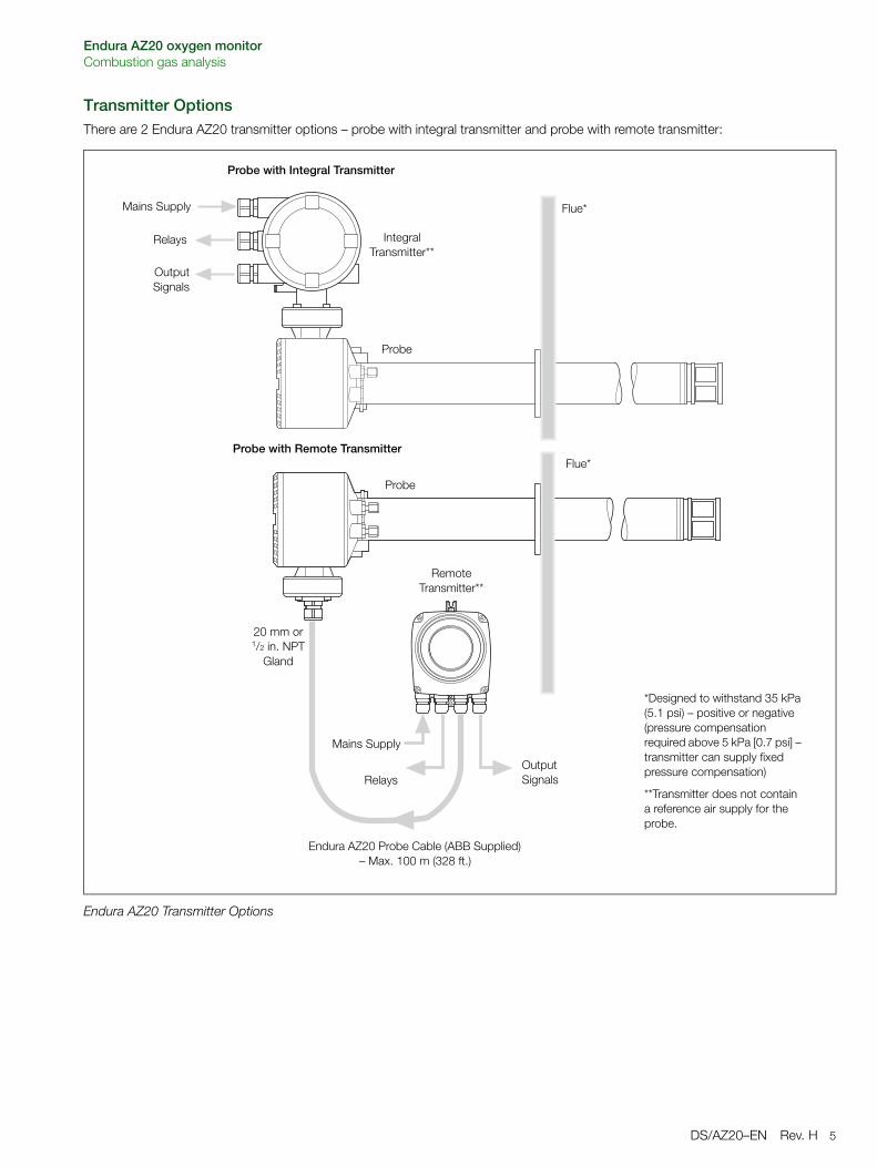
Transmitter OptionsThere are 2 Endura AZ20 transmitter options – probe with integral transmitter and probe with remote transmitter:
Endura AZ20 Transmitter Options
Mains Supply
Relays
Output Signals
Flue*
Relays
OutputSignals
Mains Supply
Probe with Integral Transmitter
Probe with Remote Transmitter
20 mm or 1/2 in. NPT
Gland
Endura AZ20 Probe Cable (ABB Supplied) – Max. 100 m (328 ft.)
*Designed to withstand 35 kPa (5.1 psi) – positive or negative (pressure compensation required above 5 kPa [0.7 psi] – transmitter can supply fixed pressure compensation)
**Transmitter does not contain a reference air supply for the probe.
Flue*
IntegralTransmitter**
Probe
Probe
RemoteTransmitter**
Endura AZ20 oxygen monitorCombustion gas analysis
6 DS/AZ20–EN Rev. H
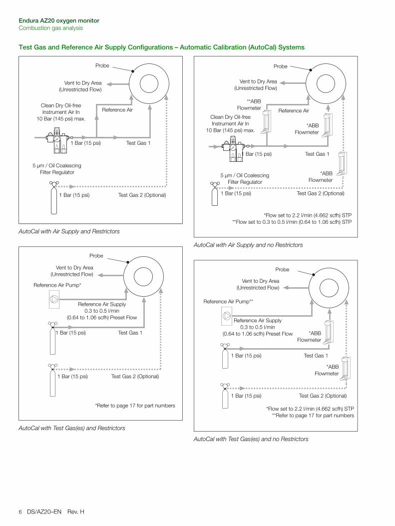
Test Gas and Reference Air Supply Configurations – Automatic Calibration (AutoCal) Systems
AutoCal with Air Supply and Restrictors
AutoCal with Test Gas(es) and Restrictors
Reference AirClean Dry Oil-free Instrument Air In
10 Bar (145 psi) max.
Test Gas 1
Vent to Dry Area(Unrestricted Flow)
Probe
Test Gas 2 (Optional)
5 µm / Oil Coalescing Filter Regulator
1 Bar (15 psi)
1 Bar (15 psi)
Test Gas 1
Vent to Dry Area(Unrestricted Flow)
Probe
Test Gas 2 (Optional)1 Bar (15 psi)
1 Bar (15 psi)
Reference Air Pump*
Reference Air Supply0.3 to 0.5 l/min
(0.64 to 1.06 scfh) Preset Flow
*Refer to page 17 for part numbers
AutoCal with Air Supply and no Restrictors
AutoCal with Test Gas(es) and no Restrictors
Reference AirClean Dry Oil-free Instrument Air In
10 Bar (145 psi) max.
Test Gas 1 1 Bar (15 psi)
Vent to Dry Area(Unrestricted Flow)
Test Gas 2 (Optional)
5 µm / Oil Coalescing Filter Regulator
*ABBFlowmeter
Probe
*ABBFlowmeter
**ABBFlowmeter
*Flow set to 2.2 l/min (4.662 scfh) STP**Flow set to 0.3 to 0.5 l/min (0.64 to 1.06 scfh) STP
1 Bar (15 psi)
Test Gas 11 Bar (15 psi)
Vent to Dry Area(Unrestricted Flow)
Test Gas 2 (Optional)
Probe
*ABBFlowmeter
*ABBFlowmeter
*Flow set to 2.2 l/min (4.662 scfh) STP**Refer to page 17 for part numbers
1 Bar (15 psi)
Reference Air Pump**
Reference Air Supply0.3 to 0.5 l/min
(0.64 to 1.06 scfh) Preset Flow
Endura AZ20 oxygen monitorCombustion gas analysis
DS/AZ20–EN Rev. H 7
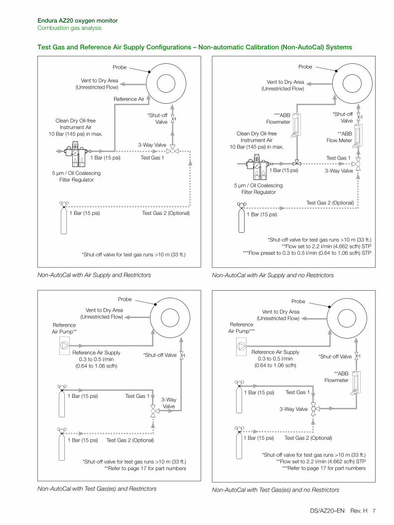
Test Gas and Reference Air Supply Configurations – Non-automatic Calibration (Non-AutoCal) Systems
Non-AutoCal with Air Supply and Restrictors
Non-AutoCal with Test Gas(es) and Restrictors
Reference Air
Clean Dry Oil-free Instrument Air
10 Bar (145 psi) in max.
Test Gas 1
Vent to Dry Area(Unrestricted Flow)
Test Gas 2 (Optional)
5 µm / Oil Coalescing Filter Regulator
Probe
*Shut-offValve
*Shut-off valve for test gas runs >10 m (33 ft.)
1 Bar (15 psi)
1 Bar (15 psi)
3-Way Valve
Reference Air Pump**
Reference Air Supply0.3 to 0.5 l/min
(0.64 to 1.06 scfh)
Test Gas 1
Vent to Dry Area(Unrestricted Flow)
Test Gas 2 (Optional)
Probe
*Shut-off Valve
*Shut-off valve for test gas runs >10 m (33 ft.)**Refer to page 17 for part numbers
1 Bar (15 psi)
1 Bar (15 psi) 3-Way Valve
Non-AutoCal with Air Supply and no Restrictors
Non-AutoCal with Test Gas(es) and no Restrictors
Clean Dry Oil-free Instrument Air
10 Bar (145 psi) in max.
Test Gas 1
Vent to Dry Area(Unrestricted Flow)
Probe
Test Gas 2 (Optional)
1 Bar (15 psi)
5 µm / Oil Coalescing Filter Regulator
**ABBFlow Meter
***ABBFlowmeter
*Shut-off valve for test gas runs >10 m (33 ft.)**Flow set to 2.2 l/min (4.662 scfh) STP
***Flow preset to 0.3 to 0.5 l/min (0.64 to 1.06 scfh) STP
*Shut-offValve
1 Bar (15 psi) 3-Way Valve
Test Gas 1 1 Bar (15 psi)
Vent to Dry Area(Unrestricted Flow)
Test Gas 2 (Optional)
Probe
**ABBFlowmeter
*Shut-off valve for test gas runs >10 m (33 ft.)**Flow set to 2.2 l/min (4.662 scfh) STP
***Refer to page 17 for part numbers
*Shut-off Valve
1 Bar (15 psi)
3-Way Valve
Reference Air Pump***
Reference Air Supply0.3 to 0.5 l/min
(0.64 to 1.06 scfh)
Endura AZ20 oxygen monitorCombustion gas analysis
8 DS/AZ20–EN Rev. H
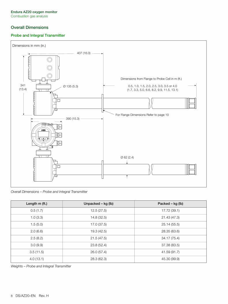
Overall Dimensions
Probe and Integral Transmitter
Dimensions in mm (in.)
Overall Dimensions – Probe and Integral Transmitter
0.5, 1.0, 1.5, 2.0, 2.5, 3.0, 3.5 or 4.0(1.7, 3.3, 5.0, 6.6, 8.2, 9.9, 11.5, 13.1)
For Flange Dimensions Refer to page 10390 (15.3)
407 (16.0)
Ø 135 (5.3)341(13.4)
168 (6.6)
Ø 62 (2.4)
Dimensions from Flange to Probe Cell in m (ft.)
Length m (ft.) Unpacked – kg (lb) Packed – kg (lb)
0.5 (1.7) 12.5 (27.5) 17.72 (39.1)
1.0 (3.3) 14.8 (32.5) 21.43 (47.3)
1.5 (5.0) 17.0 (37.5) 25.14 (55.5)
2.0 (6.6) 19.3 (42.5) 28.35 (63.6)
2.5 (8.2) 21.5 (47.5) 34.17 (75.4)
3.0 (9.9) 23.8 (52.4) 37.38 (83.5)
3.5 (11.5) 26.0 (57.4) 41.59 (91.7)
4.0 (13.1) 28.3 (62.3) 45.30 (99.9)
Weights – Probe and Integral Transmitter
Endura AZ20 oxygen monitorCombustion gas analysis
DS/AZ20–EN Rev. H 9
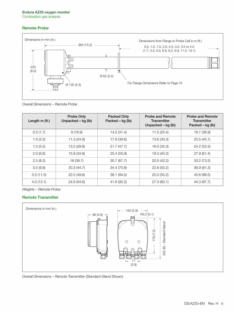
Remote Probe
Remote Transmitter
Overall Dimensions – Remote Probe
0.5, 1.0, 1.5, 2.0, 2.5, 3.0, 3.5 or 4.0(1.7, 3.3, 5.0, 6.6, 8.2, 9.9, 11.5, 13.1)
For Flange Dimensions Refer to Page 10
384 (15.2)
203(8.0)
Ø 135 (5.3)
Ø 62 (2.4)
Dimensions in mm (in.) Dimensions from Flange to Probe Cell in m (ft.)
Length m (ft.)Probe Only
Unpacked – kg (lb)Packed Only
Packed – kg (lb)Probe and Remote
Transmitter Unpacked – kg (lb)
Probe and Remote Transmitter
Packed – kg (lb)
0.5 (1.7) 9 (19.9) 14.2 (31.4) 11.5 (25.4) 16.7 (36.9)
1.0 (3.3) 11.3 (24.9) 17.9 (39.6) 13.6 (30.3) 20.5 (45.1)
1.5 (5.0) 13.5 (29.8) 21.7 (47.7) 16.0 (35.3) 24.2 (53.3)
2.0 (6.6) 15.8 (34.8) 25.4 (55.9) 18.3 (40.3) 27.9 (61.4)
2.5 (8.2) 18 (39.7) 30.7 (67.7) 20.5 (42.2) 33.2 (73.2)
3.0 (9.9) 20.3 (44.7) 34.4 (75.8) 22.8 (50.2) 36.9 (81.3)
3.5 (11.5) 22.5 (49.6) 38.1 (84.0) 25.0 (55.2) 40.6 (89.5)
4.0 (13.1) 24.8 (54.6) 41.8 (92.2) 27.3 (60.1) 44.3 (97.7)
Weights – Remote Probe
Overall Dimensions – Remote Transmitter (Standard Gland Shown)
202
(8) –
Sta
ndar
d G
land
98 (3.9) R3.2 (0.1)
71 (2.8)
179
(7.0
)
150 (5.9)Dimensions in mm (in.)
Endura AZ20 oxygen monitorCombustion gas analysis
10 DS/AZ20–EN Rev. H
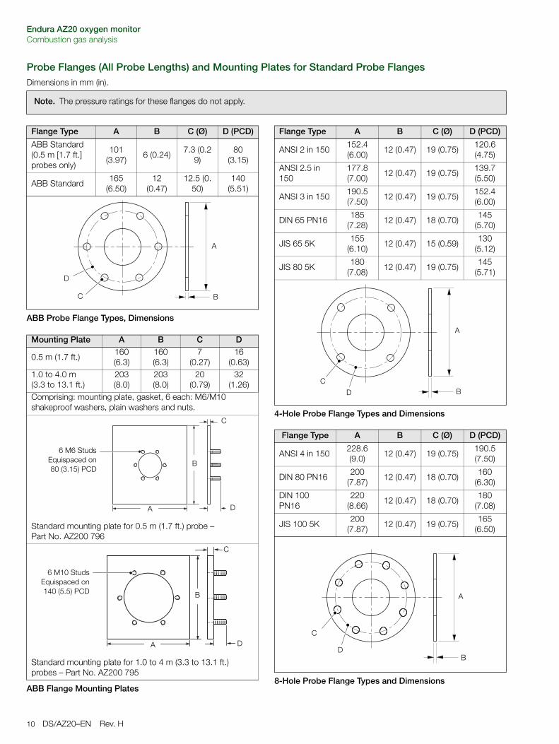
Probe Flanges (All Probe Lengths) and Mounting Plates for Standard Probe Flanges Dimensions in mm (in).
Note. The pressure ratings for these flanges do not apply.
Flange Type A B C (Ø) D (PCD)
ABB Standard(0.5 m [1.7 ft.] probes only)
101 (3.97)
6 (0.24)7.3 (0.2
9)80
(3.15)
ABB Standard165
(6.50)12
(0.47)12.5 (0.
50)140
(5.51)
ABB Probe Flange Types, Dimensions
Mounting Plate A B C D
0.5 m (1.7 ft.) 160 (6.3)
160 (6.3)
7(0.27)
16 (0.63)
1.0 to 4.0 m (3.3 to 13.1 ft.)
203 (8.0)
203 (8.0)
20(0.79)
32 (1.26)
Comprising: mounting plate, gasket, 6 each: M6/M10 shakeproof washers, plain washers and nuts.
Standard mounting plate for 0.5 m (1.7 ft.) probe – Part No. AZ200 796
Standard mounting plate for 1.0 to 4 m (3.3 to 13.1 ft.) probes – Part No. AZ200 795
ABB Flange Mounting Plates
D
C B
A
D
C
B
A
6 M6 StudsEquispaced on80 (3.15) PCD
D
C
B
A
6 M10 StudsEquispaced on140 (5.5) PCD
Flange Type A B C (Ø) D (PCD)
ANSI 2 in 150152.4 (6.00)
12 (0.47) 19 (0.75)120.6 (4.75)
ANSI 2.5 in 150
177.8 (7.00)
12 (0.47) 19 (0.75)139.7 (5.50)
ANSI 3 in 150190.5 (7.50)
12 (0.47) 19 (0.75)152.4 (6.00)
DIN 65 PN16185
(7.28)12 (0.47) 18 (0.70)
145 (5.70)
JIS 65 5K155
(6.10)12 (0.47) 15 (0.59)
130 (5.12)
JIS 80 5K180
(7.08)12 (0.47) 19 (0.75)
145 (5.71)
4-Hole Probe Flange Types and Dimensions
Flange Type A B C (Ø) D (PCD)
ANSI 4 in 150228.6 (9.0)
12 (0.47) 19 (0.75)190.5 (7.50)
DIN 80 PN16200
(7.87)12 (0.47) 18 (0.70)
160 (6.30)
DIN 100 PN16
220 (8.66)
12 (0.47) 18 (0.70)180
(7.08)
JIS 100 5K200
(7.87)12 (0.47) 19 (0.75)
165 (6.50)
8-Hole Probe Flange Types and Dimensions
D
CB
A
D
C
B
A
Endura AZ20 oxygen monitorCombustion gas analysis
DS/AZ20–EN Rev. H 11
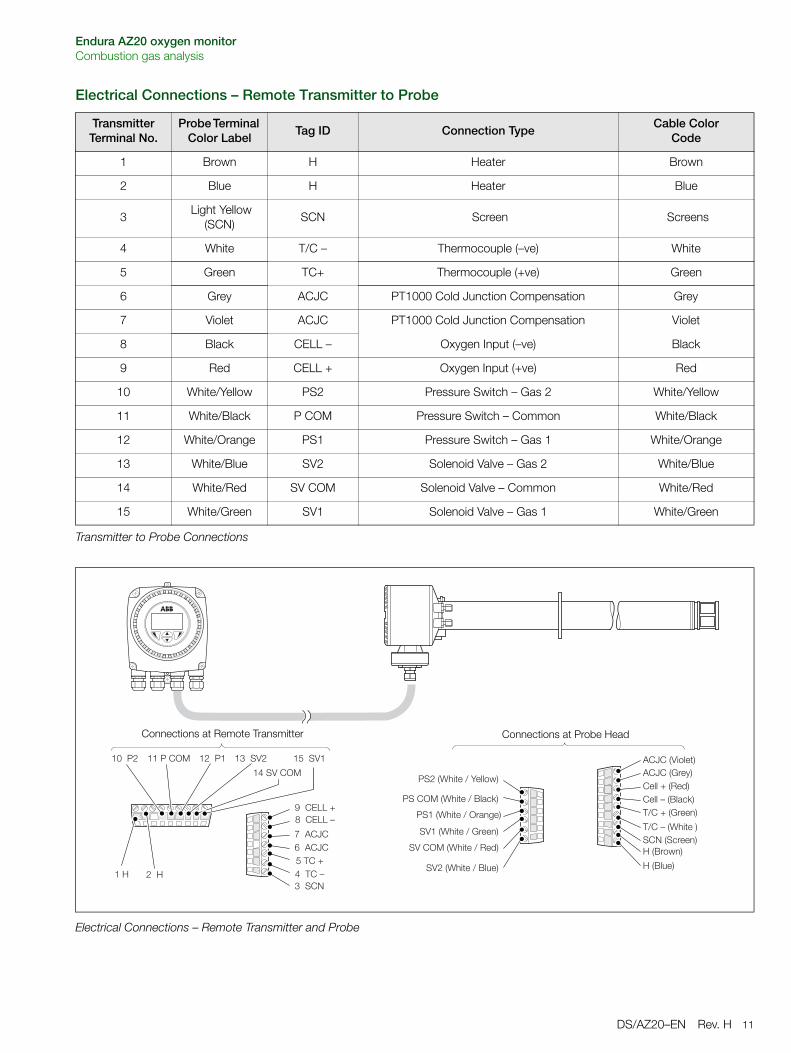
Electrical Connections – Remote Transmitter to Probe
TransmitterTerminal No.
Probe Terminal Color Label
Tag ID Connection TypeCable Color
Code
1 Brown H Heater Brown
2 Blue H Heater Blue
3 Light Yellow
(SCN)SCN Screen Screens
4 White T/C – Thermocouple (–ve) White
5 Green TC+ Thermocouple (+ve) Green
6 Grey ACJC PT1000 Cold Junction Compensation Grey
7 Violet ACJC PT1000 Cold Junction Compensation Violet
8 Black CELL – Oxygen Input (–ve) Black
9 Red CELL + Oxygen Input (+ve) Red
10 White/Yellow PS2 Pressure Switch – Gas 2 White/Yellow
11 White/Black P COM Pressure Switch – Common White/Black
12 White/Orange PS1 Pressure Switch – Gas 1 White/Orange
13 White/Blue SV2 Solenoid Valve – Gas 2 White/Blue
14 White/Red SV COM Solenoid Valve – Common White/Red
15 White/Green SV1 Solenoid Valve – Gas 1 White/Green
Transmitter to Probe Connections
Electrical Connections – Remote Transmitter and Probe
�������������������������� ���
�������
����������������
��������������������������
��������
������ !"
#$$����%#&"#$$�����$'()"�*����+�##!"
�*����,-./#�"�����(�##!"
����+�#0"�����.�$#/"
�����,-./#�*��$1#"
�������,-./#�*�%#&"
�����,-./#�*�+�##!"
����,-./#�*���'!2#"
������,-./#�*��$'()"
����,-./#�*�3#$$� "
����$1#"
Connections at Remote Transmitter Connections at Probe Head
Endura AZ20 oxygen monitorCombustion gas analysis
12 DS/AZ20–EN Rev. H
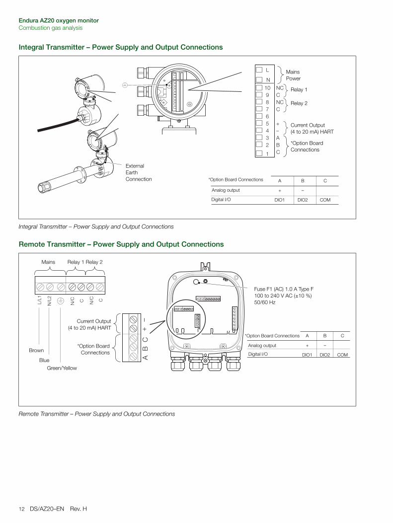
Integral Transmitter – Power Supply and Output Connections
Remote Transmitter – Power Supply and Output Connections
Integral Transmitter – Power Supply and Output Connections
1
L
N
1098765432
NCCNCC
+–ABC
Relay 1
Current Output (4 to 20 mA) HART
*Option Board Connections
Mains Power
External Earth Connection
Relay 2
*Option Board Connections
Analog output
Digital I/O
A
+
DIO1
B
–
DIO2
C
COM
Remote Transmitter – Power Supply and Output Connections
�* �*
�*��
�*��
��
��
Fuse F1 (AC) 1.0 A Type F100 to 240 V AC (±10 %) 50/60 Hz
Blue
Green/Yellow
Brown
Relay 1 Relay 2
Current Output(4 to 20 mA) HART
*Option BoardConnections
Mains
*Option Board Connections
Analog output
A
+
DIO1
B
–
DIO2
C
COM Digital I/O
Endura AZ20 oxygen monitorCombustion gas analysis
DS/AZ20–EN Rev. H 13
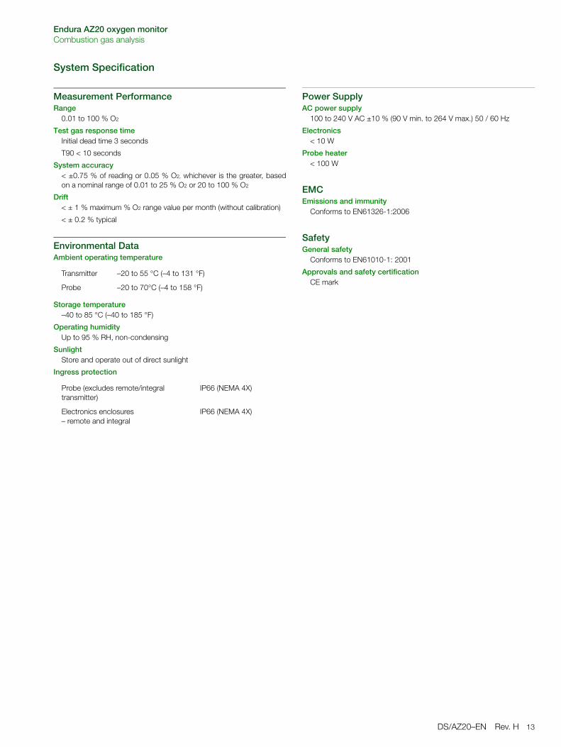
System Specification
Measurement PerformanceRange
0.01 to 100 % O2
Test gas response timeInitial dead time 3 seconds
T90 < 10 seconds
System accuracy< ±0.75 % of reading or 0.05 % O2, whichever is the greater, basedon a nominal range of 0.01 to 25 % O2 or 20 to 100 % O2
Drift< ± 1 % maximum % O2 range value per month (without calibration)
< ± 0.2 % typical
Environmental DataAmbient operating temperature
Storage temperature–40 to 85 °C (–40 to 185 °F)
Operating humidityUp to 95 % RH, non-condensing
SunlightStore and operate out of direct sunlight
Ingress protection
Power SupplyAC power supply
100 to 240 V AC ±10 % (90 V min. to 264 V max.) 50 / 60 Hz
Electronics< 10 W
Probe heater< 100 W
EMCEmissions and immunity
Conforms to EN61326-1:2006
SafetyGeneral safety
Conforms to EN61010-1: 2001
Approvals and safety certificationCE mark
Transmitter –20 to 55 °C (–4 to 131 °F)
Probe –20 to 70°C (–4 to 158 °F)
Probe (excludes remote/integral transmitter)
IP66 (NEMA 4X)
Electronics enclosures – remote and integral
IP66 (NEMA 4X)
Endura AZ20 oxygen monitorCombustion gas analysis
14 DS/AZ20–EN Rev. H
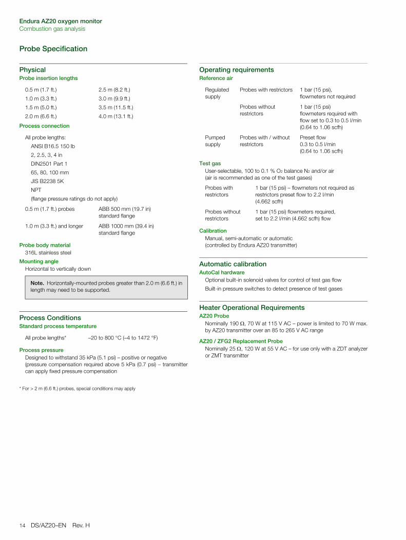
Probe Specification
PhysicalProbe insertion lengths
Process connection
Probe body material316L stainless steel
Mounting angleHorizontal to vertically down
Process ConditionsStandard process temperature
Process pressureDesigned to withstand 35 kPa (5.1 psi) – positive or negative(pressure compensation required above 5 kPa (0.7 psi) – transmittercan apply fixed pressure compensation
* For > 2 m (6.6 ft.) probes, special conditions may apply
Operating requirementsReference air
Test gasUser-selectable, 100 to 0.1 % O2 balance N2 and/or air (air is recommended as one of the test gases)
CalibrationManual, semi-automatic or automatic (controlled by Endura AZ20 transmitter)
Automatic calibrationAutoCal hardware
Optional built-in solenoid valves for control of test gas flow
Built-in pressure switches to detect presence of test gases
Heater Operational RequirementsAZ20 Probe
Nominally 190 , 70 W at 115 V AC – power is limited to 70 W max.by AZ20 transmitter over an 85 to 265 V AC range
AZ20 / ZFG2 Replacement ProbeNominally 25 , 120 W at 55 V AC – for use only with a ZDT analyzeror ZMT transmitter
0.5 m (1.7 ft.) 2.5 m (8.2 ft.)
1.0 m (3.3 ft.) 3.0 m (9.9 ft.)
1.5 m (5.0 ft.) 3.5 m (11.5 ft.)
2.0 m (6.6 ft.) 4.0 m (13.1 ft.)
All probe lengths:
ANSI B16.5 150 lb
2, 2.5, 3, 4 in
DIN2501 Part 1
65, 80, 100 mm
JIS B2238 5K
NPT
(flange pressure ratings do not apply)
0.5 m (1.7 ft.) probes ABB 500 mm (19.7 in) standard flange
1.0 m (3.3 ft.) and longer ABB 1000 mm (39.4 in) standard flange
Note. Horizontally-mounted probes greater than 2.0 m (6.6 ft.) inlength may need to be supported.
All probe lengths* –20 to 800 °C (–4 to 1472 °F)
Regulated supply
Probes with restrictors 1 bar (15 psi), flowmeters not required
Probes without restrictors
1 bar (15 psi) flowmeters required with flow set to 0.3 to 0.5 l/min (0.64 to 1.06 scfh)
Pumped supply
Probes with / without restrictors
Preset flow 0.3 to 0.5 l/min (0.64 to 1.06 scfh)
Probes with restrictors
1 bar (15 psi) – flowmeters not required as restrictors preset flow to 2.2 l/min (4.662 scfh)
Probes without restrictors
1 bar (15 psi) flowmeters required, set to 2.2 l/min (4.662 scfh) flow
Endura AZ20 oxygen monitorCombustion gas analysis
DS/AZ20–EN Rev. H 15
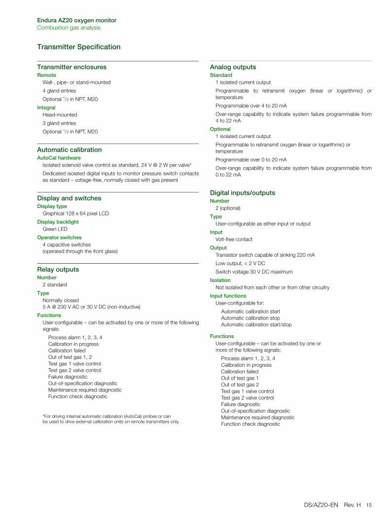
Transmitter Specification
Transmitter enclosuresRemote
Wall-, pipe- or stand-mounted
4 gland entries
Optional 1/2 in NPT, M20
IntegralHead-mounted
3 gland entries
Optional 1/2 in NPT, M20
Automatic calibrationAutoCal hardware
Isolated solenoid valve control as standard, 24 V @ 2 W per valve*
Dedicated isolated digital inputs to monitor pressure switch contactsas standard – voltage-free, normally closed with gas present
Display and switchesDisplay type
Graphical 128 x 64 pixel LCD
Display backlightGreen LED
Operator switches4 capacitive switches(operated through the front glass)
Relay outputsNumber
2 standard
TypeNormally closed5 A @ 230 V AC or 30 V DC (non-inductive)
FunctionsUser-configurable – can be activated by one or more of the followingsignals:
Process alarm 1, 2, 3, 4Calibration in progressCalibration failedOut of test gas 1, 2Test gas 1 valve controlTest gas 2 valve controlFailure diagnosticOut-of-specification diagnosticMaintenance required diagnosticFunction check diagnostic
*For driving internal automatic calibration (AutoCal) probes or can be used to drive external calibration units on remote transmitters only.
Analog outputsStandard
1 isolated current output
Programmable to retransmit oxygen (linear or logarithmic) ortemperature
Programmable over 4 to 20 mA
Over-range capability to indicate system failure programmable from4 to 22 mA
Optional1 isolated current output
Programmable to retransmit oxygen (linear or logarithmic) or temperature
Programmable over 0 to 20 mA
Over-range capability to indicate system failure programmable from0 to 22 mA
Digital inputs/outputsNumber
2 (optional)
TypeUser-configurable as either input or output
InputVolt-free contact
OutputTransistor switch capable of sinking 220 mA
Low output, < 2 V DC
Switch voltage 30 V DC maximum
IsolationNot isolated from each other or from other circuitry
Input functionsUser-configurable for:
Automatic calibration startAutomatic calibration stopAutomatic calibration start/stop
FunctionsUser-configurable – can be activated by one or more of the following signals:
Process alarm 1, 2, 3, 4Calibration in progressCalibration failedOut of test gas 1Out of test gas 2Test gas 1 valve controlTest gas 2 valve controlFailure diagnosticOut-of-specification diagnosticMaintenance required diagnosticFunction check diagnostic
Endura AZ20 oxygen monitorCombustion gas analysis
16 DS/AZ20–EN Rev. H
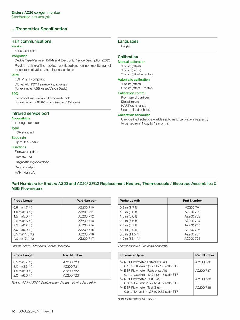
…Transmitter Specification
Hart communicationsVersion
5.7 as standard
IntegrationDevice Type Manager (DTM) and Electronic Device Description (EDD)
Provide online/offline device configuration, online monitoring ofmeasurement values and diagnostic states
DTMFDT v1.2.1 compliant
Works with FDT framework packages (for example, ABB Asset Vision Basic)
EDDCompliant with suitable framework tools (for example, SDC 625 and Simatic PDM tools)
Infrared service portAccessibility
Through front face
TypeIrDA standard
Baud rateUp to 115K baud
FunctionsFirmware update
Remote HMI
Diagnostic log download
Datalog output
HART via IrDA
Languages English
CalibrationManual calibration
1 point (offset)1 point (factor)2 point (offset + factor)
Automatic calibration1 point (offset)2 point (offset + factor)
Calibration controlFront panel controlsDigital inputsHART commandsUser-defined schedule
Calibration schedulerUser-defined schedule enables automatic calibration frequency to be set from 1 day to 12 months
Part Numbers for Endura AZ20 and AZ20/ ZFG2 Replacement Heaters, Thermocouple / Electrode Assemblies & ABB Flowmeters
Probe Length Part Number
0.5 m (1.7 ft.)1.0 m (3.3 ft.)1.5 m (5.0 ft.)2.0 m (6.6 ft.)2.5 m (8.2 ft.)3.0 m (9.9 ft.)3.5 m (11.5 ft.)4.0 m (13.1 ft.)
AZ200 710AZ200 711AZ200 712AZ200 713AZ200 714AZ200 715AZ200 716AZ200 717
Endura AZ20 – Standard Heater Assembly
Probe Length Part Number
0.5 m (1.7 ft.)1.0 m (3.3 ft.)1.5 m (5.0 ft.)2.0 m (6.6 ft.)
AZ200 720AZ200 721AZ200 722AZ200 723
Endura AZ20 / ZFG2 Replacement Probe – Heater Assembly
Probe Length Part Number
0.5 m (1.7 ft.)1.0 m (3.3 ft.)1.5 m (5.0 ft.)2.0 m (6.6 ft.)2.5 m (8.2 ft.)3.0 m (9.9 ft.)3.5 m (11.5 ft.)4.0 m (13.1 ft.)
AZ200 701AZ200 702AZ200 703AZ200 704AZ200 705AZ200 706AZ200 707AZ200 708
Thermocouple / Electrode Assembly
Flowmeter Type Part Number
1/4 NPT Flowmeter (Reference Air): 0.1 to 0.85 l/min (0.21 to 1.8 scfh) STP
1/4 BSP Flowmeter (Reference Air): 0.1 to 0.85 l/min (0.21 to 1.8 scfh) STP
1/4 NPT Flowmeter (Test Gas): 0.6 to 4.4 l/min (1.27 to 9.32 scfh) STP
1/4 BSP Flowmeter (Test Gas): 0.6 to 4.4 l/min (1.27 to 9.32 scfh) STP
AZ200 786
AZ200 787
AZ200 788
AZ200 789
ABB Flowmeters NPT/BSP
Endura AZ20 oxygen monitorCombustion gas analysis
DS/AZ20–EN Rev. H 17
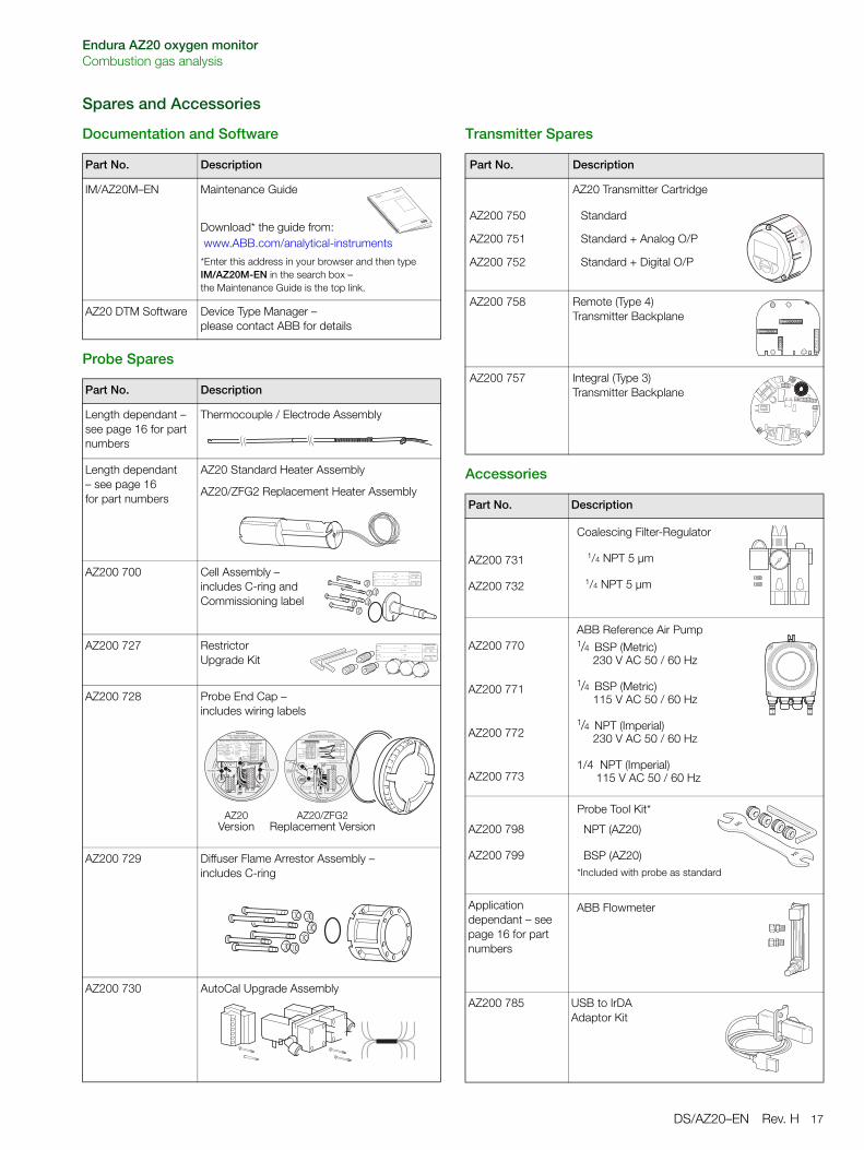
Spares and Accessories
Documentation and Software
Probe Spares
Transmitter Spares
Accessories
Part No. Description
IM/AZ20M–EN Maintenance Guide
Download* the guide from: www.ABB.com/analytical-instruments
*Enter this address in your browser and then type IM/AZ20M-EN in the search box – the Maintenance Guide is the top link.
AZ20 DTM Software Device Type Manager – please contact ABB for details
Part No. Description
Length dependant – see page 16 for part numbers
Thermocouple / Electrode Assembly
Length dependant – see page 16 for part numbers
AZ20 Standard Heater Assembly
AZ20/ZFG2 Replacement Heater Assembly
AZ200 700 Cell Assembly – includes C-ring and Commissioning label
AZ200 727 Restrictor Upgrade Kit
AZ200 728 Probe End Cap – includes wiring labels
AZ200 729 Diffuser Flame Arrestor Assembly – includes C-ring
AZ200 730 AutoCal Upgrade Assembly
���������������������
����������������
�.�$#/+�#0%#&�$'()+�##!,-./#�.2-/�3#$$� ��� !�$1#
/� /� %#&
+�##!*3#$$� +�##!,-./#
+�##!*3#$$� �$##4#&�,.�#�$##4#&�,.�#
���������� �����������������������������������������������
,-./#*3#$$� ,-./#*�$'()
,-./#*��'!2#,-./#*+�##!,-./#*%#&,-./#*�$1#
,-./#*3#$$� ,-./#*�$'(),-./#*��'!2#,-./#*+�##!,-./#*%#&,-./#*�$1#
�1/�'$��5/.�!��.6�6.//#&"
�� ���� �� ���� ��� !"��# !"� ���$ !"�
% & ' & ( ����)* �����$ +� �)# +� �� ! ,� -� -
���������
� ����������
���������������������
���������
%#&�$1#,-./#�$1#�(�##!*�'�/-��� !�$1#
%#&+�##!*3#$$�
+�##!,-./#
+�##!*3#$$� �$##4#&�,.�#�$##4#&�,.�#
%'(*$# ��
.���/���
.���/��� ����) �����+� �)+� ��! ,�0
--
77�!/��$$#&��#'/#����$/'2#��������'89
�!&1./
7%#69��.���.!#
������������������������������������������������
�(�##!
7%#69��.���.!#6��:��!&1./
#$$�';$#
��';$#
77�#'/#��';$#
AZ20Version
AZ20/ZFG2Replacement Version
Part No. Description
AZ200 750
AZ200 751
AZ200 752
AZ20 Transmitter Cartridge
Standard
Standard + Analog O/P
Standard + Digital O/P
AZ200 758 Remote (Type 4) Transmitter Backplane
AZ200 757 Integral (Type 3)Transmitter Backplane
Part No. Description
AZ200 731
AZ200 732
AZ200 770
AZ200 771
AZ200 772
AZ200 773
AZ200 798
AZ200 799
Application dependant – see page 16 for part numbers
AZ200 785 USB to IrDA Adaptor Kit
Coalescing Filter-Regulator
1/4 NPT 5 µm
1/4 NPT 5 µm
ABB Reference Air Pump1/4 BSP (Metric)
230 V AC 50 / 60 Hz
1/4 BSP (Metric) 115 V AC 50 / 60 Hz
1/4 NPT (Imperial) 230 V AC 50 / 60 Hz
1/4 NPT (Imperial) 115 V AC 50 / 60 Hz
Probe Tool Kit*
NPT (AZ20)
BSP (AZ20)*Included with probe as standard
ABB Flowmeter
Endura AZ20 oxygen monitorCombustion gas analysis
18 DS/AZ20–EN Rev. H
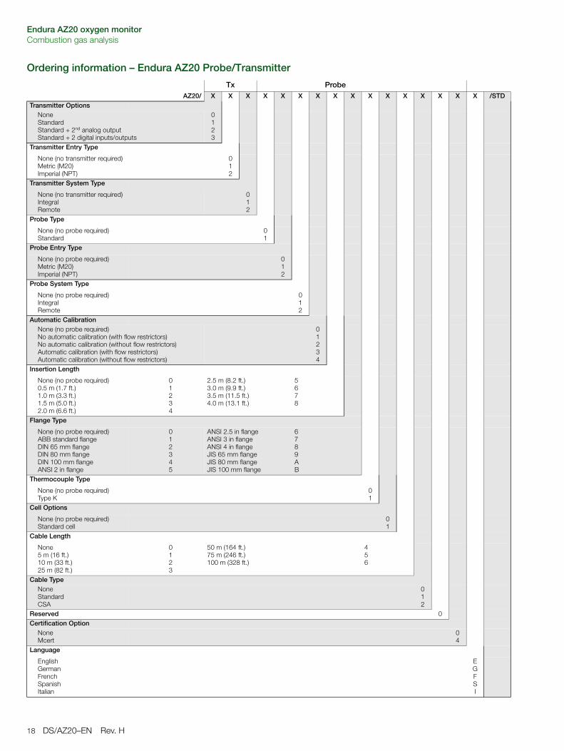
Ordering information – Endura AZ20 Probe/Transmitter
Tx ProbeAZ20/ X X X X X X X X X X X X X X X X /STD
Transmitter OptionsNoneStandardStandard + 2nd analog outputStandard + 2 digital inputs/outputs
0123
Transmitter Entry Type
None (no transmitter required)Metric (M20)Imperial (NPT)
012
Transmitter System Type
None (no transmitter required)IntegralRemote
012
Probe Type
None (no probe required)Standard
01
Probe Entry Type
None (no probe required)Metric (M20)Imperial (NPT)
012
Probe System Type
None (no probe required)IntegralRemote
012
Automatic CalibrationNone (no probe required)No automatic calibration (with flow restrictors)No automatic calibration (without flow restrictors)Automatic calibration (with flow restrictors)Automatic calibration (without flow restrictors)
01234
Insertion Length
None (no probe required)0.5 m (1.7 ft.)1.0 m (3.3 ft.)1.5 m (5.0 ft.)2.0 m (6.6 ft.)
01234
2.5 m (8.2 ft.)3.0 m (9.9 ft.)3.5 m (11.5 ft.)4.0 m (13.1 ft.)
5678
Flange Type
None (no probe required)ABB standard flangeDIN 65 mm flangeDIN 80 mm flangeDIN 100 mm flangeANSI 2 in flange
012345
ANSI 2.5 in flangeANSI 3 in flangeANSI 4 in flangeJIS 65 mm flangeJIS 80 mm flangeJIS 100 mm flange
6789AB
Thermocouple Type
None (no probe required)Type K
01
Cell Options
None (no probe required)Standard cell
01
Cable Length
None5 m (16 ft.)10 m (33 ft.)25 m (82 ft.)
0123
50 m (164 ft.)75 m (246 ft.)100 m (328 ft.)
456
Cable TypeNoneStandardCSA
012
Reserved 0Certification Option
NoneMcert
04
Language
EnglishGermanFrenchSpanishItalian
EGFSI
Endura AZ20 oxygen monitorCombustion gas analysis
DS/AZ20–EN Rev. H 19
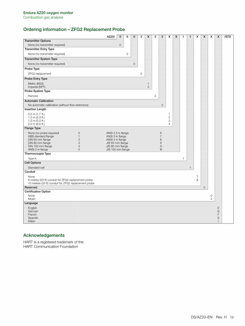
Ordering information – ZFG2 Replacement Probe
AcknowledgementsHART is a registered trademark of the HART Communication Foundation
AZ20/ 0 0 0 2 X 2 2 X X 1 1 X X X X /STDTransmitter Options
None (no transmitter required) 0Transmitter Entry Type
None (no transmitter required) 0
Transmitter System Type
None (no transmitter required) 0
Probe Type
ZFG2 replacement 2
Probe Entry Type
Metric (M20)Imperial (NPT)
12
Probe System Type
Remote 2
Automatic CalibrationNo automatic calibration (without flow restrictors) 2
Insertion Length
0.5 m (1.7 ft.)1.0 m (3.3 ft.)1.5 m (5.0 ft.)2.0 m (6.6 ft.)
1234
Flange Type
None (no probe required)ABB standard flangeDIN 65 mm flangeDIN 80 mm flangeDIN 100 mm flangeANSI 2 in flange
012345
ANSI 2.5 in flangeANSI 3 in flangeANSI 4 in flangeJIS 65 mm flangeJIS 80 mm flangeJIS 100 mm flange
6789AB
Thermocouple Type
Type K 1Cell Options
Standard cell 1Conduit
None6 metres (20 ft) conduit for ZFG2 replacement probe10 metres (33 ft) conduit for ZFG2 replacement probe
78
Reserved 0Certification Option
NoneMcert
04
Language
EnglishGermanFrenchSpanishItalian
EGFSI
Contact us
DS
/AZ2
0–E
NR
ev. H
06.2
014ABB Limited
Process AutomationOldends LaneStonehouseGloucestershire GL10 3TAUKTel: +44 1453 826 661Fax: +44 1453 829 671
ABB Inc.Process Automation125 E. County Line RoadWarminsterPA 18974USATel: +1 215 674 6000Fax: +1 215 674 7183
www.abb.com
NoteWe reserve the right to make technical changes or modify the contents of this document without prior notice. With regard to purchase orders, the agreed particulars shall prevail. ABB does not accept any responsibility whatsoever for potential errors or possible lack of information in this document.
We reserve all rights in this document and in the subject matter and illustrations contained therein. Any reproduction, disclosure to third parties or utilization of its contents in whole or in parts – is forbidden without prior written consent of ABB.
Copyright© 2014 ABBAll rights reserved
3KXA722211R1001
Sales
Service
Software
Data sheet DS/AZ30–EN Rev. C
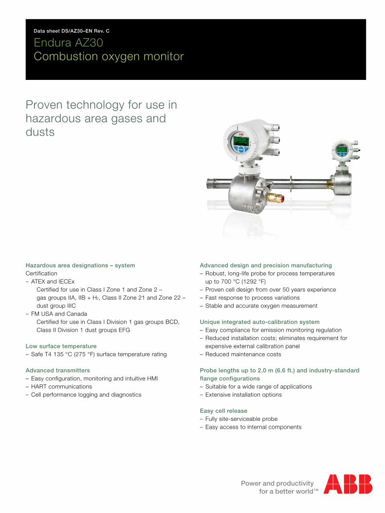
Endura AZ30Combustion oxygen monitor
Proven technology for use inhazardous area gases anddusts
Hazardous area designations – systemCertification– ATEX and IECEx
Certified for use in Class I Zone 1 and Zone 2 –gas groups IIA, IIB + H2, Class II Zone 21 and Zone 22 –dust group IIIC
– FM USA and CanadaCertified for use in Class I Division 1 gas groups BCD,Class II Division 1 dust groups EFG
Low surface temperature– Safe T4 135 °C (275 °F) surface temperature rating
Advanced transmitters– Easy configuration, monitoring and intuitive HMI– HART communications– Cell performance logging and diagnostics
Advanced design and precision manufacturing– Robust, long-life probe for process temperatures
up to 700 °C (1292 °F)– Proven cell design from over 50 years experience– Fast response to process variations– Stable and accurate oxygen measurement
Unique integrated auto-calibration system– Easy compliance for emission monitoring regulation– Reduced installation costs; eliminates requirement for
expensive external calibration panel– Reduced maintenance costs
Probe lengths up to 2.0 m (6.6 ft.) and industry-standardflange configurations– Suitable for a wide range of applications– Extensive installation options
Easy cell release– Fully site-serviceable probe– Easy access to internal components
Endura AZ30Combustion oxygen monitor
2 DS/AZ30–EN Rev. C | Endura AZ30 combustion oxygen monitor
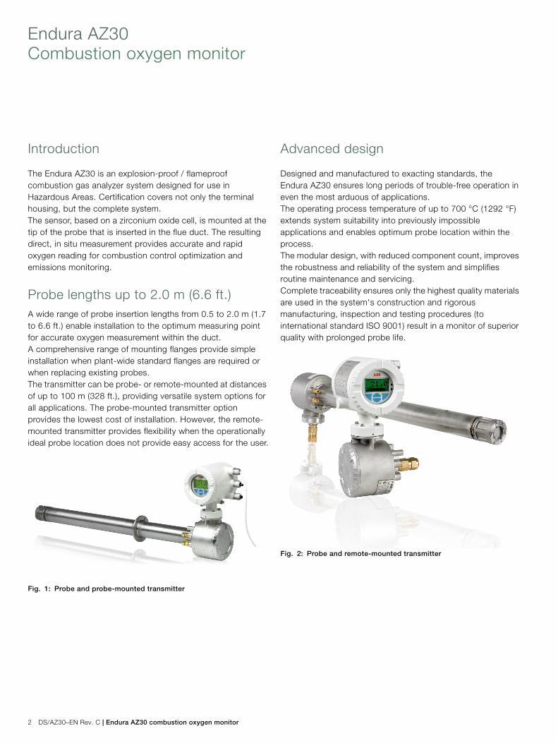
Introduction
The Endura AZ30 is an explosion-proof / flameproofcombustion gas analyzer system designed for use inHazardous Areas. Certification covers not only the terminalhousing, but the complete system.The sensor, based on a zirconium oxide cell, is mounted at thetip of the probe that is inserted in the flue duct. The resultingdirect, in situ measurement provides accurate and rapidoxygen reading for combustion control optimization andemissions monitoring.
Probe lengths up to 2.0 m (6.6 ft.)A wide range of probe insertion lengths from 0.5 to 2.0 m (1.7to 6.6 ft.) enable installation to the optimum measuring pointfor accurate oxygen measurement within the duct.A comprehensive range of mounting flanges provide simpleinstallation when plant-wide standard flanges are required orwhen replacing existing probes.The transmitter can be probe- or remote-mounted at distancesof up to 100 m (328 ft.), providing versatile system options forall applications. The probe-mounted transmitter optionprovides the lowest cost of installation. However, the remote-mounted transmitter provides flexibility when the operationallyideal probe location does not provide easy access for the user.
Advanced design
Designed and manufactured to exacting standards, theEndura AZ30 ensures long periods of trouble-free operation ineven the most arduous of applications.The operating process temperature of up to 700 °C (1292 °F)extends system suitability into previously impossibleapplications and enables optimum probe location within theprocess.The modular design, with reduced component count, improvesthe robustness and reliability of the system and simplifiesroutine maintenance and servicing.Complete traceability ensures only the highest quality materialsare used in the system's construction and rigorousmanufacturing, inspection and testing procedures (tointernational standard ISO 9001) result in a monitor of superiorquality with prolonged probe life.
Fig. 1: Probe and probe-mounted transmitter
Fig. 2: Probe and remote-mounted transmitter
Endura AZ30 combustion oxygen monitor | DS/AZ30–EN Rev. C 3
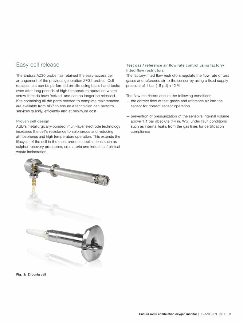
Easy cell release
The Endura AZ30 probe has retained the easy-access cellarrangement of the previous generation ZFG2 probes. Cellreplacement can be performed on-site using basic hand tools;even after long periods of high temperature operation wherescrew threads have 'seized' and can no longer be released.Kits containing all the parts needed to complete maintenanceare available from ABB to ensure a technician can performservices quickly, efficiently and at minimum cost.
Proven cell designABB's metallurgically-bonded, multi-layer electrode technologyincreases the cell's resistance to sulphurous and reducingatmospheres and high temperature operation. This extends thelifecycle of the cell in the most arduous applications such assulphur recovery processes, crematoria and industrial / clinicalwaste incineration.
Test gas / reference air flow rate control using factory-fitted flow restrictorsThe factory-fitted flow restrictors regulate the flow rate of testgases and reference air to the sensor by using a fixed supplypressure of 1 bar (15 psi) ±12 %.
The flow restrictors ensure the following conditions:— the correct flow of test gases and reference air into the
sensor for correct sensor operation
— prevention of pressurization of the sensor’s internal volumeabove 1.1 bar absolute (44 in. WG) under fault conditionssuch as internal leaks from the gas lines for certificationcompliance
Fig. 3: Zirconia cell
Endura AZ30Combustion oxygen monitor
4 DS/AZ30–EN Rev. C | Endura AZ30 combustion oxygen monitor
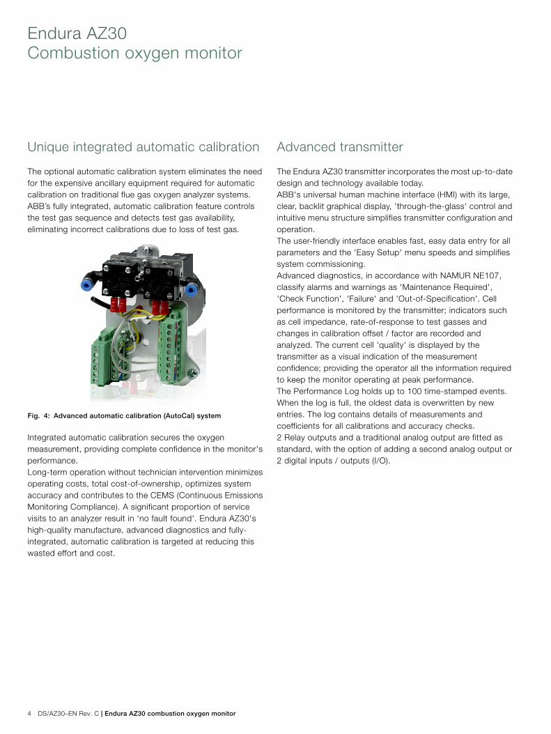
Unique integrated automatic calibration
The optional automatic calibration system eliminates the needfor the expensive ancillary equipment required for automaticcalibration on traditional flue gas oxygen analyzer systems.ABB’s fully integrated, automatic calibration feature controlsthe test gas sequence and detects test gas availability,eliminating incorrect calibrations due to loss of test gas.
Integrated automatic calibration secures the oxygenmeasurement, providing complete confidence in the monitor'sperformance.Long-term operation without technician intervention minimizesoperating costs, total cost-of-ownership, optimizes systemaccuracy and contributes to the CEMS (Continuous EmissionsMonitoring Compliance). A significant proportion of servicevisits to an analyzer result in 'no fault found'. Endura AZ30'shigh-quality manufacture, advanced diagnostics and fully-integrated, automatic calibration is targeted at reducing thiswasted effort and cost.
Advanced transmitter
The Endura AZ30 transmitter incorporates the most up-to-datedesign and technology available today.ABB's universal human machine interface (HMI) with its large,clear, backlit graphical display, 'through-the-glass' control andintuitive menu structure simplifies transmitter configuration andoperation.The user-friendly interface enables fast, easy data entry for allparameters and the 'Easy Setup' menu speeds and simplifiessystem commissioning.Advanced diagnostics, in accordance with NAMUR NE107,classify alarms and warnings as 'Maintenance Required','Check Function', 'Failure' and 'Out-of-Specification'. Cellperformance is monitored by the transmitter; indicators suchas cell impedance, rate-of-response to test gasses andchanges in calibration offset / factor are recorded andanalyzed. The current cell 'quality' is displayed by thetransmitter as a visual indication of the measurementconfidence; providing the operator all the information requiredto keep the monitor operating at peak performance.The Performance Log holds up to 100 time-stamped events.When the log is full, the oldest data is overwritten by newentries. The log contains details of measurements andcoefficients for all calibrations and accuracy checks.2 Relay outputs and a traditional analog output are fitted asstandard, with the option of adding a second analog output or2 digital inputs / outputs (I/O).
Fig. 4: Advanced automatic calibration (AutoCal) system
Endura AZ30 combustion oxygen monitor | DS/AZ30–EN Rev. C 5
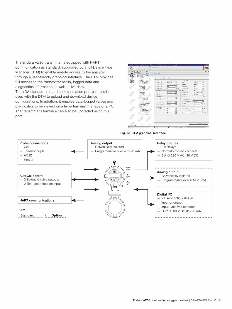
The Endura AZ30 transmitter is equipped with HARTcommunication as standard, supported by a full Device TypeManager (DTM) to enable remote access to the analyzerthrough a user-friendly graphical interface. The DTM providesfull access to the transmitter setup, logged data anddiagnostics information as well as live data.The IrDA standard infrared communication port can also beused with the DTM to upload and download deviceconfigurations. In addition, it enables data-logged values anddiagnostics to be viewed on a hyperterminal interface or a PC.The transmitter’s firmware can also be upgraded using thisport.
Fig. 5: DTM graphical interface
Probe connections— Cell— Thermocouple— ACJC— Heater
AutoCal control— 2 Solenoid valve outputs— 2 Test gas detection input
HART communications
KEY
Analog output— Galvanically isolated— Programmable over 0 to 20 mA
Relay outputs— 2 x Relays— Normally closed contacts— 5 A @ 230 V AC, 30 V DC
Digital I/O— 2 User-configurable as
input or output— Input: volt-free contacts— Output: 30 V DC @ 220 mA
Analog output— Galvanically isolated— Programmable over 4 to 20 mA
Standard Option
Endura AZ30Combustion oxygen monitor
6 DS/AZ30–EN Rev. C | Endura AZ30 combustion oxygen monitor
AZ30 system options
Schematic – probe with integral transmitter
*Transmitters do not contain a reference air supply for the probe. All external pneumatic fittings may be exchanged –
they do not form part of the certified enclosure.
**Refer to page 12 for barrier gland requirements.
***Required for certification.
55 °C (131 °F)***
–20 °C (–4 °F)***
IP66 and NEMA 4X
Mainssupply
Relays
Outputsignals
Transmitter / Terminal housing environment
EEx d barrier glands**/***Signal and mains cable
M20 or 1/2 in. NPT options(not supplied)
Flue / process
–20 °C (–4 °F)
700 °C (1292 °F)
Pneumatic fittings*1/4 in. BSP, for 6 mm OD pipes (with metric cable gland option)or1/4 in.NPT for 1/4 in. OD pipes (with 1/2 in. NPT cable gland option)ABB supply options
0.5 to 2.0 m(1.7 to 6.6 ft.)
Process 1.1 bar absolute (44 in. WG)***maximum process pressure
Hazardous areaCertified for use in Class I Zone 1 and Zone 2 – gas groups IIA, IIB + H2, Class II Zone 21 and Zone 22 – dust group IIIC
plus Class I Division 1 gas groups BCD, Class II Division 1 dust groups EFG
Maximum surfacetemperature
T4 135 °C (275 °F)
Note. Hazardous areacertification is valid onlybetween –20 to 70 °C(–4 to 158 °F)
Endura AZ30 combustion oxygen monitor | DS/AZ30–EN Rev. C 7
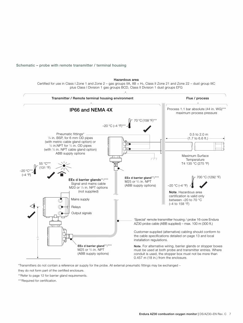
Schematic – probe with remote transmitter / terminal housing
*Transmitters do not contain a reference air supply for the probe. All external pneumatic fittings may be exchanged –
they do not form part of the certified enclosure.
**Refer to page 12 for barrier gland requirements.
***Required for certification.
'Special' remote transmitter housing / probe 16-core EnduraAZ30 probe cable (ABB supplied) – max. 100 m (300 ft.)
Customer-supplied (alternative) cabling should conform tothe cable specifications detailed on page 13 and localinstallation regulations.
Note. For alternative wiring, barrier glands or stopper boxesmust be used at both probe and transmitter entries. Whereconduit is used, the stopper box must not be more than0.457 m (18 in.) from the enclosure.
Mains supply
Relays
55 °C***(131 °F)
–20 °C***(–4 °F)
Output signals
0.5 to 2.0 m(1.7 to 6.6 ft.)
Process 1.1 bar absolute (44 in. WG)***maximum process pressure
Pneumatic fittings*1/4 in. BSP, for 6 mm OD pipes
(with metric cable gland option) or1/4 in.NPT for 1/4 in. OD pipes
(with 1/2 in. NPT cable gland option)ABB supply options
Maximum SurfaceTemperature
T4 135 °C (275 °F)
Transmitter / Remote terminal housing environment Flue / process
Hazardous areaCertified for use in Class I Zone 1 and Zone 2 – gas groups IIA, IIB + H2, Class II Zone 21 and Zone 22 – dust group IIIC
plus Class I Division 1 gas groups BCD, Class II Division 1 dust groups EFG
EEx d barrier glands**/***Signal and mains cable
M20 or 1/2 in. NPT options(not supplied)
EEx d barrier gland**/***M25 or 3/4 in. NPT(ABB supply options)
EEx d barrier gland**/***M25 or 3/4 in. NPT(ABB supply options)
IP66 and NEMA 4X
70 °C (158 °F)***
–20 °C (–4 °F)***
–20 °C (–4 °F)
700 °C (1292 °F)
Note. Hazardous areacertification is valid onlybetween –20 to 70 °C(–4 to 158 °F)
Endura AZ30Combustion oxygen monitor
8 DS/AZ30–EN Rev. C | Endura AZ30 combustion oxygen monitor
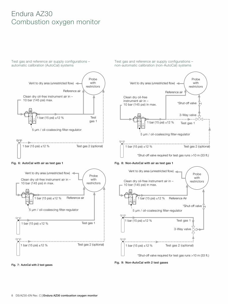
Test gas and reference air supply configurations –automatic calibration (AutoCal) systems
Test gas and reference air supply configurations –non-automatic calibration (non-AutoCal) systems
Fig. 6: AutoCal with air as test gas 1
Fig. 7: AutoCal with 2 test gases
Reference air
Clean dry oil-free instrument air in –10 bar (145 psi) max.
Testgas 1
Vent to dry area (unrestricted flow)
Test gas 2 (optional)
5 µm / oil-coalescing filter-regulator
1 bar (15 psi) ±12 %
1 bar (15 psi) ±12 %
Probewith
restrictors
Test gas 1
Vent to dry area (unrestricted flow)
Test gas 2 (optional)1 bar (15 psi) ±12 %
1 bar (15 psi) ±12 %
1 bar (15 psi) ±12 % Reference air
5 µm / oil-coalescing filter-regulator
Probewith
restrictorsClean dry oil-free instrument air in –10 bar (145 psi) in max.
Fig. 8: Non-AutoCal with air as test gas 1
Fig. 9: Non-AutoCal with 2 test gases
Reference air
Clean dry oil-freeinstrument air in –10 bar (145 psi) in max.
Test gas 1
Vent to dry area (unrestricted flow)
Test gas 2 (optional)
5 µm / oil-coalescing filter-regulator
*Shut-off valve
*Shut-off valve required for test gas runs >10 m (33 ft.)
1 bar (15 psi) ±12 %
1 bar (15 psi) ±12 %
3-Way valve
Probewith
restrictors
Test gas 1
Vent to dry area (unrestricted flow)
Test gas 2 (optional)
*Shut-off valve
*Shut-off valve required for test gas runs >10 m (33 ft.)
1 bar (15 psi) ±12 %
1 bar (15 psi) ±12 %
3-Way valve
Clean dry oil-free instrument air in –10 bar (145 psi) in max.
5 µm / oil-coalescing filter-regulator
1 bar (15 psi) ±12 % Reference Air
Probewith
restrictors
Endura AZ30 combustion oxygen monitor | DS/AZ30–EN Rev. C 9
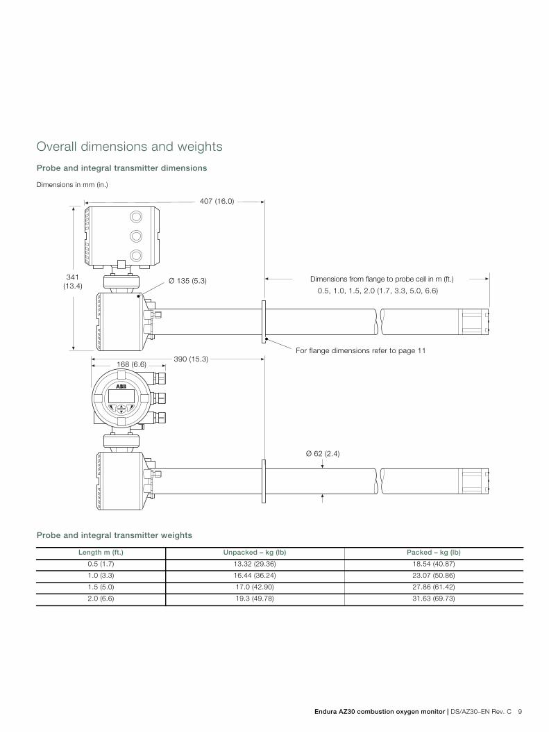
Overall dimensions and weights
Probe and integral transmitter dimensions
Probe and integral transmitter weights
Dimensions in mm (in.)
Length m (ft.) Unpacked – kg (lb) Packed – kg (lb)
0.5 (1.7) 13.32 (29.36) 18.54 (40.87)
1.0 (3.3) 16.44 (36.24) 23.07 (50.86)
1.5 (5.0) 17.0 (42.90) 27.86 (61.42)
2.0 (6.6) 19.3 (49.78) 31.63 (69.73)
0.5, 1.0, 1.5, 2.0 (1.7, 3.3, 5.0, 6.6)
For flange dimensions refer to page 11390 (15.3)
407 (16.0)
Ø 135 (5.3)341(13.4)
168 (6.6)
Ø 62 (2.4)
Dimensions from flange to probe cell in m (ft.)
Endura AZ30Combustion oxygen monitor
10 DS/AZ30–EN Rev. C | Endura AZ30 combustion oxygen monitor
Remote probe dimensions
Remote probe weights
Remote transmitter dimensions
Remote transmitter weights
Dimensions in mm (in.)
Length m (ft.) Probe only unpacked – kg (lb) Probe only packed – kg (lb)
0.5 (1.7) 9.82 (21.65) 15.02 (33.11)
1.0 (3.3) 12.94 (28.53) 19.54 (43.08)
1.5 (5.0) 15.96 (35.18) 24.16 (53.26)
2.0 (6.6) 19.18 (42.28) 28.68 (63.23)
Dimensions in mm (in.)
*Wall- / Pipe-mount bracket plus U-bolt, pipe clamp and M8 fixings supplied as standard
**Certification requirement
Remote transmitter unpacked – kg (lb) Remote transmitter packed – kg (lb)
9.5 (20.94) 12.5 (27.55)
0.5, 1.0, 1.5, 2.0 (1.7, 3.3, 5.0, 6.6)
For flange dimensions refer to page 11
384 (15.2)
203(8.0)
Ø 135 (5.3)
Ø 62 (2.4)
Dimensions from flange to probe cell in m (ft.)
170 (6.7)
135 (5.3)
168 (6.6)
341(13.4)
125 (4.9)
278(10.9)
240 (9.4)
R39(1.5)
329 (12.9)
134(5.3)
Pipe-mount installation*
Ø 8.5 (0.33)
70(27.6)
Min. clamping dia. 42 (1.65)Max. clamping dia. 60 (2.36)
Wall-mountinstallation*
Use only ABB-suppliedbolts – M8 x 1.25 pitch x35 mm (SS hex. head)**
Endura AZ30 combustion oxygen monitor | DS/AZ30–EN Rev. C 11
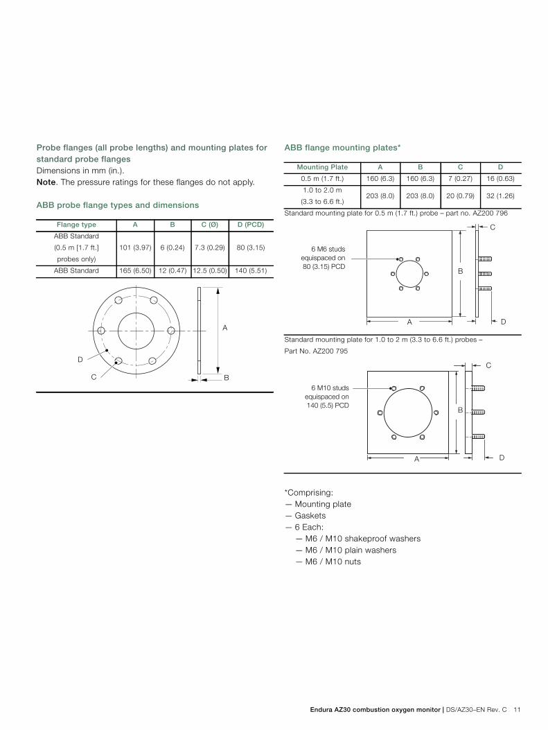
Probe flanges (all probe lengths) and mounting plates forstandard probe flangesDimensions in mm (in.).Note. The pressure ratings for these flanges do not apply.
ABB probe flange types and dimensions
ABB flange mounting plates*
*Comprising:— Mounting plate— Gaskets— 6 Each:
— M6 / M10 shakeproof washers— M6 / M10 plain washers— M6 / M10 nuts
Flange type A B C (Ø) D (PCD)
ABB Standard
(0.5 m [1.7 ft.]
probes only)
101 (3.97) 6 (0.24) 7.3 (0.29) 80 (3.15)
ABB Standard 165 (6.50) 12 (0.47) 12.5 (0.50) 140 (5.51)
D
C B
A
Mounting Plate A B C D
0.5 m (1.7 ft.) 160 (6.3) 160 (6.3) 7 (0.27) 16 (0.63)
1.0 to 2.0 m
(3.3 to 6.6 ft.)203 (8.0) 203 (8.0) 20 (0.79) 32 (1.26)
Standard mounting plate for 0.5 m (1.7 ft.) probe – part no. AZ200 796
Standard mounting plate for 1.0 to 2 m (3.3 to 6.6 ft.) probes –
Part No. AZ200 795
D
C
B
A
6 M6 studsequispaced on80 (3.15) PCD
D
C
B
A
6 M10 studsequispaced on140 (5.5) PCD
Endura AZ30Combustion oxygen monitor
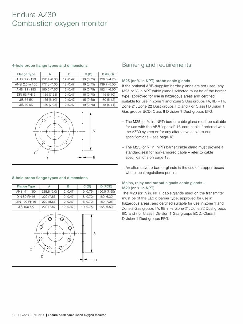
12 DS/AZ30–EN Rev. C | Endura AZ30 combustion oxygen monitor
4-hole probe flange types and dimensions
8-hole probe flange types and dimensions
Barrier gland requirements
M25 (or 3/4 in NPT) probe cable glandsIf the optional ABB-supplied barrier glands are not used, anyM25 or 3/4 in NPT cable glands selected must be of the barriertype, approved for use in hazardous areas and certifiedsuitable for use in Zone 1 and Zone 2 Gas groups IIA, IIB + H2,Zone 21, Zone 22 Dust groups IIIC and / or Class I Division 1Gas groups BCD, Class II Division 1 Dust groups EFG.
– The M25 (or 3/4 in. NPT) barrier cable gland must be suitablefor use with the ABB 'special' 16-core cable if ordered withthe AZ30 system or for any alternative cable to ourspecifications – see page 13.
– The M25 (or 3/4 in. NPT) barrier cable gland must provide astandard seal for non-armored cable – refer to cablespecifications on page 13.
– An alternative to barrier glands is the use of stopper boxeswhere local regulations permit.
Mains, relay and output signals cable glands –M20 (or 1/2 in NPT)The M20 (or 1/2 in. NPT) cable glands used on the transmittermust be of the EEx d barrier type, approved for use inhazardous areas. and certified suitable for use in Zone 1 andZone 2 Gas groups IIA, IIB + H2, Zone 21, Zone 22 Dust groupsIIIC and / or Class I Division 1 Gas groups BCD, Class IIDivision 1 Dust groups EFG.
Flange Type A B C (Ø) D (PCD)
ANSI 2 in 150 152.4 (6.00) 12 (0.47) 19 (0.75) 120.6 (4.75)
ANSI 2.5 in 150 177.8 (7.00) 12 (0.47) 19 (0.75) 139.7 (5.50)
ANSI 3 in 150 190.5 (7.50) 12 (0.47) 19 (0.75) 152.4 (6.00)
DIN 65 PN16 185 (7.28) 12 (0.47) 18 (0.70) 145 (5.70)
JIS 65 5K 155 (6.10) 12 (0.47) 15 (0.59) 130 (5.12)
JIS 80 5K 180 (7.08) 12 (0.47) 19 (0.75) 145 (5.71)
Flange Type A B C (Ø) D (PCD)
ANSI 4 in 150 228.6 (9.0) 12 (0.47) 19 (0.75) 190.5 (7.50)
DIN 80 PN16 200 (7.87) 12 (0.47) 18 (0.70) 160 (6.30)
DIN 100 PN16 220 (8.66) 12 (0.47) 18 (0.70) 180 (7.08)
JIS 100 5K 200 (7.87) 12 (0.47) 19 (0.75) 165 (6.50)
D
CB
A
D
C
B
A
Endura AZ30 combustion oxygen monitor | DS/AZ30–EN Rev. C 13
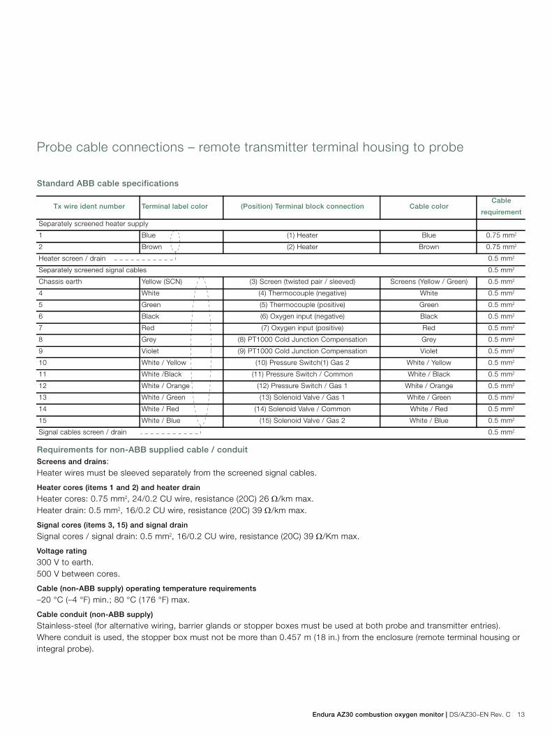
Probe cable connections – remote transmitter terminal housing to probe
Standard ABB cable specifications
Requirements for non-ABB supplied cable / conduitScreens and drains:Heater wires must be sleeved separately from the screened signal cables.
Heater cores (items 1 and 2) and heater drain
Heater cores: 0.75 mm2, 24/0.2 CU wire, resistance (20C) 26 /km max.Heater drain: 0.5 mm2, 16/0.2 CU wire, resistance (20C) 39 /km max.
Signal cores (items 3, 15) and signal drain
Signal cores / signal drain: 0.5 mm2, 16/0.2 CU wire, resistance (20C) 39 /Km max.
Voltage rating
300 V to earth.500 V between cores.
Cable (non-ABB supply) operating temperature requirements
–20 °C (–4 °F) min.; 80 °C (176 °F) max.
Cable conduit (non-ABB supply)
Stainless-steel (for alternative wiring, barrier glands or stopper boxes must be used at both probe and transmitter entries).Where conduit is used, the stopper box must not be more than 0.457 m (18 in.) from the enclosure (remote terminal housing orintegral probe).
Tx wire ident number Terminal label color (Position) Terminal block connection Cable colorCable
requirement
Separately screened heater supply
1 Blue (1) Heater Blue 0.75 mm2
2 Brown (2) Heater Brown 0.75 mm2
Heater screen / drain 0.5 mm2
Separately screened signal cables 0.5 mm2
Chassis earth Yellow (SCN) (3) Screen (twisted pair / sleeved) Screens (Yellow / Green) 0.5 mm2
4 White (4) Thermocouple (negative) White 0.5 mm2
5 Green (5) Thermocouple (positive) Green 0.5 mm2
6 Black (6) Oxygen input (negative) Black 0.5 mm2
7 Red (7) Oxygen input (positive) Red 0.5 mm2
8 Grey (8) PT1000 Cold Junction Compensation Grey 0.5 mm2
9 Violet (9) PT1000 Cold Junction Compensation Violet 0.5 mm2
10 White / Yellow (10) Pressure Switch(1) Gas 2 White / Yellow 0.5 mm2
11 White /Black (11) Pressure Switch / Common White / Black 0.5 mm2
12 White / Orange (12) Pressure Switch / Gas 1 White / Orange 0.5 mm2
13 White / Green (13) Solenoid Valve / Gas 1 White / Green 0.5 mm2
14 White / Red (14) Solenoid Valve / Common White / Red 0.5 mm2
15 White / Blue (15) Solenoid Valve / Gas 2 White / Blue 0.5 mm2
Signal cables screen / drain 0.5 mm2
Endura AZ30Combustion oxygen monitor
14 DS/AZ30–EN Rev. C | Endura AZ30 combustion oxygen monitor
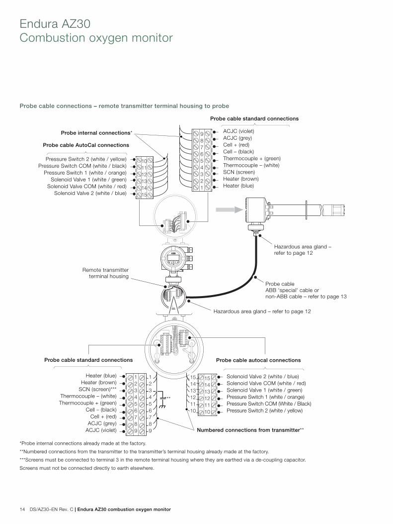
Probe cable connections – remote transmitter terminal housing to probe
*Probe internal connections already made at the factory.
**Numbered connections from the transmitter to the transmitter’s terminal housing already made at the factory.
***Screens must be connected to terminal 3 in the remote terminal housing where they are earthed via a de-coupling capacitor.
Screens must not be connected directly to earth elsewhere.
987654321
101112131415
123456789
151413121110
151413121110
123456789
Probe cable standard connections
Probe cable standard connections
Probe cable autocal connections
ACJC (violet)ACJC (grey)Cell + (red)Cell – (black)Thermocouple + (green)Thermocouple – (white)SCN (screen)Heater (brown)Heater (blue)
Solenoid Valve 2 (white / blue)Solenoid Valve COM (white / red)Solenoid Valve 1 (white / green)Pressure Switch 1 (white / orange)Pressure Switch COM (White / Black)Pressure Switch 2 (white / yellow)
Heater (blue)Heater (brown)
SCN (screen)***Thermocouple – (white)Thermocouple + (green)
Cell – (black)Cell + (red)
ACJC (grey)ACJC (violet)
Pressure Switch 2 (white / yellow)Pressure Switch COM (white / black)
Pressure Switch 1 (white / orange)Solenoid Valve 1 (white / green)
Solenoid Valve COM (white / red)Solenoid Valve 2 (white / blue)
Numbered connections from transmitter**
Probe cable AutoCal connections
Remote transmitterterminal housing
Probe internal connections*
Probe cableABB 'special' cable ornon-ABB cable – refer to page 13
***
Hazardous area gland –refer to page 12
Hazardous area gland – refer to page 12
Endura AZ30 combustion oxygen monitor | DS/AZ30–EN Rev. C 15
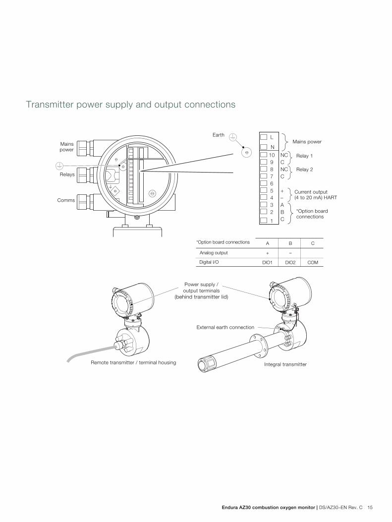
Transmitter power supply and output connections
Relay 1
Current output(4 to 20 mA) HART
*Option boardconnections
Mains power
External earth connection
Relay 2
*Option board connections
Analog output
Digital I/O
A
+
DIO1
B
–
DIO2
C
COM
Power supply /output terminals
(behind transmitter lid)
Remote transmitter / terminal housing Integral transmitter
Earth
Mainspower
Relays
Comms
Endura AZ30Combustion oxygen monitor
16 DS/AZ30–EN Rev. C | Endura AZ30 combustion oxygen monitor
System specification
Hazardous area certifications
ATEX and IECEx:– Certified for use in Class I Zone 1 and Zone 2 – gas groups
IIA, IIB + H2, Class II Zone 21 and Zone 22 – dust group IIICFM– Certified for use in Class I Division 1 gas groups BCD, Class
II Division 1 dust groups EFG
Measurement performanceRange:— 0 to 20.95 % O2 max. (condition of certification)
Test gas response time:— initial dead time 3 seconds— T9 0 < 10 seconds
System accuracy:— < ±0.75 % of reading or 0.05 % O2
Drift:— < ± 1 % maximum % O2 range value per month
(without calibration)— < ± 0.2 % typical
Environmental dataAmbient operating temperature:— transmitter: –20 to 55 °C (–4 to 131 °F)— probe: –20 to 70 °C (–4 to 158 °F)
(hazardous area certification is valid only between–20 to 70 °C [–4 to 158 °F])
Storage temperature:— –40 to 85 °C (–40 to 185 °F)
Operating humidity:— up to 95 % RH, non-condensing
Sunlight:— store and operate out of direct sunlight
Ingress protection:— probe (excludes process side of mounting flange)
IP66 and NEMA 4X— electronics enclosures (remote and integral)
IP66 and NEMA 4X
Power supplyAC power supply:— 100 to 240 V AC ±10 %
(90 V min. to 264 V max.) 50 / 60 HzMaximum current 1.2 A
Electronics:— < 10 W
Probe heater:— < 100 W
EMCEmissions and immunity:— conforms to EN61326-1:2006
SafetyGeneral safety:— conforms to EN61010-1: 2001
Approvals and safety certification:— CE mark— cFMus— ATEX
Endura AZ30 combustion oxygen monitor | DS/AZ30–EN Rev. C 17
Probe specification
Hazardous area certifications– II 2 GD– Ex d IIB +H2 T4 Gb (Ta –20°C to 70°C)– Ex tb IIIC T135°C Db (Ta –20°C to +70°C) IP66– Cert. No IECEx BAS12.0048X– ATEX Cert No. Baseefa12ATEX0076X
– Class I Division 1 Groups BCD T4– Class I Zone 1 AEx/Ex d IIB+H2 T4– Class II Division 1 Groups EFG T4
(Ta –20 °C to +70 °C) Type 4X– Max Working Pressure 1.1bar absolute– FM Certificate No. 3039243
PhysicalProbe insertion lengths:— 0.5 m (1.7 ft.)— 1.0 m (3.3 ft.)— 1.5 m (5.0 ft.)— 2.0 m (6.6 ft.)
Process connection:— All probe lengths (flange pressure ratings do not apply):
—ANSI B16.5 150 lb—2, 2.5, 3, 4 in—DIN2501 Part 1—65, 80, 100 mm—JIS B2238 5K
— 0.5 m (1.7 ft.) probes: ABB standard small flange— 1.0 m (3.3 ft.): ABB standard large flange
Probe body material:— 316 stainless steel
Mounting angle:— Horizontal to vertically down
Threaded entriesGland entry (certified):— probe cable gland entry: 1 x M25 or (optional) 3/4 in. NPT
(remote probe only)
Pneumatic entries (not certified):– 4 fittings supplied with AutoCal options or 3 fittings and 1
blanking plug supplied with non-AutoCal options. Sizeoptions: 1/4 in. BSP for 6 mm OD pipe (with M20 cable glandoption) or 1/4 in. NPT for 1/4 in. OD pipe (with 1/2 in. NPToption)
Automatic calibrationAutoCal hardware:— optional built-in solenoid valves for control of test gas flow— built-in pressure switches to detect presence of test gases
Process conditionsStandard process temperature:— all probe lengths –20 to 700 °C (–4 to 1292 °F)
Process:— this probe is certified for use in non oxygen-enriched
atmospheres, 0 to 20.95 % air only and a maximumpressure of 1.1 bar absolute (44 in. WG)
Operating requirementsReference air (clean dry instrument air free from oil):—regulated supply: 1 bar (15 psi) ±12 %*
Test gases – regulated to 1 bar (15 psi) ±12 %*:— user-selectable, 100 to 0.1 % O2 balance N2 and / or air
(air is recommended as one of the test gases)
Calibration:— manual, semi-automatic or automatic
(controlled by Endura AZ30 transmitter)
Heater operational requirementsNominally 190 W, 70 W at 115 V AC – power is limited to 70 Wmax. by AZ30 transmitter over an 85 to 265 V AC range
*Condition of certification
Endura AZ30Combustion oxygen monitor
18 DS/AZ30–EN Rev. C | Endura AZ30 combustion oxygen monitor
Transmitter specification
Hazardous area certificationsTransmitter– II 2 GD– Ex d IIB +H2 T6 Gb (Ta –20°C to 55°C)– Ex tb IIIC T85°C Db IP66 (Ta –20°C to 55°C)– Certified component– IECEx BAS12.0050U– Baseefa12ATEX0078U
– Class I Division 1 Groups BCD T6– Class I Zone 1 AEx/Ex d IIB+H2 T6– Class II Division 1 Groups EFG T6
(Ta –20 °C to +55 °C) Type 4X– FM Certificate No. 3039243– Max Current 1.2A
Remote terminal housing– II 2 GD– Ex d IIB +H2 T6 Gb (Ta –20°C to 70°C)– Ex tb IIIC T85°C Db (Ta –20°C to +70°C) IP66– Cert. No IECEx BAS12.0049X– ATEX Cert No. Baseefa12ATEX0077X
– Class I Division 1 Groups BCD T6– Class I Zone 1 AEx/Ex d IIB+H2 T6– Class II Division 1 Groups EFG T6
(Ta –20 °C to +70 °C) Type 4X– FM Certificate No. 3039243
Transmitter enclosuresRemote transmitter (mounted to remote terminal housing):—wall-, pipe- or stand-mounted (mounting bracket supplied)
Integral transmitter:—head-mounted to probe
PhysicalRemote transmitter:—aluminium (EN AC44200 or 47000)
Remote terminal housing:—316 stainless steel
Integral transmitter:—aluminium transmitter housing / stainless steel probe and
terminal housing
Threaded entriesGland entries (certified):— power and signals gland entries:
3 x M20 or (optional) 1/2 in. NPT— remote terminal housing cable gland entry:
1 x M25 or (optional) 3/4 in. NPT (remote system only)
Pneumatic entries (not certified):— 4 fittings supplied with AutoCal options or 3 fittings and 1
blanking plug supplied with non-AutoCal options. Sizeoptions: 1/4 in. BSP for 6 mm OD pipe (with M20 cable glandoption) or 1/4 in. NPT for 1/4 in. OD pipe (with 1/2 in. NPToption)
Automatic calibrationAutoCal hardware:—isolated solenoid valve control as standard,
24 V @ 2 W per valve*—dedicated isolated digital inputs to monitor pressure switch
contacts as standard: voltage-free, normally closed with gaspresent
Display and switchesDisplay type:—graphical 128 x 64 pixel LCD
Display backlight—green LED
Operator switches—4 capacitive switches (operated through the front glass)
*For driving internal automatic calibration (AutoCal) probes orcan be used to drive external calibration units on remotetransmitters only.
Endura AZ30 combustion oxygen monitor | DS/AZ30–EN Rev. C 19
Relay outputsNumber:—2 standard
Type:—normally closed
5 A @ 230 V AC or 30 V DC (non-inductive)
FunctionsUser-configurable: can be activated by 1 or more of thefollowing signals:— process alarm 1, 2, 3, 4— calibration in progress— calibration failed— out of test gas 1, 2— test gas 1 valve control— test gas 2 valve control— failure diagnostic— out-of-specification diagnostic— maintenance required diagnostic— function check diagnostic
Digital inputs / outputsNumber:—2 (optional)
Type:—user-configurable as either input or output
Input:—volt-free contact
Output:—transistor switch capable of sinking 220 mA—low output, < 2 V DC—switch voltage 30 V DC maximum
Isolation:—not isolated from each other or from other circuitry
Input functions:—user-configurable for:
— automatic calibration start— automatic calibration stop— automatic calibration start / stop
Functions—user-configurable, can be activated by one or more of the
following signals:— process alarm 1, 2, 3, 4— calibration in progress— calibration failed— out of test gas 1— out of test gas 2—test gas 1 valve control— test gas 2 valve control— failure diagnostic— out-of-specification diagnostic— maintenance required diagnostic— function check diagnostic
Analog outputsStandard:—1 isolated current output—programmable to retransmit oxygen (linear or logarithmic) or
temperature—programmable over 4 to 20 mA—over-range capability to indicate system failure
programmable from 4 to 22 mA
Optional:—1 isolated current output—programmable to retransmit oxygen (linear or logarithmic) or
temperature—programmable over 0 to 20 mA—over-range capability to indicate system failure
programmable from 0 to 22 mA
Endura AZ30Combustion oxygen monitor
20 DS/AZ30–EN Rev. C | Endura AZ30 combustion oxygen monitor
Hart communicationsVersion:—5.7 as standard
Integration:—Device Type Manager (DTM) and
Electronic Device Description (EDD)—provide online / offline device configuration, online
monitoring of measurement values and diagnostic states
DTM—FDT v1.2.1 compliant—works with FDT framework packages
(for example, ABB Asset Vision Basic)
EDD—compliant with suitable framework tools
(for example, SDC 625 and Simatic PDM tools)
Infrared service portAccessibility:—through front face
Type:—IrDA standard
Baud rate:—up to 115 K baud
Functions:—firmware update—remote HMI—diagnostic log download—datalog output—HART via IrDA
LanguagesEnglishFrenchGermanItalianSpanish
CalibrationManual calibration—1 point (offset)—1 point (factor)—2 point (offset + factor)
Automatic calibration:—1 point (offset)—2 point (offset + factor)
Calibration control:—front panel controls—digital inputs—HART commands—user-defined schedule
Calibration scheduler:—user-defined schedule enables automatic calibration
frequency to be set from 1 day to 12 months
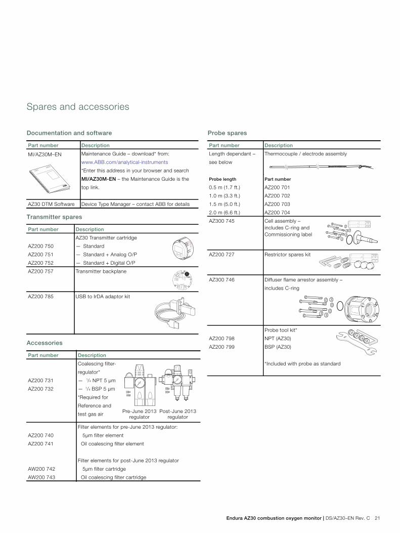
Endura AZ30 combustion oxygen monitor | DS/AZ30–EN Rev. C 21
Spares and accessories
Documentation and software
Transmitter spares
Accessories
Probe spares
Part number Description
MI/AZ30M–EN Maintenance Guide – download* from:
www.ABB.com/analytical-instruments
*Enter this address in your browser and search
MI/AZ30M-EN – the Maintenance Guide is the
top link.
AZ30 DTM Software Device Type Manager – contact ABB for details
Part number Description
AZ200 750
AZ200 751
AZ200 752
AZ30 Transmitter cartridge
— Standard
— Standard + Analog O/P
— Standard + Digital O/P
AZ200 757 Transmitter backplane
AZ200 785 USB to IrDA adaptor kit
Part number Description
AZ200 731
AZ200 732
Coalescing filter-
regulator*
— 1/4 NPT 5 µm
— 1/4 BSP 5 µm
*Required for
Reference and
test gas air
AZ200 740
AZ200 741
AW200 742
AW200 743
Filter elements for pre-June 2013 regulator:
5µm filter element
Oil coalescing filter element
Filter elements for post-June 2013 regulator
5µm filter cartridge
Oil coalescing filter cartridge
Pre-June 2013regulator
Post-June 2013regulator
Part number Description
Length dependant –
see below
Thermocouple / electrode assembly
Probe length Part number
0.5 m (1.7 ft.)
1.0 m (3.3 ft.)
1.5 m (5.0 ft.)
2.0 m (6.6 ft.)
AZ200 701
AZ200 702
AZ200 703
AZ200 704
AZ300 745 Cell assembly –includes C-ring andCommissioning label
AZ200 727 Restrictor spares kit
AZ300 746 Diffuser flame arrestor assembly –
includes C-ring
AZ200 798
AZ200 799
Probe tool kit*
NPT (AZ30)
BSP (AZ30)
*Included with probe as standard
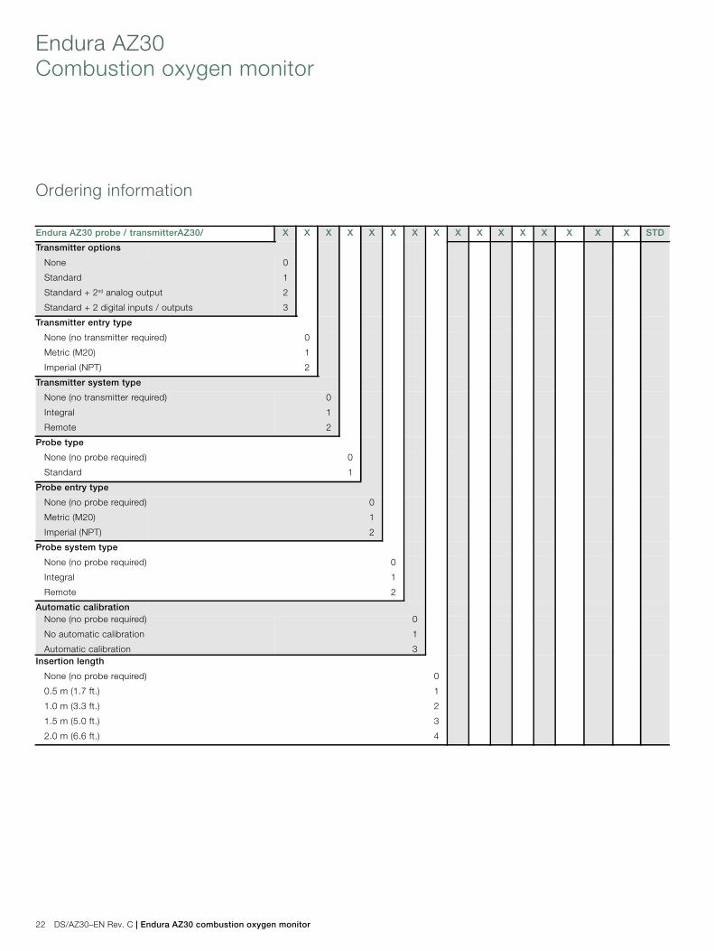
Endura AZ30Combustion oxygen monitor
22 DS/AZ30–EN Rev. C | Endura AZ30 combustion oxygen monitor
Ordering information
Endura AZ30 probe / transmitterAZ30/ X X X X X X X X X X X X X X X X STD
Transmitter options
None
Standard
Standard + 2nd analog output
Standard + 2 digital inputs / outputs
0
1
2
3
Transmitter entry type
None (no transmitter required)
Metric (M20)
Imperial (NPT)
0
1
2
Transmitter system type
None (no transmitter required)
Integral
Remote
0
1
2
Probe type
None (no probe required)
Standard
0
1
Probe entry type
None (no probe required)
Metric (M20)
Imperial (NPT)
0
1
2
Probe system type
None (no probe required)
Integral
Remote
0
1
2
Automatic calibrationNone (no probe required)
No automatic calibration
Automatic calibration
0
1
3Insertion length
None (no probe required)
0.5 m (1.7 ft.)
1.0 m (3.3 ft.)
1.5 m (5.0 ft.)
2.0 m (6.6 ft.)
0
1
2
3
4
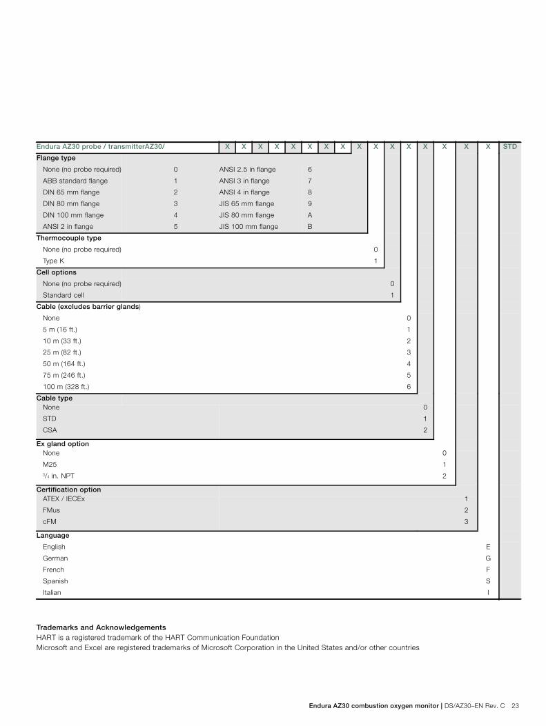
Endura AZ30 combustion oxygen monitor | DS/AZ30–EN Rev. C 23
Trademarks and AcknowledgementsHART is a registered trademark of the HART Communication FoundationMicrosoft and Excel are registered trademarks of Microsoft Corporation in the United States and/or other countries
Flange type
None (no probe required)
ABB standard flange
DIN 65 mm flange
DIN 80 mm flange
DIN 100 mm flange
ANSI 2 in flange
0
1
2
3
4
5
ANSI 2.5 in flange
ANSI 3 in flange
ANSI 4 in flange
JIS 65 mm flange
JIS 80 mm flange
JIS 100 mm flange
6
7
8
9
A
B
Thermocouple type
None (no probe required)
Type K
0
1
Cell options
None (no probe required)
Standard cell
0
1
Cable (excludes barrier glands)
None
5 m (16 ft.)
10 m (33 ft.)
25 m (82 ft.)
50 m (164 ft.)
75 m (246 ft.)
100 m (328 ft.)
0
1
2
3
4
5
6
Cable typeNone
STD
CSA
0
1
2
Ex gland optionNone
M253/4 in. NPT
0
1
2
Certification optionATEX / IECEx
FMus
cFM
1
2
3
Language
English
German
French
Spanish
Italian
E
G
F
S
I
Endura AZ30 probe / transmitterAZ30/ X X X X X X X X X X X X X X X X STD

Contact us
DS
/AZ3
0–E
NR
ev.C
07.2
013ABB Limited
Process AutomationOldends LaneStonehouseGloucestershire GL10 3TAUKTel: +44 1453 826 661Fax: +44 1453 829 671
ABB Inc.Process Automation125 E. County Line RoadWarminsterPA 18974USATel: +1 215 674 6000Fax: +1 215 674 7183
www.abb.com
NoteWe reserve the right to make technical changes ormodify the contents of this document without priornotice. With regard to purchase orders, the agreedparticulars shall prevail. ABB does not accept anyresponsibility whatsoever for potential errors orpossible lack of information in this document.
We reserve all rights in this document and in thesubject matter and illustrations contained therein.Any reproduction, disclosure to third parties orutilization of its contents – in whole or in parts – isforbidden without prior written consent of ABB.
Copyright© 2013 ABB
All rights reserved
3KXA722301R1001
Sales
Service
Software
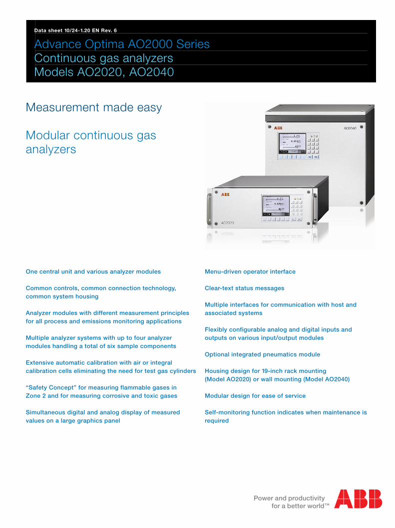
Data sheet 10/24-1.20 EN Rev. 6
Advance Optima AO2000 Series Continuous gas analyzers Models AO2020, AO2040
Measurement made easy Modular continuous gas analyzers
One central unit and various analyzer modules Common controls, common connection technology, common system housing Analyzer modules with different measurement principles for all process and emissions monitoring applications Multiple analyzer systems with up to four analyzer modules handling a total of six sample components Extensive automatic calibration with air or integral calibration cells eliminating the need for test gas cylinders “Safety Concept” for measuring flammable gases in Zone 2 and for measuring corrosive and toxic gases Simultaneous digital and analog display of measured values on a large graphics panel
Menu-driven operator interface Clear-text status messages Multiple interfaces for communication with host and associated systems Flexibly configurable analog and digital inputs and outputs on various input/output modules Optional integrated pneumatics module Housing design for 19-inch rack mounting (Model AO2020) or wall mounting (Model AO2040) Modular design for ease of service Self-monitoring function indicates when maintenance is required
2 Advance Optima AO2000 Series Data Sheet 10/24-1.20 EN Rev. 6
Modular analyzer product line
Overview
Advance Optima AO2000 Series is a line of modules used for continuous process gas analysis.
The product line consists of the following modules: • Analyzer modules • Pneumatics module • Electronics module • I/O modules • Housing with display and control unit • System bus
The modules can be arranged in various ways to form single or multiple analyzer systems.
The electronics module, power supply and housing with display and control unit are also collectively referred to as the “central unit”.
Analyzer modules
Analyzer modules: • Uras26 Infrared analyzer module • Limas11 Process photometer analyzer module • Magnos206 Oxygen analyzer module • Magnos27 Oxygen analyzer module • ZO23 Trace oxygen analyzer module • Caldos25 Thermal conductivity analyzer module • Caldos27 Thermal conductivity analyzer module • Fidas24 FID analyzer module • MultiFID14 FID analyzer module • MultiFID14 NMHC FID analyzer module • LS25 Laser analyzer module
Each analyzer module consists of the sensor and associated electronics having its own processor. The analyzer modules are linked to the system controller via the system bus. The laser analyzer module is linked to the central unit via Ethernet.
The analyzer modules are supplied with 24-VDC from an integral power supply or an external unit.
The electrochemical oxygen sensor is available as an option in combination with an analyzer module.
Pneumatics module
The pneumatics module contains the following elements when fully equipped: • One or three solenoids to control test gas supply • One or two disposable elements for fine filtration • One gas supply pump with coarse filter and capillary • One or two flow monitors
The pneumatics module is always associated with an analyzer module and installed in the same housing as the analyzer module.
Electronics module, interfaces
The electronics module incorporates the system controller with the I/O modules.
The system controller carries out the following functions: • Processing and communicating the measured values supplied
by the analyzer module sensor electronics
• Compensating measured values, e.g. cross sensitivity correction
• Controlling system functions, e.g. calibration • Display and control functions • Controlling associated systems, e.g. gas supply • Communicating with external systems
The system controller communicates with the other functional units of the gas analyzer (e.g. the analyzer modules) via the system bus.
Interfaces for controlling associated systems and for communi-cating with external systems are located on the system controller (Ethernet 10/100/1000BASE-T interface) and on the I/O modules.
The I/O modules are attached and directly connected to the system controller board. There are various types of I/O modules: • 2-way analog output modules have two analog outputs. • 4-way analog output modules have four analog outputs. • 4-way analog input modules have four analog inputs. • Digital I/O modules have four digital inputs and four digital
outputs. • Modbus modules have one RS485 and one RS232 interface. • Profibus modules have one RS485 and one MBP interface
(not intrinsically safe).
Examples of I/O module applications include: • Output of measured values • Output of status and alarm signals • Calibration control • Control of external solenoid valves and pumps • Measurement range switching and feedback • Feed of current or status signals from external analyzers • Feed of status signals from peripherals
Housing
The housing is available as a 19-inch (model AO2020) or wall-mount (model AO2040) unit with IP20 or IP54 protection. IP54 housing versions can be purged. The display and control unit is located on the front panel of the housing when the electronics module is installed.
System bus
The gas analyzer’s functional units are interconnected via the system bus. The system bus structure is linear with a maximum length of 350 meters. Only one electronics module with up to five I/O modules should be connected to a system bus structure.
Connection of sample gas conditioning modules
The SCC-F sample gas feed unit and the SCC-C sample gas cooler can be connected to the gas analyzer via the system bus by means of an I/O board installed in the sample gas feed unit. Thus it is possible to display, monitor and control individual sample gas conditioning functions in the gas analyzer such as cooler temperature or condensate and flow status. For further information please refer to the “System components and accessories for sample gas conditioning” data sheet.
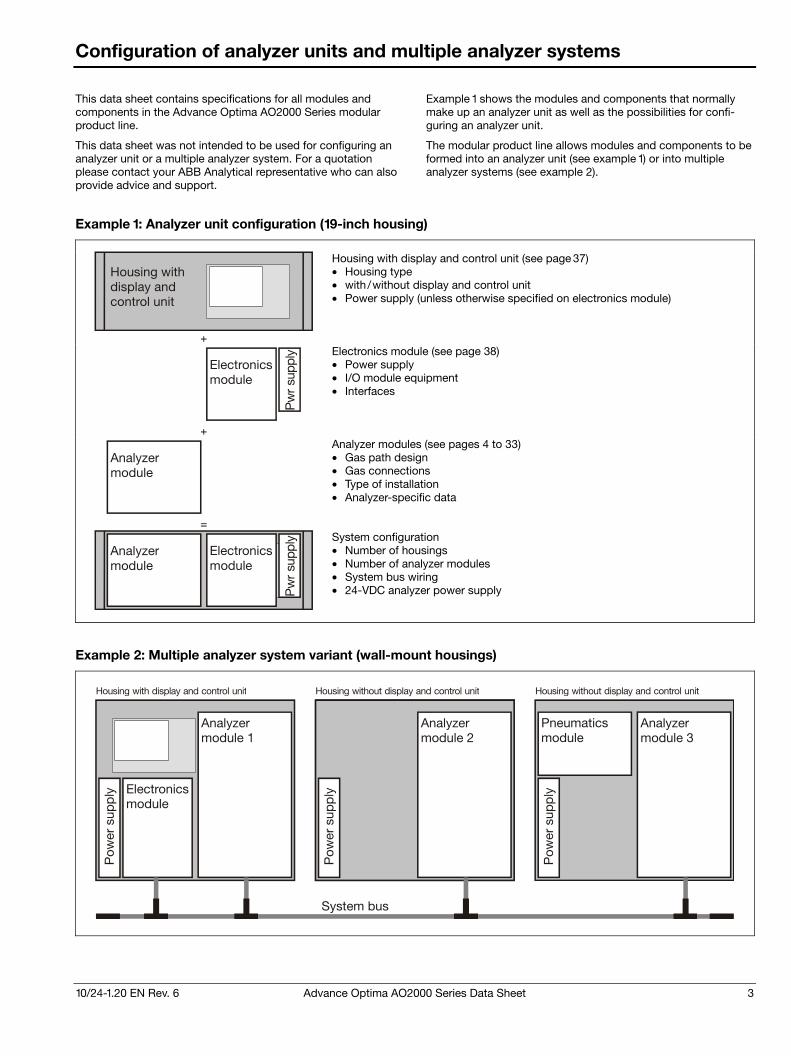
10/24-1.20 EN Rev. 6 Advance Optima AO2000 Series Data Sheet 3
Configuration of analyzer units and multiple analyzer systems
This data sheet contains specifications for all modules and components in the Advance Optima AO2000 Series modular product line.
This data sheet was not intended to be used for configuring an analyzer unit or a multiple analyzer system. For a quotation please contact your ABB Analytical representative who can also provide advice and support.
Example 1 shows the modules and components that normally make up an analyzer unit as well as the possibilities for confi-guring an analyzer unit.
The modular product line allows modules and components to be formed into an analyzer unit (see example 1) or into multiple analyzer systems (see example 2).
Example 1: Analyzer unit configuration (19-inch housing)
Housing withdisplay andcontrol unit
Housing with display and control unit (see page 37) • Housing type • with/without display and control unit • Power supply (unless otherwise specified on electronics module)
+
Pw
r su
pply
Electronicsmodule
Electronics module (see page 38) • Power supply • I/O module equipment • Interfaces
+
Analyzermodule
Analyzer modules (see pages 4 to 33) • Gas path design • Gas connections • Type of installation • Analyzer-specific data
=
Housing withdisplay andcontrol unit
Analyzermodule
Pw
r su
pply
Electronicsmodule
System configuration • Number of housings • Number of analyzer modules • System bus wiring • 24-VDC analyzer power supply
Example 2: Multiple analyzer system variant (wall-mount housings)
Housing with display and control unit Housing without display and control unit Housing without display and control unit
Analyzermodule 1
Analyzermodule 2
Analyzermodule 3
Pow
er s
upp
ly
Pow
er s
upp
ly
Pow
er s
upp
lyElectronicsmodule
Pneumaticsmodule
System bus
4 Advance Optima AO2000 Series Data Sheet 10/24-1.20 EN Rev. 6
Infrared analyzer module Uras26
Measurement principle
Non-dispersive infrared absorption in the λ = 2.5 to 8 μm wavelength range
Photometer to measure from 1 to 4 components with 1 or 2 beam paths and 1 or 2 receivers in each beam path
Sample components and measurement ranges
The Uras26 analyzer module has one physical measurement range per sample component. As an option, smaller measure-ment ranges can be electronically derived from the physical measurement range. The smallest range is measurement range 1.
The smallest measurement ranges shown in the following table are based on the first sample component in beam path 1.
Sample compo-nent
Smallest class 1 range
Smallest class 2 range
Smallest class 2 range with calibration cell
Gas group 1)
CO 0– 50 ppm 0– 10 ppm 0– 50 ppm 2) A
CO2 0– 50 ppm 0– 5 ppm 0– 25 ppm 2) A
NO 0– 75 ppm 0– 75 ppm 0– 75 ppm 2) A
SO2 0– 100 ppm 0– 25 ppm 0– 25 ppm 2) A
N2O 0– 50 ppm 0– 20 ppm 0– 50 ppm 2) A
CH4 0– 100 ppm 0– 50 ppm 0– 50 ppm 2) A
NH3 0– 500 ppm 0– 30 ppm – B
C2H2 0– 200 ppm 0– 100 ppm 0– 100 ppm B
C2H4 0– 500 ppm 0– 300 ppm 0– 300 ppm B
C2H6 0– 100 ppm 0– 50 ppm 0– 50 ppm 2) B
C3H6 0– 250 ppm 0– 100 ppm 0– 100 ppm 2) B
C3H8 0– 100 ppm 0– 50 ppm 0– 50 ppm 2) B
C4H10 0– 100 ppm 0– 50 ppm 0– 50 ppm 2) B
C6H14 0– 500 ppm 0– 100 ppm 0– 100 ppm 2) B
R 134a 0– 100 ppm 0– 50 ppm 0– 50 ppm 2) B
SF6 0– 5 ppm 0– 4 ppm – B
H2O 0– 1000 ppm 0– 500 ppm 0– 500 ppm C
1) See price information 2) The smallest measurement range 1 is shown. The largest
measurement range should be at least four times larger.
Other sample components on request.
Measurement range quantity 1 to 4 ranges per sample component
Largest measurement range 0 to 100 vol.% or 0 vol.% to saturation or 0 vol.% to LEL Measurement ranges within ignition limits cannot be provided.
Measurement range ratio ≤ 1:20
Measurement ranges with suppressed zero-point Electronic zero-point suppression or differential measurement based on a base level > 0 with flowing reference gas, max. suppression ratio of 1:10
Stability
The following data apply to measurement range 1 in a delivered analyzer module.
Linearity deviation ≤ 1 % of span Option: Linearization according to EPA specifications for automobile exhaust gas measurement
Repeatability ≤ 0.5 % of span
Zero drift ≤ 1 % of span per week; for ranges smaller than class 1 to class 2: ≤ 3 % of span per week
Sensitivity drift ≤ 1 % of measured value per week
Output fluctuation (2 σ) ≤ 0.2 % of span at electronic T90 time = 5 sec (class 1) or = 15 sec (class 2)
Detection limit (4 σ) ≤ 0.4 % of span at electronic T90 time = 5 sec (class 1) or = 15 sec (class 2)
Influence effects
Flow effect Flow rate in the 20 to 100 l/h range: Within detection limits
Associated gas effect /cross sensitivity The knowledge of the sample gas composition is necessary for the analyzer configuration. Selectivity measures to reduce associated gas effect (optional): Incorporation of interference filters or filter vessels, internal electronic cross-sensitivity correction or carrier gas correction for a sample component by other sample compo-nents measured with the Uras26.
Temperature effect Ambient temperature in permissible range – At zero-point: ≤ 1 % of span per 10 °C;
for ranges smaller than class 1 to class 2: ≤ 2 % of span per 10 °C
– On sensitivity with temperature compensation: ≤ 3 % of measured value per 10 °C
– On sensitivity with thermostat effect at 55 °C (optional): ≤ 1 % of measured value per 10 °C
Air pressure effect – At zero-point: No effect – On sensitivity with pressure correction by means of integral
pressure sensor: ≤ 0.2 % of measured value per 1 % air pressure change
The pressure sensor is located in the sample gas path if hoses are used as the internal gas lines. If tubing is used for internal gas lines the pressure sensor is routed to the outside via a hose. Pressure sensor working range: pabs = 600 to 1250 hPa
Power supply effect 24 VDC ± 5 %: ≤ 0.2 % of span
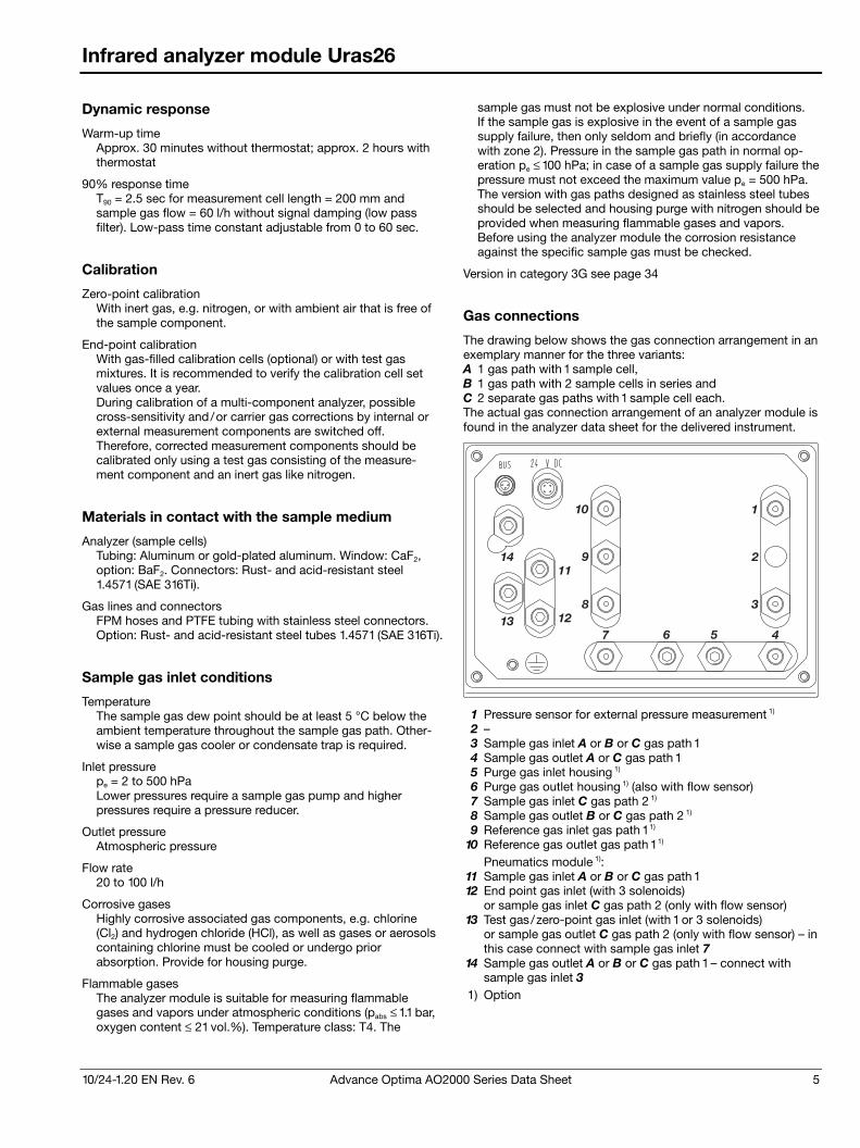
10/24-1.20 EN Rev. 6 Advance Optima AO2000 Series Data Sheet 5
Infrared analyzer module Uras26
Dynamic response
Warm-up time Approx. 30 minutes without thermostat; approx. 2 hours with thermostat
90% response time T90 = 2.5 sec for measurement cell length = 200 mm and sample gas flow = 60 l/h without signal damping (low pass filter). Low-pass time constant adjustable from 0 to 60 sec.
Calibration
Zero-point calibration With inert gas, e.g. nitrogen, or with ambient air that is free of the sample component.
End-point calibration With gas-filled calibration cells (optional) or with test gas mixtures. It is recommended to verify the calibration cell set values once a year. During calibration of a multi-component analyzer, possible cross-sensitivity and/or carrier gas corrections by internal or external measurement components are switched off. Therefore, corrected measurement components should be calibrated only using a test gas consisting of the measure-ment component and an inert gas like nitrogen.
Materials in contact with the sample medium
Analyzer (sample cells) Tubing: Aluminum or gold-plated aluminum. Window: CaF2, option: BaF2. Connectors: Rust- and acid-resistant steel 1.4571 (SAE 316Ti).
Gas lines and connectors FPM hoses and PTFE tubing with stainless steel connectors. Option: Rust- and acid-resistant steel tubes 1.4571 (SAE 316Ti).
Sample gas inlet conditions
Temperature The sample gas dew point should be at least 5 °C below the ambient temperature throughout the sample gas path. Other-wise a sample gas cooler or condensate trap is required.
Inlet pressure pe = 2 to 500 hPa Lower pressures require a sample gas pump and higher pressures require a pressure reducer.
Outlet pressure Atmospheric pressure
Flow rate 20 to 100 l/h
Corrosive gases Highly corrosive associated gas components, e.g. chlorine (Cl2) and hydrogen chloride (HCl), as well as gases or aerosols containing chlorine must be cooled or undergo prior absorption. Provide for housing purge.
Flammable gases The analyzer module is suitable for measuring flammable gases and vapors under atmospheric conditions (pabs ≤ 1.1 bar, oxygen content ≤ 21 vol.%). Temperature class: T4. The
sample gas must not be explosive under normal conditions. If the sample gas is explosive in the event of a sample gas supply failure, then only seldom and briefly (in accordance with zone 2). Pressure in the sample gas path in normal op-eration pe ≤ 100 hPa; in case of a sample gas supply failure the pressure must not exceed the maximum value pe = 500 hPa. The version with gas paths designed as stainless steel tubes should be selected and housing purge with nitrogen should be provided when measuring flammable gases and vapors. Before using the analyzer module the corrosion resistance against the specific sample gas must be checked.
Version in category 3G see page 34
Gas connections
The drawing below shows the gas connection arrangement in an exemplary manner for the three variants: A 1 gas path with 1 sample cell, B 1 gas path with 2 sample cells in series and C 2 separate gas paths with 1 sample cell each. The actual gas connection arrangement of an analyzer module is found in the analyzer data sheet for the delivered instrument.
1
2
3
4567
8
9
10
11
1213
14
1 Pressure sensor for external pressure measurement 1) 2 – 3 Sample gas inlet A or B or C gas path 1 4 Sample gas outlet A or C gas path 1 5 Purge gas inlet housing 1) 6 Purge gas outlet housing 1) (also with flow sensor) 7 Sample gas inlet C gas path 2 1) 8 Sample gas outlet B or C gas path 2 1) 9 Reference gas inlet gas path 1 1)
10 Reference gas outlet gas path 1 1) Pneumatics module 1):
11 Sample gas inlet A or B or C gas path 1 12 End point gas inlet (with 3 solenoids)
or sample gas inlet C gas path 2 (only with flow sensor) 13 Test gas/zero-point gas inlet (with 1 or 3 solenoids)
or sample gas outlet C gas path 2 (only with flow sensor) – in this case connect with sample gas inlet 7
14 Sample gas outlet A or B or C gas path 1 – connect with sample gas inlet 3
1) Option
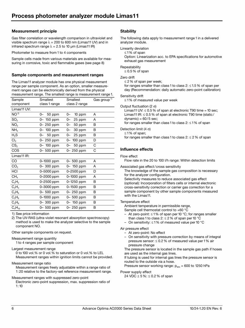
6 Advance Optima AO2000 Series Data Sheet 10/24-1.20 EN Rev. 6
Process photometer analyzer module Limas11
Measurement principle
Gas filter correlation or wavelength comparison in ultraviolet and visible spectrum range λ = 200 to 600 nm (Limas11 UV) and in infrared spectrum range λ = 2.5 to 10 μm (Limas11 IR)
Photometer to measure from 1 to 4 components
Sample cells made from various materials are available for mea-suring in corrosive, toxic and flammable gases (see page 8)
Sample components and measurement ranges
The Limas11 analyzer module has one physical measurement range per sample component. As an option, smaller measure-ment ranges can be electronically derived from the physical measurement range. The smallest range is measurement range 1.
Sample component
Smallest class 1 range
Smallest class 2 range
Gas group 1)
Limas11 UV:
NO 2) 0– 50 ppm 0– 10 ppm A
SO2 0– 150 ppm 0– 25 ppm A
NO2 0– 250 ppm 0– 50 ppm B
NH3 0– 100 ppm 0– 30 ppm B
H2S 0– 50 ppm 0– 25 ppm B
Cl2 0– 250 ppm 0– 100 ppm D
CS2 0– 100 ppm 0– 50 ppm C
COS 0– 500 ppm 0– 250 ppm C
Limas11 IR:
CO 0– 1000 ppm 0– 500 ppm A
CO2 0– 300 ppm 0– 150 ppm A
HCl 0–5000 ppm 0–2500 ppm D
CH4 0–2000 ppm 0– 1000 ppm A
C2H2 0–2500 ppm 0– 1250 ppm B
C2H4 0–3000 ppm 0– 1500 ppm B
C2H6 0– 500 ppm 0– 250 ppm B
C3H6 0– 1000 ppm 0– 500 ppm B
C3H8 0– 300 ppm 0– 150 ppm B
C4H10 0– 500 ppm 0– 250 ppm B
1) See price information 2) The UV-RAS (ultra-violet resonant absorption spectroscopy)
method is used to make the analyzer selective to the sample component NO.
Other sample components on request.
Measurement range quantity 1 to 4 ranges per sample component
Largest measurement range 0 to 100 vol.% or 0 vol.% to saturation or 0 vol.% to LEL Measurement ranges within ignition limits cannot be provided.
Measurement range ratio Measurement ranges freely adjustable within a range ratio of 1:20 relative to the factory-set reference measurement range.
Measurement ranges with suppressed zero-point Electronic zero-point suppression, max. suppression ratio of 1:10
Stability
The following data apply to measurement range 1 in a delivered analyzer module.
Linearity deviation ≤ 1 % of span Option: Linearization acc. to EPA specifications for automotive exhaust gas measurement
Repeatability ≤ 0.5 % of span
Zero drift ≤ 2 % of span per week; for ranges smaller than class 1 to class 2: ≤ 1.5 % of span per day (Recommendation: daily automatic zero-point calibration)
Sensitivity drift ≤ 1 % of measured value per week
Output fluctuation (2 σ) Limas11 UV: ≤ 0.5 % of span at electronic T90 time = 10 sec; Limas11 IR: ≤ 0.5 % of span at electronic T90 time (static / dynamic) = 60/5 sec; for ranges smaller than class 1 to class 2: ≤ 1 % of span
Detection limit (4 σ) ≤ 1 % of span; for ranges smaller than class 1 to class 2: ≤ 2 % of span
Influence effects
Flow effect Flow rate in the 20 to 100 l/h range: Within detection limits
Associated gas effect /cross sensitivity The knowledge of the sample gas composition is necessary for the analyzer configuration. Selectivity measures to reduce associated gas effect (optional): Incorporation of filters cells or internal electronic cross-sensitivity correction or carrier gas correction for a sample component by other sample components measured with the Limas11.
Temperature effect Ambient temperature in permissible range, Sample cell thermostat control to +60 °C – At zero-point: ≤ 1 % of span per 10 °C; for ranges smaller
than class 1 to class 2: ≤ 2 % of span per 10 °C – On sensitivity: ≤ 1 % of measured value per 10 °C
Air pressure effect – At zero-point: No effect – On sensitivity with pressure correction by means of integral
pressure sensor: ≤ 0.2 % of measured value per 1 % air pressure change
The pressure sensor is located in the sample gas path if hoses are used as the internal gas lines. If tubing is used for internal gas lines the pressure sensor is routed to the outside via a hose. Pressure sensor working range: pabs = 600 to 1250 hPa
Power supply effect 24 VDC ± 5 %: ≤ 0.2 % of span

10/24-1.20 EN Rev. 6 Advance Optima AO2000 Series Data Sheet 7
Process photometer analyzer module Limas11
Dynamic response
Warm-up time Approx. 2.5 hours
90% response time T90 = 4 sec for measurement cell length = 262 mm and sample gas flow = 60 l/h without signal damping (low pass filter). Low-pass time constant adjustable from 0 to 60 sec
Calibration
Zero-point calibration With inert gas, e.g. nitrogen, or with ambient air that is free of the sample component
End-point calibration With gas-filled calibration cells (optional) or with test gas. It is recommended to verify the calibration cell set values once a year. During calibration of a multi-component analyzer, possible cross-sensitivity and/or carrier gas corrections by internal or external measurement components are switched off. Therefore, corrected measurement components should be calibrated only using a test gas consisting of the measure-ment component and an inert gas like nitrogen.
Materials in contact with the sample medium
See page 8
Sample gas inlet conditions
Temperature The sample gas dew point should be at least 5 °C below the ambient temperature throughout the sample gas path. Other-wise a sample gas cooler or condensate trap is required.
Inlet pressure pe = 2 to 500 hPa (maximum pressure see page 8) Lower pressures require a sample gas pump and higher pressures require a pressure reducer.
Outlet pressure Atmospheric pressure
Flow rate 20 to 100 l/h
Corrosive, toxic and flammable gases See page 8
Purge gas See page 8
Gas connections
See page 9
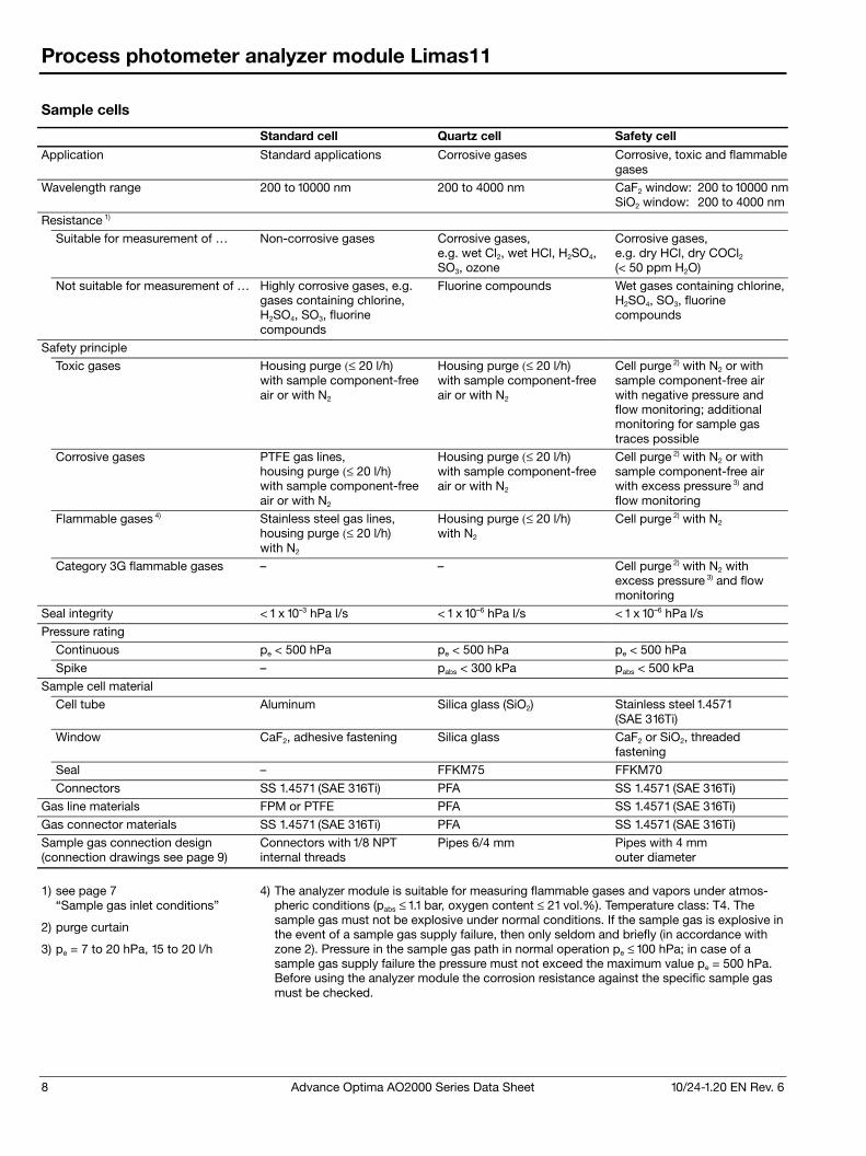
8 Advance Optima AO2000 Series Data Sheet 10/24-1.20 EN Rev. 6
Process photometer analyzer module Limas11
Sample cells
Standard cell Quartz cell Safety cell
Application Standard applications Corrosive gases Corrosive, toxic and flammable gases
Wavelength range 200 to 10000 nm 200 to 4000 nm CaF2 window: 200 to 10000 nmSiO2 window: 200 to 4000 nm
Resistance 1)
Suitable for measurement of … Non-corrosive gases Corrosive gases, e.g. wet Cl2, wet HCl, H2SO4, SO3, ozone
Corrosive gases, e.g. dry HCl, dry COCl2 (< 50 ppm H2O)
Not suitable for measurement of … Highly corrosive gases, e.g. gases containing chlorine, H2SO4, SO3, fluorine compounds
Fluorine compounds Wet gases containing chlorine, H2SO4, SO3, fluorine compounds
Safety principle
Toxic gases Housing purge (≤ 20 l/h) with sample component-free air or with N2
Housing purge (≤ 20 l/h) with sample component-free air or with N2
Cell purge 2) with N2 or with sample component-free air with negative pressure and flow monitoring; additional monitoring for sample gas traces possible
Corrosive gases PTFE gas lines, housing purge (≤ 20 l/h) with sample component-free air or with N2
Housing purge (≤ 20 l/h) with sample component-free air or with N2
Cell purge 2) with N2 or with sample component-free air with excess pressure 3) and flow monitoring
Flammable gases 4) Stainless steel gas lines, housing purge (≤ 20 l/h) with N2
Housing purge (≤ 20 l/h) with N2
Cell purge 2) with N2
Category 3G flammable gases – – Cell purge 2) with N2 with excess pressure 3) and flow monitoring
Seal integrity < 1 x 10⁻³ hPa l/s < 1 x 10⁻⁶ hPa l/s < 1 x 10⁻⁶ hPa l/s
Pressure rating
Continuous pe < 500 hPa pe < 500 hPa pe < 500 hPa
Spike – pabs < 300 kPa pabs < 500 kPa
Sample cell material
Cell tube Aluminum Silica glass (SiO2) Stainless steel 1.4571 (SAE 316Ti)
Window CaF2, adhesive fastening Silica glass CaF2 or SiO2, threaded fastening
Seal – FFKM75 FFKM70
Connectors SS 1.4571 (SAE 316Ti) PFA SS 1.4571 (SAE 316Ti)
Gas line materials FPM or PTFE PFA SS 1.4571 (SAE 316Ti)
Gas connector materials SS 1.4571 (SAE 316Ti) PFA SS 1.4571 (SAE 316Ti)
Sample gas connection design (connection drawings see page 9)
Connectors with 1/8 NPT internal threads
Pipes 6/4 mm Pipes with 4 mm outer diameter
1) see page 7 “Sample gas inlet conditions”
2) purge curtain
3) pe = 7 to 20 hPa, 15 to 20 l/h
4) The analyzer module is suitable for measuring flammable gases and vapors under atmos-pheric conditions (pabs ≤ 1.1 bar, oxygen content ≤ 21 vol.%). Temperature class: T4. The sample gas must not be explosive under normal conditions. If the sample gas is explosive in the event of a sample gas supply failure, then only seldom and briefly (in accordance with zone 2). Pressure in the sample gas path in normal operation pe ≤ 100 hPa; in case of a sample gas supply failure the pressure must not exceed the maximum value pe = 500 hPa. Before using the analyzer module the corrosion resistance against the specific sample gas must be checked.
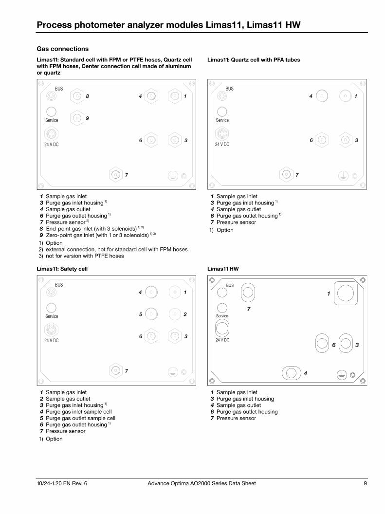
10/24-1.20 EN Rev. 6 Advance Optima AO2000 Series Data Sheet 9
Process photometer analyzer modules Limas11, Limas11 HW
Gas connections
Limas11: Standard cell with FPM or PTFE hoses, Quartz cell with FPM hoses, Center connection cell made of aluminum or quartz
Limas11: Quartz cell with PFA tubes
7
8
9
1
3
4
6
BUS
Service
24 V DC
7
1
3
4
6
BUS
Service
24 V DC
1 Sample gas inlet 1 Sample gas inlet 3 Purge gas inlet housing 1) 3 Purge gas inlet housing 1) 4 Sample gas outlet 4 Sample gas outlet 6 Purge gas outlet housing 1) 6 Purge gas outlet housing 1) 7 Pressure sensor 2) 7 Pressure sensor 8 End-point gas inlet (with 3 solenoids) 1) 3) 9 Zero-point gas inlet (with 1 or 3 solenoids) 1) 3)
1) Option
1) Option 2) external connection, not for standard cell with FPM hoses 3) not for version with PTFE hoses
Limas11: Safety cell Limas11 HW
7
1
2
3
4
5
6
BUS
Service
24 V DC
BUS
Service
24 V DC
7
6 3
1
4
1 Sample gas inlet 1 Sample gas inlet 2 Sample gas outlet 3 Purge gas inlet housing 3 Purge gas inlet housing 1) 4 Sample gas outlet 4 Purge gas inlet sample cell 6 Purge gas outlet housing 5 Purge gas outlet sample cell 7 Pressure sensor 6 Purge gas outlet housing 1) 7 Pressure sensor 1) Option
10 Advance Optima AO2000 Series Data Sheet 10/24-1.20 EN Rev. 6
Process photometer analyzer module Limas11 HW
Measurement principle and application
Limas11 HW is a multi-component analyzer for simultaneous measurement of nitrogen compounds in wet sulfur-free flue gas without converter.
Measurement principle
Photometer to measure from 1 to 4 components such as NO, NO2 and NH3.
Wavelength comparison in ultraviolet spectrum range λ = 200 to 600 nm for sample components NO2 and NH3.
The UV-RAS method (ultra-violet resonant absorption spectro-scopy) is used to make the analyzer selective to the sample component NO.
Applications
Exhaust gas measurement for the development of combustion engines and methods for exhaust gas after-treatment, in particu-lar for pure gas measurement after catalyst in – Four-stroke gasoline and diesel engines, – Catalysts for nitrogen oxide reduction.
Process measurement for flue gas scrubbing systems in gas turbines and gas-fired burners, in particular for monitoring, controlling and optimizing DeNOx SCR processes.
Sample components and measurement ranges (recommendations), stability data
Exhaust gas measurement for four-stroke gasoline and diesel engines
Sample component Smallest range Largest range
NO 0–100 ppm 0–5000 ppm
NO2 0–100 ppm 0–2500 ppm
Linearity deviation ≤ 1 % of span, ≤ 2 % of measured value acc. to EPA specifications for automotive exhaust gas measurement
Repeatability ≤ 0.25 % of span
Zero drift ≤ 1 ppm or ≤ 1 % of span per 24 hours based on the smallest recommended measurement range (daily automatic zero-point calibration recommended)
Sensitivity drift ≤ 1 % of measured value per week
Output fluctuation (2 σ) ≤ 400 ppb or ≤ 0.4 % of span at electronic T90 time = 5 sec
Detection limit (4 σ) ≤ 800 ppb or ≤ 0.8 % of span at electronic T90 time = 5 sec
Diluted exhaust gas measurement for four-stroke gasoline and diesel engines, bag measurement
Sample component Smallest range Largest range
NO 0–10 ppm 0–500 ppm
NO2 0–10 ppm 0–500 ppm
Linearity deviation ≤ 1 % of span, ≤ 2 % of measured value acc. to EPA specifications for automotive exhaust gas measurement
Repeatability ≤ 0.25 % of span
Zero drift ≤ 250 ppb or ≤ 2 % of span per 8 hours based on the smallest recommended measurement range (daily automatic zero-point calibration recommended)
Sensitivity drift ≤ 1 % of measured value per week
Output fluctuation (2 σ) NO ≤ 50 ppb, NO2 ≤ 60 ppb at electronic T90 time = 15 sec
Detection limit (4 σ) NO ≤ 100 ppb or ≤ 1 % of span, NO2 ≤ 120 ppb or ≤ 1 % of span at electronic T90 time = 15 sec
Process measurement
Sample Component Smallest Range Largest Range
NO 0–100 ppm 0– 1000 ppm
NO2 0–100 ppm 0– 500 ppm
NH3 0–100 ppm 0– 500 ppm
Linearity deviation ≤ 1 % of span
Repeatability ≤ 0.25 % of span
Zero drift ≤ 1 ppm or ≤ 1 % of span per 24 hours based on the smallest recommended measurement range (daily automatic zero-point calibration recommended)
Sensitivity drift ≤ 1 % of measured value per week
Output fluctuation (2 σ) ≤ 150 ppb or ≤ 0.15 % of span at electronic T90 time = 30 sec
Detection limit (4 σ) ≤ 300 ppb or ≤ 0.3 % of span at electronic T90 time = 30 sec
Measurement ranges
Quantity 1 to 4 ranges per sample component
Measurement range ratio Max. 1:20. Measurement ranges are freely adjustable within a range ratio of 1:20 relative to the factory-set reference meas-urement range. Max. 1:50 for fixed measurement ranges acc. to EPA specifications for automotive exhaust gas measurement
10/24-1.20 EN Rev. 6 Advance Optima AO2000 Series Data Sheet 11
Process photometer analyzer module Limas11 HW
Influence effects
Flow effect Flow rate in the 20 to 90 l/h range: within detection limits
Associated gas effect /cross sensitivity The knowledge of the sample gas composition is necessary for the analyzer configuration. Selectivity measures to reduce associated gas effect: Internal electronic cross-sensitivity correction or carrier gas correction for a sample component by other sample components measured with the Limas11 HW.
Temperature effect Ambient temperature in permissible range, Sample cell thermostat control to +80 °C – At zero-point: ≤ 2 % of span per 10 °C – On sensitivity: ≤ 2 % of measured value per 10 °C
Air pressure effect – At zero-point: No effect – On sensitivity with pressure correction by means of integral
pressure sensor: ≤ 0.2 % of measured value per 1 % air pressure change
The pressure sensor is routed to the outside via a hose. Pressure sensor working range: pabs = 600 to 1250 hPa
Power supply effect 24 VDC ± 5 %: ≤ 0.2 % of span
Dynamic response
Warm-up time Approx. 4 hours
90% response time T90 ≤ 5 sec for measurement cell length = 260 mm and sample gas flow = 60 l/h with non-linear filter (static/dynamic) = 15/1 sec. Low-pass time constant adjustable from 0 to 30 sec.
Calibration
Zero-point calibration With inert gas, e.g. nitrogen, or with ambient air that is free of the sample component
End-point calibration With gas-filled calibration cells (optional) or with test gas. It is recommended to verify the calibration cell set values once a year. During calibration of a multi-component analyzer, possible cross-sensitivity and/or carrier gas corrections by internal or external measurement components are switched off. Therefore, corrected measurement components should be calibrated only using a test gas consisting of the measure-ment component and an inert gas like nitrogen.
Materials in contact with the sample medium
Sample cell Tubing and window: Silica glass, Screw connection: PVDF; Connectors: PTFE
Gas lines and connectors Stainless steel 1.4305 (SAE 303), 1.4571 (SAE 316Ti)
Housing purge
Purge gas Sample component-free air or nitrogen Purge gas flow rate ≤ 10 l/h
Sample gas inlet conditions
Sample gas composition Sulfur-free exhaust gas of combustors, SO2 concentration < 25 ppm, H2O < 20 vol.%, filtered with pore width ≤ 0.5 μm
Temperature Sample gas dew point ≤ 65 °C
Inlet pressure pe = 2 to 500 hPa. Lower pressures require a sample gas pump and higher pressures require a pressure reducer.
Outlet pressure Atmospheric pressure
Flow rate 20 to 90 l/h
Gas connections
See page 9
Notes
The analyzer module Limas11 HW can only be mounted in the 19-inch housing.
SO2 influences the NH3 reading. If the sample gas mixture contains SO2, the requirement of internal corrections must be scrutinized.
When ordering the average water vapor concentration has to be specified. The influence is corrected internally.
Sample conditioning system requirements
Sample gas feed-in The various applications require the sample gas feed-in to the gas analyzer at temperatures of 150 to 190 °C. It is imperative to eliminate condensation and sublimation since NH3 and NO2 are easy soluble in water and can result in salification. It is also imperative to prevent condensation of potentially present low-boiling hydrocarbons.
Sample gas inlet temperature (on the process side) 150 to 190 °C
Sample gas filter For NO and NO2 measurement: Sintered metal; for NH3 measurement: Ceramics; pore width ≤ 0.5 μm
Materials in contact with the sample medium PTFE, PVDF or Silicosteel
Exhaust gas conditions Outlet pressure = atmospheric pressure, no resistance in the gas outlet.
Installation note Route the exhaust gas line declining to allow for condensate drain-off.
12 Advance Optima AO2000 Series Data Sheet 10/24-1.20 EN Rev. 6
Oxygen analyzer module Magnos206
Measurement principle
Paramagnetic behavior of oxygen
Magnetomechanical analyzer; short 90% response time
Sample component and measurement ranges
Sample component Oxygen (O2)
Smallest measurement range 0 to 0.5 vol.% O2
Measurement range quantity and limits 4 measurement ranges Measurement ranges are freely adjustable; they are factory-set to 0 to 10/15/25/100 vol.% O2 or per order.
Largest measurement range 0 to 100 vol.% O2 Measurement ranges within ignition limits cannot be provided.
Measurement ranges with suppressed zero-point Max. measurement range suppression 1:100, e.g. 99 to 100 vol.% O2. Highly suppressed measurement ranges (≥95 to 100 vol.% O2) and initial measurement ranges in the same analyzer should be avoided. Pressure correction by means of pressure sensor required.
Stability
Linearity deviation ≤ 0.5 % of span, minimum 0.005 vol.% O2
Repeatability ≤ 50 ppm O2 (time base for gas exchange ≥ 5 minutes)
Zero drift ≤ 3 % of span of the smallest measurement range (per order) per week, minimum 300 ppm O2 per week; following pro-longed transport and storage time the drift can be higher during the first weeks of operation.
Sensitivity drift ≤ 0.1 vol.% O2 per week or ≤ 1 % of measured value per week (not cumulative), whichever is smaller. ≤ 0.25 % of measured value per year, minimum 0.05 vol.% O2 per year
Output fluctuation (2 σ) ≤ 25 ppm O2 at electronic T90 time (static /dynamic) = 3 /0 sec
Detection limit (4 σ) ≤ 50 ppm O2 at electronic T90 time (static /dynamic) = 3 /0 sec
Influence effects
Flow effect ≤ 0.1 vol.% O2 in permissible range
Associated gas effect Data regarding the effect of associated gases can be found in IEC 61207-3 :2002 “Gas analyzers – Expression of perform-ance – Part 3: Paramagnetic oxygen analyzers”.
Temperature effect Ambient temperature in permissible range – At zero-point: ≤ 0.02 vol.% O2 per 10 °C – On sensitivity: ≤ 0.1 % of measured value per 10 °C Thermostat temperature = 64 °C
Air pressure effect – At zero-point: No effect – On sensitivity without pressure correction:
≤ 1 % of measured value per 1 % air pressure change – On sensitivity with pressure correction using integrated
pressure sensor (optional): ≤ 0.1 % of measured value per 1 % air pressure change; for highly suppressed measurement ranges ≤ 0.01 % of measured value per 1 % air pressure change or ≤ 0.002 vol.% O2 per 1 % air pressure change, whichever is greater. Pressure sensor working range: pabs = 600 to 1250 hPa
Power supply effect 24 VDC ± 5 %: ≤ 0.4 % of span
Position effect Zero-point shift ≤ 0.05 vol.% O2 per 1° deviation from horizontal location. Position has no effect on the hard-mounted unit.
Dynamic response
Warm-up time < 1 hour
90% response time T90 ≤ 3.5 to 10 sec at a sample gas flow of 90 l/h and elec-tronic T90 time (static /dynamic) = 3 /0 sec, gas change from nitrogen to air (applies to an analyzer unit with 1 analyzer module)
Calibration
Zero-point calibration With oxygen-free process gas or substitute gas
End-point calibration With process gas with a known oxygen concentration or a substitute gas such as dried air
Single-point calibration For measurement ranges from 0 to 5 vol.% O2 to 0 to 25 vol.% O2: Zero-point calibration with any oxygen concentration, e.g. with nitrogen or ambient air, processed through a cooler or H2O absorber. Pressure correction by means of pressure sensor is recom-mended for single-point calibration with air. Depending on the measurement task involved, the zero- and end-points should be verified periodically (recommendation: once a year).
Calibration of measurement ranges with suppressed zero-point Highly suppressed measurement ranges (≥95 to 100 vol.% O2) should only be calibrated with test gases with concentrations in the selected measurement range. Single-point calibration can also be done within a suppressed measurement range. The O2 concentration of the test gas must lie within the measurement range.
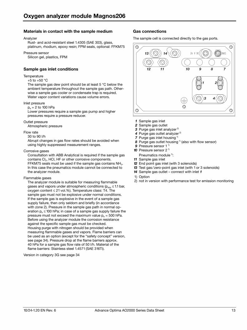
10/24-1.20 EN Rev. 6 Advance Optima AO2000 Series Data Sheet 13
Oxygen analyzer module Magnos206
Materials in contact with the sample medium
Analyzer Rust- and acid-resistant steel 1.4305 (SAE 303), glass, platinum, rhodium, epoxy resin; FPM seals, optional: FFKM75
Pressure sensor Silicon gel, plastics, FPM
Sample gas inlet conditions
Temperature +5 to +50 °C The sample gas dew point should be at least 5 °C below the ambient temperature throughout the sample gas path. Other-wise a sample gas cooler or condensate trap is required. Water vapor content variations cause volume errors.
Inlet pressure pe = 2 to 100 hPa Lower pressures require a sample gas pump and higher pressures require a pressure reducer.
Outlet pressure Atmospheric pressure
Flow rate 30 to 90 l/h Abrupt changes in gas flow rates should be avoided when using highly suppressed measurement ranges.
Corrosive gases Consultation with ABB Analytical is required if the sample gas contains Cl2, HCl, HF or other corrosive components. FFKM75 seals must be used if the sample gas contains NH3. In this case the pneumatics module cannot be connected to the analyzer module.
Flammable gases The analyzer module is suitable for measuring flammable gases and vapors under atmospheric conditions (pabs ≤ 1.1 bar, oxygen content ≤ 21 vol.%). Temperature class: T4. The sample gas must not be explosive under normal conditions. If the sample gas is explosive in the event of a sample gas supply failure, then only seldom and briefly (in accordance with zone 2). Pressure in the sample gas path in normal op-eration pe ≤ 100 hPa; in case of a sample gas supply failure the pressure must not exceed the maximum value pe = 500 hPa. Before using the analyzer module the corrosion resistance against the specific sample gas must be checked. Housing purge with nitrogen should be provided when measuring flammable gases and vapors. Flame barriers can be used as an option (except for the “safety concept” version, see page 34). Pressure drop at the flame barriers approx. 40 hPa for a sample gas flow rate of 50 l/h. Material of the flame barriers: Stainless steel 1.4571 (SAE 316Ti).
Version in category 3G see page 34
Gas connections
The sample cell is connected directly to the gas ports.
1 2
3 4
13 14
12 11 10 9 8 7
1 Sample gas inlet 2 Sample gas outlet 3 Purge gas inlet analyzer 2) 4 Purge gas outlet analyzer 2) 7 Purge gas inlet housing 1) 8 Purge gas outlet housing 1) (also with flow sensor) 9 Pressure sensor 1 1)
10 Pressure sensor 2 1) Pneumatics module 1):
11 Sample gas inlet 12 End point gas inlet (with 3 solenoids) 13 Test gas/zero-point gas inlet (with 1 or 3 solenoids) 14 Sample gas outlet – connect with inlet 1 1) Option 2) not in version with performance test for emission monitoring
14 Advance Optima AO2000 Series Data Sheet 10/24-1.20 EN Rev. 6
Oxygen analyzer module Magnos27
Measurement principle
Paramagnetic behavior of oxygen
Heavy-duty thermomagnetic analyzer
Sample component and measurement ranges
Sample component Oxygen (O2) in flue gas or in nitrogen
Smallest measurement range 0 to 3 vol.% O2
Measurement range quantity 1 to 4 measurement ranges Ranges are factory-set per customer order.
Largest measurement range 0 to 100 vol.% O2 Measurement ranges within ignition limits cannot be provided.
Stability
Linearity deviation ≤ 2 % of span
Repeatability ≤ 1 % of span
Zero drift ≤ 1 % of span per week
Sensitivity drift ≤ 2 % of measured value per week
Output fluctuation (2 σ) ≤ 0.5 % of smallest measurement range span at electronic T90 time = 0 sec
Detection limit (4 σ) ≤ 1 % of smallest measurement range span at electronic T90 time = 0 sec
Influence effects
Flow effect ≤ 1 % of span at a flow change of ±10 l/h. At an identical flow rate for test and sample gases the flow rate effect is automa-tically compensated.
Associated gas effect Magnos27 calibration applies only to the sample gas shown on the identification plate (= sample component + associated gas).
Temperature effect Ambient temperature in permissible range – At zero-point: ≤ 2 % of span per 10 °C – On sensitivity: ≤ 0.5 % of measured value per 10 °C relative to temperature at the time of calibration Thermostat temperature = 63 °C
Air pressure effect – At zero-point: < 0.05 vol.% O2 per 1 % air pressure change – On sensitivity without pressure correction:
≤ 1.5 % of measured value per 1 % air pressure change – On sensitivity with pressure correction:
≤ 0.25 % of measured value per 1 % air pressure change Option: Operating altitude over 2000 m
Power supply effect 24 VDC ± 5 %: ≤ 0.2 % of span
Position effect Approx. 3 % of smallest measurement range span per 1° deviation from horizontal orientation. Position has no effect on the hard-mounted unit.
Dynamic response
Warm-up time 2 to 4 hours
90% response time T90 = 10 to 22 sec, depending on sample gas flow and on measurement cell connection (see “Gas connections”, applies to an analyzer unit with 1 analyzer module)
Calibration
Zero-point calibration With oxygen-free process gas or substitute gas
End-point calibration With process gas having a known oxygen concentration or with substitute gas
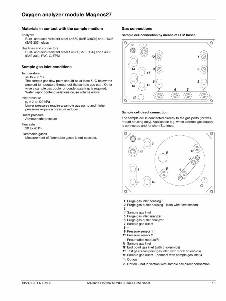
10/24-1.20 EN Rev. 6 Advance Optima AO2000 Series Data Sheet 15
Oxygen analyzer module Magnos27
Materials in contact with the sample medium
Analyzer Rust- and acid-resistant steel 1.4580 (SAE 316Cb) and 1.4305 (SAE 303), glass
Gas lines and connectors Rust- and acid-resistant steel 1.4571 (SAE 316Ti) and 1.4305 (SAE 303), PVC-C, FPM
Sample gas inlet conditions
Temperature +5 to +50 °C The sample gas dew point should be at least 5 °C below the ambient temperature throughout the sample gas path. Other-wise a sample gas cooler or condensate trap is required. Water vapor content variations cause volume errors.
Inlet pressure pe = 2 to 100 hPa Lower pressures require a sample gas pump and higher pressures require a pressure reducer.
Outlet pressure Atmospheric pressure
Flow rate 20 to 90 l/h
Flammable gases Measurement of flammable gases is not possible.
Gas connections
Sample cell connection by means of FPM hoses
1
2
3
4567
8
9
10
11
12
14
13
Sample cell direct connection
The sample cell is connected directly to the gas ports (for wall-mount housing only). Application e.g. when external gas supply is connected and for short T90 times.
1
2 10
9
4
7
68
5
1 Purge gas inlet housing 1) 2 Purge gas outlet housing 1) (also with flow sensor) 3 – 4 Sample gas inlet 5 Purge gas inlet analyzer 6 Purge gas outlet analyzer 7 Sample gas outlet 8 – 9 Pressure sensor 1 1)
10 Pressure sensor 2 1) Pneumatics module 2):
11 Sample gas inlet 12 End point gas inlet (with 3 solenoids) 13 Test gas/zero-point gas inlet (with 1 or 3 solenoids) 14 Sample gas outlet – connect with sample gas inlet 4 1) Option 2) Option – not in version with sample cell direct connection
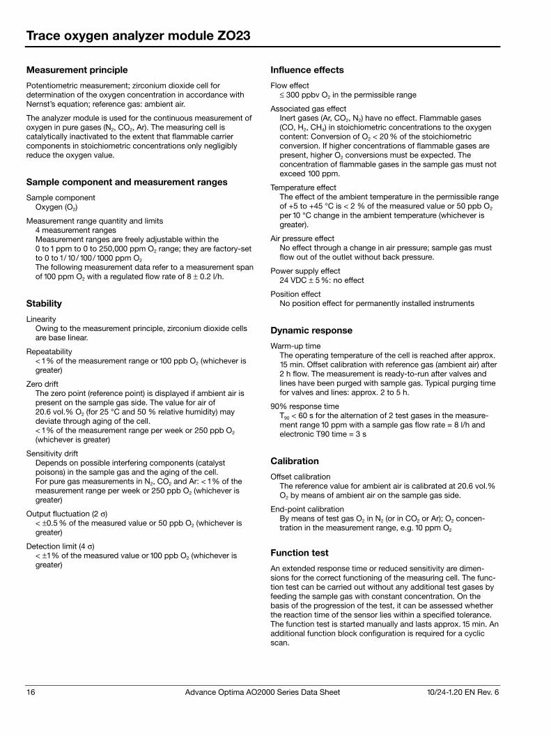
16 Advance Optima AO2000 Series Data Sheet 10/24-1.20 EN Rev. 6
Trace oxygen analyzer module ZO23
Measurement principle
Potentiometric measurement; zirconium dioxide cell for determination of the oxygen concentration in accordance with Nernst’s equation; reference gas: ambient air.
The analyzer module is used for the continuous measurement of oxygen in pure gases (N2, CO2, Ar). The measuring cell is catalytically inactivated to the extent that flammable carrier components in stoichiometric concentrations only negligibly reduce the oxygen value.
Sample component and measurement ranges
Sample component Oxygen (O2)
Measurement range quantity and limits 4 measurement ranges Measurement ranges are freely adjustable within the 0 to 1 ppm to 0 to 250,000 ppm O2 range; they are factory-set to 0 to 1/10/100/1000 ppm O2 The following measurement data refer to a measurement span of 100 ppm O2 with a regulated flow rate of 8 ± 0.2 l/h.
Stability
Linearity Owing to the measurement principle, zirconium dioxide cells are base linear.
Repeatability < 1 % of the measurement range or 100 ppb O2 (whichever is greater)
Zero drift The zero point (reference point) is displayed if ambient air is present on the sample gas side. The value for air of 20.6 vol.% O2 (for 25 °C and 50 % relative humidity) may deviate through aging of the cell. < 1 % of the measurement range per week or 250 ppb O2 (whichever is greater)
Sensitivity drift Depends on possible interfering components (catalyst poisons) in the sample gas and the aging of the cell. For pure gas measurements in N2, CO2 and Ar: < 1 % of the measurement range per week or 250 ppb O2 (whichever is greater)
Output fluctuation (2 σ) < ±0.5 % of the measured value or 50 ppb O2 (whichever is greater)
Detection limit (4 σ) < ±1 % of the measured value or 100 ppb O2 (whichever is greater)
Influence effects
Flow effect ≤ 300 ppbv O2 in the permissible range
Associated gas effect Inert gases (Ar, CO2, N2) have no effect. Flammable gases (CO, H2, CH4) in stoichiometric concentrations to the oxygen content: Conversion of O2 < 20 % of the stoichiometric conversion. If higher concentrations of flammable gases are present, higher O2 conversions must be expected. The concentration of flammable gases in the sample gas must not exceed 100 ppm.
Temperature effect The effect of the ambient temperature in the permissible range of +5 to +45 °C is < 2 % of the measured value or 50 ppb O2 per 10 °C change in the ambient temperature (whichever is greater).
Air pressure effect No effect through a change in air pressure; sample gas must flow out of the outlet without back pressure.
Power supply effect 24 VDC ± 5 %: no effect
Position effect No position effect for permanently installed instruments
Dynamic response
Warm-up time The operating temperature of the cell is reached after approx. 15 min. Offset calibration with reference gas (ambient air) after 2 h flow. The measurement is ready-to-run after valves and lines have been purged with sample gas. Typical purging time for valves and lines: approx. 2 to 5 h.
90% response time T90 < 60 s for the alternation of 2 test gases in the measure-ment range 10 ppm with a sample gas flow rate = 8 l/h and electronic T90 time = 3 s
Calibration
Offset calibration The reference value for ambient air is calibrated at 20.6 vol.% O2 by means of ambient air on the sample gas side.
End-point calibration By means of test gas O2 in N2 (or in CO2 or Ar); O2 concen-tration in the measurement range, e.g. 10 ppm O2
Function test
An extended response time or reduced sensitivity are dimen-sions for the correct functioning of the measuring cell. The func-tion test can be carried out without any additional test gases by feeding the sample gas with constant concentration. On the basis of the progression of the test, it can be assessed whether the reaction time of the sensor lies within a specified tolerance. The function test is started manually and lasts approx. 15 min. An additional function block configuration is required for a cyclic scan.
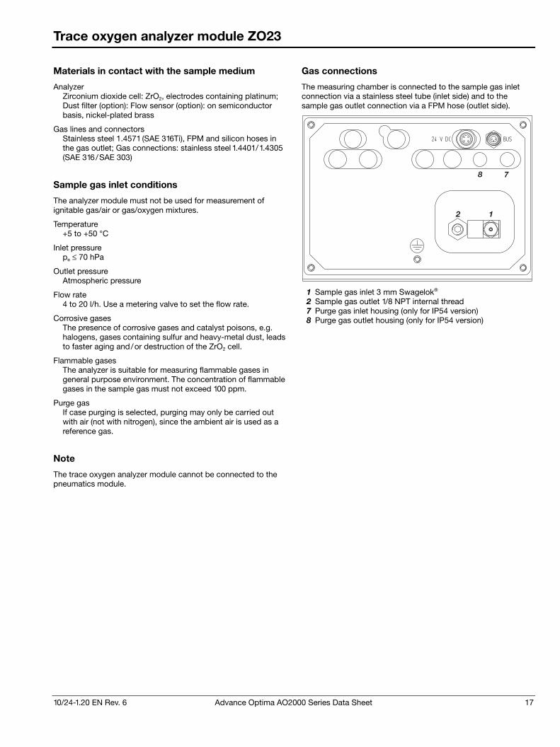
10/24-1.20 EN Rev. 6 Advance Optima AO2000 Series Data Sheet 17
Trace oxygen analyzer module ZO23
Materials in contact with the sample medium
Analyzer Zirconium dioxide cell: ZrO2, electrodes containing platinum; Dust filter (option): Flow sensor (option): on semiconductor basis, nickel-plated brass
Gas lines and connectors Stainless steel 1.4571 (SAE 316Ti), FPM and silicon hoses in the gas outlet; Gas connections: stainless steel 1.4401/1.4305 (SAE 316/SAE 303)
Sample gas inlet conditions
The analyzer module must not be used for measurement of ignitable gas/air or gas/oxygen mixtures.
Temperature +5 to +50 °C
Inlet pressure pe ≤ 70 hPa
Outlet pressure Atmospheric pressure
Flow rate 4 to 20 l/h. Use a metering valve to set the flow rate.
Corrosive gases The presence of corrosive gases and catalyst poisons, e.g. halogens, gases containing sulfur and heavy-metal dust, leads to faster aging and/or destruction of the ZrO2 cell.
Flammable gases The analyzer is suitable for measuring flammable gases in general purpose environment. The concentration of flammable gases in the sample gas must not exceed 100 ppm.
Purge gas If case purging is selected, purging may only be carried out with air (not with nitrogen), since the ambient air is used as a reference gas.
Note
The trace oxygen analyzer module cannot be connected to the pneumatics module.
Gas connections
The measuring chamber is connected to the sample gas inlet connection via a stainless steel tube (inlet side) and to the sample gas outlet connection via a FPM hose (outlet side).
12
78
1 Sample gas inlet 3 mm Swagelok® 2 Sample gas outlet 1/8 NPT internal thread 7 Purge gas inlet housing (only for IP54 version) 8 Purge gas outlet housing (only for IP54 version)
18 Advance Optima AO2000 Series Data Sheet 10/24-1.20 EN Rev. 6
Thermal conductivity analyzer module Caldos25
Measurement principle
Difference in thermal conductivity of various gases
Highly corrosion-resistant thermal conductivity analyzer, sample cells embedded in glass
Sample components and measurement ranges
The Caldos25 is specifically designed for measurements of corrosive gas components.
Sample components and smallest measurement ranges (examples)
Component and associated gas
Smallest measurement range
Reference gas
H2 in N2 or air 0–0.5 vol.% Air (sealed)
SO2 in N2 or air 0–1.5 vol.% Air (sealed)
H2 in Cl2 0–0.5 vol.% Flowing
Measurement range quantity and limits 1 to 4 measurement ranges per sample component Ranges are factory-set per customer order.
Largest measurement range 0 to 100 vol.% or 0 vol.% to saturation Measurement ranges within ignition limits cannot be provided.
Measurement range switching ratio ≤ 1:20
Measurement ranges with suppressed zero-point Span at least 2 vol.%, depending on application
Stability
Linearity deviation ≤ 2 % of span
Repeatability ≤ 1 % of span
Zero drift ≤ 1 % of span per week
Sensitivity drift ≤ 1 % of measured value per week
Output fluctuation (2 σ) ≤ 0.5 % of smallest measurement range span at electronic T90 time = 0 sec
Detection limit (4 σ) ≤ 1 % of smallest measurement range span at electronic T90 time = 0 sec
Influence effects
Flow effect ≤ 1 to 5 % of span at a flow change of ±10 l/h. At an identical flow rate for test and sample gases the flow rate effect is automatically compensated.
Associated gas effect Analyzer calibration should be based on an analysis of the sample gas. Measurement results can be greatly distorted by interfering components in complex (non-binary) gas mixtures.
Temperature effect Ambient temperature in permissible range at each point in the measurement range: ≤ 1 % of span per 10 °C, based on temperature at the time of calibration Thermostat temperature = 60 °C
Air pressure effect No effect in permissible operating condition range
Power supply effect 24 VDC ± 5 %: ≤ 0.2 % of span
Position effect < 1 % of span up to 10° deviation from horizontal orientation
Dynamic response
Warm-up time 1.5 hours
90% response time Typical T90 = 10 to 20 sec; optional: T90 < 6 sec (applies to an analyzer unit with 1 analyzer module)
Calibration
Zero-point calibration With sample component-free process gas or substitute gas
End-point calibration With process gas having a known sample gas concentration or with substitute gas
10/24-1.20 EN Rev. 6 Advance Optima AO2000 Series Data Sheet 19
Thermal conductivity analyzer module Caldos25
Materials in contact with the sample medium
Analyzer Rust- and acid-resistant steel 1.4305 (SAE 303), glass
Gas lines and connectors For sealed reference gas: Rust- and acid-resistant steel 1.4305 (SAE 303); For flowing reference gas: PVC-C, FPM seals; For corrosive sample gas: PVC-C, FPM seals; if the sample gas contains NH3, FFKM seals are used.
Sample gas inlet conditions
Temperature +5 to +50 °C The sample gas dew point should be at least 5 °C below the ambient temperature throughout the sample gas path. Other-wise a sample gas cooler or condensate trap is required. Water vapor content variations cause volume errors.
Inlet pressure pe = 2 to 100 hPa Lower pressures require a sample gas pump and higher pressures require a pressure reducer.
Outlet pressure Atmospheric pressure
Flow rate 10 to 90 l/h, max. 90 to 200 l/h for option T90 < 6 sec
Flowing reference gas Gas inlet conditions same as sample gas
Flammable gases The analyzer module is suitable for measuring flammable gases and vapors under atmospheric conditions (pabs ≤ 1.1 bar, oxygen content ≤ 21 vol.%). Temperature class: T4. The sample gas must not be explosive under normal conditions. If the sample gas is explosive in the event of a sample gas supply failure, then only seldom and briefly (in accordance with zone 2). Pressure in the sample gas path in normal op-eration pe ≤ 100 hPa; in case of a sample gas supply failure the pressure must not exceed the maximum value pe = 500 hPa. Before using the analyzer module the corrosion resistance against the specific sample gas must be checked. Housing purge with nitrogen should be provided when measuring flammable gases and vapors. Flame barriers can be used as an option (except for the “safety concept” version, see page 34). Pressure drop at the flame barriers approx. 40 hPa for a sample gas flow rate of 50 l/h. Material of the flame barriers: Stainless steel 1.4571 (SAE 316Ti).
Version in category 3G see page 34
Gas connections
Standard version
The sample cell is connected directly to the gas ports.
12
3 4
7891012 11
1413
Versions for corrosive sample gas or flowing reference gas
The sample cell is connected directly to the gas ports.
1 2
3 4
7891012 11
1413
6 5
1 Sample gas inlet 2 Sample gas outlet 3 Purge gas inlet analyzer 4 Purge gas outlet analyzer 5 Reference gas inlet 2) 6 Reference gas outlet 2)
Caution! In versions for corrosive sample gas or flowing reference gas, gas ports 1 to 6 are made of PVC-C. Do not use metal adapters or hose nozzles!
7 Purge gas inlet housing 1) 8 Purge gas outlet housing 1) (also with flow sensor) 9 Pressure sensor 1 1)
10 Pressure sensor 2 1) Pneumatics module 1) 2):
11 Sample gas inlet 12 End point gas inlet (with 3 solenoids) 13 Test gas/zero-point gas inlet (with 1 or 3 solenoids) 14 Sample gas outlet – connect with sample gas inlet 1 1) Option 2) Not in version for corrosive sample gas
20 Advance Optima AO2000 Series Data Sheet 10/24-1.20 EN Rev. 6
Thermal conductivity analyzer module Caldos27
Measurement principle
Difference in thermal conductivity of various gases
Micromechanical silicon sensor with especially short T90 time
Sample components and measurement ranges
Sample components and smallest possible measurement ranges (examples)
Component and associated gas
Measurement ranges class 1 class 2
Standard gas 1)
for calibration Ar in O2 0–20 0–2 vol.% Air, N2, O2 H2 in Ar 0–2.5 0–0.25 vol.% Air, N2, Ar H2 in N2/air 0–3 0–0.3 vol.% Air, N2 H2 in stack gas 0–5 0–0.5 vol.% Air, N2 CH4 in N2 0–20 0–2 vol.% Air, N2 CH4 in air 0–4 0–2 vol.% Air, N2 CO2 in N2/air 0–30 0–3 vol.% Air, N2 Ar in N2 75–100 97.5–100 vol.% Air, N2, Ar H2 in N2 90–100 97–100 vol.% N2, H2 99–100 2) vol.% N2, H2 CH4 in N2 90–100 99–100 vol.% N2, CH4 He in N2 90–100 97–100 vol.% He
1) Only for measurement ranges ≥ class 1 2) Daily zero-point check required
Sample components and measurement ranges for monitoring hydrogen-cooled turbo generators
Component and associated gas Measurement range CO2 in air 0–100 vol.% H2 in CO2 100–0 vol.% H2 in air 100–80/90 vol.%
Other sample components on request.
Measurement range quantity and limits 1 to 4 measurement ranges per sample component. Range limits are freely adjustable. They are factory-calibrated for the largest possible measurement range.
Largest measurement range 0 to 100 vol.% or 0 vol.% to saturation, depending on measurement task. Measurement ranges within ignition limits cannot be provided.
Measurement range switching ratio ≤ 1:20
Measurement ranges with suppressed zero-point See the table above for spans
Stability
These data apply only to measurement ranges ≥ class 2.
Linearity deviation ≤ 2 % of span
Repeatability ≤ 1 % of span
Zero drift ≤ 2 % of smallest possible measurement range per week
Sensitivity drift ≤ 0.5 % of smallest possible measurement range per week
Output fluctuation (2 σ) ≤ 0.5 % of smallest measurement range span at electronic T90 time = 0 sec
Detection limit (4 σ) ≤ 1 % of smallest measurement range span at electronic T90 time = 0 sec
Influence effects
Flow effect ≤ 0.5 % of span at a flow change of ±10 l/h. At an identical flow rate for test and sample gases the flow rate effect is automatically compensated.
Associated gas effect The knowledge of the sample gas composition is necessary for the analyzer configuration.
Temperature effect Ambient temperature in permissible range at each point in the measurement range: ≤ 0.5 % of span per 10 °C, based on temperature at the time of calibration Thermostat temperature = 60 °C
Air pressure effect ≤ 0.25 % of span per 10 hPa for the smallest possible ranges given; for larger spans the effect is correspondingly lower. Pressure sensor working range: pabs = 600 to 1250 hPa Option: Operating altitude over 2000 m
Power supply effect 24 VDC ± 5 %: ≤ 0.2 % of span
Position effect < 1 % of span up to 30° deviation from horizontal orientation
Dynamic response
Warm-up time Approx. 30/60minutes for class 1/2 measurement ranges
90% response time T90 ≤ 2 sec for direct sample cell connection and sample gas flow of 60 l/h (applies to an analyzer unit with 1 analyzer module)
Calibration
Zero-point calibration With test gas, measurement component-free process gas or substitute gas
End-point calibration With test gas, process gas having a known sample gas concentration or substitute gas
Simplified calibration with standard gas For measurement ranges ≥ class 1, a single-point calibration can be performed with standard gas, since the zero- and end-points will not drift independently due to the sensor principle employed. This technique leaves out safety-related measurements. Depending on the measurement task involved, the zero- and end-points should be verified periodically (recommendation: once a year).
10/24-1.20 EN Rev. 6 Advance Optima AO2000 Series Data Sheet 21
Thermal conductivity analyzer module Caldos27
Materials in contact with the sample medium
Analyzer Sample cell: Stainless steel 1.4305 (SAE 303); sensor: Gold, silicon oxi-nitride; seal: FFKM75
Sample gas inlet conditions
Temperature +5 to +50 °C The sample gas dew point should be at least 5 °C below the ambient temperature throughout the sample gas path. Other-wise a sample gas cooler or condensate trap is required. Water vapor content variations cause volume errors.
Inlet pressure pe = 2 to 100 hPa Lower pressures require a sample gas pump and higher pressures require a pressure reducer.
Outlet pressure Atmospheric pressure
Flow rate Normally 10 to 90 l/h, minimum 1 l/h
Corrosive gases Consultation with ABB Analytical is required if the sample gas contains Cl2, HCl, HF, SO2, NH3, H2S or other corrosive components. FPM hoses should not be used if the sample gas contains NH3. Instead, FFKM hoses should be used. In this case the pneumatics module cannot be connected to the analyzer module.
Flammable gases The analyzer module is suitable for measuring flammable gases and vapors under atmospheric conditions (pabs ≤ 1.1 bar, oxygen content ≤ 21 vol.%). Temperature class: T4. The sample gas must not be explosive under normal conditions. If the sample gas is explosive in the event of a sample gas supply failure, then only seldom and briefly (in accordance with zone 2). Pressure in the sample gas path in normal op-eration pe ≤ 100 hPa; in case of a sample gas supply failure the pressure must not exceed the maximum value pe = 500 hPa. Before using the analyzer module the corrosion resistance against the specific sample gas must be checked. Housing purge with nitrogen should be provided when measuring flammable gases and vapors. Flame barriers can be used as an option (except for the “safety concept” version, see page 34). Pressure drop at the flame barriers approx. 40 hPa for a sample gas flow rate of 50 l/h. Material of the flame barriers: Stainless steel 1.4571 (SAE 316Ti).
Version in category 3G see page 34
Gas connections
The sample cell is connected directly to the gas ports.
12
3 4
7891012 11
1413
1 Sample gas inlet 2 Sample gas outlet 3 Purge gas inlet analyzer 4 Purge gas outlet analyzer 7 Purge gas inlet housing 1) 8 Purge gas outlet housing 1) (also with flow sensor) 9 Pressure sensor 1
10 Pressure sensor 2 Pneumatics module 1):
11 Sample gas inlet 12 End point gas inlet (with 3 solenoids) 13 Test gas/zero-point gas inlet (with 1 or 3 solenoids) 14 Sample gas outlet – connect with sample gas inlet 1 1) Option
22 Advance Optima AO2000 Series Data Sheet 10/24-1.20 EN Rev. 6
FID analyzer module Fidas24
Measurement principle
Flame-ionization detector
Sample components and measurement ranges
Sample components Hydrocarbons (THC)
Number of sample components 4 sample components
Smallest measurement range 0 to 5 mg org. C/m3 or 0 to 10 ppm C1
Largest measurement range 0 to 50,000 mg org. C/m3 or 0 to 10 vol.% C1 The sample component concentration in the sample gas should not exceed 100 % of the LEL.
Measurement range quantity and limits 1 to 4 measurement ranges Ranges are factory-set per customer order.
Stability
The following data apply only if all influence factors (e.g. flow rate, temperature, atmospheric pressure) are constant. They apply to measurement ranges ≥ 50 mg org. C/m3, for smaller ranges these only apply if they are factory-set per customer order.
Linearity deviation ≤ 2 % of the span to 5,000 mg org. C/m3 this value applies in one (calibrated) measurement range
Repeatability ≤ 0.5 % of measurement range
Zero-point and sensitivity drift ≤ 0.5 mg org. C/m3 per week
Output fluctuation (2 σ) ≤ 0.5 % of span at electronic T90 time = 20 sec, not smaller than 10 μg org. C/m3
Detection limit (4 σ) ≤ 1 % of span at electronic T90 time = 20 sec, not smaller than 20 μg org. C/m3
Influence effects
Oxygen dependence ≤ 2 % of measured value for 0 to 21 vol.% O2 or ≤ 0.3 mg org. C/m3, the larger value applies
Temperature effect Ambient temperature in permissible range at zero-point and on sensitivity: ≤ 2 % per 10 °C in measurement range of 0 to 15 mg org. C/m3
Power supply effect 24 VDC ± 5 %: ≤ 0.2 % of span or 230 VAC ± 10 %: ≤ 0.2 % of span
Dynamic response
Warm-up time ≤ 2 hours
90% response time T90 < 1.5 s at sample gas flow = 80 l/h and electronic T90 time = 1 sec
Calibration
Zero-point calibration With synthetic air or catalytically purified air or nitrogen, depending on application
Sensitivity calibration With propane or another hydrocarbon (substitute gas) in air or nitrogen, depending on application
Materials in contact with the sample medium
Analyzer, gas lines and connectors Stainless steel 1.4305 (SAE 303) and 1.4571 (SAE 316Ti), FPM, PTFE, FFKM
Operating gases and test gases
Instrument air Quality per ISO 8573-1 class 2 (max. particle size 1 μm, max. particle concentration 1 mg/m3, max. oil content 0.1 mg/m3, pressure dew point at least 10 °C below the lowest foreseeable ambient temperature) Inlet pressure pe = 4000 ± 500 hPa Flow rate typically approx. 1500 l/h (1200 l/h for air injector and approx. 300 l/h for housing purge), maximum approx. 2300 l/h (1800 l/h + 500 l/h)
Combustion air Synthetic air or catalytically purified air with an organic C content < 1 % span Inlet pressure pe = 1200 ± 100 hPa Flow rate < 20 l/h
Combustion gas Hydrogen, grade 5.0, or H2/He mixture (40/60 %) Inlet pressure pe = 1200 ± 100 hPa Flow rate ≤ 3 l/h (H2) or approx. 10 l/h (H2/He) A flow limiting device must be provided on the hydrogen supply (see section “Safe operation of the gas analyzer”).
Test gases Zero-point calibration: Nitrogen, grade 5.0, or synthetic air or catalytically purified air Sensitivity calibration: Sample component or substitute gas component in Nitrogen or air Inlet pressure pe = 1000 ± 100 hPa Flow rate 130 to 250 l/h
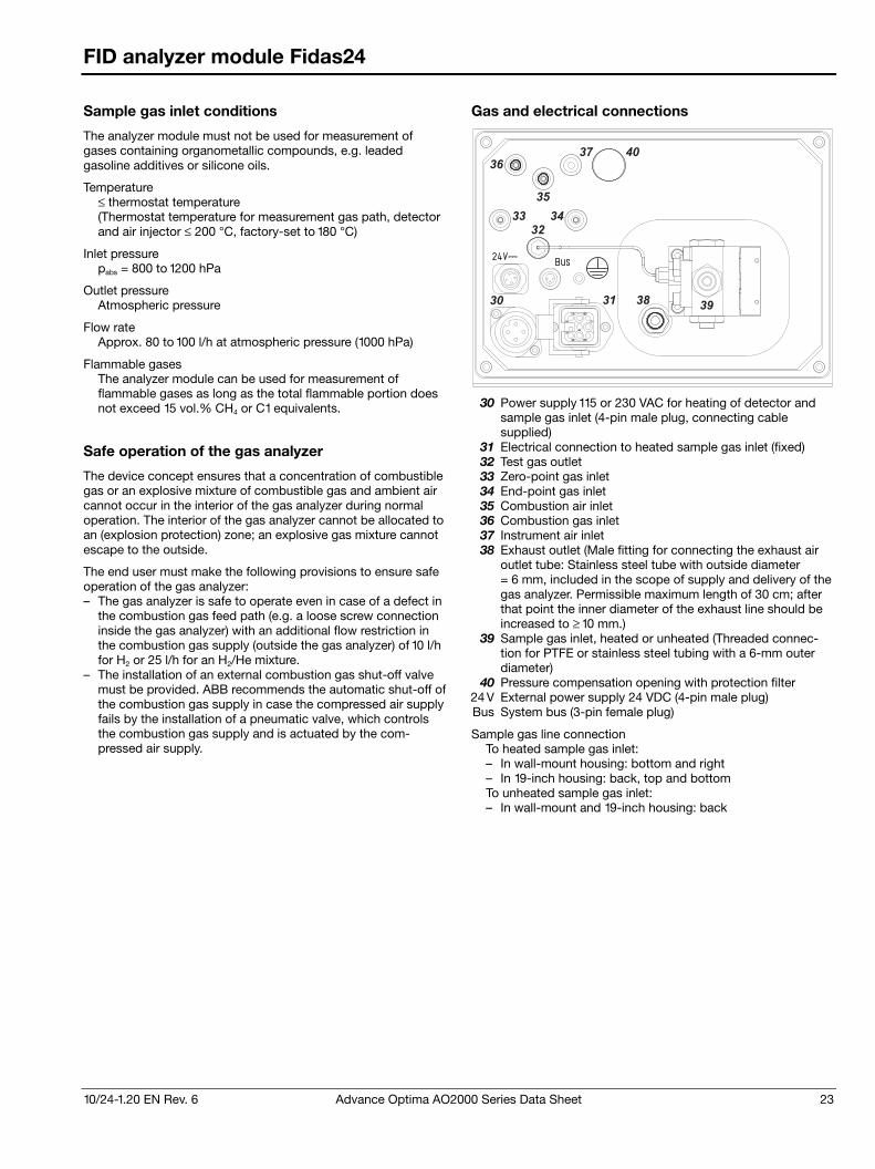
10/24-1.20 EN Rev. 6 Advance Optima AO2000 Series Data Sheet 23
FID analyzer module Fidas24
Sample gas inlet conditions
The analyzer module must not be used for measurement of gases containing organometallic compounds, e.g. leaded gasoline additives or silicone oils.
Temperature ≤ thermostat temperature (Thermostat temperature for measurement gas path, detector and air injector ≤ 200 °C, factory-set to 180 °C)
Inlet pressure pabs = 800 to 1200 hPa
Outlet pressure Atmospheric pressure
Flow rate Approx. 80 to 100 l/h at atmospheric pressure (1000 hPa)
Flammable gases The analyzer module can be used for measurement of flammable gases as long as the total flammable portion does not exceed 15 vol.% CH4 or C1 equivalents.
Safe operation of the gas analyzer
The device concept ensures that a concentration of combustible gas or an explosive mixture of combustible gas and ambient air cannot occur in the interior of the gas analyzer during normal operation. The interior of the gas analyzer cannot be allocated to an (explosion protection) zone; an explosive gas mixture cannot escape to the outside.
The end user must make the following provisions to ensure safe operation of the gas analyzer: – The gas analyzer is safe to operate even in case of a defect in
the combustion gas feed path (e.g. a loose screw connection inside the gas analyzer) with an additional flow restriction in the combustion gas supply (outside the gas analyzer) of 10 l/h for H2 or 25 l/h for an H2/He mixture.
– The installation of an external combustion gas shut-off valve must be provided. ABB recommends the automatic shut-off of the combustion gas supply in case the compressed air supply fails by the installation of a pneumatic valve, which controls the combustion gas supply and is actuated by the com-pressed air supply.
Gas and electrical connections
4037
36
35
3433
32
30 31 3839
30 Power supply 115 or 230 VAC for heating of detector and sample gas inlet (4-pin male plug, connecting cable supplied)
31 Electrical connection to heated sample gas inlet (fixed) 32 Test gas outlet 33 Zero-point gas inlet 34 End-point gas inlet 35 Combustion air inlet 36 Combustion gas inlet 37 Instrument air inlet 38 Exhaust outlet (Male fitting for connecting the exhaust air
outlet tube: Stainless steel tube with outside diameter = 6 mm, included in the scope of supply and delivery of the gas analyzer. Permissible maximum length of 30 cm; after that point the inner diameter of the exhaust line should be increased to ≥ 10 mm.)
39 Sample gas inlet, heated or unheated (Threaded connec-tion for PTFE or stainless steel tubing with a 6-mm outer diameter)
40 Pressure compensation opening with protection filter 24 V External power supply 24 VDC (4-pin male plug) Bus System bus (3-pin female plug)
Sample gas line connection To heated sample gas inlet: – In wall-mount housing: bottom and right – In 19-inch housing: back, top and bottom To unheated sample gas inlet: – In wall-mount and 19-inch housing: back
24 Advance Optima AO2000 Series Data Sheet 10/24-1.20 EN Rev. 6
FID analyzer module MultiFID14
Measurement principle
Flame-ionization detector
Sample components and measurement ranges
Sample components Hydrocarbons
Smallest measurement range 0 to 5 mg org. C/m3
Largest measurement range 0 to 100,000 mg org. C/m3 The sample component concentration in the sample gas should not exceed 50 % of the LEL.
Measurement range quantity and limits 1 to 4 measurement ranges Ranges are factory-set per customer order. They can be reduced or enlarged by a factor of max. 4 (to the smallest indicated measurement range).
Stability
The following data apply to measurement ranges ≥ 50 mg org. C/m3, for smaller ranges these only apply if they are factory-set per customer order.
Linearity deviation ≤ 2 % of the span to 10,000 mg org. C/m3 this value applies in one (calibrated) measurement range
Repeatability ≤ 0.5 % of measurement range
Zero-point and sensitivity drift ≤ 0.5 mg org. C/m3 per week
Output fluctuation (2 σ) ≤ 0.5 % of span at electronic T90 time = 20 sec
Detection limit (4 σ) ≤ 1 % of span at electronic T90 time = 20 sec
Influence effects
O2 dependence ≤ 2 % of measured value for 0 to 21 vol.% O2 or ≤ 0.3 mg org. C/m3, the greater value applies
Temperature effect Ambient temperature in permissible range At zero-point and on sensitivity: ≤ 2 % per 10 °C in measure-ment range of 0 to 15 mg org. C/m3
Power supply effect 24 VDC ± 5 %: ≤ 0.2 % of span
Dynamic response
Warm-up time ≤ 2 hours
90% response time T90 < 0.9 sec at sample gas flow = 80 l/h and electronic T90 time = 1 sec (with unheated sample gas inlet; applies to an analyzer unit with 1 analyzer module)
Calibration
Zero-point calibration With synthetic air or catalytically purified air or nitrogen
Sensitivity calibration With propane or another hydrocarbon (substitute gas) in air or nitrogen, depending on application
If an substitute gas curve is used during factory calibration, the measurement component response factors will also be calcu-lated.
Materials in contact with the sample medium
Analyzer, gas lines and connectors Stainless steel, FPM, PTFE
Operating gases and test gases
Instrument air Quality per ISO 8573-1 class 2 (max. particle size 1 μm, max. particle concentration 1 mg/m3, max. oil content 0.1 mg/m3, pressure dew point at least 10 °C below the lowest foreseeable ambient temperature) Inlet pressure pe = 4000 ± 500 hPa Flow rate typically approx. 1500 l/h (1200 l/h for air injector and approx. 300 l/h for housing purge), maximum approx. 2300 l/h (1800 l/h + 500 l/h)
Combustion air Synthetic air or catalytically purified air with an organic C content < 1 % span Inlet pressure pe = 1200 ± 100 hPa Flow rate < 40 l/h
Combustion gas Hydrogen, grade 5.0, or H2/He mixture (40/60 %) Inlet pressure pe = 1200 ± 100 hPa Flow rate ≤ 3 l/h (H2) or approx. 8 l/h (H2/He) A flow limiting device must be provided on the hydrogen supply (see section “Safe operation of the gas analyzer”).
Test gases Zero-point calibration: Nitrogen, grade 5.0, or synthetic air or catalytically purified air Sensitivity calibration: Sample component or substitute gas component in nitrogen or air Inlet pressure pe = 1000 ± 100 hPa Flow rate 130 to 250 l/h
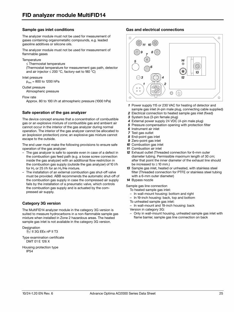
10/24-1.20 EN Rev. 6 Advance Optima AO2000 Series Data Sheet 25
FID analyzer module MultiFID14
Sample gas inlet conditions
The analyzer module must not be used for measurement of gases containing organometallic compounds, e.g. leaded gasoline additives or silicone oils.
The analyzer module must not be used for measurement of flammable gases
Temperature ≤ Thermostat temperature (Thermostat temperature for measurement gas path, detector and air injector ≤ 200 °C, factory-set to 180 °C)
Inlet pressure pabs = 800 to 1200 hPa
Outlet pressure Atmospheric pressure
Flow rate Approx. 80 to 100 l/h at atmospheric pressure (1000 hPa)
Safe operation of the gas analyzer
The device concept ensures that a concentration of combustible gas or an explosive mixture of combustible gas and ambient air cannot occur in the interior of the gas analyzer during normal operation. The interior of the gas analyzer cannot be allocated to an (explosion protection) zone; an explosive gas mixture cannot escape to the outside.
The end user must make the following provisions to ensure safe operation of the gas analyzer: – The gas analyzer is safe to operate even in case of a defect in
the combustion gas feed path (e.g. a loose screw connection inside the gas analyzer) with an additional flow restriction in the combustion gas supply (outside the gas analyzer) of 10 l/h for H2 or 25 l/h for an H2/He mixture.
– The installation of an external combustion gas shut-off valve must be provided. ABB recommends the automatic shut-off of the combustion gas supply in case the compressed air supply fails by the installation of a pneumatic valve, which controls the combustion gas supply and is actuated by the com-pressed air supply.
Category 3G version
The MultiFID14 analyzer module in the category 3G version is suited to measure hydrocarbons in a non-flammable sample gas mixture when installed in Zone 2 hazardous areas. The heated sample gas inlet is not available in the category 3G version.
Designation II 3G EEx nP II T3
Type examination certificate DMT 01 E 126 X
Housing protection type IP54
Gas and electrical connections
11 10
9 87
5
6
1 2
3 4
13
12
14
1 Power supply 115 or 230 VAC for heating of detector and sample gas inlet (4-pin male plug, connecting cable supplied)
2 Electrical connection to heated sample gas inlet (fixed) 3 System bus (3-pin female plug) 4 External power supply 24 VDC (4-pin male plug) 5 Pressure compensation opening with protection filter 6 Instrument air inlet 7 Test gas outlet 8 End-point gas inlet 9 Zero-point gas inlet
10 Combustion gas inlet 11 Combustion air inlet 12 Exhaust outlet (Threaded connection for 6-mm outer
diameter tubing. Permissible maximum length of 30 cm; after that point the inner diameter of the exhaust line should be increased to ≥ 10 mm.)
13 Sample gas inlet, heated or unheated, with stainless steel filter (Threaded connection for PTFE or stainless steel tubing with a 6-mm outer diameter)
14 Bypass nozzle
Sample gas line connection To heated sample gas inlet: – In wall-mount housing: bottom and right – In 19-inch housing: back, top and bottom To unheated sample gas inlet: – In wall-mount and 19-inch housing: back Version in category 3G: – Only in wall-mount housing, unheated sample gas inlet with
flame barrier, sample gas line connection on back
26 Advance Optima AO2000 Series Data Sheet 10/24-1.20 EN Rev. 6
FID analyzer module MultiFID14 NMHC
Measurement principle
Flame-ionization detector for non-methane hydrocarbon (NMHC) measurement
Sample components and measurement ranges
Sample components Hydrocarbons The CH4 :NMHC ratio must be in the 1:9 to 9 :1 range.
Smallest measurement range 0 to 5 mg org. C/m3
Largest measurement range 0 to 5,000 mg org. C/m3 The sample component concentration in the sample gas should not exceed 50 % of the LEL.
Measurement range quantity 1 measurement range The range is factory-set per customer order.
Display The display shows the sample components CnHm, CH4 and NMHC.
Stability
The following data apply to measurement ranges ≥ 50 mg org. C/m3, for smaller ranges these only apply if they are factory-set per customer order.
Linearity deviation ≤ 2 % of the span to 5,000 mg org. C/m3 this value applies in one (calibrated) measurement range
Repeatability ≤ 0.5 % of measurement range
Zero-point and sensitivity drift ≤ 0.5 mg org. C/m3 per week
Output fluctuation (2 σ) ≤ 0.5 % of span at electronic T90 time = 20 sec
Detection limit (4 σ) ≤ 1 % of span at electronic T90 time = 20 sec
Influence effects
O2 dependence ≤ 2 % of measured value for 0 to 21 vol.% O2 or ≤ 0.3 mg org. C/m3, the greater value applies
Temperature effect Ambient temperature in permissible range At zero-point and on sensitivity: ≤ 2 % per 10 °C in measure-ment range of 0 to 15 mg org. C/m3
Power supply effect 24 VDC ± 5 %: ≤ 0.2 % of span
Dynamic response
Warm-up time ≤ 2 hours
90% response time T90 < 3 sec at sample gas flow = 80 l/h and electronic T90 time = 1 sec (with unheated sample gas inlet; applies to an analyzer unit with 1 analyzer module)
Calibration
Zero-point calibration With synthetic air or catalytically purified air or nitrogen, depending on application
Sensitivity calibration With propane or methane in air or in nitrogen, depending on application
Catalyst
Effectiveness CH4: > 85 %, C2H6: < 2 %, C3H8: < 2 %
Switchover time Typically 30 to 120 s
Catalyst poisons (e.g . SO2, NOx, HCl, H2S, halogenated hydro-carbons) will shorten the catalyst service life. Their respective concentration should always be < 20 mg/m3.
Materials in contact with the sample medium
Analyzer, gas lines and connectors Stainless steel, FPM, PTFE, PEEK
Operating gases and test gases
Instrument air Quality per ISO 8573-1 class 2 (max. particle size 1 μm, max. particle concentration 1 mg/m3, max. oil content 0.1 mg/m3, pressure dew point at least 10 °C below the lowest foreseeable ambient temperature) Inlet pressure pe = 4000 ± 500 hPa Flow rate typically approx. 1500 l/h (1200 l/h for air injector and approx. 300 l/h for housing purge), maximum approx. 2300 l/h (1800 l/h + 500 l/h)
Combustion air Synthetic air or catalytically purified air with an organic C content < 1 % span Inlet pressure pe = 1200 ± 100 hPa Flow rate < 40 l/h
Combustion gas Hydrogen, grade 5.0, or H2/He mixture (40/60 %) Inlet pressure pe = 1200 ± 100 hPa Flow rate ≤ 4 l/h (H2) or approx. 10 l/h (H2/He) A flow limiting device must be provided on the hydrogen supply (see section “Safe operation of the gas analyzer”).
Test gases Zero-point calibration: Nitrogen, grade 5.0, or synthetic air or catalytically purified air Sensitivity calibration: Sample component or substitute gas component in nitrogen or air Inlet pressure pe = 1000 ± 100 hPa Flow rate 130 to 250 l/h
Test gases for catalyst effectiveness testing Propane and methane in nitrogen or in air (separate test gas bottles) Zero pressure via bypass Flow rate 130 to 250 l/h
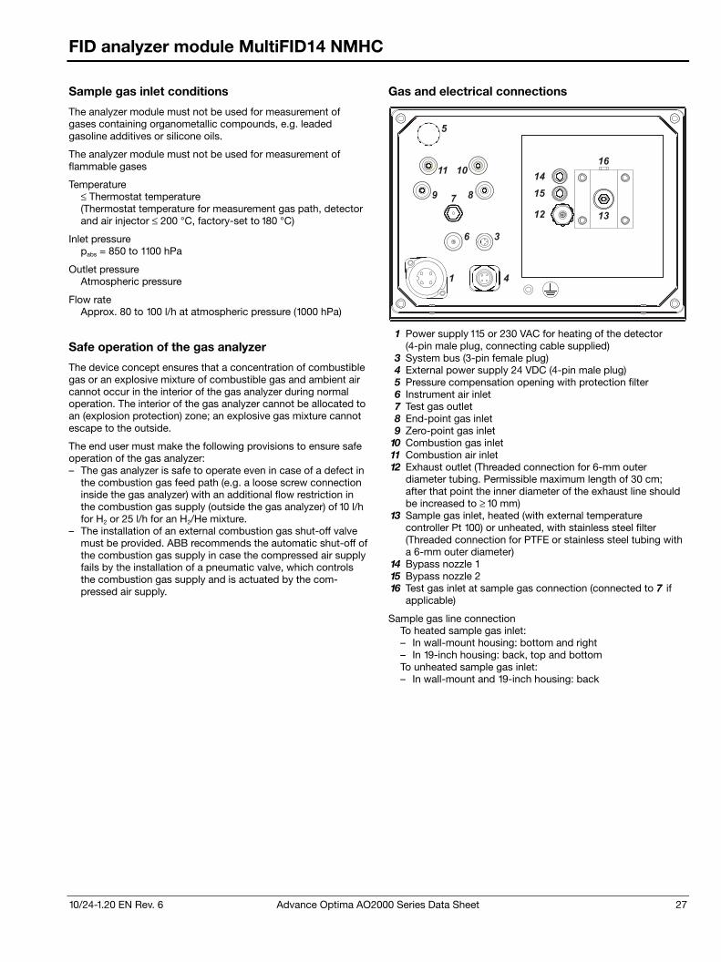
10/24-1.20 EN Rev. 6 Advance Optima AO2000 Series Data Sheet 27
FID analyzer module MultiFID14 NMHC
Sample gas inlet conditions
The analyzer module must not be used for measurement of gases containing organometallic compounds, e.g. leaded gasoline additives or silicone oils.
The analyzer module must not be used for measurement of flammable gases
Temperature ≤ Thermostat temperature (Thermostat temperature for measurement gas path, detector and air injector ≤ 200 °C, factory-set to 180 °C)
Inlet pressure pabs = 850 to 1100 hPa
Outlet pressure Atmospheric pressure
Flow rate Approx. 80 to 100 l/h at atmospheric pressure (1000 hPa)
Safe operation of the gas analyzer
The device concept ensures that a concentration of combustible gas or an explosive mixture of combustible gas and ambient air cannot occur in the interior of the gas analyzer during normal operation. The interior of the gas analyzer cannot be allocated to an (explosion protection) zone; an explosive gas mixture cannot escape to the outside.
The end user must make the following provisions to ensure safe operation of the gas analyzer: – The gas analyzer is safe to operate even in case of a defect in
the combustion gas feed path (e.g. a loose screw connection inside the gas analyzer) with an additional flow restriction in the combustion gas supply (outside the gas analyzer) of 10 l/h for H2 or 25 l/h for an H2/He mixture.
– The installation of an external combustion gas shut-off valve must be provided. ABB recommends the automatic shut-off of the combustion gas supply in case the compressed air supply fails by the installation of a pneumatic valve, which controls the combustion gas supply and is actuated by the com-pressed air supply.
Gas and electrical connections
5
11 10
9 87
6 3
41
14
15
12
16
13
1 Power supply 115 or 230 VAC for heating of the detector (4-pin male plug, connecting cable supplied)
3 System bus (3-pin female plug) 4 External power supply 24 VDC (4-pin male plug) 5 Pressure compensation opening with protection filter 6 Instrument air inlet 7 Test gas outlet 8 End-point gas inlet 9 Zero-point gas inlet
10 Combustion gas inlet 11 Combustion air inlet 12 Exhaust outlet (Threaded connection for 6-mm outer
diameter tubing. Permissible maximum length of 30 cm; after that point the inner diameter of the exhaust line should be increased to ≥ 10 mm)
13 Sample gas inlet, heated (with external temperature controller Pt 100) or unheated, with stainless steel filter (Threaded connection for PTFE or stainless steel tubing with a 6-mm outer diameter)
14 Bypass nozzle 1 15 Bypass nozzle 2 16 Test gas inlet at sample gas connection (connected to 7 if
applicable)
Sample gas line connection To heated sample gas inlet: – In wall-mount housing: bottom and right – In 19-inch housing: back, top and bottom To unheated sample gas inlet: – In wall-mount and 19-inch housing: back
28 Advance Optima AO2000 Series Data Sheet 10/24-1.20 EN Rev. 6
Laser analyzer module LS25
Measurement principle
The LS25 laser analyzer module is based on a measuring principle called single-line spectroscopy. One single target gas absorption line with no interference is chosen in the near infrared spectral range. A single mode diode laser operating around room temperature scans this single absorption line. A detector diametrically opposite detects the light and the absorption caused only by the target gas molecules. Once the absorption by the target gas molecules is detected, the gas concentration is calculated. Automatic corrections for temperature and pressure variations are included.
Sample components and measurement ranges
The LS25 laser analyzer module has one physical measurement range per sample component. The indicated measurement range can be freely adjusted within the physical measurement range. The smallest detection limits and corresponding measurement ranges are shown in the table below:
Sample component
Min. measurement range
Max. abs. pressure
Max. temperature
O2 0– 1 vol.% 20 bar 1500 °C O2 0– 5 vol.% 4 bar 1500 °C NH3 0– 15 ppm 2 bar 600 °C HCl 0– 5 ppm 2 bar 600 °C HF 0– 1.5 ppm 2 bar 400 °C H2S 0– 300 ppm 2 bar 300 °C H2O 0– 5 ppm 2 bar 400 °C H2O 0– 0.5 vol.% 5 bar 1500 °C CO 0– 30 ppm 5 bar 1500 °C CO 0– 0.3 vol.% 2 bar 1500 °C CO2 0– 100 ppm 2 bar 300 °C CO2 0– 0.3 vol.% 2 bar 1200 °C NO 0– 1000 ppm 2 bar 300 °C N2O 0– 1500 ppm 2 bar 200 °C HCN 0– 30 ppm 2 bar 300 °C CH4 0– 20 ppm 3 bar 300 °C C2H2 0– 10 ppm 2 bar 200 °C C3H6 0– 1 vol.% 3 bar 200 °C CH3I 0– 300 ppm 2 bar 200 °C CH2O 0– 50 ppm 1.5 bar 200 °C C2H4 0– 10 vol.% 2 bar 200 °C NH3 + H2O
0– 20 ppm 0– 5 vol.%
1.5 bar 600 °C
HCl + H2O
0– 10 ppm 0– 10 vol.%
1.5 bar 600 °C
HF + H2O
0– 2 ppm 0– 1 vol.%
1.5 bar 400 °C
CO + CO2
0– 1 vol.% 0– 1 vol.%
1.5 bar 600 °C
HCl + CH4
0– 50 ppm 0– 2000 ppm
1.5 bar 200 °C
CO + CH4
0– 50 ppm 0– 200 ppm
1.5 bar 200 °C
CO+ H2O
0– 200 ppm 0– 5 vol.%
1.5 bar 200 °C
CO + H2O
0– 10 vol.% 0– 10 vol.%
1.5 bar 1300 °C
O2 + temp. 0– 5 vol.% 1.5 bar 1500 °C
Other sample components on request.
All specifications refer to an optical path length (OPL) of 1 meter, tested in ABB’s test /calibration jig. The standard optical path length ranges from 0.5 to 6 m (larger OPL on request). Applica-tion-dependent variations may occur. To obtain minimum meas-urement ranges in some cases additional measures have to be taken: Low level O2 and H2O require instrument and process purging with nitrogen. Actual detection limit for a specific appli-cation will depend on the gas conditions (pressure, temperature and gas composition) and optical path length. If more than one min. measurement range is shown there are different instrument versions available.
Min. measurement range, max. pressure and max. temperature cannot necessarily be realized simultaneously. The maximum pressure and temperature given are physical (spectroscopic) limits. Applications with increased temperature or pressure or with toxic or flammable gas may require additional equipment.
Measurement range quantity 1 range per sample component, 1 x transmission
Largest measurement range Largest measurement range is generally 100 times the minimum measurement range for the same conditions. Larger measurement ranges are normally possible by adaptation of measuring path and choice of a weaker absorption line.
Stability
Repeatability ± detection limit or ± 1 % of reading, whichever is greater
Zero drift < 2 % of smallest possible measurement range per 6 months
Span drift < 4 % of measurement range per 6 months
Output fluctuation (2 σ) ≤ 0.5 % of smallest measurement range
Detection limit (4 σ) ≤ 1 % of smallest measurement range
Influence effects
Flow effect No effect on the measurement, but the flow will determine the amount of purge gas needed.
Associated gas effect /cross sensitivity No cross sensitivity within normal operation conditions.
Temperature effect – Ambient temperature in permissible range: No significant
effect – Gas temperature effect: Typically ≤ 2 % of measured value
per 10 °C (dependent on type of gas and gas conditions). For large variations in gas temperature (> ±20 °C) separate temperature measurement for compensation is recom-mended.
Pressure effect – At zero-point: No effect. – Automatic compensation for large variations in sample gas
pressure by measurement of absorption line width, alternatively by input from pressure sensor.
Power supply effect 24 VDC ± 5 %: ≤ 0.2 % of span
10/24-1.20 EN Rev. 6 Advance Optima AO2000 Series Data Sheet 29
Laser analyzer module LS25
Dynamic response
Warm-up time Approx. 1 hour
Response time Less than 2 seconds without signal averaging
Calibration
Maintenance interval Depending on application and dust load. Typically between every 6 months and once a year.
Zero-point check With inert gas, e.g. nitrogen, or with ambient air free of the sample component. The zero point cannot be calibrated. Due to the measurement principle, there is no zero-point drift.
Calibration With test gas and a flow-through test cell. Calibration interval typically between every 6 months and once a year. Recom-mended calibration interval will be stated in calibration certifi-cate which accompanies delivery.
Materials in contact with the process gas
Purge and alignment unit 316 SS
Windows BK7 glass, optional: fused silica, for HF: sapphire
Mounting
Available flanges DN50/PN10, DN80/PN10; ANSI 2″/150 lbs, ANSI 2″/300 lbs, ANSI 3″/150 lbs, ANSI 3″/300 lbs
Alignment tolerances Flanges parallel within 1.5°
Purging of windows Dry and oil-free pressurized air or gas, or by fan
Gas ports for purging Standard: 3/8-inch hose nozzle for hoses with 10 mm inner diameter. See page 30 for connection drawing.
Weight Transmitter unit plus flange with purging unit: 9.5 (6.3 + 3.2) kg Receiver unit plus flange with purging unit: 7.2 (4.0 + 3.2) kg Flow-through test cell: 3.8 kg
Electrical connections on transmitter unit
Connection to central unit Ethernet 10/100BASE-T, RJ45 connector; Cable length: Standard 15 m, max. 100 m
Connection to receiver unit 15-pin female Sub-D connector; Cable length: Standard 5 m, max. 150 m
Power supply, external pressure and temperature signals 15-pin male Sub-D connector; Cable length laser unit–power supply: Standard 3 m, max. 100 m; Cable length power supply–plug: 3 m
Service computer RS232, 9-pin female Sub-D connector; Ethernet
See page 31 for connection drawing.
Process gas properties
Maximum process gas temperature and pressure are given in the “Sample components and measurement ranges” table. Quanti-fication of dust /particle concentration is necessary in order to determine max OPL. The maximum dust concentration must be checked by ABB Analytical.
Purge gas requirements
The purge gas should not contain any sample gas components and must be oil- and dust-free.
Power supply
Input voltage 24 VDC ± 5 % from an exteral power supply unit 115/230 V AC (part of the delivery for general purpose applications)
Power consumption approx. 20 W
Installation site requirements
The mounting location strongly influences the measurement result. The measurement gas must be well stirred at the selected location to produce a representative measurement result. Stratification in the measurement gas path results in erroneous measurement. If the measurement gas is charged with dust, the LS25 must be mounted at right angles to the process gas flow.
Performance test
The AO2000-LS25 analyzer module (sample components H2O, NH3) is suitable for use in facilities requiring approval and facili-ties of the 27th BImSchV (German Federal Immissions Control Ordinance). The requirements of QAL1 according to EN 15267-3 and EN 14181 are fulfilled. Publication: Federal Gazette of March 11, 2009, No. 38, page 903. Report No. 936/21211189/A of April 24, 2009.
Explosion-proof versions
The AO2000-LS25 Ex analyzer module is suited for use in areas in which explosive atmospheres caused by vapors, gases, mists, or air /dust mixtures are likely to occur.
“Intrinsically optical safe” version for use in zone 1
Designations II 2 G Ex px II T5 II 2 D Ex pD 21 IP66 T64°C II (2) G [Ex op is T4 Gb] IIC
EC-Type examination certificates DNV-2006-OSL-ATEX-0042X Rev. 2, DNV 09 ATEX 64813
Housing protection type IP66
“Intrinsically optical safe” version for use in zone 2
Designations II 3 G Ex nA nC op is Gc IIC T4 –20°C ≤ Tamb ≤ +55°C II 3 D Ex tD A22 IP65 T100°C
EC-Type examination certificate DNV-2008-OSL-ATEX-21837 Rev. 4
Housing protection type IP66
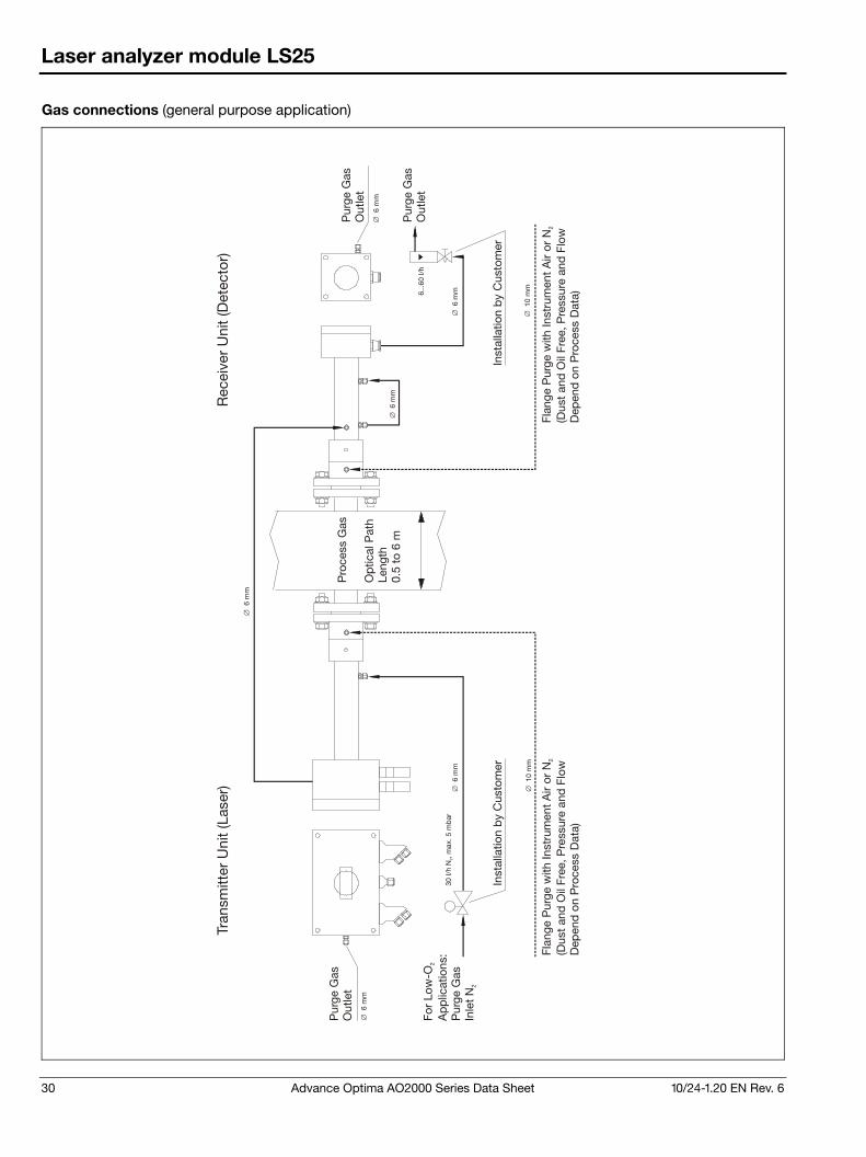
30 Advance Optima AO2000 Series Data Sheet 10/24-1.20 EN Rev. 6
Laser analyzer module LS25
Gas connections (general purpose application)
30 I/
h N
, 2m
ax. 5
mb
ar
6...6
0 I/
h
∅ 6
mm
∅ 1
0 m
m
∅ 6
mm
∅ 6
mm
∅ 6
mm
∅ 6
mm
∅ 6
mm
∅ 1
0 m
m
Pro
cess
Gas
Op
tical
Pat
h Le
ngth
0.5
to 6
m
Tran
smitt
er U
nit
(Las
er)
Rec
eive
r U
nit
(Det
ecto
r)
Pur
ge G
asO
utle
t
Pur
ge G
asO
utle
t
Inst
alla
tion
by
Cus
tom
erIn
stal
latio
n b
y C
usto
mer
Flan
ge P
urge
with
Inst
rum
ent
Air
or N
(D
ust
and
Oil
Free
, Pre
ssur
e an
d F
low
D
epen
d o
n P
roce
ss D
ata)
2Fl
ange
Pur
ge w
ith In
stru
men
t A
ir or
N
(Dus
t an
d O
il Fr
ee, P
ress
ure
and
Flo
w
Dep
end
on
Pro
cess
Dat
a)
2
Pur
ge G
asO
utle
t
For
Low
-O
Ap
plic
atio
ns:
Pur
ge G
asIn
let
N
2
2
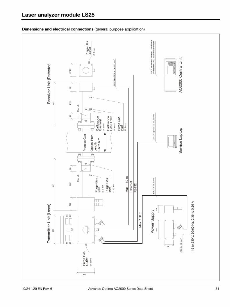
10/24-1.20 EN Rev. 6 Advance Optima AO2000 Series Data Sheet 31
Laser analyzer module LS25
Dimensions and electrical connections (general purpose application)
270
100
8012
0
180
69
252
5521
055
Li2Y
CH
-0(T
P) 6
x 2
x 0
.25
mm
2
LiY
CY
6 x
0.5
mm
2
NY
M 3
x 1
.5 m
m2
Li2Y
CH
-0(T
P) 6
x 2
x 0
.25
mm
2
85
168
465
402
-X1
-X4
-X2
-X5
-X3
**
**
∅ 6
mm
∅ 6
mm
∅ 1
0 m
m
∅ 6
mm
∅ 6
mm
∅ 6
mm
∅ 6
mm
Pro
cess
Gas
Op
tical
Pat
h Le
ngth
0.5
to 6
m
Tran
smitt
er U
nit
(Las
er)
Rec
eive
r U
nit
(Det
ecto
r )
Pur
ge G
asO
utle
t
Pur
ge G
asO
utle
t
Pur
ge G
asIn
let
Pur
ge G
asIn
let
Pur
ge G
asIn
let
Cal
ibra
tion
Gas
Inle
t
Cal
ibra
tion
Gas
Out
let
Hol
e M
8H
ole
M8
Eth
erne
tR
S23
2
115
to 2
30 V
, 50/
60 H
z , 0
.36
to 0
.26
A
Ser
vice
Lap
top
AO
2000
Cen
tral
Uni
t
Pow
er S
upp
lyC
AT.5
for
outd
oor
use
resp
. dire
ct b
uria
l, U
V r
esis
tant
, PV
C d
oub
le o
uter
she
ath
Max
. 150
m
Max
. 100
m
32 Advance Optima AO2000 Series Data Sheet 10/24-1.20 EN Rev. 6
Electrochemical oxygen sensor
Measurement principle
Electrochemical oxygen sensor
Sample component and measurement ranges
Sample component Oxygen (O2)
Measurement range quantity and limits 1 to 2 measurement ranges Adjustable from 0 to 5 vol.% O2 to 0 to 25 vol.% O2
Measurement range 2 Set to 0 to 25 vol.% O2
Stability
Linearity deviation Linear in the range > 1 vol.% O2
Repeatability ≤ 0.5 % of span
Zero drift Stable over long-term due to absolute zero point
Sensitivity drift ≤ 1 % of the measurement range per week
Output fluctuation (2 σ) ≤ 0.2 % of the measurement range at electronic T90 time (static /dynamic) = 5 /0 sec
Detection limit (4 σ) ≤ 0.4 % of the measurement range at electronic T90 time (static /dynamic) = 5 /0 sec
Influence effects
Flow effect Flow rate in the 20 to 100 l/h range: ≤ 2 % of the measurement range
Temperature effect Ambient temperature in permissible range: ≤ 0.2 vol.% O2 per 10 °C
Air pressure effect – At zero-point: No effect – On sensitivity with no pressure correction:
≤ 1 % of the measured value per 1 % air pressure change – On sensitivity with pressure correction:
≤ 0.2 % of the measured value per 1 % air pressure change Pressure correction is only possible if the oxygen sensor is connected to an analyzer module with an integral pressure sensor.
Power supply effect Voltage and frequency in the permissible range: ≤ 0.2 % of span
Dynamic response
90% response time T90 ≤ 30 sec, depending on sample gas flow and system layout
Calibration
Zero-point calibration The oxygen sensor zero is not calibrated since it is fundamentally stable.
End-point calibration With ambient air at 20.96 vol.% O2
Materials in contact with the sample medium
Sensor: Polystyrol-ABS, PTFE, FPM Housing body: PVC-U, FPM seals Gas ports: Rust- and acid-resistant steel 1.4571 (SAE 316Ti)
Sample gas inlet conditions
The oxygen sensor must not be used for measurement of flammable gases and ignitable gas/air or gas/oxygen mixtures.
Temperature The sample gas dew point should be at least 5 °C below the ambient temperature throughout the sample gas path. Other-wise a sample gas cooler or condensate trap is required.
Moisture content H2O dew point ≥ 2 °C The oxygen sensor should not be used with dry sample gas.
Inlet pressure pe = 2 to 500 hPa
Outlet pressure Atmospheric pressure
Flow rate 20 to 100 l/h
Associated gas The oxygen sensor should not be used if the associated gas contains the following components: H2S, chlorine or fluorine compounds, heavy metals, aerosols, mercaptane, alkaline components.
Notes
The oxygen sensor is always associated with an analyzer module and must be installed in the same housing with that analyzer module.
The oxygen sensor cannot be used with the following analyzer modules: – Limas11 with stainless steel, PFA or PTFE gas connections – Fidas24 – MultiFID14 – Analyzer modules for measuring corrosive gases – Analyzer modules in category 2G
10/24-1.20 EN Rev. 6 Advance Optima AO2000 Series Data Sheet 33
Pneumatics module
Test gas supply
Type One or three 3/2-way solenoid valves
Power consumption Approx. 3 W per solenoid valve
Materials in contact with the sample medium PVDF, FPM, aluminum, stainless steel 1.4305 (SAE 303)
Fine filtration
Type Disposable filter with borosilicate glass microfiber filter element
Retention rate 99.99 % for particles > 0.1 μm
Materials in contact with the sample medium Polyamide, borosilicate glass with PVDF binder
Gas supply
Type Magnetic piston pump
Feed rate Max. of 60 l/h, depending on analyzer module and inlet/outlet pressure
Flow rate Adjustable
Power consumption Approx. 10 W
Materials in contact with the sample medium PVDF, EPDM, stainless steel 1.4571 (SAE 316Ti)
Flow monitoring
Type Miniature flow sensor
Readout and limit value monitoring Configurable
Materials in contact with the sample medium Al2O3, silicon, gold, GFK
Pressure monitoring
Pressure sensor (Option) for additional monitoring tasks, e.g. pressure measurement in the 2nd gas path of the Uras26 analyzer module
Sample gas inlet conditions
The pneumatics module must not be used for measurement of flammable gases and ignitable gas/air or gas/oxygen mixtures.
Temperature +5 to +45 °C The sample gas dew point should be at least 5 °C below the ambient temperature throughout the sample gas path. Other-wise a sample gas cooler or condensate trap is required.
Inlet pressure pe = –80 to +20 hPa
Flow rate 30 to 60 l/h
Corrosive gases Corrosive associated gas components and aerosols must be cooled or undergo prior absorption.
Notes
The pneumatics module is always associated with an analyzer module and must be installed in the same housing with that analyzer module.
The pneumatics module cannot be used when stainless steel tubes are used for the internal gas lines.
The pneumatics module cannot be used with the following analyzer modules: – Limas11 with stainless steel, PFA or PTFE gas lines – Fidas24 – MultiFID14 – Analyzer modules in category 2G
34 Advance Optima AO2000 Series Data Sheet 10/24-1.20 EN Rev. 6
Explosion protected versions in category 3G
Version in category 3G for measurement of flammable and non-flammable gases (“Safety concept”)
The “safety concept” gas analyzers include: – Uras26 in the version with safety cell and purged sample cell
windows – Magnos206, Caldos25 and Caldos27 in the version with direct
sample cell connection and purged thermostat housing.
Monitoring of the purge gas flow rate is a feature of the “safety concept”. It is fully integrated into the gas analyzer, together with the controls and signal processing.
The version complies with the Directive 94/9/EC (ATEX Directive). There are the following explosion protection measures in the gas analyzer: – Non-arcing assemblies and components/non-hot compo-
nents /sealed (arcing) devices per EN 60079-15 and – Simplified positive pressure containment per EN 60079-2.
Designation II 3G Ex nA py II T4
Type examination certificate BVS 07 ATEX E 013 X
Housing protection type IP54
Sample gas inlet conditions
Sample gas Flammable and non-flammable gases and vapors – under atmospheric conditions (pabs ≤ 1.1 bar, oxygen content
≤ 21 vol.%), – Temperature class T4, – not potentially explosive under normal conditions, – if potentially explosive in the event of a fault, then only
seldom and briefly (in accordance with zone 2). If the sample gas is a mixture only of oxygen and flammable gases and vapors, it must not be explosive under any condi-tions. As a rule this can be achieved by limiting the oxygen content to a maximum of 2 vol.%. Flammable gases and vapors that are explosive under the conditions encountered in analysis even when oxygen is excluded should be present in the mixture only in concen-trations that are not critical to safety.
Pressure At sample gas inlet: positive pressure pe ≤ 3 hPa, at sample gas outlet: atmospheric
Flow rate Max. 40 l/h
Inert gas curtain/purge gas/ (Simplified) pressurized enclosure
Purge gas Inert gas (nitrogen)
Pressure Positive operating pressure pe ≥ sample gas pressure + 0.5 hPa
Flow rate During operation: 15 to 20 l/h, during initial purge: 15 to 50 l/h
Initial purge Manually controlled, initial purge duration: Uras26: 1.6 minutes at min. 15 l/h Magnos206, Caldos25, Caldos27: 18 minutes at min. 15 l/h or 6 minutes at min. 50 l/h
Alarm When flow rate drops below a minimum value of 15 l/h (corresponds to approx. 7 hPa) and when flow rate exceeds a maximum value of 50 l/h (corresponds to approx. 60 hPa)
Category 3G version for measurement of non-flammable gases
The analyzer modules Uras26, Limas11, Magnos206, Magnos27, Caldos25 und Caldos27 are suitable for measuring non-flammable gases. The analyzer modules are mounted in the central unit housing or in a separate housing (either wall-mount or 19-inch rack unit).
The version complies with the Directive 94/9/EC (ATEX Directive). The gas analyzer is protected by provisions according to EN 60079-15 (non-arcing electrical equipment, sealed arcing devices).
In undisturbed operation there cannot be any sparking, arcing or impermissible temperatures inside the device. During operation, all unused gas ports should be plugged.
Designation II 3G Ex nAc nCc IIC T4
Housing protection type IP54
MultiFID14 analyzer module in category 3G version
The MultiFID14 analyzer module in the category 3G version is suited to measure hydrocarbons in a non-flammable sample gas mixture when installed in Zone 2 hazardous areas. The heated sample gas inlet is not available in the category 3G version.
Designation II 3G EEx nP II T3
Type examination certificate DMT 01 E 126 X
Housing protection type IP54
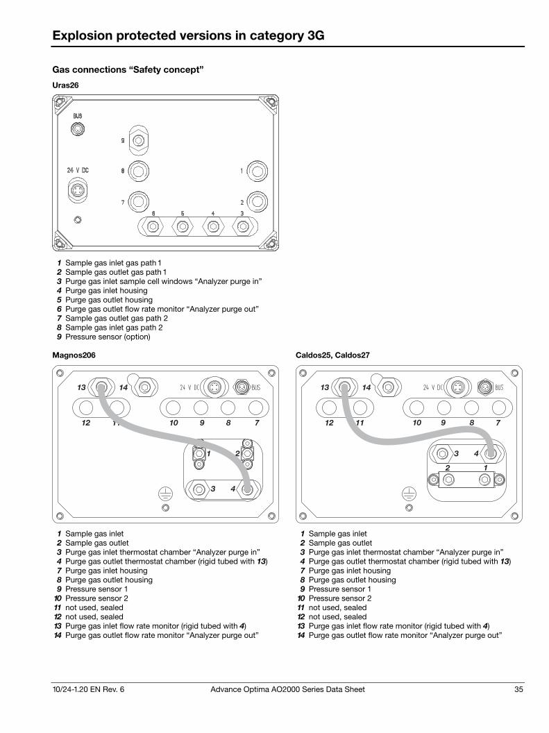
10/24-1.20 EN Rev. 6 Advance Optima AO2000 Series Data Sheet 35
Explosion protected versions in category 3G
Gas connections “Safety concept”
Uras26
1 Sample gas inlet gas path 1 2 Sample gas outlet gas path 1 3 Purge gas inlet sample cell windows “Analyzer purge in” 4 Purge gas inlet housing 5 Purge gas outlet housing 6 Purge gas outlet flow rate monitor “Analyzer purge out” 7 Sample gas outlet gas path 2 8 Sample gas inlet gas path 2 9 Pressure sensor (option)
Magnos206 Caldos25, Caldos27
1 2
3 4
13 14
12 11 10 9 8 7
12
3 4
7891012 11
1413
1 Sample gas inlet 1 Sample gas inlet 2 Sample gas outlet 2 Sample gas outlet 3 Purge gas inlet thermostat chamber “Analyzer purge in” 3 Purge gas inlet thermostat chamber “Analyzer purge in” 4 Purge gas outlet thermostat chamber (rigid tubed with 13) 4 Purge gas outlet thermostat chamber (rigid tubed with 13) 7 Purge gas inlet housing 7 Purge gas inlet housing 8 Purge gas outlet housing 8 Purge gas outlet housing 9 Pressure sensor 1 9 Pressure sensor 1
10 Pressure sensor 2 10 Pressure sensor 2 11 not used, sealed 11 not used, sealed 12 not used, sealed 12 not used, sealed 13 Purge gas inlet flow rate monitor (rigid tubed with 4) 13 Purge gas inlet flow rate monitor (rigid tubed with 4) 14 Purge gas outlet flow rate monitor “Analyzer purge out” 14 Purge gas outlet flow rate monitor “Analyzer purge out”
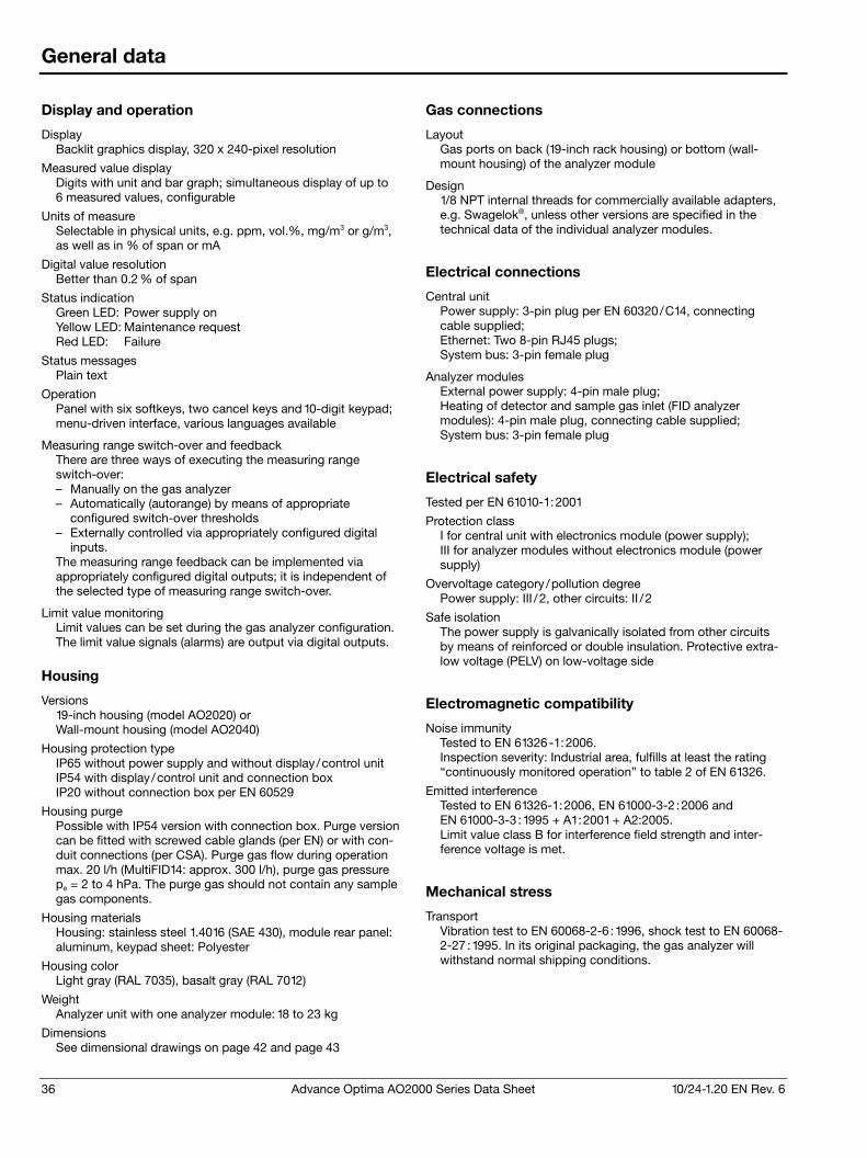
36 Advance Optima AO2000 Series Data Sheet 10/24-1.20 EN Rev. 6
General data
Display and operation
Display Backlit graphics display, 320 x 240-pixel resolution
Measured value display Digits with unit and bar graph; simultaneous display of up to 6 measured values, configurable
Units of measure Selectable in physical units, e.g. ppm, vol.%, mg/m3 or g/m3, as well as in % of span or mA
Digital value resolution Better than 0.2 % of span
Status indication Green LED: Power supply on Yellow LED: Maintenance request Red LED: Failure
Status messages Plain text
Operation Panel with six softkeys, two cancel keys and 10-digit keypad; menu-driven interface, various languages available
Measuring range switch-over and feedback There are three ways of executing the measuring range switch-over: – Manually on the gas analyzer – Automatically (autorange) by means of appropriate
configured switch-over thresholds – Externally controlled via appropriately configured digital
inputs. The measuring range feedback can be implemented via appropriately configured digital outputs; it is independent of the selected type of measuring range switch-over.
Limit value monitoring Limit values can be set during the gas analyzer configuration. The limit value signals (alarms) are output via digital outputs.
Housing
Versions 19-inch housing (model AO2020) or Wall-mount housing (model AO2040)
Housing protection type IP65 without power supply and without display/control unit IP54 with display/control unit and connection box IP20 without connection box per EN 60529
Housing purge Possible with IP54 version with connection box. Purge version can be fitted with screwed cable glands (per EN) or with con-duit connections (per CSA). Purge gas flow during operation max. 20 l/h (MultiFID14: approx. 300 l/h), purge gas pressure pe = 2 to 4 hPa. The purge gas should not contain any sample gas components.
Housing materials Housing: stainless steel 1.4016 (SAE 430), module rear panel: aluminum, keypad sheet: Polyester
Housing color Light gray (RAL 7035), basalt gray (RAL 7012)
Weight Analyzer unit with one analyzer module: 18 to 23 kg
Dimensions See dimensional drawings on page 42 and page 43
Gas connections
Layout Gas ports on back (19-inch rack housing) or bottom (wall-mount housing) of the analyzer module
Design 1/8 NPT internal threads for commercially available adapters, e.g. Swagelok®, unless other versions are specified in the technical data of the individual analyzer modules.
Electrical connections
Central unit Power supply: 3-pin plug per EN 60320/C14, connecting cable supplied; Ethernet: Two 8-pin RJ45 plugs; System bus: 3-pin female plug
Analyzer modules External power supply: 4-pin male plug; Heating of detector and sample gas inlet (FID analyzer modules): 4-pin male plug, connecting cable supplied; System bus: 3-pin female plug
Electrical safety
Tested per EN 61010-1:2001
Protection class I for central unit with electronics module (power supply); III for analyzer modules without electronics module (power supply)
Overvoltage category/pollution degree Power supply: III /2, other circuits: II /2
Safe isolation The power supply is galvanically isolated from other circuits by means of reinforced or double insulation. Protective extra-low voltage (PELV) on low-voltage side
Electromagnetic compatibility
Noise immunity Tested to EN 61326-1:2006. Inspection severity: Industrial area, fulfills at least the rating “continuously monitored operation” to table 2 of EN 61326.
Emitted interference Tested to EN 61326-1:2006, EN 61000-3-2 :2006 and EN 61000-3-3 :1995 + A1:2001 + A2:2005. Limit value class B for interference field strength and inter-ference voltage is met.
Mechanical stress
Transport Vibration test to EN 60068-2-6 :1996, shock test to EN 60068-2-27:1995. In its original packaging, the gas analyzer will withstand normal shipping conditions.
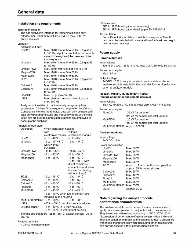
10/24-1.20 EN Rev. 6 Advance Optima AO2000 Series Data Sheet 37
General data
Installation site requirements
Installation location The gas analyzer is intended for indoor installation only. Altitude max. 2000 m, MultiFID14 NMHC: max. 1500 m above sea level
Vibration Analyzer unit only: Uras26: Max. ±0.04 mm at 5 to 55 Hz, 0.5 g at 55
to 150 Hz, slight transient effect on samplevalue in the region of the beam modula-tion frequency
Limas11: Max. ±0.04 mm at 5 to 55 Hz, 0.5 g at 55 to 150 Hz
Limas11 HW: Max. ±0.04 mm/0.5 g at 5 to 150 Hz Magnos206: Max. ±0.04 mm at 5 to 20 Hz Magnos27: Max. ±0.04 mm at 5 to 60 Hz ZO23: Max. ±0.04 mm at 5 to 55 Hz, 0.5 g at 55
to 150 Hz Caldos25: Max. ±0.04 mm at 5 to 30 Hz Caldos27: Max. ±0.04 mm at 5 to 55 Hz, 0.5 g at 55
to 150 Hz Fidas24: Max. 0.5 g, max. 150 Hz LS25: Max. ±0.6 mm around the optical axis,
max. 500 Hz Analyzer unit installed in cabinet (analyzer system): Max. acceleration 0.01 ms–2 in a frequency range of 0.1 to 200 Hz. Compliance with the metrological data can only be assured if data on vibration amplitude and frequency range at the instal-lation site are available and suitable means are employed to decouple the analyzer.
Ambient temperature When installed in housing Operation: with electronics module
without electronics module
Uras26: +5 to +40 °C +5 to +45 °C Limas11: +5 to +40/45 °C
with /without I/O cards
+5 to +45 °C
Limas11 HW: +15 to +35 °C +15 to +35 °C Magnos206: +5 to +45 °C +5 to +50 °C Magnos27: +5 to +45 °C +5 to +45 °C,
+5 to +50 °C with direct sample cell connection and when installed in housing without Uras26
ZO23: +5 to +45 °C +5 to +45 °C Caldos25: +5 to +45 °C +5 to +45 °C Caldos27: +5 to +45 °C +5 to +50 °C Fidas24: +5 to +45 °C +5 to +45 °C MultiFID14: +5 to +45 °C +5 to +45 °C +5 to +40 °C when two MultiFID14 are
installed in one housing MultiFID14 NMHC: +5 to +38 °C +5 to +38 °C LS25: –20 to +55 °C, no direct solar irradiation Oxygen sensor: +5 to +40 °C in 19-inch housing,
+5 to +35 °C in wall-mount housing Storage and transport: –25 to +65 °C, oxygen sensor: –20 to +60 °C
Relative humidity < 75 %, no condensation
Climate class 3K3 for IP20 housing (non-condensing), 3K4 for IP54 housing (condensing) per EN 60721-3-3
Air circulation For sufficient air circulation, multiple housings in a 19-inch rack must be installed with a separation of at least one height unit between housings.
Power supply
Power supply unit
Input voltage 100 to 240 VAC, –15 %, +10 %, max. 2.2 A, 50 to 60 Hz ± 3 Hz
Power consumption Max. 187 W
Output voltage 24 VDC ± 5 % to supply the electronics module and one analyzer module installed in the central unit or (optionally) one external analyzer module
Fidas24, MultiFID14, MultiFID14 NMHC: Heating of detector and sample gas inlet
Input voltage 115 V AC or 230 V AC, ± 15 % (max. 250 V AC), 47 to 63 Hz
Power consumption Fidas24: 125 VA for detector 125 VA for sample gas inlet (option) MultiFID14: 120 VA for detector 100 VA for sample gas inlet (option) MultiFID14 NMHC: Approx. 200 VA
Analyzer modules
Input voltage 24 V DC ± 5 %
Power consumption Uras26: Max. 95 W Limas11: Max. 85 W Limas11 HW: Max. 85 W Magnos206: Max. 50 W Magnos27: Max. 35 W ZO23: Approx. 12 W in continuous operation,
approx. 35 W during start-up Caldos25: Max. 25 W Caldos27: Max. 12 W Fidas24: Max. 65 W MultiFID14: Max. 65 W MultiFID14 NMHC: Max. 65 W LS25: Approx. 20 W
Note regarding the analyzer module performance characteristics
The analyzer module performance characteristics indicated apply only when operated in conjunction with the central unit. They have been determined according to IEC 61207-1:2010 “Expression of performance of gas analyzers – Part 1: General”. They are based on nitrogen as the associated gas. Compliance with these characteristics when measuring other gas mixtures can only be assured if their composition is known.
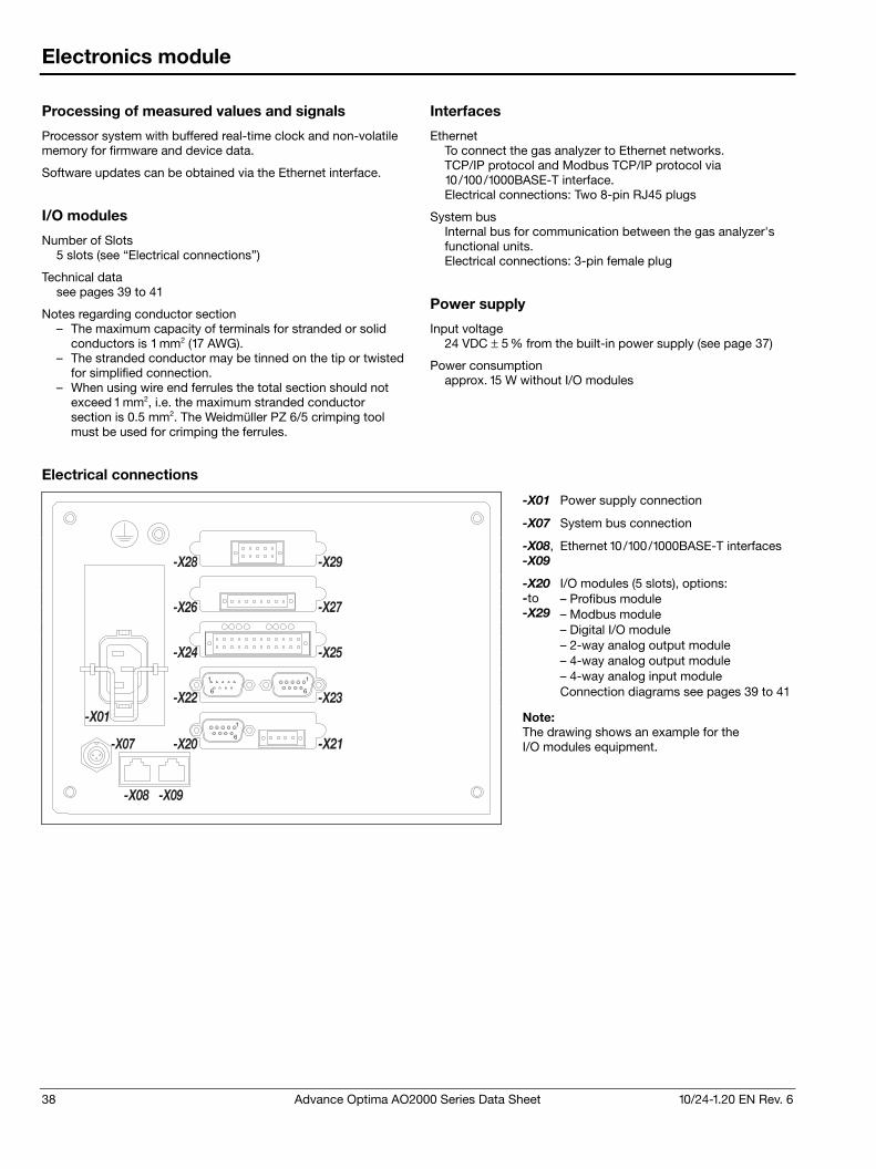
38 Advance Optima AO2000 Series Data Sheet 10/24-1.20 EN Rev. 6
Electronics module
Processing of measured values and signals
Processor system with buffered real-time clock and non-volatile memory for firmware and device data.
Software updates can be obtained via the Ethernet interface.
I/O modules
Number of Slots 5 slots (see “Electrical connections”)
Technical data see pages 39 to 41
Notes regarding conductor section – The maximum capacity of terminals for stranded or solid
conductors is 1 mm2 (17 AWG). – The stranded conductor may be tinned on the tip or twisted
for simplified connection. – When using wire end ferrules the total section should not
exceed 1 mm2, i.e. the maximum stranded conductor section is 0.5 mm2. The Weidmüller PZ 6/5 crimping tool must be used for crimping the ferrules.
Interfaces
Ethernet To connect the gas analyzer to Ethernet networks. TCP/IP protocol and Modbus TCP/IP protocol via 10/100/1000BASE-T interface. Electrical connections: Two 8-pin RJ45 plugs
System bus Internal bus for communication between the gas analyzer's functional units. Electrical connections: 3-pin female plug
Power supply
Input voltage 24 VDC ± 5 % from the built-in power supply (see page 37)
Power consumption approx. 15 W without I/O modules
Electrical connections
-X01 Power supply connection
-X07 System bus connection
-X08, -X09
Ethernet 10/100/1000BASE-T interfaces
I/O modules (5 slots), options: – Profibus module – Modbus module – Digital I/O module – 2-way analog output module – 4-way analog output module
-X20 -to -X29
– 4-way analog input module Connection diagrams see pages 39 to 41
1
6
1
6
1
6
-X29
-X27
-X25
-X26
-X24
-X22
-X20
-X28
-X23
-X21-X07
-X01
-X08 -X09
Note: The drawing shows an example for the I/O modules equipment.
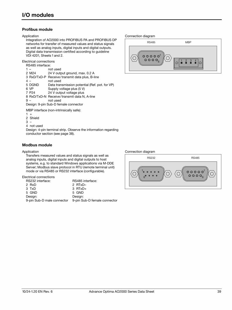
10/24-1.20 EN Rev. 6 Advance Optima AO2000 Series Data Sheet 39
I/O modules
Profibus module
Application Integration of AO2000 into PROFIBUS PA and PROFIBUS DP networks for transfer of measured values and status signals as well as analog inputs, digital inputs and digital outputs. Digital data transmission certified according to guideline VDI 4201, Sheets 1 and 2.
Electrical connections RS485 interface: 1 – not used 2 M24 24 V output ground, max. 0.2 A 3 RxD/TxD-P Receive/ transmit data plus, B-line 4 – not used 5 DGND Data transmission potential (Ref. pot. for VP) 6 VP Supply voltage plus (5 V) 7 P24 24 V output voltage plus 8 RxD/TxD-N Receive/ transmit data N, A-line 9 – not used Design: 9-pin Sub-D female connector
MBP interface (non-intrinsically safe): 1 + 2 Shield 3 – 4 not used Design: 4-pin terminal strip. Observe the information regarding conductor section (see page 38).
Connection diagram
1
6
RS485 MBP
1 2 3 4
Modbus module
Application Transfers measured values and status signals as well as analog inputs, digital inputs and digital outputs to host systems, e.g. to standard Windows applications via M-DDE Server; Modbus slave protocol in RTU (remote terminal unit) mode or via RS485 or RS232 interface (configurable).
Electrical connections RS232 interface: 2 RxD 3 TxD 5 GND Design: 9-pin Sub-D male connector
RS485 interface: 2 RTxD– 3 RTxD+ 5 GND Design: 9-pin Sub-D female connector
Connection diagram
1
6
1
6
RS232 RS485
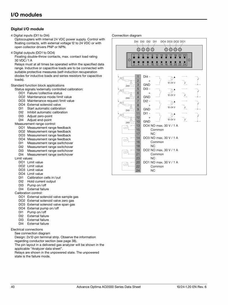
40 Advance Optima AO2000 Series Data Sheet 10/24-1.20 EN Rev. 6
I/O modules
Digital I/O module
4 Digital inputs (DI1 to DI4) Optocouplers with internal 24 VDC power supply. Control with floating contacts, with external voltage 12 to 24 VDC or with open collector drivers PNP or NPN.
4 Digital outputs (DO1 to DO4) Floating double-throw contacts, max. contact load rating 30 VDC/1 A Relays must at all times be operated within the specified data range. Inductive or capacitive loads are to be connected with suitable protective measures (self-induction recuperation diodes for inductive loads and series resistors for capacitive loads).
Standard function block applications Status signals /externally controlled calibration:
DO1 Failure/collective status DO2 Maintenance mode/ limit value DO3 Maintenance request / limit value DO4 External solenoid valve DI1 Start automatic calibration DI2 Inhibit automatic calibration DI3 Adjust zero-point DI4 Adjust end-point
Measurement range control: DO1 Measurement range feedback DO2 Measurement range feedback DO3 Measurement range feedback DO4 Measurement range feedback DI1 Measurement range switchover DI2 Measurement range switchover DI3 Measurement range switchover DI4 Measurement range switchover
Limit values: DO1 Limit value DO2 Limit value DO3 Limit value DO4 Limit value DI1 Calibration cells in /out DI2 Hold current output DI3 Pump on/off DI4 External failure
Calibration control: DO1 External solenoid valve sample gas DO2 External solenoid valve zero gas DO3 External solenoid valve span gas DO4 External pump on/off DI1 Pump on/off DI2 External failure DI3 External failure DI4 External failure
Electrical connections See connection diagram Design: 2x12-pin terminal strip. Observe the information regarding conductor section (see page 38). The pin layout in a delivered gas analyzer will be shown in the applicable “Analyzer data sheet”. Relays are shown in the unpowered state. The unpowered state is the failure mode.
Connection diagram
2
1 3 5 7 9 11 13 15 17 19 21 23
4 6 8 10 12 14 16 18 20 22 24
DI4 DO3 DO2 DO1DO4DI3 DI2 DI1
131517141618192123202224
DO4 NOCommonNC
DO3 NOCommonNC
DO2 NOCommonNC
DO1 NOCommonNC
123564789111210
max. 30 V / 1 A
max. 30 V / 1 A
max. 30 V / 1 A
max. 30 V / 1 A
DI4 -
DI3 -
DI2 -
DI1 -
+
+
+
+
GND
GND
GND
GND
24V
24V
24V
24V12-24 V
12-24 V
12-24 V
12-24 V
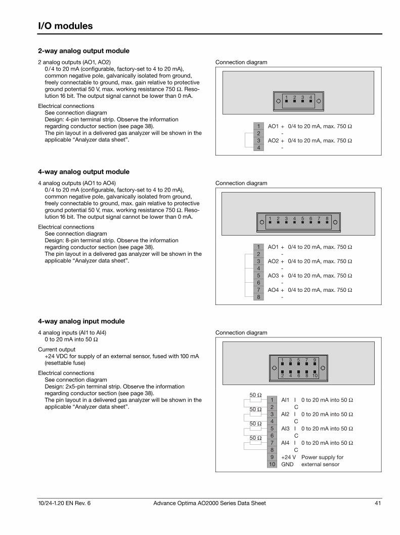
10/24-1.20 EN Rev. 6 Advance Optima AO2000 Series Data Sheet 41
I/O modules
2-way analog output module
2 analog outputs (AO1, AO2) 0 /4 to 20 mA (configurable, factory-set to 4 to 20 mA), common negative pole, galvanically isolated from ground, freely connectable to ground, max. gain relative to protective ground potential 50 V, max. working resistance 750 Ω. Reso-lution 16 bit. The output signal cannot be lower than 0 mA.
Electrical connections See connection diagram Design: 4-pin terminal strip. Observe the information regarding conductor section (see page 38). The pin layout in a delivered gas analyzer will be shown in the applicable “Analyzer data sheet”.
Connection diagram
1 2 3 4
1234
AO1 +-
AO2 +-
0/4 to 20 mA, max. 750 Ω
0/4 to 20 mA, max. 750 Ω
4-way analog output module
4 analog outputs (AO1 to AO4) 0 /4 to 20 mA (configurable, factory-set to 4 to 20 mA), common negative pole, galvanically isolated from ground, freely connectable to ground, max. gain relative to protective ground potential 50 V, max. working resistance 750 Ω. Reso-lution 16 bit. The output signal cannot be lower than 0 mA.
Electrical connections See connection diagram Design: 8-pin terminal strip. Observe the information regarding conductor section (see page 38). The pin layout in a delivered gas analyzer will be shown in the applicable “Analyzer data sheet”.
Connection diagram
1 2 3 4 5 6 7 8
12345678
AO3
AO1
+
+
-
-
AO4
AO2
+
+
-
-
0/4 to 20 mA, max. 750 Ω
0/4 to 20 mA, max. 750 Ω
0/4 to 20 mA, max. 750 Ω
0/4 to 20 mA, max. 750 Ω
4-way analog input module
4 analog inputs (AI1 to AI4) 0 to 20 mA into 50 Ω
Current output +24 VDC for supply of an external sensor, fused with 100 mA (resettable fuse)
Electrical connections See connection diagram Design: 2x5-pin terminal strip. Observe the information regarding conductor section (see page 38). The pin layout in a delivered gas analyzer will be shown in the applicable “Analyzer data sheet”.
Connection diagram
2 4 6 8 10
97531
123456789
10
50 Ω
50 Ω
50 Ω
50 Ω
AI1
AI3
I
I
C
C
AI2
AI4
I
I
C
C+24 VGND
0 to 20 mA into 50 Ω
0 to 20 mA into 50 Ω
0 to 20 mA into 50 Ω
0 to 20 mA into 50 Ω
external sensorPower supply for
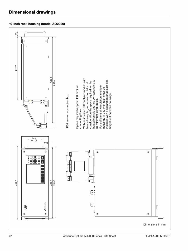
42 Advance Optima AO2000 Series Data Sheet 10/24-1.20 EN Rev. 6
Dimensional drawings
19-inch rack housing (model AO2020)
462,1
468,1
101,637,7
482,6
177
35
412,7
562,7
601,2
Dimensions in mm
IP54
ver
sion
con
nect
ion
box
Sp
ace
req
uire
d (a
pp
rox.
100
mm
) for
co
nnec
ting
lines
. W
ith a
n in
stal
led
FID
ana
lyze
r m
odul
e w
ith
heat
ed s
amp
le g
as c
onne
ctio
n ta
ke in
to
cons
ider
atio
n th
e sp
ace
req
uire
d fo
r th
e he
ated
sam
ple
gas
line
cor
resp
ond
ing
to
its m
inim
um b
end
rad
ius.
Fo
r su
ffici
ent
air
circ
ulat
ion,
mul
tiple
ho
usin
gs in
a 1
9-in
ch r
ack
mus
t b
e in
stal
led
with
a s
epar
atio
n of
at
leas
t on
e he
ight
uni
t b
etw
een
hous
ings
.
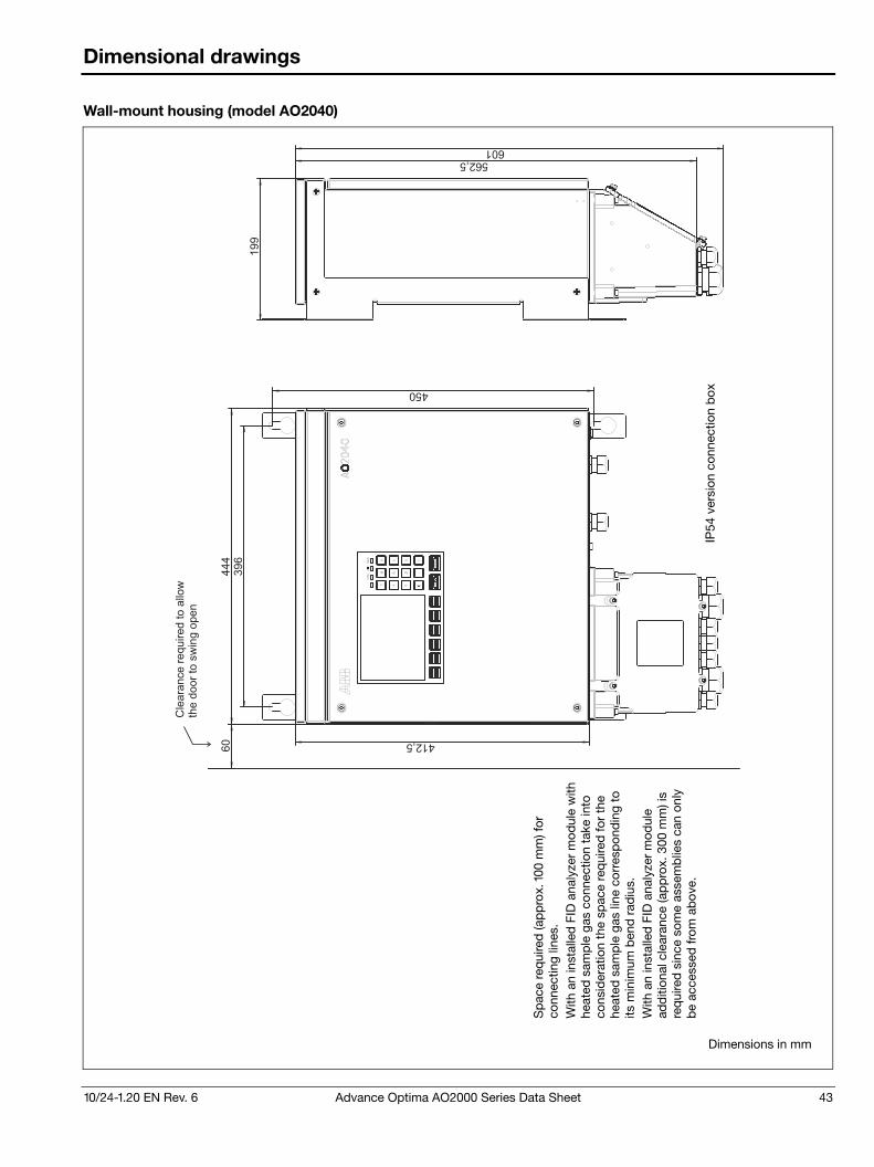
10/24-1.20 EN Rev. 6 Advance Optima AO2000 Series Data Sheet 43
Dimensional drawings
Wall-mount housing (model AO2040)
60
199
601562,5
412,5
396
450
444
Cle
ara
nce
required
toallo
wth
edoor
tosw
ing
open
Dimensions in mm
IP54
ver
sion
con
nect
ion
box
Sp
ace
req
uire
d (a
pp
rox.
100
mm
) for
co
nnec
ting
lines
. W
ith a
n in
stal
led
FID
ana
lyze
r m
odul
e w
ith
heat
ed s
amp
le g
as c
onne
ctio
n ta
ke in
to
cons
ider
atio
n th
e sp
ace
req
uire
d fo
r th
e he
ated
sam
ple
gas
line
cor
resp
ond
ing
to
its m
inim
um b
end
rad
ius.
W
ith a
n in
stal
led
FID
ana
lyze
r m
odul
e ad
diti
onal
cle
aran
ce (a
pp
rox.
300
mm
) is
req
uire
d s
ince
som
e as
sem
blie
s ca
n on
ly
be
acce
ssed
fro
m a
bov
e.
44 Advance Optima AO2000 Series Data Sheet 10/24-1.20 EN Rev. 6
Certifications
CE conformity
The AO2000 series gas analyzers satisfy the requirements of the European directives 2006/95/EC (Low voltage directive), 2004/108/EC (EMC directive) and 94/9/EC (ATEX directive – explosion protected versions only).
Compliance with the requirements of directive 2006/95/EC is evidenced by full compliance with European standards EN 61010-1:2001, EN 60825-1:1994 (LS25).
Compliance with the requirements of directive 2004/108/EC is evidenced by full compliance with European standards EN 61326-1:2006, EN 61000-3-2 :2006, EN 61000-3-3 :1995 + A1:2001 + A2:2005.
Compliance of the explosion protected versions with the require-ments of directive 94/9/EC is evidenced by full compliance with the European standards listed in the “Explosion protection to European standards” section (see page 45).
Performance test
The AO2000 series gas analyzers Uras26 (sample components CO, NO, SO2, CO2, N2O), Magnos206 (sample component O2) and electrochemical oxygen sensor (sample component O2) are certified for use in facilities requiring approval according to European directive 2001/80/EG and 2000/76/EG and meet the requirements of the 27th/30th BImSchV (German Federal Immissions Control Ordinance) and TA-Luft (German Technical Instructions on Air Quality) regulations. The requirements of QAL1 according to EN 15267 and EN 14181 are fulfilled. Report No. 821029 of June 30, 2006. Notification: Federal Gazette of October 14, 2006, No. 194, page 6715 Report No. 1249694 of March 30, 2009. Notification: Federal Gazette of August 25, 2009, No. 125, page 2932. Report No. 1710933 of September 30, 2011. Notification: Federal Gazette of March 2, 2012, No. 36, page 923. Report No. 936/21217137/A of October 14, 2011. Notification: Federal Gazette of March 2, 2012, No. 36, page 922.
Approval for USA and Canada – CSA
The AO2000 series gas analyzers are certified for use in general purpose environment, evidenced by full compliance with standards CAN/CSA-C22.2 No. 61010-1-04 and UL Std. No. 61010-1 (2nd Edition). Certificate No. 1714030
Approval for Russian Federation – GOST-R
The AO2000 series gas analyzers including the “safety concept” version are certified for use in general purpose environment. The following documents are available: GOST-R certificate No. POCC DE.HO03.H04298 and No. POCC DE.ГБ04.B01888, Rostekhnadzor operation permission No. PPC 00-39671, Pattern approval certificate No. DE.C.31.004.A No. 37985.
10/24-1.20 EN Rev. 6 Advance Optima AO2000 Series Data Sheet 45
Certifications
Explosion protection to European standards
The AO2000 series gas analyzers with Uras26, Magnos206, Caldos25 and Caldos27 in category 3G for measurement of flammable and non-flammable sample gas (“safety concept”) satisfy the European standards EN 60079-15:2005, EN 60079-2. Designation:
II 3G Ex nA py II T4 EC-Type examination certificate No. BVS 07 ATEX E 013 X
The AO2000 series gas analyzers with Uras26, Limas11, Magnos206, Magnos27, Caldos25 and Caldos27 in category 3G for measurement of non-flammable sample gas satisfy the European standard EN 60079-15:2010. Designation:
II 3G Ex nAc nCc IIC T4
LS25 analyzer module for use in zone 1 satisfies the European standards EN 60079-0 :2006, EN 60079-2 :2007, EN 60079-28:2007, EN 61241-0 :2006, EN 61241-4 :2006. Designations:
II 2 G Ex px II T5, II 2 D Ex pD 21 IP66 T64°C, II (2) G [Ex op is T4 Gb] IIC
EC-Type examination certificates No. DNV-2006-OSL-ATEX-0042X Rev. 2, DNV 09 ATEX 64813
LS25 analyzer module for use in zone 2 satisfies the European standards EN 60079-0 :2006, EN 60079-15:2005, EN 60079-28:2007, EN 61241-0 :2006, EN 61241-1:2004. Designations:
II 3 G Ex nA nC op is Gc IIC T4 –20°C ≤ Tamb ≤ +55°C, II 3 D Ex tD A22 IP65 T100°C
EC-Type examination certificate No. DNV-2008-OSL-ATEX-21837 Rev. 4
Explosion protection to U.S. and Canadian standards – CSA
The AO2000 series gas analyzers are certified for use in Class 1, Div. 2, Groups A, B, C, and D, Temperature code T4, max. ambi-ent temperature +50 °C (+55 °C for LS25) explosion hazard areas. Housing versions not equipped with conduit entries must be installed in a suitable enclosure, cabinet or rack with provision for connection of Div. 2 wiring methods, acceptable to the local inspection authority having jurisdiction. Certificate No. 1105720
Explosion protection for China – NEPSI
The AO2000 series gas analyzers with Uras26, Limas11, Magnos206, Caldos25, Caldos27 and MultiFID14 are certified for use in hazardous locations. The gas analyzers may be used for measurement of non-flammable gases and vapors. They are marked with Ex nAC II CT4 (MultiFID14: Ex nz II T3). Certificate No. GYJ101333X
The AO2000 series gas analyzers with Uras26, Limas11, Magnos206, Caldos25 and Caldos27 are certified for use in hazardous locations. The gas analyzers may be used for meas-urement of flammable gases and vapors. They are marked with Ex nAC py IIC T4/T6. Certificate No. GYJ101332X
The gas analyzer AO2000-LS25 Ex is certified for use in hazardous locations. The gas analyzer may be used for meas-urement of non-flammable gases and vapors. It is marked with Ex nAC IIC T5. Certificate No. GYJ111061X
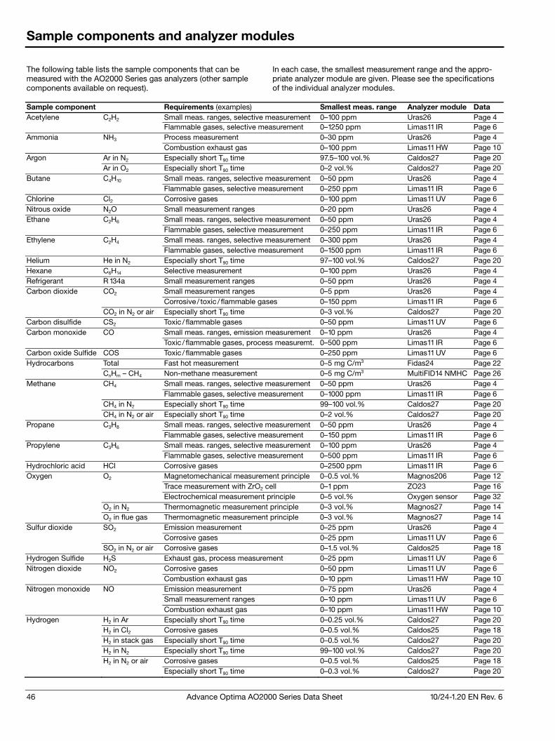
46 Advance Optima AO2000 Series Data Sheet 10/24-1.20 EN Rev. 6
Sample components and analyzer modules
The following table lists the sample components that can be measured with the AO2000 Series gas analyzers (other sample components available on request).
In each case, the smallest measurement range and the appro-priate analyzer module are given. Please see the specifications of the individual analyzer modules.
Sample component Requirements (examples) Smallest meas. range Analyzer module Data Acetylene C2H2 Small meas. ranges, selective measurement 0–100 ppm Uras26 Page 4 Flammable gases, selective measurement 0–1250 ppm Limas11 IR Page 6 Ammonia NH3 Process measurement 0–30 ppm Uras26 Page 4 Combustion exhaust gas 0–100 ppm Limas11 HW Page 10Argon Ar in N2 Especially short T90 time 97.5–100 vol.% Caldos27 Page 20 Ar in O2 Especially short T90 time 0–2 vol.% Caldos27 Page 20Butane C4H10 Small meas. ranges, selective measurement 0–50 ppm Uras26 Page 4 Flammable gases, selective measurement 0–250 ppm Limas11 IR Page 6 Chlorine Cl2 Corrosive gases 0–100 ppm Limas11 UV Page 6 Nitrous oxide N2O Small measurement ranges 0–20 ppm Uras26 Page 4 Ethane C2H6 Small meas. ranges, selective measurement 0–50 ppm Uras26 Page 4 Flammable gases, selective measurement 0–250 ppm Limas11 IR Page 6 Ethylene C2H4 Small meas. ranges, selective measurement 0–300 ppm Uras26 Page 4 Flammable gases, selective measurement 0–1500 ppm Limas11 IR Page 6 Helium He in N2 Especially short T90 time 97–100 vol.% Caldos27 Page 20Hexane C6H14 Selective measurement 0–100 ppm Uras26 Page 4 Refrigerant R 134a Small measurement ranges 0–50 ppm Uras26 Page 4 Carbon dioxide CO2 Small measurement ranges 0–5 ppm Uras26 Page 4 Corrosive / toxic / flammable gases 0–150 ppm Limas11 IR Page 6 CO2 in N2 or air Especially short T90 time 0–3 vol.% Caldos27 Page 20Carbon disulfide CS2 Toxic / flammable gases 0–50 ppm Limas11 UV Page 6 Carbon monoxide CO Small meas. ranges, emission measurement 0–10 ppm Uras26 Page 4 Toxic / flammable gases, process measuremt. 0–500 ppm Limas11 IR Page 6 Carbon oxide Sulfide COS Toxic / flammable gases 0–250 ppm Limas11 UV Page 6 Hydrocarbons Total Fast hot measurement 0–5 mg C/m3 Fidas24 Page 22 CnHm – CH4 Non-methane measurement 0–5 mg C/m3 MultiFID14 NMHC Page 26Methane CH4 Small meas. ranges, selective measurement 0–50 ppm Uras26 Page 4 Flammable gases, selective measurement 0–1000 ppm Limas11 IR Page 6 CH4 in N2 Especially short T90 time 99–100 vol.% Caldos27 Page 20 CH4 in N2 or air Especially short T90 time 0–2 vol.% Caldos27 Page 20Propane C3H8 Small meas. ranges, selective measurement 0–50 ppm Uras26 Page 4 Flammable gases, selective measurement 0–150 ppm Limas11 IR Page 6 Propylene C3H6 Small meas. ranges, selective measurement 0–100 ppm Uras26 Page 4 Flammable gases, selective measurement 0–500 ppm Limas11 IR Page 6 Hydrochloric acid HCl Corrosive gases 0–2500 ppm Limas11 IR Page 6 Oxygen O2 Magnetomechanical measurement principle 0–0.5 vol.% Magnos206 Page 12 Trace measurement with ZrO2 cell 0–1 ppm ZO23 Page 16 Electrochemical measurement principle 0–5 vol.% Oxygen sensor Page 32 O2 in N2 Thermomagnetic measurement principle 0–3 vol.% Magnos27 Page 14 O2 in flue gas Thermomagnetic measurement principle 0–3 vol.% Magnos27 Page 14Sulfur dioxide SO2 Emission measurement 0–25 ppm Uras26 Page 4 Corrosive gases 0–25 ppm Limas11 UV Page 6 SO2 in N2 or air Corrosive gases 0–1.5 vol.% Caldos25 Page 18Hydrogen Sulfide H2S Exhaust gas, process measurement 0–25 ppm Limas11 UV Page 6 Nitrogen dioxide NO2 Corrosive gases 0–50 ppm Limas11 UV Page 6 Combustion exhaust gas 0–10 ppm Limas11 HW Page 10Nitrogen monoxide NO Emission measurement 0–75 ppm Uras26 Page 4 Small measurement ranges 0–10 ppm Limas11 UV Page 6 Combustion exhaust gas 0–10 ppm Limas11 HW Page 10Hydrogen H2 in Ar Especially short T90 time 0–0.25 vol.% Caldos27 Page 20 H2 in Cl2 Corrosive gases 0–0.5 vol.% Caldos25 Page 18 H2 in stack gas Especially short T90 time 0–0.5 vol.% Caldos27 Page 20 H2 in N2 Especially short T90 time 99–100 vol.% Caldos27 Page 20 H2 in N2 or air Corrosive gases 0–0.5 vol.% Caldos25 Page 18 Especially short T90 time 0–0.3 vol.% Caldos27 Page 20

10/24-1.20 EN Rev. 6 Advance Optima AO2000 Series Data Sheet 47
This page is intentionally left blank.

Contact us
10/2
4�1.
20 E
N R
ev. 6
06.
2013
ABB Limited Process Automation Oldends Lane GL10 3TA Stonehouse Gloucestershire, United Kingdom Phone: +44 1 453 826661 Fax: +44 1 453 829671 ABB Pte. Ltd. Process Automation 2 Ayer Rajah Crescent 139935 Singapore, Singapore Phone: +65 6773 5961 Fax: +65 6778 0222 ABB Engineering Ltd. Process Automation 10 Jiuxianqiao Lu 100015 Beijing, China Phone: +86 10 84566688 Ext. 6217 Fax: +86 10 84567650 ABB Inc. Process Automation 3700 W Sam Houston Parkway South, Suite 600, Houston, TX 77042, USA Phone: +1 713 587 8000 www.abb.com/analytical
ABB Australia Pty Limited Process Automation Bapaume Road 2170 Moorebank New South Wales, Australia Phone: +61 2 9821 0968 Fax: +61 2 9400 7050 ABB Ltd. Process Automation 14 Mathura Road 121003 Faridabad, Haryana, India Phone: +91 129 2279627 Fax: +91 129 2279692 ABB Automation GmbH Process Automation Stierstaedter Strasse 5 60488 Frankfurt am Main, Germany Fax: +49 69 7930�4566 E�mail: [email protected]
Note We reserve the right to make technical changes or modify the contents of this document without prior notice. With regard to purchase orders, the agreed particulars shall prevail. ABB does not accept any responsibility whatsoever for potential errors or possible lack of information in this document. We reserve all rights in this document and in the subject matter and illustrations contained therein. Any reproduction, disclosure to third parties or utilization of its contents – in whole or in parts – is forbidden without prior written consent of ABB. Copyright© 2013 ABB All rights reserved
Sales
Service
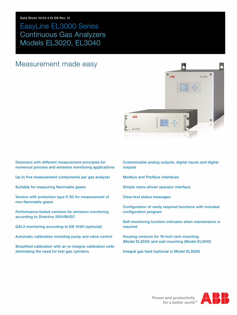
Data Sheet 10/24-4.10 EN Rev. 12
EasyLine EL3000 Series Continuous Gas Analyzers Models EL3020, EL3040
Measurement made easy
Detectors with different measurement principles for
numerous process and emission monitoring applications
Up to five measurement components per gas analyzer
Suitable for measuring flammable gases
Version with protection type II 3G for measurement of
non-flammable gases
Performance-tested versions for emission monitoring
according to Directive 2001/80/EC
QAL3 monitoring according to EN 14181 (optional)
Automatic calibration including pump and valve control
Simplified calibration with air or integral calibration cells
eliminating the need for test gas cylinders
Customizable analog outputs, digital inputs and digital
outputs
Modbus and Profibus interfaces
Simple menu-driven operator interface
Clear-text status messages
Configuration of rarely required functions with included
configuration program
Self-monitoring function indicates when maintenance is
required
Housing versions for 19-inch rack mounting
(Model EL3020) and wall mounting (Model EL3040)
Integral gas feed (optional in Model EL3020)
2 EasyLine EL3000 Series Data Sheet 10/24-4.10 EN Rev. 12
Overview of the gas analyzers
Measuring technology (analyzers)
The following analyzers are available for selection:
Uras26 infrared photometer for the measurement of infrared-active gas components e.g. CO, NO, SO2
Limas23 ultraviolet photometer for the measurement of NO, NO2 and SO2
Magnos206 oxygen analyzer for the measurement of O2 in process gas or in N2
Magnos27 oxygen analyzer for the measurement of O2 in flue gas or in N2
ZO23 trace oxygen analyzer for the measurement of O2 in pure gases (N2, CO2, Ar)
Caldos27 thermal conductivity analyzer for the measurement of binary gas mixtures with different thermal conductivity e.g. Ar in O2, H2 in Ar, CH4 in N2
Fidas24 flame-ionization detector for the measurement of hydrocarbons
Electrochemical oxygen sensor for the measurement of O2
Magnos206 can also be used in combination with Uras26 or Limas23.
Magnos27 and Caldos27 can also be used in combination with Uras26.
Fidas24 and ZO23 cannot be used in combination with one of the other analyzers. Only one ZO23 can be installed in the gas analyzer.
The electrochemical oxygen sensor can only be used in combination with Uras26 or Limas23. Two electrochemical oxygen sensors can be used in combination with Uras26 with separate gas paths (only in model EL3020).
Each analyzer has one physical measurement range per sample component. A section of the physical measurement range can be mapped to the current output (analog output) by on-site configu-ration.
Calibration is always executed in the physical measurement range. The permissible measurement range limits are given by the specifi-cation of the smallest and largest measurement ranges for the individual analyzers.
A total of up to five measurement components can be measured with one gas analyzer.
Calibration
Calibration can be performed automatically or manually. Automatic calibration – for all sample components together – is normally started on a cyclically time-controlled basis; it can also be started by an external control signal or via the Modbus as well as manually on the display and operator control unit of the gas analyzer.
Normally, simplified calibration methods with the built-in calibration cells or the so-called single-point calibration are used for automatic calibration. If calibration with test gases is required the control of solenoid valves for switching on five test gases, zero gas and sam-ple gas via digital outputs can be configured.
QAL3 monitoring
QAL3 monitoring is available as an option in the gas analyzer. It is used to fulfill the requirements according to EN 14181 for storage and analysis of device adjustment data. The QAL3 monitoring option features the following functions:
Automatic acquisition, verification and documentation of drift and precision at zero and reference points
Reporting via CUSUM and Shewhart control charts
QAL3 data storage in the gas analyzer (maximum 1 year)
QAL3 data display and read-out as well as parameter setting via web browser
Status messages on deviations beyond requirements
Data export for further processing with spreadsheet programs
10/24-4.10 EN Rev. 12 EasyLine EL3000 Series Data Sheet 3
Overview of the gas analyzers
Electrical interfaces
The electrical interfaces for the output of measured values and communication with external systems include
The integrated Ethernet-10/100BASE-T interface (for gas analyzer configuration, software update and QAL3 data transfer)
as well as the integrated I/O modules depending on the functional range and order
2-way and 4-way analog output modules with two or four analog outputs,
Digital I/O module with four digital inputs and four digital outputs,
Modbus module with one RS485 and one RS232 interface,
Profibus module with one RS485 and one MBP interface.
Integral gas feed
The integral gas feed (optional in model EL3020) is available in two versions. It includes
either the solenoid valve, pump, coarse filter, capillary tube and flow sensor modules
or a flow sensor module.
Housing design
The housing for the EL3020 gas analyzer model is designed as 19-inch housing with 3 height units (4 height units with Magnos27) and degree of protection IP20.
The housing for the EL3040 gas analyzer model is designed as wall-mount housing with degree of protection IP65.
4 EasyLine EL3000 Series Data Sheet 10/24-4.10 EN Rev. 12
Infrared photometer Uras26
Measurement principle
Non-dispersive infrared absorption
Photometer with 1 or 2 beam paths (gas paths) to measure up to 4 components
Sample components and measurement ranges
Sample components and smallest measurement ranges
Sample component Smallest measurement range
CO 0–100 ppm
CO2 0–100 ppm
NO 0–150 ppm
SO2 0–100 ppm
N2O 0–100 ppm
CH4 0–100 ppm
Measurement range quantity 2 measurement ranges
Measurement range limits
Smallest measurement range Largest measurement range
0–100 ppm (NO: 0–150 ppm) 0–500 ppm (NO: 0–750 ppm)
0–200 ppm 0–1000 ppm
0–600 ppm 0–3000 ppm
0–2000 ppm 0–10000 ppm
0–0.6 vol.% 0–3 vol.%
0–2 vol.% 0–10 vol.%
0–6 vol.% 0–30 vol.%
0–20 vol.% 0–100 vol.%
An individual measurement range within the limits shown in the table can be factory-set on special order. Measurement ranges are freely adjustable within the limits shown in the table. Measurement ranges should not be set within ignition limits.
Version for use in air separation units Only for binary gas mixtures consisting of the sample compo-nent in Ar, N2 or O2
Sample component Smallest /Largest measurement range
CO 0–10 ppm / 0–50 ppm
CO2 0–5 ppm / 0–25 ppm
N2O 0–10 ppm / 0–50 ppm
CH4 0–20 ppm / 0–100 ppm
Other than the data valid for the standard version the following data apply for this version (in % of the smallest measurement range shown in the table): Zero drift: 1.5 % per day Sensitivity drift: 1 % per week Output fluctuation (2 ): 0.5 % at T90 = 15 s Temperature effect: 2 % per 10 °C
Stability
The following data apply only if all influence factors (e.g. flow rate, temperature, atmospheric pressure) are constant. They relate to the smallest measurement range.
Linearity deviation 1 % of span
Repeatability 0.5 % of span
Zero drift 1 % of span per week
Sensitivity drift 1 % of measured value per week
Output fluctuation (2 ) 0.2 % of span at electronic T90 time (static /dynamic) = 5 /0 sec
Detection limit (4 ) 0.4 % of span at electronic T90 time (static /dynamic) = 5 /0 sec
Influence effects
Flow effect Flow rate in the 20 to 100 l/h range: within detection limits
Associated gas effect /cross sensitivity The knowledge of the sample gas composition is necessary for the analyzer configuration. Selectivity measures to reduce associated gas effect (optional): Incorporation of interference filters or filter cells, internal elec-tronic cross-sensitivity correction for one sample component by other sample components measured with the gas analyzer.
Temperature effect Ambient temperature in permissible range – At zero-point: 2 % of span per 10 °C – On sensitivity without thermostat:
3 % of measured value per 10 °C – On sensitivity with thermostat (optional):
2 % of measured value per 10 °C Thermostat temperature = 55 °C
Air pressure effect – At zero-point: No effect – On sensitivity with pressure correction by means of integral
pressure sensor: 0.2 % of measured value per 1 % baro-metric pressure change
The pressure sensor is located in the sample gas path if hoses are used as the internal gas lines. If stainless-steel tubing is used for internal gas lines the pressure sensor is routed to the outside via a hose. Pressure sensor working range: pabs = 600 to 1250 hPa
Power supply effect Voltage and frequency in the permissible range: No effect
10/24-4.10 EN Rev. 12 EasyLine EL3000 Series Data Sheet 5
Infrared photometer Uras26
Dynamic response
Warm-up time Approx. 30 minutes without thermostat; approx. 2 hours with thermostat
90% response time T90 = 2.5 sec for measurement cell length = 175 mm, sample gas flow = 60 l/h and electronic T90 time (static /dynamic) = 5 /0 sec
Calibration
Zero-point calibration With inert gas, e.g. nitrogen, or with ambient air that is free of the sample component.
End-point calibration With gas-filled calibration cells (optional) or with test gas mix-tures. It is recommended to verify the calibration cell set values once a year.
Materials in contact with the sample medium
Analyzer (sample cells) Tubing: aluminum; windows: CaF2 or BaF2; connectors: stainless steel 1.4305 (SAE 303)
Gas lines and connectors Gas lines: FPM hoses or PTFE tubes; connectors: stainless steel 1.4305 (SAE 303); solenoid valve (option in model EL3020): PVDF. When flammable components are present in the sample gas: Gas lines: stainless steel tubes 1.4571 (SAE 316Ti); connectors: stainless steel 1.4305 (SAE 303).
Gas connections
See page 25 and page 26
Sample gas inlet conditions
The analyzer must not be used for measurement of ignitable gas/air or gas/oxygen mixtures.
Temperature The sample gas dew point should be at least 5 °C below the temperature throughout the sample gas path. Otherwise a sample gas cooler or condensate trap is required.
Inlet pressure pe = 2 to 500 hPa Lower pressures require a sample gas pump and higher pressures require a pressure reducer.
Outlet pressure Atmospheric pressure
Flow rate 20 to 100 l/h
Corrosive gases Highly corrosive associated gas components, e.g. chlorine (Cl2) and hydrogen chloride (HCl), as well as gases or aerosols containing chlorine must be cooled or undergo prior absorption.
Flammable gases In the version with gas lines and connectors made of stainless steel the analyzer is suitable for measuring flammable gases in general purpose environment (see page 20).
6 EasyLine EL3000 Series Data Sheet 10/24-4.10 EN Rev. 12
Ultraviolet photometer Limas23
Measurement principle
UV-RAS (UV Resonance Absorption Spectroscopy) method for sample component NO, NDUV (Interference filter correlation) method for sample components NO2 and SO2
Photometer to measure up to 3 components
Sample components and measurement ranges
Sample components and measurement ranges
Sample component Smallest /Largest measurement range
NO 0–50 ppm / 0–5000 ppm
NO2 0–50 ppm / 0–500 ppm
SO2 0–100 ppm / 0–5 vol.%
The NOx measurement value can be evaluated as the sum of the NO and NO2 measurement values and output at an analog output. The NOx measurement range results from the sum of the NO and NO2 measurement ranges. NO processed through a converter can be indicated as sample component “NOx” on the display (factory-set). For indication of the NOx measurement value in mg/m3, the factor 1.53 is taken into account for conversion of NO to NOx (factory-set).
Measurement range quantity 2 measurement ranges
Measurement range limits
Smallest measurement range Largest measurement range
0–50 ppm 0–250 ppm
0–100 ppm 0–500 ppm
0–200 ppm 0–1000 ppm
0–400 ppm 0–2000 ppm
0–1000 ppm 0–5000 ppm
0–4000 ppm 0–20000 ppm
0–1 vol.% 0–5 vol.%
An individual measurement range within the limits shown in the table can be factory-set on special order. Measurement ranges are freely adjustable within the limits shown in the table.
Stability
The following data apply only if all influence factors (e.g. flow rate, temperature, atmospheric pressure) are constant. They relate to the smallest measurement range.
Linearity deviation 1 % of span
Repeatability 0.5 % of span
Zero drift – For NO: 2 % of span per week – For NO2 and SO2: 3 ppm per week for measurement ranges
100 ppm (daily automatic baseline check is recommended), 2.5 % of span per week for measurement ranges > 100 ppm
Sensitivity drift 1 % of measured value per week
Output fluctuation (2 ) 0.5 % of span at electronic T90 time = 20 sec
Detection limit (4 ) 1 % of span at electronic T90 time = 20 sec
Influence effects
Flow effect Flow rate in the 20 to 100 l/h range: within detection limits
Associated gas effect /cross sensitivity The knowledge of the sample gas composition is necessary for the analyzer configuration. Selectivity measures to reduce associated gas effect (optional): Internal adjustment or internal electronic cross-sensitivity correc-tion for one sample component by other sample components measured with the gas analyzer.
Temperature effect Ambient temperature in permissible range – At zero-point: 1 % of span per 10 °C – On sensitivity: 1.5 % of measured value per 10 °C
Air pressure effect – At zero-point: No effect – On sensitivity with pressure correction by means of integral
pressure sensor: 0.2 % of measured value per 1 % baro-metric pressure change
The pressure sensor is located in the sample gas path. Pressure sensor working range: pabs = 600 to 1250 hPa
Power supply effect Voltage and frequency in the permissible range: No effect
10/24-4.10 EN Rev. 12 EasyLine EL3000 Series Data Sheet 7
Ultraviolet photometer Limas23
Dynamic response
Warm-up time Approx. 2 hours
90% response time T90 3 sec for measurement cell length = 220 mm, sample gas flow = 60 l/h and electronic T90 time = 0 sec
Calibration
Zero-point calibration With inert gas, e.g. nitrogen, or with ambient air that is free of the sample component.
End-point calibration With gas-filled calibration cells (optional) or with test gases (for each sample component). It is recommended to verify the cali-bration cell set values once a year.
Materials in contact with the sample medium
Analyzer (sample cell) Tubing: aluminum; windows: CaF2; connectors: stainless steel 1.4305 (SAE 303). Option: Tubing, windows and connectors made of quartz glass.
Gas lines and connectors Gas lines: FPM hoses; gas connectors: stainless steel 1.4305 (SAE 303)
Gas connections
See page 27
Sample gas inlet conditions
The analyzer must not be used for measurement of flammable gases and ignitable gas/air or gas/oxygen mixtures.
Temperature The sample gas dew point should be at least 5 °C below the temperature throughout the sample gas path. Otherwise a sample gas cooler or condensate trap is required. The internal temperature of the gas analyzer is at least 10 °C above ambient temperature.
Inlet pressure pe = 2 to 500 hPa Lower pressures require a sample gas pump and higher pressures require a pressure reducer.
Outlet pressure Atmospheric pressure
Flow rate 20 to 100 l/h
Corrosive gases Highly corrosive associated gas components, e.g. chlorine (Cl2) and hydrogen chloride (HCl), as well as gases or aerosols con-taining chlorine must be cooled or undergo prior absorption.
Note
The analyzer cannot be used in combination with the integral gas feed.
8 EasyLine EL3000 Series Data Sheet 10/24-4.10 EN Rev. 12
Oxygen analyzer Magnos206
Measurement principle
Paramagnetic behavior of oxygen
Magnetomechanical oxygen analyzer; short 90% response time
Sample component and measurement ranges
Sample component Oxygen (O2)
Smallest measurement range 0 to 2 vol.% O2
Measurement range quantity and limits 2 measurement ranges Measurement ranges are freely adjustable; they are factory-set per order to 0 to 5 or 0 to 100 or 98 to 100 vol.% O2.
Largest measurement range 0 to 100 vol.% O2 Measurement ranges should not be set within ignition limits.
Measurement ranges with suppressed zero-point Suppressed measurement ranges are freely adjustable in the range 0 to 100 vol.% O2. Smallest span 2 vol.% O2. The combi-nation of a suppressed and an initial measurement range is not possible. Pressure correction with a pressure sensor is required. A pressure sensor is installed when the analyzer has been ordered with suppressed measurement range.
Stability
The following data apply only if all influence factors (e.g. flow rate, temperature, atmospheric pressure) are constant. They are based on a span of 2 vol.% O2.
Linearity deviation 0.5 % of span
Repeatability 50 ppm O2 (time base for gas exchange 5 minutes)
Zero drift 3 % of span of the smallest measurement range (per order) per week, minimum 300 ppm O2 per week; following prolonged transport and storage time the drift can be higher during the first weeks of operation.
Sensitivity drift 0.1 vol.% O2 per week or 1 % of measured value per week (not cumulative), whichever is smaller. 0.25 % of measured value per year, minimum 0.05 vol.% O2 per year
Output fluctuation (2 ) 25 ppm O2 at electronic T90 time (static /dynamic) = 3 /0 sec
Detection limit (4 ) 50 ppm O2 at electronic T90 time (static /dynamic) = 3 /0 sec
Influence effects
Flow effect 0.1 vol.% O2 in the 30 to 90 l/h range
Associated gas effect Data regarding the effect of associated gases can be found in IEC 61207-3 :2002 “Gas analyzers – Expression of performance – Part 3: Paramagnetic oxygen analyzers”.
Temperature effect Ambient temperature in the permissible range – At zero-point: 1 % of span per 10 °C, 2 % of span per
10 °C in combination with Uras26 – On sensitivity: 0.2 % of measured value per 10 °C Thermostat temperature = 64 °C
Air pressure effect – At zero-point: No effect – On sensitivity with no pressure correction:
1 % of measured value per 1 % air pressure change – On sensitivity with pressure correction using integrated
pressure sensor (optional): 0.01 % of measured value per 1 % pressure change or 0.002 vol.% O2 per 1 % pressure change, whichever is greater Pressure sensor working range: pabs = 600 to 1250 hPa
Power supply effect Voltage and frequency in the permissible range: 0.2 % of span
Position effect Zero-point shift 0.05 vol.% O2 per 1° deviation from horizontal orientation. Position has no effect on the hard-mounted unit.
10/24-4.10 EN Rev. 12 EasyLine EL3000 Series Data Sheet 9
Oxygen analyzer Magnos206
Dynamic response
Warm-up time < 1 hour
90% response time T90 approx. 4 sec at a sample gas flow of 90 l/h and electronic T90 time (static /dynamic) = 3 /0 sec, gas change from nitrogen to air
Calibration
Zero-point calibration With oxygen-free process gas or substitute gas
End-point calibration With process gas with a known oxygen concentration or a substitute gas such as dried air
Single-point calibration Zero-point calibration with any oxygen concentration, e.g. with nitrogen or ambient air, processed through a cooler or H2O absorber. Pressure correction by means of pressure sensor is recom-mended for single-point calibration with air. Depending on the measurement task involved, the zero- and end-points should be verified periodically (recommendation: once a year).
Calibration of measurement ranges with suppressed zero-point Highly suppressed measurement ranges (95 to 100 vol.% O2) should only be calibrated with test gases with concentrations in the selected measurement range.
Materials in contact with the sample medium
Analyzer Sample chamber (direct connection): stainless steel 1.4305 (SAE 303), glass, platinum, rhodium, epoxy resin; seals: FPM (Fluorocarbon rubber), PEEK, FFKM
Gas connectors of the solenoid valve (option in model EL3020) PVDF
Gas connections
See page 28
Sample gas inlet conditions
The analyzer must not be used for measurement of ignitable gas/air or gas/oxygen mixtures.
Temperature The sample gas dew point should be at least 5 °C below the temperature throughout the sample gas path. Otherwise a sample gas cooler or condensate trap is required. Water vapor content variations cause volume errors.
Inlet pressure pe = 2 to 100 hPa Lower pressures require a sample gas pump and higher pressures require a pressure reducer.
Outlet pressure Atmospheric pressure
Flow rate 30 to 90 l/h Abrupt changes in gas flow rates should be avoided when using highly suppressed measurement ranges.
Corrosive gases Consultation with ABB Analytical is required if the sample gas contains Cl2, HCl, HF or other corrosive components. The AO2000-Magnos206 analyzer should be used if the sample gas contains NH3.
Flammable gases The analyzer is suitable for measuring flammable gases in general purpose environment (see page 20).
10 EasyLine EL3000 Series Data Sheet 10/24-4.10 EN Rev. 12
Oxygen analyzer Magnos27
Measurement principle
Paramagnetic behavior of oxygen
Heavy-duty thermomagnetic analyzer
Sample component and measurement ranges
Sample component Oxygen (O2) in flue gas or in nitrogen (N2)
Smallest measurement range 0 to 10 vol.% O2
Measurement range quantity 1 measurement range The measurement range is factory-set per customer order.
Largest measurement range 0 to 100 vol.% O2 Measurement ranges within ignition limits cannot be provided.
Stability
Linearity deviation 2 % of span
Repeatability 1 % of span
Zero drift 1 % of span per week
Sensitivity drift 2 % of measured value per week
Output fluctuation (2 ) 0.5 % of smallest measurement range span at electronic T90 time = 0 sec
Detection limit (4 ) 1 % of smallest measurement range span at electronic T90 time = 0 sec
Influence effects
Flow effect 1 % of span at a flow change of 10 l/h. At an identical flow rate for test and sample gases the flow rate effect is automa-tically compensated.
Associated gas effect Magnos27 calibration applies only to the sample gas shown on the identification plate (= sample component + associated gas).
Temperature effect Ambient temperature in permissible range – At zero-point: 2 % of span per 10 °C – On sensitivity: 0.5 % of measured value per 10 °C relative to temperature at the time of calibration Thermostat temperature = 63 °C
Air pressure effect – At zero-point: < 0.05 vol.% O2 per 1 % air pressure change – On sensitivity without pressure correction:
1.5 % of measured value per 1 % air pressure change – On sensitivity with pressure correction using integrated
pressure sensor (optional): 0.25 % of measured value per 1 % air pressure change
Option: Operating altitude over 2000 m
Power supply effect 24 VDC 5 %: 0.2 % of span
Position effect Approx. 3 % of smallest measurement range span per 1° deviation from horizontal orientation. Position has no effect on the hard-mounted unit.
10/24-4.10 EN Rev. 12 EasyLine EL3000 Series Data Sheet 11
Oxygen analyzer Magnos27
Dynamic response
Warm-up time 2 to 4 hours
90% response time T90 = 10 to 22 sec, depending on sample gas flow and on measurement cell connection (see “Gas connections”, applies to an analyzer unit with 1 analyzer module)
Calibration
Zero-point calibration With oxygen-free process gas or substitute gas
End-point calibration With process gas having a known oxygen concentration or with substitute gas
Materials in contact with the sample medium
Analyzer Rust- and acid-resistant steel 1.4580 (SAE 316Cb) and 1.4305 (SAE 303), glass
Gas lines and connectors Rust- and acid-resistant steel 1.4571 (SAE 316Ti) and 1.4305 (SAE 303), PVC-C, FPM
Gas connections
See page 29
Sample gas inlet conditions
The analyzer must not be used for measurement of flammable gases and ignitable gas/air or gas/oxygen mixtures.
Temperature The sample gas dew point should be at least 5 °C below the temperature throughout the sample gas path. Otherwise a sample gas cooler or condensate trap is required. Water vapor content variations cause volume errors.
Inlet pressure pe = 2 to 100 hPa Lower pressures require a sample gas pump and higher pressures require a pressure reducer.
Outlet pressure Atmospheric pressure
Flow rate 20 to 90 l/h
Note
The analyzer can only be mounted in the 19-inch housing (dimen-sional drawing see page 29). The analyzer cannot be used in combination with the integral gas feed.

12 EasyLine EL3000 Series Data Sheet 10/24-4.10 EN Rev. 12
Trace oxygen analyzer ZO23
Measurement principle
Potentiometric measurement; zirconium dioxide cell for determination of the oxygen concentration in accordance with Nernst’s equation; reference gas: ambient air.
The analyzer is used for the continuous measurement of oxygen in pure gases (N2, CO2, Ar). The measuring cell is catalytically inactivated to the extent that flammable carrier components in stoichiometric concentrations only negligibly reduce the oxygen value.
Sample component and measurement ranges
Sample component Oxygen (O2)
Measurement range quantity and limits 2 measurement ranges Measurement ranges are freely adjustable within the range 0 to 1 ppm to 0 to 250,000 ppm O2; they are factory-set to 0 to 1/0 to 10 ppm O2. The following measurement data refer to a measurement span of 100 ppm O2 with a regulated flow rate of 8 0.2 l/h.
Stability
Linearity Owing to the measurement principle, zirconium dioxide cells are base linear.
Repeatability < 1 % of the measurement range or 100 ppb O2 (whichever is greater)
Zero drift The zero point (reference point) is displayed if ambient air is present on the sample gas side. The value for air of 20.6 % vol. of O2 (for 25 °C and 50 % relative humidity) may deviate through aging of the cell. < 1 % of the measurement range per week or 250 ppb O2 (whichever is greater)
Sensitivity drift Depends on possible interfering components (catalyst poisons) in the sample gas and the aging of the cell. For pure gas measurements in N2 and Ar: < 1 % of the measurement range per week or 250 ppb O2 (whichever is greater)
Output fluctuation (2 ) < 0.5 % of the measured value or 50 ppb O2 (whichever is greater)
Influence effects
Flow effect 300 ppbv O2 in the permissible range
Associated gas effect Inert gases (Ar, CO2, N2) have no effect. Flammable gases (CO, H2, CH4) in stoichiometric concentrations to the oxygen content: Conversion of O2 < 20 % of the stoichiometric conversion. If higher concentrations of flammable gases are present, higher O2 conversions must be expected. The concentration of flammable gases in the sample gas must not exceed 100 ppm.
Temperature effect The effect of the ambient temperature in the permissible range of +5 to +45 °C is < 2 % of the measured value or 50 ppb O2 per 10 °C change in the ambient temperature (whichever is greater).
Air pressure effect No effect through a change in air pressure; the sample gas must flow out of the outlet without back pressure.
Power supply effect 24 V DC 5 %: no effect
Position effect No position effect for permanently installed instruments
10/24-4.10 EN Rev. 12 EasyLine EL3000 Series Data Sheet 13
Trace oxygen analyzer ZO23
Dynamic response
Warm-up time The operating temperature of the cell is reached after approx. 15 minutes. Offset calibration with reference gas (ambient air) after 2 hours flow. The measurement is ready-to-run after valves and lines have been purged with sample gas. Typical purging time for valves and lines: approx. 2 to 5 hours.
90% response time T90 < 60 sec for the alternation of 2 test gases in the measure-ment range 10 ppm with a sample gas flow rate = 8 l/h and electronic T90 time = 3 sec
Calibration
Offset calibration The reference value for ambient air is calibrated at 20.6 vol.% O2 by means of ambient air on the sample gas side.
End-point calibration By means of test gas O2 in N2 (or in CO2 or in Ar); O2 concentration in the measurement range, e.g. 10 ppm O2
Function test
An extended response time or reduced sensitivity are dimensions for the correct functioning of the measuring cell. The function test can be carried out by feeding the sample gas without any additional test gases. On the basis of the progression of the test, it can be assessed whether the reaction time of the sensor lies within a specified tolerance. The function test is started manually and lasts approx. 15 min.
Materials in contact with the sample medium
Analyzer Zirconium dioxide cell: ZrO2, electrodes containing platinum; dust filter (option): PP; flow sensor (option): on semiconductor basis, nickel-plated brass
Gas lines and connectors Stainless steel 1.4571 (SAE 316Ti), FPM and silicon hoses in the gas outlet; gas connections: stainless steel 1.4401 (SAE 316) /1.4305 (SAE 303)
Gas connections
See page 30
Sample gas inlet conditions
The analyzer must not be used for measurement of ignitable gas/air or gas/oxygen mixtures.
Temperature +5 to +50 °C
Inlet pressure pe 70 hPa
Outlet pressure Atmospheric pressure
Flow rate 4 to 20 l/h. Use a metering valve to set the flow rate.
Corrosive gases The presence of corrosive gases and catalyst poisons, e.g. halogens, gases containing sulfur and heavy-metal dust, leads to faster aging and/or destruction of the ZrO2 cell.
Flammable gases The analyzer is suitable for measuring flammable gases in general purpose environment (see page 20). The concentration of flammable gases in the sample gas must not exceed 100 ppm.
Purge gas If case purging is selected, purging may only be carried out with air (not with nitrogen), since the ambient air is used as a reference gas.
Note
The analyzer cannot be used in combination with the integral gas feed.
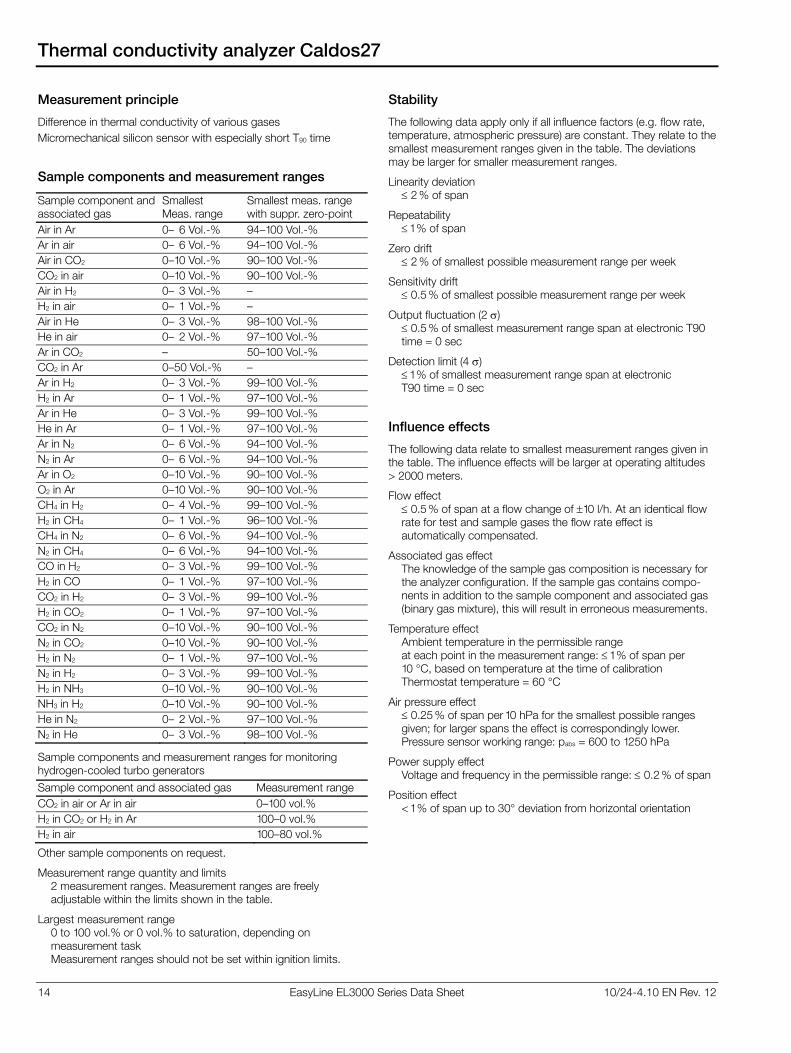
14 EasyLine EL3000 Series Data Sheet 10/24-4.10 EN Rev. 12
Thermal conductivity analyzer Caldos27
Measurement principle
Difference in thermal conductivity of various gases
Micromechanical silicon sensor with especially short T90 time
Sample components and measurement ranges
Sample component and associated gas
Smallest Meas. range
Smallest meas. rangewith suppr. zero-point
Air in Ar 0–16 Vol.-% 94–100 Vol.-%
Ar in air 0–16 Vol.-% 94–100 Vol.-%
Air in CO2 0–10 Vol.-% 90–100 Vol.-%
CO2 in air 0–10 Vol.-% 90–100 Vol.-%
Air in H2 0–13 Vol.-% –
H2 in air 0–11 Vol.-% –
Air in He 0–13 Vol.-% 98–100 Vol.-%
He in air 0–12 Vol.-% 97–100 Vol.-%
Ar in CO2 – 50–100 Vol.-%
CO2 in Ar 0–50 Vol.-% –
Ar in H2 0–13 Vol.-% 99–100 Vol.-%
H2 in Ar 0–11 Vol.-% 97–100 Vol.-%
Ar in He 0–13 Vol.-% 99–100 Vol.-%
He in Ar 0–11 Vol.-% 97–100 Vol.-%
Ar in N2 0–16 Vol.-% 94–100 Vol.-%
N2 in Ar 0–16 Vol.-% 94–100 Vol.-%
Ar in O2 0–10 Vol.-% 90–100 Vol.-%
O2 in Ar 0–10 Vol.-% 90–100 Vol.-%
CH4 in H2 0–14 Vol.-% 99–100 Vol.-%
H2 in CH4 0–11 Vol.-% 96–100 Vol.-%
CH4 in N2 0–16 Vol.-% 94–100 Vol.-%
N2 in CH4 0–16 Vol.-% 94–100 Vol.-%
CO in H2 0–13 Vol.-% 99–100 Vol.-%
H2 in CO 0–11 Vol.-% 97–100 Vol.-%
CO2 in H2 0–13 Vol.-% 99–100 Vol.-%
H2 in CO2 0–11 Vol.-% 97–100 Vol.-%
CO2 in N2 0–10 Vol.-% 90–100 Vol.-%
N2 in CO2 0–10 Vol.-% 90–100 Vol.-%
H2 in N2 0–11 Vol.-% 97–100 Vol.-%
N2 in H2 0–13 Vol.-% 99–100 Vol.-%
H2 in NH3 0–10 Vol.-% 90–100 Vol.-%
NH3 in H2 0–10 Vol.-% 90–100 Vol.-%
He in N2 0–12 Vol.-% 97–100 Vol.-%
N2 in He 0–13 Vol.-% 98–100 Vol.-%
Sample components and measurement ranges for monitoring hydrogen-cooled turbo generators
Sample component and associated gas Measurement range
CO2 in air or Ar in air 0–100 vol.%
H2 in CO2 or H2 in Ar 100–0 vol.%
H2 in air 100–80 vol.%
Other sample components on request.
Measurement range quantity and limits 2 measurement ranges. Measurement ranges are freely adjustable within the limits shown in the table.
Largest measurement range 0 to 100 vol.% or 0 vol.% to saturation, depending on measurement task Measurement ranges should not be set within ignition limits.
Stability
The following data apply only if all influence factors (e.g. flow rate, temperature, atmospheric pressure) are constant. They relate to the smallest measurement ranges given in the table. The deviations may be larger for smaller measurement ranges.
Linearity deviation 2 % of span
Repeatability 1 % of span
Zero drift 2 % of smallest possible measurement range per week
Sensitivity drift 0.5 % of smallest possible measurement range per week
Output fluctuation (2 ) 0.5 % of smallest measurement range span at electronic T90 time = 0 sec
Detection limit (4 ) 1 % of smallest measurement range span at electronic T90 time = 0 sec
Influence effects
The following data relate to smallest measurement ranges given in the table. The influence effects will be larger at operating altitudes > 2000 meters.
Flow effect 0.5 % of span at a flow change of 10 l/h. At an identical flow rate for test and sample gases the flow rate effect is automatically compensated.
Associated gas effect The knowledge of the sample gas composition is necessary for the analyzer configuration. If the sample gas contains compo-nents in addition to the sample component and associated gas (binary gas mixture), this will result in erroneous measurements.
Temperature effect Ambient temperature in the permissible range at each point in the measurement range: 1 % of span per 10 °C, based on temperature at the time of calibration Thermostat temperature = 60 °C
Air pressure effect 0.25 % of span per 10 hPa for the smallest possible ranges given; for larger spans the effect is correspondingly lower. Pressure sensor working range: pabs = 600 to 1250 hPa
Power supply effect Voltage and frequency in the permissible range: 0.2 % of span
Position effect < 1 % of span up to 30° deviation from horizontal orientation
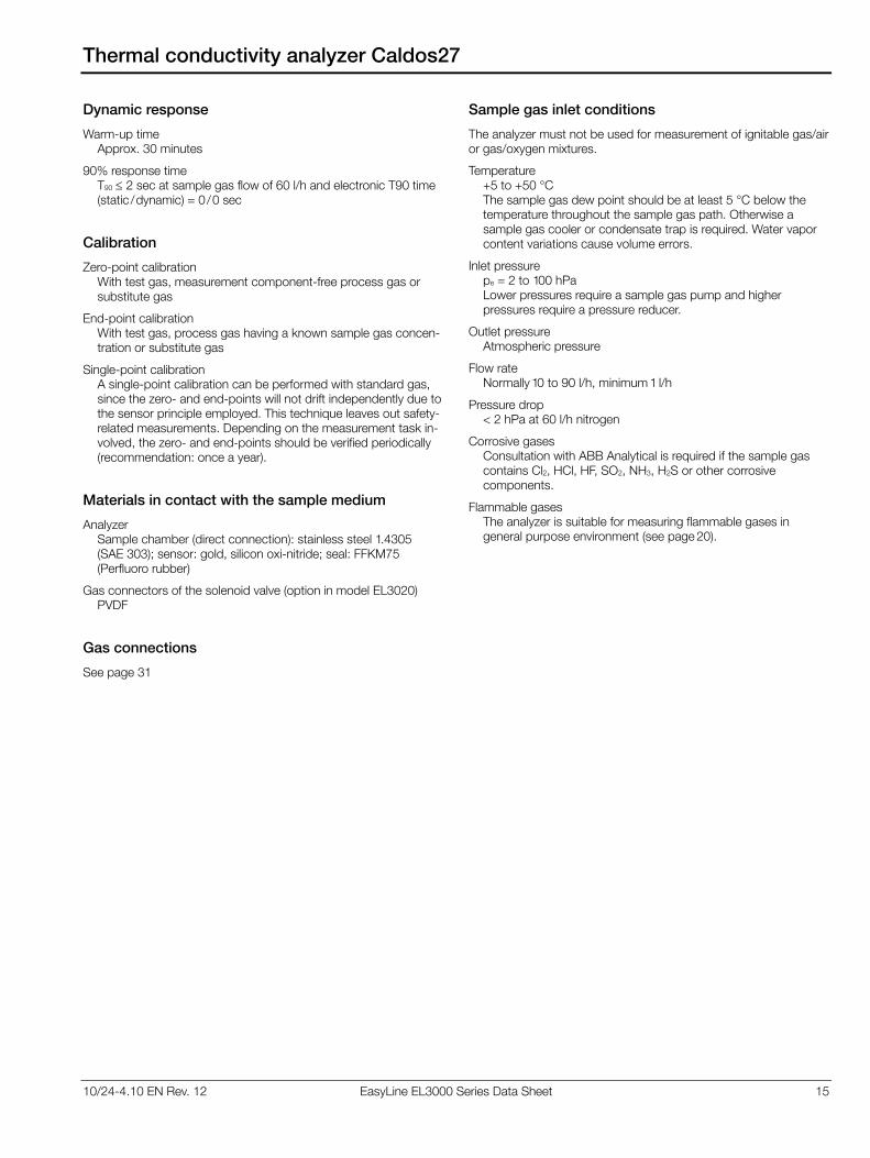
10/24-4.10 EN Rev. 12 EasyLine EL3000 Series Data Sheet 15
Thermal conductivity analyzer Caldos27
Dynamic response
Warm-up time Approx. 30 minutes
90% response time T90 2 sec at sample gas flow of 60 l/h and electronic T90 time (static /dynamic) = 0 /0 sec
Calibration
Zero-point calibration With test gas, measurement component-free process gas or substitute gas
End-point calibration With test gas, process gas having a known sample gas concen-tration or substitute gas
Single-point calibration A single-point calibration can be performed with standard gas, since the zero- and end-points will not drift independently due to the sensor principle employed. This technique leaves out safety-related measurements. Depending on the measurement task in-volved, the zero- and end-points should be verified periodically (recommendation: once a year).
Materials in contact with the sample medium
Analyzer Sample chamber (direct connection): stainless steel 1.4305 (SAE 303); sensor: gold, silicon oxi-nitride; seal: FFKM75 (Perfluoro rubber)
Gas connectors of the solenoid valve (option in model EL3020) PVDF
Gas connections
See page 31
Sample gas inlet conditions
The analyzer must not be used for measurement of ignitable gas/air or gas/oxygen mixtures.
Temperature +5 to +50 °C The sample gas dew point should be at least 5 °C below the temperature throughout the sample gas path. Otherwise a sample gas cooler or condensate trap is required. Water vapor content variations cause volume errors.
Inlet pressure pe = 2 to 100 hPa Lower pressures require a sample gas pump and higher pressures require a pressure reducer.
Outlet pressure Atmospheric pressure
Flow rate Normally 10 to 90 l/h, minimum 1 l/h
Pressure drop < 2 hPa at 60 l/h nitrogen
Corrosive gases Consultation with ABB Analytical is required if the sample gas contains Cl2, HCl, HF, SO2, NH3, H2S or other corrosive components.
Flammable gases The analyzer is suitable for measuring flammable gases in general purpose environment (see page 20).
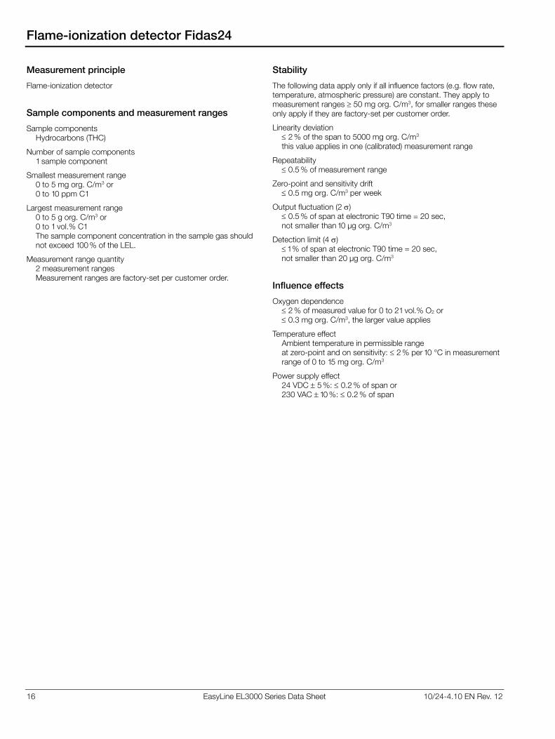
16 EasyLine EL3000 Series Data Sheet 10/24-4.10 EN Rev. 12
Flame-ionization detector Fidas24
Measurement principle
Flame-ionization detector
Sample components and measurement ranges
Sample components Hydrocarbons (THC)
Number of sample components 1 sample component
Smallest measurement range 0 to 5 mg org. C/m3 or 0 to 10 ppm C1
Largest measurement range 0 to 5 g org. C/m3 or 0 to 1 vol.% C1 The sample component concentration in the sample gas should not exceed 100 % of the LEL.
Measurement range quantity 2 measurement ranges Measurement ranges are factory-set per customer order.
Stability
The following data apply only if all influence factors (e.g. flow rate, temperature, atmospheric pressure) are constant. They apply to measurement ranges 50 mg org. C/m3, for smaller ranges these only apply if they are factory-set per customer order.
Linearity deviation 2 % of the span to 5000 mg org. C/m3 this value applies in one (calibrated) measurement range
Repeatability 0.5 % of measurement range
Zero-point and sensitivity drift 0.5 mg org. C/m3 per week
Output fluctuation (2 ) 0.5 % of span at electronic T90 time = 20 sec, not smaller than 10 μg org. C/m3
Detection limit (4 ) 1 % of span at electronic T90 time = 20 sec, not smaller than 20 μg org. C/m3
Influence effects
Oxygen dependence 2 % of measured value for 0 to 21 vol.% O2 or 0.3 mg org. C/m3, the larger value applies
Temperature effect Ambient temperature in permissible range at zero-point and on sensitivity: 2 % per 10 °C in measurement range of 0 to 15 mg org. C/m3
Power supply effect 24 VDC 5 %: 0.2 % of span or 230 VAC 10 %: 0.2 % of span
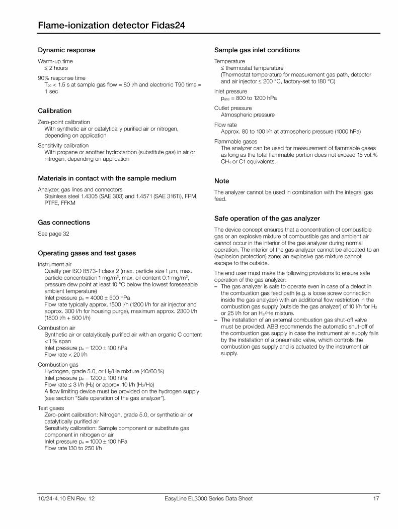
10/24-4.10 EN Rev. 12 EasyLine EL3000 Series Data Sheet 17
Flame-ionization detector Fidas24
Dynamic response
Warm-up time 2 hours
90% response time T90 < 1.5 s at sample gas flow = 80 l/h and electronic T90 time = 1 sec
Calibration
Zero-point calibration With synthetic air or catalytically purified air or nitrogen, depending on application
Sensitivity calibration With propane or another hydrocarbon (substitute gas) in air or nitrogen, depending on application
Materials in contact with the sample medium
Analyzer, gas lines and connectors Stainless steel 1.4305 (SAE 303) and 1.4571 (SAE 316Ti), FPM, PTFE, FFKM
Gas connections
See page 32
Operating gases and test gases
Instrument air Quality per ISO 8573-1 class 2 (max. particle size 1 μm, max. particle concentration 1 mg/m3, max. oil content 0.1 mg/m3, pressure dew point at least 10 °C below the lowest foreseeable ambient temperature) Inlet pressure pe = 4000 500 hPa Flow rate typically approx. 1500 l/h (1200 l/h for air injector and approx. 300 l/h for housing purge), maximum approx. 2300 l/h (1800 l/h + 500 l/h)
Combustion air Synthetic air or catalytically purified air with an organic C content < 1 % span Inlet pressure pe = 1200 100 hPa Flow rate < 20 l/h
Combustion gas Hydrogen, grade 5.0, or H2/He mixture (40/60 %) Inlet pressure pe = 1200 100 hPa Flow rate 3 l/h (H2) or approx. 10 l/h (H2/He) A flow limiting device must be provided on the hydrogen supply (see section “Safe operation of the gas analyzer”).
Test gases Zero-point calibration: Nitrogen, grade 5.0, or synthetic air or catalytically purified air Sensitivity calibration: Sample component or substitute gas component in nitrogen or air Inlet pressure pe = 1000 100 hPa Flow rate 130 to 250 l/h
Sample gas inlet conditions
Temperature thermostat temperature (Thermostat temperature for measurement gas path, detector and air injector 200 °C, factory-set to 180 °C)
Inlet pressure pabs = 800 to 1200 hPa
Outlet pressure Atmospheric pressure
Flow rate Approx. 80 to 100 l/h at atmospheric pressure (1000 hPa)
Flammable gases The analyzer can be used for measurement of flammable gases as long as the total flammable portion does not exceed 15 vol.% CH4 or C1 equivalents.
Note
The analyzer cannot be used in combination with the integral gas feed.
Safe operation of the gas analyzer
The device concept ensures that a concentration of combustible gas or an explosive mixture of combustible gas and ambient air cannot occur in the interior of the gas analyzer during normal operation. The interior of the gas analyzer cannot be allocated to an (explosion protection) zone; an explosive gas mixture cannot escape to the outside.
The end user must make the following provisions to ensure safe operation of the gas analyzer: – The gas analyzer is safe to operate even in case of a defect in
the combustion gas feed path (e.g. a loose screw connection inside the gas analyzer) with an additional flow restriction in the combustion gas supply (outside the gas analyzer) of 10 l/h for H2 or 25 l/h for an H2/He mixture.
– The installation of an external combustion gas shut-off valve must be provided. ABB recommends the automatic shut-off of the combustion gas supply in case the instrument air supply fails by the installation of a pneumatic valve, which controls the combustion gas supply and is actuated by the instrument air supply.
18 EasyLine EL3000 Series Data Sheet 10/24-4.10 EN Rev. 12
Electrochemical oxygen sensor
Measurement principle
Electrochemical oxygen sensor
Sample component and measurement range
Sample component Oxygen (O2)
Smallest measurement range 0 to 5 vol.% O2
Measurement range Factory-set to 0 to 25 vol.% O2. Adjustable from 0 to 5 vol.% O2 to 0 to 25 vol.% O2
Stability
Linearity deviation Linear in the range > 1 vol.% O2
Repeatability 0.5 % of span
Zero drift Stable over long-term due to absolute zero point
Sensitivity drift 1 % of the measurement range per week
Output fluctuation (2 ) 0.2 % of the measurement range at electronic T90 time (static /dynamic) = 5 /0 sec
Detection limit (4 ) 0.4 % of the measurement range at electronic T90 time (static /dynamic) = 5 /0 sec
Influence effects
Flow effect Flow rate in the 20 to 100 l/h range: 2 % of the measurement range
Temperature effect Ambient temperature in the +5 to +40 °C range: 0.2 vol.% O2 per 10 °C
Air pressure effect – At zero-point: No effect – On sensitivity with no pressure correction:
1 % of measured value per 1 % air pressure change – On sensitivity with pressure correction:
0.2 % of sample value per 1 % air pressure change Pressure correction is only possible if the oxygen sensor is connected to the Uras26 infrared photometer with an integral pressure sensor.
Power supply effect Voltage and frequency in the permissible range: 0.2 % of span
Dynamic response
90% response time T90 30 sec at sample gas flow of 60 l/h and electronic T90 time (static /dynamic) = 5 /0 sec
Calibration
Zero-point calibration The oxygen sensor zero is not calibrated since it is fundamentally stable.
End-point calibration With ambient air at 20.96 vol.% O2
Materials in contact with the sample medium
Sensor: Polystyrol-ABS, PTFE, FPM (Fluorocarbon rubber); Housing body: PVC, FPM (Fluorocarbon rubber) seals; Gas ports: Stainless steel 1.4571 (SAE 316Ti)
Sample gas inlet conditions
The oxygen sensor must not be used for measurement of flammable gases and ignitable gas/air or gas/oxygen mixtures.
Temperature The sample gas dew point should be at least 5 °C below the temperature throughout the sample gas path. Otherwise a sample gas cooler or condensate trap is required.
Moisture content H2O dew point 2 °C The oxygen sensor should not be used with dry sample gas.
Inlet pressure pe = 2 to 500 hPa
Outlet pressure Atmospheric pressure
Flow rate 20 to 100 l/h
Associated gas The oxygen sensor must not be used if the associated gas contains the following components: H2S, chlorine or fluorine compounds, heavy metals, aerosols, mercaptans, and alkaline components.
Note
The oxygen sensor can only be used in combination with Uras26 or Limas23. Two oxygen sensors can be used in combination with Uras26 with separate gas paths (only in model EL3020). The oxygen sensor cannot be used when the internal gas lines in the Uras26 are made up of stainless steel or PTFE pipes.
10/24-4.10 EN Rev. 12 EasyLine EL3000 Series Data Sheet 19
Integral gas feed
Versions
The integral gas feed (optional in model EL3020) is available in two versions. It includes – either the solenoid valve, pump, coarse filter, capillary tube and
flow sensor modules – or the flow sensor module.
Test gas supply
Type 3/2-way solenoid valve
Power consumption Approx. 3 W
Materials in contact with the sample medium PVDF, FPM
Gas feed
Type Magnetic piston pump
Feed rate Max. 60 l/h, depending on the analyzer type and inlet/outlet pressure
Flow rate Adjustable
Power consumption Approx. 10 W
Materials in contact with the sample medium PVDF, EPDM, stainless steel 1.4571 (SAE 316Ti)
Flow monitor
Type Miniature flow sensor
Materials in contact with the sample medium Al2O3, silicon, gold, GRP
Sample gas inlet conditions
The integral gas feed modules must not be used for measurement of flammable gases and ignitable gas/air or gas/oxygen mixtures.
Temperature +5 to +45 °C The sample gas dew point should be at least 5 °C below the temperature throughout the sample gas path. Otherwise a sample gas cooler or condensate trap is required.
Flow rate 30 to 60 l/h
Corrosive gases Corrosive associated gas components and aerosols must be cooled or undergo prior absorption.
Note
The integral gas feed cannot be used when the internal gas lines are made up of stainless steel or PTFE pipes. It cannot be used in combination with Limas23, Magnos27, ZO23 or Fidas24.
20 EasyLine EL3000 Series Data Sheet 10/24-4.10 EN Rev. 12
Special versions
Version for measurement of flammable gases
In the version with gas lines and connectors made of stainless steel the gas analyzer (Models EL3020 and EL3040) with Uras26, Magnos206, Caldos27 and ZO23 (concentration max. 100 ppm) is suitable for measuring flammable gases in general purpose environment.
In model EL3040, housing purge with nitrogen (ZO23: with air) must be provided.
The positive pressure in the sample gas feed path may not exceed a maximum value of 100 hPa in normal operation and a maximum value of 500 hPa in the event of a fault.
The special requirements must be observed (see operator’s manual).
Version with protection type II 3G for installation in hazardous location for measurement of non-flammable gases and vapors
The gas analyzer (Model EL3040) with Uras26, Limas23, Magnos206 and Caldos27 is tested for explosion protection. It is suitable for installation in hazardous locations when the technical data and the special requirements (see operator’s manual) are observed.
The gas analyzer may be used for measurement of non-flammable gases and vapors. It is marked according to the European directive 94/9/EC with
II 3G Ex nAC II T4 X
In undisturbed operation there cannot be any sparking, arcing or impermissible temperatures inside the device. Explosion protection through: Non-sparking instruments and devices with low power consumption; sealed or encapsulated devices
Judgment according to EN 60079-15:2005: Electrical apparatus for explosive gas atmospheres – Part 15: Type of protection “n”, sections 1 to 16, 19, 20, 22, 23, 29
Marking according to EN 60079-15:2005, section 35
Housing degree of protection IP65
The special requirements must be observed (see operator’s manual).
General data
Display and operation
Display Backlit graphics display with 240 x 160-pixel resolution
Measured value display – Numerical value with physical unit,
also with bar graph indication in single display – Resolution better than 0.2 % of the measurement span – Simultaneous display of up to 5 measured values – Flow: bar graph indication
Status display Symbols in the display; the active status messages can be accessed directly from the measured value display
Operation 5 keys (cursor cross and OK); menu-assisted operation
Concept of operation The functions required in normal operation are operated and configured directly on the gas analyzer. The functions which are only seldom required, e.g. during start-up, are configured offline using the configuration software ECT (“EasyLine Configuration Tool” on the enclosed CD-ROM) and then loaded into the gas analyzer.
Measuring range switch-over and feedback There are three ways of executing the measuring range switch-over: – Manually on the gas analyzer – Automatically (autorange) by means of appropriate configured
switch-over thresholds – Externally controlled via appropriately configured digital inputs. The measuring range feedback can be implemented via appro-priately configured digital outputs; it is independent of the se-lected type of measuring range switch-over. The gas analyzer is set ex works to measuring range 2 and to manual measuring range switch-over.
Limit value monitoring Limit values can be set using the configuration software ECT. The limit value signals (alarms) are output via digital outputs.
Housing
Model EL3020 Model EL3040
Version 19-inch housing Wall-mount housing
Protection type IP20 IP65
Materials
Housing Galvanized sheet steel Stainless steel1.4016 (SAE 430)
Outer surfaces varnished
Analyzer rearpanel
Aluminum, PVC-C Aluminum, PVC-C
Keypad sheet Polyester Polyester
Colors Light gray (RAL 7035), basalt gray (RAL 7012)
Weight Approx. 7 to 15 kg Approx. 13 to 21 kg
Dimensions See page 33 See page 34
Housing purge Possible only with model EL3040 (wall-mount housing). Housing purge is mandatory when measuring flammable gases (see page 20). Purge gas flow during operation min. 10 l/h, max. 20 l/h. Purge gas pressure pe = 2 to 4 hPa.
10/24-4.10 EN Rev. 12 EasyLine EL3000 Series Data Sheet 21
General data
Pressure sensor
Use Standard: with Uras26, Limas23, Caldos27, Option: with Magnos206 and Magnos27
Materials in contact with the sample medium Silicone gel, plastics, FPM (Fluorocarbon rubber)
Fine filtration
Version Disposable filter with borosilicate glass microfiber filter element (supplied as accessory)
Retention rate 99.99 % for particles > 0.1 μm
Materials in contact with the sample medium Polyamide, borosilicate glass with PVDF binder
Electrical safety
Tested per EN 61010-1:2001
Protection class I
Overvoltage category /pollution degree Power supply: III /2, other circuits: II /2
Safe isolation The power supply is galvanically isolated from other circuits by means of reinforced or double insulation. Protective extra-low voltage (PELV) on low-voltage side
Electromagnetic compatibility
Noise immunity Tested to EN 61326-1:2006. Inspection severity: Industrial area, fulfills at least the rating “continuously monitored operation” to table 2 of EN 61326.
Emitted interference Tested to EN 61326-1:2006, EN 61000-3-2 :2006 and EN 61000-3-3 :1995 + A1:2001 + A2:2005. Limit value class B for interference field strength and interference voltage is met.
Mechanical stress
Operation Vibration test to EN 60068-2-6 :1996 Vibrations up to 0.5g/150 Hz have no influence on the meas-ured value. In Uras26, slight transient effects on the measured value can occur in the region of the modulation frequency.
Transport Vibration test to EN 60068-2-6 :1996, shock test to EN 60068-2-27:1995 In its original packaging, the gas analyzer will withstand normal shipping conditions.
Installation site requirements
Installation location The gas analyzer is intended for indoor installation only. Installa-tion location altitude max. 2000 m above sea level (over 2000 m on request)
Ambient temperature Operation: +5 to +45 °C
Uras26 in combination with another analyzer, Limas23, Fidas24: +5 to +40 °C
Storage and transport: –25 to +65 °C
Relative humidity < 75 %, slight condensation allowed
Air circulation For sufficient air circulation, multiple housings in a 19-inch rack must be installed with a separation of at least one height unit between housings.
Power supply
Input voltage 100 to 240 V AC – 15/+ 10 %, 50 to 60 Hz 3 Hz
Power consumption Max. 187 VA
Connection 3-pin plug per EN 60320-1/C14; connection cable supplied. Connection diagrams see page 22.
Fidas24: Heating of detector and sample gas inlet
Input voltage 115 VAC or 230 VAC, 15 % (max. 250 VAC), 47 to 63 Hz
Power consumption 125 VA for detector heating, 125 VA for heated sample gas inlet (optional)
Connection 4-pin plug; connection cable supplied. Connection diagrams see page 32.
Note regarding the analyzers performance characteristics
The performance characteristics of the analyzers have been deter-mined according to IEC 61207-1:2010 “Expression of performance of gas analyzers – Part 1: General”. They are based on nitrogen as the associated gas. Compliance with these characteristics when measuring other gas mixtures can only be assured if their composi-tion is known.
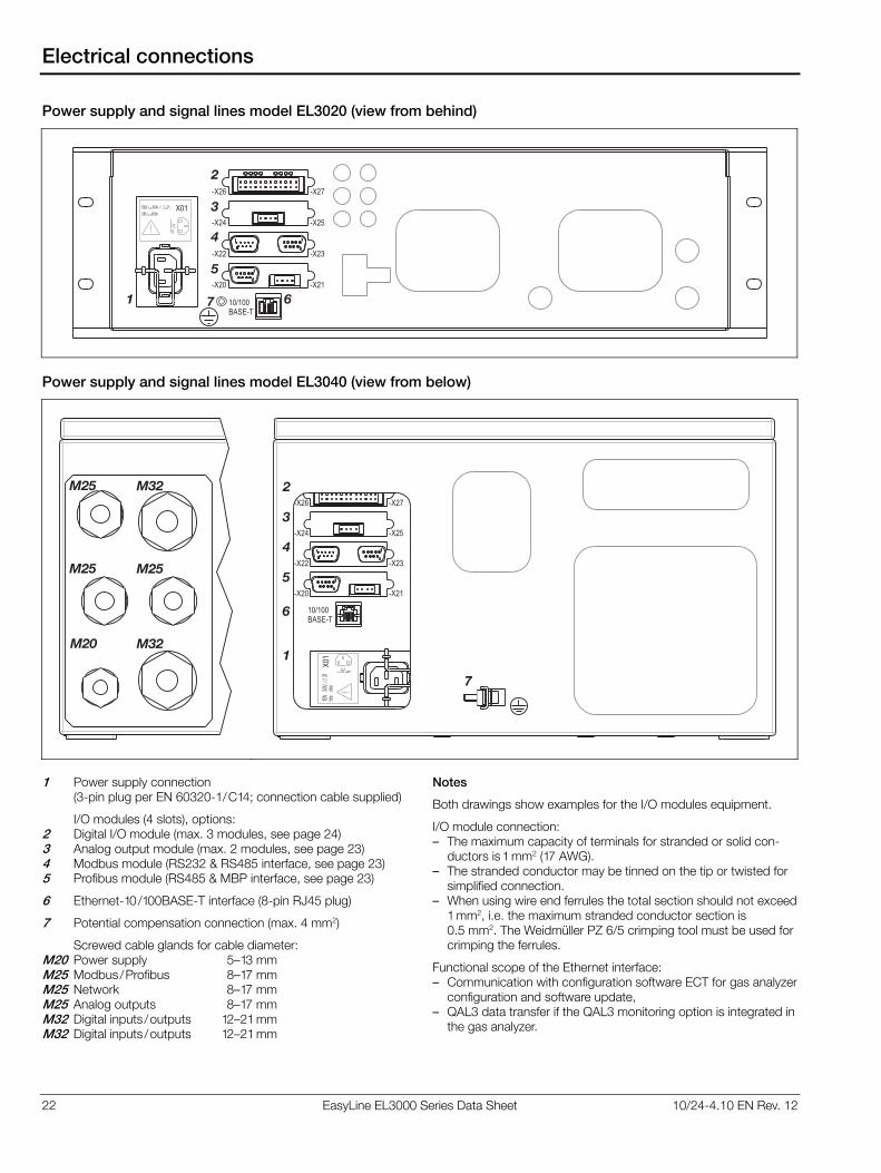
22 EasyLine EL3000 Series Data Sheet 10/24-4.10 EN Rev. 12
Electrical connections
Power supply and signal lines model EL3020 (view from behind)
X01
7
2
3
4
5
61 10/100
BASE-T
-X27
-X25
-X23
-X21-X20
-X22
-X24
-X26
Power supply and signal lines model EL3040 (view from below)
M25
M25
M20
M32
M25
M32
X0
1
7
2
3
4
5
6
1
10/100
BASE-T
-X27
-X25
-X23
-X21-X20
-X22
-X24
-X26
1 Power supply connection
(3-pin plug per EN 60320-1/C14; connection cable supplied)
I/O modules (4 slots), options: 2 Digital I/O module (max. 3 modules, see page 24) 3 Analog output module (max. 2 modules, see page 23) 4 Modbus module (RS232 & RS485 interface, see page 23) 5 Profibus module (RS485 & MBP interface, see page 23)
6 Ethernet-10/100BASE-T interface (8-pin RJ45 plug)
7 Potential compensation connection (max. 4 mm2)
Screwed cable glands for cable diameter: M20 Power supply 5–13 mm M25 Modbus/Profibus 8–17 mm M25 Network 8–17 mm M25 Analog outputs 8–17 mm M32 Digital inputs /outputs 12–21 mm M32 Digital inputs /outputs 12–21 mm
Notes
Both drawings show examples for the I/O modules equipment.
I/O module connection: – The maximum capacity of terminals for stranded or solid con-
ductors is 1 mm2 (17 AWG). – The stranded conductor may be tinned on the tip or twisted for
simplified connection. – When using wire end ferrules the total section should not exceed
1 mm2, i.e. the maximum stranded conductor section is 0.5 mm2. The Weidmüller PZ 6/5 crimping tool must be used for crimping the ferrules.
Functional scope of the Ethernet interface: – Communication with configuration software ECT for gas analyzer
configuration and software update, – QAL3 data transfer if the QAL3 monitoring option is integrated in
the gas analyzer.
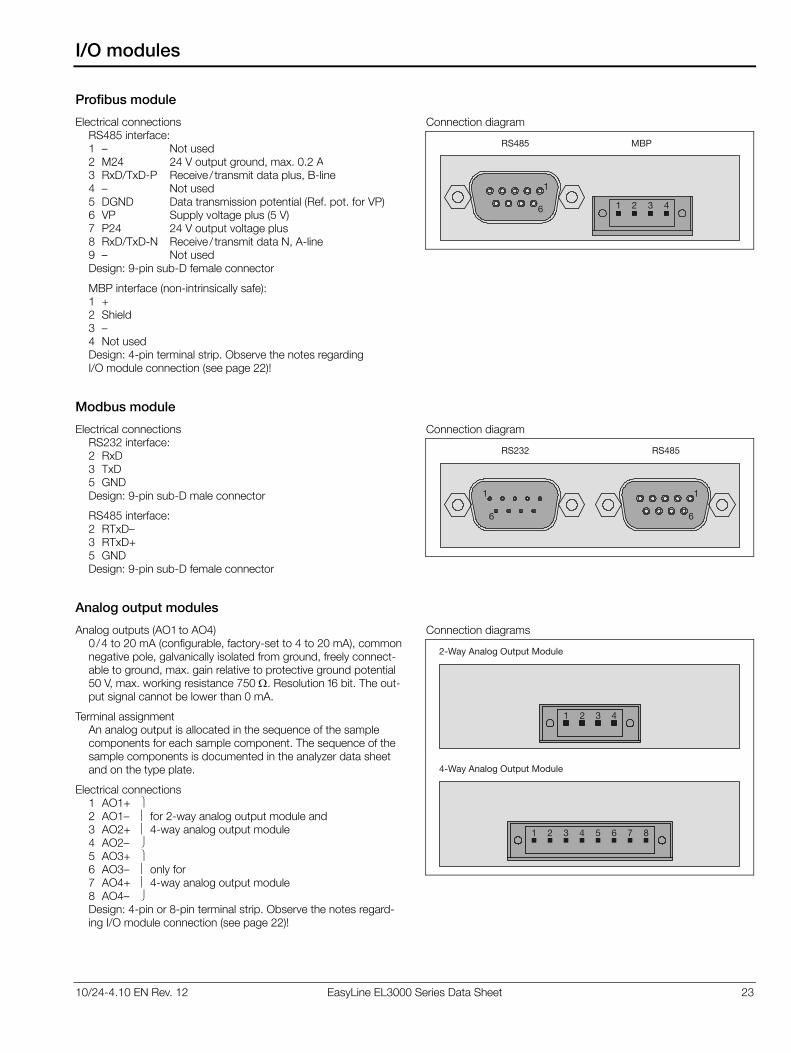
10/24-4.10 EN Rev. 12 EasyLine EL3000 Series Data Sheet 23
I/O modules
Profibus module
Electrical connections RS485 interface: 1 – Not used 2 M24 24 V output ground, max. 0.2 A 3 RxD/TxD-P Receive / transmit data plus, B-line4 – Not used 5 DGND Data transmission potential (Ref. pot. for VP)6 VP Supply voltage plus (5 V) 7 P24 24 V output voltage plus 8 RxD/TxD-N Receive / transmit data N, A-line 9 – Not used Design: 9-pin sub-D female connector
MBP interface (non-intrinsically safe): 1 + 2 Shield 3 – 4 Not used Design: 4-pin terminal strip. Observe the notes regarding I/O module connection (see page 22)!
Connection diagram
1
6
RS485 MBP
1 2 3 4
Modbus module
Electrical connections RS232 interface: 2 RxD 3 TxD 5 GND Design: 9-pin sub-D male connector
RS485 interface: 2 RTxD– 3 RTxD+ 5 GND Design: 9-pin sub-D female connector
Connection diagram
1
6
1
6
RS232 RS485
Analog output modules
Analog outputs (AO1 to AO4) 0 /4 to 20 mA (configurable, factory-set to 4 to 20 mA), common negative pole, galvanically isolated from ground, freely connect-able to ground, max. gain relative to protective ground potential 50 V, max. working resistance 750 . Resolution 16 bit. The out-put signal cannot be lower than 0 mA.
Terminal assignment An analog output is allocated in the sequence of the sample components for each sample component. The sequence of the sample components is documented in the analyzer data sheet and on the type plate.
Electrical connections 1 AO1+ 2 AO1– for 2-way analog output module and 3 AO2+ 4-way analog output module 4 AO2– 5 AO3+ 6 AO3– only for 7 AO4+ 4-way analog output module 8 AO4– Design: 4-pin or 8-pin terminal strip. Observe the notes regard-ing I/O module connection (see page 22)!
Connection diagrams
1 2 3 4
2-Way Analog Output Module
1 2 3 4 5 6 7 8
4-Way Analog Output Module
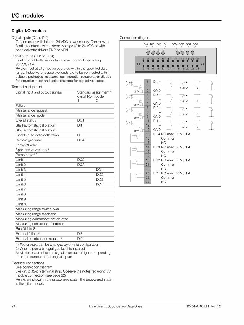
24 EasyLine EL3000 Series Data Sheet 10/24-4.10 EN Rev. 12
I/O modules
Digital I/O module
Digital inputs (DI1 to DI4) Optocouplers with internal 24 VDC power supply. Control with floating contacts, with external voltage 12 to 24 VDC or with open collector drivers PNP or NPN.
Digital outputs (DO1 to DO4) Floating double-throw contacts, max. contact load rating 30 VDC/1 A Relays must at all times be operated within the specified data range. Inductive or capacitive loads are to be connected with suitable protective measures (self-induction recuperation diodes for inductive loads and series resistors for capacitive loads).
Terminal assignment
Digital input and output signals Standard assignment 1)
digital I/O module 1 2
Failure
Maintenance request
Maintenance mode
Overall status DO1
Start automatic calibration DI1
Stop automatic calibration
Disable automatic calibration DI2
Sample gas valve DO4
Zero gas valve
Span gas valves 1 to 5
Pump on/off 2)
Limit 1 DO2
Limit 2 DO3
Limit 3 DO1
Limit 4 DO2
Limit 5 DO3
Limit 6 DO4
Limit 7
Limit 8
Limit 9
Limit 10
Measuring range switch-over
Measuring range feedback
Measuring component switch-over
Measuring component feedback
Bus DI 1 to 8
External failure 3) DI3
External maintenance request 3) DI4
1) Factory-set, can be changed by on-site configuration 2) When a pump (integral gas feed) is installed 3) Multiple external status signals can be configured depending
on the number of free digital inputs.
Electrical connections See connection diagram Design: 2x12-pin terminal strip. Observe the notes regarding I/O module connection (see page 22)! Relays are shown in the unpowered state. The unpowered state is the failure mode.
Connection diagram
2
1 3 5 7 9 11 13 15 17 19 21 23
4 6 8 10 12 14 16 18 20 22 24
DI4 DO3 DO2 DO1DO4DI3 DI2 DI1
131517141618192123202224
DO4 NOCommonNC
DO3 NOCommonNC
DO2 NOCommonNC
DO1 NOCommonNC
123564789111210
max. 30 V / 1 A
max. 30 V / 1 A
max. 30 V / 1 A
max. 30 V / 1 A
DI4 -
DI3 -
DI2 -
DI1 -
+
+
+
+
GND
GND
GND
GND
24V
24V
24V
24V12-24 V
12-24 V
12-24 V
12-24 V
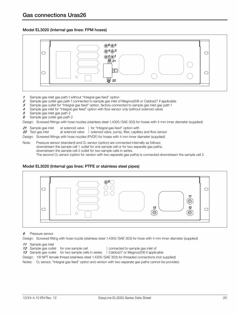
10/24-4.10 EN Rev. 12 EasyLine EL3000 Series Data Sheet 25
Gas connections Uras26
Model EL3020 (Internal gas lines: FPM hoses)
21
22
2 1
4 3
6 5
1 Sample gas inlet gas path 1 without “Integral gas feed” option 2 Sample gas outlet gas path 1 connected to sample gas inlet of Magnos206 or Caldos27 if applicable 3 Sample gas outlet for “Integral gas feed” option, factory-connected to sample gas inlet gas path 1 4 Sample gas inlet for “Integral gas feed” option with flow sensor only (without solenoid valve) 5 Sample gas inlet gas path 2 6 Sample gas outlet gas path 2
Design: Screwed fittings with hose nozzles (stainless steel 1.4305/SAE 303) for hoses with 4 mm inner diameter (supplied)
21 Sample gas inlet at solenoid valve for “Integral gas feed” option with 22 Test gas inlet at solenoid valve solenoid valve, pump, filter, capillary and flow sensor
Design: Screwed fittings with hose nozzles (PVDF) for hoses with 4 mm inner diameter (supplied)
Note: Pressure sensor (standard) and O2 sensor (option) are connected internally as follows: downstream the sample cell 1 outlet for one sample cell or for two separate gas paths, downstream the sample cell 2 outlet for two sample cells in series. The second O2 sensor (option for version with two separate gas paths) is connected downstream the sample cell 2.
Model EL3020 (Internal gas lines: PTFE or stainless steel pipes)
6
13 12
11
6 Pressure sensor
Design: Screwed fitting with hose nozzle (stainless steel 1.4305/SAE 303) for hose with 4 mm inner diameter (supplied)
11 Sample gas inlet 12 Sample gas outlet for one sample cell connected to sample gas inlet of 13 Sample gas outlet for two sample cells in series Caldos27 or Magnos206 if applicable
Design: 1/8 NPT female thread (stainless steel 1.4305/SAE 303) for threaded connections (not supplied)
Notes: O2 sensor, “Integral gas feed” option and version with two separate gas paths cannot be provided.
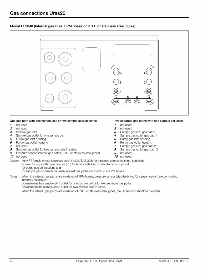
26 EasyLine EL3000 Series Data Sheet 10/24-4.10 EN Rev. 12
Gas connections Uras26
Model EL3040 (Internal gas lines: FPM hoses or PTFE or stainless steel pipes)
1
2
38
9
10
6 5 47
One gas path with one sample cell or two sample cells in series
1 not used 2 not used 3 Sample gas inlet 4 Sample gas outlet for one sample cell 5 Purge gas inlet housing 6 Purge gas outlet housing 7 not used 8 Sample gas outlet for two sample cells in series 9 Pressure sensor (internal gas paths: PTFE or stainless steel pipes) 10 not used
Two separate gas paths with one sample cell each
1 not used 2 not used 3 Sample gas inlet gas path 1 4 Sample gas outlet gas path 1 5 Purge gas inlet housing 6 Purge gas outlet housing 7 Sample gas inlet gas path 2 8 Sample gas outlet gas path 2 9 not used 10 not used
Design: 1/8 NPT female thread (stainless steel 1.4305/SAE 303) for threaded connections (not supplied; screwed fittings with hose nozzles (PP) for hoses with 4 mm inner diameter supplied for purge gas connections and for sample gas connections when internal gas paths are made up of FPM hoses.)
Notes: When the internal gas paths are made up of FPM hoses, pressure sensor (standard) and O2 sensor (option) are connected internally as follows: downstream the sample cell 1 outlet for one sample cell or for two separate gas paths, downstream the sample cell 2 outlet for two sample cells in series.
When the internal gas paths are made up of PTFE or stainless steel pipes, the O2 sensor cannot be provided.
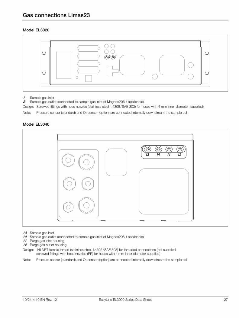
10/24-4.10 EN Rev. 12 EasyLine EL3000 Series Data Sheet 27
Gas connections Limas23
Model EL3020
2 1
1 Sample gas inlet 2 Sample gas outlet (connected to sample gas inlet of Magnos206 if applicable)
Design: Screwed fittings with hose nozzles (stainless steel 1.4305/SAE 303) for hoses with 4 mm inner diameter (supplied)
Note: Pressure sensor (standard) and O2 sensor (option) are connected internally downstream the sample cell.
Model EL3040
11 121413
13 Sample gas inlet 14 Sample gas outlet (connected to sample gas inlet of Magnos206 if applicable) 11 Purge gas inlet housing 12 Purge gas outlet housing
Design: 1/8 NPT female thread (stainless steel 1.4305/SAE 303) for threaded connections (not supplied; screwed fittings with hose nozzles (PP) for hoses with 4 mm inner diameter supplied)
Note: Pressure sensor (standard) and O2 sensor (option) are connected internally downstream the sample cell.
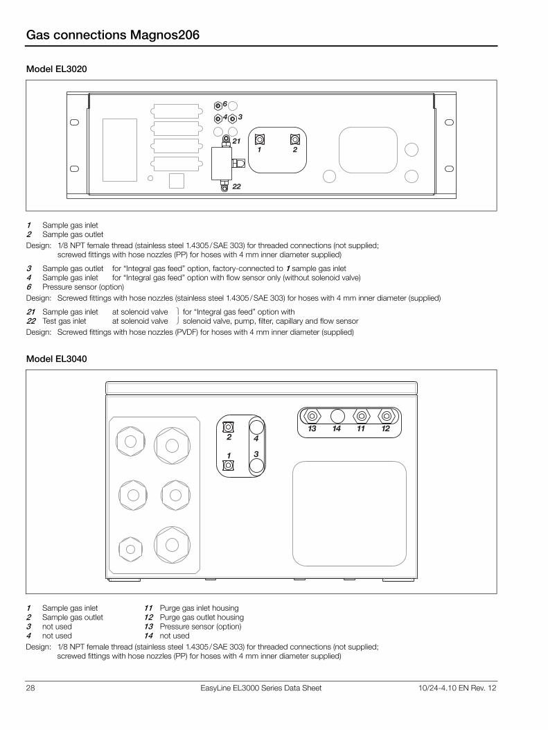
28 EasyLine EL3000 Series Data Sheet 10/24-4.10 EN Rev. 12
Gas connections Magnos206
Model EL3020
21
22
1 2
4 3
6
1 Sample gas inlet 2 Sample gas outlet
Design: 1/8 NPT female thread (stainless steel 1.4305/SAE 303) for threaded connections (not supplied; screwed fittings with hose nozzles (PP) for hoses with 4 mm inner diameter supplied)
3 Sample gas outlet for “Integral gas feed” option, factory-connected to 1 sample gas inlet 4 Sample gas inlet for “Integral gas feed” option with flow sensor only (without solenoid valve) 6 Pressure sensor (option)
Design: Screwed fittings with hose nozzles (stainless steel 1.4305/SAE 303) for hoses with 4 mm inner diameter (supplied)
21 Sample gas inlet at solenoid valve for “Integral gas feed” option with 22 Test gas inlet at solenoid valve solenoid valve, pump, filter, capillary and flow sensor
Design: Screwed fittings with hose nozzles (PVDF) for hoses with 4 mm inner diameter (supplied)
Model EL3040
1
2
3
411 121413
1 Sample gas inlet 2 Sample gas outlet 3 not used 4 not used
11 Purge gas inlet housing12 Purge gas outlet housing 13 Pressure sensor (option) 14 not used
Design: 1/8 NPT female thread (stainless steel 1.4305/SAE 303) for threaded connections (not supplied; screwed fittings with hose nozzles (PP) for hoses with 4 mm inner diameter supplied)
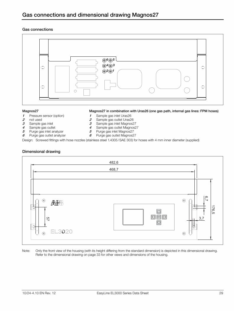
10/24-4.10 EN Rev. 12 EasyLine EL3000 Series Data Sheet 29
Gas connections and dimensional drawing Magnos27
Gas connections
1
4 3
6 5
2
Magnos27
1 Pressure sensor (option) 2 not used 3 Sample gas inlet 4 Sample gas outlet 5 Purge gas inlet analyzer 6 Purge gas outlet analyzer
Magnos27 in combination with Uras26 (one gas path, internal gas lines: FPM hoses)
1 Sample gas inlet Uras26 2 Sample gas outlet Uras26 3 Sample gas inlet Magnos27 4 Sample gas outlet Magnos27 5 Purge gas inlet Magnos27 6 Purge gas outlet Magnos27
Design: Screwed fittings with hose nozzles (stainless steel 1.4305/SAE 303) for hoses with 4 mm inner diameter (supplied)
Dimensional drawing
57
468,7
482,6
6,7
3,7
176,5
Note: Only the front view of the housing (with its height differing from the standard dimension) is depicted in this dimensional drawing. Refer to the dimensional drawing on page 33 for other views and dimensions of the housing.

30 EasyLine EL3000 Series Data Sheet 10/24-4.10 EN Rev. 12
Gas connections ZO23
Model EL3020
2 1
Model EL3040
12
11 12
1 Sample gas inlet 2 Sample gas outlet 11 Purge gas inlet housing 12 Purge gas outlet housing
Design: 1/8 NPT female thread (stainless steel 1.4305/SAE 303) for threaded connections (not supplied), sample gas inlet 3 mm Swagelok® (stainless steel 1.4401/SAE 316)
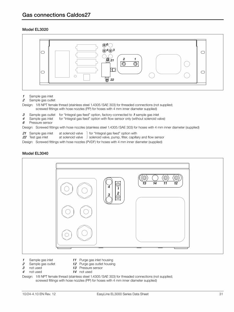
10/24-4.10 EN Rev. 12 EasyLine EL3000 Series Data Sheet 31
Gas connections Caldos27
Model EL3020
21
22
2 1
4 3
6
1 Sample gas inlet 2 Sample gas outlet
Design: 1/8 NPT female thread (stainless steel 1.4305/SAE 303) for threaded connections (not supplied; screwed fittings with hose nozzles (PP) for hoses with 4 mm inner diameter supplied)
3 Sample gas outlet for “Integral gas feed” option, factory-connected to 1 sample gas inlet 4 Sample gas inlet for “Integral gas feed” option with flow sensor only (without solenoid valve) 6 Pressure sensor
Design: Screwed fittings with hose nozzles (stainless steel 1.4305/SAE 303) for hoses with 4 mm inner diameter (supplied)
21 Sample gas inlet at solenoid valve for “Integral gas feed” option with 22 Test gas inlet at solenoid valve solenoid valve, pump, filter, capillary and flow sensor
Design: Screwed fittings with hose nozzles (PVDF) for hoses with 4 mm inner diameter (supplied)
Model EL3040
12
4
3
11 121413
1 Sample gas inlet 2 Sample gas outlet 3 not used 4 not used
11 Purge gas inlet housing12 Purge gas outlet housing 13 Pressure sensor 14 not used
Design: 1/8 NPT female thread (stainless steel 1.4305/SAE 303) for threaded connections (not supplied; screwed fittings with hose nozzles (PP) for hoses with 4 mm inner diameter supplied)
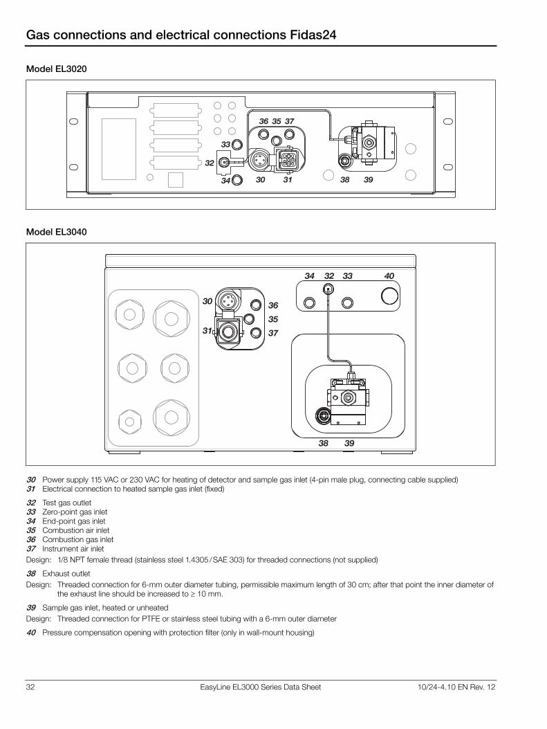
32 EasyLine EL3000 Series Data Sheet 10/24-4.10 EN Rev. 12
Gas connections and electrical connections Fidas24
Model EL3020
32
33
34
3536 37
38 3930 31
Model EL3040
30
31
32 3334
35
36
37
38 39
40
30 Power supply 115 VAC or 230 VAC for heating of detector and sample gas inlet (4-pin male plug, connecting cable supplied) 31 Electrical connection to heated sample gas inlet (fixed)
32 Test gas outlet 33 Zero-point gas inlet 34 End-point gas inlet 35 Combustion air inlet 36 Combustion gas inlet 37 Instrument air inlet
Design: 1/8 NPT female thread (stainless steel 1.4305/SAE 303) for threaded connections (not supplied)
38 Exhaust outlet
Design: Threaded connection for 6-mm outer diameter tubing, permissible maximum length of 30 cm; after that point the inner diameter of the exhaust line should be increased to 10 mm.
39 Sample gas inlet, heated or unheated
Design: Threaded connection for PTFE or stainless steel tubing with a 6-mm outer diameter
40 Pressure compensation opening with protection filter (only in wall-mount housing)
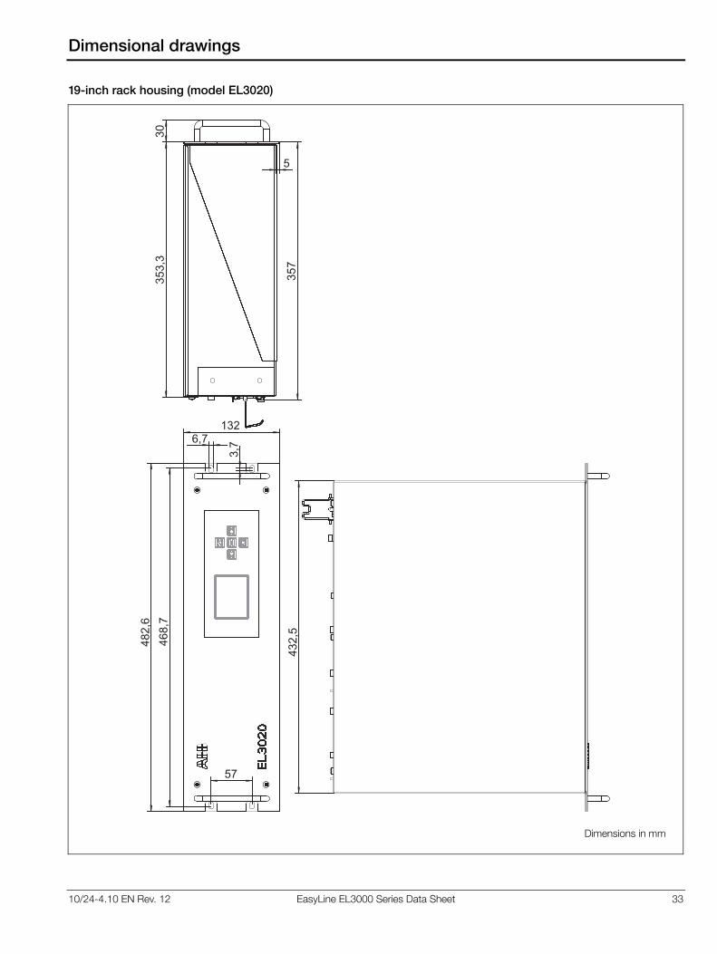
10/24-4.10 EN Rev. 12 EasyLine EL3000 Series Data Sheet 33
Dimensional drawings
19-inch rack housing (model EL3020)
482,6
468,7
57
6,7
3,7
132
30
5353,3
357
432,5
Dimensions in mm

34 EasyLine EL3000 Series Data Sheet 10/24-4.10 EN Rev. 12
Dimensional drawings
Wall-mount housing (model EL3040)
366
420360
480
Ø Ø
20
404
36
0
31
511
23
�6
0
23
0
Cle
ara
nce
req
uire
dto
allo
wth
ed
oo
rto
sw
ing
op
en
Dimensions in mm
10/24-4.10 EN Rev. 12 EasyLine EL3000 Series Data Sheet 35
Certifications
CE conformity
The EL3000 series gas analyzers satisfy the requirements of the European directives 2006/95/EC (Low voltage directive), 2004/108/EC (EMC directive) and 94/9/EC (ATEX directive).
Compliance with the requirements of directive 2006/95/EC is evidenced by full compliance with European standard EN 61010-1:2001.
Compliance with the requirements of directive 2004/108/EC is evidenced by full compliance with European standards EN 61326-1:2006, EN 61000-3-2 :2006, EN 61000-3-3 :1995 + A1:2001 + A2:2005.
Compliance of the version in category 3G for measurement of non-flammable gases and vapors with the requirements of directive 94/9/EC is evidenced by full compliance with European standard EN 60079-15:2005.
Performance test
The EL3000 series gas analyzers Uras26 (sample components CO, NO, SO2, CO2, N2O), Magnos206 (sample component O2) and electrochemical oxygen sensor (sample component O2) are certified for use in facilities requiring approval according to European directive 2001/80/EG and meet the requirements of the 27th/30th BImSchV (Federal Immissions Control Ordinance) and TA-Luft (Technical Instructions on Air Quality) regulations. The requirements of QAL1 according to EN 15267 and EN 14181 are fulfilled.
Report No. 691317 of June 30, 2006. Notification: Federal Gazette of October 14, 2006, No. 194, page 6715
Report No. 1669640 of September 30, 2011. Notification: Federal Gazette of March 2, 2012, No. 36, page 925
Report No. 936/21217137/B of October 14, 2011. Notification: Federal Gazette of March 2, 2012, No. 36, page 924
Approval for USA and Canada – CSA
The EL3000 series gas analyzers are certified for use in general purpose environment, evidenced by full compliance with standards CAN/CSA-C22.2 No. 61010-1-04 and UL Std. No. 61010-1 (2nd Edition).
Certificate No. 1714030
Approval for Russian Federation – GOST-R
The EL3000 series gas analyzers are certified for use in general purpose environment. The following documents are available:
GOST-R certificate No. POCC DE.HO03.H04298, Rostekhnadzor operation permission No. PPC 00-39671, Pattern approval certificate No. DE.C.31.004.A No. 37984.
Explosion protection for China – NEPSI
The gas analyzer model EL3040 with Uras26, Limas23, Magnos206 and Caldos27 is certified for use in hazardous loca-tions. The gas analyzer may be used for measurement of non-flammable gases and vapors. It is marked with Ex nAC II CT4.
Certificate No. GYJ101401X

Contact us
10/2
4-4
.10 E
N R
ev.
12 0
8.2
014ABB Limited
Process Automation
Oldends Lane
GL10 3TA Stonehouse
Gloucestershire, United Kingdom
Phone: +44 1 453 826661
Fax: +44 1 453 829671
ABB Pte. Ltd.
Process Automation
2 Ayer Rajah Crescent
139935 Singapore, Singapore
Phone: +65 6773 5961
Fax: +65 6778 0222
ABB Engineering Ltd.
Process Automation
10 Jiuxianqiao Lu
100015 Beijing, China
Phone: +86 10 84566688 Ext. 6217
Fax: +86 10 84567650
ABB Inc.
Process Automation
3700 W Sam Houston Parkway South,
Suite 600, Houston, TX 77042, USA
Phone: +1 713 587 8000
www.abb.com/analytical
ABB Australia Pty Limited
Process Automation
Bapaume Road
2170 Moorebank
New South Wales, Australia
Phone: +61 2 9821 0968
Fax: +61 2 9400 7050
ABB Ltd.
Process Automation
14 Mathura Road
121003 Faridabad, Haryana, India
Phone: +91 129 2279627
Fax: +91 129 2279692
ABB Automation GmbH
Process Automation
Stierstaedter Strasse 5
60488 Frankfurt am Main, Germany
Fax: +49 69 7930-4566
E-mail: [email protected]
Note
We reserve the right to make technical changes or
modify the contents of this document without prior
notice. With regard to purchase orders, the agreed
particulars shall prevail. ABB does not accept any
responsibility whatsoever for potential errors or
possible lack of information in this document.
We reserve all rights in this document and in the
subject matter and illustrations contained therein.
Any reproduction, disclosure to third parties or
utilization of its contents – in whole or in parts – is
forbidden without prior written consent of ABB.
Copyright© 2015 ABB
All rights reserved
Sales
Service

Data Sheet 10/24-4.12 EN Rev. 2
EasyLine EL3060 Series Continuous Gas Analyzers in Category II 2G Version
Proven measuring technology from Advance Optima, operator-friendliness and functional capabilities of EasyLine Flameproof Enclosure, therefore safe and uncomplicated explosion protection Category II 2G, hence suitable for use in hazardous areas of Zone 1 and Zone 2 Rugged field housing with degree of protection IP65 Safe terminal box with Increased Safety for the electrical connections on the user side
Combinable analyzers with up to five sample components and two measuring ranges Automatic calibration, simplified calibration with calibration cells and with single-point calibration Simple menu-driven operator interface Output of measured values, alarm value and status signals via individually configurable analog and digital outputs Modbus and Profibus interfaces Simple installation
2 EL3060 Series Gas Analyzers in Category II 2G Version Data Sheet 10/24-4.12 EN May 2010
Contents
Page
Overview of the Gas Analyzers 2
Infrared Photometer Uras26 4
Oxygen Analyzer Magnos206 6
Thermal Conductivity Analyzer Caldos27 8
Thermal Conductivity Analyzer Caldos25 10
General Data 11
Electrical Connections 13
Dimensional Drawings, Gas Connections 14
Certifications 16
Overview of the Gas Analyzers
Application
The Category II 2G gas analyzers of the EL3060 series are suitable for measuring flammable and non-flammable gases under atmospheric conditions which may occasionally be potentially explosive (Zone 1).
Gas Analyzers of the EL3060 Series
The EL3060 series includes the following analyzers
• Uras26 infrared photometer
• Magnos206 oxygen analyzer
• Caldos27 thermal conductivity analyzer
• Caldos25 thermal conductivity analyzer
as well as the
• EL3060-CU control unit
An EL3060 gas analyzer consists of the control unit and one or two analyzers.
The analyzers Magnos206, Caldos27 and Caldos25 are installed in the housing of the control unit. The analyzer Uras26 is installed in a separate housing; it is connected to the control unit via a data transmission cable and a power supply cable.
The analyzers Magnos206, Caldos27 and Caldos25 can also be used in combination with the analyzer Uras26.
Housing – Explosion Protection
The housing of the EL3060-CU control unit is designed as a field housing of die-cast aluminum in the type of protection “Flame-proof Enclosure ‘d’” to EN 60079-1 and in the degree of protec-tion for the housing of IP65. The display and operator control unit is installed behind a glass viewing window on the front of the housing.
A terminal housing in the type of protection “Increased Safety ‘e’” to EN 60079-7, in which the terminal strip for the electrical connections is installed, is flange-mounted on the underside of the explosion-proof housing. Certified electrical conductor bushings in increased safety are installed between the interior of the explosion housing and the terminal housing.
The housing of the Uras26 analyzer is executed as a cylindrical field housing of die-cast aluminum in the type of protection “Flameproof Enclosure ‘d’” to EN 60079-1 and in the degree of protection of housing of IP54. The data transmission cable and the power supply cable for connection to the control unit are permanently connected at the factory and led through flameproof cable glands on the underside of the housing.
The housings of the gas analyzers comply with the requirements of the explosion group IIC. As a result, the gas analyzers can also be used in hydrogen- or acetylene-containing atmospheres.
The housing can be purged with air from the non-hazardous area or with inert gas to protect the gas analyzers in a corrosive environment or with corrosive sample or associated gases.
All gas connections are led through flame barriers.
10/24-4.12 EN May 2010 EL3060 Series Gas Analyzers in Category II 2G Version Data Sheet 3
Overview of the Gas Analyzers
Analyzers – Measuring Technology
The Uras26 infrared photometer operates according to the NDIR process (Non-Dispersive Infrared-Absorption).
The measurement technique of the Magnos206 oxygen analyzer is based on the specific paramagnetic behavior of oxygen.
The thermal conductivity analyzers Caldos27 and Caldos25 make use of the differing thermal conductivity of the individual gases. The Caldos25 analyzer is especially suitable for the measurement of corrosive gases.
Each analyzer has one physical measurement range per sample component. A section of the physical measurement range can be mapped to the current output (analog output) by on-site configuration. Calibration is always executed in the physical measurement range. The permissible measurement range limits are given by the specification of the smallest and largest measurement ranges for the individual analyzers.
The performance characteristics of the analyzers have been determined according to the international standard IEC 1207-1: 1994 “Expression of performance of gas analyzers”. They are based on N2 as the associated gas. Compliance with these characteristics when measuring other gas mixtures can only be assured if their composition is known.
Calibration
The Uras26 infrared photometer can be equipped with gas-filled calibration cells as an option; this allows test gas cylinders to be dispensed with to a large extent.
Owing to its very low sensitivity drift, the Magnos206 oxygen analyzer can be routinely calibrated solely at the zero point by means of single-point calibration, provided that the measuring range is more than 0–5 % Vol. of O2; nitrogen or ambient air is used for this purpose.
Calibration can be performed automatically or manually. Auto-matic calibration – for all sample components together – is normally started on a cyclically time-controlled basis; it can also be started by an external control signal or via the Modbus as well as manually on the display and operator control unit of the gas analyzer.
Control Unit
The EL3060-CU control unit performs the following functions:
• Processing and transmitting measured values provided by the analyzer’s sensor electronics,
• Correcting measured values, e.g. cross-sensitivity correction,
• Controlling device functions, e.g. calibration,
• Display and control functions,
• Communicating with external systems.
Operation
Five touch screen fields accessible through the control unit viewing glass allow safe operation of the gas analyzer without opening the housing.
The menu-driven control system is uniform for all gas analyzers.
Electrical Interfaces
The electrical interfaces for the output of measured values and communication with external systems include
• The integrated Ethernet-10/100BASE-T interface (for configuration and software update)
as well as the I/O modules
• Analog output module with four analog outputs,
• Digital I/O module with four digital inputs and four digital outputs,
• Modbus module with one RS485 and one RS232 interface,
• Profibus module with one RS485 and one MBP interface.
A maximum of three I/O modules can be integrated in the gas analyzer. The following combinations of I/O modules are allowed, depending on the functional range and order:
• 1 analog output module and 1 digital I/O module (standard),
• 1 analog output module and 2 digital I/O modules,
• 1 analog output module, 1 digital I/O module and either 1 Modbus module or 1 Profibus module,
• 1 Modbus module,
• 1 Profibus module.
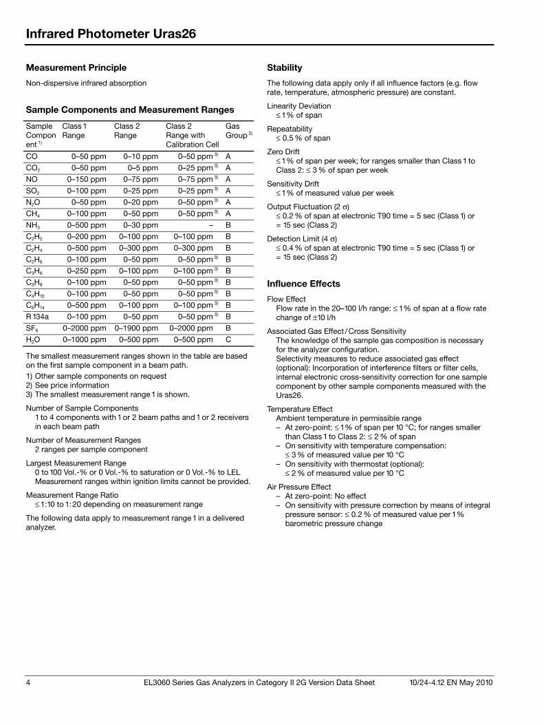
4 EL3060 Series Gas Analyzers in Category II 2G Version Data Sheet 10/24-4.12 EN May 2010
Infrared Photometer Uras26
Measurement Principle
Non-dispersive infrared absorption
Sample Components and Measurement Ranges
Sample Component 1)
Class 1 Range
Class 2 Range
Class 2 Range with Calibration Cell
Gas Group 2)
CO 0–50 ppm 0–10 ppm 0–50 ppm 3) A
CO2 0–50 ppm 0–5 ppm 0–25 ppm 3) A
NO 0–150 ppm 0–75 ppm 0–75 ppm 3) A
SO2 0–100 ppm 0–25 ppm 0–25 ppm 3) A
N2O 0–50 ppm 0–20 ppm 0–50 ppm 3) A
CH4 0–100 ppm 0–50 ppm 0–50 ppm 3) A
NH3 0–500 ppm 0–30 ppm – B
C2H2 0–200 ppm 0–100 ppm 0–100 ppm B
C2H4 0–500 ppm 0–300 ppm 0–300 ppm B
C2H6 0–100 ppm 0–50 ppm 0–50 ppm 3) B
C3H6 0–250 ppm 0–100 ppm 0–100 ppm 3) B
C3H8 0–100 ppm 0–50 ppm 0–50 ppm 3) B
C4H10 0–100 ppm 0–50 ppm 0–50 ppm 3) B
C6H14 0–500 ppm 0–100 ppm 0–100 ppm 3) B
R 134a 0–100 ppm 0–50 ppm 0–50 ppm 3) B
SF6 0–2000 ppm 0–1900 ppm 0–2000 ppm B
H2O 0–1000 ppm 0–500 ppm 0–500 ppm C
The smallest measurement ranges shown in the table are based on the first sample component in a beam path. 1) Other sample components on request 2) See price information 3) The smallest measurement range 1 is shown.
Number of Sample Components 1 to 4 components with 1 or 2 beam paths and 1 or 2 receivers in each beam path
Number of Measurement Ranges 2 ranges per sample component
Largest Measurement Range 0 to 100 Vol.-% or 0 Vol.-% to saturation or 0 Vol.-% to LEL Measurement ranges within ignition limits cannot be provided.
Measurement Range Ratio ≤ 1:10 to 1:20 depending on measurement range
The following data apply to measurement range 1 in a delivered analyzer.
Stability
The following data apply only if all influence factors (e.g. flow rate, temperature, atmospheric pressure) are constant.
Linearity Deviation ≤ 1 % of span
Repeatability ≤ 0.5 % of span
Zero Drift ≤ 1 % of span per week; for ranges smaller than Class 1 to Class 2: ≤ 3 % of span per week
Sensitivity Drift ≤ 1 % of measured value per week
Output Fluctuation (2 σ) ≤ 0.2 % of span at electronic T90 time = 5 sec (Class 1) or = 15 sec (Class 2)
Detection Limit (4 σ) ≤ 0.4 % of span at electronic T90 time = 5 sec (Class 1) or = 15 sec (Class 2)
Influence Effects
Flow Effect Flow rate in the 20–100 l/h range: ≤ 1 % of span at a flow rate change of ±10 l/h
Associated Gas Effect /Cross Sensitivity The knowledge of the sample gas composition is necessary for the analyzer configuration. Selectivity measures to reduce associated gas effect (optional): Incorporation of interference filters or filter cells, internal electronic cross-sensitivity correction for one sample component by other sample components measured with the Uras26.
Temperature Effect Ambient temperature in permissible range – At zero-point: ≤ 1 % of span per 10 °C; for ranges smaller
than Class 1 to Class 2: ≤ 2 % of span – On sensitivity with temperature compensation:
≤ 3 % of measured value per 10 °C – On sensitivity with thermostat (optional):
≤ 2 % of measured value per 10 °C
Air Pressure Effect – At zero-point: No effect – On sensitivity with pressure correction by means of integral
pressure sensor: ≤ 0.2 % of measured value per 1 % barometric pressure change
10/24-4.12 EN May 2010 EL3060 Series Gas Analyzers in Category II 2G Version Data Sheet 5
Infrared Photometer Uras26
Dynamic Response
Warm-Up Time Approx. 30 minutes without thermostat; approx. 2.5 hours with thermostat
90% Response Time T90 = 2.5 sec for measurement cell length = 200 mm, sample gas flow = 60 l/h, electronic T90 time = 0 sec
Calibration
Zero-Point Calibration With inert gas, e.g. N2, or with ambient air that is free of the sample component.
End-Point Calibration With gas-filled calibration cells (optional) or with test gas mixtures. It is recommended to verify the calibration cell set values once a year. During calibration of a multi-component analyzer, possible cross-sensitivity and/or carrier gas corrections by internal or external measurement components are switched off. Therefore, corrected measurement components should be calibrated only using a test gas consisting of the measurement component and an inert gas like N2.
Materials in Contact with the Sample Medium
Analyzer (Sample Cells) Tubing: Aluminum or gold-plated aluminum; Window: CaF2, Option: BaF2; Connectors: Rust- and acid-resistant steel 1.4571 (SAE 316Ti)
Gas Lines, Connectors and Flame Barriers Rust- and acid-resistant steel 1.4571 (SAE 316Ti)
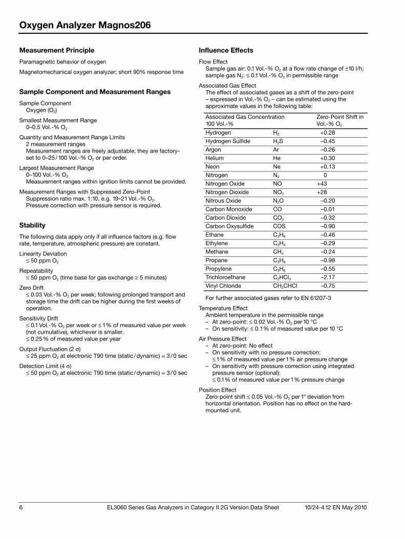
6 EL3060 Series Gas Analyzers in Category II 2G Version Data Sheet 10/24-4.12 EN May 2010
Oxygen Analyzer Magnos206
Measurement Principle
Paramagnetic behavior of oxygen
Magnetomechanical oxygen analyzer; short 90% response time
Sample Component and Measurement Ranges
Sample Component Oxygen (O2)
Smallest Measurement Range 0–0.5 Vol.-% O2
Quantity and Measurement Range Limits 2 measurement ranges Measurement ranges are freely adjustable; they are factory-set to 0–25/100 Vol.-% O2 or per order.
Largest Measurement Range 0–100 Vol.-% O2 Measurement ranges within ignition limits cannot be provided.
Measurement Ranges with Suppressed Zero-Point Suppression ratio max. 1:10, e.g. 19–21 Vol.-% O2. Pressure correction with pressure sensor is required.
Stability
The following data apply only if all influence factors (e.g. flow rate, temperature, atmospheric pressure) are constant.
Linearity Deviation ≤ 50 ppm O2
Repeatability ≤ 50 ppm O2 (time base for gas exchange ≥ 5 minutes)
Zero Drift ≤ 0.03 Vol.-% O2 per week; following prolonged transport and storage time the drift can be higher during the first weeks of operation.
Sensitivity Drift ≤ 0.1 Vol.-% O2 per week or ≤ 1 % of measured value per week (not cumulative), whichever is smaller. ≤ 0.25 % of measured value per year
Output Fluctuation (2 σ) ≤ 25 ppm O2 at electronic T90 time (static /dynamic) = 3 /0 sec
Detection Limit (4 σ) ≤ 50 ppm O2 at electronic T90 time (static /dynamic) = 3 /0 sec
Influence Effects
Flow Effect Sample gas air: 0.1 Vol.-% O2 at a flow rate change of ±10 l/h; sample gas N2: ≤ 0.1 Vol.-% O2 in permissible range
Associated Gas Effect The effect of associated gases as a shift of the zero-point – expressed in Vol.-% O2 – can be estimated using the approximate values in the following table:
Associated Gas Concentration 100 Vol.-%
Zero-Point Shift in Vol.-% O2
Hydrogen H2 +0.28
Hydrogen Sulfide H2S –0.45
Argon Ar –0.26
Helium He +0.30
Neon Ne +0.13
Nitrogen N2 0.00
Nitrogen Oxide NO +43.00
Nitrogen Dioxide NO2 +28.00
Nitrous Oxide N2O –0.20
Carbon Monoxide CO –0.01
Carbon Dioxide CO2 –0.32
Carbon Oxysulfide COS –0.90
Ethane C2H6 –0.46
Ethylene C2H4 –0.29
Methane CH4 –0.24
Propane C3H8 –0.98
Propylene C3H6 –0.55
Trichloroethane C2HCl3 –2.17
Vinyl Chloride CH2CHCl –0.75
For further associated gases refer to EN 61207-3
Temperature Effect Ambient temperature in the permissible range – At zero-point: ≤ 0.02 Vol.-% O2 per 10 °C – On sensitivity: ≤ 0.1 % of measured value per 10 °C
Air Pressure Effect – At zero-point: No effect – On sensitivity with no pressure correction:
≤ 1 % of measured value per 1 % air pressure change – On sensitivity with pressure correction using integrated
pressure sensor (optional): ≤ 0.1 % of measured value per 1 % pressure change
Position Effect Zero-point shift ≤ 0.05 Vol.-% O2 per 1° deviation from horizontal orientation. Position has no effect on the hard-mounted unit.
10/24-4.12 EN May 2010 EL3060 Series Gas Analyzers in Category II 2G Version Data Sheet 7
Oxygen Analyzer Magnos206
Dynamic Response
Warm-Up Time < 2 hours
90% Response Time T90 ≤ 4 sec at a sample gas flow of 90 l/h and electronic T90 time (static /dynamic) = 3 /0 sec, gas change from N2 to air
Calibration
Zero-Point Calibration With oxygen-free process gas or substitute gas
End-Point Calibration With process gas with a known oxygen concentration or a substitute gas such as dried air
Single-Point Calibration For measurement ranges from 0 to 5 Vol.-% O2 to 0 to 25 Vol.-% O2 Zero-point calibration with any oxygen concentration, e.g. with nitrogen (N2) or ambient air, processed through a cooler or H2O absorber. Pressure correction by means of pressure sensor is recommended for single-point calibration with air. Depending on the measurement task involved, the zero- and end-points should be verified periodically (Recommendation: once a year).
Calibration of Measurement Ranges with Suppressed Zero-Point Single-point calibration is possible for suppressed measurement ranges with a suppression ratio ≤ 1:5. The oxygen concentration of the test gas must be within the measurement range.
Materials in Contact with the Sample Medium
Analyzer (Sample Chamber) Rust- and acid-resistant steel 1.4305 (SAE 303), glass, platinum, rhodium, epoxy resin; Seals: FPM (Fluorocarbon rubber), Option: FFKM75
Gas Lines, Connectors and Flame Barriers Rust- and acid-resistant steel 1.4305 (SAE 303), 1.4571 (SAE 316Ti)
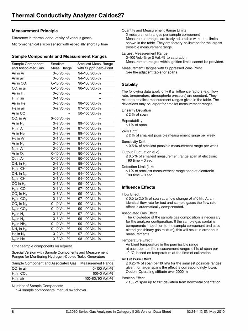
8 EL3060 Series Gas Analyzers in Category II 2G Version Data Sheet 10/24-4.12 EN May 2010
Thermal Conductivity Analyzer Caldos27
Measurement Principle
Difference in thermal conductivity of various gases
Micromechanical silicon sensor with especially short T90 time
Sample Components and Measurement Ranges
Sample Component and Associated Gas
Smallest Meas. Range
Smallest Meas. Range with Suppr. Zero-Point
Air in Ar 0–6 Vol.-% 94–100 Vol.-% Ar in air 0–6 Vol.-% 94–100 Vol.-% Air in CO2 0–10 Vol.-% 90–100 Vol.-% CO2 in air 0–10 Vol.-% 90–100 Vol.-% Air in H2 0–3 Vol.-% – H2 in air 0–1 Vol.-% – Air in He 0–3 Vol.-% 98–100 Vol.-% He in air 0–2 Vol.-% 97–100 Vol.-% Ar in CO2 – 50–100 Vol.-% CO2 in Ar 0–50 Vol.-% – Ar in H2 0–3 Vol.-% 99–100 Vol.-% H2 in Ar 0–1 Vol.-% 97–100 Vol.-% Ar in He 0–3 Vol.-% 99–100 Vol.-% He in Ar 0–1 Vol.-% 97–100 Vol.-% Ar in N2 0–6 Vol.-% 94–100 Vol.-% N2 in Ar 0–6 Vol.-% 94–100 Vol.-% Ar in O2 0–10 Vol.-% 90–100 Vol.-% O2 in Ar 0–10 Vol.-% 90–100 Vol.-% CH4 in H2 0–3 Vol.-% 99–100 Vol.-% H2 in CH4 0–1 Vol.-% 97–100 Vol.-% CH4 in N2 0–6 Vol.-% 94–100 Vol.-% N2 in CH4 0–6 Vol.-% 94–100 Vol.-% CO in H2 0–3 Vol.-% 99–100 Vol.-% H2 in CO 0–1 Vol.-% 97–100 Vol.-% CO2 in H2 0–3 Vol.-% 99–100 Vol.-% H2 in CO2 0–1 Vol.-% 97–100 Vol.-% CO2 in N2 0–10 Vol.-% 90–100 Vol.-% N2 in CO2 0–10 Vol.-% 90–100 Vol.-% H2 in N2 0–1 Vol.-% 97–100 Vol.-% N2 in H2 0–3 Vol.-% 99–100 Vol.-% H2 in NH3 0–10 Vol.-% 90–100 Vol.-% NH3 in H2 0–10 Vol.-% 90–100 Vol.-% He in N2 0–2 Vol.-% 97–100 Vol.-% N2 in He 0–3 Vol.-% 98–100 Vol.-%
Other sample components on request.
Special Version with Sample Components and Measurement Ranges for Monitoring Hydrogen-Cooled Turbo Generators
Sample Component and Associated Gas Measurement Range
CO2 in air 0–100 Vol.-%H2 in CO2 100–0 Vol.-%H2 in air 100–80/90 Vol.-%
Number of Sample Components 1–4 sample components, manual switchover
Quantity and Measurement Range Limits 2 measurement ranges per sample component Measurement ranges are freely adjustable within the limits shown in the table. They are factory-calibrated for the largest possible measurement range.
Largest Measurement Range 0–100 Vol.-% or 0 Vol.-% to saturation Measurement ranges within ignition limits cannot be provided.
Measurement Ranges with Suppressed Zero-Point See the adjacent table for spans
Stability
The following data apply only if all influence factors (e.g. flow rate, temperature, atmospheric pressure) are constant. They relate to smallest measurement ranges given in the table. The deviations may be larger for smaller measurement ranges.
Linearity Deviation ≤ 2 % of span
Repeatability ≤ 1 % of span
Zero Drift ≤ 2 % of smallest possible measurement range per week
Sensitivity Drift ≤ 0.5 % of smallest possible measurement range per week
Output Fluctuation (2 σ) ≤ 0.5 % of smallest measurement range span at electronic T90 time = 0 sec
Detection Limit (4 σ) ≤ 1 % of smallest measurement range span at electronic T90 time = 0 sec
Influence Effects
Flow Effect ≤ 0.5 to 2.5 % of span at a flow change of ±10 l/h. At an identical flow rate for test and sample gases the flow rate effect is automatically compensated.
Associated Gas Effect The knowledge of the sample gas composition is necessary for the analyzer configuration. If the sample gas contains components in addition to the sample component and asso-ciated gas (binary gas mixture), this will result in erroneous measurements.
Temperature Effect Ambient temperature in the permissible range at each point in the measurement range: ≤ 1 % of span per 10 °C, based on temperature at the time of calibration
Air Pressure Effect ≤ 0.25 % of span per 10 hPa for the smallest possible ranges given; for larger spans the effect is correspondingly lower. Option: Operating altitude over 2000 m
Position Effect < 1 % of span up to 30° deviation from horizontal orientation
10/24-4.12 EN May 2010 EL3060 Series Gas Analyzers in Category II 2G Version Data Sheet 9
Thermal Conductivity Analyzer Caldos27
Dynamic Response
Warm-Up Time Approx. 30 minutes
90% Response Time T90 ≤ 2 sec at sample gas flow of 60 l/h
Calibration
Zero-Point Calibration With test gas, measurement component-free process gas or substitute gas
End-Point Calibration With test gas, process gas having a known sample gas concentration or substitute gas
Single-Point Calibration A single-point calibration can be performed with standard gas, since the zero- and end-points will not drift independently due to the sensor principle employed. This technique leaves out safety-related measurements. Depending on the measurement task involved, the zero- and end-points should be verified periodically (Recommendation: once a year).
Materials in Contact with the Sample Medium
Analyzer Sensor: Gold, silicon oxi-nitride; Sample chamber: Rust- and acid-resistant steel 1.4305 (SAE 303); Seal: FFKM75 (Perfluoro rubber)
Gas Lines, Connectors and Flame Barriers Rust- and acid-resistant steel 1.4305 (SAE 303), 1.4571 (SAE 316Ti)
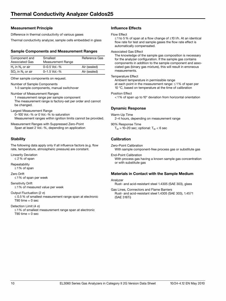
10 EL3060 Series Gas Analyzers in Category II 2G Version Data Sheet 10/24-4.12 EN May 2010
Thermal Conductivity Analyzer Caldos25
Measurement Principle
Difference in thermal conductivity of various gases
Thermal conductivity analyzer, sample cells embedded in glass
Sample Components and Measurement Ranges
Component and Associated Gas
Smallest Measurement Range
Reference Gas
H2 in N2 or air 0–0.5 Vol.-% Air (sealed)
SO2 in N2 or air 0–1.5 Vol.-% Air (sealed)
Other sample components on request.
Number of Sample Components 1–3 sample components, manual switchover
Number of Measurement Ranges 1 measurement range per sample component The measurement range is factory-set per order and cannot be changed.
Largest Measurement Range 0–100 Vol.-% or 0 Vol.-% to saturation Measurement ranges within ignition limits cannot be provided.
Measurement Ranges with Suppressed Zero-Point Span at least 2 Vol.-%, depending on application
Stability
The following data apply only if all influence factors (e.g. flow rate, temperature, atmospheric pressure) are constant.
Linearity Deviation ≤ 2 % of span
Repeatability ≤ 1 % of span
Zero Drift ≤ 1 % of span per week
Sensitivity Drift ≤ 1 % of measured value per week
Output Fluctuation (2 σ) ≤ 0.5 % of smallest measurement range span at electronic T90 time = 0 sec
Detection Limit (4 σ) ≤ 1 % of smallest measurement range span at electronic T90 time = 0 sec
Influence Effects
Flow Effect ≤ 1 to 5 % of span at a flow change of ±10 l/h. At an identical flow rate for test and sample gases the flow rate effect is automatically compensated.
Associated Gas Effect The knowledge of the sample gas composition is necessary for the analyzer configuration. If the sample gas contains components in addition to the sample component and asso-ciated gas (binary gas mixture), this will result in erroneous measurements.
Temperature Effect Ambient temperature in permissible range at each point in the measurement range: ≤ 1 % of span per 10 °C, based on temperature at the time of calibration
Position Effect < 1 % of span up to 10° deviation from horizontal orientation
Dynamic Response
Warm-Up Time 2–4 hours, depending on measurement range
90% Response Time T90 = 10–20 sec; optional: T90 < 6 sec
Calibration
Zero-Point Calibration With sample component-free process gas or substitute gas
End-Point Calibration With process gas having a known sample gas concentration or with substitute gas
Materials in Contact with the Sample Medium
Analyzer Rust- and acid-resistant steel 1.4305 (SAE 303), glass
Gas Lines, Connectors and Flame Barriers Rust- and acid-resistant steel 1.4305 (SAE 303), 1.4571 (SAE 316Ti)
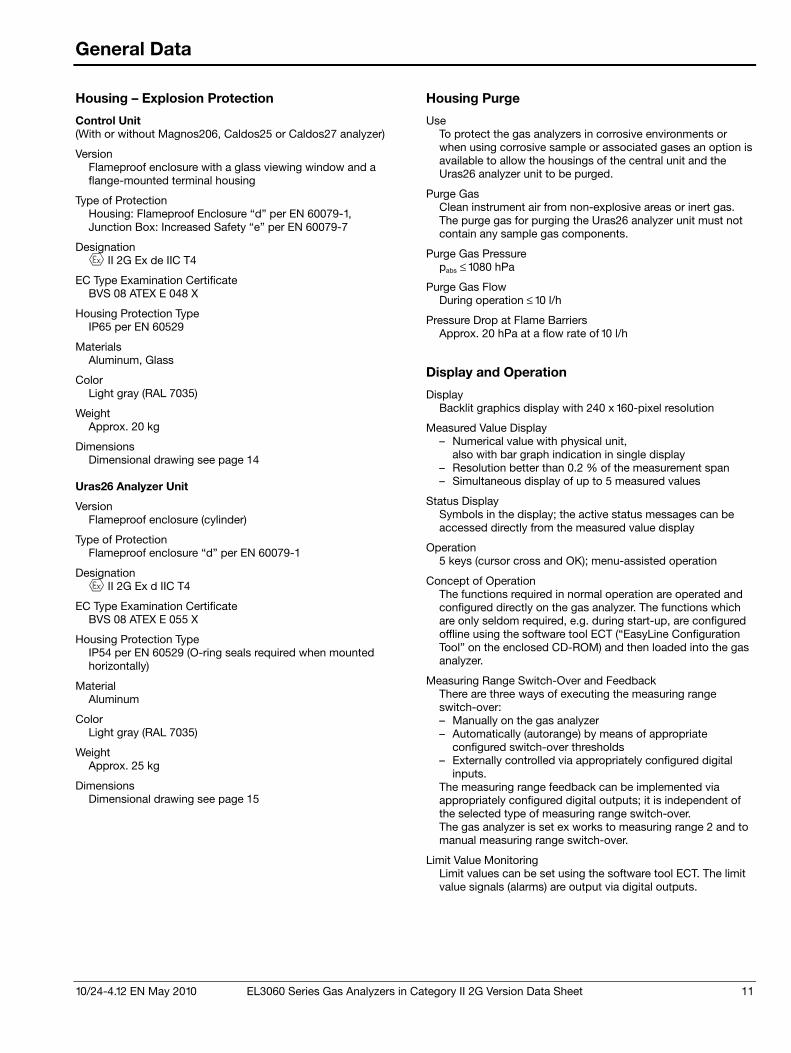
10/24-4.12 EN May 2010 EL3060 Series Gas Analyzers in Category II 2G Version Data Sheet 11
General Data
Housing – Explosion Protection
Control Unit (With or without Magnos206, Caldos25 or Caldos27 analyzer)
Version Flameproof enclosure with a glass viewing window and a flange-mounted terminal housing
Type of Protection Housing: Flameproof Enclosure “d” per EN 60079-1, Junction Box: Increased Safety “e” per EN 60079-7
Designation II 2G Ex de IIC T4
EC Type Examination Certificate BVS 08 ATEX E 048 X
Housing Protection Type IP65 per EN 60529
Materials Aluminum, Glass
Color Light gray (RAL 7035)
Weight Approx. 20 kg
Dimensions Dimensional drawing see page 14
Uras26 Analyzer Unit
Version Flameproof enclosure (cylinder)
Type of Protection Flameproof enclosure “d” per EN 60079-1
Designation II 2G Ex d IIC T4
EC Type Examination Certificate BVS 08 ATEX E 055 X
Housing Protection Type IP54 per EN 60529 (O-ring seals required when mounted horizontally)
Material Aluminum
Color Light gray (RAL 7035)
Weight Approx. 25 kg
Dimensions Dimensional drawing see page 15
Housing Purge
Use To protect the gas analyzers in corrosive environments or when using corrosive sample or associated gases an option is available to allow the housings of the central unit and the Uras26 analyzer unit to be purged.
Purge Gas Clean instrument air from non-explosive areas or inert gas. The purge gas for purging the Uras26 analyzer unit must not contain any sample gas components.
Purge Gas Pressure pabs ≤ 1080 hPa
Purge Gas Flow During operation ≤ 10 l/h
Pressure Drop at Flame Barriers Approx. 20 hPa at a flow rate of 10 l/h
Display and Operation
Display Backlit graphics display with 240 x 160-pixel resolution
Measured Value Display – Numerical value with physical unit,
also with bar graph indication in single display – Resolution better than 0.2 % of the measurement span – Simultaneous display of up to 5 measured values
Status Display Symbols in the display; the active status messages can be accessed directly from the measured value display
Operation 5 keys (cursor cross and OK); menu-assisted operation
Concept of Operation The functions required in normal operation are operated and configured directly on the gas analyzer. The functions which are only seldom required, e.g. during start-up, are configured offline using the software tool ECT (“EasyLine Configuration Tool” on the enclosed CD-ROM) and then loaded into the gas analyzer.
Measuring Range Switch-Over and Feedback There are three ways of executing the measuring range switch-over: – Manually on the gas analyzer – Automatically (autorange) by means of appropriate
configured switch-over thresholds – Externally controlled via appropriately configured digital
inputs. The measuring range feedback can be implemented via appropriately configured digital outputs; it is independent of the selected type of measuring range switch-over. The gas analyzer is set ex works to measuring range 2 and to manual measuring range switch-over.
Limit Value Monitoring Limit values can be set using the software tool ECT. The limit value signals (alarms) are output via digital outputs.
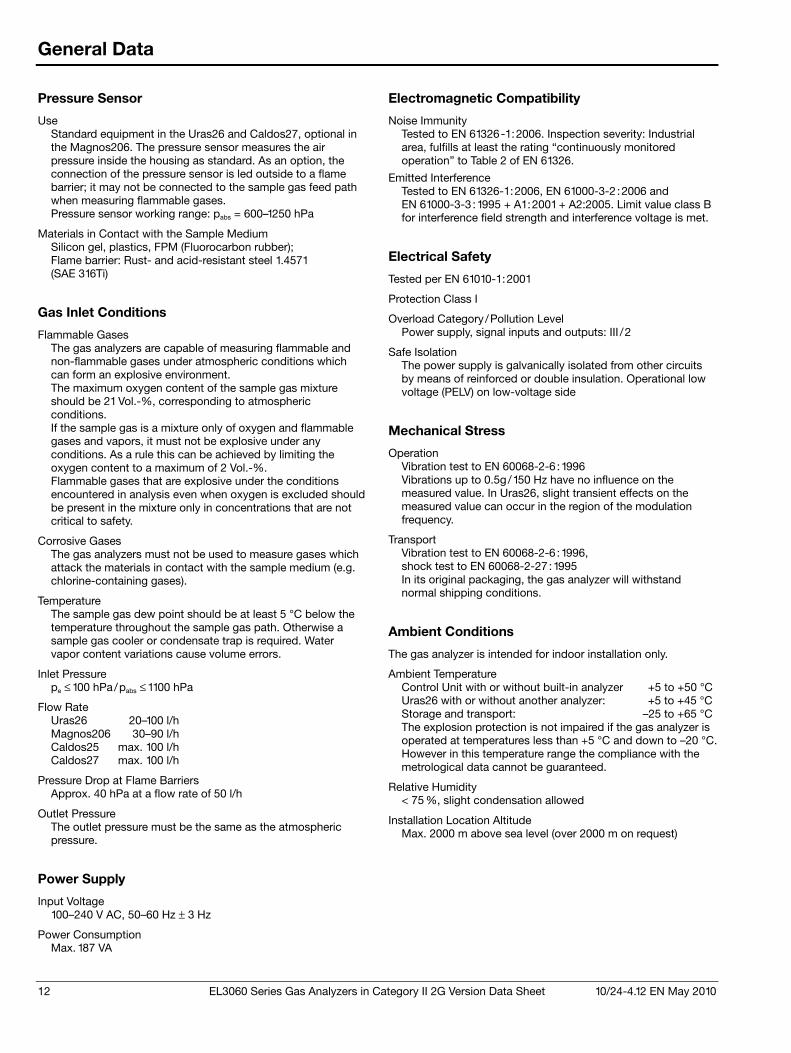
12 EL3060 Series Gas Analyzers in Category II 2G Version Data Sheet 10/24-4.12 EN May 2010
General Data
Pressure Sensor
Use Standard equipment in the Uras26 and Caldos27, optional in the Magnos206. The pressure sensor measures the air pressure inside the housing as standard. As an option, the connection of the pressure sensor is led outside to a flame barrier; it may not be connected to the sample gas feed path when measuring flammable gases. Pressure sensor working range: pabs = 600–1250 hPa
Materials in Contact with the Sample Medium Silicon gel, plastics, FPM (Fluorocarbon rubber); Flame barrier: Rust- and acid-resistant steel 1.4571 (SAE 316Ti)
Gas Inlet Conditions
Flammable Gases The gas analyzers are capable of measuring flammable and non-flammable gases under atmospheric conditions which can form an explosive environment. The maximum oxygen content of the sample gas mixture should be 21 Vol.-%, corresponding to atmospheric conditions. If the sample gas is a mixture only of oxygen and flammable gases and vapors, it must not be explosive under any conditions. As a rule this can be achieved by limiting the oxygen content to a maximum of 2 Vol.-%. Flammable gases that are explosive under the conditions encountered in analysis even when oxygen is excluded should be present in the mixture only in concentrations that are not critical to safety.
Corrosive Gases The gas analyzers must not be used to measure gases which attack the materials in contact with the sample medium (e.g. chlorine-containing gases).
Temperature The sample gas dew point should be at least 5 °C below the temperature throughout the sample gas path. Otherwise a sample gas cooler or condensate trap is required. Water vapor content variations cause volume errors.
Inlet Pressure pe ≤ 100 hPa/pabs ≤ 1100 hPa
Flow Rate Uras26 20–100 l/h Magnos206 30–90 l/h Caldos25 max. 100 l/h Caldos27 max. 100 l/h
Pressure Drop at Flame Barriers Approx. 40 hPa at a flow rate of 50 l/h
Outlet Pressure The outlet pressure must be the same as the atmospheric pressure.
Power Supply
Input Voltage 100–240 V AC, 50–60 Hz ± 3 Hz
Power Consumption Max. 187 VA
Electromagnetic Compatibility
Noise Immunity Tested to EN 61326-1:2006. Inspection severity: Industrial area, fulfills at least the rating “continuously monitored operation” to Table 2 of EN 61326.
Emitted Interference Tested to EN 61326-1:2006, EN 61000-3-2 :2006 and EN 61000-3-3 :1995 + A1:2001 + A2:2005. Limit value class B for interference field strength and interference voltage is met.
Electrical Safety
Tested per EN 61010-1:2001
Protection Class I
Overload Category/Pollution Level Power supply, signal inputs and outputs: III /2
Safe Isolation The power supply is galvanically isolated from other circuits by means of reinforced or double insulation. Operational low voltage (PELV) on low-voltage side
Mechanical Stress
Operation Vibration test to EN 60068-2-6 :1996 Vibrations up to 0.5g/150 Hz have no influence on the measured value. In Uras26, slight transient effects on the measured value can occur in the region of the modulation frequency.
Transport Vibration test to EN 60068-2-6 :1996, shock test to EN 60068-2-27:1995 In its original packaging, the gas analyzer will withstand normal shipping conditions.
Ambient Conditions
The gas analyzer is intended for indoor installation only.
Ambient Temperature Control Unit with or without built-in analyzer +5 to +50 °C Uras26 with or without another analyzer: +5 to +45 °C Storage and transport: –25 to +65 °C The explosion protection is not impaired if the gas analyzer is operated at temperatures less than +5 °C and down to –20 °C. However in this temperature range the compliance with the metrological data cannot be guaranteed.
Relative Humidity < 75 %, slight condensation allowed
Installation Location Altitude Max. 2000 m above sea level (over 2000 m on request)
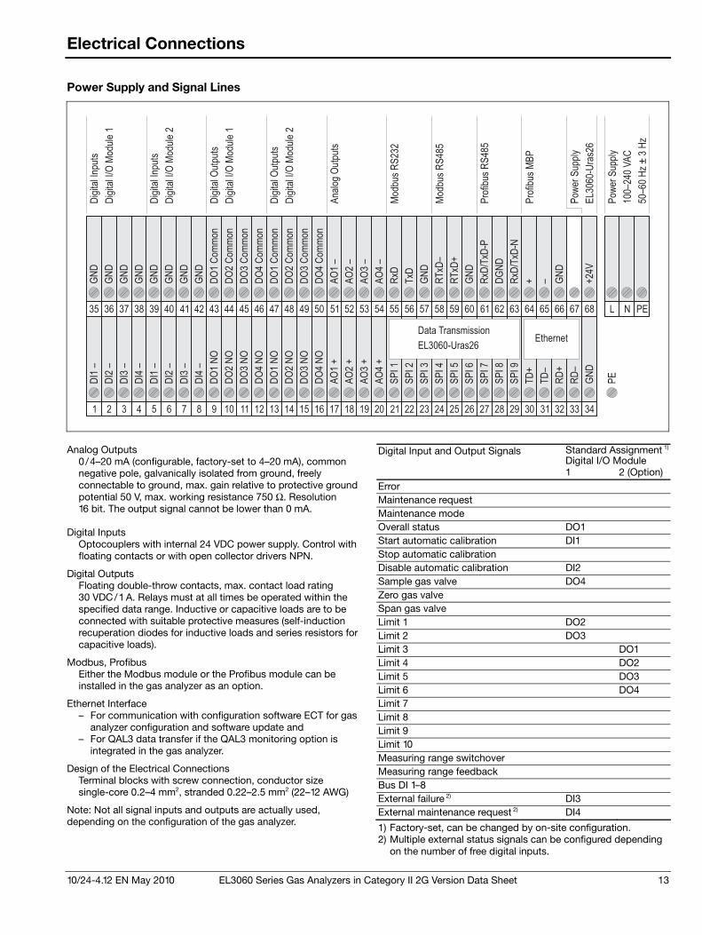
10/24-4.12 EN May 2010 EL3060 Series Gas Analyzers in Category II 2G Version Data Sheet 13
Electrical Connections
Power Supply and Signal Lines
34333231302928272625242322212019181716151413121110987654321
68 L N PE676665646362616059585756555453525150494847464544434241403938373635
Pro
fibus
MB
P
Pro
fibus
RS
485
Modbus
RS
485
GN
D
PE
TD
+
TD
–
RD
+
RD
–
SP
I1
SP
I2
SP
I3
SP
I4
SP
I5
SP
I6
SP
I7
SP
I8
SP
I9
AO
4+
AO
3+
AO
2+
AO
1+
DO
4N
O
DO
4N
O
DO
3N
O
DO
3N
O
DO
2N
O
DO
2N
O
DO
1N
O
DO
1N
O
DI4
–
DI4
–
GN
D
GN
D
GN
D
GN
D
DI2
–
DI2
–
GN
D
GN
D
GN
D
GN
D
+2
4V
GN
D
–+RxD
/TxD
-N
DG
ND
RxD
/TxD
-P
GN
D
RT
xD
+
RT
xD
–
GN
D
TxD
RxD
AO
4–
AO
3–
AO
2–
AO
1–
DO
4C
om
mo
n
DO
4C
om
mo
n
DO
3C
om
mon
DO
3C
om
mon
DO
2C
om
mo
n
DO
2C
om
mo
n
DO
1C
om
mon
DO
1C
om
mon
DI3
–
DI3
–
DI1
–
DI1
–
Modbus
RS
232
EthernetData Transmission
EL3060-Uras26
Dig
italIn
puts
Dig
italIn
puts
Dig
italO
utp
uts
Dig
italO
utp
uts
Dig
italI/O
Module
1
Dig
italI/O
Module
1
Dig
italI/O
Module
2
Dig
italI/O
Module
2
Analo
gO
utp
uts
Pow
er
Supply
100–240
VA
C
50–60
Hz
±3
Hz
Pow
er
Supply
EL3060-U
ras26
Analog Outputs
0 /4–20 mA (configurable, factory-set to 4–20 mA), common negative pole, galvanically isolated from ground, freely connectable to ground, max. gain relative to protective ground potential 50 V, max. working resistance 750 Ω. Resolution 16 bit. The output signal cannot be lower than 0 mA.
Digital Inputs Optocouplers with internal 24 VDC power supply. Control with floating contacts or with open collector drivers NPN.
Digital Outputs Floating double-throw contacts, max. contact load rating 30 VDC/1 A. Relays must at all times be operated within the specified data range. Inductive or capacitive loads are to be connected with suitable protective measures (self-induction recuperation diodes for inductive loads and series resistors for capacitive loads).
Modbus, Profibus Either the Modbus module or the Profibus module can be installed in the gas analyzer as an option.
Ethernet Interface – For communication with configuration software ECT for gas
analyzer configuration and software update and – For QAL3 data transfer if the QAL3 monitoring option is
integrated in the gas analyzer.
Design of the Electrical Connections Terminal blocks with screw connection, conductor size single-core 0.2–4 mm2, stranded 0.22–2.5 mm2 (22–12 AWG)
Note: Not all signal inputs and outputs are actually used, depending on the configuration of the gas analyzer.
Digital Input and Output Signals Standard Assignment 1)
Digital I/O Module 1 2 (Option) Error Maintenance request Maintenance mode Overall status DO1 Start automatic calibration DI1 Stop automatic calibration Disable automatic calibration DI2 Sample gas valve DO4 Zero gas valve Span gas valve Limit 1 DO2 Limit 2 DO3 Limit 3 DO1 Limit 4 DO2 Limit 5 DO3 Limit 6 DO4 Limit 7 Limit 8 Limit 9 Limit 10 Measuring range switchover Measuring range feedback Bus DI 1–8 External failure 2) DI3 External maintenance request 2) DI4
1) Factory-set, can be changed by on-site configuration. 2) Multiple external status signals can be configured depending
on the number of free digital inputs.
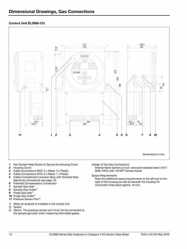
14 EL3060 Series Gas Analyzers in Category II 2G Version Data Sheet 10/24-4.12 EN May 2010
Dimensional Drawings, Gas Connections
Control Unit EL3060-CU
260
358
45.5
60.5
63
56
20.3
317
278
237.5
32
92.5124.5
278
438
466
199.5
190
59
104
EL3060
DO NOT OPEN WHEN AN EXPLOSIVE
ATMOSPHERE MAY BE PRESENT
9 7 8 1011 1 2 3 4 65
Dimensions in mm
1 Hex Socket Head Screw to Secure the Housing Cover 2 Housing Cover 3 Cable Connections M20: 2 x Metal, 3 x Plastic 4 Cable Connections M16: 2 x Metal, 1 x Plastic 5 Cable Compartment (Junction Box) with Terminal Strip
(electrical connections see page 13) 6 Potential Compensation Connection 7 Sample Gas Inlet 1) 8 Sample Gas Outlet 1) 9 Purge Gas Inlet 2) 10 Purge Gas Outlet 2) 11 Pressure Sensor Port 3)
1) When an analyzer is installed in the control unit 2) Option 3) Option. The pressure sensor port must not be connected to
the sample gas path when measuring flammable gases.
Design of the Gas Connections
Internal flame barriers of rust- and acid-resistant steel 1.4571 (SAE 316Ti) with 1/8 NPT female thread
Space Requirements Note the additional space requirements to the left and to the right of the housing as well as beneath the housing for connection lines (each approx. 10 cm).
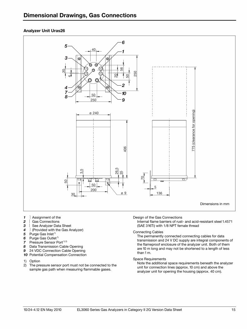
10/24-4.12 EN May 2010 EL3060 Series Gas Analyzers in Category II 2G Version Data Sheet 15
Dimensional Drawings, Gas Connections
Analyzer Unit Uras26
250
250
406
30
136
35
70
20030
3,5
26,5
50
50
ø 240
5
50
ø 9
40
20
56
4
50
775
(cle
aran
ce fo
r op
enin
g)
65
1
2
3
4
89
7 10
Dimensions in mm
1 Assignment of the 2 Gas Connections 3 See Analyzer Data Sheet 4 (Provided with the Gas Analyzer) 5 Purge Gas Inlet 1) 6 Purge Gas Outlet 1) 7 Pressure Sensor Port 1) 2) 8 Data Transmission Cable Opening 9 24 VDC Connection Cable Opening 10 Potential Compensation Connection
1) Option 2) The pressure sensor port must not be connected to the
sample gas path when measuring flammable gases.
Design of the Gas Connections
Internal flame barriers of rust- and acid-resistant steel 1.4571 (SAE 316Ti) with 1/8 NPT female thread
Connecting Cables The permanently connected connecting cables for data transmission and 24 V DC supply are integral components of the flameproof enclosure of the analyzer unit. Both of them are 10 m long and may not be shortened to a length of less than 1 m.
Space Requirements Note the additional space requirements beneath the analyzer unit for connection lines (approx. 10 cm) and above the analyzer unit for opening the housing (approx. 40 cm).
16 EL3060 Series Gas Analyzers in Category II 2G Version Data Sheet 10/24-4.12 EN May 2010
Certifications
CE Declaration of Conformity
The EL3060 Series gas analyzers satisfy the provisions of the following European directives:
2006/95/EC Low Voltage Directive 2004/108/EC EMC Directive 94/9/EC ATEX Directive
Compliance with the provisions of directive 2006/95/EC is evidenced by full compliance with European standard:
EN 61010-1:2001
Compliance with the provisions of directive 2004/108/EC is evidenced by full compliance with European standards:
EN 61326-1:2006, EN 61000-3-2 :2006 and EN 61000-3-3 :1995 + A1:2001 + A2:2005
Compliance with the provisions of directive 94/9/EC is evidenced by full compliance with European standards:
EN 60079-0 General Requirements EN 60079-1 Flameproof Enclosures “d” EN 60079-7 Increased Safety “e”


Contact us
10/2
4�4.
12 E
N R
ev. 2
12.
2011
ABB Automation GmbH Process Automation Stierstaedter Strasse 5 60488 Frankfurt am Main, Germany Fax: +49 69 7930�4566 E�mail: [email protected]
ABB Limited Process Automation Oldends Lane GL10 3TA Stonehouse Gloucestershire, United Kingdom Phone: +44 1 453 826661 Fax: +44 1 453 829671
ABB Pte. Ltd. Process Automation 2 Ayer Rajah Crescent 139935 Singapore, Singapore Phone: +65 6773 5961 Fax: +65 6778 0222
ABB Inc. Process Automation 3700 W Sam Houston Parkway South, Suite 600, Houston, TX 77042, USA Phone: +1 713 587 8000
ABB Ltd. Process Automation 14 Mathura Road 121003 Faridabad, Haryana, India Phone: +91 129 2279627 Fax: +91 129 2279692
ABB Australia Pty Limited Process Automation Bapaume Road 2170 Moorebank New South Wales, Australia Phone: +61 2 9821 0968 Fax: +61 2 9400 7050
ABB Engineering Ltd. Process Automation 10 Jiuxianqiao Lu 100015 Beijing, China Phone: +86 10 84566688 Ext. 6217 Fax: +86 10 84567650
www.abb.com/analytical To find your local ABB contact visit: www.abb.com/contacts
Note We reserve the right to make technical changes or modify the contents of this document without prior notice. With regard to purchase orders, the agreed particulars shall prevail. ABB does not accept any responsibility whatsoever for potential errors or possible lack of information in this document. We reserve all rights in this document and in the subject matter and illustrations contained therein. Any reproduction, disclosure to third parties or utilization of its contents – in whole or in parts – is forbidden without prior written consent of ABB. Copyright© 2011 ABB All rights reserved
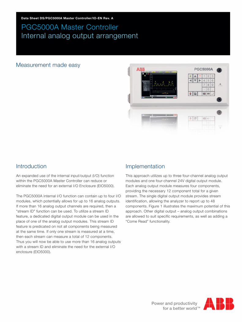
PGC5000A Master Controller Internal analog output arrangement
Data Sheet DS/PGC5000A Master Controller/IO-EN Rev. A
Measurement made easy
Introduction
An expanded use of the internal input/output (I/O) function within the PGC5000A Master Controller can reduce or eliminate the need for an external I/O Enclosure (EIO5000).
The PGC5000A internal I/O function can contain up to four I/O modules, which potentially allows for up to 16 analog outputs. If more than 16 analog output channels are required, then a “stream ID” function can be used. To utilize a stream ID feature, a dedicated digital output module can be used in the place of one of the analog output modules. This stream ID feature is predicated on not all components being measured at the same time. If only one stream is measured at a time, then each stream can measure a total of 12 components. Thus you will now be able to use more than 16 analog outputs with a stream ID and eliminate the need for the external I/O enclosure (EIO5000).
Implementation
This approach utilizes up to three four-channel analog output modules and one four-channel 24V digital output module. Each analog output module measures four components, providing the necessary 12 component total for a given stream. The single digital output module provides stream identification, allowing the analyzer to report up to 48 components. Figure 1 illustrates the maximum potential of this approach. Other digital output – analog output combinations are allowed to suit specific requirements, as well as adding a “Come Read” functionality.

Component 1
Component 2
Component 3
Component 4
Component 5
Component 5
Component 7
Component 8
Component 9
Component 10
Component 11
Component 12
Stream 1 Stream 3
Stream 2 Stream 4
DS
/PG
C50
00A
Mas
ter
Con
trol
ler/
IO-E
N R
ev.
A
5.2
015
Contact us
DS
/WM
–EN
Rev
.O01
.201
3ABB LimitedProcess AutomationOldends LaneStonehouseGloucestershire GL10 3TAUKTel: +44 1453 826 661Fax: +44 1453 829 [email protected]
ABB Inc.Process Automation125 E. County Line RoadWarminsterPA 18974USATel: +1 215 674 6000Fax: +1 215 674 7183
ABB Engineering (Shanghai) Ltd.Process AutomationNo. 5, Lane 369, Chuangye Road201319, Shanghai,P.R. ChinaPhone: +86 (0) 21 6105 6666Fax: +86 (0) 21 6105 6992Mail:[email protected]
www.abb.com
NoteWe reserve the right to make technical changes ormodify the contents of this document without priornotice. With regard to purchase orders, the agreedparticulars shall prevail. ABB does not accept anyresponsibility whatsoever for potential errors orpossible lack of information in this document.
We reserve all rights in this document and in thesubject matter and illustrations contained therein.Any reproduction, disclosure to third parties orutilization of its contents in whole or in parts – isforbidden without prior written consent of ABB.
Copyright© 2013 ABBAll rights reserved
3KXF211101R1001
Sales
Service
Software
ABB Inc. Process Automation Analytical Measurements 843 N. Jefferson Street Lewisburg, WV 24901 USATel.: 1 304 647 4358Fax: 1 304 645 4236 www.abb.com/analytical
NoteWe reserve the right to make technical changes or modify the contents of this document without prior notice. With regard to purchase orders, the agreedparticulars shall prevail. ABB does not accept any responsibility whatsoever for potential errors or possible lack of information in this document.
We reserve all rights in this document and in the subject matter and illustrations contained therein. Any reproduction, disclosure to third parties or utilization of its contents - in whole or in parts – is forbidden without prior written consent of ABB.
Copyright© 2015 ABBAll rights reserved9AAK10103A0708
Contact us
DS
/WM
–EN
Rev
.O01
.201
3ABB LimitedProcess AutomationOldends LaneStonehouseGloucestershire GL10 3TAUKTel: +44 1453 826 661Fax: +44 1453 829 [email protected]
ABB Inc.Process Automation125 E. County Line RoadWarminsterPA 18974USATel: +1 215 674 6000Fax: +1 215 674 7183
ABB Engineering (Shanghai) Ltd.Process AutomationNo. 5, Lane 369, Chuangye Road201319, Shanghai,P.R. ChinaPhone: +86 (0) 21 6105 6666Fax: +86 (0) 21 6105 6992Mail:[email protected]
www.abb.com
NoteWe reserve the right to make technical changes ormodify the contents of this document without priornotice. With regard to purchase orders, the agreedparticulars shall prevail. ABB does not accept anyresponsibility whatsoever for potential errors orpossible lack of information in this document.
We reserve all rights in this document and in thesubject matter and illustrations contained therein.Any reproduction, disclosure to third parties orutilization of its contents in whole or in parts – isforbidden without prior written consent of ABB.
Copyright© 2013 ABBAll rights reserved
3KXF211101R1001
Sales
Service
Software
4 Channel Analog Output 4 Channel Analog Output 4 Channel Analog Output 4 Channel Digital Output
Figure 1866Z004-1 866Z004-1 866Z004-1 866Z004-1
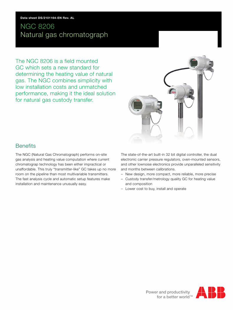
NGC 8206 Natural gas chromatograph
Data sheet DS/2101164-EN Rev. AL
The NGC 8206 is a field mounted GC which sets a new standard for determining the heating value of natural gas. The NGC combines simplicity with low installation costs and unmatched performance, making it the ideal solution for natural gas custody transfer.
BenefitsThe NGC (Natural Gas Chromatograph) performs on-site gas analysis and heating value computation where current chromatograp technology has been either impractical or unaffordable. This truly “transmitter-like” GC takes up no more room on the pipeline than most multivariable transmitters. The fast analysis cycle and automatic setup features make installation and maintenance unusually easy.
The state-of-the-art built-in 32 bit digital controller, the dual electronic carrier pressure regulators, oven-mounted sensors, and other lownoise electronics provide unparalleled sensitivity and months between calibrations. – New design, more compact, more reliable, more precise – Custody transfer/metrology quality GC for heating value
and composition – Lower cost to buy, install and operate
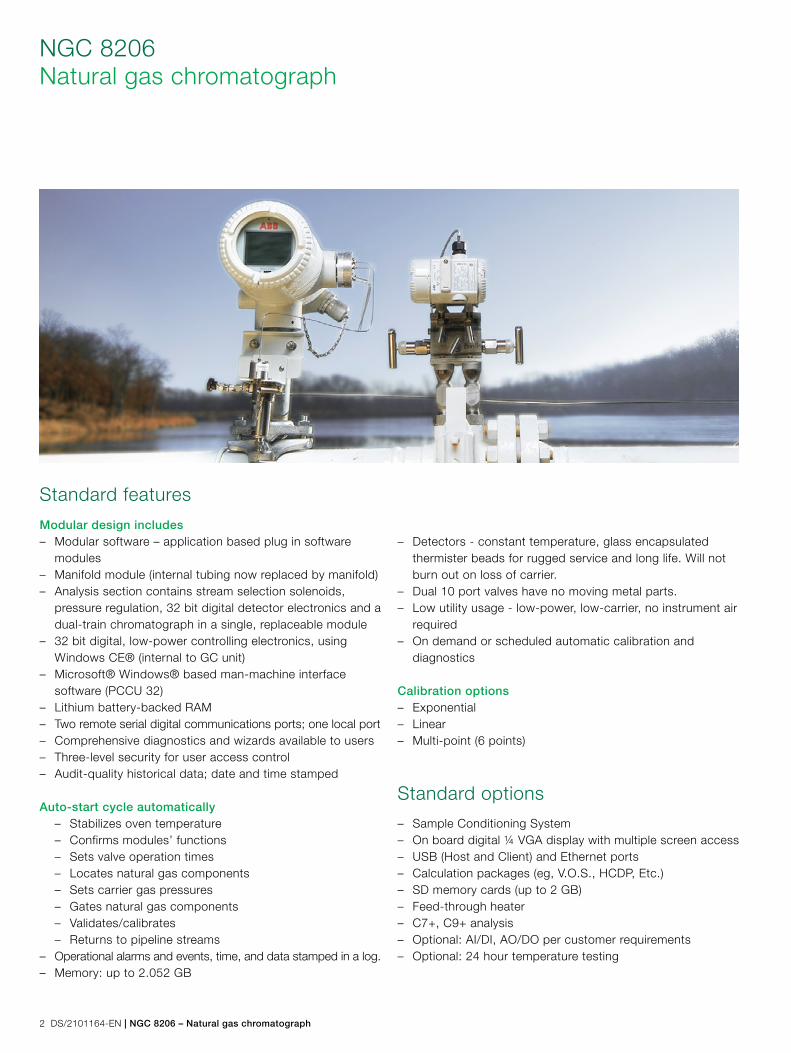
2 DS/2101164-EN | NGC 8206 – Natural gas chromatograph
NGC 8206Natural gas chromatograph
Standard features
Modular design includes – Modular software – application based plug in software
modules – Manifold module (internal tubing now replaced by manifold) – Analysis section contains stream selection solenoids,
pressure regulation, 32 bit digital detector electronics and a dual-train chromatograph in a single, replaceable module
– 32 bit digital, low-power controlling electronics, using Windows CE® (internal to GC unit)
– Microsoft® Windows® based man-machine interface software (PCCU 32)
– Lithium battery-backed RAM – Two remote serial digital communications ports; one local port – Comprehensive diagnostics and wizards available to users – Three-level security for user access control – Audit-quality historical data; date and time stamped
Auto-start cycle automatically – Stabilizes oven temperature – Confirms modules’ functions – Sets valve operation times – Locates natural gas components – Sets carrier gas pressures – Gates natural gas components – Validates/calibrates – Returns to pipeline streams
– Operational alarms and events, time, and data stamped in a log. – Memory: up to 2.052 GB
– Detectors - constant temperature, glass encapsulated thermister beads for rugged service and long life. Will not burn out on loss of carrier.
– Dual 10 port valves have no moving metal parts. – Low utility usage - low-power, low-carrier, no instrument air
required – On demand or scheduled automatic calibration and
diagnostics
Calibration options – Exponential – Linear – Multi-point (6 points)
Standard options
– Sample Conditioning System – On board digital ¼ VGA display with multiple screen access – USB (Host and Client) and Ethernet ports – Calculation packages (eg, V.O.S., HCDP, Etc.) – SD memory cards (up to 2 GB) – Feed-through heater – C7+, C9+ analysis – Optional: AI/DI, AO/DO per customer requirements – Optional: 24 hour temperature testing
NGC 8206 – Natural gas chromatograph | DS/2101164-EN 3
Description
The NGC 8206 analyzes each sample utilizing established chromatographic techniques. The resulting information consists of mole percent values for the following: – “Air” (Contains N2, Ar, CO and O2 but not CO2) – C1 CO2 C2 C3 IC4 NC4 – NeoC5 IC5 NC5 C6+
Using process chromatographic techniques, the columns are back flushed so that the NGC 8206 measures a C6+ peak. Users may input the results of a comprehensive lab analysis that reflects the split or ratio of C6 through C10 components. This ratio can be used in subsequent analysis and energy calculations. Calculated values include: – Gas compressibility per AGA 8 – Real Relative Density (Specific Gravity) – Btu/CV Value – GPM (gallons of liquid per thousand cubic ft) – Wobbe Index – Methane Number – Optional calculations can include: AGA 10 speed of sound,
Hydrocarbon Dew Point
Installation
The NGC 8206 is a weatherproof device designed for installation “on the pipe” near to the sampling point. This means it is acceptable to mount outside - in a temperature range of 0°F to 130°F (–18°C to 55°C) [provides reliable operation for –20°F to 130°F (–29°C to 55°C) with low temperature option] onto a pipeline with 2’’ to 12’’ pipe sizes or with an optional pole mount configuration. A cold weather enclosure is also available if ambient conditions are below either the sampled gas dew point or the operational specifications of the unit.
Sample conditioning system
The integral stream selector for the NGC 8206 allows sampling up to four (4) different natural gas streams. Up to two of these sample streams can be designated as the “calibration/validation sample”. Optional sample conditioning modules are available to address natural gas streams that need additional filtering and “speed loops” to reduce sample transport lag times.
Operator interface
Functional setup and operation of the NGC 8206 is accomplished by using a graphical user’s interface software package called PCCU 32 (supplied with each unit) operating on a laptop PC in a Microsoft® Windows® environment. The “Windows®” utilities, combined with software designed specifically for the NGC 8206, provide a powerful tool for operations, diagnostics, and downstream data handling. The PC can be directly connected to the NGC 8206 via an RS-232, USB, or Ethernet connection, or indirectly by remote telemetry (phone modem, radio, cell phone, satellite, etc.). The user is prompted through push-buttons, drop-down boxes, wizards, and dialog boxes for setup, operations, data collection and monitoring.In addition, the unit has an optional ¼ VGA interactive display screen allowing the user access to basic analysis data. The user can also accomplish most of the “operator” functions from the front panel display with out the use of a laptop PC. The “Run-Hold-Calibrate” functions can be done via a magnet interface through the explosion proof glass in the display.

4 DS/2101164-EN | NGC 8206 – Natural gas chromatograph
NGC 8206Natural gas chromatograph
Maintenance
The NGC 8206 was designed from the ground up to be maintained by personnel with little or no prior knowledge of Gas Chromatography. Both hardware and software are designed to provide low maintenance through easily replaceable electro-mechanical modules such as: – NGC termination panel – NGC analytical module, an easily removable
chromatograph subassembly, containing: – NGC manifold – Stream selector solenoid valves – GC module – Dual electronic carrier pressure regulator valves – Chromatograph pilot valve – NGC analytical processor – NGC feed-through (heater optional) – Sample conditioning module (SCM) – NGC controller, (32 bit processor) – NGC ¼ VGA display (optional)
Other maintenance support features
– Intuitive Local Operator Interface (PCCU 32) running Microsoft® Windows® environment
– Diagnostic software and wizards for maintenance – Diagnostic file output system for e-mail support – Digitized detector output (chromatogram) to PCCU 32 – Remote or local operation of PCCU 32 – Quick Start guide, Start up manual and Start up video
NGC 8206 – Natural gas chromatograph | DS/2101164-EN 5
Historical data
The NGC 8206 is designed to retain historical data. This data can be used for custody transfer needs, verify transmitter operation over time, and provide a limited data backup for communication link reliability.The user is allowed to configure the period of the data retained by the NGC 8206 via the Operator Interface. The default1 memory configuration provides the most recent 480 analysis cycles containing: – Normalized components – Un-normalized components – Ideal Btu/CV – Real Btu (wet and dry) / CV (superior and inferior) – Relative density (specific gravity) – Density – GPM – Wobbe index – Alarms
Stream averages for the (default1) 840 last hours, 35 last days and the most recent last month analyses. Operational Parameters for the (default1) last 480 cycles (Diagnostics Report): – Selected peak times – Selected peak areas – Ideal Btu/CV – Carrier regulator pressure – Oven temperature – Ambient temperature – Sample pressure – Detector noise values – Detector balance values
Audit logs (default1) – Last 480 alarms – Last 480 events
Data retained by the NGC 8206 can be collected via a remote communication link or by the laptop PC local operator interface PCCU 32.
Available accessories
– 120/240 V AC to 12 V DC GP and Exp power supplies – Pole or pipeline mounting kits – Cold weather enclosure (also available in pipe mount
configuration) – Cold weather thermal jacket (future) – Modular Sample System Conditioner options for
– Non-pipeline quality natural gas sample – Sample transport lag-time needs
– Probes – Temperature compensating fixed – Temperature compensating retractable – Liquid rejection – Electrically heated, retractable
– Regulators (carrier and calibration blend) – Start-up calibration/validation gas sample (±2% blend) – Carrier Gas: 99.995% pure helium (chromatographic grade) – Hydrogen carrier (optional) – SD memory card – Export crating – Tool kit – Welker liquid shut-offs – Various maintenance kits – Customer factory acceptance test (FAT)
(Default1) The default memory configuration will provide for the data storage above. User may reallocate the memory that is available.
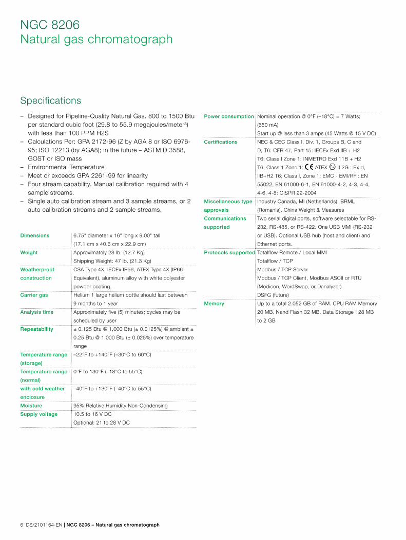
6 DS/2101164-EN | NGC 8206 – Natural gas chromatograph
NGC 8206Natural gas chromatograph
Specifications
– Designed for Pipeline-Quality Natural Gas. 800 to 1500 Btu per standard cubic foot (29.8 to 55.9 megajoules/meter³) with less than 100 PPM H2S
– Calculations Per: GPA 2172-96 (Z by AGA 8 or ISO 6976-95; ISO 12213 (by AGA8); in the future – ASTM D 3588, GOST or ISO mass
– Environmental Temperature – Meet or exceeds GPA 2261-99 for linearity – Four stream capability. Manual calibration required with 4
sample streams. – Single auto calibration stream and 3 sample streams, or 2
auto calibration streams and 2 sample streams.
Dimensions 6.75" diameter x 16" long x 9.00" tall
(17.1 cm x 40.6 cm x 22.9 cm)
Weight Approximately 28 lb. (12.7 Kg)
Shipping Weight: 47 lb. (21.3 Kg)
Weatherproof
construction
CSA Type 4X, IECEx IP56, ATEX Type 4X (IP66
Equivalent), aluminum alloy with white polyester
powder coating.
Carrier gas Helium 1 large helium bottle should last between
9 months to 1 year
Analysis time Approximately five (5) minutes; cycles may be
scheduled by user
Repeatability ± 0.125 Btu @ 1,000 Btu (± 0.0125%) @ ambient ±
0.25 Btu @ 1,000 Btu (± 0.025%) over temperature
range
Temperature range
(storage)
–22°F to +140°F (–30°C to 60°C)
Temperature range
(normal)
0°F to 130°F (–18°C to 55°C)
with cold weather
enclosure
–40°F to +130°F (–40°C to 55°C)
Moisture 95% Relative Humidity Non-Condensing
Supply voltage 10.5 to 16 V DC
Optional: 21 to 28 V DC
Power consumption Nominal operation @ 0°F (–18°C) = 7 Watts;
(650 mA)
Start up @ less than 3 amps (45 Watts @ 15 V DC)
Certifications NEC & CEC Class I, Div. 1, Groups B, C and
D, T6: CFR 47, Part 15: IECEx Exd IIB + H2
T6; Class I Zone 1: INMETRO Exd 11B + H2
T6; Class 1 Zone 1: ATEX II 2G : Ex d,
IIB+H2 T6; Class I, Zone 1: EMC - EMI/RFI: EN
55022, EN 61000-6-1, EN 61000-4-2, 4-3, 4-4,
4-6, 4-8: CISPR 22-2004
Miscellaneous type
approvals
Industry Canada, MI (Netherlands), BRML
(Romania), China Weight & Measures
Communications
supported
Two serial digital ports, software selectable for RS-
232, RS-485, or RS-422. One USB MMI (RS-232
or USB). Optional USB hub (host and client) and
Ethernet ports.
Protocols supported Totalflow Remote / Local MMI
Totalflow / TCP
Modbus / TCP Server
Modbus / TCP Client, Modbus ASCII or RTU
(Modicon, WordSwap, or Danalyzer)
DSFG (future)
Memory Up to a total 2.052 GB of RAM. CPU RAM Memory
20 MB. Nand Flash 32 MB. Data Storage 128 MB
to 2 GB
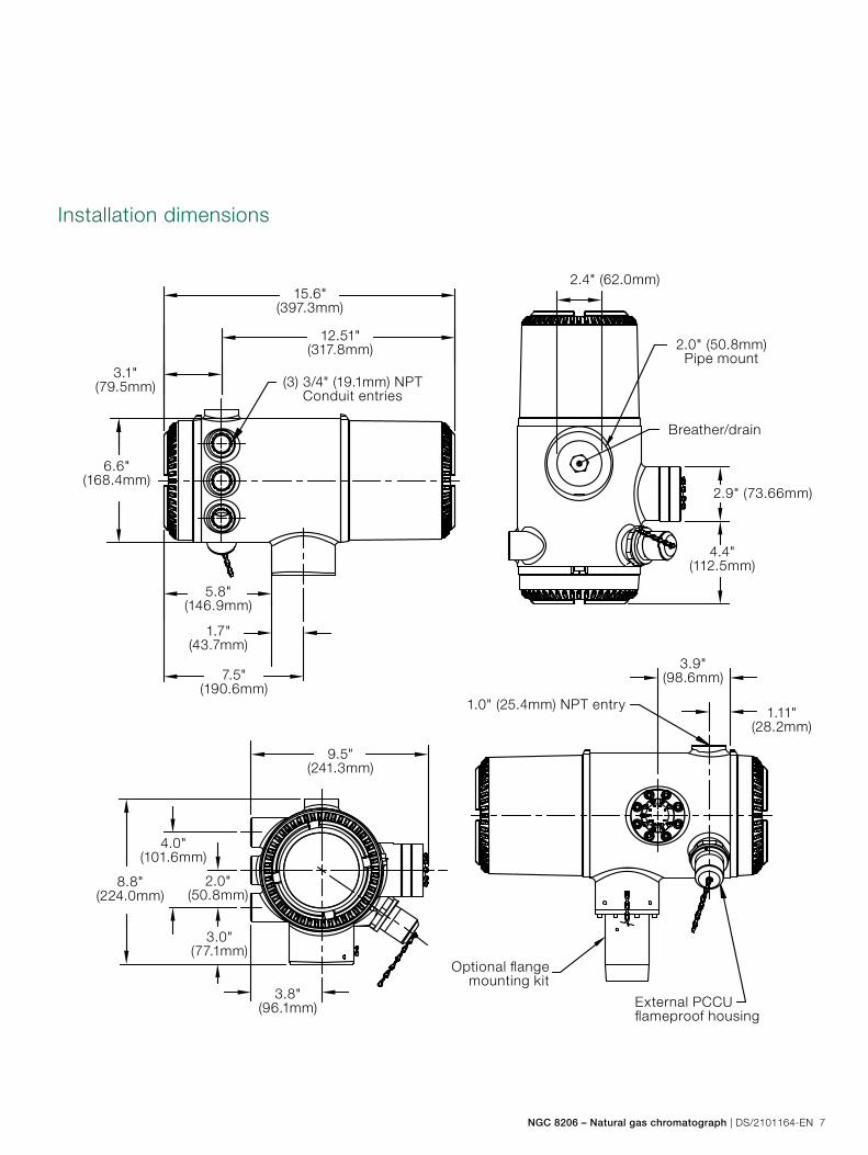
NGC 8206 – Natural gas chromatograph | DS/2101164-EN 7
15.6"(397.3mm)
2.0" (50.8mm)Pipe mount
2.9" (73.66mm)
1.0" (25.4mm) NPT entry
Optional flange mounting kit
External PCCU flameproof housing
2.4" (62.0mm)
4.4"(112.5mm)
3.9"(98.6mm)
1.11"(28.2mm)
Breather/drain
12.51"(317.8mm)
3.1"(79.5mm)
6.6"(168.4mm)
5.8"(146.9mm)
7.5"(190.6mm)
9.5"(241.3mm)
4.0"(101.6mm)
8.8"(224.0mm)
2.0"(50.8mm)
3.0"(77.1mm)
3.8"(96.1mm)
1.7"(43.7mm)
(3) 3/4" (19.1mm) NPTConduit entries
Installation dimensions
Contact us
DS
/210
1164
-EN
– R
ev.
AL
10.
2012ABB Inc.
Process AutomationMain Office7051 Industrial Boulevard Bartlesville, OK 74006 USA Tel: +1 918 338 4888 +1 800 341 3009 Fax: +1 918 338 4699
ABB Inc.Process Automation3700 W Sam Houston Parkway South, Ste. 600 Houston, TX 77042 USA Tel: +1 713 587 8000 Fax: +1 713 266 4335
ABB Inc.Process Automation3900 S. County Rd. 1290 Odessa, TX 79765 USA Tel: +1 432 563 5144 Fax: +1 432 563 8043
ABB Inc.Process Automation2 Acee Dr. Natrona Heights, PA 15065 USA Tel: +1 724 295 6100 Fax: +1 724 295 6560
ABB Inc.Process Automation4300 Stine Rd. Ste. 405-407 Bakersfield, CA 93313 USA Tel: +1 661 833 2030 Fax: +1 661 833 2034
ABB Inc.Process Automation2705 Centennial Liberal, KS 67901 USA Tel: +1 620 626 4352 Fax: +1 620 626 4354
www.abb.com/totalflow
Note We reserve the right to make technical changes or modify the contents of this document without prior notice. With regard to purchase orders, the agreed particulars shall prevail. ABB does not accept any responsibility whatsoever for potential errors or possible lack of information in this document.
We reserve all rights in this document and in the subject matter and illustrations contained therein. Any reproduction, disclosure to third parties or utilization of its contents - in whole or in parts – is forbidden without prior written consent of ABB.
Copyright© 2012 ABB All rights reserved
Sales Service Software
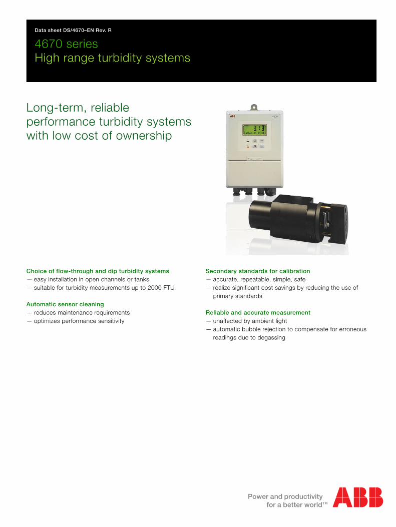
Data sheet DS/4670–EN Rev. R
4670 seriesHigh range turbidity systems
Long-term, reliable performance turbidity systems with low cost of ownership
Choice of flow-through and dip turbidity systems— easy installation in open channels or tanks— suitable for turbidity measurements up to 2000 FTU
Automatic sensor cleaning — reduces maintenance requirements— optimizes performance sensitivity
Secondary standards for calibration— accurate, repeatable, simple, safe— realize significant cost savings by reducing the use of
primary standards
Reliable and accurate measurement — unaffected by ambient light— automatic bubble rejection to compensate for erroneous
readings due to degassing
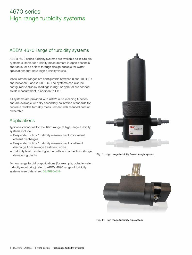
4670 seriesHigh range turbidity systems
2 DS/4670–EN Rev. R | 4670 series | High range turbidity systems
ABB's 4670 range of turbidity systems
ABB's 4670 series turbidity systems are available as in-situ dip systems suitable for turbidity measurement in open channels and tanks, or as a flow-through design suitable for water applications that have high turbidity values.
Measurement ranges are configurable between 0 and 100 FTU and between 0 and 2000 FTU. The systems can also be configured to display readings in mg/l or ppm for suspended solids measurement in addition to FTU.
All systems are provided with ABB's auto-cleaning function and are available with dry secondary calibration standards for accurate reliable turbidity measurement with reduced cost of ownership.
ApplicationsTypical applications for the 4670 range of high range turbidity systems include:— Suspended solids / turbidity measurement in industrial
effluent discharges— Suspended solids / turbidity measurement of effluent
discharge from sewage treatment works— Turbidity level monitoring in the outflow channel from sludge
dewatering plants
For low range turbidity applications (for example, potable water turbidity monitoring) refer to ABB's 4690 range of turbidity systems (see data sheet DS/4690–EN).
Fig. 1: High range turbidity flow-through system
Fig. 2: High range turbidity dip system
4670 series | High range turbidity systems | DS/4670–EN Rev. R 3
Reliable measurement
ABB's 4670 range of turbidity systems are designed for reliability, ease-of-use and maintenance simplicity. The sensors are available in flow and dip versions and are supplied with auto-cleaning to minimize maintenance, overcome optical fouling and optimize performance.
Measurement techniqueThe 4670 series of high range turbidity sensors measure turbidity by absorption (or attenuation) of a light beam passing through the sample.
This is probably the most straightforward method of measuring turbidity. A light beam is transmitted through the sample, the intensities of which are measured by a photodetector in line with the light source. The measurement of turbidity using Absorptiometers can be affected by the presence of dissolved colour. However, such effects are minimized by performing the measurement at a wavelength of 880 nm which is in the infrared region.
Automatic cell cleaning
The 4670 range of turbidity sensors feature an auto-clean system. This feature consists of a mechanical wiper assembly that physically wipes clean the optical cell at user-programmable intervals from every 15 minutes up to every 24 hours.
The highly efficient automatic cleaning process overcomes the problem of optical fouling and ensures that performance can be maintained for long periods without the need for manual intervention.
Automatic bubble rejection
Turbidity readings can be affected by short-term spikes, usually due to the effect of the sample degassing. The 4670 analyzer has an automatic bubble rejection feature that, when enabled, applies a digital filter to the measured results removing spurious high readings.
Fig. 3: Absorption turbidity monitor
LED
Lens Lens
Detector
Fig. 4: Auto-clean system on 4670 dip sensor
4670 seriesHigh range turbidity systems
4 DS/4670–EN Rev. R | 4670 series | High range turbidity systems
Simple to calibrate
The 4670 can be calibrated either by using a chemical standard such as Formazine, or by using the optional secondary calibration device.
The dry secondary calibration standard is a key feature of the 4670 turbidity systems that simplifies routine instrument verification and removes the need for the use of chemical standards.
Each secondary standard is supplied factory-certified against a primary formazine standard.
Benefits of using ABB's secondary standardsMinimum analyzer downtime— Simple and fast procedure to verify analyzer performance.
Low cost of ownership— Reduce usage of consumable chemical standards and the
time taken to prepare such standards.
Minimize employees' exposure to Formazine— Formazin is highly toxic and a suspected carcinogen
Repeatable and reliable— Removes any chemical standard preparation errors
Simple to use— The secondary standard is simply inserted into the sensor
assembly optical light path enabling the pre-calibrated optomechanical filter to divert a fixed quantity of light to the detector that corresponds to the calibrated turbidity value
Fig. 5: Auto-clean system on 4670 dip sensor
Fig. 6: Dry standard calibration
4670 series | High range turbidity systems | DS/4670–EN Rev. R 5
Flexible installation
A choice of in situ dip and flow-through sensor designs together with panel- and wall-mount transmitter options makes it flexible to install for a variety of applications
Simple to maintain
As with all analyzers, the key to success is the reliability of the sensing device coupled with simple maintenance procedures.
The 4670 turbidity sensing systems are designed to be as maintenance-free as possible. The inherent product design and auto-clean feature minimize the amount of maintenance required to regular calibration verification checks and periodic replacement of the wiper blade. All the sensing systems can be site-serviced without the need of a skilled technician.
Confidence in service
To complement the system's well proven design, unrivalled accuracy and reliability in service, the entire sensing loop is regularly self-monitored to ensure the light source is operating within specification, thereby eliminating the risk of electrical drift. In addition, the function of the wiper module is continuously validated, thereby assuring the correct performance of the cleaning function.
Fig. 7: 4670 installation options
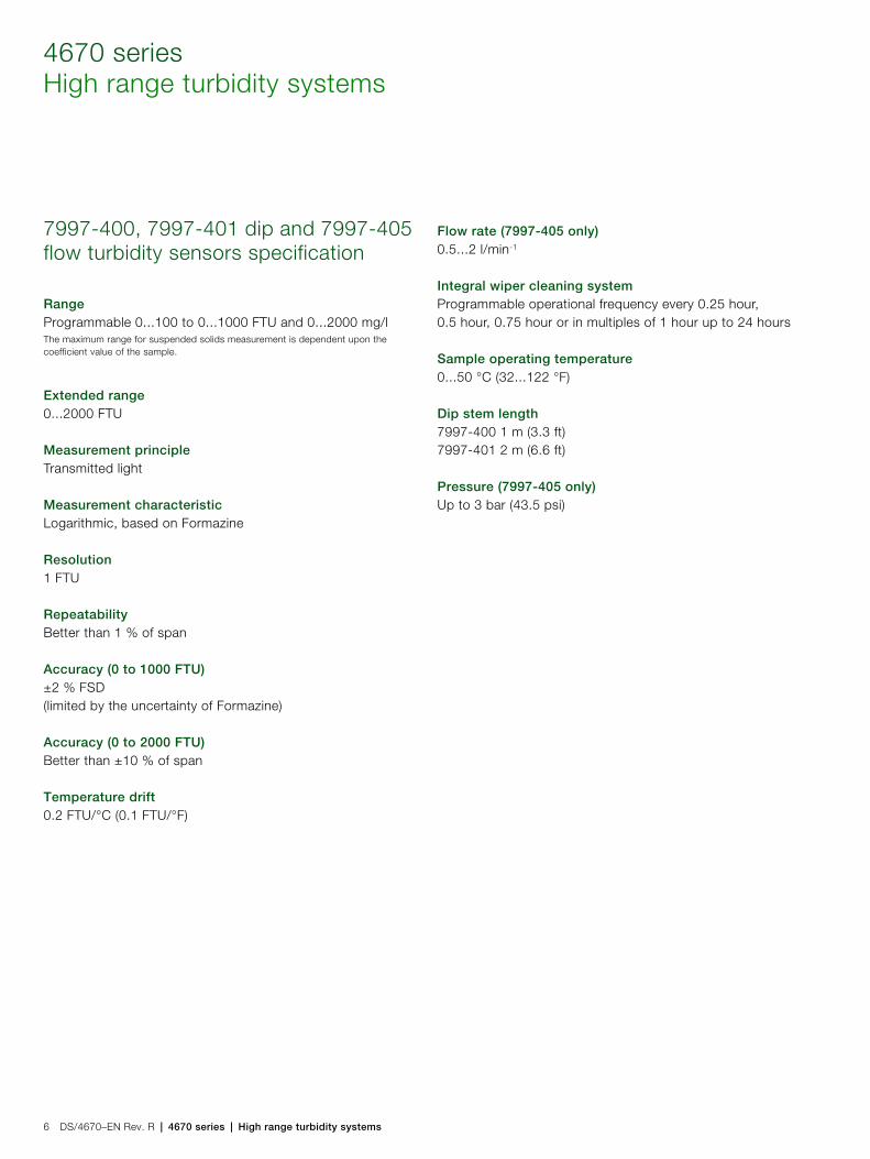
4670 seriesHigh range turbidity systems
6 DS/4670–EN Rev. R | 4670 series | High range turbidity systems
7997-400, 7997-401 dip and 7997-405 flow turbidity sensors specification
RangeProgrammable 0...100 to 0...1000 FTU and 0...2000 mg/lThe maximum range for suspended solids measurement is dependent upon the coefficient value of the sample.
Extended range0...2000 FTU
Measurement principleTransmitted light
Measurement characteristicLogarithmic, based on Formazine
Resolution1 FTU
RepeatabilityBetter than 1 % of span
Accuracy (0 to 1000 FTU)±2 % FSD(limited by the uncertainty of Formazine)
Accuracy (0 to 2000 FTU)Better than ±10 % of span
Temperature drift0.2 FTU/°C (0.1 FTU/°F)
Flow rate (7997-405 only)0.5...2 l/min-1
Integral wiper cleaning systemProgrammable operational frequency every 0.25 hour, 0.5 hour, 0.75 hour or in multiples of 1 hour up to 24 hours
Sample operating temperature0...50 °C (32...122 °F)
Dip stem length 7997-400 1 m (3.3 ft)7997-401 2 m (6.6 ft)
Pressure (7997-405 only)Up to 3 bar (43.5 psi)
4670 series | High range turbidity systems | DS/4670–EN Rev. R 7
4670 transmitter specification
GeneralMeasured value5-digit x 7-segment backlit LCD
Information16-character, single line, dot matrix, backlit LCD
Units of measurementAll models: NTU and FNUmg/l and ppm for high range models
Accuracy±0.2 % of reading, ±1 digit
Linearity±0.1 % FSD
Auto-clean timing (7998011, 7998012)Programmable 15 min, 30 min, 45 min or 1 hour up to 24 hours in 1 hour increments
Environmental dataOperating temperature limits–20...55 °C (–4...131 °F)
Storage temperature limits–25...55 °C (–13...131 °F)
Operating humidity limitsUp to 95 % RH non-condensing
Power supplyVoltage requirements100...130 V, 200...260 V, 50/60 Hz
Power consumption< 6 VA AC
Error due to power supply variationLess than 0.1 % for +6 % –20 % variation from nominal supply
InsulationMains to earth (line to ground) 2 kV RMS
Relay outputs and set pointsNo. of relaysTwo
Relay contacts
Insulation2 kV RMS contacts to earth (ground)
No. of set pointsTwo
Set point adjustmentProgrammable
Set point hysteresis±1 % fixed
Local set point annunciationRed LED
Single pole changeover
Rating: 250 V AC, 250 V DC max.
3 A AC, 3 A DC max.
Loading:
(non-inductive): 750 VA 30 W max.
(inductive): 750 VA 3 W max.
4670 seriesHigh range turbidity systems
8 DS/4670–EN Rev. R | 4670 series | High range turbidity systems
RetransmissionNo. of retransmission signalsOne fully isolated programmable 0...10 mA, 0...20 mA or 4...20 mA optional second current output Accuracy±0.25 % FSD ±0.5 % reading Resolution0.1 % at 10 A, 0.05 % at 20 mA Max. load resistance750 (20 A max.)
Mechanical dataModel 4670 Wall- / Pipe-mount transmitter
Model 4675 Panel-mount transmitter
Wall-mounting
Protection IP66 / NEMA4X
Dimensions 160 mm (6.30 in.) wide x 214 mm (8.43 in.) high x 68 mm (2.68 in.) deep
Weight 2 kg (41/2 lb)
Panel-mounting (¼ DIN)
Protection IP66 / NEMA4X front
Dimensions 96 mm (3.78 in.) wide x 96 mm (3.78 in.) high x 191 mm (7.52 in.) deep
Weight 1.5 kg (31/4 lb)
Panel cut-out: mm x mm ( in. x in.)92+0.8
0– 92+0.80–
3.62+0.030– 3.62+0.03
0–
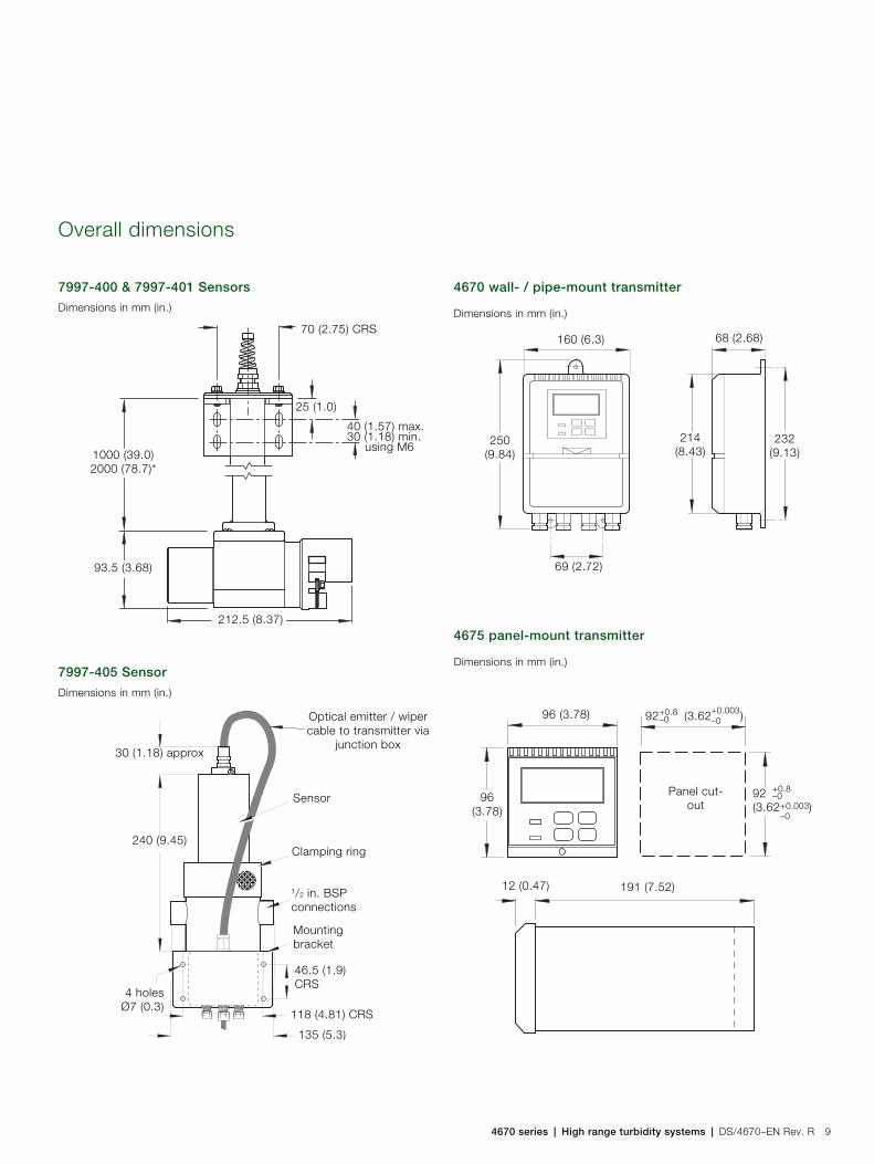
4670 series | High range turbidity systems | DS/4670–EN Rev. R 9
Overall dimensions
7997-400 & 7997-401 Sensors
7997-405 Sensor
4670 wall- / pipe-mount transmitter
4675 panel-mount transmitter
Dimensions in mm (in.)
Dimensions in mm (in.)
70 (2.75) CRS
25 (1.0)
40 (1.57) max.30 (1.18) min. using M6
1000 (39.0)2000 (78.7)*
93.5 (3.68)
212.5 (8.37)
Optical emitter / wiper cable to transmitter via
junction box30 (1.18) approx
Sensor
4 holesØ7 (0.3)
135 (5.3)
Clamping ring
1/2 in. BSP connections
Mounting bracket
46.5 (1.9)CRS
240 (9.45)
118 (4.81) CRS
Dimensions in mm (in.)
Dimensions in mm (in.)
232(9.13)
214(8.43)
250(9.84)
160 (6.3) 68 (2.68)
69 (2.72)
92(3.62 )
+0.8–0
+0.003–0
92 (3.62 )96 (3.78)
96(3.78)
12 (0.47) 191 (7.52)
Panel cut-out
+0.8–0
+0.003–0
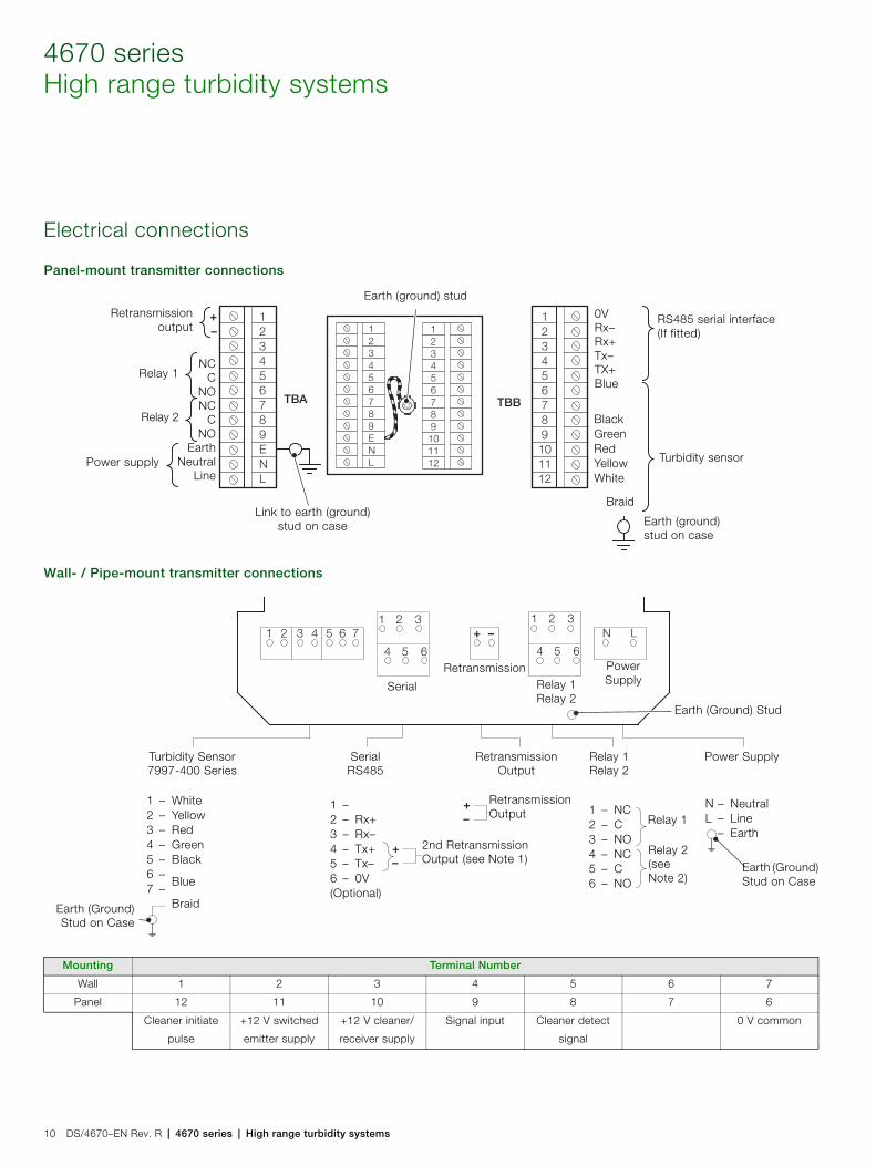
4670 seriesHigh range turbidity systems
10 DS/4670–EN Rev. R | 4670 series | High range turbidity systems
Electrical connections
Panel-mount transmitter connections
Wall- / Pipe-mount transmitter connections
Mounting Terminal Number
Wall 1 2 3 4 5 6 7
Panel 12 11 10 9 8 7 6
Cleaner initiate
pulse
+12 V switched
emitter supply
+12 V cleaner/
receiver supply
Signal input Cleaner detect
signal
0 V common
Relay 2
Earth (ground) stud
Earth (ground) stud on case
Relay 1
Retransmissionoutput
NCC
NONC
CNO
EarthNeutral
LinePower supply
RS485 serial interface (If fitted)
Turbidity sensor
Link to earth (ground) stud on case
0VRx–Rx+Tx–TX+Blue
BlackGreenRedYellowWhite
Braid
Turbidity Sensor7997-400 Series
SerialRS485
RetransmissionOutput
Relay 1Relay 2
Power Supply
Earth (Ground) Stud
Earth (Ground)Stud on Case
Earth (Ground) Stud on Case
1 – White2 – Yellow3 – Red4 – Green5 – Black6 –
Blue7 –
Braid
Serial
RetransmissionRelay 1Relay 2
PowerSupply
1 –2 – Rx+3 – Rx–4 – Tx+5 – Tx–6 – 0V(Optional)
RetransmissionOutput
2nd RetransmissionOutput (see Note 1)
Relay 1
Relay 2(see Note 2)
N – NeutralL – Line
– Earth
1 – NC2 – C3 – NO4 – NC5 – C6 – NO
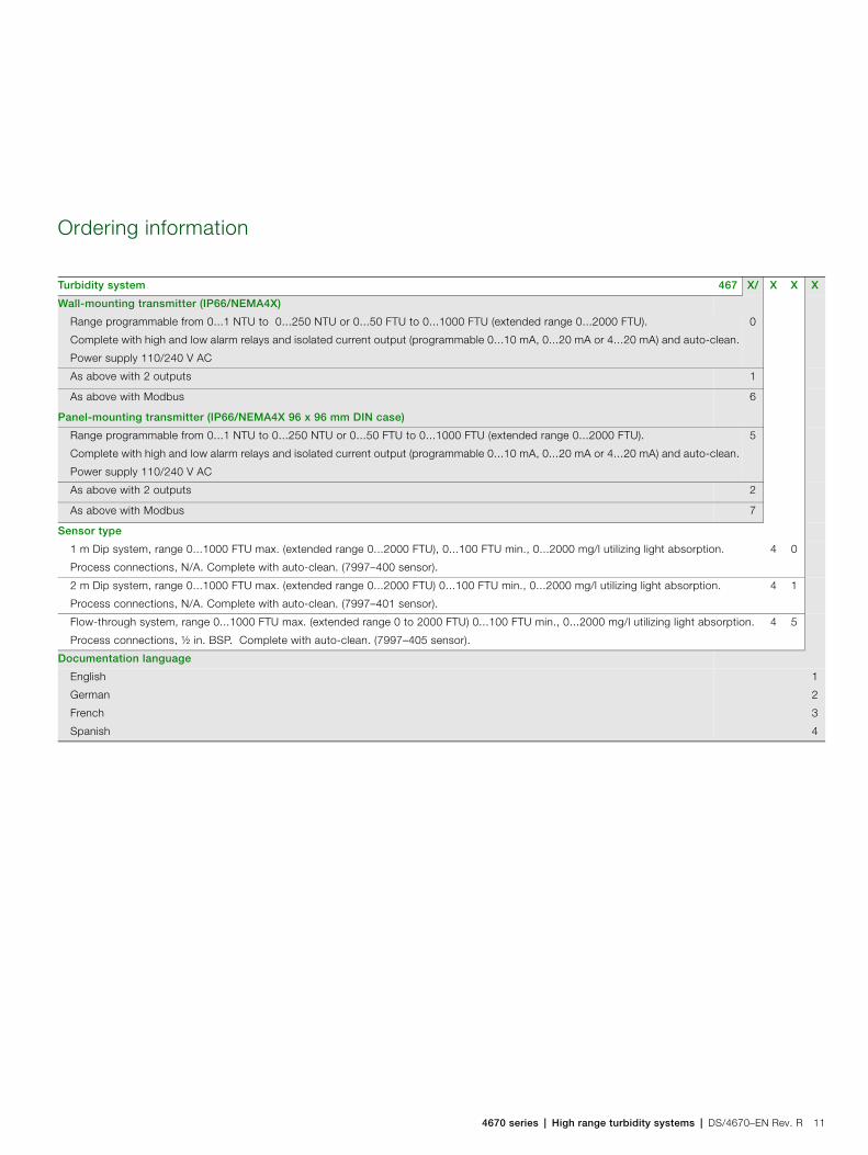
4670 series | High range turbidity systems | DS/4670–EN Rev. R 11
Ordering information
Turbidity system 467 X/ X X X
Wall-mounting transmitter (IP66/NEMA4X)
Range programmable from 0...1 NTU to 0...250 NTU or 0...50 FTU to 0...1000 FTU (extended range 0...2000 FTU).
Complete with high and low alarm relays and isolated current output (programmable 0...10 mA, 0...20 mA or 4...20 mA) and auto-clean.
Power supply 110/240 V AC
0
As above with 2 outputs 1
As above with Modbus 6
Panel-mounting transmitter (IP66/NEMA4X 96 x 96 mm DIN case)
Range programmable from 0...1 NTU to 0...250 NTU or 0...50 FTU to 0...1000 FTU (extended range 0...2000 FTU).
Complete with high and low alarm relays and isolated current output (programmable 0...10 mA, 0...20 mA or 4...20 mA) and auto-clean.
Power supply 110/240 V AC
5
As above with 2 outputs 2
As above with Modbus 7
Sensor type
1 m Dip system, range 0...1000 FTU max. (extended range 0...2000 FTU), 0...100 FTU min., 0...2000 mg/l utilizing light absorption.
Process connections, N/A. Complete with auto-clean. (7997–400 sensor).
4 0
2 m Dip system, range 0...1000 FTU max. (extended range 0...2000 FTU) 0...100 FTU min., 0...2000 mg/l utilizing light absorption.
Process connections, N/A. Complete with auto-clean. (7997–401 sensor).
4 1
Flow-through system, range 0...1000 FTU max. (extended range 0 to 2000 FTU) 0...100 FTU min., 0...2000 mg/l utilizing light absorption.
Process connections, ½ in. BSP. Complete with auto-clean. (7997–405 sensor).
4 5
Documentation language
English
German
French
Spanish
1
2
3
4

Contact us
DS
/467
0–E
N R
ev. R
06.2
012ABB Limited
Process AutomationOldends LaneStonehouseGloucestershire GL10 3TAUKTel: +44 1453 826 661Fax: +44 1453 829 671
ABB Inc.Process Automation125 E. County Line RoadWarminsterPA 18974USATel: +1 215 674 6000Fax: +1 215 674 7183
www.abb.com
NoteWe reserve the right to make technical changes or modify the contents of this document without prior notice. With regard to purchase orders, the agreed particulars shall prevail. ABB does not accept any responsibility whatsoever for potential errors or possible lack of information in this document.
We reserve all rights in this document and in the subject matter and illustrations contained therein. Any reproduction, disclosure to third parties or utilization of its contents in whole or in parts – is forbidden without prior written consent of ABB.
Copyright© 2012 ABBAll rights reserved
3KXA867001R1001
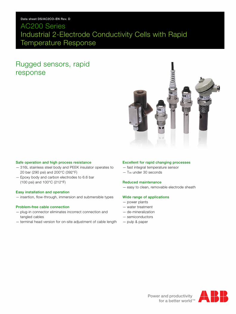
Data sheet DS/AC2CO–EN Rev. D
AC200 SeriesIndustrial 2-Electrode Conductivity Cells with Rapid Temperature Response
Rugged sensors, rapid response
Safe operation and high process resistance— 316L stainless steel body and PEEK insulator operates to
20 bar (290 psi) and 200°C (392°F)— Epoxy body and carbon electrodes to 6.6 bar
(100 psi) and 100°C (212°F)
Easy installation and operation — insertion, flow-through, immersion and submersible types
Problem-free cable connection— plug-in connector eliminates incorrect connection and
tangled cables— terminal head version for on-site adjustment of cable length
Excellent for rapid changing processes— fast integral temperature sensor— T90 under 30 seconds
Reduced maintenance— easy to clean, removable electrode sheath
Wide range of applications— power plants— water treatment— de-mineralization— semiconductors— pulp & paper
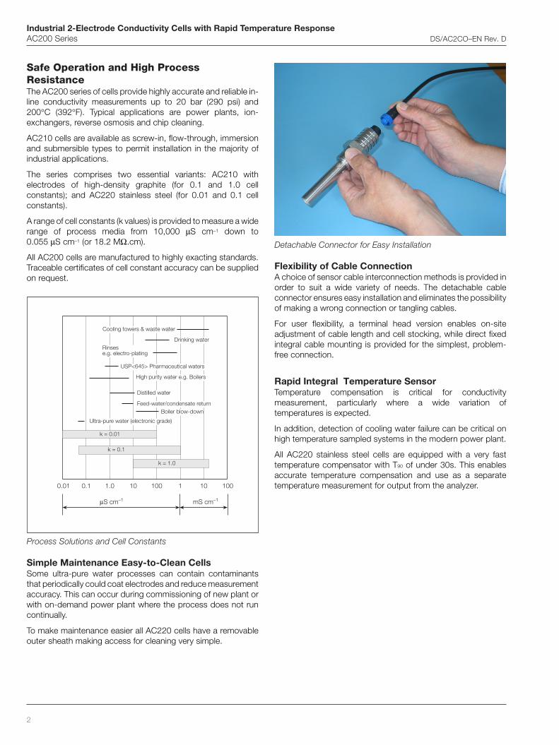
Industrial 2-Electrode Conductivity Cells with Rapid Temperature ResponseAC200 Series DS/AC2CO–EN Rev. D
2
Process Solutions and Cell Constants
Simple Maintenance Easy-to-Clean CellsSome ultra-pure water processes can contain contaminantsthat periodically could coat electrodes and reduce measurementaccuracy. This can occur during commissioning of new plant orwith on-demand power plant where the process does not runcontinually.
To make maintenance easier all AC220 cells have a removableouter sheath making access for cleaning very simple.
Cooling towers & waste water
Drinking waterRinsese.g. electro-plating
High purity water e.g. Boilers
Distilled water
Ultra-pure water (electronic grade)
k = 0.01
k = 0.1
k = 1.0
0.01 0.1 1.0 10 100 1 10 100
μS cm–1 mS cm–1
USP<645> Pharmaceutical waters
Boiler blow-downFeed-water/condensate return
Detachable Connector for Easy Installation
Flexibility of Cable ConnectionA choice of sensor cable interconnection methods is provided inorder to suit a wide variety of needs. The detachable cableconnector ensures easy installation and eliminates the possibilityof making a wrong connection or tangling cables.
For user flexibility, a terminal head version enables on-siteadjustment of cable length and cell stocking, while direct fixedintegral cable mounting is provided for the simplest, problem-free connection.
Rapid Integral Temperature SensorTemperature compensation is critical for conductivitymeasurement, particularly where a wide variation oftemperatures is expected.
In addition, detection of cooling water failure can be critical onhigh temperature sampled systems in the modern power plant.
All AC220 stainless steel cells are equipped with a very fasttemperature compensator with T90 of under 30s. This enablesaccurate temperature compensation and use as a separatetemperature measurement for output from the analyzer.
Safe Operation and High ProcessResistanceThe AC200 series of cells provide highly accurate and reliable in-line conductivity measurements up to 20 bar (290 psi) and200°C (392°F). Typical applications are power plants, ion-exchangers, reverse osmosis and chip cleaning.
AC210 cells are available as screw-in, flow-through, immersionand submersible types to permit installation in the majority ofindustrial applications.
The series comprises two essential variants: AC210 withelectrodes of high-density graphite (for 0.1 and 1.0 cellconstants); and AC220 stainless steel (for 0.01 and 0.1 cellconstants).
A range of cell constants (k values) is provided to measure a widerange of process media from 10,000 μS cm–1 down to0.055 μS cm–1 (or 18.2 MΩ.cm).
All AC200 cells are manufactured to highly exacting standards.Traceable certificates of cell constant accuracy can be suppliedon request.
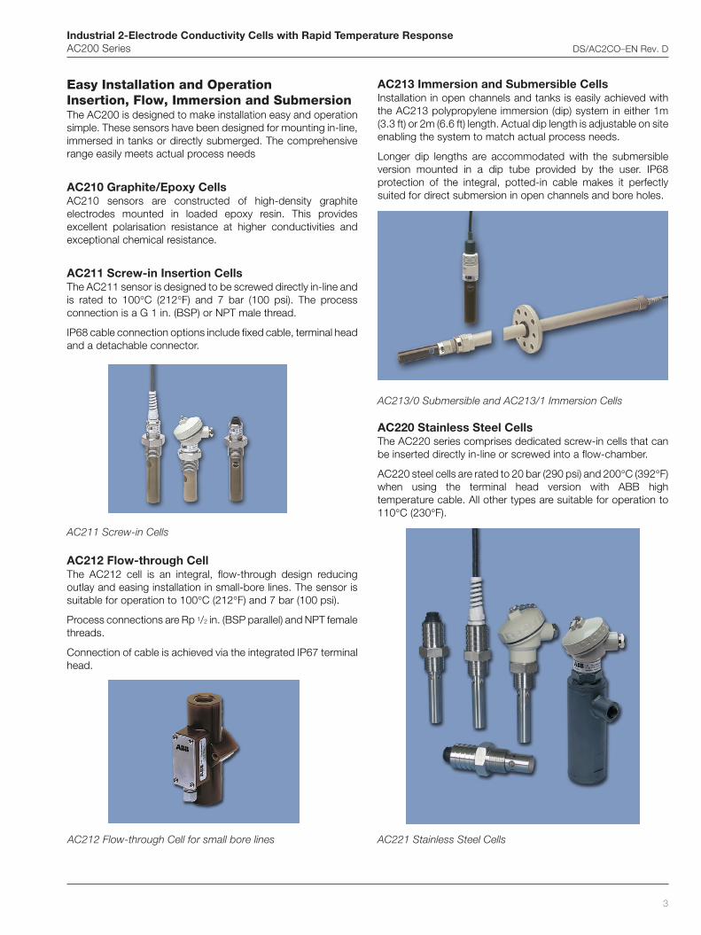
Industrial 2-Electrode Conductivity Cells with Rapid Temperature ResponseAC200 Series DS/AC2CO–EN Rev. D
3
AC213 Immersion and Submersible CellsInstallation in open channels and tanks is easily achieved withthe AC213 polypropylene immersion (dip) system in either 1m(3.3 ft) or 2m (6.6 ft) length. Actual dip length is adjustable on siteenabling the system to match actual process needs.
Longer dip lengths are accommodated with the submersibleversion mounted in a dip tube provided by the user. IP68protection of the integral, potted-in cable makes it perfectlysuited for direct submersion in open channels and bore holes.
AC213/0 Submersible and AC213/1 Immersion Cells
AC220 Stainless Steel CellsThe AC220 series comprises dedicated screw-in cells that canbe inserted directly in-line or screwed into a flow-chamber.
AC220 steel cells are rated to 20 bar (290 psi) and 200°C (392°F)when using the terminal head version with ABB hightemperature cable. All other types are suitable for operation to110°C (230°F).
Easy Installation and OperationInsertion, Flow, Immersion and SubmersionThe AC200 is designed to make installation easy and operationsimple. These sensors have been designed for mounting in-line,immersed in tanks or directly submerged. The comprehensiverange easily meets actual process needs
AC210 Graphite/Epoxy CellsAC210 sensors are constructed of high-density graphiteelectrodes mounted in loaded epoxy resin. This providesexcellent polarisation resistance at higher conductivities andexceptional chemical resistance.
AC211 Screw-in Insertion CellsThe AC211 sensor is designed to be screwed directly in-line andis rated to 100°C (212°F) and 7 bar (100 psi). The processconnection is a G 1 in. (BSP) or NPT male thread.
IP68 cable connection options include fixed cable, terminal headand a detachable connector.
AC212 Flow-through Cell for small bore lines
AC212 Flow-through CellThe AC212 cell is an integral, flow-through design reducingoutlay and easing installation in small-bore lines. The sensor issuitable for operation to 100°C (212°F) and 7 bar (100 psi).
Process connections are Rp 1/2 in. (BSP parallel) and NPT femalethreads.
Connection of cable is achieved via the integrated IP67 terminalhead.
AC211 Screw-in Cells
AC221 Stainless Steel Cells
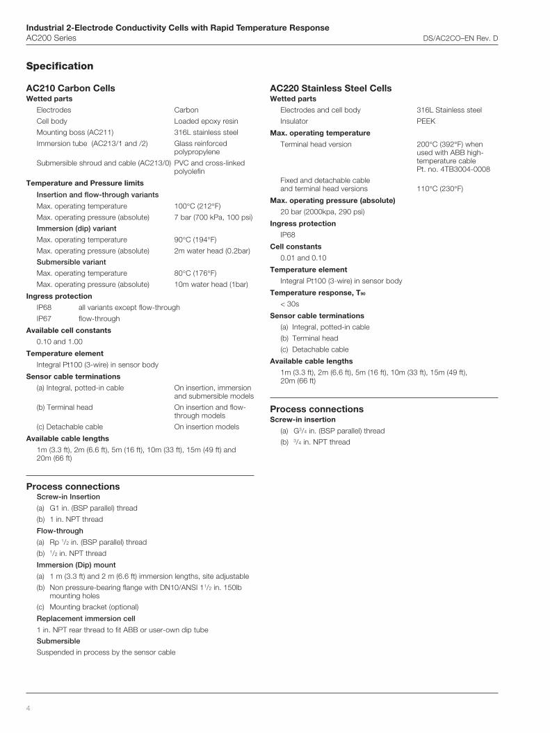
Industrial 2-Electrode Conductivity Cells with Rapid Temperature ResponseAC200 Series DS/AC2CO–EN Rev. D
4
Specification
AC210 Carbon CellsWetted parts
Electrodes Carbon
Cell body Loaded epoxy resin
Mounting boss (AC211) 316L stainless steel
Immersion tube (AC213/1 and /2) Glass reinforcedpolypropylene
Submersible shroud and cable (AC213/0) PVC and cross-linkedpolyolefin
Temperature and Pressure limits
Insertion and flow-through variants
Max. operating temperature 100°C (212°F)
Max. operating pressure (absolute) 7 bar (700 kPa, 100 psi)
Immersion (dip) variant
Max. operating temperature 90°C (194°F)
Max. operating pressure (absolute) 2m water head (0.2bar)
Submersible variant
Max. operating temperature 80°C (176°F)
Max. operating pressure (absolute) 10m water head (1bar)
Ingress protection
IP68 all variants except flow-through
IP67 flow-through
Available cell constants
0.10 and 1.00
Temperature element
Integral Pt100 (3-wire) in sensor body
Sensor cable terminations
(a) Integral, potted-in cable On insertion, immersionand submersible models
(b) Terminal head On insertion and flow-through models
(c) Detachable cable On insertion models
Available cable lengths
1m (3.3 ft), 2m (6.6 ft), 5m (16 ft), 10m (33 ft), 15m (49 ft) and20m (66 ft)
Process connectionsScrew-in Insertion
(a) G1 in. (BSP parallel) thread
(b) 1 in. NPT thread
Flow-through
(a) Rp 1/2 in. (BSP parallel) thread
(b) 1/2 in. NPT thread
Immersion (Dip) mount
(a) 1 m (3.3 ft) and 2 m (6.6 ft) immersion lengths, site adjustable
(b) Non pressure-bearing flange with DN10/ANSI 11/2 in. 150lbmounting holes
(c) Mounting bracket (optional)
Replacement immersion cell
1 in. NPT rear thread to fit ABB or user-own dip tube
Submersible
Suspended in process by the sensor cable
AC220 Stainless Steel CellsWetted parts
Electrodes and cell body 316L Stainless steel
Insulator PEEK
Max. operating temperature
Terminal head version 200°C (392°F) whenused with ABB high-temperature cablePt. no. 4TB3004-0008
Fixed and detachable cableand terminal head versions 110°C (230°F)
Max. operating pressure (absolute)
20 bar (2000kpa, 290 psi)
Ingress protection
IP68
Cell constants
0.01 and 0.10
Temperature element
Integral Pt100 (3-wire) in sensor body
Temperature response, T90
< 30s
Sensor cable terminations
(a) Integral, potted-in cable
(b) Terminal head
(c) Detachable cable
Available cable lengths
1m (3.3 ft), 2m (6.6 ft), 5m (16 ft), 10m (33 ft), 15m (49 ft),20m (66 ft)
Process connectionsScrew-in insertion
(a) G3/4 in. (BSP parallel) thread
(b) 3/4 in. NPT thread
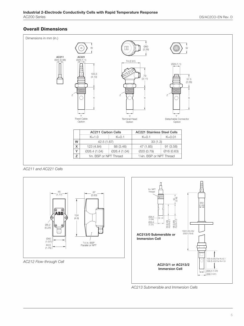
Industrial 2-Electrode Conductivity Cells with Rapid Temperature ResponseAC200 Series DS/AC2CO–EN Rev. D
5
Overall Dimensions
67(2.63)
124(4.9)
1/2 in. BSPParallel or NPT
45(1.77)
Ø6.2(0.24)
44.5(1.75)
Ø40(1.57)
Ø32(1.26)
Ø26.4 (1.04)
Ø46 (1.81)
103 (4.05) For K=0,1138 (5.43) For K=1,0
1022 (40.24)/2022 (79.6)
Ø26.4(1.04)Ø33.4(1.31)
55 (2.1
6)98
(3.8
6)Fo
r K=1
.0
63 (2
.48)
For K
=0.1
1in. NPTThread
Ø28 (1.1)
Y
W
57.5(2.26)
X
Detachable ConnectorOption
Z
74 (2.91)
Y
X
79(3.11)
Ø60(2.26)
Z
Terminal HeadOption
W
Fixed CableOption
105.5(4.13)
X
Y
AC221Ø28 (1.1)
Z
AC211Ø25 (0.98)
slleCnobraC112CA slleCleetSsselniatS122CA0.1=K 1.0=K 1.0=K 10.0=K
W )76.1(5.24 )3.1(33X )48.4(321 )64.3(88 )58.1(74 )85.3(19Y )40.1(4.62Ø )40.1(4.62Ø )97.0(02Ø )36.0(61ØZ daerhTTPNroPSB.ni1 3/4 daerhTTPNroPSB.ni
AC211 and AC221 Cells
AC213/0 Submersible orImmersion Cell
AC212 Flow-through Cell
Dimensions in mm (in.)
AC213/1 or AC213/2 Immersion Cell
AC213 Submersible and Immersion Cells
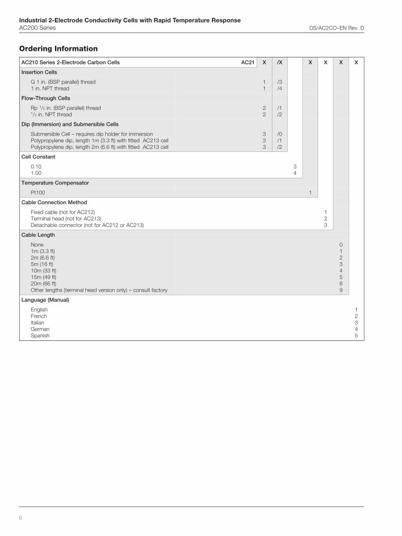
Industrial 2-Electrode Conductivity Cells with Rapid Temperature ResponseAC200 Series DS/AC2CO–EN Rev. D
6
slleCnobraCedortcelE-2seireS012CA 12CA X X/ X X X X
slleCnoitresnI
daerht)lellarapPSB(.ni1GdaerhtTPN.ni1
11
3/4/
slleChguorhT-wolF
pR 1/2 daerht)lellarapPSB(.ni1/2 daerhtTPN.ni
22
1/2/
slleCelbisrembuSdna)noisremmI(piD
noisremmirofredlohpidseriuqer–lleCelbisrembuSllec312CAdettifhtiw)tf3.3(m1htgnel,pidenelyporpyloPllec312CAdettifhtiw)tf6.6(m2htgnel,pidenelyporpyloP
333
0/1/2/
tnatsnoClleC
01.000.1
34
rotasnepmoCerutarepmeT
001tP 1
dohteMnoitcennoCelbaC
)212CArofton(elbacdexiF)312CArofton(daehlanimreT
)312CAro212CArofton(rotcennocelbahcateD
123
htgneLelbaC
enoN)tf3.3(m1)tf6.6(m2
)tf61(m5)tf33(m01)tf94(m51)tf66(m02
yrotcaftlusnoc–)ylnonoisrevdaehlanimret(shtgnelrehtO
01234569
)launaM(egaugnaL
hsilgnEhcnerF
nailatInamreGhsinapS
12345
Ordering Information
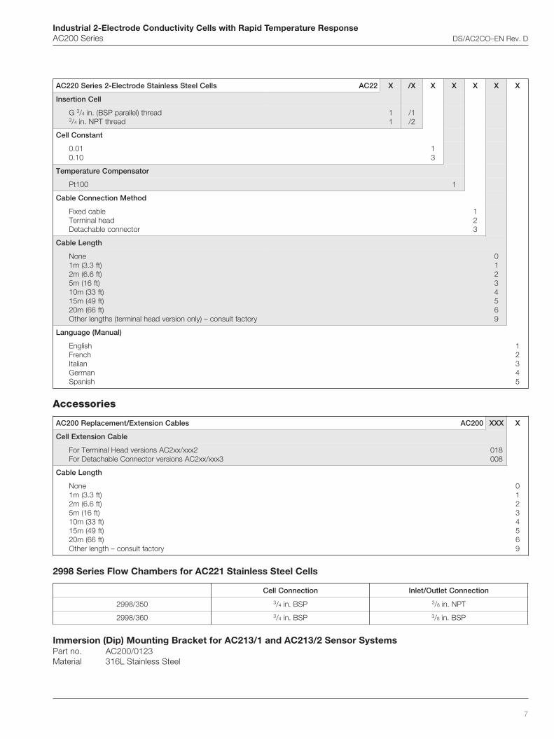
Industrial 2-Electrode Conductivity Cells with Rapid Temperature ResponseAC200 Series DS/AC2CO–EN Rev. D
7
Accessories
2998 Series Flow Chambers for AC221 Stainless Steel Cells
Immersion (Dip) Mounting Bracket for AC213/1 and AC213/2 Sensor SystemsPart no. AC200/0123Material 316L Stainless Steel
slleCleetSsselniatSedortcelE-2seireS022CA 22CA X X/ X X X X X
lleCnoitresnI
G 3/4 daerht)lellarapPSB(.ni3/4 daerhtTPN.ni
11
1/2/
tnatsnoClleC
10.001.0
13
rotasnepmoCerutarepmeT
001tP 1
dohteMnoitcennoCelbaC
elbacdexiFdaehlanimreT
rotcennocelbahcateD
123
htgneLelbaC
enoN)tf3.3(m1)tf6.6(m2
)tf61(m5)tf33(m01)tf94(m51)tf66(m02
yrotcaftlusnoc–)ylnonoisrevdaehlanimret(shtgnelrehtO
01234569
)launaM(egaugnaL
hsilgnEhcnerF
nailatInamreGhsinapS
12345
selbaCnoisnetxE/tnemecalpeR002CA 002CA XXX X
elbaCnoisnetxElleC
2xxx/xx2CAsnoisrevdaeHlanimreTroF3xxx/xx2CAsnoisrevrotcennoCelbahcateDroF
810800
htgneLelbaC
enoN)tf3.3(m1)tf6.6(m2
)tf61(m5)tf33(m01)tf94(m51)tf66(m02
yrotcaftlusnoc–htgnelrehtO
01234569
noitcennoClleC noitcennoCteltuO/telnI
053/8992 3/4 PSB.ni 3/8 TPN.ni
063/8992 3/4 PSB.ni 3/8 PSB.ni

Contact us
DS
/AC
2CO
–EN
Rev
. D12
.201
0ABB LimitedProcess AutomationOldends LaneStonehouseGloucestershire GL10 3TAUKTel: +44 1453 826 661Fax: +44 1453 829 671
ABB Inc.Process Automation125 E. County Line RoadWarminsterPA 18974USATel: +1 215 674 6000Fax: +1 215 674 7183
www.abb.com
NoteWe reserve the right to make technical changes or modify the contents of this document without prior notice. With regard to purchase orders, the agreed particulars shall prevail. ABB does not accept any responsibility whatsoever for potential errors or possible lack of information in this document.
We reserve all rights in this document and in the subject matter and illustrations contained therein. Any reproduction, disclosure to third parties or utilization of its contents in whole or in parts – is forbidden without prior written consent of ABB.
Copyright© 2010 ABBAll rights reserved
3KXA111201R1001
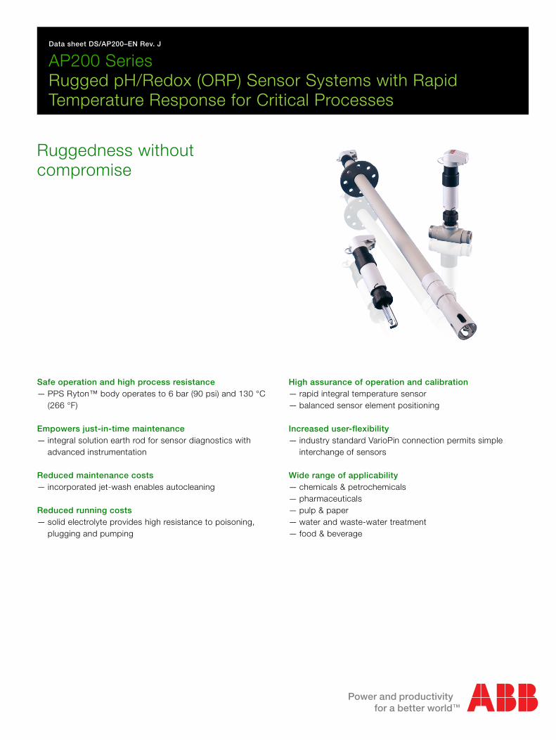
Data sheet DS/AP200–EN Rev. J
AP200 SeriesRugged pH/Redox (ORP) Sensor Systems with Rapid Temperature Response for Critical Processes
Ruggedness without compromise
Safe operation and high process resistance— PPS Ryton™ body operates to 6 bar (90 psi) and 130 °C
(266 °F)
Empowers just-in-time maintenance— integral solution earth rod for sensor diagnostics with
advanced instrumentation
Reduced maintenance costs— incorporated jet-wash enables autocleaning
Reduced running costs— solid electrolyte provides high resistance to poisoning,
plugging and pumping
High assurance of operation and calibration— rapid integral temperature sensor— balanced sensor element positioning
Increased user-flexibility— industry standard VarioPin connection permits simple
interchange of sensors
Wide range of applicability— chemicals & petrochemicals— pharmaceuticals— pulp & paper— water and waste-water treatment— food & beverage
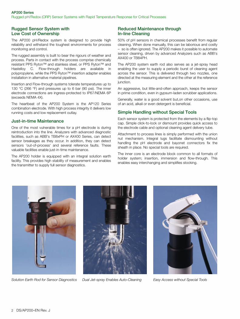
AP200 SeriesRugged pH/Redox (ORP) Sensor Systems with Rapid Temperature Response for Critical Processes
2 DS/AP200–EN Rev. J
Rugged Sensor System with Low Cost of OwnershipThe AP200 pH/Redox system is designed to provide highreliability and withstand the toughest environments for processmonitoring and control.
The rugged assembly is built to bear the rigours of weather andprocess. Parts in contact with the process comprise chemicallyresistant PPS Ryton™ and stainless steel, or PPS Ryton™ andHastelloy C. Flow-through holders are available inpolypropylene, while the PPS Ryton™ insertion adapter enablesinstallation in alternative material pipelines.
Insertion and Flow-through systems tolerate temperatures up to130 °C (266 °F) and pressures up to 6 bar (90 psi). The innerelectrode connections are ingress-protected to IP67/NEMA 6P(exceeds NEMA 4X).
The heartbeat of the AP200 System is the AP120 Seriescombination electrode. With high process integrity it delivers lowrunning costs and low replacement outlay.
Just-in-time MaintenanceOne of the most vulnerable times for a pH electrode is duringreintroduction into the line. Analyzers with advanced diagnosticfacilities, such as ABB's TB8xPH or AX400 Series, can detectsensor breakages as they occur. In addition, they can detectsensors 'out-of-process' and several reference faults. Thesevaluable facilities enable just-in-time maintenance.
The AP200 holder is equipped with an integral solution earthfacility. This provides high stability of measurement and enablesthe transmitter to supply full sensor diagnostics.
Reduced Maintenance through In-line Cleaning50% of pH sensors in chemical processes benefit from regularcleaning. When done manually, this can be laborious and costly– so is often ignored. The AP200 makes it possible to automatesensor cleaning, driven by advanced Analyzers such as ABB'sAX400 or TB84PH.
The AP200 system earth rod also serves as a jet-spray headenabling the user to supply a periodic burst of cleaning agentacross the sensor. This is delivered through two nozzles, onedirected at the measuring element and the other at the referencejunction.
An aggressive, but little-and-often approach, keeps the sensorin prime condition, even in gypsum-laden scrubber applications.
Generally, water is a good solvent but,on other occasions, useof an acid, alkali or even detergent is beneficial.
Simple Handling without Special ToolsEach sensor system is protected from the elements by a flip-topcap. Simple click-to-lock or dismount provides quick access tothe electrode cable and optional cleaning agent delivery tube.
Attachment to process lines is simply performed with the unionnut mechanism. Integral lugs facilitate dismounting withouthandling the pH electrode and bayonet connectors fix thesheath in place. No special tools are required.
The inner core is an electrode block common to all formats ofholder system; insertion, immersion and flow-through. Thisenables easy interchanging and simplifies stocking.
Solution Earth Rod for Sensor Diagnostics Dual Jet-spray Enables Auto-Cleaning Easy Access without Special Tools
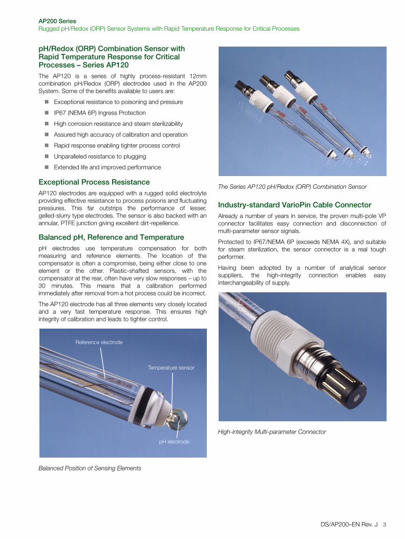
AP200 SeriesRugged pH/Redox (ORP) Sensor Systems with Rapid Temperature Response for Critical Processes
DS/AP200–EN Rev. J 3
pH/Redox (ORP) Combination Sensor with Rapid Temperature Response for Critical Processes – Series AP120 The AP120 is a series of highly process-resistant 12mmcombination pH/Redox (ORP) electrodes used in the AP200System. Some of the benefits available to users are:
Exceptional resistance to poisoning and pressure
IP67 (NEMA 6P) Ingress Protection
High corrosion resistance and steam sterilizability
Assured high accuracy of calibration and operation
Rapid response enabling tighter process control
Unparalleled resistance to plugging
Extended life and improved performance
Exceptional Process ResistanceAP120 electrodes are equipped with a rugged solid electrolyteproviding effective resistance to process poisons and fluctuatingpressures. This far outstrips the performance of lesser,gelled-slurry type electrodes. The sensor is also backed with anannular, PTFE junction giving excellent dirt-repellence.
Balanced pH, Reference and TemperaturepH electrodes use temperature compensation for bothmeasuring and reference elements. The location of thecompensator is often a compromise, being either close to oneelement or the other. Plastic-shafted sensors, with thecompensator at the rear, often have very slow responses – up to30 minutes. This means that a calibration performedimmediately after removal from a hot process could be incorrect.
The AP120 electrode has all three elements very closely locatedand a very fast temperature response. This ensures highintegrity of calibration and leads to tighter control.
Industry-standard VarioPin Cable ConnectorAlready a number of years in service, the proven multi-pole VPconnector facilitates easy connection and disconnection ofmulti-parameter sensor signals.
Protected to IP67/NEMA 6P (exceeds NEMA 4X), and suitablefor steam sterilization, the sensor connector is a real toughperformer.
Having been adopted by a number of analytical sensorsuppliers, the high-integrity connection enables easyinterchangeability of supply.
Balanced Position of Sensing Elements
Reference electrode
Temperature sensor
pH electrode
The Series AP120 pH/Redox (ORP) Combination Sensor
High-integrity Multi-parameter Connector
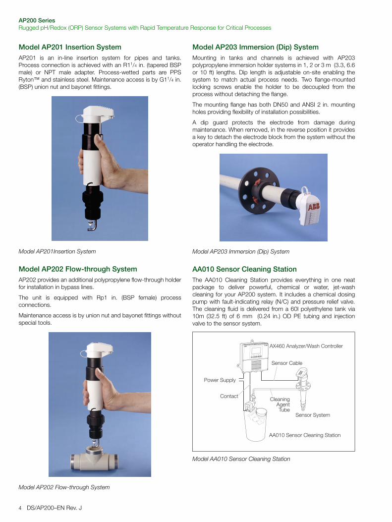
AP200 SeriesRugged pH/Redox (ORP) Sensor Systems with Rapid Temperature Response for Critical Processes
4 DS/AP200–EN Rev. J
Model AP201 Insertion SystemAP201 is an in-line insertion system for pipes and tanks.Process connection is achieved with an R11/4 in. (tapered BSPmale) or NPT male adapter. Process-wetted parts are PPSRyton™ and stainless steel. Maintenance access is by G11/4 in.(BSP) union nut and bayonet fittings.
Model AP202 Flow-through SystemAP202 provides an additional polypropylene flow-through holderfor installation in bypass lines.
The unit is equipped with Rp1 in. (BSP female) processconnections.
Maintenance access is by union nut and bayonet fittings withoutspecial tools.
Model AP203 Immersion (Dip) SystemMounting in tanks and channels is achieved with AP203polypropylene immersion holder systems in 1, 2 or 3 m (3.3, 6.6or 10 ft) lengths. Dip length is adjustable on-site enabling thesystem to match actual process needs. Two flange-mountedlocking screws enable the holder to be decoupled from theprocess without detaching the flange.
The mounting flange has both DN50 and ANSI 2 in. mountingholes providing flexibility of installation possibilities.
A dip guard protects the electrode from damage duringmaintenance. When removed, in the reverse position it providesa key to detach the electrode block from the system without theoperator handling the electrode.
AA010 Sensor Cleaning StationThe AA010 Cleaning Station provides everything in one neatpackage to deliver powerful, chemical or water, jet-washcleaning for your AP200 system. It includes a chemical dosingpump with fault-indicating relay (N/C) and pressure relief valve.The cleaning fluid is delivered from a 60l polyethylene tank via10m (32.5 ft) of 6 mm (0.24 in.) OD PE tubing and injectionvalve to the sensor system.
Model AP201Insertion System
Model AP202 Flow-through System
Model AP203 Immersion (Dip) System
Model AA010 Sensor Cleaning Station
���������
���������������������������
�������� �������
�������
������������
�������������
����� �������� ��!�����������
AP200 SeriesRugged pH/Redox (ORP) Sensor Systems with Rapid Temperature Response for Critical Processes
DS/AP200–EN Rev. J 5
Specification
All SystemsMaterials
Jet-wash facility
CertificationThe systems comply with SEP (Safe Engineering Practice) levelPressure Equipment Directive 97123/EC
AP201 Insertion SystemMaximum Temperature
Maximum Pressure6 bar (90 psi) @ 25ºC (77ºF)
Process Connections
AP202 Flow-through SystemMaterials
Maximum Temperature
Maximum Pressure6 bar (90 psi) @ 25ºC (77ºF)
Process Connections
AP203 Immersion (Dip) SystemMaterials
Maximum Temperature90 °C (194 °F)
Maximum PressureNot applicable
Process Connections
AP120 Combination SensorMeasuring Ranges
AP121/0 General Process 0 to 14 pH 0 to +100 °C (32 to 212 °F)
AP121/1 High Temp/Alkali 0 to 14 pH 10 to 130 °C (50 to 266 °F)
AP121/2 Low Resistance 0 to 10 pH –5 to 50 °C (23 to 122 °F)
AP121/6 Pt Redox (ORP) ± 2000mV 0 to 130 °C (32 to 266 °F)
Reference Electrode System
General Data
Shaft and cap Polypropylene
Sensor body Ryton™ PPS
Ground rod/Spray tube 316 Stainless steel
Non-return function Integral one-way valve
Spray tube connection 6mm compression fitting
Recommended operating pressure
Min. 1 bar (15 psi) over process pressure
130 °C (266 °F) PPS and steel adapters
90 °C (194 °F) Polypropylene adapter
Union nutG 11/4 in. (BSP)
PPS process adapter R11/4 in. (tapered BSP male)
PP process adapters R11/4 in.
11/4 in. NPT
Stainless steel adapters R1 in. (tapered BSP male)
1 in. NPT
Stainless steel sockets Angled DN25
Straight DN25
Flow-cells Polypropylene
Stainless steel
90 °C (194 °F) Polypropylene flow cell
130 °C (266 °F) Stainless steel flow cell
Union nut G11/4 in. (BSP)
Flow-cell inlet & outlet Rp1 in. (BSP female)
or 1 in. NPT
Guard, shaft and cap Polypropylene
Sliding flange Composite DIN & ANSI
DN50 / ANSI 2 in.
Immersion lengths 1 m (3.3 ft)
2 m (6.6 ft)
3 m (10 ft)
Primary Electrolyte Solid, Ag-free Gel with KCl charge
Inner reference system Ag/AgCl
JunctionAnnular PTFE, sterilizable
Nominal zero point, E0 7 pH
Minimum Conductivity > 50 µS/cm
Temperature Sensor (pH only) Integral Pt100
Temperature response T90 <70s
Electrode Shaft Length 120 mm
Max. Pressure 6 bar (90 psi)
Ingress Protection IP67/NEMA 6P (exceeds NEMA4X)
Connection head Sterilizable VP (VarioPin) connector with PG13.5 thread
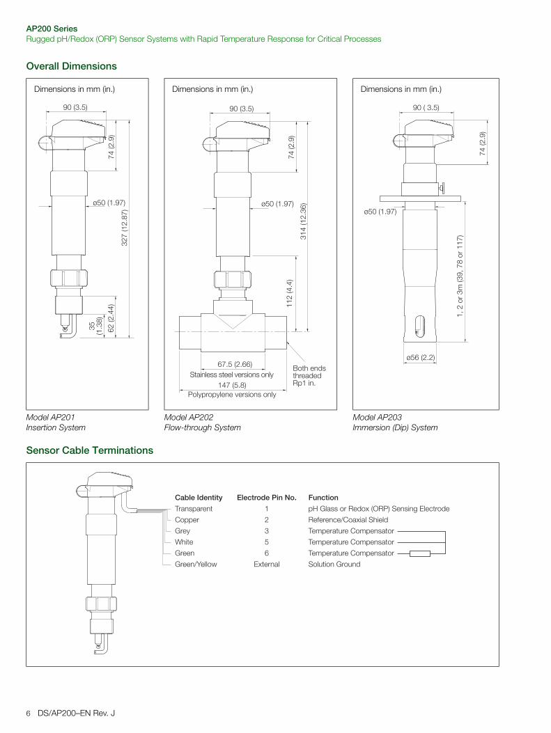
AP200 SeriesRugged pH/Redox (ORP) Sensor Systems with Rapid Temperature Response for Critical Processes
6 DS/AP200–EN Rev. J
Overall Dimensions
Sensor Cable Terminations
Dimensions in mm (in.) Dimensions in mm (in.) Dimensions in mm (in.)
"#$�%�#&'$(
�#�%#&��(
")%�&"'(
*��%"&)($��%#&*(
+)��%�&*$(
67.5 (2.66)
*��%�"&)(
$��%#&*(
+)��%�&*$(
�,�#����"��%"*,�$'������$(
+)��%#&#(
Model AP201 Insertion System
Model AP202 Flow-through System
Model AP203 Immersion (Dip) System
����������� ��������������� ������
���������� � -�.��������/�0�1�%2/�(���������3������0�
���� # /�4����������1�����!���0
.��� " ��������������������
!��� ) ��������������������
.���� � ��������������������
.�����5����� 31������ ��������.���0
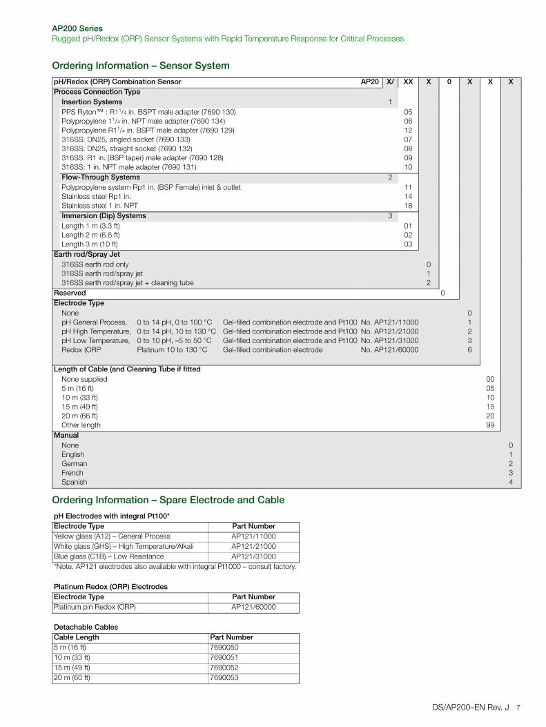
AP200 SeriesRugged pH/Redox (ORP) Sensor Systems with Rapid Temperature Response for Critical Processes
DS/AP200–EN Rev. J 7
Ordering Information – Sensor System
Ordering Information – Spare Electrode and Cable
pH/Redox (ORP) Combination Sensor AP20 X/ XX X 0 X X XProcess Connection Type
Insertion Systems 1PPS Ryton™ : R11/4 in. BSPT male adapter (7690 130)Polypropylene 11/4 in. NPT male adapter (7690 134)Polypropylene R11/4 in. BSPT male adapter (7690 129)316SS: DN25, angled socket (7690 133)316SS: DN25, straight socket (7690 132)316SS: R1 in. (BSP taper) male adapter (7690 128)316SS: 1 in. NPT male adapter (7690 131)
05061207080910
Flow-Through Systems 2Polypropylene system Rp1 in. (BSP Female) inlet & outletStainless steel Rp1 in.Stainless steel 1 in. NPT
111418
Immersion (Dip) Systems 3Length 1 m (3.3 ft)Length 2 m (6.6 ft)Length 3 m (10 ft)
010203
Earth rod/Spray Jet316SS earth rod only316SS earth rod/spray jet316SS earth rod/spray jet + cleaning tube
012
Reserved 0Electrode Type
NonepH General Process,pH High Temperature,pH Low Temperature,Redox (ORP
0 to 14 pH, 0 to 100 °C0 to 14 pH, 10 to 130 °C0 to 10 pH, –5 to 50 °CPlatinum 10 to 130 °C
Gel-filled combination electrode and Pt100Gel-filled combination electrode and Pt100Gel-filled combination electrode and Pt100Gel-filled combination electrode
No. AP121/11000No. AP121/21000No. AP121/31000No. AP121/60000
01236
Length of Cable (and Cleaning Tube if fittedNone supplied5 m (16 ft)10 m (33 ft)15 m (49 ft)20 m (66 ft)Other length
000510152099
ManualNoneEnglishGermanFrenchSpanish
01234
pH Electrodes with integral Pt100*Electrode Type Part NumberYellow glass (A12) – General Process AP121/11000White glass (GHS) – High Temperature/Alkali AP121/21000Blue glass (C1B) – Low Resistance AP121/31000*Note. AP121 electrodes also available with integral Pt1000 – consult factory.
Platinum Redox (ORP) ElectrodesElectrode Type Part NumberPlatinum pin Redox (ORP) AP121/60000
Detachable CablesCable Length Part Number5 m (16 ft) 769005010 m (33 ft) 769005115 m (49 ft) 769005220 m (60 ft) 7690053

Contact us
DS
/AP
200–
EN
Rev
. J07
.201
4ABB LimitedProcess AutomationOldends LaneStonehouseGloucestershire GL10 3TAUKTel: +44 1453 826 661Fax: +44 1453 829 671
ABB Inc.Process Automation125 E. County Line RoadWarminsterPA 18974USATel: +1 215 674 6000Fax: +1 215 674 7183
www.abb.com
NoteWe reserve the right to make technical changes or modify the contents of this document without prior notice. With regard to purchase orders, the agreed particulars shall prevail. ABB does not accept any responsibility whatsoever for potential errors or possible lack of information in this document.
We reserve all rights in this document and in the subject matter and illustrations contained therein. Any reproduction, disclosure to third parties or utilization of its contents in whole or in parts – is forbidden without prior written consent of ABB.
Copyright© 2014 ABB
All rights reserved
3KXA163201R1001
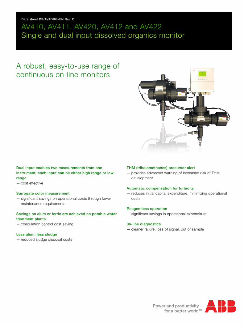
Data sheet DS/AV4ORG–EN Rev. D
AV410, AV411, AV420, AV412 and AV422Single and dual input dissolved organics monitor
A robust, easy-to-use range of continuous on-line monitors
Dual input enables two measurements from one instrument, each input can be either high range or low range— cost effective
Surrogate color measurement— significant savings on operational costs through lower
maintenance requirements
Savings on alum or ferric are achieved on potable water treatment plants— coagulation control cost saving
Less alum, less sludge— reduced sludge disposal costs
THM (trihalomethanes) precursor alert— provides advanced warning of increased risk of THM
development
Automatic compensation for turbidity— reduces initial capital expenditure, minimizing operational
costs
Reagentless operation— significant savings in operational expenditure
0n-line diagnostics— cleaner failure, loss of signal, out of sample
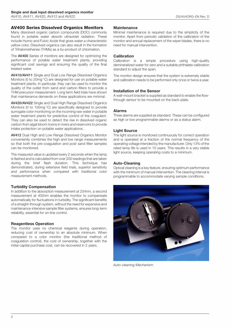
Single and dual input dissolved organics monitorAV410, AV411, AV420, AV412 and AV422 DS/AV4ORG–EN Rev. D
2
AV400 Series Dissolved Organics MonitorsMany dissolved organic carbon compounds (DOC) commonlyfound in potable water absorb ultraviolet radiation. Theseinclude Humic and Fulvic Acids that gives water a characteristicyellow color. Dissolved organics can also result in the formationof Trihalomethanes (THMs) as a by-product of chlorination.
The AV400 Series of monitors are designed for optimizing theperformance of potable water treatment plants, providingsignificant cost savings and ensuring the quality of the finaltreated water.
AV410/AV411 Single and Dual Low Range Dissolved OrganicsMonitors (0 to 20mg–1C) are designed for use on potable watertreatment plants. In particular, they can be used to monitor thequality of the outlet from sand and carbon filters to provide aTHM precursor measurement. Long term field trials have shownthat maintenance demands on these applications are minimal.
AV420/AV422 Single and Dual High Range Dissolved OrganicsMonitors (0 to 100mg–1C) are specifically designed to providesurrogate color monitoring on the incoming raw water in potablewater treatment plants for predictive control of the coagulant.They can also be used to detect the rise in dissolved organiccarbon from algal bloom toxins in rivers and reservoirs to provideintake protection on potable water applications .
AV412 Dual High and Low Range Dissolved Organics Monitorconveniently combines the high and low range measurementsso that both the pre-coagulation and post sand filter samplescan be monitored.
The measured value is updated every 2 seconds when the lampis flashed and is calculated from over 200 readings that are takenduring the brief flash duration. This technique hasdemonstrated, during extensive field trials, superior sensitivityand performance when compared with traditional colormeasurement methods.
Turbidity CompensationIn addition to the absorption measurement at 254nm, a secondmeasurement at 400nm enables the monitor to compensateautomatically for fluctuations in turbidity. The significant benefitsof a straight-through system, without the need for expensive andmaintenance-intensive sample filter systems, ensures long-termreliability, essential for on-line control.
Reagentless OperationThe monitor uses no chemical reagents during operation,reducing cost of ownership to an absolute minimum. Whencompared to a color monitor (the traditional method ofcoagulation control), the cost of ownership, together with theinitial capital purchase cost, can be recovered in 2 years.
MaintenanceMinimal maintenance is required due to the simplicity of themonitor. Apart from periodic validation of the calibration of themonitor and annual replacement of the wiper blades, there is noneed for manual intervention.
CalibrationCalibration is a simple procedure using high-qualitydemineralized water for zero and a suitable phthalate calibrationstandard to adjust the span.
The monitor design ensures that the system is extremely stableand calibration needs to be performed only once or twice a year.
Installation of the SensorA wall-mount bracket is supplied as standard to enable the flow-through sensor to be mounted on the back-plate.
AlarmsThree alarms are supplied as standard. These can be configuredas high or low programmable alarms or as a status alarm.
Light SourceThe light source is monitored continuously for correct operationand is operated at a fraction of the normal frequency of theoperating voltage intended by the manufacturer. Only 13% of therated lamp life is used in 10 years. This results in a very stablelight source, keeping operating costs to a minimum.
Auto-CleaningOptical cleaning is a key feature, ensuring optimum performancewith the minimum of manual intervention. The cleaning interval isprogrammable to accommodate varying sample conditions.
Auto-cleaning Mechanism
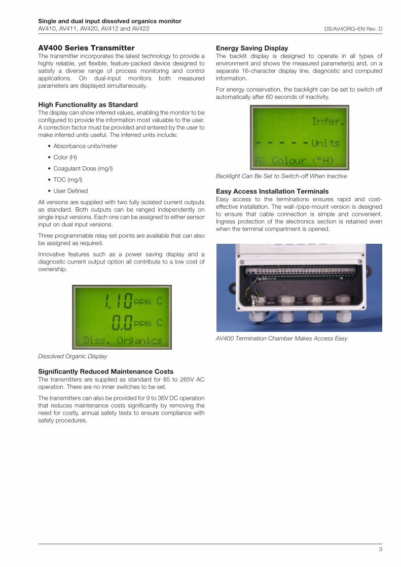
Single and dual input dissolved organics monitorAV410, AV411, AV420, AV412 and AV422 DS/AV4ORG–EN Rev. D
3
AV400 Series TransmitterThe transmitter incorporates the latest technology to provide ahighly reliable, yet flexible, feature-packed device designed tosatisfy a diverse range of process monitoring and controlapplications. On dual-input monitors both measuredparameters are displayed simultaneously.
High Functionality as StandardThe display can show inferred values, enabling the monitor to beconfigured to provide the information most valuable to the user.A correction factor must be provided and entered by the user tomake inferred units useful. The inferred units include:
• Absorbance units/meter
• Color (H)
• Coagulant Dose (mg/l)
• TOC (mg/l)
• User Defined
All versions are supplied with two fully isolated current outputsas standard. Both outputs can be ranged independently onsingle input versions. Each one can be assigned to either sensorinput on dual input versions.
Three programmable relay set points are available that can alsobe assigned as required.
Innovative features such as a power saving display and adiagnostic current output option all contribute to a low cost ofownership.
Energy Saving DisplayThe backlit display is designed to operate in all types ofenvironment and shows the measured parameter(s) and, on aseparate 16-character display line, diagnostic and computedinformation.
For energy conservation, the backlight can be set to switch offautomatically after 60 seconds of inactivity.
Dissolved Organic Display
Significantly Reduced Maintenance CostsThe transmitters are supplied as standard for 85 to 265V ACoperation. There are no inner switches to be set.
The transmitters can also be provided for 9 to 36V DC operationthat reduces maintenance costs significantly by removing theneed for costly, annual safety tests to ensure compliance withsafety procedures.
Backlight Can Be Set to Switch-off When Inactive
Easy Access Installation TerminalsEasy access to the terminations ensures rapid and cost-effective installation. The wall-/pipe-mount version is designedto ensure that cable connection is simple and convenient.Ingress protection of the electronics section is retained evenwhen the terminal compartment is opened.
AV400 Termination Chamber Makes Access Easy
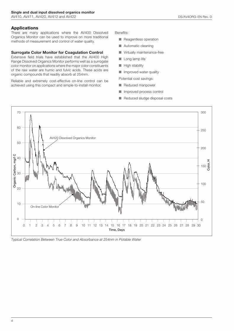
Single and dual input dissolved organics monitorAV410, AV411, AV420, AV412 and AV422 DS/AV4ORG–EN Rev. D
4
ApplicationsThere are many applications where the AV400 DissolvedOrganics Monitor can be used to improve on more traditionalmethods of measurement and control of water quality.
Surrogate Color Monitor for Coagulation ControlExtensive field trials have established that the AV400 HighRange Dissolved Organics Monitor performs well as a surrogatecolor monitor on applications where the major color constituentsof the raw water are humic and fulvic acids. These acids areorganic compounds that readily absorb at 254nm.
Reliable and extremely cost-effective on-line control can beachieved using this compact and simple-to-install monitor.
Benefits:
Reagentless operation
Automatic cleaning
Virtually maintenance-free
Long lamp life
High stability
Improved water quality
Potential cost savings:
Reduced manpower
Improved process control
Reduced sludge disposal costs
Typical Correlation Between True Color and Absorbance at 254nm in Potable Water
70
60
50
40
30
20
10
0
300
250
200
150
100
50
0
0 1 2 3 4 5 6 7 8 9 10 11 12 13 14 15 16 17 18 19 20 21 22 23 24 25 26 27 28 29 30
Org
anic
Car
bo
n, m
g/l
C
Time, Days
Co
lor,
H
AV420 Dissolved Organics Monitor
On-line Color Monitor
Single and dual input dissolved organics monitorAV410, AV411, AV420, AV412 and AV422 DS/AV4ORG–EN Rev. D
5
Algal Bloom ToxinsThe formation of toxins as a result of the decomposition of algalblooms, that die out during cold periods, frequently cause tasteand odor problems and a risk of THMs (Trihalomethanes) in thefinal treated water. It has been shown that monitoring the DOC(dissolved organic carbon compounds) in the raw water gives anearly warning of these events so the appropriate action can betaken. The often involves the addition of powdered activatedcarbon at the coagulant dosing point.
Trihalomethanes (THMs)The water reaching the disinfection stage of the potabletreatment process may contain organic compounds from any ofthree sources:
Humic and fulvic acid breakthrough from the coagulationand filtration stage of the plant
Organic compounds from the decomposition of dead algalblooms
Organic compounds from industrial effluent and sewagedischarges into the raw water source.
These pass through the coagulation stage but can be removedby an activated carbon stage.
These sources can give rise to a range of organic compoundsthat, if conditions are right, will react with the chlorine used fordisinfection to form THMs. The organic compounds are referredto as THM precursors. THMs are recognized carcinogens, theyare known to cause miscarriages, and are also linked to heart,lung, kidney, liver, and central nervous system damage.
Increasing concerns over THMs have resulted in the need foradvance warning of the unfavourable conditions that couldencourage the development of THMs in drinking water.
When used on final chlorinated water, the monitor providesadvance warning of any increase in dissolved organic carbon,thereby enabling rapid corrective action to reduce the risk.Under such clean water conditions the maintenance becomesvirtually zero.
Many of the low-range monitors are now used for thisincreasingly critical application, often in conjunction withturbidity measurement.
Single and dual input dissolved organics monitorAV410, AV411, AV420, AV412 and AV422 DS/AV4ORG–EN Rev. D
6
Specification
GeneralSensor range
(Based on potassium hydrogen phthalate calibration standards)
AV410/411 Low range 0 to 20mgl–1C
AV420/422 High range 0 to 100mgl–1C
Linearity
Low range ±2% of reading or 0.15mgl–1 Cwhichever is the greater
High range ±2% of reading or 0.5mgl–1 Cwhichever is the greater
Reproducibility
Low range ±0.15mgl–1 C
High range ±0.5mgl–1 C
Inferred units
Absorbance units/metre
Color (°H)
Coagulant dose (mgl–1)
TOC (mgl–1)
User Defined
Maximum current output scale expansion
Low range 0 to 2mgl–1 C
High range 0 to 20mgl–1 C
Response time
Normally three minutes for 90% step change depending ondamping factor
Lamp life
Rated by the manufacturer at 1.2 x 10⁹ flashes(10 years continuous operation at the rate of one flash at 2sintervals [typical] equates to 13.1% of the rated lamp life)
Internal wiper cleaning system
Programmable, operation frequency 15, 30, 45 and60 minutes 2, 4, 6, 12 and 24 hours
Maximum distance between transmitter and sensor
750mm (29.5 in.)
SampleFlow rate
0.5 to 5l min–1 (free of air bubbles).A higher flow rate is required at high turbidity levels
Temperature
0 to 40°C (32 to 104°F)
Pressure
The sensor should be operated at atmospheric pressure but canwithstand 3bar (43.4 psi) max.
DisplayType
Dual 41/2-digit, 7-segment backlit LCD
Information
16-character, single line dot matrix
Resolution
Low range 0.01mgl–1
High range 0.1mgl–1
Energy saving function
Backlit LCD configurable as ON or Auto Off after 60 seconds
Logbook
Electronic record of major events and calibration data
Real-time clock
Records time for logbook and auto cleaning
Diagnostics
Out of sample
Lamp disabled
Loss of signal
Electronic failure
Languages
English
French
German
Italian
Spanish
OutputsCurrent Outputs
Number of signals
2 fully isolated current outputs supplied as standard,configurable to one or both sensor outputs
Current outputs also programmable to any value between0 and 22mA to indicate system failure
Output current
0 to10mA, 0 to 20mA or 4 to 20mA
Maximum load resistance
750Ω at 20mA
Accuracy
±0.25% FSD ±5% of reading
Resolution
0.1% at 10mA, 0.05 at 20mA
Serial communication
PROFIBUS
Single and dual input dissolved organics monitorAV410, AV411, AV420, AV412 and AV422 DS/AV4ORG–EN Rev. D
7
…Specification
Relay outputsNumber of relays
Three supplied as standard,configurable to one or both sensor inputs or status
Set point adjustment
Fully programmable as normal or failsafe, high/low or status
Hysteresis
Programmable 0 to 5% in 0.1% increments
Delay
Programmable 0 to 100 minutes in 1 minute intervals
Relay contacts
Single-pole changeover
Rating 5A 115/230V AC, 5A DC
Insulation
2kV RMS contacts to earth/ground
Power supplyVoltage requirements
100 to 240 V AC, 50/60 Hz(90 V Min. to 264 V Max. AC)
Optional 12 to 30 V DC
Power consumption
20 W
Insulation
Mains to earth (line to ground) 2kV RMS
Mechanical DataTransmitter
IP65 (not evaluated under UL certification)
Dimensions 192mm (7.56 in.) high x 230mm (9.06 in.) wide x94mm (3.7 in.) deep
Weight 1kg (2.2 lb)
Sensor
Low Range Dimensions 327mm (12.87 in.) widex 410mm (16.14 in.) high x 162mm (6.38 in) deep
High Range Dimensions 405mm (15.94 in.) widex 373mm (14.68 in.) high x 136mm (5.35 in) deep
Weight 6kg (13.2 lb)
Cable entry types
Standard 5 or 7 x M20 cable glands
N. American 7 x knockouts suitable for 1/2 in. Hubble gland
Environmental DataOperating temperature limits
0 to 50°C (32 to 122°F)
Storage temperature limits
–25 to 75°C (–13 to 167°F)
Operating humidity limits
Up to 95%RH non-condensing
EMC emissions and immunity
Meets requirements of:
EN61326 (for an industrial environment)
EN50081-2
EN50082-2
Approvals, Certification and SafetySafety approval
UL
CE Mark
Covers EMC & LV Directives (including latest version EN 61010)
General safety
EN61010-1
Overvoltage Class II on inputs and outputs
Pollution Category 2

Single and dual input dissolved organics monitorAV410, AV411, AV420, AV412 and AV422 DS/AV4ORG–EN Rev. D
8
Transmitter
Dimensions in mm (in.)
Overall Dimensions
Pipe-mount Details
175(6.9)
150(5.9)
25 (1)
210 (8.27)192 (7.56)
96 (3.78)R10(0.4)
192(7.56)
Ø6.50
(0.26
)
23 (0.9)
25 (1)
67.5 (2.66) 67.5 (2.66)
45 (1.77) 45 (1.77)
22.5(0.88)
22.5(0.88)
94(3.7)
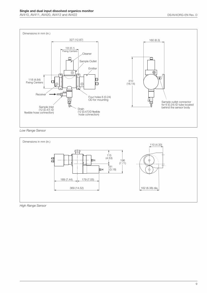
Single and dual input dissolved organics monitorAV410, AV411, AV420, AV412 and AV422 DS/AV4ORG–EN Rev. D
9
Dimensions in mm (in.)
High Range Sensor
Low Range Sensor
Dimensions in mm (in.)
369 (14.52)
189 (7.44) 179 (7.05)
81(3.18)
162 (6.38) dia.
110 (4.33)
115(4.53)
196(7.71)
410(16.14)
160 (6.3) 327 (12.87)
155 (6.1)Fixing Centers
118 (4.64)Fixing Centers
Sample outlet connectorfor 6 (0.24) ID tube locatedbehind the sensor body
Four holes 6 (0.24)OD for mounting
Sample Inlet(12 [0.47] ID
flexible hose connection)Drain(12 [0.47] ID flexible hose connection)
Sample Outlet
Cleaner
Receiver
Emitter
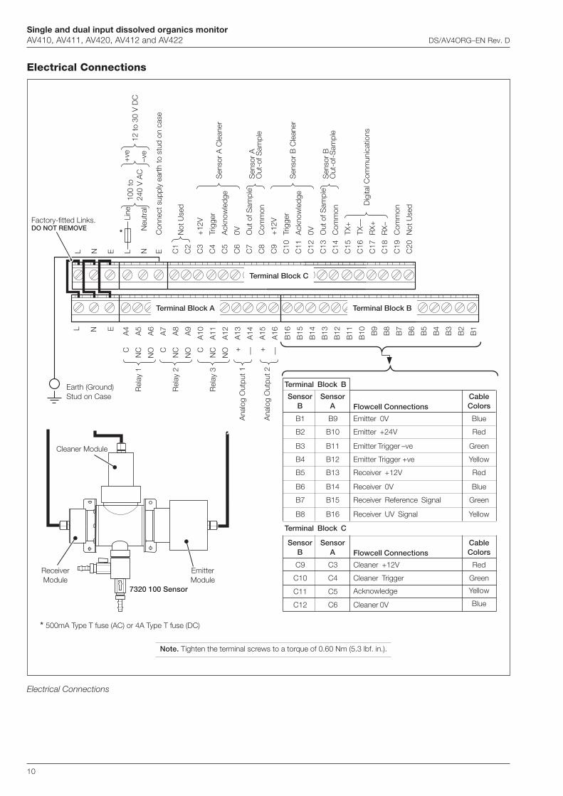
Single and dual input dissolved organics monitorAV410, AV411, AV420, AV412 and AV422 DS/AV4ORG–EN Rev. D
10
Electrical Connections
Electrical Connections
L N E
CA
4
Rel
ay 1
NC
A5
NO
A6
CA
7
Rel
ay 2
NC
A8
NO
A9
CA
10
Rel
ay 3
NC
A11
NO
A12
Ana
log
Out
put 1
+A
13
—A
14
Ana
log
Out
put 2
+A
15
—A
16
B16
B15
B14
B13
B12
B11
B10 B9
B8
B7
B6
B5
B4
B3
B2
B1
Terminal Block C
C1
Not
Use
dC
2
C3
+12
V
C4
Trig
ger
Sen
sor
A C
lean
erC
5A
ckno
wle
dge
C6
0V
C7
Out
of S
ampl
eS
enso
r A
C8
Com
mon
Out
-of S
ampl
e
C9
+12
V
C10
Trig
ger
Sen
sor
B C
lean
erC
11A
ckno
wle
dge
C12
0V
C13
Out
of S
ampl
eS
enso
r B
C14
Com
mon
Out
-of-
Sam
ple
C15
TX+
C16
TX—
Dig
ital C
omm
unic
atio
nsC
17R
X+
C18
RX–
C19
Com
mon
C20
Not
Use
d
L N E L
L
ine
N N
eutr
al
EC
onne
ct s
uppl
y ea
rth
to s
tud
on c
ase
ReceiverModule
EmitterModule
Cleaner Module
7320 100 Sensor
Factory-fitted Links.DO NOT REMOVE
100
to24
0 V
AC
+ve
–ve
12 to
30
V D
C
Terminal Block B
Terminal Block B
Flowcell ConnectionsSensor
BSensor
A
B1 B9 Emitter 0V
B2 B10 Red
B3 B11 Green
B4 B12 Yellow
B5 B13 Red
B6 B14 Blue
B7 B15 Green
B8 B16 Yellow
CableColors
Blue
Emitter +24V
Emitter Trigger –ve
Emitter Trigger +ve
Receiver +12V
Receiver 0V
Receiver Reference Signal
Receiver UV Signal
Terminal Block C
Flowcell ConnectionsSensor
BSensor
ACableColors
C9 C3 Cleaner +12V
C10 C4 Green
C12 C6 Blue
Red
Cleaner Trigger
Cleaner 0V
C11 C5 Acknowledge Yellow
Terminal Block A
Earth (Ground)Stud on Case
*
* 500mA Type T fuse (AC) or 4A Type T fuse (DC)
Note. Tighten the terminal screws to a torque of 0.60 Nm (5.3 lbf. in.).
Single and dual input dissolved organics monitorAV410, AV411, AV420, AV412 and AV422 DS/AV4ORG–EN Rev. D
11
Ordering Information
tnemtaerTretaWelbatoProfsrotinoMscinagrOdevlossiDlauD&elgniS224VA&214VA,024VA,114VA,014VA
4VA X X X/ X X 0 X
1retemaraP
scinagrodevlossidegnarwoLscinagrodevlossidegnarhgiH
12
2retemaraP
enoN*scinagrodevlossidegnarwoL
scinagrodevlossidegnarhgiH
012
sepyTerusolcnErettimsnarT
lareneG56PI–llaW
dettifsdnalgelbac–tnuom-llaWtekcarbtnuom-epiphtiwetelpmoc,dettifsdnalgelbac–tnuom-llaW
1/2/
naciremA.N56PI–llaW
tnuom-llaWtekcarbtnuom-epiphtiwetelpmoctnuom-llaW
6/7/
snoitacinummoClaireS
enoN)gnidnep(SUBIFORP
02
ylppuSrewoP
zH06ot05,CAV042ot001CDV03ot21
01
devreseR 0
launaM
hsilgnEhcnerF
nailatInamreGhsinapS
12345
.1retemaraProfdetcelesscinagrodevlossidegnarhgiHnehwelbaliavatoN*

Contact us
DS
/AV
4OR
G–E
N R
ev. D
03.2
011ABB Limited
Process AutomationOldends LaneStonehouseGloucestershire GL10 3TAUKTel: +44 1453 826 661Fax: +44 1453 829 671
ABB Inc.Process Automation125 E. County Line RoadWarminsterPA 18974USATel: +1 215 674 6000Fax: +1 215 674 7183
www.abb.com
NoteWe reserve the right to make technical changes or modify the contents of this document without prior notice. With regard to purchase orders, the agreed particulars shall prevail. ABB does not accept any responsibility whatsoever for potential errors or possible lack of information in this document.
We reserve all rights in this document and in the subject matter and illustrations contained therein. Any reproduction, disclosure to third parties or utilization of its contents in whole or in parts – is forbidden without prior written consent of ABB.
Copyright© 2011 ABBAll rights reserved
3KXA873402R1001

Data sheet DS/AW400–EN Rev. D
AW400Residual chlorine monitor
For the measurement of Free and Total Residual Chlorine, Chlorine Dioxide or Ozone in water
Total and Free Residual Chlorine Measurement— add potassium iodide to reagent to convert free chlorine
measurement to total chlorine
Reagentless Operation— reduced operating costs with reagentless operation at a pH
of 7.5 or less
Multiple Sensor Input Capability— reduced installation costs for multiple point monitoring
operations
Self Cleaning Sensor Assembly— prolongs sensor life and maintains accuracy
Fast Response Time— instant response to changes of residual chlorine, unlike
batch/DPD methods
Pressure Regulated Sample Flow— no additional plumbing required to ensure optimum sample
delivery rate and pressure
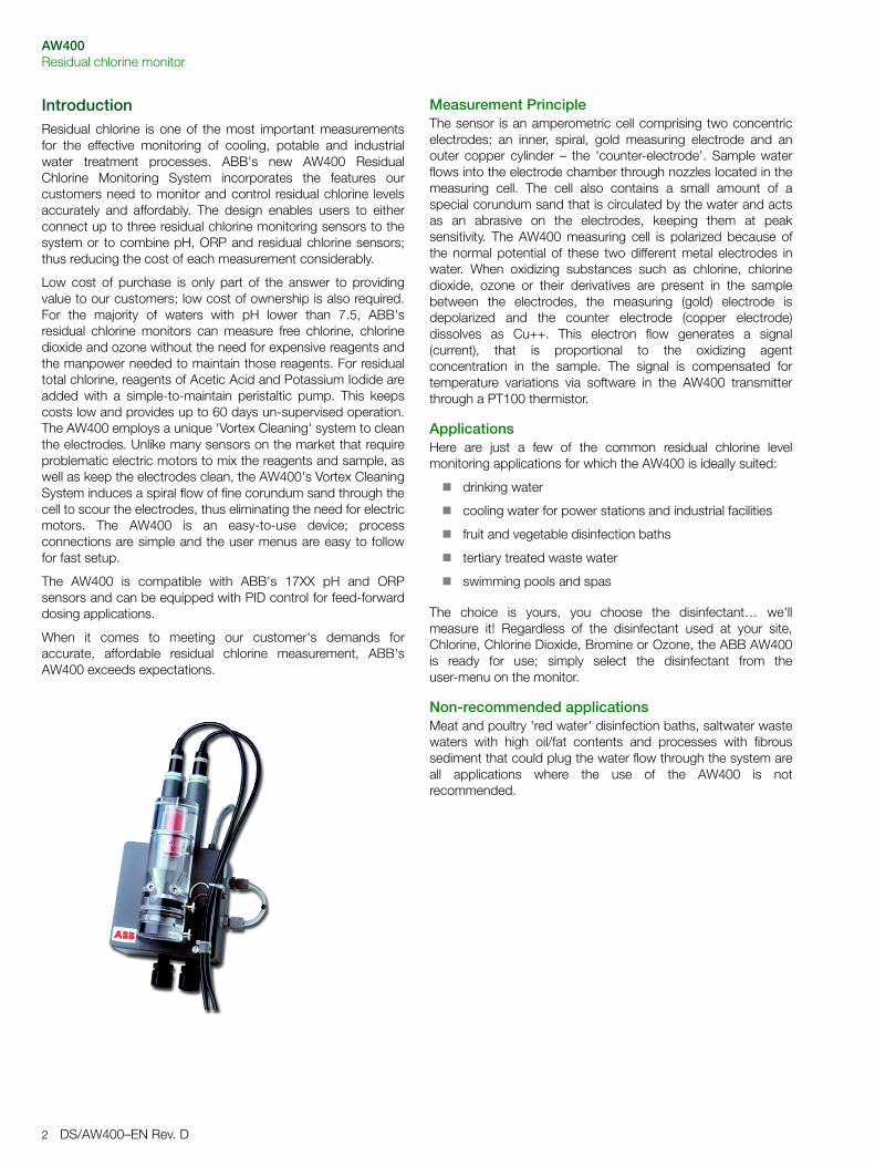
AW400Residual chlorine monitor
2 DS/AW400–EN Rev. D
IntroductionResidual chlorine is one of the most important measurementsfor the effective monitoring of cooling, potable and industrialwater treatment processes. ABB's new AW400 ResidualChlorine Monitoring System incorporates the features ourcustomers need to monitor and control residual chlorine levelsaccurately and affordably. The design enables users to eitherconnect up to three residual chlorine monitoring sensors to thesystem or to combine pH, ORP and residual chlorine sensors;thus reducing the cost of each measurement considerably.
Low cost of purchase is only part of the answer to providingvalue to our customers; low cost of ownership is also required.For the majority of waters with pH lower than 7.5, ABB'sresidual chlorine monitors can measure free chlorine, chlorinedioxide and ozone without the need for expensive reagents andthe manpower needed to maintain those reagents. For residualtotal chlorine, reagents of Acetic Acid and Potassium Iodide areadded with a simple-to-maintain peristaltic pump. This keepscosts low and provides up to 60 days un-supervised operation.The AW400 employs a unique 'Vortex Cleaning' system to cleanthe electrodes. Unlike many sensors on the market that requireproblematic electric motors to mix the reagents and sample, aswell as keep the electrodes clean, the AW400's Vortex CleaningSystem induces a spiral flow of fine corundum sand through thecell to scour the electrodes, thus eliminating the need for electricmotors. The AW400 is an easy-to-use device; processconnections are simple and the user menus are easy to followfor fast setup.
The AW400 is compatible with ABB's 17XX pH and ORPsensors and can be equipped with PID control for feed-forwarddosing applications.
When it comes to meeting our customer's demands foraccurate, affordable residual chlorine measurement, ABB'sAW400 exceeds expectations.
Measurement PrincipleThe sensor is an amperometric cell comprising two concentricelectrodes; an inner, spiral, gold measuring electrode and anouter copper cylinder – the 'counter-electrode'. Sample waterflows into the electrode chamber through nozzles located in themeasuring cell. The cell also contains a small amount of aspecial corundum sand that is circulated by the water and actsas an abrasive on the electrodes, keeping them at peaksensitivity. The AW400 measuring cell is polarized because ofthe normal potential of these two different metal electrodes inwater. When oxidizing substances such as chlorine, chlorinedioxide, ozone or their derivatives are present in the samplebetween the electrodes, the measuring (gold) electrode isdepolarized and the counter electrode (copper electrode)dissolves as Cu++. This electron flow generates a signal(current), that is proportional to the oxidizing agentconcentration in the sample. The signal is compensated fortemperature variations via software in the AW400 transmitterthrough a PT100 thermistor.
ApplicationsHere are just a few of the common residual chlorine levelmonitoring applications for which the AW400 is ideally suited:
� drinking water
� cooling water for power stations and industrial facilities
� fruit and vegetable disinfection baths
� tertiary treated waste water
� swimming pools and spas
The choice is yours, you choose the disinfectant… we'llmeasure it! Regardless of the disinfectant used at your site,Chlorine, Chlorine Dioxide, Bromine or Ozone, the ABB AW400is ready for use; simply select the disinfectant from theuser-menu on the monitor.
Non-recommended applicationsMeat and poultry 'red water' disinfection baths, saltwater wastewaters with high oil/fat contents and processes with fibroussediment that could plug the water flow through the system areall applications where the use of the AW400 is notrecommended.

AW400Residual Chlorine Monitor
DS/AW400–EN Rev. D 3
Specification
Measurement RangeChlorine, Chlorine Dioxide, Ozone 0 to 20 ppm (mg/l)
Measurement ModeMeasurement technology Amperometric cell
Measurement interval Continuous
Measurement PerformanceAccuracy Unbuffered: 2% or ±0.01 10ppb,
whichever is the greater at pH <7.5
Buffered: 2% or ±10ppb, whichever is the greater at <pH 10
Sensitivity 0.001 ppm
Minimum Detection Limit 0.005 ppm
Drift Zero drift: ±1% over 30 days Max.
Span drift: -5% over 30 days Max.
Response Time 90% in less than 90 seconds
Interferences Samples containing high concentrations of metal ions or other strong oxidants may affect analyzer operation
Environmental DataAmbient Operating Temperature -10°C to +50°C
Ambient Operating Humidity 80% RH at 31°C, with linear decrease down to 50% RH at 40°C
Sample Temperature Compensated between 2 and 50°C (36°F and 122°F).
Sample Inlet Pressure 0.2 to 4.0 bar (3 to 60 psi). For pressures over 4 bar (60 psi) install a pressure reducing valve. Recommended operating pressure is 2 bar (30 psi)
Sample Outlet Pressure Pressureless
Sample Flow Continuous, 60 - 75 l/hr
Sample pH Value 4 to 7.5 (Buffer feed assembly available for pH greater than 7.5). No correction is needed when measuring chlorine dioxide and ozone.
MaintenanceMaintenance Interval Recommended annual replacement of
O-rings and electrodes
Calibration single or two-point manual calibrationComparison of lab method with process sample or de-chlorinated
Cell Construction MaterialElectrodes Gold / Copper
Electrode chamber plexiglas
Differential pressure regulator PVC
Mechanical DataIngress Protection
Transmitter IP65
Measurement Cell IP64
Sample connections
Inlet/Outlet: 3/8" OD polyethylene or flexible PVC tubing
ElectricalMains voltage 115 Vac, ± 10%, 50/60 Hz
230 Vac, ± 10%, 50/60 Hz
Maximum Consumption 20 VA
CertificationsCE
Installation GuidelinesThe AW400 performs best when installed following these simpleguidelines:
1. Do not allow the cell to be exposed to direct sunlight.
2. Use a sampling point that is significant for the process control.
3. Allow sufficient access for maintenance operations.
4. Install in an area that is completely free of vibration.
5. Install in an area that is as far as possible from rotating or electrical commutation devices.
6. Ensure air bubbles in the sample are kept to a minimum. Frequent and large air bubbles will make the reading unstable.
7. Ensure calibration is performed on the complete system i.e. the monitor and measuring cell(s).
8. Use polyethylene or PVC tubing for delivery of the water sample.
9. Do not shorten the soft overflow tube and ensure it can drain freely without back pressure.
Note. It is advisable that sample drain into a non-metallicpipe due to the corrosive nature of chlorinated, ozonatedand bromated waters.
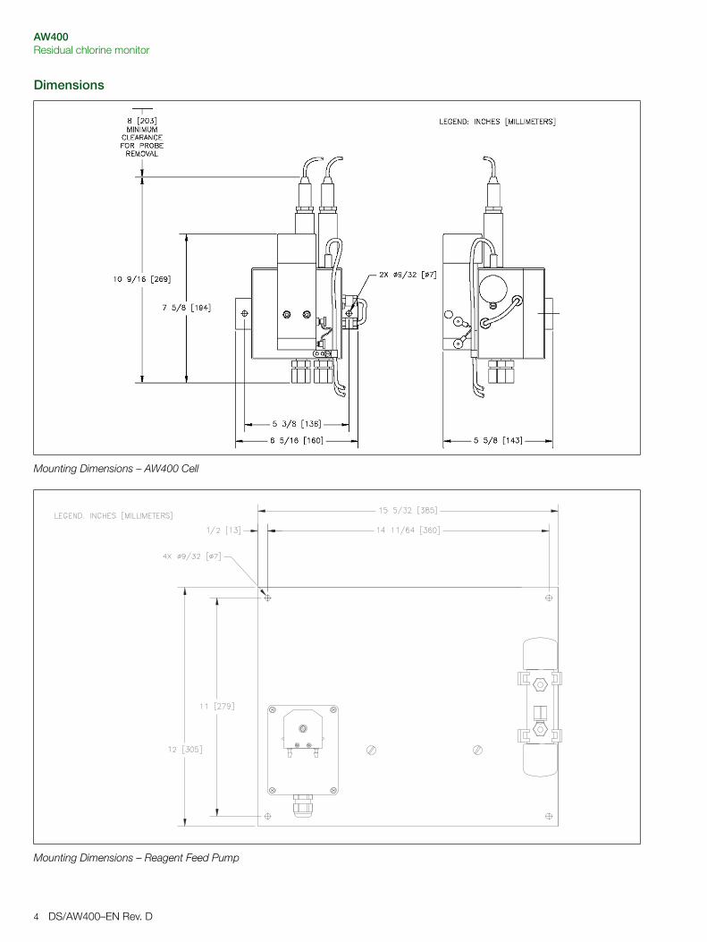
AW400Residual chlorine monitor
4 DS/AW400–EN Rev. D
Dimensions
Mounting Dimensions – AW400 Cell
Mounting Dimensions – Reagent Feed Pump
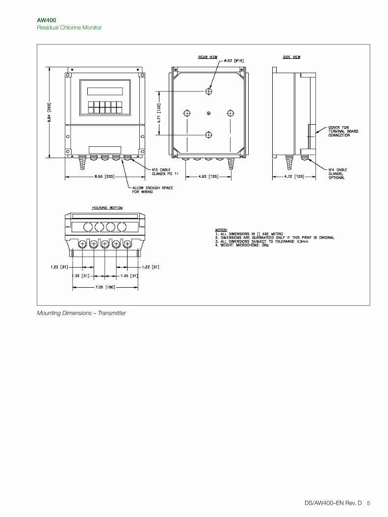
AW400Residual Chlorine Monitor
DS/AW400–EN Rev. D 5
Mounting Dimensions – Transmitter
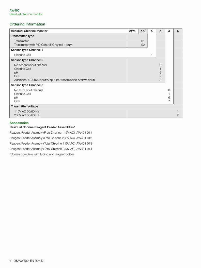
AW400Residual chlorine monitor
6 DS/AW400–EN Rev. D
Ordering Information
AccessoriesResidual Chorine Reagent Feeder Assemblies*
Reagent Feeder Asembly (Free Chlorine 115V AC) AW401 011
Reagent Feeder Asembly (Free Chlorine 230V AC) AW401 012
Reagent Feeder Asembly (Total Chlorine 115V AC) AW401 013
Reagent Feeder Asembly (Total Chlorine 230V AC) AW401 014
*Comes complete with tubing and reagent bottles
Residual Chlorine Monitor AW4 XX/ X X X X
Transmitter Type
TransmitterTransmitter with PID Control (Channel 1 only)
0102
Sensor Type Channel 1
Chlorine Cell 1
Sensor Type Channel 2
No second input channelChlorine CellpHORPAdditional 4-20mA input/output (re-transmission or flow input)
01678
Sensor Type Channel 3
No third input channelChlorine CellpHORP
0167
Transmitter Voltage
115V AC 50/60 Hz230V AC 50/60 Hz
12

AW400Residual Chlorine Monitor
DS/AW400–EN Rev. D 7
Benefits Summary� Total and Free Residual Chlorine Measurement
– add potassium iodide to reagent to convert free chlorine measurement to total chlorine
� Reagentless Operation
– reduced operating costs with reagentless operation at a pH of 7.5 or less
� Multiple Sensor Input Capability
– reduced installation costs for multiple point monitoring operations
� Self Cleaning Sensor Assembly
– prolongs sensor life and maintains accuracy
� Fast Response Time
– instant response to changes of residual chlorine, unlike batch/DPD methods
� Pressure Regulated Sample Flow
– no additional plumbing required to ensure optimum sample delivery rate and pressure
� PID Control Available
– no costly separate controllers needed
� Field Changeable Configuration
– easily reconfigured in the field from a single input device to a two or three input device
� Minimal Sample Consumption
– less than1 liter (0.22 galls) per minute flow rate required for accurate operation
� Automatic Temperature Compensation
– ensures accuracy and repeatability

Contact us
DS
/AW
400–
EN
Rev
. D12
.201
0ABB LimitedProcess AutomationOldends LaneStonehouseGloucestershire GL10 3TAUKTel: +44 1453 826 661Fax: +44 1453 829 671
ABB Inc.Process Automation125 E. County Line RoadWarminsterPA 18974USATel: +1 215 674 6000Fax: +1 215 674 7183
www.abb.com
NoteWe reserve the right to make technical changes or modify the contents of this document without prior notice. With regard to purchase orders, the agreed particulars shall prevail. ABB does not accept any responsibility whatsoever for potential errors or possible lack of information in this document.
We reserve all rights in this document and in the subject matter and illustrations contained therein. Any reproduction, disclosure to third parties or utilization of its contents in whole or in parts – is forbidden without prior written consent of ABB.
Copyright© 2010 ABBAll rights reserved
3KXA843401R1001
Data sheet DS/TB82-EN Rev. G
TB82Conductivity transmitters2-Wire
Loop-powered transmitters that reduce installation costs in hazardous areas
Intuitive user interface— Easy to use menus guide the operator through set-up,
calibration and maintenance
Full range of conductivity sensors— Make measurements in ultra-pure or high conductivity
applications
Advanced Digital Communications— Available with PROFIBUS® PA, FOUNDATION™ Fieldbus or
HART communications
Hazardous area transmitters— Withstand the harshest environments— NEMA 4X / IP65 housings
Large, Easy-to-Read Display— Shows primary measurement along with user-selectable
secondary display (temperature, output current or sensor input)
Programmable Security Codes— Prevents unauthorized modifications to transmitter
configuration and calibration
Intrinsically Safe, Non-incendive Design— Permits use in hazardous areas
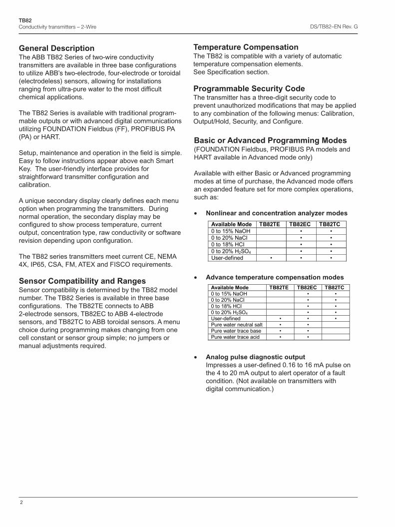
2
TB82Conductivity transmitters – 2-Wire DS/TB82–EN Rev. G
General DescriptionThe ABB TB82 Series of two-wire conductivitytransmitters are available in three base configurationsto utilize ABB’s two-electrode, four-electrode or toroidal(electrodeless) sensors, allowing for installationsranging from ultra-pure water to the most difficultchemical applications.
The TB82 Series is available with traditional program-mable outputs or with advanced digital communicationsutilizing FOUNDATION Fieldbus (FF), PROFIBUS PA(PA) or HART.
Setup, maintenance and operation in the field is simple.Easy to follow instructions appear above each SmartKey. The user-friendly interface provides forstraightforward transmitter configuration andcalibration.
A unique secondary display clearly defines each menuoption when programming the transmitters. Duringnormal operation, the secondary display may beconfigured to show process temperature, currentoutput, concentration type, raw conductivity or softwarerevision depending upon configuration.
The TB82 series transmitters meet current CE, NEMA4X, IP65, CSA, FM, ATEX and FISCO requirements.
Sensor Compatibility and RangesSensor compatibility is determined by the TB82 modelnumber. The TB82 Series is available in three baseconfigurations. The TB82TE connects to ABB2-electrode sensors, TB82EC to ABB 4-electrodesensors, and TB82TC to ABB toroidal sensors. A menuchoice during programming makes changing from onecell constant or sensor group simple; no jumpers ormanual adjustments required.
Basic or Advanced Programming Modes(FOUNDATION Fieldbus, PROFIBUS PA models andHART available in Advanced mode only)
Available with either Basic or Advanced programmingmodes at time of purchase, the Advanced mode offersan expanded feature set for more complex operations,such as:
• Nonlinear and concentration analyzer modes
• Advance temperature compensation modes
• Analog pulse diagnostic outputImpresses a user-defined 0.16 to 16 mA pulse onthe 4 to 20 mA output to alert operator of a faultcondition. (Not available on transmitters withdigital communication.)
������������� ��#$�% ��#$%� ��#$��
?����@8B���,1� � C� C�
?�����?B����.� � C� C�
?����@�B�1�.� � C� C�
?�����?B�1��,�� � C� C�
-��� � �� C� C� C�
������������� ��#$�% ��#$%� ��#$��
?����@8B���,1� � C� C�
?�����?B����.� � C� C�
?����@�B�1�.� � C� C�
?�����?B�1��,�� � C� C�
-��� � �� C� C� C�
/������ ���!���!�� C� C� �
/����������"��� C� C� �
/��������������� C� C� �
Temperature CompensationThe TB82 is compatible with a variety of automatictemperature compensation elements.See Specification section.
Programmable Security CodeThe transmitter has a three-digit security code toprevent unauthorized modifications that may be appliedto any combination of the following menus: Calibration,Output/Hold, Security, and Configure.
3
TB82Conductivity transmitters – 2-Wire DS/TB82–EN Rev. G
Adjustable DampingDamping is helpful in process environments wherenoise is present. It is a capacitive type lag wherereaction to any signal change is slowed according to theentered time constant. For example, theresponse to a step input change reachesapproximately 63 percent of its final value in fiveseconds for five seconds of damping.
CommunicationsFOUNDATION Fieldbus (FF) addresses moderninstrument users needs for flexibility and cost savings,while providing a whole host of additional features.• Measurement variable quality and diagnostic
conditions transmitted during each scheduled datatransfer
• Easily configured remotely or locally• Transmission of multiple process variables utilizes
two Analog Input Blocks (AI)• Transmitter characteristics such as device name,
manufacturer and serial number via a StandardResource Block
• Configuration and calibration capability via customEnhanced Transducer Block
• Provides calibration Methods on supported hosttools and systems
PROFIBUS PA (PA) is a standardized, open, digitalcommunications system for process automation.• Configuration, calibration and trending available via
a Device Type Manager (DTM) when used oncompatible host tools and systems
• Measurement variable quality and diagnosticconditions transmitted during each scheduled datatransfer
• Remote and local configuration capability• Choice of Standard Analyzer Profile or
Manufacturer Specific Profile — conforms toPROFIBUS PA Profile requirements v. 3.0
• GSD files available on all product variations• Utilizes one Physical, one Transducer, and two
DiagnosticsThe transmitter constantly monitors both itself and thesensor to ensure reliability and accuracy. Upondetection of a diagnostic condition, the transmitterprovides diagnostic notification by flashing FAULT onthe display and supplying a pulse on the analog output(if activated on non-HART devices).
Transmitters equipped with Foundation Fieldbus orPROFIBUS PA send a complete diagnosticdescription over the network to the controller. Thisallows for easy, immediate troubleshooting. PressingFAULT info on the transmitter provides a short descrip-tion and fault codes on the secondary display. TheFAULT icon remains active until problem has beenresolved.
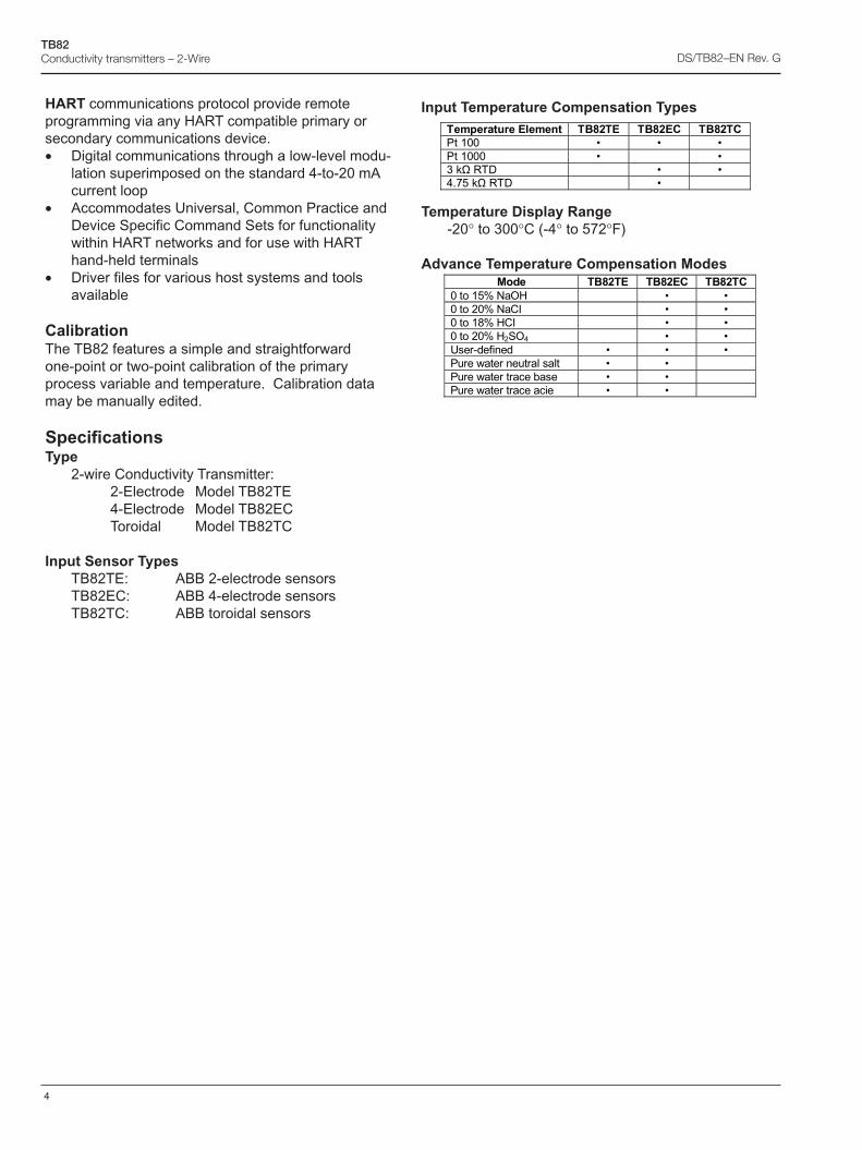
4
TB82Conductivity transmitters – 2-Wire DS/TB82–EN Rev. G
HART communications protocol provide remoteprogramming via any HART compatible primary orsecondary communications device.• Digital communications through a low-level modu-
lation superimposed on the standard 4-to-20 mAcurrent loop
• Accommodates Universal, Common Practice andDevice Specific Command Sets for functionalitywithin HART networks and for use with HARThand-held terminals
• Driver files for various host systems and toolsavailable
CalibrationThe TB82 features a simple and straightforwardone-point or two-point calibration of the primaryprocess variable and temperature. Calibration datamay be manually edited.
SpecificationsType
2-wire Conductivity Transmitter:2-Electrode Model TB82TE4-Electrode Model TB82ECToroidal Model TB82TC
Input Sensor TypesTB82TE: ABB 2-electrode sensorsTB82EC: ABB 4-electrode sensorsTB82TC: ABB toroidal sensors
����� ��� �%������ ��#$�% ��#$%� ��#$��
/��@??� C� C� C�
/��@???� C� � C�
D�9��0��� � C� C�
�*H8�9��0��� � C� �
���� ��#$�% ��#$%� ��#$��
?����@8B���,1� � C� C�
?�����?B����.� � C� C�
?����@�B�1�.� � C� C�
?�����?B�1��,�� � C� C�
-��� � �� C� C C�
/������ ���!���!�� C� C� �
/����������"��� C� C� �
/�������������� C� C� �
Input Temperature Compensation Types
Temperature Display Range-20° to 300°C (-4° to 572°F)
Advance Temperature Compensation Modes
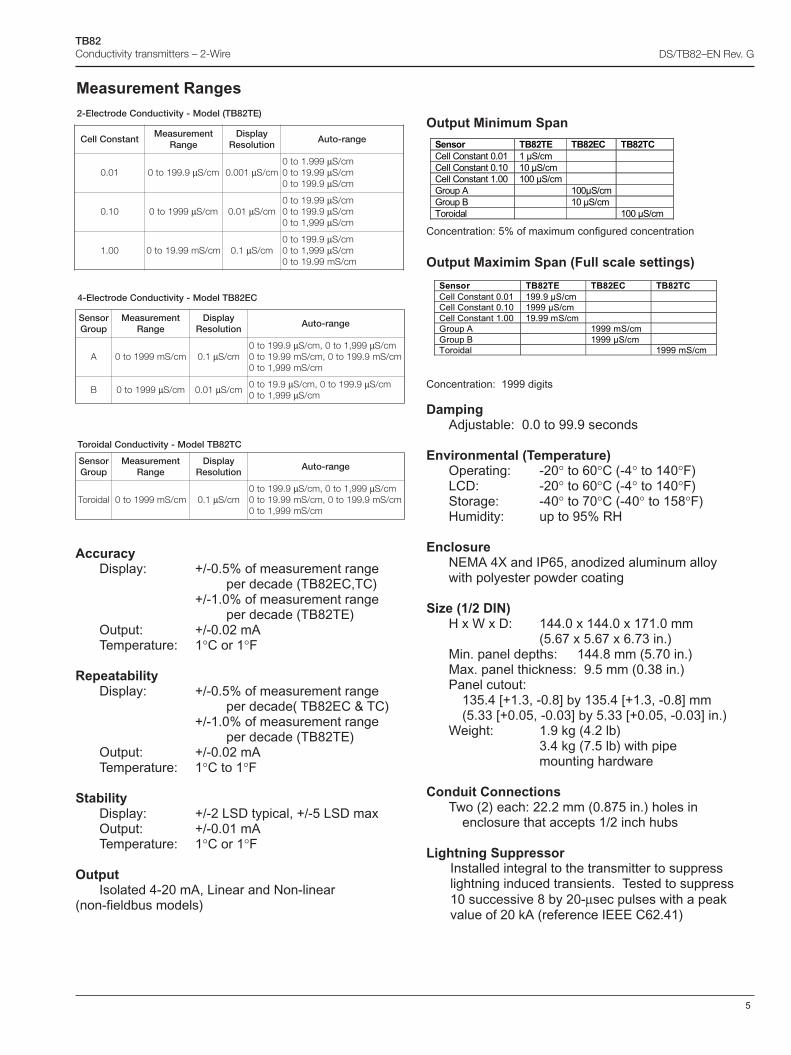
5
TB82Conductivity transmitters – 2-Wire DS/TB82–EN Rev. G
Output Minimum Span
Concentration: 5% of maximum configured concentration
Output Maximim Span (Full scale settings)
Concentration: 1999 digits
DampingAdjustable: 0.0 to 99.9 seconds
Environmental (Temperature)Operating: -20° to 60°C (-4° to 140°F)LCD: -20° to 60°C (-4° to 140°F)Storage: -40° to 70°C (-40° to 158°F)Humidity: up to 95% RH
EnclosureNEMA 4X and IP65, anodized aluminum alloywith polyester powder coating
Size (1/2 DIN)H x W x D: 144.0 x 144.0 x 171.0 mm
(5.67 x 5.67 x 6.73 in.)Min. panel depths: 144.8 mm (5.70 in.)Max. panel thickness: 9.5 mm (0.38 in.)Panel cutout:
135.4 [+1.3, -0.8] by 135.4 [+1.3, -0.8] mm(5.33 [+0.05, -0.03] by 5.33 [+0.05, -0.03] in.)
Weight: 1.9 kg (4.2 lb)3.4 kg (7.5 lb) with pipemounting hardware
Conduit ConnectionsTwo (2) each: 22.2 mm (0.875 in.) holes in
enclosure that accepts 1/2 inch hubs
Lightning SuppressorInstalled integral to the transmitter to suppresslightning induced transients. Tested to suppress10 successive 8 by 20-μsec pulses with a peakvalue of 20 kA (reference IEEE C62.41)
AccuracyDisplay: +/-0.5% of measurement range
per decade (TB82EC,TC)+/-1.0% of measurement range
per decade (TB82TE)Output: +/-0.02 mATemperature: 1°C or 1°F
RepeatabilityDisplay: +/-0.5% of measurement range
per decade( TB82EC & TC)+/-1.0% of measurement range
per decade (TB82TE)Output: +/-0.02 mATemperature: 1°C to 1°F
StabilityDisplay: +/-2 LSD typical, +/-5 LSD maxOutput: +/-0.01 mATemperature: 1°C or 1°F
OutputIsolated 4-20 mA, Linear and Non-linear
(non-fieldbus models)
Measurement Ranges
����� ��#$�% ��#$%� ��#$��
�!!��� ��� ��?*?@� @���=��� � �
�!!��� ��� ��?*@?� @?���=��� � �
�!!��� ��� ��@*??� @??���=��� � �
F��)��� � @??��=��� �
F��)��� � @?���=��� �
������!� � � @??���=���
����� ��#$�% ��#$%� ��#$��
�!!��� ��� ��?*?@� @II*I���=��� � �
�!!��� ��� ��?*@?� @III���=��� � �
�!!��� ��� ��@*??� @I*II���=��� � �
F��)��� � @III���=��� �
F��)��� � @III���=��� �
������!� � � @III���=���
CE28BTledoM-ytivitcudnoCedortcelE-4
rosneSpuorG
tnemerusaeMegnaR
yalpsiDnoituloseR
egnar-otuA
A mc/Sm9991ot0 1.0 μ mc/S9.991ot0 μ 999,1ot0,mc/S μ mc/S
mc/Sm9.991ot0,mc/Sm99.91ot0mc/Sm999,1ot0
B 9991ot0 μ mc/S 10.0 μ mc/S9.91ot0 μ 9.991ot0,mc/S μ mc/S
999,1ot0 μ mc/S
CT28BTledoM-ytivitcudnoCladioroT
rosneSpuorG
tnemerusaeMegnaR
yalpsiDnoituloseR
egnar-otuA
ladioroT mc/Sm9991ot0 1.0 μ mc/S9.991ot0 μ 999,1ot0,mc/S μ mc/S
mc/Sm9.991ot0,mc/Sm99.91ot0mc/Sm999,1ot0
)ET28BT(ledoM-ytivitcudnoCedortcelE-2
tnatsnoClleCtnemerusaeM
egnaRyalpsiD
noituloseRegnar-otuA
10.0 9.991ot0 μ mc/S 100.0 μ mc/S999.1ot0 μ mc/S99.91ot0 μ mc/S9.991ot0 μ mc/S
01.0 9991ot0 μ mc/S 10.0 μ mc/S99.91ot0 μ mc/S9.991ot0 μ mc/S999,1ot0 μ mc/S
00.1 mc/Sm99.91ot0 1.0 μ mc/S9.991ot0 μ mc/S999,1ot0 μ mc/S
mc/Sm99.91ot0
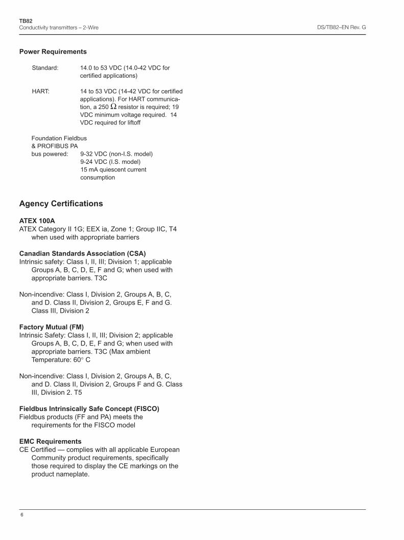
6
TB82Conductivity transmitters – 2-Wire DS/TB82–EN Rev. G
Power Requirements
Standard: 14.0 to 53 VDC (14.0-42 VDC forcertified applications)
HART: 14 to 53 VDC (14-42 VDC for certifiedapplications). For HART communica-tion, a 250 Ω resistor is required; 19VDC minimum voltage required. 14VDC required for liftoff
Foundation Fieldbus& PROFIBUS PAbus powered: 9-32 VDC (non-I.S. model)
9-24 VDC (I.S. model)15 mA quiescent currentconsumption
Agency Certifications
ATEX 100AATEX Category II 1G; EEX ia, Zone 1; Group IIC, T4
when used with appropriate barriers
Canadian Standards Association (CSA)Intrinsic safety: Class I, II, III; Division 1; applicable
Groups A, B, C, D, E, F and G; when used withappropriate barriers. T3C
Non-incendive: Class I, Division 2, Groups A, B, C,and D. Class II, Division 2, Groups E, F and G.Class III, Division 2
Factory Mutual (FM)Intrinsic Safety: Class I, II, III; Division 2; applicable
Groups A, B, C, D, E, F and G; when used withappropriate barriers. T3C (Max ambientTemperature: 60° C
Non-incendive: Class I, Division 2, Groups A, B, C,and D. Class II, Division 2, Groups F and G. ClassIII, Division 2. T5
Fieldbus Intrinsically Safe Concept (FISCO)Fieldbus products (FF and PA) meets the
requirements for the FISCO model
EMC RequirementsCE Certified — complies with all applicable European
Community product requirements, specificallythose required to display the CE markings on theproduct nameplate.
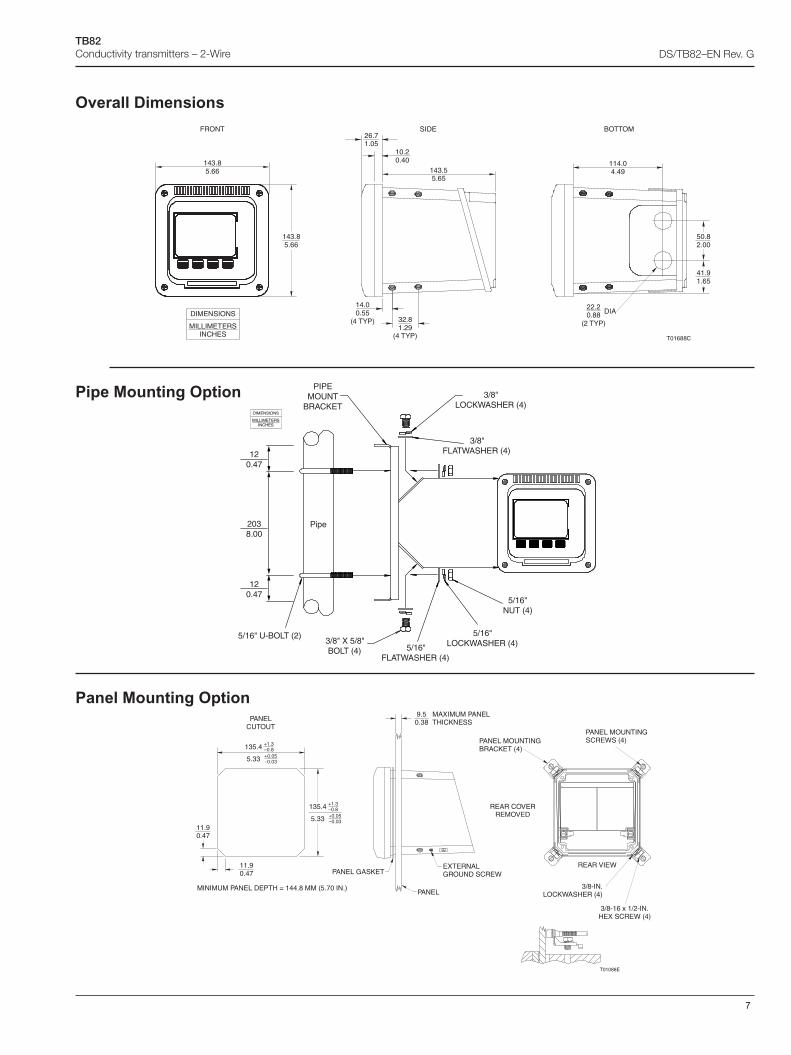
7
TB82Conductivity transmitters – 2-Wire DS/TB82–EN Rev. G
Overall Dimensions
Panel Mounting Option
REAR COVERREMOVED
EXTERNALGROUND SCREW
T01088E
PANEL GASKET
PANEL
9.50.38
MAXIMUM PANELTHICKNESS
EPTHNEL D
PANELCUTOUT
MINIMUM PA = 144.8 MM (5.70 IN.)
11.90.47
135.4 +1.3–0.8
5.33 +0.05–0.03
135.4 +1.3–0.8
5.33 +0.05–0.03
11.90.47
LOCK ASHER (4)
REAR VIEW
PANEL MOUNTINGBRACKET (4)
3/8-IN.W
3/8-16 x 1/2-IN.HEX SCREW (4)
PANEL MOUNTINGSCREWS (4)
FRONT SIDE BOTTOM
143.85.66
114.04.49143.5
5.65
22.20.88
(2 TYP)
DIA
T01688C
10.20.40
26.71.05
14.00.55
(4 TYP) 32.81.29
(4 TYP)
143.85.66
50.82.00
41.91.65
DIMENSIONS
MILLIMETERSINCHES
5/16" U-BOLT (2)
PIPEMOUNT
BRACKET3/8"
LOCKWASHER (4)
3/8"FLATWASHER (4)
3/8" X 5/8"BOLT (4) 5/16"
FLATWASHER (4)
5/16"LOCKWASHER (4)
5/16"NUT (4)
Pipe
DIMENSIONS
MILLIMETERSINCHES
2038.00
120.47
120.47
Pipe Mounting Option
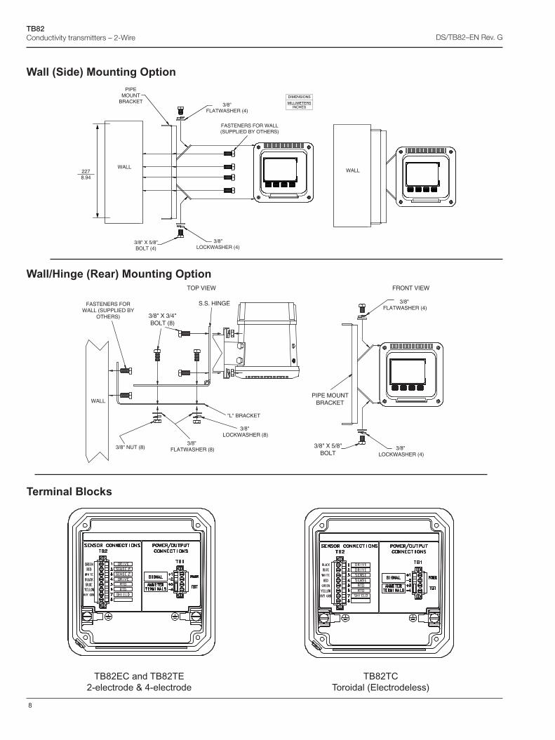
8
TB82Conductivity transmitters – 2-Wire DS/TB82–EN Rev. G
Wall (Side) Mounting Option
Wall/Hinge (Rear) Mounting Option
Terminal Blocks
TB82EC and TB82TE2-electrode & 4-electrode
TB82TCToroidal (Electrodeless)
WALL
FASTENERS FORWALL (SUPPLIED BY
OTHERS)
3/8" NUT (8)3/8"
FLATWASHER (8)
3/8" FLATWASHER (4)
3/8" LOCKWASHER (8)
3/8" LOCKWASHER (4)
"L" BRACKET
FRONT VIEWTOP VIEW
3/8" X 3/4"BOLT (8)
S.S. HINGE
PIPE MOUNTBRACKET
3/8" X 5/8"BOLT
WALL
PIPEMOUNT
BRACKET3/8"
FLATWASHER (4)
3/8" X 5/8"BOLT (4)
3/8"LOCKWASHER (4)
FASTENERS FOR WALL(SUPPLIED BY OTHERS)
WALL
DIMENSIONS
MILLIMETERSINCHES
2278.94
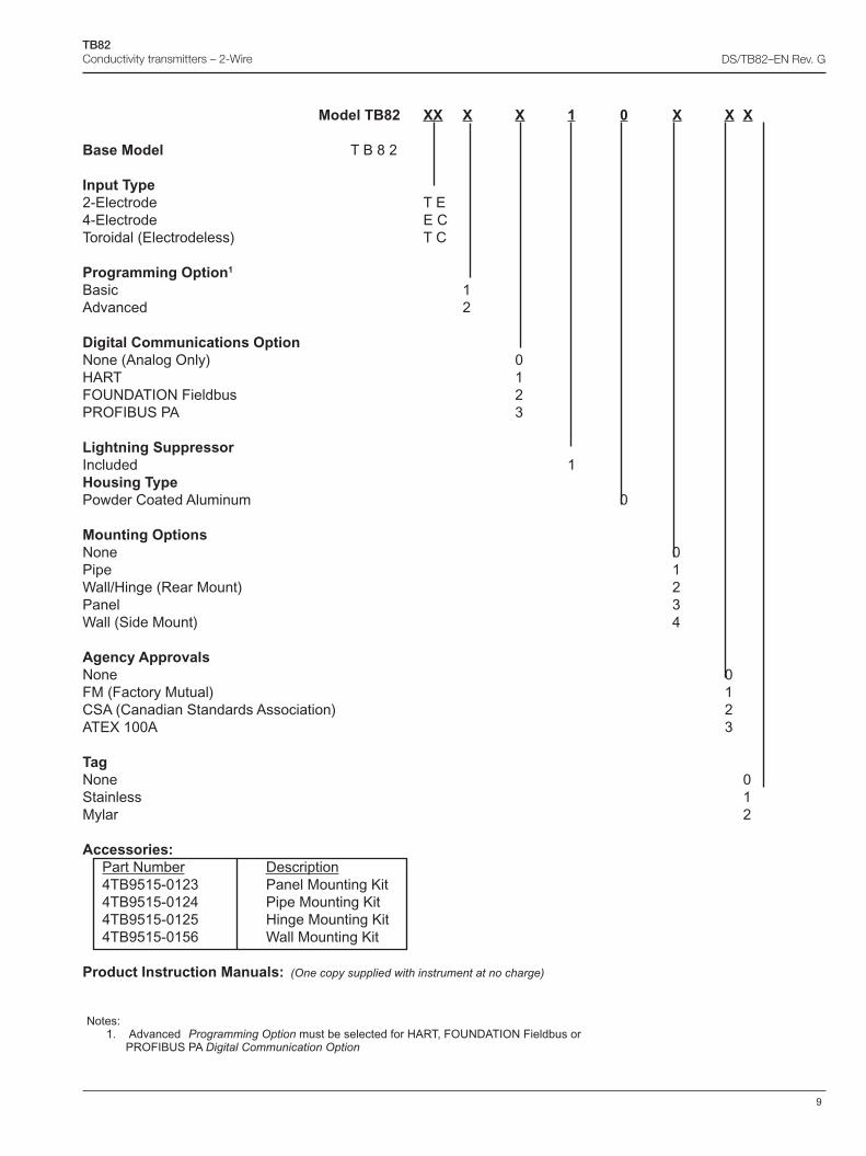
9
TB82Conductivity transmitters – 2-Wire DS/TB82–EN Rev. G
Notes:1. Advanced Programming Option must be selected for HART, FOUNDATION Fieldbus or PROFIBUS PA Digital Communication Option
Model TB82 XX X X 1 0 X X X
Base Model T B 8 2
Input Type2-Electrode T E4-Electrode E CToroidal (Electrodeless) T C
Programming Option1
Basic 1Advanced 2
Digital Communications OptionNone (Analog Only) 0HART 1FOUNDATION Fieldbus 2PROFIBUS PA 3
Lightning SuppressorIncluded 1Housing TypePowder Coated Aluminum 0
Mounting OptionsNone 0Pipe 1Wall/Hinge (Rear Mount) 2Panel 3Wall (Side Mount) 4
Agency ApprovalsNone 0FM (Factory Mutual) 1CSA (Canadian Standards Association) 2ATEX 100A 3
TagNone 0Stainless 1Mylar 2
Accessories:Part Number Description4TB9515-0123 Panel Mounting Kit4TB9515-0124 Pipe Mounting Kit4TB9515-0125 Hinge Mounting Kit4TB9515-0156 Wall Mounting Kit
Product Instruction Manuals: (One copy supplied with instrument at no charge)
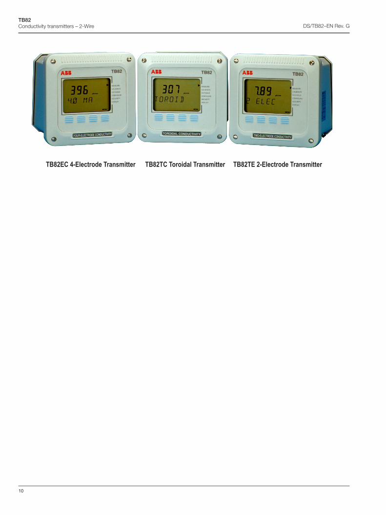
10
TB82Conductivity transmitters – 2-Wire DS/TB82–EN Rev. G
TB82EC 4-Electrode Transmitter TB82TC Toroidal Transmitter TB82TE 2-Electrode Transmitter

11
TB82Conductivity transmitters – 2-Wire DS/TB82–EN Rev. G
Notes
Contact us
DS
/TB
82–E
N R
ev. G
05.2
015ABB Inc.
Process Automation843 N Jefferson StreetPO Box 831Lewisburg 24901-9509USATel: +1 800 HELP 365 (435 7365)Fax: +1 304 647 1862
ABB LimitedProcess AutomationOldends LaneStonehouseGloucestershire GL10 3TAUKTel: +44 1453 826 661Fax: +44 1453 829 671
ABB Engineering (Shanghai) Ltd.Process AutomationNo. 5, Lane 369, Chuangye Road201319, Shanghai, P.R. ChinaPhone: +86 (0) 21 6105 6666Fax: +86 (0) 21 6105 6992Mail:[email protected]
www.abb.com
NoteWe reserve the right to make technical changes or modify the contents of this document without prior notice. With regard to purchase orders, the agreed particulars shall prevail. ABB does not accept any responsibility whatsoever for potential errors or possible lack of information in this document.
We reserve all rights in this document and in the subject matter and illustrations contained therein. Any reproduction, disclosure to third parties or utilization of its contents – in whole or in parts – is forbidden without prior written consent of ABB.
Copyright© 2015 ABBAll rights reserved
3KXA112804R1001