Computer aided part programming for improved part quality ...
10
Computer aided part programming for improved part quality and productivity R. M D. Mesquita Associate Professor, Instituto Superior Tecnico, Mechanical Engineering Department Av. Rovisco Pais, Lisboa, Portugal F. Ferreira Lima Research Assistant, Instituto Tecnol6gico para a Europa Comunitaria, Advanced Manufacturing Technology Center Lisboa, Portugal Abstract Part programming fimctions available within state-of-the-art CAD/CAM systems fail to generate high quality part programmes, in most cases due to limited built-in manufacturing expertise. The development of computer applications that implement sound machining practices and provide manufacturing expertise to part programmers is a key issue, if robust programmes enabling the use of high material removal rates, are to be achieved. This paper presents the architecture of a computer integratedand optimised system for milling operations. This system enables the automated generation of manufacturing information and implements a technology-oriented milling cycle in a commercial CAD/CAM package. The new cycle is based on experimentally derived production rules and provides the manufacturing expertise required for NC part programming. The results show that both, the integrated system and the use of the optimised pocketing cycle can improve part quality and decrease machining time. Keywords CAD/CAM, computer aided part programming, milling, pocket machining © The original version of this chapter was revised: The copyright line was incorrect. This has been corrected. The Erratum to this chapter is available at DOI: 10.1007/978-0-387-35390-6_58 IFIP International Federation for Information Processing L. M. Camarinha-Matos et al. (eds.), Intelligent Systems for Manufacturing 1998
-
Upload
khangminh22 -
Category
Documents
-
view
0 -
download
0
Transcript of Computer aided part programming for improved part quality ...

Computer aided part programming for improved part quality and productivity
R. M D. Mesquita Associate Professor, Instituto Superior Tecnico, Mechanical Engineering Department Av. Rovisco Pais, Lisboa, Portugal F. Ferreira Lima Research Assistant, Instituto Tecnol6gico para a Europa Comunitaria, Advanced Manufacturing Technology Center Lisboa, Portugal
Abstract
Part programming fimctions available within state-of-the-art CAD/CAM systems fail to generate high quality part programmes, in most cases due to limited built-in manufacturing expertise. The development of computer applications that implement sound machining practices and provide manufacturing expertise to part programmers is a key issue, if robust programmes enabling the use of high material removal rates, are to be achieved. This paper presents the architecture of a computer integratedand optimised system for milling operations. This system enables the automated generation of manufacturing information and implements a technology-oriented milling cycle in a commercial CAD/CAM package. The new cycle is based on experimentally derived production rules and provides the manufacturing expertise required for NC part programming. The results show that both, the integrated system and the use of the optimised pocketing cycle can improve part quality and decrease machining time.
Keywords CAD/CAM, computer aided part programming, milling, pocket machining
©
The original version of this chapter was revised: The copyright line was incorrect. This has been corrected. The Erratum to this chapter is available at DOI: 10.1007/978-0-387-35390-6_58
IFIP International Federation for Information Processing L. M. Camarinha-Matos et al. (eds.), Intelligent Systems for Manufacturing
1998

470
INTRODUCTION
Reductions of lead-time, together with part quality increase, are key issues in modern manufacturing companies. It can be achieved through the use of integrated software applications, numerical control systems and dynamic process, production and capacity-planning environment, where resources allocation can be supported by real-time information on the shop floor behaviour. Part quality can be increased if the applications generating the required manufacturing information, such as, part programmes, tooling lists and machining parameters, can convey reliable manufacturing expertise together with updated information on capabilities and limitations of manufacturing resources.
In this context, the introduction of manufacturing expertise in standard part programming and CAD/CAM systems is a key issue. In NC milling one of the most common operations is pocketing, both of rectangular or complex shaped contours, with or without islands. Pocketing operations are carried out with end mill/drills and require axial feeding and both full immersion and non-full immersion cutting passes. This procedure is repeated several times until the full depth is attained. The number of passes is dependent on the allowable axial depth of cut. It follows that, together with tool geometry and material, cutting speed and feed rate, axial and radial depths of cut are key parameters that have to be defined before NC programme generation. While cutting speed and feed rate can be optimised I tuned by machine-tool operator, axial and radial depths of cut determines the actual structure ofNC programme. The resultant tool-path is highly difficult to be edited at the shop floor. Editing of an improperly generated part programme can be a time consuming operation, prone to errors and inconsistent part quality. Commercial pocket cyc1es, available within state-of-the-art Numerical Controls and Computer Assisted NC programming systems can be c1assified into four broad categories: spiral-out, spiral-in, zigzag and linear. In all these cyc1es, axial and radial depth of cut are fixed and cannot be modified during the elemental passes required to machine each pocket. Cutting speed and feed rate cannot be modified either, to accommodate for changes in radial depth of cut which arise at the end of each elemental pass required to enlarge the pocket. Tool-paths are distributed according to particular algorithms that consider only geometry-related constraints, such as, pocket geometry, tool diameter and specified step-over. They are considered as geometry-oriented pocketing cyc1es being not process-oriented and technologically optimised. Similar limitations can be found in some routines that are used in CAM systems to generate other type of features (contouring, slotting, drilling, complex surfaces, etc.). It was this understanding that induced the work of Tarng (1993), Weck (1994), and Tlustly (1990) towards the introduction of optimised pocketing cyc1es.
A co-operative research project is under development at IST and lTEC, aiming the integration of software applications in the areas of CAD, process planning, CAM, production planning and control, tool management and DNC (Mesquita, 1993 and 1996). This project aims also the development of applications required to

471
optimise the use of computer aided systems, through the introduction of manufacturing expertise into state-of-the-art CAM systems (Mesquita, 1997).
In this paper, the architecture of a computer integrated and optimised system for milling operations is presented. A new procedure for the optimisation of pocket milling process planning, together with a new technology-oriented rectangular pocket milling cycle are described. They are based on production rules derived from experimental data and provide the manufacturing expertise required for NC part programming.
2 COMPUTER INTEGRATED AND OPTIMISED SYSTEM FOR MILING OPERATIONS
The building blocks of the proposed computer integrated and optimised system for milling operations are presented in Figure 1. The system includes a CAD interface module (IGES interpreter), a CAPP sub-system (MetCAPP/l from IAMS), a tool management module (Corotas from Sandvik Automation), a CAM package (Mastercam from CNC Software) and a DNC sub-system (DLOG). A manufacturing information management module controls the flow of information to and from the modules. The information required to drive individual modules is made available through ajob folder. In this context, part quality related data can be retrieved from the design database through the job folder and used as additional constraints in the CAM package. The enhanced NC pocketing cycle can take into consideration part tolerances and surface fmish, aUowing the automatie selection of machining conditions.
TMS Tool
Figure 1 Integrated manufacturing platform.
Consequently, NC programme generation is constrained not only by geometryrelated data, but also by design data, manufacturing rules and shop floor expertise, as conveyed through the integrated modules.

472
3 POCKET OPTIMISATION MODULE
The Pocket Optimisation Module (POM) uses part process plans generated by the CAPP function, together with manufacturing resources constraints and experimental machining rules to select and optimise machining parameters, and to output an optimised part process plan to be used by the CAM function. The main capabilities ofthe module can be summarised as folIows:
1. Optimisation of the sequence of operations to produce a pocket: roughing, peripheral and bottom finishing.
2. Selection of the milling method (up or down) more suitable for pocket roughing and bottom finishing.
3. Calculation of the maximum radial immersions required for pocket roughing and bottom finishing.
4. Calculation ofthe required number of additional fmishing passes (dry passes).
POM inc1udes five input interfaces, an optimisation procedure, and an output interface. POM components, functions and information flow are shown in Figure 2.
POCKEl' OPTIMISATIONMODULE
CAD Model lnla'fxe
TMS Tool DB lnterfllCe
Milling method selection
Roughing aod bouom finishing strategy selectioo
Figure 2 Pocket Optimisation Module: Functions and information flow.
3.1. Pocket optimisation module 1/0 interfaces
POM has five input interfaces. MetCAPP/l Interface is used to retrieve data from part process plan file generated within the MetCAPP/1 software. CAD Model Interface is used to retrieve part specification. The drawing number specified in part process plan is used to identify the part CAD file. At this stage, part dimensional tolerances and part surface roughness are required in the optimisation procedure. In order to retrieve information related to the manufacturing resources constraints, POM uses the Tool Management System Database (TMS) Interface and Machine Tools and Materials Database (MMDB) Interface to access cutting
473
tools, machine tools and materials databases. The Output Interface is used to store and export the optimised part process plan together with the complementary machining data generated in the POM.
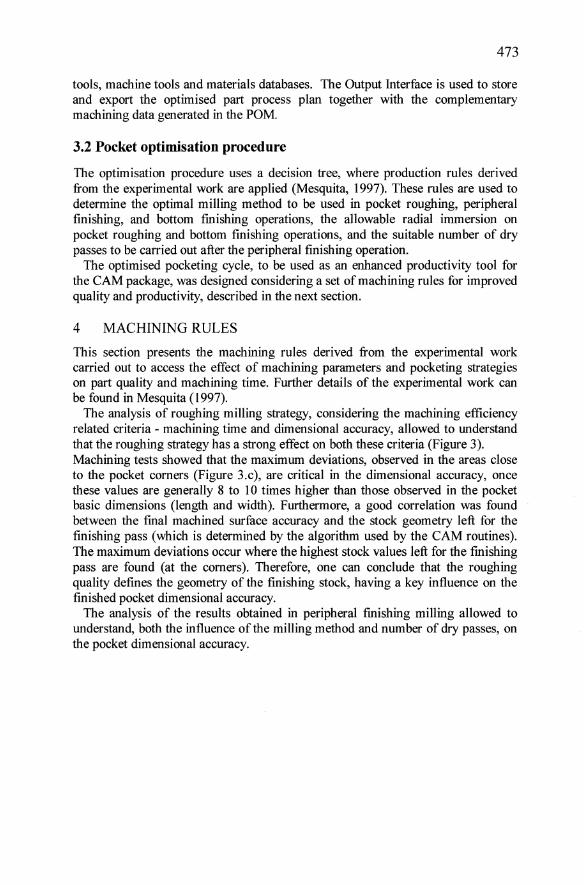
3.2 Pocket optimisation procednre
The optimisation procedure uses adecision tree, where production mIes derived from the experimental work are applied (Mesquita, 1997). These mIes are used to determine the optimal milling method to be used in pocket roughing, peripheral finishing, and bottom finishing operations, the allowable radial immersion on pocket roughing and bottom finishing operations, and the suitable number of dry passes to be carried out after the peripheral finishing operation.
The optimised pocketing cyele, to be used as an enhanced productivity tool for the CAM package, was designed considering a set of machining mIes for improved quality and productivity, described in the next section.
4 MACHINING RULES
This section presents the machining mIes derived from the experimental work carried out to access the effect of machining parameters and pocketing strategies on part quality and machining time. Further details of the experimental work can be found in Mesquita (1997).
The analysis of roughing milling strategy, considering the machining efficiency re1ated criteria - machining time and dimensional accuracy, allowed to understand that the roughing strategy has a strong effect on both these criteria (Figure 3). Machining tests showed that the maximum deviations, observed in the areas elose to the pocket corners (Figure 3.c), are critical in the dimensional accuracy, once these values are generally 8 to 10 times higher than those observed in the pocket basic dimensions (length and width). Furtherrnore, a good correlation was found between the final machined surface accuracy and the stock geometry left for the finishing pass (which is deterrnined by the algorithrn used by the CAM routines). The maximum deviations occur where the highest stock values left for the finishing pass are found (at the corners). Therefore, one can conelude that the roughing quality defines the geometry of the finishing stock, having a key influence on the finished pocket dimensional accuracy.
The analysis of the results obtained in peripheral finishing milling allowed to understand, both the influence of the milling method and number of dry passes, on the pocket dimensional accuracy.

474
1LC
Exit
'"u
Entry
BRC
x a. Zigzag strategy and finishing pass stock
1LC lRC
Exit I I
/ V Entry
b. Spiral-in strategy and finishing pass stock
500 1------;::==::::;-400
300
200
100
o Zig-zag Spiral-in
Pocketing Siralegies
c. Deviations on the pocket corners
Figure 3 Effect ofthe amount ofmaterialleft for finishing passes by the spiral-in and zigzag strategies on the dimensional deviation at the pocket corners.

475
Figure 4 shows the influence of the miIling method on pocket width and length dimensional deviations, along the axial depth of cut. These deviations are due to the ''usual'' tool deflections. However, one can observe that lower dimensional deviations can be achieved if up milling is used during the finishing pass (the errors are reduced by 60%). A detailed analysis of cutting forces, their influence on cutter and workpiece deflection, together with the resulting surface errors can be found in Mesquita (1997).
E .s ..r::: C. Q)
Cl Cij
0 ,000
o -1
-2
-3
-4
-5
-6
-7
-8
Deviaton [mm]
0,005 0,010 0,015 0,020
Figure 4 Influence ofmilling method on dimensional deviation.
0,025
The influence of dry passes on pocket dimensional deviations was also analysed. From the experimental work carried out by Mesquita et al. (1997) one can concIude that dry passes have a significant and positive influence on the final pocket dimensional accuracy. Two dry passes reduce dimensional errors to a value less than 113 of the initial values.
As a concIusion from the experimental work, the following rules were derived:
1. Spiral-in or spiral-out strategies will produce the "best" roughing quality with a marginal increase in machining time, when compared with zigzag pocketing.
2. Spiral strategies create the best conditions for a smooth fmishing operation. 3. Up milling mode should be used for finishing the pocket side wall. 4. A quantitative estimate for the number of dry passes required to produce a given
dimensional accuracy can be established.
However, if we take into consideration the work by Tlusty (1990), the spiral-out strategy should be discarded, since systematic internal cornering is present. This fact determines that even if we select, for the cuts preceding the corner, one halfimmersion pass, there will be a time during the corner where the tool is slotting. Since radial immersion has a strong effect onstability, one should avoid systematic changes from non-full immersion to full immersion conditions (Budak, 1994).
The spiral-in strategy seems to be the best strategy for rectangular pocketing. In its very basic structure, spiral-in incIudes a frame cut followed by several offsetted (to pocket center) contouring cuts. The first frame cut is carried out in full immersion . mode (slotting) and the remaining contouring cuts in non-full

476
immersion as determined by the specified and controllable step-over. This structure of the spiral-in routine, as implemented in CAD/CAM systems, entails a strong disadvantage. A unique axial depth of cut and feed rate has to be programmed for both fuH immersions and non-full immersion cuts. It follows that, to avoid chatter, conservative parameters are used in pocket machining. The improvement of both, the quality and productivity of pocket milling can be achieved if the cyc1e is divided into two routines, one for slotting (the outside frame) and the other for spiral-in in non-full immersion cutting, each one carried out with a different set of machining parameters.
5 ENHANCED POCKET MILLING CYCLE
Pocket Optimisation Module provides significant enhancements to milling quality and productivity through the possibility of selecting and optimising of machining parameters in every elemental operation. The new Enhanced Pocket Routine developed for Mastercam software environment, produces a quality-optimised pocket using a new technology-oriented sequence of machining operations (Figure 5.b): (1) Pocket Framing; (2) Pocket Roughing; (3) Pocket Peripheral Finishing; (4) Pocket Additional Peripheral Finishing, and; (5) Pocket Bottom Finishing.
Roughing pass Framing pass Roughing pass
m Roughing pass «S a. m Framing IV pass a.
s::. .!!!
Roughing pass c:
'" Q) 1J i:ii Bottom finishing pass
s::. Roughing pass .!!! Framing c:
'" pass Q) 1J i:ii Bottom finishing pass
a. b.
Figure 5 Sequence of operations in standard (a) and EPR pocketing routines (b)
Pocket framing operation consists in slotting the periphery of the pocket in as many passes as required. The suitable cutting parameters for this specific operation (the most restrictive case) are used. Considering that full immersion cuts are carried out, axial depth of cut can be reduced, only for this section of the pocket and the optimised cutting parameters for each specific operation can be used.
Pocket roughing consists in machining the pocket central area in as many passes as required, using a spiral-in strategy. If up milling is the adequate method, clockwise direction is required.
The pocket peripheral finishing operation aims the fmishing of the pocket side walls. The peripheral milling method determines the direction of the finishing pass. Additional peripheral fmishing operation (dry passes) can be used for further improvement of the pocket side wall accuracy. This operation is optional and the suitable number of dry passes is executed as determined by buiItin rules containing the shop floor expertise. FinaHy, pocket bottom finishing operation is carried out.

477
The enhanced rectangular pocketing cycle was implemented in the Mastercam package. The new cycle included both, the new operations sequence, partiaHy driven by CAD data and complemented by on-line user input, and an optimised spiral-in tool-path. With this enhanced cycle, CNC programmes can be generated with optimisation of machining parameters for several elemental machining passes required to complete the fuH cycle.
Simulations carried out in the CAM software, for different pocket geometries, using the standard and new routines (Figure 5) produced the following results:
I. Significant reductions on machining time can be achieved when the new routine is used to produce rectangular pockets. The benefit increases with the volume of material to be removed (increased length, width and depth); values from 10 to 30% can be achieved for medium size components.
2. Additional reductions on pocket machining time can be achieved iftools with a larger diameter are used. Conventional routines only allow for the use of one tool to generate the framing and spiral cuts. On the contrary, our routine allows the use of a different tool for both roughing operations (framing and spiral-in), without additional user input.
The new application, although implementing a more complex tool-path, through the splitting ofthe initial spiral-in cycle, still guarantees a reduced effort in the user input. Machining expertise is also provided to the user, since it is built-into the system. A programmer with lower process knowledge can use the system and provide higher efficiency part programmes, as measured through pocket quality (dimensional deviations) and machining time.
6 CONCLUSIONS
The architecture of a computer integrated and optimised system for milling operations in numerical control machine tools" was presented. 'Oue to the achieved computer integration, pocketing operations can be programmed by a less experienced user, requiring less manual data input and delivering improved part quality with reduced machining time.
A new rectangular pocketing cycle was developed, aHowing the reduction of machining time together with the improvement of part quality, through the implementation ofthe following features:
• A technology-oriented and optimised sequence of elemental operations for pocket machining.
• An optimised spiral-in machining strategy for pocket roughing and bottom finishing.
• An optimised set of machining parameters automatically determined by the system.
478
7 REFERENCES
Budak, E. and Altintas, Y. (1994) Peripheral milling conditions for improved dimensional accuracy. International Journal Machine Tools Manufacturing, 34, 879 - 89l.
Kline, W. A., DeVor, R. E. and Shareef, I. A. (1982) The prediction of surface accuracy in end milling. ASME Journal Engineering for Industry, 104, 272 -278.
Mesquita, R. M. (1993) Modelling and Optimisation of Tuming Operations. Proc. 30th Int. MATADOR Conf., UMIST, Manchester, 599 - 607.
Mesquita, R. M. (1996) Computer Integrated and Optimised Tuming, Proc. 4th lnt. Conf. AMST'96 Advanced Manufacturing Systems and Technology, 213 -220.
Mesquita, R. M. (1996) Architecture of an Integrated Process Planning and Tool Management System. Proc. BASYS'96 - 2nd IEEE/ECLAlIFIP Int. Conf. on Architectures and Design Methods for Balanced Automation Systems, Lisboa.
Mesquita, R. M. and Lima, F. F. (1997) Enhanced Pocket Milling Strategy for lmproved Quality. Proc. OE/IFIP/IEEE Int. Conf. on Integrated and Sustainable Industrial Production, 449 - 458.
Tamg, Y. S. and Shyur, Y. Y. (1993) Identification of radial depth of cut in numerical control pocketing routines. International Journal Machine Tools Manufacturing, 33, 1 - 11.
Tlusty, J., Smith, S. and Zamudio, C. (1990) New routines for quality in milling. Annals ofthe CIRP, 39/1,517 - 521.
Weck, M., Altintas, Y. and Beer, C., (1994) CAD assisted chatter-free NC tool path generation in milling. International Journal Machine Tools Manufacturing, 34,879 - 891.
8 BIOGRAPHY
Professor, Ph.D. Ruy Manuel Dias Mesquita Received his Ph.D. in Mechanical Engineering at the Technical University of Lisbon in 1988. He is associate professor ofManufacturing Technology at Instituto Superior Tecnico. His teaching and research activity has been developed in the area of Production Engineering since 1979. At present, he is also the Head of the Institute ofMaterials and Production Technologies at lNETI - National Institute of Engineering and Industrial Technology.
Engineer, M.Sc. Francisco Ferreira Lima Received his M.Sc. in Computer Aided Engineering at Staffordshire University, UK in 1997. He is research assistant in the Advanced Manufacturing Technologies Centre of ITEC, being involved in several projects in the areas of CAD/CAM and Computer Numerical Controlled Milling.