Micromechanical Studies of 4N Gold Wire for fine Pitch Wire-Bonding

Computational studies of a cut-wire pair and combined metamaterials
This content has been downloaded from IOPscience. Please scroll down to see the full text.
Download details:
IP Address: 183.62.172.50
This content was downloaded on 06/10/2013 at 04:28
Please note that terms and conditions apply.
2011 Adv. Nat. Sci: Nanosci. Nanotechnol. 2 033001
(http://iopscience.iop.org/2043-6262/2/3/033001)
View the table of contents for this issue, or go to the journal homepage for more
Home Search Collections Journals About Contact us My IOPscience

IOP PUBLISHING ADVANCES IN NATURAL SCIENCES: NANOSCIENCE AND NANOTECHNOLOGY
Adv. Nat. Sci.: Nanosci. Nanotechnol. 2 (2011) 033001 (9pp) doi:10.1088/2043-6262/2/3/033001
REVIEW
Computational studies of a cut-wire pairand combined metamaterialsThanh Tung Nguyen1, Peter Lievens1, Young Pak Lee2 and Dinh Lam Vu3
1 Laboratory of Solid State Physics and Magnetism, Department of Physics and Astronomy,Katholieke Universiteit Leuven, Leuven B-3001, Belgium2 Quantum Photonic Science Research Center and Department of Physics, Hanyang University,Seoul 133–791, Korea3 Institute of Materials Science, Vietnam Academy of Science and Technology, 18 Hoang Quoc Viet,Hanoi, Vietnam
E-mail: [email protected], [email protected] and [email protected]
Received 13 April 2011Accepted for publication 7 June 2011Published 1 July 2011Online at stacks.iop.org/ANSN/2/033001
AbstractThe transfer-matrix method and finite-integration simulations show how the transmissionproperties of combined metamaterials, which consist of metallic cut-wire pairs and continuouswires, are affected by geometric parameters. The corresponding effective permittivity andpermeability are retrieved from the complex scattering parameters using the standard retrievalprocedure. The electromagnetic properties of the cut-wire pair as well as the left-handedbehavior of the combined structure are understood by the effective medium theory. In addition,the dimensional dependence of transmission properties, the shapes of cut-wire pairs andcontinuous wire, and the impact of dielectric spacer are both examined. Finally, by expandingthe results of previous research (Koschny et al 2003 Phys. Rev. Lett. 93 016608), wegeneralize the transmission picture of combined structures in terms of the correlation betweenelectric and magnetic responses.
Keywords: metamaterials, left-handed materials, cut-wire pair, electromagnetic
Classification number: 5.17
1. Introduction
The terminology ‘left-handed materials (LHMs)’ to classifymaterials, which exhibit a negative index of refraction withsimultaneously negative permittivity and permeability, wasproposed more than four decades ago by Veselago [1].Afterwards, the first practical realization of LHM was shownin Smith’s experiments [2], based on Pendry’s suggestion[3, 4]. There, the negative refractive index is composed ofa periodic array of split-ring resonators (SRRs), providinga magnetically negative permeability and continuous wireswith a negative permittivity below the plasma frequency.This combination has been used widely to study andfabricate LHMs [5–7]. Recently, a progressive design calledcut-wire pair (CWP), which is a continued transformationof the symmetric SRR, has received considerable interest
due to its advanced properties [8, 9], especially foroptical implementations [10, 11]. The combined structureof CWPs and continuous wires are now recognized as anadvanced structure for left-handed (LH) behavior at highfrequencies. Their great potential has been confirmed inrecent research where the negative refraction is presented ina three-dimensional optical metamaterial [12].
There is a series of computational work [13–16] wherethe important transmission and reflection properties ofCWP/SRR-based LHMs have been investigated for bothmicrowave and optical frequencies. It was proven thatcharacteristic understanding as well as parameter optimizationare important issues in studying LHMs. Moreover, it hasbeen revealed that the combination of CWPs/SRRs withcontinuous wires does not always guarantee the LH behavior.In fact, the electric response of the combined structure results
2043-6262/11/033001+09$33.00 1 © 2011 Vietnam Academy of Science & Technology

Adv. Nat. Sci.: Nanosci. Nanotechnol. 2 (2011) 033001 T T Nguyen et al
from both continuous wires and CWPs/SRRs rather than fromonly continuous wires, since the CWPs/SRRs also exhibitthe electric resonance in addition to the original magneticone [8, 17]. The electric response of CWPs was clarified byclosing the air gap to eliminate the magnetic response. Thenthe electromagnetic behavior of closed CWPs is identical tothat of CWs. This also explains why the plasma frequencyof combined structures is always lower than that of thecontinuous wires only [18]. This important consideration,called the effective medium theory, has been widely appliedin experimental realizations of LH behavior [11, 19].
In this paper, we report on a comprehensive study of theelectric and the magnetic properties of CWP and CWP-basedcombined metamaterials. The transmission and the reflectionof CWPs and combined structures are calculated by utilizingthe transfer matrix method [20] and the finite-integrationsimulation [21]. The effective parameters are also extractedfrom transmission, reflection and phase by performing thestandard retrieved method proposed by Chen et al [22]. Theadvantage is that the correct branch of effective refractiveindex is correctly determined without classical ambiguity.The electromagnetic behavior of an LH medium, hence,is quantitatively characterized by the retrieval effectiveparameters.
This paper is organized as follows. In section 2, wediscuss the characteristics of CWP structures and howthe geometric parameters affect the electric and magneticresponses. The LH behavior of the combined structure,CWPs and continuous wires, is realized by employing theeffective medium theory and the retrieval method in section 3.Interestingly, in section 4, the negativity of refractive indexis obtained not only when both permittivity and permeabilityare negative but also when only permittivity is negative. Theimpact of the dielectric spacer on the LH transmission aswell as the dependence on the sizes of the combined structureare investigated in sections 5 and 6, respectively. Finally, wediscuss the key role of the correlation between electric andmagnetic components in constructing a better LH behavior orin making it disappear.
2. Characteristics of CWP structure
2.1. Electric and magnetic resonances of CWP structure
Figure 1 presents a CWP structure prepared by the continuoustransformation of a two-gap symmetric SRR. As can be seen,the design of the CWP, besides its simplicity, has distinctadvantages over conventional SRRs. The incident wave isnormal to the plane of the CWP structure, which enables usto construct an LHM by only one layer of sample with strongresponses [23]. So far, there is a common understanding thatthe SRR structure exhibits not only the magnetic resonancefrequency ( fm) but also the electric one ( fe). So does the CWPstructure. The magnetic resonance of CWPs comes from thecircular currents driven by the capacitance between cut wireswhile the electric resonance is a result of the symmetric modewith parallel currents [8].
Here we discuss the electromagnetic response of theCWP structure differently from three well-known methods.To begin, we apply the effective medium analysis, which
Figure 1. (a) A two-gap symmetric SRR can be transformed into apair of parallel metallic cut wires separated by a dielectric spacer.(b) A CWP structure consists of two metallic cut wires located onboth sides of a dielectric board. The width and the length of the cutwire are w and l, respectively. The thickness of the dielectric spaceris denoted by ts.
is presented in figure 2(a). Evidently, one can observe tworesonant bands of the CWP: the first around 13.8 GHz andthe second around 30 GHz. To determine whether they areelectrically or magnetically originated, we close at the endsof CWP to eliminate the effective capacitance, and thus thedriven force in the circular currents is removed. As expected,the first resonance disappears in the transmission spectrumof the shorted-CWP structure. This clearly indicates that the13.8 GHz resonance is magnetically originated and the otheraround 30.0 GHz is the electric resonance.
We independently examine the aforementioned argumentby performing the standard retrieval procedure. The effectivepermeability of CWP and shorted-CWP structures wascalculated and presented in figure 2(b). In the case of the CWPstructure, a negative permeability band is shown at 13.8 GHz,which confirms that the associated resonance is the responseto the external magnetic field while the negative-permeabilityregime is totally removed for the shorted-CWP structure.
Considering the electromagnetic behavior with respectto the orientation and the incident field, we are also ableto identify the electric and magnetic resonances of theCWP structure. Note that the magnetic resonance is actuallygenerated by circular currents generated by an in-planeexternal magnetic field. Hence, the magnetic resonance shouldbe destroyed by a normal-to-plane magnetic field. For thispurpose, we study different relative orientations, i.e. the Hfield or k normal to the CWP plane by keeping E along theCWP. The transmission spectra of these configurations arepresented in figure 2(c). As discussed, there are two resonancedips at 13.8 and 30.0 GHz, corresponding to the magneticand electric responses, respectively, in case k is normal to
2

Adv. Nat. Sci.: Nanosci. Nanotechnol. 2 (2011) 033001 T T Nguyen et al
15 20 25 30 35-70
-60
-50
-40
-30
-20
-10
0T
ran
smis
son
(d
B)
Frequency (GHz)
CWP Shorted CWP
(a)
12.5 13.0 13.5 14.0 14.5 15.0 15.5-2
-1
0
1
2
3
(b)
CWP Shorted CWP
Per
mea
bilit
y
Frequency (GHz)
15 20 25 30 35-80
-70
-60
-50
-40
-30
-20
-10
0
10
Tra
nsm
issi
on
(d
B)
Frequency (GHz)
k nomal to plane H normal to plane
(c)
12.5 13.0 13.5 14.0 14.5 15.0 15.5-80
-70
-60
-50
-40
-30
-20
-10
0
Tra
nsm
issi
on (
dB)
Frequency (GHz)
1 layer 2 layers 3 layers 4 layers
(d)
Figure 2. (a) Transmission and (b) permeability spectra of CWP and shorted CWP structures according to frequency. (c) Transmissionspectra of the CWP structure for two relative orientations of incident electromagnetic waves. Only one layer along the k-direction isconsidered in (a), (b) and (c). (d) Transmission spectra of the CWP structure according to layer number. The length and width of the cutwire are 5.5 and 1.0 mm, respectively. The CWP is assumed to be made of copper with a conductivity of 5.9 × 10⁷ S−1. The thickness of thedielectric spacer is 0.4 mm. The CWP is embedded in air with periodicities of 2.0, 7.5 and 3.5 mm along the k, the E and the H directions,respectively.
the CWP plane. However, the magnetic resonance disappearswhen H is normal to the plane of the CWP. The reason isthat for H normal to the CWP plane, there is no magneticallyinduced circular current between the two CWs, and hence nomagnetic resonance is observed. The second resonance, whichis the electric response, is nearly unchanged in both cases.
In figure 2(d), we present the difference in thetransmission spectra of the CWP structure according to thenumber of layers. The periodicity along the k-direction isfixed at 2.0 mm. Clearly, the magnetic resonance band isstrengthened and broadened by increasing the layer number.
2.2. Width and length of cut wire in tuning theelectromagnetic resonances
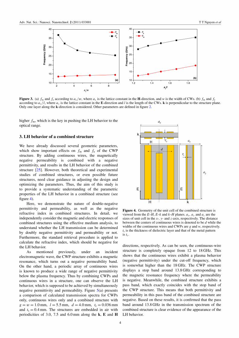
The role of the total electric plasma frequency, fp, in formingthe LH behavior has been studied elsewhere [24], in whichfp can be taken as the sum of the electric responses fromCWPs and continuous wires. It was found that the LHbehavior is best achieved only if fm is lower than fp. Withoutchange in the continuous wires, the tuning of fm and fe,therefore, is meaningful in controlling the LH behavior ofthe combined structure. In another study, it was shown that a
simple equivalent LC circuit can be used to express partly theelectromagnetic behavior of the CWP design [8]. To furtherexplore this issue, we examine the dependence of fm and fe
on the relative sizes of the cut wires, as shown in figure 3. TheCWP medium is assumed to be constructed by the periodicarrays of CWP unit cells in figure 1(b). The correspondinglattice constants along H, E and k are ax = 3.5, ay = 7.5 andaz = 3.0 mm, respectively. Only the case of k normal to theplane is considered. fm and fe are plotted as a function ofax/w in figure 3(a) and ay/ l in figure 3(b). It can be seen that,with increasing width of the cut-wire, both fm and fe change,however, in different ways. While fm shifts slightly to higherfrequencies, fe is drastically shifted downward. When fe isclose to fm by a certain value, fp can be lower than fm. At thattime, the LH properties are destroyed. This point is discussedin more detail in section 3. Note that the dependence of fe onax/w is more significant than fm. Therefore, one might thinkthat the relative factor of ax/w is useful for handling fe; inother words, fp with minor effect on fm.
Figure 3(b) shows the linear dependences of fm and fe
on ay/ l, which well supports the LC model proposed by Zhouet al [8]. Both fm and fe seem to be sensitive to the length lof the CWP. Importantly, a shorter l provides a significantly
3
Adv. Nat. Sci.: Nanosci. Nanotechnol. 2 (2011) 033001 T T Nguyen et al
2 4 6 810
15
20
25
30
35
40
Fre
qu
ency
(G
Hz)
ax/w
fm
fe
(a)1.2 1.4 1.6 1.8
10
15
20
25
30
35
40
Fre
qu
ency
(G
Hz)
ay/l
fe
fm
(b)
Figure 3. (a) fm and fe according to ax/w, where ax is the lattice constant in the H-direction, and w is the width of CWs. (b) fm and fe
according to ay/ l, where ay is the lattice constant in the E-direction and l is the length of the CWs. k is perpendicular to the structure plane.Only one layer along the k-direction is considered. Other parameters are defined in figure 2.
higher fm, which is the key in pushing the LH behavior to theoptical range.
3. LH behavior of a combined structure
We have already discussed several geometric parameters,which show important effects on fm and fe of the CWPstructure. By adding continuous wires, the magneticallynegative permeability is combined with a negativepermittivity, and results in the LH behavior of the combinedstructure [25]. However, both theoretical and experimentalstudies of combined structures, or even possible futurestructures, need clear guidance in adjusting the design andoptimizing the parameters. Thus, the aim of this study isto provide a systematic understanding of the parametricproperties of the LH behavior in a combined structure (seefigure 4).
Here, we demonstrate the nature of double-negativepermittivity and permeability, as well as the negativerefractive index in combined structures. In detail, weindependently consider the magnetic and electric responses ofcombined structures using the effective medium analysis, tounderstand whether the LH transmission can be determinedby doubly negative permittivity and permeability or not.Furthermore, the standard retrieval procedure is applied tocalculate the refractive index, which should be negative forthe LH behavior.
As mentioned previously, under an incidentelectromagnetic wave, the CWP structure exhibits a magneticresonance, which turns out a negative permeability band.On the other hand, a periodic array of continuous wiresis known to produce a wide range of negative permittivitybelow the plasma frequency. Thus by combining CWPs andcontinuous wires in a structure, one can observe the LHbehavior, which is supposed to be achieved by simultaneouslynegative permittivity and permeability. Figure 5(a) presentsa comparison of calculated transmission spectra for CWPsonly, continuous wires only and a combined structure withg = w = 1.0 mm, l = 5.5 mm, d = 4.0 mm, tc = 0.036 mmand ts = 0.4 mm. The structures are embedded in air withperiodicities of 3.0, 7.5 and 6.0 mm along the k, E and H
Figure 4. Geometry of the unit cell of the combined structure isviewed from the E–H, E–k and k–H planes. ax , ay and az are thesizes of unit cell in the x-, y- and z-axis, respectively. The distancebetween the centers of continuous wires is denoted to be d while thewidths of the continuous wires and CWPs are g and w, respectively.ts is the thickness of dielectric layer and that of the metal patternis tc.
directions, respectively. As can be seen, the continuous-wirestructure is completely opaque from 12 to 18 GHz. Thisshows that the continuous wires exhibit a plasma behavior(negative permittivity) under the cut-off frequency, whichis somewhat higher than the 18 GHz. The CWP structuredisplays a stop band around 13.8 GHz corresponding tothe magnetic resonance frequency where the permeabilityis negative. Meanwhile, the combined structure exhibits apass band, which exactly coincides with the stop band ofthe CWP structure. This means that both permittivity andpermeability in this pass band of the combined structure arenegative. Based on these results, it is confirmed that the passband around 13.8 GHz in the transmission spectrum of thecombined structure is clear evidence of the appearance of theLH behavior.
4

Adv. Nat. Sci.: Nanosci. Nanotechnol. 2 (2011) 033001 T T Nguyen et al
12 14 16 18-20
-15
-10
-5
0
Tra
nsm
issi
on (
dB)
Frequency (GHz)
Continuous wires Cut-wire pair Combined structure
(a)
12 14 16 18-20
-15
-10
-5
0
Tra
nsm
issi
on (
dB)
Frequency (GHz)
Combined structure Shorted version(b)
Figure 5. (a) Transmission spectra of CWPs, continuous wires and combined structures. (b) Those of the combined structure and itsshorted version.
-8
-6
-4
-2
0
-1
0
1
2
13 14 15
-2
-1
0
1
2
3
12.5 13.0 13.5 14.0 14.5 15.0 15.5-8
-6
-4
-2
0
2
Frequency (GHz)
ε' < 0μ' > 0n' < 0
ε'μ' n'
Frequency (GHz)
ε' < 0μ' < 0n' < 0
(d)
(b)
(c)
ε
Real part Imagine part
(a)
μ
ε', μ
', n'
n
Figure 6. Calculated values of (a) ε, (b) µ and (c) n of the combined structure, defined in section 3. (d) Real parts of ε, µ and n.
In this part, we examine whether the pass band around13.8 GHz in the combined structure results from the LHbehavior or not. For this purpose, the effective mediumanalysis is used. The shorted combined structure, in whichthe CWPs are connected through the dielectric spacer at theends of each CW, behaves as a combination of continuousand discontinuous wires. The structure is composed of ametallic pattern placed on a dielectric substrate. Both ofthem are nonmagnetic. Hence, it is expected that there is nomagnetically negative permeability for the shorted structure,exhibiting a totally plasmonic behavior instead of the LHone. In figure 5(b), the transmission spectra for one layer ofthe combined structure and its shorted version are plotted.Clearly, the pass band around 13.8 GHz of the combinedstructure disappears in the case of the shorted version.These data imply the existence of an LH pass band basedon doubly negative permittivity and permeability around13.8 GHz. In addition, from the transmission spectrum ofthe shorted combined structure, the total plasma frequencyof the combined structure can be qualitatively determinedaround 15 GHz. The second pass band at 15.5 GHz is, hence,due to right-handed behavior and still remains in the shortedversion.
4. Single- and double-negative refractive index inthe combined structure
Another important issue we should discuss here is the singlenegative refractive index of the combined structure. Forthis purpose, the results reported in [9] are reiterated. Thecomplex effective µ and ε were extracted from the scatteringparameters (see figures 6(a) and (b)). As shown in figure 6(d),µ and ε are simultaneously negative for frequencies higherthan 13.6 GHz. Interestingly, considering the real parts only,we obtain a region of double-negative n by combiningthe negative µ and ε at once. However, it can be seen that thenegative n region is significantly wider than the bandwidth ofnegative µ. For frequencies less than 13.6 GHz, µ is positivewhile ε is negative, but, strangely enough, n is still negative, inother words, a single-negative n. This is a peculiar feature ofcombined metamaterial structures, which was not completelyunderstood previously [26–28].
Actually, in metamaterials it is possible to achieve anegative n without having simultaneously negative µ and ε
if we consider both real and imaginary parts of the effectiveparameters. By representing the complex refractive indexn = n′ + in′′, in terms of complex permittivity ε = ε′ + iε′′ and
5
Adv. Nat. Sci.: Nanosci. Nanotechnol. 2 (2011) 033001 T T Nguyen et al
12.5 13.0 13.5 14.0 14.5 15.0 15.5
-2
0
2
4
6
8
12.5 13.0 13.5 14.0 14.5 15.0 15.50.0
0.2
0.4
0.6
0.8
1.0
Frequency (GHz)
n'μ'ε"
-ε'μ"
Mag
nitu
de
Exp
( μ'ε
''+ε'
μ'')
Frequency (GHz)
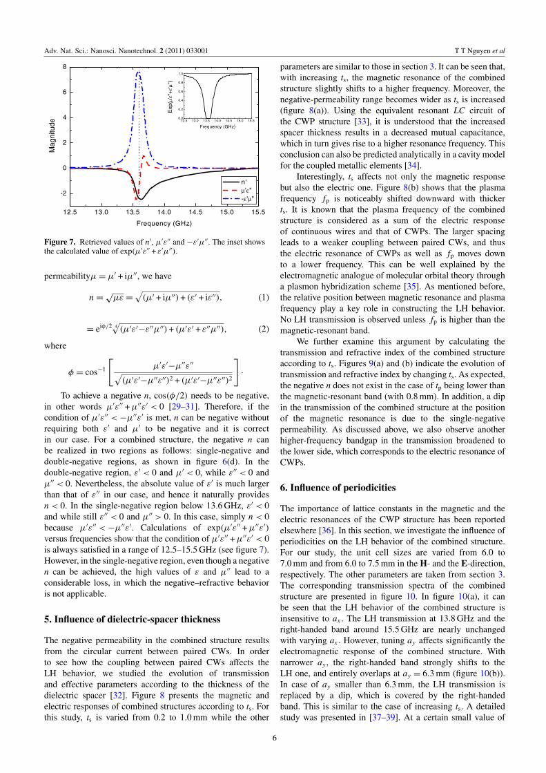
Figure 7. Retrieved values of n′, µ′ε′′ and −ε′µ′′. The inset showsthe calculated value of exp(µ′ε′′ + ε′µ′′).
permeabilityµ = µ′ + iµ′′, we have
n =√
µε =
√(µ′ + iµ′′) + (ε′ + iε′′), (1)
= eiφ/2 4√
(µ′ε′−ε′′µ′′) + (µ′ε′ + ε′′µ′′), (2)
where
φ = cos−1
[µ′ε′
−µ′′ε′′√(µ′ε′−µ′′ε′′)2 + (µ′ε′−µ′′ε′′)2
]·
To achieve a negative n, cos(φ/2) needs to be negative,in other words µ′ε′′ + µ′′ε′ < 0 [29–31]. Therefore, if thecondition of µ′ε′′ < −µ′′ε′ is met, n can be negative withoutrequiring both ε′ and µ′ to be negative and it is correctin our case. For a combined structure, the negative n canbe realized in two regions as follows: single-negative anddouble-negative regions, as shown in figure 6(d). In thedouble-negative region, ε′ < 0 and µ′ < 0, while ε′′ < 0 andµ′′ < 0. Nevertheless, the absolute value of ε′ is much largerthan that of ε′′ in our case, and hence it naturally providesn < 0. In the single-negative region below 13.6 GHz, ε′ < 0and while still ε′′ < 0 and µ′′ > 0. In this case, simply n < 0because µ′ε′′ < −µ′′ε′. Calculations of exp(µ′ε′′ + µ′′ε′)
versus frequencies show that the condition of µ′ε′′ + µ′′ε′ < 0is always satisfied in a range of 12.5–15.5 GHz (see figure 7).However, in the single-negative region, even though a negativen can be achieved, the high values of ε and µ′′ lead to aconsiderable loss, in which the negative–refractive behavioris not applicable.
5. Influence of dielectric-spacer thickness
The negative permeability in the combined structure resultsfrom the circular current between paired CWs. In orderto see how the coupling between paired CWs affects theLH behavior, we studied the evolution of transmissionand effective parameters according to the thickness of thedielectric spacer [32]. Figure 8 presents the magnetic andelectric responses of combined structures according to ts. Forthis study, ts is varied from 0.2 to 1.0 mm while the other
parameters are similar to those in section 3. It can be seen that,with increasing ts, the magnetic resonance of the combinedstructure slightly shifts to a higher frequency. Moreover, thenegative-permeability range becomes wider as ts is increased(figure 8(a)). Using the equivalent resonant LC circuit ofthe CWP structure [33], it is understood that the increasedspacer thickness results in a decreased mutual capacitance,which in turn gives rise to a higher resonance frequency. Thisconclusion can also be predicted analytically in a cavity modelfor the coupled metallic elements [34].
Interestingly, ts affects not only the magnetic responsebut also the electric one. Figure 8(b) shows that the plasmafrequency fp is noticeably shifted downward with thickerts. It is known that the plasma frequency of the combinedstructure is considered as a sum of the electric responseof continuous wires and that of CWPs. The larger spacingleads to a weaker coupling between paired CWs, and thusthe electric resonance of CWPs as well as fp moves downto a lower frequency. This can be well explained by theelectromagnetic analogue of molecular orbital theory througha plasmon hybridization scheme [35]. As mentioned before,the relative position between magnetic resonance and plasmafrequency play a key role in constructing the LH behavior.No LH transmission is observed unless fp is higher than themagnetic-resonant band.
We further examine this argument by calculating thetransmission and refractive index of the combined structureaccording to ts. Figures 9(a) and (b) indicate the evolution oftransmission and refractive index by changing ts. As expected,the negative n does not exist in the case of tp being lower thanthe magnetic-resonant band (with 0.8 mm). In addition, a dipin the transmission of the combined structure at the positionof the magnetic resonance is due to the single-negativepermeability. As discussed above, we also observe anotherhigher-frequency bandgap in the transmission broadened tothe lower side, which corresponds to the electric resonance ofCWPs.
6. Influence of periodicities
The importance of lattice constants in the magnetic and theelectric resonances of the CWP structure has been reportedelsewhere [36]. In this section, we investigate the influence ofperiodicities on the LH behavior of the combined structure.For our study, the unit cell sizes are varied from 6.0 to7.0 mm and from 6.0 to 7.5 mm in the H- and the E-direction,respectively. The other parameters are taken from section 3.The corresponding transmission spectra of the combinedstructure are presented in figure 10. In figure 10(a), it canbe seen that the LH behavior of the combined structure isinsensitive to ax . The LH transmission at 13.8 GHz and theright-handed band around 15.5 GHz are nearly unchangedwith varying ax . However, tuning ay affects significantly theelectromagnetic response of the combined structure. Withnarrower ay , the right-handed band strongly shifts to theLH one, and entirely overlaps at ay = 6.3 mm (figure 10(b)).In case of ay smaller than 6.3 mm, the LH transmission isreplaced by a dip, which is covered by the right-handedband. This is similar to the case of increasing ts. A detailedstudy was presented in [37–39]. At a certain small value of
6

Adv. Nat. Sci.: Nanosci. Nanotechnol. 2 (2011) 033001 T T Nguyen et al
12 13 14 15 16 170.2
0.3
0.4
0.5
0.6
0.7
0.8
0.9
1.0
Frequency (GHz)
ts
-2.750
0.3750
3.500
(a)12 13 14 15 16 17
0.2
0.3
0.4
0.5
0.6
0.7
0.8
0.9
1.0
ts
Frequency (GHz)
-11.00
3.500
18.00
ε = 0
(b)
Figure 8. (a) Permeability and (b) permittivity of the combined structure according to ts.
12 13 14 15 16 170.2
0.3
0.4
0.5
0.6
0.7
0.8
0.9
1.0
ts
Frequency (GHz)
0.1000
0.5500
1.000
(a)12 13 14 15 16 17
0.2
0.3
0.4
0.5
0.6
0.7
0.8
0.9
1.0
ts
Frequency (GHz)
-2.500
0
2.500
(b)
Figure 9. (a) Transmission and (b) refractive index of the combined structure according to ts.
12 13 14 15 16 176.0
6.2
6.4
6.6
6.8
7.0
(a)
Frequency (GHz)
a x (m
m)
0
0.5000
1.000
12 13 14 15 16 176.0
6.2
6.4
6.6
6.8
7.0
7.2
7.4
Frequency (GHz)
a y (m
m)
0
0.5000
1.000
(b)
Figure 10. Transmission spectra of the combined structure according to (a) ax and (b) ay .
ay , the electric resonance is very sensitive to the distancebetween adjacent CWs in the E-direction [8]. The extractedpermittivity and permeability (not shown here) also confirmthis explanation.
7. Electric–magnetic correlation in the combinedstructure
The correlation between plasma frequency and magneticresonance band (from fm to fm′ ) in constructing the LHtransmission of combined metamaterials is schematicallypresented in figure 11. By considering the influences of
geometrical parameters on the electromagnetic response ofthe combined structure, one can generalize the transmissionproperties in terms of three possibilities. Initially, the LHbehavior was analytically predicted by the effective mediumtheory [18] for the case of fm < fm′< f p (see the first infigure 11). However, as we realize in this study, changing ts oray might bring about two other possibilities, where fm< f p <
fm′ and fp < fm < fm′ . Evidently, for the existence of LHbehavior, fm < fm′< f p is not always required. It is shownthat the LH transmission is still observable even withfm< f p < fm (the second in figure 11). For this case, thenegative-permeability band is considered in two parts: the
7

Adv. Nat. Sci.: Nanosci. Nanotechnol. 2 (2011) 033001 T T Nguyen et al
Figure 11. Transmission spectra of the combined structureaccording to the electric-magnetic correlation.
doubly negative permeability and permittivity from the lowedge of magnetic resonance to the plasma frequency issupposed to be the LH behavior, while the remaining part withonly negative permeability is not. This possibility providesa narrow LH transmission that might not be useful for theapplications. This scheme also gives us an explanation fora pass band close to the magnetic resonance in the caseof fp< f m < fm′ . Since the fp is entirely lower than themagnetic-resonant band, the permittivity and permeabilitycannot simultaneously be negative. One can see a dip at themagnetic resonance and a pass band on its left side, which isdue to the double-positive behavior.
8. Conclusions
Computational results were systematically presented tocharacterize the electromagnetic behavior of CWP andcombined metamaterial structures. The electric and magneticproperties of the CWP structure were studied, based onthe effective medium theory, the retrieval procedure and theresponse to the relative orientation of the incident wave. Thestrong dependence of magnetic and electric resonances ofCWPs on their geometric parameters, i.e. the width and thelength, were investigated. Importantly, the characteristics ofLH behavior of the CWP-based combined structure werestudied in detail. The impact of the dielectric spacer onthe electromagnetic response of the combined structure wasclarified. It was found that the electric response of thecombined structure is significantly affected by changing thethickness of the spacer. Moreover, we also examinedthe influence of periodicities on the LH transmission ofthe combined structure. It was demonstrated that the LHbehavior is remarkably influenced by ay while not by ax .Finally, we propose a scheme of transmission to generalizethe transmission properties as well as the LH behaviorof the combined structure, based on the electric–magneticcorrelation. It was shown that the LH behavior is predicted
to be better, degraded or even destroyed by consideringthe overall electric–magnetic condition. Our results wouldbe useful for a theoretical understanding and fabrication ofcombined metamaterials as well as an investigation of thefeasibility of various applications.
Acknowledgments
The authors would like to thank Dr M H Cho at theDepartment of Mathematics and Statistics, University ofNorth Carolina, at Charlotte, North Carolina, for his helpfuldiscussions about the transfer matrix method. This workwas supported by the National Foundation for Scienceand Technology Development (NAFOSTED 103.02.36.09)through the Institute of Materials Science, Vietnam Academyof Science and Technology.
References
[1] Veselago V G 1968 Sov. Phys.—Usp. 10 509[2] Smith D R, Padilla W J, Vier D C, Nermat-Nasser S C and
Schultz S 2000 Phys. Rev. Lett. 84 4184[3] Pendry J B, Holden A J, Robbins D J and Stewart W J 1999
IEEE Trans. Microw. Theory Tech. 47 2075[4] Pendry J B, Holden A J, Stewart W J and Youngs I 1996 Phys.
Rev. Lett. 76 4773[5] Zhou J, Koschny T, Zhang L, Tuttle G and Soukoulis C M
2006 Appl. Phys. Lett. 88 221103[6] Liu N, Guo H, Fu L, Kaiser S, Schweizer H and Giessen H
2007 Adv. Mater. 19 3628[7] Jylha L, Kolmakov I, Maslovski S and Tretyakov S 2007
J. Appl. Phys. 99 043102[8] Zhou J, Economou E N, Koschny T and Soukoulis C M 2006
Opt. Lett. 31 3620[9] Tung N T, Lam V D, Park J W, Cho M H, Lee Y P, Rhee J Y
and Jang W H 2009 J. Appl. Phys. 106 053109[10] Drachev V P, Cai W, Chettiar U, Yuan H K, Sarychev A K,
Kildishev A V, Klimeck G and Shalaev V M 2006 LaserPhys. Lett. 3 49
[11] Guven K, Caliskan M D and Ozbay E 2006 Opt. Express14 8685
[12] Valentine J, Zhang S, Zentgraf T, Ulin-Avila E, Genov D A,Bartal G and Zhang X 2008 Nature 55 376
[13] Markos P and Soukoulis C M 2001 Phys. Rev. B 65 033401[14] Penciu R S, Kafesaki M, Gundogdu T F, Economou E N and
Soukoulis C M 2006 Photonics Nanostruct. Fundam. Appl.4 12
[15] Kafesaki M, Koschny Th, Penciu R S, Gundogdu T F,Economou E N and Soukoulis C M 2005 J. Opt. A: PureAppl. Opt. 7 S12
[16] Tung N T, Hoai T X, Lam V D, Thuy V T T and Lee Y P 2010Eur. Phys. J. B 74 47
[17] Lam V D, Kim J B, Lee Y P and Rhee J Y 2007 Opt. Express15 16651
[18] Koschny T, Kafesaki M, Economou E N and Soukoulis C M2004 Phys. Rev. Lett. 93 107402
[19] Alici K B and Ozbay E 2008 Photonics Nanostruct. Fundam.Appl. 6 102
[20] Pendry J B 1994 J. Mod. Opt. 41 209[21] www.cst.com[22] Chen X, Grzegorczyk T M, Wu B I, Pacheco J and Kong J A
2004 Phys. Rev. E 70 016608[23] Lam V D, Kim J B, Tung N T, Lee S J, Lee Y P and Rhee J Y
2008 Opt. Express 16 5934[24] Tung N T, Lam V D, Cho M H, Park J W, Lee S J, Jang W H
and Lee Y P 2009 IEEE Trans. Magn. 45 4310
8

Adv. Nat. Sci.: Nanosci. Nanotechnol. 2 (2011) 033001 T T Nguyen et al
[25] Lam V D, Kim J B, Lee S J and Lee Y P 2008 J. Appl. Phys.103 033107
[26] Zhou J, Zhang L, Tuttle G, Koschny T and Soukoulis C M2006 Phys. Rev. B 73 041101
[27] Zhou J, Koschny T, Kafesaki M and Soukoulis C M 2008Photonics Nanostruct.: Fundam. Appl. 6 96
[28] Zhang S, Fan W J, Panoiu N C, Malloy K J, Osgood R M andBrueck S R J 2005 Phys. Rev. Lett. 95 137404
[29] Boardman A D, King N and Velasco L 2005 Electromagnetics25 365
[30] McCall M W, Lakhtakia A and Weiglhofer W S 2002 Eur. J.Phys. 23 353
[31] Depine R A and Lakhtakia A 2004 Microw. Opt. Technol. Lett.41 315
[32] Lam V D, Tung N T, Cho M H, Park J W, Jang W H and LeeY P 2009 J. Phys. D: Appl. Phys. 42 115404
[33] Lomakin V, Fainman Y, Urzhumov Y and Shvets G 2006Opt. Express 14 11164
[34] Cai W, Chettiar U K, Yuan H K, de Silva V C, KildishevA V, Drachev V P and Shalaev V M 2007 Opt. Express15 3333
[35] Prodan E, Radloff C, Halas N J and Nordlander P 2003Science 302 419
[36] Lam V D, Tung N T, Cho M H, Park J W, Rhee J Y andLee Y P 2009 J. Appl. Phys. 105 113102
[37] Vu D L, Pham V T, Do T V, Nguyen T T, Thuy Vu T T,Le V H and Lee Y P 2010 Adv. Nat. Sci.: Nanosci.Nanotechnol. 1 045016
[38] Lu Y, Jin X, Lee S, Rhee J Y, Jang W H and Lee Y P 2010 Adv.Nat. Sci.: Nanosci. Nanotechnol. 1 045004
[39] Thuy Vu T T, Nguyen T T, Rhee J J, Vu D L and Lee Y P 2011Adv. Nat. Sci.: Nanosci. Nanotechnol. 2 015003
9
Copyright © 2022 FDOKUMEN