Metamaterials: transforming theory into reality
10
Purdue University Purdue e-Pubs Birck and NCN Publications Birck Nanotechnology Center 12-1-2009 Metamaterials: transforming theory into reality Natalia M. Litchinitser SUNY Buffalo V. M. Shalaev Birck Nanotechnology Center and School of Electrical and Computer Engineering, Purdue University, [email protected] This document has been made available through Purdue e-Pubs, a service of the Purdue University Libraries. Please contact [email protected] for additional information. Litchinitser, Natalia M. and Shalaev, V. M., "Metamaterials: transforming theory into reality" (2009). Birck and NCN Publications. Paper 590. http://docs.lib.purdue.edu/nanopub/590
Transcript of Metamaterials: transforming theory into reality
Purdue UniversityPurdue e-Pubs
Birck and NCN Publications Birck Nanotechnology Center
12-1-2009
Metamaterials: transforming theory into realityNatalia M. LitchinitserSUNY Buffalo
V. M. ShalaevBirck Nanotechnology Center and School of Electrical and Computer Engineering, Purdue University, [email protected]
This document has been made available through Purdue e-Pubs, a service of the Purdue University Libraries. Please contact [email protected] foradditional information.
Litchinitser, Natalia M. and Shalaev, V. M., "Metamaterials: transforming theory into reality" (2009). Birck and NCN Publications.Paper 590.http://docs.lib.purdue.edu/nanopub/590
Metamaterials: transforming theory into reality
Natalia M. Litchinitser1,* and Vladimir M. Shalaev2
1Department of Electrical Engineering, The State University of New York at Buffalo, Buffalo, New York 14260, USA2School of Electrical and Computer Engineering and Birck Nanotechnology Center, Purdue University,
West Lafayette, Indiana 47907, USA*Corresponding author: [email protected]
Received October 13, 2009; accepted October 14, 2009;posted November 3, 2009 (Doc. ID 118548); published November 30, 2009
Metamaterials constitute a new area of science that is expanding our fundamental understanding of the be-havior of the propagation of electromagnetic waves and their interactions, and providing new solutions for awide range of applications from optical communications and defense to biological imaging. In this brief review,we focus on recent progress in theoretical, numerical, and experimental studies of linear and nonlinear opticalproperties of negative index materials and in the emerging field of transformation optics. © 2009 Optical So-ciety of America
OCIS codes: 160.3918, 250.5403, 190.0190.
1. INTRODUCTIONSome forty years ago Victor Veselago theoretically inves-tigated a fundamental question of whether the refractiveindex of a material can take negative values, and pre-dicted a number of unusual phenomena associated withsuch negative index materials (NIMs) [1]. While NIMshave not been found in nature, in the past decade theywere demonstrated first in the microwave and terahertz[2,3] and then in the near-infrared (IR) [4,5] frequencyranges using the so-called metamaterial approach.
Nowadays, the notion of metamaterials embraces awide range of engineered materials with a unit cell that ismuch smaller than the wavelength and with predesignedelectromagnetic properties, while NIMs are a subclass ofmetamaterials with the remarkable property of having anantiparallel phase velocity and Poynting vector. To date, amajority of NIMs experimentally demonstrated at visibleand near-IR frequencies utilize metallic nanostructureswith resonant magnetic response, so that both dielectricpermittivity � and magnetic permeability � are negativein the same frequency range [4–10]. While these first ex-periments proved the possibility of the realization ofNIMs, several challenges are still to be solved to makethem useful for practical applications. In particular, inthe optical frequency range these include (1) further shiftof the NIMs operating wavelength to shorter (visible)wavelengths, (2) loss reduction and tunability, and (3) therealization of bulk and broadband NIMs.
Recent progress in fabrication, design, and optimiza-tion of metamaterial structures aimed at addressing someof these issues and will be reviewed in Section 2. In Sec-tion 3, some unique nonlinear properties of opticalmetamaterials are reviewed. Since numerical simulationsare an essential component of metamaterial research, inSection 4 we discuss several new developments in nu-merical modeling of linear and nonlinear, passive and ac-tive metamaterials. Finally, in Section 5, we highlight re-cent advancements in the emerging field of graded-indexmetamaterials and transformation optics.
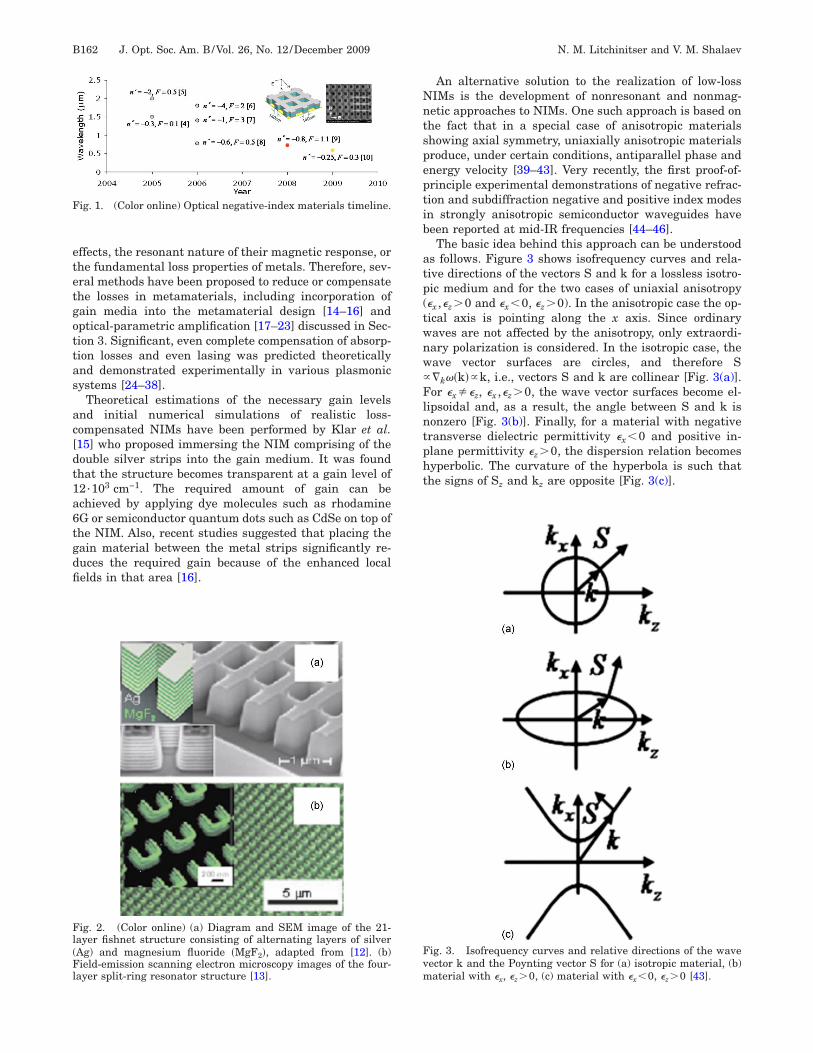
2. OPTICAL NEGATIVE INDEX MATERIALSWhile the first plasmonic NIMs were realized based on acombination of electric and magnetic resonances, it istypically very difficult to obtain a system where both reso-nances occur at the same frequency, and also, any plas-monic resonance always increases the loss in the system.Moreover, resonant electric response is not really neces-sary to achieve negative � since the inherently large nega-tive dielectric permittivity of, for example, noble metals atoptical frequencies can be used instead. By combiningnoble metals with a positive � dielectric in the proper pro-portion, any value of � could be achieved. Therefore, sucha nonresonant electric response can be combined with amagnetic resonance to create a negative index of refrac-tion. This general idea was realized in a so-called �fishnet�metamaterial structure that has become a predominantplasmonic NIM geometry (shown in the inset in Fig. 1).Using this structure, significant progress has recentlybeen made towards the realization of negative index of re-fraction at visible wavelengths. The key milestones in thefabrication of two-dimensional (thin-film) plasmonicmetamaterials are summarized in Fig. 1, where n� is thereal part of the refractive index and F= �n�� /n� is a figureof merit, and n� is the imaginary part of refractive index[4–10].
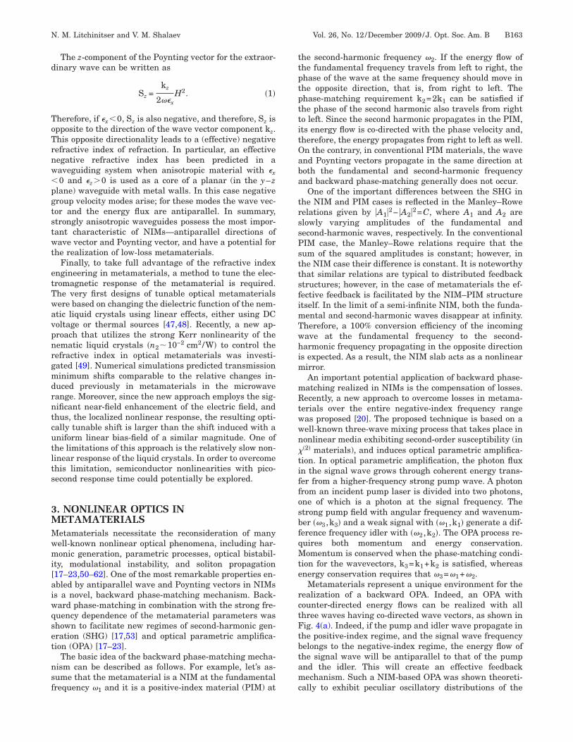
Although many unique physical properties can readilybe demonstrated in two-dimensional metamaterials, somepractical applications require bulk structures. Therefore,considerable efforts have been made in the area of fabri-cation of three-dimensional metamaterials at optical fre-quencies [11–13]. Two examples of fabricated structuresare shown in Fig. 2.
A major drawback of the above approach, however, issignificant losses inevitable in these resonant structures.Indeed, as shown in Fig. 1, the best figure of meritachieved to date is only �3. Losses in plasmonic metama-terials have various origins and are still not completelyquantified. Some known sources of loss originate fromsurface roughness, quantum size and chemical interface
N. M. Litchinitser and V. M. Shalaev Vol. 26, No. 12 /December 2009 /J. Opt. Soc. Am. B B161
0740-3224/09/12B161-9/$15.00 © 2009 Optical Society of America
effects, the resonant nature of their magnetic response, orthe fundamental loss properties of metals. Therefore, sev-eral methods have been proposed to reduce or compensatethe losses in metamaterials, including incorporation ofgain media into the metamaterial design [14–16] andoptical-parametric amplification [17–23] discussed in Sec-tion 3. Significant, even complete compensation of absorp-tion losses and even lasing was predicted theoreticallyand demonstrated experimentally in various plasmonicsystems [24–38].
Theoretical estimations of the necessary gain levelsand initial numerical simulations of realistic loss-compensated NIMs have been performed by Klar et al.[15] who proposed immersing the NIM comprising of thedouble silver strips into the gain medium. It was foundthat the structure becomes transparent at a gain level of12·103 cm−1. The required amount of gain can beachieved by applying dye molecules such as rhodamine6G or semiconductor quantum dots such as CdSe on top ofthe NIM. Also, recent studies suggested that placing thegain material between the metal strips significantly re-duces the required gain because of the enhanced localfields in that area [16].
An alternative solution to the realization of low-lossNIMs is the development of nonresonant and nonmag-netic approaches to NIMs. One such approach is based onthe fact that in a special case of anisotropic materialsshowing axial symmetry, uniaxially anisotropic materialsproduce, under certain conditions, antiparallel phase andenergy velocity [39–43]. Very recently, the first proof-of-principle experimental demonstrations of negative refrac-tion and subdiffraction negative and positive index modesin strongly anisotropic semiconductor waveguides havebeen reported at mid-IR frequencies [44–46].
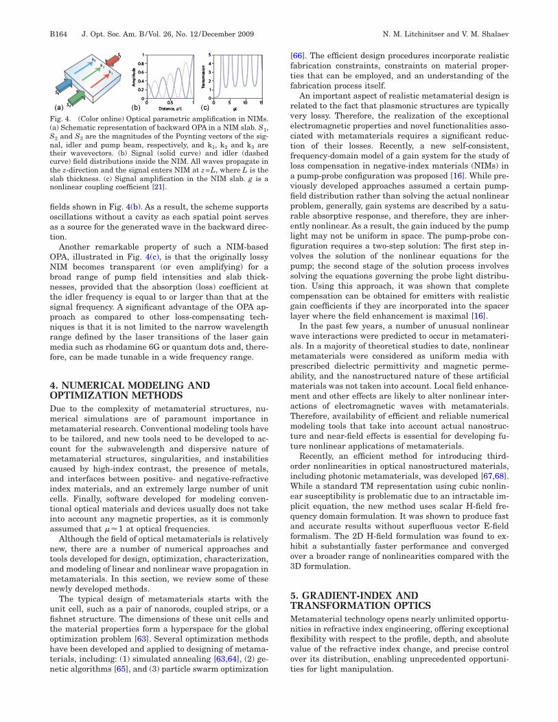
The basic idea behind this approach can be understoodas follows. Figure 3 shows isofrequency curves and rela-tive directions of the vectors S and k for a lossless isotro-pic medium and for the two cases of uniaxial anisotropy(�x ,�z�0 and �x�0, �z�0). In the anisotropic case the op-tical axis is pointing along the x axis. Since ordinarywaves are not affected by the anisotropy, only extraordi-nary polarization is considered. In the isotropic case, thewave vector surfaces are circles, and therefore S��k��k��k, i.e., vectors S and k are collinear [Fig. 3(a)].For �x��z, �x ,�z�0, the wave vector surfaces become el-lipsoidal and, as a result, the angle between S and k isnonzero [Fig. 3(b)]. Finally, for a material with negativetransverse dielectric permittivity �x�0 and positive in-plane permittivity �z�0, the dispersion relation becomeshyperbolic. The curvature of the hyperbola is such thatthe signs of Sz and kz are opposite [Fig. 3(c)].
Fig. 1. (Color online) Optical negative-index materials timeline.
Fig. 2. (Color online) (a) Diagram and SEM image of the 21-layer fishnet structure consisting of alternating layers of silver(Ag) and magnesium fluoride �MgF2�, adapted from [12]. (b)Field-emission scanning electron microscopy images of the four-layer split-ring resonator structure [13].
Fig. 3. Isofrequency curves and relative directions of the wavevector k and the Poynting vector S for (a) isotropic material, (b)material with �x, �z�0, (c) material with �x�0, �z�0 [43].
B162 J. Opt. Soc. Am. B/Vol. 26, No. 12 /December 2009 N. M. Litchinitser and V. M. Shalaev
The z-component of the Poynting vector for the extraor-dinary wave can be written as
Sz =kz
2��xH2. �1�
Therefore, if �x�0, Sz is also negative, and therefore, Sz isopposite to the direction of the wave vector component kz.This opposite directionality leads to a (effective) negativerefractive index of refraction. In particular, an effectivenegative refractive index has been predicted in awaveguiding system when anisotropic material with �x�0 and �z�0 is used as a core of a planar (in the y–zplane) waveguide with metal walls. In this case negativegroup velocity modes arise; for these modes the wave vec-tor and the energy flux are antiparallel. In summary,strongly anisotropic waveguides possess the most impor-tant characteristic of NIMs—antiparallel directions ofwave vector and Poynting vector, and have a potential forthe realization of low-loss metamaterials.
Finally, to take full advantage of the refractive indexengineering in metamaterials, a method to tune the elec-tromagnetic response of the metamaterial is required.The very first designs of tunable optical metamaterialswere based on changing the dielectric function of the nem-atic liquid crystals using linear effects, either using DCvoltage or thermal sources [47,48]. Recently, a new ap-proach that utilizes the strong Kerr nonlinearity of thenematic liquid crystals �n2�10−2 cm2/W� to control therefractive index in optical metamaterials was investi-gated [49]. Numerical simulations predicted transmissionminimum shifts comparable to the relative changes in-duced previously in metamaterials in the microwaverange. Moreover, since the new approach employs the sig-nificant near-field enhancement of the electric field, andthus, the localized nonlinear response, the resulting opti-cally tunable shift is larger than the shift induced with auniform linear bias-field of a similar magnitude. One ofthe limitations of this approach is the relatively slow non-linear response of the liquid crystals. In order to overcomethis limitation, semiconductor nonlinearities with pico-second response time could potentially be explored.
3. NONLINEAR OPTICS INMETAMATERIALSMetamaterials necessitate the reconsideration of manywell-known nonlinear optical phenomena, including har-monic generation, parametric processes, optical bistabil-ity, modulational instability, and soliton propagation[17–23,50–62]. One of the most remarkable properties en-abled by antiparallel wave and Poynting vectors in NIMsis a novel, backward phase-matching mechanism. Back-ward phase-matching in combination with the strong fre-quency dependence of the metamaterial parameters wasshown to facilitate new regimes of second-harmonic gen-eration (SHG) [17,53] and optical parametric amplifica-tion (OPA) [17–23].
The basic idea of the backward phase-matching mecha-nism can be described as follows. For example, let’s as-sume that the metamaterial is a NIM at the fundamentalfrequency �1 and it is a positive-index material (PIM) at
the second-harmonic frequency �2. If the energy flow ofthe fundamental frequency travels from left to right, thephase of the wave at the same frequency should move inthe opposite direction, that is, from right to left. Thephase-matching requirement k2=2k1 can be satisfied ifthe phase of the second harmonic also travels from rightto left. Since the second harmonic propagates in the PIM,its energy flow is co-directed with the phase velocity and,therefore, the energy propagates from right to left as well.On the contrary, in conventional PIM materials, the waveand Poynting vectors propagate in the same direction atboth the fundamental and second-harmonic frequencyand backward phase-matching generally does not occur.
One of the important differences between the SHG inthe NIM and PIM cases is reflected in the Manley–Rowerelations given by �A1�2− �A2�2=C, where A1 and A2 areslowly varying amplitudes of the fundamental andsecond-harmonic waves, respectively. In the conventionalPIM case, the Manley–Rowe relations require that thesum of the squared amplitudes is constant; however, inthe NIM case their difference is constant. It is noteworthythat similar relations are typical to distributed feedbackstructures; however, in the case of metamaterials the ef-fective feedback is facilitated by the NIM–PIM structureitself. In the limit of a semi-infinite NIM, both the funda-mental and second-harmonic waves disappear at infinity.Therefore, a 100% conversion efficiency of the incomingwave at the fundamental frequency to the second-harmonic frequency propagating in the opposite directionis expected. As a result, the NIM slab acts as a nonlinearmirror.
An important potential application of backward phase-matching realized in NIMs is the compensation of losses.Recently, a new approach to overcome losses in metama-terials over the entire negative-index frequency rangewas proposed [20]. The proposed technique is based on awell-known three-wave mixing process that takes place innonlinear media exhibiting second-order susceptibility (in��2� materials), and induces optical parametric amplifica-tion. In optical parametric amplification, the photon fluxin the signal wave grows through coherent energy trans-fer from a higher-frequency strong pump wave. A photonfrom an incident pump laser is divided into two photons,one of which is a photon at the signal frequency. Thestrong pump field with angular frequency and wavenum-ber ��3 ,k3� and a weak signal with ��1 ,k1� generate a dif-ference frequency idler with ��2 ,k2�. The OPA process re-quires both momentum and energy conservation.Momentum is conserved when the phase-matching condi-tion for the wavevectors, k3=k1+k2 is satisfied, whereasenergy conservation requires that �3=�1+�2.
Metamaterials represent a unique environment for therealization of a backward OPA. Indeed, an OPA withcounter-directed energy flows can be realized with allthree waves having co-directed wave vectors, as shown inFig. 4(a). Indeed, if the pump and idler wave propagate inthe positive-index regime, and the signal wave frequencybelongs to the negative-index regime, the energy flow ofthe signal wave will be antiparallel to that of the pumpand the idler. This will create an effective feedbackmechanism. Such a NIM-based OPA was shown theoreti-cally to exhibit peculiar oscillatory distributions of the
N. M. Litchinitser and V. M. Shalaev Vol. 26, No. 12 /December 2009 /J. Opt. Soc. Am. B B163
fields shown in Fig. 4(b). As a result, the scheme supportsoscillations without a cavity as each spatial point servesas a source for the generated wave in the backward direc-tion.
Another remarkable property of such a NIM-basedOPA, illustrated in Fig. 4(c), is that the originally lossyNIM becomes transparent (or even amplifying) for abroad range of pump field intensities and slab thick-nesses, provided that the absorption (loss) coefficient atthe idler frequency is equal to or larger than that at thesignal frequency. A significant advantage of the OPA ap-proach as compared to other loss-compensating tech-niques is that it is not limited to the narrow wavelengthrange defined by the laser transitions of the laser gainmedia such as rhodamine 6G or quantum dots and, there-fore, can be made tunable in a wide frequency range.
4. NUMERICAL MODELING ANDOPTIMIZATION METHODSDue to the complexity of metamaterial structures, nu-merical simulations are of paramount importance inmetamaterial research. Conventional modeling tools haveto be tailored, and new tools need to be developed to ac-count for the subwavelength and dispersive nature ofmetamaterial structures, singularities, and instabilitiescaused by high-index contrast, the presence of metals,and interfaces between positive- and negative-refractiveindex materials, and an extremely large number of unitcells. Finally, software developed for modeling conven-tional optical materials and devices usually does not takeinto account any magnetic properties, as it is commonlyassumed that ��1 at optical frequencies.
Although the field of optical metamaterials is relativelynew, there are a number of numerical approaches andtools developed for design, optimization, characterization,and modeling of linear and nonlinear wave propagation inmetamaterials. In this section, we review some of thesenewly developed methods.
The typical design of metamaterials starts with theunit cell, such as a pair of nanorods, coupled strips, or afishnet structure. The dimensions of these unit cells andthe material properties form a hyperspace for the globaloptimization problem [63]. Several optimization methodshave been developed and applied to designing of metama-terials, including: (1) simulated annealing [63,64], (2) ge-netic algorithms [65], and (3) particle swarm optimization
[66]. The efficient design procedures incorporate realisticfabrication constraints, constraints on material proper-ties that can be employed, and an understanding of thefabrication process itself.
An important aspect of realistic metamaterial design isrelated to the fact that plasmonic structures are typicallyvery lossy. Therefore, the realization of the exceptionalelectromagnetic properties and novel functionalities asso-ciated with metamaterials requires a significant reduc-tion of their losses. Recently, a new self-consistent,frequency-domain model of a gain system for the study ofloss compensation in negative-index materials (NIMs) ina pump-probe configuration was proposed [16]. While pre-viously developed approaches assumed a certain pump-field distribution rather than solving the actual nonlinearproblem, generally, gain systems are described by a satu-rable absorptive response, and therefore, they are inher-ently nonlinear. As a result, the gain induced by the pumplight may not be uniform in space. The pump-probe con-figuration requires a two-step solution: The first step in-volves the solution of the nonlinear equations for thepump; the second stage of the solution process involvessolving the equations governing the probe light distribu-tion. Using this approach, it was shown that completecompensation can be obtained for emitters with realisticgain coefficients if they are incorporated into the spacerlayer where the field enhancement is maximal [16].
In the past few years, a number of unusual nonlinearwave interactions were predicted to occur in metamateri-als. In a majority of theoretical studies to date, nonlinearmetamaterials were considered as uniform media withprescribed dielectric permittivity and magnetic perme-ability, and the nanostructured nature of these artificialmaterials was not taken into account. Local field enhance-ment and other effects are likely to alter nonlinear inter-actions of electromagnetic waves with metamaterials.Therefore, availability of efficient and reliable numericalmodeling tools that take into account actual nanostruc-ture and near-field effects is essential for developing fu-ture nonlinear applications of metamaterials.
Recently, an efficient method for introducing third-order nonlinearities in optical nanostructured materials,including photonic metamaterials, was developed [67,68].While a standard TM representation using cubic nonlin-ear susceptibility is problematic due to an intractable im-plicit equation, the new method uses scalar H-field fre-quency domain formulation. It was shown to produce fastand accurate results without superfluous vector E-fieldformalism. The 2D H-field formulation was found to ex-hibit a substantially faster performance and convergedover a broader range of nonlinearities compared with the3D formulation.
5. GRADIENT-INDEX ANDTRANSFORMATION OPTICSMetamaterial technology opens nearly unlimited opportu-nities in refractive index engineering, offering exceptionalflexibility with respect to the profile, depth, and absolutevalue of the refractive index change, and precise controlover its distribution, enabling unprecedented opportuni-ties for light manipulation.
Fig. 4. (Color online) Optical parametric amplification in NIMs.(a) Schematic representation of backward OPA in a NIM slab. S1,S2 and S3 are the magnitudes of the Poynting vectors of the sig-nal, idler and pump beam, respectively, and k1, k2 and k3 aretheir wavevectors. (b) Signal (solid curve) and idler (dashedcurve) field distributions inside the NIM. All waves propagate inthe z-direction and the signal enters NIM at z=L, where L is theslab thickness. (c) Signal amplification in the NIM slab. g is anonlinear coupling coefficient [21].
B164 J. Opt. Soc. Am. B/Vol. 26, No. 12 /December 2009 N. M. Litchinitser and V. M. Shalaev
It is worth noting that the most unusual properties ofNIMs are revealed at the interface of positive- andnegative-index materials. Particularly, the right-handedtriplet formed from the electric and magnetic fields andthe wave vector in the PIM undergoes an abrupt changeto form a left-handed triplet in the NIM. A topologicallycritical phenomenon such as this leads to antiparallel di-rections of the wave and Poynting vectors in the NIM.
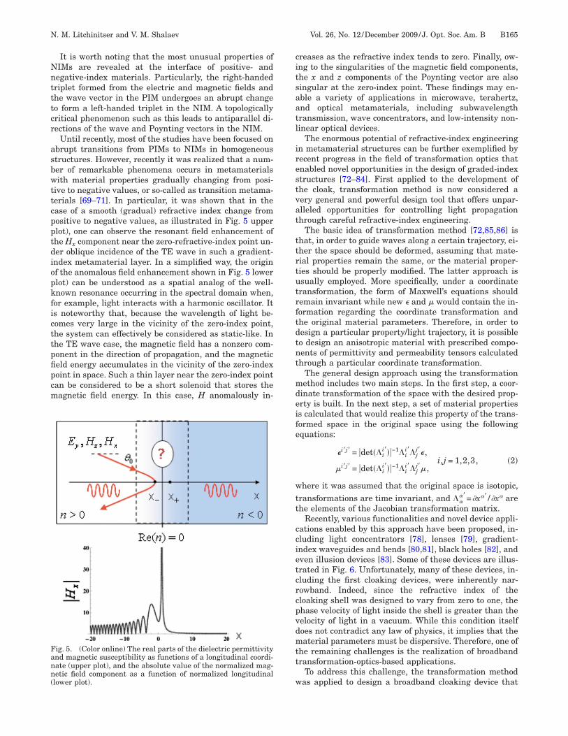
Until recently, most of the studies have been focused onabrupt transitions from PIMs to NIMs in homogeneousstructures. However, recently it was realized that a num-ber of remarkable phenomena occurs in metamaterialswith material properties gradually changing from posi-tive to negative values, or so-called as transition metama-terials [69–71]. In particular, it was shown that in thecase of a smooth (gradual) refractive index change frompositive to negative values, as illustrated in Fig. 5 upperplot), one can observe the resonant field enhancement ofthe Hx component near the zero-refractive-index point un-der oblique incidence of the TE wave in such a gradient-index metamaterial layer. In a simplified way, the originof the anomalous field enhancement shown in Fig. 5 lowerplot) can be understood as a spatial analog of the well-known resonance occurring in the spectral domain when,for example, light interacts with a harmonic oscillator. Itis noteworthy that, because the wavelength of light be-comes very large in the vicinity of the zero-index point,the system can effectively be considered as static-like. Inthe TE wave case, the magnetic field has a nonzero com-ponent in the direction of propagation, and the magneticfield energy accumulates in the vicinity of the zero-indexpoint in space. Such a thin layer near the zero-index pointcan be considered to be a short solenoid that stores themagnetic field energy. In this case, H anomalously in-
creases as the refractive index tends to zero. Finally, ow-ing to the singularities of the magnetic field components,the x and z components of the Poynting vector are alsosingular at the zero-index point. These findings may en-able a variety of applications in microwave, terahertz,and optical metamaterials, including subwavelengthtransmission, wave concentrators, and low-intensity non-linear optical devices.
The enormous potential of refractive-index engineeringin metamaterial structures can be further exemplified byrecent progress in the field of transformation optics thatenabled novel opportunities in the design of graded-indexstructures [72–84]. First applied to the development ofthe cloak, transformation method is now considered avery general and powerful design tool that offers unpar-alleled opportunities for controlling light propagationthrough careful refractive-index engineering.
The basic idea of transformation method [72,85,86] isthat, in order to guide waves along a certain trajectory, ei-ther the space should be deformed, assuming that mate-rial properties remain the same, or the material proper-ties should be properly modified. The latter approach isusually employed. More specifically, under a coordinatetransformation, the form of Maxwell’s equations shouldremain invariant while new � and � would contain the in-formation regarding the coordinate transformation andthe original material parameters. Therefore, in order todesign a particular property/light trajectory, it is possibleto design an anisotropic material with prescribed compo-nents of permittivity and permeability tensors calculatedthrough a particular coordinate transformation.
The general design approach using the transformationmethod includes two main steps. In the first step, a coor-dinate transformation of the space with the desired prop-erty is built. In the next step, a set of material propertiesis calculated that would realize this property of the trans-formed space in the original space using the followingequations:
�i�j� = �det��ii���−1�i
i��jj��,
�i�j� = �det��ii���−1�i
i��jj��,
i,j = 1,2,3, �2�
where it was assumed that the original space is isotopic,transformations are time invariant, and �
�=�x� /�x arethe elements of the Jacobian transformation matrix.
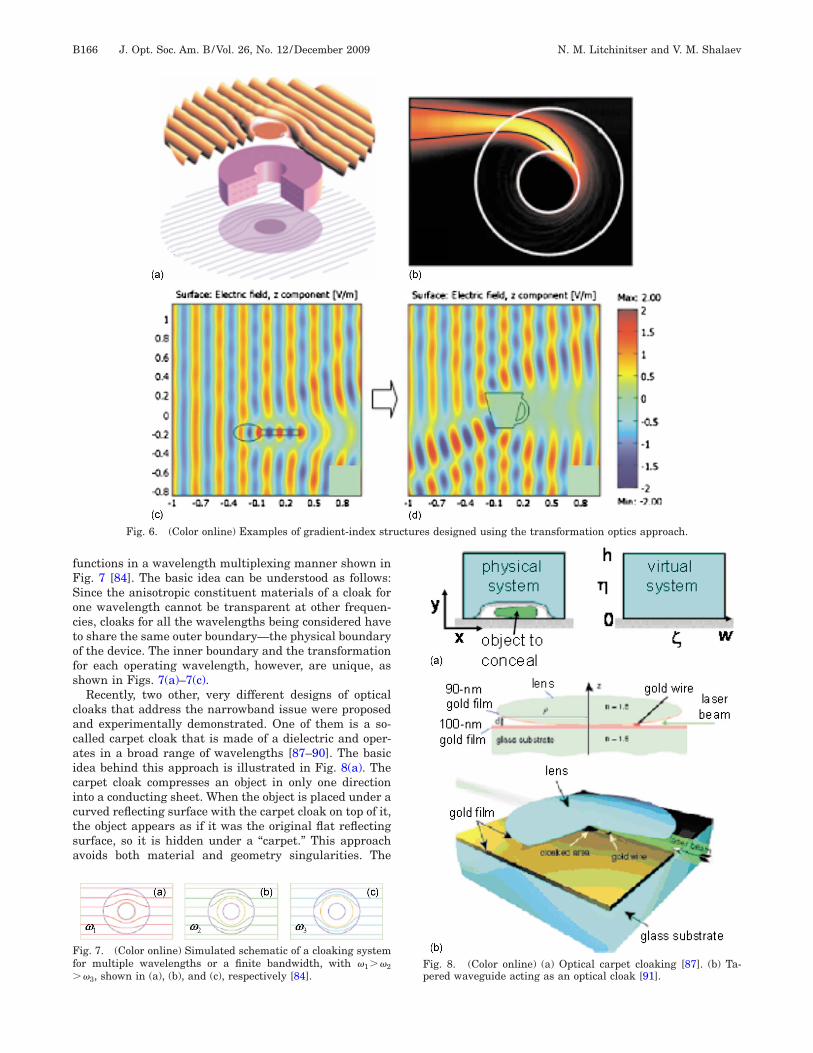
Recently, various functionalities and novel device appli-cations enabled by this approach have been proposed, in-cluding light concentrators [78], lenses [79], gradient-index waveguides and bends [80,81], black holes [82], andeven illusion devices [83]. Some of these devices are illus-trated in Fig. 6. Unfortunately, many of these devices, in-cluding the first cloaking devices, were inherently nar-rowband. Indeed, since the refractive index of thecloaking shell was designed to vary from zero to one, thephase velocity of light inside the shell is greater than thevelocity of light in a vacuum. While this condition itselfdoes not contradict any law of physics, it implies that thematerial parameters must be dispersive. Therefore, one ofthe remaining challenges is the realization of broadbandtransformation-optics-based applications.
To address this challenge, the transformation methodwas applied to design a broadband cloaking device that
Fig. 5. (Color online) The real parts of the dielectric permittivityand magnetic susceptibility as functions of a longitudinal coordi-nate (upper plot), and the absolute value of the normalized mag-netic field component as a function of normalized longitudinal(lower plot).
N. M. Litchinitser and V. M. Shalaev Vol. 26, No. 12 /December 2009 /J. Opt. Soc. Am. B B165
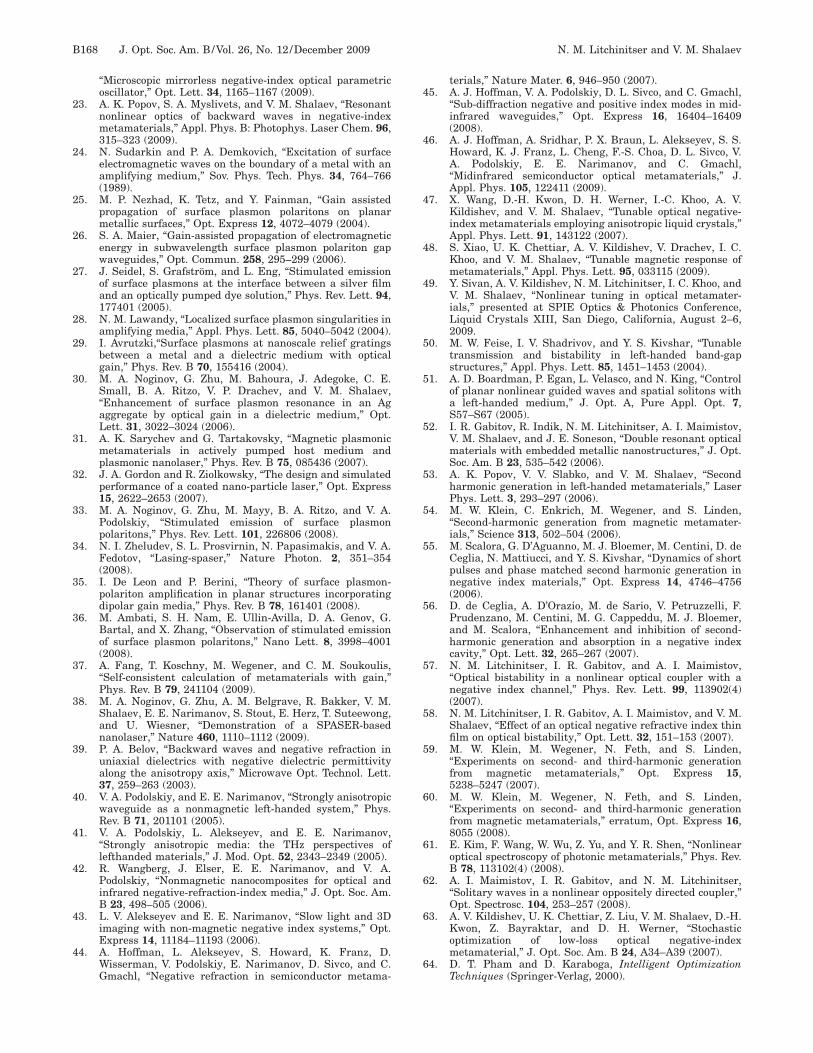
functions in a wavelength multiplexing manner shown inFig. 7 [84]. The basic idea can be understood as follows:Since the anisotropic constituent materials of a cloak forone wavelength cannot be transparent at other frequen-cies, cloaks for all the wavelengths being considered haveto share the same outer boundary—the physical boundaryof the device. The inner boundary and the transformationfor each operating wavelength, however, are unique, asshown in Figs. 7(a)–7(c).
Recently, two other, very different designs of opticalcloaks that address the narrowband issue were proposedand experimentally demonstrated. One of them is a so-called carpet cloak that is made of a dielectric and oper-ates in a broad range of wavelengths [87–90]. The basicidea behind this approach is illustrated in Fig. 8(a). Thecarpet cloak compresses an object in only one directioninto a conducting sheet. When the object is placed under acurved reflecting surface with the carpet cloak on top of it,the object appears as if it was the original flat reflectingsurface, so it is hidden under a “carpet.” This approachavoids both material and geometry singularities. The
Fig. 6. (Color online) Examples of gradient-index structures designed using the transformation optics approach.
Fig. 7. (Color online) Simulated schematic of a cloaking systemfor multiple wavelengths or a finite bandwidth, with �1��2��3, shown in (a), (b), and (c), respectively [84].
Fig. 8. (Color online) (a) Optical carpet cloaking [87]. (b) Ta-pered waveguide acting as an optical cloak [91].
B166 J. Opt. Soc. Am. B/Vol. 26, No. 12 /December 2009 N. M. Litchinitser and V. M. Shalaev
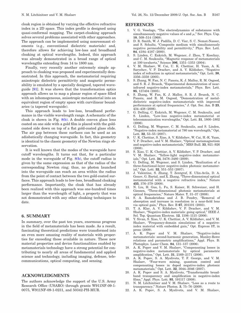
cloak region is obtained by varying the effective refractiveindex in a 2D space. This index profile is designed usingquasi-conformal mapping. The carpet-cloaking approachsolves several problems associated with other approaches.The approach can be implemented using nonresonant el-ements (e.g., conventional dielectric materials) and,therefore allows for achieving low-loss and broadbandcloaking at optical wavelengths. Indeed, this approachwas already demonstrated in a broad range of opticalwavelengths extending from 14 to 1800 nm.
Finally, very recently another extremely simple ap-proach to cloaking was proposed and experimentally dem-onstrated. In this approach, the metamaterial requiringanisotropic dielectric permittivity and magnetic perme-ability is emulated by a specially designed, tapered wave-guide [91]. It was shown that the transformation opticsapproach allows us to map a planar region of space filledwith an inhomogeneous, anisotropic metamaterial into anequivalent region of empty space with curvilinear bound-aries (a tapered waveguide).
This approach leads to low-loss, broadband perfor-mance in the visible wavelength range. A schematic of thecloak is shown in Fig. 8(b). A double convex glass lenscoated on one side with a gold film is placed with the gold-coated side down on top of a flat gold-coated glass slide.The air gap between these surfaces can be used as anadiabatically changing waveguide. In fact, this geometryis identical to the classic geometry of the Newton rings ob-servation.
It is well known that the modes of the waveguide havecutoff wavelengths. It turns out that, for a particularmode in the waveguide of Fig. 8(b), the cutoff radius isgiven by the same expression as that of the radius of thecorresponding Newton ring; thus, no photon launchedinto the waveguide can reach an area within the radiusfrom the point of contact between the two gold-coated sur-faces. This approach leads to low-loss, broadband cloakingperformance. Importantly, the cloak that has alreadybeen realized with this approach was one-hundred timeslarger than the wavelength of light, a property that wasnot demonstrated with any other cloaking techniques todate.
6. SUMMARYIn summary, over the past ten years, enormous progressin the field of metamaterials has been made. As a result,fascinating theoretical predictions were transformed intoan even more amazing reality of materials with proper-ties far exceeding those available in nature. These newmaterial properties and device functionalities enabled bymetamaterials technology have a strong potential for con-tributing to nearly all areas of fundamental and appliedscience and technology, including imaging, defense, tele-communications, optical computing, and sensing.
ACKNOWLEDGMENTSThe authors acknowledge the support of the U.S. ArmyResearch Office (USARO) through grants W911NF-09-1-0075, W911NF-09-1-0231, and 50342-PH-MUR.
REFERENCES1. V. G. Veselago, “The electrodynamics of substances with
simultaneously negative values of � and �,” Sov. Phys. Usp.10, 509–514 (1968).
2. D. R. Smith, W. J. Padilla, D. C. Vier, S. C. Nemat-Nasser,and S. Schultz, “Composite medium with simultaneouslynegative permeability and permittivity,” Phys. Rev. Lett.84, 4184–4187 (2000).
3. S. Linden, C. Enkrich, M. Wegener, J. Zhou, T. Koschny,and C. M. Soukoulis, “Magnetic response of metamaterialsat 100 terahertz,” Science 306, 1351–1353 (2004).
4. V. M. Shalaev, W. Cai, U. K. Chettiar, H. Yuan, A. K.Sarychev, V. P. Drachev, and A. V. Kildishev, “Negativeindex of refraction in optical metamaterials,” Opt. Lett. 30,3356–3358 (2005).
5. S. Zhang, W. Fan, N. C. Panoiu, K. J. Malloy, R. M. Osgood,and S. R. J. Brueck, “Experimental demonstration of near-infrared negative-index metamaterials,” Phys. Rev. Lett.95, 137404 (2005).
6. S. Zhang, W. Fan, K. J. Malloy, S. R. J. Brueck, N. C.Panoiu, and R. M. Osgood, “Demonstration of metal-dielectric negative-index metamaterials with improvedperformance at optical frequencies,” J. Opt. Soc. Am. B 23,434–438 (2006).
7. G. Dolling, C. Enkrich, M. Wegener, C. M. Soukoulis, andS. Linden, “Low-loss negative-index metamaterial attelecommunication wavelengths,” Opt. Lett. 31, 1800–1802(2006).
8. G. Dolling, M. Wegener, C. M. Soukoulis, and S. Linden,“Negative-index metamaterial at 780 nm wavelength,” Opt.Lett. 32, 53–55 (2007).
9. U. K. Chettiar, S. Xiao, A. V. Kildishev, W. Cai, H.-K. Yuan,V. P. Drachev, and V. M. Shalaev, “Optical metamagnetismand negative-index metamaterials,” MRS Bull. 33, 921–926(2008).
10. S. Xiao, U. K. Chettiar, A. V. Kildishev, V. P. Drachev, andV. M. Shalaev, “Yellow-light negative-index metamater-ials,” Opt. Lett. 34, 3478–3480 (2009).
11. G. Dolling, M. Wegener, and S. Linden, “Realization of athree-functional-layer negative-index photonic metamater-ial,” Opt. Lett. 32, 551–553 (2007).
12. J. Valentine, S. Zhang, T. Zentgraf, E. Ulin-Avila, D. A.Genov, G. Bartal, and X. Zhang, “Three-dimensional opticalmetamaterial with a negative refractive index,” Nature455, 376–379 (2008).
13. N. Liu, H. Guo, L. Fu, S. Kaiser, H. Schweizer, and H.Giessen, “Three-dimensional photonic metamaterials atoptical frequencies,” Nature Mater. 7, 31–37 (2008).
14. S. A. Ramakrishna and J. B. Pendry, “Removal ofabsorption and increase in resolution in a near-field lensvia optical gain,” Phys. Rev. B 67, 201101 (2003).
15. T. A. Klar, A. V. Kildishev, V. P. Drachev, and V. M.Shalaev, “Negative-index materials: going optical,” IEEE J.Sel. Top. Quantum Electron. 12, 1106–1115 (2006).
16. Y. Sivan, S. Xiao, U. K. Chettiar, A. V. Kildishev, and V. M.Shalaev, “Frequency-domain simulations of a negative-index material with embedded gain,” Opt. Express 17, inpress (2009).
17. A. K. Popov and V. M. Shalaev, “Negative-indexmetamaterials: second-harmonic generation, Manley-Rowerelations and parametric amplifications,” Appl. Phys. B:Photophys. Laser Chem. 84, 131–137 (2006).
18. A. K. Popov and V. M. Shalaev, “Compensating losses innegative-index metamaterials by optical parametricamplification,” Opt. Lett. 31, 2169–2171 (2006).
19. A. K. Popov, S. A. Myslivets, T. F. George, and V. M.Shalaev, “Four-wave mixing, quantum control andcompensating losses in doped negative-index photonicmetamaterials,” Opt. Lett. 32, 3044–3046 (2007).
20. A. K. Popov and S. A. Myslivets, “Transformable broad-band transparency and amplification in negative-indexfilms,” Appl. Phys. Lett. 93, 191117 (2008).
21. N. M. Litchinitser and V. M. Shalaev, “Loss as a route totransparency,” Nature Photon. 3, 75–76 (2009).
22. A. K. Popov, S. A. Myslivets, and V. M. Shalaev,
N. M. Litchinitser and V. M. Shalaev Vol. 26, No. 12 /December 2009 /J. Opt. Soc. Am. B B167
“Microscopic mirrorless negative-index optical parametricoscillator,” Opt. Lett. 34, 1165–1167 (2009).
23. A. K. Popov, S. A. Myslivets, and V. M. Shalaev, “Resonantnonlinear optics of backward waves in negative-indexmetamaterials,” Appl. Phys. B: Photophys. Laser Chem. 96,315–323 (2009).
24. N. Sudarkin and P. A. Demkovich, “Excitation of surfaceelectromagnetic waves on the boundary of a metal with anamplifying medium,” Sov. Phys. Tech. Phys. 34, 764–766(1989).
25. M. P. Nezhad, K. Tetz, and Y. Fainman, “Gain assistedpropagation of surface plasmon polaritons on planarmetallic surfaces,” Opt. Express 12, 4072–4079 (2004).
26. S. A. Maier, “Gain-assisted propagation of electromagneticenergy in subwavelength surface plasmon polariton gapwaveguides,” Opt. Commun. 258, 295–299 (2006).
27. J. Seidel, S. Grafström, and L. Eng, “Stimulated emissionof surface plasmons at the interface between a silver filmand an optically pumped dye solution,” Phys. Rev. Lett. 94,177401 (2005).
28. N. M. Lawandy, “Localized surface plasmon singularities inamplifying media,” Appl. Phys. Lett. 85, 5040–5042 (2004).
29. I. Avrutzki,“Surface plasmons at nanoscale relief gratingsbetween a metal and a dielectric medium with opticalgain,” Phys. Rev. B 70, 155416 (2004).
30. M. A. Noginov, G. Zhu, M. Bahoura, J. Adegoke, C. E.Small, B. A. Ritzo, V. P. Drachev, and V. M. Shalaev,“Enhancement of surface plasmon resonance in an Agaggregate by optical gain in a dielectric medium,” Opt.Lett. 31, 3022–3024 (2006).
31. A. K. Sarychev and G. Tartakovsky, “Magnetic plasmonicmetamaterials in actively pumped host medium andplasmonic nanolaser,” Phys. Rev. B 75, 085436 (2007).
32. J. A. Gordon and R. Ziolkowsky, “The design and simulatedperformance of a coated nano-particle laser,” Opt. Express15, 2622–2653 (2007).
33. M. A. Noginov, G. Zhu, M. Mayy, B. A. Ritzo, and V. A.Podolskiy, “Stimulated emission of surface plasmonpolaritons,” Phys. Rev. Lett. 101, 226806 (2008).
34. N. I. Zheludev, S. L. Prosvirnin, N. Papasimakis, and V. A.Fedotov, “Lasing-spaser,” Nature Photon. 2, 351–354(2008).
35. I. De Leon and P. Berini, “Theory of surface plasmon-polariton amplification in planar structures incorporatingdipolar gain media,” Phys. Rev. B 78, 161401 (2008).
36. M. Ambati, S. H. Nam, E. Ullin-Avilla, D. A. Genov, G.Bartal, and X. Zhang, “Observation of stimulated emissionof surface plasmon polaritons,” Nano Lett. 8, 3998–4001(2008).
37. A. Fang, T. Koschny, M. Wegener, and C. M. Soukoulis,“Self-consistent calculation of metamaterials with gain,”Phys. Rev. B 79, 241104 (2009).
38. M. A. Noginov, G. Zhu, A. M. Belgrave, R. Bakker, V. M.Shalaev, E. E. Narimanov, S. Stout, E. Herz, T. Suteewong,and U. Wiesner, “Demonstration of a SPASER-basednanolaser,” Nature 460, 1110–1112 (2009).
39. P. A. Belov, “Backward waves and negative refraction inuniaxial dielectrics with negative dielectric permittivityalong the anisotropy axis,” Microwave Opt. Technol. Lett.37, 259–263 (2003).
40. V. A. Podolskiy, and E. E. Narimanov, “Strongly anisotropicwaveguide as a nonmagnetic left-handed system,” Phys.Rev. B 71, 201101 (2005).
41. V. A. Podolskiy, L. Alekseyev, and E. E. Narimanov,“Strongly anisotropic media: the THz perspectives oflefthanded materials,” J. Mod. Opt. 52, 2343–2349 (2005).
42. R. Wangberg, J. Elser, E. E. Narimanov, and V. A.Podolskiy, “Nonmagnetic nanocomposites for optical andinfrared negative-refraction-index media,” J. Opt. Soc. Am.B 23, 498–505 (2006).
43. L. V. Alekseyev and E. E. Narimanov, “Slow light and 3Dimaging with non-magnetic negative index systems,” Opt.Express 14, 11184–11193 (2006).
44. A. Hoffman, L. Alekseyev, S. Howard, K. Franz, D.Wisserman, V. Podolskiy, E. Narimanov, D. Sivco, and C.Gmachl, “Negative refraction in semiconductor metama-
terials,” Nature Mater. 6, 946–950 (2007).45. A. J. Hoffman, V. A. Podolskiy, D. L. Sivco, and C. Gmachl,
“Sub-diffraction negative and positive index modes in mid-infrared waveguides,” Opt. Express 16, 16404–16409(2008).
46. A. J. Hoffman, A. Sridhar, P. X. Braun, L. Alekseyev, S. S.Howard, K. J. Franz, L. Cheng, F.-S. Choa, D. L. Sivco, V.A. Podolskiy, E. E. Narimanov, and C. Gmachl,“Midinfrared semiconductor optical metamaterials,” J.Appl. Phys. 105, 122411 (2009).
47. X. Wang, D.-H. Kwon, D. H. Werner, I.-C. Khoo, A. V.Kildishev, and V. M. Shalaev, “Tunable optical negative-index metamaterials employing anisotropic liquid crystals,”Appl. Phys. Lett. 91, 143122 (2007).
48. S. Xiao, U. K. Chettiar, A. V. Kildishev, V. Drachev, I. C.Khoo, and V. M. Shalaev, “Tunable magnetic response ofmetamaterials,” Appl. Phys. Lett. 95, 033115 (2009).
49. Y. Sivan, A. V. Kildishev, N. M. Litchinitser, I. C. Khoo, andV. M. Shalaev, “Nonlinear tuning in optical metamater-ials,” presented at SPIE Optics & Photonics Conference,Liquid Crystals XIII, San Diego, California, August 2–6,2009.
50. M. W. Feise, I. V. Shadrivov, and Y. S. Kivshar, “Tunabletransmission and bistability in left-handed band-gapstructures,” Appl. Phys. Lett. 85, 1451–1453 (2004).
51. A. D. Boardman, P. Egan, L. Velasco, and N. King, “Controlof planar nonlinear guided waves and spatial solitons witha left-handed medium,” J. Opt. A, Pure Appl. Opt. 7,S57–S67 (2005).
52. I. R. Gabitov, R. Indik, N. M. Litchinitser, A. I. Maimistov,V. M. Shalaev, and J. E. Soneson, “Double resonant opticalmaterials with embedded metallic nanostructures,” J. Opt.Soc. Am. B 23, 535–542 (2006).
53. A. K. Popov, V. V. Slabko, and V. M. Shalaev, “Secondharmonic generation in left-handed metamaterials,” LaserPhys. Lett. 3, 293–297 (2006).
54. M. W. Klein, C. Enkrich, M. Wegener, and S. Linden,“Second-harmonic generation from magnetic metamater-ials,” Science 313, 502–504 (2006).
55. M. Scalora, G. D’Aguanno, M. J. Bloemer, M. Centini, D. deCeglia, N. Mattiucci, and Y. S. Kivshar, “Dynamics of shortpulses and phase matched second harmonic generation innegative index materials,” Opt. Express 14, 4746–4756(2006).
56. D. de Ceglia, A. D’Orazio, M. de Sario, V. Petruzzelli, F.Prudenzano, M. Centini, M. G. Cappeddu, M. J. Bloemer,and M. Scalora, “Enhancement and inhibition of second-harmonic generation and absorption in a negative indexcavity,” Opt. Lett. 32, 265–267 (2007).
57. N. M. Litchinitser, I. R. Gabitov, and A. I. Maimistov,“Optical bistability in a nonlinear optical coupler with anegative index channel,” Phys. Rev. Lett. 99, 113902(4)(2007).
58. N. M. Litchinitser, I. R. Gabitov, A. I. Maimistov, and V. M.Shalaev, “Effect of an optical negative refractive index thinfilm on optical bistability,” Opt. Lett. 32, 151–153 (2007).
59. M. W. Klein, M. Wegener, N. Feth, and S. Linden,“Experiments on second- and third-harmonic generationfrom magnetic metamaterials,” Opt. Express 15,5238–5247 (2007).
60. M. W. Klein, M. Wegener, N. Feth, and S. Linden,“Experiments on second- and third-harmonic generationfrom magnetic metamaterials,” erratum, Opt. Express 16,8055 (2008).
61. E. Kim, F. Wang, W. Wu, Z. Yu, and Y. R. Shen, “Nonlinearoptical spectroscopy of photonic metamaterials,” Phys. Rev.B 78, 113102(4) (2008).
62. A. I. Maimistov, I. R. Gabitov, and N. M. Litchinitser,“Solitary waves in a nonlinear oppositely directed coupler,”Opt. Spectrosc. 104, 253–257 (2008).
63. A. V. Kildishev, U. K. Chettiar, Z. Liu, V. M. Shalaev, D.-H.Kwon, Z. Bayraktar, and D. H. Werner, “Stochasticoptimization of low-loss optical negative-indexmetamaterial,” J. Opt. Soc. Am. B 24, A34–A39 (2007).
64. D. T. Pham and D. Karaboga, Intelligent OptimizationTechniques (Springer-Verlag, 2000).
B168 J. Opt. Soc. Am. B/Vol. 26, No. 12 /December 2009 N. M. Litchinitser and V. M. Shalaev
65. R. L. Haupt and S. E. Haupt, Practical Genetic Algorithms(Wiley-Interscience, 2004).
66. J. Kennedy and R. C. Eberhart, Swarm Intelligence(Academic, 2001).
67. A. V. Kildishev, Y. Sivan, N. M. Litchinitser, and V. M.Shalaev, “Frequency-domain modeling of scalar TM wavepropagation in optical nanostructures with a third-ordernonlinear response,” Opt. Lett. 34, 3364–3366 (2009).
68. A. V. Kildishev and N. M. Litchinitser, “Efficient simulationof non-linear effects in 2D optical nanostructures to TMwaves,” Opt. Commun. Doi:10.1016/j.optcom.2009.09.039.
69. N. M. Litchinitser, A. I. Maimistov, I. R. Gabitov, R. Z.Sagdeev, and V. M. Shalaev, “Metamaterials: electromag-netic enhancement at zero-index transition,” Opt. Lett. 33,2350–2352 (2008).
70. M. Dalarsson and P. Tassin, “Analytical solution for wavepropagation through a graded index interface between aright-handed and a left-handed material,” Opt. Express 17,6747–6752 (2009).
71. K. Kim, D.-H. Lee, and H. Lim, “Resonant absorption andmode conversion in a transition layer between positive-index and negative-index media,” Opt. Express 16,18505–18513 (2008).
72. J. B. Pendry, D. Schurig, and D. R. Smith, “Controllingelectromagnetic fields,” Science 312, 1780–1782 (2006).
73. U. Leonhardt, “Optical conformal mapping,” Science 312,1777–1780 (2006).
74. U. Leonhardt and T. G. Philbin, “General relativity inelectrical engineering,” New J. Phys. 8, 247 (2006).
75. D. Schurig, J. J. Mock, B. J. Justice, S. A. Cummer, J. B.Pendry, A. F. Starr, and D. R. Smith, “Metamaterialelectromagnetic cloak at microwave frequencies,” Science314, 977–980 (2006).
76. W. Cai, U. K. Chettiar, A. V. Kildishev, and V. M. Shalaev,“Optical cloaking with metamaterials,” Nature Photon. 1,224–227 (2007).
77. W. Cai, U. K. Chettiar, A. V. Kildishev, V. M. Shalaev, andG. Milton, “Nonmagnetic cloak with minimized scattering,”Appl. Phys. Lett. 91, 111105 (2007).
78. M. Rahm, D. Schurig, D. A. Roberts, S. A. Cummer, D. R.Smith, and J. B. Pendry, “Design of electromagnetic cloaksand concentrators using form-invariant coordinatetransformations of Maxwell’s equations,” Photonics
Nanostruct. Fundam. Appl. 6, 87–95 (2008).79. A. V. Kildishev and V. M. Shalaev, “Engineering space for
light via transformation optics,” Opt. Lett. 33, 43–45(2008).
80. W. X. Jiang, T. J. Cui, X. Y. Zhou, X. M. Yang, and Q.Cheng, “Arbitrary bending of electromagnetic waves usingrealizable inhomogeneous and anisotropic materials,”Phys. Rev. E 78, 066607 (2008).
81. M. Rahm, D. A. Roberts, J. B. Pendry, and D. R. Smith,“Transformation-optical design of adaptive beam bends andbeam expanders,” Opt. Express 16, 11555–11567 (2008).
82. E. E. Narimanov and A. V. Kildishev, “Optical black hole:broadband omnidirectional light absorber,” Appl. Phys.Lett. 95, 041106 (2009).
83. Y. Lai, J. Ng, H. Y. Chen, D. Han, J. Xiao, Z.-Q. Zhang, andC. T. Chan, “Illusion optics: the optical transformation of anobject into another object,” Phys. Rev. Lett. 102, 253902(2009).
84. A. V. Kildishev, W. Cai, U. K. Chettiar, and V. M. Shalaev,“Transformation optics: approaching broadbandelectromagnetic cloaking,” New J. Phys. 10, 115029 (2008).
85. L. S. Dolin, “On the possibility of comparison of three-dimensional electromagnetic systems with nonuniformanisotropic filling,” Izv. Vyssh. Uchebn. Zaved., Radiofiz. 4,964–967 (1961).
86. A. J. Ward and J. B. Pendry, “Refraction and geometry inMaxwell’s equations,” J. Mod. Opt. 43, 773–793 (1996).
87. J. Li and J. B. Pendry, “Hiding under the carpet: a newstrategy for cloaking,” Phys. Rev. Lett. 101, 203901 (2008).
88. J. Valentine, J. Li, T. Zentgraf, G. Bartal, and X. Zhang,“An optical cloak made of dielectrics,” Nature Mater. 8,568–571 (2009).
89. R. Liu, C. Ji, J. J. Mock, J. Y. Chin, T. J. Cui, and D. R.Smith, “Broadband ground-plane cloak,” Science 323,366–369 (2009).
90. L. H. Gabrielli, J. Cardenas, C. B. Poitras, and M. Lipson,“Silicon nanostructure cloak operating at opticalfrequencies,” Nature Photon. 3, 461–463 (2009).
91. I. I. Smolyaninov, V. N. Smolyaninova, A. V. Kildishev, andV. M. Shalaev, “Anisotropic metamaterials emulated bytapered waveguides: application to optical cloaking,” Phys.Rev. Lett. 102, 213901 (2009).
N. M. Litchinitser and V. M. Shalaev Vol. 26, No. 12 /December 2009 /J. Opt. Soc. Am. B B169