Zero loss magnetic metamaterials using powered active unit cells
9
Zero loss magnetic metamaterials using powered active unit cells Yu Yuan, Bogdan-Ioan Popa, Steven A. Cummer Center for Metamaterials and Integrated Plasmonics and Department of Electrical and Computer Engineering, Duke University, Durham, North Carolina, 27708 [email protected], [email protected] Abstract: We report the design and experimental measurement of a powered active magnetic metamaterial with tunable permeability. The unit cell is based on the combination of an embedded radiofrequency amplifier and a tunable phase shifter, which together control the response of the medium. The measurements show that a negative permeability metamaterial with zero loss or even gain can be achieved through an array of such metamaterial cells. This kind of active metamaterial can find use in applications that are performance limited due to material losses. © 2009 Optical Society of America OCIS codes: (160.1245) Artificially engineered materials; (160.3918) Metamaterials; (350.4010) Other areas of optics : Microwaves References and links 1. J. B. Pendry,“Negative refraction makes a perfect lens,” Phys. Rev. Lett. 85, 3966 (2000). 2. S. Enoch, G. Tayeb, P. Sabouroux, N. Guerin, and P. Vincent, “A metamaterial for directive emission,” Phys. Rev. Lett. 89, 213902 (2002). 3. Y. Yuan, L. Shen, L. Ran, T. Jiang, J. Huangfu, and J. A. Kong, “Directive emission based on anisotropic meta- materials ,” Phys. Rev. A 77, 053821 (2008). 4. J. B. Pendry, D. Schurig, and D. R. Smith, “Controlling electromagnetic fields,” Science 312, 1780-1782 (2006). 5. D. Schurig, J. J. Mock, B. J. Justice, S. A. Cummer, J. B. Pendry, A. F. Starr, and D. R. Smith, “Metamaterial electromagnetic cloak at microwave frequencies,” Science 314, 977-980 (2006). 6. S. A. Cummer, B.-I. Popa, D. Schurig, D. R. Smith, and J. Pendry, “Full-wave simulations of electromagnetic cloaking structures,” Phys. Rev. E 74, 036621 (2006). 7. H. Chen, B.-I. Wu, B. Zhang, and J. A. Kong, “Electromagnetic wave interactions with a metamaterial cloak ,” Phys. Rev. Lett. 99, 063903 (2007). 8. S. A. Tretyakov, “Meta-materials with wideband negative permittivity and permeability,” Microwave Opt. Tech- nology Lett. 31, 163-165 (2001). 9. A. D. Boardman, Y. G. Rapoport, N. King, and V. N. Malnev, “Creating stable gain in active metamaterials,” J. Opt. Soc. Am. B 24, A53-A61 (2007). 10. R. R. A. Syms, L. Solymar, and I. R. Young, “Three-frequency parametric amplification in magneto-inductive ring resonators,” Metamaterials 2, 122-134 (2008). 11. A. Fang, Th. Koschny, M. Wegener, C. M. Soukoulis, “Self-consistent calculation of metamaterials with gain, ” Phys. Rev. B 79, 241104(R) (2009). 12. B. Nistad, and J. Skaar, “Causality and electromagnetic properties of active media,” Phys. Rev. E 78, 036603 (2008). 13. P. Kinsler, “Refractive index and wave vector in passive and active media,” Phys. Rev. A 79, 023839 (2009). 14. B. I. Popa and S. A. Cummer, “An architecture for active metamaterial particles and experimental validation at RF,” Microwave Opt. Technology Lett. 49, 2574-2577 (2007). 15. Y. Yuan, L. Ran, J. Huangfu, H. Chen, L. Shen, and J. A. Kong, “Experimental verification of zero order bandgap in a layered stack of left-handed and right-handed materials,” Opt. Express 14, 2220-2227 (2006). 16. H. Chen, J. Zhang, Y. Bai, Y. Luo, L. Ran, Q. Jiang, and J. A. Kong,“Experimental retrieval of the effective parameters of metamaterials based on a waveguide method,” Opt. Express 14, 12944-12949 (2006). 17. A. Sellier, S. N. Burokur, B. Kant, and A. de Lustrac,“Negative refractive index metamaterials using only metallic cut wires,” Opt. Express 17, 6301-6310 (2009). #112519 - $15.00 USD Received 9 Jun 2009; revised 14 Aug 2009; accepted 21 Aug 2009; published 26 Aug 2009 (C) 2009 OSA 31 August 2009 / Vol. 17, No. 18 / OPTICS EXPRESS 16135
-
Upload
independent -
Category
Documents
-
view
2 -
download
0
Transcript of Zero loss magnetic metamaterials using powered active unit cells
Zero loss magnetic metamaterials usingpowered active unit cells
Yu Yuan, Bogdan-Ioan Popa, Steven A. CummerCenter for Metamaterials and Integrated Plasmonics and Department of Electrical and
Computer Engineering, Duke University, Durham, North Carolina, [email protected], [email protected]
Abstract: We report the design and experimental measurement of apowered active magnetic metamaterial with tunable permeability. Theunit cell is based on the combination of an embedded radiofrequencyamplifier and a tunable phase shifter, which together control the responseof the medium. The measurements show that a negative permeabilitymetamaterial with zero loss or even gain can be achieved through an arrayof such metamaterial cells. This kind of active metamaterial can find use inapplications that are performance limited due to material losses.
© 2009 Optical Society of America
OCIS codes: (160.1245) Artificially engineered materials; (160.3918) Metamaterials;(350.4010) Other areas of optics : Microwaves
References and links1. J. B. Pendry,“Negative refraction makes a perfect lens,” Phys. Rev. Lett. 85, 3966 (2000).2. S. Enoch, G. Tayeb, P. Sabouroux, N. Guerin, and P. Vincent, “A metamaterial for directive emission,” Phys. Rev.
Lett. 89, 213902 (2002).3. Y. Yuan, L. Shen, L. Ran, T. Jiang, J. Huangfu, and J. A. Kong, “Directive emission based on anisotropic meta-
materials ,” Phys. Rev. A 77, 053821 (2008).4. J. B. Pendry, D. Schurig, and D. R. Smith, “Controlling electromagnetic fields,” Science 312, 1780-1782 (2006).5. D. Schurig, J. J. Mock, B. J. Justice, S. A. Cummer, J. B. Pendry, A. F. Starr, and D. R. Smith, “Metamaterial
electromagnetic cloak at microwave frequencies,” Science 314, 977-980 (2006).6. S. A. Cummer, B.-I. Popa, D. Schurig, D. R. Smith, and J. Pendry, “Full-wave simulations of electromagnetic
cloaking structures,” Phys. Rev. E 74, 036621 (2006).7. H. Chen, B.-I. Wu, B. Zhang, and J. A. Kong, “Electromagnetic wave interactions with a metamaterial cloak ,”
Phys. Rev. Lett. 99, 063903 (2007).8. S. A. Tretyakov, “Meta-materials with wideband negative permittivity and permeability,” Microwave Opt. Tech-
nology Lett. 31, 163-165 (2001).9. A. D. Boardman, Y. G. Rapoport, N. King, and V. N. Malnev, “Creating stable gain in active metamaterials,” J.
Opt. Soc. Am. B 24, A53-A61 (2007).10. R. R. A. Syms, L. Solymar, and I. R. Young, “Three-frequency parametric amplification in magneto-inductive
ring resonators,” Metamaterials 2, 122-134 (2008).11. A. Fang, Th. Koschny, M. Wegener, C. M. Soukoulis, “Self-consistent calculation of metamaterials with gain, ”
Phys. Rev. B 79, 241104(R) (2009).12. B. Nistad, and J. Skaar, “Causality and electromagnetic properties of active media,” Phys. Rev. E 78, 036603
(2008).13. P. Kinsler, “Refractive index and wave vector in passive and active media,” Phys. Rev. A 79, 023839 (2009).14. B. I. Popa and S. A. Cummer, “An architecture for active metamaterial particles and experimental validation at
RF,” Microwave Opt. Technology Lett. 49, 2574-2577 (2007).15. Y. Yuan, L. Ran, J. Huangfu, H. Chen, L. Shen, and J. A. Kong, “Experimental verification of zero order bandgap
in a layered stack of left-handed and right-handed materials,” Opt. Express 14, 2220-2227 (2006).16. H. Chen, J. Zhang, Y. Bai, Y. Luo, L. Ran, Q. Jiang, and J. A. Kong,“Experimental retrieval of the effective
parameters of metamaterials based on a waveguide method,” Opt. Express 14, 12944-12949 (2006).17. A. Sellier, S. N. Burokur, B. Kant, and A. de Lustrac,“Negative refractive index metamaterials using only metallic
cut wires,” Opt. Express 17, 6301-6310 (2009).
#112519 - $15.00 USD Received 9 Jun 2009; revised 14 Aug 2009; accepted 21 Aug 2009; published 26 Aug 2009
(C) 2009 OSA 31 August 2009 / Vol. 17, No. 18 / OPTICS EXPRESS 16135
18. O. Reynet and O. Acher, “Voltage controlled metamaterial,” Appl. Phys. Lett. 84, 1198-1200 (2004).19. D. A. Powell, I. V. Shadrivov, Y. S. Kivshar, and M. V. Gorkunov, “Self-tuning mechanisms of nonlinear split-ring
resonators ,” Appl. Phys. Lett. 91, 144107 (2007).20. T. Hand and S. A. Cummer, “Characterization of tunable metamaterial elements using MEMS switches,” IEEE
Ant. Wireless Propagation Lett. 6, 401-404 (2007).21. D. Wang, L. Ran, H. Chen, M. Mu, J. A. Kong, and B.-I. Wu, “Active left-handed material collaborated with
microwave varactors,” Appl. Phys. Lett. 91, 164101 (2007).22. H.-T. Chen, W. J. Padilla1, J. M. O. Zide, A. C. Gossard, A. J. Taylor and R. D. Averitt, “Active terahertz
metamaterial devices, Nature 444, 597-600 (2006).23. O. Paul, C. Imhof, B. Lgel, S. Wolff, J. Heinrich, S. Hfling, A. Forchel, R. Zengerle, R. Beigang, and M. Rahm,
“Polarization-independent active metamaterial for high-frequency terahertz modulation,” Opt. Express 17, 819-827 (2009).
24. D. R. Smith, S. Schultz, P. Markos, and C. M. Soukoulis, “Determination of effective permittivity and perme-ability of metamaterials from reflection and transmission coefficients,” Phys. Rev. B 65, 195104 (2002).
25. X. Chen, T. M. Grzegorczyk, B. I. Wu, J. Pacheco, and J. A. Kong, “Robust method to retrieve the constitutiveeffective parameters of metamaterials,” Phys. Rev. E 70, 016608 (2004).
26. C. R. Simovski, and S. A. Tretyakov, “Local constitutive parameters of metamaterials from an effective-mediumperspective,” Phys. Rev. B 75, 195111 (2007).
27. D. R. Smith, D. C. Vier, Th. Koschny, and C. M. Soukoulis, “Electromagnetic parameter retrieval from inhomo-geneous metamaterials,” Phys. Rev. E 71, 036617 (2005).
28. U. K. Chettiar, A. V. Kildishev, H.-K. Yuan, W. Cai, S. Xiao, V. P. Drachev, and V. M. Shalaev, “Dual-bandnegative index metamaterial: double negative at 813 nm and single negative at 772 nm,” Opt. Lett. 32, 1671-1673(2007).
29. T. Koschny, P. Markos, D. R. Smith, and C. M. Soukoulis, “Resonant and antiresonant frequency dependence ofthe effective parameters of metamaterials,” Phys. Rev. E 68, 065602(R) (2003).
30. M. V. Gorkunov, S. A. Gredeskul, I. V. Shadrivov, and Y. S. Kivshar, “Effect of microscopic disorder on magneticproperties of metamaterials,” Phys. Rev. E 73, 056605 (2006).
31. H. Chen, L. Ran, J. Huangfu, T. M. Grzegorczyk, and J. A. Kong, “Equivalent circuit model for left-handedmetamaterials,” J. Appl. Phys. 100, 024915 (2006)
32. B.-I. Popa and S. A. Cummer, “Direct measurement of evanescent wave enhancement inside passive metamate-rials,” Phys. Rev. E 73, 016617 (2006).
1. Introduction
Electromagnetic metamaterials are artificially engineered materials possessing highly versatileeffective material properties. They offer the possibility of designing and building novel devices,such as perfect lenses that overcome the diffraction limit [1], directive antennas [2, 3] and invis-ibility cloaks [4, 6, 5, 7]. However, losses in metamaterials can severely limit their performancein these applications. It has long been recognized that powered active metamaterials can, inprinciple, be used compensate for metamaterial losses [8]. The theoretical challenges involvedin creating stable active metamaterials are significant [9, 10]. Theoretical analysis has shownthat complex behavior can result when gain elements are embedded in metamaterial structure[11], and the electromagnetic wave propagation, effective parameter characterization, and fun-damental limitations resulting from causality related to the active metamaterials are also com-plex [12, 13]. Although initial experimental efforts have shown that the concept can be madeto work [10, 14], active metamaterials have yet to be demonstrated in a realistic metamaterialconfiguration.
Here we report the fabrication and experimental measurement of a novel active magneticmetamaterial composed of arrays of unit cells designed based on the combination of an em-bedded radiofrequency (RF) amplifier and a tunable phase shifter, which together control theresponse of the medium. A basic architecture for powered active metamaterial particles waspreviously proposed and validated based on a single unit cell measurements [14]. Several sig-nificant improvements have been implemented in the work reported here. Like other metama-terials and their related physical properties in the RF domain [15, 16, 17], this kind of activemetamaterial can be designed, fabricated, and find their applications in the terahertz or evenhigher frequency ranges.
#112519 - $15.00 USD Received 9 Jun 2009; revised 14 Aug 2009; accepted 21 Aug 2009; published 26 Aug 2009
(C) 2009 OSA 31 August 2009 / Vol. 17, No. 18 / OPTICS EXPRESS 16136

Fig. 1. (Color online) (a) Photograph of the constructed unit cell for the powered activemagnetic metamaterial with individual components labeled. (b) A schematic of a singleunit cell (solid) and three unit cells (dashed) inside the waveguide in the measurements.The incident magnetic field is perpendicular to the planes containing the loops, and volumeunder test to which all extracted effective parameters apply is bounded by the dashed lines.
2. Principle
In order to demonstrate the principle behind our tunable active magnetic metamaterial, de-scriptions of the magnetic moment of the unit cell and the resulting effective permeabilityare demonstrated as follows. In a medium for which the homogenization theory applies theconstitutive equation that relates the magnetic field, B, and the H-field is, in the absence ofmagneto-electric coupling:
B = µ0(H+M) (1)
where M is the magnetization vector. The relative permeability tensor can be determined fromthis equation taking into account that B = µ0 ¯̄µrH. If B, H, and M are colinear, as is the case inour analysis, only one component of the permeability tensor is relevant and is given by
µr = 1+MH
= 1+|M|eiϕ
H, (2)
where the magnetisation M, i.e. magnetic moment per unit volume created in response to theexternal H-field, is written in the form M = |M|eiϕ , where the phase ϕ is the phase of the mag-netisation relative to the applied H-field. As noted in [14] controlling this phase enables directcontrol of the real and imaginary parts of the permeability. Our design exploits this observation.Following the architecture proposed in [14], our unit cell design comprises basic components
#112519 - $15.00 USD Received 9 Jun 2009; revised 14 Aug 2009; accepted 21 Aug 2009; published 26 Aug 2009
(C) 2009 OSA 31 August 2009 / Vol. 17, No. 18 / OPTICS EXPRESS 16137

such as a loop that senses the incident magnetic field, an amplifier that boosts the sensed sig-nal, and a driven loop that creates the required magnetisation vector (see Eq. 2). In addition tothese elements, several significant improvements have been employed to obtain a more practicaldesign.
First, surface mount amplifiers are used to embed the gain elements inside the metamaterialunit cells. Second, two passive split ring resonators (SRRs) are placed adjacent to the sens-ing and driven loops to significantly enhance the local magnetic fields near the SRR resonantfrequencies and thus reduce the active gain required for a strong material response. Finally, avoltage controlled phase shifter is placed at the output of the amplifier to control the phase atthe drieven loop, which tunes the response of the cell.
This tunable element operates in a fundamentally different way than previously reported pas-sive tunable metamaterials in which the tunable element controls the self resonant frequencyor quality factor of the cell [18, 19, 20, 21, 22, 23]. Here the phase shifter directly tunes therelative phase between the magnetic field through the sensing loop and the magnetic dipolemoment produced by the driven loop. This controls the phase of the complex magnetic suscep-tibility, i.e. the ϕ term in Eq. (2), and therefore the real and imaginary parts of the effectivepermeability. This tunability proves important in creating a metamaterial with zero magneticloss.
3. Realization and parameter characterization
A photograph of a unit cell is shown in Fig. 1(a). The sensing and driven parts consist of a 36mm diameter copper loop and a SRR that is loaded with a 1 pF capacitor, resonant near 562MHz, which is within the operation bandwidth of the RF amplifier. There are 3 mm-thick foamlayers with a permittivity close to unity between the loop and the SRR that control the couplingbetween the loop and the SRR. Like typical passive metallic metamaterials, the unit cell volumeis almost entirely air.
The sensing and driven loops are mounted on an FR4 circuit board, on which a MinicircuitsVNA-28 monolithic RF amplifier and a Minicircuits JSPHS-661+ voltage controlled phaseshifter are mounted. The RF amplifier is supplied with a 2.8V DC voltage, and a DC voltagerange of 0 to 12V is applied to the phase shifter with a resulting phase shift of 0 to 220 degrees.The all dimensions of the unit cell are w = 60 mm, h = 50 mm, and l = 40 mm, where w and hare the width and the height (both transverse to the direction of the wave propagation), l is thelength (along the wave propagation direction), and they are about 1/8, 1/10, and 1/12 of a freespace wavelength around the operating frequency, respectively.
We should note that, as in [14], Eq. (2) can be expanded based on the geometry discussedabove in order to obtain an acurate prediction of the effective µr of a bulk medium made ofour active unit cells. However, such quantitative calculations are beyond the scope of this paperand provide little additional insight into how the cell behaves. Instead we use a well establishedexperimental method to recover the effective permeability of the fabricated cells.
More specifically, Fig. 1(b) shows a schematic of a single unit cell and three unit cells placedin the waveguide, which is connected to an HP 8720A vector network analyzer. The proceduredescribed in [24, 27, 25] was used to retrieve the effective permittivity and permeability fromthe measured S parameters. Note that both the one and three cell measurements are performedwith TEM waves that fill the entire cross section of the waveguide. This means that the volumeto which the extracted effective electromagnetic parameters apply is the same in each case, asdenoted by the dashed lines in the figure.
It should be stressed that retrieval of effective electromagnetic (EM) parameters using amonolayer structure along the wave propagation direction has been well validated by previ-ous research. For example, Chen et al. [25] showed that the retrieved impedances for one, two,
#112519 - $15.00 USD Received 9 Jun 2009; revised 14 Aug 2009; accepted 21 Aug 2009; published 26 Aug 2009
(C) 2009 OSA 31 August 2009 / Vol. 17, No. 18 / OPTICS EXPRESS 16138
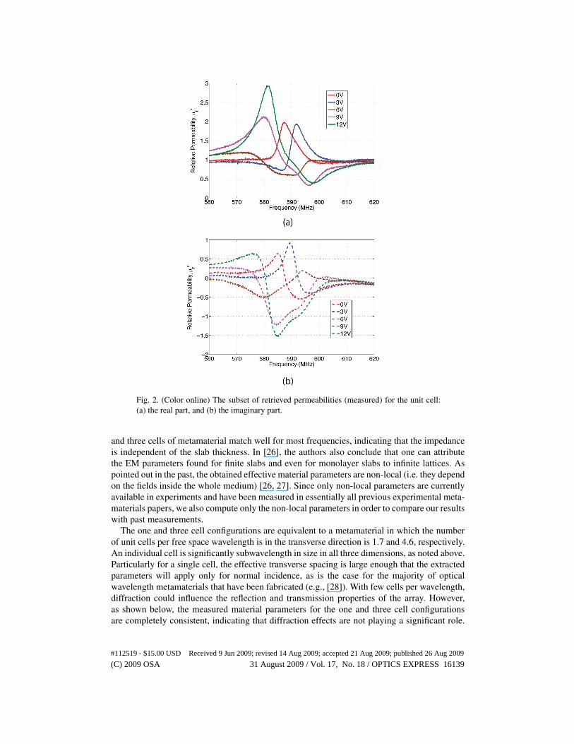
Fig. 2. (Color online) The subset of retrieved permeabilities (measured) for the unit cell:(a) the real part, and (b) the imaginary part.
and three cells of metamaterial match well for most frequencies, indicating that the impedanceis independent of the slab thickness. In [26], the authors also conclude that one can attributethe EM parameters found for finite slabs and even for monolayer slabs to infinite lattices. Aspointed out in the past, the obtained effective material parameters are non-local (i.e. they dependon the fields inside the whole medium) [26, 27]. Since only non-local parameters are currentlyavailable in experiments and have been measured in essentially all previous experimental meta-materials papers, we also compute only the non-local parameters in order to compare our resultswith past measurements.
The one and three cell configurations are equivalent to a metamaterial in which the numberof unit cells per free space wavelength is in the transverse direction is 1.7 and 4.6, respectively.An individual cell is significantly subwavelength in size in all three dimensions, as noted above.Particularly for a single cell, the effective transverse spacing is large enough that the extractedparameters will apply only for normal incidence, as is the case for the majority of opticalwavelength metamaterials that have been fabricated (e.g., [28]). With few cells per wavelength,diffraction could influence the reflection and transmission properties of the array. However,as shown below, the measured material parameters for the one and three cell configurationsare completely consistent, indicating that diffraction effects are not playing a significant role.
#112519 - $15.00 USD Received 9 Jun 2009; revised 14 Aug 2009; accepted 21 Aug 2009; published 26 Aug 2009
(C) 2009 OSA 31 August 2009 / Vol. 17, No. 18 / OPTICS EXPRESS 16139

The biasing network of the medium is composed of twisted-pair wire and surface mount shuntcapacitors on the circuit board that serve to decouple the RF and DC parts in the medium.The wire pairs are also aligned perpendicular to the incident RF electric field to minimize anyinteraction with the biasing network. These minimize any impact of the biasing network on theeffective medium parameters.
Fig. 3. (Color online) The retrieved permeability for the two cases: (a) Vb = 4.5V , and (b)Vb = 12V , where Vb is the DC voltage supply on the phase shifter.
4. Measured EM parameters and their special features
In the measurement, the DC bias voltage (Vb) on the phase shifter ranged from 0V to 12V, witha step of 1.5V (9 states available for the active unit cell). A subset of retrieved permeabilitiesfor various phase shifter biases are shown in Fig. 2. At all bias values, the unit cell exhibits asignificant magnetic response slightly above the self resonant frequency of the passive SRRsdue to the coupling between the SRR and the metallic loop. In each case the magnitude of thesusceptibility is essentially resonant, falling as frequency moves away from a single maximum.Passive metamaterials allow only one susceptibility phase distribution, resulting in losses at allfrequencies. In contrast, the combination of the amplifier and the phase shifter enable control
#112519 - $15.00 USD Received 9 Jun 2009; revised 14 Aug 2009; accepted 21 Aug 2009; published 26 Aug 2009
(C) 2009 OSA 31 August 2009 / Vol. 17, No. 18 / OPTICS EXPRESS 16140

Fig. 4. (Color online) The retrieved permeability, permittivity, and the calculated totalpower loss in the case of Vb = 4.5V . Dashed lines denote the zero-imaginary-permeabilityfrequencies, and solid lines denote the frequencies at which the unit cell is lossless.
over the relative phase of the current in the output loop with respect to the input voltage (andthus the applied magnetic field), and this clearly changes the magnetic response. For example,at the lower bias voltages, the magnetic response is predominantly positive (µ ′
r > 1) with somefrequencies exhibiting loss (µ ′′
r < 0) and others gain (µ ′′r > 0). As Vb increases, the real per-
meability exhibits a bandwidth of strong negative response and the character of the imaginarypermeability changes as well.
To demonstrate the specific ways in which the magnetic response of this particle can becontrolled, two phase shifter bias voltages, Vb = 4.5 V and Vb = 12 V, are examined in detailin Fig. 3. All combinations of real and imaginary magnetic susceptibility signs are obtained:(A) µ ′
r < 1 and µ ′′r < 0, (B) µ ′
r < 1 and µ ′′r > 0, (C) µ ′
r > 1 and µ ′′r > 0, and (D) µ ′
r > 1 andµ ′′
r < 0. The zero magnetic loss frequencies where µ ′r < 1 and µ ′′
r = 0 and µ ′r > 1 and µ ′′
r = 0 (asshown in Fig. 3(b)) are denoted by dashed lines. The case of µ ′
r < 1 and µ ′′r = 0 is particularly
interesting, for it can be used to realize negative permeability with zero loss from arrays of suchunit cells, as demonstrated later in the paper.
For an active magnetic metamaterial, the frequency of zero imaginary permeability does notalways align with the frequency at which the material is lossless because of the unavoidableelectric response of the material [29]. However, the electric response of our fabricated cell ismodest and does not strongly impact the overall material properties of this active unit cell. WithVb = 4.5 V as an example, the retrieved permeability, permittivity, and the total power emittedby the unit cell, defined as the sum of the transmitted and reflected power |S21|2 + |S11|2, areshown in Fig. 4.
In Fig. 4, there are two frequencies (585 MHz and 595.3) at which µ ′′r = 0. At the first, the
electric antiresonance has little effect, and the imaginary part of permittivity is zero, resultingin a material that not only has zero magnetic loss but also zero total loss. At the second, the ef-fective electric response of the cell is significant and exhibits a negative imaginary permittivity.This results in a material that is magnetically lossless but not lossless overall.
The positive imaginary permeability measured in our powered magnetic metamaterial iscompletely distinct from that observed in passive electric metamaterials [29]. The latter oc-curs as a consequence of the non-locality of the extracted parameters and is not a true magneticresponse in the sense that such an electric metamaterial will not respond to an applied mag-netic field alone. In our case, the particles are excited directly by the magnetic field, whichmeans that the positive imaginary permeability is a measure of the achieved magnetic gain.
#112519 - $15.00 USD Received 9 Jun 2009; revised 14 Aug 2009; accepted 21 Aug 2009; published 26 Aug 2009
(C) 2009 OSA 31 August 2009 / Vol. 17, No. 18 / OPTICS EXPRESS 16141
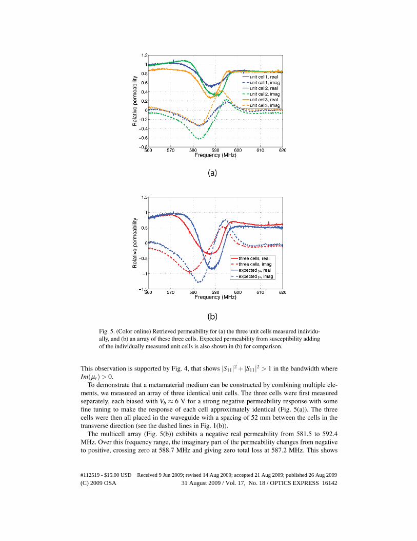
Fig. 5. (Color online) Retrieved permeability for (a) the three unit cells measured individu-ally, and (b) an array of these three cells. Expected permeability from susceptibility addingof the individually measured unit cells is also shown in (b) for comparison.
This observation is supported by Fig. 4, that shows |S11|2 + |S11|2 > 1 in the bandwidth whereIm(µr) > 0.
To demonstrate that a metamaterial medium can be constructed by combining multiple ele-ments, we measured an array of three identical unit cells. The three cells were first measuredseparately, each biased with Vb ≈ 6 V for a strong negative permeability response with somefine tuning to make the response of each cell approximately identical (Fig. 5(a)). The threecells were then all placed in the waveguide with a spacing of 52 mm between the cells in thetransverse direction (see the dashed lines in Fig. 1(b)).
The multicell array (Fig. 5(b)) exhibits a negative real permeability from 581.5 to 592.4MHz. Over this frequency range, the imaginary part of the permeability changes from negativeto positive, crossing zero at 588.7 MHz and giving zero total loss at 587.2 MHz. This shows
#112519 - $15.00 USD Received 9 Jun 2009; revised 14 Aug 2009; accepted 21 Aug 2009; published 26 Aug 2009
(C) 2009 OSA 31 August 2009 / Vol. 17, No. 18 / OPTICS EXPRESS 16142

that this multicell metamaterial array realizes a negative permeability with either zero magneticloss or zero total loss, depending on the specific frequency.
Figure 5(b) also shows the expected permeability if the magnetic susceptibilities measuredfrom each individual cell simply add. Simple addition of the magnetic susceptibilities of indi-vidual particles will occur when the particles are electrically small, are minimally interacting,and are embedded in the same volume under test, as they are for our measurements. That themeasured three cell permeability agrees closely with the simple added susceptibility permeabil-ity indicates the coupling between the closely spaced active cells is modest and the proximityof other cells does not significantly change the response of a single cell. The small discrepancymight be due to the mutual coupling between cells [30, 31], the effect of microscopic disorder[30] arising from the complex structure on the magnetic properties, or small changes, such asthe cell configuration and the position, when the cell was measured separately and when it wasput in an array. This shows that cells of this architecture can be assembled into larger arraysand thus larger metamaterial samples. When cells exhibit gain at certain frequencies there willbe limits on how they can be assembled into medium that is stable and does not spontaneouslyoscillate [9]. We note that we have found that intercell coupling in similar active cells withouta phase shifter can be difficult to control. The phase shifter in the unit cell has stable 50 ohminput and output impedance, and thus acts as a buffer to diminish the feedback from the outputloop back through the amplifier.
5. Conclusion
In conclusion, we designed, fabricated and characterized a powered active magnetic metama-terial with tunable permeability. A negative permeability metamaterial with zero loss or evengain can be achieved through an array of such metamaterial cells. This kind of active metama-terial can find use in applications that are performance limited due to material losses, such asantennas based on magnetic metamaterials [3] or evanescent wave enhancement [32], and alsopoints a way towards active metamaterials at higher frequencies where losses are more severe.
#112519 - $15.00 USD Received 9 Jun 2009; revised 14 Aug 2009; accepted 21 Aug 2009; published 26 Aug 2009
(C) 2009 OSA 31 August 2009 / Vol. 17, No. 18 / OPTICS EXPRESS 16143