Scattering from multi-layered metamaterials using wave matrices
66
Calhoun: The NPS Institutional Archive Theses and Dissertations Thesis Collection 2005-09 Scattering from multi-layered metamaterials using wave matrices Cotuk, Umit. Monterey California. Naval Postgraduate School http://hdl.handle.net/10945/2115
-
Upload
khangminh22 -
Category
Documents
-
view
2 -
download
0
Transcript of Scattering from multi-layered metamaterials using wave matrices

Calhoun: The NPS Institutional Archive
Theses and Dissertations Thesis Collection
2005-09
Scattering from multi-layered
metamaterials using wave matrices
Cotuk, Umit.
Monterey California. Naval Postgraduate School
http://hdl.handle.net/10945/2115

NAVAL
POSTGRADUATE SCHOOL
MONTEREY, CALIFORNIA
THESIS
SCATTERING FROM MULTI-LAYERED METAMATERIALS USING WAVE MATRICES
by
Umit Cotuk
September 2005
Thesis Advisor: David Jenn Second Reader: Michael A. Morgan
Approved for public release, distribution is unlimited

THIS PAGE INTENTIONALLY LEFT BLANK

REPORT DOCUMENTATION PAGE Form Approved OMB No. 0704-0188 Public reporting burden for this collection of information is estimated to average 1 hour per response, including the time for reviewing instruction, searching existing data sources, gathering and maintaining the data needed, and completing and reviewing the collection of information. Send comments regarding this burden estimate or any other aspect of this collection of information, including suggestions for reducing this burden, to Washington headquarters Services, Directorate for Information Operations and Reports, 1215 Jefferson Davis Highway, Suite 1204, Arlington, VA 22202-4302, and to the Office of Management and Budget, Paperwork Reduction Project (0704-0188) Washington DC 20503. 1. AGENCY USE ONLY (Leave blank)
2. REPORT DATE September 2005
3. REPORT TYPE AND DATES COVERED Master’s Thesis
4. TITLE AND SUBTITLE: Scattering from Multi-Layered Metamaterials Using Wave Matrices 6. AUTHOR(S) Umit Cotuk
5. FUNDING NUMBERS
7. PERFORMING ORGANIZATION NAME(S) AND ADDRESS(ES) Naval Postgraduate School Monterey, CA 93943-5000
8. PERFORMING ORGANIZATION REPORT NUMBER
9. SPONSORING /MONITORING AGENCY NAME(S) AND ADDRESS(ES) N/A
10. SPONSORING/MONITORING AGENCY REPORT NUMBER
11. SUPPLEMENTARY NOTES The views expressed in this thesis are those of the author and do not reflect the official policy or position of the Department of Defense or the U.S. Government. 12a. DISTRIBUTION / AVAILABILITY STATEMENT Approved for public release, distribution is unlimited
12b. DISTRIBUTION CODE
13. ABSTRACT (maximum 200 words) The complex permittivity ( ε ) and permeability ( µ ) of a material determine the response of the material to
electromagnetic radiation. Usually, the real parts of ε and µ are positive for naturally occurring materials at microwave frequencies. Metamaterials are engineered media that are designed to have either a negative permittivity or permeability or both. Negative permeability and negative permittivity would cause electromagnetic waves traveling through this medium to exhibit unusual characteristics such as power flow in a direction opposite to the phase velocity. In this thesis, the wave matrix approach is used to calculate the total reflection and transmission coefficients of a multilayered structure. The method is applicable to all types of materials, including metamaterials. Several layered configurations are studied including both metamaterial and conventional dielectric layers. A MATLAB program is developed to examine the effects of frequency, angle of incidence and polarization. The results are compared to published data. Potential applications of metamaterials are also discussed.
15. NUMBER OF PAGES
65
14. SUBJECT TERMS Complex Permittivity and Permeability, Negative Index, Metamaterials
16. PRICE CODE
17. SECURITY CLASSIFICATION OF REPORT
Unclassified
18. SECURITY CLASSIFICATION OF THIS PAGE
Unclassified
19. SECURITY CLASSIFICATION OF ABSTRACT
Unclassified
20. LIMITATION OF ABSTRACT
UL NSN 7540-01-280-5500 Standard Form 298 (Rev. 2-89) Prescribed by ANSI Std. 239-18
i

THIS PAGE INTENTIONALLY LEFT BLANK
ii

Approved for public release, distribution is unlimited
SCATTERING FROM MULTI-LAYERED METAMATERIALS USING WAVE MATRICES
Umit Cotuk
Lieutenant Junior Grade, Turkish Navy Electrics-Electronics Engineering, Turkish Naval Academy, 2000
Submitted in partial fulfillment of the requirements for the degree of
MASTER OF SCIENCE IN SYSTEMS ENGINEERING
from the
NAVAL POSTGRADUATE SCHOOL September 2005
Author: Umit Cotuk
Approved by: David Jenn
Thesis Advisor Michael A. Morgan
Second Reader Dan C. Boger Chairman, Department of Information Sciences
iii

THIS PAGE INTENTIONALLY LEFT BLANK
iv

ABSTRACT
The complex permittivity (ε ) and permeability (µ ) of a material determine the
response of the material to electromagnetic radiation. Usually, the real parts of ε and µ
are positive for naturally occurring materials at microwave frequencies. Metamaterials
are engineered media that are designed to have either a negative permittivity or
permeability or both. Negative permeability and negative permittivity would cause
electromagnetic waves traveling through this medium to exhibit unusual characteristics
such as power flow in a direction opposite to the phase velocity. In this thesis, the wave
matrix approach is used to calculate the total reflection and transmission coefficients of a
multilayered structure. The method is applicable to all types of materials, including
metamaterials. Several layered configurations are studied including both metamaterial
and conventional dielectric layers. A MATLAB program is developed to examine the
effects of frequency, angle of incidence and polarization. The results are compared to
published data. Potential applications of metamaterials are also discussed.
v

THIS PAGE INTENTIONALLY LEFT BLANK
vi

TABLE OF CONTENTS
I. INTRODUCTION........................................................................................................1 A. BACKGROUND ..............................................................................................1 B. OBJECTIVES ..................................................................................................1 C. ORGANIZATION OF THESIS .....................................................................2
II. WAVE REFLECTION AND TRANSMISSION ......................................................3 A. INTRODUCTION............................................................................................3 B. REFLECTION AND TRANSMISSION COEFFICIENTS.........................3 C. WAVE MATRICES FOR LAYERED MEDIA............................................6 D. SUMMARY ......................................................................................................9
III. METAMATERIALS .................................................................................................11 A. INTRODUCTION..........................................................................................11 B. NEGATIVE PERMITTIVITY AND PERMEABILITY...........................11
1. Left Hand Rule...................................................................................14 2. Negative Refraction ...........................................................................14 3. Growing Evanescent Waves..............................................................17 4. Reversed Doppler and Cerenkov Radiation....................................17
C. APPLICATIONS OF DNG MATERIALS..................................................18
IV. ANALYSIS OF SCATERING FROM MULTI-LAYERED METAMATERIALS .................................................................................................19 A. INTRODUCTION..........................................................................................19 B. MATLAB SOFTWARE AND SIMULATIONS.........................................19
1. Lossless Dielectric Panel....................................................................19 2. Radar Absorbing Material................................................................23 3. Propagation in Metamaterial Slabs..................................................26
a. Antireflection Coatings ...........................................................27 b. High-Reflection Coatings .......................................................31
4. Pairing an Epsilon-Negative Slab with a Mu-Negative Slab for Zero Reflection...................................................................................33
5. Wet Radome Effect ............................................................................36 C. SUMMARY ....................................................................................................39
V. CONCLUSIONS ........................................................................................................41 A. SUMMARY AND CONCLUSIONS ............................................................41 B. FUTURE WORK...........................................................................................42
APPENDIX. MATLAB CODE............................................................................................43
LIST OF REFERENCES......................................................................................................47
INITIAL DISTRIBUTION LIST .........................................................................................49
vii

THIS PAGE INTENTIONALLY LEFT BLANK
viii

LIST OF FIGURES Figure 1. A plane wave incident normally on an interface between two different
media (After Ref. [1]). .......................................................................................3 Figure 2. Normal incidence at a boundary between two media. .......................................6 Figure 3. Forward and backward traveling waves through N layers (After Ref. [2]). ......7 Figure 4. An artificial negative-index material made from grids of rings and wires
(From Ref. [4]).................................................................................................11 Figure 5. Three-dimensional grid of thin wires approximates a plasma (From Ref.
[7])....................................................................................................................12 Figure 6. Coplanar ring (From Ref. [7])..........................................................................13 Figure 7. Illustration of vector relationships for right-hand and left-hand rules.............14 Figure 8. Refraction in a positive-index material (top), and in a negative-index
material (bottom). ............................................................................................15 Figure 9. A microwave beam refracted in Teflon (a), and refracted in a metamaterial
(b) (From Ref. [8]). ..........................................................................................16 Figure 10. Planar metamaterial lens, known as Pendry’s perfect lens (After Ref. [5]). ...17 Figure 11. Dielectric panel with thickness t and permittivity 04ε ε= ...............................19 Figure 12. Incidence and traveling waves in a lossless dielectric panel (After Ref.
[2])....................................................................................................................21 Figure 13. Transmission and reflection coefficients of a lossless dielectric slab with
r 4ε = as a function of frequency (normal incidence, parallel polarization). ..21 Figure 14. Transmission and reflection coefficients of a lossless dielectric slab as a
function of incidence angle ( 2f = GHz, parallel polarization).......................22 Figure 15. Transmission and reflection coefficients of a lossless dielectric slab as a
function of incidence angle ( 2f = GHz, perpendicular polarization).............22 Figure 16. Universal curves for zero specular reflection (From Ref. [6]).........................24 Figure 17. Transmission and reflection coefficients of a RAM layer as a function of
angle of incidence (parallel polarization). .......................................................25 Figure 18. Transmission and reflection coefficients of a RAM layer as a function of
angle of incidence (perpendicular polarization). .............................................26 Figure 19. Transmission and reflection coefficients of a metamaterial slab as a
function of frequency (normal incidence)........................................................27 Figure 20. Dielectric and metamaterial slabs embedded in air (antireflection
coatings)...........................................................................................................28 Figure 21. Reflection and transmission coefficients of a pair of dielectric and
metamaterial slabs embedded in air as a function of frequency (normal incidence, parallel polarization).......................................................................28
Figure 22. Reflection and transmission coefficients of a pair of dielectric and metamaterial slabs embedded in air as a function of angle of incidence ( 1f = GHz). .....................................................................................................29
ix

Figure 23. Reflection and transmission coefficients of a pair of dielectric and metamaterial slabs embedded in air as a function of frequency (normal incidence, perpendicular polarization).............................................................29
Figure 24. Phase of the total transmission coefficient for a normally incident parallel polarized wave. ................................................................................................30
Figure 25. Dielectric and metamaterial slabs with different thicknesses embedded in air (high-reflection coatings)............................................................................31
Figure 26. Reflection and transmission coefficients of a pair of dielectric and metamaterial slabs with different thicknesses embedded in air as a function of frequency (normal incidence)........................................................32
Figure 27. Reflection and transmission coefficients of a pair of dielectric and metamaterial slabs with different thicknesses embedded in air as a function of angle of incidence ( 2f = GHz). ..................................................32
Figure 28. A pair of ENG-MNG slabs for zero reflection. ...............................................33 Figure 29. Sensitivity of the reflection coefficient to the variation of the angle of the
incidence (thin ENG-MNG slabs). ..................................................................34 Figure 30. Sensitivity of the reflection coefficient to the variation of the angle of the
incidence (thick ENG-MNG slabs)..................................................................35 Figure 31. Pair of ENG-MNG layers under certain conditions may provide image
displacement and virtual image reconstruction (From Ref. [12])....................36 Figure 32. Transmission through radome and water layer as a function of water layer
thickness...........................................................................................................37 Figure 33. Transmission loss through a fiberglass radome. ..............................................38 Figure 34. Transmission loss through wet radome............................................................38
x

LIST OF TABLES Table 1. Parameters for a matched pair of ENG-MNG slabs (thin slabs). ....................34 Table 2. Parameters for a matched pair of ENG-MNG slabs (thick slabs)....................35
xi

THIS PAGE INTENTIONALLY LEFT BLANK
xii

ACKNOWLEDGMENTS
I gratefully thank Professor David Jenn who guided this work and helped
whenever I was in need of assistance. He answered all my questions patiently. Without
his help, this work would not be possible. I would also like to thank Professor Michael A.
Morgan for agreeing to be the second reader.
I would like to thank the Turkish Navy for giving me the opportunity to study at
the Naval Postgraduate School.
Finally, I wish to thank my parents for their continuous support and
encouragement.
xiii

THIS PAGE INTENTIONALLY LEFT BLANK
xiv
I. INTRODUCTION
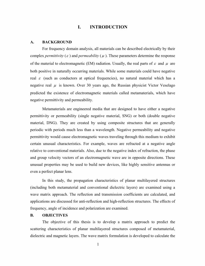
A. BACKGROUND For frequency domain analysis, all materials can be described electrically by their
complex permittivity (ε ) and permeability (µ ). These parameters determine the response
of the material to electromagnetic (EM) radiation. Usually, the real parts of ε and µ are
both positive in naturally occurring materials. While some materials could have negative
real ε (such as conductors at optical frequencies), no natural material which has a
negative real µ is known. Over 30 years ago, the Russian physicist Victor Veselago
predicted the existence of electromagnetic materials called metamaterials, which have
negative permittivity and permeability.
Metamaterials are engineered media that are designed to have either a negative
permittivity or permeability (single negative material, SNG) or both (double negative
material, DNG). They are created by using composite structures that are generally
periodic with periods much less than a wavelength. Negative permeability and negative
permittivity would cause electromagnetic waves traveling through this medium to exhibit
certain unusual characteristics. For example, waves are refracted at a negative angle
relative to conventional materials. Also, due to the negative index of refraction, the phase
and group velocity vectors of an electromagnetic wave are in opposite directions. These
unusual properties may be used to build new devices, like highly sensitive antennas or
even a perfect planar lens.
In this study, the propagation characteristics of planar multilayered structures
(including both metamaterial and conventional dielectric layers) are examined using a
wave matrix approach. The reflection and transmission coefficients are calculated, and
applications are discussed for anti-reflection and high-reflection structures. The effects of
frequency, angle of incidence and polarization are examined.
B. OBJECTIVES The objective of this thesis is to develop a matrix approach to predict the
scattering characteristics of planar multilayered structures composed of metamaterial,
dielectric and magnetic layers. The wave matrix formulation is developed to calculate the
1

reflection and transmission coefficients of multiple layers of arbitrary thicknesses and
materials. Therefore, with the help of MATLAB software, the effects of frequency, angle
of incidence, polarization and layer configuration can be examined. To validate the
MATLAB program, many test cases are presented and simulation results are compared to
published data.
C. ORGANIZATION OF THESIS
In Chapter II, equations for transmission and reflection coefficients for a single
boundary between two dielectric media are presented. The wave matrix approach for
layered media is described. The reflection and transmission coefficient equations are
given for layered media.
In Chapter III, metamaterials and their unusual characteristics are discussed. The
potential applications of DNG materials are presented.
In Chapter IV, the propagation characteristics of multilayered structures
consisting of dielectric slabs, metamaterials, or both, are discussed. Different methods are
described to achieve zero reflection or high reflection. The effects of frequency, angle of
incidence and polarization are shown. The potential applications of these structures are
described.
Finally in Chapter V, the results, conclusions and suggestions for future studies
are discussed.
2

II. WAVE REFLECTION AND TRANSMISSION
A. INTRODUCTION Electric charges generate electric fields and electric currents generate magnetic
fields. If the charge and currents sources were to vary with time, the electric and
magnetic fields become unified, and the link between them generates electromagnetic
waves (EM) that can travel through free space and in material media. If a plane wave
from one medium meets a different medium, it is partly reflected and partly transmitted
depending on the constitutive parameters of the two media involved. This chapter begins
with an examination of the reflection and transmission properties of plane waves incident
on planar boundaries, and continues with the development of wave matrices for layered
media.
B. REFLECTION AND TRANSMISSION COEFFICIENTS Consider a uniform plane wave traveling along the +z-direction that is normally
incident at the boundary between medium 1 ( 1, 1µ ε ) and medium 2 ( 2 2,µ ε ). The incident
(i), reflected (r), and transmitted (t) waves are shown in Figure 1.
iΕ
rΕ
rΗ
ka
1 1,µx
(Incident wave)
Medium #1 ( ) ε
ka
iΗ
(Reflected wave) y(
Figure 1. A plane wave incidentmedia
2 2,µ ε
tΕ
tΗka
Medium #2 ( )
(Transmitted wave)
z z = 0)
normally on an interface between two different (After Ref. [1]).
3

The incident wave is traveling in the +z direction in medium 1. For normal
incidence, the incident electric field vector can be expressed as
10( ) z
i iz e γ−Ε = Ε xa (2.1)
and the magnetic field vector
1 00
1
( ) z ii i yz e a eγ
η− 1z
yaγ−ΕΗ = Η = (2.2)
where 1η is intrinsic impedance of material 1, given as
1
1
011
1 0
r
r
µµµηε ε ε
= = (2.3)
and 1 1r r 1r
jµ µ µ′ ′= − ′1 1r r j,
1rε ε ′ ε ′′= − are the relative permeability and permittivity of the
medium. Also, 1γ is the propagation constant of the medium, and is given as
1 11 1 1 0 0 r rjγ α β ω µ ε µ ε= + = . (2.4)
The reflected wave is traveling in the –z direction in medium 1. The reflected
electric field vector can be written as
10( ) z
r rz eγΕ = Ε xa (2.5)
and the magnetic field vector is
1 00
1
( ) ( )z ir r yz e a eγ
η1z
yaγΕΗ = Η − = − . (2.6)
The transmitted wave is traveling in the +z direction in medium 2, and its electric field
vector is
20( ) z
t tz e γ−Ε = Ε xa (2.7)
and its magnetic field vector
4

2 00
2
( ) z it t yz e a eγ
η− 2z
yaγ−ΕΗ = Η = (2.8)
where 2η and 2γ are defined in manner similar to Equations (2.3) and (2.4).
In Figure 1, the total field in medium 1 includes both the incident and reflected
fields. In medium 2, only the transmitted field is present. Then, the total fields can be
written as
1
1
2
2 .
i r
i r
t
t
Ε = Ε +Ε
Η = Η +Η
Ε = Ε
Η = Η
.
The planar boundary located at z=0 separates the two media. At the boundary, the
tangential components of the electric and magnetic fields are continuous. Thus,
(2.9) 1 2 0 0t t i rΕ = Ε →Ε +Ε = Ε 0t
0 01 2 0 0 0
1 2
( )i rt t i r t
0t
η ηΕ −Ε Ε
Η = Η →Η +Η = Η → = . (2.10)
From Equations (2.9) and (2.10),
2 10
2 1r 0i
η ηη η
−Ε =
+Ε (2.11)
20
2 1
2t 0i
ηη η
Ε =+
Ε . (2.12)
Now it is possible to obtain the reflection coefficient (Γ ) and transmission
coefficient (τ ) from Equations (2.11) and (2.12),
0 2
0 2
r
i
1
1
η ηη η
Ε −Γ = =
Ε + (2.13)
0 2
0 2
2t
i 1
ητη η
Ε= =Ε +
. (2.14)
5
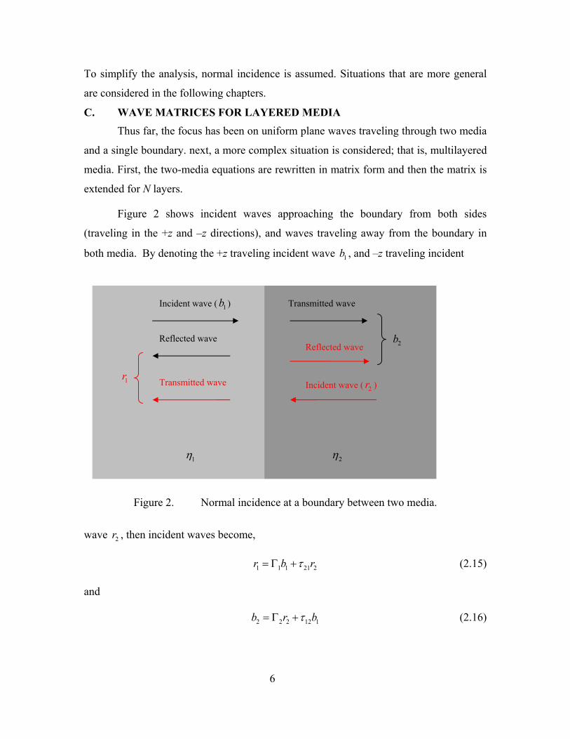
To simplify the analysis, normal incidence is assumed. Situations that are more general
are considered in the following chapters.
C. WAVE MATRICES FOR LAYERED MEDIA
Thus far, the focus has been on uniform plane waves traveling through two media
and a single boundary. next, a more complex situation is considered; that is, multilayered
media. First, the two-media equations are rewritten in matrix form and then the matrix is
extended for N layers.
Figure 2 shows incident waves approaching the boundary from both sides
(traveling in the +z and –z directions), and waves traveling away from the boundary in
both media. By denoting the +z traveling incident wave b , and –z traveling incident 1
1
1η 2η
2b
Incident wave ( b ) Transmitted wave
Reflected wave Reflected wave
Figure 2. Normal incidence at a boundary between two media.
wave , then incident waves become, 2r
1 1 1 21r b 2rτ= Γ + (2.15)
and
2 2 2 12b r 1bτ= Γ + (2.16)
Transmitted wave Incident wave ( ) 2r1r
6
where the first subscript on τ denotes the incident medium and the second subscript
denotes the transmitted medium. Now it is possible to rearrange Equations (2.15) and
(2.16), and write them in the matrix form [Ref. 2],
1 2
1 12 21 1 21 212
11b br rτ ττ
−Γ = Γ −Γ Γ
2 . (2.17)
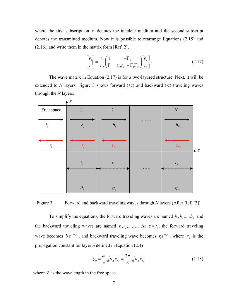
The wave matrix in Equation (2.17) is for a two-layered structure. Next, it will be
extended to N layers. Figure 3 shows forward (+z) and backward (-z) traveling waves
through the N layers.
1η 2η Nη
1t 2t Nt
1b 2b 3b 1Nb +
x
N 1 2Free space
……
1r 2r 3r 1Nr + z
……
Figure 3. Forward and backward traveling waves through N layers (After Ref. [2]).
To simplify the equations, the forward traveling waves are named b b and
the backward traveling waves are named . At
1 2, ,..., Nb
1 2, ,..., Nr r r 1z t= , the forward traveling
wave becomes 1 11
j tb e γ− , and backward traveling wave becomes 1 11
j tr e γ , where nγ is the
propagation constant for layer n defined in Equation (2.4)
2n n n nn r r rc r
ω πγ µ ε µ ελ
= = (2.18)
where λ is the wavelength in the free space.
7

For the plane wave in Figure 3, traveling from free space through the N-layered
medium, the wave matrices can be cascaded to give
11 11 12
1 21 221 1
1 n n n n
n n n n
t tNNn
t tn N Nn n
b bb a ae ea ar re e
γ γ
γ γτ
−+
−= + +
1
1
N
r+ Γ
= ≡
Γ
∏
. (2.19)
If the thickness of the last layer of the medium extends to ∞ , then it is possible to state
that b . The total transmission and reflection coefficients of the medium become, 1 0N+ =
1
1 1
1NT
bb a
τ += =1
(2.20)
1 2
1 1T
r ab a
Γ = = 1
1
. (2.21)
Thus far, the equations in this chapter are based on normal incidence. The wave
matrix can be extended to non-normal angles by using the wave impedance in place of
the intrinsic impedance. The normalized wave impedance for a parallel-polarized wave
incident at an angle iθ from the interface normal is given as [3]
2sin
cosr r i
r i
Zε µ θε θ
−= (2.22)
and for a perpendicularly-polarized wave
2
cossin
r i
r r i
Z µ θ
ε µ θ=
−. (2.23)
The transmission and reflection coefficients at the interface between the two media are
given as
2
2 1
1Z ZZ Z
−Γ =
+ (2.24)
1τ = + Γ (2.25)
where 1Z is the incidence medium and 2Z is the transmitted medium. Finally, the phase
of the layer (thickness t) is given as
8

22 sinr r itπ ε µλ
Φ = − θ . (2.26)
D. SUMMARY
The first part of this chapter presented the equations for transmission and
reflection coefficients. These equations are based on normal incidence, and a single
boundary between two dielectric media.
The second part described wave matrices for layered media. Then, reflection and
transmission coefficient equations are given, both for parallel-polarized and
perpendicularly-polarized waves incident at an angle iθ . These situations are simulated
with MATLAB 6.5 in Chapter IV, both for dielectric media and metamaterials. However,
first a brief description of metamaterials is given.
9

THIS PAGE INTENTIONALLY LEFT BLANK
10

III. METAMATERIALS
A. INTRODUCTION In 1968, Victor Veselago (a Russian physicist) forecasted the existence of a
material in which both permittivity and permeability were assumed to have negative real
values (negative index of refraction) [4]. These materials have been called metamaterials,
backward-wave materials and left-handed (LH) materials. Although these materials were
not known to exist at that time, he concluded that with these negative-index materials all
known wave propagation and optical behaviors would be changed.
Materials with negative permittivity occur naturally (e.g., metals at optical
frequencies), but those with negative permeability do not. Victor Veselago’s prediction
was verified after more than 30 years when in 1999, John Pendry (Imperial College,
London) showed how these materials could be created artificially [4]. Then, in the
following year, he published a paper in which he proposed that metamaterials could be
used to make a perfect lens [5].
B. NEGATIVE PERMITTIVITY AND PERMEABILITY Metamaterials are created by using composite structures which are engineered to
have properties that do not occur naturally. Figure 4 shows one type of negative-index
material that was constructed by David Smith at the University of California in 2000 [4].
Figure 4. An artificial negative-index material made from grids of rings and wires
(From Ref. [4]).
11

The cells are small compared to the wavelength so that macroscopically the effective
index of refraction is negative.
Metamaterials are engineered media that are designed to have either a negative
permittivity or permeability (SNG) or both (DNG). For a DNG material, the index of
refraction for real permittivity and permeability is
r rn µ ε= − , 0, 0r rµ ε< < (3.1)
and the intrinsic impedance
0 r rη η µ ε= . (3.2)
They have several unusual properties when compared to the regular materials [6]:
1. The phase velocity of EM waves is anti-parallel to the group velocity and the flow of the energy. Thus, propagation is described by a left-hand rule.
2. Waves are refracted at a negative angle relative to conventional materials.
3. Evanescent waves grow with distance into the medium.
4. The Doppler shift is reversed and Cerenkov radiation propagates backwardly.
Artificial materials are a mix of regular materials combined to obtain specific
characteristics. A negative rε ′ can be obtained by a three dimensional array of wires [7]
(Figure 5). The effective dielectric constant is given as
Wires
Figure 5. Three-dimensional grid of thin wires approximates a plasma (From Ref. [7]).
12

2
2 20
2
1eff
pr
pj ar
ωε
ε ωω ω
πσ
= −
+
(3.3)
where 2
2
2ln( )p
ca a r
πω = , r is the radius of the wire, a is the grid spacing and σ is the wire
conductivity.
A coplanar ring (CPR) is an example of a configuration that influences both the
effective permittivity and permeability of a material (Figure 6). The effective
permeability of the CPR is given as
2 2
2 2 30 0
1 2 31eff
r a
jr C
πµ ρω µ π ω µ
= −+ −
r
(3.4)
where ρ is the resistivity of the metal (ohms/m), 0 2ln st
επ
=
C is the capacitance per
meter of two parallel strips,
a = lattice spacing in the plane of rings and spacing
between sheets of rings.
=
Ε
iΗ
S
d
Metal rings with gaps
i
r
inΙ
Ι
ˆkaFigure 6. Coplanar
13
ring (F
out
rom Ref. [7
]).

1. Left Hand Rule
electrically by an equivalent complex permittivity
and per
All materials can be described
meability. The permittivity of a material ( 0 rε ε ε= ) determines its response to an
electric field, while permeability ( 0 rµ µ µ= ) determines its response to a magnetic field.
Together these two parameters deter ac the material to the EM radiation.
materials follow the left-hand (LH) rule [ onstrates these rules where
mine the re
6
tion of
]. Figure 7 dem
All natural (passive) materials follow a right-hand (RH) rule because of their positive
values of relative permittivity and permeability. However, the double negative-index
S is
the poynting vector defined as
*S=Ε×Η . (3.5)
A material for which the RH rule holds is called right-handed material (RHM). The LH
vector
2. Negative Refraction
etween angles of incidence and refraction at an
interfac
2
rule holds in a left-handed material (LHM). In a LHM, the phase of the waves (given by
vector a ) moves in the direction opposite to the direction of the energy flow (given by k
S ) .
Figure 7. Illustration of vector relationships for right-hand and left-hand rules.
Ε
Η
S
ka
Ε
Η
S
ka
Right-Handed Materials Left-Handed Materials
0, 0ε µ< <0, 0ε µ> >
Snell’s law gives the relationship b
e between two media with different indices of refraction
1 1 2sin sinn nθ θ= . (3.6)
14
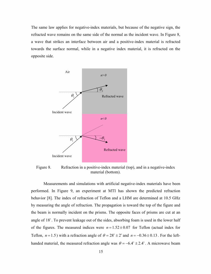
The same law applies for negative-index materials, b
refracted wave remains on the same side of the normal as the incident wave. In Figure 8,
a wave that strikes an interface between air and a positive-index material is refracted
towards the surface normal, while in a negative index material, it is refracted on the
opposite side.
rem n
erformed. In Figure 9, an expe shown the predicted refraction
behavi
ut because of the negative sign, the
Figure 8. ion in a positive-index material (top), and in a negative-index material (bottom).
Incident wave
Incident wave
Refracted wave
Refracted wave
n>0
n<0
1θ
1θ
2θ
2θ−
Air
Refract
Measu ents and simulations with artificial negative-index materials have bee
riment at MTI hasp
or [8]. The index of refraction of Teflon and a LHM are determined at 10.5 GHz
by measuring the angle of refraction. The propagation is toward the top of the figure and
the beam is normally incident on the prisms. The opposite faces of prisms are cut at an
angle of 18 . To prevent leakage out of the sides, absorbing foam is used in the lower half
of the figures. The measured indices were 1.52 0.07n = ± for Teflon (actual index for
Teflon, 1.5n ) with a refraction angle of 28 2θ= = ± and 0.36 0.13n = − ± . For the left-
handed material, the measured refraction ang .4 2.4± . A microwave beam le was 6θ = −
15
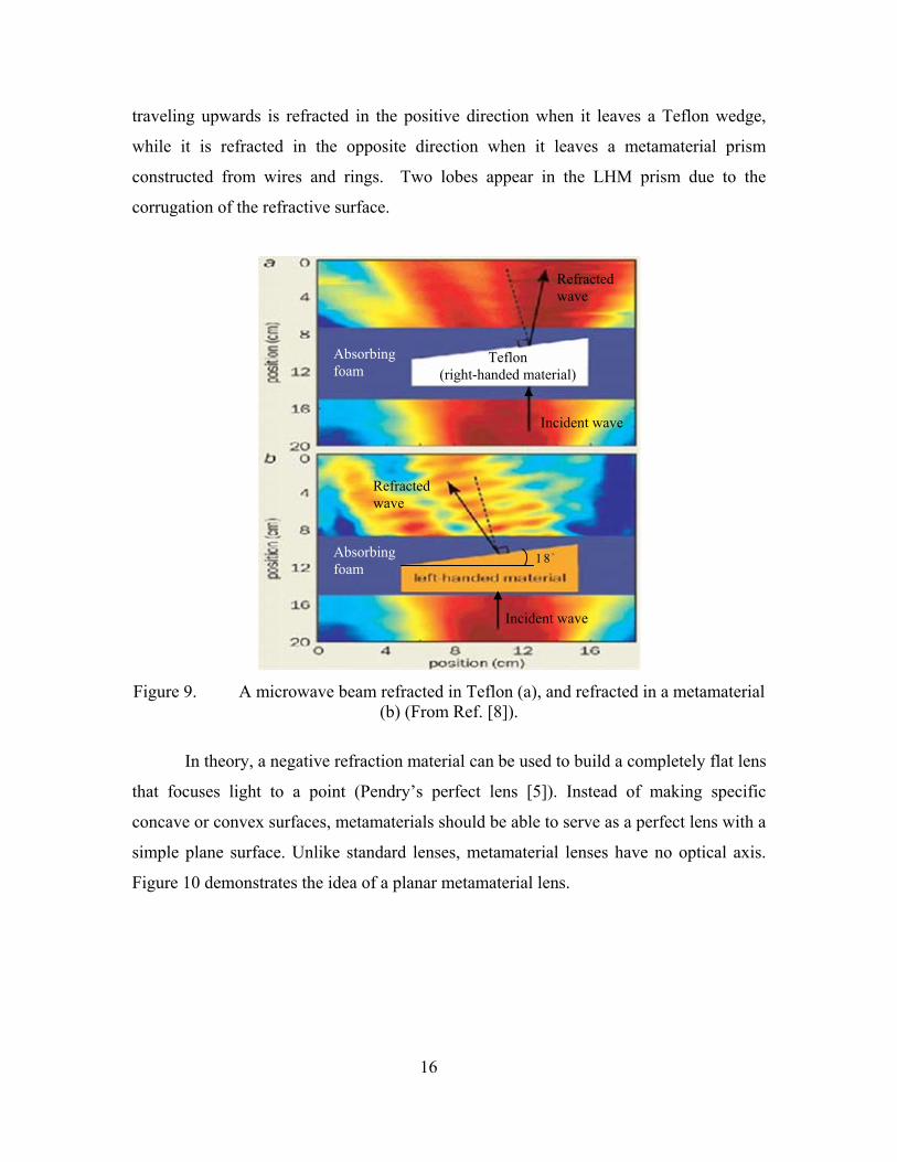
traveling rds is refracted in the posit
while it is refracted in the opposite direction when it leaves a metamaterial prism
constructed from wires and rings. Two lobes appear in the LHM prism due to the
corrugation of the refractive surface.
upwa ive direction when it leaves a Teflon wedge,
Figure 9. a metamaterial
theo
at focuses light to a point (Pe 5]). Instead of making specific
concav
A microwave beam refracted in Teflo racted i
(b) (From Ref. [8]).
Refracted wave
Teflon (right-handed material)
Incident wave
Incident wave
1 8Absorfoam
Absorbing foam
Refracted wave
bing
n (a), and ref n
In ry, a negative refraction material can be used to build a completely flat lens
ndry’s perfect lens [th
e or convex surfaces, metamaterials should be able to serve as a perfect lens with a
simple plane surface. Unlike standard lenses, metamaterial lenses have no optical axis.
Figure 10 demonstrates the idea of a planar metamaterial lens.
16

Figure 10. Planar metamaterial lens, known as Pendry’s perfect lens (After Ref. [5]).
3. Growing Evanescent Waves Evanescent waves are formed when sinusoidal waves are internally reflected off
an interface at an angle greater than the critical angle. In a RHM, the evanescent waves
decay exponentially in amplitude with distance from the interface at which they are
formed. Left-handed materials can cancel the decay of evanescent waves [5]. Pendry
showed that evanescent waves emerge from the far side of the medium enhanced in
amplitude by the transmission process [5]. This does not violate energy conservation
because evanescent waves do not carry energy.
4. Reversed Doppler and Cerenkov Radiation The Doppler Effect is the apparent change in frequency or wavelength of a wave
that is received by an observer moving relative to the source of the waves. The relation
between the actual frequency ( 0f ) and observed frequency (f) for a moving target is
given as
0 1 of f νν
= +
(3.7)
where ν is the speed of the waves in the medium and oν is the speed of the observer
(positive towards the source and negative if moving away). This yields an increase in the
observed frequency if the observer is moving towards the source. If the propagation
medium is a LHM, this effect is reversed due to the anti-parallel phase velocity [6].
n n n 1= Metamaterial
1= −1= Air Air
Point source Image Internal focus
17

Cherenkov radiation is EM radiation emitted when a charged particle moves at a
speed greater than that of light in the medium. The radiation propagates in the forward
direction in a RHM. In a LHM, radiation flows backward, opposite to the particle
velocity [6].
C. APPLICATIONS OF DNG MATERIALS Negative-index materials have attracted great attention recently. It may be
possible to build new devices by using metamaterials, like new antenna configurations or
perfect planar lenses. Some possible applications of metamaterials are [4]:
1. Highly sensitive antennas.
2. Phase and dispersion compensation phase shifters.
3. Antenna and microwave-device miniaturization.
4. Broadband and multi-band antenna design.
5. Planar lenses that exceed the diffraction limit.
The list above includes only a few examples among the possible applications. As the new
properties of metamaterials are discovered, the list is likely to be extended.
18

IV. ANALYSIS OF SCATERING FROM MULTI-LAYERED METAMATERIALS
A. INTRODUCTION
In this chapter, the wave matrix approach is used to calculate the reflection and
transmission coefficients of multilayered structures, including both metamaterial and
dielectric layers. These equations were programmed in MATLAB 6.5 so that the effects
of frequency, angle of incidence and polarization could be examined.
B. MATLAB SOFTWARE AND SIMULATIONS
1. Lossless Dielectric Panel
The first configuration considered is a single dielectric slab. Figure 11 shows a
dielectric panel that has a thickness of t 0.1= m and a relative dielectric constant of
4rε = .
41
r
r
εµ==
iΕ
ˆka
Air Air
z
t
Figure 11. Dielectric panel with thickness t and permittivity 04ε ε= .
Assuming normal incidence, from Equations (2.13) and (2.14), the reflection and
transmission coefficients become [2],
1 01
1 0
11 114
1 311 4
r
r
r
r
µεη η
η η µε
− −−
Γ = = = = −+ ++
(4.1)
1 1213
τ = + Γ = (4.2)
19

and
0 12
0 1
1114
1 314
η ηη η
−−
Γ = = =+ +
(4.3)
2 2413
τ = +Γ = . (4.4)
It is also possible to write the wave matrix for the
Figure 11 is redrawn to show the incident and reflected waves, as shown in Figure 12.
panel by using Equation (2.19). First,
Now, the wave matrix becomes
2
1
1 n nj j bb e er
Φ − Φ Γ
31
1n n
nj j
n n ne eτ Φ − Φ=
Γ ∏
nt nds to ∞ , it is possible to
=3r
(4.5)
where n nγΦ =
arbitrarily state th
. Since the thickness of the last layer ( exte
at and . Then, is obtained,
r
2t )
3 0r = 2 0Φ =
1 1
1 1j jr e eΦ − Φ Γ
1 132
21 31
11
j j bb e eΦ − Φ Γ Γ = Γ
. (4.6)
The panel transmission and reflection coefficients as a func
plotted for the range of 500 MHz to 2 GHz in Figure 13. As evident in Figure 13, the slab
has min
tion of frequency are
imum reflection (maximum transmission) coefficients at 0.75 and 1.5 GHz. These
are the frequencies where the thickness is a multiple of 2λ , where λ is wavelength in
the dielectric.
Figure 14 shows the transmission and reflection coefficients for parallel
polarization at various angles of incidence when the frequency is 2 GHz. The slab has a
minimu
When the wave is perpendicularly polarized, the slab has its minimum reflection
coefficient at . In this case, high-reflection is observed at grazing angles (Figure
15).
m reflection coefficient at 64iθ = , which is the Breuster’s angle.
0iθ =
20

Incidence and traveling wav in a lossless electric pane
[2]
0.1 m
3b1b 2b
r 2r 3r
0z = z t=
1η 2η 1η
1
Figure 12. l (After Ref. es di).
0.5 1 1.5 20
0.1
0.2
0.3
0.4
0.5
0.6
0.7
0.8
0.9
1
Frequency (GHz)
Coe
ffici
ent M
agni
tude
Reflection CoefficientTransmission Coefficient
Figure 13. Transmission and reflection coefficients of a lossless dielectric slab with
r 4ε = as a function of frequency (normal incidence, parallel polarization).
21

0 10 20 30 40 50 60 70 80 900
0.1
0.2
0.3
0.4
0.5
0.6
0.7
0.8
0.9
1
Angle (Degree)
Coe
ffici
ent M
agni
tude
Reflection CoefficientTransmission Coefficient
Figure 14. Transmission and reflection coefficients of a lossless dielectric slab as a
function of incidence angle ( 2f = GHz, parallel polarization).
0 10 20 30 40 50 60 70 80 900
0.1
0.2
0.3
0.4
0.5
0.6
0.7
0.8
0.9
1
Angle (Degree)
Coe
ffici
ent M
agni
tude
Reflection CoefficientTransmission Coefficient
Figure 15. Transmission and reflection coefficients of a lossless dielectric slab as a
function of incidence angle ( 2f = GHz, perpendicular polarization).
22

2. Radar Absorbing Material
There are several methods of reducing the RCS (radar cross section) of targets.
Radar absorbing materials (RAM) is one of them. The next case examined is a
combination of dielectric and magnetic material used in RAM applications. The proper
thickness, material configuration and electromagnetic parameter values of a single layer
RAM over a perfect conductor can produce zero specular reflection. There are two
different approaches to achieve zero specular reflection [9]. The first is the matched
characteristic impedance method, in which the characteristic impedance of the material is
made equal to the characteristic impedance of the free space. The second is the matched
wave impedance method, in which the wave impedance of the material is made equal to
that of free space.
Figure 16 shows a set of universal curves for RAM design based on the matched
wave impedance method. There are six independent parameters incorporated in the
universal curves: t, , , ,r r rλ µ µ ε′ ′′ ′ and rε ′′ . They can be reduced to four by normalizing
permittivity and permeability by t λ . Define the following:
( ) Re[ ] ( )( ) Im[ ] ( )( ) Re[ ] ( )( ) Im[ ] ( )
r
r
r
r
x t ty t ta t tb t t .
λ µ λ µλ µ λ µλ ε λ ελ ε λ ε
′= =′= =′= =′′= =
(4.7)
In Figure 16, red lines represent values of a and blue lines represent values of tan eδ ,
where tan e a bδ = . To enter the chart, a and the loss tangent (tan eδ ) are needed. Then, it
is possible to find the sets of x and y for zero reflection by using the chart.
As an example, a design of a RAM layer at 10 GHz with a maximum thickness of
3 mm is proposed. If the layer is comprised of a dielectric with 10rε ′ = and 100rε ′′ = , it is
possible to use the universal curves to determine rµ′ and rµ′′ . To enter the chart, it is
necessary to find a and the electric loss tangent. By using Equation (4.7),
23

Figure 16. Universal curves for zero specular reflection (From Ref. [6]).
0.03 m 0.1tcfλ
λ= = → = (4.8)
(0.1)(10) 1rta ελ
′= = = (4.9)
tan 10re
r
ab
εδε′′
= = =′
. (4.10)
By going to the intersection of curves for these values of a and tan eδ , it is then possible
to determine x and y:
1r rtx µ µλ
′ ′ 10= ≈ → ≈ (4.11)
1 100r rty µ µλ
′′ ′′= ≈ → ≈ (4.12)
24

10 100r jµ µ µ′ ′′= − = − . (4.13)
This is a matched characteristic impedance case where r rε µ= . In general, the upper part
of the chart represents the matched characteristic impedance absorbers.
Now, to demonstrate the zero specular reflection, the reflection and transmission
coefficients of the RAM designed by using the universal curve using the wave matrix
formulation will be plotted. Figure 17 shows reflection and transmission coefficients of
the RAM as a function of angle of incidence for a parallel polarized wave. From normal
incidence up to , the reflection coefficient is smaller than 0.1. 35iθ =
0 10 20 30 40 50 60 70 80 900
0.1
0.2
0.3
0.4
0.5
0.6
0.7
0.8
0.9
1
Angle (Degree)
Coe
ffici
ent M
agni
tude
Reflection CoefficientTransmission Coefficient
Figure 17. Transmission and reflection coefficients of a RAM layer as a function of
angle of incidence (parallel polarization).
Figure 18 shows the reflection and transmission coefficients of the RAM layer for
a perpendicularly polarized wave. As evident in the figure, coefficients are polarization
independent because r rµ ε= in the material.
25

0 10 20 30 40 50 60 70 80 900
0.1
0.2
0.3
0.4
0.5
0.6
0.7
0.8
0.9
1
Angle (Degree)
Coe
ffici
ent M
agni
tude
Reflection CoefficientTransmission Coefficient
Figure 18. Transmission and reflection coefficients of a RAM layer as a function of
angle of incidence (perpendicular polarization).
3. Propagation in Metamaterial Slabs
The wave matrix formulation for multilayered structures is given by Equations
(2.19) through (2.26). These equations are based on right-handed (RH) materials. The
expressions for reflection and transmission coefficients are identical for dielectric and
metamaterials. On the other hand, the phase Φ in Equation (2.26) is preceded by a
positive sign for a metamaterial slab and by a negative sign for a dielectric slab [10].
First, the propagation of a parallel-polarized wave in a single metamaterial slab
will be studied. To verify that transmission and reflection coefficients computed by the
software are correct, the slab in Figure 11 will be used, but this time, with a dielectric
constant 4rε = − . Figure 19 shows transmission and reflection coefficients of the
metamaterial slab as a function of frequency. The frequency range covers 500 MHz to
750 MHz. By comparing it with Figure 13 (dielectric panel), over the same frequency
range, note that the coefficients are the same.
26

0.5 0.55 0.6 0.65 0.7 0.750
0.1
0.2
0.3
0.4
0.5
0.6
0.7
0.8
0.9
1
Frequency (GHz)
Coe
ffici
ent M
agni
tude
Reflection CoefficientTransmission Coefficient
Figure 19. Transmission and reflection coefficients of a metamaterial slab as a
function of frequency (normal incidence).
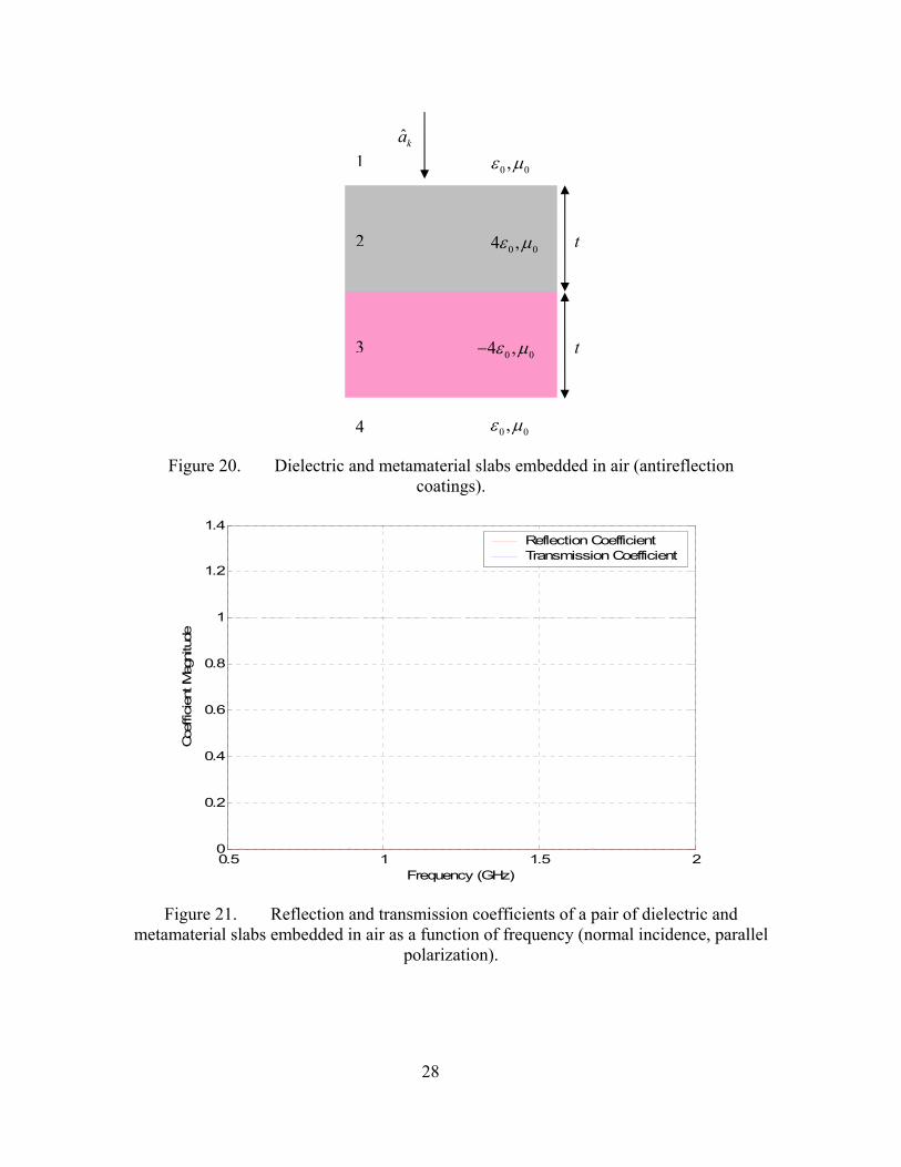
a. Antireflection Coatings Next, a structure consisting of LH and RH slabs in air (N=4) [10] will be
studied. Figure 20 shows a pair of metamaterial and dielectric slabs having the same
width ( t m), and opposite permittivities (0.1=2 3
4, 4r rε ε= = − ) embedded in air. In this
case, and 0TΓ = 1Tτ = for any frequency and any angle of incidence.
In Figure 21, the transmission and reflection coefficients of the structure
are plotted as a function of frequency for a parallel polarized wave, and Figure 22 shows
coefficients as a function of angle of incidence. At 1 GHz, the advantage of structures of
alternating slabs is that the total reflection and transmission coefficients are independent
of frequency and angle of incidence. Adding new dielectric and metamaterial pairs,
which are identical to the first pair, will not change the result. Figure 23 shows the
reflection and transmission coefficients for a perpendicularly polarized wave. As evident
in the figure, the structure is also polarization independent.
27
0 04 ,ε µ
0 04 ,ε µ−
0 0,ε µ
0 0,ε µˆka
1
t2
t3
4
Figure 20. Dielectric and metamaterial slabs embedded in air (antireflection coatings).
0.5 1 1.5 20
0.2
0.4
0.6
0.8
1
1.2
1.4
Frequency (GHz)
Coe
ffici
ent M
agni
tude
Reflection CoefficientTransmission Coefficient
Figure 21. Reflection and transmission coefficients of a pair of dielectric and
metamaterial slabs embedded in air as a function of frequency (normal incidence, parallel polarization).
28

0 10 20 30 40 50 60 70 80 900
0.2
0.4
0.6
0.8
1
1.2
1.4
Angle (Degree)
Coe
fficien
t Mag
nitu
de
Reflection CoefficientTransmission Coefficient
Figure 22. Reflection and transmission coefficients of a pair of dielectric and
metamaterial slabs embedded in air as a function of angle of incidence ( 1f = GHz).
0.5 1 1.5 20
0.2
0.4
0.6
0.8
1
1.2
1.4
Frequency (GHz)
Coe
ffici
ent M
agni
tude
Reflection CoefficientTransmission Coefficient
Figure 23. Reflection and transmission coefficients of a pair of dielectric and metamaterial slabs embedded in air as a function of frequency (normal incidence,
perpendicular polarization). 29

The phases of the second and third layers are the same but have opposite
signs. From Equation (2.26)
2 2
22 2
2 sinr r itπ ε µλ
Φ = − θ (4.14)
and
3 3
23 3
2 sinr r itπ ε µλ
Φ = − θ
3r
(4.15)
where 2 3 22 3 , andr r rt t µ µ ε= = = −ε . Therefore, theoretically the total phase of the
structure must be zero. Figure 24 shows the phase of the total transmission coefficient of
the structure as a function of frequency. As evident in the figure, the phase of the
transmission coefficient is zero except for numerical errors.
0.5 1 1.5 2-1
-0.8
-0.6
-0.4
-0.2
0
0.2
0.4
0.6
0.8
1x 10-16
Frequency (GHz)
Pha
se o
f The
Ref
lect
ion
Coe
ffici
ent (
Rad
ian)
Figure 24. Phase of the total transmission coefficient for a normally incident parallel
polarized wave.
30

b. High-Reflection Coatings In order to achieve high-reflection, metamaterial and dielectric slabs
should be chosen, as given in reference [10]
4 3 3 2 2
, ,r r r r r 1rε ε ε ε ε ε< > < (4.16)
and 2 3 2πΦ = Φ = at the central frequency. Figure 25 shows a pair of dielectric and
metamaterial slabs with different thicknesses that are embedded in air. The permittivities
are chosen to maximize the reflection coefficient. In this case, for a wave that is
normally incidence, the value of reflection coefficient varies between 0.7 and 0.88
depending on the frequency (Figure 26). At 1.25f = GHz, very high reflection values
are achieved for most incidence angles (Figure 27).
0 0,ε µ
0 00.25 ,ε µ
0 04 ,ε µ−
2 0.12t =
3 0.03t =
0 0,ε µˆka
1
4
3
2
m
m
Figure 25. Dielectric and metamaterial slabs with different thicknesses embedded in
air (high-reflection coatings).
31

0.5 1 1.5 20.45
0.5
0.55
0.6
0.65
0.7
0.75
0.8
0.85
0.9
Frequency (GHz)
Coe
ffici
ent M
agni
tude
Reflection CoefficientTransmission Coefficient
Figure 26. Reflection and transmission coefficients of a pair of dielectric and
metamaterial slabs with different thicknesses embedded in air as a function of frequency (normal incidence).
0 10 20 30 40 50 60 70 80 900
0.1
0.2
0.3
0.4
0.5
0.6
0.7
0.8
0.9
1
Angle (Degree)
Coe
ffici
ent M
agni
tude
Reflection CoefficientTransmission Coefficient
Figure 27. Reflection and transmission coefficients of a pair of dielectric and
metamaterial slabs with different thicknesses embedded in air as a function of angle of incidence ( 2f = GHz).
32
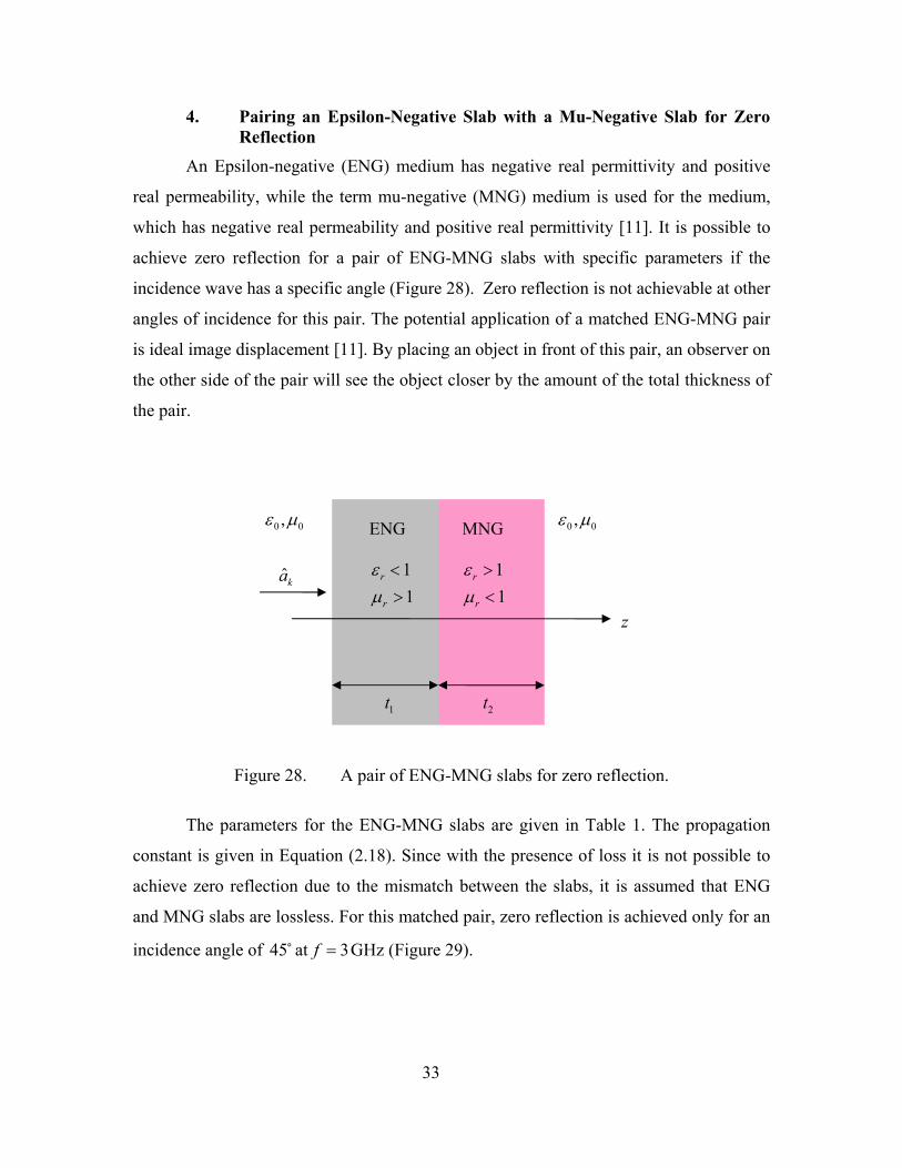
4. Pairing an Epsilon-Negative Slab with a Mu-Negative Slab for Zero Reflection
An Epsilon-negative (ENG) medium has negative real permittivity and positive
real permeability, while the term mu-negative (MNG) medium is used for the medium,
which has negative real permeability and positive real permittivity [11]. It is possible to
achieve zero reflection for a pair of ENG-MNG slabs with specific parameters if the
incidence wave has a specific angle (Figure 28). Zero reflection is not achievable at other
angles of incidence for this pair. The potential application of a matched ENG-MNG pair
is ideal image displacement [11]. By placing an object in front of this pair, an observer on
the other side of the pair will see the object closer by the amount of the total thickness of
the pair.
1t 2t
11
r
r
εµ<>
11
r
r
εµ><
ˆka
0 0,ε µ 0 0,ε µENG MNG
z
Figure 28. A pair of ENG-MNG slabs for zero reflection.
The parameters for the ENG-MNG slabs are given in Table 1. The propagation
constant is given in Equation (2.18). Since with the presence of loss it is not possible to
achieve zero reflection due to the mismatch between the slabs, it is assumed that ENG
and MNG slabs are lossless. For this matched pair, zero reflection is achieved only for an
incidence angle of at GHz (Figure 29). 45 3f =
33

Permittivity ( )ε Permeability ( )µ Thickness ( t )
ENG 03ε− 02µ 2
5 ENG
πγ
MNG 060ε 043.33µ− 2
4.8 MNG
πγ
Table 1. Parameters for a matched pair of ENG-MNG slabs (thin slabs).
The reflectivity depends more on the total thickness of the structure. The structure
is more sensitive to the variation of the incidence angle for a thicker pair (Table 2).
Figure 30 shows the reflection coefficient of a thicker pair as a function of the angle of
the incidence.
0 10 20 30 40 50 60 70 80 900
0.1
0.2
0.3
0.4
0.5
0.6
0.7
0.8
0.9
1
Angle (Degree)
Ref
lect
ion
Coe
ffici
ent
Figure 29. Sensitivity of the reflection coefficient to the variation of the angle of the
incidence (thin ENG-MNG slabs).
34

By comparing Figure 29 and Figure 30, notice that the reflection coefficient
remains low for wider range of incidence angles for a thin pair. The reflection coefficient
increases rapidly as the angle of incidence deviates from the design angle ( ) in
Figure 30.
45iθ =
Permittivity ( )ε Permeability ( )µ Thickness ( t )
ENG 03ε− 02µ 4
5 ENG
πγ
MNG 060ε 043.33µ− 2
4.8 MNG
πγ
Table 2. Parameters for a matched pair of ENG-MNG slabs (thick slabs).
0 10 20 30 40 50 60 70 80 900
0.1
0.2
0.3
0.4
0.5
0.6
0.7
0.8
0.9
1
Angle (Degree)
Ref
lect
ion
Coe
ffici
ent
Figure 30. Sensitivity of the reflection coefficient to the variation of the angle of the
incidence (thick ENG-MNG slabs).
35

The potential application of a matched ENG-MNG slab is illustrated in Figure 31.
The field distribution at the object plane can be expressed by Fourier components [11].
By selecting the ENG and MNG slab parameters ( , , ,ENG ENG MNG MNGε µ ε µ
ENG MNGt
) and thicknesses
( t t ), the Fourier components tunnel through this matched pair, and the pair
becomes transparent [11]. This means that the propagating waves will go through the slab
and show up at the exit side with the same magnitude and phase. An observer on the exit
side of the pair will see a virtual image of the point source as though it was placed closer
by the amount of the total thickness of the slabs ( t
,ENG MNG
+ ). This effect can be used in
image reconstruction and resolution enhancement. The planar lenses with negative
refraction are described in Chapter III. These lenses create a real image of the source,
whereas ENG-MNG pair forms a virtual image.
00
ENG
ENG
εµ
<>
00
MNG
MNG
εµ
><
ENGt MNGt
ENG MNG
Virtual Source Image
Figure 31. Pair of ENG-MNG layers under certain conditions may provide image
displacement and virtual image reconstruction (From Ref. [12])
5. Wet Radome Effect Water flow due to the rain on the surface of a flat radome may cause a water film
up to 1 mil (0.025 mm) thickness. This thin film cannot be seen except from reflections at
wide angles. The water layer thickness (t) on a flat panel is given as [13]
36

1 3
3cos
RLtg
µρ θ
=
(4.17)
where L is the plate length, R is the rain rate, µ is the specific viscosity of water, g is the
gravitational acceleration, ρ is the density of water and θ is the inclination angle from
vertical. The combination of water layer and radome forms a multi-layered structure that
can be analyzed using wave matrices. Figure 32 shows transmission loss
( 210log τ− dB) as a function of water layer thickness for a parallel polarized wave
normally incident upon a planar radome and water layer at 20 GHz. The radome consists
of a 0.03 in. thick laminate of fiberglass and a water repellent skin of Tedlar [14]. At 20
GHz, the refractive index of the radome is 1.7 0n .008j= − and the refractive index of
water [15] is . When the radome is present, transmission increases due to
the improved impedance match between radome surface and water layer.
6.85n = − 2.63j
0 0.2 0.4 0.6 0.8 1 1.2 1.4 1.60
5
10
15
20
25
Water Layer Thickness (mm)
Tran
smis
sion
Los
s (d
B)
Water Layer Alone
Radome and Water Layer
Figure 32. Transmission through radome and water layer as a function of water layer
thickness.
In Figure 33, transmission loss as a function of angle of incidence for a 0.032 in.
fiberglass radome ( 4rε = ) is plotted at 15.5 GHz. Figure 34 shows the transmission loss
37

for the same radome with a 0.002 in. water layer ( 49 34w jε = − ). High loss is observed
in the case of a water layer.
30 35 40
Perpendicul
Parallel
0 5 10 15 20 25 45 500
0.2
0.4
0.6
0.8
1
1.2
1.4
Angle (Degree)
Tran
smis
sion
Los
s (d
B)
ar
DRY
Figure 33. Transmission loss through a fiberglass radome.
0 5 10 15 20 25 30 35 40 45 501.5
2
2.5
3
3.5
4
4.5
5
5.5
Angle (Degree)
Tran
smis
sion
Los
s (d
B)
Perpendicular
Parallel
0.002 in. WATER FILM
Figure 34. Transmission loss through wet radome.
38

C. SUMMARY
This chapter is dedicated to simulating the propagation in structures consisting of
dielectric slabs, metamaterials or both metamaterial and dielectric slabs. Different
methods are described to achieve zero reflection or high reflection. These methods
include designing radar absorbing materials, pairing dielectric and metamaterial slabs and
pairing an epsilon-negative slab with a mu-negative slab. For all structures, reflection and
transmission coefficients are plotted as a function of frequency and angle of incidence. It
has been found that all these structures have interesting features. Potential applications of
these structures are described, such as reducing RCS of a target or image reconstruction.
Finally, transmission through a radome in rain is discussed.
39

THIS PAGE INTENTIONALLY LEFT BLANK
40

V. CONCLUSIONS
A. SUMMARY AND CONCLUSIONS Equations for transmission and reflection coefficients for a single boundary
between two dielectric media are presented and the wave matrix approach for layered
media described. Unusual properties of metamaterials are discussed and potential
applications of DNG materials are presented. Propagation characteristics of planar
multilayered structures (including both metamaterial and conventional dielectric layers)
are examined by using wave matrix approach.
A combination of dielectric and magnetic material used in RAM applications is
examined. The matched characteristic impedance method is used to achieve zero specular
reflection, and it has been found that transmission and reflection coefficients are
independent of polarization. The conditions for zero specular reflection have been used to
validate the MATLAB code.
Anti-reflection coating and high-reflection coating applications have been
proposed. It has been found that, for a structure consisting of a pair of metamaterial and
dielectric slabs embedded in air having the same width and opposite permittivities, the
reflection coefficient is zero and independent of frequency and angle of incidence. These
structures could be used as antenna radomes [10]. It has been also found that, by
choosing a pair of dielectric and metamaterial slabs with highly concentrated refractive
indices, the reflection coefficient is maximized. For one such structure modeled, the
reflection coefficient is larger than 0.7 for a large frequency range.
A pair of ENG-MNG slabs has been examined for zero reflection. The variation
of the reflection coefficient with angle of incidence is less sensitive for thinner slabs than
for the thicker ones. For a thin slab, the reflection coefficient remains low over a wider
set of incidence angles. By selecting the ENG and MNG slab parameters and thicknesses
properly, the pair becomes transparent to the wave [11]. This effect can be used in image
reconstruction and resolution enhancement.
Finally, the effects of rain on transmission through radomes is discussed. It has
been found that the existence of rain increases the transmission loss substantially.
41

B. FUTURE WORK
In this thesis, infinite planar structures consisting of dielectric and metamaterial
were examined. No edge effects and no surface or traveling waves were considered.
Future research could be conducted to examine the behavior of surface waves and edge
diffraction. It would also be interesting to explain how metamaterials could be applied to
radar cross section reduction and anechoic chamber design. In principle, absorbing DNG
layers could also be used for terminating the computational domain for the finite element
(FEM) method and the finite difference time domain (FDTD) method.
42

APPENDIX. MATLAB CODE
This appendix provides the MATLAB code used to calculate the reflection and
transmission coefficients of multi-layered structures in Chapter IV. The code is written in
MATLAB 6.5 and based on wave matrices model. This code calculates and plots
reflection and transmission coefficients as a function of frequency. It can be modified
easily to calculate the coefficients as a function of angle of incidence.
%################################################ %SCATTERING FROM MULTI-LAYERED METAMATERIALS %############################################### %This program calculates and plots refraction and transmission coefficients %of multi-layered structures as a function of frequency for a specific %angle of incidence %INPUTS %Defining structure properties clear; clc; N = input('Enter the number of layers= '); fmin=input('Enter Minimum Frequency (GHz)= '); fmax=input('Enter Maximum Frequency (GHz)= '); th=input('Enter Incidence Angle (Degree)= '); p=input ('Enter Polarization Type Parallel (1), Perpendicular (2)='); %Constants E0=8.85e-12; %Permittivity of free space Mu0=12.5664e-7; %Permeability of free space c=1/sqrt(E0*Mu0); %Speed of light (m/s) %Defining layer parameters for layer=1:N ; display(layer); Mu(layer)=input('Enter Permeability(µ) = '); Ei(layer)=input('Enter Permittivity(€) = '); t(layer)=input('Enter Layer Length (m) = '); sigma(layer)=input('Enter Loss (sigma) = '); end f=linspace(fmin,fmax); %Frequency matrix
43 thr=th*pi/180; %Angle of incidence (Radian)

st=sin(thr); ct=cos(thr); for i=1:N if Ei(i)<0 E(i)=abs(Ei(i)); else E(i)=Ei(i); end end %This part calculates the total reflection and transmission coefficients of %the structure for k =1:length(f); lambda=c/(f(k)*1e9); Beta1=2*(pi/lambda); total=1; w(k)=2*pi*f(k)*1e9; %Calculating the characteristic impedance of the layers for i=1:N Er(i)=E(i)-(j*sigma(i)/w(k)/E0); if p==1 Z(i)=sqrt(Er(i)*Mu(i)-st^2)/Er(i)/ct; elseif p==2 Z(i)=Mu(i)*ct/sqrt(Er(i)*Mu(i)-st^2); else display ('Polarization type must be 1 or 2'); end end %Individual reflection and transmission coefficients of the layers ro(1)=(Z(1)-1)/(Z(1)+1); tao(1)=ro(1)+1; for i=2:N ro(i)=(Z(i)-Z(i-1))/(Z(i)+Z(i-1)); tao(i)=ro(i)+1; end %Generating wave matrices for i =1:(N-1) if Ei(i)<0 sign=-1; else sign=1;
44

end Beta=Beta1*sign; A=exp(j*Beta*t(i)*sqrt(Er(i)-st^2)); Ac=exp(-j*Beta*t(i)*sqrt(Er(i)-st^2)); total=total*((1/tao(i))*[A,ro(i)*Ac;ro(i)*A,Ac]); end %Total reflection and transmission coefficients of the structure total=1/tao(N)*total*[1 ro(N); ro(N) 1]; rot(k)=total(2,1)/total(1,1); taot(k)=1/total(1,1); end %This part plots the coefficients as a function of frequency plot(f,abs(rot),'r-',f,abs(taot),'--'); grid; xlabel('Frequency (GHz)'); ylabel('Coefficient Magnitude'); legend('Reflection Coefficient','Transmission Coefficient');
45

THIS PAGE INTENTIONALLY LEFT BLANK
46

LIST OF REFERENCES
1. Matthew N. O. Sadiku, Elements of Electromagnetics, pp. 484-486, Temple University, Philadelphia, 1994.
2. D. Jenn, Notes for EC3630 (Radiowave Propagation), Naval Postgraduate School, 2003 (unpublished).
3. R. E. Collin, Field Theory of Guided Waves, pp. 88-91, McGraw Hill, New York, 1960.
4. David R. Smith, “The reality of negative refraction,” Physics World, May 2003.
5. J. B. Pendry “Negative refraction makes a perfect lens,” IEEE Physics Revolution Letters, 85, 3966-3969, October 2000.
6. V. G. Veselago, The Electrodynamics of Substances with Simultaneously Negative Values of ε and µ , Vol. 10, pp. 509-514, 1966.
7. Pendry, Holden, Robbins and Stewart, “Magnetism from conductors and enhanced nonlinear phenomena,” IEEE Transactions on Microwave Theory and Techniques, Vol. 47, No. 11, November 1999.
8. A. Houck, B. Brock and L. Chuang, “Experimental evolution of a left-handed material that obeys Snell’s Law,” Physical Review Letters, Vol. 90, No. 13, April 2003.
9. D. Jenn, Notes for EC4630 (Radar Cross Section Prediction and Reduction), Naval Postgraduate School, 2003 (unpublished).
10. H. Cory and C. Zach, “Wave propagation in metamaterial multi-layered structures,” IEEE Microwave and Optical Technology Letters, Vol. 40, No. 6, March 2004.
11. A. Alu and N. Engheta, “Pairing an epsilon-negative slab with a mu-negative slab,” IEEE Transactions on Antennas and Propagation, Vol. 51, No. 10, October 2003.
12. R. W. Ziolkowski and N. Engheta, “A positive future for double-negative metamaterials,” IEEE Transactions on Microwave Theory and Techniques, Vol. 53, No. 4, April 2005.
13. J. Chea, “Wet antenna effect on VSAT rain margin,” IEEE Transactions on Comm., Vol. 41, No. 8, pp. 1238-1244, August 1993.
47

14. I. Anderson, “Measurements of 20-GHz transmission through a radome in rain,” IEEE Transactions on Antennas and Propagation, Vol. 23, No. 5, September 1975.
15. D. E. Setzer, “Computed transmission through rain at microwave and visible frequencies,” Bell Syst. Tech. J., vol. 49, October 1970.
48

49
INITIAL DISTRIBUTION LIST
1. Defense Technical Information Center Ft. Belvoir, Virginia
2. Dudley Knox Library Naval Postgraduate School Monterey, California
3. Chairman, Department of Information Sciences Naval Postgraduate School Monterey, California
4. Professor David C. Jenn Department of Electrical and Computer Engineering Naval Postgraduate School Monterey, California
5. Professor Michael A. Morgan Department of Electrical and Computer Engineering Naval Postgraduate School Monterey, California
6. Ltjg. Umit Cotuk Turkish Navy Turkey
7. Deniz Harp Okulu Deniz Harp Okulu Kutuphanesi Tuzla, Istanbul
8. Hava Harp Okulu Hava Harp Okulu Kutuphanesi
Yesilyurt, Istanbul
9. Kara Harp Okulu Kara Harp Okulu Kutuphanesi
Bakanliklar, Ankara