Compositional control of IP media
23
1 Compositional Control of IP Media Pamela Zave and Eric Cheung AT&T Laboratories—Research, Florham Park, New Jersey USA pamela,[email protected] Abstract— In many IP media services, the media chan- nels are point-to-point, dynamic, and set up with the par- ticipation of one or more application servers, even though the media packets themselves travel directly between media endpoints. The application servers must be programmed so that media behavior is globally correct, even though the servers may attempt to manipulate the same media chan- nels concurrently and without knowledge of each other. Our proposed solution to this problem of compositional media control includes an architecture-independent descriptive model, a set of high-level programming primitives, a formal specification of their compositional semantics, a signaling protocol, an implementation, and partial verification of correctness. The paper includes performance analysis, com- parison to related work, and principles for making other networked applications more compositional. Index Terms— distributed applications, domain-specific architectures, protocol design, protocol verification, soft- ware/program verification, networks, streaming media, multimedia services, telecommunications, feature interac- tion I. IP MEDIA SERVICES IP media services use the Internet Protocol (IP) to make real-time audio and video connections. We are concerned with IP media services having two common characteristics. First, the media channels are point-to-point and dy- namic. This excludes dedicated long-term channels and multicast applications. It includes, however, a wide range of interactive applications including Internet telephony, home networks, computer-supported cooperative work (teleconferencing, telemonitoring, distance learning, and virtual reality), and computer-supported cooperative play (collaborative television, multiplayer games, and net- worked music performance). Second, the dynamic setup of a media channel must sometimes involve the participation of one or more application servers. The presence and significance of application servers depends on several aspects of the architecture of media services, as follows. In this paper a media endpoint is any source or sink of a media stream. Endpoints include original sources of media such as media synthesizers, cameras, and microphones. Endpoints include ultimate sinks of media such as user devices or clients with displays or speakers. Endpoints also include media-processing resources that perform a wide range of functions such as recording, playing, mixing, replicating, filtering, transcoding, and analyzing media streams. In most media services, user devices act autonomously with respect to other media endpoints (even if acting as slaves to their human masters). For example, they can request connections at any time, and choose to accept or decline connections that are offered to them. For a media channel to be established between two endpoints, the endpoints must cooperate by means of a signaling protocol. The Session Initiation Protocol (SIP) is currently the best-known and most commonly used protocol for this purpose [7], [14]. It is frequently stated that IP media services can be implemented in the participating media endpoints. User devices are computers, and any necessary new software can be installed on them. As user devices become more powerful, they can even perform the high-level media processing required by some services. Although it is certainly true that some IP media services are best implemented in the participating end- points, it is also true that many media services are best implemented in separate application servers. Here are some of the reasons for using application servers: • Handheld user devices are often disconnected from the network. An application server can provide a persistent network presence, such as voicemail, for handheld devices. A server can also make a user’s media files accessible at all times from all devices, while files stored on an inaccessible device would not be. • An application server can provide IP media services for closed user devices—user devices that were not designed to download new programs for built-in IP media services. The most obvious example of such a device is an ordinary telephone, connected to the Internet through the circuit-switched telephone network. • Many user devices do not reside in trusted adminis- trative domains. Applications with any kind of trust or security requirements cannot run on them. • Without application servers, every multi-party ser- vice must be implemented in a completely decentral- ized way. This might be difficult or inefficient com- pared to implementations with some centralization in
-
Upload
independent -
Category
Documents
-
view
0 -
download
0
Transcript of Compositional control of IP media
1
Compositional Control of IP MediaPamela Zave and Eric Cheung
AT&T Laboratories—Research, Florham Park, New Jersey USApamela,[email protected]
Abstract— In many IP media services, the media chan-nels are point-to-point, dynamic, and set up with the par-ticipation of one or more application servers, even thoughthe media packets themselves travel directly between mediaendpoints. The application servers must be programmedso that media behavior is globally correct, even though theservers may attempt to manipulate the same media chan-nels concurrently and without knowledge of each other. Ourproposed solution to this problem of compositional mediacontrol includes an architecture-independent descriptivemodel, a set of high-level programming primitives, a formalspecification of their compositional semantics, a signalingprotocol, an implementation, and partial verification ofcorrectness. The paper includes performance analysis, com-parison to related work, and principles for making othernetworked applications more compositional.
Index Terms— distributed applications, domain-specificarchitectures, protocol design, protocol verification, soft-ware/program verification, networks, streaming media,multimedia services, telecommunications, feature interac-tion
I. IP MEDIA SERVICES
IP media services use the Internet Protocol (IP) tomake real-time audio and video connections. We areconcerned with IP media services having two commoncharacteristics.
First, the media channels are point-to-point and dy-namic. This excludes dedicated long-term channels andmulticast applications. It includes, however, a wide rangeof interactive applications including Internet telephony,home networks, computer-supported cooperative work(teleconferencing, telemonitoring, distance learning, andvirtual reality), and computer-supported cooperative play(collaborative television, multiplayer games, and net-worked music performance).
Second, the dynamic setup of a media channel mustsometimes involve the participation of one or moreapplication servers. The presence and significance ofapplication servers depends on several aspects of thearchitecture of media services, as follows.
In this paper amedia endpointis any source or sinkof a media stream. Endpoints include original sourcesof media such as media synthesizers, cameras, andmicrophones. Endpoints include ultimate sinks of mediasuch as user devices or clients with displays or speakers.Endpoints also include media-processing resources that
perform a wide range of functions such as recording,playing, mixing, replicating, filtering, transcoding, andanalyzing media streams.
In most media services, user devices act autonomouslywith respect to other media endpoints (even if actingas slaves to their human masters). For example, theycan request connections at any time, and choose toaccept or decline connections that are offered to them.For a media channel to be established between twoendpoints, the endpoints must cooperate by means of asignaling protocol. The Session Initiation Protocol (SIP)is currently the best-known and most commonly usedprotocol for this purpose [7], [14].
It is frequently stated that IP media services can beimplemented in the participating media endpoints. Userdevices are computers, and any necessary new softwarecan be installed on them. As user devices become morepowerful, they can even perform the high-level mediaprocessing required by some services.
Although it is certainly true that some IP mediaservices are best implemented in the participating end-points, it is also true that many media services are bestimplemented in separate application servers. Here aresome of the reasons for using application servers:
† Handheld user devices are often disconnected fromthe network. An application server can provide apersistent network presence, such as voicemail, forhandheld devices. A server can also make a user’smedia files accessible at all times from all devices,while files stored on an inaccessible device wouldnot be.
† An application server can provide IP media servicesfor closed user devices—user devices that were notdesigned to download new programs for built-inIP media services. The most obvious example ofsuch a device is an ordinary telephone, connectedto the Internet through the circuit-switched telephonenetwork.
† Many user devices do not reside in trusted adminis-trative domains. Applications with any kind of trustor security requirements cannot run on them.
† Without application servers, every multi-party ser-vice must be implemented in a completely decentral-ized way. This might be difficult or inefficient com-pared to implementations with some centralization in
2
servers.† Without application servers, for every service ac-cessed from a device, application software must beinstalled on that device. This is not realistic forservices that are used infrequently by any one person.
We have stated that we are interested in serviceswhere the dynamic setup of a media channel sometimesinvolves the participation of one or more applicationservers. What if there are application servers, but theydo not make decisions about media channels? Thereare such servers, but there are also many servers thatmake decisions about which media channels should existwhen. They include servers concerned with switchingand conferencing. They include servers for services thatprovide access to media resources as part of the servicebeing offered. They also include servers for servicesthat use audio signaling as their user interface. Audiosignaling implements an extensible user interface on anyaudio device, by means of announcements, tones, touch-tone detection, and speech recognition. Audio signalingis a crucial ingredient of IP services that interoperatewith circuit-switched telephones, because it is the usualway to augment the user interface of the device.
Wherever there is one application server, there mightbe several. A connection between two user devicesmight be supervised by two servers in two differentadministrative domains, each one serving one of theusers. Often adding new functions to a system meansadding new servers, because adding a new server is fareasier than adding functions to an existing server. TheIP Multimedia Subsystem (IMS) architecture [1], whichis an emerging industry standard for media services,recognizes the necessity to route a particular signalingchannel through multiple servers within the same serviceprovider’s configuration.
Whenever there are multiple application servers, itis likely that they were not programmed to coordinatewith each other, beyond the common denominator offollowing a standardized signaling protocol such as SIP.Application servers representing different users may bein completely different administrative domains. Appli-cation servers performing different functions within oneadministrative domain may be produced by differentvendors.
In the services we are concerned with, a typical mediachannel looks like Figure 1. Most importantly, there isa separation between the media channel itself and thesignaling channel used to set up and control it. Thesignaling channel goes through one or more applicationservers, for all the reasons presented above. The mediapackets, on the other hand, travel directly between mediaendpoints. This is necessary because the media channeldemands high bandwidth, so packets must travel by theshortest available paths. This is also necessary because
the media channel demands low latency, so packetscannot incur extra delays from longer paths or serverhandling.
signalingchannel
mediachannel
AS AS
endpointendpoint
Fig. 1. In IP media services, signaling and media channels areseparate.
The separation of signaling and media channels isreinforced by other factors besides the presence of ap-plication servers. Because these channels differ in bothperformance and reliability requirements, they use dif-ferent underlying protocols. Signaling is low-bandwidthbut demands reliability. It is common to use TCP forsignaling, so that a signaling channel can be regardedas FIFO and reliable. Media is high-bandwidth. It iscommon to use RTP for media streams, because limitedpacket loss is preferable to delay. RTP can also becombined with quality-of-service mechanisms such asresource reservation.
II. T HE PROBLEM OF COMPOSITIONAL MEDIA
CONTROL
Section I described a class of IP-based applicationsimplemented in application servers. These servers mustbe programmed so that media behavior is globally cor-rect, even though the servers may attempt to manipu-late the same media channels concurrently and withoutknowledge of each other. We refer to this challenge as“compositional media control.”
Before giving a more detailed description of the prob-lem, we first show an example of why servers might actconcurrently and independently, and what might happenif they are not coordinated properly.
A. An example of the problem
Figure 2 is a telephony example in four snapshots. Thesnapshots show the same media endpoints and servers atfour different times.
Endpoint A is a telephone in an office with an IP PBX.Because of this, A has a permanent signaling channel tothe PBX, and all signaling channels connecting A toother telephones radiate from the PBX. Among otherfeatures, the PBX allows A to switch between multiple
3
do not
send
to Vsend
send
V
BA 43
PC
C V
PC
BBA 2
C
A
V
1
PCsend
do not
to Asend
PC
send
PBX
PBXPBX
PBX
to C
V
send
to C
to Bsend
C
to A
C
BA
senddo not
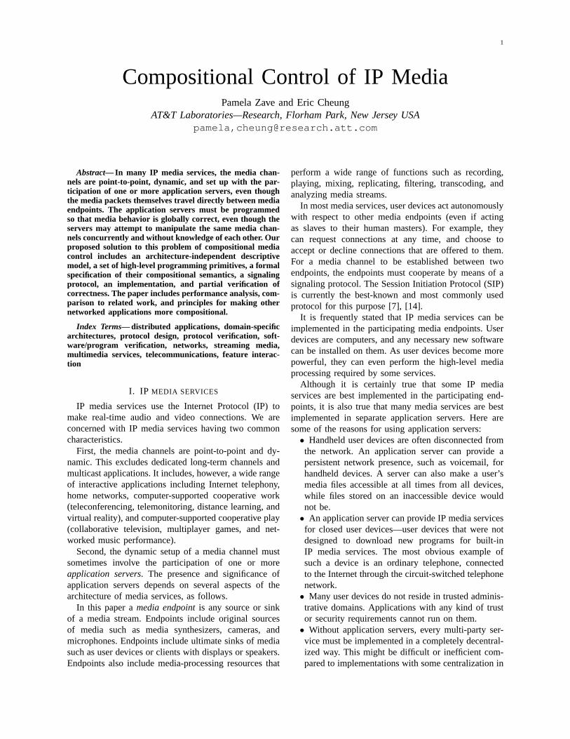
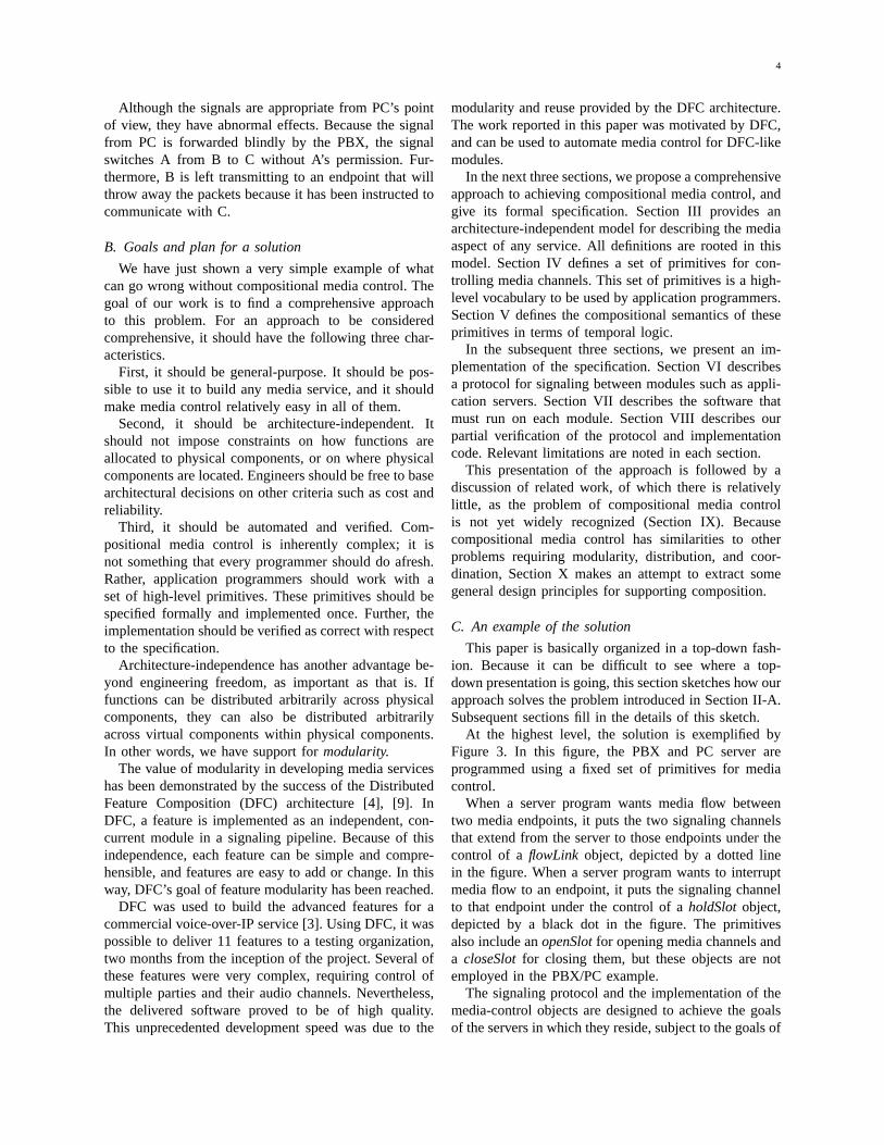
Fig. 2. An example of erroneous media control. A, B, C are telephones. PC is an application server implementing a prepaid-card feature. Vis a media resource providing a user interface for PC by means of audio signaling. Solid lines are two-way signaling channels, dashed arrowsare media channels, and dotted arrows are signals sent on signaling channels.
outside calls. Before any of the snapshots in the figurewere taken, the user of A was talking to the user oftelephone B, which is why there is a signaling channelbetween the PBX and B.
While A was talking to B, a user of telephone C, whois using a prepaid card, contacted the prepaid-card serverPC and used the card to call A. A received notificationof the incoming call and switched to C. This resulted inSnapshot 1. Note that in Snapshot 1 there is an audiochannel between A and C. There is no audio channel toor from B, because A has put B on hold.
Snapshot 2 shows what happens when the funds ofthe prepaid card become exhausted. A timer goes offin PC and the server sends three signals. In protocol-independent terms, there is a signal to A telling it tostop sending media. There is a signal to C telling it tosend media to the resource V, and a signal to V tellingit to send media to C.
It is standard behavior for a server receiving a sig-nal that does not concern itself to forward the signaluntouched. In this example, because the servers are notcoordinated—they are acting as if media signals concernmedia endpoints only—they forward all media signals
that they receive. In particular, the PBX forwards thedonot sendsignal to A.
After the endpoints respond to all commands in Snap-shot 2, the only audio channel is between C and V. Vwill use it to prompt C to supply additional funds, andto receive authorization by means of touch tones.
Snapshot 3 shows what happens when A next uses thePBX to switch back to B. The PBX sends three signalsappropriate to this function: a signal to A telling it tosend media to B, a signal to B telling it to send mediato A, and a signal to C telling it to stop sending media.This last signal passes through PC, which forwards ituntouched to C.
Although the signals are appropriate from the PBX’spoint of view, they have the abnormal effect of leaving Vwithout audio input from C. Note that the media arrowbetween C and V is now one-way.
Finally, Snapshot 4 shows what happens when Vcompletes verification of the funds from C (presumablyauthorized before C was cut off) and reconnects C withA. PC sends a signal to A telling it to send to C, a signalto C telling it to send to A, and a signal to V telling itto stop sending media.
4
Although the signals are appropriate from PC’s pointof view, they have abnormal effects. Because the signalfrom PC is forwarded blindly by the PBX, the signalswitches A from B to C without A’s permission. Fur-thermore, B is left transmitting to an endpoint that willthrow away the packets because it has been instructed tocommunicate with C.
B. Goals and plan for a solution
We have just shown a very simple example of whatcan go wrong without compositional media control. Thegoal of our work is to find a comprehensive approachto this problem. For an approach to be consideredcomprehensive, it should have the following three char-acteristics.
First, it should be general-purpose. It should be pos-sible to use it to build any media service, and it shouldmake media control relatively easy in all of them.
Second, it should be architecture-independent. Itshould not impose constraints on how functions areallocated to physical components, or on where physicalcomponents are located. Engineers should be free to basearchitectural decisions on other criteria such as cost andreliability.
Third, it should be automated and verified. Com-positional media control is inherently complex; it isnot something that every programmer should do afresh.Rather, application programmers should work with aset of high-level primitives. These primitives should bespecified formally and implemented once. Further, theimplementation should be verified as correct with respectto the specification.
Architecture-independence has another advantage be-yond engineering freedom, as important as that is. Iffunctions can be distributed arbitrarily across physicalcomponents, they can also be distributed arbitrarilyacross virtual components within physical components.In other words, we have support formodularity.
The value of modularity in developing media serviceshas been demonstrated by the success of the DistributedFeature Composition (DFC) architecture [4], [9]. InDFC, a feature is implemented as an independent, con-current module in a signaling pipeline. Because of thisindependence, each feature can be simple and compre-hensible, and features are easy to add or change. In thisway, DFC’s goal of feature modularity has been reached.
DFC was used to build the advanced features for acommercial voice-over-IP service [3]. Using DFC, it waspossible to deliver 11 features to a testing organization,two months from the inception of the project. Several ofthese features were very complex, requiring control ofmultiple parties and their audio channels. Nevertheless,the delivered software proved to be of high quality.This unprecedented development speed was due to the
modularity and reuse provided by the DFC architecture.The work reported in this paper was motivated by DFC,and can be used to automate media control for DFC-likemodules.
In the next three sections, we propose a comprehensiveapproach to achieving compositional media control, andgive its formal specification. Section III provides anarchitecture-independent model for describing the mediaaspect of any service. All definitions are rooted in thismodel. Section IV defines a set of primitives for con-trolling media channels. This set of primitives is a high-level vocabulary to be used by application programmers.Section V defines the compositional semantics of theseprimitives in terms of temporal logic.
In the subsequent three sections, we present an im-plementation of the specification. Section VI describesa protocol for signaling between modules such as appli-cation servers. Section VII describes the software thatmust run on each module. Section VIII describes ourpartial verification of the protocol and implementationcode. Relevant limitations are noted in each section.
This presentation of the approach is followed by adiscussion of related work, of which there is relativelylittle, as the problem of compositional media controlis not yet widely recognized (Section IX). Becausecompositional media control has similarities to otherproblems requiring modularity, distribution, and coor-dination, Section X makes an attempt to extract somegeneral design principles for supporting composition.
C. An example of the solution
This paper is basically organized in a top-down fash-ion. Because it can be difficult to see where a top-down presentation is going, this section sketches how ourapproach solves the problem introduced in Section II-A.Subsequent sections fill in the details of this sketch.
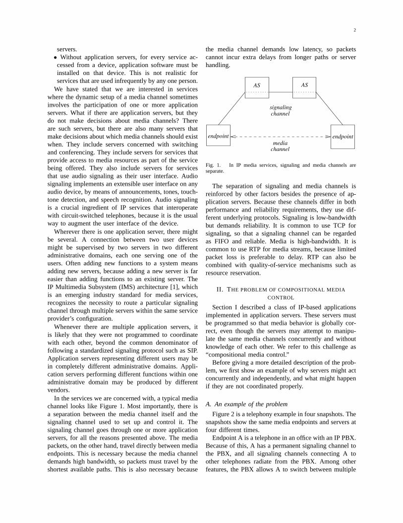
At the highest level, the solution is exemplified byFigure 3. In this figure, the PBX and PC server areprogrammed using a fixed set of primitives for mediacontrol.
When a server program wants media flow betweentwo media endpoints, it puts the two signaling channelsthat extend from the server to those endpoints under thecontrol of a flowLink object, depicted by a dotted linein the figure. When a server program wants to interruptmedia flow to an endpoint, it puts the signaling channelto that endpoint under the control of aholdSlotobject,depicted by a black dot in the figure. The primitivesalso include anopenSlotfor opening media channels anda closeSlotfor closing them, but these objects are notemployed in the PBX/PC example.
The signaling protocol and the implementation of themedia-control objects are designed to achieve the goalsof the servers in which they reside, subject to the goals of
5
BB
V
A
V
A
C C
21
VC
4
PBX PBX
PBXPBX
C
A3
PCPC
B
V
PC
A B
PC
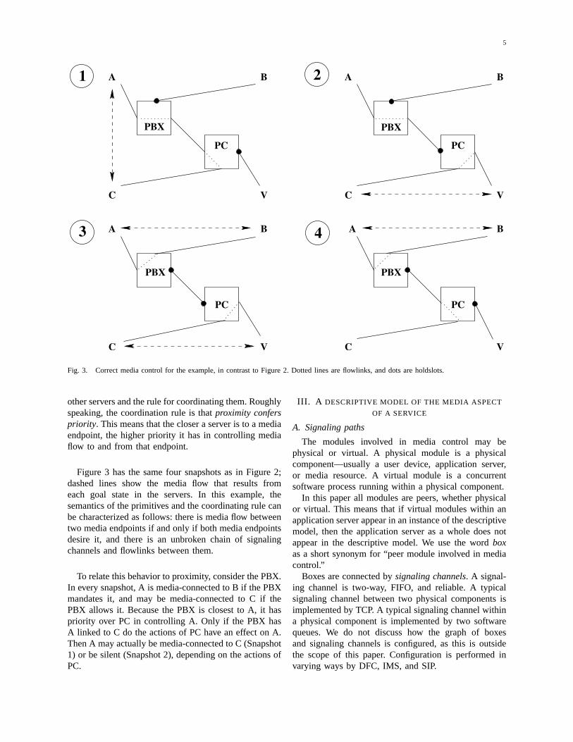
Fig. 3. Correct media control for the example, in contrast to Figure 2. Dotted lines are flowlinks, and dots are holdslots.
other servers and the rule for coordinating them. Roughlyspeaking, the coordination rule is thatproximity conferspriority. This means that the closer a server is to a mediaendpoint, the higher priority it has in controlling mediaflow to and from that endpoint.
Figure 3 has the same four snapshots as in Figure 2;dashed lines show the media flow that results fromeach goal state in the servers. In this example, thesemantics of the primitives and the coordinating rule canbe characterized as follows: there is media flow betweentwo media endpoints if and only if both media endpointsdesire it, and there is an unbroken chain of signalingchannels and flowlinks between them.
To relate this behavior to proximity, consider the PBX.In every snapshot, A is media-connected to B if the PBXmandates it, and may be media-connected to C if thePBX allows it. Because the PBX is closest to A, it haspriority over PC in controlling A. Only if the PBX hasA linked to C do the actions of PC have an effect on A.Then A may actually be media-connected to C (Snapshot1) or be silent (Snapshot 2), depending on the actions ofPC.
III. A DESCRIPTIVE MODEL OF THE MEDIA ASPECT
OF A SERVICE
A. Signaling paths
The modules involved in media control may bephysical or virtual. A physical module is a physicalcomponent—usually a user device, application server,or media resource. A virtual module is a concurrentsoftware process running within a physical component.
In this paper all modules are peers, whether physicalor virtual. This means that if virtual modules within anapplication server appear in an instance of the descriptivemodel, then the application server as a whole does notappear in the descriptive model. We use the wordboxas a short synonym for “peer module involved in mediacontrol.”
Boxes are connected bysignaling channels. A signal-ing channel is two-way, FIFO, and reliable. A typicalsignaling channel between two physical components isimplemented by TCP. A typical signaling channel withina physical component is implemented by two softwarequeues. We do not discuss how the graph of boxesand signaling channels is configured, as this is outsidethe scope of this paper. Configuration is performed invarying ways by DFC, IMS, and SIP.
6
Each signaling channel is partitioned statically intotunnels, each of which provides a separate two-waysignaling capability. Each tunnel can be used to controla separate media channel. The endpoint of a tunnel at abox is called aslot.
Media control requires a signaling protocol throughwhich boxes communicate and coordinate their efforts.The signaling protocol (defined in Section VI) operatesseparately in each tunnel of each signaling channel. Inother words,each slot is a protocol endpoint.
Within a box, two slots may be assigned to aflowLinkobject. A flowlink is a software object that reads all thesignals from its two slots and controls all the signalswritten to them. A flowlinkcoordinates the signals of itstwo slots; its behavior and implementation are discussedin several sections of this paper.
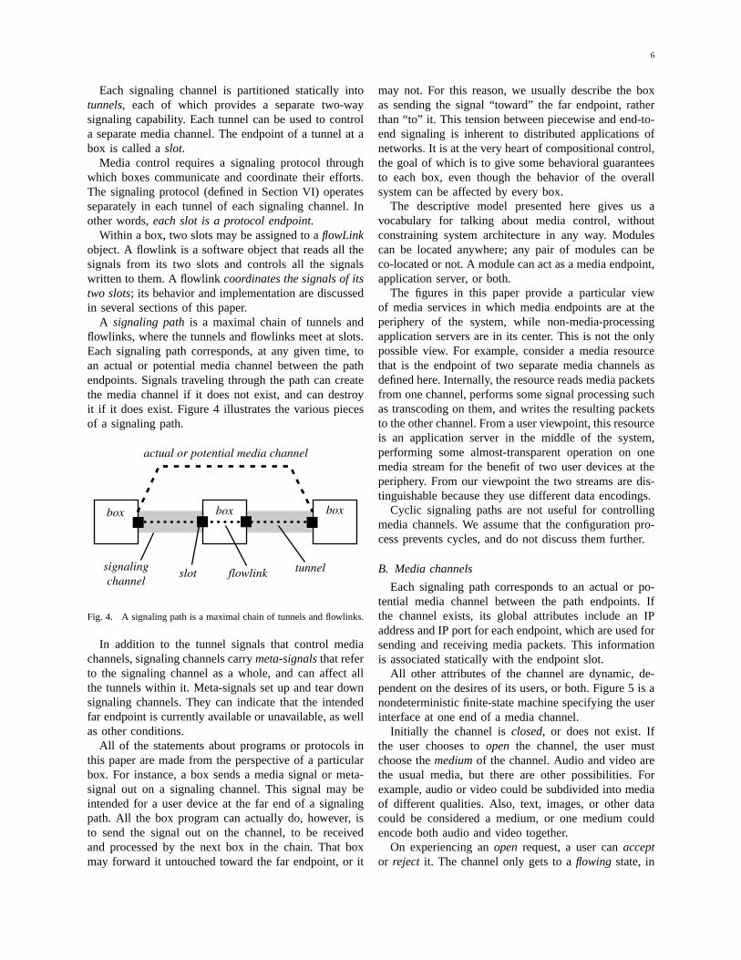
A signaling pathis a maximal chain of tunnels andflowlinks, where the tunnels and flowlinks meet at slots.Each signaling path corresponds, at any given time, toan actual or potential media channel between the pathendpoints. Signals traveling through the path can createthe media channel if it does not exist, and can destroyit if it does exist. Figure 4 illustrates the various piecesof a signaling path.
actual or potential media channel
box box box
signalingchannel
slot flowlink tunnel
Fig. 4. A signaling path is a maximal chain of tunnels and flowlinks.
In addition to the tunnel signals that control mediachannels, signaling channels carrymeta-signalsthat referto the signaling channel as a whole, and can affect allthe tunnels within it. Meta-signals set up and tear downsignaling channels. They can indicate that the intendedfar endpoint is currently available or unavailable, as wellas other conditions.
All of the statements about programs or protocols inthis paper are made from the perspective of a particularbox. For instance, a box sends a media signal or meta-signal out on a signaling channel. This signal may beintended for a user device at the far end of a signalingpath. All the box program can actually do, however, isto send the signal out on the channel, to be receivedand processed by the next box in the chain. That boxmay forward it untouched toward the far endpoint, or it
may not. For this reason, we usually describe the boxas sending the signal “toward” the far endpoint, ratherthan “to” it. This tension between piecewise and end-to-end signaling is inherent to distributed applications ofnetworks. It is at the very heart of compositional control,the goal of which is to give some behavioral guaranteesto each box, even though the behavior of the overallsystem can be affected by every box.
The descriptive model presented here gives us avocabulary for talking about media control, withoutconstraining system architecture in any way. Modulescan be located anywhere; any pair of modules can beco-located or not. A module can act as a media endpoint,application server, or both.
The figures in this paper provide a particular viewof media services in which media endpoints are at theperiphery of the system, while non-media-processingapplication servers are in its center. This is not the onlypossible view. For example, consider a media resourcethat is the endpoint of two separate media channels asdefined here. Internally, the resource reads media packetsfrom one channel, performs some signal processing suchas transcoding on them, and writes the resulting packetsto the other channel. From a user viewpoint, this resourceis an application server in the middle of the system,performing some almost-transparent operation on onemedia stream for the benefit of two user devices at theperiphery. From our viewpoint the two streams are dis-tinguishable because they use different data encodings.
Cyclic signaling paths are not useful for controllingmedia channels. We assume that the configuration pro-cess prevents cycles, and do not discuss them further.
B. Media channels
Each signaling path corresponds to an actual or po-tential media channel between the path endpoints. Ifthe channel exists, its global attributes include an IPaddress and IP port for each endpoint, which are used forsending and receiving media packets. This informationis associated statically with the endpoint slot.
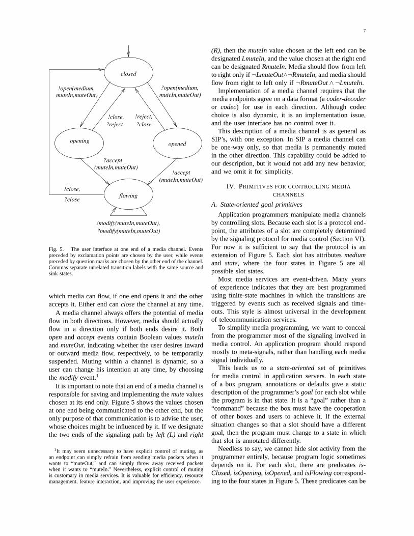
All other attributes of the channel are dynamic, de-pendent on the desires of its users, or both. Figure 5 is anondeterministic finite-state machine specifying the userinterface at one end of a media channel.
Initially the channel isclosed, or does not exist. Ifthe user chooses toopen the channel, the user mustchoose themediumof the channel. Audio and video arethe usual media, but there are other possibilities. Forexample, audio or video could be subdivided into mediaof different qualities. Also, text, images, or other datacould be considered a medium, or one medium couldencode both audio and video together.
On experiencing anopen request, a user canacceptor reject it. The channel only gets to aflowing state, in
7
!modify(muteIn,muteOut),
?close
!close,flowing
!close,?reject ?close
?modify(muteIn,muteOut)
!open(medium,muteIn,muteOut)
?accept(muteIn,muteOut)
muteIn,muteOut)?open(medium,
(muteIn,muteOut)!accept
!reject,
opening opened
closed
Fig. 5. The user interface at one end of a media channel. Eventspreceded by exclamation points are chosen by the user, while eventspreceded by question marks are chosen by the other end of the channel.Commas separate unrelated transition labels with the same source andsink states.
which media can flow, if one end opens it and the otheraccepts it. Either end canclosethe channel at any time.
A media channel always offers the potential of mediaflow in both directions. However, media should actuallyflow in a direction only if both ends desire it. Bothopenand acceptevents contain Boolean valuesmuteInandmuteOut, indicating whether the user desires inwardor outward media flow, respectively, to be temporarilysuspended. Muting within a channel is dynamic, so auser can change his intention at any time, by choosingthe modifyevent.1
It is important to note that an end of a media channel isresponsible for saving and implementing themutevalueschosen at its end only. Figure 5 shows the values chosenat one end being communicated to the other end, but theonly purpose of that communication is to advise the user,whose choices might be influenced by it. If we designatethe two ends of the signaling path byleft (L) and right
1It may seem unnecessary to have explicit control of muting, asan endpoint can simply refrain from sending media packets when itwants to “muteOut,” and can simply throw away received packetswhen it wants to “muteIn.” Nevertheless, explicit control of mutingis customary in media services. It is valuable for efficiency, resourcemanagement, feature interaction, and improving the user experience.
(R), then themuteInvalue chosen at the left end can bedesignatedLmuteIn, and the value chosen at the right endcan be designatedRmuteIn. Media should flow from leftto right only if :LmuteOut̂ :RmuteIn, and media shouldflow from right to left only if :RmuteOut̂ :LmuteIn.
Implementation of a media channel requires that themedia endpoints agree on a data format (acoder-decoderor codec) for use in each direction. Although codecchoice is also dynamic, it is an implementation issue,and the user interface has no control over it.
This description of a media channel is as general asSIP’s, with one exception. In SIP a media channel canbe one-way only, so that media is permanently mutedin the other direction. This capability could be added toour description, but it would not add any new behavior,and we omit it for simplicity.
IV. PRIMITIVES FOR CONTROLLING MEDIA
CHANNELS
A. State-oriented goal primitives
Application programmers manipulate media channelsby controlling slots. Because each slot is a protocol end-point, the attributes of a slot are completely determinedby the signaling protocol for media control (Section VI).For now it is sufficient to say that the protocol is anextension of Figure 5. Each slot has attributesmediumand state, where the four states in Figure 5 are allpossible slot states.
Most media services are event-driven. Many yearsof experience indicates that they are best programmedusing finite-state machines in which the transitions aretriggered by events such as received signals and time-outs. This style is almost universal in the developmentof telecommunication services.
To simplify media programming, we want to concealfrom the programmer most of the signaling involved inmedia control. An application program should respondmostly to meta-signals, rather than handling each mediasignal individually.
This leads us to astate-orientedset of primitivesfor media control in application servers. In each stateof a box program, annotations or defaults give a staticdescription of the programmer’sgoal for each slot whilethe program is in that state. It is a “goal” rather than a“command” because the box must have the cooperationof other boxes and users to achieve it. If the externalsituation changes so that a slot should have a differentgoal, then the program must change to a state in whichthat slot is annotated differently.
Needless to say, we cannot hide slot activity from theprogrammer entirely, because program logic sometimesdepends on it. For each slot, there are predicatesis-Closed, isOpening, isOpened,andisFlowingcorrespond-ing to the four states in Figure 5. These predicates can be
8
used as guards on transitions in box programs. If a statein a box program has a transition guarded byisClosed(s)for some slots, then that transition is executable as soonas the program enters the state, ifs is closed at that time,or as soon ass becomes closed while the program is stillin the state.
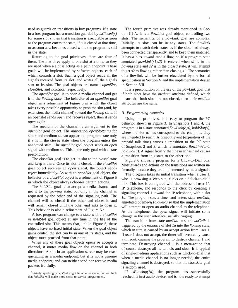
Returning to the goal primitives, there are four ofthem. The first three apply to one slot at a time, so theyare used when a slot is acting as a path endpoint. Thesegoals will be implemented by software objects, each ofwhich controls a slot. Such a goal object reads all thesignals received from its slot, and writes all the signalssent to its slot. The goal objects are namedopenSlot,closeSlot,andholdSlot,respectively.
TheopenSlotgoal is to open a media channel and getit to the flowing state. The behavior of anopenSlotgoalobject is a refinement of Figure 5 in which the objecttakes every possible opportunity to push the slot (and, byextension, the media channel) toward theflowingstate. Ifan openslot sendsopenand receivesreject, then it sendsopenagain.
The medium of the channel is an argument to theopenSlotgoal object. The annotationopenSlot(s,m)forslot s and mediumm can appear in a program state onlyif s is in the closedstate when the program enters theannotated state. TheopenSlotgoal object sends anopensignal with mediumm. This is the only goal with a stateprecondition.
The closeSlotgoal is to get its slot to theclosedstateand keep it there. Once its slot is closed, if thecloseSlotgoal object receives anopen signal, the object sendsreject immediately. As with anopenSlotgoal object, thebehavior of acloseSlotobject is a refinement of Figure 5in which the object always chooses certain actions.
The holdSlot goal is to accept a media channel andget it to the flowing state, but only if the channel isrequested by the other end of the signaling path. Thechannel will be closed if the other end closes it, andwill remain closed until the other end asks to open it.This behavior is also a refinement of Figure 5.2
A box program can change to a state with acloseSlotor holdSlot goal object at any time in the life of thecontrolled slot. This means that, unlike Figure 5, theseobjects have no fixed initial state. When the goal objectgains control the slot can be in any of its states, and theobject must proceed from that point.
When any of these goal objects opens or accepts achannel, it mutes media flow on the channel in bothdirections. A slot in an application server may be mas-querading as a media endpoint, but it is not a genuinemedia endpoint, and can neither send nor receive mediapackets fruitfully.
2Strictly speakingacceptSlotmight be a better name, but we thinkthat holdSlotwill make more sense to service programmers.
The fourth primitive was already mentioned in Sec-tion III-A. It is a flowLink goal object, controlling twoslots. The semantics of aflowLink goal are complex.Initially, its slots can be in any states. The flowlinkattempts to match their states as if the slots had alwaysbeen connected transparently, and to keep them matched.It has a bias toward media flow, so if a program stateannotatedflowLink(s1,s2)is entered whens1 is in theflowingstate ands2 is in theclosedstate, it will attemptto gets2 to flowing rather than closings1. The semanticsof a flowlink will be further elucidated by the formalspecification in Section V and the implementation designin Section VII.
It is a precondition on the use of theflowLinkgoal thatif both slots have themediumattribute defined, whichmeans that both slots are not closed, then theirmediumattributes are the same.
B. Programming examples
Using the primitives, it is easy to program the PCbehavior shown in Figure 3. In Snapshots 1 and 4, theprogram is in a state annotatedflowLink(c,a), holdSlot(v),where the slot names correspond to the endpoints theyare intended to reach. A timeout event (expiration of theprepaid talk time) causes a transition to the PC stateof Snapshots 2 and 3, which is annotatedflowLink(c,v),holdSlot(a). A signal from V that the user has paid causesa transition from this state to the other one.
Figure 6 shows a program for a Click-to-Dial box.Most guards and actions on the transitions are written in-formally, because they are implemented by meta-signals.
The program takes its initial transition when a user 1,who is browsing a Web site, clicks on a “click-to-dial”link. This box is configured with the address of user 1’sIP telephone, and responds to the click by creating asignaling channel 1 toward the IP telephone, with a slot1a. The program sets a timer and enters stateoneCall,annotatedopenSlot(1a,audio)so that the implementationwill attempt to open an audio channel to the telephone.At the telephone, theopen signal will initiate somechange in the user interface, usually ringing.
The transition from stateoneCall to statetwoCalls istriggered by the entrance of slot1a into theflowingstate,which in turn is caused by an accept action from user 1.If user 1 does not accept, the timer will eventually causea timeout, causing the program to destroy channel 1 andterminate. Destroying channel 1 is a meta-action thatof course destroys all its tunnels and slots. It is typicalof single-medium applications such as Click-to-Dial thatwhen a media channel is no longer needed, the entiresignaling channel is destroyed, so that thecloseSlotgoalis seldom used.
If isFlowing(1a), the program has successfullyreached its first audio device, and is now ready to attempt

9
"ringback" to generator
1 destroyed / destroy 2
openSlot(1a,audio)
oneCall:
create signaling channel 1 and slot 1a; set timeruser 1 clicks on Web site /
channel T and slot Ta; signal
flowLink(1a,2a)
1 destroyed / destroy 2
destroy 2; create signaling channel Tand slot Ta; signal "busyTone"
to generator
device 2 is available / create signaling
timeout / destroy 1
flowLink(1a,Ta)
ringback:
destroy 2; destroy T1 destroyed /
isFlowing(2a) /
destroy T
openSlot(2a,audio)
isFlowing(1a) / create signaling channel 2 and slot 2a
device 2 is unavailable /
2 destroyed / destroy 1
1 destroyed /destroy T transparent:
twoCalls:
openSlot(2a,audio)openSlot(1a,audio)
busyTone:
flowLink(1a,Ta)
Fig. 6. A program for a Click-to-Dial box.
reaching the second one. It creates a signaling channel2 toward the IP telephone at the clicked address on theWeb site, with slot2a. In statetwoCallsthe goal for slot1a remains the same (which means control of the slotis implemented by the same object), while the programalso puts slot2a under the control of an openslot.
In statetwoCalls the program is waiting for a meta-signal that the telephone at the end of channel 2 is avail-able or unavailable. If user 1 gives up in the meantime,his action will destroy channel 1, which will result inthe program’s destroying channel 2 and terminating.
If the device is unavailable, then the program destroyschannel 2, and creates a signaling channel T to a tone-generator resource. In statebusyToneslots1a andTa areflowlinked. On entrance to this program state, the slotstate of1a is flowing, and the slot state ofTa is closed.The flowLink implementation will match the states ofthese two slots by openingTa; once the resource acceptsthe audio channel, it will generate a busy tone, and user1 will be able to hear it. Eventually user 1 will abandonthe call, and the program can terminate.3
3It may seem strange to implement audio tones this way, and notin user 1’s telephone. The fact is that tone generation in the device isoften not feasible, because the device will not generate tones when itbelieves it is playing the role of the called party. The implementationtechnique shown here is commonly used [15].
If the device is available, then the program uses thesame technique as above to play a ringback tone foruser 1 in stateringback. At the same time, it continuesto try to open an audio channel to user 2. Because theannotation controlling slot2a is the same in both statestwoCalls and ringback, the openLinkobject controlling2a is also the same.
Finally, if and whenisFlowing(2a), the program willdestroy channel T and flowlink slots1a and 2a. TheflowLink implementation will automatically reconfigureIP addresses, ports, and codecs so that user 1 and user2 can talk to each other.
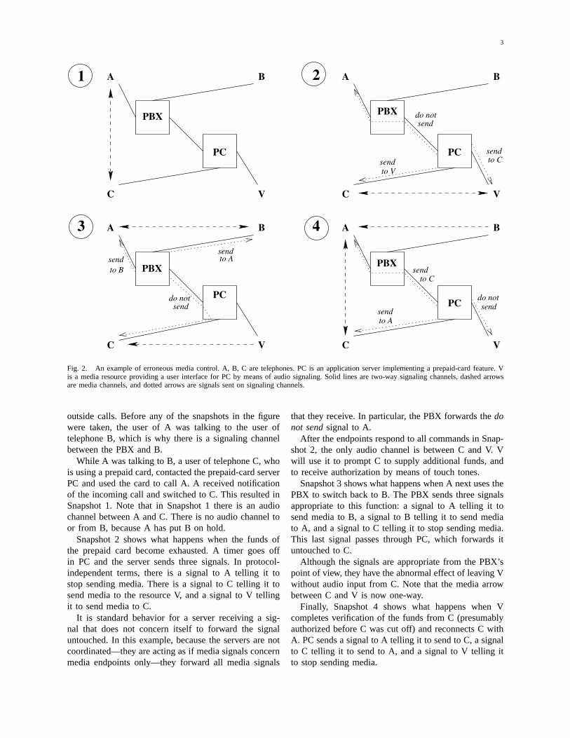
Although conferencing is used by many applicationsfor many different purposes, the implementation of con-ferencing always looks approximately the same. The sig-naling graph of a three-way audio conference is shown inFigure 7. The conference server is an application server,while the conference bridge is a media resource thatperforms audio mixing.
As can be seen in the figure, during the conferencethe conference server flowlinks the tunnel for each userdevice to a tunnel leading to the bridge. Each tunnelcorresponds to a two-way audio channel. In the directiontoward the bridge, an audio channel carries the voice ofa single user. In the direction away from the bridge, an

10
A
B
CC audio input
mixed audio output
conferenceserver
conf-erencebridge
Fig. 7. The signaling model of an audio conference. Only the mediaflow for endpoint C is shown.
audio channel carries the mixed voices of all the usersexcept the user the channel goes to.
Various conference applications require different kindsof muting. Full muting separates one user from the con-ference entirely. The conference server can accomplishthis by temporarily replacing a flowlink by two holdslots.
Partial muting is more interesting and more varied.If the conference is a large business meeting, it maybe desirable to mute the audio input from nonspeakingparticipants, so that they can hear the meeting, butbackground noise at their locations does not degradeoverall audio quality. If the conference is part of IP-basedemergency services, on the other hand, A may be a call-taker, B may be a person who has called emergencyservices, and C may be an emergency responder inthe police or fire department. In this case it must bepossible to retain the audio input from B while mutingthe conference output to B, so that B cannot hear whatthe emergency personnel are saying [2]. This is theopposite of business muting.
For a final example of partial muting, let A be anew customer-service agent, B be a customer callingfor service, and C be the supervisor of A. In a trainingsituation, the requirement is that A and B can hear eachother clearly, C can hear both of them clearly, B cannothear C, and A hears a whispered version of what Cis saying. This enables C to advise A without beingapparent to B.
The four primitives cannot achieve any of thesepartial-muting scenarios directly. They can be achievedeasily by the conference bridge, however, because theyare just different mixes of the three audio inputs. The ap-plication server simply connects all the user devices to amedia server (conference bridge), and uses standardizedmeta-signals to tell the media server how to mix them[10].
Our final example shows a scenario in the use of
collaborative television (Figure 8). The scenario is takenfrom [11], although our approach to the application ismore distributed and compositional than the architectureproposed there.
In this scenario, endpoint A is a large television ina family room. C is a laptop in a daughter’s bedroom.They are sharing a particular movie, which means thatboth are seeing the same movie at the same time point inthe movie. The signaling channel from the collaborative-control box for A to the movie server is associated inthe server with this movie and time pointer.
This signaling channel has five active tunnels control-ling five media channels. Because they are all in the samesignaling channel, the media is all from the same movieat the same time point. There are video and English audiochannels for the two video devices, which differ becausethe two devices have different media quality and usedifferent codecs. There is also a French audio channelto the headphones of a French-speaking friend in thefamily room (endpoint B).
The control box for A has control of the movie, so thatcommands to pause or play the movie are mediated byit, and affect all five media channels. The signaling pathsfrom all three devices to the movie server go through thisbox so that they are watching the movie collaboratively.
In the scenario from [11], the daughter decides toleave the collaboration and fast-forward to the end of themovie. After this change is completed, the collaborationbox of C would have its own signaling channel tothe movie server, associated with the same movie buta different time pointer. There would no longer be asignaling channel between the two collaboration boxes.Because C has its own collaboration box, other devicescould now join and share this new view of the movie.
We believe that the four primitives are sufficient forall media programming in application servers, and wehave tested them for completeness on numerous smallexamples. The only way to know for sure is to gain ex-tensive experience with programming compositional IPmedia services. At present no one has much experience,primarily because such applications are so difficult tobuild.
V. SPECIFICATION OF COMPOSITIONAL SEMANTICS
To specify correctness, we assume that media end-points are programmed using theopenSlot, closeSlot,and holdSlot goal primitives as presented above, withthe exception that users at media endpoints have fullfreedom to choose the values of themute flags. Pro-gramming endpoints in this state-oriented way would befar clumsier than implementing the events of Figure 5directly, but it is no less complete. With this assumption,all box behavior reduces to the behavior of theopenSlot,closeSlot, holdSlot,andflowLink primitives.

11
A
B
C
movieserver
collaborative controlfor A
collaborativecontrol for C
audio for C
video for C
Fig. 8. A scenario in collaborative television. Only the media flow for endpoint C is shown.
The other factor that affects media behavior is thegraph of signaling channels and boxes. We take thisgraph into account by specifying correctness in terms ofindividual signaling paths. Signaling paths depend on thegraph of signaling channels and boxes. Signaling pathsalso depend on the configuration of flowlinks withinboxes, determining which slots and tunnels form a path.
Signaling paths are an indirect encoding of the ruleof proximity confers priority.This is because, from theperspective of a media endpoint, each box in a signalingpath leading away from the endpoint has completecontrol over where the far side of the path is going. Therule ofproximity confers priorityhas been used to governmedia-control feature interactions in many applicationsbuilt using the IP-based implementation of DFC [3], [4].It is convenient, intuitive, and sufficient for a wide rangeof applications, provided that there is enough control ofthe configuration graph in which proximity is measured.
For each signaling path, we specify correct behaviorin terms of stability or recurrence properties in temporallogic. This is necessary because a set of signaling pathsis a snapshot of a system, and can change at any time asthe flowlinks change. Stability properties express the ideathat if a particular path is allowed to persist long enough,the goal primitives and protocol will do their work,and eventually achieve a desired path state. Recurrenceproperties express the same idea, plus the additional ideathat if something is perturbed while the path persists,the path state will eventually adjust to the perturbation.If the system is thrashing and paths do not persist longenough to stabilize, then this specification of correctnessdoes not say anything about their behavior.
For convenience, we identify the two ends of a sig-naling path asleft (L) andright (R). For each path, thereare two stable states that we might wish to achieve. Thefirst is thebothClosedstate, in which both endpoints arein the closedstate and there is no possibility of mediaflow. This path state is defined as
Lclosed̂ Rclosed
where the predicates refer to the endpoint states asdefined in Figure 5. The second stable path state isthe bothFlowing state, in which both endpoints are inthe flowing state. To specify a correct state completely,we need to ensure that themediumattribute of bothendpoints is the same. We also need to ensure that theimplementation state correctly reflects themuteattributesof the endpoints. The implementation state of the end-points is captured by the new history variablesLenabledand Renabled. If Lenabledis true, both endpoints areready for packets in the right-to-left direction. Theyhave agreed on a codec, they have agreed to enabletransmission, and they have each other’s IP addressand port number. IfRenabledis true, both endpointsare ready for packets in the left-to-right direction. Thecomplete definition of thebothFlowingpath state is
Lflowing^ Rflowing^ (Lmedium= Rmedium) ^(Lenabled= :LmuteIn^ :RmuteOut) ^(Renabled= :RmuteIn̂ :LmuteOut)
The implementation of the new history variablesLenabledandRenabledis described in Section VI-C.

12
Each signaling path has two ends, each of which iscontrolled by an openslot, closeslot, or holdslot. Takingsymmetry into account, there are six possible path typesbased on classification of their end slots. A path of agiven type can have any number of tunnels and flowlinks,as these should be transparent with respect to observablebehavior.
If one end of a path is controlled by a closeslot andone end is controlled by a closeslot or holdslot, thencorrectness is:
3 2 bothClosed
This stability property in linear temporal logic says thateventually the path will reach a state in which bothend slots are closed, and will remain there forever. Inpractice, of course, the slots are only required to remainclosed until the environment changes the path in someway, at which time a different specification may apply.
The specification of a path with one end controlledby a closeslot and one end controlled by an openslot isweaker, because the path will not stabilize—the openslotwill continue trying to open it. All we can be sure of isthat once the objects have had a chance to do their work,there will be no media flow in either direction. This isexpressed by the stability property:
3 2 :bothFlowing
The specification for a path with one end controlledby an openslot and one end controlled by an openslotor holdslot requires that the path reach abothFlowingstate. However, once this state is reached, the path mayleave it temporarily because amodify event in a userinterface changes amuteflag. It will take time for theimplementation to send the signals to restore theboth-Flowing state.4 Unlike the previous path specifications,this is a recurrence property, saying that the signalingpath will always eventually return to thebothFlowingstate:
2 3 bothFlowing
Finally, the specification of a path with both endscontrolled by holdslots is more complex because eitherbothClosedor bothFlowingis acceptable. (What actuallyhappens depends on the state of the path when it wasformed.) Thus the specification is a disjunction of astability property and a recurrence property:
(32bothClosed) _ (23bothFlowing)
4At the implementation level, an endpoint can also change its IPaddress, port number, or codec choice without changing its muting.Because the implementation uses the same mechanism for all suchmodifications in theflowing state, we do not consider these othermodifications separately.
All of these formulas are idealized specifications thatwill not be satisfied in the face of network or hardwarefailures. They are reasonable for our purposes, however,because there should be no defects in the software ofapplication servers.
Bandwidth limitations would not prevent an imple-mentation from satisfying the specification, because thespecification is based on the software state at the ends ofa signaling path, not on actual packet transmission. Morerelevantly, if there are bandwidth constraints on whichmedia channels should be opened or accepted, then theseconstraints should be enforced by the endpoints andapplications. Application servers should make decisionswisely, then rely on our primitives to carry out theirdecisions.
VI. SIGNALING PROTOCOL
A. Practical requirements
To set up media flow between two endpoints, asexplained in Section III-B, each endpoint must know theIP address and port number that the other will be using.The endpoints must also agree on acodecfor the mediastream in each direction.
A codec is a data format for a medium. For example,G.726 is a lower-fidelity and lower-bandwidth codecfor audio, while G.711 is a higher-fidelity and higher-bandwidth codec for audio. G.711 is approximatelyequivalent in fidelity to circuit-switched telephony. Notethat it is not necessary for the two directions of a channelto use the same codec.
Although many endpoints can interpret more than onecodec, it is still important for them to know whichcodec they are expected to interpret at a given time.This is because they allocate resources dynamically towhichever codec they are using, and need to reconfigurebefore changing codecs. Surprising as it may seem,media sources may wish to send using different codecseven within the same media episode. For example, aresource that plays recorded speech may have speechfiles that were stored in several different codecs.
We use noMedia as the name of a distinguishedpseudo-codec indicating no media transmission. For sim-plicity of presentation, we assume that any two devicessupporting the same medium have at least one real codecin common.
The separation of signaling and media channels cancause synchronization problems. Mediaclipping resultswhen media packets are lost because they arrive at anendpoint before the endpoint is set up to receive them.Clipping should be minimized, although it is not alwayscost-effective to eliminate it entirely.
13
?describe,?oack,
opened opening
!select
flowing
?oack / !select!oack / !select
?select,
closed
closing
?close / !closeack
!open
?close / !closeack?closeack
!close
?open
!describe,
?describe / !select,?select,
Fig. 9. Specification of the protocol at each protocol endpoint.?meansreceived, ! meanssent. ?oack / !selectmeans sendselectif andwhen oack is received.!oack / !selectmeans send the two signals insequence. Commas separate unrelated transition labels with the samesource and sink states.
B. Protocol definition
Recall from Section III-A that the actual scope ofthe protocol is one tunnel in one signaling channel. Forreference as the protocol description proceeds, Figure 9shows a finite-state machine specification of the protocolat each protocol endpoint, i.e., slot.
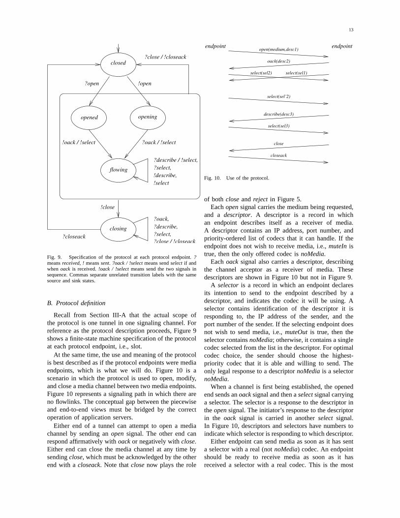
At the same time, the use and meaning of the protocolis best described as if the protocol endpoints were mediaendpoints, which is what we will do. Figure 10 is ascenario in which the protocol is used to open, modify,and close a media channel between two media endpoints.Figure 10 represents a signaling path in which there areno flowlinks. The conceptual gap between the piecewiseand end-to-end views must be bridged by the correctoperation of application servers.
Either end of a tunnel can attempt to open a mediachannel by sending anopensignal. The other end canrespond affirmatively withoackor negatively withclose.Either end can close the media channel at any time bysendingclose, which must be acknowledged by the otherend with acloseack. Note thatclosenow plays the role
select(sel’2)
select(sel2)
oack(desc2)
open(medium,desc1)
describe(desc3)
select(sel1)
closeack
close
select(sel3)
endpointendpoint
Fig. 10. Use of the protocol.
of both closeand reject in Figure 5.Eachopensignal carries the medium being requested,
and a descriptor. A descriptor is a record in whichan endpoint describes itself as a receiver of media.A descriptor contains an IP address, port number, andpriority-ordered list of codecs that it can handle. If theendpoint does not wish to receive media, i.e.,muteIn istrue, then the only offered codec isnoMedia.
Eachoacksignal also carries a descriptor, describingthe channel acceptor as a receiver of media. Thesedescriptors are shown in Figure 10 but not in Figure 9.
A selectoris a record in which an endpoint declaresits intention to send to the endpoint described by adescriptor, and indicates the codec it will be using. Aselector contains identification of the descriptor it isresponding to, the IP address of the sender, and theport number of the sender. If the selecting endpoint doesnot wish to send media, i.e.,muteOutis true, then theselector containsnoMedia; otherwise, it contains a singlecodec selected from the list in the descriptor. For optimalcodec choice, the sender should choose the highest-priority codec that it is able and willing to send. Theonly legal response to a descriptornoMediais a selectornoMedia.
When a channel is first being established, the openedend sends anoacksignal and then aselectsignal carryinga selector. The selector is a response to the descriptor intheopensignal. The initiator’s response to the descriptorin the oack signal is carried in anotherselect signal.In Figure 10, descriptors and selectors have numbers toindicate which selector is responding to which descriptor.
Either endpoint can send media as soon as it has senta selector with a real (notnoMedia) codec. An endpointshould be ready to receive media as soon as it hasreceived a selector with a real codec. This is the most

14
relaxed approach to synchronization of the signaling andmedia channels.5
At any time after sending the first selector in responseto a descriptor, an endpoint can choose a new codec fromthe list in the descriptor, send it as a selector in aselectsignal, and begin to send media in the new codec. InFigure 10,select(sel’2)shows this possibility.
At any time after sending or receivingoack, an end-point can send a new descriptor for itself in adescribesignal. The endpoint that receives the new descriptormust begin to act according to the new descriptor. Thismight mean sending to a new address or choosing a newcodec. In any case, the receiver of the descriptor mustrespond with a new selector in aselectsignal, if onlyto show that it has received the descriptor. In Figure 10,descriptor3andselector3illustrate this interaction.
It is possible that a race condition, with twoopensignals traveling in opposite directions, could occurwithin a tunnel. The race is easily detectable by bothslots, because each sends an open and receives an openin return. In this case the winner of the race is alwaysthe end of the tunnel that initiated setup of the signalingchannel, which is fixed and unambiguous. The losingopen signal is simply ignored. This aspect of protocolbehavior is not illustrated in Figure 9.
C. Properties of the protocol
At each end of a signaling path, the user interface(Figure 5) translates straightforwardly to its protocolimplementation (Figure 9). There is an extra protocolstateclosingnot observable in the user interface.Acceptevents are replaced byoack signals.Modify events arereplaced bydescribeandselectsignals. The values of themutevariables are communicated through descriptors, aspresented in the previous section.
The history variableLenabled (Renabled)is initiallyfalse. It becomes true when the left (right) endpoint ofthe signaling path sends a selector with a real (notnoMe-dia) codec. It becomes false again when the left (right)endpoint leaves theflowingstate or sends a selector withnoMediaas the codec. As required by Section V, whenLenabled (Renabled)is true both endpoints are readyfor packets in a left-to-right (right-to-left) direction: theyhave agreed on a real codec and have each other’s IPaddress and port number.
A describesignal makes it possible for a media end-point to change its characteristics as a receiver of media.
5To make absolutely sure that no media is lost, even if media packetstravel through the network faster than signals, an endpoint must begin“listening” for media in accordance with a descriptor as soon as it hassent the descriptor, and must be able to accept packets in any allowedcodec at any time. This is possible because codecs are self-describing.It is easier, however, for an endpoint to wait forselectsignals andrisk the loss of a few packets that arrive before their correspondingselectors.
This is sometimes useful, but—because the protocol isused piecewise, and every box is a protocol endpoint—mostdescribesignals are sent by application servers.
For example, consider the transition from Snapshot 1to Snapshot 2 in Figure 3. To implement this transition,PC sends adescribesignal withnoMediato A, adescribesignal with the descriptor of C to V, and adescribesignalwith the descriptor of V to C. (PC has these descriptorsavailable because it has recorded them as they passedthrough in previous signals.) The answeringselectsignalfrom A is absorbed by PC, and the answeringselectsignals from C and V are sent to each other. Thesesignals will cause the actual media paths to change asindicated in the figure.
To make media control as easy as possible,describesignals (and their answeringselects) going in oppositedirections of the same tunnel do not constrain each other.This means that changes initiated in both directions canproceed concurrently. There is no need to introduce thecomplexity and overhead of serializing them.
Another simplifying design decison is that the protocolhas no enforced pairing ofdescribe/selectsignals rele-vant to media transmission in one direction. Adescribecan be sent at any time, even if noselect has beenreceived in response to the lastdescribe. A selectcan besent at any time, even if nodescribehas been receivedsince the lastselect was sent. This makes box statesimpler and eliminates unnecessary constraints.
This protocol was designed specifically to facilitatecomposition. It is radically different from SIP [7], [14],which is the dominant protocol in use for media control.Section IX compares the two and explores the conse-quences of their differences.
VII. I MPLEMENTATION SOFTWARE
Implementation of compositional media control re-quires Java code resident in each application server.Boxobjects contain the high-level code that calls onGoaland Slot objects when necessary. Figure 11 shows thehierarchical structure of method invocations amongBox,Goal, andSlot objects.
A Slot object sees all signals received from a slot andsends all signals to the slot. Because of this completeview, it is able to maintain the complete implementation-level state of the slot, consisting of protocol state,medium,and descriptor.The descriptor of a slot in anapplication server is the most recent descriptor receivedin an open, oack,or describesignal.
The first action of a goal object is to query its slots,usingslotStateandslotDesc, to get their protocol statesand descriptors. Then, having completed this initializa-tion, the goal object proceeds to control its slot or slotsuntil its slots are moved elsewhere and this goal objectbecomes garbage.

15
slotSend(Signal)slotReceive(Signal)slotDesc()slotState()
CloseSlot(Slot)
goalReceive(Slot,Signal)FlowLink(Slot,Slot)HoldSlot(Slot)OpenSlot(Slot)
slotState()Slot(SigChan)
Goal
Box
Slot
Fig. 11. The hierarchy of method invocations among Java objects.
There is also aMapsobject that maintains the dynamicassociation between slots and goal objects. When a boxreceives a signal, the box uses these associations to findthe goal object to which it should show the signal viagoalReceive.
The openSlot, closeSlot,and holdSlot programs areall reasonably straightforward, because each controls asingle slot. The code of each is structured as a finite-state machine that follows the structure of Figure 9.The design of theflowLink code, as described below,is considerably more complex.
The primary organization of theflowLinkcode is basedon slot states. There is a flowlink state for each pairof slot states; any combination of slot states is possiblebecause a flowlink can be instantiated to control twoslots that were previously independent. Based on its pairof slot states, the flowlink performsstate matchingasshown in Figure 12. The state labels use the shorthandslive anddead, as defined in the caption.
live, oneone
live
?open both
dead
closedeitherboth
flowing
either?close
both live
?close
both dead
Fig. 12. State matching in a flowlink. Thelive states areopening,openedandflowing. The deadstates areclosedandclosing.
The dashed arrows indicate the work of state match-ing, which consists of sending signals and waiting forsignals, as needed, to push toward a goal. Which of
the three superstates the flowlink is in, at any time, ischosen by the flowlink’s environment. This is becausethe superstate depends on theopenandclosesignals thatthe flowlink receives. The dashed arrows show that theflowlink works from whichever of the three superstatesit is currently in to one of the two heavily outlinedsubstates. These are the two goal statesboth flowingandboth closed.
There is a close relationship between Figure 12 andthe formal specification of path semantics. To see thisrelationship, it is necessary to realize that:† a closeSlotobject emitsclosesignals, and neveropenor oacksignals;
† an openSlotobject emitsopenand accept/oacksig-nals, and neverclosesignals;6
† aholdSlotobject emitsaccept/oacksignals, and neveropenor closesignals.
For each type of path, the objects at its endpointsdetermine which signals will be coming toward theflowlinks. For each type of path, these signals lead toone or two goal states in Figure 12, and these are thesame goals as found in the temporal formula for thattype of path.
The secondary organization of the flowlink is based ondescriptors. A flowlink caches the most recently receiveddescriptor of each of its slots. The code design is builtaround two concepts:
† A slot is described if the object has received acurrent descriptor for it. Slots in theopenedandflowing states aredescribed, while slots in otherstates are not.
† Each slot has a Boolean variableup-to-date (utd)that is true if and only if the other slot is describedand this slot has been sent its most recent descriptor.
In any live state, the flowlink is working to make theutdvariables true. This depends on the slot states, because anutdvariable can only be true if the other slot is described,and if its slot is in a state allowing sending of a newdescriptor if necessary.
To see how these structures make a bewildering arrayof cases comprehensible, consider a flowlink state inwhich slot 1 is flowing and slot 2 isopening. Thisstate could not have arisen if the two slots were alwaysflowlinked to each other; it could only have arisen if oneor both slots were previously linked elsewhere.
From the perspective of this flowlink, either (1) slot2 wasopeningwhen it entered the flowlink, or (2) slot2 was originally dead and the flowlink made it live bysending anopen. Both utd variables in a flowlink areinitialized as false. In Case 1, when anoack is receivedfrom slot 2, slot 2 will be in theflowing state but with
6Usually it emits onlyopensignals, but in the case of a race betweentwo opens in a tunnel, it may back off and be the acceptor instead.
16
utd2 = false. This makes sense because the descriptorcarried by theopensignal that opened slot 2 had nothingto do with this flowlink. To setutd2 = true, the flowlinkmust senddescribewith the descriptor of slot 1.
In Case 2, when anoack is received from slot 2, itwill reach theflowingstate. Is slot 2 up-to-date? Variableutd2became true when the flowlink sent it anopensignalwith the then-current descriptor of slot 1. If it is still true,there is no more work to do.
However, between sendingopen to slot 2 and re-ceiving oack from it, slot 1 may have received a newdescriptor for some reason. If it has, thenutd2 has beenset to false again. It can be made true again by sendingslot 2 adescribewith the new descriptor of slot 1. Thisshows how the relevant history of three different casesis maintained concisely by theutd2 variable.
Interestingly, handling ofselectsignals is much sim-pler. In all cases in which a flowlink succeeds in reachingits goal state ofboth flowing, it sends a descriptor ofthe other slot to each slot. A selector always respondsto a descriptor, and in theboth flowingstate both slotshave received fresh descriptors. This means that onlyfresh selectors matter, so the flowlink need not keep anyhistory of them.
When a flowlink receives a selector and is in astate to forward it to the other slot, it checks beforeforwarding that the selector is a response to the otherslot’s descriptor. If it is not a proper response, then theselector is obsolete and is discarded.
VIII. V ERIFICATION AND PERFORMANCE
A. Partial verification
Partial verification has been performed by modelingthe Java code in Promela and checking the Promelamodels with the Spin model checker [8].
The scope of each model is a signaling path. Wemodeled and checked 12 signaling paths: six pathswith no flowlinks and every possible combination ofcloseslots, openslots, and holdslots at their ends, and sixpaths similar to the first six paths but with one flowlinkeach.
In every Promela model, every slot is controlled bya goal object. Each goal object has two phases. In agoal object’s initial phase, the behavior of the slot orslots it controls is allowed to be completely nondeter-ministic, and to have nothing to do with the goal. Atsome nondeterministically chosen point, the goal objectswitches permanently to a second phase in which itbehaves according to the specified goal. Because of theexistence of the nondeterministic initial phases, modelchecking covers traces in which the goal objects begintheir real work in all possible initial states of the slotsand of the signaling tunnels that connect the slots.
We performed two checks on each model. First, asafety check was run to make sure that the path modelhad no deadlocks or other abnormal terminations. Thecheck ensured that in any final state, each slot isclosedor flowing, and all signaling channels are empty. Second,we verified that each model satisfies its specification asgiven in Section V.
The definition of thebothFlowingpath state in Sec-tion V is:
Lflowing^ Rflowing^ (Lmedium= Rmedium) ^(Lenabled= :LmuteIn^ :RmuteOut) ^(Renabled= :RmuteIn̂ :LmuteOut)
The definition that we used in model checking is some-what different:
Lflowing^ Rflowing^(LdescRcvd= RdescSent) ^ (RdescRcvd= LdescSent) ^(LselRcvd= LdescSent) ^ (RselRcvd= RdescSent)^
This definition uses history variables that store the de-scriptors and selectors most recently sent and receivedat path endpoints. It abuses notation slightly in assumingthat a selector responding to a descriptor is “equal” toit. The definition says that in thebothFlowing state,each end has most recently received the descriptor mostrecently sent by the other end, and each end has mostrecently received a selector responding to its own mostrecent descriptor. From this definition and the rules aboutprotocol behavior in Section VI, it is easy to derive theoriginal definition ofbothFlowing.
It may not be feasible to model-check signaling pathswith more than one flowlink. Even with partial orderreduction, compression, and a few simplifying assump-tions, a typical check of a signaling path with a flowlinktakes 20 minutes and 3 Gb of memory on a Sun SolarisM9000 SMP machine with dual-core 2.4 GHz SPARCprocessors.7 More importantly, when we compare similarchecks of two paths, varying only in that one has aflowlink and the other does not, adding a flowlink causesthe memory to grow by a factor of 300 on the average,and the time to grow by a factor of 1000 on the average.This suggests that checking a path with two flowlinksmight take something like 900 Gb of memory and 300hours. Even if these numbers over-estimate the impactof another flowlink by an order of magnitude, they arestill forbidding.
B. Toward complete verification
Even if it were possible to model-check signalingpaths with several flowlinks, this would still not yield
7The variance among checks is considerable. The biggest check took161 minutes and 19 Gb of memory.

17
a proof of correctness for signaling paths of any length.Such a proof can only be constructed inductively.
Although we leave this inductive proof for futurework, it seems that the most promising approach wouldbe to construct the proof in terms of lemmas that couldbe verified by model-checking. For example, imagine alemma whose scope is an arbitrary contiguous segmentof a signaling path, no larger than two tunnels and threeboxes (in other words, a segment with no more thanone internal flowlink). It is plausible that such a lemmacould be verified by model-checking, and could be usedinductively to prove a theorem over whole signalingpaths of any length.
In the meantime, we give an informal argument that asignaling path with openlinks on both endpoints alwaysconverges to the correct state. This argument does notfocus on getting slots to theflowing protocol state, butrather on the exchange of descriptors and selectors. Theargument is illustrated by the message-sequence chart inFigure 13. It shows a scenario in which, starting fromSnapshot 3 of Figure 3, PC completes authorization andthe PBX switches back to C at about the same time. Thismeans that the transition from Snapshots 3 to 4 (in whichPC changes linkages) and the transition from Snapshot 4back to Snapshot 1 (in which the PBX changes linkages)are proceeding concurrently.
Control of media flow in each direction is independentand symmetric. Thus, without loss of generality, weconsider only media flow from A to C.
The new flowlink in the PBX begins by sending tothe left its most recent descriptor from the right, whichis noMedia. When A receives thedescribe signal, itresponds withselect(noMedia).
Concurrently, the new flowlink in PC begins by send-ing to the left its most recent descriptor from the right,which is that of C. When the flowlink in the PBXreceives it, to remain up-to-date, it forwardsdescribe(C)to the left. This new descriptor supersedesnoMediaatA, so A replies withselect(C).
Along the entire signaling path from left to right,select(C)matches the most recent descriptor from theright, and is therefore forwarded all the way to C. Nowmedia flow from A to C is fully established.
To generalize from this example, after a signaling pathstabilizes, eventually the descriptor of an endpoint willpropagate along the entire signaling path as the mostrecent descriptor from that end. When it reaches theother end, the other end will respond with a new selector.Because the descriptor has now stabilized along the path,the selector will be accepted and forwarded by each boxin the path.
To reiterate a point made in Section V, if signal-ing paths do not remain stable long enough for thedistributed algorithm to converge, then nothing can be
expected of the system.
C. Performance
We have tested our Java code with a suite of testdrivers, as a check on aspects of the code not modeled inPromela. Unfortunately, it is not possible to test the codeon live IP media. The reason is that testing on live mediawould require a great deal of hardware and softwareinfrastructure, all of it using this protocol. Although wehave developed such an infrastructure in our laboratoryand are accustomed to using it for live media [3], [4],the infrastructure is all based on SIP. The significance ofthis situation is discussed in Section IX.
Fortunately, the behavior of our protocol is simpleenough so that its performance can be studied analyt-ically. The most important performance measure for asignaling protocol is its latency. In our protocol, anendpoint can transmit media as soon as it has receiveda descriptor and sent a corresponding selector.
We now consider the latency of the protocol in thecompositional scenario of Figure 13. Letc be the averagetime it takes for a server to read a new stimulus froman input queue and compute the next signal to send.Let n be the average time it takes for the network orserver infrastructure to accept a signal and deliver it to itsdestination box. In Figure 13 both endpoints can transmitafter an average delay of2n+ 3c.
The actual values ofn and c can vary greatly. How-ever, to make the analysis more concrete, a typicalvalue of c might be 20 ms. In a few experiments ona typical carrier network with multiple geographic sites,n averaged 34 ms. With these numbers the latency ofFigure 13 is 128 ms.
This latency is not directly affected by other activityin the system, such as changes to other media channelscontrolled by the same signaling path (needless to say,it can be affected indirectly by processor overload). Be-cause its behavior is fundamentally simple, the analysiscan be generalized as follows.
The latency of providing media flow from a signalingpath should be measured from the moment that the lastflowlink in the path is initialized. Before this momentthe path did not exist, and all its other flowlinks wereelements of other signaling paths. From the pattern ofFigure 13, it is easy to see that the average signalingdelay after that moment will be
pn+ (p+ 1)c
wherep is the number of hops between the last flowlinkand its farther endpoint. In Figure 13p is the path lengthminus 1, which is the maximum for any path.
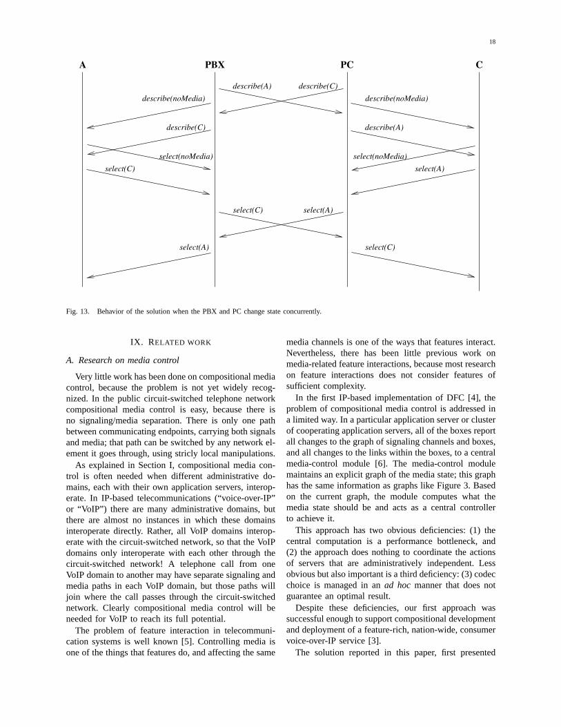
18
select(noMedia)
select(C)
describe(noMedia)
describe(C)
PC C
describe(A) describe(C)
select(C)
PBX
select(A)
select(A)
select(A)
select(C)
describe(noMedia)
describe(A)
select(noMedia)
A
Fig. 13. Behavior of the solution when the PBX and PC change state concurrently.
IX. RELATED WORK
A. Research on media control
Very little work has been done on compositional mediacontrol, because the problem is not yet widely recog-nized. In the public circuit-switched telephone networkcompositional media control is easy, because there isno signaling/media separation. There is only one pathbetween communicating endpoints, carrying both signalsand media; that path can be switched by any network el-ement it goes through, using stricly local manipulations.
As explained in Section I, compositional media con-trol is often needed when different administrative do-mains, each with their own application servers, interop-erate. In IP-based telecommunications (“voice-over-IP”or “VoIP”) there are many administrative domains, butthere are almost no instances in which these domainsinteroperate directly. Rather, all VoIP domains interop-erate with the circuit-switched network, so that the VoIPdomains only interoperate with each other through thecircuit-switched network! A telephone call from oneVoIP domain to another may have separate signaling andmedia paths in each VoIP domain, but those paths willjoin where the call passes through the circuit-switchednetwork. Clearly compositional media control will beneeded for VoIP to reach its full potential.
The problem of feature interaction in telecommuni-cation systems is well known [5]. Controlling media isone of the things that features do, and affecting the same
media channels is one of the ways that features interact.Nevertheless, there has been little previous work onmedia-related feature interactions, because most researchon feature interactions does not consider features ofsufficient complexity.
In the first IP-based implementation of DFC [4], theproblem of compositional media control is addressed ina limited way. In a particular application server or clusterof cooperating application servers, all of the boxes reportall changes to the graph of signaling channels and boxes,and all changes to the links within the boxes, to a centralmedia-control module [6]. The media-control modulemaintains an explicit graph of the media state; this graphhas the same information as graphs like Figure 3. Basedon the current graph, the module computes what themedia state should be and acts as a central controllerto achieve it.
This approach has two obvious deficiencies: (1) thecentral computation is a performance bottleneck, and(2) the approach does nothing to coordinate the actionsof servers that are administratively independent. Lessobvious but also important is a third deficiency: (3) codecchoice is managed in anad hoc manner that does notguarantee an optimal result.
Despite these deficiencies, our first approach wassuccessful enough to support compositional developmentand deployment of a feature-rich, nation-wide, consumervoice-over-IP service [3].
The solution reported in this paper, first presented

19
in [16], is different in almost every detail. The media-control protocol has been improved to support optimalcodec choice and easier composition. The API has beenrefined and formally specified. Most important of all,we have discovered a way to implement compositionalmedia control in a distributed, rather than centralized,fashion. And we have taken significant steps towardverifying our implementation.
Today most IP-based media applications are beingbuilt using SIP [7], [14]. SIP was designed for com-munication between endpoints, with little or no logicalprocessing in the network between them. This anti-compositional design philosophy was typical in the earlydays of the Internet. The problem for industry today isthat prospects and plans for IP media have moved beyondwhat was envisioned in those days. As a result, vendorsare finding it increasingly difficult to deploy services andensure interoperation of system components.
In an attempt to bridge the gap, a document onbest current practices for SIP [13] explains how a SIPapplication server, acting as an intermediary, can controlthe media streams of endpoints. However, the documentdoes not have any mention of the problem of composi-tion. All of the examples assume that the server beingdiscussed is the only server in the signaling path. All ofthe signaling techniques are presented only as orderlyscenarios in which everything proceeds in the best way,with no events occurring at inconvenient times.
In the next section, we compare SIP to our protocolwith respect to some of the relevant criteria.
B. Protocol comparison
First we compare our protocol and SIP using anend-to-end perspective. From this perspective, mediachannels are opened, closed, and modified only by theirendpoints. There are three major differences between theprotocols.
The first difference concerns basic synchronization.With respect to basic synchronization, the design ofSIP was based on HTTP, and is thereforetransactional.When SIP signals travel in unreliable UDP datagrams,which is allowed but not recommended, SIP agents usethe transactional structure to recover from lost signals.
In SIP, a media channel is opened or modified bya three-signal transaction composed of aninvite froman endpoint, asuccessfrom the other end, and anackfrom the initiator. Such an invite transaction cannotoverlap with any other invite transaction on the samesignaling path. If a race between two invite transactionsis detected, both fail immediately. The initiator of eachfailed invite is supposed to wait for a randomly chosenperiod and then retry.
Our protocol is not transactional. It depends on anunderlying mechanism such as TCP for reliability. Once
a channel has been opened, an agent can send newdescribeor selectsignals at any time. The signals thatmodify media flow in one direction are completelyindependent of the signals that pertain to media flowin the other direction. Our protocol can be described asidempotent, becausedescribeandselectsignals provideupdated information without changing the fundamentalstate, which is why they can be so unconstrained.
In terms of both programming complexity and per-formance, there is a great difference between thesetwo protocol designs. In our protocol, if an endpointneeds to modify a media channel, it simply sends anew describe immediately. When the other endpointreceives the descriptor, it can send a correspondingselectimmediately.
In SIP, on the other hand, initiating a media changecan be arduous. First the endpoint must wait for anyongoing transaction that it knows about to complete.Next the initiator sends aninvite signal. If it nextreceives a correspondingsuccess, it can sendackand befinished. If it receives aninvite, however, it has detected arace. The initiator must receive and acknowledgefailure,wait for some period, check that there is no ongoingtransaction, and start over.
The second difference concerns codec choice. Forcodec choice, SIP uses anegotiation model. To opena media channel or modify an existing one, an endpointsends in itsinvite signal anoffer containing a set ofpossible codecs that it can handle. The responder sendsin its successsignal ananswer that is a subset of theoffer codecs, all of which the responder can handle.Henceforth any of the codecs in the answer subset canbe used.
Our protocol decouples codec choice in the two di-rections, as there is no technical necessity to use thesame codec in both directions. In each direction, oneendpoint sends a set of possible choices in a descriptor,and the other end chooses one in a selector. This has theadvantage of guaranteeing that, once an endpoint hasreceived a selector, it knows exactly which codec it isexpected to interpret.
In our protocol, a descriptor is aunilateral descriptionof an endpoint. In SIP, an answer is arelativedescriptionof an endpoint, i.e., a description of one endpoint withrespect to (in negotiation with) another. The decisionto make a protocol transactional or idempotent, and thedecision to choose codecs by negotiation or unilaterally,are not independent. Negotiation requires a transaction,while unilateral codec choice does not.
Negotiation takes a toll on performance, because thedescription of the responder to the initiator (in an an-swer) must follow the description of the initiator to theresponder (in an offer). With unilateral codec choice,descriptors in both directions can travel concurrently, and
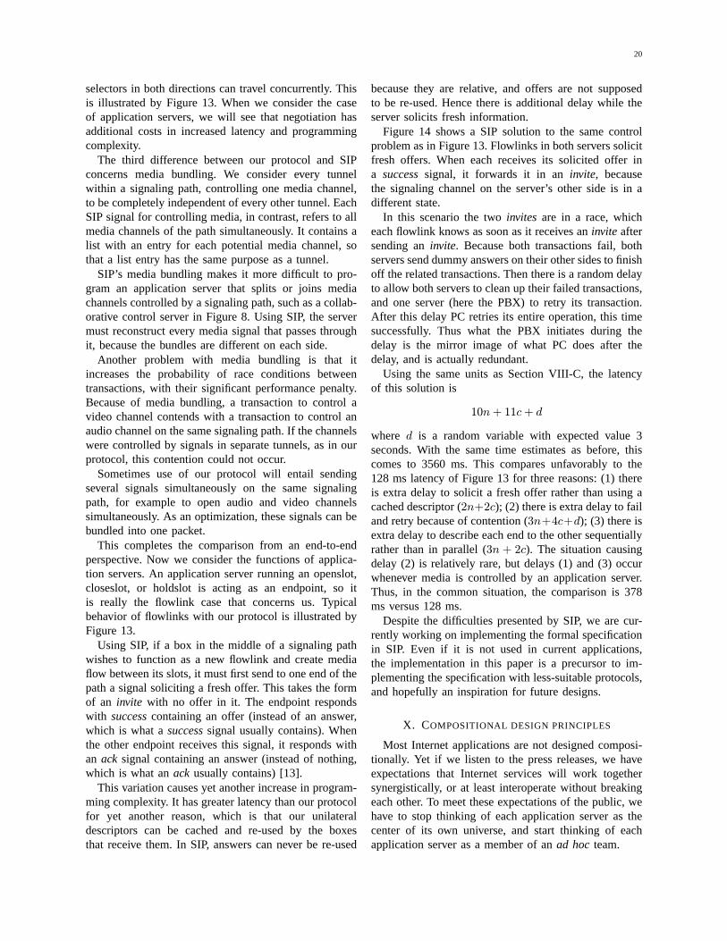
20
selectors in both directions can travel concurrently. Thisis illustrated by Figure 13. When we consider the caseof application servers, we will see that negotiation hasadditional costs in increased latency and programmingcomplexity.
The third difference between our protocol and SIPconcerns media bundling. We consider every tunnelwithin a signaling path, controlling one media channel,to be completely independent of every other tunnel. EachSIP signal for controlling media, in contrast, refers to allmedia channels of the path simultaneously. It contains alist with an entry for each potential media channel, sothat a list entry has the same purpose as a tunnel.
SIP’s media bundling makes it more difficult to pro-gram an application server that splits or joins mediachannels controlled by a signaling path, such as a collab-orative control server in Figure 8. Using SIP, the servermust reconstruct every media signal that passes throughit, because the bundles are different on each side.
Another problem with media bundling is that itincreases the probability of race conditions betweentransactions, with their significant performance penalty.Because of media bundling, a transaction to control avideo channel contends with a transaction to control anaudio channel on the same signaling path. If the channelswere controlled by signals in separate tunnels, as in ourprotocol, this contention could not occur.
Sometimes use of our protocol will entail sendingseveral signals simultaneously on the same signalingpath, for example to open audio and video channelssimultaneously. As an optimization, these signals can bebundled into one packet.
This completes the comparison from an end-to-endperspective. Now we consider the functions of applica-tion servers. An application server running an openslot,closeslot, or holdslot is acting as an endpoint, so itis really the flowlink case that concerns us. Typicalbehavior of flowlinks with our protocol is illustrated byFigure 13.
Using SIP, if a box in the middle of a signaling pathwishes to function as a new flowlink and create mediaflow between its slots, it must first send to one end of thepath a signal soliciting a fresh offer. This takes the formof an invite with no offer in it. The endpoint respondswith successcontaining an offer (instead of an answer,which is what asuccesssignal usually contains). Whenthe other endpoint receives this signal, it responds withan ack signal containing an answer (instead of nothing,which is what anack usually contains) [13].
This variation causes yet another increase in program-ming complexity. It has greater latency than our protocolfor yet another reason, which is that our unilateraldescriptors can be cached and re-used by the boxesthat receive them. In SIP, answers can never be re-used
because they are relative, and offers are not supposedto be re-used. Hence there is additional delay while theserver solicits fresh information.
Figure 14 shows a SIP solution to the same controlproblem as in Figure 13. Flowlinks in both servers solicitfresh offers. When each receives its solicited offer ina successsignal, it forwards it in aninvite, becausethe signaling channel on the server’s other side is in adifferent state.
In this scenario the twoinvites are in a race, whicheach flowlink knows as soon as it receives aninvite aftersending aninvite. Because both transactions fail, bothservers send dummy answers on their other sides to finishoff the related transactions. Then there is a random delayto allow both servers to clean up their failed transactions,and one server (here the PBX) to retry its transaction.After this delay PC retries its entire operation, this timesuccessfully. Thus what the PBX initiates during thedelay is the mirror image of what PC does after thedelay, and is actually redundant.
Using the same units as Section VIII-C, the latencyof this solution is
10n+ 11c+ d
where d is a random variable with expected value 3seconds. With the same time estimates as before, thiscomes to 3560 ms. This compares unfavorably to the128 ms latency of Figure 13 for three reasons: (1) thereis extra delay to solicit a fresh offer rather than using acached descriptor (2n+2c); (2) there is extra delay to failand retry because of contention (3n+4c+d); (3) there isextra delay to describe each end to the other sequentiallyrather than in parallel (3n + 2c). The situation causingdelay (2) is relatively rare, but delays (1) and (3) occurwhenever media is controlled by an application server.Thus, in the common situation, the comparison is 378ms versus 128 ms.
Despite the difficulties presented by SIP, we are cur-rently working on implementing the formal specificationin SIP. Even if it is not used in current applications,the implementation in this paper is a precursor to im-plementing the specification with less-suitable protocols,and hopefully an inspiration for future designs.
X. COMPOSITIONAL DESIGN PRINCIPLES
Most Internet applications are not designed composi-tionally. Yet if we listen to the press releases, we haveexpectations that Internet services will work togethersynergistically, or at least interoperate without breakingeach other. To meet these expectations of the public, wehave to stop thinking of each application server as thecenter of its own universe, and start thinking of eachapplication server as a member of anad hocteam.
21
C
invite(solicit)
success(offerA)
invite(offerA) invite(offerC)
invite(solicit)
PCA
success(offerC)
success(answerA)
success(answerA)
ack(answerA)ack
ack
delay
PBX
invite(offerC)
ack(dummyAnswer)ack(dummyAnswer)
failfail
invite(solicit)
success(offerC)
invite(offerC)
Fig. 14. Behavior of a SIP solution when the PBX and PC change state concurrently.
Our solution to compositional media control hasseveral characteristics that might be useful in makingother protocols and application programs friendlier tocomposition.
A. Piecewise protocol
The protocol is designed to be used in apiecewisefashion, so that there is no externally observable differ-ence between a tunnel and two tunnels connected by amodule acting transparently (Section III-A). It should be
22
obvious that this facilitates the use of application servers.Because SIP is not designed for piecewise use, it is anopen problem how to build a SIP application server thatis truly transparent with respect to the protocol.
B. Idempotent and unilateral protocol
Transactions are widely used in distributed program-ming, and they are very successful for client/serverinteractions. The comparison in the previous sectionshows, however, that real-time communication is notan asymmetrical client/server application, but somethingfundamentally different. In real-time communications theends of a signaling path are symmetric, and either end(or a server in the middle) can produce a stimulus thatreverberates throughout the path.
We have designed our protocol to be idempotentand unilateral rather than transactional and based onnegotiation. The comparison in Section IX-B suggeststhat idempotent signaling and unilateral description maybe superior to transactions and negotiation for controlof real-time communications. They are faster and re-quire less protocol state, both of which are importantin a compositional context. There may also be otherdistributed applications where these opposing designprinciples should be compared before making a finalchoice between them.
C. Goal-oriented programming
State-based, declarative, goal-oriented programmingprimitives are much more abstract for this purpose thanevent-oriented primitives would be. The application’scurrent goal for a media channel can be independentof the actual state of the media channel, for examplebecause there is a timeout in the application, or becausethe environment changes the state of the channel insome unexpected way. Thus there is a wide variety ofevent sequences that might be needed to match the slotstates in a flowlink, and these are best determined bythe implementation of the programming primitives. Thesame observations might be true of other programmingtasks.
D. Path specification
Attaching temporal-logic specifications to signalingpaths, where the interior of each path is an arbitrary-length sequence of identical elements (flowlinks), was abreakthrough in our understanding of this problem.
A path is a small part of the system, measured in bothspace and time. In space, it is one of a large numberof signaling paths that can exist, even among a smallset of network nodes. In time, it is a narrow windowduring which no box on the path changes the goal for
any of its slots. Because of this limited scope, paths arestraightforward formal objects, simple enough to reasonabout.
At the same time, a path-based specification com-pletely captures the requirements for compositional me-dia control. It includes, whether explicitly or implicitly,user intentions, network topology, and feature priority.
In Section III-A we characterized compositional mediacontrol as needing to give some behavioral guaranteesto each box, even though the behavior of the overallsystem can be affected by every box. What guaranteescan we give to each box, particularly boxes in applicationservers? We can answer this question in terms of paths.
If a box in an application server owns a slot, then thebox has the power to treat that slot as the endpoint ofits signaling path (by not assigning it to a flowlink). Ifthe box chooses to make it a path endpoint, then theother end of the signaling path may be a box in anotherapplication server, or it may be a media endpoint. If theother end of the signaling path is a media endpoint, thenthe box is guaranteed that the media endpoint has nomedia flow associated with that signaling path.
Not surprisingly, a box gets no “positive” guarantees,i.e., guarantees that it has the power to allow media flow.Media flow is always allowed by a consensus of boxes.
E. Implementation design
The last principle is the most difficult to general-ize. Our flowlink implementation went through manyiterations, because the earlier versions were extremelydifficult to understand and debug. The key to successfulcode design was the combination of cached descriptors,the concept ofdescribed(which says that a slot has agood cached descriptor), and the concept ofup-to-date(which says that the good cached descriptor from theother side of the flowlink has been sent to this slot).These concepts are likely to be useful for working withother idempotent, unilateral protocols.
F. Application to mobility
As an example of another application where theseprinciples might be applied, consider the problem ofproviding persistent IP connections to mobile endpoints.The difficult trade-off affecting this much-studied prob-lem concerns the number of special-purpose mobilerouters that know the current location of a mobile host.If there are many such routers, the path of a packetto a mobile host can be quite direct. Unfortunately,many routers in many different subnets are required,and they must all have access to location information.If there is only one locating router for each mobile host,however, mobile routers need not be everywhere, andeach location update is easy. Unfortunately, if the unique
23
locating router for a host is far from the sender and thecurrent location of the host, the path of each packet canbe triangular and very long [12].
In addition to this unresolved trade-off, all proposedsolutions to this problem seem to favor—if not require—isolation. It can be difficult to see how they wouldaccommodate multiple layers of mobility, or composewith a variety of other applications.
In the cases where signaling and data streams areseparable, and where other applications operate directlyonly on the signals, it might be possible to find abetter solution that is similar to compositional mediacontrol. Unique locating routers could be interspersedon signaling paths with servers for other applications.Triangular routing of data packets would be avoided bysignaling/data separation, and data packets could travelbetween endpoints by the most direct routes.
XI. CONCLUSION
This paper has defined the problem of compositionalcontrol of IP media, and explained its importance inproviding desired network services. We have presenteda comprehensive solution in the form of an architecture-independent descriptive model, a set of high-level pro-gramming primitives, a formal specification of theircompositional semantics, a signaling protocol, an imple-mentation, and partial verification of correctness. Theperformance of the implementation compares favorablyto the performance of the best comparable implemen-tation in SIP. The overall solution illustrates severalprinciples that may be useful for making other networkedapplications more compositional.
Although our implementation simulates IP media con-trol, it cannot be tested with live IP media. The reasonis that use of IP media in practical services requiresa great deal of hardware and software infrastructure.Although we have developed such an infrastructure inour laboratory and are accustomed to using it [3], [4],it is all based on SIP rather than the protocol defined inSection VI.
Despite this limitation, the architecture-independentdescriptive model, set of high-level programming prim-itives, and formal specification of their compositionalsemantics are all protocol-independent. We are currentlyworking on implementing the specification in SIP.
Work on the protocol, implementation, and verifica-tion have not been wasted, despite the fact that theycannot be used in current applications. Without them,we would have no idea where to begin with SIP. Theprotocol and implementation provide compositionality ina straightforward, relatively comprehensible form that il-lustrates some potentially useful design principles. Theyare patterns for thinking about how the Internet applica-tion environment can be made more compositional.
ACKNOWLEDGMENTS
Michael Jackson made important contributions to theearlier phases of our work on media control. We havebenefited greatly from ongoing discussions with our col-leagues Greg Bond, Hal Purdy, and Tom Smith. LaurieDillon and the referees made many helpful comments onthe presentation.
REFERENCES
[1] 3GPP. Service requirements for the IP multimedia core networksubsystem. 3GPP Technical Specification 23.228 Stage 2.
[2] National Emergency Number Association. NENA IP-capablePublic Safety Access Point features and capabilities standard.Document 58-001, 2005.
[3] Gregory W. Bond, Eric Cheung, Healfdene H. Goguen, Kar-rie J. Hanson, Don Henderson, Gerald M. Karam, K. HalPurdy, Thomas M. Smith, and Pamela Zave. Experiencewith component-based development of a telecommunication ser-vice. In Proceedings of the Eighth International Symposiumon Component-Based Software Engineering, pages 298–305.Springer-Verlag LNCS 3489, May 2005.
[4] Gregory W. Bond, Eric Cheung, K. Hal Purdy, Pamela Zave,and J. Christopher Ramming. An open architecture for next-generation telecommunication services.ACM Transactions onInternet Technology, 4(1):83–123, February 2004.
[5] E. Jane Cameron, Nancy D. Griffeth, Yow-Jian Lin, Margaret E.Nilson, William K. Schnure, and Hugo Velthuijsen. A feature-interaction benchmark for IN and beyond.IEEE Communica-tions, 31(3):64–69, March 1993.
[6] Eric Cheung, Michael Jackson, and Pamela Zave. Distributedmedia control for multimedia communications services. InProceedings of the 2002 IEEE International Conference onCommunications: Symposium on Multimedia and VoIP—Servicesand Technologies. IEEE Communications Society, 2002.
[7] M. Handley, H. Schulzrinne, E. Schooler, and J. Rosenberg.SIP: Session Initiation Protocol. IETF Network Working GroupRequest for Comments 2543, 1999.
[8] Gerard J. Holzmann. The Spin Model Checker: Primer andReference Manual. Addison-Wesley, 2004.
[9] Michael Jackson and Pamela Zave. Distributed Feature Com-position: A virtual architecture for telecommunications services.IEEE Transactions on Software Engineering, 24(10):831–847,October 1998.
[10] JSR 309: Java media server control. Java Commu-nity Process, http:// jcp.org/ aboutJava/communityprocess/ edr/ jsr309 .
[11] Verena Kahmann, Jens Brandt, and Lars Wolf. Collaborativestreaming in hetergeneous and dynamic scenarios.Communica-tions of the ACM, 49(11):58–63, November 2006.
[12] Jayanth Mysore and Vaduvur Bharghavan. A new multicasting-based architecture for Internet host mobility. InProceedings ofthe Third Annual ACM/IEEE International conference on MobileComputing and Networking. ACM, 1997.
[13] J. Rosenberg, J. Peterson, H. Schulzrinne, and G. Camarillo.Best current practices for third party call control in the SessionInitiation Protocol (SIP). IETF Network Working Group Requestfor Comments 3725, 2004.
[14] J. Rosenberg, H. Schulzrinne, G. Camarillo, A. Johnston, J. Pe-terson, R. Sparks, M. Handley, and E. Schooler. SIP: SessionInitiation Protocol. IETF Network Working Group Request forComments 3261, 2002.
[15] Pamela Zave. Audio feature interactions in voice-over-IP. InProceedings of the First International Conference on Principles,Systems and Applicatons of IP Telecommunications, pages 67–78.ACM SIGCOMM, 2007.
[16] Pamela Zave and Eric Cheung. Compositional control of IPmedia. In Proceedings of the Second Conference on FutureNetworking Technologies. ACM SIGCOMM, 2006.