Complementarity of acquisition techniques for the documentation of Neolithic engravings:...
15
Complementarity of acquisition techniques for the documentation of Neolithic engravings: lasergrammetric and photographic recording in Gavrinis passage tomb (Brittany, France) Serge Cassen a, * , Laurent Lescop b , Valentin Grimaud c , Guillaume Robin d a CNRS, Laboratoire de recherches archéologiques (UMR 6566), Université de Nantes, rue de la Censive du Tertre, BP 81227, 44312 Nantes, France b Ecole nationale supérieure d’architecture (UMR 6566), 6 quai François Mitterrand, 44262 Nantes, France c Laboratoire de recherches archéologiques (UMR 6566), Université de Nantes et Ecole nationale supérieure d’architecture, 44312 Nantes, France d McDonald Institute for Archaeological Research, University of Cambridge, Downing Street, Cambridge CB2 3ER, UK article info Article history: Received 14 November 2013 Received in revised form 28 January 2014 Accepted 22 February 2014 Keywords: Neolithic engravings Megalithic tomb Brittany Documentation techniques Lasergrammetry Photographic recording Colorimetry abstract The Neolithic tomb of Gavrinis is famous for its rich and complex engraved art that has inspired a large number of interpretative studies. However, all of these are based on unsatisfactory drawings. This article describes the methodological results of a new project for recording the Gavrinis engravings that com- bines 3D laser and 2D photographic techniques. Laser scanning not only provides accurate contextual information such as the stone relief and architectural setting in which the art is found. Specially designed processing of point clouds also makes it possible to highlight the contours of the pecked motifs and to record them directly from the 3D model of the decorated stones. This can be further improved by photography using oblique lighting and image processing techniques in order to obtain more detailed recordings of the motifs as well as insights into their chronological relationships. In the unusual case of barely visible engravings made with very slight peckmarks, experimental application of the DStretch colour detection programme has been unexpectedly successful. A comparison of all these results shows that laser and photographic techniques have different strengths and weaknesses that complement each other. Thus, combined use of these techniques within a single methodological process produces inno- vative and comprehensive documentation of Neolithic tomb art. Ó 2014 Elsevier Ltd. All rights reserved. 1. Introduction The megalithic passage tomb on the small island of Gavrinis (Larmor-Baden, France; Fig. 1), consists of a large circular stone cairn (50 m wide, 7.5 m high, 6980 m 3 ) covering an internal megalithic structure 16 m long composed of a quadrangular chamber (5.5 m 2 ) and an access passage leading to the outside (Fig. 2). The wall, floor and ceiling surfaces of the internal structure are made of granite, migmatite, orthogneiss, quartz and sandstone slabs. Gavrinis is one of the most famous Neolithic monuments in Europe for the quality and quantity of the abstract and figurative motifs that were pecked out all over the wall surface of the inner chamber. Following first official recognition of the site and its engravings (Mérimée, 1836), excavations by Closmadeuc (1884, 1886) enabled the completion of a first catalogue of the art at Gavrinis (Closmadeuc, 1873). More recent excavation by Charles- Tanguy Le Roux (1985) resulted in the discovery of new spectac- ular carvings of horned animals on the upper face of the chamber capstone (Le Roux, 1984a,b). It was then realised that this large stone and its art refitted with another decorated capstone found 3.5 km away in the chambered tomb of La Table des Marchands at Locmariaquer (Closmadeuc, 1885; Le Roux, 1984a). Both fragments were originally part of the same monumental stele which, prior to its reuse in the construction of the two tombs, stood in a large stone row of which the famous broken Grand Menhir at Locmariaquer is the only remaining element in situ (Cassen and L’Helgouac’h 1992; Cassen, 2009). Since the 19th century, the art of Gavrinis has been interpreted in many different ways through innumerable scholarly papers. However, all these interpretations were based on varying drawings made by archaeologists or artists. The best recordings so far were made 50e30 years ago by direct tracing (Shee Twohig, 1981; Le * Corresponding author. Tel.: þ33 (0) 240141107. E-mail addresses: [email protected] (S. Cassen), Laurent.lescop@ nantes.archi.fr (L. Lescop), [email protected] (V. Grimaud), ger24@ cam.ac.uk (G. Robin). Contents lists available at ScienceDirect Journal of Archaeological Science journal homepage: http://www.elsevier.com/locate/jas http://dx.doi.org/10.1016/j.jas.2014.02.019 0305-4403/Ó 2014 Elsevier Ltd. All rights reserved. Journal of Archaeological Science 45 (2014) 126e140
Transcript of Complementarity of acquisition techniques for the documentation of Neolithic engravings:...
lable at ScienceDirect
Journal of Archaeological Science 45 (2014) 126e140
Contents lists avai
Journal of Archaeological Science
journal homepage: http: / /www.elsevier .com/locate/ jas
Complementarity of acquisition techniques for the documentation ofNeolithic engravings: lasergrammetric and photographic recording inGavrinis passage tomb (Brittany, France)
Serge Cassen a,*, Laurent Lescop b, Valentin Grimaud c, Guillaume Robin d
aCNRS, Laboratoire de recherches archéologiques (UMR 6566), Université de Nantes, rue de la Censive du Tertre, BP 81227, 44312 Nantes, Franceb Ecole nationale supérieure d’architecture (UMR 6566), 6 quai François Mitterrand, 44262 Nantes, Francec Laboratoire de recherches archéologiques (UMR 6566), Université de Nantes et Ecole nationale supérieure d’architecture, 44312 Nantes, FrancedMcDonald Institute for Archaeological Research, University of Cambridge, Downing Street, Cambridge CB2 3ER, UK
a r t i c l e i n f o
Article history:Received 14 November 2013Received in revised form28 January 2014Accepted 22 February 2014
Keywords:Neolithic engravingsMegalithic tombBrittanyDocumentation techniquesLasergrammetryPhotographic recordingColorimetry
* Corresponding author. Tel.: þ33 (0) 240141107.E-mail addresses: [email protected] (
nantes.archi.fr (L. Lescop), [email protected] (G. Robin).
http://dx.doi.org/10.1016/j.jas.2014.02.0190305-4403/� 2014 Elsevier Ltd. All rights reserved.
a b s t r a c t
The Neolithic tomb of Gavrinis is famous for its rich and complex engraved art that has inspired a largenumber of interpretative studies. However, all of these are based on unsatisfactory drawings. This articledescribes the methodological results of a new project for recording the Gavrinis engravings that com-bines 3D laser and 2D photographic techniques. Laser scanning not only provides accurate contextualinformation such as the stone relief and architectural setting in which the art is found. Specially designedprocessing of point clouds also makes it possible to highlight the contours of the pecked motifs and torecord them directly from the 3D model of the decorated stones. This can be further improved byphotography using oblique lighting and image processing techniques in order to obtain more detailedrecordings of the motifs as well as insights into their chronological relationships. In the unusual case ofbarely visible engravings made with very slight peckmarks, experimental application of the DStretchcolour detection programme has been unexpectedly successful. A comparison of all these results showsthat laser and photographic techniques have different strengths and weaknesses that complement eachother. Thus, combined use of these techniques within a single methodological process produces inno-vative and comprehensive documentation of Neolithic tomb art.
� 2014 Elsevier Ltd. All rights reserved.
1. Introduction
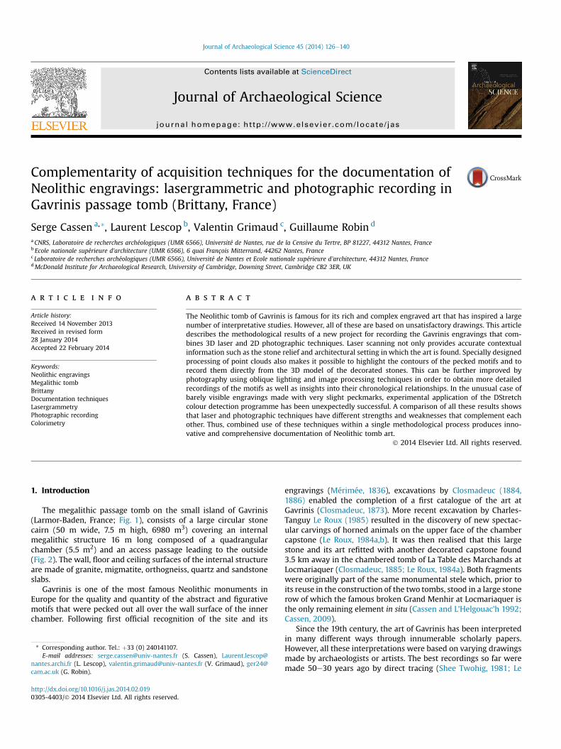
The megalithic passage tomb on the small island of Gavrinis(Larmor-Baden, France; Fig. 1), consists of a large circular stonecairn (50 m wide, 7.5 m high, 6980 m3) covering an internalmegalithic structure 16 m long composed of a quadrangularchamber (5.5 m2) and an access passage leading to the outside(Fig. 2). The wall, floor and ceiling surfaces of the internal structureare made of granite, migmatite, orthogneiss, quartz and sandstoneslabs.
Gavrinis is one of the most famous Neolithic monuments inEurope for the quality and quantity of the abstract and figurativemotifs that were pecked out all over the wall surface of the innerchamber. Following first official recognition of the site and its
S. Cassen), [email protected] (V. Grimaud), ger24@
engravings (Mérimée, 1836), excavations by Closmadeuc (1884,1886) enabled the completion of a first catalogue of the art atGavrinis (Closmadeuc, 1873). More recent excavation by Charles-Tanguy Le Roux (1985) resulted in the discovery of new spectac-ular carvings of horned animals on the upper face of the chambercapstone (Le Roux, 1984a,b). It was then realised that this largestone and its art refitted with another decorated capstone found3.5 km away in the chambered tomb of La Table des Marchands atLocmariaquer (Closmadeuc, 1885; Le Roux, 1984a). Both fragmentswere originally part of the same monumental stele which, prior toits reuse in the construction of the two tombs, stood in a large stonerow of which the famous broken Grand Menhir at Locmariaquer isthe only remaining element in situ (Cassen and L’Helgouac’h 1992;Cassen, 2009).
Since the 19th century, the art of Gavrinis has been interpretedin many different ways through innumerable scholarly papers.However, all these interpretations were based on varying drawingsmade by archaeologists or artists. The best recordings so far weremade 50e30 years ago by direct tracing (Shee Twohig, 1981; Le
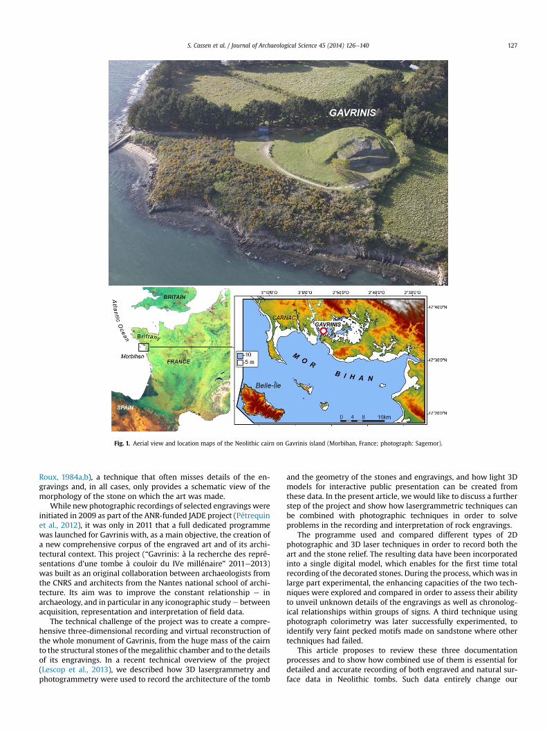
Fig. 1. Aerial view and location maps of the Neolithic cairn on Gavrinis island (Morbihan, France; photograph: Sagemor).
S. Cassen et al. / Journal of Archaeological Science 45 (2014) 126e140 127
Roux, 1984a,b), a technique that often misses details of the en-gravings and, in all cases, only provides a schematic view of themorphology of the stone on which the art was made.
While new photographic recordings of selected engravings wereinitiated in 2009 as part of the ANR-funded JADE project (Pétrequinet al., 2012), it was only in 2011 that a full dedicated programmewas launched for Gavrinis with, as a main objective, the creation ofa new comprehensive corpus of the engraved art and of its archi-tectural context. This project (“Gavrinis: à la recherche des repré-sentations d’une tombe à couloir du IVe millénaire” 2011e2013)was built as an original collaboration between archaeologists fromthe CNRS and architects from the Nantes national school of archi-tecture. Its aim was to improve the constant relationship e inarchaeology, and in particular in any iconographic studye betweenacquisition, representation and interpretation of field data.
The technical challenge of the project was to create a compre-hensive three-dimensional recording and virtual reconstruction ofthe whole monument of Gavrinis, from the huge mass of the cairnto the structural stones of themegalithic chamber and to the detailsof its engravings. In a recent technical overview of the project(Lescop et al., 2013), we described how 3D lasergrammetry andphotogrammetry were used to record the architecture of the tomb
and the geometry of the stones and engravings, and how light 3Dmodels for interactive public presentation can be created fromthese data. In the present article, we would like to discuss a furtherstep of the project and show how lasergrammetric techniques canbe combined with photographic techniques in order to solveproblems in the recording and interpretation of rock engravings.
The programme used and compared different types of 2Dphotographic and 3D laser techniques in order to record both theart and the stone relief. The resulting data have been incorporatedinto a single digital model, which enables for the first time totalrecording of the decorated stones. During the process, which was inlarge part experimental, the enhancing capacities of the two tech-niques were explored and compared in order to assess their abilityto unveil unknown details of the engravings as well as chronolog-ical relationships within groups of signs. A third technique usingphotograph colorimetry was later successfully experimented, toidentify very faint pecked motifs made on sandstone where othertechniques had failed.
This article proposes to review these three documentationprocesses and to show how combined use of them is essential fordetailed and accurate recording of both engraved and natural sur-face data in Neolithic tombs. Such data entirely change our
Fig. 2. 3D elevations of Gavrinis cairn and walls (passage and chamber) from lasergrammetric survey. Panoramic view from the chamber and location of the two engraved slabs(R11 and L6) described in the text.
S. Cassen et al. / Journal of Archaeological Science 45 (2014) 126e140128
perception of the decorated stones and provide a completely newbasis for interpretation of the art at Gavrinis.
Inevitably, the conceptual framework recently elaborated inorder to re-think the signs and their combinations (Cassen,2000) had an influence on the way these signs were docu-mented and represented. For example, particular attention wasgiven to hierarchical arrangements, oppositions and correlationsof signs within engraved compositions. This back-and-forthreflection between methodology and epistemology has
gradually become more accurate as similar recording has beenconducted on other monuments in the region over the last 10years (Runesto, Mané Croc’h, Bronzo, Vieux Moulin, Table desMarchands, Mané Kerioned, Mané Lud, Mané Rutual e Cassen,2011). At Gavrinis, therefore, a last objective was to examineoverlapping engravings in order to identify the chronologicalorder of execution of the signs on each stone, and to investigatethe semiotic relationships between groups of motifs onadjoining stones inside the tomb.
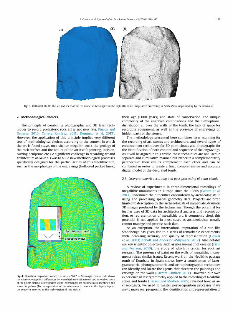
Fig. 3. Orthostat L6. On the left (A), view of the 3D model in Geomagic; on the right (B), same image after processing in Adobe Photoshop (shading by the normals).
S. Cassen et al. / Journal of Archaeological Science 45 (2014) 126e140 129
2. Methodological choices
The principle of combining photographic and 3D laser tech-niques to record prehistoric rock art is not new (e.g. Pinçon andGeneste, 2010; Carrera Ramírez, 2011; Domingo et al. 2013).However, the application of this principle implies very differentsets of methodological choices according to the context in whichthe art is found (cave, rock shelter, megalith, etc.), the geology ofthe rock surface and the nature of the art itself (painting, incision,carving, sculpture, etc.). A significant challenge in recording art andarchitecture at Gavrinis was to build newmethodological processesspecifically designed for the particularities of this Neolithic site,such as the morphology of the engravings (hollowed pecked lines),
Fig. 4. Deviation map of orthostat L6 as set on “440” in Geomagic. Colour code showsthe microtopographical differences between high resolution mesh and smoothed meshof the points cloud. Hollow pecked areas (engravings) are automatically identified andshown in yellow. (For interpretation of the references to colour in this figure legend,the reader is referred to the web version of this article.)
their age (6000 years) and state of conservation, the uniquecomplexity of the engraved compositions and their exceptionaldistribution all over the walls of the tomb, the lack of space forrecording equipment, as well as the presence of engravings onhidden parts of the stones.
The methodology presented here combines laser scanning forthe recording of art, stones and architecture, and several types ofenhancement techniques for 3D point clouds and photographs forthe identification of both content and sequence of the engravings.As it will be argued in this article, these techniques are not used inseparate and cumulative manner, but rather in a complementarityperspective: their results complement each other and can becombined in order to create a final, comprehensive and accuratedigital model of the decorated tomb.
2.1. Lasergrammetric recording and post-processing of point clouds
A review of experiments in three-dimensional recordings ofmegalithic monuments in Europe since the 1980s (Cassen et al.2013) underlined the difficulties encountered by archaeologists inusing and processing spatial geometry data. Projects are oftenlimited to description by the archaeologists of immediate, dramatic3D images produced by the technicians. Though the potential forfurther uses of 3D data for architectural analyses and reconstruc-tion, or representation of megalithic art, is commonly cited, thispotential is not applied in most cases as archaeologists usuallycannot manage and process such data.
As an exception, the international reputation of a site likeStonehenge has given rise to a series of remarkable experiments,with increasing accuracy and quality of representation (Goskaret al., 2003; Abbott and Anderson-Whymark, 2012). Also notableare key scientific objectives such as measurement of erosion (Fieldand Pearson, 2010), the study of which is crucial for rock artresearch. The presence of paint on the walls of megalithic monu-ments raises similar issues. Recent work on the Neolithic passagetomb of Dombate in Spain shows how a combination of laser-grammetric, photogrammetric and orthophotographic techniquescan identify and locate the agents that threaten the paintings andcarvings on the walls (Carrera Ramírez, 2011). However, our ownexperience of lasergrammetry applied to the recording of Neolithicsteles and tombs (Cassen and Merheb, 2005) revealed how, as ar-chaeologists, we need to master post-acquisition processes if weare tomake real progress in the identification and representation of
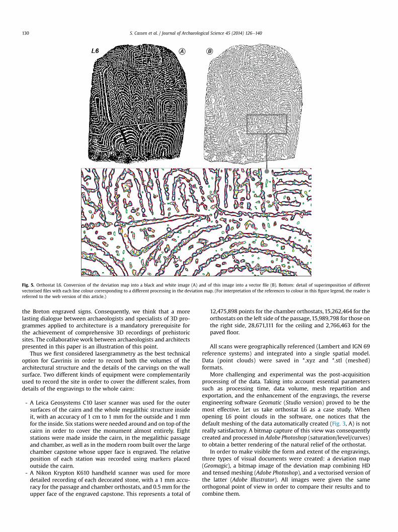
Fig. 5. Orthostat L6. Conversion of the deviation map into a black and white image (A) and of this image into a vector file (B). Bottom: detail of superimposition of differentvectorised files with each line colour corresponding to a different processing in the deviation map. (For interpretation of the references to colour in this figure legend, the reader isreferred to the web version of this article.)
S. Cassen et al. / Journal of Archaeological Science 45 (2014) 126e140130
the Breton engraved signs. Consequently, we think that a morelasting dialogue between archaeologists and specialists of 3D pro-grammes applied to architecture is a mandatory prerequisite forthe achievement of comprehensive 3D recordings of prehistoricsites. The collaborative work between archaeologists and architectspresented in this paper is an illustration of this point.
Thus we first considered lasergrammetry as the best technicaloption for Gavrinis in order to record both the volumes of thearchitectural structure and the details of the carvings on the wallsurface. Two different kinds of equipment were complementarilyused to record the site in order to cover the different scales, fromdetails of the engravings to the whole cairn:
- A Leica Geosystems C10 laser scanner was used for the outersurfaces of the cairn and the whole megalithic structure insideit, with an accuracy of 1 cm to 1 mm for the outside and 1 mmfor the inside. Six stations were needed around and on top of thecairn in order to cover the monument almost entirely. Eightstations were made inside the cairn, in the megalithic passageand chamber, as well as in the modern room built over the largechamber capstone whose upper face is engraved. The relativeposition of each station was recorded using markers placedoutside the cairn.
- A Nikon Krypton K610 handheld scanner was used for moredetailed recording of each decorated stone, with a 1 mm accu-racy for the passage and chamber orthostats, and 0.5 mm for theupper face of the engraved capstone. This represents a total of
12,475,898 points for the chamber orthostats, 15,262,464 for theorthostats on the left side of the passage,15,989,798 for those onthe right side, 28,671,111 for the ceiling and 2,766,463 for thepaved floor.
All scans were geographically referenced (Lambert and IGN 69reference systems) and integrated into a single spatial model.Data (point clouds) were saved in *.xyz and *.stl (meshed)formats.
More challenging and experimental was the post-acquisitionprocessing of the data. Taking into account essential parameterssuch as processing time, data volume, mesh repartition andexportation, and the enhancement of the engravings, the reverseengineering software Geomatic (Studio version) proved to be themost effective. Let us take orthostat L6 as a case study. Whenopening L6 point clouds in the software, one notices that thedefault meshing of the data automatically created (Fig. 3, A) is notreally satisfactory. A bitmap capture of this view was consequentlycreated and processed in Adobe Photoshop (saturation/level/curves)to obtain a better rendering of the natural relief of the orthostat.
In order to make visible the form and extent of the engravings,three types of visual documents were created: a deviation map(Geomagic), a bitmap image of the deviation map combining HDand tensed meshing (Adobe Photoshop), and a vectorised version ofthe latter (Adobe Illustrator). All images were given the sameorthogonal point of view in order to compare their results and tocombine them.
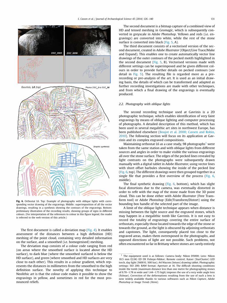
Fig. 6. Orthostat L6. Top: Example of photographs with oblique lights with corre-sponding vector drawing of the engravings. Middle: superimposition of all the vectordrawings, resulting in a synthesis showing the contours of the engravings. Bottom:preliminary illustration of the recording results, showing groups of signs in differentcolours. (For interpretation of the references to colour in this figure legend, the readeris referred to the web version of this article.)
1 The equipment used is as follows: Camera body: Nikon D5000; Lens: Nikon10.5 mm f/2.8G ED DX Fisheye-Nikkor; Remote control; Kaiser (StarCluster) LEDtorch, day light (5600 K; 500 lux); A4 Wacom (Intuos) drawing tablet. Photographicsettings: ISO 200; RAW format; Aperture at 16. The difficult shooting conditionsinside the tomb (maximum distance less than one metre for photographing stonesof 0.70e1.78 m wide and 1.44e1.75 high) imposes the use of a very wide angle lens(fisheye). Correction of the deformations resulting from the use of such a lens isnow widely available thanks to various softwares such as Nikon Capture, AdobePhotoshop or Image Trends (Hemi).
S. Cassen et al. / Journal of Archaeological Science 45 (2014) 126e140 131
The first document is called a deviation map (Fig. 4). It enablesassessment of the distances between a high definition (HD)meshing of the point cloud, containing very detailed informationon the surface, and a smoothed (i.e. homogenised) meshing.
The deviation map consists of a colour code ranging from red(on areas where the smoothed surface is located above the HDsurface), to dark blue (where the smoothed surfaced is below theHD surface), and green (where smoothed and HD surfaces are veryclose to each other). This results in a colour gradient, which rep-resents the distances in millimetres from the smoothed to the highdefinition surface. The novelty of applying this technique toNeolithic art is that the colour code makes it possible to show theengravings in yellow, and sometimes in red for the most pro-nounced reliefs.
The second document is a bitmap capture of a combined view ofHD and tensed meshing in Geomagic, which is subsequently con-verted in greyscale in Adobe Photoshop. Yellows and reds (i.e. en-gravings) are converted into white, while the rest of the stonesurface is converted into black (Fig. 5, A).
The third document consists of a vectorised version of the sec-ond document, created in Adobe Illustrator (Object/Live Trace/Makeand Expand). This enables one to create automatically vector linedrawings of the outer contours of the pecked motifs highlighted inthe second document (Fig. 5, B). Vectorised versions made withdifferent settings can be superimposed and be given different col-ours in order to provide further details on pecked contours (seedetail in Fig. 5). The resulting file is regarded more as a pre-recording or pre-analysis of the art. It is used as an initial draw-ing basis, the details of which can be transformed and adapted asfurther recording investigations are made with other techniques,and from which a final drawing of the engravings is eventuallyproduced.
2.2. Photography with oblique lights
The second recording technique used at Gavrinis is a 2Dphotographic technique, which enables identification of very faintengravings by means of oblique lighting and computer processingof photographs. A detailed description of this method, which hasbeen used in several megalithic art sites in northwest Europe, hasbeen published elsewhere (Boujot et al. 2000; Cassen and Robin,2010). The following section will focus on its application at Gav-rinis and its complex engraved compositions.
Maintaining orthostat L6 as a case study, 98 photographs1 weretaken from the same station and with oblique lights from differentsources and angles in order to make visible the various engravingsall over the stone surface. The edges of the pecked lines revealed bylight contrasts on the photographs were subsequently drawnmanually with a digital tablet in Adobe Illustrator, using vector lineswith short offset barbules showing the inside of the pecked line(Fig. 6, top). The different drawingswere then grouped together in asingle file that provides a first overview of the process (Fig. 6,middle).
The final synthetic drawing (Fig. 6, bottom), which has slightfocal distortions due to the camera, was eventually distorted inorder to refit with the map of the stone made from the 3D pointcloud. This can be done either with Adobe Illustrator (Free Trans-form tool) or Adobe Photoshop (Edit/Transform/Distort) using thebounding box handle of the selected part of the image.
A limit of the oblique light technique appears when distance ismissing between the light source and the engraved stones, whichmay happen in a megalithic tomb like Gavrinis. It is not easy torecord the totality of engravings covering the entire surface oforthostats, especially those located towards the edge of the stone ortowards the ground, as the light is obscured by adjoining orthostatsand capstones. The light, consequently placed too close to theengraved areas, makes them overexposed in the photographs, andopposed directions of light are not possible. Such problems, notoften encountered so far in Brittanywhere stones are rarely entirely
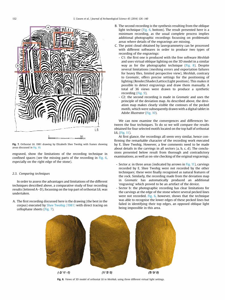
Fig. 7. Orthostat L6. 1981 drawing by Elizabeth Shee Twohig with frames showingareas discussed in Fig. 10.
S. Cassen et al. / Journal of Archaeological Science 45 (2014) 126e140132
engraved, show the limitations of the recording technique inconfined spaces (see the missing parts of the recording in Fig. 6,especially on the right edge of the stone).
2.3. Comparing techniques
In order to assess the advantages and limitations of the differenttechniques described above, a comparative study of four recordingresults (lettered AeD), focussing on the top part of orthostat L6, wasundertaken.
A. The first recording discussed here is the drawing (the best in thecorpus) executed by Shee Twohig (1981) with direct tracing oncellophane sheets (Fig. 7).
Fig. 8. Views of 3D model of orthostat L6 in Meshl
B. The second recording is the synthesis resulting from the obliquelight technique (Fig. 6, bottom). The result presented here is aminimum recording, as the usual complete process impliesadditional photographic recordings focussing on problematicareas where details of the engravings are missing.
C. The point cloud obtained by lasergrammetry can be processedwith different softwares in order to produce two types ofrecording of the engravings:- C1: the first one is produced with the free software Meshlaband uses virtual oblique lighting on the 3D model in a similarway as for the photographic technique (Fig. 8). Despiteseveral limitations (meshing errors and exportation failuresfor heavy files, limited perspective view), Meshlab, contraryto Geomatic, offers precise settings for the positioning oflighting (Render/Shader/Lattice/Light position). This makes itpossible to detect engravings and draw them manually. Atotal of 36 views were drawn to produce a syntheticrecording (Fig. 9).
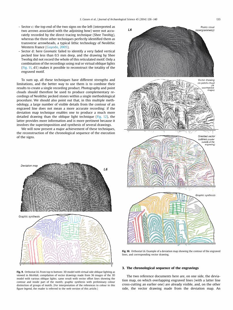
- C2: the second recording is made in Geomatic and uses theprinciple of the deviation map. As described above, the devi-ation map makes clearly visible the contours of the peckedmotifs, whichwere subsequently drawnwith a digital tablet inAdobe Illustrator (Fig. 10).
We can now examine the convergences and differences be-tween the four techniques. To do so we will compare the resultsobtained for four selectedmotifs located on the top half of orthostatL6, (Fig. 11).
At first glance, the recordings all seem very similar, hence con-firming the remarkable character of the recording work executedby E. Shee Twohig. However, a few comments need to be madeabout details in the carvings in all sectors (a, b, c, d). The conclu-sions presented below result from thorough and contradictoryexaminations, as well as on-site checking of the original engravings.
- Sector a: in three areas (indicated by arrows in Fig. 11), carvingsrecorded by E. Shee Twohig were not recorded by the othertechniques; these were finally recognised as natural features ofthe rock. Similarly, the recording made from the deviation mapin Geomatic has automatically produced an additional‘engraving’ which proved to be an artefact of the device.
- Sector b: the photographic recording has clear limitations forthe carvings at the edge of the stone where several pecked lineswere not recorded. Fig. 6, however, shows that the techniquewas able to recognise the lower edges of these pecked lines butfailed in identifying their top edges, an opposed oblique lightbeing impossible in this area.
ab, using three different virtual light settings.
S. Cassen et al. / Journal of Archaeological Science 45 (2014) 126e140 133
- Sector c: the top end of the two signs on the left (interpreted astwo arrows associated with the adjoining bow) were not accu-rately recorded by the direct tracing technique (Shee Twohig),whereas the three other techniques perfectly identified them astransverse arrowheads, a typical lithic technology of NeolithicWestern France (Guyodo, 2005).
- Sector d: here Geomatic failed to identify a very faded verticalpecked line less than 0.5 mm deep, and the drawing by SheeTwohig did not record the whole of this reticulated motif. Only acombination of the recordings using real or virtual oblique lights(Fig. 11, d1) makes it possible to reconstruct the totality of theengraved motif.
To sum up, all these techniques have different strengths andlimitations, and the better way to use them is to combine theirresults to create a single recording product. Photography and pointclouds should therefore be used to produce complementary re-cordings of Neolithic pecked stones within a single methodologicalprocedure. We should also point out that, in this multiple meth-odology, a large number of visible details from the contour of anengraved line does not mean a more accurate recording: if thedeviation map technique enables one to produce a much moredetailed drawing than the oblique light technique (Fig. 12), thelatter provides more information and is more pertinent because itinvolves the superimposition and synthesis of several drawings.
We will now present a major achievement of these techniques,the reconstruction of the chronological sequence of the executionof the signs.
Fig. 9. Orthostat L6. From top to bottom: 3D model with virtual side oblique lighting asviewed in Meshlab; compilation of vector drawings made from 36 images of the 3Dmodel with various oblique lights; same result with vector offset lines showing thecontour and inside part of the motifs; graphic synthesis with preliminary colourdistinction of groups of motifs. (For interpretation of the references to colour in thisfigure legend, the reader is referred to the web version of this article.)
Fig. 10. Orthostat L6. Example of a deviation map showing the contour of the engravedlines, and corresponding vector drawing.
3. The chronological sequence of the engravings
The two reference documents here are, on one side, the devia-tion map, on which overlapping engraved lines (with a latter linecross-cutting an earlier one) are already visible, and, on the otherside, the vector drawing made from the deviation map. An
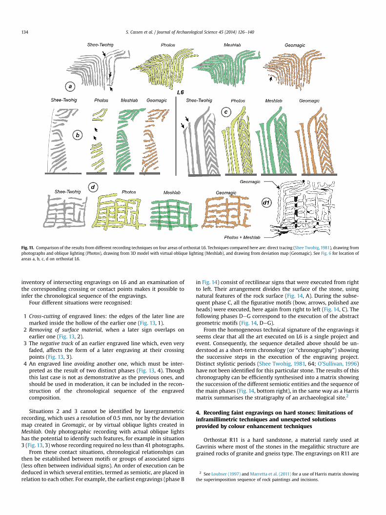
Fig. 11. Comparison of the results from different recording techniques on four areas of orthostat L6. Techniques compared here are: direct tracing (Shee Twohig, 1981), drawing fromphotographs and oblique lighting (Photos), drawing from 3D model with virtual oblique lighting (Meshlab), and drawing from deviation map (Geomagic). See Fig. 6 for location ofareas a, b, c, d on orthostat L6.
2 See Loubser (1997) and Marretta et al. (2011) for a use of Harris matrix showingthe superimposition sequence of rock paintings and incisions.
S. Cassen et al. / Journal of Archaeological Science 45 (2014) 126e140134
inventory of intersecting engravings on L6 and an examination ofthe corresponding crossing or contact points makes it possible toinfer the chronological sequence of the engravings.
Four different situations were recognised:
1 Cross-cutting of engraved lines: the edges of the later line aremarked inside the hollow of the earlier one (Fig. 13, 1).
2 Removing of surface material, when a later sign overlaps onearlier one (Fig. 13, 2).
3 The negative track of an earlier engraved line which, even veryfaded, affects the form of a later engraving at their crossingpoints (Fig. 13, 3).
4 An engraved line avoiding another one, which must be inter-preted as the result of two distinct phases (Fig. 13, 4). Thoughthis last case is not as demonstrative as the previous ones, andshould be used in moderation, it can be included in the recon-struction of the chronological sequence of the engravedcomposition.
Situations 2 and 3 cannot be identified by lasergrammetricrecording, which uses a resolution of 0.5 mm, nor by the deviationmap created in Geomagic, or by virtual oblique lights created inMeshlab. Only photographic recording with actual oblique lightshas the potential to identify such features, for example in situation3 (Fig. 13, 3) whose recording required no less than 41 photographs.
From these contact situations, chronological relationships canthen be established between motifs or groups of associated signs(less often between individual signs). An order of execution can bededuced inwhich several entities, termed as semiotic, are placed inrelation to each other. For example, the earliest engravings (phase B
in Fig. 14) consist of rectilinear signs that were executed from rightto left. Their arrangement divides the surface of the stone, usingnatural features of the rock surface (Fig. 14, A). During the subse-quent phase C, all the figurative motifs (bow, arrows, polished axeheads) were executed, here again from right to left (Fig. 14, C). Thefollowing phases DeG correspond to the execution of the abstractgeometric motifs (Fig. 14, DeG).
From the homogeneous technical signature of the engravings itseems clear that all the art executed on L6 is a single project andevent. Consequently, the sequence detailed above should be un-derstood as a short-term chronology (or “chronography”) showingthe successive steps in the execution of the engraving project.Distinct stylistic periods (Shee Twohig, 1981, 64; O’Sullivan, 1996)have not been identified for this particular stone. The results of thischronography can be efficiently synthesised into a matrix showingthe succession of the different semiotic entities and the sequence ofthe main phases (Fig. 14, bottom right), in the same way as a Harrismatrix summarises the stratigraphy of an archaeological site.2
4. Recording faint engravings on hard stones: limitations ofinframillimetric techniques and unexpected solutionsprovided by colour enhancement techniques
Orthostat R11 is a hard sandstone, a material rarely used atGavrinis where most of the stones in the megalithic structure aregrained rocks of granite and gneiss type. The engravings on R11 are
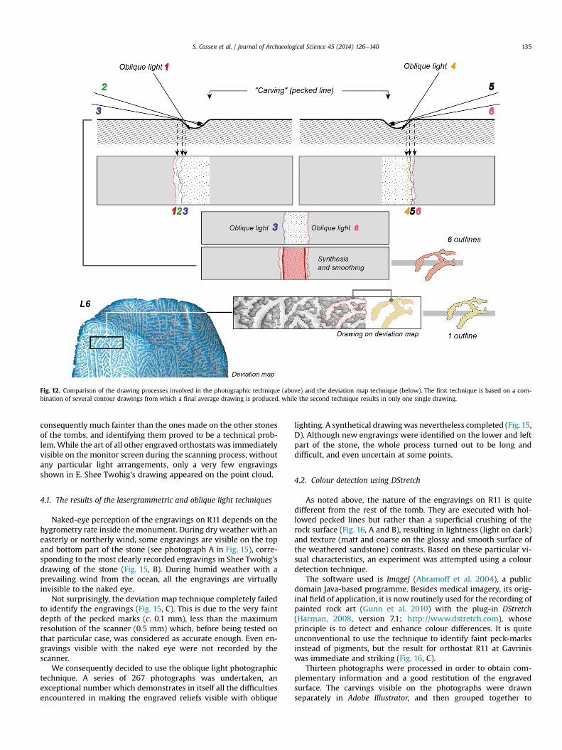
Fig. 12. Comparison of the drawing processes involved in the photographic technique (above) and the deviation map technique (below). The first technique is based on a com-bination of several contour drawings from which a final average drawing is produced, while the second technique results in only one single drawing.
S. Cassen et al. / Journal of Archaeological Science 45 (2014) 126e140 135
consequently much fainter than the ones made on the other stonesof the tombs, and identifying them proved to be a technical prob-lem.While the art of all other engraved orthostats was immediatelyvisible on the monitor screen during the scanning process, withoutany particular light arrangements, only a very few engravingsshown in E. Shee Twohig’s drawing appeared on the point cloud.
4.1. The results of the lasergrammetric and oblique light techniques
Naked-eye perception of the engravings on R11 depends on thehygrometry rate inside the monument. During dry weather with aneasterly or northerly wind, some engravings are visible on the topand bottom part of the stone (see photograph A in Fig. 15), corre-sponding to the most clearly recorded engravings in Shee Twohig’sdrawing of the stone (Fig. 15, B). During humid weather with aprevailing wind from the ocean, all the engravings are virtuallyinvisible to the naked eye.
Not surprisingly, the deviation map technique completely failedto identify the engravings (Fig. 15, C). This is due to the very faintdepth of the pecked marks (c. 0.1 mm), less than the maximumresolution of the scanner (0.5 mm) which, before being tested onthat particular case, was considered as accurate enough. Even en-gravings visible with the naked eye were not recorded by thescanner.
We consequently decided to use the oblique light photographictechnique. A series of 267 photographs was undertaken, anexceptional number which demonstrates in itself all the difficultiesencountered in making the engraved reliefs visible with oblique
lighting. A synthetical drawingwas nevertheless completed (Fig.15,D). Although new engravings were identified on the lower and leftpart of the stone, the whole process turned out to be long anddifficult, and even uncertain at some points.
4.2. Colour detection using DStretch
As noted above, the nature of the engravings on R11 is quitedifferent from the rest of the tomb. They are executed with hol-lowed pecked lines but rather than a superficial crushing of therock surface (Fig. 16, A and B), resulting in lightness (light on dark)and texture (matt and coarse on the glossy and smooth surface ofthe weathered sandstone) contrasts. Based on these particular vi-sual characteristics, an experiment was attempted using a colourdetection technique.
The software used is ImageJ (Abramoff et al. 2004), a publicdomain Java-based programme. Besides medical imagery, its orig-inal field of application, it is now routinely used for the recording ofpainted rock art (Gunn et al. 2010) with the plug-in DStretch(Harman, 2008, version 7.1; http://www.dstretch.com), whoseprinciple is to detect and enhance colour differences. It is quiteunconventional to use the technique to identify faint peck-marksinstead of pigments, but the result for orthostat R11 at Gavriniswas immediate and striking (Fig. 16, C).
Thirteen photographs were processed in order to obtain com-plementary information and a good restitution of the engravedsurface. The carvings visible on the photographs were drawnseparately in Adobe Illustrator, and then grouped together to
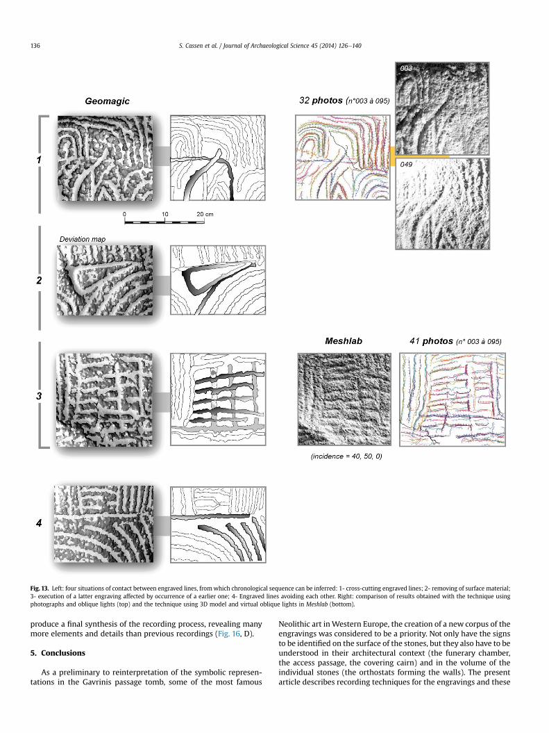
Fig. 13. Left: four situations of contact between engraved lines, fromwhich chronological sequence can be inferred: 1- cross-cutting engraved lines; 2- removing of surface material;3- execution of a latter engraving affected by occurrence of a earlier one; 4- Engraved lines avoiding each other. Right: comparison of results obtained with the technique usingphotographs and oblique lights (top) and the technique using 3D model and virtual oblique lights in Meshlab (bottom).
S. Cassen et al. / Journal of Archaeological Science 45 (2014) 126e140136
produce a final synthesis of the recording process, revealing manymore elements and details than previous recordings (Fig. 16, D).
5. Conclusions
As a preliminary to reinterpretation of the symbolic represen-tations in the Gavrinis passage tomb, some of the most famous
Neolithic art inWestern Europe, the creation of a new corpus of theengravings was considered to be a priority. Not only have the signsto be identified on the surface of the stones, but they also have to beunderstood in their architectural context (the funerary chamber,the access passage, the covering cairn) and in the volume of theindividual stones (the orthostats forming the walls). The presentarticle describes recording techniques for the engravings and these
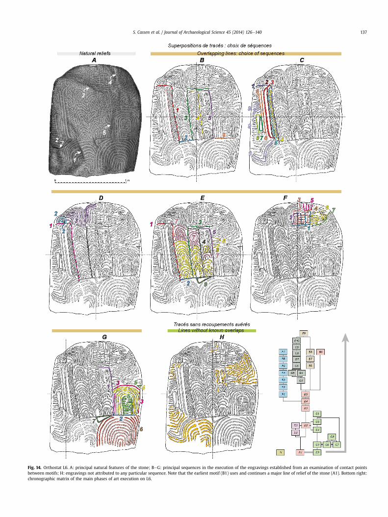
Fig. 14. Orthostat L6. A: principal natural features of the stone; BeG: principal sequences in the execution of the engravings established from an examination of contact pointsbetween motifs; H: engravings not attributed to any particular sequence. Note that the earliest motif (B1) uses and continues a major line of relief of the stone (A1). Bottom right:chronographic matrix of the main phases of art execution on L6.
S. Cassen et al. / Journal of Archaeological Science 45 (2014) 126e140 137
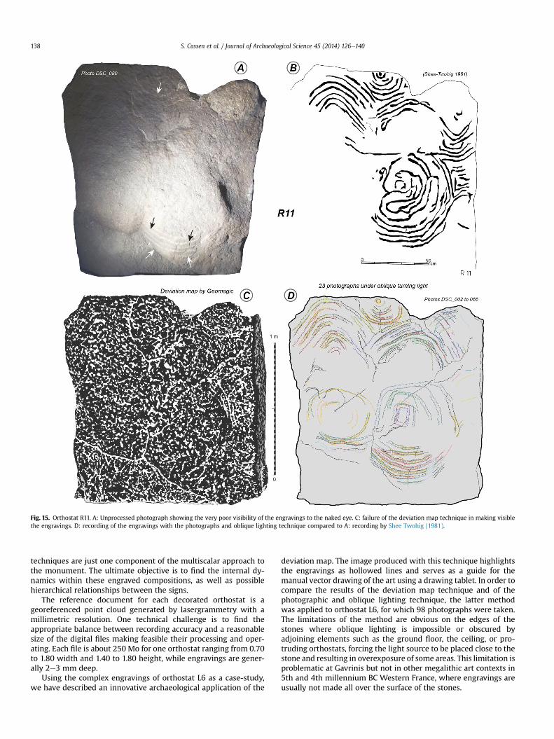
Fig. 15. Orthostat R11. A: Unprocessed photograph showing the very poor visibility of the engravings to the naked eye. C: failure of the deviation map technique in making visiblethe engravings. D: recording of the engravings with the photographs and oblique lighting technique compared to A: recording by Shee Twohig (1981).
S. Cassen et al. / Journal of Archaeological Science 45 (2014) 126e140138
techniques are just one component of the multiscalar approach tothe monument. The ultimate objective is to find the internal dy-namics within these engraved compositions, as well as possiblehierarchical relationships between the signs.
The reference document for each decorated orthostat is ageoreferenced point cloud generated by lasergrammetry with amillimetric resolution. One technical challenge is to find theappropriate balance between recording accuracy and a reasonablesize of the digital files making feasible their processing and oper-ating. Each file is about 250 Mo for one orthostat ranging from 0.70to 1.80 width and 1.40 to 1.80 height, while engravings are gener-ally 2e3 mm deep.
Using the complex engravings of orthostat L6 as a case-study,we have described an innovative archaeological application of the
deviation map. The image produced with this technique highlightsthe engravings as hollowed lines and serves as a guide for themanual vector drawing of the art using a drawing tablet. In order tocompare the results of the deviation map technique and of thephotographic and oblique lighting technique, the latter methodwas applied to orthostat L6, for which 98 photographs were taken.The limitations of the method are obvious on the edges of thestones where oblique lighting is impossible or obscured byadjoining elements such as the ground floor, the ceiling, or pro-truding orthostats, forcing the light source to be placed close to thestone and resulting in overexposure of some areas. This limitation isproblematic at Gavrinis but not in other megalithic art contexts in5th and 4th millennium BC Western France, where engravings areusually not made all over the surface of the stones.
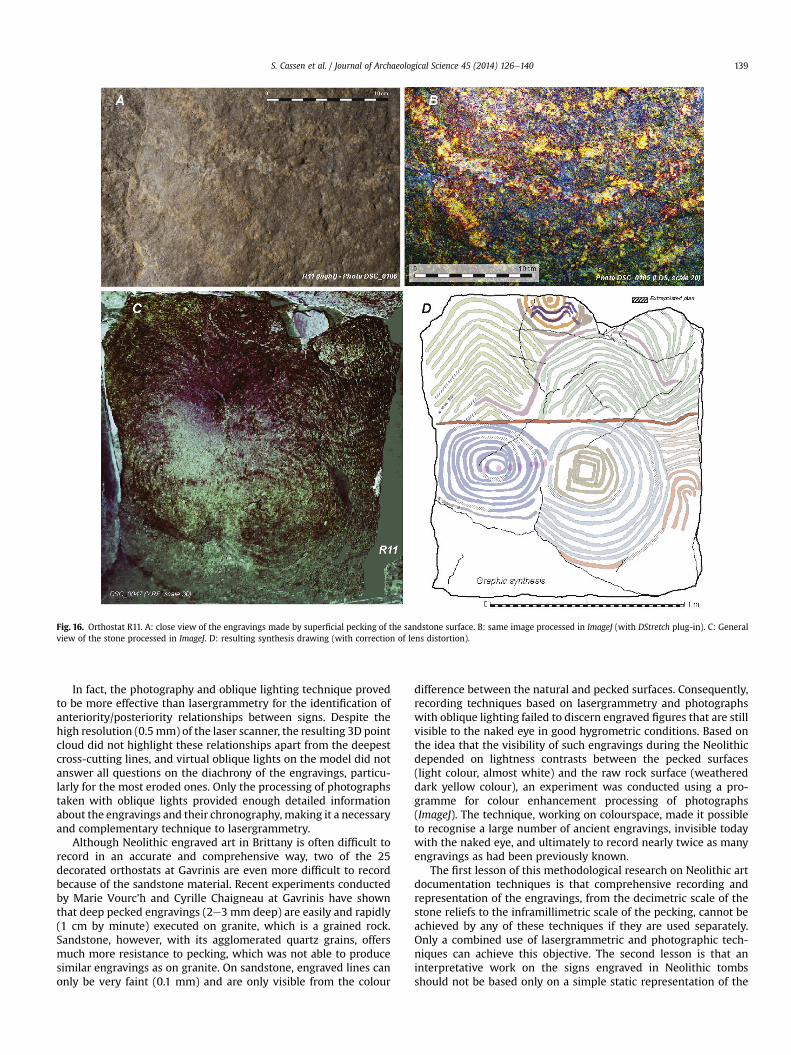
Fig. 16. Orthostat R11. A: close view of the engravings made by superficial pecking of the sandstone surface. B: same image processed in ImageJ (with DStretch plug-in). C: Generalview of the stone processed in ImageJ. D: resulting synthesis drawing (with correction of lens distortion).
S. Cassen et al. / Journal of Archaeological Science 45 (2014) 126e140 139
In fact, the photography and oblique lighting technique provedto be more effective than lasergrammetry for the identification ofanteriority/posteriority relationships between signs. Despite thehigh resolution (0.5mm) of the laser scanner, the resulting 3D pointcloud did not highlight these relationships apart from the deepestcross-cutting lines, and virtual oblique lights on the model did notanswer all questions on the diachrony of the engravings, particu-larly for the most eroded ones. Only the processing of photographstaken with oblique lights provided enough detailed informationabout the engravings and their chronography, making it a necessaryand complementary technique to lasergrammetry.
Although Neolithic engraved art in Brittany is often difficult torecord in an accurate and comprehensive way, two of the 25decorated orthostats at Gavrinis are even more difficult to recordbecause of the sandstone material. Recent experiments conductedby Marie Vourc’h and Cyrille Chaigneau at Gavrinis have shownthat deep pecked engravings (2e3 mm deep) are easily and rapidly(1 cm by minute) executed on granite, which is a grained rock.Sandstone, however, with its agglomerated quartz grains, offersmuch more resistance to pecking, which was not able to producesimilar engravings as on granite. On sandstone, engraved lines canonly be very faint (0.1 mm) and are only visible from the colour
difference between the natural and pecked surfaces. Consequently,recording techniques based on lasergrammetry and photographswith oblique lighting failed to discern engraved figures that are stillvisible to the naked eye in good hygrometric conditions. Based onthe idea that the visibility of such engravings during the Neolithicdepended on lightness contrasts between the pecked surfaces(light colour, almost white) and the raw rock surface (weathereddark yellow colour), an experiment was conducted using a pro-gramme for colour enhancement processing of photographs(ImageJ). The technique, working on colourspace, made it possibleto recognise a large number of ancient engravings, invisible todaywith the naked eye, and ultimately to record nearly twice as manyengravings as had been previously known.
The first lesson of this methodological research on Neolithic artdocumentation techniques is that comprehensive recording andrepresentation of the engravings, from the decimetric scale of thestone reliefs to the inframillimetric scale of the pecking, cannot beachieved by any of these techniques if they are used separately.Only a combined use of lasergrammetric and photographic tech-niques can achieve this objective. The second lesson is that aninterpretative work on the signs engraved in Neolithic tombsshould not be based only on a simple static representation of the
S. Cassen et al. / Journal of Archaeological Science 45 (2014) 126e140140
motifs but also on a detailed reconstruction of their spatio-temporal dynamics or chronography. The techniques described inthis paper are particularly effective in producing a reconstruction ofthis kind.
Acknowledgements
We are grateful to Dr. Marie Vourc’h (LARA, Université deNantes) and Cyrille Chaigneau (Musée de Carnac) who provideddata from their ongoing experiments on Neolithic engraving tech-niques. We would like to express our warm thanks to Michael Ilett(Paris 1 Panthéon-Sorbonne University) for his revision of thetranslation of this paper. The research programme directed bySerge Cassen (“Gavrinis: à la recherche des représentations d’unetombe à couloir du IVe millénaire”) is funded by the Départementdu Morbihan, the Ministère de la Culture (DRAC Bretagne, ENSANantes) and the CNRS, with technical support from the Sagemor.
References
Abbott, M., Anderson-Whymark, H., 2012. Stonehenge Laser Scan: ArchaeologicalAnalysis Report. Research report series n� 32. English Heritage, Fort Cumber-land, Portsmouth.
Abramoff, M.D., Magelhaes, P.J., Ram, S.J., 2004. Image processing with ImageJ.Biophot. Int. 11 (7), 36e42.
Boujot, C., Cassen, S., Defaix, J., 2000. La Pierre décorée du caveau et les gravuresrégionales nouvellement découvertes. In: Cassen, S. (Ed.), Eléments d’archi-tecture, Mémoire 19. Editions chauvinoises, Chauvigny, pp. 277e297.
Carrera Ramírez, F., 2011. El arteprehistórico y su conservación. Pinturas y grabadosen Dombate. In: Rodríguez, J.Y. (Ed.), El dolmen de Dombate : arqueología,arquitectura y conservación. Deputación da Coruña, A Coruña, pp. 230e266.
Cassen, S., 2000. Architecture du tombeau, équipement mortuaire, décor céramiqueet art gravé du Ve millénaire en Morbihan. A la recherche d’une cosmogonie despremières sociétés agricoles de l’Europe occidentale. In: Jorge, V.O. (Ed.), Actasdo 3� Congresso de Arqueologia Peninsular, Vila Real 1999, Pré-historia recenteda Peninsula ibérica, vol. IV. ADECAP, Porto, pp. 447e479.
Cassen, S. (Ed.), 2009. Autour de la Table. Explorations archéologiques et discourssavants sur une architecture néolithique restaurée à Locmariaquer, Morbihan(Table des Marchands et Grand Menhir). Université de Nantes, Nantes.
Cassen, S., 2011. Le Mané Lud en mouvement. Déroulé de signes dans un ouvragenéolithique de pierres dressées à Locmariaquer (Morbihan). Préhist. Méditerr. 2,1e58.
Cassen, S., L’Helgouac’h, J., 1992. Du Symbole de la crosse : chronologie, répartitionet interprétation. In: Le Roux, C.T. (Ed.), Paysans et Bâtisseurs. L’émergence duNéolithique atlantique et les origines du Mégalithisme. Actes du XVIIe colloqueinterrégional sur le Néolithique. Vannes 29e31 octobre 1990. Revue Archéo. del’Ouest (Suppl. 5), 223e235. Rennes.
Cassen, S., Merheb, M., 2005. Stone surfaces, earth surfaces: notes about therecording and the 3D representation of engraved steles within Neolithic funeralstructures in western France (Locmariaquer, Carnac e 4700e3800 cal. BC.). In:Dobrovolskaya, M. (Ed.), Mejedistsplinarie Issledovania v Arkheologii, Inter-disciplinary Investigation in Archaeology, vol. 4. OPUS, Moscow, pp. 182e191.
Cassen, S., Robin, G., 2010. Recording art on Neolithic stelae and passage tombs fromdigital photographs. J. Archaeol. Method Theory 17 (1), 1e14.
Cassen, S., Lescop, L., Grimaud, V., 2013. Pour une critique de la représentationtridimensionnelle des architectures mégalithiques en Europe occidentale.Méthodes et usages actuels. Ann. Bretagne Pays l’ouest 120 (1), 7e31. http://
www.academia.edu/4008990/Pour_une_critique_de_la_representation_tridimensionnelle_des_architectures_megalithiques_en_Europe_occidentale_Methodes_et_usages_actuels.
Closmadeuc, G. (de), 1873. Sculptures lapidaires et signes gravés des dolmens dansle Morbihan. Imp. De Lamarzelle, Vannes.
Closmadeuc, G. (de), 1884. Gavrinis. Fouilles et découvertes récentes. Bull. Soc.Polymat. Morbihan 2, 180e187.
Closmadeuc, G. (de), 1885. Image d’un quadrupède sculptée sous la Table du Dol-Varc’hant e Dolmen dit des Marchand ou de César, Locmariaquer. In: Matéri-aux, t. 2, pp. 453e455.
Closmadeuc, G. (de), 1886. Gavrinis. Dernières fouilles sous le dallage de la chambre.Bull. Soc. Polymat. Morbihan 2, 63e69.
Domingo, I., Villaverde, V., López-Montalvo, E., Lerma, J.L., Cabrelles, M., 2013. Latestdevelopments in rock art recording: toward an integral documentation ofLevantine rock art sites combining 2D and 3D recording techniques. J. Archaeol.Sci. 40, 1879e1889.
Field, D., Pearson, T., 2010. Stonehenge World Heritage Site Landscape Project. In:Stonehenge, Wiltshire, Archaeological Survey Report, Research DepartmentReport Series, vol. 109. Amesbury.
Goskar, T., Carty, A., Cripps, P., Brayne, C., Vickers, D., 2003. The stonehenge laser-show. Br. Archaeol. 73. http://www.britarch.ac.uk/ba/ba73/feat1.shtml.
Gunn, R.G., Ogleby, C.L., Lee, D., Whear, R.L., 2010. A method to visually rationalisesuperimposed pigment motifs. Rock Art Res. 27 (2), 131e136.
Guyodo, J.-N., 2005. Les assemblages lithiques de la fin du Néolithique ancien et duNéolithique moyen sur le Massif armoricain et ses marges. In: Marchand, G.,Tresset, A. (Eds.), Unité et diversité des processus de néolithisation sur la façadeatlantique de l’Europe (6è e 4è millénaires avant J.-C.). Actes de la table-rondede Nantes, 26e27 avril 2002, mémoire n� 36. Société Préhistorique Française,Nantes, pp. 213e224.
Harman, J., 2008. Using Decorrelation Stretch to Enhance Rock Art Images. Articleonline: http://www.dstretch.com/AlgorithmDescription.html.
Le Roux, C.-T., 1984a. À Propos des fouilles de Gavrinis (Morbihan). Nouvellesdonnées sur l’art mégalithique Armoricain. Bull. So�c. préhist. francaise 1 (8),240e245.
Le Roux, C.-T., 1984b. New excavations at Gavrinis. Antiquity 59, 183e187.Le Roux, C.-T., 1985. Gavrinis et les îles du Morbihan. In: Guides archéologiques de la
France. Ministère de la Culture, Paris.Loubser, J.H.N., 1997. The use of the Harris diagrams in recording, conserving and
interpreting rock paintings. Int. Newsl. Rock Art 18, 14e21.Lescop, L., Cassen, S., Grimaud, V., 2013. Gavrinis. The raising of digital stone. In:
Addison, A.C., De Luca, L., Guidi, G., Pescarin, S. (Eds.), Digital Heritage Inter-national Congress (Marseille, France), CAA Fall 2013 Symposium, Communi-cating Archaelogy: Theory & Practice, vol. 2, pp. 561e568.
Marretta, A., Martinotti, A., Colella, M., 2011. Nuove metodologie di documentazionee analisi sequenze istoriative su due frammenti litici con graffiti protostorici daPiancogno (Valcamonica, Bs). In: Papers of the XXIV Valcamonica Symposium2011, pp. 294e305.
Mérimée, P., 1836. Notes d’un voyage dans l’Ouest de la France. Éd. Adam Biro, 1989,Paris.
O’Sullivan, M., 1996. Megalithic art in Ireland and Brittany: divergence or conver-gence. In: L’Helgouac’h, J., Le roux, C.-T., Lecornec, J. (Eds.), Art et symboles dumégalithisme européen. Revue Archéologique de l’Ouest (Suppl. 8), 81e96.Rennes: Association pour la diffusion des recherches archéologiques dansl’ouest de la France.
Pinçon, G., Geneste, J.M. (Eds.), 2010. Art rupestre : la 3D un outil de médiation duréel invisible ?. In Situ, Revue des patrimoines 13. URL: http://insitu.revues.org/6150 [last accessed 28.10.13.].
Pétrequin, P., Cassen, S., Errera, M., Klassen, L., Sheridan, A., Pétrequin, A.M., 2012.Jade. Grandes haches alpines du Néolithique européen. Ve et IVe millénaires av.J.-C. Cahiers de la MSHE C.N. Ledoux. Presses Universitaires de Franche-Comtéet Centre de Recherche Archéologique de la Vallée de l’Ain, Besançon. vol. 2.
Shee Twohig, E., 1981. The Megalithic Art of Western Europe. Clarendon Press,Oxford.