Millimeter Wave and Terahertz Synthetic Aperture Radar for ...

Comparison of the crossed and the GregorianMizuguchi–Dragone for wide-field millimeter-wave
astronomy
Huan Tran,1,* Adrian Lee,2 Shaul Hanany,3 Michael Milligan,3 and Tom Renbarger4
1Space Sciences Laboratory, University of California, Berkeley, California 94720, USA2Department of Physics, University of California, Berkeley, California 94720, USA
3School of Physics and Astronomy, University of Minnesota, Minneapolis, Minnesota 55455, USA4Department of Physics, University of California, San Diego, California 92093, USA
*Corresponding author: [email protected]
Received 13 August 2007; accepted 8 September 2007;posted 16 November 2007 (Doc. ID 85684); published 4 January 2008
We compare the geometric and physical-optics performance of two configurations of offset dual-reflectorantennas that obey the Mizuguchi–Dragone condition. The traditional Gregorian configuration is com-pared with the larger crossed configuration. These configurations are candidates for experiments thatmeasure the polarization of the cosmic microwave background. Particular attention is given to wide-fieldperformance and polarization fidelity. Both a ray tracer and a physical optics simulation package are usedto conclude that the crossed configuration has a larger diffraction-limited field of view, but within thislimit both configurations have roughly the same instrumental polarization and both show excellentcross-polarization levels, with the crossed configuration showing �10 dB better performance. © 2008Optical Society of America
OCIS codes: 110.3000, 110.6770, 220.1000, 220.1250, 220.4830, 260.5430.
1. Introduction
Increasing demands on sensitivity have driven theneed for large-format, millimeter-wave arrays. Thecurrent generation of detector arrays have an order of1000 elements, about an order of magnitude largerthan the previous generation. These arrays are beingactively developed for use in Sunyaev–Zeldovich clus-ter surveys and in the search for primordial gravita-tional waves in the polarization of the cosmicmicrowave background (CMB). The development oflarge-format arrays has motivated parallel develop-ments in the wide-field telescope optics that feedthese arrays [1,2].
Telescopes used for CMB astronomy have someunique constraints. Many such experiments incorpo-rate a cryogenic receiver with a vacuum window. Theoptics therefore need to produce a convenient location
for the window. Spurious signals from ground con-tamination seen from far sidelobes are also a majorconcern. Unobstructed primary apertures are benefi-cial in reducing scattering and diffraction from ob-structions and supports. Furthermore, the expectedratio of the intensity of the CMB to the polarizedgravitational wave CMB signal is �90 dB, placingstringent demands on polarization fidelity.
Offset dual reflector telescopes have been popularin the radio and microwave astronomy, offering un-obstructed apertures and large diffraction-limitedfield of view (DLFOV). For most dual reflector tele-scopes, a useful theoretical construct is the “equiva-lent paraboloid,” which has the same effective focallength (EFL) and aperture field distribution as thedual reflector [3]. The offset dual reflector has oneadditional degree of freedom over centered systems,the tilt between the symmetry axes of the parentconics. This tilt can be chosen such that the equiva-lent paraboloid is rotationally symmetric. Such a de-sign is referred to as a Mizuguchi–Dragone [4,5] andhas two desirable features: low cross polarization for
0003-6935/08/020103-07$15.00/0© 2008 Optical Society of America
10 January 2008 � Vol. 47, No. 2 � APPLIED OPTICS 103
the center feed and low astigmatism, leading to alarger DLFOV.
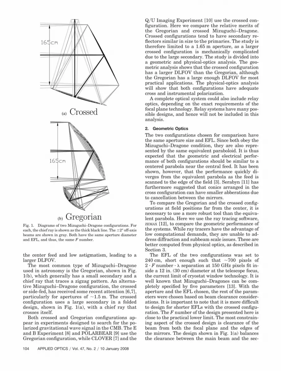
The most common type of Mizuguchi–Dragoneused in astronomy is the Gregorian, shown in Fig.1(b), which generally has a small secondary and achief ray that traces a zigzag pattern. An alterna-tive Mizuguchi–Dragone configuration, the crossedor side-fed, has received some recent attention [6,7],particularly for apertures of �1.5 m. The crossedconfiguration uses a large secondary in a foldeddesign, shown in Fig. 1(a), with a chief ray thatcrosses itself.
Both crossed and Gregorian configurations ap-pear in experiments designed to search for the po-larized gravitational wave signal in the CMB. The Eand B Experiment [8] and POLARBEAR [9] use theGregorian configuration, while CLOVER [7] and the
Q�U Imaging Experiment [10] use the crossed con-figuration. Here we compare the relative merits ofthe Gregorian and crossed Mizuguchi–Dragone.Crossed configurations tend to have secondary re-flectors similar in size to the primaries. The study istherefore limited to a 1.65 m aperture, as a largercrossed configuration is mechanically complicateddue to the large secondary. The study is divided intoa geometric and physical-optics analysis. The geo-metric analysis shows that the crossed configurationhas a larger DLFOV than the Gregorian, althoughthe Gregorian has a large enough DLFOV for mostpractical applications. The physical-optics analysiswill show that both configurations have adequatecross and instrumental polarization.
A complete optical system could also include relayoptics, depending on the exact requirements of thefocal plane technology. Relay systems have many pos-sible designs, and hence will not be included in thisanalysis.
2. Geometric Optics
The two configurations chosen for comparison havethe same aperture size and EFL. Since both obey theMizuguchi–Dragone condition, they are also repre-sented by the same equivalent paraboloid. It is thusexpected that the geometric and electrical perfor-mance of both configurations should be similar to acentered parabola near the central feed. It has beenshown, however, that the performance quickly di-verges from the equivalent parabola as the feed isscanned to the edge of the field [3]. Serabyn [11] hasfurthermore suggested that conics arranged in thecross configuration can have smaller abberations dueto cancellation between the mirrors.
To compare the Gregorian and the crossed config-urations at field positions far from the center, it isnecessary to use a more robust tool than the equiva-lent parabola. Here we use the ray tracing software,ZEMAX [12], to compare the geometric performance ofthe systems. While ray tracers have the advantage oflow computational demands, they are unable to ad-dress diffraction and subbeam scale issues. These arebetter computed from physical optics, as described inSection 3.
The EFL of the two configurations was set to240 cm, short enough such that �700 pixels of2 · F number · � separation at 150 GHz pixels fit in-side a 12 in. (30 cm) diameter at the telescope focus,the current limit of cryostat window technology. It iswell known that Mizuguchi–Dragones can be com-pletely specified by five parameters [13]. With theaperture and the EFL chosen, the rest of the param-eters were chosen based on beam clearance consider-ations. It is important to note that it is more difficultto design for shorter EFLs with the crossed configu-ration. The F number of the design presented here isclose to the practical lower limit. The most constrain-ing aspect of the crossed design is clearance of thebeam from both the focal plane and the edges ofthe mirrors. The design shown in Fig. 1(a) balancesthe clearance between the main beam and the sec-
Fig. 1. Diagrams of two Mizuguchi–Dragone configurations. Foreach, the chief ray is shown as the thick black line. The �2° off-axisbeams are shown in gray. Both have the same aperture diameterand EFL, and thus, the same F number.
104 APPLIED OPTICS � Vol. 47, No. 2 � 10 January 2008

ondary with the clearance between the main beamand the receiver. In the Gregorian design, the itemsin competition are the separation of the receiver andprimary, the size of the secondary, and the oblique-ness of the primary. The differences between the twoconfigurations are further explained in Section 5.
The aberrations for both configurations were eval-uated by calculating the Strehl ratios with the raytracing software. Figure 2 is a plot of the Strehl ratiosas a function of field position. The crossed configura-tion has nearly a factor of 2 larger focal plane diam-eter. The crossed configuration also has a nearlytelecentric focal plane, meaning that chief rays fromall field positions arrive nearly parallel at the focalplane. This makes the use of bare planar arrays ofscalar feedhorns at the telescope focus possible, elim-inating the need for relay optics. Nearly all the Gre-gorian systems, on the other hand, require a curvedfocal plane or relay optics.
3. Physical Optics
The GRASP9 [14] physical optics software package wasused to evaluate three quantities: copolar beam pro-files, cross-polar profiles, and instrumental polariza-tion. To study the effects of the telescope mirrorsonly, an idealized feedhorn was used, with zero crosspolarization and a Gaussian taper of �12 dB at theedge of the primary.
A. Copolarized and Cross-Polarized Beams
Copolarized beams for both focal planes are plotted inFig. 3. The shapes of the copolarized beams verify theray tracing conclusion that the crossed configurationhas a significantly larger DLFOV. Cross polarizationis a measure of how much the optical system rotateslinear polarization. The cross-polarized beams forboth focal planes are shown in Fig. 4.
It is important to note that the coordinates of eachhorn was chosen to null the easily calibrated meancross polarization across the beam profile. For small,flat regions of the far field, it is natural to align theunit vector defining the y polarization of the beamsalong the symmetry plane of the telescope. At thefocal plane, however, the horns are pointed inwardsuch that the chief rays intersect at the middle of the
primary aperture. This leaves no preferred orienta-tion of the horn x–y coordinates about the chief ray,thus allowing our particular choice of coordinates.Nulling the cross-polarization response in the middleof the beam produces a cross-polarized beam with acharacteristic double-lobe pattern, which cannot beremoved by a simple calibration or rotation.
After this coordinate operation, the crossed config-uration has �10 dB lower cross polarization than theGregorian. The cross polarization for the Gregorian,however, is less than �30 dB over the DLFOV. Thecross polarization of either telescope is similar to or
Fig. 2. Strehl ratios across the focal plane, calculated at 150 GHz.Crossed shows a clear advantage in terms of DLFOV. A design isconsidered diffraction-limited if the Strehl ratio is above 0.8.
Fig. 3. Copolarized beams for both the (a) crossed and (b) Grego-rian. Strehl ratio contours calculated independently by ray tracingfor different points in the focal plane are superimposed for com-parison. The beams were calculated for 150 GHz. The crossedshows a clear advantage in terms of consistency of beam shape overa larger DLFOV.
10 January 2008 � Vol. 47, No. 2 � APPLIED OPTICS 105

lower than that of the best corrugated feedhorns.Typical values of cross polarization for conical feed-horns are �20 dB [15], but it is possible to design acorrugated feedhorn with lower than �40 dB crosspolarization [16].
B. Instrumental Polarization
Instrumental polarization is spurious polarization in-duced by the optics. Also using physical optics simu-lation, we investigate the effect of finite conductivityon the metal used in the reflectors. We assume thatboth the primary and the secondary are composed ofaluminum with a conductivity of 2.5 � 107 �� m��1
[17]. Finite conductivity induces a polarization de-pendent reflectivity as expressed by the Fresnelequations. The net effect is that a beam polarized
along the symmetry plane of the telescope will beslightly different from a beam polarized orthogonal tothe symmetry plane. The difference between theseorthogonally polarized beams is a measure of how theinstrument leaks unpolarized signals from the skyinto polarized signals.
The results from this section will show that neitherdesign has a clear advantage in terms of instrumen-tal polarization, but a thorough analysis is still war-ranted, given the amount of recent work simulatingthe problems caused by instrumental polarizationwhen measuring the B-mode signal [18,19]. In theserecent approaches in the literature, the differencebeam is modeled as a difference between two Gauss-ian beam profiles. A single 2D Gaussian beam profilecan be represented as
Fig. 4. Cross polarization across the focal planes. The top two panels are the cross-polarized beams produced by GRASP9. Each feedhornwas rotated about the boresight to null the cross polarization on the middle of the beam, resulting in a characteristic double-lobe pattern.The gray scale is in decibels relative to the peak of the copolarization beam. Note that the two color scales are different. The Strehl ratiosgenerated from ray tracing are overplotted. The bottom two panels are contour plots of the maximum value of the cross polarization in eachbeam.
106 APPLIED OPTICS � Vol. 47, No. 2 � 10 January 2008

B�A, n̂; b, e� � A � exp��1
2���n1 � b1�2
�1 � e�2 �� ��n2 � b2�2
�1 � e�2 ��. (1)
To extract relevant instrumental polarization param-eters, the difference of the a and b copolarized beamswas fit to the model [18]
B�Aa, n̂; ba, ea� � B�Ab, n̂; bb, eb�. (2)
Here, b is an offset from a fiducial pointing to theactual beam center, A is the amplitude, and e is the
ellipticity. Since both configurations have the sameaperture and illumination, they both have roughlythe same beam width, � � 0.03° at 150 GHz.
For small errors it is convenient to reparameterizeEq. (1) in terms of the differences [18]:
Differential gain: a �Aa � Ab
�Aa � Ab��2, (3)
Differential ellipticity: q � �ea � eb��2, (4)
Differential pointing: d � ba � bb. (5)
The dominant effect seen in the instrumental polar-ization is differential gain, a. Differential gain is thedifference between the sensitivity of the x-polarizedbeam versus the y-polarized beam. Left uncorrected,it could result in a leakage of an intensity map di-rectly to a polarization map. Figure 5 shows the dif-
Fig. 5. Gain mismatch, a. The gray scale represents the level ofdifferential gain between the x- and the y-polarized beams. It wascalculated for each field position shown in Fig. 3. The Strehl ratiosare overplotted to delineate the DLFOV.
Fig. 6. Displacement, d. The arrows represent the displacementbetween the centers of the x- and y-polarized beams. The scale isshown below the two figures and is measured in terms of absolutedisplacement in degrees. For reference, the Gaussian width of thebeams is � � 0.03°. The Strehl ratios are overplotted to delineate theDLFOV.
10 January 2008 � Vol. 47, No. 2 � APPLIED OPTICS 107

ferential gain a calculated for each beam across thefocal plane. The differential gain appears at the 0.1%level for both the crossed and the Gregorian configu-rations. The similarity between the two configura-tions is a result of the similar incidence angles on thereflectors.
The differential pointing d is shown in Fig. 6. Thiserror will couple a double-lobe or dipole pattern and,hence, the gradient of the local intensity into thepolarization map. Here, both configurations againshow roughly the same displacement error.
The differential ellipticity, q, is represented in Fig.7. Differential ellipticity will produce a quadrupoleleakage pattern. Here, the crossed configuration
shows roughly a factor of 2 advantage over the Gre-gorian. Given the q � 10�4 levels from either config-uration, however, differential ellipticity is anothersystematic effect that will be dominated by the feed-horn.
4. Manufacturing
Gain loss due to surface irregularity of the mirrorscan be analyzed using the Ruze [20] formulation. Thecombined surface errors of the secondary and pri-mary must remain below ��28 in order to keep thegain loss under 1 dB. Ruze also points out that low Fnumber mirrors show marginally less loss for thesame physical surface error, but for the mirrors inthese designs, the difference is minimal.
The relative alignment of the mirrors and focalplane can be analyzed using the tolerance tools of theraytracer. To maintain diffraction-limited opticalperformance for the Gregorian system at 150 GHzover the field, the mirrors must be aligned to �1 mmand 0.1°. The crossed system, on the other hand, hasmuch looser translational tolerances of �1 cm. Thelooser tolerance of the crossed system must be bal-anced with the added complication of supporting alarger secondary.
There are a few examples of Gregorian telescopesused in millimeter-wave astronomy. The Archeopsballoonborne comic anisotropy experiment usedmonolithic aluminum mirrors with lightweight hon-eycomb rib structures [21], supported by an alumi-num framework. An alternative approach was takenwith the spaceborne Wilkinson microwave anisotropyprobe [22], a shaped Gregorian system based on theMizuguchi–Dragone. For this satellite system, alumi-num deposited on a composite shell and supported bya composite framework provided the necessary figureat low mass and thermal expansion.
5. Discussion
A geometric and physical optics analysis of both thecrossed and the Gregorian configurations shows thatthe most important difference between the configu-rations is the �2� larger DLFOV available to thecrossed configuration. It is important to note, how-ever, that the Gregorian configuration does have alarge enough DLFOV to couple to the current gener-ation of detector arrays with roughly 1000 elements.
One important limitation of the crossed configura-tion, which is not addressed in this study, is its sus-ceptibility to scattering and the difficulty of baffling. Ifelements near the focal plane scatter significantly, it isimportant to shield the focal plane from directly illu-minating the ground or the sky. The crossed configu-ration presents a difficult baffling situation becausethe focal plane is near the main beam. The Gregorianconfiguration, on the other hand, has a real interme-diary focus that can be exploited to effectively shieldthe focal plane from direct illumination.
The authors thank Jamie Bock and the Jet Propul-sion Laboratory for the use of GRASP9. A NASA Ein-stein Probe mission study grant “The Experimental
Fig. 7. Differential ellipticity, q. Differential ellipticity results inthe familiar cloverleaf pattern leakage of intensity into polariza-tion. It was calculated for each field position shown in Fig. 3. TheStrehl ratios are overplotted to delineate the DLFOV.
108 APPLIED OPTICS � Vol. 47, No. 2 � 10 January 2008

Probe of Inflationary Cosmology” supported A. Leeand S. Hanany.
References1. S. Hanany and D. P. Marrone, “Comparison of designs of off-
axis Gregorian telescopes for millimeter-wave large focal-plane arrays,” Appl. Opt. 41, 4666–4670 (2002).
2. S. Dicker and M. Devlin, “Millimeter wave reimaging optics forthe 100 m Green Bank telescope,” Appl. Opt. 44, 5855–5858(2005).
3. W. Rusch, A. J. Prata, Y. Rahmat-Samii, and R. Shore, “Der-ivation and application of the equivalent paraboloid for classi-cal offset Cassegrain and Gregorian antennas,” IEEE Trans.Antennas Propag. 38, 1141–1149 (1990).
4. C. Dragone, “Offset multireflector antennas with perfect pat-tern symmetry and polarization discrimination,” AT&T Tech.J. 57, 2663–2684 (1978).
5. Y. Mizugutch, A. M., and H. Yokoi, “Offset dual reflector an-tenna,” in Antennas and Propagation Society InternationalSymposium (IEEE, 1976), Vol. 14, pp. 2–5.
6. L. B. Newburgh, Berkeley Collaboration, University of Cal-ifornia, Caltech Collaboration, Columbia University Collab-oration, GSFC Collaboration, Harvard–Smithsonian CfACollaboration, JPL Collaboration, University of Chicago Col-laboration, Kavli Institute, Stanford University Collaboration,Kavli Institute, University of Miami Collaboration, Universityof Oxford Collaboration, and Princeton University Collabora-tion, “QUIET: Q U imaging experiment for detection of theCMBR polarization,” Bull. Am. Astron. Soc. 37, 1429 (2005).
7. A. C. Taylor, A. Challinor, D. Goldie, K. Grainge, M. E. Jones,A. N. Lasenby, S. Withington, G. Yassin, W. K. Gear, L. Pic-cirillo, P. Ade, P. D. Mauskopf, B. Maffei, and G. Pisano,“CLOVER—a new instrument for measuring the b-mode po-larization of the CMB,” arXiv.org e-Print archive, astro-ph�0407148, submitted 7 July 2004, http://arxiv.org/abs/astro-ph/0407148.
8. P. Oxley, P. A. Ade, C. Baccigalupi, P. de Bernardis, H.-M. Cho,M. J. Devlin, S. Hanany, B. R. Johnson, T. Jones, A. T. Lee, T.Matsumura, A. D. Miller, M. Milligan, T. Renbarger, H. G.Spieler, R. Stompor, G. S. Tucker, and M. Zaldarriaga, “TheEBEX experiment,” in Infrared Spaceborne Remote SensingXII, M. Strojnik, ed., Proc. SPIE 5543, 320–331 (2004).
9. P. Collaboration, http://bolo.berkeley.edu/polarbear.10. Q. Collaboration, http://quiet.uchicago.edu/.11. E. Serabyn, “Wide-field imaging optics for submm arrays,” in
ASP Conference Series 75: Multi-Feed Systems for Radio Tele-scopes, Astronomical Society of the Pacific Conference Series,D. T. Emerson and J. M. Payne, eds. (Astronomical Society ofthe Pacific, 1995), Vol. 75, pp. 74–81.
12. ZEMAX Development Corporation, “Zemax: software for opti-cal system design,” http://www.zemax.com/.
13. C. Granet, “Designing classical dragonian offset dual-reflectorantennas from combinations of prescribed geometric parame-ters,” IEEE Antennas Propag. Mag. 43, 1045–9243 (2001).
14. TICRA, “Grasp9:electromagnetic analysis of reflector antennaand scatterers,” http://www.ticra.dk.
15. A. D. Olver, P. J. B. Clarricoats, A. A. Kishk, and L. Shafai,Microwave Horns and Feeds (IEEE, 1994).
16. C. Granet and G. L. James, “Design of currugated horns: aprimer,” IEEE Antennas Propag. Mag. 47, 76–84 (2005).
17. M. L. Sharp, Behavior and Design of Aluminum Structures(McGraw-Hill, 1993).
18. W. Hu, M. M. Hedman, and M. Zaldarriaga, “Benchmarkparameters for CMB polarization experiments,” Phys. Rev.D 67, 043004 (2003).
19. D. O’Dea, A. Challinor, and B. R. Johnson, “Systematic errorsin cosmic microwave background polarization measurements,”Mon. Not. R. Astron. Soc. 376, 1767–1783 (2007).
20. J. Ruze, “Antenna tolerance theory: a review,” Proc. IEEE 54,633–640 (1966).
21. A. Benoît, P. Ade, A. Amblard, R. Ansari, E. Aubourg, J. Bar-tlett, J.-P. Bernard, R. S. Bhatia, A. Blanchard, J. J. Bock, A.Boscaleri, F. R. Bouchet, A. Bourrachot, P. Camus, F. Couchot,P. de Bernardis, J. Delabrouille, F.-X. Désert, O. Doré, M.Douspis, L. Dumoulin, X. Dupac, P. Filliatre, K. Ganga, F.Gannaway, B. Gautier, M. Giard, Y. Giraud-Héraud, R. Gis-pert, L. Guglielmi, J.-C. Hamilton, S. Hanany, S. Henrot-Versillé, V. V. Hristov, J. Kaplan, G. Lagache, J.-M. Lamarre,A. E. Lange, K. Madet, B. Maffei, D. Marrone, S. Masi, J. A.Murphy, F. Naraghi, F. Nati, G. Perrin, M. Piat, J.-L. Puget, D.Santos, R. V. Sudiwala, J.-C. Vanel, D. Vibert, E. Wakui, andD. Yvon, “Archeops: a high resolution, large sky coverage bal-loon experiment for mapping cosmic microwave backgroundanisotropies,” Astropart. Phys. 17, 101–124 (2002).
22. L. Page, C. Jackson, C. Barnes, C. Bennett, M. Halpern, G.Hinshaw, N. Jarosik, A. Kogut, M. Limon, S. S. Meyer, D. N.Spergel, G. S. Tucker, D. T. Wilkinson, E. Wollack, and E. L.Wright, “The optical design and characterization of the micro-wave anisotropy probe,” Astrophys. J. 585, 566–586 (2003).
10 January 2008 � Vol. 47, No. 2 � APPLIED OPTICS 109
Copyright © 2022 FDOKUMEN